Embed Size (px)
Citation preview
© 2011 Cisco and/or its affiliates. All rights reserved. This document is Cisco Public Information. Page 1 of 25
Design Guide
Cisco Connected Branch-Office-in-a-Box
Design Guide
April 29, 2011

© 2011 Cisco and/or its affiliates. All rights reserved. This document is Cisco Public Information. Page 2 of 25
Read this guide if you are a Cisco partner who…
● Has completed the CCNA® level of Cisco certification or equivalent
● Wants to minimize infrastructure footprint in customer branch offices
● Wants to deploy basic branch-office services using a single device
You will find design guidelines to help your customers…
● Create a lean branch office of fewer than 25 users with a router, switch, and server
● Support a small or medium-sized business of up to 25 users
● Support a retail or professional business office, financial branch office, or health clinic
© 2011 Cisco and/or its affiliates. All rights reserved. This document is Cisco Public Information. Page 3 of 25
Contents
Solution Overview.....................................................................................................................................................4 Features ................................................................................................................................................................ 4 Components .......................................................................................................................................................... 4 Use Cases ............................................................................................................................................................ 5 Capabilities ........................................................................................................................................................... 6
Ordering Information ................................................................................................................................................7
Configuration Examples ...........................................................................................................................................8 Example 1: Basic Network Configuration for Servers Hosted on Cisco SRE-V .................................................. 10 Example 2: Configuring NAT for the Servers Hosted in Cisco SRE-V ................................................................ 16 Example 3: Securing Servers Hosted on Cisco SRE-V Using a Zone-Based Firewall ........................................ 18
Sample Configuration ............................................................................................................................................. 20
© 2011 Cisco and/or its affiliates. All rights reserved. This document is Cisco Public Information. Page 4 of 25
Solution Overview
Cisco® Connected Branch-Office-in-a-Box is a unified routing, switching, and server solution for the lean branch
office that combines a multiservice WAN access router, a Gigabit and Fast Ethernet LAN switch, and an x86 blade
server in a single Cisco® Integrated Services Routers Generation 2 (ISR G2) router.
A lean branch office is an architectural design option in which most business applications are delivered over the
WAN and only the essential minimum infrastructure remains locally. The Cisco Connected Branch-Office-in-a-Box
is an ideal solution for providing access to the WAN and the Internet, enabling LAN connectivity between local
devices, and hosting the following types of infrastructure services and applications at the lean branch office:
● Core Windows services: Microsoft Active Directory Domain Services (AD DS), Windows File and Print
Services, Dynamic Host Configuration Protocol (DHCP) Server, and Domain Name System (DNS) Server
● Mission-critical business applications: Point-of-sale (POS) systems, bank teller in-office control points
(IOCP), electronic-medical-record (EMR) systems, and inventory management systems
● Client management services: Configuration and operations management, monitoring services, update
and patching services, backup and recovery services, and terminal server gateways
Features
● Compact, all-in-one computing, switching, and routing system
● High-performance, multiservice branch-office router
● Line-rate, hardware-based Layer 2 or Layer 3 switch
● Energy-efficient, easy-to-provision x86 64-bit blade server
● Enterprise- and production-class bare-metal hypervisor
● Remote management with network and server separation
Components
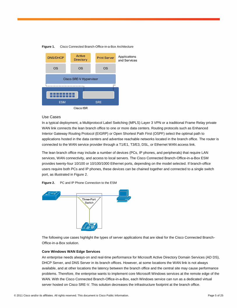
Figure 1 shows the main components of the Cisco Connected Branch-Office-in-a-Box, including:
● Cisco EtherSwitch® Module (ESM): Connects devices within the branch office, such as PCs and IP
phones, to each other and to virtual servers hosted on the Cisco Connected Branch-Office-in-a-Box
● Cisco Unified Computing System™
Express (UCS Express): Provides a converged networking,
computing, and virtualization platform with the following components:
◦ Cisco Services-Ready Engine (SRE) x86 Blade: A compact Intel 64-bit hardware platform that requires
no additional wiring or physical space.
◦ Cisco Services-Ready Engine Virtualization (SRE-V): A server virtualization platform powered by
VMware vSphere Hypervisor (ESXi) and optimized for lean branch-office use cases
◦ Microsoft Windows Server 2008 Guest Operating Systems: Multiple instances of Microsoft’s operating
system, each running one or more Windows services or mission-critical business applications
● Cisco ISR G2: Houses the SRE blade and the ESM, routes WAN bound traffic, and provides a multigigabit
fabric (MGF) backplane switch that binds the SRE blade and ESM into a common Layer 2 network
© 2011 Cisco and/or its affiliates. All rights reserved. This document is Cisco Public Information. Page 5 of 25
Figure 1. Cisco Connected Branch-Office-in-a-Box Architecture
Use Cases
In a typical deployment, a Multiprotocol Label Switching (MPLS) Layer 3 VPN or a traditional Frame Relay private
WAN link connects the lean branch office to one or more data centers. Routing protocols such as Enhanced
Interior Gateway Routing Protocol (EIGRP) or Open Shortest Path First (OSPF) select the optimal path to
applications hosted in the data centers and advertise reachable networks located in the branch office. The router is
connected to the WAN service provider through a T1/E1, T3/E3, DSL, or Ethernet WAN access link.
The lean branch office may include a number of devices (PCs, IP phones, and peripherals) that require LAN
services, WAN connectivity, and access to local servers. The Cisco Connected Branch-Office-in-a-Box ESM
provides twenty-four 10/100 or 10/100/1000 Ethernet ports, depending on the model selected. If branch-office
users require both PCs and IP phones, these devices can be chained together and connected to a single switch
port, as illustrated in Figure 2.
Figure 2. PC and IP Phone Connection to the ESM
The following use cases highlight the types of server applications that are ideal for the Cisco Connected Branch-
Office-in-a-Box solution.
Core Windows WAN Edge Services
An enterprise needs always-on and real-time performance for Microsoft Active Directory Domain Services (AD DS),
DHCP Server, and DNS Server in its branch offices. However, at some locations the WAN link is not always
available, and at other locations the latency between the branch office and the central site may cause performance
problems. Therefore, the enterprise wants to implement core Microsoft Windows services at the remote edge of the
WAN. With the Cisco Connected Branch-Office-in-a-Box, each Windows service can run as a dedicated virtual
server hosted on Cisco SRE-V. This solution decreases the infrastructure footprint at the branch office.
© 2011 Cisco and/or its affiliates. All rights reserved. This document is Cisco Public Information. Page 6 of 25
Local Point-of-Sale Server
A retail chain cannot tolerate any downtime in its in-store POS system during shopping hours. Therefore, the
retailer wants to place a POS server in the branch office to process local transactions and later synchronize the in-
store inventory with the central inventory management system. With the Cisco Connected Branch-Office-in-a-Box,
the local POS server can run on a dedicated virtual server hosted on Cisco SRE-V. This solution conserves
valuable physical space in the store.
Local Autodesk AutoCAD File Share
A global engineering firm with regional branch offices requires several copies of the Autodesk AutoCAD software to
run in each branch office. AutoCAD files are large, and frequent updates to a central file share are time-consuming.
Therefore, the firm wants to deploy a dedicated file server at each of the branch offices. With the Cisco Connected
Branch-Office-in-a-Box, the file share can be created on a dedicated virtual server hosted on Cisco SRE-V and
periodically replicated to the central site. This solution reduces complexity of the remote infrastructure.
Capabilities
The Cisco Connected Branch-Office-in-a-Box provides core network connectivity services for the lean branch
office.
Enterprise WAN Routing
The multiservice Cisco ISR G2 provides all WAN transport functions, including routing protocols, IP address
assignment, and address translation, as well as physical interfaces to connect to the WAN service provider’s
network.
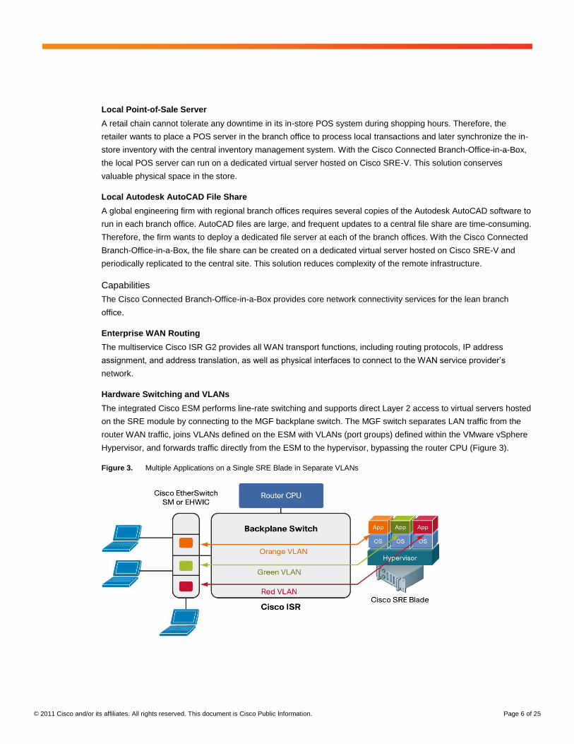
Hardware Switching and VLANs
The integrated Cisco ESM performs line-rate switching and supports direct Layer 2 access to virtual servers hosted
on the SRE module by connecting to the MGF backplane switch. The MGF switch separates LAN traffic from the
router WAN traffic, joins VLANs defined on the ESM with VLANs (port groups) defined within the VMware vSphere
Hypervisor, and forwards traffic directly from the ESM to the hypervisor, bypassing the router CPU (Figure 3).
Figure 3. Multiple Applications on a Single SRE Blade in Separate VLANs
© 2011 Cisco and/or its affiliates. All rights reserved. This document is Cisco Public Information. Page 7 of 25
Performance
Each ESM has its own processor, switching engine, and flash memory that run independently of host router
resources. The SRE has its own processor, memory, storage, Redundant Array of Independent Disks (RAID)
controller, and network interface cards (NICs) that also run independently of the host router resources. This
dedicated hardware architecture helps ensure that routing performance is not affected by server operations or
switch forwarding load.
Cisco IOS Software Features
All Cisco Connected Branch-Office-in-a-Box components are integrated into the Cisco IOS® Software. For Layer 2
ESM, Cisco IOS Software provides Layer 3 routing. For Cisco UCS Express, Cisco IOS Software exposes the
various port groups defined within the VMware vSphere Hypervisor as VLAN interfaces. Therefore, any Cisco IOS
Software feature that can be applied to a VLAN interface, such as security zone assignment, intrusion-prevention-
system (IPS) inspection, firewall policy, Virtual Route Forwarding (VRF)-Lite assignment, and traffic redirection, is
available to virtual networks defined within the hypervisor.
Ordering Information
You can order the Cisco Connected Branch-Office-in-a-Box using a single part number, as shown in Table 1. Cisco
offers ESMs with various capabilities, including Layer 3 routing and Power over Ethernet (PoE). The Cisco
Connected Branch-Office-in-a-Box bundles include the most popular ESM options: Layer 2, Layer 2 with PoE, and
Layer 3 with PoE.
Table 1. Ordering Information
Ordering SKU Description Technical Service SKUs*
(SMARTnet 8x5xNBD)
C3945-ES24-UCSE/K9 Cisco 3945 ES24 UCSE Bundle, SRE 900,SRE-V License, 24 port Layer 2 EtherSwitch SM, 4 GB ISR DRAM, 768 MB Compact Flash
CON-SNT-3945UCSE
C3925-ES24-UCSE/K9 Cisco 3925 ES24 UCSE Bundle, SRE 900,SRE-V License, 24 port Layer 2 PoE EtherSwitch SM, PoE Power Supply, 4 GB ISR DRAM, 768 MB Compact Flash
CON-SNT-3925UCSE
C2951-ES24-UCSE/K9 Cisco 2951 ES24 UCSE Bundle, SRE 900,SRE-V License, 24 port Layer 3 PoE EtherSwitch SM, PoE Power Supply, 4 GB ISR DRAM, 768 MB Compact Flash
CON-SNT-2951UCSE
* Customers can purchase Cisco SMARTnet
® Service (CON-SNT-XXX) for technical support on Cisco UCS Express bundles,
which covers the router and modules (including the SRE module and SRE-V software).
You can order (optional) the Microsoft Windows Server 2008 R2 along with the Cisco Connected Branch-Office-in-
a-Box bundle by ordering part number MSWS-08R2ST-X86-K9. Microsoft Windows Server purchased through
Cisco is shipped preinstalled as a single virtual server on the Cisco SRE-V.
Additional SRE memory may be required, depending on the number of virtual servers hosted on the Cisco UCS
Express platform. The Cisco Connected Branch-Office-in-a-Box bundles provide 4 GB of memory for the Cisco
SRE 900 module. An additional 4 GB (for a total or 8 GB) can be attached to the bundles. A typical lean branch-
office server running the applications described in the “Use Cases” section needs 1 to 2 GB of memory. Therefore,
the 4-GB configuration is targeted at one or 2 virtual servers and the 8-GB configuration is for three or four virtual
servers.
The capability to connect the SRE module to the ESM through the MGF switch requires Cisco IOS Software
Release 15.1(4) M or later, which is configured by default in the Cisco Connected Branch-Office-in-a-Box bundles.
© 2011 Cisco and/or its affiliates. All rights reserved. This document is Cisco Public Information. Page 8 of 25
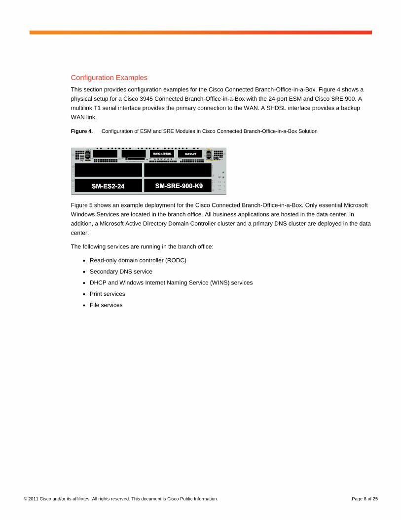
Configuration Examples
This section provides configuration examples for the Cisco Connected Branch-Office-in-a-Box. Figure 4 shows a
physical setup for a Cisco 3945 Connected Branch-Office-in-a-Box with the 24-port ESM and Cisco SRE 900. A
multilink T1 serial interface provides the primary connection to the WAN. A SHDSL interface provides a backup
WAN link.
Figure 4. Configuration of ESM and SRE Modules in Cisco Connected Branch-Office-in-a-Box Solution
Figure 5 shows an example deployment for the Cisco Connected Branch-Office-in-a-Box. Only essential Microsoft
Windows Services are located in the branch office. All business applications are hosted in the data center. In
addition, a Microsoft Active Directory Domain Controller cluster and a primary DNS cluster are deployed in the data
center.
The following services are running in the branch office:
● Read-only domain controller (RODC)
● Secondary DNS service
● DHCP and Windows Internet Naming Service (WINS) services
● Print services
● File services
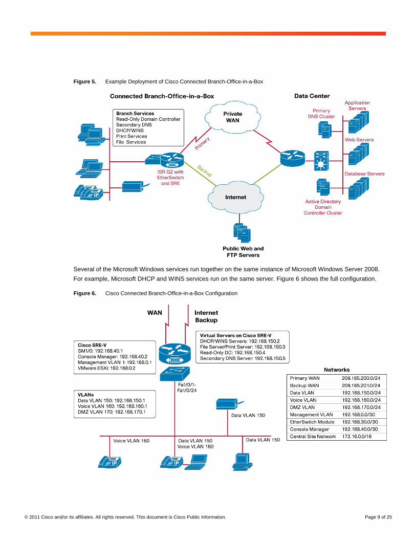
© 2011 Cisco and/or its affiliates. All rights reserved. This document is Cisco Public Information. Page 9 of 25
Figure 5. Example Deployment of Cisco Connected Branch-Office-in-a-Box
Several of the Microsoft Windows services run together on the same instance of Microsoft Windows Server 2008.
For example, Microsoft DHCP and WINS services run on the same server. Figure 6 shows the full configuration.
Figure 6. Cisco Connected Branch-Office-in-a-Box Configuration
© 2011 Cisco and/or its affiliates. All rights reserved. This document is Cisco Public Information. Page 10 of 25
Configuration examples in the following sections assume a working knowledge of these products:
1. VMware ESXi and vSphere Client
2. Cisco IOS Software environment and command-line interface
3. Microsoft Windows Server 2008 and Read-Only Domain Controller
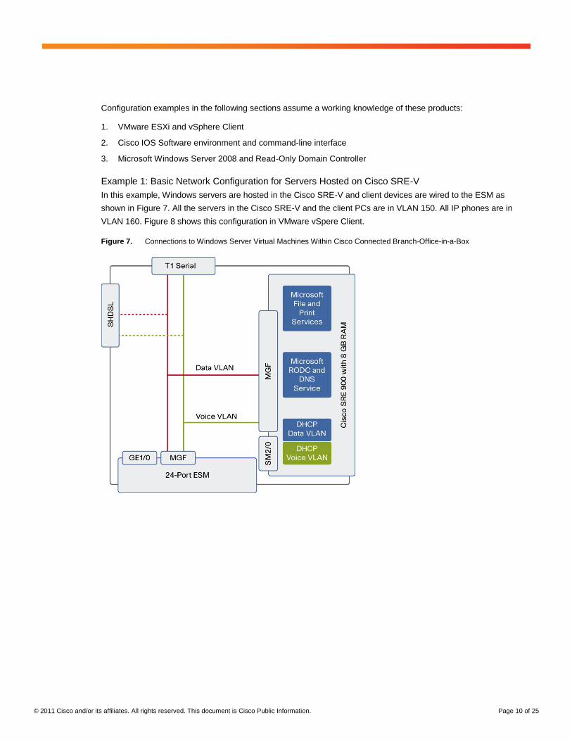
Example 1: Basic Network Configuration for Servers Hosted on Cisco SRE-V
In this example, Windows servers are hosted in the Cisco SRE-V and client devices are wired to the ESM as
shown in Figure 7. All the servers in the Cisco SRE-V and the client PCs are in VLAN 150. All IP phones are in
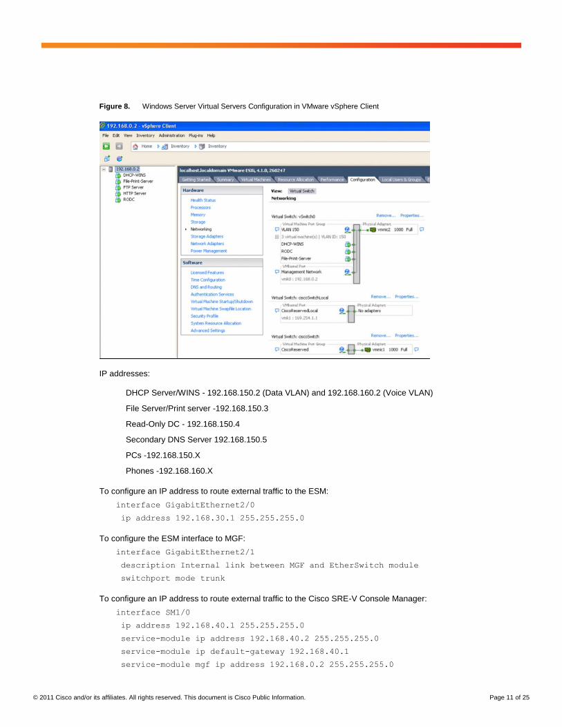
VLAN 160. Figure 8 shows this configuration in VMware vSpere Client.
Figure 7. Connections to Windows Server Virtual Machines Within Cisco Connected Branch-Office-in-a-Box
© 2011 Cisco and/or its affiliates. All rights reserved. This document is Cisco Public Information. Page 11 of 25
Figure 8. Windows Server Virtual Servers Configuration in VMware vSphere Client
IP addresses:
DHCP Server/WINS - 192.168.150.2 (Data VLAN) and 192.168.160.2 (Voice VLAN)
File Server/Print server -192.168.150.3
Read-Only DC - 192.168.150.4
Secondary DNS Server 192.168.150.5
PCs -192.168.150.X
Phones -192.168.160.X
To configure an IP address to route external traffic to the ESM:
interface GigabitEthernet2/0
ip address 192.168.30.1 255.255.255.0
To configure the ESM interface to MGF:
interface GigabitEthernet2/1
description Internal link between MGF and EtherSwitch module
switchport mode trunk
To configure an IP address to route external traffic to the Cisco SRE-V Console Manager:
interface SM1/0
ip address 192.168.40.1 255.255.255.0
service-module ip address 192.168.40.2 255.255.255.0
service-module ip default-gateway 192.168.40.1
service-module mgf ip address 192.168.0.2 255.255.255.0
© 2011 Cisco and/or its affiliates. All rights reserved. This document is Cisco Public Information. Page 12 of 25
To configure a default gateway for the Cisco SRE-V Console Manager:
service-module SM1/0 session
srev#hypervisor set ip default-gateway 192.168.0.1
To configure the Cisco SRE-V interface to the MGF:
interface SM1/1
description Internal link between MGF and Service Module
switchport mode trunk
To configure an IP address to route external traffic to the Cisco SRE-V Hypervisor:
interface Vlan1
description Management
ip address 192.168.0.1 255.255.255.0
To configure the Data VLAN interface for virtual servers (DHCP, DNS, and AD) hosted in the Cisco SRE-V and
place them on the same VLAN as PCs connected to the ESM:
interface Vlan150
description Data
ip address 192.168.150.1 255.255.255.0
To configure the Voice VLAN interface for the virtual server running DHCP in the Cisco SRE-V, place it on the
same VLAN as phones connected to ESM, and forward DHCP requests from the phones:
interface Vlan160
description Voice
ip helper-address 192.168.150.2
ip address 192.168.160.1 255.255.255.0
Check that the VLANs have been recognized with the command show interfaces sm1/1 trunk. Also check
that the VLAN interfaces are up with the command show ip interface brief. If the line protocol is down,
then re-add the interface by getting into configuration mode and using the command interface vlan number,
and then exit and save the configuration.
To configure the ESM external ports (1-port example):
service-module gigabitEthernet 2/0 session
esm(config)# vlan 150
esm(config)# vlan 160
interface FastEthernet0/4
description to Phone and PC
switchport access vlan 150
switchport voice vlan 160
© 2011 Cisco and/or its affiliates. All rights reserved. This document is Cisco Public Information. Page 13 of 25
To configure the ESM internal interface to the router:
Note: If dot1q tunneling is the default protocol in the Cisco IOS Software image, the Cisco IOS Software
command switchport trunk encapsulation dot1q is not required and cannot be added.
interface GigabitEthernet0/25
switchport trunk encapsulation dot1q
switchport mode trunk
To configure the ESM internal interface connecting to the MGF:
Note: If dot1q tunneling is the default protocol in the Cisco IOS Software image, the Cisco IOS Software
command switchport trunk encapsulation dot1q is not required and cannot be added.
interface GigabitEthernet0/26
switchport trunk encapsulation dot1q
switchport mode trunk
Installing Windows Server 2008 Virtual Servers
For virtual-machine installation instructions, refer to the Cisco SRE-V user guide at:
http://developer.cisco.com/web/srev/docs.
Add Windows Servers to a Domain
Follow these steps to add the virtual servers to the Windows domain:
1. Click Start, point to Settings, and then click Control Panel.
2. Open System in the Control Panel.
3. Under Computer name, domain, and workgroup settings, click Change settings.
4. On the Computer Name page, click Change. Then type the new computer name in the dialog box.
Example: ucse-win2k8r2
5. Under Member Of, click Domain, type the domain name, and then click OK.
Example: mydomain.mycompany.com
Note: If the system is not able to resolve the domain, make sure that it can contact the DNS server and verify
that the DNS settings are correct.
6. When prompted, provide a valid username and password.
7. When prompted, restart your computer to apply the changes.
Virtual Machine 1: Configuring Windows Server as a Read-Only Domain Controller in a Microsoft Active
Directory Cluster (Including Secondary DNS Server)
RODC is an additional domain controller for a domain that hosts read-only partitions of the Active Directory
database. An RODC is designed primarily for deployment in a branch-office environment because branch offices
typically have relatively few users, poor physical security, and relatively poor network bandwidth to a hub site.
Replicating Active Directory data to RODC helps ensure information availability for the branch office during WAN
failure.
© 2011 Cisco and/or its affiliates. All rights reserved. This document is Cisco Public Information. Page 14 of 25
Note: To run the DNS server on the RODC, another domain controller running Windows Server 2008 must be
running in the domain and hosting the DNS domain zone.
1. Log on to the server as a member of the Domain Admins group.
2. Click Start, and then click Run. In the upcoming window, type dcpromo, and then press Enter to start the
Active Directory Domain Services Installation Wizard.
3. On the Choose a Deployment Configuration page, click Existing forest, click Add a domain controller to an
existing domain, and then click Next.
4. On the Network Credentials page, type the name of a domain in the forest where you plan to install the RODC.
When prompted, enter the username and password for the Domain Administrator.
5. Select the domain for the RODC, and then click Next. If prompted by the system, install the Active Directory
Prep Controller - ADPrepController.
6. Click the Active Directory site for the RODC, and then click Next.
7. Select the Read-only Domain Controller check box. By default, the DNS server check box is also selected.
Note: An Active Directory-integrated zone on an RODC is always a read-only copy of the zone file. Updates
are sent to a DNS server in a hub site instead of being made locally on the RODC.
8. To use the default folders that are specified for the Active Directory database, the log files, and SYSVOL, click
Next.
9. Type and then confirm a Directory Services Restore Mode password, and then click Next.
10. Confirm the information that appears on the Summary page, and then click Next to start the AD DS
installation. You can select the Reboot on completion check box to make the rest of the installation complete
automatically.
Virtual Machine 2: Configuring DHCP and WINS Services on Windows Server
1. Log on to the computer as an administrator.
2. Click Start, point to Administrative tools, and then click Server Manager.
3. Select Roles and then click Add Roles.
4. In the Select Server Role list, click the DHCP Server check box, and then click Next.
5. Click the Network adapter (192.168.150.2) check box, and then click Next.
6. To provide DNS with the address, enter the parent DNS domain and primary and secondary DNS server IP
addresses, and click Next.
7. Enter the WINS server IP address and click Next.
8. Click Add to enter the scope details for the data VLAN (starting and ending IP address and default gateway),
and click Next.
9. Verify that the information entered is correct and click Install.
10. Go to the Server Manager and click Roles.
11. Expand DHCP Server and click Server.
12. Check that the data VLAN scope status is active.
13. Right click the server to add a new scope for voice.
14. Enter a name, description, and details for voice VLAN (starting and ending IP address and default gateway),
and click Next.
© 2011 Cisco and/or its affiliates. All rights reserved. This document is Cisco Public Information. Page 15 of 25
15. Enable option 150 to provide the TFTP address of the Cisco Unified Communications Manager or Cisco
Unified Communications Manager Express with the IP address for the phones.
16. Click the server and set the predefined options. Enter a name such as “Cisco TFTP”, select the IP address in
the Data type drop-down list, and enter 150.
17. Click Next.
18. Enter the IP address of the TFTP server (Cisco Unified Communications Manager or Cisco Unified
Communications Manager Express).
19. Expand the voice scope, right click on scope options, choose Configure options, and choose Option 150.
20. Connect PCs and phones in the service-module switch ports configured with Data and Voice VLAN.
21. To verify the address leases, open the Server Manager and DHCP Role, click the server to expand the scope,
and then check the address leases.
WINS Server Installation
1. Log on to the computer as an administrator.
2. Click Start, point to Administrative tools, and then click Server Manager.
3. Select Features and then click Add Features.
4. In the Select Features list, click WINS Server, click Next, and then click Install.
5. Verify that the Installation succeeded message is displayed.
6. Click Close and then click Features in the Server Manager.
7. Verify that the WINS feature is displayed.
8. Go to Start, right click Network, and then click Properties.
9. Click Change Adapter Settings and then right click the Network Adapter card.
10. Select Properties, click TCP/IPv4, and then choose Advanced.
11. Click WINS and then Add. Enter the IP address of the WINS server (192.168.150.2).
12. Repeat the same on the client PCs.
On the WINS Server, verify the WINS registration:
1. Go to the Server Manager, Click WINS feature, and then double-click Active Registrations.
2. Click More Actions, select Display Records, and click Find now.
Virtual Machine 3: Configuring Print and File Services on Windows Server
1. Log on to the computer as an administrator.
2. Click Start, point to Administrative tools, and then click Server Manager.
3. Select Roles and then click Add Roles.
4. In the select server Role list, click Print and Document Services, and then click Next.
5. In the Select Role Services list, click Print Server, and then click Next.
6. Click Install in the next Window and check if the Installation succeeded message is displayed.
7. Close the Window, go to the Server Manager and choose Roles, Expand Print and Document Services.
8. Expand Print Servers and right click the printers.

© 2011 Cisco and/or its affiliates. All rights reserved. This document is Cisco Public Information. Page 16 of 25
9. Click Add printer and select TCP/IP Device in the Type of Device drop-down box. Enter the IP address of the
printer and click Next.
Windows should detect the printer and display the model name correctly.
10. Click Share this printer, enter the share name, and click Next.
Example: Bob-Printer1
11. After the print drive is installed, click Print test page and click Finish.
12. Verify that the printer prints the test page.
13. To add the printer for clients, go to the control panel. Choose Printers, Add printers, select A network printer,
and click Next.
14. Select Connect to this printer, enter \\192.128.150.3\Bob-Printer1 in the Name box, and click Next.
File Services Configuration
1. Log in to the computer as an administrator.
2. Open Explorer and click C:
3. Right click C: and add a new folder (share1).
4. Right click the share1 folder, click Share with specific people, and select Everyone.
5. To access the shared folder from the PC, click Start and then Run and enter \\192.128.150.3\share1.
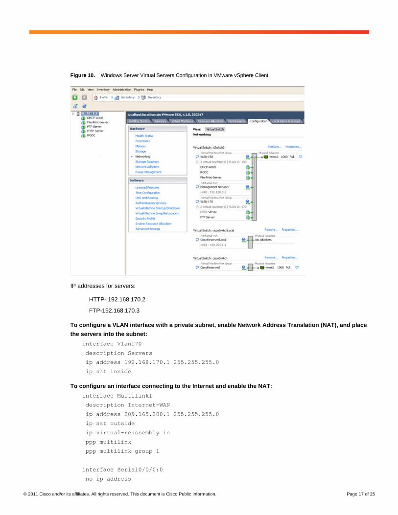
Example 2: Configuring NAT for the Servers Hosted in Cisco SRE-V
In this example, access is provided to Windows servers from the Internet for servers hosted in the Cisco SRE-V
that are configured with private IP addresses as shown in Figure 9. The servers are placed in VLAN 170. Figure 10
shows this configuration in VMware vSpere Client.
Figure 9. Connection to Public Servers Within the Cisco Connected Branch-Office-in-a-Box
© 2011 Cisco and/or its affiliates. All rights reserved. This document is Cisco Public Information. Page 17 of 25
Figure 10. Windows Server Virtual Servers Configuration in VMware vSphere Client
IP addresses for servers:
HTTP- 192.168.170.2
FTP-192.168.170.3
To configure a VLAN interface with a private subnet, enable Network Address Translation (NAT), and place
the servers into the subnet:
interface Vlan170
description Servers
ip address 192.168.170.1 255.255.255.0
ip nat inside
To configure an interface connecting to the Internet and enable the NAT:
interface Multilink1
description Internet-WAN
ip address 209.165.200.1 255.255.255.0
ip nat outside
ip virtual-reassembly in
ppp multilink
ppp multilink group 1
interface Serial0/0/0:0
no ip address
© 2011 Cisco and/or its affiliates. All rights reserved. This document is Cisco Public Information. Page 18 of 25
encapsulation ppp
ppp multilink
ppp multilink group 1
max-reserved-bandwidth 100
interface Serial0/0/1:0
no ip address
encapsulation ppp
ppp multilink
ppp multilink group 1
no cdp enable
To configure a public NAT address pool for the servers:
ip nat pool servers 209.165.200.3 209.165.200.4 netmask 255.255.255.0
To configure a private address range to be translated using the public address:
ip nat inside source list 10 pool servers
To configure an access list for the private address configured in the servers:
access-list 10 permit 192.168.170.0 0.0.0.7
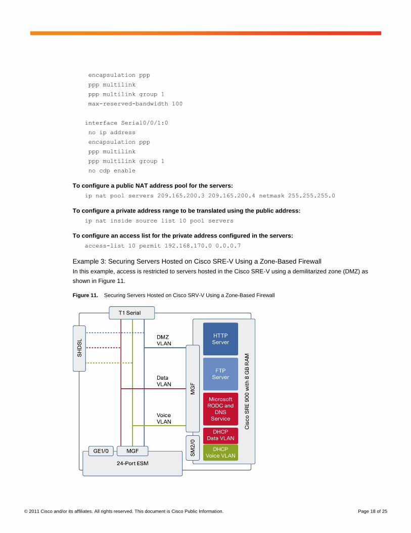
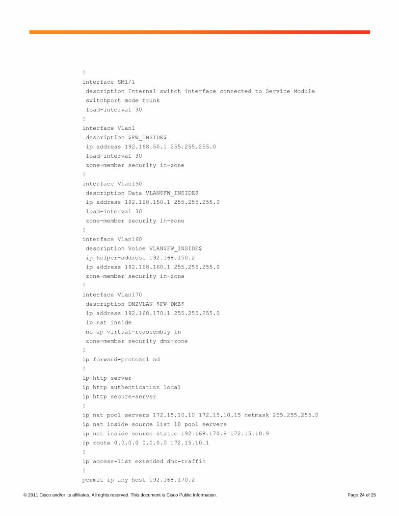
Example 3: Securing Servers Hosted on Cisco SRE-V Using a Zone-Based Firewall
In this example, access is restricted to servers hosted in the Cisco SRE-V using a demilitarized zone (DMZ) as
shown in Figure 11.
Figure 11. Securing Servers Hosted on Cisco SRV-V Using a Zone-Based Firewall
© 2011 Cisco and/or its affiliates. All rights reserved. This document is Cisco Public Information. Page 19 of 25
To place servers with restricted access in the DMZ:
zone security dmz-zone (zone used for restricted access)
zone security out-zone (zone used for interface connecting to internet)
zone security in-zone (zone used for the internal network)
To configure the Data VLAN and place the servers and PCs in the firewall “in” zone:
interface Vlan150
description Data VLAN$FW_INSIDE$
ip address 192.168.150.1 255.255.255.0
zone-member security in-zone
To configure the Voice VLAN and place the phones in the firewall “in” zone:
interface Vlan160
description Voice VLAN$FW_INSIDE$
ip helper-address 192.168.150.2
ip address 192.168.160.1 255.255.255.0
zone-member security in-zone
To configure the VLAN for DMZ servers (HTTP and FTP) in the Cisco SRE-V and place the servers in the firewall
DMZ:
interface Vlan170
description DMZVLAN $FW_DMZ$
ip address 192.168.170.1 255.255.255.0
ip nat inside
no ip virtual-reassembly in
zone-member security dmz-zone
To specify protocols allowed for DMZ access:
class-map type inspect match-any dmz-protocols
match protocol http
match protocol cifs
match protocol ftp
To configure an access list to the servers in the DMZ:
ip access-list extended dmz-traffic
permit ip any host 192.168.170.2
permit ip any host 192.168.170.3
To restrict HTTP, FTP, and Common Internet File System (CIFS) access to the previously specified DMZ servers:
class-map type inspect match-all dmz-traffic
match access-group name dmz-traffic
match class-map dmz-protocols
© 2011 Cisco and/or its affiliates. All rights reserved. This document is Cisco Public Information. Page 20 of 25
To specify firewall inspection for DMZ servers and drop all other traffic:
policy-map type inspect permit-dmzservice
class type inspect dmz-traffic
inspect
class class-default
drop
To apply the firewall policy thus defined to all traffic from the internal interfaces to the DMZ:
zone-pair security zp-in-dmz source in-zone destination dmz-zone
service-policy type inspect permit-dmzservice
To apply the firewall policy thus defined to all traffic from the public Internet to the DMZ:
zone-pair security zp-out-dmz source out-zone destination dmz-zone
service-policy type inspect permit-dmzservice
Sample Configuration
version 15.1
no service pad
service timestamps debug datetime msec localtime show-timezone
service timestamps log datetime msec localtime show-timezone
no service password-encryption
service internal
!
hostname BOB_2951
!
boot-start-marker
boot-end-marker
!
card type t1 0 0
logging buffered 200000
no logging console
enable password cisco
!
no aaa new-model
!
clock timezone PDT -1 0
clock summer-time PST recurring
clock calendar-valid
no network-clock-participate wic 0
!
no ipv6 cef
ip source-route
ip cef
!
© 2011 Cisco and/or its affiliates. All rights reserved. This document is Cisco Public Information. Page 21 of 25
multilink bundle-name authenticated
!
voice-card 0
!
license udi pid CISCO2951/K9 sn FHH1216P07N
license boot module c2951 technology-package uck9
hw-module pvdm 0/0
!
hw-module sm 1
!
hw-module sm 2
!
archive
log config
hidekeys
username admin privilege 15 password 0 cisco123
!
redundancy
!
controller T1 0/0/0
cablelength long 0db
channel-group 0 timeslots 1-24
!
controller T1 0/0/1
cablelength long 0db
channel-group 0 timeslots 1-24
!
vlan 150,160,170,302
!
class-map type inspect match-any ccp-dmz-protocols
match protocol http
match protocol cifs
match protocol ftp
!
class-map type inspect match-all ccp-dmz-traffic
match access-group name dmz-traffic
match class-map ccp-dmz-protocols
policy-map type inspect ccp-permit-dmzservice
class type inspect ccp-dmz-traffic
inspect
class class-default
drop
!
zone security dmz-zone
zone security out-zone
© 2011 Cisco and/or its affiliates. All rights reserved. This document is Cisco Public Information. Page 22 of 25
zone security in-zone
zone-pair security ccp-zp-in-dmz source in-zone destination dmz-zone
service-policy type inspect ccp-permit-dmzservice
zone-pair security ccp-zp-out-dmz source out-zone destination dmz-zone
service-policy type inspect ccp-permit-dmzservice
!
interface Loopback0
ip address 22.0.60.253 255.255.255.255
!
interface Multilink1
description $FW_OUTSIDE$
ip address 172.15.10.2 255.255.255.0
ip nat outside
ip virtual-reassembly in
load-interval 30
ppp multilink
ppp multilink group 1
zone-member security out-zone
!
interface GigabitEthernet0/0
load-interval 30
duplex auto
speed auto
no keepalive
!
interface GigabitEthernet0/1
no ip address
load-interval 30
duplex auto
speed auto
media-type rj45
no keepalive
!
interface GigabitEthernet0/2
no ip address
duplex auto
speed auto
!
interface Serial0/0/0:0
no ip address
encapsulation ppp
load-interval 30
ppp multilink
ppp multilink group 1
max-reserved-bandwidth 100

© 2011 Cisco and/or its affiliates. All rights reserved. This document is Cisco Public Information. Page 23 of 25
!
interface Serial0/0/1:0
no ip address
encapsulation ppp
ppp multilink
ppp multilink group 1
no cdp enable
!
controller SHDSL 0/2/0
termination cpe
dsl-group 0 pairs 0, 1, 2, 3 ima
shdsl annex A-B
shdsl rate auto
!
interface ATM0/2/IMA0
no ip address
no atm ilmi-keepalive
!
interface ATM0/2/IMA0.1 point-to-point
ip vrf forwarding Inet-public
ip address 172.38.10.2 255.255.255.252
pvc 5/5
protocol ip 172.38.10.1 broadcast
vbr-rt 8912 8912
oam-pvc manage
encapsulation aal5mux ppp Virtual-Template12
!
!
interface Virtual-Template12
bandwidth 8192
ip unnumbered ATM0/2/IMA0.1
!
interface GigabitEthernet2/0
ip address 192.168.0.1 255.255.255.0
!
interface GigabitEthernet2/1
switchport mode trunk
load-interval 30
!
interface SM1/0
ip address 192.168.40.1 255.255.255.0
service-module ip address 192.168.40.5 255.255.255.0
!Application: SRE-V Running on SMV
service-module ip default-gateway 192.168.40.1
service-module mgf ip address 192.168.50.5 255.255.255.0
© 2011 Cisco and/or its affiliates. All rights reserved. This document is Cisco Public Information. Page 24 of 25
!
interface SM1/1
description Internal switch interface connected to Service Module
switchport mode trunk
load-interval 30
!
interface Vlan1
description $FW_INSIDE$
ip address 192.168.50.1 255.255.255.0
load-interval 30
zone-member security in-zone
!
interface Vlan150
description Data VLAN$FW_INSIDE$
ip address 192.168.150.1 255.255.255.0
load-interval 30
zone-member security in-zone
!
interface Vlan160
description Voice VLAN$FW_INSIDE$
ip helper-address 192.168.150.2
ip address 192.168.160.1 255.255.255.0
zone-member security in-zone
!
interface Vlan170
description DMZVLAN $FW_DMZ$
ip address 192.168.170.1 255.255.255.0
ip nat inside
no ip virtual-reassembly in
zone-member security dmz-zone
!
ip forward-protocol nd
!
ip http server
ip http authentication local
ip http secure-server
!
ip nat pool servers 172.15.10.10 172.15.10.15 netmask 255.255.255.0
ip nat inside source list 10 pool servers
ip nat inside source static 192.168.170.9 172.15.10.9
ip route 0.0.0.0 0.0.0.0 172.15.10.1
!
ip access-list extended dmz-traffic
!
permit ip any host 192.168.170.2
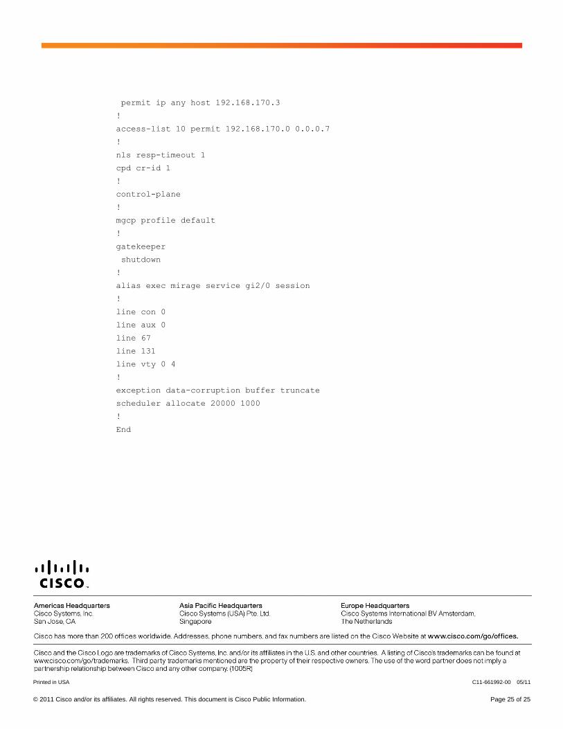
© 2011 Cisco and/or its affiliates. All rights reserved. This document is Cisco Public Information. Page 25 of 25
permit ip any host 192.168.170.3
!
access-list 10 permit 192.168.170.0 0.0.0.7
!
nls resp-timeout 1
cpd cr-id 1
!
control-plane
!
mgcp profile default
!
gatekeeper
shutdown
!
alias exec mirage service gi2/0 session
!
line con 0
line aux 0
line 67
line 131
line vty 0 4
!
exception data-corruption buffer truncate
scheduler allocate 20000 1000
!
End
Printed in USA C11-661992-00 05/11