Embed Size (px)
Citation preview
Send document comments to nexus7k -doc feedback@c i sco .com.
Cisco DCNM Security Configuration Guide, Release 4.1December 15, 2008
Americas HeadquartersCisco Systems, Inc.170 West Tasman DriveSan Jose, CA 95134-1706 USAhttp://www.cisco.comTel: 408 526-4000
800 553-NETS (6387)Fax: 408 527-0883
Text Part Number: OL-18346-01

Send document comments to nexus7k -doc feedback@c i sco .com.
THE SPECIFICATIONS AND INFORMATION REGARDING THE PRODUCTS IN THIS MANUAL ARE SUBJECT TO CHANGE WITHOUT NOTICE. ALL STATEMENTS, INFORMATION, AND RECOMMENDATIONS IN THIS MANUAL ARE BELIEVED TO BE ACCURATE BUT ARE PRESENTED WITHOUT WARRANTY OF ANY KIND, EXPRESS OR IMPLIED. USERS MUST TAKE FULL RESPONSIBILITY FOR THEIR APPLICATION OF ANY PRODUCTS.
THE SOFTWARE LICENSE AND LIMITED WARRANTY FOR THE ACCOMPANYING PRODUCT ARE SET FORTH IN THE INFORMATION PACKET THAT SHIPPED WITH THE PRODUCT AND ARE INCORPORATED HEREIN BY THIS REFERENCE. IF YOU ARE UNABLE TO LOCATE THE SOFTWARE LICENSE OR LIMITED WARRANTY, CONTACT YOUR CISCO REPRESENTATIVE FOR A COPY.
The Cisco implementation of TCP header compression is an adaptation of a program developed by the University of California, Berkeley (UCB) as part of UCB’s public domain version of the UNIX operating system. All rights reserved. Copyright © 1981, Regents of the University of California.
NOTWITHSTANDING ANY OTHER WARRANTY HEREIN, ALL DOCUMENT FILES AND SOFTWARE OF THESE SUPPLIERS ARE PROVIDED “AS IS” WITH ALL FAULTS. CISCO AND THE ABOVE-NAMED SUPPLIERS DISCLAIM ALL WARRANTIES, EXPRESSED OR IMPLIED, INCLUDING, WITHOUT LIMITATION, THOSE OF MERCHANTABILITY, FITNESS FOR A PARTICULAR PURPOSE AND NONINFRINGEMENT OR ARISING FROM A COURSE OF DEALING, USAGE, OR TRADE PRACTICE.
IN NO EVENT SHALL CISCO OR ITS SUPPLIERS BE LIABLE FOR ANY INDIRECT, SPECIAL, CONSEQUENTIAL, OR INCIDENTAL DAMAGES, INCLUDING, WITHOUT LIMITATION, LOST PROFITS OR LOSS OR DAMAGE TO DATA ARISING OUT OF THE USE OR INABILITY TO USE THIS MANUAL, EVEN IF CISCO OR ITS SUPPLIERS HAVE BEEN ADVISED OF THE POSSIBILITY OF SUCH DAMAGES.
CCDE, CCENT, Cisco Eos, Cisco HealthPresence, the Cisco logo, Cisco Lumin, Cisco Nexus, Cisco StadiumVision, Cisco TelePresence, Cisco WebEx, DCE, and Welcome to the Human Network are trademarks; Changing the Way We Work, Live, Play, and Learn and Cisco Store are service marks; and Access Registrar, Aironet, AsyncOS, Bringing the Meeting To You, Catalyst, CCDA, CCDP, CCIE, CCIP, CCNA, CCNP, CCSP, CCVP, Cisco, the Cisco Certified Internetwork Expert logo, Cisco IOS, Cisco Press, Cisco Systems, Cisco Systems Capital, the Cisco Systems logo, Cisco Unity, Collaboration Without Limitation, EtherFast, EtherSwitch, Event Center, Fast Step, Follow Me Browsing, FormShare, GigaDrive, HomeLink, Internet Quotient, IOS, iPhone, iQuick Study, IronPort, the IronPort logo, LightStream, Linksys, MediaTone, MeetingPlace, MeetingPlace Chime Sound, MGX, Networkers, Networking Academy, Network Registrar, PCNow, PIX, PowerPanels, ProConnect, ScriptShare, SenderBase, SMARTnet, Spectrum Expert, StackWise, The Fastest Way to Increase Your Internet Quotient, TransPath, WebEx, and the WebEx logo are registered trademarks of Cisco Systems, Inc. and/or its affiliates in the United States and certain other countries.
All other trademarks mentioned in this document or website are the property of their respective owners. The use of the word partner does not imply a partnership relationship between Cisco and any other company. (0812R)
Any Internet Protocol (IP) addresses used in this document are not intended to be actual addresses. Any examples, command display output, and figures included in the document are shown for illustrative purposes only. Any use of actual IP addresses in illustrative content is unintentional and coincidental.
Cisco DCNM Security Configuration Guide, Release 4.1 © 2008-2009 Cisco Systems, Inc. All rights reserved.
Send document comments to nexus7k -doc feedback@c i sco .com.
New and Changed Information
This chapter provides release-specific information for each new and changed feature in the Cisco DCNM Security Configuration Guide, Release 4.1. The latest version of this document is available at the following Cisco website: http://www.cisco.com/en/US/docs/switches/datacenter/sw/4_1/nx-os/security/configuration/guide/sec_nx-os_cfg.html
To check for additional information about Cisco DCNM Release 4.1, see the Cisco DCNM Release Notes, Release 4.1 available at the following Cisco website: http://www.cisco.com/en/US/products/ps9369/prod_release_notes_list.html
Table 1 summarizes the new and changed features for the Cisco DCNM Security Configuration Guide, Release 4.1, and tells you where they are documented.
Table 1 New and Changed Features for Release 4.1
Feature DescriptionChanged in Release Where Documented
Atomic ACL updates Added information about the atomic ACL update feature available with Nexus 7000 Series devices.
4.1(4) Chapter 7, “Configuring IP ACLs”
IPv6 ACLs Added support for IPv6 ACLs 4.1(2) Chapter 7, “Configuring IP ACLs”
VLAN access maps Support was added for multiple entries in VLAN access maps. In addition, each entry supports multiple ACLs.
4.1(2) Chapter 9, “Configuring VLAN ACLs”
DCHP server support The number of DHCP server addresses that you can configure for each Layer 3 Ethernet interface increased from four to 16.
4.1(2) Chapter 11, “Configuring DHCP Snooping”
iiiCisco DCNM Security Configuration Guide, Release 4.1
OL-18346-01

Send document comments to nexus7k -doc feedback@c i sco .com.
New and Changed Information
ivCisco DCNM Security Configuration Guide, Release 4.1
OL-18346-01
Send document comments to nexus7k -doc feedback@c i sco .com.
OL-18346-01
C O N T E N T S
New and Changed Information i-iii
Preface xix
Audience xix
Document Organization xix
Document Conventions xx
Related Documentation xx
Cisco DCNM Software Upgrade Guide, Release 4.1 xxi
Obtaining Documentation and Submitting a Service Request xxi
C H A P T E R 1 Overview 1-1
Authentication, Authorization, and Accounting 1-1
RADIUS and TACACS+ Security Protocols 1-2
User Accounts and Roles 1-2
802.1X 1-3
IP ACLs 1-3
MAC ACLs 1-3
VACLs 1-3
Port Security 1-3
DHCP Snooping 1-4
Dynamic ARP Inspection 1-4
IP Source Guard 1-4
Keychain Management 1-5
Traffic Storm Control 1-5
C H A P T E R 2 Configuring AAA 2-1
Information About AAA 2-1
AAA Security Services 2-1
Benefits of Using AAA 2-2
Remote AAA Services 2-2
AAA Server Groups 2-3
AAA Service Configuration Options 2-3
Authentication and Authorization Process for User Login 2-4
vCisco DCNM Security Configuration Guide, Release 4.1
Send document comments to nexus7k -doc feedback@c i sco .com.
Contents
Virtualization Support 2-5
Licensing Requirements for AAA 2-6
Prerequisites for AAA 2-6
AAA Guidelines and Limitations 2-6
Configuring AAA 2-7
Changing an AAA Authentication Rule Method 2-8
Adding an AAA Authentication Rule Method 2-8
Rearranging an AAA Authentication Rule Method 2-9
Deleting an AAA Authentication Rule Method 2-10
Changing an AAA Accounting Rule Method 2-10
Adding an AAA Accounting Rule Method 2-11
Rearranging an AAA Accounting Rule Method 2-12
Deleting an AAA Accounting Rule Method 2-13
Using AAA Server VSAs with Cisco NX-OS Devices 2-13
About VSAs 2-13
VSA Format 2-14
Specifying Cisco NX-OS User Roles and SMNPv3 Parameters on AAA Servers 2-14
Field Descriptions for AAA 2-15
Security: AAA: Rules: Summary Pane 2-15
Security: AAA: Rules: device: Authentication Rules: Rule: Authentication Rules Tab 2-15
Security: AAA: Rules: device: Accounting Rules: Rule: Accounting Rules Tab 2-16
Additional References 2-16
Related Documents 2-16
Standards 2-16
MIBs 2-17
Feature History for AAA 2-17
C H A P T E R 3 Configuring RADIUS 3-1
Information About RADIUS 3-1
RADIUS Network Environments 3-2
RADIUS Operation 3-2
RADIUS Server Monitoring 3-3
Vendor-Specific Attributes 3-3
Virtualization Support 3-5
Licensing Requirements for RADIUS 3-5
Prerequisites for RADIUS 3-5
Guidelines and Limitations 3-5
Configuring RADIUS Servers 3-6
viCisco DCNM Security Configuration Guide, Release 4.1
OL-18346-01
Send document comments to nexus7k -doc feedback@c i sco .com.
Contents
RADIUS Server Configuration Process 3-6
Adding a RADIUS Server Host 3-8
Copying a RADIUS Server Host 3-9
Deleting a RADIUS Server Host 3-10
Configuring a Global RADIUS Key 3-10
Configuring a Key for a Specific RADIUS Server 3-11
Adding a RADIUS Server Group 3-12
Adding a RADIUS Server Host to a RADIUS Server Group 3-12
Deleting a RADIUS Server Host from a RADIUS Server Group 3-13
Deleting a RADIUS Server Group 3-14
Allowing Users to Specify a RADIUS Server at Login 3-14
Configuring the Global RADIUS Transmission Retry Count and Timeout Interval 3-15
Configuring the RADIUS Transmission Retry Count and Timeout Interval for a Server 3-15
Configuring Accounting and Authentication Attributes for RADIUS Servers 3-16
Configuring Periodic RADIUS Server Monitoring 3-17
Configuring Periodic RADIUS Server Monitoring 3-17
Configuring the Dead-Time Interval 3-18
Deleting a RADIUS Server Host 3-19
Displaying RADIUS Server Statistics 3-19
Where to Go Next 3-20
Field Descriptions for RADIUS Server Groups and Servers 3-20
Security: AAA: Server Groups: Summary Pane 3-20
Security: AAA: Server Groups: device: Default RADIUS Server Group: Global RADIUS Settings Tab 3-21
Security: AAA: Server Groups: device: Default RADIUS Server Group: server: Server Details Tab 3-21
Security: AAA: Server Groups: device: server group: Details Tab 3-22
Additional References 3-22
Related Documents 3-22
Standards 3-22
MIBs 3-23
Feature History for RADIUS 3-23
C H A P T E R 4 Configuring TACACS+ 4-1
Information About TACACS+ 4-1
TACACS+ Advantages 4-2
TACACS+ Operation for User Login 4-2
Default TACACS+ Server Encryption Type and Secret Key 4-3
TACACS+ Server Monitoring 4-3
viiCisco DCNM Security Configuration Guide, Release 4.1
OL-18346-01
Send document comments to nexus7k -doc feedback@c i sco .com.
Contents
Vendor-Specific Attributes 4-4
Cisco VSA Format 4-4
Cisco TACACS+ Privilege Levels 4-5
Virtualization Support 4-5
Licensing Requirements for TACACS+ 4-5
Prerequisites for TACACS+ 4-6
Guidelines and Limitations 4-6
Configuring TACACS+ 4-6
TACACS+ Server Configuration Process 4-7
Enabling TACACS+ 4-9
Adding a TACACS+ Server Host 4-9
Copying a TACACS+ Server Host 4-11
Deleting a TACACS+ Server Host 4-11
Configuring a Global TACACS+ Key 4-12
Configuring a Key for a Specific TACACS+ Server 4-12
Adding a TACACS+ Server Group 4-13
Adding a TACACS+ Server Host to a TACACS+ Server Group 4-14
Deleting a TACACS+ Server Host from a TACACS+ Server Group 4-14
Deleting a TACACS+ Server Group 4-15
Specifying a TACACS+ Server at Login 4-15
Configuring the Global TACACS+ Timeout Interval 4-16
Configuring the Timeout Interval for a Server 4-17
Configuring TCP Ports 4-17
Configuring Periodic TACACS+ Server Monitoring 4-18
Configuring the Dead-Time Interval 4-19
Disabling TACACS+ 4-19
Displaying TACACS+ Statistics 4-20
Where to Go Next 4-20
Field Descriptions for TACACS+ Server Groups and Servers 4-20
Security: AAA: Server Groups: Summary Pane 4-21
Security: AAA: Server Groups: device: Default TACACS Server Group: Global TACACS Settings Tab 4-21
Security: AAA: Server Groups: device: Default TACACS Server Group: server: Server Details Tab 4-21
Security: AAA: Server Groups: device: server group: Details Tab 4-22
Additional References 4-22
Related Documents 4-22
Standards 4-23
MIBs 4-23
viiiCisco DCNM Security Configuration Guide, Release 4.1
OL-18346-01
Send document comments to nexus7k -doc feedback@c i sco .com.
Contents
Feature History for TACACS+ 4-23
C H A P T E R 5 Configuring RBAC 5-1
Information About User Accounts and RBAC 5-1
About User Accounts 5-1
Characteristics of Strong Passwords 5-2
About User Roles 5-3
About User Role Rules 5-3
Virtualization Support 5-4
Licensing Requirements for User Accounts and RBAC 5-4
Guidelines and Limitations 5-4
Configuring User Accounts 5-5
Creating a User Account 5-5
Copying a User Account 5-7
Changing a User Account Password 5-8
Changing a User Account Expiry Date 5-9
Adding a User Account Role 5-10
Deleting a User Account Role 5-10
Deleting a User Account 5-11
Configuring Roles 5-12
Creating a User Role 5-13
Adding a Rule to a User Role 5-13
Changing a Rule in a User Role 5-14
Rearranging a Rule in a User Role 5-15
Deleting a Rule from a User Role 5-16
Changing a User Role Interface Policy 5-16
Changing a User Role VLAN Policy 5-17
Changing a User Role VRF Policy 5-19
Copying a User Role 5-20
Field Descriptions for RBAC 5-20
Security: RBAC: Roles: Summary Pane 5-21
Security: RBAC: Roles: device: role: Details Tab: General Area 5-21
Security: RBAC: Roles: device: role: Details Tab: Command Authorization Rules Area 5-21
Security: RBAC: Users: Summary Pane 5-22
Additional References 5-22
Related Documents 5-22
Standards 5-22
MIBs 5-23
Feature History for User Accounts and RBAC 5-23
ixCisco DCNM Security Configuration Guide, Release 4.1
OL-18346-01
Send document comments to nexus7k -doc feedback@c i sco .com.
Contents
C H A P T E R 6 Configuring 802.1X 6-1
Information About 802.1X 6-1
Device Roles 6-2
Authentication Initiation and Message Exchange 6-3
Ports in Authorized and Unauthorized States 6-4
MAC Address Authentication Bypass 6-5
Single Host and Multiple Hosts Support 6-6
802.1X with Port Security 6-6
Supported Topologies 6-7
Virtualization Support 6-7
Licensing Requirements for 802.1X 6-7
Prerequisites for 802.1X 6-8
802.1X Guidelines and Limitations 6-8
Configuring 802.1X 6-8
Process for Configuring 802.1X 6-9
Enabling the 802.1X Feature 6-11
Configuring an AAA Authentication Method for 802.1X 6-11
Enabling the 802.1X Feature on an Interface 6-12
Controlling 802.1X Authentication on an Interface 6-12
Enabling Global Periodic Reauthentication 6-13
Enabling Periodic Reauthentication for an Interface 6-14
Changing Global 802.1X Authentication Timers 6-14
Changing 802.1X Authentication Timers for an Interface 6-15
Enabling Single Host or Multiple Hosts Mode 6-17
Enabling MAC Address Authentication Bypass 6-17
Disabling 802.1X Authentication on the Device 6-18
Disabling the 802.1X Feature 6-19
Setting the Global Maximum Authenticator-to-Supplicant Frame Retransmission Retry Count 6-19
Configuring the Maximum Authenticator-to-Supplicant Frame Retransmission Retry Count for an Interface 6-20
Enabling RADIUS Accounting for 802.1X Authentication 6-20
Configuring AAA Accounting Methods for 802.1X 6-21
Setting the Maximum Reauthentication Retry Count on an Interface 6-22
Displaying 802.1X Statistics 6-22
Field Descriptions for 802.1X 6-23
Security: Dot1X: Summary Pane 6-23
Security: Dot1X: device: Global Settings Tab: General 6-23
Security: Dot1X: device: Global Settings Tab: Timers 6-24
Security: Dot1X: device: slot: interface: Interface Settings Tab: General 6-24
xCisco DCNM Security Configuration Guide, Release 4.1
OL-18346-01
Send document comments to nexus7k -doc feedback@c i sco .com.
Contents
Security: Dot1X: device: slot: interface: Interface Settings Tab: Timers 6-25
Additional References 6-25
Related Documents 6-25
Standards 6-26
MIBs 6-26
Feature History for 802.1X 6-26
C H A P T E R 7 Configuring IP ACLs 7-1
Information About ACLs 7-1
ACL Types and Applications 7-2
Order of ACL Application 7-3
About Rules 7-4
Protocols 7-4
Source and Destination 7-5
Implicit Rules 7-5
Additional Filtering Options 7-5
Logical Operators and Logical Operation Units 7-7
Logging 7-7
Time Ranges 7-8
Statistics 7-9
Atomic ACL Updates 7-9
Virtualization Support 7-9
Licensing Requirements for IP ACLs 7-10
Prerequisites for IP ACLs 7-10
Guidelines and Limitations 7-10
Configuring IP ACLs 7-11
Creating an IP ACL 7-12
Changing an IP ACL 7-13
Changing Sequence Numbers in an IP ACL 7-13
Removing an IP ACL 7-14
Applying an IP ACL to a Physical Port 7-15
Applying an IP ACL to a Port Channel 7-15
Applying an IP ACL as a VACL 7-16
Displaying and Clearing IP ACL Statistics 7-16
Field Descriptions for IPv4 ACLs 7-16
IPv4 ACL: Details Tab 7-17
IPv4 Access Rule: Details Tab 7-17
IPv4 Access Rule: Details: Source and Destination Section 7-18
IPv4 Access Rule: Details: Protocol and Others Section 7-19
xiCisco DCNM Security Configuration Guide, Release 4.1
OL-18346-01
Send document comments to nexus7k -doc feedback@c i sco .com.
Contents
IPv4 Access Rule: Details: Advanced Section 7-21
IPv4 ACL Remark: Remark Details Tab 7-21
Field Descriptions for IPv6 ACLs 7-21
IPv6 ACL: Details Tab 7-22
IPv6 Access Rule: Details Tab 7-22
IPv6 Access Rule: Details: Source and Destination Section 7-23
IPv6 Access Rule: Details: Protocol and Others Section 7-24
IPv6 Access Rule: Details: Advanced Section 7-26
IPv6 ACL Remark: Remark Details Tab 7-26
Configuring Time Ranges 7-27
Creating a Time Range 7-27
Changing a Time Range 7-28
Removing a Time Range 7-28
Field Descriptions for Time Ranges 7-30
Additional References 7-31
Related Documents 7-31
Standards 7-31
Feature History for IP ACLs 7-31
C H A P T E R 8 Configuring MAC ACLs 8-1
Information About MAC ACLs 8-1
Licensing Requirements for MAC ACLs 8-1
Prerequisites for MAC ACLs 8-2
Guidelines and Limitations 8-2
Configuring MAC ACLs 8-2
Creating a MAC ACL 8-3
Changing a MAC ACL 8-3
Changing Sequence Numbers in a MAC ACL 8-4
Removing a MAC ACL 8-4
Applying a MAC ACL to a Physical Port 8-5
Applying a MAC ACL as a VACL 8-6
Displaying and Clearing MAC ACL Statistics 8-6
Field Descriptions for MAC ACLs 8-6
MAC ACL: ACL Details Tab 8-6
MAC Access Rule: Details: General Section 8-6
MAC Access Rule: Details: Source and Destination Section 8-7
MAC ACL Remark: Remark Details Tab 8-8
Additional References 8-8
xiiCisco DCNM Security Configuration Guide, Release 4.1
OL-18346-01
Send document comments to nexus7k -doc feedback@c i sco .com.
Contents
Related Documents 8-8
Standards 8-8
Feature History for MAC ACLs 8-9
C H A P T E R 9 Configuring VLAN ACLs 9-1
Information About VLAN ACLs 9-1
Access Maps and Entries 9-1
Actions 9-2
Virtualization Support 9-2
Licensing Requirements for VACLs 9-2
Prerequisites for VACLs 9-2
Guidelines and Limitations 9-3
Configuring VACLs 9-3
Adding a VACL 9-3
Changing a VACL 9-4
Removing a VACL or a VACL Entry 9-5
Applying a VACL to a VLAN 9-6
Field Descriptions for VACLs 9-7
VLAN Access Map Entry: Details Tab 9-7
VLAN Access Map Entry: Details: Match Condition And Action Section 9-7
Additional References 9-8
Related Documents 9-8
Standards 9-8
Feature History for VLAN ACLs 9-8
C H A P T E R 10 Configuring Port Security 10-1
Information About Port Security 10-1
Secure MAC Address Learning 10-2
Static Method 10-2
Dynamic Method 10-2
Sticky Method 10-2
Dynamic Address Aging 10-3
Secure MAC Address Maximums 10-3
Security Violations and Actions 10-4
Port Security and Port Types 10-5
Port Type Changes 10-5
802.1X and Port Security 10-5
Virtualization Support 10-6
xiiiCisco DCNM Security Configuration Guide, Release 4.1
OL-18346-01
Send document comments to nexus7k -doc feedback@c i sco .com.
Contents
Licensing Requirements for Port Security 10-6
Prerequisites for Port Security 10-6
Guidelines and Limitations 10-7
Configuring Port Security 10-7
Enabling or Disabling Port Security Globally 10-8
Enabling or Disabling Port Security on a Layer 2 Interface 10-9
Enabling or Disabling Sticky MAC Address Learning 10-10
Adding a Static Secure MAC Address on an Interface 10-10
Removing a Static Secure MAC Address on an Interface 10-12
Removing a Dynamic or Sticky Secure MAC Address 10-12
Configuring a Maximum Number of MAC Addresses 10-13
Configuring an Address Aging Type and Time 10-14
Configuring a Security Violation Action 10-15
Displaying Secure MAC Addresses 10-15
Displaying Violation Statistics 10-16
Field Descriptions for Port Security 10-16
Device: Global Settings Tab 10-16
Interface: Secure Interface Details: Secure Interface Configuration Section 10-16
Interface: Secure Interface Details: Secure Address Configuration Section 10-17
Interface: Dynamic MAC Addresses Tab 10-17
Additional References 10-18
Related Documents 10-18
Standards 10-18
MIBs 10-19
Feature History for Port Security 10-19
C H A P T E R 11 Configuring DHCP Snooping 11-1
Information About DHCP Snooping 11-1
Trusted and Untrusted Sources 11-2
DHCP Snooping Binding Database 11-2
DHCP Relay Agent 11-3
Packet Validation 11-3
DHCP Snooping Option-82 Data Insertion 11-3
Virtualization Support for DHCP Snooping 11-5
Licensing Requirements for DHCP Snooping 11-5
Prerequisites for DHCP Snooping 11-6
Guidelines and Limitations 11-6
Configuring DHCP Snooping 11-7
xivCisco DCNM Security Configuration Guide, Release 4.1
OL-18346-01
Send document comments to nexus7k -doc feedback@c i sco .com.
Contents
Minimum DHCP Snooping Configuration 11-7
Enabling or Disabling the DHCP Snooping Feature 11-8
Enabling or Disabling DHCP Snooping Globally 11-9
Enabling or Disabling DHCP Snooping on a VLAN 11-9
Enabling or Disabling DHCP Snooping MAC Address Verification 11-10
Enabling or Disabling Option-82 Data Insertion and Removal 11-11
Configuring a Layer 2 Interface as Trusted or Untrusted 11-11
Enabling or Disabling the DHCP Relay Agent 11-12
Enabling or Disabling Option 82 for the DHCP Relay Agent 11-13
Configuring a DHCP Server Address on a Layer 3 Ethernet Interface 11-13
Configuring a DHCP Server Address on a Port Channel 11-14
Configuring a DHCP Server Address on a VLAN Interface 11-15
Displaying DHCP Bindings 11-16
Field Descriptions for DHCP Snooping 11-16
Device: Configuration Tab 11-17
Device: Configuration: Global Settings Section 11-17
Device: Configuration: DHCP Trust State Section 11-17
Device: Dynamic Binding Tab 11-18
VLAN: DHCP VLAN Details Tab 11-18
Additional References 11-18
Related Documents 11-19
Standards 11-19
Feature History for DHCP Snooping 11-19
C H A P T E R 12 Configuring Dynamic ARP Inspection 12-1
Information About DAI 12-1
Understanding ARP 12-2
Understanding ARP Spoofing Attacks 12-2
Understanding DAI and ARP Spoofing Attacks 12-3
Interface Trust States and Network Security 12-3
Prioritizing ARP ACLs and DHCP Snooping Entries 12-4
Logging DAI Packets 12-5
Virtualization Support 12-5
Licensing Requirements for DAI 12-5
Prerequisites for DAI 12-6
Guidelines and Limitations 12-6
Configuring DAI 12-7
Enabling or Disabling DAI on VLANs 12-8
Configuring the DAI Trust State of a Layer 2 Interface 12-8
xvCisco DCNM Security Configuration Guide, Release 4.1
OL-18346-01
Send document comments to nexus7k -doc feedback@c i sco .com.
Contents
Applying ARP ACLs to VLANs for DAI Filtering 12-9
Enabling or Disabling Additional Validation 12-10
Configuring the DAI Logging Buffer Size 12-11
Configuring the DAI System Logging Rate 12-11
Configuring DAI Log Filtering 12-12
Displaying and Clearing DAI Statistics 12-13
Field Descriptions for DAI 12-13
Device: Details: Global Settings Section 12-13
Device: Details: ARP Trust State Section 12-14
VLAN: DAI VLAN Details Tab 12-14
Related Fields 12-14
Configuring ARP ACLs 12-15
Creating an ARP ACL 12-15
Changing an ARP ACL 12-16
Removing an ARP ACL 12-17
Field Descriptions for ARP ACLs 12-17
ARP ACL: ACL Details Tab 12-18
ARP Access Rule: ACE Details Tab 12-18
ARP Access Rule: ACE Details: Source and Destination Section 12-18
ARP ACL Remark: Remark Details Tab 12-21
Related Fields 12-21
Additional References 12-21
Related Documents 12-21
Standards 12-21
Feature History for DAI 12-22
C H A P T E R 13 Configuring IP Source Guard 13-1
Information About IP Source Guard 13-1
Virtualization Support 13-2
Licensing Requirements for IP Source Guard 13-2
Prerequisites for IP Source Guard 13-2
Guidelines and Limitations 13-3
Configuring IP Source Guard 13-3
Enabling or Disabling IP Source Guard on a Layer 2 Interface 13-4
Adding or Removing a Static IP Source Entry 13-5
Displaying IP Source Guard Bindings 13-5
Field Descriptions for IP Source Guard 13-6
Device: Static Binding Tab 13-6
xviCisco DCNM Security Configuration Guide, Release 4.1
OL-18346-01
Send document comments to nexus7k -doc feedback@c i sco .com.
Contents
Interface: Interface Configuration Tab 13-6
Additional References 13-7
Related Documents 13-7
Standards 13-7
Feature History for IP Source Guard 13-7
C H A P T E R 14 Configuring Keychain Management 14-1
Information About Keychain Management 14-1
Keychains and Keychain Management 14-1
Lifetime of a Key 14-2
Virtualization Support 14-2
Licensing Requirements for Keychain Management 14-2
Prerequisites for Keychain Management 14-3
Guidelines and Limitations 14-3
Configuring Keychain Management 14-3
Creating a Keychain 14-4
Removing a Keychain 14-4
Configuring a Key 14-5
Configuring Text for a Key 14-5
Configuring Accept and Send Lifetimes for a Key 14-6
Where to Go Next 14-7
Field Descriptions for Keychain Management 14-7
Keychain Object 14-7
Keychain Entry Object 14-8
Related Fields 14-8
Additional References 14-8
Related Documents 14-9
Standards 14-9
Feature History for Keychain Management 14-9
C H A P T E R 15 Configuring Traffic Storm Control 15-1
Information About Traffic Storm Control 15-1
Virtualization Support For Traffic Storm Control 15-3
Licensing Requirements for Traffic Storm Control 15-3
Guidelines and Limitations 15-3
Configuring Traffic Storm Control 15-4
Displaying Traffic Storm Control Statistics 15-5
xviiCisco DCNM Security Configuration Guide, Release 4.1
OL-18346-01

Send document comments to nexus7k -doc feedback@c i sco .com.
Contents
Field Descriptions for Traffic Storm Control 15-5
Switching: Traffic Storm Control: Summary Pane 15-5
Switching: Traffic Storm Control: device: interface type: interface: Interface Configuration Tab 15-6
Additional References 15-6
Related Documents 15-6
Feature History for Traffic Storm Control 15-7
I N D E X
xviiiCisco DCNM Security Configuration Guide, Release 4.1
OL-18346-01
Send document comments to nexus7k -doc feedback@c i sco .com.
Preface
This preface describes the audience, organization, and conventions of the Cisco DCNM Security Configuration Guide, Release 4.1. It also provides information on how to obtain related documentation.
This chapter includes the following sections:
• Audience, page xix
• Document Organization, page xix
• Document Conventions, page xx
• Related Documentation, page xx
• Obtaining Documentation and Submitting a Service Request, page xxi
AudienceThis publication is for experienced network administrators who configure and maintain NX-OS devices.
Document OrganizationThis document is organized into the following chapters:
Chapter Description
Chapter 1, “Overview” Describes the security features supported by DCNM.
Chapter 2, “Configuring AAA” Describes how to configure authentication, authorization, and accounting (AAA) features.
Chapter 3, “Configuring RADIUS” Describes how to configure the RADIUS security protocol.
Chapter 4, “Configuring TACACS+” Describes how to configure the TACACS+ security protocol.
Chapter 5, “Configuring RBAC” Describes how to configure user accounts and role-based access control (RBAC).
Chapter 6, “Configuring 802.1X” Describes how to configure 802.1X authentication.
Chapter 7, “Configuring IP ACLs” Describes how to configure IP access control lists (ACLs).
Chapter 8, “Configuring MAC ACLs” Describes how to configure MAC ACLs.
Chapter 9, “Configuring VLAN ACLs” Describes how to configure VLAN ACLs.
Chapter 10, “Configuring Port Security” Describes how to configure port security.
xixCisco DCNM Security Configuration Guide, Release 4.1
OL-18346-01
Send document comments to nexus7k -doc feedback@c i sco .com.
Preface
Document ConventionsThis document uses the following conventions:
Note Means reader take note. Notes contain helpful suggestions or references to material not covered in the manual.
Caution Means reader be careful. In this situation, you might do something that could result in equipment damage or loss of data.
Related DocumentationCisco DCNM documentation is available at the following URL:
http://www.cisco.com/en/US/products/ps9369/tsd_products_support_series_home.html
The documentation set for Cisco DCNM includes the following documents:
Release Notes
Cisco DCNM Release Notes, Release 4.1
DCNM Configuration Guides
Cisco DCNM Getting Started with Virtual Device Contexts, Release 4.1
Cisco DCNM Fundamentals Configuration Guide, Release 4.1
Cisco DCNM Interfaces Configuration Guide, Release 4.1
Cisco DCNM Layer 2 Switching Configuration Guide, Release 4.1
Cisco DCNM Web Services API Guide, Release 4.1
Cisco DCNM Security Configuration Guide, Release 4.1
Chapter 11, “Configuring DHCP Snooping”
Describes how to configure Dynamic Host Configuration Protocol (DHCP) snooping.
Chapter 12, “Configuring Dynamic ARP Inspection”
Describes how to configure Address Resolution Protocol (ARP) inspection.
Chapter 13, “Configuring IP Source Guard”
Describes how to configure IP Source Guard.
Chapter 14, “Configuring Keychain Management”
Describes how to configure keychain management.
Chapter 15, “Configuring Traffic Storm Control”
Describes how to configure traffic storm control.
Chapter Description
xxCisco DCNM Security Configuration Guide, Release 4.1
OL-18346-01
Send document comments to nexus7k -doc feedback@c i sco .com.
Preface
Cisco DCNM Unicast Routing Configuration Guide, Release 4.1
Cisco DCNM Virtual Device Context Configuration Guide, Release 4.1
Cisco DCNM Software Upgrade Guide, Release 4.1
Obtaining Documentation and Submitting a Service RequestFor information on obtaining documentation, submitting a service request, and gathering additional information, see the monthly What’s New in Cisco Product Documentation, which also lists all new and revised Cisco technical documentation, at:
http://www.cisco.com/en/US/docs/general/whatsnew/whatsnew.html
Subscribe to the What’s New in Cisco Product Documentation as a Really Simple Syndication (RSS) feed and set content to be delivered directly to your desktop using a reader application. The RSS feeds are a free service and Cisco currently supports RSS version 2.0.
xxiCisco DCNM Security Configuration Guide, Release 4.1
OL-18346-01

Send document comments to nexus7k -doc feedback@c i sco .com.
Preface
xxiiCisco DCNM Security Configuration Guide, Release 4.1
OL-18346-01
Send document comments to nexus7k -doc feedback@c i sco .com.
CiscOL-18346-01
C H A P T E R1
OverviewCisco NX-OS supports security features that can protect your network against degradation or failure and also against data loss or compromise resulting from intentional attacks and from unintended but damaging mistakes by well-meaning network users.
This chapter includes the following sections:
• Authentication, Authorization, and Accounting, page 1-1
• RADIUS and TACACS+ Security Protocols, page 1-2
• User Accounts and Roles, page 1-2
• 802.1X, page 1-3
• `IP ACLs, page 1-3
• MAC ACLs, page 1-3
• VACLs, page 1-3
• Port Security, page 1-3
• DHCP Snooping, page 1-4
• Dynamic ARP Inspection, page 1-4
• IP Source Guard, page 1-4
• Keychain Management, page 1-5
• Traffic Storm Control, page 1-5
Authentication, Authorization, and AccountingAuthentication, authorization, and accounting (AAA) is an architectural framework for configuring a set of three independent security functions in a consistent, modular manner:
• Authentication—Provides the method of identifying users, including login and password dialog, challenge and response, messaging support, and, depending on the security protocol that you select, encryption. Authentication is the way a user is identified prior to being allowed access to the network and network services. You configure AAA authentication by defining a named list of authentication methods and then applying that list to various interfaces.
• Authorization—Provides the method for remote access control, including one-time authorization or authorization for each service, per-user account list and profile, user group support, and support of IP, IPX, ARA, and Telnet.
1-1o DCNM Security Configuration Guide, Release 4.1
Send document comments to nexus7k -doc feedback@c i sco .com.
Chapter 1 OverviewRADIUS and TACACS+ Security Protocols
Remote security servers, such as RADIUS and TACACS+, authorize users for specific rights by associating attribute-value (AV) pairs, which define those rights, with the appropriate user. AAA authorization works by assembling a set of attributes that describe what the user is authorized to perform. These attributes are compared with the information contained in a database for a given user, and the result is returned to AAA to determine the user’s actual capabilities and restrictions.
• Accounting—Provides the method for collecting and sending security server information used for billing, auditing, and reporting, such as user identities, start and stop times, executed commands (such as PPP), number of packets, and number of bytes. Accounting enables you to track the services that users are accessing, as well as the amount of network resources that they are consuming.
Note You can configure authentication outside of AAA. However, you must configure AAA if you want to use RADIUS or TACACS+, or if you want to configure a backup authentication method.
For information on configuring AAA, see Chapter 2, “Configuring AAA.”
RADIUS and TACACS+ Security ProtocolsAAA uses security protocols to administer its security functions. If your router or access server is acting as a network access server, AAA is the means through which you establish communication between your network access server and your RADIUS or TACACS+ security server.
The chapters in this guide describe how to configure the following security server protocols:
• RADIUS—A distributed client/server system implemented through AAA that secures networks against unauthorized access. In the Cisco implementation, RADIUS clients run on Cisco routers and send authentication requests to a central RADIUS server that contains all user authentication and network service access information.
• TACACS+—A security application implemented through AAA that provides a centralized validation of users who are attempting to gain access to a router or network access server. TACACS+ services are maintained in a database on a TACACS+ daemon running, typically, on a UNIX or Windows NT workstation. TACACS+ provides for separate and modular authentication, authorization, and accounting facilities.
For information on configuring RADIUS, see Chapter 3, “Configuring RADIUS.” For information on configuring TACACS+, see Chapter 4, “Configuring TACACS+.”
User Accounts and RolesYou can create and manage user accounts and assign roles that limit access to operations on the NX-OS device. Role-based access control (RBAC) allows you to define the rules for an assign role that restrict the authorization that the user has to access management operations.
For information on configuring user accounts and RBAC, see Chapter 5, “Configuring RBAC.”
1-2Cisco DCNM Security Configuration Guide, Release 4.1
OL-18346-01
Send document comments to nexus7k -doc feedback@c i sco .com.
Chapter 1 Overview802.1X
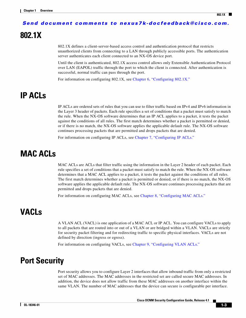
802.1X802.1X defines a client-server-based access control and authentication protocol that restricts unauthorized clients from connecting to a LAN through publicly accessible ports. The authentication server authenticates each client connected to an NX-OS device port.
Until the client is authenticated, 802.1X access control allows only Extensible Authentication Protocol over LAN (EAPOL) traffic through the port to which the client is connected. After authentication is successful, normal traffic can pass through the port.
For information on configuring 802.1X, see Chapter 6, “Configuring 802.1X.”
IP ACLsIP ACLs are ordered sets of rules that you can use to filter traffic based on IPv4 and IPv6 information in the Layer 3 header of packets. Each rule specifies a set of conditions that a packet must satisfy to match the rule. When the NX-OS software determines that an IP ACL applies to a packet, it tests the packet against the conditions of all rules. The first match determines whether a packet is permitted or denied, or if there is no match, the NX-OS software applies the applicable default rule. The NX-OS software continues processing packets that are permitted and drops packets that are denied.
For information on configuring IP ACLs, see Chapter 7, “Configuring IP ACLs.”
MAC ACLsMAC ACLs are ACLs that filter traffic using the information in the Layer 2 header of each packet. Each rule specifies a set of conditions that a packet must satisfy to match the rule. When the NX-OS software determines that a MAC ACL applies to a packet, it tests the packet against the conditions of all rules. The first match determines whether a packet is permitted or denied, or if there is no match, the NX-OS software applies the applicable default rule. The NX-OS software continues processing packets that are permitted and drops packets that are denied.
For information on configuring MAC ACLs, see Chapter 8, “Configuring MAC ACLs.”
VACLsA VLAN ACL (VACL) is one application of a MAC ACL or IP ACL. You can configure VACLs to apply to all packets that are routed into or out of a VLAN or are bridged within a VLAN. VACLs are strictly for security packet filtering and for redirecting traffic to specific physical interfaces. VACLs are not defined by direction (ingress or egress).
For information on configuring VACLs, see Chapter 9, “Configuring VLAN ACLs.”
Port SecurityPort security allows you to configure Layer 2 interfaces that allow inbound traffic from only a restricted set of MAC addresses. The MAC addresses in the restricted set are called secure MAC addresses. In addition, the device does not allow traffic from these MAC addresses on another interface within the same VLAN. The number of MAC addresses that the device can secure is configurable per interface.
1-3Cisco DCNM Security Configuration Guide, Release 4.1
OL-18346-01
Send document comments to nexus7k -doc feedback@c i sco .com.
Chapter 1 OverviewDHCP Snooping
For information on configuring port security, see Chapter 10, “Configuring Port Security.”
DHCP SnoopingDHCP snooping acts like a firewall between untrusted hosts and trusted DHCP servers. DHCP snooping performs the following activities:
• Validates DHCP messages received from untrusted sources and filters out invalid messages.
• Builds and maintains the DHCP snooping binding database, which contains information about untrusted hosts with leased IP addresses.
• Uses the DHCP snooping binding database to validate subsequent requests from untrusted hosts.
Dynamic ARP inspection (DAI) and IP Source Guard also use information stored in the DHCP snooping binding database.
For information on configuring DHCP snooping, see Chapter 11, “Configuring DHCP Snooping.”
Dynamic ARP InspectionDynamic ARP inspection (DAI) ensures that only valid ARP requests and responses are relayed. When DAI is enabled and properly configured, an NX-OS device performs these activities:
• Intercepts all ARP requests and responses on untrusted ports.
• Verifies that each of these intercepted packets has a valid IP-to-MAC address binding before updating the local ARP cache or before forwarding the packet to the appropriate destination.
• Drops invalid ARP packets.
DAI can determine the validity of an ARP packet based on valid IP-to-MAC address bindings stored in a DHCP snooping binding database. This database is built by DHCP snooping if DHCP snooping is enabled on the VLANs and on the device. If the ARP packet is received on a trusted interface, the device forwards the packet without any checks. On untrusted interfaces, the device forwards the packet only if it is valid.
For information on configuring DAI, see Chapter 12, “Configuring Dynamic ARP Inspection.”
IP Source GuardIP Source Guard is a per-interface traffic filter that permits IP traffic only when the IP address and MAC address of each packet matches one of two sources of IP and MAC address bindings:
• Entries in the DHCP snooping binding table.
• Static IP source entries that you configure.
Filtering on trusted IP and MAC address bindings helps prevent attacks that rely on spoofing the IP address of a valid host. To circumvent IP Source Guard, an attacker would have to spoof both the IP address and the MAC address of a valid host.
For information on configuring IP Source Guard, see Chapter 13, “Configuring IP Source Guard.”
1-4Cisco DCNM Security Configuration Guide, Release 4.1
OL-18346-01
Send document comments to nexus7k -doc feedback@c i sco .com.
Chapter 1 OverviewKeychain Management
Keychain ManagementKeychain management allows you to create and maintain keychains, which are sequences of keys (sometimes called shared secrets). You can use keychains with features that secure communications with other devices by using key-based authentication. The device allows you to configure multiple keychains.
Some routing protocols that support key-based authentication can use a keychain to implement a hitless key rollover for authentication.
For information on configuring keychain management, see Chapter 14, “Configuring Keychain Management.”
Traffic Storm ControlTraffic storm control (also called traffic suppression) allows you to monitor the levels of the incoming traffic over a 1-second interval. During this interval, the traffic level, which is a percentage of the total available bandwidth of the port, is compared with the traffic storm control level that you configured. When the ingress traffic reaches the traffic storm control level that is configured on the port, traffic storm control drops the traffic until the interval ends.
For information on configuring traffic storm control, see Chapter 15, “Configuring Traffic Storm Control.”
1-5Cisco DCNM Security Configuration Guide, Release 4.1
OL-18346-01

Send document comments to nexus7k -doc feedback@c i sco .com.
Chapter 1 OverviewTraffic Storm Control
1-6Cisco DCNM Security Configuration Guide, Release 4.1
OL-18346-01
Send document comments to nexus7k -doc feedback@c i sco .com.
CiscOL-18346-01
C H A P T E R2
Configuring AAAThis chapter describes how to configure authentication, authorization, and accounting (AAA) on Cisco NX-OS devices.
This chapter includes the following sections:
• Information About AAA, page 2-1
• Licensing Requirements for AAA, page 2-6
• Prerequisites for AAA, page 2-6
• AAA Guidelines and Limitations, page 2-6
• Configuring AAA, page 2-7
• Field Descriptions for AAA, page 2-15
• Field Descriptions for AAA, page 2-15
• Additional References, page 2-16
Information About AAAThis section includes the following topics:
• AAA Security Services, page 2-1
• Benefits of Using AAA, page 2-2
• Remote AAA Services, page 2-2
• AAA Server Groups, page 2-3
• AAA Service Configuration Options, page 2-3
• Authentication and Authorization Process for User Login, page 2-4
• Virtualization Support, page 2-5
AAA Security ServicesThe AAA feature allows you to verify the identity of, grant access to, and track the actions of users managing an Cisco NX-OS device. Cisco NX-OS devices support Remote Access Dial-In User Service (RADIUS) or Terminal Access Controller Access Control device Plus (TACACS+) protocols.
2-1o DCNM Security Configuration Guide, Release 4.1

Send document comments to nexus7k -doc feedback@c i sco .com.
Chapter 2 Configuring AAAInformation About AAA
Based on the user ID and password combination that you provide, Cisco NX-OS devices perform local authentication or authorization using the local database or remote authentication or authorization using one or more AAA servers. A preshared secret key provides security for communication between the Cisco NX-OS device and AAA servers. You can configure a common secret key for all AAA servers or for only a specific AAA server.
AAA security provides the following services:
• Authentication—Identifies users, including login and password dialog, challenge and response, messaging support, and, depending on the security protocol that you select, encryption.
Authentication is the process of verifying the identity of the person or device accessing the Cisco NX-OS device, which is based on the user ID and password combination provided by the entity trying to access the Cisco NX-OS device. Cisco NX-OS devices allow you to perform local authentication (using the local lookup database) or remote authentication (using one or more RADIUS or TACACS+ servers).
• Authorization—Provides access control.
AAA authorization is the process of assembling a set of attributes that describe what the user is authorized to perform. Authorization in the Cisco NX-OS software is provided by attributes that are downloaded from AAA servers. Remote security servers, such as RADIUS and TACACS+, authorize users for specific rights by associating attribute-value (AV) pairs, which define those rights with the appropriate user.
• Accounting—Provides the method for collecting information, logging the information locally, and sending the information to the AAA server for billing, auditing, and reporting.
The accounting feature tracks and maintains a log of every management session used to access the Cisco NX-OS device. You can use this information to generate reports for troubleshooting and auditing purposes. You can store accounting logs locally or send them to remote AAA servers.
Note The Cisco NX-OS software supports authentication, authorization, and accounting independently. For example, you can configure authentication and authorization without configuring accounting.
Benefits of Using AAAAAA provides the following benefits:
• Increased flexibility and control of access configuration
• Scalability
• Standardized authentication methods, such as RADIUS and TACACS+
• Multiple backup devices
Remote AAA ServicesRemote AAA services provided through RADIUS and TACACS+ protocols have the following advantages over local AAA services:
• It is easier to manage user password lists for each Cisco NX-OS device in the fabric.
• AAA servers are already deployed widely across enterprises and can be easily used for AAA services.
2-2Cisco DCNM Security Configuration Guide, Release 4.1
OL-18346-01
Send document comments to nexus7k -doc feedback@c i sco .com.
Chapter 2 Configuring AAAInformation About AAA
• You can centrally manage the accounting log for all Cisco NX-OS devices in the fabric.
• It is easier to manage user attributes for each Cisco NX-OS device in the fabric than using the local databases on the Cisco NX-OS devices.
AAA Server GroupsYou can specify remote AAA servers for authentication, authorization, and accounting using server groups. A server group is a set of remote AAA servers that implement the same AAA protocol. The purpose of a server group is to provide for fail-over servers in case a remote AAA server fails to respond. If the first remote server in the group fails to respond, the next remote server in the group is tried until one of the servers sends a response. If all the AAA servers in the server group fail to respond, then that server group option is considered a failure. If required, you can specify multiple server groups. If the Cisco NX-OS device encounters errors from the servers in the first group, it tries the servers in the next server group.
AAA Service Configuration OptionsAAA configuration in Cisco NX-OS devices is service based, which means that you can have separate AAA configurations for the following services:
• User Telnet or Secure Shell (SSH) login authentication
• Console login authentication
• 802.1X authentication (see Chapter 6, “Configuring 802.1X”)
• User management session accounting
• 802.1X accounting (see Chapter 6, “Configuring 802.1X”)
You can specify the following authentication methods for the AAA services:
• RADIUS server groups—Uses the global pool of RADIUS servers for authentication.
• Specified server groups—Uses specified RADIUS or TACACS+ server groups for authentication.
• Local—Uses the local username or password database for authentication.
• None—Uses only the username.
Note If the method is all RADIUS servers, rather than a specific server group, the Cisco NX-OS device chooses the RADIUS server from the global pool of configured RADIUS servers, in the order of configuration. Servers from this global pool are the servers that can be selectively configured in a RADIUS server group on the Cisco NX-OS device.
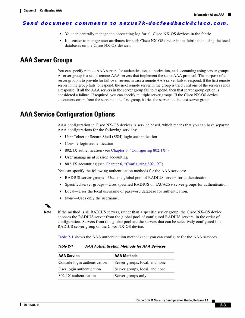
Table 2-1 shows the AAA authentication methods that you can configure for the AAA services.
Table 2-1 AAA Authentication Methods for AAA Services
AAA Service AAA Methods
Console login authentication Server groups, local, and none
User login authentication Server groups, local, and none
802.1X authentication Server groups only
2-3Cisco DCNM Security Configuration Guide, Release 4.1
OL-18346-01
Send document comments to nexus7k -doc feedback@c i sco .com.
Chapter 2 Configuring AAAInformation About AAA
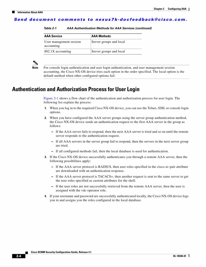
Note For console login authentication and user login authentication, and user management session accounting, the Cisco NX-OS device tries each option in the order specified. The local option is the default method when other configured options fail.
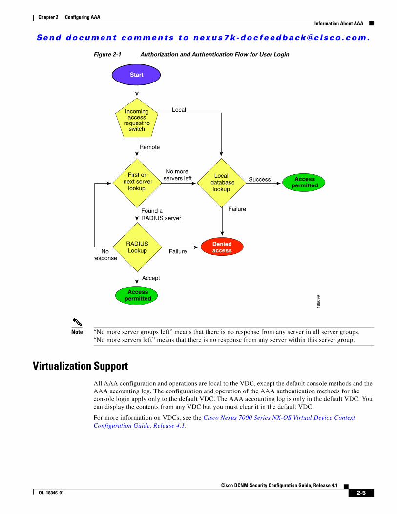
Authentication and Authorization Process for User LoginFigure 2-1 shows a flow chart of the authentication and authorization process for user login. The following list explain the process:
1. When you log in to the required Cisco NX-OS device, you can use the Telnet, SSH, or console login options.
2. When you have configured the AAA server groups using the server group authentication method, the Cisco NX-OS device sends an authentication request to the first AAA server in the group as follows:
– If the AAA server fails to respond, then the next AAA server is tried and so on until the remote server responds to the authentication request.
– If all AAA servers in the server group fail to respond, then the servers in the next server group are tried.
– If all configured methods fail, then the local database is used for authentication.
3. If the Cisco NX-OS device successfully authenticates you through a remote AAA server, then the following possibilities apply:
– If the AAA server protocol is RADIUS, then user roles specified in the cisco-av-pair attribute are downloaded with an authentication response.
– If the AAA server protocol is TACACS+, then another request is sent to the same server to get the user roles specified as custom attributes for the shell.
– If the user roles are not successfully retrieved from the remote AAA server, then the user is assigned with the vdc-operator role.
4. If your username and password are successfully authenticated locally, the Cisco NX-OS device logs you in and assigns you the roles configured in the local database.
User management session accounting
Server groups and local
802.1X accounting Server groups and local
Table 2-1 AAA Authentication Methods for AAA Services (continued)
AAA Service AAA Methods
2-4Cisco DCNM Security Configuration Guide, Release 4.1
OL-18346-01
Send document comments to nexus7k -doc feedback@c i sco .com.
Chapter 2 Configuring AAAInformation About AAA
Figure 2-1 Authorization and Authentication Flow for User Login
Note “No more server groups left” means that there is no response from any server in all server groups. “No more servers left” means that there is no response from any server within this server group.
Virtualization SupportAll AAA configuration and operations are local to the VDC, except the default console methods and the AAA accounting log. The configuration and operation of the AAA authentication methods for the console login apply only to the default VDC. The AAA accounting log is only in the default VDC. You can display the contents from any VDC but you must clear it in the default VDC.
For more information on VDCs, see the Cisco Nexus 7000 Series NX-OS Virtual Device Context Configuration Guide, Release 4.1.
Accept
Access permitted
Incoming access
request to switch
FailureNoresponse
Failure
Access permitted
Local
Success
Denied access
No more servers left
Remote
Found aRADIUS server
1850
99
Incomingaccess
request toswitch
RADIUS Lookup
First or next server
lookup
Local database lookup
Start
2-5Cisco DCNM Security Configuration Guide, Release 4.1
OL-18346-01
Send document comments to nexus7k -doc feedback@c i sco .com.
Chapter 2 Configuring AAALicensing Requirements for AAA
Licensing Requirements for AAAThe following table shows the licensing requirements for this feature:
Prerequisites for AAARemote AAA servers have the following prerequisites:
• Ensure that at least one RADIUS or TACACS+ server is IP reachable (see the “Adding a RADIUS Server Host” section on page 3-8 and the “Adding a TACACS+ Server Host” section on page 4-9).
• Ensure that the Cisco NX-OS device is configured as a client of the AAA servers.
• Ensure that the preshared secret key is configured on the Cisco NX-OS device and the remote AAA servers.
• Ensure that the logging level for AAA in the Cisco NX-OS software is set to 5 using the command-line interface (CLI).
switch# configure terminalswitch(config)# logging level aaa 5
AAA Guidelines and Limitations RADIUS has the following guidelines and limitations:
• The Cisco NX-OS software does not support all numeric usernames, whether created with TACACS+ or RADIUS, or created locally, and does not create local users with all numeric names. If an all numeric username exists on an AAA server and is entered during login, the Cisco NX-OS device does log in the user.
• If you have a user account configured on the local Cisco NX-OS device that has the same name as a remote user account on an AAA server, the Cisco NX-OS software applies the user roles for the local user account to the remote user, not the user roles configured on the AAA server.
Product License Requirement
DCNM AAA requires no license. Any feature not included in a license package is bundled with the Cisco DCNM and is provided at no charge to you. For a complete explanation of the DCNM licensing scheme, see the Cisco DCNM Fundamentals Configuration Guide, Release 4.1.
Cisco NX-OS AAA requires no license. Any feature not included in a license package is bundled with the Cisco NX-OS system images and is provided at no extra charge to you. For a complete explanation of the Cisco NX-OS licensing scheme, see the Cisco Nexus 7000 Series NX-OS Licensing Guide, Release 4.1.
2-6Cisco DCNM Security Configuration Guide, Release 4.1
OL-18346-01
Send document comments to nexus7k -doc feedback@c i sco .com.
Chapter 2 Configuring AAAConfiguring AAA
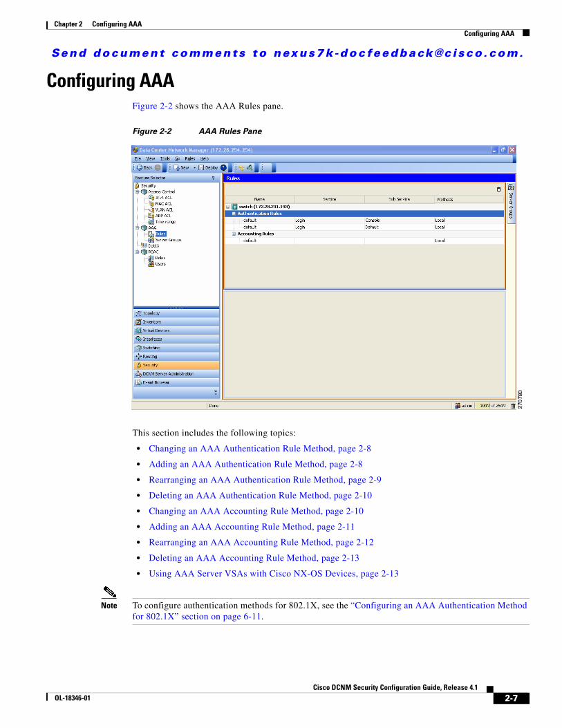
Configuring AAAFigure 2-2 shows the AAA Rules pane.
Figure 2-2 AAA Rules Pane
This section includes the following topics:
• Changing an AAA Authentication Rule Method, page 2-8
• Adding an AAA Authentication Rule Method, page 2-8
• Rearranging an AAA Authentication Rule Method, page 2-9
• Deleting an AAA Authentication Rule Method, page 2-10
• Changing an AAA Accounting Rule Method, page 2-10
• Adding an AAA Accounting Rule Method, page 2-11
• Rearranging an AAA Accounting Rule Method, page 2-12
• Deleting an AAA Accounting Rule Method, page 2-13
• Using AAA Server VSAs with Cisco NX-OS Devices, page 2-13
Note To configure authentication methods for 802.1X, see the “Configuring an AAA Authentication Method for 802.1X” section on page 6-11.
2-7Cisco DCNM Security Configuration Guide, Release 4.1
OL-18346-01
Send document comments to nexus7k -doc feedback@c i sco .com.
Chapter 2 Configuring AAAConfiguring AAA
Changing an AAA Authentication Rule MethodYou can change an AAA authentication rule method.
The methods include the following:
• Group—RADIUS server groups
• Local—Local database on the device
• None—Username only
The default method is local.
The rules are applied in the sequence order. If all methods fail, the device uses the default local method.
Note The configuration and operation of the AAA for the console login apply to the default VDC.
BEFORE YOU BEGIN
Configure RADIUS or TACACS+ server groups, as needed.
DETAILED STEPS
To change an authentication rule method, follow these steps:
Step 1 From the Feature Selector pane, choose Security > AAA > Rules.
Step 2 Double-click Authentication Rules to display the list of accounting rules.
Step 3 Click the rule to which to add a method.
Step 4 Click the rule to change.
The Authentication Rules tab appears in the Details pane.
Step 5 From the Authentication Rules tab, click the method to change.
Step 6 Double-click the method cell under Type and choose the method type from the drop-down list.
Step 7 If you chose the Group method type, double-click the method cell under Server Group Name and choose a server group name from the drop-down list. Click OK.
Step 8 From the menu bar, choose File > Deploy to apply your changes to the device.
Adding an AAA Authentication Rule MethodYou can change an AAA authentication rule method.
The methods include the following:
• Group—RADIUS server groups
• Local—Local database on the Cisco NX-OS device
• None—Username only
The default method is local.
2-8Cisco DCNM Security Configuration Guide, Release 4.1
OL-18346-01
Send document comments to nexus7k -doc feedback@c i sco .com.
Chapter 2 Configuring AAAConfiguring AAA
The rules are applied in the sequence order. If all methods fail, the Cisco NX-OS device uses the default local method.
Note The configuration and operation of the AAA for the console login only apply to the default VDC.
BEFORE YOU BEGIN
Configure RADIUS or TACACS+ server groups, as needed.
DETAILED STEPS
To add an authentication rule method, follow these steps:
Step 1 From the Feature Selector pane, choose Security > AAA > Rules.
Step 2 From the Summary pane, double-click the device.
Step 3 Double-click Authentication Rules to display the list of accounting rules.
Step 4 Click the rule to which to add a method.
The Authentication Rules tab appears in the Details pane.
Step 5 Right-click on a method and click Add Method from the pop-up menu.
A new rule displays at the end of the list with a sequence number and blank fields.
Step 6 Double-click the cell under Type in the new method and choose the method type from the drop-down list.
Note If you chose None for the method type, it must always be the last method in the list.
Step 7 If you chose the Group method type, double-click the method cell under Server Group Name and choose a server group name from the drop-down list. Click OK.
Step 8 From the menu bar, choose File > Deploy to apply your changes to the device.
Rearranging an AAA Authentication Rule MethodYou can rearrange the sequence of the methods for an AAA authentication rule.
Note The None method must always be the last method in the list.
DETAILED STEPS
To rearrange an AAA authentication rule method, follow these steps:
Step 1 From the Feature Selector pane, choose Security > AAA > Rules.
Step 2 From the Summary pane, double-click the device.
Step 3 Double-click Authentication Rules to display the list of accounting rules.
2-9Cisco DCNM Security Configuration Guide, Release 4.1
OL-18346-01
Send document comments to nexus7k -doc feedback@c i sco .com.
Chapter 2 Configuring AAAConfiguring AAA
Step 4 Click the rule which has the method that you want to rearrange.
The Authentication Rules tab appears in the Details pane with the list of methods.
Step 5 Click the methodthat you want to rearrange.
Step 6 Right-click and click Move Up or Move Up from the pop-up menu.
Step 7 From the menu bar, choose File > Deploy to apply your changes to the device.
Deleting an AAA Authentication Rule MethodYou can delete an AAA authentication rule method.
Note An AAA authentication rule must have at least one method. You can only delete a method when the rule had more than one method.
DETAILED STEPS
To delete an authentication rule method, follow these steps:
Step 1 From the Feature Selector pane, choose Security > AAA > Rules.
Step 2 From the Summary pane, double-click the device.
Step 3 Double-click Authentication Rules to display the list of accounting rules.
Step 4 Click the rule from which to delete a method.
The Authentication Rules tab appears in the Details pane.
Step 5 Click the method that you want to delete.
Note You can only delete a method with sequence number 2 or greater. To delete the rule with sequence number 1, you must first rearrange the methods (see the “Rearranging an AAA Authentication Rule Method” section on page 2-9).
Step 6 Right-click and click Delete Method from the pop-up menu.
The rule disappears from the list and the sequence numbers are updated.
Step 7 From the menu bar, choose File > Deploy to apply your changes to the device.
Changing an AAA Accounting Rule MethodYou can change an AAA accounting rule method. The device supports TACACS+ and RADIUS methods for accounting, which report user activity to TACACS+ or RADIUS security servers in the form of accounting records.
You can specify the following accounting methods:
• Server group—Uses a specified RADIUS or TACACS+ server group for accounting.
2-10Cisco DCNM Security Configuration Guide, Release 4.1
OL-18346-01
Send document comments to nexus7k -doc feedback@c i sco .com.
Chapter 2 Configuring AAAConfiguring AAA
• Local—Uses the local username or password database for accounting.
The default method is local.
Note If you have configured server groups and the server groups do not respond, by default, the local database is used for authentication.
BEFORE YOU BEGIN
Configure RADIUS or TACACS+ server groups, as needed.
DETAILED STEPS
To change an accounting rule method, follow these steps:
Step 1 From the Feature Selector pane, choose Security > AAA > Rules.
Step 2 From the Summary pane, double-click the device.
Step 3 Double-click Accounting Rules to display the list of accounting rules.
Step 4 Click the rule to change.
The Accounting Rules tab appears in the Details pane.
Step 5 From the Accounting Rules tab, click the method to change.
Step 6 Double-click the method cell under Type and choose the method type from the drop-down list.
Step 7 If you chose the Group method type, double-click the method cell under Server Group Name and choose a server group name from the drop-down list. Click OK.
Step 8 From the menu bar, choose File > Deploy to apply your changes to the device.
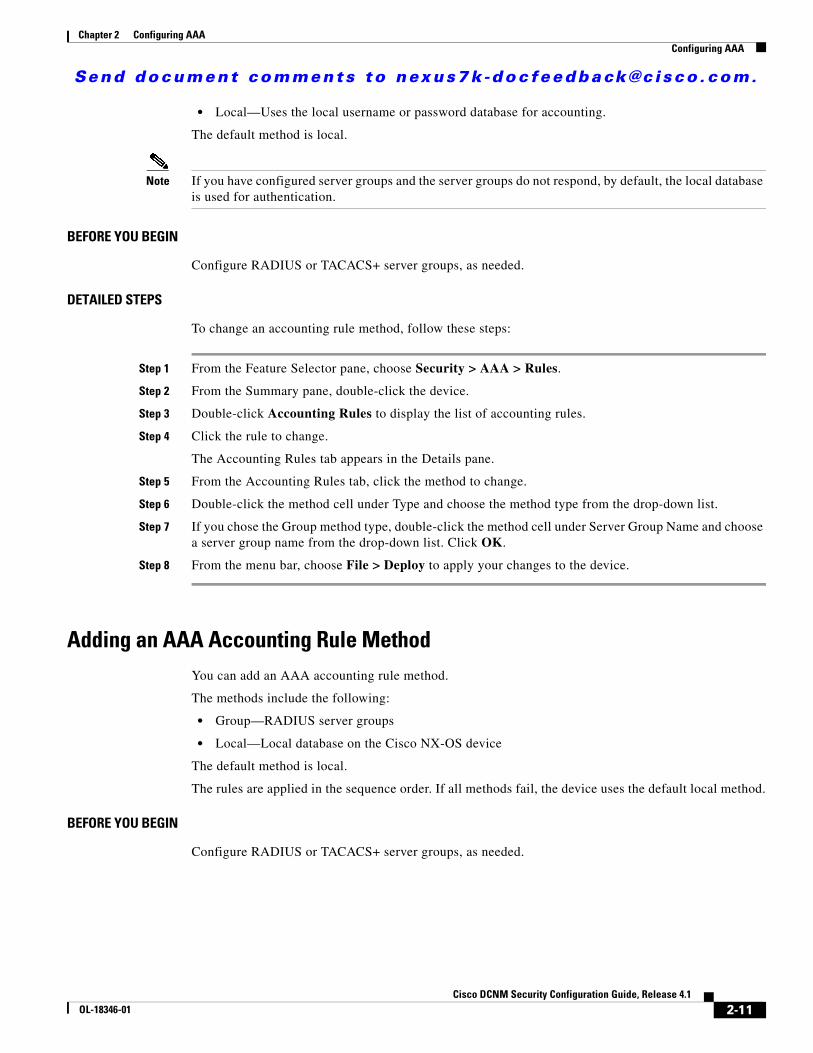
Adding an AAA Accounting Rule MethodYou can add an AAA accounting rule method.
The methods include the following:
• Group—RADIUS server groups
• Local—Local database on the Cisco NX-OS device
The default method is local.
The rules are applied in the sequence order. If all methods fail, the device uses the default local method.
BEFORE YOU BEGIN
Configure RADIUS or TACACS+ server groups, as needed.
2-11Cisco DCNM Security Configuration Guide, Release 4.1
OL-18346-01
Send document comments to nexus7k -doc feedback@c i sco .com.
Chapter 2 Configuring AAAConfiguring AAA
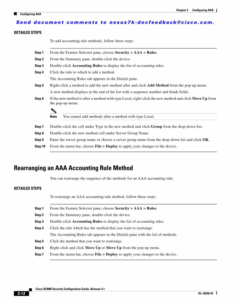
DETAILED STEPS
To add accounting rule methods, follow these steps:
Step 1 From the Feature Selector pane, choose Security > AAA > Rules.
Step 2 From the Summary pane, double-click the device.
Step 3 Double-click Accounting Rules to display the list of accounting rules.
Step 4 Click the rule to which to add a method.
The Accounting Rules tab appears in the Details pane.
Step 5 Right-click a method to add the new method after and click Add Method from the pop-up menu.
A new method displays at the end of the list with a sequence number and blank fields.
Step 6 If the new method is after a method with type Local, right-click the new method and click Move Up from the pop-up menu.
Note You cannot add methods after a method with type Local.
Step 7 Double-click the cell under Type in the new method and click Group from the drop-down list.
Step 8 Double-click the new method cell under Server Group Name.
Step 9 Enter the server group name or choose a server group name from the drop-down list and click OK.
Step 10 From the menu bar, choose File > Deploy to apply your changes to the device.
Rearranging an AAA Accounting Rule MethodYou can rearrange the sequence of the methods for an AAA accounting rule.
DETAILED STEPS
To rearrange an AAA accounting rule method, follow these steps:
Step 1 From the Feature Selector pane, choose Security > AAA > Rules.
Step 2 From the Summary pane, double-click the device.
Step 3 Double-click Accounting Rules to display the list of accounting rules.
Step 4 Click the rule which has the method that you want to rearrange.
The Accounting Rules tab appears in the Details pane with the list of methods.
Step 5 Click the method that you want to rearrange.
Step 6 Right-click and click Move Up or Move Up from the pop-up menu.
Step 7 From the menu bar, choose File > Deploy to apply your changes to the device.
2-12Cisco DCNM Security Configuration Guide, Release 4.1
OL-18346-01
Send document comments to nexus7k -doc feedback@c i sco .com.
Chapter 2 Configuring AAAConfiguring AAA
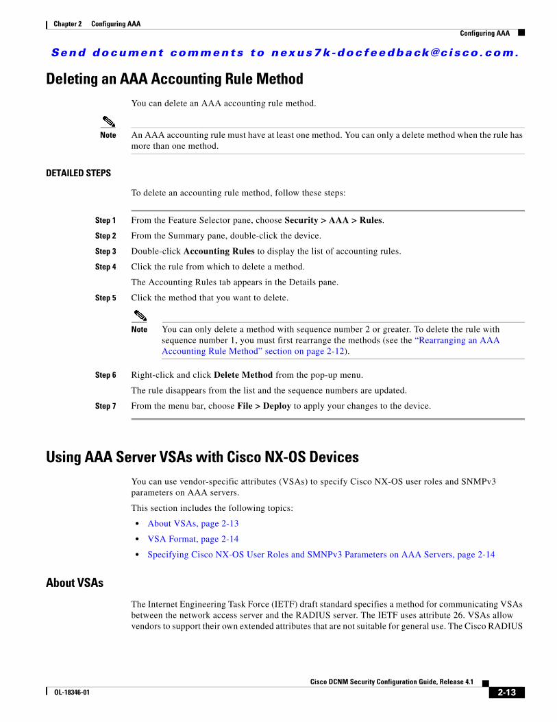
Deleting an AAA Accounting Rule MethodYou can delete an AAA accounting rule method.
Note An AAA accounting rule must have at least one method. You can only a delete method when the rule has more than one method.
DETAILED STEPS
To delete an accounting rule method, follow these steps:
Step 1 From the Feature Selector pane, choose Security > AAA > Rules.
Step 2 From the Summary pane, double-click the device.
Step 3 Double-click Accounting Rules to display the list of accounting rules.
Step 4 Click the rule from which to delete a method.
The Accounting Rules tab appears in the Details pane.
Step 5 Click the method that you want to delete.
Note You can only delete a method with sequence number 2 or greater. To delete the rule with sequence number 1, you must first rearrange the methods (see the “Rearranging an AAA Accounting Rule Method” section on page 2-12).
Step 6 Right-click and click Delete Method from the pop-up menu.
The rule disappears from the list and the sequence numbers are updated.
Step 7 From the menu bar, choose File > Deploy to apply your changes to the device.
Using AAA Server VSAs with Cisco NX-OS DevicesYou can use vendor-specific attributes (VSAs) to specify Cisco NX-OS user roles and SNMPv3 parameters on AAA servers.
This section includes the following topics:
• About VSAs, page 2-13
• VSA Format, page 2-14
• Specifying Cisco NX-OS User Roles and SMNPv3 Parameters on AAA Servers, page 2-14
About VSAs
The Internet Engineering Task Force (IETF) draft standard specifies a method for communicating VSAs between the network access server and the RADIUS server. The IETF uses attribute 26. VSAs allow vendors to support their own extended attributes that are not suitable for general use. The Cisco RADIUS
2-13Cisco DCNM Security Configuration Guide, Release 4.1
OL-18346-01
Send document comments to nexus7k -doc feedback@c i sco .com.
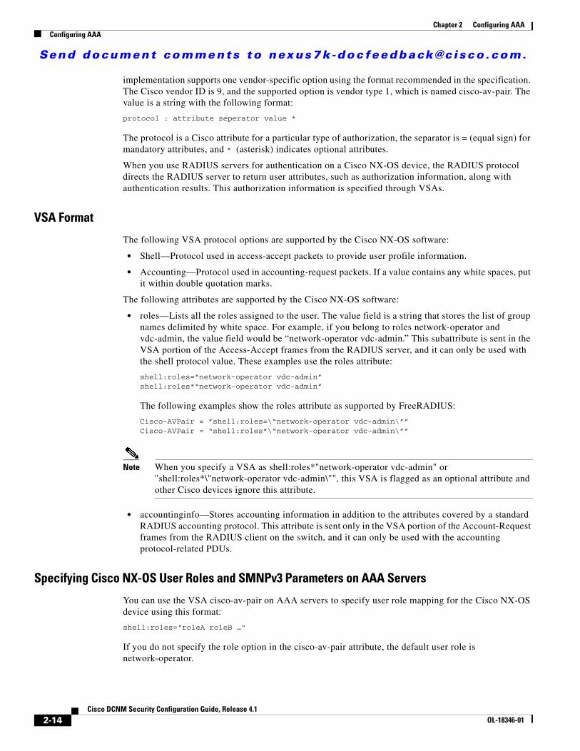
Chapter 2 Configuring AAAConfiguring AAA
implementation supports one vendor-specific option using the format recommended in the specification. The Cisco vendor ID is 9, and the supported option is vendor type 1, which is named cisco-av-pair. The value is a string with the following format:
protocol : attribute seperator value *
The protocol is a Cisco attribute for a particular type of authorization, the separator is = (equal sign) for mandatory attributes, and * (asterisk) indicates optional attributes.
When you use RADIUS servers for authentication on a Cisco NX-OS device, the RADIUS protocol directs the RADIUS server to return user attributes, such as authorization information, along with authentication results. This authorization information is specified through VSAs.
VSA Format
The following VSA protocol options are supported by the Cisco NX-OS software:
• Shell—Protocol used in access-accept packets to provide user profile information.
• Accounting—Protocol used in accounting-request packets. If a value contains any white spaces, put it within double quotation marks.
The following attributes are supported by the Cisco NX-OS software:
• roles—Lists all the roles assigned to the user. The value field is a string that stores the list of group names delimited by white space. For example, if you belong to roles network-operator and vdc-admin, the value field would be “network-operator vdc-admin.” This subattribute is sent in the VSA portion of the Access-Accept frames from the RADIUS server, and it can only be used with the shell protocol value. These examples use the roles attribute:
shell:roles=“network-operator vdc-admin” shell:roles*“network-operator vdc-admin”
The following examples show the roles attribute as supported by FreeRADIUS:
Cisco-AVPair = ”shell:roles=\“network-operator vdc-admin\””Cisco-AVPair = “shell:roles*\“network-operator vdc-admin\””
Note When you specify a VSA as shell:roles*"network-operator vdc-admin" or "shell:roles*\"network-operator vdc-admin\"", this VSA is flagged as an optional attribute and other Cisco devices ignore this attribute.
• accountinginfo—Stores accounting information in addition to the attributes covered by a standard RADIUS accounting protocol. This attribute is sent only in the VSA portion of the Account-Request frames from the RADIUS client on the switch, and it can only be used with the accounting protocol-related PDUs.
Specifying Cisco NX-OS User Roles and SMNPv3 Parameters on AAA Servers
You can use the VSA cisco-av-pair on AAA servers to specify user role mapping for the Cisco NX-OS device using this format:
shell:roles="roleA roleB …"
If you do not specify the role option in the cisco-av-pair attribute, the default user role is network-operator.
2-14Cisco DCNM Security Configuration Guide, Release 4.1
OL-18346-01
Send document comments to nexus7k -doc feedback@c i sco .com.
Chapter 2 Configuring AAAField Descriptions for AAA
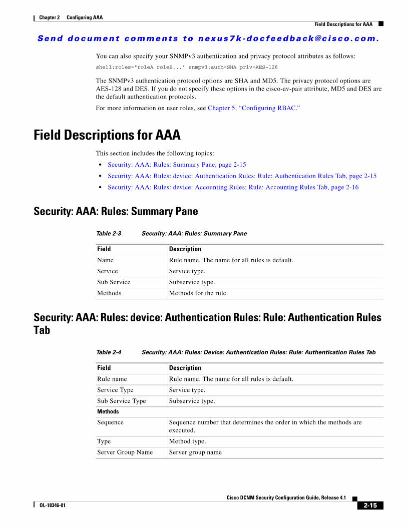
You can also specify your SNMPv3 authentication and privacy protocol attributes as follows:
shell:roles="roleA roleB..." snmpv3:auth=SHA priv=AES-128
The SNMPv3 authentication protocol options are SHA and MD5. The privacy protocol options are AES-128 and DES. If you do not specify these options in the cisco-av-pair attribute, MD5 and DES are the default authentication protocols.
For more information on user roles, see Chapter 5, “Configuring RBAC.”
Field Descriptions for AAAThis section includes the following topics:
• Security: AAA: Rules: Summary Pane, page 2-15
• Security: AAA: Rules: device: Authentication Rules: Rule: Authentication Rules Tab, page 2-15
• Security: AAA: Rules: device: Accounting Rules: Rule: Accounting Rules Tab, page 2-16
Security: AAA: Rules: Summary Pane
Security: AAA: Rules: device: Authentication Rules: Rule: Authentication Rules Tab
Table 2-3 Security: AAA: Rules: Summary Pane
Field Description
Name Rule name. The name for all rules is default.
Service Service type.
Sub Service Subservice type.
Methods Methods for the rule.
Table 2-4 Security: AAA: Rules: Device: Authentication Rules: Rule: Authentication Rules Tab
Field Description
Rule name Rule name. The name for all rules is default.
Service Type Service type.
Sub Service Type Subservice type.
Methods
Sequence Sequence number that determines the order in which the methods are executed.
Type Method type.
Server Group Name Server group name
2-15Cisco DCNM Security Configuration Guide, Release 4.1
OL-18346-01
Send document comments to nexus7k -doc feedback@c i sco .com.
Chapter 2 Configuring AAAAdditional References
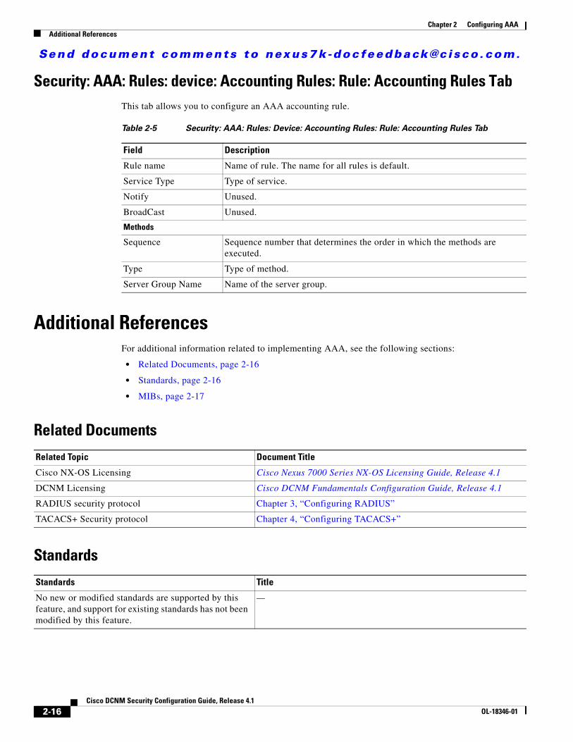
Security: AAA: Rules: device: Accounting Rules: Rule: Accounting Rules TabThis tab allows you to configure an AAA accounting rule.
Additional ReferencesFor additional information related to implementing AAA, see the following sections:
• Related Documents, page 2-16
• Standards, page 2-16
• MIBs, page 2-17
Related Documents
Standards
Table 2-5 Security: AAA: Rules: Device: Accounting Rules: Rule: Accounting Rules Tab
Field Description
Rule name Name of rule. The name for all rules is default.
Service Type Type of service.
Notify Unused.
BroadCast Unused.
Methods
Sequence Sequence number that determines the order in which the methods are executed.
Type Type of method.
Server Group Name Name of the server group.
Related Topic Document Title
Cisco NX-OS Licensing Cisco Nexus 7000 Series NX-OS Licensing Guide, Release 4.1
DCNM Licensing Cisco DCNM Fundamentals Configuration Guide, Release 4.1
RADIUS security protocol Chapter 3, “Configuring RADIUS”
TACACS+ Security protocol Chapter 4, “Configuring TACACS+”
Standards Title
No new or modified standards are supported by this feature, and support for existing standards has not been modified by this feature.
—
2-16Cisco DCNM Security Configuration Guide, Release 4.1
OL-18346-01
Send document comments to nexus7k -doc feedback@c i sco .com.
Chapter 2 Configuring AAAFeature History for AAA
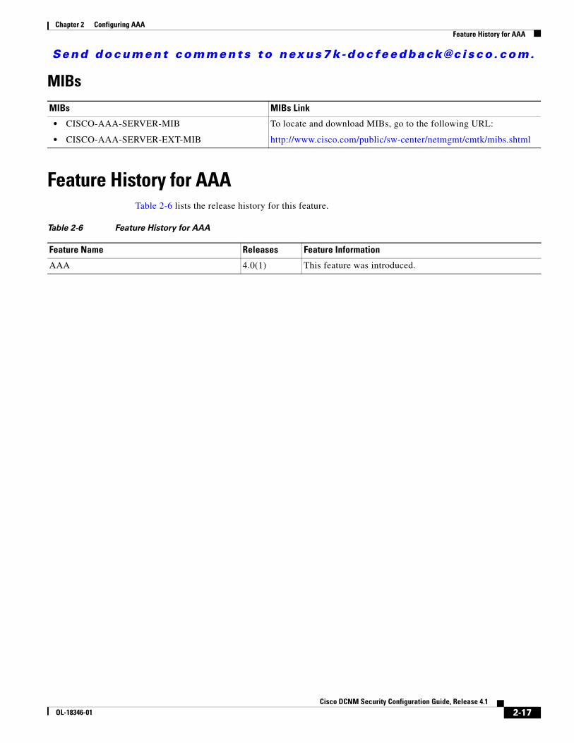
MIBs
Feature History for AAATable 2-6 lists the release history for this feature.
MIBs MIBs Link
• CISCO-AAA-SERVER-MIB
• CISCO-AAA-SERVER-EXT-MIB
To locate and download MIBs, go to the following URL:
http://www.cisco.com/public/sw-center/netmgmt/cmtk/mibs.shtml
Table 2-6 Feature History for AAA
Feature Name Releases Feature Information
AAA 4.0(1) This feature was introduced.
2-17Cisco DCNM Security Configuration Guide, Release 4.1
OL-18346-01

Send document comments to nexus7k -doc feedback@c i sco .com.
Chapter 2 Configuring AAAFeature History for AAA
2-18Cisco DCNM Security Configuration Guide, Release 4.1
OL-18346-01
Send document comments to nexus7k -doc feedback@c i sco .com.
CiscOL-18346-01
C H A P T E R3
Configuring RADIUSThis chapter describes how to configure the Remote Access Dial-In User Service (RADIUS) protocol on NX-OS devices.
This chapter includes the following sections:
• Information About RADIUS, page 3-1
• Licensing Requirements for RADIUS, page 3-5
• Prerequisites for RADIUS, page 3-5
• Guidelines and Limitations, page 3-5
• Configuring RADIUS Servers, page 3-6
• Displaying RADIUS Server Statistics, page 3-18
• Where to Go Next, page 3-18
• Field Descriptions for RADIUS Server Groups and Servers, page 3-19
• Additional References, page 3-21
• Feature History for RADIUS, page 3-21
Information About RADIUSThe RADIUS distributed client/server system allows you to secure networks against unauthorized access. In the Cisco implementation, RADIUS clients run on Cisco NX-OS devices and send authentication and accounting requests to a central RADIUS server that contains all user authentication and network service access information.
This section includes the following topics:
• RADIUS Network Environments, page 3-2
• RADIUS Operation, page 3-2
• RADIUS Server Monitoring, page 3-3
• Vendor-Specific Attributes, page 3-3
• Virtualization Support, page 3-5
3-1o DCNM Security Configuration Guide, Release 4.1
Send document comments to nexus7k -doc feedback@c i sco .com.
Chapter 3 Configuring RADIUSInformation About RADIUS
RADIUS Network EnvironmentsRADIUS can be implemented in a variety of network environments that require high levels of security while maintaining network access for remote users.
You can use RADIUS in the following network environments that require access security:
• Networks with multiple-vendor network devices, each supporting RADIUS. For example, network devices from several vendors can use a single RADIUS server-based security database.
• Networks already using RADIUS. You can add a Cisco NX-OS device with RADIUS to the network. This action might be the first step when you make a transition to a AAA server.
• Networks that require resource accounting. You can use RADIUS accounting independent of RADIUS authentication or authorization. The RADIUS accounting functions allow data to be sent at the start and end of services, indicating the amount of resources (such as time, packets, bytes, and so on) used during the session. An Internet service provider (ISP) might use a freeware-based version of the RADIUS access control and accounting software to meet special security and billing needs.
• Networks that support authentication profiles. Using the RADIUS server in your network, you can configure AAA authentication and set up per-user profiles. Per-user profiles enable the Cisco NX-OS device to better manage ports using their existing RADIUS solutions and to efficiently manage shared resources to offer different service-level agreements.
RADIUS OperationWhen a user attempts to log in and authenticate to a Cisco NX-OS device using RADIUS, the following process occurs:
1. The user is prompted for and enters a username and password.
2. The username and encrypted password are sent over the network to the RADIUS server.
3. The user receives one of the following responses from the RADIUS server:
– ACCEPT—The user is authenticated.
– REJECT—The user is not authenticated and is prompted to reenter the username and password, or access is denied.
– CHALLENGE—A challenge is issued by the RADIUS server. The challenge collects additional data from the user.
– CHANGE PASSWORD—A request is issued by the RADIUS server, asking the user to select a new password.
The ACCEPT or REJECT response is bundled with additional data that is used for EXEC or network authorization. You must first complete RADIUS authentication before using RADIUS authorization. The additional data included with the ACCEPT or REJECT packets consists of the following:
• Services that the user can access, including Telnet, rlogin, or local-area transport (LAT) connections, and Point-to-Point Protocol (PPP), Serial Line Internet Protocol (SLIP), or EXEC services.
• Connection parameters, including the host or client IPv4 or IPv6 address, access list, and user timeouts.
3-2Cisco DCNM Security Configuration Guide, Release 4.1
OL-18346-01
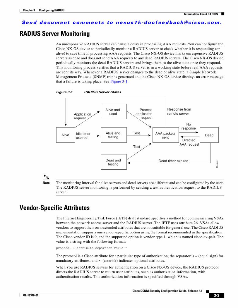
Send document comments to nexus7k -doc feedback@c i sco .com.
Chapter 3 Configuring RADIUSInformation About RADIUS
RADIUS Server MonitoringAn unresponsive RADIUS server can cause a delay in processing AAA requests. You can configure the Cisco NX-OS device to periodically monitor a RADIUS server to check whether it is responding (or alive) to save time in processing AAA requests. The Cisco NX-OS device marks unresponsive RADIUS servers as dead and does not send AAA requests to any dead RADIUS servers. The Cisco NX-OS device periodically monitors the dead RADIUS servers and brings them to the alive state once they respond. This monitoring process verifies that a RADIUS server is in a working state before real AAA requests are sent its way. Whenever a RADIUS server changes to the dead or alive state, a Simple Network Management Protocol (SNMP) trap is generated and the Cisco NX-OS device displays an error message that a failure is taking place. See Figure 3-1.
Figure 3-1 RADIUS Server States
Note The monitoring interval for alive servers and dead servers are different and can be configured by the user. The RADIUS server monitoring is performed by sending a test authentication request to the RADIUS server.
Vendor-Specific AttributesThe Internet Engineering Task Force (IETF) draft standard specifies a method for communicating VSAs between the network access server and the RADIUS server. The IETF uses attribute 26. VSAs allow vendors to support their own extended attributes that are not suitable for general use. The Cisco RADIUS implementation supports one vendor-specific option using the format recommended in the specification. The Cisco vendor ID is 9, and the supported option is vendor type 1, which is named cisco-av-pair. The value is a string with the following format:
protocol : attribute separator value *
The protocol is a Cisco attribute for a particular type of authorization, the separator is = (equal sign) for mandatory attributes, and * (asterisk) indicates optional attributes.
When you use RADIUS servers for authentication on a Cisco NX-OS device, the RADIUS protocol directs the RADIUS server to return user attributes, such as authorization information, with authentication results. This authorization information is specified through VSAs.
Noresponse
Test
Test
Idle timerexpired
Directed AAA request
Dead timer expired
Response fromremote server
AAA packetssent
Alive
Alive and used
Dead andtesting
Alive andtesting Dead
Applicationrequest
Processapplication
request
1545
34
3-3Cisco DCNM Security Configuration Guide, Release 4.1
OL-18346-01
Send document comments to nexus7k -doc feedback@c i sco .com.
Chapter 3 Configuring RADIUSInformation About RADIUS
The following VSA protocol options are supported by the Cisco NX-OS software:
• Shell—Protocol used in access-accept packets to provide user profile information.
• Accounting—Protocol used in accounting-request packets. If a value contains any white spaces, you should enclose the value within double quotation marks.
The Cisco NX-OS software supports the following attributes:
• roles—Lists all the roles to which the user belongs. The value field is a string that lists the role names delimited by white space. For example, if the user belongs to roles network-operator and vdc-admin, the value field would be “network-operator vdc-admin.” This subattribute, which the RADIUS server sends in the VSA portion of the Access-Accept frames, can only be used with the shell protocol value. The following examples show the roles attribute that supported by the Cisco Access Control Server (ACS):
shell:roles=“network-operator vdc-admin”
shell:roles*“network-operator vdc-admin”
The following examples show the roles attribute that is supported by FreeRADIUS:
Cisco-AVPair = ”shell:roles=\“network-operator vdc-admin\””
Cisco-AVPair = “shell:roles*\“network-operator vdc-admin\””
Note When you specify a VSA as shell:roles*"network-operator vdc-admin" or "shell:roles*\"network-operator vdc-admin\"", this VSA is flagged as an optional attribute and other Cisco devices ignore this attribute.
• accountinginfo—Stores accounting information in addition to the attributes covered by a standard RADIUS accounting protocol. This attribute is sent only in the VSA portion of the Account-Request frames from the RADIUS client on the switch. It can be used only with the accounting protocol data units (PDUs).
3-4Cisco DCNM Security Configuration Guide, Release 4.1
OL-18346-01
Send document comments to nexus7k -doc feedback@c i sco .com.
Chapter 3 Configuring RADIUSLicensing Requirements for RADIUS
Virtualization SupportRADIUS configuration and operation are local to the virtual device context (VDC). For more information on VDCs, see the Cisco DCNM Virtual Device Context Configuration Guide, Release 4.1.
The Cisco NX-OS device uses virtual routing and forwarding instances (VRFs) to access the RADIUS servers. For more information on VRFs, see the Cisco DCNM Unicast Routing Configuration Guide, Release 4.1.
Licensing Requirements for RADIUSThe following table shows the licensing requirements for this feature:
Prerequisites for RADIUSRADIUS has the following prerequisites:
• Obtain IPv4 or IPv6 addresses or hostnames for the RADIUS servers.
• Obtain keys from the RADIUS servers.
• Ensure that the Cisco NX-OS device is configured as a RADIUS client of the AAA servers.
• Ensure that the logging level for RADIUS in the Cisco NX-OS software is set to 5 using the command-line interface (CLI).
switch# configure terminalswitch(config)# logging level radius 5
Guidelines and LimitationsRADIUS has the following guidelines and limitations:
• You can configure a maximum of 64 RADIUS servers on the Cisco NX-OS device.
• If you have a user account configured on the local Cisco NX-OS device that has the same name as a remote user account on an AAA server, the Cisco NX-OS software applies the user roles for the local user account to the remote user, not the user roles configured on the AAA server.
Product License Requirement
DCNM RADIUS requires no license. Any feature not included in a license package is bundled with the Cisco DCNM and is provided at no charge to you. For a complete explanation of the DCNM licensing scheme, see the Cisco DCNM Fundamentals Configuration Guide, Release 4.1.
NX-OS RADIUS requires no license. Any feature not included in a license package is bundled with the Cisco NX-OS system images and is provided at no extra charge to you. For a complete explanation of the Cisco NX-OS licensing scheme, see the Cisco Nexus 7000 Series NX-OS Licensing Guide, Release 4.1.
3-5Cisco DCNM Security Configuration Guide, Release 4.1
OL-18346-01
Send document comments to nexus7k -doc feedback@c i sco .com.
Chapter 3 Configuring RADIUSConfiguring RADIUS Servers
Configuring RADIUS ServersThis section includes the following topics:
• RADIUS Server Configuration Process, page 3-6
• Adding a RADIUS Server Host, page 3-8
• Copying a RADIUS Server Host, page 3-9
• Deleting a RADIUS Server Host, page 3-10
• Configuring a Global RADIUS Key, page 3-10
• Configuring a Key for a Specific RADIUS Server, page 3-11
• Adding a RADIUS Server Group, page 3-12
• Adding a RADIUS Server Host to a RADIUS Server Group, page 3-12
• Deleting a RADIUS Server Host from a RADIUS Server Group, page 3-13
• Deleting a RADIUS Server Group, page 3-14
• Allowing Users to Specify a RADIUS Server at Login, page 3-14
• Configuring the Global RADIUS Transmission Retry Count and Timeout Interval, page 3-15
• Configuring the RADIUS Transmission Retry Count and Timeout Interval for a Server, page 3-15
• Configuring Accounting and Authentication Attributes for RADIUS Servers, page 3-16
• Configuring Periodic RADIUS Server Monitoring, page 3-17
• Configuring the Dead-Time Interval, page 3-17
• Displaying RADIUS Server Statistics, page 3-18
RADIUS Server Configuration ProcessFollow these steps to configure RADIUS servers:
Step 1 Establish the RADIUS server connections to the Cisco NX-OS device (see the “Adding a RADIUS Server Host” section on page 3-8).
Step 2 Configure the RADIUS secret keys for the RADIUS servers (see the “Configuring a Global RADIUS Key” section on page 3-10).
Step 3 If needed, configure RADIUS server groups with subsets of the RADIUS servers for AAA authentication methods (see the “Adding a RADIUS Server Group” section on page 3-12 and the “Configuring AAA” section on page 2-7).
Step 4 If needed, configure any of the following optional parameters:
• Dead-time interval (see the “Configuring the Dead-Time Interval” section on page 3-17).
• Allow specification of a RADIUS server at login (see the “Allowing Users to Specify a RADIUS Server at Login” section on page 3-14).
• Transmission retry count and timeout interval (see the “Configuring the Global RADIUS Transmission Retry Count and Timeout Interval” section on page 3-15).
• Accounting and authentication attributes (see the “Configuring Accounting and Authentication Attributes for RADIUS Servers” section on page 3-16).
3-6Cisco DCNM Security Configuration Guide, Release 4.1
OL-18346-01
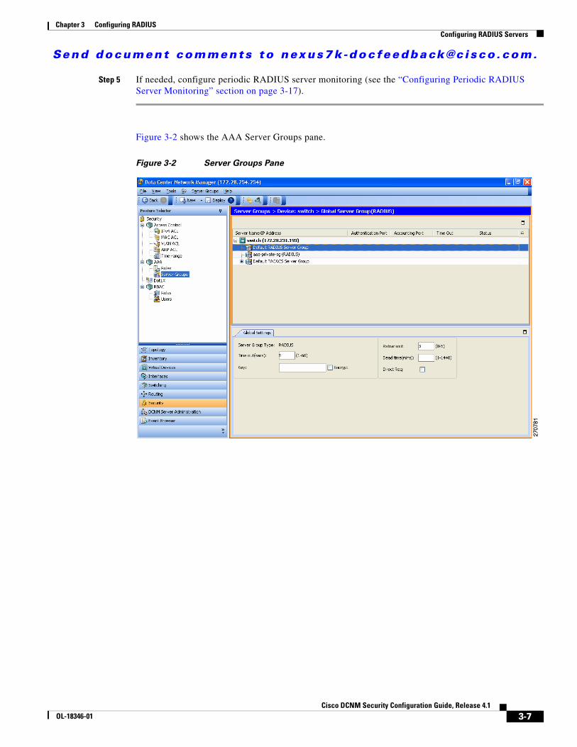
Send document comments to nexus7k -doc feedback@c i sco .com.
Chapter 3 Configuring RADIUSConfiguring RADIUS Servers
Step 5 If needed, configure periodic RADIUS server monitoring (see the “Configuring Periodic RADIUS Server Monitoring” section on page 3-17).
Figure 3-2 shows the AAA Server Groups pane.
Figure 3-2 Server Groups Pane
3-7Cisco DCNM Security Configuration Guide, Release 4.1
OL-18346-01
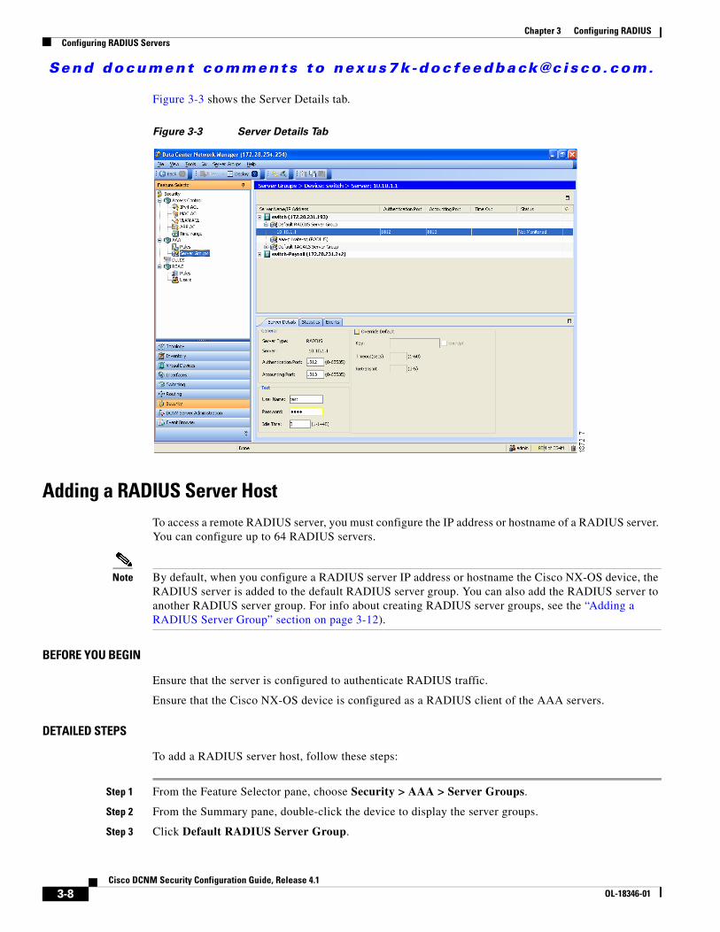
Send document comments to nexus7k -doc feedback@c i sco .com.
Chapter 3 Configuring RADIUSConfiguring RADIUS Servers
Figure 3-3 shows the Server Details tab.
Figure 3-3 Server Details Tab
Adding a RADIUS Server HostTo access a remote RADIUS server, you must configure the IP address or hostname of a RADIUS server. You can configure up to 64 RADIUS servers.
Note By default, when you configure a RADIUS server IP address or hostname the Cisco NX-OS device, the RADIUS server is added to the default RADIUS server group. You can also add the RADIUS server to another RADIUS server group. For info about creating RADIUS server groups, see the “Adding a RADIUS Server Group” section on page 3-12).
BEFORE YOU BEGIN
Ensure that the server is configured to authenticate RADIUS traffic.
Ensure that the Cisco NX-OS device is configured as a RADIUS client of the AAA servers.
DETAILED STEPS
To add a RADIUS server host, follow these steps:
Step 1 From the Feature Selector pane, choose Security > AAA > Server Groups.
Step 2 From the Summary pane, double-click the device to display the server groups.
Step 3 Click Default RADIUS Server Group.
3-8Cisco DCNM Security Configuration Guide, Release 4.1
OL-18346-01
Send document comments to nexus7k -doc feedback@c i sco .com.
Chapter 3 Configuring RADIUSConfiguring RADIUS Servers
Step 4 From the menu bar, choose Actions > Add Server.
The Server Details appear in the Details pane.
Step 5 In the Server field, enter the RADIUS server IPv4 address, IPv6 address, or hostname in the Server field.
Step 6 From the Server drop-down list, choose either the IPv4 address, IPv6 address, or hostname as the correct server identifier type.
Note If the server identifier format matches the identifier type selected, DCNM outlines the Server field in yellow to indicate that it is correct. If the server identifier format does not match the identifier type, DCNM outlines the Server field in red to indicate an error. Change the address or the address type to correct this problem.
Step 7 (Optional) In the Authentication Port field, enter a new UDP port number or clear the field to disable authentication.
The default authentication UDP port is 1812.
Step 8 (Optional) In the Accounting Port field, enter a new UDP port number or clear the field to disable accounting.
The default accounting UDP port is 1813.
Step 9 (Optional) In the Test area, you can enter a username, password, and idle time interval in minutes for periodic server host monitoring.
The default username is test, the default password is test, and the default idle time interval is 0 minutes, which disables periodic monitoring.
Step 10 (Optional) Check Override Defaults and enter a key, timeout interval, and retransmit time interval in minutes to override the global values.
Step 11 From the menu bar, choose File > Deploy to apply your changes to the device.
Copying a RADIUS Server HostYou can copy the configuration of a RADIUS server host from one RADIUS server to another server group, either on the same NX-OS device or on another NX-OS device.
BEFORE YOU BEGIN
Ensure that you have configured the server in the default RADIUS server group (see “Adding a RADIUS Server Host” section on page 3-8).
Ensure that you have created the target RADIUS server group (see “Adding a RADIUS Server Group” section on page 3-12).
DETAILED STEPS
To copy the configuration of a RADIUS server host, follow these steps:
Step 1 From the Feature Selector pane, choose Security > AAA > Server Groups.
Step 2 From the Summary pane, double-click the device to display the server groups.
3-9Cisco DCNM Security Configuration Guide, Release 4.1
OL-18346-01
Send document comments to nexus7k -doc feedback@c i sco .com.
Chapter 3 Configuring RADIUSConfiguring RADIUS Servers
Step 3 Double-click Default RADIUS Server Group.
The list of configured RADIUS server hosts appears.
Step 4 Click on the server host that you want to copy.
Step 5 From the menu bar, choose Actions > Copy.
Step 6 Click the destination server group.
Note You can copy the server host configuration to a server group within the same device or in another device.
Step 7 From the menu bar, choose Actions > Paste.
The RADIUS server host appears in the list of servers for the server group.
Step 8 From the menu bar, choose File > Deploy to apply your changes to the device.
Deleting a RADIUS Server HostYou can delete a RADIUS server host from a server group.
DETAILED STEPS
To delete a RADIUS server host, follow these steps:
Step 1 From the Feature Selector pane, choose Security > AAA > Server Groups.
Step 2 From the Summary pane, double-click the device to display the server groups.
Step 3 Double-click the server group to display the list of server hosts.
Step 4 Click the RADIUS server host to delete.
Step 5 From the menu bar, choose Server Groups > Delete Server and click Yes on the confirmation dialog.
The RADIUS server host disappears from the list.
Step 6 From the menu bar, choose File > Deploy to apply your changes to the device.
Configuring a Global RADIUS KeyYou can configure a RADIUS key for all servers used by the Cisco NX-OS device. A RADIUS key is a shared secret text string between the Cisco NX-OS device and the RADIUS server hosts. To configure a RADIUS key specific to a RADIUS server, see the “Adding a RADIUS Server Group” section on page 3-12.
BEFORE YOU BEGIN
Obtain the RADIUS key values for the remote RADIUS servers.
Configure the RADIUS key on the remote RADIUS servers.
3-10Cisco DCNM Security Configuration Guide, Release 4.1
OL-18346-01
Send document comments to nexus7k -doc feedback@c i sco .com.
Chapter 3 Configuring RADIUSConfiguring RADIUS Servers
DETAILED STEPS
To configure a global RADIUS key, follow these steps:
Step 1 From the Feature Selector pane, choose Security > AAA > Server Groups.
Step 2 From the Summary pane, double-click the device to display the server groups.
Step 3 Click Default RADIUS Server Group.
Step 4 From the Details pane, click the Global RADIUS Settings tab.
Step 5 In the Key field, enter the RADIUS key.
Step 6 (Optional) Check Encrypt to encrypt the key.
The default is clear text. The Cisco NX-OS software encrypts a clear text key before saving it to the running configuration.
Step 7 From the menu bar, choose File > Deploy to apply your changes to the device.
Configuring a Key for a Specific RADIUS ServerYou can configure a key on the Cisco NX-OS device for a specific RADIUS server. A RADIUS key is a secret text string shared between the Cisco NX-OS device and a specific RADIUS server.
BEFORE YOU BEGIN
Configure one or more RADIUS server hosts (see the “Adding a RADIUS Server Host” section on page 3-8).
Obtain the key value for the remote RADIUS server.
Configure the key on the RADIUS server.
DETAILED STEPS
To configure a RADIUS server key, follow these steps:
Step 1 From the Feature Selector pane, choose Security > AAA > Server Groups.
Step 2 From the Summary pane, double-click the device to display the server groups.
Step 3 Double-click Default RADIUS Server Group to display the list of RADIUS servers.
Step 4 Click the desired RADIUS server.
Step 5 From the Details pane, click the Server Details tab.
Step 6 Check Override Defaults.
Step 7 In the Key field, enter the RADIUS key.
The default is the global RADIUS key.
Step 8 (Optional) Check Encrypt to encrypt the key.
The default is clear text. The Cisco NX-OS software encrypts a clear text key before saving it to the running configuration.
3-11Cisco DCNM Security Configuration Guide, Release 4.1
OL-18346-01
Send document comments to nexus7k -doc feedback@c i sco .com.
Chapter 3 Configuring RADIUSConfiguring RADIUS Servers
Step 9 From the menu bar, choose File > Deploy to apply your changes to the device.
Adding a RADIUS Server GroupYou can reference one or more remote AAA servers to authenticate users using server groups. All members of a group must belong to the RADIUS protocol. The servers are tried in the same order in which you configure them.
You can configure these server groups at any time but they only take effect when you apply them to an AAA service. For information on AAA services, see the “Remote AAA Services” section on page 2-2.
BEFORE YOU BEGIN
Configure one or more RADIUS server hosts (see the “Adding a RADIUS Server Host” section on page 3-8).
DETAILED STEPS
To add a RADIUS server group, follow these steps:
Step 1 From the Feature Selector pane, choose Security > AAA > Server Groups.
Step 2 From the Summary pane, click the device.
Step 3 From the menu bar, choose Server Groups > RADIUS Server Group.
A new line appears at the end of the server group list for the device and the Details tab appears in the Details pane.
Step 4 In the Server Group Name field, enter the name and press the Enter key.
The server group name is a case-sensitive alphanumeric string with a maximum length of 127 characters.
Step 5 (Optional) In the Dead time(mins) field, enter the number of minutes for the dead-time interval.
The default dead-time interval is 0 minutes.
Step 6 In the VRF Name field, click the down arrow to display the VRF Name dialog and click a VRF. Click OK.
Step 7 From the menu bar, choose File > Deploy to apply your changes to the device.
Adding a RADIUS Server Host to a RADIUS Server GroupYou can add a RADIUS server host to a RADIUS server group.
BEFORE YOU BEGIN
Ensure that you have added the RADIUS server host to the Default RADIUS Server Group (see the “Adding a RADIUS Server Host” section on page 3-8).
3-12Cisco DCNM Security Configuration Guide, Release 4.1
OL-18346-01
Send document comments to nexus7k -doc feedback@c i sco .com.
Chapter 3 Configuring RADIUSConfiguring RADIUS Servers
DETAILED STEPS
To add a RADIUS server host to a RADIUS server group, follow these steps:
Step 1 From the Feature Selector pane, choose Security > AAA > Server Groups.
Step 2 From the Summary pane, double-click the device to display the server groups.
Step 3 Click a RADIUS server group.
Step 4 From the menu bar, choose Server Groups > Add Server.
The Server Details appear in the Details pane.
Step 5 In the Server field, enter the RADIUS server IPv4 address, IPv6 address, or hostname in the Server field.
Step 6 From the Server drop-down list, choose either the IPv4 address, IPv6 address, or hostname as the correct server identifier type.
Note If the server identifier format matches the identifier type selected, DCNM outlines the Server field in yellow to indicate that it is correct. If the server identifier format does not match the identifier type, DCNM outlines the Server field in red to indicate an error. Change the address or the address type to correct this problem.
Step 7 From the menu bar, choose File > Deploy to apply your changes to the device.
Deleting a RADIUS Server Host from a RADIUS Server GroupYou can delete a RADIUS server host from a RADIUS server group.
DETAILED STEPS
To delete a RADIUS server host from a RADIUS server group, follow these steps:
Step 1 From the Feature Selector pane, choose Security > AAA > Server Groups.
Step 2 From the Summary pane, double-click the device to display the server groups.
Step 3 Double-click the server group to display the list of server hosts.
Step 4 Click the RADIUS server host to delete.
Step 5 From the menu bar, choose Server Groups > Delete Server and click Yes on the confirmation dialog.
The RADIUS server host disappears from the list.
Step 6 From the menu bar, choose File > Deploy to apply your changes to the device.
3-13Cisco DCNM Security Configuration Guide, Release 4.1
OL-18346-01
Send document comments to nexus7k -doc feedback@c i sco .com.
Chapter 3 Configuring RADIUSConfiguring RADIUS Servers
Deleting a RADIUS Server GroupYou can delete a RADIUS server group.
BEFORE YOU BEGIN
Ensure that all servers in the group are RADIUS servers.
DETAILED STEPS
To delete a RADIUS server group, follow these steps:
Step 1 From the Feature Selector pane, choose Security > AAA > Server Groups.
Step 2 From the Summary pane, double-click the device to display the list of server groups.
Step 3 Click the RADIUS server group to delete.
Step 4 From the menu bar, choose Server Groups > Delete Server Group and click Yes in the confirmation dialog.
The server group disappears from the server group list.
Step 5 From the menu bar, choose File > Deploy to apply your changes to the device.
Allowing Users to Specify a RADIUS Server at LoginBy default, the Cisco NX-OS device forwards an authentication request based on the default AAA authentication method. You can configure the Cisco NX-OS device to allow the user to specify a VRF and RADIUS server to send the authentication request by enabling the directed-request option. If you enable this option, the user can log in as username@vrfname:hostname, where vrfname is the VRF to use and hostname is the name of a configured RADIUS server.
Note If you enable the directed-request option, the device uses only the RADIUS method for authentication and not the default local method.
Note User-specified logins are supported only for Telnet sessions.
DETAILED STEPS
To allow users to specify a RADIUS server at login, follow these steps:
Step 1 From the Feature Selector pane, choose Security > AAA > Server Groups.
Step 2 From the Summary pane, double-click the device to display the server groups.
Step 3 Click Default RADIUS Server Group.
Step 4 From the Details pane, click the Global RADIUS Settings tab.
Step 5 Click Direct Req.
3-14Cisco DCNM Security Configuration Guide, Release 4.1
OL-18346-01
Send document comments to nexus7k -doc feedback@c i sco .com.
Chapter 3 Configuring RADIUSConfiguring RADIUS Servers
Step 6 From the menu bar, choose File > Deploy to apply your changes to the device.
Configuring the Global RADIUS Transmission Retry Count and Timeout IntervalYou can configure a global retransmission retry count and timeout interval for all RADIUS servers. By default, a Cisco NX-OS device retries transmission to a RADIUS server only once before reverting to local authentication. You can increase this number up to a maximum of five retries per server. The timeout interval determines how long the Cisco NX-OS device waits for responses from RADIUS servers before declaring a timeout failure.
DETAILED STEPS
To configure the global RADIUS transmission retry count and timeout interval, follow these steps:
Step 1 From the Feature Selector pane, choose Security > AAA > Server Groups.
Step 2 From the Summary pane, double-click the device to display the server groups.
Step 3 Click Default RADIUS Server Group.
Step 4 From the Details pane, click the Global RADIUS Settings tab.
Step 5 In the Retransmit field, enter a number of retransmit attempts.
The default is 1.
Step 6 In the Time out(secs) field, enter the number of seconds for the timeout interval.
The default is 5 seconds.
Step 7 From the menu bar, choose File > Deploy to apply your changes to the device.
Configuring the RADIUS Transmission Retry Count and Timeout Interval for a Server
By default, a Cisco NX-OS device retries a transmission to a RADIUS server only once before reverting to local authentication. You can increase this number up to a maximum of five retries per server. You can also set a timeout interval that the Cisco NX-OS device waits for responses from RADIUS servers before declaring a timeout failure.
BEFORE YOU BEGIN
Configure one or more RADIUS server hosts (see the “Adding a RADIUS Server Host” section on page 3-8).
DETAILED STEPS
To configure the transmission retry count and timeout interval for a RADIUS server, follow these steps:
Step 1 From the Feature Selector pane, choose Security > AAA > Server Groups.
3-15Cisco DCNM Security Configuration Guide, Release 4.1
OL-18346-01
Send document comments to nexus7k -doc feedback@c i sco .com.
Chapter 3 Configuring RADIUSConfiguring RADIUS Servers
Step 2 From the Summary pane, double-click the device to display the server groups.
Step 3 Double-click Default RADIUS Server Group to display the list of RADIUS servers.
Step 4 Click the desired RADIUS server.
Step 5 From the Details pane, click the Server Details tab.
Step 6 Check Override Defaults.
Step 7 In the Retransmit field, enter the number of retransmit attempts.
The default is 1.
Step 8 In the Timeout(secs) field, enter the number of seconds for the retransmission interval.
The default is 5 seconds.
Step 9 From the menu bar, choose File > Deploy to apply your changes to the device.
Configuring Accounting and Authentication Attributes for RADIUS ServersYou can specify that a RADIUS server is to be used only for accounting purposes or only for authentication purposes. By default, RADIUS servers are used for both accounting and authentication. You can also specify the destination UDP port numbers where RADIUS accounting and authentication messages should be sent if there is a conflict with the default port.
BEFORE YOU BEGIN
Configure one or more RADIUS server hosts (see the “Adding a RADIUS Server Host” section on page 3-8).
DETAILED STEPS
To configure the authentication and accounting attributes for RADIUS servers, follow these steps:
Step 1 From the Feature Selector pane, choose Security > AAA > Server Groups.
Step 2 From the Summary pane, double-click the device to display the server groups.
Step 3 Double-click Default RADIUS Server Group to display the list of RADIUS servers.
Step 4 Click the desired RADIUS server.
Step 5 From the Details pane, click the Server Details tab.
Step 6 (Optional) In the Authentication Port field, enter a new UDP port number or clear the field to disable authentication.
The default authentication UDP port is 1812.
Step 7 (Optional) In the Accounting Port field, enter a new UDP port number or clear the field to disable accounting.
The default accounting UDP port is 1813.
Step 8 From the menu bar, choose File > Deploy to apply your changes to the device.
3-16Cisco DCNM Security Configuration Guide, Release 4.1
OL-18346-01
Send document comments to nexus7k -doc feedback@c i sco .com.
Chapter 3 Configuring RADIUSConfiguring RADIUS Servers
Configuring Periodic RADIUS Server MonitoringYou can monitor the availability of RADIUS servers. These parameters include the username and password to use for the server and an idle timer. The idle timer specifies the interval during which a RADIUS server receives no requests before the Cisco NX-OS device sends out a test packet. You can configure this option to test servers periodically.
Note For security reasons, we recommend that you do not configure a test username that is the same as an existing user in the RADIUS database.
The test idle timer specifies the interval during which a RADIUS server receives no requests before the Cisco NX-OS device sends out a test packet.
Note The default idle timer value is 0 minutes. When the idle time interval is 0 minutes, the Cisco NX-OS device does not perform periodic RADIUS server monitoring.
BEFORE YOU BEGIN
Add one or more RADIUS server hosts (see the “Adding a RADIUS Server Host” section on page 3-8).
DETAILED STEPS
To configure periodic RADIUS server monitoring, follow these steps:
Step 1 From the Feature Selector pane, choose Security > AAA > Server Groups.
Step 2 From the Summary pane, double-click the device to display the server groups.
Step 3 Double-click Default RADIUS Server Group to display the list of RADIUS servers.
Step 4 Click the desired RADIUS server.
Step 5 From the Details pane, click the Server Details tab.
Step 6 In the User Name field, enter a username.
Step 7 In the Password field, enter a password.
Step 8 In the Idle Time field, enter the number of minutes for periodic monitoring.
Step 9 From the menu bar, choose File > Deploy to apply your changes to the device.
Configuring the Dead-Time IntervalYou can configure the dead-time interval for all RADIUS servers. The dead-time interval specifies the time that the Cisco NX-OS device waits after declaring a RADIUS server is dead, before sending out a test packet to determine if the server is now alive. The default value is 0 minutes.
3-17Cisco DCNM Security Configuration Guide, Release 4.1
OL-18346-01
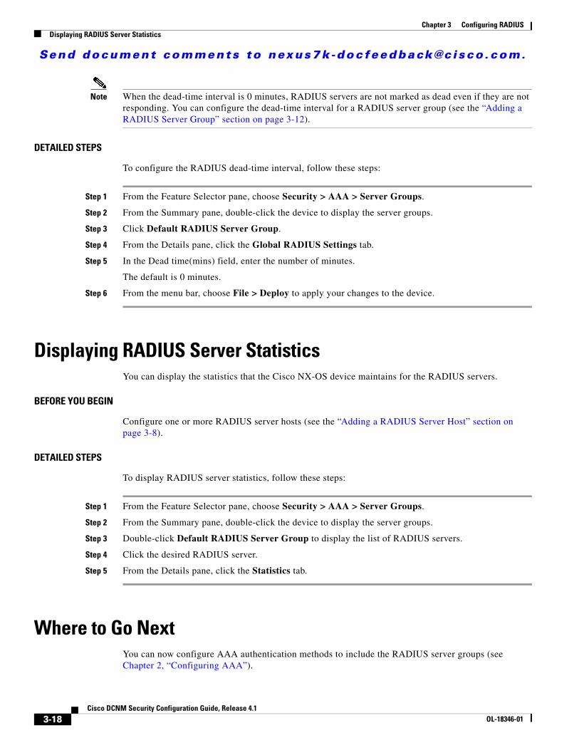
Send document comments to nexus7k -doc feedback@c i sco .com.
Chapter 3 Configuring RADIUSDisplaying RADIUS Server Statistics
Note When the dead-time interval is 0 minutes, RADIUS servers are not marked as dead even if they are not responding. You can configure the dead-time interval for a RADIUS server group (see the “Adding a RADIUS Server Group” section on page 3-12).
DETAILED STEPS
To configure the RADIUS dead-time interval, follow these steps:
Step 1 From the Feature Selector pane, choose Security > AAA > Server Groups.
Step 2 From the Summary pane, double-click the device to display the server groups.
Step 3 Click Default RADIUS Server Group.
Step 4 From the Details pane, click the Global RADIUS Settings tab.
Step 5 In the Dead time(mins) field, enter the number of minutes.
The default is 0 minutes.
Step 6 From the menu bar, choose File > Deploy to apply your changes to the device.
Displaying RADIUS Server StatisticsYou can display the statistics that the Cisco NX-OS device maintains for the RADIUS servers.
BEFORE YOU BEGIN
Configure one or more RADIUS server hosts (see the “Adding a RADIUS Server Host” section on page 3-8).
DETAILED STEPS
To display RADIUS server statistics, follow these steps:
Step 1 From the Feature Selector pane, choose Security > AAA > Server Groups.
Step 2 From the Summary pane, double-click the device to display the server groups.
Step 3 Double-click Default RADIUS Server Group to display the list of RADIUS servers.
Step 4 Click the desired RADIUS server.
Step 5 From the Details pane, click the Statistics tab.
Where to Go Next You can now configure AAA authentication methods to include the RADIUS server groups (see Chapter 2, “Configuring AAA”).
3-18Cisco DCNM Security Configuration Guide, Release 4.1
OL-18346-01
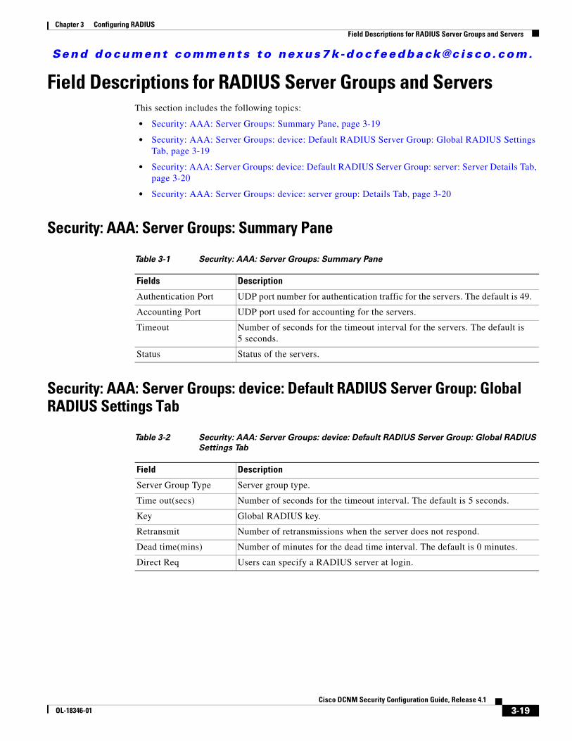
Send document comments to nexus7k -doc feedback@c i sco .com.
Chapter 3 Configuring RADIUSField Descriptions for RADIUS Server Groups and Servers
Field Descriptions for RADIUS Server Groups and ServersThis section includes the following topics:
• Security: AAA: Server Groups: Summary Pane, page 3-19
• Security: AAA: Server Groups: device: Default RADIUS Server Group: Global RADIUS Settings Tab, page 3-19
• Security: AAA: Server Groups: device: Default RADIUS Server Group: server: Server Details Tab, page 3-20
• Security: AAA: Server Groups: device: server group: Details Tab, page 3-20
Security: AAA: Server Groups: Summary Pane
Security: AAA: Server Groups: device: Default RADIUS Server Group: Global RADIUS Settings Tab
Table 3-1 Security: AAA: Server Groups: Summary Pane
Fields Description
Authentication Port UDP port number for authentication traffic for the servers. The default is 49.
Accounting Port UDP port used for accounting for the servers.
Timeout Number of seconds for the timeout interval for the servers. The default is 5 seconds.
Status Status of the servers.
Table 3-2 Security: AAA: Server Groups: device: Default RADIUS Server Group: Global RADIUS
Settings Tab
Field Description
Server Group Type Server group type.
Time out(secs) Number of seconds for the timeout interval. The default is 5 seconds.
Key Global RADIUS key.
Retransmit Number of retransmissions when the server does not respond.
Dead time(mins) Number of minutes for the dead time interval. The default is 0 minutes.
Direct Req Users can specify a RADIUS server at login.
3-19Cisco DCNM Security Configuration Guide, Release 4.1
OL-18346-01
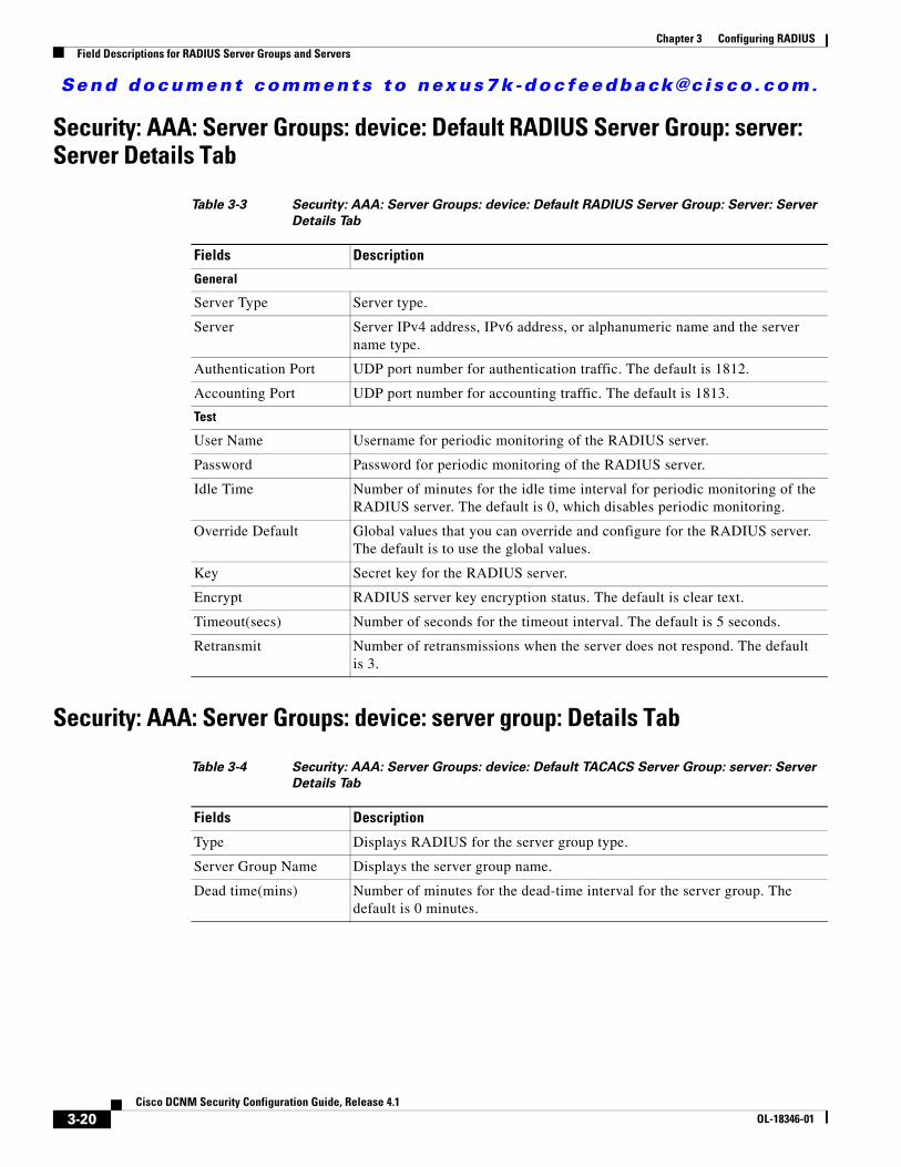
Send document comments to nexus7k -doc feedback@c i sco .com.
Chapter 3 Configuring RADIUSField Descriptions for RADIUS Server Groups and Servers
Security: AAA: Server Groups: device: Default RADIUS Server Group: server: Server Details Tab
Security: AAA: Server Groups: device: server group: Details Tab
Table 3-3 Security: AAA: Server Groups: device: Default RADIUS Server Group: Server: Server
Details Tab
Fields Description
General
Server Type Server type.
Server Server IPv4 address, IPv6 address, or alphanumeric name and the server name type.
Authentication Port UDP port number for authentication traffic. The default is 1812.
Accounting Port UDP port number for accounting traffic. The default is 1813.
Test
User Name Username for periodic monitoring of the RADIUS server.
Password Password for periodic monitoring of the RADIUS server.
Idle Time Number of minutes for the idle time interval for periodic monitoring of the RADIUS server. The default is 0, which disables periodic monitoring.
Override Default Global values that you can override and configure for the RADIUS server. The default is to use the global values.
Key Secret key for the RADIUS server.
Encrypt RADIUS server key encryption status. The default is clear text.
Timeout(secs) Number of seconds for the timeout interval. The default is 5 seconds.
Retransmit Number of retransmissions when the server does not respond. The default is 3.
Table 3-4 Security: AAA: Server Groups: device: Default TACACS Server Group: server: Server
Details Tab
Fields Description
Type Displays RADIUS for the server group type.
Server Group Name Displays the server group name.
Dead time(mins) Number of minutes for the dead-time interval for the server group. The default is 0 minutes.
3-20Cisco DCNM Security Configuration Guide, Release 4.1
OL-18346-01
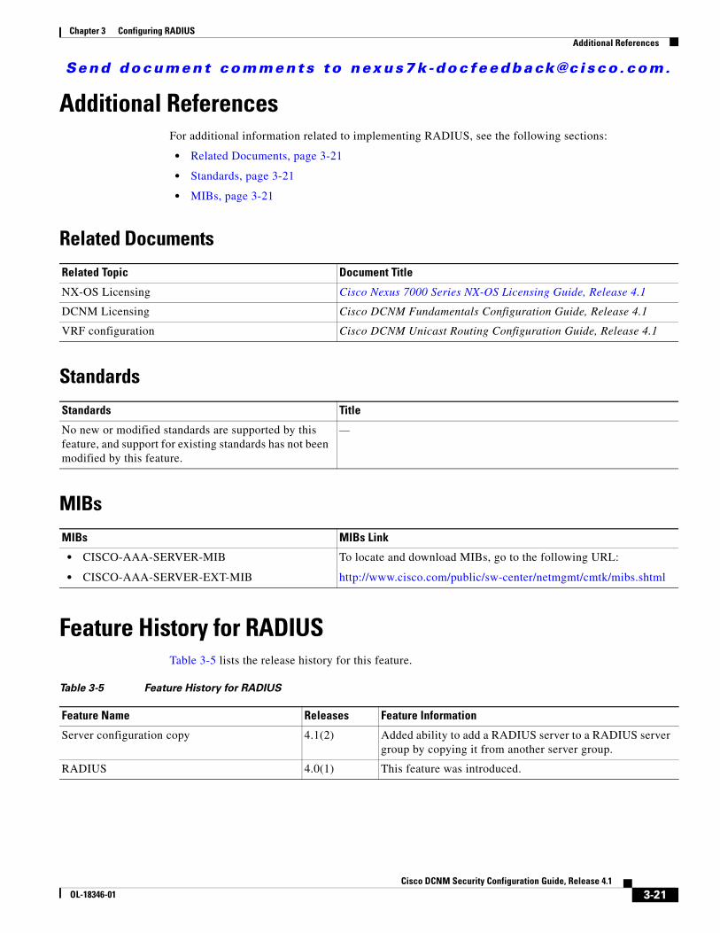
Send document comments to nexus7k -doc feedback@c i sco .com.
Chapter 3 Configuring RADIUSAdditional References
Additional ReferencesFor additional information related to implementing RADIUS, see the following sections:
• Related Documents, page 3-21
• Standards, page 3-21
• MIBs, page 3-21
Related Documents
Standards
MIBs
Feature History for RADIUSTable 3-5 lists the release history for this feature.
Related Topic Document Title
NX-OS Licensing Cisco Nexus 7000 Series NX-OS Licensing Guide, Release 4.1
DCNM Licensing Cisco DCNM Fundamentals Configuration Guide, Release 4.1
VRF configuration Cisco DCNM Unicast Routing Configuration Guide, Release 4.1
Standards Title
No new or modified standards are supported by this feature, and support for existing standards has not been modified by this feature.
—
MIBs MIBs Link
• CISCO-AAA-SERVER-MIB
• CISCO-AAA-SERVER-EXT-MIB
To locate and download MIBs, go to the following URL:
http://www.cisco.com/public/sw-center/netmgmt/cmtk/mibs.shtml
Table 3-5 Feature History for RADIUS
Feature Name Releases Feature Information
Server configuration copy 4.1(2) Added ability to add a RADIUS server to a RADIUS server group by copying it from another server group.
RADIUS 4.0(1) This feature was introduced.
3-21Cisco DCNM Security Configuration Guide, Release 4.1
OL-18346-01

Send document comments to nexus7k -doc feedback@c i sco .com.
Chapter 3 Configuring RADIUSFeature History for RADIUS
3-22Cisco DCNM Security Configuration Guide, Release 4.1
OL-18346-01
Send document comments to nexus7k -doc feedback@c i sco .com.
CiscOL-18346-01
C H A P T E R4
Configuring TACACS+This chapter describes how to configure the Terminal Access Controller Access Control System Plus (TACACS+) protocol on Cisco NX-OS devices.
This chapter includes the following sections:
• Information About TACACS+, page 4-1
• Licensing Requirements for TACACS+, page 4-5
• Prerequisites for TACACS+, page 4-6
• Guidelines and Limitations, page 4-6
• Configuring TACACS+, page 4-6
• Displaying TACACS+ Statistics, page 4-20
• Where to Go Next, page 4-20
• Field Descriptions for TACACS+ Server Groups and Servers, page 4-20
• Additional References, page 4-22
Information About TACACS+The TACACS+ security protocol provides centralized validation of users attempting to gain access to a Cisco NX-OS device. TACACS+ services are maintained in a database on a TACACS+ daemon running, typically, on a UNIX or Windows NT workstation. You must have access to and must configure a TACACS+ server before the configured TACACS+ features on your NX-OS device are available.
TACACS+ provides for separate authentication, authorization, and accounting facilities. TACACS+ allows for a single access control server (the TACACS+ daemon) to provide each service—authentication, authorization, and accounting—independently. Each service can be tied into its own database to take advantage of other services available on that server or on the network, depending on the capabilities of the daemon.
The TACACS+ client/server protocol uses TCP (TCP port 49) for transport requirements. Cisco NX-OS devices provide centralized authentication using the TACACS+ protocol.
This section includes the following topics:
• TACACS+ Advantages, page 4-2
• TACACS+ Operation for User Login, page 4-2
• Default TACACS+ Server Encryption Type and Secret Key, page 4-3
4-1o DCNM Security Configuration Guide, Release 4.1
Send document comments to nexus7k -doc feedback@c i sco .com.
Chapter 4 Configuring TACACS+Information About TACACS+
• TACACS+ Server Monitoring, page 4-3
• Vendor-Specific Attributes, page 4-4
• Virtualization Support, page 4-5
TACACS+ AdvantagesTACACS+ has the following advantages over RADIUS authentication:
• Provides independent AAA facilities. For example, the Cisco NX-OS device can authorize access without authenticating.
• Uses the TCP transport protocol to send data between the AAA client and server, making reliable transfers with a connection-oriented protocol.
• Encrypts the entire protocol payload between the switch and the AAA server to ensure higher data confidentiality. The RADIUS protocol only encrypts passwords.
TACACS+ Operation for User LoginWhen a user attempts a Password Authentication Protocol (PAP) login to a Cisco NX-OS device using TACACS+, the following actions occur:
1. When the Cisco NX-OS device establishes a connection, it contacts the TACACS+ daemon to obtain the username and password.
Note TACACS+ allows an arbitrary conversation between the daemon and the user until the daemon receives enough information to authenticate the user. This action is usually done by prompting for a username and password combination, but may include prompts for other items, such as mother’s maiden name.
2. The Cisco NX-OS device will eventually receive one of the following responses from the TACACS+ daemon:
a. ACCEPT—User authentication succeeds and service begins. If the Cisco NX-OS device requires user authorization, authorization begins.
b. REJECT—User authentication failed. The TACACS+ daemon either denies further access to the user or prompts the user to retry the login sequence.
c. ERROR—An error occurred at some time during authentication either at the daemon or in the network connection between the daemon and the Cisco NX-OS device. If the Cisco NX-OS device receives an ERROR response, the Cisco NX-OS device tries to use an alternative method for authenticating the user.
After authentication, the user also undergoes an additional authorization phase if authorization has been enabled on the Cisco NX-OS device. Users must first successfully complete TACACS+ authentication before proceeding to TACACS+ authorization.
3. If TACACS+ authorization is required, the Cisco NX-OS device again contacts the TACACS+ daemon and it returns an ACCEPT or REJECT authorization response. An ACCEPT response contains attributes that are used to direct the EXEC or NETWORK session for that user and determines the services that the user can access.
4-2Cisco DCNM Security Configuration Guide, Release 4.1
OL-18346-01
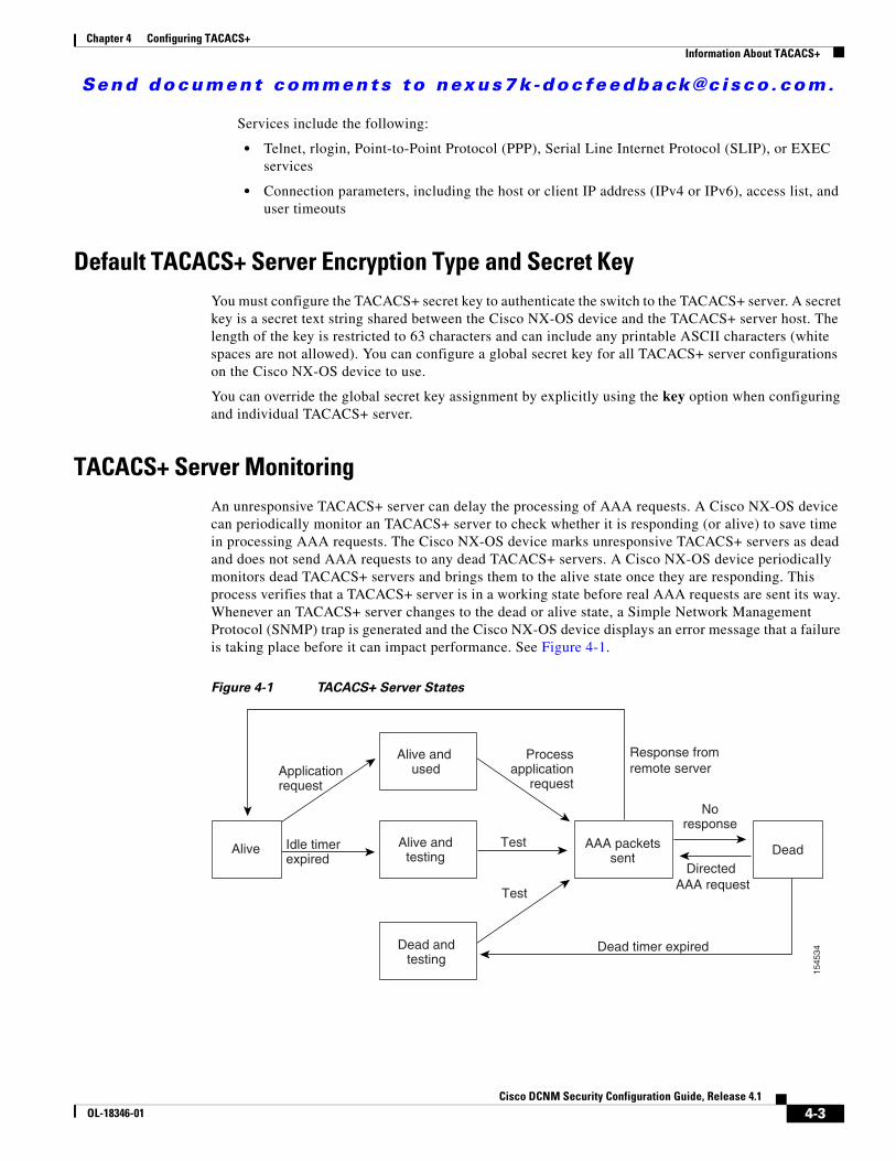
Send document comments to nexus7k -doc feedback@c i sco .com.
Chapter 4 Configuring TACACS+Information About TACACS+
Services include the following:
• Telnet, rlogin, Point-to-Point Protocol (PPP), Serial Line Internet Protocol (SLIP), or EXEC services
• Connection parameters, including the host or client IP address (IPv4 or IPv6), access list, and user timeouts
Default TACACS+ Server Encryption Type and Secret KeyYou must configure the TACACS+ secret key to authenticate the switch to the TACACS+ server. A secret key is a secret text string shared between the Cisco NX-OS device and the TACACS+ server host. The length of the key is restricted to 63 characters and can include any printable ASCII characters (white spaces are not allowed). You can configure a global secret key for all TACACS+ server configurations on the Cisco NX-OS device to use.
You can override the global secret key assignment by explicitly using the key option when configuring and individual TACACS+ server.
TACACS+ Server MonitoringAn unresponsive TACACS+ server can delay the processing of AAA requests. A Cisco NX-OS device can periodically monitor an TACACS+ server to check whether it is responding (or alive) to save time in processing AAA requests. The Cisco NX-OS device marks unresponsive TACACS+ servers as dead and does not send AAA requests to any dead TACACS+ servers. A Cisco NX-OS device periodically monitors dead TACACS+ servers and brings them to the alive state once they are responding. This process verifies that a TACACS+ server is in a working state before real AAA requests are sent its way. Whenever an TACACS+ server changes to the dead or alive state, a Simple Network Management Protocol (SNMP) trap is generated and the Cisco NX-OS device displays an error message that a failure is taking place before it can impact performance. See Figure 4-1.
Figure 4-1 TACACS+ Server States
Noresponse
Test
Test
Idle timerexpired
Directed AAA request
Dead timer expired
Response fromremote server
AAA packetssent
Alive
Alive and used
Dead andtesting
Alive andtesting Dead
Applicationrequest
Processapplication
request
1545
34
4-3Cisco DCNM Security Configuration Guide, Release 4.1
OL-18346-01
Send document comments to nexus7k -doc feedback@c i sco .com.
Chapter 4 Configuring TACACS+Information About TACACS+
Note The monitoring interval for alive servers and dead servers are different and can be configured by the user. The TACACS+ server monitoring is performed by sending a test authentication request to the TACACS+ server.
Vendor-Specific AttributesThe Internet Engineering Task Force (IETF) draft standard specifies a method for communicating vendor-specific attributes (VSAs) between the network access server and the TACACS+ server. The IETF uses attribute 26. VSAs allow vendors to support their own extended attributes that are not suitable for general use.
This section includes the following topics:
• Cisco VSA Format, page 4-4
• Cisco TACACS+ Privilege Levels, page 4-5
Cisco VSA Format
The Cisco TACACS+ implementation supports one vendor-specific option using the format recommended in the IETF specification. The Cisco vendor ID is 9, and the supported option is vendor type 1, which is named cisco-av-pair. The value is a string with the following format:
protocol : attribute separator value *
The protocol is a Cisco attribute for a particular type of authorization, separator is = (equal sign) for mandatory attributes, and * (asterisk) indicates optional attributes.
When you use TACACS+ servers for authentication on a Cisco NX-OS device, the TACACS+ protocol directs the TACACS+ server to return user attributes, such as authorization information, along with authentication results. This authorization information is specified through VSAs.
The following VSA protocol options are supported by the Cisco NX-OS software:
• Shell—Protocol used in access-accept packets to provide user profile information.
• Accounting—Protocol used in accounting-request packets. If a value contains any white spaces, you should enclose the value within double quotation marks.
The Cisco NX-OS software supports the following attributes:
• roles—Lists all the roles to which the user belongs. The value field is a string that lists the role names delimited by white space. For example, if the user belongs to roles network-operator and vdc-admin, the value field would be “network-operator vdc-admin.” This subattribute, which the TACACS+ server sends in the VSA portion of the Access-Accept frames, can only be used with the shell protocol value. The following examples show the roles attribute as supported by Cisco ACS:
shell:roles=“network-operator vdc-admin”
shell:roles*“network-operator vdc-admin”
4-4Cisco DCNM Security Configuration Guide, Release 4.1
OL-18346-01
Send document comments to nexus7k -doc feedback@c i sco .com.
Chapter 4 Configuring TACACS+Licensing Requirements for TACACS+
Note When you specify a VSA as shell:roles*“network-operator vdc-admin”, this VSA is flagged as an optional attribute and other Cisco devices ignore this attribute.
• accountinginfo—Stores accounting information in addition to the attributes covered by a standard TACACS+ accounting protocol. This attribute is sent only in the VSA portion of the Account-Request frames from the TACACS+ client on the switch. It can be used only with the accounting protocol data units (PDUs).
Cisco TACACS+ Privilege Levels
TACACS+ servers support privilege levels for specifying the permissions that users have when logging into a Cisco NX-OS device. For the maximum privilege level 15, the Cisco NX-OS software applies the network-admin role in the default VDC or the vdc-admin role for nondefault VDCs. All other privilege levels are translated to the vdc-operator role. For more information on user roles, see Chapter 5, “Configuring RBAC.”
Note If you specify a user role in the cisco-av-pair, that takes precedence over the privilege level.
Virtualization SupportTACACS+ configuration and operation are local to the virtual device context (VDC). For more information on VDCs, see the Cisco DCNM Virtual Device Context Configuration Guide, Release 4.1.
The Cisco NX-OS device uses virtual routing and forwarding instances (VRFs) to access the TACACS+ servers. For more information on VRFs, see the Cisco DCNM Unicast Routing Configuration Guide, Release 4.1.
Licensing Requirements for TACACS+The following table shows the licensing requirements for this feature:
Product License Requirement
DCNM TACACS+ requires no license. Any feature not included in a license package is bundled with the Cisco DCNM and is provided at no charge to you. For a complete explanation of the DCNM licensing scheme, see the Cisco DCNM Fundamentals Configuration Guide, Release 4.1.
NX-OS TACACS+ requires no license. Any feature not included in a license package is bundled with the Cisco NX-OS system images and is provided at no extra charge to you. For a complete explanation of the Cisco NX-OS licensing scheme, see the Cisco Nexus 7000 Series NX-OS Licensing Guide, Release 4.1.
4-5Cisco DCNM Security Configuration Guide, Release 4.1
OL-18346-01
Send document comments to nexus7k -doc feedback@c i sco .com.
Chapter 4 Configuring TACACS+Prerequisites for TACACS+
Prerequisites for TACACS+TACACS+ has the following prerequisites:
• Obtain the IPv4 or IPv6 addresses or hostnames for the TACACS+ servers.
• Obtain the secret keys from the TACACS+ servers, if any.
• Ensure that the Cisco NX-OS device is configured as a TACACS+ client of the AAA servers.
• Ensure that the logging level for TACACS+ in the Cisco NX-OS software is set to 5 using the command-line interface (CLI).
switch# configure terminalswitch(config)# logging level tacacs+ 5
Guidelines and LimitationsTACACS+ has the following guidelines and limitations:
• You can configure a maximum of 64 TACACS+ servers on the Cisco NX-OS device.
• If you have a user account configured on the local Cisco NX-OS device that has the same name as a remote user account on an AAA server, the Cisco NX-OS software applies the user roles for the local user account to the remote user, not the user roles configured on the AAA server.
Configuring TACACS+This section includes the following topics:
• TACACS+ Server Configuration Process, page 4-7
• Enabling TACACS+, page 4-9
• Adding a TACACS+ Server Host, page 4-9
• Copying a TACACS+ Server Host, page 4-11
• Deleting a TACACS+ Server Host, page 4-11
• Configuring a Global TACACS+ Key, page 4-12
• Configuring a Key for a Specific TACACS+ Server, page 4-12
• Adding a TACACS+ Server Group, page 4-13
• Adding a TACACS+ Server Host to a TACACS+ Server Group, page 4-14
• Deleting a TACACS+ Server Host from a TACACS+ Server Group, page 4-14
• Deleting a TACACS+ Server Group, page 4-15
• Specifying a TACACS+ Server at Login, page 4-15
• Configuring the Global TACACS+ Timeout Interval, page 4-16
• Configuring the Timeout Interval for a Server, page 4-17
• Configuring TCP Ports, page 4-17
• Configuring Periodic TACACS+ Server Monitoring, page 4-18
• Configuring the Dead-Time Interval, page 4-19
4-6Cisco DCNM Security Configuration Guide, Release 4.1
OL-18346-01
Send document comments to nexus7k -doc feedback@c i sco .com.
Chapter 4 Configuring TACACS+Configuring TACACS+
• Disabling TACACS+, page 4-19
TACACS+ Server Configuration ProcessTo configure TACACS+ servers, follow these steps:
Step 1 Enable TACACS+ (see the “Enabling TACACS+” section on page 4-9).
Step 2 Establish the TACACS+ server connections to the Cisco NX-OS device (see the “Adding a TACACS+ Server Host” section on page 4-9).
Step 3 Configure the secret keys for the TACACS+ servers (see the “Configuring a Global TACACS+ Key” section on page 4-12 and the “Configuring a Key for a Specific TACACS+ Server” section on page 4-12).
Step 4 If needed, configure TACACS+ server groups with subsets of the TACACS+ servers for AAA authentication methods (see the “Adding a TACACS+ Server Group” section on page 4-13 and the “Configuring AAA” section on page 2-7).
Step 5 If needed, configure any of the following optional parameters:
• Dead-time interval (see the “Configuring the Dead-Time Interval” section on page 4-19).
• TACACS+ server specification allowed at user login (see the “Specifying a TACACS+ Server at Login” section on page 4-15).
• Timeout interval (see the “Configuring the Global TACACS+ Timeout Interval” section on page 4-16).
• TCP port (see the “Configuring TCP Ports” section on page 4-17).
Step 6 If needed, configure periodic TACACS+ server monitoring (see the “Configuring Periodic TACACS+ Server Monitoring” section on page 4-18).
4-7Cisco DCNM Security Configuration Guide, Release 4.1
OL-18346-01
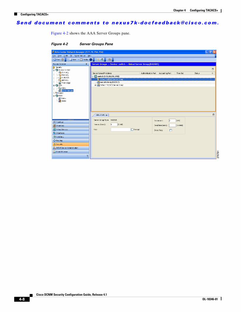
Send document comments to nexus7k -doc feedback@c i sco .com.
Chapter 4 Configuring TACACS+Configuring TACACS+
Figure 4-2 shows the AAA Server Groups pane.
Figure 4-2 Server Groups Pane
4-8Cisco DCNM Security Configuration Guide, Release 4.1
OL-18346-01
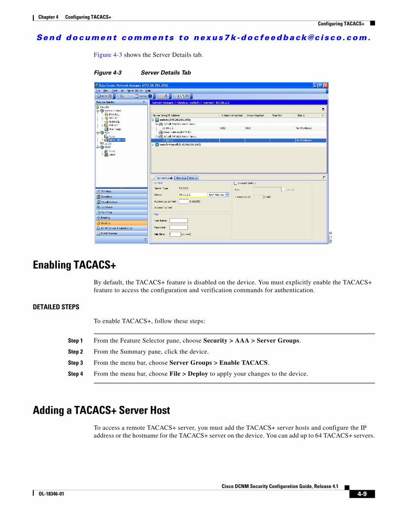
Send document comments to nexus7k -doc feedback@c i sco .com.
Chapter 4 Configuring TACACS+Configuring TACACS+
Figure 4-3 shows the Server Details tab.
Figure 4-3 Server Details Tab
Enabling TACACS+ By default, the TACACS+ feature is disabled on the device. You must explicitly enable the TACACS+ feature to access the configuration and verification commands for authentication.
DETAILED STEPS
To enable TACACS+, follow these steps:
Step 1 From the Feature Selector pane, choose Security > AAA > Server Groups.
Step 2 From the Summary pane, click the device.
Step 3 From the menu bar, choose Server Groups > Enable TACACS.
Step 4 From the menu bar, choose File > Deploy to apply your changes to the device.
Adding a TACACS+ Server HostTo access a remote TACACS+ server, you must add the TACACS+ server hosts and configure the IP address or the hostname for the TACACS+ server on the device. You can add up to 64 TACACS+ servers.
4-9Cisco DCNM Security Configuration Guide, Release 4.1
OL-18346-01
Send document comments to nexus7k -doc feedback@c i sco .com.
Chapter 4 Configuring TACACS+Configuring TACACS+
Note By default, when you configure a TACACS+ server IP address or hostname the Cisco NX-OS device, the TACACS+ server is added to the default TACACS+ server group. You can also add the TACACS+ server to another TACACS+ server group. For information about creating TACACS+ server groups, see the“Adding a TACACS+ Server Group” section on page 4-13 and the “Adding a TACACS+ Server Host to a TACACS+ Server Group” section on page 4-14).
BEFORE YOU BEGIN
Enable TACACS+ (see the “Enabling TACACS+” section on page 4-9).
Obtain the IPv4 or IPv6 addresses or the hostnames for the remote TACACS+ servers.
DETAILED STEPS
To add a TACACS+ server host, follow these steps:
Step 1 From the Feature Selector pane, choose Security > AAA > Server Groups.
Step 2 From the Summary pane, double-click the device to display the server groups.
Step 3 Click Default TACACS Server Group.
Step 4 From the menu bar, choose Server Groups > Add Server.
The Server Details appears in the Details pane.
Step 5 In the Server field, enter the TACACS+ server IPv4 address, IPv6 address, or hostname in the Server field.
Step 6 From the Server drop-down list, choose either the IPv4 address, IPv6 address, or hostname as the correct server identifier type.
Note If the server identifier format matches the identifier type selected, DCNM outlines the Server field in yellow to indicate that it is correct. If the server identifier format does not match the identifier type, DCNM outlines the Server field in red to indicate an error. Change the address or the address type to correct this problem.
Step 7 (Optional) In the Authentication Port field, enter a new TCP port number or clear it to disable authentication.
The default authentication TCP port is 49.
Step 8 (Optional) In the Test area, you can enter a username, password, and idle time interval in minutes for periodic server host monitoring.
The default username is test, the default password is test, and the default idle time interval is 0 minutes, which disables periodic monitoring.
Step 9 From the menu bar, choose File > Deploy to apply your changes to the device.
4-10Cisco DCNM Security Configuration Guide, Release 4.1
OL-18346-01
Send document comments to nexus7k -doc feedback@c i sco .com.
Chapter 4 Configuring TACACS+Configuring TACACS+
Copying a TACACS+ Server HostYou can copy the configuration of a TACACS+ server host from one TACACS+ server group to another server group, either on the same NX-OS device or on another NX-OS device.
BEFORE YOU BEGIN
Ensure that you have configured the server in the default TACACS+ server group (see the “Adding a TACACS+ Server Host” section on page 4-9).
Ensure that you have created the target TACACS+ server group (see the “Adding a TACACS+ Server Group” section on page 4-13).
DETAILED STEPS
To copy the configuration of a TACACS+ server host, follow these steps:
Step 1 From the Feature Selector pane, choose Security > AAA > Server Groups.
Step 2 From the Summary pane, double-click the device to display the server groups.
Step 3 Double-click Default TACACS Server Group.
The list of configured TACACS+ server hosts appears.
Step 4 Click on the server host you want to copy.
Step 5 From the menu bar, choose Actions > Copy.
Step 6 Click the destination server group.
Note You can copy the server host configuration to a server group within the same device or in another device.
Step 7 From the menu bar, choose Actions > Paste.
The TACACS+ server host appears in the list of servers for the server group.
Step 8 From the menu bar, choose File > Deploy to apply your changes to the device.
Deleting a TACACS+ Server HostYou can delete a TACACS+ server host from a server group.
DETAILED STEPS
To delete a TACACS+ server host, follow these steps:
Step 1 From the Feature Selector pane, choose Security > AAA > Server Groups.
Step 2 From the Summary pane, double-click the device to display the server groups.
Step 3 Double-click the server group to display the list of server hosts.
Step 4 Click the TACACS+ server host to delete.
4-11Cisco DCNM Security Configuration Guide, Release 4.1
OL-18346-01
Send document comments to nexus7k -doc feedback@c i sco .com.
Chapter 4 Configuring TACACS+Configuring TACACS+
Step 5 From the menu bar, choose Server Groups > Delete Server and click Yes on the confirmation dialog.
The TACACS+ server host disappears from the list.
Step 6 From the menu bar, choose File > Deploy to apply your changes to the device.
Configuring a Global TACACS+ KeyYou can configure secret keys at the global level for all servers used by the device. A secret key is a shared secret text string between the device and the TACACS+ server hosts.
BEFORE YOU BEGIN
Enable TACACS+ (see the “Enabling TACACS+” section on page 4-9).
Obtain the secret key values for the remote TACACS+ servers.
DETAILED STEPS
To configure a global secret key, follow these steps:
Step 1 From the Feature Selector pane, choose Security > AAA > Server Groups.
Step 2 From the Summary pane, double-click the device to display the server groups.
Step 3 Click Default TACACS Server Group.
Step 4 From the Details pane, click the Global TACACS Settings tab.
Step 5 In the Key field, enter the secret key.
Step 6 (Optional) Check Encrypt to encrypt the key.
The default is clear text. The Cisco NX-OS software encrypts a clear text key before saving it to the running configuration.
Step 7 From the menu bar, choose File > Deploy to apply your changes to the device.
Configuring a Key for a Specific TACACS+ ServerYou can configure secret keys for a TACACS+ server. A secret key is a shared secret text string between the Cisco NX-OS device and the TACACS+ server host.
BEFORE YOU BEGIN
Enable TACACS+ (see the “Enabling TACACS+” section on page 4-9).
Configure one or more TACACS+ server hosts (see the “Adding a TACACS+ Server Host” section on page 4-9).
Obtain the secret key values for the remote TACACS+ servers.
4-12Cisco DCNM Security Configuration Guide, Release 4.1
OL-18346-01
Send document comments to nexus7k -doc feedback@c i sco .com.
Chapter 4 Configuring TACACS+Configuring TACACS+
DETAILED STEPS
To configure a TACACS+ server secret key, follow these steps:
Step 1 From the Feature Selector pane, choose Security > AAA > Server Groups.
Step 2 From the Summary pane, double-click the device to display the server groups.
Step 3 Double-click Default TACACS Server Group to display the list of TACACS+ servers.
Step 4 Click the desired TACACS+ server.
Step 5 From the Details pane, click the Server Details tab.
Step 6 Check Override Defaults.
Step 7 In the Key field, enter the secret key.
The default is the global secret key.
Step 8 (Optional) Check Encrypt to encrypt the key.
The default is clear text.
Step 9 From the menu bar, choose File > Deploy to apply your changes to the device.
Adding a TACACS+ Server GroupYou can reference one or more remote AAA servers to authenticate users using server groups. All members of a group must belong to the TACACS+ protocol. The servers are tried in the same order in which you configure them.
You can configure these server groups at any time but they only take effect when you apply them to an AAA service. For information on AAA services, see the “Remote AAA Services” section on page 2-2.
BEFORE YOU BEGIN
Enable TACACS+ (see the “Enabling TACACS+” section on page 4-9).
Configure one or more TACACS+ server hosts (see the “Adding a TACACS+ Server Host” section on page 4-9).
DETAILED STEPS
To add a TACACS+ server group, follow these steps:
Step 1 From the Feature Selector pane, choose Security > AAA > Server Groups.
Step 2 From the Summary pane, click the device.
Step 3 From the menu bar, choose Server Groups > TACACS Server Group.
A new line appears at the end of the server group list for the device and the Details tab appears in the Details pane.
Step 4 In the Server Group Name field, enter the name and press the Enter key.
The server group name is a case-sensitive alphanumeric string with a maximum length of 127 characters.
Step 5 (Optional) In the Dead time(mins) field, enter the number of minutes for the dead-time interval.
4-13Cisco DCNM Security Configuration Guide, Release 4.1
OL-18346-01
Send document comments to nexus7k -doc feedback@c i sco .com.
Chapter 4 Configuring TACACS+Configuring TACACS+
The default dead-time interval is 0 minutes.
Step 6 In the VRF Name field, click the down arrow to display the VRF Name dialog and click a VRF. Click OK.
Step 7 From the menu bar, choose File > Deploy to apply your changes to the device.
Adding a TACACS+ Server Host to a TACACS+ Server GroupYou can add a TACACS+ server host to a TACACS+ server group.
BEFORE YOU BEGIN
Ensure that you have added the TACACS+ server host to the Default TACACS+ Server Group (see the “Adding a TACACS+ Server Host” section on page 4-9).
DETAILED STEPS
To add a TACACS+ server host to a TACACS+ server group, follow these steps:
Step 1 From the Feature Selector pane, choose Security > AAA > Server Groups.
Step 2 From the Summary pane, double-click the device to display the server groups.
Step 3 Click a TACACS+ server group.
Step 4 From the menu bar, choose Server Groups > Add Server.
The Server Details appear in the Details pane.
Step 5 In the Server field, enter the TACACS+ server IPv4 address, IPv6 address, or hostname in the Server field.
Step 6 From the Server drop-down list, choose either the IPv4 address, IPv6 address, or hostname as the correct server identifier type.
Note If the server identifier format matches the identifier type selected, DCNM outlines the Server field in yellow to indicate that it is correct. If the server identifier format does not match the identifier type, DCNM outlines the Server field in red to indicate an error. Change the address or the address type to correct this problem.
Step 7 From the menu bar, choose File > Deploy to apply your changes to the device.
Deleting a TACACS+ Server Host from a TACACS+ Server GroupYou can delete a TACACS+ server host from a TACACS+ server group.
4-14Cisco DCNM Security Configuration Guide, Release 4.1
OL-18346-01
Send document comments to nexus7k -doc feedback@c i sco .com.
Chapter 4 Configuring TACACS+Configuring TACACS+
DETAILED STEPS
To delete a TACACS+ server host from a TACACS+ server group, follow these steps:
Step 1 From the Feature Selector pane, choose Security > AAA > Server Groups.
Step 2 From the Summary pane, double-click the device to display the server groups.
Step 3 Double-click the server group to display the list of server hosts.
Step 4 Click the TACACS+ server host to delete.
Step 5 From the menu bar, choose Server Groups > Delete Server and click Yes on the confirmation dialog.
The TACACS+ server host disappears from the list.
Step 6 From the menu bar, choose File > Deploy to apply your changes to the device.
Deleting a TACACS+ Server GroupYou can delete a TACACS+ server group.
DETAILED STEPS
To delete a TACACS+ server group, follow these steps:
Step 1 From the Feature Selector pane, choose Security > AAA > Server Groups.
Step 2 From the Summary pane, double-click the device to display the list of server groups.
Step 3 Click the TACACS+ server group to delete.
Step 4 From the menu bar, choose Server Groups > Delete Server Group and click Yes in the confirmation dialog.
The server group disappears from the server group list.
Step 5 From the menu bar, choose File > Deploy to apply your changes to the device.
Specifying a TACACS+ Server at LoginYou can configure the switch to allow the user to specify which TACACS+ server to send the authentication request by enabling the directed-request option. By default, a device forwards an authentication request based on the default AAA authentication method. If you enable this option, the user can log in as username@vrfname:hostname, where vrfname is the VRF to use and hostname is the name of a configured TACACS+ server.
Note If you enable the directed-request option, the device uses only the TACACS+ method for authentication and not the default local method.
4-15Cisco DCNM Security Configuration Guide, Release 4.1
OL-18346-01
Send document comments to nexus7k -doc feedback@c i sco .com.
Chapter 4 Configuring TACACS+Configuring TACACS+
Note User-specified logins are supported only for Telnet sessions.
BEFORE YOU BEGIN
Enable TACACS+ (see the “Enabling TACACS+” section on page 4-9).
DETAILED STEPS
To allow users to specify a TACACS+ server at login, follow these steps:
Step 1 From the Feature Selector pane, choose Security > AAA > Server Groups.
Step 2 From the Summary pane, double-click the device to display the server groups.
Step 3 Click Default TACACS Server Group.
Step 4 From the Details pane, click the Global TACACS Settings tab.
Step 5 Check Direct Req.
Step 6 From the menu bar, choose File > Deploy to apply your changes to the device.
Configuring the Global TACACS+ Timeout IntervalYou can set a global timeout interval that the device waits for responses from all TACACS+ servers before declaring a timeout failure. The timeout interval determines how long the device waits for responses from TACACS+ servers before declaring a timeout failure.
BEFORE YOU BEGIN
Enable TACACS+ (see the “Enabling TACACS+” section on page 4-9).
DETAILED STEPS
To configure the global TACACS+ timeout interval, follow these steps:
Step 1 From the Feature Selector pane, choose Security > AAA > Server Groups.
Step 2 From the Summary pane, double-click the device to display the server groups.
Step 3 Click Default TACACS Server Group.
Step 4 From the Details pane, click the Global TACACS Settings tab.
Step 5 In the Time out(secs) field, enter the number of seconds for the timeout interval.
The default is 5 seconds.
Step 6 From the menu bar, choose File > Deploy to apply your changes to the device.
4-16Cisco DCNM Security Configuration Guide, Release 4.1
OL-18346-01
Send document comments to nexus7k -doc feedback@c i sco .com.
Chapter 4 Configuring TACACS+Configuring TACACS+
Configuring the Timeout Interval for a ServerYou can set a timeout interval that the device waits for responses from a TACACS+ server before declaring a timeout failure. The timeout interval determines how long the device waits for responses from a TACACS+ server before declaring a timeout failure.
BEFORE YOU BEGIN
Enable TACACS+ (see the “Enabling TACACS+” section on page 4-9).
Configure one or more TACACS+ server hosts (see the “Adding a TACACS+ Server Host” section on page 4-9).
DETAILED STEPS
To configure the timeout interval for a TACACS+ server, follow these steps:
Step 1 From the Feature Selector pane, choose Security > AAA > Server Groups.
Step 2 From the Summary pane, double-click the device to display the server groups.
Step 3 Double-click Default TACACS Server Group to display the list of TACACS+ servers.
Step 4 Click the desired TACACS+ server.
Step 5 From the Details pane, click the Server Details tab.
Step 6 Check Override Defaults.
Step 7 In the Timeout(secs) field, enter the number of seconds for the timeout interval.
The default is 5 seconds.
Step 8 From the menu bar, choose File > Deploy to apply your changes to the device.
Configuring TCP PortsYou can configure another TCP port for the TACACS+ servers if there are conflicts with another application. By default, devices use port 49 for all TACACS+ requests.
BEFORE YOU BEGIN
Enable TACACS+ (see the “Enabling TACACS+” section on page 4-9).
Configure one or more TACACS+ server hosts (see the “Adding a TACACS+ Server Host” section on page 4-9).
DETAILED STEPS
To configure the authentication port for TACACS+ servers, follow these steps:
Step 1 From the Feature Selector pane, choose Security > AAA > Server Groups.
Step 2 From the Summary pane, double-click the device to display the server groups.
Step 3 Double-click Default TACACS Server Group to display the list of TACACS+ servers.
4-17Cisco DCNM Security Configuration Guide, Release 4.1
OL-18346-01
Send document comments to nexus7k -doc feedback@c i sco .com.
Chapter 4 Configuring TACACS+Configuring TACACS+
Step 4 Click the desired TACACS+ server.
Step 5 From the Details pane, click the Server Details tab.
Step 6 In the Authentication Port field, enter a new TCP port number or clear it to disable authentication.
The default authentication TCP port is 49.
Step 7 From the menu bar, choose File > Deploy to apply your changes to the device.
Configuring Periodic TACACS+ Server MonitoringYou can monitor the availability of TACACS+ servers. These parameters include the username and password to use for the server and an idle timer. The idle timer specifies the interval in which a TACACS+ server receives no requests before the device sends out a test packet. You can configure this option to test servers periodically, or you can run a one-time only test.
Note To protect network security, we recommend that you use a username that is not the same as an existing username in the TACACS+ database.
The test idle timer specifies the interval in which a TACACS+ server receives no requests before the device sends out a test packet.
Note The default idle timer value is 0 minutes. When the idle time interval is 0 minutes, periodic TACACS+ server monitoring is not performed.
BEFORE YOU BEGIN
Enable TACACS+ (see the “Enabling TACACS+” section on page 4-9).
Configure one or more TACACS+ server hosts (see the “Adding a TACACS+ Server Host” section on page 4-9).
DETAILED STEPS
To configure periodic TACACS+ server monitoring, follow these steps:
Step 1 From the Feature Selector pane, choose Security > AAA > Server Groups.
Step 2 From the Summary pane, double-click the device to display the server groups.
Step 3 Double-click Default TACACS Server Group to display the list of TACACS+ servers.
Step 4 Click the desired TACACS+ server.
Step 5 From the Details pane, click the Server Details tab.
Step 6 In the User Name field, enter a username.
Step 7 In the Password field, enter a password.
Step 8 In the Idle Time field, enter the number of minutes for periodic monitoring.
4-18Cisco DCNM Security Configuration Guide, Release 4.1
OL-18346-01
Send document comments to nexus7k -doc feedback@c i sco .com.
Chapter 4 Configuring TACACS+Configuring TACACS+
Step 9 From the menu bar, choose File > Deploy to apply your changes to the device.
Configuring the Dead-Time IntervalYou can configure the dead-time interval for all TACACS+ servers. The dead-time interval specifies the time that the device waits, after declaring a TACACS+ server is dead, before sending out a test packet to determine if the server is now alive.
Note When the dead-timer interval is 0 minutes, TACACS+ servers are not marked as dead even if they are not responding. You can configure the dead-timer per group (see the “Adding a TACACS+ Server Group” section on page 4-13).
BEFORE YOU BEGIN
Enable TACACS+ (see the “Enabling TACACS+” section on page 4-9).
DETAILED STEPS
To configure the dead-time interval, follow these steps:
Step 1 From the Feature Selector pane, choose Security > AAA > Server Groups.
Step 2 From the Summary pane, double-click the device to display the server groups.
Step 3 Click Default TACACS Server Group.
Step 4 From the Details pane, click the Global TACACS Settings tab.
Step 5 In the Dead time(mins) field, enter the number of minutes.
The default is 0 minutes.
Step 6 From the menu bar, choose File > Deploy to apply your changes to the device.
Disabling TACACS+ You can disable TACACS+.
Caution When you disable TACACS+, all related configurations are automatically discarded.
DETAILED STEPS
To disable TACACS+, follow these steps:
Step 1 From the Feature Selector pane, choose Security > AAA > Server Groups.
Step 2 From the Summary pane, click the device.
4-19Cisco DCNM Security Configuration Guide, Release 4.1
OL-18346-01
Send document comments to nexus7k -doc feedback@c i sco .com.
Chapter 4 Configuring TACACS+Displaying TACACS+ Statistics
Step 3 From the menu bar, choose Server Groups > Disable TACACS.
Step 4 From the menu bar, choose File > Deploy to apply your changes to the device.
Displaying TACACS+ StatisticsYou can display the statistics that the device maintains for TACACS+ activity.
BEFORE YOU BEGIN
Enable TACACS+ (see the “Enabling TACACS+” section on page 4-9).
Configure one or more TACACS+ server hosts (see the “Adding a TACACS+ Server Host” section on page 4-9).
DETAILED STEPS
To display TACACS+ server statistics, follow these steps:
Step 1 From the Feature Selector pane, choose Security > AAA > Server Groups.
Step 2 From the Summary pane, double-click the device to display the server groups.
Step 3 Double-click Default TACACS Server Group to display the list of TACACS+ servers.
Step 4 Click the desired TACACS+ server.
Step 5 From the Details pane, click the Statistics tab.
Where to Go Next You can now configure AAA authentication methods to include the TACACS+ server groups (see Chapter 2, “Configuring AAA”).
Field Descriptions for TACACS+ Server Groups and ServersThis section includes the following topics:
• Security: AAA: Server Groups: Summary Pane, page 4-21
• Security: AAA: Server Groups: device: Default TACACS Server Group: Global TACACS Settings Tab, page 4-21
• Security: AAA: Server Groups: device: Default TACACS Server Group: server: Server Details Tab, page 4-21
• Security: AAA: Server Groups: device: server group: Details Tab, page 4-22
4-20Cisco DCNM Security Configuration Guide, Release 4.1
OL-18346-01
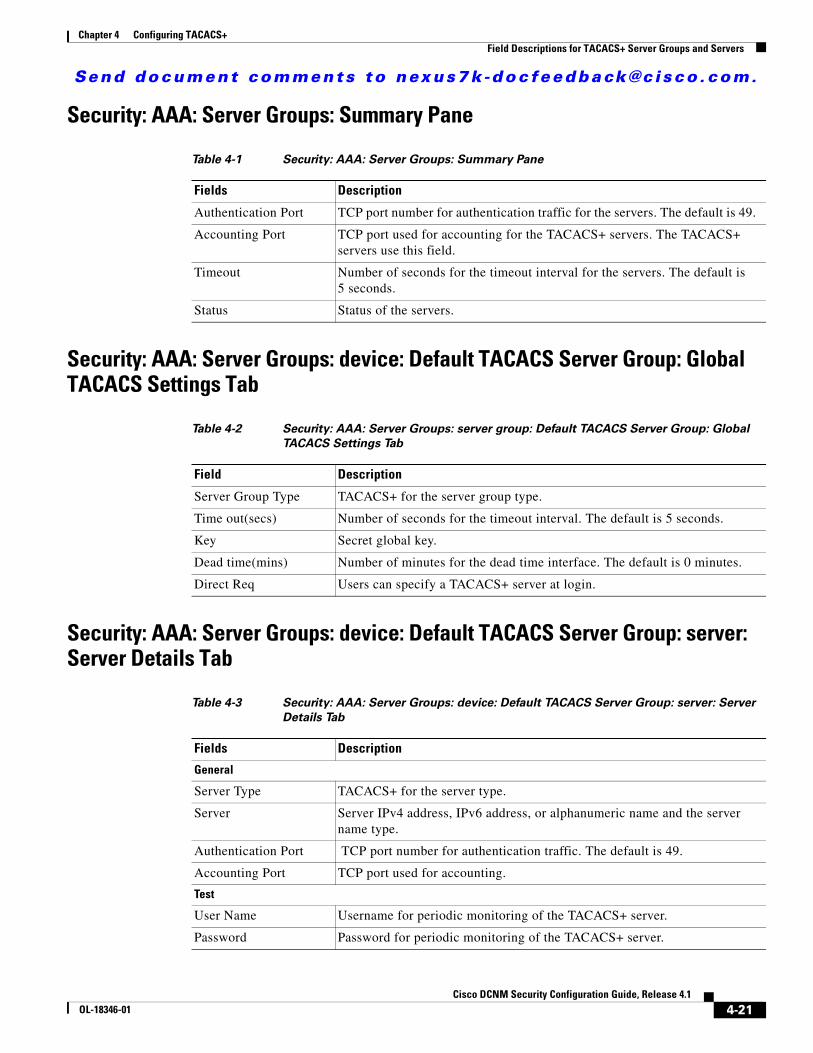
Send document comments to nexus7k -doc feedback@c i sco .com.
Chapter 4 Configuring TACACS+Field Descriptions for TACACS+ Server Groups and Servers
Security: AAA: Server Groups: Summary Pane
Security: AAA: Server Groups: device: Default TACACS Server Group: Global TACACS Settings Tab
Security: AAA: Server Groups: device: Default TACACS Server Group: server: Server Details Tab
Table 4-1 Security: AAA: Server Groups: Summary Pane
Fields Description
Authentication Port TCP port number for authentication traffic for the servers. The default is 49.
Accounting Port TCP port used for accounting for the TACACS+ servers. The TACACS+ servers use this field.
Timeout Number of seconds for the timeout interval for the servers. The default is 5 seconds.
Status Status of the servers.
Table 4-2 Security: AAA: Server Groups: server group: Default TACACS Server Group: Global
TACACS Settings Tab
Field Description
Server Group Type TACACS+ for the server group type.
Time out(secs) Number of seconds for the timeout interval. The default is 5 seconds.
Key Secret global key.
Dead time(mins) Number of minutes for the dead time interface. The default is 0 minutes.
Direct Req Users can specify a TACACS+ server at login.
Table 4-3 Security: AAA: Server Groups: device: Default TACACS Server Group: server: Server
Details Tab
Fields Description
General
Server Type TACACS+ for the server type.
Server Server IPv4 address, IPv6 address, or alphanumeric name and the server name type.
Authentication Port TCP port number for authentication traffic. The default is 49.
Accounting Port TCP port used for accounting.
Test
User Name Username for periodic monitoring of the TACACS+ server.
Password Password for periodic monitoring of the TACACS+ server.
4-21Cisco DCNM Security Configuration Guide, Release 4.1
OL-18346-01
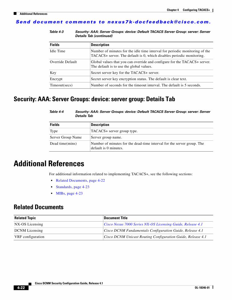
Send document comments to nexus7k -doc feedback@c i sco .com.
Chapter 4 Configuring TACACS+Additional References
Security: AAA: Server Groups: device: server group: Details Tab
Additional ReferencesFor additional information related to implementing TACACS+, see the following sections:
• Related Documents, page 4-22
• Standards, page 4-23
• MIBs, page 4-23
Related Documents
Idle Time Number of minutes for the idle time interval for periodic monitoring of the TACACS+ server. The default is 0, which disables periodic monitoring.
Override Default Global values that you can override and configure for the TACACS+ server. The default is to use the global values.
Key Secret server key for the TACACS+ server.
Encrypt Secret server key encryption status. The default is clear text.
Timeout(secs) Number of seconds for the timeout interval. The default is 5 seconds.
Table 4-4 Security: AAA: Server Groups: device: Default TACACS Server Group: server: Server
Details Tab
Fields Description
Type TACACS+ server group type.
Server Group Name Server group name.
Dead time(mins) Number of minutes for the dead-time interval for the server group. The default is 0 minutes.
Table 4-3 Security: AAA: Server Groups: device: Default TACACS Server Group: server: Server
Details Tab (continued)
Fields Description
Related Topic Document Title
NX-OS Licensing Cisco Nexus 7000 Series NX-OS Licensing Guide, Release 4.1
DCNM Licensing Cisco DCNM Fundamentals Configuration Guide, Release 4.1
VRF configuration Cisco DCNM Unicast Routing Configuration Guide, Release 4.1
4-22Cisco DCNM Security Configuration Guide, Release 4.1
OL-18346-01
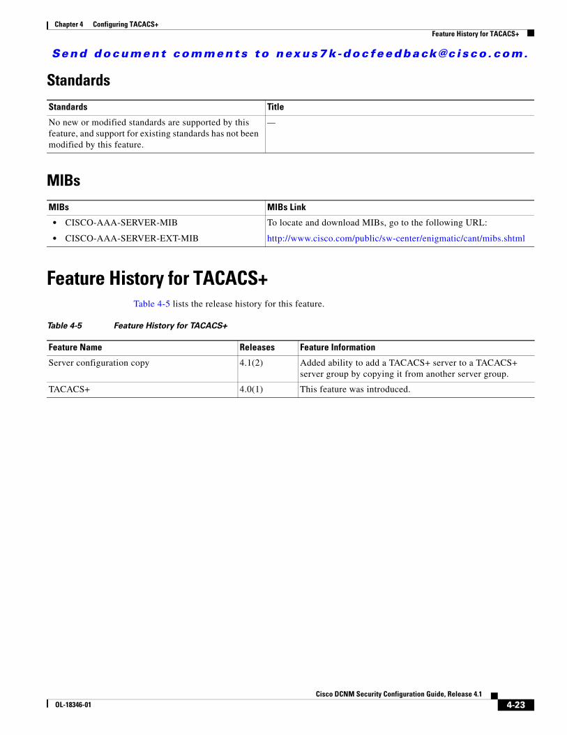
Send document comments to nexus7k -doc feedback@c i sco .com.
Chapter 4 Configuring TACACS+Feature History for TACACS+
Standards
MIBs
Feature History for TACACS+Table 4-5 lists the release history for this feature.
Standards Title
No new or modified standards are supported by this feature, and support for existing standards has not been modified by this feature.
—
MIBs MIBs Link
• CISCO-AAA-SERVER-MIB
• CISCO-AAA-SERVER-EXT-MIB
To locate and download MIBs, go to the following URL:
http://www.cisco.com/public/sw-center/enigmatic/cant/mibs.shtml
Table 4-5 Feature History for TACACS+
Feature Name Releases Feature Information
Server configuration copy 4.1(2) Added ability to add a TACACS+ server to a TACACS+ server group by copying it from another server group.
TACACS+ 4.0(1) This feature was introduced.
4-23Cisco DCNM Security Configuration Guide, Release 4.1
OL-18346-01

Send document comments to nexus7k -doc feedback@c i sco .com.
Chapter 4 Configuring TACACS+Feature History for TACACS+
4-24Cisco DCNM Security Configuration Guide, Release 4.1
OL-18346-01
Send document comments to nexus7k -doc feedback@c i sco .com.
CiscOL-18346-01
C H A P T E R5
Configuring RBACThis chapter describes how to configure user accounts and role-based access control (RBAC) on NX-OS devices.
This chapter includes the following sections:
• Information About User Accounts and RBAC, page 5-1
• Licensing Requirements for User Accounts and RBAC, page 5-4
• Guidelines and Limitations, page 5-4
• Configuring User Accounts, page 5-5
• Configuring Roles, page 5-12
• Field Descriptions for RBAC, page 5-20
• Additional References, page 5-22
• Feature History for User Accounts and RBAC, page 5-23
Information About User Accounts and RBACYou can create and manage users accounts and assign roles that limit access to operations on the NX-OS device. RBAC allows you to define the rules for an assign role that restrict the authorization that the user has to access management operations.
This section includes the following topics:
• About User Accounts, page 5-1
• Characteristics of Strong Passwords, page 5-2
• About User Roles, page 5-3
• About User Role Rules, page 5-3
• Virtualization Support, page 5-4
About User AccountsYou can configure up to a maximum of 256 user accounts. By default, the user account does not expire unless you explicitly configure it to expire. The expire option determines the date when the user account is disabled.
5-1o DCNM Security Configuration Guide, Release 4.1
Send document comments to nexus7k -doc feedback@c i sco .com.
Chapter 5 Configuring RBACInformation About User Accounts and RBAC
Users can have user accounts on multiple VDCs. These users can move between VDCs after an initial connection to a VDC.
The Cisco NX-OS software provides two default user accounts, admin and adminbackup.
Tip The following words are reserved and cannot be used to configure users: bin, daemon, adm, lp, sync, shutdown, halt, mail, news, uucp, operator, games, gopher, ftp, nobody, nscd, mailnull, rpc, rpcuser, xfs, gdm, mtsuser, ftpuser, man, and sys.
Note User passwords are not displayed in the configuration files.
Caution The Cisco NX-OS software does not support all numeric usernames, whether created with TACACS+ or RADIUS, or created locally. Local users with all numeric names cannot be created. If an all numeric user name exists on an AAA server and is entered during login, the user is not logged in.
Characteristics of Strong PasswordsA strong password has the following characteristics:
• At least eight characters long
• Does not contain many consecutive characters (such as “abcd”)
• Does not contain many repeating characters (such as “aaabbb”)
• Does not contain dictionary words
• Does not contain proper names
• Contains both uppercase and lowercase characters
• Contains numbers
The following are examples of strong passwords:
• If2CoM18
• 2004AsdfLkj30
• Cb1955S21
Note Clear text passwords cannot include the dollar sign ($) special character.
Tip If a password is trivial (such as a short, easy-to-decipher password), the NX-OS software will reject your password configuration if password-strength checking is enabled. Be sure to configure a strong password as shown in the sample configuration. Passwords are case sensitive.
5-2Cisco DCNM Security Configuration Guide, Release 4.1
OL-18346-01
Send document comments to nexus7k -doc feedback@c i sco .com.
Chapter 5 Configuring RBACInformation About User Accounts and RBAC
About User RolesUser roles contain rules that define the operations allowed for the user who is assigned the role. Each user role can contain multiple rules and each user can have multiple roles. For example, if role1 allows access only to configuration operations, and role2 allows access only to debug operations, then users who belong to both role1 and role2 can access configuration and debug operations. You can also limit access to specific VLANs, virtual routing and forwarding instances (VRFs), and interfaces.
The Cisco NX-OS software provides four default user roles:
• network-admin—Complete read-and-write access to the entire NX-OS device (only available in the default VDC)
• network-operator—Complete read access to the entire NX-OS device (only available in the default VDC)
• vdc-admin—Read-and-write access limited to a VDC
• vdc-operator—Read access limited to a VDC
Note You cannot change the default user roles.
You can create custom roles within a VDC. By default, the user roles that you create do not allow access to any device operations. You must add rules to allow users to display or configure features.
The VDCs do not share user roles. Each VDC maintains an independent user role database. Within a VDC, roles are configured by rule and attribute assignment.
Note If you belong to multiple roles, you can execute a combination of all the commands permitted by these roles. Access to a command takes priority over being denied access to a command. For example, suppose a user has RoleA, which denied access to the configuration commands. However, the user also has RoleB, which has access to the configuration commands. In this case, the user has access to the configuration commands.
About User Role RulesThe rule is the basic element of a role. A rule defines what operations the role allows the user to perform. You can apply rules for the following parameters:
• Command—A command or group of commands defined in a regular expression.
• Feature—Commands that apply to a function provided by the NX-OS software.
• Feature group—Default or user-defined group of features.
These parameters create a hierarchical relationship. The most basic control parameter is the command. The next control parameter is the feature, which represents all commands associated with the feature. The last control parameter is the feature group. The feature group combines related features and allows you to easily manage the rules. The NX-OS software also supports the predefined feature group L3 that you can use.
You can configure up to 256 rules for each role. The user-specified rule number determines the order in which the rules are applied. Rules are applied in descending order. For example, if a role has three rules, rule 3 is applied before rule 2, which is applied before rule 1.
5-3Cisco DCNM Security Configuration Guide, Release 4.1
OL-18346-01
Send document comments to nexus7k -doc feedback@c i sco .com.
Chapter 5 Configuring RBACLicensing Requirements for User Accounts and RBAC
Virtualization SupportThe users with the network-admin and network-operator roles can operate in all virtual device contexts (VDCs) when logged in from the default VDC. All other user roles are local to the VDC. Roles are not shared between VDCs. Each VDC maintains an independent user role database. For more information on VDCs, see the Cisco DCNM Virtual Device Context Configuration Guide, Release 4.1.
Licensing Requirements for User Accounts and RBACThe following table shows the licensing requirements for this feature:
Guidelines and LimitationsUser accounts and RBAC have the following configuration guidelines and limitations:
• You can create up to 64 user-defined roles in a VDC in addition to the four default user roles in the default VDC and the two default user roles in the nondefault VDCs.
• You can add up to 256 rules to a user role.
• You can add up to 64 user-defined feature groups to a VDC in addition to the default feature group, L3.
• You can configure up to 256 users in a VDC.
• You can assign a maximum of 64 user roles to a user account.
• If you have a user account configured on the local Cisco NX-OS device that has the same name as a remote user account on an AAA server, the Cisco NX-OS software applies the user roles for the local user account to the remote user, not the user roles configured on the AAA server.
• You cannot delete the default admin or adminbackup user account.
• You cannot remove the default user roles from the default admin or adminbackup user account.
• You cannot change the default user roles network-admin, vdc-admin, network-operator, and vdc-operator.
Product License Requirement
DCNM User accounts and RBAC require no license. Any feature not included in a license package is bundled with the Cisco DCNM and is provided at no charge to you. For a complete explanation of the DCNM licensing scheme, see the Cisco DCNM Fundamentals Configuration Guide, Release 4.1.
NX-OS User accounts and RBAC require no license. Any feature not included in a license package is bundled with the Cisco NX-OS system images and is provided at no extra charge to you. For a complete explanation of the NX-OS licensing scheme, see the Cisco Nexus 7000 Series NX-OS Licensing Guide, Release 4.1.
5-4Cisco DCNM Security Configuration Guide, Release 4.1
OL-18346-01
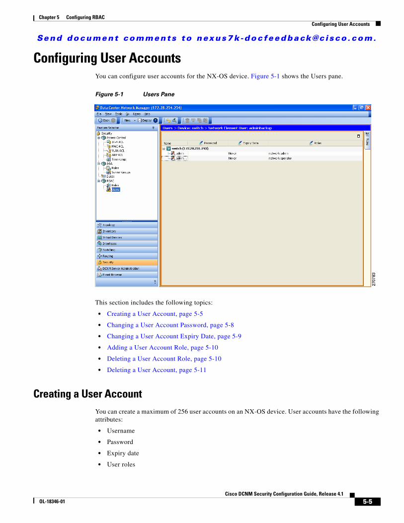
Send document comments to nexus7k -doc feedback@c i sco .com.
Chapter 5 Configuring RBACConfiguring User Accounts
Configuring User AccountsYou can configure user accounts for the NX-OS device. Figure 5-1 shows the Users pane.
Figure 5-1 Users Pane
This section includes the following topics:
• Creating a User Account, page 5-5
• Changing a User Account Password, page 5-8
• Changing a User Account Expiry Date, page 5-9
• Adding a User Account Role, page 5-10
• Deleting a User Account Role, page 5-10
• Deleting a User Account, page 5-11
Creating a User AccountYou can create a maximum of 256 user accounts on an NX-OS device. User accounts have the following attributes:
• Username
• Password
• Expiry date
• User roles
5-5Cisco DCNM Security Configuration Guide, Release 4.1
OL-18346-01
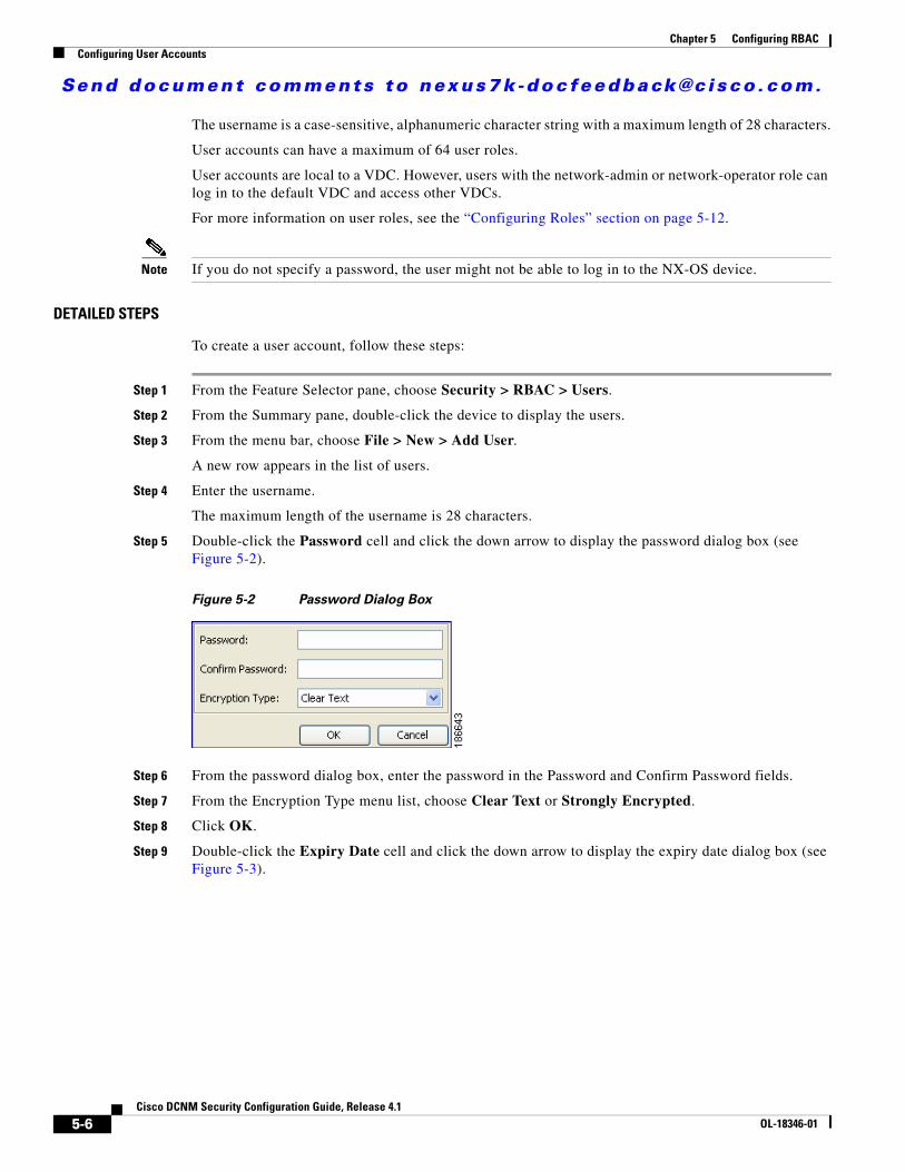
Send document comments to nexus7k -doc feedback@c i sco .com.
Chapter 5 Configuring RBACConfiguring User Accounts
The username is a case-sensitive, alphanumeric character string with a maximum length of 28 characters.
User accounts can have a maximum of 64 user roles.
User accounts are local to a VDC. However, users with the network-admin or network-operator role can log in to the default VDC and access other VDCs.
For more information on user roles, see the “Configuring Roles” section on page 5-12.
Note If you do not specify a password, the user might not be able to log in to the NX-OS device.
DETAILED STEPS
To create a user account, follow these steps:
Step 1 From the Feature Selector pane, choose Security > RBAC > Users.
Step 2 From the Summary pane, double-click the device to display the users.
Step 3 From the menu bar, choose File > New > Add User.
A new row appears in the list of users.
Step 4 Enter the username.
The maximum length of the username is 28 characters.
Step 5 Double-click the Password cell and click the down arrow to display the password dialog box (see Figure 5-2).
Figure 5-2 Password Dialog Box
Step 6 From the password dialog box, enter the password in the Password and Confirm Password fields.
Step 7 From the Encryption Type menu list, choose Clear Text or Strongly Encrypted.
Step 8 Click OK.
Step 9 Double-click the Expiry Date cell and click the down arrow to display the expiry date dialog box (see Figure 5-3).
5-6Cisco DCNM Security Configuration Guide, Release 4.1
OL-18346-01
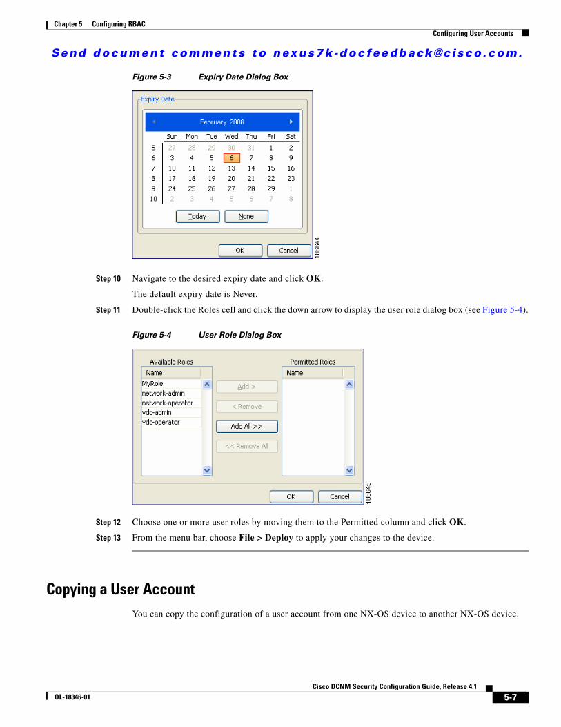
Send document comments to nexus7k -doc feedback@c i sco .com.
Chapter 5 Configuring RBACConfiguring User Accounts
Figure 5-3 Expiry Date Dialog Box
Step 10 Navigate to the desired expiry date and click OK.
The default expiry date is Never.
Step 11 Double-click the Roles cell and click the down arrow to display the user role dialog box (see Figure 5-4).
Figure 5-4 User Role Dialog Box
Step 12 Choose one or more user roles by moving them to the Permitted column and click OK.
Step 13 From the menu bar, choose File > Deploy to apply your changes to the device.
Copying a User AccountYou can copy the configuration of a user account from one NX-OS device to another NX-OS device.
5-7Cisco DCNM Security Configuration Guide, Release 4.1
OL-18346-01
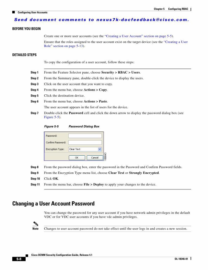
Send document comments to nexus7k -doc feedback@c i sco .com.
Chapter 5 Configuring RBACConfiguring User Accounts
BEFORE YOU BEGIN
Create one or more user accounts (see the “Creating a User Account” section on page 5-5).
Ensure that the roles assigned to the user account exist on the target device (see the “Creating a User Role” section on page 5-13).
DETAILED STEPS
To copy the configuration of a user account, follow these steps:
Step 1 From the Feature Selector pane, choose Security > RBAC > Users.
Step 2 From the Summary pane, double-click the device to display the users.
Step 3 Click on the user account that you want to copy.
Step 4 From the menu bar, choose Actions > Copy.
Step 5 Click the destination device.
Step 6 From the menu bar, choose Actions > Paste.
The user account appears in the list of users for the device.
Step 7 Double-click the Password cell and click the down arrow to display the password dialog box (see Figure 5-5).
Figure 5-5 Password Dialog Box
Step 8 From the password dialog box, enter the password in the Password and Confirm Password fields.
Step 9 From the Encryption Type menu list, choose Clear Text or Strongly Encrypted.
Step 10 Click OK.
Step 11 From the menu bar, choose File > Deploy to apply your changes to the device.
Changing a User Account PasswordYou can change the password for any user account if you have network-admin privileges in the default VDC or for VDC user accounts if you have vdc-admin privileges.
Note Changes to user account password do not take effect until the user logs in and creates a new session.
5-8Cisco DCNM Security Configuration Guide, Release 4.1
OL-18346-01
Send document comments to nexus7k -doc feedback@c i sco .com.
Chapter 5 Configuring RBACConfiguring User Accounts
BEFORE YOU BEGIN
Create one or more user accounts (see the “Creating a User Account” section on page 5-5).
DETAILED STEPS
To change user account passwords, follow these steps:
Step 1 From the Feature Selector pane, choose Security > RBAC > Users.
Step 2 From the Summary pane, double-click the device to display the users.
Step 3 Click the user account to change.
Step 4 Double-click the Password cell and click the down arrow to display the password dialog box (see Figure 5-2).
Step 5 From the password dialog box, enter the password in the Password and Confirm Password fields.
Step 6 From the Encryption Type menu list, choose Clear Text or Strongly Encrypted and click OK.
Step 7 From the menu bar, choose File > Deploy to apply your changes to the device.
Changing a User Account Expiry DateYou can change the expiry date for any user account if you have network-admin privileges in the default VDC or you can change the expiry date for a VDC user account if you have vdc-admin privileges.
Note Changes to the user account expiry date do not take effect until the user logs in and creates a new session.
Note You cannot change expiry date for the default admin user account.
BEFORE YOU BEGIN
Create one or more user accounts (see the “Creating a User Account” section on page 5-5).
DETAILED STEPS
To change a user account expiry date, follow these steps:
Step 1 From the Feature Selector pane, choose Security > RBAC > Users.
Step 2 From the Summary pane, double-click the device to display the users.
Step 3 Click the user account to change.
Step 4 Double-click the Expiry Date cell and click the down arrow to display the expiry date dialog box (see Figure 5-3).
5-9Cisco DCNM Security Configuration Guide, Release 4.1
OL-18346-01
Send document comments to nexus7k -doc feedback@c i sco .com.
Chapter 5 Configuring RBACConfiguring User Accounts
Step 5 Navigate to the desired expiry date and click OK.
The default expiry date is Never.
Step 6 From the menu bar, choose File > Deploy to apply your changes to the device.
Adding a User Account RoleYou can add roles to a user account if you have network-admin privileges in the default VDC or you can add roles for VDC user accounts if you have vdc-admin privileges.
Note Changes to user account roles do not take effect until the user logs in and creates a new session.
Note You cannot add a role to the default admin user account.
BEFORE YOU BEGIN
Create one or more user accounts (see the “Creating a User Account” section on page 5-5).
DETAILED STEPS
To add a user account role, follow these steps:
Step 1 From the Feature Selector pane, choose Security > RBAC > Users.
Step 2 From the Summary pane, double-click the device to display the users.
Step 3 Click the user account to change.
Step 4 Double-click the Roles cell and click the down arrow to display the user roles dialog box (see Figure 5-4).
Step 5 Choose one or more user roles by moving them to the Permitted Roles column and click OK.
Step 6 From the menu bar, choose File > Deploy to apply your changes to the device.
Deleting a User Account RoleYou can delete the roles from a user account if you have network-admin privileges in the default VDC or for VDC user accounts if you have vdc-admin privileges.
Note Changes to a user account role do not take effect until the user logs in and creates a new session.
Note You cannot delete the network-admin role from the default admin user account in the default VDC or the vdc-admin role from the default admin user account in nondefault VDCs.
5-10Cisco DCNM Security Configuration Guide, Release 4.1
OL-18346-01
Send document comments to nexus7k -doc feedback@c i sco .com.
Chapter 5 Configuring RBACConfiguring User Accounts
BEFORE YOU BEGIN
Create one or more user accounts (see the “Creating a User Account” section on page 5-5).
Add a role to the user account (see the “Adding a User Account Role” section on page 5-10.
DETAILED STEPS
To delete a user account role, follow these steps:
Step 1 From the Feature Selector pane, choose Security > RBAC > Users.
Step 2 From the Summary pane, double-click the device to display the users.
Step 3 Click the user account to change.
Step 4 Double-click the Roles cell and click the down arrow to display the user roles dialog box (see Figure 5-4).
Step 5 Delete one or more user roles by moving them to the Available Roles column and click OK.
Step 6 From the menu bar, choose File > Deploy to apply your changes to the device.
Deleting a User AccountYou can delete a user account.
Note You cannot delete the default admin user account.
BEFORE YOU BEGIN
Create one or more user accounts (see the “Creating a User Account” section on page 5-5).
DETAILED STEPS
To delete a user account, follow these steps:
Step 1 From the Feature Selector pane, choose Security > RBAC > Users.
Step 2 From the Summary pane, double-click the device to display the users.
Step 3 Click the user account to delete.
Step 4 From the top menu bar, choose Users > Delete User and click Yes in the confirmation dialog.
The user account name disappears from the user account list.
Step 5 From the menu bar, choose File > Deploy to apply your changes to the device.
5-11Cisco DCNM Security Configuration Guide, Release 4.1
OL-18346-01
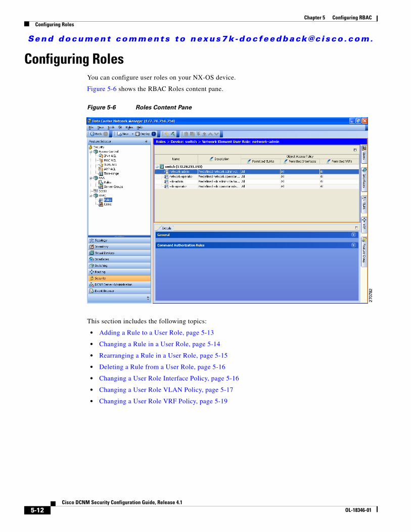
Send document comments to nexus7k -doc feedback@c i sco .com.
Chapter 5 Configuring RBACConfiguring Roles
Configuring RolesYou can configure user roles on your NX-OS device.
Figure 5-6 shows the RBAC Roles content pane.
Figure 5-6 Roles Content Pane
This section includes the following topics:
• Adding a Rule to a User Role, page 5-13
• Changing a Rule in a User Role, page 5-14
• Rearranging a Rule in a User Role, page 5-15
• Deleting a Rule from a User Role, page 5-16
• Changing a User Role Interface Policy, page 5-16
• Changing a User Role VLAN Policy, page 5-17
• Changing a User Role VRF Policy, page 5-19
5-12Cisco DCNM Security Configuration Guide, Release 4.1
OL-18346-01
Send document comments to nexus7k -doc feedback@c i sco .com.
Chapter 5 Configuring RBACConfiguring Roles
Creating a User RoleYou can configure up to 64 user roles in a VDC. You can assign a user role to more that one user account.
DETAILED STEPS
To create user roles, follow these steps:
Step 1 From the Feature Selector pane, choose Security > RBAC > Roles.
Step 2 From the Summary pane, double-click the device to display the roles.
Step 3 From the menu bar, choose File > New > Add Role.
A new row appears in the list of roles.
Step 4 In the Name cell, enter the role name.
The maximum length of the role name is 16 characters.
Step 5 (Optional) In the Description cell, enter the role description.
Step 6 From the menu bar, choose File > Deploy to apply your changes to the device.
Adding a Rule to a User RoleYou can use rules to define the actions that users can perform on the NX-OS device. Each user role can have up to 256 rules.
The rule number that you specify determines the order in which the rules are applied. Rules are applied in descending order. For example, if a role has three rules, rule 3 is applied before rule 2, which is applied before rule 1.
BEFORE YOU BEGIN
Create one or more user roles (see the “Creating a User Role” section on page 5-13).
DETAILED STEPS
To add a rule to a user role, follow these steps:
Step 1 From the Feature Selector pane, choose Security > RBAC > Roles.
Step 2 From the Summary pane, double-click the device to display the user roles.
The Details tab appears in the Details pane.
Step 3 Click the user role to which to add a rule.
Note You cannot modify the default roles network-admin, network-operator, vdc-admin, and vdc-operator.
Step 4 From the Details tab, click Command Authorization Rules.
5-13Cisco DCNM Security Configuration Guide, Release 4.1
OL-18346-01
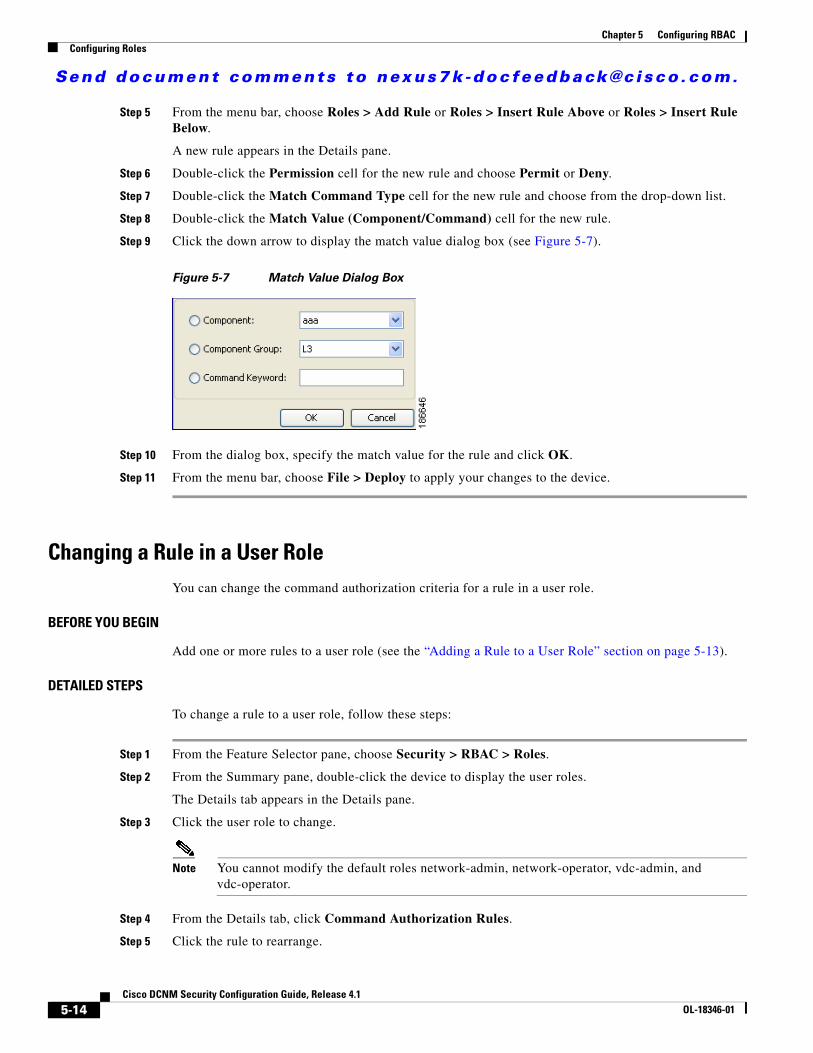
Send document comments to nexus7k -doc feedback@c i sco .com.
Chapter 5 Configuring RBACConfiguring Roles
Step 5 From the menu bar, choose Roles > Add Rule or Roles > Insert Rule Above or Roles > Insert Rule Below.
A new rule appears in the Details pane.
Step 6 Double-click the Permission cell for the new rule and choose Permit or Deny.
Step 7 Double-click the Match Command Type cell for the new rule and choose from the drop-down list.
Step 8 Double-click the Match Value (Component/Command) cell for the new rule.
Step 9 Click the down arrow to display the match value dialog box (see Figure 5-7).
Figure 5-7 Match Value Dialog Box
Step 10 From the dialog box, specify the match value for the rule and click OK.
Step 11 From the menu bar, choose File > Deploy to apply your changes to the device.
Changing a Rule in a User RoleYou can change the command authorization criteria for a rule in a user role.
BEFORE YOU BEGIN
Add one or more rules to a user role (see the “Adding a Rule to a User Role” section on page 5-13).
DETAILED STEPS
To change a rule to a user role, follow these steps:
Step 1 From the Feature Selector pane, choose Security > RBAC > Roles.
Step 2 From the Summary pane, double-click the device to display the user roles.
The Details tab appears in the Details pane.
Step 3 Click the user role to change.
Note You cannot modify the default roles network-admin, network-operator, vdc-admin, and vdc-operator.
Step 4 From the Details tab, click Command Authorization Rules.
Step 5 Click the rule to rearrange.
5-14Cisco DCNM Security Configuration Guide, Release 4.1
OL-18346-01
Send document comments to nexus7k -doc feedback@c i sco .com.
Chapter 5 Configuring RBACConfiguring Roles
Step 6 Double-click the Match Command Type cell for the rule and choose from the drop-down list.
Step 7 Double-click the Match Value (Component/Command) cell for the rule.
Step 8 Click the down arrow to display the match value dialog box (see Figure 5-7 on page 5-14).
Step 9 From the dialog box, specify the match value for the rule and click OK.
Step 10 From the menu bar, choose File > Deploy to apply your changes to the device.
Rearranging a Rule in a User RoleYou can rearrange a rule in a user role.
BEFORE YOU BEGIN
Add one or more rules to a user role (see the “Adding a Rule to a User Role” section on page 5-13).
DETAILED STEPS
To rearrange a rule to a user role, follow these steps:
Step 1 From the Feature Selector pane, choose Security > RBAC > Roles.
Step 2 From the Summary pane, double-click the device to display the user roles.
The Details tab appears in the Details pane.
Step 3 Click the user role to change.
Note You cannot modify the default roles network-admin, network-operator, vdc-admin, and vdc-operator.
Step 4 From the Details tab, click Command Authorization Rules.
Step 5 Click the rule to rearrange.
Step 6 From the menu bar, choose Roles > Move Up or Roles > Move Down.
Step 7 Double-click the Match Value (Component/Command) cell for the rule.
Step 8 Click the down arrow to display the match value dialog box (see Figure 5-7 on page 5-14).
Step 9 From the dialog box, specify the match value for the rule and click OK.
Step 10 From the menu bar, choose File > Deploy to apply your changes to the device.
5-15Cisco DCNM Security Configuration Guide, Release 4.1
OL-18346-01
Send document comments to nexus7k -doc feedback@c i sco .com.
Chapter 5 Configuring RBACConfiguring Roles
Deleting a Rule from a User RoleYou can delete rules from a user role. Each role must have at least one rule.
BEFORE YOU BEGIN
Add one or more rules to a user role (see the “Adding a Rule to a User Role” section on page 5-13).
DETAILED STEPS
To delete a rule from a user role, follow these steps:
Step 1 From the Feature Selector pane, choose Security > RBAC > Roles.
Step 2 From the Summary pane, double-click the device to display the user roles.
The Details tab appears in the Details pane.
Step 3 Click the user role from which to delete the rule.
Note You cannot modify the default roles network-admin, network-operator, vdc-admin, and vdc-operator.
Step 4 From the Details tab, click Command Authorization Rules.
Step 5 Click the rule that you want to delete.
Step 6 From the menu bar, choose Roles > Delete Rule and click Yes in the confirmation dialog box.
The rule disappears from the Details pane.
Step 7 From the menu bar, choose File > Deploy to apply your changes to the device.
Changing a User Role Interface PolicyYou can change a user role interface policy to limit the interfaces that the user can access. By default, a user role allows access to all interfaces in the VDC.
BEFORE YOU BEGIN
Create one or more user roles (see the “Creating a User Role” section on page 5-13).
DETAILED STEPS
To change user role interface policies, follow these steps:
Step 1 From the Feature Selector pane, choose Security > RBAC > Roles.
Step 2 From the Summary pane, double-click the device to display the roles.
Step 3 Click the role to change.
The Details tab appears in the Details pane.
5-16Cisco DCNM Security Configuration Guide, Release 4.1
OL-18346-01
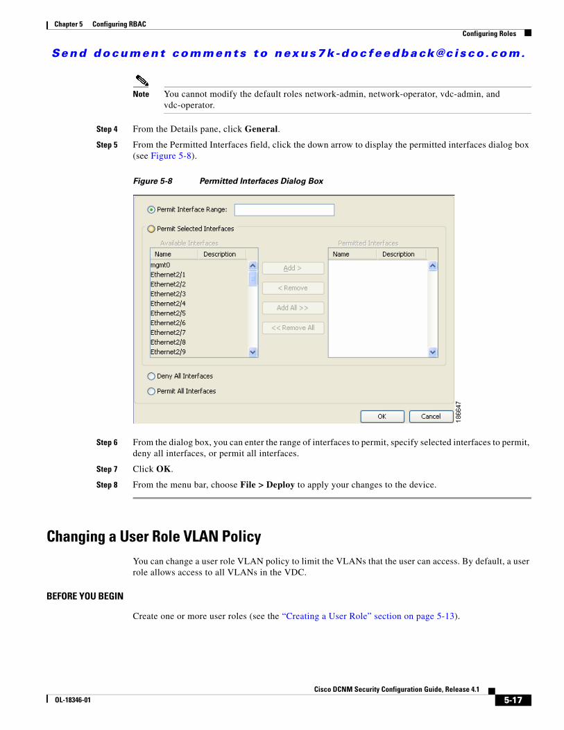
Send document comments to nexus7k -doc feedback@c i sco .com.
Chapter 5 Configuring RBACConfiguring Roles
Note You cannot modify the default roles network-admin, network-operator, vdc-admin, and vdc-operator.
Step 4 From the Details pane, click General.
Step 5 From the Permitted Interfaces field, click the down arrow to display the permitted interfaces dialog box (see Figure 5-8).
Figure 5-8 Permitted Interfaces Dialog Box
Step 6 From the dialog box, you can enter the range of interfaces to permit, specify selected interfaces to permit, deny all interfaces, or permit all interfaces.
Step 7 Click OK.
Step 8 From the menu bar, choose File > Deploy to apply your changes to the device.
Changing a User Role VLAN PolicyYou can change a user role VLAN policy to limit the VLANs that the user can access. By default, a user role allows access to all VLANs in the VDC.
BEFORE YOU BEGIN
Create one or more user roles (see the “Creating a User Role” section on page 5-13).
5-17Cisco DCNM Security Configuration Guide, Release 4.1
OL-18346-01
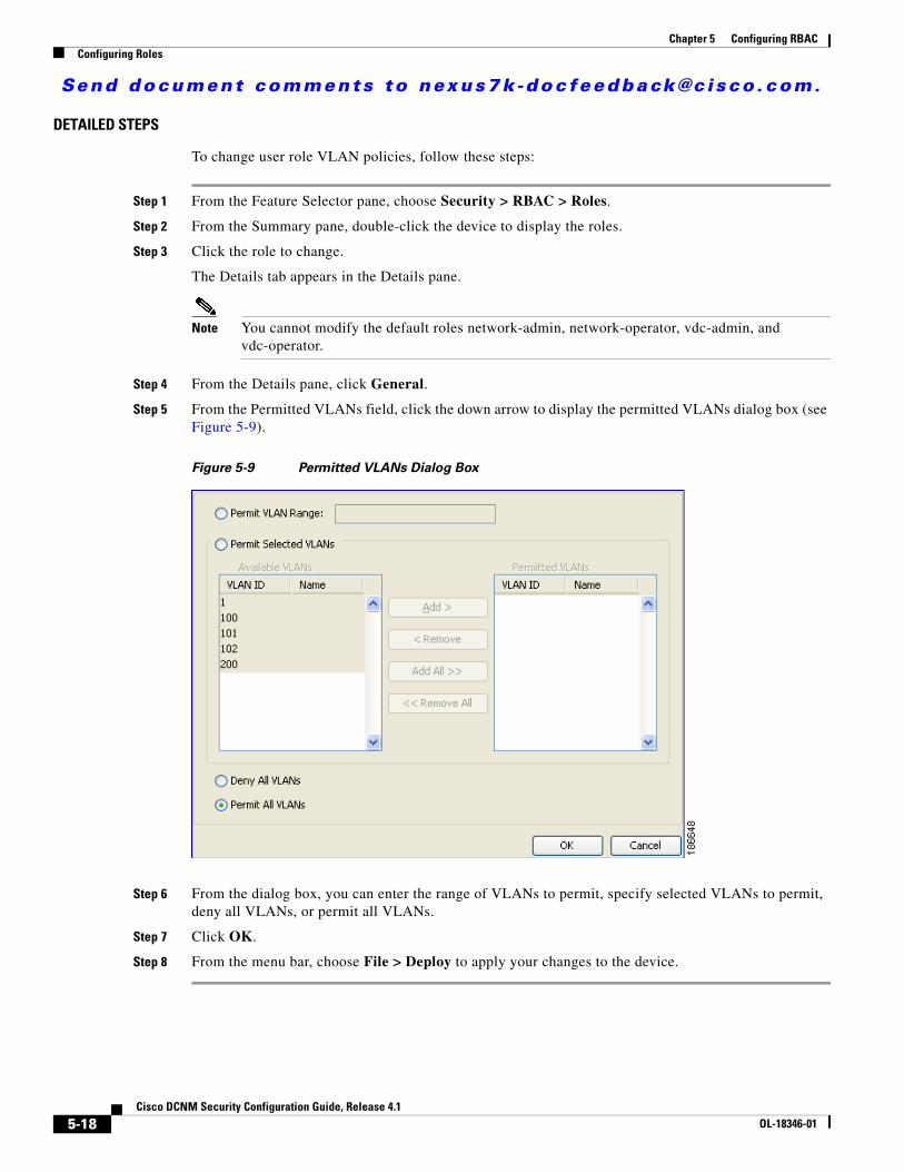
Send document comments to nexus7k -doc feedback@c i sco .com.
Chapter 5 Configuring RBACConfiguring Roles
DETAILED STEPS
To change user role VLAN policies, follow these steps:
Step 1 From the Feature Selector pane, choose Security > RBAC > Roles.
Step 2 From the Summary pane, double-click the device to display the roles.
Step 3 Click the role to change.
The Details tab appears in the Details pane.
Note You cannot modify the default roles network-admin, network-operator, vdc-admin, and vdc-operator.
Step 4 From the Details pane, click General.
Step 5 From the Permitted VLANs field, click the down arrow to display the permitted VLANs dialog box (see Figure 5-9).
Figure 5-9 Permitted VLANs Dialog Box
Step 6 From the dialog box, you can enter the range of VLANs to permit, specify selected VLANs to permit, deny all VLANs, or permit all VLANs.
Step 7 Click OK.
Step 8 From the menu bar, choose File > Deploy to apply your changes to the device.
5-18Cisco DCNM Security Configuration Guide, Release 4.1
OL-18346-01
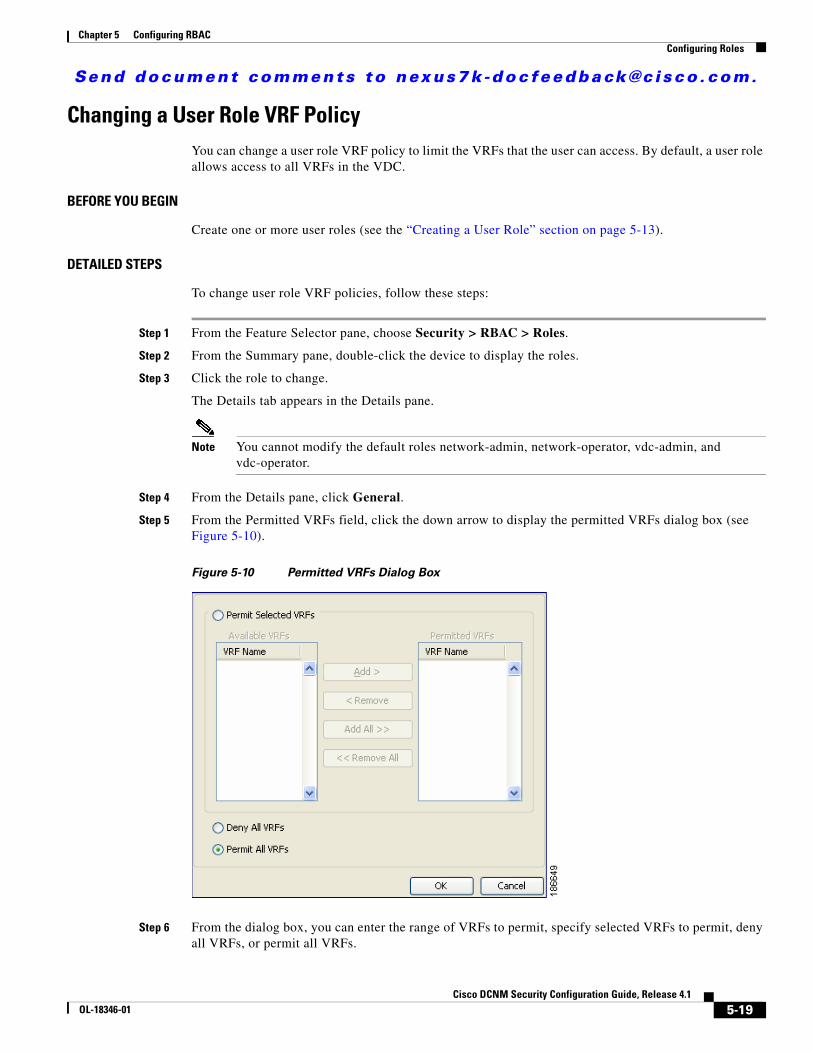
Send document comments to nexus7k -doc feedback@c i sco .com.
Chapter 5 Configuring RBACConfiguring Roles
Changing a User Role VRF PolicyYou can change a user role VRF policy to limit the VRFs that the user can access. By default, a user role allows access to all VRFs in the VDC.
BEFORE YOU BEGIN
Create one or more user roles (see the “Creating a User Role” section on page 5-13).
DETAILED STEPS
To change user role VRF policies, follow these steps:
Step 1 From the Feature Selector pane, choose Security > RBAC > Roles.
Step 2 From the Summary pane, double-click the device to display the roles.
Step 3 Click the role to change.
The Details tab appears in the Details pane.
Note You cannot modify the default roles network-admin, network-operator, vdc-admin, and vdc-operator.
Step 4 From the Details pane, click General.
Step 5 From the Permitted VRFs field, click the down arrow to display the permitted VRFs dialog box (see Figure 5-10).
Figure 5-10 Permitted VRFs Dialog Box
Step 6 From the dialog box, you can enter the range of VRFs to permit, specify selected VRFs to permit, deny all VRFs, or permit all VRFs.
5-19Cisco DCNM Security Configuration Guide, Release 4.1
OL-18346-01
Send document comments to nexus7k -doc feedback@c i sco .com.
Chapter 5 Configuring RBACField Descriptions for RBAC
Step 7 Click OK.
Step 8 From the menu bar, choose File > Deploy to apply your changes to the device.
Copying a User RoleYou can copy the configuration of a user role within an NX-OS device or from one NX-OS device to another NX-OS device.
BEFORE YOU BEGIN
Create one or more user account roles (see the “Creating a User Role” section on page 5-13).
DETAILED STEPS
To copy the configuration of a user account, follow these steps:
Step 1 From the Feature Selector pane, choose Security > RBAC > Roles.
Step 2 From the Summary pane, double-click the device to display the roles.
Step 3 Click the role you that want to copy.
Step 4 From the menu bar, choose Actions > Copy.
Step 5 Click the destination device.
Step 6 From the menu bar, choose Actions > Paste.
The role appears in the list of roles for the device.
Step 7 From the menu bar, choose File > Deploy to apply your changes to the device.
Field Descriptions for RBACThis section includes the following topics:
• Security: RBAC: Roles: Summary Pane, page 5-21
• Security: RBAC: Roles: device: role: Details Tab: General Area, page 5-21
• Security: RBAC: Roles: device: role: Details Tab: Command Authorization Rules Area, page 5-21
• Security: RBAC: Users: Summary Pane, page 5-22
5-20Cisco DCNM Security Configuration Guide, Release 4.1
OL-18346-01
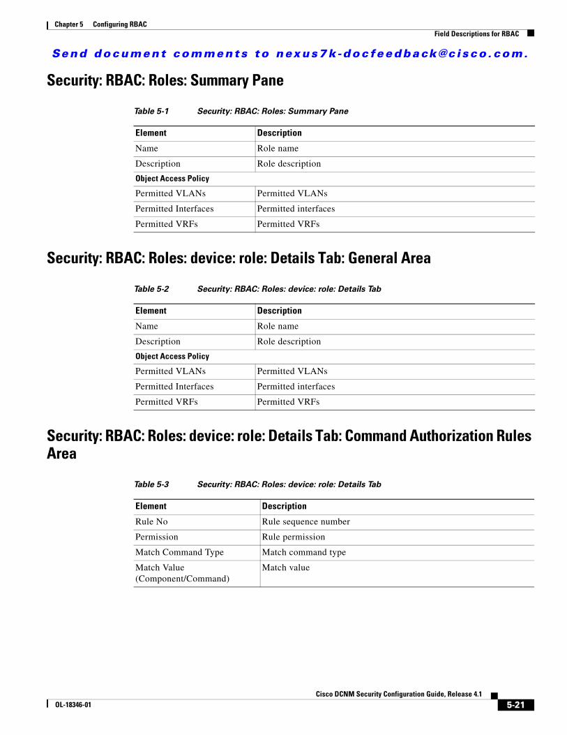
Send document comments to nexus7k -doc feedback@c i sco .com.
Chapter 5 Configuring RBACField Descriptions for RBAC
Security: RBAC: Roles: Summary Pane
Security: RBAC: Roles: device: role: Details Tab: General Area
Security: RBAC: Roles: device: role: Details Tab: Command Authorization Rules Area
Table 5-1 Security: RBAC: Roles: Summary Pane
Element Description
Name Role name
Description Role description
Object Access Policy
Permitted VLANs Permitted VLANs
Permitted Interfaces Permitted interfaces
Permitted VRFs Permitted VRFs
Table 5-2 Security: RBAC: Roles: device: role: Details Tab
Element Description
Name Role name
Description Role description
Object Access Policy
Permitted VLANs Permitted VLANs
Permitted Interfaces Permitted interfaces
Permitted VRFs Permitted VRFs
Table 5-3 Security: RBAC: Roles: device: role: Details Tab
Element Description
Rule No Rule sequence number
Permission Rule permission
Match Command Type Match command type
Match Value (Component/Command)
Match value
5-21Cisco DCNM Security Configuration Guide, Release 4.1
OL-18346-01
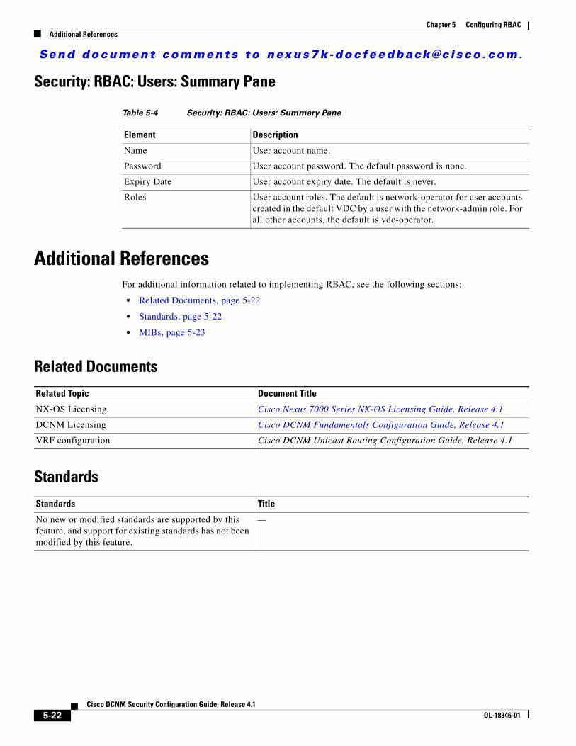
Send document comments to nexus7k -doc feedback@c i sco .com.
Chapter 5 Configuring RBACAdditional References
Security: RBAC: Users: Summary Pane
Additional ReferencesFor additional information related to implementing RBAC, see the following sections:
• Related Documents, page 5-22
• Standards, page 5-22
• MIBs, page 5-23
Related Documents
Standards
Table 5-4 Security: RBAC: Users: Summary Pane
Element Description
Name User account name.
Password User account password. The default password is none.
Expiry Date User account expiry date. The default is never.
Roles User account roles. The default is network-operator for user accounts created in the default VDC by a user with the network-admin role. For all other accounts, the default is vdc-operator.
Related Topic Document Title
NX-OS Licensing Cisco Nexus 7000 Series NX-OS Licensing Guide, Release 4.1
DCNM Licensing Cisco DCNM Fundamentals Configuration Guide, Release 4.1
VRF configuration Cisco DCNM Unicast Routing Configuration Guide, Release 4.1
Standards Title
No new or modified standards are supported by this feature, and support for existing standards has not been modified by this feature.
—
5-22Cisco DCNM Security Configuration Guide, Release 4.1
OL-18346-01
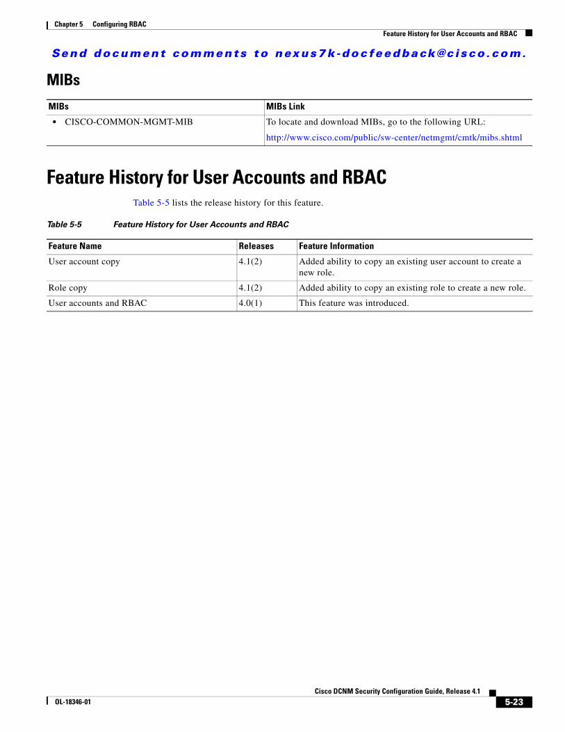
Send document comments to nexus7k -doc feedback@c i sco .com.
Chapter 5 Configuring RBACFeature History for User Accounts and RBAC
MIBs
Feature History for User Accounts and RBACTable 5-5 lists the release history for this feature.
MIBs MIBs Link
• CISCO-COMMON-MGMT-MIB To locate and download MIBs, go to the following URL:
http://www.cisco.com/public/sw-center/netmgmt/cmtk/mibs.shtml
Table 5-5 Feature History for User Accounts and RBAC
Feature Name Releases Feature Information
User account copy 4.1(2) Added ability to copy an existing user account to create a new role.
Role copy 4.1(2) Added ability to copy an existing role to create a new role.
User accounts and RBAC 4.0(1) This feature was introduced.
5-23Cisco DCNM Security Configuration Guide, Release 4.1
OL-18346-01

Send document comments to nexus7k -doc feedback@c i sco .com.
Chapter 5 Configuring RBACFeature History for User Accounts and RBAC
5-24Cisco DCNM Security Configuration Guide, Release 4.1
OL-18346-01
Send document comments to nexus7k -doc feedback@c i sco .com.
CiscOL-18346-01
C H A P T E R6
Configuring 802.1XThis chapter describes how to configure IEEE 802.1X port-based authentication on NX-OS devices.
This chapter includes the following sections:
• Information About 802.1X, page 6-1
• Licensing Requirements for 802.1X, page 6-7
• Prerequisites for 802.1X, page 6-8
• 802.1X Guidelines and Limitations, page 6-8
• Configuring 802.1X, page 6-8
• Displaying 802.1X Statistics, page 6-22
• Field Descriptions for 802.1X, page 6-23
• Additional References, page 6-25
• Feature History for 802.1X, page 6-26
Information About 802.1X802.1X defines a client-server-based access control and authentication protocol that restricts unauthorized clients from connecting to a LAN through publicly accessible ports. The authentication server authenticates each client connected to an NX-OS device port.
Until the client is authenticated, 802.1X access control allows only Extensible Authentication Protocol over LAN (EAPOL) traffic through the port to which the client is connected. After authentication is successful, normal traffic can pass through the port.
This section includes the following topics about 802.1X port-based authentication:
• Device Roles, page 6-2
• Authentication Initiation and Message Exchange, page 6-3
• Ports in Authorized and Unauthorized States, page 6-4
• MAC Address Authentication Bypass, page 6-5
• 802.1X with Port Security, page 6-6
• Supported Topologies, page 6-7
• Virtualization Support, page 6-7
6-1o DCNM Security Configuration Guide, Release 4.1
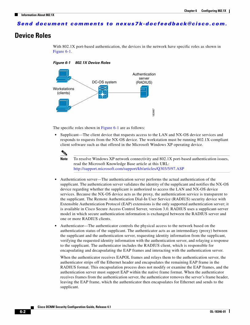
Send document comments to nexus7k -doc feedback@c i sco .com.
Chapter 6 Configuring 802.1XInformation About 802.1X
Device RolesWith 802.1X port-based authentication, the devices in the network have specific roles as shown in Figure 6-1.
Figure 6-1 802.1X Device Roles
The specific roles shown in Figure 6-1 are as follows:
• Supplicant—The client device that requests access to the LAN and NX-OS device services and responds to requests from the NX-OS device. The workstation must be running 802.1X-compliant client software such as that offered in the Microsoft Windows XP operating device.
Note To resolve Windows XP network connectivity and 802.1X port-based authentication issues, read the Microsoft Knowledge Base article at this URL: http://support.microsoft.com/support/kb/articles/Q303/5/97.ASP
• Authentication server—The authentication server performs the actual authentication of the supplicant. The authentication server validates the identity of the supplicant and notifies the NX-OS device regarding whether the supplicant is authorized to access the LAN and NX-OS device services. Because the NX-OS device acts as the proxy, the authentication service is transparent to the supplicant. The Remote Authentication Dial-In User Service (RADIUS) security device with Extensible Authentication Protocol (EAP) extensions is the only supported authentication server; it is available in Cisco Secure Access Control Server, version 3.0. RADIUS uses a supplicant-server model in which secure authentication information is exchanged between the RADIUS server and one or more RADIUS clients.
• Authenticator—The authenticator controls the physical access to the network based on the authentication status of the supplicant. The authenticator acts as an intermediary (proxy) between the supplicant and the authentication server, requesting identity information from the supplicant, verifying the requested identity information with the authentication server, and relaying a response to the supplicant. The authenticator includes the RADIUS client, which is responsible for encapsulating and decapsulating the EAP frames and interacting with the authentication server.
When the authenticator receives EAPOL frames and relays them to the authentication server, the authenticator strips off the Ethernet header and encapsulates the remaining EAP frame in the RADIUS format. This encapsulation process does not modify or examine the EAP frames, and the authentication server must support EAP within the native frame format. When the authenticator receives frames from the authentication server, the authenticator removes the server’s frame header, leaving the EAP frame, which the authenticator then encapsulates for Ethernet and sends to the supplicant.
Workstations(clients)
DC-OS system
Authenticationserver
(RADIUS)
1839
87
6-2Cisco DCNM Security Configuration Guide, Release 4.1
OL-18346-01
Send document comments to nexus7k -doc feedback@c i sco .com.
Chapter 6 Configuring 802.1XInformation About 802.1X
Note The NX-OS device can only be a 802.1X authenticator.
Authentication Initiation and Message ExchangeEither the authenticator (NX-OS device) or the supplicant (client) can initiate authentication. If you enable authentication on a port, the authenticator must initiate authentication when it determines that the port link state transitions from down to up. The authenticator then sends an EAP-request/identity frame to the supplicant to request its identity (typically, the authenticator sends an initial identity/request frame followed by one or more requests for authentication information). When the supplicant receives the frame, it responds with an EAP-response/identity frame.
If the supplicant does not receive an EAP-request/identity frame from the authenticator during bootup, the supplicant can initiate authentication by sending an EAPOL-start frame, which prompts the authenticator to request the supplicant’s identity.
Note If 802.1X is not enabled or supported on the network access device, the NX-OS device drops any EAPOL frames from the supplicant. If the supplicant does not receive an EAP-request/identity frame after three attempts to start authentication, the supplicant transmits data as if the port is in the authorized state. A port in the authorized state means that the supplicant has been successfully authenticated. For more information, see the “Ports in Authorized and Unauthorized States” section on page 6-4.
When the supplicant supplies its identity, the authenticator begins its role as the intermediary, passing EAP frames between the supplicant and the authentication server until authentication succeeds or fails. If the authentication succeeds, the authenticator port becomes authorized. For more information, see the “Ports in Authorized and Unauthorized States” section on page 6-4.
The specific exchange of EAP frames depends on the authentication method being used. Figure 6-2 shows a message exchange initiated by the supplicant using the One-Time-Password (OTP) authentication method with a RADIUS server. OTP authentication device uses a secret pass-phrase to generate a sequence of one-time (single use) passwords. The user’s secret pass-phrase never crosses the network at any time such as during authentication or during pass-phrase changes.
6-3Cisco DCNM Security Configuration Guide, Release 4.1
OL-18346-01
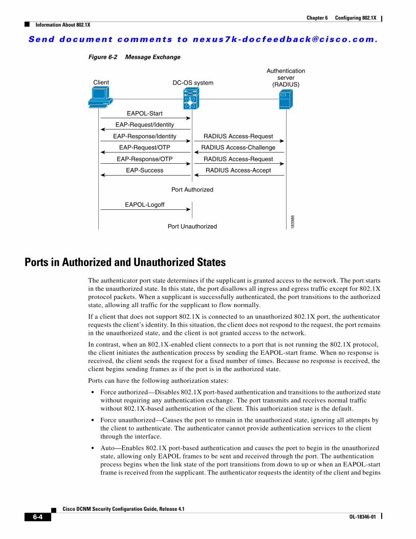
Send document comments to nexus7k -doc feedback@c i sco .com.
Chapter 6 Configuring 802.1XInformation About 802.1X
Figure 6-2 Message Exchange
Ports in Authorized and Unauthorized StatesThe authenticator port state determines if the supplicant is granted access to the network. The port starts in the unauthorized state. In this state, the port disallows all ingress and egress traffic except for 802.1X protocol packets. When a supplicant is successfully authenticated, the port transitions to the authorized state, allowing all traffic for the supplicant to flow normally.
If a client that does not support 802.1X is connected to an unauthorized 802.1X port, the authenticator requests the client’s identity. In this situation, the client does not respond to the request, the port remains in the unauthorized state, and the client is not granted access to the network.
In contrast, when an 802.1X-enabled client connects to a port that is not running the 802.1X protocol, the client initiates the authentication process by sending the EAPOL-start frame. When no response is received, the client sends the request for a fixed number of times. Because no response is received, the client begins sending frames as if the port is in the authorized state.
Ports can have the following authorization states:
• Force authorized—Disables 802.1X port-based authentication and transitions to the authorized state without requiring any authentication exchange. The port transmits and receives normal traffic without 802.1X-based authentication of the client. This authorization state is the default.
• Force unauthorized—Causes the port to remain in the unauthorized state, ignoring all attempts by the client to authenticate. The authenticator cannot provide authentication services to the client through the interface.
• Auto—Enables 802.1X port-based authentication and causes the port to begin in the unauthorized state, allowing only EAPOL frames to be sent and received through the port. The authentication process begins when the link state of the port transitions from down to up or when an EAPOL-start frame is received from the supplicant. The authenticator requests the identity of the client and begins
Client DC-OS system
Port Authorized
Port Unauthorized
EAPOL-Start
EAP-Request/Identity
EAP-Response/Identity
EAP-Request/OTP
EAP-Response/OTP
EAP-Success
RADIUS Access-Request
RADIUS Access-Challenge
RADIUS Access-Request
RADIUS Access-Accept
EAPOL-Logoff
Authenticationserver
(RADIUS)
1839
88
6-4Cisco DCNM Security Configuration Guide, Release 4.1
OL-18346-01
Send document comments to nexus7k -doc feedback@c i sco .com.
Chapter 6 Configuring 802.1XInformation About 802.1X
relaying authentication messages between the client and the authentication server. Each supplicant that attempts to access the network is uniquely identified by the authenticator by using the supplicant’s MAC address.
If the supplicant is successfully authenticated (receives an Accept frame from the authentication server), the port state changes to authorized, and all frames from the authenticated supplicant are allowed through the port. If the authentication fails, the port remains in the unauthorized state, but authentication can be retried. If the authentication server cannot be reached, the authenticator can retransmit the request. If no response is received from the server after the specified number of attempts, authentication fails, and the supplicant is not granted network access.
When a supplicant logs off, it sends an EAPOL-logoff message, which causes the authenticator port to transition to the unauthorized state.
If the link state of a port transitions from up to down, or if an EAPOL-logoff frame is received, the port returns to the unauthorized state.
MAC Address Authentication BypassYou can configure the NX-OS device to authorize a supplicant based on the supplicant MAC address by using the MAC authentication bypass feature. For example, you can enable this feature on interfaces configured for 802.1X that are connected to devices such as printers.
If 802.1X authentication times out while waiting for an EAPOL response from the supplicant, the NX-OS device tries to authorize the client by using MAC authentication bypass.
When you enable the MAC authentication bypass feature an interface, the NX-OS device uses the MAC address as the supplicant identity. The authentication server has a database of supplicant MAC addresses that are allowed network access. After detecting a client on the interface, the NX-OS device waits for an Ethernet packet from the client. The NX-OS device sends the authentication server a RADIUS-access/request frame with a username and password based on the MAC address. If authorization succeeds, the NX-OS device grants the client access to the network. If authorization fails, the NX-OS device assigns the port to the guest VLAN if one is configured.
If an EAPOL packet is detected on the interface during the lifetime of the link, the NX-OS device determines that the device connected to that interface is an 802.1X-capable supplicant and uses 802.1X authentication (not MAC authentication bypass) to authorize the interface. EAPOL history is cleared if the interface link status goes down.
If the NX-OS device already authorized an interface by using MAC authentication bypass and detects an 802.1X supplicant, the NX-OS device does not unauthorize the client connected to the interface. When reauthentication occurs, the NX-OS device uses 802.1X authentication as the preferred reauthentication process if the previous session ended because the Termination-Action RADIUS attribute value is DEFAULT.
Clients that were authorized with MAC authentication bypass can be reauthenticated. The reauthentication process is the same as that for clients that were authenticated with 802.1X. During reauthentication, the port remains in the previously assigned VLAN. If reauthentication is successful, the switch keeps the port in the same VLAN. If reauthentication fails, the switch assigns the port to the guest VLAN, if one is configured.
If reauthentication is based on the Session-Timeout RADIUS attribute (Attribute[27]) and the Termination-Action RADIUS attribute (Attribute [29]) and if the Termination-Action RADIUS attribute (Attribute [29]) action is Initialize, (the attribute value is DEFAULT), the MAC authentication bypass session ends, and connectivity is lost during reauthentication. If MAC authentication bypass is enabled
6-5Cisco DCNM Security Configuration Guide, Release 4.1
OL-18346-01
Send document comments to nexus7k -doc feedback@c i sco .com.
Chapter 6 Configuring 802.1XInformation About 802.1X
and the 802.1X authentication times out, the switch uses the MAC authentication bypass feature to initiate reauthorization. For more information about these AV pairs, see RFC 3580, “IEEE 802.1X Remote Authentication Dial In User Service (RADIUS) Usage Guidelines.”
MAC authentication bypass interacts with the features:
802.1X authentication—You can enable MAC authentication bypass only if 802.1X authentication is enabled on the port.
Port security—See the “802.1X with Port Security” section on page 6-6.
Network admission control (NAC) Layer 2 IP validation—This feature takes effect after an 802.1X port is authenticated with MAC authentication bypass, including hosts in the exception list.
Single Host and Multiple Hosts SupportThe 802.1X feature can restrict traffic on a port to only one endpoint device (single-host mode) or allow traffic from multiple endpoint devices on a port (multi-host mode).
Single-host mode allows traffic from only one endpoint device on the 802.1X port. Once the endpoint device is authenticated, the NX-OS device puts the port in the authorized state. When the endpoint device leaves the port, the NX-OS device put the port back into the unauthorized state. A security violation in 802.1X is defined as a detection of frames sourced from any MAC address other than the single MAC address authorized as a result of successful authentication. In this case, the interface on which this security association violation is detected (EAPOL frame from the other MAC address) will be disabled. Single host mode is applicable only for host-to-switch topology and when a single host is connected to the Layer 2 (Ethernet access port) or Layer 3 port (routed port) of the NX-OS device.
Only the first host has to be authenticated on the 802.1X port configured with multiple host mode. The port is moved to the authorized state after the successful authorization of the first host. Subsequent hosts are not required to be authorized to gain network access once the port is in the authorized state. If the port becomes unauthorized when reauthentication fails or an EAPOL logoff message is received, all attached hosts are denied access to the network. The capability of the interface to shutdown upon security association violation is disabled in multiple host mode. This mode is applicable for both switch-to-switch and host-to-switch topologies.
802.1X with Port SecurityOn NX-OS devices, you can configure 802.1X authentication and port security on the same Layer 2 ports. 802.1X uses RADIUS servers to authenticate the endpoint devices connected to a port. Port security secures ports based on MAC addresses, up to a maximum number of MAC addresses on a port. This difference allows the two features to work together. The NX-OS software supports 802.1X authentication with port security for Layer 2 ports in both host-to-switch and switch-to-switch topologies.
When 802.1X works with port security, both 802.1X and port security must authenticate supplicant MAC addresses. In multi-host mode, port security authenticates only the first supplicant MAC address. After the successful authentication of the first supplicant, the NX-OS device sends subsequent traffic from other supplicants to port security.
For more information on port security, see Chapter 10, “Configuring Port Security.”
6-6Cisco DCNM Security Configuration Guide, Release 4.1
OL-18346-01
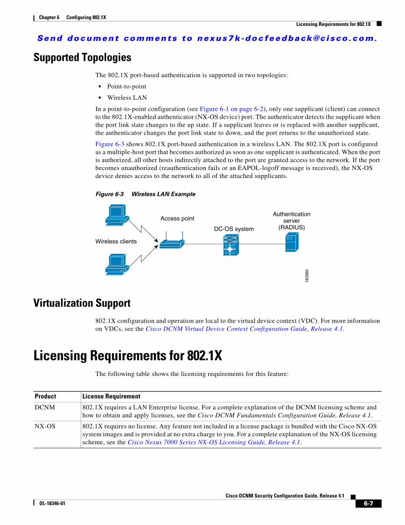
Send document comments to nexus7k -doc feedback@c i sco .com.
Chapter 6 Configuring 802.1XLicensing Requirements for 802.1X
Supported TopologiesThe 802.1X port-based authentication is supported in two topologies:
• Point-to-point
• Wireless LAN
In a point-to-point configuration (see Figure 6-1 on page 6-2), only one supplicant (client) can connect to the 802.1X-enabled authenticator (NX-OS device) port. The authenticator detects the supplicant when the port link state changes to the up state. If a supplicant leaves or is replaced with another supplicant, the authenticator changes the port link state to down, and the port returns to the unauthorized state.
Figure 6-3 shows 802.1X port-based authentication in a wireless LAN. The 802.1X port is configured as a multiple-host port that becomes authorized as soon as one supplicant is authenticated. When the port is authorized, all other hosts indirectly attached to the port are granted access to the network. If the port becomes unauthorized (reauthentication fails or an EAPOL-logoff message is received), the NX-OS device denies access to the network to all of the attached supplicants.
Figure 6-3 Wireless LAN Example
Virtualization Support802.1X configuration and operation are local to the virtual device context (VDC). For more information on VDCs, see the Cisco DCNM Virtual Device Context Configuration Guide, Release 4.1.
Licensing Requirements for 802.1XThe following table shows the licensing requirements for this feature:
Wireless clients
Access point
DC-OS system
Authenticationserver
(RADIUS)
1839
89
Product License Requirement
DCNM 802.1X requires a LAN Enterprise license. For a complete explanation of the DCNM licensing scheme and how to obtain and apply licenses, see the Cisco DCNM Fundamentals Configuration Guide, Release 4.1.
NX-OS 802.1X requires no license. Any feature not included in a license package is bundled with the Cisco NX-OS system images and is provided at no extra charge to you. For a complete explanation of the NX-OS licensing scheme, see the Cisco Nexus 7000 Series NX-OS Licensing Guide, Release 4.1.
6-7Cisco DCNM Security Configuration Guide, Release 4.1
OL-18346-01
Send document comments to nexus7k -doc feedback@c i sco .com.
Chapter 6 Configuring 802.1XPrerequisites for 802.1X
Prerequisites for 802.1X802.1X has the following prerequisites:
• One or more RADIUS servers accessible in the network.
• 802.1X supplicants are attached to the ports, unless you enable MAC address authentication bypass (see the “Disabling 802.1X Authentication on the Device” section on page 6-18).
• Ensure that the logging level for 802.1X in the NX-OS software is set to 5 using the command-line interface (CLI).
switch# configure terminalswitch(config)# logging level dot1x 5
802.1X Guidelines and Limitations802.1X port-based authentication has the following configuration guidelines and limitations:
• The NX-OS software supports 802.1X only on physical ports.
• The NX-OS software does not support 802.1X on subinterfaces or port channels.
• When you enable 802.1X authentication, supplicants are authenticated before any other Layer 2 or Layer 3 features are enabled on an Ethernet interface.
• The NX-OS software supports 802.1X authentication only on Ethernet interfaces that are in a port channel or a trunk.
• The NX-OS software does not support single host mode on trunk interfaces or member interfaces in a port channel.
• The NX-OS software does not support MAC address authentication bypass on trunk interfaces.
• The NX-OS software does not support the following 802.1X protocol enhancements:
– One-to-many logical VLAN name to ID mapping
– Web authorization
– Dynamic domain bridge assignment
– IP telephony
– Guest VLANs
Configuring 802.1XThis section includes the following topics:
• Process for Configuring 802.1X, page 6-9
• Enabling the 802.1X Feature, page 6-11
• Configuring an AAA Authentication Method for 802.1X, page 6-11
• Enabling the 802.1X Feature on an Interface, page 6-12
• Controlling 802.1X Authentication on an Interface, page 6-12
• Enabling Global Periodic Reauthentication, page 6-13
6-8Cisco DCNM Security Configuration Guide, Release 4.1
OL-18346-01
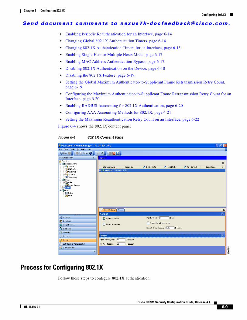
Send document comments to nexus7k -doc feedback@c i sco .com.
Chapter 6 Configuring 802.1XConfiguring 802.1X
• Enabling Periodic Reauthentication for an Interface, page 6-14
• Changing Global 802.1X Authentication Timers, page 6-14
• Changing 802.1X Authentication Timers for an Interface, page 6-15
• Enabling Single Host or Multiple Hosts Mode, page 6-17
• Enabling MAC Address Authentication Bypass, page 6-17
• Disabling 802.1X Authentication on the Device, page 6-18
• Disabling the 802.1X Feature, page 6-19
• Setting the Global Maximum Authenticator-to-Supplicant Frame Retransmission Retry Count, page 6-19
• Configuring the Maximum Authenticator-to-Supplicant Frame Retransmission Retry Count for an Interface, page 6-20
• Enabling RADIUS Accounting for 802.1X Authentication, page 6-20
• Configuring AAA Accounting Methods for 802.1X, page 6-21
• Setting the Maximum Reauthentication Retry Count on an Interface, page 6-22
Figure 6-4 shows the 802.1X content pane.
Figure 6-4 802.1X Content Pane
Process for Configuring 802.1XFollow these steps to configure 802.1X authentication:
6-9Cisco DCNM Security Configuration Guide, Release 4.1
OL-18346-01
Send document comments to nexus7k -doc feedback@c i sco .com.
Chapter 6 Configuring 802.1XConfiguring 802.1X
Step 1 Enable the 802.1X feature (see the “Enabling the 802.1X Feature” section on page 6-11).
Step 2 Configure the connection to the remote RADIUS server (see the “Configuring an AAA Authentication Method for 802.1X” section on page 6-11).
Step 3 Enable 802.1X feature on the Ethernet interfaces (see the “Enabling the 802.1X Feature on an Interface” section on page 6-12).
Step 4 Enable 802.1X authentication on the Ethernet interfaces (see the “Controlling 802.1X Authentication on an Interface” section on page 6-12).
You can perform the following optional maintenance tasks for 802.1X authentication:
• Enable periodic automatic reauthentication (see the “Enabling Periodic Reauthentication for an Interface” section on page 6-14)
• Change the global 802.1X authentication timers (see the “Changing Global 802.1X Authentication Timers” section on page 6-14)
• Change the interface 802.1X authentication timers (see the “Changing 802.1X Authentication Timers for an Interface” section on page 6-15)
• Enable multiple hosts on an interface (see the “Enabling Single Host or Multiple Hosts Mode” section on page 6-17)
• Enable MAC address authentication bypass on an interface (see the “Enabling MAC Address Authentication Bypass” section on page 6-17)
• Disallow 802.1X authentication (see the “Disabling 802.1X Authentication on the Device” section on page 6-18)
• Disable the 802.1X feature (see the “Disabling the 802.1X Feature” section on page 6-19)
• Change the frame retransmission retry count (see the “Configuring the Maximum Authenticator-to-Supplicant Frame Retransmission Retry Count for an Interface” section on page 6-20)
• Enable RADIUS accounting for 802.1X authentication (see the “Configuring AAA Accounting Methods for 802.1X” section on page 6-21)
• Configure AAA accounting for 802.1X (see the “Configuring AAA Accounting Methods for 802.1X” section on page 6-21)
• Change the maximum 802.1X authentication requests (see the “Configuring the Maximum Authenticator-to-Supplicant Frame Retransmission Retry Count for an Interface” section on page 6-20)
• Change the maximum 802.1X reauthentication requests (see the “Setting the Maximum Reauthentication Retry Count on an Interface” section on page 6-22)
6-10Cisco DCNM Security Configuration Guide, Release 4.1
OL-18346-01
Send document comments to nexus7k -doc feedback@c i sco .com.
Chapter 6 Configuring 802.1XConfiguring 802.1X
Enabling the 802.1X FeatureYou must enable the 802.1X feature on the device before authenticating any supplicant devices.
BEFORE YOU BEGIN
Ensure that the logging level for 802.1X in the NX-OS software is set to 5 using the command-line interface (CLI).
switch# configure terminalswitch(config)# logging level dot1x 5
DETAILED STEPS
To enable the 802.1X feature, follow these steps:
Step 1 From the Feature Selector pane, choose Security > Dot1X.
Step 2 From the Summary pane, click a device.
Step 3 From the menu bar, choose Dot1X > Enable 802.1X.
Step 4 From the menu bar, choose File > Deploy to apply your changes to the device.
Configuring an AAA Authentication Method for 802.1XYou can use remote RADIUS servers for 802.1X authentication. You must configure RADIUS servers and RADIUS server groups and specify the default AAA authentication method before the device can perform 802.1X authentication.
For more information on configuring RADIUS servers, see Chapter 3, “Configuring RADIUS.” For information on configuring RADIUS server groups, see Chapter 2, “Configuring AAA.”
BEFORE YOU BEGIN
Obtain the names or addresses for the remote RADIUS server groups.
DETAILED STEPS
To configure AAA authentication methods for 802.1X, follow these steps:
Step 1 From the Feature Selector pane, choose Security > AAA > Rules.
Step 2 From the Summary table pane, click the expand icon by the device to display the list of rules.
Step 3 Click the expand icon by Authentication Rules.
Step 4 From the menu bar, choose Rules > Add Rule.
A new default rule appears in the list and the Authentication Rules tab appears in the Details pane.
Step 5 From the Service Type drop-down list, choose Dot1x.
Step 6 Double-click the cell under Type in the new method.
6-11Cisco DCNM Security Configuration Guide, Release 4.1
OL-18346-01
Send document comments to nexus7k -doc feedback@c i sco .com.
Chapter 6 Configuring 802.1XConfiguring 802.1X
Group appears in the method cell.
Step 7 Double-click the method cell under Server Group Name.
Step 8 Enter the server group name or choose a server group name from the drop-down list and click OK.
Step 9 (Optional) To add more methods, right-click on a method, choose Add Method from the pop-up menu, and repeat Step 6 through Step 8 for the new method.
Step 10 From the menu bar, choose File > Deploy to apply your changes to the device.
Enabling the 802.1X Feature on an InterfaceYou must enable the 802.1X feature on the interfaces you want to use for 802.1X authentication.
BEFORE YOU BEGIN
Enable the 802.1X feature on the device (see the “Enabling the 802.1X Feature” section on page 6-11).
DETAILED STEPS
To enable the 802.1X feature on an interface, follow these steps:
Step 1 From the Feature Selector pane, choose Security > Dot1X.
Step 2 From the Summary pane, double-click a device to display the slots.
Step 3 Double-click a slot to display the interfaces.
Step 4 Click an interface.
Step 5 From the Interface Settings tab, click Enable Dot1X.
Step 6 From the menu bar, choose File > Deploy to apply your changes to the device.
Controlling 802.1X Authentication on an InterfaceYou can control the 802.1X authentication performed on an interface. An interface can have the following 802.1X authentication states:
• Auto—Enables 802.1X authentication on the interface.
• Force-authorized—Disables 802.1X authentication on the interface and allows all traffic on the interface without authentication. This state is the default.
• Force-unauthorized—Disallows all traffic on the interface.
BEFORE YOU BEGIN
Enable the 802.1X feature on the device (see the “Enabling the 802.1X Feature” section on page 6-11).
Enable the 802.1X feature on the interface (see the “Enabling the 802.1X Feature on an Interface” section on page 6-12).
6-12Cisco DCNM Security Configuration Guide, Release 4.1
OL-18346-01
Send document comments to nexus7k -doc feedback@c i sco .com.
Chapter 6 Configuring 802.1XConfiguring 802.1X
DETAILED STEPS
To control the 802.1X authentication on an interface, follow these steps:
Step 1 From the Feature Selector pane, choose Security > Dot1X.
Step 2 From the Summary pane, double-click a device to display the slots.
Step 3 Double-click a slot to display the interfaces.
Step 4 Click an interface.
Step 5 Click the Interface Settings tab.
Step 6 Click General.
Step 7 From the Port Control drop-down list, choose the port control type.
Step 8 From the menu bar, choose File > Deploy to apply your changes to the device.
Enabling Global Periodic ReauthenticationYou can enable global periodic 802.1X reauthentication and specify how often it occurs. If you do not specify a time period before enabling reauthentication, the number of seconds between reauthentication attempts is 3600 (1 hour).
Note During the reauthentication process, the status of an already authenticated supplicant is not disrupted.
BEFORE YOU BEGIN
Enable the 802.1X feature on the device (see the “Enabling the 802.1X Feature” section on page 6-11).
DETAILED STEPS
To enable global period reauthentication, follow these steps:
Step 1 From the Feature Selector pane, choose Security > Dot1X.
Step 2 From the Summary pane, click a device.
Step 3 Click the Global Settings tab.
Step 4 Click General.
Step 5 Check Enable Re-authentication.
Step 6 (Optional) In the Re-auth Period(secs), enter the number of seconds between period reauthentication for supplicants on the interface.
The default is 3600 seconds (10 hours).
Step 7 From the menu bar, choose File > Deploy to apply your changes to the device.
6-13Cisco DCNM Security Configuration Guide, Release 4.1
OL-18346-01
Send document comments to nexus7k -doc feedback@c i sco .com.
Chapter 6 Configuring 802.1XConfiguring 802.1X
Enabling Periodic Reauthentication for an InterfaceYou can enable periodic 802.1X reauthentication on an interface and specify how often it occurs. If you do not specify a time period before enabling reauthentication, the number of seconds between reauthentication defaults to the global value.
Note During the reauthentication process, the status of an already authenticated supplicant is not disrupted.
BEFORE YOU BEGIN
Enable the 802.1X feature on the device (see the “Enabling the 802.1X Feature” section on page 6-11).
Enable the 802.1X feature on the interface (see the “Enabling the 802.1X Feature on an Interface” section on page 6-12).
DETAILED STEPS
To enable periodic reauthentication on an interface, follow these steps:
Step 1 From the Feature Selector pane, choose Security > Dot1X.
Step 2 From the Summary pane, double-click a device to display the slots.
Step 3 Double-click a slot to display the interfaces.
Step 4 Click an interface.
Step 5 Click the Interface Settings tab.
Step 6 Click General.
Step 7 Check Enable Re-authentication.
Step 8 (Optional) In the Re-auth Period(secs), enter the number of seconds between period reauthentication for supplicants on the interface.
The default is the global setting.
Step 9 From the menu bar, choose File > Deploy to apply your changes to the device.
Changing Global 802.1X Authentication TimersThe following global 802.1X authentication timers are supported on the device:
• Quiet-period timer—When the device cannot authenticate the supplicant, the device remains idle for a set period of time, and then tries again. The quiet-period timer value determines the idle period. An authentication failure might occur because the supplicant provided an invalid password. You can provide a faster response time to the user by entering a number smaller than the default. The default is 60 seconds. The range is from 1 to 65535.
• Switch-to-supplicant retransmission period timer—The client responds to the EAP-request/identity frame from the device with an EAP-response/identity frame. If the device does not receive this response, it waits a set period of time (known as the retransmission time) and then retransmits the frame. The default is 30. The range is from 1 to 65535 seconds.
6-14Cisco DCNM Security Configuration Guide, Release 4.1
OL-18346-01
Send document comments to nexus7k -doc feedback@c i sco .com.
Chapter 6 Configuring 802.1XConfiguring 802.1X
Note You can also configure the quiet-period timer and switch-to-supplicant transmission period timer at the interface level (see the “Changing 802.1X Authentication Timers for an Interface” section on page 6-15).
Note You should change the default values only to adjust for unusual circumstances such as unreliable links or specific behavioral problems with certain supplicants and authentication servers.
BEFORE YOU BEGIN
Enable the 802.1X feature on the device (see the “Enabling the 802.1X Feature” section on page 6-11).
DETAILED STEPS
To configure the global 802.1X timers, follow these steps:
Step 1 From the Feature Selector pane, choose Security > Dot1X.
Step 2 From the Summary pane, click a device.
Step 3 Click the Global Settings tab.
Step 4 Click Timers.
Step 5 (Optional) In the Quiet Period(secs) field, enter the number of seconds for the quiet-period timer.
The default is 60 seconds.
Step 6 (Optional) In the TX Period(secs) field, enter the number of seconds for the switch-to-supplicant retransmission timer.
The default is 30 seconds.
Step 7 From the menu bar, choose File > Deploy to apply your changes to the device.
Changing 802.1X Authentication Timers for an InterfaceYou can change the following 802.1X authentication timers on the device interfaces:
• Quiet-period timer—When the device cannot authenticate the supplicant, the switch remains idle for a set period of time and then tries again. The quiet-period timer value determines the idle period. An authentication failure might occur because the supplicant provided an invalid password. You can provide a faster response time to the user by entering a smaller number than the default. The default is the value of the global quiet period timer. The range is from 1 to 65535 seconds.
• Rate-limit timer—The rate-limit period throttles EAPOL-Start packets from supplicants that are sending too many EAPOL-Start packets. The authenticator ignores EAPOL-Start packets from supplicants that have successfully authenticated for the rate-limit period duration. The default value is 0 seconds and the authenticator processes all EAPOL-Start packets. The range is from 1 to 65535 seconds.
6-15Cisco DCNM Security Configuration Guide, Release 4.1
OL-18346-01
Send document comments to nexus7k -doc feedback@c i sco .com.
Chapter 6 Configuring 802.1XConfiguring 802.1X
• Switch-to-authentication-server retransmission timer for Layer 4 packets—The authentication server notifies the switch each time that it receives a Layer 4 packet. If the switch does not receive a notification after sending a packet, the device waits a set period of time and then retransmits the packet. The default is 30 seconds. The range is from 1 to 65535 seconds.
• Switch-to-supplicant retransmission timer for EAP response frames—The supplicant responds to the EAP-request/identity frame from the device with an EAP-response/identity frame. If the device does not receive this response, it waits a set period of time (known as the retransmission time) and then retransmits the frame. The default is 30 seconds. The range is from 1 to 65535 seconds.
• Switch-to-supplicant retransmission timer for EAP request frames—The supplicant notifies the device it that received the EAP request frame. If the authenticator does not receive this notification, it waits a set period of time and then retransmits the frame. The default is the value of the global retransmission period timer. The range is from 1 to 65535 seconds.
Note You should change the default values only to adjust for unusual circumstances such as unreliable links or specific behavioral problems with certain supplicants and authentication servers.
BEFORE YOU BEGIN
Enable the 802.1X feature on the device (see the “Enabling the 802.1X Feature” section on page 6-11).
Enable the 802.1X feature on the interface (see the “Enabling the 802.1X Feature on an Interface” section on page 6-12).
DETAILED STEPS
To configure 802.1X timers on an interface, follow these steps:
Step 1 From the Feature Selector pane, choose Security > Dot1X.
Step 2 From the Summary pane, double-click a device to display the slots.
Step 3 Double-click a slot to display the interfaces.
Step 4 Click an interface.
Step 5 Click the Interface Settings tab.
Step 6 Click Timers.
Step 7 (Optional) In the Quiet Period(secs) field, enter the number of seconds for the quiet-period timer.
The default is the global setting.
Step 8 (Optional) In the TX Period(secs) field, enter the number of seconds for the switch-to-supplicant retransmission timer for EAP request frames.
The default is the global setting.
Step 9 (Optional) In the Supplicant Period(secs) field, enter the number of seconds for the switch-to-supplicant retransmission timer for EAP response frames interval.
The default is 30 seconds.
Step 10 (Optional) In the Server Period(secs) field, enter the number of seconds for the switch-to-authentication-server retransmission timer for Layer 4 packets.
The default is 30 seconds.
6-16Cisco DCNM Security Configuration Guide, Release 4.1
OL-18346-01
Send document comments to nexus7k -doc feedback@c i sco .com.
Chapter 6 Configuring 802.1XConfiguring 802.1X
Step 11 (Optional) In the Rate Limit Period(secs) field, enter the number of seconds for the rate-limit timer.
The default is 30 seconds.
Step 12 From the menu bar, choose File > Deploy to apply your changes to the device.
Enabling Single Host or Multiple Hosts ModeYou can enable single host or multiple hosts mode on an interface.
BEFORE YOU BEGIN
Enable the 802.1X feature on the device (see the “Enabling the 802.1X Feature” section on page 6-11).
Enable the 802.1X feature on the interface (see the “Enabling the 802.1X Feature on an Interface” section on page 6-12).
DETAILED STEPS
To enable a single host or multiple hosts, follow these steps:
Step 1 From the Feature Selector pane, choose Security > Dot1X.
Step 2 From the Summary pane, double-click a device to display the slots.
Step 3 Double-click a slot to display the interfaces.
Step 4 Click an interface.
Step 5 Click the Interface Settings tab.
Step 6 Click General.
Step 7 From the Host Mode drop-down list, choose Single or Multiple.
The default is Single.
Step 8 From the menu bar, choose File > Deploy to apply your changes to the device.
Enabling MAC Address Authentication BypassYou can enable MAC address authentication bypass on an interface that has no supplicant connected.
BEFORE YOU BEGIN
Enable the 802.1X feature on the device (see the “Enabling the 802.1X Feature” section on page 6-11).
Enable the 802.1X feature on the interface (see the “Enabling the 802.1X Feature on an Interface” section on page 6-12).
6-17Cisco DCNM Security Configuration Guide, Release 4.1
OL-18346-01
Send document comments to nexus7k -doc feedback@c i sco .com.
Chapter 6 Configuring 802.1XConfiguring 802.1X
DETAILED STEPS
To enable a single host or multiple hosts, follow these steps:
Step 1 From the Feature Selector pane, choose Security > Dot1X.
Step 2 From the Summary pane, double-click a device to display the slots.
Step 3 Double-click a slot to display the interfaces.
Step 4 Click an interface.
Step 5 Click the Interface Settings tab.
Step 6 Click General.
Step 7 Check the Mac-auth-bypass check box.
The default is disabled.
Step 8 (Optional) Check the EAP Authentication check box to enable MAC authentication bypass for EAP authentication.
Step 9 From the menu bar, choose File > Deploy to apply your changes to the device.
Disabling 802.1X Authentication on the DeviceYou can disable 802.1X authentication on the device. By default, the NX-OS software enables 802.1X authentication after you enable the 802.1X feature. However, when you disable the 802.1x feature, the configuration is removed from the device. The NX-OS software allow you to disable 802.1X authentication without losing the 802.1X configuration.
Note When you disable 802.1X authentication, the port mode for all interfaces defaults to force-authorized regardless of the configured port mode (see the “Controlling 802.1X Authentication on an Interface” section on page 6-12). When you reenable 802.1X authentication, the NX-OS software restores the configured port mode on the interfaces.
BEFORE YOU BEGIN
Enable the 802.1X feature on the device (see the “Enabling the 802.1X Feature” section on page 6-11).
DETAILED STEPS
To disable the 802.1X authentication, follow these steps:
Step 1 From the Feature Selector pane, choose Security > Dot1X.
Step 2 From the Summary pane, click a device.
Step 3 Click the Global Settings tab.
Step 4 Click General.
Step 5 Uncheck Sys Auth Enable.
The default is enabled.
6-18Cisco DCNM Security Configuration Guide, Release 4.1
OL-18346-01
Send document comments to nexus7k -doc feedback@c i sco .com.
Chapter 6 Configuring 802.1XConfiguring 802.1X
Step 6 From the menu bar, choose File > Deploy to apply your changes to the device.
Disabling the 802.1X FeatureYou can disable the 802.1X feature on the device.
Caution Disabling 802.1X removes all 802.1X configuration from the device. If you want to stop 802.1X authentication, see the “Disabling 802.1X Authentication on the Device” section on page 6-18.
BEFORE YOU BEGIN
Enable the 802.1X feature on the device (see the “Enabling the 802.1X Feature” section on page 6-11).
DETAILED STEPS
To disable the 802.1X feature, follow these steps:
Step 1 From the Feature Selector pane, choose Security > Dot1X.
Step 2 From the Summary pane, click a device.
Step 3 From the menu bar, choose Dot1X > Disable 802.1X.
Step 4 From the menu bar, choose File > Deploy to apply your changes to the device.
Setting the Global Maximum Authenticator-to-Supplicant Frame Retransmission Retry Count
In addition to changing the authenticator-to-supplicant retransmission time, you can set the number of times that the device sends an EAP-request/identity frame (assuming no response is received) to the supplicant before restarting the authentication process.
Note You should change the default value of this command only to adjust for unusual circumstances such as unreliable links or specific behavioral problems with certain supplicants and authentication servers.
BEFORE YOU BEGIN
Enable the 802.1X feature on the device (see the “Enabling the 802.1X Feature” section on page 6-11).
DETAILED STEPS
To set the global maximum authenticator-to-supplicant frame retransmission retry count, follow these steps:
Step 1 From the Feature Selector pane, choose Security > Dot1X.
6-19Cisco DCNM Security Configuration Guide, Release 4.1
OL-18346-01
Send document comments to nexus7k -doc feedback@c i sco .com.
Chapter 6 Configuring 802.1XConfiguring 802.1X
Step 2 From the Summary pane, click a device.
Step 3 Click the Global Settings tab.
Step 4 Click General.
Step 5 In the Max Request field, enter the maximum request retry count.
The default is 2.
Step 6 From the menu bar, choose File > Deploy to apply your changes to the device.
Configuring the Maximum Authenticator-to-Supplicant Frame Retransmission Retry Count for an Interface
You can configure the maximum number of times that the device retransmits authentication requests to the supplicant on an interface before the session times out. The default is 2 times and the range is from 1 to 10.
BEFORE YOU BEGIN
Enable the 802.1X feature on the device (see the “Enabling the 802.1X Feature” section on page 6-11).
DETAILED STEPS
To set the maximum authenticator-to-supplicant frame retransmission retry count for an interface, follow these steps:
Step 1 From the Feature Selector pane, choose Security > Dot1X.
Step 2 From the Summary pane, double-click a device to display the slots.
Step 3 Double-click a slot to display the interfaces.
Step 4 Click an interface.
Step 5 Click the Interface Settings tab.
Step 6 Click General.
Step 7 In the Max Request field, enter the maximum request retry count.
The default is 2.
Step 8 From the menu bar, choose File > Deploy to apply your changes to the device.
Enabling RADIUS Accounting for 802.1X AuthenticationYou can enable RADIUS accounting for the 802.1X authentication activity.
BEFORE YOU BEGIN
Enable the 802.1X feature on the device (see the “Enabling the 802.1X Feature” section on page 6-11).
6-20Cisco DCNM Security Configuration Guide, Release 4.1
OL-18346-01
Send document comments to nexus7k -doc feedback@c i sco .com.
Chapter 6 Configuring 802.1XConfiguring 802.1X
DETAILED STEPS
To enable RADIUS accounting for 802.1X authentication, follow these steps:
Step 1 From the Feature Selector pane, choose Security > Dot1X.
Step 2 From the Summary pane, click a device.
Step 3 Click the Global Settings tab.
Step 4 Click General.
Step 5 Check RADIUS Accounting.
The default is disabled.
Step 6 From the menu bar, choose File > Deploy to apply your changes to the device.
Configuring AAA Accounting Methods for 802.1XYou can enable AAA accounting Methods for the 802.1X feature.
BEFORE YOU BEGIN
Enable the 802.1X feature on the device (see the “Enabling the 802.1X Feature” section on page 6-11).
DETAILED STEPS
To configure AAA accounting methods for 802.1X, follow these steps:
Step 1 From the Feature Selector pane, choose Security > AAA > Rules.
Step 2 From the Summary table pane, click the desired device.
Step 3 Click the expand icon by the device to display the list of rules.
Step 4 Click Accounting Rules.
Step 5 Click the expand icon by Accounting Rules.
Step 6 From the menu bar, choose Rules > Add Rule.
A new default rule appears in the list and the Authentication Rules tab appears in the Details pane.
Step 7 From the Service Type drop-down list, choose Dot1x.
Step 8 Double-click the cell under Type in the new method.
Group appears in the method cell.
Step 9 Double-click the method cell under Server Group Name.
Step 10 Enter the server group name or choose a server group name from the drop-down list and click OK.
Step 11 (Optional) To add more methods, right-click on a method, choose Add Method from the pop-up menu, and repeat Step 6 through Step 8 for the new method.
Step 12 From the menu bar, choose File > Deploy to apply your changes to the device.
6-21Cisco DCNM Security Configuration Guide, Release 4.1
OL-18346-01
Send document comments to nexus7k -doc feedback@c i sco .com.
Chapter 6 Configuring 802.1XDisplaying 802.1X Statistics
Setting the Maximum Reauthentication Retry Count on an InterfaceYou can set the maximum number of times that the device retransmits reauthentication requests to the supplicant on an interface before the session times out. The default is 2 times and the range is from 1 to 10.
BEFORE YOU BEGIN
Enable the 802.1X feature on the NX-OS device (see the “Enabling the 802.1X Feature” section on page 6-11).
DETAILED STEPS
To configure maximum reauthentication retry count on an interface, follow these steps:
Step 1 From the Feature Selector pane, choose Security > Dot1X.
Step 2 From the Summary pane, double-click a device to display the slots.
Step 3 Double-click a slot to display the interfaces.
Step 4 Click an interface.
Step 5 Click the Interface Settings tab.
Step 6 Click General.
Step 7 In the Max Reauth Request field, enter the maximum reauthentication request retry count.
The default is 2.
Step 8 From the menu bar, choose File > Deploy to apply your changes to the device.
Displaying 802.1X StatisticsYou can display the statistics that the device maintains for the 802.1X activity.
BEFORE YOU BEGIN
Enable the 802.1X feature on the device (see the “Enabling the 802.1X Feature” section on page 6-11).
DETAILED STEPS
To display RADIUS server statistics, follow these steps:
Step 1 From the Feature Selector pane, choose Security > Dot1X.
Step 2 From the Summary pane, click a device.
Step 3 From the Details pane, click the Statistics tab for 802.1X statistics for the device.
Step 4 From the Summary pane, double-click a device to display the slots.
Step 5 Double-click a slot to display the interfaces.
6-22Cisco DCNM Security Configuration Guide, Release 4.1
OL-18346-01
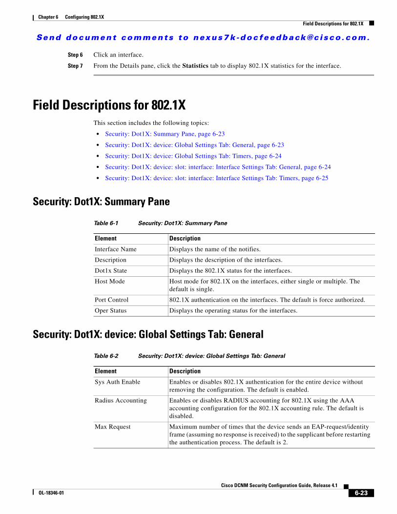
Send document comments to nexus7k -doc feedback@c i sco .com.
Chapter 6 Configuring 802.1XField Descriptions for 802.1X
Step 6 Click an interface.
Step 7 From the Details pane, click the Statistics tab to display 802.1X statistics for the interface.
Field Descriptions for 802.1XThis section includes the following topics:
• Security: Dot1X: Summary Pane, page 6-23
• Security: Dot1X: device: Global Settings Tab: General, page 6-23
• Security: Dot1X: device: Global Settings Tab: Timers, page 6-24
• Security: Dot1X: device: slot: interface: Interface Settings Tab: General, page 6-24
• Security: Dot1X: device: slot: interface: Interface Settings Tab: Timers, page 6-25
Security: Dot1X: Summary Pane
Security: Dot1X: device: Global Settings Tab: General
Table 6-1 Security: Dot1X: Summary Pane
Element Description
Interface Name Displays the name of the notifies.
Description Displays the description of the interfaces.
Dot1x State Displays the 802.1X status for the interfaces.
Host Mode Host mode for 802.1X on the interfaces, either single or multiple. The default is single.
Port Control 802.1X authentication on the interfaces. The default is force authorized.
Oper Status Displays the operating status for the interfaces.
Table 6-2 Security: Dot1X: device: Global Settings Tab: General
Element Description
Sys Auth Enable Enables or disables 802.1X authentication for the entire device without removing the configuration. The default is enabled.
Radius Accounting Enables or disables RADIUS accounting for 802.1X using the AAA accounting configuration for the 802.1X accounting rule. The default is disabled.
Max Request Maximum number of times that the device sends an EAP-request/identity frame (assuming no response is received) to the supplicant before restarting the authentication process. The default is 2.
6-23Cisco DCNM Security Configuration Guide, Release 4.1
OL-18346-01
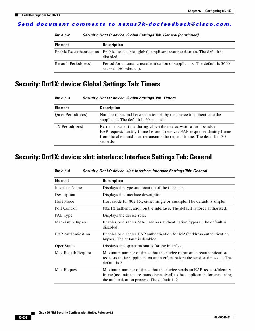
Send document comments to nexus7k -doc feedback@c i sco .com.
Chapter 6 Configuring 802.1XField Descriptions for 802.1X
Security: Dot1X: device: Global Settings Tab: Timers
Security: Dot1X: device: slot: interface: Interface Settings Tab: General
Enable Re-authentication Enables or disables global supplicant reauthentication. The default is disabled.
Re-auth Period(secs) Period for automatic reauthentication of supplicants. The default is 3600 seconds (60 minutes).
Table 6-3 Security: Dot1X: device: Global Settings Tab: Timers
Element Description
Quiet Period(secs) Number of second between attempts by the device to authenticate the supplicant. The default is 60 seconds.
TX Period(secs) Retransmission time during which the device waits after it sends a EAP-request/identity frame before it receives EAP-response/identity frame from the client and then retransmits the request frame. The default is 30 seconds.
Table 6-4 Security: Dot1X: device: slot: interface: Interface Settings Tab: General
Element Description
Interface Name Displays the type and location of the interface.
Description Displays the interface description.
Host Mode Host mode for 802.1X, either single or multiple. The default is single.
Port Control 802.1X authentication on the interface. The default is force authorized.
PAE Type Displays the device role.
Mac-Auth-Bypass Enables or disables MAC address authentication bypass. The default is disabled.
EAP Authentication Enables or disables EAP authentication for MAC address authentication bypass. The default is disabled.
Oper Status Displays the operation status for the interface.
Max Reauth Request Maximum number of times that the device retransmits reauthentication requests to the supplicant on an interface before the session times out. The default is 2.
Max Request Maximum number of times that the device sends an EAP-request/identity frame (assuming no response is received) to the supplicant before restarting the authentication process. The default is 2.
Table 6-2 Security: Dot1X: device: Global Settings Tab: General (continued)
Element Description
6-24Cisco DCNM Security Configuration Guide, Release 4.1
OL-18346-01
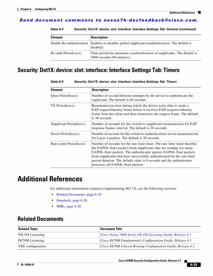
Send document comments to nexus7k -doc feedback@c i sco .com.
Chapter 6 Configuring 802.1XAdditional References
Security: Dot1X: device: slot: interface: Interface Settings Tab: Timers
Additional ReferencesFor additional information related to implementing 802.1X, see the following sections:
• Related Documents, page 6-25
• Standards, page 6-26
• MIBs, page 6-26
Related Documents
Enable Re-authentication Enables or disables global supplicant reauthentication. The default is disabled.
Re-auth Period(secs) Time period for automatic reauthentication of supplicants. The default is 3600 seconds (60 minutes).
Table 6-5 Security: Dot1X: device: slot: interface: Interface Settings Tab: Timers
Element Description
Quiet Period(secs) Number of second between attempts by the device to authenticate the supplicant. The default is 60 seconds.
TX Period(secs) Retransmission time during which the device waits after it sends a EAP-request/identity frame before it receives EAP-response/identity frame from the client and then retransmits the request frame. The default is 30 seconds.
Supplicant Period(secs) Number of seconds for the switch-to-supplicant retransmission for EAP response frames interval. The default is 30 seconds.
Server Period(secs) Number of seconds for the switch-to-authentication-server retransmission for Layer 4 packets. The default is 30 seconds.
Rate Limit Period(secs) Number of seconds for the rate limit timer. The rate limit timer throttles the EAPOL-Start packets from supplicants that are sending too many EAPOL-Start packets. The authenticator ignores EAPOL-Start packets from supplicants that have successfully authenticated for the rate-limit period duration. The default value is 0 seconds and the authenticator processes all EAPOL-Start packets.
Table 6-4 Security: Dot1X: device: slot: interface: Interface Settings Tab: General (continued)
Element Description
Related Topic Document Title
NX-OS Licensing Cisco Nexus 7000 Series NX-OS Licensing Guide, Release 4.1
DCNM Licensing Cisco DCNM Fundamentals Configuration Guide, Release 4.1
VRF configuration Cisco DCNM Unicast Routing Configuration Guide, Release 4.1
6-25Cisco DCNM Security Configuration Guide, Release 4.1
OL-18346-01
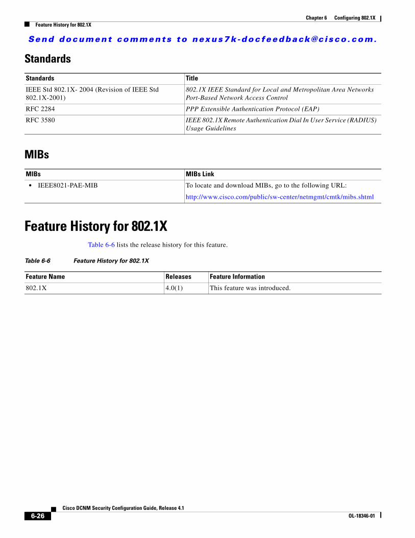
Send document comments to nexus7k -doc feedback@c i sco .com.
Chapter 6 Configuring 802.1XFeature History for 802.1X
Standards
MIBs
Feature History for 802.1XTable 6-6 lists the release history for this feature.
Standards Title
IEEE Std 802.1X- 2004 (Revision of IEEE Std 802.1X-2001)
802.1X IEEE Standard for Local and Metropolitan Area Networks Port-Based Network Access Control
RFC 2284 PPP Extensible Authentication Protocol (EAP)
RFC 3580 IEEE 802.1X Remote Authentication Dial In User Service (RADIUS) Usage Guidelines
MIBs MIBs Link
• IEEE8021-PAE-MIB To locate and download MIBs, go to the following URL:
http://www.cisco.com/public/sw-center/netmgmt/cmtk/mibs.shtml
Table 6-6 Feature History for 802.1X
Feature Name Releases Feature Information
802.1X 4.0(1) This feature was introduced.
6-26Cisco DCNM Security Configuration Guide, Release 4.1
OL-18346-01
Send document comments to nexus7k -doc feedback@c i sco .com.
CiscOL-18346-01
C H A P T E R7
Configuring IP ACLsThis chapter describes how to configure IP access control lists (ACLs) on NX-OS devices.
Unless otherwise specified, the term IP ACL refers to IPv4 and IPv6ACLs.
This chapter includes the following sections:
• Information About ACLs, page 7-1
• Licensing Requirements for IP ACLs, page 7-10
• Prerequisites for IP ACLs, page 7-10
• Guidelines and Limitations, page 7-10
• Configuring IP ACLs, page 7-11
• Displaying and Clearing IP ACL Statistics, page 7-16
• Field Descriptions for IPv4 ACLs, page 7-16
• Field Descriptions for IPv6 ACLs, page 7-21
• Configuring Time Ranges, page 7-27
• Field Descriptions for Time Ranges, page 7-30
• Additional References, page 7-31
• Feature History for IP ACLs, page 7-31
Information About ACLsAn ACL is an ordered set of rules that you can use to filter traffic. Each rule specifies a set of conditions that a packet must satisfy to match the rule. When the device determines that an ACL applies to a packet, it tests the packet against the conditions of all rules. The first matching rule determines whether the packet is permitted or denied. If there is no match, the device applies the applicable default rule. The device continues processing packets that are permitted and drops packets that are denied. For more information, see the “Implicit Rules” section on page 7-5.
You can use ACLs to protect networks and specific hosts from unnecessary or unwanted traffic. For example, you could use ACLs to disallow HTTP traffic from a high-security network to the Internet. You could also use ACLs to allow HTTP traffic but only to specific sites, using the IP address of the site to identify it in an IP ACL.
This section includes the following topics:
• ACL Types and Applications, page 7-2
7-1o DCNM Security Configuration Guide, Release 4.1
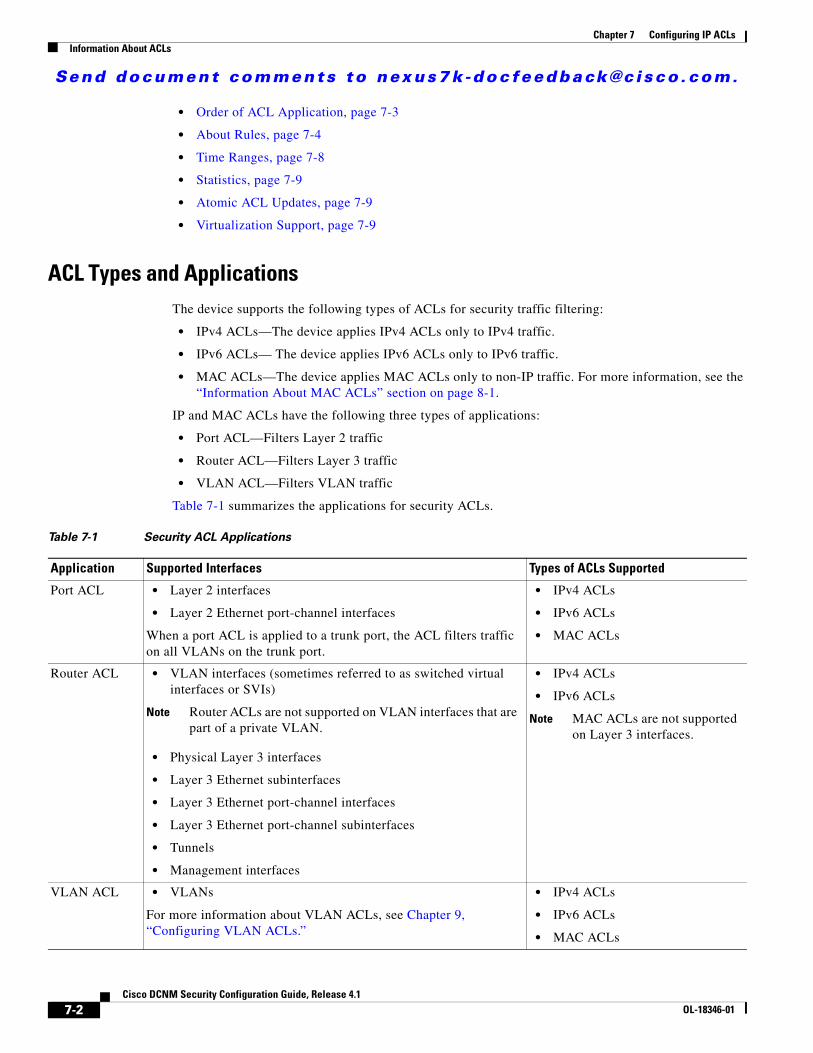
Send document comments to nexus7k -doc feedback@c i sco .com.
Chapter 7 Configuring IP ACLsInformation About ACLs
• Order of ACL Application, page 7-3
• About Rules, page 7-4
• Time Ranges, page 7-8
• Statistics, page 7-9
• Atomic ACL Updates, page 7-9
• Virtualization Support, page 7-9
ACL Types and ApplicationsThe device supports the following types of ACLs for security traffic filtering:
• IPv4 ACLs—The device applies IPv4 ACLs only to IPv4 traffic.
• IPv6 ACLs— The device applies IPv6 ACLs only to IPv6 traffic.
• MAC ACLs—The device applies MAC ACLs only to non-IP traffic. For more information, see the “Information About MAC ACLs” section on page 8-1.
IP and MAC ACLs have the following three types of applications:
• Port ACL—Filters Layer 2 traffic
• Router ACL—Filters Layer 3 traffic
• VLAN ACL—Filters VLAN traffic
Table 7-1 summarizes the applications for security ACLs.
Table 7-1 Security ACL Applications
Application Supported Interfaces Types of ACLs Supported
Port ACL • Layer 2 interfaces
• Layer 2 Ethernet port-channel interfaces
When a port ACL is applied to a trunk port, the ACL filters traffic on all VLANs on the trunk port.
• IPv4 ACLs
• IPv6 ACLs
• MAC ACLs
Router ACL • VLAN interfaces (sometimes referred to as switched virtual interfaces or SVIs)
Note Router ACLs are not supported on VLAN interfaces that are part of a private VLAN.
• Physical Layer 3 interfaces
• Layer 3 Ethernet subinterfaces
• Layer 3 Ethernet port-channel interfaces
• Layer 3 Ethernet port-channel subinterfaces
• Tunnels
• Management interfaces
• IPv4 ACLs
• IPv6 ACLs
Note MAC ACLs are not supported on Layer 3 interfaces.
VLAN ACL • VLANs
For more information about VLAN ACLs, see Chapter 9, “Configuring VLAN ACLs.”
• IPv4 ACLs
• IPv6 ACLs
• MAC ACLs
7-2Cisco DCNM Security Configuration Guide, Release 4.1
OL-18346-01
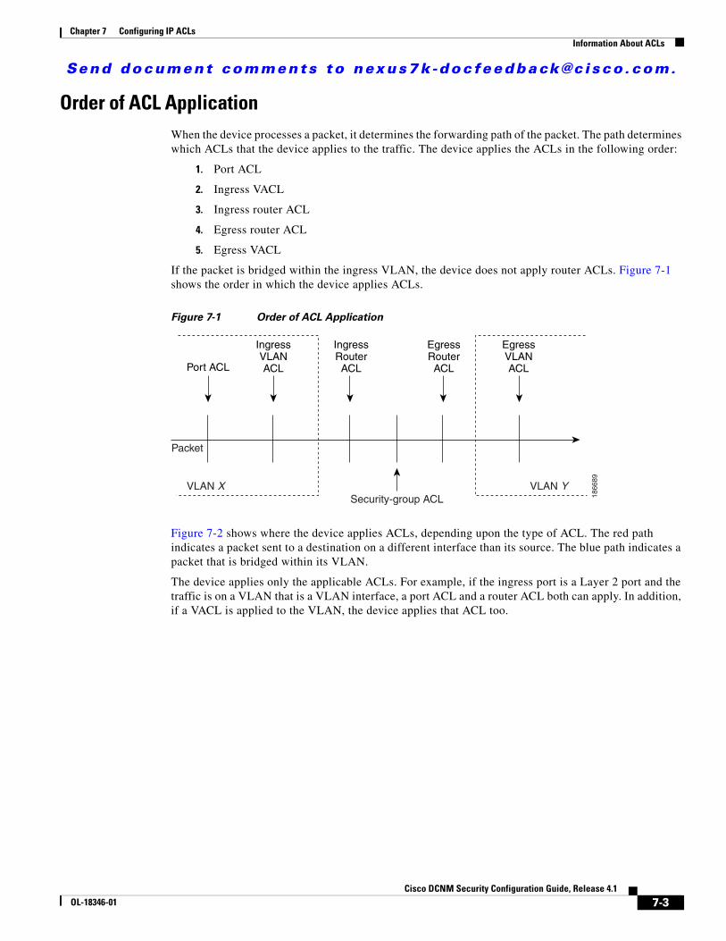
Send document comments to nexus7k -doc feedback@c i sco .com.
Chapter 7 Configuring IP ACLsInformation About ACLs
Order of ACL ApplicationWhen the device processes a packet, it determines the forwarding path of the packet. The path determines which ACLs that the device applies to the traffic. The device applies the ACLs in the following order:
1. Port ACL
2. Ingress VACL
3. Ingress router ACL
4. Egress router ACL
5. Egress VACL
If the packet is bridged within the ingress VLAN, the device does not apply router ACLs. Figure 7-1 shows the order in which the device applies ACLs.
Figure 7-1 Order of ACL Application
Figure 7-2 shows where the device applies ACLs, depending upon the type of ACL. The red path indicates a packet sent to a destination on a different interface than its source. The blue path indicates a packet that is bridged within its VLAN.
The device applies only the applicable ACLs. For example, if the ingress port is a Layer 2 port and the traffic is on a VLAN that is a VLAN interface, a port ACL and a router ACL both can apply. In addition, if a VACL is applied to the VLAN, the device applies that ACL too.
Port ACL
IngressVLANACL
EgressVLANACL
IngressRouterACL
EgressRouterACL
Packet
VLAN X VLAN YSecurity-group ACL 18
6689
7-3Cisco DCNM Security Configuration Guide, Release 4.1
OL-18346-01
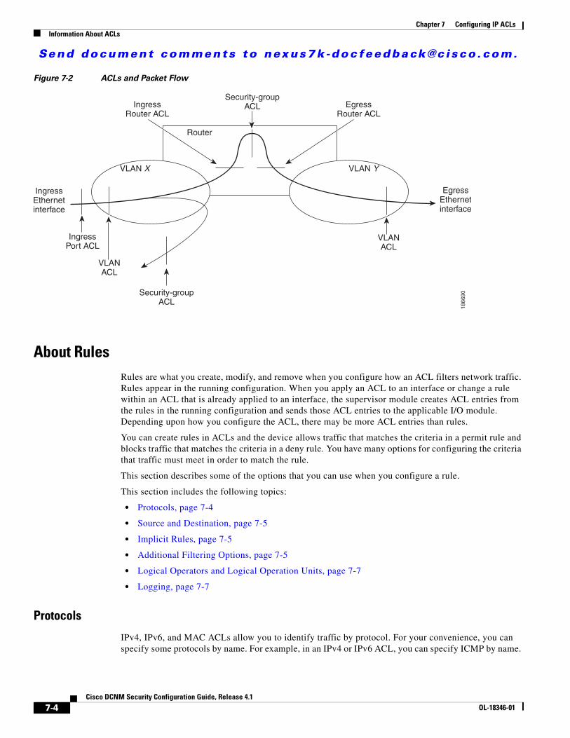
Send document comments to nexus7k -doc feedback@c i sco .com.
Chapter 7 Configuring IP ACLsInformation About ACLs
Figure 7-2 ACLs and Packet Flow
About RulesRules are what you create, modify, and remove when you configure how an ACL filters network traffic. Rules appear in the running configuration. When you apply an ACL to an interface or change a rule within an ACL that is already applied to an interface, the supervisor module creates ACL entries from the rules in the running configuration and sends those ACL entries to the applicable I/O module. Depending upon how you configure the ACL, there may be more ACL entries than rules.
You can create rules in ACLs and the device allows traffic that matches the criteria in a permit rule and blocks traffic that matches the criteria in a deny rule. You have many options for configuring the criteria that traffic must meet in order to match the rule.
This section describes some of the options that you can use when you configure a rule.
This section includes the following topics:
• Protocols, page 7-4
• Source and Destination, page 7-5
• Implicit Rules, page 7-5
• Additional Filtering Options, page 7-5
• Logical Operators and Logical Operation Units, page 7-7
• Logging, page 7-7
Protocols
IPv4, IPv6, and MAC ACLs allow you to identify traffic by protocol. For your convenience, you can specify some protocols by name. For example, in an IPv4 or IPv6 ACL, you can specify ICMP by name.
VLAN X VLAN Y
VLANACL
VLANACL
EgressRouter ACL
IngressRouter ACL
IngressPort ACL
Router
Security-groupACL
Security-groupACL
IngressEthernetinterface
EgressEthernetinterface
1866
90
7-4Cisco DCNM Security Configuration Guide, Release 4.1
OL-18346-01
Send document comments to nexus7k -doc feedback@c i sco .com.
Chapter 7 Configuring IP ACLsInformation About ACLs
You can specify any protocol by number. In MAC ACLs, you can specify protocols by the Ethertype number of the protocol, which is a hexadecimal number. For example, you can use 0x0800 to specify IP traffic in a MAC ACL rule.
In IPv4 and IPv6 ACLs, you can specify protocols by the integer that represents the Internet protocol number. For example, you can use 115 to specify Layer 2 Tunneling Protocol (L2TP) traffic.
Source and Destination
In each rule, you specify the source and the destination of the traffic that matches the rule. You can specify both the source and destination as a specific host, a network or group of hosts, or any host. How you specify the source and destination depends on whether you are configuring IPv4, IPv6, or MAC ACLs.
Implicit Rules
IP and MAC ACLs have implicit rules, which means that although these rules do not appear in the running configuration, the device applies them to traffic when no other rules in an ACL match. When you configure the device to maintain per-rule statistics for an ACL, the device does not maintain statistics for implicit rules.
All IPv4 ACLs include the following implicit rule:
deny ip any any
This implicit rule ensures that the device denies unmatched IP traffic.
All IPv6 ACLs include the following implicit rules:
permit icmp any any nd-napermit icmp any any nd-nspermit icmp any any router-advertisementpermit icmp any any router-solicitationdeny ipv6 any any
Unless you configure an IPv6 ACL with a rule that denies ICMPv6 neighbor discovery messages, the first four rules ensure that the device permits neighbor discovery advertisement and solicitation messages. The fifth rule ensures that the device denies unmatched IPv6 traffic.
Note If you explicitly configure an IPv6 ACL with a deny ipv6 any any rule, the implicit permit rules can never permit traffic. If you explicitly configure a deny ipv6 any any rule but want to permit ICMPv6 neighbor discovery messages, explicitly configure a rule for all five implicit IPv6 ACL rules.
All MAC ACLs include the following implicit rule:
deny any any protocol
This implicit rule ensures that the device denies the unmatched traffic, regardless of the protocol specified in the Layer 2 header of the traffic.
Additional Filtering Options
You can identify traffic by using additional options. These options differ by ACL type. The following list includes most but not all additional filtering options:
• IPv4 ACLs support the following additional filtering options:
7-5Cisco DCNM Security Configuration Guide, Release 4.1
OL-18346-01
Send document comments to nexus7k -doc feedback@c i sco .com.
Chapter 7 Configuring IP ACLsInformation About ACLs
– Layer 4 protocol
– Authentication Header Protocol
– Enhanced Interior Gateway Routing Protocol (EIGRP)
– Encapsulating Security Payload
– General Routing Encapsulation (GRE)
– KA9Q NOS-compatible IP-over-IP tunneling
– Open Shortest Path First (OSPF)
– Payload Compression Protocol
– Protocol-independent multicast (PIM)
– TCP and UDP ports
– ICMP types and codes
– IGMP types
– Precedence level
– Differentiated Services Code Point (DSCP) value
– TCP packets with the ACK, FIN, PSH, RST, SYN, or URG bit set
– Established TCP connections
– Packet length
• IPv6 ACLs support the following additional filtering options:
– Layer 4 protocol
– Authentication Header Protocol
– Encapsulating Security Payload
– Payload Compression Protocol
– Stream Control Transmission Protocol (SCTP)
– SCTP, TCP, and UDP ports
– ICMP types and codes
– IGMP types
– Flow label
– DSCP value
– TCP packets with the ACK, FIN, PSH, RST, SYN, or URG bit set
– Established TCP connections
– Packet length
• MAC ACLs support the following additional filtering options:
– Layer 3 protocol
– VLAN ID
– Class of Service (CoS)
7-6Cisco DCNM Security Configuration Guide, Release 4.1
OL-18346-01
Send document comments to nexus7k -doc feedback@c i sco .com.
Chapter 7 Configuring IP ACLsInformation About ACLs
Logical Operators and Logical Operation Units
IP ACL rules for TCP and UDP traffic can use logical operators to filter traffic based on port numbers. The device stores operator-operand couples in registers called logical operator units (LOUs). Cisco Nexus 7000-series devices support 104 LOUs.
The LOU usage for each type of operator is as follows:
• eq—Is never stored in an LOU
• gt—Uses 1/2 LOU
• lt—Uses 1/2 LOU
• neq—Uses 1/2 LOU
• range—Uses 1 LOU
The following guidelines determine when the devices store operator-operand couples in LOUs:
• If the operator or operand differs from other operator-operand couples that are used in other rules, the couple is stored in an LOU.
For example, the operator-operand couples “gt 10” and “gt 11” would be stored separately in half an LOU each. The couples “gt 10” and “lt 10” would also be stored separately.
• Whether the operator-operand couple is applied to a source port or a destination port in the rule affects LOU usage. Identical couples are stored separately when one of the identical couples is applied to a source port and the other couple is applied to a destination port.
For example, if a rule applies the operator-operand couple “gt 10” to a source port and another rule applies a “gt 10” couple to a destination port, both couples would also be stored in half an LOU, resulting in the use of one whole LOU. Any additional rules using a “gt 10” couple would not result in further LOU usage.
Logging
You can enable the device to create an informational log message for packets that match a rule.
Note ACL logging supports ACL processing that occurs on I/O modules only. ACL logging does not support ACL processing that occurs on a supervisor module. For more information about ACL processing on a supervisor module, see the “Guidelines and Limitations” section on page 7-10.
The log message contains the following information about the packet:
• Protocol
• Status of whether the packet is a TCP, UDP, or ICMP packet, or if the packet is only a numbered packet
• Source and destination address
• Source and destination port numbers, if applicable
7-7Cisco DCNM Security Configuration Guide, Release 4.1
OL-18346-01
Send document comments to nexus7k -doc feedback@c i sco .com.
Chapter 7 Configuring IP ACLsInformation About ACLs
Time RangesYou can use time ranges to control when an ACL rule is in effect. For example, if the device determines that a particular ACL applies to traffic arriving on an interface, and a rule in the ACL uses a time range that is not in effect, the device does not compare the traffic to that rule. The device evaluates time ranges based on its clock.
When you apply an ACL that uses time ranges, the device updates the affected I/O module whenever a time range referenced in the ACL starts or ends. Updates that are initiated by time ranges occur on a best-effort priority. If the device is especially busy when a time range causes an update, the device may delay the update by up to a few seconds.
IPv4, IPv6,and MAC ACLs support time ranges. When the device applies an ACL to traffic, the rules in effect are as follows:
• All rules without a time range specified.
• Rules with a time range that includes the second when the device applies the ACL to traffic.
The device supports named, reusable time ranges, which allows you to configure a time range once and specify it by name when you configure many ACL rules. Time range names have a maximum length of 64 alphanumeric characters.
A time range contains one or more rules. The two types of rules are as follows:
• Absolute—A rule with a specific start date and time, specific end date and time, both, or neither. The following items describe how the presence or absence of a start or end date and time affect whether an absolute time range rule is active:
– Start and end date and time both specified—The time range rule is active when the current time is later than the start date and time and earlier than the end date and time.
– Start date and time specified with no end date and time—The time range rule is active when the current time is later than the start date and time.
– No start date and time with end date and time specified—The time range rule is active when the current time is earlier than the end date and time.
– No start or end date and time specified—The time range rule is always active.
For example, you could prepare your network to allow access to a new subnet by specifying a time range that allows access beginning at midnight of the day that you plan to place the subnet online. You can use that time range in ACL rules that apply to the subnet. After the start time and date have passed, the device automatically begins applying the rules that use this time range when it applies the ACLs that contain the rules.
• Periodic—A rule that is active one or more times per week. For example, you could use a periodic time range to allow access to a lab subnet only during work hours on a weekdays. The device automatically applies ACL rules that use this time range only when the range is active and when it applies the ACLs that contain the rules.
Note The order of rules in a time range does not affect how a device evaluates whether a time range is active.
Time ranges also allow you to include remarks, which you can use to insert comments into a time range. Remarks have a maximum length of 100 alphanumeric characters.
The device determines whether a time range is active as follows:
• The time range contains one or more absolute rules—The time range is active if the current time is within one or more absolute rules.
7-8Cisco DCNM Security Configuration Guide, Release 4.1
OL-18346-01
Send document comments to nexus7k -doc feedback@c i sco .com.
Chapter 7 Configuring IP ACLsInformation About ACLs
• The time range contains one or more periodic rules—The time range is active if the current time is within one or more periodic rules.
• The time range contains both absolute and periodic rules—The time range is active if the current time is within one or more absolute rules and within one or more periodic rules.
When a time range contains both absolute and periodic rules, the periodic rules can only be active when at least one absolute rule is active.
StatisticsThe device can maintain global statistics for each rule that you configure in IPv4, IPv6, and MAC ACLs. If an ACL is applied to multiple interfaces, the maintained rule statistics are the sum of packet matches (hits) on all the interfaces on which that ACL is applied.
Note • The device does not support interface-level ACL statistics.
• ACL statistics are not supported if the DHCP snooping feature is enabled.
For each ACL that you configure, you can specify whether the device maintains statistics for that ACL, which allows you to turn ACL statistics on or off as needed to monitor traffic filtered by an ACL or to help troubleshoot the configuration of an ACL.
The device does not maintain statistics for implicit rules in an ACL. For example, the device does not maintain a count of packets that match the implicit deny ip any any rule at the end of all IPv4 ACLs. If you want to maintain statistics for implicit rules, you must explicitly configure the ACL with rules that are identical to the implicit rules. For more information, see the “Implicit Rules” section on page 7-5.
For information about displaying IP ACL statistics, see the “Displaying and Clearing IP ACL Statistics” section on page 7-16. For information about displaying MAC ACL statistics, see the “Displaying and Clearing MAC ACL Statistics” section on page 8-6.
Atomic ACL UpdatesBy default, when a supervisor module of a Cisco Nexus 7000 Series device updates an I/O module with changes to an ACL, it performs an atomic ACL update. An atomic update does not disrupt traffic that the updated ACL applies to; however, an atomic update requires that an I/O module that receives an ACL update has enough available resources to store each updated ACL entry in addition to all pre-existing entries in the affected ACL. After the update occurs, the additional resources used for the update are freed. If the I/O module lacks the required resources, the device generates an error message and the ACL update to the I/O module fails.
If an I/O module lacks required resources, you can disable atomic updates by using the command-line interface of the device. DCNM cannot configure the atomic ACL update feature. For more information, see the Cisco Nexus 7000 Series NX-OS Security Configuration Guide, Release 4.1.
Virtualization SupportThe following information applies to IP and MAC ACLs used in Virtual Device Contexts (VDCs):
• ACLs are unique per VDC. You cannot use an ACL that you created in one VDC in a different VDC.
7-9Cisco DCNM Security Configuration Guide, Release 4.1
OL-18346-01
Send document comments to nexus7k -doc feedback@c i sco .com.
Chapter 7 Configuring IP ACLsLicensing Requirements for IP ACLs
• Because ACLs are not shared by VDCs, you can reuse ACL names in different VDCs.
• The device does not limit ACLs or rules on a per-VDC basis.
Licensing Requirements for IP ACLsThe following table shows the licensing requirements for this feature:
Prerequisites for IP ACLsIP ACLs have the following prerequisites:
• You must be familiar with IP addressing and protocols to configure IP ACLs.
• You must be familiar with the interface types that you want to configure with ACLs.
Guidelines and LimitationsIP ACLs have the following configuration guidelines and limitations:
• In most cases, ACL processing for IP packets are processed on the I/O modules. In some circumstances, processing occurs on the supervisor module, which is slower than the processing that occurs on I/O modules. Packets are processed on the supervisor module in the following circumstances:
– Management interface traffic is always processed on the supervisor module.
– IP packets exiting a Layer 3 interface that has an egress ACL with a large number of rules may be sent to the supervisor module.
ACL logging does not support ACL processing that occurs on the supervisor module.
• When you apply an ACL that uses time ranges, the device updates the ACL entries on the affected I/O modules whenever a time range referenced in an ACL entry starts or ends. Updates that are initiated by time ranges occur on a best-effort priority. If the device is especially busy when a time range causes an update, the device may delay the update by up to a few seconds.
• To apply an IP ACL to a VLAN interface, you must have enabled VLAN interfaces globally. For more information about VLAN interfaces, see the Cisco DCNM Interfaces Configuration Guide, Release 4.1.
• ACL statistics are not supported if the DHCP Snooping feature is enabled.
Product License Requirement
DCNM IP ACLs require no license. Any feature not included in a license package is bundled with the Cisco DCNM and is provided at no charge to you. For a complete explanation of the DCNM licensing scheme, see the Cisco DCNM Fundamentals Configuration Guide, Release 4.1.
NX-OS IP ACLs require no license. Any feature not included in a license package is bundled with the Cisco NX-OS system images and is provided at no extra charge to you. For a complete explanation of the NX-OS licensing scheme, see the Cisco Nexus 7000 Series NX-OS Licensing Guide, Release 4.1.
7-10Cisco DCNM Security Configuration Guide, Release 4.1
OL-18346-01
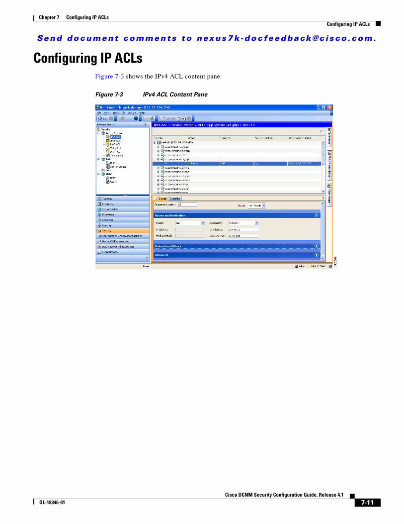
Send document comments to nexus7k -doc feedback@c i sco .com.
Chapter 7 Configuring IP ACLsConfiguring IP ACLs
Configuring IP ACLsFigure 7-3 shows the IPv4 ACL content pane.
Figure 7-3 IPv4 ACL Content Pane
7-11Cisco DCNM Security Configuration Guide, Release 4.1
OL-18346-01
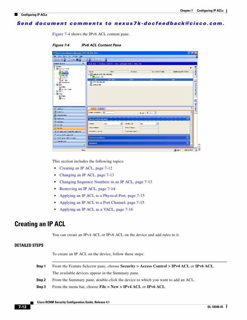
Send document comments to nexus7k -doc feedback@c i sco .com.
Chapter 7 Configuring IP ACLsConfiguring IP ACLs
Figure 7-4 shows the IPv6 ACL content pane.
Figure 7-4 IPv6 ACL Content Pane
This section includes the following topics:
• Creating an IP ACL, page 7-12
• Changing an IP ACL, page 7-13
• Changing Sequence Numbers in an IP ACL, page 7-13
• Removing an IP ACL, page 7-14
• Applying an IP ACL to a Physical Port, page 7-15
• Applying an IP ACL to a Port Channel, page 7-15
• Applying an IP ACL as a VACL, page 7-16
Creating an IP ACLYou can create an IPv4 ACL or IPv6 ACL on the device and add rules to it.
DETAILED STEPS
To create an IP ACL on the device, follow these steps:
Step 1 From the Feature Selector pane, choose Security > Access Control > IPv4 ACL or IPv6 ACL.
The available devices appear in the Summary pane.
Step 2 From the Summary pane, double-click the device to which you want to add an ACL.
Step 3 From the menu bar, choose File > New > IPv4 ACL or IPv6 ACL.
7-12Cisco DCNM Security Configuration Guide, Release 4.1
OL-18346-01
Send document comments to nexus7k -doc feedback@c i sco .com.
Chapter 7 Configuring IP ACLsConfiguring IP ACLs
A new row appears in the Summary pane. The Details tab appears in the Details pane.
Step 4 From the Details tab, in the Name field, type a name for the ACL.
Step 5 (Optional) If you want the device to maintain global statistics for rules in this MAC ACL, check Statistics.
Step 6 For each rule that you want to add to the ACL, from the menu bar, choose File > New and choose the type of rule. From the Details tab, configure fields as needed.
Step 7 From the menu bar, choose File > Deploy to apply your changes to the device.
Changing an IP ACLYou can change, reorder, add, and remove rules in an existing IPv4 or IPv6 ACL.
DETAILED STEPS
To change an IP ACL, follow these steps:
Step 1 From the Feature Selector pane, choose Security > Access Control > IPv4 ACL or IPv6 ACL.
The available devices appear in the Summary pane.
Step 2 From the Summary pane, double-click the device that has the ACL that you want to change and then double-click the ACL.
The ACLs on the device and the rules of the ACL that you double-clicked appear in the Summary pane.
Step 3 (Optional) If you change whether the device maintains global statistics for rules in this IP ACL, click the ACL in the Summary pane. On the Details tab, check or uncheck Statistics as needed.
Step 4 (Optional) If you want to change the details of a rule, click the rule in the Summary pane. From the Details tab, configure fields as needed.
Step 5 (Optional) If you want to add a rule, click the ACL in the Summary pane and then from the menu bar, choose File > New and choose the type of rule. On the Details tab, configure fields as needed.
Step 6 (Optional) If you want to remove a rule, click the rule and then from the menu bar, choose Actions > Delete.
Step 7 (Optional) If you want to move a rule to a different position in the ACL, click the rule in the Summary pane and then from the menu bar, choose one of the following, as applicable:
• Actions > Move Up
• Actions > Move Down
The rule swaps places and sequence numbers with the rule above it or below it, as you chose.
Step 8 From the menu bar, choose File > Deploy to apply your changes to the device.
Changing Sequence Numbers in an IP ACLYou can change all the sequence numbers assigned to the rules in an IP ACL.
7-13Cisco DCNM Security Configuration Guide, Release 4.1
OL-18346-01
Send document comments to nexus7k -doc feedback@c i sco .com.
Chapter 7 Configuring IP ACLsConfiguring IP ACLs
DETAILED STEPS
To change sequence numbers in an IP ACL, follow these steps:
Step 1 From the Feature Selector pane, choose Security > Access Control > IPv4 ACL or IPv6 ACL.
The available devices appear in the Summary pane.
Step 2 From the Summary pane, double-click the device that has the ACL that you want to change and then double-click the ACL.
The ACLs on the device and the rules of the ACL that you double-clicked appear in the Summary pane. The Seq No column shows the sequence number assigned to each rule.
Step 3 Click the rule whose sequence number you want to change.
The Details pane shows the Sequence Number field for the rule.
Step 4 Click the Sequence Number field, edit the number, and press Tab.
In the Summary pane, the new sequence number appears and, if applicable, the rule moves to the position determined by the new sequence number.
Step 5 From the menu bar, choose File > Deploy to apply your changes to the device.
Removing an IP ACLYou can remove an IP ACL from the device.
BEFORE YOU BEGIN
Ensure that you know whether the ACL is applied to an interface. The device allows you to remove ACLs that are currently applied. Removing an ACL does not affect the configuration of interfaces where you have applied the ACL. Instead, the device considers the removed ACL to be empty.
DETAILED STEPS
To remove an IP ACL from the device, follow these steps:
Step 1 From the Feature Selector pane, choose Security > Access Control > IPv4 ACL or IPv6 ACL.
Available devices appear in the Summary pane.
Step 2 From the Summary pane, double-click the device from which you want to remove an ACL.
The ACLs currently on the device appear in the Summary pane.
Step 3 Click the ACL that you want to remove.
Step 4 From the menu bar, choose Actions > Delete.
The ACL disappears from the Summary pane.
Step 5 From the menu bar, choose File > Deploy to apply your changes to the device.
7-14Cisco DCNM Security Configuration Guide, Release 4.1
OL-18346-01
Send document comments to nexus7k -doc feedback@c i sco .com.
Chapter 7 Configuring IP ACLsConfiguring IP ACLs
Applying an IP ACL to a Physical PortYou can apply an IPv4 and IPv6 ACL to a physical Ethernet port.
DCNM allows you to apply IP ACLs directionally; that is, you can specify separate ACLs for incoming traffic and outgoing traffic on a physical Ethernet port.
BEFORE YOU BEGIN
Ensure that the ACL that you want to apply exists and that it is configured to filter traffic in the manner that you need for this application. For more information, see the “Creating an IP ACL” section on page 7-12 or the “Changing an IP ACL” section on page 7-13.
DETAILED STEPS
To apply an IP ACL to a physical Ethernet port, follow these steps:
Step 1 From the Feature Selector pane, choose Interfaces > Physical > Ethernet.
Available devices appear in the Summary pane.
Step 2 From the Summary pane, double-click the applicable device and then double-click the slot that contain the port.
The ports in the slot that you double-clicked appear in the Summary pane.
Step 3 Click the port to which you want to apply an IP ACL.
Settings for the port that you clicked appear in the Details pane.
Step 4 From the Details pane, click the Port Details tab and expand the Advanced Settings section, if necessary.
The following drop-down lists appear in the Advanced Settings section:
• Incoming Ipv4 Traffic
• Outgoing Ipv4 Traffic
• Incoming Ipv6 Traffic
• Outgoing Ipv6 Traffic
Step 5 For each ACL type and traffic direction that you want to apply an ACL, from the applicable drop-down list, choose the ACL that you want to apply.
Step 6 From the menu bar, choose File > Deploy to apply your changes to the device.
Applying an IP ACL to a Port ChannelYou can apply IPv4 and IPv6 ACLs to an Ethernet port channel.
DCNM allows you to apply IP ACLs directionally; you can specify separate ACLs for incoming traffic and outgoing traffic on an Ethernet port channel.
7-15Cisco DCNM Security Configuration Guide, Release 4.1
OL-18346-01
Send document comments to nexus7k -doc feedback@c i sco .com.
Chapter 7 Configuring IP ACLsDisplaying and Clearing IP ACL Statistics
BEFORE YOU BEGIN
Ensure that the ACL you want to apply exists and that it is configured to filter traffic in the manner that you need for this application. For more information, see the “Creating an IP ACL” section on page 7-12 or the “Changing an IP ACL” section on page 7-13.
DETAILED STEPS
To apply an IP ACL to a Ethernet port channel, follow these steps:
Step 1 From the Feature Selector pane, choose Ports > Logical > Port Channel.
Available devices appear in the Summary pane.
Step 2 From the Summary pane, double-click the applicable device.
Port channels on the device that you double-clicked appear in the Summary pane.
Step 3 Click the port channel to which you want to apply an IP ACL.
Settings about the port channel appear in the Details pane.
Step 4 From the Details pane, click the Port Channel Advanced Settings tab and expand the Advanced Settings section, if necessary.
In the Advanced Settings section, the IPv4 ACL and IPv6 ACL areas each contain an Incoming Traffic drop-down list and an Outgoing Traffic drop-down list.
Step 5 For each ACL type and traffic direction that you want to apply an ACL, from the applicable drop-down list, choose the ACL that you want to apply.
Step 6 From the menu bar, choose File > Deploy to apply your changes to the device.
Applying an IP ACL as a VACLYou can apply an IP ACL as a VACL. For information about how to create a VACL using an IPv4 or IPv6 ACL, see the “Adding a VACL” section on page 9-3.
Displaying and Clearing IP ACL StatisticsThe following window appears in the Statistics tab:
• Access Rule Statistics Chart—Information about the number of packets that match the selected IP ACL rule.
See the Cisco DCNM Fundamentals Configuration Guide, Release 4.1 for more information on collecting statistics for this feature.
Field Descriptions for IPv4 ACLsThis section includes the following topics:
• IPv4 ACL: Details Tab, page 7-17
7-16Cisco DCNM Security Configuration Guide, Release 4.1
OL-18346-01
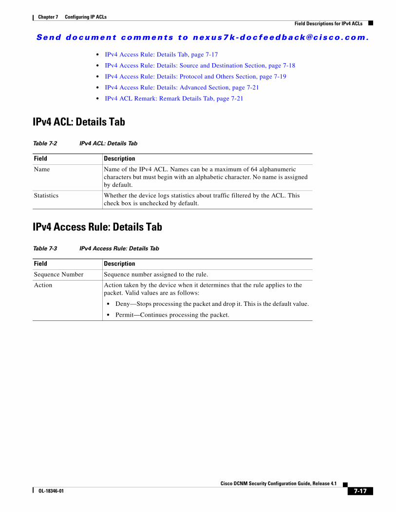
Send document comments to nexus7k -doc feedback@c i sco .com.
Chapter 7 Configuring IP ACLsField Descriptions for IPv4 ACLs
• IPv4 Access Rule: Details Tab, page 7-17
• IPv4 Access Rule: Details: Source and Destination Section, page 7-18
• IPv4 Access Rule: Details: Protocol and Others Section, page 7-19
• IPv4 Access Rule: Details: Advanced Section, page 7-21
• IPv4 ACL Remark: Remark Details Tab, page 7-21
IPv4 ACL: Details Tab
IPv4 Access Rule: Details Tab
Table 7-2 IPv4 ACL: Details Tab
Field Description
Name Name of the IPv4 ACL. Names can be a maximum of 64 alphanumeric characters but must begin with an alphabetic character. No name is assigned by default.
Statistics Whether the device logs statistics about traffic filtered by the ACL. This check box is unchecked by default.
Table 7-3 IPv4 Access Rule: Details Tab
Field Description
Sequence Number Sequence number assigned to the rule.
Action Action taken by the device when it determines that the rule applies to the packet. Valid values are as follows:
• Deny—Stops processing the packet and drop it. This is the default value.
• Permit—Continues processing the packet.
7-17Cisco DCNM Security Configuration Guide, Release 4.1
OL-18346-01
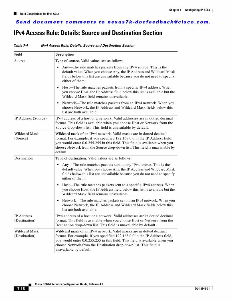
Send document comments to nexus7k -doc feedback@c i sco .com.
Chapter 7 Configuring IP ACLsField Descriptions for IPv4 ACLs
IPv4 Access Rule: Details: Source and Destination Section
Table 7-4 IPv4 Access Rule: Details: Source and Destination Section
Field Description
Source Type of source. Valid values are as follows:
• Any—The rule matches packets from any IPv4 source. This is the default value. When you choose Any, the IP Address and Wildcard Mask fields below this list are unavailable because you do not need to specify either of them.
• Host—The rule matches packets from a specific IPv4 address. When you choose Host, the IP Address field below this list is available but the Wildcard Mask field remains unavailable.
• Network—The rule matches packets from an IPv4 network. When you choose Network, the IP Address and Wildcard Mask fields below this list are both available.
IP Address (Source) IPv4 address of a host or a network. Valid addresses are in dotted decimal format. This field is available when you choose Host or Network from the Source drop-down list. This field is unavailable by default.
Wildcard Mask (Source)
Wildcard mask of an IPv4 network. Valid masks are in dotted decimal format. For example, if you specified 192.168.0.0 in the IP Address field, you would enter 0.0.255.255 in this field. This field is available when you choose Network from the Source drop-down list. This field is unavailable by default.
Destination Type of destination. Valid values are as follows:
• Any—The rule matches packets sent to any IPv4 source. This is the default value. When you choose Any, the IP Address and Wildcard Mask fields below this list are unavailable because you do not need to specify either of them.
• Host—The rule matches packets sent to a specific IPv4 address. When you choose Host, the IP Address field below this list is available but the Wildcard Mask field remains unavailable.
• Network—The rule matches packets sent to an IPv4 network. When you choose Network, the IP Address and Wildcard Mask fields below this list are both available.
IP Address (Destination)
IPv4 address of a host or a network. Valid addresses are in dotted decimal format. This field is available when you choose Host or Network from the Destination drop-down list. This field is unavailable by default.
Wildcard Mask (Destination)
Wildcard mask of an IPv4 network. Valid masks are in dotted decimal format. For example, if you specified 192.168.0.0 in the IP Address field, you would enter 0.0.255.255 in this field. This field is available when you choose Network from the Destination drop-down list. This field is unavailable by default.
7-18Cisco DCNM Security Configuration Guide, Release 4.1
OL-18346-01
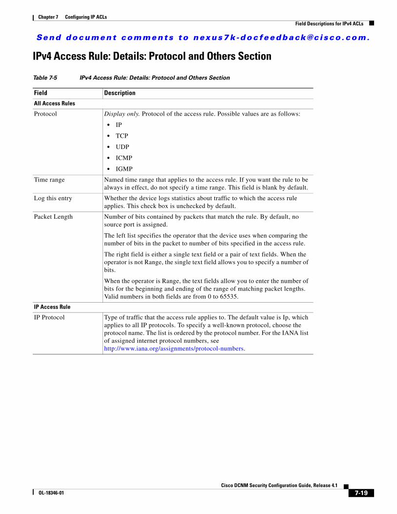
Send document comments to nexus7k -doc feedback@c i sco .com.
Chapter 7 Configuring IP ACLsField Descriptions for IPv4 ACLs
IPv4 Access Rule: Details: Protocol and Others Section
Table 7-5 IPv4 Access Rule: Details: Protocol and Others Section
Field Description
All Access Rules
Protocol Display only. Protocol of the access rule. Possible values are as follows:
• IP
• TCP
• UDP
• ICMP
• IGMP
Time range Named time range that applies to the access rule. If you want the rule to be always in effect, do not specify a time range. This field is blank by default.
Log this entry Whether the device logs statistics about traffic to which the access rule applies. This check box is unchecked by default.
Packet Length Number of bits contained by packets that match the rule. By default, no source port is assigned.
The left list specifies the operator that the device uses when comparing the number of bits in the packet to number of bits specified in the access rule.
The right field is either a single text field or a pair of text fields. When the operator is not Range, the single text field allows you to specify a number of bits.
When the operator is Range, the text fields allow you to enter the number of bits for the beginning and ending of the range of matching packet lengths. Valid numbers in both fields are from 0 to 65535.
IP Access Rule
IP Protocol Type of traffic that the access rule applies to. The default value is Ip, which applies to all IP protocols. To specify a well-known protocol, choose the protocol name. The list is ordered by the protocol number. For the IANA list of assigned internet protocol numbers, see http://www.iana.org/assignments/protocol-numbers.
7-19Cisco DCNM Security Configuration Guide, Release 4.1
OL-18346-01
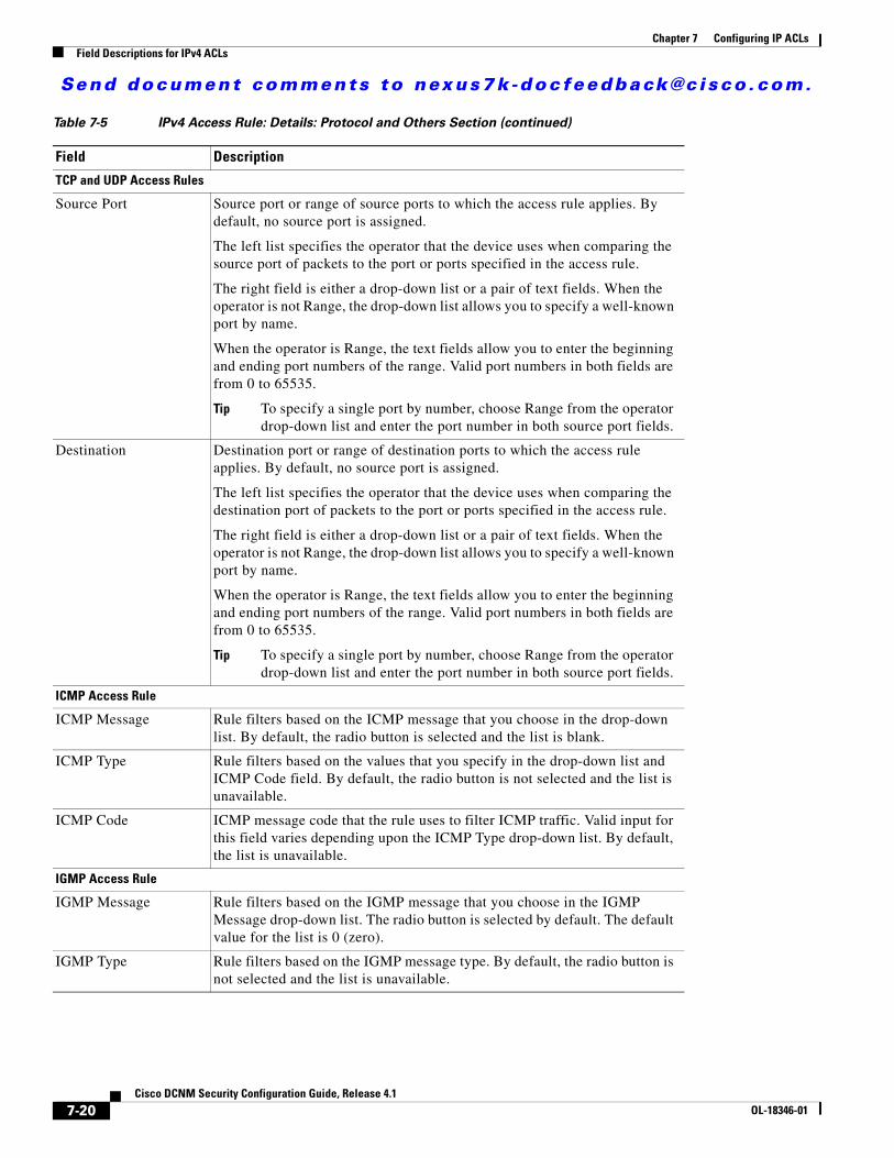
Send document comments to nexus7k -doc feedback@c i sco .com.
Chapter 7 Configuring IP ACLsField Descriptions for IPv4 ACLs
TCP and UDP Access Rules
Source Port Source port or range of source ports to which the access rule applies. By default, no source port is assigned.
The left list specifies the operator that the device uses when comparing the source port of packets to the port or ports specified in the access rule.
The right field is either a drop-down list or a pair of text fields. When the operator is not Range, the drop-down list allows you to specify a well-known port by name.
When the operator is Range, the text fields allow you to enter the beginning and ending port numbers of the range. Valid port numbers in both fields are from 0 to 65535.
Tip To specify a single port by number, choose Range from the operator drop-down list and enter the port number in both source port fields.
Destination Destination port or range of destination ports to which the access rule applies. By default, no source port is assigned.
The left list specifies the operator that the device uses when comparing the destination port of packets to the port or ports specified in the access rule.
The right field is either a drop-down list or a pair of text fields. When the operator is not Range, the drop-down list allows you to specify a well-known port by name.
When the operator is Range, the text fields allow you to enter the beginning and ending port numbers of the range. Valid port numbers in both fields are from 0 to 65535.
Tip To specify a single port by number, choose Range from the operator drop-down list and enter the port number in both source port fields.
ICMP Access Rule
ICMP Message Rule filters based on the ICMP message that you choose in the drop-down list. By default, the radio button is selected and the list is blank.
ICMP Type Rule filters based on the values that you specify in the drop-down list and ICMP Code field. By default, the radio button is not selected and the list is unavailable.
ICMP Code ICMP message code that the rule uses to filter ICMP traffic. Valid input for this field varies depending upon the ICMP Type drop-down list. By default, the list is unavailable.
IGMP Access Rule
IGMP Message Rule filters based on the IGMP message that you choose in the IGMP Message drop-down list. The radio button is selected by default. The default value for the list is 0 (zero).
IGMP Type Rule filters based on the IGMP message type. By default, the radio button is not selected and the list is unavailable.
Table 7-5 IPv4 Access Rule: Details: Protocol and Others Section (continued)
Field Description
7-20Cisco DCNM Security Configuration Guide, Release 4.1
OL-18346-01
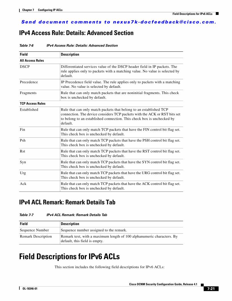
Send document comments to nexus7k -doc feedback@c i sco .com.
Chapter 7 Configuring IP ACLsField Descriptions for IPv6 ACLs
IPv4 Access Rule: Details: Advanced Section
IPv4 ACL Remark: Remark Details Tab
Field Descriptions for IPv6 ACLsThis section includes the following field descriptions for IPv6 ACLs:
Table 7-6 IPv4 Access Rule: Details: Advanced Section
Field Description
All Access Rules
DSCP Differentiated services value of the DSCP header field in IP packets. The rule applies only to packets with a matching value. No value is selected by default.
Precedence IP Precedence field value. The rule applies only to packets with a matching value. No value is selected by default.
Fragments Rule that can only match packets that are noninitial fragments. This check box is unchecked by default.
TCP Access Rules
Established Rule that can only match packets that belong to an established TCP connection. The device considers TCP packets with the ACK or RST bits set to belong to an established connection. This check box is unchecked by default.
Fin Rule that can only match TCP packets that have the FIN control bit flag set. This check box is unchecked by default.
Psh Rule that can only match TCP packets that have the PSH control bit flag set. This check box is unchecked by default.
Rst Rule that can only match TCP packets that have the RST control bit flag set. This check box is unchecked by default.
Syn Rule that can only match TCP packets that have the SYN control bit flag set. This check box is unchecked by default.
Urg Rule that can only match TCP packets that have the URG control bit flag set. This check box is unchecked by default.
Ack Rule that can only match TCP packets that have the ACK control bit flag set. This check box is unchecked by default.
Table 7-7 IPv4 ACL Remark: Remark Details Tab
Field Description
Sequence Number Sequence number assigned to the remark.
Remark Description Remark text, with a maximum length of 100 alphanumeric characters. By default, this field is empty.
7-21Cisco DCNM Security Configuration Guide, Release 4.1
OL-18346-01
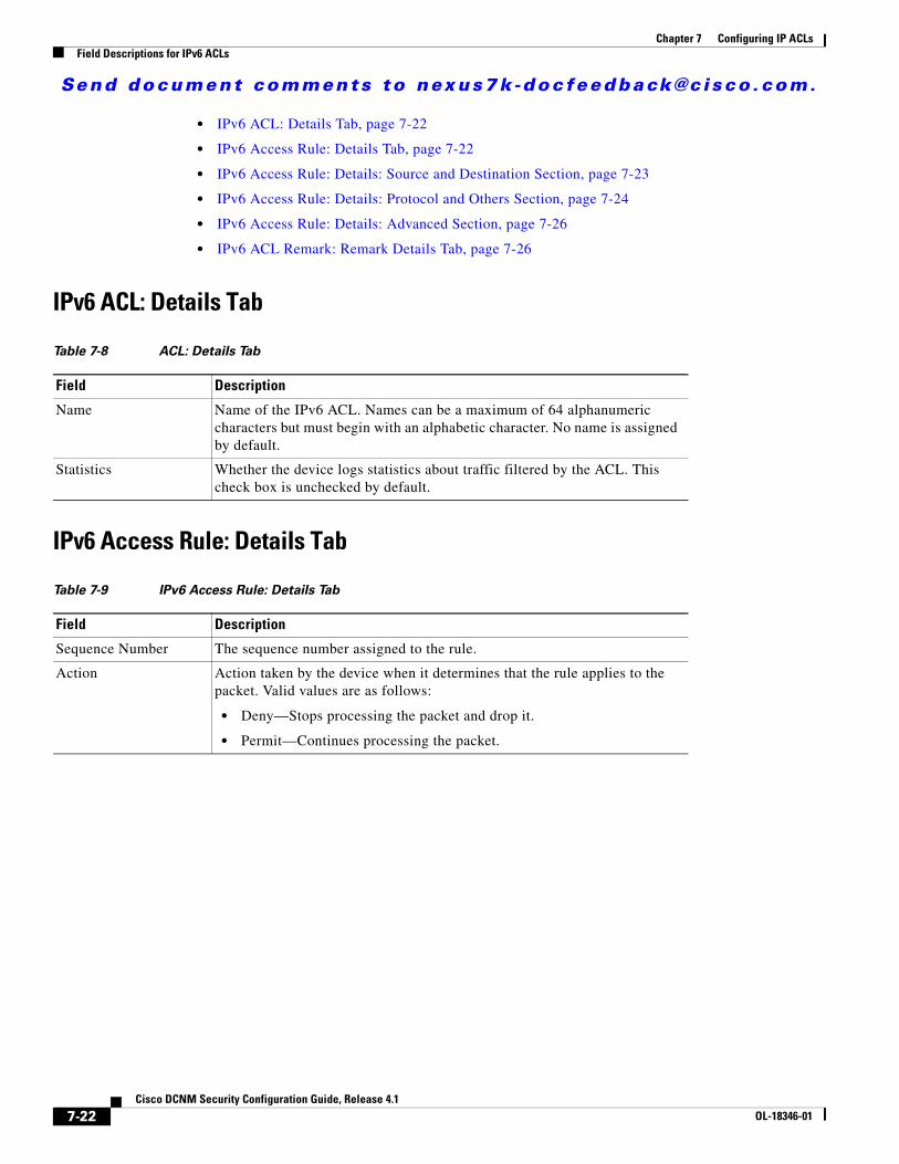
Send document comments to nexus7k -doc feedback@c i sco .com.
Chapter 7 Configuring IP ACLsField Descriptions for IPv6 ACLs
• IPv6 ACL: Details Tab, page 7-22
• IPv6 Access Rule: Details Tab, page 7-22
• IPv6 Access Rule: Details: Source and Destination Section, page 7-23
• IPv6 Access Rule: Details: Protocol and Others Section, page 7-24
• IPv6 Access Rule: Details: Advanced Section, page 7-26
• IPv6 ACL Remark: Remark Details Tab, page 7-26
IPv6 ACL: Details Tab
IPv6 Access Rule: Details Tab
Table 7-8 ACL: Details Tab
Field Description
Name Name of the IPv6 ACL. Names can be a maximum of 64 alphanumeric characters but must begin with an alphabetic character. No name is assigned by default.
Statistics Whether the device logs statistics about traffic filtered by the ACL. This check box is unchecked by default.
Table 7-9 IPv6 Access Rule: Details Tab
Field Description
Sequence Number The sequence number assigned to the rule.
Action Action taken by the device when it determines that the rule applies to the packet. Valid values are as follows:
• Deny—Stops processing the packet and drop it.
• Permit—Continues processing the packet.
7-22Cisco DCNM Security Configuration Guide, Release 4.1
OL-18346-01
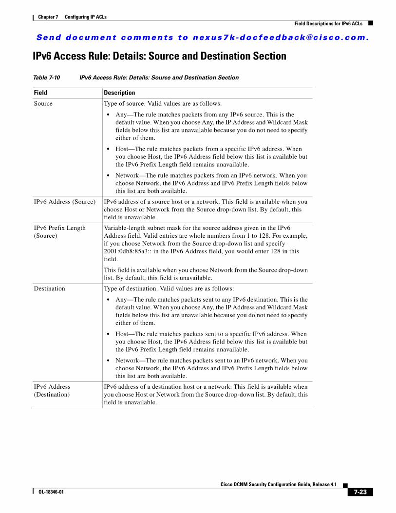
Send document comments to nexus7k -doc feedback@c i sco .com.
Chapter 7 Configuring IP ACLsField Descriptions for IPv6 ACLs
IPv6 Access Rule: Details: Source and Destination Section
Table 7-10 IPv6 Access Rule: Details: Source and Destination Section
Field Description
Source Type of source. Valid values are as follows:
• Any—The rule matches packets from any IPv6 source. This is the default value. When you choose Any, the IP Address and Wildcard Mask fields below this list are unavailable because you do not need to specify either of them.
• Host—The rule matches packets from a specific IPv6 address. When you choose Host, the IPv6 Address field below this list is available but the IPv6 Prefix Length field remains unavailable.
• Network—The rule matches packets from an IPv6 network. When you choose Network, the IPv6 Address and IPv6 Prefix Length fields below this list are both available.
IPv6 Address (Source) IPv6 address of a source host or a network. This field is available when you choose Host or Network from the Source drop-down list. By default, this field is unavailable.
IPv6 Prefix Length (Source)
Variable-length subnet mask for the source address given in the IPv6 Address field. Valid entries are whole numbers from 1 to 128. For example, if you choose Network from the Source drop-down list and specify 2001:0db8:85a3:: in the IPv6 Address field, you would enter 128 in this field.
This field is available when you choose Network from the Source drop-down list. By default, this field is unavailable.
Destination Type of destination. Valid values are as follows:
• Any—The rule matches packets sent to any IPv6 destination. This is the default value. When you choose Any, the IP Address and Wildcard Mask fields below this list are unavailable because you do not need to specify either of them.
• Host—The rule matches packets sent to a specific IPv6 address. When you choose Host, the IPv6 Address field below this list is available but the IPv6 Prefix Length field remains unavailable.
• Network—The rule matches packets sent to an IPv6 network. When you choose Network, the IPv6 Address and IPv6 Prefix Length fields below this list are both available.
IPv6 Address (Destination)
IPv6 address of a destination host or a network. This field is available when you choose Host or Network from the Source drop-down list. By default, this field is unavailable.
7-23Cisco DCNM Security Configuration Guide, Release 4.1
OL-18346-01
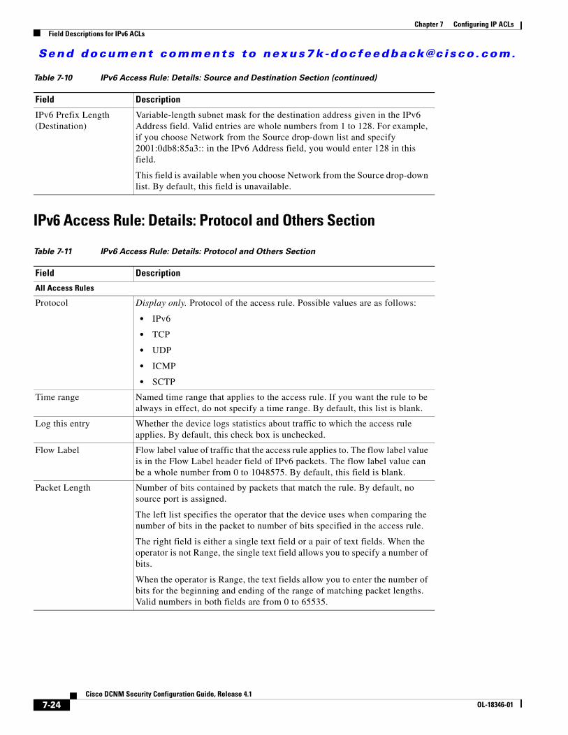
Send document comments to nexus7k -doc feedback@c i sco .com.
Chapter 7 Configuring IP ACLsField Descriptions for IPv6 ACLs
IPv6 Access Rule: Details: Protocol and Others Section
IPv6 Prefix Length (Destination)
Variable-length subnet mask for the destination address given in the IPv6 Address field. Valid entries are whole numbers from 1 to 128. For example, if you choose Network from the Source drop-down list and specify 2001:0db8:85a3:: in the IPv6 Address field, you would enter 128 in this field.
This field is available when you choose Network from the Source drop-down list. By default, this field is unavailable.
Table 7-11 IPv6 Access Rule: Details: Protocol and Others Section
Field Description
All Access Rules
Protocol Display only. Protocol of the access rule. Possible values are as follows:
• IPv6
• TCP
• UDP
• ICMP
• SCTP
Time range Named time range that applies to the access rule. If you want the rule to be always in effect, do not specify a time range. By default, this list is blank.
Log this entry Whether the device logs statistics about traffic to which the access rule applies. By default, this check box is unchecked.
Flow Label Flow label value of traffic that the access rule applies to. The flow label value is in the Flow Label header field of IPv6 packets. The flow label value can be a whole number from 0 to 1048575. By default, this field is blank.
Packet Length Number of bits contained by packets that match the rule. By default, no source port is assigned.
The left list specifies the operator that the device uses when comparing the number of bits in the packet to number of bits specified in the access rule.
The right field is either a single text field or a pair of text fields. When the operator is not Range, the single text field allows you to specify a number of bits.
When the operator is Range, the text fields allow you to enter the number of bits for the beginning and ending of the range of matching packet lengths. Valid numbers in both fields are from 0 to 65535.
Table 7-10 IPv6 Access Rule: Details: Source and Destination Section (continued)
Field Description
7-24Cisco DCNM Security Configuration Guide, Release 4.1
OL-18346-01
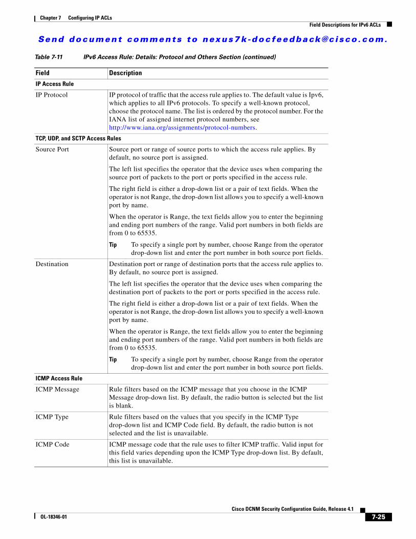
Send document comments to nexus7k -doc feedback@c i sco .com.
Chapter 7 Configuring IP ACLsField Descriptions for IPv6 ACLs
IP Access Rule
IP Protocol IP protocol of traffic that the access rule applies to. The default value is Ipv6, which applies to all IPv6 protocols. To specify a well-known protocol, choose the protocol name. The list is ordered by the protocol number. For the IANA list of assigned internet protocol numbers, see http://www.iana.org/assignments/protocol-numbers.
TCP, UDP, and SCTP Access Rules
Source Port Source port or range of source ports to which the access rule applies. By default, no source port is assigned.
The left list specifies the operator that the device uses when comparing the source port of packets to the port or ports specified in the access rule.
The right field is either a drop-down list or a pair of text fields. When the operator is not Range, the drop-down list allows you to specify a well-known port by name.
When the operator is Range, the text fields allow you to enter the beginning and ending port numbers of the range. Valid port numbers in both fields are from 0 to 65535.
Tip To specify a single port by number, choose Range from the operator drop-down list and enter the port number in both source port fields.
Destination Destination port or range of destination ports that the access rule applies to. By default, no source port is assigned.
The left list specifies the operator that the device uses when comparing the destination port of packets to the port or ports specified in the access rule.
The right field is either a drop-down list or a pair of text fields. When the operator is not Range, the drop-down list allows you to specify a well-known port by name.
When the operator is Range, the text fields allow you to enter the beginning and ending port numbers of the range. Valid port numbers in both fields are from 0 to 65535.
Tip To specify a single port by number, choose Range from the operator drop-down list and enter the port number in both source port fields.
ICMP Access Rule
ICMP Message Rule filters based on the ICMP message that you choose in the ICMP Message drop-down list. By default, the radio button is selected but the list is blank.
ICMP Type Rule filters based on the values that you specify in the ICMP Type drop-down list and ICMP Code field. By default, the radio button is not selected and the list is unavailable.
ICMP Code ICMP message code that the rule uses to filter ICMP traffic. Valid input for this field varies depending upon the ICMP Type drop-down list. By default, this list is unavailable.
Table 7-11 IPv6 Access Rule: Details: Protocol and Others Section (continued)
Field Description
7-25Cisco DCNM Security Configuration Guide, Release 4.1
OL-18346-01

Send document comments to nexus7k -doc feedback@c i sco .com.
Chapter 7 Configuring IP ACLsField Descriptions for IPv6 ACLs
IPv6 Access Rule: Details: Advanced Section
IPv6 ACL Remark: Remark Details Tab
Table 7-12 IPv6 Access Rule: Details: Advanced Section
Field Description
All Access Rules
DSCP Differentiated services value of the DSCP header field in IP packets. The rule applies only to packets with a matching value. By default, this list is blank.
Fragments Rule that can only match packets that are noninitial fragments. By default, this check box is unchecked.
TCP Access Rules
Established Rule that can only match packets belong to an established TCP connection. The device considers TCP packets with the ACK or RST bits set to belong to an established connection. By default, this check box is unchecked.
Fin Rule that can only match TCP packets that have the FIN control bit flag set. By default, this check box is unchecked.
Psh Rule that can only match TCP packets that have the PSH control bit flag set. By default, this check box is unchecked.
Rst Rule that can only match TCP packets that have the RST control bit flag set. By default, this check box is unchecked.
Syn Rule that can only match TCP packets that have the SYN control bit flag set. By default, this check box is unchecked.
Urg Rule that can only match TCP packets that have the URG control bit flag set. By default, this check box is unchecked.
Ack Rule that can only match TCP packets that have the ACK control bit flag set. By default, this check box is unchecked.
Table 7-13 IPv6 ACL Remark: Remark Details Tab
Field Description
Remark Sequence Number
Display only. Sequence number assigned to the remark.
Remark Description Remark text, with a maximum length of 100 alphanumeric characters. By default, this field is blank.
7-26Cisco DCNM Security Configuration Guide, Release 4.1
OL-18346-01
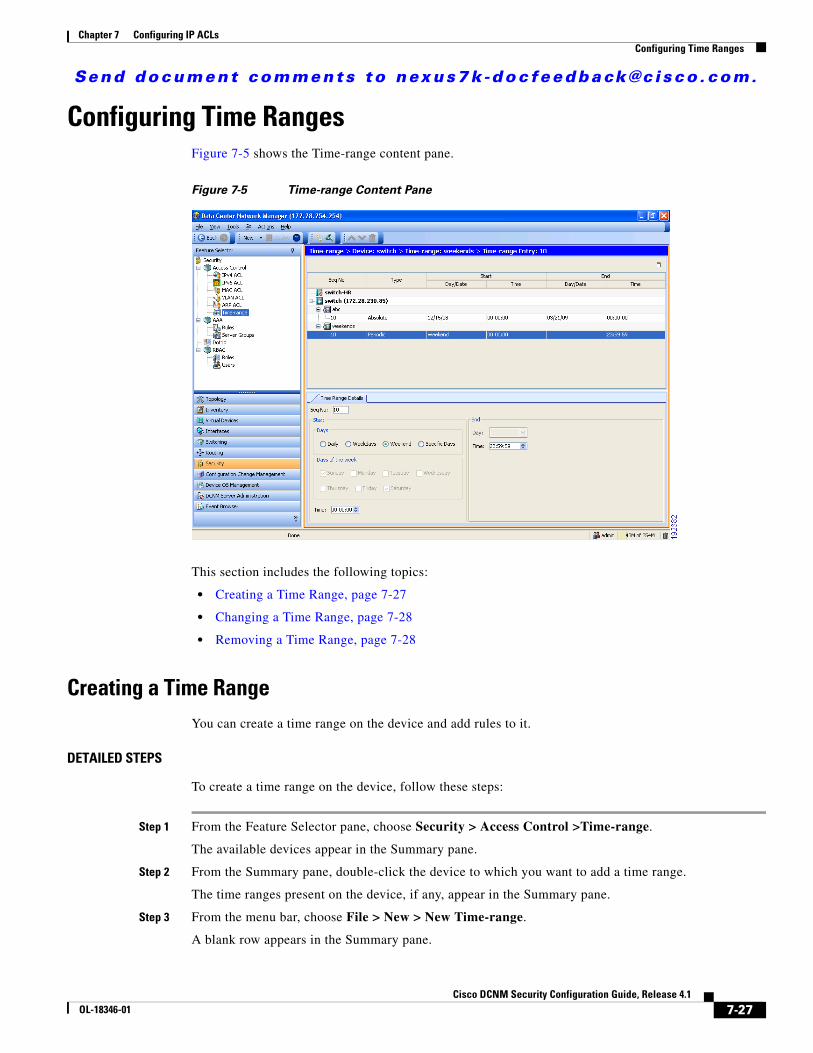
Send document comments to nexus7k -doc feedback@c i sco .com.
Chapter 7 Configuring IP ACLsConfiguring Time Ranges
Configuring Time RangesFigure 7-5 shows the Time-range content pane.
Figure 7-5 Time-range Content Pane
This section includes the following topics:
• Creating a Time Range, page 7-27
• Changing a Time Range, page 7-28
• Removing a Time Range, page 7-28
Creating a Time RangeYou can create a time range on the device and add rules to it.
DETAILED STEPS
To create a time range on the device, follow these steps:
Step 1 From the Feature Selector pane, choose Security > Access Control >Time-range.
The available devices appear in the Summary pane.
Step 2 From the Summary pane, double-click the device to which you want to add a time range.
The time ranges present on the device, if any, appear in the Summary pane.
Step 3 From the menu bar, choose File > New > New Time-range.
A blank row appears in the Summary pane.
7-27Cisco DCNM Security Configuration Guide, Release 4.1
OL-18346-01
Send document comments to nexus7k -doc feedback@c i sco .com.
Chapter 7 Configuring IP ACLsConfiguring Time Ranges
Step 4 In the row, enter a name for the time range.
Step 5 For each rule or remark that you want to add to the time range, from the menu bar, choose File > New and choose the type of rule or remark. On the Time Range Details tab, configure fields as needed.
Step 6 From the menu bar, choose File > Deploy to apply your changes to the device.
Changing a Time RangeYou can change, reorder, add, and remove rules in an existing time range.
DETAILED STEPS
To change a time range, follow these steps:
Step 1 From the Feature Selector pane, choose Security > Access Control >Time-range.
The available devices appear in the Summary pane.
Step 2 From the Summary pane, double-click the device that has the time range that you want to change and then double-click the time range.
Time ranges on the device and the rules of the time range that you double-clicked appear in the Summary pane.
Step 3 (Optional) If you want to change the details of a rule, click the rule in the Summary pane. On the Time Range Details tab, configure fields as needed.
Step 4 (Optional) If you want to move a rule to a different position in the time range, click the rule and then from the menu bar, choose one of the following, as applicable:
• Actions > Move Up
• Actions > Move Down
The rule moves up or down, as you chose. The sequence number of the rules adjust accordingly.
Step 5 (Optional) If you want to add a rule, click the time range in the Summary pane and then from the menu bar, choose File > New and choose the type of rule. On the Time Range Details tab, configure fields as needed.
Step 6 (Optional) If you want to remove a rule, click the rule in the Summary pane and then from the menu bar, choose Actions > Delete.
Step 7 From the menu bar, choose File > Deploy to apply your changes to the device.
Removing a Time RangeYou can remove a time range from the device.
7-28Cisco DCNM Security Configuration Guide, Release 4.1
OL-18346-01
Send document comments to nexus7k -doc feedback@c i sco .com.
Chapter 7 Configuring IP ACLsConfiguring Time Ranges
BEFORE YOU BEGIN
Ensure that you know whether the time range is used in any ACL rules. The device allows you to remove time ranges that are used in ACL rules. Removing a time range that is in use in an ACL rule does not affect the configuration of interfaces where you have applied the ACL. Instead, the device considers the ACL rule using the removed time range to be empty.
DETAILED STEPS
To remove a time range, follow these steps:
Step 1 From the Feature Selector pane, choose Security > Access Control >Time-range.
The available devices appear in the Summary pane.
Step 2 From the Summary pane, double-click the device from which you want to remove a time range.
Time ranges currently on the device appear in the Summary pane.
Step 3 From the Summary pane, click the time range that you want to remove.
Step 4 From the menu bar, choose Actions > Delete.
The time range disappears from the Summary pane.
Step 5 From the menu bar, choose File > Deploy to apply your changes to the device.
7-29Cisco DCNM Security Configuration Guide, Release 4.1
OL-18346-01
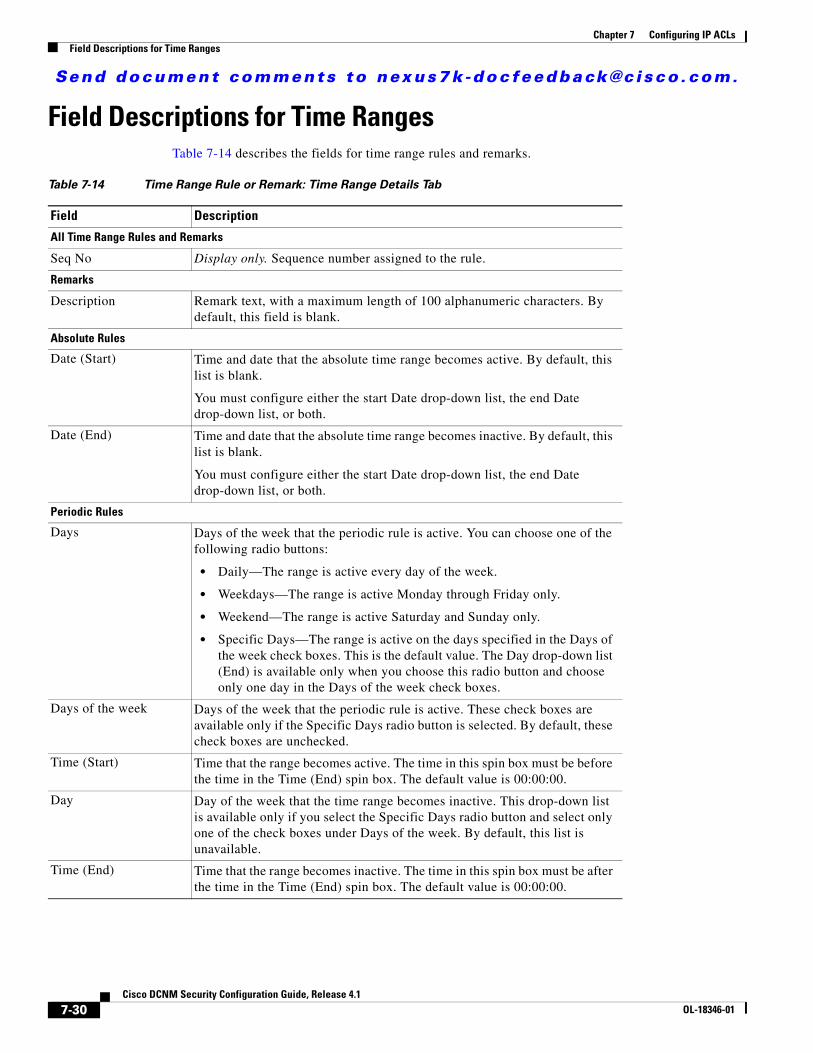
Send document comments to nexus7k -doc feedback@c i sco .com.
Chapter 7 Configuring IP ACLsField Descriptions for Time Ranges
Field Descriptions for Time RangesTable 7-14 describes the fields for time range rules and remarks.
Table 7-14 Time Range Rule or Remark: Time Range Details Tab
Field Description
All Time Range Rules and Remarks
Seq No Display only. Sequence number assigned to the rule.
Remarks
Description Remark text, with a maximum length of 100 alphanumeric characters. By default, this field is blank.
Absolute Rules
Date (Start) Time and date that the absolute time range becomes active. By default, this list is blank.
You must configure either the start Date drop-down list, the end Date drop-down list, or both.
Date (End) Time and date that the absolute time range becomes inactive. By default, this list is blank.
You must configure either the start Date drop-down list, the end Date drop-down list, or both.
Periodic Rules
Days Days of the week that the periodic rule is active. You can choose one of the following radio buttons:
• Daily—The range is active every day of the week.
• Weekdays—The range is active Monday through Friday only.
• Weekend—The range is active Saturday and Sunday only.
• Specific Days—The range is active on the days specified in the Days of the week check boxes. This is the default value. The Day drop-down list (End) is available only when you choose this radio button and choose only one day in the Days of the week check boxes.
Days of the week Days of the week that the periodic rule is active. These check boxes are available only if the Specific Days radio button is selected. By default, these check boxes are unchecked.
Time (Start) Time that the range becomes active. The time in this spin box must be before the time in the Time (End) spin box. The default value is 00:00:00.
Day Day of the week that the time range becomes inactive. This drop-down list is available only if you select the Specific Days radio button and select only one of the check boxes under Days of the week. By default, this list is unavailable.
Time (End) Time that the range becomes inactive. The time in this spin box must be after the time in the Time (End) spin box. The default value is 00:00:00.
7-30Cisco DCNM Security Configuration Guide, Release 4.1
OL-18346-01
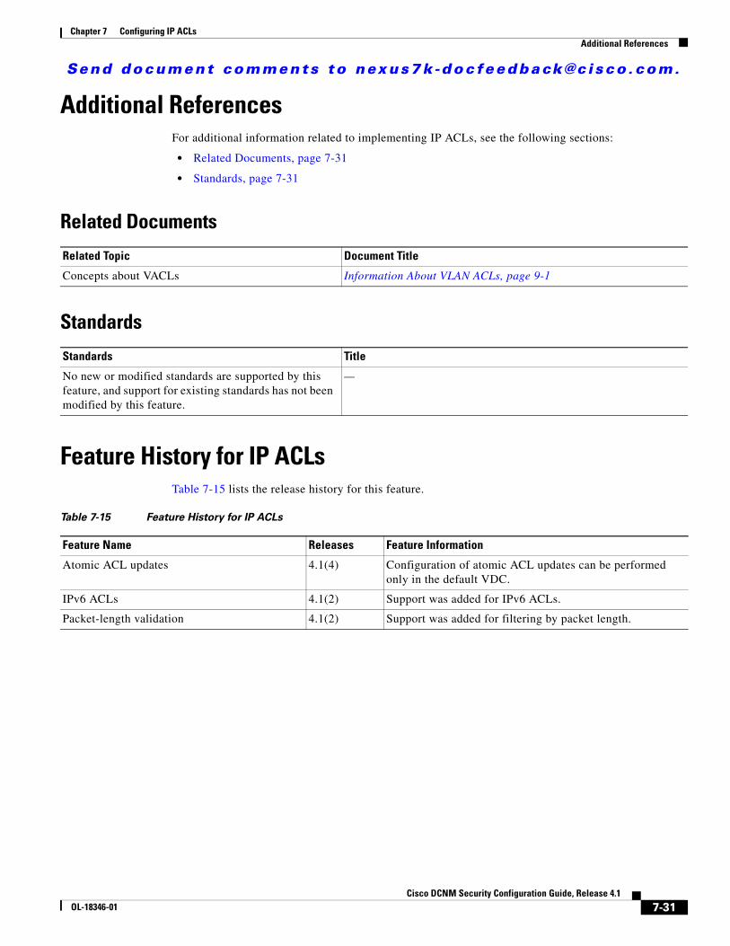
Send document comments to nexus7k -doc feedback@c i sco .com.
Chapter 7 Configuring IP ACLsAdditional References
Additional ReferencesFor additional information related to implementing IP ACLs, see the following sections:
• Related Documents, page 7-31
• Standards, page 7-31
Related Documents
Standards
Feature History for IP ACLsTable 7-15 lists the release history for this feature.
Related Topic Document Title
Concepts about VACLs Information About VLAN ACLs, page 9-1
Standards Title
No new or modified standards are supported by this feature, and support for existing standards has not been modified by this feature.
—
Table 7-15 Feature History for IP ACLs
Feature Name Releases Feature Information
Atomic ACL updates 4.1(4) Configuration of atomic ACL updates can be performed only in the default VDC.
IPv6 ACLs 4.1(2) Support was added for IPv6 ACLs.
Packet-length validation 4.1(2) Support was added for filtering by packet length.
7-31Cisco DCNM Security Configuration Guide, Release 4.1
OL-18346-01

Send document comments to nexus7k -doc feedback@c i sco .com.
Chapter 7 Configuring IP ACLsFeature History for IP ACLs
7-32Cisco DCNM Security Configuration Guide, Release 4.1
OL-18346-01
Send document comments to nexus7k -doc feedback@c i sco .com.
CiscOL-18346-01
C H A P T E R8
Configuring MAC ACLsThis chapter describes how to configure MAC access lists (ACLs) on NX-OS devices.
This chapter includes the following sections:
• Information About MAC ACLs, page 8-1
• Licensing Requirements for MAC ACLs, page 8-1
• Prerequisites for MAC ACLs, page 8-2
• Guidelines and Limitations, page 8-2
• Configuring MAC ACLs, page 8-2
• Displaying and Clearing MAC ACL Statistics, page 8-6
• Field Descriptions for MAC ACLs, page 8-6
• Additional References, page 8-8
• Feature History for MAC ACLs, page 8-9
Information About MAC ACLsMAC ACLs are ACLs that filter traffic using information in the Layer 2 header of each packet. MAC ACLs share many fundamental concepts with IP ACLs, including support for virtualization. For information about these shared concepts, see the “Information About ACLs” section on page 7-1.
Licensing Requirements for MAC ACLsThe following table shows the licensing requirements for this feature:
Product License Requirement
DCNM MAC ACLs require no license. Any feature not included in a license package is bundled with the Cisco DCNM and is provided at no charge to you. For a complete explanation of the DCNM licensing scheme, see the Cisco DCNM Fundamentals Configuration Guide, Release 4.1.
NX-OS MAC ACLs require no license. Any feature not included in a license package is bundled with the Cisco NX-OS system images and is provided at no extra charge to you. For a complete explanation of the NX-OS licensing scheme, see the Cisco Nexus 7000 Series NX-OS Licensing Guide, Release 4.1.
8-1o DCNM Security Configuration Guide, Release 4.1
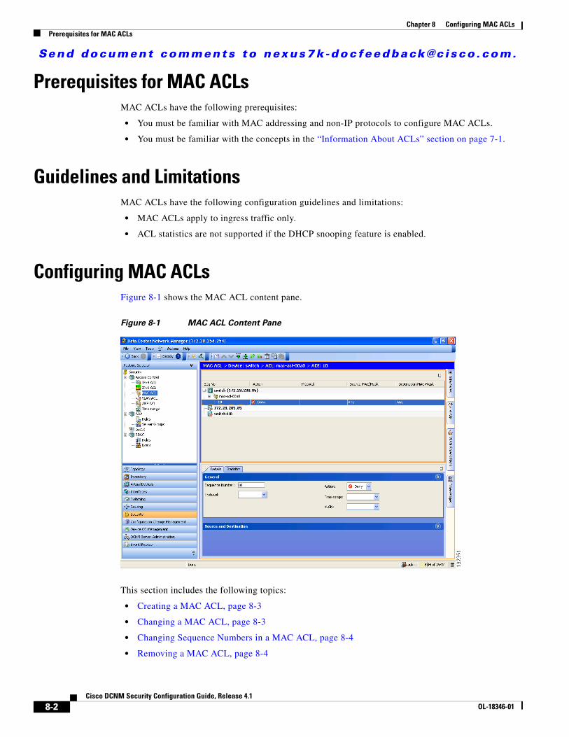
Send document comments to nexus7k -doc feedback@c i sco .com.
Chapter 8 Configuring MAC ACLsPrerequisites for MAC ACLs
Prerequisites for MAC ACLsMAC ACLs have the following prerequisites:
• You must be familiar with MAC addressing and non-IP protocols to configure MAC ACLs.
• You must be familiar with the concepts in the “Information About ACLs” section on page 7-1.
Guidelines and LimitationsMAC ACLs have the following configuration guidelines and limitations:
• MAC ACLs apply to ingress traffic only.
• ACL statistics are not supported if the DHCP snooping feature is enabled.
Configuring MAC ACLsFigure 8-1 shows the MAC ACL content pane.
Figure 8-1 MAC ACL Content Pane
This section includes the following topics:
• Creating a MAC ACL, page 8-3
• Changing a MAC ACL, page 8-3
• Changing Sequence Numbers in a MAC ACL, page 8-4
• Removing a MAC ACL, page 8-4
8-2Cisco DCNM Security Configuration Guide, Release 4.1
OL-18346-01
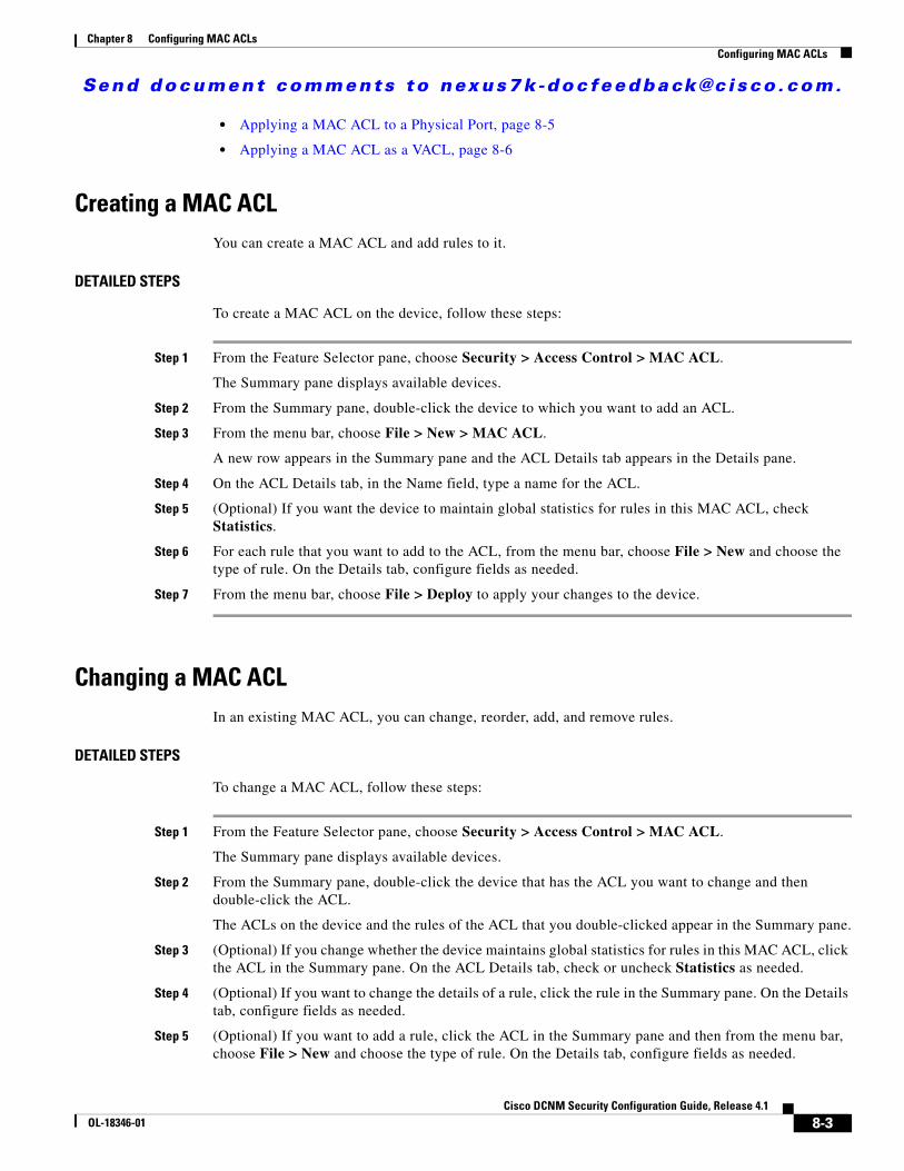
Send document comments to nexus7k -doc feedback@c i sco .com.
Chapter 8 Configuring MAC ACLsConfiguring MAC ACLs
• Applying a MAC ACL to a Physical Port, page 8-5
• Applying a MAC ACL as a VACL, page 8-6
Creating a MAC ACLYou can create a MAC ACL and add rules to it.
DETAILED STEPS
To create a MAC ACL on the device, follow these steps:
Step 1 From the Feature Selector pane, choose Security > Access Control > MAC ACL.
The Summary pane displays available devices.
Step 2 From the Summary pane, double-click the device to which you want to add an ACL.
Step 3 From the menu bar, choose File > New > MAC ACL.
A new row appears in the Summary pane and the ACL Details tab appears in the Details pane.
Step 4 On the ACL Details tab, in the Name field, type a name for the ACL.
Step 5 (Optional) If you want the device to maintain global statistics for rules in this MAC ACL, check Statistics.
Step 6 For each rule that you want to add to the ACL, from the menu bar, choose File > New and choose the type of rule. On the Details tab, configure fields as needed.
Step 7 From the menu bar, choose File > Deploy to apply your changes to the device.
Changing a MAC ACLIn an existing MAC ACL, you can change, reorder, add, and remove rules.
DETAILED STEPS
To change a MAC ACL, follow these steps:
Step 1 From the Feature Selector pane, choose Security > Access Control > MAC ACL.
The Summary pane displays available devices.
Step 2 From the Summary pane, double-click the device that has the ACL you want to change and then double-click the ACL.
The ACLs on the device and the rules of the ACL that you double-clicked appear in the Summary pane.
Step 3 (Optional) If you change whether the device maintains global statistics for rules in this MAC ACL, click the ACL in the Summary pane. On the ACL Details tab, check or uncheck Statistics as needed.
Step 4 (Optional) If you want to change the details of a rule, click the rule in the Summary pane. On the Details tab, configure fields as needed.
Step 5 (Optional) If you want to add a rule, click the ACL in the Summary pane and then from the menu bar, choose File > New and choose the type of rule. On the Details tab, configure fields as needed.
8-3Cisco DCNM Security Configuration Guide, Release 4.1
OL-18346-01
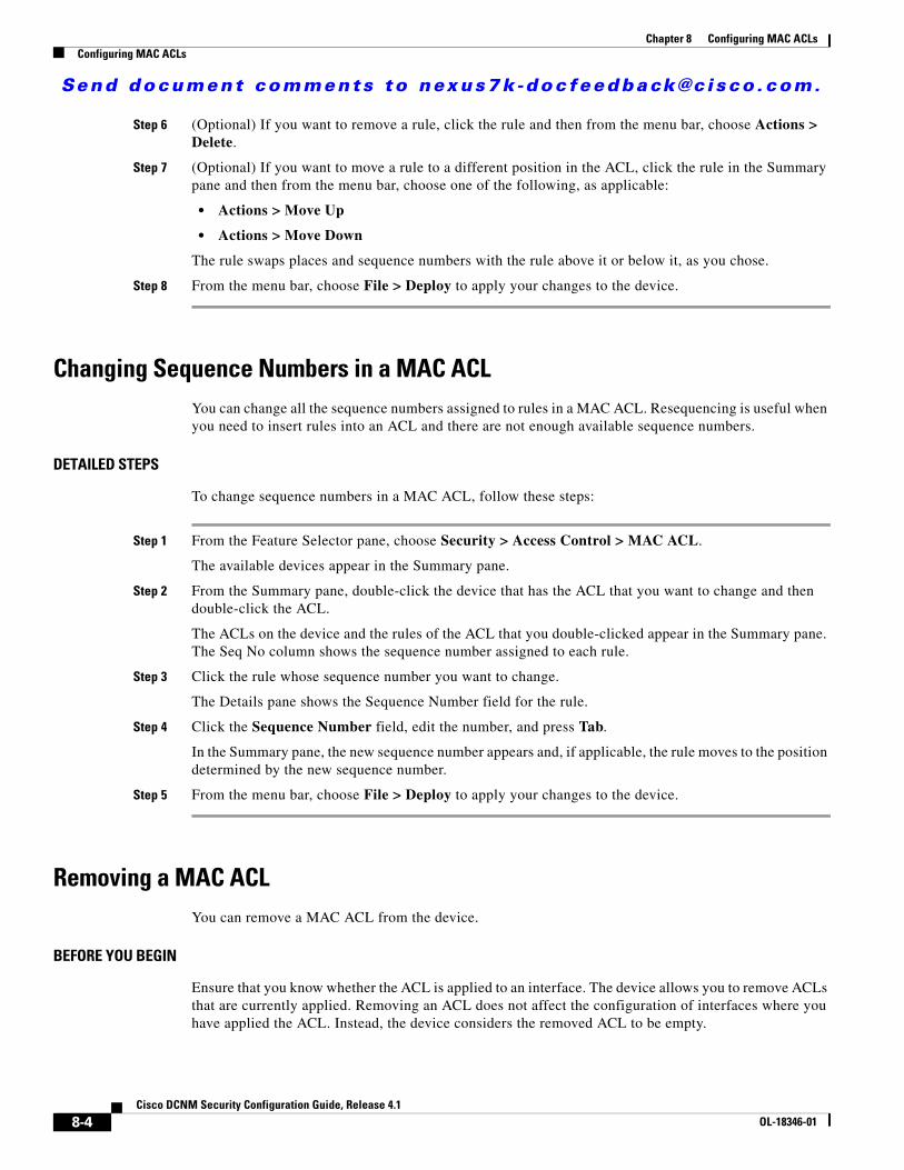
Send document comments to nexus7k -doc feedback@c i sco .com.
Chapter 8 Configuring MAC ACLsConfiguring MAC ACLs
Step 6 (Optional) If you want to remove a rule, click the rule and then from the menu bar, choose Actions > Delete.
Step 7 (Optional) If you want to move a rule to a different position in the ACL, click the rule in the Summary pane and then from the menu bar, choose one of the following, as applicable:
• Actions > Move Up
• Actions > Move Down
The rule swaps places and sequence numbers with the rule above it or below it, as you chose.
Step 8 From the menu bar, choose File > Deploy to apply your changes to the device.
Changing Sequence Numbers in a MAC ACLYou can change all the sequence numbers assigned to rules in a MAC ACL. Resequencing is useful when you need to insert rules into an ACL and there are not enough available sequence numbers.
DETAILED STEPS
To change sequence numbers in a MAC ACL, follow these steps:
Step 1 From the Feature Selector pane, choose Security > Access Control > MAC ACL.
The available devices appear in the Summary pane.
Step 2 From the Summary pane, double-click the device that has the ACL that you want to change and then double-click the ACL.
The ACLs on the device and the rules of the ACL that you double-clicked appear in the Summary pane. The Seq No column shows the sequence number assigned to each rule.
Step 3 Click the rule whose sequence number you want to change.
The Details pane shows the Sequence Number field for the rule.
Step 4 Click the Sequence Number field, edit the number, and press Tab.
In the Summary pane, the new sequence number appears and, if applicable, the rule moves to the position determined by the new sequence number.
Step 5 From the menu bar, choose File > Deploy to apply your changes to the device.
Removing a MAC ACLYou can remove a MAC ACL from the device.
BEFORE YOU BEGIN
Ensure that you know whether the ACL is applied to an interface. The device allows you to remove ACLs that are currently applied. Removing an ACL does not affect the configuration of interfaces where you have applied the ACL. Instead, the device considers the removed ACL to be empty.
8-4Cisco DCNM Security Configuration Guide, Release 4.1
OL-18346-01
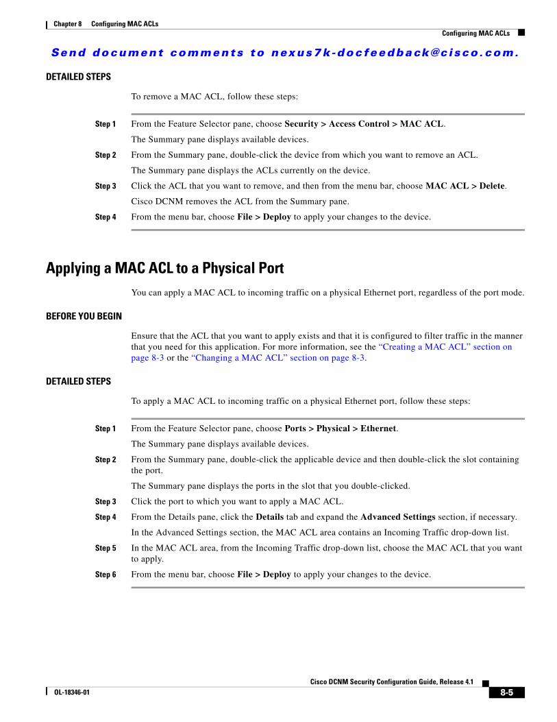
Send document comments to nexus7k -doc feedback@c i sco .com.
Chapter 8 Configuring MAC ACLsConfiguring MAC ACLs
DETAILED STEPS
To remove a MAC ACL, follow these steps:
Step 1 From the Feature Selector pane, choose Security > Access Control > MAC ACL.
The Summary pane displays available devices.
Step 2 From the Summary pane, double-click the device from which you want to remove an ACL.
The Summary pane displays the ACLs currently on the device.
Step 3 Click the ACL that you want to remove, and then from the menu bar, choose MAC ACL > Delete.
Cisco DCNM removes the ACL from the Summary pane.
Step 4 From the menu bar, choose File > Deploy to apply your changes to the device.
Applying a MAC ACL to a Physical PortYou can apply a MAC ACL to incoming traffic on a physical Ethernet port, regardless of the port mode.
BEFORE YOU BEGIN
Ensure that the ACL that you want to apply exists and that it is configured to filter traffic in the manner that you need for this application. For more information, see the “Creating a MAC ACL” section on page 8-3 or the “Changing a MAC ACL” section on page 8-3.
DETAILED STEPS
To apply a MAC ACL to incoming traffic on a physical Ethernet port, follow these steps:
Step 1 From the Feature Selector pane, choose Ports > Physical > Ethernet.
The Summary pane displays available devices.
Step 2 From the Summary pane, double-click the applicable device and then double-click the slot containing the port.
The Summary pane displays the ports in the slot that you double-clicked.
Step 3 Click the port to which you want to apply a MAC ACL.
Step 4 From the Details pane, click the Details tab and expand the Advanced Settings section, if necessary.
In the Advanced Settings section, the MAC ACL area contains an Incoming Traffic drop-down list.
Step 5 In the MAC ACL area, from the Incoming Traffic drop-down list, choose the MAC ACL that you want to apply.
Step 6 From the menu bar, choose File > Deploy to apply your changes to the device.
8-5Cisco DCNM Security Configuration Guide, Release 4.1
OL-18346-01
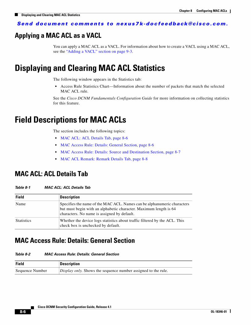
Send document comments to nexus7k -doc feedback@c i sco .com.
Chapter 8 Configuring MAC ACLsDisplaying and Clearing MAC ACL Statistics
Applying a MAC ACL as a VACLYou can apply a MAC ACL as a VACL. For information about how to create a VACL using a MAC ACL, see the “Adding a VACL” section on page 9-3.
Displaying and Clearing MAC ACL StatisticsThe following window appears in the Statistics tab:
• Access Rule Statistics Chart—Information about the number of packets that match the selected MAC ACL rule.
See the Cisco DCNM Fundamentals Configuration Guide for more information on collecting statistics for this feature.
Field Descriptions for MAC ACLsThe section includes the following topics:
• MAC ACL: ACL Details Tab, page 8-6
• MAC Access Rule: Details: General Section, page 8-6
• MAC Access Rule: Details: Source and Destination Section, page 8-7
• MAC ACL Remark: Remark Details Tab, page 8-8
MAC ACL: ACL Details Tab
MAC Access Rule: Details: General Section
Table 8-1 MAC ACL: ACL Details Tab
Field Description
Name Specifies the name of the MAC ACL. Names can be alphanumeric characters but must begin with an alphabetic character. Maximum length is 64 characters. No name is assigned by default.
Statistics Whether the device logs statistics about traffic filtered by the ACL. This check box is unchecked by default.
Table 8-2 MAC Access Rule: Details: General Section
Field Description
Sequence Number Display only. Shows the sequence number assigned to the rule.
8-6Cisco DCNM Security Configuration Guide, Release 4.1
OL-18346-01
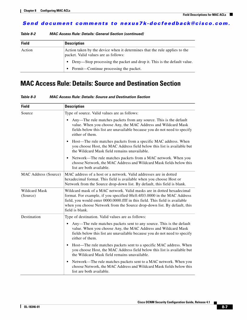
Send document comments to nexus7k -doc feedback@c i sco .com.
Chapter 8 Configuring MAC ACLsField Descriptions for MAC ACLs
MAC Access Rule: Details: Source and Destination Section
Action Action taken by the device when it determines that the rule applies to the packet. Valid values are as follows:
• Deny—Stop processing the packet and drop it. This is the default value.
• Permit—Continue processing the packet.
Table 8-3 MAC Access Rule: Details: Source and Destination Section
Field Description
Source Type of source. Valid values are as follows:
• Any—The rule matches packets from any source. This is the default value. When you choose Any, the MAC Address and Wildcard Mask fields below this list are unavailable because you do not need to specify either of them.
• Host—The rule matches packets from a specific MAC address. When you choose Host, the MAC Address field below this list is available but the Wildcard Mask field remains unavailable.
• Network—The rule matches packets from a MAC network. When you choose Network, the MAC Address and Wildcard Mask fields below this list are both available.
MAC Address (Source) MAC address of a host or a network. Valid addresses are in dotted hexadecimal format. This field is available when you choose Host or Network from the Source drop-down list. By default, this field is blank.
Wildcard Mask (Source)
Wildcard mask of a MAC network. Valid masks are in dotted hexadecimal format. For example, if you specified 00c0.4f03.0000 in the MAC Address field, you would enter 0000.0000.ffff in this field. This field is available when you choose Network from the Source drop-down list. By default, this field is blank.
Destination Type of destination. Valid values are as follows:
• Any—The rule matches packets sent to any source. This is the default value. When you choose Any, the MAC Address and Wildcard Mask fields below this list are unavailable because you do not need to specify either of them.
• Host—The rule matches packets sent to a specific MAC address. When you choose Host, the MAC Address field below this list is available but the Wildcard Mask field remains unavailable.
• Network—The rule matches packets sent to a MAC network. When you choose Network, the MAC Address and Wildcard Mask fields below this list are both available.
Table 8-2 MAC Access Rule: Details: General Section (continued)
Field Description
8-7Cisco DCNM Security Configuration Guide, Release 4.1
OL-18346-01
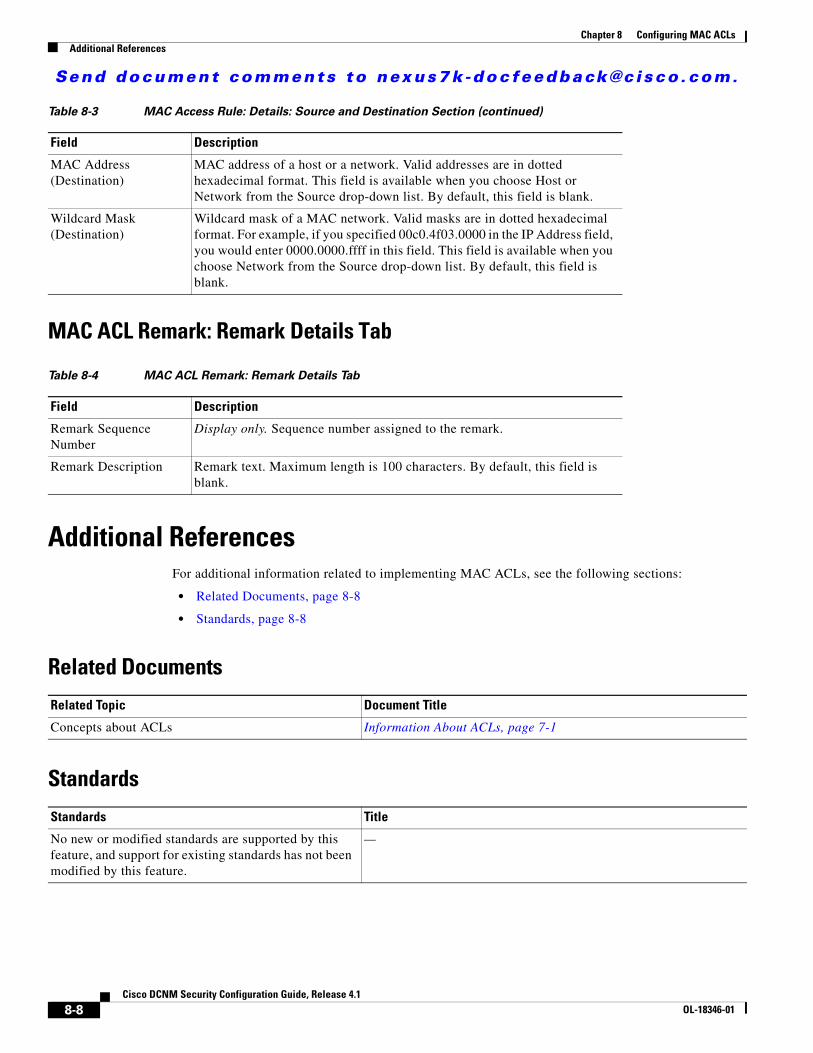
Send document comments to nexus7k -doc feedback@c i sco .com.
Chapter 8 Configuring MAC ACLsAdditional References
MAC ACL Remark: Remark Details Tab
Additional ReferencesFor additional information related to implementing MAC ACLs, see the following sections:
• Related Documents, page 8-8
• Standards, page 8-8
Related Documents
Standards
MAC Address (Destination)
MAC address of a host or a network. Valid addresses are in dotted hexadecimal format. This field is available when you choose Host or Network from the Source drop-down list. By default, this field is blank.
Wildcard Mask (Destination)
Wildcard mask of a MAC network. Valid masks are in dotted hexadecimal format. For example, if you specified 00c0.4f03.0000 in the IP Address field, you would enter 0000.0000.ffff in this field. This field is available when you choose Network from the Source drop-down list. By default, this field is blank.
Table 8-4 MAC ACL Remark: Remark Details Tab
Field Description
Remark Sequence Number
Display only. Sequence number assigned to the remark.
Remark Description Remark text. Maximum length is 100 characters. By default, this field is blank.
Table 8-3 MAC Access Rule: Details: Source and Destination Section (continued)
Field Description
Related Topic Document Title
Concepts about ACLs Information About ACLs, page 7-1
Standards Title
No new or modified standards are supported by this feature, and support for existing standards has not been modified by this feature.
—
8-8Cisco DCNM Security Configuration Guide, Release 4.1
OL-18346-01
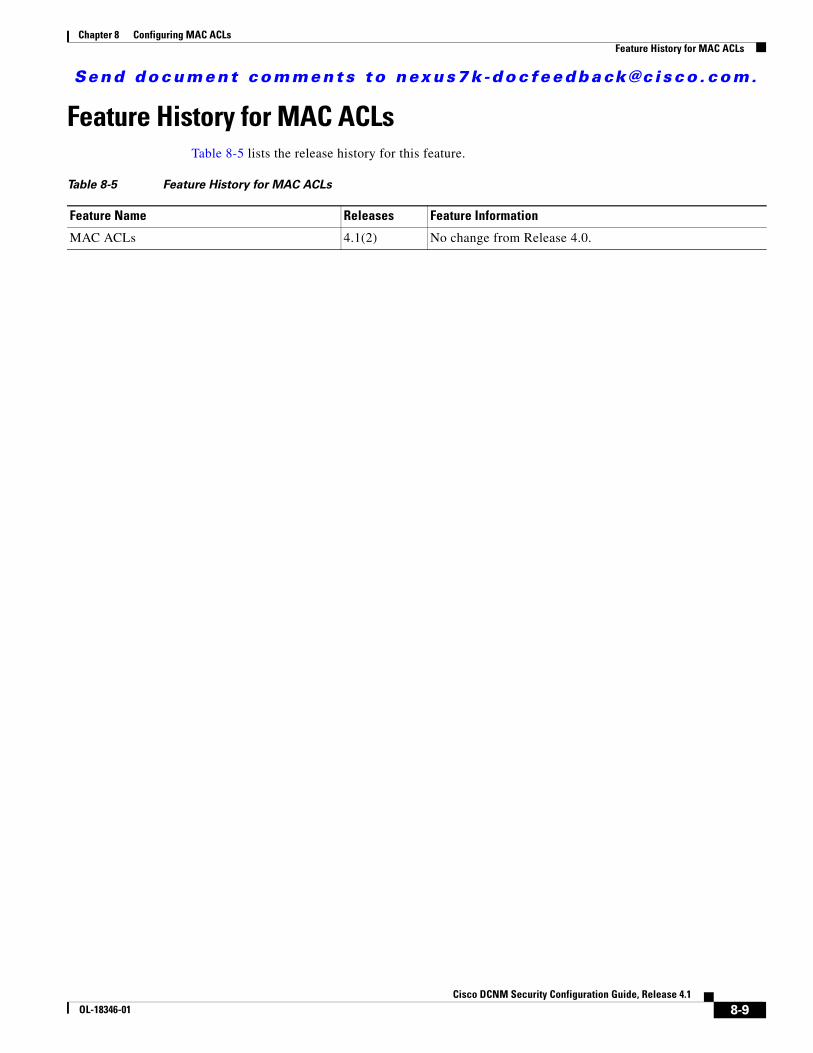
Send document comments to nexus7k -doc feedback@c i sco .com.
Chapter 8 Configuring MAC ACLsFeature History for MAC ACLs
Feature History for MAC ACLsTable 8-5 lists the release history for this feature.
Table 8-5 Feature History for MAC ACLs
Feature Name Releases Feature Information
MAC ACLs 4.1(2) No change from Release 4.0.
8-9Cisco DCNM Security Configuration Guide, Release 4.1
OL-18346-01

Send document comments to nexus7k -doc feedback@c i sco .com.
Chapter 8 Configuring MAC ACLsFeature History for MAC ACLs
8-10Cisco DCNM Security Configuration Guide, Release 4.1
OL-18346-01
Send document comments to nexus7k -doc feedback@c i sco .com.
CiscOL-18346-01
C H A P T E R9
Configuring VLAN ACLsThis chapter describes how to configure VLAN access lists (ACLs) on NX-OS devices.
This chapter includes the following sections:
• Information About VLAN ACLs, page 9-1
• Licensing Requirements for VACLs, page 9-2
• Prerequisites for VACLs, page 9-2
• Guidelines and Limitations, page 9-3
• Configuring VACLs, page 9-3
• Field Descriptions for VACLs, page 9-7
• Additional References, page 9-8
• Feature History for VLAN ACLs, page 9-8
Information About VLAN ACLsA VLAN ACL (VACL) is one application of a MAC ACL or IP ACL. You can configure VACLs to apply to all packets that are routed into or out of a VLAN or are bridged within a VLAN. VACLs are strictly for security packet filtering and for redirecting traffic to specific physical interfaces. VACLs are not defined by direction (ingress or egress).
For more information about the types and applications of ACLs, see the “Information About ACLs” section on page 7-1.
This section includes the following topics:
• Access Maps and Entries, page 9-1
• Actions, page 9-2
• Virtualization Support, page 9-2
Access Maps and EntriesVACLs use access maps to contain an ordered list of one or more map entries. Each map entry associates IP or MAC ACLs to an action. Each entry has a sequence number, which allows you to control the precedence of entries.
9-1o DCNM Security Configuration Guide, Release 4.1
Send document comments to nexus7k -doc feedback@c i sco .com.
Chapter 9 Configuring VLAN ACLsLicensing Requirements for VACLs
When the device applies a VACL to a packet, it applies the action that is configured in the first access map entry that contains an ACL that permits the packet.
ActionsEach VLAN access map entry can specify one of the following actions:
• Forward—Sends the traffic to the destination determined by normal operation of the switch.
• Redirect—Redirects the traffic to one or more specified interfaces.
• Drop—Drops the traffic. If you specify drop as the action, you can also specify that the device logs the dropped packets.
Virtualization SupportThe following information applies to VACLs used in Virtual Device Contexts (VDCs):
• ACLs are unique per VDC. You cannot use an ACL that you created in one VDC in a different VDC.
• Because ACLs are not shared by VDCs, you can reuse ACL names in different VDCs.
• The device does not limit ACLs or rules on a per-VDC basis.
Licensing Requirements for VACLsThe following table shows the licensing requirements for this feature:
Prerequisites for VACLsVACLs have the following prerequisites:
• You must be familiar with VLANs to configure VACLs.
• You must be familiar with the concepts in the “Information About ACLs” section on page 7-1.
Product License Requirement
DCNM VACLs require no license. Any feature not included in a license package is bundled with the Cisco DCNM and is provided at no charge to you. For a complete explanation of the DCNM licensing scheme, see the Cisco DCNM Fundamentals Configuration Guide, Release 4.1.
NX-OS VACLs require no license. Any feature not included in a license package is bundled with the Cisco NX-OS system images and is provided at no extra charge to you. For a complete explanation of the NX-OS licensing scheme, see the Cisco Nexus 7000 Series NX-OS Licensing Guide, Release 4.1.
9-2Cisco DCNM Security Configuration Guide, Release 4.1
OL-18346-01
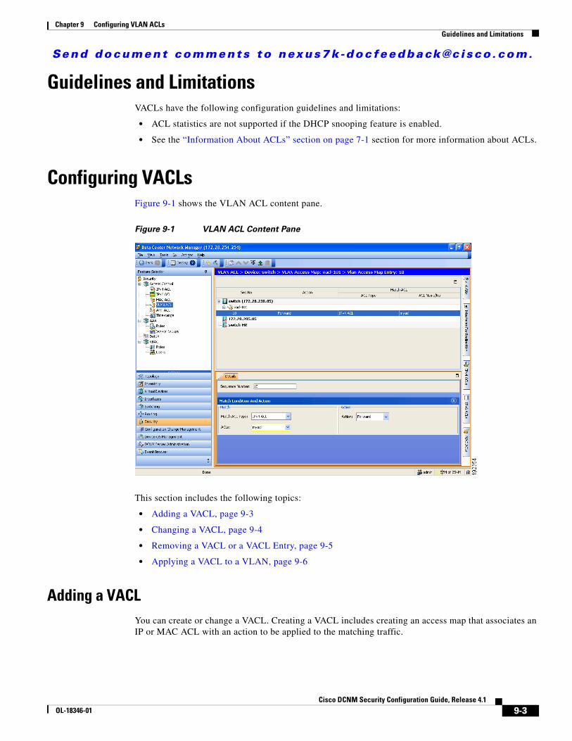
Send document comments to nexus7k -doc feedback@c i sco .com.
Chapter 9 Configuring VLAN ACLsGuidelines and Limitations
Guidelines and LimitationsVACLs have the following configuration guidelines and limitations:
• ACL statistics are not supported if the DHCP snooping feature is enabled.
• See the “Information About ACLs” section on page 7-1 section for more information about ACLs.
Configuring VACLsFigure 9-1 shows the VLAN ACL content pane.
Figure 9-1 VLAN ACL Content Pane
This section includes the following topics:
• Adding a VACL, page 9-3
• Changing a VACL, page 9-4
• Removing a VACL or a VACL Entry, page 9-5
• Applying a VACL to a VLAN, page 9-6
Adding a VACLYou can create or change a VACL. Creating a VACL includes creating an access map that associates an IP or MAC ACL with an action to be applied to the matching traffic.
9-3Cisco DCNM Security Configuration Guide, Release 4.1
OL-18346-01
Send document comments to nexus7k -doc feedback@c i sco .com.
Chapter 9 Configuring VLAN ACLsConfiguring VACLs
BEFORE YOU BEGIN
Ensure that the IP ACL or MAC ACL that you want to use in the VACL exists and is configured to filter traffic in the manner that you need for this application. For more information about configuring IP ACLs, see the “Configuring IP ACLs” section on page 7-1. For more information about configuring MAC ACLs, see the “Configuring MAC ACLs” section on page 8-1.
DETAILED STEPS
To add a VACL, follow these steps:
Step 1 From the Feature Selector pane, choose Security > Access Control > VLAN ACL.
The Summary pane displays available devices.
Step 2 From the Summary pane, double-click the device to which you want to add a VACL.
Step 3 From the menu bar, choose File > New > VLAN Access Map.
Below the device that you selected, a new row appears in the Summary pane.
Step 4 In the new row, enter a name for the VACL.
The VACL remains selected in the Summary pane.
Step 5 For each VLAN access map entry that you want to create, follow these steps:
a. From the menu bar, choose File > New > VLAN Access Map Entry.
Below the VACL, a new row appears in the Summary pane.
b. From the Details pane, click the Details tab and expand the Match Condition And Action section, if necessary.
c. From the Match ACL Type drop-down list, select the type of ACL that you want to use in the VACL. You can choose IPv4 ACL, IPv6 ACL, or MAC ACL.
The ACLs drop-down list contains ACLs that are the type you selected and that exist on the currently selected device.
d. From the ACLs drop-down list, select the ACL that you want to use.
e. From the Action drop-down list, select the action that the device should take upon traffic matching the VACL.
Step 6 From the menu bar, choose File > Save to apply your changes to the device.
Changing a VACLYou can change a VACL.
DETAILED STEPS
To create or change a VACL, follow these steps:
Step 1 From the Feature Selector pane, choose Security > Access Control > VLAN ACL.
The Summary pane displays available devices.
9-4Cisco DCNM Security Configuration Guide, Release 4.1
OL-18346-01
Send document comments to nexus7k -doc feedback@c i sco .com.
Chapter 9 Configuring VLAN ACLsConfiguring VACLs
Step 2 From the Summary pane, double-click the device that contains the VACL and then click the VACL.
Step 3 (Optional) To add a VLAN access map entry, from the menu bar, choose File > New > VLAN Access Map Entry.
Below the VACL, the new VLAN access map entry appears in the Summary pane.
Step 4 (Optional) To change a new or existing VLAN access map entry, follow these steps:
a. Click the VLAN access map entry that you want to change.
b. From the Details pane, click the Details tab and expand the Match Condition And Action section, if necessary.
c. From the Match ACL Type drop-down list, select the type of ACL that you want to use in the VACL. You can choose IPv4 ACL, IPv6 ACL, or MAC ACL.
The ACLs drop-down list contains ACLs that are the type you selected and that exist on the currently selected device.
d. From the ACLs drop-down list, select the ACL that you want to use.
e. From the Action drop-down list, select the action that the device should take upon traffic matching the VACL.
Step 5 (Optional) If you want to move a VLAN access map entry to a different position in the VACL, click the entry in the Summary pane and then from the menu bar, choose one of the following, as applicable:
• Actions > Move Up
• Actions > Move Down
The entry swaps places and sequence numbers with the entry above it or below it, as you chose.
Step 6 (Optional) To remove a VLAN access map entry, click the VLAN access map entry and then choose Actions > Delete.
Step 7 From the menu bar, choose File > Save to apply your changes to the device.
Removing a VACL or a VACL EntryYou can remove a VACL, which means that you will delete the VLAN access map.
You can also remove a single VLAN access-map entry from a VACL.
BEFORE YOU BEGIN
Ensure that you know whether the VACL is applied to a VLAN. The device allows you to remove VACLs that are currently applied. Removing a VACL does not affect the configuration of VLANs where you have applied the VACL. Instead, the device considers the removed VACL to be empty.
DETAILED STEPS
To remove a VACL or a VACL entry, follow these steps:
Step 1 From the Feature Selector pane, choose Security > Access Control > VLAN ACL.
Available devices appear in the Summary pane.
Step 2 From the Summary pane, double-click the device from which you want to remove a VACL.
9-5Cisco DCNM Security Configuration Guide, Release 4.1
OL-18346-01
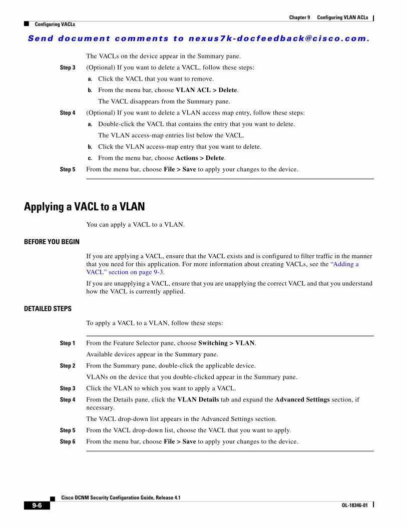
Send document comments to nexus7k -doc feedback@c i sco .com.
Chapter 9 Configuring VLAN ACLsConfiguring VACLs
The VACLs on the device appear in the Summary pane.
Step 3 (Optional) If you want to delete a VACL, follow these steps:
a. Click the VACL that you want to remove.
b. From the menu bar, choose VLAN ACL > Delete.
The VACL disappears from the Summary pane.
Step 4 (Optional) If you want to delete a VLAN access map entry, follow these steps:
a. Double-click the VACL that contains the entry that you want to delete.
The VLAN access-map entries list below the VACL.
b. Click the VLAN access-map entry that you want to delete.
c. From the menu bar, choose Actions > Delete.
Step 5 From the menu bar, choose File > Save to apply your changes to the device.
Applying a VACL to a VLANYou can apply a VACL to a VLAN.
BEFORE YOU BEGIN
If you are applying a VACL, ensure that the VACL exists and is configured to filter traffic in the manner that you need for this application. For more information about creating VACLs, see the “Adding a VACL” section on page 9-3.
If you are unapplying a VACL, ensure that you are unapplying the correct VACL and that you understand how the VACL is currently applied.
DETAILED STEPS
To apply a VACL to a VLAN, follow these steps:
Step 1 From the Feature Selector pane, choose Switching > VLAN.
Available devices appear in the Summary pane.
Step 2 From the Summary pane, double-click the applicable device.
VLANs on the device that you double-clicked appear in the Summary pane.
Step 3 Click the VLAN to which you want to apply a VACL.
Step 4 From the Details pane, click the VLAN Details tab and expand the Advanced Settings section, if necessary.
The VACL drop-down list appears in the Advanced Settings section.
Step 5 From the VACL drop-down list, choose the VACL that you want to apply.
Step 6 From the menu bar, choose File > Save to apply your changes to the device.
9-6Cisco DCNM Security Configuration Guide, Release 4.1
OL-18346-01
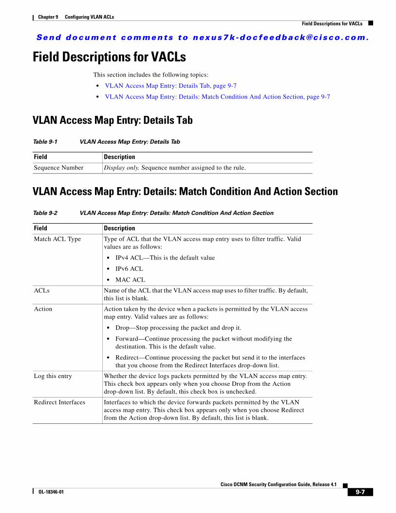
Send document comments to nexus7k -doc feedback@c i sco .com.
Chapter 9 Configuring VLAN ACLsField Descriptions for VACLs
Field Descriptions for VACLsThis section includes the following topics:
• VLAN Access Map Entry: Details Tab, page 9-7
• VLAN Access Map Entry: Details: Match Condition And Action Section, page 9-7
VLAN Access Map Entry: Details Tab
VLAN Access Map Entry: Details: Match Condition And Action Section
Table 9-1 VLAN Access Map Entry: Details Tab
Field Description
Sequence Number Display only. Sequence number assigned to the rule.
Table 9-2 VLAN Access Map Entry: Details: Match Condition And Action Section
Field Description
Match ACL Type Type of ACL that the VLAN access map entry uses to filter traffic. Valid values are as follows:
• IPv4 ACL—This is the default value
• IPv6 ACL
• MAC ACL
ACLs Name of the ACL that the VLAN access map uses to filter traffic. By default, this list is blank.
Action Action taken by the device when a packets is permitted by the VLAN access map entry. Valid values are as follows:
• Drop—Stop processing the packet and drop it.
• Forward—Continue processing the packet without modifying the destination. This is the default value.
• Redirect—Continue processing the packet but send it to the interfaces that you choose from the Redirect Interfaces drop-down list.
Log this entry Whether the device logs packets permitted by the VLAN access map entry. This check box appears only when you choose Drop from the Action drop-down list. By default, this check box is unchecked.
Redirect Interfaces Interfaces to which the device forwards packets permitted by the VLAN access map entry. This check box appears only when you choose Redirect from the Action drop-down list. By default, this list is blank.
9-7Cisco DCNM Security Configuration Guide, Release 4.1
OL-18346-01
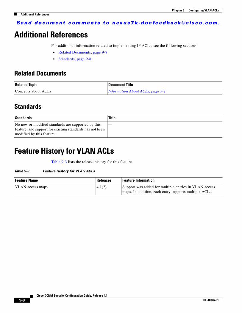
Send document comments to nexus7k -doc feedback@c i sco .com.
Chapter 9 Configuring VLAN ACLsAdditional References
Additional ReferencesFor additional information related to implementing IP ACLs, see the following sections:
• Related Documents, page 9-8
• Standards, page 9-8
Related Documents
Standards
Feature History for VLAN ACLsTable 9-3 lists the release history for this feature.
Related Topic Document Title
Concepts about ACLs Information About ACLs, page 7-1
Standards Title
No new or modified standards are supported by this feature, and support for existing standards has not been modified by this feature.
—
Table 9-3 Feature History for VLAN ACLs
Feature Name Releases Feature Information
VLAN access maps 4.1(2) Support was added for multiple entries in VLAN access maps. In addition, each entry supports multiple ACLs.
9-8Cisco DCNM Security Configuration Guide, Release 4.1
OL-18346-01
Send document comments to nexus7k -doc feedback@c i sco .com.
CiscOL-18346-01
C H A P T E R10
Configuring Port SecurityThis chapter describes how to configure port security on NX-OS devices.
This chapter includes the following sections:
• Information About Port Security, page 10-1
• Licensing Requirements for Port Security, page 10-6
• Prerequisites for Port Security, page 10-6
• Guidelines and Limitations, page 10-7
• Configuring Port Security, page 10-7
• Displaying Secure MAC Addresses, page 10-15
• Displaying Violation Statistics, page 10-16
• Field Descriptions for Port Security, page 10-16
• Additional References, page 10-18
• Feature History for Port Security, page 10-19
Information About Port SecurityPort security allows you to configure Layer 2 interfaces that allow inbound traffic from only a restricted set of MAC addresses. The MAC addresses in the restricted set are called secure MAC addresses. In addition, the device does not allow traffic from these MAC addresses on another interface within the same VLAN. The number of MAC addresses that the device can secure is configurable per interface.
This section includes the following topics:
• Secure MAC Address Learning, page 10-2
• Dynamic Address Aging, page 10-3
• Secure MAC Address Maximums, page 10-3
• Security Violations and Actions, page 10-4
• Port Security and Port Types, page 10-5
• Port Type Changes, page 10-5
• 802.1X and Port Security, page 10-5
• Virtualization Support, page 10-6
10-1o DCNM Security Configuration Guide, Release 4.1
Send document comments to nexus7k -doc feedback@c i sco .com.
Chapter 10 Configuring Port SecurityInformation About Port Security
Secure MAC Address LearningThe process of securing a MAC address is called learning. The number of addresses that can be learned is restricted, as described in the “Secure MAC Address Maximums” section on page 10-3. For each interface that you enable port security on, the device can learn addresses by the static, dynamic, or sticky methods.
Static Method
The static learning method allows you to manually add or remove secure MAC addresses to the configuration of an interface.
A static secure MAC address entry remains in the configuration of an interface until one of the following events occurs:
• You explicitly remove the address from the configuration. For more information, see the “Removing a Static Secure MAC Address on an Interface” section on page 10-12.
• You configure the interface to act as a Layer 3 interface. For more information, see the “Port Type Changes” section on page 10-5.
Adding secure addresses by the static method is not affected by whether dynamic or sticky address learning is enabled.
Dynamic Method
By default, when you enable port security on an interface, you enable the dynamic learning method. With this method, the device secures MAC addresses as ingress traffic passes through the interface. If the address is not yet secured and the device has not reached any applicable maximum, it secures the address and allows the traffic.
The device ages dynamic addresses and drops them once the age limit is reached, as described in the “Dynamic Address Aging” section on page 10-3.
Dynamic addresses do not persist through a device restart or through restarting the interface.
To remove a specific address learned by the dynamic method or to remove all addresses learned by the dynamic method on a specific interface, see the “Removing a Dynamic or Sticky Secure MAC Address” section on page 10-12.
Sticky Method
If you enable the sticky method, the device secures MAC addresses in the same manner as dynamic address learning, but the device stores addresses learned by this method in non-volatile RAM (NVRAM). As a result, addresses learned by the sticky method persist through a device restart. Sticky secure MAC addresses do not appear in the running configuration of an interface.
Dynamic and sticky address learning are mutually exclusive. When you enable sticky learning on an interface, the device stops dynamic learning and performs sticky learning instead. If you disable sticky learning, the device resumes dynamic learning.
The device does not age sticky secure MAC addresses.
To remove a specific address learned by the sticky method, see the “Removing a Static Secure MAC Address on an Interface” section on page 10-12.
10-2Cisco DCNM Security Configuration Guide, Release 4.1
OL-18346-01
Send document comments to nexus7k -doc feedback@c i sco .com.
Chapter 10 Configuring Port SecurityInformation About Port Security
Dynamic Address AgingThe device ages MAC addresses learned by the dynamic method and drops them after the age limit is reached. You can configure the age limit on each interface. The range is from 0 to 1440 minutes, where 0 disables aging.
The method that the device uses to determine that the MAC address age is also configurable. The two methods of determining address age are as follows:
• Inactivity—The length of time after the device last received a packet from the address on the applicable interface.
• Absolute—The length of time after the device learned the address. This is the default aging method; however, the default aging time is 0 minutes, which disables aging.
Secure MAC Address MaximumsBy default, an interface can have only one secure MAC address. You can configure the maximum number of MAC addresses permitted per interface or per VLAN on an interface. Maximums apply to secure MAC addresses learned by any method: dynamic, sticky, or static.
Tip To ensure that an attached device has the full bandwidth of the port, set the maximum number of addresses to one and configure the MAC address of the attached device.
The following three limits can determine how many secure MAC address are permitted on an interface:
• Device maximum—The device has a nonconfigurable limit of 8192 secure MAC addresses. If learning a new address would violate the device maximum, the device does not permit the new address to be learned, even if the interface or VLAN maximum has not been reached.
• Interface maximum—You can configure a maximum number of secure MAC addresses for each interface protected by port security. The default interface maximum is one address. Interface maximums cannot exceed the device maximum.
• VLAN maximum—You can configure the maximum number of secure MAC addresses per VLAN for each interface protected by port security. A VLAN maximum cannot exceed the interface maximum. VLAN maximums are useful only for trunk ports. There are no default VLAN maximums.
For an example of how VLAN and interface maximums interact, see the “Security Violations and Actions” section on page 10-4.
You can configure VLAN and interface maximums per interface, as needed; however, when the new limit is less than the applicable number of secure addresses, you must reduce the number of secure MAC addresses first. To remove dynamically learned addresses, see the “Removing a Dynamic or Sticky Secure MAC Address” section on page 10-12. To remove addresses learned by the sticky or static methods, see the “Removing a Static Secure MAC Address on an Interface” section on page 10-12.
10-3Cisco DCNM Security Configuration Guide, Release 4.1
OL-18346-01
Send document comments to nexus7k -doc feedback@c i sco .com.
Chapter 10 Configuring Port SecurityInformation About Port Security
Security Violations and ActionsPort security triggers security violations when either of the two following events occur:
• Ingress traffic arrives at an interface from a nonsecure MAC address and learning the address would exceed the applicable maximum number of secure MAC addresses.
When an interface has both a VLAN maximum and an interface maximum configured, a violation occurs when either maximum is exceeded. For example, consider the following on a single interface configured with port security:
– VLAN 1 has a maximum of 5 addresses
– The interface has a maximum of 10 addresses
The device detects a violation when any of the following occurs:
– The device has learned five addresses for VLAN 1 and inbound traffic from a sixth address arrives at the interface in VLAN 1.
– The device has learned 10 addresses on the interface and inbound traffic from an 11th address arrives at the interface.
• Ingress traffic from a secure MAC address arrives at a different interface in the same VLAN as the interface on which the address is secured.
Note After a secure MAC address is configured or learned on one secure port, the sequence of events that occurs when port security detects that secure MAC address on a different port in the same VLAN is known as a MAC move violation.
When a security violation occurs, the device takes the action specified by the port security configuration of the applicable interface. The possible actions that the device can take are as follows:
• Shutdown—Shuts down the interface that received the packet triggering the violation. The interface is error disabled. This action is the default. After you reenable the interface, it retains its port security configuration, including its secure MAC addresses.
• Restrict—Drops ingress traffic from any nonsecure MAC addresses. The device keeps a count of the number of dropped packets.
• Protect—Prevents violations from occurring. Address learning continues until the maximum number of MAC addresses on the interface is reached, after which the device disables learning on the interface and drops all ingress traffic from nonsecure MAC addresses.
If a violation occurs because ingress traffic from a secure MAC address arrives at a different interface than the interface on which the address is secure, the device applies the action on the interface that received the traffic.
10-4Cisco DCNM Security Configuration Guide, Release 4.1
OL-18346-01
Send document comments to nexus7k -doc feedback@c i sco .com.
Chapter 10 Configuring Port SecurityInformation About Port Security
Port Security and Port TypesYou can configure port security only on Layer 2 interfaces. Details about port security and different types of interfaces or ports are as follows:
• Access ports—You can configure port security on interfaces that you have configured as Layer 2 access ports. On an access port, port security applies only to the access VLAN.
• Trunk ports—You can configure port security on interfaces that you have configured as Layer 2 trunk ports. VLAN maximums are not useful for access ports. The device allows VLAN maximums only for VLANs associated with the trunk port.
• SPAN ports—You can configure port security on SPAN source ports but not on SPAN destination ports.
• Ethernet Port Channels—Port security is not supported on Ethernet port channels.
Port Type ChangesWhen you have configured port security on a Layer 2 interface and you change the port type of the interface, the device behaves as follows:
• Access port to trunk port—When you change a Layer 2 interface from an access port to a trunk port, the device drops all secure addresses learned by the dynamic method. The device moves the addresses learned by the static or sticky method to the native trunk VLAN.
• Trunk port to access port—When you change a Layer 2 interface from a trunk port to an access port, the device drops all secure addresses learned by the dynamic method. It also moves all addresses learned by the sticky method on the native trunk VLAN to the access VLAN. The device drops secure addresses learned by the sticky method if they are not on the native trunk VLAN.
• Switched port to routed port—When you change an interface from a Layer 2 interface to a Layer 3 interface, the device disables port security on the interface and discards all port security configuration for the interface. The device also discards all secure MAC addresses for the interface, regardless of the method used to learn the address.
• Routed port to switched port—When you change an interface from a Layer 3 interface to a Layer 2 interface, the device has no port security configuration for the interface.
802.1X and Port SecurityYou can configure port security and 802.1X on the same interfaces. Port security secures the MAC addresses that 802.1X authenticates. 802.1X processes packets before port security processes them, so when you enable both on an interface, 802.1X is already preventing inbound traffic on the interface from unknown MAC addresses.
When you enable 802.1X and port security on the same interface, port security continues to learn MAC addresses by the sticky or dynamic method, as configured. Additionally, depending on whether you enable 802.1X in single-host mode or multiple-host mode, one of the following occurs:
• Single host mode—Port security learns the MAC address of the authenticated host.
• Multiple host mode—Port security drops any MAC addresses learned for this interface by the dynamic method and learns the MAC address of the first host authenticated by 802.1X.
If a MAC address that 802.1X passes to port security would violate the applicable maximum number of secure MAC addresses, the device sends an authentication failure message to the host.
10-5Cisco DCNM Security Configuration Guide, Release 4.1
OL-18346-01
Send document comments to nexus7k -doc feedback@c i sco .com.
Chapter 10 Configuring Port SecurityLicensing Requirements for Port Security
The device treats MAC addresses authenticated by 802.1X as though they were learned by the dynamic method, even if port security previously learned the address by the sticky or static methods. If you attempt to delete a secure MAC address that has been authenticated by 802.1X, the address remains secure.
If the MAC address of an authenticated host is secured by the sticky or static method, the device treats the address as if it were learned by the dynamic method, and you cannot delete the MAC address manually.
Port security integrates with 802.1X to reauthenticate hosts when the authenticated and secure MAC address of the host reaches its port security age limit. The device behaves differently depending upon the type of aging, as follows:
• Absolute—Port security notifies 802.1X and the device attempts to reauthenticate the host. The result of reauthentication determines whether the address remains secure. If reauthentication succeeds, the device restarts the aging timer on the secure address; otherwise, the device drops the address from the list of secure addressees for the interface.
• Inactivity—Port security drops the secure address from the list of secure addresses for the interface and notifies 802.1X. The device attempts to reauthenticate the host. If reauthentication succeeds, port security secures the address again.
Virtualization SupportPort security supports VDCs as follows:
• Port security is local to each VDC. You enable and configure port security on a per-VDC basis.
• Each VDC maintains secure MAC addresses separately.
• The device cannot issue a security violation when a secured MAC address in one VDC is seen on a protected interface in another VDC.
Licensing Requirements for Port SecurityThe following table shows the licensing requirements for this feature:
Prerequisites for Port SecurityPort security has the following prerequisites:
• You must globally enable port security for the device that you want to protect with port security.
Product License Requirement
DCNM Port security requires a LAN Enterprise license. For a complete explanation of the DCNM licensing scheme and how to obtain and apply licenses, see the Cisco DCNM Fundamentals Configuration Guide, Release 4.1.
NX-OS Port security requires no license. Any feature not included in a license package is bundled with the Cisco NX-OS device images and is provided at no extra charge to you. For a complete explanation of the NX-OS licensing scheme, see the Cisco Nexus 7000 Series NX-OS Licensing Guide, Release 4.1.
10-6Cisco DCNM Security Configuration Guide, Release 4.1
OL-18346-01
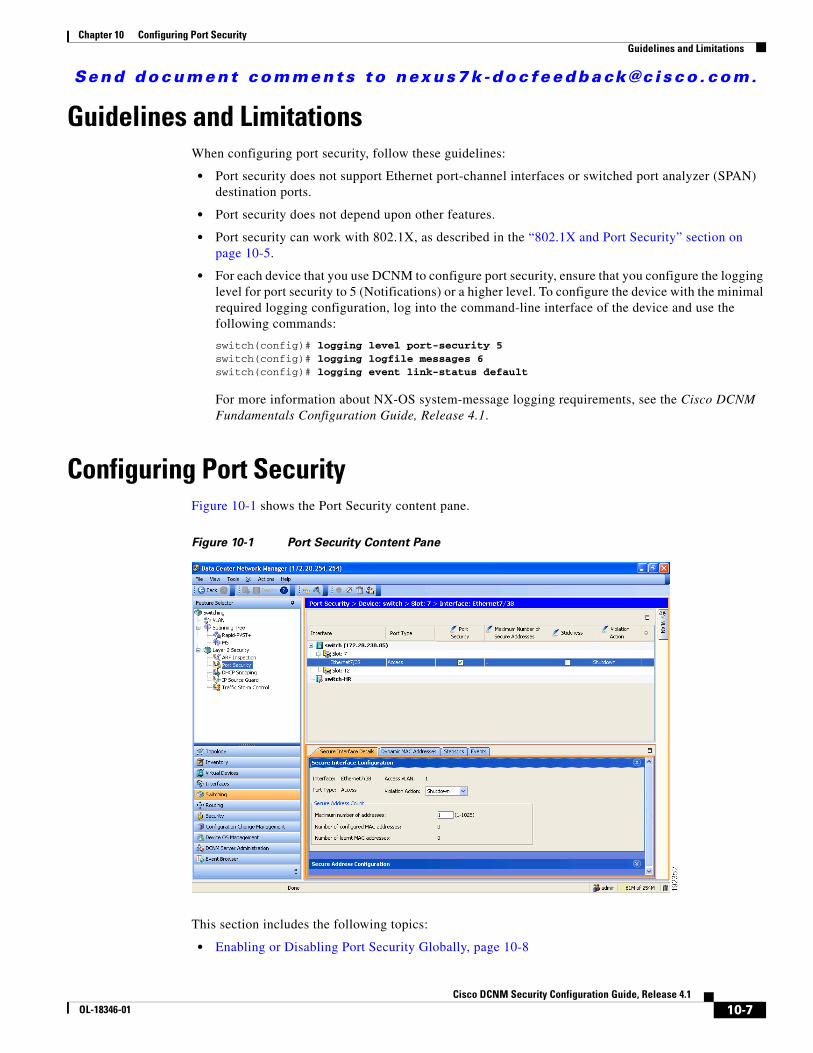
Send document comments to nexus7k -doc feedback@c i sco .com.
Chapter 10 Configuring Port SecurityGuidelines and Limitations
Guidelines and LimitationsWhen configuring port security, follow these guidelines:
• Port security does not support Ethernet port-channel interfaces or switched port analyzer (SPAN) destination ports.
• Port security does not depend upon other features.
• Port security can work with 802.1X, as described in the “802.1X and Port Security” section on page 10-5.
• For each device that you use DCNM to configure port security, ensure that you configure the logging level for port security to 5 (Notifications) or a higher level. To configure the device with the minimal required logging configuration, log into the command-line interface of the device and use the following commands:
switch(config)# logging level port-security 5switch(config)# logging logfile messages 6switch(config)# logging event link-status default
For more information about NX-OS system-message logging requirements, see the Cisco DCNM Fundamentals Configuration Guide, Release 4.1.
Configuring Port SecurityFigure 10-1 shows the Port Security content pane.
Figure 10-1 Port Security Content Pane
This section includes the following topics:
• Enabling or Disabling Port Security Globally, page 10-8
10-7Cisco DCNM Security Configuration Guide, Release 4.1
OL-18346-01
Send document comments to nexus7k -doc feedback@c i sco .com.
Chapter 10 Configuring Port SecurityConfiguring Port Security
• Enabling or Disabling Port Security on a Layer 2 Interface, page 10-9
• Enabling or Disabling Sticky MAC Address Learning, page 10-10
• Adding a Static Secure MAC Address on an Interface, page 10-10
• Removing a Static Secure MAC Address on an Interface, page 10-12
• Removing a Dynamic or Sticky Secure MAC Address, page 10-12
• Configuring a Maximum Number of MAC Addresses, page 10-13
• Configuring an Address Aging Type and Time, page 10-14
• Configuring a Security Violation Action, page 10-15
Enabling or Disabling Port Security GloballyYou can enable or disable port security globally on a device.
When you disable port security globally, all port security configuration is lost, including any statically configured secure MAC addresses and all dynamic or sticky secured MAC addresses.
BEFORE YOU BEGIN
By default, port security is disabled.
Ensure that you configure the logging level for port security to 5 (Informational) or a higher level on the NX-OS device. To configure the device with the minimal required logging configuration, log into the command-line interface of the device and use the following commands:
switch(config)# logging level port-security 5switch(config)# logging logfile messages 6switch(config)# logging event link-status default
For more information about NX-OS system-message logging requirements, see the Cisco DCNM Fundamentals Configuration Guide, Release 4.1.
DETAILED STEPS
To enable or disable port security on a device, follow these steps:
Step 1 From the Feature Selector pane, choose Switching > Layer 2 Security > Port Security.
The available devices appear in the Summary pane.
Step 2 From the Summary pane, click the device on which you want to enable or disable port security.
Step 3 Do one of the following:
• To enable port security globally on the device, from the menu bar, choose Port Security > Enable Port Security.
The Stop Learning check box appears on the Global Settings tab in the Details pane.
• To disable port security globally on the device, from the menu bar, choose Port Security > Disable Port Security.
The “Port Security is disabled on device” message appears on the Global Settings tab in the Details pane.
10-8Cisco DCNM Security Configuration Guide, Release 4.1
OL-18346-01
Send document comments to nexus7k -doc feedback@c i sco .com.
Chapter 10 Configuring Port SecurityConfiguring Port Security
Step 4 From the menu bar, choose File > Deploy to apply your changes to the device.
Enabling or Disabling Port Security on a Layer 2 InterfaceYou can enable or disable port security on a Layer 2 interface. For more information about dynamic learning of MAC addresses, see the “Secure MAC Address Learning” section on page 10-2.
Note You cannot enable port security on a routed interface.
BEFORE YOU BEGIN
By default, port security is disabled on all interfaces.
Enabling port security on an interface also enables dynamic MAC address learning. If you want to enable sticky MAC address learning, you must also complete the steps in the “Enabling or Disabling Sticky MAC Address Learning” section on page 10-10.
Ensure that port security is enabled. To enable port security, see the “Enabling or Disabling Port Security Globally” section on page 10-8.
DETAILED STEPS
To enable or disable port security on an interface, follow these steps:
Step 1 From the Feature Selector pane, choose Switching > Layer 2 Security > Port Security.
The available devices appear in the Summary pane.
Step 2 From the Summary pane, double-click the device and then double-click the slot that contains the interface on which you want to enable or disable port security.
The Summary pane displays the slots on the device and any interfaces on which port security is configured. The slot remains selected.
Step 3 (Optional) If the interface that you need does not appear, from the menu bar, choose Actions > Add Interface. In the Interface column, from the drop-down list, choose the interface on which you want to enable port security.
The interface name appears in the new row of the Summary pane.
Step 4 Click the interface on which you want to enable or disable port security.
Step 5 Do one of the following:
• To enable port security on the selected interface, in the Port Security column, check the check box.
Port security is enabled on the selected interface.
• To disable port security on the selected interface, in the Port Security column, uncheck the check box.
Port security is disabled on the selected interface.
Step 6 From the menu bar, choose File > Deploy to apply your changes to the device.
10-9Cisco DCNM Security Configuration Guide, Release 4.1
OL-18346-01

Send document comments to nexus7k -doc feedback@c i sco .com.
Chapter 10 Configuring Port SecurityConfiguring Port Security
Enabling or Disabling Sticky MAC Address LearningYou can disable or enable sticky MAC address learning on an interface. If you disable sticky learning, the device returns to dynamic MAC address learning on the interface, which is the default learning method.
BEFORE YOU BEGIN
By default, sticky MAC address learning is disabled.
Ensure that port security is enabled globally and on the interface that you are configuring. To enable port security globally, see the “Enabling or Disabling Port Security Globally” section on page 10-8. To enable port security on the interface, see the “Enabling or Disabling Port Security on a Layer 2 Interface” section on page 10-9.
DETAILED STEPS
To enable or disable sticky secure MAC address learning, follow these steps:
Step 1 From the Feature Selector pane, choose Switching > Layer 2 Security > Port Security.
The available devices appear in the Summary pane.
Step 2 From the Summary pane, double-click the device and then double-click the slot that contains the interface on which you want to enable or disable port security.
The slots on the device and any interfaces on which port security is configured appear in the Summary pane. The slot remains selected.
Step 3 Click the interface on which you want to enable or disable sticky MAC address learning.
Step 4 Do one of the following:
• To enable sticky MAC address learning on the selected interface, in the Stickiness column, check the check box.
Sticky MAC address learning is enabled on the selected interface.
• To disable sticky MAC address learning on the selected interface, in the Stickiness column, uncheck the check box.
Sticky MAC address learning is disabled on the selected interface.
Step 5 From the menu bar, choose File > Deploy to apply your changes to the device.
Adding a Static Secure MAC Address on an InterfaceYou can add a static secure MAC address on a Layer 2 interface. If the interface is in trunk port mode, you must assign the new static secure MAC address to a VLAN.
BEFORE YOU BEGIN
By default, no static secure MAC addresses are configured on an interface.
10-10Cisco DCNM Security Configuration Guide, Release 4.1
OL-18346-01
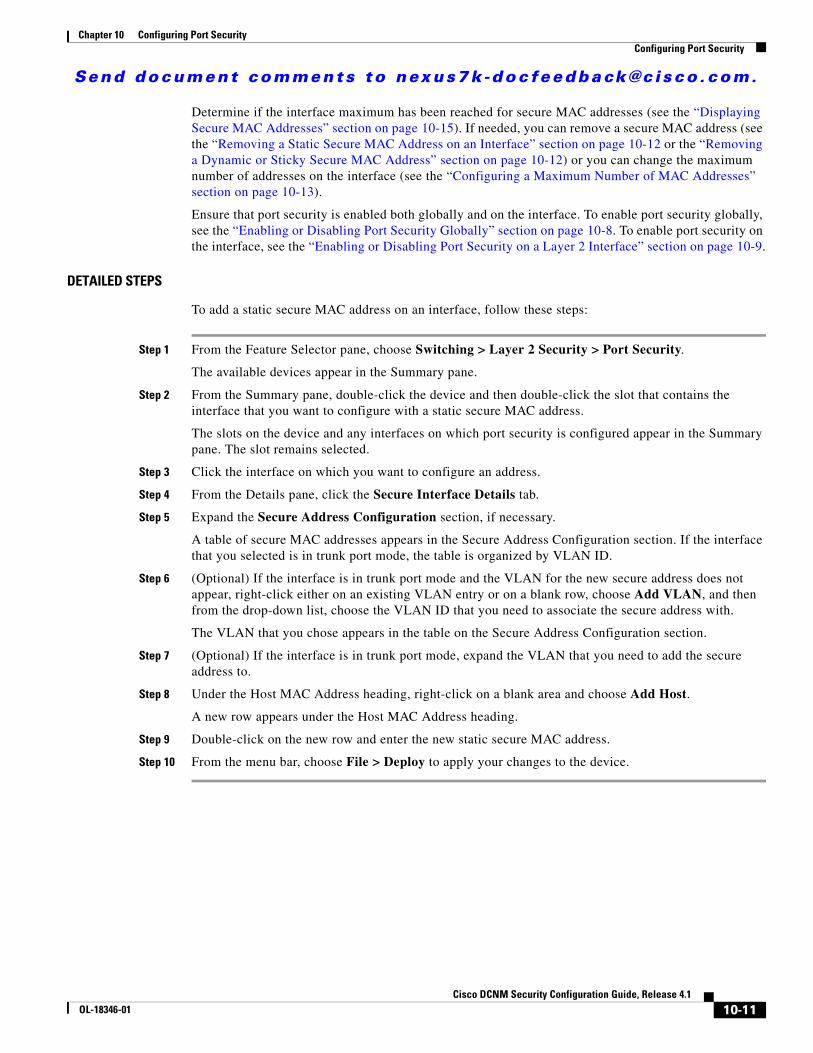
Send document comments to nexus7k -doc feedback@c i sco .com.
Chapter 10 Configuring Port SecurityConfiguring Port Security
Determine if the interface maximum has been reached for secure MAC addresses (see the “Displaying Secure MAC Addresses” section on page 10-15). If needed, you can remove a secure MAC address (see the “Removing a Static Secure MAC Address on an Interface” section on page 10-12 or the “Removing a Dynamic or Sticky Secure MAC Address” section on page 10-12) or you can change the maximum number of addresses on the interface (see the “Configuring a Maximum Number of MAC Addresses” section on page 10-13).
Ensure that port security is enabled both globally and on the interface. To enable port security globally, see the “Enabling or Disabling Port Security Globally” section on page 10-8. To enable port security on the interface, see the “Enabling or Disabling Port Security on a Layer 2 Interface” section on page 10-9.
DETAILED STEPS
To add a static secure MAC address on an interface, follow these steps:
Step 1 From the Feature Selector pane, choose Switching > Layer 2 Security > Port Security.
The available devices appear in the Summary pane.
Step 2 From the Summary pane, double-click the device and then double-click the slot that contains the interface that you want to configure with a static secure MAC address.
The slots on the device and any interfaces on which port security is configured appear in the Summary pane. The slot remains selected.
Step 3 Click the interface on which you want to configure an address.
Step 4 From the Details pane, click the Secure Interface Details tab.
Step 5 Expand the Secure Address Configuration section, if necessary.
A table of secure MAC addresses appears in the Secure Address Configuration section. If the interface that you selected is in trunk port mode, the table is organized by VLAN ID.
Step 6 (Optional) If the interface is in trunk port mode and the VLAN for the new secure address does not appear, right-click either on an existing VLAN entry or on a blank row, choose Add VLAN, and then from the drop-down list, choose the VLAN ID that you need to associate the secure address with.
The VLAN that you chose appears in the table on the Secure Address Configuration section.
Step 7 (Optional) If the interface is in trunk port mode, expand the VLAN that you need to add the secure address to.
Step 8 Under the Host MAC Address heading, right-click on a blank area and choose Add Host.
A new row appears under the Host MAC Address heading.
Step 9 Double-click on the new row and enter the new static secure MAC address.
Step 10 From the menu bar, choose File > Deploy to apply your changes to the device.
10-11Cisco DCNM Security Configuration Guide, Release 4.1
OL-18346-01
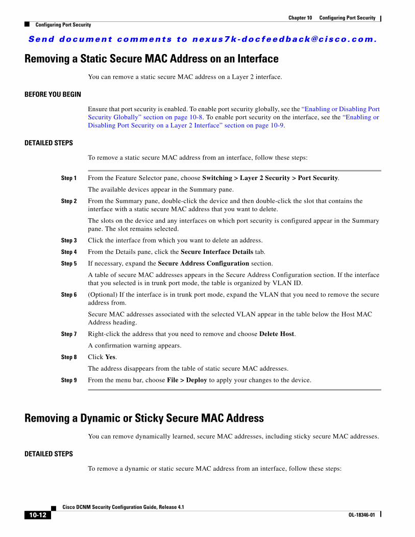
Send document comments to nexus7k -doc feedback@c i sco .com.
Chapter 10 Configuring Port SecurityConfiguring Port Security
Removing a Static Secure MAC Address on an InterfaceYou can remove a static secure MAC address on a Layer 2 interface.
BEFORE YOU BEGIN
Ensure that port security is enabled. To enable port security globally, see the “Enabling or Disabling Port Security Globally” section on page 10-8. To enable port security on the interface, see the “Enabling or Disabling Port Security on a Layer 2 Interface” section on page 10-9.
DETAILED STEPS
To remove a static secure MAC address from an interface, follow these steps:
Step 1 From the Feature Selector pane, choose Switching > Layer 2 Security > Port Security.
The available devices appear in the Summary pane.
Step 2 From the Summary pane, double-click the device and then double-click the slot that contains the interface with a static secure MAC address that you want to delete.
The slots on the device and any interfaces on which port security is configured appear in the Summary pane. The slot remains selected.
Step 3 Click the interface from which you want to delete an address.
Step 4 From the Details pane, click the Secure Interface Details tab.
Step 5 If necessary, expand the Secure Address Configuration section.
A table of secure MAC addresses appears in the Secure Address Configuration section. If the interface that you selected is in trunk port mode, the table is organized by VLAN ID.
Step 6 (Optional) If the interface is in trunk port mode, expand the VLAN that you need to remove the secure address from.
Secure MAC addresses associated with the selected VLAN appear in the table below the Host MAC Address heading.
Step 7 Right-click the address that you need to remove and choose Delete Host.
A confirmation warning appears.
Step 8 Click Yes.
The address disappears from the table of static secure MAC addresses.
Step 9 From the menu bar, choose File > Deploy to apply your changes to the device.
Removing a Dynamic or Sticky Secure MAC AddressYou can remove dynamically learned, secure MAC addresses, including sticky secure MAC addresses.
DETAILED STEPS
To remove a dynamic or static secure MAC address from an interface, follow these steps:
10-12Cisco DCNM Security Configuration Guide, Release 4.1
OL-18346-01
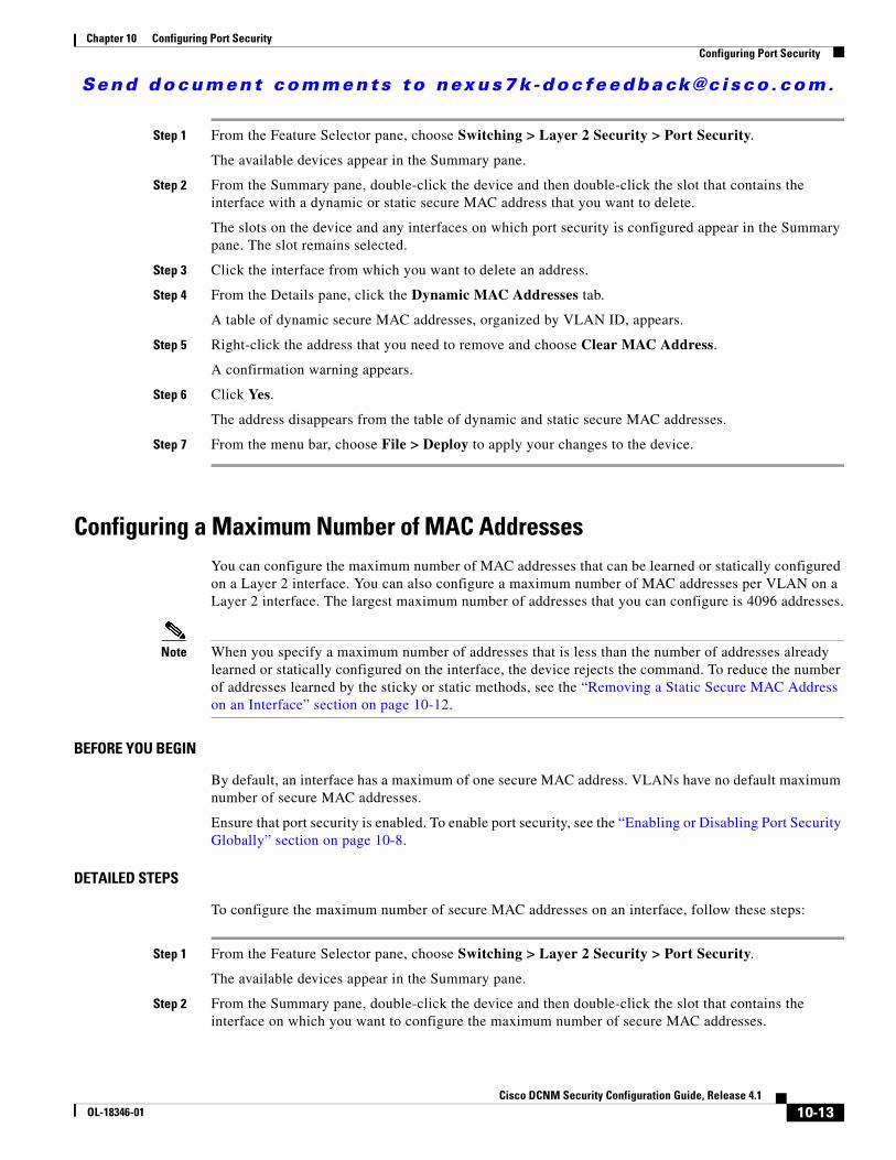
Send document comments to nexus7k -doc feedback@c i sco .com.
Chapter 10 Configuring Port SecurityConfiguring Port Security
Step 1 From the Feature Selector pane, choose Switching > Layer 2 Security > Port Security.
The available devices appear in the Summary pane.
Step 2 From the Summary pane, double-click the device and then double-click the slot that contains the interface with a dynamic or static secure MAC address that you want to delete.
The slots on the device and any interfaces on which port security is configured appear in the Summary pane. The slot remains selected.
Step 3 Click the interface from which you want to delete an address.
Step 4 From the Details pane, click the Dynamic MAC Addresses tab.
A table of dynamic secure MAC addresses, organized by VLAN ID, appears.
Step 5 Right-click the address that you need to remove and choose Clear MAC Address.
A confirmation warning appears.
Step 6 Click Yes.
The address disappears from the table of dynamic and static secure MAC addresses.
Step 7 From the menu bar, choose File > Deploy to apply your changes to the device.
Configuring a Maximum Number of MAC AddressesYou can configure the maximum number of MAC addresses that can be learned or statically configured on a Layer 2 interface. You can also configure a maximum number of MAC addresses per VLAN on a Layer 2 interface. The largest maximum number of addresses that you can configure is 4096 addresses.
Note When you specify a maximum number of addresses that is less than the number of addresses already learned or statically configured on the interface, the device rejects the command. To reduce the number of addresses learned by the sticky or static methods, see the “Removing a Static Secure MAC Address on an Interface” section on page 10-12.
BEFORE YOU BEGIN
By default, an interface has a maximum of one secure MAC address. VLANs have no default maximum number of secure MAC addresses.
Ensure that port security is enabled. To enable port security, see the “Enabling or Disabling Port Security Globally” section on page 10-8.
DETAILED STEPS
To configure the maximum number of secure MAC addresses on an interface, follow these steps:
Step 1 From the Feature Selector pane, choose Switching > Layer 2 Security > Port Security.
The available devices appear in the Summary pane.
Step 2 From the Summary pane, double-click the device and then double-click the slot that contains the interface on which you want to configure the maximum number of secure MAC addresses.
10-13Cisco DCNM Security Configuration Guide, Release 4.1
OL-18346-01
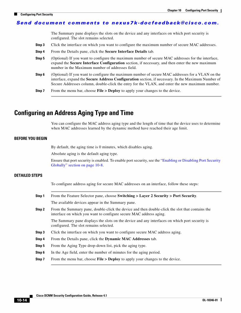
Send document comments to nexus7k -doc feedback@c i sco .com.
Chapter 10 Configuring Port SecurityConfiguring Port Security
The Summary pane displays the slots on the device and any interfaces on which port security is configured. The slot remains selected.
Step 3 Click the interface on which you want to configure the maximum number of secure MAC addresses.
Step 4 From the Details pane, click the Secure Interface Details tab.
Step 5 (Optional) If you want to configure the maximum number of secure MAC addresses for the interface, expand the Secure Interface Configuration section, if necessary, and then enter the new maximum number in the Maximum number of addresses field.
Step 6 (Optional) If you want to configure the maximum number of secure MAC addresses for a VLAN on the interface, expand the Secure Address Configuration section, if necessary. In the Maximum Number of Secure Addresses column, double-click the entry for the VLAN, and enter the new maximum number.
Step 7 From the menu bar, choose File > Deploy to apply your changes to the device.
Configuring an Address Aging Type and TimeYou can configure the MAC address aging type and the length of time that the device uses to determine when MAC addresses learned by the dynamic method have reached their age limit.
BEFORE YOU BEGIN
By default, the aging time is 0 minutes, which disables aging.
Absolute aging is the default aging type.
Ensure that port security is enabled. To enable port security, see the “Enabling or Disabling Port Security Globally” section on page 10-8.
DETAILED STEPS
To configure address aging for secure MAC addresses on an interface, follow these steps:
Step 1 From the Feature Selector pane, choose Switching > Layer 2 Security > Port Security.
The available devices appear in the Summary pane.
Step 2 From the Summary pane, double-click the device and then double-click the slot that contains the interface on which you want to configure secure MAC address aging.
The Summary pane displays the slots on the device and any interfaces on which port security is configured. The slot remains selected.
Step 3 Click the interface on which you want to configure secure MAC address aging.
Step 4 From the Details pane, click the Dynamic MAC Addresses tab.
Step 5 From the Aging Type drop-down list, pick the aging type.
Step 6 In the Age field, enter the number of minutes for the aging period.
Step 7 From the menu bar, choose File > Deploy to apply your changes to the device.
10-14Cisco DCNM Security Configuration Guide, Release 4.1
OL-18346-01
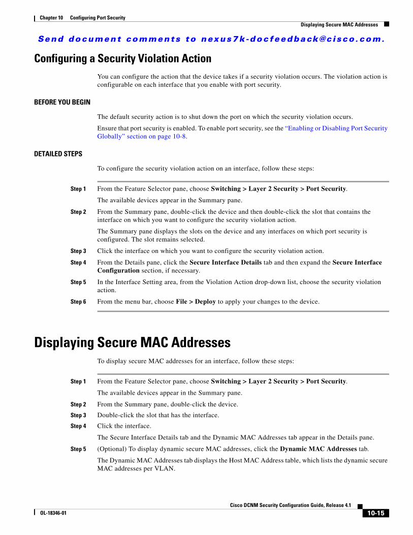
Send document comments to nexus7k -doc feedback@c i sco .com.
Chapter 10 Configuring Port SecurityDisplaying Secure MAC Addresses
Configuring a Security Violation ActionYou can configure the action that the device takes if a security violation occurs. The violation action is configurable on each interface that you enable with port security.
BEFORE YOU BEGIN
The default security action is to shut down the port on which the security violation occurs.
Ensure that port security is enabled. To enable port security, see the “Enabling or Disabling Port Security Globally” section on page 10-8.
DETAILED STEPS
To configure the security violation action on an interface, follow these steps:
Step 1 From the Feature Selector pane, choose Switching > Layer 2 Security > Port Security.
The available devices appear in the Summary pane.
Step 2 From the Summary pane, double-click the device and then double-click the slot that contains the interface on which you want to configure the security violation action.
The Summary pane displays the slots on the device and any interfaces on which port security is configured. The slot remains selected.
Step 3 Click the interface on which you want to configure the security violation action.
Step 4 From the Details pane, click the Secure Interface Details tab and then expand the Secure Interface Configuration section, if necessary.
Step 5 In the Interface Setting area, from the Violation Action drop-down list, choose the security violation action.
Step 6 From the menu bar, choose File > Deploy to apply your changes to the device.
Displaying Secure MAC AddressesTo display secure MAC addresses for an interface, follow these steps:
Step 1 From the Feature Selector pane, choose Switching > Layer 2 Security > Port Security.
The available devices appear in the Summary pane.
Step 2 From the Summary pane, double-click the device.
Step 3 Double-click the slot that has the interface.
Step 4 Click the interface.
The Secure Interface Details tab and the Dynamic MAC Addresses tab appear in the Details pane.
Step 5 (Optional) To display dynamic secure MAC addresses, click the Dynamic MAC Addresses tab.
The Dynamic MAC Addresses tab displays the Host MAC Address table, which lists the dynamic secure MAC addresses per VLAN.
10-15Cisco DCNM Security Configuration Guide, Release 4.1
OL-18346-01
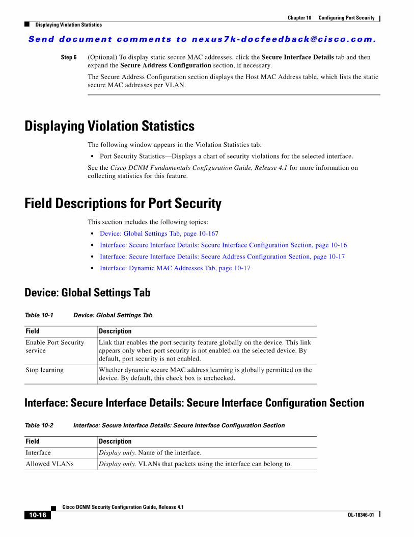
Send document comments to nexus7k -doc feedback@c i sco .com.
Chapter 10 Configuring Port SecurityDisplaying Violation Statistics
Step 6 (Optional) To display static secure MAC addresses, click the Secure Interface Details tab and then expand the Secure Address Configuration section, if necessary.
The Secure Address Configuration section displays the Host MAC Address table, which lists the static secure MAC addresses per VLAN.
Displaying Violation StatisticsThe following window appears in the Violation Statistics tab:
• Port Security Statistics—Displays a chart of security violations for the selected interface.
See the Cisco DCNM Fundamentals Configuration Guide, Release 4.1 for more information on collecting statistics for this feature.
Field Descriptions for Port SecurityThis section includes the following topics:
• Device: Global Settings Tab, page 10-167
• Interface: Secure Interface Details: Secure Interface Configuration Section, page 10-16
• Interface: Secure Interface Details: Secure Address Configuration Section, page 10-17
• Interface: Dynamic MAC Addresses Tab, page 10-17
Device: Global Settings Tab
Interface: Secure Interface Details: Secure Interface Configuration Section
Table 10-1 Device: Global Settings Tab
Field Description
Enable Port Security service
Link that enables the port security feature globally on the device. This link appears only when port security is not enabled on the selected device. By default, port security is not enabled.
Stop learning Whether dynamic secure MAC address learning is globally permitted on the device. By default, this check box is unchecked.
Table 10-2 Interface: Secure Interface Details: Secure Interface Configuration Section
Field Description
Interface Display only. Name of the interface.
Allowed VLANs Display only. VLANs that packets using the interface can belong to.
10-16Cisco DCNM Security Configuration Guide, Release 4.1
OL-18346-01
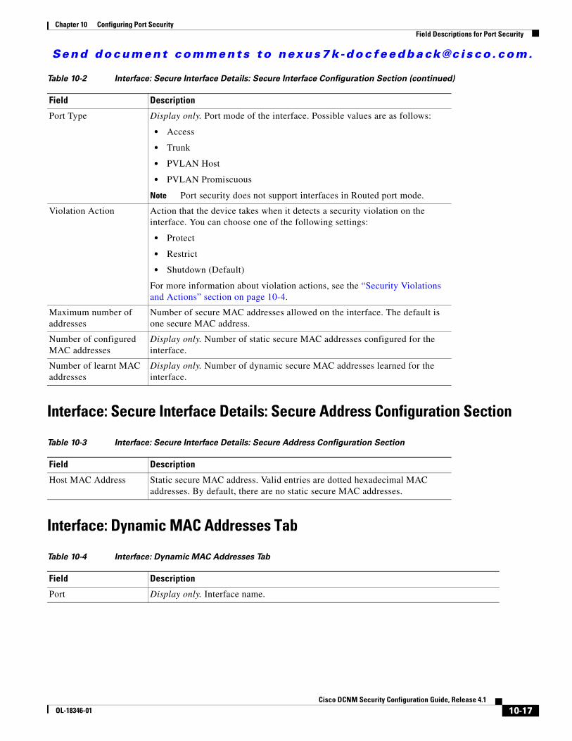
Send document comments to nexus7k -doc feedback@c i sco .com.
Chapter 10 Configuring Port SecurityField Descriptions for Port Security
Interface: Secure Interface Details: Secure Address Configuration Section
Interface: Dynamic MAC Addresses Tab
Port Type Display only. Port mode of the interface. Possible values are as follows:
• Access
• Trunk
• PVLAN Host
• PVLAN Promiscuous
Note Port security does not support interfaces in Routed port mode.
Violation Action Action that the device takes when it detects a security violation on the interface. You can choose one of the following settings:
• Protect
• Restrict
• Shutdown (Default)
For more information about violation actions, see the “Security Violations and Actions” section on page 10-4.
Maximum number of addresses
Number of secure MAC addresses allowed on the interface. The default is one secure MAC address.
Number of configured MAC addresses
Display only. Number of static secure MAC addresses configured for the interface.
Number of learnt MAC addresses
Display only. Number of dynamic secure MAC addresses learned for the interface.
Table 10-3 Interface: Secure Interface Details: Secure Address Configuration Section
Field Description
Host MAC Address Static secure MAC address. Valid entries are dotted hexadecimal MAC addresses. By default, there are no static secure MAC addresses.
Table 10-4 Interface: Dynamic MAC Addresses Tab
Field Description
Port Display only. Interface name.
Table 10-2 Interface: Secure Interface Details: Secure Interface Configuration Section (continued)
Field Description
10-17Cisco DCNM Security Configuration Guide, Release 4.1
OL-18346-01
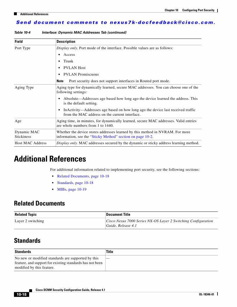
Send document comments to nexus7k -doc feedback@c i sco .com.
Chapter 10 Configuring Port SecurityAdditional References
Additional ReferencesFor additional information related to implementing port security, see the following sections:
• Related Documents, page 10-18
• Standards, page 10-18
• MIBs, page 10-19
Related Documents
Standards
Port Type Display only. Port mode of the interface. Possible values are as follows:
• Access
• Trunk
• PVLAN Host
• PVLAN Promiscuous
Note Port security does not support interfaces in Routed port mode.
Aging Type Aging type for dynamically learned, secure MAC addresses. You can choose one of the following settings:
• Absolute—Addresses age based how long ago the device learned the address. This is the default setting.
• InActivity—Addresses age based on how long ago the device last received traffic from the MAC address on the current interface.
Age Aging time, in minutes, for dynamically learned, secure MAC addresses. Valid entries are whole numbers from 1 to 1440.
Dynamic MAC Stickiness
Whether the device stores addresses learned by this method in NVRAM. For more information, see the “Sticky Method” section on page 10-2.
Host MAC Address Display only. MAC addresses secured by the dynamic or sticky address learning method.
Table 10-4 Interface: Dynamic MAC Addresses Tab (continued)
Field Description
Related Topic Document Title
Layer 2 switching Cisco Nexus 7000 Series NX-OS Layer 2 Switching Configuration Guide, Release 4.1
Standards Title
No new or modified standards are supported by this feature, and support for existing standards has not been modified by this feature.
—
10-18Cisco DCNM Security Configuration Guide, Release 4.1
OL-18346-01
Send document comments to nexus7k -doc feedback@c i sco .com.
Chapter 10 Configuring Port SecurityFeature History for Port Security
MIBsNX-OS provides read-only SNMP support for port security.
Feature History for Port SecurityTable 10-5 lists the release history for this feature.
MIBs MIBs Link
• CISCO-PORT-SECURITY-MIB To locate and download MIBs, go to the following URL:
http://www.cisco.com/nx-os/mibs
Table 10-5 Feature History for Port Security
Feature Name Releases Feature Information
Port security 4.1(2) No change from Release 4.0.
10-19Cisco DCNM Security Configuration Guide, Release 4.1
OL-18346-01

Send document comments to nexus7k -doc feedback@c i sco .com.
Chapter 10 Configuring Port SecurityFeature History for Port Security
10-20Cisco DCNM Security Configuration Guide, Release 4.1
OL-18346-01
Send document comments to nexus7k -doc feedback@c i sco .com.
CiscOL-18346-01
C H A P T E R11
Configuring DHCP SnoopingThis chapter describes how to configure Dynamic Host Configuration Protocol (DHCP) snooping on an NX-OS device.
This chapter includes the following sections:
• Information About DHCP Snooping, page 11-1
• Licensing Requirements for DHCP Snooping, page 11-5
• Prerequisites for DHCP Snooping, page 11-6
• Guidelines and Limitations, page 11-6
• Configuring DHCP Snooping, page 11-7
• Displaying DHCP Bindings, page 11-16
• Field Descriptions for DHCP Snooping, page 11-16
• Additional References, page 11-18
• Feature History for DHCP Snooping, page 11-19
Information About DHCP SnoopingDHCP snooping acts like a firewall between untrusted hosts and trusted DHCP servers. DHCP snooping performs the following activities:
• Validates DHCP messages received from untrusted sources and filters out invalid messages.
• Builds and maintains the DHCP snooping binding database, which contains information about untrusted hosts with leased IP addresses.
• Uses the DHCP snooping binding database to validate subsequent requests from untrusted hosts.
Dynamic ARP inspection (DAI) and IP Source Guard also use information stored in the DHCP snooping binding database.
DHCP snooping is enabled on a per-VLAN basis. By default, the feature is inactive on all VLANs. You can enable the feature on a single VLAN or a range of VLANs.
This section includes the following topics:
• Trusted and Untrusted Sources, page 11-2
• DHCP Snooping Binding Database, page 11-2
• DHCP Relay Agent, page 11-3
11-1o DCNM Security Configuration Guide, Release 4.1
Send document comments to nexus7k -doc feedback@c i sco .com.
Chapter 11 Configuring DHCP SnoopingInformation About DHCP Snooping
• Packet Validation, page 11-3
• DHCP Snooping Option-82 Data Insertion, page 11-3
• Virtualization Support for DHCP Snooping, page 11-5
Trusted and Untrusted SourcesYou can configure whether DHCP snooping trusts traffic sources. An untrusted source may initiate traffic attacks or other hostile actions. To prevent such attacks, DHCP snooping filters messages from untrusted sources.
In an enterprise network, a trusted source is a device that is under your administrative control. These devices include the switches, routers, and servers in the network. Any device beyond the firewall or outside the network is an untrusted source. Generally, host ports are treated as untrusted sources.
In a service provider environment, any device that is not in the service provider network is an untrusted source (such as a customer switch). Host ports are untrusted sources.
In the NX-OS device, you indicate that a source is trusted by configuring the trust state of its connecting interface.
The default trust state of all interfaces is untrusted. You must configure DHCP server interfaces as trusted. You can also configure other interfaces as trusted if they connect to devices (such as switches or routers) inside your network. You usually do not configure host port interfaces as trusted.
Note For DHCP snooping to function properly, all DHCP servers must be connected to the device through trusted interfaces.
DHCP Snooping Binding DatabaseUsing information extracted from intercepted DHCP messages, DHCP snooping dynamically builds and maintains a database. The database contains an entry for each untrusted host with a leased IP address if the host is associated with a VLAN that has DHCP snooping enabled. The database does not contain entries for hosts connected through trusted interfaces.
Note The DHCP snooping binding database is also referred to as the DHCP snooping binding table.
DHCP snooping updates the database when the device receives specific DHCP messages. For example, the feature adds an entry to the database when the device receives a DHCPACK message from the server. The feature removes the entry in the database when the IP address lease expires or the device receives a DHCPRELEASE message from the host.
Each entry in the DHCP snooping binding database includes the MAC address of the host, the leased IP address, the lease time, the binding type, and the VLAN number and interface information associated with the host.
11-2Cisco DCNM Security Configuration Guide, Release 4.1
OL-18346-01
Send document comments to nexus7k -doc feedback@c i sco .com.
Chapter 11 Configuring DHCP SnoopingInformation About DHCP Snooping
DHCP Relay AgentYou can configure the device to run a DHCP relay agent, which forwards DHCP packets between clients and servers. This feature is useful when clients and servers are not on the same physical subnet. Relay agent forwarding is distinct from the normal forwarding of an IP router, where IP datagrams are switched between networks somewhat transparently. By contrast, relay agents receive DHCP messages and then generate a new DHCP message to send out on another interface. The relay agent sets the gateway address (giaddr field of the DHCP packet) and, if configured, adds the relay agent information option (option82) in the packet and forwards it to the DHCP server. The reply from the server is forwarded back to the client after removing option 82.
Packet ValidationThe device validates DHCP packets received on the untrusted interfaces of VLANs that have DHCP snooping enabled. The device forwards the DHCP packet unless any of the following conditions occur (in which case the packet is dropped):
• The device receives a DHCP response packet (such as DHCPACK, DHCPNAK, or DHCPOFFER packet) on an untrusted interface.
• The device receives a packet on an untrusted interface, and the source MAC address and the DHCP client hardware address do not match. This check is performed only if the DHCP snooping MAC address verification option is turned on.
• The device receives a DHCPRELEASE or DHCPDECLINE message from an untrusted host with an entry in the DHCP snooping binding table, and the interface information in the binding table does not match the interface on which the message was received.
• The device receives a DHCP packet that includes a relay agent IP address that is not 0.0.0.0.
DHCP Snooping Option-82 Data InsertionIn residential, metropolitan Ethernet-access environments, DHCP can centrally manage the IP address assignments for a large number of subscribers. When you enable option 82, the device identifies a subscriber device that connects to the network (in addition to its MAC address). Multiple hosts on the subscriber LAN can connect to the same port on the access device and are uniquely identified.
Figure 11-1 shows an example of a metropolitan Ethernet network in which a centralized DHCP server assigns IP addresses to subscribers connected to the device at the access layer. Because the DHCP clients and their associated DHCP server do not reside on the same IP network or subnet, a DHCP relay agent is configured with a helper address to enable broadcast forwarding and to transfer DHCP messages between the clients and the server.
11-3Cisco DCNM Security Configuration Guide, Release 4.1
OL-18346-01
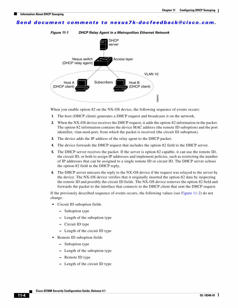
Send document comments to nexus7k -doc feedback@c i sco .com.
Chapter 11 Configuring DHCP SnoopingInformation About DHCP Snooping
Figure 11-1 DHCP Relay Agent in a Metropolitan Ethernet Network
When you enable option 82 on the NX-OS device, the following sequence of events occurs:
1. The host (DHCP client) generates a DHCP request and broadcasts it on the network.
2. When the NX-OS device receives the DHCP request, it adds the option-82 information in the packet. The option-82 information contains the device MAC address (the remote ID suboption) and the port identifier, vlan-mod-port, from which the packet is received (the circuit ID suboption).
3. The device adds the IP address of the relay agent to the DHCP packet.
4. The device forwards the DHCP request that includes the option-82 field to the DHCP server.
5. The DHCP server receives the packet. If the server is option-82 capable, it can use the remote ID, the circuit ID, or both to assign IP addresses and implement policies, such as restricting the number of IP addresses that can be assigned to a single remote ID or circuit ID. The DHCP server echoes the option-82 field in the DHCP reply.
6. The DHCP server unicasts the reply to the NX-OS device if the request was relayed to the server by the device. The NX-OS device verifies that it originally inserted the option-82 data by inspecting the remote ID and possibly the circuit ID fields. The NX-OS device removes the option-82 field and forwards the packet to the interface that connects to the DHCP client that sent the DHCP request.
If the previously described sequence of events occurs, the following values (see Figure 11-2) do not change:
• Circuit ID suboption fields
– Suboption type
– Length of the suboption type
– Circuit ID type
– Length of the circuit ID type
• Remote ID suboption fields
– Suboption type
– Length of the suboption type
– Remote ID type
– Length of the circuit ID type
Subscribers
Nexus switch(DHCP relay agent)
Host A(DHCP client)
Access layer
DHCPserver
Host B(DHCP client)
1866
93
VLAN 10
11-4Cisco DCNM Security Configuration Guide, Release 4.1
OL-18346-01
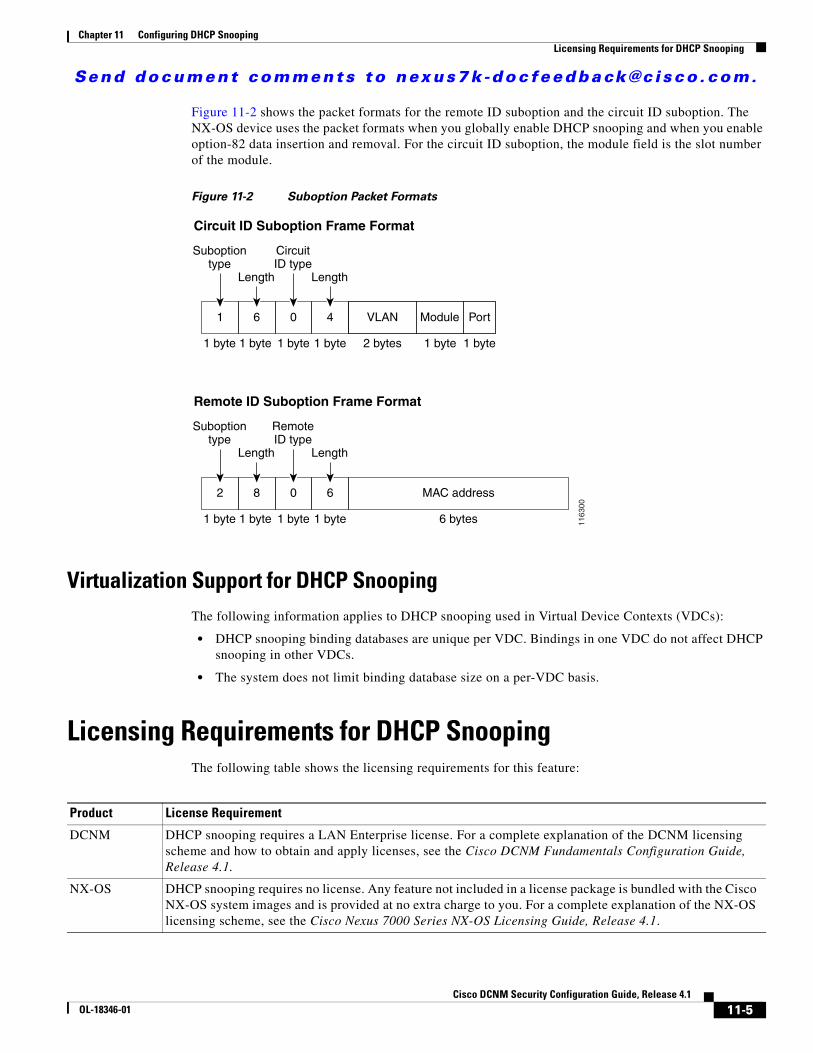
Send document comments to nexus7k -doc feedback@c i sco .com.
Chapter 11 Configuring DHCP SnoopingLicensing Requirements for DHCP Snooping
Figure 11-2 shows the packet formats for the remote ID suboption and the circuit ID suboption. The NX-OS device uses the packet formats when you globally enable DHCP snooping and when you enable option-82 data insertion and removal. For the circuit ID suboption, the module field is the slot number of the module.
Figure 11-2 Suboption Packet Formats
Virtualization Support for DHCP SnoopingThe following information applies to DHCP snooping used in Virtual Device Contexts (VDCs):
• DHCP snooping binding databases are unique per VDC. Bindings in one VDC do not affect DHCP snooping in other VDCs.
• The system does not limit binding database size on a per-VDC basis.
Licensing Requirements for DHCP SnoopingThe following table shows the licensing requirements for this feature:
Length Length
CircuitID type
Suboptiontype
Circuit ID Suboption Frame Format
Remote ID Suboption Frame Format
6 bytes
MAC address
1 byte 1 byte 1 byte
Suboptiontype
1 byte
Length Length
RemoteID type
1 byte 1 byte 1 byte1 byte 1163
00
4061
6082
Module Port
1 byte 1 byte2 bytes
VLAN
Product License Requirement
DCNM DHCP snooping requires a LAN Enterprise license. For a complete explanation of the DCNM licensing scheme and how to obtain and apply licenses, see the Cisco DCNM Fundamentals Configuration Guide, Release 4.1.
NX-OS DHCP snooping requires no license. Any feature not included in a license package is bundled with the Cisco NX-OS system images and is provided at no extra charge to you. For a complete explanation of the NX-OS licensing scheme, see the Cisco Nexus 7000 Series NX-OS Licensing Guide, Release 4.1.
11-5Cisco DCNM Security Configuration Guide, Release 4.1
OL-18346-01
Send document comments to nexus7k -doc feedback@c i sco .com.
Chapter 11 Configuring DHCP SnoopingPrerequisites for DHCP Snooping
Prerequisites for DHCP SnoopingDHCP snooping has the following prerequisites:
• You must be familiar with DHCP to configure DHCP snooping.
Guidelines and LimitationsDHCP snooping has the following configuration guidelines and limitations:
• When you use the feature dhcp command to enable the DHCP snooping feature, there is a delay of approximately 30 seconds before the I/O modules receive DHCP snooping or DAI configuration. This delay occurs regardless of the method that you use to change from a configuration with DHCP snooping disabled to a configuration with DHCP snooping enabled. For example, if you use the Rollback feature to revert to a configuration that enables DHCP snooping, the I/O modules receive DHCP snooping and DAI configuration approximately 30 seconds after you complete the rollback.
• The DHCP snooping database can store 2000 bindings.
• DHCP snooping is not active until you enable the feature, enable DHCP snooping globally, and enable DHCP snooping on at least one VLAN.
• Before globally enabling DHCP snooping on the device, make sure that the devices acting as the DHCP server and the DHCP relay agent are configured and enabled.
• Access-control list (ACL) statistics are not supported if the DHCP snooping feature is enabled.
• For each device that you use DCNM to configure DHCP snooping, ensure that you configure the logging level for DHCP snooping to 6 (Informational) or a higher level. To configure the device with the minimal required logging configuration, log into the command-line interface of the device and use the following commands:
switch(config)# logging level dhcp 6switch(config)# logging logfile messages 6switch(config)# logging event link-status default
For more information about NX-OS system-message logging requirements, see the Cisco DCNM Fundamentals Configuration Guide, Release 4.1.
11-6Cisco DCNM Security Configuration Guide, Release 4.1
OL-18346-01
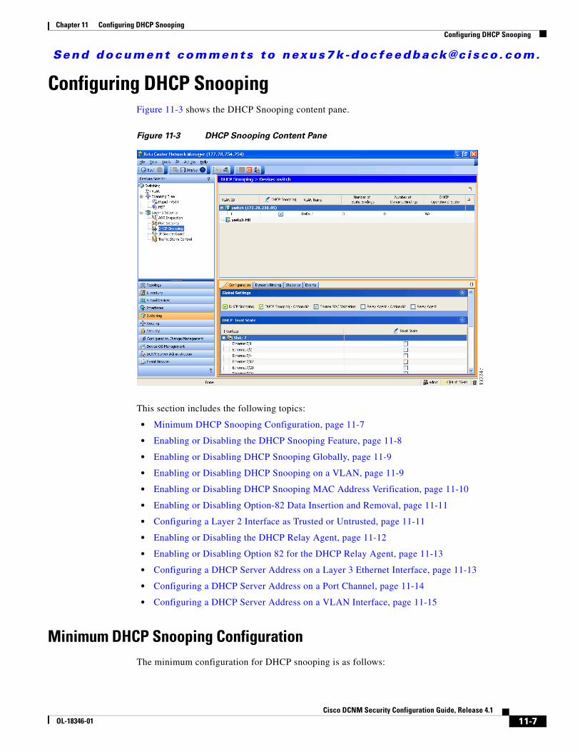
Send document comments to nexus7k -doc feedback@c i sco .com.
Chapter 11 Configuring DHCP SnoopingConfiguring DHCP Snooping
Configuring DHCP SnoopingFigure 11-3 shows the DHCP Snooping content pane.
Figure 11-3 DHCP Snooping Content Pane
This section includes the following topics:
• Minimum DHCP Snooping Configuration, page 11-7
• Enabling or Disabling the DHCP Snooping Feature, page 11-8
• Enabling or Disabling DHCP Snooping Globally, page 11-9
• Enabling or Disabling DHCP Snooping on a VLAN, page 11-9
• Enabling or Disabling DHCP Snooping MAC Address Verification, page 11-10
• Enabling or Disabling Option-82 Data Insertion and Removal, page 11-11
• Configuring a Layer 2 Interface as Trusted or Untrusted, page 11-11
• Enabling or Disabling the DHCP Relay Agent, page 11-12
• Enabling or Disabling Option 82 for the DHCP Relay Agent, page 11-13
• Configuring a DHCP Server Address on a Layer 3 Ethernet Interface, page 11-13
• Configuring a DHCP Server Address on a Port Channel, page 11-14
• Configuring a DHCP Server Address on a VLAN Interface, page 11-15
Minimum DHCP Snooping ConfigurationThe minimum configuration for DHCP snooping is as follows:
11-7Cisco DCNM Security Configuration Guide, Release 4.1
OL-18346-01
Send document comments to nexus7k -doc feedback@c i sco .com.
Chapter 11 Configuring DHCP SnoopingConfiguring DHCP Snooping
Step 1 Enable the DHCP snooping feature. For more information, see the “Enabling or Disabling the DHCP Snooping Feature” section on page 11-8.
When the DHCP snooping feature is disabled, you cannot configure DHCP snooping.
Step 2 Enable DHCP snooping globally. For more information, see the “Enabling or Disabling DHCP Snooping Globally” section on page 11-9.
Step 3 Enable DHCP snooping on at least one VLAN. For more information, see the “Enabling or Disabling DHCP Snooping on a VLAN” section on page 11-9.
By default, DHCP snooping is disabled on all VLANs.
Step 4 Ensure that the DHCP server is connected to the device using a trusted interface. For more information, see the “Configuring a Layer 2 Interface as Trusted or Untrusted” section on page 11-11.
Step 5 (Optional) Enable the DHCP relay agent. For more information, see the “Enabling or Disabling the DHCP Relay Agent” section on page 11-12.
Step 6 (Optional) Configure an interface with the IP address of the DHCP server. For more information, see one of the following topics:
• Configuring a DHCP Server Address on a Layer 3 Ethernet Interface, page 11-13
• Configuring a DHCP Server Address on a Port Channel, page 11-14
• Configuring a DHCP Server Address on a VLAN Interface, page 11-15
Enabling or Disabling the DHCP Snooping FeatureYou can enable or disable the DHCP snooping feature on the device. By default, DHCP snooping is disabled.
BEFORE YOU BEGIN
If you disable the DHCP snooping feature, all DHCP snooping configuration is lost. If you want to turn off DHCP snooping and preserve the DHCP snooping configuration, disable DHCP globally. For more information, see the “Enabling or Disabling DHCP Snooping Globally” section on page 11-9.
If you enable DHCP snooping, ensure that you configure the logging level for DHCP snooping to 6 (Informational) or a higher level on the NX-OS device. To configure the device with the minimal required logging configuration, log into the command-line interface of the device and use the following commands:
switch(config)# logging level dhcp 6switch(config)# logging logfile messages 6switch(config)# logging event link-status default
For more information about NX-OS system-message logging requirements, see the Cisco DCNM Fundamentals Configuration Guide, Release 4.1.
DETAILED STEPS
To enable or disable the DHCP snooping feature on the device, follow these steps:
Step 1 From the Feature Selector pane, choose Switching > Layer 2 Security > DHCP Snooping.
11-8Cisco DCNM Security Configuration Guide, Release 4.1
OL-18346-01
Send document comments to nexus7k -doc feedback@c i sco .com.
Chapter 11 Configuring DHCP SnoopingConfiguring DHCP Snooping
The available devices appear in the Summary pane.
Step 2 From the Summary pane, click the device on which you want to enable or disable DHCP snooping.
Step 3 Do one of the following:
• To enable DHCP snooping, from the menu bar, choose Actions > Enable DHCP Snooping Service.
In the Details pane, the Global Settings and DHCP Rate Limiting sections appear on the Configuration tab.
• To disable DHCP snooping, from the menu bar, choose Actions > Disable DHCP Snooping Service.
In the Details pane, the Enable DHCP Snooping service link appears on the Configuration tab.
Step 4 From the menu bar, choose File > Deploy to apply your changes to the device.
Enabling or Disabling DHCP Snooping GloballyYou can enable or disable the DHCP snooping globally on the device.
BEFORE YOU BEGIN
By default, DHCP snooping is globally disabled.
Ensure that you have enabled the DHCP snooping feature. For more information, see the “Enabling or Disabling the DHCP Snooping Feature” section on page 11-8.
Globally disabling DHCP snooping stops the device from performing any DHCP snooping or relaying DHCP messages. It preserves DCHP snooping configuration.
DETAILED STEPS
To enable or disable DHCP snooping globally on the device, follow these steps:
Step 1 From the Feature Selector pane, choose Switching > Layer 2 Security > DHCP Snooping.
The available devices appear in the Summary pane.
Step 2 From the Summary pane, click the device on which you want to enable or disable DHCP snooping globally.
Step 3 From the Details pane, click the Configuration tab and expand the Global Settings section, if necessary.
Step 4 Do one of the following:
• To enable DCHP snooping globally, check DHCP Snooping.
• To disable DCHP snooping globally, uncheck DHCP Snooping.
Step 5 From the menu bar, choose File > Deploy to apply your changes to the device.
Enabling or Disabling DHCP Snooping on a VLANYou can enable or disable DHCP snooping on one or more VLANs.
11-9Cisco DCNM Security Configuration Guide, Release 4.1
OL-18346-01
Send document comments to nexus7k -doc feedback@c i sco .com.
Chapter 11 Configuring DHCP SnoopingConfiguring DHCP Snooping
BEFORE YOU BEGIN
By default, DHCP snooping is disabled on all VLANs.
Ensure that DHCP snooping is enabled. For more information, see the “Enabling or Disabling the DHCP Snooping Feature” section on page 11-8.
DETAILED STEPS
To enable or disable DHCP snooping on a VLAN, follow these steps:
Step 1 From the Feature Selector pane, choose Switching > Layer 2 Security > DHCP Snooping.
The available devices appear in the Summary pane.
Step 2 From the Summary pane, double-click the device on which you want to enable or disable per-VLAN DHCP snooping.
The VLANs for the device that you double-clicked appear in the Summary pane.
Step 3 Click the VLAN that you want to configure with DHCP snooping.
In the Details pane, the DHCP VLAN Details tab appears.
Step 4 Do one of the following:
• To enable DHCP snooping on a VLAN, on the DHCP VLAN Details tab, check DHCP Snooping.
• To disable per-VLAN DHCP snooping, on the DHCP VLAN Details tab, uncheck DHCP Snooping.
Step 5 From the menu bar, choose File > Deploy to apply your changes to the device.
Enabling or Disabling DHCP Snooping MAC Address VerificationYou can enable or disable DHCP snooping MAC address verification. If the device receives a packet on an untrusted interface and the source MAC address and the DHCP client hardware address do not match, address verification causes the device to drop the packet.
BEFORE YOU BEGIN
MAC address verification is enabled by default.
Ensure that DHCP snooping is enabled. For more information, see the “Enabling or Disabling the DHCP Snooping Feature” section on page 11-8.
DETAILED STEPS
To enable or disable DHCP snooping MAC address verification, follow these steps:
Step 1 From the Feature Selector pane, choose Switching > Layer 2 Security > DHCP Snooping.
The available devices appear in the Summary pane.
Step 2 From the Summary pane, click the device on which you want to enable or disable DHCP snooping MAC address verification.
Step 3 From the Details pane, click the Configuration tab and expand the Global Settings section, if necessary.
11-10Cisco DCNM Security Configuration Guide, Release 4.1
OL-18346-01
Send document comments to nexus7k -doc feedback@c i sco .com.
Chapter 11 Configuring DHCP SnoopingConfiguring DHCP Snooping
Step 4 Do one of the following:
• To enable MAC address verification, check Source MAC Validation.
• To disable MAC address verification, uncheck Source MAC Validation.
Step 5 From the menu bar, choose File > Deploy to apply your changes to the device.
Enabling or Disabling Option-82 Data Insertion and RemovalYou can enable or disable the insertion and removal of option-82 information for DHCP packets forwarded without the use of the DHCP relay agent.
Note You must separately configure the DHCP relay agent to support option 82. For more information, see the “Enabling or Disabling Option 82 for the DHCP Relay Agent” section on page 11-13.
BEFORE YOU BEGIN
By default, the device does not include option-82 information in DHCP packets.
Ensure that DHCP snooping is enabled. For more information, see the “Enabling or Disabling the DHCP Snooping Feature” section on page 11-8.
DETAILED STEPS
To enable or disable Option-82 data insertion and removal, follow these steps:
Step 1 From the Feature Selector pane, choose Switching > Layer 2 Security > DHCP Snooping.
The available devices appear in the Summary pane.
Step 2 From the Summary pane, click the device on which you want to enable or disable option-82 data insertion and removal.
Step 3 From the Details pane, click the Configuration tab and expand the Global Settings section, if necessary.
Step 4 Do one of the following:
• To enable option-82 data insertion and removal, check DHCP Snooping - Option 82.
• To disable option-82 data insertion and removal, uncheck DHCP Snooping - Option 82.
Step 5 From the menu bar, choose File > Deploy to apply your changes to the device.
Configuring a Layer 2 Interface as Trusted or Untrusted
You can configure whether an interface is a trusted or untrusted source of DHCP messages. You can configure this on interfaces operating in any the following port modes:
• Access
• Trunk
11-11Cisco DCNM Security Configuration Guide, Release 4.1
OL-18346-01
Send document comments to nexus7k -doc feedback@c i sco .com.
Chapter 11 Configuring DHCP SnoopingConfiguring DHCP Snooping
• Private VLAN Host
• Private VLAN Promiscuous
BEFORE YOU BEGIN
By default, all interfaces are untrusted.
Ensure that DHCP snooping is enabled. For more information, see the “Enabling or Disabling the DHCP Snooping Feature” section on page 11-8.
DETAILED STEPS
To configure an interface as trusted or untrusted, follow these steps:
Step 1 From the Feature Selector pane, choose Switching > Layer 2 Security > DHCP Snooping.
The available devices appear in the Summary pane.
Step 2 From the Summary pane, click the device on which you want to configure an interface trust state.
Step 3 From the Details pane, click the Configuration tab and expand the DHCP Rate Limiting section, if necessary.
Step 4 From the DHCP Rate Limiting section, expand the slot that contains the interface that you want to configure, if necessary.
The Layer 2 interfaces on the slot appear in the Details pane. For each interface, a check box in the Trust State column indicates whether the device trusts the interface.
Step 5 For each interface whose trust state you want to configure, do one of the following:
• To make the interface a trusted interface, check the check box in the Trust State column.
• To make the interface an untrusted interface, uncheck the check box in the Trust State column.
Step 6 From the menu bar, choose File > Deploy to apply your changes to the device.
Enabling or Disabling the DHCP Relay AgentYou can enable or disable the DHCP relay agent.
BEFORE YOU BEGIN
By default, the DHCP relay agent is disabled.
Ensure that DHCP snooping is enabled. For more information, see the “Enabling or Disabling the DHCP Snooping Feature” section on page 11-8.
DETAILED STEPS
To enable or disable the DHCP relay agent, follow these steps:
Step 1 From the Feature Selector pane, choose Switching > Layer 2 Security > DHCP Snooping.
The available devices appear in the Summary pane.
11-12Cisco DCNM Security Configuration Guide, Release 4.1
OL-18346-01
Send document comments to nexus7k -doc feedback@c i sco .com.
Chapter 11 Configuring DHCP SnoopingConfiguring DHCP Snooping
Step 2 From the Summary pane, click the device on which you want to enable or disable option-82 data insertion and removal.
Step 3 From the Details pane, click the Configuration tab and expand the Global Settings section, if necessary.
Step 4 Do one of the following:
• To enable the DHCP relay agent, check Relay Agent.
• To disable the DHCP relay agent, uncheck Relay Agent.
Step 5 From the menu bar, choose File > Deploy to apply your changes to the device.
Enabling or Disabling Option 82 for the DHCP Relay AgentYou can enable or disable the device to insert and remove option-82 information on DHCP packets forwarded by the relay agent.
BEFORE YOU BEGIN
By default, the DHCP relay agent does not include option-82 information in DHCP packets.
Ensure that DHCP snooping is enabled. For more information, see the “Enabling or Disabling the DHCP Snooping Feature” section on page 11-8.
DETAILED STEPS
To enable or disable option 82 for the DHCP relay agent, follow these steps:
Step 1 From the Feature Selector pane, choose Switching > Layer 2 Security > DHCP Snooping.
The available devices appear in the Summary pane.
Step 2 From the Summary pane, click the device on which you want to enable or disable option-82 data insertion and removal.
Step 3 From the Details pane, click the Configuration tab and expand the Global Settings section, if necessary.
Step 4 Do one of the following:
• To enable option 82 for the relay agent, check Relay Agent - Option 82.
• To disable option 82 for the relay agent, uncheck Relay Agent - Option 82.
Step 5 From the menu bar, choose File > Deploy to apply your changes to the device.
Configuring a DHCP Server Address on a Layer 3 Ethernet InterfaceYou can configure up to 16 DHCP server IP addresses on a Layer 3 Ethernet interface or subinterface. A Layer 3 Ethernet interface is an interface that is operating in routed port mode. When an inbound DHCP BOOTREQUEST packet arrives on the interface, the relay agent forwards the packet to all DHCP server IP addresses specified. The relay agent forwards replies from all DHCP servers to the host that sent the request.
11-13Cisco DCNM Security Configuration Guide, Release 4.1
OL-18346-01
Send document comments to nexus7k -doc feedback@c i sco .com.
Chapter 11 Configuring DHCP SnoopingConfiguring DHCP Snooping
BEFORE YOU BEGIN
By default, there is no DHCP server IP address configured on a Layer 3 interface.
Ensure that the DHCP server is correctly configured.
Determine the IP address of the DHCP server.
Ensure that DHCP snooping is enabled. For more information, see the “Enabling or Disabling the DHCP Snooping Feature” section on page 11-8.
DETAILED STEPS
To configure a DHCP server IP address on a Layer 3 Ethernet interface or subinterface, follow these steps:
Step 1 From the Feature Selector pane, choose Interfaces > Physical > Ethernet.
The available devices appear in the Summary pane.
Step 2 From the Summary pane, double-click the device that has the interface that you want to configure.
Available slots on the device appear in the Summary pane.
Step 3 Double-click the slot that has the interface that you want to configure.
Available interfaces on the slot appear in the Summary pane.
Step 4 Double-click the interface that you want to configure or that has the subinterface that you want to configure.
The Port Details tab appears in the Details pane.
Step 5 (Optional) Click the subinterface that you want to configure.
Step 6 From the Details pane, click the Port Details tab and expand the Port Mode Settings section, if necessary.
Step 7 For each DHCP server IP address that you want to specify, perform the following steps:
a. In the Port Mode Settings section, in the Helper area, right-click and choose Add Helper IP.
b. Enter the IPv4 address of the DHCP server.
Step 8 From the menu bar, choose File > Deploy to apply your changes to the device.
Configuring a DHCP Server Address on a Port ChannelYou can configure up to 16 DHCP server IP addresses on a port channel. When an inbound DHCP BOOTREQUEST packet arrives on a port that is a member of the port channel, the relay agent forwards the packet to all DHCP server IP addresses specified. The relay agent forwards replies from all DHCP servers to the host that sent the request.
BEFORE YOU BEGIN
By default, there is no DHCP server IP address configured on a port channel.
Ensure that the DHCP server is correctly configured.
Determine the IP address of the DHCP server.
11-14Cisco DCNM Security Configuration Guide, Release 4.1
OL-18346-01
Send document comments to nexus7k -doc feedback@c i sco .com.
Chapter 11 Configuring DHCP SnoopingConfiguring DHCP Snooping
Ensure that DHCP snooping is enabled. For more information, see the “Enabling or Disabling the DHCP Snooping Feature” section on page 11-8.
DETAILED STEPS
To configure a DHCP server IP address on a port channel, follow these steps:
Step 1 From the Feature Selector pane, choose Interfaces > Logical > Port Channel.
The available devices appear in the Summary pane.
Step 2 From the Summary pane, double-click the device that has the port channel that you want to configure.
Available port channels on the device appear in the Summary pane.
Step 3 Click the channel ID of the port channel that you want to configure.
The Port Channel Advanced Settings tab appears in the Details pane.
Step 4 From the Details pane, click the Port Channel Advanced Settings tab and expand the IP Address Settings section, if necessary.
Step 5 For each DHCP server IP address that you want to specify, perform the following steps:
a. In the IP Address Settings section, in the Helper area, right-click and choose Add Helper IP.
b. Enter the IPv4 address of the DHCP server.
Step 6 From the menu bar, choose File > Deploy to apply your changes to the device.
Configuring a DHCP Server Address on a VLAN InterfaceYou can configure up to 16 DHCP server IP addresses on a VLAN interface (sometimes referred to as a switched virtual interface or SVI). When an inbound DHCP BOOTREQUEST packet arrives on the VLAN interface, the relay agent forwards the packet to all the IP addresses specified. The relay agent forwards replies from all DHCP servers to the host that sent the request.
BEFORE YOU BEGIN
By default, there is no DHCP server IP address configured on a VLAN interface.
Ensure that the DHCP server is correctly configured.
Determine the IP address of the DHCP server.
Ensure that DHCP snooping is enabled. For more information, see the “Enabling or Disabling the DHCP Snooping Feature” section on page 11-8.
DETAILED STEPS
To configure a DHCP server IP address on a VLAN interface, follow these steps:
Step 1 From the Feature Selector pane, choose Interfaces > Logical > VLAN Network Interface.
The available devices appear in the Summary pane.
Step 2 From the Summary pane, double-click the device that has the interface that you want to configure.
11-15Cisco DCNM Security Configuration Guide, Release 4.1
OL-18346-01
Send document comments to nexus7k -doc feedback@c i sco .com.
Chapter 11 Configuring DHCP SnoopingDisplaying DHCP Bindings
Available VLAN interfaces on the device appear in the Summary pane.
Step 3 Click the VLAN ID of the VLAN interface that you want to configure.
The Details tab appears in the Details pane.
Step 4 From the Details pane, click the Details tab and expand the IP Address Settings section, if necessary.
Step 5 For each DHCP server IP address that you want to specify, perform the following steps:
a. In the IP Address Settings section, in the Helper area, right-click and choose Add Helper IP.
b. Enter the IPv4 address of the DHCP server.
Step 6 From the menu bar, choose File > Deploy to apply your changes to the device.
Displaying DHCP BindingsTo display DHCP bindings for a device, follow these steps:
Step 1 From the Feature Selector pane, choose Switching > Layer 2 Security > DHCP Snooping.
The available devices appear in the Summary pane.
Step 2 From the Summary pane, click the device.
The Dynamic Binding tab appears in the Details pane.
Step 3 Double-click the slot that has the interface.
Step 4 From the Details pane, click the Dynamic Binding tab.
The Dynamic Binding tab displays a table that lists the DHCP bindings per VLAN.
Field Descriptions for DHCP SnoopingThis section includes the following topics:
• Device: Configuration Tab, page 11-17
• Device: Configuration: Global Settings Section, page 11-17
• Device: Configuration: DHCP Trust State Section, page 11-17
• Device: Dynamic Binding Tab, page 11-18
• VLAN: DHCP VLAN Details Tab, page 11-18
11-16Cisco DCNM Security Configuration Guide, Release 4.1
OL-18346-01
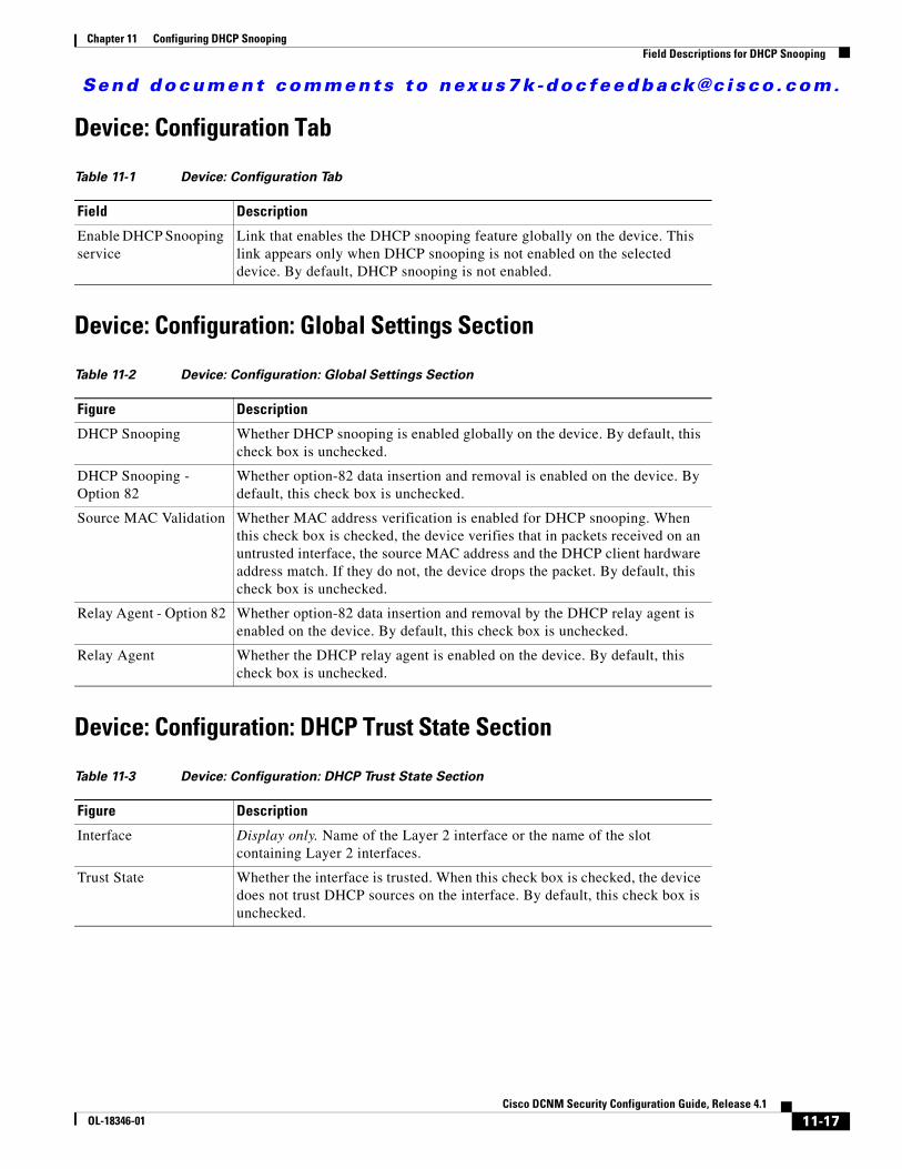
Send document comments to nexus7k -doc feedback@c i sco .com.
Chapter 11 Configuring DHCP SnoopingField Descriptions for DHCP Snooping
Device: Configuration Tab
Device: Configuration: Global Settings Section
Device: Configuration: DHCP Trust State Section
Table 11-1 Device: Configuration Tab
Field Description
Enable DHCP Snooping service
Link that enables the DHCP snooping feature globally on the device. This link appears only when DHCP snooping is not enabled on the selected device. By default, DHCP snooping is not enabled.
Table 11-2 Device: Configuration: Global Settings Section
Figure Description
DHCP Snooping Whether DHCP snooping is enabled globally on the device. By default, this check box is unchecked.
DHCP Snooping - Option 82
Whether option-82 data insertion and removal is enabled on the device. By default, this check box is unchecked.
Source MAC Validation Whether MAC address verification is enabled for DHCP snooping. When this check box is checked, the device verifies that in packets received on an untrusted interface, the source MAC address and the DHCP client hardware address match. If they do not, the device drops the packet. By default, this check box is unchecked.
Relay Agent - Option 82 Whether option-82 data insertion and removal by the DHCP relay agent is enabled on the device. By default, this check box is unchecked.
Relay Agent Whether the DHCP relay agent is enabled on the device. By default, this check box is unchecked.
Table 11-3 Device: Configuration: DHCP Trust State Section
Figure Description
Interface Display only. Name of the Layer 2 interface or the name of the slot containing Layer 2 interfaces.
Trust State Whether the interface is trusted. When this check box is checked, the device does not trust DHCP sources on the interface. By default, this check box is unchecked.
11-17Cisco DCNM Security Configuration Guide, Release 4.1
OL-18346-01
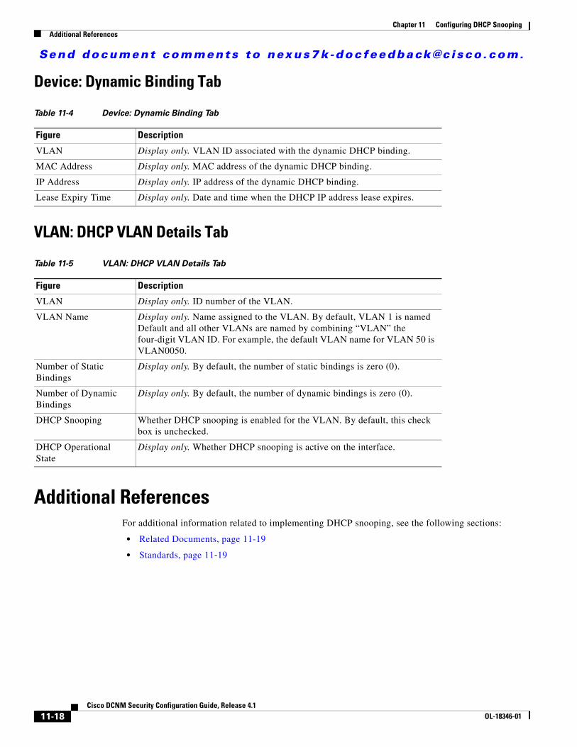
Send document comments to nexus7k -doc feedback@c i sco .com.
Chapter 11 Configuring DHCP SnoopingAdditional References
Device: Dynamic Binding Tab
VLAN: DHCP VLAN Details Tab
Additional ReferencesFor additional information related to implementing DHCP snooping, see the following sections:
• Related Documents, page 11-19
• Standards, page 11-19
Table 11-4 Device: Dynamic Binding Tab
Figure Description
VLAN Display only. VLAN ID associated with the dynamic DHCP binding.
MAC Address Display only. MAC address of the dynamic DHCP binding.
IP Address Display only. IP address of the dynamic DHCP binding.
Lease Expiry Time Display only. Date and time when the DHCP IP address lease expires.
Table 11-5 VLAN: DHCP VLAN Details Tab
Figure Description
VLAN Display only. ID number of the VLAN.
VLAN Name Display only. Name assigned to the VLAN. By default, VLAN 1 is named Default and all other VLANs are named by combining “VLAN” the four-digit VLAN ID. For example, the default VLAN name for VLAN 50 is VLAN0050.
Number of Static Bindings
Display only. By default, the number of static bindings is zero (0).
Number of Dynamic Bindings
Display only. By default, the number of dynamic bindings is zero (0).
DHCP Snooping Whether DHCP snooping is enabled for the VLAN. By default, this check box is unchecked.
DHCP Operational State
Display only. Whether DHCP snooping is active on the interface.
11-18Cisco DCNM Security Configuration Guide, Release 4.1
OL-18346-01
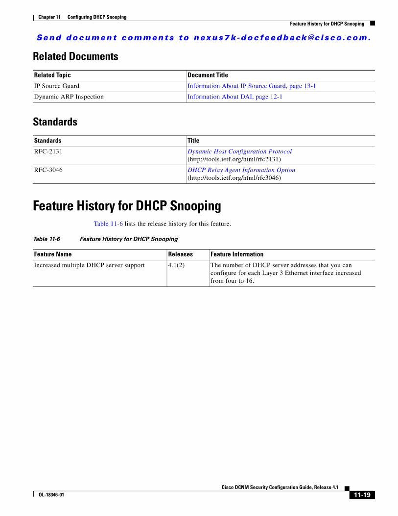
Send document comments to nexus7k -doc feedback@c i sco .com.
Chapter 11 Configuring DHCP SnoopingFeature History for DHCP Snooping
Related Documents
Standards
Feature History for DHCP SnoopingTable 11-6 lists the release history for this feature.
Related Topic Document Title
IP Source Guard Information About IP Source Guard, page 13-1
Dynamic ARP Inspection Information About DAI, page 12-1
Standards Title
RFC-2131 Dynamic Host Configuration Protocol (http://tools.ietf.org/html/rfc2131)
RFC-3046 DHCP Relay Agent Information Option (http://tools.ietf.org/html/rfc3046)
Table 11-6 Feature History for DHCP Snooping
Feature Name Releases Feature Information
Increased multiple DHCP server support 4.1(2) The number of DHCP server addresses that you can configure for each Layer 3 Ethernet interface increased from four to 16.
11-19Cisco DCNM Security Configuration Guide, Release 4.1
OL-18346-01

Send document comments to nexus7k -doc feedback@c i sco .com.
Chapter 11 Configuring DHCP SnoopingFeature History for DHCP Snooping
11-20Cisco DCNM Security Configuration Guide, Release 4.1
OL-18346-01
Send document comments to nexus7k -doc feedback@c i sco .com.
CiscOL-18346-01
C H A P T E R12
Configuring Dynamic ARP InspectionThis chapter describes how to configure dynamic Address Resolution Protocol (ARP) inspection (DAI) on an NX-OS device.
This chapter includes the following sections:
• Information About DAI, page 12-1
• Licensing Requirements for DAI, page 12-5
• Prerequisites for DAI, page 12-6
• Guidelines and Limitations, page 12-6
• Configuring DAI, page 12-7
• Displaying and Clearing DAI Statistics, page 12-13
• Field Descriptions for DAI, page 12-13
• Configuring ARP ACLs, page 12-15
• Field Descriptions for ARP ACLs, page 12-17
• Additional References, page 12-21
• Feature History for DAI, page 12-22
Information About DAIThis section includes the following topics:
• Understanding ARP, page 12-2
• Understanding ARP Spoofing Attacks, page 12-2
• Understanding DAI and ARP Spoofing Attacks, page 12-3
• Interface Trust States and Network Security, page 12-3
• Prioritizing ARP ACLs and DHCP Snooping Entries, page 12-4
• Logging DAI Packets, page 12-5
• Virtualization Support, page 12-5
12-1o DCNM Security Configuration Guide, Release 4.1
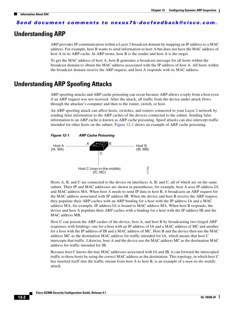
Send document comments to nexus7k -doc feedback@c i sco .com.
Chapter 12 Configuring Dynamic ARP InspectionInformation About DAI
Understanding ARPARP provides IP communication within a Layer 2 broadcast domain by mapping an IP address to a MAC address. For example, host B wants to send information to host A but does not have the MAC address of host A in its ARP cache. In ARP terms, host B is the sender and host A is the target.
To get the MAC address of host A, host B generates a broadcast message for all hosts within the broadcast domain to obtain the MAC address associated with the IP address of host A. All hosts within the broadcast domain receive the ARP request, and host A responds with its MAC address.
Understanding ARP Spoofing AttacksARP spoofing attacks and ARP cache poisoning can occur because ARP allows a reply from a host even if an ARP request was not received. After the attack, all traffic from the device under attack flows through the attacker’s computer and then to the router, switch, or host.
An ARP spoofing attack can affect hosts, switches, and routers connected to your Layer 2 network by sending false information to the ARP caches of the devices connected to the subnet. Sending false information to an ARP cache is known as ARP cache poisoning. Spoof attacks can also intercept traffic intended for other hosts on the subnet. Figure 12-1 shows an example of ARP cache poisoning.
Figure 12-1 ARP Cache Poisoning
Hosts A, B, and C are connected to the device on interfaces A, B, and C, all of which are on the same subnet. Their IP and MAC addresses are shown in parentheses; for example, host A uses IP address IA and MAC address MA. When host A needs to send IP data to host B, it broadcasts an ARP request for the MAC address associated with IP address IB. When the device and host B receive the ARP request, they populate their ARP caches with an ARP binding for a host with the IP address IA and a MAC address MA; for example, IP address IA is bound to MAC address MA. When host B responds, the device and host A populate their ARP caches with a binding for a host with the IP address IB and the MAC address MB.
Host C can poison the ARP caches of the device, host A, and host B by broadcasting two forged ARP responses with bindings: one for a host with an IP address of IA and a MAC address of MC and another for a host with the IP address of IB and a MAC address of MC. Host B and the device then use the MAC address MC as the destination MAC address for traffic intended for IA, which means that host C intercepts that traffic. Likewise, host A and the device use the MAC address MC as the destination MAC address for traffic intended for IB.
Because host C knows the true MAC addresses associated with IA and IB, it can forward the intercepted traffic to those hosts by using the correct MAC address as the destination. This topology, in which host C has inserted itself into the traffic stream from host A to host B, is an example of a man-in-the middle attack.
A B
C
Host A(IA, MA)
Host B(IB, MB)
Host C (man-in-the-middle)(IC, MC) 11
1750
12-2Cisco DCNM Security Configuration Guide, Release 4.1
OL-18346-01
Send document comments to nexus7k -doc feedback@c i sco .com.
Chapter 12 Configuring Dynamic ARP InspectionInformation About DAI
Understanding DAI and ARP Spoofing AttacksDAI ensures that only valid ARP requests and responses are relayed. When DAI is enabled and properly configured, an NX-OS device performs these activities:
• Intercepts all ARP requests and responses on untrusted ports
• Verifies that each of these intercepted packets has a valid IP-to-MAC address binding before updating the local ARP cache or before forwarding the packet to the appropriate destination
• Drops invalid ARP packets
DAI can determine the validity of an ARP packet based on valid IP-to-MAC address bindings stored in a Dynamic Host Configuration Protocol (DHCP) snooping binding database. This database is built by DHCP snooping if DHCP snooping is enabled on the VLANs and on the device. It can also contain static entries that you create. If the ARP packet is received on a trusted interface, the device forwards the packet without any checks. On untrusted interfaces, the device forwards the packet only if it is valid.
DAI can validate ARP packets against user-configured ARP access control lists (ACLs) for hosts with statically configured IP addresses (see the “Applying ARP ACLs to VLANs for DAI Filtering” section on page 12-9). The device logs dropped packets (see the “Logging DAI Packets” section on page 12-5).
You can configure DAI to drop ARP packets when the IP addresses in the packets are invalid or when the MAC addresses in the body of the ARP packets do not match the addresses specified in the Ethernet header (see the “Enabling or Disabling Additional Validation” section on page 12-10).
Interface Trust States and Network SecurityDAI associates a trust state with each interface on the device. Packets that arrive on trusted interfaces bypass all DAI validation checks, and packets that arrive on untrusted interfaces go through the DAI validation process.
In a typical network configuration, the guidelines for configuring the trust state of interfaces as follows:
• Untrusted—Interfaces that are connected to hosts
• Trusted—Interfaces that are connected to devices
With this configuration, all ARP packets that enter the network from a device bypass the security check. No other validation is needed at any other place in the VLAN or in the network. For information about configuring the trust state of an interface, see the “Configuring the DAI Trust State of a Layer 2 Interface” section on page 12-8.
Caution Use the trust state configuration carefully. Configuring interfaces as untrusted when they should be trusted can result in a loss of connectivity.
In Figure 12-2, assume that both device A and device B are running DAI on the VLAN that includes host 1 and host 2. If host 1 and host 2 acquire their IP addresses from the DHCP server connected to device A, only device A binds the IP-to-MAC address of host 1. If the interface between device A and device B is untrusted, the ARP packets from host 1 are dropped by device B and connectivity between host 1 and host 2 is lost.
12-3Cisco DCNM Security Configuration Guide, Release 4.1
OL-18346-01
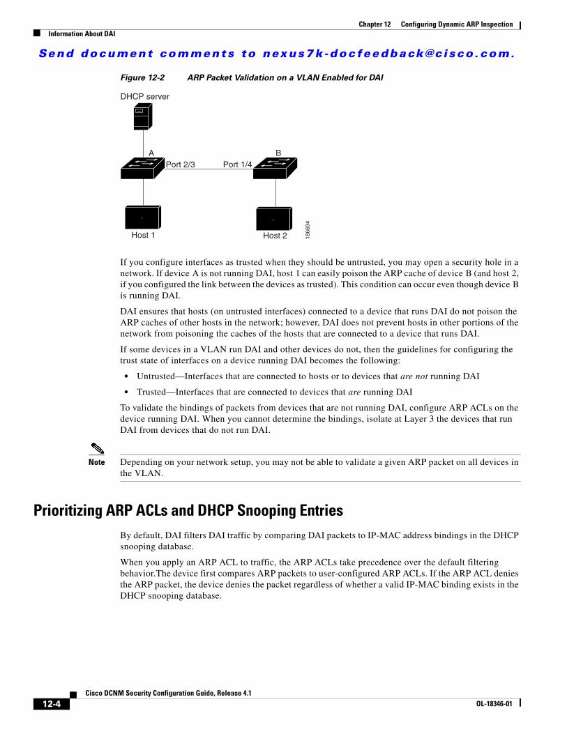
Send document comments to nexus7k -doc feedback@c i sco .com.
Chapter 12 Configuring Dynamic ARP InspectionInformation About DAI
Figure 12-2 ARP Packet Validation on a VLAN Enabled for DAI
If you configure interfaces as trusted when they should be untrusted, you may open a security hole in a network. If device A is not running DAI, host 1 can easily poison the ARP cache of device B (and host 2, if you configured the link between the devices as trusted). This condition can occur even though device B is running DAI.
DAI ensures that hosts (on untrusted interfaces) connected to a device that runs DAI do not poison the ARP caches of other hosts in the network; however, DAI does not prevent hosts in other portions of the network from poisoning the caches of the hosts that are connected to a device that runs DAI.
If some devices in a VLAN run DAI and other devices do not, then the guidelines for configuring the trust state of interfaces on a device running DAI becomes the following:
• Untrusted—Interfaces that are connected to hosts or to devices that are not running DAI
• Trusted—Interfaces that are connected to devices that are running DAI
To validate the bindings of packets from devices that are not running DAI, configure ARP ACLs on the device running DAI. When you cannot determine the bindings, isolate at Layer 3 the devices that run DAI from devices that do not run DAI.
Note Depending on your network setup, you may not be able to validate a given ARP packet on all devices in the VLAN.
Prioritizing ARP ACLs and DHCP Snooping EntriesBy default, DAI filters DAI traffic by comparing DAI packets to IP-MAC address bindings in the DHCP snooping database.
When you apply an ARP ACL to traffic, the ARP ACLs take precedence over the default filtering behavior.The device first compares ARP packets to user-configured ARP ACLs. If the ARP ACL denies the ARP packet, the device denies the packet regardless of whether a valid IP-MAC binding exists in the DHCP snooping database.
DHCP server
A B
Host 1 Host 2
Port 2/3 Port 1/4
1866
94
12-4Cisco DCNM Security Configuration Guide, Release 4.1
OL-18346-01
Send document comments to nexus7k -doc feedback@c i sco .com.
Chapter 12 Configuring Dynamic ARP InspectionLicensing Requirements for DAI
Note VLAN ACLs (VACLs) take precedence over both ARP ACLs and DHCP snooping entries. For example, if you apply a VACL and an ARP ACL to a VLAN and you configured the VACL to act on ARP traffic, the device permits or denies ARP traffic as determined by the VACL, not the ARP ACL or DHCP snooping entries.
For information about configuring ARP ACLs, see the “Configuring ARP ACLs” section on page 12-15. For information about applying an ARP ACL, see the “Applying ARP ACLs to VLANs for DAI Filtering” section on page 12-9.
Logging DAI PacketsNX-OS maintains a buffer of log entries about DAI packets processed. Each log entry contains flow information, such as the receiving VLAN, the port number, the source and destination IP addresses, and the source and destination MAC addresses.
You can also specify the type of packets that are logged. By default, an NX-OS device logs only packets that DAI drops. For configuration information, see the “Configuring DAI Log Filtering” section on page 12-12.
If the log buffer overflows, the device overwrites the oldest DAI log entries with newer entries. You can configure the maximum number of entries in the buffer. For more information, see the “Configuring the DAI Logging Buffer Size” section on page 12-11.
Note NX-OS does not generate system messages about DAI packets that are logged.
Virtualization SupportThe following information applies to DAI used in Virtual Device Contexts (VDCs):
• IP-MAC address bindings are unique per VDC.
• ARP ACLs are unique per VDC. You cannot use an ACL that you created in one VDC in a different VDC.
• Because ACLs are not shared by VDCs, you can reuse ACL names in different VDCs.
• The system does not limit ARP ACLs or rules on a per-VDC basis.
Licensing Requirements for DAIThe following table shows the licensing requirements for this feature:
Product License Requirement
DCNM DAI requires a LAN Enterprise license. For a complete explanation of the DCNM licensing scheme and how to obtain and apply licenses, see the Cisco DCNM Fundamentals Configuration Guide, Release 4.1.
NX-OS DAI requires no license. Any feature not included in a license package is bundled with the Cisco NX-OS system images and is provided at no extra charge to you. For a complete explanation of the NX-OS licensing scheme, see the Cisco Nexus 7000 Series NX-OS Licensing Guide, Release 4.1.
12-5Cisco DCNM Security Configuration Guide, Release 4.1
OL-18346-01
Send document comments to nexus7k -doc feedback@c i sco .com.
Chapter 12 Configuring Dynamic ARP InspectionPrerequisites for DAI
Prerequisites for DAIYou should be familiar with the following before you configure DAI:
• ARP
• DHCP snooping
Guidelines and LimitationsDAI has the following configuration guidelines and limitations:
• DAI is an ingress security feature; it does not perform any egress checking.
• DAI is not effective for hosts connected to devices that do not support DAI or that do not have this feature enabled. Because man-in-the-middle attacks are limited to a single Layer 2 broadcast domain, you should separate the domain with DAI from domains without DAI. This separation secures the ARP caches of hosts in the domain with DAI.
• DAI depends on the entries in the DHCP snooping binding database to verify IP-to-MAC address bindings in incoming ARP requests and ARP responses. If you want DAI to use static IP-MAC address bindings to determine if ARP packets are valid, DHCP snooping needs only to be enabled. If you want DAI to use dynamic IP-MAC address bindings to determine if ARP packets are valid, DHCP snooping must configured on the same VLANs on which you configure DAI. For configuration information, see the “Configuring DHCP Snooping” section on page 11-7.
• When you use the feature dhcp command to enable the DHCP snooping feature, there is a delay of approximately 30 seconds before the I/O modules receive DHCP snooping or DAI configuration. This delay occurs regardless of the method that you use to change from a configuration with DHCP snooping disabled to a configuration with DHCP snooping enabled. For example, if you use the Rollback feature to revert to a configuration that enables DHCP snooping, the I/O modules receive DHCP snooping and DAI configuration approximately 30 seconds after you complete the rollback.
• When DHCP snooping is disabled or used in a non-DHCP environment, you should use ARP ACLs to permit or to deny packets.
• DAI is supported on access ports, trunk ports, port-channel ports, and private VLAN ports.
• The DAI trust configuration of a port channel determines the trust state of all physical ports that you assign to the port channel. For example, if you have configured a physical port as a trusted interface and then you add that physical port to a port channel that is an untrusted interface, the physical port becomes untrusted.
• When you remove a physical port from a port channel, the physical port does not retain the DAI trust state configuration of the port channel.
• When you change the trust state on the port channel, the device configures a new trust state on all the physical ports that comprise the channel.
• If you want DAI to use static IP-MAC address bindings to determine if ARP packets are valid, ensure that the DHCP snooping feature is enabled and that you have configured the static IP-MAC address bindings. For configuration information, see the “Configuring DHCP Snooping” section on page 11-7.
• If you want DAI to use dynamic IP-MAC address bindings to determine if ARP packets are valid, ensure that DHCP snooping is configured (see the “Configuring DHCP Snooping” section on page 11-7).
12-6Cisco DCNM Security Configuration Guide, Release 4.1
OL-18346-01
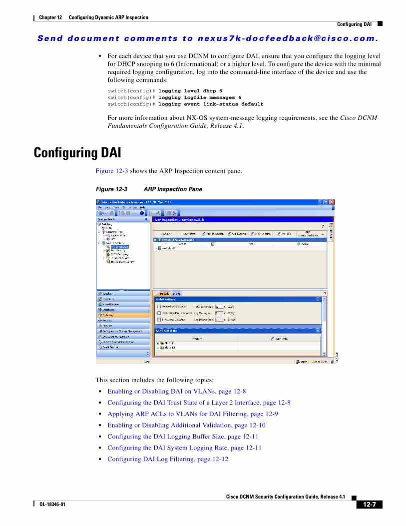
Send document comments to nexus7k -doc feedback@c i sco .com.
Chapter 12 Configuring Dynamic ARP InspectionConfiguring DAI
• For each device that you use DCNM to configure DAI, ensure that you configure the logging level for DHCP snooping to 6 (Informational) or a higher level. To configure the device with the minimal required logging configuration, log into the command-line interface of the device and use the following commands:
switch(config)# logging level dhcp 6switch(config)# logging logfile messages 6switch(config)# logging event link-status default
For more information about NX-OS system-message logging requirements, see the Cisco DCNM Fundamentals Configuration Guide, Release 4.1.
Configuring DAIFigure 12-3 shows the ARP Inspection content pane.
Figure 12-3 ARP Inspection Pane
This section includes the following topics:
• Enabling or Disabling DAI on VLANs, page 12-8
• Configuring the DAI Trust State of a Layer 2 Interface, page 12-8
• Applying ARP ACLs to VLANs for DAI Filtering, page 12-9
• Enabling or Disabling Additional Validation, page 12-10
• Configuring the DAI Logging Buffer Size, page 12-11
• Configuring the DAI System Logging Rate, page 12-11
• Configuring DAI Log Filtering, page 12-12
12-7Cisco DCNM Security Configuration Guide, Release 4.1
OL-18346-01
Send document comments to nexus7k -doc feedback@c i sco .com.
Chapter 12 Configuring Dynamic ARP InspectionConfiguring DAI
Enabling or Disabling DAI on VLANsYou can enable or disable DAI on VLANs.
BEFORE YOU BEGIN
By default, DAI is disabled on all VLANs.
If you are enabling DAI, ensure the following:
• DHCP snooping is enabled. For more information, see the “Enabling or Disabling the DHCP Snooping Feature” section on page 11-8.
• The VLANs on which you want to enable DAI are configured.
• Ensure that you configure the logging level for DHCP snooping to 6 (Informational) or a higher level on the device. To configure the device with the minimal required logging configuration, log into the command-line interface of the device and use the following commands:
switch(config)# logging level dhcp 6switch(config)# logging logfile messages 6switch(config)# logging event link-status default
For more information about NX-OS system-message logging requirements, see the Cisco DCNM Fundamentals Configuration Guide, Release 4.1.
DETAILED STEPS
To enable or disable DAI on a VLAN, follow these steps:
Step 1 From the Feature Selector pane, choose Switching > Layer 2 Security > ARP Inspection.
The available devices appear in the Summary pane.
Step 2 From the Summary pane, double-click the device that has the VLAN that you want to configure with DAI.
The VLANs on the device appear in the Summary pane.
Step 3 From the Summary pane, click the VLAN that you want to configure with DAI.
The DAI VLAN Details tab appears in the Details pane.
Step 4 From the DAI VLAN Details tab, do one of the following:
• To enable DAI on the selected VLAN, check ARP Inspection.
• To disable DAI on the selected VLAN, uncheck ARP Inspection.
Step 5 From the menu bar, choose File > Deploy to apply your changes to the device.
Configuring the DAI Trust State of a Layer 2 InterfaceYou can configure the DAI interface trust state of a Layer 2 interface.
A device forwards ARP packets that it receives on a trusted Layer 2 interface but does not check them. For more information about DAI trust states, see the “Interface Trust States and Network Security” section on page 12-3.
12-8Cisco DCNM Security Configuration Guide, Release 4.1
OL-18346-01
Send document comments to nexus7k -doc feedback@c i sco .com.
Chapter 12 Configuring Dynamic ARP InspectionConfiguring DAI
On untrusted interfaces, the device intercepts all ARP requests and responses, verifies that the intercepted packets have valid IP-MAC address bindings before updating the local cache and forwarding the packet to the appropriate destination. If the device determines that packets have invalid bindings, it drops the packets and logs them according to the logging configuration. For more information, see the “Configuring DAI Log Filtering” section on page 12-12.
BEFORE YOU BEGIN
By default, all interfaces are untrusted.
If you are enabling DAI, ensure that DHCP snooping is enabled. For more information, see the “Enabling or Disabling the DHCP Snooping Feature” section on page 11-8.
DETAILED STEPS
To configure the DAI trust state of a Layer 2 interface, follow these steps:
Step 1 From the Feature Selector pane, choose Switching > Layer 2 Security > ARP Inspection.
The available devices appear in the Summary pane.
Step 2 From the Summary pane, click the device that has the Layer 2 interface whose DAI trust state you want to configure.
The Details tab appears in the Details pane.
Step 3 From the Details tab, expand the ARP Trust State section, if necessary.
A table of slots on the selected device appears in the ARP Trust State section.
Step 4 Double-click the slot that contains the Layer 2 interface that you want to configure.
The Layer 2 interfaces on the slot appear. For each interface, a check box in the Trust State column indicates whether the device trusts the interface.
Step 5 In the Trust State column for the interface that you want to configure, do one of the following:
• To make the interface a trusted DAI interface, check or uncheck Trust State.
• To make the interface an untrusted DAI interface, uncheck Trust State.
Step 6 From the menu bar, choose File > Deploy to apply your changes to the device.
Applying ARP ACLs to VLANs for DAI FilteringYou can apply an ARP ACL to one or more VLANs. The device permits packets only if the ACL permits them.
BEFORE YOU BEGIN
By default, no VLANs have an ARP ACL applied.
Ensure that the ARP ACL that you want to apply is correctly configured. For information about configuring an ARP ACL, see the “Configuring ARP ACLs” section on page 12-15.
12-9Cisco DCNM Security Configuration Guide, Release 4.1
OL-18346-01
Send document comments to nexus7k -doc feedback@c i sco .com.
Chapter 12 Configuring Dynamic ARP InspectionConfiguring DAI
DETAILED STEPS
To apply an ARP ACL to a VLAN for DAI filtering, follow these steps:
Step 1 From the Feature Selector pane, choose Switching > Layer 2 Security > ARP Inspection.
The available devices appear in the Summary pane.
Step 2 From the Summary pane, double-click the device that has the VLAN that you want to configure with an ARP ACL.
The VLANs on the device appear in the Summary pane.
Step 3 From the Summary pane, click the VLAN that you want to configure with an ARP ACL.
The DAI VLAN Details tab appears in the Details pane. On the DAI VLAN Details tab, the ARP ACL drop-down list appears.
Step 4 From the DAI VLAN Details tab, do one of the following:
• To apply an ARP ACL to the VLAN, from the ARP ACL drop-down list, choose the ACL that you want to apply.
• To remove an ARP ACL from the VLAN, from the menu bar, choose Actions > Remove ARP ACL from VLAN.
Step 5 From the menu bar, choose File > Deploy to apply your changes to the device.
Enabling or Disabling Additional ValidationYou can enable or disable additional validation of ARP packets.
DAI intercepts, logs, and discards ARP packets with invalid IP-to-MAC address bindings. You can enable additional validation on the destination MAC address, the sender and target IP addresses, and the source MAC address.
BEFORE YOU BEGIN
By default, no additional validation of ARP packets is enabled.
DETAILED STEPS
To enable or disable additional validation, follow these steps:
Step 1 From the Feature Selector pane, choose Switching > Layer 2 Security > ARP Inspection.
The available devices appear in the Summary pane.
Step 2 From the Summary pane, double-click the device that you want to configure with additional validation.
The Details tab appears in the Details pane.
Step 3 From the Details tab, expand the Global Settings section, if necessary.
Step 4 (Optional) To enable or disable source MAC address validation, check or uncheck Source MAC Validation.
Step 5 (Optional) To enable or disable destination MAC address validation, check or uncheck Destination MAC Validation.
12-10Cisco DCNM Security Configuration Guide, Release 4.1
OL-18346-01
Send document comments to nexus7k -doc feedback@c i sco .com.
Chapter 12 Configuring Dynamic ARP InspectionConfiguring DAI
Step 6 (Optional) To enable or disable source and target IP address validation, check or uncheck IP Address Validation.
Step 7 From the menu bar, choose File > Deploy to apply your changes to the device.
Configuring the DAI Logging Buffer SizeYou can configure the DAI logging buffer size.
BEFORE YOU BEGIN
The default buffer size is 32 messages.
DETAILED STEPS
To configuring the DAI logging buffer size, follow these steps:
Step 1 From the Feature Selector pane, choose Switching > Layer 2 Security > ARP Inspection.
The available devices appear in the Summary pane.
Step 2 From the Summary pane, click the device whose DAI logging buffer size you want to configure.
The Details tab appears in the Details pane.
Step 3 From the Details tab, expand the Global Settings section, if necessary.
The Total Buffer Size field appears in the Global Settings section.
Step 4 Click the Total Buffer Size field and enter the maximum number of DAI messages that the buffer can have.
Step 5 From the menu bar, choose File > Deploy to apply your changes to the device.
Configuring the DAI System Logging Rate
Note The DAI system logging rate is not configurable in NX-OS 4.1.
You can configure the DAI system logging rate.
BEFORE YOU BEGIN
The default DAI system logging rate is five messages every second.
DETAILED STEPS
To configure the DAI system logging rate, follow these steps:
Step 1 From the Feature Selector pane, choose Switching > Layer 2 Security > ARP Inspection.
12-11Cisco DCNM Security Configuration Guide, Release 4.1
OL-18346-01
Send document comments to nexus7k -doc feedback@c i sco .com.
Chapter 12 Configuring Dynamic ARP InspectionConfiguring DAI
The available devices appear in the Summary pane.
Step 2 From the Summary pane, click the device whose DAI logging buffer size you want to configure.
The Details tab appears in the Details pane.
Step 3 From the Details tab, expand the Global Settings section, if necessary.
The Log Messages field and the Log Interval (sec) field appear in the Global Settings section. The device sends messages at the rate of the number of messages in the Log Messages field per the number of seconds in the Log Interval (sec) field.
Step 4 (Optional) Click the Log Messages field and enter the number of messages.
Step 5 (Optional) Click the Log Interval(sec) field and enter the number of seconds.
Step 6 From the menu bar, choose File > Deploy to apply your changes to the device.
Configuring DAI Log FilteringYou can configure how the device determines whether to log a DAI packet.
BEFORE YOU BEGIN
By default, the device logs DAI packets that are dropped.
DETAILED STEPS
To configure DAI log filtering, follow these steps:
Step 1 From the Feature Selector pane, choose Switching > Layer 2 Security > ARP Inspection.
The available devices appear in the Summary pane.
Step 2 From the Summary pane, double-click the device that has the VLAN that you want to configure with DAI log filtering.
The VLANs on the device appear in the Summary pane.
Step 3 From the Summary pane, click the VLAN that you want to configure with DAI log filtering.
The DAI VLAN Details tab appears in the Details pane. On the DAI VLAN Details tab, the ACL Logging drop-down list and the DHCP Logging drop-down list appear.
Step 4 (Optional) From the ACL Logging drop-down list, choose the ACL logging option that you want.
Note The ACL Logging option is not supported in NX-OS 4.0.
Step 5 (Optional) From the DHCP drop-down list, choose the DHCP-binding logging option that you want.
Step 6 From the menu bar, choose File > Deploy to apply your changes to the device.
12-12Cisco DCNM Security Configuration Guide, Release 4.1
OL-18346-01
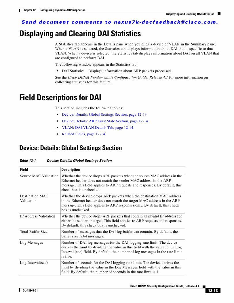
Send document comments to nexus7k -doc feedback@c i sco .com.
Chapter 12 Configuring Dynamic ARP InspectionDisplaying and Clearing DAI Statistics
Displaying and Clearing DAI StatisticsA Statistics tab appears in the Details pane when you click a device or VLAN in the Summary pane. When a VLAN is selected, the Statistics tab displays information about DAI that is specific to that VLAN. When a device is selected, the Statistics tab displays information about DAI on all VLAN that are configured to perform DAI.
The following window appears in the Statistics tab:
• DAI Statistics—Displays information about ARP packets processed.
See the Cisco DCNM Fundamentals Configuration Guide, Release 4.1 for more information on collecting statistics for this feature.
Field Descriptions for DAIThis section includes the following topics:
• Device: Details: Global Settings Section, page 12-13
• Device: Details: ARP Trust State Section, page 12-14
• VLAN: DAI VLAN Details Tab, page 12-14
• Related Fields, page 12-14
Device: Details: Global Settings Section
Table 12-1 Device: Details: Global Settings Section
Field Description
Source MAC Validation Whether the device drops ARP packets when the source MAC address in the Ethernet header does not match the sender MAC address in the ARP message. This field applies to ARP requests and responses. By default, this check box is unchecked.
Destination MAC Validation
Whether the device drops ARP packets when the destination MAC address in the Ethernet header does not match the target MAC address in the ARP message. This field applies to ARP responses only. By default, this check box is unchecked.
IP Address Validation Whether the device drops ARP packets that contain an invalid IP address for either the sender or target. This field applies to ARP requests and responses. By default, this check box is unchecked.
Total Buffer Size Number of messages that the DAI log buffer can contain. By default, the buffer size is 64 messages.
Log Messages Number of DAI log messages for the DAI logging rate limit. The device derives the limit by dividing the value in this field with the value in the Log Interval (sec) field. By default, the number of log messages in the rate limit is five.
Log Interval(sec) Number of seconds for the DAI logging rate limit. The device derives the limit by dividing the value in the Log Messages field with the value in this field. By default, the number of seconds in the rate limit is 1.
12-13Cisco DCNM Security Configuration Guide, Release 4.1
OL-18346-01
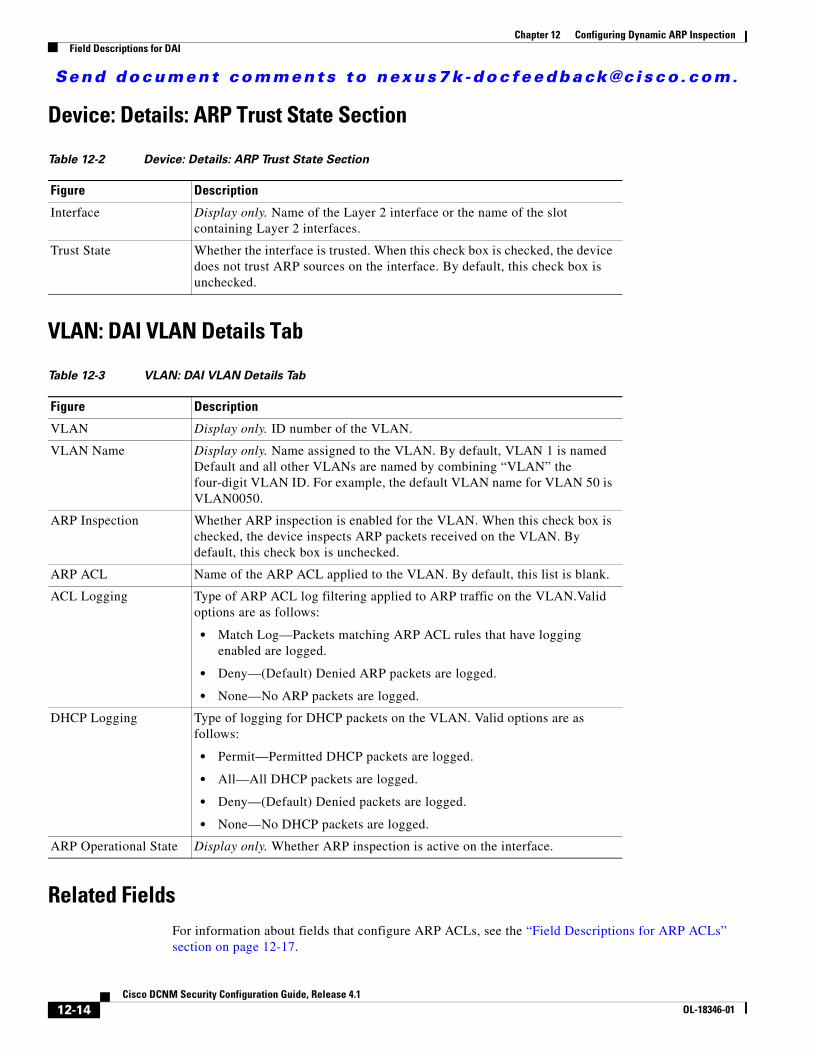
Send document comments to nexus7k -doc feedback@c i sco .com.
Chapter 12 Configuring Dynamic ARP InspectionField Descriptions for DAI
Device: Details: ARP Trust State Section
VLAN: DAI VLAN Details Tab
Related FieldsFor information about fields that configure ARP ACLs, see the “Field Descriptions for ARP ACLs” section on page 12-17.
Table 12-2 Device: Details: ARP Trust State Section
Figure Description
Interface Display only. Name of the Layer 2 interface or the name of the slot containing Layer 2 interfaces.
Trust State Whether the interface is trusted. When this check box is checked, the device does not trust ARP sources on the interface. By default, this check box is unchecked.
Table 12-3 VLAN: DAI VLAN Details Tab
Figure Description
VLAN Display only. ID number of the VLAN.
VLAN Name Display only. Name assigned to the VLAN. By default, VLAN 1 is named Default and all other VLANs are named by combining “VLAN” the four-digit VLAN ID. For example, the default VLAN name for VLAN 50 is VLAN0050.
ARP Inspection Whether ARP inspection is enabled for the VLAN. When this check box is checked, the device inspects ARP packets received on the VLAN. By default, this check box is unchecked.
ARP ACL Name of the ARP ACL applied to the VLAN. By default, this list is blank.
ACL Logging Type of ARP ACL log filtering applied to ARP traffic on the VLAN.Valid options are as follows:
• Match Log—Packets matching ARP ACL rules that have logging enabled are logged.
• Deny—(Default) Denied ARP packets are logged.
• None—No ARP packets are logged.
DHCP Logging Type of logging for DHCP packets on the VLAN. Valid options are as follows:
• Permit—Permitted DHCP packets are logged.
• All—All DHCP packets are logged.
• Deny—(Default) Denied packets are logged.
• None—No DHCP packets are logged.
ARP Operational State Display only. Whether ARP inspection is active on the interface.
12-14Cisco DCNM Security Configuration Guide, Release 4.1
OL-18346-01
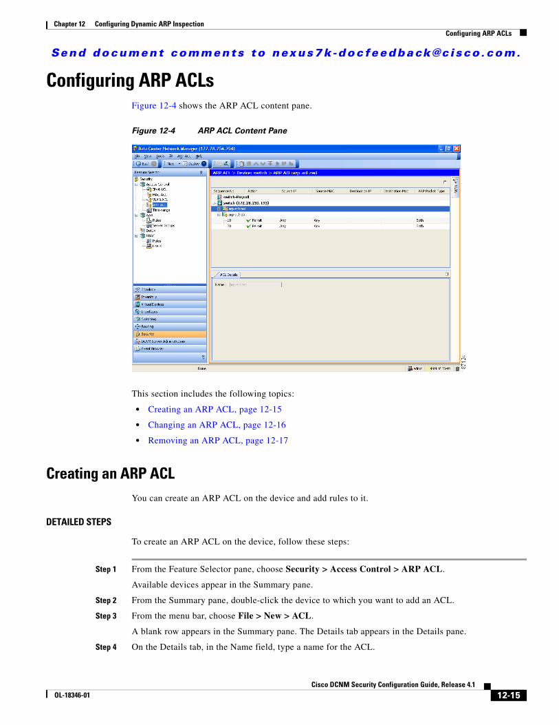
Send document comments to nexus7k -doc feedback@c i sco .com.
Chapter 12 Configuring Dynamic ARP InspectionConfiguring ARP ACLs
Configuring ARP ACLsFigure 12-4 shows the ARP ACL content pane.
Figure 12-4 ARP ACL Content Pane
This section includes the following topics:
• Creating an ARP ACL, page 12-15
• Changing an ARP ACL, page 12-16
• Removing an ARP ACL, page 12-17
Creating an ARP ACLYou can create an ARP ACL on the device and add rules to it.
DETAILED STEPS
To create an ARP ACL on the device, follow these steps:
Step 1 From the Feature Selector pane, choose Security > Access Control > ARP ACL.
Available devices appear in the Summary pane.
Step 2 From the Summary pane, double-click the device to which you want to add an ACL.
Step 3 From the menu bar, choose File > New > ACL.
A blank row appears in the Summary pane. The Details tab appears in the Details pane.
Step 4 On the Details tab, in the Name field, type a name for the ACL.
12-15Cisco DCNM Security Configuration Guide, Release 4.1
OL-18346-01
Send document comments to nexus7k -doc feedback@c i sco .com.
Chapter 12 Configuring Dynamic ARP InspectionConfiguring ARP ACLs
Step 5 For each rule or remark that you want to add to the ACL, from the menu bar, choose File > New and choose ACE or Remark. On the Details tab, configure fields as needed.
Note To log packets that match a rule, check Log, complete the procedure, and then confirm that DAI logging for each VLAN that you apply the ACL to is configured to log packets when they match a rule in the ARP ACL. For more information, see the “Configuring DAI Log Filtering” section on page 12-12.
Step 6 From the menu bar, choose File > Deploy to apply your changes to the device.
Changing an ARP ACLYou can change, reorder, add, and remove rules in an existing ARP ACL.
DETAILED STEPS
To change an ARP ACL, follow these steps:
Step 1 From the Feature Selector pane, choose Security > Access Control > ARP ACL.
Available devices appear in the Summary pane.
Step 2 From the Summary pane, double-click the device that has the ACL that you want to change and then double-click the ACL.
The ACLs on the device and the rules of the ACL that you double-clicked appear in the Summary pane.
Step 3 (Optional) If you want to change the details of a rule, click the rule in the Summary pane. On the Details tab, configure fields as needed.
Note To log packets that match a rule, check Log, complete the procedure, and then confirm that DAI logging for each VLAN that you apply the ACL to is configured to log packets when they match a rule in the ARP ACL. For more information, see the “Configuring DAI Log Filtering” section on page 12-12.
Step 4 (Optional) If you want to add a rule or remark, click the ACL in the Summary pane and then from the menu bar, choose File > New and choose ACE or Remark. On the Details tab, configure fields as needed.
Step 5 (Optional) If you want to remove a rule, click the rule and then from the menu bar, choose ARP ACL > Delete.
Step 6 (Optional) If you want to move a rule or remark to a different position in the ACL, click the rule or remark and then from the menu bar, choose one of the following, as applicable:
• ARP ACL > Move Up
• ARP ACL > Move Down
The rule moves up or down, as you chose. The sequence number of the rules adjust accordingly.
12-16Cisco DCNM Security Configuration Guide, Release 4.1
OL-18346-01
Send document comments to nexus7k -doc feedback@c i sco .com.
Chapter 12 Configuring Dynamic ARP InspectionField Descriptions for ARP ACLs
Step 7 From the menu bar, choose File > Deploy to apply your changes to the device.
Removing an ARP ACLYou can remove an ARP ACL from the device.
BEFORE YOU BEGIN
Ensure that you know whether the ACL is applied to a VLAN. The device allows you to remove ACLs that are currently applied. Removing an ACL does not affect the configuration of VLANs where you have applied the ACL. Instead, the device considers the removed ACL to be empty.
DETAILED STEPS
To remove an ARP ACL from the device, follow these steps:
Step 1 From the Feature Selector pane, choose Security > Access Control > ARP ACL.
Available devices appear in the Summary pane.
Step 2 From the Summary pane, double-click the device from which you want to remove an ACL.
The ACLs currently on the device appear in the Summary pane.
Step 3 Click the ACL that you want to remove.
Step 4 From the menu bar, choose ARP ACL > Delete.
The ACL disappears from the Summary pane.
Step 5 From the menu bar, choose File > Deploy to apply your changes to the device.
Field Descriptions for ARP ACLsThis section includes the following topics:
• ARP ACL: ACL Details Tab, page 12-18
• ARP Access Rule: ACE Details Tab, page 12-18
• ARP Access Rule: ACE Details: Source and Destination Section, page 12-18
• ARP ACL Remark: Remark Details Tab, page 12-21
• Related Fields, page 12-21
12-17Cisco DCNM Security Configuration Guide, Release 4.1
OL-18346-01

Send document comments to nexus7k -doc feedback@c i sco .com.
Chapter 12 Configuring Dynamic ARP InspectionField Descriptions for ARP ACLs
ARP ACL: ACL Details Tab
ARP Access Rule: ACE Details Tab
ARP Access Rule: ACE Details: Source and Destination Section
Table 12-4 ARP ACL: ACL Details Tab
Field Description
Name Name of the ARP ACL. Names can be a maximum of 64 alphanumeric characters but must begin with an alphabetic character. No name is assigned by default.
Table 12-5 ARP Access Rule: ACE Details Tab
Field Description
Sequence No. Sequence number of the rule. Must be a whole number between 1 and 4294967295. If you add a rule after another rule, the default sequence number is 10 greater than the preceding rule. If you add a rule before another rule, the number is 10 less than the following rule.
Action Action taken by the device when it determines that the rule applies to the packet. Valid values are as follows:
• Deny—Stops processing the packet and drop it.
• Permit—Continues processing the packet. This is the default value.
Log Whether the device logs statistics about traffic to which the access rule applies. This check box is unchecked by default.
Table 12-6 ARP Access Rule: ACE Details: Source and Destination Section
Field Description
ARP Packet Type Type of ARP packet that the rule matches:
• Response—The rule matches ARP responses only.
• Both—(Default) The rule matches ARP response and request packets.
• Request—The rule matches ARP requests only.
12-18Cisco DCNM Security Configuration Guide, Release 4.1
OL-18346-01
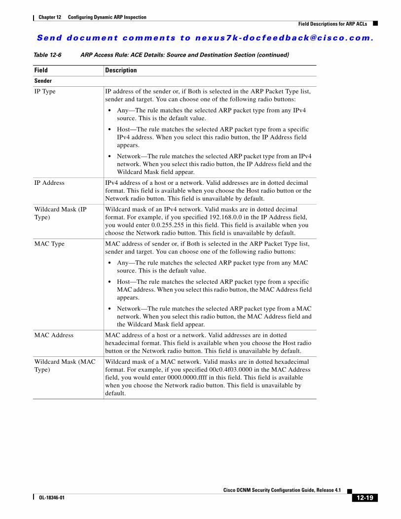
Send document comments to nexus7k -doc feedback@c i sco .com.
Chapter 12 Configuring Dynamic ARP InspectionField Descriptions for ARP ACLs
Sender
IP Type IP address of the sender or, if Both is selected in the ARP Packet Type list, sender and target. You can choose one of the following radio buttons:
• Any—The rule matches the selected ARP packet type from any IPv4 source. This is the default value.
• Host—The rule matches the selected ARP packet type from a specific IPv4 address. When you select this radio button, the IP Address field appears.
• Network—The rule matches the selected ARP packet type from an IPv4 network. When you select this radio button, the IP Address field and the Wildcard Mask field appear.
IP Address IPv4 address of a host or a network. Valid addresses are in dotted decimal format. This field is available when you choose the Host radio button or the Network radio button. This field is unavailable by default.
Wildcard Mask (IP Type)
Wildcard mask of an IPv4 network. Valid masks are in dotted decimal format. For example, if you specified 192.168.0.0 in the IP Address field, you would enter 0.0.255.255 in this field. This field is available when you choose the Network radio button. This field is unavailable by default.
MAC Type MAC address of sender or, if Both is selected in the ARP Packet Type list, sender and target. You can choose one of the following radio buttons:
• Any—The rule matches the selected ARP packet type from any MAC source. This is the default value.
• Host—The rule matches the selected ARP packet type from a specific MAC address. When you select this radio button, the MAC Address field appears.
• Network—The rule matches the selected ARP packet type from a MAC network. When you select this radio button, the MAC Address field and the Wildcard Mask field appear.
MAC Address MAC address of a host or a network. Valid addresses are in dotted hexadecimal format. This field is available when you choose the Host radio button or the Network radio button. This field is unavailable by default.
Wildcard Mask (MAC Type)
Wildcard mask of a MAC network. Valid masks are in dotted hexadecimal format. For example, if you specified 00c0.4f03.0000 in the MAC Address field, you would enter 0000.0000.ffff in this field. This field is available when you choose the Network radio button. This field is unavailable by default.
Table 12-6 ARP Access Rule: ACE Details: Source and Destination Section (continued)
Field Description
12-19Cisco DCNM Security Configuration Guide, Release 4.1
OL-18346-01
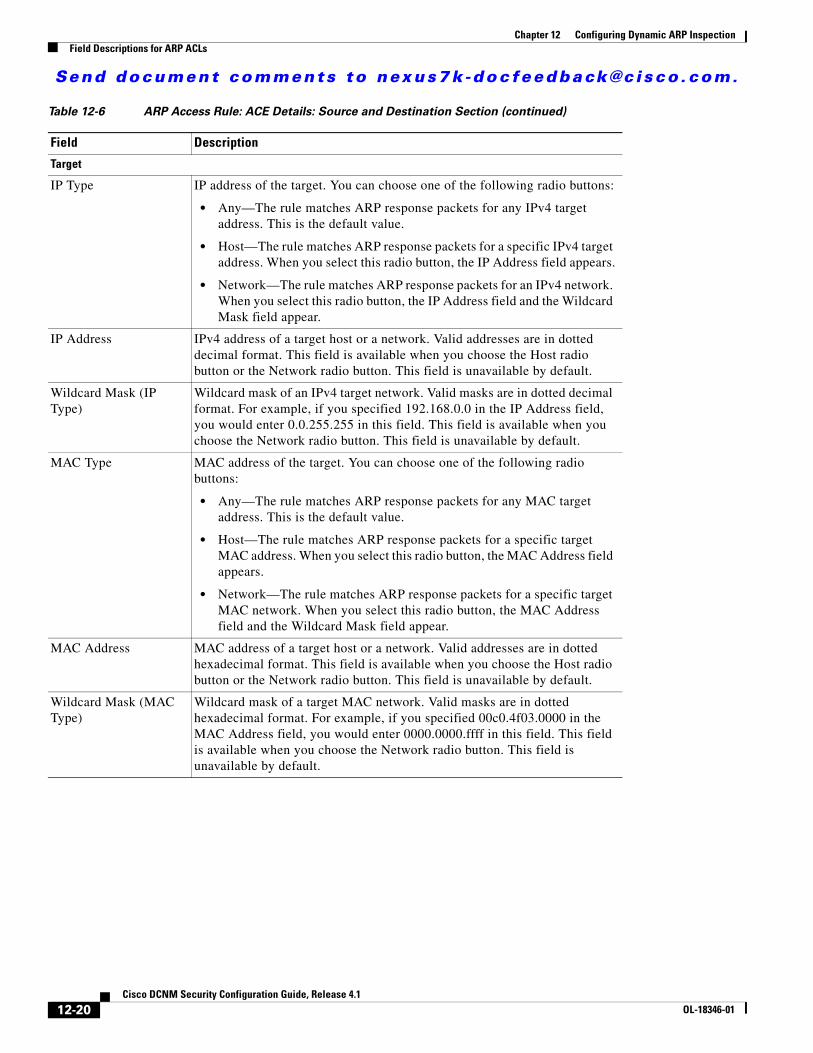
Send document comments to nexus7k -doc feedback@c i sco .com.
Chapter 12 Configuring Dynamic ARP InspectionField Descriptions for ARP ACLs
Target
IP Type IP address of the target. You can choose one of the following radio buttons:
• Any—The rule matches ARP response packets for any IPv4 target address. This is the default value.
• Host—The rule matches ARP response packets for a specific IPv4 target address. When you select this radio button, the IP Address field appears.
• Network—The rule matches ARP response packets for an IPv4 network. When you select this radio button, the IP Address field and the Wildcard Mask field appear.
IP Address IPv4 address of a target host or a network. Valid addresses are in dotted decimal format. This field is available when you choose the Host radio button or the Network radio button. This field is unavailable by default.
Wildcard Mask (IP Type)
Wildcard mask of an IPv4 target network. Valid masks are in dotted decimal format. For example, if you specified 192.168.0.0 in the IP Address field, you would enter 0.0.255.255 in this field. This field is available when you choose the Network radio button. This field is unavailable by default.
MAC Type MAC address of the target. You can choose one of the following radio buttons:
• Any—The rule matches ARP response packets for any MAC target address. This is the default value.
• Host—The rule matches ARP response packets for a specific target MAC address. When you select this radio button, the MAC Address field appears.
• Network—The rule matches ARP response packets for a specific target MAC network. When you select this radio button, the MAC Address field and the Wildcard Mask field appear.
MAC Address MAC address of a target host or a network. Valid addresses are in dotted hexadecimal format. This field is available when you choose the Host radio button or the Network radio button. This field is unavailable by default.
Wildcard Mask (MAC Type)
Wildcard mask of a target MAC network. Valid masks are in dotted hexadecimal format. For example, if you specified 00c0.4f03.0000 in the MAC Address field, you would enter 0000.0000.ffff in this field. This field is available when you choose the Network radio button. This field is unavailable by default.
Table 12-6 ARP Access Rule: ACE Details: Source and Destination Section (continued)
Field Description
12-20Cisco DCNM Security Configuration Guide, Release 4.1
OL-18346-01
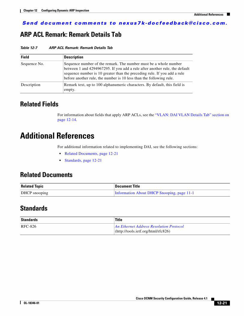
Send document comments to nexus7k -doc feedback@c i sco .com.
Chapter 12 Configuring Dynamic ARP InspectionAdditional References
ARP ACL Remark: Remark Details Tab
Related FieldsFor information about fields that apply ARP ACLs, see the “VLAN: DAI VLAN Details Tab” section on page 12-14.
Additional ReferencesFor additional information related to implementing DAI, see the following sections:
• Related Documents, page 12-21
• Standards, page 12-21
Related Documents
Standards
Table 12-7 ARP ACL Remark: Remark Details Tab
Field Description
Sequence No. Sequence number of the remark. The number must be a whole number between 1 and 4294967295. If you add a rule after another rule, the default sequence number is 10 greater than the preceding rule. If you add a rule before another rule, the number is 10 less than the following rule.
Description Remark text, up to 100 alphanumeric characters. By default, this field is empty.
Related Topic Document Title
DHCP snooping Information About DHCP Snooping, page 11-1
Standards Title
RFC-826 An Ethernet Address Resolution Protocol (http://tools.ietf.org/html/rfc826)
12-21Cisco DCNM Security Configuration Guide, Release 4.1
OL-18346-01
Send document comments to nexus7k -doc feedback@c i sco .com.
Chapter 12 Configuring Dynamic ARP InspectionFeature History for DAI
Feature History for DAITable 12-8 lists the release history for this feature.
Table 12-8 Feature History for DAI
Feature Name Releases Feature Information
DAI 4.1(2) No change from Release 4.0.
12-22Cisco DCNM Security Configuration Guide, Release 4.1
OL-18346-01
Send document comments to nexus7k -doc feedback@c i sco .com.
CiscOL-18346-01
C H A P T E R13
Configuring IP Source GuardThis chapter describes how to configure IP Source Guard on NX-OS devices.
This chapter includes the following sections:
• Information About IP Source Guard, page 13-1
• Licensing Requirements for IP Source Guard, page 13-2
• Prerequisites for IP Source Guard, page 13-2
• Guidelines and Limitations, page 13-3
• Configuring IP Source Guard, page 13-3
• Displaying IP Source Guard Bindings, page 13-5
• Field Descriptions for IP Source Guard, page 13-6
• Additional References, page 13-7
• Feature History for IP Source Guard, page 13-7
Information About IP Source GuardIP Source Guard is a per-interface traffic filter that permits IP traffic only when the IP address and MAC address of each packet matches one of two sources of IP and MAC address bindings:
• Entries in the Dynamic Host Configuration Protocol (DHCP) snooping binding table.
• Static IP source entries that you configure.
Filtering on trusted IP and MAC address bindings helps prevent attacks that rely on spoofing attacks, in which an attacker uses the IP address of a valid host to gain unauthorized network access. To circumvent IP Source Guard, an attacker would have to spoof both the IP address and the MAC address of a valid host.
You can enable IP Source Guard on Layer 2 interfaces that are not trusted by DHCP snooping. IP Source Guard supports interfaces that are configured to operate in access mode and trunk mode. When you initially enable IP Source Guard, all inbound IP traffic on the interface is blocked except for the following:
• DHCP packets, which DHCP snooping inspects and then forwards or drops, depending upon the results of inspecting the packet.
• IP traffic from static IP source entries that you have configured in the NX-OS device.
13-1o DCNM Security Configuration Guide, Release 4.1
Send document comments to nexus7k -doc feedback@c i sco .com.
Chapter 13 Configuring IP Source GuardLicensing Requirements for IP Source Guard
The device permits the IP traffic when DHCP snooping adds a binding table entry for the IP address and MAC address of an IP packet or when you have configured a static IP source entry.
The device drops IP packets when the IP address and MAC address of the packet do not have a binding table entry or a static IP source entry. For example, assume that the binding table contains the following entry:
MacAddress IpAddress LeaseSec Type VLAN Interface ---------- ---------- --------- ------ ------- --------- 00:02:B3:3F:3B:99 10.5.5.2 6943 dhcp-snooping 10 Ethernet2/3
If the device receives an IP packet with an IP address of 10.5.5.2, IP Source Guard forward the packet only if the MAC address of the packet is 00:02:B3:3F:3B:99.
Virtualization SupportThe following information applies to IP Source Guard used in Virtual Device Contexts (VDCs):
• IP-MAC address bindings are unique per VDC. Bindings in one VDC do not affect IP Source Guard in other VDCs.
• NX-OS does not limit binding database size on a per-VDC basis.
Licensing Requirements for IP Source GuardThe following table shows the licensing requirements for this feature:
Prerequisites for IP Source GuardIP Source Guard has the following prerequisites:
• You should be familiar with DHCP snooping before you configure IP Source Guard.
• DHCP snooping is enabled (see the “Configuring DHCP Snooping” section on page 11-7).
Product License Requirement
DCNM IP Source Guard requires a LAN Enterprise license. For a complete explanation of the DCNM licensing scheme and how to obtain and apply licenses, see the Cisco DCNM Fundamentals Configuration Guide, Release 4.1.
NX-OS IP Source Guard requires no license. Any feature not included in a license package is bundled with the Cisco NX-OS system images and is provided at no extra charge to you. For a complete explanation of the NX-OS licensing scheme, see the Cisco Nexus 7000 Series NX-OS Licensing Guide, Release 4.1.
13-2Cisco DCNM Security Configuration Guide, Release 4.1
OL-18346-01
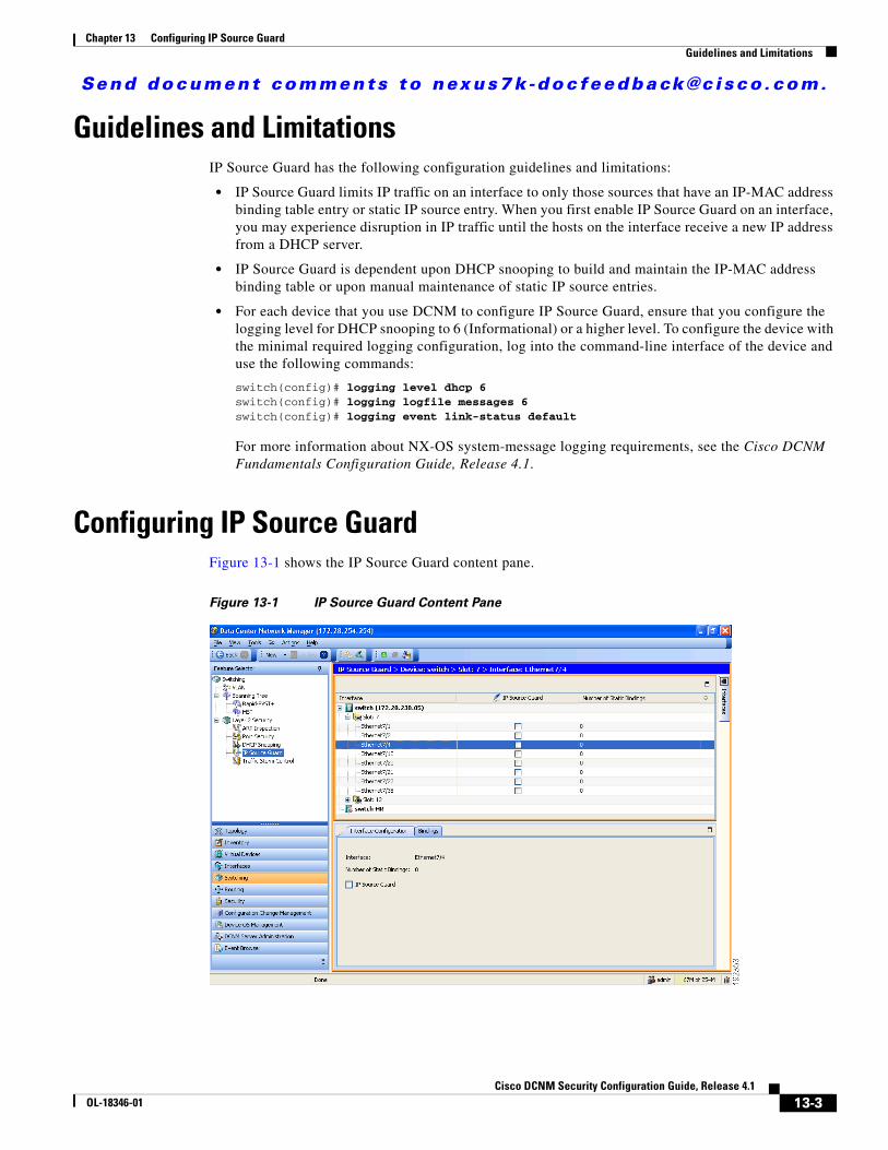
Send document comments to nexus7k -doc feedback@c i sco .com.
Chapter 13 Configuring IP Source GuardGuidelines and Limitations
Guidelines and LimitationsIP Source Guard has the following configuration guidelines and limitations:
• IP Source Guard limits IP traffic on an interface to only those sources that have an IP-MAC address binding table entry or static IP source entry. When you first enable IP Source Guard on an interface, you may experience disruption in IP traffic until the hosts on the interface receive a new IP address from a DHCP server.
• IP Source Guard is dependent upon DHCP snooping to build and maintain the IP-MAC address binding table or upon manual maintenance of static IP source entries.
• For each device that you use DCNM to configure IP Source Guard, ensure that you configure the logging level for DHCP snooping to 6 (Informational) or a higher level. To configure the device with the minimal required logging configuration, log into the command-line interface of the device and use the following commands:
switch(config)# logging level dhcp 6switch(config)# logging logfile messages 6switch(config)# logging event link-status default
For more information about NX-OS system-message logging requirements, see the Cisco DCNM Fundamentals Configuration Guide, Release 4.1.
Configuring IP Source GuardFigure 13-1 shows the IP Source Guard content pane.
Figure 13-1 IP Source Guard Content Pane
13-3Cisco DCNM Security Configuration Guide, Release 4.1
OL-18346-01
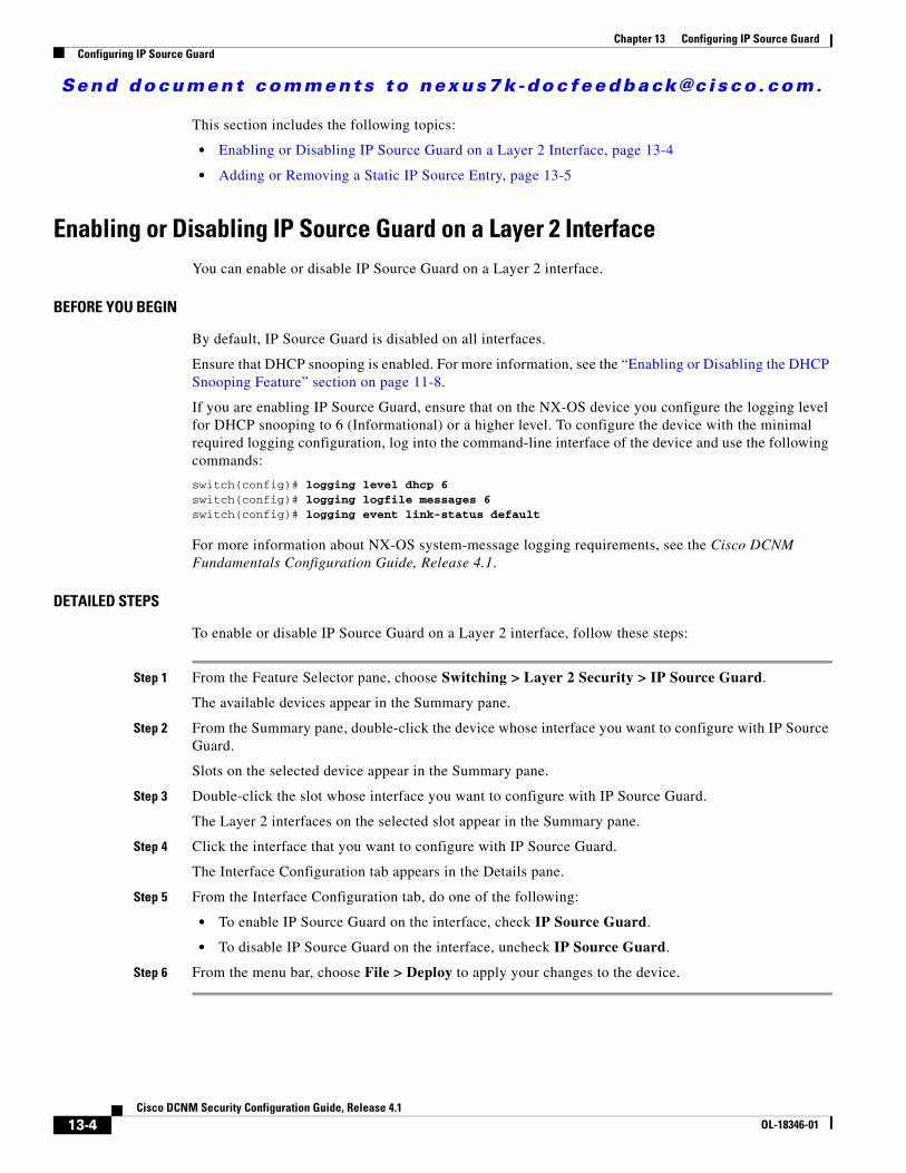
Send document comments to nexus7k -doc feedback@c i sco .com.
Chapter 13 Configuring IP Source GuardConfiguring IP Source Guard
This section includes the following topics:
• Enabling or Disabling IP Source Guard on a Layer 2 Interface, page 13-4
• Adding or Removing a Static IP Source Entry, page 13-5
Enabling or Disabling IP Source Guard on a Layer 2 InterfaceYou can enable or disable IP Source Guard on a Layer 2 interface.
BEFORE YOU BEGIN
By default, IP Source Guard is disabled on all interfaces.
Ensure that DHCP snooping is enabled. For more information, see the “Enabling or Disabling the DHCP Snooping Feature” section on page 11-8.
If you are enabling IP Source Guard, ensure that on the NX-OS device you configure the logging level for DHCP snooping to 6 (Informational) or a higher level. To configure the device with the minimal required logging configuration, log into the command-line interface of the device and use the following commands:
switch(config)# logging level dhcp 6switch(config)# logging logfile messages 6switch(config)# logging event link-status default
For more information about NX-OS system-message logging requirements, see the Cisco DCNM Fundamentals Configuration Guide, Release 4.1.
DETAILED STEPS
To enable or disable IP Source Guard on a Layer 2 interface, follow these steps:
Step 1 From the Feature Selector pane, choose Switching > Layer 2 Security > IP Source Guard.
The available devices appear in the Summary pane.
Step 2 From the Summary pane, double-click the device whose interface you want to configure with IP Source Guard.
Slots on the selected device appear in the Summary pane.
Step 3 Double-click the slot whose interface you want to configure with IP Source Guard.
The Layer 2 interfaces on the selected slot appear in the Summary pane.
Step 4 Click the interface that you want to configure with IP Source Guard.
The Interface Configuration tab appears in the Details pane.
Step 5 From the Interface Configuration tab, do one of the following:
• To enable IP Source Guard on the interface, check IP Source Guard.
• To disable IP Source Guard on the interface, uncheck IP Source Guard.
Step 6 From the menu bar, choose File > Deploy to apply your changes to the device.
13-4Cisco DCNM Security Configuration Guide, Release 4.1
OL-18346-01
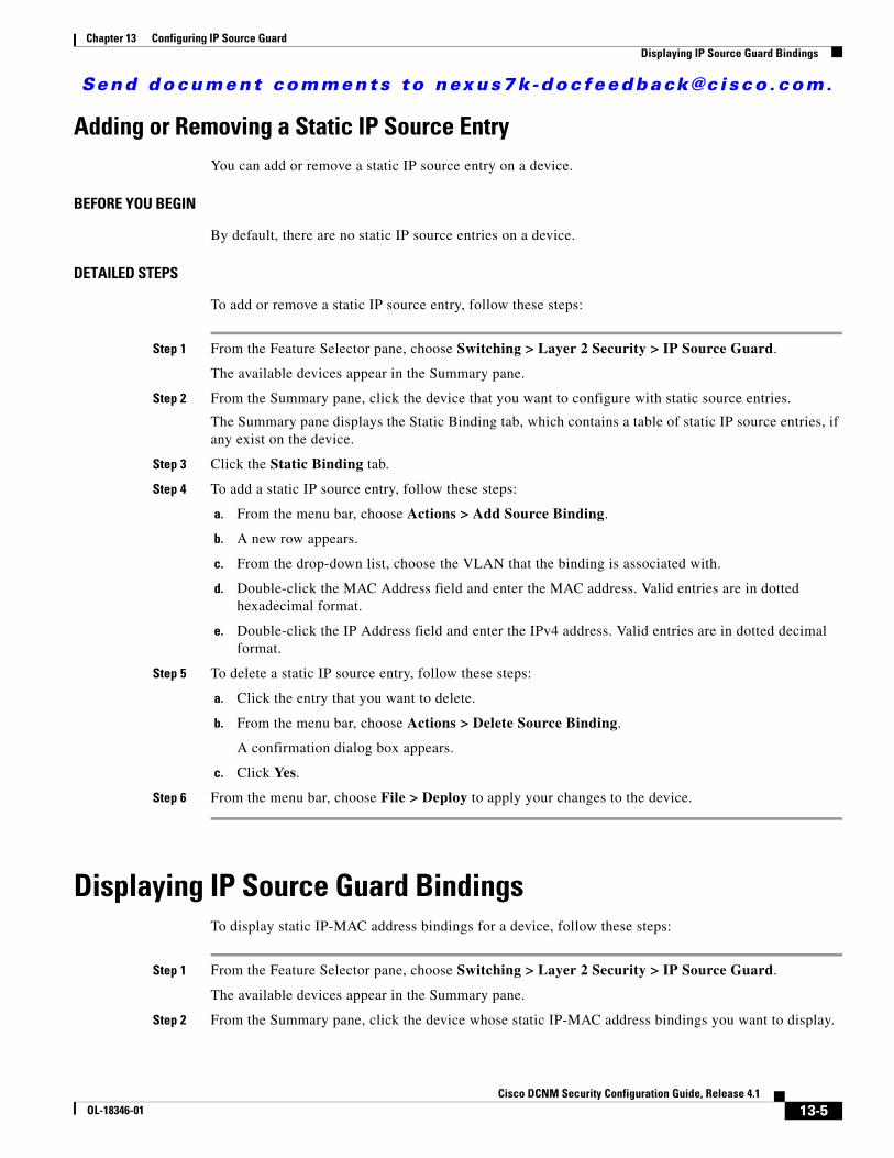
Send document comments to nexus7k -doc feedback@c i sco .com.
Chapter 13 Configuring IP Source GuardDisplaying IP Source Guard Bindings
Adding or Removing a Static IP Source EntryYou can add or remove a static IP source entry on a device.
BEFORE YOU BEGIN
By default, there are no static IP source entries on a device.
DETAILED STEPS
To add or remove a static IP source entry, follow these steps:
Step 1 From the Feature Selector pane, choose Switching > Layer 2 Security > IP Source Guard.
The available devices appear in the Summary pane.
Step 2 From the Summary pane, click the device that you want to configure with static source entries.
The Summary pane displays the Static Binding tab, which contains a table of static IP source entries, if any exist on the device.
Step 3 Click the Static Binding tab.
Step 4 To add a static IP source entry, follow these steps:
a. From the menu bar, choose Actions > Add Source Binding.
b. A new row appears.
c. From the drop-down list, choose the VLAN that the binding is associated with.
d. Double-click the MAC Address field and enter the MAC address. Valid entries are in dotted hexadecimal format.
e. Double-click the IP Address field and enter the IPv4 address. Valid entries are in dotted decimal format.
Step 5 To delete a static IP source entry, follow these steps:
a. Click the entry that you want to delete.
b. From the menu bar, choose Actions > Delete Source Binding.
A confirmation dialog box appears.
c. Click Yes.
Step 6 From the menu bar, choose File > Deploy to apply your changes to the device.
Displaying IP Source Guard BindingsTo display static IP-MAC address bindings for a device, follow these steps:
Step 1 From the Feature Selector pane, choose Switching > Layer 2 Security > IP Source Guard.
The available devices appear in the Summary pane.
Step 2 From the Summary pane, click the device whose static IP-MAC address bindings you want to display.
13-5Cisco DCNM Security Configuration Guide, Release 4.1
OL-18346-01
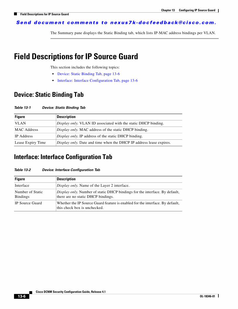
Send document comments to nexus7k -doc feedback@c i sco .com.
Chapter 13 Configuring IP Source GuardField Descriptions for IP Source Guard
The Summary pane displays the Static Binding tab, which lists IP-MAC address bindings per VLAN.
Field Descriptions for IP Source GuardThis section includes the following topics:
• Device: Static Binding Tab, page 13-6
• Interface: Interface Configuration Tab, page 13-6
Device: Static Binding Tab
Interface: Interface Configuration Tab
Table 13-1 Device: Static Binding Tab
Figure Description
VLAN Display only. VLAN ID associated with the static DHCP binding.
MAC Address Display only. MAC address of the static DHCP binding.
IP Address Display only. IP address of the static DHCP binding.
Lease Expiry Time Display only. Date and time when the DHCP IP address lease expires.
Table 13-2 Device: Interface Configuration Tab
Figure Description
Interface Display only. Name of the Layer 2 interface.
Number of Static Bindings
Display only. Number of static DHCP bindings for the interface. By default, there are no static DHCP bindings.
IP Source Guard Whether the IP Source Guard feature is enabled for the interface. By default, this check box is unchecked.
13-6Cisco DCNM Security Configuration Guide, Release 4.1
OL-18346-01
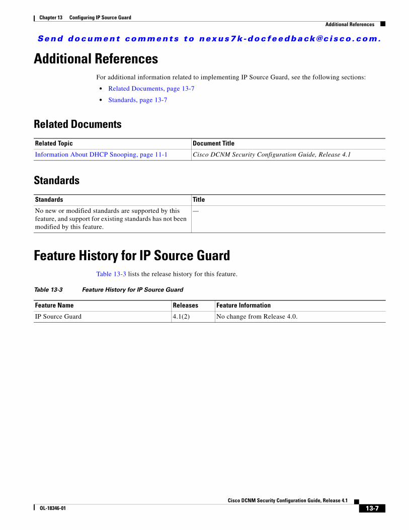
Send document comments to nexus7k -doc feedback@c i sco .com.
Chapter 13 Configuring IP Source GuardAdditional References
Additional ReferencesFor additional information related to implementing IP Source Guard, see the following sections:
• Related Documents, page 13-7
• Standards, page 13-7
Related Documents
Standards
Feature History for IP Source GuardTable 13-3 lists the release history for this feature.
Related Topic Document Title
Information About DHCP Snooping, page 11-1 Cisco DCNM Security Configuration Guide, Release 4.1
Standards Title
No new or modified standards are supported by this feature, and support for existing standards has not been modified by this feature.
—
Table 13-3 Feature History for IP Source Guard
Feature Name Releases Feature Information
IP Source Guard 4.1(2) No change from Release 4.0.
13-7Cisco DCNM Security Configuration Guide, Release 4.1
OL-18346-01

Send document comments to nexus7k -doc feedback@c i sco .com.
Chapter 13 Configuring IP Source GuardFeature History for IP Source Guard
13-8Cisco DCNM Security Configuration Guide, Release 4.1
OL-18346-01
Send document comments to nexus7k -doc feedback@c i sco .com.
CiscOL-18346-01
C H A P T E R14
Configuring Keychain ManagementThis chapter describes how to configure keychain management on an NX-OS device.
This chapter includes the following sections:
• Information About Keychain Management, page 14-1
• Licensing Requirements for Keychain Management, page 14-2
• Prerequisites for Keychain Management, page 14-3
• Guidelines and Limitations, page 14-3
• Configuring Keychain Management, page 14-3
• Where to Go Next, page 14-7
• Field Descriptions for Keychain Management, page 14-7
• Additional References, page 14-8
• Feature History for Keychain Management, page 14-9
Information About Keychain ManagementThis section includes the following topics:
• Keychains and Keychain Management, page 14-1
• Lifetime of a Key, page 14-2
Keychains and Keychain ManagementKeychain management allows you to create and maintain keychains, which are sequences of keys (sometimes called shared secrets). You can use keychains with features that secure communications with other devices by using key-based authentication. The device allows you to configure multiple keychains.
Some routing protocols that support key-based authentication can use a keychain to implement a hitless key rollover for authentication. For more information, see the Cisco DCNM Unicast Routing Configuration Guide, Release 4.1.
14-1o DCNM Security Configuration Guide, Release 4.1
Send document comments to nexus7k -doc feedback@c i sco .com.
Chapter 14 Configuring Keychain ManagementLicensing Requirements for Keychain Management
Lifetime of a KeyTo maintain stable communications, each device that uses a protocol that is secured by key-based authentication must be able to store and use more than one key for a feature at the same time. Based on the send and accept lifetimes of a key, keychain management provides a secure mechanism to handle key rollover. The device uses the lifetimes of keys to determine which keys in a keychain are active.
Each key in a keychain has two lifetimes, as follows:
• Accept lifetime—The time interval within which the device accepts the key during key exchange with another device.
• Send lifetime—The time interval within which the device sends the key during key exchange with another device.
You define the send and accept lifetimes of a key using the following parameters:
• Start-time—The absolute time that the lifetime begins.
• End-time—The end time can be defined in one of the following ways:
– The absolute time that the lifetime ends
– The number of seconds after the start time that the lifetime ends
– Infinite lifetime (no end-time)
During a key send lifetime, the device sends routing update packets with the key. The device does not accept communication from other devices when the key sent is not within the accept lifetime of the key on the device.
We recommend that you configure key lifetimes that overlap within every keychain. This practice avoids failure of neighbor authentication due to the absence of active keys.
Virtualization SupportThe following information applies to keychains used in Virtual Device Contexts (VDCs):
• Keychains are unique per VDC. You cannot use a keychain that you created in one VDC in a different VDC.
• Because keychains are not shared by VDCs, you can reuse keychain names in different VDCs.
• The device does not limit keychains on a per-VDC basis.
Licensing Requirements for Keychain ManagementThe following table shows the licensing requirements for this feature:
Product License Requirement
DCNM Keychain management requires a LAN Enterprise license. For a complete explanation of the DCNM licensing scheme and how to obtain and apply licenses, see the Cisco DCNM Fundamentals Configuration Guide, Release 4.1.
NX-OS Keychain management requires no license. Any feature not included in a license package is bundled with the Cisco NX-OS system images and is provided at no extra charge to you. For a complete explanation of the NX-OS licensing scheme, see the Cisco Nexus 7000 Series NX-OS Licensing Guide, Release 4.1.
14-2Cisco DCNM Security Configuration Guide, Release 4.1
OL-18346-01
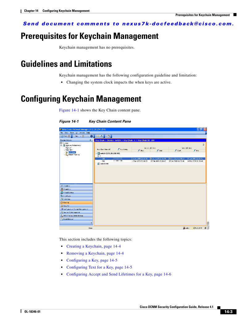
Send document comments to nexus7k -doc feedback@c i sco .com.
Chapter 14 Configuring Keychain ManagementPrerequisites for Keychain Management
Prerequisites for Keychain ManagementKeychain management has no prerequisites.
Guidelines and LimitationsKeychain management has the following configuration guideline and limitation:
• Changing the system clock impacts the when keys are active.
Configuring Keychain ManagementFigure 14-1 shows the Key Chain content pane.
Figure 14-1 Key Chain Content Pane
This section includes the following topics:
• Creating a Keychain, page 14-4
• Removing a Keychain, page 14-4
• Configuring a Key, page 14-5
• Configuring Text for a Key, page 14-5
• Configuring Accept and Send Lifetimes for a Key, page 14-6
14-3Cisco DCNM Security Configuration Guide, Release 4.1
OL-18346-01
Send document comments to nexus7k -doc feedback@c i sco .com.
Chapter 14 Configuring Keychain ManagementConfiguring Keychain Management
Creating a KeychainYou can create a keychain on the device.
BEFORE YOU BEGIN
A new keychain contains no keys. For information about adding a key, see the “Configuring a Key” section on page 14-5.
DETAILED STEPS
To create a keychain, follow these steps:
Step 1 From the Feature Selector pane, choose Routing > Gateway Redundancy > Key Chain.
The available devices appear in the Summary pane.
Step 2 From the Summary pane, click the device that you want to configure with a keychain.
Step 3 From the menu bar, choose Actions > Key Chain.
A new row appears in the Summary pane.
Step 4 Enter a name for the keychain. Valid keychain names are alphanumeric and can be up to 63 characters long.
Step 5 From the menu bar, choose File > Deploy to apply your changes to the device.
Removing a KeychainYou can remove a keychain on the device.
Note Removing a keychain removes any keys within the keychain.
BEFORE YOU BEGIN
If you are removing a keychain, ensure that no feature uses it. If a feature is configured to use a keychain that you remove, that feature is likely to fail to communicate with other devices.
DETAILED STEPS
To remove a keychain, follow these steps:
Step 1 From the Feature Selector pane, choose Routing > Gateway Redundancy > Key Chain.
The available devices appear in the Summary pane.
Step 2 From the Summary pane, double-click the device that has a keychain that you want to delete.
Keychains on the device appear in the Summary table.
Step 3 Click the keychain you want to delete.
Step 4 From the menu bar, choose Actions > Delete.
14-4Cisco DCNM Security Configuration Guide, Release 4.1
OL-18346-01
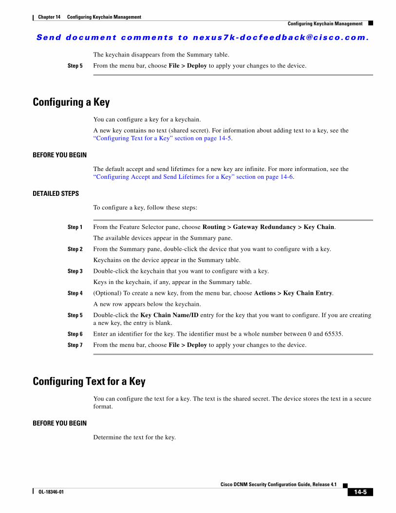
Send document comments to nexus7k -doc feedback@c i sco .com.
Chapter 14 Configuring Keychain ManagementConfiguring Keychain Management
The keychain disappears from the Summary table.
Step 5 From the menu bar, choose File > Deploy to apply your changes to the device.
Configuring a KeyYou can configure a key for a keychain.
A new key contains no text (shared secret). For information about adding text to a key, see the “Configuring Text for a Key” section on page 14-5.
BEFORE YOU BEGIN
The default accept and send lifetimes for a new key are infinite. For more information, see the “Configuring Accept and Send Lifetimes for a Key” section on page 14-6.
DETAILED STEPS
To configure a key, follow these steps:
Step 1 From the Feature Selector pane, choose Routing > Gateway Redundancy > Key Chain.
The available devices appear in the Summary pane.
Step 2 From the Summary pane, double-click the device that you want to configure with a key.
Keychains on the device appear in the Summary table.
Step 3 Double-click the keychain that you want to configure with a key.
Keys in the keychain, if any, appear in the Summary table.
Step 4 (Optional) To create a new key, from the menu bar, choose Actions > Key Chain Entry.
A new row appears below the keychain.
Step 5 Double-click the Key Chain Name/ID entry for the key that you want to configure. If you are creating a new key, the entry is blank.
Step 6 Enter an identifier for the key. The identifier must be a whole number between 0 and 65535.
Step 7 From the menu bar, choose File > Deploy to apply your changes to the device.
Configuring Text for a KeyYou can configure the text for a key. The text is the shared secret. The device stores the text in a secure format.
BEFORE YOU BEGIN
Determine the text for the key.
14-5Cisco DCNM Security Configuration Guide, Release 4.1
OL-18346-01
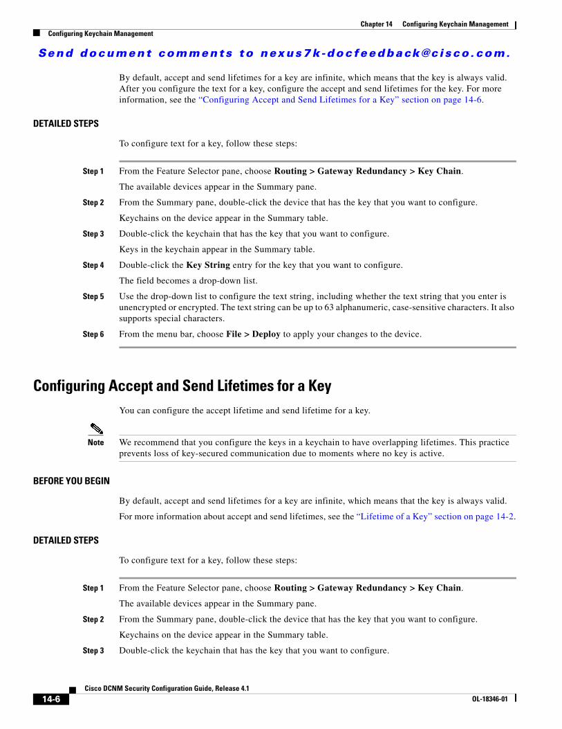
Send document comments to nexus7k -doc feedback@c i sco .com.
Chapter 14 Configuring Keychain ManagementConfiguring Keychain Management
By default, accept and send lifetimes for a key are infinite, which means that the key is always valid. After you configure the text for a key, configure the accept and send lifetimes for the key. For more information, see the “Configuring Accept and Send Lifetimes for a Key” section on page 14-6.
DETAILED STEPS
To configure text for a key, follow these steps:
Step 1 From the Feature Selector pane, choose Routing > Gateway Redundancy > Key Chain.
The available devices appear in the Summary pane.
Step 2 From the Summary pane, double-click the device that has the key that you want to configure.
Keychains on the device appear in the Summary table.
Step 3 Double-click the keychain that has the key that you want to configure.
Keys in the keychain appear in the Summary table.
Step 4 Double-click the Key String entry for the key that you want to configure.
The field becomes a drop-down list.
Step 5 Use the drop-down list to configure the text string, including whether the text string that you enter is unencrypted or encrypted. The text string can be up to 63 alphanumeric, case-sensitive characters. It also supports special characters.
Step 6 From the menu bar, choose File > Deploy to apply your changes to the device.
Configuring Accept and Send Lifetimes for a KeyYou can configure the accept lifetime and send lifetime for a key.
Note We recommend that you configure the keys in a keychain to have overlapping lifetimes. This practice prevents loss of key-secured communication due to moments where no key is active.
BEFORE YOU BEGIN
By default, accept and send lifetimes for a key are infinite, which means that the key is always valid.
For more information about accept and send lifetimes, see the “Lifetime of a Key” section on page 14-2.
DETAILED STEPS
To configure text for a key, follow these steps:
Step 1 From the Feature Selector pane, choose Routing > Gateway Redundancy > Key Chain.
The available devices appear in the Summary pane.
Step 2 From the Summary pane, double-click the device that has the key that you want to configure.
Keychains on the device appear in the Summary table.
Step 3 Double-click the keychain that has the key that you want to configure.
14-6Cisco DCNM Security Configuration Guide, Release 4.1
OL-18346-01
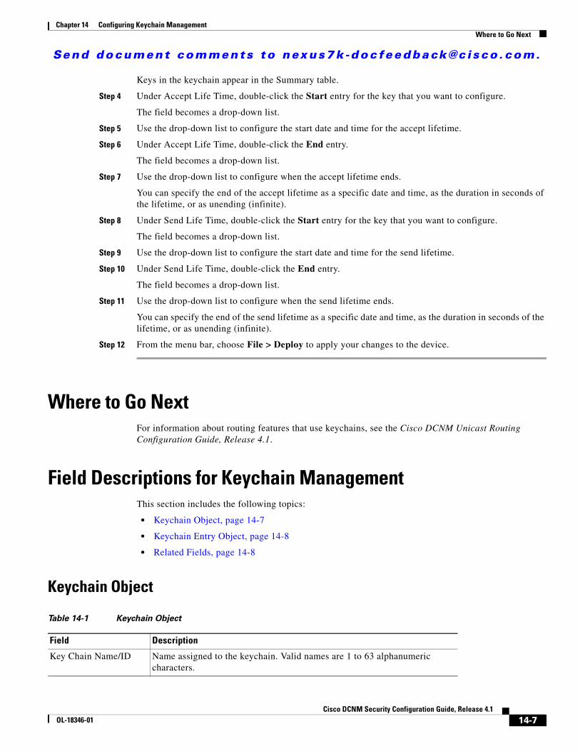
Send document comments to nexus7k -doc feedback@c i sco .com.
Chapter 14 Configuring Keychain ManagementWhere to Go Next
Keys in the keychain appear in the Summary table.
Step 4 Under Accept Life Time, double-click the Start entry for the key that you want to configure.
The field becomes a drop-down list.
Step 5 Use the drop-down list to configure the start date and time for the accept lifetime.
Step 6 Under Accept Life Time, double-click the End entry.
The field becomes a drop-down list.
Step 7 Use the drop-down list to configure when the accept lifetime ends.
You can specify the end of the accept lifetime as a specific date and time, as the duration in seconds of the lifetime, or as unending (infinite).
Step 8 Under Send Life Time, double-click the Start entry for the key that you want to configure.
The field becomes a drop-down list.
Step 9 Use the drop-down list to configure the start date and time for the send lifetime.
Step 10 Under Send Life Time, double-click the End entry.
The field becomes a drop-down list.
Step 11 Use the drop-down list to configure when the send lifetime ends.
You can specify the end of the send lifetime as a specific date and time, as the duration in seconds of the lifetime, or as unending (infinite).
Step 12 From the menu bar, choose File > Deploy to apply your changes to the device.
Where to Go NextFor information about routing features that use keychains, see the Cisco DCNM Unicast Routing Configuration Guide, Release 4.1.
Field Descriptions for Keychain ManagementThis section includes the following topics:
• Keychain Object, page 14-7
• Keychain Entry Object, page 14-8
• Related Fields, page 14-8
Keychain Object
Table 14-1 Keychain Object
Field Description
Key Chain Name/ID Name assigned to the keychain. Valid names are 1 to 63 alphanumeric characters.
14-7Cisco DCNM Security Configuration Guide, Release 4.1
OL-18346-01
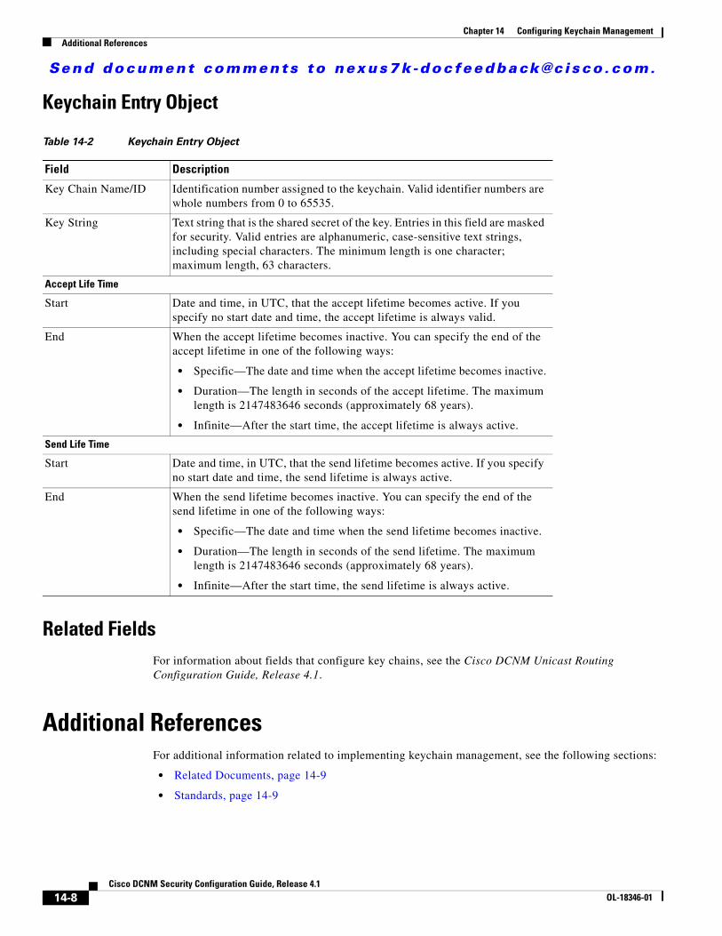
Send document comments to nexus7k -doc feedback@c i sco .com.
Chapter 14 Configuring Keychain ManagementAdditional References
Keychain Entry Object
Related FieldsFor information about fields that configure key chains, see the Cisco DCNM Unicast Routing Configuration Guide, Release 4.1.
Additional ReferencesFor additional information related to implementing keychain management, see the following sections:
• Related Documents, page 14-9
• Standards, page 14-9
Table 14-2 Keychain Entry Object
Field Description
Key Chain Name/ID Identification number assigned to the keychain. Valid identifier numbers are whole numbers from 0 to 65535.
Key String Text string that is the shared secret of the key. Entries in this field are masked for security. Valid entries are alphanumeric, case-sensitive text strings, including special characters. The minimum length is one character; maximum length, 63 characters.
Accept Life Time
Start Date and time, in UTC, that the accept lifetime becomes active. If you specify no start date and time, the accept lifetime is always valid.
End When the accept lifetime becomes inactive. You can specify the end of the accept lifetime in one of the following ways:
• Specific—The date and time when the accept lifetime becomes inactive.
• Duration—The length in seconds of the accept lifetime. The maximum length is 2147483646 seconds (approximately 68 years).
• Infinite—After the start time, the accept lifetime is always active.
Send Life Time
Start Date and time, in UTC, that the send lifetime becomes active. If you specify no start date and time, the send lifetime is always active.
End When the send lifetime becomes inactive. You can specify the end of the send lifetime in one of the following ways:
• Specific—The date and time when the send lifetime becomes inactive.
• Duration—The length in seconds of the send lifetime. The maximum length is 2147483646 seconds (approximately 68 years).
• Infinite—After the start time, the send lifetime is always active.
14-8Cisco DCNM Security Configuration Guide, Release 4.1
OL-18346-01
Send document comments to nexus7k -doc feedback@c i sco .com.
Chapter 14 Configuring Keychain ManagementFeature History for Keychain Management
Related Documents
Standards
Feature History for Keychain ManagementTable 14-3 lists the release history for this feature.
Related Topic Document Title
Gateway Load Balancing Protocol Cisco DCNM Unicast Routing Configuration Guide, Release 4.1
Standards Title
No new or modified standards are supported by this feature, and support for existing standards has not been modified by this feature.
—
Table 14-3 Feature History for Keychain Management
Feature Name Releases Feature Information
Keychain management 4.1(2) No change from Release 4.0.
14-9Cisco DCNM Security Configuration Guide, Release 4.1
OL-18346-01

Send document comments to nexus7k -doc feedback@c i sco .com.
Chapter 14 Configuring Keychain ManagementFeature History for Keychain Management
14-10Cisco DCNM Security Configuration Guide, Release 4.1
OL-18346-01
Send document comments to nexus7k -doc feedback@c i sco .com.
CiscOL-18346-01
C H A P T E R15
Configuring Traffic Storm ControlThis chapter describes how to configure traffic storm control on the NX-OS device.
This chapter includes the following sections:
• Information About Traffic Storm Control, page 15-1
• Virtualization Support For Traffic Storm Control, page 15-3
• Licensing Requirements for Traffic Storm Control, page 15-3
• Guidelines and Limitations, page 15-3
• Configuring Traffic Storm Control, page 15-4
• Field Descriptions for Traffic Storm Control, page 15-5
• Field Descriptions for Traffic Storm Control, page 15-5
• Additional References, page 15-6
• Feature History for Traffic Storm Control, page 15-7
Information About Traffic Storm ControlA traffic storm occurs when packets flood the LAN, creating excessive traffic and degrading network performance. You can use the traffic storm control feature to prevent disruptions on Layer 2 ports by a broadcast, multicast, or unicast traffic storm on physical interfaces.
Traffic storm control (also called traffic suppression) allows you to monitor the levels of the incoming broadcast, multicast, and unicast traffic over a 1-second interval. During this interval, the traffic level, which is a percentage of the total available bandwidth of the port, is compared with the traffic storm control level that you configured. When the ingress traffic reaches the traffic storm control level that is configured on the port, traffic storm control drops the traffic until the interval ends.
Figure 15-1 shows the broadcast traffic patterns on a Layer 2 interface over a given interval. In this example, traffic storm control occurs between times T1 and T2 and between T4 and T5. During those intervals, the amount of broadcast traffic exceeded the configured threshold.
15-1o DCNM Security Configuration Guide, Release 4.1
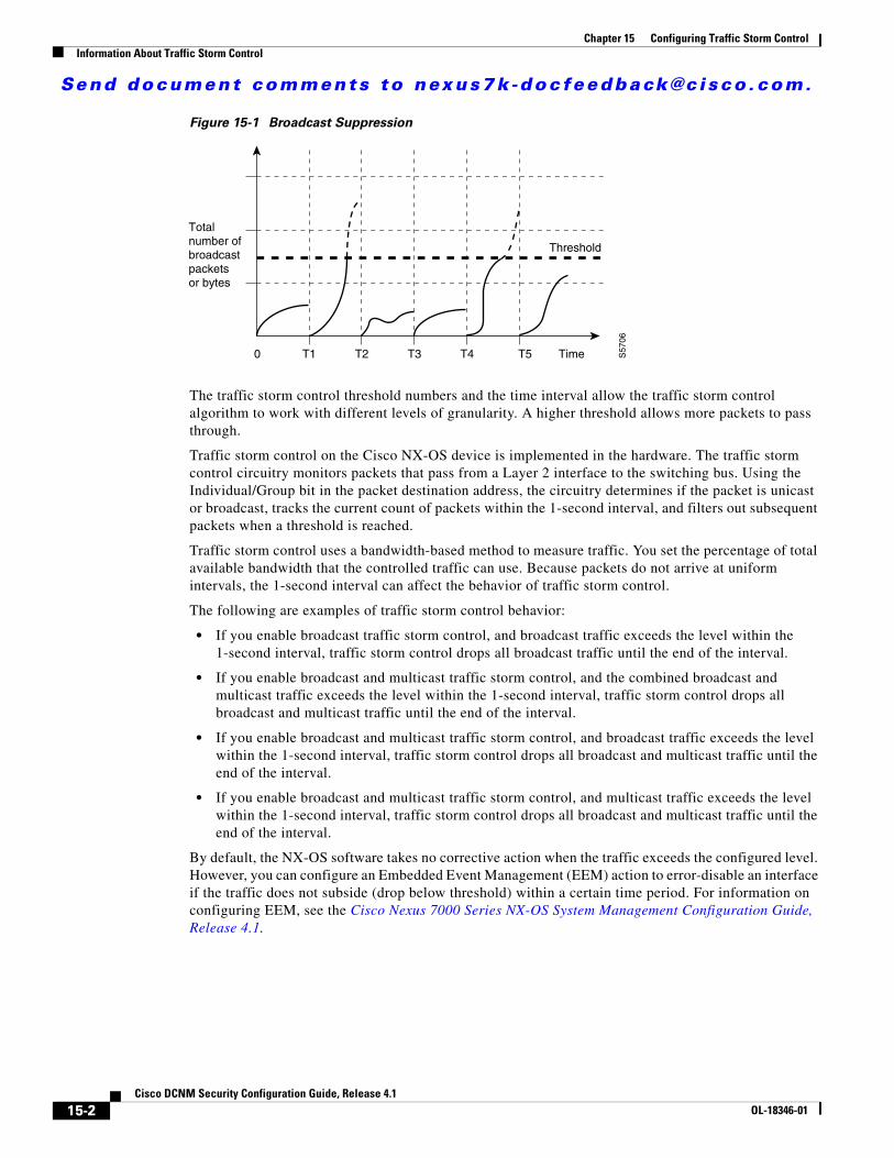
Send document comments to nexus7k -doc feedback@c i sco .com.
Chapter 15 Configuring Traffic Storm ControlInformation About Traffic Storm Control
Figure 15-1 Broadcast Suppression
The traffic storm control threshold numbers and the time interval allow the traffic storm control algorithm to work with different levels of granularity. A higher threshold allows more packets to pass through.
Traffic storm control on the Cisco NX-OS device is implemented in the hardware. The traffic storm control circuitry monitors packets that pass from a Layer 2 interface to the switching bus. Using the Individual/Group bit in the packet destination address, the circuitry determines if the packet is unicast or broadcast, tracks the current count of packets within the 1-second interval, and filters out subsequent packets when a threshold is reached.
Traffic storm control uses a bandwidth-based method to measure traffic. You set the percentage of total available bandwidth that the controlled traffic can use. Because packets do not arrive at uniform intervals, the 1-second interval can affect the behavior of traffic storm control.
The following are examples of traffic storm control behavior:
• If you enable broadcast traffic storm control, and broadcast traffic exceeds the level within the 1-second interval, traffic storm control drops all broadcast traffic until the end of the interval.
• If you enable broadcast and multicast traffic storm control, and the combined broadcast and multicast traffic exceeds the level within the 1-second interval, traffic storm control drops all broadcast and multicast traffic until the end of the interval.
• If you enable broadcast and multicast traffic storm control, and broadcast traffic exceeds the level within the 1-second interval, traffic storm control drops all broadcast and multicast traffic until the end of the interval.
• If you enable broadcast and multicast traffic storm control, and multicast traffic exceeds the level within the 1-second interval, traffic storm control drops all broadcast and multicast traffic until the end of the interval.
By default, the NX-OS software takes no corrective action when the traffic exceeds the configured level. However, you can configure an Embedded Event Management (EEM) action to error-disable an interface if the traffic does not subside (drop below threshold) within a certain time period. For information on configuring EEM, see the Cisco Nexus 7000 Series NX-OS System Management Configuration Guide, Release 4.1.
Totalnumber of broadcastpackets or bytes
0 T1
Threshold
T2 T4 T5 S57
06
T3 Time
15-2Cisco DCNM Security Configuration Guide, Release 4.1
OL-18346-01
Send document comments to nexus7k -doc feedback@c i sco .com.
Chapter 15 Configuring Traffic Storm ControlVirtualization Support For Traffic Storm Control
Virtualization Support For Traffic Storm ControlTraffic storm control configuration and operation are local to the virtual device context (VDC).
For more information on VDCs, see the Cisco DCNM Virtual Device Context Configuration Guide, Release 4.1.
Licensing Requirements for Traffic Storm ControlThe following table shows the licensing requirements for this feature:
Guidelines and LimitationsWhen configuring the traffic storm control level, note the following guidelines and limitations:
• You can configure traffic storm control on a port-channel interface.
• Do not configure traffic storm control on interfaces that are members of a port-channel interface. Configuring traffic storm control on interfaces that are configured as members of a port channel puts the ports into a suspended state.
• Specify the level as a percentage of the total interface bandwidth:
– The level can be from 0 to 100.
– The optional fraction of a level can be from 0 to 99.
– 100 percent means no traffic storm control.
– 0.0 percent suppresses all traffic.
Because of hardware limitations and the method by which packets of different sizes are counted, the level percentage is an approximation. Depending on the sizes of the frames that make up the incoming traffic, the actual enforced level might differ from the configured level by several percentage points.
Product License Requirement
DCNM Traffic storm control requires a LAN Enterprise license. For a complete explanation of the DCNM licensing scheme and how to obtain and apply licenses, see the Cisco DCNM Fundamentals Configuration Guide, Release 4.1.
NX-OS Traffic storm control requires no license. Any feature not included in a license package is bundled with the Cisco NX-OS system images and is provided at no extra charge to you. For a complete explanation of the NX-OS licensing scheme, see the Cisco Nexus 7000 Series NX-OS Licensing Guide, Release 4.1.
15-3Cisco DCNM Security Configuration Guide, Release 4.1
OL-18346-01
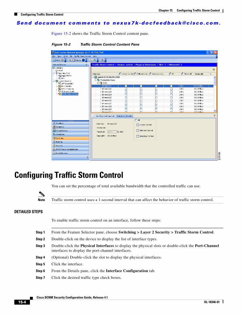
Send document comments to nexus7k -doc feedback@c i sco .com.
Chapter 15 Configuring Traffic Storm ControlConfiguring Traffic Storm Control
Figure 15-2 shows the Traffic Storm Control content pane.
Figure 15-2 Traffic Storm Control Content Pane
Configuring Traffic Storm ControlYou can set the percentage of total available bandwidth that the controlled traffic can use.
Note Traffic storm control uses a 1-second interval that can affect the behavior of traffic storm control.
DETAILED STEPS
To enable traffic storm control on an interface, follow these steps:
Step 1 From the Feature Selector pane, choose Switching > Layer 2 Security > Traffic Storm Control.
Step 2 Double-click on the device to display the list of interface types.
Step 3 Double-click the Physical Interfaces to display the physical slots or double-click the Port-Channel interfaces to display the port-channel interfaces.
Step 4 (Optional) Double-click the slot to display the physical interfaces.
Step 5 Click the interface.
Step 6 From the Details pane, click the Interface Configuration tab.
Step 7 Click the desired traffic type check boxes.
15-4Cisco DCNM Security Configuration Guide, Release 4.1
OL-18346-01
Send document comments to nexus7k -doc feedback@c i sco .com.
Chapter 15 Configuring Traffic Storm ControlDisplaying Traffic Storm Control Statistics
Tip To apply traffic storm control for broadcast, multicast, and unicast traffic types, check the All check box.
Step 8 In the Threshold field, enter a traffic suppression level percentage.
Step 9 From the menu bar, click File > Deploy to apply your changes to the device.
Displaying Traffic Storm Control StatisticsYou can display the statistics the NX-OS device maintains for traffic storm control activity.
DETAILED STEPS
To display traffic storm control statistics for an interface, follow these steps:
Step 1 From the Feature Selector pane, choose Switching > Layer 2 Security > Traffic Storm Control.
Step 2 Double-click on the device to display the list of interface types.
Step 3 Double-click the Physical Interfaces to display the physical slots or double-click the Port-Channel interfaces to display the port-channel interfaces.
Step 4 Double-click the slot to display the physical interfaces.
Step 5 Click the interface.
Step 6 From the Details pane, click the Statistics tab to display traffic storm control statistics for the interface.
Field Descriptions for Traffic Storm ControlThis section includes the following topics:
• Switching: Traffic Storm Control: Summary Pane, page 15-5
• Switching: Traffic Storm Control: device: interface type: interface: Interface Configuration Tab, page 15-6
Switching: Traffic Storm Control: Summary Pane
Table 15-1 Switching: Traffic Storm Control: Summary Pane
Element Description
Interface Interface ID.
Unicast Control Check box to enable or disable unicast traffic control.
Multicast Control Check box to enable or disable multicast traffic control.
15-5Cisco DCNM Security Configuration Guide, Release 4.1
OL-18346-01
Send document comments to nexus7k -doc feedback@c i sco .com.
Chapter 15 Configuring Traffic Storm ControlAdditional References
Switching: Traffic Storm Control: device: interface type: interface: Interface Configuration Tab
Additional ReferencesFor additional information related to implementing traffic storm control, see the following sections:
• Related Documents, page 15-6
Related Documents
Broadcast Control Check box to enable or disable broadcast traffic control.
All Check box to enable or disable unicast, multicast, and broadcast traffic control.
Bandwidth(bps) Interface bandwidth in bits per second.
Threshold Traffic-storm control threshold percentage for the selected traffic. The default is 100 percent.
Table 15-2 Switching: Traffic Storm Control: device: interface type: interface: Interface
Configuration Tab
Element Description
Interface Interface ID.
Description Interface description.
Threshold Traffic-storm control threshold percentage for the selected traffic. The default is 100 percent.
Bandwidth(bps) Interface bandwidth in bits per second.
All Check box to enable or disable unicast, multicast, and broadcast traffic control.
Unicast Control Check box to enable or disable unicast traffic control.
Multicast Control Check box to enable or disable multicast traffic control.
Broadcast Control Check box to enable or disable broadcast traffic control.
Table 15-1 Switching: Traffic Storm Control: Summary Pane (continued)
Element Description
Related Topic Document Title
NX-OS Licensing Cisco Nexus 7000 Series NX-OS Licensing Guide, Release 4.1
DCNM Licensing Cisco DCNM Fundamentals Configuration Guide, Release 4.1
15-6Cisco DCNM Security Configuration Guide, Release 4.1
OL-18346-01
Send document comments to nexus7k -doc feedback@c i sco .com.
Chapter 15 Configuring Traffic Storm ControlFeature History for Traffic Storm Control
Feature History for Traffic Storm ControlTable 15-3 lists the release history for this feature.
Table 15-3 Feature History for Traffic Storm Control
Feature Name Releases Feature Information
Traffic storm control 4.0(1) This feature was introduced.
15-7Cisco DCNM Security Configuration Guide, Release 4.1
OL-18346-01

Send document comments to nexus7k -doc feedback@c i sco .com.
Chapter 15 Configuring Traffic Storm ControlFeature History for Traffic Storm Control
15-8Cisco DCNM Security Configuration Guide, Release 4.1
OL-18346-01
Send document comments to nexus7k -doc feedback@c i sco .com.
CiscOL-18346-01
I N D E X
Numerics
802.1X
AAA authentication methods 6-11
configuration process 6-9
configuring 6-8 to 6-22
configuring AAA accounting methods 6-21
description 6-1 to 6-7
disabling authentication on the device 6-18
disabling on the device 6-19
displaying statistics 6-22
enabling MAC address authentication bypass 6-17
enabling multiply hosts on an interface 6-17
enabling on interfaces 6-12
enabling RADIUS accounting 6-20
enabling single hosts on an interface 6-17
field descriptions 6-23
guidelines 6-8
licensing requirements 6-7
limitations 6-8
MIBs 6-26
multiple host support 6-6
port security on same port 6-6
prerequisites 6-8
single host support 6-6
supported topologies 6-7
virtualization support 6-7
802.1X authentication
authorization states for ports 6-4
controlling on interfaces 6-12
disabling on the device 6-18
initiation 6-3
802.1X feature
disabling on the device 6-19
enabling 6-11
802.1X reauthentication
enabling global periodic 6-13
enabling periodic on interfaces 6-14
setting retry counts on interfaces 6-22
802.1X retry counts
setting globally 6-19
setting on interfaces 6-20
802.1X timers
changes interface timers 6-15
changing global timers 6-14
A
AAA
802.1X authentication methods 6-11
accounting 2-2
authentication 2-2
authorization 2-2
benefits 2-2
configuring 2-7 to 2-15
description 2-1 to 2-5
field descriptions 2-15
guidelines 2-6
licensing requirements 2-6
limitations 2-6
MIBs 2-17
monitoring TACACS+ servers 4-3
prerequisites 2-6
RADIUS server groups 3-12, 3-14
standards 2-16
TACACS+ server groups 4-13, 4-15
IN-1o DCNM Security Configuration Guide, Release 4.1
Send document comments to nexus7k -doc feedback@c i sco .com.
Index
user login process 2-4
virtualization support 2-5
AAA accounting
adding rule methods 2-11
changing rule methods 2-10
configuring methods for 802.1X 6-21
deleting rule methods 2-13
rearranging rule methods 2-12
AAA authentication rules
adding methods 2-8
changing methods 2-8
deleting methods 2-10
rearranging methods 2-9
AAA protocols
RADIUS 2-1
TACACS+ 2-1
AAA server groups
description 2-3
AAA servers
FreeRADIUS VSA format 3-4
specifying SNMPv3 parameters 2-13, 2-14
specifying user roles 2-14
specifying user roles in VSAs 2-13
AAA services
configuration options 2-3
remote 2-2
security 2-1
access control lists
description 7-1 to 7-10
order of application 7-3
types of 7-2
See also ARP ACLs
See also IP ACLs
See also MAC ACLs
See also policy-based ACLs
See also port ACLs
See also router ACLs
See also VLAN ACLs
accounting
IN-2Cisco DCNM Security Configuration Guide, Release 4.1
description 2-2
VDC support 2-5
ARP ACLs
applying to VLANs 12-9
changing 12-16
creating 12-15
description 12-15
priority of ARP ACLs and DHCP snooping entries 12-4
removing 12-17
ARP inspection
See dynamic ARP inspection
authentication
802.1X 6-3
description 2-2
local 2-2
methods 2-3
remote 2-2
user logins 2-4
authentication, authorization, and accounting. See AAA
authorization
description 2-2
user logins 2-4
B
broadcast storms. See traffic storm control
C
Cisco
vendor ID 2-14, 3-3, 4-4
cisco-av-pair
specifying AAA user parameters 2-13, 2-14
D
DHCP binding database
See DHCP snooping binding database
OL-18346-01
Send document comments to nexus7k -doc feedback@c i sco .com.
Index
DHCP option 82
description 11-3
DHCP snooping
binding database
See DHCP snooping binding database
description 11-1
displaying DHCP bindings 11-16
enabling feature 11-8
enabling globally 11-9
enabling on a VLAN 11-9
interface trust state 11-11
MAC address verification 11-10
message exchange process 11-4
minimum configuration 11-7
option 82 11-3
overview 11-1
relay agent 11-12
DHCP snooping binding database
described 11-2
entries 11-2
documentation
additional publications iii-xx
dynamic ARP inspection
additional validation 12-10
applying ARP ACLs 12-9
ARP cache poisoning 12-2
ARP requests 12-2
ARP spoofing attack 12-2
configuring log buffer size 12-11
configuring trust state 12-8
description 12-1
DHCP snooping binding database 12-3
enabling on VLANs 12-8
function of 12-3
interface trust states 12-3
logging of dropped packets 12-5
man-in-the middle attack 12-2
network security issues and interface trust states 12-3
OL-18346-01
priority of ARP ACLs and DHCP snooping entries 12-4
Dynamic Host Configuration Protocol snooping
See DHCP snooping
F
field descriptions
802.1X 6-23
AAA 2-15
TACACS+ 4-20
FreeRADIUS
VSA format for role attributes 2-14, 3-4
I
IDs
Cisco vendor ID 2-14, 3-3, 4-4
interfaces
controlling 802.1X authentication 6-12
enabling 802.1X 6-12
enabling periodic 802.1X reauthentication 6-14
setting 802.1X reauthentication retry counts 6-22
setting 802.1X retransmission retry counts 6-20
IP ACLs
applying to a physical port 7-15
applying to a port channel 7-15
changing an IP ACL 7-13
configuring 7-11 to 7-16
creating an IP ACL 7-12
field descriptions for IPv4 ACLs 7-16
guidelines 7-10
licensing 7-10
limitations 7-10
prerequisites 7-10
removing an IP ACL 7-14
virtualization support 7-9
IP Source Guard
description 13-1
IN-3Cisco DCNM Security Configuration Guide, Release 4.1
Send document comments to nexus7k -doc feedback@c i sco .com.
Index
enabling 13-4
static IP source entries 13-5
K
key chain
end-time 14-2
lifetime 14-2
start-time 14-2
keychain management
configuring a key 14-5
configuring lifetimes 14-6
configuring text for a key 14-5
creating a keychain 14-4
description 14-1
L
licensing
802.1X 6-7
AAA 2-6
IP ACLs 7-10
RADIUS 3-5
TACACS+ 4-5
traffic storm control 15-3
M
MAC ACLs
applying to a physical port 8-5
changing a MAC ACL 8-3
creating a MAC ACL 8-3
description 8-1
removing a MAC ACL 8-4
virtualization support 7-9
MAC addresses
enabling authentication bypass for 802.1X 6-17
MIBs
IN-4Cisco DCNM Security Configuration Guide, Release 4.1
802.1X 6-26
AAA 2-17
multicast storms. See traffic storm control
multiple hosts
enabling for 802.1X 6-17
N
network-admin user role
description 5-3
network-operator user role
description 5-3
P
passwords
strong characteristics 5-2
port ACLs
definition 7-2
port-based authentication
encapsulation 6-2
ports
authorization states for 802.1X 6-4
port security
802.1X on same port 6-6
description 10-1
enabling globally 10-8
enabling on an interface 10-9
MAC move 10-4
static MAC address 10-10
violations 10-4
preshared keys
TACACS+ 4-3
R
RADIUS
configuring global keys 3-10
OL-18346-01
Send document comments to nexus7k -doc feedback@c i sco .com.
Index
configuring servers 3-6
configuring timeout intervals 3-15
configuring transmission retry counts 3-15
description 3-1
licensing 3-5
network environments 3-2
operation 3-2
prerequisites 3-5
specifying server at login 3-14
virtualization support 3-5
VSAs 3-3
RADIUS accounting
enabling for 802.1X 6-20
RADIUS servers
configuration process 3-6
configuring accounting attributes 3-16
configuring authentication attributes 3-16
configuring dead-time intervals 3-18
configuring hosts 3-8, 3-9, 3-10, 3-12, 3-13, 4-11, 4-14, 5-7, 5-20
configuring keys 3-11, 4-12
configuring periodic monitoring 3-17
configuring server groups 3-12, 3-14
configuring timeout interval 3-15
configuring transmission retry count 3-15
deleting hosts 3-19
displaying statistics 3-19
monitoring 3-3
RBAC
configuring 5-12
description 5-3
field descriptions 5-20
See also user roles
related documents iii-xx
router ACLs
definition 7-2
rules. See user role rules
OL-18346-01
S
server groups. See AAA server groups
single hosts
enabling for 802.1X 6-17
SNMPv3
specifying AAA parameters 2-13
specifying parameters for AAA servers 2-14
statistics
802.1X 6-22
RADIUS servers 3-19
TACACS+ 4-20
traffic storm control 15-5
superuser role. See network-admin user role
T
TACACS+
advantages over RADIUS 4-2
configuring 4-6
configuring global preshared keys 4-12
configuring global timeout interval 4-16
description 4-1
disabling 4-19
displaying statistics 4-20
enabling 4-9
field descriptions 4-20
global preshared keys 4-3
guidelines 4-6
licensing requirements 4-5
limitations 4-6
prerequisites 4-6
preshared key 4-3
specifying TACACS+ servers at login 4-15
user login operation 4-2
virtualization 4-5
VSAs 4-4
TACACS+ servers
configuration process 4-7
IN-5Cisco DCNM Security Configuration Guide, Release 4.1
Send document comments to nexus7k -doc feedback@c i sco .com.
Index
configuring dead-time interval 4-19
configuring hosts 4-9, 4-11, 4-14
configuring periodic monitoring 4-18
configuring server groups 4-13, 4-15
configuring TCP ports 4-17
configuring timeout interval 4-17
displaying statistics 4-20
field descriptions 4-20
monitoring 4-3
privilege levels 4-5
TCP ports
TACACS+ servers 4-17
time range
description 7-27
time ranges
absolute 7-8
changing a time range 7-28
configuring 7-27 to 7-30
creating a time range 7-27
description 7-8
field descriptions 7-30
periodic 7-8
removing a time range 7-28
traffic storm control
configuring 15-4
description 15-1
displaying statistics 15-5
field descriptions 15-5
guidelines 15-3
licensing 15-3
limitations 15-3
virtualization support 15-3
U
unicast storms. See traffic storm control
user accounts
adding roles 5-10
changing expiry date 5-9
IN-6Cisco DCNM Security Configuration Guide, Release 4.1
changing passwords 5-8
configuring 5-5
creating 5-5
deleting 5-11
deleting roles 5-10
description 5-1
guidelines 5-4
password characteristics 5-2
virtualization support 5-4
user accounts limitations 5-4
user logins
authentication process 2-4
authorization process 2-4
user role rules
description 5-3
user roles
adding rules 5-13
change rules 5-14
change VLAN policies 5-17
changing interface policies 5-16
changing VRF policies 5-19
creating 5-13
defaults 5-3
deleting rules 5-16
description 5-3
guidelines 5-4
limitations 5-4
rearranging rules 5-15
specifying on AAA servers 2-13, 2-14
virtualization support 5-4
V
vdc-admin user role
description 5-3
vdc-operator user role
description 5-3
vendor-specific attributes. See VSAs
virtualization
OL-18346-01
Send document comments to nexus7k -doc feedback@c i sco .com.
Index
802.1X 6-7
AAA 2-5
RADIUS 3-5
TACACS+ 4-5
traffic storm control 15-3
user accounts 5-4
user roles 5-4
VLAN ACLs
applying a VACL 9-6
creating and changing VACLs 9-3, 9-4
definition 7-2
description 9-1
removing a VACL 9-5
VSAs
format 2-14
protocol options 2-14, 3-4, 4-4
support description 2-13
OL-18346-01
IN-7Cisco DCNM Security Configuration Guide, Release 4.1
Send document comments to nexus7k -doc feedback@c i sco .com.
Index
IN-8Cisco DCNM Security Configuration Guide, Release 4.1
OL-18346-01