Embed Size (px)
Citation preview
Cisco Gigabit-Ethernet OptimizedVoD SolutionDesign and Implementation Guide, Release 2.0
Corporate HeadquartersCisco Systems, Inc.170 West Tasman DriveSan Jose, CA 95134-1706 USAhttp://www.cisco.comTel: 408 526-4000
800 553-NETS (6387)Fax: 408 526-4100
Customer Order Number: Text Part Number: OL-5472-02
THE SPECIFICATIONS AND INFORMATION REGARDING THE PRODUCTS IN THIS MANUAL ARE SUBJECT TO CHANGE WITHOUT NOTICE. ALL STATEMENTS, INFORMATION, AND RECOMMENDATIONS IN THIS MANUAL ARE BELIEVED TO BE ACCURATE BUT ARE PRESENTED WITHOUT WARRANTY OF ANY KIND, EXPRESS OR IMPLIED. USERS MUST TAKE FULL RESPONSIBILITY FOR THEIR APPLICATION OF ANY PRODUCTS.
THE SOFTWARE LICENSE AND LIMITED WARRANTY FOR THE ACCOMPANYING PRODUCT ARE SET FORTH IN THE INFORMATION PACKET THAT SHIPPED WITH THE PRODUCT AND ARE INCORPORATED HEREIN BY THIS REFERENCE. IF YOU ARE UNABLE TO LOCATE THE SOFTWARE LICENSE OR LIMITED WARRANTY, CONTACT YOUR CISCO REPRESENTATIVE FOR A COPY.
The Cisco implementation of TCP header compression is an adaptation of a program developed by the University of California, Berkeley (UCB) as part of UCB’s public domain version of the UNIX operating system. All rights reserved. Copyright © 1981, Regents of the University of California.
NOTWITHSTANDING ANY OTHER WARRANTY HEREIN, ALL DOCUMENT FILES AND SOFTWARE OF THESE SUPPLIERS ARE PROVIDED “AS IS” WITH ALL FAULTS. CISCO AND THE ABOVE-NAMED SUPPLIERS DISCLAIM ALL WARRANTIES, EXPRESSED OR IMPLIED, INCLUDING, WITHOUT LIMITATION, THOSE OF MERCHANTABILITY, FITNESS FOR A PARTICULAR PURPOSE AND NONINFRINGEMENT OR ARISING FROM A COURSE OF DEALING, USAGE, OR TRADE PRACTICE.
IN NO EVENT SHALL CISCO OR ITS SUPPLIERS BE LIABLE FOR ANY INDIRECT, SPECIAL, CONSEQUENTIAL, OR INCIDENTAL DAMAGES, INCLUDING, WITHOUT LIMITATION, LOST PROFITS OR LOSS OR DAMAGE TO DATA ARISING OUT OF THE USE OR INABILITY TO USE THIS MANUAL, EVEN IF CISCO OR ITS SUPPLIERS HAVE BEEN ADVISED OF THE POSSIBILITY OF SUCH DAMAGES.
Cisco Gigabit-Ethernet Optimized VoD Solution Design and Implementation Guide, Release 2.0Copyright © 2004, Cisco Systems, Inc.All rights reserved.
Certified Internetwork Expert logo, Cisco IOS, Cisco Press, Cisco Systems, Cisco Systems Capital, the Cisco Systems logo, Empowering the Internet Generation, Enterprise/Solver, EtherChannel, EtherFast, EtherSwitch, Fast Step, GigaDrive, GigaStack, HomeLink, Internet Quotient, IOS, IP/TV, iQ Expertise, the iQ logo, iQ Net Readiness Scorecard, LightStream, Linksys, MeetingPlace, MGX, the Networkers logo, Networking Academy, Network Registrar, Packet, PIX, Post-Routing, Pre-Routing, ProConnect, RateMUX, Registrar, ScriptShare, SlideCast, SMARTnet, StrataView Plus, SwitchProbe, TeleRouter, The Fastest Way to Increase Your Internet Quotient, TransPath, and VCO are registered trademarks of Cisco Systems, Inc. and/or its affiliates in the United States and certain other countries.
All other trademarks mentioned in this document or Website are the property of their respective owners. The use of the word partner does not imply a partnership relationship between Cisco and any other company. (0406R)
Cisco Gigabit-Ethernet Optimized VoD SOL-5472-02
C O N T E N T S
Preface vii
Document Version and Solution Release vii
Document Objectives and Scope viii
Audience viii
Document Organization ix
Related Documentation ix
Solution Documentation ix
Switch Documentation ix
Cisco Catalyst 4500 Series Switches x
Cisco Catalyst 6500 Series Switches x
Cisco 7600 Series Routers x
Optical Component Documentation x
Cisco ONS 15454 x
Cisco ONS 15216 x
Cisco DWDM GBICs x
QAM Gateway Documentation x
Document Conventions xi
Obtaining Documentation xii
Cisco.com xii
Ordering Documentation xii
Documentation Feedback xiii
Obtaining Technical Assistance xiii
Cisco Technical Support Website xiii
Submitting a Service Request xiii
Definitions of Service Request Severity xiv
Obtaining Additional Publications and Information xiv
C H A P T E R 1 Solution Overview 1-1
Solution Description 1-1
Generic Architecture 1-1
Point-to-Point Topology 1-2
Multihop Architecture 1-2
Hub-and-Spoke Topology 1-3
Solution Components 1-3
iiiolution Design and Implementation Guide, Release 2.0
Contents
Cisco Core Components 1-3
Cisco GE QAM Gateways 1-4
Third-Party Equipment 1-5
Video Servers 1-5
QAM Gateways 1-5
Management 1-6
C H A P T E R 2 Designing the Solution 2-1
Topologies and Components 2-2
Optical Designs and Topology 2-2
Transponders 2-3
Multihop Architecture 2-3
Using the Cisco ONS 15454 MSTP 2-4
Using the Cisco ONS 15216 FlexLayer 2-6
Ethernet Topology and Components 2-7
Overview 2-7
Ethernet Topologies 2-8
Bidirectional Connectivity 2-11
Routing and QoS 2-12
Out-of-Band Traffic 2-13
Multihop Video 2-13
Support for Embedded QAM Gateways 2-14
Converged Multiservice Architecture 2-16
Overview 2-16
Using VRF-lite and Differentiated Services in a Converged Multiservice Architecture 2-18
VRF-lite 2-18
DSCP Features and Values Used in Release 2.0 2-20
Security Considerations 2-21
Scaling 2-22
C H A P T E R 3 Implementing and Configuring the Solution 3-1
Configuring a Point-to-Point and Multihop Ethernet Topology 3-1
Configuring the Headend 3-3
Confirming Hardware 3-4
Establishing Quality of Service (QoS) 3-4
Enabling OSPF and VRF-lite for Video-over-IP Traffic 3-8
Enabling OSPF for Non-video Traffic 3-9
Enabling Load Balancing 3-10
Establishing Interfaces on the Headend Switch 3-10
ivCisco Gigabit-Ethernet Optimized VoD Solution Design and Implementation Guide, Release 2.0
OL-5472-02
Contents
Configuring Dhub A 3-17
Confirming Hardware 3-17
Establishing Quality of Service (QoS) 3-17
Enabling OSPF and VRF-lite for Video-over-IP Traffic 3-18
Enabling OSPF for Non-video Traffic 3-19
Establishing Interfaces 3-20
Configuring Dhub B 3-26
Confirming Hardware 3-26
Establishing Quality of Service (QoS) 3-26
Enabling OSPF and VRF-lite for Video-over-IP Traffic 3-27
Enabling OSPF for Non-video Traffic 3-28
Establishing Interfaces 3-29
Configuring Dhub C 3-35
Confirming Hardware 3-35
Establishing Quality of Service (QoS) 3-35
Enabling OSPF and VRF-lite for Video-over-IP Traffic 3-36
Enabling OSPF for Non-video Traffic 3-37
Establishing Interfaces 3-37
Implementing Optics 3-42
Implementing the Cisco ONS 15216 FlexLayer 3-42
Implementing the Cisco ONS 15216 OSC-1510 3-42
Implementing and Configuring Cisco Video Gateways 3-43
Implementing and Configuring the Cisco uMG9820 QAM Gateway 3-43
Implementing and Configuring the Cisco uMG9850 QAM Module 3-43
C H A P T E R 4 Providing Redundancy and Reliability 4-1
Overview 4-1
IP Layer Redundancy: Unequal-Cost Paths 4-2
Optical Redundancy 4-3
C H A P T E R 5 Monitoring and Troubleshooting 5-1
Using CLI Commands to Monitor the Cisco 7609 and Cisco Catalyst 6500 5-1
logging event link-status 5-2
show access-lists 5-2
show arp 5-2
show class-map 5-3
show interfaces 5-3
show ip arp vrf 5-5
show ip route 5-6
vCisco Gigabit-Ethernet Optimized VoD Solution Design and Implementation Guide, Release 2.0
OL-5472-02
Contents
show ip route vrf 5-7
show ip vrf 5-7
show mls qos 5-8
show policy-map 5-10
show queueing interface 5-11
show standby 5-12
Using CLI Commands to Monitor the Cisco Catalyst 4500 5-12
show arp 5-13
show interfaces 5-13
show mac-address-table 5-14
Using CLI Commands to Monitor and Troubleshoot the Cisco uMG9820 5-14
Using CLI Commands to Monitor and Troubleshoot the Cisco uMG9850 5-14
A P P E N D I X A Sample Configuration for a Headend Switch A-1
A P P E N D I X B Sample Configurations for Dhub Switches B-1
DHub_Sw_A Configuration B-1
DHub_Sw_B Configuration B-5
DHub_Sw_C Configuration B-9
A P P E N D I X C Sample Configurations for QAM Switches C-1
QAM_Sw_A Configuration C-1
QAM_Sw_B Configuration C-6
QAM_Sw_C Configuration C-9
viCisco Gigabit-Ethernet Optimized VoD Solution Design and Implementation Guide, Release 2.0
OL-5472-02
Preface
This preface explains the objectives, intended audience, and organization of the Cisco Gigabit-Ethernet Optimized VoD Solution Design and Implementation Guide, Release 2.0. The section also defines the conventions used to convey instructions and information, available related documentation, and the process for obtaining Cisco documentation and technical assistance.
This preface presents the following major topics:
• Document Version and Solution Release, page vii
• Document Objectives and Scope, page viii
• Audience, page viii
• Document Organization, page ix
• Related Documentation, page ix
• Document Conventions, page xi
• Obtaining Documentation, page xii
• Documentation Feedback, page xiii
• Obtaining Technical Assistance, page xiii
• Obtaining Additional Publications and Information, page xiv
Document Version and Solution ReleaseThis is the first version of this document, which covers Release 2.0 of the Cisco Gigabit-Ethernet Optimized VoD Solution.
Document History
Document Version Date Notes
1 09/10/2004 This document was first released. Release 1.0 documentation was released on 07/30/2003. Release 1.1 documentation was released on 03/15/2004.
2 09/17/2004 Incorporates minor changes.
viiCisco Gigabit-Ethernet Optimized VoD Solution Design and Implementation Guide, Release 2.0
OL-5472-02
PrefaceDocument Objectives and Scope
Document Objectives and ScopeThis guide describes the architecture, the components, and the processes necessary for the design and implementation of the Cisco Gigabit-Ethernet Optimized VoD Solution, Release 2.0.
This guide supplements the fundamental design and configuration information that is required to establish the various services provided by the Cisco Gigabit-Ethernet Optimized VoD Solution, Release 1.1. MSO (multiple system operator) and service provider networks may have additional requirements that are beyond the scope of this document.
With respect to Release 1.1, the Cisco Gigabit-Ethernet Optimized VoD Solution, Release 2.0 adds major enhancements in the areas of Ethernet switching, optical transport, and Cisco video edge QAM devices, including support for the following:
• Cisco Catalyst 6509 switch and the Cisco 7609 in the headend and Dhub, with 10 Gigabit Ethernet (GE)
• 10-GE external transponders and intelligent optical filters in conjunction with the Cisco ONS 15454 MSTP (Multi-Service Transport Platform)
• Cisco uMG9850 QAM Modules
• Graphical user interface (GUI)-based network management
In addition, the video architecture of Release 2.0 leverages transport and routing designs for fully converged networks that support not only video, but also high-speed data (HSD), voice over IP (VoIP), and other applications.
Note This document is primarily for Cisco products. To establish and maintain the third-party products and applications that may be a part of the Cisco Gigabit-Ethernet Optimized VoD Solution, refer to the documentation provided by the vendors of those products.
AudienceThe target audience for this document is assumed to have basic knowledge of and experience with the installation and acceptance of the products covered by this solution. See Chapter 1, “Solution Overview.”
In addition, it is assumed that the user understands the procedures required to upgrade and troubleshoot optical transport systems and Ethernet switches, with emphasis on Cisco Catalyst series switches).
Note This document addresses Cisco components only. It does not discuss how to implement third-party optical components, VoD servers, or QAM devices, or how to enable service between QAM devices and hybrid fiber coax (HFC) distribution.
viiiCisco Gigabit-Ethernet Optimized VoD Solution Design and Implementation Guide, Release 2.0
OL-5472-02
PrefaceDocument Organization
Document OrganizationThe major sections of this document are as follows:
Related Documentation
Solution DocumentationThis document, and Release Notes for Cisco Gigabit-Ethernet Optimized VoD Solution, Release 2.0, are available under Cisco Gigabit-Ethernet Optimized VoD Solution, Release 2.0, at the following URL:
http://www.cisco.com/univercd/cc/td/doc/solution/vodsols/geopt2_0/index.htm
Switch DocumentationDocumentation resources for the Cisco Catalyst switches and the Cisco 7609 router are available at the following URLs:
Note The Cisco 7609 router used in this solution functions as a switch, and is considered to be a switch in this documentation.
Section Title Major Topics
Chapter 1 Solution Overview Introduces applications, example scenarios, and components.
Chapter 2 Designing the Solution Provides detailed requirements of various scenarios.
Chapter 3 Implementing and Configuring the Solution
Describes the configuration and implementation of the solution and provides example implementations.
Chapter 4 Providing Redundancy and Reliability
Describes failure scenarios and their remedies.
Chapter 5 Monitoring and Troubleshooting
Provides an introduction to monitoring and troubleshooting the Cisco Ethernet switches used in the solution.
Appendix A Sample Configuration for a Headend Switch
Provides an example configuration for a headend switch.
Appendix B Sample Configurations for Dhub Switches
Provides example configurations for Dhub switches.
Appendix C Sample Configurations for QAM Switches
Provides example configurations for QAM switches.
ixCisco Gigabit-Ethernet Optimized VoD Solution Design and Implementation Guide, Release 2.0
OL-5472-02
PrefaceRelated Documentation
Cisco Catalyst 4500 Series Switches
For all hardware and software documentation for this series, go to the following URL:
http://www.cisco.com/univercd/cc/td/doc/product/lan/cat4000/index.htm
Cisco Catalyst 6500 Series Switches
For all hardware and software documentation for this series, go to the following URL:
http://www.cisco.com/univercd/cc/td/doc/product/lan/cat6000/index.htm
Cisco 7600 Series Routers
For all hardware and software documentation for this series, go to the following URL:
http://www.cisco.com/univercd/cc/td/doc/product/core/cis7600/index.htm
Optical Component Documentation
Cisco ONS 15454
• Cisco ONS 15454 User Documentation, Release 4.6
http://www.cisco.com/univercd/cc/td/doc/product/ong/15400/index.htm
Cisco ONS 15216
• Cisco ONS 15216
http://www.cisco.com/univercd/cc/td/doc/product/ong/15216/index.htm
• Cisco ONS 15216 FlexLayer User Guide, Release 1.0
http://www.cisco.com/univercd/cc/td/doc/product/ong/15216/flxlyr10/index.htm
Cisco DWDM GBICs
• Cisco DWDM Gigabit Interface Converter Installation Guide
www.cisco.com/univercd/cc/td/doc/product/gbic_sfp/gbic_doc/78_15574.htm
• Cisco Dense Wavelength Division Multiplexing GBICs Compatibility Matrix
www.cisco.com/univercd/cc/td/doc/product/gbic_sfp/gbic_doc/ol_4604.htm
QAM Gateway Documentation• Cisco uMG9820 QAM Gateway
http://www.cisco.com/univercd/cc/td/doc/product/cable/vod/umg9820/index.htm
• Cisco uMG9850 QAM Module
http://www.cisco.com/univercd/cc/td/doc/product/cable/vod/umg9850/index.htm
xCisco Gigabit-Ethernet Optimized VoD Solution Design and Implementation Guide, Release 2.0
OL-5472-02
PrefaceDocument Conventions
Note Other references are provided as appropriate throughout this document.
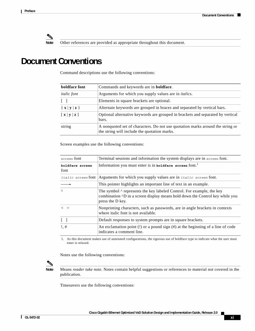
Document ConventionsCommand descriptions use the following conventions:
Screen examples use the following conventions:
Notes use the following conventions:
Note Means reader take note. Notes contain helpful suggestions or references to material not covered in the publication.
Timesavers use the following conventions:
boldface font Commands and keywords are in boldface.
italic font Arguments for which you supply values are in italics.
[ ] Elements in square brackets are optional.
{ x | y | z } Alternate keywords are grouped in braces and separated by vertical bars.
[ x | y | z ] Optional alternative keywords are grouped in brackets and separated by vertical bars.
string A nonquoted set of characters. Do not use quotation marks around the string or the string will include the quotation marks.
screen font Terminal sessions and information the system displays are in screen font.
boldface screen font
Information you must enter is in boldface screen font.1
1. As this document makes use of annotated configurations, the rigorous use of boldface type to indicate what the user must enter is relaxed.
italic screen font Arguments for which you supply values are in italic screen font.
This pointer highlights an important line of text in an example.
^ The symbol ^ represents the key labeled Control. For example, the key combination ^D in a screen display means hold down the Control key while you press the D key.
< > Nonprinting characters, such as passwords, are in angle brackets in contexts where italic font is not available.
[ ] Default responses to system prompts are in square brackets.
!, # An exclamation point (!) or a pound sign (#) at the beginning of a line of code indicates a comment line.
xiCisco Gigabit-Ethernet Optimized VoD Solution Design and Implementation Guide, Release 2.0
OL-5472-02
PrefaceObtaining Documentation
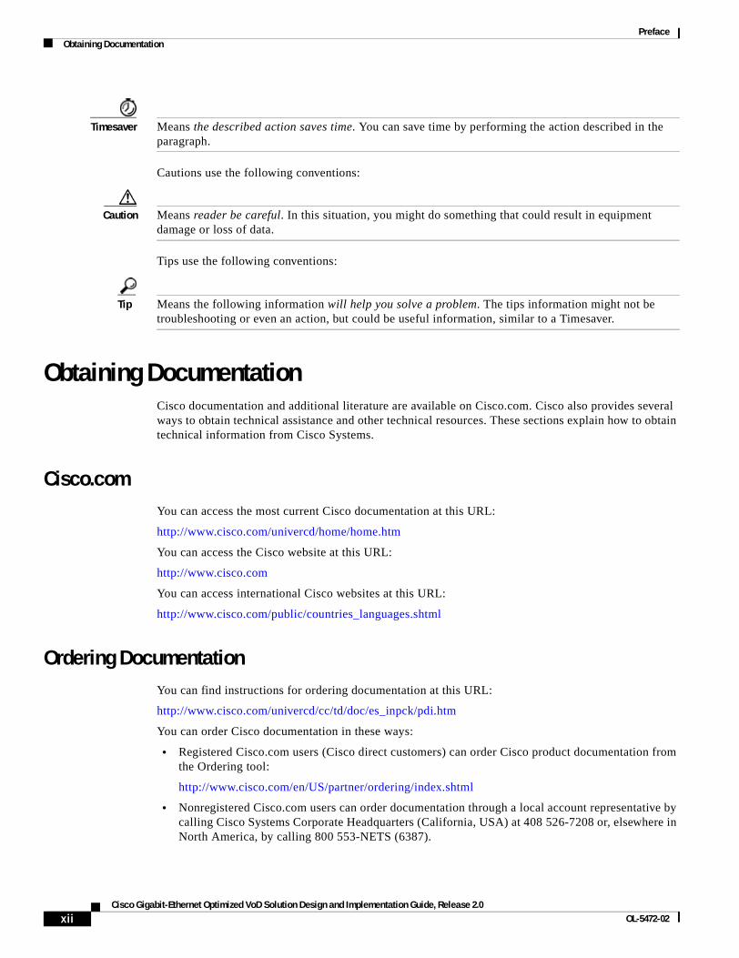
Timesaver Means the described action saves time. You can save time by performing the action described in the paragraph.
Cautions use the following conventions:
Caution Means reader be careful. In this situation, you might do something that could result in equipment damage or loss of data.
Tips use the following conventions:
Tip Means the following information will help you solve a problem. The tips information might not be troubleshooting or even an action, but could be useful information, similar to a Timesaver.
Obtaining DocumentationCisco documentation and additional literature are available on Cisco.com. Cisco also provides several ways to obtain technical assistance and other technical resources. These sections explain how to obtain technical information from Cisco Systems.
Cisco.comYou can access the most current Cisco documentation at this URL:
http://www.cisco.com/univercd/home/home.htm
You can access the Cisco website at this URL:
http://www.cisco.com
You can access international Cisco websites at this URL:
http://www.cisco.com/public/countries_languages.shtml
Ordering DocumentationYou can find instructions for ordering documentation at this URL:
http://www.cisco.com/univercd/cc/td/doc/es_inpck/pdi.htm
You can order Cisco documentation in these ways:
• Registered Cisco.com users (Cisco direct customers) can order Cisco product documentation from the Ordering tool:
http://www.cisco.com/en/US/partner/ordering/index.shtml
• Nonregistered Cisco.com users can order documentation through a local account representative by calling Cisco Systems Corporate Headquarters (California, USA) at 408 526-7208 or, elsewhere in North America, by calling 800 553-NETS (6387).
xiiCisco Gigabit-Ethernet Optimized VoD Solution Design and Implementation Guide, Release 2.0
OL-5472-02
PrefaceDocumentation Feedback
Documentation FeedbackYou can send comments about technical documentation to [email protected].
You can submit comments by using the response card (if present) behind the front cover of your document or by writing to the following address:
Cisco SystemsAttn: Customer Document Ordering170 West Tasman DriveSan Jose, CA 95134-9883
We appreciate your comments.
Obtaining Technical AssistanceFor all customers, partners, resellers, and distributors who hold valid Cisco service contracts, Cisco Technical Support provides 24-hour-a-day, award-winning technical assistance. The Cisco Technical Support Website on Cisco.com features extensive online support resources. In addition, Cisco Technical Assistance Center (TAC) engineers provide telephone support. If you do not hold a valid Cisco service contract, contact your reseller.
Cisco Technical Support WebsiteThe Cisco Technical Support Website provides online documents and tools for troubleshooting and resolving technical issues with Cisco products and technologies. The website is available 24 hours a day, 365 days a year at this URL:
http://www.cisco.com/techsupport
Access to all tools on the Cisco Technical Support Website requires a Cisco.com user ID and password. If you have a valid service contract but do not have a user ID or password, you can register at this URL:
http://tools.cisco.com/RPF/register/register.do
Submitting a Service RequestUsing the online TAC Service Request Tool is the fastest way to open S3 and S4 service requests. (S3 and S4 service requests are those in which your network is minimally impaired or for which you require product information.) After you describe your situation, the TAC Service Request Tool automatically provides recommended solutions. If your issue is not resolved using the recommended resources, your service request will be assigned to a Cisco TAC engineer. The TAC Service Request Tool is located at this URL:
http://www.cisco.com/techsupport/servicerequest
For S1 or S2 service requests or if you do not have Internet access, contact the Cisco TAC by telephone. (S1 or S2 service requests are those in which your production network is down or severely degraded.) Cisco TAC engineers are assigned immediately to S1 and S2 service requests to help keep your business operations running smoothly.
xiiiCisco Gigabit-Ethernet Optimized VoD Solution Design and Implementation Guide, Release 2.0
OL-5472-02
PrefaceObtaining Additional Publications and Information
To open a service request by telephone, use one of the following numbers:
Asia-Pacific: +61 2 8446 7411 (Australia: 1 800 805 227)EMEA: +32 2 704 55 55USA: 1 800 553 2447
For a complete list of Cisco TAC contacts, go to this URL:
http://www.cisco.com/techsupport/contacts
Definitions of Service Request SeverityTo ensure that all service requests are reported in a standard format, Cisco has established severity definitions.
Severity 1 (S1)—Your network is “down,” or there is a critical impact to your business operations. You and Cisco will commit all necessary resources around the clock to resolve the situation.
Severity 2 (S2)—Operation of an existing network is severely degraded, or significant aspects of your business operation are negatively affected by inadequate performance of Cisco products. You and Cisco will commit full-time resources during normal business hours to resolve the situation.
Severity 3 (S3)—Operational performance of your network is impaired, but most business operations remain functional. You and Cisco will commit resources during normal business hours to restore service to satisfactory levels.
Severity 4 (S4)—You require information or assistance with Cisco product capabilities, installation, or configuration. There is little or no effect on your business operations.
Obtaining Additional Publications and InformationInformation about Cisco products, technologies, and network solutions is available from various online and printed sources.
• Cisco Marketplace provides a variety of Cisco books, reference guides, and logo merchandise. Visit Cisco Marketplace, the company store, at this URL:
http://www.cisco.com/go/marketplace/
• The Cisco Product Catalog describes the networking products offered by Cisco Systems, as well as ordering and customer support services. Access the Cisco Product Catalog at this URL:
http://cisco.com/univercd/cc/td/doc/pcat/
• Cisco Press publishes a wide range of general networking, training and certification titles. Both new and experienced users will benefit from these publications. For current Cisco Press titles and other information, go to Cisco Press at this URL:
http://www.ciscopress.com
• Packet magazine is the Cisco Systems technical user magazine for maximizing Internet and networking investments. Each quarter, Packet delivers coverage of the latest industry trends, technology breakthroughs, and Cisco products and solutions, as well as network deployment and troubleshooting tips, configuration examples, customer case studies, certification and training information, and links to scores of in-depth online resources. You can access Packet magazine at this URL:
http://www.cisco.com/packet
xivCisco Gigabit-Ethernet Optimized VoD Solution Design and Implementation Guide, Release 2.0
OL-5472-02
PrefaceObtaining Additional Publications and Information
• iQ Magazine is the quarterly publication from Cisco Systems designed to help growing companies learn how they can use technology to increase revenue, streamline their business, and expand services. The publication identifies the challenges facing these companies and the technologies to help solve them, using real-world case studies and business strategies to help readers make sound technology investment decisions. You can access iQ Magazine at this URL:
http://www.cisco.com/go/iqmagazine
• Internet Protocol Journal is a quarterly journal published by Cisco Systems for engineering professionals involved in designing, developing, and operating public and private internets and intranets. You can access the Internet Protocol Journal at this URL:
http://www.cisco.com/ipj
• World-class networking training is available from Cisco. You can view current offerings at this URL:
http://www.cisco.com/en/US/learning/index.html
xvCisco Gigabit-Ethernet Optimized VoD Solution Design and Implementation Guide, Release 2.0
OL-5472-02
PrefaceObtaining Additional Publications and Information
xviCisco Gigabit-Ethernet Optimized VoD Solution Design and Implementation Guide, Release 2.0
OL-5472-02
Cisco Gigabit-Ethernet Optimized VoD Solution DesignOL-5472-02
C H A P T E R 1
Solution OverviewThe Cisco Gigabit-Ethernet Optimized VoD Solution, Release 2.0 builds on the switch-in-Dhub (distribution hub) architecture established for previous releases, introducing support for additional switching and transport components.
The following are not included in Release 2.0:
• Additional functionality for the no-switch-in-Dhub architecture described in Release 1.1
• Support for third-party equipment
• Support for 1-GE links beyond those supported in Release 1.1
Note Documentation for this and previous releases of the Cisco Video on Demand Solution, including Cisco Gigabit-Ethernet Optimized VoD Solution, Release 1.1, is at the following URL:
http://www.cisco.com/univercd/cc/td/doc/solution/vodsols/index.htm
However, it is not necessary to read previous releases of the solution documentation before reading this document.
This chapter presents the following major topics:
• Solution Description, page 1-1
• Solution Components, page 1-3
Solution Description
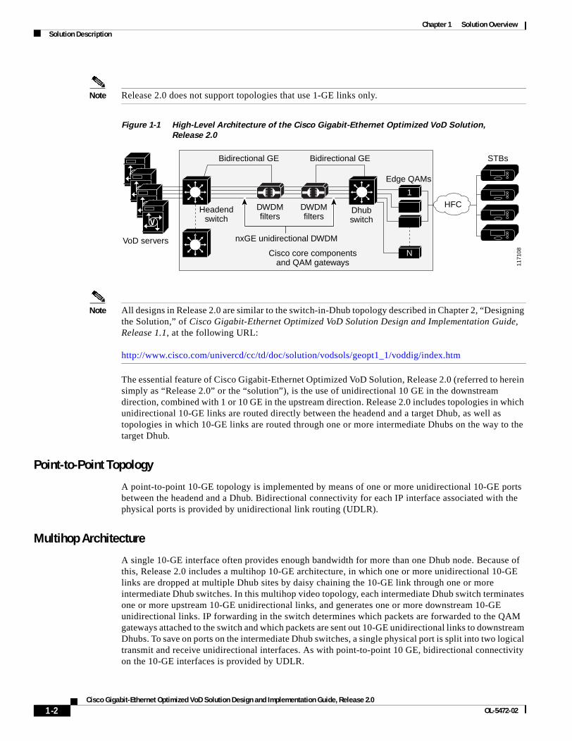
Generic ArchitectureFigure 1-1 on page 1-2 illustrates the generic switch-in-Dhub plus optical transport architecture used by Releases 1.1 and 2.0 of the solution. All solution components are located in either a video headend or a Dhub site. The basic solution topology is an Ethernet hub and spoke between the headend site and multiple Dhub sites. The switch in the headend is called the headend switch, and the switch in the Dhub is called the Dhub switch. Where the Cisco uMG9850 QAM Module is used, a Cisco Catalyst 4507 switch, adjacent to the Dhub switch, is also required. This switch is referred to as the QAM switch.
1-1 and Implementation Guide, Release 2.0
Chapter 1 Solution OverviewSolution Description
Note Release 2.0 does not support topologies that use 1-GE links only.
Figure 1-1 High-Level Architecture of the Cisco Gigabit-Ethernet Optimized VoD Solution,
Release 2.0
Note All designs in Release 2.0 are similar to the switch-in-Dhub topology described in Chapter 2, “Designing the Solution,” of Cisco Gigabit-Ethernet Optimized VoD Solution Design and Implementation Guide, Release 1.1, at the following URL:
http://www.cisco.com/univercd/cc/td/doc/solution/vodsols/geopt1_1/voddig/index.htm
The essential feature of Cisco Gigabit-Ethernet Optimized VoD Solution, Release 2.0 (referred to herein simply as “Release 2.0” or the “solution”), is the use of unidirectional 10 GE in the downstream direction, combined with 1 or 10 GE in the upstream direction. Release 2.0 includes topologies in which unidirectional 10-GE links are routed directly between the headend and a target Dhub, as well as topologies in which 10-GE links are routed through one or more intermediate Dhubs on the way to the target Dhub.
Point-to-Point Topology
A point-to-point 10-GE topology is implemented by means of one or more unidirectional 10-GE ports between the headend and a Dhub. Bidirectional connectivity for each IP interface associated with the physical ports is provided by unidirectional link routing (UDLR).
Multihop Architecture
A single 10-GE interface often provides enough bandwidth for more than one Dhub node. Because of this, Release 2.0 includes a multihop 10-GE architecture, in which one or more unidirectional 10-GE links are dropped at multiple Dhub sites by daisy chaining the 10-GE link through one or more intermediate Dhub switches. In this multihop video topology, each intermediate Dhub switch terminates one or more upstream 10-GE unidirectional links, and generates one or more downstream 10-GE unidirectional links. IP forwarding in the switch determines which packets are forwarded to the QAM gateways attached to the switch and which packets are sent out 10-GE unidirectional links to downstream Dhubs. To save on ports on the intermediate Dhub switches, a single physical port is split into two logical transmit and receive unidirectional interfaces. As with point-to-point 10 GE, bidirectional connectivity on the 10-GE interfaces is provided by UDLR.
V
V
V
V
1171
08
VoD servers
Bidirectional GE
Headendswitch
Bidirectional GE
DWDMfilters
DWDMfilters
Dhubswitch
Edge QAMs
STBs
nxGE unidirectional DWDM
Cisco core componentsand QAM gateways
HFC1
N
1-2Cisco Gigabit-Ethernet Optimized VoD Solution Design and Implementation Guide, Release 2.0
OL-5472-02
Chapter 1 Solution OverviewSolution Components
Hub-and-Spoke Topology
What is essentially an Ethernet hub-and-spoke topology can be realized in either physical hub-and-spoke or physical fiber-ring environments. When the solution is deployed in networks that use physical ring topologies, the physical ring networks must be converted to an Ethernet hub-and-spoke network at the optical layer. Both 10-GE optical topologies in Release 2.0 are based on physical ring designs.
Note For the details of converting fiber rings to hub-and-spoke GE, refer to Chapter 6, “Converting Fiber Rings to Hub-and-Spoke Gigabit Ethernet,” in Cisco Gigabit-Ethernet Optimized VoD Solution Design and Implementation Guide, Release 1.1.
Solution ComponentsRelease 2.0 consists of core Cisco components that are tested, documented, and fully supported by Cisco. Also, third-party equipment, although not fully supported by Cisco, has been selected and tested in conjunction with the core components, to increase the number of test cases and improve the overall quality of the solution in practical networks.
The following solution components are discussed:
• Cisco Core Components
• Cisco GE QAM Gateways
• Third-Party Equipment
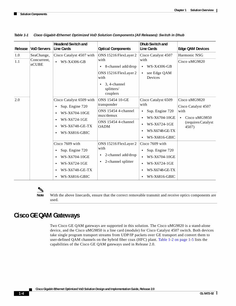
Cisco Core ComponentsTable 1-1 on page 1-4 illustrates the core components used in the switch-in-Dhub configuration of each release of the Cisco Gigabit-Ethernet Optimized VoD Solution. Release 2.0 uses 10-GE connectivity between the headend and the Dhub. However, the use of 10-GE interfaces limits the choice of platforms that can be used as the headend switch, requiring the Cisco Catalyst 6509 switch or the Cisco 7609, as opposed to the Cisco Catalyst 4507, in the headend. Because edge QAM devices do not support 10-GE interfaces, the use of 10 GE makes it necessary to use a Dhub switch as well. Release 2.0 uses the Cisco 7609 and the Cisco Catalyst 4507 with 10-GE interfaces as Dhub switches.
The use of 10 GE in Release 2.0 also results in changes in the optical components used for the solution.
Release 2.0 uses two optical topologies. The first is based on the Cisco ONS 15454 Multi-Service Transport Platform (MSTP) and the 10-gigabit dense wavelength-division multiplex (DWDM) transponder card. This platform provides configuration, performance, and fault management. The second topology is based on the Cisco ONS 15216 FlexLayer passive optical components and pluggable 10-gigabit DWDM XENPAK modules. Because it is passive, this lower-cost topology does not provide integrated optical monitoring capabilities.
While the change from 1-GE to 10-GE interfaces in Release 2.0 results in some solution components changing, it does not significantly alter the switching architecture from what was used for previous releases. Release 2.0 still uses a hub-and-spoke GE architecture. It also uses load balancing technologies to distribute the load between multiple 10-GE links when they are used between sites.
1-3Cisco Gigabit-Ethernet Optimized VoD Solution Design and Implementation Guide, Release 2.0
OL-5472-02
Chapter 1 Solution OverviewSolution Components
Note With the above linecards, ensure that the correct removable transmit and receive optics components are used.
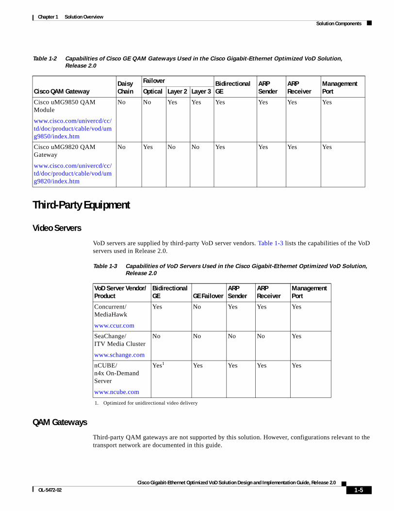
Cisco GE QAM GatewaysTwo Cisco GE QAM gateways are supported in this solution. The Cisco uMG9820 is a stand-alone device, and the Cisco uMG9850 is a line card (module) for Cisco Catalyst 4507 switch. Both devices take single program transport streams from UDP/IP packets over GE transport and convert them to user-defined QAM channels on the hybrid fiber coax (HFC) plant. Table 1-2 on page 1-5 lists the capabilities of the Cisco GE QAM gateways used in Release 2.0.
Table 1-1 Cisco Gigabit-Ethernet Optimized VoD Solution Components (All Releases): Switch in Dhub
Release VoD ServersHeadend Switch and Line Cards Optical Components
Dhub Switch and Line Cards Edge QAM Devices
1.0 SeaChange, Concurrent, nCUBE
Cisco Catalyst 4507 with
• WS-X4306-GB
ONS 15216 FlexLayer 2 with
• 8-channel add/drop
ONS 15216 FlexLayer 2 with
• 3, 4-channel splitters/couplers
Cisco Catalyst 4507 with
• WS-X4306-GB
• see Edge QAM Devices
Harmonic NSG
1.1 Cisco uMG9820
2.0 Cisco Catalyst 6509 with
• Sup. Engine 720
• WS-X6704-10GE
• WS-X6724-1GE
• WS-X6748-GE-TX
• WS-X6816-GBIC
ONS 15454 10-GE transponder
Cisco Catalyst 6509 with
• Sup. Engine 720
• WS-X6704-10GE
• WS-X6724-1GE
• WS-X6748-GE-TX
• WS-X6816-GBIC
Cisco uMG9820
Cisco Catalyst 4507 with
• Cisco uMG9850 (requires Catalyst 4507)
ONS 15454 4-channel mux/demux
ONS 15454 4-channel OADM
Cisco 7609 with
• Sup. Engine 720
• WS-X6704-10GE
• WS-X6724-1GE
• WS-X6748-GE-TX
• WS-X6816-GBIC
ONS 15216 FlexLayer 2 with
• 2-channel add/drop
• 2-channel splitter
Cisco 7609 with
• Sup. Engine 720
• WS-X6704-10GE
• WS-X6724-1GE
• WS-X6748-GE-TX
• WS-X6816-GBIC
1-4Cisco Gigabit-Ethernet Optimized VoD Solution Design and Implementation Guide, Release 2.0
OL-5472-02
Chapter 1 Solution OverviewSolution Components
Third-Party Equipment
Video Servers
VoD servers are supplied by third-party VoD server vendors. Table 1-3 lists the capabilities of the VoD servers used in Release 2.0.
QAM Gateways
Third-party QAM gateways are not supported by this solution. However, configurations relevant to the transport network are documented in this guide.
Table 1-2 Capabilities of Cisco GE QAM Gateways Used in the Cisco Gigabit-Ethernet Optimized VoD Solution,
Release 2.0
Cisco QAM Gateway Daisy Chain
Failover Bidirectional GE
ARP Sender
ARP Receiver
Management PortOptical Layer 2 Layer 3
Cisco uMG9850 QAM Module
www.cisco.com/univercd/cc/td/doc/product/cable/vod/umg9850/index.htm
No No Yes Yes Yes Yes Yes Yes
Cisco uMG9820 QAM Gateway
www.cisco.com/univercd/cc/td/doc/product/cable/vod/umg9820/index.htm
No Yes No No Yes Yes Yes Yes
Table 1-3 Capabilities of VoD Servers Used in the Cisco Gigabit-Ethernet Optimized VoD Solution,
Release 2.0
VoD Server Vendor/Product
Bidirectional GE GE Failover
ARP Sender
ARP Receiver
Management Port
Concurrent/MediaHawk
www.ccur.com
Yes No Yes Yes Yes
SeaChange/ITV Media Cluster
www.schange.com
No No No No Yes
nCUBE/n4x On-Demand Server
www.ncube.com
Yes1
1. Optimized for unidirectional video delivery
Yes Yes Yes Yes
1-5Cisco Gigabit-Ethernet Optimized VoD Solution Design and Implementation Guide, Release 2.0
OL-5472-02
Chapter 1 Solution OverviewSolution Components
ManagementProvisioning and fault management of Cisco Catalyst series switches used in the solution are performed through the command line interface (CLI) of the Cisco IOS.
Network management is not supported. Also, fault management is not provided for the passive optical components of the solution, including multiplexers, demultiplexers, splitters, and the optical supervisory channel (OSC). Because Cisco ONS 15216-based optical components are completely passive, no management capabilities are provided for these components.
1-6Cisco Gigabit-Ethernet Optimized VoD Solution Design and Implementation Guide, Release 2.0
OL-5472-02
Cisco Gigabit-Ethernet Optimized VoD Solution DesignOL-5472-02
C H A P T E R 2
Designing the SolutionIn customer deployments, all Cisco Gigabit-Ethernet Optimized VoD Solution components are located in either a video headend site or a distribution hub (Dhub) site. The basic topology is an Ethernet hub-and-spoke topology between the headend and multiple Dhubs. The Ethernet hub-and-spoke topology can be built in either physical hub-and-spoke or physical fiber-ring environments. (As long as optical signaling quality is maintained, different optical-layer topologies have no effect on either the operation or performance of Gigabit Ethernet.) All topologies are point to point. The most significant change with this release is support for point-to-point 10-GE topologies, combined with support for a converged multiservice architecture.
Note For a discussion of converting a ring network to a hub-and-spoke network, see Chapter 6, “Deploying the Cisco Gigabit-Ethernet Optimized VoD Solution in Fiber Ring Topologies,” of Cisco Gigabit-Ethernet Optimized VoD Solution Design and Implementation Guide, Release 1.1, at the following URL:
http://www.cisco.com/univercd/cc/td/doc/solution/vodsols/geopt1_1/voddig/index.htm
After the topologies and components are introduced, the topologies are discussed with respect to Ethernet switching.
This chapter presents the following major topics:
• Topologies and Components, page 2-2
• Converged Multiservice Architecture, page 2-16
• Scaling, page 2-22
2-1 and Implementation Guide, Release 2.0
Chapter 2 Designing the SolutionTopologies and Components
Topologies and ComponentsThe following major topics are presented:
• Optical Designs and Topology
• Ethernet Topology and Components
Optical Designs and TopologyRelease 2.0 includes support for two optical designs. One design is based on the Cisco ONS 15454 MSTP (Multi-Service Transport Platform), while the other is based on the Cisco ONS 15216 FlexLayer product family. The optical topology for both 10-GE designs in Release 2.0 consists of a physical ring that is converted to a 10-GE hub-and-spoke design at the optical layer. Release 2.0 uses both integrated 10-GE DWDM (dense wavelength-division multiplexing) optics as well as external 10-GE DWDM transponders.
Note Although the optical components chosen for this solution have been individually characterized for their optical characteristics, solution testing did not include the analog characterization of the optical topologies presented. Consequently, this document does not include design rules for the optical components used in this solution. Refer to the documentation for each optical product. (See Optical Component Documentation, page x, and references therein.)
The Cisco ONS 15454 MSTP provides optical management functionality, supporting optical-layer fault and performance management. The Cisco 15454 platform also supports a 10-gigabit DWDM transponder. When additional power is required for long distances, this transponder can be used in place of integrated Cisco XENPAK DWDM optics for 10-GE line cards.
The Cisco ONS 15216-based design uses the passive optical components of the Cisco 15216 FlexLayer product family. This design is a lower-cost alternative to the Cisco ONS 15454-based design, because it uses passive optics and integrated XENPAK DWDM optics for 10-GE line cards. The Cisco ONS 15216-based design does not include integrated support for optical management, because the components used are all passive. Although it is not included in the Release 2.0 optical design, the Cisco ONS 15216 FlexLayer product family does include an erbium-doped fiber amplifier (EDFA) optical amplifier, the Cisco ONS-15216 EDFA-2, that does support optical management.
As with previous releases, the optical transport portion of Release 2.0 consists primarily of a unidirectional optical network to support the video streams, providing the following:
• Support for 10-GE DWDM
• Cost-effective asymmetric transport
• An ability to monitor optical characteristics at optical components
Note Monitoring applies only to Cisco ONS 15454 and Cisco ONS 15216 designs that include optical amplifiers. Only the Cisco ONS 15216 optical amplifier supports integrated monitoring.
2-2Cisco Gigabit-Ethernet Optimized VoD Solution Design and Implementation Guide, Release 2.0
OL-5472-02
Chapter 2 Designing the SolutionTopologies and Components
Transponders
The Cisco ONS 15454-10T-L1 (10-Gbps multirate transponder) card is an MSTP component used as an external transponder, converting gray optics into DWDM. This card processes one 10-Gbps signal on the client side into one 10-Gbps, 100-GHz DWDM signal on the trunk side. The Cisco ONS 15454-10T-L1 card is tunable over two neighboring wavelengths in the 1550-nm, ITU 100-GHz range. It is available in four different versions, covering eight different wavelengths in the 1550-nm range. The trunk port operates at 9.95328 Gbps (or 10.70923 Gbps with ITU-T G.709 Digital Wrapper/FEC) over unamplified distances up to 50 miles (80 km), with different types of fiber such as C-SMF (C-band single-mode fiber) or dispersion-compensated fiber limited by loss or dispersion. ITU-T G.709 specifies a form of forward error correction (FEC) that uses a “wrapper” approach. FEC enables longer fiber links, because errors caused by the degradation of the optical signal with distance are corrected. The longer distances supported by the Cisco ONS 15454-10T-L1 transponder is one of the main reasons it may be chosen over integrated 10-GE DWDM optics.
Multihop Architecture
A single 10-GE interface often provides enough bandwidth for more than one Dhub node. Because of this, Release 2.0 includes a multihop 10-GE architecture, in which one or more unidirectional 10-GE links are dropped at multiple Dhub sites by daisy chaining the 10-GE link through one or more intermediate Dhub switches. In this architecture (which is logically point-to-point in a hub-and-spoke Ethernet topology), each intermediate Dhub switch terminates one or more upstream 10-GE unidirectional links and generates one or more downstream 10-GE unidirectional links. IP forwarding in the switch (see Ethernet Topology and Components, page 2-7) determines which packets are forwarded to the QAMs attached to the switch and which packets are sent out 10-GE unidirectional links to downstream Dhubs. To save on ports on the intermediate Dhub switches, a single physical port is split into two logical transmit and receive unidirectional interfaces (see Bidirectional Connectivity, page 2-11).
To save fibers between the headend and Dhub sites, the DWDM wavelengths associated with multiple 10-GE interfaces may be multiplexed onto a single fiber. DWDM wavelengths for one or more 10-GE interfaces are then dropped off at each Dhub site, by means of Cisco ONS 15216 optical multiplexers, add/drop modules, and demultiplexers.
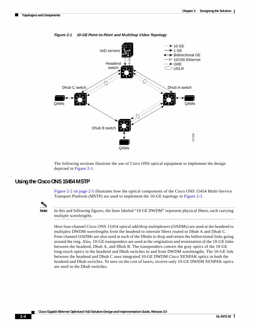
Figure 2-1 on page 2-4 illustrates the Ethernet topology and switching components used in Release 2.0, incorporating 10-GE point-to-point and multihop connectivity, as well as a redundant bidirectional GE topology using an optical ring The network includes a point-to-point 10-GE Ethernet segment between the headend and Dhub C, as well as multihop video segments between the headend and Dhub A and Dhub B. A bidirectional 1-GE or 10-GE link between the headend switch and all the Dhub switches is used for redundant bidirectional connectivity. When 1-GE interfaces are used for the ring, unidirectional link routing (UDLR) is used to make the unidirectional 10-GE links appear bidirectional.
2-3Cisco Gigabit-Ethernet Optimized VoD Solution Design and Implementation Guide, Release 2.0
OL-5472-02
Chapter 2 Designing the SolutionTopologies and Components
Figure 2-1 10-GE Point-to-Point and Multihop Video Topology
The following sections illustrate the use of Cisco ONS optical equipment to implement the design depicted in Figure 2-1.
Using the Cisco ONS 15454 MSTP
Figure 2-2 on page 2-5 illustrates how the optical components of the Cisco ONS 15454 Multi-Service Transport Platform (MSTP) are used to implement the 10-GE topology in Figure 2-1.
Note In this and following figures, the lines labeled “10 GE DWDM” represent physical fibers, each carrying multiple wavelengths.
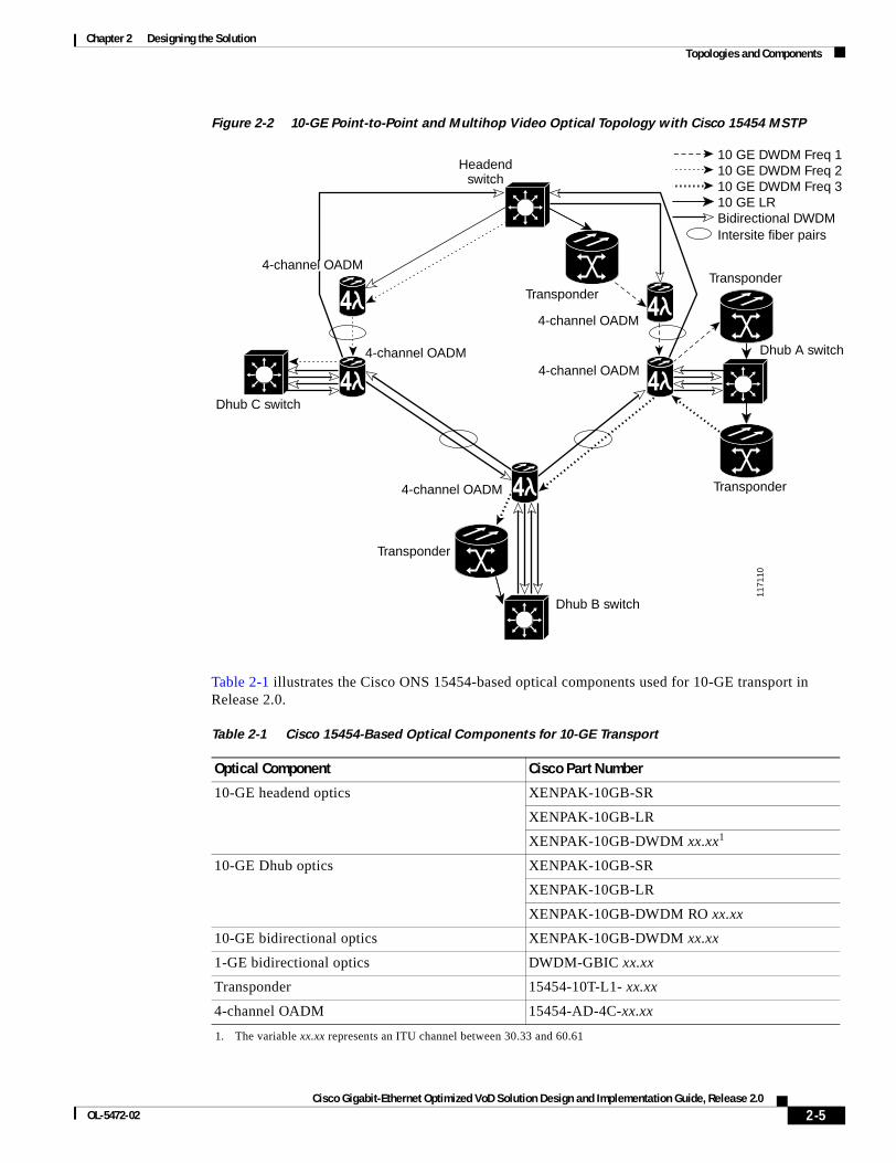
Here four-channel Cisco ONS 15454 optical add/drop multiplexers (OADMs) are used at the headend to multiplex DWDM wavelengths from the headend to intersite fibers routed to Dhub A and Dhub C. Four-channel OADMs are also used at each of the Dhubs to drop and return the bidirectional links going around the ring. Also, 10-GE transponders are used at the origination and termination of the 10-GE links between the headend, Dhub A, and Dhub B. The transponders convert the gray optics of the 10-GE long-reach optics in the headend and Dhub switches to and from DWDM wavelengths. The 10-GE link between the headend and Dhub C uses integrated 10-GE DWDM Cisco XENPAK optics in both the headend and Dhub switches. To save on the cost of lasers, receive-only 10-GE DWDM XENPAK optics are used in the Dhub switches.
V
1171
09
VoD servers
Headendswitch
Dhub A switchDhub C switch
Dhub B switch
QAMs
GREUDLR
10/100 EthernetBidirectional GE1 GE10 GE
QAMs
QAMs
2-4Cisco Gigabit-Ethernet Optimized VoD Solution Design and Implementation Guide, Release 2.0
OL-5472-02
Chapter 2 Designing the SolutionTopologies and Components
Figure 2-2 10-GE Point-to-Point and Multihop Video Optical Topology with Cisco 15454 MSTP
Table 2-1 illustrates the Cisco ONS 15454-based optical components used for 10-GE transport in Release 2.0.
1171
10
Headendswitch
Intersite fiber pairsBidirectional DWDM10 GE LR10 GE DWDM Freq 310 GE DWDM Freq 210 GE DWDM Freq 1
Transponder
4-channel OADM
Transponder
Dhub A switch
Transponder
4-channel OADM
Dhub B switch
4-channel OADM
Transponder
4-channel OADM
Dhub C switch
Four-channel OADMADM4-channel OADM
Table 2-1 Cisco 15454-Based Optical Components for 10-GE Transport
Optical Component Cisco Part Number
10-GE headend optics XENPAK-10GB-SR
XENPAK-10GB-LR
XENPAK-10GB-DWDM xx.xx1
1. The variable xx.xx represents an ITU channel between 30.33 and 60.61
10-GE Dhub optics XENPAK-10GB-SR
XENPAK-10GB-LR
XENPAK-10GB-DWDM RO xx.xx
10-GE bidirectional optics XENPAK-10GB-DWDM xx.xx
1-GE bidirectional optics DWDM-GBIC xx.xx
Transponder 15454-10T-L1- xx.xx
4-channel OADM 15454-AD-4C-xx.xx
2-5Cisco Gigabit-Ethernet Optimized VoD Solution Design and Implementation Guide, Release 2.0
OL-5472-02
Chapter 2 Designing the SolutionTopologies and Components
Using the Cisco ONS 15216 FlexLayer
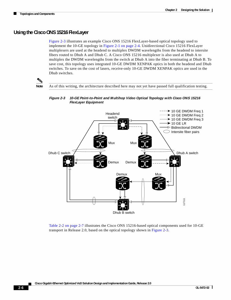
Figure 2-3 illustrates an example Cisco ONS 15216 FlexLayer-based optical topology used to implement the 10-GE topology in Figure 2-1 on page 2-4. Unidirectional Cisco 15216 FlexLayer multiplexers are used at the headend to multiplex DWDM wavelengths from the headend to intersite fibers routed to Dhub A and Dhub C. A Cisco ONS 15216 multiplexer is also used at Dhub A to multiplex the DWDM wavelengths from the switch at Dhub A into the fiber terminating at Dhub B. To save cost, this topology uses integrated 10-GE DWDM XENPAK optics in both the headend and Dhub switches. To save on the cost of lasers, receive-only 10-GE DWDM XENPAK optics are used in the Dhub switches.
Note As of this writing, the architecture described here may not yet have passed full qualification testing.
Figure 2-3 10-GE Point-to-Point and Multihop Video Optical Topology with Cisco ONS 15216
FlexLayer Equipment
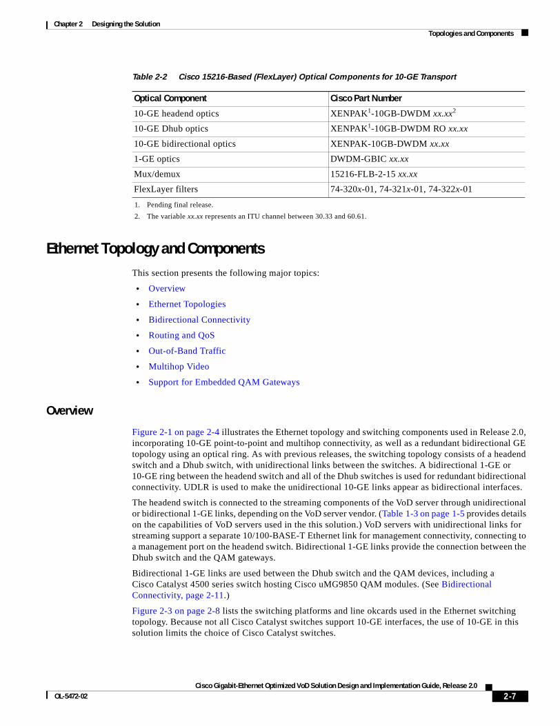
Table 2-2 on page 2-7 illustrates the Cisco ONS 15216-based optical components used for 10-GE transport in Release 2.0, based on the optical topology shown in Figure 2-3.
1171
11
Headendswitch
Intersite fiber pairsBidirectional DWDM10 GE LR10 GE DWDM Freq 310 GE DWDM Freq 210 GE DWDM Freq 1
MuxMux
Mux
DemuxDemux
Demux
Dhub A switch
Dhub B switch
Dhub C switch
2-6Cisco Gigabit-Ethernet Optimized VoD Solution Design and Implementation Guide, Release 2.0
OL-5472-02
Chapter 2 Designing the SolutionTopologies and Components
Ethernet Topology and ComponentsThis section presents the following major topics:
• Overview
• Ethernet Topologies
• Bidirectional Connectivity
• Routing and QoS
• Out-of-Band Traffic
• Multihop Video
• Support for Embedded QAM Gateways
Overview
Figure 2-1 on page 2-4 illustrates the Ethernet topology and switching components used in Release 2.0, incorporating 10-GE point-to-point and multihop connectivity, as well as a redundant bidirectional GE topology using an optical ring. As with previous releases, the switching topology consists of a headend switch and a Dhub switch, with unidirectional links between the switches. A bidirectional 1-GE or 10-GE ring between the headend switch and all of the Dhub switches is used for redundant bidirectional connectivity. UDLR is used to make the unidirectional 10-GE links appear as bidirectional interfaces.
The headend switch is connected to the streaming components of the VoD server through unidirectional or bidirectional 1-GE links, depending on the VoD server vendor. (Table 1-3 on page 1-5 provides details on the capabilities of VoD servers used in the this solution.) VoD servers with unidirectional links for streaming support a separate 10/100-BASE-T Ethernet link for management connectivity, connecting to a management port on the headend switch. Bidirectional 1-GE links provide the connection between the Dhub switch and the QAM gateways.
Bidirectional 1-GE links are used between the Dhub switch and the QAM devices, including a Cisco Catalyst 4500 series switch hosting Cisco uMG9850 QAM modules. (See Bidirectional Connectivity, page 2-11.)
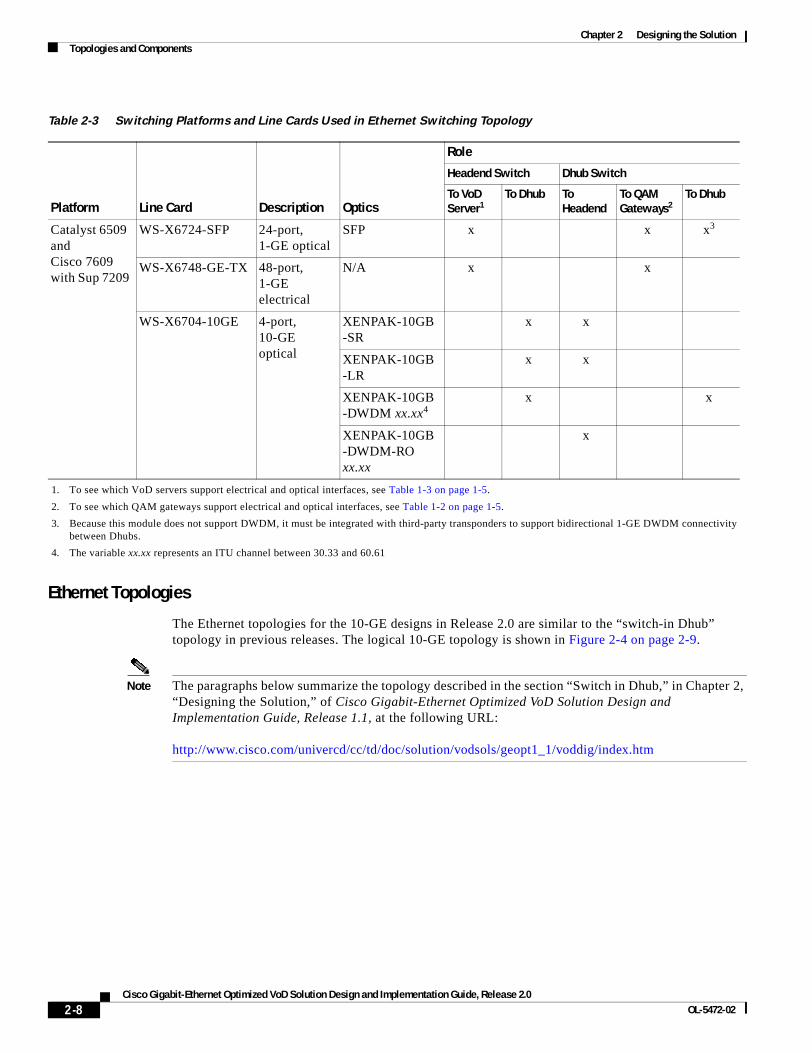
Figure 2-3 on page 2-8 lists the switching platforms and line okcards used in the Ethernet switching topology. Because not all Cisco Catalyst switches support 10-GE interfaces, the use of 10-GE in this solution limits the choice of Cisco Catalyst switches.
Table 2-2 Cisco 15216-Based (FlexLayer) Optical Components for 10-GE Transport
Optical Component Cisco Part Number
10-GE headend optics XENPAK1-10GB-DWDM xx.xx2
10-GE Dhub optics XENPAK1-10GB-DWDM RO xx.xx
10-GE bidirectional optics XENPAK-10GB-DWDM xx.xx
1-GE optics DWDM-GBIC xx.xx
Mux/demux 15216-FLB-2-15 xx.xx
FlexLayer filters 74-320x-01, 74-321x-01, 74-322x-01
1. Pending final release.
2. The variable xx.xx represents an ITU channel between 30.33 and 60.61.
2-7Cisco Gigabit-Ethernet Optimized VoD Solution Design and Implementation Guide, Release 2.0
OL-5472-02
Chapter 2 Designing the SolutionTopologies and Components
Ethernet Topologies
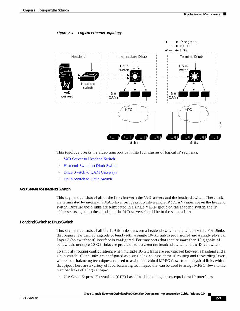
The Ethernet topologies for the 10-GE designs in Release 2.0 are similar to the “switch-in Dhub” topology in previous releases. The logical 10-GE topology is shown in Figure 2-4 on page 2-9.
Note The paragraphs below summarize the topology described in the section “Switch in Dhub,” in Chapter 2, “Designing the Solution,” of Cisco Gigabit-Ethernet Optimized VoD Solution Design and Implementation Guide, Release 1.1, at the following URL:
http://www.cisco.com/univercd/cc/td/doc/solution/vodsols/geopt1_1/voddig/index.htm
Table 2-3 Switching Platforms and Line Cards Used in Ethernet Switching Topology
Platform Line Card Description Optics
Role
Headend Switch Dhub Switch
To VoD Server1
1. To see which VoD servers support electrical and optical interfaces, see Table 1-3 on page 1-5.
To Dhub To Headend
To QAM Gateways2
2. To see which QAM gateways support electrical and optical interfaces, see Table 1-2 on page 1-5.
To Dhub
Catalyst 6509 and Cisco 7609 with Sup 7209
WS-X6724-SFP 24-port, 1-GE optical
SFP x x x3
3. Because this module does not support DWDM, it must be integrated with third-party transponders to support bidirectional 1-GE DWDM connectivity between Dhubs.
WS-X6748-GE-TX 48-port, 1-GE electrical
N/A x x
WS-X6704-10GE 4-port, 10-GE optical
XENPAK-10GB-SR
x x
XENPAK-10GB-LR
x x
XENPAK-10GB-DWDM xx.xx4
4. The variable xx.xx represents an ITU channel between 30.33 and 60.61
x x
XENPAK-10GB-DWDM-RO xx.xx
x
2-8Cisco Gigabit-Ethernet Optimized VoD Solution Design and Implementation Guide, Release 2.0
OL-5472-02
Chapter 2 Designing the SolutionTopologies and Components
Figure 2-4 Logical Ethernet Topology
This topology breaks the video transport path into four classes of logical IP segments:
• VoD Server to Headend Switch
• Headend Switch to Dhub Switch
• Dhub Switch to QAM Gateways
• Dhub Switch to Dhub Switch
VoD Server to Headend Switch
This segment consists of all of the links between the VoD servers and the headend switch. These links are terminated by means of a MAC-layer bridge group into a single IP (VLAN) interface on the headend switch. Because these links are terminated in a single VLAN group on the headend switch, the IP addresses assigned to these links on the VoD servers should be in the same subnet.
Headend Switch to Dhub Switch
This segment consists of all the 10-GE links between a headend switch and a Dhub switch. For Dhubs that require less than 10 gigabits of bandwidth, a single 10-GE link is provisioned and a single physical Layer 3 (no switchport) interface is configured. For transports that require more than 10 gigabits of bandwidth, multiple 10-GE links are provisioned between the headend switch and the Dhub switch.
To simplify routing configurations when multiple 10-GE links are provisioned between a headend and a Dhub switch, all the links are configured as a single logical pipe at the IP routing and forwarding layer, where load-balancing techniques are used to assign individual MPEG flows to the physical links within that pipe. There are a variety of load-balancing techniques that can be used to assign MPEG flows to the member links of a logical pipe:
• Use Cisco Express Forwarding (CEF)-based load balancing across equal-cost IP interfaces.
VVVV
1171
13
VoDservers
Headendswitch
Headend Intermediate Dhub Terminal Dhub
Dhubswitch
Dhubswitch
GEQAMs
GEQAMs
HFC
10 GE1 GE
IP segment
HFC
STBs STBs
2-9Cisco Gigabit-Ethernet Optimized VoD Solution Design and Implementation Guide, Release 2.0
OL-5472-02
Chapter 2 Designing the SolutionTopologies and Components
• Assign all of the physical ports associated with the logical pipe to an EtherChannel group and use EtherChannel-based load balancing.
• Assign the member links to sets of equal-cost EtherChannel groups and use a combination of EtherChannel and IP load balancing across the EtherChannel groups.
Because most headend-to-Dhub switch connections do not require more than 20 gigabits of bandwidth, the Cisco Gigabit-Ethernet Optimized VoD Solution, Release 2.0 limits load balancing to a single EtherChannel group of two ports assigned to a single physical Layer 3 (no switchport) interface.
Because of the inherently unidirectional nature of MPEG video, it is important to use physical Layer 3 interfaces as opposed to VLAN interfaces. The reason for this is that when packets are switched to an outgoing VLAN interface, they are first switched at Layer 3 using IP forwarding, and then at Layer 2 using a VLAN interface-specific bridging table. Unlike IP routing tables, which do not forward packets unless there is a routing table entry for the destination address of an IP packet, bridging tables typically flood packets until a MAC layer forwarding entry is created. For MPEG video, this flooding process could be disastrous, as it could end up causing congestion on all the physical ports assigned to the VLAN trunk. In fact, flooding is not normally an issue for VLAN interfaces, because the normal Address Resolution Protocol (ARP) process associated with bidirectional Ethernet interfaces ends up populating a MAC-layer forwarding entry for the bridging table associated with the VLAN interface. However, even with ARP, entries in a MAC-layer bridging table can be removed as a result of periodic aging processes or error conditions that may occur during normal operation. For these reasons, physical Layer 3 (no switchport) as opposed to VLAN interfaces are used in Release 2.0.
Dhub Switch to QAM Gateways
This segment consists of all the 1-GE links between the Dhub switch and the QAM gateways (either the Cisco uMG9820 or the Cisco uMG9850). For QAM gateways that require less than 1 gigabit of bandwidth (that is, the Cisco uMG9820), a single 1-GE link is provisioned and a single physical Layer 3 (no switchport) interface is configured. For QAM devices that require more than 1 gigabit of bandwidth (that is, the Cisco uMG9850 modules hosted in a Cisco Catalyst 4500 series switch), multiple 1-GE links are provisioned between the Dhub switch and those modules. These links can be configured and assigned to Layer 3 interfaces in one of two ways.
Method 1
The first method of assigning the links of a multilink Dhub-switch-to-QAM-devices segment to Layer 3 interfaces is to bundle the links into a single physical Layer 3 interface (no switchport) consisting of a single EtherChannel group of bidirectional 1-GE ports. In this type of configuration, the QAM switch is configured to allow any module to be reached from the EtherChannel interface in that switch by means of Layer 2 switching. (For more information on configuring a Cisco Catalyst 4500 series switch to support this, see Support for Embedded QAM Gateways, page 2-14.) To ensure optimum load-balancing efficiency, Release 2.0 limits the number of 1-GE ports that may be combined into this EtherChannel group to 2, 4, or 8 ports. While this provides limited choices in the amount of bandwidth that may be provisioned between the Dhub switch and the QAM switch, it does simplify routing configuration, becaus only a single Layer 3 interface and IP address must be configured. The main benefit of this, however, is resiliency.
In addition, when a single EtherChannel is used between the Dhub switch and a QAM switch, that EtherChannel can be configured to provide resiliency. (Instead of using a Layer 3 interface to a QAM group, another option—not tested as part of this solution—is to use a two-gigabit EtherChannel. This overprovisioning also provides resiliency.) When there is a link failure, both asymmetric and bidirectional EtherChannel rehash the flows going through a given EtherChannel to the remaining links in the bundle. If an EtherChannel group is overprovisioned so that more links are assigned to the EtherChannel group than the potential peak load can generate, then this property has the benefit that a link failure may cause no degradation of service at all. However, if the EtherChannel group is not
2-10Cisco Gigabit-Ethernet Optimized VoD Solution Design and Implementation Guide, Release 2.0
OL-5472-02
Chapter 2 Designing the SolutionTopologies and Components
overprovisioned, this property can negatively affect all the subscribers associated with that EtherChannel group. This is because a link failure can end up causing congestion on all of the remaining links in the EtherChannel group.
Method 2
The second method is to configure a separate physical Layer 3 interface for each link between the Dhub switch and QAM switch. If each QAM gateway were reachable from each of these links, they would appear as equal-cost links to the CEF switching layer, because the links run between the same two nodes and can reach the same sets of IP destinations (the Dhub switch and QAM devices). However, to obtain maximum efficiency when multiple links are used between a pair of nodes in Release 2.0, CEF-based IP load balancing is not recommended on the Cisco Catalyst 6509 or the Cisco 7609. Instead, each 1-GE port on the Dhub switch is configured so that only a single QAM gateway (the Cisco uMG9850) can be reached from it. This is accomplished by assigning each physical Layer 3 interface to a separate subnet, and then assigning one Cisco uMG9850 in the host switch (the Cisco Catalyst 4507 switch hosting that module) to that same subnet. To ensure that only a single Cisco uMG9850 in the QAM switch can be reached from each physical Layer 3 interface on the Dhub switch, each GE interface (port) in the QAM switch is paired with a single Cisco uMG9850 module by configuring Layer 2 switching between the GE interface in the host switch and the module, and assigning them both to a unique logical VLAN. (For more information on configuring a Cisco Catalyst 4500 series switch to support this, see Support for Embedded QAM Gateways, page 2-14.)
The choice of which of the above two methods is used to configure the links between the Dhub switch and a QAM switch depends on the tradeoff between ease of configuration and the flexibility of assigning bandwidth to these links.
Dhub Switch to Dhub Switch
In multihop video topologies, a fourth IP segment runs between an intermediate Dhub and either a terminal Dhub or another intermediate Dhub. Interfaces associated with this segment should be configured exactly as discussed in Headend Switch to Dhub Switch, page 2-9. (For more information about multihop video, see Multihop Video, page 2-13.)
Subtended Dhubs
Because the 10-GE configurations in Release 2.0 use optical rings, Release 2.0 supports subtended Dhubs.
Note For a discussion of subtended Dhubs, see “Subtended Dhubs” in Chapter 2, “Designing the Solution,” of Cisco Gigabit-Ethernet Optimized VoD Solution Design and Implementation Guide, Release 1.1, at the following URL:
http://www.cisco.com/univercd/cc/td/doc/solution/vodsols/index.htm
Bidirectional Connectivity
Either 1-GE or 10-GE bidirectional interfaces are used between the headend and Dhubs to enable bidirectional connectivity between the headend and the Dhubs. The bidirectional GE interfaces provide the return path for the generic routing encapsulation (GRE) tunnels associated with unidirectional link routing (UDLR). UDLR makes the unidirectional 10-GE links appear to be bidirectional to protocols such as Address Resolution Protocol (ARP) and Open Shortest Path First (OSPF), which rely on having bidirectional connectivity on interfaces. The bidirectional GE interfaces may also carry video control-plane messages between set-top boxes (STBs) and control plane components located in both the
2-11Cisco Gigabit-Ethernet Optimized VoD Solution Design and Implementation Guide, Release 2.0
OL-5472-02
Chapter 2 Designing the SolutionTopologies and Components
Dhubs and the headend. Video control-plane protocols such as DSM-CC are used to originate movie requests from an STB and to allocate resources such as QAM channels to a VoD session. Finally, the bidirectional GE links may also carry traffic from other services such as Internet access and telephony. An Internet access service would generate traffic between Cable Modem Termination System (CMTS) aggregation routers located in Dhubs and point-of-presence (POP) routers located in the headend. A telephony service would route voice traffic originated at voice-enabled endpoints connected to the HFC network through CMTSs located in the Dhubs to VoIP gateways located in the headend or to a voice-enabled network between multiple headends. Since the bidirectional GE links may be used for many functions and services, it is important that the bidirectional GE topology be redundant. (See Chapter 4, “Providing Redundancy and Reliability.”) Redundancy for the bidirectional GE topology is often provided by running the links around a fiber-ring interface connecting the headend to a set of Dhubs.
Release 2.0 uses UDLR with the 10-GE interfaces to make them appear bidirectional to ARP, OSPF, and other protocols that rely on sending return packets on a specific interface. While UDLR allows an arbitrary IP return topology, Release 2.0 was tested with a dedicated GE return path. Asymmetric EtherChannel was not tested with the 10-GE topologies in Release 2.0, because the amount of bandwidth required from Dhub sites to the headend is typically less than 1 gigabit. An asymmetric EtherChannel uses multiple unidirectional links downstream and single bidirectional link upstream, all of which are 10-GE links.
Routing and QoS
As in the previous releases, OSPF is the routing protocol used in the solution. OSPF populates routes to the QAM gateways on the headend switch, and also enables equal-cost load balancing when multiple IP interfaces are configured between the headend and Dhub switches.
Release 2.0 enables Quality of Service (QoS) on the interfaces between the headend and Dhub switches, as well as on the interfaces between Dhub switches. For example, input access lists are enabled on the headend switch interface that is connected to the VoD servers. These access lists mark ingress traffic on the links from the VoD servers with DSCP 0b100000 (CS4), ingress traffic on links from out-of-band controllers with DSCP 0b011000 (CS3), and ingress traffic from all other external links with DSCP 0. If a management port is connected to the headend switch, all packets arriving on that port are marked with DSCP 0.
Note DSCP stands for Differentiated Services Code Point. For more information, see Establishing Quality of Service (QoS), page 3-4.
Note also the following:
• Egress QoS is enabled on the Ethernet ports connected to the Dhubs.
• Packets marked with DSCP 0b100000 (CS4) are serviced by a priority queue.
• Packets marked with DSCP 0b011000 (CS3) are serviced by a weighted queue configured for 80% of the physical link bandwidth.
• Packets marked with any other DSCP value are serviced by a weighted queue configured for 20% of the physical link bandwidth.
This configuration should allow VoD out-of-band traffic to be serviced in a timely manner, while not adversely affecting the MPEG video streams.
2-12Cisco Gigabit-Ethernet Optimized VoD Solution Design and Implementation Guide, Release 2.0
OL-5472-02
Chapter 2 Designing the SolutionTopologies and Components
Out-of-Band Traffic
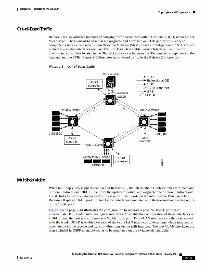
Release 2.0 also validates methods of carrying traffic associated with out-of-band (OOB) messages for VoD service. These out-of-band messages originate and terminate on STBs and various headend components such as the Cisco System Resource Manager (SRM). Since current-generation STBs do not include IP-capable interfaces such as DOCSIS (Data Over Cable Service Interface Specification), out-of-band controllers located in the Dhub act as gateways between the IP-connected components in the headend and the STBs. Figure 2-5 illustrates out-of-band traffic in the Release 2.0 topology.
Figure 2-5 Out-of-Band Traffic
Multihop Video
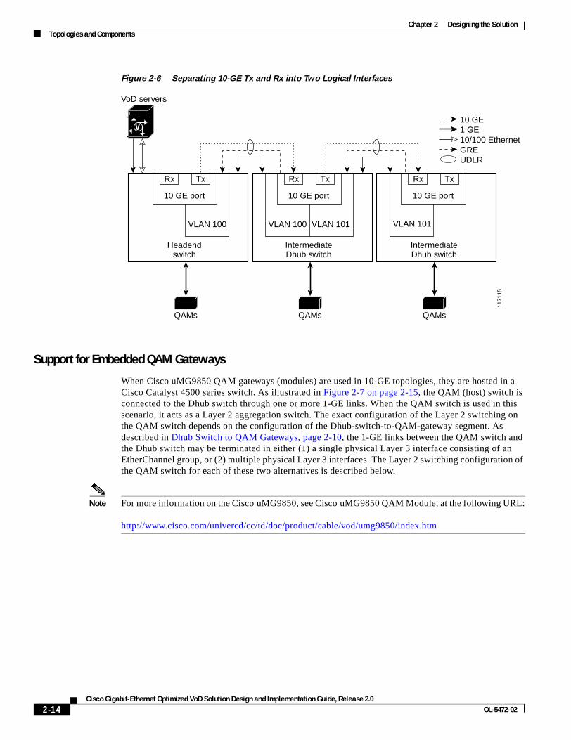
When multihop video segments are used in Release 2.0, the intermediate Dhub switches terminate one or more unidirectional 10-GE links from the upstream switch, and originate one or more unidirectional 10-GE links to the downstream switch. To save on 10-GE ports on the intermediate Dhub switches, Release 2.0 splits a 10-GE port into two logical interfaces associated with the transmit and receive optics of the 10-GE port.
Figure 2-6 on page 2-14 illustrates the configuration to separate a physical 10-GE port on an intermediate Dhub switch into two logical interfaces. To enable the configuration of these interfaces on a 10-GE port, the port is configured as a VLAN trunk port. Two VLAN interfaces are then associated with the trunk. UDLR is enabled on each of the two VLAN interfaces to determine which interface is associated with the receive and transmit directions on the split interface. The two VLAN interfaces are then included in OSPF to enable routes to be populated on the switches dynamically.
V
1212
28
VoD servers
Headendswitch
Dhub A switchDhub C switch
Dhub B switch
uMG9820 uMG9820
uMG9850
OOBcontroller
Catalyst 4500 series
GREUDLR
10/100 Ethernet1 GE
10 GEBidirectional GE
OOBcontroller
OOBcontroller
OOBcontroller
2-13Cisco Gigabit-Ethernet Optimized VoD Solution Design and Implementation Guide, Release 2.0
OL-5472-02
Chapter 2 Designing the SolutionTopologies and Components
Figure 2-6 Separating 10-GE Tx and Rx into Two Logical Interfaces
Support for Embedded QAM Gateways
When Cisco uMG9850 QAM gateways (modules) are used in 10-GE topologies, they are hosted in a Cisco Catalyst 4500 series switch. As illustrated in Figure 2-7 on page 2-15, the QAM (host) switch is connected to the Dhub switch through one or more 1-GE links. When the QAM switch is used in this scenario, it acts as a Layer 2 aggregation switch. The exact configuration of the Layer 2 switching on the QAM switch depends on the configuration of the Dhub-switch-to-QAM-gateway segment. As described in Dhub Switch to QAM Gateways, page 2-10, the 1-GE links between the QAM switch and the Dhub switch may be terminated in either (1) a single physical Layer 3 interface consisting of an EtherChannel group, or (2) multiple physical Layer 3 interfaces. The Layer 2 switching configuration of the QAM switch for each of these two alternatives is described below.
Note For more information on the Cisco uMG9850, see Cisco uMG9850 QAM Module, at the following URL:
http://www.cisco.com/univercd/cc/td/doc/product/cable/vod/umg9850/index.htm
V
1171
15
VoD servers
QAMs QAMs QAMs
Rx Tx
10 GE port
Headendswitch
VLAN 100
GREUDLR
10/100 Ethernet1 GE10 GE
Rx Tx
10 GE port
IntermediateDhub switch
IntermediateDhub switch
VLAN 101VLAN 100
Rx Tx
10 GE port
VLAN 101
2-14Cisco Gigabit-Ethernet Optimized VoD Solution Design and Implementation Guide, Release 2.0
OL-5472-02
Chapter 2 Designing the SolutionTopologies and Components
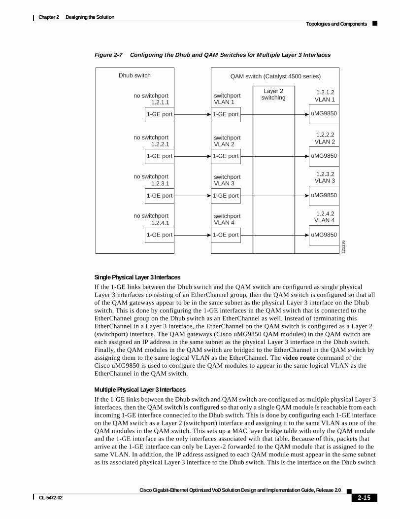
Figure 2-7 Configuring the Dhub and QAM Switches for Multiple Layer 3 Interfaces
Single Physical Layer 3 Interfaces
If the 1-GE links between the Dhub switch and the QAM switch are configured as single physical Layer 3 interfaces consisting of an EtherChannel group, then the QAM switch is configured so that all of the QAM gateways appear to be in the same subnet as the physical Layer 3 interface on the Dhub switch. This is done by configuring the 1-GE interfaces in the QAM switch that is connected to the EtherChannel group on the Dhub switch as an EtherChannel as well. Instead of terminating this EtherChannel in a Layer 3 interface, the EtherChannel on the QAM switch is configured as a Layer 2 (switchport) interface. The QAM gateways (Cisco uMG9850 QAM modules) in the QAM switch are each assigned an IP address in the same subnet as the physical Layer 3 interface in the Dhub switch. Finally, the QAM modules in the QAM switch are bridged to the EtherChannel in the QAM switch by assigning them to the same logical VLAN as the EtherChannel. The video route command of the Cisco uMG9850 is used to configure the QAM modules to appear in the same logical VLAN as the EtherChannel in the QAM switch.
Multiple Physical Layer 3 Interfaces
If the 1-GE links between the Dhub switch and QAM switch are configured as multiple physical Layer 3 interfaces, then the QAM switch is configured so that only a single QAM module is reachable from each incoming 1-GE interface connected to the Dhub switch. This is done by configuring each 1-GE interface on the QAM switch as a Layer 2 (switchport) interface and assigning it to the same VLAN as one of the QAM modules in the QAM switch. This sets up a MAC layer bridge table with only the QAM module and the 1-GE interface as the only interfaces associated with that table. Because of this, packets that arrive at the 1-GE interface can only be Layer-2 forwarded to the QAM module that is assigned to the same VLAN. In addition, the IP address assigned to each QAM module must appear in the same subnet as its associated physical Layer 3 interface to the Dhub switch. This is the interface on the Dhub switch
1.2.1.2
1.2.4.2
1.2.3.2
1.2.2.2
1.2.1.1
1.2.2.1
1.2.3.1
1.2.4.1no switchport
no switchport
no switchport
no switchport
switchportVLAN 4
switchportVLAN 3
switchportVLAN 2
switchportVLAN 1
1-GE port
1-GE port
1-GE port
1-GE port
1-GE port
1-GE port
1-GE port
1-GE port
QAM switch (Catalyst 4500 series)
Layer 2switching
Dhub switch
uMG9850
uMG9850
uMG9850
uMG9850
VLAN 1
VLAN 2
VLAN 3
VLAN 4
1212
36
2-15Cisco Gigabit-Ethernet Optimized VoD Solution Design and Implementation Guide, Release 2.0
OL-5472-02
Chapter 2 Designing the SolutionConverged Multiservice Architecture
that is connected to the 1-GE interface on the QAM switch that appears in the same VLAN as the QAM. Figure 2-7 on page 2-15 illustrates the Dhub and QAM switch configuration used when multiple physical Layer 3 interfaces are configured on the Dhub switch.
Converged Multiservice ArchitectureThis section presents the following major topics:
• Overview
• Using VRF-lite and Differentiated Services in a Converged Multiservice Architecture
• Security Considerations
OverviewBecause successfully converged multiple services are supported only in a 10-GE environment, the Release 2.0 transport architecture supports the ability to implement the VoD service as part of a converged multiservice IP network. Examples of other services that may be carried in the same IP network are VoIP, residential Internet access, and broadcast video. To allow more flexible use of bandwidth among services, the IP transport architecture supports converged services at the IP packet-switching layer, as opposed to the TDM (SONET/SDH) layer or the physical (DWDM) layer.
While all services are converged at the IP packet-switching layer, each service may have different IP-topology and network-convergence requirements. For example, the VoD service requires much more bandwidth than services such as VoIP, while the VoIP service has more-stringent requirements for service availability. Because of this, the IP routing topology associated with the VoD service may be restricted to only 10-GE links and have no redundant paths for failover, while the topology associated with the VoIP service must have redundant paths between all nodes. To allow packets from different services to be routed separately, Release 2.0 uses VRF-lite as the routing and forwarding technology. (See Using VRF-lite and Differentiated Services in a Converged Multiservice Architecture, page 2-18.)
Figure 2-8 on page 2-17 illustrates an example multiservice topology that a multiple system operator (MSO) may use to combine multiple services on a single IP-based transport infrastructure. The topology illustrates a network with a single headend and three Dhubs. The headend contains VoD servers for on-demand services, voice gateways for voice services, and links to the IP backbone as well as intercarrier connections for Internet access services. The headend includes the headend switch, which acts as the interconnection point between the headend and Dhubs for all services. The headend is connected to the Dhubs by means of 10-GE unidirectional links, as well as a 1-GE-based ring. Each Dhub contains a switch that routes traffic for all services, a CMTS for data and voice services, and QAM gateways for video services. Both the QAM gateways and the CMTS connect to the HFC plant in the Dhubs. On the other side of the HFC network, the customer premises contains a voice-enabled Universal Mobile Telecommunications System (UMTS), which terminates the voice and Internet access services, as well as one or more set-top boxes that terminate the video services.
Because the bandwidth, QoS, and availability requirements for each of these services is different, the transport network may be configured to enable each service to run on a separate logical or physical topology. For example, the traffic associated with the VoD service may be routed to the unidirectional 10-GE links, while traffic associated with the voice and Internet access services may be routed to the bidirectional ring. The directly connected 10-GE links provide the bandwidth required for the VoD service, while the bidirectional ring provides the redundancy required for the voice and Internet access services.
2-16Cisco Gigabit-Ethernet Optimized VoD Solution Design and Implementation Guide, Release 2.0
OL-5472-02
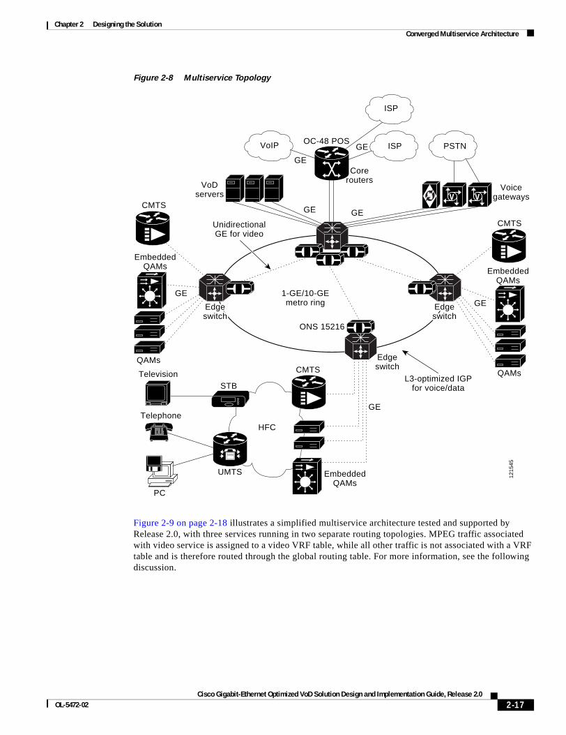
Chapter 2 Designing the SolutionConverged Multiservice Architecture
Figure 2-8 Multiservice Topology
Figure 2-9 on page 2-18 illustrates a simplified multiservice architecture tested and supported by Release 2.0, with three services running in two separate routing topologies. MPEG traffic associated with video service is assigned to a video VRF table, while all other traffic is not associated with a VRF table and is therefore routed through the global routing table. For more information, see the following discussion.
V V
VoIP
ISP
ISP PSTN
1-GE/10-GEmetro ring
ONS 15216
Edgeswitch
EmbeddedQAMs
EmbeddedQAMs
EmbeddedQAMs
QAMs
QAMs
CMTS
CMTS
CMTS
GE
GE
GEGE
GE
GE
GE
UMTS
HFC
STBTelevision
Telephone
PC
UnidirectionalGE for video
L3-optimized IGPfor voice/data
VoDservers
Corerouters
OC-48 POS
Voicegateways
1215
45
EdgeEdgeswitchswitch
EdgeEdgeswitchswitch
Edgeswitch
Edgeswitch
2-17Cisco Gigabit-Ethernet Optimized VoD Solution Design and Implementation Guide, Release 2.0
OL-5472-02
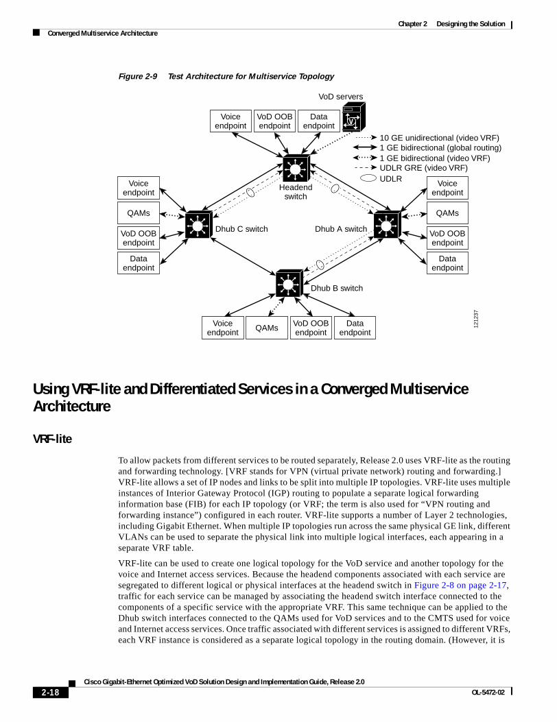
Chapter 2 Designing the SolutionConverged Multiservice Architecture
Figure 2-9 Test Architecture for Multiservice Topology
Using VRF-lite and Differentiated Services in a Converged Multiservice Architecture
VRF-lite
To allow packets from different services to be routed separately, Release 2.0 uses VRF-lite as the routing and forwarding technology. [VRF stands for VPN (virtual private network) routing and forwarding.] VRF-lite allows a set of IP nodes and links to be split into multiple IP topologies. VRF-lite uses multiple instances of Interior Gateway Protocol (IGP) routing to populate a separate logical forwarding information base (FIB) for each IP topology (or VRF; the term is also used for “VPN routing and forwarding instance”) configured in each router. VRF-lite supports a number of Layer 2 technologies, including Gigabit Ethernet. When multiple IP topologies run across the same physical GE link, different VLANs can be used to separate the physical link into multiple logical interfaces, each appearing in a separate VRF table.
VRF-lite can be used to create one logical topology for the VoD service and another topology for the voice and Internet access services. Because the headend components associated with each service are segregated to different logical or physical interfaces at the headend switch in Figure 2-8 on page 2-17, traffic for each service can be managed by associating the headend switch interface connected to the components of a specific service with the appropriate VRF. This same technique can be applied to the Dhub switch interfaces connected to the QAMs used for VoD services and to the CMTS used for voice and Internet access services. Once traffic associated with different services is assigned to different VRFs, each VRF instance is considered as a separate logical topology in the routing domain. (However, it is
V
1212
37
VoD servers
Headendswitch
Dhub C switch Dhub A switch
Dhub B switch
UDLR GRE (video VRF)UDLR
1 GE bidirectional (global routing)10 GE unidirectional (video VRF)
1 GE bidirectional (video VRF)
Voiceendpoint
QAMs
VoD OOBendpoint
Dataendpoint
Voiceendpoint QAMs VoD OOB
endpointData
endpoint
Voiceendpoint
VoD OOBendpoint
Dataendpoint
Voiceendpoint
QAMs
VoD OOBendpoint
Dataendpoint
2-18Cisco Gigabit-Ethernet Optimized VoD Solution Design and Implementation Guide, Release 2.0
OL-5472-02
Chapter 2 Designing the SolutionConverged Multiservice Architecture
possible to configure an interface so that it is not associated with a particular VRF. In this case, the interface is associated with the global routing table that is associated with all VRFs.) By constraining the configuration of which transport links are included in each logical topology, the network can be engineered to ensure that the physical topology associated with each logical topology meets the bandwidth, QoS, and availability requirements for each service.
Note For an introduction to VRF-lite that is also applicable to headend switches, see Configuring VRF-lite at the following URL:
http://www.cisco.com/univercd/cc/td/doc/product/lan/cat4000/12_1_20/config/vrf.htm
MPEG video traffic is routed through the video VRF by assigning the video links from the VoD servers and the links to the QAM gateways to the video VRF. In addition, the 10-GE unidirectional links and the associated UDLR interfaces are assigned to the video VRF. The GRE tunnels associated with the UDLR interfaces use routes installed in the global routing table. Note that because MPEG video is unidirectional and the tunnel interfaces associated with UDLR are installed in the video VRF table, there should be no traffic sent through the UDLR tunnels other than locally generated protocol messages such as ARP and OSPF. MPEG video traffic is marked for QoS treatment at the ingress interface on the headend switch.
Packets that enter the headend switch on the 1-GE interfaces attached to the VoD servers should be marked with DSCP value 32. A value of 32 corresponds to Class Selector 4 (CS4), which is Cisco’s recommended DSCP value for streaming video services.
Note For more information on DSCP, see DSCP Features and Values Used in Release 2.0, page 2-20.
Traffic associated with voice and Internet access services is not assigned to a VRF table. Because of this, routes associated with these services are installed in the global routing table. Traffic associated with these services is marked for QoS treatment at the ingress interfaces of the headend and Dhub switches. All packets that enter the headend and Dhub switches on the ports attached to voice components shown in Figure 2-9 on page 2-18 should be marked with DSCP value 46. That value is assigned to the Expedited Forwarding (EF) per-hop behavior (PHB), which ensures that voice packets receive low-latency treatment through the network. All packets that enter the headend and Dhub switches on the ports associated with the Internet access service should be marked with DSCP value 0. DSCP value 0 is assigned to the DiffServ default class, which provides best-effort packet scheduling. DSCP value 0 is chosen for the Internet access service, because there are typically no QoS guarantees associated with residential Internet access.
A fourth traffic type associated with out-of-band messages for VoD service is supported by Release 2.0. These messages originate and terminate on STBs and various headend components, such as the Cisco System Resource Manager (SRM). Because current-generation STBs do not include IP-capable interfaces such as DOCSIS interfaces, separate out-of-band controllers are used as gateways that convert HFC-specific out-of-bound Layer 2 interfaces such as DAVIC (Digital Audio Video Council) or Aloha to standard IP Layer 2 interfaces such as Ethernet. The out-of-band controllers in the Dhub are used to forward IP packets associated with out-of-band messaging.
Out-of-band messages are marked for QoS treatment at the ingress interfaces on the headend and Dhub switches. All packets that enter the headend and Dhub switches on the ports attached to the VoD out-of-band controllers should be marked with DSCP value 24. That value is assigned to DiffServ Class Selector 3 (CS3), the DSCP value that Cisco recommends for voice and video session signaling.
2-19Cisco Gigabit-Ethernet Optimized VoD Solution Design and Implementation Guide, Release 2.0
OL-5472-02
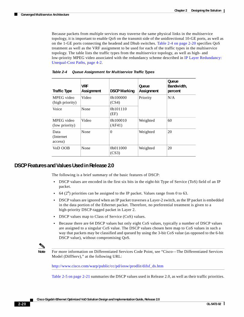
Chapter 2 Designing the SolutionConverged Multiservice Architecture
Because packets from multiple services may traverse the same physical links in the multiservice topology, it is important to enable QoS on the transmit side of the unidirectional 10-GE ports, as well as on the 1-GE ports connecting the headend and Dhub switches. Table 2-4 on page 2-20 specifies QoS treatment as well as the VRF assignment to be used for each of the traffic types in the multiservice topology. The table lists the traffic types from the multiservice topology, as well as high- and low-priority MPEG video associated with the redundancy scheme described in IP Layer Redundancy: Unequal-Cost Paths, page 4-2.
DSCP Features and Values Used in Release 2.0
The following is a brief summary of the basic features of DSCP:
• DSCP values are encoded in the first six bits in the eight-bit Type of Service (ToS) field of an IP packet.
• 64 (26) priorities can be assigned to the IP packet. Values range from 0 to 63.
• DSCP values are ignored when an IP packet traverses a Layer-2 switch, as the IP packet is embedded in the data portion of the Ethernet packet. Therefore, no preferential treatment is given to a high-priority DSCP-tagged packet in Layer 2.
• DSCP values map to Class of Service (CoS) values.
• Because there are 64 DSCP values but only eight CoS values, typically a number of DSCP values are assigned to a singular CoS value. The DSCP values chosen here map to CoS values in such a way that packets may be classified and queued by using the 3-bit CoS value (as opposed to the 6-bit DSCP value), without compromising QoS.
Note For more information on Differentiated Services Code Point, see “Cisco—The Differentiated Services Model (DiffServ),” at the following URL:
http://www.cisco.com/warp/public/cc/pd/iosw/prodlit/difsf_ds.htm
Table 2-5 on page 2-21 summaries the DSCP values used in Release 2.0, as well as their traffic priorities.
Table 2-4 Queue Assignment for Multiservice Traffic Types
Traffic TypeVRF Assignment DSCP Marking
Queue Assignment
Queue Bandwidth, percent
MPEG video(high priority)
Video 0b100000(CS4)
Priority N/A
Voice None 0b101110(EF)
MPEG video(low priority)
Video 0b100010(AF41)
Weighted 60
Data(Internet access)
None 0 Weighted 20
VoD OOB None 0b011000(CS3)
Weighted 20
2-20Cisco Gigabit-Ethernet Optimized VoD Solution Design and Implementation Guide, Release 2.0
OL-5472-02
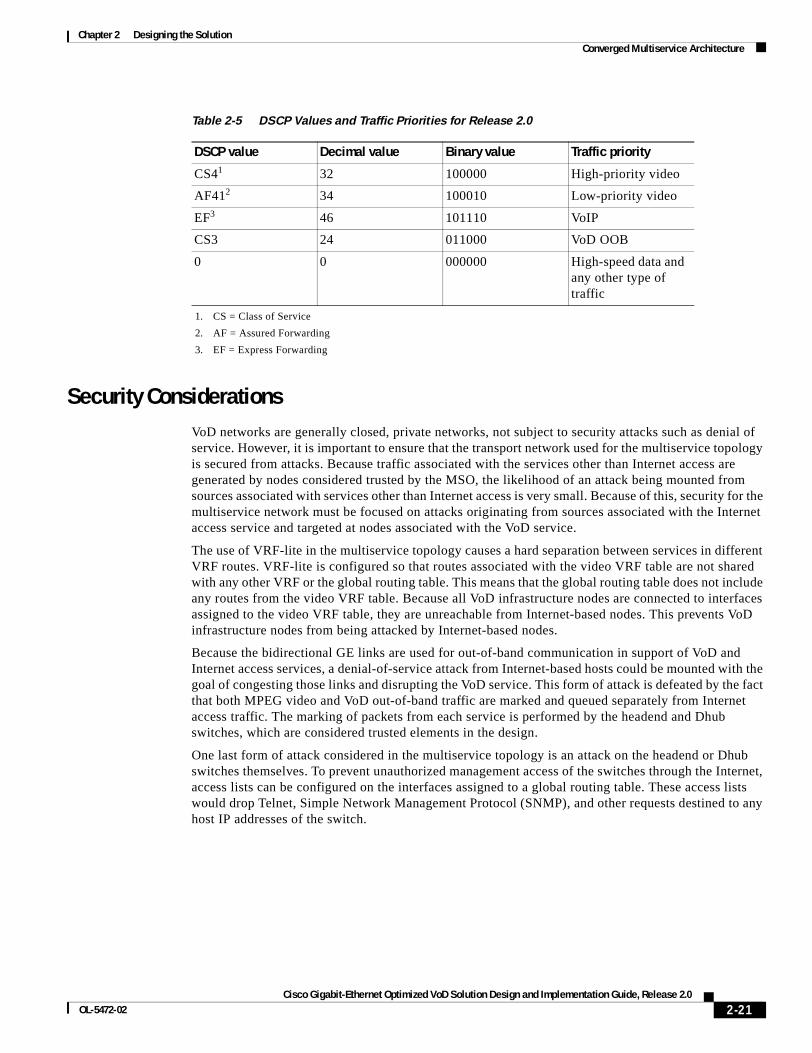
Chapter 2 Designing the SolutionConverged Multiservice Architecture
Security ConsiderationsVoD networks are generally closed, private networks, not subject to security attacks such as denial of service. However, it is important to ensure that the transport network used for the multiservice topology is secured from attacks. Because traffic associated with the services other than Internet access are generated by nodes considered trusted by the MSO, the likelihood of an attack being mounted from sources associated with services other than Internet access is very small. Because of this, security for the multiservice network must be focused on attacks originating from sources associated with the Internet access service and targeted at nodes associated with the VoD service.
The use of VRF-lite in the multiservice topology causes a hard separation between services in different VRF routes. VRF-lite is configured so that routes associated with the video VRF table are not shared with any other VRF or the global routing table. This means that the global routing table does not include any routes from the video VRF table. Because all VoD infrastructure nodes are connected to interfaces assigned to the video VRF table, they are unreachable from Internet-based nodes. This prevents VoD infrastructure nodes from being attacked by Internet-based nodes.
Because the bidirectional GE links are used for out-of-band communication in support of VoD and Internet access services, a denial-of-service attack from Internet-based hosts could be mounted with the goal of congesting those links and disrupting the VoD service. This form of attack is defeated by the fact that both MPEG video and VoD out-of-band traffic are marked and queued separately from Internet access traffic. The marking of packets from each service is performed by the headend and Dhub switches, which are considered trusted elements in the design.
One last form of attack considered in the multiservice topology is an attack on the headend or Dhub switches themselves. To prevent unauthorized management access of the switches through the Internet, access lists can be configured on the interfaces assigned to a global routing table. These access lists would drop Telnet, Simple Network Management Protocol (SNMP), and other requests destined to any host IP addresses of the switch.
Table 2-5 DSCP Values and Traffic Priorities for Release 2.0
DSCP value Decimal value Binary value Traffic priority
CS41
1. CS = Class of Service
32 100000 High-priority video
AF412
2. AF = Assured Forwarding
34 100010 Low-priority video
EF3
3. EF = Express Forwarding
46 101110 VoIP
CS3 24 011000 VoD OOB
0 0 000000 High-speed data and any other type of traffic
2-21Cisco Gigabit-Ethernet Optimized VoD Solution Design and Implementation Guide, Release 2.0
OL-5472-02
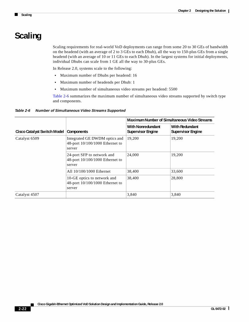
Chapter 2 Designing the SolutionScaling
ScalingScaling requirements for real-world VoD deployments can range from some 20 to 30 GEs of bandwidth on the headend (with an average of 2 to 3 GEs to each Dhub), all the way to 150-plus GEs from a single headend (with an average of 10 or 11 GEs to each Dhub). In the largest systems for initial deployments, individual Dhubs can scale from 1 GE all the way to 30-plus GEs.
In Release 2.0, systems scale to the following:
• Maximum number of Dhubs per headend: 16
• Maximum number of headends per Dhub: 1
• Maximum number of simultaneous video streams per headend: 5500
Table 2-6 summarizes the maximum number of simultaneous video streams supported by switch type and components.
Table 2-6 Number of Simultaneous Video Streams Supported
Cisco Catalyst Switch Model Components
Maximum Number of Simultaneous Video Streams
With Nonredundant Supervisor Engine
With Redundant Supervisor Engine
Catalyst 6509 Integrated GE DWDM optics and 48-port 10/100/1000 Ethernet to server
19,200 19,200
24-port SFP to network and 48-port 10/100/1000 Ethernet to server
24,000 19,200
All 10/100/1000 Ethernet 38,400 33,600
10-GE optics to network and 48-port 10/100/1000 Ethernet to server
38,400 28,800
Catalyst 4507 3,840 3,840
2-22Cisco Gigabit-Ethernet Optimized VoD Solution Design and Implementation Guide, Release 2.0
OL-5472-02
Cisco Gigabit-Ethernet Optimized VoD Solution DesignOL-5472-02
C H A P T E R 3
Implementing and Configuring the SolutionThis chapter presents the following major tasks:
• Configuring a Point-to-Point and Multihop Ethernet Topology, page 3-1
• Implementing Optics, page 3-42
• Implementing and Configuring Cisco Video Gateways, page 3-43
Configuring a Point-to-Point and Multihop Ethernet TopologyThis section addresses the following:
• Configuring the Headend
• Configuring Dhub A
• Configuring Dhub B
• Configuring Dhub C
Figure 3-1 on page 3-2 illustrates the point-to-point and multihop Ethernet topology discussed in this section. Table 3-1 on page 3-3 lists the loopback and VLAN IP addresses for the headend, Dhub, and QAM switches.
3-1 and Implementation Guide, Release 2.0

Chapter 3 Implementing and Configuring the SolutionConfiguring a Point-to-Point and Multihop Ethernet Topology
Figure 3-1 Example Point-to-Point and Multihop Topology
HeadendCisco 7609
DHub_Sw_ACatalyst 6509
UDL1
BD
L2
192.168.168.5/30
1/17/1
Tunnel1
192.168.168.6/30
192.168.169.10/30
192.168.168.14/30
192.168.168.10/30
192.168.168.9/30
BDL3
UDL3
Tunnel3
192.168.169.9/30
192.168.168.13/30
BDL13/12/15
192.168.168.1/30 192.168.168.2/30
DHub_Sw_BCatalyst 6509
DHub_Sw_CCatalyst 6509
3/2
3/2
BD
L4
3/3
3/3
3/1
1/1
2/16
7/3
VLAN 50
192.168.160.17/30 3/8
192.168.160.1/283/7
QAM_Sw_ACatalyst 4507
4/14
uMG9850
192.168.160.3
VLAN 160
uMG9820
Dhub A
Dhub B
HeadendHeadend
Dhub C
192.168.160.18BDL53
VLAN 160 4/17
192.168.50.111Concurrent
3/37BDL6
VLAN 50
192.168.50.120SeaChange
3/38BDL7
3/4BDL42
192.168.168.17/30
4/44
BDL44VLAN 164
192.168.161.17/30 3/8
QAM_Sw_BCatalyst 4507
uMG9850
192.168.161.3VLAN 161
uMG9820
192.168.161.18BDL56
5/17
3/4BDL43
192.168.168.21/30
192.168.162.17/304/3
192.168.162.1/294/1
QAM_Sw_CCatalyst 4507
BDL57
6/13uMG9850
192.168.162.3
VLAN 162
uMG9820
192.168.162.18BDL59
VLAN 1626/17
4/46BDL48
VLAN 165
2/9
BDL32VLAN 65
2/10
BDL33
High-speed data
VLAN 65
VoIPVLAN 66
VLAN 66
3/1
BDL34
3/2BDL35
1 GE
BDL VoDUDL VoD
BDL non-VoD
10 GE
Tunnel
VLAN 50
192.168.50.116Concurrent
3/39BDL8
VLAN 1690VLAN 1690
VLAN 16941/1
3/8BDL52
VoD OOB
VLAN 67
VLAN 1664/48
BDL55
Link Types
VLAN 16941/1
Tun
nel2
UD
L2
3/6 3/1
VLAN 160
PortChannel1
192.168.161.1/28
3/6 3/2 VLAN 161
3/7 5/14 VLAN 161
PortChannel2
192.168.65.100
192.168.65.101
192.168.66.100
192.168.66.101
VoIP
192.168.67.100
High-speed data
192.168.168.18
High-speed data
192.168.168.22
VoIP
192.168.164.100
VoD OOB
192.168.166.100
VoIP
192.168.165.100
1215
01
BDL52
BDL51
BDL54
BDL55
BDL52
BDL51
BDL54
BDL55
3-2Cisco Gigabit-Ethernet Optimized VoD Solution Design and Implementation Guide, Release 2.0
OL-5472-02
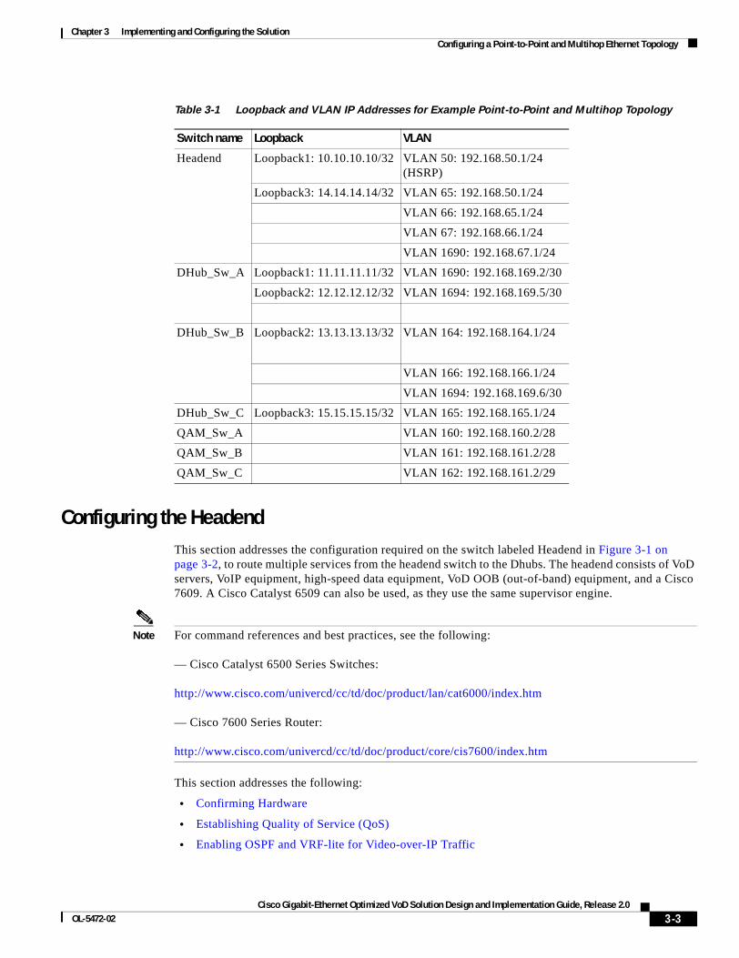
Chapter 3 Implementing and Configuring the SolutionConfiguring a Point-to-Point and Multihop Ethernet Topology
Configuring the HeadendThis section addresses the configuration required on the switch labeled Headend in Figure 3-1 on page 3-2, to route multiple services from the headend switch to the Dhubs. The headend consists of VoD servers, VoIP equipment, high-speed data equipment, VoD OOB (out-of-band) equipment, and a Cisco 7609. A Cisco Catalyst 6509 can also be used, as they use the same supervisor engine.
Note For command references and best practices, see the following:
— Cisco Catalyst 6500 Series Switches:
http://www.cisco.com/univercd/cc/td/doc/product/lan/cat6000/index.htm
— Cisco 7600 Series Router:
http://www.cisco.com/univercd/cc/td/doc/product/core/cis7600/index.htm
This section addresses the following:
• Confirming Hardware
• Establishing Quality of Service (QoS)
• Enabling OSPF and VRF-lite for Video-over-IP Traffic
Table 3-1 Loopback and VLAN IP Addresses for Example Point-to-Point and Multihop Topology
Switch name Loopback VLAN
Headend Loopback1: 10.10.10.10/32 VLAN 50: 192.168.50.1/24 (HSRP)
Loopback3: 14.14.14.14/32 VLAN 65: 192.168.50.1/24
VLAN 66: 192.168.65.1/24
VLAN 67: 192.168.66.1/24
VLAN 1690: 192.168.67.1/24
DHub_Sw_A Loopback1: 11.11.11.11/32 VLAN 1690: 192.168.169.2/30
Loopback2: 12.12.12.12/32 VLAN 1694: 192.168.169.5/30
DHub_Sw_B Loopback2: 13.13.13.13/32 VLAN 164: 192.168.164.1/24
VLAN 166: 192.168.166.1/24
VLAN 1694: 192.168.169.6/30
DHub_Sw_C Loopback3: 15.15.15.15/32 VLAN 165: 192.168.165.1/24
QAM_Sw_A VLAN 160: 192.168.160.2/28
QAM_Sw_B VLAN 161: 192.168.161.2/28
QAM_Sw_C VLAN 162: 192.168.161.2/29
3-3Cisco Gigabit-Ethernet Optimized VoD Solution Design and Implementation Guide, Release 2.0
OL-5472-02
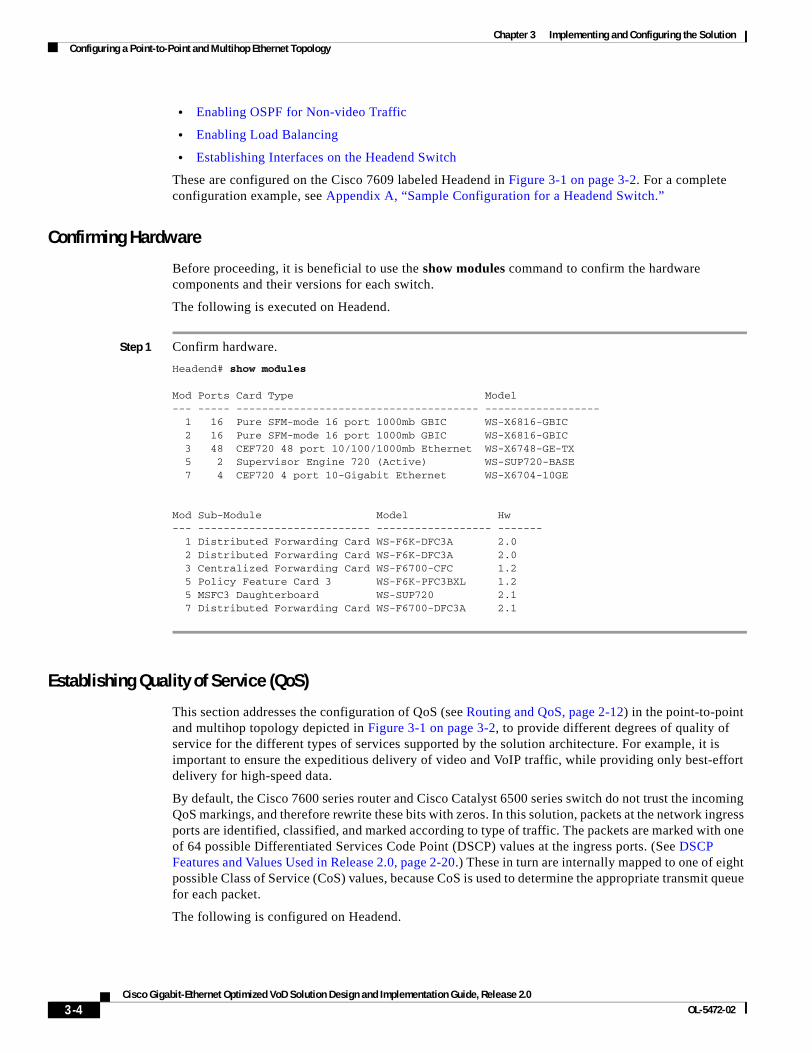
Chapter 3 Implementing and Configuring the SolutionConfiguring a Point-to-Point and Multihop Ethernet Topology
• Enabling OSPF for Non-video Traffic
• Enabling Load Balancing
• Establishing Interfaces on the Headend Switch
These are configured on the Cisco 7609 labeled Headend in Figure 3-1 on page 3-2. For a complete configuration example, see Appendix A, “Sample Configuration for a Headend Switch.”
Confirming Hardware
Before proceeding, it is beneficial to use the show modules command to confirm the hardware components and their versions for each switch.
The following is executed on Headend.
Step 1 Confirm hardware.
Headend# show modules Mod Ports Card Type Model --- ----- -------------------------------------- ------------------ 1 16 Pure SFM-mode 16 port 1000mb GBIC WS-X6816-GBIC 2 16 Pure SFM-mode 16 port 1000mb GBIC WS-X6816-GBIC 3 48 CEF720 48 port 10/100/1000mb Ethernet WS-X6748-GE-TX 5 2 Supervisor Engine 720 (Active) WS-SUP720-BASE 7 4 CEF720 4 port 10-Gigabit Ethernet WS-X6704-10GE
Mod Sub-Module Model Hw --- --------------------------- ------------------ ------- 1 Distributed Forwarding Card WS-F6K-DFC3A 2.0 2 Distributed Forwarding Card WS-F6K-DFC3A 2.0 3 Centralized Forwarding Card WS-F6700-CFC 1.2 5 Policy Feature Card 3 WS-F6K-PFC3BXL 1.2 5 MSFC3 Daughterboard WS-SUP720 2.1 7 Distributed Forwarding Card WS-F6700-DFC3A 2.1
Establishing Quality of Service (QoS)
This section addresses the configuration of QoS (see Routing and QoS, page 2-12) in the point-to-point and multihop topology depicted in Figure 3-1 on page 3-2, to provide different degrees of quality of service for the different types of services supported by the solution architecture. For example, it is important to ensure the expeditious delivery of video and VoIP traffic, while providing only best-effort delivery for high-speed data.
By default, the Cisco 7600 series router and Cisco Catalyst 6500 series switch do not trust the incoming QoS markings, and therefore rewrite these bits with zeros. In this solution, packets at the network ingress ports are identified, classified, and marked according to type of traffic. The packets are marked with one of 64 possible Differentiated Services Code Point (DSCP) values at the ingress ports. (See DSCP Features and Values Used in Release 2.0, page 2-20.) These in turn are internally mapped to one of eight possible Class of Service (CoS) values, because CoS is used to determine the appropriate transmit queue for each packet.
The following is configured on Headend.
3-4Cisco Gigabit-Ethernet Optimized VoD Solution Design and Implementation Guide, Release 2.0
OL-5472-02
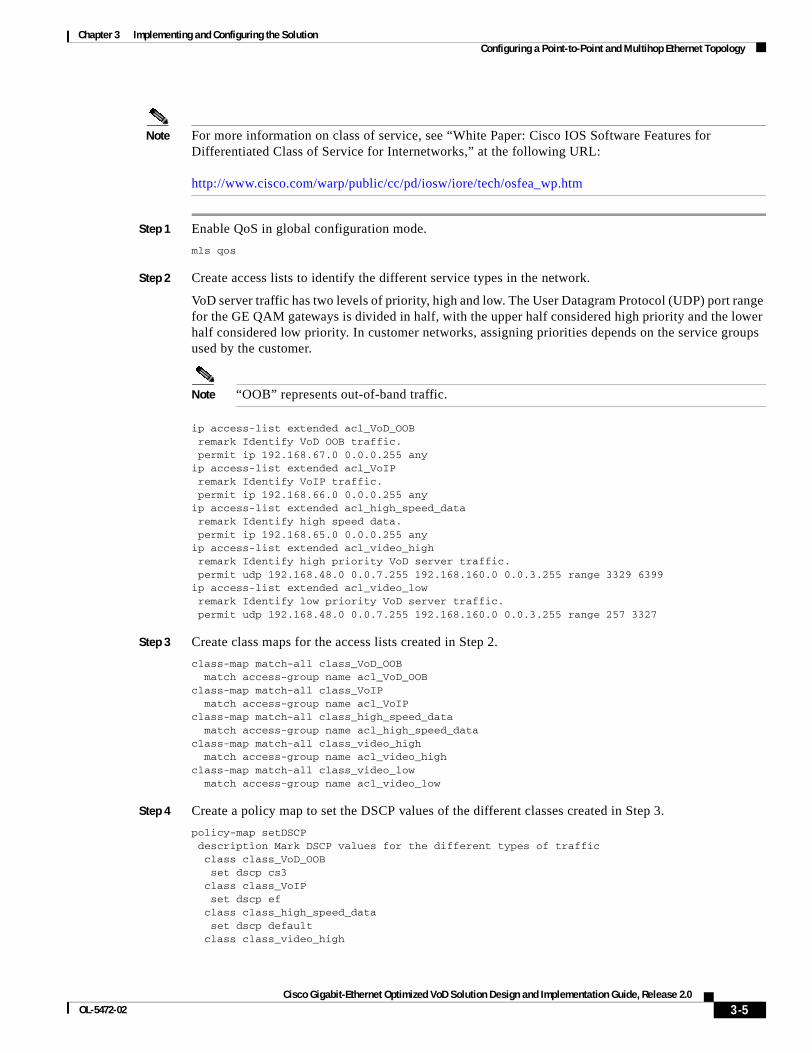
Chapter 3 Implementing and Configuring the SolutionConfiguring a Point-to-Point and Multihop Ethernet Topology
Note For more information on class of service, see “White Paper: Cisco IOS Software Features for Differentiated Class of Service for Internetworks,” at the following URL:
http://www.cisco.com/warp/public/cc/pd/iosw/iore/tech/osfea_wp.htm
Step 1 Enable QoS in global configuration mode.
mls qos
Step 2 Create access lists to identify the different service types in the network.
VoD server traffic has two levels of priority, high and low. The User Datagram Protocol (UDP) port range for the GE QAM gateways is divided in half, with the upper half considered high priority and the lower half considered low priority. In customer networks, assigning priorities depends on the service groups used by the customer.
Note “OOB” represents out-of-band traffic.
ip access-list extended acl_VoD_OOBremark Identify VoD OOB traffic.permit ip 192.168.67.0 0.0.0.255 any
ip access-list extended acl_VoIPremark Identify VoIP traffic.permit ip 192.168.66.0 0.0.0.255 any
ip access-list extended acl_high_speed_dataremark Identify high speed data.permit ip 192.168.65.0 0.0.0.255 any
ip access-list extended acl_video_highremark Identify high priority VoD server traffic.permit udp 192.168.48.0 0.0.7.255 192.168.160.0 0.0.3.255 range 3329 6399
ip access-list extended acl_video_lowremark Identify low priority VoD server traffic.permit udp 192.168.48.0 0.0.7.255 192.168.160.0 0.0.3.255 range 257 3327
Step 3 Create class maps for the access lists created in Step 2.
class-map match-all class_VoD_OOB match access-group name acl_VoD_OOBclass-map match-all class_VoIP match access-group name acl_VoIPclass-map match-all class_high_speed_data match access-group name acl_high_speed_dataclass-map match-all class_video_high match access-group name acl_video_highclass-map match-all class_video_low match access-group name acl_video_low
Step 4 Create a policy map to set the DSCP values of the different classes created in Step 3.
policy-map setDSCP description Mark DSCP values for the different types of traffic class class_VoD_OOB set dscp cs3 class class_VoIP set dscp ef class class_high_speed_data set dscp default class class_video_high
3-5Cisco Gigabit-Ethernet Optimized VoD Solution Design and Implementation Guide, Release 2.0
OL-5472-02
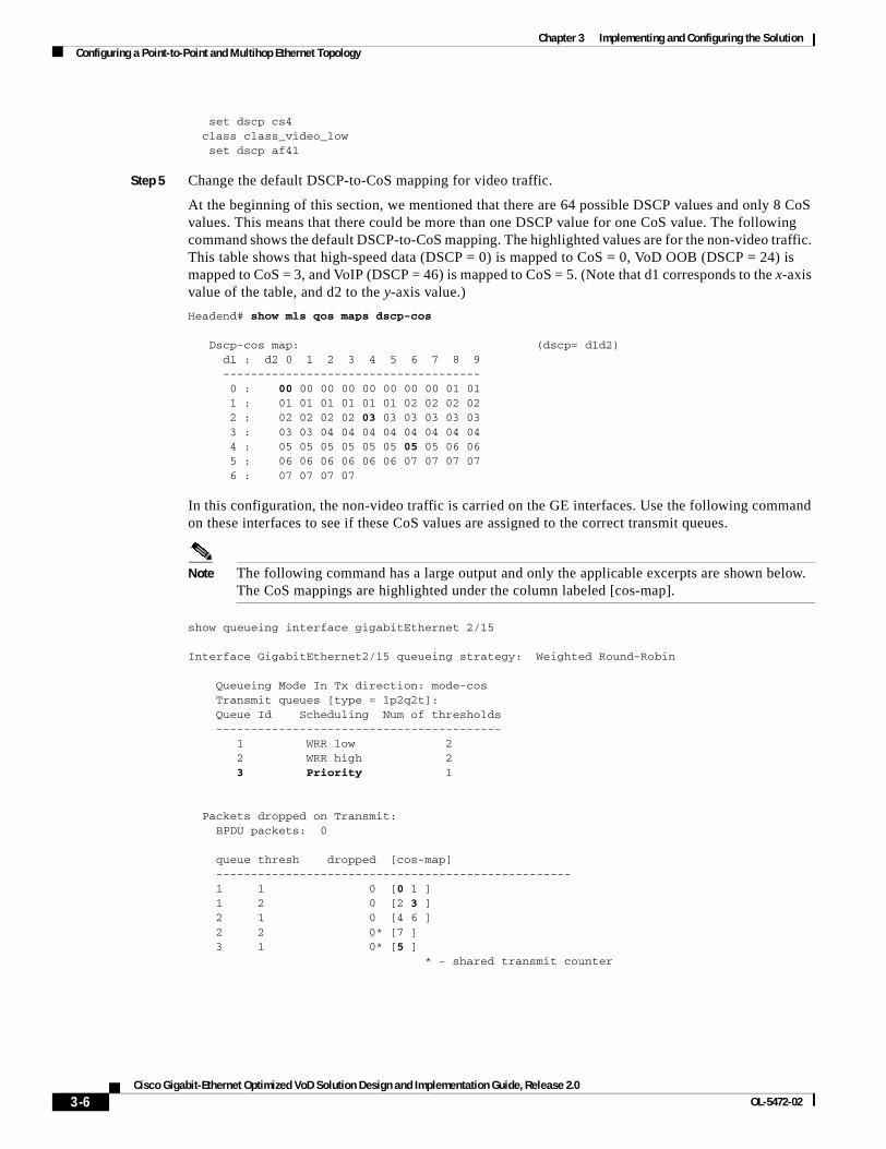
Chapter 3 Implementing and Configuring the SolutionConfiguring a Point-to-Point and Multihop Ethernet Topology
set dscp cs4 class class_video_low set dscp af41
Step 5 Change the default DSCP-to-CoS mapping for video traffic.
At the beginning of this section, we mentioned that there are 64 possible DSCP values and only 8 CoS values. This means that there could be more than one DSCP value for one CoS value. The following command shows the default DSCP-to-CoS mapping. The highlighted values are for the non-video traffic. This table shows that high-speed data (DSCP = 0) is mapped to CoS = 0, VoD OOB (DSCP = 24) is mapped to CoS = 3, and VoIP (DSCP = 46) is mapped to CoS = 5. (Note that d1 corresponds to the x-axis value of the table, and d2 to the y-axis value.)
Headend# show mls qos maps dscp-cos
Dscp-cos map: (dscp= d1d2) d1 : d2 0 1 2 3 4 5 6 7 8 9 ------------------------------------- 0 : 00 00 00 00 00 00 00 00 01 01 1 : 01 01 01 01 01 01 02 02 02 02 2 : 02 02 02 02 03 03 03 03 03 03 3 : 03 03 04 04 04 04 04 04 04 04 4 : 05 05 05 05 05 05 05 05 06 06 5 : 06 06 06 06 06 06 07 07 07 07 6 : 07 07 07 07
In this configuration, the non-video traffic is carried on the GE interfaces. Use the following command on these interfaces to see if these CoS values are assigned to the correct transmit queues.
Note The following command has a large output and only the applicable excerpts are shown below. The CoS mappings are highlighted under the column labeled [cos-map].
show queueing interface gigabitEthernet 2/15
Interface GigabitEthernet2/15 queueing strategy: Weighted Round-Robin Queueing Mode In Tx direction: mode-cos Transmit queues [type = 1p2q2t]: Queue Id Scheduling Num of thresholds ----------------------------------------- 1 WRR low 2 2 WRR high 2 3 Priority 1
Packets dropped on Transmit: BPDU packets: 0
queue thresh dropped [cos-map] --------------------------------------------------- 1 1 0 [0 1 ] 1 2 0 [2 3 ] 2 1 0 [4 6 ] 2 2 0* [7 ] 3 1 0* [5 ] * - shared transmit counter
3-6Cisco Gigabit-Ethernet Optimized VoD Solution Design and Implementation Guide, Release 2.0
OL-5472-02
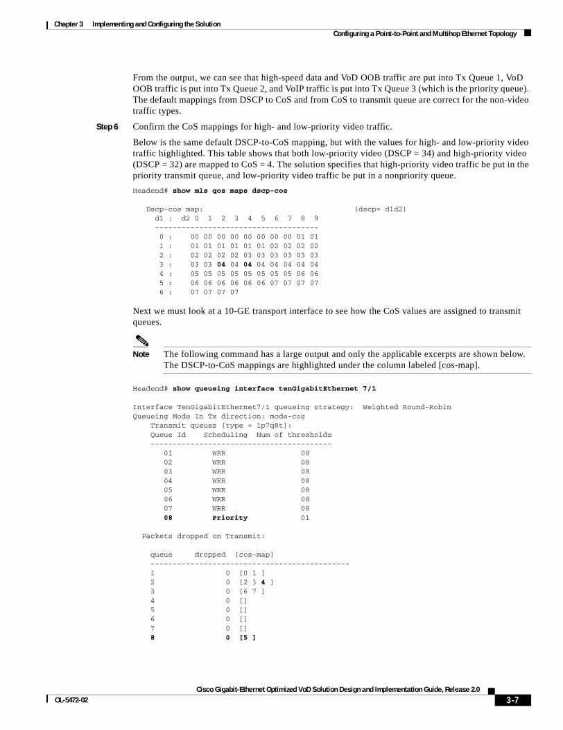
Chapter 3 Implementing and Configuring the SolutionConfiguring a Point-to-Point and Multihop Ethernet Topology
From the output, we can see that high-speed data and VoD OOB traffic are put into Tx Queue 1, VoD OOB traffic is put into Tx Queue 2, and VoIP traffic is put into Tx Queue 3 (which is the priority queue). The default mappings from DSCP to CoS and from CoS to transmit queue are correct for the non-video traffic types.
Step 6 Confirm the CoS mappings for high- and low-priority video traffic.
Below is the same default DSCP-to-CoS mapping, but with the values for high- and low-priority video traffic highlighted. This table shows that both low-priority video (DSCP = 34) and high-priority video (DSCP = 32) are mapped to CoS = 4. The solution specifies that high-priority video traffic be put in the priority transmit queue, and low-priority video traffic be put in a nonpriority queue.
Headend# show mls qos maps dscp-cos
Dscp-cos map: (dscp= d1d2) d1 : d2 0 1 2 3 4 5 6 7 8 9 ------------------------------------- 0 : 00 00 00 00 00 00 00 00 01 01 1 : 01 01 01 01 01 01 02 02 02 02 2 : 02 02 02 02 03 03 03 03 03 03 3 : 03 03 04 04 04 04 04 04 04 04 4 : 05 05 05 05 05 05 05 05 06 06 5 : 06 06 06 06 06 06 07 07 07 07 6 : 07 07 07 07
Next we must look at a 10-GE transport interface to see how the CoS values are assigned to transmit queues.
Note The following command has a large output and only the applicable excerpts are shown below. The DSCP-to-CoS mappings are highlighted under the column labeled [cos-map].
Headend# show queueing interface tenGigabitEthernet 7/1
Interface TenGigabitEthernet7/1 queueing strategy: Weighted Round-RobinQueueing Mode In Tx direction: mode-cos Transmit queues [type = 1p7q8t]: Queue Id Scheduling Num of thresholds ----------------------------------------- 01 WRR 08 02 WRR 08 03 WRR 08 04 WRR 08 05 WRR 08 06 WRR 08 07 WRR 08 08 Priority 01
Packets dropped on Transmit:
queue dropped [cos-map] --------------------------------------------- 1 0 [0 1 ] 2 0 [2 3 4 ] 3 0 [6 7 ] 4 0 [] 5 0 [] 6 0 [] 7 0 [] 8 0 [5 ]
3-7Cisco Gigabit-Ethernet Optimized VoD Solution Design and Implementation Guide, Release 2.0
OL-5472-02
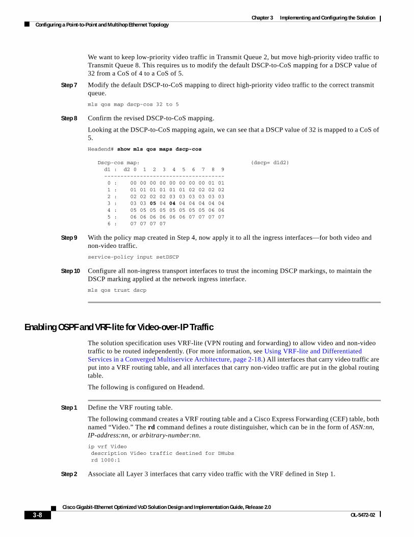
Chapter 3 Implementing and Configuring the SolutionConfiguring a Point-to-Point and Multihop Ethernet Topology
We want to keep low-priority video traffic in Transmit Queue 2, but move high-priority video traffic to Transmit Queue 8. This requires us to modify the default DSCP-to-CoS mapping for a DSCP value of 32 from a CoS of 4 to a CoS of 5.
Step 7 Modify the default DSCP-to-CoS mapping to direct high-priority video traffic to the correct transmit queue.
mls qos map dscp-cos 32 to 5
Step 8 Confirm the revised DSCP-to-CoS mapping.
Looking at the DSCP-to-CoS mapping again, we can see that a DSCP value of 32 is mapped to a CoS of 5.
Headend# show mls qos maps dscp-cos
Dscp-cos map: (dscp= d1d2) d1 : d2 0 1 2 3 4 5 6 7 8 9 ------------------------------------- 0 : 00 00 00 00 00 00 00 00 01 01 1 : 01 01 01 01 01 01 02 02 02 02 2 : 02 02 02 02 03 03 03 03 03 03 3 : 03 03 05 04 04 04 04 04 04 04 4 : 05 05 05 05 05 05 05 05 06 06 5 : 06 06 06 06 06 06 07 07 07 07 6 : 07 07 07 07
Step 9 With the policy map created in Step 4, now apply it to all the ingress interfaces—for both video and non-video traffic.
service-policy input setDSCP
Step 10 Configure all non-ingress transport interfaces to trust the incoming DSCP markings, to maintain the DSCP marking applied at the network ingress interface.
mls qos trust dscp
Enabling OSPF and VRF-lite for Video-over-IP Traffic
The solution specification uses VRF-lite (VPN routing and forwarding) to allow video and non-video traffic to be routed independently. (For more information, see Using VRF-lite and Differentiated Services in a Converged Multiservice Architecture, page 2-18.) All interfaces that carry video traffic are put into a VRF routing table, and all interfaces that carry non-video traffic are put in the global routing table.
The following is configured on Headend.
Step 1 Define the VRF routing table.
The following command creates a VRF routing table and a Cisco Express Forwarding (CEF) table, both named “Video.” The rd command defines a route distinguisher, which can be in the form of ASN:nn, IP-address:nn, or arbitrary-number:nn.
ip vrf Video description Video traffic destined for DHubs rd 1000:1
Step 2 Associate all Layer 3 interfaces that carry video traffic with the VRF defined in Step 1.
3-8Cisco Gigabit-Ethernet Optimized VoD Solution Design and Implementation Guide, Release 2.0
OL-5472-02
Chapter 3 Implementing and Configuring the SolutionConfiguring a Point-to-Point and Multihop Ethernet Topology
For Headend, this includes VLANs 50 and 1690, and TenGigabitEthernet7/3. An interface cannot be assigned to both the “Video” VRF routing table and the global routing table at the same time.
Caution Be aware that executing this command on an interface removes the IP address if it was previously configured.
ip vrf forwarding Video
Step 3 Create the OSPF process and associate it with the VRF routing table defined in Step 1.
The router ospf 100 vrf Video command associates the “Video” VRF routing table with OSPF routing process 100. Because the solution does not use Border Gateway Protocol (BGP), the capability vrf-lite command is used to suppress specific checks on the switch when the OSPF process is associated with the VRF routing table. The network statements should include all interfaces that carry video traffic. This includes all VoD server ingress ports and the transport interfaces to the Dhubs.
router ospf 100 vrf Videolog-adjacency-changescapability vrf-litenetwork 192.168.50.0 0.0.0.255 area 0network 192.168.169.0 0.0.0.3 area 0network 192.168.169.8 0.0.0.3 area 0network 192.168.169.32 0.0.0.3 area 0network 192.168.169.36 0.0.0.3 area 0
Note To configure passive interfaces in the OSPF process associated with the Video VRF table, include the passive-interface command in the global OSPF process.
Enabling OSPF for Non-video Traffic
The solution specification uses the global routing table for non-video traffic. All interfaces that carry non-video traffic are put into the global routing table. This includes VoIP ingress ports, VoD OOB ingress ports, high speed data ingress ports, the transport interfaces that carry this traffic and the loopback interfaces. The loopback interfaces serve as the endpoints for the GRE tunnels that are the bidirectional return paths for the unidirectional links between the headend and Dhubs.
The following is configured on Headend.
Step 1 Define a second OSPF routing process to carry non-video traffic.
router ospf 101 log-adjacency-changesnetwork 1.14.0.0 0.0.255.255 area 0
network 10.10.10.10 0.0.0.0 area 0 network 14.14.14.14 0.0.0.0 area 0 network 192.168.65.0 0.0.0.255 area 0 network 192.168.66.0 0.0.0.255 area 0 network 192.168.67.0 0.0.0.255 area 0 network 192.168.168.0 0.0.0.3 area 0 network 192.168.168.12 0.0.0.3 area 0
3-9Cisco Gigabit-Ethernet Optimized VoD Solution Design and Implementation Guide, Release 2.0
OL-5472-02
Chapter 3 Implementing and Configuring the SolutionConfiguring a Point-to-Point and Multihop Ethernet Topology
Note To configure passive interfaces in the OSPF process associated with the Video VRF, include the passive-interface command in the global OSPF process.
Enabling Load Balancing
If multiple 10-GE links are required between the headend and a Dhub, caution should be taken when configuring load balancing. Simulations and lab tests have shown that the Cisco IOS Release 12.2.17d-SXB1 for the Cisco Catalyst 6500 series switches and the Cisco 7609 (both of which use Supervisor Engine 720) does not provide acceptable Layer 3 CEF load balancing of VoD server traffic across 2 through 8 equal-cost paths. For this reason, EtherChannel load balancing is recommended over Layer 3 CEF load balancing.
Although EtherChannels can be configured with up to 8 members, only sizes of 2, 4, or 8 members should be configured. These are the only size EtherChannels that provide acceptable load balancing for the VoD server traffic. The default EtherChannel load balancing must be modified to achieve the desired results. By default, the Layer 4 ports are not included in the algorithm, and so we require the destination Layer 4 port to be included in the algorithm by using the following command:
port-channel load-balance dst-port
Establishing Interfaces on the Headend Switch
This section addresses the following:
• Establishing a VLAN for VoD Server Traffic
• Establishing GE Interfaces for the VoD Servers
• Establishing VLANs for VoIP, High-Speed Data, and VoD OOB Traffic
• Establishing GE Interfaces for VoIP, High-Speed Data, and VoD OOB Traffic
• Establishing Bidirectional 1-GE Links to the Dhubs
• Establishing Unidirectional 10-GE Links to the Dhubs
• Establishing GRE Tunnels to the Dhubs
Establishing a VLAN for VoD Server Traffic
The VoD servers connect to Layer 2 interfaces on the headend switch and their traffic is aggregated into a VLAN. The following steps detail the configuration of the VLAN.
The following is configured on Headend.
Step 1 In global configuration mode, add the VLAN to the VLAN database.
vlan 50
Step 2 Create the VLAN interface.
interface Vlan50description VoD servers
3-10Cisco Gigabit-Ethernet Optimized VoD Solution Design and Implementation Guide, Release 2.0
OL-5472-02
Chapter 3 Implementing and Configuring the SolutionConfiguring a Point-to-Point and Multihop Ethernet Topology
Step 3 Disable the sending of Internet Control Message Protocol (ICMP) protocol-unreachable and host-unreachable messages. When enabled, host-unreachable messages are sent from the VLAN to the VoD server if the VLAN is unable to deliver packets to the ultimate destination—because it knows of no route to the destination address.
no ip unreachables
Step 4 Associate the VLAN with the Video VRF. (See Using VRF-lite and Differentiated Services in a Converged Multiservice Architecture, page 2-18.)
ip vrf forwarding Video
Step 5 Assign the VLAN a virtual IP address and virtual MAC address using Hot Standby Routing Protocol (HSRP). The ip address 192.168.50.2 255.255.255.0 command assigns a physical IP address to the VLAN, and the MAC address is the burned-in address. The standby 50 ip 192.168.50.1 command assigns a virtual IP address of 192.168.50.1 and a virtual MAC address of 0000.0c07.ac32 to the VLAN.
Caution Be sure to include a group number when using the standby command. Otherwise, the group number defaults to 0.
ip address 192.168.50.2 255.255.255.0standby 50 ip 192.168.50.1
Note The show interface vlan 50 command does not show the virtual IP and MAC addresses. You must use the show standby command to verify this information, as in the step below.
Step 6 Verify the virtual IP and MAC addresses.
Headend# show standbyVlan50 - Group 50 Local state is Active, priority 100 Hellotime 3 sec, holdtime 10 sec Next hello sent in 0.768 Virtual IP address is 192.168.50.1 configured Active router is local Standby router is unknown Virtual mac address is 0000.0c07.ac32 2 state changes, last state change 2w2d IP redundancy name is "hsrp-Vl50-50" (default)
Establishing GE Interfaces for the VoD Servers
The VoD servers connect to Layer 2 interfaces on the headend switch and their traffic is aggregated into a VLAN. The following steps detail the configuration of the GigabitEthernet 3/37 Layer 2 interface. GigabitEthernet 3/38 and 3/39 are configured similarly.
The following is configured on Headend.
Step 1 Create the Layer 2 interface and assign it to VLAN 50.
interface GigabitEthernet3/37description BDL6: Concurrent VoD server ingress (MH-4000-1)no ip addressswitchport
3-11Cisco Gigabit-Ethernet Optimized VoD Solution Design and Implementation Guide, Release 2.0
OL-5472-02
Chapter 3 Implementing and Configuring the SolutionConfiguring a Point-to-Point and Multihop Ethernet Topology
switchport access vlan 50switchport mode access
Step 2 If using 10/100/1000-Mbps ports, we recommend that the speed and duplex be forced to 1000 Mbps and full duplex, respectively.
speed 1000duplex full
Step 3 Disable the Cisco Discovery Protocol on the interface, because the VoD servers do not support it.
no cdp enable
Step 4 Enable PortFast on the interface to bypass the listening and learning states in Spanning Tree Protocol (STP). This allows the interface to move immediately from the blocking state to the forwarding state, rather than waiting for STP to converge.
spanning-tree portfast
Step 5 Apply the “setDSCP” service policy that marks DSPC values in the inbound IP packets. (See DSCP Features and Values Used in Release 2.0, page 2-20.)
service-policy input setDSCP
Establishing VLANs for VoIP, High-Speed Data, and VoD OOB Traffic
In this configuration, Layer 2 interfaces and VLANs are used to connect the headend switch to resources for VoIP, high-speed data, and VoD OOB traffic. The following steps detail the configuration of a VLAN dedicated to high-speed data, VLAN 65. VLANs for VoIP (VLAN 66) and VoD OOB traffic (VLAN 67) are configured similarly.
Note Although Release 2.0 supports a multiservice architecture, interface configurations for VoIP, high-speed data, and VoD OOB equipment are beyond the scope of this solution. Vendor- and equipment-specific resources should be used to configure these interfaces properly.
Step 1 In global configuration mode, add the VLAN to the VLAN database.
vlan 65
Step 2 Create the VLAN interfaces.
interface Vlan65description High speed data
ip address 192.168.65.1 255.255.255.0
Establishing GE Interfaces for VoIP, High-Speed Data, and VoD OOB Traffic
The following steps detail the configuration of GigabitEthernet 2/9, which is the Layer 2 interface for high-speed data. GigabitEthernet 2/10, GigabitEthernet 3/1 and 3/2, and GigabitEthernet 3/8 and 3/9 are configured similarly.
The following is configured on Headend.
3-12Cisco Gigabit-Ethernet Optimized VoD Solution Design and Implementation Guide, Release 2.0
OL-5472-02
Chapter 3 Implementing and Configuring the SolutionConfiguring a Point-to-Point and Multihop Ethernet Topology
Step 1 Create the Layer 2 interface and assign it to VLAN 65.
interface GigabitEthernet2/9description BDL32: High speed data
no ip addressswitchportswitchport access vlan 65switchport mode access
Step 2 Disable CDP on the interface, because the VoD servers do not support it.
no cdp enable
Step 3 Enable PortFast on the interface to bypass the listening and learning states in STP. This allows the interface to move immediately from the blocking state to the forwarding state, rather than waiting for STP to converge.
spanning-tree portfast
Note This command should be used in conjunction with the global command spanning-tree portfast bpduguard default. The bpduguard command option configures the switch to disable any interface that is configured for PortFast and receives a Bridge Protocol Data Unit (BPDU). This guards against a user accidentally connecting a switch to a switchport that is intended for a VoD server or other host. The switchport is disabled and the user must investigate why the port is down. If this command is not used and such an accidental connection were to happen, STP could reconverge and block other connections in the switch.
Step 4 Apply the “setDSCP” service policy that marks DSPC values in the inbound IP packets. (See DSCP Features and Values Used in Release 2.0, page 2-20.)
service-policy input setDSCP
Establishing Bidirectional 1-GE Links to the Dhubs
In this example, there are two 1-GE connections between the headend and the Dhubs. One is from Headend to DHub_Sw_A, and the other is from Headend to DHub_Sw_C. These connections carry VoIP and high-speed data, as well as VoD OOB, OSPF, and Address Resolution Protocol (ARP) traffic. All traffic on these interfaces is part of the global routing table, except for the GRE tunnels that provide the return paths for the 10-GE unidirectional links. GigabitEthernet2/16 is configured similarly.
The following is configured on Headend.
Step 1 Configure the Layer 3 bidirectional 1-GE interface.
interface GigabitEthernet2/15description BDL1: Non-video traffic to/from DHub_Sw_A (Gig3/1)ip address 192.168.168.1 255.255.255.252
Step 2 Since the DSCP values are marked at the ingress interfaces, the DSCP values of the inbound IP packets can be trusted on the transport interfaces. By default, these DSCP values are not trusted and are written with zeros. The following command must be entered on the transport interfaces so that they trust and not write over the DSCP values of the inbound IP packets.
mls qos trust dscp
3-13Cisco Gigabit-Ethernet Optimized VoD Solution Design and Implementation Guide, Release 2.0
OL-5472-02
Chapter 3 Implementing and Configuring the SolutionConfiguring a Point-to-Point and Multihop Ethernet Topology
Establishing Unidirectional 10-GE Links to the Dhubs
In this example, there are two 10-GE unidirectional connections between the headend and Dhub switches. The first is a multihop connection from Headend to DHub_Sw_A and DHub_Sw_B. The second is a point-to-point connection between Headend and DHub_Sw_C.
The multihop connection uses a split-optics 10-GE interface on DHub_Sw_A; the receive side of the interface terminates the unidirectional connection from Headend, and the transmit side initiates a second unidirectional connection to DHub_Sw_B. To configure more than one unidirectional subnet on the split-optics interface, you must use two VLANs and a trunk. This requires a VLAN on the Headend side of the 10-GE connection.
The following is configured on Headend.
Step 1 In global configuration mode, add the VLAN to the VLAN database.
vlan 1690
Step 2 Turn off STP for the VLAN. This allows the interface to come up immediately as soon as the link is up.
no spanning-tree vlan 1690
Step 3 Create the VLAN interface.
interface Vlan1690description Video traffic to/from DHub_Sw_A
Step 4 Associate the VLAN with the Video VRF.
ip vrf forwarding Video
Step 5 Assign the interface an IP address.
ip address 192.168.169.1 255.255.255.252
Step 6 Disable the sending of ICMP protocol-unreachable and host-unreachable messages. When enabled, host-unreachable messages are sent from the VLAN to the source if the VLAN is unable to deliver packets to the ultimate destination—because it knows of no route to the destination address.
no ip unreachables
Now that VLAN 1960 has been created, the unidirectional 10-GE interface can be configured as a trunk, which carries traffic for that VLAN.
The following is configured on Headend.
Step 1 Create the Layer 2 trunk interface and assign it to VLAN 1690. Configure the trunk for 802.1Q encapsulation with no negotiation.
interface TenGigabitEthernet7/1description UDL1: Video traffic to DHub_Sw_A (TenGig1/1)no ip addressswitchportswitchport trunk encapsulation dot1qswitchport trunk allowed vlan 1690switchport mode trunkswitchport nonegotiate
3-14Cisco Gigabit-Ethernet Optimized VoD Solution Design and Implementation Guide, Release 2.0
OL-5472-02
Chapter 3 Implementing and Configuring the SolutionConfiguring a Point-to-Point and Multihop Ethernet Topology
Step 2 Configure the interface as a unidirectional send-only interface.
unidirectional send-only
Step 3 Turn off Weighted Random Early Discard (WRED) on Tx Queue 2. This enables tail drop in the event of oversubscription.
no wrr-queue random-detect 2
The configuration for this 10-GE link is less complex, because it is a point-to-point Layer 3 connection with no split optics.
Step 1 Configure the Layer 3 unidirectional interface between Headend and DHub_Sw_C, and associate it with the Video VRF.
interface TenGigabitEthernet7/3description UDL3: Video traffic to DHub_Sw_C (TenGig1/1)ip vrf forwarding Video
ip address 192.168.169.9 255.255.255.252
Step 2 Configure the interface as a unidirectional send-only interface.
unidirectional send-only
Step 3 Turn off Weighted Random Early Discard (WRED) on Tx Queue 2. This enables tail drop in the event of over-subscription.
no wrr-queue random-detect 2
Establishing GRE Tunnels to the Dhubs
In this example, two GRE tunnels are required between the headend and Dhub switches. The first is the return path for the multihop connection from Headend to DHub_Sw_A, and the second is the return path for the point-to-point connection between Headend and DHub_Sw_C. Loopback interfaces (rather than physical interfaces) are used as endpoints of the tunnels, because loopback interfaces never go down, and each tunnel requires its own unique set of endpoints.
The following establishes the first GRE tunnel. This is the receive path for the unidirectional 10-GE interface between Headend and DHub_Sw_A. This trunk interface is associated with VLAN 1690.
The following is configured on Headend.
Step 1 Create a loopback interface to serve as the tunnel endpoint on Headend.
interface Loopback1description Endpoint for Tunnel1ip address 10.10.10.10 255.255.255.255
Note For the tunnel to be established, the loopback interface must be advertised in the global OSPF routing process.
3-15Cisco Gigabit-Ethernet Optimized VoD Solution Design and Implementation Guide, Release 2.0
OL-5472-02
Chapter 3 Implementing and Configuring the SolutionConfiguring a Point-to-Point and Multihop Ethernet Topology
Step 2 Create the first tunnel interface. No IP address is required for the tunnel itself.
interface Tunnel1description Vlan1690 Rx from DHub_Sw_Ano ip address
Step 3 Configure the source and destination endpoints of the tunnel. The destination endpoint is on DHub_Sw_A.
tunnel source Loopback1tunnel destination 11.11.11.11
Step 4 Configure UDLR for the tunnel. This tunnel represents the receive side of VLAN 1690.
tunnel udlr receive-only Vlan1690
Step 5 Associate the VLAN with the Video VRF.
ip vrf forwarding Video
The following establishes the second tunnel. This is the receive path for the unidirectional 10-GE interface between Headend and DHub_Sw_C.
Step 1 Create a loopback interface to serve as the tunnel endpoint on Headend.
interface Loopback3description Endpoint for Tunnel3ip address 14.14.14.14 255.255.255.255
Note For the tunnel to be established, the loopback interface must be advertised in the global OSPF routing process.
Step 2 Create the second tunnel interface. No IP address is required for the tunnel itself.
interface Tunnel3description UDL3 Rx from DHub_Sw_Cno ip address
Step 3 Configure the source and destination endpoints of the tunnel. The destination endpoint is on DHub_Sw_C.
tunnel source Loopback3tunnel destination 15.15.15.15
Step 4 Configure UDLR for the tunnel. This tunnel represents the receive side of TenGigabitEthernet7/3.
tunnel udlr receive-only TenGigabitEthernet7/3
Step 5 Associate the VLAN with the Video VRF table.
ip vrf forwarding Video
3-16Cisco Gigabit-Ethernet Optimized VoD Solution Design and Implementation Guide, Release 2.0
OL-5472-02
Chapter 3 Implementing and Configuring the SolutionConfiguring a Point-to-Point and Multihop Ethernet Topology
Configuring Dhub ADhub A consists of a Dhub switch (DHub_Sw_A), a QAM switch (QAM_Sw_A) with Cisco uMG9850 modules, and Cisco uMG9820 gateways. Refer to Figure 3-1 on page 3-2.
This section addresses the following:
• Confirming Hardware
• Establishing Quality of Service (QoS)
• Enabling OSPF and VRF-lite for Video-over-IP Traffic
• Enabling OSPF and VRF-lite for Video-over-IP Traffic
• Enabling OSPF for Non-video Traffic
• Establishing Interfaces
For a complete configuration example, see DHub_Sw_A Configuration in Appendix B, “Sample Configurations for Dhub Switches.”
Confirming Hardware
Before proceeding, it is beneficial to use the show modules command to confirm the hardware components and their versions for each switch.
The following is executed on DHub_Sw_A.
Step 1 Confirm hardware.
DHub_Sw_A# show modules Mod Ports Card Type Model --- ----- -------------------------------------- ------------------ 1 4 CEF720 4 port 10-Gigabit Ethernet WS-X6704-10GE 3 8 8 port 1000mb GBIC Enhanced QoS WS-X6408A-GBIC 5 2 Supervisor Engine 720 (Active) WS-SUP720-BASE
Mod Sub-Module Model Hw --- --------------------------- ------------------ ------- 1 Distributed Forwarding Card WS-F6700-DFC3A 2.1 5 Policy Feature Card 3 WS-F6K-PFC3BXL 1.2 5 MSFC3 Daughterboard WS-SUP720 2.1
Establishing Quality of Service (QoS)
DHub_Sw_A receives traffic from Headend that has already been marked at the ingress points, so the transport ports on this Dhub switch are configured to trust the incoming DSCP values. This Dhub has a high-speed data ingress point, so the data entering here must be marked with the appropriate DSCP values.
The following is configured on DHub_Sw_A.
Step 1 In global configuration mode, enable QoS.
mls qos
3-17Cisco Gigabit-Ethernet Optimized VoD Solution Design and Implementation Guide, Release 2.0
OL-5472-02
Chapter 3 Implementing and Configuring the SolutionConfiguring a Point-to-Point and Multihop Ethernet Topology
Step 2 Create access lists to identify the different service types in the network.
In this configuration, only one type of traffic enters the network on DHub_Sw_A. Therefore, only one access list is defined to identify high-speed data traffic.
ip access-list extended acl_high_speed_dataremark Identify high speed data traffic.
permit ip 192.168.168.16 0.0.0.3 any
Step 3 Create class maps for the access lists created in Step 2.
class-map match-all class_high_speed_datamatch access-group name acl_high_speed_data
Step 4 Create a policy map to set the DSCP value of the class created in Step 3.
policy-map setDSCPdescription Mark DSCP values for the different types of traffic.class class_high_speed_dataset dscp default
Step 5 Change the default DSCP-to-CoS mapping. (See Establishing Quality of Service (QoS), page 3-4, for more information.)
mls qos map dscp-cos 32 to 5
Step 6 Apply the policy map to the high-speed data ingress interface GigabitEthernet3/4.
service-policy input setDSCP
Step 7 Configure all non-ingress transport interfaces to trust the incoming DSCP markings, to maintain the DSCP marking at the network ingress interface.
These interfaces are GigabitEthernet3/1, GigabitEthernet3/2, and TenGigabitEthernet1/1.
mls qos trust dscp
Enabling OSPF and VRF-lite for Video-over-IP Traffic
All interfaces that carry video traffic are put into a VRF routing table. For DHub_Sw_A, this includes the 10-GEs links from Headend, as well as to DHub_Sw_B and the QAM interfaces.
The following is configured on DHub_Sw_A.
Step 1 Define the VRF routing table.
The following command creates a VRF routing table and a Cisco Express Forwarding (CEF) table, both named “Video.” The rd command defines a route distinguisher, which can be in the form of ASN:nn, IP-address:nn, or arbitrary-number:nn.
ip vrf Videodescription Video traffic received from Headend
rd 1000:2
Step 2 Associate all Layer 3 interfaces that carry video traffic with the VRF table defined in Step 1.
These interfaces are VLANs 1690 and 1694, Port-channel1, and GigabitEthernet3/8. An interface cannot be assigned to both the “Video” VRF routing table and the global routing table at the same time.
ip vrf forwarding Video
3-18Cisco Gigabit-Ethernet Optimized VoD Solution Design and Implementation Guide, Release 2.0
OL-5472-02
Chapter 3 Implementing and Configuring the SolutionConfiguring a Point-to-Point and Multihop Ethernet Topology
Caution Be aware that executing this command on an interface removes the IP address if it was previously configured.
Step 3 Create the OSPF process and associate it with the VRF defined in Step 1.
router ospf 100 vrf Videolog-adjacency-changescapability vrf-litenetwork 192.168.160.0 0.0.0.255 area 0network 192.168.169.0 0.0.0.7 area 0
Note To configure passive interfaces in the OSPF process associated with the Video VRF, include the passive-interface command in the global OSPF process.
Enabling OSPF for Non-video Traffic
All interfaces that carry non-video traffic are put into the global routing table. For DHub_Sw_A this includes the high-speed data ingress port, the 1-GE transport interfaces that carry this traffic, and the loopback interfaces.
The following is configured on DHub_Sw_A.
Step 1 Define a second OSPF routing process to route non-video traffic.
router ospf 101log-adjacency-changespassive-interface defaultno passive-interface Vlan1690no passive-interface Vlan1694no passive-interface GigabitEthernet3/1no passive-interface GigabitEthernet3/2network 11.11.11.11 0.0.0.0 area 0network 12.12.12.12 0.0.0.0 area 0network 192.168.168.0 0.0.0.31 area 0
Note To configure passive interfaces in the OSPF process associated with the Video VRF, include the passive-interface command in the global OSPF process.
3-19Cisco Gigabit-Ethernet Optimized VoD Solution Design and Implementation Guide, Release 2.0
OL-5472-02
Chapter 3 Implementing and Configuring the SolutionConfiguring a Point-to-Point and Multihop Ethernet Topology
Establishing Interfaces
This section addresses the following:
• Establishing a GE Interface for High-Speed Data
• Establishing Bidirectional 1-GE Links to Headend and DHub_Sw_B
• Establishing Unidirectional 10-GE Links to Headend and DHub_Sw_B
• Establishing GRE Tunnels to Headend and DHub_Sw_B
• Establishing Bidirectional 1-GE Links to QAM_Sw_A
• Establishing the Cisco_uMG9850 GE Interfaces
• Establishing Bidirectional 1-GE Links to the Cisco uMG9820
Establishing a GE Interface for High-Speed Data
In this example, high-speed data enters DHub_Sw_A through a Layer 3 interface. The following steps detail the configuration of the GE interface.
Note Although Release 2.0 supports a multiservice architecture, interface configurations for VoIP, high-speed data, and VoD OOB equipment are beyond the scope of this solution. Vendor- and equipment-specific resources should be used to configure these interfaces properly.
The following is configured on DHub_Sw_A.
Step 1 Configure the Layer 3 interface.
interface GigabitEthernet3/4description BDL42: High speed dataip address 192.168.168.17 255.255.255.252
Step 2 Turn off Cisco Discovery Protocol.
no cdp enable
Step 3 Apply the “setDSCP” service policy that marks DSPC values in the inbound IP packets. (See DSCP Features and Values Used in Release 2.0, page 2-20.)
service-policy input setDSCP
Establishing Bidirectional 1-GE Links to Headend and DHub_Sw_B
In this example, there are two 1-GE connections between DHub_Sw_A and the other switches. One is to Headend, and the other is to DHub_Sw_B. These connections carry VoIP and high-speed data, as well as VoD OOB, OSPF, and ARP traffic. All traffic on these interfaces is part of the global routing table, except for the GRE tunnels that provide the return paths for the 10-GE unidirectional links. The configuration for GigabitEthernet3/1 is shown below, with GigabitEthernet3/2 configured similarly.
The following is configured on DHub_Sw_A.
Step 1 Configure the Layer 3 interface.
interface GigabitEthernet3/1
3-20Cisco Gigabit-Ethernet Optimized VoD Solution Design and Implementation Guide, Release 2.0
OL-5472-02
Chapter 3 Implementing and Configuring the SolutionConfiguring a Point-to-Point and Multihop Ethernet Topology
description BDL1: Non-video traffic to/from Headend (Gig2/15)ip address 192.168.168.2 255.255.255.252
Step 2 Because the DSCP values are marked at the ingress interfaces, the DSCP values of the inbound IP packets can be trusted on the transport interfaces. By default, these DSCP values are not trusted and are written with zeros. The following command must be entered on the transport interfaces so that they trust and do not write over the DSCP values of the inbound IP packets.
mls qos trust dscp
Establishing Unidirectional 10-GE Links to Headend and DHub_Sw_B
In this example, there are two 10-GE unidirectional connections between Dhub_Sw_A and the other switches. The first is a receive-only link from Headend, and the second is a send-only link to DHub_Sw_B. Both of these connect to DHub_Sw_A at a single split-optics interface. (See Multihop Video, page 2-13.) To configure more than one unidirectional subnet on the split-optics interface, two VLANs and a trunk must be used.
The following is configured on DHub_Sw_A.
Step 1 In global configuration mode, add the VLANs to the VLAN database.
vlan 1690vlan 1694
Step 2 Turn off STP for the VLANs.
This allows the interfaces to come up immediately as soon as the link is up.
no spanning-tree vlan 1690no spanning-tree vlan 1694
Step 3 Create the VLAN interface for the unidirectional link from Headend, and associate the VLAN with the Video VRF.
interface Vlan1690description Video traffic to/from Headendip vrf forwarding Videoip address 192.168.169.2 255.255.255.252
Step 4 Create the VLAN interface for the unidirectional link to DHub_Sw_B, and associate the VLAN with the Video VRF.
interface Vlan1694description Video traffic to/from DHub_Sw_Bip vrf forwarding Videoip address 192.168.169.5 255.255.255.252
Step 5 Create the Layer 2 trunk interface and allow both VLAN 1690 and VLAN 1694 to be routed on it.
Configure the trunk for 802.1Q encapsulation with no negotiation.
interface TenGigabitEthernet1/1description UDL1 Rx from Headend, UDL2 Tx to DHub_Sw_Bno ip addressswitchportswitchport trunk encapsulation dot1qswitchport trunk allowed vlan 1690,1694switchport mode trunkswitchport nonegotiate
3-21Cisco Gigabit-Ethernet Optimized VoD Solution Design and Implementation Guide, Release 2.0
OL-5472-02
Chapter 3 Implementing and Configuring the SolutionConfiguring a Point-to-Point and Multihop Ethernet Topology
Note An “allowed” VLAN is one that can be on the trunk.
Step 6 Configure the interface to trust the inbound DSCP value in the IP packets.
mls qos trust dscp
Step 7 Turn off Weighted Random Early Discard (WRED) on Tx Queue 2. This enables tail drop in the event of over-subscription.
no wrr-queue random-detect 2
Establishing GRE Tunnels to Headend and DHub_Sw_B
In this example, there are two GRE tunnels on DHub_Sw_A. The first is the return path for the unidirectional 10-GE link from Headend, and the second is the return path for the 10-GE link to DHub_Sw_B. Loopback interfaces (rather than physical interfaces) are used as endpoints of the tunnels, because loopback interfaces never go down, and each tunnel requires its own unique set of endpoints.
The following establishes the first GRE tunnel on DHub_Sw_A. This is the transmit path for the unidirectional VLAN 1690.
The following is configured on DHub_Sw_A.
Step 1 Create a loopback interface to serve as the tunnel endpoint on Headend.
interface Loopback1description Endpoint for Tunnel1ip address 11.11.11.11 255.255.255.255
Note For the tunnel to be established, the loopback interface must be advertised in the global OSPF routing process.
Step 2 Create the first tunnel interface. No IP address is required for the tunnel itself.
interface Tunnel1description Vlan1690 Tx to Headendno ip address
Step 3 Configure the source and destination endpoints of the tunnel. The destination endpoint is on Headend.
tunnel source Loopback1tunnel destination 10.10.10.10
Step 4 Configure UDLR for the tunnel. This tunnel represents the transmit side of VLAN 1690.
tunnel udlr send-only Vlan1690
Step 5 Associate the tunnel with the Video VRF.
ip vrf forwarding Video
3-22Cisco Gigabit-Ethernet Optimized VoD Solution Design and Implementation Guide, Release 2.0
OL-5472-02
Chapter 3 Implementing and Configuring the SolutionConfiguring a Point-to-Point and Multihop Ethernet Topology
Step 6 Configure the tunnel to carry ARP responses to requests received on the unidirectional 10-GE interface.
tunnel udlr address-resolution
The following establishes the second GRE tunnel on DHub_Sw_A. This is the receive path for the unidirectional VLAN 1694.
The following is configured on DHub_Sw_A.
Step 1 Create a loopback interface to serve as the tunnel endpoint on Headend.
interface Loopback2description Endpoint for Tunnel2ip address 12.12.12.12 255.255.255.255
Note For the tunnel to be established, the loopback interface must be advertised in the global OSPF routing process.
Step 2 Create the second tunnel interface. No IP address is required for the tunnel itself.
interface Tunnel2description Vlan1694 Rx from DHub_Sw_Bno ip address
Step 3 Configure the source and destination endpoints of the tunnel. The destination endpoint is on DHub_Sw_B.
tunnel source Loopback2tunnel destination 13.13.13.13
Step 4 Configure UDLR for the tunnel. This tunnel represents the receive side of VLAN 1694.
tunnel udlr receive-only Vlan1694
Step 5 Associate the tunnel with the Video VRF table.
ip vrf forwarding Video
Establishing Bidirectional 1-GE Links to QAM_Sw_A
In this example, there are two Cisco uMG9850s in Dhub A. These reside in the Cisco Catalyst 4507 switch named QAM_Sw_A, and receive traffic from DHub_Sw_A over two 1-GE links grouped into an EtherChannel. The DHub_Sw_A side of the EtherChannel is configured as a Layer 3 interface, and the QAM_Sw_A side is configured as a Layer 2 interface. The two Cisco uMG9850s are configured as hosts in the same VLAN as the EtherChannel. (See Implementing and Configuring the Cisco uMG9850 QAM Module, page 3-43.)
The following is configured on DHub_Sw_A.
Step 1 Configure the two 1-GE interfaces that are members of the EtherChannel, and associate these interfaces with the Video VRF. When the channel-group 1 mode on command is entered, the switch adds an interface for Port-channel1 to the running configuration.
interface GigabitEthernet3/6
3-23Cisco Gigabit-Ethernet Optimized VoD Solution Design and Implementation Guide, Release 2.0
OL-5472-02
Chapter 3 Implementing and Configuring the SolutionConfiguring a Point-to-Point and Multihop Ethernet Topology
description BDL51: Video traffic to/from QAM_Sw_A (Gig3/1)ip vrf forwarding Videono ip addresschannel-group 1 mode on
interface GigabitEthernet3/7description BDL52: Video traffic to/from QAM_Sw_A (Gig4/14)ip vrf forwarding Videono ip addresschannel-group 1 mode on
Step 2 Configure the Layer 3 EtherChannel that was created as a result of Step 1. Associate the EtherChannel with the Video VRF.
interface Port-channel1description Video traffic to/from QAM_Sw_A (Gig3/1,Gig4/14)ip vrf forwarding Videoip address 192.168.160.1 255.255.255.240
Establishing the Cisco_uMG9850 GE Interfaces
In this example, interfaces are established to the Cisco uMG9850 modules in QAM_Sw_A.
The following is configured on DHub_Sw_A.
Step 1 In global configuration mode, add the VLAN to the VLAN database.
vlan 160
Step 2 Create the VLAN interface.
interface Vlan160 description Video traffic to/from DHub_A_S7 ip address 192.168.160.2 255.255.255.240
Step 3 Configure the two 1-GE interfaces as Layer 2 ports, and then configure them to be part of the EtherChannel. When the channel-group 1 mode on command is entered, the switch adds an interface for Port-Channel 1 to the running configuration.
interface GigabitEthernet3/1 description BDL51: Video traffic to/from DHub_A_S7 (Gig3/6) switchport access vlan 160 channel-group 1 mode on
interface GigabitEthernet4/14 description BDL52: Video traffic to/from DHub_A_S7 (Gig3/7) switchport access vlan 160 channel-group 1 mode on
Step 4 The Port-Channel interface was created as a result of Step 3, and needs only a description.
interface Port-channel1 description Video traffic to/from DHub_A_S7 (Gig3/6,Gig3/7) switchport switchport access vlan 160
Step 5 Configure the Cisco uMG9850s with IP addresses and associate them with the VLAN created in Step 1. The two Cisco uMG9850s are located in switch slots 4 and 7.
video 4 route Vlan160 ip-address 192.168.160.3
3-24Cisco Gigabit-Ethernet Optimized VoD Solution Design and Implementation Guide, Release 2.0
OL-5472-02
Chapter 3 Implementing and Configuring the SolutionConfiguring a Point-to-Point and Multihop Ethernet Topology
video 7 route Vlan160 ip-address 192.168.160.4
Caution Because the two Cisco uMG9850s reside in the same VLAN, avoid removing either module while it is receiving data. Otherwise, the remaining module is flooded by data destined for the removed module. If the sum of the traffic destined for both modules is greater than 1 Gbps, the interface can be oversubscribed and packets are dropped.
Establishing Bidirectional 1-GE Links to the Cisco uMG9820
In this example, bidirectional 1-GE links are established to the Cisco uMG9820 gateway in Dhub A.
The following is configured on DHub_Sw_A.
Step 1 Configure the Layer 3 interface and associate it with the Video VRF.
interface GigabitEthernet3/8description BDL53: Video traffic to/from uMG9820ip vrf forwarding Videoip address 192.168.160.17 255.255.255.252
Step 2 Disable the sending of ICMP protocol-unreachable and host-unreachable messages.
no ip unreachables
Step 3 Configure the interface not to negotiate the 1-GE interface.
speed nonegotiate
3-25Cisco Gigabit-Ethernet Optimized VoD Solution Design and Implementation Guide, Release 2.0
OL-5472-02
Chapter 3 Implementing and Configuring the SolutionConfiguring a Point-to-Point and Multihop Ethernet Topology
Configuring Dhub BDhub B consists of a Dhub switch (DHub_Sw_B), a QAM switch (QAM_Sw_B) with Cisco uMG9850 modules, and Cisco uMG9820 gateways. Refer to Figure 3-1 on page 3-2.
This section addresses the following:
• Confirming Hardware
• Establishing Quality of Service (QoS)
• Enabling OSPF and VRF-lite for Video-over-IP Traffic
• Enabling OSPF for Non-video Traffic
• Establishing Interfaces
For a complete configuration example, see DHub_Sw_B Configuration in Appendix B, “Sample Configurations for Dhub Switches.”
Confirming Hardware
Before proceeding, it is beneficial to use the show modules command to confirm the hardware components and their versions for each switch.
The following is executed on DHub_Sw_B.
Step 1 Confirm hardware.
DHub_SW_B# show modules Mod Ports Card Type Model --- ----- -------------------------------------- ------------------ 1 4 CEF720 4 port 10-Gigabit Ethernet WS-X6704-10GE 2 24 CEF720 24 port 1000mb SFP WS-X6724-SFP 3 8 8 port 1000mb GBIC Enhanced QoS WS-X6408A-GBIC 4 48 48 port 10/100 mb RJ-45 ethernet WS-X6248-RJ-45 5 2 Supervisor Engine 720 (Active) WS-SUP720-BASE
Mod Sub-Module Model Hw --- --------------------------- ------------------ ------- 1 Distributed Forwarding Card WS-F6700-DFC3A 2.2 2 Centralized Forwarding Card WS-F6700-CFC 1.2 5 Policy Feature Card 3 WS-F6K-PFC3BXL 1.2 5 MSFC3 Daughterboard WS-SUP720 2.0
Establishing Quality of Service (QoS)
DHub_Sw_B receives from DHub_Sw_A and DHub_Sw_C traffic that has already been marked at the ingress points, so these transport ports are configured to trust the incoming DSCP values. There are VoIP, high-speed data, and VoD OOB traffic ingress ports at this Dhub, so the data entering these ports must be marked with the appropriate DSCP values.
The following is configured on DHub_Sw_B.
Step 1 In global configuration mode, enable QoS.
3-26Cisco Gigabit-Ethernet Optimized VoD Solution Design and Implementation Guide, Release 2.0
OL-5472-02
Chapter 3 Implementing and Configuring the SolutionConfiguring a Point-to-Point and Multihop Ethernet Topology
mls qos
Step 2 Create access lists to identify the different service types in the network. In this configuration, three types of traffic enter the network on DHub_Sw_B.
ip access-list extended acl_VoD_OOB remark Identify VoD OOB traffic.permit ip 192.168.166.0 0.0.0.255 any
ip access-list extended acl_VoIPremark Identify VoIP traffic.permit ip 192.168.164.0 0.0.0.255 any
ip access-list extended acl_high_speed_dataremark Identify high speed data.permit ip 192.168.168.20 0.0.0.3 any
Step 3 Create class maps for the access lists created in Step 2.
class-map match-all class_VoIPmatch access-group name acl_VoIP
class-map match-all class_high_speed_datamatch access-group name acl_high_speed_data
class-map match-all class_VoD_OOBmatch access-group name acl_VoD_OOB
Step 4 Create a policy map to set the DSCP value of the class created in Step 3.
policy-map setDSCPdescription Mark DSCP values for the different types of trafficclass class_VoIPset dscp efclass class_VoD_OOBset dscp cs3class class_high_speed_dataset dscp default
Step 5 Change the default DSCP-to-CoS mapping. (See Establishing Quality of Service (QoS), page 3-4, for more information.)
mls qos map dscp-cos 32 to 5
Step 6 Apply the policy map to ingress interfaces GigabitEthernet3/4, GigabitEthernet 4/44, and GigabitEthernet4/48.
service-policy input setDSCP
Step 7 Configure all non-ingress transport interfaces to trust the incoming DSCP markings, to maintain the DSCP marking at the network ingress interface.
mls qos trust dscp
Enabling OSPF and VRF-lite for Video-over-IP Traffic
All interfaces that carry video traffic are put into a VRF routing table. For DHub_Sw_B, this includes the 10-GE link from DHub_Sw_A and the QAM interfaces.
The following is configured on DHub_Sw_B.
Step 1 Define the VRF routing table.
3-27Cisco Gigabit-Ethernet Optimized VoD Solution Design and Implementation Guide, Release 2.0
OL-5472-02
Chapter 3 Implementing and Configuring the SolutionConfiguring a Point-to-Point and Multihop Ethernet Topology
The following command creates a VRF routing table and a Cisco Express Forwarding (CEF) table, both named “Video.” The rd command defines a route distinguisher, which can be in the form of ASN:nn, IP-address:nn, or arbitrary-number:nn.
ip vrf Videodescription Video traffic received from Headendrd 1000:3
Step 2 Associate all Layer 3 interfaces that carry video traffic with the VRF defined in Step 1.
Apply the following to interfaces VLAN 1694, Port-channel2, and GigabitEthernet3/8. An interface cannot be assigned to both the Video VRF routing table and the global routing table at the same time.
ip vrf forwarding Video
Caution Be aware that executing this command on an interface removes the IP address if it has been configured.
Step 3 Create the OSPF process and associate it with the VRF defined in Step 1.
router ospf 100 vrf Videolog-adjacency-changescapability vrf-litenetwork 192.168.161.0 0.0.0.255 area 0network 192.168.169.0 0.0.0.15 area 0
Note To configure passive interfaces in the OSPF process associated with the Video VRF table, include the passive-interface command in the global OSPF process.
Enabling OSPF for Non-video Traffic
All interfaces that carry non-video traffic are put into the global routing table. For DHub_Sw_B this includes the VoIP, high-speed data, and VoD OOB ingress ports, the transport interfaces that carry this traffic, and the loopback interfaces.
The following is configured on DHub_Sw_B.
Step 1 Define a second OSPF routing process to route non-video traffic.
router ospf 101log-adjacency-changespassive-interface defaultno passive-interface Vlan1694no passive-interface GigabitEthernet3/2no passive-interface GigabitEthernet3/3network 13.13.13.13 0.0.0.0 area 0network 192.168.164.0 0.0.0.255 area 0network 192.168.166.0 0.0.0.255 area 0network 192.168.168.0 0.0.0.63 area 0
Note To configure passive interfaces in the OSPF process associated with the Video VRF, include the passive-interface command in the global OSPF process.
3-28Cisco Gigabit-Ethernet Optimized VoD Solution Design and Implementation Guide, Release 2.0
OL-5472-02
Chapter 3 Implementing and Configuring the SolutionConfiguring a Point-to-Point and Multihop Ethernet Topology
Establishing Interfaces
This section addresses the following:
• Establishing Interfaces for VoIP, High-Speed Data, and VoD OOB Traffic
• Establishing Bidirectional 1-GE Links to DHub_Sw_A and DHub_Sw_C
• Establishing a Unidirectional 10-GE Link from DHub_Sw_A
• Establishing a GRE Tunnel to DHub_Sw_A
• Establishing Bidirectional 1-GE Links to QAM_Sw_B Hosting the Cisco uMG9850
• Establishing the Cisco uMG9850 1-GE Interfaces on QAM_Sw_B
• Establishing Bidirectional 1-GE Links to the Cisco uMG9820
Establishing Interfaces for VoIP, High-Speed Data, and VoD OOB Traffic
In this example, high-speed data enters DHub_Sw_B through a Layer 3 interface, and VoIP and VoD OOB traffic enter through Layer 2 interfaces. The following steps detail the configuration of the 1-GE interfaces.
Note Although Release 2.0 supports a multiservice architecture, interface configurations for VoIP, high-speed data, and VoD OOB equipment are beyond the scope of this solution. Vendor- and equipment-specific resources should be used to configure these interfaces properly.
The following is configured on DHub_Sw_B.
Step 1 Configure the Layer 3 interface for high-speed data. Because this is an ingress interface, the “setDSCP” service policy is applied to the interface input.
interface GigabitEthernet3/4description BDL43: High speed data
ip address 192.168.168.21 255.255.255.252no cdp enableservice-policy input setDSCP
Step 2 Configure the VLAN and Layer 2 interface for VoIP traffic.
a. In global configuration mode, add the VLAN to the database.
vlan 164
b. Create the VLAN interface.
interface Vlan164description VoIP traffic
ip address 192.168.164.1 255.255.255.0
c. Create the Layer 2 interface.
Because this is an ingress interface, the “setDSCP” service policy is applied to the interface input.
interface FastEthernet4/44description VoIP trafficno ip addressswitchportswitchport access vlan 164switchport mode accessspanning-tree portfast
3-29Cisco Gigabit-Ethernet Optimized VoD Solution Design and Implementation Guide, Release 2.0
OL-5472-02
Chapter 3 Implementing and Configuring the SolutionConfiguring a Point-to-Point and Multihop Ethernet Topology
service-policy input setDSCP
Step 3 Configure the VLAN and Layer 2 interface for VoD OOB traffic.
a. In global configuration mode, add the VLAN to the database.
vlan 166
b. Create the VLAN interface.
interface Vlan166description VoD OOB traffic
ip address 192.168.166.1 255.255.255.0
c. Create the Layer 2 interface.
Because this is an ingress interface, the “setDSCP” service policy is applied to the interface input.
interface FastEthernet4/48description VoD OOB trafficno ip addressspeed 100duplex fullswitchportswitchport access vlan 166switchport mode accessno cdp enablespanning-tree portfastservice-policy input setDSCP
Establishing Bidirectional 1-GE Links to DHub_Sw_A and DHub_Sw_C
In this example, there are two 1-GE connections between DHub_Sw_B and the other switches. One is to DHub_Sw_A, and the other to DHub_Sw_C. These connections carry VoIP, high-speed data, VoD OOB, OSPF, and ARP traffic. All traffic on these interfaces is part of the global routing table, except for the GRE tunnels that provide the return paths for the 10-GE unidirectional links. The configuration for GigabitEthernet3/2 is shown below, with GigabitEthernet3/3 configured similarly.
The following is configured on DHub_Sw_B.
Step 1 Configure the Layer 3 interface.
interface GigabitEthernet3/2description BDL2: Non-video traffic to/from DHub_Sw_A (Gig3/2)ip address 192.168.168.6 255.255.255.252
Step 2 Since the DSCP values are marked at the ingress interfaces, the DSCP values of the inbound IP packets can be trusted on the transport interfaces. By default, these DSCP values are not trusted and are written with zeros. The following command must be entered on the transport interfaces so that they trust and do not write over the DSCP values of the inbound IP packets.
mls qos trust dscp
3-30Cisco Gigabit-Ethernet Optimized VoD Solution Design and Implementation Guide, Release 2.0
OL-5472-02
Chapter 3 Implementing and Configuring the SolutionConfiguring a Point-to-Point and Multihop Ethernet Topology
Establishing a Unidirectional 10-GE Link from DHub_Sw_A
In this example, there is one 10-GE unidirectional connection coming from Dhub_Sw_A. This is the second link of the multihop configuration between Headend, DHub_Sw_A, and DHub_Sw_B. The split-optics configuration on DHub_Sw_A requires a trunk with two unidirectional VLANs, so the 10-GE connection on DHub_Sw_B is configured similarly.
The following is configured on DHub_Sw_B.
Step 1 In global configuration mode, add the VLAN to the VLAN database.
vlan 1694
Step 2 Turn off STP for the VLAN. This allows the interfaces to come up immediately as soon as the link is up.
no spanning-tree vlan 1694
Step 3 Create the VLAN interface for the 10-GE unidirectional link from DHub_Sw_A and associate the VLAN with the Video VRF. Disable ICMP IP-unreachables messages from being sent from the interface.
interface Vlan1694description Video traffic to/from DHub_Sw_Aip vrf forwarding Videoip address 192.168.169.6 255.255.255.252no ip unreachables
Step 4 Create the Layer 2 trunk interface and assign it to VLAN 1694. Configure the trunk for 802.1Q encapsulation with no negotiation.
interface TenGigabitEthernet1/1description UDL2: Video traffic from DHub_Sw_A (TenGig1/1)no ip addressswitchportswitchport trunk encapsulation dot1qswitchport trunk allowed vlan 1694switchport mode trunkswitchport nonegotiateno keepalive
Step 5 Configure the interface as a unidirectional receive-only interface.
unidirectional receive-only
Step 6 Configure the interface to trust the inbound DSCP value in the IP packets.
mls qos trust dscp
Establishing a GRE Tunnel to DHub_Sw_A
In this example, there is one GRE tunnel on DHub_Sw_B. This is the return path for the unidirectional 10GigE link from DHub_Sw_A. Loopback interfaces (rather than physical interfaces) are used as endpoints of the tunnels, because loopback interfaces never go down, and each tunnel requires it own unique set of endpoints.
The following is configured on DHub_Sw_B.
Step 1 Create a loopback interface to serve as the tunnel endpoint on Headend.
interface Loopback2description Endpoint for Tunnel2
3-31Cisco Gigabit-Ethernet Optimized VoD Solution Design and Implementation Guide, Release 2.0
OL-5472-02
Chapter 3 Implementing and Configuring the SolutionConfiguring a Point-to-Point and Multihop Ethernet Topology
ip address 13.13.13.13 255.255.255.255
Note For the tunnel to be established, the loopback interface must be advertised in the global OSPF routing process.
Step 2 Create the tunnel interface. No IP address is required for the tunnel itself.
interface Tunnel2description UDL2 Tx to DHub_Sw_A
no ip address
Step 3 Configure the source and destination endpoints of the tunnel. The destination endpoint is on DHub_Sw_A.
tunnel source Loopback2tunnel destination 12.12.12.12
Step 4 Configure UDLR for the tunnel. This tunnel represents the transmit side of VLAN 1694.
tunnel udlr send-only Vlan1694
Step 5 Associate the tunnel with the Video VRF.
ip vrf forwarding Video
Step 6 Configure the tunnel to carry ARP responses to requests received on the unidirectional 10-GE interface.
tunnel udlr address-resolution
Establishing Bidirectional 1-GE Links to QAM_Sw_B Hosting the Cisco uMG9850
In this example, there is one Cisco uMG9850 in DHub_B. It resides in the Cisco Catalyst 4507 switch named QAM_Sw_B and receives traffic from DHub_Sw_B through two 1-GE links grouped into an EtherChannel. The DHub_Sw_B side of the EtherChannel is configured as a Layer 3 interface, and the QAM_Sw_B side is configured as a Layer 2 interface. The Cisco uMG9850 is configured as a host in the same VLAN as the EtherChannel.
The following is configured on DHub_Sw_B.
Step 1 Configure the two 1-GE interfaces that are members of the EtherChannel. Associate these interfaces with the Video VRF. When the channel-group 2 mode on command is entered, the switch adds an interface for Port-channel 2 to the running configuration.
interface GigabitEthernet3/6description BDL54: Video traffic to/from QAM_Sw_B (Gig3/2)ip vrf forwarding Videono ip addresschannel-group 2 mode on
interface GigabitEthernet3/7description BDL55: Video traffic to/from QAM_Sw_B (Gig5/14)ip vrf forwarding Videono ip addresschannel-group 2 mode on
3-32Cisco Gigabit-Ethernet Optimized VoD Solution Design and Implementation Guide, Release 2.0
OL-5472-02
Chapter 3 Implementing and Configuring the SolutionConfiguring a Point-to-Point and Multihop Ethernet Topology
Step 2 Configure the Layer 3 EtherChannel that was created as a result of Step 1. Associate the EtherChannel with the Video VRF.
interface Port-channel2description Video traffic to/from QAM_Sw_B (Gig3/2,Gig5/14)ip vrf forwarding Videoip address 192.168.161.1 255.255.255.240
Establishing the Cisco uMG9850 1-GE Interfaces on QAM_Sw_B
The following is configured on DHub_Sw_B.
Step 1 In global configuration mode, add the VLAN to the VLAN database.
vlan 161
Step 2 Create the VLAN interface.
interface Vlan161 description Video traffic to/from DHub_B_S7 ip address 192.168.161.2 255.255.255.240
Step 3 Configure the two 1-GE interfaces as Layer 2 ports, and then configure them to be part of the EtherChannel. When the channel-group 2 mode on command is entered, the switch adds an interface for Port-channel 2 to the running configuration.
interface GigabitEthernet3/2 description BDL54: Video traffic to/from DHub_B_S7 (Gig3/6) switchport access vlan 161 channel-group 2 mode on
interface GigabitEthernet5/14 description BDL55: Video traffic to/from DHub_B_S7 (Gig3/7) switchport access vlan 161 channel-group 2 mode on
Step 4 The Port-channel interface was created as a result of Step 3, and needs only a description.
interface Port-channel2 description Video traffic to/from DHub_B_S7 (Gig3/6,Gig3/7) switchport switchport access vlan 161
Step 5 Configure the Cisco uMG9850 with an IP address and associate it with the VLAN created in Step 1. The Cisco uMG9850 is located in slot 5. See Implementing and Configuring the Cisco uMG9850 QAM Module, page 3-43.
video 5 route Vlan161 ip-address 192.168.161.3
3-33Cisco Gigabit-Ethernet Optimized VoD Solution Design and Implementation Guide, Release 2.0
OL-5472-02
Chapter 3 Implementing and Configuring the SolutionConfiguring a Point-to-Point and Multihop Ethernet Topology
Establishing Bidirectional 1-GE Links to the Cisco uMG9820
The following is configured on DHub_Sw_B.
Step 1 Configure the Layer 3 interface and associate it with the Video VRF table.
interface GigabitEthernet3/8description BDL56: Video traffic to/from uMG9820ip vrf forwarding Videoip address 192.168.161.17 255.255.255.252
Step 2 Disable the sending of ICMP protocol-unreachable and host-unreachable messages.
no ip unreachables
Step 3 Configure the interface not to negotiate the 1-GE interface.
speed nonegotiate
3-34Cisco Gigabit-Ethernet Optimized VoD Solution Design and Implementation Guide, Release 2.0
OL-5472-02
Chapter 3 Implementing and Configuring the SolutionConfiguring a Point-to-Point and Multihop Ethernet Topology
Configuring Dhub CDhub C consists of a Dhub switch (DHub_Sw_C), a QAM switch (QAM_Sw_C) with Cisco uMG9850 modules, and a Cisco uMG9820 gateway. Refer to Figure 3-1 on page 3-2.
This section addresses the following:
• Confirming Hardware
• Establishing Quality of Service (QoS)
• Enabling OSPF and VRF-lite for Video-over-IP Traffic
• Enabling OSPF for Non-video Traffic
• Establishing Interfaces
For a complete configuration example, see DHub_Sw_C Configuration in Appendix B, “Sample Configurations for Dhub Switches.”
Confirming Hardware
Before proceeding, it is beneficial to use the show modules command to confirm the hardware components and their versions for each switch.
The following is executed on Headend.
Step 1 Confirm hardware.
DHub_Sw_C# show modules Mod Ports Card Type Model --- ----- -------------------------------------- ------------------ 1 4 CEF720 4 port 10-Gigabit Ethernet WS-X6704-10GE 3 16 SFM-capable 16 port 1000mb GBIC WS-X6516A-GBIC 4 48 CEF720 48 port 10/100/1000mb Ethernet WS-X6748-GE-TX 5 2 Supervisor Engine 720 (Active) WS-SUP720-BASE
Mod Sub-Module Model Hw --- --------------------------- ------------------ ------- 1 Distributed Forwarding Card WS-F6700-DFC3A 2.1 4 Centralized Forwarding Card WS-F6700-CFC 2.0 5 Policy Feature Card 3 WS-F6K-PFC3BXL 1.2 5 MSFC3 Daughterboard WS-SUP720 2.1
Establishing Quality of Service (QoS)
DHub_Sw_C receives from Headend and DHub_Sw_B traffic that has already been marked at the ingress points, so these transport ports are configured to trust the incoming DSCP values. There is a VoIP ingress point at this Dhub, so the data entering these points must be marked with the appropriate DSCP values.
The following is configured on DHub_Sw_C.
Step 1 In global configuration mode, enable QoS.
mls qos
3-35Cisco Gigabit-Ethernet Optimized VoD Solution Design and Implementation Guide, Release 2.0
OL-5472-02
Chapter 3 Implementing and Configuring the SolutionConfiguring a Point-to-Point and Multihop Ethernet Topology
Step 2 Create an access list to identify the VoIP traffic entering the network.
ip access-list extended acl_VoIPremark Identify VoIP traffic.permit ip 192.168.165.0 0.0.0.255 any
Step 3 Create class maps for the access lists created in Step 2.
class-map match-all class_VoIPmatch access-group name acl_VoIP
Step 4 Create a policy map to set the DSCP value of the class created in Step 3.
policy-map setDSCPdescription Mark DSCP values for the VoIP traffic.class class_VoIPset dscp ef
Step 5 Change the default DSCP-to-CoS mapping. (See Establishing Quality of Service (QoS), page 3-4, for more information.)
mls qos map dscp-cos 32 to 5
Step 6 Apply the policy map to the ingress interface GigabitEthernet3/4.
service-policy input setDSCP
Step 7 Configure all non-ingress transport interfaces to trust the incoming DSCP markings, to maintain the DSCP marking at the network ingress interface.
mls qos trust dscp
Enabling OSPF and VRF-lite for Video-over-IP Traffic
All interfaces that carry video traffic are put into a VRF routing table. For DHub_Sw_C, this includes the 10-GE link from Headend and the QAM interfaces.
The following is configured on DHub_Sw_C.
Step 1 Step 1 Define the VRF routing table.
The following command creates a VRF routing table and a Cisco Express Forwarding (CEF) table, both named “Video.” The rd command defines a route distinguisher, which can be in the form of ASN:nn, IP-address:nn, or arbitrary-number:nn.
ip vrf Videodescription Video traffic received from Headendrd 1001:4
Step 2 Associate all Layer 2 interfaces that carry video traffic with the VRF defined in Step 1.
This applies to TenGigabitEthernet1/1 and GigabitEthernet4/1. An interface cannot be assigned to both the “Video” VRF routing table and the global routing table at the same time.
ip vrf forwarding Video
Caution Be aware that executing this command on an interface removes the IP address if it has been previously configured.
3-36Cisco Gigabit-Ethernet Optimized VoD Solution Design and Implementation Guide, Release 2.0
OL-5472-02
Chapter 3 Implementing and Configuring the SolutionConfiguring a Point-to-Point and Multihop Ethernet Topology
Step 3 Create the OSPF process and associate it with the VRF defined in Step 1.
router ospf 100 vrf Videolog-adjacency-changescapability vrf-litenetwork 192.168.162.0 0.0.0.255 area 0network 192.168.169.0 0.0.0.31 area 0
Note To configure passive interfaces in the OSPF process associated with the Video VRF, include the passive-interface command in the global OSPF process.
Enabling OSPF for Non-video Traffic
All interfaces that carry non-video traffic are put into the global routing table. For DHub_Sw_C this includes the VoIP ingress port, the transport interfaces that carry this traffic, and the loopback interfaces.
The following is configured on DHub_Sw_C.
Step 1 Define a second OSPF routing process to route non-video traffic.
router ospf 101log-adjacency-changespassive-interface defaultno passive-interface TenGigabitEthernet1/1no passive-interface GigabitEthernet3/1no passive-interface GigabitEthernet3/3network 15.15.15.15 0.0.0.0 area 0network 192.168.165.0 0.0.0.255 area 0network 192.168.168.8 0.0.0.7 area 0
Note To configure passive interfaces in the OSPF process associated with the Video VRF, include the passive-interface command in the global OSPF process.
Establishing Interfaces
This section addresses the following:
• Establishing an Interface for VoIP Traffic
• Establishing Bidirectional 1-GE Links to Headend and DHub_Sw_B
• Establishing a Unidirectional 10-GE Link from Headend
• Establishing a GRE Tunnel to Headend
• Establishing Bidirectional 1-GE Links to QAM_Sw_C Hosting the Cisco uMG9850
• Establishing the Cisco uMG9850 1-GE Interfaces on QAM_Sw_C
• Establishing Bidirectional 1-GE Links to the Cisco uMG9820
3-37Cisco Gigabit-Ethernet Optimized VoD Solution Design and Implementation Guide, Release 2.0
OL-5472-02
Chapter 3 Implementing and Configuring the SolutionConfiguring a Point-to-Point and Multihop Ethernet Topology
Establishing an Interface for VoIP Traffic
In this example, VoIP traffic enters DHub_Sw_C through a Layer 2 interface. The following steps detail the configuration of the 1-GE interface.
Note Although Release 2.0 supports a multiservice architecture, interface configurations for VoIP, high-speed data, and VoD OOB equipment are beyond the scope of this solution. Vendor- and equipment-specific resources should be used to configure these interfaces properly.
The following is configured on DHub_Sw_C.
Step 1 Configure the VLAN and Layer 2 interface for VoIP traffic.
a. In global configuration mode, add the VLAN to the database.
vlan 165
b. Create the VLAN interface.
interface Vlan165description VoIP trafficip address 192.168.165.1 255.255.255.0
c. Create the Layer 2 interface.
Because this is an ingress interface, the “setDSCP” service policy is applied to the interface input.
interface GigabitEthernet4/46description VoIP traffic no ip addressload-interval 30switchportswitchport access vlan 165switchport mode accessspanning-tree portfastservice-policy input setDSCP
Establishing Bidirectional 1-GE Links to Headend and DHub_Sw_B
In this example, there are two 1-GE connections between DHub_Sw_C and the other switches. One is to Headend and the other is to DHub_Sw_B. These connections carry VoIP, high-speed data, VoD OOB, OSPF, and ARP traffic. All traffic on these interfaces is part of the global routing table, except for the GRE tunnels that provide the return paths for the 10-GE unidirectional links. The configuration for GigabitEthernet3/1 is shown below, with GigabitEthernet3/3 configured similarly.
The following is configured on DHub_Sw_C.
Step 1 Configure the Layer 3 interface.
interface GigabitEthernet3/1description BDL3: Non-video traffic to/from Headend (Gig2/16)ip address 192.168.168.14 255.255.255.252
3-38Cisco Gigabit-Ethernet Optimized VoD Solution Design and Implementation Guide, Release 2.0
OL-5472-02
Chapter 3 Implementing and Configuring the SolutionConfiguring a Point-to-Point and Multihop Ethernet Topology
Step 2 Because the DSCP values are marked at the ingress interfaces, the DSCP values of the inbound IP packets can be trusted on the transport interfaces. By default, these DSCP values are not trusted and are written with zeros. The following command must be entered on the transport interfaces so that they trust and do not write over the DSCP values of the inbound IP packets.
mls qos trust dscp
Establishing a Unidirectional 10-GE Link from Headend
In this example, there is only one 10-GE unidirectional link from Headend to DHub_Sw_C.
The following is configured on DHub_Sw_C. For a complete configuration example of this and the other QAM switches, see Appendix C, “Sample Configurations for QAM Switches.”
Step 1 Configure the Layer 3 interface.
interface TenGigabitEthernet1/1description UDL3: Video traffic from Headend (TenGig7/3)
Step 2 Associate the VLAN with the Video VRF.
ip vrf forwarding Video
Step 3 Assign the interface an IP address.
ip address 192.168.169.10 255.255.255.252
Step 4 Configure the interface as a unidirectional receive-only interface.
unidirectional receive-only
Step 5 Configure the interface to trust the inbound DSCP value in the IP packets.
mls qos trust dscp
Establishing a GRE Tunnel to Headend
In this example, there is one GRE tunnel on DHub_Sw_C. This is the return path for the unidirectional 10-GE link from Headend. Loopback interfaces (rather than physical interfaces) are used as endpoints of the tunnels, because loopback interfaces never go down, and each tunnel requires it own unique set of endpoints.
The following is configured on DHub_Sw_C.
Step 1 Create a loopback interface to serve as the tunnel endpoint on Headend.
interface Loopback3description Endpoint for Tunnel 3ip address 15.15.15.15 255.255.255.255
Note For the tunnel to be established, the loopback interface must be advertised in the global OSPF routing process.
Step 2 Create the tunnel interface. No IP address is required for the tunnel itself.
3-39Cisco Gigabit-Ethernet Optimized VoD Solution Design and Implementation Guide, Release 2.0
OL-5472-02
Chapter 3 Implementing and Configuring the SolutionConfiguring a Point-to-Point and Multihop Ethernet Topology
interface Tunnel3description UDL3 Tx to Headendno ip address
Step 3 Configure the source and destination endpoints of the tunnel. The destination endpoint is on DHub_Sw_A.
tunnel source Loopback3tunnel destination 14.14.14.14
Step 4 Configure UDLR for the tunnel. This tunnel represents the transmit side of TenGigabitEthernet1/1.
tunnel udlr send-only TenGigabitEthernet1/1
Step 5 Associate the tunnel with the Video VRF table.
ip vrf forwarding Video
Step 6 Configure the tunnel to carry ARP responses to requests received on the unidirectional 10-GE interface.
tunnel udlr address-resolution
Establishing Bidirectional 1-GE Links to QAM_Sw_C Hosting the Cisco uMG9850
In this example, there is one Cisco uMG9850 in Dhub C. It resides in the Cisco Catalyst 4507 switch named QAM_Sw_C and receives traffic from DHub_Sw_C through a Layer 3 1-GE link. The Layer 3 link carries traffic for only one Cisco uMG9850. The DHub_Sw_C side of the link is configured as a Layer 3 interface, and the QAM_Sw_C side is configured as a Layer 2 interface. The Cisco uMG9850 is configured as a host in the VLAN used for the Layer 2 interface.
The following is configured on DHub_Sw_C.
Step 1 Configure the 1-GE interface, and associate the interface with the Video VRF.
interface GigabitEthernet4/1description BDL57: Video traffic to QAM_Sw_C (Gig6/13)ip vrf forwarding Videoip address 192.168.162.1 255.255.255.248
Establishing the Cisco uMG9850 1-GE Interfaces on QAM_Sw_C
The following is configured on QAM_Sw_C.
Step 1 In global configuration mode, add the VLAN to the VLAN database.
vlan 162
Step 2 Create the VLAN interface.
interface Vlan162 description Video traffic to/from DHub_C_S8 ip address 192.168.162.2 255.255.255.248
Step 3 Configure the 1-GE interface as a Layer 2 port.
interface GigabitEthernet6/13 description BDL57: Video traffic to/from DHub_C_S8 (Gig4/1)
3-40Cisco Gigabit-Ethernet Optimized VoD Solution Design and Implementation Guide, Release 2.0
OL-5472-02
Chapter 3 Implementing and Configuring the SolutionConfiguring a Point-to-Point and Multihop Ethernet Topology
switchport access vlan 162
Step 4 Configure the Cisco uMG9850 with an IP address and associate it with the VLAN created in Step 1.
The Cisco uMG9850 is located in slot 6. See Implementing and Configuring the Cisco uMG9850 QAM Module, page 3-43.
video 6 route Vlan162 ip-address 192.168.162.3
Establishing Bidirectional 1-GE Links to the Cisco uMG9820
The following is configured on DHub_Sw_C.
Step 1 Configure the Layer 3 interface and associate it with the Video VRF.
interface GigabitEthernet4/3description BDL59: VoD traffic to uMG9820ip vrf forwarding Videoip address 192.168.162.17 255.255.255.252
Step 2 Disable the sending of ICMP protocol-unreachable and host-unreachable messages.
no ip unreachables
Step 3 Configure the interface not to negotiate the 1-GE interface.
speed nonegotiate
3-41Cisco Gigabit-Ethernet Optimized VoD Solution Design and Implementation Guide, Release 2.0
OL-5472-02
Chapter 3 Implementing and Configuring the SolutionImplementing Optics
Implementing OpticsThe following discussions present a variety of options for implementing the various optics and supervisory channels for the Cisco Gigabit-Ethernet Optimized VoD Solution:
• Implementing the Cisco ONS 15216 FlexLayer
• Implementing the Cisco ONS 15216 OSC-1510
Implementing the Cisco ONS 15216 FlexLayerThe Cisco Gigabit-Ethernet Optimized VoD Solution uses the Cisco ONS 15216 FlexLayer Solution to provide modular support for a variety of optical functions. A single chassis accommodates multiplex/demultiplex filters, combiner or splitter assemblies, and optical attenuators, providing for easy and cost-effective expansion.
Note For more about features and the various modules, refer to “Data Sheet: Cisco ONS 15216 Metropolitan Dense Wavelength Division Multiplexing 100-GHz FlexLayer Filter Solution,” at the following URL:
http://www.cisco.com/warp/public/cc/pd/olpl/metro/15200/prodlit/flexp_ds.htm
To install and use the Cisco ONS 15216 FlexLayer and its various components, refer to Cisco ONS 15216 FlexLayer User Guide, Release 1.0, at the following URL:
http://www.cisco.com/univercd/cc/td/doc/product/ong/15216/flxlyr10/
Implementing the Cisco ONS 15216 OSC-1510The Cisco ONS 15216 OSC-1510 can be used in the Cisco Gigabit-Ethernet Optimized VoD Solution to provide optical supervisory channel (OSC) communication to a site without the need for an optical add/drop multiplexer (OADM), (erbium-doped fiber amplifier (EDFA), or multiplexing/demultiplexing at that site. This passive single-channel 100-GHz device allows you to add or drop a protected OSC wavelength in each direction at any point of a DWDM link. The dropped supervisory channel is then sent to the receive gigabit interface converter (GBIC) port on the switch.
Note For a description of the Cisco ONS 15216 OSC-1510 and installation instructions, refer to Cisco ONS 15216 OSC-1510 User Guide at the following URL:
http://www.cisco.com/univercd/cc/td/doc/product/ong/15216/osc.htm
Although that document refers to the Cisco Catalyst 2950 switch, the Cisco ONS 15216 OSC-1510 is compatible with the Cisco Catalyst 4500 series switches.
3-42Cisco Gigabit-Ethernet Optimized VoD Solution Design and Implementation Guide, Release 2.0
OL-5472-02
Chapter 3 Implementing and Configuring the SolutionImplementing and Configuring Cisco Video Gateways
Implementing and Configuring Cisco Video Gateways
Implementing and Configuring the Cisco uMG9820 QAM GatewayFor information on preparing, installing, starting, and configuring the Cisco uMG9820 QAM Gateway, as well as release notes, refer to Cisco uMG9820 QAM Gateway at the following URL:
http://www.cisco.com/univercd/cc/td/doc/product/cable/vod/umg9820/index.htm
Implementing and Configuring the Cisco uMG9850 QAM ModuleThe four Cisco uMG9850s in our example design can be configured similarly. Two are in QAM_Sw_A, and one each is in QAM_Sw_B and QAM_Sw_C. The configurations are minimal, insofar as they mainly use default values without video management features.
For information on preparing, installing, and configuring the Cisco uMG9850 QAM Module, as well as release notes, refer to Cisco uMG9850 QAM Module at the following URL:
http://www.cisco.com/univercd/cc/td/doc/product/cable/vod/umg9850/index.htm
This section discusses the general and QAM-specific configuration of the Cisco uMG9850 module in slot 4 of QAM_Sw_A. The I-GE links from QAM_Sw_A to DHub_Sw_A and the IP address of the module are described in Establishing the Cisco_uMG9850 GE Interfaces, page 3-24.
The following is configured on the Cisco uMG9850 in slot 4 of QAM_Sw_A.
Step 1 Confirm the location of modules in the QAM switch.
Switch# show modules
Chassis Type : WS-C4507R
Power consumed by backplane : 40 Watts
Mod Ports Card Type Model ---+-----+--------------------------------------+----------------- 1 2 1000BaseX (GBIC) Supervisor(active) WS-X4013+ 3 6 1000BaseX (GBIC) WS-X4306-GB 4 15 24QAM 1SFP(1000BaseX) 1RJ45(10/100/100 WS-X4712-QAM-24B 7 15 24QAM 1SFP(1000BaseX) 1RJ45(10/100/100 WS-X4712-UMG9850
M Hw Fw Sw --+--------------------------------+---+------------+---------------- 1 2.1 12.1(20r)EW1 12.1(20040401:01 3 2.2 4 5.9 12.1(20V)EWV 12.1(20V)EWV1 7 1.0 12.1(20V)EWV 12.1(20V)EWV1
Step 2 Modify the default UDP port mapping.
The default mapping uses UDP port 57377 for program 1 on QAM4/1.1, and 57409 for program 1 on QAM4/1.2.
Tip To see a complete map, use the show interface interface.qam video portmap command.
3-43Cisco Gigabit-Ethernet Optimized VoD Solution Design and Implementation Guide, Release 2.0
OL-5472-02
Chapter 3 Implementing and Configuring the SolutionImplementing and Configuring Cisco Video Gateways
The following command modifies the UDP port mapping to use 257 for program 1 on QAM4/1.1 and 513 for program 1 on QAM4/1.2
video 4 emulation-mode 24-qam-number
Note For more information, see the discussion of default and modified UDP port mappings in Configuring the Cisco uMG9850 QAM Module at the following URL:
http://www.cisco.com/univercd/cc/td/doc/product/cable/vod/umg9850/index.htm
Step 3 Configure the QAM frequencies.
The QAMx/x.1 and QAMx/x.2 outputs share an upconverter, so the frequencies are 6 MHz apart. Configuring one channel automatically configures the other. Here we configure the lower channel.
interface QAM4/11/1viceo frequency 771000000
The default values are not shown in the running configuration. The default QAM channel power level is 50 dBmV, and the defafult modulation format is 256QAM. To verify these settings, use the show interface qam interface.qam video command.
Step 4 (Optional) You can use the ASI monitor interface to monitor the MPEG transport streams before they are processed by the QAM modulator and upconverters. Only one QAM channel can be monitored at a time.
interface ASI4/15keepalive 5video route qam 4/1/1
3-44Cisco Gigabit-Ethernet Optimized VoD Solution Design and Implementation Guide, Release 2.0
OL-5472-02
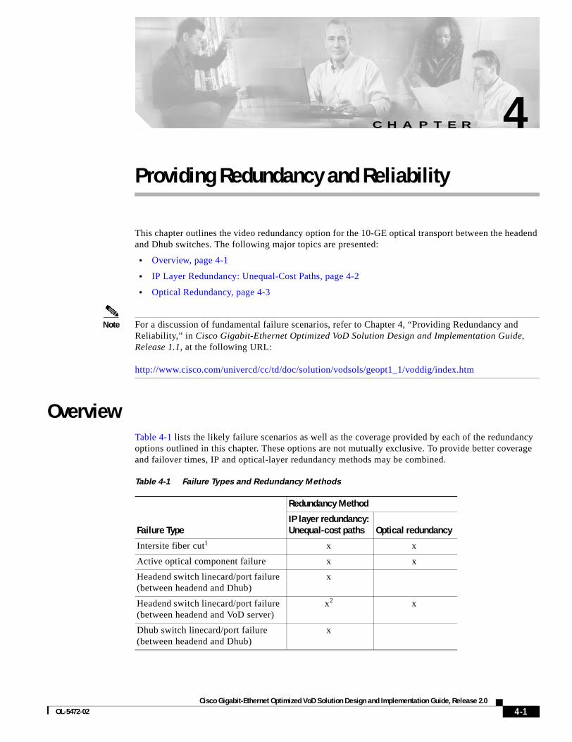
Cisco Gigabit-Ethernet Optimized VoD Solution DesignOL-5472-02
C H A P T E R 4
Providing Redundancy and ReliabilityThis chapter outlines the video redundancy option for the 10-GE optical transport between the headend and Dhub switches. The following major topics are presented:
• Overview, page 4-1
• IP Layer Redundancy: Unequal-Cost Paths, page 4-2
• Optical Redundancy, page 4-3
Note For a discussion of fundamental failure scenarios, refer to Chapter 4, “Providing Redundancy and Reliability,” in Cisco Gigabit-Ethernet Optimized VoD Solution Design and Implementation Guide, Release 1.1, at the following URL:
http://www.cisco.com/univercd/cc/td/doc/solution/vodsols/geopt1_1/voddig/index.htm
OverviewTable 4-1 lists the likely failure scenarios as well as the coverage provided by each of the redundancy options outlined in this chapter. These options are not mutually exclusive. To provide better coverage and failover times, IP and optical-layer redundancy methods may be combined.
Table 4-1 Failure Types and Redundancy Methods
Failure Type
Redundancy Method
IP layer redundancy:Unequal-cost paths Optical redundancy
Intersite fiber cut1 x x
Active optical component failure x x
Headend switch linecard/port failure (between headend and Dhub)
x
Headend switch linecard/port failure (between headend and VoD server)
x2 x
Dhub switch linecard/port failure (between headend and Dhub)
x
4-1 and Implementation Guide, Release 2.0
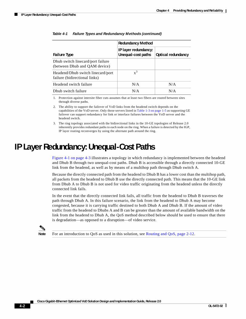
Chapter 4 Providing Redundancy and ReliabilityIP Layer Redundancy: Unequal-Cost Paths
IP Layer Redundancy: Unequal-Cost PathsFigure 4-1 on page 4-3 illustrates a topology in which redundancy is implemented between the headend and Dhub B through two unequal-cost paths. Dhub B is accessible through a directly connected 10-GE link from the headend, as well as by means of a multihop path through Dhub switch A.
Because the directly connected path from the headend to Dhub B has a lower cost than the multihop path, all packets from the headend to Dhub B use the directly connected path. This means that the 10-GE link from Dhub A to Dhub B is not used for video traffic originating from the headend unless the directly connected link fails.
In the event that the directly connected link fails, all traffic from the headend to Dhub B traverses the path through Dhub A. In this failure scenario, the link from the headend to Dhub A may become congested, because it is carrying traffic destined to both Dhub A and Dhub B. If the amount of video traffic from the headend to Dhubs A and B can be greater than the amount of available bandwidth on the link from the headend to Dhub A, the QoS method described below should be used to ensure that there is degradation—as opposed to a disruption—of video service.
Note For an introduction to QoS as used in this solution, see Routing and QoS, page 2-12.
Dhub switch linecard/port failure (between Dhub and QAM device)
Headend/Dhub switch linecard/port failure (bidirectional links)
x3
Headend switch failure N/A N/A
Dhub switch failure N/A N/A
1. Protection against intersite fiber cuts assumes that at least two fibers are routed between sites through diverse paths.
2. The ability to support the failover of VoD links from the headend switch depends on the capabilities of the VoD server. Only those servers listed in Table 1-3 on page 1-5 as supporting GE failover can support redundancy for link or interface failures between the VoD server and the headend switch.
3. The ring topology associated with the bidirectional links in the 10-GE topologies of Release 2.0 inherently provides redundant paths to each node on the ring. When a failure is detected by the IGP, IP layer routing reconverges by using the alternate path around the ring.
Table 4-1 Failure Types and Redundancy Methods (continued)
Failure Type
Redundancy Method
IP layer redundancy:Unequal-cost paths Optical redundancy
4-2Cisco Gigabit-Ethernet Optimized VoD Solution Design and Implementation Guide, Release 2.0
OL-5472-02
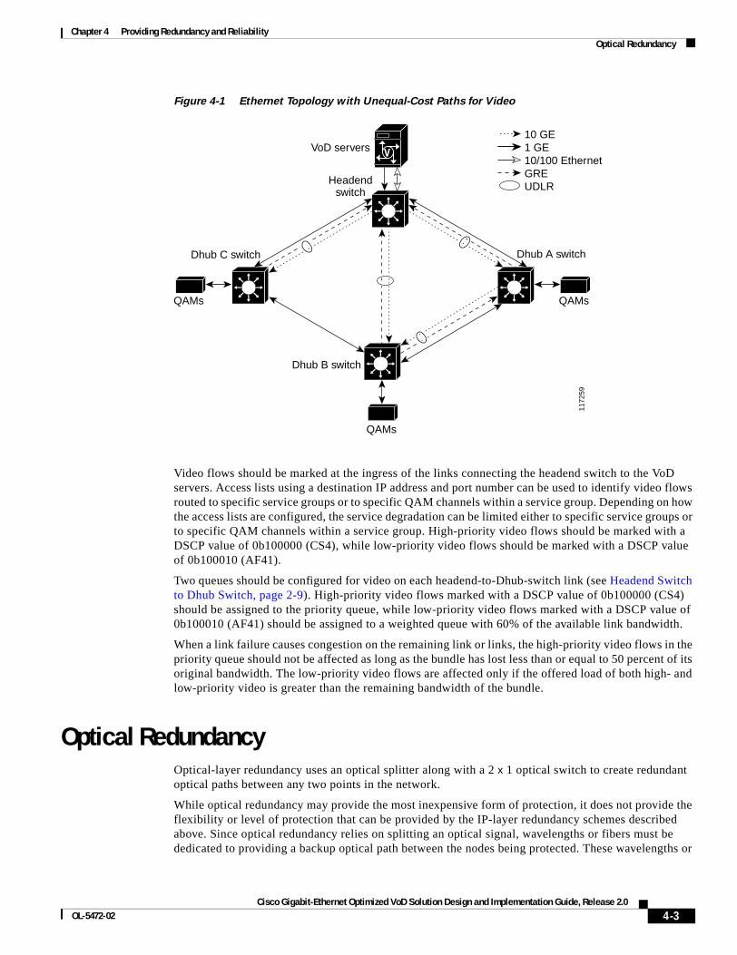
Chapter 4 Providing Redundancy and ReliabilityOptical Redundancy
Figure 4-1 Ethernet Topology with Unequal-Cost Paths for Video
Video flows should be marked at the ingress of the links connecting the headend switch to the VoD servers. Access lists using a destination IP address and port number can be used to identify video flows routed to specific service groups or to specific QAM channels within a service group. Depending on how the access lists are configured, the service degradation can be limited either to specific service groups or to specific QAM channels within a service group. High-priority video flows should be marked with a DSCP value of 0b100000 (CS4), while low-priority video flows should be marked with a DSCP value of 0b100010 (AF41).
Two queues should be configured for video on each headend-to-Dhub-switch link (see Headend Switch to Dhub Switch, page 2-9). High-priority video flows marked with a DSCP value of 0b100000 (CS4) should be assigned to the priority queue, while low-priority video flows marked with a DSCP value of 0b100010 (AF41) should be assigned to a weighted queue with 60% of the available link bandwidth.
When a link failure causes congestion on the remaining link or links, the high-priority video flows in the priority queue should not be affected as long as the bundle has lost less than or equal to 50 percent of its original bandwidth. The low-priority video flows are affected only if the offered load of both high- and low-priority video is greater than the remaining bandwidth of the bundle.
Optical RedundancyOptical-layer redundancy uses an optical splitter along with a 2 x 1 optical switch to create redundant optical paths between any two points in the network.
While optical redundancy may provide the most inexpensive form of protection, it does not provide the flexibility or level of protection that can be provided by the IP-layer redundancy schemes described above. Since optical redundancy relies on splitting an optical signal, wavelengths or fibers must be dedicated to providing a backup optical path between the nodes being protected. These wavelengths or
V
1172
59
VoD servers
Headendswitch
Dhub A switchDhub C switch
Dhub B switch
QAMsQAMs
QAMs
GREUDLR
10/100 Ethernet1 GE10 GE
4-3Cisco Gigabit-Ethernet Optimized VoD Solution Design and Implementation Guide, Release 2.0
OL-5472-02
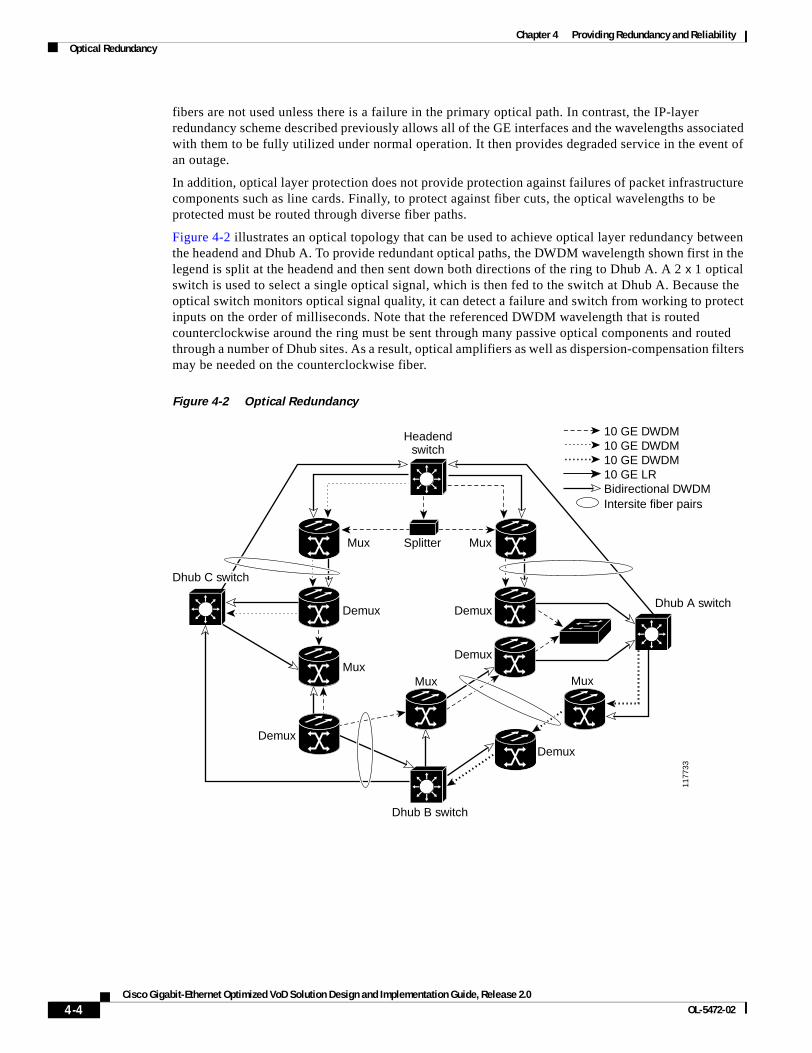
Chapter 4 Providing Redundancy and ReliabilityOptical Redundancy
fibers are not used unless there is a failure in the primary optical path. In contrast, the IP-layer redundancy scheme described previously allows all of the GE interfaces and the wavelengths associated with them to be fully utilized under normal operation. It then provides degraded service in the event of an outage.
In addition, optical layer protection does not provide protection against failures of packet infrastructure components such as line cards. Finally, to protect against fiber cuts, the optical wavelengths to be protected must be routed through diverse fiber paths.
Figure 4-2 illustrates an optical topology that can be used to achieve optical layer redundancy between the headend and Dhub A. To provide redundant optical paths, the DWDM wavelength shown first in the legend is split at the headend and then sent down both directions of the ring to Dhub A. A 2 x 1 optical switch is used to select a single optical signal, which is then fed to the switch at Dhub A. Because the optical switch monitors optical signal quality, it can detect a failure and switch from working to protect inputs on the order of milliseconds. Note that the referenced DWDM wavelength that is routed counterclockwise around the ring must be sent through many passive optical components and routed through a number of Dhub sites. As a result, optical amplifiers as well as dispersion-compensation filters may be needed on the counterclockwise fiber.
Figure 4-2 Optical Redundancy
1177
33
Headendswitch
Intersite fiber pairsBidirectional DWDM10 GE LR10 GE DWDM10 GE DWDM10 GE DWDM
MuxSplitterMux
MuxMux Mux
Demux
Demux
Demux
DemuxDemux
Dhub B switch
Dhub A sDhub A switch
Dhub C sDhub C switchwitch
Dhub A switch
Dhub C switch
4-4Cisco Gigabit-Ethernet Optimized VoD Solution Design and Implementation Guide, Release 2.0
OL-5472-02
Cisco Gigabit-Ethernet Optimized VoD Solution DesignOL-5472-02
C H A P T E R 5
Monitoring and TroubleshootingThis chapter provides an introduction to monitoring and troubleshooting the Cisco Ethernet switches in the Cisco Gigabit-Ethernet Optimized VoD Solution, Release 2.0, and presents the following major topics:
• Using CLI Commands to Monitor the Cisco 7609 and Cisco Catalyst 6500, page 5-1
• Using CLI Commands to Monitor the Cisco Catalyst 4500, page 5-12
• Using CLI Commands to Monitor and Troubleshoot the Cisco uMG9820, page 5-14
• Using CLI Commands to Monitor and Troubleshoot the Cisco uMG9820, page 5-14
For the architecture of the components discussed here, see Chapter 3, “Implementing and Configuring the Solution.”
Using CLI Commands to Monitor the Cisco 7609 and Cisco Catalyst 6500
This section addresses the following command-line interface (CLI) commands, presented in alphabetical order:
• logging event link-status, page 5-2
• show access-lists, page 5-2
• show arp, page 5-2
• show class-map, page 5-3
• show ip arp vrf, page 5-5
• show ip route, page 5-6
• show ip route vrf, page 5-7
• show mls qos, page 5-8
• show policy-map, page 5-10
• show queueing interface, page 5-11
• show standby, page 5-12
5-1 and Implementation Guide, Release 2.0
Chapter 5 Monitoring and TroubleshootingUsing CLI Commands to Monitor the Cisco 7609 and Cisco Catalyst 6500
logging event link-statusThe command logging event link-status is useful in providing the up/down status of links, sending messages to the console when the status of a link changes. This command can be used in conjunction with management applications such as Cisco Info Center (CIC) (which can pick up console messages and perform a notification process), as there is less latency with this command than there is with MIBs and traps. However, take into account that the logging event link-status command should not be used unless it is necessary, because logging can burden the CPU, especially if traps are also being used.
show access-listsThe show access-lists command displays the access lists that are defined on the switch. The syntax is
show access-lists [number | name]
where
number = Access list number <1–2699>.
name = Extended access list name.
The following displays the access lists defined on the switch Headend.
Headend# show access-lists
Extended IP access list acl_VoD_OOB 10 permit ip 192.168.67.0 0.0.0.255 anyExtended IP access list acl_VoIP 10 permit ip 192.168.66.0 0.0.0.255 anyExtended IP access list acl_high_speed_data 10 permit ip 192.168.65.0 0.0.0.255 anyExtended IP access list acl_video_high 10 permit udp 192.168.48.0 0.0.7.255 192.168.160.0 0.0.3.255 range 3329 6399Extended IP access list acl_video_low 10 permit udp 192.168.48.0 0.0.7.255 192.168.160.0 0.0.3.255 range 257 3327
show arpThe command show arp displays the ARP table for all ARP entries related to the global routing table. The following displays the ARP table for the switch Headend.
Headend# show arp
Protocol Address Age (min) Hardware Addr Type InterfaceInternet 1.14.0.3 141 0060.2fa3.e6f1 ARPA GigabitEthernet5/2Internet 1.14.0.1 225 0000.0c07.ac16 ARPA GigabitEthernet5/2Internet 192.168.65.1 - 000f.24c0.f080 ARPA Vlan65Internet 192.168.67.1 - 000f.24c0.f080 ARPA Vlan67Internet 192.168.66.1 - 000f.24c0.f080 ARPA Vlan66Internet 192.168.65.101 13 0010.9402.0818 ARPA Vlan65Internet 192.168.65.100 79 0010.9402.0817 ARPA Vlan65Internet 192.168.67.100 119 0000.0000.0016 ARPA Vlan67Internet 1.14.135.1 - 000f.24c0.f080 ARPA GigabitEthernet5/2Internet 1.14.133.1 9 0040.f488.57c0 ARPA GigabitEthernet5/2Internet 192.168.168.1 - 000f.24c0.f080 ARPA GigabitEthernet2/15Internet 192.168.168.2 195 000e.d631.8800 ARPA GigabitEthernet2/15Internet 192.168.168.13 - 000f.24c0.f080 ARPA GigabitEthernet2/16Internet 192.168.168.14 164 000c.cfbe.f100 ARPA GigabitEthernet2/16
5-2Cisco Gigabit-Ethernet Optimized VoD Solution Design and Implementation Guide, Release 2.0
OL-5472-02
Chapter 5 Monitoring and TroubleshootingUsing CLI Commands to Monitor the Cisco 7609 and Cisco Catalyst 6500
show class-mapThe show class-map command displays class map information. The syntax is
show class-map class_name
where
class_name = Name of the class map.
The following displays the class map defined on the switch Headend.
Headend# show class-map
Class Map match-all class_video_high (id 1) Match access-group name acl_video_high Class Map match-all class_VoIP (id 2) Match access-group name acl_VoIP Class Map match-any class-default (id 0) Match any Class Map match-all class_high_speed_data (id 3) Match access-group name acl_high_speed_data Class Map match-all class_VoD_OOB (id 4) Match access-group name acl_VoD_OOB Class Map match-all class_video_low (id 5) Match access-group name acl_video_low
show interfacesThe show interfaces command displays a summary of IP information and status for an interface. The syntax is
show interfaces [type number]
where
type = (Optional) Interface type. For this example, values for type include fastethernet, gigabitethernet, tengigabitethernet, loopback, port-channel, vlan, and tunnel.
number = (Optional) Port number on the selected interface.
The show interfaces command, without a specific interface as an option, retrieves information from every interface. Below are the counters that are relevant to troubleshooting:
• input errors—This is a count of any errors that occurred while the switch is trying to receive packets from the referenced port. The counter includes both cyclic redundancy check (CRC) and frame errors, but does not include ignored packets. CRC errors occur when the received packets fail the CRC. Frame errors occur when the receiving frame is not complete. The ignored counter counts the number of frames dropped on input because of resource exhaustion in the switch fabric. Overruns occur when interframe gaps (IFGs) are so short that a new Ethernet frame arrives before the previous frame has been completely stored in shared memory.
• output errors—This is a count of any errors that occurred while the switch is trying to transmit packets from the referenced port. Collisions shows the number of times a collision occurred while the switch is trying to transmit a packet from the referenced port. This counter should be 0 for a port operating in full-duplex mode. The interface resets counter counts the number of times the port resets itself, generally the result of link-up or link-down transitions. Underruns occur when packets are not retrieved quickly enough from shared memory to be transmitted.
5-3Cisco Gigabit-Ethernet Optimized VoD Solution Design and Implementation Guide, Release 2.0
OL-5472-02

Chapter 5 Monitoring and TroubleshootingUsing CLI Commands to Monitor the Cisco 7609 and Cisco Catalyst 6500
• babbles and late collisions—A babble is an error caused by the transmission of frames in excess of 1518 bytes in size. A late collision is a collision that occurs outside of the collision window, which is typically caused by a duplex mismatch or a wire length that exceeds the distance limitations (100 meters for 10/100BASE-T ports). The deferred counter tabulates the number of times the port had to wait to transmit as a result of traffic on the wire.
• lost carrier and no carrier—The carrier is an electrical signal that Ethernet devices use to detect whether the wire is currently being used by another transmitting station. The lost carrier counter increases each time a carrier sense loss occurs. This happens when the hardware is transmitting a frame onto the wire and does not see its own carrier wave on the Ethernet. The absence of the carrier signal increments the no carrier counter.
The following forms of the show interfaces command can provide a great deal of information of assistance in troubleshooting Cisco 7609 and Cisco Catalyst 6500 series switches. The examples below show nominal values for a show interfaces command on a headend switch for the following interfaces.
The following shows the VoD ingress port GigabitEthernet 3/38 on Headend.
Headend# show interfaces GigabitEthernet 3/38
GigabitEthernet3/38 is up, line protocol is up (connected) Hardware is C6k 1000Mb 802.3, address is 000e.8400.2305 (bia 000e.8400.2305) Description: BDL7: SeaChange VoD server ingress (ITVDemo1) MTU 1500 bytes, BW 1000000 Kbit, DLY 10 usec, reliability 255/255, txload 1/255, rxload 78/255 Encapsulation ARPA, loopback not set Full-duplex, 1000Mb/s input flow-control is off, output flow-control is on Clock mode is auto ARP type: ARPA, ARP Timeout 04:00:00 Last input never, output never, output hang never Last clearing of "show interface" counters 00:08:46 Input queue: 0/2000/0/0 (size/max/drops/flushes); Total output drops: 0 Queueing strategy: fifo Output queue: 0/40 (size/max) 30 second input rate 308167000 bits/sec, 28283 packets/sec 30 second output rate 0 bits/sec, 0 packets/sec 14704804 packets input, 20027945772 bytes, 0 no buffer Received 0 broadcasts, 0 runts, 0 giants, 0 throttles 0 input errors, 0 CRC, 0 frame, 0 overrun, 0 ignored 0 input packets with dribble condition detected 231 packets output, 16093 bytes, 0 underruns 0 output errors, 0 collisions, 0 interface resets 0 babbles, 0 late collision, 0 deferred 0 lost carrier, 0 no carrier 0 output buffer failures, 0 output buffers swapped out
The following shows the 10-GE optical transport link on Headend. The destination is DHub_Sw_A.
Headend# show interfaces TenGigabitEthernet 7/1
TenGigabitEthernet7/1 is up, line protocol is up (connected) Hardware is C6k 10000Mb 802.3, address is 000e.834a.2160 (bia 000e.834a.2160) Description: UDL1: Video traffic to DHub_Sw_A (TenGig1/1) MTU 1500 bytes, BW 10000000 Kbit, DLY 10 usec, reliability 255/255, txload 6/255, rxload 1/255 Encapsulation ARPA, loopback not set Full-duplex, 10Gb/s input flow-control is off, output flow-control is on ARP type: ARPA, ARP Timeout 04:00:00 Last input never, output 00:00:24, output hang never Last clearing of "show interface" counters 00:10:10 Input queue: 0/2000/0/0 (size/max/drops/flushes); Total output drops: 0
5-4Cisco Gigabit-Ethernet Optimized VoD Solution Design and Implementation Guide, Release 2.0
OL-5472-02
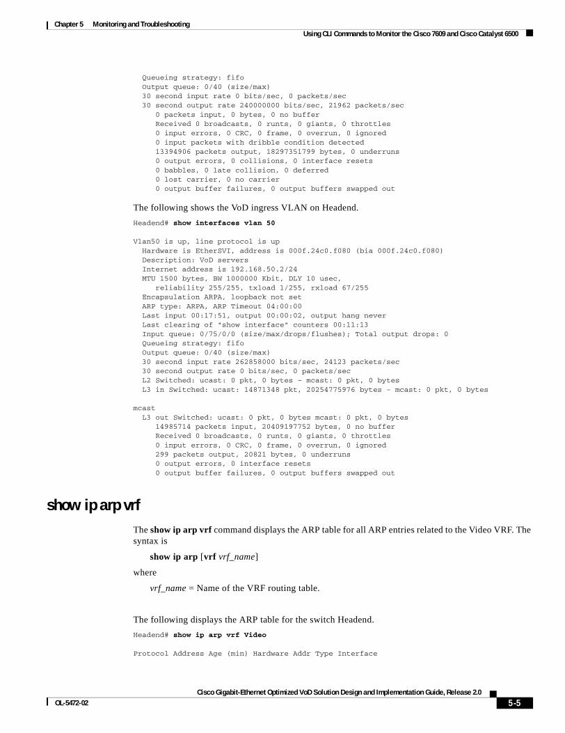
Chapter 5 Monitoring and TroubleshootingUsing CLI Commands to Monitor the Cisco 7609 and Cisco Catalyst 6500
Queueing strategy: fifo Output queue: 0/40 (size/max) 30 second input rate 0 bits/sec, 0 packets/sec 30 second output rate 240000000 bits/sec, 21962 packets/sec 0 packets input, 0 bytes, 0 no buffer Received 0 broadcasts, 0 runts, 0 giants, 0 throttles 0 input errors, 0 CRC, 0 frame, 0 overrun, 0 ignored 0 input packets with dribble condition detected 13394906 packets output, 18297351799 bytes, 0 underruns 0 output errors, 0 collisions, 0 interface resets 0 babbles, 0 late collision, 0 deferred 0 lost carrier, 0 no carrier 0 output buffer failures, 0 output buffers swapped out
The following shows the VoD ingress VLAN on Headend.
Headend# show interfaces vlan 50
Vlan50 is up, line protocol is up Hardware is EtherSVI, address is 000f.24c0.f080 (bia 000f.24c0.f080) Description: VoD servers Internet address is 192.168.50.2/24 MTU 1500 bytes, BW 1000000 Kbit, DLY 10 usec, reliability 255/255, txload 1/255, rxload 67/255 Encapsulation ARPA, loopback not set ARP type: ARPA, ARP Timeout 04:00:00 Last input 00:17:51, output 00:00:02, output hang never Last clearing of "show interface" counters 00:11:13 Input queue: 0/75/0/0 (size/max/drops/flushes); Total output drops: 0 Queueing strategy: fifo Output queue: 0/40 (size/max) 30 second input rate 262858000 bits/sec, 24123 packets/sec 30 second output rate 0 bits/sec, 0 packets/sec L2 Switched: ucast: 0 pkt, 0 bytes - mcast: 0 pkt, 0 bytes L3 in Switched: ucast: 14871348 pkt, 20254775976 bytes - mcast: 0 pkt, 0 bytes
mcast L3 out Switched: ucast: 0 pkt, 0 bytes mcast: 0 pkt, 0 bytes 14985714 packets input, 20409197752 bytes, 0 no buffer Received 0 broadcasts, 0 runts, 0 giants, 0 throttles 0 input errors, 0 CRC, 0 frame, 0 overrun, 0 ignored 299 packets output, 20821 bytes, 0 underruns 0 output errors, 0 interface resets 0 output buffer failures, 0 output buffers swapped out
show ip arp vrf The show ip arp vrf command displays the ARP table for all ARP entries related to the Video VRF. The syntax is
show ip arp [vrf vrf_name]
where
vrf_name = Name of the VRF routing table.
The following displays the ARP table for the switch Headend.
Headend# show ip arp vrf Video
Protocol Address Age (min) Hardware Addr Type Interface
5-5Cisco Gigabit-Ethernet Optimized VoD Solution Design and Implementation Guide, Release 2.0
OL-5472-02
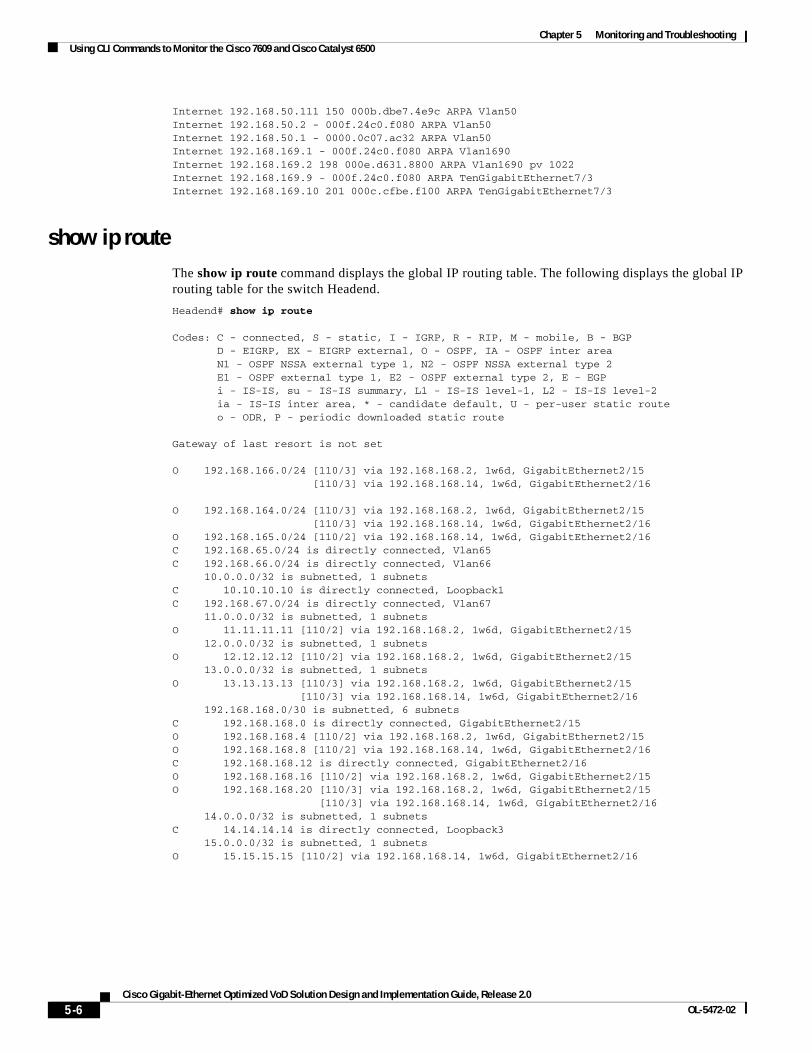
Chapter 5 Monitoring and TroubleshootingUsing CLI Commands to Monitor the Cisco 7609 and Cisco Catalyst 6500
Internet 192.168.50.111 150 000b.dbe7.4e9c ARPA Vlan50Internet 192.168.50.2 - 000f.24c0.f080 ARPA Vlan50Internet 192.168.50.1 - 0000.0c07.ac32 ARPA Vlan50Internet 192.168.169.1 - 000f.24c0.f080 ARPA Vlan1690Internet 192.168.169.2 198 000e.d631.8800 ARPA Vlan1690 pv 1022Internet 192.168.169.9 - 000f.24c0.f080 ARPA TenGigabitEthernet7/3Internet 192.168.169.10 201 000c.cfbe.f100 ARPA TenGigabitEthernet7/3
show ip routeThe show ip route command displays the global IP routing table. The following displays the global IP routing table for the switch Headend.
Headend# show ip route
Codes: C - connected, S - static, I - IGRP, R - RIP, M - mobile, B - BGP D - EIGRP, EX - EIGRP external, O - OSPF, IA - OSPF inter area N1 - OSPF NSSA external type 1, N2 - OSPF NSSA external type 2 E1 - OSPF external type 1, E2 - OSPF external type 2, E - EGP i - IS-IS, su - IS-IS summary, L1 - IS-IS level-1, L2 - IS-IS level-2 ia - IS-IS inter area, * - candidate default, U - per-user static route o - ODR, P - periodic downloaded static route
Gateway of last resort is not set
O 192.168.166.0/24 [110/3] via 192.168.168.2, 1w6d, GigabitEthernet2/15 [110/3] via 192.168.168.14, 1w6d, GigabitEthernet2/16
O 192.168.164.0/24 [110/3] via 192.168.168.2, 1w6d, GigabitEthernet2/15 [110/3] via 192.168.168.14, 1w6d, GigabitEthernet2/16O 192.168.165.0/24 [110/2] via 192.168.168.14, 1w6d, GigabitEthernet2/16C 192.168.65.0/24 is directly connected, Vlan65C 192.168.66.0/24 is directly connected, Vlan66 10.0.0.0/32 is subnetted, 1 subnetsC 10.10.10.10 is directly connected, Loopback1C 192.168.67.0/24 is directly connected, Vlan67 11.0.0.0/32 is subnetted, 1 subnetsO 11.11.11.11 [110/2] via 192.168.168.2, 1w6d, GigabitEthernet2/15 12.0.0.0/32 is subnetted, 1 subnetsO 12.12.12.12 [110/2] via 192.168.168.2, 1w6d, GigabitEthernet2/15 13.0.0.0/32 is subnetted, 1 subnetsO 13.13.13.13 [110/3] via 192.168.168.2, 1w6d, GigabitEthernet2/15 [110/3] via 192.168.168.14, 1w6d, GigabitEthernet2/16 192.168.168.0/30 is subnetted, 6 subnetsC 192.168.168.0 is directly connected, GigabitEthernet2/15O 192.168.168.4 [110/2] via 192.168.168.2, 1w6d, GigabitEthernet2/15O 192.168.168.8 [110/2] via 192.168.168.14, 1w6d, GigabitEthernet2/16C 192.168.168.12 is directly connected, GigabitEthernet2/16O 192.168.168.16 [110/2] via 192.168.168.2, 1w6d, GigabitEthernet2/15O 192.168.168.20 [110/3] via 192.168.168.2, 1w6d, GigabitEthernet2/15 [110/3] via 192.168.168.14, 1w6d, GigabitEthernet2/16 14.0.0.0/32 is subnetted, 1 subnetsC 14.14.14.14 is directly connected, Loopback3 15.0.0.0/32 is subnetted, 1 subnetsO 15.15.15.15 [110/2] via 192.168.168.14, 1w6d, GigabitEthernet2/16
5-6Cisco Gigabit-Ethernet Optimized VoD Solution Design and Implementation Guide, Release 2.0
OL-5472-02
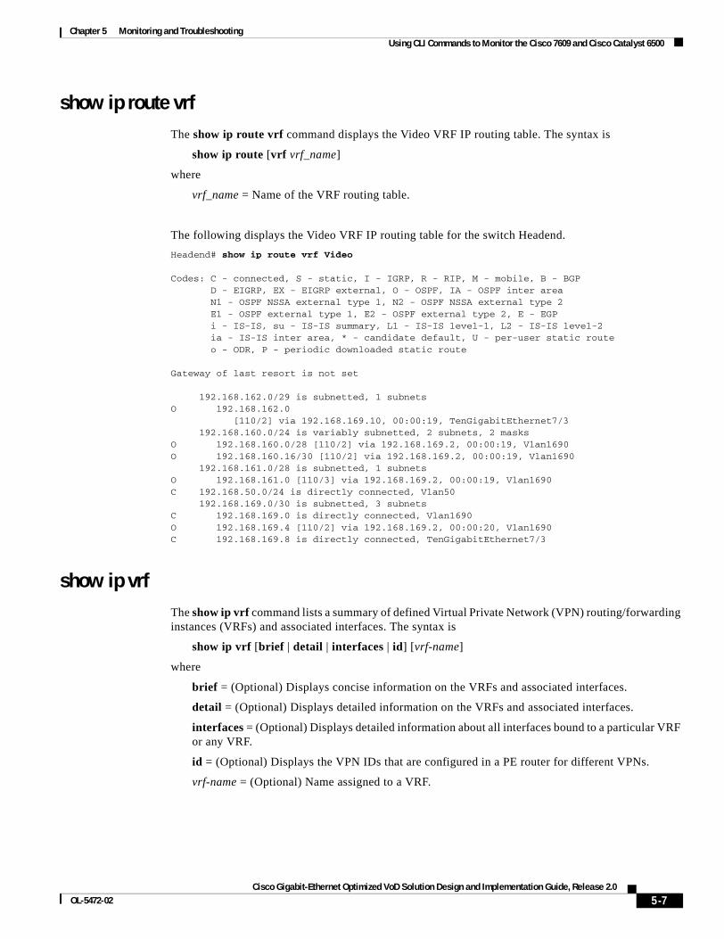
Chapter 5 Monitoring and TroubleshootingUsing CLI Commands to Monitor the Cisco 7609 and Cisco Catalyst 6500
show ip route vrfThe show ip route vrf command displays the Video VRF IP routing table. The syntax is
show ip route [vrf vrf_name]
where
vrf_name = Name of the VRF routing table.
The following displays the Video VRF IP routing table for the switch Headend.
Headend# show ip route vrf Video
Codes: C - connected, S - static, I - IGRP, R - RIP, M - mobile, B - BGP D - EIGRP, EX - EIGRP external, O - OSPF, IA - OSPF inter area N1 - OSPF NSSA external type 1, N2 - OSPF NSSA external type 2 E1 - OSPF external type 1, E2 - OSPF external type 2, E - EGP i - IS-IS, su - IS-IS summary, L1 - IS-IS level-1, L2 - IS-IS level-2 ia - IS-IS inter area, * - candidate default, U - per-user static route o - ODR, P - periodic downloaded static route
Gateway of last resort is not set
192.168.162.0/29 is subnetted, 1 subnetsO 192.168.162.0 [110/2] via 192.168.169.10, 00:00:19, TenGigabitEthernet7/3 192.168.160.0/24 is variably subnetted, 2 subnets, 2 masksO 192.168.160.0/28 [110/2] via 192.168.169.2, 00:00:19, Vlan1690O 192.168.160.16/30 [110/2] via 192.168.169.2, 00:00:19, Vlan1690 192.168.161.0/28 is subnetted, 1 subnetsO 192.168.161.0 [110/3] via 192.168.169.2, 00:00:19, Vlan1690C 192.168.50.0/24 is directly connected, Vlan50 192.168.169.0/30 is subnetted, 3 subnetsC 192.168.169.0 is directly connected, Vlan1690O 192.168.169.4 [110/2] via 192.168.169.2, 00:00:20, Vlan1690C 192.168.169.8 is directly connected, TenGigabitEthernet7/3
show ip vrf The show ip vrf command lists a summary of defined Virtual Private Network (VPN) routing/forwarding instances (VRFs) and associated interfaces. The syntax is
show ip vrf [brief | detail | interfaces | id] [vrf-name]
where
brief = (Optional) Displays concise information on the VRFs and associated interfaces.
detail = (Optional) Displays detailed information on the VRFs and associated interfaces.
interfaces = (Optional) Displays detailed information about all interfaces bound to a particular VRF or any VRF.
id = (Optional) Displays the VPN IDs that are configured in a PE router for different VPNs.
vrf-name = (Optional) Name assigned to a VRF.
5-7Cisco Gigabit-Ethernet Optimized VoD Solution Design and Implementation Guide, Release 2.0
OL-5472-02
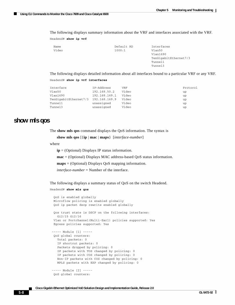
Chapter 5 Monitoring and TroubleshootingUsing CLI Commands to Monitor the Cisco 7609 and Cisco Catalyst 6500
The following displays summary information about the VRF and interfaces associated with the VRF.
Headend# show ip vrf
Name Default RD Interfaces Video 1000:1 Vlan50 Vlan1690 TenGigabitEthernet7/3 Tunnel1 Tunnel3
The following displays detailed information about all interfaces bound to a particular VRF or any VRF.
Headend# show ip vrf interfaces
Interface IP-Address VRF ProtocolVlan50 192.168.50.2 Video up Vlan1690 192.168.169.1 Video up TenGigabitEthernet7/3 192.168.169.9 Video up Tunnel1 unassigned Video up Tunnel3 unassigned Video up
show mls qosThe show mls qos command displays the QoS information. The syntax is
show mls qos [{ip | mac | maps} [interface-number]
where
ip = (Optional) Displays IP status information.
mac = (Optional) Displays MAC address-based QoS status information.
maps = (Optional) Displays QoS mapping information.
interface-number = Number of the interface.
The following displays a summary status of QoS on the switch Headend.
Headend# show mls qos
QoS is enabled globally Microflow policing is enabled globally QoS ip packet dscp rewrite enabled globally
Qos trust state is DSCP on the following interfaces: Gi2/15 Gi2/16 Vlan or Portchannel(Multi-Earl) policies supported: Yes Egress policies supported: Yes
----- Module [1] ----- QoS global counters: Total packets: 0 IP shortcut packets: 0 Packets dropped by policing: 0 IP packets with TOS changed by policing: 0 IP packets with COS changed by policing: 0 Non-IP packets with COS changed by policing: 0 MPLS packets with EXP changed by policing: 0
----- Module [2] ----- QoS global counters:
5-8Cisco Gigabit-Ethernet Optimized VoD Solution Design and Implementation Guide, Release 2.0
OL-5472-02
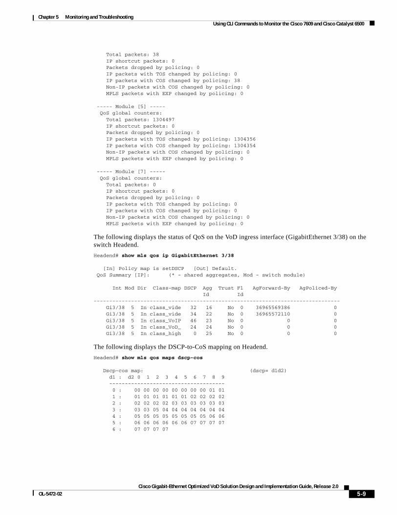
Chapter 5 Monitoring and TroubleshootingUsing CLI Commands to Monitor the Cisco 7609 and Cisco Catalyst 6500
Total packets: 38 IP shortcut packets: 0 Packets dropped by policing: 0 IP packets with TOS changed by policing: 0 IP packets with COS changed by policing: 38 Non-IP packets with COS changed by policing: 0 MPLS packets with EXP changed by policing: 0
----- Module [5] ----- QoS global counters: Total packets: 1304497 IP shortcut packets: 0 Packets dropped by policing: 0 IP packets with TOS changed by policing: 1304356 IP packets with COS changed by policing: 1304354 Non-IP packets with COS changed by policing: 0 MPLS packets with EXP changed by policing: 0
----- Module [7] ----- QoS global counters: Total packets: 0 IP shortcut packets: 0 Packets dropped by policing: 0 IP packets with TOS changed by policing: 0 IP packets with COS changed by policing: 0 Non-IP packets with COS changed by policing: 0 MPLS packets with EXP changed by policing: 0
The following displays the status of QoS on the VoD ingress interface (GigabitEthernet 3/38) on the switch Headend.
Headend# show mls qos ip GigabitEthernet 3/38
[In] Policy map is setDSCP [Out] Default. QoS Summary [IP]: (* - shared aggregates, Mod - switch module)
Int Mod Dir Class-map DSCP Agg Trust Fl AgForward-By AgPoliced-By Id Id ------------------------------------------------------------------------------- Gi3/38 5 In class_vide 32 16 No 0 36965569386 0 Gi3/38 5 In class_vide 34 22 No 0 36965572110 0 Gi3/38 5 In class_VoIP 46 23 No 0 0 0 Gi3/38 5 In class_VoD_ 24 24 No 0 0 0 Gi3/38 5 In class_high 0 25 No 0 0 0
The following displays the DSCP-to-CoS mapping on Headend.
Headend# show mls qos maps dscp-cos
Dscp-cos map: (dscp= d1d2) d1 : d2 0 1 2 3 4 5 6 7 8 9 ------------------------------------- 0 : 00 00 00 00 00 00 00 00 01 01 1 : 01 01 01 01 01 01 02 02 02 02 2 : 02 02 02 02 03 03 03 03 03 03 3 : 03 03 05 04 04 04 04 04 04 04 4 : 05 05 05 05 05 05 05 05 06 06 5 : 06 06 06 06 06 06 07 07 07 07 6 : 07 07 07 07
5-9Cisco Gigabit-Ethernet Optimized VoD Solution Design and Implementation Guide, Release 2.0
OL-5472-02
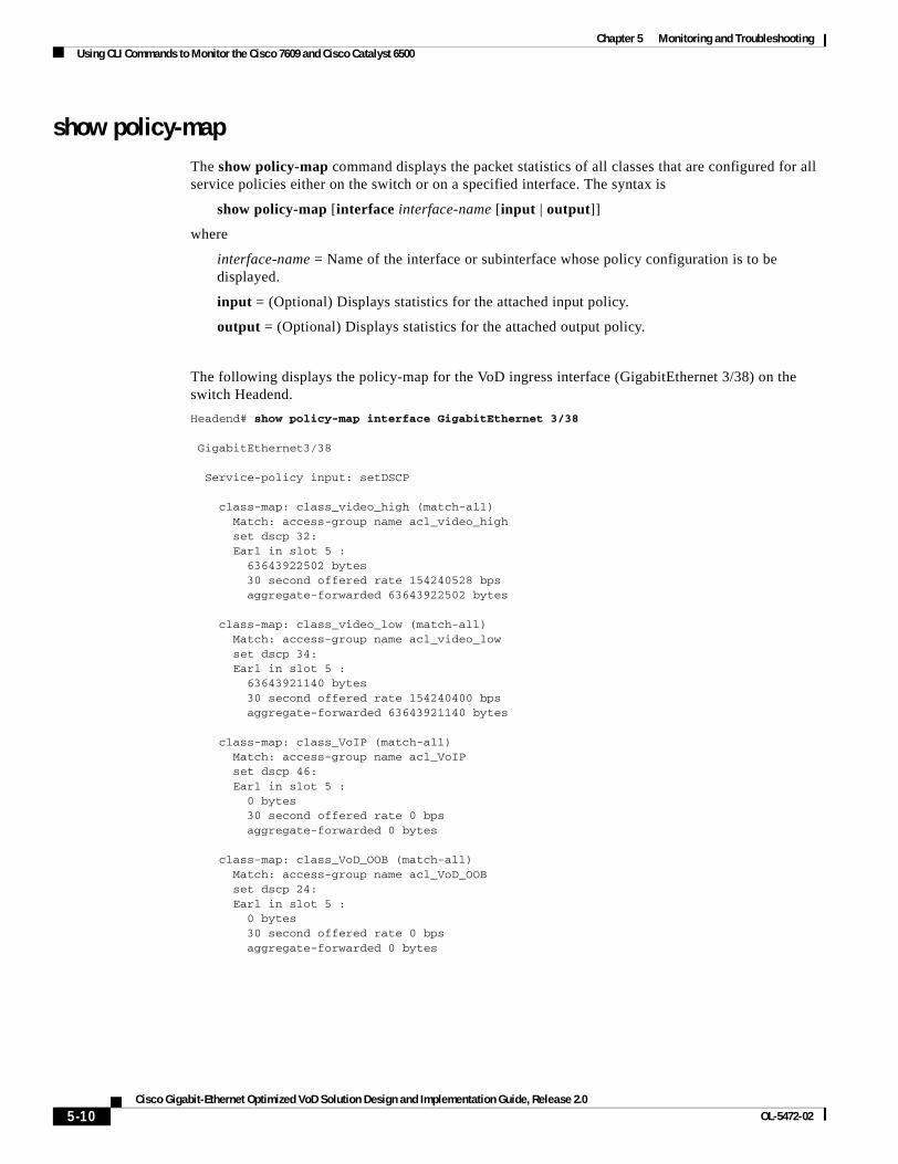
Chapter 5 Monitoring and TroubleshootingUsing CLI Commands to Monitor the Cisco 7609 and Cisco Catalyst 6500
show policy-mapThe show policy-map command displays the packet statistics of all classes that are configured for all service policies either on the switch or on a specified interface. The syntax is
show policy-map [interface interface-name [input | output]]
where
interface-name = Name of the interface or subinterface whose policy configuration is to be displayed.
input = (Optional) Displays statistics for the attached input policy.
output = (Optional) Displays statistics for the attached output policy.
The following displays the policy-map for the VoD ingress interface (GigabitEthernet 3/38) on the switch Headend.
Headend# show policy-map interface GigabitEthernet 3/38
GigabitEthernet3/38
Service-policy input: setDSCP
class-map: class_video_high (match-all) Match: access-group name acl_video_high set dscp 32: Earl in slot 5 : 63643922502 bytes 30 second offered rate 154240528 bps aggregate-forwarded 63643922502 bytes
class-map: class_video_low (match-all) Match: access-group name acl_video_low set dscp 34: Earl in slot 5 : 63643921140 bytes 30 second offered rate 154240400 bps aggregate-forwarded 63643921140 bytes
class-map: class_VoIP (match-all) Match: access-group name acl_VoIP set dscp 46: Earl in slot 5 : 0 bytes 30 second offered rate 0 bps aggregate-forwarded 0 bytes
class-map: class_VoD_OOB (match-all) Match: access-group name acl_VoD_OOB set dscp 24: Earl in slot 5 : 0 bytes 30 second offered rate 0 bps aggregate-forwarded 0 bytes
5-10Cisco Gigabit-Ethernet Optimized VoD Solution Design and Implementation Guide, Release 2.0
OL-5472-02
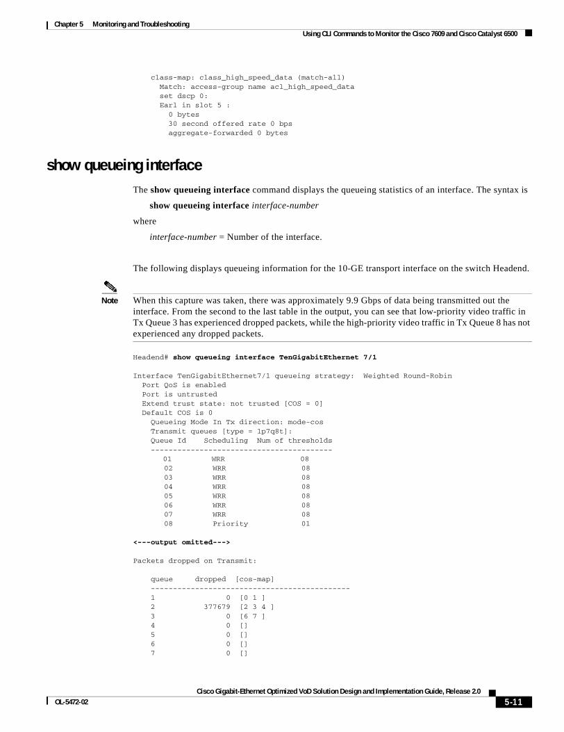
Chapter 5 Monitoring and TroubleshootingUsing CLI Commands to Monitor the Cisco 7609 and Cisco Catalyst 6500
class-map: class_high_speed_data (match-all) Match: access-group name acl_high_speed_data set dscp 0: Earl in slot 5 : 0 bytes 30 second offered rate 0 bps aggregate-forwarded 0 bytes
show queueing interfaceThe show queueing interface command displays the queueing statistics of an interface. The syntax is
show queueing interface interface-number
where
interface-number = Number of the interface.
The following displays queueing information for the 10-GE transport interface on the switch Headend.
Note When this capture was taken, there was approximately 9.9 Gbps of data being transmitted out the interface. From the second to the last table in the output, you can see that low-priority video traffic in Tx Queue 3 has experienced dropped packets, while the high-priority video traffic in Tx Queue 8 has not experienced any dropped packets.
Headend# show queueing interface TenGigabitEthernet 7/1
Interface TenGigabitEthernet7/1 queueing strategy: Weighted Round-Robin Port QoS is enabled Port is untrusted Extend trust state: not trusted [COS = 0] Default COS is 0 Queueing Mode In Tx direction: mode-cos Transmit queues [type = 1p7q8t]: Queue Id Scheduling Num of thresholds -----------------------------------------
01 WRR 08 02 WRR 08 03 WRR 08 04 WRR 08 05 WRR 08 06 WRR 08 07 WRR 08 08 Priority 01 <---output omitted--->
Packets dropped on Transmit:
queue dropped [cos-map] --------------------------------------------- 1 0 [0 1 ] 2 377679 [2 3 4 ] 3 0 [6 7 ] 4 0 [] 5 0 [] 6 0 [] 7 0 []
5-11Cisco Gigabit-Ethernet Optimized VoD Solution Design and Implementation Guide, Release 2.0
OL-5472-02
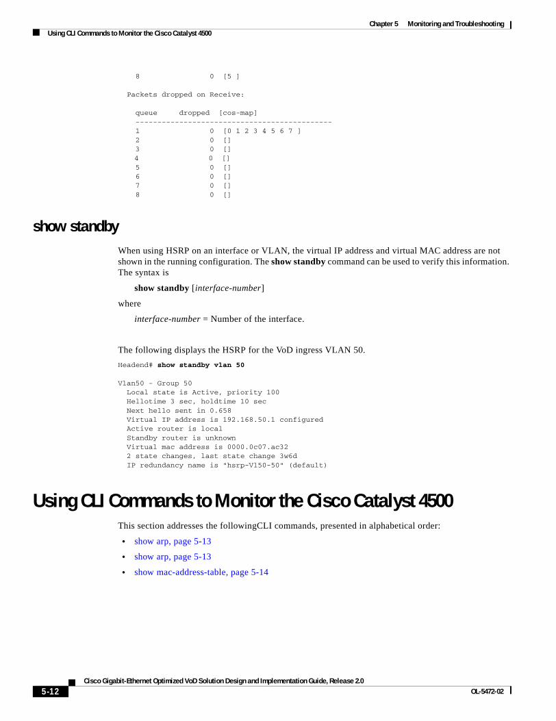
Chapter 5 Monitoring and TroubleshootingUsing CLI Commands to Monitor the Cisco Catalyst 4500
8 0 [5 ]
Packets dropped on Receive:
queue dropped [cos-map] --------------------------------------------- 1 0 [0 1 2 3 4 5 6 7 ] 2 0 [] 3 0 []
4 0 [] 5 0 [] 6 0 [] 7 0 [] 8 0 []
show standbyWhen using HSRP on an interface or VLAN, the virtual IP address and virtual MAC address are not shown in the running configuration. The show standby command can be used to verify this information. The syntax is
show standby [interface-number]
where
interface-number = Number of the interface.
The following displays the HSRP for the VoD ingress VLAN 50.
Headend# show standby vlan 50
Vlan50 - Group 50 Local state is Active, priority 100 Hellotime 3 sec, holdtime 10 sec Next hello sent in 0.658 Virtual IP address is 192.168.50.1 configured Active router is local Standby router is unknown Virtual mac address is 0000.0c07.ac32 2 state changes, last state change 3w6d IP redundancy name is "hsrp-Vl50-50" (default)
Using CLI Commands to Monitor the Cisco Catalyst 4500This section addresses the followingCLI commands, presented in alphabetical order:
• show arp, page 5-13
• show arp, page 5-13
• show mac-address-table, page 5-14
5-12Cisco Gigabit-Ethernet Optimized VoD Solution Design and Implementation Guide, Release 2.0
OL-5472-02
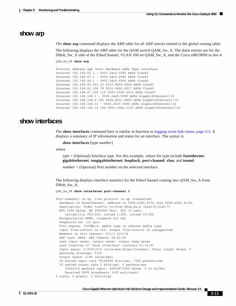
Chapter 5 Monitoring and TroubleshootingUsing CLI Commands to Monitor the Cisco Catalyst 4500
show arpThe show arp command displays the ARP table for all ARP entries related to the global routing table.
The following displays the ARP table for the QAM switch QAM_Sw_A. The three entries are for the DHub_Sw_A side of the EtherChannel, VLAN 160 on QAM_Sw_A, and the Cisco uMG9850 in slot 4.
QAM_Sw_A# show arp
Protocol Address Age (min) Hardware Addr Type InterfaceInternet 192.168.65.1 - 000f.24c0.f080 ARPA Vlan65Internet 192.168.67.1 - 000f.24c0.f080 ARPA Vlan67Internet 192.168.66.1 - 000f.24c0.f080 ARPA Vlan66Internet 192.168.65.101 13 0010.9402.0818 ARPA Vlan65Internet 192.168.65.100 79 0010.9402.0817 ARPA Vlan65Internet 192.168.67.100 119 0000.0000.0016 ARPA Vlan67Internet 192.168.168.1 - 000f.24c0.f080 ARPA GigabitEthernet2/15Internet 192.168.168.2 195 000e.d631.8800 ARPA GigabitEthernet2/15Internet 192.168.168.13 - 000f.24c0.f080 ARPA GigabitEthernet2/16Internet 192.168.168.14 164 000c.cfbe.f100 ARPA GigabitEthernet2/16
show interfacesThe show interfaces command here is similar in function to logging event link-status, page 5-2. It displays a summary of IP information and status for an interface. The syntax is
show interfaces [type number]
where
type = (Optional) Interface type. For this example, values for type include fastethernet, gigabitethernet, tengigabitethernet, loopback, port-channel, vlan, and tunnel.
number = (Optional) Port number on the selected interface.
The following displays interface statistics for the EtherChannel coming into QAM_Sw_A from DHub_Sw_A.
QAM_Sw_A# show interfaces port-channel 1
Port-channel1 is up, line protocol is up (connected) Hardware is EtherChannel, address is 0008.e365.fc7a (bia 0008.e365.fc7a) Description: Video traffic to/from DHub_Sw_A (Gig3/6,Gig3/7) MTU 1500 bytes, BW 2000000 Kbit, DLY 10 usec, reliability 255/255, txload 1/255, rxload 10/255 Encapsulation ARPA, loopback not set Keepalive set (10 sec) Full-duplex, 1000Mb/s, media type is unknown media type input flow-control is off, output flow-control is unsupported Members in this channel: Gi3/1 Gi4/14 ARP type: ARPA, ARP Timeout 04:00:00 Last input never, output never, output hang never Last clearing of "show interface" counters 01:16:41 Input queue: 0/2000/0/0 (size/max/drops/flushes); Total output drops: 0 Queueing strategy: fifo Output queue: 0/40 (size/max) 30 second input rate 79138000 bits/sec, 7263 packets/sec 30 second output rate 0 bits/sec, 0 packets/sec 33522516 packets input, 45653971005 bytes, 0 no buffer Received 2889 broadcasts (635 multicast)0 runts, 0 giants, 0 throttles
5-13Cisco Gigabit-Ethernet Optimized VoD Solution Design and Implementation Guide, Release 2.0
OL-5472-02
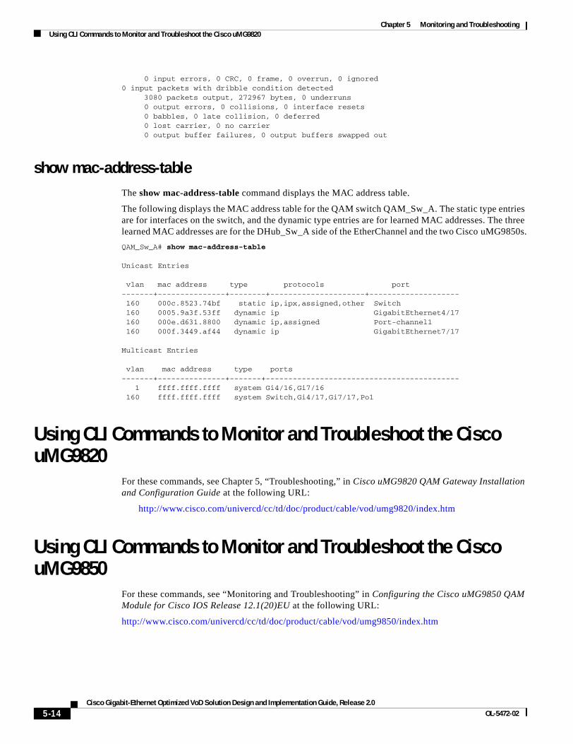
Chapter 5 Monitoring and TroubleshootingUsing CLI Commands to Monitor and Troubleshoot the Cisco uMG9820
0 input errors, 0 CRC, 0 frame, 0 overrun, 0 ignored0 input packets with dribble condition detected 3080 packets output, 272967 bytes, 0 underruns 0 output errors, 0 collisions, 0 interface resets 0 babbles, 0 late collision, 0 deferred 0 lost carrier, 0 no carrier 0 output buffer failures, 0 output buffers swapped out
show mac-address-tableThe show mac-address-table command displays the MAC address table.
The following displays the MAC address table for the QAM switch QAM_Sw_A. The static type entries are for interfaces on the switch, and the dynamic type entries are for learned MAC addresses. The three learned MAC addresses are for the DHub_Sw_A side of the EtherChannel and the two Cisco uMG9850s.
QAM_Sw_A# show mac-address-table
Unicast Entries
vlan mac address type protocols port-------+---------------+--------+---------------------+-------------------- 160 000c.8523.74bf static ip,ipx,assigned,other Switch 160 0005.9a3f.53ff dynamic ip GigabitEthernet4/17 160 000e.d631.8800 dynamic ip,assigned Port-channel1 160 000f.3449.af44 dynamic ip GigabitEthernet7/17
Multicast Entries
vlan mac address type ports-------+---------------+-------+------------------------------------------- 1 ffff.ffff.ffff system Gi4/16,Gi7/16 160 ffff.ffff.ffff system Switch,Gi4/17,Gi7/17,Po1
Using CLI Commands to Monitor and Troubleshoot the Cisco uMG9820
For these commands, see Chapter 5, “Troubleshooting,” in Cisco uMG9820 QAM Gateway Installation and Configuration Guide at the following URL:
http://www.cisco.com/univercd/cc/td/doc/product/cable/vod/umg9820/index.htm
Using CLI Commands to Monitor and Troubleshoot the Cisco uMG9850
For these commands, see “Monitoring and Troubleshooting” in Configuring the Cisco uMG9850 QAM Module for Cisco IOS Release 12.1(20)EU at the following URL:
http://www.cisco.com/univercd/cc/td/doc/product/cable/vod/umg9850/index.htm
5-14Cisco Gigabit-Ethernet Optimized VoD Solution Design and Implementation Guide, Release 2.0
OL-5472-02
Cisco Gigabit-Ethernet Optimized VoD Solution DesignOL-5472-02
A P P E N D I X A
Sample Configuration for a Headend SwitchThis appendix presents a sample configuration for the Cisco 7609 labeled Headend in Figure 3-1 on page 3-2.
version 12.2service timestamps debug datetime localtimeservice timestamps log datetime localtimeno service password-encryption!hostname Headend!boot system bootflash:s72033-jk9o3sv-mz.122-17d.SXB1.binlogging snmp-authfailenable password cisco123!clock timezone PST -8clock summer-time PDT recurringvtp mode transparentip subnet-zero!no ip domain-lookup!ip vrf Video description Video traffic destined for DHubs rd 1000:1!mpls ldp logging neighbor-changesno mls flow ipno mls flow ipv6mls qos map dscp-cos 32 to 5mls qosmls cef error action freeze!!spanning-tree mode pvstspanning-tree portfast bpduguard defaultno spanning-tree optimize bpdu transmissionspanning-tree extend system-idno spanning-tree vlan 1690diagnostic cns publish cisco.cns.device.diag_resultsdiagnostic cns subscribe cisco.cns.device.diag_commands!redundancy mode rpr-plus main-cpu auto-sync running-config auto-sync standard
A-1 and Implementation Guide, Release 2.0
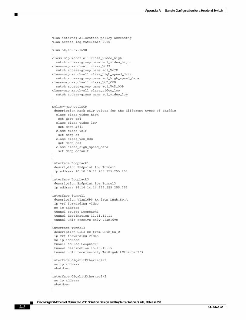
Appendix A Sample Configuration for a Headend Switch
!vlan internal allocation policy ascendingvlan access-log ratelimit 2000!vlan 50,65-67,1690 !class-map match-all class_video_high match access-group name acl_video_highclass-map match-all class_VoIP match access-group name acl_VoIPclass-map match-all class_high_speed_data match access-group name acl_high_speed_dataclass-map match-all class_VoD_OOB match access-group name acl_VoD_OOBclass-map match-all class_video_low match access-group name acl_video_low!!policy-map setDSCP description Mark DSCP values for the different types of traffic class class_video_high set dscp cs4 class class_video_low set dscp af41 class class_VoIP set dscp ef class class_VoD_OOB set dscp cs3 class class_high_speed_data set dscp default!!interface Loopback1 description Endpoint for Tunnel1 ip address 10.10.10.10 255.255.255.255!interface Loopback3 description Endpoint for Tunnel3 ip address 14.14.14.14 255.255.255.255!interface Tunnel1 description Vlan1690 Rx from DHub_Sw_A ip vrf forwarding Video no ip address tunnel source Loopback1 tunnel destination 11.11.11.11 tunnel udlr receive-only Vlan1690!interface Tunnel3 description UDL3 Rx from DHub_Sw_C ip vrf forwarding Video no ip address tunnel source Loopback3 tunnel destination 15.15.15.15 tunnel udlr receive-only TenGigabitEthernet7/3!interface GigabitEthernet2/1 no ip address shutdown!interface GigabitEthernet2/2 no ip address shutdown!
A-2Cisco Gigabit-Ethernet Optimized VoD Solution Design and Implementation Guide, Release 2.0
OL-5472-02
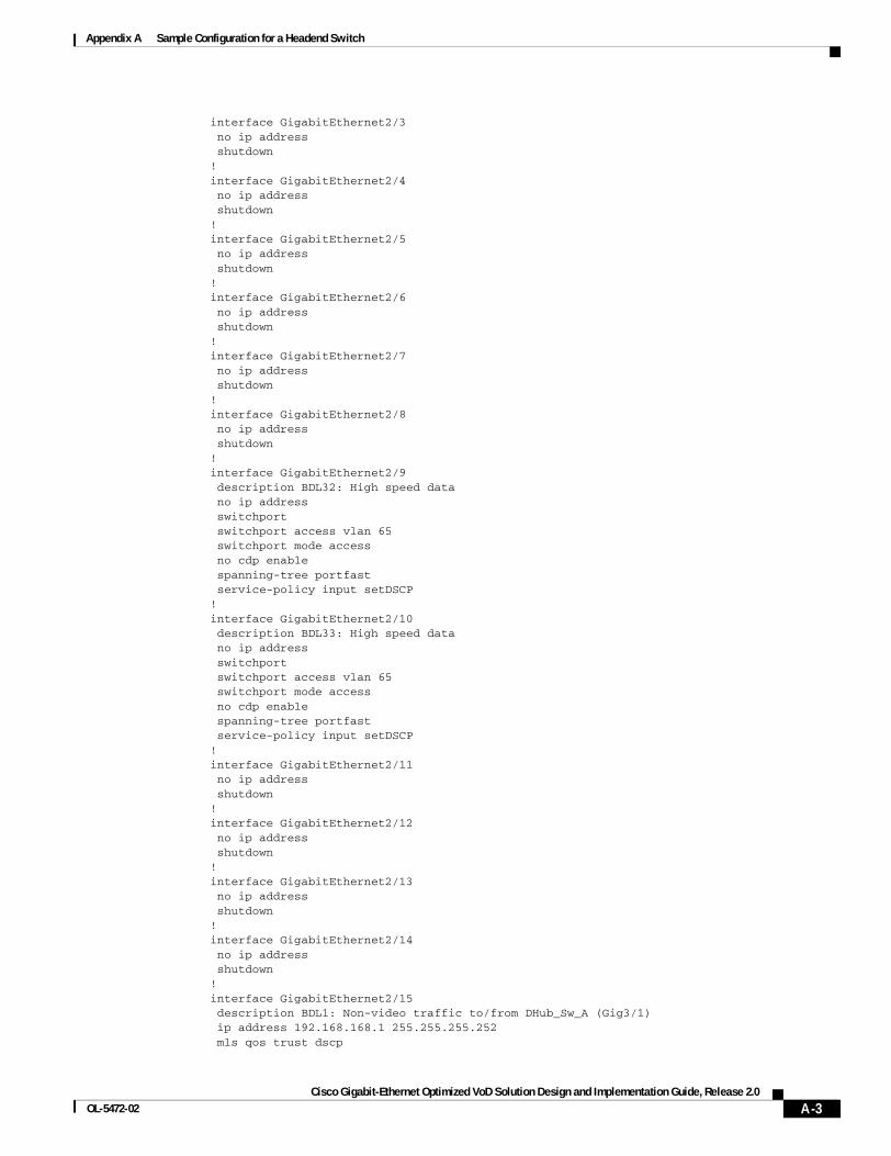
Appendix A Sample Configuration for a Headend Switch
interface GigabitEthernet2/3 no ip address shutdown!interface GigabitEthernet2/4 no ip address shutdown!interface GigabitEthernet2/5 no ip address shutdown!interface GigabitEthernet2/6 no ip address shutdown!interface GigabitEthernet2/7 no ip address shutdown!interface GigabitEthernet2/8 no ip address shutdown!interface GigabitEthernet2/9 description BDL32: High speed data no ip address switchport switchport access vlan 65 switchport mode access no cdp enable spanning-tree portfast service-policy input setDSCP!interface GigabitEthernet2/10 description BDL33: High speed data no ip address switchport switchport access vlan 65 switchport mode access no cdp enable spanning-tree portfast service-policy input setDSCP!interface GigabitEthernet2/11 no ip address shutdown!interface GigabitEthernet2/12 no ip address shutdown!interface GigabitEthernet2/13 no ip address shutdown!interface GigabitEthernet2/14 no ip address shutdown!interface GigabitEthernet2/15 description BDL1: Non-video traffic to/from DHub_Sw_A (Gig3/1) ip address 192.168.168.1 255.255.255.252 mls qos trust dscp
A-3Cisco Gigabit-Ethernet Optimized VoD Solution Design and Implementation Guide, Release 2.0
OL-5472-02
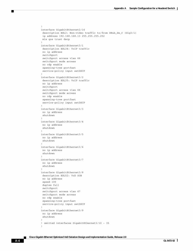
Appendix A Sample Configuration for a Headend Switch
!interface GigabitEthernet2/16 description BDL3: Non-video traffic to/from DHub_Sw_C (Gig3/1) ip address 192.168.168.13 255.255.255.252 mls qos trust dscp!interface GigabitEthernet3/1 description BDL34: VoIP traffic no ip address switchport switchport access vlan 66 switchport mode access no cdp enable spanning-tree portfast service-policy input setDSCP!interface GigabitEthernet3/2 description BDL35: VoIP traffic no ip address switchport switchport access vlan 66 switchport mode access no cdp enable spanning-tree portfast service-policy input setDSCP!interface GigabitEthernet3/3 no ip address shutdown!interface GigabitEthernet3/4 no ip address shutdown!interface GigabitEthernet3/5 no ip address shutdown!interface GigabitEthernet3/6 no ip address shutdown!interface GigabitEthernet3/7 no ip address shutdown!interface GigabitEthernet3/8 description BDL52: VoD OOB no ip address speed 100 duplex full switchport switchport access vlan 67 switchport mode access no cdp enable spanning-tree portfast service-policy input setDSCP!interface GigabitEthernet3/9 no ip address shutdown!! omitted interfaces GigabitEthernet3/10 - 35!
A-4Cisco Gigabit-Ethernet Optimized VoD Solution Design and Implementation Guide, Release 2.0
OL-5472-02
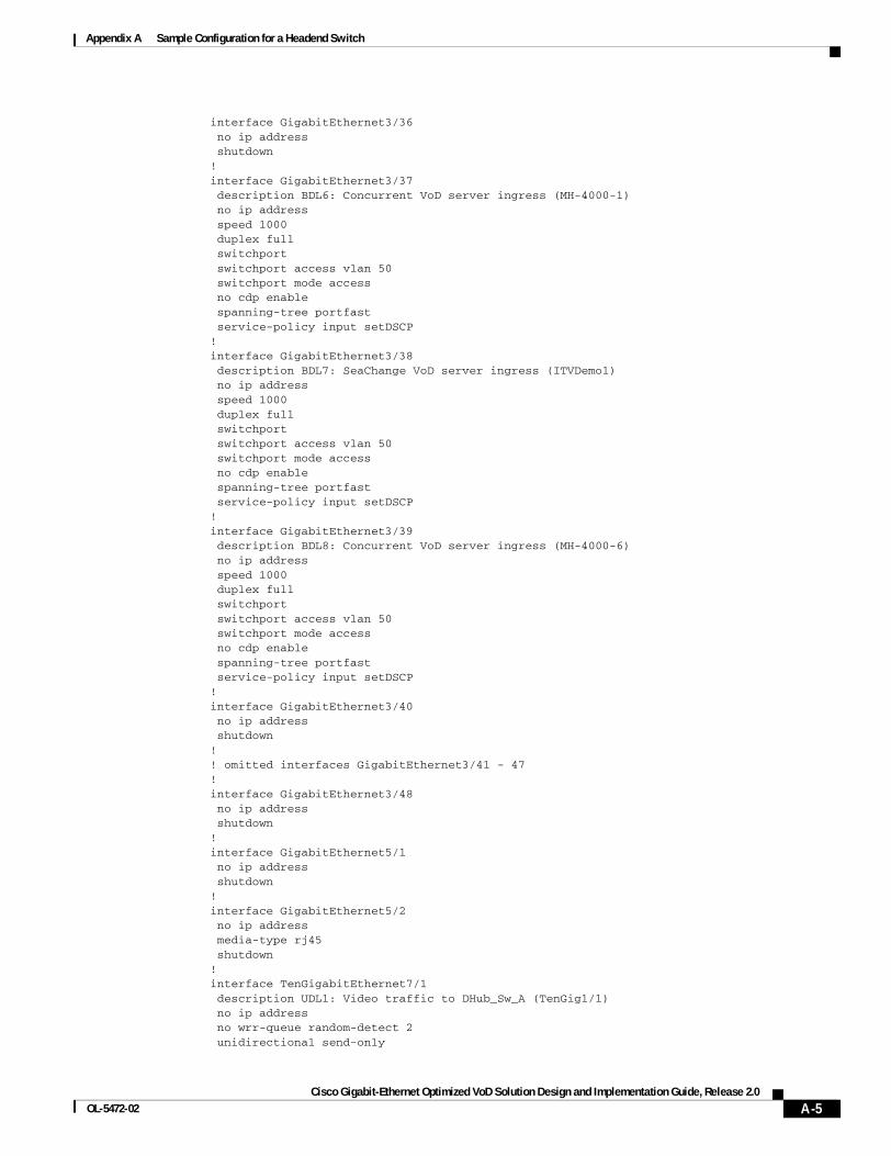
Appendix A Sample Configuration for a Headend Switch
interface GigabitEthernet3/36 no ip address shutdown!interface GigabitEthernet3/37 description BDL6: Concurrent VoD server ingress (MH-4000-1) no ip address speed 1000 duplex full switchport switchport access vlan 50 switchport mode access no cdp enable spanning-tree portfast service-policy input setDSCP!interface GigabitEthernet3/38 description BDL7: SeaChange VoD server ingress (ITVDemo1) no ip address speed 1000 duplex full switchport switchport access vlan 50 switchport mode access no cdp enable spanning-tree portfast service-policy input setDSCP!interface GigabitEthernet3/39 description BDL8: Concurrent VoD server ingress (MH-4000-6) no ip address speed 1000 duplex full switchport switchport access vlan 50 switchport mode access no cdp enable spanning-tree portfast service-policy input setDSCP!interface GigabitEthernet3/40 no ip address shutdown!! omitted interfaces GigabitEthernet3/41 - 47!interface GigabitEthernet3/48 no ip address shutdown!interface GigabitEthernet5/1 no ip address shutdown!interface GigabitEthernet5/2 no ip address media-type rj45 shutdown!interface TenGigabitEthernet7/1 description UDL1: Video traffic to DHub_Sw_A (TenGig1/1) no ip address no wrr-queue random-detect 2 unidirectional send-only
A-5Cisco Gigabit-Ethernet Optimized VoD Solution Design and Implementation Guide, Release 2.0
OL-5472-02
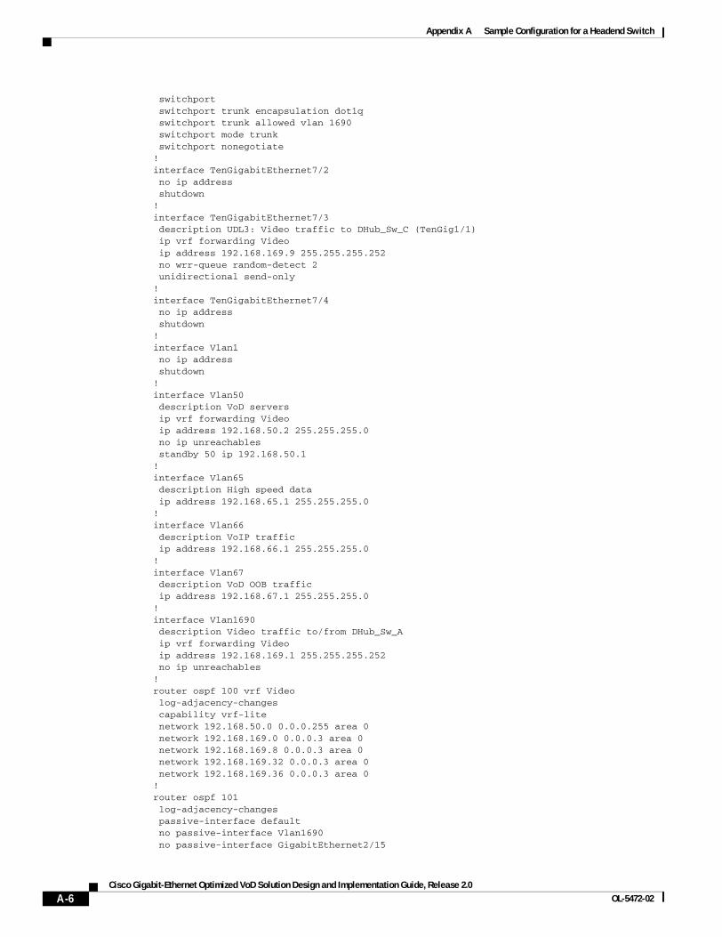
Appendix A Sample Configuration for a Headend Switch
switchport switchport trunk encapsulation dot1q switchport trunk allowed vlan 1690 switchport mode trunk switchport nonegotiate!interface TenGigabitEthernet7/2 no ip address shutdown!interface TenGigabitEthernet7/3 description UDL3: Video traffic to DHub_Sw_C (TenGig1/1) ip vrf forwarding Video ip address 192.168.169.9 255.255.255.252 no wrr-queue random-detect 2 unidirectional send-only!interface TenGigabitEthernet7/4 no ip address shutdown!interface Vlan1 no ip address shutdown!interface Vlan50 description VoD servers ip vrf forwarding Video ip address 192.168.50.2 255.255.255.0 no ip unreachables standby 50 ip 192.168.50.1!interface Vlan65 description High speed data ip address 192.168.65.1 255.255.255.0!interface Vlan66 description VoIP traffic ip address 192.168.66.1 255.255.255.0!interface Vlan67 description VoD OOB traffic ip address 192.168.67.1 255.255.255.0!interface Vlan1690 description Video traffic to/from DHub_Sw_A ip vrf forwarding Video ip address 192.168.169.1 255.255.255.252 no ip unreachables!router ospf 100 vrf Video log-adjacency-changes capability vrf-lite network 192.168.50.0 0.0.0.255 area 0 network 192.168.169.0 0.0.0.3 area 0 network 192.168.169.8 0.0.0.3 area 0 network 192.168.169.32 0.0.0.3 area 0 network 192.168.169.36 0.0.0.3 area 0!router ospf 101 log-adjacency-changes passive-interface default no passive-interface Vlan1690 no passive-interface GigabitEthernet2/15
A-6Cisco Gigabit-Ethernet Optimized VoD Solution Design and Implementation Guide, Release 2.0
OL-5472-02
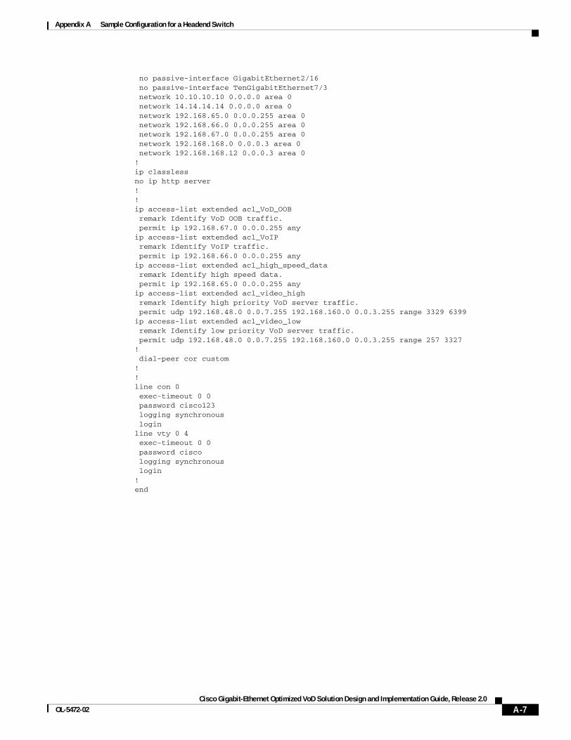
Appendix A Sample Configuration for a Headend Switch
no passive-interface GigabitEthernet2/16 no passive-interface TenGigabitEthernet7/3 network 10.10.10.10 0.0.0.0 area 0 network 14.14.14.14 0.0.0.0 area 0 network 192.168.65.0 0.0.0.255 area 0 network 192.168.66.0 0.0.0.255 area 0 network 192.168.67.0 0.0.0.255 area 0 network 192.168.168.0 0.0.0.3 area 0 network 192.168.168.12 0.0.0.3 area 0!ip classlessno ip http server!!ip access-list extended acl_VoD_OOB remark Identify VoD OOB traffic. permit ip 192.168.67.0 0.0.0.255 anyip access-list extended acl_VoIP remark Identify VoIP traffic. permit ip 192.168.66.0 0.0.0.255 anyip access-list extended acl_high_speed_data remark Identify high speed data. permit ip 192.168.65.0 0.0.0.255 anyip access-list extended acl_video_high remark Identify high priority VoD server traffic. permit udp 192.168.48.0 0.0.7.255 192.168.160.0 0.0.3.255 range 3329 6399ip access-list extended acl_video_low remark Identify low priority VoD server traffic. permit udp 192.168.48.0 0.0.7.255 192.168.160.0 0.0.3.255 range 257 3327! dial-peer cor custom!!line con 0 exec-timeout 0 0 password cisco123 logging synchronous loginline vty 0 4 exec-timeout 0 0 password cisco logging synchronous login!end
A-7Cisco Gigabit-Ethernet Optimized VoD Solution Design and Implementation Guide, Release 2.0
OL-5472-02

Appendix A Sample Configuration for a Headend Switch
A-8Cisco Gigabit-Ethernet Optimized VoD Solution Design and Implementation Guide, Release 2.0
OL-5472-02
Cisco Gigabit-Ethernet Optimized VoD Solution DesignOL-5472-02
A P P E N D I X B
Sample Configurations for Dhub SwitchesThis appendix presents sample configurations for the following Cisco Catalyst 6509 Dhub switches in Figure 3-1 on page 3-2, in Dhub A, Dhub B, and Dhub C, respectively:
• DHub_Sw_A Configuration, page B-1
• DHub_Sw_B Configuration, page B-5
• DHub_Sw_C Configuration, page B-9
DHub_Sw_A Configurationversion 12.2service timestamps debug datetime localtimeservice timestamps log datetime localtimeno service password-encryptionservice internal!hostname DHub_Sw_A!boot system bootflash:s72033-jk9o3sv-mz.122-17d.SXB1.binlogging snmp-authfailenable password cisco123!clock timezone PST -8clock summer-time PDT recurringvtp mode transparentip subnet-zero!!no ip domain-lookup!ip vrf Video description Video traffic received from Headend rd 1000:2!mpls ldp logging neighbor-changesno mls flow ipno mls flow ipv6mls qos map dscp-cos 32 to 5mls qosmls cef error action freeze!!power redundancy-mode combined!
B-1 and Implementation Guide, Release 2.0
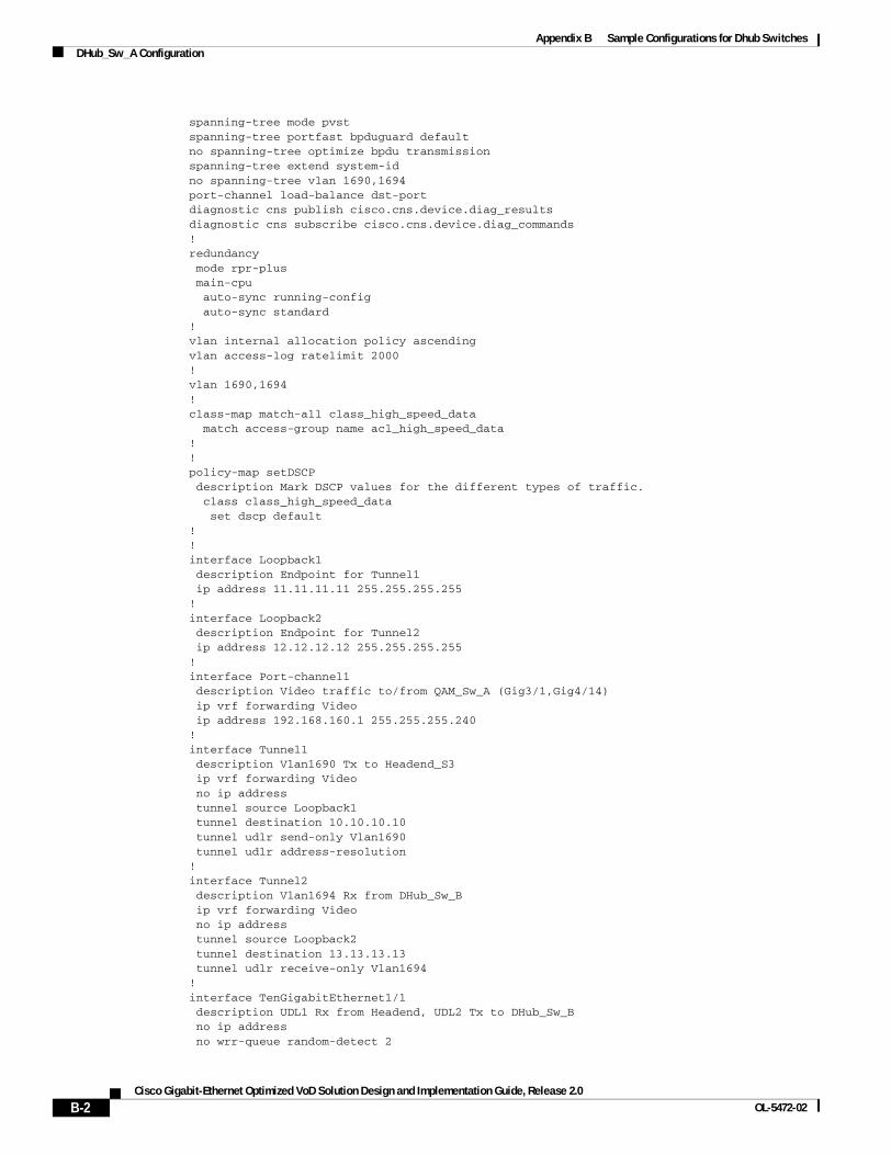
Appendix B Sample Configurations for Dhub SwitchesDHub_Sw_A Configuration
spanning-tree mode pvstspanning-tree portfast bpduguard defaultno spanning-tree optimize bpdu transmissionspanning-tree extend system-idno spanning-tree vlan 1690,1694port-channel load-balance dst-portdiagnostic cns publish cisco.cns.device.diag_resultsdiagnostic cns subscribe cisco.cns.device.diag_commands!redundancy mode rpr-plus main-cpu auto-sync running-config auto-sync standard!vlan internal allocation policy ascendingvlan access-log ratelimit 2000!vlan 1690,1694 !class-map match-all class_high_speed_data match access-group name acl_high_speed_data!!policy-map setDSCP description Mark DSCP values for the different types of traffic. class class_high_speed_data set dscp default!!interface Loopback1 description Endpoint for Tunnel1 ip address 11.11.11.11 255.255.255.255!interface Loopback2 description Endpoint for Tunnel2 ip address 12.12.12.12 255.255.255.255!interface Port-channel1 description Video traffic to/from QAM_Sw_A (Gig3/1,Gig4/14) ip vrf forwarding Video ip address 192.168.160.1 255.255.255.240!interface Tunnel1 description Vlan1690 Tx to Headend_S3 ip vrf forwarding Video no ip address tunnel source Loopback1 tunnel destination 10.10.10.10 tunnel udlr send-only Vlan1690 tunnel udlr address-resolution!interface Tunnel2 description Vlan1694 Rx from DHub_Sw_B ip vrf forwarding Video no ip address tunnel source Loopback2 tunnel destination 13.13.13.13 tunnel udlr receive-only Vlan1694!interface TenGigabitEthernet1/1 description UDL1 Rx from Headend, UDL2 Tx to DHub_Sw_B no ip address no wrr-queue random-detect 2
B-2Cisco Gigabit-Ethernet Optimized VoD Solution Design and Implementation Guide, Release 2.0
OL-5472-02
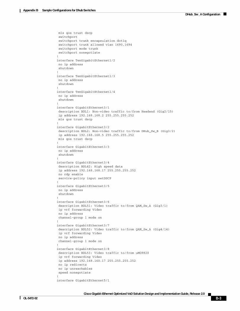
Appendix B Sample Configurations for Dhub SwitchesDHub_Sw_A Configuration
mls qos trust dscp switchport switchport trunk encapsulation dot1q switchport trunk allowed vlan 1690,1694 switchport mode trunk switchport nonegotiate!interface TenGigabitEthernet1/2 no ip address shutdown!interface TenGigabitEthernet1/3 no ip address shutdown!interface TenGigabitEthernet1/4 no ip address shutdown!interface GigabitEthernet3/1 description BDL1: Non-video traffic to/from Headend (Gig2/15) ip address 192.168.168.2 255.255.255.252 mls qos trust dscp!interface GigabitEthernet3/2 description BDL2: Non-video traffic to/from DHub_Sw_B (Gig3/2) ip address 192.168.168.5 255.255.255.252 mls qos trust dscp!interface GigabitEthernet3/3 no ip address shutdown!interface GigabitEthernet3/4 description BDL42: High speed data ip address 192.168.168.17 255.255.255.252 no cdp enable service-policy input setDSCP!interface GigabitEthernet3/5 no ip address shutdown!interface GigabitEthernet3/6 description BDL51: Video traffic to/from QAM_Sw_A (Gig3/1) ip vrf forwarding Video no ip address channel-group 1 mode on!interface GigabitEthernet3/7 description BDL52: Video traffic to/from QAM_Sw_A (Gig4/14) ip vrf forwarding Video no ip address channel-group 1 mode on!interface GigabitEthernet3/8 description BDL53: Video traffic to/from uMG9820 ip vrf forwarding Video ip address 192.168.160.17 255.255.255.252 no ip redirects no ip unreachables speed nonegotiate!interface GigabitEthernet5/1
B-3Cisco Gigabit-Ethernet Optimized VoD Solution Design and Implementation Guide, Release 2.0
OL-5472-02
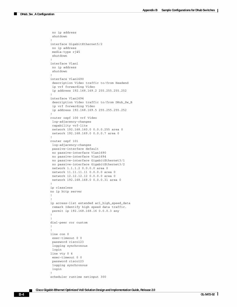
Appendix B Sample Configurations for Dhub SwitchesDHub_Sw_A Configuration
no ip address shutdown!interface GigabitEthernet5/2 no ip address media-type rj45 shutdown!interface Vlan1 no ip address shutdown!interface Vlan1690 description Video traffic to/from Headend ip vrf forwarding Video ip address 192.168.169.2 255.255.255.252!interface Vlan1694 description Video traffic to/from DHub_Sw_B ip vrf forwarding Video ip address 192.168.169.5 255.255.255.252!router ospf 100 vrf Video log-adjacency-changes capability vrf-lite network 192.168.160.0 0.0.0.255 area 0 network 192.168.169.0 0.0.0.7 area 0!router ospf 101 log-adjacency-changes passive-interface default no passive-interface Vlan1690 no passive-interface Vlan1694 no passive-interface GigabitEthernet3/1 no passive-interface GigabitEthernet3/2 network 1.1.1.2 0.0.0.0 area 0 network 11.11.11.11 0.0.0.0 area 0 network 12.12.12.12 0.0.0.0 area 0 network 192.168.168.0 0.0.0.31 area 0!ip classlessno ip http server!!ip access-list extended acl_high_speed_data remark Identify high speed data traffic. permit ip 192.168.168.16 0.0.0.3 any!!dial-peer cor custom!!line con 0 exec-timeout 0 0 password cisco123 logging synchronous loginline vty 0 4 exec-timeout 0 0 password cisco123 logging synchronous login!scheduler runtime netinput 300
B-4Cisco Gigabit-Ethernet Optimized VoD Solution Design and Implementation Guide, Release 2.0
OL-5472-02
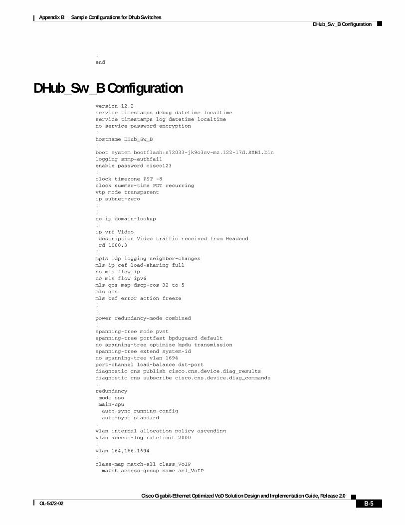
Appendix B Sample Configurations for Dhub SwitchesDHub_Sw_B Configuration
!end
DHub_Sw_B Configurationversion 12.2service timestamps debug datetime localtimeservice timestamps log datetime localtimeno service password-encryption!hostname DHub_Sw_B!boot system bootflash:s72033-jk9o3sv-mz.122-17d.SXB1.binlogging snmp-authfailenable password cisco123!clock timezone PST -8clock summer-time PDT recurringvtp mode transparentip subnet-zero!!no ip domain-lookup!ip vrf Video description Video traffic received from Headend rd 1000:3!mpls ldp logging neighbor-changesmls ip cef load-sharing fullno mls flow ipno mls flow ipv6mls qos map dscp-cos 32 to 5mls qosmls cef error action freeze!!power redundancy-mode combined!spanning-tree mode pvstspanning-tree portfast bpduguard defaultno spanning-tree optimize bpdu transmissionspanning-tree extend system-idno spanning-tree vlan 1694port-channel load-balance dst-portdiagnostic cns publish cisco.cns.device.diag_resultsdiagnostic cns subscribe cisco.cns.device.diag_commands!redundancy mode sso main-cpu auto-sync running-config auto-sync standard!vlan internal allocation policy ascendingvlan access-log ratelimit 2000!vlan 164,166,1694 !class-map match-all class_VoIP match access-group name acl_VoIP
B-5Cisco Gigabit-Ethernet Optimized VoD Solution Design and Implementation Guide, Release 2.0
OL-5472-02
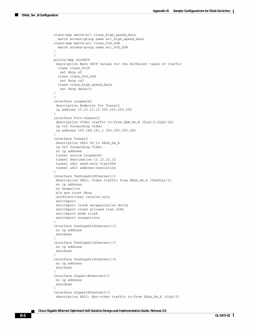
Appendix B Sample Configurations for Dhub SwitchesDHub_Sw_B Configuration
class-map match-all class_high_speed_data match access-group name acl_high_speed_dataclass-map match-all class_VoD_OOB match access-group name acl_VoD_OOB!!policy-map setDSCP description Mark DSCP values for the different types of traffic class class_VoIP set dscp ef class class_VoD_OOB set dscp cs3 class class_high_speed_data set dscp default!!interface Loopback2 description Endpoint for Tunnel2 ip address 13.13.13.13 255.255.255.255!interface Port-channel2 description Video traffic to/from QAM_Sw_B (Gig3/2,Gig5/14) ip vrf forwarding Video ip address 192.168.161.1 255.255.255.240!interface Tunnel2 description UDL2 Tx to DHub_Sw_A ip vrf forwarding Video no ip address tunnel source Loopback2 tunnel destination 12.12.12.12 tunnel udlr send-only Vlan1694 tunnel udlr address-resolution!interface TenGigabitEthernet1/1 description UDL2: Video traffic from DHub_Sw_A (TenGig1/1) no ip address no keepalive mls qos trust dscp unidirectional receive-only switchport switchport trunk encapsulation dot1q switchport trunk allowed vlan 1694 switchport mode trunk switchport nonegotiate!interface TenGigabitEthernet1/2 no ip address shutdown!interface TenGigabitEthernet1/3 no ip address shutdown!interface TenGigabitEthernet1/4 no ip address shutdown!interface GigabitEthernet3/1 no ip address shutdown!interface GigabitEthernet3/2 description BDL2: Non-video traffic to/from DHub_Sw_A (Gig3/2)
B-6Cisco Gigabit-Ethernet Optimized VoD Solution Design and Implementation Guide, Release 2.0
OL-5472-02
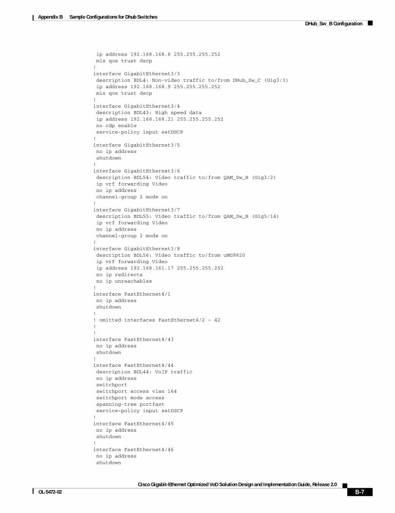
Appendix B Sample Configurations for Dhub SwitchesDHub_Sw_B Configuration
ip address 192.168.168.6 255.255.255.252 mls qos trust dscp!interface GigabitEthernet3/3 description BDL4: Non-video traffic to/from DHub_Sw_C (Gig3/3) ip address 192.168.168.9 255.255.255.252 mls qos trust dscp!interface GigabitEthernet3/4 description BDL43: High speed data ip address 192.168.168.21 255.255.255.252 no cdp enable service-policy input setDSCP!interface GigabitEthernet3/5 no ip address shutdown!interface GigabitEthernet3/6 description BDL54: Video traffic to/from QAM_Sw_B (Gig3/2) ip vrf forwarding Video no ip address channel-group 2 mode on!interface GigabitEthernet3/7 description BDL55: Video traffic to/from QAM_Sw_B (Gig5/14) ip vrf forwarding Video no ip address channel-group 2 mode on!interface GigabitEthernet3/8 description BDL56: Video traffic to/from uMG9820 ip vrf forwarding Video ip address 192.168.161.17 255.255.255.252 no ip redirects no ip unreachables!interface FastEthernet4/1 no ip address shutdown!! omitted interfaces FastEthernet4/2 - 42!!interface FastEthernet4/43 no ip address shutdown!interface FastEthernet4/44 description BDL44: VoIP traffic no ip address switchport switchport access vlan 164 switchport mode access spanning-tree portfast service-policy input setDSCP!interface FastEthernet4/45 no ip address shutdown!interface FastEthernet4/46 no ip address shutdown
B-7Cisco Gigabit-Ethernet Optimized VoD Solution Design and Implementation Guide, Release 2.0
OL-5472-02
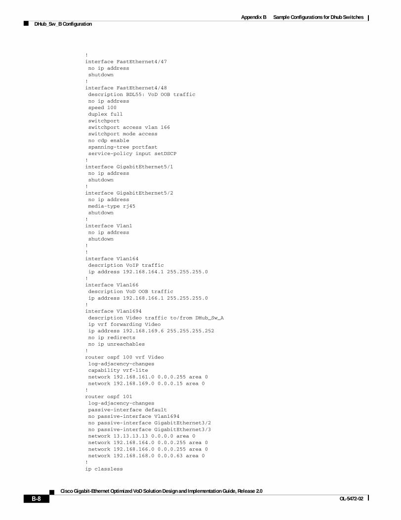
Appendix B Sample Configurations for Dhub SwitchesDHub_Sw_B Configuration
!interface FastEthernet4/47 no ip address shutdown!interface FastEthernet4/48 description BDL55: VoD OOB traffic no ip address speed 100 duplex full switchport switchport access vlan 166 switchport mode access no cdp enable spanning-tree portfast service-policy input setDSCP!interface GigabitEthernet5/1 no ip address shutdown!interface GigabitEthernet5/2 no ip address media-type rj45 shutdown!interface Vlan1 no ip address shutdown!!interface Vlan164 description VoIP traffic ip address 192.168.164.1 255.255.255.0!interface Vlan166 description VoD OOB traffic ip address 192.168.166.1 255.255.255.0!interface Vlan1694 description Video traffic to/from DHub_Sw_A ip vrf forwarding Video ip address 192.168.169.6 255.255.255.252 no ip redirects no ip unreachables!router ospf 100 vrf Video log-adjacency-changes capability vrf-lite network 192.168.161.0 0.0.0.255 area 0 network 192.168.169.0 0.0.0.15 area 0!router ospf 101 log-adjacency-changes passive-interface default no passive-interface Vlan1694 no passive-interface GigabitEthernet3/2 no passive-interface GigabitEthernet3/3 network 13.13.13.13 0.0.0.0 area 0 network 192.168.164.0 0.0.0.255 area 0 network 192.168.166.0 0.0.0.255 area 0 network 192.168.168.0 0.0.0.63 area 0!ip classless
B-8Cisco Gigabit-Ethernet Optimized VoD Solution Design and Implementation Guide, Release 2.0
OL-5472-02
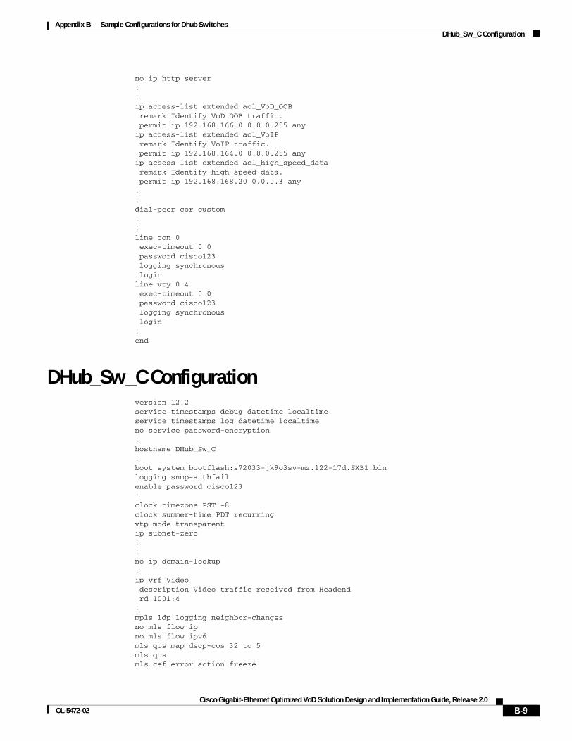
Appendix B Sample Configurations for Dhub SwitchesDHub_Sw_C Configuration
no ip http server!!ip access-list extended acl_VoD_OOB remark Identify VoD OOB traffic. permit ip 192.168.166.0 0.0.0.255 anyip access-list extended acl_VoIP remark Identify VoIP traffic. permit ip 192.168.164.0 0.0.0.255 anyip access-list extended acl_high_speed_data remark Identify high speed data. permit ip 192.168.168.20 0.0.0.3 any!!dial-peer cor custom!!line con 0 exec-timeout 0 0 password cisco123 logging synchronous loginline vty 0 4 exec-timeout 0 0 password cisco123 logging synchronous login!end
DHub_Sw_C Configurationversion 12.2service timestamps debug datetime localtimeservice timestamps log datetime localtimeno service password-encryption!hostname DHub_Sw_C!boot system bootflash:s72033-jk9o3sv-mz.122-17d.SXB1.binlogging snmp-authfailenable password cisco123!clock timezone PST -8clock summer-time PDT recurringvtp mode transparentip subnet-zero!!no ip domain-lookup!ip vrf Video description Video traffic received from Headend rd 1001:4!mpls ldp logging neighbor-changesno mls flow ipno mls flow ipv6mls qos map dscp-cos 32 to 5mls qosmls cef error action freeze
B-9Cisco Gigabit-Ethernet Optimized VoD Solution Design and Implementation Guide, Release 2.0
OL-5472-02
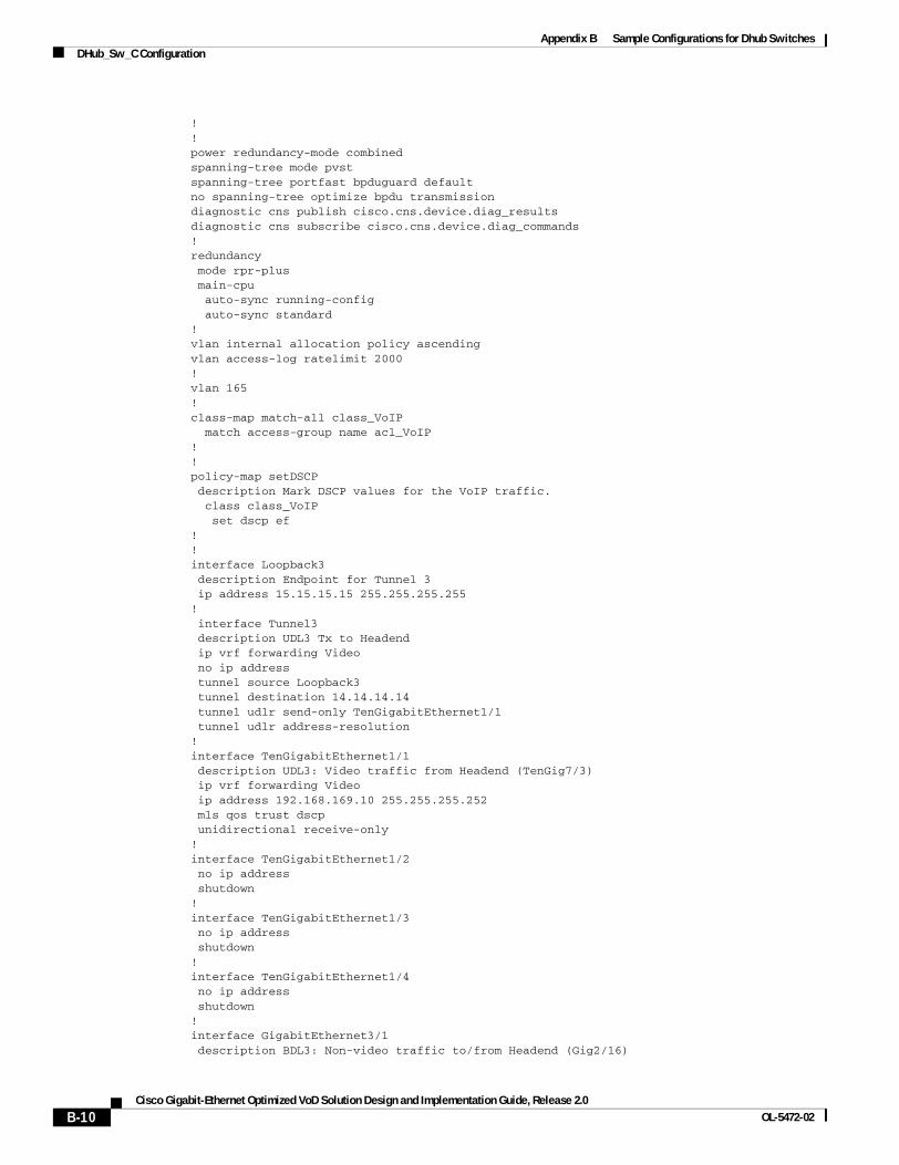
Appendix B Sample Configurations for Dhub SwitchesDHub_Sw_C Configuration
!!power redundancy-mode combinedspanning-tree mode pvstspanning-tree portfast bpduguard defaultno spanning-tree optimize bpdu transmissiondiagnostic cns publish cisco.cns.device.diag_resultsdiagnostic cns subscribe cisco.cns.device.diag_commands!redundancy mode rpr-plus main-cpu auto-sync running-config auto-sync standard!vlan internal allocation policy ascendingvlan access-log ratelimit 2000!vlan 165 !class-map match-all class_VoIP match access-group name acl_VoIP!!policy-map setDSCP description Mark DSCP values for the VoIP traffic. class class_VoIP set dscp ef!!interface Loopback3 description Endpoint for Tunnel 3 ip address 15.15.15.15 255.255.255.255! interface Tunnel3 description UDL3 Tx to Headend ip vrf forwarding Video no ip address tunnel source Loopback3 tunnel destination 14.14.14.14 tunnel udlr send-only TenGigabitEthernet1/1 tunnel udlr address-resolution!interface TenGigabitEthernet1/1 description UDL3: Video traffic from Headend (TenGig7/3) ip vrf forwarding Video ip address 192.168.169.10 255.255.255.252 mls qos trust dscp unidirectional receive-only!interface TenGigabitEthernet1/2 no ip address shutdown!interface TenGigabitEthernet1/3 no ip address shutdown!interface TenGigabitEthernet1/4 no ip address shutdown!interface GigabitEthernet3/1 description BDL3: Non-video traffic to/from Headend (Gig2/16)
B-10Cisco Gigabit-Ethernet Optimized VoD Solution Design and Implementation Guide, Release 2.0
OL-5472-02
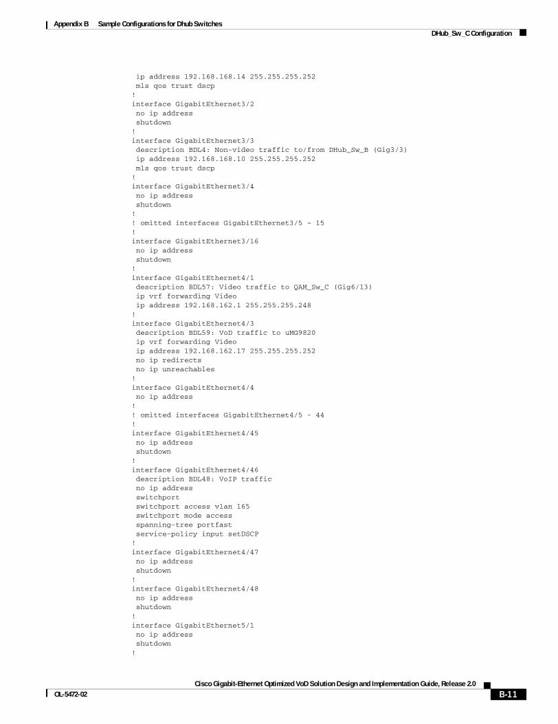
Appendix B Sample Configurations for Dhub SwitchesDHub_Sw_C Configuration
ip address 192.168.168.14 255.255.255.252 mls qos trust dscp!interface GigabitEthernet3/2 no ip address shutdown!interface GigabitEthernet3/3 description BDL4: Non-video traffic to/from DHub_Sw_B (Gig3/3) ip address 192.168.168.10 255.255.255.252 mls qos trust dscp!interface GigabitEthernet3/4 no ip address shutdown!! omitted interfaces GigabitEthernet3/5 - 15!interface GigabitEthernet3/16 no ip address shutdown!interface GigabitEthernet4/1 description BDL57: Video traffic to QAM_Sw_C (Gig6/13) ip vrf forwarding Video ip address 192.168.162.1 255.255.255.248!interface GigabitEthernet4/3 description BDL59: VoD traffic to uMG9820 ip vrf forwarding Video ip address 192.168.162.17 255.255.255.252 no ip redirects no ip unreachables!interface GigabitEthernet4/4 no ip address!! omitted interfaces GigabitEthernet4/5 - 44!interface GigabitEthernet4/45 no ip address shutdown!interface GigabitEthernet4/46 description BDL48: VoIP traffic no ip address switchport switchport access vlan 165 switchport mode access spanning-tree portfast service-policy input setDSCP!interface GigabitEthernet4/47 no ip address shutdown!interface GigabitEthernet4/48 no ip address shutdown!interface GigabitEthernet5/1 no ip address shutdown!
B-11Cisco Gigabit-Ethernet Optimized VoD Solution Design and Implementation Guide, Release 2.0
OL-5472-02
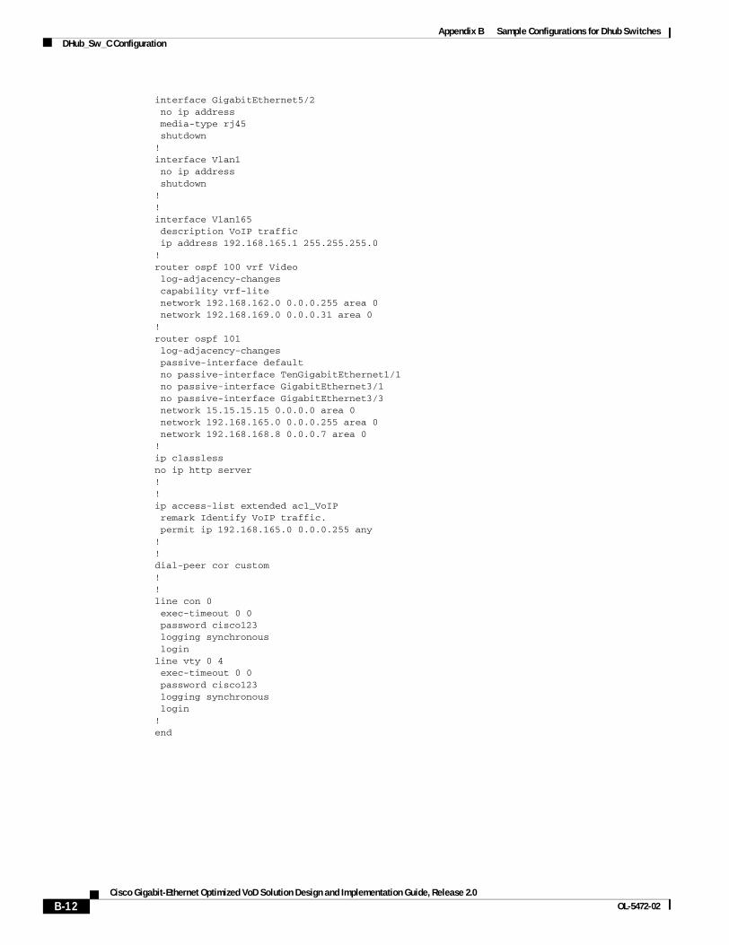
Appendix B Sample Configurations for Dhub SwitchesDHub_Sw_C Configuration
interface GigabitEthernet5/2 no ip address media-type rj45 shutdown!interface Vlan1 no ip address shutdown!!interface Vlan165 description VoIP traffic ip address 192.168.165.1 255.255.255.0!router ospf 100 vrf Video log-adjacency-changes capability vrf-lite network 192.168.162.0 0.0.0.255 area 0 network 192.168.169.0 0.0.0.31 area 0!router ospf 101 log-adjacency-changes passive-interface default no passive-interface TenGigabitEthernet1/1 no passive-interface GigabitEthernet3/1 no passive-interface GigabitEthernet3/3 network 15.15.15.15 0.0.0.0 area 0 network 192.168.165.0 0.0.0.255 area 0 network 192.168.168.8 0.0.0.7 area 0!ip classlessno ip http server!!ip access-list extended acl_VoIP remark Identify VoIP traffic. permit ip 192.168.165.0 0.0.0.255 any!!dial-peer cor custom!!line con 0 exec-timeout 0 0 password cisco123 logging synchronous loginline vty 0 4 exec-timeout 0 0 password cisco123 logging synchronous login!end
B-12Cisco Gigabit-Ethernet Optimized VoD Solution Design and Implementation Guide, Release 2.0
OL-5472-02
Cisco Gigabit-Ethernet Optimized VoD Solution DesignOL-5472-02
A P P E N D I X C
Sample Configurations for QAM SwitchesThis appendix presents sample configurations for the following Cisco Catalyst 4507 QAM switches in Figure 3-1 on page 3-2, in Dhub A, Dhub B, and Dhub C, respectively:
• QAM_Sw_A Configuration, page C-1
• QAM_Sw_B Configuration, page C-6
• QAM_Sw_C Configuration, page C-9
QAM_Sw_A Configurationversion 12.1no service padservice timestamps debug datetime localtimeservice timestamps log datetime localtimeno service password-encryptionservice internalservice compress-config!hostname QAM_Sw_A!boot system bootflash:cat4000-i5su3-mz.mr1.403no logging console!vtp mode transparentip subnet-zerono ip domain-lookup! video 4 route Vlan160 ip-address 192.168.160.3video 4 emulation-mode 24-qam-numbervideo 7 route Vlan160 ip-address 192.168.160.4video 7 emulation-mode 24-qam-numberspanning-tree portfast bpduguard defaultspanning-tree extend system-id!redundancy notification-timer 60000 mode rpr main-cpu auto-sync standard!!vlan 160!!
C-1 and Implementation Guide, Release 2.0
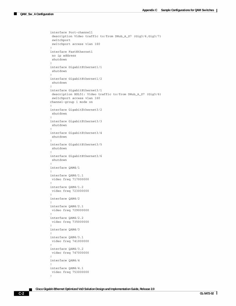
Appendix C Sample Configurations for QAM SwitchesQAM_Sw_A Configuration
interface Port-channel1 description Video traffic to/from DHub_A_S7 (Gig3/6,Gig3/7) switchport switchport access vlan 160!interface FastEthernet1 no ip address shutdown!interface GigabitEthernet1/1 shutdown!interface GigabitEthernet1/2 shutdown!interface GigabitEthernet3/1 description BDL51: Video traffic to/from DHub_A_S7 (Gig3/6) switchport access vlan 160channel-group 1 mode on!interface GigabitEthernet3/2 shutdown!interface GigabitEthernet3/3 shutdown!interface GigabitEthernet3/4 shutdown!interface GigabitEthernet3/5 shutdown!interface GigabitEthernet3/6 shutdown!interface QAM4/1!interface QAM4/1.1 video freq 717000000!interface QAM4/1.2 video freq 723000000!interface QAM4/2!interface QAM4/2.1 video freq 729000000!interface QAM4/2.2 video freq 735000000!interface QAM4/3!interface QAM4/3.1 video freq 741000000!interface QAM4/3.2 video freq 747000000!interface QAM4/4!interface QAM4/4.1 video freq 753000000!
C-2Cisco Gigabit-Ethernet Optimized VoD Solution Design and Implementation Guide, Release 2.0
OL-5472-02
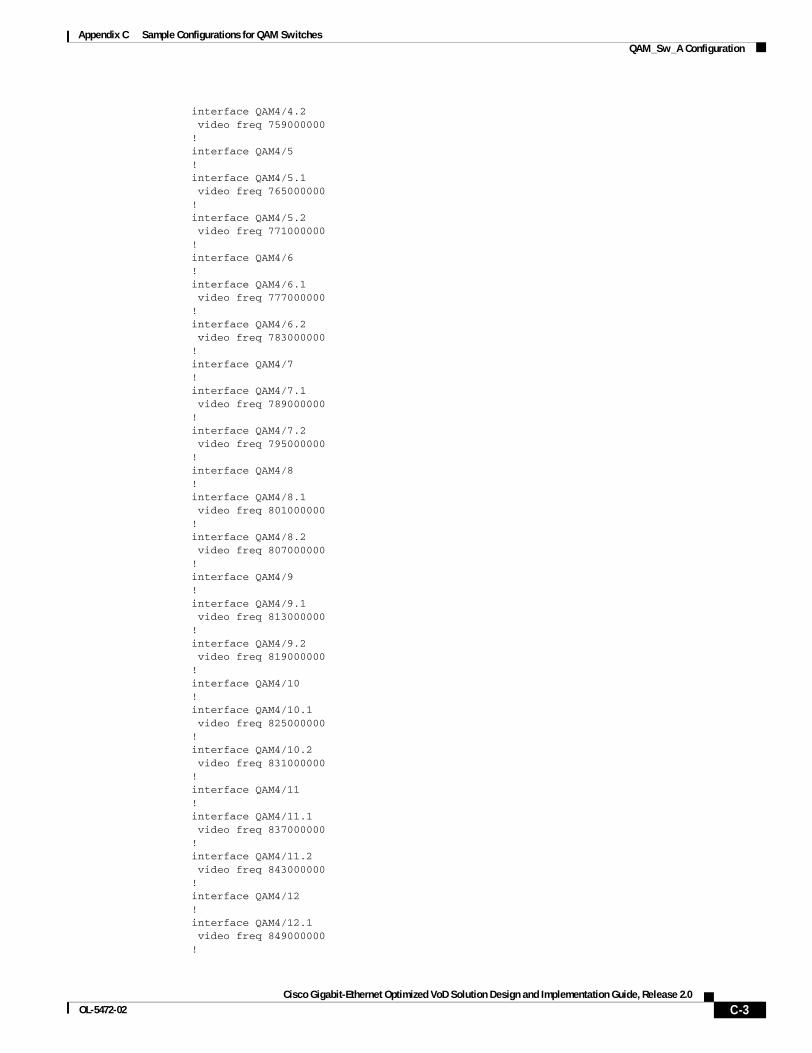
Appendix C Sample Configurations for QAM SwitchesQAM_Sw_A Configuration
interface QAM4/4.2 video freq 759000000!interface QAM4/5!interface QAM4/5.1 video freq 765000000!interface QAM4/5.2 video freq 771000000!interface QAM4/6!interface QAM4/6.1 video freq 777000000!interface QAM4/6.2 video freq 783000000!interface QAM4/7!interface QAM4/7.1 video freq 789000000! interface QAM4/7.2 video freq 795000000!interface QAM4/8!interface QAM4/8.1 video freq 801000000!interface QAM4/8.2 video freq 807000000!interface QAM4/9!interface QAM4/9.1 video freq 813000000!interface QAM4/9.2 video freq 819000000!interface QAM4/10!interface QAM4/10.1 video freq 825000000!interface QAM4/10.2 video freq 831000000!interface QAM4/11!interface QAM4/11.1 video freq 837000000!interface QAM4/11.2 video freq 843000000!interface QAM4/12!interface QAM4/12.1 video freq 849000000!
C-3Cisco Gigabit-Ethernet Optimized VoD Solution Design and Implementation Guide, Release 2.0
OL-5472-02
Appendix C Sample Configurations for QAM SwitchesQAM_Sw_A Configuration
interface QAM4/12.2 video freq 855000000!interface GigabitEthernet4/13 shutdown! interface GigabitEthernet4/14 description BDL52: Video traffic to/from DHub_A_S7 (Gig3/7) switchport access vlan 160 channel-group 1 mode on!interface ASI4/15 keepalive 5 video route qam 4/1.1!interface QAM7/1!interface QAM7/1.1 video freq 717000000!interface QAM7/1.2 video freq 723000000!interface QAM7/2!interface QAM7/2.1 video freq 729000000!interface QAM7/2.2 video freq 735000000!interface QAM7/3!interface QAM7/3.1 video freq 741000000!interface QAM7/3.2 video freq 747000000! interface QAM7/4!interface QAM7/4.1 video freq 753000000!interface QAM7/4.2 video freq 759000000!interface QAM7/5!interface QAM7/5.1 video freq 765000000!interface QAM7/5.2 video freq 771000000!interface QAM7/6!interface QAM7/6.1 video freq 777000000!interface QAM7/6.2 video freq 783000000!interface QAM7/7
C-4Cisco Gigabit-Ethernet Optimized VoD Solution Design and Implementation Guide, Release 2.0
OL-5472-02
Appendix C Sample Configurations for QAM SwitchesQAM_Sw_A Configuration
!interface QAM7/7.1 video freq 789000000!interface QAM7/7.2 video freq 795000000!interface QAM7/8!interface QAM7/8.1 video freq 801000000!interface QAM7/8.2 video freq 807000000!interface QAM7/9!interface QAM7/9.1 video freq 813000000!interface QAM7/9.2 video freq 819000000!interface QAM7/10!interface QAM7/10.1 video freq 825000000!interface QAM7/10.2 video freq 831000000!interface QAM7/11!interface QAM7/11.1 video freq 837000000!interface QAM7/11.2 video freq 843000000!interface QAM7/12!interface QAM7/12.1 video freq 849000000! interface QAM7/12.2 video freq 855000000!interface GigabitEthernet7/13!interface GigabitEthernet7/14!interface ASI7/15 no ip address keepalive 5 shutdown!interface Vlan1 no ip address!interface Vlan160 description Video traffic to/from DHub_A_S7 ip address 192.168.160.2 255.255.255.240!!
C-5Cisco Gigabit-Ethernet Optimized VoD Solution Design and Implementation Guide, Release 2.0
OL-5472-02
Appendix C Sample Configurations for QAM SwitchesQAM_Sw_B Configuration
ip classlessno ip http server!! line con 0 exec-timeout 0 0 password cisco123 logging synchronous login stopbits 1line vty 0 4 exec-timeout 0 0 password cisco123 logging synchronous login!scheduler runtime netinput 100!end
QAM_Sw_B Configurationversion 12.1no service padservice timestamps debug datetime localtimeservice timestamps log datetime localtimeno service password-encryptionservice internalservice compress-config!hostname QAM_Sw_B!boot system bootflash:cat4000-i5su3-mz.mr1.403no logging console!vtp mode transparentip subnet-zerono ip domain-lookup! video 5 route Vlan161 ip-address 192.168.161.3video 5 emulation-mode 24-qam-numberspanning-tree portfast bpduguard defaultspanning-tree extend system-id!redundancy notification-timer 60000 mode rpr main-cpu auto-sync standard!!vlan 161 !!interface Port-channel2 description Video traffic to/from DHub_B_S7 (Gig3/6,Gig3/7) switchport switchport access vlan 161!interface FastEthernet1 no ip address
C-6Cisco Gigabit-Ethernet Optimized VoD Solution Design and Implementation Guide, Release 2.0
OL-5472-02
Appendix C Sample Configurations for QAM SwitchesQAM_Sw_B Configuration
shutdown!interface GigabitEthernet1/1 shutdown!interface GigabitEthernet1/2 shutdown!interface GigabitEthernet3/1 shutdown!interface GigabitEthernet3/2 description BDL54: Video traffic to/from DHub_B_S7 (Gig3/6) switchport access vlan 161 channel-group 2 mode on!interface GigabitEthernet3/3 shutdown!interface GigabitEthernet3/4 shutdown!interface GigabitEthernet3/5 shutdown!interface GigabitEthernet3/6 shutdown!!interface QAM5/1!interface QAM5/1.1 video freq 717000000!interface QAM5/1.2 video freq 723000000!interface QAM5/2!interface QAM5/2.1 video freq 729000000! interface QAM5/2.2 video freq 735000000!interface QAM5/3!interface QAM5/3.1 video freq 741000000!interface QAM5/3.2 video freq 747000000!interface QAM5/4!interface QAM5/4.1 video freq 753000000!interface QAM5/4.2 video freq 759000000!interface QAM5/5!interface QAM5/5.1
C-7Cisco Gigabit-Ethernet Optimized VoD Solution Design and Implementation Guide, Release 2.0
OL-5472-02
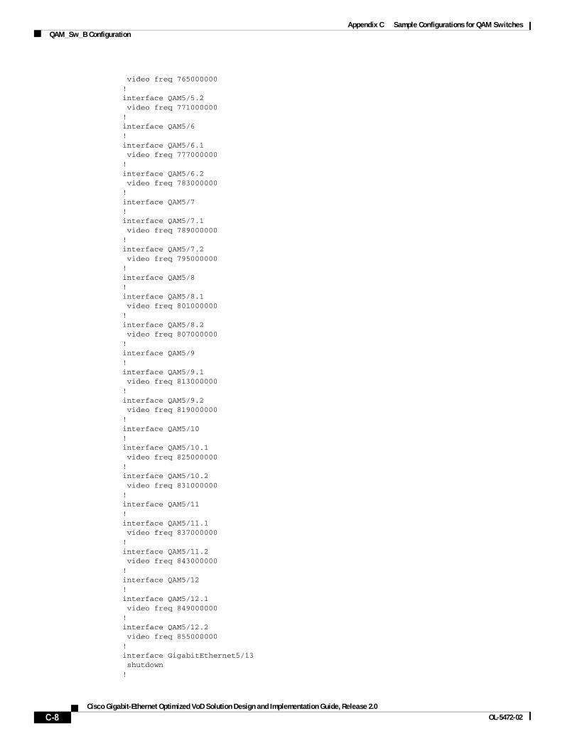
Appendix C Sample Configurations for QAM SwitchesQAM_Sw_B Configuration
video freq 765000000!interface QAM5/5.2 video freq 771000000!interface QAM5/6!interface QAM5/6.1 video freq 777000000!interface QAM5/6.2 video freq 783000000!interface QAM5/7!interface QAM5/7.1 video freq 789000000!interface QAM5/7.2 video freq 795000000!interface QAM5/8!interface QAM5/8.1 video freq 801000000!interface QAM5/8.2 video freq 807000000!interface QAM5/9!interface QAM5/9.1 video freq 813000000!interface QAM5/9.2 video freq 819000000!interface QAM5/10!interface QAM5/10.1 video freq 825000000!interface QAM5/10.2 video freq 831000000!interface QAM5/11! interface QAM5/11.1 video freq 837000000!interface QAM5/11.2 video freq 843000000!interface QAM5/12!interface QAM5/12.1 video freq 849000000!interface QAM5/12.2 video freq 855000000!interface GigabitEthernet5/13 shutdown!
C-8Cisco Gigabit-Ethernet Optimized VoD Solution Design and Implementation Guide, Release 2.0
OL-5472-02
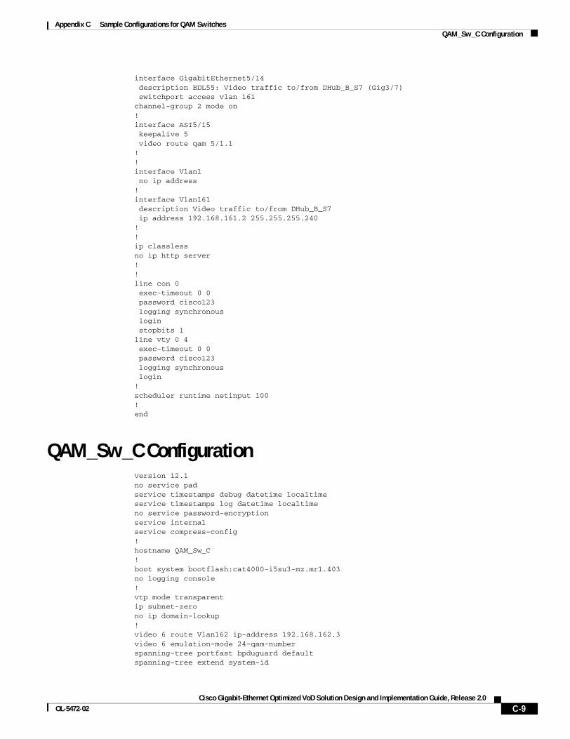
Appendix C Sample Configurations for QAM SwitchesQAM_Sw_C Configuration
interface GigabitEthernet5/14 description BDL55: Video traffic to/from DHub_B_S7 (Gig3/7) switchport access vlan 161channel-group 2 mode on! interface ASI5/15 keepalive 5 video route qam 5/1.1!!interface Vlan1 no ip address!interface Vlan161 description Video traffic to/from DHub_B_S7 ip address 192.168.161.2 255.255.255.240!!ip classlessno ip http server!! line con 0 exec-timeout 0 0 password cisco123 logging synchronous login stopbits 1line vty 0 4 exec-timeout 0 0 password cisco123 logging synchronous login!scheduler runtime netinput 100!end
QAM_Sw_C Configurationversion 12.1no service padservice timestamps debug datetime localtimeservice timestamps log datetime localtimeno service password-encryptionservice internalservice compress-config!hostname QAM_Sw_C!boot system bootflash:cat4000-i5su3-mz.mr1.403no logging console!vtp mode transparentip subnet-zerono ip domain-lookup! video 6 route Vlan162 ip-address 192.168.162.3video 6 emulation-mode 24-qam-numberspanning-tree portfast bpduguard defaultspanning-tree extend system-id
C-9Cisco Gigabit-Ethernet Optimized VoD Solution Design and Implementation Guide, Release 2.0
OL-5472-02
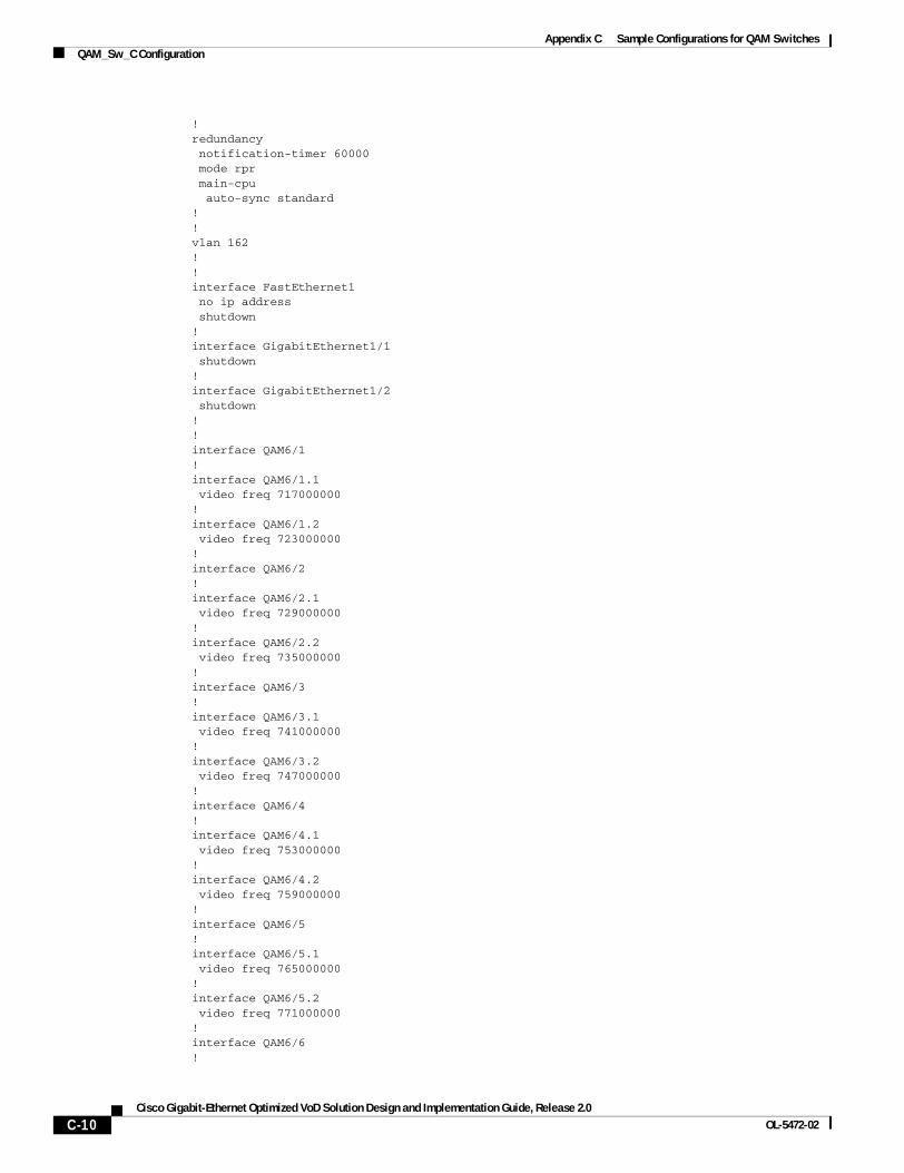
Appendix C Sample Configurations for QAM SwitchesQAM_Sw_C Configuration
!redundancy notification-timer 60000 mode rpr main-cpu auto-sync standard!!vlan 162 !!interface FastEthernet1 no ip address shutdown!interface GigabitEthernet1/1 shutdown!interface GigabitEthernet1/2 shutdown!!interface QAM6/1!interface QAM6/1.1 video freq 717000000!interface QAM6/1.2 video freq 723000000!interface QAM6/2!interface QAM6/2.1 video freq 729000000!interface QAM6/2.2 video freq 735000000!interface QAM6/3!interface QAM6/3.1 video freq 741000000!interface QAM6/3.2 video freq 747000000!interface QAM6/4!interface QAM6/4.1 video freq 753000000!interface QAM6/4.2 video freq 759000000!interface QAM6/5!interface QAM6/5.1 video freq 765000000!interface QAM6/5.2 video freq 771000000!interface QAM6/6!
C-10Cisco Gigabit-Ethernet Optimized VoD Solution Design and Implementation Guide, Release 2.0
OL-5472-02
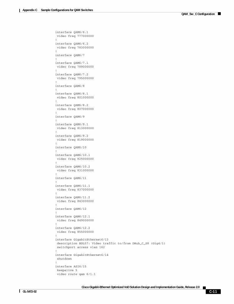
Appendix C Sample Configurations for QAM SwitchesQAM_Sw_C Configuration
interface QAM6/6.1 video freq 777000000!interface QAM6/6.2 video freq 783000000!interface QAM6/7!interface QAM6/7.1 video freq 789000000!interface QAM6/7.2 video freq 795000000!interface QAM6/8!interface QAM6/8.1 video freq 801000000!interface QAM6/8.2 video freq 807000000!interface QAM6/9!interface QAM6/9.1 video freq 813000000!interface QAM6/9.2 video freq 819000000!interface QAM6/10!interface QAM6/10.1 video freq 825000000!interface QAM6/10.2 video freq 831000000!interface QAM6/11!interface QAM6/11.1 video freq 837000000!interface QAM6/11.2 video freq 843000000! interface QAM6/12!interface QAM6/12.1 video freq 849000000!interface QAM6/12.2 video freq 855000000!interface GigabitEthernet6/13 description BDL57: Video traffic to/from DHub_C_S8 (Gig4/1) switchport access vlan 162!interface GigabitEthernet6/14 shutdown!interface ASI6/15 keepalive 5 video route qam 6/1.1
C-11Cisco Gigabit-Ethernet Optimized VoD Solution Design and Implementation Guide, Release 2.0
OL-5472-02
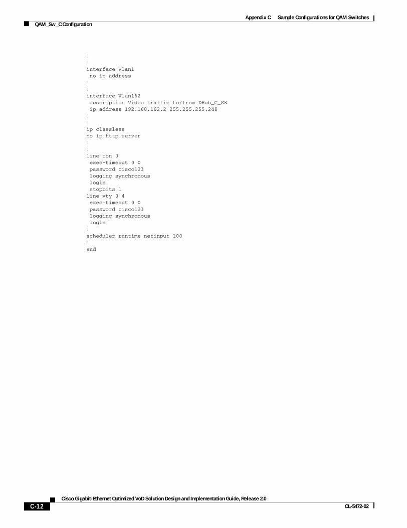
Appendix C Sample Configurations for QAM SwitchesQAM_Sw_C Configuration
!!interface Vlan1 no ip address!!interface Vlan162 description Video traffic to/from DHub_C_S8 ip address 192.168.162.2 255.255.255.248!!ip classlessno ip http server!! line con 0 exec-timeout 0 0 password cisco123 logging synchronous login stopbits 1line vty 0 4 exec-timeout 0 0 password cisco123 logging synchronous login!scheduler runtime netinput 100!end
C-12Cisco Gigabit-Ethernet Optimized VoD Solution Design and Implementation Guide, Release 2.0
OL-5472-02