Embed Size (px)
Citation preview
Send documenta t ion comments to mdsfeedback -doc@c i sco .com
Cisco MDS 9000 Family NX-OS Storage Media Encryption Configuration GuideCisco MDS NX-OS Release 5.2(6)August 2012
Americas HeadquartersCisco Systems, Inc.170 West Tasman DriveSan Jose, CA 95134-1706 USAhttp://www.cisco.comTel: 408 526-4000
800 553-NETS (6387)Fax: 408 527-0883
Text Part Number: OL-24977-01
Send documenta t ion comments to mdsfeedback -doc@c i sco .com
THE SPECIFICATIONS AND INFORMATION REGARDING THE PRODUCTS IN THIS MANUAL ARE SUBJECT TO CHANGE WITHOUT NOTICE. ALL STATEMENTS, INFORMATION, AND RECOMMENDATIONS IN THIS MANUAL ARE BELIEVED TO BE ACCURATE BUT ARE PRESENTED WITHOUT WARRANTY OF ANY KIND, EXPRESS OR IMPLIED. USERS MUST TAKE FULL RESPONSIBILITY FOR THEIR APPLICATION OF ANY PRODUCTS.
THE SOFTWARE LICENSE AND LIMITED WARRANTY FOR THE ACCOMPANYING PRODUCT ARE SET FORTH IN THE INFORMATION PACKET THAT SHIPPED WITH THE PRODUCT AND ARE INCORPORATED HEREIN BY THIS REFERENCE. IF YOU ARE UNABLE TO LOCATE THE SOFTWARE LICENSE OR LIMITED WARRANTY, CONTACT YOUR CISCO REPRESENTATIVE FOR A COPY.
The Cisco implementation of TCP header compression is an adaptation of a program developed by the University of California, Berkeley (UCB) as part of UCB’s public domain version of the UNIX operating system. All rights reserved. Copyright © 1981, Regents of the University of California.
NOTWITHSTANDING ANY OTHER WARRANTY HEREIN, ALL DOCUMENT FILES AND SOFTWARE OF THESE SUPPLIERS ARE PROVIDED “AS IS” WITH ALL FAULTS. CISCO AND THE ABOVE-NAMED SUPPLIERS DISCLAIM ALL WARRANTIES, EXPRESSED OR IMPLIED, INCLUDING, WITHOUT LIMITATION, THOSE OF MERCHANTABILITY, FITNESS FOR A PARTICULAR PURPOSE AND NONINFRINGEMENT OR ARISING FROM A COURSE OF DEALING, USAGE, OR TRADE PRACTICE.
IN NO EVENT SHALL CISCO OR ITS SUPPLIERS BE LIABLE FOR ANY INDIRECT, SPECIAL, CONSEQUENTIAL, OR INCIDENTAL DAMAGES, INCLUDING, WITHOUT LIMITATION, LOST PROFITS OR LOSS OR DAMAGE TO DATA ARISING OUT OF THE USE OR INABILITY TO USE THIS MANUAL, EVEN IF CISCO OR ITS SUPPLIERS HAVE BEEN ADVISED OF THE POSSIBILITY OF SUCH DAMAGES.
Cisco and the Cisco logo are trademarks or registered trademarks of Cisco and/or its affiliates in the U.S. and other countries. To view a list of Cisco trademarks, go to this URL: www.cisco.com/go/trademarks. Third-party trademarks mentioned are the property of their respective owners. The use of the word partner does not imply a partnership relationship between Cisco and any other company. (1110R)
Any Internet Protocol (IP) addresses and phone numbers used in this document are not intended to be actual addresses and phone numbers. Any examples, command display output, network topology diagrams, and other figures included in the document are shown for illustrative purposes only. Any use of actual IP addresses or phone numbers in illustrative content is unintentional and coincidental.
Cisco MDS 9000 Family NX-OS Storage Media Encryption Configuration Guide© 2012 Cisco Systems, Inc. All rights reserved.
Send documenta t ion comments to mdsfeedback -doc@c i sco .com
OL-24977-01, Cisco MDS NX-OS Release 5.x
C O N T E N T S
Preface xiii
Audience xiii
Organization xiii
Document Conventions xiv
Related Documentation xv
Release Notes xv
Regulatory Compliance and Safety Information xv
Compatibility Information xv
Hardware Installation xv
Software Installation and Upgrade xv
Cisco NX-OS xvi
Cisco DCNM xvi
Cisco DCNM-SAN xvi
Command-Line Interface xvi
Intelligent Storage Networking Services Configuration Guides xvii
Troubleshooting and Reference xvii
Obtaining Documentation and Submitting a Service Request xvii
C H A P T E R 1 Storage Media Encryption Overview 1-1
About SME 1-1
SME Features 1-2
Transparent Fabric Service 1-3
Encryption 1-3
SME Roles 1-3
Key Management 1-4
Clustering 1-5
FC-Redirect 1-6
Server-Based Discovery for Provisioning Disks and Tapes 1-6
Target-Based Load Balancing 1-6
SME Terminology 1-6
Supported Topologies 1-7
Single-Fabric Topology for Tape 1-8
Single-Fabric Topology for Disk 1-9
In-Service Software Upgrade in SME 1-9
iiiCisco MDS 9000 Family NX-OS Storage Media Encryption Configuration Guide
Send documenta t ion comments to mdsfeedback -doc@c i sco .com
Contents
About MIBs 1-9
Software and Hardware Requirements 1-10
Software Requirements 1-10
Hardware Requirements 1-10
Cisco MDS 9000 Family 18/4-Port Multiservice Module 1-11
Cisco MDS 9222i Multiservice Modular Switch 1-11
Cisco MDS 16-Port Storage Services Node 1-12
FC-Redirect-Capable Switches 1-12
Smart Card Readers 1-13
SME Prerequisites 1-13
Java Cryptography Extension Requirement 1-13
Zoning Requirement 1-13
FC-Redirect Requirements 1-13
SME Security Overview 1-14
Additional Security Capabilities 1-14
C H A P T E R 2 Configuring SME 2-1
Information About SME Configuration 2-1
Cisco DCNM-SAN 2-1
Command Line Interface 2-2
Licensing Requirements for SME Configuration 2-2
Prerequisites for SME Configuration 2-3
SME Installation Requirements 2-3
FCIP Write Acceleration and Tape Acceleration Topology Requirements 2-4
Guidelines and Limitations 2-4
FCIP Write Acceleration and Tape Acceleration Topology Requirements 2-4
Guidelines and Limitations 2-4
Installing DCNM-SAN Server 2-6
Configuring SME Tasks 2-15
Required Preconfiguration Tasks 2-16
Enabling Clustering 2-16
Enabling Clustering Using DCNM-SAN 2-17
Enabling Clustering Using Device Manager 2-17
Enabling SME 2-18
Enabling SME Using DCNM-SAN 2-18
Enabling SME Using Device Manager 2-18
Enabling DNS 2-18
sme.useIP for IP Address or Name Selection 2-19
ivCisco MDS 9000 Family NX-OS Storage Media Encryption Configuration Guide
OL-24977-01, Cisco MDS NX-OS Release 5.x
Send documenta t ion comments to mdsfeedback -doc@c i sco .com
Contents
IP Access Lists for the Management Interface 2-19
Creating and Assigning SME Roles and SME Users 2-19
Configuring the AAA Roles 2-21
Creating and Assigning SME Roles Using DCNM-SAN 2-21
Creating and Assigning SME Roles Using the CLI 2-22
Installing DCNM-SAN and DCNM-SAN Client 2-23
Adding a Fabric and Changing the Fabric Name 2-23
Choosing a Key Manager 2-24
Using FC-Redirect with CFS Regions 2-25
Installing Smart Card Drivers 2-25
Restrictions 2-25
Troubleshooting Tips 2-25
SME Configuration Process 2-25
Initial SME Configuration 2-26
Saving SME Cluster Configurations 2-26
SME Configuration Restrictions 2-26
FICON Restriction 2-26
iSCSI Restriction 2-26
Field Descriptions for SME Configuration 2-27
Members 2-27
SME Interfaces 2-27
Hosts 2-28
Feature History for SME Configuration 2-28
C H A P T E R 3 Configuring SME Interfaces 3-1
Configuring the SME Interface 3-1
Adding an SME Interface from a Local or Remote Switch 3-1
Creating the SME Interface 3-2
Deleting the SME Interface 3-3
Viewing SME Interface Information Using the CLI 3-3
Configuring the SME Interface Using the GUI 3-5
Configuring and Starting an SME Interface Using Device Manager 3-5
Configuring SME Interfaces in DCNM-SAN 3-6
Creating SME Interfaces 3-6
Deleting SME Interfaces 3-6
Saving Your Interface Configurations 3-7
Adding SME Interfaces to a SME Configuration 3-7
Removing (Unbinding) SME Interfaces from a SME Cluster 3-8
Deleting Switches From a SME Cluster 3-8
vCisco MDS 9000 Family NX-OS Storage Media Encryption Configuration Guide
OL-24977-01, Cisco MDS NX-OS Release 5.x
Send documenta t ion comments to mdsfeedback -doc@c i sco .com
Contents
Verifying SME Interface Configuration 3-9
Monitoring SME Interface 3-9
Feature History for SME Interface 3-10
C H A P T E R 4 Configuring SME Cluster Management 4-1
Information About SME Cluster Management 4-1
Cluster Quorum and Master Switch Election 4-1
Cluster Quorum 4-2
Master Switch Election 4-2
In-Service Software Upgrade in a Two-Node Cluster 4-5
Server Clusters 4-5
Configuring SME Cluster Management Using the CLI 4-5
Creating the SME Cluster 4-6
Enabling and Disabling Clustering 4-8
Enabling and Disabling SME Service 4-8
Setting the SME Cluster Security Level 4-8
Setting Up the SME Administrator and Recovery Office Roles 4-9
Configuring SME Cluster Management Using the GUI 4-10
Creating a SME Cluster Using the SME Wizard 4-10
Launching SME Wizard 4-10
Choosing a Cluster Name 4-11
Selecting Fabrics 4-11
Selecting Interfaces 4-11
Selecting Master Key Security Levels 4-11
Selecting Media Key Settings 4-13
Specifying the Key Management Center Server 4-14
Selecting Transport Settings 4-14
Confirming the Cluster Creation 4-15
Downloading Key File and Storing Keyshares 4-15
Downloading the Key File for Basic Security 4-15
Configuring Standard Security Level 4-15
Configuring Advanced Security Level 4-16
Deactivating and Purging an SME Cluster 4-17
Deactivating an SME Cluster 4-17
Purging an SME Cluster 4-18
Verifying SME Cluster Management Configuration 4-18
Monitoring SME Cluster Management 4-19
Viewing SME Cluster Details Using the CLI 4-19
Viewing SME Cluster, Internal, and Transport Information 4-19
viCisco MDS 9000 Family NX-OS Storage Media Encryption Configuration Guide
OL-24977-01, Cisco MDS NX-OS Release 5.x
Send documenta t ion comments to mdsfeedback -doc@c i sco .com
Contents
Viewing SME Cluster Details 4-19
Viewing Cluster Key Information 4-20
Viewing Cluster Node Information 4-21
Viewing Recovery Officer Information 4-21
Viewing SME Cluster Details Using the GUI 4-22
Viewing Cluster States 4-22
Viewing Members in a Cluster 4-22
Viewing and Modifying Transport Settings in Cluster Detail Page 4-22
Viewing and Modifying Key Management Servers Settings 4-23
Viewing Cluster Information Using DCNM-SAN Client 4-23
Viewing Cluster Information Using Device Manager 4-23
Feature History for SME Cluster Management 4-24
C H A P T E R 5 Configuring SME Tapes 5-1
Information About SME Tape Management 5-1
Configuring SME Tape Management Using the CLI 5-2
Enabling and Disabling Tape Compression 5-3
Enabling and Disabling Key-on-Tape 5-3
Configuring a Tape Volume Group 5-4
Enabling and Disabling Automatic Volume Groups 5-4
Adding a Tape Device to the Tape Group 5-5
Adding Paths to the Tape Device 5-5
Bypassing Tape Encryption 5-6
Configuring SME Tape Management Using the GUI 5-7
Configuring Groups 5-7
Adding Tape Groups 5-7
Deleting Tape Groups 5-8
Configuring Tape Devices 5-9
Adding Tape Devices 5-9
Deleting Tape Devices 5-9
Configuring Tape Paths 5-9
Adding Tape Paths 5-10
Deleting Paths from a Device 5-10
Configuring Tape Volume Groups 5-10
Adding Tape Volume Groups 5-10
Deleting Tape Volume Groups 5-11
Configuring Key Management Operations 5-11
Purging Volumes 5-12
Purging Volume Groups 5-12
viiCisco MDS 9000 Family NX-OS Storage Media Encryption Configuration Guide
OL-24977-01, Cisco MDS NX-OS Release 5.x
Send documenta t ion comments to mdsfeedback -doc@c i sco .com
Contents
Exporting Volume Groups 5-13
Importing Volume Groups 5-13
Rekeying Tape Volume Groups 5-14
Auto Replicating Tape Media Keys 5-14
Creating Tape Key Replication Relationships 5-15
Removing Tape Key Replication Relationships 5-15
Using Basic Security Mode for Master Key Download 5-15
Replacing Smart Cards 5-16
Replacing Smart Cards Using Standard Mode 5-16
Replacing Smart Cards Using Advanced Mode 5-16
Exporting Volume Groups From Deactivated Clusters 5-17
Exporting Volume Groups Using Basic Mode 5-18
Exporting Volume Groups Using Standard Mode 5-18
Exporting Volume Groups Using Advanced Mode 5-18
Migrating KMC Server 5-19
Verifying SME Tape Management Configuration 5-20
Monitoring SME Tape Management 5-20
Viewing Host Details 5-20
Viewing Tape Device Details 5-20
Viewing SME Tape Information Using the CLI 5-21
Viewing Tape Cartridge Information 5-21
Viewing Tape Volume Group Information 5-21
Viewing the Status of the Tape Device 5-21
Feature History for SME Tape Management 5-24
C H A P T E R 6 Configuring SME Disks 6-1
Information About SME Disk Management 6-1
SME Disk Architecture 6-2
Replication 6-3
Snapshot 6-4
Managing Replication with SME 6-4
Manage Key Change Operations in DCNM for DKR 6-4
Managing Snapshots in SME 6-5
Cluster Support 6-5
Data Preparation 6-6
Recovering SME Disk when Data Preparation Fails 6-7
Offline Data Preparation 6-7
Online Data Preparation 6-8
Rekeying 6-8
viiiCisco MDS 9000 Family NX-OS Storage Media Encryption Configuration Guide
OL-24977-01, Cisco MDS NX-OS Release 5.x
Send documenta t ion comments to mdsfeedback -doc@c i sco .com
Contents
Replacing an SME Enabled MDS Switch 6-9
Multi-node Cluster 6-9
Single-node Cluster 6-9
Turning Off Encryption 6-9
Snapshot Support 6-9
SME Disk Key Management 6-9
Key Generation 6-10
Disk States 6-10
Cisco KMC 6-10
Archiving Clusters 6-11
Purging Disks or Disk Groups 6-11
Rekeying 6-11
Accounting 6-11
Quorum Disk 6-12
Data Replication 6-12
SME Disk Key Replication 6-12
Prerequisites for DKR 6-13
Guidelines and Limitations for DKR 6-13
Replication or Mirroring Requirements 6-13
DKR Features 6-14
DKR Relationships 6-14
ISSU with SME Disk 6-15
Managing Key Change Operations in Cisco DCNM for DKR 6-15
Read-Only Disks 6-16
Write Signature 6-16
Configuring SME Disk Management Using the CLI 6-16
Discovering IT-Nexus 6-17
Displaying IT-Nexus 6-17
Adding SME Nodes to the Cluster 6-18
Adding SME Encryption Engine to the Cluster 6-18
Configuring a Disk Group 6-19
Adding a Disk to the Disk Group 6-19
Adding Paths to the Disk 6-20
Displaying ITL-Nexus 6-20
Managing Disks 6-21
Enabling Encryption on the SME Disk with Data Preparation 6-21
Modifying the SME Disk Key 6-25
Recovering the SME Disk 6-26
Configuring SME Disk Management Using the GUI 6-29
Configuring Disk Groups 6-29
ixCisco MDS 9000 Family NX-OS Storage Media Encryption Configuration Guide
OL-24977-01, Cisco MDS NX-OS Release 5.x
Send documenta t ion comments to mdsfeedback -doc@c i sco .com
Contents
Creating Disk Groups 6-29
Deleting Disk Groups 6-30
Configuring Disks 6-31
Adding Disks 6-31
Deleting Disks 6-31
Configuring Signature Mode 6-32
Converting Disks to Signature Mode 6-32
Verifying Signatures for Disks 6-32
Configuring Disk Paths 6-33
Configuring and Discovering Disk Paths 6-33
Adding Discovered Path 6-33
Removing Disk Paths 6-34
Suspending and Resuming the Configured Disk 6-34
Suspending the Configured Disk 6-34
Resuming the Configured Disk 6-35
Managing Disk Encryption on SME Disks 6-35
Performing Data Preparation on the Disk for Converting Clear Data to Encrypted Data 6-36
Using Select New Key 6-36
Using Select Key 6-38
Using Input GUID 6-39
Performing Data Preparation on the Disk for Converting Encrypted Data to Clear Data 6-39
Rekeying on an Encrypted Disk 6-40
Recovering SME Disks 6-41
Recovering a Disk to Clear Status 6-41
Recovering a Disk to Encrypted Status 6-42
Recovering a Disk Using Metadata Signature 6-42
Recovering a Disk from Key Manager 6-42
Performing Disk Encryption to Convert the Disk Status from Clear to Crypto 6-43
Using Select New Key 6-43
Using Select Key 6-43
Using Input GUID 6-44
Performing Disk Encryption to Convert the Disk Status from Crypto to Clear 6-44
Exporting and Importing Keys 6-45
Exporting Keys for Single Disk 6-45
Exporting Keys for Multiple Disks 6-45
Importing Keys to a Single Disk or to a Disk Set 6-46
Restoring an Encrypted Disk from a Deactivated Key 6-46
Restoring a Deactivated Key Using the Select Key Option 6-46
Restoring a Deactivated Key Using the Input GUID Option 6-47
Configuring DKR 6-48
xCisco MDS 9000 Family NX-OS Storage Media Encryption Configuration Guide
OL-24977-01, Cisco MDS NX-OS Release 5.x
Send documenta t ion comments to mdsfeedback -doc@c i sco .com
Contents
Creating Disk Key Replication 6-48
Enabling or Disabling Disk Key Replication 6-51
Removing or Deleting Replication Relationships 6-52
Importing DKR Configurations 6-52
Performing the Switchover Operation 6-53
Labels & Filtering 6-53
Performing the Sync Operation 6-53
Configuring Key Management Operations 6-53
Replacing Smart Cards 6-54
Configuring Master Key Rekey 6-55
Resume Sync 6-56
Verifying the SME Disk Management Configuration 6-56
Monitoring SME Disk Management 6-58
Viewing Host Details 6-58
Viewing Disk Group Details 6-58
Viewing Disk Details 6-58
Viewing Disk Path Details 6-59
Viewing Signature Mode Clusters 6-59
Viewing SME Disk Information Using the CLI 6-59
Feature History for SME Disk Management 6-78
C H A P T E R 7 Configuring SME Key Management 7-1
Information About SME Key Management 7-1
About Key Hierarchy 7-1
Master Key 7-2
Tape Volume Group Key 7-2
Tape Volume Key 7-2
Disk Key 7-2
About Cisco Key Management Center 7-3
About Master Key Security Modes 7-3
About Key Management Settings 7-4
Tape Recycling 7-5
About High Availability Key Management Center 7-6
About Auto Key Replication of Keys Across Data Centers 7-6
Translating Media Keys 7-6
About Accounting Log Information 7-7
Configuring SME Key Management Using the CLI 7-8
Configuring Unique or Shared Key Mode 7-8
Configuring SME Key Management Using the GUI 7-9
xiCisco MDS 9000 Family NX-OS Storage Media Encryption Configuration Guide
OL-24977-01, Cisco MDS NX-OS Release 5.x
Send documenta t ion comments to mdsfeedback -doc@c i sco .com
Contents
Choosing High Availability Settings 7-9
Configuring Key Management Operations 7-9
Monitoring SME Key Management 7-9
Viewing KMC Accounting Log Messages Output 7-10
Viewing Accounting Log Information 7-14
Viewing Standard Security Mode Smart Cards 7-14
Viewing Advanced Security Mode Smart Cards 7-15
Viewing Keys for SME Tape 7-15
Viewing Keys for SME Disk 7-15
Feature History for SME Key Management 7-16
C H A P T E R 8 Provisioning Certificates 8-1
Information About Public Key Infrastructure Certificates 8-1
Prerequisites for SSL 8-1
Configuring SSL Using CLI 8-2
Creating the CA Certificate 8-2
Configuring Trustpoints 8-2
Removing Trustpoints 8-4
Generating KMC Certificate 8-5
Configuring SSL Using the GUI 8-6
Feature History for SSL 8-7
C H A P T E R 9 RSA Key Manager and SME 9-1
Prerequisites for RKM 9-1
Configuring RKM 9-1
Installing the RKM Application 9-2
Generating CA Certificates 9-2
Creating JKS Files Using the Java Keytool 9-4
Placing Certificates in RKM 9-5
Adding the SME User to RKM 9-5
Selecting RKM 9-5
Migrating From Cisco KMC to RKM 9-6
Feature History for RKM 9-7
C H A P T E R 10 SME Best Practices 10-1
Overview of Best Practices 10-1
General Practices 10-1
SME Configuration Practices 10-1
xiiCisco MDS 9000 Family NX-OS Storage Media Encryption Configuration Guide
OL-24977-01, Cisco MDS NX-OS Release 5.x
Send documenta t ion comments to mdsfeedback -doc@c i sco .com
Contents
SME Disk and VAAI or Thin Provisioning Support 10-2
KMC Practices 10-2
Fabric Management Practices 10-2
C H A P T E R 11 SME Troubleshooting 11-1
Troubleshooting Resources 11-1
Cluster Recovery Scenarios 11-1
Deleting an Offline Switch from a SME Cluster 11-2
Deleting a SME Cluster with One or More Offline Switches while the Master Switch is Online 11-2
Deleting a SME Cluster when All Switches are Offline 11-3
Reviving an SME Cluster 11-4
Troubleshooting General Issues 11-6
Troubleshooting Scenarios 11-6
A P P E N D I X L SME CLI Commands L-1
SME Commands L-1
A P P E N D I X M Disaster Recovery in SME M-1
Disaster Recovery Sequence for SME Tape M-1
Disaster Recovery Sequence for SME Disk M-2
A P P E N D I X N Offline Data Recovery in SME N-1
Information About Offline Data Restore Tool N-1
ODRT Requirements N-2
A P P E N D I X O Database Backup and Restore O-1
Backing Up the DCNM-SAN Database O-1
Restoring the DCNM-SAN Database O-2
Database Backup and Restore Operations O-2
A P P E N D I X P Planning For SME Installation P-1
SAN Considerations P-1
Interoperability Matrix P-2
MSM-18/4 Modules P-2
Key Management Center and DCNM-SAN Server P-2
Security P-3
xiiiCisco MDS 9000 Family NX-OS Storage Media Encryption Configuration Guide
OL-24977-01, Cisco MDS NX-OS Release 5.x
Send documenta t ion comments to mdsfeedback -doc@c i sco .com
Contents
Communication P-3
Preinstallation Requirements P-4
Preconfiguration Tasks P-4
Installing DCNM-SAN P-4
Configuring CFS Regions For FC-Redirect P-5
Enabling SME Services P-5
Assigning SME Roles and Users P-6
Creating SME Fabrics P-6
Installing SSL Certificates P-6
Provisioning SME P-7
A P P E N D I X Q Migrating SME Database Tables Q-1
xivCisco MDS 9000 Family NX-OS Storage Media Encryption Configuration Guide
OL-24977-01, Cisco MDS NX-OS Release 5.x
Send documenta t ion comments to mdsfeedback -doc@c i sco .com
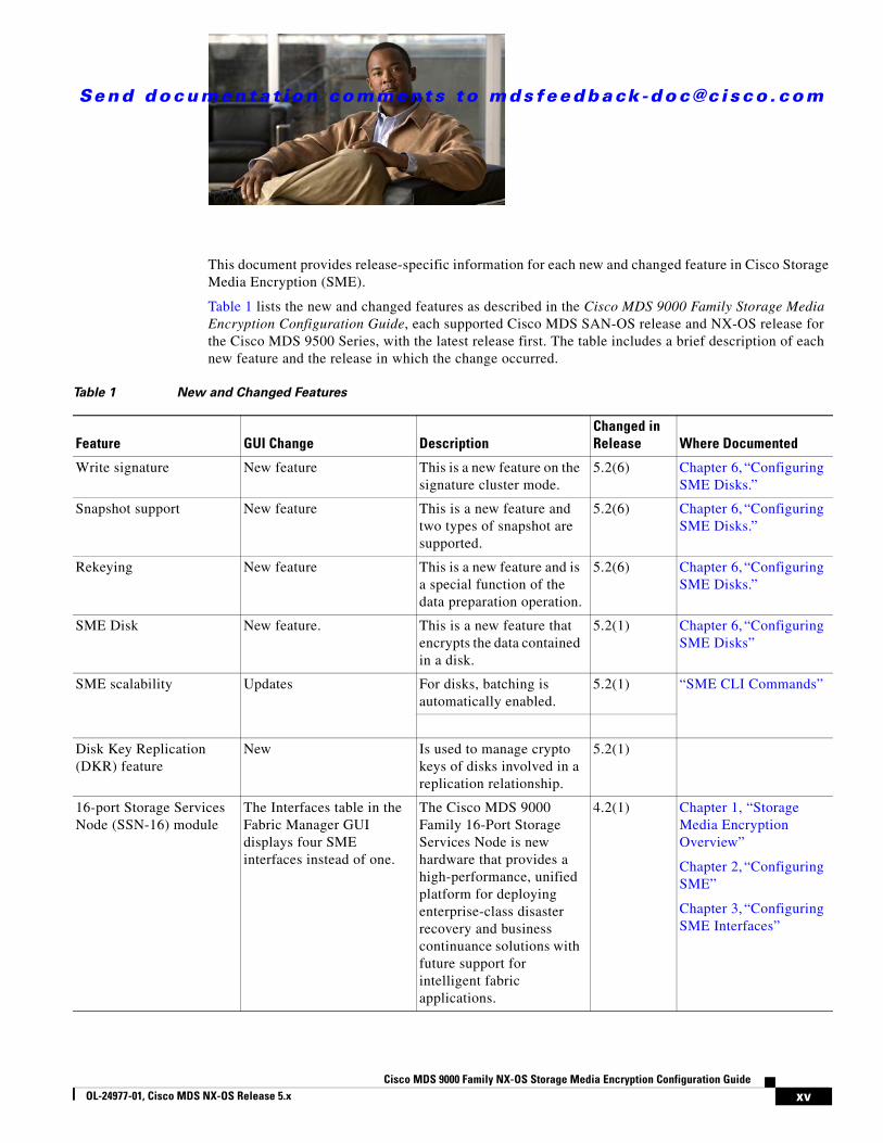
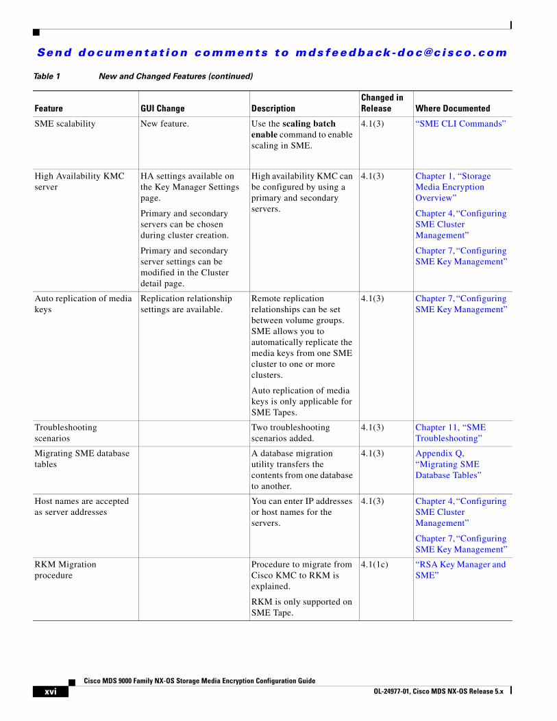
This document provides release-specific information for each new and changed feature in Cisco Storage Media Encryption (SME).
Table 1 lists the new and changed features as described in the Cisco MDS 9000 Family Storage Media Encryption Configuration Guide, each supported Cisco MDS SAN-OS release and NX-OS release for the Cisco MDS 9500 Series, with the latest release first. The table includes a brief description of each new feature and the release in which the change occurred.
Table 1 New and Changed Features
Feature GUI Change DescriptionChanged in Release Where Documented
Write signature New feature This is a new feature on the signature cluster mode.
5.2(6) Chapter 6, “Configuring SME Disks.”
Snapshot support New feature This is a new feature and two types of snapshot are supported.
5.2(6) Chapter 6, “Configuring SME Disks.”
Rekeying New feature This is a new feature and is a special function of the data preparation operation.
5.2(6) Chapter 6, “Configuring SME Disks.”
SME Disk New feature. This is a new feature that encrypts the data contained in a disk.
5.2(1) Chapter 6, “Configuring SME Disks”
SME scalability Updates For disks, batching is automatically enabled.
5.2(1) “SME CLI Commands”
Disk Key Replication (DKR) feature
New Is used to manage crypto keys of disks involved in a replication relationship.
5.2(1)
16-port Storage Services Node (SSN-16) module
The Interfaces table in the Fabric Manager GUI displays four SME interfaces instead of one.
The Cisco MDS 9000 Family 16-Port Storage Services Node is new hardware that provides a high-performance, unified platform for deploying enterprise-class disaster recovery and business continuance solutions with future support for intelligent fabric applications.
4.2(1) Chapter 1, “Storage Media Encryption Overview”
Chapter 2, “Configuring SME”
Chapter 3, “Configuring SME Interfaces”
xvCisco MDS 9000 Family NX-OS Storage Media Encryption Configuration Guide
OL-24977-01, Cisco MDS NX-OS Release 5.x
Send documenta t ion comments to mdsfeedback -doc@c i sco .com
SME scalability New feature. Use the scaling batch enable command to enable scaling in SME.
4.1(3) “SME CLI Commands”
High Availability KMC server
HA settings available on the Key Manager Settings page.
Primary and secondary servers can be chosen during cluster creation.
Primary and secondary server settings can be modified in the Cluster detail page.
High availability KMC can be configured by using a primary and secondary servers.
4.1(3) Chapter 1, “Storage Media Encryption Overview”
Chapter 4, “Configuring SME Cluster Management”
Chapter 7, “Configuring SME Key Management”
Auto replication of media keys
Replication relationship settings are available.
Remote replication relationships can be set between volume groups. SME allows you to automatically replicate the media keys from one SME cluster to one or more clusters.
Auto replication of media keys is only applicable for SME Tapes.
4.1(3) Chapter 7, “Configuring SME Key Management”
Troubleshooting scenarios
Two troubleshooting scenarios added.
4.1(3) Chapter 11, “SME Troubleshooting”
Migrating SME database tables
A database migration utility transfers the contents from one database to another.
4.1(3) Appendix Q, “Migrating SME Database Tables”
Host names are accepted as server addresses
You can enter IP addresses or host names for the servers.
4.1(3) Chapter 4, “Configuring SME Cluster Management”
Chapter 7, “Configuring SME Key Management”
RKM Migration procedure
Procedure to migrate from Cisco KMC to RKM is explained.
RKM is only supported on SME Tape.
4.1(1c) “RSA Key Manager and SME”
Table 1 New and Changed Features (continued)
Feature GUI Change DescriptionChanged in Release Where Documented
xviCisco MDS 9000 Family NX-OS Storage Media Encryption Configuration Guide
OL-24977-01, Cisco MDS NX-OS Release 5.x
Send documenta t ion comments to mdsfeedback -doc@c i sco .com
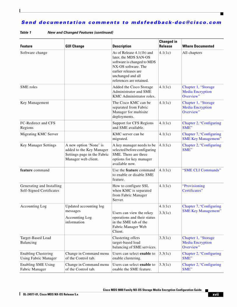
Software change As of Release 4.1(1b) and later, the MDS SAN-OS software is changed to MDS NX-OS software. The earlier releases are unchanged and all references are retained.
4.1(1c) All chapters
SME roles Added the Cisco Storage Administrator and SME KMC Administrator roles.
4.1(1c) Chapter 1, “Storage Media Encryption Overview”
Key Management The Cisco KMC can be separated from Fabric Manager for multisite deployments.
4.1(1c) Chapter 1, “Storage Media Encryption Overview”
FC-Redirect and CFS Regions
Support for CFS Regions and SME available.
4.1(1c) Chapter 2, “Configuring SME”
Migrating KMC Server KMC server can be migrated.
4.1(1c) Chapter 7, “Configuring SME Key Management”
Key Manager Settings A new option ‘None’ is added to the Key Manager Settings page in the Fabric Manager web client.
A key manager needs to be selected before configuring SME. There are three options for key manager available now.
4.1(1c) Chapter 2, “Configuring SME”
feature command Use the feature command to enable or disable SME feature.
4.1(1c) “SME CLI Commands”
Generating and Installing Self-Signed Certificates
How to configure SSL when KMC is separated from Fabric Manager Server.
4.1(1c) “Provisioning Certificates”
Accounting Log Updated accounting log messages
Accounting Log information
Users can view the rekey operations and their status in the SME tab of the Fabric Manager Web Client.
4.1(1c)
3.3(1c)
Chapter 7, “Configuring SME Key Management”
Target-Based Load Balancing
Clustering offers target-based load balancing of SME services.
3.3(1c) Chapter 1, “Storage Media Encryption Overview”
Enabling Clustering Using Fabric Manager
Change in Command menu of the Control tab.
Users can select enable to enable clustering.
3.3(1c) Chapter 2, “Configuring SME”
Enabling SME Using Fabric Manager
Change in Command menu of the Control tab.
Users can select enable to enable the SME feature.
3.3(1c) Chapter 2, “Configuring SME”
Table 1 New and Changed Features (continued)
Feature GUI Change DescriptionChanged in Release Where Documented
xviiCisco MDS 9000 Family NX-OS Storage Media Encryption Configuration Guide
OL-24977-01, Cisco MDS NX-OS Release 5.x
Send documenta t ion comments to mdsfeedback -doc@c i sco .com
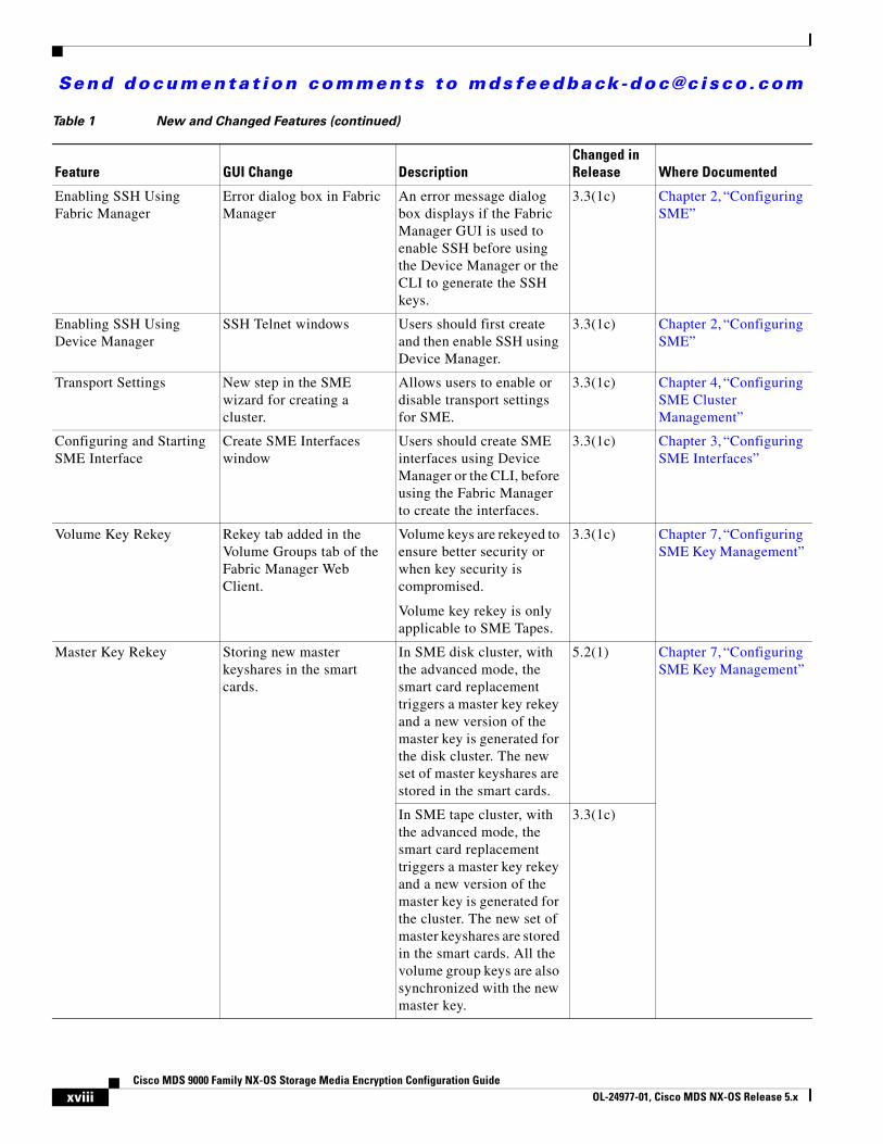
Enabling SSH Using Fabric Manager
Error dialog box in Fabric Manager
An error message dialog box displays if the Fabric Manager GUI is used to enable SSH before using the Device Manager or the CLI to generate the SSH keys.
3.3(1c) Chapter 2, “Configuring SME”
Enabling SSH Using Device Manager
SSH Telnet windows Users should first create and then enable SSH using Device Manager.
3.3(1c) Chapter 2, “Configuring SME”
Transport Settings New step in the SME wizard for creating a cluster.
Allows users to enable or disable transport settings for SME.
3.3(1c) Chapter 4, “Configuring SME Cluster Management”
Configuring and Starting SME Interface
Create SME Interfaces window
Users should create SME interfaces using Device Manager or the CLI, before using the Fabric Manager to create the interfaces.
3.3(1c) Chapter 3, “Configuring SME Interfaces”
Volume Key Rekey Rekey tab added in the Volume Groups tab of the Fabric Manager Web Client.
Volume keys are rekeyed to ensure better security or when key security is compromised.
Volume key rekey is only applicable to SME Tapes.
3.3(1c) Chapter 7, “Configuring SME Key Management”
Master Key Rekey Storing new master keyshares in the smart cards.
In SME disk cluster, with the advanced mode, the smart card replacement triggers a master key rekey and a new version of the master key is generated for the disk cluster. The new set of master keyshares are stored in the smart cards.
5.2(1) Chapter 7, “Configuring SME Key Management”
In SME tape cluster, with the advanced mode, the smart card replacement triggers a master key rekey and a new version of the master key is generated for the cluster. The new set of master keyshares are stored in the smart cards. All the volume group keys are also synchronized with the new master key.
3.3(1c)
Table 1 New and Changed Features (continued)
Feature GUI Change DescriptionChanged in Release Where Documented
xviiiCisco MDS 9000 Family NX-OS Storage Media Encryption Configuration Guide
OL-24977-01, Cisco MDS NX-OS Release 5.x
Send documenta t ion comments to mdsfeedback -doc@c i sco .com
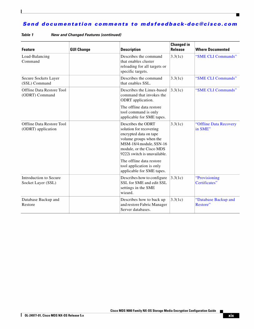
Load-Balancing Command
Describes the command that enables cluster reloading for all targets or specific targets.
3.3(1c) “SME CLI Commands”
Secure Sockets Layer (SSL) Command
Describes the command that enables SSL.
3.3(1c) “SME CLI Commands”
Offline Data Restore Tool (ODRT) Command
Describes the Linux-based command that invokes the ODRT application.
The offline data restore tool command is only applicable for SME tapes.
3.3(1c) “SME CLI Commands”
Offline Data Restore Tool (ODRT) application
Describes the ODRT solution for recovering encrypted data on tape volume groups when the MSM-18/4 module, SSN-16 module, or the Cisco MDS 9222i switch is unavailable.
The offline data restore tool application is only applicable for SME tapes.
3.3(1c) “Offline Data Recovery in SME”
Introduction to Secure Socket Layer (SSL)
Describes how to configure SSL for SME and edit SSL settings in the SME wizard.
3.3(1c) “Provisioning Certificates”
Database Backup and Restore
Describes how to back up and restore Fabric Manager Server databases.
3.3(1c) “Database Backup and Restore”
Table 1 New and Changed Features (continued)
Feature GUI Change DescriptionChanged in Release Where Documented
xixCisco MDS 9000 Family NX-OS Storage Media Encryption Configuration Guide
OL-24977-01, Cisco MDS NX-OS Release 5.x

Send documenta t ion comments to mdsfeedback -doc@c i sco .com
xxCisco MDS 9000 Family NX-OS Storage Media Encryption Configuration Guide
OL-24977-01, Cisco MDS NX-OS Release 5.x
Send documenta t ion comments to mdsfeedback -doc@c i sco .com
Preface
This preface describes the audience, organization, and conventions of the Cisco MDS 9000 Family NX-OS Storage Media Encryption Configuration Guide. The preface also provides information on how to obtain related documentation.
AudienceThis guide is for experienced network administrators who are responsible for planning, installing, configuring, and maintaining the Cisco MDS 9000 Family Storage Media Encryption (SME) application.
OrganizationThis document is organized as follows:
Chapter Title Description
Chapter 1 Storage Media Encryption Overview Presents an overview of the Cisco MDS SME feature and the software and hardware requirements.
Chapter 2 Configuring SME Describes the installation, preliminary configuration tasks, and the configuration limits.
Chapter 3 Configuring SME Interfaces Describes how to configure, start, add, and remove SME interfaces and switches.
Chapter 4 Configuring SME Cluster Management
Describes how to configure, monitor, and manage SME clusters.
Chapter 5 Configuring SME Tapes Describes how to add and delete tape groups, devices, paths, and tape volume groups.
Chapter 6 Configuring SME Disks Describes managing and configuring disks using SME.
Chapter 7 Configuring SME Key Management Describes the comprehensive and secure key hierarchy system and how to export and import volume groups.
Chapter 8 Provisioning Certificates Describes the configuring of SSL in SME.
xiiiCisco MDS 9000 Family Storage Media EncryptionConfiguration Guide
OL-24977-01, Cisco MDS NX-OS Release 5.x
Send documenta t ion comments to mdsfeedback -doc@c i sco .com
Preface
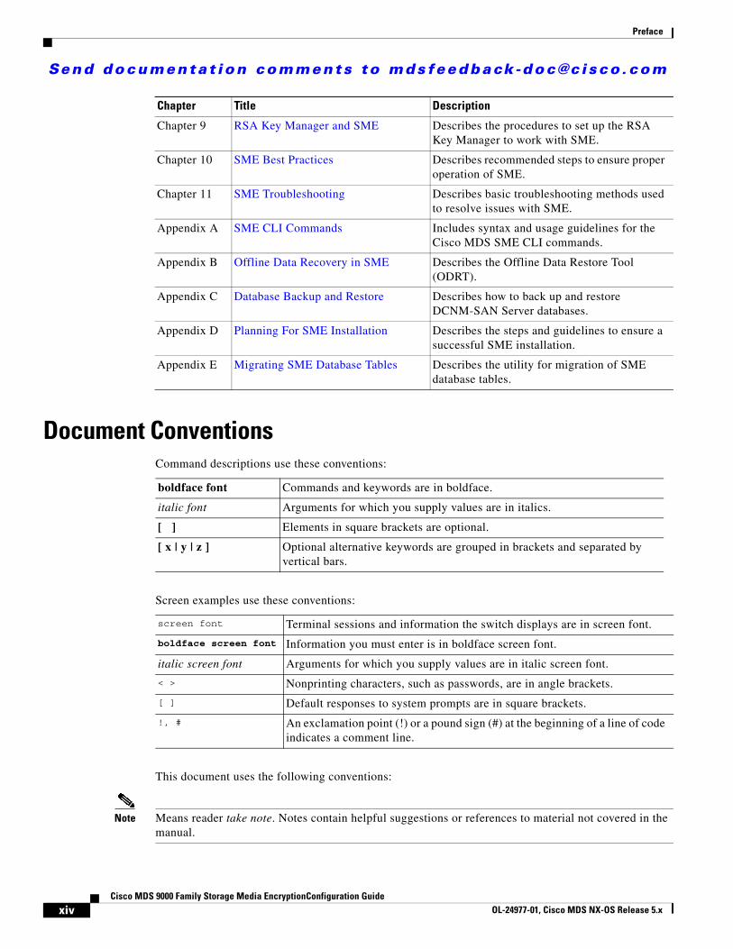
Document ConventionsCommand descriptions use these conventions:
Screen examples use these conventions:
This document uses the following conventions:
Note Means reader take note. Notes contain helpful suggestions or references to material not covered in the manual.
Chapter 9 RSA Key Manager and SME Describes the procedures to set up the RSA Key Manager to work with SME.
Chapter 10 SME Best Practices Describes recommended steps to ensure proper operation of SME.
Chapter 11 SME Troubleshooting Describes basic troubleshooting methods used to resolve issues with SME.
Appendix A SME CLI Commands Includes syntax and usage guidelines for the Cisco MDS SME CLI commands.
Appendix B Offline Data Recovery in SME Describes the Offline Data Restore Tool (ODRT).
Appendix C Database Backup and Restore Describes how to back up and restore DCNM-SAN Server databases.
Appendix D Planning For SME Installation Describes the steps and guidelines to ensure a successful SME installation.
Appendix E Migrating SME Database Tables Describes the utility for migration of SME database tables.
Chapter Title Description
boldface font Commands and keywords are in boldface.
italic font Arguments for which you supply values are in italics.
[ ] Elements in square brackets are optional.
[ x | y | z ] Optional alternative keywords are grouped in brackets and separated by vertical bars.
screen font Terminal sessions and information the switch displays are in screen font.
boldface screen font Information you must enter is in boldface screen font.
italic screen font Arguments for which you supply values are in italic screen font.
< > Nonprinting characters, such as passwords, are in angle brackets.
[ ] Default responses to system prompts are in square brackets.
!, # An exclamation point (!) or a pound sign (#) at the beginning of a line of code indicates a comment line.
xivCisco MDS 9000 Family Storage Media EncryptionConfiguration Guide
OL-24977-01, Cisco MDS NX-OS Release 5.x

Send documenta t ion comments to mdsfeedback -doc@c i sco .com
Preface
Caution Means reader be careful. In this situation, you might do something that could result in equipment damage or loss of data.
Related DocumentationThe documentation set for the Cisco MDS 9000 Family includes the following documents. To find a document online, use the Cisco MDS NX-OS Documentation Locator at:
http://www.cisco.com/en/US/docs/storage/san_switches/mds9000/roadmaps/doclocater.htm
Release Notes • Cisco MDS 9000 Family Release Notes for Cisco MDS NX-OS Releases
• Cisco MDS 9000 Family Release Notes for MDS SAN-OS Releases
• Cisco MDS 9000 Family Release Notes for Cisco MDS 9000 EPLD Images
• Cisco DCNM Release Notes
Regulatory Compliance and Safety Information • Regulatory Compliance and Safety Information for the Cisco MDS 9000 Family
Compatibility Information • Cisco Data Center Interoperability Support Matrix
• Cisco MDS 9000 NX-OS Hardware and Software Compatibility Information and Feature Lists
• Cisco MDS 9000 Family Switch-to-Switch Interoperability Configuration Guide
Hardware Installation • Cisco MDS 9500 Series Hardware Installation Guide
• Cisco MDS 9200 Series Hardware Installation Guide
• Cisco MDS 9100 Series Hardware Installation Guide
• Cisco MDS 9124 and Cisco MDS 9134 Multilayer Fabric Switch Quick Start Guide
Software Installation and Upgrade• Cisco MDS 9000 NX-OS Software Upgrade and Downgrade Guide
xvCisco MDS 9000 Family Storage Media Encryption Configuration Guide
OL-24977-01, Cisco MDS NX-OS Release 5.x
Send documenta t ion comments to mdsfeedback -doc@c i sco .com
Preface
Cisco NX-OS • Cisco MDS 9000 Family NX-OS Licensing Guide
• Cisco MDS 9000 Family NX-OS Fundamentals Configuration Guide
• Cisco MDS 9000 Family NX-OS System Management Configuration Guide
• Cisco MDS 9000 Family NX-OS Interfaces Configuration Guide
• Cisco MDS 9000 Family NX-OS Fabric Configuration Guide
• Cisco MDS 9000 Family NX-OS Quality of Service Configuration Guide
• Cisco MDS 9000 Family NX-OS Security Configuration Guide
• Cisco MDS 9000 Family NX-OS IP Services Configuration Guide
• Cisco MDS 9000 Family NX-OS Intelligent Storage Services Configuration Guide
• Cisco MDS 9000 Family NX-OS High Availability and Redundancy Configuration Guide
• Cisco MDS 9000 Family NX-OS Inter-VSAN Routing Configuration Guide
• Cisco MDS 9000 Family Cookbook for Cisco MDS SAN-OS
Cisco DCNM• Cisco DCNM Fundamentals Guide, Release 6.x
• Cisco DCNM Installation and Licensing Guide, Release 6.x
Cisco DCNM-SAN • System Management Configuration Guide, Cisco DCNM for SAN, Release 6.x
• Interfaces Configuration Guide, Cisco DCNM for SAN, Release 6.x
• Fabric Configuration Guide, Cisco DCNM for SAN, Release 6.x
• Quality of Service Configuration Guide, Cisco DCNM for SAN, Release 6.x
• Security Configuration Guide, Cisco DCNM for SAN, Release 6.x
• IP Services Configuration Guide, Cisco DCNM for SAN, Release 6.x
• Intelligent Storage Services Configuration Guide, Cisco DCNM for SAN, Release 6.x
• High Availability and Redundancy Configuration Guide, Cisco DCNM for SAN, Release 6.x
• Inter-VSAN Routing Configuration Guide, Cisco DCNM for SAN, Release 6.x
• SMI-S and Web Services Programming Guide, Cisco DCNM for SAN, Release 6.x
Command-Line Interface • Cisco MDS 9000 Family Command Reference
xviCisco MDS 9000 Family Storage Media EncryptionConfiguration Guide
OL-24977-01, Cisco MDS NX-OS Release 5.x
Send documenta t ion comments to mdsfeedback -doc@c i sco .com
Preface
Intelligent Storage Networking Services Configuration Guides • Cisco MDS 9000 Family I/O Acceleration Configuration Guide
• Cisco MDS 9000 Family SANTap Deployment Guide
• Cisco MDS 9000 Family Data Mobility Manager Configuration Guide
• Cisco MDS 9000 Family Storage Media Encryption Configuration Guide
Troubleshooting and Reference • Cisco MDS 9000 Family and Nexus 7000 Series System Messages Reference
• Cisco MDS 9000 Family SAN-OS Troubleshooting Guide
• Cisco MDS 9000 Family NX-OS MIB Quick Reference
• Cisco DCNM for SAN Database Schema Reference
Obtaining Documentation and Submitting a Service RequestFor information on obtaining documentation, submitting a service request, and gathering additional information, see the monthly What’s New in Cisco Product Documentation, which also lists all new and revised Cisco technical documentation, at:
http://www.cisco.com/en/US/docs/general/whatsnew/whatsnew.html
• Subscribe to the What’s New in Cisco Product Documentation as a Really Simple Syndication (RSS) feed and set content to be delivered directly to your desktop using a reader application. The RSS feeds are a free service and Cisco currently supports RSS version 2.0.
xviiCisco MDS 9000 Family Storage Media Encryption Configuration Guide
OL-24977-01, Cisco MDS NX-OS Release 5.x

Send documenta t ion comments to mdsfeedback -doc@c i sco .com
Preface
xviiiCisco MDS 9000 Family Storage Media EncryptionConfiguration Guide
OL-24977-01, Cisco MDS NX-OS Release 5.x
Send documenta t ion comments to mdsfeedback -doc@c i sco .com
Cisco MDS 9000 Family NXOL-24977-01, Cisco MDS NX-OS Release 5.x
C H A P T E R 1
Storage Media Encryption OverviewEncrypting storage media in the data center has become a critical issue. Numerous high profile incidents of lost or stolen tape and disk devices have underscored the risk and exposure companies face when sensitive information falls into the wrong hands. To satisfy the most demanding requirements, Cisco MDS 9000 Family Storage Media Encryption (SME) for the Cisco MDS 9000 family switches offers a highly scalable, reliable, and flexible solution that integrates encryption transparently as a fabric service for Fibre Channel SANs.
This chapter provides an overview of the SME and the hardware and software requirements for the product. It contains the following sections:
• About SME, page 1-1
• About MIBs, page 1-9
• Software and Hardware Requirements, page 1-10
• SME Prerequisites, page 1-13
• SME Security Overview, page 1-14
About SMEThe SME solution is a comprehensive network-integrated encryption service with enterprise-class key management that works transparently with existing and new SANs. The innovative Cisco network-integrated solution has numerous advantages over competitive solutions available today:
• SME installation and provisioning are both simple and nondisruptive. Unlike other solutions, SME does not require rewiring or SAN reconfiguration.
• Encryption engines are integrated on the Cisco MDS 9000 18/4-Port Multiservice Module (MSM-18/4), the Cisco MDS 9222i Multiservice Module Switch, and the 16-Port Gigabit Ethernet Storage Services Node (SSN-16), which eliminates the need to purchase and manage extra switch ports, cables, and appliances.
• Traffic from any virtual SAN (VSAN) can be encrypted using SME, enabling flexible, automated load balancing through network traffic management across multiple SANs.
• No additional software is required for provisioning, key, and user role management; SME is integrated into Cisco DCNM for SAN (DCNM-SAN), which reduces operating expenses.
1-1-OS Storage Media Encryption Configuration Guide
Send documenta t ion comments to mdsfeedback -doc@c i sco .com
Chapter 1 Storage Media Encryption OverviewAbout SME
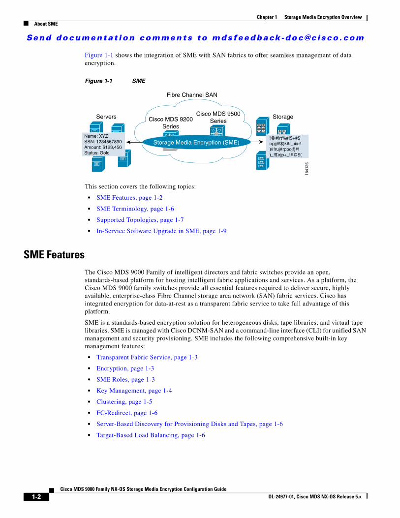
Figure 1-1 shows the integration of SME with SAN fabrics to offer seamless management of data encryption.
Figure 1-1 SME
This section covers the following topics:
• SME Features, page 1-2
• SME Terminology, page 1-6
• Supported Topologies, page 1-7
• In-Service Software Upgrade in SME, page 1-9
SME FeaturesThe Cisco MDS 9000 Family of intelligent directors and fabric switches provide an open, standards-based platform for hosting intelligent fabric applications and services. As a platform, the Cisco MDS 9000 family switches provide all essential features required to deliver secure, highly available, enterprise-class Fibre Channel storage area network (SAN) fabric services. Cisco has integrated encryption for data-at-rest as a transparent fabric service to take full advantage of this platform.
SME is a standards-based encryption solution for heterogeneous disks, tape libraries, and virtual tape libraries. SME is managed with Cisco DCNM-SAN and a command-line interface (CLI) for unified SAN management and security provisioning. SME includes the following comprehensive built-in key management features:
• Transparent Fabric Service, page 1-3
• Encryption, page 1-3
• SME Roles, page 1-3
• Key Management, page 1-4
• Clustering, page 1-5
• FC-Redirect, page 1-6
• Server-Based Discovery for Provisioning Disks and Tapes, page 1-6
• Target-Based Load Balancing, page 1-6
Servers Storage
Fibre Channel SAN
Cisco MDS 9200Series
Cisco MDS 9500Series
Storage Media Encryption (SME)Name: XYZSSN: 1234567890Amount: $123,456Status: Gold
!@#!rt%#!$+#$opjj#!$)k#r_)i#r!)#!ruj#rppojf)#!)_!$)rjp+_!#@$(
1841
36
1-2Cisco MDS 9000 Family NX-OS Storage Media Encryption Configuration Guide
OL-24977-01, Cisco MDS NX-OS Release 5.x
Send documenta t ion comments to mdsfeedback -doc@c i sco .com
Chapter 1 Storage Media Encryption OverviewAbout SME
Transparent Fabric Service
Cisco employs a Fibre Channel redirect scheme that automatically redirects the traffic flow to an MSM-18/4 module, a MDS 9222i switch, or a SSN-16 module anywhere in the fabric. There are no appliances in-line in the data path and there is no SAN rewiring or reconfiguration.
Encryption
SME uses strong, IEEE-compliant AES 256 encryption algorithms to protect data at rest. Advanced Cisco MDS 9000 SAN-OS and NX-OS software security features, such as Secure Shell (SSH), Secure Sockets Layer (SSL), RADIUS, and Fibre Channel Security Protocol (FC-SP) provide the foundation for the secure architecture.
SME uses the NIST-approved random number standard to generate the keys for encryption.
Encryption and compression services are transparent to the hosts and storage devices.
Encryption Algorithms
The IEEE-approved standard for encryption of disk drives is IEEE 1619—Standard Architecture for Encrypted Shared Storage Media (1619.1 for tape drives). It specifies the XTS encryption mode commonly used for disk encryption. The IEEE Security in Storage Working Group (SISWG) was investigating the possibility of submitting the XTS mode to NIST for consideration as an Approved Mode of Operation for FIPS 140-2 certification. It uses a narrow-block encryption algorithm, and the standardization process for a wide-block algorithm is currently in progress as 1619.2. Other encryption algorithms for consideration are LRW-AES and AES-CBS. Draft versions of the IEEE 1619 standard had used LRW-AES, which was later replaced by XTS-AES.
SME Roles
SME services include the following four configuration and security roles:
• SME Administrator
• SME Storage Administrator
• SME Key Management Center (KMC) Administrator
• SME Recovery Officer
The SME Administrator configures and maintains SME. This role can be filled by multiple storage network administrators. The SME Storage Administrators are responsible for SME provisioning operations and the SME KMC Administrators are responsible for the SME KMC administration operations. The security officer may be assigned the SME KMC Administrator role in some scenarios.
Note SME Administrator role includes the SME Storage Administrator and the SME KMC Administrator roles.
The SME Recovery Officers are responsible for key recovery operations. During SME configuration, additional Recovery Officers can be added. SME Recovery Officers play a critical role in recovering the key database of a deactivated cluster and they are responsible for protecting the master key. The role of the SME Recovery Officer separates master key management from SME administrations and operations. In some organizations, a security officer may be assigned to this role.
1-3Cisco MDS 9000 Family NX-OS Storage Media Encryption Configuration Guide
OL-24977-01, Cisco MDS NX-OS Release 5.x
Send documenta t ion comments to mdsfeedback -doc@c i sco .com
Chapter 1 Storage Media Encryption OverviewAbout SME
At the advanced security level, a quorum of SME Recovery Officers is required to perform recovery procedures. The default is 2 out of 5. In this case 2 of the 5 recovery officers are required to unlock the master key.
For additional information on SME Administrator and SME Recovery Officer roles, see the “Creating and Assigning SME Roles and SME Users” section on page 2-19.
Key Management
Cisco Key Management Center (KMC) provides essential features such as key archival, secure export and import, and key shredding.
Key management features include the following:
• Master key resides in password protected file or in smart cards.
– If the cluster security mode is set to Basic, the master key resides in the password protected file.
– If the cluster security mode is set to Standard, the master key resides in only one smart card. And the same smart card is required to recover the master key.
– If the cluster security mode is set to Advanced, the master key resides in multiple smart cards. Quorum (2 out of 3 or 2 out of 5 or 3 out of 5) of smart cards are required to recover the master key based on the user selection.
• Unique key per tape for an SME tape cluster.
• Unique key per LUN for an SME disk cluster.
• Keys reside in clear-text only inside a FIPS boundary.
• Tape keys and intermediate keys are wrapped by the master key and deactivated in the CKMC.
• Disk keys are wrapped by the cluster master key and deactivated in the CKMC.
• Option to store tape keys on tape media.
The centralized key lifecycle management includes the following:
• Archive, shred, recover, and distribute media keys.
– Integrated into DCNM-SAN.
– Secure transport of keys.
• End-to-end key management using HTTPS/SSL/SSH.
– Access controls and accounting.
– Use of existing AAA mechanisms.
The Cisco KMC provides dedicated key management for SME, with support for single and multisite deployments. The Cisco KMC performs key management operations.
The Cisco KMC is either integrated or separated from DCNM-SAN depending on the deployment requirements.
Single site operations can be managed by the integration of the Cisco KMC in DCNM-SAN. In multisite deployments, the centralized Cisco KMC can be used together with the local DCNM-SAN servers that are used for fabric management. This separation provides robustness to the KMC and also supports the SME deployments in different locations sharing the same Cisco KMC.
Figure 1-2 shows how Cisco KMC is separated from DCNM-SAN for a multisite deployment.
1-4Cisco MDS 9000 Family NX-OS Storage Media Encryption Configuration Guide
OL-24977-01, Cisco MDS NX-OS Release 5.x
Send documenta t ion comments to mdsfeedback -doc@c i sco .com
Chapter 1 Storage Media Encryption OverviewAbout SME
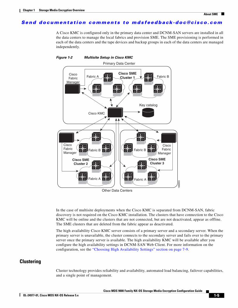
A Cisco KMC is configured only in the primary data center and DCNM-SAN servers are installed in all the data centers to manage the local fabrics and provision SME. The SME provisioning is performed in each of the data centers and the tape devices and backup groups in each of the data centers are managed independently.
Figure 1-2 Multisite Setup in Cisco KMC
In the case of multisite deployments when the Cisco KMC is separated from DCNM-SAN, fabric discovery is not required on the Cisco KMC installation. The clusters that have connection to the Cisco KMC will be online and the clusters that are not connected, but are not deactivated, appear as offline. The SME clusters that are deleted from the fabric appear as deactivated.
The high availability Cisco KMC server consists of a primary server and a secondary server. When the primary server is unavailable, the cluster connects to the secondary server and fails over to the primary server once the primary server is available. The high availability KMC will be available after you configure the high availability settings in DCNM-SAN Web Client. For more information on the configuration, see the “Choosing High Availability Settings” section on page 7-9.
Clustering
Cluster technology provides reliability and availability, automated load balancing, failover capabilities, and a single point of management.
Primary Data Center
Fabric A
Fabric A
Cisco SMECluster 2
Cisco SMECluster 3
Fabric A
Cisco KMC
CiscoFabric
Manager
CiscoFabricManager
CiscoFabric
Manager
Fabric B
Fabric B Fabric B
Cisco SMECluster 1
Key catalog
Other Data Centers
1888
93
1-5Cisco MDS 9000 Family NX-OS Storage Media Encryption Configuration Guide
OL-24977-01, Cisco MDS NX-OS Release 5.x
Send documenta t ion comments to mdsfeedback -doc@c i sco .com
Chapter 1 Storage Media Encryption OverviewAbout SME
FC-Redirect
SME performance can easily be scaled up by adding more Cisco MDS 9000 Family switches or modules. The innovative Fibre Channel redirect capabilities in Cisco MDS 9000 NX-OS enable traffic from any switch port to be encrypted without SAN reconfiguration or rewiring.
Server-Based Discovery for Provisioning Disks and Tapes
SME provides discovery of backend targets using the identity of the host during a session establishment.
Target-Based Load Balancing
The SME cluster consists of a set of switches (in a dual-fabric environment) running the SME application. Clustering offers target-based load balancing of SME application services. The cluster infrastructure allows the SME application to communicate and coordinate to maintain consistency and high availability.
Load balancing is achieved by distributing ownership of the various metadata objects throughout the cluster. SME assigns hosts to the available SME interfaces using the following algorithm:
• All hosts for a given target port are always assigned to the same SME interface.
• If a target port is connected to one of the SME switches, an interface is selected based on the load from the target-connected switch. That is, the target locality is considered when choosing a SME interface for a target.
• If a target is connected to a switch that has no SME interface, then the target is assigned to the least loaded available interface in the SME cluster.
In target-based load balancing, the load on an interface refers to the number of targets assigned to that interface.
Caution SME provides a load balancing CLI that allows you to rebalance the targets assigned to the available SME interfaces in the cluster. However, the load balancing command is disruptive to the traffic. Ensure that you execute this command at a scheduled downtime, otherwise, the existing traffic will be affected.
SME TerminologyThe following SME-related terms are used in this book:
• SME interface—The security engine in the MSM-18/4 module or fixed slot of a Cisco MDS 9222i fabric switch. Each MSM-18/4 module and MDS 9222i switch has one security engine.
• SME cluster—A network of MDS switches that are configured to provide the SME functionality; each switch includes one or more MSM-18/4 modules and each module includes a security engine. Includes one or more nodes or switches for high availability (HA) and load balancing.
• Fabric—A physical fabric topology in the SAN as seen by DCNM-SAN. There can be multiple VSANs (logical fabrics) within the physical fabric.
• Tape group—A backup environment in the SAN. This consists of all the tape backup servers and the tape libraries that they access.
• Tape device—A tape drive that is configured for encryption.
• Tape volumes—A physical tape cartridge identified by a barcode for a given use.
1-6Cisco MDS 9000 Family NX-OS Storage Media Encryption Configuration Guide
OL-24977-01, Cisco MDS NX-OS Release 5.x

Send documenta t ion comments to mdsfeedback -doc@c i sco .com
Chapter 1 Storage Media Encryption OverviewAbout SME
• Tape volume group—A logical set of tape volumes that are configured for a specific use, for example, a group of tape volumes used to backup a database.
• Disk group—The disks that are grouped functionally to form disk groups.
• Disk—Disk is a LUN. A LUN is a logical unit that is exported to the host by the storage controller.
• IT-NEXUS—Initiator or Target pWWNs that defines a host to target connection.
• SME node—Each switch in the cluster is called an SME node and plays a role in determining if the cluster has a quorum.
• Cisco Key Management Center (CKMC)—A component of DCNM-SAN that stores the encryption keys.
• Master key—An encryption key generated when an SME cluster is created. The master key encrypts the tape volume keys and tape keys and it is required to decrypt those keys in order to retrieve encrypted data.
• Media key—A key that is used for encrypting and authenticating the data on specific tapes.
• Disk key—A key that is used for encrypting and authenticating the data on specific disks.
• SmartCard—A card (approximately the size of a credit card) with a built-in microprocessor and memory used for authentication.
• SME Administrator—An administrator who configures SME. This role includes the Cisco Storage Administrator role where the administrator manages the SME operations and the SME KMC Administrator role where the administrator is responsible for the SME key management operations.
• Storage Administrator —An administrator who manages the SME operations.
• SME KMC Administrator—An administrator who is responsible for the SME key management operations.
• SME Recovery Officer—A data security officer entrusted with smart cards and the associated PINs. Each smart card stores a share of the cluster master key. Recovery officers must present their cards and PINs to recover the key database of a deactivated cluster. A quorum of recovery officers are required to execute this operation.
Supported TopologiesSME supports single-and dual-fabric topologies. The Cisco MSM-18/4 module, the MDS 9222i switch, and the SSN-16 provides the SME engines used by SME to encrypt and compress data-at-rest. Multiple modules can be deployed in a Fibre Channel fabric to easily scale-up performance, to enable simplified load balancing, and to increase availability. In a typical configuration, one MSM-18/4 module is required in each SME cluster.
SME clusters include designated backup servers, tape libraries, and one or more MDS switches running Cisco SAN-OS Release 3.2(2c) or later or NX-OS 4.x or later. One cluster switch must include an MSM-18/4 module. With easy-to-use provisioning, traffic between any host and tape on the fabric can utilize the SME services.
Required SME engines are included in the following Cisco products:
• Cisco MDS 9000 Family 18/4-Port Multiservice Module (MSM-18/4)
• Cisco MDS 9222i Multiservice Module Switch
• Cisco MDS 16-Port Storage Services Node (SSN-16)
1-7Cisco MDS 9000 Family NX-OS Storage Media Encryption Configuration Guide
OL-24977-01, Cisco MDS NX-OS Release 5.x
Send documenta t ion comments to mdsfeedback -doc@c i sco .com
Chapter 1 Storage Media Encryption OverviewAbout SME
Single-Fabric Topology for Tape
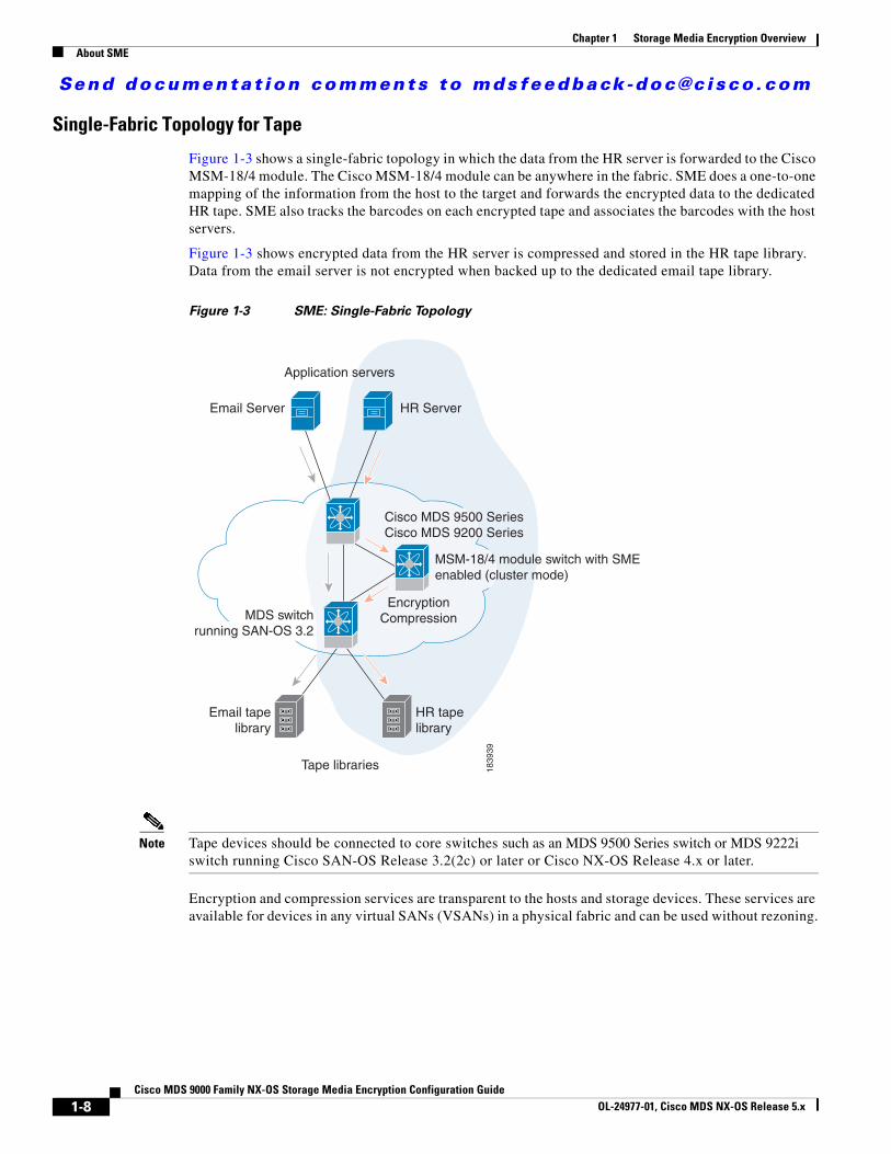
Figure 1-3 shows a single-fabric topology in which the data from the HR server is forwarded to the Cisco MSM-18/4 module. The Cisco MSM-18/4 module can be anywhere in the fabric. SME does a one-to-one mapping of the information from the host to the target and forwards the encrypted data to the dedicated HR tape. SME also tracks the barcodes on each encrypted tape and associates the barcodes with the host servers.
Figure 1-3 shows encrypted data from the HR server is compressed and stored in the HR tape library. Data from the email server is not encrypted when backed up to the dedicated email tape library.
Figure 1-3 SME: Single-Fabric Topology
Note Tape devices should be connected to core switches such as an MDS 9500 Series switch or MDS 9222i switch running Cisco SAN-OS Release 3.2(2c) or later or Cisco NX-OS Release 4.x or later.
Encryption and compression services are transparent to the hosts and storage devices. These services are available for devices in any virtual SANs (VSANs) in a physical fabric and can be used without rezoning.
Tape libraries
MSM-18/4 module switch with SMEenabled (cluster mode)
1839
39
Application servers
Email Server
Email tapelibrary
HR tapelibrary
HR Server
Cisco MDS 9500 SeriesCisco MDS 9200 Series
EncryptionCompressionMDS switch
running SAN-OS 3.2
1-8Cisco MDS 9000 Family NX-OS Storage Media Encryption Configuration Guide
OL-24977-01, Cisco MDS NX-OS Release 5.x
Send documenta t ion comments to mdsfeedback -doc@c i sco .com
Chapter 1 Storage Media Encryption OverviewAbout MIBs
Single-Fabric Topology for Disk
A single-fabric topology in which the data from the HR server is forwarded to the Cisco MSM-18/4 module, Cisco MDS 922i switch or SSN-16 module. The Cisco MSM-18/4 module, Cisco MDS 9222i switch or SSN-16 module can be anywhere in the fabric. SME does a one-to-one mapping of the information from the host to the target and forwards the encrypted data to the dedicated HR disk.
Note SME disk also supports dual-fabric topology with which the data can be encrypted on all the paths.
Disk devices should be connected to core switches, such as an MDS 9500 Series switch or an MDS 9222i switch, running on Cisco NX-OS Release 5.2(1) or later.
Encryptions are transparent to the hosts and storage devices. These services are available for devices in any virtual SANs (VSANs) in a physical fabric and can be used without rezoning.
In-Service Software Upgrade in SMEIn-Service Software Upgrade (ISSU) is a comprehensive, transparent software upgrade capability that allows you to add new features and services without any disruption to the traffic.
In a cluster, which has the MDS 9222i switch as nodes, if the nodes are not able to communicate, then the node having the lowest node identifier (node ID) remains in the cluster while the other node leaves the cluster. However, when an ISSU is performed on a node having the lowest node identifier, a complete loss of the cluster results since both the nodes leave the cluster.
This undesirable situation is addressed in a two-node cluster as follows:
• The upgrading node sends a message to the other node of the intent to leave the cluster. The upgrading node can either be a master node or a slave node.
• The remaining node remains in the cluster and performs the role of the master node if it was a slave node. This node continues to remain in the cluster with the quorum intact.
• After the ISSU is completed and the switches boots up, the upgraded node rejoins the cluster as a slave node.
SME disk has disk-specific ISSU restrictions and limitations. For more information about these restrictions, see Chapter 6, “Configuring SME Disks.”
Note This feature is tied to the internals of ISSU logic and no additional command needs to be executed for this purpose.
About MIBsThe MIB module manages SME service. SME is an encryption service provided by an encryption node residing on a line card in a storage device. It receives clear-text data from the host, encrypts and then sends it to be written to tape or disk. It does the reverse in the opposite direction so the service is completely transparent to the host. The purpose of this service is to enhance data security in case the tape or disk is lost or stolen.
1-9Cisco MDS 9000 Family NX-OS Storage Media Encryption Configuration Guide
OL-24977-01, Cisco MDS NX-OS Release 5.x
Send documenta t ion comments to mdsfeedback -doc@c i sco .com
Chapter 1 Storage Media Encryption OverviewSoftware and Hardware Requirements
As with any services important the user requires that provides some level of fault tolerance in a graceful manner. SME provides fault tolerance by allowing encryption nodes to be grouped into a cluster. Nodes in the same cluster immediately take over the work of a failed node so that the user does not experience service disruption.
Software and Hardware RequirementsThis section includes the following topics:
• Software Requirements, page 1-10
• Hardware Requirements, page 1-10
Software RequirementsAll MDS switches in the SME cluster must be running the current release of Cisco SAN-OS Release 3.2(2c) or later, or Cisco NX-OS 4.x or later software for SME Tape. Cisco NX-OS Release 5.2(1) or later software is required for SME Disk. The software requirements include the following:
• DCNM-SAN must be running Cisco SAN-OS Release 3.2(2c) or later or Cisco NX-OS Release 4.x or later for SME Tape.
• The Cisco MDS switches attached to tape devices must be running Cisco SAN-OS Release 3.2(2c) or later or Cisco NX-OS Release 4.x or later for SME Tape.
• All switches that include MSM-18/4 modules must be running Cisco SAN-OS Release 3.2(2c) or later or Cisco NX-OS Release 4.x or later software for SME Tape.
• DCNM-SAN must be running Cisco NX-OS Release 5.2(1) for SME Disk.
• All Cisco MDS switches in the SME cluster enabled for disks must be running Cisco NX-OS Release 5.2(1).
• All switches that include MSM-18/4 modules, MDS 9222i switch or SSN-16 modules must be running Cisco NX-OS Release 5.2(1) for SME Disk.
Hardware RequirementsSME requires at least one encryption service engine in each cluster. The SME engines on the required modules provide the transparent encryption and compression services to the hosts and storage devices. To take full advantage of the standard and advanced security levels, a smart card reader is required.
For detailed information on required hardware and installing required hardware, refer to the specific installation guides. For information about ordering hardware, refer to http://www.cisco.com/en/US/ordering/index.shtml.
This section includes information about the following required hardware:
• Cisco MDS 9000 Family 18/4-Port Multiservice Module, page 1-11
• Cisco MDS 9222i Multiservice Modular Switch, page 1-11
• Cisco MDS 16-Port Storage Services Node, page 1-12
• FC-Redirect-Capable Switches, page 1-12
• Smart Card Readers, page 1-13
1-10Cisco MDS 9000 Family NX-OS Storage Media Encryption Configuration Guide
OL-24977-01, Cisco MDS NX-OS Release 5.x
Send documenta t ion comments to mdsfeedback -doc@c i sco .com
Chapter 1 Storage Media Encryption OverviewSoftware and Hardware Requirements
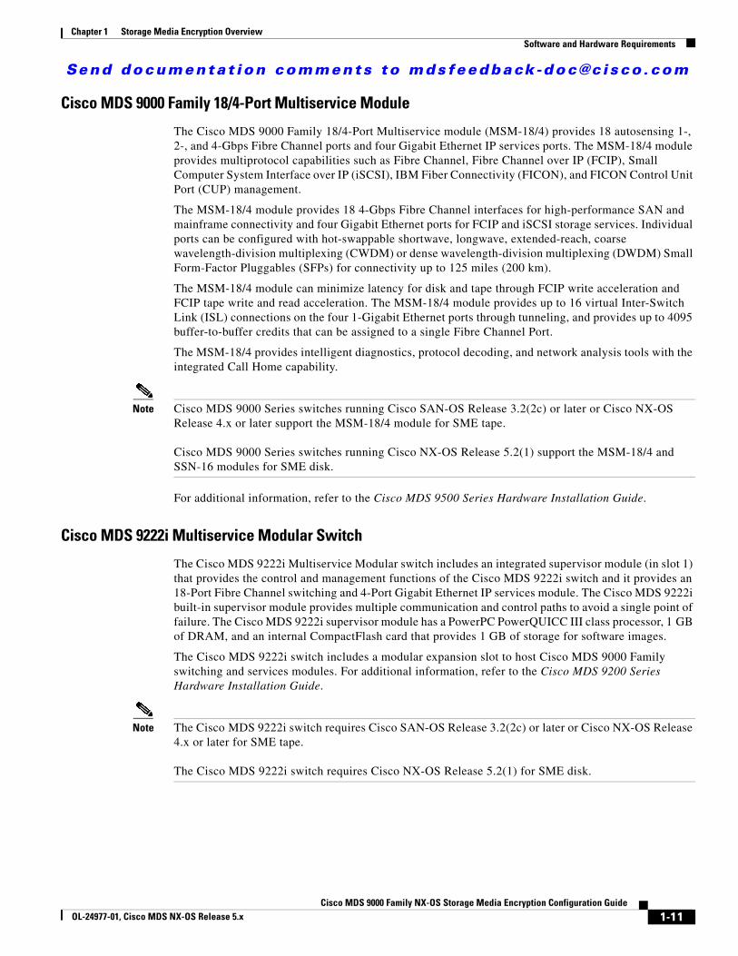
Cisco MDS 9000 Family 18/4-Port Multiservice Module
The Cisco MDS 9000 Family 18/4-Port Multiservice module (MSM-18/4) provides 18 autosensing 1-, 2-, and 4-Gbps Fibre Channel ports and four Gigabit Ethernet IP services ports. The MSM-18/4 module provides multiprotocol capabilities such as Fibre Channel, Fibre Channel over IP (FCIP), Small Computer System Interface over IP (iSCSI), IBM Fiber Connectivity (FICON), and FICON Control Unit Port (CUP) management.
The MSM-18/4 module provides 18 4-Gbps Fibre Channel interfaces for high-performance SAN and mainframe connectivity and four Gigabit Ethernet ports for FCIP and iSCSI storage services. Individual ports can be configured with hot-swappable shortwave, longwave, extended-reach, coarse wavelength-division multiplexing (CWDM) or dense wavelength-division multiplexing (DWDM) Small Form-Factor Pluggables (SFPs) for connectivity up to 125 miles (200 km).
The MSM-18/4 module can minimize latency for disk and tape through FCIP write acceleration and FCIP tape write and read acceleration. The MSM-18/4 module provides up to 16 virtual Inter-Switch Link (ISL) connections on the four 1-Gigabit Ethernet ports through tunneling, and provides up to 4095 buffer-to-buffer credits that can be assigned to a single Fibre Channel Port.
The MSM-18/4 provides intelligent diagnostics, protocol decoding, and network analysis tools with the integrated Call Home capability.
Note Cisco MDS 9000 Series switches running Cisco SAN-OS Release 3.2(2c) or later or Cisco NX-OS Release 4.x or later support the MSM-18/4 module for SME tape.
Cisco MDS 9000 Series switches running Cisco NX-OS Release 5.2(1) support the MSM-18/4 and SSN-16 modules for SME disk.
For additional information, refer to the Cisco MDS 9500 Series Hardware Installation Guide.
Cisco MDS 9222i Multiservice Modular Switch
The Cisco MDS 9222i Multiservice Modular switch includes an integrated supervisor module (in slot 1) that provides the control and management functions of the Cisco MDS 9222i switch and it provides an 18-Port Fibre Channel switching and 4-Port Gigabit Ethernet IP services module. The Cisco MDS 9222i built-in supervisor module provides multiple communication and control paths to avoid a single point of failure. The Cisco MDS 9222i supervisor module has a PowerPC PowerQUICC III class processor, 1 GB of DRAM, and an internal CompactFlash card that provides 1 GB of storage for software images.
The Cisco MDS 9222i switch includes a modular expansion slot to host Cisco MDS 9000 Family switching and services modules. For additional information, refer to the Cisco MDS 9200 Series Hardware Installation Guide.
Note The Cisco MDS 9222i switch requires Cisco SAN-OS Release 3.2(2c) or later or Cisco NX-OS Release 4.x or later for SME tape.
The Cisco MDS 9222i switch requires Cisco NX-OS Release 5.2(1) for SME disk.
1-11Cisco MDS 9000 Family NX-OS Storage Media Encryption Configuration Guide
OL-24977-01, Cisco MDS NX-OS Release 5.x

Send documenta t ion comments to mdsfeedback -doc@c i sco .com
Chapter 1 Storage Media Encryption OverviewSoftware and Hardware Requirements
Cisco MDS 16-Port Storage Services Node
The Cisco MDS 9000 Family 16-Port Storage Services Node (SSN-16) hosts four independent service engines which can be individually and incrementally enabled to scale as business requirements grow. The SSN-16 configuration is based on the single service engine of the Cisco MDS 9000 Family 18/4-Port Multiservice module and the four-to-one consolidation provides hardware savings and frees up slots in the MDS 9500 series chassis.
The SSN-16 seamlessly integrates into the Cisco MDS 9500 Series Multilayer directors and the Cisco MDS 9222i Multiservice Modular switch. Each of the four service engines supports four Gigabit Ethernet IP storage services ports for a total of 16 ports of Fibre Channel over IP (FCIP) connectivity. The traffic can be switched between an IP port and any Fibre Channel port on Cisco MDS 9000 Family switches.
The SSN-16 supports the full range of services available on other Cisco MDS 9000 Family modules including VSAN, security, and traffic management. Features such as I/O Accelerator (IOA), SME Disk and Tape, and FCIP can be configured in different octeons in a single SSN-16 module.
By running four separate, concurrent applications on one module, SSN-16 provides the following functions:
• Provides better disaster recovery and continuity solutions for mission critical applications.
• Minimizes the number of devices required, which improves the reliability.
• Consolidates the management with a single module, which provides end-to-end visibility.
• Facilitates solution-level performance optimization.
The SSN-16 module provides transparent services to any port in a fabric and does not require additional SAN reconfiguration and rewiring. The module does not require the host or target to be directly attached and is available with multimodule clustering and balancing.
The SSN-16 module supports up to four SME interfaces per module and provides higher scalability and improved performance of up to 20 percent on the MSM-18/4 module and 9222i switches.
Note Cisco MDS 9500 Series switches running Cisco NX-OS Release 4.2(1) or later support the SSN-16.
For additional information, refer to the Cisco MDS 9500 Series Hardware Installation Guide.
FC-Redirect-Capable Switches
SME requires that each target switch be FC-Redirect capable. FC-Redirect is not supported on the following switches:
• Cisco MDS 9120 switch
• Cisco MDS 9140 switch
• Cisco MDS 9124 switch
• Cisco MDS 9134 switch
• Cisco MDS 9020 switch
Note Disk devices, tape devices, and tape libraries are not supported in these edge switches. Disks and tapes cannot be connected to these switches.
1-12Cisco MDS 9000 Family NX-OS Storage Media Encryption Configuration Guide
OL-24977-01, Cisco MDS NX-OS Release 5.x
Send documenta t ion comments to mdsfeedback -doc@c i sco .com
Chapter 1 Storage Media Encryption OverviewSME Prerequisites
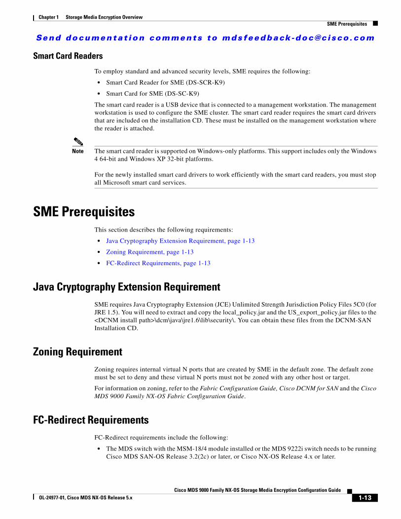
Smart Card Readers
To employ standard and advanced security levels, SME requires the following:
• Smart Card Reader for SME (DS-SCR-K9)
• Smart Card for SME (DS-SC-K9)
The smart card reader is a USB device that is connected to a management workstation. The management workstation is used to configure the SME cluster. The smart card reader requires the smart card drivers that are included on the installation CD. These must be installed on the management workstation where the reader is attached.
Note The smart card reader is supported on Windows-only platforms. This support includes only the Windows 4 64-bit and Windows XP 32-bit platforms.
For the newly installed smart card drivers to work efficiently with the smart card readers, you must stop all Microsoft smart card services.
SME PrerequisitesThis section describes the following requirements:
• Java Cryptography Extension Requirement, page 1-13
• Zoning Requirement, page 1-13
• FC-Redirect Requirements, page 1-13
Java Cryptography Extension RequirementSME requires Java Cryptography Extension (JCE) Unlimited Strength Jurisdiction Policy Files 5C0 (for JRE 1.5). You will need to extract and copy the local_policy.jar and the US_export_policy.jar files to the <DCNM install path>\dcm\java\jre1.6\lib\security\. You can obtain these files from the DCNM-SAN Installation CD.
Zoning RequirementZoning requires internal virtual N ports that are created by SME in the default zone. The default zone must be set to deny and these virtual N ports must not be zoned with any other host or target.
For information on zoning, refer to the Fabric Configuration Guide, Cisco DCNM for SAN and the Cisco MDS 9000 Family NX-OS Fabric Configuration Guide.
FC-Redirect RequirementsFC-Redirect requirements include the following:
• The MDS switch with the MSM-18/4 module installed or the MDS 9222i switch needs to be running Cisco MDS SAN-OS Release 3.2(2c) or later, or Cisco NX-OS Release 4.x or later.
1-13Cisco MDS 9000 Family NX-OS Storage Media Encryption Configuration Guide
OL-24977-01, Cisco MDS NX-OS Release 5.x
Send documenta t ion comments to mdsfeedback -doc@c i sco .com
Chapter 1 Storage Media Encryption OverviewSME Security Overview
• The target must be connected to an MDS 95XX, 9216, or 9222i switch running Cisco MDS SAN-OS Release 3.2(2c) or later, or Cisco NX-OS Release 4.x or later.
• 32 targets per MSM-18/4 module can be FC-redirected.
• Each FC-redirected target can be zoned to 16 hosts or less.
• CFS should be enabled on all required switches for FC-Redirect.
• SME servers, disk targets, and tape devices should not be part of an IVR zone set.
• Advanced zoning capabilities such as quality of service (QoS), logical unit number (LUN) zoning, and read-only LUNs must not be used for FC-Redirect hosts and targets.
SME Security OverviewSME transparently encrypts and decrypts data inside the storage environment without slowing or disrupting business critical applications.
In SME Tape, SME generates a master key, tape volume keys, and tape keys. The keys are encrypted in a hierarchical order: the master key encrypts the tape volume keys and the tape keys.
In SME Disk, SME generates a master key and disk keys. The keys are encrypted in a hierarchical order: the master key encrypts the disk keys.
The keys are also copied to the key catalog on the Cisco KMC server for backup and archival. Eventually inactive keys are removed from the fabric, but they are retained in the Cisco KMC catalog. The keys can be retrieved automatically from the Cisco KMC by the SME services in the fabric if needed again.
A single Cisco KMC can be used as a centralized key repository for multiple fabrics with SME services if desired. Key catalog import and export capabilities are also provided to accommodate moving tape media to different fabrics in environments with multiple Cisco KMC servers. Backup applications can be used to archive the key catalogs for additional protection.
Note SME cluster can be configured either for SME Disk or for SME Tape. Both Tape and Disk configurations cannot be configured under a same cluster. A cluster can be configured only for one of them.
Additional Security CapabilitiesAdditional security capabilities offered by Cisco NX-OS complete the SME solution. For example, RADIUS and TACACS+ servers can be used to authenticate, authorize, and provide accounting (AAA) for SME administrators. Management of SME can be limited to authorized administrators using role-based access controls (RBACs). When communication occurs from the DCNM-SAN to cluster nodes, the secure shell (SSHv2) protocol provides message integrity and privacy. PKI certificates can be configured in the CKMC and cluster nodes to enable trustpoint (SSL-protected transport).
1-14Cisco MDS 9000 Family NX-OS Storage Media Encryption Configuration Guide
OL-24977-01, Cisco MDS NX-OS Release 5.x
Send documenta t ion comments to mdsfeedback -doc@c i sco .com
Cisco MDS 9000 Family NXOL-24977-01, Cisco MDS NX-OS Release 5.x
C H A P T E R 2
Configuring SMEThis chapter includes information about configuring SME, SME installation, and the preliminary tasks that you must complete before configuring SME.
This chapter includes the following topics:
• Information About SME Configuration, page 2-1
• Licensing Requirements for SME Configuration, page 2-2
• Prerequisites for SME Configuration, page 2-3
• Guidelines and Limitations, page 2-4
• Installing DCNM-SAN Server, page 2-6
• Configuring SME Tasks, page 2-15
• Required Preconfiguration Tasks, page 2-16
• Field Descriptions for SME Configuration, page 2-27
• Feature History for SME Configuration, page 2-28
Information About SME ConfigurationYou can use one of these two configuration management tools to configure SME:
• Cisco DCNM-SAN, page 2-1
• Command Line Interface, page 2-2
The Cisco DCNM-SAN Web Client can be used to configure and manage SME using a web browser.
Cisco DCNM-SANCisco DCNM-SAN is a set of network management tools that supports Secure Simple Network Management Protocol version 3 (SNMPv3). Cisco DCNM-SAN includes the following applications:
• DCNM-SAN Web Client—Provides a graphical user interface (GUI) that displays real-time views of your network fabric, and lets you manage the configuration of Cisco MDS 9000 Family devices and third-party switches.
2-1-OS Storage Media Encryption Configuration Guide
Send documenta t ion comments to mdsfeedback -doc@c i sco .com
Chapter 2 Configuring SMELicensing Requirements for SME Configuration
Note SME configuration is supported in DCNM-SAN Web Client only.
• DCNM-SAN —Installed on a server and must be started before running the DCNM-SAN client. It can be accessed by up to 16 DCNM-SAN Clients at a time.
• Device Manager—Provides two views of a switch.
– Device View displays a continuously updated physical representation of the switch configuration, and provides access to statistics and configuration information for a single switch.
– Summary View displays real-time performance statistics of all active interfaces and channels on the switch for Fibre Channel and IP connections.
Note During the DCNM-SAN installation, the use_ip flag in the smeserver.properties file is set to FALSE by default. If you choose to use IP addresses, the DNS server should not be configured on any switch in the fabric and the use_ip flag in the smeserver.properties file must be set to TRUE.
The smeserver.properties file is located at the following location: <fm install path>\dcm\fm\conf\
Once you make any modifications to the smeserver.properties file, you must restart DCNM-SAN.
The Cisco DCNM-SAN applications are an alternative to the CLI for most switch configuration commands.
For more information on configuring the Cisco MDS switch using DCNM-SAN, refer to the Cisco DCNM Fundamentals Guide.
Command Line InterfaceWith the CLI, you can type commands at the switch prompt, and the commands are executed when you press the Enter key. The CLI parser provides command help, command completion, and keyboard sequences that allow you to access previously executed commands from the buffer history.
Licensing Requirements for SME ConfigurationTo use the SME feature, you need the appropriate SME license. However, enabling SME without a license key starts a counter on the grace period. You then have 120 days to install the appropriate license keys or disable the use of SME. If at the end of the 120-day grace period the switch does not have a valid license key for SME, it will be automatically disabled.
Note Although you need to install DCNM-SAN, you do not need a DCNM-SAN license to use SME. Additional DCNM-SAN capabilities are not enabled by default with SME, so there is no free performance monitoring or other functionality.
To identify if the SME feature is active, use the show license usage license-name command.
2-2Cisco MDS 9000 Family NX-OS Storage Media Encryption Configuration Guide
OL-24977-01, Cisco MDS NX-OS Release 5.x
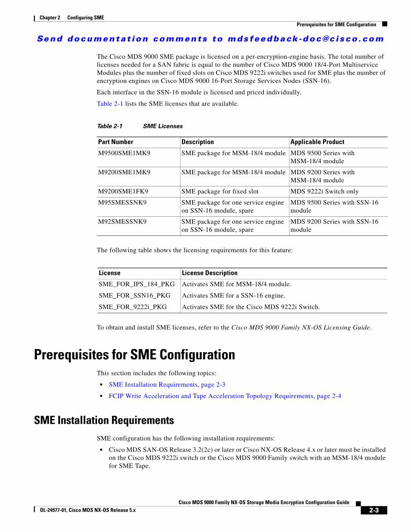
Send documenta t ion comments to mdsfeedback -doc@c i sco .com
Chapter 2 Configuring SMEPrerequisites for SME Configuration
The Cisco MDS 9000 SME package is licensed on a per-encryption-engine basis. The total number of licenses needed for a SAN fabric is equal to the number of Cisco MDS 9000 18/4-Port Multiservice Modules plus the number of fixed slots on Cisco MDS 9222i switches used for SME plus the number of encryption engines on Cisco MDS 9000 16-Port Storage Services Nodes (SSN-16).
Each interface in the SSN-16 module is licensed and priced individually.
Table 2-1 lists the SME licenses that are available.
The following table shows the licensing requirements for this feature:
To obtain and install SME licenses, refer to the Cisco MDS 9000 Family NX-OS Licensing Guide.
Prerequisites for SME ConfigurationThis section includes the following topics:
• SME Installation Requirements, page 2-3
• FCIP Write Acceleration and Tape Acceleration Topology Requirements, page 2-4
SME Installation RequirementsSME configuration has the following installation requirements:
• Cisco MDS SAN-OS Release 3.2(2c) or later or Cisco NX-OS Release 4.x or later must be installed on the Cisco MDS 9222i switch or the Cisco MDS 9000 Family switch with an MSM-18/4 module for SME Tape.
Table 2-1 SME Licenses
Part Number Description Applicable Product
M9500SME1MK9 SME package for MSM-18/4 module MDS 9500 Series with MSM-18/4 module
M9200SME1MK9 SME package for MSM-18/4 module MDS 9200 Series with MSM-18/4 module
M9200SME1FK9 SME package for fixed slot MDS 9222i Switch only
M95SMESSNK9 SME package for one service engine on SSN-16 module, spare
MDS 9500 Series with SSN-16 module
M92SMESSNK9 SME package for one service engine on SSN-16 module, spare
MDS 9200 Series with SSN-16 module
License License Description
SME_FOR_IPS_184_PKG
SME_FOR_SSN16_PKG
SME_FOR_9222i_PKG
Activates SME for MSM-18/4 module.
Activates SME for a SSN-16 engine.
Activates SME for the Cisco MDS 9222i Switch.
2-3Cisco MDS 9000 Family NX-OS Storage Media Encryption Configuration Guide
OL-24977-01, Cisco MDS NX-OS Release 5.x
Send documenta t ion comments to mdsfeedback -doc@c i sco .com
Chapter 2 Configuring SMEGuidelines and Limitations
• Cisco NX-OS Release 5.2(1) must be installed on the Cisco MDS 9222i switch or the Cisco MDS 9000 Family switch with an MSM-18/4 module or SSN-16 module for SME Disk.
• Cisco DCNM-SAN must be installed on a server that you use to provide centralized MDS management services and performance monitoring. The Cisco Key Management Center (Cisco KMC) is on this server.
• DCNM-SAN Web Client can be used to configure and manage SME using a web browser.
For DCNM-SAN server installation that is specific to SME, see Installing DCNM-SAN Server, page 2-6.
For information about installing DCNM-SAN, see the Cisco DCNM Installation and Licensing Guide.
Caution If the Cisco Key Management Center (CKMC) is part of , then the switches and must not be upgraded at the same time.
FCIP Write Acceleration and Tape Acceleration Topology RequirementsSME Disk and SME Tape with FCIP write acceleration or tape acceleration topology has the following requirements:
• If an initiator is on a non-FC-Redirect-capable switch, SME switches should be on the target side of the FCIP tunnel.
• If an initiator is on an FC-Redirect-capable switch, SME switches should be on the host side of the FCIP tunnel.
Guidelines and LimitationsTo design CFS regions for FC-Redirect, follow these guidelines:
• Ensure the CFS region configuration for FC-Redirect can be applied to all FC-Redirect-based applications. The applications include SME, Cisco DMM, and any future applications.
• Ensure that all FC-Redirect-capable switches that are connected to the hosts, targets, and the application switches (switches with MSM-18/4 modules in a cluster) are configured in the same region.
• If there are multiple SME clusters in a region, a target can be part of the SME configuration in only one cluster. To change the target to a different cluster, the configuration in the first cluster must be deleted before creating the configuration in the second cluster.
• All switches in the region must have a common VSAN.
• For existing SME installations, refer to “Configuring CFS Regions For FC-Redirect” section on page D-5 for steps on migrating to CFS regions.
• Remove all instances of the previous configurations when a switch is moved to a region or moved out of a region.
To configure a CFS region, refer to the “Configuring CFS Regions For FC-Redirect” section on page D-5.
Table 2-2 lists the SME configurations and the corresponding limits.
• Cisco NX-OS Release 5.2(1) must be installed on the Cisco MDS 9222i switch or the Cisco MDS 9000 Family switch with an MSM-18/4 module or SSN-16 module for SME Disk.
• Cisco DCNM-SAN must be installed on a server that you use to provide centralized MDS management services and performance monitoring. The Cisco Key Management Center (Cisco KMC) is on this server.
• DCNM-SAN Web Client can be used to configure and manage SME using a web browser.
For DCNM-SAN server installation that is specific to SME, see “Installing DCNM-SAN Server” section on page 2-6.
For more information about installing DCNM-SAN, see the Cisco DCNM Installation and Licensing Guide.
Caution If the Cisco Key Management Center (CKMC) is part of DCNM-SAN, then the switches and DCNM-SAN must not be upgraded at the same time.
FCIP Write Acceleration and Tape Acceleration Topology RequirementsSME Disk and SME Tape with FCIP write acceleration or tape acceleration topology has the following requirements:
• If an initiator is on a non-FC-Redirect-capable switch, SME switches should be on the target side of the FCIP tunnel.
• If an initiator is on an FC-Redirect-capable switch, SME switches should be on the host side of the FCIP tunnel.
Guidelines and LimitationsTo design CFS regions for FC-Redirect, follow these guidelines:
• Ensure the CFS region configuration for FC-Redirect can be applied to all FC-Redirect-based applications. The applications include SME, Cisco DMM, and any future applications.
• Ensure that all FC-Redirect-capable switches that are connected to the hosts, targets, and the application switches (switches with MSM-18/4 modules in a cluster) are configured in the same region.
• If there are multiple SME clusters in a region, a target can be part of the SME configuration in only one cluster. To change the target to a different cluster, the configuration in the first cluster must be deleted before creating the configuration in the second cluster.
• All switches in the region must have a common VSAN.
• For existing SME installations, refer to “Configuring CFS Regions For FC-Redirect” section on page D-5 for steps on migrating to CFS regions.
• Remove all instances of the previous configurations when a switch is moved to a region or moved out of a region.
To configure a CFS region, refer to the “Configuring CFS Regions For FC-Redirect” section on page D-5.
Table 2-2 lists the SME configurations and the corresponding limits.
2-4Cisco MDS 9000 Family NX-OS Storage Media Encryption Configuration Guide
OL-24977-01, Cisco MDS NX-OS Release 5.x
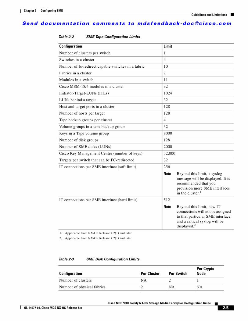
Send documenta t ion comments to mdsfeedback -doc@c i sco .com
Chapter 2 Configuring SMEGuidelines and Limitations
Table 2-2 SME Tape Configuration Limits
Configuration Limit
Number of clusters per switch 1
Switches in a cluster 4
Number of fc-redirect capable switches in a fabric 10
Fabrics in a cluster 2
Modules in a switch 11
Cisco MSM-18/4 modules in a cluster 32
Initiator-Target-LUNs (ITLs) 1024
LUNs behind a target 32
Host and target ports in a cluster 128
Number of hosts per target 128
Tape backup groups per cluster 4
Volume groups in a tape backup group 32
Keys in a Tape volume group 8000
Number of disk groups 128
Number of SME disks (LUNs) 2000
Cisco Key Management Center (number of keys) 32,000
Targets per switch that can be FC-redirected 32
IT connections per SME interface (soft limit) 256
Note Beyond this limit, a syslog message will be displayed. It is recommended that you provision more SME interfaces in the cluster.1
1. Applicable from NX-OS Release 4.2(1) and later
IT connections per SME interface (hard limit) 512
Note Beyond this limit, new IT connections will not be assigned to that particular SME interface and a critical syslog will be displayed.2
2. Applicable from NX-OS Release 4.2(1) and later
Table 2-3 SME Disk Configuration Limits
Configuration Per Cluster Per SwitchPer Crypto Node
Number of clusters NA 2 1
Number of physical fabrics 2 NA NA
2-5Cisco MDS 9000 Family NX-OS Storage Media Encryption Configuration Guide
OL-24977-01, Cisco MDS NX-OS Release 5.x
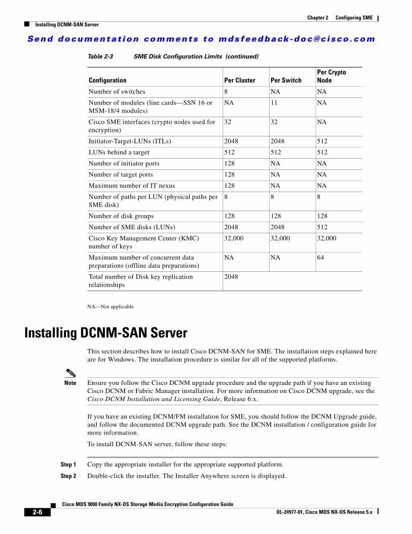
Send documenta t ion comments to mdsfeedback -doc@c i sco .com
Chapter 2 Configuring SMEInstalling DCNM-SAN Server
NA—Not applicable
Installing DCNM-SAN ServerThis section describes how to install Cisco DCNM-SAN for SME. The installation steps explained here are for Windows. The installation procedure is similar for all of the supported platforms.
Note Ensure you follow the Cisco DCNM upgrade procedure and the upgrade path if you have an existing Cisco DCNM or Fabric Manager installation. For more information on Cisco DCNM upgrade, see the Cisco DCNM Installation and Licensing Guide, Release 6.x.
If you have an existing DCNM/FM installation for SME, you should follow the DCNM Upgrade guide, and follow the documented DCNM upgrade path. See the DCNM installation / configuration guide for more information.
To install DCNM-SAN server, follow these steps:
Step 1 Copy the appropriate installer for the appropriate supported platform.
Step 2 Double-click the installer. The Installer Anywhere screen is displayed.
Number of switches 8 NA NA
Number of modules (line cards—SSN 16 or MSM-18/4 modules)
NA 11 NA
Cisco SME interfaces (crypto nodes used for encryption)
32 32 NA
Initiator-Target-LUNs (ITLs) 2048 2048 512
LUNs behind a target 512 512 512
Number of initiator ports 128 NA NA
Number of target ports 128 NA NA
Maximum number of IT nexus 128 NA NA
Number of paths per LUN (physical paths per SME disk)
8 8 8
Number of disk groups 128 128 128
Number of SME disks (LUNs) 2048 2048 512
Cisco Key Management Center (KMC) number of keys
32,000 32,000 32,000
Maximum number of concurrent data preparations (offline data preparations)
NA NA 64
Total number of Disk key replication relationships
2048
Table 2-3 SME Disk Configuration Limits (continued)
Configuration Per Cluster Per SwitchPer Crypto Node
2-6Cisco MDS 9000 Family NX-OS Storage Media Encryption Configuration Guide
OL-24977-01, Cisco MDS NX-OS Release 5.x
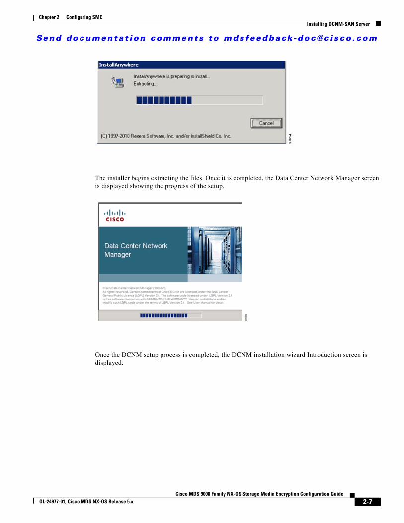
Send documenta t ion comments to mdsfeedback -doc@c i sco .com
Chapter 2 Configuring SMEInstalling DCNM-SAN Server
The installer begins extracting the files. Once it is completed, the Data Center Network Manager screen is displayed showing the progress of the setup.
Once the DCNM setup process is completed, the DCNM installation wizard Introduction screen is displayed.
2-7Cisco MDS 9000 Family NX-OS Storage Media Encryption Configuration Guide
OL-24977-01, Cisco MDS NX-OS Release 5.x

Send documenta t ion comments to mdsfeedback -doc@c i sco .com
Chapter 2 Configuring SMEInstalling DCNM-SAN Server
Step 3 Click Next. The Installation Help screen is displayed.
Step 4 Click Next. The Choose Install Folder screen is displayed.
2-8Cisco MDS 9000 Family NX-OS Storage Media Encryption Configuration Guide
OL-24977-01, Cisco MDS NX-OS Release 5.x
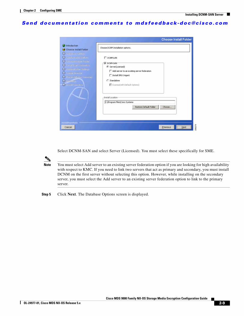
Send documenta t ion comments to mdsfeedback -doc@c i sco .com
Chapter 2 Configuring SMEInstalling DCNM-SAN Server
Select DCNM-SAN and select Server (Licensed). You must select these specifically for SME.
Note You must select Add server to an existing server federation option if you are looking for high availability with respect to KMC. If you need to link two servers that act as primary and secondary, you must install DCNM on the first server without selecting this option. However, while installing on the secondary server, you must select the Add server to an existing server federation option to link to the primary server.
Step 5 Click Next. The Database Options screen is displayed.
2-9Cisco MDS 9000 Family NX-OS Storage Media Encryption Configuration Guide
OL-24977-01, Cisco MDS NX-OS Release 5.x
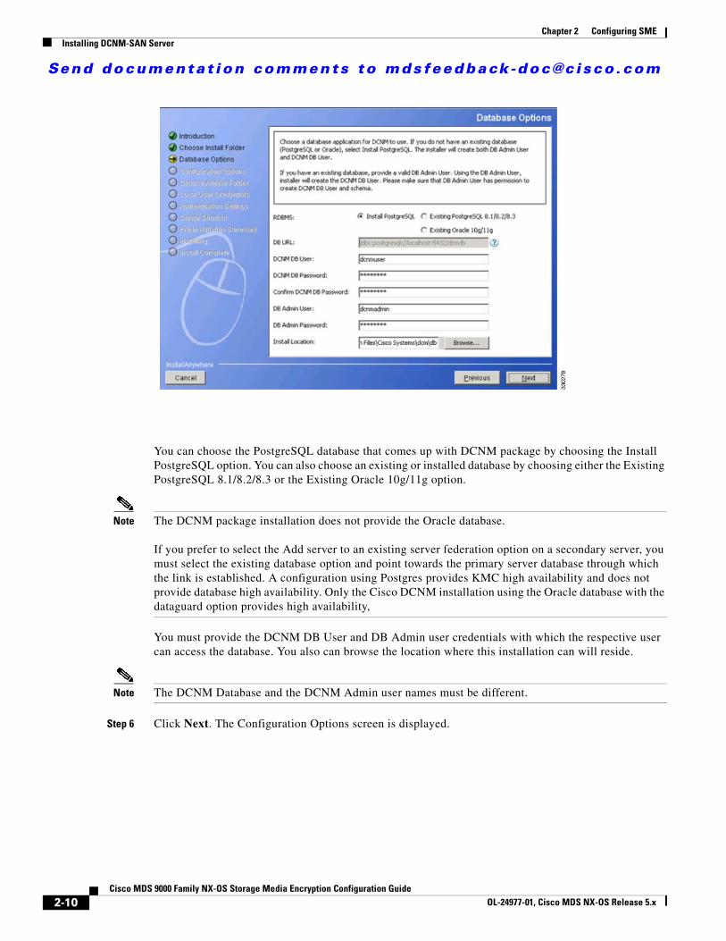
Send documenta t ion comments to mdsfeedback -doc@c i sco .com
Chapter 2 Configuring SMEInstalling DCNM-SAN Server
You can choose the PostgreSQL database that comes up with DCNM package by choosing the Install PostgreSQL option. You can also choose an existing or installed database by choosing either the Existing PostgreSQL 8.1/8.2/8.3 or the Existing Oracle 10g/11g option.
Note The DCNM package installation does not provide the Oracle database.
If you prefer to select the Add server to an existing server federation option on a secondary server, you must select the existing database option and point towards the primary server database through which the link is established. A configuration using Postgres provides KMC high availability and does not provide database high availability. Only the Cisco DCNM installation using the Oracle database with the dataguard option provides high availability,
You must provide the DCNM DB User and DB Admin user credentials with which the respective user can access the database. You also can browse the location where this installation can will reside.
Note The DCNM Database and the DCNM Admin user names must be different.
Step 6 Click Next. The Configuration Options screen is displayed.
2-10Cisco MDS 9000 Family NX-OS Storage Media Encryption Configuration Guide
OL-24977-01, Cisco MDS NX-OS Release 5.x
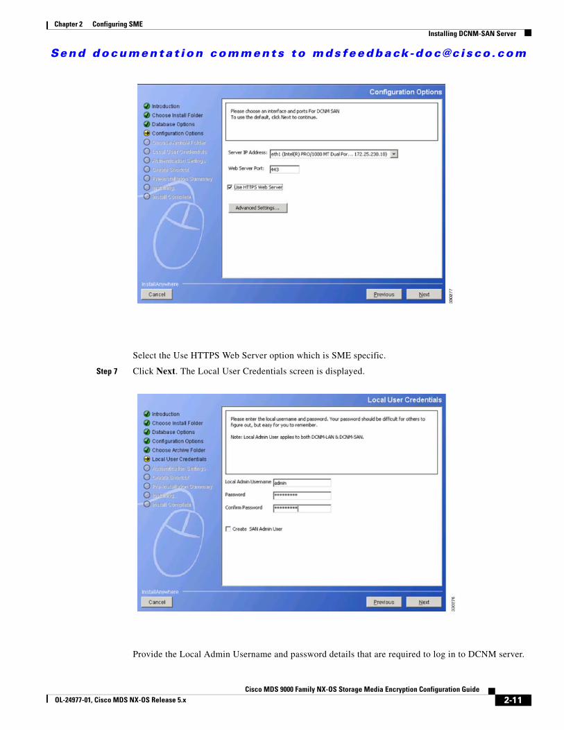
Send documenta t ion comments to mdsfeedback -doc@c i sco .com
Chapter 2 Configuring SMEInstalling DCNM-SAN Server
Select the Use HTTPS Web Server option which is SME specific.
Step 7 Click Next. The Local User Credentials screen is displayed.
Provide the Local Admin Username and password details that are required to log in to DCNM server.
2-11Cisco MDS 9000 Family NX-OS Storage Media Encryption Configuration Guide
OL-24977-01, Cisco MDS NX-OS Release 5.x

Send documenta t ion comments to mdsfeedback -doc@c i sco .com
Chapter 2 Configuring SMEInstalling DCNM-SAN Server
Note You must ensure that the Local Admin Username and Password values are the same as the switch username and password that are a part of a cluster. If not, the cluster creation fails.
Step 8 Click Next. The Authentication Settings screen is displayed.
Select one of the modes from the Local, RADIUS, or TACACS+ options. If you select either the RADIUS or the TACACS+ option, you must provide the server address and secret key (remote authentication).
Step 9 Click Next. The Create Shortcut screen is displayed.
2-12Cisco MDS 9000 Family NX-OS Storage Media Encryption Configuration Guide
OL-24977-01, Cisco MDS NX-OS Release 5.x
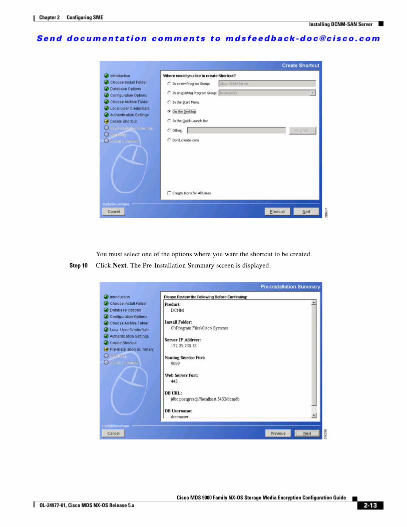
Send documenta t ion comments to mdsfeedback -doc@c i sco .com
Chapter 2 Configuring SMEInstalling DCNM-SAN Server
You must select one of the options where you want the shortcut to be created.
Step 10 Click Next. The Pre-Installation Summary screen is displayed.
2-13Cisco MDS 9000 Family NX-OS Storage Media Encryption Configuration Guide
OL-24977-01, Cisco MDS NX-OS Release 5.x
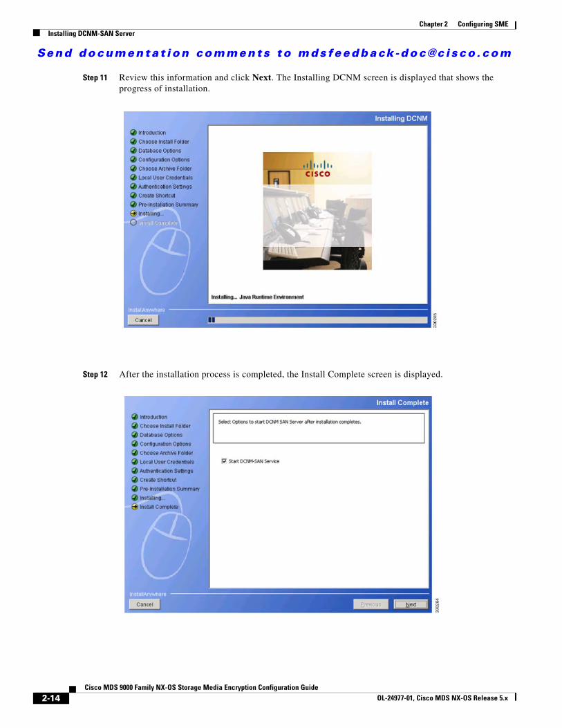
Send documenta t ion comments to mdsfeedback -doc@c i sco .com
Chapter 2 Configuring SMEInstalling DCNM-SAN Server
Step 11 Review this information and click Next. The Installing DCNM screen is displayed that shows the progress of installation.
Step 12 After the installation process is completed, the Install Complete screen is displayed.
2-14Cisco MDS 9000 Family NX-OS Storage Media Encryption Configuration Guide
OL-24977-01, Cisco MDS NX-OS Release 5.x
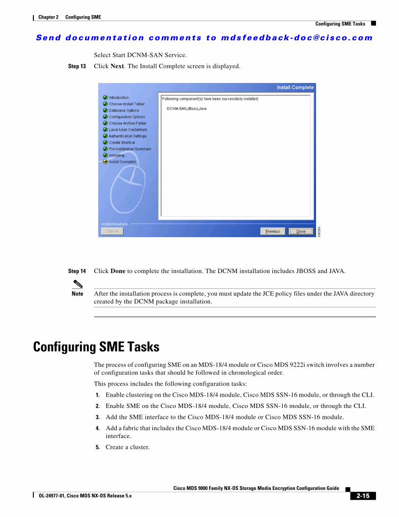
Send documenta t ion comments to mdsfeedback -doc@c i sco .com
Chapter 2 Configuring SMEConfiguring SME Tasks
Select Start DCNM-SAN Service.
Step 13 Click Next. The Install Complete screen is displayed.
Step 14 Click Done to complete the installation. The DCNM installation includes JBOSS and JAVA.
Note After the installation process is complete, you must update the JCE policy files under the JAVA directory created by the DCNM package installation.
Configuring SME TasksThe process of configuring SME on an MDS-18/4 module or Cisco MDS 9222i switch involves a number of configuration tasks that should be followed in chronological order.
This process includes the following configuration tasks:
1. Enable clustering on the Cisco MDS-18/4 module, Cisco MDS SSN-16 module, or through the CLI.
2. Enable SME on the Cisco MDS-18/4 module, Cisco MDS SSN-16 module, or through the CLI.
3. Add the SME interface to the Cisco MDS-18/4 module or Cisco MDS SSN-16 module.
4. Add a fabric that includes the Cisco MDS-18/4 module or Cisco MDS SSN-16 module with the SME interface.
5. Create a cluster.
2-15Cisco MDS 9000 Family NX-OS Storage Media Encryption Configuration Guide
OL-24977-01, Cisco MDS NX-OS Release 5.x
Send documenta t ion comments to mdsfeedback -doc@c i sco .com
Chapter 2 Configuring SMERequired Preconfiguration Tasks
Note The cluster can either be defined for SME Disk or SME Tape. By default, the cluster is tape capable. However, the cluster-capability disk command under the cluster defines the cluster as disk capable. For more information, see the “Creating the SME Cluster” section on page 4-6.
a. Name the cluster.
b. Select the fabrics that you want to create a cluster from.
c. Select the SME interfaces from the fabrics that you are including in the cluster.
d. Select the master key security level (Basic, Standard, or Advanced).
e. Select the security key (shared or unique) and tape preferences (store the key on tape, automatic volume grouping, and compression).
f. Specify the Key Management Center server and key certificate file.
g. Specify the password to encrypt the master key and download the key file.
Required Preconfiguration TasksThis section describes the required tasks that must be completed before you configure SME.
This section includes the following topics:
• Enabling Clustering, page 2-16
• Enabling SME, page 2-18
• Enabling DNS, page 2-18
• IP Access Lists for the Management Interface, page 2-19
• Creating and Assigning SME Roles and SME Users, page 2-19
• Installing DCNM-SAN and DCNM-SAN Client, page 2-23
• Adding a Fabric and Changing the Fabric Name, page 2-23
• Choosing a Key Manager, page 2-24
• Using FC-Redirect with CFS Regions, page 2-25
• Installing Smart Card Drivers, page 2-25
• SME Configuration Process, page 2-25
• SME Configuration Restrictions, page 2-26
Before configuring SME, you must explicitly enable clustering, SME, SSH, and DNS on the MDS switch with an installed MSM-18/4 module or on the MDS 9222i switch. By default, these are disabled. The configuration and verification operations for SME are only available when these are enabled on a switch.
Enabling ClusteringYou can enable clustering on the Cisco MDS 9000 switch with an installed MSM-18/4 module using DCNM-SAN and Device Manager 3.2(2c) or later, or Cisco NX-OS 4.x or later.
2-16Cisco MDS 9000 Family NX-OS Storage Media Encryption Configuration Guide
OL-24977-01, Cisco MDS NX-OS Release 5.x

Send documenta t ion comments to mdsfeedback -doc@c i sco .com
Chapter 2 Configuring SMERequired Preconfiguration Tasks
Note Be sure to enable clustering first, and then enable SME.
This section includes the following topics:
• Enabling Clustering Using DCNM-SAN, page 2-17
• Enabling Clustering Using Device Manager, page 2-17
Enabling Clustering Using DCNM-SAN
Note All the MDS switches with SME interfaces in the cluster should match the authentication credentials used by DCNM-SAN.
Detailed Steps
To enable clustering using DCNM-SAN, follow these steps:
Step 1 In the Physical Attributes pane, select Intelligent Features > SME > Clusters.
Step 2 From the Control tab in the information pane, locate the switch.
Step 3 From the drop-down menu in the Command column, select enable. The default is noSelection.
Note You can select enable on multiple switches, and then click Apply.
Step 4 Click Apply.
Enabling Clustering Using Device Manager
Detailed Steps
To enable clustering using Device Manager, follow these steps for a specific switch:
Step 1 From the Admin menu in the device screen, select Feature Control.
Step 2 Select cluster.
Step 3 From the Action column drop-down menu, select enable.
Step 4 Click Apply.
2-17Cisco MDS 9000 Family NX-OS Storage Media Encryption Configuration Guide
OL-24977-01, Cisco MDS NX-OS Release 5.x
Send documenta t ion comments to mdsfeedback -doc@c i sco .com
Chapter 2 Configuring SMERequired Preconfiguration Tasks
Enabling SMEYou can enable SME using DCNM-SAN or Device Manager.
Note Be sure to enable clustering first, and then enable SME.
This section includes the following topics:
• Enabling SME Using DCNM-SAN, page 2-18
• Enabling SME Using Device Manager, page 2-18
Enabling SME Using DCNM-SAN
Detailed Steps
To enable SME using DCNM-SAN, follow these steps:
Step 1 In the Physical Attributes pane, select Intelligent Features > SME > Clusters.
Step 2 From the Control tab in the information pane, locate the switch.
Step 3 From the drop-down menu in the Command column, select enable. The default is noSelection.
Note You can select enable on multiple switches, and then click Apply.
Step 4 Click Apply.
Enabling SME Using Device Manager
Detailed Steps
To enable SME using Device Manager, do the following for a specific device:
Step 1 From the Admin menu in the device screen, select Feature Control.
Step 2 Select sme.
Step 3 From the Action column drop-down menu, select enable.
Step 4 Click Apply.
Enabling DNSDNS offers services to map a host name to an IP address in the network through a DNS server. When you configure DNS on the switch, you can substitute the host name for the IP address with all IP commands, such as ping, telnet, upload, and download.
2-18Cisco MDS 9000 Family NX-OS Storage Media Encryption Configuration Guide
OL-24977-01, Cisco MDS NX-OS Release 5.x
Send documenta t ion comments to mdsfeedback -doc@c i sco .com
Chapter 2 Configuring SMERequired Preconfiguration Tasks
If you use DNS, the following requirements apply:
• All switches should be configured using DNS.
• The domain name (or the domain list), and the IP name server must be configured to reach remote switches.
• The DNS server should be configured on the same server where DCNM-SAN is installed.
If you use IP addresses, the DNS should not be configured on any switch in the fabric and the use_ip flag in the smeserver.properties must be set to TRUE.
For information on configuring DNS, refer to the IP Services Configuration Guide, Cisco DCNM for SAN and the Cisco MDS 9000 Family NX-OS IP Services Configuration Guide.
sme.useIP for IP Address or Name Selection
If you do not have DNS configured on all switches in the cluster, you can use sme.useIP. The smeserver.properties file is located in the following location: <fm install path>\dcm\fm\conf\.
During the DCNM-SAN installation, the use_ip flag in the smeserver.properties file is set to FALSE by default. If you choose to use IP addresses, the DNS server should not be configured on any switch in the fabric and the use_ip flag in the smeserver.properties file must be set to TRUE. Once you make any modifications to the smeserver.properties file, you must restart DCNM-SAN.
Ensure you enable clustering first, and then enable SME.
You must decide to use DNS completely or to use IP addresses fully in your fabric. A combination of these will not work with the SME feature.
To verify that DNS is enabled everywhere in the cluster, ping between the DCNM-SAN server and the MDS switches and also between the MDS switches with DNS names.
IP Access Lists for the Management InterfaceCluster communication requires the use of the management interface. IP ACL configurations must allow UDP and TCP traffic on ports 9333, 9334, 9335, and 9336.
Creating and Assigning SME Roles and SME UsersThe SME feature provides two primary roles: SME Administrator and the SME Recovery Officer. The SME Administrator role also includes the SME Storage Administrator and SME KMC Administrator roles. By default, SME assigns both the SME Administrator and the SME Recovery Officer to the same user. This assignment works well for small scale deployments of SME.
Note The DCNM-SAN user credentials must be the same as the switch user.
Table 2-4 shows a description of the SME roles and the number of users that should be considered for each role.
2-19Cisco MDS 9000 Family NX-OS Storage Media Encryption Configuration Guide
OL-24977-01, Cisco MDS NX-OS Release 5.x
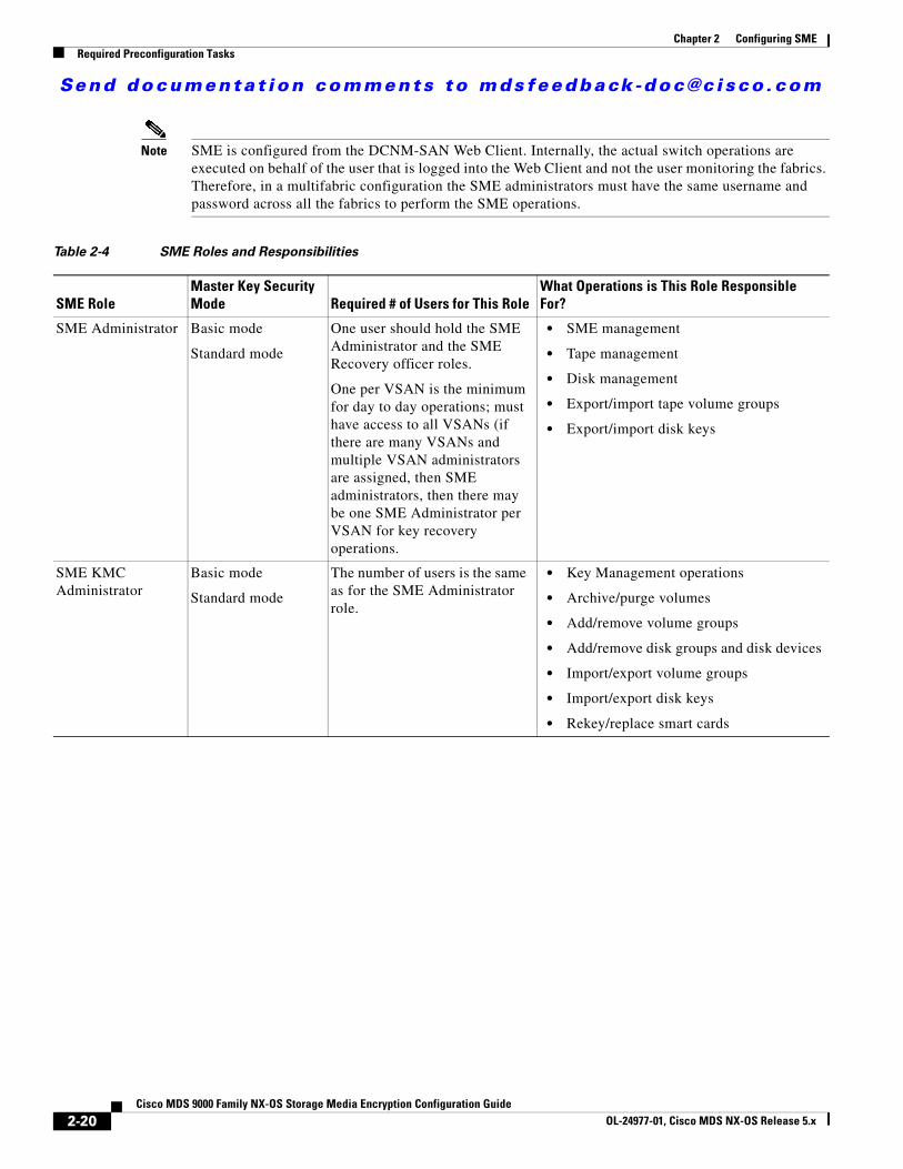
Send documenta t ion comments to mdsfeedback -doc@c i sco .com
Chapter 2 Configuring SMERequired Preconfiguration Tasks
Note SME is configured from the DCNM-SAN Web Client. Internally, the actual switch operations are executed on behalf of the user that is logged into the Web Client and not the user monitoring the fabrics. Therefore, in a multifabric configuration the SME administrators must have the same username and password across all the fabrics to perform the SME operations.
Table 2-4 SME Roles and Responsibilities
SME RoleMaster Key Security Mode Required # of Users for This Role
What Operations is This Role Responsible For?
SME Administrator Basic mode
Standard mode
One user should hold the SME Administrator and the SME Recovery officer roles.
One per VSAN is the minimum for day to day operations; must have access to all VSANs (if there are many VSANs and multiple VSAN administrators are assigned, then SME administrators, then there may be one SME Administrator per VSAN for key recovery operations.
• SME management
• Tape management
• Disk management
• Export/import tape volume groups
• Export/import disk keys
SME KMC Administrator
Basic mode
Standard mode
The number of users is the same as for the SME Administrator role.
• Key Management operations
• Archive/purge volumes
• Add/remove volume groups
• Add/remove disk groups and disk devices
• Import/export volume groups
• Import/export disk keys
• Rekey/replace smart cards
2-20Cisco MDS 9000 Family NX-OS Storage Media Encryption Configuration Guide
OL-24977-01, Cisco MDS NX-OS Release 5.x
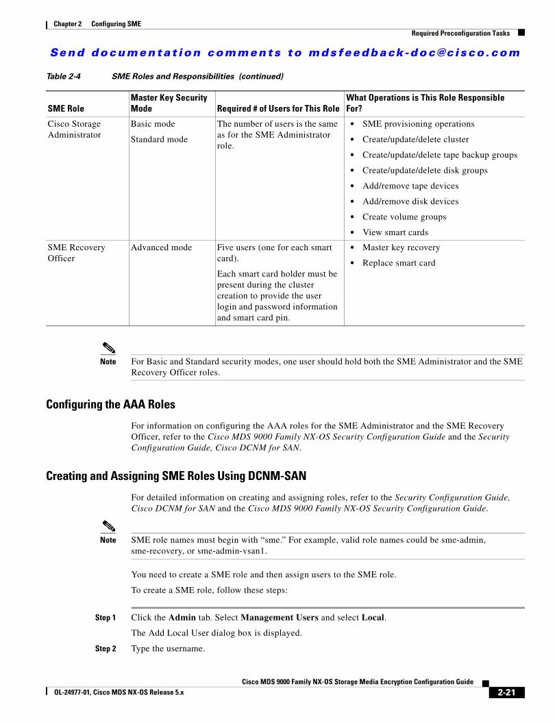
Send documenta t ion comments to mdsfeedback -doc@c i sco .com
Chapter 2 Configuring SMERequired Preconfiguration Tasks
Note For Basic and Standard security modes, one user should hold both the SME Administrator and the SME Recovery Officer roles.
Configuring the AAA Roles
For information on configuring the AAA roles for the SME Administrator and the SME Recovery Officer, refer to the Cisco MDS 9000 Family NX-OS Security Configuration Guide and the Security Configuration Guide, Cisco DCNM for SAN.
Creating and Assigning SME Roles Using DCNM-SAN
For detailed information on creating and assigning roles, refer to the Security Configuration Guide, Cisco DCNM for SAN and the Cisco MDS 9000 Family NX-OS Security Configuration Guide.
Note SME role names must begin with “sme.” For example, valid role names could be sme-admin, sme-recovery, or sme-admin-vsan1.
You need to create a SME role and then assign users to the SME role.
To create a SME role, follow these steps:
Step 1 Click the Admin tab. Select Management Users and select Local.
The Add Local User dialog box is displayed.
Step 2 Type the username.
Cisco Storage Administrator
Basic mode
Standard mode
The number of users is the same as for the SME Administrator role.
• SME provisioning operations
• Create/update/delete cluster
• Create/update/delete tape backup groups
• Create/update/delete disk groups
• Add/remove tape devices
• Add/remove disk devices
• Create volume groups
• View smart cards
SME Recovery Officer
Advanced mode Five users (one for each smart card).
Each smart card holder must be present during the cluster creation to provide the user login and password information and smart card pin.
• Master key recovery
• Replace smart card
Table 2-4 SME Roles and Responsibilities (continued)
SME RoleMaster Key Security Mode Required # of Users for This Role
What Operations is This Role Responsible For?
2-21Cisco MDS 9000 Family NX-OS Storage Media Encryption Configuration Guide
OL-24977-01, Cisco MDS NX-OS Release 5.x
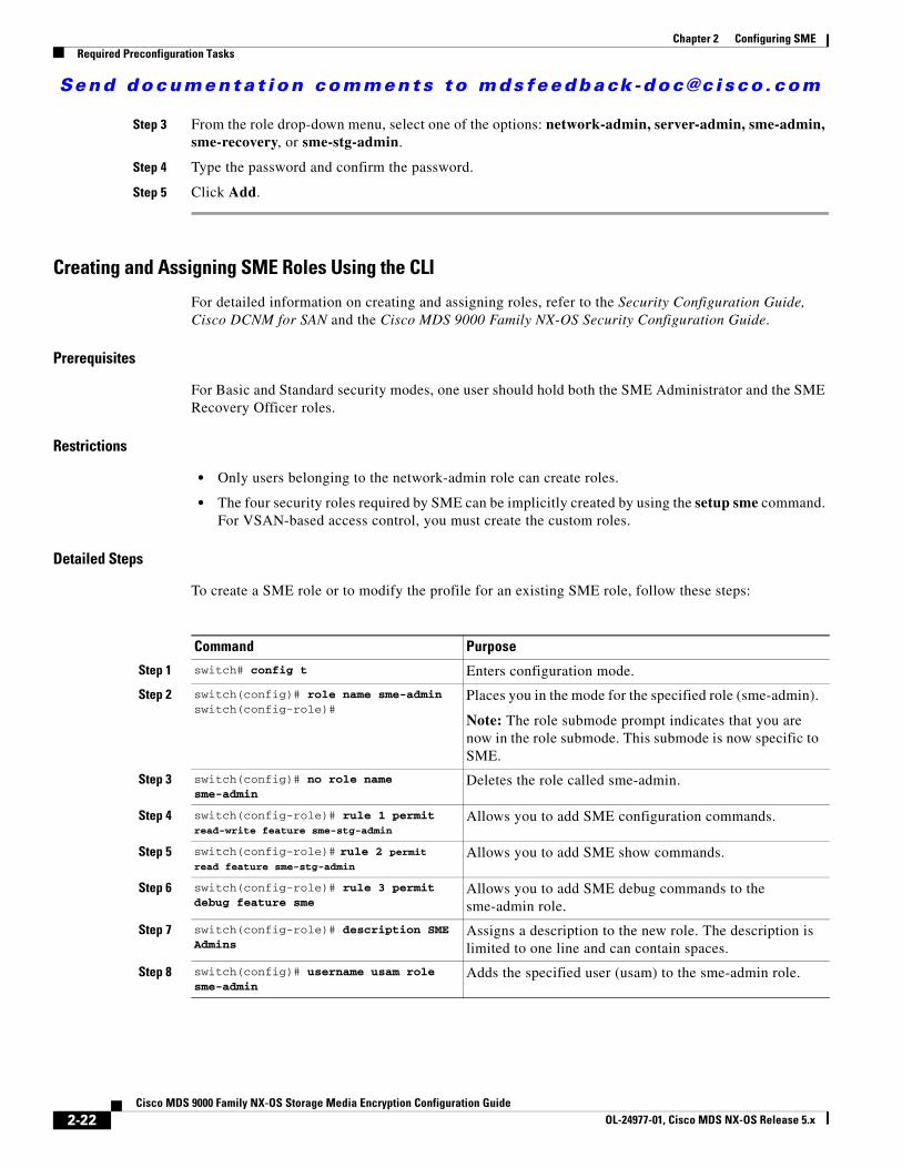
Send documenta t ion comments to mdsfeedback -doc@c i sco .com
Chapter 2 Configuring SMERequired Preconfiguration Tasks
Step 3 From the role drop-down menu, select one of the options: network-admin, server-admin, sme-admin, sme-recovery, or sme-stg-admin.
Step 4 Type the password and confirm the password.
Step 5 Click Add.
Creating and Assigning SME Roles Using the CLI
For detailed information on creating and assigning roles, refer to the Security Configuration Guide, Cisco DCNM for SAN and the Cisco MDS 9000 Family NX-OS Security Configuration Guide.
Prerequisites
For Basic and Standard security modes, one user should hold both the SME Administrator and the SME Recovery Officer roles.
Restrictions
• Only users belonging to the network-admin role can create roles.
• The four security roles required by SME can be implicitly created by using the setup sme command. For VSAN-based access control, you must create the custom roles.
Detailed Steps
To create a SME role or to modify the profile for an existing SME role, follow these steps:
Command Purpose
Step 1 switch# config t Enters configuration mode.
Step 2 switch(config)# role name sme-admin switch(config-role)#
Places you in the mode for the specified role (sme-admin).
Note: The role submode prompt indicates that you are now in the role submode. This submode is now specific to SME.
Step 3 switch(config)# no role name sme-admin
Deletes the role called sme-admin.
Step 4 switch(config-role)# rule 1 permit read-write feature sme-stg-admin
Allows you to add SME configuration commands.
Step 5 switch(config-role)# rule 2 permit read feature sme-stg-admin
Allows you to add SME show commands.
Step 6 switch(config-role)# rule 3 permit debug feature sme
Allows you to add SME debug commands to the sme-admin role.
Step 7 switch(config-role)# description SME Admins
Assigns a description to the new role. The description is limited to one line and can contain spaces.
Step 8 switch(config)# username usam role sme-admin
Adds the specified user (usam) to the sme-admin role.
2-22Cisco MDS 9000 Family NX-OS Storage Media Encryption Configuration Guide
OL-24977-01, Cisco MDS NX-OS Release 5.x
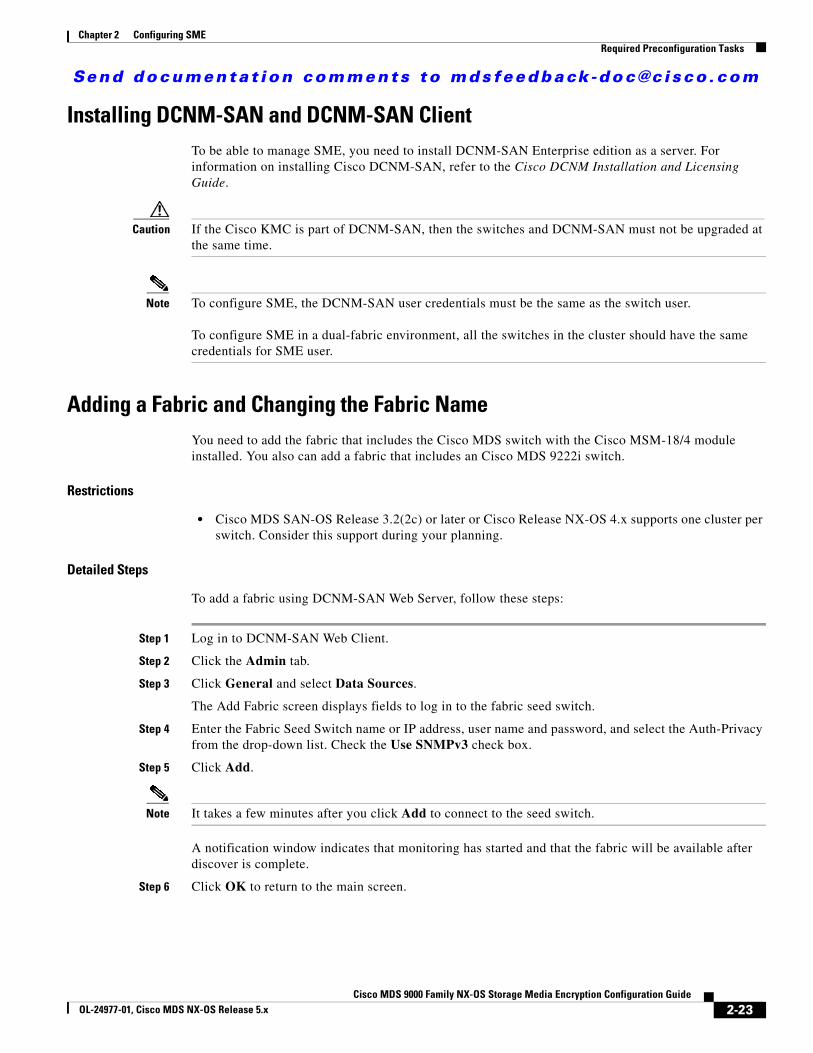
Send documenta t ion comments to mdsfeedback -doc@c i sco .com
Chapter 2 Configuring SMERequired Preconfiguration Tasks
Installing DCNM-SAN and DCNM-SAN ClientTo be able to manage SME, you need to install DCNM-SAN Enterprise edition as a server. For information on installing Cisco DCNM-SAN, refer to the Cisco DCNM Installation and Licensing Guide.
Caution If the Cisco KMC is part of DCNM-SAN, then the switches and DCNM-SAN must not be upgraded at the same time.
Note To configure SME, the DCNM-SAN user credentials must be the same as the switch user.
To configure SME in a dual-fabric environment, all the switches in the cluster should have the same credentials for SME user.
Adding a Fabric and Changing the Fabric NameYou need to add the fabric that includes the Cisco MDS switch with the Cisco MSM-18/4 module installed. You also can add a fabric that includes an Cisco MDS 9222i switch.
Restrictions
• Cisco MDS SAN-OS Release 3.2(2c) or later or Cisco Release NX-OS 4.x supports one cluster per switch. Consider this support during your planning.
Detailed Steps
To add a fabric using DCNM-SAN Web Server, follow these steps:
Step 1 Log in to DCNM-SAN Web Client.
Step 2 Click the Admin tab.
Step 3 Click General and select Data Sources.
The Add Fabric screen displays fields to log in to the fabric seed switch.
Step 4 Enter the Fabric Seed Switch name or IP address, user name and password, and select the Auth-Privacy from the drop-down list. Check the Use SNMPv3 check box.
Step 5 Click Add.
Note It takes a few minutes after you click Add to connect to the seed switch.
A notification window indicates that monitoring has started and that the fabric will be available after discover is complete.
Step 6 Click OK to return to the main screen.
2-23Cisco MDS 9000 Family NX-OS Storage Media Encryption Configuration Guide
OL-24977-01, Cisco MDS NX-OS Release 5.x
Send documenta t ion comments to mdsfeedback -doc@c i sco .com
Chapter 2 Configuring SMERequired Preconfiguration Tasks
Note The fabric name is identified as Fabric_ and the switch name. If you reopen the fabric with a different seed switch, you need to manually change the fabric name to what it was called before so that the fabric name remains the same. If you reopen the fabric with a different seed switch and do not manually change the fabric name, the fabric might be renamed to show the new switch name. This will conflict with the configured SME fabric name in the MDS switches. Choose a unique name that is easily identifiable.
Step 7 Select the fabric and click Edit.
Step 8 Enter a unique fabric name, user name, and password.
Step 9 Select Managed Continuously and click Modify.
Note SME requires that you select Manage Continuously to receive continuous updates from the switches.
Step 10 Click Close to return to the main screen and view the modified fabric name.
Choosing a Key Manager
Prerequisites
• Before configuring SME, you need to choose a key manager.
• To use an installation as a key manager, you should configure the settings for the key manager.
Restrictions
• After you choose a key manager, the key manager cannot be changed. You should be logged into the appropriate role to select or edit any key manager settings.
Detailed Steps
To choose a key manager using DCNM-SAN, follow these steps:
Step 1 Log in to DCNM-SAN Web Client.
Step 2 Click the SME tab and select Key Manager Settings. The Key Manager Settings window is displayed.
Note If you try to select SME before choosing a key manager, DCNM-SAN redirects you to the Key Manager Settings screen so that a key manager can be selected.
RSA key manager is not supported for SME disk.
Step 3 Choose any of the available three options.
a. Select None if you do not want to use this installation as a key manager.
b. Select Cisco if you want to use the installation as a Cisco key manager.
c. Select RSA if you want to choose the RSA key manager.
2-24Cisco MDS 9000 Family NX-OS Storage Media Encryption Configuration Guide
OL-24977-01, Cisco MDS NX-OS Release 5.x
Send documenta t ion comments to mdsfeedback -doc@c i sco .com
Chapter 2 Configuring SMERequired Preconfiguration Tasks
Step 4 Click Submit Settings to save changes.
Using FC-Redirect with CFS RegionsThe Fibre Channel redirect (FC-Redirect) feature uses Cisco Fabric Services (CFS) regions to distribute the FC-Redirect configuration.
By default, the configuration is propagated to all FC-Redirect-capable switches in the fabric. CFS regions can be used to restrict the distribution of the FC-Redirect configuration.
Note Using FC-Redirect with CFS regions is an optional procedure.
To learn more about CFS regions, refer to System Management Configuration Guide, Cisco DCNM for SAN and the Cisco MDS 9000 Family NX-OS System Management Configuration Guide.
Installing Smart Card DriversThe smart card reader must be connected to a management workstation that is used to configure SME. The smart card driver and the smart card drivers library file must be installed in the workstation.
You can download the latest drivers from the Config > Install Smartcard Driver link on the DCNM-SAN Web Client.
Restrictions
The smart card reader is only supported on Windows platforms. This includes only the Windows XP 32 bit, Windows server 2003 32 bit and Windows 7 64-bit platforms.
Note For Windows 7 64-bit smart card system, you must contact Gemalto for access to their Classic Client 6.1 for 64-bit systems. Smart cards are only tested on 6.10.020.001. Any other version of Classic Client for Windows 7 64-bit is at best effort only, and is not Cisco supported. Windows 7 32-bit is not supported.
Troubleshooting Tips
When connecting a new smart card reader after the installation of smart card drivers, you may be required to restart the computer. If the card reader is not recognized on your workstation, you may need to install the latest smart card drivers.
SME Configuration ProcessBefore configuring SME on your switch, it is important to become familiar with the SME configuration process. This section provides an overview of the SME configuration process.
2-25Cisco MDS 9000 Family NX-OS Storage Media Encryption Configuration Guide
OL-24977-01, Cisco MDS NX-OS Release 5.x
Send documenta t ion comments to mdsfeedback -doc@c i sco .com
Chapter 2 Configuring SMERequired Preconfiguration Tasks
• Initial SME Configuration, page 2-26
• Saving SME Cluster Configurations, page 2-26
Initial SME Configuration
Note For information about what you need to do before you initially configure SME, see the “Required Preconfiguration Tasks” section on page 2-16.
Complete the SME configuration tasks on the switch with an installed Cisco MSM-18/4 module or on a Cisco MDS 9222i switch.
These basic configuration tasks provide an overview of the basic SME configuration process:
• Create the SME interface (Chapter 3, “Configuring SME Interfaces”)
• Create a cluster for SME (Chapter 4, “Configuring SME Cluster Management”)
• Add the interfaces to the cluster (Chapter 4, “Configuring SME Cluster Management”)
• Create a tape group (including selecting the backup server and discovering backup libraries) (Chapter 5, “Configuring SME Tapes”)
Saving SME Cluster Configurations
Note Configuration changes must be saved on all switches in the cluster for correct cluster operation. This must be done after the initial cluster creation and after all subsequent changes are made to the cluster configuration.
You must save configuration changes whenever switches or interfaces are added or deleted from a cluster.
SME Configuration RestrictionsThis section includes information on SME configuration restrictions and includes the following topics:
• FICON Restriction, page 2-26
• iSCSI Restriction, page 2-26
FICON Restriction
SME is not supported on FICON devices and SME cluster devices cannot be part of a FICON VSAN.
iSCSI Restriction
You cannot configure SME and iSCSI on the same Cisco MDS MSM-18/4 module because SME uses the iSCSI port indices.
2-26Cisco MDS 9000 Family NX-OS Storage Media Encryption Configuration Guide
OL-24977-01, Cisco MDS NX-OS Release 5.x
Send documenta t ion comments to mdsfeedback -doc@c i sco .com
Chapter 2 Configuring SMEField Descriptions for SME Configuration
Field Descriptions for SME ConfigurationThis section describes the following fields that are used in the SME configuration:
• Members, page 2-27
• SME Interfaces, page 2-27
• Hosts, page 2-28
Members
SME Interfaces
Related Topics
Field Description
Cluster SME cluster name.
State The operational state of the SME cluster.
Master Identifies the SME cluster master’s IP address.
Members Identifies the IP address of the switch that is a member of the SME cluster.
IsLocal? Identifies if the switch is a local or remote member of this cluster.
Field Description
Cluster Identifies the cluster to which this SME interface belongs.
Switch Name of the switch.
Interface Identifies the SME interface.
State Operational state of this SME interface.
Cluster State The operational state of the cluster.
Cluster Name Name of the cluster.
Description Description of the switch.
Speed Admin Configured port speed.
Speed Oper Operational speed.
Status Admin The desired state of the interface.
Status Oper The current operational state of the interface.
StatusFailureCause The reason for the current operational state of the port.
StatusLastChange The value of sysUpTime when the interface entered its current operational state. If the current state was prior to the last reinitialization of the local network management subsystem, then this object will have a zero value.
2-27Cisco MDS 9000 Family NX-OS Storage Media Encryption Configuration Guide
OL-24977-01, Cisco MDS NX-OS Release 5.x
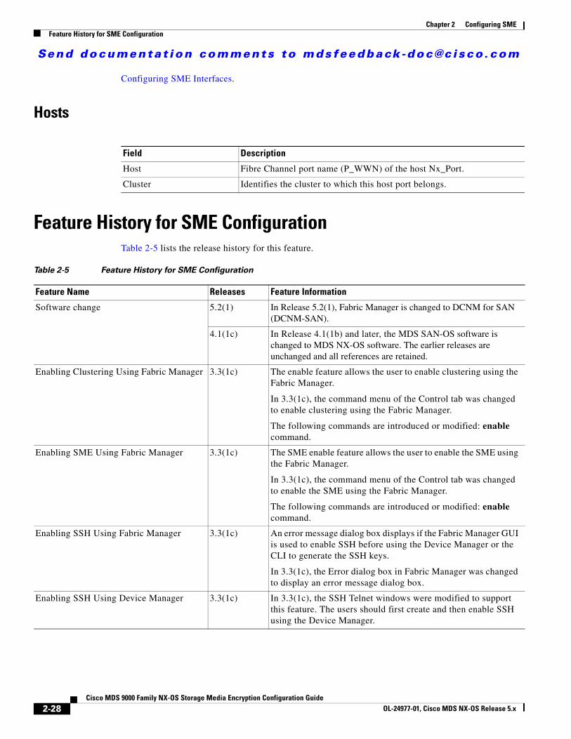
Send documenta t ion comments to mdsfeedback -doc@c i sco .com
Chapter 2 Configuring SMEFeature History for SME Configuration
Configuring SME Interfaces.
Hosts
Feature History for SME ConfigurationTable 2-5 lists the release history for this feature.
Field Description
Host Fibre Channel port name (P_WWN) of the host Nx_Port.
Cluster Identifies the cluster to which this host port belongs.
Table 2-5 Feature History for SME Configuration
Feature Name Releases Feature Information
Software change 5.2(1) In Release 5.2(1), Fabric Manager is changed to DCNM for SAN (DCNM-SAN).
4.1(1c) In Release 4.1(1b) and later, the MDS SAN-OS software is changed to MDS NX-OS software. The earlier releases are unchanged and all references are retained.
Enabling Clustering Using Fabric Manager 3.3(1c) The enable feature allows the user to enable clustering using the Fabric Manager.
In 3.3(1c), the command menu of the Control tab was changed to enable clustering using the Fabric Manager.
The following commands are introduced or modified: enable command.
Enabling SME Using Fabric Manager 3.3(1c) The SME enable feature allows the user to enable the SME using the Fabric Manager.
In 3.3(1c), the command menu of the Control tab was changed to enable the SME using the Fabric Manager.
The following commands are introduced or modified: enable command.
Enabling SSH Using Fabric Manager 3.3(1c) An error message dialog box displays if the Fabric Manager GUI is used to enable SSH before using the Device Manager or the CLI to generate the SSH keys.
In 3.3(1c), the Error dialog box in Fabric Manager was changed to display an error message dialog box.
Enabling SSH Using Device Manager 3.3(1c) In 3.3(1c), the SSH Telnet windows were modified to support this feature. The users should first create and then enable SSH using the Device Manager.
2-28Cisco MDS 9000 Family NX-OS Storage Media Encryption Configuration Guide
OL-24977-01, Cisco MDS NX-OS Release 5.x
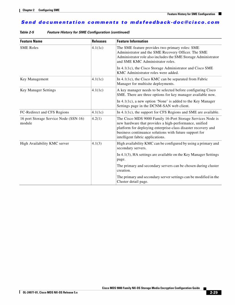
Send documenta t ion comments to mdsfeedback -doc@c i sco .com
Chapter 2 Configuring SMEFeature History for SME Configuration
SME Roles 4.1(1c) The SME feature provides two primary roles: SME Administrator and the SME Recovery Officer. The SME Administrator role also includes the SME Storage Administrator and SME KMC Administrator roles.
In 4.1(1c), the Cisco Storage Administrator and Cisco SME KMC Administrator roles were added.
Key Management 4.1(1c) In 4.1(1c), the Cisco KMC can be separated from Fabric Manager for multisite deployments.
Key Manager Settings 4.1(1c) A key manager needs to be selected before configuring Cisco SME. There are three options for key manager available now.
In 4.1(1c), a new option ‘None’ is added to the Key Manager Settings page in the DCNM-SAN web client.
FC-Redirect and CFS Regions 4.1(1c) In 4.1(1c), the support for CFS Regions and SME are available.
16 port Storage Service Node (SSN-16) module
4.2(1) The Cisco MDS 9000 Family 16-Port Storage Services Node is new hardware that provides a high-performance, unified platform for deploying enterprise-class disaster recovery and business continuance solutions with future support for intelligent fabric applications.
High Availability KMC server 4.1(3) High availability KMC can be configured by using a primary and secondary servers.
In 4.1(3), HA settings are available on the Key Manager Settings page.
The primary and secondary servers can be chosen during cluster creation.
The primary and secondary server settings can be modified in the Cluster detail page.
Table 2-5 Feature History for SME Configuration (continued)
Feature Name Releases Feature Information
2-29Cisco MDS 9000 Family NX-OS Storage Media Encryption Configuration Guide
OL-24977-01, Cisco MDS NX-OS Release 5.x

Send documenta t ion comments to mdsfeedback -doc@c i sco .com
Chapter 2 Configuring SMEFeature History for SME Configuration
2-30Cisco MDS 9000 Family NX-OS Storage Media Encryption Configuration Guide
OL-24977-01, Cisco MDS NX-OS Release 5.x

Send documenta t ion comments to mdsfeedback -doc@c i sco .com
Cisco MDS 9000 Family NXOL-24977-01, Cisco MDS NX-OS Release 5.x
C H A P T E R 3
Configuring SME InterfacesThis chapter describes how to configure and start SME interfaces using DCNM-SAN and Device Manager.
After completing the preliminary tasks, you need to configure the SME interface on a Cisco MDS switch with an installed MSM-18/4 module, SSN-16 module, or on a Cisco MDS 9222i switch.
This chapter includes the following topics:
• Configuring the SME Interface, page 3-1
• Configuring the SME Interface Using the GUI, page 3-5
• Verifying SME Interface Configuration, page 3-9
• Monitoring SME Interface, page 3-9
• Feature History for SME Interface, page 3-10
Configuring the SME InterfaceSME interfaces are configured either by using Device Manager or the CLI.
For information about creating SME interfaces using Device Manager, see “Configuring the SME Interface Using the GUI” section on page 3-5
This section includes the following topics:
• Adding an SME Interface from a Local or Remote Switch, page 3-1
• Creating the SME Interface, page 3-2
• Deleting the SME Interface, page 3-3
• Viewing SME Interface Information Using the CLI, page 3-3
Adding an SME Interface from a Local or Remote Switch
Prerequisites
• Before adding an SME interface, be sure to enable clustering, enable SME, start the SME interface on the switch, and add the interface to the cluster.
Note You can add an SME interface from a local switch or from a remote switch.
3-1-OS Storage Media Encryption Configuration Guide
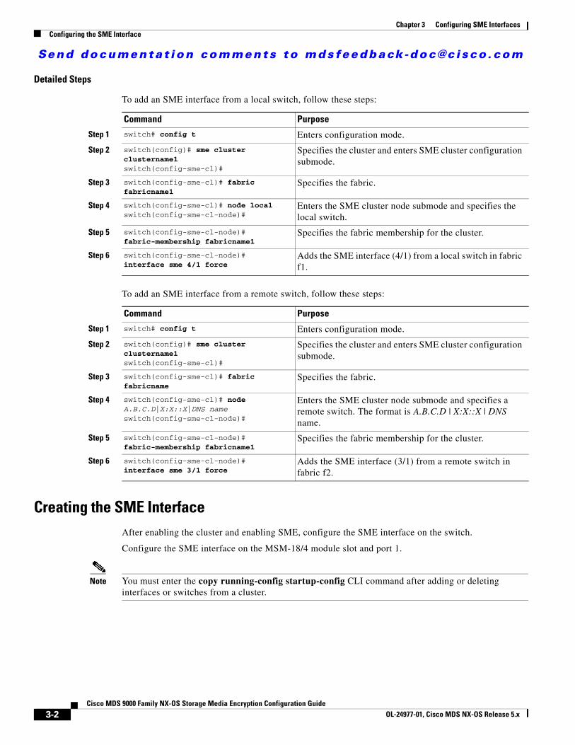
Send documenta t ion comments to mdsfeedback -doc@c i sco .com
Chapter 3 Configuring SME InterfacesConfiguring the SME Interface
Detailed Steps
To add an SME interface from a local switch, follow these steps:
To add an SME interface from a remote switch, follow these steps:
Creating the SME InterfaceAfter enabling the cluster and enabling SME, configure the SME interface on the switch.
Configure the SME interface on the MSM-18/4 module slot and port 1.
Note You must enter the copy running-config startup-config CLI command after adding or deleting interfaces or switches from a cluster.
Command Purpose
Step 1 switch# config t Enters configuration mode.
Step 2 switch(config)# sme cluster clustername1switch(config-sme-cl)#
Specifies the cluster and enters SME cluster configuration submode.
Step 3 switch(config-sme-cl)# fabric fabricname1
Specifies the fabric.
Step 4 switch(config-sme-cl)# node localswitch(config-sme-cl-node)#
Enters the SME cluster node submode and specifies the local switch.
Step 5 switch(config-sme-cl-node)# fabric-membership fabricname1
Specifies the fabric membership for the cluster.
Step 6 switch(config-sme-cl-node)# interface sme 4/1 force
Adds the SME interface (4/1) from a local switch in fabric f1.
Command Purpose
Step 1 switch# config t Enters configuration mode.
Step 2 switch(config)# sme cluster clustername1switch(config-sme-cl)#
Specifies the cluster and enters SME cluster configuration submode.
Step 3 switch(config-sme-cl)# fabric fabricname
Specifies the fabric.
Step 4 switch(config-sme-cl)# node A.B.C.D|X:X::X|DNS nameswitch(config-sme-cl-node)#
Enters the SME cluster node submode and specifies a remote switch. The format is A.B.C.D | X:X::X | DNS name.
Step 5 switch(config-sme-cl-node)# fabric-membership fabricname1
Specifies the fabric membership for the cluster.
Step 6 switch(config-sme-cl-node)# interface sme 3/1 force
Adds the SME interface (3/1) from a remote switch in fabric f2.
3-2Cisco MDS 9000 Family NX-OS Storage Media Encryption Configuration Guide
OL-24977-01, Cisco MDS NX-OS Release 5.x
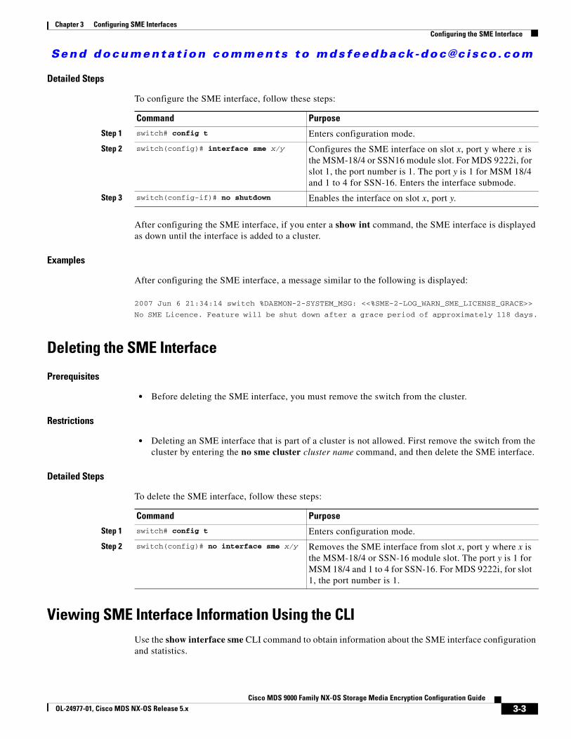
Send documenta t ion comments to mdsfeedback -doc@c i sco .com
Chapter 3 Configuring SME InterfacesConfiguring the SME Interface
Detailed Steps
To configure the SME interface, follow these steps:
After configuring the SME interface, if you enter a show int command, the SME interface is displayed as down until the interface is added to a cluster.
Examples
After configuring the SME interface, a message similar to the following is displayed:
2007 Jun 6 21:34:14 switch %DAEMON-2-SYSTEM_MSG: <<%SME-2-LOG_WARN_SME_LICENSE_GRACE>>
No SME Licence. Feature will be shut down after a grace period of approximately 118 days.
Deleting the SME Interface
Prerequisites
• Before deleting the SME interface, you must remove the switch from the cluster.
Restrictions
• Deleting an SME interface that is part of a cluster is not allowed. First remove the switch from the cluster by entering the no sme cluster cluster name command, and then delete the SME interface.
Detailed Steps
To delete the SME interface, follow these steps:
Viewing SME Interface Information Using the CLIUse the show interface sme CLI command to obtain information about the SME interface configuration and statistics.
Command Purpose
Step 1 switch# config t Enters configuration mode.
Step 2 switch(config)# interface sme x/y Configures the SME interface on slot x, port y where x is the MSM-18/4 or SSN16 module slot. For MDS 9222i, for slot 1, the port number is 1. The port y is 1 for MSM 18/4 and 1 to 4 for SSN-16. Enters the interface submode.
Step 3 switch(config-if)# no shutdown Enables the interface on slot x, port y.
Command Purpose
Step 1 switch# config t Enters configuration mode.
Step 2 switch(config)# no interface sme x/y Removes the SME interface from slot x, port y where x is the MSM-18/4 or SSN-16 module slot. The port y is 1 for MSM 18/4 and 1 to 4 for SSN-16. For MDS 9222i, for slot 1, the port number is 1.
3-3Cisco MDS 9000 Family NX-OS Storage Media Encryption Configuration Guide
OL-24977-01, Cisco MDS NX-OS Release 5.x
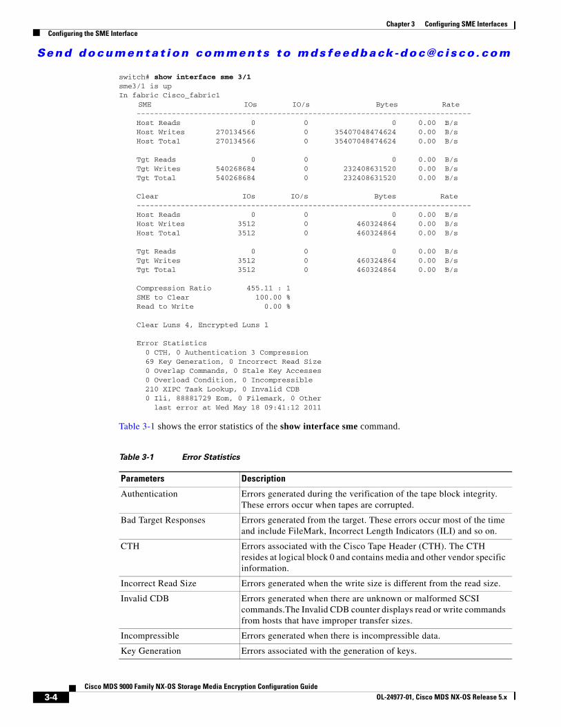
Send documenta t ion comments to mdsfeedback -doc@c i sco .com
Chapter 3 Configuring SME InterfacesConfiguring the SME Interface
switch# show interface sme 3/1sme3/1 is upIn fabric Cisco_fabric1
SME IOs IO/s Bytes Rate ---------------------------------------------------------------------------- Host Reads 0 0 0 0.00 B/s Host Writes 270134566 0 35407048474624 0.00 B/s Host Total 270134566 0 35407048474624 0.00 B/s
Tgt Reads 0 0 0 0.00 B/s Tgt Writes 540268684 0 232408631520 0.00 B/s Tgt Total 540268684 0 232408631520 0.00 B/s
Clear IOs IO/s Bytes Rate ---------------------------------------------------------------------------- Host Reads 0 0 0 0.00 B/s Host Writes 3512 0 460324864 0.00 B/s Host Total 3512 0 460324864 0.00 B/s
Tgt Reads 0 0 0 0.00 B/s Tgt Writes 3512 0 460324864 0.00 B/s Tgt Total 3512 0 460324864 0.00 B/s
Compression Ratio 455.11 : 1 SME to Clear 100.00 % Read to Write 0.00 %
Clear Luns 4, Encrypted Luns 1
Error Statistics 0 CTH, 0 Authentication 3 Compression 69 Key Generation, 0 Incorrect Read Size 0 Overlap Commands, 0 Stale Key Accesses 0 Overload Condition, 0 Incompressible 210 XIPC Task Lookup, 0 Invalid CDB 0 Ili, 88881729 Eom, 0 Filemark, 0 Other
last error at Wed May 18 09:41:12 2011
Table 3-1 shows the error statistics of the show interface sme command.
Table 3-1 Error Statistics
Parameters Description
Authentication Errors generated during the verification of the tape block integrity. These errors occur when tapes are corrupted.
Bad Target Responses Errors generated from the target. These errors occur most of the time and include FileMark, Incorrect Length Indicators (ILI) and so on.
CTH Errors associated with the Cisco Tape Header (CTH). The CTH resides at logical block 0 and contains media and other vendor specific information.
Incorrect Read Size Errors generated when the write size is different from the read size.
Invalid CDB Errors generated when there are unknown or malformed SCSI commands.The Invalid CDB counter displays read or write commands from hosts that have improper transfer sizes.
Incompressible Errors generated when there is incompressible data.
Key Generation Errors associated with the generation of keys.
3-4Cisco MDS 9000 Family NX-OS Storage Media Encryption Configuration Guide
OL-24977-01, Cisco MDS NX-OS Release 5.x
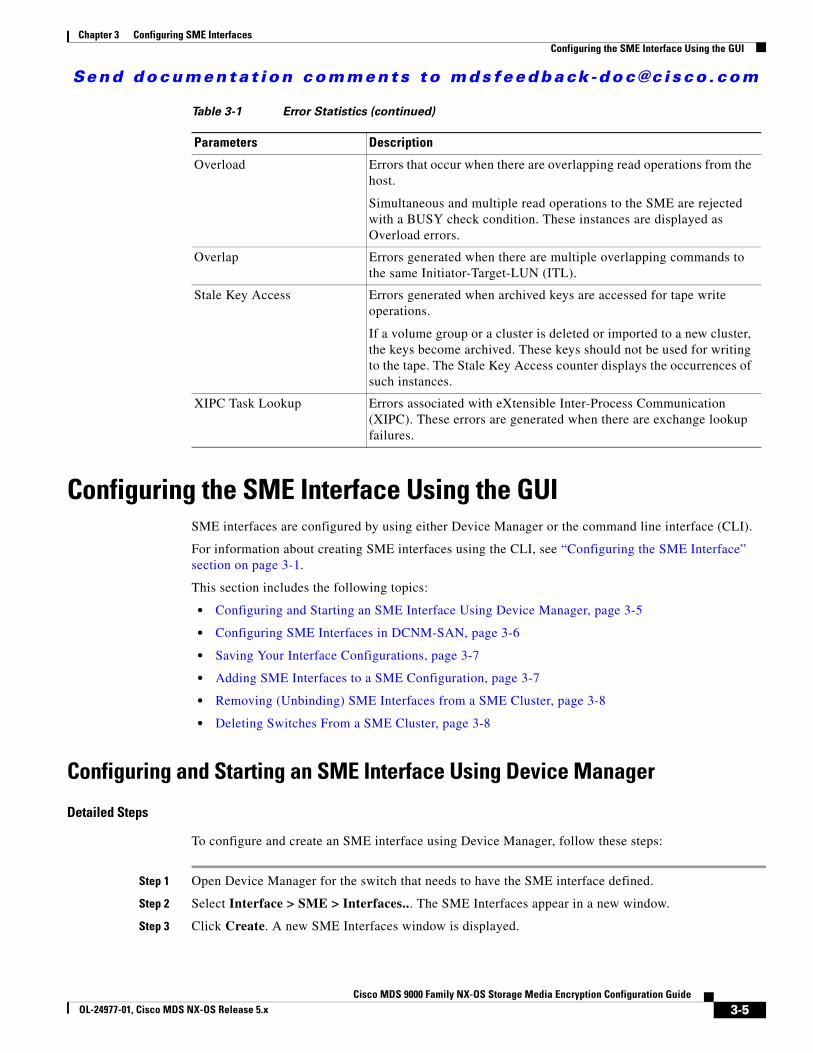
Send documenta t ion comments to mdsfeedback -doc@c i sco .com
Chapter 3 Configuring SME InterfacesConfiguring the SME Interface Using the GUI
Configuring the SME Interface Using the GUISME interfaces are configured by using either Device Manager or the command line interface (CLI).
For information about creating SME interfaces using the CLI, see “Configuring the SME Interface” section on page 3-1.
This section includes the following topics:
• Configuring and Starting an SME Interface Using Device Manager, page 3-5
• Configuring SME Interfaces in DCNM-SAN, page 3-6
• Saving Your Interface Configurations, page 3-7
• Adding SME Interfaces to a SME Configuration, page 3-7
• Removing (Unbinding) SME Interfaces from a SME Cluster, page 3-8
• Deleting Switches From a SME Cluster, page 3-8
Configuring and Starting an SME Interface Using Device Manager
Detailed Steps
To configure and create an SME interface using Device Manager, follow these steps:
Step 1 Open Device Manager for the switch that needs to have the SME interface defined.
Step 2 Select Interface > SME > Interfaces... The SME Interfaces appear in a new window.
Step 3 Click Create. A new SME Interfaces window is displayed.
Overload Errors that occur when there are overlapping read operations from the host.
Simultaneous and multiple read operations to the SME are rejected with a BUSY check condition. These instances are displayed as Overload errors.
Overlap Errors generated when there are multiple overlapping commands to the same Initiator-Target-LUN (ITL).
Stale Key Access Errors generated when archived keys are accessed for tape write operations.
If a volume group or a cluster is deleted or imported to a new cluster, the keys become archived. These keys should not be used for writing to the tape. The Stale Key Access counter displays the occurrences of such instances.
XIPC Task Lookup Errors associated with eXtensible Inter-Process Communication (XIPC). These errors are generated when there are exchange lookup failures.
Table 3-1 Error Statistics (continued)
Parameters Description
3-5Cisco MDS 9000 Family NX-OS Storage Media Encryption Configuration Guide
OL-24977-01, Cisco MDS NX-OS Release 5.x
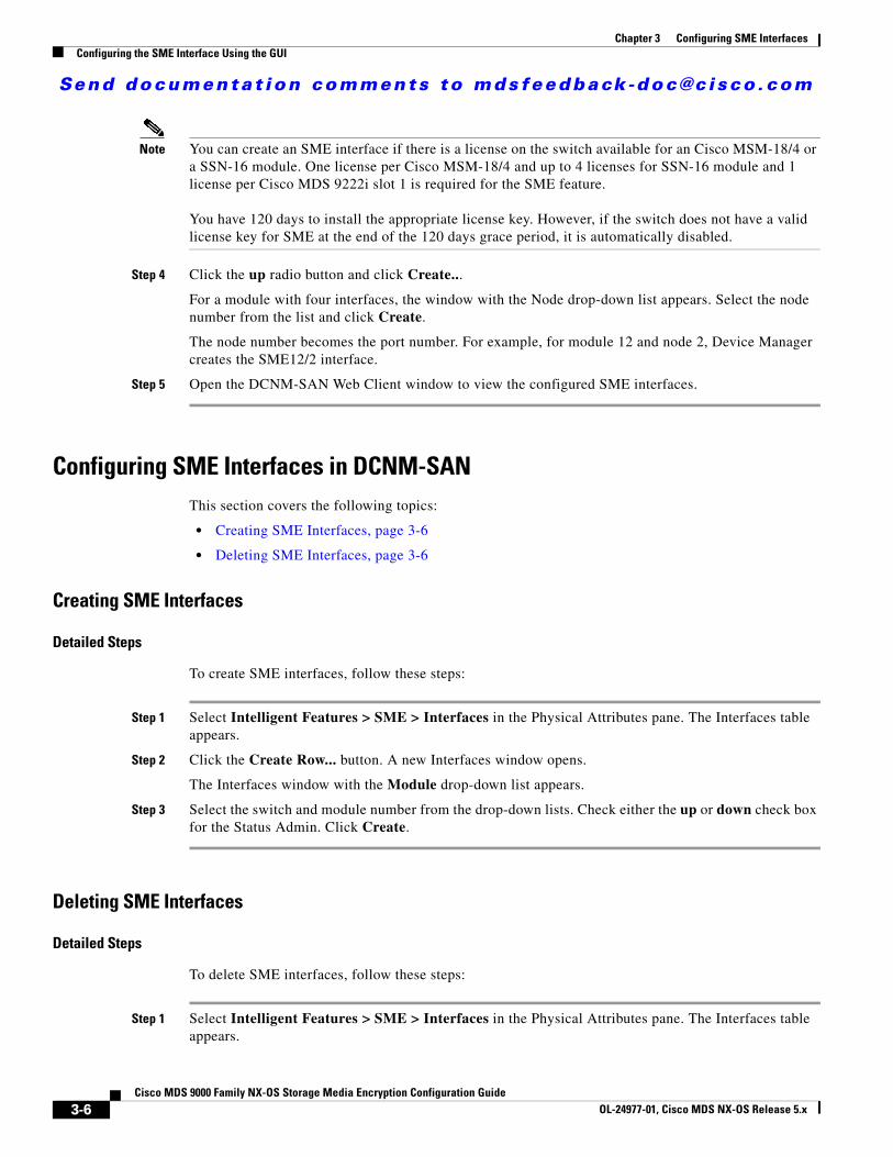
Send documenta t ion comments to mdsfeedback -doc@c i sco .com
Chapter 3 Configuring SME InterfacesConfiguring the SME Interface Using the GUI
Note You can create an SME interface if there is a license on the switch available for an Cisco MSM-18/4 or a SSN-16 module. One license per Cisco MSM-18/4 and up to 4 licenses for SSN-16 module and 1 license per Cisco MDS 9222i slot 1 is required for the SME feature.
You have 120 days to install the appropriate license key. However, if the switch does not have a valid license key for SME at the end of the 120 days grace period, it is automatically disabled.
Step 4 Click the up radio button and click Create...
For a module with four interfaces, the window with the Node drop-down list appears. Select the node number from the list and click Create.
The node number becomes the port number. For example, for module 12 and node 2, Device Manager creates the SME12/2 interface.
Step 5 Open the DCNM-SAN Web Client window to view the configured SME interfaces.
Configuring SME Interfaces in DCNM-SANThis section covers the following topics:
• Creating SME Interfaces, page 3-6
• Deleting SME Interfaces, page 3-6
Creating SME Interfaces
Detailed Steps
To create SME interfaces, follow these steps:
Step 1 Select Intelligent Features > SME > Interfaces in the Physical Attributes pane. The Interfaces table appears.
Step 2 Click the Create Row... button. A new Interfaces window opens.
The Interfaces window with the Module drop-down list appears.
Step 3 Select the switch and module number from the drop-down lists. Check either the up or down check box for the Status Admin. Click Create.
Deleting SME Interfaces
Detailed Steps
To delete SME interfaces, follow these steps:
Step 1 Select Intelligent Features > SME > Interfaces in the Physical Attributes pane. The Interfaces table appears.
3-6Cisco MDS 9000 Family NX-OS Storage Media Encryption Configuration Guide
OL-24977-01, Cisco MDS NX-OS Release 5.x

Send documenta t ion comments to mdsfeedback -doc@c i sco .com
Chapter 3 Configuring SME InterfacesConfiguring the SME Interface Using the GUI
Step 2 Select the interface to be deleted and click the Delete Row button. Click Yes to confirm and remove the interface.
Saving Your Interface ConfigurationsWhen an SME interface is deleted on one switch in a cluster and then added back, even if the saved SME configurations were the same, the SME interface will not be added back to the cluster.
When the switch is reloaded, the SME interfaces will not be added back to the cluster due to a certificate mismatch (because the SME interface was removed and then added back). You need to delete the SME interface and add it back, and then enter the copy running-config startup-config CLI command.
Note You must enter the copy running-config startup-config CLI command after adding or deleting interfaces or switches.
Adding SME Interfaces to a SME ConfigurationSME includes an Add Interface Wizard to simplify the process of adding interfaces to an existing cluster. You can add additional interfaces when you add additional Cisco MSM-18/4 modules, SSN-16 modules, and Cisco MDS 9222i switches.
Note You must enter the copy running-config startup-config CLI command after adding or deleting interfaces or switches.
Restrictions
After adding a SME interface on a switch that is not already part of the cluster, wait for the switch to join the cluster before attempting to add another SME interface. Adding a new switch to a cluster affects the quorum calculation of the cluster (see the “Cluster Quorum and Master Switch Election” section on page 4-1). Adding more than one switch that is not online can shut down the SME application due to a lost quorum.
Detailed Steps
To add SME interfaces to an existing SME configuration, follow these steps:
Step 1 From the SME navigation pane, click Members to display the switches and interfaces already configured in the cluster.
Step 2 Click Add to display the Add Interface Wizard.
Step 3 Select the fabrics you want to add interfaces from. Click Next.
Step 4 Select the SME interfaces that you would like to use. Click Next.
Step 5 View the interface information. Click Confirm to view the newly added interface.
3-7Cisco MDS 9000 Family NX-OS Storage Media Encryption Configuration Guide
OL-24977-01, Cisco MDS NX-OS Release 5.x
Send documenta t ion comments to mdsfeedback -doc@c i sco .com
Chapter 3 Configuring SME InterfacesConfiguring the SME Interface Using the GUI
Removing (Unbinding) SME Interfaces from a SME ClusterRemoving a SME interface from a cluster means that the interface is still up but it is not bound to a cluster.
In the existing MDS 9000 Family platform, a module can be replaced with another module and there is no change in configuration. In SME, due to security reasons, when an MSM-18/4 module or a SSN-16 module is configured as part of a cluster, it cannot be replaced with another MSM-18/4 or a SSN-16 module, otherwise, the SME interface will come up in an inactive state. The correct procedure is to remove the SME interface from the cluster and re-add the interface into the cluster. This procedure should be followed to bring a new MSM-18/4 or a SSN-16 module into the cluster.
Note You must enter the copy running-config startup-config CLI command after adding or deleting interfaces or switches from a cluster.
Prerequisites
Before you remove an SME interface, you must close the SME interface using the CLI or DCNM-SAN.
Detailed Steps
To remove (unbind) a SME interface from an existing SME configuration, follow these steps:
Step 1 From the SME navigation pane, click Members to display the switches and interfaces already configured in the cluster.
Step 2 Select a SME interface and click Remove.
Step 3 Click OK to delete (unbind) the interface.
Step 4 View the notification that the interface was removed.
Note The interface is removed while the node remains defined.
Deleting Switches From a SME Cluster
Prerequisites
• If the cluster includes more than one switch, you must delete all non-master switches first. It is not possible to delete the master switch from a cluster without first deleting all non-master switches.
Detailed Steps
To delete a switch from a cluster, follow these steps:
3-8Cisco MDS 9000 Family NX-OS Storage Media Encryption Configuration Guide
OL-24977-01, Cisco MDS NX-OS Release 5.x
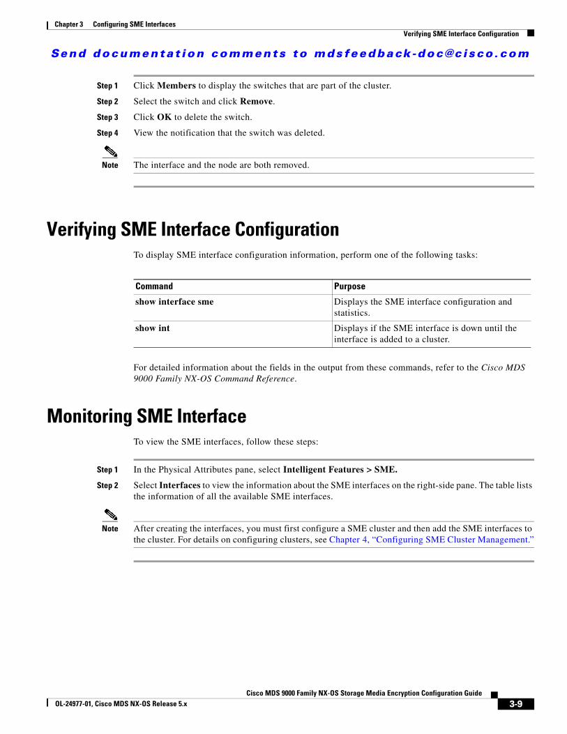
Send documenta t ion comments to mdsfeedback -doc@c i sco .com
Chapter 3 Configuring SME InterfacesVerifying SME Interface Configuration
Step 1 Click Members to display the switches that are part of the cluster.
Step 2 Select the switch and click Remove.
Step 3 Click OK to delete the switch.
Step 4 View the notification that the switch was deleted.
Note The interface and the node are both removed.
Verifying SME Interface ConfigurationTo display SME interface configuration information, perform one of the following tasks:
For detailed information about the fields in the output from these commands, refer to the Cisco MDS 9000 Family NX-OS Command Reference.
Monitoring SME InterfaceTo view the SME interfaces, follow these steps:
Step 1 In the Physical Attributes pane, select Intelligent Features > SME.
Step 2 Select Interfaces to view the information about the SME interfaces on the right-side pane. The table lists the information of all the available SME interfaces.
Note After creating the interfaces, you must first configure a SME cluster and then add the SME interfaces to the cluster. For details on configuring clusters, see Chapter 4, “Configuring SME Cluster Management.”
Command Purpose
show interface sme Displays the SME interface configuration and statistics.
show int Displays if the SME interface is down until the interface is added to a cluster.
3-9Cisco MDS 9000 Family NX-OS Storage Media Encryption Configuration Guide
OL-24977-01, Cisco MDS NX-OS Release 5.x
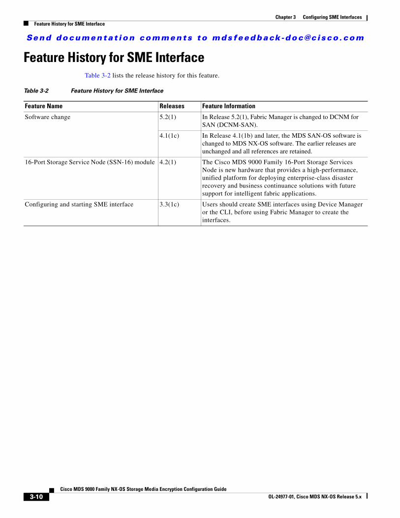
Send documenta t ion comments to mdsfeedback -doc@c i sco .com
Chapter 3 Configuring SME InterfacesFeature History for SME Interface
Feature History for SME InterfaceTable 3-2 lists the release history for this feature.
Table 3-2 Feature History for SME Interface
Feature Name Releases Feature Information
Software change 5.2(1) In Release 5.2(1), Fabric Manager is changed to DCNM for SAN (DCNM-SAN).
4.1(1c) In Release 4.1(1b) and later, the MDS SAN-OS software is changed to MDS NX-OS software. The earlier releases are unchanged and all references are retained.
16-Port Storage Service Node (SSN-16) module 4.2(1) The Cisco MDS 9000 Family 16-Port Storage Services Node is new hardware that provides a high-performance, unified platform for deploying enterprise-class disaster recovery and business continuance solutions with future support for intelligent fabric applications.
Configuring and starting SME interface 3.3(1c) Users should create SME interfaces using Device Manager or the CLI, before using Fabric Manager to create the interfaces.
3-10Cisco MDS 9000 Family NX-OS Storage Media Encryption Configuration Guide
OL-24977-01, Cisco MDS NX-OS Release 5.x
Send documenta t ion comments to mdsfeedback -doc@c i sco .com
Cisco MDS 9000 Family NXOL-24977-01, Cisco MDS NX-OS Release 5.x
C H A P T E R 4
Configuring SME Cluster ManagementDCNM-SAN provides a web browser interface that displays real-time views of your network fabrics and lets you configure the SME with easy-to-use wizards.
This chapter contains information about the SME initial configuration and the tasks that are used to manage SME clusters using DCNM-SAN.
This chapter includes the following topics:
• Information About SME Cluster Management, page 4-1
• Configuring SME Cluster Management Using the CLI, page 4-5
• Configuring SME Cluster Management Using the GUI, page 4-10
• Verifying SME Cluster Management Configuration, page 4-18
• Monitoring SME Cluster Management, page 4-19
• Feature History for SME Cluster Management, page 4-24
Information About SME Cluster ManagementAn SME cluster consists of a group of MDS switches running the SME application in a single fabric environment where each switch is a member or node. The cluster infrastructure enables the SME application to offer high availability and load balancing by providing the ability to communicate and coordinate with the other members to maintain a consistent and distributed view of the application’s configuration and operational state.
The process of configuring SME on an MDS switch with an installed Cisco MSM-18/4 module, SSN-16 module, or on a Cisco MDS 9222i switch involves a number of configuration tasks that should be followed in chronological order. See the topics in the Before You Begin online help in DCNM-SAN Web Server. Configure SSH and refer to Chapter 2, “Configuring SME” and Chapter 3, “Configuring SME Interfaces” for information about the tasks must be completed before creating an SME cluster.
Cluster Quorum and Master Switch ElectionThis section describes the SME cluster quorum and the process for electing the master switch in a cluster.
• Cluster Quorum, page 4-2
4-1-OS Storage Media Encryption Configuration Guide
Send documenta t ion comments to mdsfeedback -doc@c i sco .com
Chapter 4 Configuring SME Cluster ManagementInformation About SME Cluster Management
• Master Switch Election, page 4-2
Node ID
Every switch in a cluster has a node ID. SME assigns a node ID to every new switch as it is added to the cluster. The switch where the cluster is created is assigned the node ID of 1. This is the master switch. When a new switch is added to the cluster, it is assigned the next available higher node ID. For example, when a second switch is added to the cluster it gets the node ID of 2 and the third switch gets the node ID of 3, and so on.
Cluster View
The cluster view is the set of switches that are part of the operational cluster.
Cluster Quorum
For a cluster to be operational, it must include more than half the number of configured switches in the cluster view. In an N-switch cluster, N/2 + 1 switches form a cluster quorum.
If N is even, the cluster quorum requires N/2 switches and also, the presence of the switch with the lowest node ID.
The quorum logic ensures that in the event of cluster partitions, at most one partition can be operational. All other switches are nonoperational. This guarantees the consistency of the cluster.
Master Switch Election
When a cluster is created, the switch on which the cluster is created becomes the cluster master switch. When the master switch fails or is rebooted, another switch takes over as the master switch. The master election logic uses the node ID and the latest cluster configuration to determine which switch in the cluster will become the master switch. The master election logic is describe as follows:
• If the master switch fails in an operational cluster, the switch with the next lowest node ID takes over as the master switch. Note that in an operational cluster, all the switches run the same cluster configuration.
– When the previous master switch comes back online and joins the cluster, it does not immediately become the master.
• When all the switches of a cluster are coming up, the switch that has the latest cluster configuration becomes the master switch. If there are multiple switches with the same configuration, the switch with the lowest node ID is chosen to be the master switch.
– Once a master switch is chosen and the cluster is operational (there is a quorum), even if a switch with a lower node ID joins the cluster at a later time, the master switch does not change.
For example, there are three switches S1, S2, and S3 with node IDs 1, 2, and 3, respectively. If switches S2 and S3 form a quorum then switch S2 becomes the master switch. Even if switch S1 with the node ID of 1 comes up and joins the cluster at a later time, switch S2 continues to be the master. However, if switch S2 goes down for any reason, switch S1 will become the master switch.
Note Because there might be changes in the Master switch, all switches in the cluster need to be configured to handle SNMP configuration, SME roles, user credentials, and SSH. Switches in the cluster should directly communicate with KMC.
4-2Cisco MDS 9000 Family NX-OS Storage Media Encryption Configuration Guide
OL-24977-01, Cisco MDS NX-OS Release 5.x
Send documenta t ion comments to mdsfeedback -doc@c i sco .com
Chapter 4 Configuring SME Cluster ManagementInformation About SME Cluster Management
Two-Switch Cluster Scenarios
According to the cluster quorum logic “Cluster Quorum” section on page 4-2, a cluster with two configured switches can be operational if both switches are operational or the switch with the lowest node ID is operational.
In the latter case, the switch with the lowest node ID is the master of the one-switch cluster. The other switch could have failed or simply lost connectivity to the operational switch. In either case, the switch with the higher node ID would become nonoperational. If the switch with the lower node ID failed, the other switch cannot form an operational cluster.
The examples that follow describe these scenarios. The first three examples consider single switch failures.
1. Assume that in a two-switch cluster with switches S1 (node ID 1) and S2 (node ID 2), S1 is the master (the master has the lower node ID).
When the switches lose connectivity between them, the master switch S1 continues to be operational since it has the lower node ID and can form an (N/2) switch cluster. Switch S2 becomes non-operational.
2. Assume that in a two-switch cluster with switches S1 (node ID 1) and S2 (node ID 2), S2 is the master (note that the master has the higher node ID because it has the latest configuration when both the switches came online).
When the switches lose connectivity between them, switch S2 becomes non-operational and S1 takes over as the master to form a 1-switch cluster. This is consistent with the quorum logic in a two-switch cluster (N/2 with lowest node ID).
3. Assume that in a two-switch cluster with switches S1 (node ID 1) and S2 (node ID 2). If S1 fails (regardless of which switch was the master), S2 will also become non-operational as long as S1 is down.
When S1 comes up, S1 and S2 will form a two-switch cluster.
The next set of examples describe reboots of both switches (S1 with node ID 1 and S2 with node ID 2).
Caution If you perform any configuration change on a cluster, you must save the running configuration to the startup configuration by entering the copy running-config startup-config CLI command on all switches before rebooting them. Otherwise, the cluster may not form correctly after the reboot.
4. After a reboot, if both switches S1 and S2 come up about the same time, a two-switch cluster will be formed.
a. If the cluster configurations are the same, S1 (with the lower node ID) will become the master.
b. If the cluster configurations are different, the switch with the latest cluster configuration will become the master.
5. After a reboot, if switch S2 comes up first, it will not be able to form a cluster until S1 also comes up. After that, the algorithm explained in the previous case will be used.
6. After a reboot, if switch S1 comes up first, it will form a one-switch cluster (N/2 with lowest node ID). When S2 comes up, it will join the cluster to form a two-switch cluster.
When S2 comes up and if it happens to have the latest cluster configuration in the startup configuration (this can happen if you did not save the running configuration to the startup configuration on S1 but did so on S2), it will not be able to join the cluster formed by S1.
4-3Cisco MDS 9000 Family NX-OS Storage Media Encryption Configuration Guide
OL-24977-01, Cisco MDS NX-OS Release 5.x
Send documenta t ion comments to mdsfeedback -doc@c i sco .com
Chapter 4 Configuring SME Cluster ManagementInformation About SME Cluster Management
Caution It is critical that you save the running configuration on all switches before a reboot.
Three-Switch Cluster Scenarios
In a three-switch cluster, the quorum requires two switches to be in the cluster view (N/2 + 1). The examples below explain three scenarios in a three-switch cluster with switches S1 (node ID 1), S2 (node ID 2) and S3 (node ID 3). S1 is the master switch.
1. In a three-switch operational cluster, if switch S3 fails or loses connectivity with the other two switches, then S3 becomes nonoperational. Switches S1 and S2 will form an operational cluster. When S3 comes up again, it will rejoin the cluster.
2. In a three-switch operational cluster, if the master switch S1 fails or loses connectivity with the other two switches, then S1 becomes nonoperational. Switches S2 and S3 will form an operational cluster and S2 will be the master. When S1 comes up again, it will rejoin the cluster. Note that S2 will continue to be the master.
3. If two switches fail, the cluster will become nonoperational.
The examples below describe reboots on all switches in the cluster.
Caution If you perform any configuration change on a cluster, you must save the running configuration to the startup configuration by entering the copy running-config startup-config command on all switches before rebooting them. Otherwise, the cluster may not form correctly after the reboot.
4. After a reboot, if all switches come up at about the same time, first a 2-switch cluster will be formed and later the third switch will be added.
a. If the cluster configurations are the same, S1 (with the lower node ID) will become the master switch and form the 2-switch cluster first; and then add the third switch.
b. If the cluster configurations are different, the switch that is running the latest configuration will become the master switch and then form a 2-switch cluster; and then add the third switch.
5. After a reboot, if the switches come up one at a time, a 2-switch cluster will be formed after the first two switches are up. Later, when the third switch comes online, it will join the cluster.
If the third switch happens to be running the latest cluster configuration in the startup configuration (this can happen if you save the running configuration only on this switch but not on the other two), the third switch will not be able to join the cluster.
Caution It is critical that you save the running configuration on all switches before a reboot.
Four-Switch Cluster Scenarios
The four-switch cluster scenario is very similar to the examples above. The cluster will be operational if the cluster view has at least three switches (N/2 + 1), or if the cluster view has two switches including the switch with the lowest node ID (N/2 with lowest node ID).
4-4Cisco MDS 9000 Family NX-OS Storage Media Encryption Configuration Guide
OL-24977-01, Cisco MDS NX-OS Release 5.x
Send documenta t ion comments to mdsfeedback -doc@c i sco .com
Chapter 4 Configuring SME Cluster ManagementConfiguring SME Cluster Management Using the CLI
In-Service Software Upgrade in a Two-Node ClusterIn-Service Software Upgrade (ISSU) is a comprehensive, transparent software upgrade application that allows you to deploy bug fixes and add new features and services without any disruption to the traffic.
In a cluster consisting of the MDS 9222i switches as members, if the switches are not able to communicate, then the switch having the lowest node identifier (node ID) remains in the cluster while the other switch leaves the cluster. However, when an ISSU is performed on a switch having the lowest node identifier, a complete loss of the cluster results because both the switches leave the cluster.
This undesirable situation is addressed in a two-switch cluster as follows:
• The upgrading switch sends a message to the other switch of the intent to leave the cluster. The upgrading switch can either be a master switch or a slave switch.
• The remaining switch remains in the cluster and performs the role of the master switch if it was a slave switch. This switch continues to remain in the cluster with the quorum intact.
• After the ISSU is completed and the switches boot up, the upgraded switch rejoins the cluster as a slave switch.
Note This feature is tied to the internals of ISSU logic and no additional commands need to be executed.
Server ClustersA cluster is group of servers linked together to perform a common task.
Clusters provide the following features:
• High availability—If one server in the cluster goes down, the work assigned to that server is migrated to another server in the cluster.
• Load balancing—Clusters allow work to be distributed across different servers.
Clusters can use the shared model or the nonshared model. The shared model requires distributed lock manager (DLM) to manage concurrent access to shared resources. The nonshared model does not require DLM and as a result, requires less overhead. For example, the MSCS (Microsoft clusters) use the nonshared model. This means that a node owns a resource and another node takes ownership of that resource when the owner node fails.
For more information on Cluster-Quorum, see the “Cluster Quorum” section on page 4-2.
Configuring SME Cluster Management Using the CLIYou can configure SME Cluster Management using the CLI. This section includes the following topics:
• Creating the SME Cluster, page 4-6
• Enabling and Disabling Clustering, page 4-8
• Enabling and Disabling SME Service, page 4-8
• Setting the SME Cluster Security Level, page 4-8
• Setting Up the SME Administrator and Recovery Office Roles, page 4-9
4-5Cisco MDS 9000 Family NX-OS Storage Media Encryption Configuration Guide
OL-24977-01, Cisco MDS NX-OS Release 5.x
Send documenta t ion comments to mdsfeedback -doc@c i sco .com
Chapter 4 Configuring SME Cluster ManagementConfiguring SME Cluster Management Using the CLI
Note SSH feature must be enabled in all the switches to be a part of a cluster.
Creating the SME ClusterTo create an SME tape cluster, identify the fabrics that you want to include in the cluster and configure the following:
• Automatic volume grouping
• Key Management Center (KMC)
• Target discovery
• Tape groups
• Key-on-tape mode
• Recovery
• Shared key mode
• Shutdown cluster for recovery
• Volume tape groups
• Tape compression
To create an SME disk cluster, identify the fabrics that you want to include in the cluster and you configure the following:
• CKMC
• Target discovery
• Disk groups
• Disk device
• Disk path
• Recovery
• Shutdown cluster for recovery
Detailed Steps
You can create an SME cluster for either a tape or a disk.
Caution By default, the cluster is capable for SME tapes. However, when you enter the cluster-capability disk command, this cluster can be used only for the disk devices.
To create an SME cluster for tape, follow these steps:
Command Purpose
Step 1 switch# config t Enters configuration mode.
4-6Cisco MDS 9000 Family NX-OS Storage Media Encryption Configuration Guide
OL-24977-01, Cisco MDS NX-OS Release 5.x
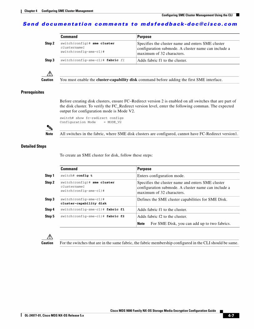
Send documenta t ion comments to mdsfeedback -doc@c i sco .com
Chapter 4 Configuring SME Cluster ManagementConfiguring SME Cluster Management Using the CLI
Caution You must enable the cluster-capability disk command before adding the first SME interface.
Prerequisites
Before creating disk clusters, ensure FC–Redirect version 2 is enabled on all switches that are part of the disk cluster. To verify the FC_Redirect version level, enter the following comman. The expected output for configuration mode is Mode V2.
switch# show fc-redirect configs Configuration Mode = MODE_V2
Note All switches in the fabric, where SME disk clusters are configured, cannot have FC-Redirect version1.
Detailed Steps
To create an SME cluster for disk, follow these steps:
Caution For the switches that are in the same fabric, the fabric membership configured in the CLI should be same.
Step 2 switch(config)# sme cluster clustername1switch(config-sme-cl)#
Specifies the cluster name and enters SME cluster configuration submode. A cluster name can include a maximum of 32 characters.
Step 3 switch(config-sme-cl)# fabric f1 Adds fabric f1 to the cluster.
Command Purpose
Command Purpose
Step 1 switch# config t Enters configuration mode.
Step 2 switch(config)# sme cluster clustername1switch(config-sme-cl)#
Specifies the cluster name and enters SME cluster configuration submode. A cluster name can include a maximum of 32 characters.
Step 3 switch(config-sme-cl)# cluster-capability disk
Defines the SME cluster capabilities for SME Disk.
Step 4 switch(config-sme-cl)# fabric f1 Adds fabric f1 to the cluster.
Step 5 switch(config-sme-cl)# fabric f2 Adds fabric f2 to the cluster.
Note For SME Disk, you can add up to two fabrics.
4-7Cisco MDS 9000 Family NX-OS Storage Media Encryption Configuration Guide
OL-24977-01, Cisco MDS NX-OS Release 5.x
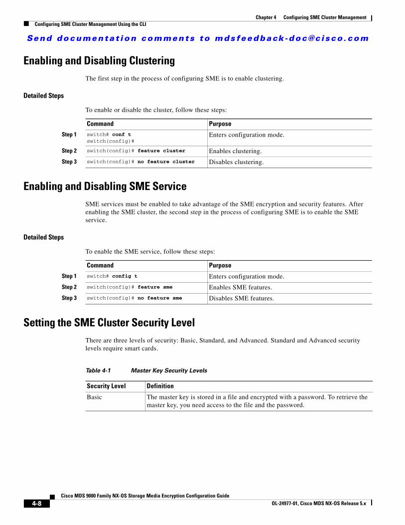
Send documenta t ion comments to mdsfeedback -doc@c i sco .com
Chapter 4 Configuring SME Cluster ManagementConfiguring SME Cluster Management Using the CLI
Enabling and Disabling ClusteringThe first step in the process of configuring SME is to enable clustering.
Detailed Steps
To enable or disable the cluster, follow these steps:
Enabling and Disabling SME ServiceSME services must be enabled to take advantage of the SME encryption and security features. After enabling the SME cluster, the second step in the process of configuring SME is to enable the SME service.
Detailed Steps
To enable the SME service, follow these steps:
Setting the SME Cluster Security LevelThere are three levels of security: Basic, Standard, and Advanced. Standard and Advanced security levels require smart cards.
Command Purpose
Step 1 switch# conf tswitch(config)#
Enters configuration mode.
Step 2 switch(config)# feature cluster Enables clustering.
Step 3 switch(config)# no feature cluster Disables clustering.
Command Purpose
Step 1 switch# config t Enters configuration mode.
Step 2 switch(config)# feature sme Enables SME features.
Step 3 switch(config)# no feature sme Disables SME features.
Table 4-1 Master Key Security Levels
Security Level Definition
Basic The master key is stored in a file and encrypted with a password. To retrieve the master key, you need access to the file and the password.
4-8Cisco MDS 9000 Family NX-OS Storage Media Encryption Configuration Guide
OL-24977-01, Cisco MDS NX-OS Release 5.x
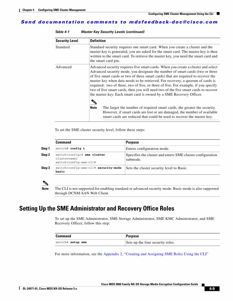
Send documenta t ion comments to mdsfeedback -doc@c i sco .com
Chapter 4 Configuring SME Cluster ManagementConfiguring SME Cluster Management Using the CLI
To set the SME cluster security level, follow these steps:
Note The CLI is not supported for enabling standard or advanced security mode. Basic mode is also supported through DCNM-SAN Web Client.
Setting Up the SME Administrator and Recovery Office RolesTo set up the SME Administrator, SME Storage Administrator, SME KMC Administrator, and SME Recovery Officer, follow this step:
For more information, see the Appendix 2, “Creating and Assigning SME Roles Using the CLI”
Standard Standard security requires one smart card. When you create a cluster and the master key is generated, you are asked for the smart card. The master key is then written to the smart card. To retrieve the master key, you need the smart card and the smart card pin.
Advanced Advanced security requires five smart cards. When you create a cluster and select Advanced security mode, you designate the number of smart cards (two or three of five smart cards or two of three smart cards) that are required to recover the master key when data needs to be retrieved. For recovery, a quorum of cards is required: two of three, two of five, or three of five. For example, if you specify two of five smart cards, then you will need two of the five smart cards to recover the master key. Each smart card is owned by a SME Recovery Officer.
Note The larger the number of required smart cards, the greater the security. However, if smart cards are lost or are damaged, the number of available smart cards are reduced that could be used to recover the master key.
Table 4-1 Master Key Security Levels (continued)
Security Level Definition
Command Purpose
Step 1 switch# config t Enters configuration mode.
Step 2 switch(config)# sme cluster clustername1switch(config-sme-cl)#
Specifies the cluster and enters SME cluster configuration submode.
Step 3 switch(config-sme-cl)# security-mode basic
Sets the cluster security level to Basic.
Command Purposeswitch# setup sme Sets up the four security roles.
4-9Cisco MDS 9000 Family NX-OS Storage Media Encryption Configuration Guide
OL-24977-01, Cisco MDS NX-OS Release 5.x
Send documenta t ion comments to mdsfeedback -doc@c i sco .com
Chapter 4 Configuring SME Cluster ManagementConfiguring SME Cluster Management Using the GUI
Configuring SME Cluster Management Using the GUIYou can configure the SME Cluster Management using the GUI. This section includes the following topics:
• Creating a SME Cluster Using the SME Wizard, page 4-10
• Deactivating and Purging an SME Cluster, page 4-17
Creating a SME Cluster Using the SME WizardThe SME Wizard is an easy-to-use interface that guides you through the process of creating a SME cluster.
The following sections describe the steps in this process:
• Launching SME Wizard, page 4-10
• Choosing a Cluster Name, page 4-11
• Selecting Fabrics, page 4-11
• Selecting Interfaces, page 4-11
• Selecting Master Key Security Levels, page 4-11
• Selecting Media Key Settings, page 4-13
• Specifying the Key Management Center Server, page 4-14
• Selecting Transport Settings, page 4-14
• Confirming the Cluster Creation, page 4-15
• Downloading Key File and Storing Keyshares, page 4-15
Launching SME Wizard
Note The Node option is available only from Release 4.2(1).
Detailed Steps
To launch the SME wizard, follow these steps:
Step 1 Open the web browser to DCNM-SAN Web Client. Log in with the user name and password.
For login information, refer to the Cisco DCNM-SAN Fundamentals Guide.
Step 2 In the DCNM-SAN Web Client, click the SME tab.
Note When you are accessing SME from Cisco DCNM for the first time, you will be asked to choose the Key Management role for the given DCNM. See the “Configuring Key Management Operations” section on page 6-54 section for more information.
4-10Cisco MDS 9000 Family NX-OS Storage Media Encryption Configuration Guide
OL-24977-01, Cisco MDS NX-OS Release 5.x

Send documenta t ion comments to mdsfeedback -doc@c i sco .com
Chapter 4 Configuring SME Cluster ManagementConfiguring SME Cluster Management Using the GUI
Step 3 Select Clusters in the navigation pane.
Step 4 Click Create in the information pane.
The SME wizard launches to guide you through the easy configuration process.
Choosing a Cluster Name
Note Cluster names must not contain spaces or special characters.
To choose a cluster name, in the Choose Name screen, enter a cluster name. Click Next.
Note You can create an SME cluster for either a tape or a disk. However, when you provide the cluster name and select the Include Disk Support check box, it specifies that the cluster can be used only for disk devices. Unselecting this check box specifies that the cluster can be used only for tape devices.
Select the Disk Signature Mode check box to create signature mode clusters.
Selecting Fabrics
To select a fabric, highlight the fabric that you want to include in the cluster. Click Next.
Selecting Interfaces
Note Cisco MDS SAN-OS Release 3.2(2c) or later or Cisco NX-OS Release 4.x or later supports one cluster per switch.
To select interfaces, in the Select Interfaces screen, highlight the SME interfaces that you want to include in your cluster. Click Next.
For information about adding interfaces, see Chapter 3, “Configuring SME Interfaces.”
Selecting Master Key Security Levels
There are three master key security levels: Basic, Standard, and Advanced. Standard and Advanced security levels require smart cards. Table 4-2 describes the master key security levels.
Caution You cannot modify the cluster security level after a cluster is created. Before confirming the cluster creation, you are prompted to review the cluster details. At that time, you can return to modify the security level.
Note For information on cluster security, see the “SME Security Overview” section on page 1-14 and the “About Master Key Security Modes” section on page 7-3.
4-11Cisco MDS 9000 Family NX-OS Storage Media Encryption Configuration Guide
OL-24977-01, Cisco MDS NX-OS Release 5.x
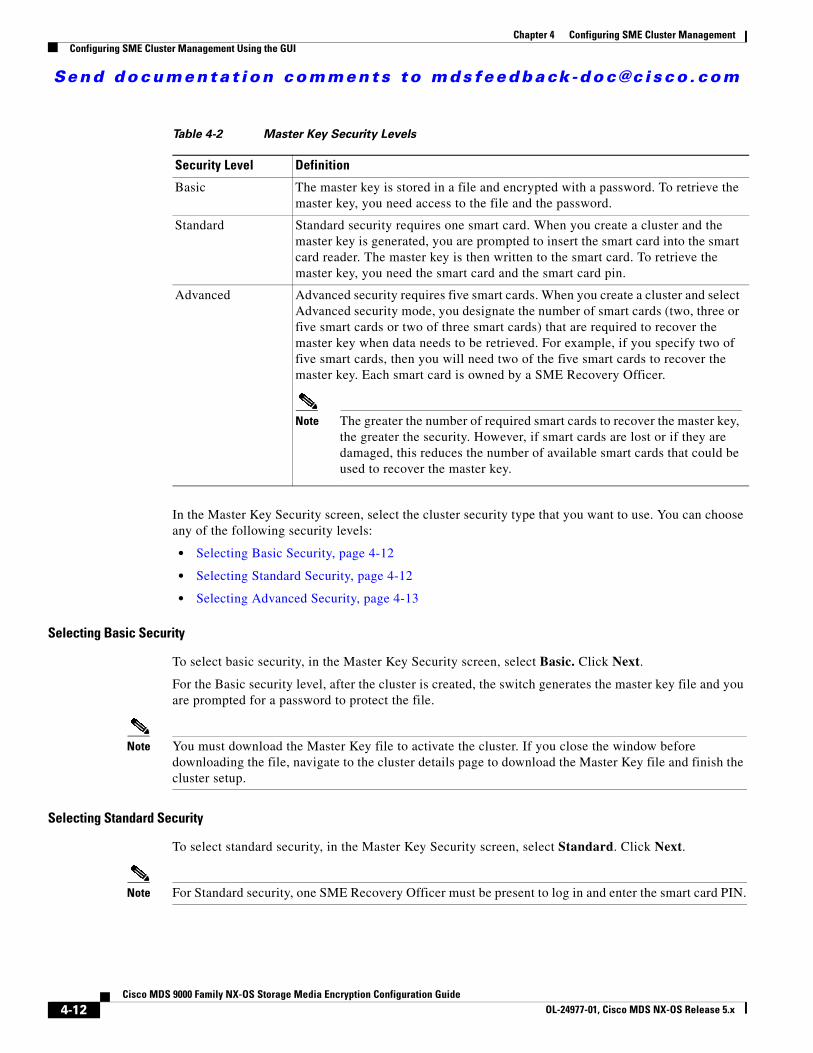
Send documenta t ion comments to mdsfeedback -doc@c i sco .com
Chapter 4 Configuring SME Cluster ManagementConfiguring SME Cluster Management Using the GUI
In the Master Key Security screen, select the cluster security type that you want to use. You can choose any of the following security levels:
• Selecting Basic Security, page 4-12
• Selecting Standard Security, page 4-12
• Selecting Advanced Security, page 4-13
Selecting Basic Security
To select basic security, in the Master Key Security screen, select Basic. Click Next.
For the Basic security level, after the cluster is created, the switch generates the master key file and you are prompted for a password to protect the file.
Note You must download the Master Key file to activate the cluster. If you close the window before downloading the file, navigate to the cluster details page to download the Master Key file and finish the cluster setup.
Selecting Standard Security
To select standard security, in the Master Key Security screen, select Standard. Click Next.
Note For Standard security, one SME Recovery Officer must be present to log in and enter the smart card PIN.
Table 4-2 Master Key Security Levels
Security Level Definition
Basic The master key is stored in a file and encrypted with a password. To retrieve the master key, you need access to the file and the password.
Standard Standard security requires one smart card. When you create a cluster and the master key is generated, you are prompted to insert the smart card into the smart card reader. The master key is then written to the smart card. To retrieve the master key, you need the smart card and the smart card pin.
Advanced Advanced security requires five smart cards. When you create a cluster and select Advanced security mode, you designate the number of smart cards (two, three or five smart cards or two of three smart cards) that are required to recover the master key when data needs to be retrieved. For example, if you specify two of five smart cards, then you will need two of the five smart cards to recover the master key. Each smart card is owned by a SME Recovery Officer.
Note The greater the number of required smart cards to recover the master key, the greater the security. However, if smart cards are lost or if they are damaged, this reduces the number of available smart cards that could be used to recover the master key.
4-12Cisco MDS 9000 Family NX-OS Storage Media Encryption Configuration Guide
OL-24977-01, Cisco MDS NX-OS Release 5.x
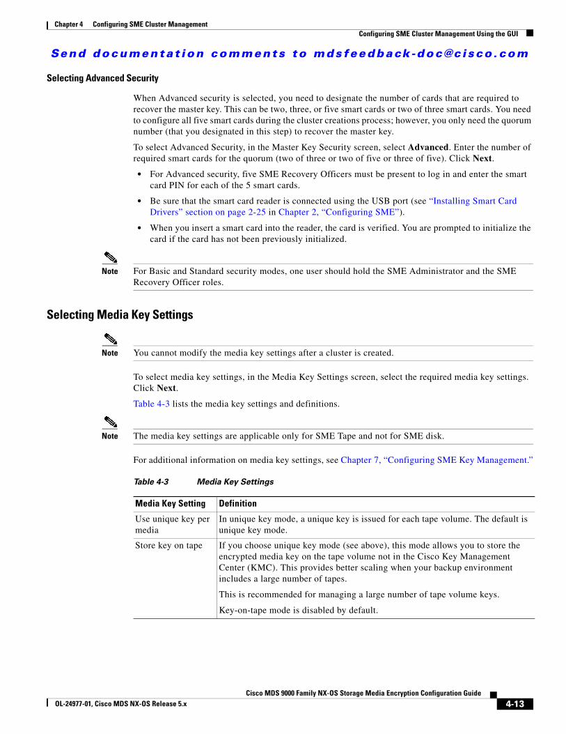
Send documenta t ion comments to mdsfeedback -doc@c i sco .com
Chapter 4 Configuring SME Cluster ManagementConfiguring SME Cluster Management Using the GUI
Selecting Advanced Security
When Advanced security is selected, you need to designate the number of cards that are required to recover the master key. This can be two, three, or five smart cards or two of three smart cards. You need to configure all five smart cards during the cluster creations process; however, you only need the quorum number (that you designated in this step) to recover the master key.
To select Advanced Security, in the Master Key Security screen, select Advanced. Enter the number of required smart cards for the quorum (two of three or two of five or three of five). Click Next.
• For Advanced security, five SME Recovery Officers must be present to log in and enter the smart card PIN for each of the 5 smart cards.
• Be sure that the smart card reader is connected using the USB port (see “Installing Smart Card Drivers” section on page 2-25 in Chapter 2, “Configuring SME”).
• When you insert a smart card into the reader, the card is verified. You are prompted to initialize the card if the card has not been previously initialized.
Note For Basic and Standard security modes, one user should hold the SME Administrator and the SME Recovery Officer roles.
Selecting Media Key Settings
Note You cannot modify the media key settings after a cluster is created.
To select media key settings, in the Media Key Settings screen, select the required media key settings. Click Next.
Table 4-3 lists the media key settings and definitions.
Note The media key settings are applicable only for SME Tape and not for SME disk.
For additional information on media key settings, see Chapter 7, “Configuring SME Key Management.”
Table 4-3 Media Key Settings
Media Key Setting Definition
Use unique key per media
In unique key mode, a unique key is issued for each tape volume. The default is unique key mode.
Store key on tape If you choose unique key mode (see above), this mode allows you to store the encrypted media key on the tape volume not in the Cisco Key Management Center (KMC). This provides better scaling when your backup environment includes a large number of tapes.
This is recommended for managing a large number of tape volume keys.
Key-on-tape mode is disabled by default.
4-13Cisco MDS 9000 Family NX-OS Storage Media Encryption Configuration Guide
OL-24977-01, Cisco MDS NX-OS Release 5.x
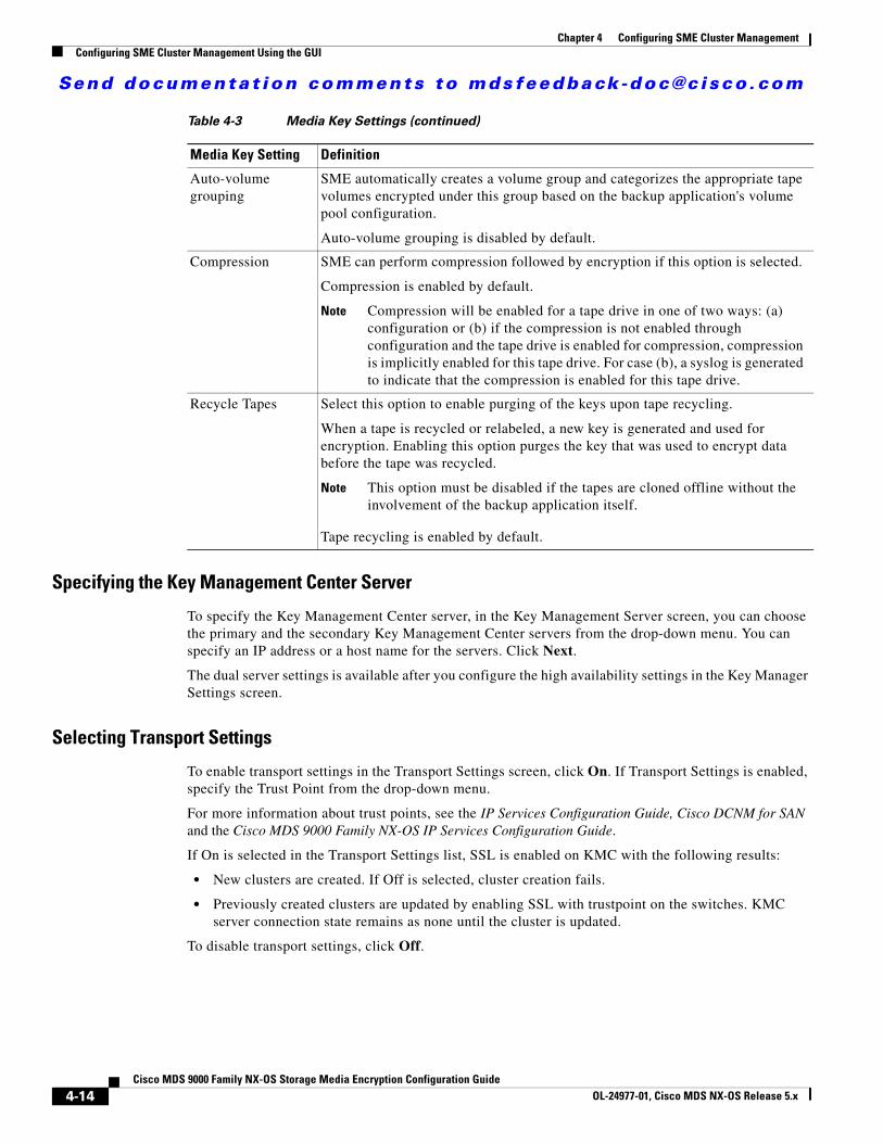
Send documenta t ion comments to mdsfeedback -doc@c i sco .com
Chapter 4 Configuring SME Cluster ManagementConfiguring SME Cluster Management Using the GUI
Specifying the Key Management Center Server
To specify the Key Management Center server, in the Key Management Server screen, you can choose the primary and the secondary Key Management Center servers from the drop-down menu. You can specify an IP address or a host name for the servers. Click Next.
The dual server settings is available after you configure the high availability settings in the Key Manager Settings screen.
Selecting Transport Settings
To enable transport settings in the Transport Settings screen, click On. If Transport Settings is enabled, specify the Trust Point from the drop-down menu.
For more information about trust points, see the IP Services Configuration Guide, Cisco DCNM for SAN and the Cisco MDS 9000 Family NX-OS IP Services Configuration Guide.
If On is selected in the Transport Settings list, SSL is enabled on KMC with the following results:
• New clusters are created. If Off is selected, cluster creation fails.
• Previously created clusters are updated by enabling SSL with trustpoint on the switches. KMC server connection state remains as none until the cluster is updated.
To disable transport settings, click Off.
Auto-volume grouping
SME automatically creates a volume group and categorizes the appropriate tape volumes encrypted under this group based on the backup application's volume pool configuration.
Auto-volume grouping is disabled by default.
Compression SME can perform compression followed by encryption if this option is selected.
Compression is enabled by default.
Note Compression will be enabled for a tape drive in one of two ways: (a) configuration or (b) if the compression is not enabled through configuration and the tape drive is enabled for compression, compression is implicitly enabled for this tape drive. For case (b), a syslog is generated to indicate that the compression is enabled for this tape drive.
Recycle Tapes Select this option to enable purging of the keys upon tape recycling.
When a tape is recycled or relabeled, a new key is generated and used for encryption. Enabling this option purges the key that was used to encrypt data before the tape was recycled.
Note This option must be disabled if the tapes are cloned offline without the involvement of the backup application itself.
Tape recycling is enabled by default.
Table 4-3 Media Key Settings (continued)
Media Key Setting Definition
4-14Cisco MDS 9000 Family NX-OS Storage Media Encryption Configuration Guide
OL-24977-01, Cisco MDS NX-OS Release 5.x
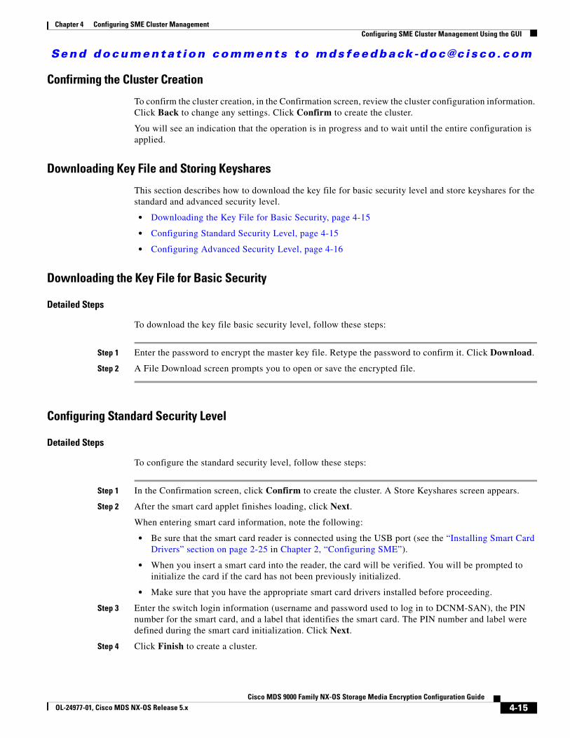
Send documenta t ion comments to mdsfeedback -doc@c i sco .com
Chapter 4 Configuring SME Cluster ManagementConfiguring SME Cluster Management Using the GUI
Confirming the Cluster Creation
To confirm the cluster creation, in the Confirmation screen, review the cluster configuration information. Click Back to change any settings. Click Confirm to create the cluster.
You will see an indication that the operation is in progress and to wait until the entire configuration is applied.
Downloading Key File and Storing Keyshares
This section describes how to download the key file for basic security level and store keyshares for the standard and advanced security level.
• Downloading the Key File for Basic Security, page 4-15
• Configuring Standard Security Level, page 4-15
• Configuring Advanced Security Level, page 4-16
Downloading the Key File for Basic Security
Detailed Steps
To download the key file basic security level, follow these steps:
Step 1 Enter the password to encrypt the master key file. Retype the password to confirm it. Click Download.
Step 2 A File Download screen prompts you to open or save the encrypted file.
Configuring Standard Security Level
Detailed Steps
To configure the standard security level, follow these steps:
Step 1 In the Confirmation screen, click Confirm to create the cluster. A Store Keyshares screen appears.
Step 2 After the smart card applet finishes loading, click Next.
When entering smart card information, note the following:
• Be sure that the smart card reader is connected using the USB port (see the “Installing Smart Card Drivers” section on page 2-25 in Chapter 2, “Configuring SME”).
• When you insert a smart card into the reader, the card will be verified. You will be prompted to initialize the card if the card has not been previously initialized.
• Make sure that you have the appropriate smart card drivers installed before proceeding.
Step 3 Enter the switch login information (username and password used to log in to DCNM-SAN), the PIN number for the smart card, and a label that identifies the smart card. The PIN number and label were defined during the smart card initialization. Click Next.
Step 4 Click Finish to create a cluster.
4-15Cisco MDS 9000 Family NX-OS Storage Media Encryption Configuration Guide
OL-24977-01, Cisco MDS NX-OS Release 5.x

Send documenta t ion comments to mdsfeedback -doc@c i sco .com
Chapter 4 Configuring SME Cluster ManagementConfiguring SME Cluster Management Using the GUI
Step 5 Click Close to return to the DCNM-SAN Web Client and to view the smart card information after the cluster creation is completed.
Step 6 View the smart card information.
Note When an error occurs while storing shares on the cards, the cluster should be deleted and recreated.
Note The smart card reader is only supported on Windows platforms. This includes only the Windows XP 32 bit and Windows server 2003 32 bit platforms
Configuring Advanced Security Level
Note When an error occurs while storing shares on the cards, the cluster should be deleted and recreated.
Detailed Steps
To configure the advanced security level, follow these steps:
Step 1 In the Create Cluster: Confirmation screen, click Confirm to create the cluster. The Create Cluster: A Store Keyshares screen appears.
Step 2 After the smart card applet finishes loading, click Next.
When entering smart card information, note the following:
• Be sure that the smart card reader is connected using the USB port (see the “Installing Smart Card Drivers” section on page 2-25 in Chapter 2, “Configuring SME”).
• When you insert a smart card into the reader, the card will be verified. You will be prompted to initialize the card if the card has not been previously initialized.
• For each smart card, each SME Recovery Officer must log in and enter the smart card PIN.
• Make sure that you have the correct smart card drivers installed before proceeding.
Step 3 Enter the switch login information (username and password used to log in to DCNM-SAN), the PIN number for the smart card, and a label that identifies the smart card. The PIN number and label were defined during the smart card initialization.
Step 4 Click Next.
You will see a notification that the keyshare is being stored. This notification is shown after each keyshare is stored.
Step 5 Click Next.
Step 6 Enter the switch credentials and PIN information for the second recovery officer. Click Next.
Step 7 Enter the switch credentials and PIN information for the third recovery officer. Click Next.
Step 8 Enter the switch credentials and PIN information for the fourth recovery officer. Click Next.
Step 9 Enter the switch credentials and PIN information for the fifth recovery officer. Click Next.
Step 10 Click Finish to return to the DCNM-SAN Web Client to view the smart card information.
4-16Cisco MDS 9000 Family NX-OS Storage Media Encryption Configuration Guide
OL-24977-01, Cisco MDS NX-OS Release 5.x

Send documenta t ion comments to mdsfeedback -doc@c i sco .com
Chapter 4 Configuring SME Cluster ManagementConfiguring SME Cluster Management Using the GUI
Step 11 View the smart card information by selecting Smartcards.
Deactivating and Purging an SME ClusterYou can archive clusters that are Online, Pending, or Deprecated. For information on cluster states, see the “Viewing Cluster States” section on page 4-22.
Archiving and then purging a SME tape cluster involves the following steps:
• Delete all tape groups, tape devices, and tape volume groups. (See Chapter 5, “Configuring SME Tapes.”)
• Delete all switches and SME interfaces from the cluster. (See Chapter 3, “Configuring SME Interfaces.”)
• Change the cluster state to deactivated. (See “Deactivating an SME Cluster” section on page 4-17.)
• Purge (permanently delete) a SME cluster. (See “Purging an SME Cluster” section on page 4-18.)
Archiving and then purging a SME disk cluster involves the following steps:
• Delete all disk groups and disk devices. (See Chapter 6, “Configuring SME Disks.”)
• Delete all switches and SME interfaces from the cluster. (See Chapter 3, “Configuring SME Interfaces.”)
• Change the cluster state to deactivated. (See “Deactivating an SME Cluster” section on page 4-17.)
• Purge (permanently delete) a SME cluster. (See “Purging an SME Cluster” section on page 4-18.)
This section covers the following topics:
• Deactivating an SME Cluster, page 4-17
• Purging an SME Cluster, page 4-18
Deactivating an SME Cluster
Deactivating deletes the cluster from the switch and retains the keys in the Cisco KMC.
Detailed Steps
To change the cluster state to Deactivated, follow these steps:
Step 1 Click Clusters in the navigation pane to display the clusters.
Step 2 Select a cluster in the information pane and click Remove.
Note Changes the cluster state to deactivated and retains the keys in the Cisco KMC.
Caution Do not click Remove again unless you want to permanently delete the cluster configuration information and the master key information from the Cisco KMC.
4-17Cisco MDS 9000 Family NX-OS Storage Media Encryption Configuration Guide
OL-24977-01, Cisco MDS NX-OS Release 5.x

Send documenta t ion comments to mdsfeedback -doc@c i sco .com
Chapter 4 Configuring SME Cluster ManagementVerifying SME Cluster Management Configuration
Step 3 Click OK.
Step 4 Refresh DCNM-SAN Web Client to view the notification that the cluster has been deactivated.
Purging an SME Cluster
Purging an SME cluster includes the following steps:
• Delete all cluster elements (tape paths, tape devices, volume groups, tape groups, and switches).
• Delete (unbind) any SME interfaces that are configured in the cluster.
• Change the cluster state to deactivated.
• Purge the cluster to remove the cluster and the master keys from the Cisco KMC.
Restrictions
• You can only purge a cluster that is in the deactivated state.
Detailed Steps
To purge an SME cluster, follow these steps:
Step 1 Click Clusters in the navigation pane to display the SME clusters.
Step 2 Select an deactivated cluster in the information pane and click Remove.
Step 3 Click OK to delete the cluster.
Caution Do not click OK unless you want to permanently delete the cluster configuration information and the master key from the Cisco KMC.
Step 4 Refresh the DCNM-SAN Web Client to view the notification that the cluster has been purged.
Verifying SME Cluster Management ConfigurationTo display SME Cluster Management configuration information, perform one of the following tasks:
Command Purpose
show sme Displays a specific cluster configuration, internal information, and transport information.
show sme cluster Displays additional cluster information.
show sme cluster key Displays information about the cluster key database.
show sme cluster node Displays information about a local or remote switch.
show sme cluster recovery officer
Displays information about a specific Recovery Officer or for all the Recovery Officers for a specific cluster.
4-18Cisco MDS 9000 Family NX-OS Storage Media Encryption Configuration Guide
OL-24977-01, Cisco MDS NX-OS Release 5.x
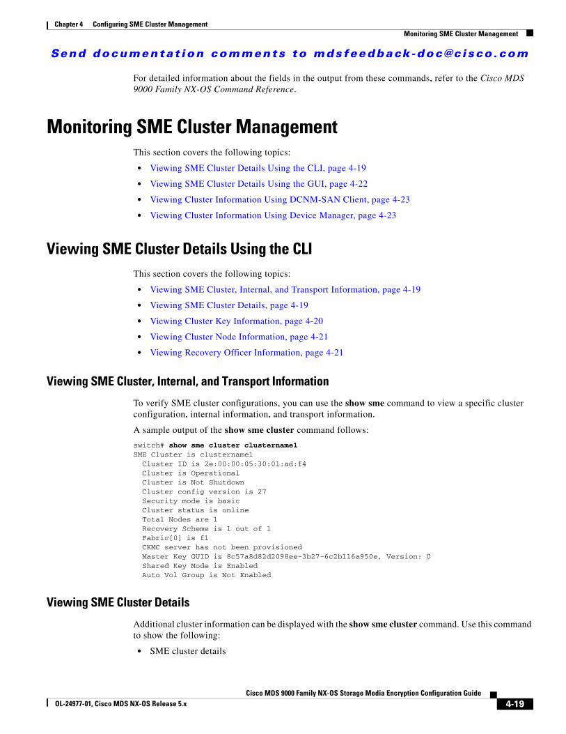
Send documenta t ion comments to mdsfeedback -doc@c i sco .com
Chapter 4 Configuring SME Cluster ManagementMonitoring SME Cluster Management
For detailed information about the fields in the output from these commands, refer to the Cisco MDS 9000 Family NX-OS Command Reference.
Monitoring SME Cluster ManagementThis section covers the following topics:
• Viewing SME Cluster Details Using the CLI, page 4-19
• Viewing SME Cluster Details Using the GUI, page 4-22
• Viewing Cluster Information Using DCNM-SAN Client, page 4-23
• Viewing Cluster Information Using Device Manager, page 4-23
Viewing SME Cluster Details Using the CLIThis section covers the following topics:
• Viewing SME Cluster, Internal, and Transport Information, page 4-19
• Viewing SME Cluster Details, page 4-19
• Viewing Cluster Key Information, page 4-20
• Viewing Cluster Node Information, page 4-21
• Viewing Recovery Officer Information, page 4-21
Viewing SME Cluster, Internal, and Transport Information
To verify SME cluster configurations, you can use the show sme command to view a specific cluster configuration, internal information, and transport information.
A sample output of the show sme cluster command follows:
switch# show sme cluster clustername1 SME Cluster is clustername1 Cluster ID is 2e:00:00:05:30:01:ad:f4 Cluster is Operational Cluster is Not Shutdown Cluster config version is 27 Security mode is basic Cluster status is online Total Nodes are 1 Recovery Scheme is 1 out of 1 Fabric[0] is f1 CKMC server has not been provisioned Master Key GUID is 8c57a8d82d2098ee-3b27-6c2b116a950e, Version: 0 Shared Key Mode is Enabled Auto Vol Group is Not Enabled
Viewing SME Cluster Details
Additional cluster information can be displayed with the show sme cluster command. Use this command to show the following:
• SME cluster details
4-19Cisco MDS 9000 Family NX-OS Storage Media Encryption Configuration Guide
OL-24977-01, Cisco MDS NX-OS Release 5.x
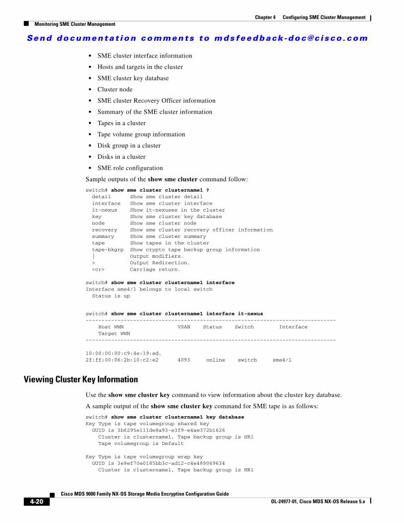
Send documenta t ion comments to mdsfeedback -doc@c i sco .com
Chapter 4 Configuring SME Cluster ManagementMonitoring SME Cluster Management
• SME cluster interface information
• Hosts and targets in the cluster
• SME cluster key database
• Cluster node
• SME cluster Recovery Officer information
• Summary of the SME cluster information
• Tapes in a cluster
• Tape volume group information
• Disk group in a cluster
• Disks in a cluster
• SME role configuration
Sample outputs of the show sme cluster command follow:
switch# show sme cluster clustername1 ?detail Show sme cluster detail
interface Show sme cluster interface it-nexus Show it-nexuses in the cluster key Show sme cluster key database node Show sme cluster node recovery Show sme cluster recovery officer information summary Show sme cluster summary tape Show tapes in the cluster tape-bkgrp Show crypto tape backup group information | Output modifiers. > Output Redirection. <cr> Carriage return.
switch# show sme cluster clustername1 interfaceInterface sme4/1 belongs to local switch Status is up
switch# show sme cluster clustername1 interface it-nexus ------------------------------------------------------------------------------- Host WWN VSAN Status Switch Interface Target WWN-------------------------------------------------------------------------------
10:00:00:00:c9:4e:19:ed,2f:ff:00:06:2b:10:c2:e2 4093 online switch sme4/1
Viewing Cluster Key Information
Use the show sme cluster key command to view information about the cluster key database.
A sample output of the show sme cluster key command for SME tape is as follows:
switch# show sme cluster clustername1 key database Key Type is tape volumegroup shared key GUID is 3b6295e111de8a93-e3f9-e4ae372b1626 Cluster is clustername1, Tape backup group is HR1 Tape volumegroup is Default
Key Type is tape volumegroup wrap key GUID is 3e9ef70e0185bb3c-ad12-c4e489069634 Cluster is clustername1, Tape backup group is HR1
4-20Cisco MDS 9000 Family NX-OS Storage Media Encryption Configuration Guide
OL-24977-01, Cisco MDS NX-OS Release 5.x
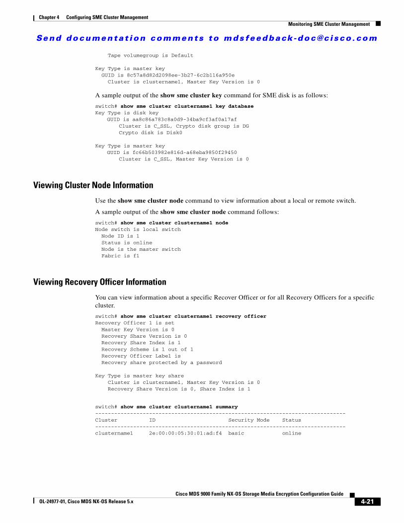
Send documenta t ion comments to mdsfeedback -doc@c i sco .com
Chapter 4 Configuring SME Cluster ManagementMonitoring SME Cluster Management
Tape volumegroup is Default
Key Type is master key GUID is 8c57a8d82d2098ee-3b27-6c2b116a950e Cluster is clustername1, Master Key Version is 0
A sample output of the show sme cluster key command for SME disk is as follows:
switch# show sme cluster clustername1 key database Key Type is disk key
GUID is aa8c86a783c8a0d9-34ba9cf3af0a17afCluster is C_SSL, Crypto disk group is DGCrypto disk is Disk0
Key Type is master keyGUID is fc66b503982e816d-a68eba9850f29450
Cluster is C_SSL, Master Key Version is 0
Viewing Cluster Node Information
Use the show sme cluster node command to view information about a local or remote switch.
A sample output of the show sme cluster node command follows:
switch# show sme cluster clustername1 node Node switch is local switch Node ID is 1 Status is online Node is the master switch Fabric is f1
Viewing Recovery Officer Information
You can view information about a specific Recover Officer or for all Recovery Officers for a specific cluster.
switch# show sme cluster clustername1 recovery officer Recovery Officer 1 is set Master Key Version is 0 Recovery Share Version is 0 Recovery Share Index is 1 Recovery Scheme is 1 out of 1 Recovery Officer Label is Recovery share protected by a password
Key Type is master key share Cluster is clustername1, Master Key Version is 0 Recovery Share Version is 0, Share Index is 1
switch# show sme cluster clustername1 summary -------------------------------------------------------------------------------Cluster ID Security Mode Status -------------------------------------------------------------------------------clustername1 2e:00:00:05:30:01:ad:f4 basic online
4-21Cisco MDS 9000 Family NX-OS Storage Media Encryption Configuration Guide
OL-24977-01, Cisco MDS NX-OS Release 5.x
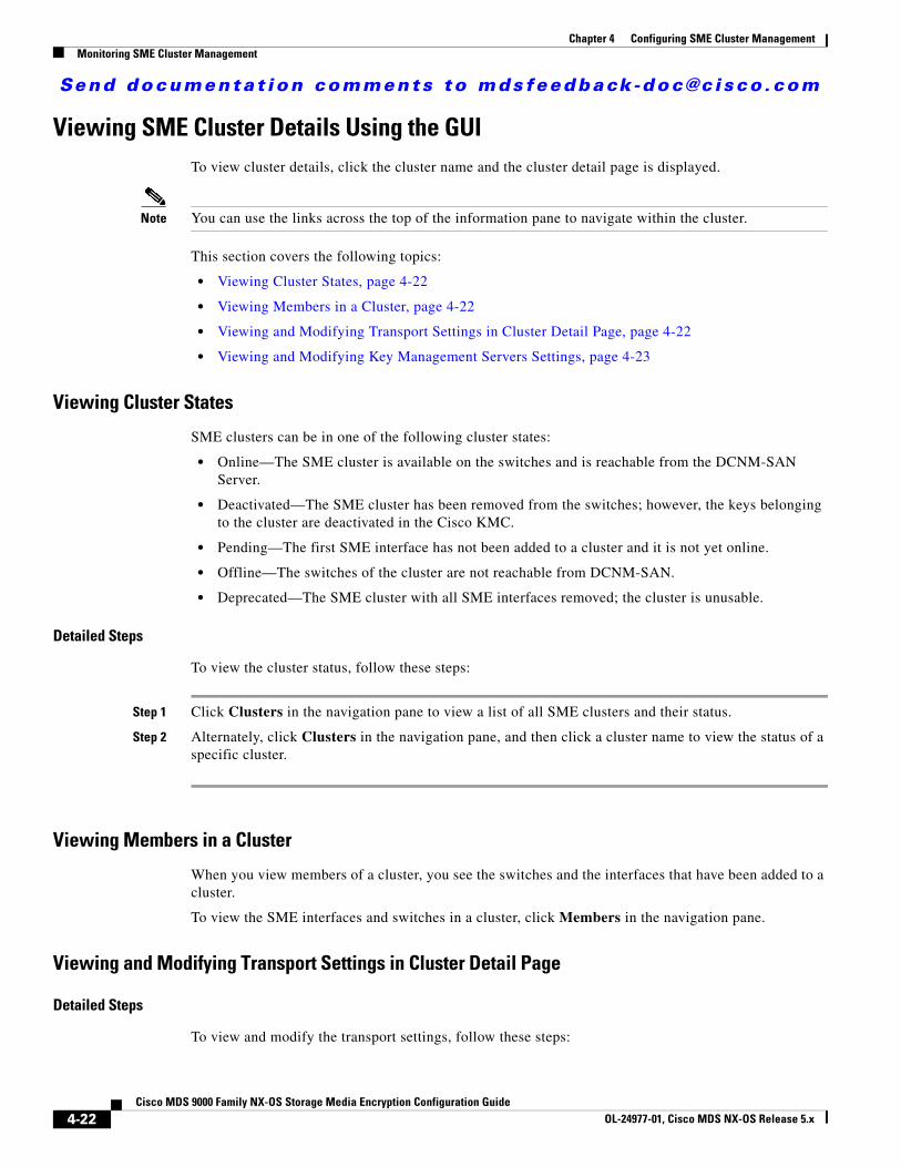
Send documenta t ion comments to mdsfeedback -doc@c i sco .com
Chapter 4 Configuring SME Cluster ManagementMonitoring SME Cluster Management
Viewing SME Cluster Details Using the GUITo view cluster details, click the cluster name and the cluster detail page is displayed.
Note You can use the links across the top of the information pane to navigate within the cluster.
This section covers the following topics:
• Viewing Cluster States, page 4-22
• Viewing Members in a Cluster, page 4-22
• Viewing and Modifying Transport Settings in Cluster Detail Page, page 4-22
• Viewing and Modifying Key Management Servers Settings, page 4-23
Viewing Cluster States
SME clusters can be in one of the following cluster states:
• Online—The SME cluster is available on the switches and is reachable from the DCNM-SAN Server.
• Deactivated—The SME cluster has been removed from the switches; however, the keys belonging to the cluster are deactivated in the Cisco KMC.
• Pending—The first SME interface has not been added to a cluster and it is not yet online.
• Offline—The switches of the cluster are not reachable from DCNM-SAN.
• Deprecated—The SME cluster with all SME interfaces removed; the cluster is unusable.
Detailed Steps
To view the cluster status, follow these steps:
Step 1 Click Clusters in the navigation pane to view a list of all SME clusters and their status.
Step 2 Alternately, click Clusters in the navigation pane, and then click a cluster name to view the status of a specific cluster.
Viewing Members in a Cluster
When you view members of a cluster, you see the switches and the interfaces that have been added to a cluster.
To view the SME interfaces and switches in a cluster, click Members in the navigation pane.
Viewing and Modifying Transport Settings in Cluster Detail Page
Detailed Steps
To view and modify the transport settings, follow these steps:
4-22Cisco MDS 9000 Family NX-OS Storage Media Encryption Configuration Guide
OL-24977-01, Cisco MDS NX-OS Release 5.x
Send documenta t ion comments to mdsfeedback -doc@c i sco .com
Chapter 4 Configuring SME Cluster ManagementMonitoring SME Cluster Management
Step 1 Select the newly created cluster in the navigation pane to display the cluster detail page.
The transport settings details are displayed when SSL is selected.
The transport settings details are displayed when SSL is Off.
You can also modify the transport settings in the cluster detail page by clicking Modify.
Step 2 Select SSL and choose a Trust Point from the drop-down menu. Click Apply to save the settings.
Viewing and Modifying Key Management Servers Settings
Detailed Steps
To view and modify the primary and secondary key management servers settings, follow these steps:
Step 1 Select the cluster in the navigation pane to display the cluster detail page. Scroll to the Key Management Settings section and click Modify to edit the server settings.
Step 2 Enter the IP addresses for the primary and/or the secondary servers. Click Apply to save the changes. Click Cancel to revert back to previous settings.
Note KMC server can also be modified through the cluster list view.
Step 3 Refresh the DCNM-SAN Web Client to view the notification that the cluster has been modified.
Viewing Cluster Information Using DCNM-SAN Client
Detailed Steps
To view SME cluster information using DCNM-SAN Client, follow these steps:
Step 1 In the Physical Attributes pane, select Intelligent Features > SME > Clusters.
Step 2 Click the Members tab to view members in a cluster.
Step 3 Click the Interfaces tab to view information about SME interfaces.
Viewing Cluster Information Using Device Manager
Detailed Steps
To view SME cluster information using Device Manager, follow these steps:
4-23Cisco MDS 9000 Family NX-OS Storage Media Encryption Configuration Guide
OL-24977-01, Cisco MDS NX-OS Release 5.x
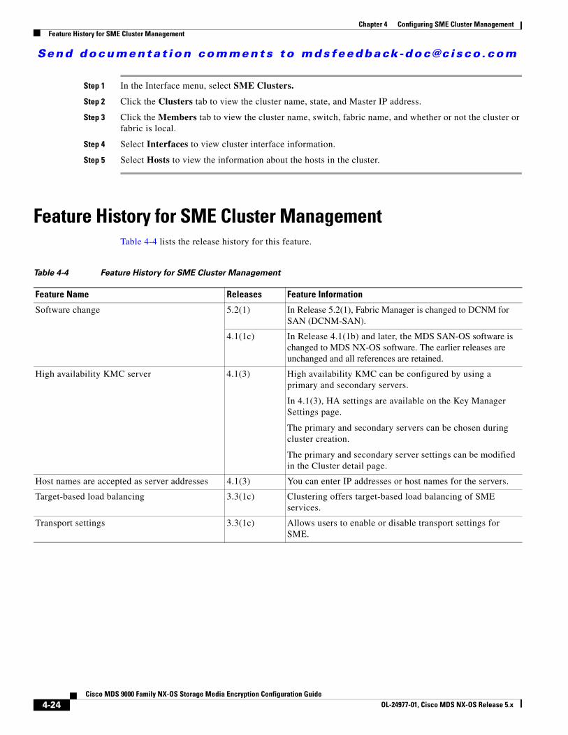
Send documenta t ion comments to mdsfeedback -doc@c i sco .com
Chapter 4 Configuring SME Cluster ManagementFeature History for SME Cluster Management
Step 1 In the Interface menu, select SME Clusters.
Step 2 Click the Clusters tab to view the cluster name, state, and Master IP address.
Step 3 Click the Members tab to view the cluster name, switch, fabric name, and whether or not the cluster or fabric is local.
Step 4 Select Interfaces to view cluster interface information.
Step 5 Select Hosts to view the information about the hosts in the cluster.
Feature History for SME Cluster ManagementTable 4-4 lists the release history for this feature.
Table 4-4 Feature History for SME Cluster Management
Feature Name Releases Feature Information
Software change 5.2(1) In Release 5.2(1), Fabric Manager is changed to DCNM for SAN (DCNM-SAN).
4.1(1c) In Release 4.1(1b) and later, the MDS SAN-OS software is changed to MDS NX-OS software. The earlier releases are unchanged and all references are retained.
High availability KMC server 4.1(3) High availability KMC can be configured by using a primary and secondary servers.
In 4.1(3), HA settings are available on the Key Manager Settings page.
The primary and secondary servers can be chosen during cluster creation.
The primary and secondary server settings can be modified in the Cluster detail page.
Host names are accepted as server addresses 4.1(3) You can enter IP addresses or host names for the servers.
Target-based load balancing 3.3(1c) Clustering offers target-based load balancing of SME services.
Transport settings 3.3(1c) Allows users to enable or disable transport settings for SME.
4-24Cisco MDS 9000 Family NX-OS Storage Media Encryption Configuration Guide
OL-24977-01, Cisco MDS NX-OS Release 5.x
Send documenta t ion comments to mdsfeedback -doc@c i sco .com
Cisco MDS 9000 Family NXOL-24977-01, Cisco MDS NX-OS Release 5.x
C H A P T E R 5
Configuring SME TapesThis chapter contains information about managing tapes that are encrypted using SME.
This chapter includes the following topics:
• Information About SME Tape Management, page 5-1
• Configuring SME Tape Management Using the CLI, page 5-2
• Configuring SME Tape Management Using the GUI, page 5-7
• Configuring Key Management Operations, page 5-11
• Verifying SME Tape Management Configuration, page 5-20
• Monitoring SME Tape Management, page 5-20
• Feature History for SME Tape Management, page 5-24
Information About SME Tape ManagementOnce provisioned, SME provides transparency to hosts and targets. To manage the paths from a hosts to tape devices, SME uses the following:
• Tape group—A backup environment in the SAN. This consists of all the tape backup servers and the tape libraries that they access.
• Tape device—A tape drive that is configured for encryption.
• Tape volume—A physical tape cartridge identified by a barcode for a given use.
• Tape volume group—A logical set of tape volumes configured for a specific purpose. Using SME, a tape volume group can be configured using a barcode range or a specified regular expression. In an auto-volume group, a tape volume group can be the volume pool name configured at the backup application.
SME provides the capability to export a volume group with an encryption password. This file could later be imported to a volume group. Also, volume group filtering options provide mechanisms to specify what type of information will be included in a specific volume group. For example, you could filter information in a volume group by specifying a barcode range.
5-1-OS Storage Media Encryption Configuration Guide
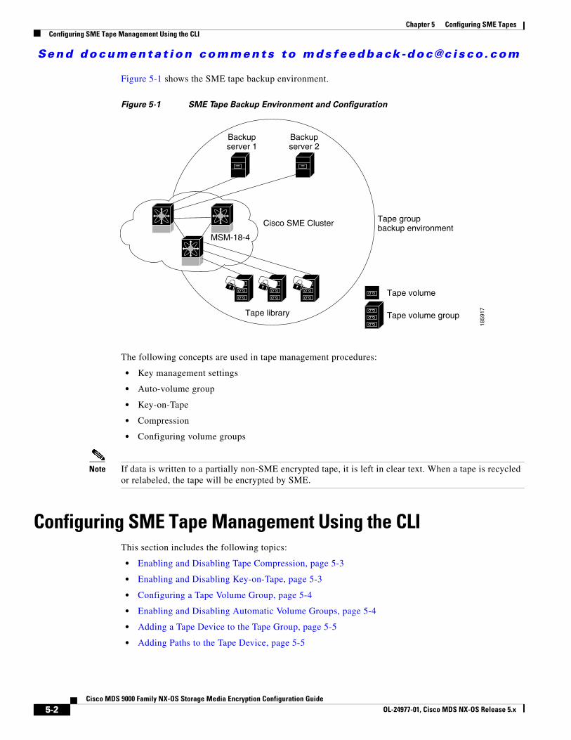
Send documenta t ion comments to mdsfeedback -doc@c i sco .com
Chapter 5 Configuring SME TapesConfiguring SME Tape Management Using the CLI
Figure 5-1 shows the SME tape backup environment.
Figure 5-1 SME Tape Backup Environment and Configuration
The following concepts are used in tape management procedures:
• Key management settings
• Auto-volume group
• Key-on-Tape
• Compression
• Configuring volume groups
Note If data is written to a partially non-SME encrypted tape, it is left in clear text. When a tape is recycled or relabeled, the tape will be encrypted by SME.
Configuring SME Tape Management Using the CLIThis section includes the following topics:
• Enabling and Disabling Tape Compression, page 5-3
• Enabling and Disabling Key-on-Tape, page 5-3
• Configuring a Tape Volume Group, page 5-4
• Enabling and Disabling Automatic Volume Groups, page 5-4
• Adding a Tape Device to the Tape Group, page 5-5
• Adding Paths to the Tape Device, page 5-5
MSM-18-4
Backupserver 1
Backupserver 2
Cisco SME Cluster
Tape library
Tape volume
Tape volume group
Tape groupbackup environment
1859
17
5-2Cisco MDS 9000 Family NX-OS Storage Media Encryption Configuration Guide
OL-24977-01, Cisco MDS NX-OS Release 5.x
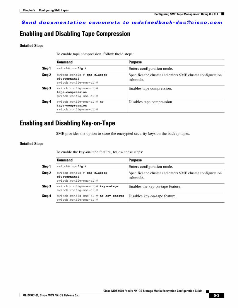
Send documenta t ion comments to mdsfeedback -doc@c i sco .com
Chapter 5 Configuring SME TapesConfiguring SME Tape Management Using the CLI
Enabling and Disabling Tape Compression
Detailed Steps
To enable tape compression, follow these steps:
Enabling and Disabling Key-on-TapeSME provides the option to store the encrypted security keys on the backup tapes.
Detailed Steps
To enable the key-on-tape feature, follow these steps:
Command Purpose
Step 1 switch# config t Enters configuration mode.
Step 2 switch(config)# sme cluster clustername1switch(config-sme-cl)#
Specifies the cluster and enters SME cluster configuration submode.
Step 3 switch(config-sme-cl)# tape-compressionswitch(config-sme-cl)#
Enables tape compression.
Step 4 switch(config-sme-cl)# no tape-compressionswitch(config-sme-cl)#
Disables tape compression.
Command Purpose
Step 1 switch# config t Enters configuration mode.
Step 2 switch(config)# sme cluster clustername1switch(config-sme-cl)#
Specifies the cluster and enters SME cluster configuration submode.
Step 3 switch(config-sme-cl)# key-ontapeswitch(config-sme-cl)#
Enables the key-on-tape feature.
Step 4 switch(config-sme-cl)# no key-ontapeswitch(config-sme-cl)#
Disables key-on-tape feature.
5-3Cisco MDS 9000 Family NX-OS Storage Media Encryption Configuration Guide
OL-24977-01, Cisco MDS NX-OS Release 5.x
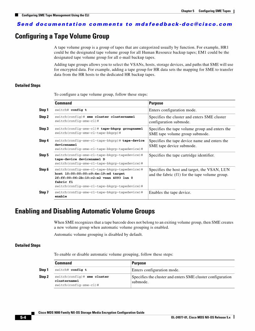
Send documenta t ion comments to mdsfeedback -doc@c i sco .com
Chapter 5 Configuring SME TapesConfiguring SME Tape Management Using the CLI
Configuring a Tape Volume GroupA tape volume group is a group of tapes that are categorized usually by function. For example, HR1 could be the designated tape volume group for all Human Resource backup tapes; EM1 could be the designated tape volume group for all e-mail backup tapes.
Adding tape groups allows you to select the VSANs, hosts, storage devices, and paths that SME will use for encrypted data. For example, adding a tape group for HR data sets the mapping for SME to transfer data from the HR hosts to the dedicated HR backup tapes.
Detailed Steps
To configure a tape volume group, follow these steps:
Enabling and Disabling Automatic Volume GroupsWhen SME recognizes that a tape barcode does not belong to an exiting volume group, then SME creates a new volume group when automatic volume grouping is enabled.
Automatic volume grouping is disabled by default.
Detailed Steps
To enable or disable automatic volume grouping, follow these steps:
Command Purpose
Step 1 switch# config t Enters configuration mode.
Step 2 switch(config)# sme cluster clustername1switch(config-sme-cl)#
Specifies the cluster and enters SME cluster configuration submode.
Step 3 switch(config-sme-cl)# tape-bkgrp groupname1switch(config-sme-cl-tape-bkgrp)#
Specifies the tape volume group and enters the SME tape volume group submode.
Step 4 switch(config-sme-cl-tape-bkgrp)# tape-device devicename1switch(config-sme-cl-tape-bkgrp-tapedevice)#
Specifies the tape device name and enters the SME tape device submode.
Step 5 switch(config-sme-cl-tape-bkgrp-tapedevice)# tape-device devicename1 Dswitch(config-sme-cl-tape-bkgrp-tapedevice)#
Specifies the tape cartridge identifier.
Step 6 switch(config-sme-cl-tape-bkgrp-tapedevice)# host 10:00:00:00:c9:4e:19:ed target 2f:ff:00:06:2b:10:c2:e2 vsan 4093 lun 0 fabric f1switch(config-sme-cl-tape-bkgrp-tapedevice)#
Specifies the host and target, the VSAN, LUN and the fabric (f1) for the tape volume group.
Step 7 switch(config-sme-cl-tape-bkgrp-tapedevice)# enable
Enables the tape device.
Command Purpose
Step 1 switch# config t Enters configuration mode.
Step 2 switch(config)# sme cluster clustername1switch(config-sme-cl)#
Specifies the cluster and enters SME cluster configuration submode.
5-4Cisco MDS 9000 Family NX-OS Storage Media Encryption Configuration Guide
OL-24977-01, Cisco MDS NX-OS Release 5.x
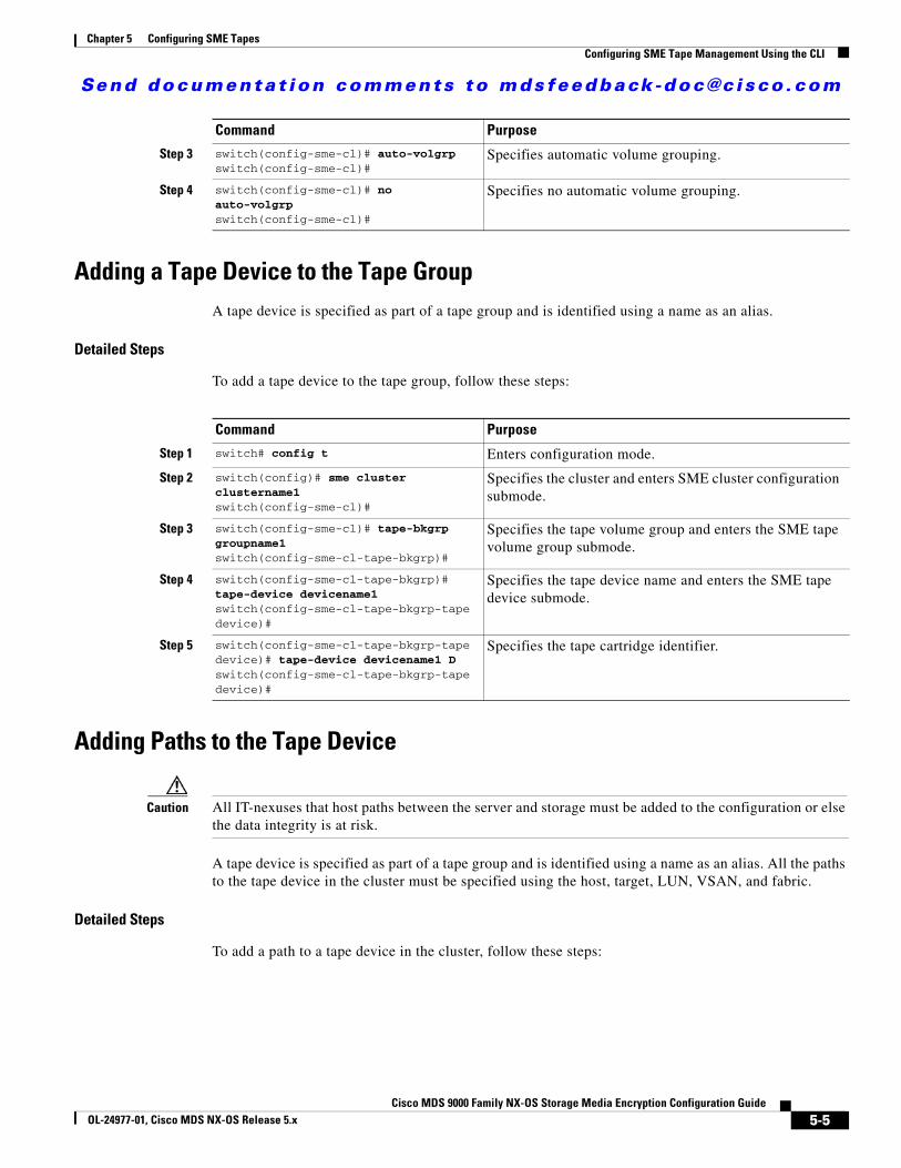
Send documenta t ion comments to mdsfeedback -doc@c i sco .com
Chapter 5 Configuring SME TapesConfiguring SME Tape Management Using the CLI
Adding a Tape Device to the Tape GroupA tape device is specified as part of a tape group and is identified using a name as an alias.
Detailed Steps
To add a tape device to the tape group, follow these steps:
Adding Paths to the Tape Device
Caution All IT-nexuses that host paths between the server and storage must be added to the configuration or else the data integrity is at risk.
A tape device is specified as part of a tape group and is identified using a name as an alias. All the paths to the tape device in the cluster must be specified using the host, target, LUN, VSAN, and fabric.
Detailed Steps
To add a path to a tape device in the cluster, follow these steps:
Step 3 switch(config-sme-cl)# auto-volgrpswitch(config-sme-cl)#
Specifies automatic volume grouping.
Step 4 switch(config-sme-cl)# no auto-volgrpswitch(config-sme-cl)#
Specifies no automatic volume grouping.
Command Purpose
Command Purpose
Step 1 switch# config t Enters configuration mode.
Step 2 switch(config)# sme cluster clustername1switch(config-sme-cl)#
Specifies the cluster and enters SME cluster configuration submode.
Step 3 switch(config-sme-cl)# tape-bkgrp groupname1switch(config-sme-cl-tape-bkgrp)#
Specifies the tape volume group and enters the SME tape volume group submode.
Step 4 switch(config-sme-cl-tape-bkgrp)# tape-device devicename1switch(config-sme-cl-tape-bkgrp-tapedevice)#
Specifies the tape device name and enters the SME tape device submode.
Step 5 switch(config-sme-cl-tape-bkgrp-tapedevice)# tape-device devicename1 Dswitch(config-sme-cl-tape-bkgrp-tapedevice)#
Specifies the tape cartridge identifier.
5-5Cisco MDS 9000 Family NX-OS Storage Media Encryption Configuration Guide
OL-24977-01, Cisco MDS NX-OS Release 5.x
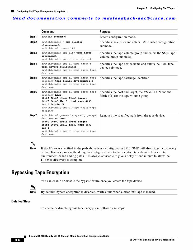
Send documenta t ion comments to mdsfeedback -doc@c i sco .com
Chapter 5 Configuring SME TapesConfiguring SME Tape Management Using the CLI
Note If the IT-nexus specified in the path above is not configured in SME, SME will also trigger a discovery of the IT-nexus along with adding the configured path to the specified tape device. In a scripted environment, when adding paths, it is always advisable to give a delay of one minute to allow the IT-nexus discovery to complete.
Bypassing Tape EncryptionYou can enable or disable the bypass feature once you create the tape device.
Note By default, bypass encryption is disabled. Writes fails when a clear text tape is loaded.
Detailed Steps
To enable or disable bypass tape encryption, follow these steps:
Command Purpose
Step 1 switch# config t Enters configuration mode.
Step 2 switch(config)# sme cluster clustername1switch(config-sme-cl)#
Specifies the cluster and enters SME cluster configuration submode.
Step 3 switch(config-sme-cl)# tape-bkgrp groupname1switch(config-sme-cl-tape-bkgrp)#
Specifies the tape volume group and enters the SME tape volume group submode.
Step 4 switch(config-sme-cl-tape-bkgrp)# tape-device devicename1switch(config-sme-cl-tape-bkgrp-tapedevice)#
Specifies the tape device name and enters the SME tape device submode.
Step 5 switch(config-sme-cl-tape-bkgrp-tapedevice)# tape-device devicename1 Dswitch(config-sme-cl-tape-bkgrp-tapedevice)#
Specifies the tape cartridge identifier.
Step 6 switch(config-sme-cl-tape-bkgrp-tapedevice)# host 10:00:00:00:c9:4e:19:ed target 2f:ff:00:06:2b:10:c2:e2 vsan 4093 lun 0 fabric f1switch(config-sme-cl-tape-bkgrp-tapedevice)#
Specifies the host and target, the VSAN, LUN and the fabric (f1) for the tape volume group.
Step 7 switch(config-sme-cl-tape-bkgrp-tapedevice)# no host 10:00:00:00:c9:4e:19:ed target 2f:ff:00:06:2b:10:c2:e2 vsan 4093 lun 0switch(config-sme-cl-tape-bkgrp-tapedevice)#
Removes the specified path from the tape device.
5-6Cisco MDS 9000 Family NX-OS Storage Media Encryption Configuration Guide
OL-24977-01, Cisco MDS NX-OS Release 5.x
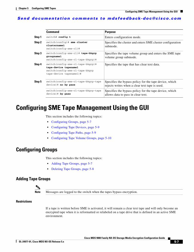
Send documenta t ion comments to mdsfeedback -doc@c i sco .com
Chapter 5 Configuring SME TapesConfiguring SME Tape Management Using the GUI
Configuring SME Tape Management Using the GUIThis section includes the following topics:
• Configuring Groups, page 5-7
• Configuring Tape Devices, page 5-9
• Configuring Tape Paths, page 5-9
• Configuring Tape Volume Groups, page 5-10
Configuring GroupsThis section includes the following topics:
• Adding Tape Groups, page 5-7
• Deleting Tape Groups, page 5-8
Adding Tape Groups
Note Messages are logged to the switch when the tapes bypass encryption.
Restrictions
If a tape is written before SME is activated, it will remain a clear text tape and will only become an encrypted tape when it is reformatted or relabeled on a tape drive that is defined in an active SME environment.
Command Purpose
Step 1 switch# config t Enters configuration mode.
Step 2 switch(config)# sme cluster clustername1switch(config-sme-cl)#
Specifies the cluster and enters SME cluster configuration submode.
Step 3 switch(config-sme-cl)# tape-bkgrp groupname1switch(config-sme-cl-tape-bkgrp)#
Specifies the tape volume group and enters the SME tape volume group submode.
Step 4 switch(config-sme-cl-tape-bkgrp)# tape-device tapename1switch(config-sme-cl-tape-bkgrp tape-device tapename1)#
Specifies the tape that has clear text data.
Step 5 switch(config-sme-cl-tape-bkgrp-tape device)# no by pass
Specifies the bypass policy for the tape device, which rejects writes when a clear text tape is used.
switch(config-sme-cl-tape-bkgrp-tape device)# by pass
Specifies the bypass policy for the tape device, which allows data to pass in clear text.
5-7Cisco MDS 9000 Family NX-OS Storage Media Encryption Configuration Guide
OL-24977-01, Cisco MDS NX-OS Release 5.x
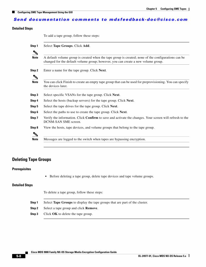
Send documenta t ion comments to mdsfeedback -doc@c i sco .com
Chapter 5 Configuring SME TapesConfiguring SME Tape Management Using the GUI
Detailed Steps
To add a tape group, follow these steps:
Step 1 Select Tape Groups. Click Add.
Note A default volume group is created when the tape group is created; none of the configurations can be changed for the default volume group; however, you can create a new volume group.
Step 2 Enter a name for the tape group. Click Next.
Note You can click Finish to create an empty tape group that can be used for preprovisioning. You can specify the devices later.
Step 3 Select specific VSANs for the tape group. Click Next.
Step 4 Select the hosts (backup servers) for the tape group. Click Next.
Step 5 Select the tape drives for the tape group. Click Next.
Step 6 Select the paths to use to create the tape group. Click Next.
Step 7 Verify the information. Click Confirm to save and activate the changes. Your screen will refresh to the DCNM-SAN SME screen.
Step 8 View the hosts, tape devices, and volume groups that belong to the tape group.
Note Messages are logged to the switch when tapes are bypassing encryption.
Deleting Tape Groups
Prerequisites
• Before deleting a tape group, delete tape devices and tape volume groups.
Detailed Steps
To delete a tape group, follow these steps:
Step 1 Select Tape Groups to display the tape groups that are part of the cluster.
Step 2 Select a tape group and click Remove.
Step 3 Click OK to delete the tape group.
5-8Cisco MDS 9000 Family NX-OS Storage Media Encryption Configuration Guide
OL-24977-01, Cisco MDS NX-OS Release 5.x
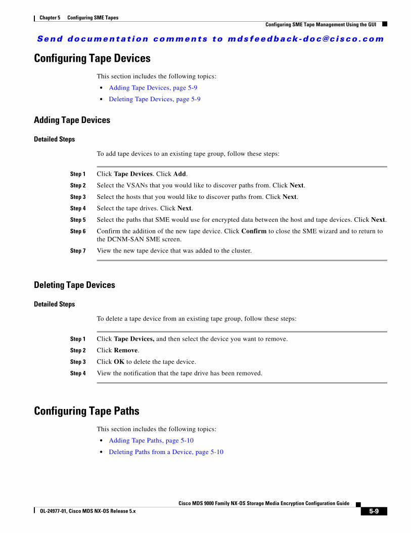
Send documenta t ion comments to mdsfeedback -doc@c i sco .com
Chapter 5 Configuring SME TapesConfiguring SME Tape Management Using the GUI
Configuring Tape DevicesThis section includes the following topics:
• Adding Tape Devices, page 5-9
• Deleting Tape Devices, page 5-9
Adding Tape Devices
Detailed Steps
To add tape devices to an existing tape group, follow these steps:
Step 1 Click Tape Devices. Click Add.
Step 2 Select the VSANs that you would like to discover paths from. Click Next.
Step 3 Select the hosts that you would like to discover paths from. Click Next.
Step 4 Select the tape drives. Click Next.
Step 5 Select the paths that SME would use for encrypted data between the host and tape devices. Click Next.
Step 6 Confirm the addition of the new tape device. Click Confirm to close the SME wizard and to return to the DCNM-SAN SME screen.
Step 7 View the new tape device that was added to the cluster.
Deleting Tape Devices
Detailed Steps
To delete a tape device from an existing tape group, follow these steps:
Step 1 Click Tape Devices, and then select the device you want to remove.
Step 2 Click Remove.
Step 3 Click OK to delete the tape device.
Step 4 View the notification that the tape drive has been removed.
Configuring Tape PathsThis section includes the following topics:
• Adding Tape Paths, page 5-10
• Deleting Paths from a Device, page 5-10
5-9Cisco MDS 9000 Family NX-OS Storage Media Encryption Configuration Guide
OL-24977-01, Cisco MDS NX-OS Release 5.x

Send documenta t ion comments to mdsfeedback -doc@c i sco .com
Chapter 5 Configuring SME TapesConfiguring SME Tape Management Using the GUI
Adding Tape Paths
Use the Tape Path Wizard to quickly add or modify tape paths between hosts and target backup devices.
Caution All IT-nexuses that host paths between the server and storage must be added to the configuration or else the data integrity is at risk.
Detailed Steps
To add a tape path to a tape device, follow these steps:
Step 1 Select a tape device.
Step 2 Click Add.
Step 3 Select the appropriate fabric and enter the VSAN, initiator and target WWNs, and the LUN. Click Next.
Step 4 Confirm the addition of the new tape path. Click Confirm to close the SME wizard and to return to the DCNM-SAN SME screen.
Deleting Paths from a Device
Detailed Steps
To delete a tape path from a device, follow these steps:
Step 1 Click a tape device name to display the tape device details and the paths.
Step 2 Select a tape path and click Remove.
Step 3 Click OK to delete the tape path and to view the tape path removed notification.
Configuring Tape Volume GroupsThis section includes the following topics:
• Adding Tape Volume Groups, page 5-10
• Deleting Tape Volume Groups, page 5-11
Adding Tape Volume Groups
Restrictions
• Overlapping ranges are not recommended. If there are overlapping ranges, then SME places the volume based on the lexicographic ordering of the volume group.
5-10Cisco MDS 9000 Family NX-OS Storage Media Encryption Configuration Guide
OL-24977-01, Cisco MDS NX-OS Release 5.x
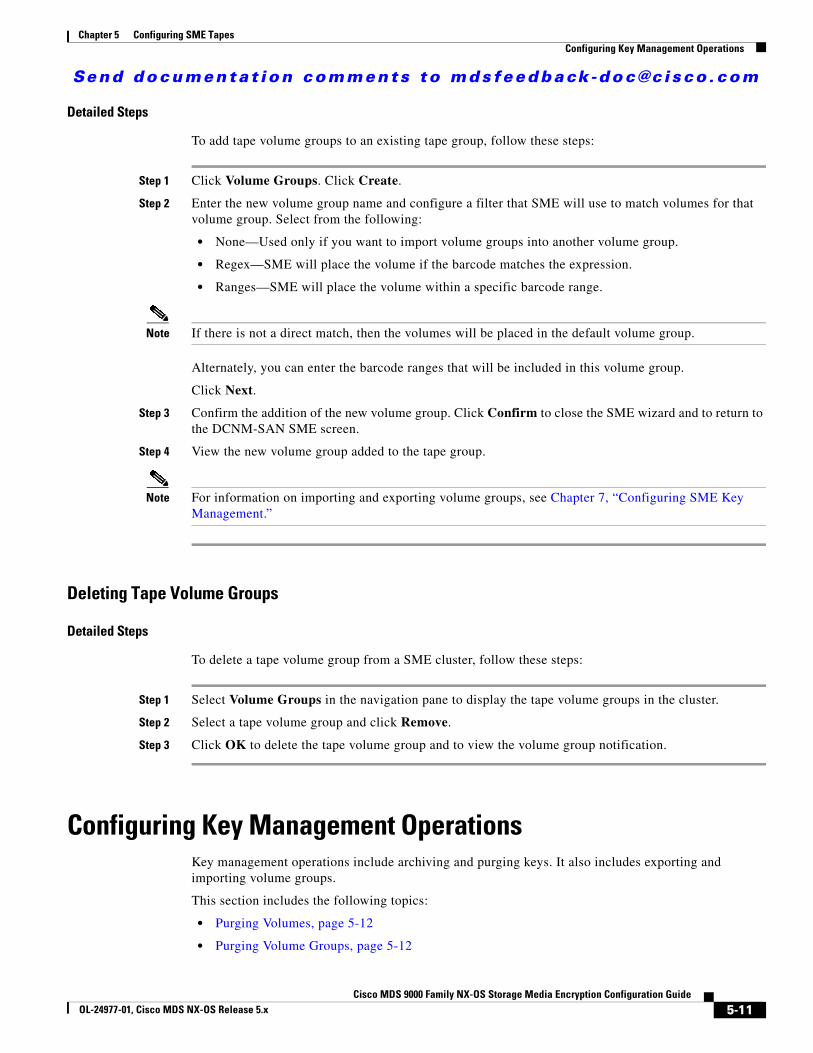
Send documenta t ion comments to mdsfeedback -doc@c i sco .com
Chapter 5 Configuring SME TapesConfiguring Key Management Operations
Detailed Steps
To add tape volume groups to an existing tape group, follow these steps:
Step 1 Click Volume Groups. Click Create.
Step 2 Enter the new volume group name and configure a filter that SME will use to match volumes for that volume group. Select from the following:
• None—Used only if you want to import volume groups into another volume group.
• Regex—SME will place the volume if the barcode matches the expression.
• Ranges—SME will place the volume within a specific barcode range.
Note If there is not a direct match, then the volumes will be placed in the default volume group.
Alternately, you can enter the barcode ranges that will be included in this volume group.
Click Next.
Step 3 Confirm the addition of the new volume group. Click Confirm to close the SME wizard and to return to the DCNM-SAN SME screen.
Step 4 View the new volume group added to the tape group.
Note For information on importing and exporting volume groups, see Chapter 7, “Configuring SME Key Management.”
Deleting Tape Volume Groups
Detailed Steps
To delete a tape volume group from a SME cluster, follow these steps:
Step 1 Select Volume Groups in the navigation pane to display the tape volume groups in the cluster.
Step 2 Select a tape volume group and click Remove.
Step 3 Click OK to delete the tape volume group and to view the volume group notification.
Configuring Key Management OperationsKey management operations include archiving and purging keys. It also includes exporting and importing volume groups.
This section includes the following topics:
• Purging Volumes, page 5-12
• Purging Volume Groups, page 5-12
5-11Cisco MDS 9000 Family NX-OS Storage Media Encryption Configuration Guide
OL-24977-01, Cisco MDS NX-OS Release 5.x
Send documenta t ion comments to mdsfeedback -doc@c i sco .com
Chapter 5 Configuring SME TapesConfiguring Key Management Operations
• Exporting Volume Groups, page 5-13
• Importing Volume Groups, page 5-13
• Rekeying Tape Volume Groups, page 5-14
• Auto Replicating Tape Media Keys, page 5-14
• Using Basic Security Mode for Master Key Download, page 5-15
• Replacing Smart Cards, page 5-16
• Exporting Volume Groups From Deactivated Clusters, page 5-17
• Migrating KMC Server, page 5-19
Purging VolumesPurging keys deletes deactivated or active keys from the Cisco KMC. You can delete the deactivated volume group, which purges all keys. If you delete an active volume group, all the keys are deactivated.
Purging keys at the volume level in unique key mode allows you to purge specific volumes.
Restrictions
• Purging keys from the Cisco KMC cannot be undone.
Detailed Steps
To purge keys that are currently active or deactivated, follow these steps:
Step 1 Select a volume group and click Active or Deactivated to view the keys that are deactivated in the Cisco KMC.
Step 2 Select the deactivated keys that you want to purge.
Step 3 Click Remove.
Purging Volume Groups
Detailed Steps
To purge a volume group, follow these steps:
Step 1 Select a deactivated volume group and click Remove.
Step 2 Click Confirm.
5-12Cisco MDS 9000 Family NX-OS Storage Media Encryption Configuration Guide
OL-24977-01, Cisco MDS NX-OS Release 5.x

Send documenta t ion comments to mdsfeedback -doc@c i sco .com
Chapter 5 Configuring SME TapesConfiguring Key Management Operations
Exporting Volume GroupsExporting tape volume groups can be advantageous when tapes are moved to a different cluster. In that scenario, you will need the keys if you have to restore those tapes. If the source cluster is online, follow the steps in this section.
Detailed Steps
To export volume groups from an online cluster, follow these steps:
Step 1 Select a volume group to display the volume groups in the cluster.
Step 2 Select a volume group.
Step 3 Click Export.
Step 4 Enter the volume group file password. Click Next.
Step 5 Click Download to download the volume group file.
Step 6 A dialog box appears asking you if you want to save this file. Save the .dat file.
Note The exported volume group file can be used by the Offline Data Restore Tool (ODRT) software to convert the SME encrypted tape back to clear-text when the SME line card or the Cisco MDS switch is unavailable.
Importing Volume GroupsYou can import a previously exported volume group file into a selected volume group.
Detailed Steps
To import a volume group file, follow these steps:
Step 1 Select Volume Groups in the navigation pane to display the volume groups in the cluster.
Step 2 Select a volume group and click Import.
Note You must select an existing volume group. To import into a new volume group, create the volume group first, and then import a volume group.
5-13Cisco MDS 9000 Family NX-OS Storage Media Encryption Configuration Guide
OL-24977-01, Cisco MDS NX-OS Release 5.x
Send documenta t ion comments to mdsfeedback -doc@c i sco .com
Chapter 5 Configuring SME TapesConfiguring Key Management Operations
Step 3 Browse and locate the file to import. Enter the password that was assigned to encrypt the file. Click Next.
Step 4 Select the volume group .dat file. Click Open.
Step 5 Click Confirm to begin the import process or click Back to choose another volume group file.
Note The imported keys in tape volume groups are read-only by default. However, if the entry “sme.retain.imported.key.state=true” is set in the conf/smeserver.properties file and the DCNM-SAN is restarted, the state of the imported keys are retained and both read and write operations can be performed.
Rekeying Tape Volume GroupsTape volume groups can be rekeyed periodically to ensure better security and also when the key security has been compromised.
In the unique key mode, the rekey operation generates a new tape volume group wrap key. The current tape volume group wrap key is archived. The current media keys remain unchanged, and the new media keys are wrapped with the new tape volume group wrap key.
In the shared key mode, the rekey operation generates a new tape volume group wrap key and a new tape volume group shared key. The current tape volume group wrap key is archived while the current tape volume group shared key remain unchanged (in active state).
The volume groups can be rekeyed monthly even if you do not use the unique key mode.
Detailed Steps
To rekey tape volume groups, follow these steps:
Step 1 In the DCNM-SAN Web Client navigation pane, select Volume Groups to display the volume groups in the cluster.
Step 2 Select one or more volume groups.
Step 3 Click Rekey. A confirmation dialog box is displayed asking if the rekey operation is to be performed. Click OK to rekey the selected volume groups.
Auto Replicating Tape Media KeysThis section describes how to auto replicate the media keys in the DCNM-SAN Web Client. The following topics are covered:
• Creating Tape Key Replication Relationships, page 5-15
• Removing Tape Key Replication Relationships, page 5-15
5-14Cisco MDS 9000 Family NX-OS Storage Media Encryption Configuration Guide
OL-24977-01, Cisco MDS NX-OS Release 5.x
Send documenta t ion comments to mdsfeedback -doc@c i sco .com
Chapter 5 Configuring SME TapesConfiguring Key Management Operations
Creating Tape Key Replication Relationships
Detailed Steps
To auto replicate the tape media keys, follow these steps:
Step 1 In the DCNM-SAN Web Client, click the SME tab.
Step 2 Select Clusters in the navigation pane to display the clusters.
Step 3 Select a cluster and select Tape Key Replication. The Tape Key Replication Relationships pane appears.
Step 4 Click Create to create a tape key replication relationship. A Create Replication Relationship area appears where the source cluster and the destination clusters are displayed.
Step 5 Select the clusters to expand or collapse the list of the Source Volume Group and the Destination Volume Group. Choose tape groups from the Source Volume Group and the Destination Volume Group to create a tape key replication relationship context.
Step 6 Click Submit to save the settings. A notification window appears to indicate the creation of the tape key replication relationship and the replication status shows as Created.
Removing Tape Key Replication Relationships
Detailed Steps
To remove a tape key replication relationship, follow these steps:
Step 1 Click Clusters in the navigation pane to display the clusters and select Tape Key Replication. The Tape Key Replication Relationships area appears on the right-hand pane.
Step 2 Select the tape group whose replication relationship needs to be removed. Click Remove.
Step 3 A confirmation dialog box is displayed asking if the relationship needs to be removed. Click OK to remove the replication relationship of the selected volume groups.
Step 4 A notification window appears that indicates the removal of the tape key replication relationship.
Using Basic Security Mode for Master Key DownloadIn Basic security mode, the master key file can be downloaded multiple times from the DCNM-SAN Web Client. The cluster detail view includes a button to download the master key file.
Detailed Steps
To download the master key file (Basic security mode), follow these steps:
Step 1 Select a cluster name in the navigation pane to view the cluster details.
Step 2 Click the Download Keyfile button to download the master key file.
5-15Cisco MDS 9000 Family NX-OS Storage Media Encryption Configuration Guide
OL-24977-01, Cisco MDS NX-OS Release 5.x
Send documenta t ion comments to mdsfeedback -doc@c i sco .com
Chapter 5 Configuring SME TapesConfiguring Key Management Operations
Step 3 Enter the password to protect the master key file. Confirm the password. Click Download to begin downloading the encrypted file.
Step 4 Click Close to close the wizard.
Step 5 You will be asked if you want to open or save the file. Click Save to save the downloaded master key file.
Replacing Smart CardsThis section describes how to replace smart cards for clusters in the following modes:
• Replacing Smart Cards Using Standard Mode, page 5-16
• Replacing Smart Cards Using Advanced Mode, page 5-16
Replacing Smart Cards Using Standard Mode
In Standard security mode, the master key can be downloaded to a replacement smart card from the DCNM-SAN Web Client.
Detailed Steps
To replace a smart card (Standard security mode), follow these steps:
Step 1 Select Smartcards to display the smart card information for the cluster.
Step 2 Click Replace to launch the smart card replacement wizard. Click Next.
Step 3 Insert the smart card and enter the Password, PIN, and Label for the smart card. Click Next.
Step 4 Click Finish to close the wizard.
Replacing Smart Cards Using Advanced Mode
Note In SME Disk cluster, replacing smart cards does not rewrap disk keys. This feature will be supported in a future release.
Detailed Steps
To replace a smart card (Advanced security mode), follow these steps:
Step 1 Select Smartcards to display the smart card information for the cluster.
Step 2 Select the smart card that you want to replace. Click Replace to launch the smart card replacement wizard.
Step 3 Insert the new smart card. Click Next.
5-16Cisco MDS 9000 Family NX-OS Storage Media Encryption Configuration Guide
OL-24977-01, Cisco MDS NX-OS Release 5.x
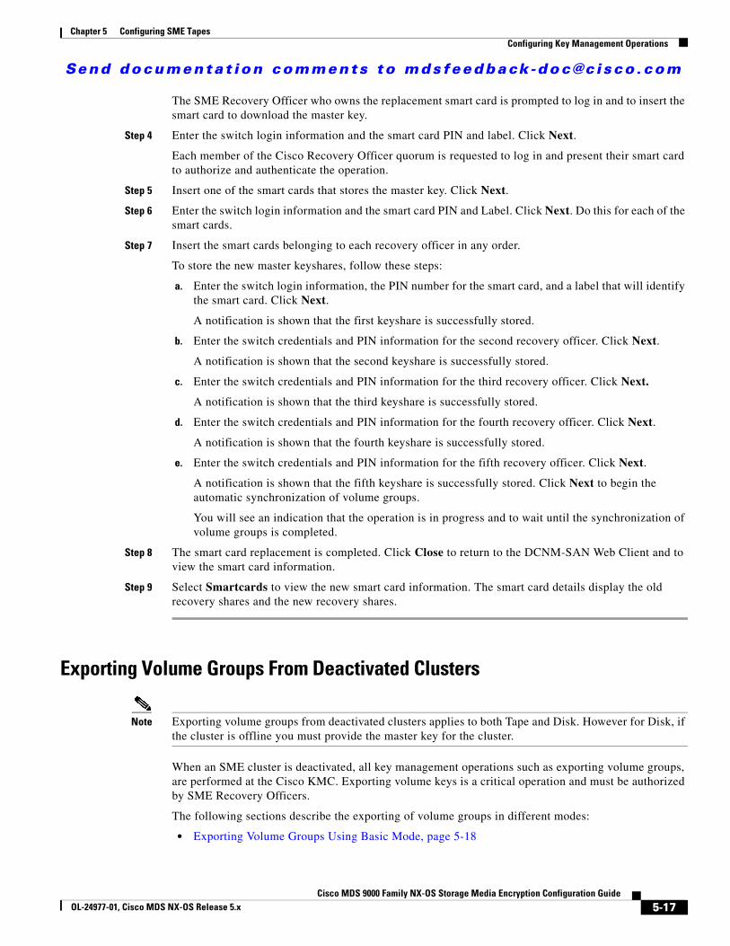
Send documenta t ion comments to mdsfeedback -doc@c i sco .com
Chapter 5 Configuring SME TapesConfiguring Key Management Operations
The SME Recovery Officer who owns the replacement smart card is prompted to log in and to insert the smart card to download the master key.
Step 4 Enter the switch login information and the smart card PIN and label. Click Next.
Each member of the Cisco Recovery Officer quorum is requested to log in and present their smart card to authorize and authenticate the operation.
Step 5 Insert one of the smart cards that stores the master key. Click Next.
Step 6 Enter the switch login information and the smart card PIN and Label. Click Next. Do this for each of the smart cards.
Step 7 Insert the smart cards belonging to each recovery officer in any order.
To store the new master keyshares, follow these steps:
a. Enter the switch login information, the PIN number for the smart card, and a label that will identify the smart card. Click Next.
A notification is shown that the first keyshare is successfully stored.
b. Enter the switch credentials and PIN information for the second recovery officer. Click Next.
A notification is shown that the second keyshare is successfully stored.
c. Enter the switch credentials and PIN information for the third recovery officer. Click Next.
A notification is shown that the third keyshare is successfully stored.
d. Enter the switch credentials and PIN information for the fourth recovery officer. Click Next.
A notification is shown that the fourth keyshare is successfully stored.
e. Enter the switch credentials and PIN information for the fifth recovery officer. Click Next.
A notification is shown that the fifth keyshare is successfully stored. Click Next to begin the automatic synchronization of volume groups.
You will see an indication that the operation is in progress and to wait until the synchronization of volume groups is completed.
Step 8 The smart card replacement is completed. Click Close to return to the DCNM-SAN Web Client and to view the smart card information.
Step 9 Select Smartcards to view the new smart card information. The smart card details display the old recovery shares and the new recovery shares.
Exporting Volume Groups From Deactivated Clusters
Note Exporting volume groups from deactivated clusters applies to both Tape and Disk. However for Disk, if the cluster is offline you must provide the master key for the cluster.
When an SME cluster is deactivated, all key management operations such as exporting volume groups, are performed at the Cisco KMC. Exporting volume keys is a critical operation and must be authorized by SME Recovery Officers.
The following sections describe the exporting of volume groups in different modes:
• Exporting Volume Groups Using Basic Mode, page 5-18
5-17Cisco MDS 9000 Family NX-OS Storage Media Encryption Configuration Guide
OL-24977-01, Cisco MDS NX-OS Release 5.x

Send documenta t ion comments to mdsfeedback -doc@c i sco .com
Chapter 5 Configuring SME TapesConfiguring Key Management Operations
• Exporting Volume Groups Using Standard Mode, page 5-18
• Exporting Volume Groups Using Advanced Mode, page 5-18
Exporting Volume Groups Using Basic Mode
Detailed Steps
To export a volume group from a deactivated cluster (Basic security mode), follow these steps:
Step 1 Select a volume group to display the volume groups in the cluster. Click Export.
Step 2 Click Browse to locate the volume group master key file.
Step 3 Select the master key file. Click Open.
Step 4 Enter the password that protects the master key for the archived volume group. Click Next.
Step 5 Enter the password that will be used to encrypt the exported file. Confirm the password and click Next.
Step 6 Click Download to begin downloading the volume group file.
Step 7 You will be asked if you want to open or save the file. To save the exported volume group, click Save.
Exporting Volume Groups Using Standard Mode
Detailed Steps
To export a volume group from a deactivated cluster (Standard security mode), follow these steps:
Step 1 Select Volume Groups (in a deactivated cluster) to display the volume groups in the cluster. Select a volume group and click Export.
Step 2 Insert one of the five smart cards into the smart card reader. Click Next.
Step 3 Enter the smart card Label and PIN. Click Next.
Step 4 Enter the password to encrypt the volume group file. Confirm the password and click Next.
Step 5 Click Download to begin downloading the file.
Step 6 You will be asked if you want to open or save the file. To save the file, click Save.
Exporting Volume Groups Using Advanced Mode
Detailed Steps
To export a volume group from a deactivated cluster (Advanced security mode), follow these steps:
Step 1 Select Volume Groups (in a deactivated cluster) to display the volume groups in the cluster. Select a volume group and click Export.
Step 2 Insert one of the five smart cards into the smart card reader. Click Next.
5-18Cisco MDS 9000 Family NX-OS Storage Media Encryption Configuration Guide
OL-24977-01, Cisco MDS NX-OS Release 5.x
Send documenta t ion comments to mdsfeedback -doc@c i sco .com
Chapter 5 Configuring SME TapesConfiguring Key Management Operations
Step 3 Enter the smart card Label and PIN. Click Next.
The keyshare is retrieved.
Step 4 Insert the next smart card into the smart card reader. Click Next.
Note Repeat this step for each smart card that is required to unlock the master key. The number of required smart cards depends on the quorum number selected during the cluster creation, for example, two of five smart cards.
Step 5 Enter the smart card Label and PIN. Click Next.
Step 6 Enter the volume group file password. Confirm the password and click Next.
Step 7 Click Download to begin downloading the volume group.
Step 8 You will be asked if you want to open or save the file. Click Save to save the .dat file.
Migrating KMC Server
Prerequisites
If the KMC server is integrated with RSA Key Manager, both the KMC and RSA Key Manager must be synchronized. If a KMC server is removed to purge all the keys, follow the required procedures to purge all the keys first before you uninstall the KMC server. This ensures that the keys in the RSA Key Manager are also purged.
Restrictions
The migrating of the KMC server is only applicable for SME Tape. For SME Disk, there is no RSA key manager support.
Detailed Steps
To migrate a KMC server, follow these steps:
Step 1 Migrate all keys to the new KMC server. Refer to the backup and restore procedures outlined in Appendix O, “Database Backup and Restore Operations.”
Step 2 After restoring the database, install DCNM-SAN in the new KMC server and point the DCNM-SAN to the database. This ensures that all the keys are maintained across the KMC migration.
Step 3 Update the cluster with the new KMC server details when the new KMC server is active.
a. Go to the DCNM-SAN Web Client and click the SME tab.
b. Select the cluster. The cluster details page displays.
c. Click Modify and choose the new KMC server.
If the KMC server is integrated with RSA Key Manager, modify the settings and select the RKM server.
5-19Cisco MDS 9000 Family NX-OS Storage Media Encryption Configuration Guide
OL-24977-01, Cisco MDS NX-OS Release 5.x

Send documenta t ion comments to mdsfeedback -doc@c i sco .com
Chapter 5 Configuring SME TapesVerifying SME Tape Management Configuration
Step 4 Uninstall the DCNM-SAN server instance of the previous KMC server. This removes the previous KMC server.
Verifying SME Tape Management ConfigurationTo display SME Tape management configuration information, perform one of the following tasks:
For detailed information about the fields in the output from these commands, refer to the Cisco MDS 9000 Family NX-OS Command Reference.
Monitoring SME Tape ManagementThis section includes the following topics:
• Viewing Host Details, page 5-20
• Viewing Tape Device Details, page 5-20
• Viewing SME Tape Information Using the CLI, page 5-21
Viewing Host DetailsYou can view detailed information about hosts in a SME cluster. Information for a specific host includes the tape group membership, paths from the host to the target, VSAN, fabric, status, and the tape device.
To view the host details, select a host in the navigation pane.
Viewing Tape Device DetailsYou can view detailed information about tape devices in a SME cluster. Information for a specific tape device includes the tape group membership, device description, serial number, and the host and target PWWN.
To view the tape device details, select a tape device in the navigation pane.
Command Purpose
show sme cluster tape Displays summary or detailed information about tapes.
show sme cluster tape detail Displays information about tape cartridges.
show sme cluster tape-bkgrp Displays information about all tape volume groups or about a specific group.
5-20Cisco MDS 9000 Family NX-OS Storage Media Encryption Configuration Guide
OL-24977-01, Cisco MDS NX-OS Release 5.x
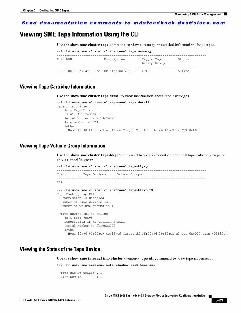
Send documenta t ion comments to mdsfeedback -doc@c i sco .com
Chapter 5 Configuring SME TapesMonitoring SME Tape Management
Viewing SME Tape Information Using the CLIUse the show sme cluster tape command to view summary or detailed information about tapes.
switch# show sme cluster clustername1 tape summary -------------------------------------------------------------------------------Host WWN Description Crypto-Tape Status Backup Group-------------------------------------------------------------------------------10:00:00:00:c9:4e:19:ed HP Ultrium 2-SCSI HR1 online
Viewing Tape Cartridge Information
Use the show sme cluster tape detail to view information about tape cartridges.
switch# show sme cluster clustername1 tape detail Tape 1 is online Is a Tape Drive HP Ultrium 2-SCSI Serial Number is 2b10c2e22f Is a member of HR1 Paths Host 10:00:00:00:c9:4e:19:ed Target 2f:ff:00:06:2b:10:c2:e2 LUN 0x0000
Viewing Tape Volume Group Information
Use the show sme cluster tape-bkgrp command to view information about all tape volume groups or about a specific group.
switch# show sme cluster clustername1 tape-bkgrp -------------------------------------------------------------------------------Name Tape Devices Volume Groups-------------------------------------------------------------------------------HR1 1 1
switch# show sme cluster clustername1 tape-bkgrp HR1 Tape Backupgroup HR1 Compression is Disabled Number of tape devices is 1 Number of volume groups is 1
Tape device td1 is online Is a tape drive Description is HP Ultrium 2-SCSI Serial number is 2b10c2e22f Paths Host 10:00:00:00:c9:4e:19:ed Target 2f:ff:00:06:2b:10:c2:e2 Lun 0x0000 vsan 4093[f1]
Viewing the Status of the Tape Device
Use the show sme internal info cluster <cname> tape-all command to view tape information.
SWitch# show sme internal info cluster tie1 tape-all
Tape Backup Groups : 1 Last Seq Id : 1
5-21Cisco MDS 9000 Family NX-OS Storage Media Encryption Configuration Guide
OL-24977-01, Cisco MDS NX-OS Release 5.x
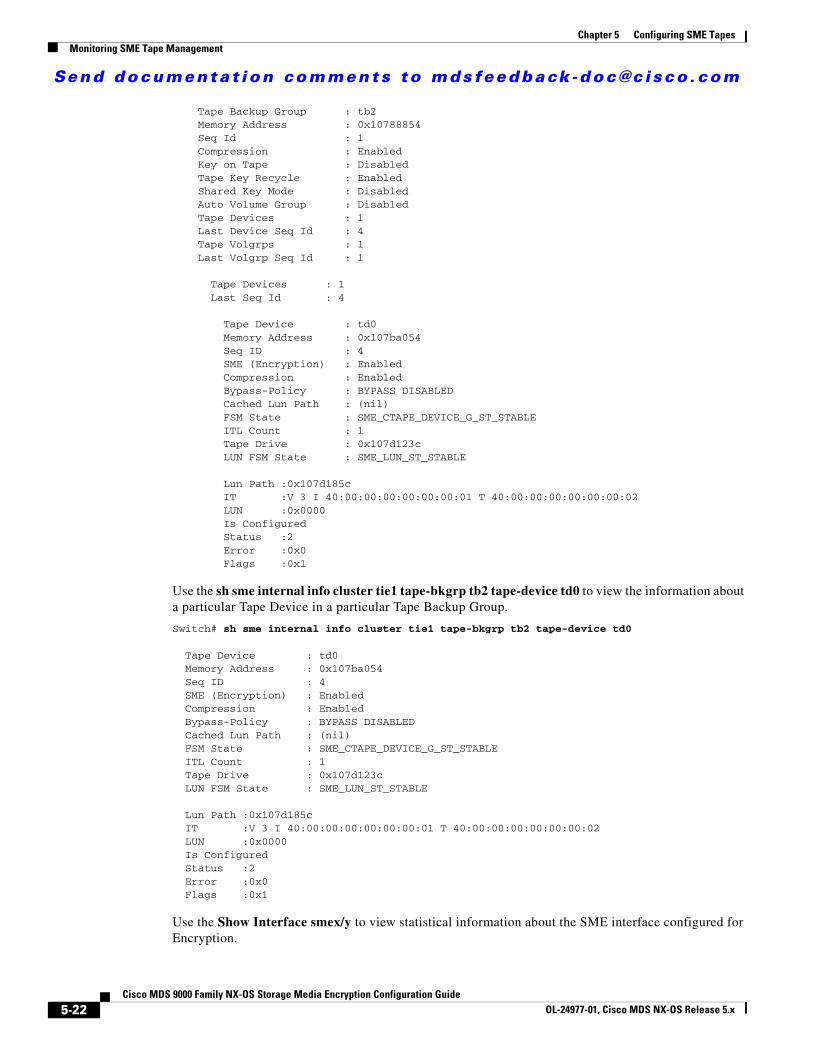
Send documenta t ion comments to mdsfeedback -doc@c i sco .com
Chapter 5 Configuring SME TapesMonitoring SME Tape Management
Tape Backup Group : tb2 Memory Address : 0x10788854 Seq Id : 1 Compression : Enabled Key on Tape : Disabled Tape Key Recycle : Enabled Shared Key Mode : Disabled Auto Volume Group : Disabled Tape Devices : 1 Last Device Seq Id : 4 Tape Volgrps : 1 Last Volgrp Seq Id : 1
Tape Devices : 1 Last Seq Id : 4
Tape Device : td0 Memory Address : 0x107ba054 Seq ID : 4 SME (Encryption) : Enabled Compression : Enabled Bypass-Policy : BYPASS DISABLED Cached Lun Path : (nil) FSM State : SME_CTAPE_DEVICE_G_ST_STABLE ITL Count : 1 Tape Drive : 0x107d123c LUN FSM State : SME_LUN_ST_STABLE
Lun Path :0x107d185c IT :V 3 I 40:00:00:00:00:00:00:01 T 40:00:00:00:00:00:00:02 LUN :0x0000 Is Configured Status :2 Error :0x0 Flags :0x1
Use the sh sme internal info cluster tie1 tape-bkgrp tb2 tape-device td0 to view the information about a particular Tape Device in a particular Tape Backup Group.
Switch# sh sme internal info cluster tie1 tape-bkgrp tb2 tape-device td0
Tape Device : td0 Memory Address : 0x107ba054 Seq ID : 4 SME (Encryption) : Enabled Compression : Enabled Bypass-Policy : BYPASS DISABLED Cached Lun Path : (nil) FSM State : SME_CTAPE_DEVICE_G_ST_STABLE ITL Count : 1 Tape Drive : 0x107d123c LUN FSM State : SME_LUN_ST_STABLE
Lun Path :0x107d185c IT :V 3 I 40:00:00:00:00:00:00:01 T 40:00:00:00:00:00:00:02 LUN :0x0000 Is Configured Status :2 Error :0x0 Flags :0x1
Use the Show Interface smex/y to view statistical information about the SME interface configured for Encryption.
5-22Cisco MDS 9000 Family NX-OS Storage Media Encryption Configuration Guide
OL-24977-01, Cisco MDS NX-OS Release 5.x
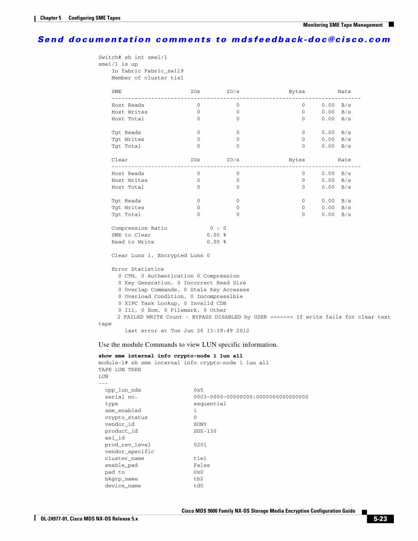
Send documenta t ion comments to mdsfeedback -doc@c i sco .com
Chapter 5 Configuring SME TapesMonitoring SME Tape Management
Switch# sh int sme1/1sme1/1 is up In fabric Fabric_sw119 Member of cluster tie1
SME IOs IO/s Bytes Rate ---------------------------------------------------------------------------- Host Reads 0 0 0 0.00 B/s Host Writes 0 0 0 0.00 B/s Host Total 0 0 0 0.00 B/s
Tgt Reads 0 0 0 0.00 B/s Tgt Writes 0 0 0 0.00 B/s Tgt Total 0 0 0 0.00 B/s
Clear IOs IO/s Bytes Rate ---------------------------------------------------------------------------- Host Reads 0 0 0 0.00 B/s Host Writes 0 0 0 0.00 B/s Host Total 0 0 0 0.00 B/s
Tgt Reads 0 0 0 0.00 B/s Tgt Writes 0 0 0 0.00 B/s Tgt Total 0 0 0 0.00 B/s
Compression Ratio 0 : 0 SME to Clear 0.00 % Read to Write 0.00 %
Clear Luns 1, Encrypted Luns 0
Error Statistics 0 CTH, 0 Authentication 0 Compression 0 Key Generation, 0 Incorrect Read Size 0 Overlap Commands, 0 Stale Key Accesses 0 Overload Condition, 0 Incompressible 0 XIPC Task Lookup, 0 Invalid CDB 0 Ili, 0 Eom, 0 Filemark, 0 Other 2 FAILED WRITE Count - BYPASS DISABLED by USER ======> If write fails for clear text tape last error at Tue Jun 26 13:39:49 2012
Use the module Commands to view LUN specific information.
show sme internal info crypto-node 1 lun allmodule-1# sh sme internal info crypto-node 1 lun allTAPE LUN TREELUN--- cpp_lun_ndx 0x5 serial no. 0003-0000-00000000:0000000000000000 type sequential sme_enabled 1 crypto_status 0 vendor_id SONY product_id SDZ-130 asl_id prod_rev_level 0201 vendor_specific cluster_name tie1 enable_pad False pad to 0x0 bkgrp_name tb2 device_name td0
5-23Cisco MDS 9000 Family NX-OS Storage Media Encryption Configuration Guide
OL-24977-01, Cisco MDS NX-OS Release 5.x

Send documenta t ion comments to mdsfeedback -doc@c i sco .com
Chapter 5 Configuring SME TapesFeature History for SME Tape Management
flags 0 granularity 2 max_block_len_lim 1000 min_block_len_lim 4 block_length 512 compression 1 key_ontape 0 Bypass_Policy BYPASS DISABLED has tape yes position 200 has cth no bypass enc no wrap guid 0000000000000000-0000000000000000 media guid 0000000000000000-0000000000000000 total itl count 1 active itl count 1 cmd_send_err 0 Not locked
Feature History for SME Tape ManagementTable 5-1 lists the release history for this feature.
Table 5-1 Feature History for SME Tape Configuration
Feature Name Releases Feature Information
Added a new SME tape command 5.2(6) Added a new SME tape command.
Software change 5.2(1) In Release 5.2(1), Fabric Manager is changed to DCNM for SAN (DCNM-SAN).
4.1(1c) In Release 4.1(1b) and later, the MDS SAN-OS software is changed to MDS NX-OS software. The earlier releases are unchanged and all refrerences are retained.
5-24Cisco MDS 9000 Family NX-OS Storage Media Encryption Configuration Guide
OL-24977-01, Cisco MDS NX-OS Release 5.x
Send documenta t ion comments to mdsfeedback -doc@c i sco .com
Cisco MDS 9000 Family NXOL-24977-01, Cisco MDS NX-OS Release 5.x
C H A P T E R 6
Configuring SME DisksThis chapter contains information about managing disks using SME, referred to as SME Disk management.
Note Read all of the Cautions carefully while configuring SME Disks.
This chapter includes the following topics:
• Information About SME Disk Management, page 6-1
• Guidelines and Limitations for DKR, page 6-13
• Configuring SME Disk Management Using the CLI, page 6-16
• Configuring SME Disk Management Using the GUI, page 6-29
• Verifying the SME Disk Management Configuration, page 6-57
• Monitoring SME Disk Management, page 6-59
Information About SME Disk ManagementSME Disk management includes the following topics:
• SME Disk Architecture, page 6-2
• Replication, page 6-3
• Snapshot, page 6-4
• Managing Replication with SME, page 6-4
• Managing Snapshots in SME, page 6-5
• Data Preparation, page 6-6
• Rekeying, page 6-8
• Replacing an SME Enabled MDS Switch, page 6-9
• SME Disk Key Management, page 6-9
• Cisco KMC, page 6-10
• Data Replication, page 6-12
• SME Disk Key Replication, page 6-12
• ISSU with SME Disk, page 6-15
6-1-OS Storage Media Encryption Configuration Guide
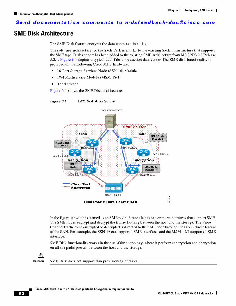
Send documenta t ion comments to mdsfeedback -doc@c i sco .com
Chapter 6 Configuring SME DisksInformation About SME Disk Management
SME Disk ArchitectureThe SME Disk feature encrypts the data contained in a disk.
The software architecture for the SME Disk is similar to the existing SME infrastructure that supports the SME tape. Disk support has been added to the existing SME architecture from MDS NX-OS Release 5.2.1. Figure 6-1 depicts a typical dual-fabric production data center. The SME disk functionality is provided on the following Cisco MDS hardware:
• 16-Port Storage Services Node (SSN-16) Module
• 18/4 Multiservice Module (MSM-18/4)
• 9222i Switch
Figure 6-1 shows the SME Disk architecture.
Figure 6-1 SME Disk Architecture
In the figure, a switch is termed as an SME node. A module has one or more interfaces that support SME. The SME nodes encrypt and decrypt the traffic flowing between the host and the storage. The Fibre Channel traffic to be encrypted or decrypted is directed to the SME node through the FC-Redirect feature of the SAN. For example, the SSN-16 can support 4 SME interfaces and the MSM-18/4 supports 1 SME interface.
SME Disk functionality works in the dual-fabric topology, where it performs encryption and decryption on all the paths present between the host and the storage.
Caution SME Disk does not support thin provisioning of disks.
6-2Cisco MDS 9000 Family NX-OS Storage Media Encryption Configuration Guide
OL-24977-01, Cisco MDS NX-OS Release 5.x
Send documenta t ion comments to mdsfeedback -doc@c i sco .com
Chapter 6 Configuring SME DisksInformation About SME Disk Management
SME Disk needs to manage all the paths to the disk in both the fabrics. An SME cluster provides this functionality. An SME cluster consists of a collection of SME nodes. Any SME node that fails in a cluster triggers another node in the same cluster to take control of the encryption and/or decryption activity.
The disk on which the SME Disk provides the encryption and/or decryption functionality can be the one without any existing data or the one with existing data. If the disk has existing data, the existing data needs to be encrypted. The process of converting the existing clear data to encrypted data is termed as data preparation.
Data preparation can be performed in offline mode. In the offline data preparation mode, the application on the host accessing the disk is quiesced and no I/Os are sent to the disk. SME Disk functionality also ensures that if any host tries to read or write the data from or into the disk, the particular I/O is failed back to the host.
In the Online Mode, the application on the host can continue to perform I/O on the disk while SME is converting the existing data on the disk from clear text to encrypted text.
The disk is uniquely identified in configuration by the cluster name, disk group name, and disk name.
For the purpose of encryption or decryption, the SME Disk requires encryption keys. For every encrypted disk, a key is generated. The SME’s existing Key Management Center (KMC) infrastructure is used for SME disk key management. Keys for each disk are generated by the Storage Media Encryption coprocessor and are stored in the SME Key Management Center.
Caution SME Disk does not allow dynamic resizing of LUN.
For Release 5.2.1, the maximum supported disk size is one block less than two terabyte (TB). The maximum LBA is 0xFFFFFFFE.
From Release 5.2.6, the supported disk size for signature and nonsignature mode clusters is greater than two TB.
SME Disk only supports disk block size of 512 bytes.
For Release 5.2.1, SME Disk does not support online conversion of existing clear data on the disk to encrypted data.
ReplicationThere are two kinds of replication:
• Mirrors or Clones—When the data for the source disk is duplicated by the disk array into another disk in the same storage system, the destination disk is called a mirror or clone of the source disk. This is called local replication.
• Remote Replication—When the data for the source disk is being duplicated by the disk array into another disk in a remote storage system, then the source disk and the remote disk are in a replication relationship. Based on the distance and bandwidth availability between local and the remote site, remote replication is categorised under the following types:
– Synchronous—The local disk array does not respond to the write command on the local LUN until the data is also written to the remote LUN.
6-3Cisco MDS 9000 Family NX-OS Storage Media Encryption Configuration Guide
OL-24977-01, Cisco MDS NX-OS Release 5.x
Send documenta t ion comments to mdsfeedback -doc@c i sco .com
Chapter 6 Configuring SME DisksInformation About SME Disk Management
– Asynchronous—The local disk array does not immediately write the data to the remote LUN. The changes to the local LUN are batched into a delta dataset and periodically sent to the remote LUN.
SnapshotSnapshots are point-in-time copies that can be created instantly for a source disk. Once a snapshot is created any writes to the source disk will result in the previous data to be saved elsewhere before modification. This allows the disk array to present a specific point-in-time copy of the data of the source disk.
Managing Replication with SME SME supports replication through Disk key replication (DKR). DKR simplifies the key management of the source and destination disk by automating the propagation of the source disk key to destination disk. SME Disk Clusters are of two modes:
• Non-signature cluster
• Signature cluster
Replication management is the same for both the cluster modes. Replication management consists of following steps:
• Extraction of replication relationship using array vendor specific technology. The output of this step results in identifying the source and destination disk relationship based on the SCSI properties of the vendor, product. and device identifiers.
• Importing the replication relationship information into SME through DKR using DCNM.
Note Ensure you manage all SME configuration operations on the disks in a DKR relationship through DCNM only.
Manage Key Change Operations in DCNM for DKR
Key change operations involve the following:
• No data preparation—Any local key changes will result in DKR suspending host access to the remote disk. Once the local key change is verified for data integrity and the data replication to the remote end is synchronized, the admin can select the corresponding relationship and perform the sync operation in DKR. This operation will synchronized the source and destination keys and resume the host access to the remote disk.
• Data preparation—Ensure you disable DKR relationship and the replication between the source and destination disk before you start data preparation on the source disk. This is a disk array vendor specific operation. Once you complete data preparation and have verified for data integrity, follow the procedure below:.
– Enable the data replication between the source and destination using disk array vendor specific operation.
– Once data is synchronized between the source and destination disk, enable the DKR relationship. This operation will synchronize the source and estination keys.
6-4Cisco MDS 9000 Family NX-OS Storage Media Encryption Configuration Guide
OL-24977-01, Cisco MDS NX-OS Release 5.x
Send documenta t ion comments to mdsfeedback -doc@c i sco .com
Chapter 6 Configuring SME DisksInformation About SME Disk Management
Note Host access on the destination disk should be quiesced until the above two steps are completed.
Managing Snapshots in SMEThis section describes how to manage snapshots of crypto disks. Snapshot management is different for signature and non-signature clusters.
To manage crypto snapshots that are discovered by a same host through the same SME cluster as the source disk, then follow the below procedure:
Step 1 Start a discovery in SME for configuring the snapshot disks.
Step 2 If SME finds a valid SME metadata on the disk media with no corresponding active key in the Key management center (KMC) then the disk is put in a failed state by SME.
Step 3 The administrator has the option to recover the disk using recovery from- metadata option.
Step 4 Once the above recovery is performed, the snapshot comes up as a crypto disk and it can be accessed by the host.
To manage snapshots that are being discovered by a different host through a differnt SME cluster from the source, use DKR and follow the below procedure:
Step 1 tart a discovery in SME for configuring the snapshot disks.
Step 2 Once the snapshot disks are configured into SME, create a DKR relationship between the source and snapshot disk.
Step 3 Enable the DKR relationship to synchronize the source and snapshot key.
Step 4 Destroy the DKR relationship between the source and snapshot.
Step 5 Host can now have access to the snapshot disk.
Note Ensure you destroy the DKR relationship between the source and snapshot after key synchronization. If the source key is rekeyed, it may result in data integrity issues on the snapshot.
Cluster Support
For Release 5.2.1, the switch can support up to two SME clusters. The following prerequisites must be met for supporting multiple clusters. If these prerequisites are not met data loss can occur.
• For SME disks, the SME cluster must be set as disk capable.
• SME Tape and SME Disk cannot co-exist in the same SME cluster. Use different clusters for SME Disk and SME Tape.
• Multiple SME clusters can be supported on the same MDS chassis with the following requirements :
– SME tape cluster node is on one Cisco MSM18/4 switching module.
6-5Cisco MDS 9000 Family NX-OS Storage Media Encryption Configuration Guide
OL-24977-01, Cisco MDS NX-OS Release 5.x
Send documenta t ion comments to mdsfeedback -doc@c i sco .com
Chapter 6 Configuring SME DisksInformation About SME Disk Management
– SME disk cluster node is on another Cisco MSM 18/4 switching module.
– For the SSN-16, SME Tape and Disk belong to different crypto nodes and belong to different clusters.
• Do not use the same target ports in different clusters.
• The same disk cannot be part of more than one SME cluster otherwise data loss occurs.
• Do not add the same SME interfaces in two different clusters.
From MDS Release 5.2(6), SME Disk can write a signature to the media to identify the disk as a crypto disk. These SME clusters are called signature clusters. Nonsignature clusters are SME Disks that do not write a signature on the media to identify crypto on the disk.
Data PreparationData preparation is a process that converts the clear data on the disk to encrypted data and vice versa. When the SME Disk feature is enabled on an existing disk containing clear data, the existing clear data needs to be converted to encrypted data. The process can be done in two ways:
• With the host accessing the data. This is called as the online data preparation mode.
• With the disk that is inaccessible to the host. This is called as the offline data preparation mode.
Note Only offline data preparation mode is supported.
When the SME Disk feature is enabled on a new disk that does not contain prior data, the host I/Os read/write is decrypted or encrypted using a key. This encryption process is transparent to the application. For these disks, the data preparation process is not required.
Note Ensure you do not change the cluster configuration while data preparation is under progress and do not remove node or add a new node while data preparation is in progress.
For disks requiring data preparation, the user must have backed up data before starting conversion of clear data to encrypted data.
In an SME cluster, there can be multiple SME nodes handling the ITLs associated with a particular crypto disk. The multiple SME nodes encrypt or decrypt data written to or read from the crypto disk. However, the responsibility of the data preparation or rekeying for a crypto disk is assigned to one SME node which is the data preparation node. The cluster master handles the data preparation node based on the following:
• LUN visibility (report LUN, INQ, and so on) or accessibility (reservations)
• Target port affinity
• Load factor of the SME nodes
For signature mode, when converting a clear disk to crypto disk, the administrator must ensure that the reserved space of 64 MB at the end of the disk is available on the SME disk.
Note Disk Key Replication (DKR) must be disabled when performing data preparation on the source disk.
6-6Cisco MDS 9000 Family NX-OS Storage Media Encryption Configuration Guide
OL-24977-01, Cisco MDS NX-OS Release 5.x

Send documenta t ion comments to mdsfeedback -doc@c i sco .com
Chapter 6 Configuring SME DisksInformation About SME Disk Management
Recovering SME Disk when Data Preparation FailsWhen data preparation fails, SME Disk puts the disk in a failed state. The disk is not accessible to hosts and all paths of the disk are put in I/O reject state ( reject all host I/Os state). To recover the disk from the failed state, follow these steps:
Step 1 Because the disk is not accessible from the host, restore the contents of the failed disk on the backend storage.
Step 2 Enter the recover command with appropriate arguments to recover the disk to the proper crypto state based on the backup data. For more information on the recover command syntax using CLI, see “Recovering the SME Disk” section on page 6-27 and through the GUI, see “Recovering SME Disks” section on page 6-41.
In the Signature mode, the disk can be recovered by using the signature information on the media.
Offline Data Preparation
Offline data preparation is performed when the applications running on the host is not accessing data from the disk that is undergoing data preparation.
Figure 6-2 shows the SME Disk offline data preparation architecture.
Figure 6-2 SME Disk Offline Data Preparation Architecture
The offline data preparation involves the following actions:
• Quiescing the host applications by stopping the host I/O traffic.
6-7Cisco MDS 9000 Family NX-OS Storage Media Encryption Configuration Guide
OL-24977-01, Cisco MDS NX-OS Release 5.x
Send documenta t ion comments to mdsfeedback -doc@c i sco .com
Chapter 6 Configuring SME DisksInformation About SME Disk Management
• Backing up the clear data in the targeted disk. The backup can be to another disk or to an external tape. This backup is used to recover from errors.
• Server I/Os during the duration of the offline data preparation are rejected by the SME node.
Caution While host I/Os are blocked the host paths must be online during offline data preparation since the identity of the host port is used by the crypto engine. All DKR relationships that involves disk must be in disable state. Disk Key Replication (DKR) is used to manage remote replication relationships. For more information, see Configuring DKR, page 6-48.
Caution Disable all replication links of that disk before starting data preparation on the disk.
Caution Destroy older snapshots once the rekey is successful. The old snapshot can be kept as a backup to recover in case data preparation or rekey fails. Once successful, SME Disk does not support reading from older snapshots using previous keys.
• The offline data preparation is done by one SME node that uses the host identity of the selected path on which data preparation related I/Os are issued to the disk. During this process, I/Os to the targeted disk are failed back to the host with a SCSI check condition not ready. Server I/Os during the duration of the offline data preparation are sent back to the host as an SCSI check condition.
• Unquiescing the host applications. After the data preparation is completed, the applications running on the host are brought online to start access data from the encrypted crypto disk.
Online Data Preparation
Online data preparation is performed when the applications on the host are accessing the data on the crypto disk. The server read or write I/Os are decrypted or encrypted by the SME nodes while the data preparation process is going on.
Note For this release, only offline data preparation mode is supported.
RekeyingOnce the data on the disk is encrypted, the key associated with the encrypted data has to be changed for security reasons. The change policy is organization specific. The process of changing the key associated with the encrypted data for a disk from an old key to a new key is referred to as the rekey process.
Rekeying is a special function of the data preparation operation where the currently encrypted contents of the disk is read, decrypted using the current (old) key, encrypted with a new key, and written back to the disk.
Note You cannot change the quorum or the master node during a Master key rekey.
6-8Cisco MDS 9000 Family NX-OS Storage Media Encryption Configuration Guide
OL-24977-01, Cisco MDS NX-OS Release 5.x
Send documenta t ion comments to mdsfeedback -doc@c i sco .com
Chapter 6 Configuring SME DisksInformation About SME Disk Management
Replacing an SME Enabled MDS Switch The steps to replace an MDS Switch acting as a node in one or more SME clusters depends on your current topology and configuration.
Multi-node Cluster
If the MDS switch you want to replace is the master node in one or more SME Clusters, you must first fail the master node and then remove the failed master node.
If the MDS switch you want to replace is a non-master node in a multi-node SME cluster, you must remove the SME interfaces (if any) and the node from the clusters using the DCNM SME management UI. For more infomation, see “Removing (Unbinding) SME Interfaces from a SME Cluster” section on page 3-8 and “Deleting Switches From a SME Cluster” section on page 3-8.
Single-node Cluster
If the MDS switch you want replace is the only node in an SME Cluster, the operation is completely destructive to the SME Cluster. Follow the procedure under Appendix M, “Disaster Recovery in SME.” to build a new SME Cluster on the new switch.
Turning Off EncryptionIf you disable encryption in the signature mode, the host can view the exact size of the disk. The exact size of the disk is 64 MB more than the size of the disk seen during encryption.
Snapshot Support There are two types of snapshot supported:
• Nonsignature mode—In the nonsignature mode, when a snapshot is first discovered, SME does not detect it as a snapshot of a crypto LUN. The administrator must use the key of the source LUN and enable encryption without data preparation on the new LUN.
• Signature mode—In the signature mode, the SME disk detects snapshots during discovery. The SME disk discovers the signature of the media and moves these disks to a failed state with the explanation that they may be possible crypto snapshots. To enable encryption on crypto snapshots, you can use the recover-from-metadata option.
SME Disk Key ManagementSME disk uses a two-level key hierarchy. An SME cluster consists of various disks that are grouped functionally into disk groups. The following is the key hierarchy:
• Master Key—Generated when a SME cluster is created. A master key is used to wrap the disk keys in the cluster. A master key is always wrapped with a password. The three security modes to store the master key are Basic, Standard, and Advanced. For more information on SME key details and the security modes, see “Configuring SME Key Management” section on page 7-1.
• Disk Key—Generated only when the encryption is enabled. Only when it is enabled, the disk status is Crypto. Disk keys are always wrapped with the master key.
6-9Cisco MDS 9000 Family NX-OS Storage Media Encryption Configuration Guide
OL-24977-01, Cisco MDS NX-OS Release 5.x
Send documenta t ion comments to mdsfeedback -doc@c i sco .com
Chapter 6 Configuring SME DisksInformation About SME Disk Management
Keys are identified using a Globally Unique Identifier (GUID) and disk keys are stored in the Cisco Key Management Center (KMC). These disk keys are encrypted using the master key.
Key Generation
The secure keys are generated for each SME disk in the cluster in the SME node in a cryptographic way. Random key numbers are generated with the FIPS random-number generation. The key size used is 256 bits.
A new key can be generated for each SME disk that is enabled. Keys also can be imported from a key file. Keys can also be replicated using the disk key replication feature.
Disk States
These types of disk states are available:
• Clear—The disk is online and encryption is disabled.
• Crypto—The disk is online and encryption is enabled.
• Suspend—The disk has been suspended and the host I/O access is suspended.
• Data-preparing—The data on the disk is currently being converted by SME Disk.
• Failed—The disk data needs to be restored due to the failed data preparation.
• Failed—Fails due to a mismatch between the signature and KMC.
• Pending enable no-dataprepare (Wait SME enable)—When there is a disk state mismatch between switch persistent data and CKMC. This state occurs when a customer does not copy the running configuration to saved configuration before rebooting the switch.
MKR fails when the disks are in the following states:
• Failure—MKR fails when there is a mismatch between the metadata and KMC.
• Failure—MKR fails when the metadata exists but there is no key in the KMC.
• Failure—MKR fails when the metadata write fails.
• Preparing (progress 2%, remainin…...)—MKR displays the status preparing and fails.
• Configured path status
• Offline—MKR fails if the disk itl discovery is pending.
• Is online—MKRfails when the disk itl is in a fault I/O state and is configured.
• Crypto—MKR fails when the KMC verification is still pending.
• MKR fails if the metadata update is pending.
• Crypto—MKR fails if the FSM update is pending.
Note Ensure all paths to the disk are discovered and are online.
Cisco KMCThe Cisco KMC is the centralized key management system that stores the key database for active and archived keys required for the encryption and decryption in the SME disk.
6-10Cisco MDS 9000 Family NX-OS Storage Media Encryption Configuration Guide
OL-24977-01, Cisco MDS NX-OS Release 5.x
Send documenta t ion comments to mdsfeedback -doc@c i sco .com
Chapter 6 Configuring SME DisksInformation About SME Disk Management
Each SME disk can have zero or one active key and zero or more archived keys.
Each key entry consists of the following:
• Cluster name, disk group name and disk name needed to identify the configured disk in sme configuration
• Vendor ID, Product ID, and Device Identifier needed to identify the corresponding physical disk in SAN
• Active or archived state
• Creation and archived timestamp
SME cluster will contact and verify and update the CKMC during configuration changes.
CKMC provides the following features:
• Centralized key management to archive, purge, recover, and distribute disk keys.
• Integration into the DCNM-SAN Server depending on the deployment requirements.
• Integrated access controls using AAA mechanisms.
For more information on the security modes and key management settings, see the “Configuring SME Key Management” section on page 7-1
Cisco KMC supports SME disk-related operations. KMC operations include the following topics:
• Archiving Clusters, page 6-11
• Purging Disks or Disk Groups, page 6-11
• Rekeying, page 6-11
• Accounting, page 6-12
Archiving Clusters
Archiving deletes the cluster from the switch and it retains the keys in the Cisco KMC.
Purging Disks or Disk Groups
When storage arrays are decommissioned either due to lease expiration or upgrade, the keys associated with the disks can be purged. Purging keys can be done either at the disk level or at the disk group level. By deleting an active disk group, all the keys are archived. By deleting an archived disk group, all the keys are purged.
Caution Purging the key is an unrecoverable operation. Unless there are exported backups of the key database, the key that is purged cannot be retrieved forever.
Rekeying
Data in the disk and disk group can be rekeyed either periodically for better security or on-demand when the key security has been compromised.
Note From Release 5.2.6, master key rekey is supported.
6-11Cisco MDS 9000 Family NX-OS Storage Media Encryption Configuration Guide
OL-24977-01, Cisco MDS NX-OS Release 5.x
Send documenta t ion comments to mdsfeedback -doc@c i sco .com
Chapter 6 Configuring SME DisksInformation About SME Disk Management
The rekey operation at an individual disk level generates a new key for the disk and archives the old key. A data preparation operation is triggered to decrypt the data using old key, encrypt the data with the new key, and write it back to the disk.
The rekey operation performed at a disk group level on all the disks or a subset of disks in the disk group. KMC maintains a history of keys for all of the disks.
Accounting
Cisco KMC maintains an accounting log to record all the key-related operations, their results, and other related information. The view provides support to filter the log records based on the patterns. For more information, see Cisco KMC, page 6-10.
Quorum Disk
A quorum has to be present for a cluster to be functional as a cluster is a group of servers. A quorum is defined as N/2 + 1 servers in the cluster are up and running. N is the total number of servers in the cluster. To avoid a split-brain scenario for a cluster with an even number of servers, in the case where half of the members of the cluster lose communication with the other half of the members of the cluster, a quorum disk is used to determine which partition has the quorum for remaining in the cluster.
Because a server cluster has to be functional even when an SME cluster fails, it is important that the quorum disk not be configured as a crypto disk.
Data ReplicationReplication is a disk array based technology where the disk array automatically duplicates data from one LUN to another.
Data replication relationship is of two types:
• Synchronous mode
• Asynchronous mode
Remote replication involves in moving of data on primary storage arrays over WAN links to secondary storage arrays on secondary sites. Remote replication protects data loss in case of primary site failure or a geographical disaster.
SME does not perform data replication. SME is designed to support other third-party data replication solutions.
SME Disk Key ReplicationThe SME Disk Key Replication (DKR) feature manages key replication in support of third-party data mirroring solutions. The DKR feature supports the following:
• Mirrors or clones—A copy of the data in the source disk is duplicated by the disk array into another disk (mirror or clone) in the same storage system.
• Replication—The data in the source disk is duplicated by the disk array into another disk in a remote storage system. Two types of replication are available: Synchronous and Asynchronous.
6-12Cisco MDS 9000 Family NX-OS Storage Media Encryption Configuration Guide
OL-24977-01, Cisco MDS NX-OS Release 5.x
Send documenta t ion comments to mdsfeedback -doc@c i sco .com
Chapter 6 Configuring SME DisksInformation About SME Disk Management
Note Disk Key Replication only takes care of key replication. The user needs to ensure data replication.
Note DKR relationships are only allowed between the same SME Disk Clusters of the same type. For example, a Signature SME Disk cluster cannot be used in DKR with a nonsignature SME Disk cluster.
The source and the destination disk can be in three stable states: clear, crypto, and failed. When a disk key replication relationship is synchronized, both the state and the active crypto key of the source disk are replicated to the destination disk.
The DKR feature is maintained by DCNM-SAN and all SME key modification operations for disks using DKR must be done through DCNM-SAN.
Caution The key replication must be disabled when a disk is undergoing data preparation or rekey. The combination is not supported.
Note To ensure appropriate key associations, you must ensure that the same KMC (database) manages all the disks that are involved in a replication or snapshot relationship.
Note DKR must be disabled when converting a nonsignature SME disk cluster to a signature SME disk cluster.
Prerequisites for DKR
DKR has the following prerequisites:
• The CKMC must be the same for the DKR feature to connect and transfer data. The same KMC should be used for source and destination disks that are managed for disk replication.
• Disk replication takes care of key replication only and not the data replication as it is done by the storage vendor. Proper steps should be followed while syncing the keys.
Caution Once a disk is added to an DKR relationship all SME operations on that disk must be done only through DCNM-SAN. SME Disk configuration must not be done through CLI for disks involved in DKR relationship. Using the CLI results in unpredictable results and can put data on the disk at risk.
Guidelines and Limitations for DKR
The following are the guidelines and limitations for disk replication support:
• The Recover Point I/O journal snapshots are not supported across key change operations.
• Any type of snapshot is not supported when encryption is enabled, encryption is disabled, or on a rekey operation.
6-13Cisco MDS 9000 Family NX-OS Storage Media Encryption Configuration Guide
OL-24977-01, Cisco MDS NX-OS Release 5.x
Send documenta t ion comments to mdsfeedback -doc@c i sco .com
Chapter 6 Configuring SME DisksInformation About SME Disk Management
Caution For non-signature clusters, we recommend that the snapshots be destroyed once the above operation is successfully completed. For signature clusters, snapshots can be supported across rekey operations.FR
Replication or Mirroring Requirements
The following are the requirements for replication or mirroring:
• A key update on the source disk must result in a key update on the destination disk that is in a current replication relationship with the source disk.
• A source disk can be the source disk for multiple destination disks.
• A destination disk in a replication relationship can be the destination of only one replication relationship.
DKR Features
DKR provides the following key features:
• DKR map file—Contains the XML-formatted information that allows you to input information about the replication relationships into DCNM-SAN.
• DKR database—DCNM-SAN processes the DKR map file and stores the relationships in a database in the source disk:destination disk:type of relationship:state of relationship format.
• Management of SME disk key change operations—All of the key change operations on the source disk need to be replicated on the destination disk.
DKR Relationships
DKR relationships are created through the DKR map file. Specify the source and destination disks that are in a DKR relationship, which allows you to input a large number of entries in a single operation. DKR relationships can be set up in two ways:
• Remote Replication relationship—The destination disk might be exported to the host and can be visible to the SME disk through device discovery.
DKR Mapping File
You can populate the DKR database by giving DCNM-SAN a map file that contains the replication and snapshot relationships. Each DKR relationship consists of a source and destination disk.
The disk can be identified in the following format:
<?xml version="1.0" encoding="UTF-8"?><SME_DKR xmlns:xsi="http://www.w3.org/2001/XMLSchema-instance" xsi:noNamespaceSchemaLocation="DKR.xsd"><Version>Version</Version><Options>SME_DKR_NONE</Options><Relations><Type>SME_DKR_MIRROR</Type><Source><Label>grp-1</Label><Cluster_Name>source-1</Cluster_Name> <Disk_Group_Name>primary-cx400</Disk_Group_Name> <Disk_Name>pry0</Disk_Name> <Identifier>
6-14Cisco MDS 9000 Family NX-OS Storage Media Encryption Configuration Guide
OL-24977-01, Cisco MDS NX-OS Release 5.x
Send documenta t ion comments to mdsfeedback -doc@c i sco .com
Chapter 6 Configuring SME DisksInformation About SME Disk Management
<VPW><Vendor>DGC </Vendor><Product>VRAID </Product><WWN>600601609bc12a008ca7298a9c44e011</WWN> </VPW></Identifier></Source><Destination><Label>grp-2emote</Label><Cluster_Name>destination-1</Cluster_Name> <Disk_Group_Name>secondary-cx400</Disk_Group_Name> <Disk_Name>sec0</Disk_Name> <Identifier><VPW><Vendor>DGC </Vendor><Product>VRAID </Product><WWN>600601600e602a00b461b7289b44e011</WWN> </VPW></Identifier></Destination></Relations></SME_DKR>
Note The administrator has to configure and discover the destination disk explicitly because DCNM-SAN does not configure the destination disk in the destination cluster.
ISSU with SME DiskIn-Service Software Upgrade (ISSU) has the following requirements:
• No SME configuration changes must be in progress or initiated while an ISSU is in progress.
• Ensure that no data preparation operations are underway before you schedule ISSU.
• ISSU causes the crypto nodes (DPP) to become offline during the firmware upgrade causing host I/O traffic to be disrupted.
• The IT-nexus that are bound to that crypto node can end up migrating to a different crypto which can cause an imbalanced load distribution.
Note For SME disk, the ISSU from Cisco NX-OS Release prior to 5.2(1) is not supported and the SME Disk configuration will be rejected.
When upgrading from Release 5.2.1 to Release 5.2.6, the clusters have to be in the nonsignature mode and when downgrading from Release 5.2.6 to Release 5.2.1, signature clusters have to be deleted.
Managing Key Change Operations in Cisco DCNM for DKRThe following are the two key change operations:
• No data preparation—Any local key changes result in DKR suspending host access to the remote disk. Once the local key change is verified for data integrity and the data replication to the remote end is synchronized, the administrator can select the required relationship and perform the synchronization operation in DKR. This operation synchronizes the source and destination keys and resumes the host access to the remote disk.
6-15Cisco MDS 9000 Family NX-OS Storage Media Encryption Configuration Guide
OL-24977-01, Cisco MDS NX-OS Release 5.x
Send documenta t ion comments to mdsfeedback -doc@c i sco .com
Chapter 6 Configuring SME DisksConfiguring SME Disk Management Using the CLI
• Data preparation—Ensure that you complete the following before starting the data preparation on the source disk:
– Disable DKR relationship.
– Disable the replication between source and destination disk. This is a disk array vendor-specific operation.
Once data preparation is complete and verified for data integrity, perform the following:
– Enable the data replication between the source and destination using the disk array vendor-specific operation.
– Once data is synchronized between the source and destination disk, enable the DKR relationship. This operation synchronizes the source and destination keys.
Caution Stop accessing the host on the destination disk until the data preparation is complete. Accessing the host during data preparation results in data loss.
Read-Only DisksRead-only disks allows the host to read the contents of a disk in a failed state by specifying an encryption key. This is a solution to recover the contents of a disk. When there is an situation where the possible set of keys to a disk is known, this mode can be used to try each of the possible keys to find the correct key to read the contents of the disk. This mode is not expected to be used in the normal configuration or normal recovery procedures that have been discussed in this document.
To recover the data using the read-only mode, perform the following steps:
Step 1 In the Manage Disk Encryption:Settings page, select Make Read-Only.
Once you get the correct key, you can recover the disk using the recovery wizard.
Step 2 For more information in recovering disks, see Recovering SME Disks, page 6-41.
Write Signature
You can use this feature on the signature cluster mode. When a disk has not been converted to signature mode, you can write the signature to the disk manually. You can do this through the disk details page or in batch mode through the cluster details page.
Note Use this command for converting a non-signature disk cluster to a signature disk cluster.
Configuring SME Disk Management Using the CLI
Caution Cisco KMC must be online at all times during configuration changes.
6-16Cisco MDS 9000 Family NX-OS Storage Media Encryption Configuration Guide
OL-24977-01, Cisco MDS NX-OS Release 5.x
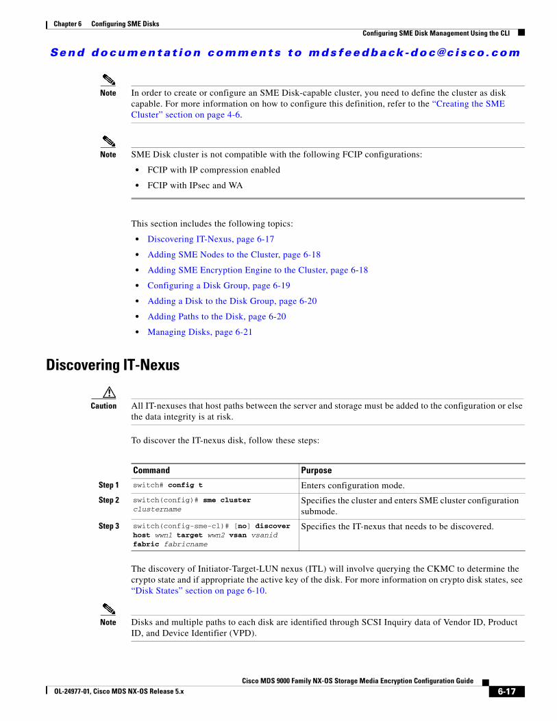
Send documenta t ion comments to mdsfeedback -doc@c i sco .com
Chapter 6 Configuring SME DisksConfiguring SME Disk Management Using the CLI
Note In order to create or configure an SME Disk-capable cluster, you need to define the cluster as disk capable. For more information on how to configure this definition, refer to the “Creating the SME Cluster” section on page 4-6.
Note SME Disk cluster is not compatible with the following FCIP configurations:
• FCIP with IP compression enabled
• FCIP with IPsec and WA
This section includes the following topics:
• Discovering IT-Nexus, page 6-17
• Adding SME Nodes to the Cluster, page 6-18
• Adding SME Encryption Engine to the Cluster, page 6-18
• Configuring a Disk Group, page 6-19
• Adding a Disk to the Disk Group, page 6-20
• Adding Paths to the Disk, page 6-20
• Managing Disks, page 6-21
Discovering IT-Nexus
Caution All IT-nexuses that host paths between the server and storage must be added to the configuration or else the data integrity is at risk.
To discover the IT-nexus disk, follow these steps:
The discovery of Initiator-Target-LUN nexus (ITL) will involve querying the CKMC to determine the crypto state and if appropriate the active key of the disk. For more information on crypto disk states, see “Disk States” section on page 6-10.
Note Disks and multiple paths to each disk are identified through SCSI Inquiry data of Vendor ID, Product ID, and Device Identifier (VPD).
Command Purpose
Step 1 switch# config t Enters configuration mode.
Step 2 switch(config)# sme cluster clustername
Specifies the cluster and enters SME cluster configuration submode.
Step 3 switch(config-sme-cl)# [no] discover host wwn1 target wwn2 vsan vsanid fabric fabricname
Specifies the IT-nexus that needs to be discovered.
6-17Cisco MDS 9000 Family NX-OS Storage Media Encryption Configuration Guide
OL-24977-01, Cisco MDS NX-OS Release 5.x
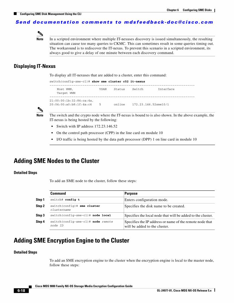
Send documenta t ion comments to mdsfeedback -doc@c i sco .com
Chapter 6 Configuring SME DisksConfiguring SME Disk Management Using the CLI
Note In a scripted environment where multiple IT-nexuses discovery is issued simultaneously, the resulting situation can cause too many queries to CKMC. This can sometimes result in some queries timing out. The workaround is to rediscover the IT-nexus. To prevent this scenario in a scripted environment, its always good to give a delay of one minute between each discovery command.
Displaying IT-Nexus
To display all IT-nexuses that are added to a cluster, enter this command:
switch(config-sme-cl)# show sme cluster c52 it-nexus ------------------------------------------------------------------------------- Host WWN, VSAN Status Switch Interface Target WWN-------------------------------------------------------------------------------21:00:00:1b:32:84:ca:4a,20:04:00:a0:b8:1f:4a:c6 5 online 172.23.146.52sme10/1
Note The switch and the crypto node where the IT-nexus is bound to is also shown. In the above example, the IT-nexus is being hosted by the following:
• Switch with IP address 172.23.146.52
• On the control path processor (CPP) in the line card on module 10
• I/O traffic is being hosted by the data path processor (DPP) 1 on line card in module 10
Adding SME Nodes to the Cluster
Detailed Steps
To add an SME node to the cluster, follow these steps:
Adding SME Encryption Engine to the Cluster
Detailed Steps
To add an SME encryption engine to the cluster when the encryption engine is local to the master node, follow these steps:
Command Purpose
Step 1 switch# config t Enters configuration mode.
Step 2 switch(config)# sme cluster clustername
Specifies the disk name to be created.
Step 3 switch(config-sme-cl)# node local Specifies the local node that will be added to the cluster.
Step 4 switch(config-sme-cl)# node remote node ID
Specifies the IP address or name of the remote node that will be added to the cluster.
6-18Cisco MDS 9000 Family NX-OS Storage Media Encryption Configuration Guide
OL-24977-01, Cisco MDS NX-OS Release 5.x
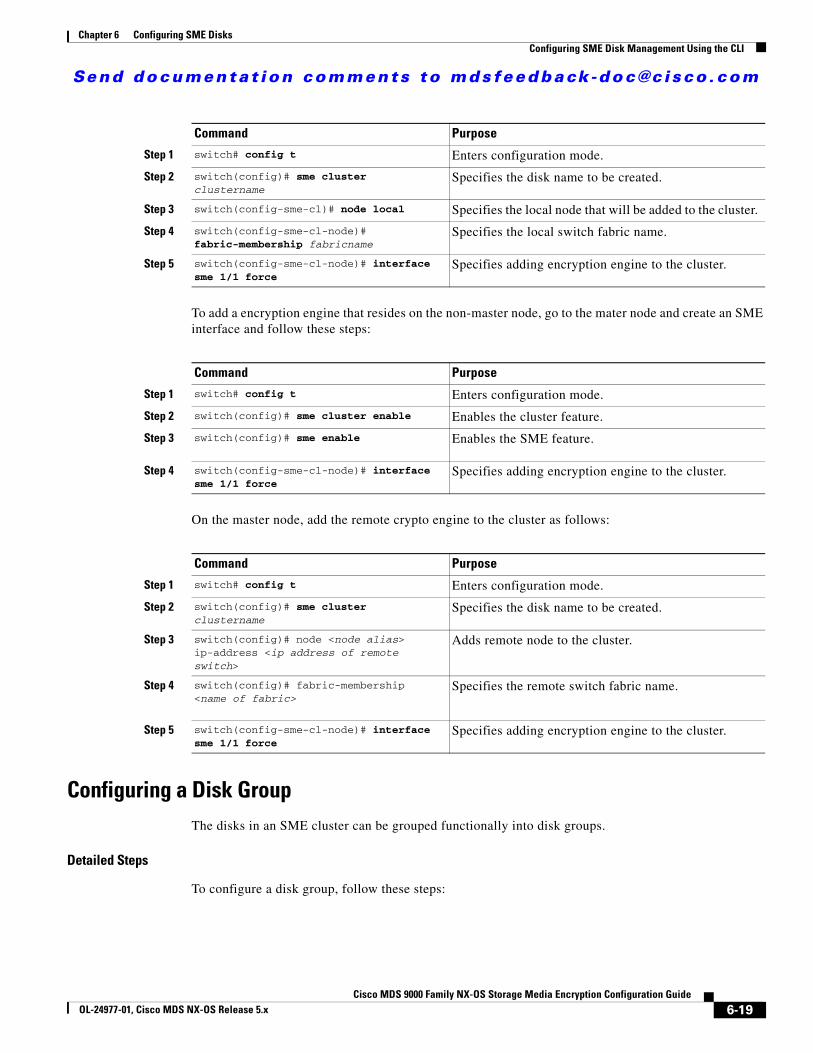
Send documenta t ion comments to mdsfeedback -doc@c i sco .com
Chapter 6 Configuring SME DisksConfiguring SME Disk Management Using the CLI
To add a encryption engine that resides on the non-master node, go to the mater node and create an SME interface and follow these steps:
On the master node, add the remote crypto engine to the cluster as follows:
Configuring a Disk GroupThe disks in an SME cluster can be grouped functionally into disk groups.
Detailed Steps
To configure a disk group, follow these steps:
Command Purpose
Step 1 switch# config t Enters configuration mode.
Step 2 switch(config)# sme cluster clustername
Specifies the disk name to be created.
Step 3 switch(config-sme-cl)# node local Specifies the local node that will be added to the cluster.
Step 4 switch(config-sme-cl-node)# fabric-membership fabricname
Specifies the local switch fabric name.
Step 5 switch(config-sme-cl-node)# interface sme 1/1 force
Specifies adding encryption engine to the cluster.
Command Purpose
Step 1 switch# config t Enters configuration mode.
Step 2 switch(config)# sme cluster enable Enables the cluster feature.
Step 3 switch(config)# sme enable Enables the SME feature.
Step 4 switch(config-sme-cl-node)# interface sme 1/1 force
Specifies adding encryption engine to the cluster.
Command Purpose
Step 1 switch# config t Enters configuration mode.
Step 2 switch(config)# sme cluster clustername
Specifies the disk name to be created.
Step 3 switch(config)# node <node alias> ip-address <ip address of remote switch>
Adds remote node to the cluster.
Step 4 switch(config)# fabric-membership <name of fabric>
Specifies the remote switch fabric name.
Step 5 switch(config-sme-cl-node)# interface sme 1/1 force
Specifies adding encryption engine to the cluster.
6-19Cisco MDS 9000 Family NX-OS Storage Media Encryption Configuration Guide
OL-24977-01, Cisco MDS NX-OS Release 5.x
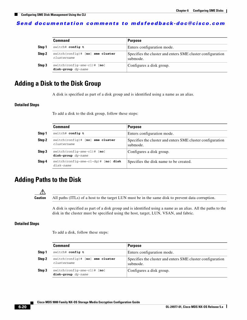
Send documenta t ion comments to mdsfeedback -doc@c i sco .com
Chapter 6 Configuring SME DisksConfiguring SME Disk Management Using the CLI
Adding a Disk to the Disk GroupA disk is specified as part of a disk group and is identified using a name as an alias.
Detailed Steps
To add a disk to the disk group, follow these steps:
Adding Paths to the Disk
Caution All paths (ITLs) of a host to the target LUN must be in the same disk to prevent data corruption.
A disk is specified as part of a disk group and is identified using a name as an alias. All the paths to the disk in the cluster must be specified using the host, target, LUN, VSAN, and fabric.
Detailed Steps
To add a disk, follow these steps:
Command Purpose
Step 1 switch# config t Enters configuration mode.
Step 2 switch(config)# [no] sme cluster clustername
Specifies the cluster and enters SME cluster configuration submode.
Step 3 switch(config-sme-cl)# [no] disk-group dg-name
Configures a disk group.
Command Purpose
Step 1 switch# config t Enters configuration mode.
Step 2 switch(config)# [no] sme cluster clustername
Specifies the cluster and enters SME cluster configuration submode.
Step 3 switch(config-sme-cl)# [no] disk-group dg-name
Configures a disk group.
Step 4 switch(config-sme-cl-dg)# [no] disk disk-name
Specifies the disk name to be created.
Command Purpose
Step 1 switch# config t Enters configuration mode.
Step 2 switch(config)# [no] sme cluster clustername
Specifies the cluster and enters SME cluster configuration submode.
Step 3 switch(config-sme-cl)# [no] disk-group dg-name
Configures a disk group.
6-20Cisco MDS 9000 Family NX-OS Storage Media Encryption Configuration Guide
OL-24977-01, Cisco MDS NX-OS Release 5.x

Send documenta t ion comments to mdsfeedback -doc@c i sco .com
Chapter 6 Configuring SME DisksConfiguring SME Disk Management Using the CLI
Note If the IT-nexus specified in the path above is not configured in SME, SME will also trigger a discovery of the IT-nexus along with adding the configured path to the specified disk. In a scripted environment, when adding paths, it is always advisable to give a delay of one minute to allow the IT-nexus discovery to complete.
Displaying ITL-Nexus
To see the list of paths discovered on SUP, enter this command:
switch(config-sme-cl)# show sme cluster c52 disk detailDisk 1 is crypto Model is LSI INF-01-00 Vendor ID is LSI Product ID is INF-01-00 Device ID is 600a0b80001f4ac4000032454a3a69ce ASL ID is 581688B7 Is configured as disk device d1 in disk group dg1 Paths Host 21:00:00:1b:32:84:ca:4a Target 20:04:00:a0:b8:1f:4a:c6 Lun 0x0000 vsan 5 Is online (SUCCESS), configured
To see the list of paths discovered on CPP where IT-nexus is bound, enter this command:
switch# attach module 10Attaching to module 10 ...To exit type 'exit', to abort type '$.' module-10# show sme internal info crypto-node 1 itl brief------------------------------------------------------------------------------------------ if-ndx host tgt vsan lun type sme locking event state ------------------------------------------------------------------------------------------ 0x12480000 21:00:00:1b:32:84:ca:4a 20:04:00:a0:b8:1f:4a:c6 5 0x0000 1 1 Unlocked SMED_ISAPI_ITL_ST_UP_CRYPTO
Managing DisksThis section includes the following topics:
• Enabling Encryption on the SME Disk with Data Preparation, page 6-22
• Modifying the SME Disk Key, page 6-26
• Recovering the SME Disk, page 6-27
Step 4 switch(config-sme-cl-dg)# [no] disk disk-name
Specifies the disk name to be created.
Step 5 switch(config-sme-cl-dg-disk)# [no] host wwn1 target wwn2 lun 11 vsan v1 fabric f1
Specifies the path to the disk in the cluster.
Command Purpose
6-21Cisco MDS 9000 Family NX-OS Storage Media Encryption Configuration Guide
OL-24977-01, Cisco MDS NX-OS Release 5.x
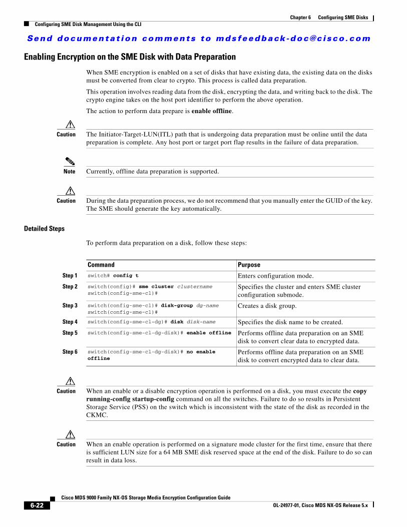
Send documenta t ion comments to mdsfeedback -doc@c i sco .com
Chapter 6 Configuring SME DisksConfiguring SME Disk Management Using the CLI
Enabling Encryption on the SME Disk with Data Preparation
When SME encryption is enabled on a set of disks that have existing data, the existing data on the disks must be converted from clear to crypto. This process is called data preparation.
This operation involves reading data from the disk, encrypting the data, and writing back to the disk. The crypto engine takes on the host port identifier to perform the above operation.
The action to perform data prepare is enable offline.
Caution The Initiator-Target-LUN(ITL) path that is undergoing data preparation must be online until the data preparation is complete. Any host port or target port flap results in the failure of data preparation.
Note Currently, offline data preparation is supported.
Caution During the data preparation process, we do not recommend that you manually enter the GUID of the key. The SME should generate the key automatically.
Detailed Steps
To perform data preparation on a disk, follow these steps:
Caution When an enable or a disable encryption operation is performed on a disk, you must execute the copy running-config startup-config command on all the switches. Failure to do so results in Persistent Storage Service (PSS) on the switch which is inconsistent with the state of the disk as recorded in the CKMC.
Caution When an enable operation is performed on a signature mode cluster for the first time, ensure that there is sufficient LUN size for a 64 MB SME disk reserved space at the end of the disk. Failure to do so can result in data loss.
Command Purpose
Step 1 switch# config t Enters configuration mode.
Step 2 switch(config)# sme cluster clusternameswitch(config-sme-cl)#
Specifies the cluster and enters SME cluster configuration submode.
Step 3 switch(config-sme-cl)# disk-group dg-nameswitch(config-sme-cl)#
Creates a disk group.
Step 4 switch(config-sme-cl-dg)# disk disk-name Specifies the disk name to be created.
Step 5 switch(config-sme-cl-dg-disk)# enable offline Performs offline data preparation on an SME disk to convert clear data to encrypted data.
Step 6 switch(config-sme-cl-dg-disk)# no enable offline
Performs offline data preparation on an SME disk to convert encrypted data to clear data.
6-22Cisco MDS 9000 Family NX-OS Storage Media Encryption Configuration Guide
OL-24977-01, Cisco MDS NX-OS Release 5.x
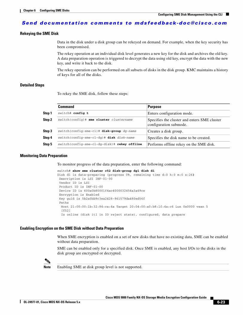
Send documenta t ion comments to mdsfeedback -doc@c i sco .com
Chapter 6 Configuring SME DisksConfiguring SME Disk Management Using the CLI
Rekeying the SME Disk
Data in the disk under a disk group can be rekeyed on demand. For example, when the key security has been compromised.
The rekey operation at an individual disk level generates a new key for the disk and archives the old key. A data preparation operation is triggered to decrypt the data using old key, encrypt the data with the new key, and write it back to the disk.
The rekey operation can be performed on all subsets of disks in the disk group. KMC maintains a history of keys for all of the disks.
Detailed Steps
To rekey the SME disk, follow these steps:
Monitoring Data Preparation
To monitor progress of the data preparation, enter the following command:
switch# show sme cluster c52 disk-group dg1 disk d1Disk d1 is data-preparing (progress 0%, remaining time d:0 h:0 m:0 s:26) Description is LSI INF-01-00 Vendor ID is LSI Product ID is INF-01-00 Device ID is 600a0b80001f4ac4000032454a3a69ce Encryption is Enabled Key guid is 5b2a0bb9c3ea2428-961579da480ed56f Paths Host 21:00:00:1b:32:84:ca:4a Target 20:04:00:a0:b8:1f:4a:c6 Lun 0x0000 vsan 5 [f52] Is online (disk itl in IO reject state), configured, data prepare
Enabling Encryption on the SME Disk without Data Preparation
When SME encryption is enabled on a set of new disks that have no existing data, SME can be enabled without data preparation.
SME can be enabled only for a specified disk. Once SME is enabled, any host I/Os to the disks in the disk group are encrypted or decrypted.
Note Enabling SME at disk group level is not supported.
Command Purpose
Step 1 switch# config t Enters configuration mode.
Step 2 switch(config)# sme cluster clustername Specifies the cluster and enters SME cluster configuration submode.
Step 3 switch(config-sme-cl)# disk-group dg-name Creates a disk group.
Step 4 switch(config-sme-cl-dg)# disk disk-name Specifies the disk name to be created.
Step 5 switch(config-sme-cl-dg-disk)# rekey offline Performs offline rekey on the SME disk.
6-23Cisco MDS 9000 Family NX-OS Storage Media Encryption Configuration Guide
OL-24977-01, Cisco MDS NX-OS Release 5.x
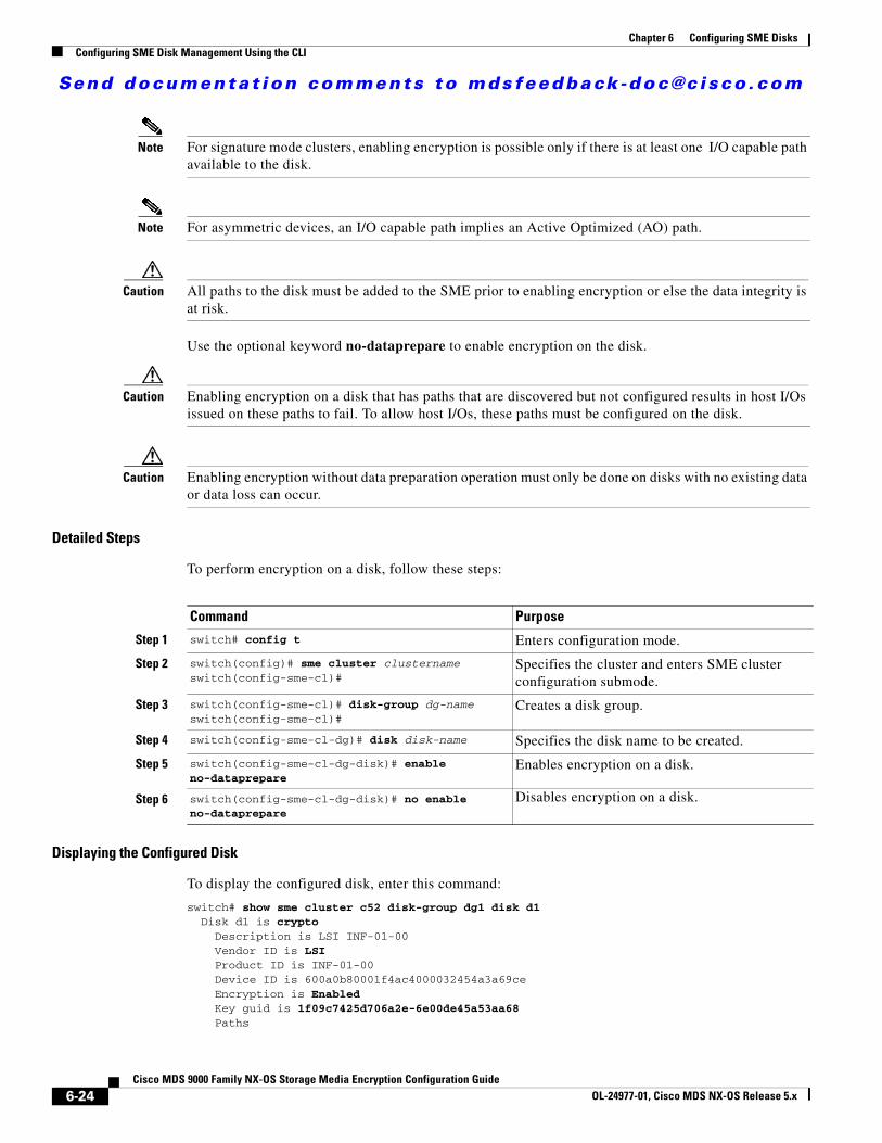
Send documenta t ion comments to mdsfeedback -doc@c i sco .com
Chapter 6 Configuring SME DisksConfiguring SME Disk Management Using the CLI
Note For signature mode clusters, enabling encryption is possible only if there is at least one I/O capable path available to the disk.
Note For asymmetric devices, an I/O capable path implies an Active Optimized (AO) path.
Caution All paths to the disk must be added to the SME prior to enabling encryption or else the data integrity is at risk.
Use the optional keyword no-dataprepare to enable encryption on the disk.
Caution Enabling encryption on a disk that has paths that are discovered but not configured results in host I/Os issued on these paths to fail. To allow host I/Os, these paths must be configured on the disk.
Caution Enabling encryption without data preparation operation must only be done on disks with no existing data or data loss can occur.
Detailed Steps
To perform encryption on a disk, follow these steps:
Displaying the Configured Disk
To display the configured disk, enter this command:
switch# show sme cluster c52 disk-group dg1 disk d1 Disk d1 is crypto Description is LSI INF-01-00 Vendor ID is LSI Product ID is INF-01-00 Device ID is 600a0b80001f4ac4000032454a3a69ce Encryption is Enabled Key guid is 1f09c7425d706a2e-6e00de45a53aa68 Paths
Command Purpose
Step 1 switch# config t Enters configuration mode.
Step 2 switch(config)# sme cluster clusternameswitch(config-sme-cl)#
Specifies the cluster and enters SME cluster configuration submode.
Step 3 switch(config-sme-cl)# disk-group dg-nameswitch(config-sme-cl)#
Creates a disk group.
Step 4 switch(config-sme-cl-dg)# disk disk-name Specifies the disk name to be created.
Step 5 switch(config-sme-cl-dg-disk)# enable no-dataprepare
Enables encryption on a disk.
Step 6 switch(config-sme-cl-dg-disk)# no enable no-dataprepare
Disables encryption on a disk.
6-24Cisco MDS 9000 Family NX-OS Storage Media Encryption Configuration Guide
OL-24977-01, Cisco MDS NX-OS Release 5.x
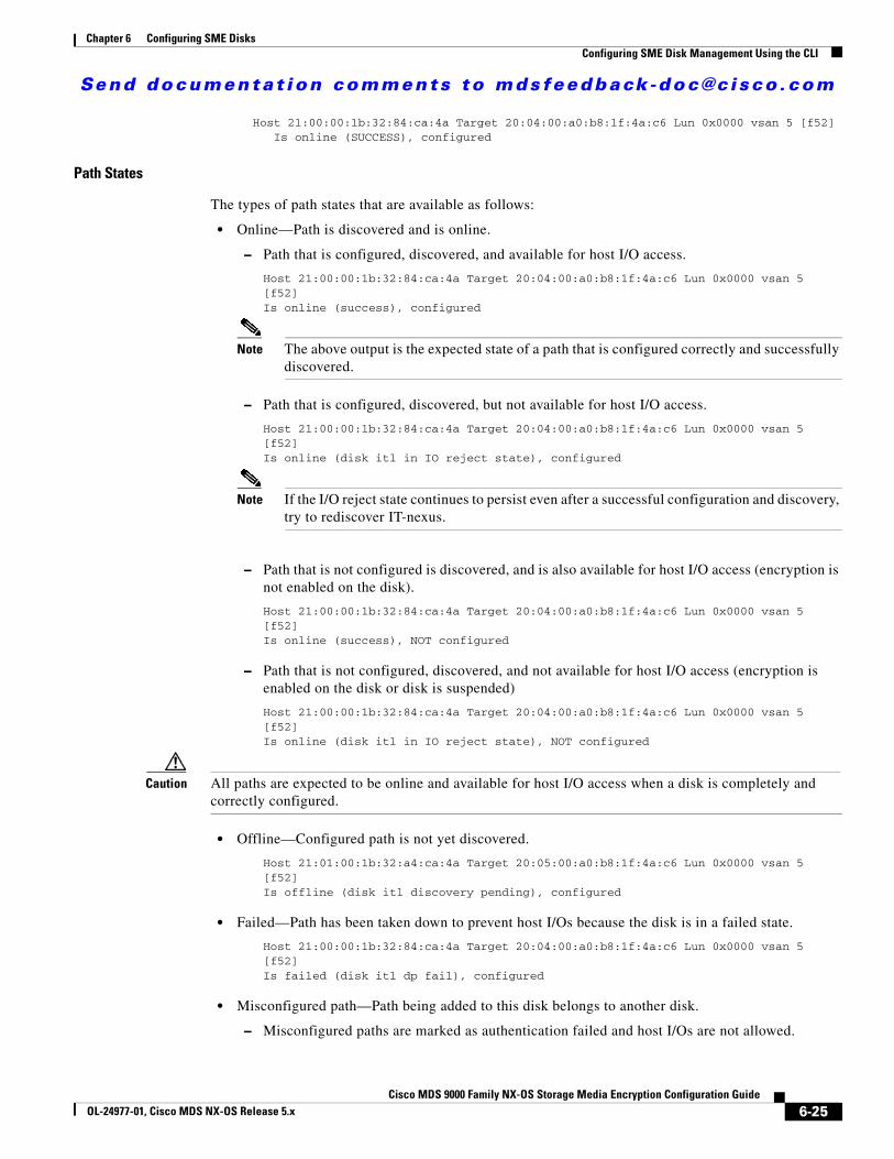
Send documenta t ion comments to mdsfeedback -doc@c i sco .com
Chapter 6 Configuring SME DisksConfiguring SME Disk Management Using the CLI
Host 21:00:00:1b:32:84:ca:4a Target 20:04:00:a0:b8:1f:4a:c6 Lun 0x0000 vsan 5 [f52] Is online (SUCCESS), configured
Path States
The types of path states that are available as follows:
• Online—Path is discovered and is online.
– Path that is configured, discovered, and available for host I/O access.
Host 21:00:00:1b:32:84:ca:4a Target 20:04:00:a0:b8:1f:4a:c6 Lun 0x0000 vsan 5 [f52]Is online (success), configured
Note The above output is the expected state of a path that is configured correctly and successfully discovered.
– Path that is configured, discovered, but not available for host I/O access.
Host 21:00:00:1b:32:84:ca:4a Target 20:04:00:a0:b8:1f:4a:c6 Lun 0x0000 vsan 5 [f52]Is online (disk itl in IO reject state), configured
Note If the I/O reject state continues to persist even after a successful configuration and discovery, try to rediscover IT-nexus.
– Path that is not configured is discovered, and is also available for host I/O access (encryption is not enabled on the disk).
Host 21:00:00:1b:32:84:ca:4a Target 20:04:00:a0:b8:1f:4a:c6 Lun 0x0000 vsan 5 [f52]Is online (success), NOT configured
– Path that is not configured, discovered, and not available for host I/O access (encryption is enabled on the disk or disk is suspended)
Host 21:00:00:1b:32:84:ca:4a Target 20:04:00:a0:b8:1f:4a:c6 Lun 0x0000 vsan 5 [f52]Is online (disk itl in IO reject state), NOT configured
Caution All paths are expected to be online and available for host I/O access when a disk is completely and correctly configured.
• Offline—Configured path is not yet discovered.
Host 21:01:00:1b:32:a4:ca:4a Target 20:05:00:a0:b8:1f:4a:c6 Lun 0x0000 vsan 5 [f52]Is offline (disk itl discovery pending), configured
• Failed—Path has been taken down to prevent host I/Os because the disk is in a failed state.
Host 21:00:00:1b:32:84:ca:4a Target 20:04:00:a0:b8:1f:4a:c6 Lun 0x0000 vsan 5 [f52]Is failed (disk itl dp fail), configured
• Misconfigured path—Path being added to this disk belongs to another disk.
– Misconfigured paths are marked as authentication failed and host I/Os are not allowed.
6-25Cisco MDS 9000 Family NX-OS Storage Media Encryption Configuration Guide
OL-24977-01, Cisco MDS NX-OS Release 5.x
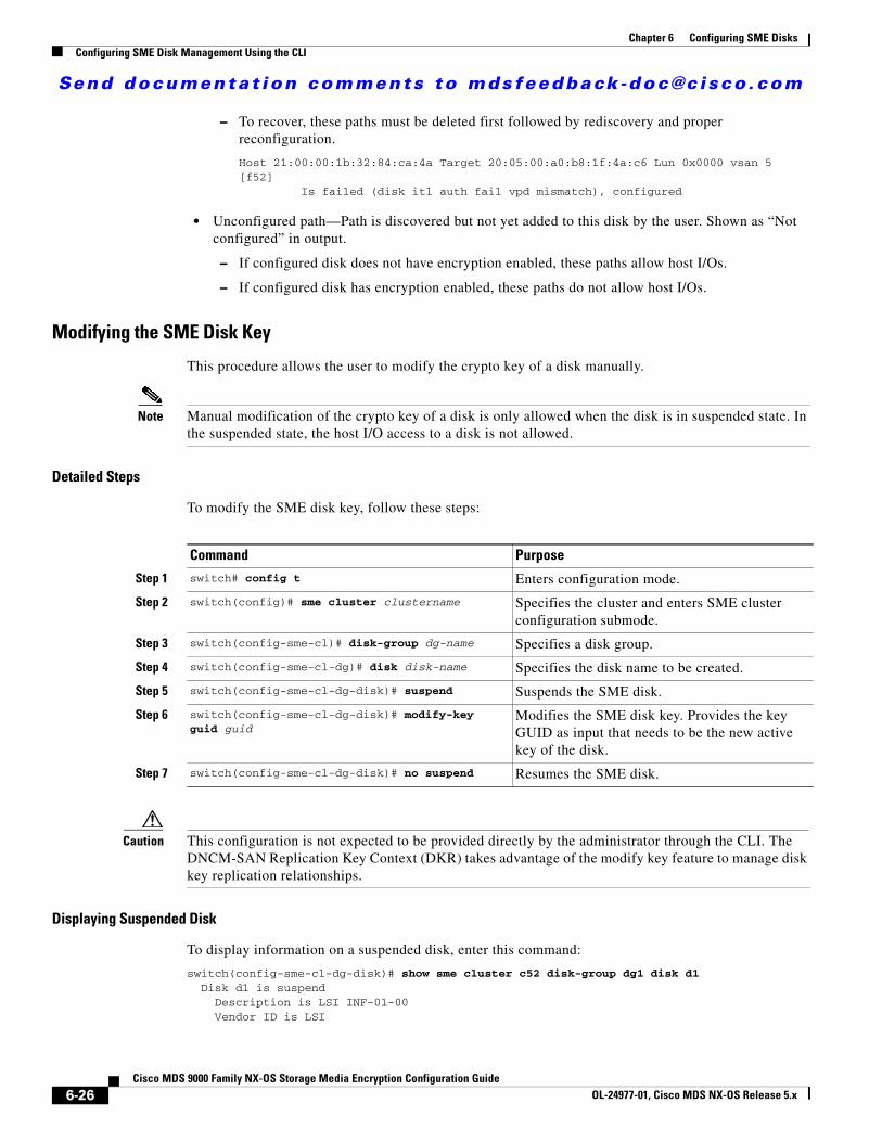
Send documenta t ion comments to mdsfeedback -doc@c i sco .com
Chapter 6 Configuring SME DisksConfiguring SME Disk Management Using the CLI
– To recover, these paths must be deleted first followed by rediscovery and proper reconfiguration.
Host 21:00:00:1b:32:84:ca:4a Target 20:05:00:a0:b8:1f:4a:c6 Lun 0x0000 vsan 5 [f52] Is failed (disk itl auth fail vpd mismatch), configured
• Unconfigured path—Path is discovered but not yet added to this disk by the user. Shown as “Not configured” in output.
– If configured disk does not have encryption enabled, these paths allow host I/Os.
– If configured disk has encryption enabled, these paths do not allow host I/Os.
Modifying the SME Disk Key
This procedure allows the user to modify the crypto key of a disk manually.
Note Manual modification of the crypto key of a disk is only allowed when the disk is in suspended state. In the suspended state, the host I/O access to a disk is not allowed.
Detailed Steps
To modify the SME disk key, follow these steps:
Caution This configuration is not expected to be provided directly by the administrator through the CLI. The DNCM-SAN Replication Key Context (DKR) takes advantage of the modify key feature to manage disk key replication relationships.
Displaying Suspended Disk
To display information on a suspended disk, enter this command:
switch(config-sme-cl-dg-disk)# show sme cluster c52 disk-group dg1 disk d1 Disk d1 is suspend Description is LSI INF-01-00 Vendor ID is LSI
Command Purpose
Step 1 switch# config t Enters configuration mode.
Step 2 switch(config)# sme cluster clustername Specifies the cluster and enters SME cluster configuration submode.
Step 3 switch(config-sme-cl)# disk-group dg-name Specifies a disk group.
Step 4 switch(config-sme-cl-dg)# disk disk-name Specifies the disk name to be created.
Step 5 switch(config-sme-cl-dg-disk)# suspend Suspends the SME disk.
Step 6 switch(config-sme-cl-dg-disk)# modify-key guid guid
Modifies the SME disk key. Provides the key GUID as input that needs to be the new active key of the disk.
Step 7 switch(config-sme-cl-dg-disk)# no suspend Resumes the SME disk.
6-26Cisco MDS 9000 Family NX-OS Storage Media Encryption Configuration Guide
OL-24977-01, Cisco MDS NX-OS Release 5.x

Send documenta t ion comments to mdsfeedback -doc@c i sco .com
Chapter 6 Configuring SME DisksConfiguring SME Disk Management Using the CLI
Product ID is INF-01-00 Device ID is 600a0b80001f4ac4000032454a3a69ce Encryption is Enabled Key guid is 1f09c7425d706a2e-6e00de45a53aa68c Paths Host 21:00:00:1b:32:84:ca:4a Target 20:04:00:a0:b8:1f:4a:c6 Lun 0x0000 vsan 5 [f52] Is online (disk itl in IO reject state), configured
Recovering the SME Disk
In order to perform the recovery on a failed disk, the administrator needs to first restore the contents of the disk from the backup, which is a storage operation. The administrator then needs to update the state of the failed disk in SME configuration with the recover command.
Recovery can be done in two ways:
• Recovering SME Disk to Clear State, page 6-27
• Recovering SME Disk to Crypto State, page 6-27
Caution The SME recover CLI command is used only for recovery of encryption key and not for data.
Recovering SME Disk to Clear State
If the disk was recovered from a backup that contains clear data then the administrator need to recover the SME Disk to clear state.
Note For signature mode clusters, there must be at least one I/O-capable path for recovery to succeed. As part of the recovery, SME disk clears the signature from the signature portion of the disk.
Detailed Steps
To recover the SME disk to clear state, follow these steps:
Recovering SME Disk to Crypto State
If the disk was recovered from a backup that contains encrypted data then the administrator should recover the SME disk to crypto state.
Command Purpose
Step 1 switch# config t Enters configuration mode.
Step 2 switch(config)# sme cluster clusternameswitch(config-sme-cl)#
Specifies the cluster and enters SME cluster configuration submode.
Step 3 switch(config-sme-cl)# disk-group dg-nameswitch(config-sme-cl)#
Specifies a disk group.
Step 4 switch(config-sme-cl-dg)# disk disk-name Specifies the disk name to be created.
Step 5 switch(config-sme-cl-dg-disk)# recover Resets the crypto state of the disk to a clear state. That is, no encryption is performed on the host I/Os issued on the disk.
6-27Cisco MDS 9000 Family NX-OS Storage Media Encryption Configuration Guide
OL-24977-01, Cisco MDS NX-OS Release 5.x
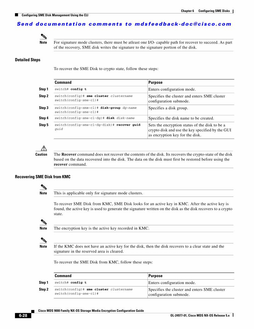
Send documenta t ion comments to mdsfeedback -doc@c i sco .com
Chapter 6 Configuring SME DisksConfiguring SME Disk Management Using the CLI
Note For signature mode clusters, there must be atleast one I/O- capable path for recover to succeed. As part of the recovery, SME disk writes the signature to the signature portion of the disk.
Detailed Steps
To recover the SME Disk to crypto state, follow these steps:
Caution The Recover command does not recover the contents of the disk. Its recovers the crypto-state of the disk based on the data recovered into the disk. The data on the disk must first be restored before using the recover command.
Recovering SME Disk from KMC
Note This is applicable only for signature mode clusters.
To recover SME Disk from KMC, SME Disk looks for an active key in KMC. After the active key is found, the active key is used to generate the signature written on the disk as the disk recovers to a crypto state.
Note The encryption key is the active key recorded in KMC.
Note If the KMC does not have an active key for the disk, then the disk recovers to a clear state and the signature in the reserved area is cleared.
To recover the SME Disk from KMC, follow these steps:
Command Purpose
Step 1 switch# config t Enters configuration mode.
Step 2 switch(config)# sme cluster clusternameswitch(config-sme-cl)#
Specifies the cluster and enters SME cluster configuration submode.
Step 3 switch(config-sme-cl)# disk-group dg-nameswitch(config-sme-cl)#
Specifies a disk group.
Step 4 switch(config-sme-cl-dg)# disk disk-name Specifies the disk name to be created.
Step 5 switch(config-sme-cl-dg-disk)# recover guid guid
Sets the encryption status of the disk to be a crypto disk and use the key specified by the GUI as encryption key for the disk.
Command Purpose
Step 1 switch# config t Enters configuration mode.
Step 2 switch(config)# sme cluster clusternameswitch(config-sme-cl)#
Specifies the cluster and enters SME cluster configuration submode.
6-28Cisco MDS 9000 Family NX-OS Storage Media Encryption Configuration Guide
OL-24977-01, Cisco MDS NX-OS Release 5.x
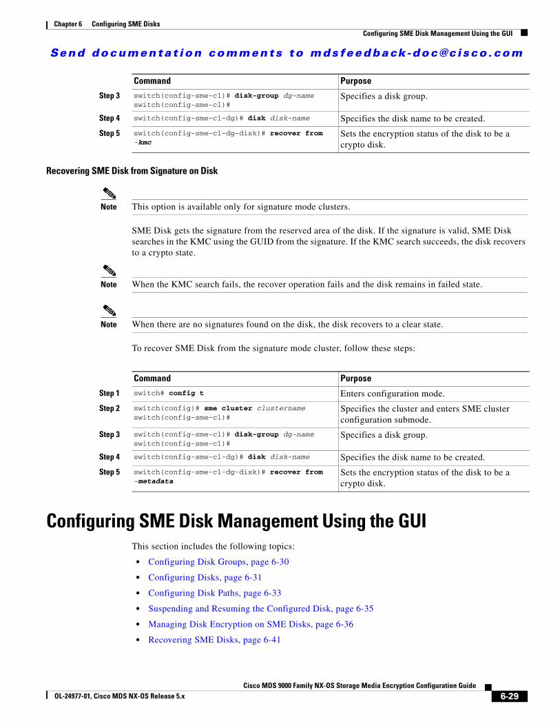
Send documenta t ion comments to mdsfeedback -doc@c i sco .com
Chapter 6 Configuring SME DisksConfiguring SME Disk Management Using the GUI
Recovering SME Disk from Signature on Disk
Note This option is available only for signature mode clusters.
SME Disk gets the signature from the reserved area of the disk. If the signature is valid, SME Disk searches in the KMC using the GUID from the signature. If the KMC search succeeds, the disk recovers to a crypto state.
Note When the KMC search fails, the recover operation fails and the disk remains in failed state.
Note When there are no signatures found on the disk, the disk recovers to a clear state.
To recover SME Disk from the signature mode cluster, follow these steps:
Configuring SME Disk Management Using the GUIThis section includes the following topics:
• Configuring Disk Groups, page 6-30
• Configuring Disks, page 6-31
• Configuring Disk Paths, page 6-33
• Suspending and Resuming the Configured Disk, page 6-35
• Managing Disk Encryption on SME Disks, page 6-36
• Recovering SME Disks, page 6-41
Step 3 switch(config-sme-cl)# disk-group dg-nameswitch(config-sme-cl)#
Specifies a disk group.
Step 4 switch(config-sme-cl-dg)# disk disk-name Specifies the disk name to be created.
Step 5 switch(config-sme-cl-dg-disk)# recover from -kmc
Sets the encryption status of the disk to be a crypto disk.
Command Purpose
Command Purpose
Step 1 switch# config t Enters configuration mode.
Step 2 switch(config)# sme cluster clusternameswitch(config-sme-cl)#
Specifies the cluster and enters SME cluster configuration submode.
Step 3 switch(config-sme-cl)# disk-group dg-nameswitch(config-sme-cl)#
Specifies a disk group.
Step 4 switch(config-sme-cl-dg)# disk disk-name Specifies the disk name to be created.
Step 5 switch(config-sme-cl-dg-disk)# recover from -metadata
Sets the encryption status of the disk to be a crypto disk.
6-29Cisco MDS 9000 Family NX-OS Storage Media Encryption Configuration Guide
OL-24977-01, Cisco MDS NX-OS Release 5.x
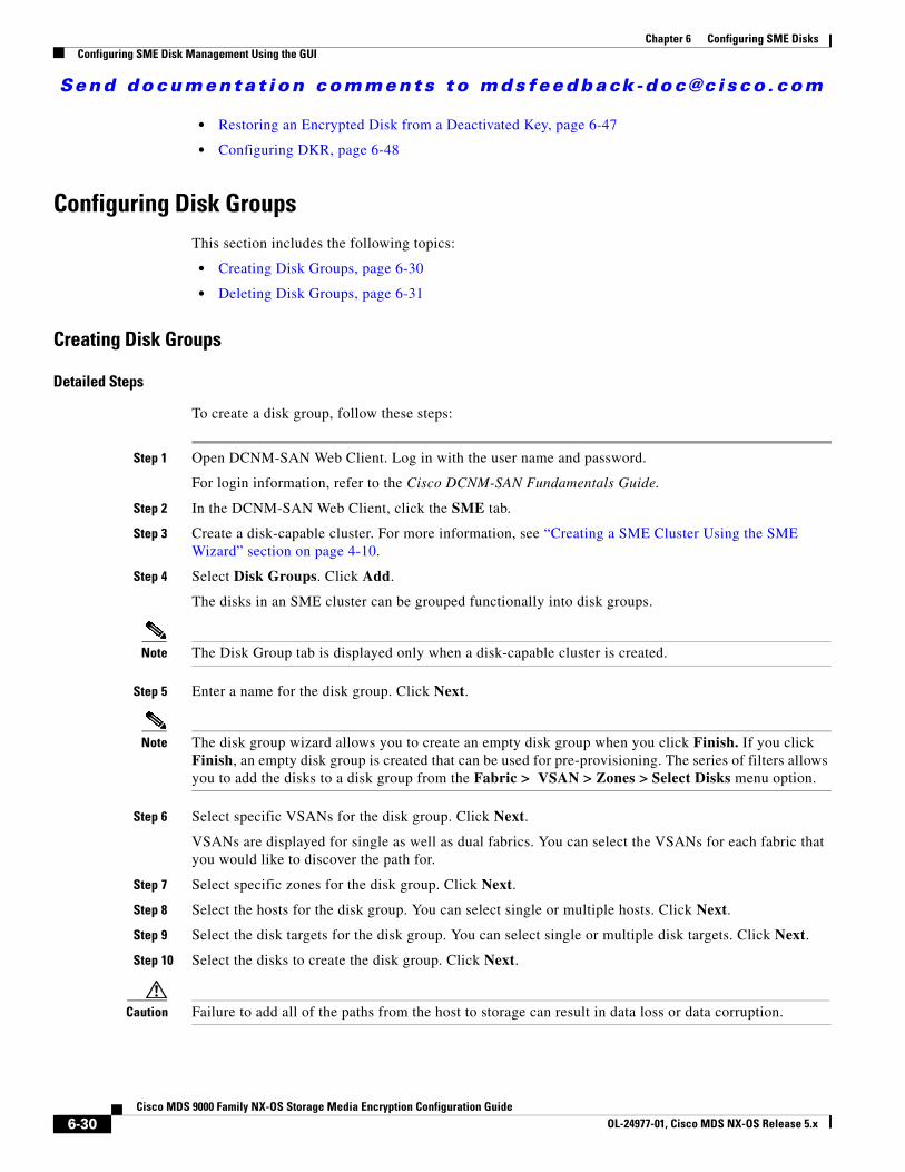
Send documenta t ion comments to mdsfeedback -doc@c i sco .com
Chapter 6 Configuring SME DisksConfiguring SME Disk Management Using the GUI
• Restoring an Encrypted Disk from a Deactivated Key, page 6-47
• Configuring DKR, page 6-48
Configuring Disk GroupsThis section includes the following topics:
• Creating Disk Groups, page 6-30
• Deleting Disk Groups, page 6-31
Creating Disk Groups
Detailed Steps
To create a disk group, follow these steps:
Step 1 Open DCNM-SAN Web Client. Log in with the user name and password.
For login information, refer to the Cisco DCNM-SAN Fundamentals Guide.
Step 2 In the DCNM-SAN Web Client, click the SME tab.
Step 3 Create a disk-capable cluster. For more information, see “Creating a SME Cluster Using the SME Wizard” section on page 4-10.
Step 4 Select Disk Groups. Click Add.
The disks in an SME cluster can be grouped functionally into disk groups.
Note The Disk Group tab is displayed only when a disk-capable cluster is created.
Step 5 Enter a name for the disk group. Click Next.
Note The disk group wizard allows you to create an empty disk group when you click Finish. If you click Finish, an empty disk group is created that can be used for pre-provisioning. The series of filters allows you to add the disks to a disk group from the Fabric > VSAN > Zones > Select Disks menu option.
Step 6 Select specific VSANs for the disk group. Click Next.
VSANs are displayed for single as well as dual fabrics. You can select the VSANs for each fabric that you would like to discover the path for.
Step 7 Select specific zones for the disk group. Click Next.
Step 8 Select the hosts for the disk group. You can select single or multiple hosts. Click Next.
Step 9 Select the disk targets for the disk group. You can select single or multiple disk targets. Click Next.
Step 10 Select the disks to create the disk group. Click Next.
Caution Failure to add all of the paths from the host to storage can result in data loss or data corruption.
6-30Cisco MDS 9000 Family NX-OS Storage Media Encryption Configuration Guide
OL-24977-01, Cisco MDS NX-OS Release 5.x
Send documenta t ion comments to mdsfeedback -doc@c i sco .com
Chapter 6 Configuring SME DisksConfiguring SME Disk Management Using the GUI
The select disk path screen shows the Disk Name that you can modify, Vendor ID (VID), Product ID (PID), Device ID (DID), and number of paths for the disk. Along with this information when you click on the zoom icon, you can see the Initiator PWWN, Target PWWN, and the number of LUNs for the corresponding disk.
Step 11 Verify the information shown on the confirmation screen. Click Confirm to save and activate the changes.
Step 12 View the disk group that is successfully added to a cluster.
Deleting Disk Groups
Prerequisites
Before deleting a disk group, ensure that the configured disks are deleted from the disk groups.
Detailed Steps
To delete a disk group, follow these steps:
Step 1 Select Disk Groups to display the disk groups that are part of the cluster.
Step 2 Select a disk group and click Remove.
Step 3 Click OK to delete the disk group.
Step 4 View the notification that the disk group has been removed.
Configuring DisksThis section includes the following topics:
• Adding Disks, page 6-31
• Deleting Disks, page 6-32
Adding Disks
Note When you add disks to a signature mode cluster and if the volume contains data, you have to resize the disk to reserve at least 64MB of space for Cisco SME signature information at the end of the volume.
Detailed Steps
To add disks to an existing disk group, follow these steps:
Step 1 Select the configured Disk Group.
Step 2 Select the Disks under the configured Disk Group and click Add.
6-31Cisco MDS 9000 Family NX-OS Storage Media Encryption Configuration Guide
OL-24977-01, Cisco MDS NX-OS Release 5.x
Send documenta t ion comments to mdsfeedback -doc@c i sco .com
Chapter 6 Configuring SME DisksConfiguring SME Disk Management Using the GUI
Step 3 Select the VSANs that you would like to discover paths from. Click Next.
Step 4 Select specific zones for the disk. Click Next.
Step 5 Select the hosts for the disk. You can select single or multiple hosts. Click Next.
Step 6 Select the disk targets. You can select single or multiple targets. Click Next.
Step 7 Select the paths that SME would use for encrypted data between the host and the disk. Click Next.
Step 8 Click Confirm to add the new disk to the disk group.
Step 9 View the disks successfully added to the disk group.
Deleting Disks
Detailed Steps
To delete a disk from an existing disk group, follow these steps:
Step 1 Select the disk from a disk group that you want to remove.
Step 2 Click Remove.
Step 3 Click OK to delete the disk.
Step 4 View the notification that the disk has been removed.
Note If there are any errors in performing the required action, the error is shown in red text with a red border so that it is highlighted.
Configuring Signature Mode
Note Converting a SME Disk cluster from a non-signature mode to signature mode will result in writing signatures to all the configured crypto disks. Once the conversion is complete, verify if all the crypto disks and their paths are in online state and verify the signature of the disks.
To convert a cluster to signature mode, follow these steps:
Step 1 In DCNM-SAN Web Client, click the SME tab.
Step 2 Select Clusters in the navigation pane. Click and expand on the desired destination clusters.
The Cluster Details screen is displayed.
Step 3 Click Convert to Signature Mode.
Note You will not see this option for disks that are already in signature mode.
6-32Cisco MDS 9000 Family NX-OS Storage Media Encryption Configuration Guide
OL-24977-01, Cisco MDS NX-OS Release 5.x
Send documenta t ion comments to mdsfeedback -doc@c i sco .com
Chapter 6 Configuring SME DisksConfiguring SME Disk Management Using the GUI
The Signature Mode Conversion screen is displayed.
Step 4 Click Next.
The Convert Cluster screen is displayed.
Once the conversion is complete, ensure there are no failed disks and verify the signature for crypto disks to ensure the signature is correct. For failed disks, see Recovering SME Disks, page 6-41.
Converting Disks to Signature Mode To convert a cluster to signature mode, follow these steps:
Step 1 In DCNM-SAN Web Client, click the SME tab.
Step 2 Select Clusters in the navigation pane. Click and expand on the desired destination clusters.
The Cluster Details screen is displayed.
Step 3 Click Convert Disks to Signature Mode.
The Signature Mode Conversion screen is displayed.
Step 4 Click Next.
The Convert Cluster screen is displayed.
Verifying Signatures for DisksTo verify signatures on disks, follow these steps:
Step 1 In the DCNM-SAN web client, click the SME tab.
Step 2 Under Disk Groups, select the disk for signature verification.
The Disk Details screen is displayed.
Step 3 Under Disk Signature, click Verify Signature.
The signature is verifies and the signature verification is successful message is displayed.
Configuring Disk PathsThis section includes the following topics:
• Configuring and Discovering Disk Paths, page 6-34
• Adding Discovered Path, page 6-34
• Removing Disk Paths, page 6-34
6-33Cisco MDS 9000 Family NX-OS Storage Media Encryption Configuration Guide
OL-24977-01, Cisco MDS NX-OS Release 5.x
Send documenta t ion comments to mdsfeedback -doc@c i sco .com
Chapter 6 Configuring SME DisksConfiguring SME Disk Management Using the GUI
Configuring and Discovering Disk Paths
Launch the Add Disk Path Wizard to add the disk paths to the disk by clicking Configure/Discover.
Detailed Steps
To configure and discover a disk path to a disk, follow these steps:
Step 1 Select the disk to which the new disk path has to be added. In the Discovered Paths section, click Configure/Discover to configure and discover the disk path corresponding to the disk path.
Step 2 Select the VSANs that you want to discover paths from. Click Next.
Step 3 Select specific zones for the disk. Click Next.
Step 4 Select the disk path that you want to add to the disk. Click Next.
Step 5 Click Confirm to add the disk path.
Step 6 Verify that the selected disk path is successfully added to the disk. The disk paths are shown in the Configure Paths area under the disk section.
Adding Discovered Path
During the disk discovery, the disk paths that are corresponding to the disk also get discovered. The corresponding disk paths for a disk get discovered and are displayed in the Discovered Paths area under the disk section.
Caution All the paths for a disk must be configured. Writing to an encrypted disk using an unconfigured path will results in corruption or loss of data.
Detailed Steps
Step 1 To add the discovered path to a disk, select the discovered path. Click Configure/Discover.
Step 2 Click OK to continue. This configures and adds the selected disk displayed under the Discovered Paths area to the Configured Paths area.
Step 3 Verify that the selected Discovered Path is successfully added to the Configured Paths under the disk section.
Removing Disk Paths
Detailed Steps
To delete a disk path from a disk, follow these steps:
Step 1 Click a disk name to display the disk details and configured paths.
Step 2 Select a disk path and click Remove.
6-34Cisco MDS 9000 Family NX-OS Storage Media Encryption Configuration Guide
OL-24977-01, Cisco MDS NX-OS Release 5.x
Send documenta t ion comments to mdsfeedback -doc@c i sco .com
Chapter 6 Configuring SME DisksConfiguring SME Disk Management Using the GUI
Step 3 Click OK to delete the disk path.
Step 4 Verify that the selected disk path is removed successfully.
Suspending and Resuming the Configured DiskRestore operation mainly requires suspend and resume operations.
These operations are used in Disk Key Replication. There are some limitations for Disk Key Replication. For more information see, “SME Disk Key Replication” section on page 6-12.
Caution Suspending a disk results in SME rejecting all the I/Os issued by the host. If you suspend a disk that is being actively used by a host, application I/O failures can occur. We recommend that the applications using this disk be quiesced, or failover to an alternate disk before suspending the disk.
Suspending the Configured Disk
Note You can suspend the disk that is in either crypto state or clear state.
To suspend an encrypted disk, follow these steps:
Step 1 Select the required disks from the Disk group.
Step 2 Click Suspend/Resume. The drop-down list displays Suspend Disks and Resume Disks.
Step 3 Select Suspend Disks. Click OK to suspend the selected disks.
The Disk suspended successfully message is displayed in the top of the screen.
Resuming the Configured Disk
Note For resuming, the disk should be in the suspended state.
To resume the suspended disk, follow these steps:
Step 1 Select the required Disks from the Disk group.
Step 2 Click Suspend/Resume. The drop-down list displays Suspend Disks and Resume Disks.
Step 3 Select Resume Disks. Click OK to resume the selected disks.
The Disk resumed successfully message is displayed in the top of the screen.
6-35Cisco MDS 9000 Family NX-OS Storage Media Encryption Configuration Guide
OL-24977-01, Cisco MDS NX-OS Release 5.x
Send documenta t ion comments to mdsfeedback -doc@c i sco .com
Chapter 6 Configuring SME DisksConfiguring SME Disk Management Using the GUI
Managing Disk Encryption on SME DisksManaging data encryption on SME disks contains the following topics:
• Performing Data Preparation on the Disk for Converting Clear Data to Encrypted Data, page 6-36
• Performing Data Preparation on the Disk for Converting Encrypted Data to Clear Data, page 6-40
• Rekeying on an Encrypted Disk, page 6-41
• Recovering SME Disks, page 6-41
• Performing Disk Encryption to Convert the Disk Status from Clear to Crypto, page 6-43
• Performing Disk Encryption to Convert the Disk Status from Crypto to Clear, page 6-45
• Exporting and Importing Keys, page 6-45
Caution When the enable or disable operation is performed on the disk in signature mode, ensure that there is a minimum of one I/O path to the disk. If there are no I/O paths, enable fails. During disable, if there are no I/O paths, the media continues using stored signatures which results in failure during discovery.
Caution When the enable or disable operation is performed on a disk, you must save running-config to startup-config on all the switches. Failure to do so results in Persistent Storage Service (PSS) on the switch inconsistent with the state of the disk as recorded in the CKMC. During the disable operation, if there are no I/O paths, the key for the disk in the KMC is archived and the disk state is set to clear. However, the signature on the media is not cleared by SME since there is no I/O access to the disk. This results in the disk going to a failed state because of the inconsistency in the state of the disk between KMC and the information in the disk signature.
Performing Data Preparation on the Disk for Converting Clear Data to Encrypted Data
Caution During the data preparation process, we do not recommend manually entering the GUID of the key. We recommended that SME generates the key automatically.
You can convert clear data to encrypted data by performing offline data preparation on a clear disk using the following options:
• Using Select New Key, page 6-37
• Using Select Key, page 6-38
• Using Input GUID, page 6-39
Note Manage Encryption page view is different for the different operations.
If you click on the Manage Encryption button without selecting any disk, only the Import Operation button is enabled and only the Import option can be performed.
However, if you click on the Manage Encryption button after selecting multiple disks that are in the same
6-36Cisco MDS 9000 Family NX-OS Storage Media Encryption Configuration Guide
OL-24977-01, Cisco MDS NX-OS Release 5.x
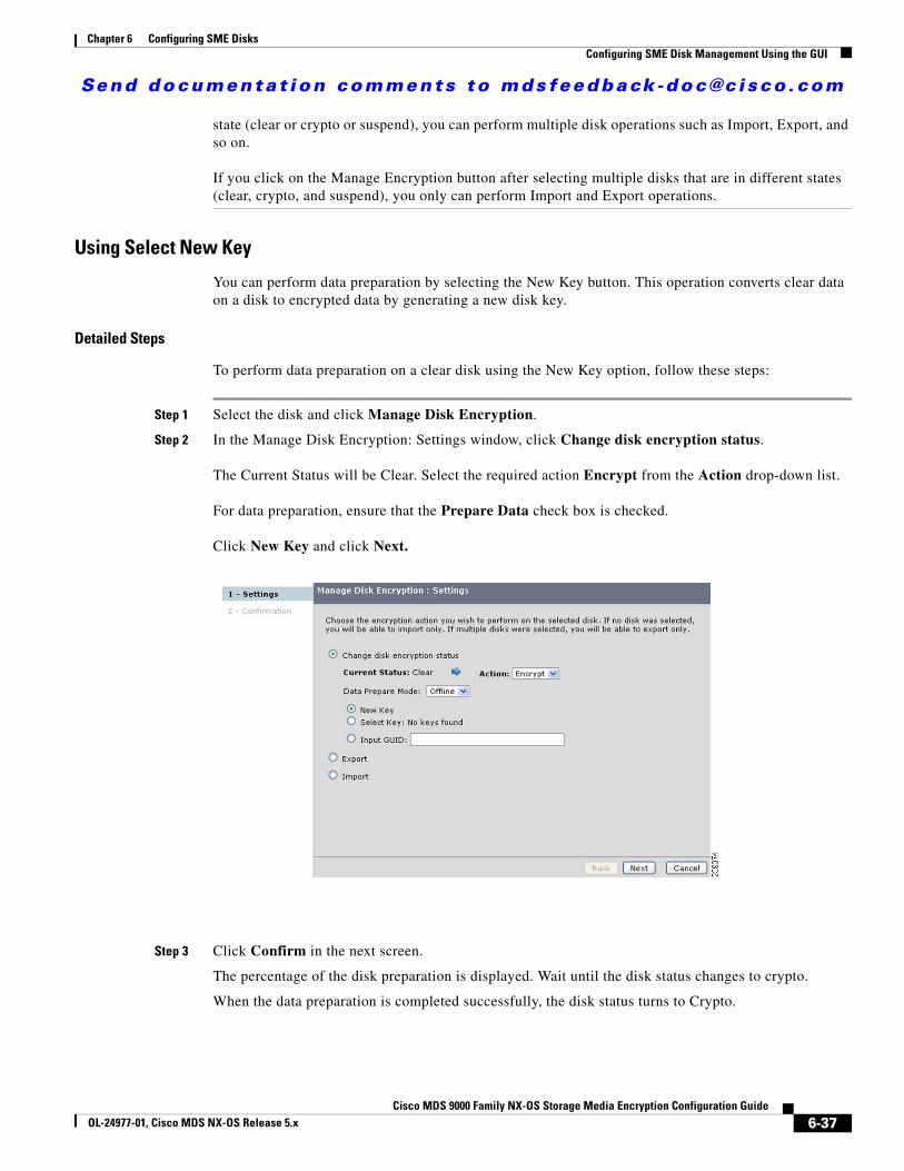
Send documenta t ion comments to mdsfeedback -doc@c i sco .com
Chapter 6 Configuring SME DisksConfiguring SME Disk Management Using the GUI
state (clear or crypto or suspend), you can perform multiple disk operations such as Import, Export, and so on.
If you click on the Manage Encryption button after selecting multiple disks that are in different states (clear, crypto, and suspend), you only can perform Import and Export operations.
Using Select New Key
You can perform data preparation by selecting the New Key button. This operation converts clear data on a disk to encrypted data by generating a new disk key.
Detailed Steps
To perform data preparation on a clear disk using the New Key option, follow these steps:
Step 1 Select the disk and click Manage Disk Encryption.
Step 2 In the Manage Disk Encryption: Settings window, click Change disk encryption status.
The Current Status will be Clear. Select the required action Encrypt from the Action drop-down list.
For data preparation, ensure that the Prepare Data check box is checked.
Click New Key and click Next.
Step 3 Click Confirm in the next screen.
The percentage of the disk preparation is displayed. Wait until the disk status changes to crypto.
When the data preparation is completed successfully, the disk status turns to Crypto.
6-37Cisco MDS 9000 Family NX-OS Storage Media Encryption Configuration Guide
OL-24977-01, Cisco MDS NX-OS Release 5.x
Send documenta t ion comments to mdsfeedback -doc@c i sco .com
Chapter 6 Configuring SME DisksConfiguring SME Disk Management Using the GUI
Note There is no automatic refresh to display the status. The disk preparation status can be monitored only by refreshing the page manually.
Caution Aborting the data preparation results in losing the contents of the disk.
Note You can choose to abort the data preparation process by clicking the Abort button. The Abort button is available under Disk Level when the data preparation is happening.
We do not recommend aborting the data preparation as it will result in losing the contents. However, when you abort the data preparation operation, you need to recover the disk data from the backup. The recover state also should be consistent with the data in the backup.
Using Select Key
You can perform data preparation by using the Select Key button. This operation converts clear data on a disk to encrypted data by using an existing disk key.
Detailed Steps
To perform data preparation on a clear disk using an existing key option, follow these steps:
Step 1 Select the disk and click Manage Disk Encryption.
a. In the Manage Disk Encryption: Settings screen, click Change disk encryption status.
b. The Current Status will be Clear. Select the required action Encrypt from the Action drop-down list.
c. For data preparation, ensure that the Prepare Data check box is checked.
d. Click Select Key and select a key from the drop-down list.
e. Click Next.
6-38Cisco MDS 9000 Family NX-OS Storage Media Encryption Configuration Guide
OL-24977-01, Cisco MDS NX-OS Release 5.x
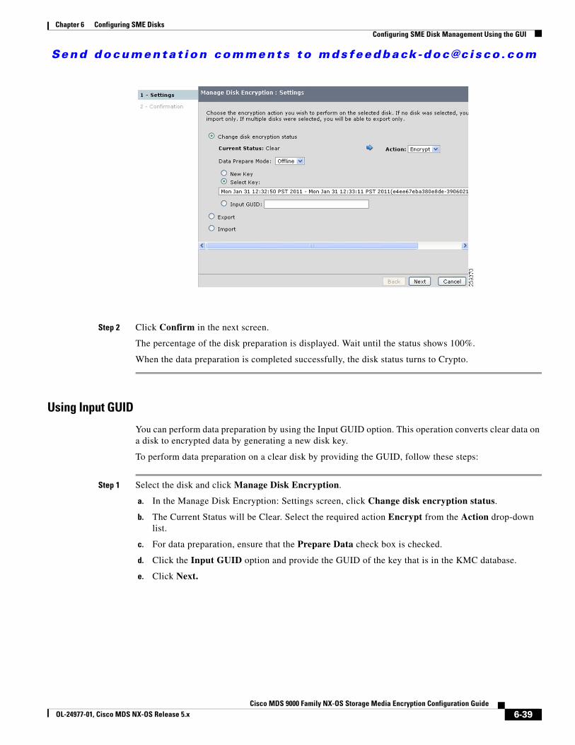
Send documenta t ion comments to mdsfeedback -doc@c i sco .com
Chapter 6 Configuring SME DisksConfiguring SME Disk Management Using the GUI
Step 2 Click Confirm in the next screen.
The percentage of the disk preparation is displayed. Wait until the status shows 100%.
When the data preparation is completed successfully, the disk status turns to Crypto.
Using Input GUID
You can perform data preparation by using the Input GUID option. This operation converts clear data on a disk to encrypted data by generating a new disk key.
To perform data preparation on a clear disk by providing the GUID, follow these steps:
Step 1 Select the disk and click Manage Disk Encryption.
a. In the Manage Disk Encryption: Settings screen, click Change disk encryption status.
b. The Current Status will be Clear. Select the required action Encrypt from the Action drop-down list.
c. For data preparation, ensure that the Prepare Data check box is checked.
d. Click the Input GUID option and provide the GUID of the key that is in the KMC database.
e. Click Next.
6-39Cisco MDS 9000 Family NX-OS Storage Media Encryption Configuration Guide
OL-24977-01, Cisco MDS NX-OS Release 5.x
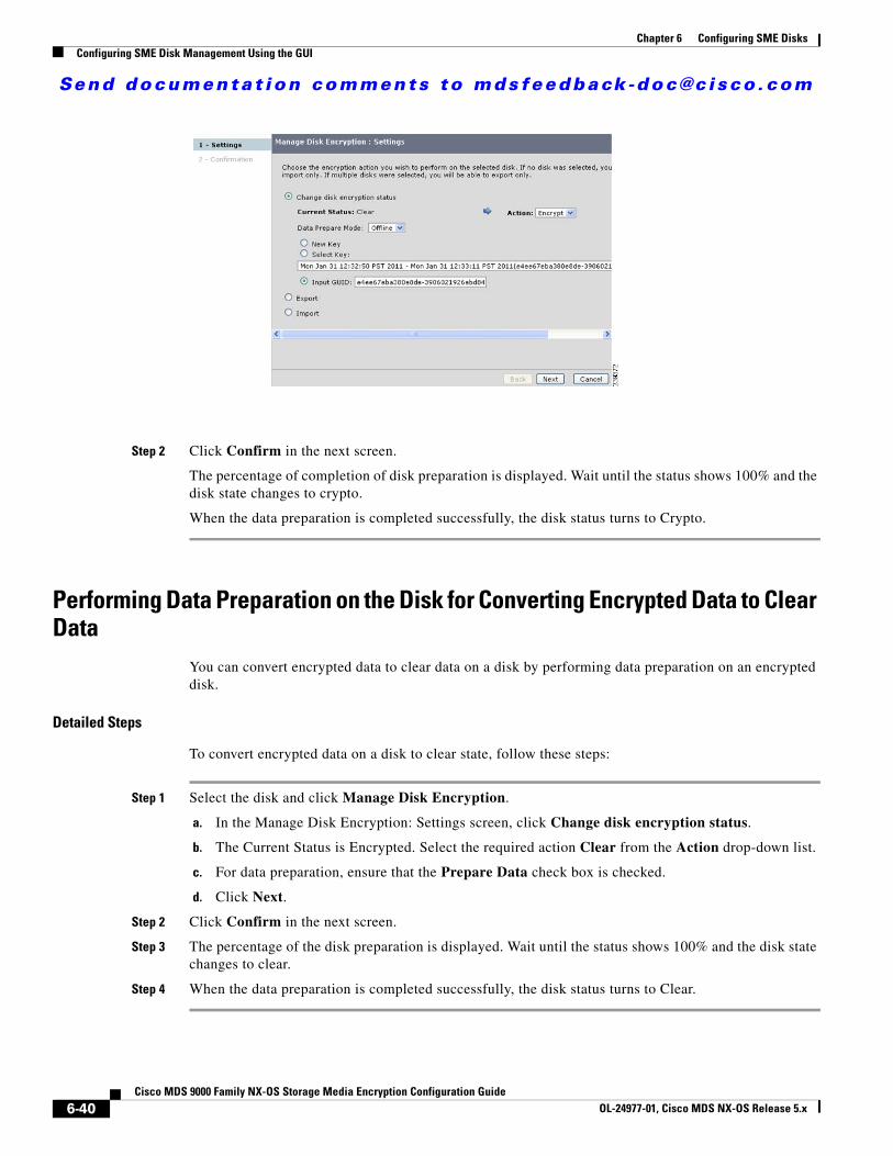
Send documenta t ion comments to mdsfeedback -doc@c i sco .com
Chapter 6 Configuring SME DisksConfiguring SME Disk Management Using the GUI
Step 2 Click Confirm in the next screen.
The percentage of completion of disk preparation is displayed. Wait until the status shows 100% and the disk state changes to crypto.
When the data preparation is completed successfully, the disk status turns to Crypto.
Performing Data Preparation on the Disk for Converting Encrypted Data to Clear Data
You can convert encrypted data to clear data on a disk by performing data preparation on an encrypted disk.
Detailed Steps
To convert encrypted data on a disk to clear state, follow these steps:
Step 1 Select the disk and click Manage Disk Encryption.
a. In the Manage Disk Encryption: Settings screen, click Change disk encryption status.
b. The Current Status is Encrypted. Select the required action Clear from the Action drop-down list.
c. For data preparation, ensure that the Prepare Data check box is checked.
d. Click Next.
Step 2 Click Confirm in the next screen.
Step 3 The percentage of the disk preparation is displayed. Wait until the status shows 100% and the disk state changes to clear.
Step 4 When the data preparation is completed successfully, the disk status turns to Clear.
6-40Cisco MDS 9000 Family NX-OS Storage Media Encryption Configuration Guide
OL-24977-01, Cisco MDS NX-OS Release 5.x
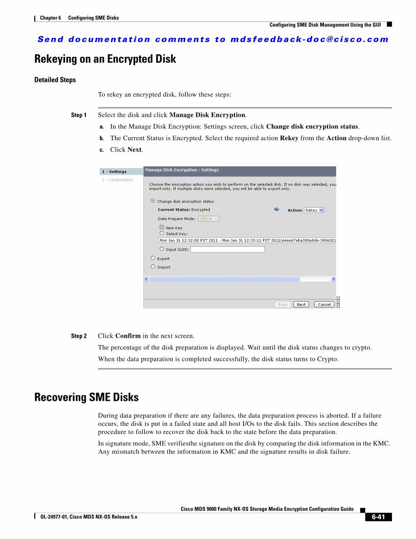
Send documenta t ion comments to mdsfeedback -doc@c i sco .com
Chapter 6 Configuring SME DisksConfiguring SME Disk Management Using the GUI
Rekeying on an Encrypted Disk
Detailed Steps
To rekey an encrypted disk, follow these steps:
Step 1 Select the disk and click Manage Disk Encryption.
a. In the Manage Disk Encryption: Settings screen, click Change disk encryption status.
b. The Current Status is Encrypted. Select the required action Rekey from the Action drop-down list.
c. Click Next.
Step 2 Click Confirm in the next screen.
The percentage of the disk preparation is displayed. Wait until the disk status changes to crypto.
When the data preparation is completed successfully, the disk status turns to Crypto.
Recovering SME DisksDuring data preparation if there are any failures, the data preparation process is aborted. If a failure occurs, the disk is put in a failed state and all host I/Os to the disk fails. This section describes the procedure to follow to recover the disk back to the state before the data preparation.
In signature mode, SME verifiesthe signature on the disk by comparing the disk information in the KMC. Any mismatch between the information in KMC and the signature results in disk failure.
6-41Cisco MDS 9000 Family NX-OS Storage Media Encryption Configuration Guide
OL-24977-01, Cisco MDS NX-OS Release 5.x

Send documenta t ion comments to mdsfeedback -doc@c i sco .com
Chapter 6 Configuring SME DisksConfiguring SME Disk Management Using the GUI
Caution The Recover command does not recover the contents of the disk. This command recovers the crypto-state of the disk based on the data recovered into the disk. The data on the disk must first be restored before using the recover command.
Note Restoration of the contents of the disk is done by a backend storage operation that copies the backup data from a mirror or snapshot in the disk array. This restoration does not require the failed disk to be accessible from host. This is important because SME does not allow any host access to the failed disk.
Recovering a Disk to Clear Status
Detailed Steps
To recover a failure disk to a clear disk, follow these steps:
Step 1 Click the disk that is in failed (Failure) state.
Step 2 Click the Recover option that is available in the Disk Details area.
Step 3 Select Recover to clear snapshot and click Next.
Step 4 Click Confirm to perform the recover operation on the Recover Disk : Confirmation screen.
The disk recovered successful message is displayed in the top of the screen showing the disk status as Clear.
Recovering a Disk to Encrypted Status
Detailed Steps
To recover a failure disk to a crypto disk, follow these steps:
Step 1 Click the disk that is in failed state.
Step 2 Click the Recover option that is available in the Disk Details area.
Step 3 Select Recover to crypto snapshot by providing the key GUID and click Next.
Step 4 Click Confirm to perform the recover operation on the Recover Disk: Confirmation screen.
The Disk recovered successful message is displayed in the top of the screen showing the disk status as Crypto.
Recovering a Disk Using Metadata Signature
Note You can only recover signature disks.
6-42Cisco MDS 9000 Family NX-OS Storage Media Encryption Configuration Guide
OL-24977-01, Cisco MDS NX-OS Release 5.x
Send documenta t ion comments to mdsfeedback -doc@c i sco .com
Chapter 6 Configuring SME DisksConfiguring SME Disk Management Using the GUI
Detailed Steps
To recover the failure disk using the metadata, follow these steps:
Step 1 Click the disk that is in failed state.
Step 2 Click the Recover option that is available in the Disk Details area.
Step 3 Select Recover from metadata by providing the key GUID and click Next.
Step 4 Click Confirm to perform the recover operation on the Recover Disk: Confirmation screen.
The Disk recovered successful message is displayed in the top of the screen.
Recovering a Disk from Key Manager
Step 1 Click the disk that is in failed state.
Step 2 Click the Recover option that is available in the Disk Details area.
Step 3 Select Recover from key manager by providing the key GUID and click Next.
Step 4 Click Confirm to perform the recover operation on the Recover Disk: Confirmation screen.
The Disk recovered successful message is displayed in the top of the screen.
Performing Disk Encryption to Convert the Disk Status from Clear to CryptoYou can perform disk encryption operation to convert the disk status from clear to crypto using the following options:
• Using Select New Key, page 6-43
• Using Input GUID, page 6-44
• Using Input GUID, page 6-44
Using Select New Key
You can perform disk encryption by selecting the New Key button. This operation converts the disk status from clear to crypto by using new disk key.
Detailed Steps
To perform disk encryption using the New Key option, follow these steps:
Step 1 Select the disk and click Manage Disk Encryption.
a. In the Manage Disk Encryption: Settings screen, click Change disk encryption status.
b. The Current Status will be Clear. Select the required action Encrypt from the Action drop-down list.
c. For disk encryption, ensure that the Prepare Data check box is not checked.
6-43Cisco MDS 9000 Family NX-OS Storage Media Encryption Configuration Guide
OL-24977-01, Cisco MDS NX-OS Release 5.x
Send documenta t ion comments to mdsfeedback -doc@c i sco .com
Chapter 6 Configuring SME DisksConfiguring SME Disk Management Using the GUI
d. Select New Key and click Next.
Step 2 Click Confirm in the next screen.
The percentage of the disk encryption is displayed. Wait until the status shows 100%.
When the disk encryption is completed successfully, the disk status turns to Crypto.
Using Select Key
You can perform disk encryption by using the Select Key option. This operation converts the disk status from clear to crypto by using an existing disk key.
Detailed Steps
To perform disk encryption using an existing key option, follow these steps:
Step 1 Select the disk and click Manage Disk Encryption.
a. In the Manage Disk Encryption: Settings screen, click Change disk encryption status.
b. The Current Status will be Clear. Select the required action Encrypt from the Action drop-down list.
c. For disk encryption, ensure that the Prepare Data check box is not checked.
d. Click Select Key and select a key from the drop-down list. Click Next.
Step 2 Click Confirm in the next screen.
The percentage of the disk preparation is displayed. Wait until the status shows 100%.
When the disk encryption is completed successfully, the disk status turns to Crypto.
Using Input GUID
You can perform disk encryption by using the Input GUID option. This operation converts the disk status from clear to crypto by using Input GUID.
Detailed Steps
To perform disk encryption using the Input GUID, follow these steps:
Step 1 Select the disk and click Manage Disk Encryption.
a. In the Manage Disk Encryption: Settings screen, click Change disk encryption status.
b. The Current Status will be Clear. Select the required action Encrypt from the Action drop-down list.
c. For disk encryption, ensure that the Prepare Data check box is not checked.
d. Select the Input GUID option and provide the GUID of the key that is in the KMC database. Click Next.
Step 2 Click Confirm in the next screen.
6-44Cisco MDS 9000 Family NX-OS Storage Media Encryption Configuration Guide
OL-24977-01, Cisco MDS NX-OS Release 5.x
Send documenta t ion comments to mdsfeedback -doc@c i sco .com
Chapter 6 Configuring SME DisksConfiguring SME Disk Management Using the GUI
The percentage of the disk preparation is displayed. Wait until the status shows 100%.
When the disk encryption is completed successfully, the disk status turns to Crypto.
Performing Disk Encryption to Convert the Disk Status from Crypto to Clear
Detailed Steps
To perform disk encryption operation for converting the disk status from crypto to clear, follow these steps:
Step 1 Select the disk and click Manage Disk Encryption.
a. In the Manage Disk Encryption: Settings screen, click Change disk encryption status.
b. The Current Status is Encrypted. Select the required action Clear from the Action drop-down list.
c. For disk encryption, ensure that the Prepare Data check box is not checked.
d. Click Next.
Step 2 Click Confirm in the next screen.
The percentage of the disk preparation is displayed. Wait until the status shows 100%.
When the disk encryption is completed successfully, the disk status turns to Clear.
Exporting and Importing KeysYou can explicitly export the keys that are generated during the key generation process or encryption process, and save the keys in a password-protected file.
Note The disk keys are not protected by the master key. However, they are protected by the password generated key.
This section includes these exporting and importing tasks:
• Exporting Keys for Single Disk, page 6-45
• Exporting Keys for Multiple Disks, page 6-46
• Importing Keys to a Single Disk or to a Disk Set, page 6-46
Exporting Keys for Single Disk
You can export keys for a single disk by selecting a particular disk.
6-45Cisco MDS 9000 Family NX-OS Storage Media Encryption Configuration Guide
OL-24977-01, Cisco MDS NX-OS Release 5.x
Send documenta t ion comments to mdsfeedback -doc@c i sco .com
Chapter 6 Configuring SME DisksConfiguring SME Disk Management Using the GUI
Detailed Steps
To export keys for a single disk, follow these steps:
Step 1 Select a single disk from a disk group and click Manage Encryption.
Step 2 In the Manage Disk Encryption: Settings screen, click Export.
a. Provide data for Password and Confirm Password in the appropriate fields.
b. Click Next.
Step 3 The keys for the selected disk are exported to a file. Click Download in the next screen to begin the download.
Step 4 When the download activity is completed, click Close to close the wizard.
Exporting Keys for Multiple Disks
You can export keys for multiple disks by selecting multiple disks.
Detailed Steps
To export keys for multiple disks, follow these steps:
Step 1 Select multiple disks from a disk group and click Manage Encryption.
Step 2 In the Manage Disk Encryption: Settings screen, click Export.
a. Provide data for Password and Confirm Password in the appropriate fields.
b. Click Next.
Step 3 The keys for the selected disks are exported to a file. Click Download in the next screen to begin the download.
Step 4 When the download activity is completed, click Close to close the wizard.
Importing Keys to a Single Disk or to a Disk Set
You can import keys to a single disk or import the disk keys to a defined disk set.
Detailed Steps
To import keys to a single disk or to a defined disk set, follow these steps:
Step 1 Do not select any disk. Click Manage Encryption.
Step 2 In the Manage Disk Encryption: Settings screen, click Import.
a. Browse to the single or multiple keys file from where the key or keys file was exported earlier. Provide the password for the corresponding file in the field provided to perform import operation.
b. Click Next.
6-46Cisco MDS 9000 Family NX-OS Storage Media Encryption Configuration Guide
OL-24977-01, Cisco MDS NX-OS Release 5.x
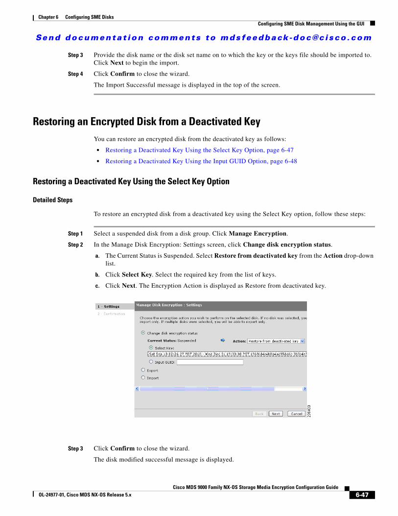
Send documenta t ion comments to mdsfeedback -doc@c i sco .com
Chapter 6 Configuring SME DisksConfiguring SME Disk Management Using the GUI
Step 3 Provide the disk name or the disk set name on to which the key or the keys file should be imported to. Click Next to begin the import.
Step 4 Click Confirm to close the wizard.
The Import Successful message is displayed in the top of the screen.
Restoring an Encrypted Disk from a Deactivated KeyYou can restore an encrypted disk from the deactivated key as follows:
• Restoring a Deactivated Key Using the Select Key Option, page 6-47
• Restoring a Deactivated Key Using the Input GUID Option, page 6-48
Restoring a Deactivated Key Using the Select Key Option
Detailed Steps
To restore an encrypted disk from a deactivated key using the Select Key option, follow these steps:
Step 1 Select a suspended disk from a disk group. Click Manage Encryption.
Step 2 In the Manage Disk Encryption: Settings screen, click Change disk encryption status.
a. The Current Status is Suspended. Select Restore from deactivated key from the Action drop-down list.
b. Click Select Key. Select the required key from the list of keys.
c. Click Next. The Encryption Action is displayed as Restore from deactivated key.
Step 3 Click Confirm to close the wizard.
The disk modified successful message is displayed.
6-47Cisco MDS 9000 Family NX-OS Storage Media Encryption Configuration Guide
OL-24977-01, Cisco MDS NX-OS Release 5.x
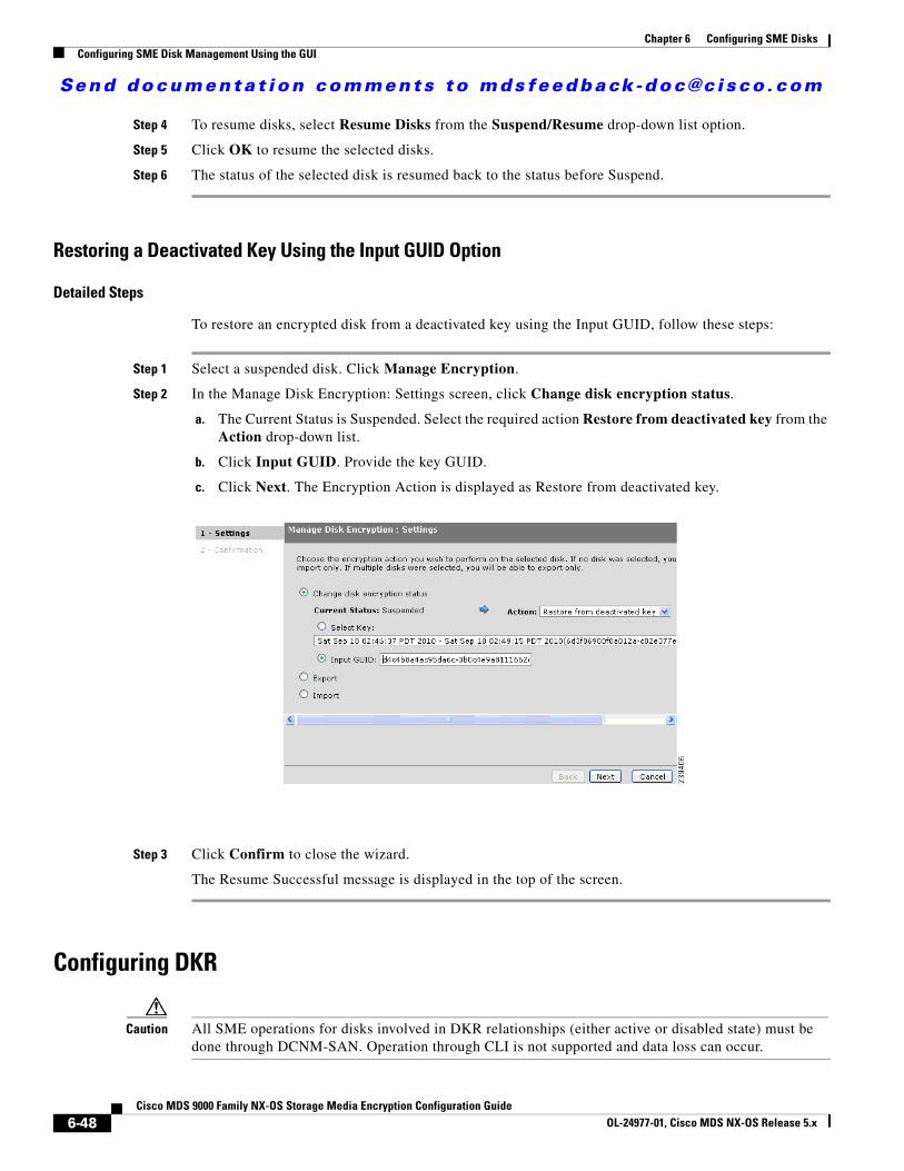
Send documenta t ion comments to mdsfeedback -doc@c i sco .com
Chapter 6 Configuring SME DisksConfiguring SME Disk Management Using the GUI
Step 4 To resume disks, select Resume Disks from the Suspend/Resume drop-down list option.
Step 5 Click OK to resume the selected disks.
Step 6 The status of the selected disk is resumed back to the status before Suspend.
Restoring a Deactivated Key Using the Input GUID Option
Detailed Steps
To restore an encrypted disk from a deactivated key using the Input GUID, follow these steps:
Step 1 Select a suspended disk. Click Manage Encryption.
Step 2 In the Manage Disk Encryption: Settings screen, click Change disk encryption status.
a. The Current Status is Suspended. Select the required action Restore from deactivated key from the Action drop-down list.
b. Click Input GUID. Provide the key GUID.
c. Click Next. The Encryption Action is displayed as Restore from deactivated key.
Step 3 Click Confirm to close the wizard.
The Resume Successful message is displayed in the top of the screen.
Configuring DKR
Caution All SME operations for disks involved in DKR relationships (either active or disabled state) must be done through DCNM-SAN. Operation through CLI is not supported and data loss can occur.
6-48Cisco MDS 9000 Family NX-OS Storage Media Encryption Configuration Guide
OL-24977-01, Cisco MDS NX-OS Release 5.x
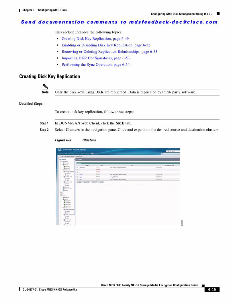
Send documenta t ion comments to mdsfeedback -doc@c i sco .com
Chapter 6 Configuring SME DisksConfiguring SME Disk Management Using the GUI
This section includes the following topics:
• Creating Disk Key Replication, page 6-49
• Enabling or Disabling Disk Key Replication, page 6-52
• Removing or Deleting Replication Relationships, page 6-53
• Importing DKR Configurations, page 6-53
• Performing the Sync Operation, page 6-54
Creating Disk Key Replication
Note Only the disk keys using DKR are replicated. Data is replicated by third- party software.
Detailed Steps
To create disk key replication, follow these steps:
Step 1 In DCNM-SAN Web Client, click the SME tab.
Step 2 Select Clusters in the navigation pane. Click and expand on the desired source and destination clusters.
Figure 6-3 Clusters
6-49Cisco MDS 9000 Family NX-OS Storage Media Encryption Configuration Guide
OL-24977-01, Cisco MDS NX-OS Release 5.x
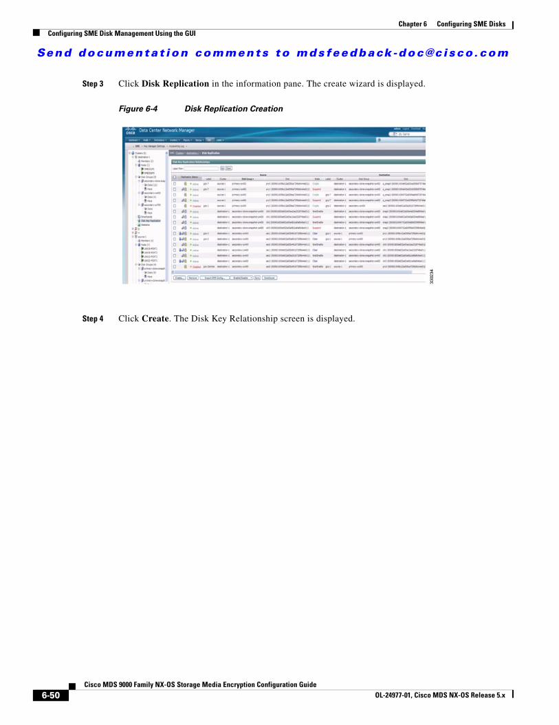
Send documenta t ion comments to mdsfeedback -doc@c i sco .com
Chapter 6 Configuring SME DisksConfiguring SME Disk Management Using the GUI
Step 3 Click Disk Replication in the information pane. The create wizard is displayed.
Figure 6-4 Disk Replication Creation
Step 4 Click Create. The Disk Key Relationship screen is displayed.
6-50Cisco MDS 9000 Family NX-OS Storage Media Encryption Configuration Guide
OL-24977-01, Cisco MDS NX-OS Release 5.x
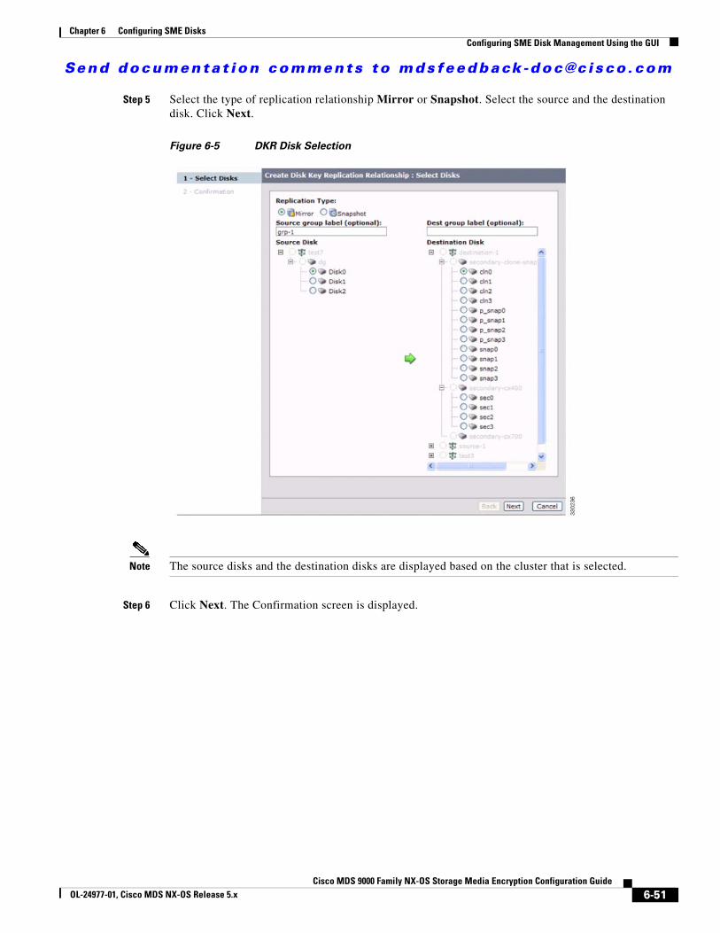
Send documenta t ion comments to mdsfeedback -doc@c i sco .com
Chapter 6 Configuring SME DisksConfiguring SME Disk Management Using the GUI
Step 5 Select the type of replication relationship Mirror or Snapshot. Select the source and the destination disk. Click Next.
Figure 6-5 DKR Disk Selection
Note The source disks and the destination disks are displayed based on the cluster that is selected.
Step 6 Click Next. The Confirmation screen is displayed.
6-51Cisco MDS 9000 Family NX-OS Storage Media Encryption Configuration Guide
OL-24977-01, Cisco MDS NX-OS Release 5.x
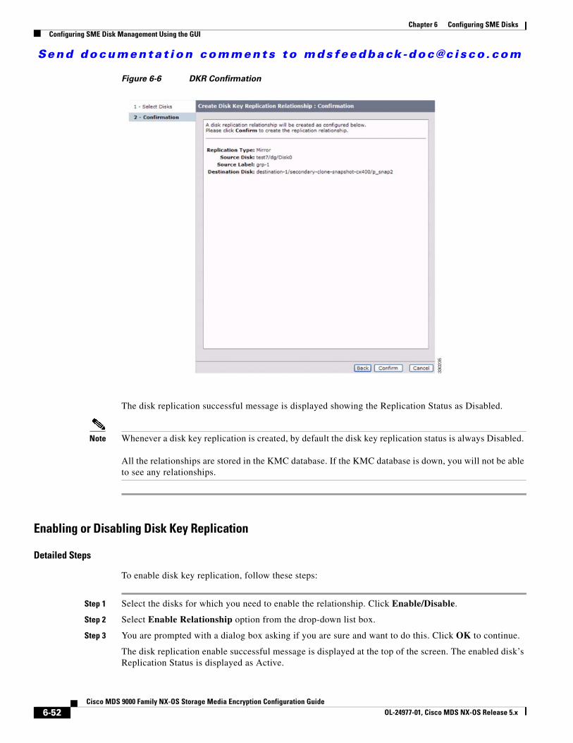
Send documenta t ion comments to mdsfeedback -doc@c i sco .com
Chapter 6 Configuring SME DisksConfiguring SME Disk Management Using the GUI
Figure 6-6 DKR Confirmation
The disk replication successful message is displayed showing the Replication Status as Disabled.
Note Whenever a disk key replication is created, by default the disk key replication status is always Disabled.
All the relationships are stored in the KMC database. If the KMC database is down, you will not be able to see any relationships.
Enabling or Disabling Disk Key Replication
Detailed Steps
To enable disk key replication, follow these steps:
Step 1 Select the disks for which you need to enable the relationship. Click Enable/Disable.
Step 2 Select Enable Relationship option from the drop-down list box.
Step 3 You are prompted with a dialog box asking if you are sure and want to do this. Click OK to continue.
The disk replication enable successful message is displayed at the top of the screen. The enabled disk’s Replication Status is displayed as Active.
6-52Cisco MDS 9000 Family NX-OS Storage Media Encryption Configuration Guide
OL-24977-01, Cisco MDS NX-OS Release 5.x

Send documenta t ion comments to mdsfeedback -doc@c i sco .com
Chapter 6 Configuring SME DisksConfiguring SME Disk Management Using the GUI
Step 4 Perform disk encryption on the replicated disk.
Note The source and destination disk can either be in the same cluster or be in a different cluster; however, they should be using the same KMC.
A source disk can be a source disk for multiple relationships. However, the destination disk can be the destination disk for only one relationship.
A source disk must be discovered and configured in the source cluster before an DKR relationship is established.
Note If the source disk or the destination disk is not in either CLEAR, CRYPTO, or FAILED states, DCNM-SAN displays an error and does not process the entry. The state of the source disk or the destination disk must be obtained from the switch.
To disable disk key replications, follow these steps:
Step 1 Select the disks for which you need to disable the relationship. Click Enable/Disable.
Step 2 Select Disable Relationship.
Step 3 The prompt appears asking you are sure you want to do this. Click OK to continue.
The disk replication disable successful message is displayed at the top of the screen. The disabled disk’s Replication Status is displayed as Disabled.
Removing or Deleting Replication Relationships
Detailed Steps
To remove or delete replication relationships, follow these steps:
Step 1 Select the disks for which you need to remove or delete the relationship. Click Remove.
Step 2 You are prompted a question if you are sure to remove replication relationships. Click OK to continue.
The replication relationships are removed or deleted.
Importing DKR Configurations
To import an DKR relationship configuration file, follow these steps:
6-53Cisco MDS 9000 Family NX-OS Storage Media Encryption Configuration Guide
OL-24977-01, Cisco MDS NX-OS Release 5.x
Send documenta t ion comments to mdsfeedback -doc@c i sco .com
Chapter 6 Configuring SME DisksConfiguring Key Management Operations
Step 1 Click Import DKR Config...The Import DKR config file: Provide file screen is displayed. Click Browse and select the required DKR Config File.
Step 2 Click Next. The confirmation screen is displayed asking you to confirm to begin import of the DKR Config file. Click Confirm to continue.
The import file operation is processed and the DKR Config file is imported and successful import message is displayed.
Performing the Switchover Operation
Detailed Steps
You can perform a switchover operation to swap the source and destination in a disk key replication relationship. A switchover can only be performed on a DKR relationship in a Disabled state. To perform the switchover operation, follow these steps:
Step 1 Select the disabled relationships on which you want to perform the switchover operation. Click Switchover.
Step 2 You are prompted a question if you are sure you want to do this. Click OK to continue.
The relationships will have their source and destinations swapped. The relationships will still be in a disabled state.
Labels & Filtering
Labels can be associated with both sides of a disk key replication relationship. The DKR view provides the ability to filter based on these labels.
Performing the Sync Operation
You can perform the Sync operation on multiple relationships. To do this, follow these steps:
Step 1 Select the relationships on which you want to perform the Sync operation. Click Sync.
Step 2 You are prompted a question if you are sure you want to do this. Click OK to continue.
The relationships are replicated and are made similar and in sync with each other.
Configuring Key Management OperationsThis section includes the following topics:
• Replacing Smart Cards, page 6-55
• Configuring Master Key Rekey, page 6-56
6-54Cisco MDS 9000 Family NX-OS Storage Media Encryption Configuration Guide
OL-24977-01, Cisco MDS NX-OS Release 5.x
Send documenta t ion comments to mdsfeedback -doc@c i sco .com
Chapter 6 Configuring SME DisksConfiguring Key Management Operations
Replacing Smart CardsThis section describes how to replace smart cards for clusters.
Detailed Steps
To replace a smart card (Advanced security mode), follow these steps:
Step 1 Under Data Center Network Manager, click SME. The cluster list is displayed.
Step 2 Click Smartcards. The Recovery shares details along with the associated list of smart cards is displayed.
Step 3 Select the smart card that you would want to replace and click Replace Smartcard and Rekey Master Key.
The smart card replacement wizard is displayed.
Step 4 Insert the new smart card. Click Next.
The SME Recovery Officer who owns the replacement smart card is prompted to log in and to insert the smart card to download the master key.
Step 5 Enter the switch login information and the smart card PIN and label. Click Next.
Each member of the Cisco Recovery Officer quorum is requested to log in and present their smart card to authorize and authenticate the operation.
Step 6 Insert one of the smart cards that stores the master key. Click Next.
Step 7 Enter the switch login information and the smart card PIN and Label. Click Next. Do this for each of the smart cards.
Step 8 Insert the smart cards belonging to each recovery officer in any order.
To store the new master keyshares, follow these steps:
a. Enter the switch login information, the PIN number for the smart card, and a label that will identify the smart card. Click Next.
A notification is shown that the first keyshare is successfully stored.
b. Enter the switch credentials and PIN information for the second recovery officer. Click Next.
A notification is shown that the second keyshare is successfully stored.
c. Enter the switch credentials and PIN information for the third recovery officer. Click Next.
A notification is shown that the third keyshare is successfully stored.
d. Enter the switch credentials and PIN information for the fourth recovery officer. Click Next.
A notification is shown that the fourth keyshare is successfully stored.
e. Enter the switch credentials and PIN information for the fifth recovery officer. Click Next.
A notification is shown that the fifth keyshare is successfully stored. Click Next to begin the automatic synchronization of volume groups.
Step 9 The smart card replacement is completed. Click Close to return to the DCNM-SAN Web Client and to view the smart card information.
Step 10 Select Smartcards to view the new smart card information. The smart card details display the old recovery shares and the new recovery shares.
6-55Cisco MDS 9000 Family NX-OS Storage Media Encryption Configuration Guide
OL-24977-01, Cisco MDS NX-OS Release 5.x
Send documenta t ion comments to mdsfeedback -doc@c i sco .com
Chapter 6 Configuring SME DisksConfiguring Key Management Operations
Configuring Master Key RekeyYou can initiate the master key rekey operation using one of the following methods:
• Under Data Center Network Manager, click SME. The cluster list is displayed. Click on the required cluster. Under Cluster Details > Security Mode, click Rekey Master Key.
• Under Data Center Network Manager, click SME. The cluster list is displayed. Click Smartcards. The Recovery shares details along with the associated list of smart cards is displayed. Under Recovery Shares, click Rekey Master Key.
Prerequisites
• Ensure you install the smartcard drivers on the web client where MKR is initiated.
• Ensure there is IP communication between the Cisco DCNM server, primary server, secondary server, CKMC, and switches.
• Ensure Cisco DCNM-SAN services are running.
• Ensure the clusters are online throughout the MKR process.
• Ensure you export the keys before starting MKR.
• Ensure there is free space for new shares on the smart cards.
• Always start MKR on a fresh browser and ensure there are no instances of DCNM client running.
• Ensure you do not start MKR if the disk is in one of the following states:
– DP error
– DP in-progress
– Pending KMC update
– ITL Offline
– Crypto state with no paths (VPD not known)
– Suspend state with no paths (VPD not known)
– Data Prepare (discovery pending)
– Wait enabled
Detailed Steps
Step 1 Once you initiate the rekey master key operation, you will receive a confirmation dialog box. Click OK
The Get Keyshares dialog box is displayed.
Note All nodes that are part of the cluster should remain online until the rekey master key operation is complete.
Step 2 Insert the Smart Card.
To rekey the master keyshares, follow these steps:
a. Enter the switch login information, the PIN number for the smart card, and a label that will identify the smart card. Click Next.
A notification is shown that the first keyshare is successfully stored.
6-56Cisco MDS 9000 Family NX-OS Storage Media Encryption Configuration Guide
OL-24977-01, Cisco MDS NX-OS Release 5.x
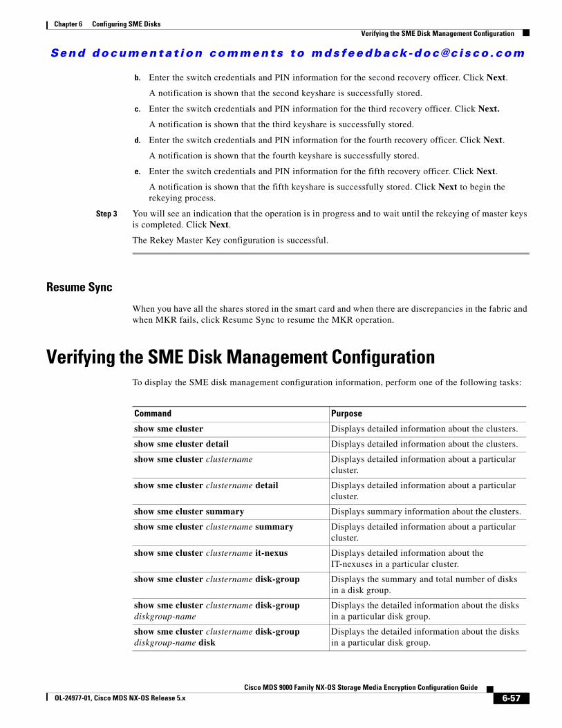
Send documenta t ion comments to mdsfeedback -doc@c i sco .com
Chapter 6 Configuring SME DisksVerifying the SME Disk Management Configuration
b. Enter the switch credentials and PIN information for the second recovery officer. Click Next.
A notification is shown that the second keyshare is successfully stored.
c. Enter the switch credentials and PIN information for the third recovery officer. Click Next.
A notification is shown that the third keyshare is successfully stored.
d. Enter the switch credentials and PIN information for the fourth recovery officer. Click Next.
A notification is shown that the fourth keyshare is successfully stored.
e. Enter the switch credentials and PIN information for the fifth recovery officer. Click Next.
A notification is shown that the fifth keyshare is successfully stored. Click Next to begin the rekeying process.
Step 3 You will see an indication that the operation is in progress and to wait until the rekeying of master keys is completed. Click Next.
The Rekey Master Key configuration is successful.
Resume Sync
When you have all the shares stored in the smart card and when there are discrepancies in the fabric and when MKR fails, click Resume Sync to resume the MKR operation.
Verifying the SME Disk Management ConfigurationTo display the SME disk management configuration information, perform one of the following tasks:
Command Purpose
show sme cluster Displays detailed information about the clusters.
show sme cluster detail Displays detailed information about the clusters.
show sme cluster clustername Displays detailed information about a particular cluster.
show sme cluster clustername detail Displays detailed information about a particular cluster.
show sme cluster summary Displays summary information about the clusters.
show sme cluster clustername summary Displays detailed information about a particular cluster.
show sme cluster clustername it-nexus Displays detailed information about the IT-nexuses in a particular cluster.
show sme cluster clustername disk-group Displays the summary and total number of disks in a disk group.
show sme cluster clustername disk-group diskgroup-name
Displays the detailed information about the disks in a particular disk group.
show sme cluster clustername disk-group diskgroup-name disk
Displays the detailed information about the disks in a particular disk group.
6-57Cisco MDS 9000 Family NX-OS Storage Media Encryption Configuration Guide
OL-24977-01, Cisco MDS NX-OS Release 5.x
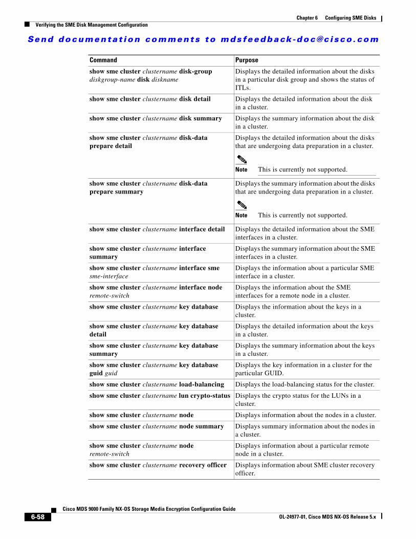
Send documenta t ion comments to mdsfeedback -doc@c i sco .com
Chapter 6 Configuring SME DisksVerifying the SME Disk Management Configuration
show sme cluster clustername disk-group diskgroup-name disk diskname
Displays the detailed information about the disks in a particular disk group and shows the status of ITLs.
show sme cluster clustername disk detail Displays the detailed information about the disk in a cluster.
show sme cluster clustername disk summary Displays the summary information about the disk in a cluster.
show sme cluster clustername disk-data prepare detail
Displays the detailed information about the disks that are undergoing data preparation in a cluster.
Note This is currently not supported.
show sme cluster clustername disk-data prepare summary
Displays the summary information about the disks that are undergoing data preparation in a cluster.
Note This is currently not supported.
show sme cluster clustername interface detail Displays the detailed information about the SME interfaces in a cluster.
show sme cluster clustername interface summary
Displays the summary information about the SME interfaces in a cluster.
show sme cluster clustername interface sme sme-interface
Displays the information about a particular SME interface in a cluster.
show sme cluster clustername interface node remote-switch
Displays the information about the SME interfaces for a remote node in a cluster.
show sme cluster clustername key database Displays the information about the keys in a cluster.
show sme cluster clustername key database detail
Displays the detailed information about the keys in a cluster.
show sme cluster clustername key database summary
Displays the summary information about the keys in a cluster.
show sme cluster clustername key database guid guid
Displays the key information in a cluster for the particular GUID.
show sme cluster clustername load-balancing Displays the load-balancing status for the cluster.
show sme cluster clustername lun crypto-status Displays the crypto status for the LUNs in a cluster.
show sme cluster clustername node Displays information about the nodes in a cluster.
show sme cluster clustername node summary Displays summary information about the nodes in a cluster.
show sme cluster clustername node remote-switch
Displays information about a particular remote node in a cluster.
show sme cluster clustername recovery officer Displays information about SME cluster recovery officer.
Command Purpose
6-58Cisco MDS 9000 Family NX-OS Storage Media Encryption Configuration Guide
OL-24977-01, Cisco MDS NX-OS Release 5.x
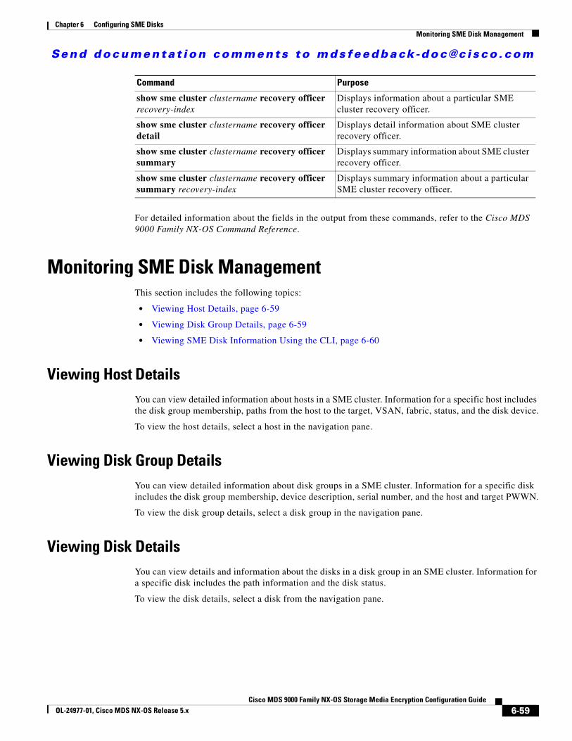
Send documenta t ion comments to mdsfeedback -doc@c i sco .com
Chapter 6 Configuring SME DisksMonitoring SME Disk Management
For detailed information about the fields in the output from these commands, refer to the Cisco MDS 9000 Family NX-OS Command Reference.
Monitoring SME Disk ManagementThis section includes the following topics:
• Viewing Host Details, page 6-59
• Viewing Disk Group Details, page 6-59
• Viewing SME Disk Information Using the CLI, page 6-60
Viewing Host DetailsYou can view detailed information about hosts in a SME cluster. Information for a specific host includes the disk group membership, paths from the host to the target, VSAN, fabric, status, and the disk device.
To view the host details, select a host in the navigation pane.
Viewing Disk Group DetailsYou can view detailed information about disk groups in a SME cluster. Information for a specific disk includes the disk group membership, device description, serial number, and the host and target PWWN.
To view the disk group details, select a disk group in the navigation pane.
Viewing Disk DetailsYou can view details and information about the disks in a disk group in an SME cluster. Information for a specific disk includes the path information and the disk status.
To view the disk details, select a disk from the navigation pane.
show sme cluster clustername recovery officer recovery-index
Displays information about a particular SME cluster recovery officer.
show sme cluster clustername recovery officer detail
Displays detail information about SME cluster recovery officer.
show sme cluster clustername recovery officer summary
Displays summary information about SME cluster recovery officer.
show sme cluster clustername recovery officer summary recovery-index
Displays summary information about a particular SME cluster recovery officer.
Command Purpose
6-59Cisco MDS 9000 Family NX-OS Storage Media Encryption Configuration Guide
OL-24977-01, Cisco MDS NX-OS Release 5.x
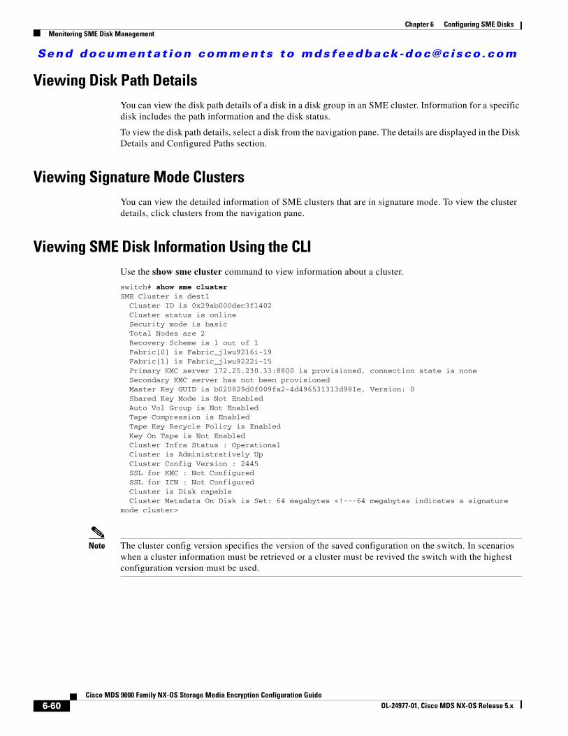
Send documenta t ion comments to mdsfeedback -doc@c i sco .com
Chapter 6 Configuring SME DisksMonitoring SME Disk Management
Viewing Disk Path DetailsYou can view the disk path details of a disk in a disk group in an SME cluster. Information for a specific disk includes the path information and the disk status.
To view the disk path details, select a disk from the navigation pane. The details are displayed in the Disk Details and Configured Paths section.
Viewing Signature Mode ClustersYou can view the detailed information of SME clusters that are in signature mode. To view the cluster details, click clusters from the navigation pane.
Viewing SME Disk Information Using the CLIUse the show sme cluster command to view information about a cluster.
switch# show sme cluster SME Cluster is dest1 Cluster ID is 0x29ab000dec3f1402 Cluster status is online Security mode is basic Total Nodes are 2 Recovery Scheme is 1 out of 1 Fabric[0] is Fabric_jlwu9216i-19 Fabric[1] is Fabric_jlwu9222i-15 Primary KMC server 172.25.230.33:8800 is provisioned, connection state is none Secondary KMC server has not been provisioned Master Key GUID is b020829d0f009fa2-4d496531313d981e, Version: 0 Shared Key Mode is Not Enabled Auto Vol Group is Not Enabled Tape Compression is Enabled Tape Key Recycle Policy is Enabled Key On Tape is Not Enabled Cluster Infra Status : Operational Cluster is Administratively Up Cluster Config Version : 2445 SSL for KMC : Not Configured SSL for ICN : Not Configured Cluster is Disk capable Cluster Metadata On Disk is Set: 64 megabytes <!---64 megabytes indicates a signature mode cluster>
Note The cluster config version specifies the version of the saved configuration on the switch. In scenarios when a cluster information must be retrieved or a cluster must be revived the switch with the highest configuration version must be used.
6-60Cisco MDS 9000 Family NX-OS Storage Media Encryption Configuration Guide
OL-24977-01, Cisco MDS NX-OS Release 5.x
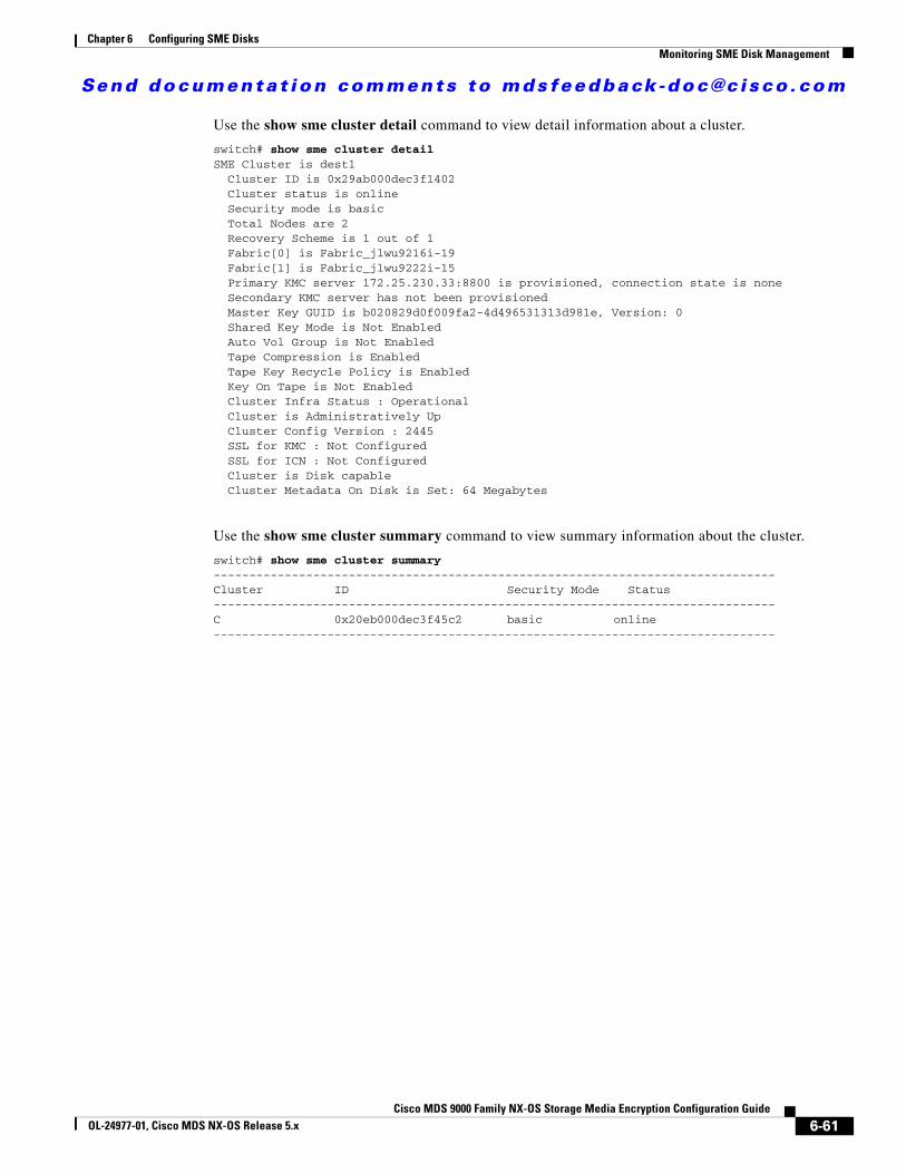
Send documenta t ion comments to mdsfeedback -doc@c i sco .com
Chapter 6 Configuring SME DisksMonitoring SME Disk Management
Use the show sme cluster detail command to view detail information about a cluster.
switch# show sme cluster detail SME Cluster is dest1 Cluster ID is 0x29ab000dec3f1402 Cluster status is online Security mode is basic Total Nodes are 2 Recovery Scheme is 1 out of 1 Fabric[0] is Fabric_jlwu9216i-19 Fabric[1] is Fabric_jlwu9222i-15 Primary KMC server 172.25.230.33:8800 is provisioned, connection state is none Secondary KMC server has not been provisioned Master Key GUID is b020829d0f009fa2-4d496531313d981e, Version: 0 Shared Key Mode is Not Enabled Auto Vol Group is Not Enabled Tape Compression is Enabled Tape Key Recycle Policy is Enabled Key On Tape is Not Enabled Cluster Infra Status : Operational Cluster is Administratively Up Cluster Config Version : 2445 SSL for KMC : Not Configured SSL for ICN : Not Configured Cluster is Disk capable Cluster Metadata On Disk is Set: 64 Megabytes
Use the show sme cluster summary command to view summary information about the cluster.
switch# show sme cluster summary -------------------------------------------------------------------------------Cluster ID Security Mode Status-------------------------------------------------------------------------------C 0x20eb000dec3f45c2 basic online -------------------------------------------------------------------------------
6-61Cisco MDS 9000 Family NX-OS Storage Media Encryption Configuration Guide
OL-24977-01, Cisco MDS NX-OS Release 5.x
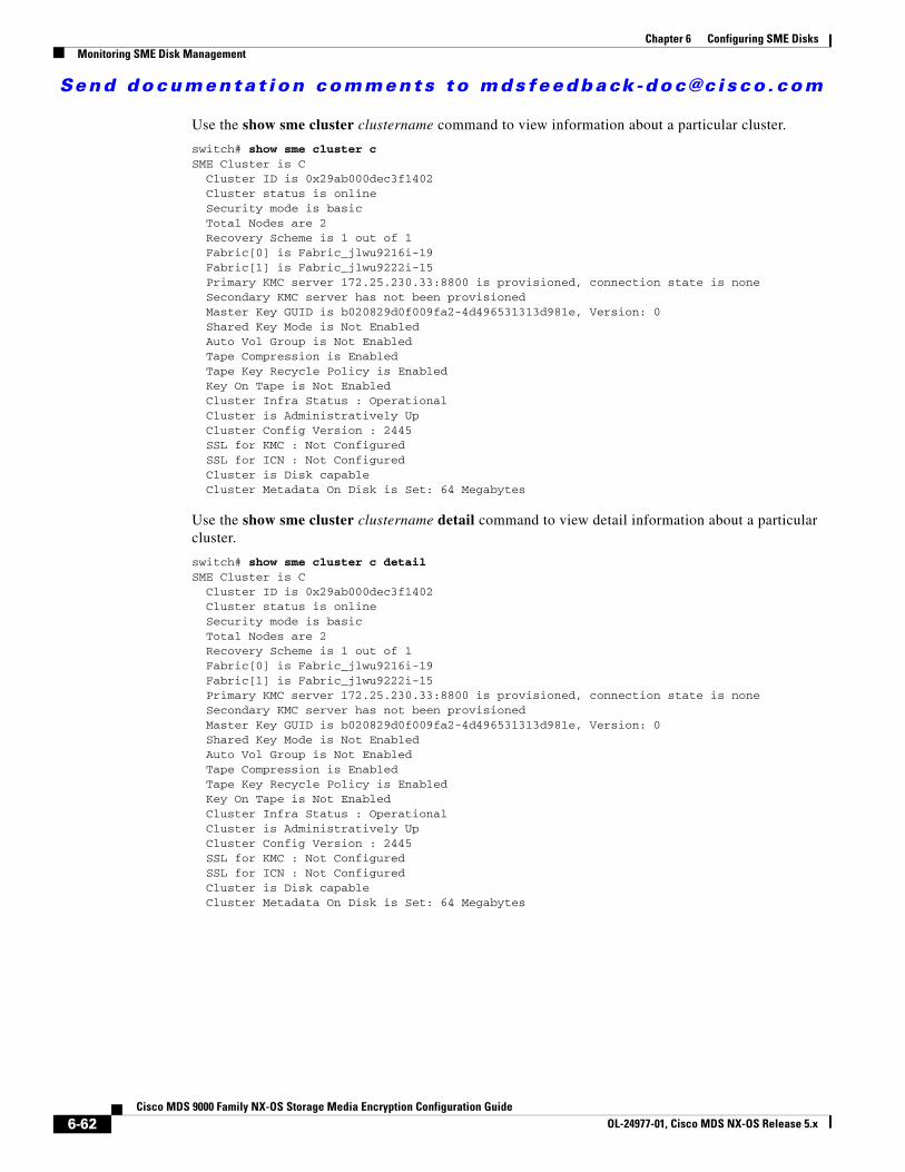
Send documenta t ion comments to mdsfeedback -doc@c i sco .com
Chapter 6 Configuring SME DisksMonitoring SME Disk Management
Use the show sme cluster clustername command to view information about a particular cluster.
switch# show sme cluster c SME Cluster is C Cluster ID is 0x29ab000dec3f1402 Cluster status is online Security mode is basic Total Nodes are 2 Recovery Scheme is 1 out of 1 Fabric[0] is Fabric_jlwu9216i-19 Fabric[1] is Fabric_jlwu9222i-15 Primary KMC server 172.25.230.33:8800 is provisioned, connection state is none Secondary KMC server has not been provisioned Master Key GUID is b020829d0f009fa2-4d496531313d981e, Version: 0 Shared Key Mode is Not Enabled Auto Vol Group is Not Enabled Tape Compression is Enabled Tape Key Recycle Policy is Enabled Key On Tape is Not Enabled Cluster Infra Status : Operational Cluster is Administratively Up Cluster Config Version : 2445 SSL for KMC : Not Configured SSL for ICN : Not Configured Cluster is Disk capable Cluster Metadata On Disk is Set: 64 Megabytes
Use the show sme cluster clustername detail command to view detail information about a particular cluster.
switch# show sme cluster c detailSME Cluster is C Cluster ID is 0x29ab000dec3f1402 Cluster status is online Security mode is basic Total Nodes are 2 Recovery Scheme is 1 out of 1 Fabric[0] is Fabric_jlwu9216i-19 Fabric[1] is Fabric_jlwu9222i-15 Primary KMC server 172.25.230.33:8800 is provisioned, connection state is none Secondary KMC server has not been provisioned Master Key GUID is b020829d0f009fa2-4d496531313d981e, Version: 0 Shared Key Mode is Not Enabled Auto Vol Group is Not Enabled Tape Compression is Enabled Tape Key Recycle Policy is Enabled Key On Tape is Not Enabled Cluster Infra Status : Operational Cluster is Administratively Up Cluster Config Version : 2445 SSL for KMC : Not Configured SSL for ICN : Not Configured Cluster is Disk capable Cluster Metadata On Disk is Set: 64 Megabytes
6-62Cisco MDS 9000 Family NX-OS Storage Media Encryption Configuration Guide
OL-24977-01, Cisco MDS NX-OS Release 5.x

Send documenta t ion comments to mdsfeedback -doc@c i sco .com
Chapter 6 Configuring SME DisksMonitoring SME Disk Management
Use the show sme cluster clustername summary command to view summary information about a particular cluster.
switch# show sme cluster c summary -------------------------------------------------------------------------------Cluster ID Security Mode Status-------------------------------------------------------------------------------C 0x20eb000dec3f45c2 basic online -------------------------------------------------------------------------------
Use the show sme cluster clustername disk group command to view the disk group information in particular cluster.
switch# show sme cluster c disk-group ------------------------------------Disk Group Name Total Disks------------------------------------DG 8
Use the show sme cluster clustername disk-group DG command to view information about a disk group in a cluster.
switch# show sme cluster scluster20 disk-group dg1Disk group dg1 Number of disks is 16
Disk group dg1 Number of disks is 16
Disk Disk0 is clear Description is LSI INF-01-00 Vendor ID is LSI Product ID is INF-01-00 Device ID is 600a0bb0000000005006218003813000 Encryption is Not Enabled
Disk Disk1 is clear Description is LSI INF-01-00 Vendor ID is LSI Product ID is INF-01-00 Device ID is 600a0bb0000000015006218003813000 Encryption is Not Enabled
Disk Disk10 is clear Description is LSI INF-01-00 Vendor ID is LSI Product ID is INF-01-00 Device ID is 600a0bb00000000a5006218003813000 Encryption is Not Enabled
Disk Disk11 is clear Description is LSI INF-01-00 Vendor ID is LSI Product ID is INF-01-00 Device ID is 600a0bb00000000b5006218003813000 Encryption is Not Enabled
Disk Disk12 is clear Description is LSI INF-01-00 Vendor ID is LSI Product ID is INF-01-00 Device ID is 600a0bb00000000c5006218003813000
6-63Cisco MDS 9000 Family NX-OS Storage Media Encryption Configuration Guide
OL-24977-01, Cisco MDS NX-OS Release 5.x
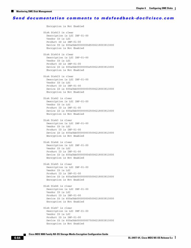
Send documenta t ion comments to mdsfeedback -doc@c i sco .com
Chapter 6 Configuring SME DisksMonitoring SME Disk Management
Encryption is Not Enabled
Disk Disk13 is clear Description is LSI INF-01-00 Vendor ID is LSI Product ID is INF-01-00 Device ID is 600a0bb00000000d5006218003813000 Encryption is Not Enabled
Disk Disk14 is clear Description is LSI INF-01-00 Vendor ID is LSI Product ID is INF-01-00 Device ID is 600a0bb00000000e5006218003813000 Encryption is Not Enabled
Disk Disk15 is clear Description is LSI INF-01-00 Vendor ID is LSI Product ID is INF-01-00 Device ID is 600a0bb00000000f5006218003813000 Encryption is Not Enabled
Disk Disk2 is clear Description is LSI INF-01-00 Vendor ID is LSI Product ID is INF-01-00 Device ID is 600a0bb0000000025006218003813000 Encryption is Not Enabled
Disk Disk3 is clear Description is LSI INF-01-00 Vendor ID is LSI Product ID is INF-01-00 Device ID is 600a0bb0000000035006218003813000 Encryption is Not Enabled
Disk Disk4 is clear Description is LSI INF-01-00 Vendor ID is LSI Product ID is INF-01-00 Device ID is 600a0bb0000000045006218003813000 Encryption is Not Enabled
Disk Disk5 is clear Description is LSI INF-01-00 Vendor ID is LSI Product ID is INF-01-00 Device ID is 600a0bb0000000055006218003813000 Encryption is Not Enabled
Disk Disk6 is clear Description is LSI INF-01-00 Vendor ID is LSI Product ID is INF-01-00 Device ID is 600a0bb0000000065006218003813000 Encryption is Not Enabled
Disk Disk7 is clear Description is LSI INF-01-00 Vendor ID is LSI Product ID is INF-01-00 Device ID is 600a0bb0000000075006218003813000 Encryption is Not Enabled
6-64Cisco MDS 9000 Family NX-OS Storage Media Encryption Configuration Guide
OL-24977-01, Cisco MDS NX-OS Release 5.x
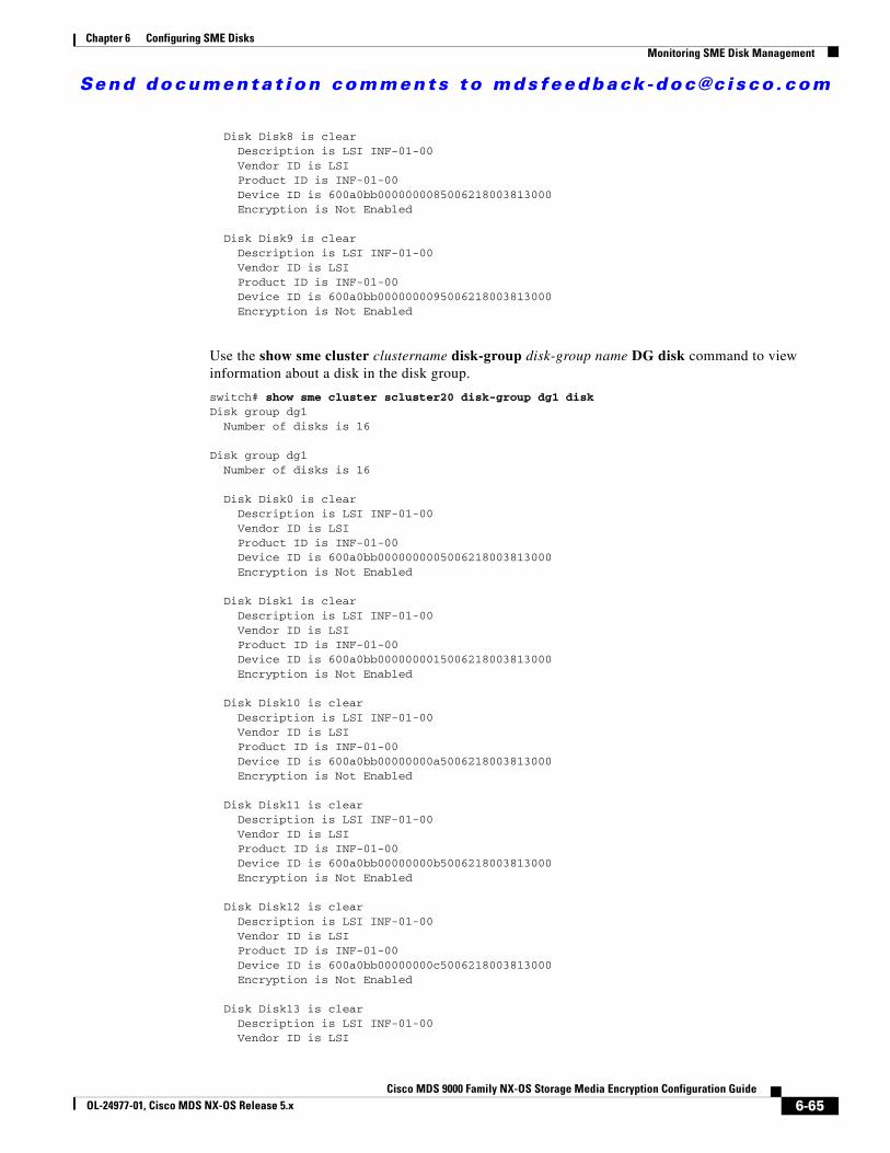
Send documenta t ion comments to mdsfeedback -doc@c i sco .com
Chapter 6 Configuring SME DisksMonitoring SME Disk Management
Disk Disk8 is clear Description is LSI INF-01-00 Vendor ID is LSI Product ID is INF-01-00 Device ID is 600a0bb0000000085006218003813000 Encryption is Not Enabled
Disk Disk9 is clear Description is LSI INF-01-00 Vendor ID is LSI Product ID is INF-01-00 Device ID is 600a0bb0000000095006218003813000 Encryption is Not Enabled
Use the show sme cluster clustername disk-group disk-group name DG disk command to view information about a disk in the disk group.
switch# show sme cluster scluster20 disk-group dg1 diskDisk group dg1 Number of disks is 16
Disk group dg1 Number of disks is 16
Disk Disk0 is clear Description is LSI INF-01-00 Vendor ID is LSI Product ID is INF-01-00 Device ID is 600a0bb0000000005006218003813000 Encryption is Not Enabled
Disk Disk1 is clear Description is LSI INF-01-00 Vendor ID is LSI Product ID is INF-01-00 Device ID is 600a0bb0000000015006218003813000 Encryption is Not Enabled
Disk Disk10 is clear Description is LSI INF-01-00 Vendor ID is LSI Product ID is INF-01-00 Device ID is 600a0bb00000000a5006218003813000 Encryption is Not Enabled
Disk Disk11 is clear Description is LSI INF-01-00 Vendor ID is LSI Product ID is INF-01-00 Device ID is 600a0bb00000000b5006218003813000 Encryption is Not Enabled
Disk Disk12 is clear Description is LSI INF-01-00 Vendor ID is LSI Product ID is INF-01-00 Device ID is 600a0bb00000000c5006218003813000 Encryption is Not Enabled
Disk Disk13 is clear Description is LSI INF-01-00 Vendor ID is LSI
6-65Cisco MDS 9000 Family NX-OS Storage Media Encryption Configuration Guide
OL-24977-01, Cisco MDS NX-OS Release 5.x
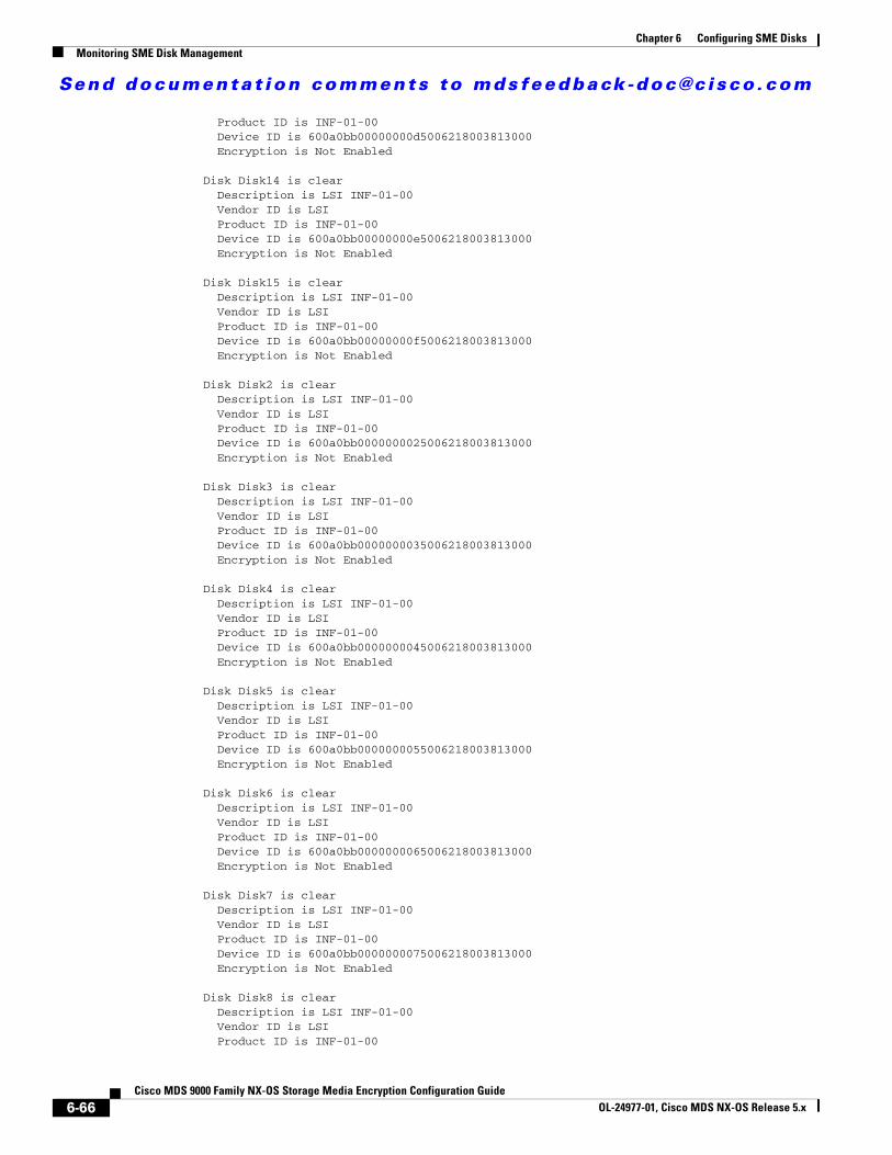
Send documenta t ion comments to mdsfeedback -doc@c i sco .com
Chapter 6 Configuring SME DisksMonitoring SME Disk Management
Product ID is INF-01-00 Device ID is 600a0bb00000000d5006218003813000 Encryption is Not Enabled
Disk Disk14 is clear Description is LSI INF-01-00 Vendor ID is LSI Product ID is INF-01-00 Device ID is 600a0bb00000000e5006218003813000 Encryption is Not Enabled
Disk Disk15 is clear Description is LSI INF-01-00 Vendor ID is LSI Product ID is INF-01-00 Device ID is 600a0bb00000000f5006218003813000 Encryption is Not Enabled
Disk Disk2 is clear Description is LSI INF-01-00 Vendor ID is LSI Product ID is INF-01-00 Device ID is 600a0bb0000000025006218003813000 Encryption is Not Enabled
Disk Disk3 is clear Description is LSI INF-01-00 Vendor ID is LSI Product ID is INF-01-00 Device ID is 600a0bb0000000035006218003813000 Encryption is Not Enabled
Disk Disk4 is clear Description is LSI INF-01-00 Vendor ID is LSI Product ID is INF-01-00 Device ID is 600a0bb0000000045006218003813000 Encryption is Not Enabled
Disk Disk5 is clear Description is LSI INF-01-00 Vendor ID is LSI Product ID is INF-01-00 Device ID is 600a0bb0000000055006218003813000 Encryption is Not Enabled
Disk Disk6 is clear Description is LSI INF-01-00 Vendor ID is LSI Product ID is INF-01-00 Device ID is 600a0bb0000000065006218003813000 Encryption is Not Enabled
Disk Disk7 is clear Description is LSI INF-01-00 Vendor ID is LSI Product ID is INF-01-00 Device ID is 600a0bb0000000075006218003813000 Encryption is Not Enabled
Disk Disk8 is clear Description is LSI INF-01-00 Vendor ID is LSI Product ID is INF-01-00
6-66Cisco MDS 9000 Family NX-OS Storage Media Encryption Configuration Guide
OL-24977-01, Cisco MDS NX-OS Release 5.x
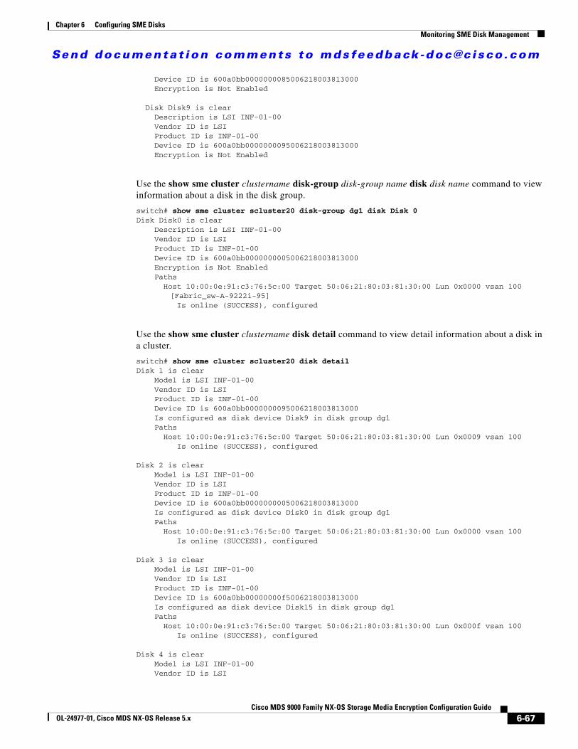
Send documenta t ion comments to mdsfeedback -doc@c i sco .com
Chapter 6 Configuring SME DisksMonitoring SME Disk Management
Device ID is 600a0bb0000000085006218003813000 Encryption is Not Enabled
Disk Disk9 is clear Description is LSI INF-01-00 Vendor ID is LSI Product ID is INF-01-00 Device ID is 600a0bb0000000095006218003813000 Encryption is Not Enabled
Use the show sme cluster clustername disk-group disk-group name disk disk name command to view information about a disk in the disk group.
switch# show sme cluster scluster20 disk-group dg1 disk Disk 0Disk Disk0 is clear Description is LSI INF-01-00 Vendor ID is LSI Product ID is INF-01-00 Device ID is 600a0bb0000000005006218003813000 Encryption is Not Enabled Paths Host 10:00:0e:91:c3:76:5c:00 Target 50:06:21:80:03:81:30:00 Lun 0x0000 vsan 100
[Fabric_sw-A-9222i-95] Is online (SUCCESS), configured
Use the show sme cluster clustername disk detail command to view detail information about a disk in a cluster.
switch# show sme cluster scluster20 disk detailDisk 1 is clear Model is LSI INF-01-00 Vendor ID is LSI Product ID is INF-01-00 Device ID is 600a0bb0000000095006218003813000 Is configured as disk device Disk9 in disk group dg1 Paths Host 10:00:0e:91:c3:76:5c:00 Target 50:06:21:80:03:81:30:00 Lun 0x0009 vsan 100 Is online (SUCCESS), configured
Disk 2 is clear Model is LSI INF-01-00 Vendor ID is LSI Product ID is INF-01-00 Device ID is 600a0bb0000000005006218003813000 Is configured as disk device Disk0 in disk group dg1 Paths Host 10:00:0e:91:c3:76:5c:00 Target 50:06:21:80:03:81:30:00 Lun 0x0000 vsan 100 Is online (SUCCESS), configured
Disk 3 is clear Model is LSI INF-01-00 Vendor ID is LSI Product ID is INF-01-00 Device ID is 600a0bb00000000f5006218003813000 Is configured as disk device Disk15 in disk group dg1 Paths Host 10:00:0e:91:c3:76:5c:00 Target 50:06:21:80:03:81:30:00 Lun 0x000f vsan 100 Is online (SUCCESS), configured
Disk 4 is clear Model is LSI INF-01-00 Vendor ID is LSI
6-67Cisco MDS 9000 Family NX-OS Storage Media Encryption Configuration Guide
OL-24977-01, Cisco MDS NX-OS Release 5.x
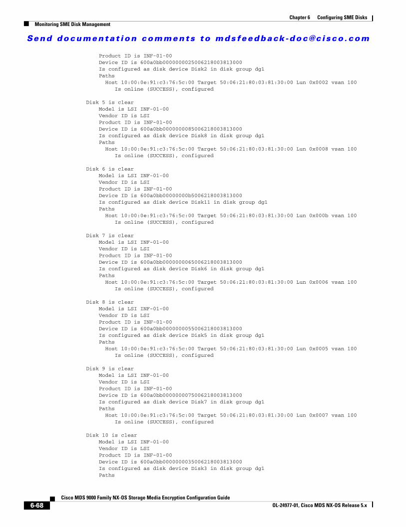
Send documenta t ion comments to mdsfeedback -doc@c i sco .com
Chapter 6 Configuring SME DisksMonitoring SME Disk Management
Product ID is INF-01-00 Device ID is 600a0bb0000000025006218003813000 Is configured as disk device Disk2 in disk group dg1 Paths Host 10:00:0e:91:c3:76:5c:00 Target 50:06:21:80:03:81:30:00 Lun 0x0002 vsan 100 Is online (SUCCESS), configured
Disk 5 is clear Model is LSI INF-01-00 Vendor ID is LSI Product ID is INF-01-00 Device ID is 600a0bb0000000085006218003813000 Is configured as disk device Disk8 in disk group dg1 Paths Host 10:00:0e:91:c3:76:5c:00 Target 50:06:21:80:03:81:30:00 Lun 0x0008 vsan 100 Is online (SUCCESS), configured
Disk 6 is clear Model is LSI INF-01-00 Vendor ID is LSI Product ID is INF-01-00 Device ID is 600a0bb00000000b5006218003813000 Is configured as disk device Disk11 in disk group dg1 Paths Host 10:00:0e:91:c3:76:5c:00 Target 50:06:21:80:03:81:30:00 Lun 0x000b vsan 100 Is online (SUCCESS), configured
Disk 7 is clear Model is LSI INF-01-00 Vendor ID is LSI Product ID is INF-01-00 Device ID is 600a0bb0000000065006218003813000 Is configured as disk device Disk6 in disk group dg1 Paths Host 10:00:0e:91:c3:76:5c:00 Target 50:06:21:80:03:81:30:00 Lun 0x0006 vsan 100 Is online (SUCCESS), configured
Disk 8 is clear Model is LSI INF-01-00 Vendor ID is LSI Product ID is INF-01-00 Device ID is 600a0bb0000000055006218003813000 Is configured as disk device Disk5 in disk group dg1 Paths Host 10:00:0e:91:c3:76:5c:00 Target 50:06:21:80:03:81:30:00 Lun 0x0005 vsan 100 Is online (SUCCESS), configured
Disk 9 is clear Model is LSI INF-01-00 Vendor ID is LSI Product ID is INF-01-00 Device ID is 600a0bb0000000075006218003813000 Is configured as disk device Disk7 in disk group dg1 Paths Host 10:00:0e:91:c3:76:5c:00 Target 50:06:21:80:03:81:30:00 Lun 0x0007 vsan 100 Is online (SUCCESS), configured
Disk 10 is clear Model is LSI INF-01-00 Vendor ID is LSI Product ID is INF-01-00 Device ID is 600a0bb0000000035006218003813000 Is configured as disk device Disk3 in disk group dg1 Paths
6-68Cisco MDS 9000 Family NX-OS Storage Media Encryption Configuration Guide
OL-24977-01, Cisco MDS NX-OS Release 5.x

Send documenta t ion comments to mdsfeedback -doc@c i sco .com
Chapter 6 Configuring SME DisksMonitoring SME Disk Management
Host 10:00:0e:91:c3:76:5c:00 Target 50:06:21:80:03:81:30:00 Lun 0x0003 vsan 100 Is online (SUCCESS), configured
Disk 11 is clear Model is LSI INF-01-00 Vendor ID is LSI Product ID is INF-01-00 Device ID is 600a0bb0000000045006218003813000 Is configured as disk device Disk4 in disk group dg1 Paths Host 10:00:0e:91:c3:76:5c:00 Target 50:06:21:80:03:81:30:00 Lun 0x0004 vsan 100 Is online (SUCCESS), configured
Disk 12 is clear Model is LSI INF-01-00 Vendor ID is LSI Product ID is INF-01-00 Device ID is 600a0bb0000000015006218003813000 Is configured as disk device Disk1 in disk group dg1 Paths Host 10:00:0e:91:c3:76:5c:00 Target 50:06:21:80:03:81:30:00 Lun 0x0001 vsan 100 Is online (SUCCESS), configured
Disk 13 is clear Model is LSI INF-01-00 Vendor ID is LSI Product ID is INF-01-00 Device ID is 600a0bb00000000d5006218003813000 Is configured as disk device Disk13 in disk group dg1 Paths Host 10:00:0e:91:c3:76:5c:00 Target 50:06:21:80:03:81:30:00 Lun 0x000d vsan 100 Is online (SUCCESS), configured
Disk 14 is clear Model is LSI INF-01-00 Vendor ID is LSI Product ID is INF-01-00 Device ID is 600a0bb00000000c5006218003813000 Is configured as disk device Disk12 in disk group dg1 Paths Host 10:00:0e:91:c3:76:5c:00 Target 50:06:21:80:03:81:30:00 Lun 0x000c vsan 100 Is online (SUCCESS), configured
Disk 15 is clear Model is LSI INF-01-00 Vendor ID is LSI Product ID is INF-01-00 Device ID is 600a0bb00000000a5006218003813000 Is configured as disk device Disk10 in disk group dg1 Paths Host 10:00:0e:91:c3:76:5c:00 Target 50:06:21:80:03:81:30:00 Lun 0x000a vsan 100 Is online (SUCCESS), configured
Disk 16 is clear Model is LSI INF-01-00 Vendor ID is LSI Product ID is INF-01-00 Device ID is 600a0bb00000000e5006218003813000 Is configured as disk device Disk14 in disk group dg1 Paths Host 10:00:0e:91:c3:76:5c:00 Target 50:06:21:80:03:81:30:00 Lun 0x000e vsan 100 Is online (SUCCESS), configured
6-69Cisco MDS 9000 Family NX-OS Storage Media Encryption Configuration Guide
OL-24977-01, Cisco MDS NX-OS Release 5.x

Send documenta t ion comments to mdsfeedback -doc@c i sco .com
Chapter 6 Configuring SME DisksMonitoring SME Disk Management
Use the show sme cluster clustername disk summary command to view summary information about a particular disk in a cluster.
switch# show sme cluster c disk summary -------------------------------------------------------------------------------Target WWN Lun Description Crypto-Disk Status-------------------------------------------------------------------------------50:06:01:6b:30:60:06:d6 0x0002 DGC DISK Disk7 clear50:06:01:6b:30:60:06:d6 0x0000 DGC DISK Disk5 clear50:06:01:6b:30:60:06:d6 0x0001 DGC DISK Disk6 clear50:06:01:63:30:60:06:d6 0x0003 DGC RAID 5 Disk3 clear50:06:01:63:30:60:06:d6 0x0004 DGC RAID 5 Disk4 clear50:06:01:63:30:60:06:d6 0x0001 DGC RAID 5 Disk1 clear50:06:01:63:30:60:06:d6 0x0002 DGC RAID 5 Disk2 clear50:06:01:63:30:60:06:d6 0x0000 DGC RAID 5 Disk0 clear
Use the show sme cluster clustername it-nexus command to view detail information about the IT-nexuses in a particular cluster.
switch# show sme cluster c it-nexus ------------------------------------------------------------------------------- Host WWN, VSAN Status Switch Interface Target WWN-------------------------------------------------------------------------------
21:00:00:1b:32:8a:1d:4c,50:06:01:63:30:60:06:d6 2 online 172.28.234.68 sme1/1
21:01:00:1b:32:aa:49:4c,50:06:01:6b:30:60:06:d6 2 online 172.28.234.68 sme1/1
21:02:00:1b:32:ca:49:4c,50:06:01:6b:30:60:06:d6 2 online 172.28.234.68 sme1/1
Use the show sme cluster clustername interface detail command to view detail information about the SME interfaces in a cluster.
Interface sme1/1 belongs to local switch Status is up RSA Certificate is (len 247 fingerprint SHA1:: 87:2f:16:6d:91:ec:8f:cb:95:3a:df:6b:c6:49:c3:67:c4:a9:39:6f:)-----BEGIN RSA PUBLIC KEY-----MIGHAoGBAMJGt4JoIhfV3KU6eJPdfmzIjYLqbZ2mA3VdJ7T86btzyMhpZZI4x76OuCvLxEIuKW+p/XRqhpV4AN7YQDVCw0OB3dacXfRQjM8EdoC6lMXDGsKCzYzti51HZqQvAKCMydz/P3CSbVx3MsoOeDuvv/Hj6wvIngtDGfvHkWms9b1lAgED-----END RSA PUBLIC KEY-----
Use the show sme cluster clustername interface summary command to view summary information about the SME interfaces in a cluster.
switch# show sme cluster c interface summary -------------------------------------------------------------------------------Switch Interface Status-------------------------------------------------------------------------------local switch sme1/1 up
Use the show sme cluster clustername interface sme sme-interface command to view information about a particular SME interface in a cluster.
switch# show sme cluster c interface sme 1/1Interface sme1/1 belongs to local switch
6-70Cisco MDS 9000 Family NX-OS Storage Media Encryption Configuration Guide
OL-24977-01, Cisco MDS NX-OS Release 5.x
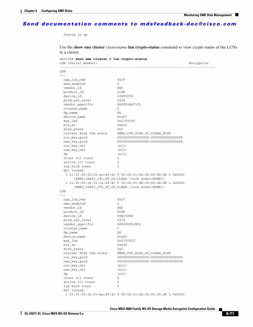
Send documenta t ion comments to mdsfeedback -doc@c i sco .com
Chapter 6 Configuring SME DisksMonitoring SME Disk Management
Status is up
Use the show sme cluster clustername lun crypto-status command to view crypto status of the LUNs in a cluster.
switch# show sme cluster c lun crypto-statusLUN (Serial Number) Encryption------------------------------------------------------------------------------LUN--- cpp_lun_ndx 0x29 sme_enabled 0 vendor_id DGC product_id DISK device_id 10493CF4 prod_rev_level 0216 vendor_specific 860000AB71CL cluster_name C dg_name DG device_name Disk7 max_lba 0x27fffff blk_sz 0x200 disk_state 0x1 current disk fsm state SMED_CPP_DISK_ST_CLEAR_DISK cur_key_guid 0000000000000000-0000000000000000 new_key_guid 0000000000000000-0000000000000000 cur_key_obj (nil) new_key_obj (nil) dp (nil) total itl count 2 active itl count 2 lun hold count 0 Not locked I 21:01:00:1b:32:aa:49:4c T 50:06:01:6b:30:60:06:d6 L 0x0002 (SMED_ISAPI_ITL_ST_UP_CLEAR [lock event=NONE]) I 21:02:00:1b:32:ca:49:4c T 50:06:01:6b:30:60:06:d6 L 0x0002 (SMED_ISAPI_ITL_ST_UP_CLEAR [lock event=NONE])LUN--- cpp_lun_ndx 0x27 sme_enabled 0 vendor_id DGC product_id DISK device_id 93B1508B prod_rev_level 0216 vendor_specific 8000009529CL cluster_name C dg_name DG device_name Disk5 max_lba 0x27fffff blk_sz 0x200 disk_state 0x1 current disk fsm state SMED_CPP_DISK_ST_CLEAR_DISK cur_key_guid 0000000000000000-0000000000000000 new_key_guid 0000000000000000-0000000000000000 cur_key_obj (nil) new_key_obj (nil) dp (nil) total itl count 2 active itl count 2 lun hold count 0 Not locked I 21:01:00:1b:32:aa:49:4c T 50:06:01:6b:30:60:06:d6 L 0x0000
6-71Cisco MDS 9000 Family NX-OS Storage Media Encryption Configuration Guide
OL-24977-01, Cisco MDS NX-OS Release 5.x
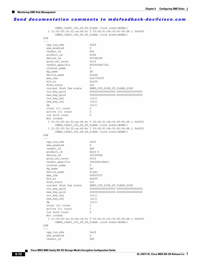
Send documenta t ion comments to mdsfeedback -doc@c i sco .com
Chapter 6 Configuring SME DisksMonitoring SME Disk Management
(SMED_ISAPI_ITL_ST_UP_CLEAR [lock event=NONE]) I 21:02:00:1b:32:ca:49:4c T 50:06:01:6b:30:60:06:d6 L 0x0000 (SMED_ISAPI_ITL_ST_UP_CLEAR [lock event=NONE])LUN--- cpp_lun_ndx 0x28 sme_enabled 0 vendor_id DGC product_id DISK device_id F074E188 prod_rev_level 0216 vendor_specific 850000AA73CL cluster_name C dg_name DG device_name Disk6 max_lba 0x27fffff blk_sz 0x200 disk_state 0x1 current disk fsm state SMED_CPP_DISK_ST_CLEAR_DISK cur_key_guid 0000000000000000-0000000000000000 new_key_guid 0000000000000000-0000000000000000 cur_key_obj (nil) new_key_obj (nil) dp (nil) total itl count 2 active itl count 2 lun hold count 0 Not locked I 21:01:00:1b:32:aa:49:4c T 50:06:01:6b:30:60:06:d6 L 0x0001 (SMED_ISAPI_ITL_ST_UP_CLEAR [lock event=NONE]) I 21:02:00:1b:32:ca:49:4c T 50:06:01:6b:30:60:06:d6 L 0x0001 (SMED_ISAPI_ITL_ST_UP_CLEAR [lock event=NONE])LUN--- cpp_lun_ndx 0x25 sme_enabled 0 vendor_id DGC product_id RAID 5 device_id 3C2590FB prod_rev_level 0216 vendor_specific 39000061BDCL cluster_name C dg_name DG device_name Disk3 max_lba 0x9fffff blk_sz 0x200 disk_state 0x1 current disk fsm state SMED_CPP_DISK_ST_CLEAR_DISK cur_key_guid 0000000000000000-0000000000000000 new_key_guid 0000000000000000-0000000000000000 cur_key_obj (nil) new_key_obj (nil) dp (nil) total itl count 1 active itl count 1 lun hold count 0 Not locked I 21:00:00:1b:32:8a:1d:4c T 50:06:01:63:30:60:06:d6 L 0x0003 (SMED_ISAPI_ITL_ST_UP_CLEAR [lock event=NONE])LUN--- cpp_lun_ndx 0x26 sme_enabled 0 vendor_id DGC
6-72Cisco MDS 9000 Family NX-OS Storage Media Encryption Configuration Guide
OL-24977-01, Cisco MDS NX-OS Release 5.x
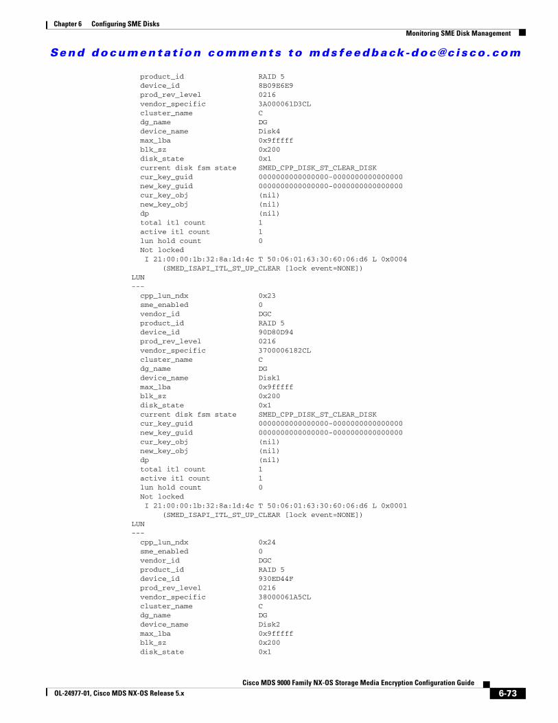
Send documenta t ion comments to mdsfeedback -doc@c i sco .com
Chapter 6 Configuring SME DisksMonitoring SME Disk Management
product_id RAID 5 device_id 8B09E6E9 prod_rev_level 0216 vendor_specific 3A000061D3CL cluster_name C dg_name DG device_name Disk4 max_lba 0x9fffff blk_sz 0x200 disk_state 0x1 current disk fsm state SMED_CPP_DISK_ST_CLEAR_DISK cur_key_guid 0000000000000000-0000000000000000 new_key_guid 0000000000000000-0000000000000000 cur_key_obj (nil) new_key_obj (nil) dp (nil) total itl count 1 active itl count 1 lun hold count 0 Not locked I 21:00:00:1b:32:8a:1d:4c T 50:06:01:63:30:60:06:d6 L 0x0004 (SMED_ISAPI_ITL_ST_UP_CLEAR [lock event=NONE])LUN--- cpp_lun_ndx 0x23 sme_enabled 0 vendor_id DGC product_id RAID 5 device_id 90D80D94 prod_rev_level 0216 vendor_specific 3700006182CL cluster_name C dg_name DG device_name Disk1 max_lba 0x9fffff blk_sz 0x200 disk_state 0x1 current disk fsm state SMED_CPP_DISK_ST_CLEAR_DISK cur_key_guid 0000000000000000-0000000000000000 new_key_guid 0000000000000000-0000000000000000 cur_key_obj (nil) new_key_obj (nil) dp (nil) total itl count 1 active itl count 1 lun hold count 0 Not locked I 21:00:00:1b:32:8a:1d:4c T 50:06:01:63:30:60:06:d6 L 0x0001 (SMED_ISAPI_ITL_ST_UP_CLEAR [lock event=NONE])LUN--- cpp_lun_ndx 0x24 sme_enabled 0 vendor_id DGC product_id RAID 5 device_id 930ED44F prod_rev_level 0216 vendor_specific 38000061A5CL cluster_name C dg_name DG device_name Disk2 max_lba 0x9fffff blk_sz 0x200 disk_state 0x1
6-73Cisco MDS 9000 Family NX-OS Storage Media Encryption Configuration Guide
OL-24977-01, Cisco MDS NX-OS Release 5.x
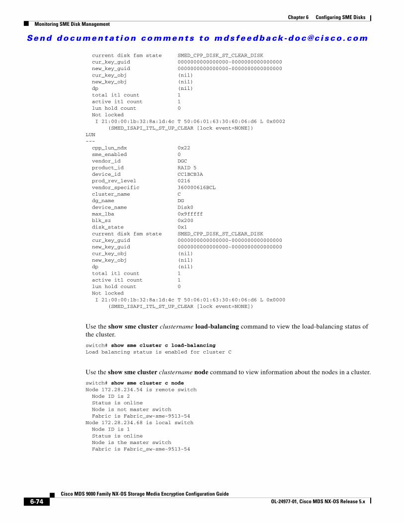
Send documenta t ion comments to mdsfeedback -doc@c i sco .com
Chapter 6 Configuring SME DisksMonitoring SME Disk Management
current disk fsm state SMED_CPP_DISK_ST_CLEAR_DISK cur_key_guid 0000000000000000-0000000000000000 new_key_guid 0000000000000000-0000000000000000 cur_key_obj (nil) new_key_obj (nil) dp (nil) total itl count 1 active itl count 1 lun hold count 0 Not locked I 21:00:00:1b:32:8a:1d:4c T 50:06:01:63:30:60:06:d6 L 0x0002 (SMED_ISAPI_ITL_ST_UP_CLEAR [lock event=NONE])LUN--- cpp_lun_ndx 0x22 sme_enabled 0 vendor_id DGC product_id RAID 5 device_id CC1BCB3A prod_rev_level 0216 vendor_specific 360000616BCL cluster_name C dg_name DG device_name Disk0 max_lba 0x9fffff blk_sz 0x200 disk_state 0x1 current disk fsm state SMED_CPP_DISK_ST_CLEAR_DISK cur_key_guid 0000000000000000-0000000000000000 new_key_guid 0000000000000000-0000000000000000 cur_key_obj (nil) new_key_obj (nil) dp (nil) total itl count 1 active itl count 1 lun hold count 0 Not locked I 21:00:00:1b:32:8a:1d:4c T 50:06:01:63:30:60:06:d6 L 0x0000 (SMED_ISAPI_ITL_ST_UP_CLEAR [lock event=NONE])
Use the show sme cluster clustername load-balancing command to view the load-balancing status of the cluster.
switch# show sme cluster c load-balancingLoad balancing status is enabled for cluster C
Use the show sme cluster clustername node command to view information about the nodes in a cluster.
switch# show sme cluster c nodeNode 172.28.234.54 is remote switch Node ID is 2 Status is online Node is not master switch Fabric is Fabric_sw-sme-9513-54Node 172.28.234.68 is local switch Node ID is 1 Status is online Node is the master switch Fabric is Fabric_sw-sme-9513-54
6-74Cisco MDS 9000 Family NX-OS Storage Media Encryption Configuration Guide
OL-24977-01, Cisco MDS NX-OS Release 5.x
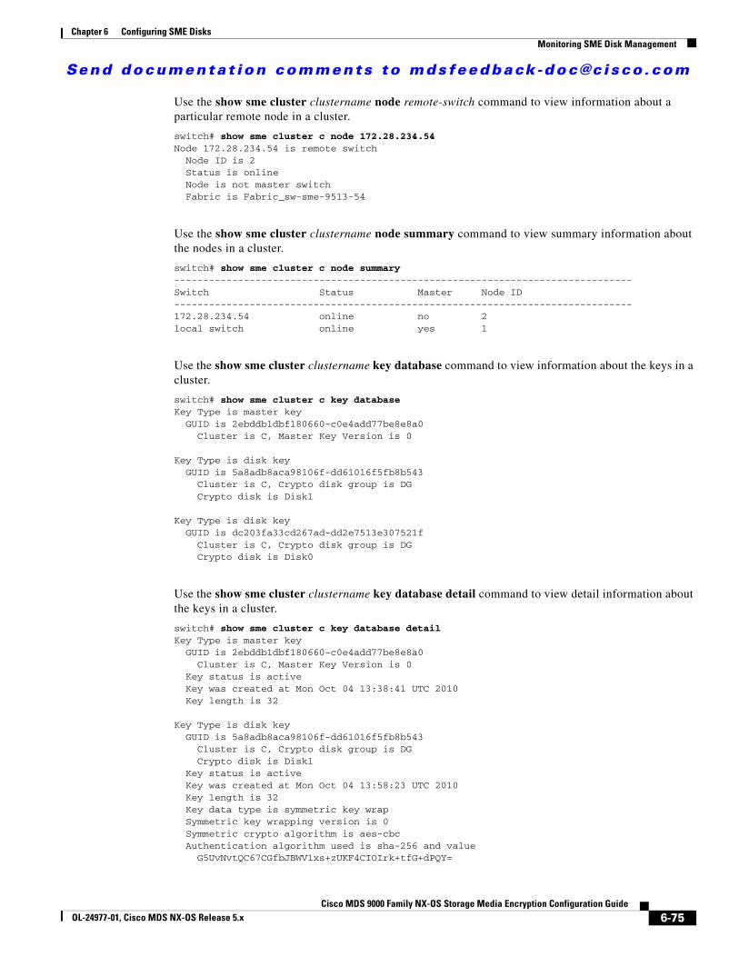
Send documenta t ion comments to mdsfeedback -doc@c i sco .com
Chapter 6 Configuring SME DisksMonitoring SME Disk Management
Use the show sme cluster clustername node remote-switch command to view information about a particular remote node in a cluster.
switch# show sme cluster c node 172.28.234.54Node 172.28.234.54 is remote switch Node ID is 2 Status is online Node is not master switch Fabric is Fabric_sw-sme-9513-54
Use the show sme cluster clustername node summary command to view summary information about the nodes in a cluster.
switch# show sme cluster c node summary-------------------------------------------------------------------------------Switch Status Master Node ID-------------------------------------------------------------------------------172.28.234.54 online no 2local switch online yes 1
Use the show sme cluster clustername key database command to view information about the keys in a cluster.
switch# show sme cluster c key databaseKey Type is master key GUID is 2ebddb1dbf180660-c0e4add77be8e8a0 Cluster is C, Master Key Version is 0
Key Type is disk key GUID is 5a8adb8aca98106f-dd61016f5fb8b543 Cluster is C, Crypto disk group is DG Crypto disk is Disk1
Key Type is disk key GUID is dc203fa33cd267ad-dd2e7513e307521f Cluster is C, Crypto disk group is DG Crypto disk is Disk0
Use the show sme cluster clustername key database detail command to view detail information about the keys in a cluster.
switch# show sme cluster c key database detailKey Type is master key GUID is 2ebddb1dbf180660-c0e4add77be8e8a0 Cluster is C, Master Key Version is 0 Key status is active Key was created at Mon Oct 04 13:38:41 UTC 2010 Key length is 32
Key Type is disk key GUID is 5a8adb8aca98106f-dd61016f5fb8b543 Cluster is C, Crypto disk group is DG Crypto disk is Disk1 Key status is active Key was created at Mon Oct 04 13:58:23 UTC 2010 Key length is 32 Key data type is symmetric key wrap Symmetric key wrapping version is 0 Symmetric crypto algorithm is aes-cbc Authentication algorithm used is sha-256 and value G5UvNvtQC67CGfbJBWV1xs+zUKF4CIOIrk+tfG+dPQY=
6-75Cisco MDS 9000 Family NX-OS Storage Media Encryption Configuration Guide
OL-24977-01, Cisco MDS NX-OS Release 5.x
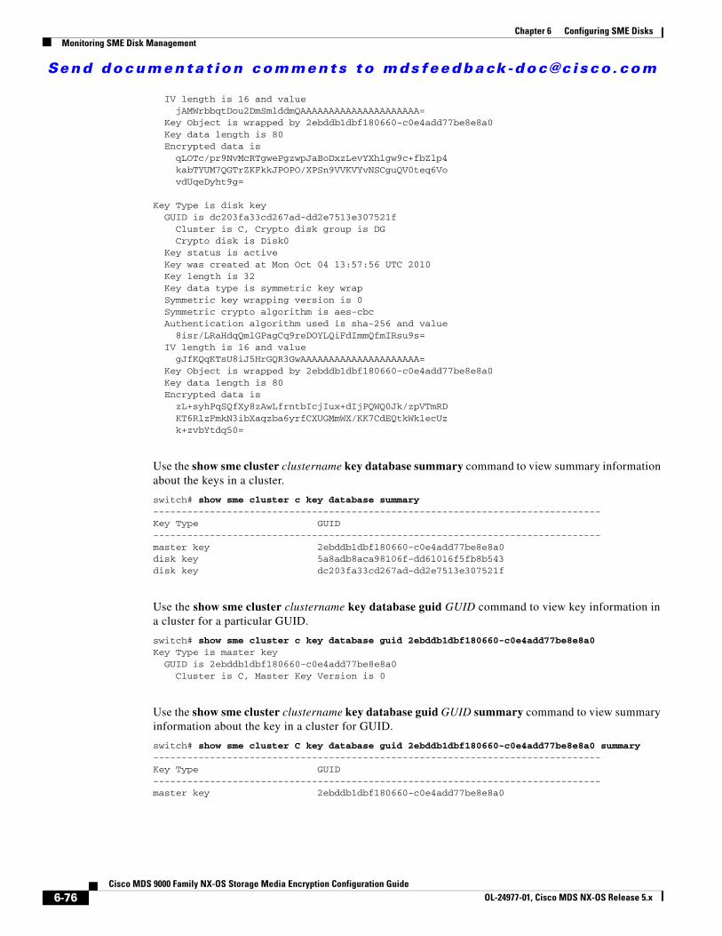
Send documenta t ion comments to mdsfeedback -doc@c i sco .com
Chapter 6 Configuring SME DisksMonitoring SME Disk Management
IV length is 16 and value jAMWrbbqtDou2DmSmlddmQAAAAAAAAAAAAAAAAAAAAA= Key Object is wrapped by 2ebddb1dbf180660-c0e4add77be8e8a0 Key data length is 80 Encrypted data is qLOTc/pr9NvMcRTgwePgzwpJaBoDxzLevYXh1gw9c+fbZlp4 kabTYUM7QGTrZKFkkJPOPO/XPSn9VVKVYvNSCguQV0teq6Vo vdUqeDyht9g=
Key Type is disk key GUID is dc203fa33cd267ad-dd2e7513e307521f Cluster is C, Crypto disk group is DG Crypto disk is Disk0 Key status is active Key was created at Mon Oct 04 13:57:56 UTC 2010 Key length is 32 Key data type is symmetric key wrap Symmetric key wrapping version is 0 Symmetric crypto algorithm is aes-cbc Authentication algorithm used is sha-256 and value 8isr/LRaHdqQmlGPagCq9reDOYLQiFdImmQfmIRsu9s= IV length is 16 and value gJfKQqKTsU8iJ5HrGQR3GwAAAAAAAAAAAAAAAAAAAAA= Key Object is wrapped by 2ebddb1dbf180660-c0e4add77be8e8a0 Key data length is 80 Encrypted data is zL+syhPqSQfXy8zAwLfrntbIcjIux+dIjPQWQ0Jk/zpVTmRD KT6RlzFmkN3ibXaqzba6yrfCXUGMmWX/KK7CdEQtkWk1ecUz k+zvbYtdq50=
Use the show sme cluster clustername key database summary command to view summary information about the keys in a cluster.
switch# show sme cluster c key database summary-------------------------------------------------------------------------------Key Type GUID-------------------------------------------------------------------------------master key 2ebddb1dbf180660-c0e4add77be8e8a0disk key 5a8adb8aca98106f-dd61016f5fb8b543disk key dc203fa33cd267ad-dd2e7513e307521f
Use the show sme cluster clustername key database guid GUID command to view key information in a cluster for a particular GUID.
switch# show sme cluster c key database guid 2ebddb1dbf180660-c0e4add77be8e8a0Key Type is master key GUID is 2ebddb1dbf180660-c0e4add77be8e8a0 Cluster is C, Master Key Version is 0
Use the show sme cluster clustername key database guid GUID summary command to view summary information about the key in a cluster for GUID.
switch# show sme cluster C key database guid 2ebddb1dbf180660-c0e4add77be8e8a0 summary-------------------------------------------------------------------------------Key Type GUID-------------------------------------------------------------------------------master key 2ebddb1dbf180660-c0e4add77be8e8a0
6-76Cisco MDS 9000 Family NX-OS Storage Media Encryption Configuration Guide
OL-24977-01, Cisco MDS NX-OS Release 5.x
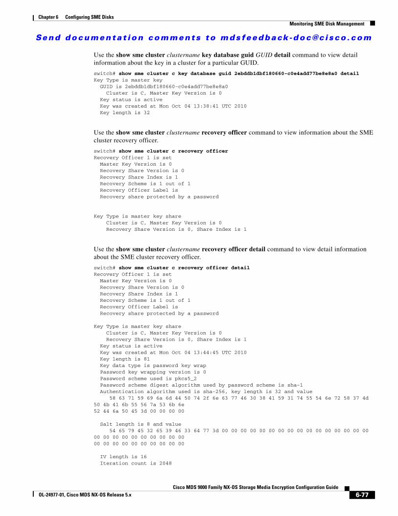
Send documenta t ion comments to mdsfeedback -doc@c i sco .com
Chapter 6 Configuring SME DisksMonitoring SME Disk Management
Use the show sme cluster clustername key database guid GUID detail command to view detail information about the key in a cluster for a particular GUID.
switch# show sme cluster c key database guid 2ebddb1dbf180660-c0e4add77be8e8a0 detailKey Type is master key GUID is 2ebddb1dbf180660-c0e4add77be8e8a0 Cluster is C, Master Key Version is 0 Key status is active Key was created at Mon Oct 04 13:38:41 UTC 2010 Key length is 32
Use the show sme cluster clustername recovery officer command to view information about the SME cluster recovery officer.
switch# show sme cluster c recovery officerRecovery Officer 1 is set Master Key Version is 0 Recovery Share Version is 0 Recovery Share Index is 1 Recovery Scheme is 1 out of 1 Recovery Officer Label is Recovery share protected by a password
Key Type is master key share Cluster is C, Master Key Version is 0 Recovery Share Version is 0, Share Index is 1
Use the show sme cluster clustername recovery officer detail command to view detail information about the SME cluster recovery officer.
switch# show sme cluster c recovery officer detailRecovery Officer 1 is set Master Key Version is 0 Recovery Share Version is 0 Recovery Share Index is 1 Recovery Scheme is 1 out of 1 Recovery Officer Label is Recovery share protected by a password
Key Type is master key share Cluster is C, Master Key Version is 0 Recovery Share Version is 0, Share Index is 1 Key status is active Key was created at Mon Oct 04 13:44:45 UTC 2010 Key length is 81 Key data type is password key wrap Password key wrapping version is 0 Password scheme used is pkcs5_2 Password scheme digest algorithm used by password scheme is sha-1 Authentication algorithm used is sha-256, key length is 32 and value 58 63 71 59 69 6a 6d 44 50 74 2f 6e 63 77 46 30 38 41 59 31 74 55 54 6e 72 58 37 4d 50 4b 41 6b 55 56 7a 53 6b 6e52 44 6a 50 45 3d 00 00 00 00
Salt length is 8 and value 54 65 79 45 32 65 39 46 33 64 77 3d 00 00 00 00 00 00 00 00 00 00 00 00 00 00 00 00 00 00 00 00 00 00 00 00 00 0000 00 00 00 00 00 00 00 00 00
IV length is 16 Iteration count is 2048
6-77Cisco MDS 9000 Family NX-OS Storage Media Encryption Configuration Guide
OL-24977-01, Cisco MDS NX-OS Release 5.x
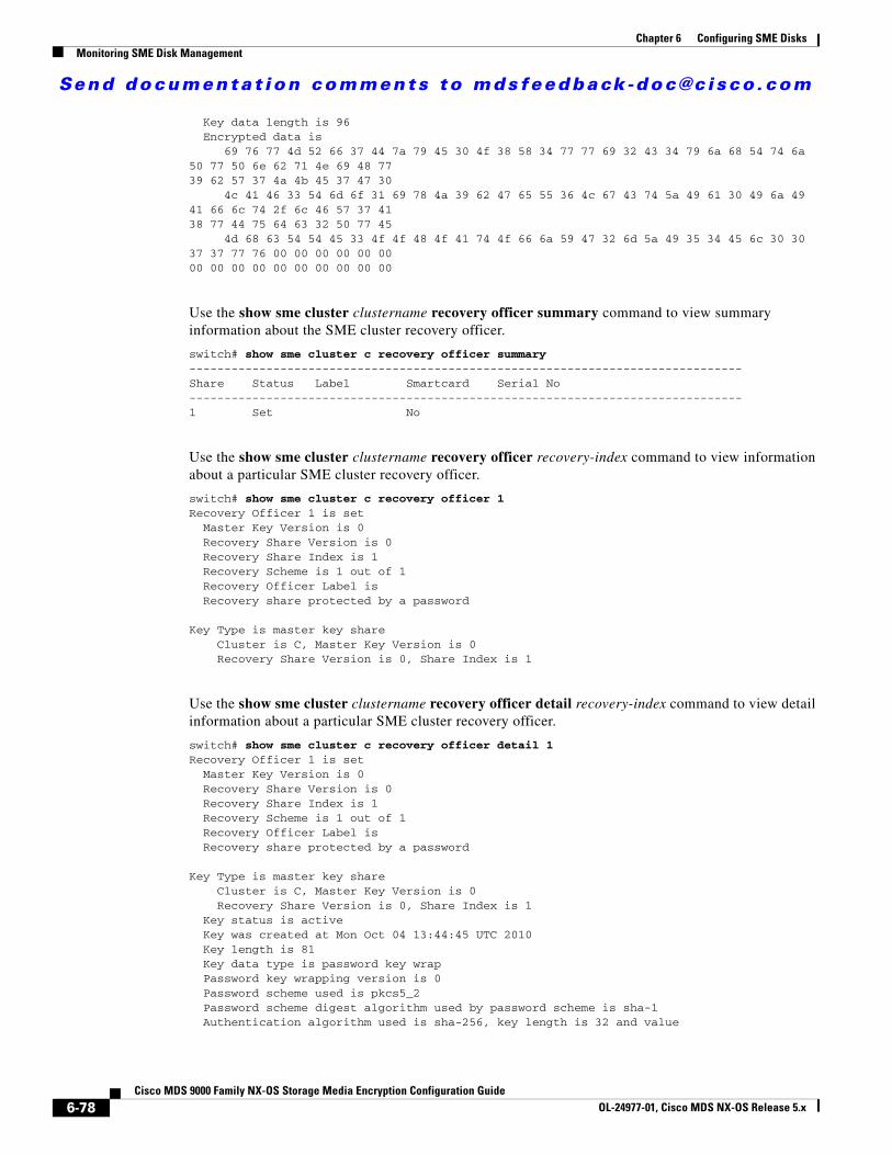
Send documenta t ion comments to mdsfeedback -doc@c i sco .com
Chapter 6 Configuring SME DisksMonitoring SME Disk Management
Key data length is 96 Encrypted data is 69 76 77 4d 52 66 37 44 7a 79 45 30 4f 38 58 34 77 77 69 32 43 34 79 6a 68 54 74 6a 50 77 50 6e 62 71 4e 69 48 7739 62 57 37 4a 4b 45 37 47 30 4c 41 46 33 54 6d 6f 31 69 78 4a 39 62 47 65 55 36 4c 67 43 74 5a 49 61 30 49 6a 49 41 66 6c 74 2f 6c 46 57 37 4138 77 44 75 64 63 32 50 77 45 4d 68 63 54 54 45 33 4f 4f 48 4f 41 74 4f 66 6a 59 47 32 6d 5a 49 35 34 45 6c 30 30 37 37 77 76 00 00 00 00 00 0000 00 00 00 00 00 00 00 00 00
Use the show sme cluster clustername recovery officer summary command to view summary information about the SME cluster recovery officer.
switch# show sme cluster c recovery officer summary -------------------------------------------------------------------------------Share Status Label Smartcard Serial No-------------------------------------------------------------------------------1 Set No
Use the show sme cluster clustername recovery officer recovery-index command to view information about a particular SME cluster recovery officer.
switch# show sme cluster c recovery officer 1 Recovery Officer 1 is set Master Key Version is 0 Recovery Share Version is 0 Recovery Share Index is 1 Recovery Scheme is 1 out of 1 Recovery Officer Label is Recovery share protected by a password
Key Type is master key share Cluster is C, Master Key Version is 0 Recovery Share Version is 0, Share Index is 1
Use the show sme cluster clustername recovery officer detail recovery-index command to view detail information about a particular SME cluster recovery officer.
switch# show sme cluster c recovery officer detail 1 Recovery Officer 1 is set Master Key Version is 0 Recovery Share Version is 0 Recovery Share Index is 1 Recovery Scheme is 1 out of 1 Recovery Officer Label is Recovery share protected by a password
Key Type is master key share Cluster is C, Master Key Version is 0 Recovery Share Version is 0, Share Index is 1 Key status is active Key was created at Mon Oct 04 13:44:45 UTC 2010 Key length is 81 Key data type is password key wrap Password key wrapping version is 0 Password scheme used is pkcs5_2 Password scheme digest algorithm used by password scheme is sha-1 Authentication algorithm used is sha-256, key length is 32 and value
6-78Cisco MDS 9000 Family NX-OS Storage Media Encryption Configuration Guide
OL-24977-01, Cisco MDS NX-OS Release 5.x
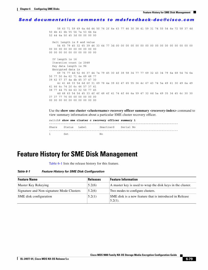
Send documenta t ion comments to mdsfeedback -doc@c i sco .com
Chapter 6 Configuring SME DisksFeature History for SME Disk Management
58 63 71 59 69 6a 6d 44 50 74 2f 6e 63 77 46 30 38 41 59 31 74 55 54 6e 72 58 37 4d 50 4b 41 6b 55 56 7a 53 6b 6e52 44 6a 50 45 3d 00 00 00 00
Salt length is 8 and value 54 65 79 45 32 65 39 46 33 64 77 3d 00 00 00 00 00 00 00 00 00 00 00 00 00 00 00 00 00 00 00 00 00 00 00 00 00 0000 00 00 00 00 00 00 00 00 00
IV length is 16 Iteration count is 2048 Key data length is 96 Encrypted data is 69 76 77 4d 52 66 37 44 7a 79 45 30 4f 38 58 34 77 77 69 32 43 34 79 6a 68 54 74 6a 50 77 50 6e 62 71 4e 69 48 7739 62 57 37 4a 4b 45 37 47 30 4c 41 46 33 54 6d 6f 31 69 78 4a 39 62 47 65 55 36 4c 67 43 74 5a 49 61 30 49 6a 49 41 66 6c 74 2f 6c 46 57 37 4138 77 44 75 64 63 32 50 77 45 4d 68 63 54 54 45 33 4f 4f 48 4f 41 74 4f 66 6a 59 47 32 6d 5a 49 35 34 45 6c 30 30 37 37 77 76 00 00 00 00 00 0000 00 00 00 00 00 00 00 00 00
Use the show sme cluster <clustername> recovery officer summary <recovery-index> command to view summary information about a particular SME cluster recovery officer.
switch# show sme cluster c recovery officer summary 1-------------------------------------------------------------------------------Share Status Label Smartcard Serial No-------------------------------------------------------------------------------1 Set No
Feature History for SME Disk ManagementTable 6-1 lists the release history for this feature.
Table 6-1 Feature History for SME Disk Configuration
Feature Name Releases Feature Information
Master Key Rekeying 5.2(6) A master key is used to wrap the disk keys in the cluster.
Signature and Non-signature Mode Clusters 5.2(6) Two modes to configure clusters.
SME disk configuration 5.2(1) SME disk is a new feature that is introduced in Release 5.2(1).
6-79Cisco MDS 9000 Family NX-OS Storage Media Encryption Configuration Guide
OL-24977-01, Cisco MDS NX-OS Release 5.x

Send documenta t ion comments to mdsfeedback -doc@c i sco .com
Chapter 6 Configuring SME DisksFeature History for SME Disk Management
6-80Cisco MDS 9000 Family NX-OS Storage Media Encryption Configuration Guide
OL-24977-01, Cisco MDS NX-OS Release 5.x

Send documenta t ion comments to mdsfeedback -doc@c i sco .com
Cisco MDS 9000 Family NXOL-24977-01, Cisco MDS NX-OS Release 5.x
C H A P T E R 7
Configuring SME Key ManagementThis chapter contains information about SME comprehensive key management.
This chapter includes the following topics:
• Information About SME Key Management, page 7-1
• Configuring SME Key Management Using the CLI, page 7-8
• Configuring SME Key Management Using the GUI, page 7-9
• Monitoring SME Key Management, page 7-9
• Feature History for SME Key Management, page 7-16
Information About SME Key ManagementSME Key Management includes the following topics:
• About Key Hierarchy, page 7-1
• About Cisco Key Management Center, page 7-3
• About Master Key Security Modes, page 7-3
• About Key Management Settings, page 7-4
• About High Availability Key Management Center, page 7-6
• About Auto Key Replication of Keys Across Data Centers, page 7-6
• About Accounting Log Information, page 7-7
About Key HierarchySME includes a comprehensive and secure system for protecting encrypted data using a hierarchy of security keys. The highest level key is the master key, which is generated when a cluster is created. Every cluster has a unique master key. In SME tape, the master key encrypts the tape volume group keys which in turn encrypts the tape volume keys using key wrapping. In SME disk, the master key encrypts the disk keys using key wrapping.
For recovery purposes, the master key can be stored in a password-protected file, or in one or more smart cards. When a cluster state is Archived (the key database has been archived) and you want to recover the keys, you will need the master key file or the smart cards. The master key cannot be improperly extracted by either tampering with the MSM-18/4 module or by tampering with a smart card.
7-1-OS Storage Media Encryption Configuration Guide

Send documenta t ion comments to mdsfeedback -doc@c i sco .com
Chapter 7 Configuring SME Key ManagementInformation About SME Key Management
Keys are essential to safeguarding your encrypted data and should not be compromised. Keys should be stored in the Cisco Key Management Center. In addition, unique tape keys can be stored directly on the tape cartridge. The keys are identified across the system by a globally unique identifier (GUID).
The SME key management system includes the following types of keys for SME tape:
• Master key
• Tape volume group keys
• Tape volume keys
Every backup tape has an associated tape volume key, tape volume group key, and a master key.
The SME key management system includes the following types of keys for SME disk:
• Master key
• Disk keys
Master Key
When a SME cluster is created, a security engine generates the master key. Considering that a single fabric can host more than one cluster, for example, to support the needs of multiple business groups within the same organization, there will be as many master keys as there are clusters. Each master key is unique and it is shared across all cluster members. The master key is used to wrap the tape volume group keys.
Tape Volume Group Key
The tape volume group key is used to encrypt and authenticate the tape volume keys, which are the keys that encrypt all tapes belonging to the same tape volume group. A tape volume group can be created on the basis of a bar code range for a set of backup tapes or it can be associated with a specific backup application. Tape volume group keys are occasionally rekeyed for increased security or when the security of the key has been compromised.
Tape Volume Key
The tape volume key is used to encrypt and authenticate the data on the tapes.
In unique key mode, the tape volume keys are unique for each physical tape and they can be stored in the Cisco KMC or stored on the tape. The Cisco KMC database does not need to store a tape volume key if the key is stored on the tape itself. The option to store the key on the tape may dramatically reduce the number of keys stored on the Cisco KMC.
In shared key mode, there is one tape volume key which is used to encrypt all volumes in a volume group.
Disk Key
The disk key is used to encrypt and decrypt the data on the disks.
7-2Cisco MDS 9000 Family NX-OS Storage Media Encryption Configuration Guide
OL-24977-01, Cisco MDS NX-OS Release 5.x
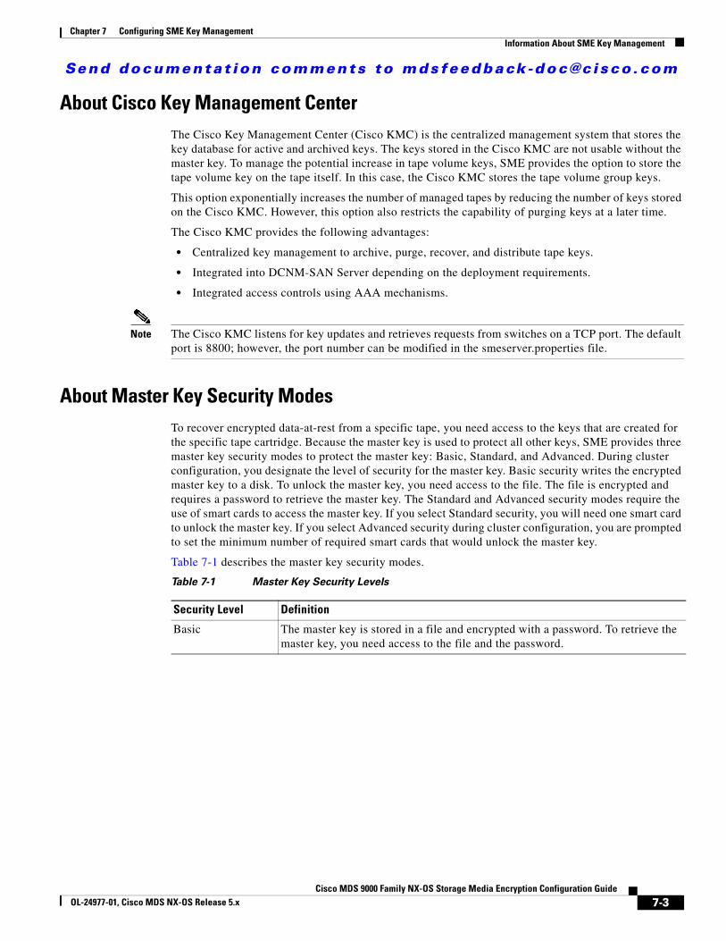
Send documenta t ion comments to mdsfeedback -doc@c i sco .com
Chapter 7 Configuring SME Key ManagementInformation About SME Key Management
About Cisco Key Management CenterThe Cisco Key Management Center (Cisco KMC) is the centralized management system that stores the key database for active and archived keys. The keys stored in the Cisco KMC are not usable without the master key. To manage the potential increase in tape volume keys, SME provides the option to store the tape volume key on the tape itself. In this case, the Cisco KMC stores the tape volume group keys.
This option exponentially increases the number of managed tapes by reducing the number of keys stored on the Cisco KMC. However, this option also restricts the capability of purging keys at a later time.
The Cisco KMC provides the following advantages:
• Centralized key management to archive, purge, recover, and distribute tape keys.
• Integrated into DCNM-SAN Server depending on the deployment requirements.
• Integrated access controls using AAA mechanisms.
Note The Cisco KMC listens for key updates and retrieves requests from switches on a TCP port. The default port is 8800; however, the port number can be modified in the smeserver.properties file.
About Master Key Security ModesTo recover encrypted data-at-rest from a specific tape, you need access to the keys that are created for the specific tape cartridge. Because the master key is used to protect all other keys, SME provides three master key security modes to protect the master key: Basic, Standard, and Advanced. During cluster configuration, you designate the level of security for the master key. Basic security writes the encrypted master key to a disk. To unlock the master key, you need access to the file. The file is encrypted and requires a password to retrieve the master key. The Standard and Advanced security modes require the use of smart cards to access the master key. If you select Standard security, you will need one smart card to unlock the master key. If you select Advanced security during cluster configuration, you are prompted to set the minimum number of required smart cards that would unlock the master key.
Table 7-1 describes the master key security modes.
Table 7-1 Master Key Security Levels
Security Level Definition
Basic The master key is stored in a file and encrypted with a password. To retrieve the master key, you need access to the file and the password.
7-3Cisco MDS 9000 Family NX-OS Storage Media Encryption Configuration Guide
OL-24977-01, Cisco MDS NX-OS Release 5.x
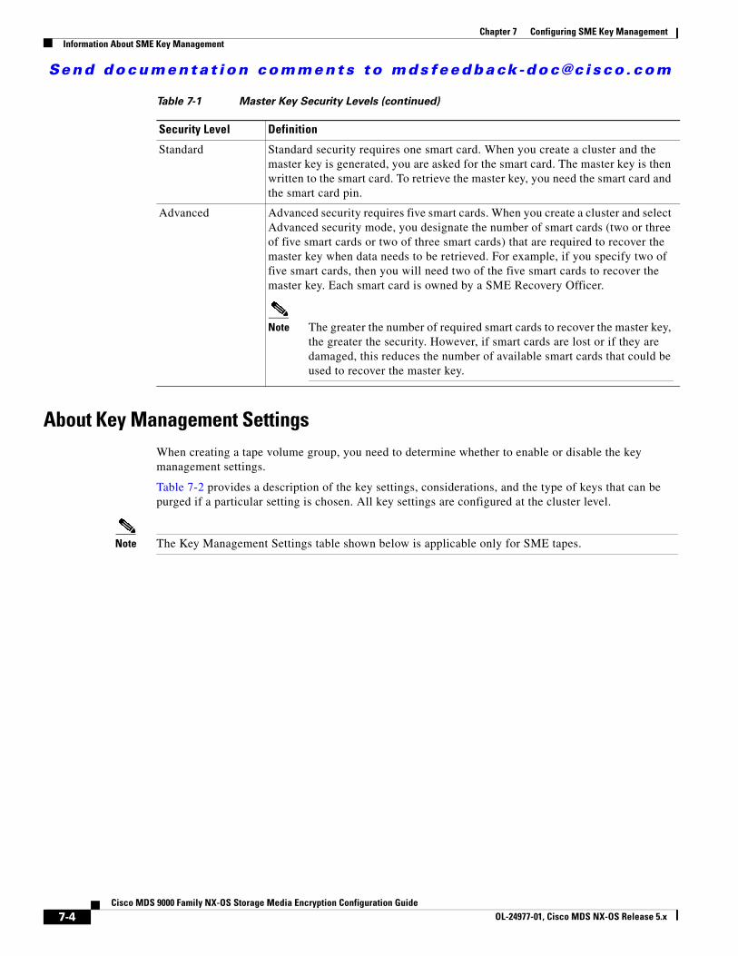
Send documenta t ion comments to mdsfeedback -doc@c i sco .com
Chapter 7 Configuring SME Key ManagementInformation About SME Key Management
About Key Management SettingsWhen creating a tape volume group, you need to determine whether to enable or disable the key management settings.
Table 7-2 provides a description of the key settings, considerations, and the type of keys that can be purged if a particular setting is chosen. All key settings are configured at the cluster level.
Note The Key Management Settings table shown below is applicable only for SME tapes.
Standard Standard security requires one smart card. When you create a cluster and the master key is generated, you are asked for the smart card. The master key is then written to the smart card. To retrieve the master key, you need the smart card and the smart card pin.
Advanced Advanced security requires five smart cards. When you create a cluster and select Advanced security mode, you designate the number of smart cards (two or three of five smart cards or two of three smart cards) that are required to recover the master key when data needs to be retrieved. For example, if you specify two of five smart cards, then you will need two of the five smart cards to recover the master key. Each smart card is owned by a SME Recovery Officer.
Note The greater the number of required smart cards to recover the master key, the greater the security. However, if smart cards are lost or if they are damaged, this reduces the number of available smart cards that could be used to recover the master key.
Table 7-1 Master Key Security Levels (continued)
Security Level Definition
7-4Cisco MDS 9000 Family NX-OS Storage Media Encryption Configuration Guide
OL-24977-01, Cisco MDS NX-OS Release 5.x
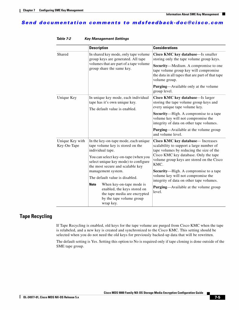
Send documenta t ion comments to mdsfeedback -doc@c i sco .com
Chapter 7 Configuring SME Key ManagementInformation About SME Key Management
Tape Recycling
If Tape Recycling is enabled, old keys for the tape volume are purged from Cisco KMC when the tape is relabeled, and a new key is created and synchronized to the Cisco KMC. This setting should be selected when you do not need the old keys for previously backed-up data that will be rewritten.
The default setting is Yes. Setting this option to No is required only if tape cloning is done outside of the SME tape group.
Table 7-2 Key Management Settings
Description Considerations
Shared In shared key mode, only tape volume group keys are generated. All tape volumes that are part of a tape volume group share the same key.
Cisco KMC key database—Is smaller storing only the tape volume group keys.
Security—Medium. A compromise to one tape volume group key will compromise the data in all tapes that are part of that tape volume group.
Purging—Available only at the volume group level.
Unique Key In unique key mode, each individual tape has it’s own unique key.
The default value is enabled.
Cisco KMC key database—Is larger storing the tape volume group keys and every unique tape volume key.
Security—High. A compromise to a tape volume key will not compromise the integrity of data on other tape volumes.
Purging—Available at the volume group and volume level.
Unique Key with Key-On-Tape
In the key-on-tape mode, each unique tape volume key is stored on the individual tape.
You can select key-on-tape (when you select unique key mode) to configure the most secure and scalable key management system.
The default value is disabled.
Note When key-on-tape mode is enabled, the keys stored on the tape media are encrypted by the tape volume group wrap key.
Cisco KMC key database— Increases scalability to support a large number of tape volumes by reducing the size of the Cisco KMC key database. Only the tape volume group keys are stored on the Cisco KMC.
Security—High. A compromise to a tape volume key will not compromise the integrity of data on other tape volumes.
Purging—Available at the volume group level.
7-5Cisco MDS 9000 Family NX-OS Storage Media Encryption Configuration Guide
OL-24977-01, Cisco MDS NX-OS Release 5.x
Send documenta t ion comments to mdsfeedback -doc@c i sco .com
Chapter 7 Configuring SME Key ManagementInformation About SME Key Management
About High Availability Key Management CenterThe Cisco KMC server consists of a pair of KMC servers (KMS) that provides high availability and reliability. These high availability servers helps to avoid both downtime and loss of data through synchronization and redundancy. The KMS consists of a primary and a secondary KMC server which point to the same database.
Both the KMS should use the same Oracle 11g Enterprise installation to achieve high availability. The Oracle 11g Enterprise installation should be installed on the two servers and synchronized using Oracle Active Data guard.
Each SME cluster is configured with primary and secondary KMC servers. The primary server is preferred over the secondary server.
The cluster is connected to the primary server and, at any indication of failure, connects to the secondary server. The cluster periodically checks for the availability of the primary server and resumes connection to the primary server when it becomes available.
All the switches in a cluster use the same KMC server. When a switch connects to a secondary server, an automatic cluster-wide failover occurs to the secondary server. The switches in the cluster fail over to the primary server once it is available.
Note Configure the primary and secondary servers during the cluster creation or update the Key Manager Settings for a created cluster.
About Auto Key Replication of Keys Across Data Centers
Note Auto key replication of keys across data centers is applicable only for SME tape.
The auto replication of media keys enables the moving of tapes from one data center to another. The replication of keys allows the same tape media to be accessed by more than one SME cluster. In most cases, the SME clusters are located in different locations, such as a primary data center and a disaster recovery site. SME allows you to automatically replicate the media keys from one SME cluster to one or more clusters. The automated process of replicating keys eliminates the need for the manual key export and import procedures. The media key auto-replication is configured on per tape volume group basis.
One KMC manages all the data centers and the replicated keys are stored on the KMC.
Translating Media Keys
Each cluster is associated with a translation context. The translation context contains the public key for the key pair generated by the crypto-module of one of the clusters.
A replication relationship is set between the volume groups in the different clusters and the replication context for the destination clusters need to be acquired. Once the relationship is set up between the clusters, whenever a key is generated in the source cluster, the key is automatically translated to the destination cluster.
7-6Cisco MDS 9000 Family NX-OS Storage Media Encryption Configuration Guide
OL-24977-01, Cisco MDS NX-OS Release 5.x
Send documenta t ion comments to mdsfeedback -doc@c i sco .com
Chapter 7 Configuring SME Key ManagementInformation About SME Key Management
The translation of the keys is a scheduled process and based on the preset frequency all the key pairs generated in that time period are translated to the destination cluster. Every key that is generated and scheduled for replication, since last job start time, are translated using the replication context, which is the public key of the destination cluster.
The key replication across data centers requires the translation of key hierarchy. The key from the source cluster is translated using the public key of the destination cluster and then sent to the destination cluster. In the destination cluster, the key is unwrapped with the private key of the destination cluster and then wrapped with the key hierarchy of the destination cluster.
About Accounting Log InformationThis section describes the KMC accounting log messages.
The accounting.log file in the DCNM-SAN log directory displays the KMC accounting log messages. The accounting log records key-related operations, their resulting status, and any related information.
The log files are stored in a relational database and are searchable, archivable, and portable.
A log entry consists of the following information:
• hostname—The name of the host machine where the operation occurred.
• timestamp—The time at which an event was recorded to the accounting log system.
• username—The username associated with the operation.
• clusterName—The name of the cluster the operation was performed on.
• clusterId—The ID of the cluster the operation was performed on.
• operation—The type of operation.
• status—The status of the operation when the event was logged.
• details—Additional data, depending on the type of operation.
Figure 7-1 shows an example of the accounting log information.
7-7Cisco MDS 9000 Family NX-OS Storage Media Encryption Configuration Guide
OL-24977-01, Cisco MDS NX-OS Release 5.x
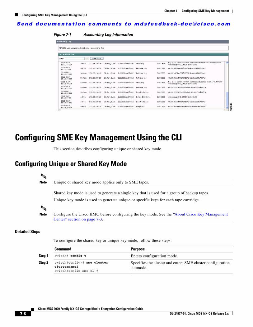
Send documenta t ion comments to mdsfeedback -doc@c i sco .com
Chapter 7 Configuring SME Key ManagementConfiguring SME Key Management Using the CLI
Figure 7-1 Accounting Log Information
Configuring SME Key Management Using the CLIThis section describes configuring unique or shared key mode.
Configuring Unique or Shared Key Mode
Note Unique or shared key mode applies only to SME tapes.
Shared key mode is used to generate a single key that is used for a group of backup tapes.
Unique key mode is used to generate unique or specific keys for each tape cartridge.
Note Configure the Cisco KMC before configuring the key mode. See the “About Cisco Key Management Center” section on page 7-3.
Detailed Steps
To configure the shared key or unique key mode, follow these steps:
Command Purpose
Step 1 switch# config t Enters configuration mode.
Step 2 switch(config)# sme cluster clustername1switch(config-sme-cl)#
Specifies the cluster and enters SME cluster configuration submode.
7-8Cisco MDS 9000 Family NX-OS Storage Media Encryption Configuration Guide
OL-24977-01, Cisco MDS NX-OS Release 5.x
Send documenta t ion comments to mdsfeedback -doc@c i sco .com
Chapter 7 Configuring SME Key ManagementConfiguring SME Key Management Using the GUI
Configuring SME Key Management Using the GUIThis section includes the following topics:
• Choosing High Availability Settings, page 7-9
• Configuring Key Management Operations, page 7-9
Choosing High Availability Settings
Detailed Steps
To choose the primary or secondary server, follow these steps:
Step 1 From DCNM-SAN Web Client, choose Key Manager Settings.
Step 2 In the High Availability Settings area, click Edit HA Settings.
Step 3 Choose the KMC role of the server to be the Primary Server and specify the IP address of the SME Secondary KMC. Alternately, you can choose the server to be the secondary server and specify the IP address of the primary server.
Step 4 Click OK to save the settings to view the notification that the settings have been saved.
Configuring Key Management OperationsFor configuring key management operations for a tapes, see “Configuring Key Management Operations” section on page 5-11.
For configuring key management operations for a disk cluster, see “Exporting and Importing Keys” section on page 6-45.
Monitoring SME Key ManagementThis section includes the following topics:
• Viewing KMC Accounting Log Messages Output, page 7-10
• Viewing Accounting Log Information, page 7-14
• Viewing Standard Security Mode Smart Cards, page 7-14
• Viewing Advanced Security Mode Smart Cards, page 7-15
Step 3 switch(config-sme-cl)# shared-key modeswitch(config-sme-cl)#
Specifies shared key mode.
Step 4 switch(config-sme-cl)# no shared-key modeswitch(config-sme-cl)#
Specifies shared unique key mode.
Command Purpose
7-9Cisco MDS 9000 Family NX-OS Storage Media Encryption Configuration Guide
OL-24977-01, Cisco MDS NX-OS Release 5.x
Send documenta t ion comments to mdsfeedback -doc@c i sco .com
Chapter 7 Configuring SME Key ManagementMonitoring SME Key Management
• Viewing Keys for SME Tape, page 7-15
• Viewing Keys for SME Disk, page 7-15
Viewing KMC Accounting Log Messages OutputThe output of the log entry is displayed in the following format:
"<timestamp> User: <username> Host: <host> Cluster: <cluster name> Id: <cluster id> Operation: <operation> Status: <status> Details: <details>"
The following is a complete listing of logged SME operations and expected status values. The logged details for an operation depends upon the resulting status of the operation and/or other criteria documented below.
-------------------------------------Operation: STORE_KEY Logged as: "Store key"Description: A new key is being written to the keystore. The details for the accounting log of a STORE_KEY operation depends upon the KEY_TYPE and the STATUS for the operation.
Details:
KEY_TYPE: MasterKey
SUCCESS: "key type: <key type> GUID: <guid>"FAILURE: "key type: <key type> GUID: <guid> error: <description>"
KEY_TYPE: TapeVolumeGroupSharedKey
SUCCESS: "key type: <key type> GUID: <guid> tape group: <tape group name> tape volume group: <tape volume group name>"FAILURE: "key type: <key type> GUID: <guid> tape group: <tape group name> tape volume group: <tape volume group name> error: <description>"
KEY_TYPE: TapeVolumeGroupWrapKey
SUCCESS: "key type: <key type> GUID: <guid> tape group: <tape group name> tape volume group: <tape volume group name>"FAILURE: "key type: <key type> GUID: <guid> tape group: <tape group name> tape volume group: <tape volume group name> error: <description>"
KEY_TYPE: TapeVolumeKey
SUCCESS: "key type: <key type> GUID: <guid> tape group: <tape group name> tape volume group: <tape volume group name> barcode: <barcode>"FAILURE: "key type: <key type> GUID: <guid> tape group: <tape group name> tape volume group: <tape volume group name> barcode: <barcode> error: <description>"
-------------------------------------Operation: GET_KEY Logged as: "Retrieve key"Description: A key is being requested from keystore. The details for the accounting log of a GET_KEY operation depend upon the query parameter and STATUS for the operation.
Details:
QUERY PARAMETER: Guid
SUCCESS: "GUID: <guid>"
7-10Cisco MDS 9000 Family NX-OS Storage Media Encryption Configuration Guide
OL-24977-01, Cisco MDS NX-OS Release 5.x

Send documenta t ion comments to mdsfeedback -doc@c i sco .com
Chapter 7 Configuring SME Key ManagementMonitoring SME Key Management
FAILURE: "GUID: <guid>"
QUERY PARAMETER: Cloned from Guid
SUCCESS: "Cloned from GUID: <guid>"FAILURE: "Cloned from GUID: <guid>"
-------------------------------------Operation: ARCHIVE_KEY Logged as: "Archive key"Description: A key is removed from "active" state and moved to "archived" state.
Details:
SUCCESS: "GUID: <guid>"FAILURE: "GUID: <guid> error: <description>"
-------------------------------------Operation: ARCHIVE_ALL_KEYS Logged as: "Archive all keys"Description: All keys are archived for an instance of a KEY_TYPE. The details for the accounting log of a ARCHIVE_ALL_KEYS operation depends upon the KEY_TYPE and the STATUS for the operation.
Details:
KEY_TYPE: TapeVolumeGroupSharedKey
SUCCESS: "tape group: <tape group name> tape volume group: <tape volume group name>"FAILURE: "tape group: <tape group name> tape volume group: <tape volume group name> error: <description>"
KEY_TYPE: TapeVolumeGroupWrapKey
SUCCESS: "tape group: <tape group name> tape volume group: <tape volume group name>"FAILURE: "tape group: <tape group name> tape volume group: <tape volume group name> error: <description>"
KEY_TYPE: TapeVolumeKey
SUCCESS: "tape group: <tape group name> tape volume group: <tape volume group name> barcode: <barcode>"FAILURE: "tape group: <tape group name> tape volume group: <tape volume group name> barcode: <barcode> error: <description>"
-------------------------------------Operation: PURGE_KEY Logged as: "Purge key"Description: A key and references to it are removed from the keystore.
Details:
SUCCESS: "GUID: <guid>"FAILURE: "GUID: <guid> error: <description>"
-------------------------------------Operation: DELETE_ALL_TAPE_VOLUME_KEYS Logged as: "Delete Tape Volume Keys"Description: All tape volume keys for the given tape volume are removed from the keystore.
Details:
7-11Cisco MDS 9000 Family NX-OS Storage Media Encryption Configuration Guide
OL-24977-01, Cisco MDS NX-OS Release 5.x

Send documenta t ion comments to mdsfeedback -doc@c i sco .com
Chapter 7 Configuring SME Key ManagementMonitoring SME Key Management
SUCCESS: "tape group: <tape group name> tape volume group: <tape volume group name>"
-------------------------------------Operation: DELETE_ALL_TAPE_VOLUME_SHARED_KEYS Logged as: "Delete Tape Volume Group Shared Keys for cluster"Description: All shared keys for the given tape volume are removed from the keystore.
Details:
SUCCESS: "tape group: <tape group name> tape volume group: <tape volume group name>"
-------------------------------------Operation: DELETE_ALL_TAPE_VOLUME_WRAP_KEYS Logged as: "Delete Tape Volume Group Wrap Keys for cluster"Description: All wrap keys for the given tape volume are removed from the keystore.
Details:
SUCCESS: "tape group: <tape group name> tape volume group: <tape volume group name>"
-------------------------------------Operation: EXPORT_ARCHIVED Logged as: "Export archived cluster"Description: An archived cluster is being exported. The operation is being logged per tape volume group exported for the requested cluster.
Details:
INITIATED: "tape group: <tape group name> tape volume group: <tape volume group name> keys exported: null"SUCCESS: "tape group: <tape group name> tape volume group: <tape volume group name> keys exported: <count>"FAILURE: "tape group: <tape group name> tape volume group: <tape volume group name> keys exported: <count> error: <description>"
-------------------------------------Operation: EXPORT Logged as: "Export cluster"Description: A cluster is being exported. The operation is being logged per tape volume group exported from the requested cluster.
Details:
INITIATED: "tape group: <tape group name> tape volume group: <tape volume group name> keys exported: null"SUCCESS: "tape group: <tape group name> tape volume group: <tape volume group name> keys exported: <count>"FAILURE: "tape group: <tape group name> tape volume group: <tape volume group name> keys exported: <count> error: <description>"
-------------------------------------Operation: IMPORT Logged as: "Import keys"Description: Keys are imported into a cluster. The operation is being logged per tape volume group.
Details:
INITIATED: "tape group: <tape group name> tape volume group: <tape volume group name> keys imported: null"SUCCESS: "tape group: <tape group name> tape volume group: <tape
7-12Cisco MDS 9000 Family NX-OS Storage Media Encryption Configuration Guide
OL-24977-01, Cisco MDS NX-OS Release 5.x
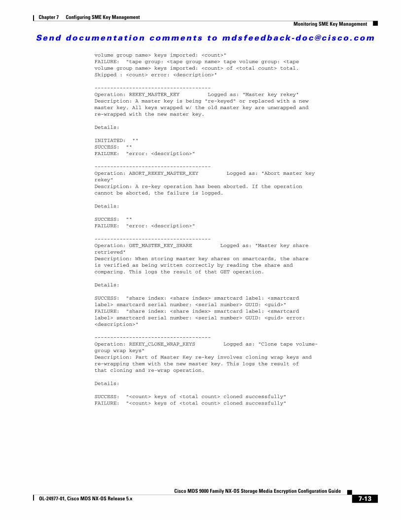
Send documenta t ion comments to mdsfeedback -doc@c i sco .com
Chapter 7 Configuring SME Key ManagementMonitoring SME Key Management
volume group name> keys imported: <count>"FAILURE: "tape group: <tape group name> tape volume group: <tape volume group name> keys imported: <count> of <total count> total. Skipped : <count> error: <description>"
-------------------------------------Operation: REKEY_MASTER_KEY Logged as: "Master key rekey"Description: A master key is being "re-keyed" or replaced with a new master key. All keys wrapped w/ the old master key are unwrapped and re-wrapped with the new master key.
Details:
INITIATED: ""SUCCESS: ""FAILURE: "error: <description>"
-------------------------------------Operation: ABORT_REKEY_MASTER_KEY Logged as: "Abort master key rekey"Description: A re-key operation has been aborted. If the operation cannot be aborted, the failure is logged.
Details:
SUCCESS: ""FAILURE: "error: <description>"
-------------------------------------Operation: GET_MASTER_KEY_SHARE Logged as: "Master key share retrieved"Description: When storing master key shares on smartcards, the share is verified as being written correctly by reading the share and comparing. This logs the result of that GET operation.
Details:
SUCCESS: "share index: <share index> smartcard label: <smartcard label> smartcard serial number: <serial number> GUID: <guid>"FAILURE: "share index: <share index> smartcard label: <smartcard label> smartcard serial number: <serial number> GUID: <guid> error: <description>"
-------------------------------------Operation: REKEY_CLONE_WRAP_KEYS Logged as: "Clone tape volume- group wrap keys"Description: Part of Master Key re-key involves cloning wrap keys and re-wrapping them with the new master key. This logs the result of that cloning and re-wrap operation.
Details:
SUCCESS: "<count> keys of <total count> cloned successfully"FAILURE: "<count> keys of <total count> cloned successfully"
7-13Cisco MDS 9000 Family NX-OS Storage Media Encryption Configuration Guide
OL-24977-01, Cisco MDS NX-OS Release 5.x
Send documenta t ion comments to mdsfeedback -doc@c i sco .com
Chapter 7 Configuring SME Key ManagementMonitoring SME Key Management
Viewing Accounting Log InformationThe SME accounting log is configurable as of 4.2.x. Accounting entries are made in the database, and then flushed to a file on a defined schedule. By default, this happens weekly. The logs are written to a uniquely named file for example: sme_accounting_log.2011-01-30-12-00-01.log. This file is available in the host where the DCNM application is running, for example in the <Install Path>/dcm/fm/logs directory.
Detailed Steps
To view and modify the key operations, their status and frequency, follow these steps:
Step 1 Edit the <Install Path>/dcm/fm/conf/smeserver.properties file.
Step 2 Add sme.kmc.archive.accounting.log.frequency=
The valid values are:
• hourly
• daily
• weekly
• monthly
• test (if you want to validate, which does it every 5 minutes). This should NOT be left enabled. It will flood your machine with files.
Note Due to the nature of the files, SME will not delete or overwrite these files. Test or even hourly settings will generate a significant number of files over time. The accounting log entries not yet flushed from the database are visible in the Accounting Log Tab.
Step 3 Click the SME tab in the DCNM-SAN Web Client.
Step 4 Click the Accounting Log in the SME tab to display the log information. The location of the accounting log in the Cisco KMC database is displayed in the KMC Log Location.
Step 5 Enter a pattern in the Filter and click Go. The accounting pattern is displayed based on the selected pattern.
Step 6 Click Clear Filter to display the complete accounting log information.
Viewing Standard Security Mode Smart CardsTo view Standard security smart card information, select Smartcards in the navigation pane to view the smart card information.
7-14Cisco MDS 9000 Family NX-OS Storage Media Encryption Configuration Guide
OL-24977-01, Cisco MDS NX-OS Release 5.x
Send documenta t ion comments to mdsfeedback -doc@c i sco .com
Chapter 7 Configuring SME Key ManagementMonitoring SME Key Management
Viewing Advanced Security Mode Smart CardsTo view Advanced security smart card information, select Smartcards in the navigation pane to view the smart card information.
Viewing Keys for SME TapeYou can view information about unique tape volume keys, tape volume group keys, and shared tape volume group keys. Using DCNM-SAN Web Client, you can view keys that are stored in the Cisco KMC. When keys are generated, they are marked as active; keys that are imported are marked as deactivated. The keys are never displayed in clear text.
Detailed Steps
To view tape volume group keys, follow these steps:
Step 1 Click a volume group to display the volume group key information.
In the unique key mode, only the wrap key is showing. The wrap key is the tape volume group key that wraps volume keys. If shared mode is selected, the wrap key and a shared key are in view. The wrap key wraps the shared key. Keys are listed as TapeVolumeGroupWrapKey or the TapeVolumeGroupSharedKey.
There are no volume keys in shared key mode; you will see only the shared key.
Step 2 Click the Active tab to view all active keys.
Step 3 Click the Deactivated tab to view all keys that have been marked as deactivated and stored in the Cisco KMC. You can view the barcode, GUID (the unique key identifier generated by the switch), deactivated date, and version (the version of the tape key generated for the same barcode).
Viewing Keys for SME DiskYou can view information about disk keys. Using DCNM-SAN Web Client, you can view keys that are stored in the Cisco KMC. When keys are generated, they are marked as active; keys that are imported are marked as deactivated. The keys are never displayed in clear text.
Detailed Steps
To view disk keys, follow these steps:
Step 1 Click a configured disk under a disk group.
The keys that are associated with the configured disk are displayed.
Step 2 Click Keys section under disk groups. All of the keys for all of the disks that are associated with the disk group are displayed.
7-15Cisco MDS 9000 Family NX-OS Storage Media Encryption Configuration Guide
OL-24977-01, Cisco MDS NX-OS Release 5.x

Send documenta t ion comments to mdsfeedback -doc@c i sco .com
Chapter 7 Configuring SME Key ManagementFeature History for SME Key Management
Feature History for SME Key ManagementTable 7-3 lists the release history for this feature.
Table 7-3 Feature History for SME Key Management
Feature Name Releases Feature Information
Software change 5.2(1) In Release 5.2(1), Fabric Manager is changed to DCNM for SAN (DCNM-SAN).
4.1(1c) In Release 4.1(1b) and later, the MDS SAN-OS software is changed to MDS NX-OS software. The earlier releases are unchanged and all references are retained.
Migrating KMC server 4.1(1c) In 4.1(1c), the KMC server can be migrated.
Accounting log 4.1(1c) In 4.1(1c) and later, users can view the rekey operations and their status in the SME tab of the Fabric Manager Web Client.
High availability KMC server 4.1(3) High availability KMC can be configured by using a primary and secondary servers.
In 4.1(3), HA settings are available on the Key Manager Settings page.
The primary and secondary servers can be chosen during cluster creation.
The primary and secondary server settings can be modified in the Cluster detail page.
Auto replication of media keys 4.1(3) In 4.1(3) Tape Key replication was known as Remote Replication. A remote replication relationship can be set between volume groups. SME allows you to automatically replicate the media keys from one SME cluster to one or more clusters.
In 4.1(3), remote replication relationship settings are available.
Host names are accepted as server addresses 4.1(3) You can enter IP addresses or host names for the servers.
Volume key rekey 3.3(1c) Volume keys are rekeyed to ensure better security or when key security is compromised.
Master key rekey 3.3(1c) In the advanced mode, the smart card replacement triggers a master key rekey and a new version of the master key is generated for the cluster. The new set of master keyshares are stored in the smart cards. All the volume group keys are also synchronized with the new master key.
7-16Cisco MDS 9000 Family NX-OS Storage Media Encryption Configuration Guide
OL-24977-01, Cisco MDS NX-OS Release 5.x
Send documenta t ion comments to mdsfeedback -doc@c i sco .com
Cisco MDS 9000 Family NXOL-24977-01, Cisco MDS NX-OS Release 5.x
C H A P T E R 8
Provisioning CertificatesThe Secure Socket Layer (SSL) protocol secures the network communication and allows data to be encrypted before transmission and provides security. Many application servers and web servers support the use of keystores for SSL configuration. The use of SSL between the switches and KMC requires provisioning of Public Key Infrastructure.
This chapter includes the following topics:
• Information About Public Key Infrastructure Certificates, page 8-1
• Prerequisites for SSL, page 8-1
• Configuring SSL Using CLI, page 8-2
• Configuring SSL Using the GUI, page 8-6
• Feature History for SSL, page 8-7
Information About Public Key Infrastructure CertificatesA certificate is an electronic document that you use to identify a server, a company, or some other entity and to associate that identity with a public key.
Certificate authority (CA) are entities that validate identities and issue certificates. The certificate that the CA issues binds a particular public key to the name of the entity that the certificate identifies (such as the name of a server or device). Only the public key that the certificate certifies works with the corresponding private key that is possessed by the entity that the certificate identifies. Certificates help prevent the use of fake public keys for impersonation.
Prerequisites for SSLBefore configuring SSL, consider the following:
• You must install a third-party tool such as the freely available OpenSSL application to generate keys, certificates, and certificate signing requests. Download OpenSSL for Windows from the following link: http://gnuwin32.sourceforge.net/packages/openssl.htm. After installing in Windows, by default, openssl.exe is located at c:\openssl\bin.
• Ensure that the time in all the switches, DCNM-SAN and the system running the OpenSSL commands, are all synchronized.
• Provide different identities for the CA certificate and KMC certificate.
8-1-OS Storage Media Encryption Configuration Guide
Send documenta t ion comments to mdsfeedback -doc@c i sco .com
Chapter 8 Provisioning CertificatesConfiguring SSL Using CLI
• Only JRE1.6 JAVA keytool is supported for importing PKCS12 certificates to Java Keystores (JKS) files.
Configuring SSL Using CLIThis section describes the following SSL configuration topics:
• Creating the CA Certificate, page 8-2
• Configuring Trustpoints, page 8-2
• Removing Trustpoints, page 8-4
• Generating KMC Certificate, page 8-5
Creating the CA CertificateYour organization might already have a CA certificate. If you are requesting the CA from a security administrator, indicate that you need the CA certificate in PEM format, and you will need them to sign certificates as part of configuring SME. If you do not have or want to use an existing CA, you can create a new one by using an OpenSSL command.
This command is used to create the Certificate Authority (CA). This command creates a certificate (identify plus public key) and a private key. The private key must always be protected. In a typical enterprise organization, the private key should already exist.
Create a CA certificate using the OpenSSL application. Enter the following command for the 365-day certificate:
OpenSSL> req -x509 -days 365 -newkey rsa:2048 -out cacert.pem -outform PEM
This command creates two files: a cacert.pem file and a privkey.pem file in the directory with OpenSSL.exe. The cacert.pem file is the certificate. The privkey.pem file must be stored in a safe location.
Configuring TrustpointsThis sequence of steps must be done for all of the switches managed by a DCNM-SAN server. Ensure that the same trustpoint name is used for all the switches.
Detailed Steps
To configure truspoints, follow these steps:
Step 1 Enter the configuration mode.
switch# config t
Enter configuration commands, one per line. End with CNTL/Z.
Step 2 Create a trust point named my_ca.
switch(config)# crypto ca trustpoint my_ca
Step 3 Create an RSA key pair for the switch in the trustpoint submode.
8-2Cisco MDS 9000 Family NX-OS Storage Media Encryption Configuration Guide
OL-24977-01, Cisco MDS NX-OS Release 5.x
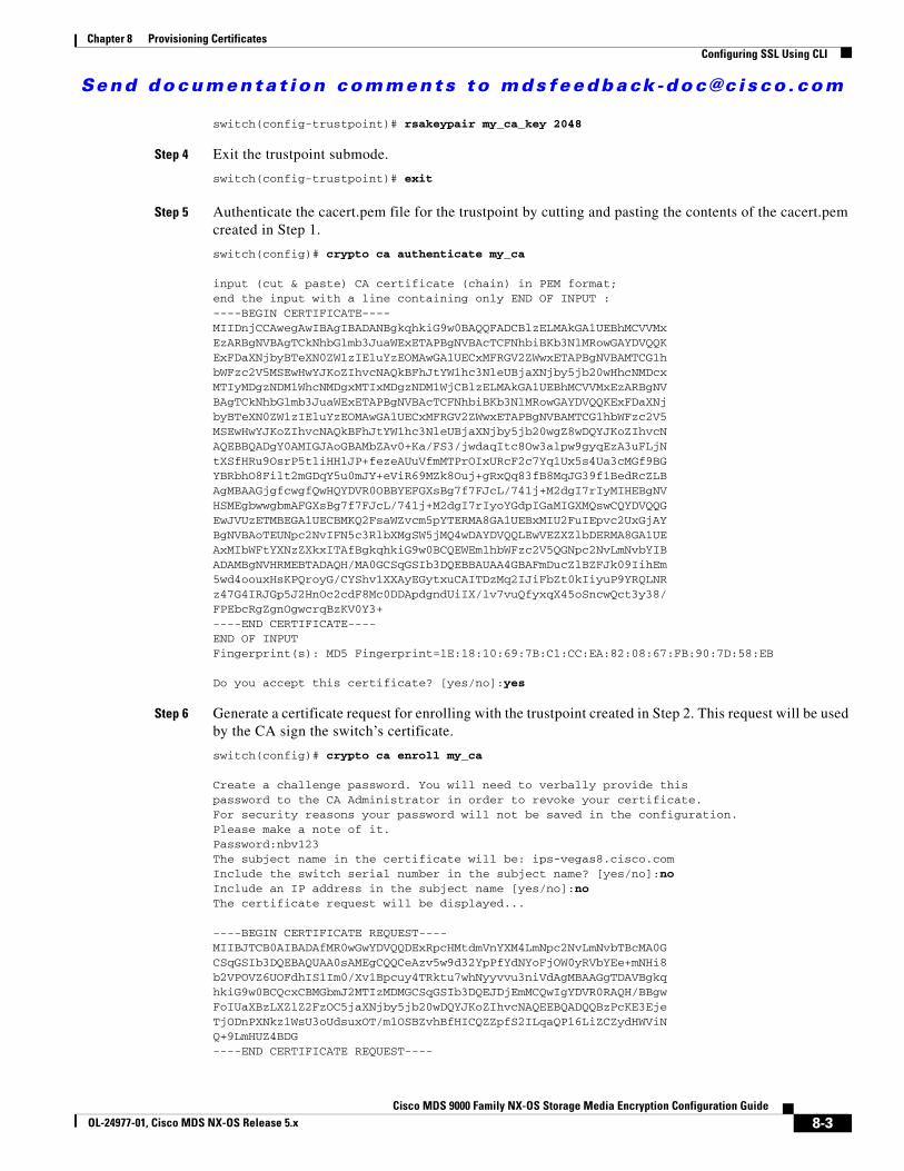
Send documenta t ion comments to mdsfeedback -doc@c i sco .com
Chapter 8 Provisioning CertificatesConfiguring SSL Using CLI
switch(config-trustpoint)# rsakeypair my_ca_key 2048
Step 4 Exit the trustpoint submode.
switch(config-trustpoint)# exit
Step 5 Authenticate the cacert.pem file for the trustpoint by cutting and pasting the contents of the cacert.pem created in Step 1.
switch(config)# crypto ca authenticate my_ca
input (cut & paste) CA certificate (chain) in PEM format;end the input with a line containing only END OF INPUT :----BEGIN CERTIFICATE----MIIDnjCCAwegAwIBAgIBADANBgkqhkiG9w0BAQQFADCBlzELMAkGA1UEBhMCVVMxEzARBgNVBAgTCkNhbGlmb3JuaWExETAPBgNVBAcTCFNhbiBKb3NlMRowGAYDVQQKExFDaXNjbyBTeXN0ZW1zIEluYzEOMAwGA1UECxMFRGV2ZWwxETAPBgNVBAMTCG1hbWFzc2V5MSEwHwYJKoZIhvcNAQkBFhJtYW1hc3NleUBjaXNjby5jb20wHhcNMDcxMTIyMDgzNDM1WhcNMDgxMTIxMDgzNDM1WjCBlzELMAkGA1UEBhMCVVMxEzARBgNVBAgTCkNhbGlmb3JuaWExETAPBgNVBAcTCFNhbiBKb3NlMRowGAYDVQQKExFDaXNjbyBTeXN0ZW1zIEluYzEOMAwGA1UECxMFRGV2ZWwxETAPBgNVBAMTCG1hbWFzc2V5MSEwHwYJKoZIhvcNAQkBFhJtYW1hc3NleUBjaXNjby5jb20wgZ8wDQYJKoZIhvcNAQEBBQADgY0AMIGJAoGBAMbZAv0+Ka/FS3/jwdaqItc8Ow3alpw9gyqEzA3uFLjNtXSfHRu9OsrP5tliHHlJP+fezeAUuVfmMTPrOIxURcF2c7Yq1Ux5s4Ua3cMGf9BGYBRbhO8Filt2mGDqY5u0mJY+eViR69MZk8Ouj+gRxQq83fB8MqJG39f1BedRcZLBAgMBAAGjgfcwgfQwHQYDVR0OBBYEFGXsBg7f7FJcL/741j+M2dgI7rIyMIHEBgNVHSMEgbwwgbmAFGXsBg7f7FJcL/741j+M2dgI7rIyoYGdpIGaMIGXMQswCQYDVQQGEwJVUzETMBEGA1UECBMKQ2FsaWZvcm5pYTERMA8GA1UEBxMIU2FuIEpvc2UxGjAYBgNVBAoTEUNpc2NvIFN5c3RlbXMgSW5jMQ4wDAYDVQQLEwVEZXZlbDERMA8GA1UEAxMIbWFtYXNzZXkxITAfBgkqhkiG9w0BCQEWEm1hbWFzc2V5QGNpc2NvLmNvbYIBADAMBgNVHRMEBTADAQH/MA0GCSqGSIb3DQEBBAUAA4GBAFmDucZlBZFJk09IihEm5wd4oouxHsKPQroyG/CYShv1XXAyEGytxuCAITDzMq2IJiFbZt0kIiyuP9YRQLNRz47G4IRJGp5J2HnOc2cdF8Mc0DDApdgndUiIX/lv7vuQfyxqX45oSncwQct3y38/FPEbcRgZgnOgwcrqBzKV0Y3+----END CERTIFICATE----END OF INPUTFingerprint(s): MD5 Fingerprint=1E:18:10:69:7B:C1:CC:EA:82:08:67:FB:90:7D:58:EB
Do you accept this certificate? [yes/no]:yes
Step 6 Generate a certificate request for enrolling with the trustpoint created in Step 2. This request will be used by the CA sign the switch’s certificate.
switch(config)# crypto ca enroll my_ca
Create a challenge password. You will need to verbally provide thispassword to the CA Administrator in order to revoke your certificate.For security reasons your password will not be saved in the configuration.Please make a note of it.Password:nbv123The subject name in the certificate will be: ips-vegas8.cisco.comInclude the switch serial number in the subject name? [yes/no]:noInclude an IP address in the subject name [yes/no]:noThe certificate request will be displayed...
----BEGIN CERTIFICATE REQUEST----MIIBJTCB0AIBADAfMR0wGwYDVQQDExRpcHMtdmVnYXM4LmNpc2NvLmNvbTBcMA0GCSqGSIb3DQEBAQUAA0sAMEgCQQCeAzv5w9d32YpPfYdNYoFjOW0yRVbYEe+mNHi8b2VPOVZ6UOFdhIS1Im0/Xv1Bpcuy4TRktu7whNyyvvu3niVdAgMBAAGgTDAVBgkqhkiG9w0BCQcxCBMGbmJ2MTIzMDMGCSqGSIb3DQEJDjEmMCQwIgYDVR0RAQH/BBgwFoIUaXBzLXZlZ2FzOC5jaXNjby5jb20wDQYJKoZIhvcNAQEEBQADQQBzPcKE3EjeTjODnPXNkz1WsU3oUdsuxOT/m1OSBZvhBfHICQZZpfS2ILqaQP16LiZCZydHWViNQ+9LmHUZ4BDG----END CERTIFICATE REQUEST----
8-3Cisco MDS 9000 Family NX-OS Storage Media Encryption Configuration Guide
OL-24977-01, Cisco MDS NX-OS Release 5.x

Send documenta t ion comments to mdsfeedback -doc@c i sco .com
Chapter 8 Provisioning CertificatesConfiguring SSL Using CLI
switch(config)#
Step 7 Create a file named switch.csr in the OpenSSL.exe directory. Cut and paste the certificate request created in Step 6.
Ensure that you include the BEGIN CERTIFICATE REQUEST and END CERTIFICATE REQUEST lines in the file content.
Step 8 Generate a certificate using the switch certificate request in the OpenSSL application by entering the following command:
OpenSSL> x509 -req -days 365 -in switch.csr -CA cacert.pem -CAkey privkey.pem -set_serial 01 -out switch.pem
This is the switch’s public certificate, now signed by the CA.
Note If your security administrator controls the CA, you will need to send them the switch.csr file and request that they complete this step and respond with the switch.pem file.
Step 9 Import the signed certificate on the switch by cutting and pasting the contents of the switch.pem file that was created in Step 8.
switch(config)# crypto ca import my_ca certificateinput (cut & paste) certificate in PEM format:----BEGIN CERTIFICATE----MIIB4jCCAUsCAQEwDQYJKoZIhvcNAQEEBQAwgZcxCzAJBgNVBAYTAlVTMRMwEQYDVQQIEwpDYWxpZm9ybmlhMREwDwYDVQQHEwhTYW4gSm9zZTEaMBgGA1UEChMRQ2lzY28gU3lzdGVtcyBJbmMxDjAMBgNVBAsTBURldmVsMREwDwYDVQQDEwhtYW1hc3NleTEhMB8GCSqGSIb3DQEJARYSbWFtYXNzZXlAY2lzY28uY29tMB4XDTA3MTIxNDAyMzIzOVoXDTA4MTIxMzAyMzIzOVowHzEdMBsGA1UEAxMUaXBzLXZlZ2FzOC5jaXNjby5jb20wXDANBgkqhkiG9w0BAQEFAANLADBIAkEAngM7+cPXd9mKT32HTWKBYzltMkVW2BHvpjR4vG9lTzlWelDhXYSEtSJtP179QaXLsuE0ZLbu8ITcsr77t54lXQIDAQABMA0GCSqGSIb3DQEBBAUAA4GBAKR3WAAF/9zMb2u9A42I2cB2G5lucSzndc4P+O4sYZF5pBt7UpyAs1GKAqivGXVq2FJ2JetX78Fqy7jYCzanWm0tck0/G1dSfr/XlCFXUuVed9de02yqxARSEx8mX4ifqzYHErHdbi+vDAaMzkUEvHWthOuUZ7fvpoNH+xhRAuBo----END CERTIFICATE----
You now have a fully configured trustpoint on the switch: A defined trustpoint, a recognized CA, a public/private key pair, and a CA signed certificate identifying the switch. The signed certificate can be used for PKI communications with all entities that recognize the CA. Repeat steps 1 through 9 for every switch in the fabric.
Removing TrustpointsThis sequence of steps must be done for all of the switches to remove the crypto CA signed trustpoints.
Detailed Steps
To remove the trustpoints, follow these steps:
Step 1 Enter the configuration mode.
switch# config t
8-4Cisco MDS 9000 Family NX-OS Storage Media Encryption Configuration Guide
OL-24977-01, Cisco MDS NX-OS Release 5.x

Send documenta t ion comments to mdsfeedback -doc@c i sco .com
Chapter 8 Provisioning CertificatesConfiguring SSL Using CLI
Enter configuration commands, one per line. End with CNTL/Z.
Step 2 Enter into the trustpoint mode.
switch(config)# crypto ca trustpoint my_ca
Step 3 Remove the certificate corresponding to the trustpoint.
switch(config-trustpoint)# delete certificate force
Step 4 Remove an RSA keypair for the switch in the trustpoint submode.
switch(config-trustpoint)# no rsakeypair my_ca_key
Step 5 Remove the CA certificate corresponding to the trustpoint.
switch(config-trustpoint)# delete ca-certificate
Step 6 Exit the trustpoint submode.
switch(config-trustpoint)# exit
Step 7 Removing the trustpoint that is configured.
switch(config)# no crypto ca trustpoint my_ca
Generating KMC Certificate
Detailed Steps
To generate the KMC certificate, follow these steps. Generate KMC certificate by entering the following commands in the OpenSSL application:
Step 1 Create the KCM Server’s private key.
OpenSSL> genrsa -out sme_kmc_server.key 2048
Step 2 Create a certificate signing request using the private key from Step 1.
OpenSSL> req -new -key sme_kmc_server.key -out sme_kmc_server.csr -config openssl.conf
Step 3 Using the certificate and private key, create a signed certificate for the KMC Server.
OpenSSL> x509 -req -days 365 -in sme_kmc_server.csr -CA cacert.pem -CAkey privkey.pem -CAcreateserial -out sme_kmc_server.cert
Note If your security administrator controls the CA, you will need to send them the sme_kmc_server.csr and request that they complete this step and respond with the sme_kmc_server.cert.
Step 4 Export the signed KMC certificate to pkcs12 format.
OpenSSL> pkcs12 -export -in sme_kmc_server.cert -inkey sme_kmc_server.key -out sme_kmc_server.p12
Step 5 Import this PKCS12 keystore to Java Keystores using JAVA keytool (JRE 1.6).
8-5Cisco MDS 9000 Family NX-OS Storage Media Encryption Configuration Guide
OL-24977-01, Cisco MDS NX-OS Release 5.x

Send documenta t ion comments to mdsfeedback -doc@c i sco .com
Chapter 8 Provisioning CertificatesConfiguring SSL Using the GUI
"<JAVA_HOME>\bin\keytool" -importkeystore -srckeystore sme_kmc_server.p12 -srcstoretype PKCS12 -destkeystore sme_kmc_server.jks -deststoretype JKS
Note Remember the password because it needs to be updated in the properties file.
Step 6 Import the CA certificate to Java Keystores using JAVA keytool (JRE 1.6).
"<JAVA_HOME>\bin\keytool" -importcert -file cacert.pem -keystore sme_kmc_trust.jks -storetype JKS
Step 7 Place these keystore files in the <install path>dcm\fm\conf\cert directory.
Step 8 Modify the KMC SSL settings in the Key Manager Settings in DCNM-SAN Web Client.
Step 9 Restart the DCNM-SAN server.
Note You can also use sme_kmc_server.p12 as KMC certificate and cacert.pem as KMC trust certificate instead of using Java keystores created in Step 5 and 6.
Configuring SSL Using the GUIThis section describes editing the SSL settings in Cisco DCNM-SAN Web Client.
You can only edit the SSL settings if you are logged into the DCNM-SAN Web Client of the DCNM-SAN server you configured as the CKMC.
Detailed Steps
To edit the SSL settings in the SME wizard, follow these steps:
Step 1 Log into DCNM-SAN.
Step 2 Click the SME tab and select Key Manager Settings. The Key Manager Settings window is displayed.
Step 3 Click Edit SSL Settings.
Step 4 In the KMC SSL settings area, select the SME KMC Trust certificate from the drop-down menu. This is the CA certificate.
Note You must copy the certs to the <install path>dcm\fm\conf\cert directory. Certificates in the conf\cert directory are listed in the drop-down menu only after DCNM-SAN server has been restarted.
Step 5 From the drop-down menu, select the SME KMC Server certificate.
The keystore files that are stored in the KMC directory are listed in the drop-down menu.
Step 6 Enter the server certificate password. Confirm the password.
Step 7 Click Submit SSL Settings to apply the changes, or click Cancel. Save the settings.
To change the SSL settings again, click Edit SSL Settings.
8-6Cisco MDS 9000 Family NX-OS Storage Media Encryption Configuration Guide
OL-24977-01, Cisco MDS NX-OS Release 5.x

Send documenta t ion comments to mdsfeedback -doc@c i sco .com
Chapter 8 Provisioning CertificatesFeature History for SSL
Note After editing the SSL settings, restart the DCNM-SAN.
If On is selected in the Transport Settings during cluster creation, then SSL is enabled on KMC with the following results:
• New clusters are created. If Off is selected, cluster creation fails.
• Previously created clusters are updated by enabling SSL with trustpoint on the switches. KMC server connection state remains as none until the cluster is updated.
For more information, refer to “Selecting Transport Settings” section on page 4-14.
Feature History for SSLTable 8-1 lists the release history for this feature.
Table 8-1 Feature History for SSL
Feature Name Releases Feature Information
Software change 5.2(1) In Release 5.2(1), Fabric Manager is changed to DCNM for SAN (DCNM-SAN).
4.1(1c) In Release 4.1(1b) and later, the MDS SAN-OS software is changed to MDS NX-OS software. The earlier releases are unchanged and all references are retained.
Generating and installing self-signed certificates
4.1(1c) In Release 4.1(1c) and later, the SSL configuration when KMC is separated from Fabric Manager Server.
Introduction to Secure Socket Layer (SSL) 3.3(1c) Describes how to configure SSL for SME and edit SSL settings in the SME wizard.
8-7Cisco MDS 9000 Family NX-OS Storage Media Encryption Configuration Guide
OL-24977-01, Cisco MDS NX-OS Release 5.x

Send documenta t ion comments to mdsfeedback -doc@c i sco .com
Chapter 8 Provisioning CertificatesFeature History for SSL
8-8Cisco MDS 9000 Family NX-OS Storage Media Encryption Configuration Guide
OL-24977-01, Cisco MDS NX-OS Release 5.x
Send documenta t ion comments to mdsfeedback -doc@c i sco .com
Cisco MDS 9000 Family NXOL-24977-01, Cisco MDS NX-OS Release 5.x
C H A P T E R 9
RSA Key Manager and SMEThis chapter describes the procedures to be followed to set up the RSA Key Manager (RKM) to work with SME.
This chapter includes the following topics:
• Prerequisites for RKM, page 9-1
• Configuring RKM, page 9-1
• Feature History for RKM, page 9-7
Note RSA Key Manager is not supported for SME Disk. It is only applicable for SME Tape.
Prerequisites for RKMIn order to implement a complete working security solution between Cisco KMC and RKM, you need to install and set up the RKM application.
The following applications are required:
• Windows WK2, XP, or W2K3 host
• DCNM-SAN Server, Release, 3.2(3)
• OpenSSL
• JAVA JDK or JRE
Configuring RKMThe process of setting up the RKM to work with SME, involves the following tasks:
• Installing the RKM Application, page 9-2
• Generating CA Certificates, page 9-2
• Creating JKS Files Using the Java Keytool, page 9-4
• Placing Certificates in RKM, page 9-5
• Adding the SME User to RKM, page 9-5
• Selecting RKM, page 9-5
9-1-OS Storage Media Encryption Configuration Guide

Send documenta t ion comments to mdsfeedback -doc@c i sco .com
Chapter 9 RSA Key Manager and SMEConfiguring RKM
• Migrating From Cisco KMC to RKM, page 9-6
After completing these tasks, you will be able to select RSA as the key manager for SME, and create a cluster.
Installing the RKM ApplicationTo install the RKM application, follow the instructions provided in the RSA Install Guide.
Generating CA CertificatesThe files that are created during this process are stored in the /bin directory of the OpenSSL program.
Prerequisites
• Generating CA certificates requires access to an OpenSSL system. You can obtain a Windows version at http://gnuwin32.sourceforge.net/packages/openssl.htm.
Detailed Steps
To generate CA certificates, follow these steps:
Step 1 Double-click openssl.exe in the directory.
Step 2 Create the key using the OpenSSL application. Enter the following command:
OpenSSL> genrsa -out rt.key 1024Loading 'screen' into random state - doneGenerating RSA private key, 1024 bit long modulus.++++++.......++++++e is 65537 (0x10001)
Step 3 Set how long the certificate will be valid. Keep track of this date.
Note Use a different common name for the client and server certificates.
OpenSSL> req -new -key rt.key -x509 -days 365 -out rt.certYou are about to be asked to enter information that will be incorporated into your certificate request.What you are about to enter is what is called a Distinguished Name or a DN.There are quite a few fields but you can leave some blankFor some fields there will be a default value,If you enter '.', the field will be left blank.-----Country Name (2 letter code) [AU]:State or Province Name (full name) [Some-State]:Locality Name (eg, city) []:Organization Name (eg, company) [Internet Widgits Pty Ltd]:Organizational Unit Name (eg, section) []:Common Name (eg, YOUR name) []:homeEmail Address []:
Step 4 Create the proper pkcs12 certificate. The export password is the password needed by the SME RSA installation.
9-2Cisco MDS 9000 Family NX-OS Storage Media Encryption Configuration Guide
OL-24977-01, Cisco MDS NX-OS Release 5.x
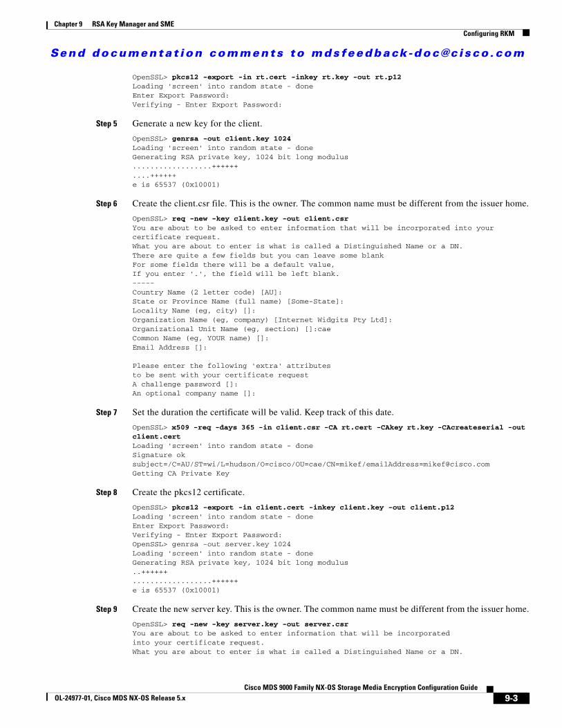
Send documenta t ion comments to mdsfeedback -doc@c i sco .com
Chapter 9 RSA Key Manager and SMEConfiguring RKM
OpenSSL> pkcs12 -export -in rt.cert -inkey rt.key -out rt.p12Loading 'screen' into random state - doneEnter Export Password:Verifying - Enter Export Password:
Step 5 Generate a new key for the client.
OpenSSL> genrsa -out client.key 1024Loading 'screen' into random state - doneGenerating RSA private key, 1024 bit long modulus..................++++++....++++++e is 65537 (0x10001)
Step 6 Create the client.csr file. This is the owner. The common name must be different from the issuer home.
OpenSSL> req -new -key client.key -out client.csrYou are about to be asked to enter information that will be incorporated into your certificate request.What you are about to enter is what is called a Distinguished Name or a DN.There are quite a few fields but you can leave some blankFor some fields there will be a default value,If you enter '.', the field will be left blank.-----Country Name (2 letter code) [AU]:State or Province Name (full name) [Some-State]:Locality Name (eg, city) []:Organization Name (eg, company) [Internet Widgits Pty Ltd]:Organizational Unit Name (eg, section) []:caeCommon Name (eg, YOUR name) []:Email Address []:
Please enter the following 'extra' attributesto be sent with your certificate requestA challenge password []:An optional company name []:
Step 7 Set the duration the certificate will be valid. Keep track of this date.
OpenSSL> x509 -req -days 365 -in client.csr -CA rt.cert -CAkey rt.key -CAcreateserial -out client.certLoading 'screen' into random state - doneSignature oksubject=/C=AU/ST=wi/L=hudson/O=cisco/OU=cae/CN=mikef/[email protected] CA Private Key
Step 8 Create the pkcs12 certificate.
OpenSSL> pkcs12 -export -in client.cert -inkey client.key -out client.p12Loading 'screen' into random state - doneEnter Export Password:Verifying - Enter Export Password:OpenSSL> genrsa -out server.key 1024Loading 'screen' into random state - doneGenerating RSA private key, 1024 bit long modulus..++++++..................++++++e is 65537 (0x10001)
Step 9 Create the new server key. This is the owner. The common name must be different from the issuer home.
OpenSSL> req -new -key server.key -out server.csrYou are about to be asked to enter information that will be incorporatedinto your certificate request.What you are about to enter is what is called a Distinguished Name or a DN.
9-3Cisco MDS 9000 Family NX-OS Storage Media Encryption Configuration Guide
OL-24977-01, Cisco MDS NX-OS Release 5.x
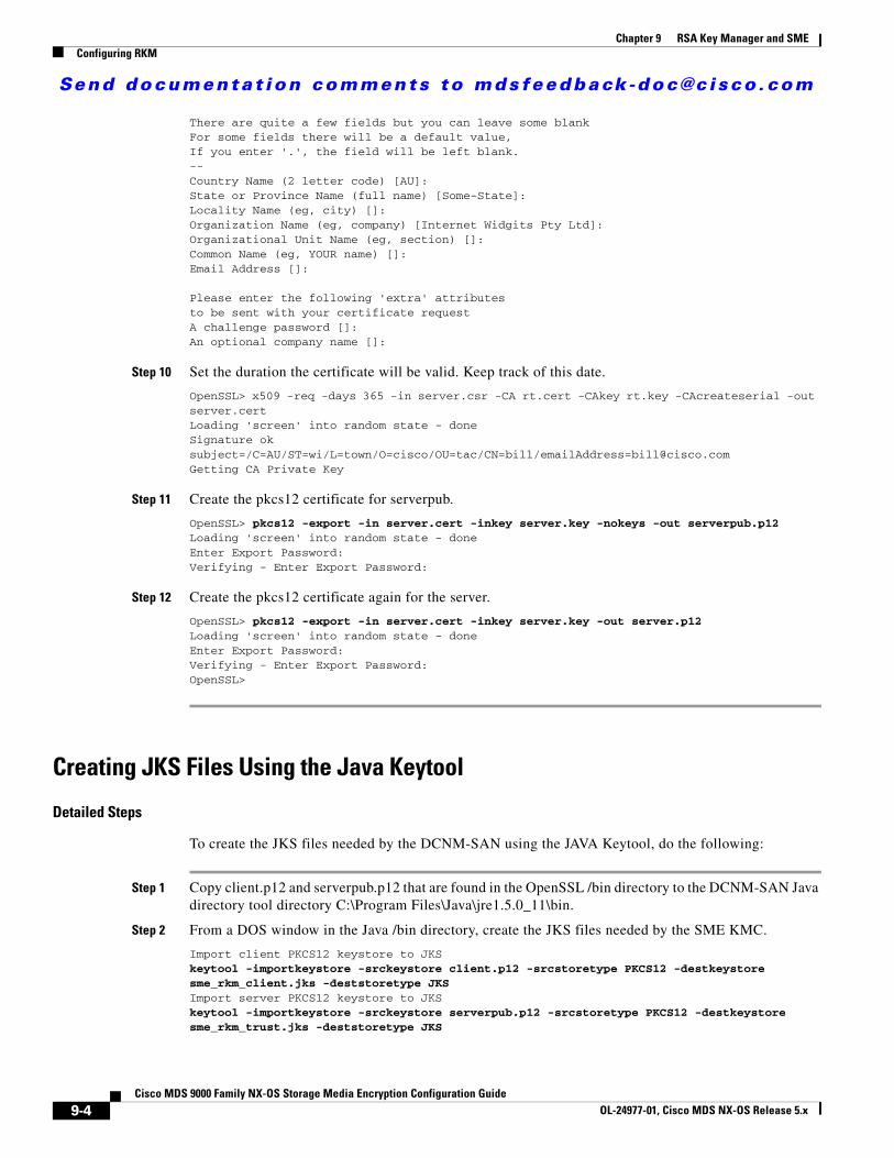
Send documenta t ion comments to mdsfeedback -doc@c i sco .com
Chapter 9 RSA Key Manager and SMEConfiguring RKM
There are quite a few fields but you can leave some blankFor some fields there will be a default value,If you enter '.', the field will be left blank.--Country Name (2 letter code) [AU]:State or Province Name (full name) [Some-State]:Locality Name (eg, city) []:Organization Name (eg, company) [Internet Widgits Pty Ltd]:Organizational Unit Name (eg, section) []:Common Name (eg, YOUR name) []:Email Address []:
Please enter the following 'extra' attributesto be sent with your certificate requestA challenge password []:An optional company name []:
Step 10 Set the duration the certificate will be valid. Keep track of this date.
OpenSSL> x509 -req -days 365 -in server.csr -CA rt.cert -CAkey rt.key -CAcreateserial -out server.certLoading 'screen' into random state - doneSignature oksubject=/C=AU/ST=wi/L=town/O=cisco/OU=tac/CN=bill/[email protected] CA Private Key
Step 11 Create the pkcs12 certificate for serverpub.
OpenSSL> pkcs12 -export -in server.cert -inkey server.key -nokeys -out serverpub.p12Loading 'screen' into random state - doneEnter Export Password:Verifying - Enter Export Password:
Step 12 Create the pkcs12 certificate again for the server.
OpenSSL> pkcs12 -export -in server.cert -inkey server.key -out server.p12Loading 'screen' into random state - doneEnter Export Password:Verifying - Enter Export Password:OpenSSL>
Creating JKS Files Using the Java Keytool
Detailed Steps
To create the JKS files needed by the DCNM-SAN using the JAVA Keytool, do the following:
Step 1 Copy client.p12 and serverpub.p12 that are found in the OpenSSL /bin directory to the DCNM-SAN Java directory tool directory C:\Program Files\Java\jre1.5.0_11\bin.
Step 2 From a DOS window in the Java /bin directory, create the JKS files needed by the SME KMC.
Import client PKCS12 keystore to JKS keytool -importkeystore -srckeystore client.p12 -srcstoretype PKCS12 -destkeystore sme_rkm_client.jks -deststoretype JKSImport server PKCS12 keystore to JKS keytool -importkeystore -srckeystore serverpub.p12 -srcstoretype PKCS12 -destkeystore sme_rkm_trust.jks -deststoretype JKS
9-4Cisco MDS 9000 Family NX-OS Storage Media Encryption Configuration Guide
OL-24977-01, Cisco MDS NX-OS Release 5.x
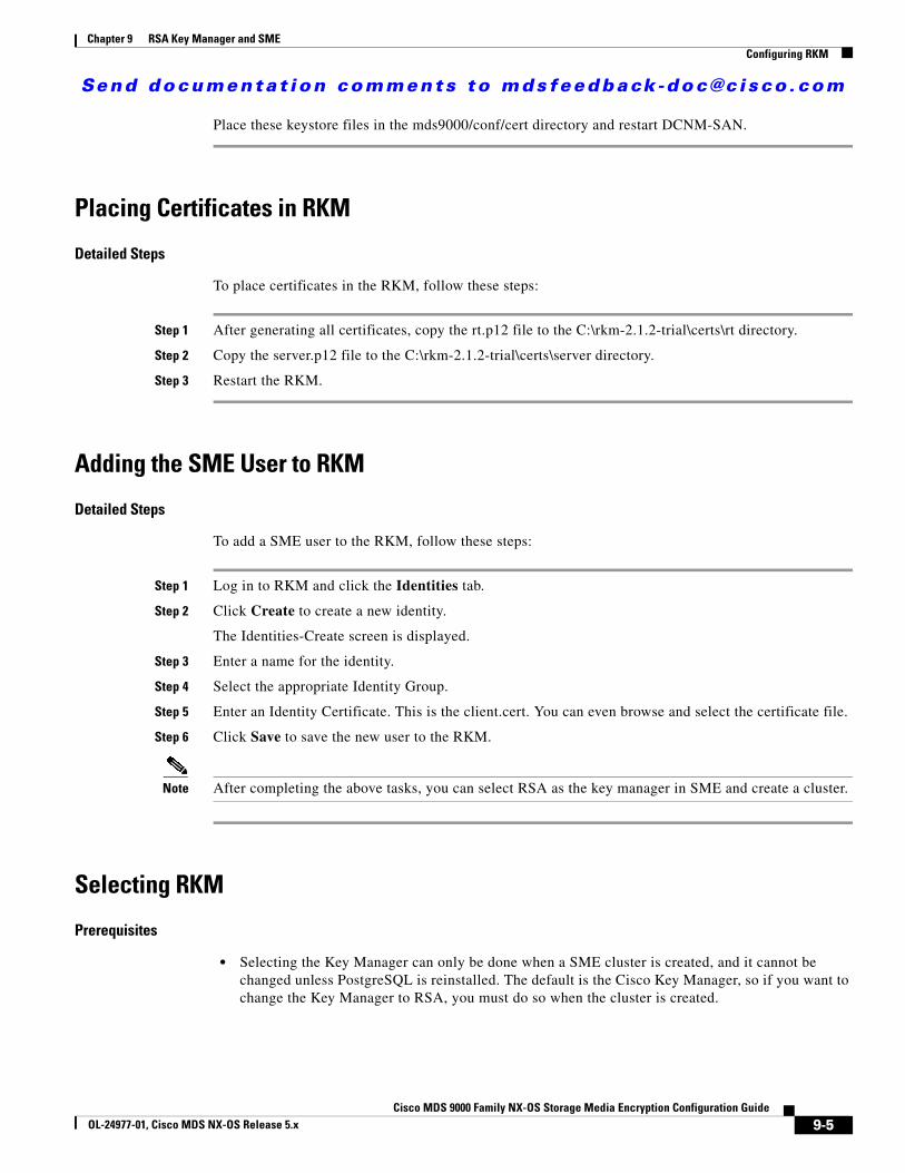
Send documenta t ion comments to mdsfeedback -doc@c i sco .com
Chapter 9 RSA Key Manager and SMEConfiguring RKM
Place these keystore files in the mds9000/conf/cert directory and restart DCNM-SAN.
Placing Certificates in RKM
Detailed Steps
To place certificates in the RKM, follow these steps:
Step 1 After generating all certificates, copy the rt.p12 file to the C:\rkm-2.1.2-trial\certs\rt directory.
Step 2 Copy the server.p12 file to the C:\rkm-2.1.2-trial\certs\server directory.
Step 3 Restart the RKM.
Adding the SME User to RKM
Detailed Steps
To add a SME user to the RKM, follow these steps:
Step 1 Log in to RKM and click the Identities tab.
Step 2 Click Create to create a new identity.
The Identities-Create screen is displayed.
Step 3 Enter a name for the identity.
Step 4 Select the appropriate Identity Group.
Step 5 Enter an Identity Certificate. This is the client.cert. You can even browse and select the certificate file.
Step 6 Click Save to save the new user to the RKM.
Note After completing the above tasks, you can select RSA as the key manager in SME and create a cluster.
Selecting RKM
Prerequisites
• Selecting the Key Manager can only be done when a SME cluster is created, and it cannot be changed unless PostgreSQL is reinstalled. The default is the Cisco Key Manager, so if you want to change the Key Manager to RSA, you must do so when the cluster is created.
9-5Cisco MDS 9000 Family NX-OS Storage Media Encryption Configuration Guide
OL-24977-01, Cisco MDS NX-OS Release 5.x
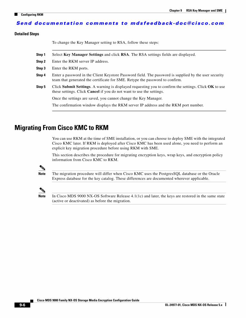
Send documenta t ion comments to mdsfeedback -doc@c i sco .com
Chapter 9 RSA Key Manager and SMEConfiguring RKM
Detailed Steps
To change the Key Manager setting to RSA, follow these steps:
Step 1 Select Key Manager Settings and click RSA. The RSA settings fields are displayed.
Step 2 Enter the RKM server IP address.
Step 3 Enter the RKM ports.
Step 4 Enter a password in the Client Keystore Password field. The password is supplied by the user security team that generated the certificate for SME. Retype the password to confirm.
Step 5 Click Submit Settings. A warning is displayed requesting you to confirm the settings. Click OK to use these settings. Click Cancel if you do not want to use the settings.
Once the settings are saved, you cannot change the Key Manager.
The confirmation window displays the RKM server IP address and the RKM port number.
Migrating From Cisco KMC to RKM You can use RKM at the time of SME installation, or you can choose to deploy SME with the integrated Cisco KMC later. If RKM is deployed after Cisco KMC has been used alone, you need to perform an explicit key migration procedure before using RKM with SME.
This section describes the procedure for migrating encryption keys, wrap keys, and encryption policy information from Cisco KMC to RKM.
Note The migration procedure will differ when Cisco KMC uses the PostgresSQL database or the Oracle Express database for the key catalog. These differences are documented wherever applicable.
Note In Cisco MDS 9000 NX-OS Software Release 4.1(1c) and later, the keys are restored in the same state (active or deactivated) as before the migration.
9-6Cisco MDS 9000 Family NX-OS Storage Media Encryption Configuration Guide
OL-24977-01, Cisco MDS NX-OS Release 5.x
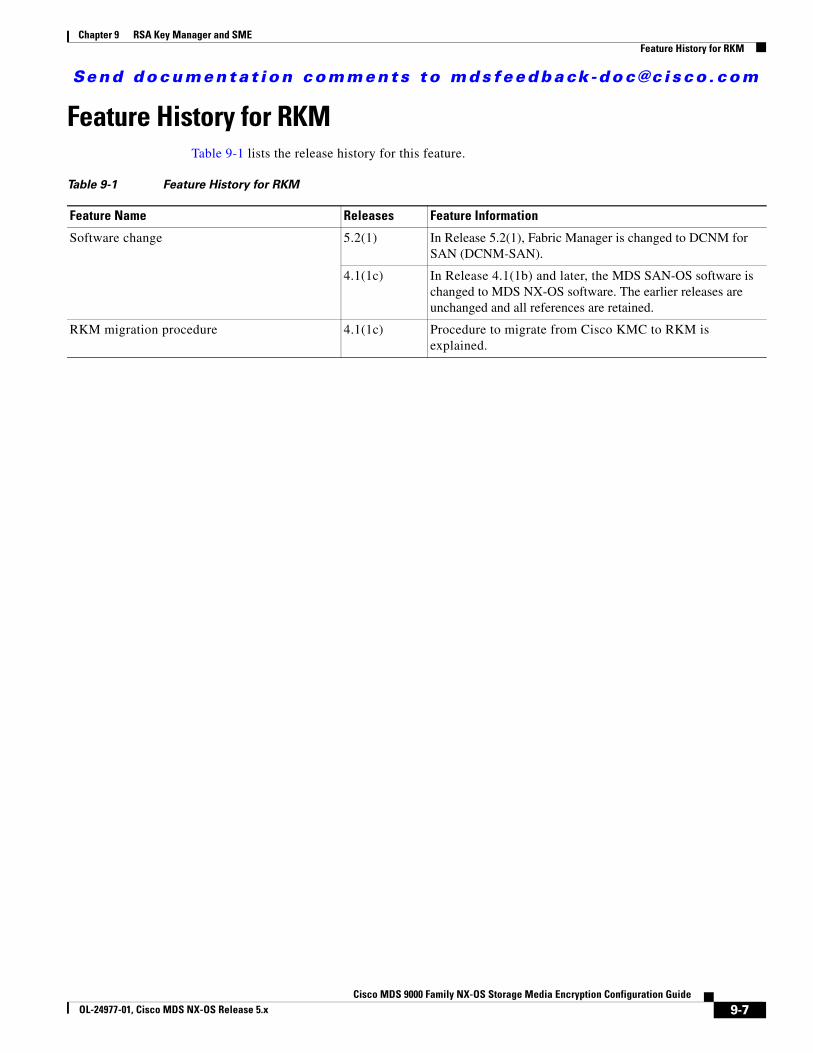
Send documenta t ion comments to mdsfeedback -doc@c i sco .com
Chapter 9 RSA Key Manager and SMEFeature History for RKM
Feature History for RKMTable 9-1 lists the release history for this feature.
Table 9-1 Feature History for RKM
Feature Name Releases Feature Information
Software change 5.2(1) In Release 5.2(1), Fabric Manager is changed to DCNM for SAN (DCNM-SAN).
4.1(1c) In Release 4.1(1b) and later, the MDS SAN-OS software is changed to MDS NX-OS software. The earlier releases are unchanged and all references are retained.
RKM migration procedure 4.1(1c) Procedure to migrate from Cisco KMC to RKM is explained.
9-7Cisco MDS 9000 Family NX-OS Storage Media Encryption Configuration Guide
OL-24977-01, Cisco MDS NX-OS Release 5.x

Send documenta t ion comments to mdsfeedback -doc@c i sco .com
Chapter 9 RSA Key Manager and SMEFeature History for RKM
9-8Cisco MDS 9000 Family NX-OS Storage Media Encryption Configuration Guide
OL-24977-01, Cisco MDS NX-OS Release 5.x
Send documenta t ion comments to mdsfeedback -doc@c i sco .com
Cisco MDS 9000 Family NXOL-24977-01, Cisco MDS NX-OS Release 4.x
C H A P T E R 10
SME Best PracticesThis chapter describes SME best practices. You can avoid problems when configuring SME if you observe the best practices described in this chapter.
Overview of Best PracticesBest practices are the recommended steps you should take to ensure the proper operation of SME. We recommend the following best practices for SME configurations:
• General Practices, page 10-1
• SME Configuration Practices, page 10-1
• SME Disk and VAAI or Thin Provisioning Support, page 10-2
• KMC Practices, page 10-2
• Fabric Management Practices, page 10-2
General Practices• Maintain a consistent Cisco NX-OS release across all your Cisco MDS switches.
• Refer to the “Planning For SME Installation” appendix for preconfiguration information and procedures.
• Enable system message logging. For information on system messages, refer to the Cisco MDS 9000 Family Troubleshooting Guide.
• Refer to the release notes for your Cisco SAN-OS or NX-OS release for the latest features, limitations, and caveats.
SME Configuration Practices• Troubleshoot any new configuration changes after implementing the change.
• Save all configuration changes on all switches in the cluster for correct cluster operation.
• When designing your backup environment, consider that Cisco SAN-OS or NX-OS supports one cluster per switch.
10-1-OS Storage Media Encryption Configuration Guide
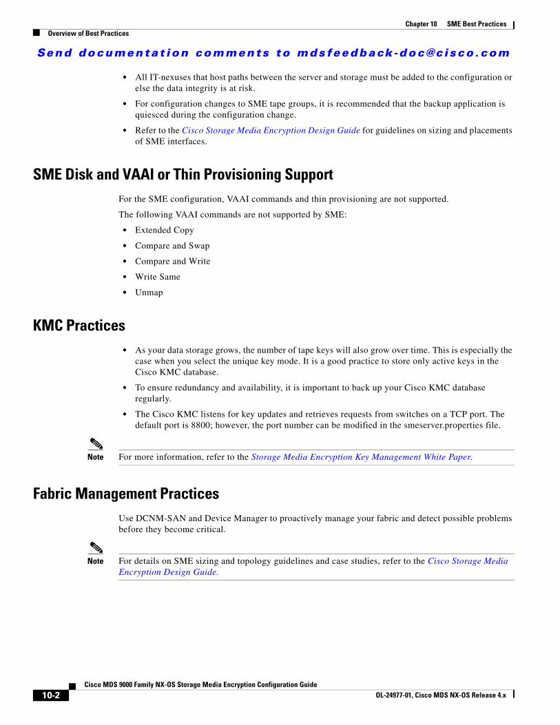
Send documenta t ion comments to mdsfeedback -doc@c i sco .com
Chapter 10 SME Best PracticesOverview of Best Practices
• All IT-nexuses that host paths between the server and storage must be added to the configuration or else the data integrity is at risk.
• For configuration changes to SME tape groups, it is recommended that the backup application is quiesced during the configuration change.
• Refer to the Cisco Storage Media Encryption Design Guide for guidelines on sizing and placements of SME interfaces.
SME Disk and VAAI or Thin Provisioning SupportFor the SME configuration, VAAI commands and thin provisioning are not supported.
The following VAAI commands are not supported by SME:
• Extended Copy
• Compare and Swap
• Compare and Write
• Write Same
• Unmap
KMC Practices• As your data storage grows, the number of tape keys will also grow over time. This is especially the
case when you select the unique key mode. It is a good practice to store only active keys in the Cisco KMC database.
• To ensure redundancy and availability, it is important to back up your Cisco KMC database regularly.
• The Cisco KMC listens for key updates and retrieves requests from switches on a TCP port. The default port is 8800; however, the port number can be modified in the smeserver.properties file.
Note For more information, refer to the Storage Media Encryption Key Management White Paper.
Fabric Management PracticesUse DCNM-SAN and Device Manager to proactively manage your fabric and detect possible problems before they become critical.
Note For details on SME sizing and topology guidelines and case studies, refer to the Cisco Storage Media Encryption Design Guide.
10-2Cisco MDS 9000 Family NX-OS Storage Media Encryption Configuration Guide
OL-24977-01, Cisco MDS NX-OS Release 4.x
Send documenta t ion comments to mdsfeedback -doc@c i sco .com
Cisco MDS 9000 Family NXOL-24977-01, Cisco MDS NX-OS Release 5.x
C H A P T E R 11
SME TroubleshootingThis chapter describes basic troubleshooting methods used to resolve issues with Cisco Storage Media Encryption.
This chapter includes the following sections:
• Troubleshooting Resources, page 11-1
• Cluster Recovery Scenarios, page 11-1
• Troubleshooting General Issues, page 11-6
• Troubleshooting Scenarios, page 11-6
Troubleshooting ResourcesFor additional information on troubleshooting, the Cisco MDS 9000 Family NX-OS Troubleshooting Guide provides guidance for troubleshooting issues that may appear when deploying a storage area network (SAN) using the Cisco MDS 9000 Family of switches. The Cisco MDS 9000 NX-OS Family Troubleshooting Guide introduces tools and methodologies that are used to recognize a problem, determine its cause, and find possible solutions.
Cluster Recovery ScenariosThis section includes information on recovery procedures used when one or more switches in a SME cluster are offline or when you want to change the master switch assignment from one switch to another switch. It includes the following procedures:
• Deleting an Offline Switch from a SME Cluster, page 11-2
• Deleting a SME Cluster with One or More Offline Switches while the Master Switch is Online, page 11-2
• Deleting a SME Cluster when All Switches are Offline, page 11-3
• Reviving an SME Cluster, page 11-4
Note The procedures in this section describe troubleshooting solutions that use the CLI.
11-1-OS Storage Media Encryption Configuration Guide
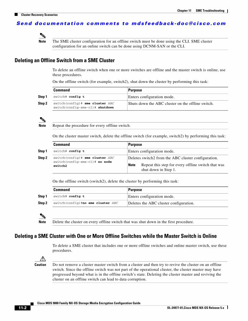
Send documenta t ion comments to mdsfeedback -doc@c i sco .com
Chapter 11 SME TroubleshootingCluster Recovery Scenarios
Note The SME cluster configuration for an offline switch must be done using the CLI. SME cluster configuration for an online switch can be done using DCNM-SAN or the CLI.
Deleting an Offline Switch from a SME Cluster
To delete an offline switch when one or more switches are offline and the master switch is online, use these procedures.
On the offline switch (for example, switch2), shut down the cluster by performing this task:
Note Repeat the procedure for every offline switch.
On the cluster master switch, delete the offline switch (for example, switch2) by performing this task:
On the offline switch (switch2), delete the cluster by performing this task:
Note Delete the cluster on every offline switch that was shut down in the first procedure.
Deleting a SME Cluster with One or More Offline Switches while the Master Switch is Online
To delete a SME cluster that includes one or more offline switches and online master switch, use these procedures.
Caution Do not remove a cluster master switch from a cluster and then try to revive the cluster on an offline switch. Since the offline switch was not part of the operational cluster, the cluster master may have progressed beyond what is in the offline switch’s state. Deleting the cluster master and reviving the cluster on an offline switch can lead to data corruption.
Command Purpose
Step 1 switch# config t Enters configuration mode.
Step 2 switch(config)# sme cluster ABCswitch(config-sme-cl)# shutdown
Shuts down the ABC cluster on the offline switch.
Command Purpose
Step 1 switch# config t Enters configuration mode.
Step 2 switch(config)# sme cluster ABC switch(config-sme-cl)# no node switch2
Deletes switch2 from the ABC cluster configuration.
Note Repeat this step for every offline switch that was shut down in Step 1.
Command Purpose
Step 1 switch# config t Enters configuration mode.
Step 2 switch(config)#no sme cluster ABC Deletes the ABC cluster configuration.
11-2Cisco MDS 9000 Family NX-OS Storage Media Encryption Configuration Guide
OL-24977-01,Cisco MDS NX-OS Release 5.x
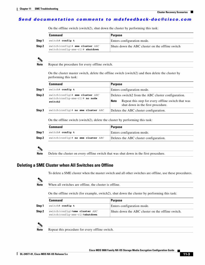
Send documenta t ion comments to mdsfeedback -doc@c i sco .com
Chapter 11 SME TroubleshootingCluster Recovery Scenarios
On the offline switch (switch2), shut down the cluster by performing this task:
Note Repeat the procedure for every offline switch.
On the cluster master switch, delete the offline switch (switch2) and then delete the cluster by performing this task:
On the offline switch (switch2), delete the cluster by performing this task:
Note Delete the cluster on every offline switch that was shut down in the first procedure.
Deleting a SME Cluster when All Switches are Offline
To delete a SME cluster when the master switch and all other switches are offline, use these procedures.
Note When all switches are offline, the cluster is offline.
On the offline switch (for example, switch2), shut down the cluster by performing this task:
Note Repeat this procedure for every offline switch.
Command Purpose
Step 1 switch# config t Enters configuration mode.
Step 2 switch(config)# sme cluster ABCswitch(config-sme-cl)# shutdown
Shuts down the ABC cluster on the offline switch
Command Purpose
Step 1 switch# config t Enters configuration mode.
Step 2 switch(config)# sme cluster ABC switch(config-sme-cl)# no node switch2
Deletes switch2 from the ABC cluster configuration.
Note Repeat this step for every offline switch that was shut down in the first procedure.
Step 3 switch(config)# no sme cluster ABC Deletes the ABC cluster configuration.
Command Purpose
Step 1 switch# config t Enters configuration mode.
Step 2 switch(config)# no sme cluster ABC Deletes the ABC cluster configuration.
Command Purpose
Step 1 switch# config t Enters configuration mode.
Step 2 switch(config)#sme cluster ABCswitch(config-sme-cl)#shutdown
Shuts down the ABC cluster on the offline switch.
11-3Cisco MDS 9000 Family NX-OS Storage Media Encryption Configuration Guide
OL-24977-01, Cisco MDS NX-OS Release 5.x
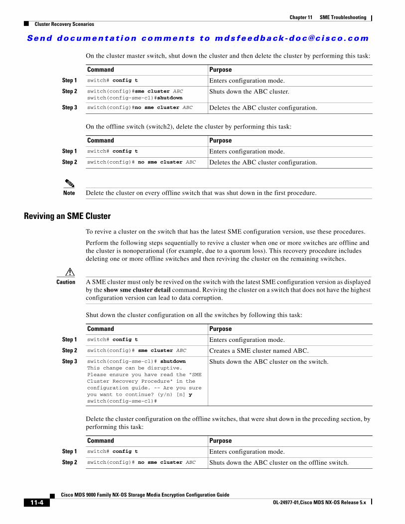
Send documenta t ion comments to mdsfeedback -doc@c i sco .com
Chapter 11 SME TroubleshootingCluster Recovery Scenarios
On the cluster master switch, shut down the cluster and then delete the cluster by performing this task:
On the offline switch (switch2), delete the cluster by performing this task:
Note Delete the cluster on every offline switch that was shut down in the first procedure.
Reviving an SME Cluster
To revive a cluster on the switch that has the latest SME configuration version, use these procedures.
Perform the following steps sequentially to revive a cluster when one or more switches are offline and the cluster is nonoperational (for example, due to a quorum loss). This recovery procedure includes deleting one or more offline switches and then reviving the cluster on the remaining switches.
Caution A SME cluster must only be revived on the switch with the latest SME configuration version as displayed by the show sme cluster detail command. Reviving the cluster on a switch that does not have the highest configuration version can lead to data corruption.
Shut down the cluster configuration on all the switches by following this task:
Delete the cluster configuration on the offline switches, that were shut down in the preceding section, by performing this task:
Command Purpose
Step 1 switch# config t Enters configuration mode.
Step 2 switch(config)#sme cluster ABC switch(config-sme-cl)#shutdown
Shuts down the ABC cluster.
Step 3 switch(config)#no sme cluster ABC Deletes the ABC cluster configuration.
Command Purpose
Step 1 switch# config t Enters configuration mode.
Step 2 switch(config)# no sme cluster ABC Deletes the ABC cluster configuration.
Command Purpose
Step 1 switch# config t Enters configuration mode.
Step 2 switch(config)# sme cluster ABC Creates a SME cluster named ABC.
Step 3 switch(config-sme-cl)# shutdownThis change can be disruptive. Please ensure you have read the "SME Cluster Recovery Procedure" in the configuration guide. -- Are you sure you want to continue? (y/n) [n] yswitch(config-sme-cl)#
Shuts down the ABC cluster on the switch.
Command Purpose
Step 1 switch# config t Enters configuration mode.
Step 2 switch(config)# no sme cluster ABC Shuts down the ABC cluster on the offline switch.
11-4Cisco MDS 9000 Family NX-OS Storage Media Encryption Configuration Guide
OL-24977-01,Cisco MDS NX-OS Release 5.x
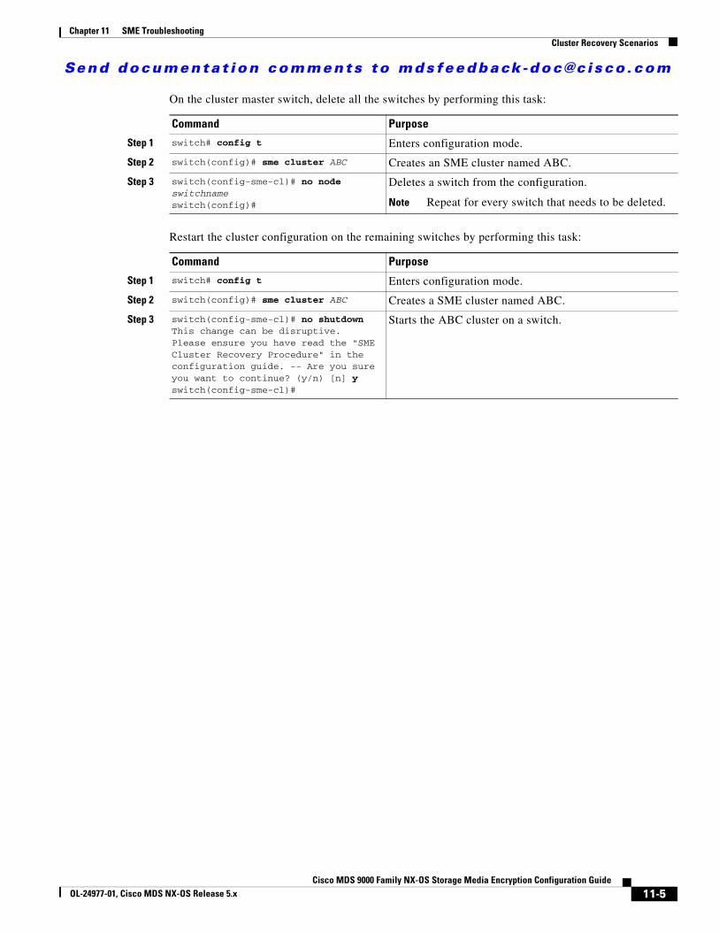
Send documenta t ion comments to mdsfeedback -doc@c i sco .com
Chapter 11 SME TroubleshootingCluster Recovery Scenarios
On the cluster master switch, delete all the switches by performing this task:
Restart the cluster configuration on the remaining switches by performing this task:
Command Purpose
Step 1 switch# config t Enters configuration mode.
Step 2 switch(config)# sme cluster ABC Creates an SME cluster named ABC.
Step 3 switch(config-sme-cl)# no node switchnameswitch(config)#
Deletes a switch from the configuration.
Note Repeat for every switch that needs to be deleted.
Command Purpose
Step 1 switch# config t Enters configuration mode.
Step 2 switch(config)# sme cluster ABC Creates a SME cluster named ABC.
Step 3 switch(config-sme-cl)# no shutdownThis change can be disruptive. Please ensure you have read the "SME Cluster Recovery Procedure" in the configuration guide. -- Are you sure you want to continue? (y/n) [n] yswitch(config-sme-cl)#
Starts the ABC cluster on a switch.
11-5Cisco MDS 9000 Family NX-OS Storage Media Encryption Configuration Guide
OL-24977-01, Cisco MDS NX-OS Release 5.x
Send documenta t ion comments to mdsfeedback -doc@c i sco .com
Chapter 11 SME TroubleshootingTroubleshooting General Issues
Troubleshooting General IssuesThe SME naming convention includes alphanumeric, dash, and underscore characters. Other types of characters will cause problems in the cluster configuration.
Troubleshooting ScenariosThe following scenarios are described in this section:
• If DNS is not configured on all switches in a cluster, page 11-6
• If you need to replace an MSM-18/4 module with another MSM-18/4 module, page 11-7
• If an SME cluster is not successfully created, page 11-7
• SME Interface creation error, page 11-7
• An SME interface does not come up in a cluster, page 11-7
• When selecting paths, a “no paths found” message is displayed, page 11-7
• Newly added tape drives are not showing in a cluster, page 11-8
• If you need to contact your customer support representative or Cisco TAC, page 11-8
• A syslog message is displayed when a Cisco MDS switch configured with SME in the startup configuration boots up, page 11-8
• Importing a volume group file causes a 'wrap key object not found' error message, page 11-8
• Accounting log file shows the replication of keys failed, page 11-8
• Issues with smart card(s) or card reader, page 11-8
If DNS is not configured on all switches in a cluster
You can use sme.useIP for IP address or name selection when DNS is not configured on all switches in a cluster.
sme.useIP can be used in smeserver.properties to enable the use of IP addresses instead of switch names. By default sme.useIP is set to false and DNS names will be used. When DNS is not configured, DCNM-SAN cannot resolve the switch names.
When sme.useIP is set to true, DCNM-SAN uses an IP address to communicate with switch in the cluster using SSH. All switches are added to the cluster with an IP address. When you add a local switch, the switch name is used if the name server is configured on the switch, otherwise, the IP address is used.
When sme.useIP is false, DCNM-SAN will use the switch name to select interfaces. All the switches added to the clusters will be identified with names. A name server is required for this type of configuration. Otherwise, switches will not be able to communicate with other switches to form the cluster and DCNM-SAN will not be able to resolve the switch name.
11-6Cisco MDS 9000 Family NX-OS Storage Media Encryption Configuration Guide
OL-24977-01,Cisco MDS NX-OS Release 5.x
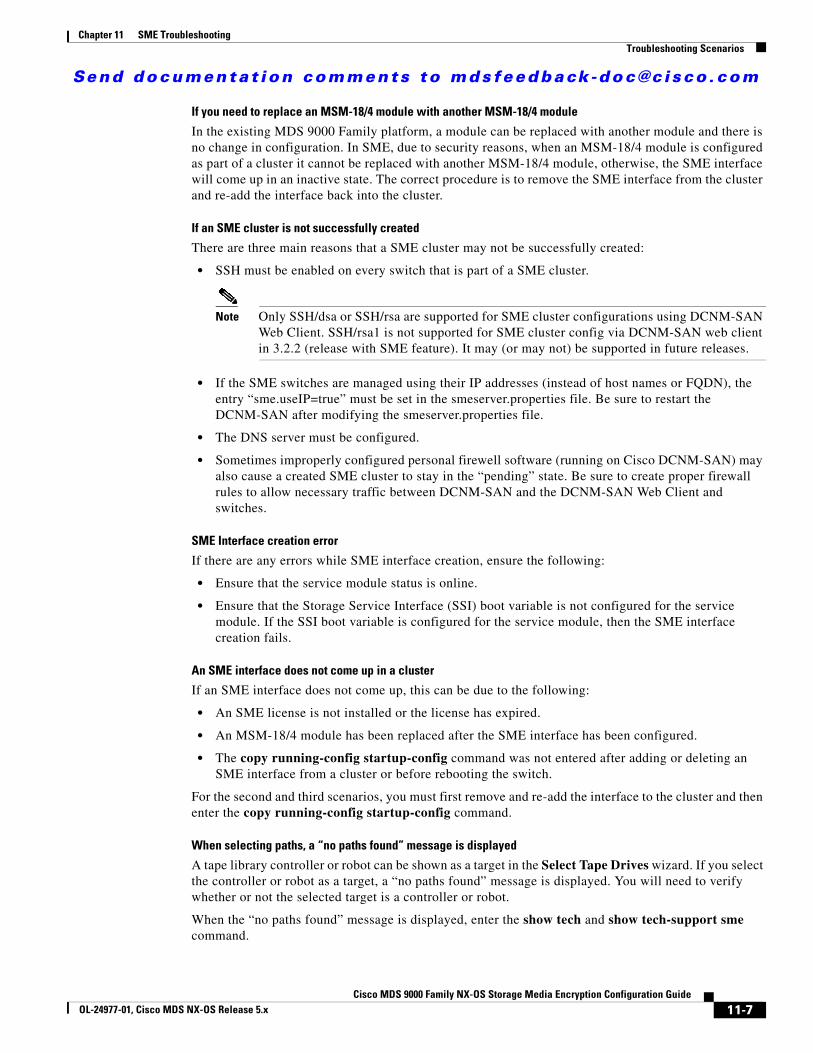
Send documenta t ion comments to mdsfeedback -doc@c i sco .com
Chapter 11 SME TroubleshootingTroubleshooting Scenarios
If you need to replace an MSM-18/4 module with another MSM-18/4 module
In the existing MDS 9000 Family platform, a module can be replaced with another module and there is no change in configuration. In SME, due to security reasons, when an MSM-18/4 module is configured as part of a cluster it cannot be replaced with another MSM-18/4 module, otherwise, the SME interface will come up in an inactive state. The correct procedure is to remove the SME interface from the cluster and re-add the interface back into the cluster.
If an SME cluster is not successfully created
There are three main reasons that a SME cluster may not be successfully created:
• SSH must be enabled on every switch that is part of a SME cluster.
Note Only SSH/dsa or SSH/rsa are supported for SME cluster configurations using DCNM-SAN Web Client. SSH/rsa1 is not supported for SME cluster config via DCNM-SAN web client in 3.2.2 (release with SME feature). It may (or may not) be supported in future releases.
• If the SME switches are managed using their IP addresses (instead of host names or FQDN), the entry “sme.useIP=true” must be set in the smeserver.properties file. Be sure to restart the DCNM-SAN after modifying the smeserver.properties file.
• The DNS server must be configured.
• Sometimes improperly configured personal firewell software (running on Cisco DCNM-SAN) may also cause a created SME cluster to stay in the “pending” state. Be sure to create proper firewall rules to allow necessary traffic between DCNM-SAN and the DCNM-SAN Web Client and switches.
SME Interface creation error
If there are any errors while SME interface creation, ensure the following:
• Ensure that the service module status is online.
• Ensure that the Storage Service Interface (SSI) boot variable is not configured for the service module. If the SSI boot variable is configured for the service module, then the SME interface creation fails.
An SME interface does not come up in a cluster
If an SME interface does not come up, this can be due to the following:
• An SME license is not installed or the license has expired.
• An MSM-18/4 module has been replaced after the SME interface has been configured.
• The copy running-config startup-config command was not entered after adding or deleting an SME interface from a cluster or before rebooting the switch.
For the second and third scenarios, you must first remove and re-add the interface to the cluster and then enter the copy running-config startup-config command.
When selecting paths, a “no paths found” message is displayed
A tape library controller or robot can be shown as a target in the Select Tape Drives wizard. If you select the controller or robot as a target, a “no paths found” message is displayed. You will need to verify whether or not the selected target is a controller or robot.
When the “no paths found” message is displayed, enter the show tech and show tech-support sme command.
11-7Cisco MDS 9000 Family NX-OS Storage Media Encryption Configuration Guide
OL-24977-01, Cisco MDS NX-OS Release 5.x
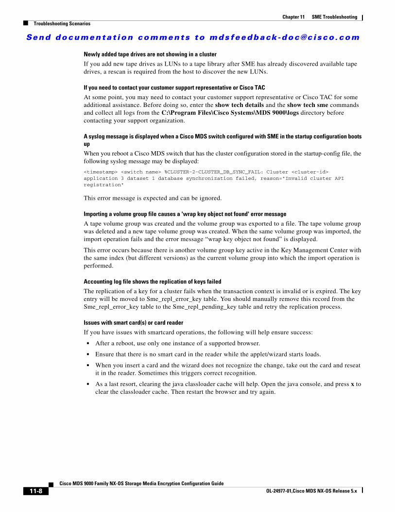
Send documenta t ion comments to mdsfeedback -doc@c i sco .com
Chapter 11 SME TroubleshootingTroubleshooting Scenarios
Newly added tape drives are not showing in a cluster
If you add new tape drives as LUNs to a tape library after SME has already discovered available tape drives, a rescan is required from the host to discover the new LUNs.
If you need to contact your customer support representative or Cisco TAC
At some point, you may need to contact your customer support representative or Cisco TAC for some additional assistance. Before doing so, enter the show tech details and the show tech sme commands and collect all logs from the C:\Program Files\Cisco Systems\MDS 9000\logs directory before contacting your support organization.
A syslog message is displayed when a Cisco MDS switch configured with SME in the startup configuration boots up
When you reboot a Cisco MDS switch that has the cluster configuration stored in the startup-config file, the following syslog message may be displayed:
<timestamp> <switch name> %CLUSTER-2-CLUSTER_DB_SYNC_FAIL: Cluster <cluster-id> application 3 dataset 1 database synchronization failed, reason="Invalid cluster API registration"
This error message is expected and can be ignored.
Importing a volume group file causes a 'wrap key object not found' error message
A tape volume group was created and the volume group was exported to a file. The tape volume group was deleted and a new tape volume group was created. When the same volume group was imported, the import operation fails and the error message “wrap key object not found” is displayed.
This error occurs because there is another volume group key active in the Key Management Center with the same index (but different versions) as the current volume group into which the import operation is performed.
Accounting log file shows the replication of keys failed
The replication of a key for a cluster fails when the transaction context is invalid or is expired. The key entry will be moved to Sme_repl_error_key table. You should manually remove this record from the Sme_repl_error_key table to the Sme_repl_pending_key table and retry the replication process.
Issues with smart card(s) or card reader
If you have issues with smartcard operations, the following will help ensure success:
• After a reboot, use only one instance of a supported browser.
• Ensure that there is no smart card in the reader while the applet/wizard starts loads.
• When you insert a card and the wizard does not recognize the change, take out the card and reseat it in the reader. Sometimes this triggers correct recognition.
• As a last resort, clearing the java classloader cache will help. Open the java console, and press x to clear the classloader cache. Then restart the browser and try again.
11-8Cisco MDS 9000 Family NX-OS Storage Media Encryption Configuration Guide
OL-24977-01,Cisco MDS NX-OS Release 5.x
Send documenta t ion comments to mdsfeedback -doc@c i sco .com
Cisco MDS 9000 Family NX-OS StoOL-24977-01, Cisco MDS NX-OS Release 5.x
A
P P E N D I X A SME CLI CommandsThe commands in this appendix apply to the Cisco MDS 9000 Family of multilayer directors and fabric switches. See the “Command Modes” section to determine the appropriate mode for each command.
SME CommandsThis appendix contains an alphabetical listing of commands that are unique to the SME features.
A-1rage Media Encryption Configuration Guide
Send documenta t ion comments to mdsfeedback -doc@c i sco .com
Appendix A SME CLI Commandsauto-volgrp
auto-volgrpTo configure the automatic volume grouping, use the auto-volgrp command. To disable this feature, use the no form of the command.
auto-volgrp
no auto-volgrp
Syntax Description This command has no arguments or keywords.
Defaults Disabled.
Command Modes SME cluster configuration submode.
Command History
Usage Guidelines If SME recognizes that the tape’s barcode does not belong to an existing volume group, then a new volume group is created when automatic volume grouping is enabled.
Examples The following example enables automatic volume grouping:
switch# config tswitch(config)# sme cluster c1switch(config-sme-cl)# auto-volgrpswitch(config-sme-cl)#
The following example disables automatic volume grouping:
switch# config tswitch(config)# sme cluster c1switch(config-sme-cl)# auto-volgrpswitch(config-sme-cl)#
Related Commands
Release Modification
3.2(2c) This command was introduced.
Command Description
show sme cluster Displays SME cluster information.
A-2Cisco MDS 9000 Family NX-OS Storage Media Encryption Configuration Guide
OL-24977-01, Cisco MDS NX-OS Release 5.x
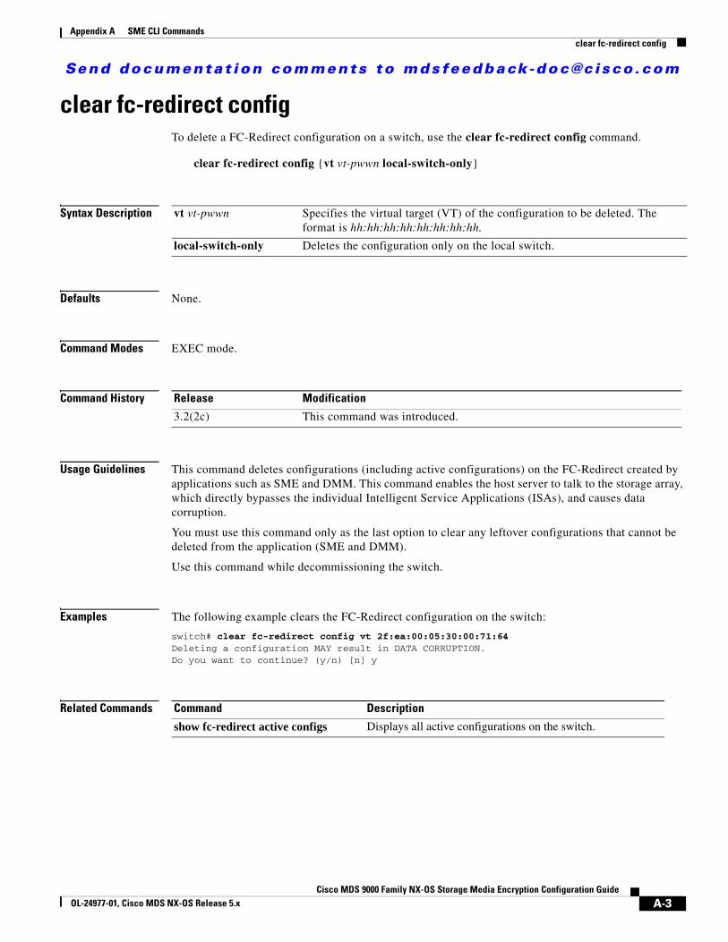
Send documenta t ion comments to mdsfeedback -doc@c i sco .com
Appendix A SME CLI Commandsclear fc-redirect config
clear fc-redirect configTo delete a FC-Redirect configuration on a switch, use the clear fc-redirect config command.
clear fc-redirect config {vt vt-pwwn local-switch-only}
Syntax Description
Defaults None.
Command Modes EXEC mode.
Command History
Usage Guidelines This command deletes configurations (including active configurations) on the FC-Redirect created by applications such as SME and DMM. This command enables the host server to talk to the storage array, which directly bypasses the individual Intelligent Service Applications (ISAs), and causes data corruption.
You must use this command only as the last option to clear any leftover configurations that cannot be deleted from the application (SME and DMM).
Use this command while decommissioning the switch.
Examples The following example clears the FC-Redirect configuration on the switch:
switch# clear fc-redirect config vt 2f:ea:00:05:30:00:71:64Deleting a configuration MAY result in DATA CORRUPTION.Do you want to continue? (y/n) [n] y
Related Commands
vt vt-pwwn Specifies the virtual target (VT) of the configuration to be deleted. The format is hh:hh:hh:hh:hh:hh:hh:hh.
local-switch-only Deletes the configuration only on the local switch.
Release Modification
3.2(2c) This command was introduced.
Command Description
show fc-redirect active configs Displays all active configurations on the switch.
A-3Cisco MDS 9000 Family NX-OS Storage Media Encryption Configuration Guide
OL-24977-01, Cisco MDS NX-OS Release 5.x
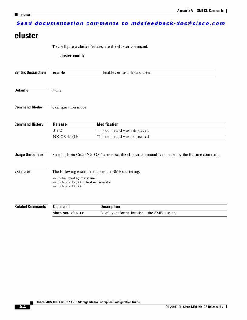
Send documenta t ion comments to mdsfeedback -doc@c i sco .com
Appendix A SME CLI Commandscluster
clusterTo configure a cluster feature, use the cluster command.
cluster enable
Syntax Description
Defaults None.
Command Modes Configuration mode.
Command History
Usage Guidelines Starting from Cisco NX-OS 4.x release, the cluster command is replaced by the feature command.
Examples The following example enables the SME clustering:
switch# config terminalswitch(config)# cluster enableswitch(config)#
Related Commands
enable Enables or disables a cluster.
Release Modification
3.2(2) This command was introduced.
NX-OS 4.1(1b) This command was deprecated.
Command Description
show sme cluster Displays information about the SME cluster.
A-4Cisco MDS 9000 Family NX-OS Storage Media Encryption Configuration Guide
OL-24977-01, Cisco MDS NX-OS Release 5.x

Send documenta t ion comments to mdsfeedback -doc@c i sco .com
Appendix A SME CLI Commandsdebug sme
debug smeTo enable debugging for the SME features, use the debug sme command. To disable a debug command, use the no form of the command.
debug sme {all | demux vsan vsan id | deque | error | event vsan vsan id | ha vsan vsan id | trace vsan vsan id | trace-detail vsan vsan id | warning vsan vsan id | wwn-janitor {disable | enable | set-timer-value}}
no debug sme {all | demux vsan vsan id | deque | error | event vsan vsan id | ha vsan vsan id | trace vsan vsan id | trace-detail vsan vsan id | warning vsan vsan id | wwn-janitor {disable | enable | set-timer-value}}
Syntax Description
Defaults None.
Command Modes EXEC mode.
Command History
Usage Guidelines None.
Examples The following example displays the system output from the debug sme all command:
all Enables debugging of all SME features.
demux Enables debugging of SME message demux.
vsan vsan id Restricts debugging to a specified VSAN ID. The range is 1 to 4094.
deque Enables debugging of SME message dequeue.
error Enables debugging of SME errors.
event Enables debugging of SME finite state machine (FSM) and events.
ha Enables debugging of SME high availability (HA).
trace Enables debugging of SME trace.
trace-detail Enables debugging of SME trace-detail.
warning Enables debugging of SME warning.
wwn-janitor Displays SME WWN janitor related information.
disable Disables SME WWN janitor task timer.
enable Enables SME WWN janitor task timer.
set-timer-value Sets SME WWN janitor task timer value in microseconds. The range is from 2000 to 240000.
Release Modification
3.2(2c) This command was introduced.
A-5Cisco MDS 9000 Family NX-OS Storage Media Encryption Configuration Guide
OL-24977-01, Cisco MDS NX-OS Release 5.x
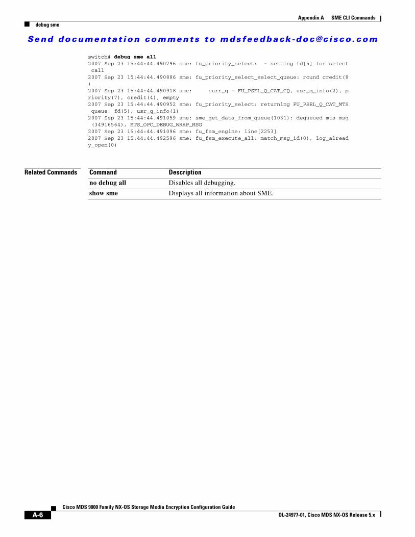
Send documenta t ion comments to mdsfeedback -doc@c i sco .com
Appendix A SME CLI Commandsdebug sme
switch# debug sme all2007 Sep 23 15:44:44.490796 sme: fu_priority_select: - setting fd[5] for select call2007 Sep 23 15:44:44.490886 sme: fu_priority_select_select_queue: round credit(8)2007 Sep 23 15:44:44.490918 sme: curr_q - FU_PSEL_Q_CAT_CQ, usr_q_info(2), priority(7), credit(4), empty2007 Sep 23 15:44:44.490952 sme: fu_priority_select: returning FU_PSEL_Q_CAT_MTS queue, fd(5), usr_q_info(1)2007 Sep 23 15:44:44.491059 sme: sme_get_data_from_queue(1031): dequeued mts msg (34916564), MTS_OPC_DEBUG_WRAP_MSG2007 Sep 23 15:44:44.491096 sme: fu_fsm_engine: line[2253]2007 Sep 23 15:44:44.492596 sme: fu_fsm_execute_all: match_msg_id(0), log_already_open(0)
Related Commands Command Description
no debug all Disables all debugging.
show sme Displays all information about SME.
A-6Cisco MDS 9000 Family NX-OS Storage Media Encryption Configuration Guide
OL-24977-01, Cisco MDS NX-OS Release 5.x
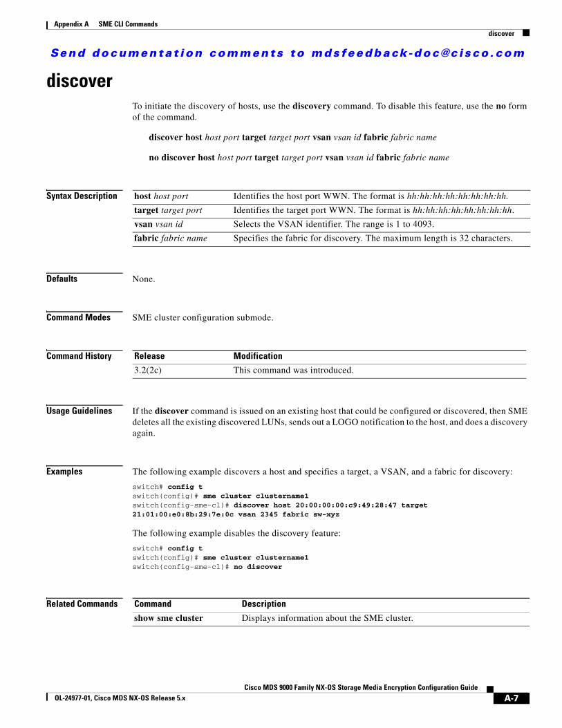
Send documenta t ion comments to mdsfeedback -doc@c i sco .com
Appendix A SME CLI Commandsdiscover
discoverTo initiate the discovery of hosts, use the discovery command. To disable this feature, use the no form of the command.
discover host host port target target port vsan vsan id fabric fabric name
no discover host host port target target port vsan vsan id fabric fabric name
Syntax Description
Defaults None.
Command Modes SME cluster configuration submode.
Command History
Usage Guidelines If the discover command is issued on an existing host that could be configured or discovered, then SME deletes all the existing discovered LUNs, sends out a LOGO notification to the host, and does a discovery again.
Examples The following example discovers a host and specifies a target, a VSAN, and a fabric for discovery:
switch# config tswitch(config)# sme cluster clustername1switch(config-sme-cl)# discover host 20:00:00:00:c9:49:28:47 target 21:01:00:e0:8b:29:7e:0c vsan 2345 fabric sw-xyz
The following example disables the discovery feature:
switch# config tswitch(config)# sme cluster clustername1switch(config-sme-cl)# no discover
Related Commands
host host port Identifies the host port WWN. The format is hh:hh:hh:hh:hh:hh:hh:hh.
target target port Identifies the target port WWN. The format is hh:hh:hh:hh:hh:hh:hh:hh.
vsan vsan id Selects the VSAN identifier. The range is 1 to 4093.
fabric fabric name Specifies the fabric for discovery. The maximum length is 32 characters.
Release Modification
3.2(2c) This command was introduced.
Command Description
show sme cluster Displays information about the SME cluster.
A-7Cisco MDS 9000 Family NX-OS Storage Media Encryption Configuration Guide
OL-24977-01, Cisco MDS NX-OS Release 5.x
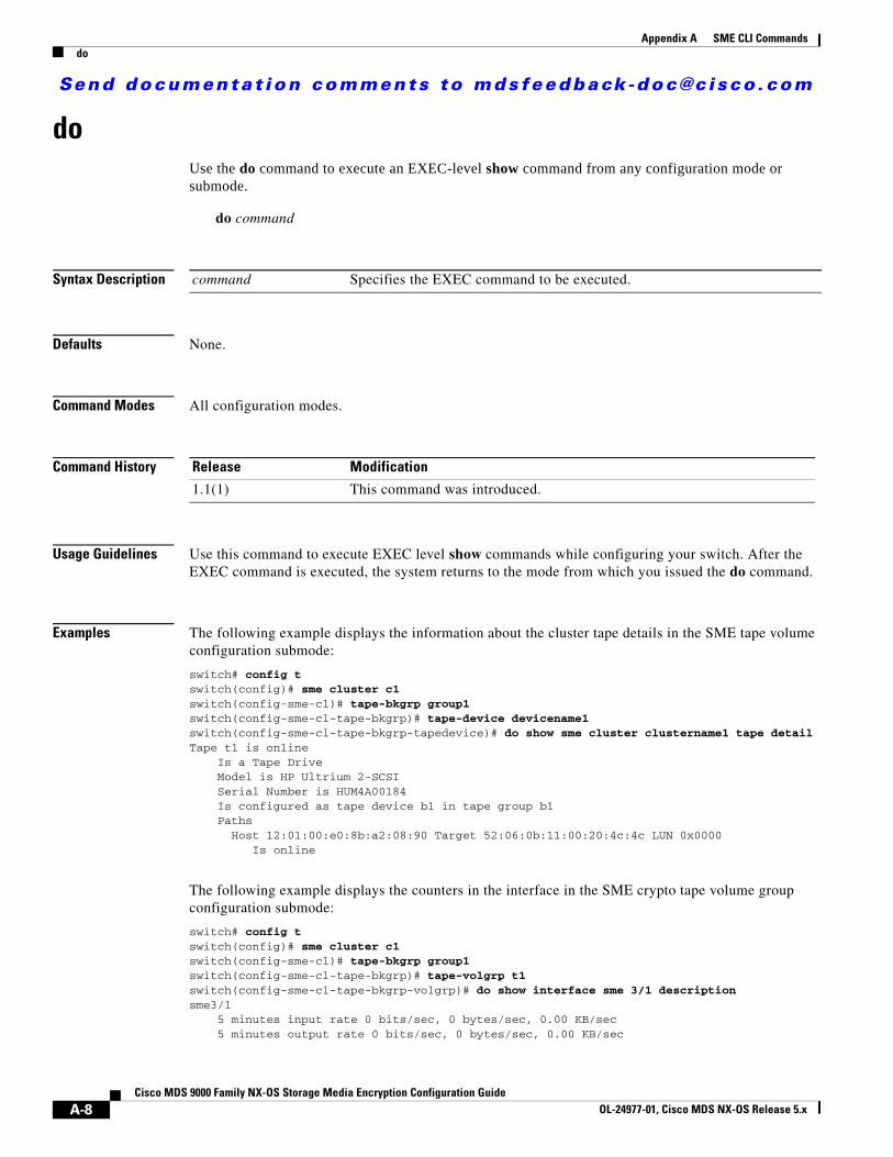
Send documenta t ion comments to mdsfeedback -doc@c i sco .com
Appendix A SME CLI Commandsdo
do Use the do command to execute an EXEC-level show command from any configuration mode or submode.
do command
Syntax Description
Defaults None.
Command Modes All configuration modes.
Command History
Usage Guidelines Use this command to execute EXEC level show commands while configuring your switch. After the EXEC command is executed, the system returns to the mode from which you issued the do command.
Examples The following example displays the information about the cluster tape details in the SME tape volume configuration submode:
switch# config tswitch(config)# sme cluster c1switch(config-sme-cl)# tape-bkgrp group1switch(config-sme-cl-tape-bkgrp)# tape-device devicename1switch(config-sme-cl-tape-bkgrp-tapedevice)# do show sme cluster clustername1 tape detailTape t1 is online Is a Tape Drive Model is HP Ultrium 2-SCSI Serial Number is HUM4A00184 Is configured as tape device b1 in tape group b1 Paths Host 12:01:00:e0:8b:a2:08:90 Target 52:06:0b:11:00:20:4c:4c LUN 0x0000 Is online
The following example displays the counters in the interface in the SME crypto tape volume group configuration submode:
switch# config tswitch(config)# sme cluster c1switch(config-sme-cl)# tape-bkgrp group1switch(config-sme-cl-tape-bkgrp)# tape-volgrp t1switch(config-sme-cl-tape-bkgrp-volgrp)# do show interface sme 3/1 descriptionsme3/1 5 minutes input rate 0 bits/sec, 0 bytes/sec, 0.00 KB/sec 5 minutes output rate 0 bits/sec, 0 bytes/sec, 0.00 KB/sec
command Specifies the EXEC command to be executed.
Release Modification
1.1(1) This command was introduced.
A-8Cisco MDS 9000 Family NX-OS Storage Media Encryption Configuration Guide
OL-24977-01, Cisco MDS NX-OS Release 5.x
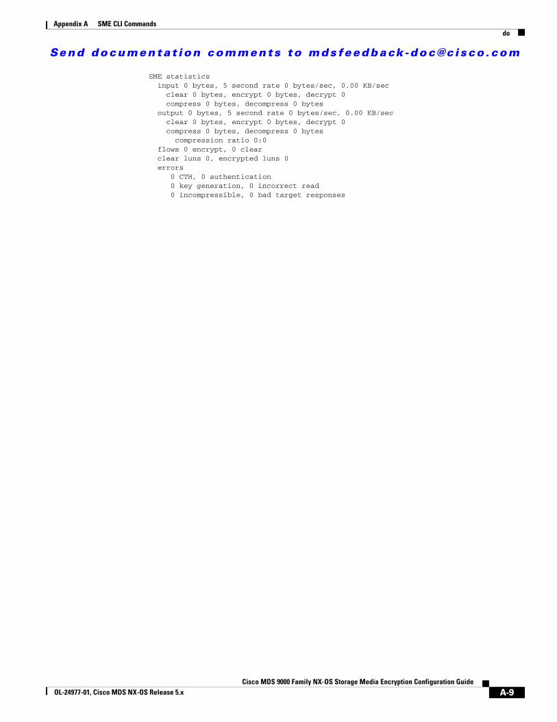
Send documenta t ion comments to mdsfeedback -doc@c i sco .com
Appendix A SME CLI Commandsdo
SME statistics input 0 bytes, 5 second rate 0 bytes/sec, 0.00 KB/sec clear 0 bytes, encrypt 0 bytes, decrypt 0 compress 0 bytes, decompress 0 bytes output 0 bytes, 5 second rate 0 bytes/sec, 0.00 KB/sec clear 0 bytes, encrypt 0 bytes, decrypt 0 compress 0 bytes, decompress 0 bytes compression ratio 0:0 flows 0 encrypt, 0 clear clear luns 0, encrypted luns 0 errors 0 CTH, 0 authentication 0 key generation, 0 incorrect read 0 incompressible, 0 bad target responses
A-9Cisco MDS 9000 Family NX-OS Storage Media Encryption Configuration Guide
OL-24977-01, Cisco MDS NX-OS Release 5.x

Send documenta t ion comments to mdsfeedback -doc@c i sco .com
Appendix A SME CLI Commandsfabric
fabricTo add a fabric to the cluster, use the fabric command in the SME cluster configuration submode.
fabric fabric name
Syntax Description
Defaults None.
Command Modes SME cluster configuration submode.
Command History
Usage Guidelines None.
Examples The following example adds a fabric named sw-xyz to a cluster:
switch# config terminalswitch(config)# sme cluster c1switch(config-sme-cl)# fabric sw-xyz
Related Commands
fabric name Specifies the fabric name. The maximum length is 32 characters.
Release Modification
3.2(2c) This command was introduced.
Command Description
show sme cluster Displays information about SME cluster.
A-10Cisco MDS 9000 Family NX-OS Storage Media Encryption Configuration Guide
OL-24977-01, Cisco MDS NX-OS Release 5.x
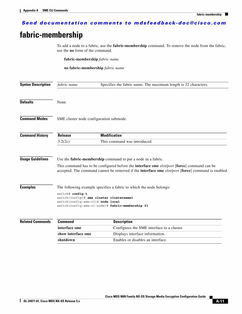
Send documenta t ion comments to mdsfeedback -doc@c i sco .com
Appendix A SME CLI Commandsfabric-membership
fabric-membership To add a node to a fabric, use the fabric-membership command. To remove the node from the fabric, use the no form of the command.
fabric-membership fabric name
no fabric-membership fabric name
Syntax Description
Defaults None.
Command Modes SME cluster node configuration submode.
Command History
Usage Guidelines Use the fabric-membership command to put a node in a fabric.
This command has to be configured before the interface sme slot/port [force] command can be accepted. The command cannot be removed if the interface sme slot/port [force] command is enabled.
Examples The following example specifies a fabric to which the node belongs:
switch# config tswitch(config)# sme cluster clustername1switch(config-sme-cl)# node localswitch(config-sme-cl-node)# fabric-membership f1
Related Commands
fabric name Specifies the fabric name. The maximum length is 32 characters.
Release Modification
3.2(2c) This command was introduced.
Command Description
interface sme Configures the SME interface to a cluster.
show interface sme Displays interface information.
shutdown Enables or disables an interface.
A-11Cisco MDS 9000 Family NX-OS Storage Media Encryption Configuration Guide
OL-24977-01, Cisco MDS NX-OS Release 5.x
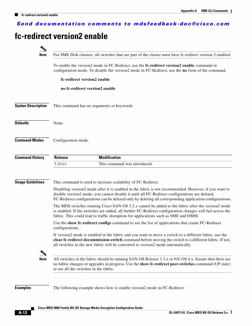
Send documenta t ion comments to mdsfeedback -doc@c i sco .com
Appendix A SME CLI Commandsfc-redirect version2 enable
fc-redirect version2 enable
Note For SME Disk clusters, all switches that are part of the cluster must have fc-redirect version 2 enabled.
To enable the version2 mode in FC-Redirect, use the fc-redirect version2 enable command in configuration mode. To disable the version2 mode in FC-Redirect, use the no form of the command.
fc-redirect version2 enable
no fc-redirect version2 enable
Syntax Description This command has no arguments or keywords.
Defaults None.
Command Modes Configuration mode.
Command History
Usage Guidelines This command is used to increase scalability of FC-Redirect.
Disabling version2 mode after it is enabled in the fabric is not recommended. However, if you want to disable version2 mode, you cannot disable it until all FC-Redirect configurations are deleted. FC-Redirect configurations can be deleted only by deleting all corresponding application configurations.
The MDS switches running Cisco SAN-OS 3.2.x cannot be added to the fabric after the version2 mode is enabled. If the switches are added, all further FC-Redirect configuration changes will fail across the fabric. This could lead to traffic disruption for applications such as SME and DMM.
Use the show fc-redirect configs command to see the list of applications that create FC-Redirect configurations.
If version2 mode is enabled in the fabric and you want to move a switch to a different fabric, use the clear fc-redirect decommission-switch command before moving the switch to a different fabric. If not, all switches in the new fabric will be converted to version2 mode automatically.
Note All switches in the fabric should be running SAN-OS Release 3.3.x or NX-OS 4.x. Ensure that there are no fabric changes or upgrades in progress. Use the show fc-redirect peer-switches command (UP state) to see all the switches in the fabric.
Examples The following example shows how to enable version2 mode in FC-Redirect:
Release Modification
3.3(1c) This command was introduced.
A-12Cisco MDS 9000 Family NX-OS Storage Media Encryption Configuration Guide
OL-24977-01, Cisco MDS NX-OS Release 5.x
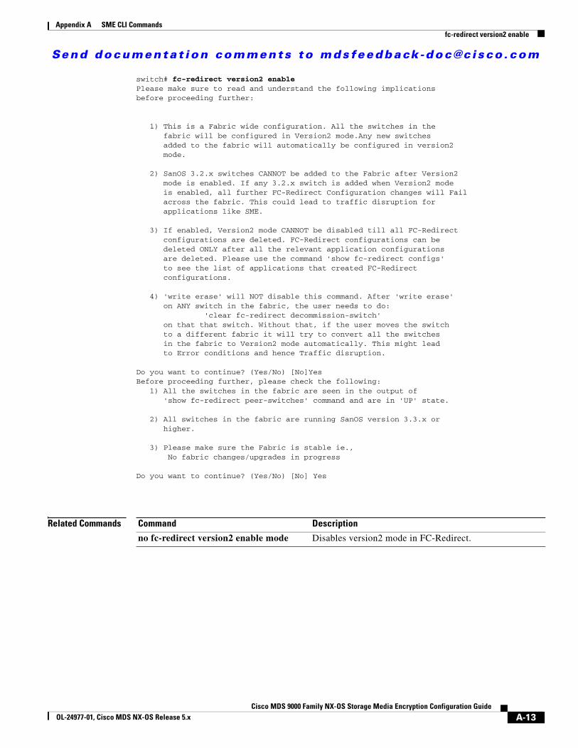
Send documenta t ion comments to mdsfeedback -doc@c i sco .com
Appendix A SME CLI Commandsfc-redirect version2 enable
switch# fc-redirect version2 enablePlease make sure to read and understand the following implicationsbefore proceeding further:
1) This is a Fabric wide configuration. All the switches in the fabric will be configured in Version2 mode.Any new switches added to the fabric will automatically be configured in version2 mode.
2) SanOS 3.2.x switches CANNOT be added to the Fabric after Version2 mode is enabled. If any 3.2.x switch is added when Version2 mode is enabled, all further FC-Redirect Configuration changes will Fail across the fabric. This could lead to traffic disruption for applications like SME.
3) If enabled, Version2 mode CANNOT be disabled till all FC-Redirect configurations are deleted. FC-Redirect configurations can be deleted ONLY after all the relevant application configurations are deleted. Please use the command 'show fc-redirect configs' to see the list of applications that created FC-Redirect configurations.
4) 'write erase' will NOT disable this command. After 'write erase' on ANY switch in the fabric, the user needs to do: 'clear fc-redirect decommission-switch' on that that switch. Without that, if the user moves the switch to a different fabric it will try to convert all the switches in the fabric to Version2 mode automatically. This might lead to Error conditions and hence Traffic disruption.
Do you want to continue? (Yes/No) [No]YesBefore proceeding further, please check the following: 1) All the switches in the fabric are seen in the output of 'show fc-redirect peer-switches' command and are in 'UP' state.
2) All switches in the fabric are running SanOS version 3.3.x or higher.
3) Please make sure the Fabric is stable ie., No fabric changes/upgrades in progress
Do you want to continue? (Yes/No) [No] Yes
Related Commands Command Description
no fc-redirect version2 enable mode Disables version2 mode in FC-Redirect.
A-13Cisco MDS 9000 Family NX-OS Storage Media Encryption Configuration Guide
OL-24977-01, Cisco MDS NX-OS Release 5.x
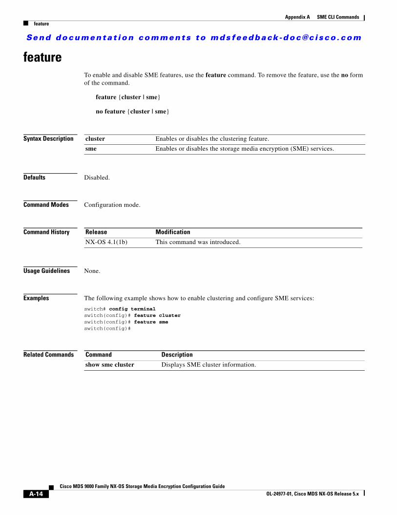
Send documenta t ion comments to mdsfeedback -doc@c i sco .com
Appendix A SME CLI Commandsfeature
feature To enable and disable SME features, use the feature command. To remove the feature, use the no form of the command.
feature {cluster | sme}
no feature {cluster | sme}
Syntax Description
Defaults Disabled.
Command Modes Configuration mode.
Command History
Usage Guidelines None.
Examples The following example shows how to enable clustering and configure SME services:
switch# config terminalswitch(config)# feature clusterswitch(config)# feature smeswitch(config)#
Related Commands
cluster Enables or disables the clustering feature.
sme Enables or disables the storage media encryption (SME) services.
Release Modification
NX-OS 4.1(1b) This command was introduced.
Command Description
show sme cluster Displays SME cluster information.
A-14Cisco MDS 9000 Family NX-OS Storage Media Encryption Configuration Guide
OL-24977-01, Cisco MDS NX-OS Release 5.x
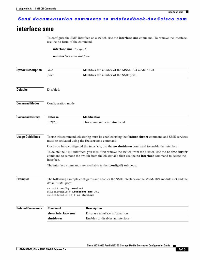
Send documenta t ion comments to mdsfeedback -doc@c i sco .com
Appendix A SME CLI Commandsinterface sme
interface sme To configure the SME interface on a switch, use the interface sme command. To remove the interface, use the no form of the command.
interface sme slot /port
no interface sme slot /port
Syntax Description
Defaults Disabled.
Command Modes Configuration mode.
Command History
Usage Guidelines To use this command, clustering must be enabled using the feature cluster command and SME services must be activated using the feature sme command.
Once you have configured the interface, use the no shutdown command to enable the interface.
To delete the SME interface, you must first remove the switch from the cluster. Use the no sme cluster command to remove the switch from the cluster and then use the no interface command to delete the interface.
The interface commands are available in the (config-if) submode.
Examples The following example configures and enables the SME interface on the MSM-18/4 module slot and the default SME port:
switch# config terminalswitch(config)# interface sme 3/1switch(config-if)# no shutdown
Related Commands
slot Identifies the number of the MSM-18/4 module slot.
port Identifies the number of the SME port.
Release Modification
3.2(2c) This command was introduced.
Command Description
show interface sme Displays interface information.
shutdown Enables or disables an interface.
A-15Cisco MDS 9000 Family NX-OS Storage Media Encryption Configuration Guide
OL-24977-01, Cisco MDS NX-OS Release 5.x
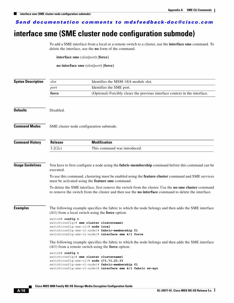
Send documenta t ion comments to mdsfeedback -doc@c i sco .com
Appendix A SME CLI Commandsinterface sme (SME cluster node configuration submode)
interface sme (SME cluster node configuration submode)To add a SME interface from a local or a remote switch to a cluster, use the interface sme command. To delete the interface, use the no form of the command.
interface sme (slot/port) [force]
no interface sme (slot/port) [force]
Syntax Description
Defaults Disabled.
Command Modes SME cluster node configuration submode.
Command History
Usage Guidelines You have to first configure a node using the fabric-membership command before this command can be executed.
To use this command, clustering must be enabled using the feature cluster command and SME services must be activated using the feature sme command.
To delete the SME interface, first remove the switch from the cluster. Use the no sme cluster command to remove the switch from the cluster and then use the no interface command to delete the interface.
Examples The following example specifies the fabric to which the node belongs and then adds the SME interface (4/1) from a local switch using the force option:
switch# config tswitch(config)# sme cluster clustername1switch(config-sme-cl)# node localswitch(config-sme-cl-node)# fabric-membership f1switch(config-sme-cl-node)# interface sme 4/1 force
The following example specifies the fabric to which the node belongs and then adds the SME interface (4/1) from a remote switch using the force option:
switch# config tswitch(config)# sme cluster clustername1switch(config-sme-cl)# node 171.71.23.33switch(config-sme-cl-node)# fabric-membership f1switch(config-sme-cl-node)# interface sme 4/1 fabric sw-xyz
slot Identifies the MSM-18/4 module slot.
port Identifies the SME port.
force (Optional) Forcibly clears the previous interface context in the interface.
Release Modification
3.2(2c) This command was introduced.
A-16Cisco MDS 9000 Family NX-OS Storage Media Encryption Configuration Guide
OL-24977-01, Cisco MDS NX-OS Release 5.x
Send documenta t ion comments to mdsfeedback -doc@c i sco .com
Appendix A SME CLI Commandsinterface sme (SME cluster node configuration submode)
Related Commands Command Description
fabric-membership Adds the node to a fabric.
show interface Displays SME interface details.
A-17Cisco MDS 9000 Family NX-OS Storage Media Encryption Configuration Guide
OL-24977-01, Cisco MDS NX-OS Release 5.x
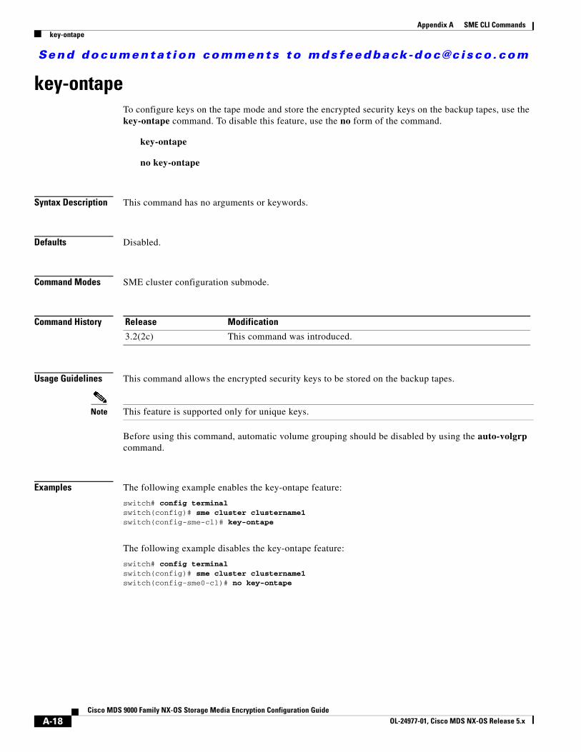
Send documenta t ion comments to mdsfeedback -doc@c i sco .com
Appendix A SME CLI Commandskey-ontape
key-ontapeTo configure keys on the tape mode and store the encrypted security keys on the backup tapes, use the key-ontape command. To disable this feature, use the no form of the command.
key-ontape
no key-ontape
Syntax Description This command has no arguments or keywords.
Defaults Disabled.
Command Modes SME cluster configuration submode.
Command History
Usage Guidelines This command allows the encrypted security keys to be stored on the backup tapes.
Note This feature is supported only for unique keys.
Before using this command, automatic volume grouping should be disabled by using the auto-volgrp command.
Examples The following example enables the key-ontape feature:
switch# config terminalswitch(config)# sme cluster clustername1switch(config-sme-cl)# key-ontape
The following example disables the key-ontape feature:
switch# config terminalswitch(config)# sme cluster clustername1switch(config-sme0-cl)# no key-ontape
Release Modification
3.2(2c) This command was introduced.
A-18Cisco MDS 9000 Family NX-OS Storage Media Encryption Configuration Guide
OL-24977-01, Cisco MDS NX-OS Release 5.x
Send documenta t ion comments to mdsfeedback -doc@c i sco .com
Appendix A SME CLI Commandskey-ontape
Related Commands Command Description
no auto-volgrp Disables automatic volume grouping.
no shared-key Specifies unique key mode.
show sme cluster key Displays information about cluster key database.
show sme cluster <clustername> tape summary
Displays information about tapes.
A-19Cisco MDS 9000 Family NX-OS Storage Media Encryption Configuration Guide
OL-24977-01, Cisco MDS NX-OS Release 5.x
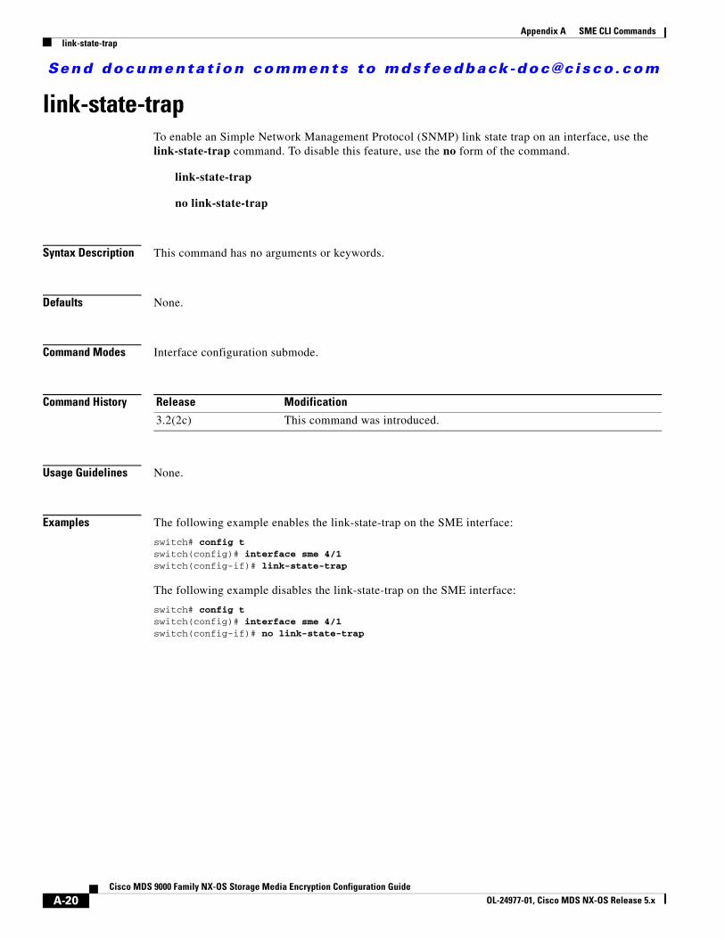
Send documenta t ion comments to mdsfeedback -doc@c i sco .com
Appendix A SME CLI Commandslink-state-trap
link-state-trapTo enable an Simple Network Management Protocol (SNMP) link state trap on an interface, use the link-state-trap command. To disable this feature, use the no form of the command.
link-state-trap
no link-state-trap
Syntax Description This command has no arguments or keywords.
Defaults None.
Command Modes Interface configuration submode.
Command History
Usage Guidelines None.
Examples The following example enables the link-state-trap on the SME interface:
switch# config tswitch(config)# interface sme 4/1switch(config-if)# link-state-trap
The following example disables the link-state-trap on the SME interface:
switch# config tswitch(config)# interface sme 4/1switch(config-if)# no link-state-trap
Release Modification
3.2(2c) This command was introduced.
A-20Cisco MDS 9000 Family NX-OS Storage Media Encryption Configuration Guide
OL-24977-01, Cisco MDS NX-OS Release 5.x
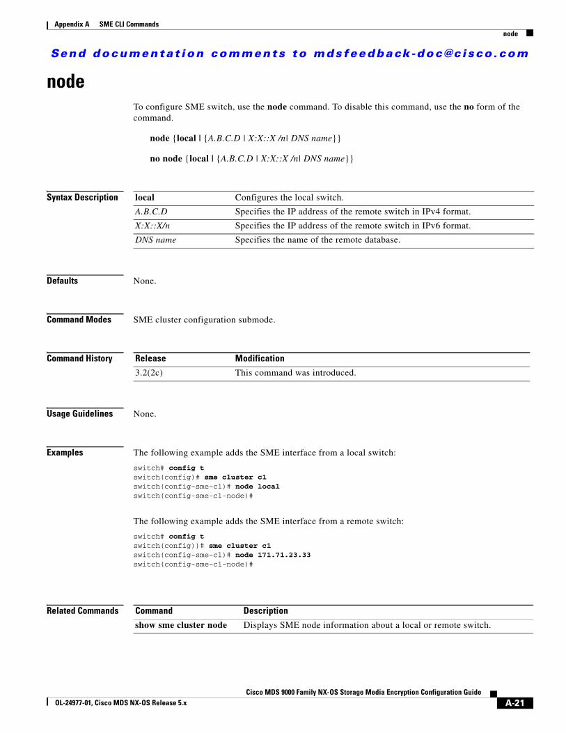
Send documenta t ion comments to mdsfeedback -doc@c i sco .com
Appendix A SME CLI Commandsnode
nodeTo configure SME switch, use the node command. To disable this command, use the no form of the command.
node {local | {A.B.C.D | X:X::X /n| DNS name}}
no node {local | {A.B.C.D | X:X::X /n| DNS name}}
Syntax Description
Defaults None.
Command Modes SME cluster configuration submode.
Command History
Usage Guidelines None.
Examples The following example adds the SME interface from a local switch:
switch# config tswitch(config)# sme cluster c1switch(config-sme-cl)# node localswitch(config-sme-cl-node)#
The following example adds the SME interface from a remote switch:
switch# config tswitch(config))# sme cluster c1switch(config-sme-cl)# node 171.71.23.33switch(config-sme-cl-node)#
Related Commands
local Configures the local switch.
A.B.C.D Specifies the IP address of the remote switch in IPv4 format.
X:X::X/n Specifies the IP address of the remote switch in IPv6 format.
DNS name Specifies the name of the remote database.
Release Modification
3.2(2c) This command was introduced.
Command Description
show sme cluster node Displays SME node information about a local or remote switch.
A-21Cisco MDS 9000 Family NX-OS Storage Media Encryption Configuration Guide
OL-24977-01, Cisco MDS NX-OS Release 5.x
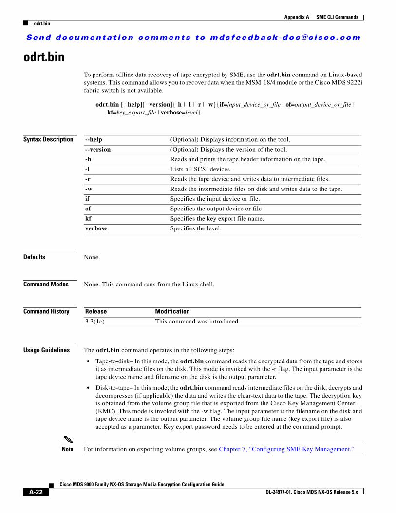
Send documenta t ion comments to mdsfeedback -doc@c i sco .com
Appendix A SME CLI Commandsodrt.bin
odrt.binTo perform offline data recovery of tape encrypted by SME, use the odrt.bin command on Linux-based systems. This command allows you to recover data when the MSM-18/4 module or the Cisco MDS 9222i fabric switch is not available.
odrt.bin [--help][--version]{-h | -l | -r | -w}{if=input_device_or_file | of=output_device_or_file | kf=key_export_file | verbose=level}
Syntax Description
Defaults None.
Command Modes None. This command runs from the Linux shell.
Command History
Usage Guidelines The odrt.bin command operates in the following steps:
• Tape-to-disk– In this mode, the odrt.bin command reads the encrypted data from the tape and stores it as intermediate files on the disk. This mode is invoked with the -r flag. The input parameter is the tape device name and filename on the disk is the output parameter.
• Disk-to-tape– In this mode, the odrt.bin command reads intermediate files on the disk, decrypts and decompresses (if applicable) the data and writes the clear-text data to the tape. The decryption key is obtained from the volume group file that is exported from the Cisco Key Management Center (KMC). This mode is invoked with the -w flag. The input parameter is the filename on the disk and tape device name is the output parameter. The volume group file name (key export file) is also accepted as a parameter. Key export password needs to be entered at the command prompt.
Note For information on exporting volume groups, see Chapter 7, “Configuring SME Key Management.”
--help (Optional) Displays information on the tool.
--version (Optional) Displays the version of the tool.
-h Reads and prints the tape header information on the tape.
-l Lists all SCSI devices.
-r Reads the tape device and writes data to intermediate files.
-w Reads the intermediate files on disk and writes data to the tape.
if Specifies the input device or file.
of Specifies the output device or file
kf Specifies the key export file name.
verbose Specifies the level.
Release Modification
3.3(1c) This command was introduced.
A-22Cisco MDS 9000 Family NX-OS Storage Media Encryption Configuration Guide
OL-24977-01, Cisco MDS NX-OS Release 5.x
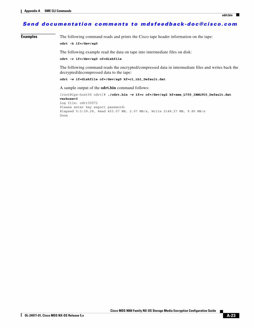
Send documenta t ion comments to mdsfeedback -doc@c i sco .com
Appendix A SME CLI Commandsodrt.bin
Examples The following command reads and prints the Cisco tape header information on the tape:
odrt -h if=/dev/sg0
The following example read the data on tape into intermediate files on disk:
odrt -r if=/dev/sg0 of=diskfile
The following command reads the encrypted/compressed data in intermediate files and writes back the decrypted/decompressed data to the tape:
odrt -w if=diskfile of=/dev/sg0 kf=c1_tb1_Default.dat
A sample output of the odrt.bin command follows:
[root@ips-host06 odrt]# ./odrt.bin -w if=c of=/dev/sg2 kf=sme_L700_IBMLTO3_Default.dat verbose=3Log file: odrt30072Please enter key export password:Elapsed 0:3:39.28, Read 453.07 MB, 2.07 MB/s, Write 2148.27 MB, 9.80 MB/sDone
A-23Cisco MDS 9000 Family NX-OS Storage Media Encryption Configuration Guide
OL-24977-01, Cisco MDS NX-OS Release 5.x
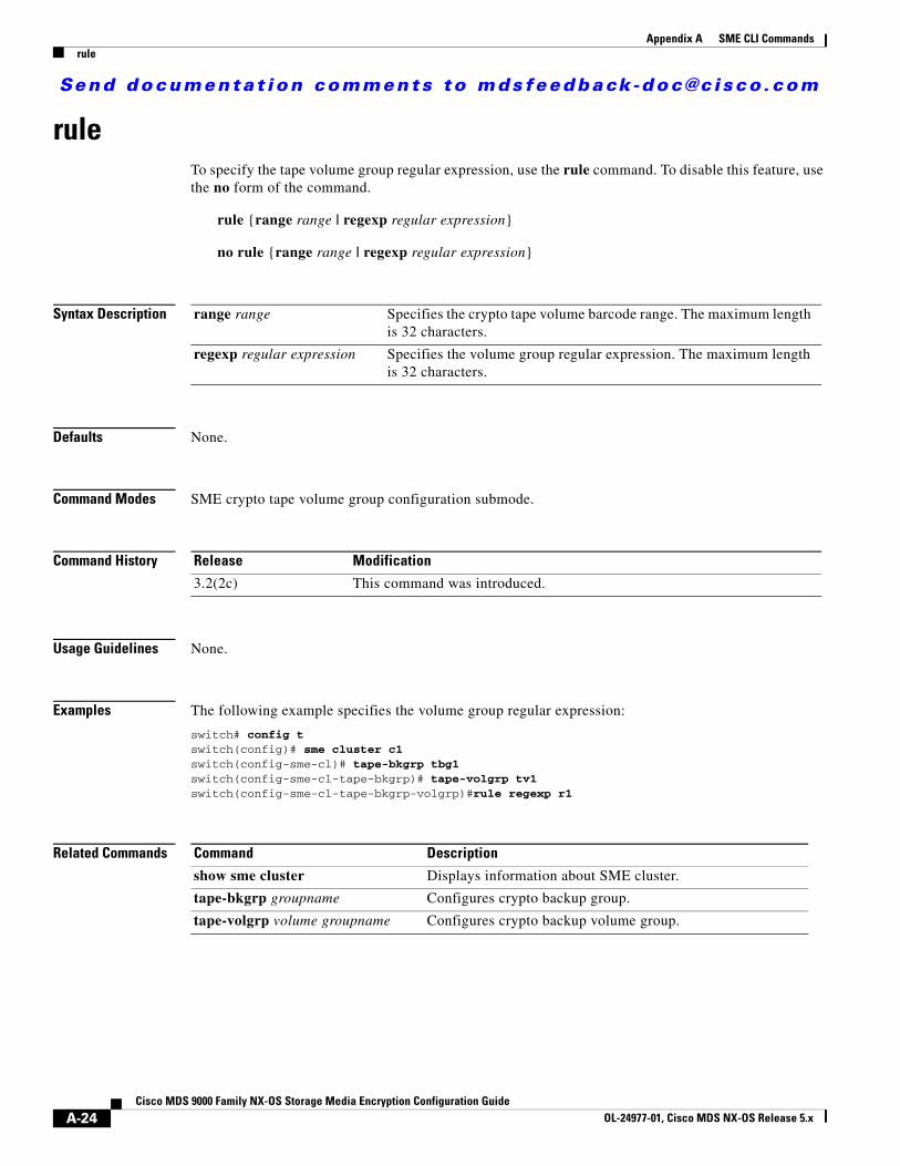
Send documenta t ion comments to mdsfeedback -doc@c i sco .com
Appendix A SME CLI Commandsrule
ruleTo specify the tape volume group regular expression, use the rule command. To disable this feature, use the no form of the command.
rule {range range | regexp regular expression}
no rule {range range | regexp regular expression}
Syntax Description
Defaults None.
Command Modes SME crypto tape volume group configuration submode.
Command History
Usage Guidelines None.
Examples The following example specifies the volume group regular expression:
switch# config tswitch(config)# sme cluster c1switch(config-sme-cl)# tape-bkgrp tbg1switch(config-sme-cl-tape-bkgrp)# tape-volgrp tv1switch(config-sme-cl-tape-bkgrp-volgrp)#rule regexp r1
Related Commands
range range Specifies the crypto tape volume barcode range. The maximum length is 32 characters.
regexp regular expression Specifies the volume group regular expression. The maximum length is 32 characters.
Release Modification
3.2(2c) This command was introduced.
Command Description
show sme cluster Displays information about SME cluster.
tape-bkgrp groupname Configures crypto backup group.
tape-volgrp volume groupname Configures crypto backup volume group.
A-24Cisco MDS 9000 Family NX-OS Storage Media Encryption Configuration Guide
OL-24977-01, Cisco MDS NX-OS Release 5.x
Send documenta t ion comments to mdsfeedback -doc@c i sco .com
Appendix A SME CLI Commandsscaling batch enable
scaling batch enable
Note For SME Disk clusters, batching mode is automatically enabled.
To enable scalability in the SME configuration, use the scaling batch enable command. To disable this feature, use the no form of the command.
scaling batch enable
no scaling batch enable
Syntax Description This command has no arguments or keywords.
Defaults None.
Command Modes SME cluster configuration submode.
Command History
Usage Guidelines None.
Examples The following example enables SME scalability:
switch# config tswitch(config)# sme cluster c1switch(config-sme-cl)# scaling batch enableswitch(config-sme-cl)#
Release Modification
4.1(3) This command was introduced.
A-25Cisco MDS 9000 Family NX-OS Storage Media Encryption Configuration Guide
OL-24977-01, Cisco MDS NX-OS Release 5.x
Send documenta t ion comments to mdsfeedback -doc@c i sco .com
Appendix A SME CLI Commandssecurity-mode
security-modeTo configure the SME security settings, use the security-mode command. To delete the security settings, use the no form of the command.
security-mode {basic | standard | advanced {schema threshold threshold total total }}
no security-mode {basic | standard | advanced {schema threshold threshold total total }}
Syntax Description
Defaults None.
Command Modes SME cluster configuration submode.
Command History
Usage Guidelines None.
Examples The following example sets the security mode to basic:
switch# config tswitch(config)# sme cluster c1switch(config-sme-cl)# security-mode basic
The following example sets the security mode to advanced:
switch# config tswitch(config)# sme cluster c1switch(config-sme-cl)# security-mode advanced schema threshold 3 total 5
Related Commands
basic Sets the SME security level to basic.
standard Sets the SME security level to standard.
advanced Sets the SME security level to advanced.
schema Configures the recovery schema.
threshold threshold Configures the recovery schema threshold. The limit is 2 to 3.
total total Configures the recovery schema total. The limit is 5 to 5.
Release Modification
3.2(2c) This command was introduced.
Command Description
show sme cluster Displays information about the security settings.
A-26Cisco MDS 9000 Family NX-OS Storage Media Encryption Configuration Guide
OL-24977-01, Cisco MDS NX-OS Release 5.x
Send documenta t ion comments to mdsfeedback -doc@c i sco .com
Appendix A SME CLI Commandssetup
setupTo run the basic setup facility, use the setup command.
setup ficon | sme
Syntax Description
Defaults None.
Command Modes EXEC.
Command History
Usage Guidelines Use the setup sme command to create the sme-admin and sme-recovery roles for SME.
Examples The following example creates the sme-admin and sme-recovery roles:
switch(config)# setup smeSet up four roles necessary for SME, sme-admin, sme-stg-admin, sme-kmc-admin and sme-recovery? (yes/no) [no] yesIf CFS is enabled, please commit the roles so that they can be available. SME setup done.
Related Commands
ficon Runs the basic FICON setup command facility.
sme Runs the basic SME setup command facility.
Release Modification
3.3(1c) This command was introduced.
Command Description
show role Displays information about the various SME role configurations.
A-27Cisco MDS 9000 Family NX-OS Storage Media Encryption Configuration Guide
OL-24977-01, Cisco MDS NX-OS Release 5.x
Send documenta t ion comments to mdsfeedback -doc@c i sco .com
Appendix A SME CLI Commandsshared-keymode
shared-keymodeTo configure the shared key mode, use the shared-keymode command. To specify the unique key mode, use the no form of the command.
shared-keymode
no shared-keymode
Syntax Description This command has no arguments or keywords.
Defaults None.
Command Modes SME cluster configuration submode.
Command History
Usage Guidelines The shared-keymode command generates a single key that is used for a group of backup tapes.
The no shared-keymode command generates unique or specific keys for each tape cartridge.
Note The shared unique key mode should be specified if you want to enable the key-ontape feature.
Examples The following example specifies the shared key mode:
switch# config tswitch(config)# sme cluster c1switch(config-sme-cl)# shared-keymode
The following example specifies the shared unique keymode:
switch# config tswitch(config)# sme cluster c1switch(config-sme-cl)# no shared-keymode
Related Commands
Release Modification
3.2(2c) This command was introduced.
Command Description
show sme cluster Displays SME cluster information.
A-28Cisco MDS 9000 Family NX-OS Storage Media Encryption Configuration Guide
OL-24977-01, Cisco MDS NX-OS Release 5.x
Send documenta t ion comments to mdsfeedback -doc@c i sco .com
Appendix A SME CLI Commandsshow debug
show debugTo display all SME-related debug commands configured on the switch, use the show debug command.
show debug {cluster {bypass | sap sap bypass} | sme bypass}
Syntax Description
Defaults None.
Command Modes EXEC mode.
Command History
Usage Guidelines None.
Examples The following example shows all debug commands configured on the switch:
switch# show debugILC helper: ILC_HELPER errors debugging is on ILC_HELPER info debugging is on
Related Commands
cluster Displays all the debugging flags.
bypass Displays the bypass flags.
sap sap Displays all debugging flags of SAP. Specifies the SAP in the range from 1 to 65535.
sme Displays all the debugging flags of SME.
Release Modification
3.2(2c) This command was introduced.
Commands Description
debug sme Debugs SME features.
A-29Cisco MDS 9000 Family NX-OS Storage Media Encryption Configuration Guide
OL-24977-01, Cisco MDS NX-OS Release 5.x
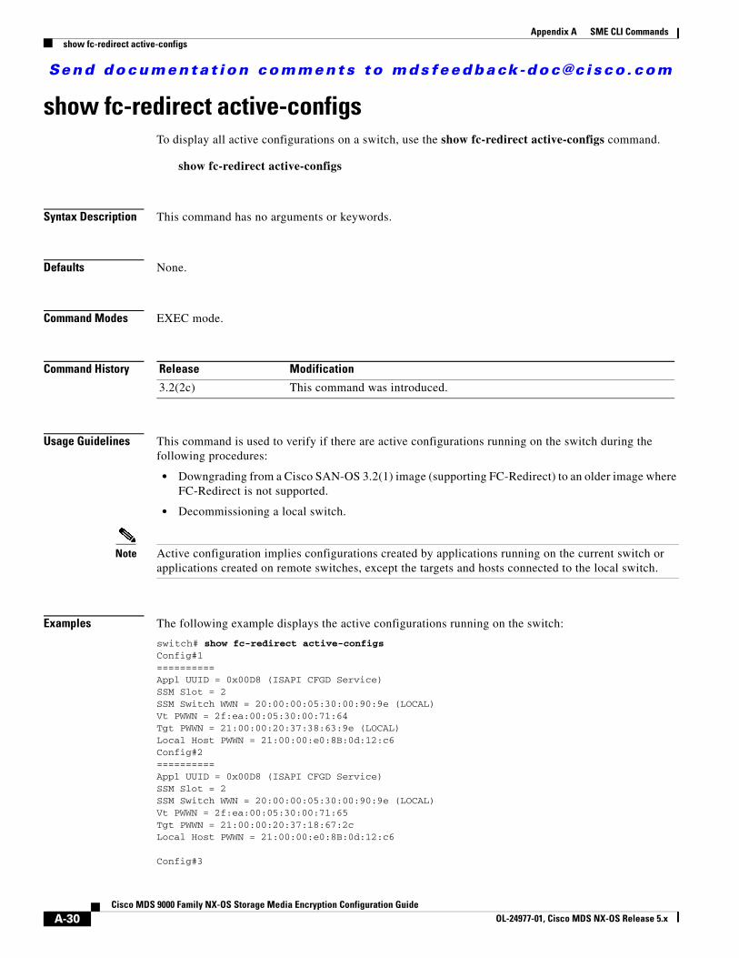
Send documenta t ion comments to mdsfeedback -doc@c i sco .com
Appendix A SME CLI Commandsshow fc-redirect active-configs
show fc-redirect active-configsTo display all active configurations on a switch, use the show fc-redirect active-configs command.
show fc-redirect active-configs
Syntax Description This command has no arguments or keywords.
Defaults None.
Command Modes EXEC mode.
Command History
Usage Guidelines This command is used to verify if there are active configurations running on the switch during the following procedures:
• Downgrading from a Cisco SAN-OS 3.2(1) image (supporting FC-Redirect) to an older image where FC-Redirect is not supported.
• Decommissioning a local switch.
Note Active configuration implies configurations created by applications running on the current switch or applications created on remote switches, except the targets and hosts connected to the local switch.
Examples The following example displays the active configurations running on the switch:
switch# show fc-redirect active-configsConfig#1==========Appl UUID = 0x00D8 (ISAPI CFGD Service)SSM Slot = 2SSM Switch WWN = 20:00:00:05:30:00:90:9e (LOCAL)Vt PWWN = 2f:ea:00:05:30:00:71:64Tgt PWWN = 21:00:00:20:37:38:63:9e (LOCAL)Local Host PWWN = 21:00:00:e0:8B:0d:12:c6Config#2==========Appl UUID = 0x00D8 (ISAPI CFGD Service)SSM Slot = 2SSM Switch WWN = 20:00:00:05:30:00:90:9e (LOCAL)Vt PWWN = 2f:ea:00:05:30:00:71:65Tgt PWWN = 21:00:00:20:37:18:67:2cLocal Host PWWN = 21:00:00:e0:8B:0d:12:c6
Config#3
Release Modification
3.2(2c) This command was introduced.
A-30Cisco MDS 9000 Family NX-OS Storage Media Encryption Configuration Guide
OL-24977-01, Cisco MDS NX-OS Release 5.x
Send documenta t ion comments to mdsfeedback -doc@c i sco .com
Appendix A SME CLI Commandsshow fc-redirect active-configs
==========Appl UUID = 0x00D8 (ISAPI CFGD Service)SSM Slot = 2SSM Switch WWN = 20:00:00:0d:EC:20:13:00 (REMOTE)Vt PWWN = 2f:ea:00:05:30:00:71:66Tgt PWWN = 21:00:00:20:37:18:64:92Local Host PWWN = 21:00:00:e0:8B:0d:12:c6
Related Commands Command Description
clear fc-redirect vt Clears the active configurations on the local switch.
A-31Cisco MDS 9000 Family NX-OS Storage Media Encryption Configuration Guide
OL-24977-01, Cisco MDS NX-OS Release 5.x
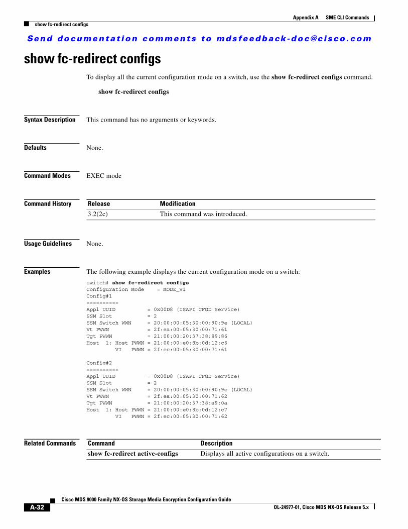
Send documenta t ion comments to mdsfeedback -doc@c i sco .com
Appendix A SME CLI Commandsshow fc-redirect configs
show fc-redirect configsTo display all the current configuration mode on a switch, use the show fc-redirect configs command.
show fc-redirect configs
Syntax Description This command has no arguments or keywords.
Defaults None.
Command Modes EXEC mode
Command History
Usage Guidelines None.
Examples The following example displays the current configuration mode on a switch:
switch# show fc-redirect configsConfiguration Mode = MODE_V1Config#1==========Appl UUID = 0x00D8 (ISAPI CFGD Service)SSM Slot = 2SSM Switch WWN = 20:00:00:05:30:00:90:9e (LOCAL)Vt PWWN = 2f:ea:00:05:30:00:71:61Tgt PWWN = 21:00:00:20:37:38:89:86Host 1: Host PWWN = 21:00:00:e0:8b:0d:12:c6 VI PWWN = 2f:ec:00:05:30:00:71:61
Config#2==========Appl UUID = 0x00D8 (ISAPI CFGD Service)SSM Slot = 2SSM Switch WWN = 20:00:00:05:30:00:90:9e (LOCAL)Vt PWWN = 2f:ea:00:05:30:00:71:62Tgt PWWN = 21:00:00:20:37:38:a9:0aHost 1: Host PWWN = 21:00:00:e0:8b:0d:12:c7 VI PWWN = 2f:ec:00:05:30:00:71:62
Related Commands
Release Modification
3.2(2c) This command was introduced.
Command Description
show fc-redirect active-configs Displays all active configurations on a switch.
A-32Cisco MDS 9000 Family NX-OS Storage Media Encryption Configuration Guide
OL-24977-01, Cisco MDS NX-OS Release 5.x
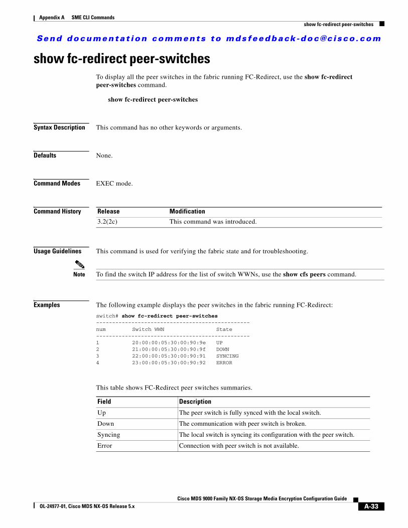
Send documenta t ion comments to mdsfeedback -doc@c i sco .com
Appendix A SME CLI Commandsshow fc-redirect peer-switches
show fc-redirect peer-switchesTo display all the peer switches in the fabric running FC-Redirect, use the show fc-redirect peer-switches command.
show fc-redirect peer-switches
Syntax Description This command has no other keywords or arguments.
Defaults None.
Command Modes EXEC mode.
Command History
Usage Guidelines This command is used for verifying the fabric state and for troubleshooting.
Note To find the switch IP address for the list of switch WWNs, use the show cfs peers command.
Examples The following example displays the peer switches in the fabric running FC-Redirect:
switch# show fc-redirect peer-switches------------------------------------------------num Switch WWN State------------------------------------------------1 20:00:00:05:30:00:90:9e UP2 21:00:00:05:30:00:90:9f DOWN3 22:00:00:05:30:00:90:91 SYNCING4 23:00:00:05:30:00:90:92 ERROR
This table shows FC-Redirect peer switches summaries.
Release Modification
3.2(2c) This command was introduced.
Field Description
Up The peer switch is fully synced with the local switch.
Down The communication with peer switch is broken.
Syncing The local switch is syncing its configuration with the peer switch.
Error Connection with peer switch is not available.
A-33Cisco MDS 9000 Family NX-OS Storage Media Encryption Configuration Guide
OL-24977-01, Cisco MDS NX-OS Release 5.x

Send documenta t ion comments to mdsfeedback -doc@c i sco .com
Appendix A SME CLI Commandsshow fc-redirect peer-switches
Related Commands Command Description
clear fc-redirect vt Clears the active configurations on the local switch.
A-34Cisco MDS 9000 Family NX-OS Storage Media Encryption Configuration Guide
OL-24977-01, Cisco MDS NX-OS Release 5.x
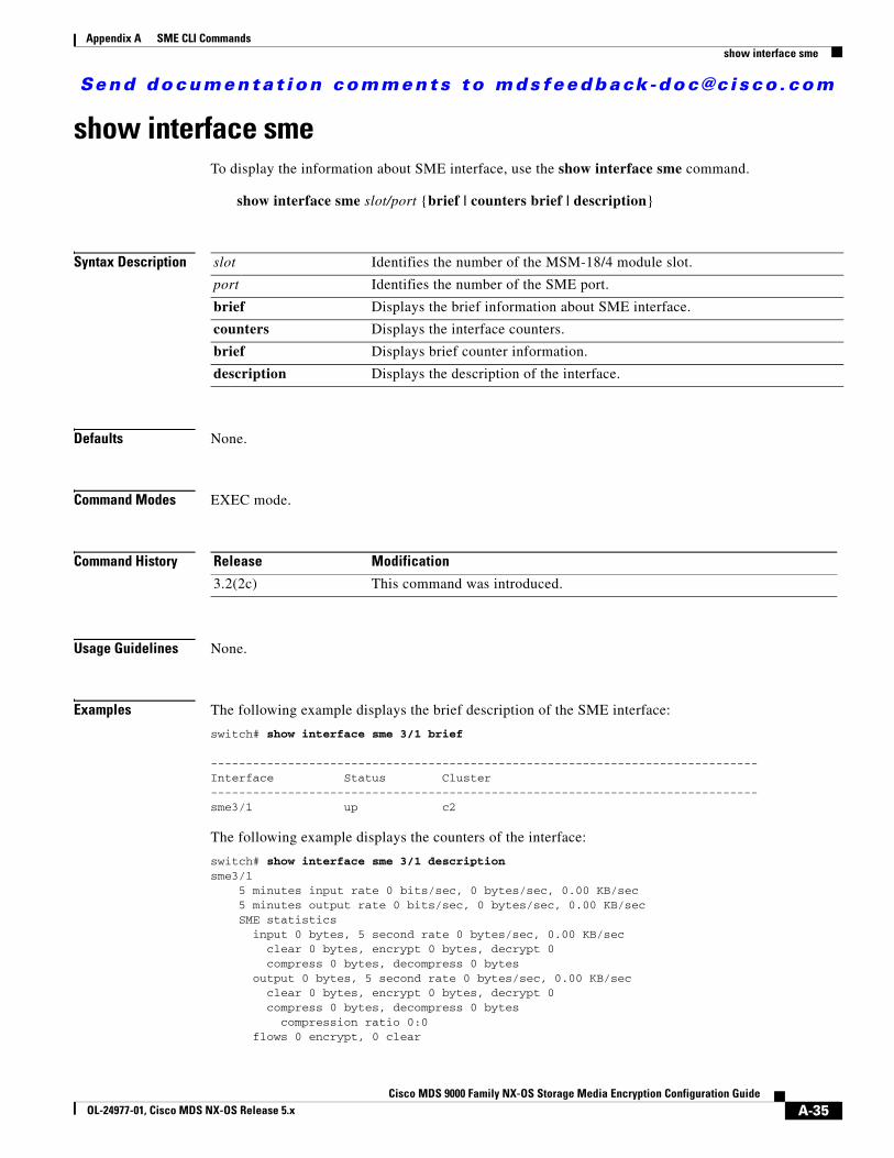
Send documenta t ion comments to mdsfeedback -doc@c i sco .com
Appendix A SME CLI Commandsshow interface sme
show interface smeTo display the information about SME interface, use the show interface sme command.
show interface sme slot/port {brief | counters brief | description}
Syntax Description
Defaults None.
Command Modes EXEC mode.
Command History
Usage Guidelines None.
Examples The following example displays the brief description of the SME interface:
switch# show interface sme 3/1 brief
------------------------------------------------------------------------------Interface Status Cluster------------------------------------------------------------------------------sme3/1 up c2
The following example displays the counters of the interface:
switch# show interface sme 3/1 descriptionsme3/1 5 minutes input rate 0 bits/sec, 0 bytes/sec, 0.00 KB/sec 5 minutes output rate 0 bits/sec, 0 bytes/sec, 0.00 KB/sec SME statistics input 0 bytes, 5 second rate 0 bytes/sec, 0.00 KB/sec clear 0 bytes, encrypt 0 bytes, decrypt 0 compress 0 bytes, decompress 0 bytes output 0 bytes, 5 second rate 0 bytes/sec, 0.00 KB/sec clear 0 bytes, encrypt 0 bytes, decrypt 0 compress 0 bytes, decompress 0 bytes compression ratio 0:0 flows 0 encrypt, 0 clear
slot Identifies the number of the MSM-18/4 module slot.
port Identifies the number of the SME port.
brief Displays the brief information about SME interface.
counters Displays the interface counters.
brief Displays brief counter information.
description Displays the description of the interface.
Release Modification
3.2(2c) This command was introduced.
A-35Cisco MDS 9000 Family NX-OS Storage Media Encryption Configuration Guide
OL-24977-01, Cisco MDS NX-OS Release 5.x

Send documenta t ion comments to mdsfeedback -doc@c i sco .com
Appendix A SME CLI Commandsshow interface sme
clear luns 0, encrypted luns 0 errors 0 CTH, 0 authentication 0 key generation, 0 incorrect read 0 incompressible, 0 bad target responses
Related Commands Command Description
interface sme Configures the SME interface on the switch.
A-36Cisco MDS 9000 Family NX-OS Storage Media Encryption Configuration Guide
OL-24977-01, Cisco MDS NX-OS Release 5.x
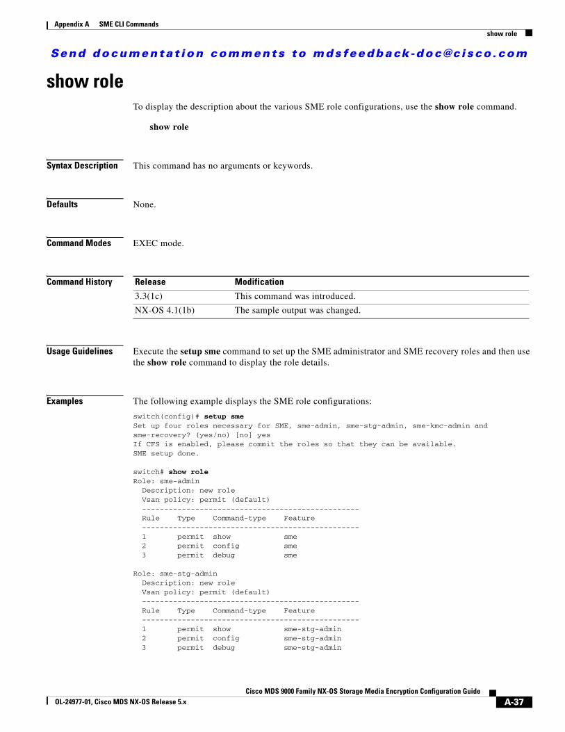
Send documenta t ion comments to mdsfeedback -doc@c i sco .com
Appendix A SME CLI Commandsshow role
show roleTo display the description about the various SME role configurations, use the show role command.
show role
Syntax Description This command has no arguments or keywords.
Defaults None.
Command Modes EXEC mode.
Command History
Usage Guidelines Execute the setup sme command to set up the SME administrator and SME recovery roles and then use the show role command to display the role details.
Examples The following example displays the SME role configurations:
switch(config)# setup smeSet up four roles necessary for SME, sme-admin, sme-stg-admin, sme-kmc-admin and sme-recovery? (yes/no) [no] yesIf CFS is enabled, please commit the roles so that they can be available. SME setup done.
switch# show role Role: sme-admin Description: new role Vsan policy: permit (default) ------------------------------------------------- Rule Type Command-type Feature ------------------------------------------------- 1 permit show sme 2 permit config sme 3 permit debug sme Role: sme-stg-admin Description: new role Vsan policy: permit (default) ------------------------------------------------- Rule Type Command-type Feature ------------------------------------------------- 1 permit show sme-stg-admin 2 permit config sme-stg-admin 3 permit debug sme-stg-admin
Release Modification
3.3(1c) This command was introduced.
NX-OS 4.1(1b) The sample output was changed.
A-37Cisco MDS 9000 Family NX-OS Storage Media Encryption Configuration Guide
OL-24977-01, Cisco MDS NX-OS Release 5.x
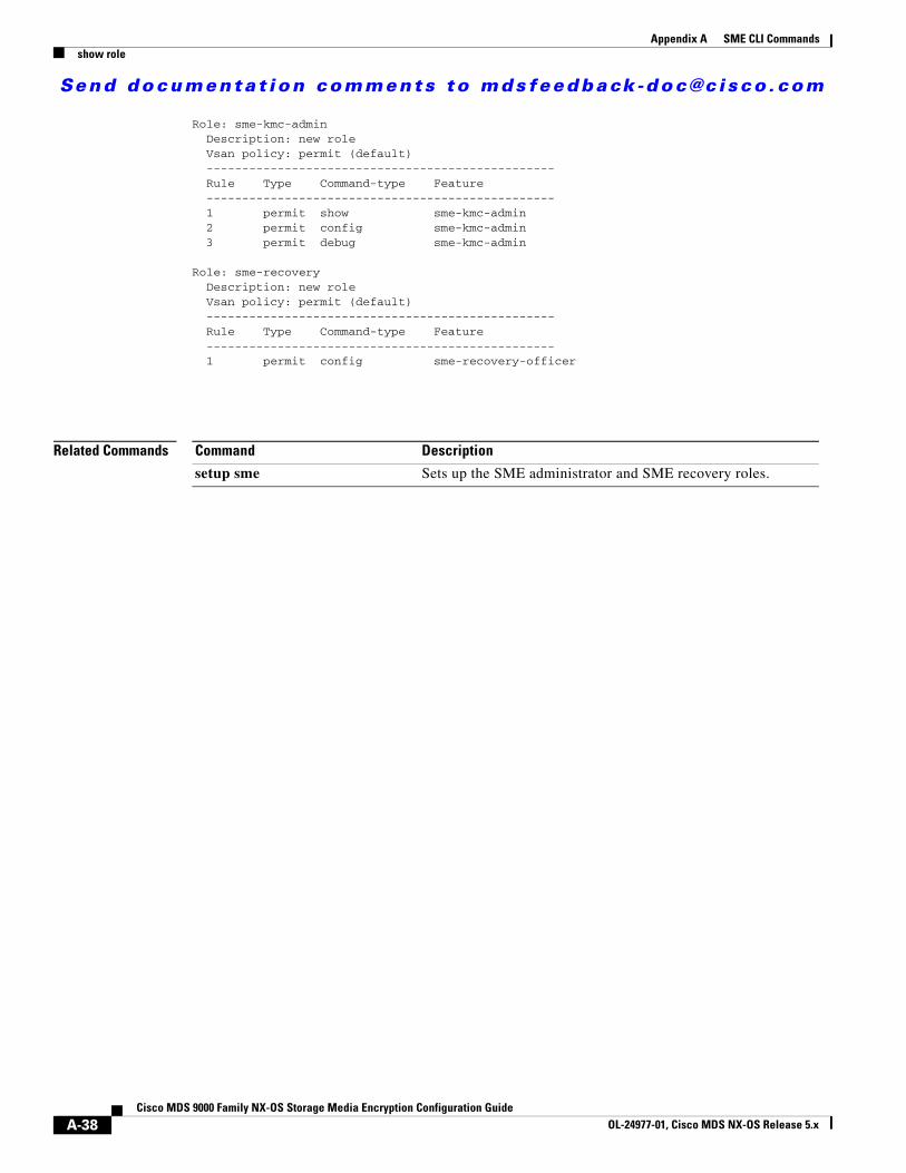
Send documenta t ion comments to mdsfeedback -doc@c i sco .com
Appendix A SME CLI Commandsshow role
Role: sme-kmc-admin Description: new role Vsan policy: permit (default) ------------------------------------------------- Rule Type Command-type Feature ------------------------------------------------- 1 permit show sme-kmc-admin 2 permit config sme-kmc-admin 3 permit debug sme-kmc-admin Role: sme-recovery Description: new role Vsan policy: permit (default) ------------------------------------------------- Rule Type Command-type Feature ------------------------------------------------- 1 permit config sme-recovery-officer
Related Commands Command Description
setup sme Sets up the SME administrator and SME recovery roles.
A-38Cisco MDS 9000 Family NX-OS Storage Media Encryption Configuration Guide
OL-24977-01, Cisco MDS NX-OS Release 5.x
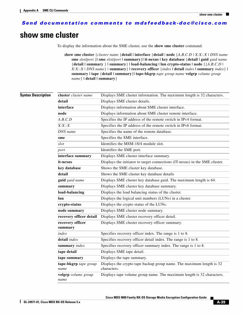
Send documenta t ion comments to mdsfeedback -doc@c i sco .com
Appendix A SME CLI Commandsshow sme cluster
show sme cluster To display the information about the SME cluster, use the show sme cluster command.
show sme cluster {cluster name {detail | interface {detail | node {A.B.C.D | X:X::X | DNS name sme slot/port }| sme slot/port | summary}| it-nexus | key database {detail | guid guid name {detail | summary } | summary} | load-balancing | lun crypto-status | node {{A.B.C.D | X:X::X | DNS name} | summary} | recovery officer {index | detail index | summary index} | summary | tape {detail | summary}| tape-bkgrp tape group name volgrp volume group name} | detail | summary}
Syntax Description cluster cluster name Displays SME cluster information. The maximum length is 32 characters.
detail Displays SME cluster details.
interface Displays information about SME cluster interface.
node Displays information about SME cluster remote interface.
A.B.C.D Specifies the IP address of the remote switch in IPv4 format.
X:X::X Specifies the IP address of the remote switch in IPv6 format.
DNS name Specifies the name of the remote database.
sme Specifies the SME interface.
slot Identifies the MSM-18/4 module slot.
port Identifies the SME port.
interface summary Displays SME cluster interface summary.
it-nexus Displays the initiator to target connections (IT-nexus) in the SME cluster.
key database Shows the SME cluster key database.
detail Shows the SME cluster key database details
guid guid name Displays SME cluster key database guid. The maximum length is 64.
summary Displays SME cluster key database summary.
load-balancing Displays the load balancing status of the cluster.
lun Displays the logical unit numbers (LUNs) in a cluster.
crypto-status Displays the crypto status of the LUNs.
node summary Displays SME cluster node summary.
recovery officer detail Displays SME cluster recovery officer detail.
recovery officer summary
Displays SME cluster recovery officer summary.
index Specifies recovery officer index. The range is 1 to 8.
detail index Specifies recovery officer detail index. The range is 1 to 8.
summary index Specifies recovery officer summary index. The range is 1 to 8.
tape detail Displays SME tape detail.
tape summary Displays the tape summary.
tape-bkgrp tape group name
Displays the crypto tape backup group name. The maximum length is 32 characters.
volgrp volume group name
Displays tape volume group name. The maximum length is 32 characters.
A-39Cisco MDS 9000 Family NX-OS Storage Media Encryption Configuration Guide
OL-24977-01, Cisco MDS NX-OS Release 5.x
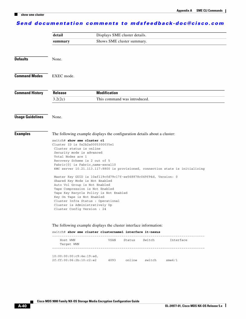
Send documenta t ion comments to mdsfeedback -doc@c i sco .com
Appendix A SME CLI Commandsshow sme cluster
Defaults None.
Command Modes EXEC mode.
Command History
Usage Guidelines None.
Examples The following example displays the configuration details about a cluster:
switch# show sme cluster c1Cluster ID is 0x2b2a0005300035e1 Cluster status is online Security mode is advanced Total Nodes are 1 Recovery Scheme is 2 out of 5 Fabric[0] is Fabric_name-excal10 KMC server 10.21.113.117:8800 is provisioned, connection state is initializing
Master Key GUID is 10af119cfd79c17f-ee568878c049f94d, Version: 0 Shared Key Mode is Not Enabled Auto Vol Group is Not Enabled Tape Compression is Not Enabled Tape Key Recycle Policy is Not Enabled Key On Tape is Not Enabled Cluster Infra Status : Operational Cluster is Administratively Up Cluster Config Version : 24
The following example displays the cluster interface information:
switch# show sme cluster clustername1 interface it-nexus ------------------------------------------------------------------------------- Host WWN VSAN Status Switch Interface Target WWN-------------------------------------------------------------------------------
10:00:00:00:c9:4e:19:ed,2f:ff:00:06:2b:10:c2:e2 4093 online switch sme4/1
detail Displays SME cluster details.
summary Shows SME cluster summary.
Release Modification
3.2(2c) This command was introduced.
A-40Cisco MDS 9000 Family NX-OS Storage Media Encryption Configuration Guide
OL-24977-01, Cisco MDS NX-OS Release 5.x
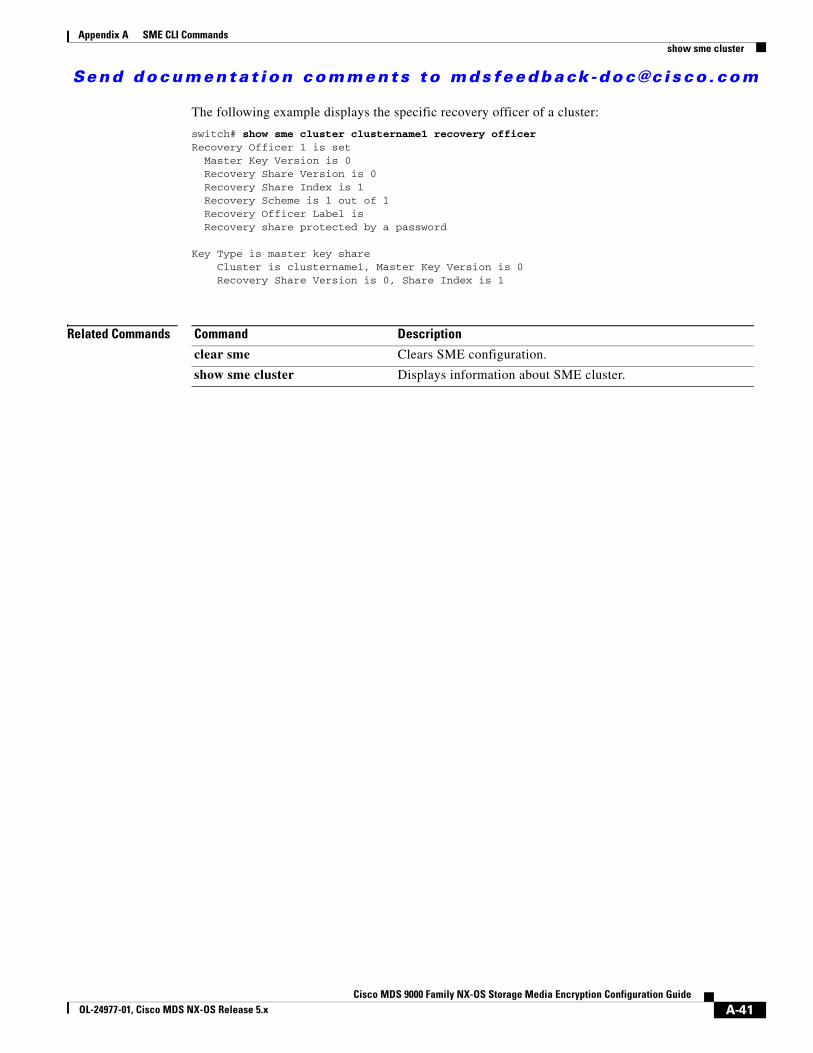
Send documenta t ion comments to mdsfeedback -doc@c i sco .com
Appendix A SME CLI Commandsshow sme cluster
The following example displays the specific recovery officer of a cluster:
switch# show sme cluster clustername1 recovery officer Recovery Officer 1 is set Master Key Version is 0 Recovery Share Version is 0 Recovery Share Index is 1 Recovery Scheme is 1 out of 1 Recovery Officer Label is Recovery share protected by a password
Key Type is master key share Cluster is clustername1, Master Key Version is 0 Recovery Share Version is 0, Share Index is 1
Related Commands Command Description
clear sme Clears SME configuration.
show sme cluster Displays information about SME cluster.
A-41Cisco MDS 9000 Family NX-OS Storage Media Encryption Configuration Guide
OL-24977-01, Cisco MDS NX-OS Release 5.x

Send documenta t ion comments to mdsfeedback -doc@c i sco .com
Appendix A SME CLI Commandsshow sme transport
show sme transportTo display the SME cluster transport information, use the show sme transport command.
show sme transport ssl truspoint
Syntax Description
Defaults None.
Command Modes EXEC mode.
Command History
Usage Guidelines None.
Examples The following example displays the internal cluster errors:
switch# show sme transport ssl trustpointSME Transport SSL trustpoint is trustpoint-label
Related Commands
ssl Displays transport Secure Sockets Layer (SSL) information.
trustpoint Displays transport SSL trustpoint information.
Release Modification
3.2(2c) This command was introduced.
Command Description
clear sme Clears SME configuration.
show sme cluster Displays all information of SME cluster.
A-42Cisco MDS 9000 Family NX-OS Storage Media Encryption Configuration Guide
OL-24977-01, Cisco MDS NX-OS Release 5.x
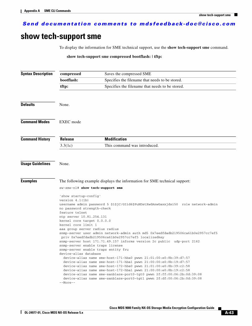
Send documenta t ion comments to mdsfeedback -doc@c i sco .com
Appendix A SME CLI Commandsshow tech-support sme
show tech-support smeTo display the information for SME technical support, use the show tech-support sme command.
show tech-support sme compressed bootflash: | tftp:
Syntax Description
Defaults None.
Command Modes EXEC mode
Command History
Usage Guidelines None.
Examples The following example displays the information for SME technical support:
sw-sme-n1# show tech-support sme
'show startup-config'version 4.1(1b)username admin password 5 $1$jC/GIid6$PuNDstXwdAnwGaxxjdxi50 role network-adminno password strength-checkfeature telnetntp server 10.81.254.131kernel core target 0.0.0.0kernel core limit 1aaa group server radius radius snmp-server user admin network-admin auth md5 0x7eedfdadb219506ca61b0e2957cc7ef5 priv 0x7eedfdadb219506ca61b0e2957cc7ef5 localizedkeysnmp-server host 171.71.49.157 informs version 2c public udp-port 2162snmp-server enable traps licensesnmp-server enable traps entity frudevice-alias database device-alias name sme-host-171-hba0 pwwn 21:01:00:e0:8b:39:d7:57 device-alias name sme-host-171-hba1 pwwn 21:00:00:e0:8b:19:d7:57 device-alias name sme-host-172-hba0 pwwn 21:01:00:e0:8b:39:c2:58 device-alias name sme-host-172-hba1 pwwn 21:00:00:e0:8b:19:c2:58 device-alias name sme-sanblaze-port0-tgt0 pwwn 2f:ff:00:06:2b:0d:39:08 device-alias name sme-sanblaze-port0-tgt1 pwwn 2f:df:00:06:2b:0d:39:08--More--
compressed Saves the compressed SME
bootflash: Specifies the filename that needs to be stored.
tftp: Specifies the filename that needs to be stored.
Release Modification
3.3(1c) This command was introduced.
A-43Cisco MDS 9000 Family NX-OS Storage Media Encryption Configuration Guide
OL-24977-01, Cisco MDS NX-OS Release 5.x
Send documenta t ion comments to mdsfeedback -doc@c i sco .com
Appendix A SME CLI Commandsshutdown (interface configuration submode)
shutdown (interface configuration submode)To disable an SME interface, use the shutdown command. To enable the interface, use the no form of the command.
shutdown
no shutdown
Syntax Description This command has no arguments or keywords.
Defaults None.
Command Modes Interface configuration submode.
Command History
Usage Guidelines The default state for SME interfaces is shutdown. Use the no shutdown command to enable the interface to carry traffic.
The show interface command shows that the SME interface is down until the interface is added to a cluster.
Examples The following example enables a SME interface:
switch# config tswitch(config)# interface sme 4/1switch(config-if)# no shutdown
The following example disables a SME interface:
switch# config tswitch(config)# interface sme 4/1switch(config-if)# shutdown
Related Commands
Release Modification
3.2(2c) This command was introduced.
Command Description
show interface sme Displays information about the SME interface.
A-44Cisco MDS 9000 Family NX-OS Storage Media Encryption Configuration Guide
OL-24977-01, Cisco MDS NX-OS Release 5.x
Send documenta t ion comments to mdsfeedback -doc@c i sco .com
Appendix A SME CLI Commandsshutdown (SME cluster configuration submode)
shutdown (SME cluster configuration submode)To disable a cluster for recovery, use the shutdown command. To enable the cluster for recovery, use the no form of the command.
shutdown
no shutdown
Syntax Description This command has no arguments or keywords.
Defaults None.
Command Modes SME cluster configuration submode.
Command History
Usage Guidelines To disable operation of a cluster for the purpose of recovery, use the shutdown command. To enable the cluster for normal usage, use the no shutdown command.
The default state for clusters is no shutdown. Use the shutdown command for cluster recovery. See the Chapter 11, “SME Troubleshooting” for additional details about recovery scenarios.
Examples The following example restarts the cluster after recovery is complete:
switch# config tswitch(config)# sme cluster c1switch(config-sme-cl)# no shutdown
The following example disables the cluster operation in order to start recovery:
switch# config tswitch(config))# sme cluster c1switch(config-sme-cl)# shutdown
Related Commands
Release Modification
3.2(2c) This command was introduced.
Command Description
show sme cluster Displays information about the SME cluster.
A-45Cisco MDS 9000 Family NX-OS Storage Media Encryption Configuration Guide
OL-24977-01, Cisco MDS NX-OS Release 5.x
Send documenta t ion comments to mdsfeedback -doc@c i sco .com
Appendix A SME CLI Commandssme
smeTo enable or disable the SME services, use the sme command.
sme {cluster name | transport ssl trustpoint trustpoint label}
Syntax Description
Defaults Disabled.
Command Modes Configuration mode.
Command History
Usage Guidelines SME services must be enabled to take advantage of the encryption and security features.
To use this command, you must enable SME clustering using the feature cluster command.
Examples The following example shows how to configure a cluster:
switch# config tsw-sme-n1(config)# sme cluster clusternamesw-sme-n1(config-sme-cl)#
cluster Configures the cluster.
name Identifies the cluster name.
transport Configures the transport information.
ssl Configures the transport SSL information.
trustpoint Configures the transport SSL trustpoint.
trustpoint label Identifies the trustpoint label.
Release Modification
3.2(2c) This command was introduced.
A-46Cisco MDS 9000 Family NX-OS Storage Media Encryption Configuration Guide
OL-24977-01, Cisco MDS NX-OS Release 5.x
Send documenta t ion comments to mdsfeedback -doc@c i sco .com
Appendix A SME CLI Commandsssl
sslTo configure Secure Sockets Layer (SSL), use the ssl command. Use the no form of this command to disable this feature.
ssl kmc
no ssl kmc
Syntax Description
Defaults None.
Command Modes SME cluster configuration mode submode.
Command History
Usage Guidelines None.
Examples The following example enables SSL:
switch# config tswitch(config)# sme cluster c1switch(config-sme-cl)# ssl kmc
kmc Enables SSL for Key Management Center (KMC) communication.
Release Modification
3.3(1c) This command was introduced.
A-47Cisco MDS 9000 Family NX-OS Storage Media Encryption Configuration Guide
OL-24977-01, Cisco MDS NX-OS Release 5.x
Send documenta t ion comments to mdsfeedback -doc@c i sco .com
Appendix A SME CLI Commandstape-bkgrp
tape-bkgrpTo configure a crypto tape backup group, use the tape-bkgrp command. To disable this feature, use the no form of the command.
tape-bkgrp groupname
no tape-bkgrp groupname
Syntax Description
Defaults None.
Command Modes SME cluster configuration mode submode.
Command History
Usage Guidelines A tape volume group is a group of tapes that are categorized by function. For example, HR1 could be designated tape volume group for all Human Resources backup tapes.
Adding tape groups allows you to select VSANs, hosts, storage devices, and paths that SME will use for encrypted data. For example, adding a tape group for HR data sets the mapping for SME to transfer data from the HR hosts to the dedicated HR backup tapes.
Examples The following example adds a backup tape group:
switch# config tswitch(config)# sme cluster c1switch(config-sme-cl)# tape-bkgrp group1switch(config-sme-cl-tape-bkgrp)#
The following example removes a backup tape group:
switch# config tswitch(config)# sme cluster c1switch(config-sme-cl)# no tape-bkgrp group1switch(config-sme-cl-tape-bkgrp)#
Related Commands
groupname Specifies the backup tape group. The maximum length is 31 characters.
Release Modification
3.2(2c) This command was introduced.
Command Description
clear sme Clears SME configuration.
show sme cluster Displays information about the SME cluster.
A-48Cisco MDS 9000 Family NX-OS Storage Media Encryption Configuration Guide
OL-24977-01, Cisco MDS NX-OS Release 5.x
Send documenta t ion comments to mdsfeedback -doc@c i sco .com
Appendix A SME CLI Commandstape-compression
tape-compressionTo configure tape compression, use the tape-compression command. To disable this feature, use the no form of the command.
tape-compression
no tape-compression
Syntax Description This command has no arguments or keywords.
Defaults None.
Command Modes SME cluster configuration submode.
Command History
Usage Guidelines Use this command to compress encrypted data.
Examples The following example enables tape compression:
switch# config tswitch(config)# sme cluster c1switch(config-sme-cl)# tape-compression
The following example disables tape compression:
switch# config tswitch(config)# sme cluster c1switch(config-sme-cl)# no tape-compression
Related Commands
Release Modification
3.2(2c) This command was introduced.
Command Description
clear sme Clears SME configuration.
show sme cluster Displays information about the SME cluster.
show sme cluster tape Displays information about all tape volume groups or a specific group.
A-49Cisco MDS 9000 Family NX-OS Storage Media Encryption Configuration Guide
OL-24977-01, Cisco MDS NX-OS Release 5.x
Send documenta t ion comments to mdsfeedback -doc@c i sco .com
Appendix A SME CLI Commandstape-device
tape-deviceTo configure a crypto tape device, use the tape-device command. To disable this feature, use the no form of the command.
tape-device device name
no tape-device device name
Syntax Description
Defaults None.
Command Modes SME tape volume configuration submode.
Command History
Usage Guidelines The tape device commands are available in the (config-sme-cl-tape-bkgrp-tapedevice) submode.
Examples The following example configures a crypto tape device:
switch# config tswitch(config)# sme cluster c1switch(config-sme-cl)# tape-bkgrp group1switch(config-sme-cl-tape-bkgrp)# tape-device devicename1switch(config-sme-cl-tape-bkgrp-tapedevice)#
The following example removes a crypto tape device:
switch# config tswitch(config)# sme cluster c1switch(config-sme-cl)# tape-bkgrp group1switch(config-sme-cl-tape-bkgrp)# no tape-device devicename1switch(config-sme-cl-tape-bkgrp-tapedevice)#
Related Commands
device name Specifies the name of the tape device.
Release Modification
3.2(2c) This command was introduced.
Command Description
clear sme Clears SME configuration.
show sme cluster Displays information about the SME cluster.
show sme cluster tape Displays information about all tape volume groups or a specific group.
A-50Cisco MDS 9000 Family NX-OS Storage Media Encryption Configuration Guide
OL-24977-01, Cisco MDS NX-OS Release 5.x

Send documenta t ion comments to mdsfeedback -doc@c i sco .com
Appendix A SME CLI Commandstape-keyrecycle
tape-keyrecycleTo configure a tape key recycle policy, use the tape-keyrecycle command. To disable this feature, use the no form of the command.
tape-keyrecycle
no tape-keyrecycle
Syntax Description This command has no arguments or keywords.
Defaults None.
Command Modes SME cluster configuration submode.
Command History
Usage Guidelines SME allows you to recycle the tape keys. If you enable tape key recycling, all the previous instances of the tape key will be deleted.
Examples The following example enables tape key recycling:
switch# config tswitch(config)# sme cluster c1switch(config-sme-cl)# tape-keyrecycle
The following example disables tape key recycling:
switch# config tswitch(config)# sme cluster c1switch(config-sme-cl)# no tape-keyrecycle
Related Commands
Release Modification
3.2(2c) This command was introduced.
Command Description
clear sme Clears SME configuration.
show sme cluster Displays information about the SME cluster.
A-51Cisco MDS 9000 Family NX-OS Storage Media Encryption Configuration Guide
OL-24977-01, Cisco MDS NX-OS Release 5.x
Send documenta t ion comments to mdsfeedback -doc@c i sco .com
Appendix A SME CLI Commandstape-volgrp
tape-volgrpTo configure the crypto tape volume group, use the tape-volgrp command. To disable this command, use the no form of the command.
tape-volgrp group name
no tape-volgrp group name
Syntax Description
Defaults None.
Command Modes SME crypto backup tape group configuration submode.
Command History
Usage Guidelines The tape volume group commands are available in the SME crypto tape volume group (config-sme-cl-tape-bkgrp-volgrp) submode.
Examples The following example configures a crypto tape volume group:
switch# config tswitch(config))# sme cluster c1switch(config-sme-cl)# tape-bkgrp tbg1switch(config-sme-cl-tape-bkgrp)# tape-volgrp tv1switch(config-sme-cl-tape-bkgrp-volgrp)#
The following example removes a crypto tape volume group:
switch# config tswitch(config)# sme cluster c1switch(config-sme-cl)# tape-bkgrp tbg1switch(config-sme-cl-tape-bkgrp)# no tape-volgrp tv1
Related Commands
group name Specifies the tape volume group name.
Release Modification
3.2(2c) This command was introduced.
Command Description
clear sme Clears SME configuration.
show sme cluster tape Displays information about tapes.
A-52Cisco MDS 9000 Family NX-OS Storage Media Encryption Configuration Guide
OL-24977-01, Cisco MDS NX-OS Release 5.x
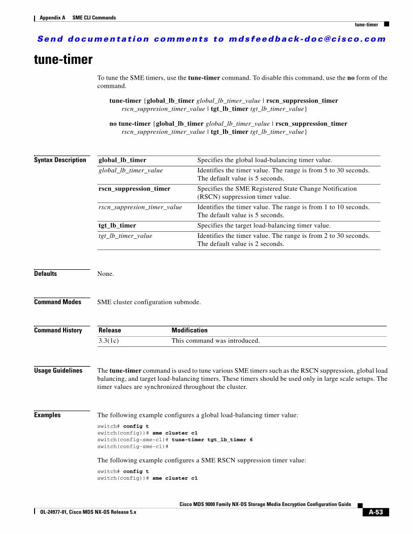
Send documenta t ion comments to mdsfeedback -doc@c i sco .com
Appendix A SME CLI Commandstune-timer
tune-timerTo tune the SME timers, use the tune-timer command. To disable this command, use the no form of the command.
tune-timer {global_lb_timer global_lb_timer_value | rscn_suppression_timer rscn_suppresion_timer_value | tgt_lb_timer tgt_lb_timer_value}
no tune-timer {global_lb_timer global_lb_timer_value | rscn_suppression_timer rscn_suppresion_timer_value | tgt_lb_timer tgt_lb_timer_value}
Syntax Description
Defaults None.
Command Modes SME cluster configuration submode.
Command History
Usage Guidelines The tune-timer command is used to tune various SME timers such as the RSCN suppression, global load balancing, and target load-balancing timers. These timers should be used only in large scale setups. The timer values are synchronized throughout the cluster.
Examples The following example configures a global load-balancing timer value:
switch# config tswitch(config))# sme cluster c1switch(config-sme-cl)# tune-timer tgt_lb_timer 6switch(config-sme-cl)#
The following example configures a SME RSCN suppression timer value:
switch# config tswitch(config))# sme cluster c1
global_lb_timer Specifies the global load-balancing timer value.
global_lb_timer_value Identifies the timer value. The range is from 5 to 30 seconds. The default value is 5 seconds.
rscn_suppression_timer Specifies the SME Registered State Change Notification (RSCN) suppression timer value.
rscn_suppresion_timer_value Identifies the timer value. The range is from 1 to 10 seconds. The default value is 5 seconds.
tgt_lb_timer Specifies the target load-balancing timer value.
tgt_lb_timer_value Identifies the timer value. The range is from 2 to 30 seconds. The default value is 2 seconds.
Release Modification
3.3(1c) This command was introduced.
A-53Cisco MDS 9000 Family NX-OS Storage Media Encryption Configuration Guide
OL-24977-01, Cisco MDS NX-OS Release 5.x
Send documenta t ion comments to mdsfeedback -doc@c i sco .com
Appendix A SME CLI Commandstune-timer
switch(config-sme-cl)# tune-timer rscn_suppression_timer 2switch(config-sme-cl)#
The following example configures a target load balancing timer value:
switch# config tswitch(config))# sme cluster c1switch(config-sme-cl)# tune-timer rscn_suppression_timer 2switch(config-sme-cl)#
A-54Cisco MDS 9000 Family NX-OS Storage Media Encryption Configuration Guide
OL-24977-01, Cisco MDS NX-OS Release 5.x
Send documenta t ion comments to mdsfeedback -doc@c i sco .com
Cisco MDS 9000 Family NX-OS StoOL-24977-01, Cisco MDS NX-OS Release 5.x
A
P P E N D I X B Disaster Recovery in SMEThis appendix includes the following sections:
• Disaster Recovery Sequence for SME Tape, page B-1
• Disaster Recovery Sequence for SME Tape, page B-1
Disaster Recovery Sequence for SME Tape
Caution Use this procedure only if the SME cluster cannot be recovered to an online / active state. A new SME Cluster must be created and existing keys imported into the new SME Cluster.
Detailed Steps
To recover SME tape, follow these steps:
Step 1 Ensure that all backup operations are stopped.
Step 2 If the ASCII configuration of the SME Cluster exists on the switches, you must removed it. Save the show SME tech support and show running config commands off the switches before any changes are done. These files are useful when configuring the new SME Cluster.
Step 3 Log in to the Key Manager (DCNM Web Client) with credentials that allow you to do key operations (admin, sme-kmc-admin, network-operator).
Step 4 Export all volume groups from the original cluster. If you already have an up to date exported backup, you can skip this step. The Master Key of the old SME Cluster is required to complete this step. If the Cluster’s security mode is Basic, you must have the Master Key file. If the Cluster’s security mode is Standard or Advanced, you must supply the required number of smart cards to reconstitute the Master Key.
• View the tape group, select each volume group and click export. The web client will guide you through an offline export requiring the input of the master key for each export.
• The keys are exported to a passwor- protected file.
• If there is more than one tape group, this procedure must be done for each tape group, including every volume group. The files should be clearly labelled so that you know which tape group the export belongs to.
Step 5 Using the DCNM UI, create a new cluster with a new name, with the same cluster settings.
B-1rage Media Encryption Configuration Guide

Send documenta t ion comments to mdsfeedback -doc@c i sco .com
Appendix B Disaster Recovery in SMEDisaster Recovery Sequence for SME Disk
Step 6 Create a new tape group to match each old tape group.
• Create a new volume group to match each volume group from the original Cluster.
• Add the tape devices.
Step 7 If you want to continue writing to existing tapes, modify smeserver.properties in the FMS conf directory. If you skip this step, the existing tapes will be read only.
a. Edit smeserver.properties and add sme.retain.imported.key.state=true
b. Restart the DCNM Server.
c. Wait for FMS to restart and log in again.
Step 8 Import the volume groups from step 3 into the new cluster in their respective tape groups volume groups.
Step 9 If you did not skip step 7, complete these steps:
a. Edit smeserver.properties and remove sme.retain.imported.key.state=true
b. Restart Fabric Manager Server.
c. Wait for FMS to restart and log in again.
The new SME Cluster should now be online, with a stable connection to the KMC. The keys from the old SME Cluster have now been imported into the new SME Cluster. Backup operations can be resumed.
Disaster Recovery Sequence for SME DiskDetailed Steps
To recover SME disk, follow these steps:
Step 1 Ensure that all backup operations are stopped.
Step 2 If the ASCII configuration of the SME Cluster exists on the switches, you must remove it. save the show sme tech support and show running config commands of the switches before any changes are done. These files will be useful when configuring the new SME Cluster.
Step 3 Log in to the Key Manager (DCNM Web Client) with credentials that allow you to do key operations (admin, sme-kmc-admin, network-operator).
Step 4 Export all of the disk keys from the original cluster. If you already have an up-to-date exported backup, you can skip this step. The Master Key of the old SME cluster is required to complete this step. If the cluster’s security mode is Basic, you must have the Master Key file. If the cluster’s security mode is Standard or Advanced, you must supply the required number of smart cards to reconstitute the Master Key.
• View the Disk Group, select all Disks, and click export. The web client guides you through an offline export requiring the input of the master key for each export.
• The keys are exported to a password-protected file.
• If there is more than one disk group, this procedure must be done for each disk group. The files should be clearly labelled so that you know which disk group the export belongs to.
Step 5 Using the DCNM GUI, create a new cluster with a new name with the same cluster settings.
Step 6 Create a new disk group to match each old disk group.
B-2Cisco MDS 9000 Family NX-OS Storage Media Encryption Configuration Guide
OL-24977-01, Cisco MDS NX-OS Release 5.x
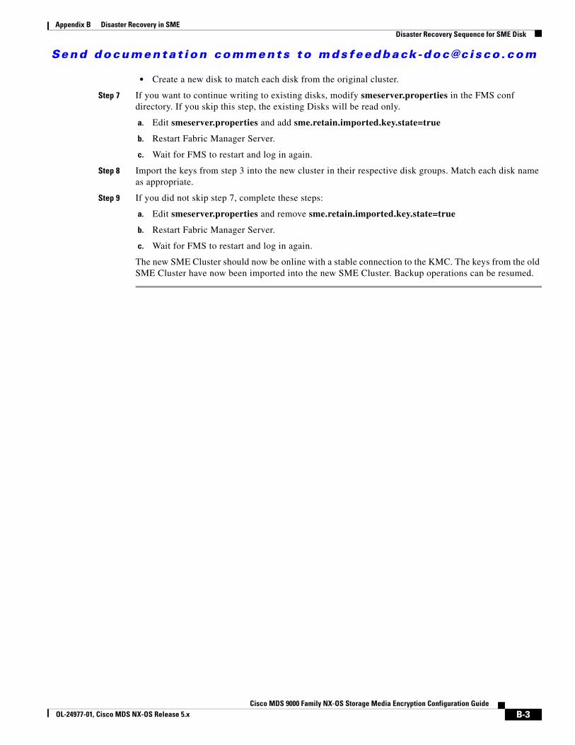
Send documenta t ion comments to mdsfeedback -doc@c i sco .com
Appendix B Disaster Recovery in SMEDisaster Recovery Sequence for SME Disk
• Create a new disk to match each disk from the original cluster.
Step 7 If you want to continue writing to existing disks, modify smeserver.properties in the FMS conf directory. If you skip this step, the existing Disks will be read only.
a. Edit smeserver.properties and add sme.retain.imported.key.state=true
b. Restart Fabric Manager Server.
c. Wait for FMS to restart and log in again.
Step 8 Import the keys from step 3 into the new cluster in their respective disk groups. Match each disk name as appropriate.
Step 9 If you did not skip step 7, complete these steps:
a. Edit smeserver.properties and remove sme.retain.imported.key.state=true
b. Restart Fabric Manager Server.
c. Wait for FMS to restart and log in again.
The new SME Cluster should now be online with a stable connection to the KMC. The keys from the old SME Cluster have now been imported into the new SME Cluster. Backup operations can be resumed.
B-3Cisco MDS 9000 Family NX-OS Storage Media Encryption Configuration Guide
OL-24977-01, Cisco MDS NX-OS Release 5.x

Send documenta t ion comments to mdsfeedback -doc@c i sco .com
Appendix B Disaster Recovery in SMEDisaster Recovery Sequence for SME Disk
B-4Cisco MDS 9000 Family NX-OS Storage Media Encryption Configuration Guide
OL-24977-01, Cisco MDS NX-OS Release 5.x
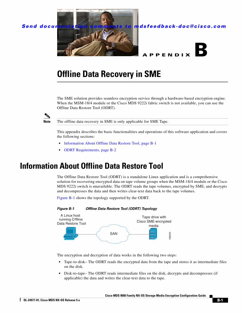
Send documenta t ion comments to mdsfeedback -doc@c i sco .com
Cisco MDS 9000 Family NX-OS StoOL-24977-01, Cisco MDS NX-OS Release 5.x
A
P P E N D I X B Offline Data Recovery in SMEThe SME solution provides seamless encryption service through a hardware-based encryption engine. When the MSM-18/4 module or the Cisco MDS 9222i fabric switch is not available, you can use the Offline Data Restore Tool (ODRT).
Note The offline data recovery in SME is only applicable for SME Tape.
This appendix describes the basic functionalities and operations of this software application and covers the following sections:
• Information About Offline Data Restore Tool, page B-1
• ODRT Requirements, page B-2
Information About Offline Data Restore ToolThe Offline Data Restore Tool (ODRT) is a standalone Linux application and is a comprehensive solution for recovering encrypted data on tape volume groups when the MSM-18/4 module or the Cisco MDS 9222i switch is unavailable. The ODRT reads the tape volumes, encrypted by SME, and decrypts and decompresses the data and then writes clear-text data back to the tape volumes.
Figure B-1 shows the topology supported by the ODRT.
Figure B-1 Offline Data Restore Tool (ODRT) Topology
The encryption and decryption of data works in the following two steps:
• Tape-to-disk– The ODRT reads the encrypted data from the tape and stores it as intermediate files on the disk.
• Disk-to-tape– The ODRT reads intermediate files on the disk, decrypts and decompresses (if applicable) the data and writes the clear-text data to the tape.
A Linux host running O ffline
Data Restore Tool
SAN
Tape drive withCisco SME-encrypted
media
1869
33
B-1rage Media Encryption Configuration Guide
Send documenta t ion comments to mdsfeedback -doc@c i sco .com
Appendix B Offline Data Recovery in SMEODRT Requirements
The decryption key is obtained from the volume group file which you need to export from the Cisco Key Management Center (KMC). For information on exporting volume groups, see Chapter 7, “Configuring SME Key Management.”
The ODRT feature is invoked by entering the odrt.bin command from the Linux shell. For more information about the odrt.bin command, see Appendix A, “SME CLI Commands.”
ODRT Requirements The prerequistes for running the ODRT tool are as follows:
• Platform—The ODRT is currently supported in Red Hat Enterprise Linux 5.
• CPU— The little-endian CPU design is supported, such as the x86 family of microprocessors. It is recommended that you use a fast CPU.
• Memory— There is no specific limit and a memory of 1 GB to 2 GB would be sufficient.
• Disk Sizing— The disk should hold 1 tetrabytes of data.
• Fibre Channel (FC) connectivity to the tape drive should be present.
B-2Cisco MDS 9000 Family NX-OS Storage Media Encryption Configuration Guide
OL-24977-01, Cisco MDS NX-OS Release 5.x
Send documenta t ion comments to mdsfeedback -doc@c i sco .com
Cisco MDS 9000 Family NX-OS StoOL-24977-01, Cisco MDS NX-OS Release 5.x
A
P P E N D I X C Database Backup and RestoreDatabases need to have a well-defined and thoroughly tested backup and restore plan so that access to data is not at risk. The backup and recovery of databases involve the process of making a copy of a database in case of an equipment failure or disaster, then retrieving the copied database if needed.
This appendix explains how to back up and restore DCNM-SAN databases.
DCNM-SAN uses the PostgreSQL database management system as the default database. PostgreSQL databases are backed up with the pg_dump command. The pg_dump utility dumps the PostgreSQL database content to an ASCII dump file. The backup dump file represents a snapshot of the database at the time of backup.
The database is restored with the pg_restore utility. The pg_restore utility uses psql to rebuild the PostgreSQL database from the dump file created by pg_dump.
Note Oracle Database Servers are supported for Cisco DCNM and SME. The management, backup, and restoring of Oracle Databases is outside the scope of this document. For more information, contact your local Oracle DBA for a backup and restore plan of your Oracle Database.
For more information about pg_dump, go to this URL:
http://www.postgresql.org/docs/current/interactive/app-pgdump.html
This appendix includes the following sections:
• Backing Up the DCNM-SAN Database, page C-1
• Restoring the DCNM-SAN Database, page C-2
• Database Backup and Restore Operations, page C-2
Backing Up the DCNM-SAN DatabaseTo back up the DCNM-SAN database, use the PostgreSQL pg_dump command as follows:
cd $INSTALLDIR/bin./pgbackup.sh 02252008.data (on Linux and Solaris operation systems)pgbackup.bat 02252008.data (on Windows operating system)
The INSTALLDIR is the top directory of DCNM-SAN Installation, and a backup file (02252008.data) is created in the $INSTALLDIR/bin directory.
Specify the full path name of the dump file to create the backup file in a standard backup directory.
C-1rage Media Encryption Configuration Guide
Send documenta t ion comments to mdsfeedback -doc@c i sco .com
Appendix C Database Backup and RestoreRestoring the DCNM-SAN Database
Note In all operating systems, the scripts run the pg_dump command to back up the database.
Restoring the DCNM-SAN DatabaseTo restore the DCNM-SAN database, use the pg_restore command.
cd $ INSTALLDIR/bin./pgrestore.sh 02252008.data (on Linux and Solaris operating systems)pgrestore.bat 02252008.data (on Windows operating system)
The backup restore process requires the server to be stopped.
Note In all operating systems, the scripts run pg_restore command to restore the database.
Database Backup and Restore OperationsWhen implementing the DCNM-SAN backup and restore operations, note the following guidelines:
• The new media keys created after the backup of the database are lost after the restore operation since the backup copy does not have the latest media keys.
• If there are new tape backup groups and tape volume groups created after the database backup, the property should be set to true in smeserver.properties before starting the DCNM-SAN. This will synchronize the new volume group keys to the KMC.
sme.kmc.sync.model.at.startup=true
This property is also applicable for any tape volume group rekey operation.
• If a master key is rekeyed after the database backup, then restoring the data of the previous database makes the cluster unusable. After the master key rekey operation, make a backup of the database and discard the copies of the previous database backup.
C-2Cisco MDS 9000 Family NX-OS Storage Media Encryption Configuration Guide
OL-24977-01, Cisco MDS NX-OS Release 5.x
Send documenta t ion comments to mdsfeedback -doc@c i sco .com
Cisco MDS 9000 Family NX-OS StoOL-24977-01, Cisco MDS NX-OS Release 5.x
A
P P E N D I X D Planning For SME InstallationThis appendix outlines the steps and guidelines that you need to be follow to ensure a successful SME installation. Before installing the application, read the requirements and prerequisites for the following services and features:
• SAN Considerations, page D-1
• Interoperability Matrix, page D-2
• MSM-18/4 Modules, page D-2
• Key Management Center and DCNM-SAN Server, page D-2
• Security, page D-3
• Communication, page D-3
• Preinstallation Requirements, page D-4
• Preconfiguration Tasks, page D-4
• Provisioning SME, page D-7
SAN Considerations Collect the following information about the SAN before installing SME:
• Version of the SAN or NX-OS operating system.
Note We suggest that you use version Cisco SAN-OS Release 3.1(1a) or later or NX-OS Release 4.x or later.
• SAN switch vendors.
Note SME is supported on Cisco-only SANs. However, SANs that have switches from other vendors may also be supported on a case-by-case basis.
• SAN topology, including the placement of hosts and targets and number of fabrics.
• Backup host operating system.
• Backup application type and version.
• HBA type and firmware version.
D-1rage Media Encryption Configuration Guide
Send documenta t ion comments to mdsfeedback -doc@c i sco .com
Appendix D Planning For SME InstallationInteroperability Matrix
• Tape library and drive types.
• Number of hosts and tape drives.
• SAN topology diagram.
• Types of modules used for ISL connectivity (Generation 1 or Generation 2).
Note This information is required for large SME setups.
• Zoning of the hosts and tape drives and if all the drives are accessible to all the hosts. It is preferred that there is selective accessibility between the hosts and drives.
Interoperability MatrixVerify the interoperability matrix to be used. If needed, submit an RPQ for new types and versions of SAN components such as tape libraries and drives, or new backup application software versions.
Refer to the Cisco MDS 9000 Family Interoperability Support Matrix.
MSM-18/4 ModulesCollect the following information about MSM-18/4 modules:
• Determine the total throughput requirement and the required number of MSM-18/4 modules. The throughput requirement can be based on either meeting the backup window or based on achieving the line rate throughput for each drive. Refer to the Cisco Storage Media Encryption Design Guide for details.
• Determine the placement of the MSM-18/4 modules. Consult the design guide for sample topology and recommendations.
• For large SME setups, determine if the line cards used for ISLs can scale for the FC Redirect configuration. Refer to the Cisco Storage Media Encryption Design Guide for details.
Note Generation 2 modules are recommended for ISL connectivity.
• Order the appropriate number of SME licenses.
Key Management Center and DCNM-SAN ServerDetermine which of the following key management strategies and policies are appropriate for you:
• Use Cisco KMC or KMC with RSA Key Manager for the data center.
• Use PostgreSQL database or Oracle Express as the database.
We recommend that you use PostgreSQL as the database.
• Use shared key mode or unique key per tape.
• Configure key-on-tape mode.
D-2Cisco MDS 9000 Family NX-OS Storage Media Encryption Configuration Guide
OL-24977-01, Cisco MDS NX-OS Release 5.x
Send documenta t ion comments to mdsfeedback -doc@c i sco .com
Appendix D Planning For SME InstallationSecurity
• Use tape recycling.
Note For more information about key policies, refer to the Storage Media Encryption Key Management White Paper and Chapter 7, “Configuring SME Key Management.”
• Use basic or standard or advanced key security mode.
To learn more about master key security modes, refer to Chapter 4, “Configuring SME Cluster Management.”
If you are using smart cards in the standard or advanced security mode, ensure that you do the following:
• Install the GemPlus smart card reader drivers on the host used for SME provisioning. These card reader drivers are included in the Cisco MDS 9000 Management Software and Documentation CD-ROM.
• Order the required number of smart cards and readers.
• Identify a host in the customer environment for setting up the DCNM-SAN and KMC.
Refer to Chapter 1, “Storage Media Encryption Overview” to learn about the requirements.
SecurityDetermine whether you will use SSL for switch-to-KMC communication. If you are using SSL, then do the following tasks:
• Identify whether a self-signed certificate is required or whether the customer will use their own certificate as the root certificate.
• List the names and IP addresses of the switches where the certificates will be installed.
• Install OpenSSL. This application could be installed on the server used for DCNM-SAN and KMC.
– For the server running Windows operating system, download and install OpenSSL from the following locations:
http://gnuwin32.sourceforge.net/packages/openssl.htm
http://www.slproweb.com/products/Win32OpenSSL.html
The SSL installed should be used to generate keys.
– Use the OpenSSL application installed at the following location:
C:\Program Files\GnuWin32\bin\openssl.exe
Note For a server running on Linux, the OpenSSL application should already be available on the server.
• Identify the authentication modes used in the SAN, that is local database, TACACS+, or RADIUS.
CommunicationVerify that you do the following tasks:
• Allow the following ports on the firewall server:
D-3Cisco MDS 9000 Family NX-OS Storage Media Encryption Configuration Guide
OL-24977-01, Cisco MDS NX-OS Release 5.x
Send documenta t ion comments to mdsfeedback -doc@c i sco .com
Appendix D Planning For SME InstallationPreinstallation Requirements
– Ports 9333 to 9339 for TCP and UDP for SME cluster communication
– Ports 8800 and 8900 for Cisco KMC communication
– Ports HTTP (80) and HTTPS (443) for SME web-client communication
• Use either DNS or IP address (not a mix) for the SAN and KMC communication
Note If you are using IP addresses, refer to the “sme.useIP for IP Address or Name Selection” section on page 2-19 to learn about sme.useIP.
Preinstallation RequirementsBefore installing SME, ensure that you do the following tasks:
• Install Java 1.5 or 1.6 on the DCNM-SAN.
• If you are using SSL, install OpenSSL on the server to be used for SSL certificate generation.
• Ensure that essential ports are allowed through the firewall and on the management interface.
• If you are using DNS, ensure that all switches and the KMC server, are mutually reachable (through the ping command) using their DNS names.
• Synchronize the time between all the switches, the KMC and the server used for generating SSL certificates. Configure NTP if required.
• Ensure that the hosts and the tape drives are appropriately zoned.
• Ensure that there is CLI access to the switches.
• Install smart card reader drivers.
• Ensure that the required number of smart cards and readers are available.
• Install the MSM-18/4 modules and SME licenses on the required set of switches.
Preconfiguration TasksBefore configuring SME, you need to install DCNM-SAN, enable the services, assign roles and users, create fabrics, install SSL certificates, and then provision SME. The following sections describe the steps that you need to follow:
• Installing DCNM-SAN, page D-4
• Configuring CFS Regions For FC-Redirect, page D-5
• Enabling SME Services, page D-5
• Assigning SME Roles and Users, page D-6
• Creating SME Fabrics, page D-6
• Installing SSL Certificates, page D-6
Installing DCNM-SAN While installing DCNM-SAN, do the following tasks:
D-4Cisco MDS 9000 Family NX-OS Storage Media Encryption Configuration Guide
OL-24977-01, Cisco MDS NX-OS Release 5.x
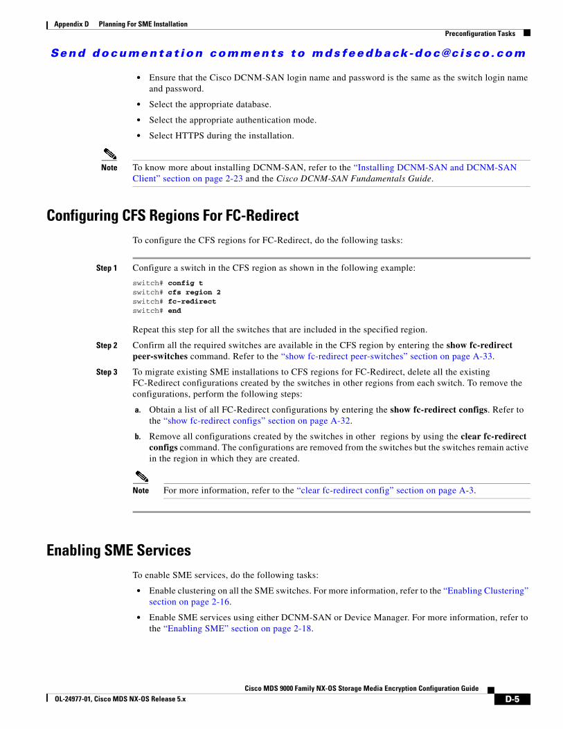
Send documenta t ion comments to mdsfeedback -doc@c i sco .com
Appendix D Planning For SME InstallationPreconfiguration Tasks
• Ensure that the Cisco DCNM-SAN login name and password is the same as the switch login name and password.
• Select the appropriate database.
• Select the appropriate authentication mode.
• Select HTTPS during the installation.
Note To know more about installing DCNM-SAN, refer to the “Installing DCNM-SAN and DCNM-SAN Client” section on page 2-23 and the Cisco DCNM-SAN Fundamentals Guide.
Configuring CFS Regions For FC-RedirectTo configure the CFS regions for FC-Redirect, do the following tasks:
Step 1 Configure a switch in the CFS region as shown in the following example:
switch# config tswitch# cfs region 2switch# fc-redirectswitch# end
Repeat this step for all the switches that are included in the specified region.
Step 2 Confirm all the required switches are available in the CFS region by entering the show fc-redirect peer-switches command. Refer to the “show fc-redirect peer-switches” section on page A-33.
Step 3 To migrate existing SME installations to CFS regions for FC-Redirect, delete all the existing FC-Redirect configurations created by the switches in other regions from each switch. To remove the configurations, perform the following steps:
a. Obtain a list of all FC-Redirect configurations by entering the show fc-redirect configs. Refer to the “show fc-redirect configs” section on page A-32.
b. Remove all configurations created by the switches in other regions by using the clear fc-redirect configs command. The configurations are removed from the switches but the switches remain active in the region in which they are created.
Note For more information, refer to the “clear fc-redirect config” section on page A-3.
Enabling SME ServicesTo enable SME services, do the following tasks:
• Enable clustering on all the SME switches. For more information, refer to the “Enabling Clustering” section on page 2-16.
• Enable SME services using either DCNM-SAN or Device Manager. For more information, refer to the “Enabling SME” section on page 2-18.
D-5Cisco MDS 9000 Family NX-OS Storage Media Encryption Configuration Guide
OL-24977-01, Cisco MDS NX-OS Release 5.x
Send documenta t ion comments to mdsfeedback -doc@c i sco .com
Appendix D Planning For SME InstallationPreconfiguration Tasks
• Set the FC-Redirect version to 2 (if you are using SAN-OS Release 3.1(1a) or later or NX-OS Release 4.x). To learn more about enabling the version2 mode, refer to the “fc-redirect version2 enable” section on page A-12.
Note To learn about enabling these services, refer to Chapter 2, “Configuring SME.”
Assigning SME Roles and UsersThe SME feature provides two primary roles: SME Administrator (sme-admin) and the SME Recovery Officer (sme-recovery). The SME Administrator role also includes the SME Storage Administrator (sme-stg-admin) and SME KMC Administrator (sme-kmc-admin) roles.
To set up the roles and users, note the following guidelines:
• Create the appropriate SME roles, that is, sme-admin and/or sme-stg-admin and sme-kmc-admin, and sme-recovery in the Advanced Master Key Security mode.
• Choose separate users for the sme-kmc-admin role and the sme-stg-admin role to split the responsiblities of key management and SME provisioning. To combine these responsibilities into one role, choose the stg-admin role.
• Use DCNM-SAN to create users for sme-admin, sme-stg-admin, and sme-kmc-admin roles as appropriate.
• In the Advanced mode for the master key, create three or five users under the sme-recovery role.
• Create users on the switches for all of these roles.
To learn more about the roles and their responsibilities refer to the “Creating and Assigning SME Roles and SME Users” section on page 2-19. For detailed information on creating and assigning roles, refer to the Security Configuration Guide, Cisco DCNM for SAN and the Cisco MDS 9000 Family NX-OS Security Configuration Guide.
Creating SME FabricsWhen creating SME fabrics, note the following guidelines:
• Add the SME fabrics using the DCNM-SAN Web Client. Modify the names to exclude switch names from the fabric name.
• The fabric name must remain constant. You cannot change the fabric name after you have configured SME.
Installing SSL CertificatesTo create SSL certificates, do the following tasks:
• Follow the procedure specified in Chapter 8, “Provisioning Certificates,” to install SSL certificates on the switches and the KMC.
• Use the same password at every step of the installation procedure to simplify the process.
• Restart the DCNM-SAN and KMC after installing the SSL certificates.
D-6Cisco MDS 9000 Family NX-OS Storage Media Encryption Configuration Guide
OL-24977-01, Cisco MDS NX-OS Release 5.x
Send documenta t ion comments to mdsfeedback -doc@c i sco .com
Appendix D Planning For SME InstallationProvisioning SME
Provisioning SMEWhen provisioning and configuring SME, do the following tasks:
• Create a SME interface for each of the MSM-18/4 modules that will be used for storage media encryption. For more information, refer to Chapter 3, “Configuring SME Interfaces.”
• Follow the steps outlined in Chapter 4, “Configuring SME Cluster Management,” including cluster creation and tape backup group configuration procedures.
• Save the running configuration to startup configuration.
For more informaiton, see the solution guide to SME which contains additional details and requirements for installing SME Disk in specific configurations.
D-7Cisco MDS 9000 Family NX-OS Storage Media Encryption Configuration Guide
OL-24977-01, Cisco MDS NX-OS Release 5.x

Send documenta t ion comments to mdsfeedback -doc@c i sco .com
Appendix D Planning For SME InstallationProvisioning SME
D-8Cisco MDS 9000 Family NX-OS Storage Media Encryption Configuration Guide
OL-24977-01, Cisco MDS NX-OS Release 5.x

Send documenta t ion comments to mdsfeedback -doc@c i sco .com
Cisco MDS 9000 Family NX-OS StoOL-24977-01, Cisco MDS NX-OS Release 5.x
A
P P E N D I X E Migrating SME Database TablesNote Data migration is currently supported only for SME Tapes. It is not yet supported for SME Disks.
This appendix describes a database migration utility and also outlines the steps you need to follow to migrate SME tables from one database to another database.
The database migration utility transfers contents of database tables in Oracle Express installation or in PostgreSQL to an Oracle Enterprise installation.
This utility is packaged in the Cisco DCNM for SAN CD starting from NX-OS Software Release 4.1(3) and is available at /software/SMEdbmigrate.zip.
Note The DCNM-SAN application should be installed before the migration process by using the destination database so that DCNM-SAN tables gets created in the destination database.
To migrate database files from the source database to the destination database, follow these steps:
Step 1 Extract the contents of the SMEdbmigrate.zip file to your directory folder. The contents of the file will be as follows:
• SMEdbmigrate.jar
• ojdbc14.jar
• postgresql-8.1.jar
• smedbmigrate.bat
• smedbmigrate.sh
• smedbmigration.properties
Step 2 Right-click the smedbmigration.properties file to open in a text editor. Modify the existing database URL, type, and user name and the destination database URL, type, and user name.
Step 3 To migrate the data files, run the following shell script or batch file:
• sh smedbmigrate.sh (for Unix)
• smedbmigrate.bat (for Windows)
The shell script or the batch file can be executed from any server that has to access to both the source database and the destination database.
Step 4 Enter passwords for the source and destination database when prompted.
E-1rage Media Encryption Configuration Guide

Send documenta t ion comments to mdsfeedback -doc@c i sco .com
Appendix E Migrating SME Database Tables
The sample output would be as follows:
[root@test-vm-236 SMEdbmigrate]# ./smedbmigrate.sh [INFO] File /root/download/SMEdbmigrate/smedbmigration.properties foundPlease enter the passsword for user admin on source database jdbc:postgresql://172.28.233.186:5432/dcmdb ********** Please enter the passsword for user admin on destination database jdbc:postgresql://172.28.255.110:5432/dcmdb ***********[INFO] Migrating database from jdbc:postgresql://172.28.233.186:5432/dcmdb to jdbc:postgresql://172.28.255.110:5432/dcmdb[INFO] Migration Start for SME_SETTINGS………[INFO] Migration complete[root@test-vm-236 SMEdbmigrate]#
Note Run a key retrieval operation to confirm that the migration has been successful.
E-2Cisco MDS 9000 Family NX-OS Storage Media Encryption Configuration Guide
OL-24977-01, Cisco MDS NX-OS Release 5.x
Send documenta t ion comments to mdsfeedback -doc@c i sco .com
Cisco MDS 9000 Family NXOL-24977-01, Cisco MDS NX-OS Release 5.x
I N D E X
A
Advanced security
about 7-4
configuring smart cards 4-16
stored keyshares 4-16
advanced security
about 4-12
Auto key replication
remote replication relationships
create 5-15
remove 5-15
translating media keys 7-6
B
Basic security
about 7-3
downloading key file 4-15
basic security
about 4-12
best practices
overview 10-1
C
CFS requirement 1-14
Changing the Fabric Name 2-23
Cisco Key Management Center
about 1-4, 7-3
advantages 7-3
features 1-4
Cisco KMC 6-10
Cisco MDS 9000 Family 18/4-Port Multiservice Module (MSM-18/4)
replacing 11-7
Cisco SME
best practices 10-1
configuration
initial 2-26
limitations 2-26
required engines 1-7
security overview 1-14
Terminology 1-6
CLI
DCNM-SAN alternative 2-2
description 2-2
cluster details
transport settings
modifying,viewing 4-22
viewing cluster members 4-22
viewing cluster states 4-22
clustering 1-5
clusters
archiving 4-17
creating 4-10
purging 4-17, 4-18
quorum 4-1
recovery scenarios 11-1
reviving 11-4
viewing details 4-22
viewing members 4-22
viewing states 4-22
viewing using DCNM-SAN 4-23
viewing using Device Manager 4-23
command-line interface. See CLI
IN-1-OS Storage Media Encryption Configuration Guide

Send documenta t ion comments to mdsfeedback -doc@c i sco .com
Index
contacting support 11-8
D
DCNM-SAN
description 2-1
installation 2-23
DCNM-SAN Client
installation 2-23
DCNM-SAN Server 2-2
Backing Up O-1
DCNM-SAN Server database
Restoring O-2
DCNM-SAN Web Client 2-1
Device Manager 2-2
Disaster Recovery
SME Disk M-2
SME Tape M-1
disk key 7-2
DNS
alternative 2-19
configuration 11-6
enabling 2-18
E
Enabling clustering
using DCNM-SAN 2-17
Encryption 1-3
exporting volume groups 5-13
F
fabrics
adding 2-23
changing a fabric name 2-23
selecting 4-11
FCIP tape acceleration
IN-2Cisco MDS 9000 Family NX-OS Storage Media Encryption Configur
requriements 2-4
FC Redirect 1-6
FC redirect
requirements 1-13
H
hardware
requirements 1-10
Cisco MDS 18/4-Port Multiservice Module (MSM-18/4) 1-11
Cisco MDS 9222i Multiservice Module Switch 1-11
Hardware Requirements 1-10
High Availability KMC
about 7-6
I
IEEE-compliant AES 256 encryption 1-3
importing volume groups 5-13
interfaces
selecting 4-11
IVR zoneset 1-14
J
Java Requirement 1-13
K
key hierarchy
about 7-1
disk key 7-2
master key 7-2
tape volume group key 7-2
tape volume key 7-2
Key Management 1-4
key management
ation GuideOL-24977-01, Cisco MDS NX-OS Release 5.x
Send documenta t ion comments to mdsfeedback -doc@c i sco .com
Index
operations 5-11
key management settings 7-4
Key-On-Tape 7-5
Shared 7-5
Unique Key 7-5
keys
active 7-15
purging 5-12
viewing for SME disk 7-15
viewing for SME tape 7-15
KMC server 7-9
L
licenses
for fixed slot - MDS 9222i Switch 2-3
for MSM-18/4 module-MDS 9200 Series with SSM 2-3
for MSM-18/4 module - MDS 9500 Series with SSM 2-3
load balancing
about 1-6
M
master key 7-2
Master Key Security
Advanced 4-12, 7-4
Basic 4-12, 7-3
modes 7-3
Standard 4-12, 7-4
master key security levels
selecting 4-11
master switch election 4-1
four-switch cluster scenarios 4-4
three-switch cluster scenarios 4-4
Media Key Settings
selecting 4-13
store key on tape 4-13
Cisco MDS 9000 FOL-19796-01, Cisco MDS NX-OS Release 4.x
unique key 4-13
members
viewing 4-22
migrating 7-9
migrating database tables
about Q-1
procedure Q-1
MSM-18/4 1-11
N
NIST 1-3
O
Offline Data Restore Tool
about N-1
P
purging
clusters 4-17
Q
Quorum Disk 6-12
R
recycling tapes 7-5
replication relationship 7-6
Requirements
FC-Redirect 1-13
Hardware 1-10
Installation 2-3
Java Cryptography Extension 1-13
Software 1-10
Zoning 1-13
IN-3amily NX-OS Storage Media Encryption Configuration Guide
Send documenta t ion comments to mdsfeedback -doc@c i sco .com
Index
Roles
about 1-3
S
security
additional capabilities 1-14
security levels
selecting Advanced 4-13
selecting Basic 4-12
selecting Standard 4-12
Server-based discovery for provisioning tapes 1-6
Server Clusters 4-5
smart cards
drivers 2-25
GemSafe library file 2-25
installing 2-25
SME 1-3
security 1-14
supported single-fabric topology 1-8, 1-9
SME configuration
Basic 2-26
SME Disk
adding disk to the disk group 6-19
adding paths to the disk 5-5, 6-20
adding SME encryption engine 6-18
adding SME nodes 6-18
architecture 6-2
cluster support 6-5
configuring disk group 6-19
configuring using the CLI 6-16
configuring using the GUI 6-29
data preparation 6-6
data replication 6-12
Disk Key Replication, features 6-14
Disk Key Replication, relationships 6-14
disk states 6-10
ISSU 6-15
key generation 6-10
IN-4Cisco MDS 9000 Family NX-OS Storage Media Encryption Configur
key management 6-9
key replication 6-12
managing disks 6-21
monitoring SME Disk management 6-58
offline data preparation 6-7
online data preparation 6-8
purging disk groups 6-11
purging disks 6-11
recovering SME disk 6-26
rekeying 6-8
verifying SME Disk management configuration 6-56
Standard security
about 7-4
configuring smart cards 4-15, 5-17, 6-54, 6-55
stored keyshares 4-15
standard security
about 4-12
supported topologies
single-fabric 1-8, 1-9
T
tape drives
troubleshooting 11-8
tapes
recycling 7-5
tape volume group key 7-2
tape volume key 7-2
translation context 7-6
transparent fabric service 1-3
troubleshooting 11-1
"no paths found" 11-7
cluster recovery scenarios 11-1
deleting a cluster 11-2, 11-3
deleting an offline switch 11-2
DNS 11-6
newly added tape drives 11-8
replacing an MSM-18/4 module 11-7
reviving a cluster 11-4
ation GuideOL-24977-01, Cisco MDS NX-OS Release 5.x
Send documenta t ion comments to mdsfeedback -doc@c i sco .com
Index
scenarios 11-6
V
volume groups
exporting 5-13
importing 5-13
Cisco MDS 9000 FOL-19796-01, Cisco MDS NX-OS Release 4.x
IN-5amily NX-OS Storage Media Encryption Configuration Guide

Send documenta t ion comments to mdsfeedback -doc@c i sco .com
Index
IN-6Cisco MDS 9000 Family NX-OS Storage Media Encryption Configur
ation GuideOL-24977-01, Cisco MDS NX-OS Release 5.x