Embed Size (px)
Citation preview
Cisco ME 3400E Ethernet Access Switch Hardware Installation Guide February 2009
Americas HeadquartersCisco Systems, Inc.170 West Tasman DriveSan Jose, CA 95134-1706 USAhttp://www.cisco.comTel: 408 526-4000
800 553-NETS (6387)Fax: 408 527-0883
Text Part Number: OL-16447-01
THE SPECIFICATIONS AND INFORMATION REGARDING THE PRODUCTS IN THIS MANUAL ARE SUBJECT TO CHANGE WITHOUT NOTICE. ALL STATEMENTS, INFORMATION, AND RECOMMENDATIONS IN THIS MANUAL ARE BELIEVED TO BE ACCURATE BUT ARE PRESENTED WITHOUT WARRANTY OF ANY KIND, EXPRESS OR IMPLIED. USERS MUST TAKE FULL RESPONSIBILITY FOR THEIR APPLICATION OF ANY PRODUCTS.
THE SOFTWARE LICENSE AND LIMITED WARRANTY FOR THE ACCOMPANYING PRODUCT ARE SET FORTH IN THE INFORMATION PACKET THAT SHIPPED WITH THE PRODUCT AND ARE INCORPORATED HEREIN BY THIS REFERENCE. IF YOU ARE UNABLE TO LOCATE THE SOFTWARE LICENSE OR LIMITED WARRANTY, CONTACT YOUR CISCO REPRESENTATIVE FOR A COPY.
The following information is for FCC compliance of Class A devices: This equipment has been tested and found to comply with the limits for a Class A digital device, pursuant to part 15 of the FCC rules. These limits are designed to provide reasonable protection against harmful interference when the equipment is operated in a commercial environment. This equipment generates, uses, and can radiate radio-frequency energy and, if not installed and used in accordance with the instruction manual, may cause harmful interference to radio communications. Operation of this equipment in a residential area is likely to cause harmful interference, in which case users will be required to correct the interference at their own expense.
The following information is for FCC compliance of Class B devices: This equipment has been tested and found to comply with the limits for a Class B digital device, pursuant to part 15 of the FCC rules. These limits are designed to provide reasonable protection against harmful interference in a residential installation. This equipment generates, uses and can radiate radio frequency energy and, if not installed and used in accordance with the instructions, may cause harmful interference to radio communications. However, there is no guarantee that interference will not occur in a particular installation. If the equipment causes interference to radio or television reception, which can be determined by turning the equipment off and on, users are encouraged to try to correct the interference by using one or more of the following measures:
• Reorient or relocate the receiving antenna.
• Increase the separation between the equipment and receiver.
• Connect the equipment into an outlet on a circuit different from that to which the receiver is connected.
• Consult the dealer or an experienced radio/TV technician for help.
Modifications to this product not authorized by Cisco could void the FCC approval and negate your authority to operate the product.
The Cisco implementation of TCP header compression is an adaptation of a program developed by the University of California, Berkeley (UCB) as part of UCB’s public domain version of the UNIX operating system. All rights reserved. Copyright © 1981, Regents of the University of California.
NOTWITHSTANDING ANY OTHER WARRANTY HEREIN, ALL DOCUMENT FILES AND SOFTWARE OF THESE SUPPLIERS ARE PROVIDED “AS IS” WITH ALL FAULTS. CISCO AND THE ABOVE-NAMED SUPPLIERS DISCLAIM ALL WARRANTIES, EXPRESSED OR IMPLIED, INCLUDING, WITHOUT LIMITATION, THOSE OF MERCHANTABILITY, FITNESS FOR A PARTICULAR PURPOSE AND NONINFRINGEMENT OR ARISING FROM A COURSE OF DEALING, USAGE, OR TRADE PRACTICE.
Cisco and the Cisco logo are trademarks or registered trademarks of Cisco and/or its affiliates in the U.S. and other countries. To view a list of Cisco trademarks, go to this URL: www.cisco.com/go/trademarks. Third-party trademarks mentioned are the property of their respective owners. The use of the word partner does not imply a partnership relationship between Cisco and any other company. (1110R)
Any Internet Protocol (IP) addresses used in this document are not intended to be actual addresses. Any examples, command display output, and figures included in the document are shown for illustrative purposes only. Any use of actual IP addresses in illustrative content is unintentional and coincidental.
Cisco ME 3400E Ethernet Access Switch Hardware Installation Guide © 2009-2012 Cisco Systems, Inc. All rights reserved.
OL-16447-01
C O N T E N T S
Preface vii
Audience i-vii
Purpose i-vii
Related Publications i-viii
Obtaining Documentation and Submitting a Service Request i-ix
C H A P T E R 1 Product Overview 1-1
Setting Up the Switch 1-1
Switch Models 1-1
Front Panel 1-2
AC- and DC-Power Input Connectors 1-4
Alarm Input Port 1-4
Management Port 1-5
10/100 Fast Ethernet Ports 1-5
Dual-Purpose Ports 1-5
SFP Modules 1-5
SFP Module Patch Cable 1-6
UNIs, NNIs, and ENIs 1-7
LEDs 1-7
Switch LED Panels 1-8
Power-Supply Module LEDs 1-9
Ethernet Management Port LED 1-10
Alarm LEDs 1-11
Port LEDs 1-11
Dual-Purpose Port LEDs 1-11
Rear Panel 1-12
Power Supply Features 1-13
Management Options 1-14
Network Configurations 1-14
C H A P T E R 2 Switch Installation 2-1
Warnings 2-1
Installation Guidelines 2-4
iiiCisco ME 3400E Ethernet Access Switch Hardware Installation Guide
Contents
Verifying Switch Operation 2-5
Powering Off the Switch 2-5
Installing the Switch 2-5
Rack-Mounting 2-6
Removing Screws from the Switch 2-6
Attaching Brackets to the Switch 2-7
Mounting in a Rack 2-13
Wall-Mounting 2-14
Attaching Brackets for Wall-Mounting 2-14
Mounting the Switch on a Wall 2-15
Table- or Shelf-Mounting 2-19
Installing and Removing SFP Modules 2-19
Installing SFP Modules 2-19
Removing SFP Modules 2-21
Inserting and Removing the SFP Module Patch Cable 2-21
Removing the SFP Module Patch Cable 2-22
Connecting to the 10/100 and 10/100/1000 Ports 2-22
Connecting to Fiber-Optic SFP Modules 2-24
Connecting to 1000BASE-T SFP Modules 2-25
Connecting to Dual-Purpose Ports 2-26
Where to Go Next 2-26
C H A P T E R 3 Installing and Removing AC- and DC-Power-Supply Modules 3-1
Product Overview 3-1
Power-Supply Module Description 3-1
Handle-Side Description 3-2
Connector-Side Description 3-4
Power-Supply Module Installation 3-4
Tools and Equipment 3-5
Installation Guidelines 3-5
Installing an AC-Power-Supply Module 3-6
Removing AC-Power-Supply Modules 3-7
Installing a DC-Power-Supply Module 3-8
Preparing for Installation 3-9
Grounding the Switch 3-9
Installing the DC-Power-Supply Module in the Switch 3-11
Wiring the DC-Input Power Source 3-12
Removing the DC-Power-Supply Module 3-16
ivCisco ME 3400E Ethernet Access Switch Hardware Installation Guide
OL-16447-01
Contents
Power Supply Settings 3-17
C H A P T E R 4 Troubleshooting 4-1
Diagnosing Problems 4-1
Switch POST Results 4-1
Switch LEDs 4-2
Switch Connections 4-2
Bad or Damaged Cable 4-2
Ethernet and Fiber Cables 4-2
Link Status 4-2
SFP Module Port Issues 4-3
Port and Interface Settings 4-3
Ping the End Device 4-3
Spanning Tree Loops 4-3
Switch Performance 4-4
Speed, Duplex, and Autonegotiation 4-4
Autonegotiation and NICs 4-4
Cabling Distance 4-4
Clearing the Switch IP Address and Configuration 4-4
Finding the Switch Serial Number 4-5
A P P E N D I X A Technical Specifications A-1
Environmental Ranges and Technical Specifications for the Switch A-1
Environmental and Technical Specifications for the Power-Supply Modules A-6
A P P E N D I X B Connector and Cable Specifications B-1
Connector Specifications B-1
10/100 B-1
SFP Module Connectors B-2
Dual-Purpose Ports B-3
10/100 Ethernet Management Port B-3
Alarm Input Port B-3
Cables and Adapters B-4
SFP Module Cables B-4
Cable Pinouts B-6
Console Port Adapter Pinouts B-7
vCisco ME 3400E Ethernet Access Switch Hardware Installation Guide
OL-16447-01
Contents
A P P E N D I X C Configuring the Switch with the CLI-Based Setup Program C-1
Accessing the CLI Through the Console Port C-1
Starting the Terminal-Emulation Software C-1
Entering the Initial Configuration Information C-2
IP Settings C-2
Completing the Setup Program C-2
I N D E X
viCisco ME 3400E Ethernet Access Switch Hardware Installation Guide
OL-16447-01
Preface
Audience This guide is for the networking or computer technician installing the Cisco Metro Ethernet (ME) 3400E Series Ethernet Access switch, also known as the switch. We assume that you are familiar with the concepts and terminology of Ethernet and local area networking.
PurposeThis guide describes the hardware features of the switch. It describes the physical and performance characteristics of the switch, explains how to install it, and provides troubleshooting information.
This guide does not describe system messages that you might receive or how to configure your switch. For more information, see the switch software configuration guide, the switch command reference, and the switch system message guide on Cisco.com at:
http://www.cisco.com/en/US/products/ps9637/tsd_products_support_series_home.html
Note Means reader take note. Notes contain helpful suggestions or references to materials not contained in this manual.
Caution Means reader be careful. In this situation, you might do something that could result in equipment damage or loss of data.
viiCisco ME 3400E Ethernet Access Switch Hardware Installation Guide
OL-16447-01
PrefaceRelated Publications
The safety warnings for this product are translated into several languages in the Regulatory Compliance and Safety Information for the Cisco ME 3400E Ethernet Access Switches that ships with the product on the documentation CD. The EMC regulatory statements are also included in that guide.
Related PublicationsThese documents provide information about the switch and are available from this Cisco.com site:
http://www.cisco.com/en/US/products/ps9637/tsd_products_support_series_home.html
• Release Notes for the Cisco ME 3400E Ethernet Access Switch
Note Before installing, configuring, or upgrading the switch, see the release notes on Cisco.com for the latest information.
• Cisco ME 3400E Ethernet Access Switch Software Configuration Guide
• Cisco ME 3400E Ethernet Access Switch Command Reference
• Cisco ME 3400E, ME 3400, and ME 2400 Ethernet Switches System Message Guide
• Cisco ME 3400E Ethernet Access Switch Hardware Installation Guide
• Cisco ME 3400E Ethernet Access Switch Getting Started Guide
• Cisco ME 3400E Ethernet Access Switch Power-Supply Module Quick Start Guide
• Regulatory Compliance and Safety Information for the Cisco ME 3400E Ethernet Access Switch
• Cisco Small Form-Factor Pluggable Modules Installation Notes
• Cisco CWDM GBIC and CWDM SFP Installation Notes
These compatibility matrix documents are available from this Cisco.com site:
http://www.cisco.com/en/US/products/hw/modules/ps5455/products_device_support_tables_list.html
• Cisco Gigabit Ethernet Transceiver Modules Compatibility Matrix
• Cisco 100-Megabit Ethernet SFP Modules Compatibility Matrix
• Cisco CWDM SFP Transceiver Compatibility Matrix
Warning IMPORTANT SAFETY INSTRUCTIONS
This warning symbol means danger. You are in a situation that could cause bodily injury. Before you work on any equipment, be aware of the hazards involved with electrical circuitry and be familiar with standard practices for preventing accidents. Use the statement number provided at the end of each warning to locate its translation in the translated safety warnings that accompanied this device. Statement 1071
SAVE THESE INSTRUCTIONS
viiiCisco ME 3400E Ethernet Access Switch Hardware Installation Guide
OL-16447-01
PrefaceObtaining Documentation and Submitting a Service Request
• Cisco Small Form-Factor Pluggable Modules Compatibility Matrix
• Compatibility Matrix for 1000BASE-T Small Form-Factor Pluggable Modules
Obtaining Documentation and Submitting a Service RequestFor information on obtaining documentation, submitting a service request, and gathering additional information, see the monthly What’s New in Cisco Product Documentation, which also lists all new and revised Cisco technical documentation, at:
http://www.cisco.com/en/US/docs/general/whatsnew/whatsnew.html
Subscribe to the What’s New in Cisco Product Documentation as a Really Simple Syndication (RSS) feed and set content to be delivered directly to your desktop using a reader application. The RSS feeds are a free service and Cisco currently supports RSS version 2.0.
ixCisco ME 3400E Ethernet Access Switch Hardware Installation Guide
OL-16447-01
PrefaceObtaining Documentation and Submitting a Service Request
xCisco ME 3400E Ethernet Access Switch Hardware Installation Guide
OL-16447-01
Cisco ME 3400E EtOL-16447-01
C H A P T E R 1
Product OverviewThe Cisco Metro Ethernet (ME) 3400E Ethernet Access switch—referred to as the switch—is an Ethernet access switch that you can connect to other network devices, such as routers, other switches, a home access gateway (HAG), or a computer.
• Setting Up the Switch, page 1-1
• Switch Models, page 1-1
• Front Panel, page 1-2
• Rear Panel, page 1-12
• Power Supply Features, page 1-13
• Fans, page 1-14
• Management Options, page 1-14
Setting Up the SwitchSee the Cisco ME 3400E Ethernet Access Switch Getting Started Guide on the documentation CD for instructions on how to initially configure your switch. The getting started guide also covers switch management options, basic rack-mounting procedures, port and module connections, power connection procedures, and troubleshooting help.
For instructions on setting up your switch using the command-line interface (CLI), see Appendix C, “Configuring the Switch with the CLI-Based Setup Program.”
Switch ModelsYou can deploy the switch as a backbone switch, aggregating 10BASE-T, 100BASE-TX, 1000BASE-T, and fiber-optic Ethernet traffic from other network devices.
See the switch software configuration guide for examples that show how you might deploy the switch in your network.
1-1hernet Access Switch Hardware Installation Guide
Chapter 1 Product OverviewFront Panel
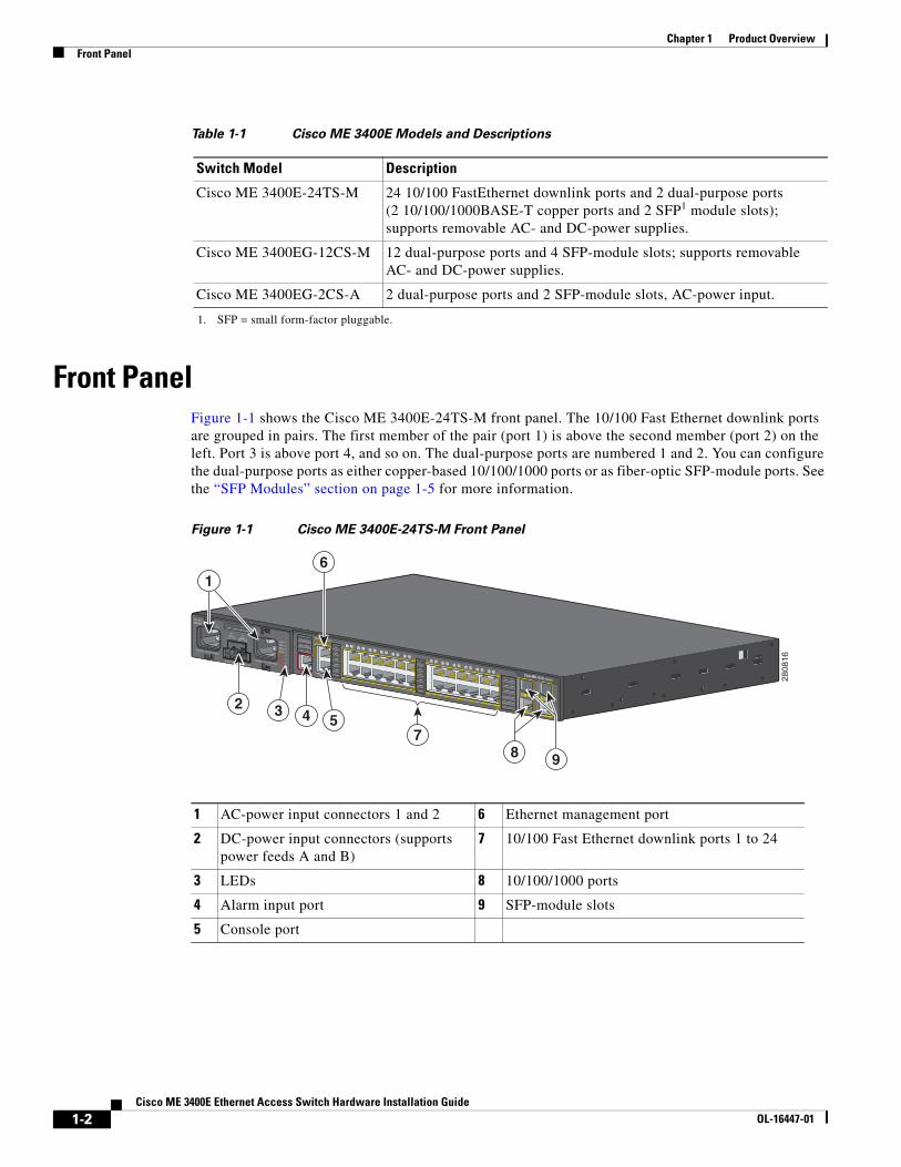
Front Panel Figure 1-1 shows the Cisco ME 3400E-24TS-M front panel. The 10/100 Fast Ethernet downlink ports are grouped in pairs. The first member of the pair (port 1) is above the second member (port 2) on the left. Port 3 is above port 4, and so on. The dual-purpose ports are numbered 1 and 2. You can configure the dual-purpose ports as either copper-based 10/100/1000 ports or as fiber-optic SFP-module ports. See the “SFP Modules” section on page 1-5 for more information.
Figure 1-1 Cisco ME 3400E-24TS-M Front Panel
Table 1-1 Cisco ME 3400E Models and Descriptions
Switch Model Description
Cisco ME 3400E-24TS-M 24 10/100 FastEthernet downlink ports and 2 dual-purpose ports (2 10/100/1000BASE-T copper ports and 2 SFP1 module slots); supports removable AC- and DC-power supplies.
1. SFP = small form-factor pluggable.
Cisco ME 3400EG-12CS-M 12 dual-purpose ports and 4 SFP-module slots; supports removable AC- and DC-power supplies.
Cisco ME 3400EG-2CS-A 2 dual-purpose ports and 2 SFP-module slots, AC-power input.
1 AC-power input connectors 1 and 2 6 Ethernet management port
2 DC-power input connectors (supports power feeds A and B)
7 10/100 Fast Ethernet downlink ports 1 to 24
3 LEDs 8 10/100/1000 ports
4 Alarm input port 9 SFP-module slots
5 Console port
2808
16
3 5 4
1
8 9
7
2
6
1-2Cisco ME 3400E Ethernet Access Switch Hardware Installation Guide
OL-16447-01
Chapter 1 Product OverviewFront Panel
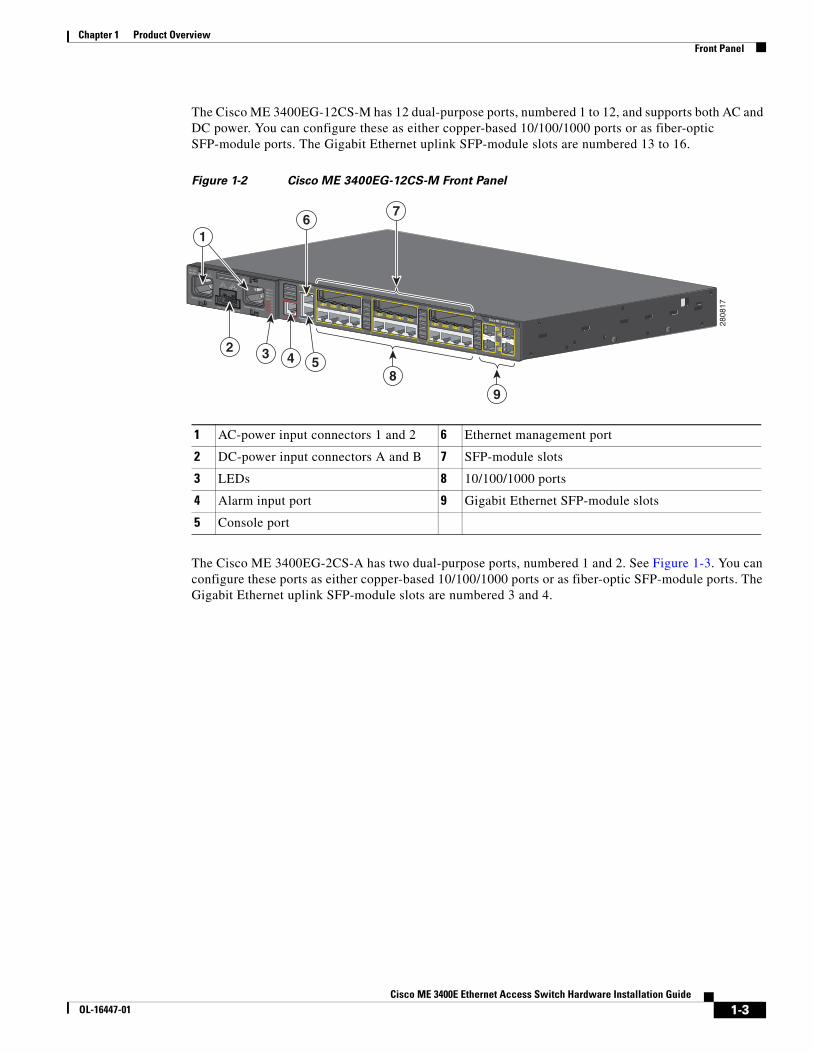
The Cisco ME 3400EG-12CS-M has 12 dual-purpose ports, numbered 1 to 12, and supports both AC and DC power. You can configure these as either copper-based 10/100/1000 ports or as fiber-optic SFP-module ports. The Gigabit Ethernet uplink SFP-module slots are numbered 13 to 16.
Figure 1-2 Cisco ME 3400EG-12CS-M Front Panel
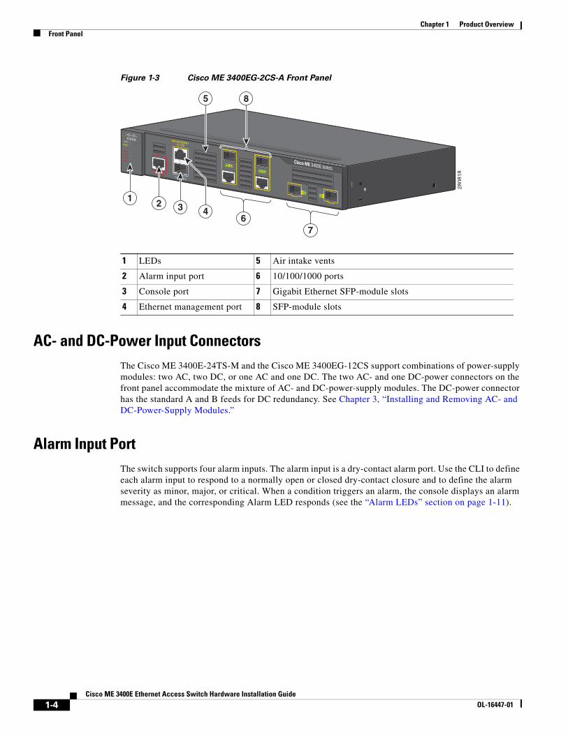
The Cisco ME 3400EG-2CS-A has two dual-purpose ports, numbered 1 and 2. See Figure 1-3. You can configure these ports as either copper-based 10/100/1000 ports or as fiber-optic SFP-module ports. The Gigabit Ethernet uplink SFP-module slots are numbered 3 and 4.
1 AC-power input connectors 1 and 2 6 Ethernet management port
2 DC-power input connectors A and B 7 SFP-module slots
3 LEDs 8 10/100/1000 ports
4 Alarm input port 9 Gigabit Ethernet SFP-module slots
5 Console port
2808
17
354
1
8
2
67
9
1-3Cisco ME 3400E Ethernet Access Switch Hardware Installation Guide
OL-16447-01
Chapter 1 Product OverviewFront Panel
Figure 1-3 Cisco ME 3400EG-2CS-A Front Panel
AC- and DC-Power Input ConnectorsThe Cisco ME 3400E-24TS-M and the Cisco ME 3400EG-12CS support combinations of power-supply modules: two AC, two DC, or one AC and one DC. The two AC- and one DC-power connectors on the front panel accommodate the mixture of AC- and DC-power-supply modules. The DC-power connector has the standard A and B feeds for DC redundancy. See Chapter 3, “Installing and Removing AC- and DC-Power-Supply Modules.”
Alarm Input PortThe switch supports four alarm inputs. The alarm input is a dry-contact alarm port. Use the CLI to define each alarm input to respond to a normally open or closed dry-contact closure and to define the alarm severity as minor, major, or critical. When a condition triggers an alarm, the console displays an alarm message, and the corresponding Alarm LED responds (see the “Alarm LEDs” section on page 1-11).
1 LEDs 5 Air intake vents
2 Alarm input port 6 10/100/1000 ports
3 Console port 7 Gigabit Ethernet SFP-module slots
4 Ethernet management port 8 SFP-module slots
2808
18
2
6
1 3 4
7
5 8
1-4Cisco ME 3400E Ethernet Access Switch Hardware Installation Guide
OL-16447-01
Chapter 1 Product OverviewFront Panel
Management PortYou can connect the switch to a host such as a Windows workstation or a terminal server through the 10/100 Ethernet management port or the console port. The 10/100 Ethernet management port connection uses a standard RJ-45 crossover or straight-through Ethernet cable. The console port connection uses the supplied RJ-45-to-DB-9 female cable.
The Ethernet management port operates in any combination of half duplex, full duplex, or 10 or 100 Mb/s, and its traffic is isolated from the other ports. See Table 1-7 for descriptions of the Ethernet management port LEDs. See the “10/100 Ethernet Management Port” section on page B-3 for pinout information.
For console port and adapter pinout information, see the “Console Port Adapter Pinouts” section on page B-7.
10/100 Fast Ethernet Ports You can set the 10/100 ports on the switch to operate in any combination of half duplex, full duplex, or 10 or 100 Mb/s. You can set the ports for speed and duplex autonegotiation. The default setting is autonegotiate.
When set for autonegotiation, the port senses the speed and duplex settings of the attached device and advertises its own capabilities. If the connected device also supports autonegotiation, the switch port negotiates the best connection (the fastest line speed that both devices support and full-duplex transmission if the attached device supports it) and configures itself accordingly. In all cases, the attached device must be within 328 feet (100 meters).
Dual-Purpose PortsYou can configure the dual-purpose ports on the switch as either 10/100/1000 ports or as SFP-module ports. You can set the 10/100/1000 ports to autonegotiate. You can also configure them as fixed 10, 100, or 1000 Mb/s (Gigabit) Ethernet ports.
By default, the switch dynamically selects the medium for each dual-purpose port (10/100/1000BASE-T or SFP). When a link is achieved on one media type, the switch disables the other media type until the active link goes down. If links are active on both media, the SFP-module port has priority, but you can manually designate the port as an RJ-45 port or an SFP port by using the media-type interface configuration command.
You can configure the speed and duplex settings consistent with the selected media type. For information on configuring interfaces, see the switch software configuration guide.
SFP ModulesThe switch Gigabit Ethernet SFP modules are used for connections to other devices. These transceiver modules are field-replaceable, providing the uplink interfaces when inserted in an SFP-module slot. You can use any combination of SFP modules. The SFP modules have LC connectors for fiber-optic connections or RJ-45 connectors for copper connections.
1-5Cisco ME 3400E Ethernet Access Switch Hardware Installation Guide
OL-16447-01
Chapter 1 Product OverviewFront Panel
For more information on configuring interfaces, see the switch software configuration guide.
Note The Cisco ME 3400E-24TS-M does not support 1000BASE-T SFP modules.
For more information about SFP modules, see your SFP module documentation and the “Installing and Removing SFP Modules” section on page 2-19. For cable specifications, see Appendix B, “SFP Module Connectors.”
SFP Module Patch Cable
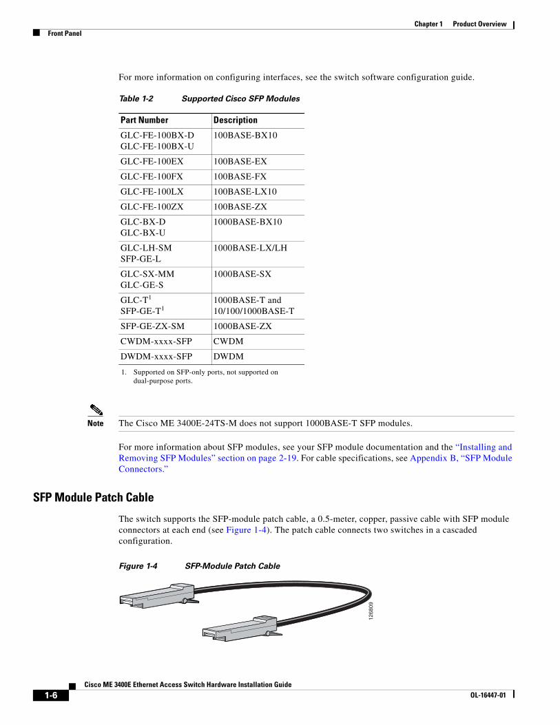
The switch supports the SFP-module patch cable, a 0.5-meter, copper, passive cable with SFP module connectors at each end (see Figure 1-4). The patch cable connects two switches in a cascaded configuration.
Figure 1-4 SFP-Module Patch Cable
Table 1-2 Supported Cisco SFP Modules
Part Number Description
GLC-FE-100BX-D GLC-FE-100BX-U
100BASE-BX10
GLC-FE-100EX 100BASE-EX
GLC-FE-100FX 100BASE-FX
GLC-FE-100LX 100BASE-LX10
GLC-FE-100ZX 100BASE-ZX
GLC-BX-D GLC-BX-U
1000BASE-BX10
GLC-LH-SM SFP-GE-L
1000BASE-LX/LH
GLC-SX-MM GLC-GE-S
1000BASE-SX
GLC-T1 SFP-GE-T1
1. Supported on SFP-only ports, not supported on dual-purpose ports.
1000BASE-T and 10/100/1000BASE-T
SFP-GE-ZX-SM 1000BASE-ZX
CWDM-xxxx-SFP CWDM
DWDM-xxxx-SFP DWDM
1268
09
1-6Cisco ME 3400E Ethernet Access Switch Hardware Installation Guide
OL-16447-01
Chapter 1 Product OverviewFront Panel
See the “Inserting and Removing the SFP Module Patch Cable” section on page 2-21 for more information about using the SFP module patch cable.
You can order the SFP module patch cable (part number CAB-SFP-50CM=).
UNIs, NNIs, and ENIsThe switch supports user-network interfaces (UNIs), network node interfaces (NNIs), and enhanced network interfaces (ENIs). UNIs are typically connected to a host, such as customer premises equipment (CPE) or a home access gateway. NNIs are typically connected to a router or to another switch. ENIs have the same functionality as UNIs, but can be configured to support protocol control packets for Cisco Discovery Protocol (CDP), Spanning-Tree Protocol (STP), Link Layer Discovery Protocol (LLDP), EtherChannel Link Aggregation Control Protocol (LACP), or Port Aggregation Protocol (PAgP). Every port is in an UNI, ENI, or NNI mode at any time, but not all ports have to all be set the same.
By default, the dual-purpose ports on the Cisco ME 3400E-12CS-M and on the Cisco ME 3400EG-2CS-A are configured as UNIs, and the SFP-only uplink ports are configured as NNIs. You must specifically configure ports to be ENIs; no ports are ENIs by default. By default, the 10/100 ports on the Cisco ME 3400E-24TS-M are UNIs, and the dual-purpose ports are NNIs.
A port can be reconfigured from UNI to NNI or an ENI, and the reverse. When a port is reconfigured as another interface type, it inherits all the characteristics of that interface type. For information on configuring interfaces, see the switch software configuration guide.
LEDsYou can use the switch system and port LEDs to monitor switch activity and performance.
• Switch LED Panels, page 1-8
• Power-Supply Module LEDs, page 1-9
• Ethernet Management Port LED, page 1-10
• Alarm LEDs, page 1-11
• Port LEDs, page 1-11
• Dual-Purpose Port LEDs, page 1-11
1-7Cisco ME 3400E Ethernet Access Switch Hardware Installation Guide
OL-16447-01
Chapter 1 Product OverviewFront Panel
Switch LED Panels
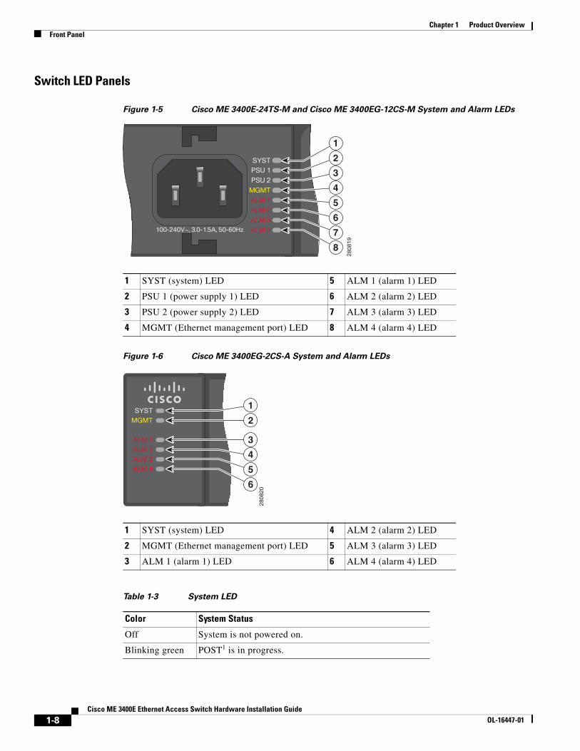
Figure 1-5 Cisco ME 3400E-24TS-M and Cisco ME 3400EG-12CS-M System and Alarm LEDs
Figure 1-6 Cisco ME 3400EG-2CS-A System and Alarm LEDs
1 SYST (system) LED 5 ALM 1 (alarm 1) LED
2 PSU 1 (power supply 1) LED 6 ALM 2 (alarm 2) LED
3 PSU 2 (power supply 2) LED 7 ALM 3 (alarm 3) LED
4 MGMT (Ethernet management port) LED 8 ALM 4 (alarm 4) LED
2808
19
1
2
3
4
5
6
7
8
1 SYST (system) LED 4 ALM 2 (alarm 2) LED
2 MGMT (Ethernet management port) LED 5 ALM 3 (alarm 3) LED
3 ALM 1 (alarm 1) LED 6 ALM 4 (alarm 4) LED
Table 1-3 System LED
Color System Status
Off System is not powered on.
Blinking green POST1 is in progress.
2808
20
1
2
3
4
5
6
1-8Cisco ME 3400E Ethernet Access Switch Hardware Installation Guide
OL-16447-01
Chapter 1 Product OverviewFront Panel
Power-Supply Module LEDs
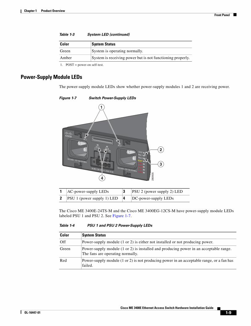
The power-supply module LEDs show whether power-supply modules 1 and 2 are receiving power.
Figure 1-7 Switch Power-Supply LEDs
The Cisco ME 3400E-24TS-M and the Cisco ME 3400EG-12CS-M have power-supply module LEDs labeled PSU 1 and PSU 2. See Figure 1-7.
Green System is operating normally.
Amber System is receiving power but is not functioning properly.
1. POST = power-on self-test.
Table 1-3 System LED (continued)
Color System Status
1 AC-power-supply LEDs 3 PSU 2 (power supply 2) LED
2 PSU 1 (power supply 1) LED 4 DC-power-supply LEDs
2809
35
4
1
3
2
Table 1-4 PSU 1 and PSU 2 Power-Supply LEDs
Color System Status
Off Power-supply module (1 or 2) is either not installed or not producing power.
Green Power-supply module (1 or 2) is installed and producing power in an acceptable range. The fans are operating normally.
Red Power-supply module (1 or 2) is not producing power in an acceptable range, or a fan has failed.
1-9Cisco ME 3400E Ethernet Access Switch Hardware Installation Guide
OL-16447-01
Chapter 1 Product OverviewFront Panel
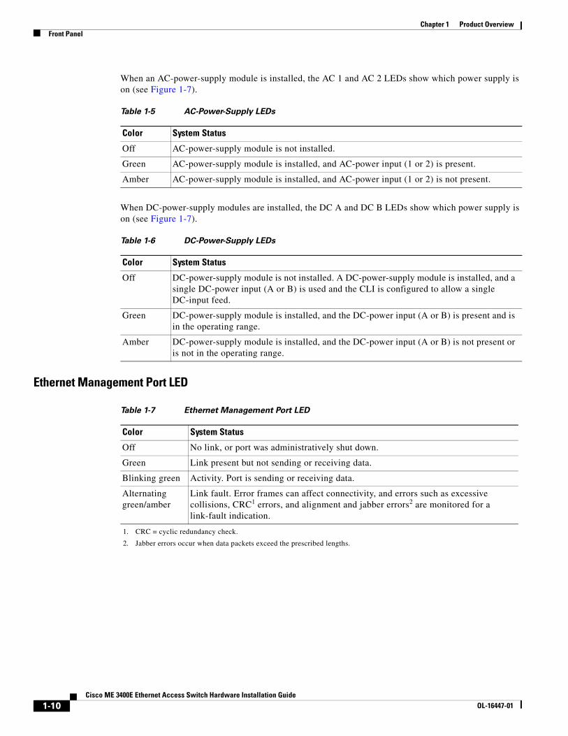
When an AC-power-supply module is installed, the AC 1 and AC 2 LEDs show which power supply is on (see Figure 1-7).
When DC-power-supply modules are installed, the DC A and DC B LEDs show which power supply is on (see Figure 1-7).
Ethernet Management Port LED
Table 1-5 AC-Power-Supply LEDs
Color System Status
Off AC-power-supply module is not installed.
Green AC-power-supply module is installed, and AC-power input (1 or 2) is present.
Amber AC-power-supply module is installed, and AC-power input (1 or 2) is not present.
Table 1-6 DC-Power-Supply LEDs
Color System Status
Off DC-power-supply module is not installed. A DC-power-supply module is installed, and a single DC-power input (A or B) is used and the CLI is configured to allow a single DC-input feed.
Green DC-power-supply module is installed, and the DC-power input (A or B) is present and is in the operating range.
Amber DC-power-supply module is installed, and the DC-power input (A or B) is not present or is not in the operating range.
Table 1-7 Ethernet Management Port LED
Color System Status
Off No link, or port was administratively shut down.
Green Link present but not sending or receiving data.
Blinking green Activity. Port is sending or receiving data.
Alternating green/amber
Link fault. Error frames can affect connectivity, and errors such as excessive collisions, CRC1 errors, and alignment and jabber errors2 are monitored for a link-fault indication.
1. CRC = cyclic redundancy check.
2. Jabber errors occur when data packets exceed the prescribed lengths.
1-10Cisco ME 3400E Ethernet Access Switch Hardware Installation Guide
OL-16447-01

Chapter 1 Product OverviewFront Panel
Alarm LEDs
Port LEDs
Each RJ-45 port and SFP-module slot has a port LED. These port LEDs, as a group or individually, display information about the switch and about the individual ports.
Dual-Purpose Port LEDs
The dual-purpose port LEDs on the switch show the connection of either a copper-based connector or an SFP module. See Figure 1-8. The ports can autonegotiate, or you can manually configure each dual-purpose port as either an 10/100/1000 with copper connectors or as an SFP-module port, but not both types at the same time.
Table 1-8 Alarm LEDs
Color System Status
Off No alarm
Amber Minor alarm
Red Major alarm
Blinking red Critical alarm
Table 1-9 Meaning of Port LED Colors
LED Color Meaning
Off No link, or port was administratively shut down.
Green Link present but not sending or receiving data.
Blinking green Activity. Port is sending or receiving data.
Alternating green-amber
Link fault. Error frames can affect connectivity, and errors such as excessive collisions, CRC errors, and alignment and jabber errors are monitored for a link-fault indication.
Amber Port is blocked by Spanning Tree Protocol (STP) and is not forwarding data. After a port is reconfigured, the port LED can remain amber for up to 30 seconds as STP checks the switch for possible loops.
1-11Cisco ME 3400E Ethernet Access Switch Hardware Installation Guide
OL-16447-01
Chapter 1 Product OverviewRear Panel
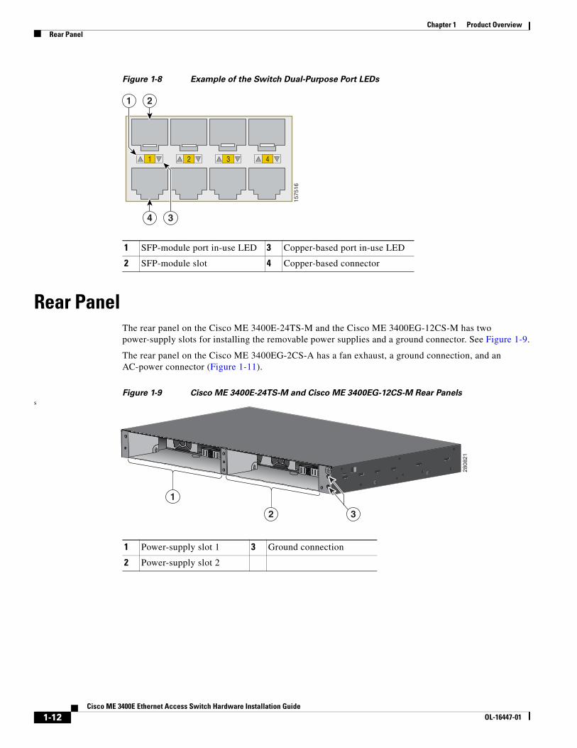
Figure 1-8 Example of the Switch Dual-Purpose Port LEDs
Rear PanelThe rear panel on the Cisco ME 3400E-24TS-M and the Cisco ME 3400EG-12CS-M has two power-supply slots for installing the removable power supplies and a ground connector. See Figure 1-9.
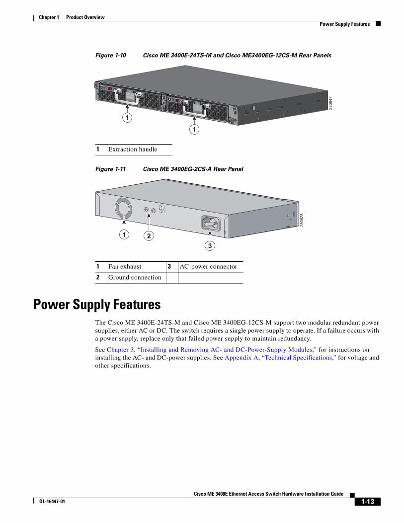
The rear panel on the Cisco ME 3400EG-2CS-A has a fan exhaust, a ground connection, and an AC-power connector (Figure 1-11).
Figure 1-9 Cisco ME 3400E-24TS-M and Cisco ME 3400EG-12CS-M Rear Panelss
1 SFP-module port in-use LED 3 Copper-based port in-use LED
2 SFP-module slot 4 Copper-based connector
1 2 3 4
4
2
1575
16
3
1
1 Power-supply slot 1 3 Ground connection
2 Power-supply slot 2
1
2
2808
21
3
1-12Cisco ME 3400E Ethernet Access Switch Hardware Installation Guide
OL-16447-01
Chapter 1 Product OverviewPower Supply Features
Figure 1-10 Cisco ME 3400E-24TS-M and Cisco ME3400EG-12CS-M Rear Panels
Figure 1-11 Cisco ME 3400EG-2CS-A Rear Panel
Power Supply FeaturesThe Cisco ME 3400E-24TS-M and Cisco ME 3400EG-12CS-M support two modular redundant power supplies, either AC or DC. The switch requires a single power supply to operate. If a failure occurs with a power supply, replace only that failed power supply to maintain redundancy.
See Chapter 3, “Installing and Removing AC- and DC-Power-Supply Modules,” for instructions on installing the AC- and DC-power supplies. See Appendix A, “Technical Specifications,” for voltage and other specifications.
1 Extraction handle
PSU OK+24V -48V
DC
PSU OK+24V -48V
DC
1
1
2809
47
1 Fan exhaust 3 AC-power connector
2 Ground connection
2808
25
1
3
2
1-13Cisco ME 3400E Ethernet Access Switch Hardware Installation Guide
OL-16447-01
Chapter 1 Product OverviewFans
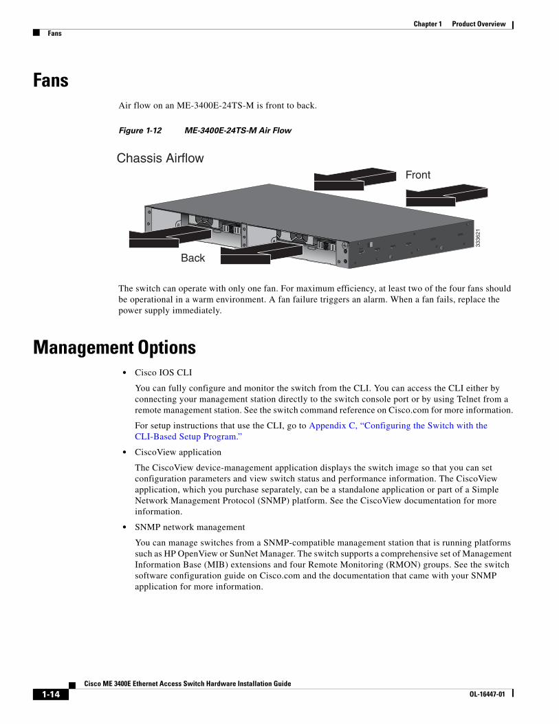
FansAir flow on an ME-3400E-24TS-M is front to back.
Figure 1-12 ME-3400E-24TS-M Air Flow
The switch can operate with only one fan. For maximum efficiency, at least two of the four fans should be operational in a warm environment. A fan failure triggers an alarm. When a fan fails, replace the power supply immediately.
Management Options • Cisco IOS CLI
You can fully configure and monitor the switch from the CLI. You can access the CLI either by connecting your management station directly to the switch console port or by using Telnet from a remote management station. See the switch command reference on Cisco.com for more information.
For setup instructions that use the CLI, go to Appendix C, “Configuring the Switch with the CLI-Based Setup Program.”
• CiscoView application
The CiscoView device-management application displays the switch image so that you can set configuration parameters and view switch status and performance information. The CiscoView application, which you purchase separately, can be a standalone application or part of a Simple Network Management Protocol (SNMP) platform. See the CiscoView documentation for more information.
• SNMP network management
You can manage switches from a SNMP-compatible management station that is running platforms such as HP OpenView or SunNet Manager. The switch supports a comprehensive set of Management Information Base (MIB) extensions and four Remote Monitoring (RMON) groups. See the switch software configuration guide on Cisco.com and the documentation that came with your SNMP application for more information.
3336
21
Front
Back
Chassis Airflow
1-14Cisco ME 3400E Ethernet Access Switch Hardware Installation Guide
OL-16447-01
Chapter 1 Product OverviewManagement Options
Network ConfigurationsSee the switch software configuration guide on Cisco.com for an explanation of network configuration concepts. The software configuration guide also provides examples of network configurations that use the switch to create dedicated network segments that are interconnected through Ethernet connections.
1-15Cisco ME 3400E Ethernet Access Switch Hardware Installation Guide
OL-16447-01
Chapter 1 Product OverviewManagement Options
1-16Cisco ME 3400E Ethernet Access Switch Hardware Installation Guide
OL-16447-01
Cisco ME 3400E EtOL-16447-01
C H A P T E R 2
Switch InstallationRead the topics and perform the procedures in this order:
• Warnings, page 2-1
• Installation Guidelines, page 2-4
• Verifying Switch Operation, page 2-5
• Installing the Switch, page 2-5
• Installing and Removing SFP Modules, page 2-19
• Inserting and Removing the SFP Module Patch Cable, page 2-21
• Connecting to the 10/100 and 10/100/1000 Ports, page 2-22
• Connecting to Fiber-Optic SFP Modules, page 2-24
• Connecting to 1000BASE-T SFP Modules, page 2-25
• Connecting to Dual-Purpose Ports, page 2-26
• Where to Go Next, page 2-26
WarningsThese warnings are translated into several languages in the Regulatory Compliance and Safety Information for the Cisco ME 3400E Ethernet Access Switches document that ships with the switch.
These warning statements apply to all the switches:
Warning Before working on equipment that is connected to power lines, remove jewelry (including rings, necklaces, and watches). Metal objects will heat up when connected to power and ground and can cause serious burns or weld the metal object to the terminals. Statement 43
Warning Do not stack the chassis on any other equipment. If the chassis falls, it can cause severe bodily injury and equipment damage. Statement 48
2-1hernet Access Switch Hardware Installation Guide
Chapter 2 Switch InstallationWarnings
Warning Blank faceplates (filler panels) serve three important functions: they prevent exposure to hazardous voltages and currents inside the chassis; they contain electromagnetic interference (EMI) that might disrupt other equipment; and they direct the flow of cooling air through the chassis. Do not operate the system unless all cards and faceplates are in place. Statement 156
Warning Ethernet cables must be shielded when used in a central office environment. Statement 171
Note Ethernet cables must be shielded and grounded at both ends when they are used in a central office environment.
Warning Read the wall-mounting instructions carefully before beginning installation. Failure to use the correct hardware or to follow the correct procedures could result in a hazardous situation to people and damage to the system. Statement 378
Warning Do not work on the system or connect or disconnect cables during periods of lightning activity. Statement 1001
Warning Read the installation instructions before connecting the system to the power source. Statement 1004
.
Warning Class 1 laser product. Statement 1008
Warning This unit is intended for installation in restricted access areas. A restricted access area can be accessed only through the use of a special tool, lock and key, or other means of security. Statement 1017
Warning To prevent bodily injury when mounting or servicing this unit in a rack, you must take special precautions to ensure that the system remains stable. The following guidelines are provided to ensure your safety:
• This unit should be mounted at the bottom of the rack if it is the only unit in the rack.
• When mounting this unit in a partially filled rack, load the rack from the bottom to the top with the heaviest component at the bottom of the rack.
• If the rack is provided with stabilizing devices, install the stabilizers before mounting or servicing the unit in the rack. Statement 1006
2-2Cisco ME 3400E Ethernet Access Switch Hardware Installation Guide
OL-16447-01
Chapter 2 Switch InstallationWarnings
Warning The plug-socket combination must be accessible at all times, because it serves as the main disconnecting device. Statement 1019
Warning This equipment must be grounded. Never defeat the ground conductor or operate the equipment in the absence of a suitably installed ground conductor. Contact the appropriate electrical inspection authority or an electrician if you are uncertain that suitable grounding is available. Statement 1024
Warning Only trained and qualified personnel should be allowed to install, replace, or service this equipment. Statement 1030
Warning Ultimate disposal of this product should be handled according to all national laws and regulations. Statement 1040
Warning For connections outside the building where the equipment is installed, the following ports must be connected through an approved network termination unit with integral circuit protection. 10/100/1000 Ethernet Statement 1044
Warning When installing or replacing the unit, the ground connection must always be made first and disconnected last. Statement 1046
Warning No user-serviceable parts inside. Do not open. Statement 1073
Warning Installation of the equipment must comply with local and national electrical codes. Statement 1074
Caution To comply with the Telcordia GR-1089 Network Equipment Building Systems (NEBS) standard for electromagnetic compatibility and safety, connect the Ethernet cables only to intrabuilding or nonexposed wiring or cabling.
Note The grounding architecture of this product is DC-isolated (DC-I).
You can use the grounding lug to attach a wrist strap for ESD protection during servicing.
2-3Cisco ME 3400E Ethernet Access Switch Hardware Installation Guide
OL-16447-01
Chapter 2 Switch InstallationInstallation Guidelines
These warning statements apply to the Cisco ME 3400E-24TS-M and the Cisco ME 3400EG-12CS-M:
Warning To prevent the system from overheating, do not operate it in an area that exceeds the maximum recommended ambient temperature of: 149•F (65•C) Statement 1047
Warning This unit might have more than one power supply connection. All connections must be removed to de-energize the unit. Statement 1028
This warning statement applies to the Cisco ME 3400EG-2CS-A:
Warning To prevent the system from overheating, do not operate it in an area that exceeds the maximum recommended ambient temperature of: 140•F (60•C) Statement 1047
Installation GuidelinesBefore installing the switch, verify that these guidelines are met:
• For Ethernet ports, including the 10/100, the 10/100/1000 dual-purpose, and 1000BASE-T SFP module ports, cable lengths from the switch to connected devices can be up to 328 feet (100 meters).
• For cable requirements for SFP module connections, see the “Cable Pinouts” section on page B-6.
• Operating environment is within the ranges listed in Appendix A, “Technical Specifications.”
• Front-panel indicators can be easily read, and access to ports is sufficient for unrestricted cabling.
• AC-power cord reaches from the power outlet to the connector.
• Cabling is away from sources of electrical noise, such as radios, power lines, and fluorescent lighting fixtures. Make sure that the cabling is safely away from other devices that might damage the cables.
• Airflow around the switch and through the vents is unrestricted.
Note If the switch is installed in a closed or multirack assembly, the temperature around it might be greater than normal room temperature.
• Before you connect the switch to a power source, note the power consumption specifications in Appendix A, “Technical Specifications.”
2-4Cisco ME 3400E Ethernet Access Switch Hardware Installation Guide
OL-16447-01
Chapter 2 Switch InstallationVerifying Switch Operation
Verifying Switch OperationBefore installing the switch in a rack, on a wall, on a table, or on a shelf, you should power the switch and verify that the switch passes the power-on self-test (POST).
• To power on the Cisco ME 3400E-24TS-M and Cisco ME 3400EG-12CS-M, see Chapter 3, “Installing and Removing AC- and DC-Power-Supply Modules.”
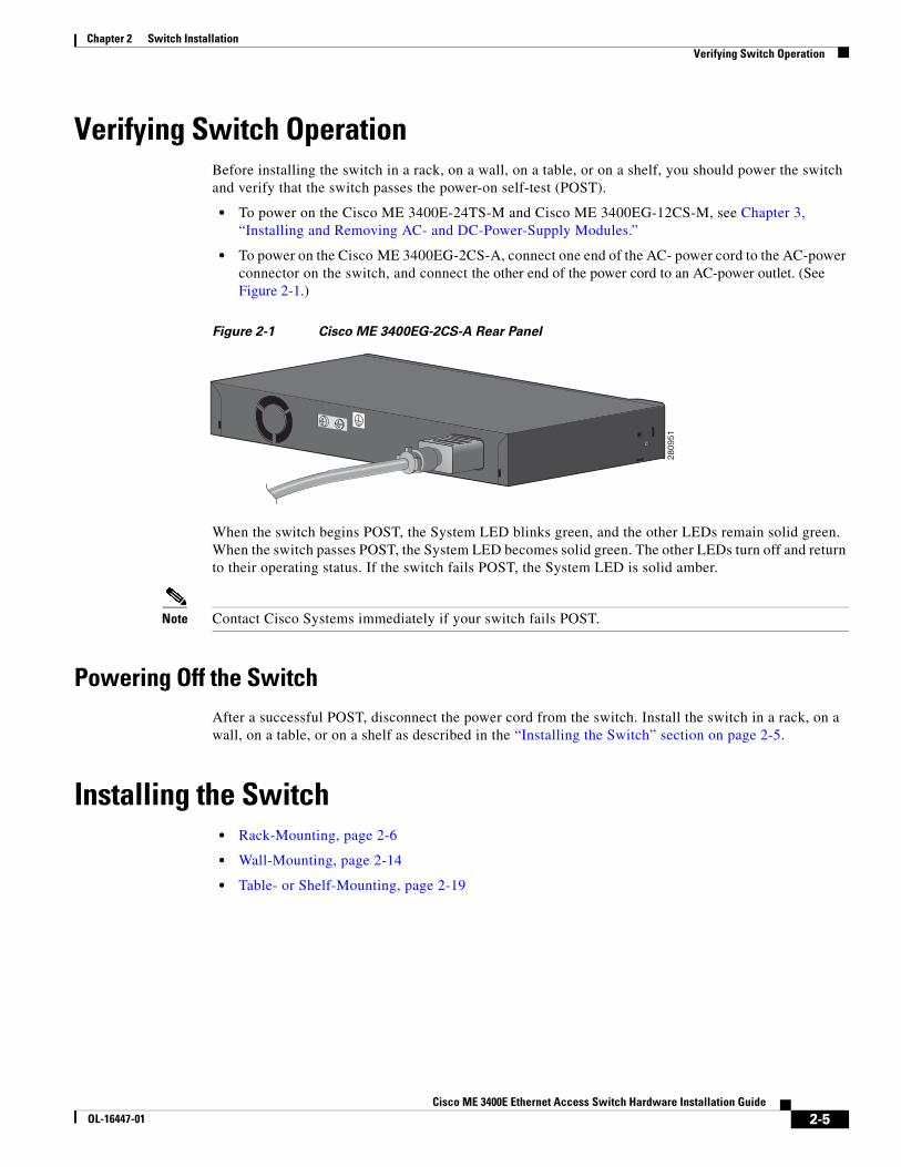
• To power on the Cisco ME 3400EG-2CS-A, connect one end of the AC- power cord to the AC-power connector on the switch, and connect the other end of the power cord to an AC-power outlet. (See Figure 2-1.)
Figure 2-1 Cisco ME 3400EG-2CS-A Rear Panel
When the switch begins POST, the System LED blinks green, and the other LEDs remain solid green. When the switch passes POST, the System LED becomes solid green. The other LEDs turn off and return to their operating status. If the switch fails POST, the System LED is solid amber.
Note Contact Cisco Systems immediately if your switch fails POST.
Powering Off the SwitchAfter a successful POST, disconnect the power cord from the switch. Install the switch in a rack, on a wall, on a table, or on a shelf as described in the “Installing the Switch” section on page 2-5.
Installing the Switch • Rack-Mounting, page 2-6
• Wall-Mounting, page 2-14
• Table- or Shelf-Mounting, page 2-19
2809
51
2-5Cisco ME 3400E Ethernet Access Switch Hardware Installation Guide
OL-16447-01
Chapter 2 Switch InstallationInstalling the Switch
Rack-Mounting To install the switch in a 19-inch, 23-inch, 24-inch rack, or a European Telecommunications Standards Institute (ETSI) rack, follow these instructions. (The 24-inch racks and the ETSI racks require optional mounting hardware.)
• Removing Screws from the Switch, page 2-6
• Attaching Brackets to the Switch, page 2-7
• Mounting in a Rack, page 2-13
.
Note Installing the switch in a 24-inch rack requires an optional bracket kit that is not included with the switch. You can order a kit containing the 24-inch rack-mounting brackets and hardware from Cisco. The kit part number is RCKMNT-1RU= (700-12398-XX).
Removing Screws from the Switch
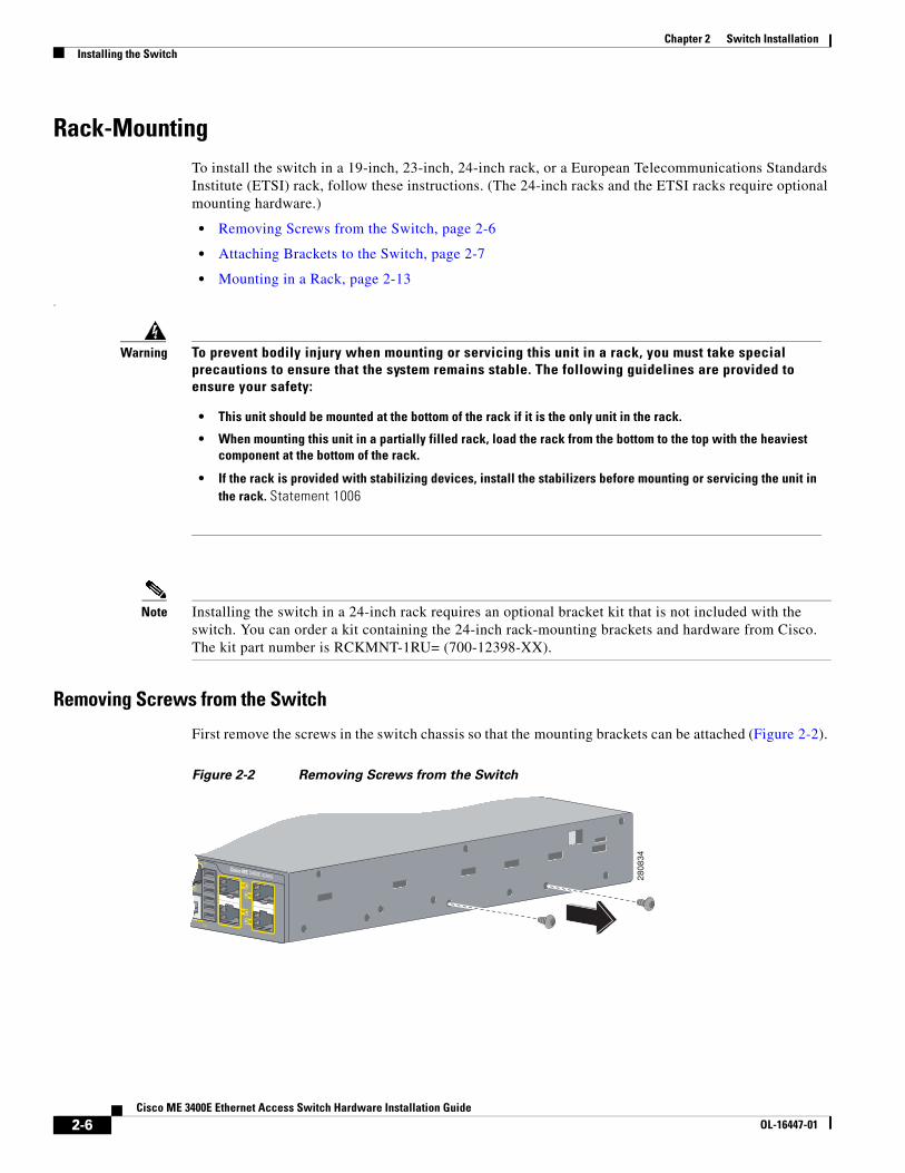
First remove the screws in the switch chassis so that the mounting brackets can be attached (Figure 2-2).
Figure 2-2 Removing Screws from the Switch
Warning To prevent bodily injury when mounting or servicing this unit in a rack, you must take special precautions to ensure that the system remains stable. The following guidelines are provided to ensure your safety:
• This unit should be mounted at the bottom of the rack if it is the only unit in the rack.
• When mounting this unit in a partially filled rack, load the rack from the bottom to the top with the heaviest component at the bottom of the rack.
• If the rack is provided with stabilizing devices, install the stabilizers before mounting or servicing the unit in the rack. Statement 1006
2808
34
2-6Cisco ME 3400E Ethernet Access Switch Hardware Installation Guide
OL-16447-01
Chapter 2 Switch InstallationInstalling the Switch
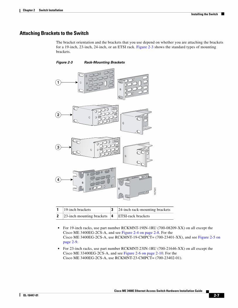
Attaching Brackets to the Switch
The bracket orientation and the brackets that you use depend on whether you are attaching the brackets for a 19-inch, 23-inch, 24-inch, or an ETSI rack. Figure 2-3 shows the standard types of mounting brackets.
Figure 2-3 Rack-Mounting Brackets
• For 19-inch racks, use part number RCKMNT-19IN-1RU (700-08209-XX) on all except the Cisco ME 3400EG-2CS-A, and see Figure 2-4 on page 2-8. For the Cisco ME 3400EG-2CS-A, use RCKMNT-19-CMPCT= (700-23401-XX), and see Figure 2-5 on page 2-9.
• For 23-inch racks, use part number RCKMNT-23IN-1RU (700-21646-XX) on all except the Cisco ME 33400EG-2CS-A, and see Figure 2-6 on page 2-10. For the Cisco ME 3400EG-2CS-A, use RCKMNT-23-CMPCT= (700-23402-01).
1 19-inch brackets 3 24-inch rack-mounting brackets
2 23-inch mounting brackets 4 ETSI-rack brackets
1
2
3
4
1575
31
2-7Cisco ME 3400E Ethernet Access Switch Hardware Installation Guide
OL-16447-01
Chapter 2 Switch InstallationInstalling the Switch
• For 24-inch racks, use part number RCKMNT-24IN-1RU (700-13248-XX), and see Figure 2-7 on page 2-11.
• For ETSI racks, use part number RCKMNT-ETSI-1RU= (700-19781-XX), and see Figure 2-8 on page 2-12. The Cisco ME 3400EG-2CS-A does not support the ETSI racks.
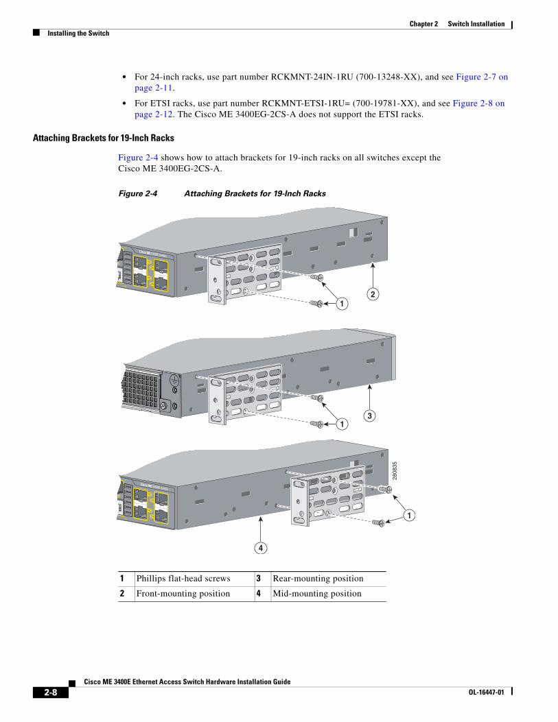
Attaching Brackets for 19-Inch Racks
Figure 2-4 shows how to attach brackets for 19-inch racks on all switches except the Cisco ME 3400EG-2CS-A.
Figure 2-4 Attaching Brackets for 19-Inch Racks
1 Phillips flat-head screws 3 Rear-mounting position
2 Front-mounting position 4 Mid-mounting position
2808
35
1
1
1
2
3
4
2-8Cisco ME 3400E Ethernet Access Switch Hardware Installation Guide
OL-16447-01
Chapter 2 Switch InstallationInstalling the Switch
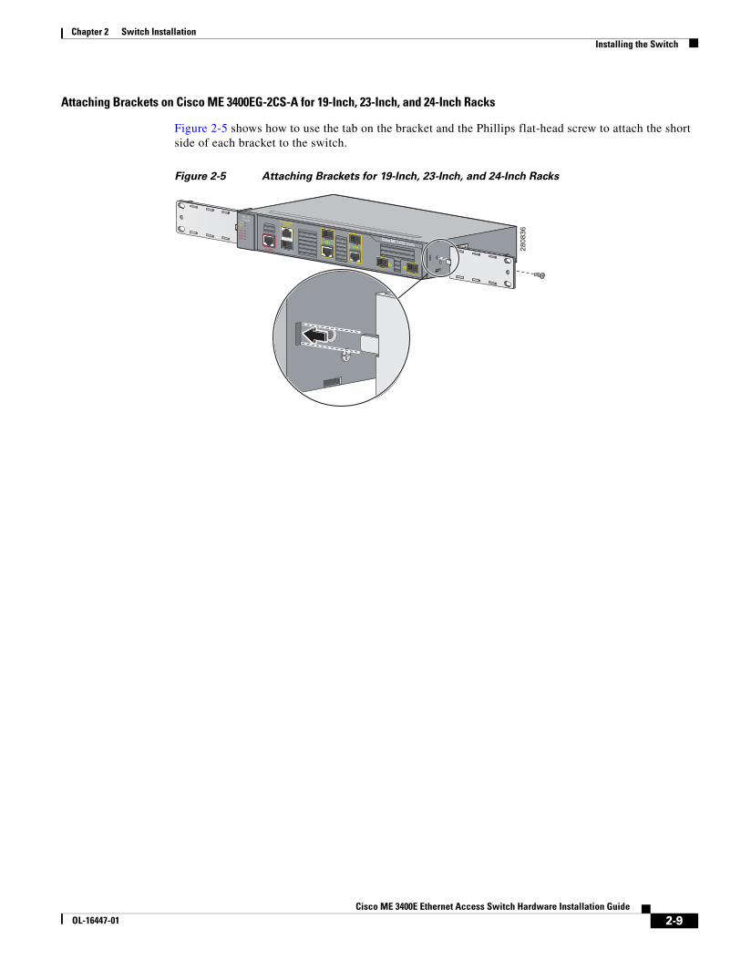
Attaching Brackets on Cisco ME 3400EG-2CS-A for 19-Inch, 23-Inch, and 24-Inch Racks
Figure 2-5 shows how to use the tab on the bracket and the Phillips flat-head screw to attach the short side of each bracket to the switch.
Figure 2-5 Attaching Brackets for 19-Inch, 23-Inch, and 24-Inch Racks
2808
36
2-9Cisco ME 3400E Ethernet Access Switch Hardware Installation Guide
OL-16447-01
Chapter 2 Switch InstallationInstalling the Switch
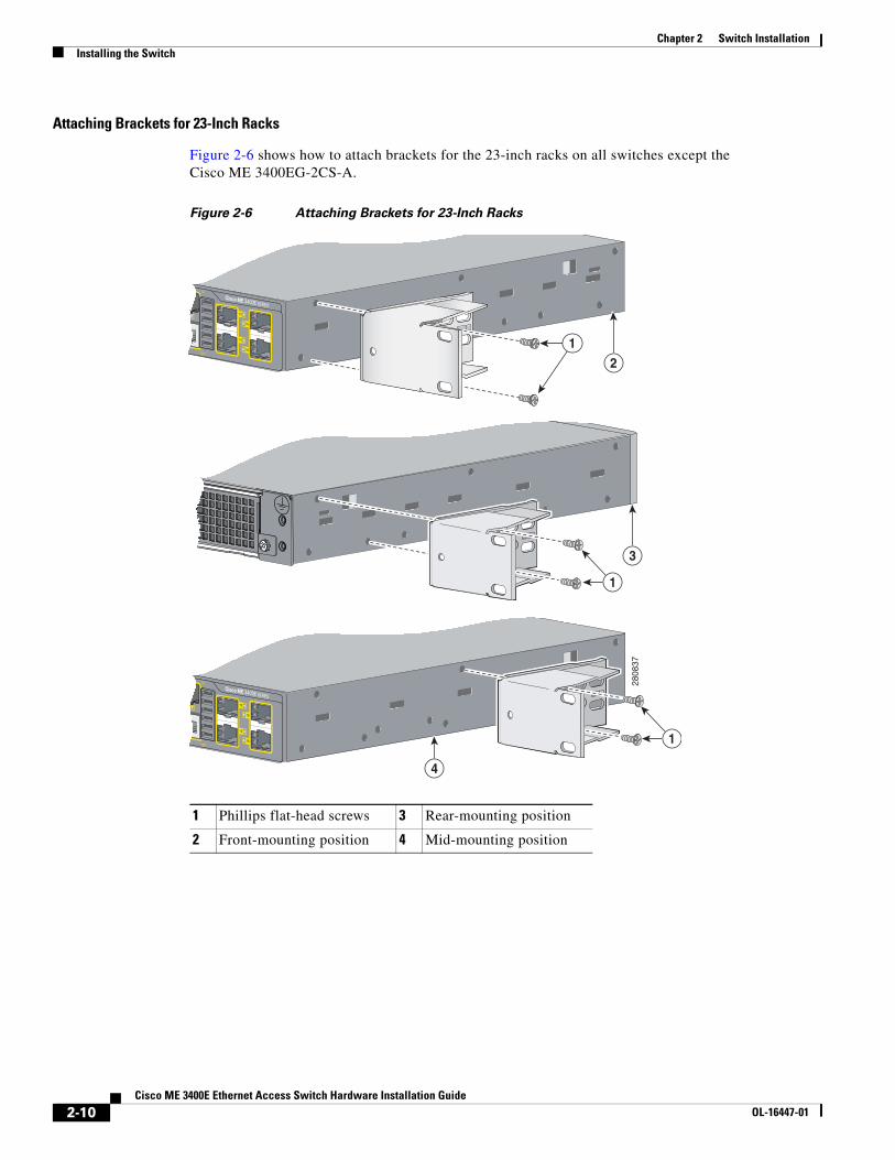
Attaching Brackets for 23-Inch Racks
Figure 2-6 shows how to attach brackets for the 23-inch racks on all switches except the Cisco ME 3400EG-2CS-A.
Figure 2-6 Attaching Brackets for 23-Inch Racks
1 Phillips flat-head screws 3 Rear-mounting position
2 Front-mounting position 4 Mid-mounting position
2808
37
1
1
2
4
3
1
2-10Cisco ME 3400E Ethernet Access Switch Hardware Installation Guide
OL-16447-01
Chapter 2 Switch InstallationInstalling the Switch
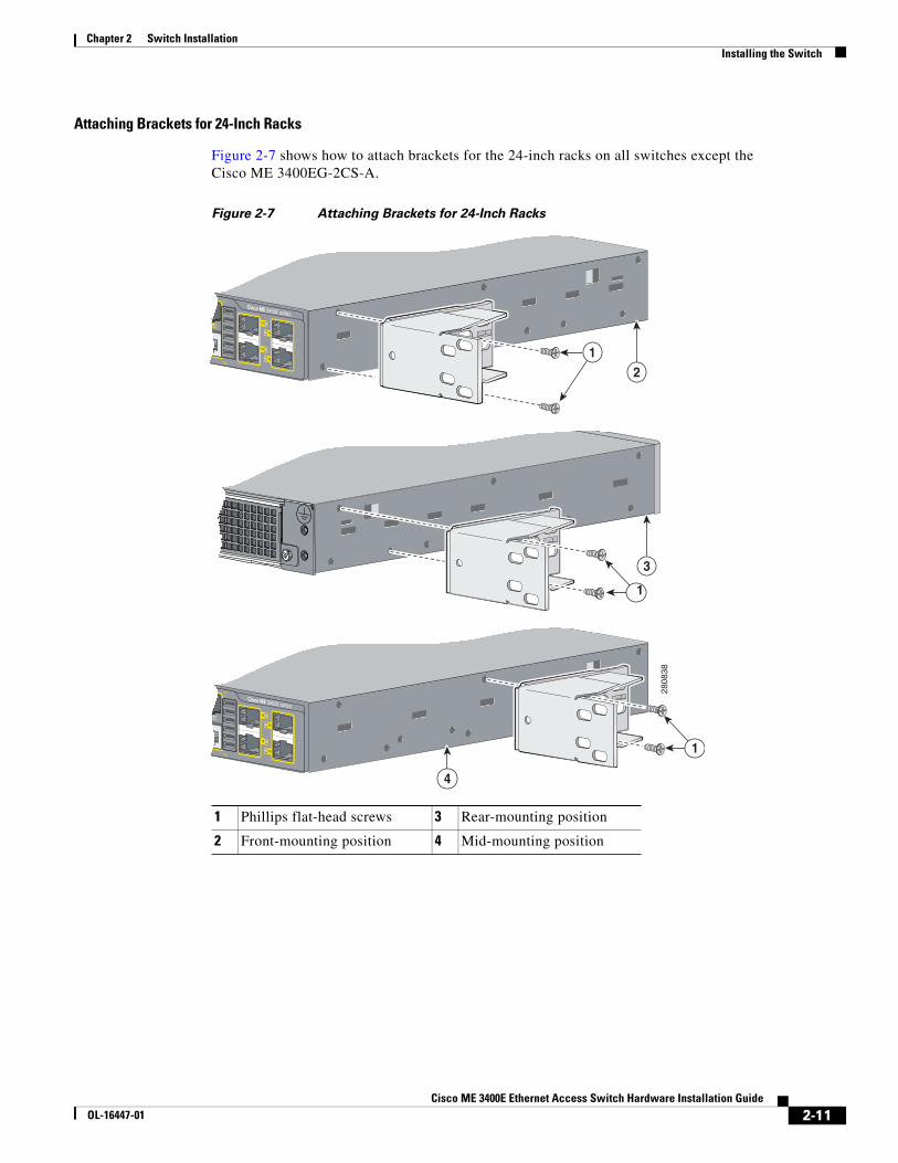
Attaching Brackets for 24-Inch Racks
Figure 2-7 shows how to attach brackets for the 24-inch racks on all switches except the Cisco ME 3400EG-2CS-A.
Figure 2-7 Attaching Brackets for 24-Inch Racks
1 Phillips flat-head screws 3 Rear-mounting position
2 Front-mounting position 4 Mid-mounting position
2808
38
1
1
2
4
3
1
2-11Cisco ME 3400E Ethernet Access Switch Hardware Installation Guide
OL-16447-01
Chapter 2 Switch InstallationInstalling the Switch
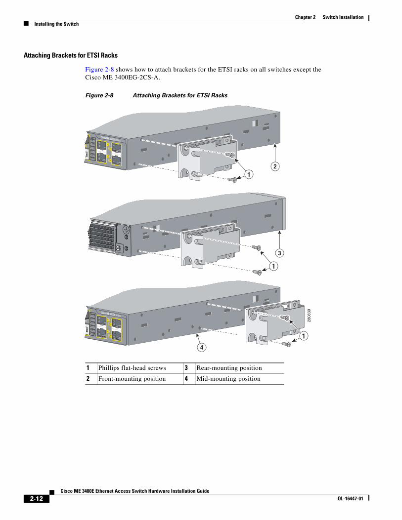
Attaching Brackets for ETSI Racks
Figure 2-8 shows how to attach brackets for the ETSI racks on all switches except the Cisco ME 3400EG-2CS-A.
Figure 2-8 Attaching Brackets for ETSI Racks
1 Phillips flat-head screws 3 Rear-mounting position
2 Front-mounting position 4 Mid-mounting position
2808
39
21
3
4
1
1
2-12Cisco ME 3400E Ethernet Access Switch Hardware Installation Guide
OL-16447-01
Chapter 2 Switch InstallationInstalling the Switch
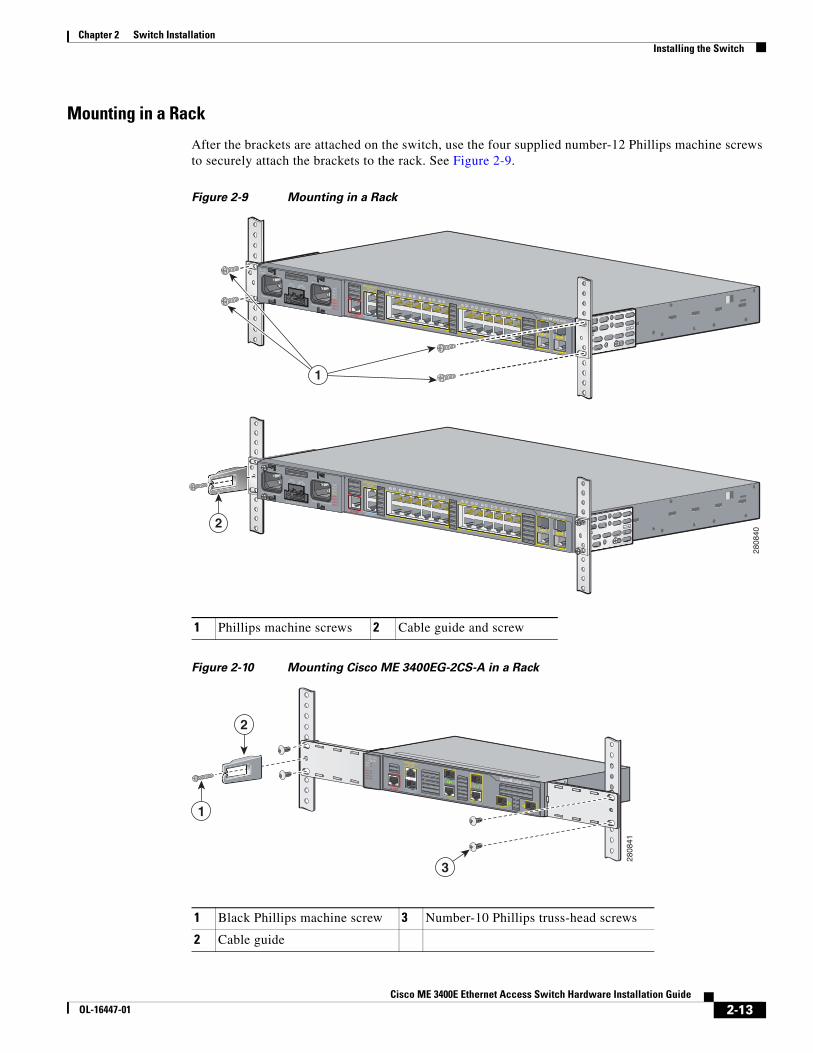
Mounting in a Rack
After the brackets are attached on the switch, use the four supplied number-12 Phillips machine screws to securely attach the brackets to the rack. See Figure 2-9.
Figure 2-9 Mounting in a Rack
Figure 2-10 Mounting Cisco ME 3400EG-2CS-A in a Rack
1 Phillips machine screws 2 Cable guide and screw
1
2
2808
40
1 Black Phillips machine screw 3 Number-10 Phillips truss-head screws
2 Cable guide
2
3
1
2808
41
2-13Cisco ME 3400E Ethernet Access Switch Hardware Installation Guide
OL-16447-01
Chapter 2 Switch InstallationInstalling the Switch
After the switch is mounted in the rack, you need to do these tasks to complete the installation:
• Power on the switch. See the “Verifying Switch Operation” section on page 2-5.
• Connect to the RJ-45 connector of a dual-purpose port, and run the initial configuration dialog. See the Cisco ME 3400E Ethernet Access Switch Getting Started Guide for instructions.
• Connect to the front-panel ports. See the “Connecting to the 10/100 and 10/100/1000 Ports” section on page 2-22, the “Connecting to Fiber-Optic SFP Modules” section on page 2-24, and the “Connecting to 1000BASE-T SFP Modules” section on page 2-25 to complete the installation.
• We recommend attaching the cable guide to prevent the cables from obscuring the front panel of the switch and the other devices installed in the rack. Use the supplied black screw shown in Figure 2-9 to attach the cable guide to the left or right bracket.
For configuration instructions about using the CLI setup program, go to Appendix C, “Configuring the Switch with the CLI-Based Setup Program.”
Wall-Mounting • Attaching Brackets for Wall-Mounting, page 2-14
• Mounting the Switch on a Wall, page 2-15
Note Wall-mounting has not been evaluated for NEBS applications.
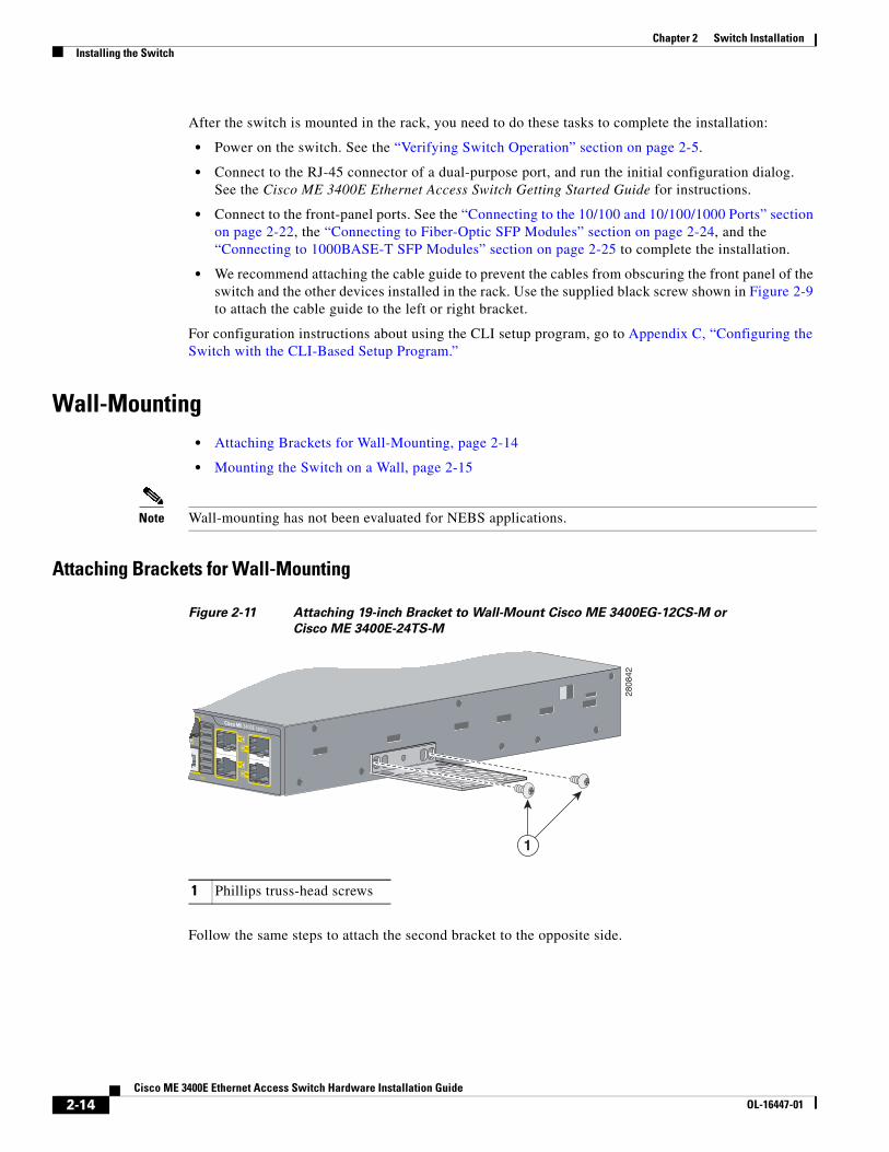
Attaching Brackets for Wall-Mounting
Figure 2-11 Attaching 19-inch Bracket to Wall-Mount Cisco ME 3400EG-12CS-M or Cisco ME 3400E-24TS-M
Follow the same steps to attach the second bracket to the opposite side.
1 Phillips truss-head screws
2808
42
1
2-14Cisco ME 3400E Ethernet Access Switch Hardware Installation Guide
OL-16447-01
Chapter 2 Switch InstallationInstalling the Switch
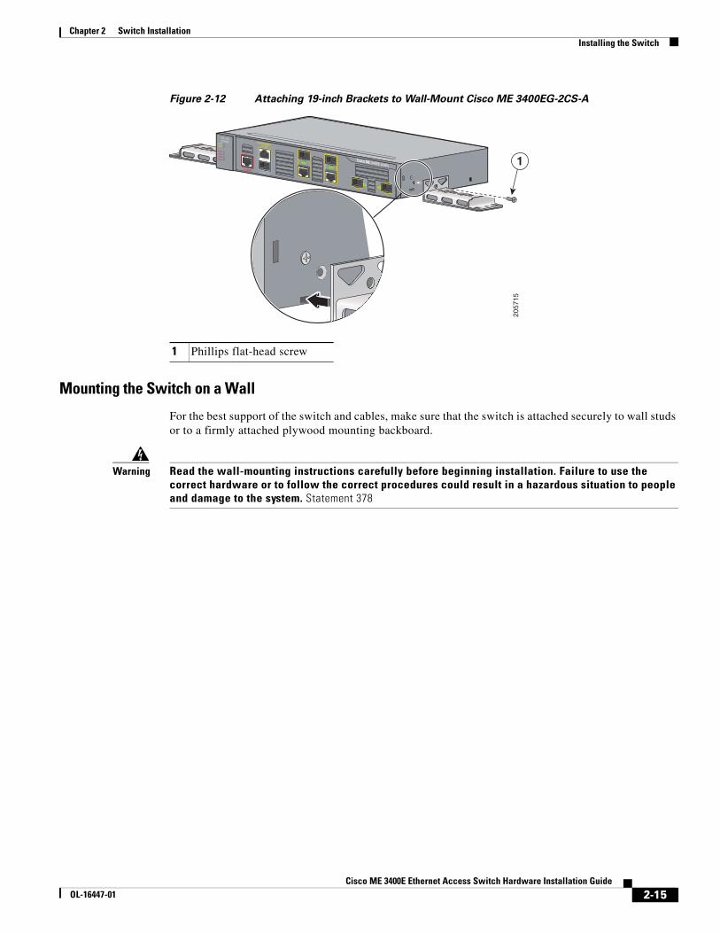
Figure 2-12 Attaching 19-inch Brackets to Wall-Mount Cisco ME 3400EG-2CS-A
Mounting the Switch on a Wall
For the best support of the switch and cables, make sure that the switch is attached securely to wall studs or to a firmly attached plywood mounting backboard.
Warning Read the wall-mounting instructions carefully before beginning installation. Failure to use the correct hardware or to follow the correct procedures could result in a hazardous situation to people and damage to the system. Statement 378
1 Phillips flat-head screw
2057
15
1
2-15Cisco ME 3400E Ethernet Access Switch Hardware Installation Guide
OL-16447-01
Chapter 2 Switch InstallationInstalling the Switch
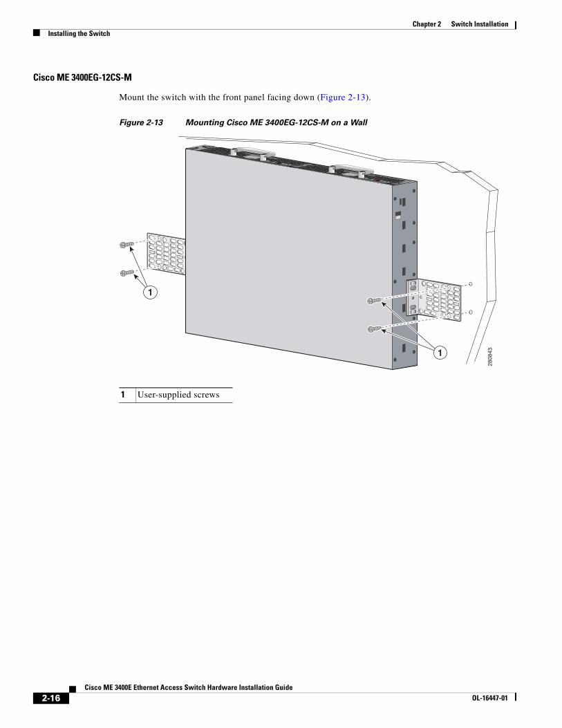
Cisco ME 3400EG-12CS-M
Mount the switch with the front panel facing down (Figure 2-13).
Figure 2-13 Mounting Cisco ME 3400EG-12CS-M on a Wall
1 User-supplied screws
2808
431
1
PSU OK+24V -48V
DC
PSU OK+24V -48V
DC
2-16Cisco ME 3400E Ethernet Access Switch Hardware Installation Guide
OL-16447-01
Chapter 2 Switch InstallationInstalling the Switch
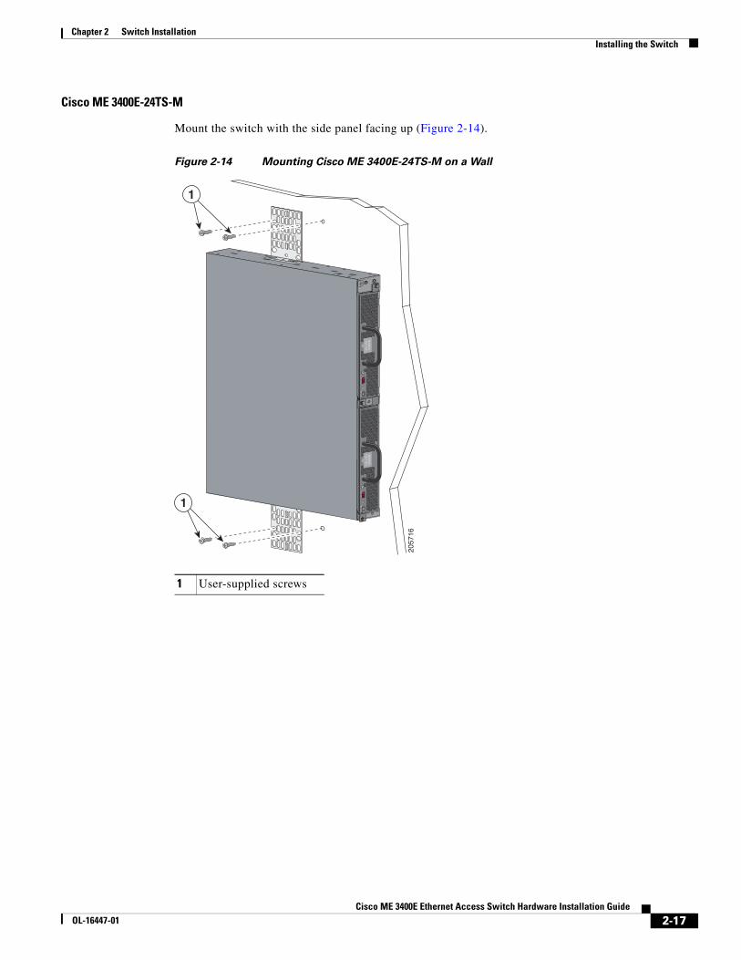
Cisco ME 3400E-24TS-M
Mount the switch with the side panel facing up (Figure 2-14).
Figure 2-14 Mounting Cisco ME 3400E-24TS-M on a Wall
1 User-supplied screws
2057
16
PS
U O
K+2
4V -
48V
DC
PS
U O
K+2
4V -
48V
DC
1
1
2-17Cisco ME 3400E Ethernet Access Switch Hardware Installation Guide
OL-16447-01
Chapter 2 Switch InstallationInstalling the Switch
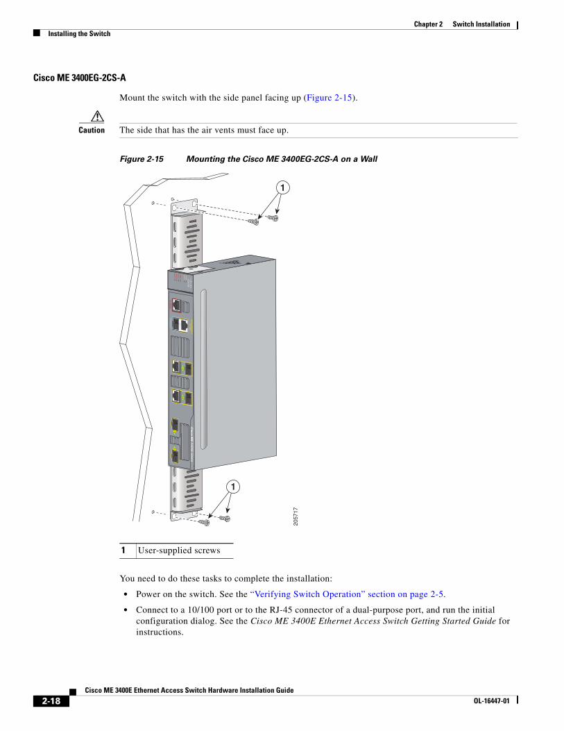
Cisco ME 3400EG-2CS-A
Mount the switch with the side panel facing up (Figure 2-15).
Caution The side that has the air vents must face up.
Figure 2-15 Mounting the Cisco ME 3400EG-2CS-A on a Wall
You need to do these tasks to complete the installation:
• Power on the switch. See the “Verifying Switch Operation” section on page 2-5.
• Connect to a 10/100 port or to the RJ-45 connector of a dual-purpose port, and run the initial configuration dialog. See the Cisco ME 3400E Ethernet Access Switch Getting Started Guide for instructions.
1 User-supplied screws
2057
17
1
1
2-18Cisco ME 3400E Ethernet Access Switch Hardware Installation Guide
OL-16447-01
Chapter 2 Switch InstallationInstalling and Removing SFP Modules
• Connect to the front-panel ports. See the “Connecting to the 10/100 and 10/100/1000 Ports” section on page 2-22, the “Connecting to Fiber-Optic SFP Modules” section on page 2-24, and the “Connecting to 1000BASE-T SFP Modules” section on page 2-25 to complete the installation.
For configuration instructions about using the CLI setup program, go to Appendix C, “Configuring the Switch with the CLI-Based Setup Program.”
Table- or Shelf-MountingFollow these steps to install the switch on a table or a shelf:
Step 1 Place the switch on a table or a shelf near an AC-power source.
Step 2 After the switch is placed on the table or shelf, you need to do these tasks to complete the installation:
• Power on the switch. See the “Verifying Switch Operation” section on page 2-5.
• Connect to a 10/100 port or to the RJ-45 connector of a dual-purpose port, and run the initial configuration dialog. See the Cisco ME 3400E Ethernet Access Switch Getting Started Guide for instructions.
• Connect to the front-panel ports. See the “Connecting to the 10/100 and 10/100/1000 Ports” section on page 2-22, the “Connecting to Fiber-Optic SFP Modules” section on page 2-24, and the “Connecting to 1000BASE-T SFP Modules” section on page 2-25 to complete the installation.
For configuration instructions about using the CLI setup program, go to Appendix C, “Configuring the Switch with the CLI-Based Setup Program.”
Note When the connectors are not being used, replace the dust covers on them for protection.
Installing and Removing SFP Modules
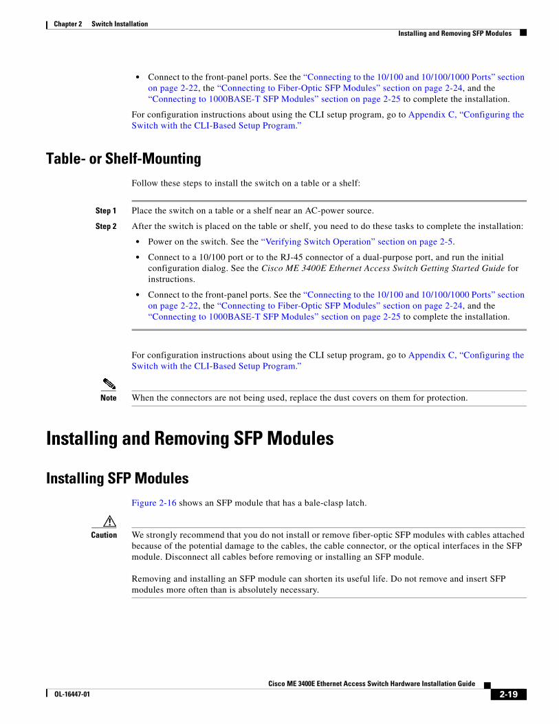
Installing SFP ModulesFigure 2-16 shows an SFP module that has a bale-clasp latch.
Caution We strongly recommend that you do not install or remove fiber-optic SFP modules with cables attached because of the potential damage to the cables, the cable connector, or the optical interfaces in the SFP module. Disconnect all cables before removing or installing an SFP module. Removing and installing an SFP module can shorten its useful life. Do not remove and insert SFP modules more often than is absolutely necessary.
2-19Cisco ME 3400E Ethernet Access Switch Hardware Installation Guide
OL-16447-01
Chapter 2 Switch InstallationInstalling and Removing SFP Modules
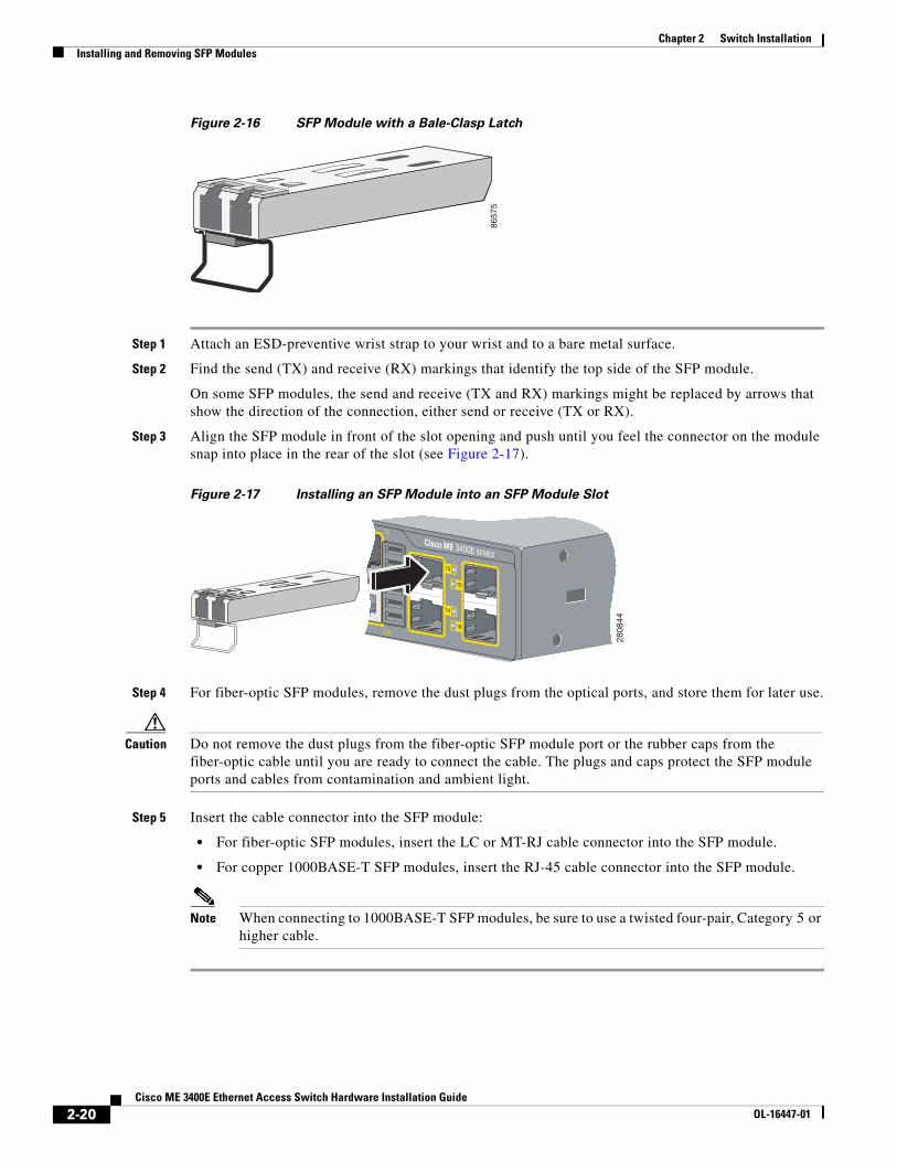
Figure 2-16 SFP Module with a Bale-Clasp Latch
Step 1 Attach an ESD-preventive wrist strap to your wrist and to a bare metal surface.
Step 2 Find the send (TX) and receive (RX) markings that identify the top side of the SFP module.
On some SFP modules, the send and receive (TX and RX) markings might be replaced by arrows that show the direction of the connection, either send or receive (TX or RX).
Step 3 Align the SFP module in front of the slot opening and push until you feel the connector on the module snap into place in the rear of the slot (see Figure 2-17).
Figure 2-17 Installing an SFP Module into an SFP Module Slot
Step 4 For fiber-optic SFP modules, remove the dust plugs from the optical ports, and store them for later use.
Caution Do not remove the dust plugs from the fiber-optic SFP module port or the rubber caps from the fiber-optic cable until you are ready to connect the cable. The plugs and caps protect the SFP module ports and cables from contamination and ambient light.
Step 5 Insert the cable connector into the SFP module:
• For fiber-optic SFP modules, insert the LC or MT-RJ cable connector into the SFP module.
• For copper 1000BASE-T SFP modules, insert the RJ-45 cable connector into the SFP module.
Note When connecting to 1000BASE-T SFP modules, be sure to use a twisted four-pair, Category 5 or higher cable.
8657
5
2808
44
2-20Cisco ME 3400E Ethernet Access Switch Hardware Installation Guide
OL-16447-01
Chapter 2 Switch InstallationInserting and Removing the SFP Module Patch Cable
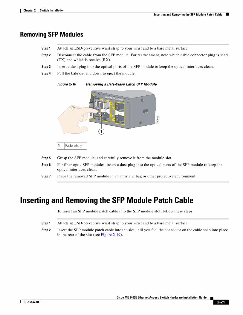
Removing SFP Modules
Step 1 Attach an ESD-preventive wrist strap to your wrist and to a bare metal surface.
Step 2 Disconnect the cable from the SFP module. For reattachment, note which cable connector plug is send (TX) and which is receive (RX).
Step 3 Insert a dust plug into the optical ports of the SFP module to keep the optical interfaces clean.
Step 4 Pull the bale out and down to eject the module.
Figure 2-18 Removing a Bale-Clasp Latch SFP Module
Step 5 Grasp the SFP module, and carefully remove it from the module slot.
Step 6 For fiber-optic SFP modules, insert a dust plug into the optical ports of the SFP module to keep the optical interfaces clean.
Step 7 Place the removed SFP module in an antistatic bag or other protective environment.
Inserting and Removing the SFP Module Patch CableTo insert an SFP module patch cable into the SFP module slot, follow these steps:
Step 1 Attach an ESD-preventive wrist strap to your wrist and to a bare metal surface.
Step 2 Insert the SFP module patch cable into the slot until you feel the connector on the cable snap into place in the rear of the slot (see Figure 2-19).
1 Bale clasp
2808
45
1
2-21Cisco ME 3400E Ethernet Access Switch Hardware Installation Guide
OL-16447-01
Chapter 2 Switch InstallationConnecting to the 10/100 and 10/100/1000 Ports
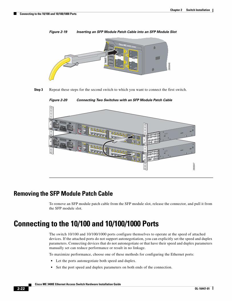
Figure 2-19 Inserting an SFP Module Patch Cable into an SFP Module Slot
Step 3 Repeat these steps for the second switch to which you want to connect the first switch.
Figure 2-20 Connecting Two Switches with an SFP Module Patch Cable
Removing the SFP Module Patch CableTo remove an SFP module patch cable from the SFP module slot, release the connector, and pull it from the SFP module slot.
Connecting to the 10/100 and 10/100/1000 PortsThe switch 10/100 and 10/100/1000 ports configure themselves to operate at the speed of attached devices. If the attached ports do not support autonegotiation, you can explicitly set the speed and duplex parameters. Connecting devices that do not autonegotiate or that have their speed and duplex parameters manually set can reduce performance or result in no linkage.
To maximize performance, choose one of these methods for configuring the Ethernet ports:
• Let the ports autonegotiate both speed and duplex.
• Set the port speed and duplex parameters on both ends of the connection.
2808
46
2808
47
2-22Cisco ME 3400E Ethernet Access Switch Hardware Installation Guide
OL-16447-01
Chapter 2 Switch InstallationConnecting to the 10/100 and 10/100/1000 Ports
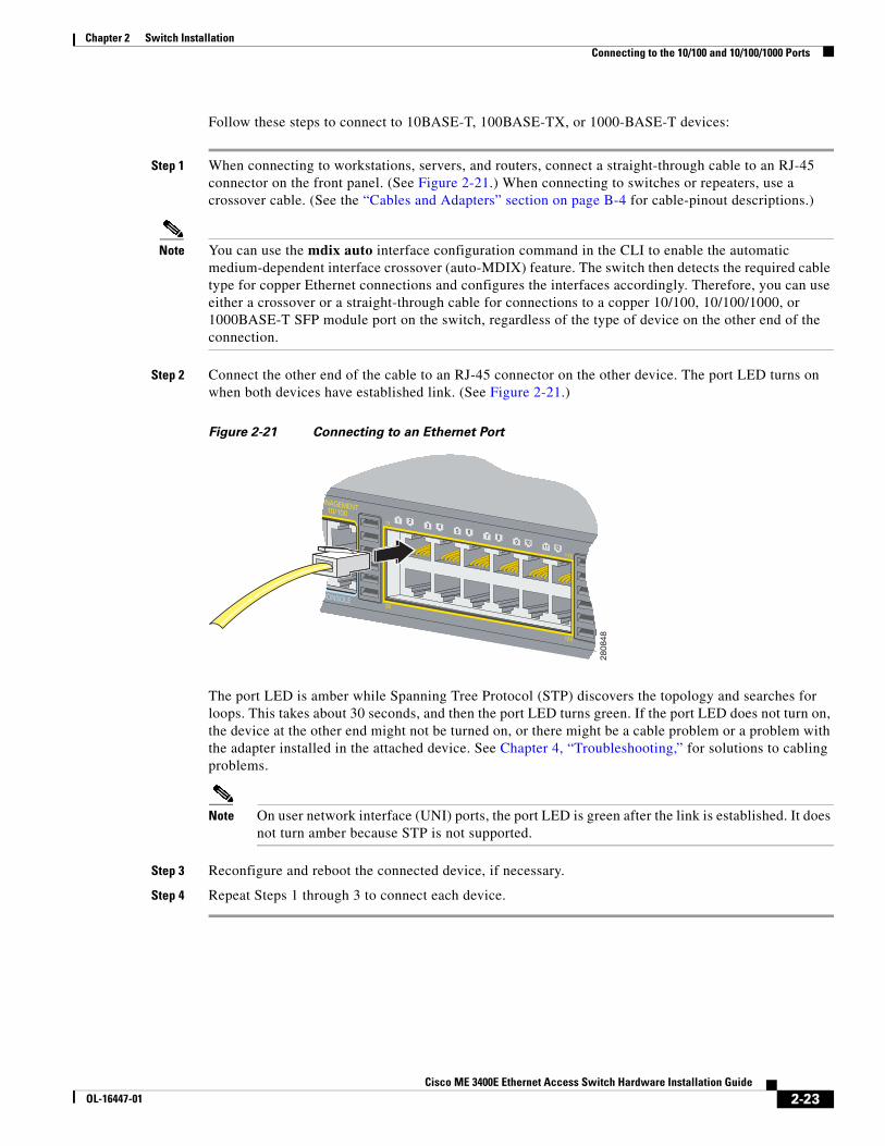
Follow these steps to connect to 10BASE-T, 100BASE-TX, or 1000-BASE-T devices:
Step 1 When connecting to workstations, servers, and routers, connect a straight-through cable to an RJ-45 connector on the front panel. (See Figure 2-21.) When connecting to switches or repeaters, use a crossover cable. (See the “Cables and Adapters” section on page B-4 for cable-pinout descriptions.)
Note You can use the mdix auto interface configuration command in the CLI to enable the automatic medium-dependent interface crossover (auto-MDIX) feature. The switch then detects the required cable type for copper Ethernet connections and configures the interfaces accordingly. Therefore, you can use either a crossover or a straight-through cable for connections to a copper 10/100, 10/100/1000, or 1000BASE-T SFP module port on the switch, regardless of the type of device on the other end of the connection.
Step 2 Connect the other end of the cable to an RJ-45 connector on the other device. The port LED turns on when both devices have established link. (See Figure 2-21.)
Figure 2-21 Connecting to an Ethernet Port
The port LED is amber while Spanning Tree Protocol (STP) discovers the topology and searches for loops. This takes about 30 seconds, and then the port LED turns green. If the port LED does not turn on, the device at the other end might not be turned on, or there might be a cable problem or a problem with the adapter installed in the attached device. See Chapter 4, “Troubleshooting,” for solutions to cabling problems.
Note On user network interface (UNI) ports, the port LED is green after the link is established. It does not turn amber because STP is not supported.
Step 3 Reconfigure and reboot the connected device, if necessary.
Step 4 Repeat Steps 1 through 3 to connect each device.
2808
48
2-23Cisco ME 3400E Ethernet Access Switch Hardware Installation Guide
OL-16447-01
Chapter 2 Switch InstallationConnecting to Fiber-Optic SFP Modules
Connecting to Fiber-Optic SFP Modules
Warning Class 1 laser product. Statement 1008
Caution Do not remove the rubber plugs from the SFP module port or the rubber caps from the fiber-optic cable until you are ready to connect the cable. The plugs and caps protect the SFP module ports and cables from contamination and ambient light. Before connecting to the SFP module, be sure that you understand the port and cabling stipulations in the “Installation Guidelines” section on page 2-4 and in the “SFP Modules” section on page 1-5. See Appendix B, “Connector and Cable Specifications,” for information about the LC on the SFP module.
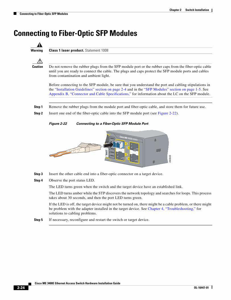
Step 1 Remove the rubber plugs from the module port and fiber-optic cable, and store them for future use.
Step 2 Insert one end of the fiber-optic cable into the SFP module port (see Figure 2-22).
Figure 2-22 Connecting to a Fiber-Optic SFP Module Port
Step 3 Insert the other cable end into a fiber-optic connector on a target device.
Step 4 Observe the port status LED.
The LED turns green when the switch and the target device have an established link.
The LED turns amber while the STP discovers the network topology and searches for loops. This process takes about 30 seconds, and then the port LED turns green.
If the LED is off, the target device might not be turned on, there might be a cable problem, or there might be problem with the adapter installed in the target device. See Chapter 4, “Troubleshooting,” for solutions to cabling problems.
Step 5 If necessary, reconfigure and restart the switch or target device.
2808
49
2-24Cisco ME 3400E Ethernet Access Switch Hardware Installation Guide
OL-16447-01
Chapter 2 Switch InstallationConnecting to 1000BASE-T SFP Modules
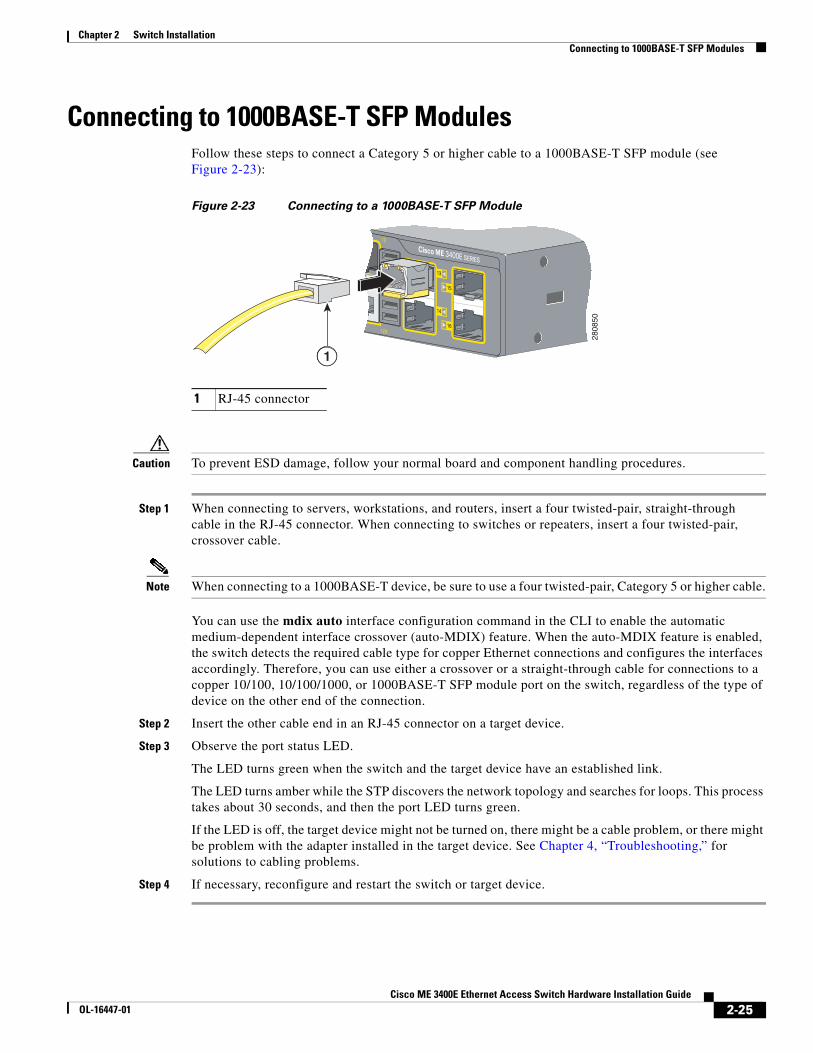
Connecting to 1000BASE-T SFP ModulesFollow these steps to connect a Category 5 or higher cable to a 1000BASE-T SFP module (see Figure 2-23):
Figure 2-23 Connecting to a 1000BASE-T SFP Module
Caution To prevent ESD damage, follow your normal board and component handling procedures.
Step 1 When connecting to servers, workstations, and routers, insert a four twisted-pair, straight-through cable in the RJ-45 connector. When connecting to switches or repeaters, insert a four twisted-pair, crossover cable.
Note When connecting to a 1000BASE-T device, be sure to use a four twisted-pair, Category 5 or higher cable.
You can use the mdix auto interface configuration command in the CLI to enable the automatic medium-dependent interface crossover (auto-MDIX) feature. When the auto-MDIX feature is enabled, the switch detects the required cable type for copper Ethernet connections and configures the interfaces accordingly. Therefore, you can use either a crossover or a straight-through cable for connections to a copper 10/100, 10/100/1000, or 1000BASE-T SFP module port on the switch, regardless of the type of device on the other end of the connection.
Step 2 Insert the other cable end in an RJ-45 connector on a target device.
Step 3 Observe the port status LED.
The LED turns green when the switch and the target device have an established link.
The LED turns amber while the STP discovers the network topology and searches for loops. This process takes about 30 seconds, and then the port LED turns green.
If the LED is off, the target device might not be turned on, there might be a cable problem, or there might be problem with the adapter installed in the target device. See Chapter 4, “Troubleshooting,” for solutions to cabling problems.
Step 4 If necessary, reconfigure and restart the switch or target device.
1 RJ-45 connector
2808
50
1
2-25Cisco ME 3400E Ethernet Access Switch Hardware Installation Guide
OL-16447-01
Chapter 2 Switch InstallationConnecting to Dual-Purpose Ports
Connecting to Dual-Purpose Ports
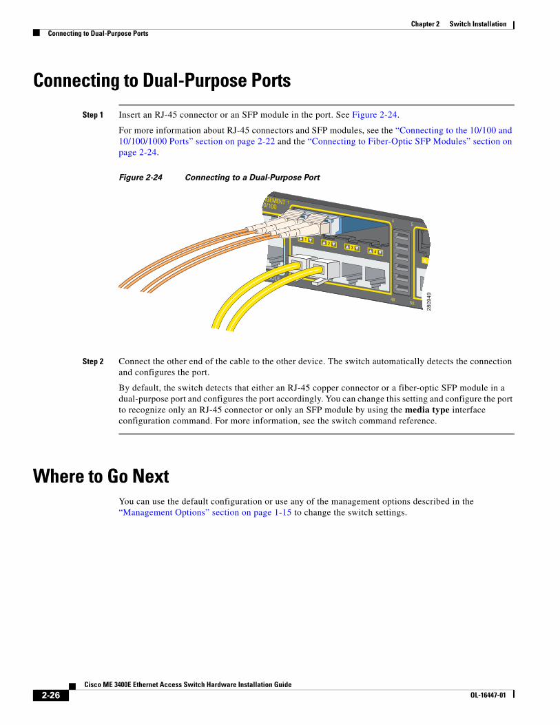
Step 1 Insert an RJ-45 connector or an SFP module in the port. See Figure 2-24.
For more information about RJ-45 connectors and SFP modules, see the “Connecting to the 10/100 and 10/100/1000 Ports” section on page 2-22 and the “Connecting to Fiber-Optic SFP Modules” section on page 2-24.
Figure 2-24 Connecting to a Dual-Purpose Port
Step 2 Connect the other end of the cable to the other device. The switch automatically detects the connection and configures the port.
By default, the switch detects that either an RJ-45 copper connector or a fiber-optic SFP module in a dual-purpose port and configures the port accordingly. You can change this setting and configure the port to recognize only an RJ-45 connector or only an SFP module by using the media type interface configuration command. For more information, see the switch command reference.
Where to Go NextYou can use the default configuration or use any of the management options described in the “Management Options” section on page 1-15 to change the switch settings.
11
2809
49
2-26Cisco ME 3400E Ethernet Access Switch Hardware Installation Guide
OL-16447-01

Cisco ME 3400E EtOL-16447-01
C H A P T E R 3
Installing and Removing AC- and DC-Power-Supply ModulesThis chapter provides the installation and removal instructions for the AC- and DC-power-supply modules for the Cisco ME 3400E-24TS-M and the Cisco ME 3400EG-12CS-M. Your switch ships with at least one power-supply module installed, either AC or DC, depending on your order. The power-supply modules are field-replaceable units (FRUs).
For translations of the safety warnings in this chapter, see the Regulatory Compliance and Safety Information for the Cisco ME 3400E Switch on the documentation CD and also on Cisco.com.
• Product Overview, page 3-1
• Power-Supply Module Installation, page 3-4
• Power Supply Settings, page 3-17
Product OverviewThis section gives an overview of the AC- and DC-power-supply modules.
• Power-Supply Module Description, page 3-1
• Handle-Side Description, page 3-2
• Connector-Side Description, page 3-4
Power-Supply Module Description
The 80-W AC-power-supply module is an autoranging unit that supports input voltages between 85 and 264 VAC. The DC-power-supply module has dual input feeds (A and B) and supports input voltages between –36 to –72 VDC for telecom applications and +18 to +36 VDC for industrial applications.
Table 3-1 Power-Supply Module Model Numbers and Descriptions
Model number Description
ME34X-PWR-AC AC-power-supply and fan module.
ME34X-PWR-DC DC-power-supply and fan module.
ME34X-PWR-BLANK= Spare blank cover for power-supply and fan module slot.
3-1hernet Access Switch Hardware Installation Guide
Chapter 3 Installing and Removing AC- and DC-Power-Supply ModulesProduct Overview
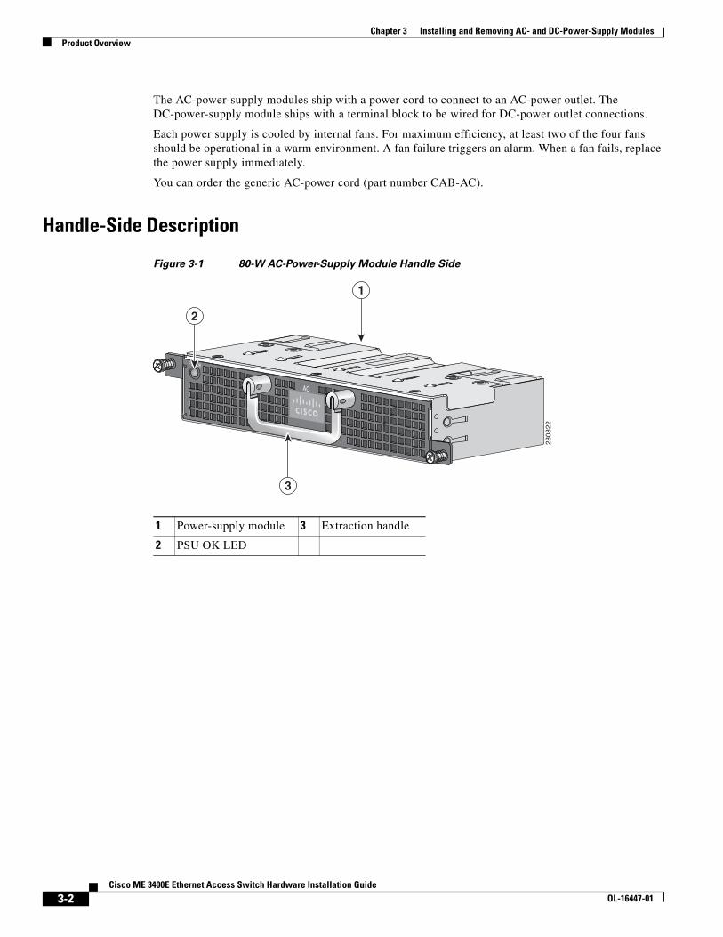
The AC-power-supply modules ship with a power cord to connect to an AC-power outlet. The DC-power-supply module ships with a terminal block to be wired for DC-power outlet connections.
Each power supply is cooled by internal fans. For maximum efficiency, at least two of the four fans should be operational in a warm environment. A fan failure triggers an alarm. When a fan fails, replace the power supply immediately.
You can order the generic AC-power cord (part number CAB-AC).
Handle-Side Description
Figure 3-1 80-W AC-Power-Supply Module Handle Side
1 Power-supply module 3 Extraction handle
2 PSU OK LED28
0822
PSU OK
AC
1
3
2
3-2Cisco ME 3400E Ethernet Access Switch Hardware Installation Guide
OL-16447-01
Chapter 3 Installing and Removing AC- and DC-Power-Supply ModulesProduct Overview
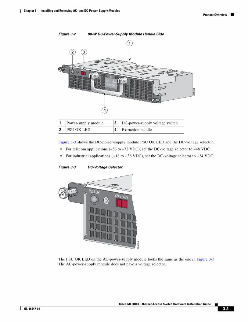
Figure 3-2 80-W DC-Power-Supply Module Handle Side
Figure 3-3 shows the DC-power-supply module PSU OK LED and the DC-voltage selector.
• For telecom applications (–36 to –72 VDC), set the DC-voltage selector to –48 VDC.
• For industrial applications (+18 to +36 VDC), set the DC-voltage selector to +24 VDC.
Figure 3-3 DC-Voltage Selector
The PSU OK LED on the AC-power-supply module looks the same as the one in Figure 3-3. The AC-power-supply module does not have a voltage selector.
1 Power-supply module 3 DC-power-supply voltage switch
2 PSU OK LED 4 Extraction handle
2808
23
PSU OK+24V -48V
DC
1
2 3
4
PSU OK+24V -48V
2808
24
3-3Cisco ME 3400E Ethernet Access Switch Hardware Installation Guide
OL-16447-01
Chapter 3 Installing and Removing AC- and DC-Power-Supply ModulesPower-Supply Module Installation
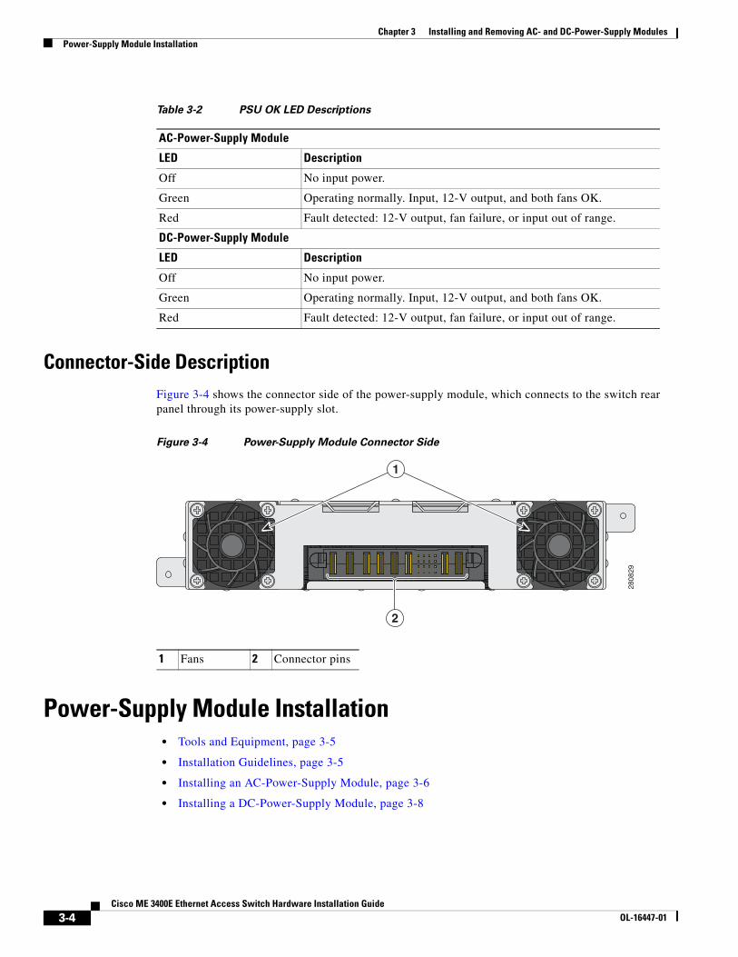
Connector-Side DescriptionFigure 3-4 shows the connector side of the power-supply module, which connects to the switch rear panel through its power-supply slot.
Figure 3-4 Power-Supply Module Connector Side
Power-Supply Module Installation • Tools and Equipment, page 3-5
• Installation Guidelines, page 3-5
• Installing an AC-Power-Supply Module, page 3-6
• Installing a DC-Power-Supply Module, page 3-8
Table 3-2 PSU OK LED Descriptions
AC-Power-Supply Module
LED Description
Off No input power.
Green Operating normally. Input, 12-V output, and both fans OK.
Red Fault detected: 12-V output, fan failure, or input out of range.
DC-Power-Supply Module
LED Description
Off No input power.
Green Operating normally. Input, 12-V output, and both fans OK.
Red Fault detected: 12-V output, fan failure, or input out of range.
1 Fans 2 Connector pins
2808
29
1
2
3-4Cisco ME 3400E Ethernet Access Switch Hardware Installation Guide
OL-16447-01
Chapter 3 Installing and Removing AC- and DC-Power-Supply ModulesPower-Supply Module Installation
Tools and EquipmentObtain these necessary tools and equipment:
• Ratcheting torque screwdriver with a number-2 Phillips head that exerts up to 15 inch-pounds (in-lb) of pressure.
• Power-supply power-cord retainer in the switch accessory kit.
Installation GuidelinesObserve these guidelines when you install a power-supply module:
• Do not force the power-supply module into the slot. This can damage the pins on the switch if they are not aligned with the unit.
• A power-supply module that is only partially connected to the switch can disrupt the system operation.
• Turn off switch power before you install the module.
• Verify that you are using the correct power cord.
Warning Blank faceplates (filler panels) serve three important functions: they prevent exposure to hazardous voltages and currents inside the chassis; they contain electromagnetic interference (EMI) that might disrupt other equipment; and they direct the flow of cooling air through the chassis. Do not operate the system unless all cards and faceplates are in place. Statement 156
Warning Do not reach into a vacant slot or chassis while you install or remove a module or a fan. Exposed circuitry could constitute an energy hazard. Statement 206
Warning Only trained and qualified personnel should be allowed to install, replace, or service this equipment. Statement 1030
Warning Do not work on the system or connect or disconnect cables during periods of lightning activity. Statement 1001
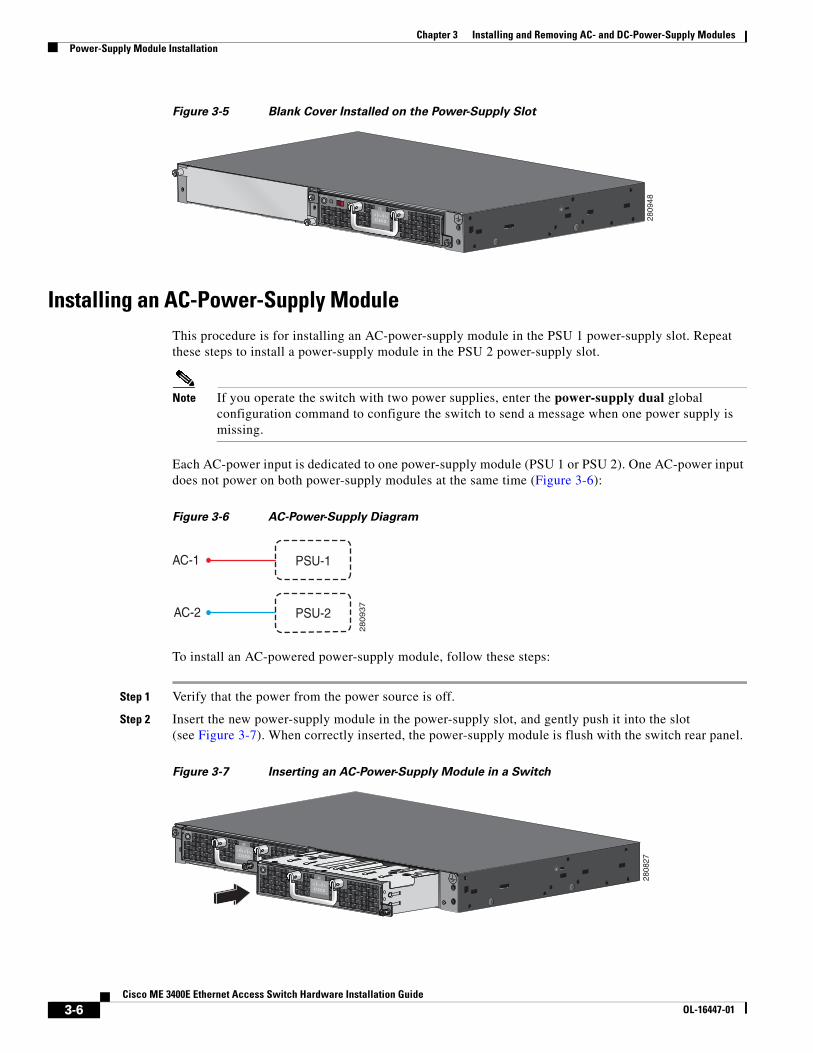
Caution To prevent overheating and to maintain proper air flow, either a power-supply module or a blank cover must be installed in each power-supply module slot at all times. Never operate the switch for extended periods of time without either a power-supply module or a blank cover installed in each power-supply module slot. (See Figure 3-5.) You can order the blank cover (part number ME34X-PWR-BLANK=) from Cisco.
3-5Cisco ME 3400E Ethernet Access Switch Hardware Installation Guide
OL-16447-01
Chapter 3 Installing and Removing AC- and DC-Power-Supply ModulesPower-Supply Module Installation
Figure 3-5 Blank Cover Installed on the Power-Supply Slot
Installing an AC-Power-Supply ModuleThis procedure is for installing an AC-power-supply module in the PSU 1 power-supply slot. Repeat these steps to install a power-supply module in the PSU 2 power-supply slot.
Note If you operate the switch with two power supplies, enter the power-supply dual global configuration command to configure the switch to send a message when one power supply is missing.
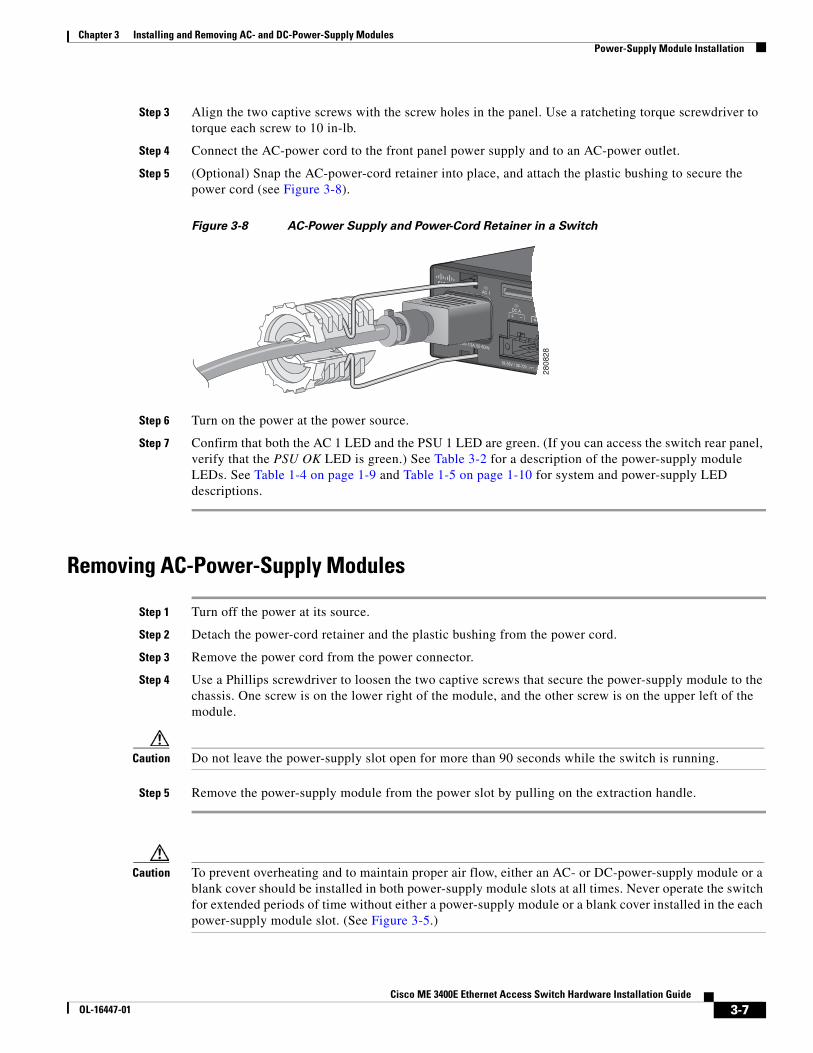
Each AC-power input is dedicated to one power-supply module (PSU 1 or PSU 2). One AC-power input does not power on both power-supply modules at the same time (Figure 3-6):
Figure 3-6 AC-Power-Supply Diagram
To install an AC-powered power-supply module, follow these steps:
Step 1 Verify that the power from the power source is off.
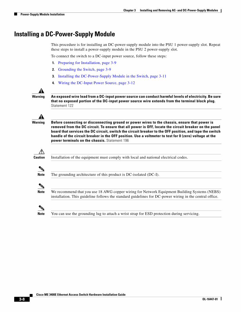
Step 2 Insert the new power-supply module in the power-supply slot, and gently push it into the slot (see Figure 3-7). When correctly inserted, the power-supply module is flush with the switch rear panel.
Figure 3-7 Inserting an AC-Power-Supply Module in a Switch
PSU OK+24V -48V
DC
2809
48
AC-1
AC-2
PSU-1
PSU-2
280937
PSU OK
AC
PSU OK
AC 2808
27
3-6Cisco ME 3400E Ethernet Access Switch Hardware Installation Guide
OL-16447-01
Chapter 3 Installing and Removing AC- and DC-Power-Supply ModulesPower-Supply Module Installation
Step 3 Align the two captive screws with the screw holes in the panel. Use a ratcheting torque screwdriver to torque each screw to 10 in-lb.
Step 4 Connect the AC-power cord to the front panel power supply and to an AC-power outlet.
Step 5 (Optional) Snap the AC-power-cord retainer into place, and attach the plastic bushing to secure the power cord (see Figure 3-8).
Figure 3-8 AC-Power Supply and Power-Cord Retainer in a Switch
Step 6 Turn on the power at the power source.
Step 7 Confirm that both the AC 1 LED and the PSU 1 LED are green. (If you can access the switch rear panel, verify that the PSU OK LED is green.) See Table 3-2 for a description of the power-supply module LEDs. See Table 1-4 on page 1-9 and Table 1-5 on page 1-10 for system and power-supply LED descriptions.
Removing AC-Power-Supply Modules
Step 1 Turn off the power at its source.
Step 2 Detach the power-cord retainer and the plastic bushing from the power cord.
Step 3 Remove the power cord from the power connector.
Step 4 Use a Phillips screwdriver to loosen the two captive screws that secure the power-supply module to the chassis. One screw is on the lower right of the module, and the other screw is on the upper left of the module.
Caution Do not leave the power-supply slot open for more than 90 seconds while the switch is running.
Step 5 Remove the power-supply module from the power slot by pulling on the extraction handle.
Caution To prevent overheating and to maintain proper air flow, either an AC- or DC-power-supply module or a blank cover should be installed in both power-supply module slots at all times. Never operate the switch for extended periods of time without either a power-supply module or a blank cover installed in the each power-supply module slot. (See Figure 3-5.)
2808
28
3-7Cisco ME 3400E Ethernet Access Switch Hardware Installation Guide
OL-16447-01
Chapter 3 Installing and Removing AC- and DC-Power-Supply ModulesPower-Supply Module Installation
Installing a DC-Power-Supply ModuleThis procedure is for installing an DC-power-supply module into the PSU 1 power-supply slot. Repeat these steps to install a power-supply module in the PSU 2 power-supply slot.
To connect the switch to a DC-input power source, follow these steps:
1. Preparing for Installation, page 3-9
2. Grounding the Switch, page 3-9
3. Installing the DC-Power-Supply Module in the Switch, page 3-11
4. Wiring the DC-Input Power Source, page 3-12
Warning An exposed wire lead from a DC-input power source can conduct harmful levels of electricity. Be sure that no exposed portion of the DC-input power source wire extends from the terminal block plug. Statement 122
Warning Before connecting or disconnecting ground or power wires to the chassis, ensure that power is removed from the DC circuit. To ensure that all power is OFF, locate the circuit breaker on the panel board that services the DC circuit, switch the circuit breaker to the OFF position, and tape the switch handle of the circuit breaker in the OFF position. Use a voltmeter to test for 0 (zero) voltage at the power terminals on the chassis. Statement 196
Caution Installation of the equipment must comply with local and national electrical codes.
Note The grounding architecture of this product is DC-isolated (DC-I).
Note We recommend that you use 18 AWG copper wiring for Network Equipment Building Systems (NEBS) installation. This guideline follows the standard guidelines for DC-power wiring in the central office.
Note You can use the grounding lug to attach a wrist strap for ESD protection during servicing.
3-8Cisco ME 3400E Ethernet Access Switch Hardware Installation Guide
OL-16447-01
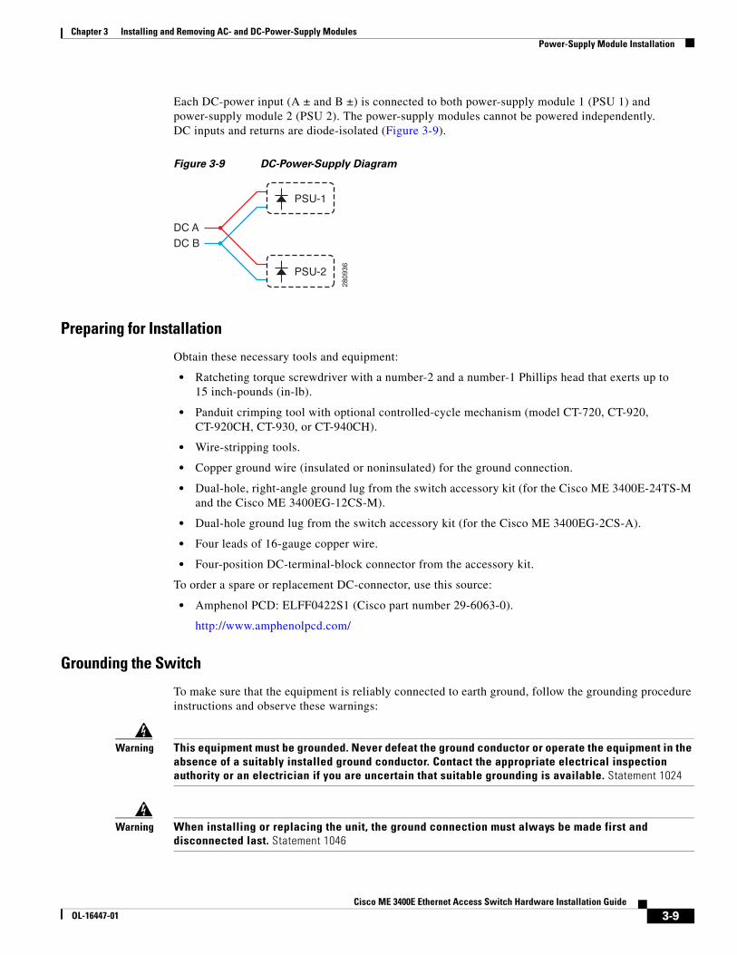
Chapter 3 Installing and Removing AC- and DC-Power-Supply ModulesPower-Supply Module Installation
Each DC-power input (A ± and B ±) is connected to both power-supply module 1 (PSU 1) and power-supply module 2 (PSU 2). The power-supply modules cannot be powered independently. DC inputs and returns are diode-isolated (Figure 3-9).
Figure 3-9 DC-Power-Supply Diagram
Preparing for Installation
Obtain these necessary tools and equipment:
• Ratcheting torque screwdriver with a number-2 and a number-1 Phillips head that exerts up to 15 inch-pounds (in-lb).
• Panduit crimping tool with optional controlled-cycle mechanism (model CT-720, CT-920, CT-920CH, CT-930, or CT-940CH).
• Wire-stripping tools.
• Copper ground wire (insulated or noninsulated) for the ground connection.
• Dual-hole, right-angle ground lug from the switch accessory kit (for the Cisco ME 3400E-24TS-M and the Cisco ME 3400EG-12CS-M).
• Dual-hole ground lug from the switch accessory kit (for the Cisco ME 3400EG-2CS-A).
• Four leads of 16-gauge copper wire.
• Four-position DC-terminal-block connector from the accessory kit.
To order a spare or replacement DC-connector, use this source:
• Amphenol PCD: ELFF0422S1 (Cisco part number 29-6063-0).
http://www.amphenolpcd.com/
Grounding the Switch
To make sure that the equipment is reliably connected to earth ground, follow the grounding procedure instructions and observe these warnings:
Warning This equipment must be grounded. Never defeat the ground conductor or operate the equipment in the absence of a suitably installed ground conductor. Contact the appropriate electrical inspection authority or an electrician if you are uncertain that suitable grounding is available. Statement 1024
Warning When installing or replacing the unit, the ground connection must always be made first and disconnected last. Statement 1046
DC ADC B
PSU-1
PSU-2
2809
36
3-9Cisco ME 3400E Ethernet Access Switch Hardware Installation Guide
OL-16447-01
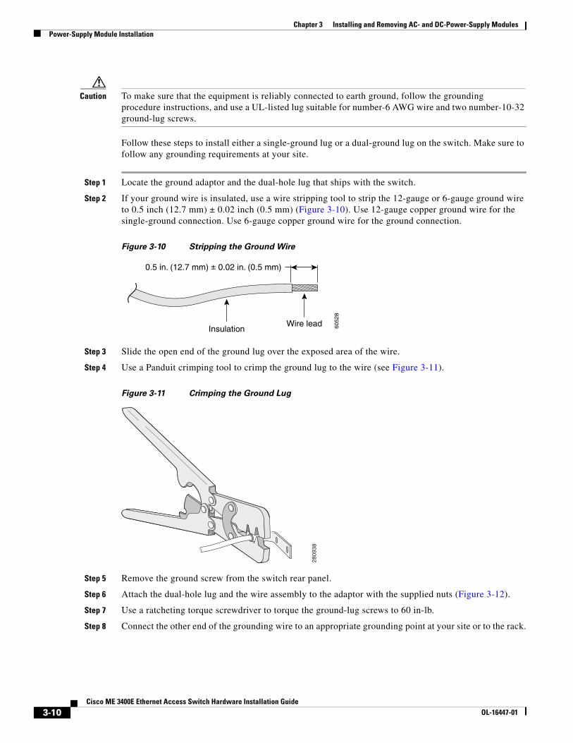
Chapter 3 Installing and Removing AC- and DC-Power-Supply ModulesPower-Supply Module Installation
Caution To make sure that the equipment is reliably connected to earth ground, follow the grounding procedure instructions, and use a UL-listed lug suitable for number-6 AWG wire and two number-10-32 ground-lug screws.
Follow these steps to install either a single-ground lug or a dual-ground lug on the switch. Make sure to follow any grounding requirements at your site.
Step 1 Locate the ground adaptor and the dual-hole lug that ships with the switch.
Step 2 If your ground wire is insulated, use a wire stripping tool to strip the 12-gauge or 6-gauge ground wire to 0.5 inch (12.7 mm) ± 0.02 inch (0.5 mm) (Figure 3-10). Use 12-gauge copper ground wire for the single-ground connection. Use 6-gauge copper ground wire for the ground connection.
Figure 3-10 Stripping the Ground Wire
Step 3 Slide the open end of the ground lug over the exposed area of the wire.
Step 4 Use a Panduit crimping tool to crimp the ground lug to the wire (see Figure 3-11).
Figure 3-11 Crimping the Ground Lug
Step 5 Remove the ground screw from the switch rear panel.
Step 6 Attach the dual-hole lug and the wire assembly to the adaptor with the supplied nuts (Figure 3-12).
Step 7 Use a ratcheting torque screwdriver to torque the ground-lug screws to 60 in-lb.
Step 8 Connect the other end of the grounding wire to an appropriate grounding point at your site or to the rack.
InsulationWire lead
0.5 in. (12.7 mm) ± 0.02 in. (0.5 mm)
6052
8
2809
38
3-10Cisco ME 3400E Ethernet Access Switch Hardware Installation Guide
OL-16447-01
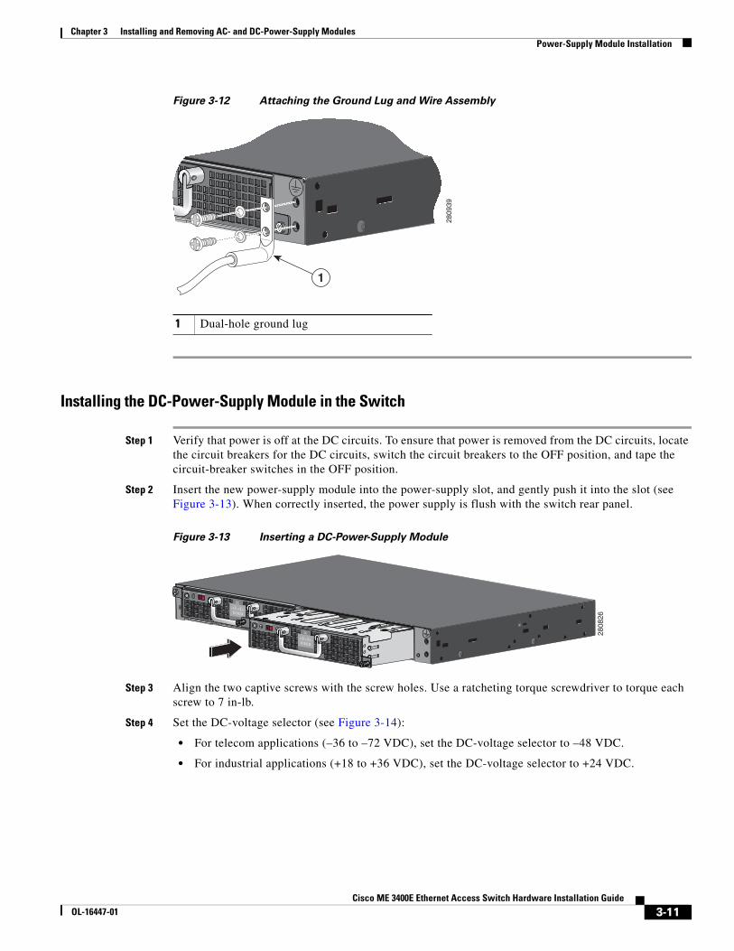
Chapter 3 Installing and Removing AC- and DC-Power-Supply ModulesPower-Supply Module Installation
Figure 3-12 Attaching the Ground Lug and Wire Assembly
Installing the DC-Power-Supply Module in the Switch
Step 1 Verify that power is off at the DC circuits. To ensure that power is removed from the DC circuits, locate the circuit breakers for the DC circuits, switch the circuit breakers to the OFF position, and tape the circuit-breaker switches in the OFF position.
Step 2 Insert the new power-supply module into the power-supply slot, and gently push it into the slot (see Figure 3-13). When correctly inserted, the power supply is flush with the switch rear panel.
Figure 3-13 Inserting a DC-Power-Supply Module
Step 3 Align the two captive screws with the screw holes. Use a ratcheting torque screwdriver to torque each screw to 7 in-lb.
Step 4 Set the DC-voltage selector (see Figure 3-14):
• For telecom applications (–36 to –72 VDC), set the DC-voltage selector to –48 VDC.
• For industrial applications (+18 to +36 VDC), set the DC-voltage selector to +24 VDC.
1 Dual-hole ground lug
2809
39
1
PSU OK+24V -48V
DC
PSU OK+24V -48V
DC 2808
26
3-11Cisco ME 3400E Ethernet Access Switch Hardware Installation Guide
OL-16447-01
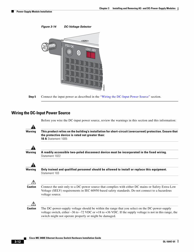
Chapter 3 Installing and Removing AC- and DC-Power-Supply ModulesPower-Supply Module Installation
Figure 3-14 DC-Voltage Selector
Step 5 Connect the input power as described in the “Wiring the DC-Input Power Source” section.
Wiring the DC-Input Power Source
Before you wire the DC-input power source, review the warnings in this section and this information:
Warning This product relies on the building’s installation for short-circuit (overcurrent) protection. Ensure that the protective device is rated not greater than: 10 A Statement 1005
Warning A readily accessible two-poled disconnect device must be incorporated in the fixed wiring. Statement 1022
Warning Only trained and qualified personnel should be allowed to install or replace this equipment. Statement 103
Caution Connect the unit only to a DC-power source that complies with either DC mains or Safety Extra-Low Voltage (SELV) requirements in IEC 60950 based safety standards. Do not connect to a hazardous voltage source.
Caution The DC-power-supply voltage should be within the range that you select on the DC-power-supply voltage switch, either –36 to –72 VDC or +18 to +36 VDC. If the supply voltage is not in this range, the switch might not operate properly or might be damaged.
PSU OK+24V -48V
2808
24
3-12Cisco ME 3400E Ethernet Access Switch Hardware Installation Guide
OL-16447-01
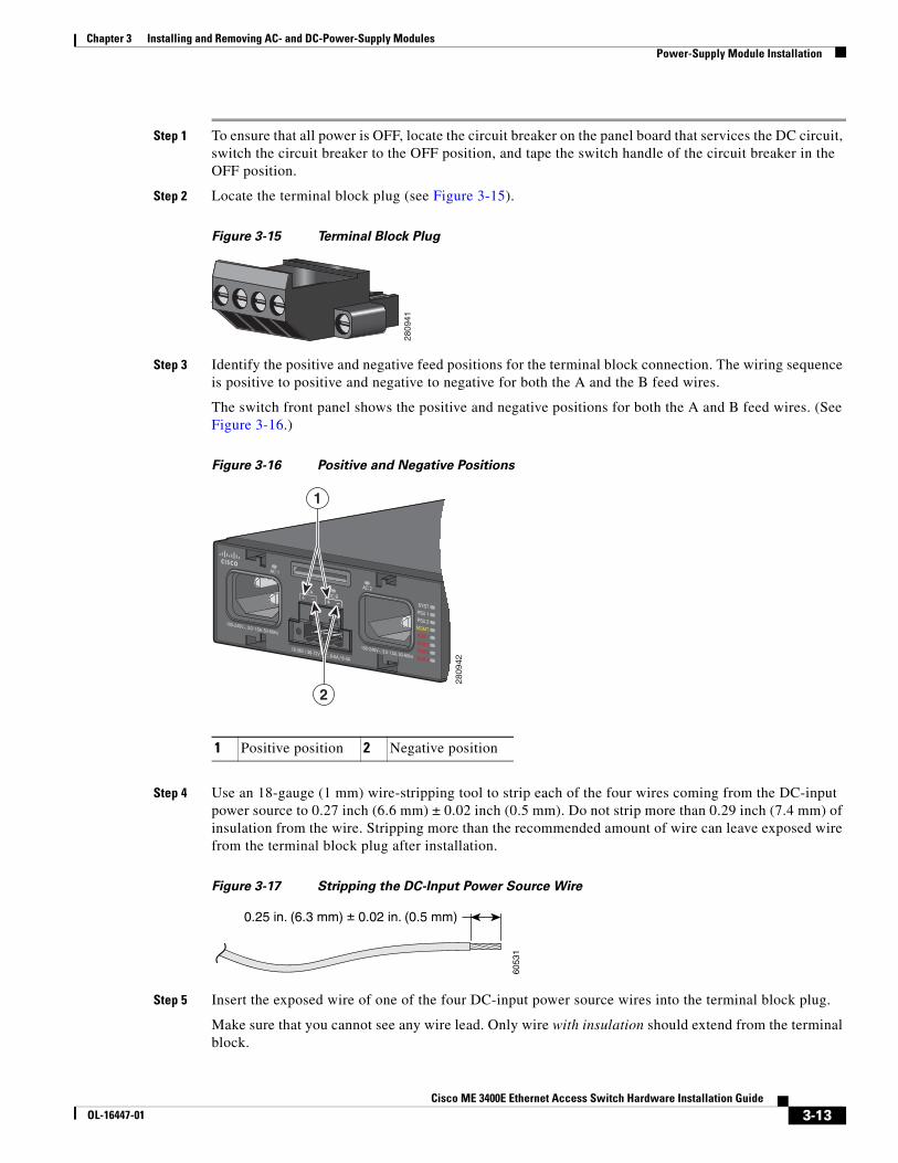
Chapter 3 Installing and Removing AC- and DC-Power-Supply ModulesPower-Supply Module Installation
Step 1 To ensure that all power is OFF, locate the circuit breaker on the panel board that services the DC circuit, switch the circuit breaker to the OFF position, and tape the switch handle of the circuit breaker in the OFF position.
Step 2 Locate the terminal block plug (see Figure 3-15).
Figure 3-15 Terminal Block Plug
Step 3 Identify the positive and negative feed positions for the terminal block connection. The wiring sequence is positive to positive and negative to negative for both the A and the B feed wires.
The switch front panel shows the positive and negative positions for both the A and B feed wires. (See Figure 3-16.)
Figure 3-16 Positive and Negative Positions
Step 4 Use an 18-gauge (1 mm) wire-stripping tool to strip each of the four wires coming from the DC-input power source to 0.27 inch (6.6 mm) ± 0.02 inch (0.5 mm). Do not strip more than 0.29 inch (7.4 mm) of insulation from the wire. Stripping more than the recommended amount of wire can leave exposed wire from the terminal block plug after installation.
Figure 3-17 Stripping the DC-Input Power Source Wire
Step 5 Insert the exposed wire of one of the four DC-input power source wires into the terminal block plug.
Make sure that you cannot see any wire lead. Only wire with insulation should extend from the terminal block.
2809
41
1 Positive position 2 Negative position
1
2809
42
2
0.25 in. (6.3 mm) ± 0.02 in. (0.5 mm)
6053
1
3-13Cisco ME 3400E Ethernet Access Switch Hardware Installation Guide
OL-16447-01
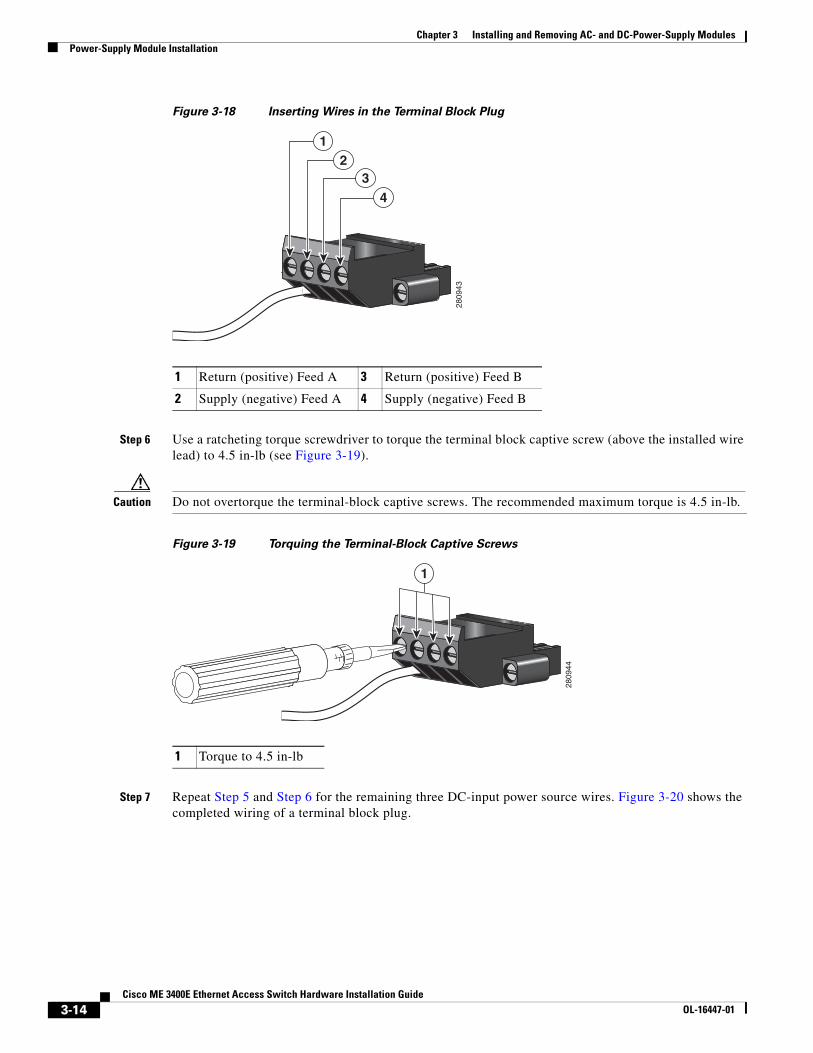
Chapter 3 Installing and Removing AC- and DC-Power-Supply ModulesPower-Supply Module Installation
Figure 3-18 Inserting Wires in the Terminal Block Plug
Step 6 Use a ratcheting torque screwdriver to torque the terminal block captive screw (above the installed wire lead) to 4.5 in-lb (see Figure 3-19).
Caution Do not overtorque the terminal-block captive screws. The recommended maximum torque is 4.5 in-lb.
Figure 3-19 Torquing the Terminal-Block Captive Screws
Step 7 Repeat Step 5 and Step 6 for the remaining three DC-input power source wires. Figure 3-20 shows the completed wiring of a terminal block plug.
1 Return (positive) Feed A 3 Return (positive) Feed B
2 Supply (negative) Feed A 4 Supply (negative) Feed B
2809
43
12
34
1 Torque to 4.5 in-lb
2809
441
3-14Cisco ME 3400E Ethernet Access Switch Hardware Installation Guide
OL-16447-01
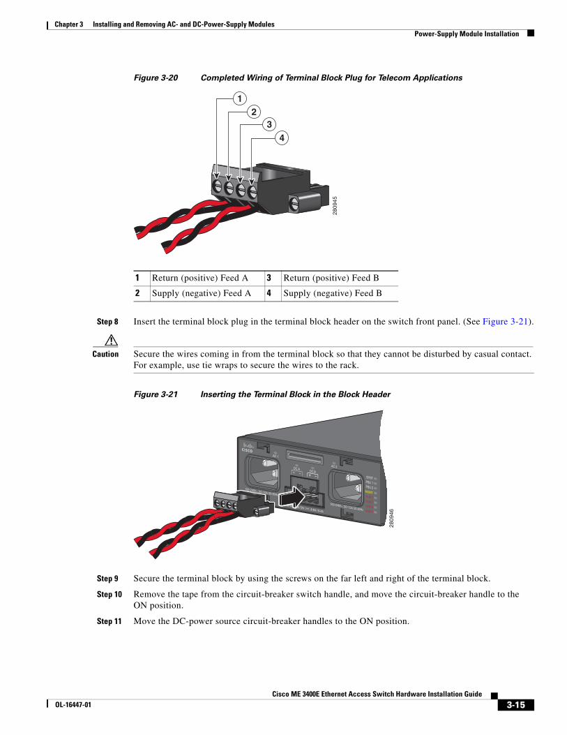
Chapter 3 Installing and Removing AC- and DC-Power-Supply ModulesPower-Supply Module Installation
Figure 3-20 Completed Wiring of Terminal Block Plug for Telecom Applications
Step 8 Insert the terminal block plug in the terminal block header on the switch front panel. (See Figure 3-21).
Caution Secure the wires coming in from the terminal block so that they cannot be disturbed by casual contact. For example, use tie wraps to secure the wires to the rack.
Figure 3-21 Inserting the Terminal Block in the Block Header
Step 9 Secure the terminal block by using the screws on the far left and right of the terminal block.
Step 10 Remove the tape from the circuit-breaker switch handle, and move the circuit-breaker handle to the ON position.
Step 11 Move the DC-power source circuit-breaker handles to the ON position.
1 Return (positive) Feed A 3 Return (positive) Feed B
2 Supply (negative) Feed A 4 Supply (negative) Feed B
2809
45
12
34
2809
46
3-15Cisco ME 3400E Ethernet Access Switch Hardware Installation Guide
OL-16447-01
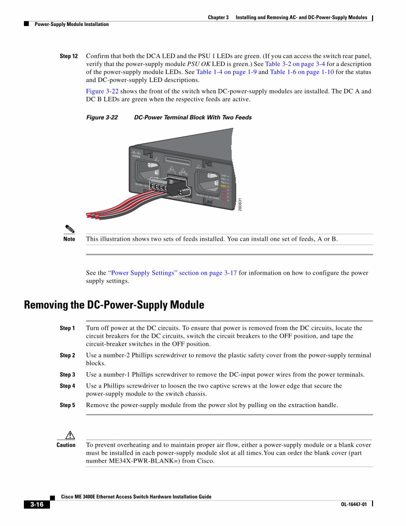
Chapter 3 Installing and Removing AC- and DC-Power-Supply ModulesPower-Supply Module Installation
Step 12 Confirm that both the DCA LED and the PSU 1 LEDs are green. (If you can access the switch rear panel, verify that the power-supply module PSU OK LED is green.) See Table 3-2 on page 3-4 for a description of the power-supply module LEDs. See Table 1-4 on page 1-9 and Table 1-6 on page 1-10 for the status and DC-power-supply LED descriptions.
Figure 3-22 shows the front of the switch when DC-power-supply modules are installed. The DC A and DC B LEDs are green when the respective feeds are active.
Figure 3-22 DC-Power Terminal Block With Two Feeds
Note This illustration shows two sets of feeds installed. You can install one set of feeds, A or B.
See the “Power Supply Settings” section on page 3-17 for information on how to configure the power supply settings.
Removing the DC-Power-Supply Module
Step 1 Turn off power at the DC circuits. To ensure that power is removed from the DC circuits, locate the circuit breakers for the DC circuits, switch the circuit breakers to the OFF position, and tape the circuit-breaker switches in the OFF position.
Step 2 Use a number-2 Phillips screwdriver to remove the plastic safety cover from the power-supply terminal blocks.
Step 3 Use a number-1 Phillips screwdriver to remove the DC-input power wires from the power terminals.
Step 4 Use a Phillips screwdriver to loosen the two captive screws at the lower edge that secure the power-supply module to the switch chassis.
Step 5 Remove the power-supply module from the power slot by pulling on the extraction handle.
Caution To prevent overheating and to maintain proper air flow, either a power-supply module or a blank cover must be installed in each power-supply module slot at all times.You can order the blank cover (part number ME34X-PWR-BLANK=) from Cisco.
2808
31
3-16Cisco ME 3400E Ethernet Access Switch Hardware Installation Guide
OL-16447-01
Chapter 3 Installing and Removing AC- and DC-Power-Supply ModulesPower Supply Settings
Power Supply Settings • Use the no power-supply global configuration command (the default) when installing one
power-supply module. The switch does not send an alarm when the second power-supply module is missing.
• Use the power-supply dual global configuration command when installing two power-supply modules. When both are operating properly, all applicable LEDs are green, and the switch does not send an alarm. If a power-supply module is missing, the switch sends an alarm. An error message appears and the appropriate power-supply LED turns red.
• Use the power-supply dual dc-feed global configuration command when two DC-input feeds are connected to the DC-power source. When both are operating properly, all the applicable LEDs are green and the switch does not send an alarm. If only one DC-input feed is connected, and there is at least one DC-power-supply module installed, the switch sends an alarm. An error message appears and the DC-power-supply LED for the missing DC-input feed turns amber. The LED for the connected DC-input feed turns green.
• Use the no power-supply dual dc-feed global configuration command when only one DC-input feed is connected. The switch does not send an alarm when the second DC-input feed is not connected.
See the switch software configuration guide and switch command reference for more details on these settings.
3-17Cisco ME 3400E Ethernet Access Switch Hardware Installation Guide
OL-16447-01
Chapter 3 Installing and Removing AC- and DC-Power-Supply ModulesPower Supply Settings
3-18Cisco ME 3400E Ethernet Access Switch Hardware Installation Guide
OL-16447-01
Cisco ME 3400E EtOL-16447-01
C H A P T E R 4
Troubleshooting• Diagnosing Problems, page 4-1
• Clearing the Switch IP Address and Configuration, page 4-4
• Finding the Switch Serial Number, page 4-5
Diagnosing ProblemsThe LEDs on the front panel provide troubleshooting information about the switch. They show power-on self-test (POST) failures, port-connectivity problems, and overall switch performance. You can also get statistics from the CLI or from an SNMP workstation. See the software configuration guide and the switch command reference on Cisco.com or the documentation that came with your SNMP application for more information.
Switch POST ResultsAs the switch powers on, it begins the POST, a series of tests that runs automatically to ensure that the switch functions properly. It might take several minutes for the switch to complete POST.
When the switch begins POST, the System LED blinks green, and the other LEDs remain solid green. When POST succeeds, the System LED becomes solid green. The other LEDs turn off and return to their operating status. If the switch fails POST, the System LED is solid amber.
You can use the show diagnostics post user EXEC command to display the POST results.
Note POST failures are usually serious. Contact your Cisco technical support representative if your switch does not pass POST.
4-1hernet Access Switch Hardware Installation Guide
Appendix 4 TroubleshootingDiagnosing Problems
Switch LEDsYou must have physical access to the switch to do this. Look at the port LEDs for troubleshooting information about the switch. See the “LEDs” section on page 1-7 for a description of the LED colors and their meanings.
Switch Connections
Bad or Damaged Cable
Always examine the cable for marginal damage or failure. A cable might be just good enough to connect at the physical layer, but it could corrupt packets as a result of subtle damage to the wiring or connectors. You can identify this situation because the port has many packet errors or the port constantly flaps (loses and regains link).
• Examine or exchange the copper or fiber-optic cable with a known, good cable.
• Look for broken or missing pins on cable connectors.
• Rule out any bad patch panel connections or media convertors between the source and the destination. If possible, bypass the patch panel, or eliminate faulty media convertors (fiber-optic-to-copper).
• Try the cable in another port or interface, if possible, to see if the problem follows the cable.
Ethernet and Fiber Cables
Make sure that you have the correct cable type for the connection:
• For Ethernet, use Category 3 copper cable for 10 Mb/s UTP connections. Use either Category 5, Category 5e, or Category 6 UTP for 10/100 or 10/100/1000 Mb/s connections.
• For fiber-optic connectors, verify that you have the correct cable for the distance and port type. Make sure that the connected device ports both match and use the same type encoding, optical frequency, and fiber type.
• For copper connections, determine if a crossover cable was used when a straight-through was required or the reverse. Enable auto-MDIX on the switch, or replace the cable. See Table 2-1 for recommended Ethernet cables.
Link Status
Verify that both sides have link. A single broken wire or one shutdown port can cause one side to show link, but the other side does not have link.
A port LED does not guarantee that the cable is fully functional. The cable might have encountered physical stress that causes it to function at a marginal level. If the port LED does not turn on:
• Connect the cable from the switch to a known good device.
• Make sure that both ends of the cable are connected to the correct ports.
• Verify that both devices have power.
4-2Cisco ME 3400E Ethernet Access Switch Hardware Installation Guide
OL-16447-01
Appendix 4 TroubleshootingDiagnosing Problems
• Verify that you are using the correct cable type. See Appendix B, “Connector and Cable Specifications,” for more information.
• Look for loose connections. Sometimes a cable appears to be seated, but is not. Disconnect the cable and then reconnect it.
SFP Module Port Issues
Use only Cisco SFP modules on the switch. Each Cisco module has an internal serial EEPROM that is encoded with security information. This encoding provides a way for Cisco to identify and validate that the module meets the requirements for the switch. Check these items:
• Bad or wrong SFP module. Exchange the suspect module with known good module. Verify that the module is supported on this platform. (The switch release notes on Cisco.com list the SFP modules that the switch supports.)
• Use the show interfaces privileged EXEC command to see if the port or module is error-disabled, disabled, or shutdown. Re-enable the port if needed.
• Make sure that all fiber connections are properly cleaned and securely connected.
Port and Interface Settings
An obvious but sometimes overlooked cause of port connectivity failure is a disabled interface. Verify that the interface is not disabled or powered off for some reason. If an interface is manually shut down on one side of the link or the other side, the link does not come up until you re-enable the interface. Use the show interfaces privileged EXEC command to see if the interface is error-disabled, disabled, or shutdown on either side of the connection. If needed, re-enable the interface.
Ping the End Device
Ping from the directly connected switch first, and then work your way back port by port, interface by interface, trunk by trunk, until you find the source of the connectivity issue. Make sure that each switch can identify the end device MAC address in its Content-Addressable Memory (CAM) table.
Spanning Tree Loops
STP loops can cause serious performance issues that look like port or interface problems.
Unidirectional links can cause spanning-tree loops. A unidirectional link occurs when the traffic sent by the switch is received by its neighbor, but does not receive traffic sent by the neighbor. A broken fiber-optic cable, other cabling, or a port issue could cause this one-way communication.
The UniDirectional Link Detection (UDLD) protocol helps identify unidirectional link problems. For more information, see the “Understanding UDLD” section in the switch software configuration guide on Cisco.com.
4-3Cisco ME 3400E Ethernet Access Switch Hardware Installation Guide
OL-16447-01
Appendix 4 TroubleshootingClearing the Switch IP Address and Configuration
Switch Performance
Speed, Duplex, and Autonegotiation
If the port statistics show a large amount of alignment errors, frame check sequence (FCS), or late-collisions errors, this might mean a speed or duplex mismatch.
A common issue with speed and duplex is when the duplex settings are mismatched between two switches, between a switch and a router, or between the switch and a workstation or server. Mismatches can happen when manually setting the speed and duplex or from autonegotiation issues between the two devices.
To maximize switch performance and to ensure a link, follow one of these guidelines when changing the duplex or speed settings.
• Let both ports autonegotiate both speed and duplex.
• Manually set the speed and duplex parameters for the ports on both ends of the connection.
• If a remote device does not autonegotiate, set the same duplex settings on the two ports. The speed parameter adjusts itself even if the connected port does not autonegotiate.
Autonegotiation and NICs
Problems sometimes occur between the switch and third-party network interface cards (NICs). By default, the switch ports and interfaces are set to autonegotiate. Devices like laptops or other devices are commonly set to autonegotiate, yet sometimes autonegotation issues occur.
To troubleshoot autonegotiation problems, try manually setting both sides of the connection. If this does not solve the problem, there could be a problem with the firmware or software on your NIC. You can resolve this by upgrading the NIC driver to the latest available version.
Cabling Distance
If the port statistics show excessive FCS, late-collision, or alignment errors, verify that the cable distance from the switch to the connected device meets the recommended guidelines. See the “Cables and Adapters” section on page B-4 for cabling guidelines.
Clearing the Switch IP Address and ConfigurationThis section describes how to reset the switch by rerunning the initial configuration dialog (system configuration dialog). These are reasons why you might want to reset the switch:
• You installed the switch in your network and cannot connect to it because you assigned the wrong IP address.
• You want to clear all the configuration settings from the switch and assign a new IP address.
Caution This procedure clears the IP address and all configuration information stored on the switch. Do not follow this procedure unless you want to completely reconfigure the switch.
4-4Cisco ME 3400E Ethernet Access Switch Hardware Installation Guide
OL-16447-01
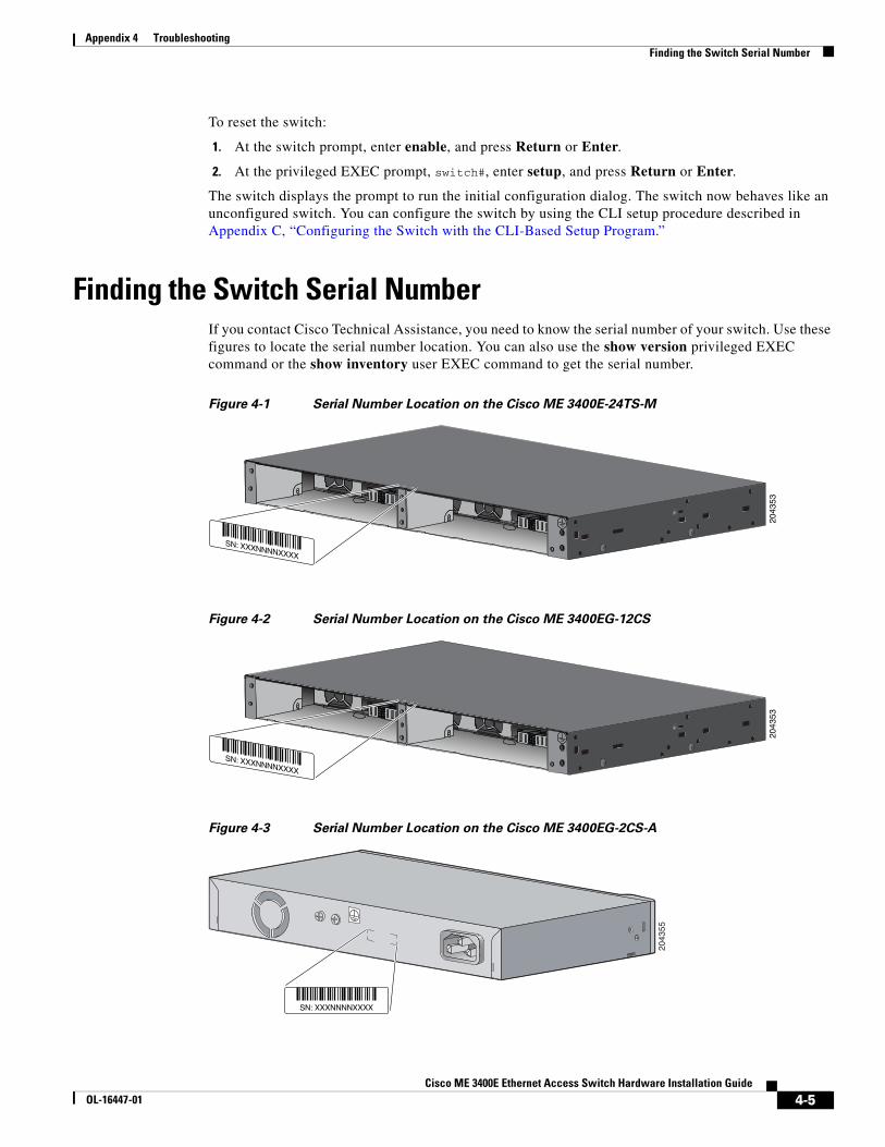
Appendix 4 TroubleshootingFinding the Switch Serial Number
To reset the switch:
1. At the switch prompt, enter enable, and press Return or Enter.
2. At the privileged EXEC prompt, switch#, enter setup, and press Return or Enter.
The switch displays the prompt to run the initial configuration dialog. The switch now behaves like an unconfigured switch. You can configure the switch by using the CLI setup procedure described in Appendix C, “Configuring the Switch with the CLI-Based Setup Program.”
Finding the Switch Serial NumberIf you contact Cisco Technical Assistance, you need to know the serial number of your switch. Use these figures to locate the serial number location. You can also use the show version privileged EXEC command or the show inventory user EXEC command to get the serial number.
Figure 4-1 Serial Number Location on the Cisco ME 3400E-24TS-M
Figure 4-2 Serial Number Location on the Cisco ME 3400EG-12CS
Figure 4-3 Serial Number Location on the Cisco ME 3400EG-2CS-A
SN: XXXNNNNXXXX
2043
53
SN: XXXNNNNXXXX20
4353
2043
55
SN: XXXNNNNXXXX
4-5Cisco ME 3400E Ethernet Access Switch Hardware Installation Guide
OL-16447-01

Appendix 4 TroubleshootingFinding the Switch Serial Number
4-6Cisco ME 3400E Ethernet Access Switch Hardware Installation Guide
OL-16447-01

Cisco ME 3400E EthernetOL-16447-01
A
P P E N D I X A Technical Specifications• Environmental Ranges and Technical Specifications for the Switch
• Environmental and Technical Specifications for the Power-Supply Modules
Environmental Ranges and Technical Specifications for the Switch
The operating temperature for the switch varies depending on the type of SFP module and the number of power-supply modules installed in the switch. In Table A-2, Table A-3, and Table A-4, Yes means that the operating temperature range is supported, and No means it is not supported.
Table A-1 Environmental Ranges for the Switch
Environmental Ranges
Operating temperature See Table A-2, Table A-3, and Table A-4.
Storage temperature –13 to 158°F (–25 to 70°C).
Relative humidity 10 to 85% (noncondensing).
Operating altitude Up to 10,000 ft (3049 m).
Storage altitude Up to 15,000 ft (4570 m).
Table A-2 Operating Temperatures for the Cisco ME 3400EG-2CS-A
SFP Module 32 to 131°F (0 to 55°C) 32 to 140°F (0 to 60°C)
GLC-FE-100FX Yes Yes
GLC-FE-100LX Yes Yes
GLC-FE-100EX Yes Yes
GLC-FE-100ZX Yes Yes
GLC-FE-100BX-D Yes Yes
GLC-FE-100BX-U Yes Yes
GLC-SX-MM Yes No
GLC-LH-SM Yes No
A-1 Access Switch Hardware Installation Guide
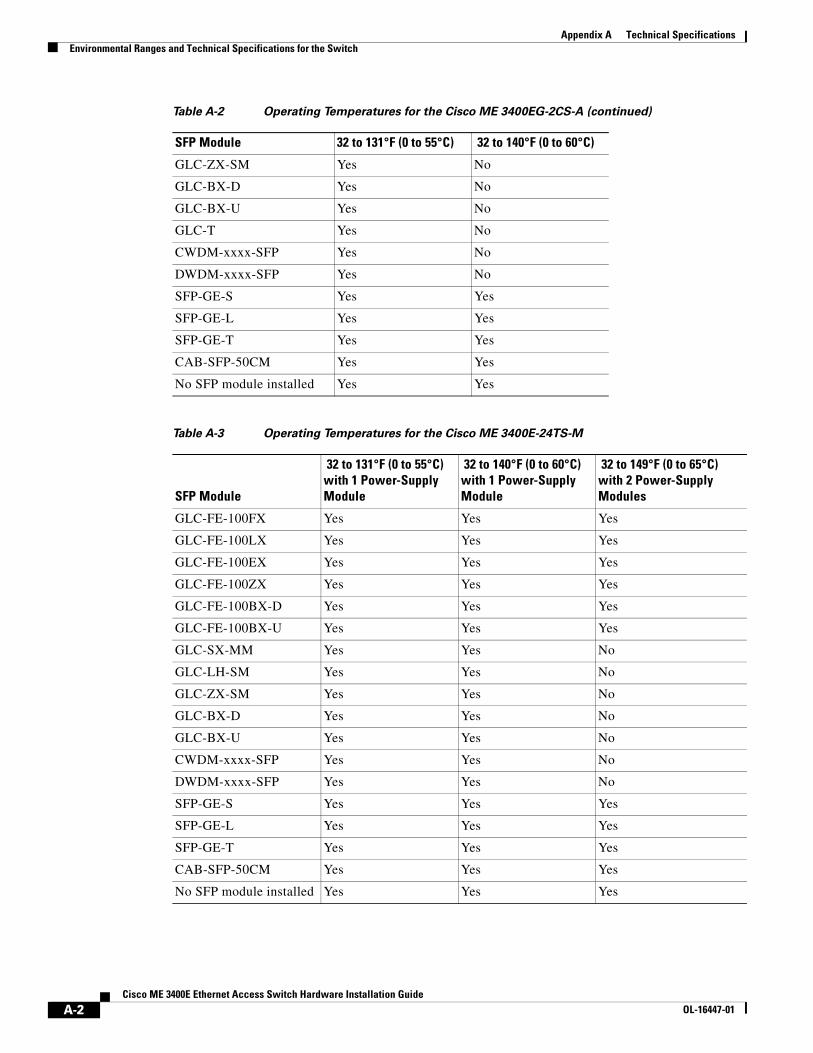
Appendix A Technical SpecificationsEnvironmental Ranges and Technical Specifications for the Switch
GLC-ZX-SM Yes No
GLC-BX-D Yes No
GLC-BX-U Yes No
GLC-T Yes No
CWDM-xxxx-SFP Yes No
DWDM-xxxx-SFP Yes No
SFP-GE-S Yes Yes
SFP-GE-L Yes Yes
SFP-GE-T Yes Yes
CAB-SFP-50CM Yes Yes
No SFP module installed Yes Yes
Table A-3 Operating Temperatures for the Cisco ME 3400E-24TS-M
SFP Module
32 to 131°F (0 to 55°C) with 1 Power-Supply Module
32 to 140°F (0 to 60°C) with 1 Power-Supply Module
32 to 149°F (0 to 65°C) with 2 Power-Supply Modules
GLC-FE-100FX Yes Yes Yes
GLC-FE-100LX Yes Yes Yes
GLC-FE-100EX Yes Yes Yes
GLC-FE-100ZX Yes Yes Yes
GLC-FE-100BX-D Yes Yes Yes
GLC-FE-100BX-U Yes Yes Yes
GLC-SX-MM Yes Yes No
GLC-LH-SM Yes Yes No
GLC-ZX-SM Yes Yes No
GLC-BX-D Yes Yes No
GLC-BX-U Yes Yes No
CWDM-xxxx-SFP Yes Yes No
DWDM-xxxx-SFP Yes Yes No
SFP-GE-S Yes Yes Yes
SFP-GE-L Yes Yes Yes
SFP-GE-T Yes Yes Yes
CAB-SFP-50CM Yes Yes Yes
No SFP module installed Yes Yes Yes
Table A-2 Operating Temperatures for the Cisco ME 3400EG-2CS-A (continued)
SFP Module 32 to 131°F (0 to 55°C) 32 to 140°F (0 to 60°C)
A-2Cisco ME 3400E Ethernet Access Switch Hardware Installation Guide
OL-16447-01
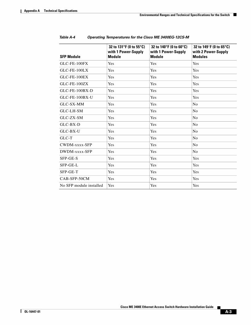
Appendix A Technical SpecificationsEnvironmental Ranges and Technical Specifications for the Switch
Table A-4 Operating Temperatures for the Cisco ME 3400EG-12CS-M
SFP Module
32 to 131°F (0 to 55°C) with 1 Power-Supply Module
32 to 140°F (0 to 60°C) with 1 Power-Supply Module
32 to 149°F (0 to 65°C) with 2 Power-Supply Modules
GLC-FE-100FX Yes Yes Yes
GLC-FE-100LX Yes Yes Yes
GLC-FE-100EX Yes Yes Yes
GLC-FE-100ZX Yes Yes Yes
GLC-FE-100BX-D Yes Yes Yes
GLC-FE-100BX-U Yes Yes Yes
GLC-SX-MM Yes Yes No
GLC-LH-SM Yes Yes No
GLC-ZX-SM Yes Yes No
GLC-BX-D Yes Yes No
GLC-BX-U Yes Yes No
GLC-T Yes Yes No
CWDM-xxxx-SFP Yes Yes No
DWDM-xxxx-SFP Yes Yes No
SFP-GE-S Yes Yes Yes
SFP-GE-L Yes Yes Yes
SFP-GE-T Yes Yes Yes
CAB-SFP-50CM Yes Yes Yes
No SFP module installed Yes Yes Yes
A-3Cisco ME 3400E Ethernet Access Switch Hardware Installation Guide
OL-16447-01
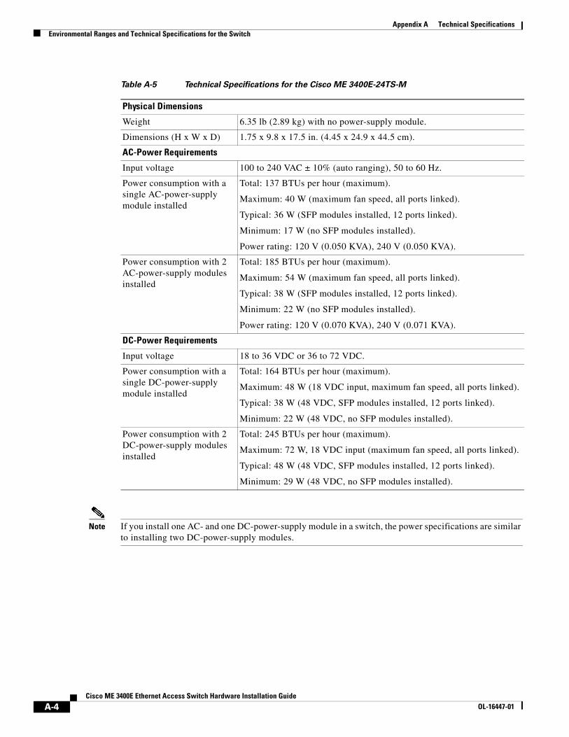
Appendix A Technical SpecificationsEnvironmental Ranges and Technical Specifications for the Switch
Note If you install one AC- and one DC-power-supply module in a switch, the power specifications are similar to installing two DC-power-supply modules.
Table A-5 Technical Specifications for the Cisco ME 3400E-24TS-M
Physical Dimensions
Weight 6.35 lb (2.89 kg) with no power-supply module.
Dimensions (H x W x D) 1.75 x 9.8 x 17.5 in. (4.45 x 24.9 x 44.5 cm).
AC-Power Requirements
Input voltage 100 to 240 VAC ± 10% (auto ranging), 50 to 60 Hz.
Power consumption with a single AC-power-supply module installed
Total: 137 BTUs per hour (maximum).
Maximum: 40 W (maximum fan speed, all ports linked).
Typical: 36 W (SFP modules installed, 12 ports linked).
Minimum: 17 W (no SFP modules installed).
Power rating: 120 V (0.050 KVA), 240 V (0.050 KVA).
Power consumption with 2 AC-power-supply modules installed
Total: 185 BTUs per hour (maximum).
Maximum: 54 W (maximum fan speed, all ports linked).
Typical: 38 W (SFP modules installed, 12 ports linked).
Minimum: 22 W (no SFP modules installed).
Power rating: 120 V (0.070 KVA), 240 V (0.071 KVA).
DC-Power Requirements
Input voltage 18 to 36 VDC or 36 to 72 VDC.
Power consumption with a single DC-power-supply module installed
Total: 164 BTUs per hour (maximum).
Maximum: 48 W (18 VDC input, maximum fan speed, all ports linked).
Typical: 38 W (48 VDC, SFP modules installed, 12 ports linked).
Minimum: 22 W (48 VDC, no SFP modules installed).
Power consumption with 2 DC-power-supply modules installed
Total: 245 BTUs per hour (maximum).
Maximum: 72 W, 18 VDC input (maximum fan speed, all ports linked).
Typical: 48 W (48 VDC, SFP modules installed, 12 ports linked).
Minimum: 29 W (48 VDC, no SFP modules installed).
A-4Cisco ME 3400E Ethernet Access Switch Hardware Installation Guide
OL-16447-01
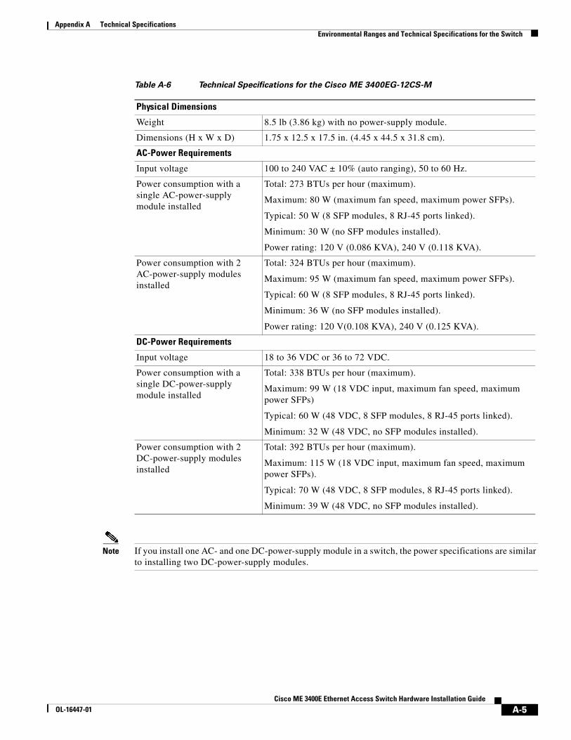
Appendix A Technical SpecificationsEnvironmental Ranges and Technical Specifications for the Switch
Note If you install one AC- and one DC-power-supply module in a switch, the power specifications are similar to installing two DC-power-supply modules.
Table A-6 Technical Specifications for the Cisco ME 3400EG-12CS-M
Physical Dimensions
Weight 8.5 lb (3.86 kg) with no power-supply module.
Dimensions (H x W x D) 1.75 x 12.5 x 17.5 in. (4.45 x 44.5 x 31.8 cm).
AC-Power Requirements
Input voltage 100 to 240 VAC ± 10% (auto ranging), 50 to 60 Hz.
Power consumption with a single AC-power-supply module installed
Total: 273 BTUs per hour (maximum).
Maximum: 80 W (maximum fan speed, maximum power SFPs).
Typical: 50 W (8 SFP modules, 8 RJ-45 ports linked).
Minimum: 30 W (no SFP modules installed).
Power rating: 120 V (0.086 KVA), 240 V (0.118 KVA).
Power consumption with 2 AC-power-supply modules installed
Total: 324 BTUs per hour (maximum).
Maximum: 95 W (maximum fan speed, maximum power SFPs).
Typical: 60 W (8 SFP modules, 8 RJ-45 ports linked).
Minimum: 36 W (no SFP modules installed).
Power rating: 120 V(0.108 KVA), 240 V (0.125 KVA).
DC-Power Requirements
Input voltage 18 to 36 VDC or 36 to 72 VDC.
Power consumption with a single DC-power-supply module installed
Total: 338 BTUs per hour (maximum).
Maximum: 99 W (18 VDC input, maximum fan speed, maximum power SFPs)
Typical: 60 W (48 VDC, 8 SFP modules, 8 RJ-45 ports linked).
Minimum: 32 W (48 VDC, no SFP modules installed).
Power consumption with 2 DC-power-supply modules installed
Total: 392 BTUs per hour (maximum).
Maximum: 115 W (18 VDC input, maximum fan speed, maximum power SFPs).
Typical: 70 W (48 VDC, 8 SFP modules, 8 RJ-45 ports linked).
Minimum: 39 W (48 VDC, no SFP modules installed).
A-5Cisco ME 3400E Ethernet Access Switch Hardware Installation Guide
OL-16447-01
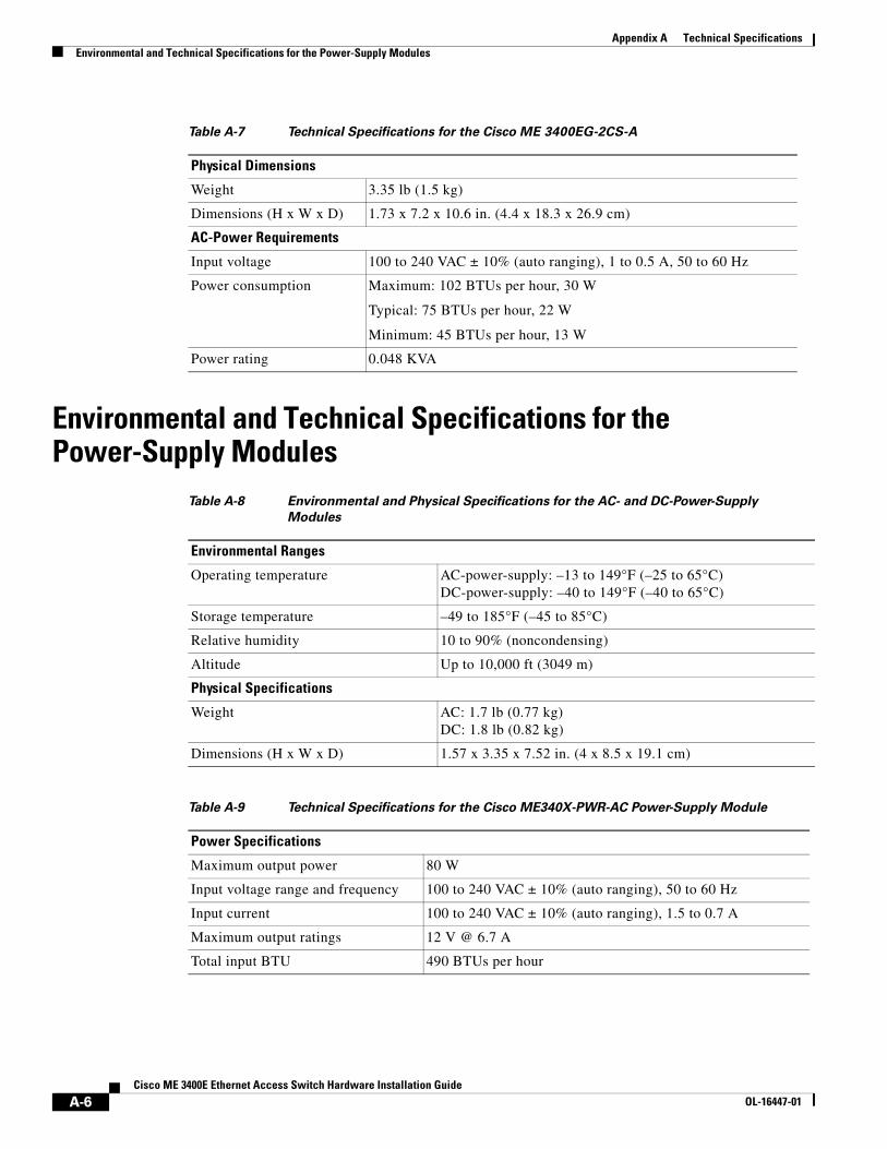
Appendix A Technical SpecificationsEnvironmental and Technical Specifications for the Power-Supply Modules
Environmental and Technical Specifications for the Power-Supply Modules
Table A-7 Technical Specifications for the Cisco ME 3400EG-2CS-A
Physical Dimensions
Weight 3.35 lb (1.5 kg)
Dimensions (H x W x D) 1.73 x 7.2 x 10.6 in. (4.4 x 18.3 x 26.9 cm)
AC-Power Requirements
Input voltage 100 to 240 VAC ± 10% (auto ranging), 1 to 0.5 A, 50 to 60 Hz
Power consumption Maximum: 102 BTUs per hour, 30 W
Typical: 75 BTUs per hour, 22 W
Minimum: 45 BTUs per hour, 13 W
Power rating 0.048 KVA
Table A-8 Environmental and Physical Specifications for the AC- and DC-Power-Supply
Modules
Environmental Ranges
Operating temperature AC-power-supply: –13 to 149°F (–25 to 65°C) DC-power-supply: –40 to 149°F (–40 to 65°C)
Storage temperature –49 to 185°F (–45 to 85°C)
Relative humidity 10 to 90% (noncondensing)
Altitude Up to 10,000 ft (3049 m)
Physical Specifications
Weight AC: 1.7 lb (0.77 kg) DC: 1.8 lb (0.82 kg)
Dimensions (H x W x D) 1.57 x 3.35 x 7.52 in. (4 x 8.5 x 19.1 cm)
Table A-9 Technical Specifications for the Cisco ME340X-PWR-AC Power-Supply Module
Power Specifications
Maximum output power 80 W
Input voltage range and frequency 100 to 240 VAC ± 10% (auto ranging), 50 to 60 Hz
Input current 100 to 240 VAC ± 10% (auto ranging), 1.5 to 0.7 A
Maximum output ratings 12 V @ 6.7 A
Total input BTU 490 BTUs per hour
A-6Cisco ME 3400E Ethernet Access Switch Hardware Installation Guide
OL-16447-01
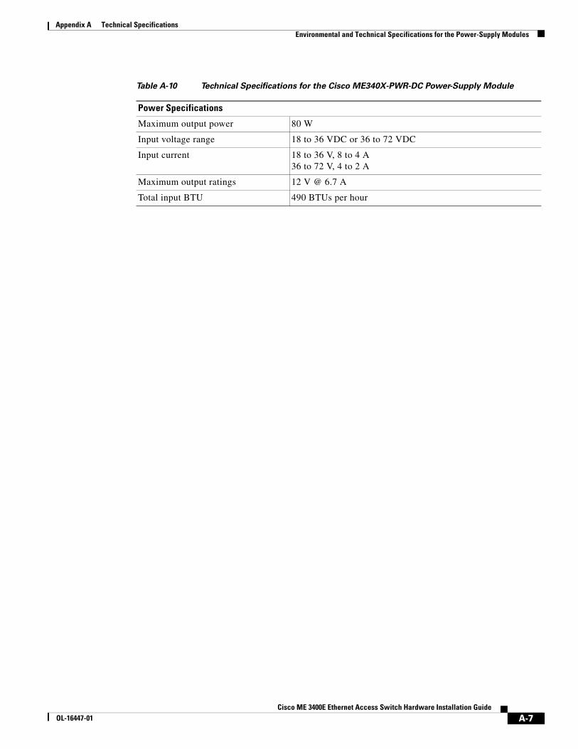
Appendix A Technical SpecificationsEnvironmental and Technical Specifications for the Power-Supply Modules
Table A-10 Technical Specifications for the Cisco ME340X-PWR-DC Power-Supply Module
Power Specifications
Maximum output power 80 W
Input voltage range 18 to 36 VDC or 36 to 72 VDC
Input current 18 to 36 V, 8 to 4 A 36 to 72 V, 4 to 2 A
Maximum output ratings 12 V @ 6.7 A
Total input BTU 490 BTUs per hour
A-7Cisco ME 3400E Ethernet Access Switch Hardware Installation Guide
OL-16447-01
Appendix A Technical SpecificationsEnvironmental and Technical Specifications for the Power-Supply Modules
A-8Cisco ME 3400E Ethernet Access Switch Hardware Installation Guide
OL-16447-01
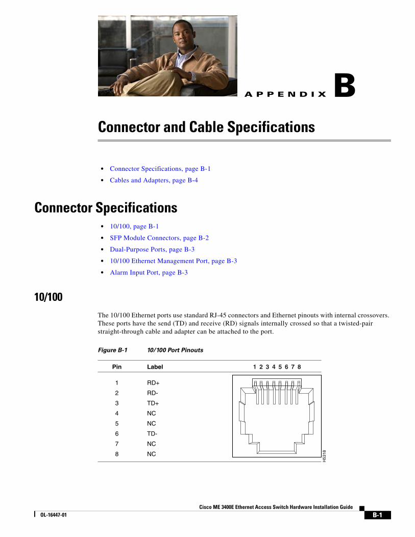
Cisco ME 3400E EthernetOL-16447-01
A
P P E N D I X B Connector and Cable Specifications• Connector Specifications, page B-1
• Cables and Adapters, page B-4
Connector Specifications • 10/100, page B-1
• SFP Module Connectors, page B-2
• Dual-Purpose Ports, page B-3
• 10/100 Ethernet Management Port, page B-3
• Alarm Input Port, page B-3
10/100The 10/100 Ethernet ports use standard RJ-45 connectors and Ethernet pinouts with internal crossovers. These ports have the send (TD) and receive (RD) signals internally crossed so that a twisted-pair straight-through cable and adapter can be attached to the port.
Figure B-1 10/100 Port Pinouts
H53
18
2 31 4 5 6 7 8Pin Label
1
2
3
4
5
6
7
8
RD+
RD-
TD+
NC
NC
TD-
NC
NC
B-1 Access Switch Hardware Installation Guide
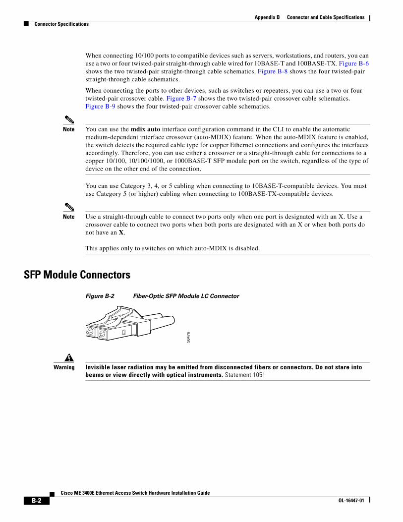
Appendix B Connector and Cable SpecificationsConnector Specifications
When connecting 10/100 ports to compatible devices such as servers, workstations, and routers, you can use a two or four twisted-pair straight-through cable wired for 10BASE-T and 100BASE-TX. Figure B-6 shows the two twisted-pair straight-through cable schematics. Figure B-8 shows the four twisted-pair straight-through cable schematics.
When connecting the ports to other devices, such as switches or repeaters, you can use a two or four twisted-pair crossover cable. Figure B-7 shows the two twisted-pair crossover cable schematics. Figure B-9 shows the four twisted-pair crossover cable schematics.
Note You can use the mdix auto interface configuration command in the CLI to enable the automatic medium-dependent interface crossover (auto-MDIX) feature. When the auto-MDIX feature is enabled, the switch detects the required cable type for copper Ethernet connections and configures the interfaces accordingly. Therefore, you can use either a crossover or a straight-through cable for connections to a copper 10/100, 10/100/1000, or 1000BASE-T SFP module port on the switch, regardless of the type of device on the other end of the connection.
You can use Category 3, 4, or 5 cabling when connecting to 10BASE-T-compatible devices. You must use Category 5 (or higher) cabling when connecting to 100BASE-TX-compatible devices.
Note Use a straight-through cable to connect two ports only when one port is designated with an X. Use a crossover cable to connect two ports when both ports are designated with an X or when both ports do not have an X. This applies only to switches on which auto-MDIX is disabled.
SFP Module Connectors
Figure B-2 Fiber-Optic SFP Module LC Connector
Warning Invisible laser radiation may be emitted from disconnected fibers or connectors. Do not stare into beams or view directly with optical instruments. Statement 1051
5847
6
B-2Cisco ME 3400E Ethernet Access Switch Hardware Installation Guide
OL-16447-01
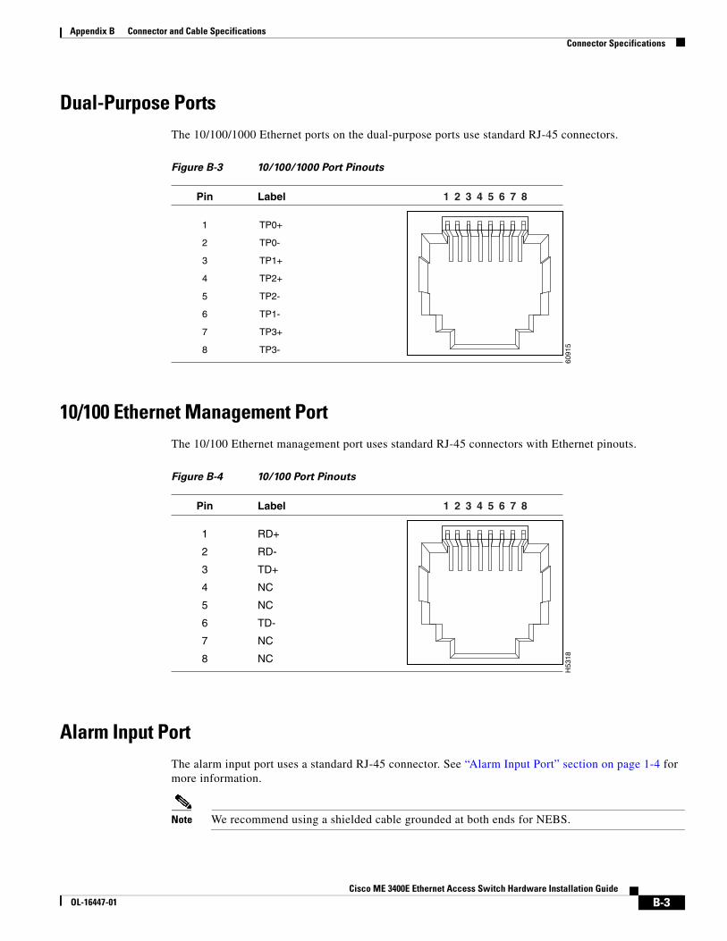
Appendix B Connector and Cable SpecificationsConnector Specifications
Dual-Purpose PortsThe 10/100/1000 Ethernet ports on the dual-purpose ports use standard RJ-45 connectors.
Figure B-3 10/100/1000 Port Pinouts
10/100 Ethernet Management PortThe 10/100 Ethernet management port uses standard RJ-45 connectors with Ethernet pinouts.
Figure B-4 10/100 Port Pinouts
Alarm Input PortThe alarm input port uses a standard RJ-45 connector. See “Alarm Input Port” section on page 1-4 for more information.
Note We recommend using a shielded cable grounded at both ends for NEBS.
6091
5
2 31 4 5 6 7 8Pin Label
1
2
3
4
5
6
7
8
TP0+
TP0-
TP1+
TP2+
TP2-
TP1-
TP3+
TP3-
H53
18
2 31 4 5 6 7 8Pin Label
1
2
3
4
5
6
7
8
RD+
RD-
TD+
NC
NC
TD-
NC
NC
B-3Cisco ME 3400E Ethernet Access Switch Hardware Installation Guide
OL-16447-01
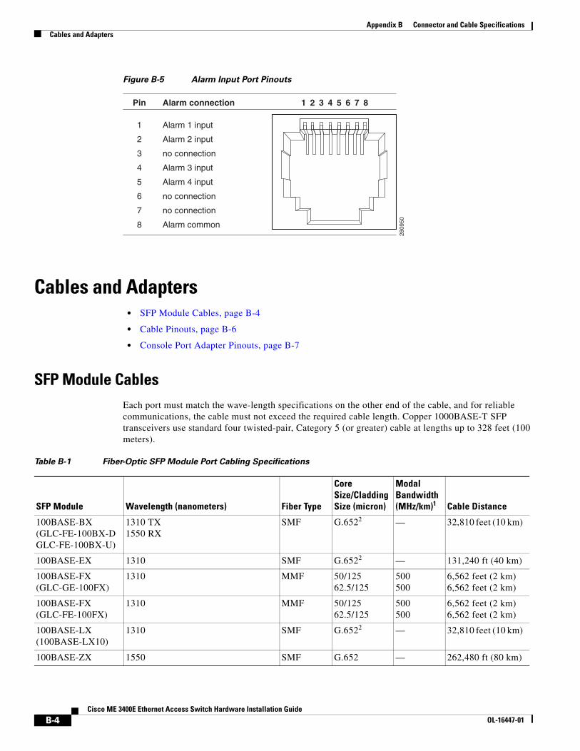
Appendix B Connector and Cable SpecificationsCables and Adapters
Figure B-5 Alarm Input Port Pinouts
Cables and Adapters • SFP Module Cables, page B-4
• Cable Pinouts, page B-6
• Console Port Adapter Pinouts, page B-7
SFP Module Cables Each port must match the wave-length specifications on the other end of the cable, and for reliable communications, the cable must not exceed the required cable length. Copper 1000BASE-T SFP transceivers use standard four twisted-pair, Category 5 (or greater) cable at lengths up to 328 feet (100 meters).
2809
50
2 31 4 5 6 7 8Pin Alarm connection
1
2
3
4
5
6
7
8
Alarm 1 input
Alarm 2 input
no connection
Alarm 3 input
Alarm 4 input
no connection
no connection
Alarm common
Table B-1 Fiber-Optic SFP Module Port Cabling Specifications
SFP Module Wavelength (nanometers) Fiber Type
Core Size/Cladding Size (micron)
Modal Bandwidth (MHz/km)1 Cable Distance
100BASE-BX (GLC-FE-100BX-D GLC-FE-100BX-U)
1310 TX 1550 RX
SMF G.6522 — 32,810 feet (10 km)
100BASE-EX 1310 SMF G.6522 — 131,240 ft (40 km)
100BASE-FX (GLC-GE-100FX)
1310 MMF 50/125 62.5/125
500 500
6,562 feet (2 km) 6,562 feet (2 km)
100BASE-FX (GLC-FE-100FX)
1310 MMF 50/125 62.5/125
500 500
6,562 feet (2 km) 6,562 feet (2 km)
100BASE-LX (100BASE-LX10)
1310 SMF G.6522 — 32,810 feet (10 km)
100BASE-ZX 1550 SMF G.652 — 262,480 ft (80 km)
B-4Cisco ME 3400E Ethernet Access Switch Hardware Installation Guide
OL-16447-01
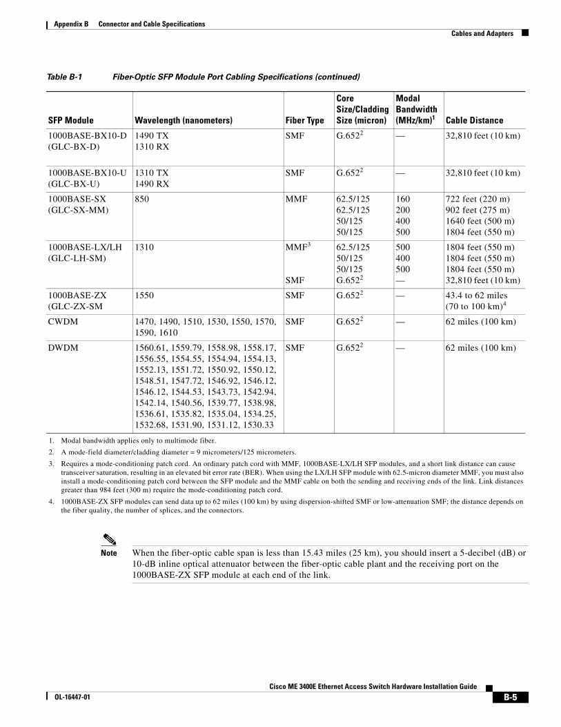
Appendix B Connector and Cable SpecificationsCables and Adapters
Note When the fiber-optic cable span is less than 15.43 miles (25 km), you should insert a 5-decibel (dB) or 10-dB inline optical attenuator between the fiber-optic cable plant and the receiving port on the 1000BASE-ZX SFP module at each end of the link.
1000BASE-BX10-D (GLC-BX-D)
1490 TX 1310 RX
SMF G.6522 — 32,810 feet (10 km)
1000BASE-BX10-U (GLC-BX-U)
1310 TX 1490 RX
SMF G.6522 — 32,810 feet (10 km)
1000BASE-SX (GLC-SX-MM)
850 MMF 62.5/125 62.5/125 50/125 50/125
160 200 400 500
722 feet (220 m) 902 feet (275 m) 1640 feet (500 m) 1804 feet (550 m)
1000BASE-LX/LH (GLC-LH-SM)
1310 MMF3 SMF
62.5/125 50/125 50/125 G.6522
500 400 500 —
1804 feet (550 m) 1804 feet (550 m) 1804 feet (550 m) 32,810 feet (10 km)
1000BASE-ZX (GLC-ZX-SM
1550 SMF G.6522 — 43.4 to 62 miles (70 to 100 km)4
CWDM 1470, 1490, 1510, 1530, 1550, 1570, 1590, 1610
SMF G.6522 — 62 miles (100 km)
DWDM 1560.61, 1559.79, 1558.98, 1558.17, 1556.55, 1554.55, 1554.94, 1554.13, 1552.13, 1551.72, 1550.92, 1550.12, 1548.51, 1547.72, 1546.92, 1546.12, 1546.12, 1544.53, 1543.73, 1542.94, 1542.14, 1540.56, 1539.77, 1538.98, 1536.61, 1535.82, 1535.04, 1534.25, 1532.68, 1531.90, 1531.12, 1530.33
SMF G.6522 — 62 miles (100 km)
1. Modal bandwidth applies only to multimode fiber.
2. A mode-field diameter/cladding diameter = 9 micrometers/125 micrometers.
3. Requires a mode-conditioning patch cord. An ordinary patch cord with MMF, 1000BASE-LX/LH SFP modules, and a short link distance can cause transceiver saturation, resulting in an elevated bit error rate (BER). When using the LX/LH SFP module with 62.5-micron diameter MMF, you must also install a mode-conditioning patch cord between the SFP module and the MMF cable on both the sending and receiving ends of the link. Link distances greater than 984 feet (300 m) require the mode-conditioning patch cord.
4. 1000BASE-ZX SFP modules can send data up to 62 miles (100 km) by using dispersion-shifted SMF or low-attenuation SMF; the distance depends on the fiber quality, the number of splices, and the connectors.
Table B-1 Fiber-Optic SFP Module Port Cabling Specifications (continued)
SFP Module Wavelength (nanometers) Fiber Type
Core Size/Cladding Size (micron)
Modal Bandwidth (MHz/km)1 Cable Distance
B-5Cisco ME 3400E Ethernet Access Switch Hardware Installation Guide
OL-16447-01
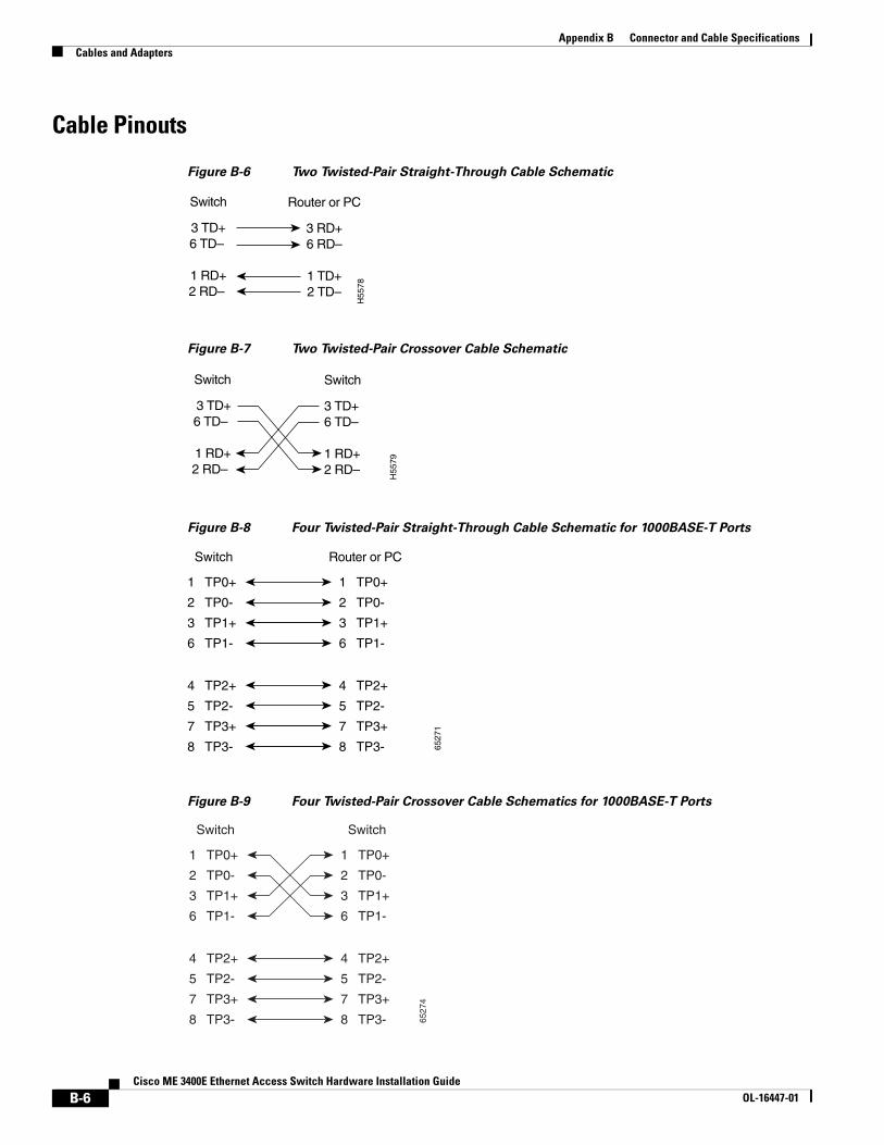
Appendix B Connector and Cable SpecificationsCables and Adapters
Cable Pinouts
Figure B-6 Two Twisted-Pair Straight-Through Cable Schematic
Figure B-7 Two Twisted-Pair Crossover Cable Schematic
Figure B-8 Four Twisted-Pair Straight-Through Cable Schematic for 1000BASE-T Ports
Figure B-9 Four Twisted-Pair Crossover Cable Schematics for 1000BASE-T Ports
Switch
3 TD+6 TD–
1 RD+2 RD–
Router or PC
3 RD+6 RD–
1 TD+2 TD–
H55
78
Switch
3 TD+6 TD–
1 RD+2 RD–
Switch
3 TD+6 TD–
1 RD+2 RD–
H55
79
1 TP0+
2 TP0-
3 TP1+
6 TP1-
1 TP0+
2 TP0-
3 TP1+
6 TP1-
Switch Router or PC
4 TP2+
5 TP2-
7 TP3+
8 TP3-
4 TP2+
5 TP2-
7 TP3+
8 TP3- 6527
1
1 TP0+
2 TP0-
3 TP1+
6 TP1-
1 TP0+
Switch Switch
2 TP0-
3 TP1+
6 TP1-
4 TP2+
5 TP2-
7 TP3+
8 TP3-
4 TP2+
5 TP2-
7 TP3+
8 TP3- 6527
4
B-6Cisco ME 3400E Ethernet Access Switch Hardware Installation Guide
OL-16447-01
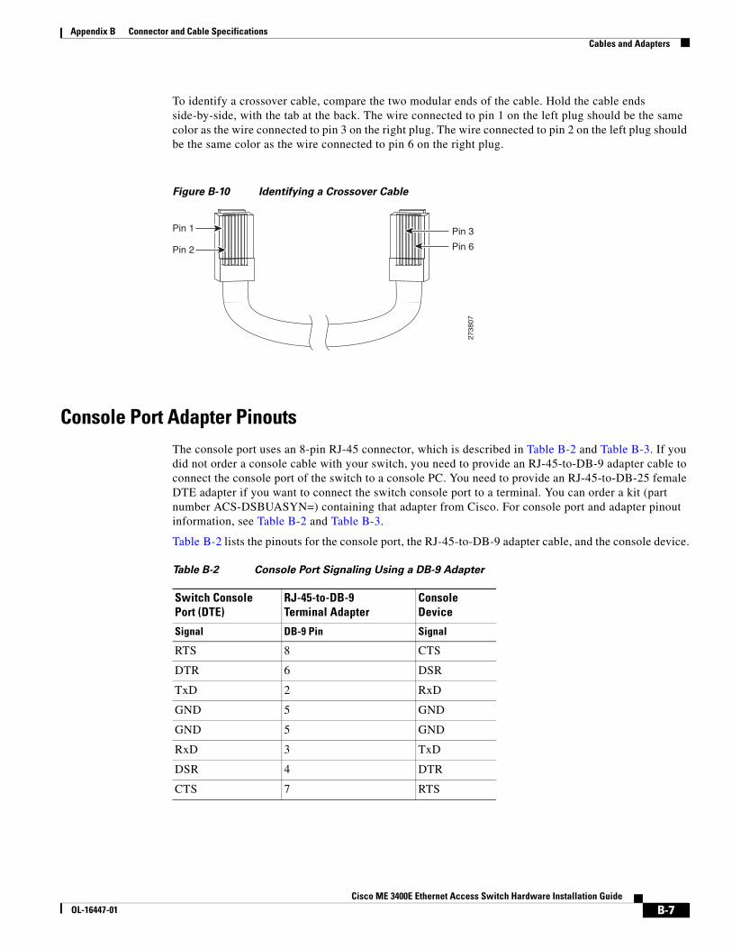
Appendix B Connector and Cable SpecificationsCables and Adapters
To identify a crossover cable, compare the two modular ends of the cable. Hold the cable ends side-by-side, with the tab at the back. The wire connected to pin 1 on the left plug should be the same color as the wire connected to pin 3 on the right plug. The wire connected to pin 2 on the left plug should be the same color as the wire connected to pin 6 on the right plug.
Figure B-10 Identifying a Crossover Cable
Console Port Adapter PinoutsThe console port uses an 8-pin RJ-45 connector, which is described in Table B-2 and Table B-3. If you did not order a console cable with your switch, you need to provide an RJ-45-to-DB-9 adapter cable to connect the console port of the switch to a console PC. You need to provide an RJ-45-to-DB-25 female DTE adapter if you want to connect the switch console port to a terminal. You can order a kit (part number ACS-DSBUASYN=) containing that adapter from Cisco. For console port and adapter pinout information, see Table B-2 and Table B-3.
Table B-2 lists the pinouts for the console port, the RJ-45-to-DB-9 adapter cable, and the console device.
Pin 1
Pin 2
2738
07
Pin 6
Pin 3
Table B-2 Console Port Signaling Using a DB-9 Adapter
Switch Console Port (DTE)
RJ-45-to-DB-9 Terminal Adapter
Console Device
Signal DB-9 Pin Signal
RTS 8 CTS
DTR 6 DSR
TxD 2 RxD
GND 5 GND
GND 5 GND
RxD 3 TxD
DSR 4 DTR
CTS 7 RTS
B-7Cisco ME 3400E Ethernet Access Switch Hardware Installation Guide
OL-16447-01
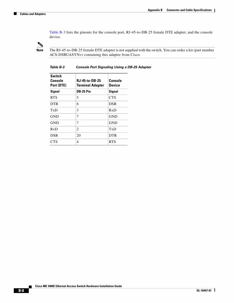
Appendix B Connector and Cable SpecificationsCables and Adapters
Table B-3 lists the pinouts for the console port, RJ-45-to-DB-25 female DTE adapter, and the console device.
Note The RJ-45-to-DB-25 female DTE adapter is not supplied with the switch. You can order a kit (part number ACS-DSBUASYN=) containing this adapter from Cisco.
Table B-3 Console Port Signaling Using a DB-25 Adapter
Switch Console Port (DTE)
RJ-45-to-DB-25 Terminal Adapter
Console Device
Signal DB-25 Pin Signal
RTS 5 CTS
DTR 6 DSR
TxD 3 RxD
GND 7 GND
GND 7 GND
RxD 2 TxD
DSR 20 DTR
CTS 4 RTS
B-8Cisco ME 3400E Ethernet Access Switch Hardware Installation Guide
OL-16447-01
Cisco ME 3400E EthernetOL-16447-01
A
P P E N D I X C Configuring the Switch with the CLI-Based Setup ProgramThis appendix provides a command-line interface (CLI)-based setup procedure for a standalone switch. Before connecting the switch to a power source, review the safety warnings in Chapter 2, “Switch Installation” and Chapter 3, “Installing and Removing AC- and DC-Power-Supply Modules.”
Accessing the CLI Through the Console PortYou can access the CLI on a configured or unconfigured switch by connecting the console port of the switch to the serial port on your PC or workstation and accessing the switch through a Telnet session.
Starting the Terminal-Emulation SoftwareBefore you power on the switch, start the terminal emulation session so that you can see the output display from the power-on self-test (POST).
The terminal-emulation software—frequently a PC application such as Hyperterminal or ProcommPlus—makes communication between the switch and your PC or terminal possible.
Follow these steps to start a terminal-emulation session:
Step 1 Start the terminal-emulation program if you are using a PC or terminal.
Step 2 Configure the baud rate and character format of the PC or terminal to match these console port default characteristics:
• 9600 baud or 115200 baud (suggested rate)
• 8 data bits
• 1 stop bit
• No parity
• None (flow control)
C-1 Access Switch Hardware Installation Guide
Appendix C Configuring the Switch with the CLI-Based Setup ProgramEntering the Initial Configuration Information
To power on the switch, connect one end of the AC-power cord to the AC-power connector on the switch, and connect the other end of the power cord to an AC-power outlet.
To power on a DC switch, see Chapter 3, “Installing and Removing AC- and DC-Power-Supply Modules.”
Entering the Initial Configuration Information To set up the switch, you need to complete the setup program, which runs automatically after the switch is powered up. You must assign an IP address and other configuration information necessary for the switch to communicate with the local routers and the Internet.
IP SettingsYou will need this information from your network administrator before you complete the setup program:
• Switch IP address
• Subnet mask (IP netmask)
• Default gateway (router)
• Enable secret password
• Enable password
• Telnet password
Completing the Setup ProgramFollow these steps to complete the setup program and to create an initial configuration for the switch:
Step 1 Enter Yes at these two prompts.
Would you like to enter the initial configuration dialog? [yes/no]: yes
At any point you may enter a question mark '?' for help.Use ctrl-c to abort configuration dialog at any prompt.Default settings are in square brackets '[]'.
Basic management setup configures only enough connectivityfor management of the system, extended setup will ask youto configure each interface on the system.
Would you like to enter basic management setup? [yes/no]: yes
Step 2 Enter a host name for the switch, and press Return.
On a command switch, the host name is limited to 28 characters; on a member switch to 31 characters. Do not use -n, where n is a number, as the last character in a host name for any switch.
Enter host name [Switch]: host_name
C-2Cisco ME 3400E Ethernet Access Switch Hardware Installation Guide
OL-16447-01
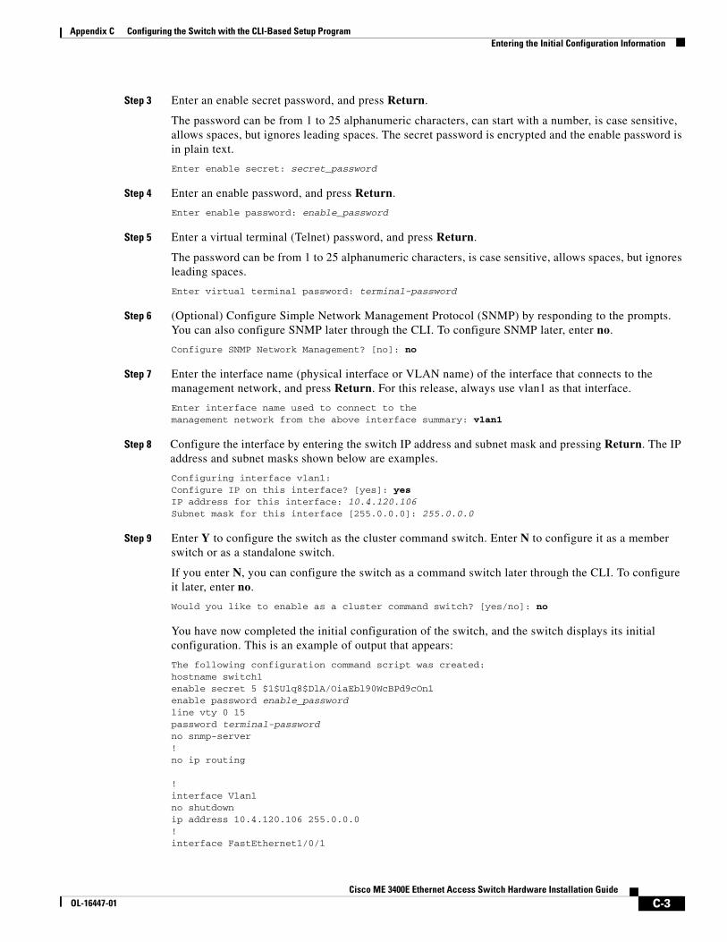
Appendix C Configuring the Switch with the CLI-Based Setup ProgramEntering the Initial Configuration Information
Step 3 Enter an enable secret password, and press Return.
The password can be from 1 to 25 alphanumeric characters, can start with a number, is case sensitive, allows spaces, but ignores leading spaces. The secret password is encrypted and the enable password is in plain text.
Enter enable secret: secret_password
Step 4 Enter an enable password, and press Return.
Enter enable password: enable_password
Step 5 Enter a virtual terminal (Telnet) password, and press Return.
The password can be from 1 to 25 alphanumeric characters, is case sensitive, allows spaces, but ignores leading spaces.
Enter virtual terminal password: terminal-password
Step 6 (Optional) Configure Simple Network Management Protocol (SNMP) by responding to the prompts. You can also configure SNMP later through the CLI. To configure SNMP later, enter no.
Configure SNMP Network Management? [no]: no
Step 7 Enter the interface name (physical interface or VLAN name) of the interface that connects to the management network, and press Return. For this release, always use vlan1 as that interface.
Enter interface name used to connect to themanagement network from the above interface summary: vlan1
Step 8 Configure the interface by entering the switch IP address and subnet mask and pressing Return. The IP address and subnet masks shown below are examples.
Configuring interface vlan1:Configure IP on this interface? [yes]: yes IP address for this interface: 10.4.120.106Subnet mask for this interface [255.0.0.0]: 255.0.0.0
Step 9 Enter Y to configure the switch as the cluster command switch. Enter N to configure it as a member switch or as a standalone switch.
If you enter N, you can configure the switch as a command switch later through the CLI. To configure it later, enter no.
Would you like to enable as a cluster command switch? [yes/no]: no
You have now completed the initial configuration of the switch, and the switch displays its initial configuration. This is an example of output that appears:
The following configuration command script was created:hostname switch1enable secret 5 $1$Ulq8$DlA/OiaEbl90WcBPd9cOn1enable password enable_passwordline vty 0 15password terminal-passwordno snmp-server!no ip routing
!interface Vlan1no shutdownip address 10.4.120.106 255.0.0.0!interface FastEthernet1/0/1
C-3Cisco ME 3400E Ethernet Access Switch Hardware Installation Guide
OL-16447-01
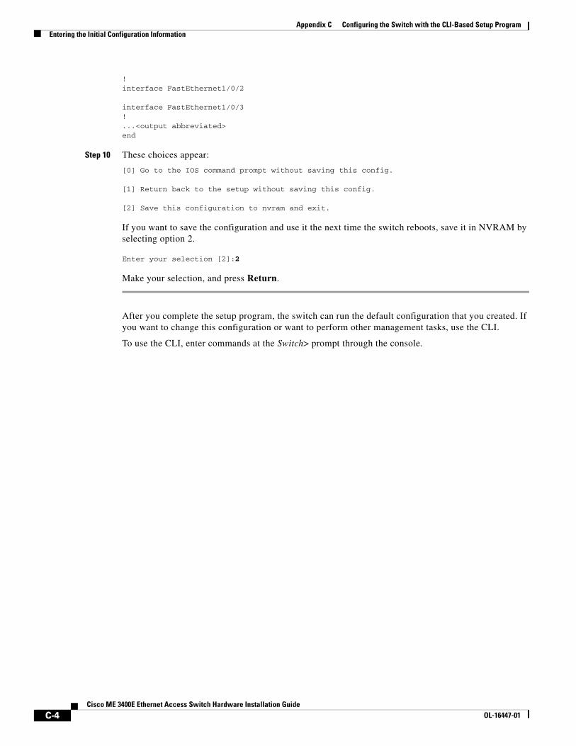
Appendix C Configuring the Switch with the CLI-Based Setup ProgramEntering the Initial Configuration Information
!interface FastEthernet1/0/2
interface FastEthernet1/0/3!...<output abbreviated>end
Step 10 These choices appear:
[0] Go to the IOS command prompt without saving this config.
[1] Return back to the setup without saving this config.
[2] Save this configuration to nvram and exit.
If you want to save the configuration and use it the next time the switch reboots, save it in NVRAM by selecting option 2.
Enter your selection [2]:2
Make your selection, and press Return.
After you complete the setup program, the switch can run the default configuration that you created. If you want to change this configuration or want to perform other management tasks, use the CLI.
To use the CLI, enter commands at the Switch> prompt through the console.
C-4Cisco ME 3400E Ethernet Access Switch Hardware Installation Guide
OL-16447-01
Cisco ME 3400E EtOL-16447-01
I N D E X
LEDs (continued)
power-supply modules (continued)
SFP modules (continued)
warnings (continued)
Numerics
10/100/1000BASE-T SFP module 1-6
10/100/1000 ports 1-11, B-3
10/100 ports
cable lengths 2-4
connecting to 2-22
described 1-5
1000BASE-BX10 SFP module 1-6
1000BASE-BX SFP module 1-6
1000BASE-LX/LH SFP module 1-6
1000BASE-SX SFP module 1-6
1000BASE-T SFP module 1-6
1000BASE-T SFP module cable lengths 2-4
1000BASE-ZX SFP module 1-6
100BASE-BX SFP module 1-6
100BASE-EX SFP module 1-6
100BASE-FX SFP module 1-6
100BASE-LX SFP module 1-6
100BASE-ZX SFP module 1-6
19-inch rack-mounting brackets 2-8 to 2-9
19- to 24-inch racks 2-6
23-inch rack-mounting brackets 2-10, 2-11
24-inch rack-mounting brackets 2-11
A
AC power
connecting to 2-5, C-2
AC power-supply module LEDs 1-10
adapter pinouts, terminal
RJ-45-to-DB-25 B-8
RJ-45-to-DB-9 B-7
alarm input port
connectors B-3
described 1-4
autonegotiation
on dual-purpose ports 1-5
troubleshooting 4-4
B
brackets
See mounting brackets
C
cable guide, attaching 2-14
cable lengths 2-4
cables
crossover
four twisted-pair pinout, 1000BASE-T ports B-6
identifying B-7
two twisted-pair pinout, 10/100 ports B-6
crossover, connecting to B-2
pinouts B-6
See also connectors
SFP module B-4
IN-1hernet Access Switch Hardware Installation Guide
Index
straight-through
connecting to B-2
four twisted-pair pinout, 1000BASE-T ports B-6
two twisted-pair pinout B-6
Cisco IOS command-line interface 1-14
Cisco ME 3400E-24TS-M switch described 1-2
Cisco ME 3400EG-12CS-M switch described 1-3
Cisco ME 3400EG-2CS-A switch described 1-3
CiscoView 1-14
CLI
accessing through console port C-1
management options 1-14
coarse wavelength-division multiplexing
See CWDM
command-line interface
See CLI
configuration examples, network 1-1
connecting
to AC power 3-7
to console port B-7
to DC power 3-11, C-2
to SFP modules 2-25
connecting outside the building warning 2-3
connection procedures 2-22 to 2-25
connectors
alarm input port B-3
dual-purpose ports B-3
Ethernet management port B-3
SFP module connectors B-2
console port
connecting to B-7
described 1-5, B-7
crossover cable
connecting to 1000BASE-T SFP module ports 2-25
pinout
four twisted-pair, 1000BASE-T ports B-6
CWDM SFP module 1-6
IN-2Cisco ME 3400E Ethernet Access Switch Hardware Installation Gu
D
DC connectors, ordering replacements 3-9
DC power
connecting to 2-5, C-2
specifications A-4 to A-5
DC-power-supply module LEDs 1-10
DC power warning 3-8
dense wavelength-division multiplexing
See DWDM
diagnosing problems 4-1
dimensions A-6
disconnect device warning 3-12
disposal of product warning 2-3
dual-purpose ports
description 1-5
LEDs 1-11
numbering of dual-purpose ports 1-2 to 1-3
duplex
troubleshooting 4-4
DWDM SFP module 1-6
E
electrical code compliance warning 2-3
electrical noise, avoiding 2-4
ESD protection 2-3
Ethernet and fiber cable troubleshooting 4-2
Ethernet cable warning 2-2
Ethernet management port
connectors B-3
described 1-5
ETSI rack-mounting brackets 2-12
ETSI racks 2-6
European Telecommunications Standards Institute
See ETSI
examples, network configuration 1-1
ideOL-16447-01
Index
F
front panel
clearance 2-4
description 1-2 to 1-11
LEDs 1-7
G
ground conductor warning 2-3, 3-9
ground connection warning 2-3, 3-9
grounding architecture requirement 2-3
H
HP OpenView 1-14
I
installation
assigning the IP Address C-2
connecting to a power source 2-5, C-2
rack-mounting 2-6 to 2-14
shelf-mounting 2-19
site requirements 2-4
starting the terminal emulation software C-1
table-mounting 2-19
wall-mounting 2-14
See also procedures
installation warning 2-1, 3-12
installing SFP modules 2-19 to 2-20
interface troubleshooting 4-3
J
jewelry removal warning 2-1
Cisco MEOL-16447-01
L
laser warning 2-2
LEDs
AC-power-supply modules 1-10
alarms 1-11
DC-power-supply modules 1-10
descriptions and locations 1-7 to 1-11
dual-purpose port 1-11
ethernet management 1-10
port 1-11
POST results 4-1
PSU 1 and PSU 2 1-9
PSU OK 3-4
system 1-8
troubleshooting with 4-1 to 4-2
lightning activity warning 2-2, 3-5
link status troubleshooting 4-2
M
mounting
rack 2-6
shelf 2-19
table 2-19
wall 2-14
mounting brackets
attaching 2-7
attaching for 19-inch racks 2-8 to 2-9
attaching for 23-inch racks 2-10, 2-11
attaching for 24-inch racks 2-11
attaching for ETSI racks 2-12
multiple power supply warning 2-4
N
NEBS compliance 2-3
network configuration examples 1-1
Network Equipment Building Systems
IN-3 3400E Ethernet Access Switch Hardware Installation Guide
Index
See NEBS compliance
noise, electrical 2-4
O
overcurrent protection warning 3-12
overheating warning 2-4
P
pinouts
10/100 ports B-2
console port B-8
crossover cables
four twisted-pair, 1000BASE-T ports B-6
two twisted-pair 10/100 ports B-6
RJ-45-to-DB-25 terminal adapter B-8
RJ-45-to-DB-9 terminal adapter B-7
SFP module ports B-2
straight-through cables
four twisted-pair 1000BASE-T ports B-6
two twisted-pair B-6
plug-socket combination warning 2-3
port LEDs 1-11
ports
10/100/1000 1-11, B-3
alarm input 1-4
console 1-5
dual-purpose 1-5
Ethernet management 1-5
SFP module 1-5
POST
LEDs 4-1
power
connecting to AC 2-5, C-2
connecting to DC 2-5, C-2
power input connectors described 3-6
power on 2-5, C-2
IN-4Cisco ME 3400E Ethernet Access Switch Hardware Installation Gu
power source warning 2-2
power-supply modules 3-1
description 3-2 to 3-4
installing AC 3-6 to 3-7
installing DC 3-8 to 3-16
LEDs 1-9
overview 1-13, 3-1
removing AC 3-7
removing DC 3-16
procedures
connection 2-22 to 2-25
installation 2-5 to 2-19
product disposal warning 2-3
PSU 1 and PSU 2 LEDs 1-9
PSU OK LEDs 3-4
publications, related i-viii
R
rack-mounting 2-6 to 2-14
rack-mounting warning 2-2
rear panel
clearance 2-4
description 1-12 to 1-13
removing SFP modules 2-21
requirement for grounding architecture 2-3
restricted access area warning 2-2
RJ-45 connector
alarm input port B-3
console port B-7
Ethernet management port B-3
S
safety 2-1
serial number location 4-5
SFP module patch cable
description 1-6
ideOL-16447-01
Index
installing 2-21
removing 2-22
SFP modules
10/100/1000BASE-T 1-6
1000BASE-BX 1-6
1000BASE-BX10 1-6
1000BASE-LX/LH 1-6
1000BASE-SX 1-6
1000BASE-T 1-6
1000BASE-ZX 1-6
100BASE-BX 1-6
100BASE-EX 1-6
100BASE-FX 1-6
100BASE-LX 1-6
100BASE-ZX 1-6
connecting to 2-25
connectors B-2
CWDM 1-6
DWDM 1-6
installing 2-19 to 2-20
numbering of SFP module slots 1-3
SFP module slots 1-5
shelf-mounting 2-19
short-circuit protection warning 3-12
Simple Network Management Protocol
See SNMP
SNMP 1-14
software switch management 1-14
spare or replacement DC connectors 3-9
specifications A-1 to A-6
speed
troubleshooting 4-4
stacking chassis warning 2-1
straight-through cable pinout
four twisted-pair 1000BASE-T ports B-6
two twisted-pair 10/100 ports B-6
SunNet Manager 1-14
switch features 1-1 to 1-14
switch models illustrated 1-2
Cisco MEOL-16447-01
switch powering on 2-5, C-2
T
table-mounting 2-19
technical specifications A-1 to A-6
telco racks 2-6
Telnet, and accessing the CLI 1-14
temperature, operating A-1 to A-3
terminal emulation software C-1
trained and qualified personnel warning 2-3
troubleshooting
bad or damaged cable 4-2
diagnosing problems 4-1
Ethernet and fiber cables 4-2
interface settings 4-3
link status 4-2
ping end device 4-3
POST 4-1
spanning tree loops 4-3
speed, duplex, and autonegotiation 4-4
with LEDs 4-1 to 4-2
U
user-serviceable parts warning 2-3
W
wall-mounting 2-14
wall-mounting warning 2-2, 2-15
warnings
Class 1 laser 2-2
connections outside the building 2-3
DC power 3-8
disposal of product 2-3
electrical code compliance 2-3
ground conductor 2-3, 3-9
IN-5 3400E Ethernet Access Switch Hardware Installation Guide
Index
ground connection 2-3, 3-9
installation 2-1, 3-12
jewelry removal 2-1
lightning activity 2-2, 3-5
multiple power supply 2-4
no user-serviceable parts 2-3
overheating 2-4
plug-socket combination 2-3
power source 2-2
rack-mounting 2-2
restricted access area 2-2
shield Ethernet cables 2-2
short-circuit (overcurrent) protection 3-12
stacking chassis 2-1
trained and qualified personnel 2-3
two-poled disconnect device 3-12
wall-mounting 2-2, 2-15
IN-6Cisco ME 3400E Ethernet Access Switch Hardware Installation Gu
ideOL-16447-01