Embed Size (px)
Citation preview
CisRelease 11, Part Number 78-13569-01 Rev. E0, October 2003
C H A P T E R 3
Accessing the Network and Service MIBsThis chapter provides descriptions of the Cisco WAN Manager (CWM) Network and Service MIBs and how to access them.
Cisco Networking TerminologyThis section describes networking terminology as it applies to networks managed by CWM.
Network TopologyThe following terms are applicable to network topology.
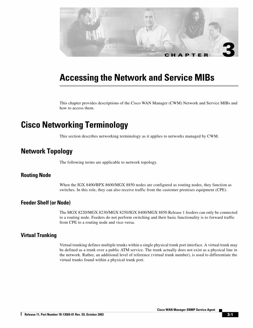
Routing Node
When the IGX 8400/BPX 8600/MGX 8850 nodes are configured as routing nodes, they function as switches. In this role, they can also receive traffic from the customer premises equipment (CPE).
Feeder Shelf (or Node)
The MGX 8220/MGX 8230/MGX 8250/IGX 8400/MGX 8850 Release 1 feeders can only be connected to a routing node. Feeders do not perform switching and their basic functionality is to forward traffic from CPE to a routing node and vice-versa.
Virtual Trunking
Virtual trunking defines multiple trunks within a single physical trunk port interface. A virtual trunk may be defined as a trunk over a public ATM service. The trunk actually does not exist as a physical line in the network. Rather, an additional level of reference (virtual trunk number), is used to differentiate the virtual trunks found within a physical trunk port.
3-1co WAN Manager SNMP Service Agent
Chapter 3 Accessing the Network and Service MIBsCisco Networking Terminology
Traffic ManagementFrame Relay ForeSight is a closed-loop, rate-based, traffic congestion management feature for transmitting bursty data across cell-based networks. When unused network bandwidth is available, ForeSight allows cell bursts above the committed information rate (CIR) for extended periods.
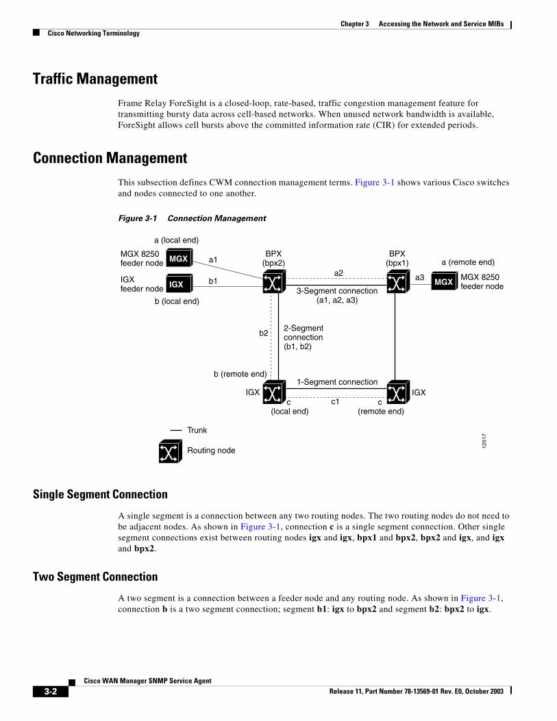
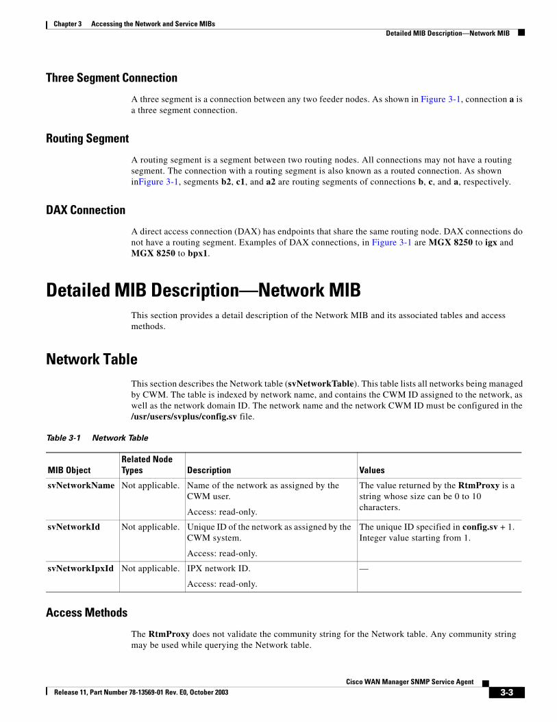
Connection ManagementThis subsection defines CWM connection management terms. Figure 3-1 shows various Cisco switches and nodes connected to one another.
Figure 3-1 Connection Management
Single Segment Connection
A single segment is a connection between any two routing nodes. The two routing nodes do not need to be adjacent nodes. As shown in Figure 3-1, connection c is a single segment connection. Other single segment connections exist between routing nodes igx and igx, bpx1 and bpx2, bpx2 and igx, and igx and bpx2.
Two Segment Connection
A two segment is a connection between a feeder node and any routing node. As shown in Figure 3-1, connection b is a two segment connection; segment b1: igx to bpx2 and segment b2: bpx2 to igx.
MGX 8250feeder nodeMGX
MGX 8250feeder node MGX
IGXfeeder node IGX
BPX(bpx1)
BPX(bpx2)
IGXIGX
a (remote end)
a (local end)
c (remote end)
c (local end)
b (remote end)
b (local end)
a3
a1
b1
b2
c1
a2
3-Segment connection(a1, a2, a3)
1-Segment connection
2-Segment connection(b1, b2)
Trunk
Routing node 1251
7
3-2Cisco WAN Manager SNMP Service Agent
Release 11, Part Number 78-13569-01 Rev. E0, October 2003
Chapter 3 Accessing the Network and Service MIBsDetailed MIB Description—Network MIB
Three Segment Connection
A three segment is a connection between any two feeder nodes. As shown in Figure 3-1, connection a is a three segment connection.
Routing Segment
A routing segment is a segment between two routing nodes. All connections may not have a routing segment. The connection with a routing segment is also known as a routed connection. As shown inFigure 3-1, segments b2, c1, and a2 are routing segments of connections b, c, and a, respectively.
DAX Connection
A direct access connection (DAX) has endpoints that share the same routing node. DAX connections do not have a routing segment. Examples of DAX connections, in Figure 3-1 are MGX 8250 to igx and MGX 8250 to bpx1.
Detailed MIB Description—Network MIBThis section provides a detail description of the Network MIB and its associated tables and access methods.
Network TableThis section describes the Network table (svNetworkTable). This table lists all networks being managed by CWM. The table is indexed by network name, and contains the CWM ID assigned to the network, as well as the network domain ID. The network name and the network CWM ID must be configured in the /usr/users/svplus/config.sv file.
Access Methods
The RtmProxy does not validate the community string for the Network table. Any community string may be used while querying the Network table.
Table 3-1 Network Table
MIB ObjectRelated Node Types Description Values
svNetworkName Not applicable. Name of the network as assigned by the CWM user.
Access: read-only.
The value returned by the RtmProxy is a string whose size can be 0 to 10 characters.
svNetworkId Not applicable. Unique ID of the network as assigned by the CWM system.
Access: read-only.
The unique ID specified in config.sv + 1. Integer value starting from 1.
svNetworkIpxId Not applicable. IPX network ID.
Access: read-only.
—
3-3Cisco WAN Manager SNMP Service Agent
Release 11, Part Number 78-13569-01 Rev. E0, October 2003
Chapter 3 Accessing the Network and Service MIBsDetailed MIB Description—Network MIB
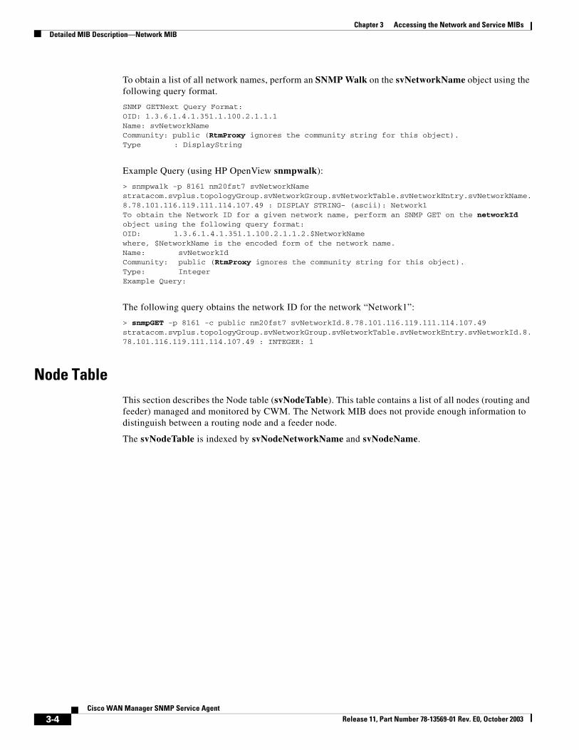
To obtain a list of all network names, perform an SNMP Walk on the svNetworkName object using the following query format.
SNMP GETNext Query Format:OID: 1.3.6.1.4.1.351.1.100.2.1.1.1Name: svNetworkNameCommunity: public (RtmProxy ignores the community string for this object).Type : DisplayString
Example Query (using HP OpenView snmpwalk):
> snmpwalk -p 8161 nm20fst7 svNetworkNamestratacom.svplus.topologyGroup.svNetworkGroup.svNetworkTable.svNetworkEntry.svNetworkName.8.78.101.116.119.111.114.107.49 : DISPLAY STRING- (ascii): Network1To obtain the Network ID for a given network name, perform an SNMP GET on the networkId object using the following query format:OID: 1.3.6.1.4.1.351.1.100.2.1.1.2.$NetworkNamewhere, $NetworkName is the encoded form of the network name.Name: svNetworkIdCommunity: public (RtmProxy ignores the community string for this object).Type: IntegerExample Query:
The following query obtains the network ID for the network “Network1”:
> snmpGET -p 8161 -c public nm20fst7 svNetworkId.8.78.101.116.119.111.114.107.49stratacom.svplus.topologyGroup.svNetworkGroup.svNetworkTable.svNetworkEntry.svNetworkId.8.78.101.116.119.111.114.107.49 : INTEGER: 1
Node TableThis section describes the Node table (svNodeTable). This table contains a list of all nodes (routing and feeder) managed and monitored by CWM. The Network MIB does not provide enough information to distinguish between a routing node and a feeder node.
The svNodeTable is indexed by svNodeNetworkName and svNodeName.
3-4Cisco WAN Manager SNMP Service Agent
Release 11, Part Number 78-13569-01 Rev. E0, October 2003
Chapter 3 Accessing the Network and Service MIBsDetailed MIB Description—Network MIB
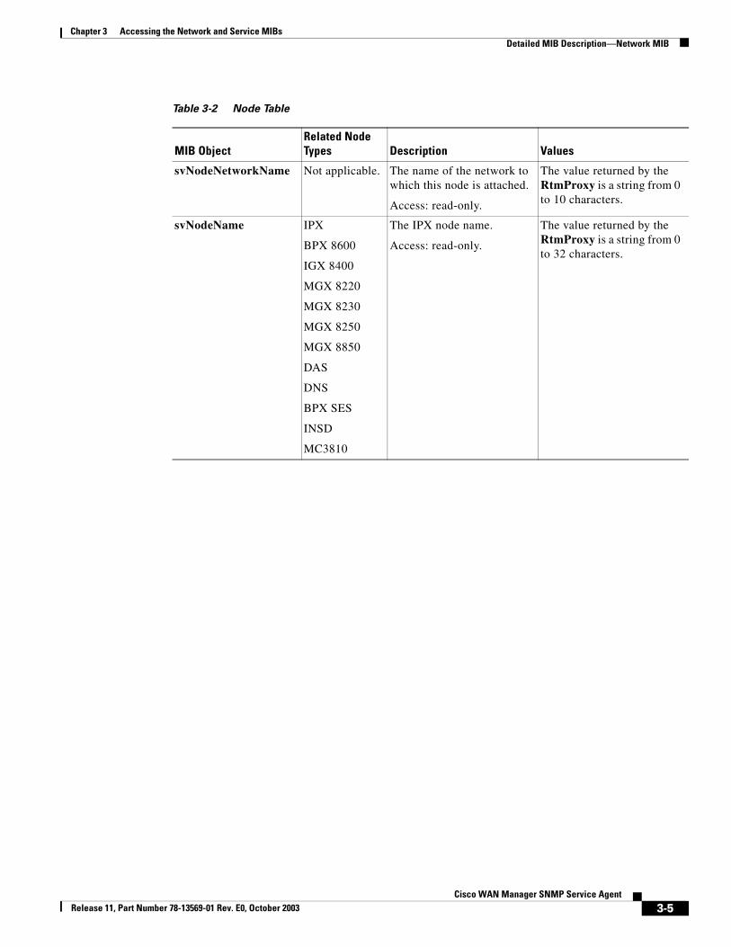
Table 3-2 Node Table
MIB ObjectRelated Node Types Description Values
svNodeNetworkName Not applicable. The name of the network to which this node is attached.
Access: read-only.
The value returned by the RtmProxy is a string from 0 to 10 characters.
svNodeName IPX
BPX 8600
IGX 8400
MGX 8220
MGX 8230
MGX 8250
MGX 8850
DAS
DNS
BPX SES
INSD
MC3810
The IPX node name.
Access: read-only.
The value returned by the RtmProxy is a string from 0 to 32 characters.
3-5Cisco WAN Manager SNMP Service Agent
Release 11, Part Number 78-13569-01 Rev. E0, October 2003
Chapter 3 Accessing the Network and Service MIBsDetailed MIB Description—Network MIB
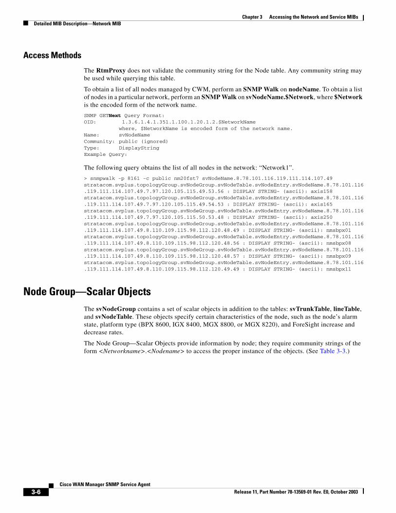
Access Methods
The RtmProxy does not validate the community string for the Node table. Any community string may be used while querying this table.
To obtain a list of all nodes managed by CWM, perform an SNMP Walk on nodeName. To obtain a list of nodes in a particular network, perform an SNMP Walk on svNodeName.$Network, where $Network is the encoded form of the network name.
SNMP GETNext Query Format:OID: 1.3.6.1.4.1.351.1.100.1.20.1.2.$NetworkName
where, $NetworkName is encoded form of the network name.Name: svNodeNameCommunity: public (ignored)Type: DisplayStringExample Query:
The following query obtains the list of all nodes in the network: “Network1”.
> snmpwalk -p 8161 -c public nm20fst7 svNodeName.8.78.101.116.119.111.114.107.49stratacom.svplus.topologyGroup.svNodeGroup.svNodeTable.svNodeEntry.svNodeName.8.78.101.116.119.111.114.107.49.7.97.120.105.115.49.53.56 : DISPLAY STRING- (ascii): axis158stratacom.svplus.topologyGroup.svNodeGroup.svNodeTable.svNodeEntry.svNodeName.8.78.101.116.119.111.114.107.49.7.97.120.105.115.49.54.53 : DISPLAY STRING- (ascii): axis165stratacom.svplus.topologyGroup.svNodeGroup.svNodeTable.svNodeEntry.svNodeName.8.78.101.116.119.111.114.107.49.7.97.120.105.115.50.53.48 : DISPLAY STRING- (ascii): axis250stratacom.svplus.topologyGroup.svNodeGroup.svNodeTable.svNodeEntry.svNodeName.8.78.101.116.119.111.114.107.49.8.110.109.115.98.112.120.48.49 : DISPLAY STRING- (ascii): nmsbpx01stratacom.svplus.topologyGroup.svNodeGroup.svNodeTable.svNodeEntry.svNodeName.8.78.101.116.119.111.114.107.49.8.110.109.115.98.112.120.48.56 : DISPLAY STRING- (ascii): nmsbpx08stratacom.svplus.topologyGroup.svNodeGroup.svNodeTable.svNodeEntry.svNodeName.8.78.101.116.119.111.114.107.49.8.110.109.115.98.112.120.48.57 : DISPLAY STRING- (ascii): nmsbpx09stratacom.svplus.topologyGroup.svNodeGroup.svNodeTable.svNodeEntry.svNodeName.8.78.101.116.119.111.114.107.49.8.110.109.115.98.112.120.49.49 : DISPLAY STRING- (ascii): nmsbpx11
Node Group—Scalar ObjectsThe svNodeGroup contains a set of scalar objects in addition to the tables: svTrunkTable, lineTable, and svNodeTable. These objects specify certain characteristics of the node, such as the node’s alarm state, platform type (BPX 8600, IGX 8400, MGX 8800, or MGX 8220), and ForeSight increase and decrease rates.
The Node Group—Scalar Objects provide information by node; they require community strings of the form <Networkname>.<Nodename> to access the proper instance of the objects. (See Table 3-3.)
3-6Cisco WAN Manager SNMP Service Agent
Release 11, Part Number 78-13569-01 Rev. E0, October 2003
Chapter 3 Accessing the Network and Service MIBsDetailed MIB Description—Network MIB
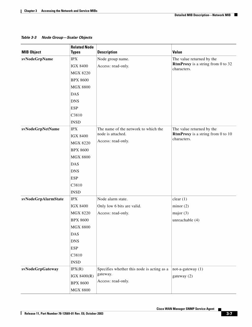
Table 3-3 Node Group—Scalar Objects
MIB ObjectRelated Node Types Description Value
svNodeGrpName IPX
IGX 8400
MGX 8220
BPX 8600
MGX 8800
DAS
DNS
ESP
C3810
INSD
Node group name.
Access: read-only.
The value returned by the RtmProxy is a string from 0 to 32 characters.
svNodeGrpNetName IPX
IGX 8400
MGX 8220
BPX 8600
MGX 8800
DAS
DNS
ESP
C3810
INSD
The name of the network to which the node is attached.
Access: read-only.
The value returned by the RtmProxy is a string from 0 to 10 characters.
svNodeGrpAlarmState IPX
IGX 8400
MGX 8220
BPX 8600
MGX 8800
DAS
DNS
ESP
C3810
INSD
Node alarm state.
Only low 6 bits are valid.
Access: read-only.
clear (1)
minor (2)
major (3)
unreachable (4)
svNodeGrpGateway IPX(R)
IGX 8400(R)
BPX 8600
MGX 8800
Specifies whether this node is acting as a gateway.
Access: read-only.
not-a-gateway (1)
gateway (2)
3-7Cisco WAN Manager SNMP Service Agent
Release 11, Part Number 78-13569-01 Rev. E0, October 2003
Chapter 3 Accessing the Network and Service MIBsDetailed MIB Description—Network MIB
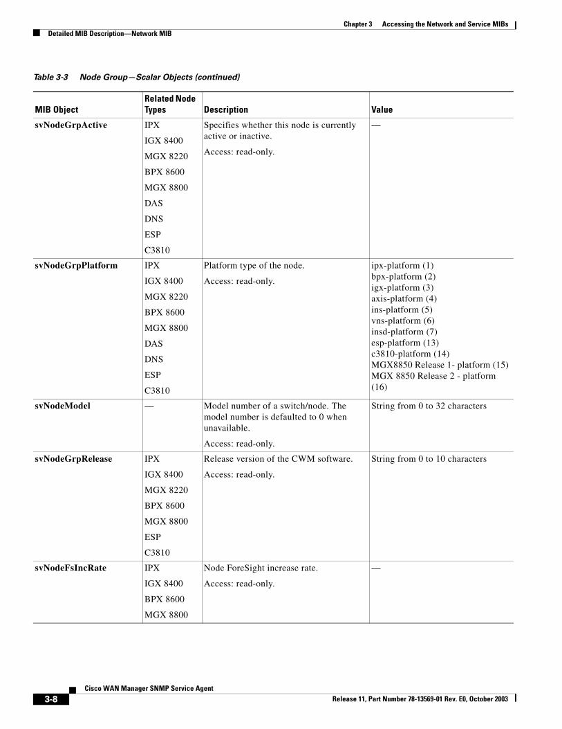
svNodeGrpActive IPX
IGX 8400
MGX 8220
BPX 8600
MGX 8800
DAS
DNS
ESP
C3810
Specifies whether this node is currently active or inactive.
Access: read-only.
—
svNodeGrpPlatform IPX
IGX 8400
MGX 8220
BPX 8600
MGX 8800
DAS
DNS
ESP
C3810
Platform type of the node.
Access: read-only.
ipx-platform (1)bpx-platform (2)igx-platform (3)axis-platform (4)ins-platform (5)vns-platform (6)insd-platform (7)esp-platform (13)c3810-platform (14)MGX8850 Release 1- platform (15)MGX 8850 Release 2 - platform (16)
svNodeModel — Model number of a switch/node. The model number is defaulted to 0 when unavailable.
Access: read-only.
String from 0 to 32 characters
svNodeGrpRelease IPX
IGX 8400
MGX 8220
BPX 8600
MGX 8800
ESP
C3810
Release version of the CWM software.
Access: read-only.
String from 0 to 10 characters
svNodeFsIncRate IPX
IGX 8400
BPX 8600
MGX 8800
Node ForeSight increase rate.
Access: read-only.
—
Table 3-3 Node Group—Scalar Objects (continued)
MIB ObjectRelated Node Types Description Value
3-8Cisco WAN Manager SNMP Service Agent
Release 11, Part Number 78-13569-01 Rev. E0, October 2003
Chapter 3 Accessing the Network and Service MIBsDetailed MIB Description—Network MIB
svNodeFsDecRate IPX
IGX 8400
BPX 8600
MGX 8800
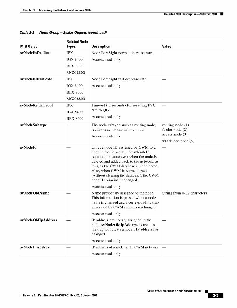
Node ForeSight normal decrease rate.
Access: read-only.
—
svNodeFsFastRate IPX
IGX 8400
BPX 8600
MGX 8800
Node ForeSight fast decrease rate.
Access: read-only.
—
svNodeRstTimeout IPX
IGX 8400
BPX 8600
Timeout (in seconds) for resetting PVC rate to QIR.
Access: read-only.
—
svNodeSubtype — The node subtype such as routing node, feeder node, or standalone node.
Access: read-only.
routing-node (1)feeder-node (2)access-node (3)
standalone node (5)
svNodeId — Unique node ID assigned by CWM to a node in the network. The svNodeId remains the same even when the node is deleted and added back to the network, as long as the CWM database is not cleared. Also, when CWM is warm started (without clearing the database), the CWM node ID remains unchanged.
Access: read-only.
—
svNodeOldName — Name previously assigned to the node. This information is passed when a node name is changed and a corresponding trap generated by CWM remains unchanged.
Access: read-only.
String from 0-32 characters
svNodeOldIpAddress — IP address previously assigned to the node. svNodeOldIpAddress is used in the trap to indicate a node’s IP address has changed.
Access: read-only.
—
svNodeIpAddress — IP address of a node in the CWM network.
Access: read-only.
—
Table 3-3 Node Group—Scalar Objects (continued)
MIB ObjectRelated Node Types Description Value
3-9Cisco WAN Manager SNMP Service Agent
Release 11, Part Number 78-13569-01 Rev. E0, October 2003
Chapter 3 Accessing the Network and Service MIBsDetailed MIB Description—Network MIB
Note svNodeSubtype, svNodeId, svNodeOldName, svNodeOldIpAddress, and svNodeIpAddress are used for traps only and no values are returned by snmpGET.
The scalar objects in the Node Group can be accessed using the SNMP GET command. These objects require a community string of the form
<networkname>.<nodename>
where <networkname> is the network name to which node <nodename> is attached.
The following mechanism allows reading of the Node Alarm state for all the nodes in all networks:
1. Perform SNMP Walk on svNetworkName to obtain the list of network names.
2. For each network, perform an SNMP Walk on svNodeName.$Network to obtain a list of nodes in a network (where $Network is the encoded form of the network name).
3. For each node perform an SNMP GET on svNodeGrpAlarmState.0 with community <networkname>.<nodename>.
SNMP GET Query Format:OID: 1.3.6.1.4.1.351.1.100.1.7.0Name: svNodeGrpAlarmStateCommunity: <networkname>.<nodename>Type: IntegerExample Query:
The following query obtains the alarm state of the node nmsipx03 in the network Network1:
> snmpGET -p 8161 -c “Network1.nmsipx03” nm20fst7 svNodeGrpAlarmState.0stratacom.svplus.topologyGroup.svNodeGroup.svNodeGrpAlarmState.0 : INTEGER: minor
Trunk TableThe Trunk table (svTrunkTable) contains the list of all trunk lines in the network. (See Table 3-4.)This table provides the information on a per node basis. Therefore, nodal community of the form <networkname>.<nodename> must be used the in the queries. The trunk table provides the remote node information as NodeId. The CWM Network MIB does not have a mechanism to map NodeId to the corresponding Node name.
The Trunk table is indexed by svTrunkLocalSlot, svTrunkLocalPort, and svTrunkLocalVtrkId.
3-10Cisco WAN Manager SNMP Service Agent
Release 11, Part Number 78-13569-01 Rev. E0, October 2003
Chapter 3 Accessing the Network and Service MIBsDetailed MIB Description—Network MIB
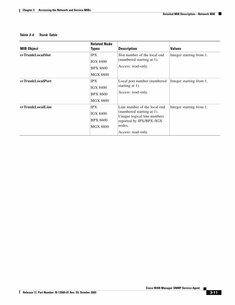
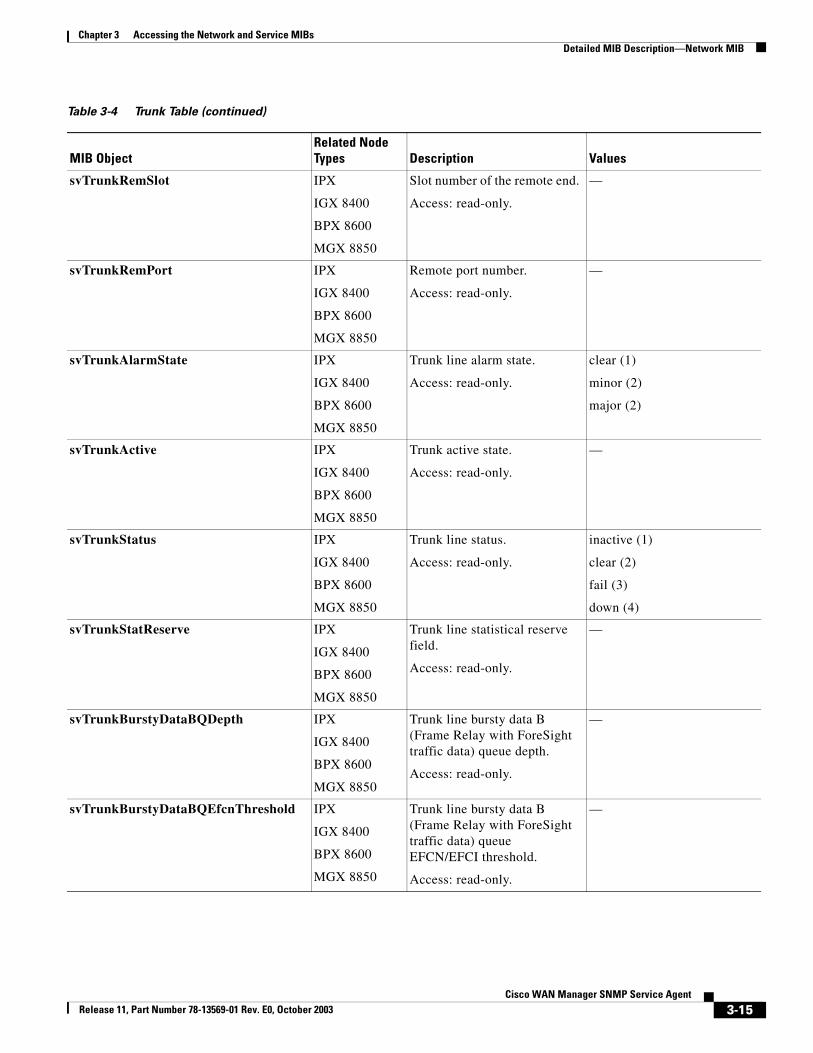
Table 3-4 Trunk Table
MIB ObjectRelated Node Types Description Values
svTrunkLocalSlot IPX
IGX 8400
BPX 8600
MGX 8800
Slot number of the local end (numbered starting at 1).
Access: read-only.
Integer starting from 1.
svTrunkLocalPort IPX
IGX 8400
BPX 8600
MGX 8800
Local port number (numbered starting at 1).
Access: read-only.
Integer starting from 1.
svTrunkLocalLine IPX
IGX 8400
BPX 8600
MGX 8800
Line number of the local end (numbered starting at 1). Unique logical line numbers reported by IPX/BPX /IGX nodes.
Access: read-only.
Integer starting from 1.
3-11Cisco WAN Manager SNMP Service Agent
Release 11, Part Number 78-13569-01 Rev. E0, October 2003
Chapter 3 Accessing the Network and Service MIBsDetailed MIB Description—Network MIB
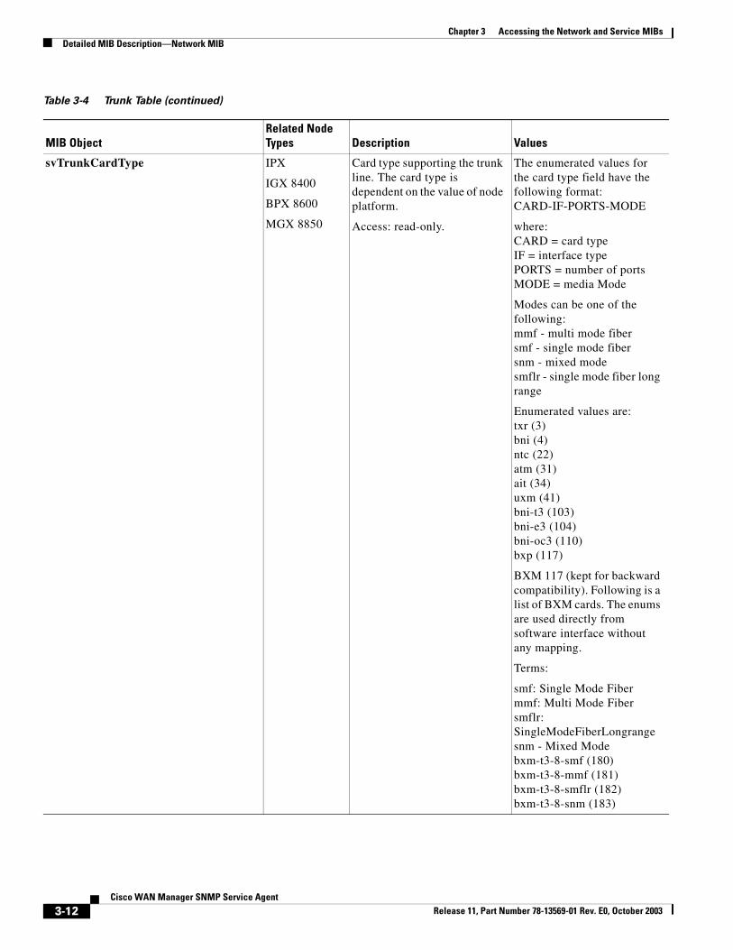
svTrunkCardType IPX
IGX 8400
BPX 8600
MGX 8850
Card type supporting the trunk line. The card type is dependent on the value of node platform.
Access: read-only.
The enumerated values for the card type field have the following format:CARD-IF-PORTS-MODE
where:CARD = card typeIF = interface typePORTS = number of portsMODE = media Mode
Modes can be one of the following:mmf - multi mode fibersmf - single mode fibersnm - mixed modesmflr - single mode fiber long range
Enumerated values are:txr (3)bni (4)ntc (22)atm (31)ait (34)uxm (41)bni-t3 (103)bni-e3 (104)bni-oc3 (110)bxp (117)
BXM 117 (kept for backward compatibility). Following is a list of BXM cards. The enums are used directly from software interface without any mapping.
Terms:
smf: Single Mode Fibermmf: Multi Mode Fibersmflr: SingleModeFiberLongrangesnm - Mixed Modebxm-t3-8-smf (180)bxm-t3-8-mmf (181)bxm-t3-8-smflr (182)bxm-t3-8-snm (183)
Table 3-4 Trunk Table (continued)
MIB ObjectRelated Node Types Description Values
3-12Cisco WAN Manager SNMP Service Agent
Release 11, Part Number 78-13569-01 Rev. E0, October 2003
Chapter 3 Accessing the Network and Service MIBsDetailed MIB Description—Network MIB
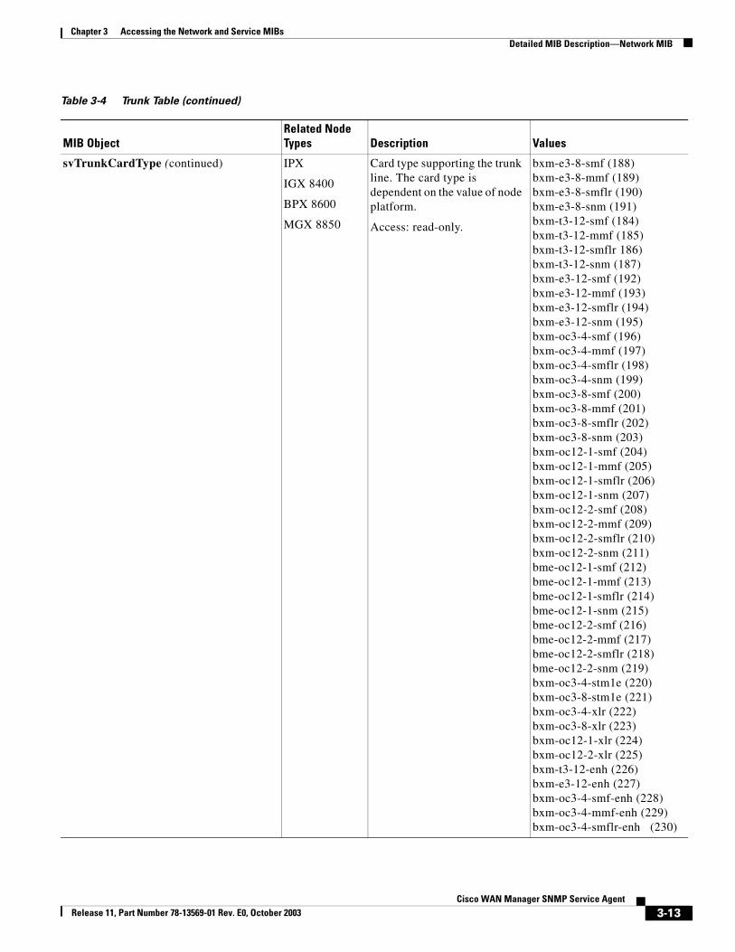
svTrunkCardType (continued) IPX
IGX 8400
BPX 8600
MGX 8850
Card type supporting the trunk line. The card type is dependent on the value of node platform.
Access: read-only.
bxm-e3-8-smf (188)bxm-e3-8-mmf (189)bxm-e3-8-smflr (190)bxm-e3-8-snm (191)bxm-t3-12-smf (184)bxm-t3-12-mmf (185)bxm-t3-12-smflr 186)bxm-t3-12-snm (187)bxm-e3-12-smf (192)bxm-e3-12-mmf (193)bxm-e3-12-smflr (194)bxm-e3-12-snm (195)bxm-oc3-4-smf (196)bxm-oc3-4-mmf (197)bxm-oc3-4-smflr (198)bxm-oc3-4-snm (199)bxm-oc3-8-smf (200)bxm-oc3-8-mmf (201)bxm-oc3-8-smflr (202)bxm-oc3-8-snm (203)bxm-oc12-1-smf (204)bxm-oc12-1-mmf (205)bxm-oc12-1-smflr (206)bxm-oc12-1-snm (207)bxm-oc12-2-smf (208)bxm-oc12-2-mmf (209)bxm-oc12-2-smflr (210)bxm-oc12-2-snm (211)bme-oc12-1-smf (212)bme-oc12-1-mmf (213) bme-oc12-1-smflr (214) bme-oc12-1-snm (215) bme-oc12-2-smf (216) bme-oc12-2-mmf (217) bme-oc12-2-smflr (218) bme-oc12-2-snm (219)bxm-oc3-4-stm1e (220) bxm-oc3-8-stm1e (221) bxm-oc3-4-xlr (222) bxm-oc3-8-xlr (223) bxm-oc12-1-xlr (224) bxm-oc12-2-xlr (225) bxm-t3-12-enh (226) bxm-e3-12-enh (227) bxm-oc3-4-smf-enh (228) bxm-oc3-4-mmf-enh (229) bxm-oc3-4-smflr-enh (230)
Table 3-4 Trunk Table (continued)
MIB ObjectRelated Node Types Description Values
3-13Cisco WAN Manager SNMP Service Agent
Release 11, Part Number 78-13569-01 Rev. E0, October 2003
Chapter 3 Accessing the Network and Service MIBsDetailed MIB Description—Network MIB
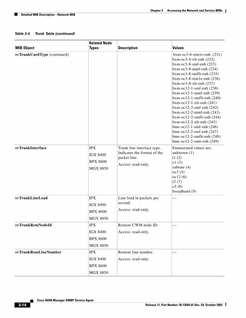
svTrunkCardType (continued) bxm-oc3-4-stm1e-enh (231) bxm-oc3-4-xlr-enh (232) bxm-oc3-8-smf-enh (233) bxm-oc3-8-mmf-enh (234) bxm-oc3-8-smflr-enh (235) bxm-oc3-8-stm1e-enh (236) bxm-oc3-8-xlr-enh (237) bxm-oc12-1-smf-enh (238) bxm-oc12-1-mmf-enh (239) bxm-oc12-1-smflr-enh (240) bxm-oc12-1-xlr-enh (241) bxm-oc12-2-smf-enh (242) bxm-oc12-2-mmf-enh (243) bxm-oc12-2-smflr-enh (244) bxm-oc12-2-xlr-enh (245) bme-oc12-1-smf-enh (246) bme-oc12-2-smf-enh (247) bme-oc12-2-smflr-enh (248) bme-oc12-2-snm-enh (249)
svTrunkInterface IPX
IGX 8400
BPX 8600
MGX 8850
Trunk line interface type. Indicates the format of the packet line.
Access: read-only.
Enumerated values are:unknown (1)t1 (2)e1 (3)subrate (4)oc3 (5)oc12 (6)t3 (7)e3 (8)broadband (9)
svTrunkLineLoad IPX
IGX 8400
BPX 8600
MGX 8850
Line load in packets per second.
Access: read-only.
—
svTrunkRemNodeId IPX
IGX 8400
BPX 8600
MGX 8850
Remote CWM node ID.
Access: read-only.
—
svTrunkRemLineNumber IPX
IGX 8400
BPX 8600
MGX 8850
Remote line number.
Access: read-only.
—
Table 3-4 Trunk Table (continued)
MIB ObjectRelated Node Types Description Values
3-14Cisco WAN Manager SNMP Service Agent
Release 11, Part Number 78-13569-01 Rev. E0, October 2003
Chapter 3 Accessing the Network and Service MIBsDetailed MIB Description—Network MIB
svTrunkRemSlot IPX
IGX 8400
BPX 8600
MGX 8850
Slot number of the remote end.
Access: read-only.
—
svTrunkRemPort IPX
IGX 8400
BPX 8600
MGX 8850
Remote port number.
Access: read-only.
—
svTrunkAlarmState IPX
IGX 8400
BPX 8600
MGX 8850
Trunk line alarm state.
Access: read-only.
clear (1)
minor (2)
major (2)
svTrunkActive IPX
IGX 8400
BPX 8600
MGX 8850
Trunk active state.
Access: read-only.
—
svTrunkStatus IPX
IGX 8400
BPX 8600
MGX 8850
Trunk line status.
Access: read-only.
inactive (1)
clear (2)
fail (3)
down (4)
svTrunkStatReserve IPX
IGX 8400
BPX 8600
MGX 8850
Trunk line statistical reserve field.
Access: read-only.
—
svTrunkBurstyDataBQDepth IPX
IGX 8400
BPX 8600
MGX 8850
Trunk line bursty data B (Frame Relay with ForeSight traffic data) queue depth.
Access: read-only.
—
svTrunkBurstyDataBQEfcnThreshold IPX
IGX 8400
BPX 8600
MGX 8850
Trunk line bursty data B (Frame Relay with ForeSight traffic data) queue EFCN/EFCI threshold.
Access: read-only.
—
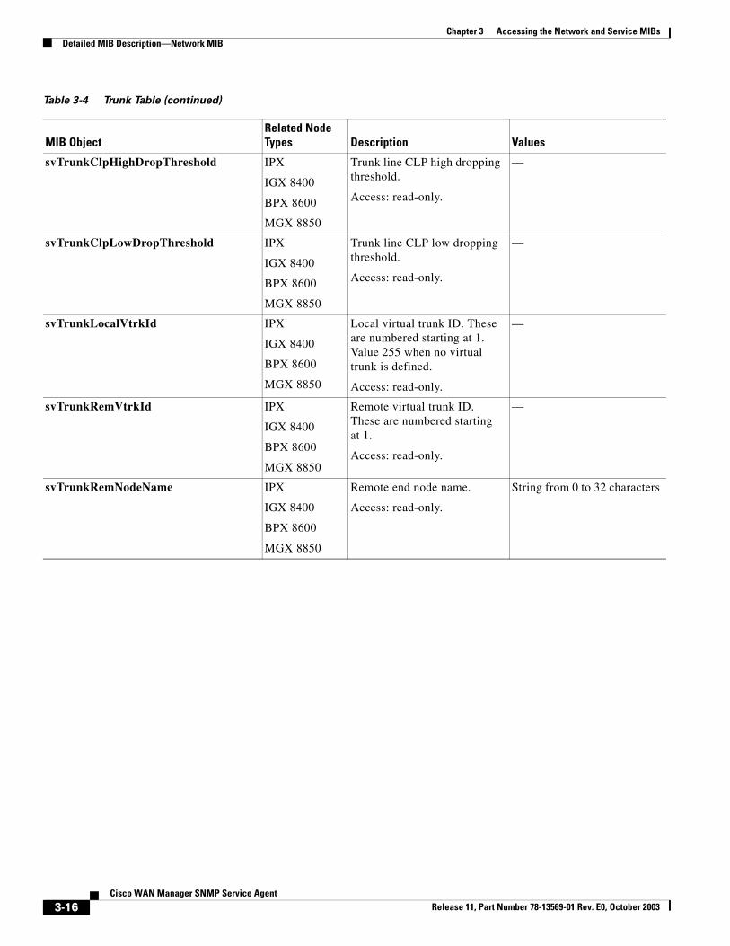
Table 3-4 Trunk Table (continued)
MIB ObjectRelated Node Types Description Values
3-15Cisco WAN Manager SNMP Service Agent
Release 11, Part Number 78-13569-01 Rev. E0, October 2003
Chapter 3 Accessing the Network and Service MIBsDetailed MIB Description—Network MIB
svTrunkClpHighDropThreshold IPX
IGX 8400
BPX 8600
MGX 8850
Trunk line CLP high dropping threshold.
Access: read-only.
—
svTrunkClpLowDropThreshold IPX
IGX 8400
BPX 8600
MGX 8850
Trunk line CLP low dropping threshold.
Access: read-only.
—
svTrunkLocalVtrkId IPX
IGX 8400
BPX 8600
MGX 8850
Local virtual trunk ID. These are numbered starting at 1. Value 255 when no virtual trunk is defined.
Access: read-only.
—
svTrunkRemVtrkId IPX
IGX 8400
BPX 8600
MGX 8850
Remote virtual trunk ID. These are numbered starting at 1.
Access: read-only.
—
svTrunkRemNodeName IPX
IGX 8400
BPX 8600
MGX 8850
Remote end node name.
Access: read-only.
String from 0 to 32 characters
Table 3-4 Trunk Table (continued)
MIB ObjectRelated Node Types Description Values
3-16Cisco WAN Manager SNMP Service Agent
Release 11, Part Number 78-13569-01 Rev. E0, October 2003
Chapter 3 Accessing the Network and Service MIBsDetailed MIB Description—Network MIB
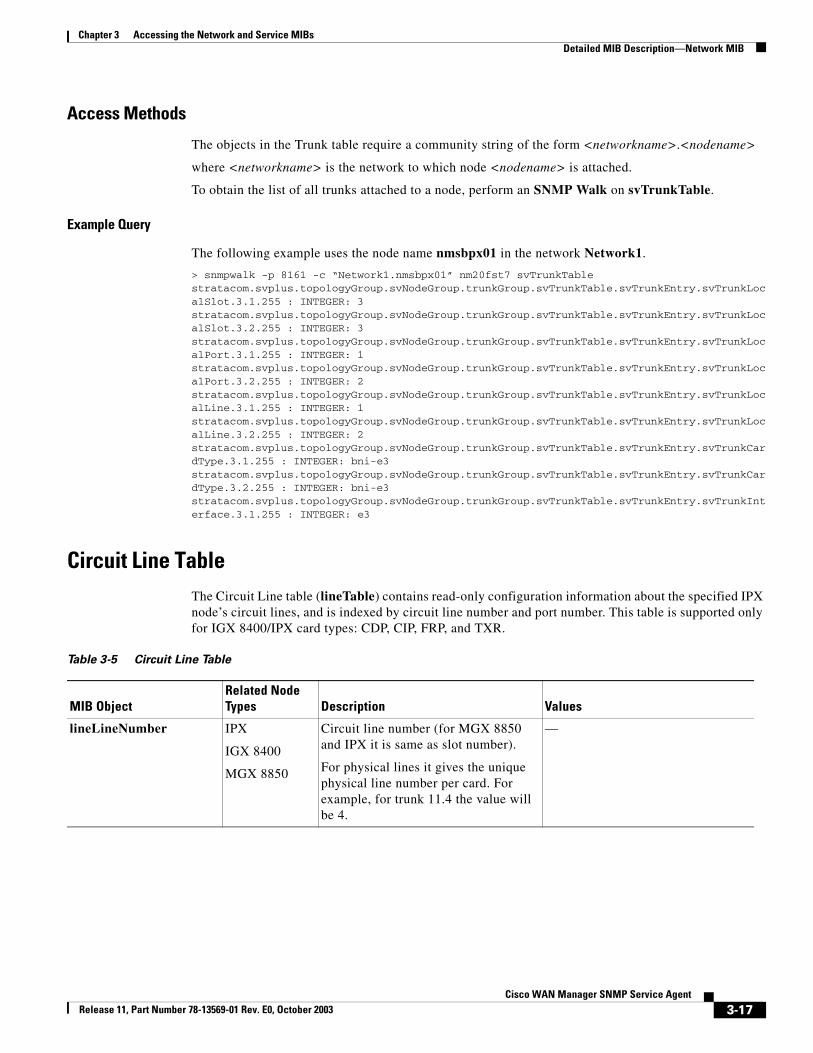
Access Methods
The objects in the Trunk table require a community string of the form <networkname>.<nodename>
where <networkname> is the network to which node <nodename> is attached.
To obtain the list of all trunks attached to a node, perform an SNMP Walk on svTrunkTable.
Example Query
The following example uses the node name nmsbpx01 in the network Network1.
> snmpwalk -p 8161 -c “Network1.nmsbpx01” nm20fst7 svTrunkTablestratacom.svplus.topologyGroup.svNodeGroup.trunkGroup.svTrunkTable.svTrunkEntry.svTrunkLocalSlot.3.1.255 : INTEGER: 3stratacom.svplus.topologyGroup.svNodeGroup.trunkGroup.svTrunkTable.svTrunkEntry.svTrunkLocalSlot.3.2.255 : INTEGER: 3stratacom.svplus.topologyGroup.svNodeGroup.trunkGroup.svTrunkTable.svTrunkEntry.svTrunkLocalPort.3.1.255 : INTEGER: 1stratacom.svplus.topologyGroup.svNodeGroup.trunkGroup.svTrunkTable.svTrunkEntry.svTrunkLocalPort.3.2.255 : INTEGER: 2stratacom.svplus.topologyGroup.svNodeGroup.trunkGroup.svTrunkTable.svTrunkEntry.svTrunkLocalLine.3.1.255 : INTEGER: 1stratacom.svplus.topologyGroup.svNodeGroup.trunkGroup.svTrunkTable.svTrunkEntry.svTrunkLocalLine.3.2.255 : INTEGER: 2stratacom.svplus.topologyGroup.svNodeGroup.trunkGroup.svTrunkTable.svTrunkEntry.svTrunkCardType.3.1.255 : INTEGER: bni-e3stratacom.svplus.topologyGroup.svNodeGroup.trunkGroup.svTrunkTable.svTrunkEntry.svTrunkCardType.3.2.255 : INTEGER: bni-e3stratacom.svplus.topologyGroup.svNodeGroup.trunkGroup.svTrunkTable.svTrunkEntry.svTrunkInterface.3.1.255 : INTEGER: e3
Circuit Line TableThe Circuit Line table (lineTable) contains read-only configuration information about the specified IPX node’s circuit lines, and is indexed by circuit line number and port number. This table is supported only for IGX 8400/IPX card types: CDP, CIP, FRP, and TXR.
Table 3-5 Circuit Line Table
MIB ObjectRelated Node Types Description Values
lineLineNumber IPX
IGX 8400
MGX 8850
Circuit line number (for MGX 8850 and IPX it is same as slot number).
For physical lines it gives the unique physical line number per card. For example, for trunk 11.4 the value will be 4.
—
3-17Cisco WAN Manager SNMP Service Agent
Release 11, Part Number 78-13569-01 Rev. E0, October 2003
Chapter 3 Accessing the Network and Service MIBsDetailed MIB Description—Network MIB
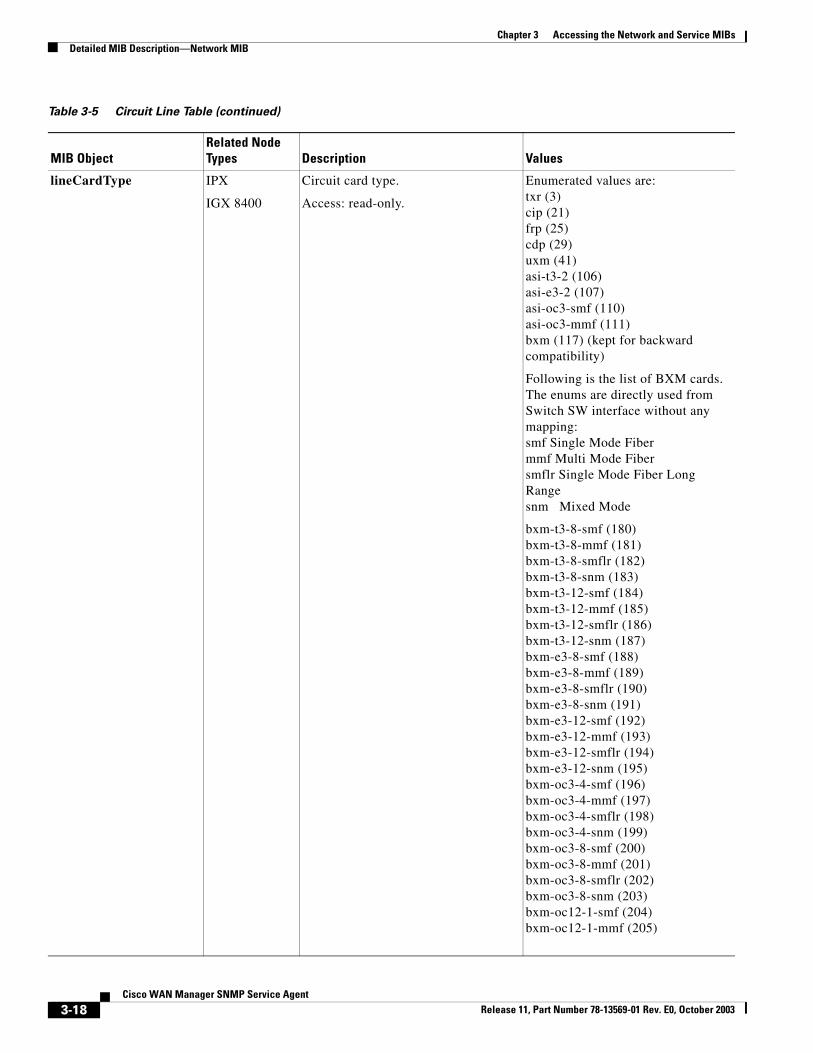
lineCardType IPX
IGX 8400
Circuit card type.
Access: read-only.
Enumerated values are:txr (3)cip (21)frp (25)cdp (29)uxm (41)asi-t3-2 (106)asi-e3-2 (107)asi-oc3-smf (110)asi-oc3-mmf (111)bxm (117) (kept for backward compatibility)
Following is the list of BXM cards. The enums are directly used from Switch SW interface without any mapping:smf Single Mode Fibermmf Multi Mode Fibersmflr Single Mode Fiber Long Rangesnm Mixed Mode
bxm-t3-8-smf (180)bxm-t3-8-mmf (181)bxm-t3-8-smflr (182)bxm-t3-8-snm (183)bxm-t3-12-smf (184)bxm-t3-12-mmf (185)bxm-t3-12-smflr (186)bxm-t3-12-snm (187)bxm-e3-8-smf (188)bxm-e3-8-mmf (189)bxm-e3-8-smflr (190)bxm-e3-8-snm (191)bxm-e3-12-smf (192)bxm-e3-12-mmf (193)bxm-e3-12-smflr (194)bxm-e3-12-snm (195)bxm-oc3-4-smf (196)bxm-oc3-4-mmf (197)bxm-oc3-4-smflr (198)bxm-oc3-4-snm (199)bxm-oc3-8-smf (200)bxm-oc3-8-mmf (201)bxm-oc3-8-smflr (202)bxm-oc3-8-snm (203)bxm-oc12-1-smf (204)bxm-oc12-1-mmf (205)
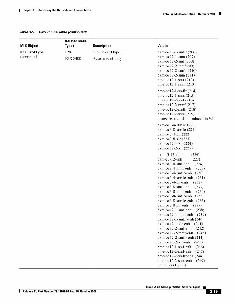
Table 3-5 Circuit Line Table (continued)
MIB ObjectRelated Node Types Description Values
3-18Cisco WAN Manager SNMP Service Agent
Release 11, Part Number 78-13569-01 Rev. E0, October 2003
Chapter 3 Accessing the Network and Service MIBsDetailed MIB Description—Network MIB
lineCardType (continued)
IPX
IGX 8400
Circuit card type.
Access: read-only.
bxm-oc12-1-smflr (206)bxm-oc12-1-snm (207)bxm-oc12-2-smf (208)bxm-oc12-2-mmf 209)bxm-oc12-2-smflr (210)bxm-oc12-2-snm (211)bme-oc12-1-smf (212)bme-oc12-1-mmf (213)
bme-oc12-1-smflr (214)bme-oc12-1-snm (215)bme-oc12-2-smf (216)bme-oc12-2-mmf (217)bme-oc12-2-smflr (218)bme-oc12-2-snm (219)-- new bxm cards introduced in 9.1
bxm-oc3-4-stm1e (220)bxm-oc3-8-stm1e (221)bxm-oc3-4-xlr (222)bxm-oc3-8-xlr (223)bxm-oc12-1-xlr (224)bxm-oc12-2-xlr (225)
bxm-t3-12-enh (226)bxm-e3-12-enh (227)bxm-oc3-4-smf-enh (228)bxm-oc3-4-mmf-enh (229)bxm-oc3-4-smflr-enh (230)bxm-oc3-4-stm1e-enh (231)bxm-oc3-4-xlr-enh (232)bxm-oc3-8-smf-enh (233)bxm-oc3-8-mmf-enh (234)bxm-oc3-8-smflr-enh (235)bxm-oc3-8-stm1e-enh (236)bxm-oc3-8-xlr-enh (237)bxm-oc12-1-smf-enh (238)bxm-oc12-1-mmf-enh (239)bxm-oc12-1-smflr-enh (240)bxm-oc12-1-xlr-enh (241)bxm-oc12-2-smf-enh (242)bxm-oc12-2-mmf-enh (243)bxm-oc12-2-smflr-enh (244)bxm-oc12-2-xlr-enh (245)bme-oc12-1-smf-enh (246)bme-oc12-2-smf-enh (247)bme-oc12-2-smflr-enh (248)bme-oc12-2-snm-enh (249)unknown (10000)
Table 3-5 Circuit Line Table (continued)
MIB ObjectRelated Node Types Description Values
3-19Cisco WAN Manager SNMP Service Agent
Release 11, Part Number 78-13569-01 Rev. E0, October 2003
Chapter 3 Accessing the Network and Service MIBsTrap Config Group
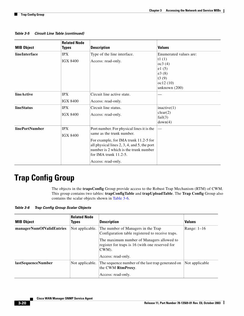
Trap Config GroupThe objects in the trapsConfig Group provide access to the Robust Trap Mechanism (RTM) of CWM. This group contains two tables: trapConfigTable and trapUploadTable. The Trap Config Group also contains the scalar objects shown in Table 3-6.
lineInterface IPX
IGX 8400
Type of the line interface.
Access: read-only.
Enumerated values are:t1 (1)oc3 (4)e1 (5)e3 (8)t3 (9)oc12 (10)unknown (200)
lineActive IPX
IGX 8400
Circuit line active state.
Access: read-only.
—
lineStatus IPX
IGX 8400
Circuit line status.
Access: read-only.
inactive(1)clear(2)fail(3)down(4)
linePortNumber IPX
IGX 8400
Port number. For physical lines it is the same as the trunk number.
For example, for IMA trunk 11.2-5 for all physical lines 2, 3, 4, and 5, the port number is 2 which is the trunk number for IMA trunk 11.2-5.
Access: read-only.
—
Table 3-5 Circuit Line Table (continued)
MIB ObjectRelated Node Types Description Values
Table 3-6 Trap Config Group Scalar Objects
MIB ObjectRelated Node Types Description Values
managerNumOfValidEntries Not applicable. The number of Managers in the Trap Configuration table registered to receive traps.
The maximum number of Managers allowed to register for traps is 16 (with one reserved for CWM).
Access: read-only.
Range: 1–16
lastSequenceNumber Not applicable. The sequence number of the last trap generated on the CWM RtmProxy.
Access: read-only.
Not applicable
3-20Cisco WAN Manager SNMP Service Agent
Release 11, Part Number 78-13569-01 Rev. E0, October 2003
Chapter 3 Accessing the Network and Service MIBsTrap Config Group
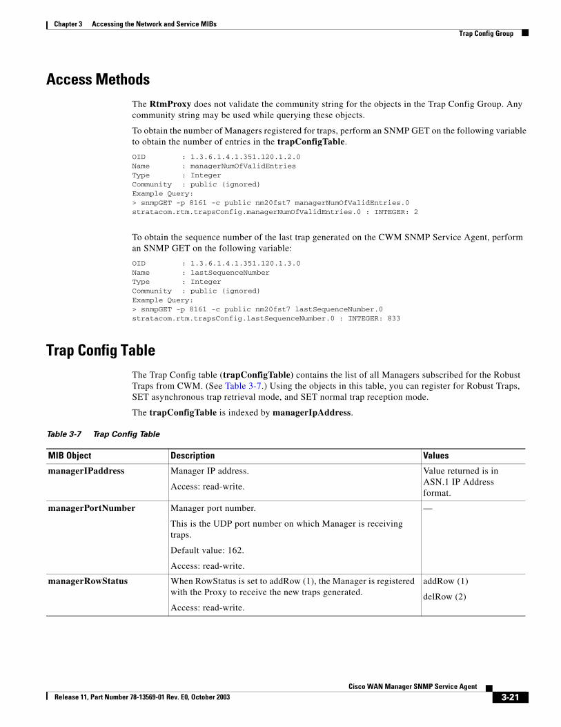
Access MethodsThe RtmProxy does not validate the community string for the objects in the Trap Config Group. Any community string may be used while querying these objects.
To obtain the number of Managers registered for traps, perform an SNMP GET on the following variable to obtain the number of entries in the trapConfigTable.
OID : 1.3.6.1.4.1.351.120.1.2.0Name : managerNumOfValidEntriesType : IntegerCommunity : public (ignored)Example Query:> snmpGET -p 8161 -c public nm20fst7 managerNumOfValidEntries.0stratacom.rtm.trapsConfig.managerNumOfValidEntries.0 : INTEGER: 2
To obtain the sequence number of the last trap generated on the CWM SNMP Service Agent, perform an SNMP GET on the following variable:
OID : 1.3.6.1.4.1.351.120.1.3.0Name : lastSequenceNumberType : IntegerCommunity : public (ignored)Example Query:> snmpGET -p 8161 -c public nm20fst7 lastSequenceNumber.0stratacom.rtm.trapsConfig.lastSequenceNumber.0 : INTEGER: 833
Trap Config TableThe Trap Config table (trapConfigTable) contains the list of all Managers subscribed for the Robust Traps from CWM. (See Table 3-7.) Using the objects in this table, you can register for Robust Traps, SET asynchronous trap retrieval mode, and SET normal trap reception mode.
The trapConfigTable is indexed by managerIpAddress.
Table 3-7 Trap Config Table
MIB Object Description Values
managerIPaddress Manager IP address.
Access: read-write.
Value returned is in ASN.1 IP Address format.
managerPortNumber Manager port number.
This is the UDP port number on which Manager is receiving traps.
Default value: 162.
Access: read-write.
—
managerRowStatus When RowStatus is set to addRow (1), the Manager is registered with the Proxy to receive the new traps generated.
Access: read-write.
addRow (1)
delRow (2)
3-21Cisco WAN Manager SNMP Service Agent
Release 11, Part Number 78-13569-01 Rev. E0, October 2003
Chapter 3 Accessing the Network and Service MIBsTrap Config Group
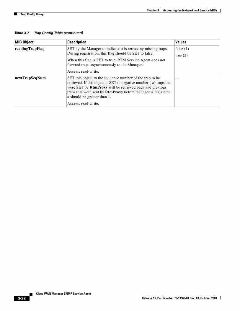
readingTrapFlag SET by the Manager to indicate it is retrieving missing traps. During registration, this flag should be SET to false.
When this flag is SET to true, RTM Service Agent does not forward traps asynchronously to the Manager.
Access: read-write.
false (1)
true (2)
nextTrapSeqNum SET this object to the sequence number of the trap to be retrieved. If this object is SET to negative number (-n) traps that were SET by RtmProxy will be retrieved back and previous traps that were sent by RtmProxy before manager is registered. n should be greater than 1.
Access: read-write.
—
Table 3-7 Trap Config Table (continued)
MIB Object Description Values
3-22Cisco WAN Manager SNMP Service Agent
Release 11, Part Number 78-13569-01 Rev. E0, October 2003
Chapter 3 Accessing the Network and Service MIBsTrap Config Group
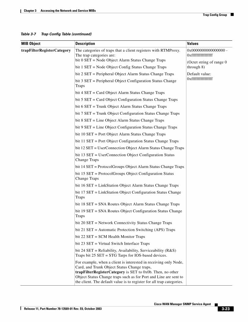
trapFilterRegisterCategory The categories of traps that a client registers with RTMProxy. The trap categories are:bit 0 SET = Node Object Alarm Status Change Traps
bit 1 SET = Node Object Config Status Change Traps
bit 2 SET = Peripheral Object Alarm Status Change Traps
bit 3 SET = Peripheral Object Configuration Status Change Traps
bit 4 SET = Card Object Alarm Status Change Traps
bit 5 SET = Card Object Configuration Status Change Traps
bit 6 SET = Trunk Object Alarm Status Change Traps
bit 7 SET = Trunk Object Configuration Status Change Traps
bit 8 SET = Line Object Alarm Status Change Traps
bit 9 SET = Line Object Configuration Status Change Traps
bit 10 SET = Port Object Alarm Status Change Traps
bit 11 SET = Port Object Configuration Status Change Traps
bit 12 SET = UserConnection Object Alarm Status Change Traps
bit 13 SET = UserConnection Object Configuration Status Change Traps
bit 14 SET = ProtocolGroups Object Alarm Status Change Traps
bit 15 SET = ProtocolGroups Object Configuration Status Change Traps
bit 16 SET = LinkStation Object Alarm Status Change Traps
bit 17 SET = LinkStation Object Configuration Status Change Traps
bit 18 SET = SNA Routes Object Alarm Status Change Traps
bit 19 SET = SNA Routes Object Configuration Status Change Traps
bit 20 SET = Network Connectivity Status Change Traps
bit 21 SET = Automatic Protection Switching (APS) Traps
bit 22 SET = SCM Health Monitor Traps
bit 23 SET = Virtual Switch Interface Traps
bit 24 SET = Reliability, Availability, Serviceability (R&S) Traps bit 25 SET = STG Tarps for IOS-based devices.
For example, when a client is interested in receiving only Node, Card, and Trunk Object Status Change traps, trapFilterRegisterCategory is SET to 0x0b. Then, no other Object Status Change traps such as for Port and Line are sent to the client. The default value is to register for all trap categories.
0x0000000000000000 - 0xffffffffffffffff
(Octet string of range 0 through 8)
Default value: 0xffffffffffffffff
Table 3-7 Trap Config Table (continued)
MIB Object Description Values
3-23Cisco WAN Manager SNMP Service Agent
Release 11, Part Number 78-13569-01 Rev. E0, October 2003
Chapter 3 Accessing the Network and Service MIBsTrap Config Group
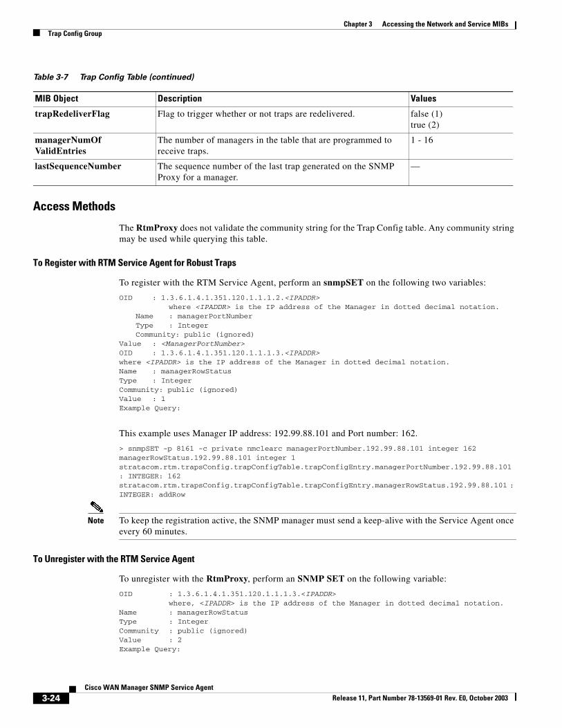
Access Methods
The RtmProxy does not validate the community string for the Trap Config table. Any community string may be used while querying this table.
To Register with RTM Service Agent for Robust Traps
To register with the RTM Service Agent, perform an snmpSET on the following two variables:
OID : 1.3.6.1.4.1.351.120.1.1.1.2.<IPADDR>where <IPADDR> is the IP address of the Manager in dotted decimal notation.
Name : managerPortNumberType : IntegerCommunity: public (ignored)
Value : <ManagerPortNumber>OID : 1.3.6.1.4.1.351.120.1.1.1.3.<IPADDR>where <IPADDR> is the IP address of the Manager in dotted decimal notation.Name : managerRowStatusType : IntegerCommunity: public (ignored)Value : 1Example Query:
This example uses Manager IP address: 192.99.88.101 and Port number: 162.
> snmpSET -p 8161 -c private nmclearc managerPortNumber.192.99.88.101 integer 162 managerRowStatus.192.99.88.101 integer 1stratacom.rtm.trapsConfig.trapConfigTable.trapConfigEntry.managerPortNumber.192.99.88.101 : INTEGER: 162stratacom.rtm.trapsConfig.trapConfigTable.trapConfigEntry.managerRowStatus.192.99.88.101 : INTEGER: addRow
Note To keep the registration active, the SNMP manager must send a keep-alive with the Service Agent once every 60 minutes.
To Unregister with the RTM Service Agent
To unregister with the RtmProxy, perform an SNMP SET on the following variable:
OID : 1.3.6.1.4.1.351.120.1.1.1.3.<IPADDR>where, <IPADDR> is the IP address of the Manager in dotted decimal notation.
Name : managerRowStatusType : IntegerCommunity : public (ignored)Value : 2Example Query:
trapRedeliverFlag Flag to trigger whether or not traps are redelivered. false (1)true (2)
managerNumOf ValidEntries
The number of managers in the table that are programmed to receive traps.
1 - 16
lastSequenceNumber The sequence number of the last trap generated on the SNMP Proxy for a manager.
—
Table 3-7 Trap Config Table (continued)
MIB Object Description Values
3-24Cisco WAN Manager SNMP Service Agent
Release 11, Part Number 78-13569-01 Rev. E0, October 2003
Chapter 3 Accessing the Network and Service MIBsTrap Config Group
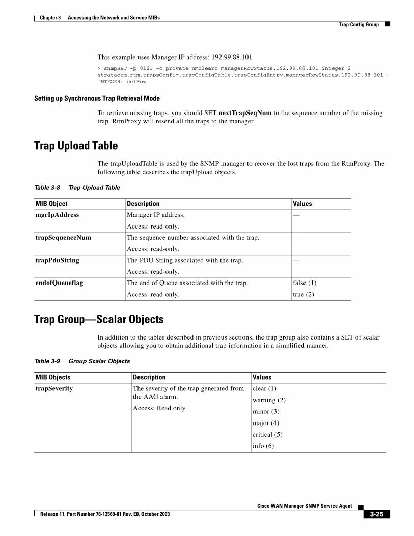
This example uses Manager IP address: 192.99.88.101
> snmpSET -p 8161 -c private nmclearc managerRowStatus.192.99.88.101 integer 2stratacom.rtm.trapsConfig.trapConfigTable.trapConfigEntry.managerRowStatus.192.99.88.101 : INTEGER: delRow
Setting up Synchronous Trap Retrieval Mode
To retrieve missing traps, you should SET nextTrapSeqNum to the sequence number of the missing trap. RtmProxy will resend all the traps to the manager.
Trap Upload TableThe trapUploadTable is used by the SNMP manager to recover the lost traps from the RtmProxy. The following table describes the trapUpload objects.
Trap Group—Scalar ObjectsIn addition to the tables described in previous sections, the trap group also contains a SET of scalar objects allowing you to obtain additional trap information in a simplified manner.
Table 3-8 Trap Upload Table
MIB Object Description Values
mgrIpAddress Manager IP address.
Access: read-only.
—
trapSequenceNum The sequence number associated with the trap.
Access: read-only.
—
trapPduString The PDU String associated with the trap.
Access: read-only.
—
endofQueueflag The end of Queue associated with the trap.
Access: read-only.
false (1)
true (2)
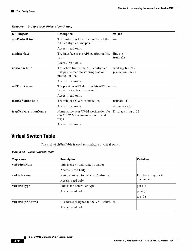
Table 3-9 Group Scalar Objects
MIB Objects Description Values
trapSeverity The severity of the trap generated from the AAG alarm.
Access: Read only.
clear (1)
warning (2)
minor (3)
major (4)
critical (5)
info (6)
3-25Cisco WAN Manager SNMP Service Agent
Release 11, Part Number 78-13569-01 Rev. E0, October 2003
Chapter 3 Accessing the Network and Service MIBsTrap Config Group
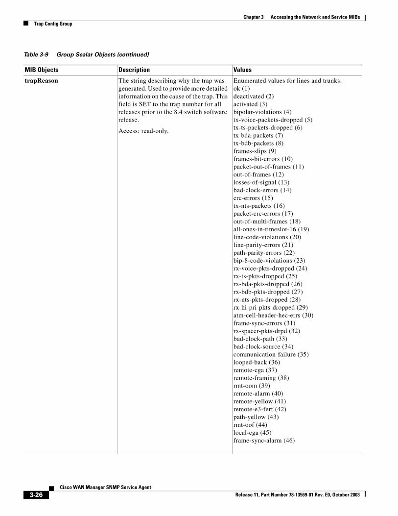
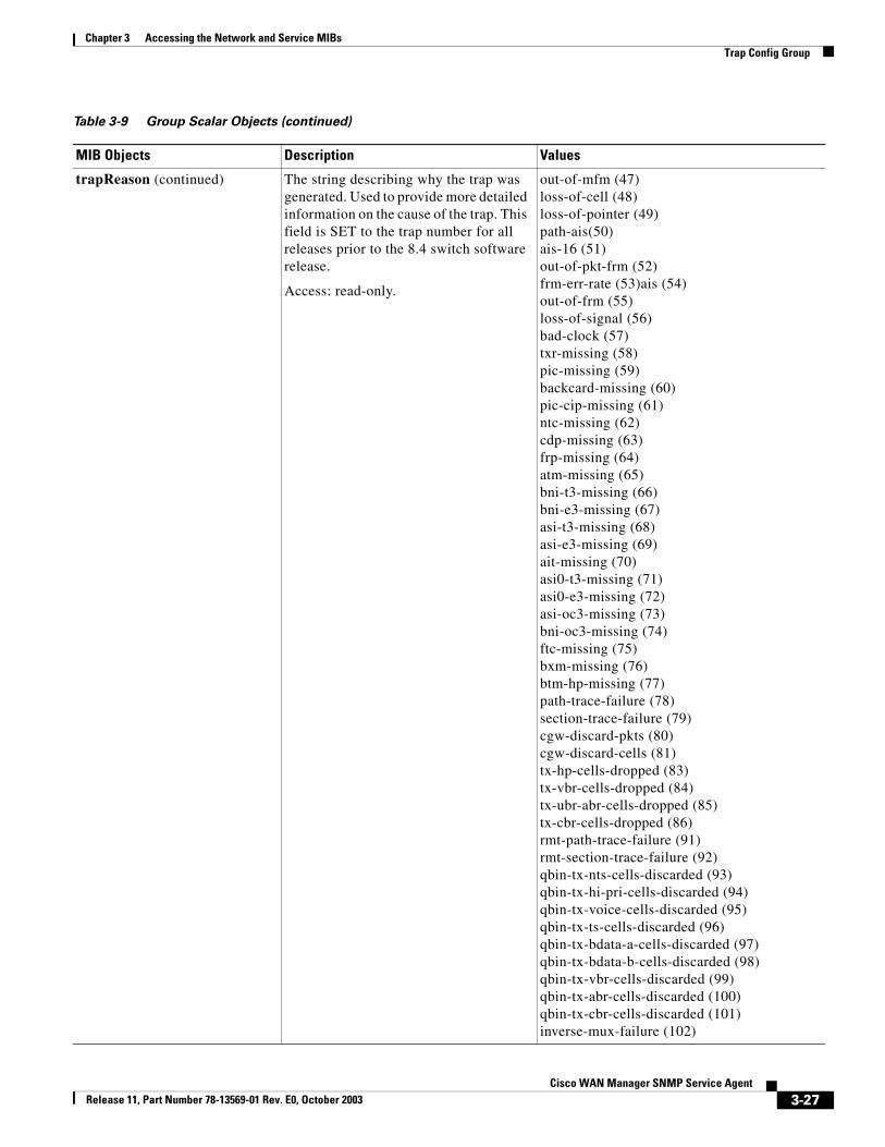
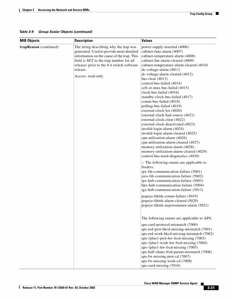
trapReason The string describing why the trap was generated. Used to provide more detailed information on the cause of the trap. This field is SET to the trap number for all releases prior to the 8.4 switch software release.
Access: read-only.
Enumerated values for lines and trunks:ok (1)deactivated (2)activated (3)bipolar-violations (4)tx-voice-packets-dropped (5)tx-ts-packets-dropped (6)tx-bda-packets (7)tx-bdb-packets (8)frames-slips (9)frames-bit-errors (10)packet-out-of-frames (11)out-of-frames (12)losses-of-signal (13)bad-clock-errors (14)crc-errors (15)tx-nts-packets (16)packet-crc-errors (17)out-of-multi-frames (18)all-ones-in-timeslot-16 (19)line-code-violations (20)line-parity-errors (21)path-parity-errors (22)bip-8-code-violations (23)rx-voice-pkts-dropped (24)rx-ts-pkts-dropped (25)rx-bda-pkts-dropped (26)rx-bdb-pkts-dropped (27)rx-nts-pkts-dropped (28)rx-hi-pri-pkts-dropped (29)atm-cell-header-hec-errs (30)frame-sync-errors (31)rx-spacer-pkts-drpd (32)bad-clock-path (33)bad-clock-source (34)communication-failure (35)looped-back (36)remote-cga (37)remote-framing (38)rmt-oom (39)remote-alarm (40)remote-yellow (41)remote-e3-ferf (42)path-yellow (43)rmt-oof (44)local-cga (45)frame-sync-alarm (46)
Table 3-9 Group Scalar Objects (continued)
MIB Objects Description Values
3-26Cisco WAN Manager SNMP Service Agent
Release 11, Part Number 78-13569-01 Rev. E0, October 2003
Chapter 3 Accessing the Network and Service MIBsTrap Config Group
trapReason (continued) The string describing why the trap was generated. Used to provide more detailed information on the cause of the trap. This field is SET to the trap number for all releases prior to the 8.4 switch software release.
Access: read-only.
out-of-mfm (47)loss-of-cell (48)loss-of-pointer (49)path-ais(50)ais-16 (51)out-of-pkt-frm (52)frm-err-rate (53)ais (54)out-of-frm (55)loss-of-signal (56)bad-clock (57)txr-missing (58)pic-missing (59)backcard-missing (60)pic-cip-missing (61)ntc-missing (62)cdp-missing (63)frp-missing (64)atm-missing (65)bni-t3-missing (66)bni-e3-missing (67)asi-t3-missing (68)asi-e3-missing (69)ait-missing (70)asi0-t3-missing (71)asi0-e3-missing (72)asi-oc3-missing (73)bni-oc3-missing (74)ftc-missing (75)bxm-missing (76)btm-hp-missing (77)path-trace-failure (78)section-trace-failure (79)cgw-discard-pkts (80)cgw-discard-cells (81)tx-hp-cells-dropped (83)tx-vbr-cells-dropped (84)tx-ubr-abr-cells-dropped (85)tx-cbr-cells-dropped (86)rmt-path-trace-failure (91)rmt-section-trace-failure (92)qbin-tx-nts-cells-discarded (93)qbin-tx-hi-pri-cells-discarded (94)qbin-tx-voice-cells-discarded (95)qbin-tx-ts-cells-discarded (96)qbin-tx-bdata-a-cells-discarded (97)qbin-tx-bdata-b-cells-discarded (98)qbin-tx-vbr-cells-discarded (99)qbin-tx-abr-cells-discarded (100)qbin-tx-cbr-cells-discarded (101)inverse-mux-failure (102)
Table 3-9 Group Scalar Objects (continued)
MIB Objects Description Values
3-27Cisco WAN Manager SNMP Service Agent
Release 11, Part Number 78-13569-01 Rev. E0, October 2003
Chapter 3 Accessing the Network and Service MIBsTrap Config Group
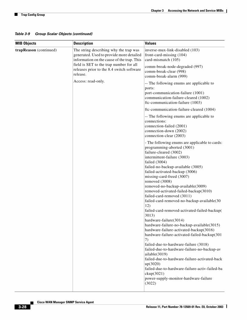
trapReason (continued) The string describing why the trap was generated. Used to provide more detailed information on the cause of the trap. This field is SET to the trap number for all releases prior to the 8.4 switch software release.
Access: read-only.
inverse-mux-link-disabled (103)front-card-missing (104)card-mismatch (105)
comm-break-node-degraded (997)comm-break-clear (998)comm-break-alarm (999)
-- The following enums are applicable to ports:port-communication-failure (1001)communication-failure-cleared (1002)ftc-communication-failure (1003)
ftc-communication-failure-cleared (1004)
-- The following enums are applicable to connections:connection-failed (2001)connection-down (2002)connection-clear (2003)
- The following enums are applicable to cards:programming-aborted (3001)failure-cleared (3002)intermittent-failure (3003)failed (3004)failed-no-backup-available (3005)failed-activated-backup (3006)missing-card-freed (3007)removed (3008)removed-no-backup-available(3009)removed-activated-failed-backup(3010)failed-card-removed (3011)failed-card-removed-no-backup-available(3012)failed-card-removed-activated-failed-backup(3013)hardware-failure(3014)hardware-failure-no-backup-available(3015)hardware-failure-activated-backup(3016)hardware-failure-activated-failed-backup(3017)failed-due-to-hardware-failure (3018)failed-due-to-hardware-failure-no-backup-available(3019)failed-due-to-hardware-failure-activated-backup(3020)failed-due-to-hardware-failure-activ-failed-backup(3021)power-supply-monitor-hardware-failure (3022)
Table 3-9 Group Scalar Objects (continued)
MIB Objects Description Values
3-28Cisco WAN Manager SNMP Service Agent
Release 11, Part Number 78-13569-01 Rev. E0, October 2003
Chapter 3 Accessing the Network and Service MIBsTrap Config Group
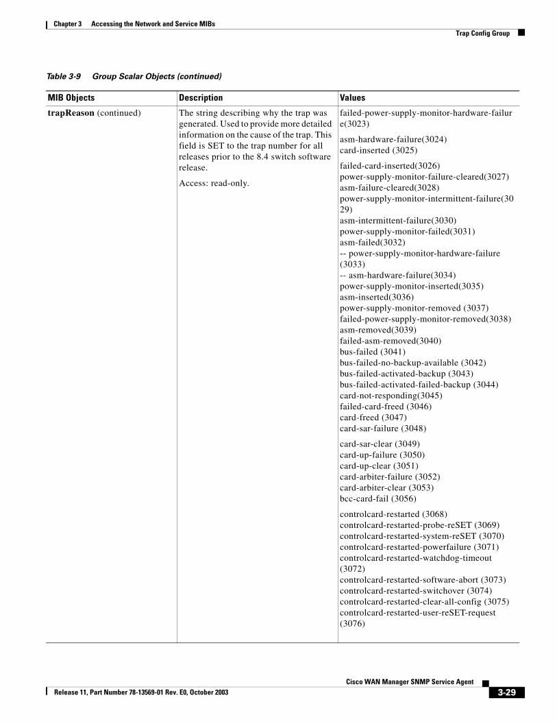
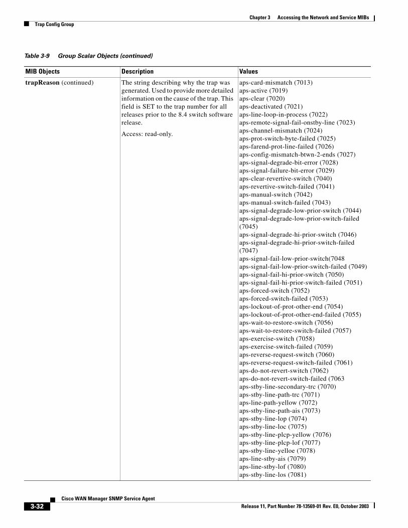
trapReason (continued) The string describing why the trap was generated. Used to provide more detailed information on the cause of the trap. This field is SET to the trap number for all releases prior to the 8.4 switch software release.
Access: read-only.
failed-power-supply-monitor-hardware-failure(3023)
asm-hardware-failure(3024)card-inserted (3025)
failed-card-inserted(3026)power-supply-monitor-failure-cleared(3027)asm-failure-cleared(3028)power-supply-monitor-intermittent-failure(3029)asm-intermittent-failure(3030)power-supply-monitor-failed(3031)asm-failed(3032)-- power-supply-monitor-hardware-failure (3033)-- asm-hardware-failure(3034)power-supply-monitor-inserted(3035)asm-inserted(3036)power-supply-monitor-removed (3037)failed-power-supply-monitor-removed(3038)asm-removed(3039)failed-asm-removed(3040)bus-failed (3041)bus-failed-no-backup-available (3042)bus-failed-activated-backup (3043)bus-failed-activated-failed-backup (3044)card-not-responding(3045)failed-card-freed (3046)card-freed (3047)card-sar-failure (3048)
card-sar-clear (3049)card-up-failure (3050)card-up-clear (3051)card-arbiter-failure (3052)card-arbiter-clear (3053)bcc-card-fail (3056)
controlcard-restarted (3068)controlcard-restarted-probe-reSET (3069)controlcard-restarted-system-reSET (3070)controlcard-restarted-powerfailure (3071)controlcard-restarted-watchdog-timeout (3072)controlcard-restarted-software-abort (3073)controlcard-restarted-switchover (3074)controlcard-restarted-clear-all-config (3075)controlcard-restarted-user-reSET-request (3076)
Table 3-9 Group Scalar Objects (continued)
MIB Objects Description Values
3-29Cisco WAN Manager SNMP Service Agent
Release 11, Part Number 78-13569-01 Rev. E0, October 2003
Chapter 3 Accessing the Network and Service MIBsTrap Config Group
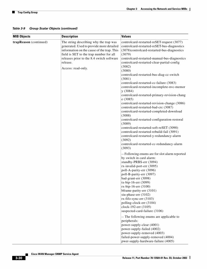
trapReason (continued) The string describing why the trap was generated. Used to provide more detailed information on the cause of the trap. This field is SET to the trap number for all releases prior to the 8.4 switch software release.
Access: read-only.
controlcard-restarted-reSET-request (3077)controlcard-restarted-reSET-bus-diagnostics (3078)controlcard-restarted-bus-diagnostics (3079)controlcard-restarted-manual-bus-diagnostics controlcard-restarted-clear-partial-config (3082)(3080)controlcard-restarted-bus-diag-cc-switch (3081)controlcard-restarted-cc-failure (3083)controlcard-restarted-incomplete-nvc-memory (3084)controlcard-restarted-primary-revision-change (3085)controlcard-restarted-revision-change (3086)controlcard-restarted-bad-crc (3087)controlcard-restarted-completed-download (3088)controlcard-restarted-configuration-restoral (3089)controlcard-restarted-soft-reSET (3090)controlcard-restarted-rebuild-fail (3091)controlcard-restarted-y-redundancy-alarm (3092)controlcard-restarted-cc-redundancy-alarm (3093)
-- Following enums are for slot alarm reported by switch in card alarm:standby-PRBS-err (3094)rx-invalid-port-err (3095)poll-A-parity-err (3096)poll-B-parity-err (3097)bad-grant-err (3098)tx-bip-16-err (3099)rx-bip-16-err (3100)bframe-parity-err (3101)siu-phase-err (3102)rx-fifo-sync-err (3103)polling-clock-err (3104)clock-192-err (3105)suspected-card-failure (3106)
-- The following enums are applicable to peripherals:power-supply-clear (4001)power-supply-failed (4002)power-supply-removed (4003)failed-power-supply-removed (4004)pwer-supply-hardware-failure (4005)
Table 3-9 Group Scalar Objects (continued)
MIB Objects Description Values
3-30Cisco WAN Manager SNMP Service Agent
Release 11, Part Number 78-13569-01 Rev. E0, October 2003
Chapter 3 Accessing the Network and Service MIBsTrap Config Group
trapReason (continued) The string describing why the trap was generated. Used to provide more detailed information on the cause of the trap. This field is SET to the trap number for all releases prior to the 8.4 switch software release.
Access: read-only.
power-supply-inserted (4006)cabinet-fans-alarm (4007)cabinet-temperature-alarm (4008)cabinet-fan-alarm-cleared (4009)cabinet-temperature-alarm-cleared (4010)dc-voltage-alarm (4011)dc-voltage-alarm-cleared (4012)bus-clear (4013)control-bus-failed (4014)cell-or-mux-bus-failed (4015)clock-bus-failed (4016)standby-clock-bus-failed (4017)comm-bus-failed (4018)polling-bus-failed (4019)external-clock-los (4020)external-clock-bad-source (4021)external-clock-clear (4022)external-clock-deactivated (4023)invalid-login-alarm (4024)invalid-login-alarm-cleared (4025)cpu-utilization-alarm (4026)cpu-utilization-alarm-cleared (4027)memory-utilization-alarm (4028)memory-utilization-alarm-cleared (4029)control-bus-need-diagnostics (4030)
-- The following enums are applicable to feeders:ipx-fdr-communication-failure (5001)axis-fdr-communication-failure (5002)ipx-hub-communication-failure (5003)bpx-hub-communication-failure (5004)igx-hub-communication-failure (5013)
popeye-fdrtrk-comm-failure (5019) popeye-fdrtrk-alarm-cleared (5020) popeye-fdrtrk-majororminor-alarm (5021)
The following enums are applicable to APS:
aps-card-protocol-mismatch (7000)aps-red-prot-bkcd-missing-mismatch (7001)aps-red-work-bkcd-missing-mismatch (7002)aps-1plus1-prot-hw-frcd-missing (7003)aps-1plus1-work-hw-frcd-missing (7004)aps-1plus1-hw-frcd-missing (7005)aps-half-chans-frcd-param-mismatch (7006)aps-fw-missing-prot-cd (7007)aps-fw-missing-work-cd (7008)aps-card-missing (7010)
Table 3-9 Group Scalar Objects (continued)
MIB Objects Description Values
3-31Cisco WAN Manager SNMP Service Agent
Release 11, Part Number 78-13569-01 Rev. E0, October 2003
Chapter 3 Accessing the Network and Service MIBsTrap Config Group
trapReason (continued) The string describing why the trap was generated. Used to provide more detailed information on the cause of the trap. This field is SET to the trap number for all releases prior to the 8.4 switch software release.
Access: read-only.
aps-card-mismatch (7013)aps-active (7019)aps-clear (7020)aps-deactivated (7021)aps-line-loop-in-process (7022)aps-remote-signal-fail-onstby-line (7023)aps-channel-mismatch (7024)aps-prot-switch-byte-failed (7025)aps-farend-prot-line-failed (7026)aps-config-mismatch-btwn-2-ends (7027)aps-signal-degrade-bit-error (7028)aps-signal-failure-bit-error (7029)aps-clear-revertive-switch (7040)aps-revertive-switch-failed (7041)aps-manual-switch (7042)aps-manual-switch-failed (7043)aps-signal-degrade-low-prior-switch (7044)aps-signal-degrade-low-prior-switch-failed (7045)aps-signal-degrade-hi-prior-switch (7046)aps-signal-degrade-hi-prior-switch-failed (7047)aps-signal-fail-low-prior-switch(7048aps-signal-fail-low-prior-switch-failed (7049)aps-signal-fail-hi-prior-switch (7050)aps-signal-fail-hi-prior-switch-failed (7051)aps-forced-switch (7052)aps-forced-switch-failed (7053)aps-lockout-of-prot-other-end (7054)aps-lockout-of-prot-other-end-failed (7055)aps-wait-to-restore-switch (7056)aps-wait-to-restore-switch-failed (7057)aps-exercise-switch (7058)aps-exercise-switch-failed (7059)aps-reverse-request-switch (7060)aps-reverse-request-switch-failed (7061)aps-do-not-revert-switch (7062)aps-do-not-revert-switch-failed (7063aps-stby-line-secondary-trc (7070)aps-stby-line-path-trc (7071)aps-line-path-yellow (7072)aps-stby-line-path-ais (7073)aps-stby-line-lop (7074)aps-stby-line-loc (7075)aps-stby-line-plcp-yellow (7076)aps-stby-line-plcp-lof (7077)aps-stby-line-yelloe (7078)aps-line-stby-ais (7079)aps-line-stby-lof (7080)aps-stby-line-los (7081)
Table 3-9 Group Scalar Objects (continued)
MIB Objects Description Values
3-32Cisco WAN Manager SNMP Service Agent
Release 11, Part Number 78-13569-01 Rev. E0, October 2003
Chapter 3 Accessing the Network and Service MIBsTrap Config Group
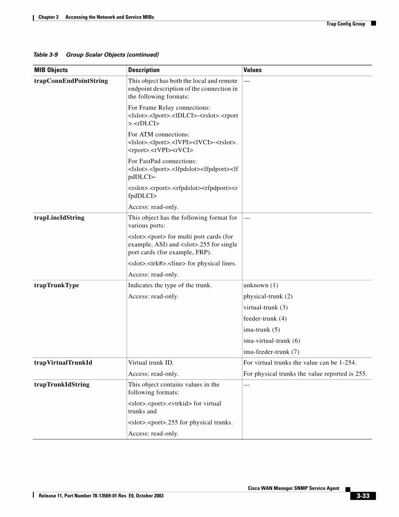
trapConnEndPointString This object has both the local and remote endpoint description of the connection in the following formats:
For Frame Relay connections:<lslot>.<lport>.<lDLCI>-<rslot>.<rport>.<rDLCI>
For ATM connections:<lslot>.<lport>.<lVPI><lVCI>-<rslot>.<rport>.<rVPI><rVCI>
For FastPad connections:<lslot>.<lport>.<lfpdslot><lfpdport><lfpdDLCI>-
<rslot>.<rport>.<rfpdslot><rfpdport><rfpdDLCI>
Access: read-only.
—
trapLineIdString This object has the following format for various ports:
<slot>.<port> for multi port cards (for example, ASI) and <slot>.255 for single port cards (for example, FRP).
<slot>.<trk#>.<line> for physical lines.
Access: read-only.
—
trapTrunkType Indicates the type of the trunk.
Access: read-only.
unknown (1)
physical-trunk (2)
virtual-trunk (3)
feeder-trunk (4)
ima-trunk (5)
ima-virtual-trunk (6)
ima-feeder-trunk (7)
trapVirtualTrunkId Virtual trunk ID.
Access: read-only.
For virtual trunks the value can be 1-254.
For physical trunks the value reported is 255.
trapTrunkIdString This object contains values in the following formats:
<slot>.<port>.<vtrkid> for virtual trunks and
<slot>.<port>.255 for physical trunks.
Access: read-only.
—
Table 3-9 Group Scalar Objects (continued)
MIB Objects Description Values
3-33Cisco WAN Manager SNMP Service Agent
Release 11, Part Number 78-13569-01 Rev. E0, October 2003
Chapter 3 Accessing the Network and Service MIBsTrap Config Group
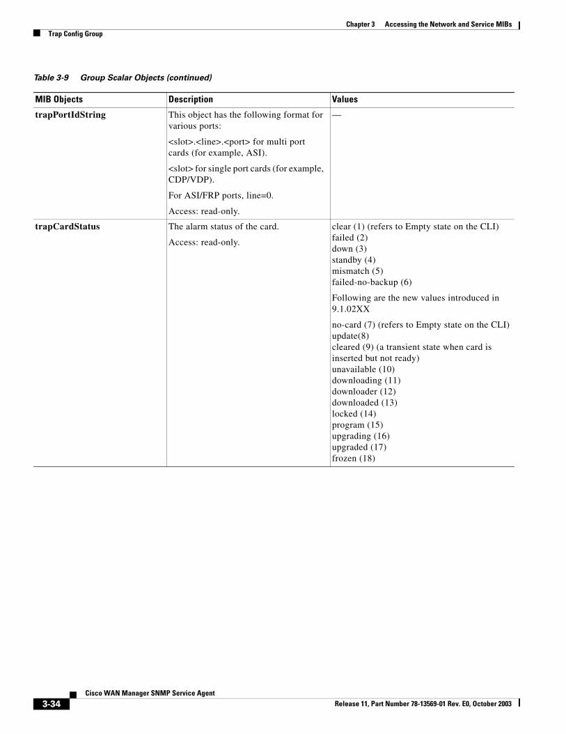
trapPortIdString This object has the following format for various ports:
<slot>.<line>.<port> for multi port cards (for example, ASI).
<slot> for single port cards (for example, CDP/VDP).
For ASI/FRP ports, line=0.
Access: read-only.
—
trapCardStatus The alarm status of the card.
Access: read-only.
clear (1) (refers to Empty state on the CLI)failed (2)down (3)standby (4)mismatch (5)failed-no-backup (6)
Following are the new values introduced in 9.1.02XX
no-card (7) (refers to Empty state on the CLI)update(8)cleared (9) (a transient state when card is inserted but not ready)unavailable (10)downloading (11)downloader (12)downloaded (13)locked (14)program (15)upgrading (16)upgraded (17)frozen (18)
Table 3-9 Group Scalar Objects (continued)
MIB Objects Description Values
3-34Cisco WAN Manager SNMP Service Agent
Release 11, Part Number 78-13569-01 Rev. E0, October 2003
Chapter 3 Accessing the Network and Service MIBsTrap Config Group
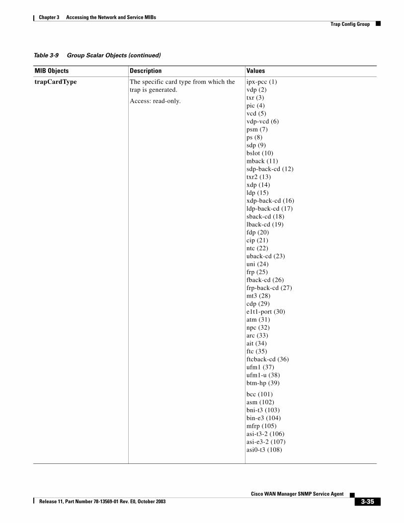
trapCardType The specific card type from which the trap is generated.
Access: read-only.
ipx-pcc (1)vdp (2)txr (3)pic (4)vcd (5)vdp-vcd (6)psm (7)ps (8)sdp (9)bslot (10)mback (11)sdp-back-cd (12)txr2 (13)xdp (14)ldp (15)xdp-back-cd (16)ldp-back-cd (17)sback-cd (18)lback-cd (19)fdp (20)cip (21)ntc (22)uback-cd (23)uni (24)frp (25)fback-cd (26)frp-back-cd (27)mt3 (28)cdp (29)e1t1-port (30)atm (31)npc (32)arc (33)ait (34)ftc (35)ftcback-cd (36)ufm1 (37)ufm1-u (38)btm-hp (39)
bcc (101)asm (102)bni-t3 (103)bin-e3 (104)mfrp (105)asi-t3-2 (106)asi-e3-2 (107)asi0-t3 (108)
Table 3-9 Group Scalar Objects (continued)
MIB Objects Description Values
3-35Cisco WAN Manager SNMP Service Agent
Release 11, Part Number 78-13569-01 Rev. E0, October 2003

Chapter 3 Accessing the Network and Service MIBsTrap Config Group
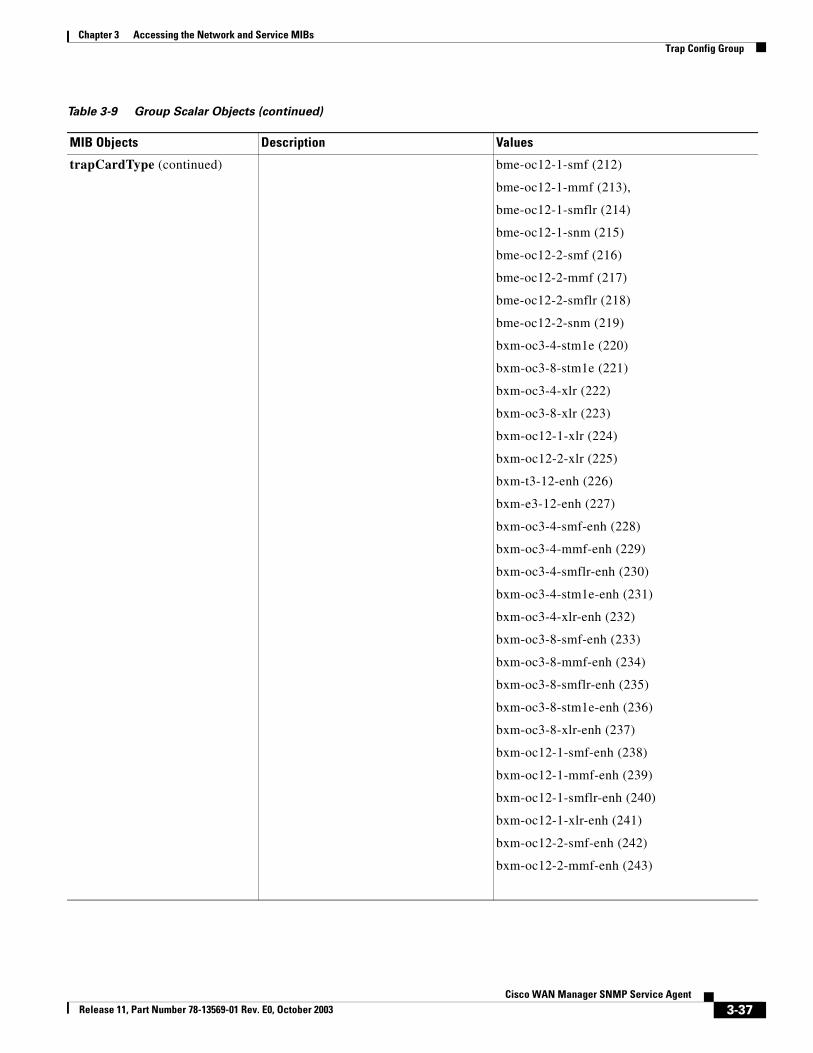
trapCardType (continued) The specific card type from which the trap is generated.
Access: read-only.
asi0-e3 (109)bni-oc3 (110)asi-oc3 (111)bpx-bslot (112)bcc3 (113)unknown (114)bxm (117) (kept for backward compatibility)
Following is the list of BXM cards. The enums are directly used from the switch SW interface without any mapping:smf Single Mode Fibermmf Multi Mode Fibersmflr Single Mode Fiber LongRangesnm Mixed Mode
bxm-t3-8-smf (180)bxm-t3-8-mmf (181)bxm-t3-8-smflr (182)bxm-t3-8-snm (183)bxm-t3-12-smf (184)bxm-t3-12-mmf (185)bxm-t3-12-smflr (186)bxm-t3-12-snm (187)bxm-e3-8-smf (188)bxm-e3-8-mmf (189)bxm-e3-8-smflr (190)bxm-e3-8-snm (191)bxm-e3-12-smf (192)bxm-e3-12-mmf (193)bxm-e3-12-smflr (194)bxm-e3-12-snm (195)bxm-oc3-4-smf (196)bxm-oc3-4-mmf (197)bxm-oc3-4-smflr (198)bxm-oc3-4-snm (199)bxm-oc3-8-smf (200)bxm-oc3-8-mmf (201)bxm-oc3-8-smflr (202)bxm-oc3-8-snm (203)bxm-oc12-1-smf (204)bxm-oc12-1-mmf (205)bxm-oc12-1-smflr (206)bxm-oc12-1-snm (207)bxm-oc12-2-smf (208)bxm-oc12-2-mmf (209)bxm-oc12-2-smflr (210)bxm-oc12-2-snm (211)
Table 3-9 Group Scalar Objects (continued)
MIB Objects Description Values
3-36Cisco WAN Manager SNMP Service Agent
Release 11, Part Number 78-13569-01 Rev. E0, October 2003
Chapter 3 Accessing the Network and Service MIBsTrap Config Group
trapCardType (continued) bme-oc12-1-smf (212)
bme-oc12-1-mmf (213),
bme-oc12-1-smflr (214)
bme-oc12-1-snm (215)
bme-oc12-2-smf (216)
bme-oc12-2-mmf (217)
bme-oc12-2-smflr (218)
bme-oc12-2-snm (219)
bxm-oc3-4-stm1e (220)
bxm-oc3-8-stm1e (221)
bxm-oc3-4-xlr (222)
bxm-oc3-8-xlr (223)
bxm-oc12-1-xlr (224)
bxm-oc12-2-xlr (225)
bxm-t3-12-enh (226)
bxm-e3-12-enh (227)
bxm-oc3-4-smf-enh (228)
bxm-oc3-4-mmf-enh (229)
bxm-oc3-4-smflr-enh (230)
bxm-oc3-4-stm1e-enh (231)
bxm-oc3-4-xlr-enh (232)
bxm-oc3-8-smf-enh (233)
bxm-oc3-8-mmf-enh (234)
bxm-oc3-8-smflr-enh (235)
bxm-oc3-8-stm1e-enh (236)
bxm-oc3-8-xlr-enh (237)
bxm-oc12-1-smf-enh (238)
bxm-oc12-1-mmf-enh (239)
bxm-oc12-1-smflr-enh (240)
bxm-oc12-1-xlr-enh (241)
bxm-oc12-2-smf-enh (242)
bxm-oc12-2-mmf-enh (243)
Table 3-9 Group Scalar Objects (continued)
MIB Objects Description Values
3-37Cisco WAN Manager SNMP Service Agent
Release 11, Part Number 78-13569-01 Rev. E0, October 2003
Chapter 3 Accessing the Network and Service MIBsTrap Config Group
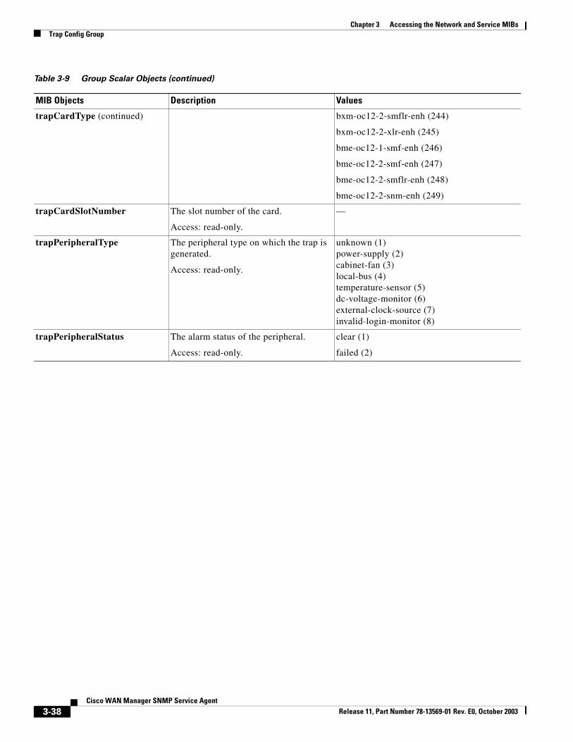
trapCardType (continued) bxm-oc12-2-smflr-enh (244)
bxm-oc12-2-xlr-enh (245)
bme-oc12-1-smf-enh (246)
bme-oc12-2-smf-enh (247)
bme-oc12-2-smflr-enh (248)
bme-oc12-2-snm-enh (249)
trapCardSlotNumber The slot number of the card.
Access: read-only.
—
trapPeripheralType The peripheral type on which the trap is generated.
Access: read-only.
unknown (1)power-supply (2)cabinet-fan (3)local-bus (4)temperature-sensor (5)dc-voltage-monitor (6)external-clock-source (7)invalid-login-monitor (8)
trapPeripheralStatus The alarm status of the peripheral.
Access: read-only.
clear (1)
failed (2)
Table 3-9 Group Scalar Objects (continued)
MIB Objects Description Values
3-38Cisco WAN Manager SNMP Service Agent
Release 11, Part Number 78-13569-01 Rev. E0, October 2003
Chapter 3 Accessing the Network and Service MIBsTrap Config Group
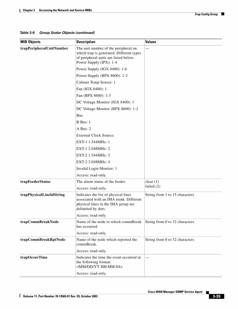
trapPeripheralUnitNumber The unit number of the peripheral on which trap is generated. Different types of peripheral units are listed below:Power Supply (IPX): 1-4
Power Supply (IGX 8400): 1-6
Power Supply (BPX 8600): 1-2
Cabinet Temp Sensor: 1
Fan (IGX 8400): 1
Fan (BPX 8600): 1-3
DC Voltage Monitor (IGX 8400): 1
DC Voltage Monitor (BPX 8600): 1-2
Bus
B Bus: 1
A Bus: 2
External Clock Source:
EXT-1 1.544MHz: 1
EXT-1 2.048MHz: 2
EXT-2 1.544MHz: 3
EXT-2 2.048MHz: 4
Invalid Login Monitor: 1
Access: read-only.
—
trapFeederStatus The alarm status of the feeder.
Access: read-only.
clear (1)failed (2)
trapPhysicalLineIdString Indicates the list of physical lines associated with an IMA trunk. Different physical lines in the IMA group are delimited by dots.
Access: read-only.
String from 1 to 15 characters
trapCommBreakNode Name of the node to which commBreak has occurred.
Access: read-only.
String from 0 to 32 characters
trapCommBreakRptNode Name of the node which reported the commBreak.
Access: read-only.
String from 0 to 32 characters
trapOccurTime Indicates the time the event occurred in the following format:<MM/DD/YY HH:MM:SS>
Access: read-only.
—
Table 3-9 Group Scalar Objects (continued)
MIB Objects Description Values
3-39Cisco WAN Manager SNMP Service Agent
Release 11, Part Number 78-13569-01 Rev. E0, October 2003
Chapter 3 Accessing the Network and Service MIBsTrap Config Group
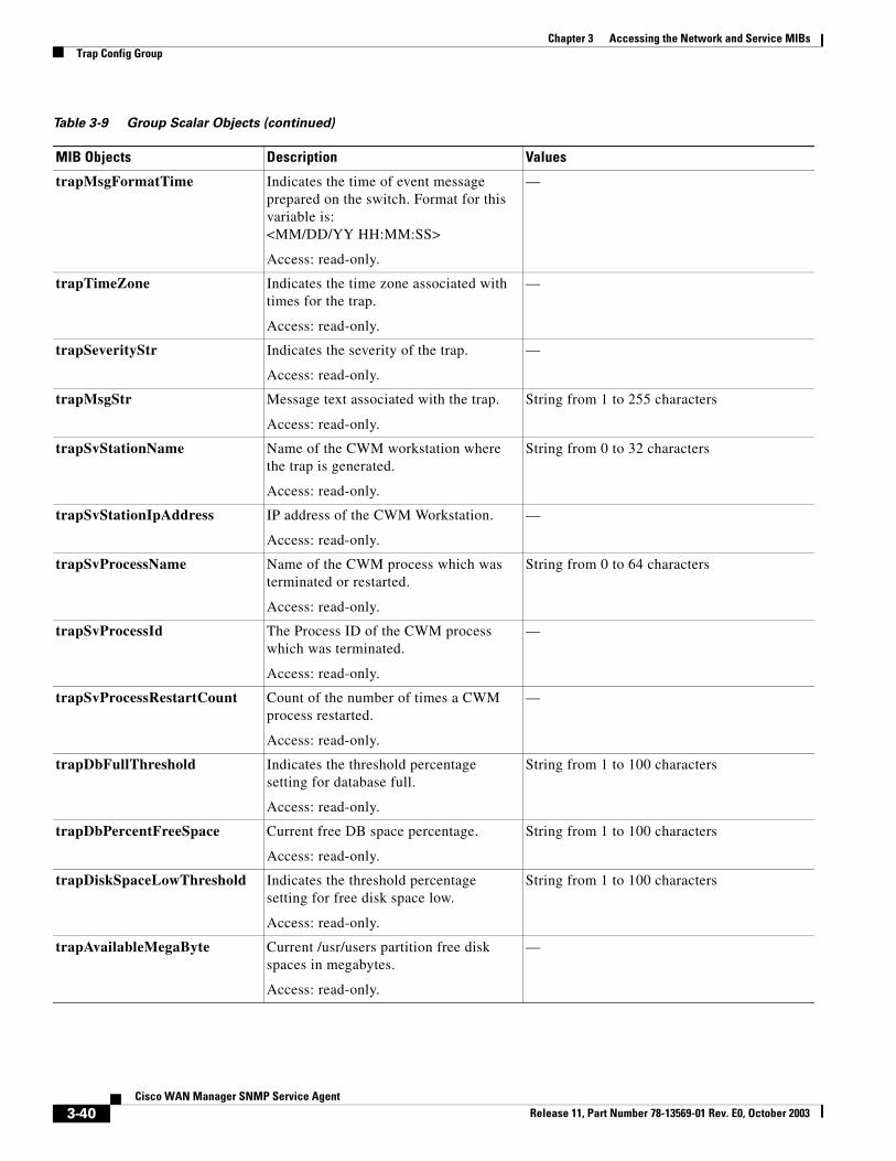
trapMsgFormatTime Indicates the time of event message prepared on the switch. Format for this variable is:<MM/DD/YY HH:MM:SS>
Access: read-only.
—
trapTimeZone Indicates the time zone associated with times for the trap.
Access: read-only.
—
trapSeverityStr Indicates the severity of the trap.
Access: read-only.
—
trapMsgStr Message text associated with the trap.
Access: read-only.
String from 1 to 255 characters
trapSvStationName Name of the CWM workstation where the trap is generated.
Access: read-only.
String from 0 to 32 characters
trapSvStationIpAddress IP address of the CWM Workstation.
Access: read-only.
—
trapSvProcessName Name of the CWM process which was terminated or restarted.
Access: read-only.
String from 0 to 64 characters
trapSvProcessId The Process ID of the CWM process which was terminated.
Access: read-only.
—
trapSvProcessRestartCount Count of the number of times a CWM process restarted.
Access: read-only.
—
trapDbFullThreshold Indicates the threshold percentage setting for database full.
Access: read-only.
String from 1 to 100 characters
trapDbPercentFreeSpace Current free DB space percentage.
Access: read-only.
String from 1 to 100 characters
trapDiskSpaceLowThreshold Indicates the threshold percentage setting for free disk space low.
Access: read-only.
String from 1 to 100 characters
trapAvailableMegaByte Current /usr/users partition free disk spaces in megabytes.
Access: read-only.
—
Table 3-9 Group Scalar Objects (continued)
MIB Objects Description Values
3-40Cisco WAN Manager SNMP Service Agent
Release 11, Part Number 78-13569-01 Rev. E0, October 2003
Chapter 3 Accessing the Network and Service MIBsTrap Config Group
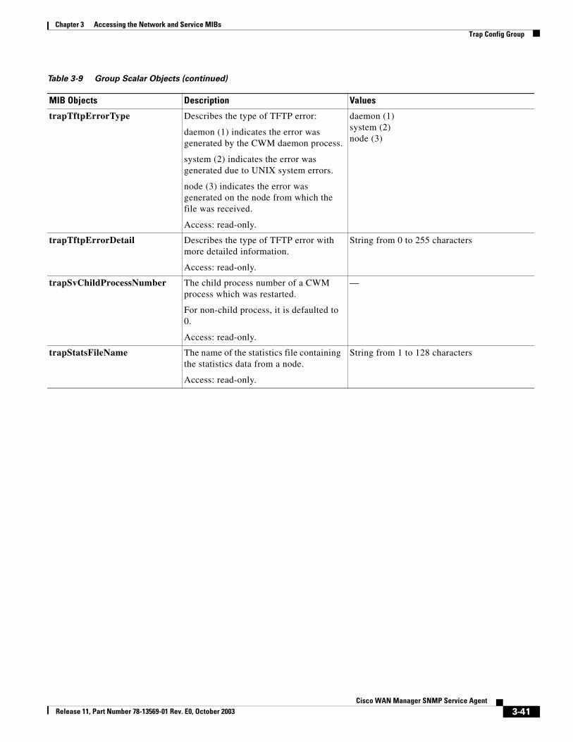
trapTftpErrorType Describes the type of TFTP error:
daemon (1) indicates the error was generated by the CWM daemon process.
system (2) indicates the error was generated due to UNIX system errors.
node (3) indicates the error was generated on the node from which the file was received.
Access: read-only.
daemon (1)system (2)node (3)
trapTftpErrorDetail Describes the type of TFTP error with more detailed information.
Access: read-only.
String from 0 to 255 characters
trapSvChildProcessNumber The child process number of a CWM process which was restarted.
For non-child process, it is defaulted to 0.
Access: read-only.
—
trapStatsFileName The name of the statistics file containing the statistics data from a node.
Access: read-only.
String from 1 to 128 characters
Table 3-9 Group Scalar Objects (continued)
MIB Objects Description Values
3-41Cisco WAN Manager SNMP Service Agent
Release 11, Part Number 78-13569-01 Rev. E0, October 2003
Chapter 3 Accessing the Network and Service MIBsTrap Config Group
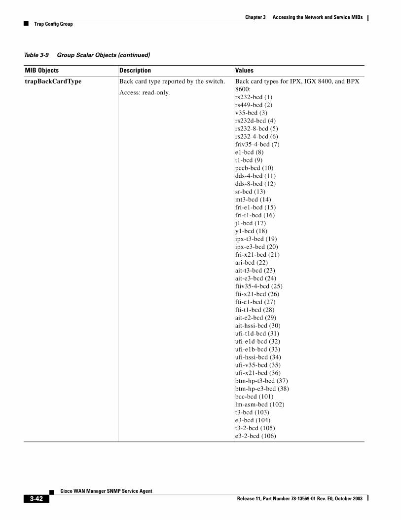
trapBackCardType Back card type reported by the switch.
Access: read-only.
Back card types for IPX, IGX 8400, and BPX 8600:rs232-bcd (1)rs449-bcd (2)v35-bcd (3)rs232d-bcd (4)rs232-8-bcd (5)rs232-4-bcd (6)friv35-4-bcd (7)e1-bcd (8)t1-bcd (9)pccb-bcd (10)dds-4-bcd (11)dds-8-bcd (12)sr-bcd (13)mt3-bcd (14)fri-e1-bcd (15)fri-t1-bcd (16)j1-bcd (17)y1-bcd (18)ipx-t3-bcd (19)ipx-e3-bcd (20)fri-x21-bcd (21)ari-bcd (22)ait-t3-bcd (23)ait-e3-bcd (24)ftiv35-4-bcd (25)fti-x21-bcd (26)fti-e1-bcd (27)fti-t1-bcd (28)ait-e2-bcd (29)ait-hssi-bcd (30)ufi-t1d-bcd (31)ufi-e1d-bcd (32)ufi-e1b-bcd (33)ufi-hssi-bcd (34)ufi-v35-bcd (35)ufi-x21-bcd (36)btm-hp-t3-bcd (37)btm-hp-e3-bcd (38)bcc-bcd (101)lm-asm-bcd (102)t3-bcd (103)e3-bcd (104)t3-2-bcd (105)e3-2-bcd (106)
Table 3-9 Group Scalar Objects (continued)
MIB Objects Description Values
3-42Cisco WAN Manager SNMP Service Agent
Release 11, Part Number 78-13569-01 Rev. E0, October 2003
Chapter 3 Accessing the Network and Service MIBsTrap Config Group
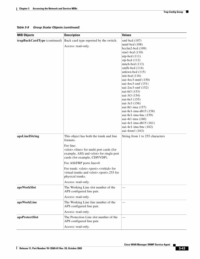
trapBackCardType (continued) Back card type reported by the switch.
Access: read-only.
smf-bcd (107)mmf-bcd (108)bcclm2-bcd (109)stm1-bcd (110)utp-bcd (111)stp-bcd (112)mnch-bcd (113)smflr-bcd (114)unkwn-bcd (115)init-bcd (116)uai-4oc3-mmf (150)uai-4oc3-smf (151)uai-2oc3-smf (152)uai-6t3 (153)uai-3t3 (154)uai-6e3 (155)uai-3e3 (156)uai-8t1-ima (157)uai-8e1-ima-db15 (158)uai-8e1-ima-bnc (159)uai-4t1-ima (160)uai-4e1-ima-db15 (161)uai-4e1-ima-bnc (162)uai-4stm1 (163)
apsLineIString This object has both the trunk and line formats.
For line:<slot>.<line> for multi port cards (for example, ASI) and <slot> for single port cards (for example, CDP/VDP).
For ASI/FRP ports line=0.
For trunk: <slot>.<port>.<vtrkid> for virtual trunks and <slot>.<port>.255 for physical trunks.
Access: read-only.
String from 1 to 255 characters
apsWorkSlot The Working Line slot number of the APS configured line pair.
Access: read-only.
—
apsWorkLine The Working Line line number of the APS configured line pair.
Access: read-only.
—
apsProtectSlot The Protection Line slot number of the APS configured line pair.
Access: read-only.
—
Table 3-9 Group Scalar Objects (continued)
MIB Objects Description Values
3-43Cisco WAN Manager SNMP Service Agent
Release 11, Part Number 78-13569-01 Rev. E0, October 2003
Chapter 3 Accessing the Network and Service MIBsTrap Config Group
Virtual Switch TableThe vsiSwitchGrpTable is used to configure a virtual switch.
apsProtectLine The Protection Line line number of the APS configured line pair.
Access: read-only.
—
apsInterface The interface of the APS configured line pair.
Access: read-only.
line (1)trunk (2)
apsActiveLine The active line of the APS configured line pair; either the working line or protection line.
Access: read-only.
working line (1)protection line (2)
oldTrapReason The previous APS alarm on this APS line before a clear trap is received.
Access: read-only.
—
trapSvStationRole The role of a CWM workstation.
Access: read-only.
primary (1)
secondary (2)
trapSvPeerStationName Name of the peer CWM workstation for CWM-CWM communication related traps.
Access: read-only.
Display string 0–32
Table 3-9 Group Scalar Objects (continued)
MIB Objects Description Values
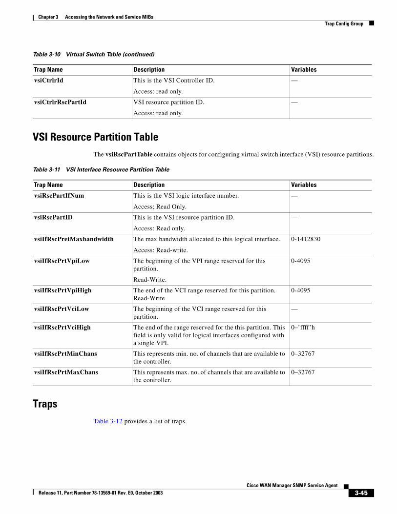
Table 3-10 Virtual Switch Table
Trap Name Description Variables
vsiSwitchNum This is the virtual switch number.
Access: Read Only.
—
vsiCtrlrName Name assigned to the VSI Controller.
Access: read only.
Display string: 0-32 characters.
vsiCtrlrType This is the controller type
Access: read only.
par (1)
pnni (2)
tag (3)
vsiCtrlrIpAddress IP address assigned to the VSI Controller.
Access: read only.
—
3-44Cisco WAN Manager SNMP Service Agent
Release 11, Part Number 78-13569-01 Rev. E0, October 2003
Chapter 3 Accessing the Network and Service MIBsTrap Config Group
VSI Resource Partition TableThe vsiRscPartTable contains objects for configuring virtual switch interface (VSI) resource partitions.
TrapsTable 3-12 provides a list of traps.
vsiCtrlrId This is the VSI Controller ID.
Access: read only.
—
vsiCtrlrRscPartId VSI resource partition ID.
Access: read only.
—
Table 3-10 Virtual Switch Table (continued)
Trap Name Description Variables
Table 3-11 VSI Interface Resource Partition Table
Trap Name Description Variables
vsiRscPartIfNum This is the VSI logic interface number.
Access; Read Only.
—
vsiRscPartID This is the VSI resource partition ID.
Access: Read only.
—
vsiIfRscPretMaxbandwidth The max bandwidth allocated to this logical interface.
Access: Read-write.
0-1412830
vsiIfRscPrtVpiLow The beginning of the VPI range reserved for this partition.
Read-Write.
0-4095
vsiIfRscPrtVpiHigh The end of the VCI range reserved for this partition. Read-Write
0-4095
vsiIfRscPrtVciLow The beginning of the VCI range reserved for this partition.
—
vsiIfRscPrtVciHigh The end of the range reserved for the this partition. This field is only valid for logical interfaces configured with a single VPI.
0–’ffff’h
vsiIfRscPrtMinChans This represents min. no. of channels that are available to the controller.
0–32767
vsiIfRscPrtMaxChans This represents max. no. of channels that are available to the controller.
0–32767
3-45Cisco WAN Manager SNMP Service Agent
Release 11, Part Number 78-13569-01 Rev. E0, October 2003
Chapter 3 Accessing the Network and Service MIBsTrap Config Group
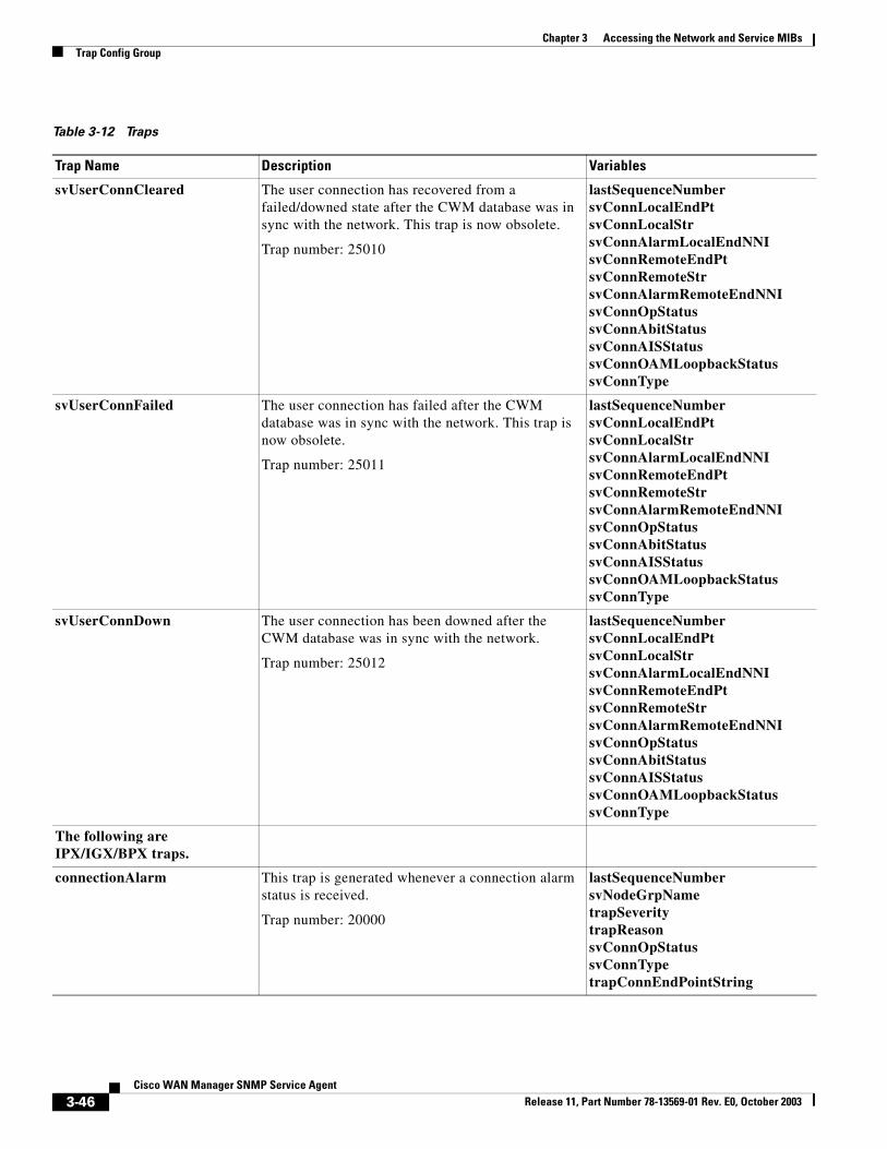
Table 3-12 Traps
Trap Name Description Variables
svUserConnCleared The user connection has recovered from a failed/downed state after the CWM database was in sync with the network. This trap is now obsolete.
Trap number: 25010
lastSequenceNumbersvConnLocalEndPtsvConnLocalStrsvConnAlarmLocalEndNNIsvConnRemoteEndPtsvConnRemoteStrsvConnAlarmRemoteEndNNIsvConnOpStatussvConnAbitStatussvConnAISStatussvConnOAMLoopbackStatussvConnType
svUserConnFailed The user connection has failed after the CWM database was in sync with the network. This trap is now obsolete.
Trap number: 25011
lastSequenceNumbersvConnLocalEndPtsvConnLocalStrsvConnAlarmLocalEndNNIsvConnRemoteEndPtsvConnRemoteStrsvConnAlarmRemoteEndNNIsvConnOpStatussvConnAbitStatussvConnAISStatussvConnOAMLoopbackStatussvConnType
svUserConnDown The user connection has been downed after the CWM database was in sync with the network.
Trap number: 25012
lastSequenceNumbersvConnLocalEndPtsvConnLocalStrsvConnAlarmLocalEndNNIsvConnRemoteEndPtsvConnRemoteStrsvConnAlarmRemoteEndNNIsvConnOpStatussvConnAbitStatussvConnAISStatussvConnOAMLoopbackStatussvConnType
The following are IPX/IGX/BPX traps.
connectionAlarm This trap is generated whenever a connection alarm status is received.
Trap number: 20000
lastSequenceNumbersvNodeGrpNametrapSeveritytrapReasonsvConnOpStatussvConnTypetrapConnEndPointString
3-46Cisco WAN Manager SNMP Service Agent
Release 11, Part Number 78-13569-01 Rev. E0, October 2003
Chapter 3 Accessing the Network and Service MIBsTrap Config Group
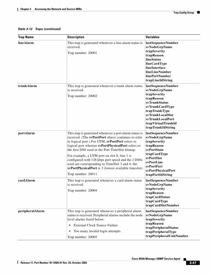
lineAlarm This trap is generated whenever a line alarm status is received.
Trap number: 20001
lastSequenceNumbersvNodeGrpNametrapSeveritytrapReasonlineStatuslineCardTypelineInterfacelineLineNumberlinePortNumbertrapLineIdString
trunkAlarm This trap is generated whenever a trunk alarm status is received.
Trap number: 20002
lastSequenceNumbersvNodeGrpNametrapSeveritytrapReasonsvTrunkStatussvTrunkCardTypetrapTrunkTypesvTrunkLocalSlotsvTrunkLocalPorttrapVirtualTrunkIdtrapTrunkIdString
portAlarm This trap is generated whenever a port alarm status is received. (The svPortPort object continues to refer to logical port.) For UFM, svPortPort refers to logical port whereas svPortPhysicalPort refers to the first DS0 used in the Port TimeSlot bitmap.
For example, a UFM port on slot 8, line 1 is configured with 128 kbps port speed and the 2 DS0s used are corresponding to TimeSlot 3 and 4, the svPortPhysicalPort is 3 (lowest available timeslot).
Trap number: 20011
lastSequenceNumbersvNodeGrpNametrapSeveritytrapReasonsvPortStatetrapCardTypesvPortSlotsvPortLinesvPortPortsvPortPhysicalPorttrapPortIdString
cardAlarm This trap is generated whenever a card alarm status is received.
Trap number: 20004
lastSequenceNumbersvNodeGrpNametrapSeveritytrapReasontrapCardStatustrapCardTypetrapCardSlotNumber
peripheralAlarm This trap is generated whenever a peripheral alarm status is received. Peripheral alarms include the node level alarms listed below:
• External Clock Source Failure
• Too many invalid login attempts
Trap number: 20005
lastSequenceNumbersvNodeGrpNametrapSeveritytrapReasontrapPeripheralStatustrapPeripheralTypetrapPeripheralUnitNumber
Table 3-12 Traps (continued)
Trap Name Description Variables
3-47Cisco WAN Manager SNMP Service Agent
Release 11, Part Number 78-13569-01 Rev. E0, October 2003
Chapter 3 Accessing the Network and Service MIBsTrap Config Group
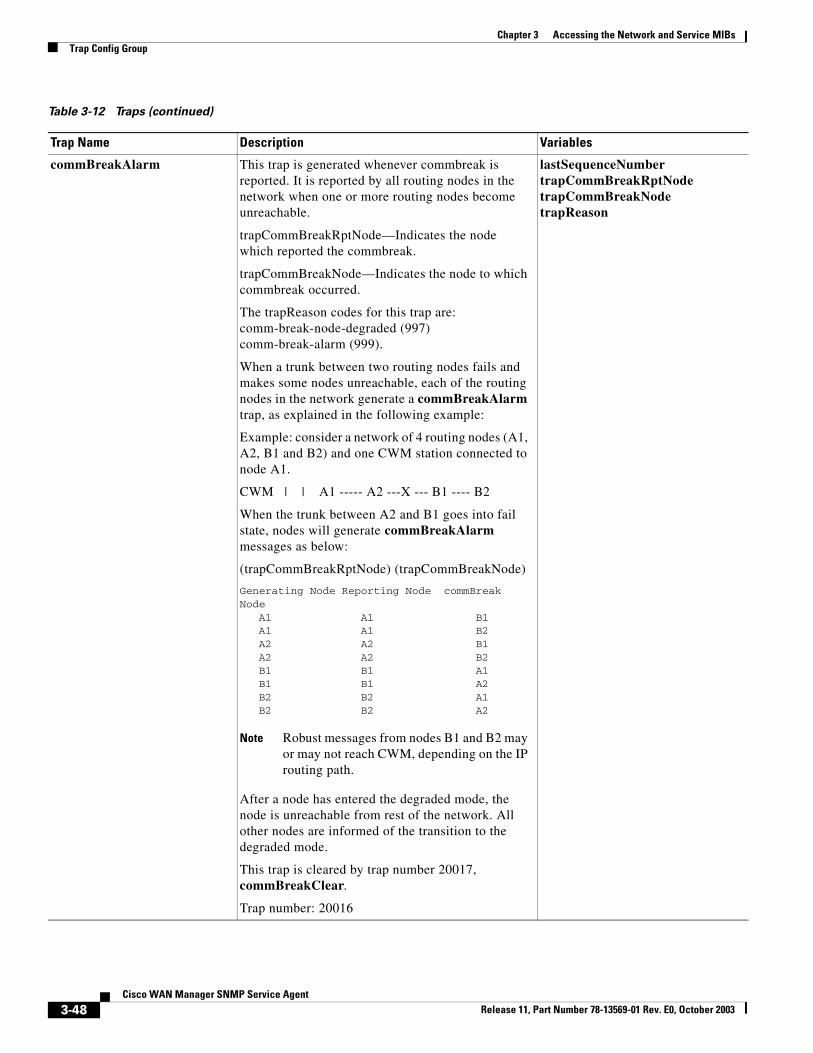
commBreakAlarm This trap is generated whenever commbreak is reported. It is reported by all routing nodes in the network when one or more routing nodes become unreachable.
trapCommBreakRptNode—Indicates the node which reported the commbreak.
trapCommBreakNode—Indicates the node to which commbreak occurred.
The trapReason codes for this trap are:comm-break-node-degraded (997)comm-break-alarm (999).
When a trunk between two routing nodes fails and makes some nodes unreachable, each of the routing nodes in the network generate a commBreakAlarm trap, as explained in the following example:
Example: consider a network of 4 routing nodes (A1, A2, B1 and B2) and one CWM station connected to node A1.
CWM | | A1 ----- A2 ---X --- B1 ---- B2
When the trunk between A2 and B1 goes into fail state, nodes will generate commBreakAlarm messages as below:
(trapCommBreakRptNode) (trapCommBreakNode)
Generating Node Reporting Node commBreak Node A1 A1 B1 A1 A1 B2 A2 A2 B1 A2 A2 B2 B1 B1 A1 B1 B1 A2 B2 B2 A1 B2 B2 A2
Note Robust messages from nodes B1 and B2 may or may not reach CWM, depending on the IP routing path.
After a node has entered the degraded mode, the node is unreachable from rest of the network. All other nodes are informed of the transition to the degraded mode.
This trap is cleared by trap number 20017, commBreakClear.
Trap number: 20016
lastSequenceNumbertrapCommBreakRptNodetrapCommBreakNodetrapReason
Table 3-12 Traps (continued)
Trap Name Description Variables
3-48Cisco WAN Manager SNMP Service Agent
Release 11, Part Number 78-13569-01 Rev. E0, October 2003
Chapter 3 Accessing the Network and Service MIBsTrap Config Group
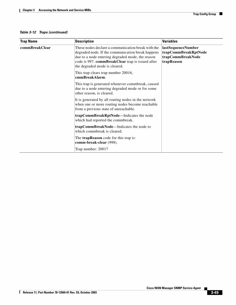
commBreakClear These nodes declare a communication break with the degraded node. If the communication break happens due to a node entering degraded mode, the reason code is 997. commBreakClear trap is issued after the degraded mode is cleared.
This trap clears trap number 20016, cmmBreakAlarm.
This trap is generated whenever commbreak, caused due to a node entering degraded mode or for some other reason, is cleared.
It is generated by all routing nodes in the network when one or more routing nodes become reachable from a previous state of unreachable.
trapCommBreakRptNode—Indicates the node which had reported the commbreak.
trapCommBreakNode—Indicates the node to which commbreak is cleared.
The trapReason code for this trap is:comm-break-clear (998).
Trap number: 20017
lastSequenceNumbertrapCommBreakRptNodetrapCommBreakNodetrapReason
Table 3-12 Traps (continued)
Trap Name Description Variables
3-49Cisco WAN Manager SNMP Service Agent
Release 11, Part Number 78-13569-01 Rev. E0, October 2003
Chapter 3 Accessing the Network and Service MIBsTrap Config Group
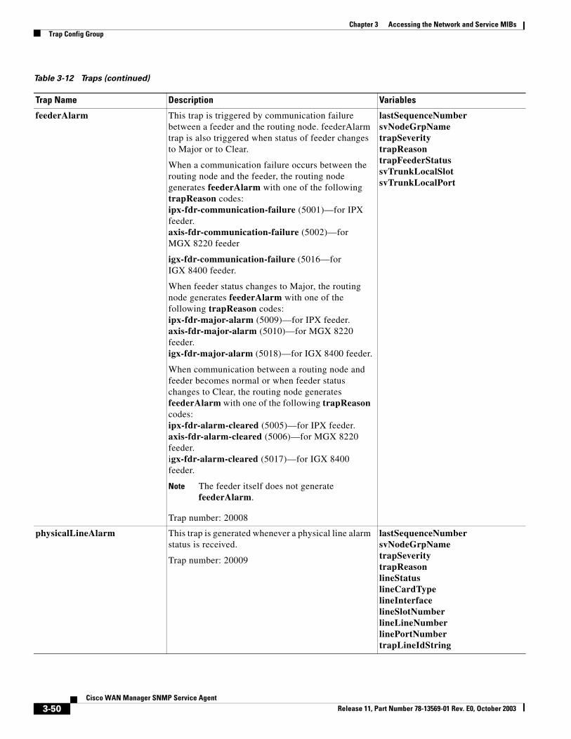
feederAlarm This trap is triggered by communication failure between a feeder and the routing node. feederAlarm trap is also triggered when status of feeder changes to Major or to Clear.
When a communication failure occurs between the routing node and the feeder, the routing node generates feederAlarm with one of the following trapReason codes:ipx-fdr-communication-failure (5001)—for IPX feeder.axis-fdr-communication-failure (5002)—for MGX 8220 feeder
igx-fdr-communication-failure (5016—for IGX 8400 feeder.
When feeder status changes to Major, the routing node generates feederAlarm with one of the following trapReason codes:ipx-fdr-major-alarm (5009)—for IPX feeder.axis-fdr-major-alarm (5010)—for MGX 8220 feeder.igx-fdr-major-alarm (5018)—for IGX 8400 feeder.
When communication between a routing node and feeder becomes normal or when feeder status changes to Clear, the routing node generates feederAlarm with one of the following trapReason codes:ipx-fdr-alarm-cleared (5005)—for IPX feeder.axis-fdr-alarm-cleared (5006)—for MGX 8220 feeder.igx-fdr-alarm-cleared (5017)—for IGX 8400 feeder.
Note The feeder itself does not generate feederAlarm.
Trap number: 20008
lastSequenceNumbersvNodeGrpNametrapSeveritytrapReasontrapFeederStatussvTrunkLocalSlotsvTrunkLocalPort
physicalLineAlarm This trap is generated whenever a physical line alarm status is received.
Trap number: 20009
lastSequenceNumbersvNodeGrpNametrapSeveritytrapReasonlineStatuslineCardTypelineInterfacelineSlotNumberlineLineNumberlinePortNumbertrapLineIdString
Table 3-12 Traps (continued)
Trap Name Description Variables
3-50Cisco WAN Manager SNMP Service Agent
Release 11, Part Number 78-13569-01 Rev. E0, October 2003
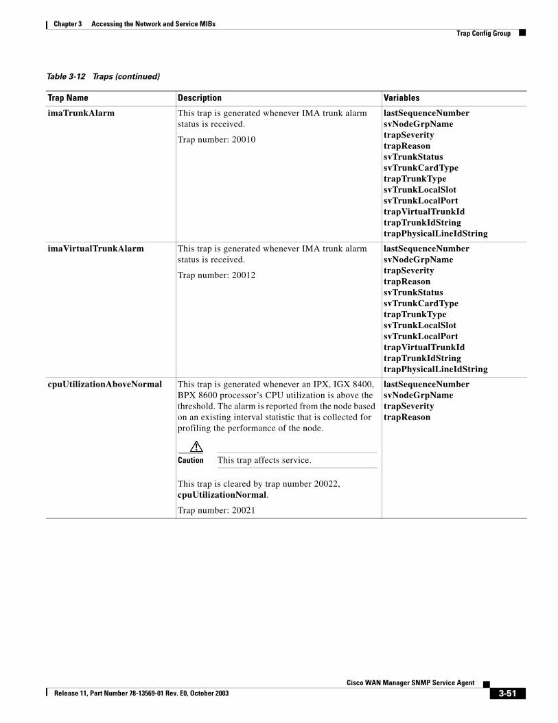
Chapter 3 Accessing the Network and Service MIBsTrap Config Group
imaTrunkAlarm This trap is generated whenever IMA trunk alarm status is received.
Trap number: 20010
lastSequenceNumbersvNodeGrpNametrapSeveritytrapReasonsvTrunkStatussvTrunkCardTypetrapTrunkTypesvTrunkLocalSlotsvTrunkLocalPorttrapVirtualTrunkIdtrapTrunkIdStringtrapPhysicalLineIdString
imaVirtualTrunkAlarm This trap is generated whenever IMA trunk alarm status is received.
Trap number: 20012
lastSequenceNumbersvNodeGrpNametrapSeveritytrapReasonsvTrunkStatussvTrunkCardTypetrapTrunkTypesvTrunkLocalSlotsvTrunkLocalPorttrapVirtualTrunkIdtrapTrunkIdStringtrapPhysicalLineIdString
cpuUtilizationAboveNormal This trap is generated whenever an IPX, IGX 8400, BPX 8600 processor’s CPU utilization is above the threshold. The alarm is reported from the node based on an existing interval statistic that is collected for profiling the performance of the node.
Caution This trap affects service.
This trap is cleared by trap number 20022, cpuUtilizationNormal.
Trap number: 20021
lastSequenceNumbersvNodeGrpNametrapSeveritytrapReason
Table 3-12 Traps (continued)
Trap Name Description Variables
3-51Cisco WAN Manager SNMP Service Agent
Release 11, Part Number 78-13569-01 Rev. E0, October 2003
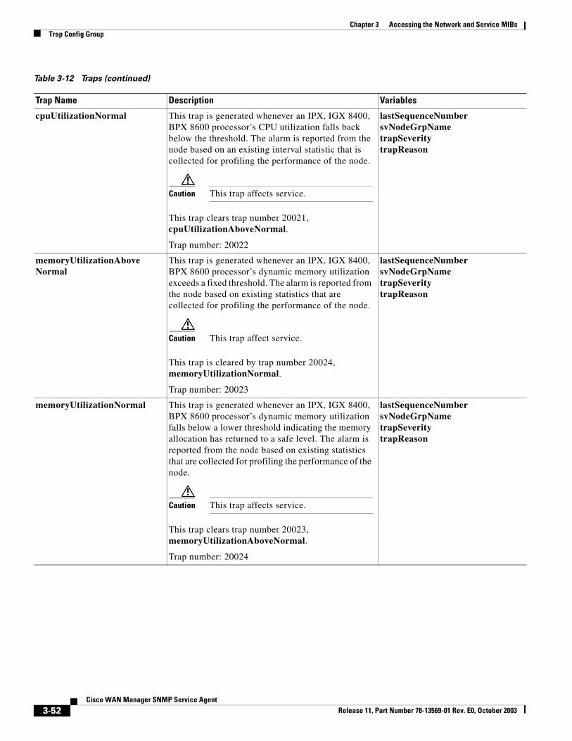
Chapter 3 Accessing the Network and Service MIBsTrap Config Group
cpuUtilizationNormal This trap is generated whenever an IPX, IGX 8400, BPX 8600 processor’s CPU utilization falls back below the threshold. The alarm is reported from the node based on an existing interval statistic that is collected for profiling the performance of the node.
Caution This trap affects service.
This trap clears trap number 20021, cpuUtilizationAboveNormal.
Trap number: 20022
lastSequenceNumbersvNodeGrpNametrapSeveritytrapReason
memoryUtilizationAboveNormal
This trap is generated whenever an IPX, IGX 8400, BPX 8600 processor’s dynamic memory utilization exceeds a fixed threshold. The alarm is reported from the node based on existing statistics that are collected for profiling the performance of the node.
Caution This trap affect service.
This trap is cleared by trap number 20024, memoryUtilizationNormal.
Trap number: 20023
lastSequenceNumbersvNodeGrpNametrapSeveritytrapReason
memoryUtilizationNormal This trap is generated whenever an IPX, IGX 8400, BPX 8600 processor’s dynamic memory utilization falls below a lower threshold indicating the memory allocation has returned to a safe level. The alarm is reported from the node based on existing statistics that are collected for profiling the performance of the node.
Caution This trap affects service.
This trap clears trap number 20023, memoryUtilizationAboveNormal.
Trap number: 20024
lastSequenceNumbersvNodeGrpNametrapSeveritytrapReason
Table 3-12 Traps (continued)
Trap Name Description Variables
3-52Cisco WAN Manager SNMP Service Agent
Release 11, Part Number 78-13569-01 Rev. E0, October 2003
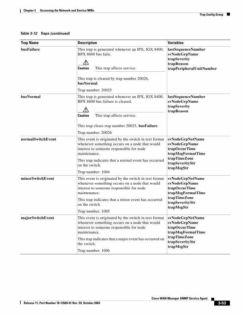
Chapter 3 Accessing the Network and Service MIBsTrap Config Group
busFailure This trap is generated whenever an IPX, IGX 8400, BPX 8600 bus fails.
Caution This trap affects service.
This trap is cleared by trap number 20026, busNormal.
Trap number: 20025
lastSequenceNumbersvNodeGrpNametrapSeveritytrapReasontrapPeripheralUnitNumber
busNormal This trap is generated whenever an IPX, IGX 8400, BPX 8600 bus failure is cleared.
Caution This trap affects service.
This trap clears trap number 20025, busFailure.
Trap number: 20026
lastSequenceNumbersvNodeGrpNametrapSeveritytrapReason
normalSwitchEvent This event is originated by the switch in text format whenever something occurs on a node that would interest to someone responsible for node maintenance.
This trap indicates that a normal event has occurred on the switch.
Trap number: 1004
svNodeGrpNetNamesvNodeGrpNametrapOccurTimetrapMsgFormatTimetrapTimeZonetrapSeverityStrtrapMsgStr
minorSwitchEvent This event is originated by the switch in text format whenever something occurs on a node that would interest to someone responsible for node maintenance.
This trap indicates that a minor event has occurred on the switch.
Trap number: 1005
svNodeGrpNetNamesvNodeGrpNametrapOccurTimetrapMsgFormatTimetrapTimeZonetrapSeverityStrtrapMsgStr
majorSwitchEvent This event is originated by the switch in text format whenever something occurs on a node that would interest to someone responsible for node maintenance.
This trap indicates that a major event has occurred on the switch.
Trap number: 1006
svNodeGrpNetNamesvNodeGrpNametrapOccurTimetrapMsgFormatTimetrapTimeZonetrapSeverityStrtrapMsgStr
Table 3-12 Traps (continued)
Trap Name Description Variables
3-53Cisco WAN Manager SNMP Service Agent
Release 11, Part Number 78-13569-01 Rev. E0, October 2003
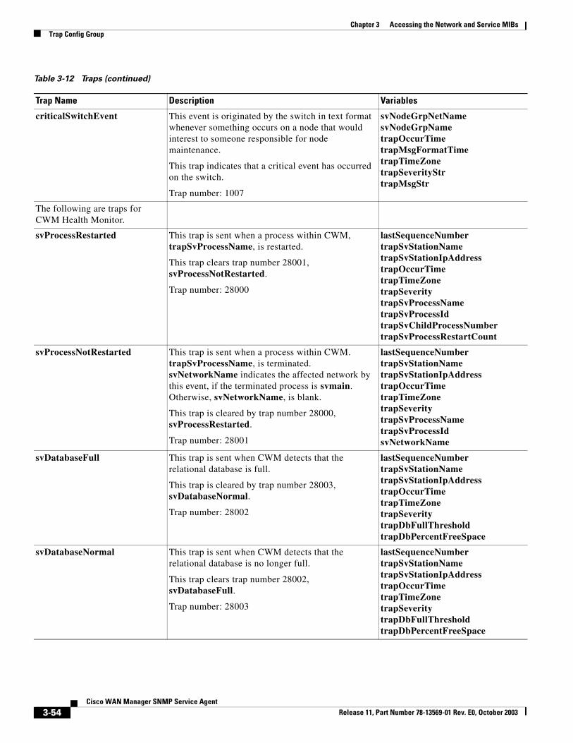
Chapter 3 Accessing the Network and Service MIBsTrap Config Group
criticalSwitchEvent This event is originated by the switch in text format whenever something occurs on a node that would interest to someone responsible for node maintenance.
This trap indicates that a critical event has occurred on the switch.
Trap number: 1007
svNodeGrpNetNamesvNodeGrpNametrapOccurTimetrapMsgFormatTimetrapTimeZonetrapSeverityStrtrapMsgStr
The following are traps for CWM Health Monitor.
svProcessRestarted This trap is sent when a process within CWM, trapSvProcessName, is restarted.
This trap clears trap number 28001, svProcessNotRestarted.
Trap number: 28000
lastSequenceNumbertrapSvStationNametrapSvStationIpAddresstrapOccurTimetrapTimeZonetrapSeveritytrapSvProcessNametrapSvProcessIdtrapSvChildProcessNumbertrapSvProcessRestartCount
svProcessNotRestarted This trap is sent when a process within CWM. trapSvProcessName, is terminated. svNetworkName indicates the affected network by this event, if the terminated process is svmain. Otherwise, svNetworkName, is blank.
This trap is cleared by trap number 28000, svProcessRestarted.
Trap number: 28001
lastSequenceNumbertrapSvStationNametrapSvStationIpAddresstrapOccurTimetrapTimeZonetrapSeveritytrapSvProcessNametrapSvProcessIdsvNetworkName
svDatabaseFull This trap is sent when CWM detects that the relational database is full.
This trap is cleared by trap number 28003, svDatabaseNormal.
Trap number: 28002
lastSequenceNumbertrapSvStationNametrapSvStationIpAddresstrapOccurTimetrapTimeZonetrapSeveritytrapDbFullThresholdtrapDbPercentFreeSpace
svDatabaseNormal This trap is sent when CWM detects that the relational database is no longer full.
This trap clears trap number 28002, svDatabaseFull.
Trap number: 28003
lastSequenceNumbertrapSvStationNametrapSvStationIpAddresstrapOccurTimetrapTimeZonetrapSeveritytrapDbFullThresholdtrapDbPercentFreeSpace
Table 3-12 Traps (continued)
Trap Name Description Variables
3-54Cisco WAN Manager SNMP Service Agent
Release 11, Part Number 78-13569-01 Rev. E0, October 2003
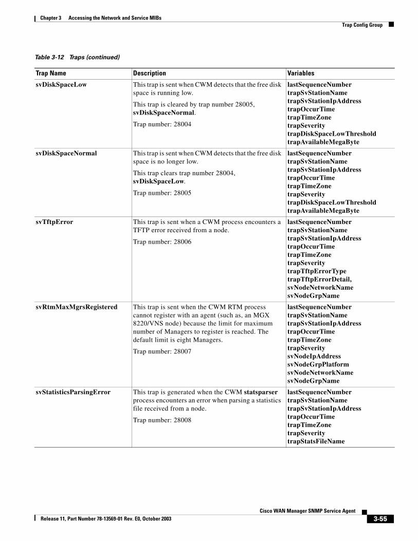
Chapter 3 Accessing the Network and Service MIBsTrap Config Group
svDiskSpaceLow This trap is sent when CWM detects that the free disk space is running low.
This trap is cleared by trap number 28005, svDiskSpaceNormal.
Trap number: 28004
lastSequenceNumbertrapSvStationNametrapSvStationIpAddresstrapOccurTimetrapTimeZonetrapSeveritytrapDiskSpaceLowThresholdtrapAvailableMegaByte
svDiskSpaceNormal This trap is sent when CWM detects that the free disk space is no longer low.
This trap clears trap number 28004, svDiskSpaceLow.
Trap number: 28005
lastSequenceNumbertrapSvStationNametrapSvStationIpAddresstrapOccurTimetrapTimeZonetrapSeveritytrapDiskSpaceLowThresholdtrapAvailableMegaByte
svTftpError This trap is sent when a CWM process encounters a TFTP error received from a node.
Trap number: 28006
lastSequenceNumbertrapSvStationNametrapSvStationIpAddresstrapOccurTimetrapTimeZonetrapSeveritytrapTftpErrorTypetrapTftpErrorDetail,svNodeNetworkNamesvNodeGrpName
svRtmMaxMgrsRegistered This trap is sent when the CWM RTM process cannot register with an agent (such as, an MGX 8220/VNS node) because the limit for maximum number of Managers to register is reached. The default limit is eight Managers.
Trap number: 28007
lastSequenceNumbertrapSvStationNametrapSvStationIpAddresstrapOccurTimetrapTimeZonetrapSeveritysvNodeIpAddresssvNodeGrpPlatformsvNodeNetworkNamesvNodeGrpName
svStatisticsParsingError This trap is generated when the CWM statsparser process encounters an error when parsing a statistics file received from a node.
Trap number: 28008
lastSequenceNumbertrapSvStationNametrapSvStationIpAddresstrapOccurTimetrapTimeZonetrapSeveritytrapStatsFileName
Table 3-12 Traps (continued)
Trap Name Description Variables
3-55Cisco WAN Manager SNMP Service Agent
Release 11, Part Number 78-13569-01 Rev. E0, October 2003
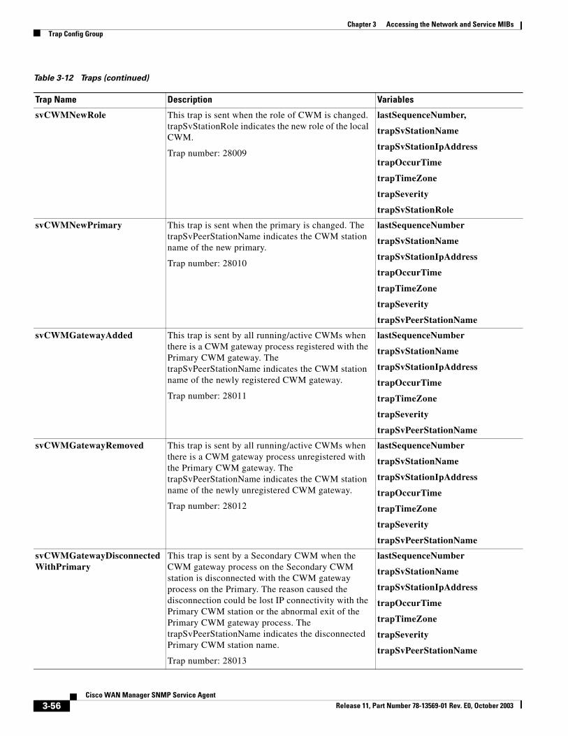
Chapter 3 Accessing the Network and Service MIBsTrap Config Group
svCWMNewRole This trap is sent when the role of CWM is changed. trapSvStationRole indicates the new role of the local CWM.
Trap number: 28009
lastSequenceNumber,
trapSvStationName
trapSvStationIpAddress
trapOccurTime
trapTimeZone
trapSeverity
trapSvStationRole
svCWMNewPrimary This trap is sent when the primary is changed. The trapSvPeerStationName indicates the CWM station name of the new primary.
Trap number: 28010
lastSequenceNumber
trapSvStationName
trapSvStationIpAddress
trapOccurTime
trapTimeZone
trapSeverity
trapSvPeerStationName
svCWMGatewayAdded This trap is sent by all running/active CWMs when there is a CWM gateway process registered with the Primary CWM gateway. The trapSvPeerStationName indicates the CWM station name of the newly registered CWM gateway.
Trap number: 28011
lastSequenceNumber
trapSvStationName
trapSvStationIpAddress
trapOccurTime
trapTimeZone
trapSeverity
trapSvPeerStationName
svCWMGatewayRemoved This trap is sent by all running/active CWMs when there is a CWM gateway process unregistered with the Primary CWM gateway. The trapSvPeerStationName indicates the CWM station name of the newly unregistered CWM gateway.
Trap number: 28012
lastSequenceNumber
trapSvStationName
trapSvStationIpAddress
trapOccurTime
trapTimeZone
trapSeverity
trapSvPeerStationName
svCWMGatewayDisconnectedWithPrimary
This trap is sent by a Secondary CWM when the CWM gateway process on the Secondary CWM station is disconnected with the CWM gateway process on the Primary. The reason caused the disconnection could be lost IP connectivity with the Primary CWM station or the abnormal exit of the Primary CWM gateway process. The trapSvPeerStationName indicates the disconnected Primary CWM station name.
Trap number: 28013
lastSequenceNumber
trapSvStationName
trapSvStationIpAddress
trapOccurTime
trapTimeZone
trapSeverity
trapSvPeerStationName
Table 3-12 Traps (continued)
Trap Name Description Variables
3-56Cisco WAN Manager SNMP Service Agent
Release 11, Part Number 78-13569-01 Rev. E0, October 2003
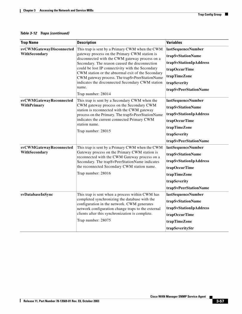
Chapter 3 Accessing the Network and Service MIBsTrap Config Group
svCWMGatewayDisconnectedWithSecondary
This trap is sent by a Primary CWM when the CWM gateway process on the Primary CWM station is disconnected with the CWM gateway process on a Secondary. The reason caused the disconnection could be lost IP connectivity with the Secondary CWM station or the abnormal exit of the Secondary CWM gateway process. The trapSvPeerStationName indicates the disconnected Secondary CWM station name.
Trap number: 28014
lastSequenceNumber
trapSvStationName
trapSvStationIpAddress
trapOccurTime
trapTimeZone
trapSeverity
trapSvPeerStationName
svCWMGatewayReconnectedWithPrimary
This trap is sent by a Secondary CWM when the CWM gateway process on the Secondary CWM station is reconnected with the CWM gateway process on the Primary. The trapSvPeerStationName indicates the current connected Primary CWM station name.
Trap number: 28015
lastSequenceNumber
trapSvStationName
trapSvStationIpAddress
trapOccurTime
trapTimeZone
trapSeverity
trapSvPeerStationName
svCWMGatewayReconnectedWithSecondary
This trap is sent by a Primary CWM when the CWM Gateway process on the Primary CWM station is reconnected with the CWM Gateway process on a Secondary. The trapSvPeerStationName indicates the reconnected Secondary CWM station name.
Trap number: 28016
lastSequenceNumber
trapSvStationName
trapSvStationIpAddress
trapOccurTime
trapTimeZone
trapSeverity
trapSvPeerStationName
svDatabaseInSync This trap is sent when a process within CWM has completed synchronizing the database with the configuration in the network. CWM generates network configuration change traps to the external clients after this synchronization is complete.
Trap number: 28075
lastSequenceNumber
trapSvStationName
trapSvStationIpAddress
trapOccurTime
trapTimeZone
trapSeverityStr
Table 3-12 Traps (continued)
Trap Name Description Variables
3-57Cisco WAN Manager SNMP Service Agent
Release 11, Part Number 78-13569-01 Rev. E0, October 2003
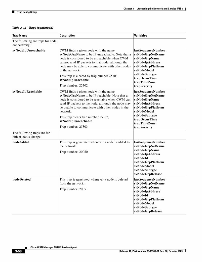
Chapter 3 Accessing the Network and Service MIBsTrap Config Group
The following are traps for node connectivity:
svNodeIpUnreachable CWM finds a given node with the name svNodeGrpName to be IP unreachable. Note that a node is considered to be unreachable when CWM cannot send IP packets to that node, although the node may be able to communicate with other nodes in the network.
This trap is cleared by trap number 25303, svNodeIpReachable.
Trap number: 25302
lastSequenceNumbersvNodeGrpNetNamesvNodeGrpNamesvNodeIpAddresssvNodeGrpPlatformsvNodeModelsvNodeSubtypetrapOccurTimetrapTimeZonetrapSeverity
svNodeIpReachable CWM finds a given node with the name svNodeGrpName to be IP reachable. Note that a node is considered to be reachable when CWM can send IP packets to the node, although the node may be unable to communicate with other nodes in the network.
This trap clears trap number 25302, svNodeIpUnreachable.
Trap number: 25303
lastSequenceNumbersvNodeGrpNetNamesvNodeGrpNamesvNodeIpAddresssvNodeGrpPlatformsvNodeModelsvNodeSubtypetrapOccurTimetrapTimeZonetrapSeverity
The following traps are for object status change
nodeAdded This trap is generated whenever a node is added to the network.
Trap number: 20050
lastSequenceNumbersvNodeGrpNetNamesvNodeGrpNamesvNodeIpAddresssvNodeIdsvNodeGrpPlatformsvNodeModelsvNodeSubtypesvNodeGrpRelease
nodeDeleted This trap is generated whenever a node is deleted from the network.
Trap number: 20051
lastSequenceNumbersvNodeGrpNetNamesvNodeGrpNamesvNodeIpAddresssvNodeIdsvNodeGrpPlatformsvNodeModelsvNodeSubtypesvNodeGrpRelease
Table 3-12 Traps (continued)
Trap Name Description Variables
3-58Cisco WAN Manager SNMP Service Agent
Release 11, Part Number 78-13569-01 Rev. E0, October 2003
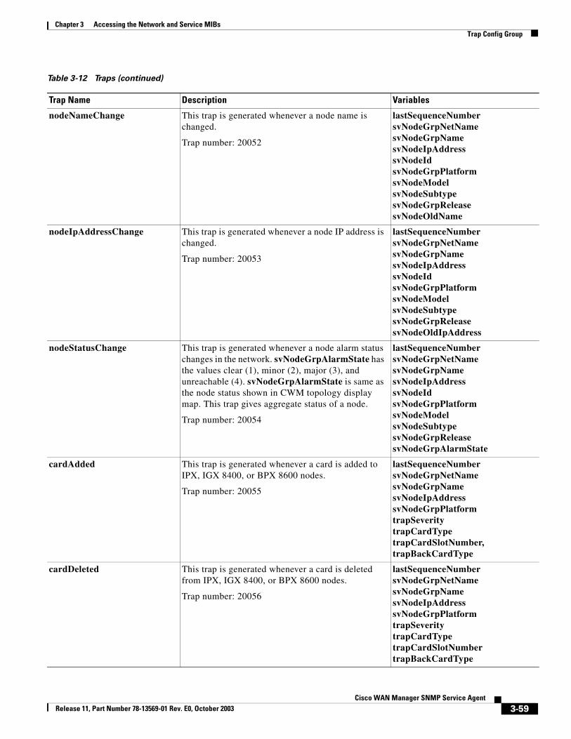
Chapter 3 Accessing the Network and Service MIBsTrap Config Group
nodeNameChange This trap is generated whenever a node name is changed.
Trap number: 20052
lastSequenceNumbersvNodeGrpNetNamesvNodeGrpNamesvNodeIpAddresssvNodeIdsvNodeGrpPlatformsvNodeModelsvNodeSubtypesvNodeGrpReleasesvNodeOldName
nodeIpAddressChange This trap is generated whenever a node IP address is changed.
Trap number: 20053
lastSequenceNumbersvNodeGrpNetNamesvNodeGrpNamesvNodeIpAddresssvNodeIdsvNodeGrpPlatformsvNodeModelsvNodeSubtypesvNodeGrpReleasesvNodeOldIpAddress
nodeStatusChange This trap is generated whenever a node alarm status changes in the network. svNodeGrpAlarmState has the values clear (1), minor (2), major (3), and unreachable (4). svNodeGrpAlarmState is same as the node status shown in CWM topology display map. This trap gives aggregate status of a node.
Trap number: 20054
lastSequenceNumbersvNodeGrpNetNamesvNodeGrpNamesvNodeIpAddresssvNodeIdsvNodeGrpPlatformsvNodeModelsvNodeSubtypesvNodeGrpReleasesvNodeGrpAlarmState
cardAdded This trap is generated whenever a card is added to IPX, IGX 8400, or BPX 8600 nodes.
Trap number: 20055
lastSequenceNumbersvNodeGrpNetNamesvNodeGrpNamesvNodeIpAddresssvNodeGrpPlatformtrapSeveritytrapCardTypetrapCardSlotNumber,trapBackCardType
cardDeleted This trap is generated whenever a card is deleted from IPX, IGX 8400, or BPX 8600 nodes.
Trap number: 20056
lastSequenceNumbersvNodeGrpNetNamesvNodeGrpNamesvNodeIpAddresssvNodeGrpPlatformtrapSeveritytrapCardTypetrapCardSlotNumbertrapBackCardType
Table 3-12 Traps (continued)
Trap Name Description Variables
3-59Cisco WAN Manager SNMP Service Agent
Release 11, Part Number 78-13569-01 Rev. E0, October 2003
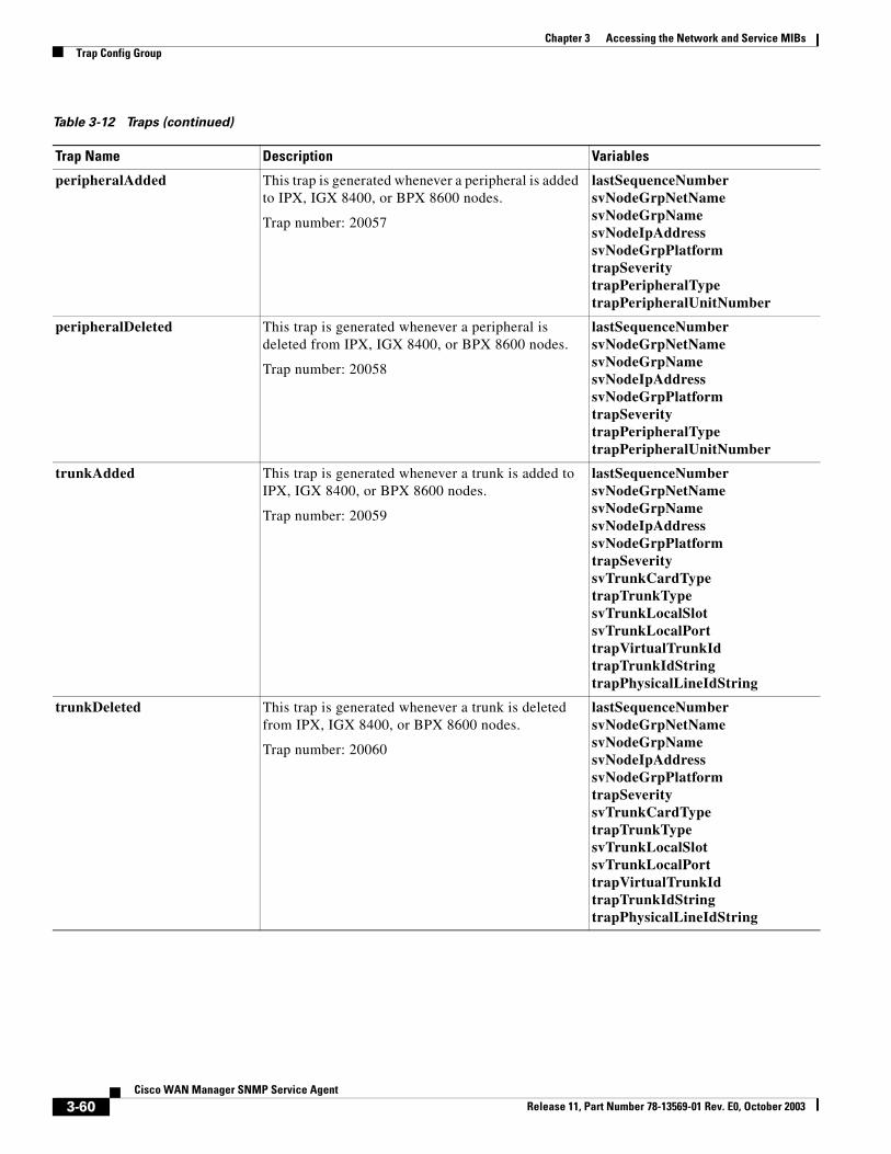
Chapter 3 Accessing the Network and Service MIBsTrap Config Group
peripheralAdded This trap is generated whenever a peripheral is added to IPX, IGX 8400, or BPX 8600 nodes.
Trap number: 20057
lastSequenceNumbersvNodeGrpNetNamesvNodeGrpNamesvNodeIpAddresssvNodeGrpPlatformtrapSeveritytrapPeripheralTypetrapPeripheralUnitNumber
peripheralDeleted This trap is generated whenever a peripheral is deleted from IPX, IGX 8400, or BPX 8600 nodes.
Trap number: 20058
lastSequenceNumbersvNodeGrpNetNamesvNodeGrpNamesvNodeIpAddresssvNodeGrpPlatformtrapSeveritytrapPeripheralTypetrapPeripheralUnitNumber
trunkAdded This trap is generated whenever a trunk is added to IPX, IGX 8400, or BPX 8600 nodes.
Trap number: 20059
lastSequenceNumbersvNodeGrpNetNamesvNodeGrpNamesvNodeIpAddresssvNodeGrpPlatformtrapSeveritysvTrunkCardTypetrapTrunkTypesvTrunkLocalSlotsvTrunkLocalPorttrapVirtualTrunkIdtrapTrunkIdStringtrapPhysicalLineIdString
trunkDeleted This trap is generated whenever a trunk is deleted from IPX, IGX 8400, or BPX 8600 nodes.
Trap number: 20060
lastSequenceNumbersvNodeGrpNetNamesvNodeGrpNamesvNodeIpAddresssvNodeGrpPlatformtrapSeveritysvTrunkCardTypetrapTrunkTypesvTrunkLocalSlotsvTrunkLocalPorttrapVirtualTrunkIdtrapTrunkIdStringtrapPhysicalLineIdString
Table 3-12 Traps (continued)
Trap Name Description Variables
3-60Cisco WAN Manager SNMP Service Agent
Release 11, Part Number 78-13569-01 Rev. E0, October 2003
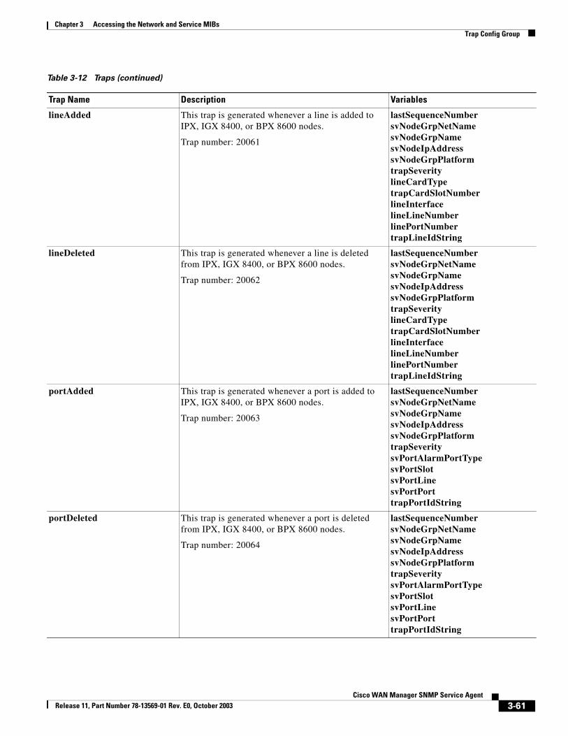
Chapter 3 Accessing the Network and Service MIBsTrap Config Group
lineAdded This trap is generated whenever a line is added to IPX, IGX 8400, or BPX 8600 nodes.
Trap number: 20061
lastSequenceNumbersvNodeGrpNetNamesvNodeGrpNamesvNodeIpAddresssvNodeGrpPlatformtrapSeveritylineCardTypetrapCardSlotNumberlineInterfacelineLineNumberlinePortNumbertrapLineIdString
lineDeleted This trap is generated whenever a line is deleted from IPX, IGX 8400, or BPX 8600 nodes.
Trap number: 20062
lastSequenceNumbersvNodeGrpNetNamesvNodeGrpNamesvNodeIpAddresssvNodeGrpPlatformtrapSeveritylineCardTypetrapCardSlotNumberlineInterfacelineLineNumberlinePortNumbertrapLineIdString
portAdded This trap is generated whenever a port is added to IPX, IGX 8400, or BPX 8600 nodes.
Trap number: 20063
lastSequenceNumbersvNodeGrpNetNamesvNodeGrpNamesvNodeIpAddresssvNodeGrpPlatformtrapSeveritysvPortAlarmPortTypesvPortSlotsvPortLinesvPortPorttrapPortIdString
portDeleted This trap is generated whenever a port is deleted from IPX, IGX 8400, or BPX 8600 nodes.
Trap number: 20064
lastSequenceNumbersvNodeGrpNetNamesvNodeGrpNamesvNodeIpAddresssvNodeGrpPlatformtrapSeveritysvPortAlarmPortTypesvPortSlotsvPortLinesvPortPorttrapPortIdString
Table 3-12 Traps (continued)
Trap Name Description Variables
3-61Cisco WAN Manager SNMP Service Agent
Release 11, Part Number 78-13569-01 Rev. E0, October 2003
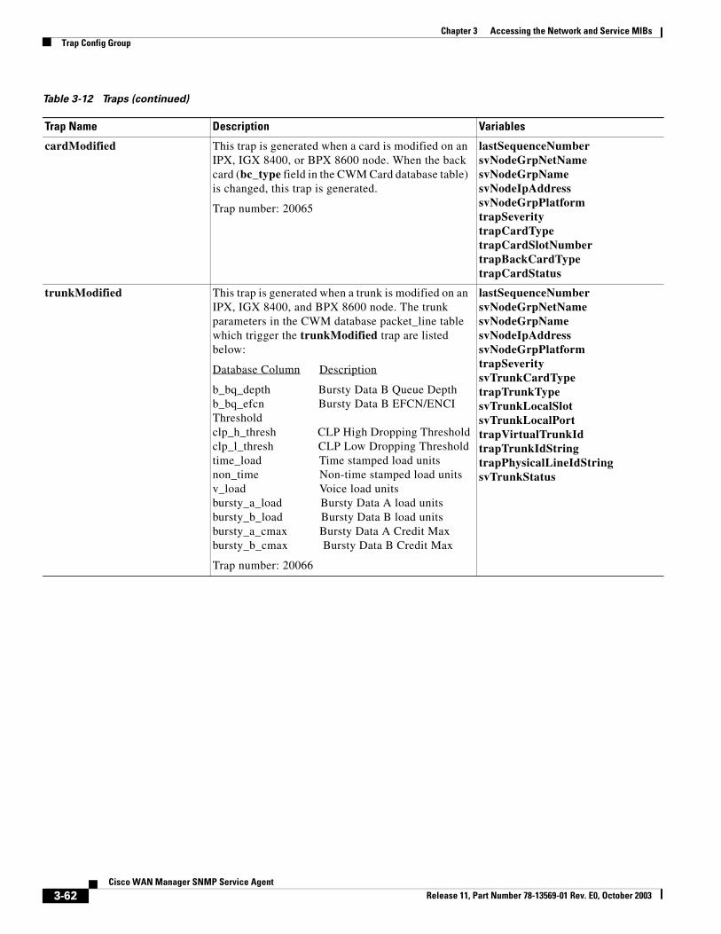
Chapter 3 Accessing the Network and Service MIBsTrap Config Group
cardModified This trap is generated when a card is modified on an IPX, IGX 8400, or BPX 8600 node. When the back card (bc_type field in the CWM Card database table) is changed, this trap is generated.
Trap number: 20065
lastSequenceNumbersvNodeGrpNetNamesvNodeGrpNamesvNodeIpAddresssvNodeGrpPlatformtrapSeveritytrapCardTypetrapCardSlotNumbertrapBackCardTypetrapCardStatus
trunkModified This trap is generated when a trunk is modified on an IPX, IGX 8400, and BPX 8600 node. The trunk parameters in the CWM database packet_line table which trigger the trunkModified trap are listed below:
Database Column Description
b_bq_depth Bursty Data B Queue Depthb_bq_efcn Bursty Data B EFCN/ENCI Thresholdclp_h_thresh CLP High Dropping Thresholdclp_l_thresh CLP Low Dropping Thresholdtime_load Time stamped load unitsnon_time Non-time stamped load unitsv_load Voice load unitsbursty_a_load Bursty Data A load unitsbursty_b_load Bursty Data B load unitsbursty_a_cmax Bursty Data A Credit Maxbursty_b_cmax Bursty Data B Credit Max
Trap number: 20066
lastSequenceNumbersvNodeGrpNetNamesvNodeGrpNamesvNodeIpAddresssvNodeGrpPlatformtrapSeveritysvTrunkCardTypetrapTrunkTypesvTrunkLocalSlotsvTrunkLocalPorttrapVirtualTrunkIdtrapTrunkIdStringtrapPhysicalLineIdStringsvTrunkStatus
Table 3-12 Traps (continued)
Trap Name Description Variables
3-62Cisco WAN Manager SNMP Service Agent
Release 11, Part Number 78-13569-01 Rev. E0, October 2003
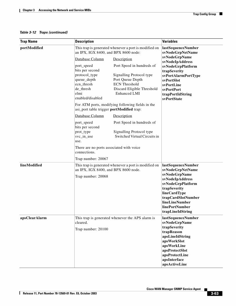
Chapter 3 Accessing the Network and Service MIBsTrap Config Group
portModified This trap is generated whenever a port is modified on an IPX, IGX 8400, and BPX 8600 node:
Database Column Description
port_speed Port Speed in hundreds of bits per secondprotocol_type Signalling Protocol typequeue_depth Port Queue Depthecn_thresh ECN Thresholdde_thresh Discard Eligible Thresholdelmi Enhanced LMI enabled/disabled
For ATM ports, modifying following fields in the asi_port table trigger portModified trap:
Database Column Description
port_speed Port Speed in hundreds of bits per secondprot_type Signalling Protocol typesvc_in_use Switched Virtual Circuits in use.
There are no ports associated with voice connections.
Trap number: 20067
lastSequenceNumbersvNodeGrpNetNamesvNodeGrpNamesvNodeIpAddresssvNodeGrpPlatformtrapSeveritysvPortAlarmPortTypesvPortSlotsvPortLinesvPortPorttrapPortIdStringsvPortState
lineModified This trap is generated whenever a port is modified on an IPX, IGX 8400, and BPX 8600 node.
Trap number: 20068
lastSequenceNumbersvNodeGrpNetNamesvNodeGrpNamesvNodeIpAddresssvNodeGrpPlatformtrapSeveritylineCardTypetrapCardSlotNumberlineLineNumberlinePortNumbertrapLineIdString
apsClearAlarm This trap is generated whenever the APS alarm is cleared.
Trap number: 20100
lastSequenceNumbersvNodeGrpNametrapSeveritytrapReasonapsLineIdStringapsWorkSlotapsWorkLineapsProtectSlotapsProtectLineapsInterfaceapsActiveLine
Table 3-12 Traps (continued)
Trap Name Description Variables
3-63Cisco WAN Manager SNMP Service Agent
Release 11, Part Number 78-13569-01 Rev. E0, October 2003
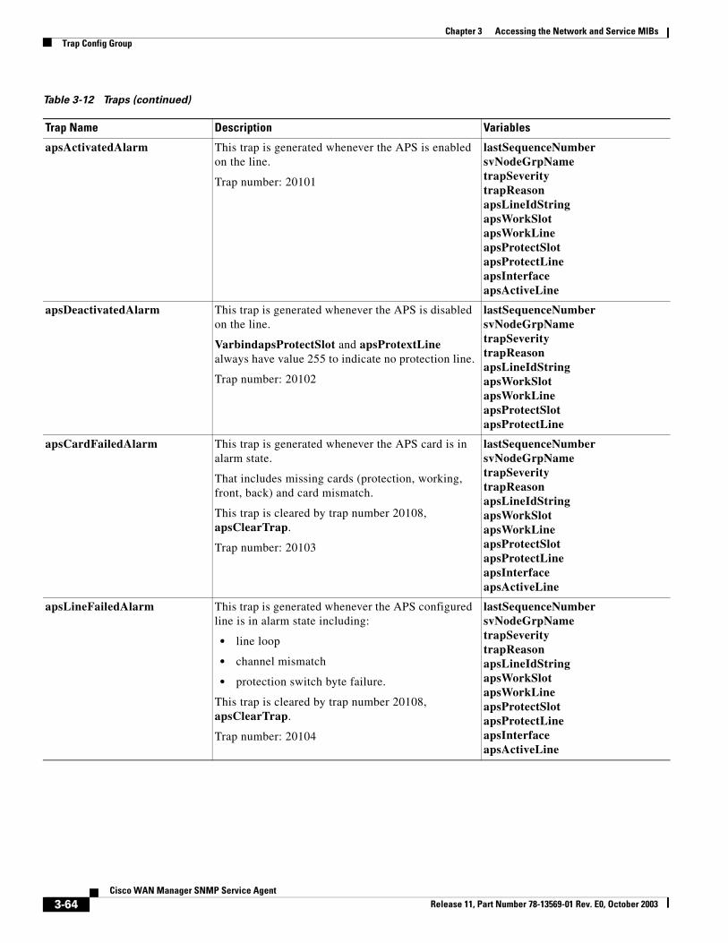
Chapter 3 Accessing the Network and Service MIBsTrap Config Group
apsActivatedAlarm This trap is generated whenever the APS is enabled on the line.
Trap number: 20101
lastSequenceNumbersvNodeGrpNametrapSeveritytrapReasonapsLineIdStringapsWorkSlotapsWorkLineapsProtectSlotapsProtectLineapsInterfaceapsActiveLine
apsDeactivatedAlarm This trap is generated whenever the APS is disabled on the line.
VarbindapsProtectSlot and apsProtextLine always have value 255 to indicate no protection line.
Trap number: 20102
lastSequenceNumbersvNodeGrpNametrapSeveritytrapReasonapsLineIdStringapsWorkSlotapsWorkLineapsProtectSlotapsProtectLine
apsCardFailedAlarm This trap is generated whenever the APS card is in alarm state.
That includes missing cards (protection, working, front, back) and card mismatch.
This trap is cleared by trap number 20108, apsClearTrap.
Trap number: 20103
lastSequenceNumbersvNodeGrpNametrapSeveritytrapReasonapsLineIdStringapsWorkSlotapsWorkLineapsProtectSlotapsProtectLineapsInterfaceapsActiveLine
apsLineFailedAlarm This trap is generated whenever the APS configured line is in alarm state including:
• line loop
• channel mismatch
• protection switch byte failure.
This trap is cleared by trap number 20108, apsClearTrap.
Trap number: 20104
lastSequenceNumbersvNodeGrpNametrapSeveritytrapReasonapsLineIdStringapsWorkSlotapsWorkLineapsProtectSlotapsProtectLineapsInterfaceapsActiveLine
Table 3-12 Traps (continued)
Trap Name Description Variables
3-64Cisco WAN Manager SNMP Service Agent
Release 11, Part Number 78-13569-01 Rev. E0, October 2003
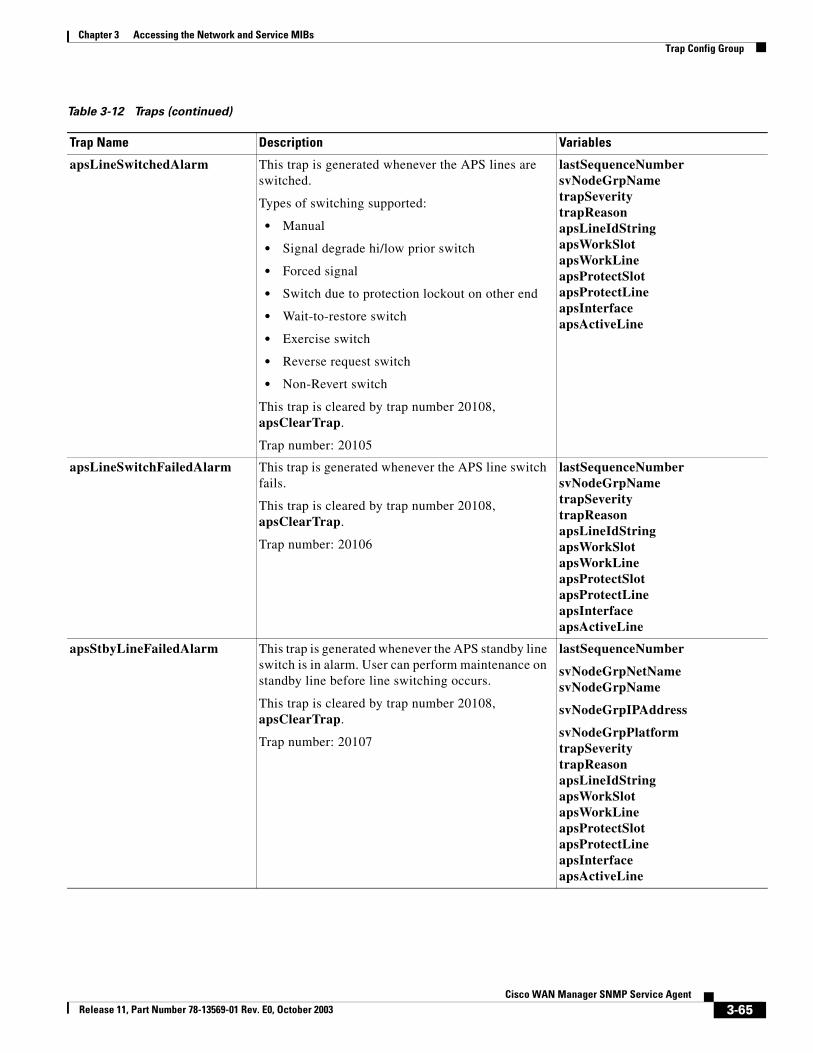
Chapter 3 Accessing the Network and Service MIBsTrap Config Group
apsLineSwitchedAlarm This trap is generated whenever the APS lines are switched.
Types of switching supported:
• Manual
• Signal degrade hi/low prior switch
• Forced signal
• Switch due to protection lockout on other end
• Wait-to-restore switch
• Exercise switch
• Reverse request switch
• Non-Revert switch
This trap is cleared by trap number 20108, apsClearTrap.
Trap number: 20105
lastSequenceNumbersvNodeGrpNametrapSeveritytrapReasonapsLineIdStringapsWorkSlotapsWorkLineapsProtectSlotapsProtectLineapsInterfaceapsActiveLine
apsLineSwitchFailedAlarm This trap is generated whenever the APS line switch fails.
This trap is cleared by trap number 20108, apsClearTrap.
Trap number: 20106
lastSequenceNumbersvNodeGrpNametrapSeveritytrapReasonapsLineIdStringapsWorkSlotapsWorkLineapsProtectSlotapsProtectLineapsInterfaceapsActiveLine
apsStbyLineFailedAlarm This trap is generated whenever the APS standby line switch is in alarm. User can perform maintenance on standby line before line switching occurs.
This trap is cleared by trap number 20108, apsClearTrap.
Trap number: 20107
lastSequenceNumber
svNodeGrpNetNamesvNodeGrpName
svNodeGrpIPAddress
svNodeGrpPlatformtrapSeveritytrapReasonapsLineIdStringapsWorkSlotapsWorkLineapsProtectSlotapsProtectLineapsInterfaceapsActiveLine
Table 3-12 Traps (continued)
Trap Name Description Variables
3-65Cisco WAN Manager SNMP Service Agent
Release 11, Part Number 78-13569-01 Rev. E0, October 2003
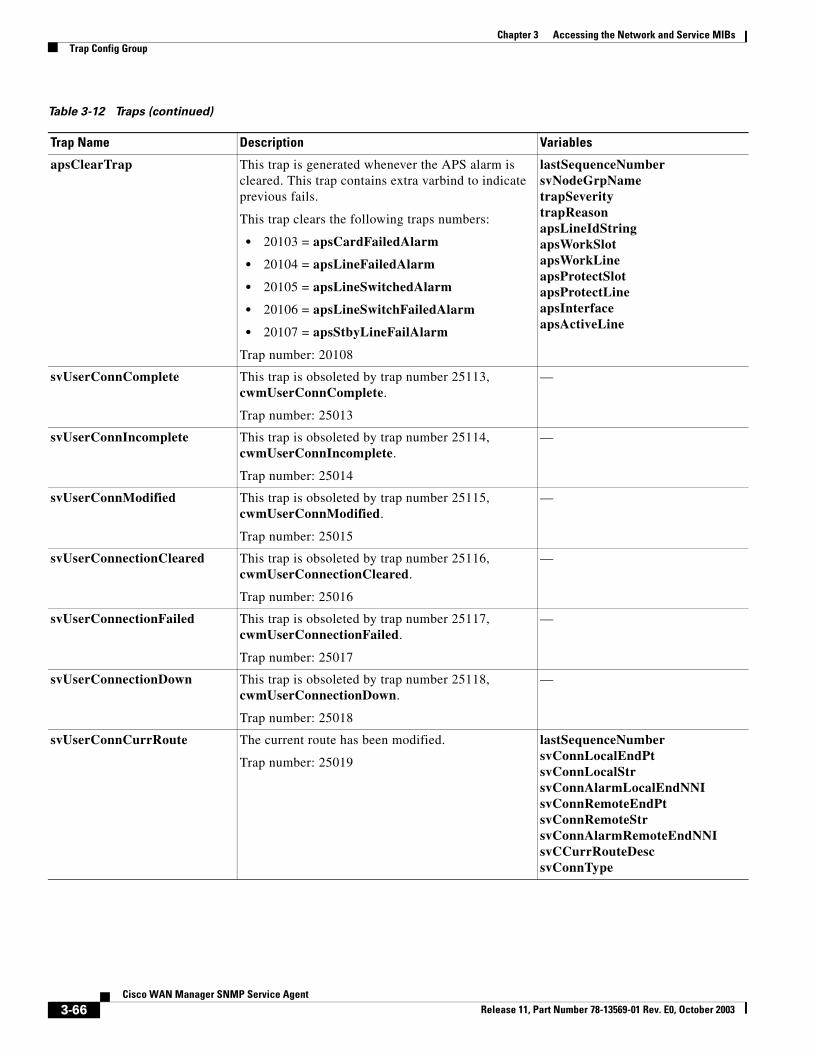
Chapter 3 Accessing the Network and Service MIBsTrap Config Group
apsClearTrap This trap is generated whenever the APS alarm is cleared. This trap contains extra varbind to indicate previous fails.
This trap clears the following traps numbers:
• 20103 = apsCardFailedAlarm
• 20104 = apsLineFailedAlarm
• 20105 = apsLineSwitchedAlarm
• 20106 = apsLineSwitchFailedAlarm
• 20107 = apsStbyLineFailAlarm
Trap number: 20108
lastSequenceNumbersvNodeGrpNametrapSeveritytrapReasonapsLineIdStringapsWorkSlotapsWorkLineapsProtectSlotapsProtectLineapsInterfaceapsActiveLine
svUserConnComplete This trap is obsoleted by trap number 25113, cwmUserConnComplete.
Trap number: 25013
—
svUserConnIncomplete This trap is obsoleted by trap number 25114, cwmUserConnIncomplete.
Trap number: 25014
—
svUserConnModified This trap is obsoleted by trap number 25115, cwmUserConnModified.
Trap number: 25015
—
svUserConnectionCleared This trap is obsoleted by trap number 25116, cwmUserConnectionCleared.
Trap number: 25016
—
svUserConnectionFailed This trap is obsoleted by trap number 25117, cwmUserConnectionFailed.
Trap number: 25017
—
svUserConnectionDown This trap is obsoleted by trap number 25118, cwmUserConnectionDown.
Trap number: 25018
—
svUserConnCurrRoute The current route has been modified.
Trap number: 25019
lastSequenceNumbersvConnLocalEndPtsvConnLocalStrsvConnAlarmLocalEndNNIsvConnRemoteEndPtsvConnRemoteStrsvConnAlarmRemoteEndNNIsvCCurrRouteDescsvConnType
Table 3-12 Traps (continued)
Trap Name Description Variables
3-66Cisco WAN Manager SNMP Service Agent
Release 11, Part Number 78-13569-01 Rev. E0, October 2003
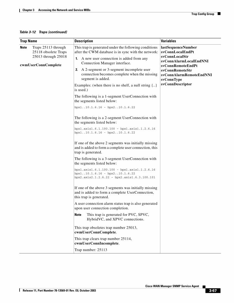
Chapter 3 Accessing the Network and Service MIBsTrap Config Group
Note Traps 25113 through 25118 obsolete Traps 25013 through 25018
cwmUserConnComplete
This trap is generated under the following conditions after the CWM database is in sync with the network:
1. A new user connection is added from any Connection Manager interface.
2. A 2-segment or 3-segment incomplete user connection becomes complete when the missing segment is added.
Examples: (when there is no shelf, a null string {..} is used.)
The following is a 1-segment UserConnection with the segments listed below:
bpx1..10.1.6.16 - bpx2..10.1.6.22
The following is a 2-segment UserConnection with the segments listed below:
bpx1.axis1.6.1.100.100 - bpx1.axis1.1.2.6.16bpx1..10.1.6.16 - bpx2..10.1.6.22
If one of the above 2 segments was initially missing and is added to form a complete user connection, this trap is generated.
The following is a 3-segment UserConnection with the segments listed below:
bpx1.axis1.6.1.100.100 - bpx1.axis1.1.2.6.16bpx1..10.1.6.16 - bpx2..10.1.6.22bpx2.axis2.1.2.6.22 - bpx2.axis1.6.3.100.101
If one of the above 3 segments was initially missing and is added to form a complete UserConnection, this trap is generated.
A user connection alarm status trap is also generated upon user connection completion.
Note This trap is generated for PVC, SPVC, HybridVC, and XPVC connections.
This trap obsoletes trap number 25013, cwmUserConnComplete.
This trap clears trap number 25114, cwmUserConnIncomplete.
Trap number: 25113
lastSequenceNumbersvConnLocalEndPtsvConnLocalStrsvConnAlarmLocalEndNNIsvConnRemoteEndPtsvConnRemoteStrsvConnAlarmRemoteEndNNIsvConnTypesvConnDescriptor
Table 3-12 Traps (continued)
Trap Name Description Variables
3-67Cisco WAN Manager SNMP Service Agent
Release 11, Part Number 78-13569-01 Rev. E0, October 2003
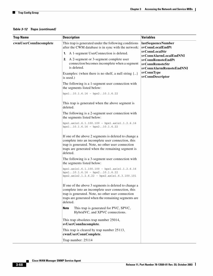
Chapter 3 Accessing the Network and Service MIBsTrap Config Group
cwmUserConnIncomplete This trap is generated under the following conditions after the CWM database is in sync with the network:
1. A 1-segment UserConnection is deleted.
2. A 2-segment or 3-segment complete user connection becomes incomplete when a segment is deleted.
Examples: (when there is no shelf, a null string {..} is used.)
The following is a 1-segment user connection with the segments listed below:
bpx1..10.1.6.16 - bpx2..10.1.6.22
This trap is generated when the above segment is deleted.
The following is a 2-segment user connection with the segments listed below:
bpx1.axis1.6.1.100.100 - bpx1.axis1.1.2.6.16bpx1..10.1.6.16 - bpx2..10.1.6.22
If one of the above 2 segments is deleted to change a complete into an incomplete user connection, this trap is generated. Note, no other user connection traps are generated when the remaining segment is deleted.
The following is a 3-segment user connection with the segments listed below:
bpx1.axis1.6.1.100.100 - bpx1.axis1.1.2.6.16bpx1..10.1.6.16 - bpx2..10.1.6.22bpx2.axis2.1.2.6.22 - bpx2.axis1.6.3.100.101
If one of the above 3 segments is deleted to change a complete into an incomplete user connection, this trap is generated. Note, no other user connection traps are generated when the remaining segments are deleted.
Note This trap is generated for PVC, SPVC, HybridVC, and XPVC connections.
This trap obsoletes trap number 25014, svUserConnIncomplete.
This trap is cleared by trap number 25113, cwmUserConnComplete.
Trap number: 25114
lastSequenceNumbersvConnLocalEndPtsvConnLocalStrsvConnAlarmLocalEndNNIsvConnRemoteEndPtsvConnRemoteStrsvConnAlarmRemoteEndNNIsvConnTypesvConnDescriptor
Table 3-12 Traps (continued)
Trap Name Description Variables
3-68Cisco WAN Manager SNMP Service Agent
Release 11, Part Number 78-13569-01 Rev. E0, October 2003
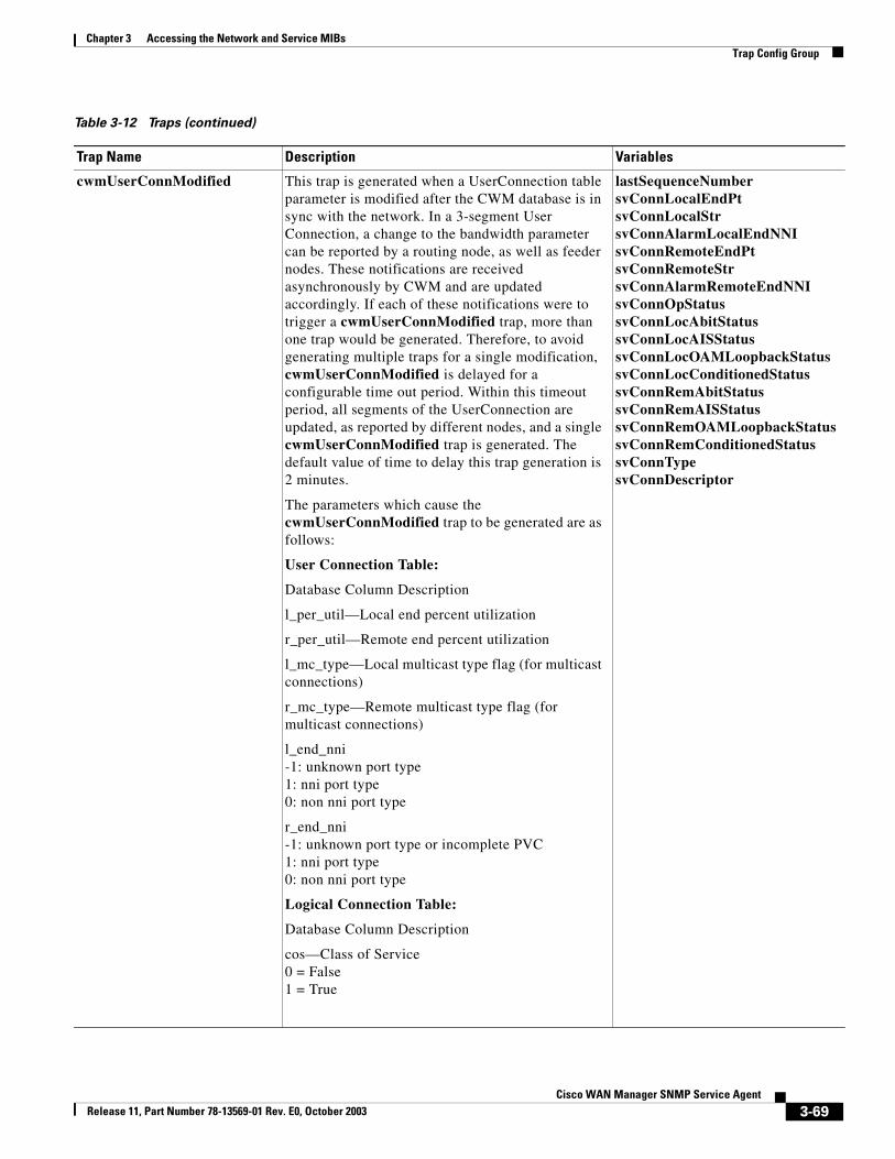
Chapter 3 Accessing the Network and Service MIBsTrap Config Group
cwmUserConnModified This trap is generated when a UserConnection table parameter is modified after the CWM database is in sync with the network. In a 3-segment User Connection, a change to the bandwidth parameter can be reported by a routing node, as well as feeder nodes. These notifications are received asynchronously by CWM and are updated accordingly. If each of these notifications were to trigger a cwmUserConnModified trap, more than one trap would be generated. Therefore, to avoid generating multiple traps for a single modification, cwmUserConnModified is delayed for a configurable time out period. Within this timeout period, all segments of the UserConnection are updated, as reported by different nodes, and a single cwmUserConnModified trap is generated. The default value of time to delay this trap generation is 2 minutes.
The parameters which cause the cwmUserConnModified trap to be generated are as follows:
User Connection Table:
Database Column Description
l_per_util—Local end percent utilization
r_per_util—Remote end percent utilization
l_mc_type—Local multicast type flag (for multicast connections)
r_mc_type—Remote multicast type flag (for multicast connections)
l_end_nni -1: unknown port type1: nni port type0: non nni port type
r_end_nni -1: unknown port type or incomplete PVC1: nni port type0: non nni port type
Logical Connection Table:
Database Column Description
cos—Class of Service0 = False1 = True
lastSequenceNumbersvConnLocalEndPtsvConnLocalStrsvConnAlarmLocalEndNNIsvConnRemoteEndPtsvConnRemoteStrsvConnAlarmRemoteEndNNIsvConnOpStatussvConnLocAbitStatussvConnLocAISStatussvConnLocOAMLoopbackStatussvConnLocConditionedStatussvConnRemAbitStatussvConnRemAISStatussvConnRemOAMLoopbackStatussvConnRemConditionedStatussvConnTypesvConnDescriptor
Table 3-12 Traps (continued)
Trap Name Description Variables
3-69Cisco WAN Manager SNMP Service Agent
Release 11, Part Number 78-13569-01 Rev. E0, October 2003
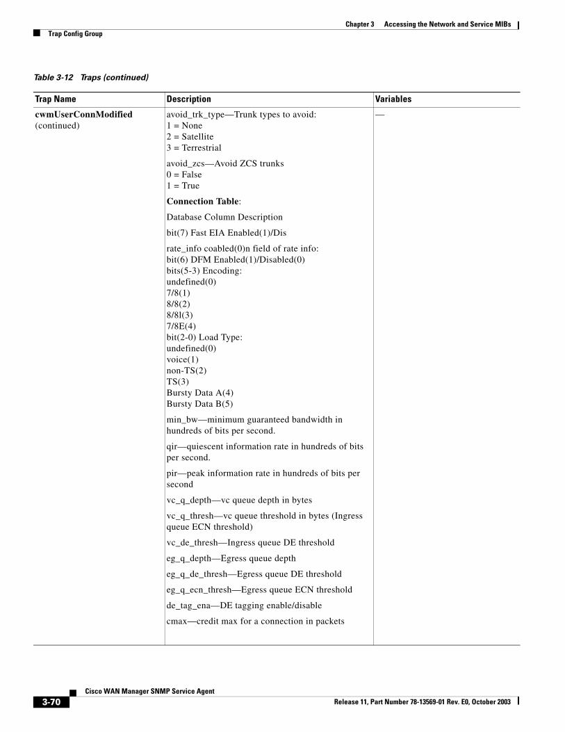
Chapter 3 Accessing the Network and Service MIBsTrap Config Group
cwmUserConnModified (continued)
avoid_trk_type—Trunk types to avoid:1 = None2 = Satellite3 = Terrestrial
avoid_zcs—Avoid ZCS trunks0 = False1 = True
Connection Table:
Database Column Description
bit(7) Fast EIA Enabled(1)/Dis
rate_info coabled(0)n field of rate info:bit(6) DFM Enabled(1)/Disabled(0)bits(5-3) Encoding:undefined(0)7/8(1)8/8(2)8/8l(3)7/8E(4)bit(2-0) Load Type:undefined(0)voice(1)non-TS(2)TS(3)Bursty Data A(4)Bursty Data B(5)
min_bw—minimum guaranteed bandwidth in hundreds of bits per second.
qir—quiescent information rate in hundreds of bits per second.
pir—peak information rate in hundreds of bits per second
vc_q_depth—vc queue depth in bytes
vc_q_thresh—vc queue threshold in bytes (Ingress queue ECN threshold)
vc_de_thresh—Ingress queue DE threshold
eg_q_depth—Egress queue depth
eg_q_de_thresh—Egress queue DE threshold
eg_q_ecn_thresh—Egress queue ECN threshold
de_tag_ena—DE tagging enable/disable
cmax—credit max for a connection in packets
—
Table 3-12 Traps (continued)
Trap Name Description Variables
3-70Cisco WAN Manager SNMP Service Agent
Release 11, Part Number 78-13569-01 Rev. E0, October 2003
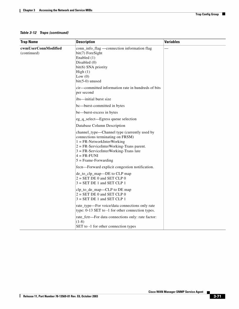
Chapter 3 Accessing the Network and Service MIBsTrap Config Group
cwmUserConnModified (continued)
conn_info_flag —connection information flagbit(7) ForeSightEnabled (1)Disabled (0)bit(6) SNA priorityHigh (1)Low (0)bit(5-0) unused
cir—committed information rate in hundreds of bits per second
ibs—initial burst size
bc—burst-committed in bytes
be—burst-excess in bytes
eg_q_select—Egress queue selection
Database Column Description
channel_type—Channel type (currently used by connections terminating on FRSM)1 = FR-NetworkInterWorking2 = FR-ServiceInterWorking-Trans parent.3 = FR-ServiceInterWorking-Trans late4 = FR-FUNI5 = Frame-Forwarding
fecn—Forward explicit congestion notification.
de_to_clp_map—DE to CLP map2 = SET DE 0 and SET CLP 03 = SET DE 1 and SET CLP 1
clp_to_de_map—CLP to DE map2 = SET DE 0 and SET CLP 03 = SET DE 1 and SET CLP 1
rate_type—For voice/data connections only rate type: 0-13 SET to -1 for other connection types.
rate_fctr—For data connections only: rate factor: (1-8)SET to -1 for other connection types
—
Table 3-12 Traps (continued)
Trap Name Description Variables
3-71Cisco WAN Manager SNMP Service Agent
Release 11, Part Number 78-13569-01 Rev. E0, October 2003
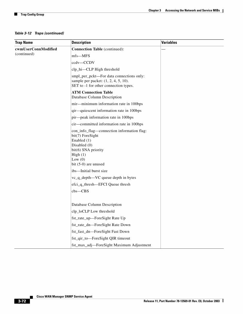
Chapter 3 Accessing the Network and Service MIBsTrap Config Group
cwmUserConnModified (continued)
Connection Table (continued):
mfs—MFS
ccdv—CCDV
clp_hi—CLP High threshold
smpl_per_pckt—For data connections only:sample per packet: (1, 2, 4, 5, 10).SET to -1 for other connection types.
ATM Connection TableDatabase Column Description
mir—minimum information rate in 100bps
qir—quiescent information rate in 100bps
pir—peak information rate in 100bps
cir—committed information rate in 100bps
con_info_flag—connection information flag:bit(7) ForeSightEnabled (1)Disabled (0)bit(6) SNA priorityHigh (1)Low (0)bit (5-0) are unused
ibs—Initial burst size
vc_q_depth—VC queue depth in bytes
efci_q_thresh—EFCI Queue thresh
cbs—CBS
Database Column Description
clp_loCLP Low threshold
fst_rate_up—ForeSight Rate Up
fst_rate_dn—ForeSight Rate Down
fst_fast_dn—ForeSight Fast Down
fst_qir_to—ForeSight QIR timeout
fst_max_adj—ForeSight Maximum Adjustment
—
Table 3-12 Traps (continued)
Trap Name Description Variables
3-72Cisco WAN Manager SNMP Service Agent
Release 11, Part Number 78-13569-01 Rev. E0, October 2003
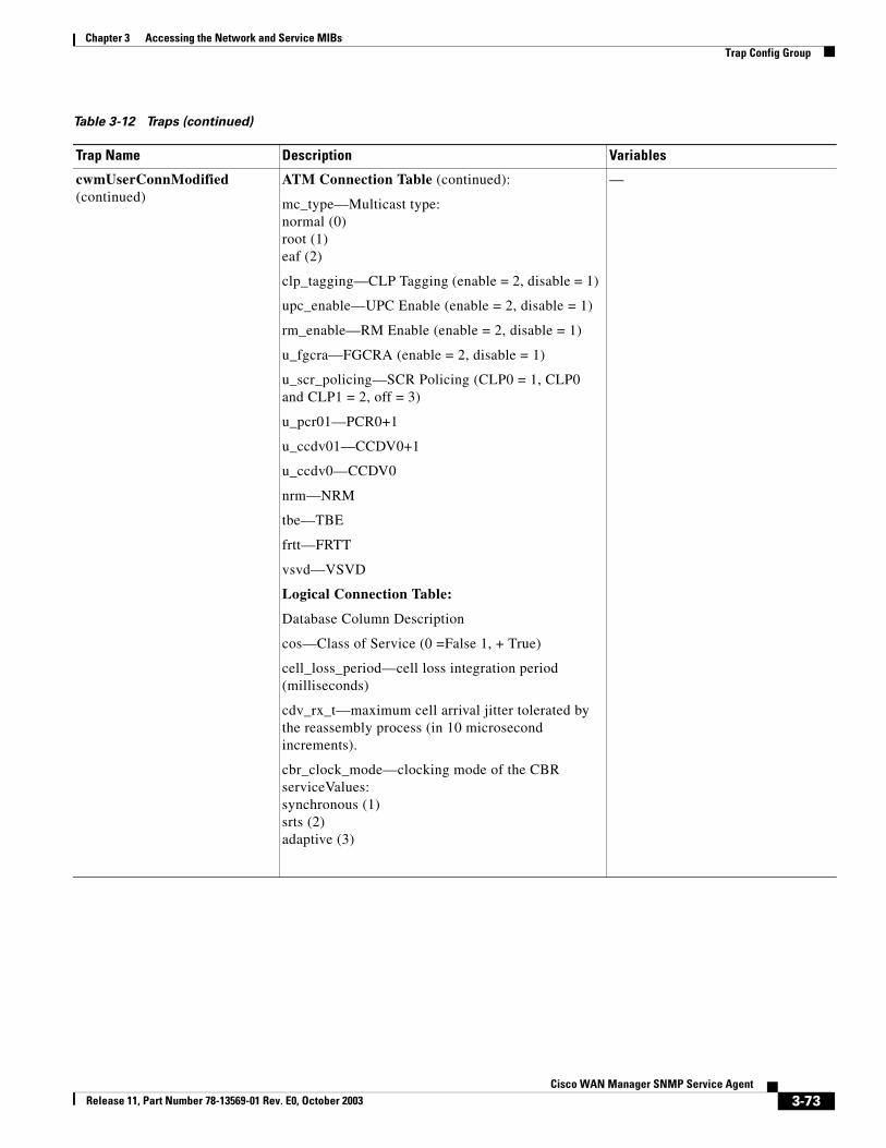
Chapter 3 Accessing the Network and Service MIBsTrap Config Group
cwmUserConnModified (continued)
ATM Connection Table (continued):
mc_type—Multicast type:normal (0)root (1)eaf (2)
clp_tagging—CLP Tagging (enable = 2, disable = 1)
upc_enable—UPC Enable (enable = 2, disable = 1)
rm_enable—RM Enable (enable = 2, disable = 1)
u_fgcra—FGCRA (enable = 2, disable = 1)
u_scr_policing—SCR Policing (CLP0 = 1, CLP0 and CLP1 = 2, off = 3)
u_pcr01—PCR0+1
u_ccdv01—CCDV0+1
u_ccdv0—CCDV0
nrm—NRM
tbe—TBE
frtt—FRTT
vsvd—VSVD
Logical Connection Table:
Database Column Description
cos—Class of Service (0 =False 1, + True)
cell_loss_period—cell loss integration period (milliseconds)
cdv_rx_t—maximum cell arrival jitter tolerated by the reassembly process (in 10 microsecond increments).
cbr_clock_mode—clocking mode of the CBR serviceValues:synchronous (1)srts (2)adaptive (3)
—
Table 3-12 Traps (continued)
Trap Name Description Variables
3-73Cisco WAN Manager SNMP Service Agent
Release 11, Part Number 78-13569-01 Rev. E0, October 2003
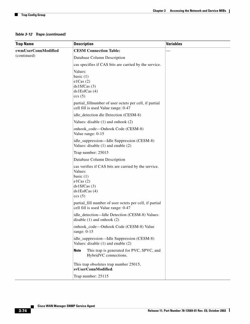
Chapter 3 Accessing the Network and Service MIBsTrap Config Group
cwmUserConnModified (continued)
CESM Connection Table:
Database Column Description
cas specifies if CAS bits are carried by the service.
Values:basic (1)e1Cas (2)ds1SfCas (3)ds1EsfCas (4)ccs (5)
partial_fillnumber of user octets per cell, if partial cell fill is used Value range: 0-47
idle_detection dle Detection (CESM-8)
Values: disable (1) and onhook (2)
onhook_code—Onhook Code (CESM-8) Value range: 0-15
idle_suppression—Idle Suppression (CESM-8) Values: disable (1) and enable (2)
Trap number: 25015
Database Column Description
cas verifies if CAS bits are carried by the service. Values:basic (1)e1Cas (2)ds1SfCas (3)ds1EsfCas (4)ccs (5)
partial_fill number of user octets per cell, if partial cell fill is used Value range: 0-47
idle_detection—Idle Detection (CESM-8) Values:disable (1) and onhook (2)
onhook_code—Onhook Code (CESM-8) Value range: 0-15
idle_suppression—Idle Suppression (CESM-8) Values: disable (1) and enable (2)
Note This trap is generated for PVC, SPVC, and HybridVC connections.
This trap obsoletes trap number 25015, svUserConnModified.
Trap number: 25115
—
Table 3-12 Traps (continued)
Trap Name Description Variables
3-74Cisco WAN Manager SNMP Service Agent
Release 11, Part Number 78-13569-01 Rev. E0, October 2003
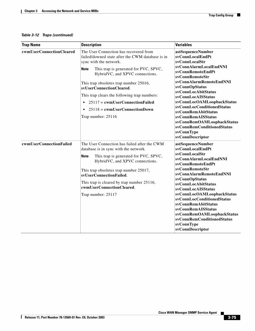
Chapter 3 Accessing the Network and Service MIBsTrap Config Group
cwmUserConnectionCleared The User Connection has recovered from failed/downed state after the CWM database is in sync with the network.
Note This trap is generated for PVC, SPVC, HybridVC, and XPVC connections.
This trap obsoletes trap number 25016, svUserConnectionCleared.
This trap clears the following trap numbers:
• 25117 = cwmUserConnectionFailed
• 25118 = cwmUserConnectionDown
Trap number: 25116
astSequenceNumbersvConnLocalEndPtsvConnLocalStrsvConnAlarmLocalEndNNIsvConnRemoteEndPtsvConnRemoteStrsvConnAlarmRemoteEndNNIsvConnOpStatussvConnLocAbitStatussvConnLocAISStatussvConnLocOAMLoopbackStatussvConnLocConditionedStatussvConnRemAbitStatussvConnRemAISStatussvConnRemOAMLoopbackStatussvConnRemConditionedStatussvConnTypesvConnDescriptor
cwmUserConnectionFailed The User Connection has failed after the CWM database is in sync with the network.
Note This trap is generated for PVC, SPVC, HybridVC, and XPVC connections.
This trap obsoletes trap number 25017, svUserConnectionFailed.
This trap is cleared by trap number 25116, cwmUserConnectionCleared.
Trap number: 25117
astSequenceNumbersvConnLocalEndPtsvConnLocalStrsvConnAlarmLocalEndNNIsvConnRemoteEndPtsvConnRemoteStrsvConnAlarmRemoteEndNNIsvConnOpStatussvConnLocAbitStatussvConnLocAISStatussvConnLocOAMLoopbackStatussvConnLocConditionedStatussvConnRemAbitStatussvConnRemAISStatussvConnRemOAMLoopbackStatussvConnRemConditionedStatussvConnTypesvConnDescriptor
Table 3-12 Traps (continued)
Trap Name Description Variables
3-75Cisco WAN Manager SNMP Service Agent
Release 11, Part Number 78-13569-01 Rev. E0, October 2003
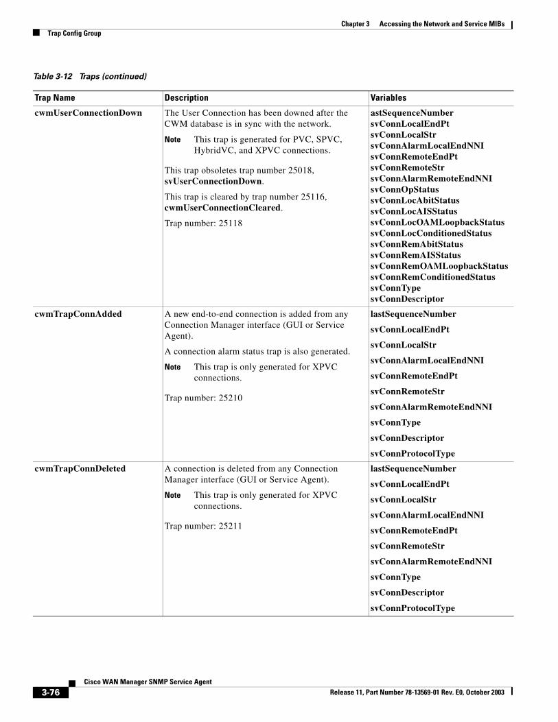
Chapter 3 Accessing the Network and Service MIBsTrap Config Group
cwmUserConnectionDown The User Connection has been downed after the CWM database is in sync with the network.
Note This trap is generated for PVC, SPVC, HybridVC, and XPVC connections.
This trap obsoletes trap number 25018, svUserConnectionDown.
This trap is cleared by trap number 25116, cwmUserConnectionCleared.
Trap number: 25118
astSequenceNumbersvConnLocalEndPtsvConnLocalStrsvConnAlarmLocalEndNNIsvConnRemoteEndPtsvConnRemoteStrsvConnAlarmRemoteEndNNIsvConnOpStatussvConnLocAbitStatussvConnLocAISStatussvConnLocOAMLoopbackStatussvConnLocConditionedStatussvConnRemAbitStatussvConnRemAISStatussvConnRemOAMLoopbackStatussvConnRemConditionedStatussvConnTypesvConnDescriptor
cwmTrapConnAdded A new end-to-end connection is added from any Connection Manager interface (GUI or Service Agent).
A connection alarm status trap is also generated.
Note This trap is only generated for XPVC connections.
Trap number: 25210
lastSequenceNumber
svConnLocalEndPt
svConnLocalStr
svConnAlarmLocalEndNNI
svConnRemoteEndPt
svConnRemoteStr
svConnAlarmRemoteEndNNI
svConnType
svConnDescriptor
svConnProtocolType
cwmTrapConnDeleted A connection is deleted from any Connection Manager interface (GUI or Service Agent).
Note This trap is only generated for XPVC connections.
Trap number: 25211
lastSequenceNumber
svConnLocalEndPt
svConnLocalStr
svConnAlarmLocalEndNNI
svConnRemoteEndPt
svConnRemoteStr
svConnAlarmRemoteEndNNI
svConnType
svConnDescriptor
svConnProtocolType
Table 3-12 Traps (continued)
Trap Name Description Variables
3-76Cisco WAN Manager SNMP Service Agent
Release 11, Part Number 78-13569-01 Rev. E0, October 2003
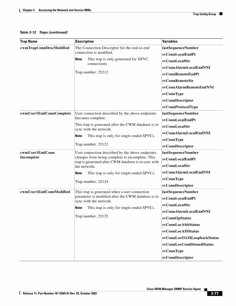
Chapter 3 Accessing the Network and Service MIBsTrap Config Group
cwmTrapConnDescModified The Connection Descriptor for the end-to-end connection is modified.
Note This trap is only generated for XPVC connections.
Trap number: 25212
lastSequenceNumber
svConnLocalEndPt
svConnLocalStr
svConnAlarmLocalEndNNI
svConnRemoteEndPt
svConnRemoteStr
svConnAlarmRemoteEndNNI
svConnType
svConnDescriptor
svConnProtocolType
cwmUser1EndConnComplete User connection described by the above endpoints becomes complete.
This trap is generated after the CWM database is in sync with the network.
Note This trap is only for single-ended SPVCs.
Trap number: 25123
lastSequenceNumber
svConnLocalEndPt
svConnLocalStr
svConnAlarmLocalEndNNI
svConnType
svConnDescriptor
cwmUser1EndConnIncomplete
User connection described by the above endpoints changes from being complete to incomplete. This trap is generated after CWM database is in sync with the network.
Note This trap is only for single-ended SPVCs.
Trap number: 25124
lastSequenceNumber
svConnLocalEndPt
svConnLocalStr
svConnAlarmLocalEndNNI
svConnType
svConnDescriptor
cwmUser1EndConnModified This trap is generated when a user connection parameter is modified after the CWM database is in sync with the network.
Note This trap is only for single-ended SPVCs.
Trap number: 25125
lastSequenceNumber
svConnLocalEndPt
svConnLocalStr
svConnAlarmLocalEndNNI
svConnOpStatus
svConnLocAbitStatus
svConnLocAISStatus
svConnLocOAMLoopbackStatus
svConnLocConditionedStatus
svConnType
svConnDescriptor
Table 3-12 Traps (continued)
Trap Name Description Variables
3-77Cisco WAN Manager SNMP Service Agent
Release 11, Part Number 78-13569-01 Rev. E0, October 2003
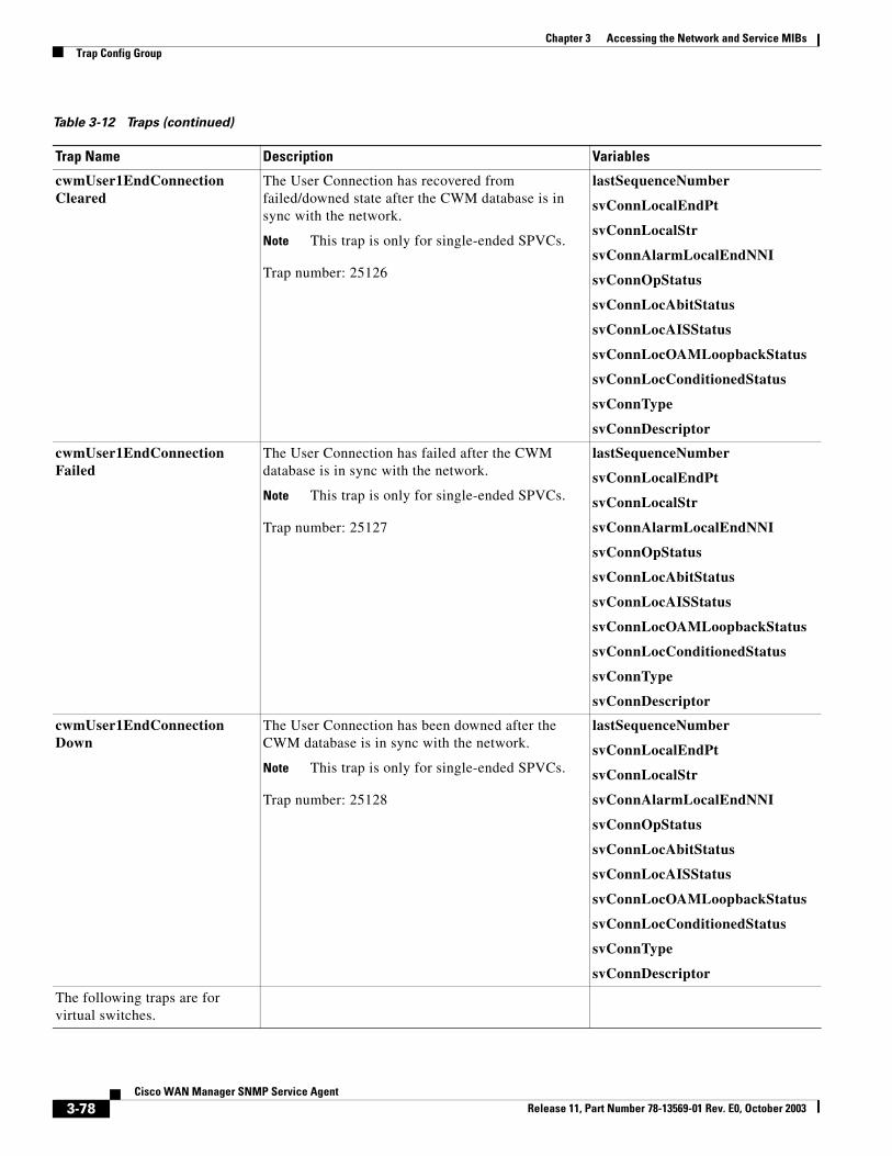
Chapter 3 Accessing the Network and Service MIBsTrap Config Group
cwmUser1EndConnectionCleared
The User Connection has recovered from failed/downed state after the CWM database is in sync with the network.
Note This trap is only for single-ended SPVCs.
Trap number: 25126
lastSequenceNumber
svConnLocalEndPt
svConnLocalStr
svConnAlarmLocalEndNNI
svConnOpStatus
svConnLocAbitStatus
svConnLocAISStatus
svConnLocOAMLoopbackStatus
svConnLocConditionedStatus
svConnType
svConnDescriptor
cwmUser1EndConnectionFailed
The User Connection has failed after the CWM database is in sync with the network.
Note This trap is only for single-ended SPVCs.
Trap number: 25127
lastSequenceNumber
svConnLocalEndPt
svConnLocalStr
svConnAlarmLocalEndNNI
svConnOpStatus
svConnLocAbitStatus
svConnLocAISStatus
svConnLocOAMLoopbackStatus
svConnLocConditionedStatus
svConnType
svConnDescriptor
cwmUser1EndConnectionDown
The User Connection has been downed after the CWM database is in sync with the network.
Note This trap is only for single-ended SPVCs.
Trap number: 25128
lastSequenceNumber
svConnLocalEndPt
svConnLocalStr
svConnAlarmLocalEndNNI
svConnOpStatus
svConnLocAbitStatus
svConnLocAISStatus
svConnLocOAMLoopbackStatus
svConnLocConditionedStatus
svConnType
svConnDescriptor
The following traps are for virtual switches.
Table 3-12 Traps (continued)
Trap Name Description Variables
3-78Cisco WAN Manager SNMP Service Agent
Release 11, Part Number 78-13569-01 Rev. E0, October 2003
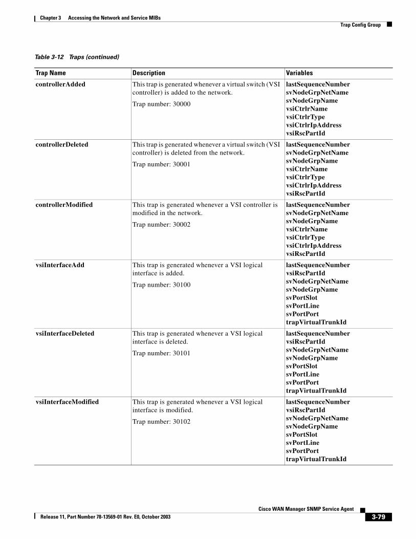
Chapter 3 Accessing the Network and Service MIBsTrap Config Group
controllerAdded This trap is generated whenever a virtual switch (VSI controller) is added to the network.
Trap number: 30000
lastSequenceNumbersvNodeGrpNetNamesvNodeGrpNamevsiCtrlrNamevsiCtrlrTypevsiCtrlrIpAddressvsiRscPartId
controllerDeleted This trap is generated whenever a virtual switch (VSI controller) is deleted from the network.
Trap number: 30001
lastSequenceNumbersvNodeGrpNetNamesvNodeGrpNamevsiCtrlrNamevsiCtrlrTypevsiCtrlrIpAddressvsiRscPartId
controllerModified This trap is generated whenever a VSI controller is modified in the network.
Trap number: 30002
lastSequenceNumbersvNodeGrpNetNamesvNodeGrpNamevsiCtrlrNamevsiCtrlrTypevsiCtrlrIpAddressvsiRscPartId
vsiInterfaceAdd This trap is generated whenever a VSI logical interface is added.
Trap number: 30100
lastSequenceNumbervsiRscPartIdsvNodeGrpNetNamesvNodeGrpNamesvPortSlotsvPortLinesvPortPorttrapVirtualTrunkId
vsiInterfaceDeleted This trap is generated whenever a VSI logical interface is deleted.
Trap number: 30101
lastSequenceNumbervsiRscPartIdsvNodeGrpNetNamesvNodeGrpNamesvPortSlotsvPortLinesvPortPorttrapVirtualTrunkId
vsiInterfaceModified This trap is generated whenever a VSI logical interface is modified.
Trap number: 30102
lastSequenceNumbervsiRscPartIdsvNodeGrpNetNamesvNodeGrpNamesvPortSlotsvPortLinesvPortPorttrapVirtualTrunkId
Table 3-12 Traps (continued)
Trap Name Description Variables
3-79Cisco WAN Manager SNMP Service Agent
Release 11, Part Number 78-13569-01 Rev. E0, October 2003
Chapter 3 Accessing the Network and Service MIBsDetailed MIB Description—Service MIB
Detailed MIB Description—Service MIBThis section describes the Service MIB (SV+Service.mib) and its associated tables and access methods.
The CWM Service MIB contains the following service groups:
• connGroup (Connection Service Group)
• portGroup (Port Service Group)
• cardGroup (Card Service Group)
• cardPaErrorGroup (Card Proxy Error Group)
Connection Service GroupThe Connection Service Group (connGroup) contains SETs of objects creating, configuring, deleting, and performing other management related tasks on connections and protocol specific endpoints. All objects under the connGroup tree are managed by the CWM sub-agent ConnProxy.
The connGroup contains the following tables and scalar objects:
svConnTable
The svConnTable is used for end-to-end PVC, SPVC, HybridVC, and XPVC connection entries. For detailed information, see the “Connection Table” section. For XPVC entries, see the “XPVC Connection Table” section.
svConnMibUpTime
This scalar object provides the elapsed time since the management entity supporting this MIB was started. For detailed information, see the “Connection Group—Scalar Objects” section.
svCmpaErrorLastIndex
This scalar object provides the last error index in the svCmpaErrorTable. See Section, “Connection Group—Scalar Objects” for detailed information.
svCmpaErrorFlushAll
This scalar object allows you to flush all entries in the svCmpaErrorTable. See Section, “Connection Group—Scalar Objects” for detailed information.
svCmpaErrorTable
This table shows recent errors reported by the ConnProxy sub-agent. See Section, “ConnProxy Error Table” for detailed information.
3-80Cisco WAN Manager SNMP Service Agent
Release 11, Part Number 78-13569-01 Rev. E0, October 2003
Chapter 3 Accessing the Network and Service MIBsDetailed MIB Description—Service MIB
svCmpaErrorLastDesc
This scalar object describes the last error generated by the ConnProxy sub-agent. See Section, “ConnProxy Error Table” for detailed information.
svCmpaErrorLastEcode
This scalar object provides the error code of the last error generated by the ConnProxy sub-agent. See Section, “ConnProxy Error Table” for detailed information.
svCeEndPointTable
This table shows Circuit Emulation (CE) endpoint entries. See Section, “Circuit Emulation Endpoint Table” for detailed information.
atmEndPointTable
Table of ATM endpoint entries. See Section, “ATM Endpoint Table”.
svConnMCViewTable
Table of root or leaf connections in a multicast group. See Section, “Multicast Connection View Table”.
frEndPointTable
This table shows Frame Relay endpoint entries. See Section, “Frame Relay Endpoint Table”.
svConnAlarmTable
This table provides a list of connections in an alarmed state. See Section, “Connection Alarm Table”.
voiceEndPointTable
Table of voice endpoint entries. See Section, “Voice Endpoint Table”.
dataEndPointTable
Table of data end-point entries. See Section, “Data Endpoint Table”.
rpmEndPointTable
Table of RPM endpoint entries. See Section, “RPM Endpoint Table”.
3-81Cisco WAN Manager SNMP Service Agent
Release 11, Part Number 78-13569-01 Rev. E0, October 2003
Chapter 3 Accessing the Network and Service MIBsDetailed MIB Description—Service MIB
Port Service GroupThe Port Service Group (portGroup) contains SETs of objects to create, configure, delete, and perform other management related tasks on ports. All objects under the portGroup tree are handled by the CWM sub-agent PortProxy.
The portGroup contains the following tables and scalar objects:
svPortTable
This table provides state information of all ports. See Section, “Port State Table”.
svNextLogicalPortTable
This table allows you to obtain the next available logical port on a card supporting logical ports. See Section, “Next Available Logical Port Table”.
svPhysicalToLogicalMapTable
This table provides the logical port associated with the given physical port specifics on a card supporting logical ports. See Section, “Physical To Logical Map Table”.
svAtmPortTable
Table of all ATM and IMA ports. See Section, “ATM Port Table”.
psaErrorTable
Table of recent errors reported by the PortProxy sub-agent. See Section, “PortProxy Error Table”.
svPortAlarmTable
This table provides a list of ports in an alarmed state. See Section, “Port Alarm Table”.
psaErrorLastIndex
Scalar object providing the last error index in psaErrorTable. See Section, “Port Group—Scalar Objects”.
psaErrorFlushAll
This scalar object allows you to flush all entries in the psaErrorTable. See Section, “Port Group—Scalar Objects”.
psaErrorLastDesc
This scalar object provides the description of the last error generated by the PortProxy sub-agent. See Section, “Port Group—Scalar Objects”.
3-82Cisco WAN Manager SNMP Service Agent
Release 11, Part Number 78-13569-01 Rev. E0, October 2003
Chapter 3 Accessing the Network and Service MIBsDetailed MIB Description—Service MIB
psaErrorLastEcode
This scalar object provides the error code of the last error generated by the PortProxy sub-agent. See Table 3-38 for a list of the possible errors.
svCesmPortTable
This table gives all CESM ports See Section, “CESM Port Configuration Table”.
svFrsmVhsServiceQTable
This table contains configuration information about all of the service queues on FRSM-VHS ports. See Section, “FRSM VHS Service Queue Configuration Table”.
svVoiceDataPortTable
This table contains configuration information about all of the voice and data ports in the network. See Section, “Voice Data Port Table”.
svFrPortTable
This table lists all Frame Relay ports. See section “Frame Relay Port Table”.
Card Service GroupThe Card Service Group (cardGroup) provides card information about the network nodes. For the MGX 8220 core card SET, this MIB also provides a switch over function. All objects under the cardGroup tree are handled by the CWM sub-agent PortProxy.
The cardGroup group contains the following tables and scalar objects:
svCardTable
This table provides card information about the network nodes.
svcardAlarmTable
This table provides information about the cards in an alarmed state.
Card Proxy Error GroupThe Card Proxy Error Group (cardPaErrorGroup) provides error information about SNMP SET requests from a manager for the Card Service Group.
3-83Cisco WAN Manager SNMP Service Agent
Release 11, Part Number 78-13569-01 Rev. E0, October 2003
Chapter 3 Accessing the Network and Service MIBsDetailed MIB Description—Service MIB
The cardPaErrorGroup contains the following tables and scalar objects:
cardPaErrorLastDesc
This scalar object provides the description of the last error generated. If the error table does not contain errors, an SNMP GET on this object returns a NULL string. See section Card Proxy Error Group - Scalar Objects.
cardPaErrorLastEcode
This scalar object provides the error code of the last error generated by the Card proxy sub-agent. See the table for possible errors.
cardPaErrorFlushAll
This scalar object is used to flush all entries in the cardPaErrorTable. See Section Card Proxy Error Group - Scalar Objects.
cardPaErrorTable
This table provides recent errors reported by the CardProxy subagent.
Connection TableThe Connection table (svConnTable) contains a list of all the FR-FR, FR-ATM, ATM-ATM, ATM-CE, and CE-CE connections in the network. This table maintains information about all end-to-end PVC, SPVC, Hybrid, and XPVC connections in the network. The entries describe the association between a local endpoint and a remote endpoint. These two endpoints define the end-to-end connection, regardless of the network topology.
This table is indexed by svConnIndex.
3-84Cisco WAN Manager SNMP Service Agent
Release 11, Part Number 78-13569-01 Rev. E0, October 2003
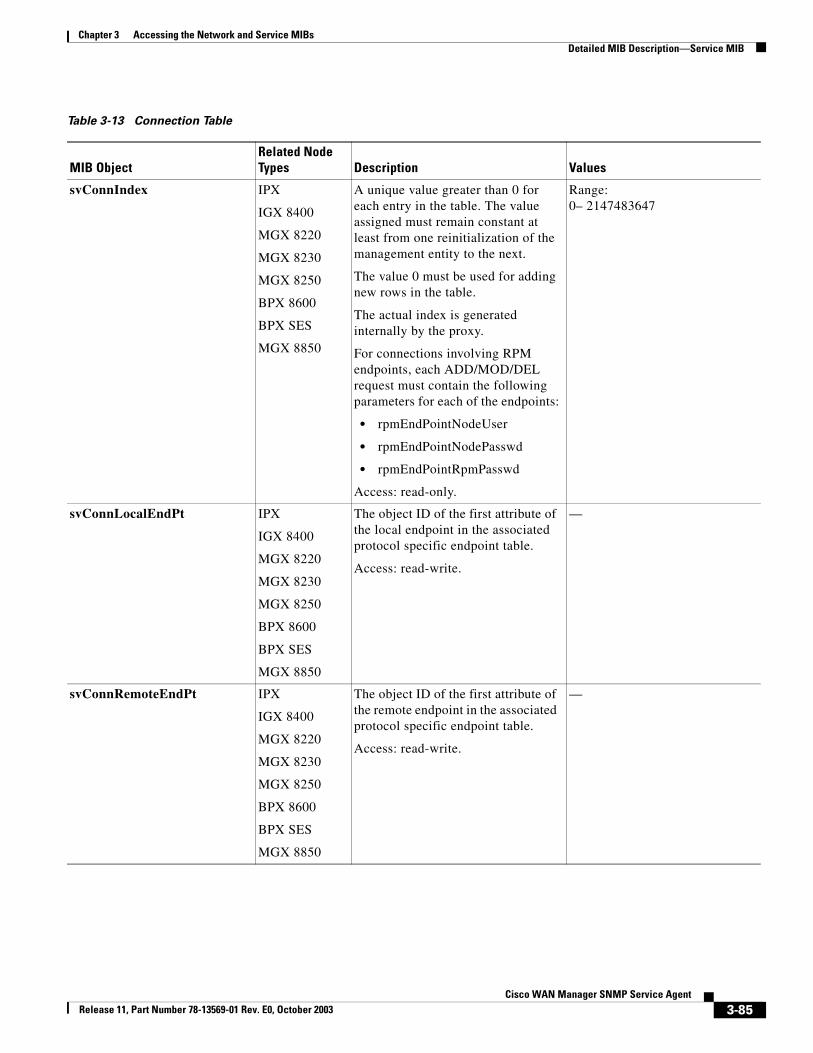
Chapter 3 Accessing the Network and Service MIBsDetailed MIB Description—Service MIB
Table 3-13 Connection Table
MIB ObjectRelated Node Types Description Values
svConnIndex IPX
IGX 8400
MGX 8220
MGX 8230
MGX 8250
BPX 8600
BPX SES
MGX 8850
A unique value greater than 0 for each entry in the table. The value assigned must remain constant at least from one reinitialization of the management entity to the next.
The value 0 must be used for adding new rows in the table.
The actual index is generated internally by the proxy.
For connections involving RPM endpoints, each ADD/MOD/DEL request must contain the following parameters for each of the endpoints:
• rpmEndPointNodeUser
• rpmEndPointNodePasswd
• rpmEndPointRpmPasswd
Access: read-only.
Range: 0– 2147483647
svConnLocalEndPt IPX
IGX 8400
MGX 8220
MGX 8230
MGX 8250
BPX 8600
BPX SES
MGX 8850
The object ID of the first attribute of the local endpoint in the associated protocol specific endpoint table.
Access: read-write.
—
svConnRemoteEndPt IPX
IGX 8400
MGX 8220
MGX 8230
MGX 8250
BPX 8600
BPX SES
MGX 8850
The object ID of the first attribute of the remote endpoint in the associated protocol specific endpoint table.
Access: read-write.
—
3-85Cisco WAN Manager SNMP Service Agent
Release 11, Part Number 78-13569-01 Rev. E0, October 2003
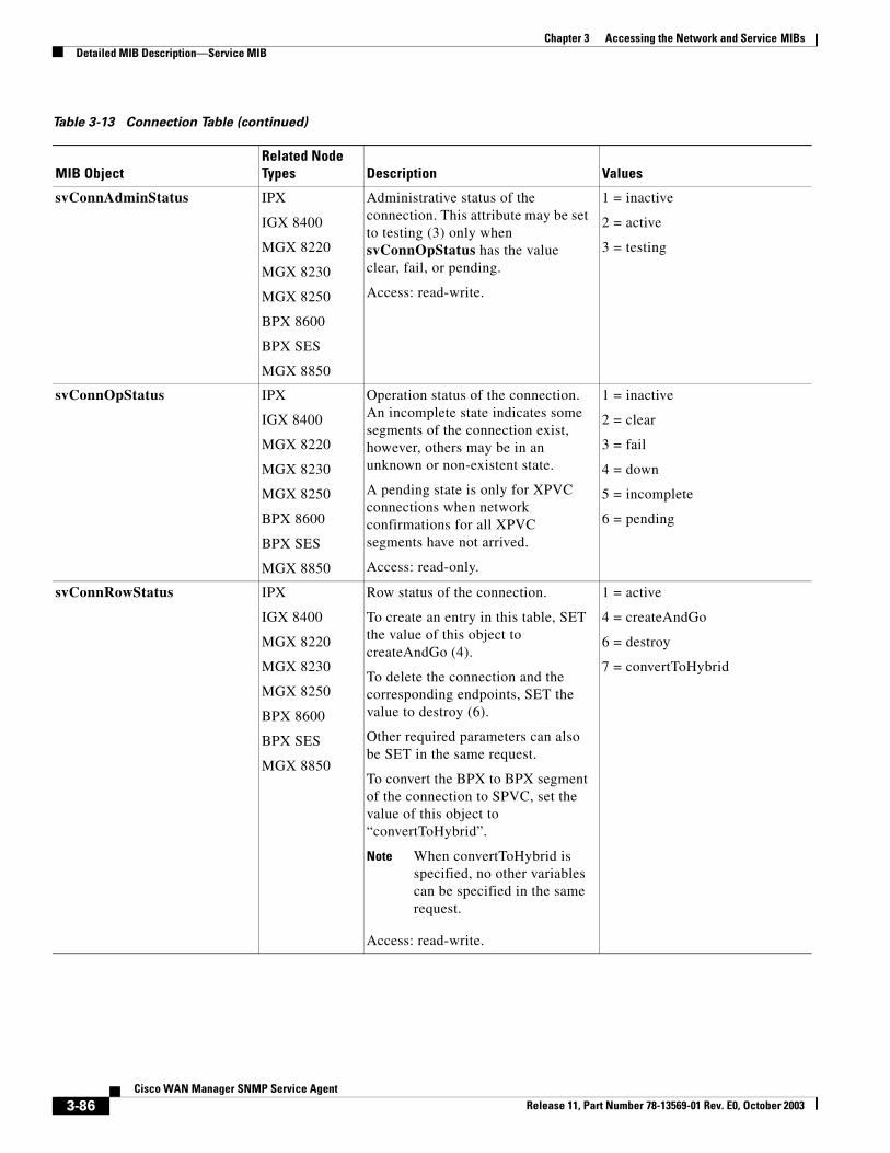
Chapter 3 Accessing the Network and Service MIBsDetailed MIB Description—Service MIB
svConnAdminStatus IPX
IGX 8400
MGX 8220
MGX 8230
MGX 8250
BPX 8600
BPX SES
MGX 8850
Administrative status of the connection. This attribute may be set to testing (3) only when svConnOpStatus has the value clear, fail, or pending.
Access: read-write.
1 = inactive
2 = active
3 = testing
svConnOpStatus IPX
IGX 8400
MGX 8220
MGX 8230
MGX 8250
BPX 8600
BPX SES
MGX 8850
Operation status of the connection. An incomplete state indicates some segments of the connection exist, however, others may be in an unknown or non-existent state.
A pending state is only for XPVC connections when network confirmations for all XPVC segments have not arrived.
Access: read-only.
1 = inactive
2 = clear
3 = fail
4 = down
5 = incomplete
6 = pending
svConnRowStatus IPX
IGX 8400
MGX 8220
MGX 8230
MGX 8250
BPX 8600
BPX SES
MGX 8850
Row status of the connection.
To create an entry in this table, SET the value of this object to createAndGo (4).
To delete the connection and the corresponding endpoints, SET the value to destroy (6).
Other required parameters can also be SET in the same request.
To convert the BPX to BPX segment of the connection to SPVC, set the value of this object to “convertToHybrid”.
Note When convertToHybrid is specified, no other variables can be specified in the same request.
Access: read-write.
1 = active
4 = createAndGo
6 = destroy
7 = convertToHybrid
Table 3-13 Connection Table (continued)
MIB ObjectRelated Node Types Description Values
3-86Cisco WAN Manager SNMP Service Agent
Release 11, Part Number 78-13569-01 Rev. E0, October 2003
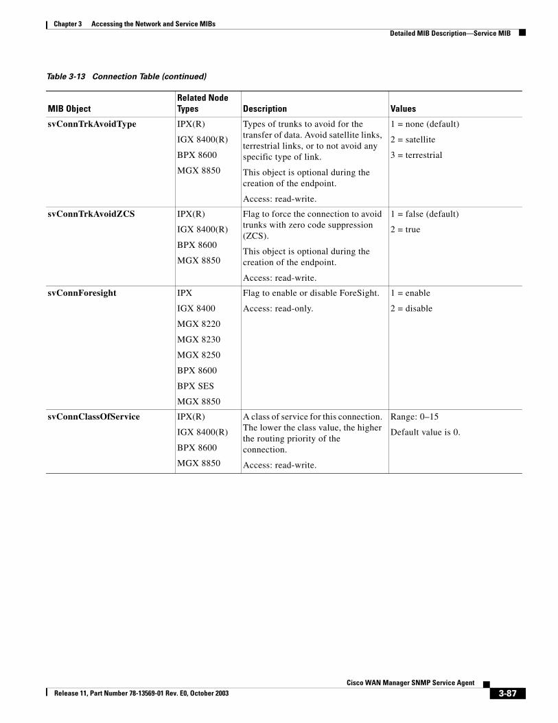
Chapter 3 Accessing the Network and Service MIBsDetailed MIB Description—Service MIB
svConnTrkAvoidType IPX(R)
IGX 8400(R)
BPX 8600
MGX 8850
Types of trunks to avoid for the transfer of data. Avoid satellite links, terrestrial links, or to not avoid any specific type of link.
This object is optional during the creation of the endpoint.
Access: read-write.
1 = none (default)
2 = satellite
3 = terrestrial
svConnTrkAvoidZCS IPX(R)
IGX 8400(R)
BPX 8600
MGX 8850
Flag to force the connection to avoid trunks with zero code suppression (ZCS).
This object is optional during the creation of the endpoint.
Access: read-write.
1 = false (default)
2 = true
svConnForesight IPX
IGX 8400
MGX 8220
MGX 8230
MGX 8250
BPX 8600
BPX SES
MGX 8850
Flag to enable or disable ForeSight.
Access: read-only.
1 = enable
2 = disable
svConnClassOfService IPX(R)
IGX 8400(R)
BPX 8600
MGX 8850
A class of service for this connection. The lower the class value, the higher the routing priority of the connection.
Access: read-write.
Range: 0–15
Default value is 0.
Table 3-13 Connection Table (continued)
MIB ObjectRelated Node Types Description Values
3-87Cisco WAN Manager SNMP Service Agent
Release 11, Part Number 78-13569-01 Rev. E0, October 2003
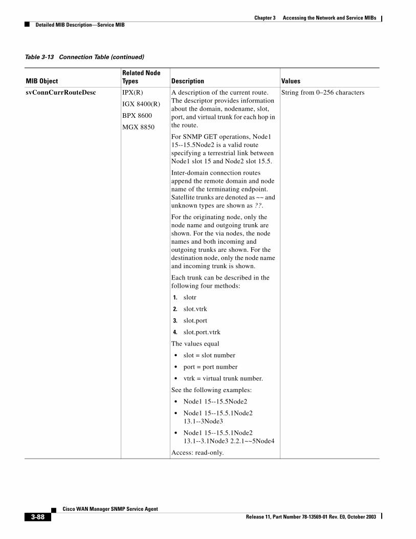
Chapter 3 Accessing the Network and Service MIBsDetailed MIB Description—Service MIB
svConnCurrRouteDesc IPX(R)
IGX 8400(R)
BPX 8600
MGX 8850
A description of the current route. The descriptor provides information about the domain, nodename, slot, port, and virtual trunk for each hop in the route.
For SNMP GET operations, Node1 15--15.5Node2 is a valid route specifying a terrestrial link between Node1 slot 15 and Node2 slot 15.5.
Inter-domain connection routes append the remote domain and node name of the terminating endpoint. Satellite trunks are denoted as ~~ and unknown types are shown as ??.
For the originating node, only the node name and outgoing trunk are shown. For the via nodes, the node names and both incoming and outgoing trunks are shown. For the destination node, only the node name and incoming trunk is shown.
Each trunk can be described in the following four methods:
1. slotr
2. slot.vtrk
3. slot.port
4. slot.port.vtrk
The values equal
• slot = slot number
• port = port number
• vtrk = virtual trunk number.
See the following examples:
• Node1 15--15.5Node2
• Node1 15--15.5.1Node2 13.1--3Node3
• Node1 15--15.5.1Node2 13.1--3.1Node3 2.2.1~~5Node4
Access: read-only.
String from 0–256 characters
Table 3-13 Connection Table (continued)
MIB ObjectRelated Node Types Description Values
3-88Cisco WAN Manager SNMP Service Agent
Release 11, Part Number 78-13569-01 Rev. E0, October 2003
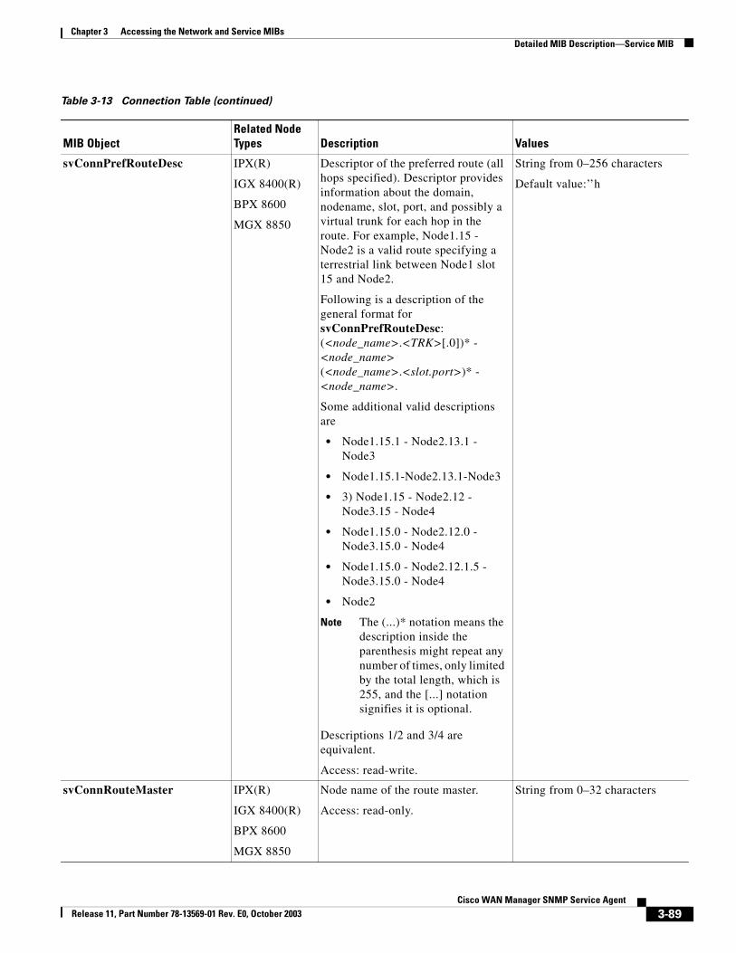
Chapter 3 Accessing the Network and Service MIBsDetailed MIB Description—Service MIB
svConnPrefRouteDesc IPX(R)
IGX 8400(R)
BPX 8600
MGX 8850
Descriptor of the preferred route (all hops specified). Descriptor provides information about the domain, nodename, slot, port, and possibly a virtual trunk for each hop in the route. For example, Node1.15 - Node2 is a valid route specifying a terrestrial link between Node1 slot 15 and Node2.
Following is a description of the general format for svConnPrefRouteDesc: (<node_name>.<TRK>[.0])* - <node_name> (<node_name>.<slot.port>)* - <node_name>.
Some additional valid descriptions are
• Node1.15.1 - Node2.13.1 - Node3
• Node1.15.1-Node2.13.1-Node3
• 3) Node1.15 - Node2.12 - Node3.15 - Node4
• Node1.15.0 - Node2.12.0 - Node3.15.0 - Node4
• Node1.15.0 - Node2.12.1.5 - Node3.15.0 - Node4
• Node2
Note The (...)* notation means the description inside the parenthesis might repeat any number of times, only limited by the total length, which is 255, and the [...] notation signifies it is optional.
Descriptions 1/2 and 3/4 are equivalent.
Access: read-write.
String from 0–256 characters
Default value:’’h
svConnRouteMaster IPX(R)
IGX 8400(R)
BPX 8600
MGX 8850
Node name of the route master.
Access: read-only.
String from 0–32 characters
Table 3-13 Connection Table (continued)
MIB ObjectRelated Node Types Description Values
3-89Cisco WAN Manager SNMP Service Agent
Release 11, Part Number 78-13569-01 Rev. E0, October 2003
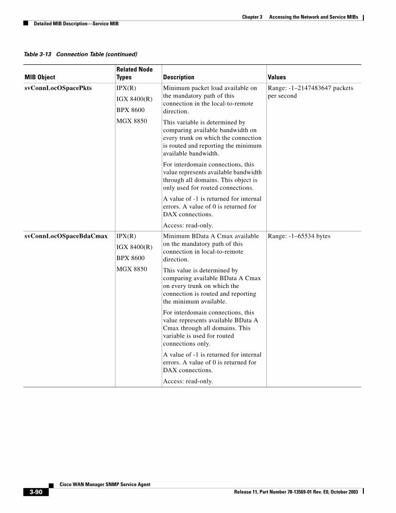
Chapter 3 Accessing the Network and Service MIBsDetailed MIB Description—Service MIB
svConnLocOSpacePkts IPX(R)
IGX 8400(R)
BPX 8600
MGX 8850
Minimum packet load available on the mandatory path of this connection in the local-to-remote direction.
This variable is determined by comparing available bandwidth on every trunk on which the connection is routed and reporting the minimum available bandwidth.
For interdomain connections, this value represents available bandwidth through all domains. This object is only used for routed connections.
A value of -1 is returned for internal errors. A value of 0 is returned for DAX connections.
Access: read-only.
Range: -1–2147483647 packets per second
svConnLocOSpaceBdaCmax IPX(R)
IGX 8400(R)
BPX 8600
MGX 8850
Minimum BData A Cmax available on the mandatory path of this connection in local-to-remote direction.
This value is determined by comparing available BData A Cmax on every trunk on which the connection is routed and reporting the minimum available.
For interdomain connections, this value represents available BData A Cmax through all domains. This variable is used for routed connections only.
A value of -1 is returned for internal errors. A value of 0 is returned for DAX connections.
Access: read-only.
Range: -1–65534 bytes
Table 3-13 Connection Table (continued)
MIB ObjectRelated Node Types Description Values
3-90Cisco WAN Manager SNMP Service Agent
Release 11, Part Number 78-13569-01 Rev. E0, October 2003
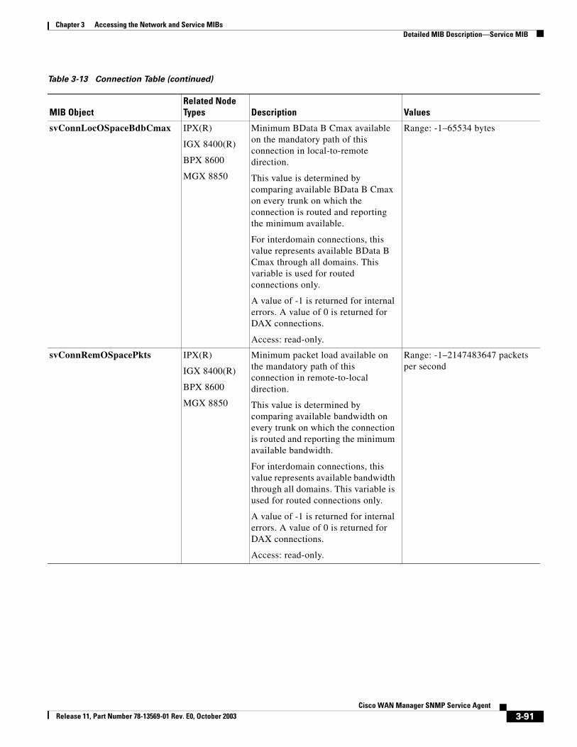
Chapter 3 Accessing the Network and Service MIBsDetailed MIB Description—Service MIB
svConnLocOSpaceBdbCmax IPX(R)
IGX 8400(R)
BPX 8600
MGX 8850
Minimum BData B Cmax available on the mandatory path of this connection in local-to-remote direction.
This value is determined by comparing available BData B Cmax on every trunk on which the connection is routed and reporting the minimum available.
For interdomain connections, this value represents available BData B Cmax through all domains. This variable is used for routed connections only.
A value of -1 is returned for internal errors. A value of 0 is returned for DAX connections.
Access: read-only.
Range: -1–65534 bytes
svConnRemOSpacePkts IPX(R)
IGX 8400(R)
BPX 8600
MGX 8850
Minimum packet load available on the mandatory path of this connection in remote-to-local direction.
This value is determined by comparing available bandwidth on every trunk on which the connection is routed and reporting the minimum available bandwidth.
For interdomain connections, this value represents available bandwidth through all domains. This variable is used for routed connections only.
A value of -1 is returned for internal errors. A value of 0 is returned for DAX connections.
Access: read-only.
Range: -1–2147483647 packets per second
Table 3-13 Connection Table (continued)
MIB ObjectRelated Node Types Description Values
3-91Cisco WAN Manager SNMP Service Agent
Release 11, Part Number 78-13569-01 Rev. E0, October 2003
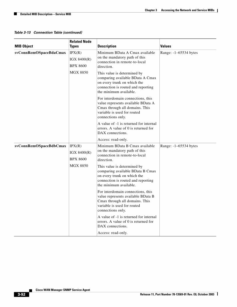
Chapter 3 Accessing the Network and Service MIBsDetailed MIB Description—Service MIB
svConnRemOSpaceBdaCmax IPX(R)
IGX 8400(R)
BPX 8600
MGX 8850
Minimum BData A Cmax available on the mandatory path of this connection in remote-to-local direction.
This value is determined by comparing available BData A Cmax on every trunk on which the connection is routed and reporting the minimum available.
For interdomain connections, this value represents available BData A Cmax through all domains. This variable is used for routed connections only.
A value of -1 is returned for internal errors. A value of 0 is returned for DAX connections.
Access: read-only.
Range: -1–65534 bytes
svConnRemOSpaceBdbCmax IPX(R)
IGX 8400(R)
BPX 8600
MGX 8850
Minimum BData B Cmax available on the mandatory path of this connection in remote-to-local direction.
This value is determined by comparing available BData B Cmax on every trunk on which the connection is routed and reporting the minimum available.
For interdomain connections, this value represents available BData B Cmax through all domains. This variable is used for routed connections only.
A value of -1 is returned for internal errors. A value of 0 is returned for DAX connections.
Access: read-only.
Range: -1–65534 bytes
Table 3-13 Connection Table (continued)
MIB ObjectRelated Node Types Description Values
3-92Cisco WAN Manager SNMP Service Agent
Release 11, Part Number 78-13569-01 Rev. E0, October 2003
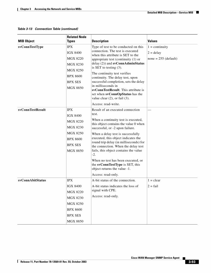
Chapter 3 Accessing the Network and Service MIBsDetailed MIB Description—Service MIB
svConnTestType IPX
IGX 8400
MGX 8220
MGX 8230
MGX 8250
BPX 8600
BPX SES
MGX 8850
Type of test to be conducted on this connection. The test is executed when this attribute is SET to the appropriate test (continuity (1) or delay (2)) and svConnAdminStatus is SET to testing (3).
The continuity test verifies continuity. The delay test, upon successful completion, sets the delay in milliseconds in svConnTestResult. This attribute is set when svConnOpStatus has the value clear (2), or fail (3).
Access: read-write.
1 = continuity
2 = delay
none = 255 (default)
svConnTestResult IPX
IGX 8400
MGX 8220
MGX 8230
MGX 8250
BPX 8600
BPX SES
MGX 8850
Result of an executed connection test.
When a continuity test is executed, this object contains the value 0 when successful, or -2 upon failure.
When a delay test is successfully executed, this object indicates the round trip delay (in milliseconds) for the connection. When the delay test fails, this object contains the value -2.
When no test has been executed, or the svConnTestType is SET, this object returns the value -1.
Access: read-only.
—
svConnAbitStatus IPX
IGX 8400
MGX 8220
MGX 8230
MGX 8250
BPX 8600
BPX SES
MGX 8850
A-bit status of the connection.
A-bit status indicates the loss of signal with CPE.
Access: read-only.
1 = clear
2 = fail
Table 3-13 Connection Table (continued)
MIB ObjectRelated Node Types Description Values
3-93Cisco WAN Manager SNMP Service Agent
Release 11, Part Number 78-13569-01 Rev. E0, October 2003
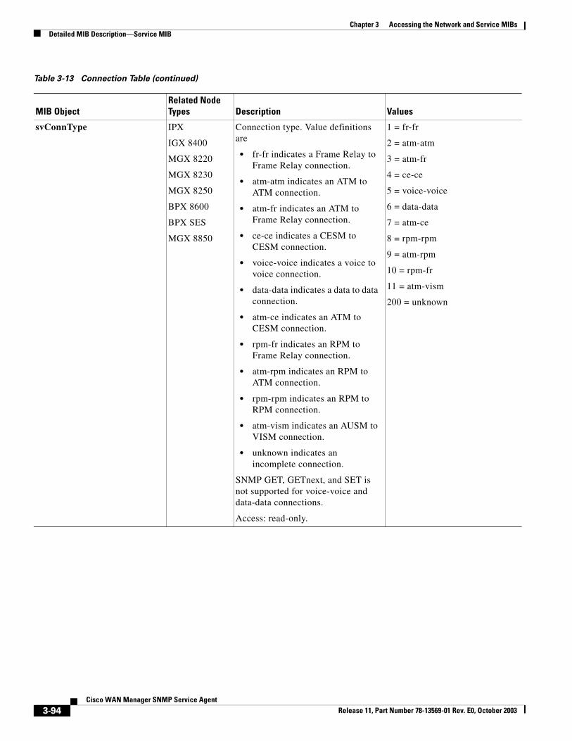
Chapter 3 Accessing the Network and Service MIBsDetailed MIB Description—Service MIB
svConnType IPX
IGX 8400
MGX 8220
MGX 8230
MGX 8250
BPX 8600
BPX SES
MGX 8850
Connection type. Value definitions are
• fr-fr indicates a Frame Relay to Frame Relay connection.
• atm-atm indicates an ATM to ATM connection.
• atm-fr indicates an ATM to Frame Relay connection.
• ce-ce indicates a CESM to CESM connection.
• voice-voice indicates a voice to voice connection.
• data-data indicates a data to data connection.
• atm-ce indicates an ATM to CESM connection.
• rpm-fr indicates an RPM to Frame Relay connection.
• atm-rpm indicates an RPM to ATM connection.
• rpm-rpm indicates an RPM to RPM connection.
• atm-vism indicates an AUSM to VISM connection.
• unknown indicates an incomplete connection.
SNMP GET, GETnext, and SET is not supported for voice-voice and data-data connections.
Access: read-only.
1 = fr-fr
2 = atm-atm
3 = atm-fr
4 = ce-ce
5 = voice-voice
6 = data-data
7 = atm-ce
8 = rpm-rpm
9 = atm-rpm
10 = rpm-fr
11 = atm-vism
200 = unknown
Table 3-13 Connection Table (continued)
MIB ObjectRelated Node Types Description Values
3-94Cisco WAN Manager SNMP Service Agent
Release 11, Part Number 78-13569-01 Rev. E0, October 2003
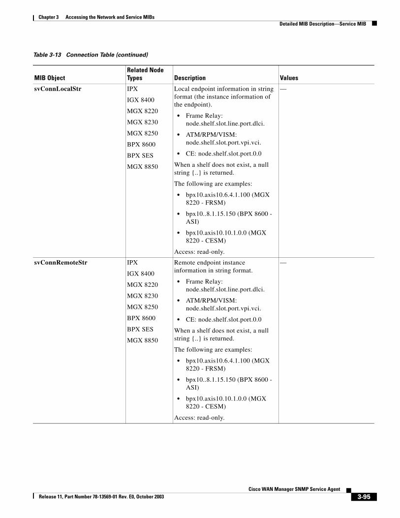
Chapter 3 Accessing the Network and Service MIBsDetailed MIB Description—Service MIB
svConnLocalStr IPX
IGX 8400
MGX 8220
MGX 8230
MGX 8250
BPX 8600
BPX SES
MGX 8850
Local endpoint information in string format (the instance information of the endpoint).
• Frame Relay: node.shelf.slot.line.port.dlci.
• ATM/RPM/VISM: node.shelf.slot.port.vpi.vci.
• CE: node.shelf.slot.port.0.0
When a shelf does not exist, a null string {..} is returned.
The following are examples:
• bpx10.axis10.6.4.1.100 (MGX 8220 - FRSM)
• bpx10..8.1.15.150 (BPX 8600 - ASI)
• bpx10.axis10.10.1.0.0 (MGX 8220 - CESM)
Access: read-only.
—
svConnRemoteStr IPX
IGX 8400
MGX 8220
MGX 8230
MGX 8250
BPX 8600
BPX SES
MGX 8850
Remote endpoint instance information in string format.
• Frame Relay: node.shelf.slot.line.port.dlci.
• ATM/RPM/VISM: node.shelf.slot.port.vpi.vci.
• CE: node.shelf.slot.port.0.0
When a shelf does not exist, a null string {..} is returned.
The following are examples:
• bpx10.axis10.6.4.1.100 (MGX 8220 - FRSM)
• bpx10..8.1.15.150 (BPX 8600 - ASI)
• bpx10.axis10.10.1.0.0 (MGX 8220 - CESM)
Access: read-only.
—
Table 3-13 Connection Table (continued)
MIB ObjectRelated Node Types Description Values
3-95Cisco WAN Manager SNMP Service Agent
Release 11, Part Number 78-13569-01 Rev. E0, October 2003
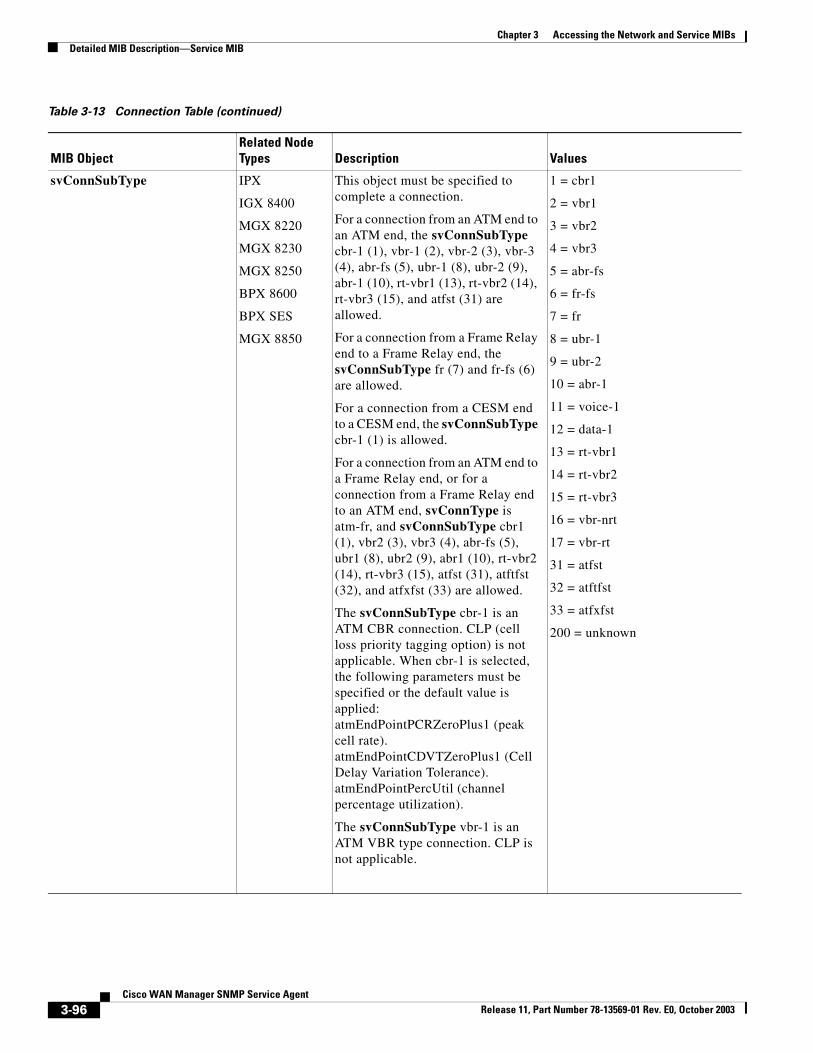
Chapter 3 Accessing the Network and Service MIBsDetailed MIB Description—Service MIB
svConnSubType IPX
IGX 8400
MGX 8220
MGX 8230
MGX 8250
BPX 8600
BPX SES
MGX 8850
This object must be specified to complete a connection.
For a connection from an ATM end to an ATM end, the svConnSubType cbr-1 (1), vbr-1 (2), vbr-2 (3), vbr-3 (4), abr-fs (5), ubr-1 (8), ubr-2 (9), abr-1 (10), rt-vbr1 (13), rt-vbr2 (14), rt-vbr3 (15), and atfst (31) are allowed.
For a connection from a Frame Relay end to a Frame Relay end, the svConnSubType fr (7) and fr-fs (6) are allowed.
For a connection from a CESM end to a CESM end, the svConnSubType cbr-1 (1) is allowed.
For a connection from an ATM end to a Frame Relay end, or for a connection from a Frame Relay end to an ATM end, svConnType is atm-fr, and svConnSubType cbr1 (1), vbr2 (3), vbr3 (4), abr-fs (5), ubr1 (8), ubr2 (9), abr1 (10), rt-vbr2 (14), rt-vbr3 (15), atfst (31), atftfst (32), and atfxfst (33) are allowed.
The svConnSubType cbr-1 is an ATM CBR connection. CLP (cell loss priority tagging option) is not applicable. When cbr-1 is selected, the following parameters must be specified or the default value is applied:atmEndPointPCRZeroPlus1 (peak cell rate).atmEndPointCDVTZeroPlus1 (Cell Delay Variation Tolerance).atmEndPointPercUtil (channel percentage utilization).
The svConnSubType vbr-1 is an ATM VBR type connection. CLP is not applicable.
1 = cbr1
2 = vbr1
3 = vbr2
4 = vbr3
5 = abr-fs
6 = fr-fs
7 = fr
8 = ubr-1
9 = ubr-2
10 = abr-1
11 = voice-1
12 = data-1
13 = rt-vbr1
14 = rt-vbr2
15 = rt-vbr3
16 = vbr-nrt
17 = vbr-rt
31 = atfst
32 = atftfst
33 = atfxfst
200 = unknown
Table 3-13 Connection Table (continued)
MIB ObjectRelated Node Types Description Values
3-96Cisco WAN Manager SNMP Service Agent
Release 11, Part Number 78-13569-01 Rev. E0, October 2003
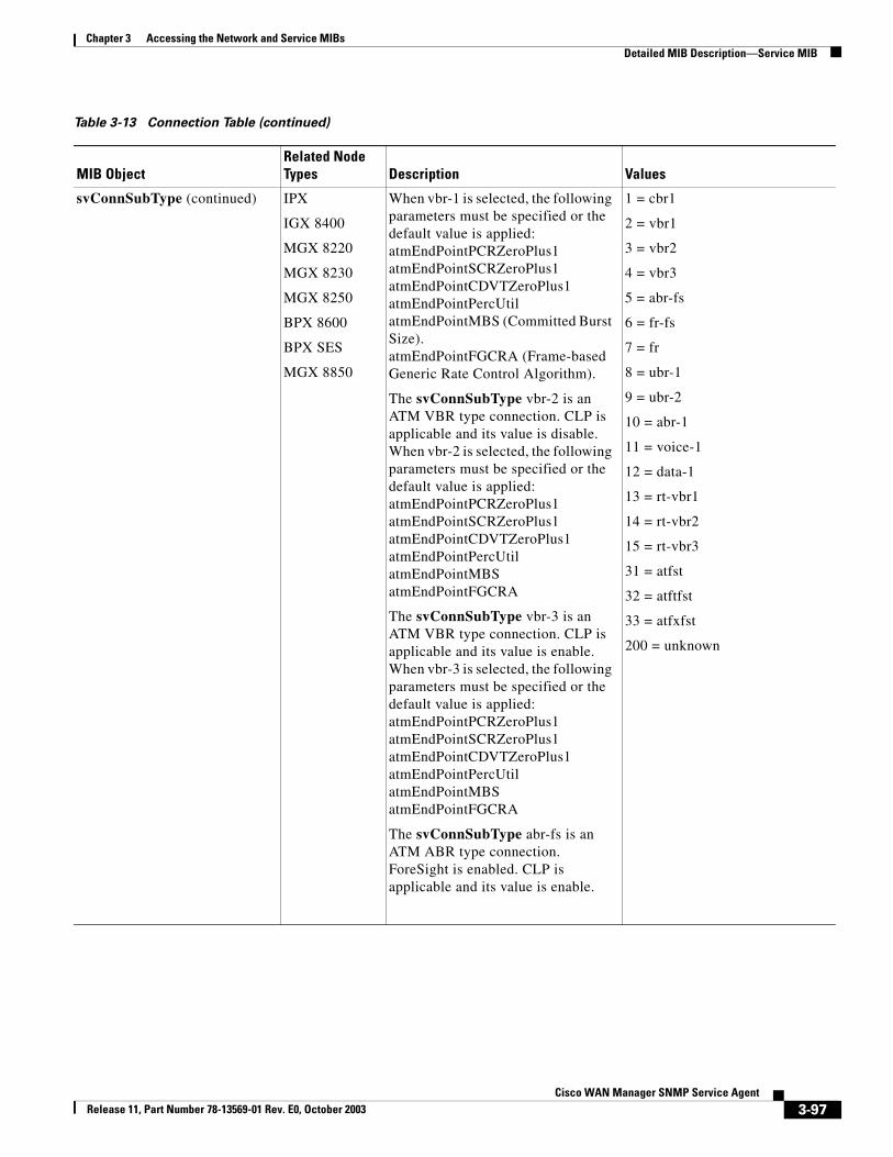
Chapter 3 Accessing the Network and Service MIBsDetailed MIB Description—Service MIB
svConnSubType (continued) IPX
IGX 8400
MGX 8220
MGX 8230
MGX 8250
BPX 8600
BPX SES
MGX 8850
When vbr-1 is selected, the following parameters must be specified or the default value is applied:atmEndPointPCRZeroPlus1atmEndPointSCRZeroPlus1atmEndPointCDVTZeroPlus1atmEndPointPercUtilatmEndPointMBS (Committed Burst Size).atmEndPointFGCRA (Frame-based Generic Rate Control Algorithm).
The svConnSubType vbr-2 is an ATM VBR type connection. CLP is applicable and its value is disable. When vbr-2 is selected, the following parameters must be specified or the default value is applied:atmEndPointPCRZeroPlus1atmEndPointSCRZeroPlus1atmEndPointCDVTZeroPlus1atmEndPointPercUtilatmEndPointMBSatmEndPointFGCRA
The svConnSubType vbr-3 is an ATM VBR type connection. CLP is applicable and its value is enable. When vbr-3 is selected, the following parameters must be specified or the default value is applied:atmEndPointPCRZeroPlus1atmEndPointSCRZeroPlus1atmEndPointCDVTZeroPlus1atmEndPointPercUtilatmEndPointMBSatmEndPointFGCRA
The svConnSubType abr-fs is an ATM ABR type connection. ForeSight is enabled. CLP is applicable and its value is enable.
1 = cbr1
2 = vbr1
3 = vbr2
4 = vbr3
5 = abr-fs
6 = fr-fs
7 = fr
8 = ubr-1
9 = ubr-2
10 = abr-1
11 = voice-1
12 = data-1
13 = rt-vbr1
14 = rt-vbr2
15 = rt-vbr3
31 = atfst
32 = atftfst
33 = atfxfst
200 = unknown
Table 3-13 Connection Table (continued)
MIB ObjectRelated Node Types Description Values
3-97Cisco WAN Manager SNMP Service Agent
Release 11, Part Number 78-13569-01 Rev. E0, October 2003
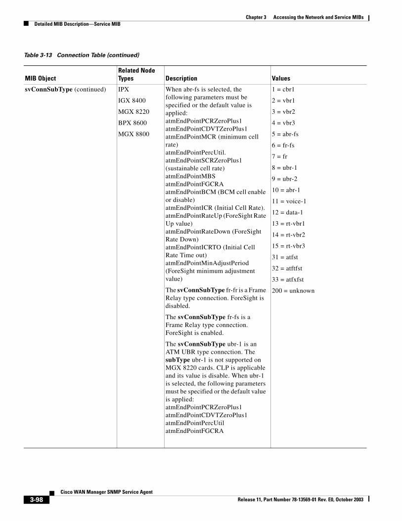
Chapter 3 Accessing the Network and Service MIBsDetailed MIB Description—Service MIB
svConnSubType (continued) IPX
IGX 8400
MGX 8220
BPX 8600
MGX 8800
When abr-fs is selected, the following parameters must be specified or the default value is applied:atmEndPointPCRZeroPlus1atmEndPointCDVTZeroPlus1atmEndPointMCR (minimum cell rate)atmEndPointPercUtil.atmEndPointSCRZeroPlus1 (sustainable cell rate)atmEndPointMBSatmEndPointFGCRAatmEndPointBCM (BCM cell enable or disable)atmEndPointICR (Initial Cell Rate).atmEndPointRateUp (ForeSight Rate Up value)atmEndPointRateDown (ForeSight Rate Down)atmEndPointICRTO (Initial Cell Rate Time out)atmEndPointMinAdjustPeriod (ForeSight minimum adjustment value)
The svConnSubType fr-fr is a Frame Relay type connection. ForeSight is disabled.
The svConnSubType fr-fs is a Frame Relay type connection. ForeSight is enabled.
The svConnSubType ubr-1 is an ATM UBR type connection. The subType ubr-1 is not supported on MGX 8220 cards. CLP is applicable and its value is disable. When ubr-1 is selected, the following parameters must be specified or the default value is applied:atmEndPointPCRZeroPlus1atmEndPointCDVTZeroPlus1atmEndPointPercUtilatmEndPointFGCRA
1 = cbr1
2 = vbr1
3 = vbr2
4 = vbr3
5 = abr-fs
6 = fr-fs
7 = fr
8 = ubr-1
9 = ubr-2
10 = abr-1
11 = voice-1
12 = data-1
13 = rt-vbr1
14 = rt-vbr2
15 = rt-vbr3
31 = atfst
32 = atftfst
33 = atfxfst
200 = unknown
Table 3-13 Connection Table (continued)
MIB ObjectRelated Node Types Description Values
3-98Cisco WAN Manager SNMP Service Agent
Release 11, Part Number 78-13569-01 Rev. E0, October 2003
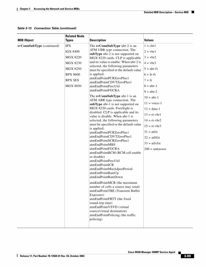
Chapter 3 Accessing the Network and Service MIBsDetailed MIB Description—Service MIB
svConnSubType (continued) IPX
IGX 8400
MGX 8220
MGX 8230
MGX 8250
BPX 8600
BPX SES
MGX 8850
The svConnSubType ubr-2 is an ATM UBR type connection. The subType ubr-2 is not supported on MGX 8220 cards. CLP is applicable and its value is enable. When ubr-2 is selected, the following parameters must be specified or the default value is applied:atmEndPointPCRZeroPlus1atmEndPointCDVTZeroPlus1atmEndPointPercUtilatmEndPointFGCRA
The svConnSubType abr-1 is an ATM ABR type connection. The subType abr-1 is not supported on MGX 8220 cards. ForeSight is disabled. CLP is applicable and its value is disable. When abr-1 is selected, the following parameters must be specified or the default value is applied:atmEndPointPCRZeroPlus1atmEndPointCDVTZeroPlus1atmEndPointSCRZeroPlus1atmEndPointMBSatmEndPointFGCRAatmEndPointBCM (BCM cell enable or disable)atmEndPointPercUtilatmEndPointICRatmEndPointMinAdjustPeriodatmEndPointRateUpatmEndPointRateDown
atmEndPointMCR (the maximum number of cells a source may send)atmEndPointTBE (Transient Buffer Exposure)atmEndPointFRTT (the fixed round-trip time)atmEndPointVSVD (virtual source/virtual destination)atmEndPointPolicing (the traffic policing)
1 = cbr1
2 = vbr1
3 = vbr2
4 = vbr3
5 = abr-fs
6 = fr-fs
7 = fr
8 = ubr-1
9 = ubr-2
10 = abr-1
11 = voice-1
12 = data-1
13 = rt-vbr1
14 = rt-vbr2
15 = rt-vbr3
31 = atfst
32 = atftfst
33 = atfxfst
200 = unknown
Table 3-13 Connection Table (continued)
MIB ObjectRelated Node Types Description Values
3-99Cisco WAN Manager SNMP Service Agent
Release 11, Part Number 78-13569-01 Rev. E0, October 2003
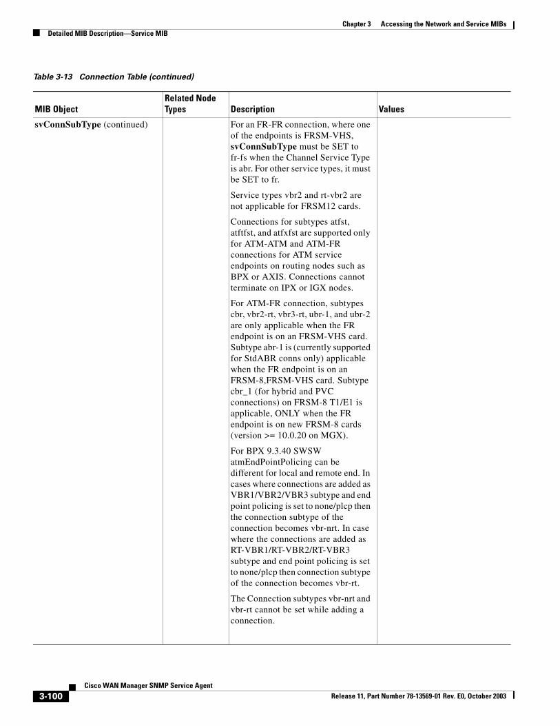
Chapter 3 Accessing the Network and Service MIBsDetailed MIB Description—Service MIB
svConnSubType (continued) For an FR-FR connection, where one of the endpoints is FRSM-VHS, svConnSubType must be SET to fr-fs when the Channel Service Type is abr. For other service types, it must be SET to fr.
Service types vbr2 and rt-vbr2 are not applicable for FRSM12 cards.
Connections for subtypes atfst, atftfst, and atfxfst are supported only for ATM-ATM and ATM-FR connections for ATM service endpoints on routing nodes such as BPX or AXIS. Connections cannot terminate on IPX or IGX nodes.
For ATM-FR connection, subtypes cbr, vbr2-rt, vbr3-rt, ubr-1, and ubr-2 are only applicable when the FR endpoint is on an FRSM-VHS card. Subtype abr-1 is (currently supported for StdABR conns only) applicable when the FR endpoint is on an FRSM-8,FRSM-VHS card. Subtype cbr_1 (for hybrid and PVC connections) on FRSM-8 T1/E1 is applicable, ONLY when the FR endpoint is on new FRSM-8 cards (version >= 10.0.20 on MGX).
For BPX 9.3.40 SWSW atmEndPointPolicing can be different for local and remote end. In cases where connections are added as VBR1/VBR2/VBR3 subtype and end point policing is set to none/plcp then the connection subtype of the connection becomes vbr-nrt. In case where the connections are added as RT-VBR1/RT-VBR2/RT-VBR3 subtype and end point policing is set to none/plcp then connection subtype of the connection becomes vbr-rt.
The Connection subtypes vbr-nrt and vbr-rt cannot be set while adding a connection.
Table 3-13 Connection Table (continued)
MIB ObjectRelated Node Types Description Values
3-100Cisco WAN Manager SNMP Service Agent
Release 11, Part Number 78-13569-01 Rev. E0, October 2003
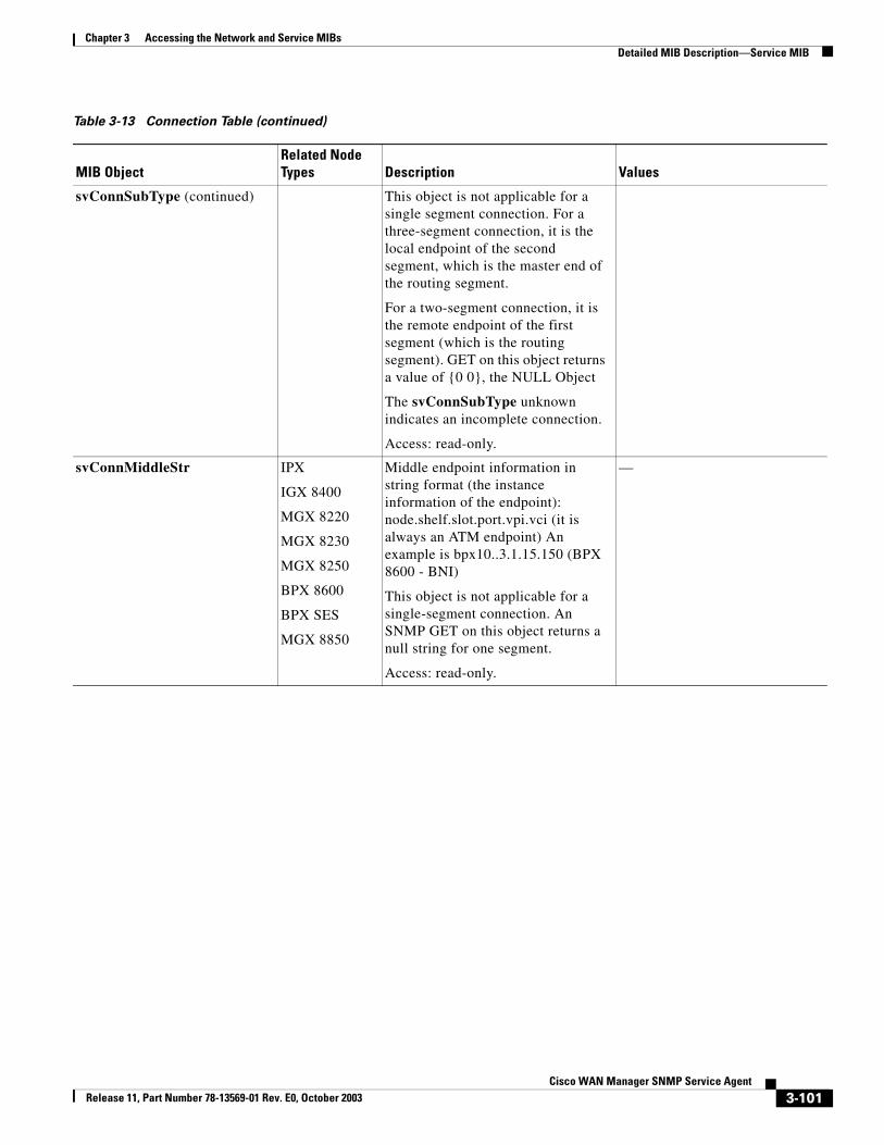
Chapter 3 Accessing the Network and Service MIBsDetailed MIB Description—Service MIB
svConnSubType (continued) This object is not applicable for a single segment connection. For a three-segment connection, it is the local endpoint of the second segment, which is the master end of the routing segment.
For a two-segment connection, it is the remote endpoint of the first segment (which is the routing segment). GET on this object returns a value of {0 0}, the NULL Object
The svConnSubType unknown indicates an incomplete connection.
Access: read-only.
svConnMiddleStr IPX
IGX 8400
MGX 8220
MGX 8230
MGX 8250
BPX 8600
BPX SES
MGX 8850
Middle endpoint information in string format (the instance information of the endpoint): node.shelf.slot.port.vpi.vci (it is always an ATM endpoint) An example is bpx10..3.1.15.150 (BPX 8600 - BNI)
This object is not applicable for a single-segment connection. An SNMP GET on this object returns a null string for one segment.
Access: read-only.
—
Table 3-13 Connection Table (continued)
MIB ObjectRelated Node Types Description Values
3-101Cisco WAN Manager SNMP Service Agent
Release 11, Part Number 78-13569-01 Rev. E0, October 2003
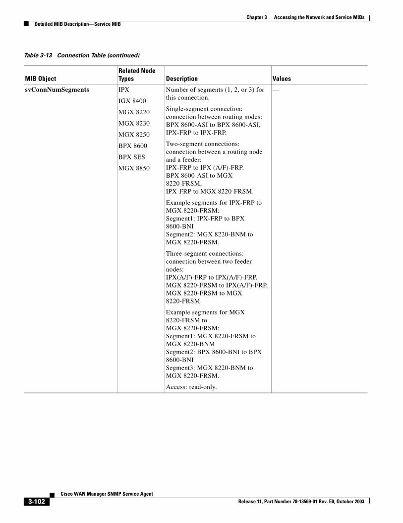
Chapter 3 Accessing the Network and Service MIBsDetailed MIB Description—Service MIB
svConnNumSegments IPX
IGX 8400
MGX 8220
MGX 8230
MGX 8250
BPX 8600
BPX SES
MGX 8850
Number of segments (1, 2, or 3) for this connection.
Single-segment connection: connection between routing nodes: BPX 8600-ASI to BPX 8600-ASI, IPX-FRP to IPX-FRP.
Two-segment connections: connection between a routing node and a feeder:IPX-FRP to IPX (A/F)-FRP,BPX 8600-ASI to MGX 8220-FRSM,IPX-FRP to MGX 8220-FRSM.
Example segments for IPX-FRP toMGX 8220-FRSM:Segment1: IPX-FRP to BPX 8600-BNISegment2: MGX 8220-BNM to MGX 8220-FRSM.
Three-segment connections: connection between two feeder nodes:IPX(A/F)-FRP to IPX(A/F)-FRP,MGX 8220-FRSM to IPX(A/F)-FRP,MGX 8220-FRSM to MGX 8220-FRSM.
Example segments for MGX 8220-FRSM toMGX 8220-FRSM:Segment1: MGX 8220-FRSM to MGX 8220-BNMSegment2: BPX 8600-BNI to BPX 8600-BNISegment3: MGX 8220-BNM to MGX 8220-FRSM.
Access: read-only.
—
Table 3-13 Connection Table (continued)
MIB ObjectRelated Node Types Description Values
3-102Cisco WAN Manager SNMP Service Agent
Release 11, Part Number 78-13569-01 Rev. E0, October 2003
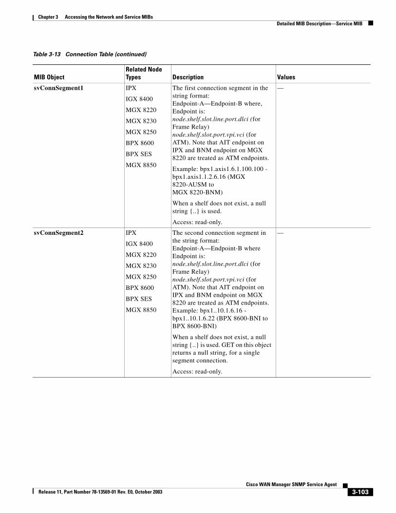
Chapter 3 Accessing the Network and Service MIBsDetailed MIB Description—Service MIB
svConnSegment1 IPX
IGX 8400
MGX 8220
MGX 8230
MGX 8250
BPX 8600
BPX SES
MGX 8850
The first connection segment in the string format: Endpoint-A—Endpoint-B where, Endpoint is: node.shelf.slot.line.port.dlci (for Frame Relay) node.shelf.slot.port.vpi.vci (for ATM). Note that AIT endpoint on IPX and BNM endpoint on MGX 8220 are treated as ATM endpoints.
Example: bpx1.axis1.6.1.100.100 - bpx1.axis1.1.2.6.16 (MGX 8220-AUSM toMGX 8220-BNM)
When a shelf does not exist, a null string {..} is used.
Access: read-only.
—
svConnSegment2 IPX
IGX 8400
MGX 8220
MGX 8230
MGX 8250
BPX 8600
BPX SES
MGX 8850
The second connection segment in the string format: Endpoint-A—Endpoint-B where Endpoint is: node.shelf.slot.line.port.dlci (for Frame Relay) node.shelf.slot.port.vpi.vci (for ATM). Note that AIT endpoint on IPX and BNM endpoint on MGX 8220 are treated as ATM endpoints.Example: bpx1..10.1.6.16 - bpx1..10.1.6.22 (BPX 8600-BNI to BPX 8600-BNI)
When a shelf does not exist, a null string {..} is used. GET on this object returns a null string, for a single segment connection.
Access: read-only.
—
Table 3-13 Connection Table (continued)
MIB ObjectRelated Node Types Description Values
3-103Cisco WAN Manager SNMP Service Agent
Release 11, Part Number 78-13569-01 Rev. E0, October 2003
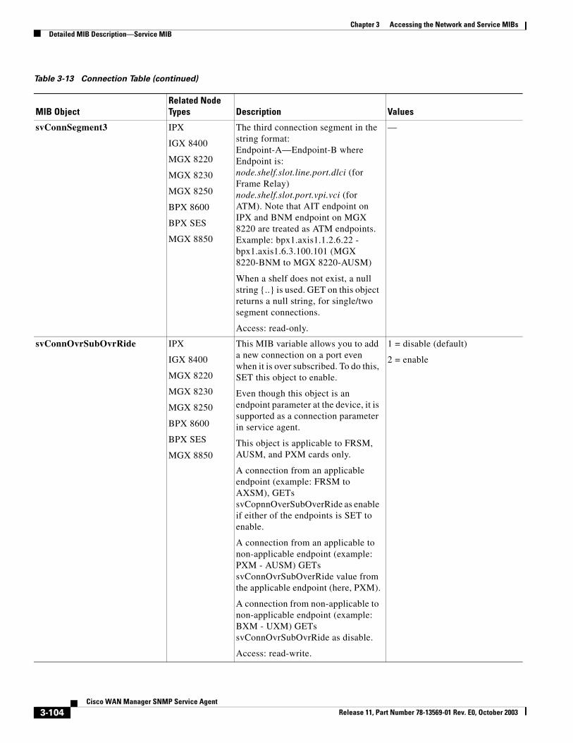
Chapter 3 Accessing the Network and Service MIBsDetailed MIB Description—Service MIB
svConnSegment3 IPX
IGX 8400
MGX 8220
MGX 8230
MGX 8250
BPX 8600
BPX SES
MGX 8850
The third connection segment in the string format: Endpoint-A—Endpoint-B where Endpoint is: node.shelf.slot.line.port.dlci (for Frame Relay) node.shelf.slot.port.vpi.vci (for ATM). Note that AIT endpoint on IPX and BNM endpoint on MGX 8220 are treated as ATM endpoints.Example: bpx1.axis1.1.2.6.22 - bpx1.axis1.6.3.100.101 (MGX 8220-BNM to MGX 8220-AUSM)
When a shelf does not exist, a null string {..} is used. GET on this object returns a null string, for single/two segment connections.
Access: read-only.
—
svConnOvrSubOvrRide IPX
IGX 8400
MGX 8220
MGX 8230
MGX 8250
BPX 8600
BPX SES
MGX 8850
This MIB variable allows you to add a new connection on a port even when it is over subscribed. To do this, SET this object to enable.
Even though this object is an endpoint parameter at the device, it is supported as a connection parameter in service agent.
This object is applicable to FRSM, AUSM, and PXM cards only.
A connection from an applicable endpoint (example: FRSM to AXSM), GETs svCopnnOverSubOverRide as enable if either of the endpoints is SET to enable.
A connection from an applicable to non-applicable endpoint (example: PXM - AUSM) GETs svConnOvrSubOverRide value from the applicable endpoint (here, PXM).
A connection from non-applicable to non-applicable endpoint (example: BXM - UXM) GETs svConnOvrSubOvrRide as disable.
Access: read-write.
1 = disable (default)
2 = enable
Table 3-13 Connection Table (continued)
MIB ObjectRelated Node Types Description Values
3-104Cisco WAN Manager SNMP Service Agent
Release 11, Part Number 78-13569-01 Rev. E0, October 2003
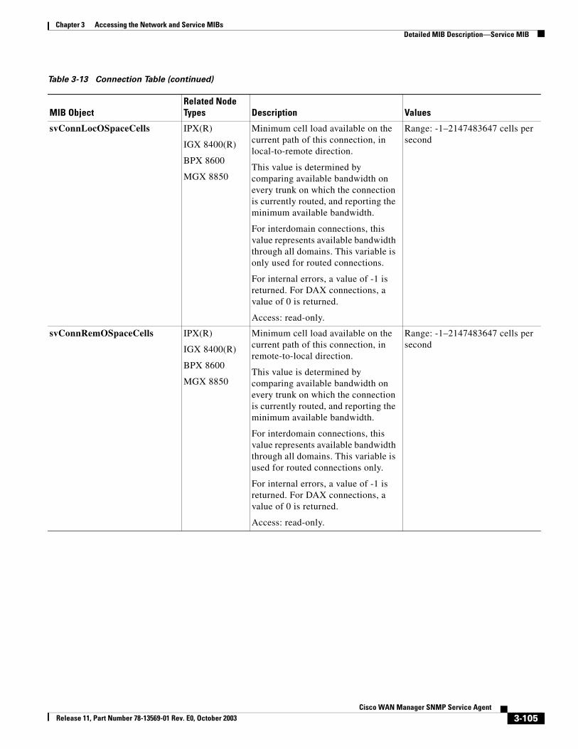
Chapter 3 Accessing the Network and Service MIBsDetailed MIB Description—Service MIB
svConnLocOSpaceCells IPX(R)
IGX 8400(R)
BPX 8600
MGX 8850
Minimum cell load available on the current path of this connection, in local-to-remote direction.
This value is determined by comparing available bandwidth on every trunk on which the connection is currently routed, and reporting the minimum available bandwidth.
For interdomain connections, this value represents available bandwidth through all domains. This variable is only used for routed connections.
For internal errors, a value of -1 is returned. For DAX connections, a value of 0 is returned.
Access: read-only.
Range: -1–2147483647 cells per second
svConnRemOSpaceCells IPX(R)
IGX 8400(R)
BPX 8600
MGX 8850
Minimum cell load available on the current path of this connection, in remote-to-local direction.
This value is determined by comparing available bandwidth on every trunk on which the connection is currently routed, and reporting the minimum available bandwidth.
For interdomain connections, this value represents available bandwidth through all domains. This variable is used for routed connections only.
For internal errors, a value of -1 is returned. For DAX connections, a value of 0 is returned.
Access: read-only.
Range: -1–2147483647 cells per second
Table 3-13 Connection Table (continued)
MIB ObjectRelated Node Types Description Values
3-105Cisco WAN Manager SNMP Service Agent
Release 11, Part Number 78-13569-01 Rev. E0, October 2003
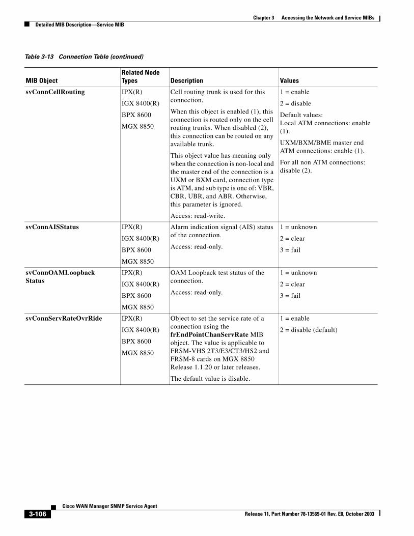
Chapter 3 Accessing the Network and Service MIBsDetailed MIB Description—Service MIB
svConnCellRouting IPX(R)
IGX 8400(R)
BPX 8600
MGX 8850
Cell routing trunk is used for this connection.
When this object is enabled (1), this connection is routed only on the cell routing trunks. When disabled (2), this connection can be routed on any available trunk.
This object value has meaning only when the connection is non-local and the master end of the connection is a UXM or BXM card, connection type is ATM, and sub type is one of: VBR, CBR, UBR, and ABR. Otherwise, this parameter is ignored.
Access: read-write.
1 = enable
2 = disable
Default values:Local ATM connections: enable (1).
UXM/BXM/BME master end ATM connections: enable (1).
For all non ATM connections: disable (2).
svConnAISStatus IPX(R)
IGX 8400(R)
BPX 8600
MGX 8850
Alarm indication signal (AIS) status of the connection.
Access: read-only.
1 = unknown
2 = clear
3 = fail
svConnOAMLoopbackStatus
IPX(R)
IGX 8400(R)
BPX 8600
MGX 8850
OAM Loopback test status of the connection.
Access: read-only.
1 = unknown
2 = clear
3 = fail
svConnServRateOvrRide IPX(R)
IGX 8400(R)
BPX 8600
MGX 8850
Object to set the service rate of a connection using the frEndPointChanServRate MIB object. The value is applicable to FRSM-VHS 2T3/E3/CT3/HS2 and FRSM-8 cards on MGX 8850 Release 1.1.20 or later releases.
The default value is disable.
1 = enable
2 = disable (default)
Table 3-13 Connection Table (continued)
MIB ObjectRelated Node Types Description Values
3-106Cisco WAN Manager SNMP Service Agent
Release 11, Part Number 78-13569-01 Rev. E0, October 2003
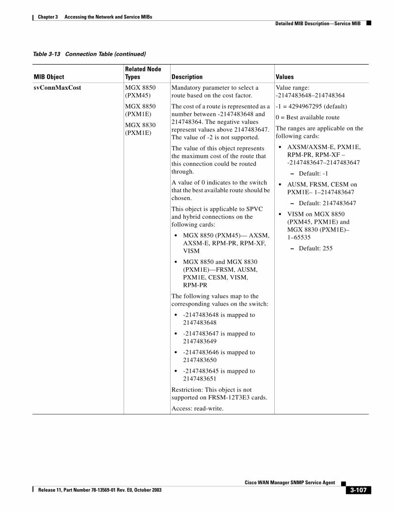
Chapter 3 Accessing the Network and Service MIBsDetailed MIB Description—Service MIB
svConnMaxCost MGX 8850 (PXM45)
MGX 8850 (PXM1E)
MGX 8830 (PXM1E)
Mandatory parameter to select a route based on the cost factor.
The cost of a route is represented as a number between -2147483648 and 214748364. The negative values represent values above 2147483647. The value of -2 is not supported.
The value of this object represents the maximum cost of the route that this connection could be routed through.
A value of 0 indicates to the switch that the best available route should be chosen.
This object is applicable to SPVC and hybrid connections on the following cards:
• MGX 8850 (PXM45)— AXSM, AXSM-E, RPM-PR, RPM-XF, VISM
• MGX 8850 and MGX 8830 (PXM1E)—FRSM, AUSM, PXM1E, CESM, VISM, RPM-PR
The following values map to the corresponding values on the switch:
• -2147483648 is mapped to 2147483648
• -2147483647 is mapped to 2147483649
• -2147483646 is mapped to 2147483650
• -2147483645 is mapped to 2147483651
Restriction: This object is not supported on FRSM-12T3E3 cards.
Access: read-write.
Value range: -2147483648–214748364
-1 = 4294967295 (default)
0 = Best available route
The ranges are applicable on the following cards:
• AXSM/AXSM-E, PXM1E, RPM-PR, RPM-XF – -2147483647–2147483647
– Default: -1
• AUSM, FRSM, CESM on PXM1E– 1–2147483647
– Default: 2147483647
• VISM on MGX 8850 (PXM45, PXM1E) and MGX 8830 (PXM1E)– 1–65535
– Default: 255
Table 3-13 Connection Table (continued)
MIB ObjectRelated Node Types Description Values
3-107Cisco WAN Manager SNMP Service Agent
Release 11, Part Number 78-13569-01 Rev. E0, October 2003
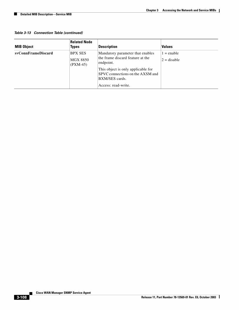
Chapter 3 Accessing the Network and Service MIBsDetailed MIB Description—Service MIB
svConnFrameDiscard BPX SES
MGX 8850 (PXM-45)
Mandatory parameter that enables the frame discard feature at the endpoint.
This object is only applicable for SPVC connections on the AXSM and BXM/SES cards.
Access: read-write.
1 = enable
2 = disable
Table 3-13 Connection Table (continued)
MIB ObjectRelated Node Types Description Values
3-108Cisco WAN Manager SNMP Service Agent
Release 11, Part Number 78-13569-01 Rev. E0, October 2003
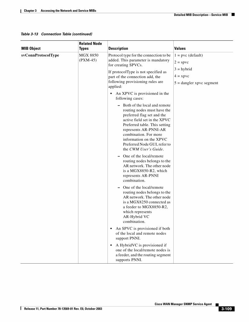
Chapter 3 Accessing the Network and Service MIBsDetailed MIB Description—Service MIB
svConnProtocolType MGX 8850 (PXM-45)
Protocol type for the connection to be added. This parameter is mandatory for creating SPVCs.
If protocolType is not specified as part of the connection add, the following provisioning rules are applied:
• An XPVC is provisioned in the following cases:
– Both of the local and remote routing nodes must have the preferred flag set and the active field set in the XPVC Preferred table. This setting represents AR-PNNI-AR combination. For more information on the XPVC Preferred Node GUI, refer to the CWM User’s Guide.
– One of the local/remote routing nodes belongs to the AR network. The other node is a MGX8850-R2, which represents AR-PNNI combination.
– One of the local/remote routing nodes belongs to the AR network. The other node is a MGX8250 connected as a feeder to MGX8850-R2, which represents AR-Hybrid VC combination.
• An SPVC is provisioned if both of the local and remote nodes support PNNI.
• A HybridVC is provisioned if one of the local/remote nodes is a feeder, and the routing segment supports PNNI.
1 = pvc (default)
2 = spvc
3 = hybrid
4 = xpvc
5 = dangler xpvc segment
Table 3-13 Connection Table (continued)
MIB ObjectRelated Node Types Description Values
3-109Cisco WAN Manager SNMP Service Agent
Release 11, Part Number 78-13569-01 Rev. E0, October 2003
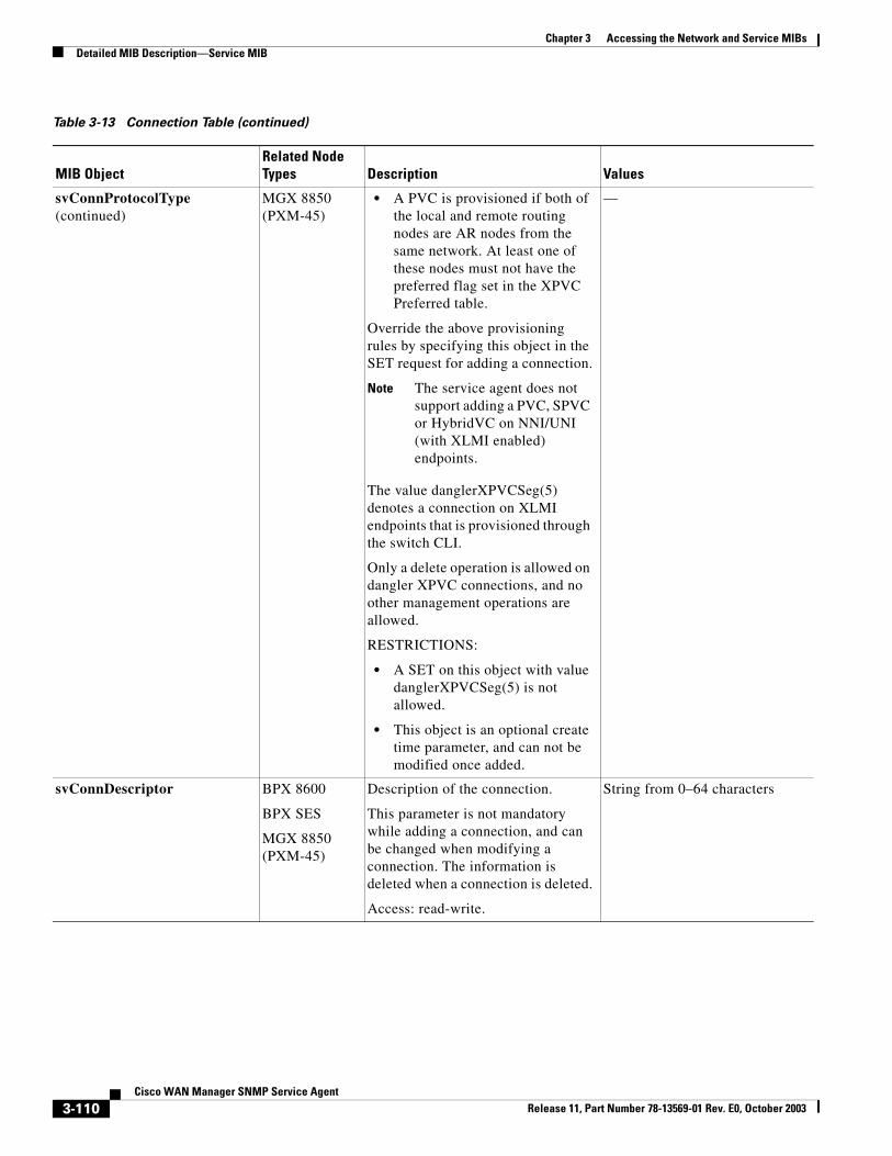
Chapter 3 Accessing the Network and Service MIBsDetailed MIB Description—Service MIB
svConnProtocolType (continued)
MGX 8850 (PXM-45)
• A PVC is provisioned if both of the local and remote routing nodes are AR nodes from the same network. At least one of these nodes must not have the preferred flag set in the XPVC Preferred table.
Override the above provisioning rules by specifying this object in the SET request for adding a connection.
Note The service agent does not support adding a PVC, SPVC or HybridVC on NNI/UNI (with XLMI enabled) endpoints.
The value danglerXPVCSeg(5) denotes a connection on XLMI endpoints that is provisioned through the switch CLI.
Only a delete operation is allowed on dangler XPVC connections, and no other management operations are allowed.
RESTRICTIONS:
• A SET on this object with value danglerXPVCSeg(5) is not allowed.
• This object is an optional create time parameter, and can not be modified once added.
—
svConnDescriptor BPX 8600
BPX SES
MGX 8850 (PXM-45)
Description of the connection.
This parameter is not mandatory while adding a connection, and can be changed when modifying a connection. The information is deleted when a connection is deleted.
Access: read-write.
String from 0–64 characters
Table 3-13 Connection Table (continued)
MIB ObjectRelated Node Types Description Values
3-110Cisco WAN Manager SNMP Service Agent
Release 11, Part Number 78-13569-01 Rev. E0, October 2003

Chapter 3 Accessing the Network and Service MIBsDetailed MIB Description—Service MIB
svConnAbrERS MGX 8850 (PXM-45)
Mandatory parameter that configures an endpoint for explicit rate stamping.
This object is applicable to ABR1 connections on AXSM cards.
The object is used for three-segment hybrid connections, where AXSM is not one of the local or remote endpoints.
For SPVC and two-segment hybrid connections, use the atmEndPointAbrERS object.
Access: read-write.
1 = none
2 = enable ingress
3 = enable egress
4 = enable both
svConnEnableStats BPX 8600
BPX SES
MGX 8850 (PXM-45)
Mandatory parameter that enables and disables statistics collection on a per connection basis.
This object is applicable for AXSM and BXM/SES cards.
The object is used for three-segment hybrid connections, where AXSM and BXM/SES are not one of the local or remote endpoints.
For SPVC and two-segment hybrid connections, use the atmEndPointEnableStats object.
Access: read-write.
1 = enable
2 = disable
svConnEnableCC MGX 8850 (PXM-45)
Mandatory parameter that enables or disables continuity check (CC) on a connection endpoint.
This object is applicable for AXSM cards.
The object is used for three-segment hybrid connections, where AXSM is not one of the local or remote endpoints.
For SPVC and two-segment hybrid connections, use the atmEndPointEnableCC object.
Access: read-write.
1 = enable
2 = disable
Table 3-13 Connection Table (continued)
MIB ObjectRelated Node Types Description Values
3-111Cisco WAN Manager SNMP Service Agent
Release 11, Part Number 78-13569-01 Rev. E0, October 2003
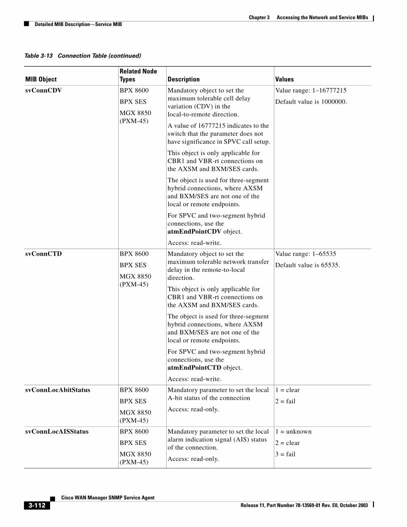
Chapter 3 Accessing the Network and Service MIBsDetailed MIB Description—Service MIB
svConnCDV BPX 8600
BPX SES
MGX 8850 (PXM-45)
Mandatory object to set the maximum tolerable cell delay variation (CDV) in the local-to-remote direction.
A value of 16777215 indicates to the switch that the parameter does not have significance in SPVC call setup.
This object is only applicable for CBR1 and VBR-rt connections on the AXSM and BXM/SES cards.
The object is used for three-segment hybrid connections, where AXSM and BXM/SES are not one of the local or remote endpoints.
For SPVC and two-segment hybrid connections, use the atmEndPointCDV object.
Access: read-write.
Value range: 1–16777215
Default value is 1000000.
svConnCTD BPX 8600
BPX SES
MGX 8850 (PXM-45)
Mandatory object to set the maximum tolerable network transfer delay in the remote-to-local direction.
This object is only applicable for CBR1 and VBR-rt connections on the AXSM and BXM/SES cards.
The object is used for three-segment hybrid connections, where AXSM and BXM/SES are not one of the local or remote endpoints.
For SPVC and two-segment hybrid connections, use the atmEndPointCTD object.
Access: read-write.
Value range: 1–65535
Default value is 65535.
svConnLocAbitStatus BPX 8600
BPX SES
MGX 8850 (PXM-45)
Mandatory parameter to set the local A-bit status of the connection
Access: read-only.
1 = clear
2 = fail
svConnLocAISStatus BPX 8600
BPX SES
MGX 8850 (PXM-45)
Mandatory parameter to set the local alarm indication signal (AIS) status of the connection.
Access: read-only.
1 = unknown
2 = clear
3 = fail
Table 3-13 Connection Table (continued)
MIB ObjectRelated Node Types Description Values
3-112Cisco WAN Manager SNMP Service Agent
Release 11, Part Number 78-13569-01 Rev. E0, October 2003
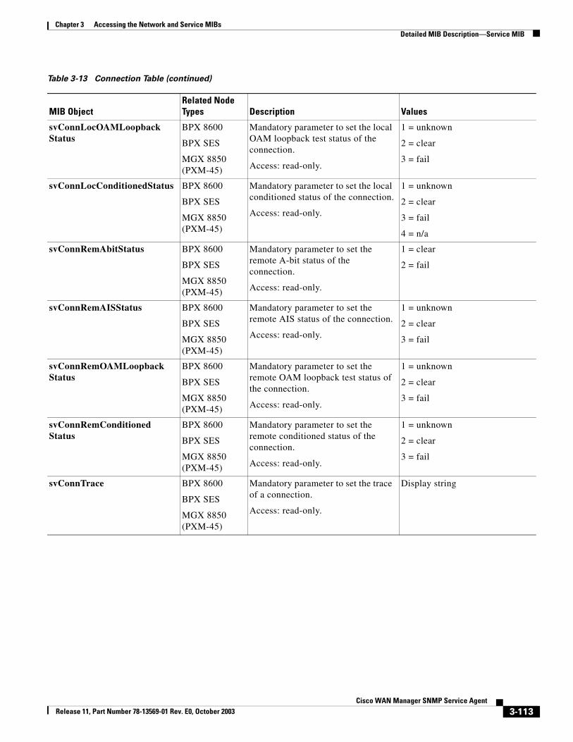
Chapter 3 Accessing the Network and Service MIBsDetailed MIB Description—Service MIB
svConnLocOAMLoopbackStatus
BPX 8600
BPX SES
MGX 8850 (PXM-45)
Mandatory parameter to set the local OAM loopback test status of the connection.
Access: read-only.
1 = unknown
2 = clear
3 = fail
svConnLocConditionedStatus BPX 8600
BPX SES
MGX 8850 (PXM-45)
Mandatory parameter to set the local conditioned status of the connection.
Access: read-only.
1 = unknown
2 = clear
3 = fail
4 = n/a
svConnRemAbitStatus BPX 8600
BPX SES
MGX 8850 (PXM-45)
Mandatory parameter to set the remote A-bit status of the connection.
Access: read-only.
1 = clear
2 = fail
svConnRemAISStatus BPX 8600
BPX SES
MGX 8850 (PXM-45)
Mandatory parameter to set the remote AIS status of the connection.
Access: read-only.
1 = unknown
2 = clear
3 = fail
svConnRemOAMLoopbackStatus
BPX 8600
BPX SES
MGX 8850 (PXM-45)
Mandatory parameter to set the remote OAM loopback test status of the connection.
Access: read-only.
1 = unknown
2 = clear
3 = fail
svConnRemConditionedStatus
BPX 8600
BPX SES
MGX 8850 (PXM-45)
Mandatory parameter to set the remote conditioned status of the connection.
Access: read-only.
1 = unknown
2 = clear
3 = fail
svConnTrace BPX 8600
BPX SES
MGX 8850 (PXM-45)
Mandatory parameter to set the trace of a connection.
Access: read-only.
Display string
Table 3-13 Connection Table (continued)
MIB ObjectRelated Node Types Description Values
3-113Cisco WAN Manager SNMP Service Agent
Release 11, Part Number 78-13569-01 Rev. E0, October 2003
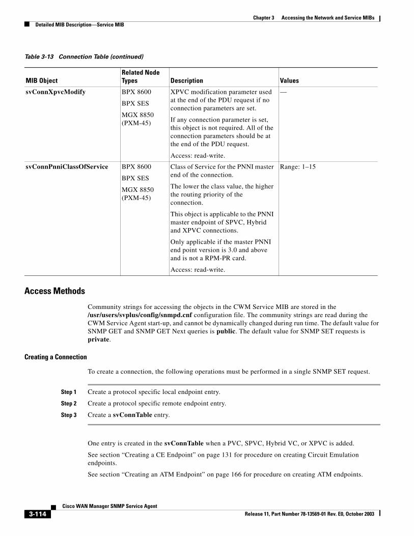
Chapter 3 Accessing the Network and Service MIBsDetailed MIB Description—Service MIB
Access Methods
Community strings for accessing the objects in the CWM Service MIB are stored in the /usr/users/svplus/config/snmpd.cnf configuration file. The community strings are read during the CWM Service Agent start-up, and cannot be dynamically changed during run time. The default value for SNMP GET and SNMP GET Next queries is public. The default value for SNMP SET requests is private.
Creating a Connection
To create a connection, the following operations must be performed in a single SNMP SET request.
Step 1 Create a protocol specific local endpoint entry.
Step 2 Create a protocol specific remote endpoint entry.
Step 3 Create a svConnTable entry.
One entry is created in the svConnTable when a PVC, SPVC, Hybrid VC, or XPVC is added.
See section “Creating a CE Endpoint” on page 131 for procedure on creating Circuit Emulation endpoints.
See section “Creating an ATM Endpoint” on page 166 for procedure on creating ATM endpoints.
svConnXpvcModify BPX 8600
BPX SES
MGX 8850 (PXM-45)
XPVC modification parameter used at the end of the PDU request if no connection parameters are set.
If any connection parameter is set, this object is not required. All of the connection parameters should be at the end of the PDU request.
Access: read-write.
—
svConnPnniClassOfService BPX 8600
BPX SES
MGX 8850 (PXM-45)
Class of Service for the PNNI master end of the connection.
The lower the class value, the higher the routing priority of the connection.
This object is applicable to the PNNI master endpoint of SPVC, Hybrid and XPVC connections.
Only applicable if the master PNNI end point version is 3.0 and above and is not a RPM-PR card.
Access: read-write.
Range: 1–15
Table 3-13 Connection Table (continued)
MIB ObjectRelated Node Types Description Values
3-114Cisco WAN Manager SNMP Service Agent
Release 11, Part Number 78-13569-01 Rev. E0, October 2003
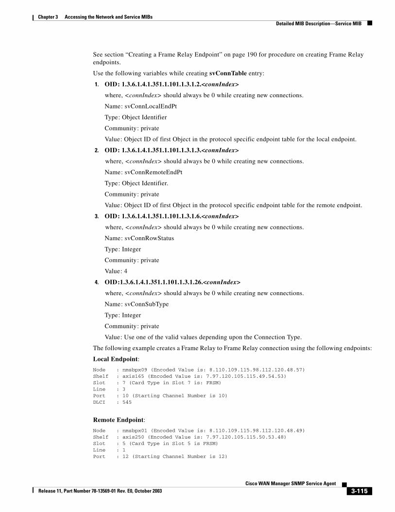
Chapter 3 Accessing the Network and Service MIBsDetailed MIB Description—Service MIB
See section “Creating a Frame Relay Endpoint” on page 190 for procedure on creating Frame Relay endpoints.
Use the following variables while creating svConnTable entry:
1. OID: 1.3.6.1.4.1.351.1.101.1.3.1.2.<connIndex>
where, <connIndex> should always be 0 while creating new connections.
Name: svConnLocalEndPt
Type: Object Identifier
Community: private
Value: Object ID of first Object in the protocol specific endpoint table for the local endpoint.
2. OID: 1.3.6.1.4.1.351.1.101.1.3.1.3.<connIndex>
where, <connIndex> should always be 0 while creating new connections.
Name: svConnRemoteEndPt
Type: Object Identifier.
Community: private
Value: Object ID of first Object in the protocol specific endpoint table for the remote endpoint.
3. OID: 1.3.6.1.4.1.351.1.101.1.3.1.6.<connIndex>
where, <connIndex> should always be 0 while creating new connections.
Name: svConnRowStatus
Type: Integer
Community: private
Value: 4
4. OID:1.3.6.1.4.1.351.1.101.1.3.1.26.<connIndex>
where, <connIndex> should always be 0 while creating new connections.
Name: svConnSubType
Type: Integer
Community: private
Value: Use one of the valid values depending upon the Connection Type.
The following example creates a Frame Relay to Frame Relay connection using the following endpoints:
Local Endpoint:
Node : nmsbpx09 (Encoded Value is: 8.110.109.115.98.112.120.48.57)Shelf : axis165 (Encoded Value is: 7.97.120.105.115.49.54.53)Slot : 7 (Card Type in Slot 7 is: FRSM)Line : 3Port : 10 (Starting Channel Number is 10)DLCI : 545
Remote Endpoint:
Node : nmsbpx01 (Encoded Value is: 8.110.109.115.98.112.120.48.49)Shelf : axis250 (Encoded Value is: 7.97.120.105.115.50.53.48)Slot : 5 (Card Type in Slot 5 is FRSM)Line : 1Port : 12 (Starting Channel Number is 12)
3-115Cisco WAN Manager SNMP Service Agent
Release 11, Part Number 78-13569-01 Rev. E0, October 2003
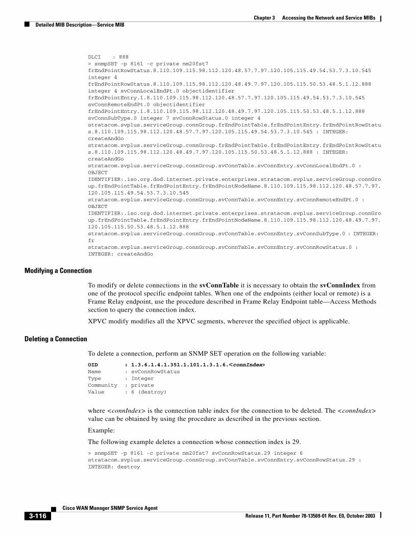
Chapter 3 Accessing the Network and Service MIBsDetailed MIB Description—Service MIB
DLCI : 888> snmpSET -p 8161 -c private nm20fst7 frEndPointRowStatus.8.110.109.115.98.112.120.48.57.7.97.120.105.115.49.54.53.7.3.10.545 integer 4 frEndPointRowStatus.8.110.109.115.98.112.120.48.49.7.97.120.105.115.50.53.48.5.1.12.888 integer 4 svConnLocalEndPt.0 objectidentifier frEndPointEntry.1.8.110.109.115.98.112.120.48.57.7.97.120.105.115.49.54.53.7.3.10.545 svConnRemoteEndPt.0 objectidentifier frEndPointEntry.1.8.110.109.115.98.112.120.48.49.7.97.120.105.115.50.53.48.5.1.12.888 svConnSubType.0 integer 7 svConnRowStatus.0 integer 4stratacom.svplus.serviceGroup.connGroup.frEndPointTable.frEndPointEntry.frEndPointRowStatus.8.110.109.115.98.112.120.48.57.7.97.120.105.115.49.54.53.7.3.10.545 : INTEGER: createAndGostratacom.svplus.serviceGroup.connGroup.frEndPointTable.frEndPointEntry.frEndPointRowStatus.8.110.109.115.98.112.120.48.49.7.97.120.105.115.50.53.48.5.1.12.888 : INTEGER: createAndGostratacom.svplus.serviceGroup.connGroup.svConnTable.svConnEntry.svConnLocalEndPt.0 : OBJECT IDENTIFIER:.iso.org.dod.internet.private.enterprises.stratacom.svplus.serviceGroup.connGroup.frEndPointTable.frEndPointEntry.frEndPointNodeName.8.110.109.115.98.112.120.48.57.7.97.120.105.115.49.54.53.7.3.10.545stratacom.svplus.serviceGroup.connGroup.svConnTable.svConnEntry.svConnRemoteEndPt.0 : OBJECT IDENTIFIER:.iso.org.dod.internet.private.enterprises.stratacom.svplus.serviceGroup.connGroup.frEndPointTable.frEndPointEntry.frEndPointNodeName.8.110.109.115.98.112.120.48.49.7.97.120.105.115.50.53.48.5.1.12.888stratacom.svplus.serviceGroup.connGroup.svConnTable.svConnEntry.svConnSubType.0 : INTEGER: frstratacom.svplus.serviceGroup.connGroup.svConnTable.svConnEntry.svConnRowStatus.0 : INTEGER: createAndGo
Modifying a Connection
To modify or delete connections in the svConnTable it is necessary to obtain the svConnIndex from one of the protocol specific endpoint tables. When one of the endpoints (either local or remote) is a Frame Relay endpoint, use the procedure described in Frame Relay Endpoint table—Access Methods section to query the connection index.
XPVC modify modifies all the XPVC segments, wherever the specified object is applicable.
Deleting a Connection
To delete a connection, perform an SNMP SET operation on the following variable:
OID : 1.3.6.1.4.1.351.1.101.1.3.1.6.<connIndex>Name : svConnRowStatusType : IntegerCommunity : privateValue : 6 (destroy)
where <connIndex> is the connection table index for the connection to be deleted. The <connIndex> value can be obtained by using the procedure as described in the previous section.
Example:
The following example deletes a connection whose connection index is 29.
> snmpSET -p 8161 -c private nm20fst7 svConnRowStatus.29 integer 6stratacom.svplus.serviceGroup.connGroup.svConnTable.svConnEntry.svConnRowStatus.29 : INTEGER: destroy
3-116Cisco WAN Manager SNMP Service Agent
Release 11, Part Number 78-13569-01 Rev. E0, October 2003
Chapter 3 Accessing the Network and Service MIBsDetailed MIB Description—Service MIB
Note Deleting a connection automatically deletes associated endpoint entries.
XPVC deletions from this table automatically deletes the corresponding entries in the cwmConnTable.
Testing a Connection
To test a connection (either for continuity or for round trip delay), use the following procedure:
Note XPVC does not support connection testing. The test delay support for XPVCs in this table is end-to-end. Test delay support for XPVC segment (fault segment isolation) is available in the cwmConnTable.
Step 1 GET the connection index for the connection.
Step 2 SET svConnAdminStatus to “testing” and svConnTestType to “continuity” or “delay”.
Step 3 Perform an SNMP GET on svConnTestResult to obtain the result of the test operation.
Step 4 To initiate the connection testing, perform an SNMP SET on the following variables:
OID : 1.3.6.1.4.1.351.1.101.1.3.1.4.<connIndex>Name : svConnAdminStatusType : IntegerCommunity : privateValue : 3 (testing)OID : 1.3.6.1.4.1.351.1.101.1.3.1.20.<connIndex>Name : svConnTestTypeType : IntegerCommunity : privateValue : 1 (for testing continuity) or 2 (for testing delay)
where <connIndex> is the svConnTable index for the connection to be deleted. The <connIndex> value can be obtained using the procedure as described in the previous section.
Step 5 To obtain the result of the test, perform an SNMP GET on the following variables:
OID : 1.3.6.1.4.1.351.1.101.1.3.1.21.<connIndex>Name : svConnTestResultType : IntegerCommunity : public.
Connection Group—Scalar ObjectsThe connGroup contains a SET of scalar objects in addition to other connection management tables and the ConnProxy Error table. These scalar objects allow CWM to flush the ConnProxy Error table. The connGroup Scalar objects also allow you to access the last error message and error code from the ConnProxy Error table. The svConnMibUpTime object provides the time elapsed since the ConnProxy was started.
3-117Cisco WAN Manager SNMP Service Agent
Release 11, Part Number 78-13569-01 Rev. E0, October 2003
Chapter 3 Accessing the Network and Service MIBsDetailed MIB Description—Service MIB
Access Methods
Community strings for accessing the objects in the CWM Service MIB are stored in the /usr/users/svplus/config/snmpd.cnf configuration file. The community strings are read during the CWM Service Agent start-up, and cannot be dynamically changed during run time. The default value for SNMP GET and SNMP GET NEXT queries is public. The default value for SNMP SET requests is private.
Obtaining the ConnProxy Uptime
To obtain the elapsed time since the ConnProxy sub-agent was started, perform an SNMP GET on the following variable:
OID : 1.3.6.1.4.1.351.1.101.1.1.<0>Name : svConnMibUpTimeType : TimeTicksCommunity : publicExample Query:> snmpGET -p 8161 -c public nm20fst7 svConnMibUpTime.0stratacom.svplus.serviceGroup.connGroup.svConnMibUpTime.0 : Timeticks: (8506646) 23:37:46.46
Table 3-14 Connection Group—Scalar Objects
MIB ObjectRelated Node Types Description Values
svCmpaErrorLastIndex Not applicable. When at least one entry exists in the svCmpaErrorTable, the value of this object contains the index corresponding to the last entry inserted in the table.
When no entries have been inserted in svCmpaErrorTable, the agent returns 0 for a query of this variable.
This object is not required anymore because of the new objects svCmpaErrorLastDisk and svCmpaErrorLastEncode. You can do a GET directly on either.
Access: read-only.
—
svCmpaErrorFlushAll Not applicable. Setting this object to the value “flush” indicates to the agent that a Manager would like the svCmpaErrorTable to be immediately flushed of all entries.
A management retrieval of this object always returns the value “noOp.”
setting this object to the value “noOp” is invalid.
Access: read-write.
noOp (1)flush (2)
3-118Cisco WAN Manager SNMP Service Agent
Release 11, Part Number 78-13569-01 Rev. E0, October 2003
Chapter 3 Accessing the Network and Service MIBsDetailed MIB Description—Service MIB
Obtaining the Error Code and Description of the Last Error in the svCmpaErrorTable
To obtain the error description of the last SNMP SET failure from one of the ConnProxy tables, perform an SNMP GET on the following variables:
OID : 1.3.6.1.4.1.351.1.101.1.10.<0>Name : svCmpaErrorLastEcodeType : IntegerCommunity : publicOID : 1.3.6.1.4.1.351.1.101.1.11.<0>Name : svCmpaErrorLastDescType : DisplayStringCommunity : publicExample Query:> snmpGET -p 8161 -c public nm20fst7 svCmpaErrorLastEcode.0 svCmpaErrorLastDesc.0stratacom.svplus.serviceGroup.connGroup.svCmpaErrorLastEcode.0 : INTEGER: endpt-existsstratacom.svplus.serviceGroup.connGroup.svCmpaErrorLastDesc.0 : DISPLAY STRING- (ascii): [09/26/97 14:58:14] EndPtVpi.Vci already in use: nmsbpx02.axis164.11.1.1.100.-1
ConnProxy Error TableThe ConnProxy Error table (svCmpaErrorTable) contains a list of recent errors reported by the ConnProxy sub-agent. When an SNMP SET on one of the connGroup table object fails, an entry is created in this table and the svCmpaErrorLastIndex object is updated. Even though this table is indexed by requestId only, the same requestId can be used by different Managers. The reason is the Managers’s IP Address is used as an additional index.
This table is indexed by svCmpaErrorReqId.
Table 3-15 ConnProxy Error Table
MIB Object Description Values
svCmpaErrorReqId This object contains the PDU request ID associated with the SNMP SET request. The Manager must use this information to find the error associated with a particular SNMP request.
Note An SNMP request ID may be reused by the same Manager. When this occurs, the older entry in the table is replaced with the new error status. Managers must be aware that error information may therefore be lost.
Access: read-only.
—
svCmpaErrorDesc This object contains error status information for failed SNMP SETs to one or more objects in the frPortsCfgTable table. Rows in this table may be created as the result of a failed SNMP SET operation. As the SNMP standard allows only a limited number of error result codes, the Managers can retrieve this variable to obtain additional information on a failed SET operation. Typically, this object contains a user-friendly description of the cause of the error.
Access: read-only.
String from 1-255 characters.
3-119Cisco WAN Manager SNMP Service Agent
Release 11, Part Number 78-13569-01 Rev. E0, October 2003
Chapter 3 Accessing the Network and Service MIBsDetailed MIB Description—Service MIB
ConnProxy Error Codes
The following table describes the enumerated values returned by the svCmpaErrorEcode and svCmpaErrorLastEcode objects.
svCmpaErrorEcode This object contains the error code of the failed SNMP SET operation. The error codes from 500 upwards are specific to the Error table operation itself. Note, currently SNMP GET errors are not updated in the Error table.
Access: read-only.
See Table 3-16 for descriptions of the enumerated values for this object.
svCmpaErrorLastDesc Contains the error description of the last error generated. When the error table contains no errors, an SNMP GET on this returns a NULL string.
String from 1-255 characters.
svCmpaErrorLastEcode Contains the error code of the last error generated. When the error table contains no errors, an SNMP GET on this object returns 500.
See Table 3-16 for descriptions of the enumerated values for this object.
Table 3-15 ConnProxy Error Table (continued)
MIB Object Description Values
Table 3-16 ConnProxy Error Codes Table
Error Code Description
invalid-network (1) No such network (domain) in the database.
invalid-node (2) No such node in the database.
invalid-shelf (3) No such shelf for the given node.
invalid-release (4) Unsupported release for the given node/shelf.
node-timeout (5) Timeout from the given node/shelf.
node-busy (6) Node is busy processing other requests.
no-snmpcomm (7) The snmpcomm demon process is not running.
snmpcomm-error (8) Internal error at the snmpcomm demon process.
node-error (9) Error at the embedded agent.
bad-value (10) Bad value for the given object.
port-not-found (11) The specified port does not exist.
slot-is-full (12) AddConn error, no more connections on this slot.
slot-not-found (20) The specified slot does not exist.
conn-not-found (100) The specified connection does not exist.
endpt-exists (101) AddConn error, endpoint already exists.
lendpt-exists (102) AddConn error, local endpoint already exists.
rendpt-exists (103) AddConn error, remote endpoint already exists.
lendpt-missing (104) svConnLocalEndPt is missing from the SET request.
rendpt-missing (105) svConnRemoteEndPt is missing from the SET request.
db-lendpt-not-found (106) Could not find local endpoint in database.
3-120Cisco WAN Manager SNMP Service Agent
Release 11, Part Number 78-13569-01 Rev. E0, October 2003
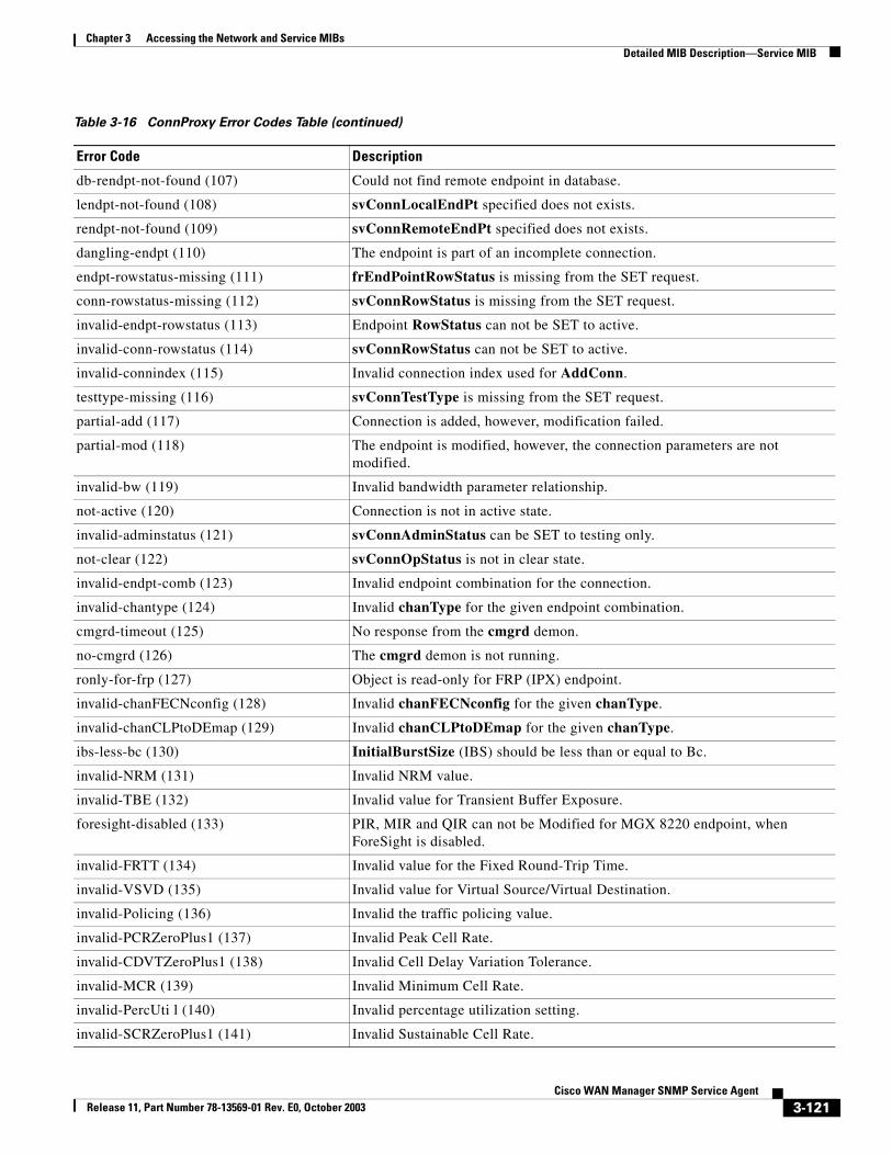
Chapter 3 Accessing the Network and Service MIBsDetailed MIB Description—Service MIB
db-rendpt-not-found (107) Could not find remote endpoint in database.
lendpt-not-found (108) svConnLocalEndPt specified does not exists.
rendpt-not-found (109) svConnRemoteEndPt specified does not exists.
dangling-endpt (110) The endpoint is part of an incomplete connection.
endpt-rowstatus-missing (111) frEndPointRowStatus is missing from the SET request.
conn-rowstatus-missing (112) svConnRowStatus is missing from the SET request.
invalid-endpt-rowstatus (113) Endpoint RowStatus can not be SET to active.
invalid-conn-rowstatus (114) svConnRowStatus can not be SET to active.
invalid-connindex (115) Invalid connection index used for AddConn.
testtype-missing (116) svConnTestType is missing from the SET request.
partial-add (117) Connection is added, however, modification failed.
partial-mod (118) The endpoint is modified, however, the connection parameters are not modified.
invalid-bw (119) Invalid bandwidth parameter relationship.
not-active (120) Connection is not in active state.
invalid-adminstatus (121) svConnAdminStatus can be SET to testing only.
not-clear (122) svConnOpStatus is not in clear state.
invalid-endpt-comb (123) Invalid endpoint combination for the connection.
invalid-chantype (124) Invalid chanType for the given endpoint combination.
cmgrd-timeout (125) No response from the cmgrd demon.
no-cmgrd (126) The cmgrd demon is not running.
ronly-for-frp (127) Object is read-only for FRP (IPX) endpoint.
invalid-chanFECNconfig (128) Invalid chanFECNconfig for the given chanType.
invalid-chanCLPtoDEmap (129) Invalid chanCLPtoDEmap for the given chanType.
ibs-less-bc (130) InitialBurstSize (IBS) should be less than or equal to Bc.
invalid-NRM (131) Invalid NRM value.
invalid-TBE (132) Invalid value for Transient Buffer Exposure.
foresight-disabled (133) PIR, MIR and QIR can not be Modified for MGX 8220 endpoint, when ForeSight is disabled.
invalid-FRTT (134) Invalid value for the Fixed Round-Trip Time.
invalid-VSVD (135) Invalid value for Virtual Source/Virtual Destination.
invalid-Policing (136) Invalid the traffic policing value.
invalid-PCRZeroPlus1 (137) Invalid Peak Cell Rate.
invalid-CDVTZeroPlus1 (138) Invalid Cell Delay Variation Tolerance.
invalid-MCR (139) Invalid Minimum Cell Rate.
invalid-PercUti l (140) Invalid percentage utilization setting.
invalid-SCRZeroPlus1 (141) Invalid Sustainable Cell Rate.
Table 3-16 ConnProxy Error Codes Table (continued)
Error Code Description
3-121Cisco WAN Manager SNMP Service Agent
Release 11, Part Number 78-13569-01 Rev. E0, October 2003
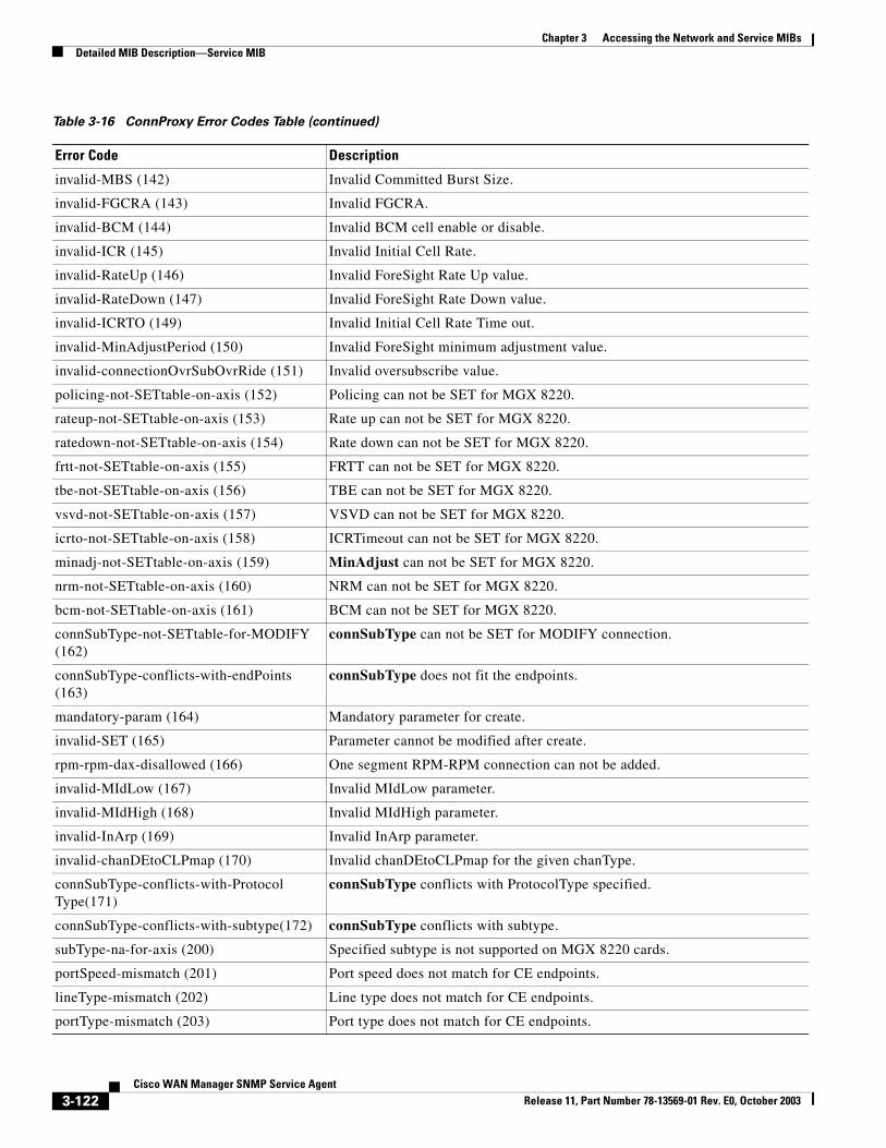
Chapter 3 Accessing the Network and Service MIBsDetailed MIB Description—Service MIB
invalid-MBS (142) Invalid Committed Burst Size.
invalid-FGCRA (143) Invalid FGCRA.
invalid-BCM (144) Invalid BCM cell enable or disable.
invalid-ICR (145) Invalid Initial Cell Rate.
invalid-RateUp (146) Invalid ForeSight Rate Up value.
invalid-RateDown (147) Invalid ForeSight Rate Down value.
invalid-ICRTO (149) Invalid Initial Cell Rate Time out.
invalid-MinAdjustPeriod (150) Invalid ForeSight minimum adjustment value.
invalid-connectionOvrSubOvrRide (151) Invalid oversubscribe value.
policing-not-SETtable-on-axis (152) Policing can not be SET for MGX 8220.
rateup-not-SETtable-on-axis (153) Rate up can not be SET for MGX 8220.
ratedown-not-SETtable-on-axis (154) Rate down can not be SET for MGX 8220.
frtt-not-SETtable-on-axis (155) FRTT can not be SET for MGX 8220.
tbe-not-SETtable-on-axis (156) TBE can not be SET for MGX 8220.
vsvd-not-SETtable-on-axis (157) VSVD can not be SET for MGX 8220.
icrto-not-SETtable-on-axis (158) ICRTimeout can not be SET for MGX 8220.
minadj-not-SETtable-on-axis (159) MinAdjust can not be SET for MGX 8220.
nrm-not-SETtable-on-axis (160) NRM can not be SET for MGX 8220.
bcm-not-SETtable-on-axis (161) BCM can not be SET for MGX 8220.
connSubType-not-SETtable-for-MODIFY (162)
connSubType can not be SET for MODIFY connection.
connSubType-conflicts-with-endPoints (163)
connSubType does not fit the endpoints.
mandatory-param (164) Mandatory parameter for create.
invalid-SET (165) Parameter cannot be modified after create.
rpm-rpm-dax-disallowed (166) One segment RPM-RPM connection can not be added.
invalid-MIdLow (167) Invalid MIdLow parameter.
invalid-MIdHigh (168) Invalid MIdHigh parameter.
invalid-InArp (169) Invalid InArp parameter.
invalid-chanDEtoCLPmap (170) Invalid chanDEtoCLPmap for the given chanType.
connSubType-conflicts-with-ProtocolType(171)
connSubType conflicts with ProtocolType specified.
connSubType-conflicts-with-subtype(172) connSubType conflicts with subtype.
subType-na-for-axis (200) Specified subtype is not supported on MGX 8220 cards.
portSpeed-mismatch (201) Port speed does not match for CE endpoints.
lineType-mismatch (202) Line type does not match for CE endpoints.
portType-mismatch (203) Port type does not match for CE endpoints.
Table 3-16 ConnProxy Error Codes Table (continued)
Error Code Description
3-122Cisco WAN Manager SNMP Service Agent
Release 11, Part Number 78-13569-01 Rev. E0, October 2003
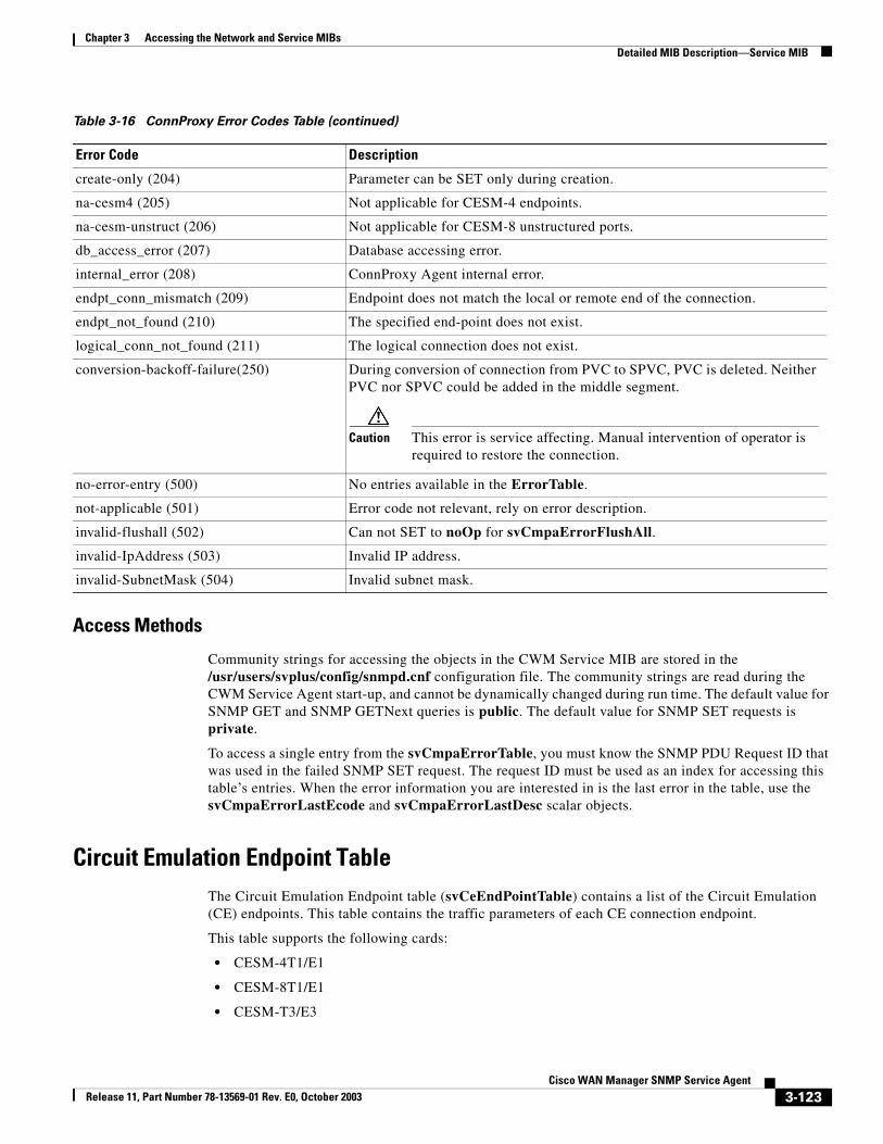
Chapter 3 Accessing the Network and Service MIBsDetailed MIB Description—Service MIB
Access Methods
Community strings for accessing the objects in the CWM Service MIB are stored in the /usr/users/svplus/config/snmpd.cnf configuration file. The community strings are read during the CWM Service Agent start-up, and cannot be dynamically changed during run time. The default value for SNMP GET and SNMP GETNext queries is public. The default value for SNMP SET requests is private.
To access a single entry from the svCmpaErrorTable, you must know the SNMP PDU Request ID that was used in the failed SNMP SET request. The request ID must be used as an index for accessing this table’s entries. When the error information you are interested in is the last error in the table, use the svCmpaErrorLastEcode and svCmpaErrorLastDesc scalar objects.
Circuit Emulation Endpoint TableThe Circuit Emulation Endpoint table (svCeEndPointTable) contains a list of the Circuit Emulation (CE) endpoints. This table contains the traffic parameters of each CE connection endpoint.
This table supports the following cards:
• CESM-4T1/E1
• CESM-8T1/E1
• CESM-T3/E3
create-only (204) Parameter can be SET only during creation.
na-cesm4 (205) Not applicable for CESM-4 endpoints.
na-cesm-unstruct (206) Not applicable for CESM-8 unstructured ports.
db_access_error (207) Database accessing error.
internal_error (208) ConnProxy Agent internal error.
endpt_conn_mismatch (209) Endpoint does not match the local or remote end of the connection.
endpt_not_found (210) The specified end-point does not exist.
logical_conn_not_found (211) The logical connection does not exist.
conversion-backoff-failure(250) During conversion of connection from PVC to SPVC, PVC is deleted. Neither PVC nor SPVC could be added in the middle segment.
Caution This error is service affecting. Manual intervention of operator is required to restore the connection.
no-error-entry (500) No entries available in the ErrorTable.
not-applicable (501) Error code not relevant, rely on error description.
invalid-flushall (502) Can not SET to noOp for svCmpaErrorFlushAll.
invalid-IpAddress (503) Invalid IP address.
invalid-SubnetMask (504) Invalid subnet mask.
Table 3-16 ConnProxy Error Codes Table (continued)
Error Code Description
3-123Cisco WAN Manager SNMP Service Agent
Release 11, Part Number 78-13569-01 Rev. E0, October 2003
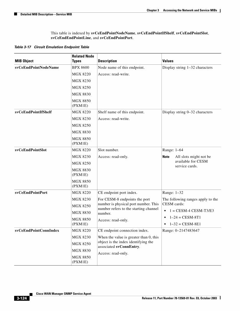
Chapter 3 Accessing the Network and Service MIBsDetailed MIB Description—Service MIB
This table is indexed by svCeEndPointNodeName, svCeEndPointIfShelf, svCeEndPointSlot, svCeEndEndPointLine, and svCeEndPointPort.
Table 3-17 Circuit Emulation Endpoint Table
MIB ObjectRelated Node Types Description Values
svCeEndPointNodeName BPX 8600
MGX 8220
MGX 8230
MGX 8250
MGX 8830
MGX 8850 (PXM1E)
Node name of this endpoint.
Access: read-write.
Display string 1–32 characters
svCeEndPointIfShelf MGX 8220
MGX 8230
MGX 8250
MGX 8830
MGX 8850 (PXM1E)
Shelf name of this endpoint.
Access: read-write.
Display string 0–32 characters
svCeEndPointSlot MGX 8220
MGX 8230
MGX 8250
MGX 8830 (PXM1E)
MGX 8850 (PXM1E)
Slot number.
Access: read-only.
Range: 1–64
Note All slots might not be available for CESM service cards.
svCeEndPointPort MGX 8220
MGX 8230
MGX 8250
MGX 8830
MGX 8850 (PXM1E)
CE endpoint port index.
For CESM-8 endpoints the port number is physical port number. This number refers to the starting channel number.
Access: read-only.
Range: 1–32
The following ranges apply to the CESM cards:
• 1 = CESM-4 CESM-T3/E3
• 1–24 = CESM-8T1
• 1–32 = CESM-8E1
svCeEndPointConnIndex MGX 8220
MGX 8230
MGX 8250
MGX 8830
MGX 8850 (PXM1E)
CE endpoint connection index.
When the value is greater than 0, this object is the index identifying the associated svConnEntry.
Access: read-only.
Range: 0–2147483647
3-124Cisco WAN Manager SNMP Service Agent
Release 11, Part Number 78-13569-01 Rev. E0, October 2003
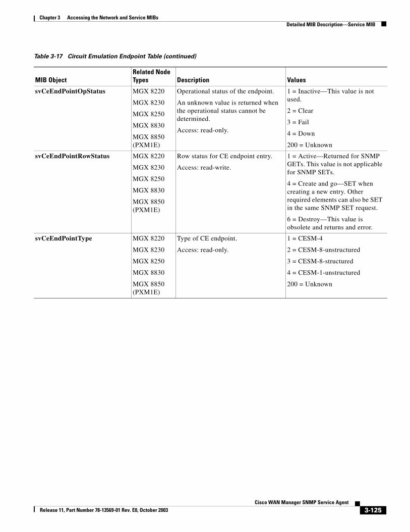
Chapter 3 Accessing the Network and Service MIBsDetailed MIB Description—Service MIB
svCeEndPointOpStatus MGX 8220
MGX 8230
MGX 8250
MGX 8830
MGX 8850 (PXM1E)
Operational status of the endpoint.
An unknown value is returned when the operational status cannot be determined.
Access: read-only.
1 = Inactive—This value is not used.
2 = Clear
3 = Fail
4 = Down
200 = Unknown
svCeEndPointRowStatus MGX 8220
MGX 8230
MGX 8250
MGX 8830
MGX 8850 (PXM1E)
Row status for CE endpoint entry.
Access: read-write.
1 = Active—Returned for SNMP GETs. This value is not applicable for SNMP SETs.
4 = Create and go—SET when creating a new entry. Other required elements can also be SET in the same SNMP SET request.
6 = Destroy—This value is obsolete and returns and error.
svCeEndPointType MGX 8220
MGX 8230
MGX 8250
MGX 8830
MGX 8850 (PXM1E)
Type of CE endpoint.
Access: read-only.
1 = CESM-4
2 = CESM-8-unstructured
3 = CESM-8-structured
4 = CESM-1-unstructured
200 = Unknown
Table 3-17 Circuit Emulation Endpoint Table (continued)
MIB ObjectRelated Node Types Description Values
3-125Cisco WAN Manager SNMP Service Agent
Release 11, Part Number 78-13569-01 Rev. E0, October 2003
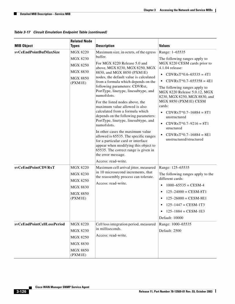
Chapter 3 Accessing the Network and Service MIBsDetailed MIB Description—Service MIB
svCeEndPointBufMaxSize MGX 8220
MGX 8230
MGX 8250
MGX 8830
MGX 8850 (PXM1E)
Maximum size, in octets, of the egress buffer.
For MGX 8220 Release 5.0 and above, MGX 8230, MGX 8250, MGX 8830, and MGX 8850 (PXM1E) nodes, the default value is calculated from a formula which depends on the following parameters: CDVRxt, PortType, linetype, linesubtype, and numofslots.
For the listed nodes above, the maximum value allowed is also calculated from a formula which depends on the following parameters: PortType, linetype, linesubtype, and numofslots.
In other cases the maximum value allowed is 65535. The specific ranges for a particular card or interface appear when modifying this object to 65535. The correct range is given in the error message.
Access: read-write.
Range: 1–65535
The following ranges apply to MGX 8220 CESM cards prior to 4.1.04 release:
• CDVRxT*0.6–65535 = 4T1
• CDVRxT*0.7–655358 = 4E1
The following ranges apply to MGX 8220 Release 5.0.12, MGX 8230, MGX 8250, MGX 8830, and MGX 8850 (PXM1E) CESM cards:
• CDVRxT*0.7–16884 = 8T1 unstructured
• CDVRxT*0.7–9216 = 8T1 structured
• CDVRxT*0.7–16884 = 8E1 unstructured/structured
svCeEndPointCDVRxT MGX 8220
MGX 8230
MGX 8250
MGX 8830
MGX 8850 (PXM1E)
Maximum cell arrival jitter, measured in 10 microsecond increments, that the reassembly process can tolerate.
Access: read-write.
Range: 125–65535
The following ranges apply to the different cards:
• 1000–65535 = CESM-4
• 125–24000 = CESM-8T1
• 125–26000 = CESM-8E1
• 125–1447 = CESM-1T3
• 125–1884 = CESM-1E3
Default: 10000
svCeEndPointCellLossPeriod MGX 8220
MGX 8230
MGX 8250
MGX 8830
MGX 8850 (PXM1E)
Cell loss integration period, measured in milliseconds.
Access: read-write.
Range: 1000–65535
Default: 2500
Table 3-17 Circuit Emulation Endpoint Table (continued)
MIB ObjectRelated Node Types Description Values
3-126Cisco WAN Manager SNMP Service Agent
Release 11, Part Number 78-13569-01 Rev. E0, October 2003
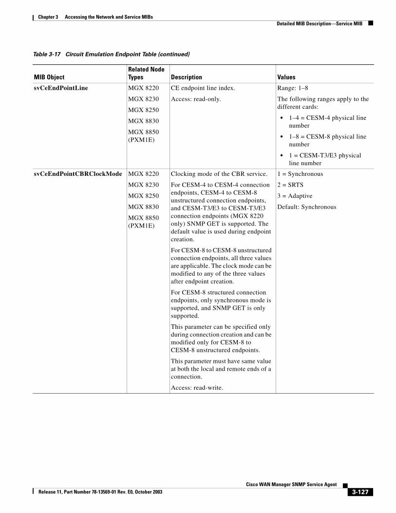
Chapter 3 Accessing the Network and Service MIBsDetailed MIB Description—Service MIB
svCeEndPointLine MGX 8220
MGX 8230
MGX 8250
MGX 8830
MGX 8850 (PXM1E)
CE endpoint line index.
Access: read-only.
Range: 1–8
The following ranges apply to the different cards:
• 1–4 = CESM-4 physical line number
• 1–8 = CESM-8 physical line number
• 1 = CESM-T3/E3 physical line number
svCeEndPointCBRClockMode MGX 8220
MGX 8230
MGX 8250
MGX 8830
MGX 8850 (PXM1E)
Clocking mode of the CBR service.
For CESM-4 to CESM-4 connection endpoints, CESM-4 to CESM-8 unstructured connection endpoints, and CESM-T3/E3 to CESM-T3/E3 connection endpoints (MGX 8220 only) SNMP GET is supported. The default value is used during endpoint creation.
For CESM-8 to CESM-8 unstructured connection endpoints, all three values are applicable. The clock mode can be modified to any of the three values after endpoint creation.
For CESM-8 structured connection endpoints, only synchronous mode is supported, and SNMP GET is only supported.
This parameter can be specified only during connection creation and can be modified only for CESM-8 to CESM-8 unstructured endpoints.
This parameter must have same value at both the local and remote ends of a connection.
Access: read-write.
1 = Synchronous
2 = SRTS
3 = Adaptive
Default: Synchronous
Table 3-17 Circuit Emulation Endpoint Table (continued)
MIB ObjectRelated Node Types Description Values
3-127Cisco WAN Manager SNMP Service Agent
Release 11, Part Number 78-13569-01 Rev. E0, October 2003
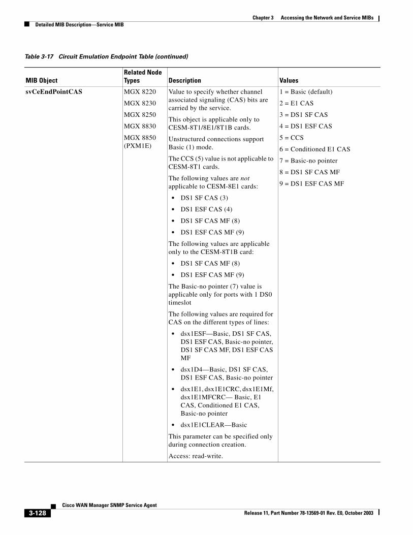
Chapter 3 Accessing the Network and Service MIBsDetailed MIB Description—Service MIB
svCeEndPointCAS MGX 8220
MGX 8230
MGX 8250
MGX 8830
MGX 8850 (PXM1E)
Value to specify whether channel associated signaling (CAS) bits are carried by the service.
This object is applicable only to CESM-8T1/8E1/8T1B cards.
Unstructured connections support Basic (1) mode.
The CCS (5) value is not applicable to CESM-8T1 cards.
The following values are not applicable to CESM-8E1 cards:
• DS1 SF CAS (3)
• DS1 ESF CAS (4)
• DS1 SF CAS MF (8)
• DS1 ESF CAS MF (9)
The following values are applicable only to the CESM-8T1B card:
• DS1 SF CAS MF (8)
• DS1 ESF CAS MF (9)
The Basic-no pointer (7) value is applicable only for ports with 1 DS0 timeslot
The following values are required for CAS on the different types of lines:
• dsx1ESF—Basic, DS1 SF CAS, DS1 ESF CAS, Basic-no pointer, DS1 SF CAS MF, DS1 ESF CAS MF
• dsx1D4—Basic, DS1 SF CAS, DS1 ESF CAS, Basic-no pointer
• dsx1E1, dsx1E1CRC, dsx1E1Mf, dsx1E1MFCRC— Basic, E1 CAS, Conditioned E1 CAS, Basic-no pointer
• dsx1E1CLEAR—Basic
This parameter can be specified only during connection creation.
Access: read-write.
1 = Basic (default)
2 = E1 CAS
3 = DS1 SF CAS
4 = DS1 ESF CAS
5 = CCS
6 = Conditioned E1 CAS
7 = Basic-no pointer
8 = DS1 SF CAS MF
9 = DS1 ESF CAS MF
Table 3-17 Circuit Emulation Endpoint Table (continued)
MIB ObjectRelated Node Types Description Values
3-128Cisco WAN Manager SNMP Service Agent
Release 11, Part Number 78-13569-01 Rev. E0, October 2003
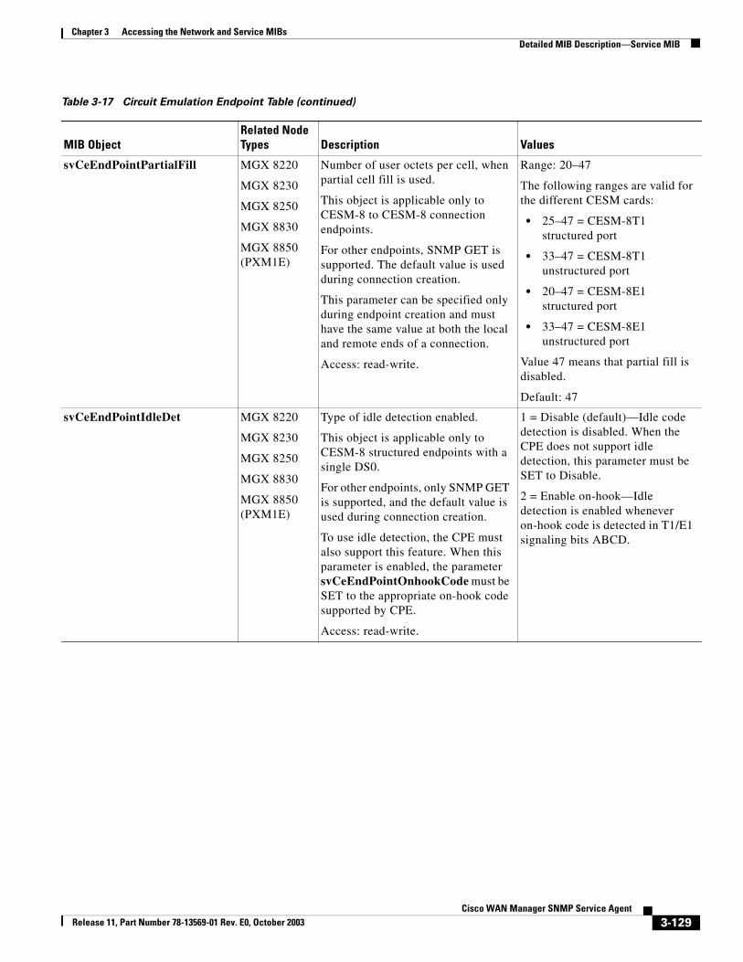
Chapter 3 Accessing the Network and Service MIBsDetailed MIB Description—Service MIB
svCeEndPointPartialFill MGX 8220
MGX 8230
MGX 8250
MGX 8830
MGX 8850 (PXM1E)
Number of user octets per cell, when partial cell fill is used.
This object is applicable only to CESM-8 to CESM-8 connection endpoints.
For other endpoints, SNMP GET is supported. The default value is used during connection creation.
This parameter can be specified only during endpoint creation and must have the same value at both the local and remote ends of a connection.
Access: read-write.
Range: 20–47
The following ranges are valid for the different CESM cards:
• 25–47 = CESM-8T1 structured port
• 33–47 = CESM-8T1 unstructured port
• 20–47 = CESM-8E1 structured port
• 33–47 = CESM-8E1 unstructured port
Value 47 means that partial fill is disabled.
Default: 47
svCeEndPointIdleDet MGX 8220
MGX 8230
MGX 8250
MGX 8830
MGX 8850 (PXM1E)
Type of idle detection enabled.
This object is applicable only to CESM-8 structured endpoints with a single DS0.
For other endpoints, only SNMP GET is supported, and the default value is used during connection creation.
To use idle detection, the CPE must also support this feature. When this parameter is enabled, the parameter svCeEndPointOnhookCode must be SET to the appropriate on-hook code supported by CPE.
Access: read-write.
1 = Disable (default)—Idle code detection is disabled. When the CPE does not support idle detection, this parameter must be SET to Disable.
2 = Enable on-hook—Idle detection is enabled whenever on-hook code is detected in T1/E1 signaling bits ABCD.
Table 3-17 Circuit Emulation Endpoint Table (continued)
MIB ObjectRelated Node Types Description Values
3-129Cisco WAN Manager SNMP Service Agent
Release 11, Part Number 78-13569-01 Rev. E0, October 2003
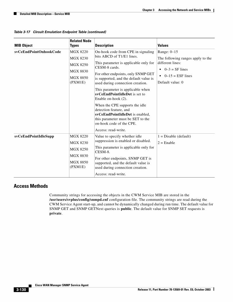
Chapter 3 Accessing the Network and Service MIBsDetailed MIB Description—Service MIB
Access Methods
Community strings for accessing the objects in the CWM Service MIB are stored in the /usr/users/svplus/config/snmpd.cnf configuration file. The community strings are read during the CWM Service Agent start-up, and cannot be dynamically changed during run time. The default value for SNMP GET and SNMP GETNext queries is public. The default value for SNMP SET requests is private.
svCeEndPointOnhookCode MGX 8220
MGX 8230
MGX 8250
MGX 8830
MGX 8850 (PXM1E)
On-hook code from CPE in signaling bits ABCD of T1/E1 lines.
This parameter is applicable only for CESM-8 cards.
For other endpoints, only SNMP GET is supported, and the default value is used during connection creation.
This parameter is applicable when svCeEndPointIdleDet is set to Enable on-hook (2).
When the CPE supports the idle detection feature, and svCeEndPointIdleDet is enabled, this parameter must be SET to the on-hook code of the CPE.
Access: read-write.
Range: 0–15
The following ranges apply to the different lines:
• 0–3 = SF lines
• 0–15 = ESF lines
Default value: 0
svCeEndPointIdleSupp MGX 8220
MGX 8230
MGX 8250
MGX 8830
MGX 8850 (PXM1E)
Value to specify whether idle suppression is enabled or disabled.
This parameter is applicable only for CESM-8.
For other endpoints, SNMP GET is supported, and the default value is used during connection creation.
Access: read-write.
1 = Disable (default)
2 = Enable
Table 3-17 Circuit Emulation Endpoint Table (continued)
MIB ObjectRelated Node Types Description Values
3-130Cisco WAN Manager SNMP Service Agent
Release 11, Part Number 78-13569-01 Rev. E0, October 2003
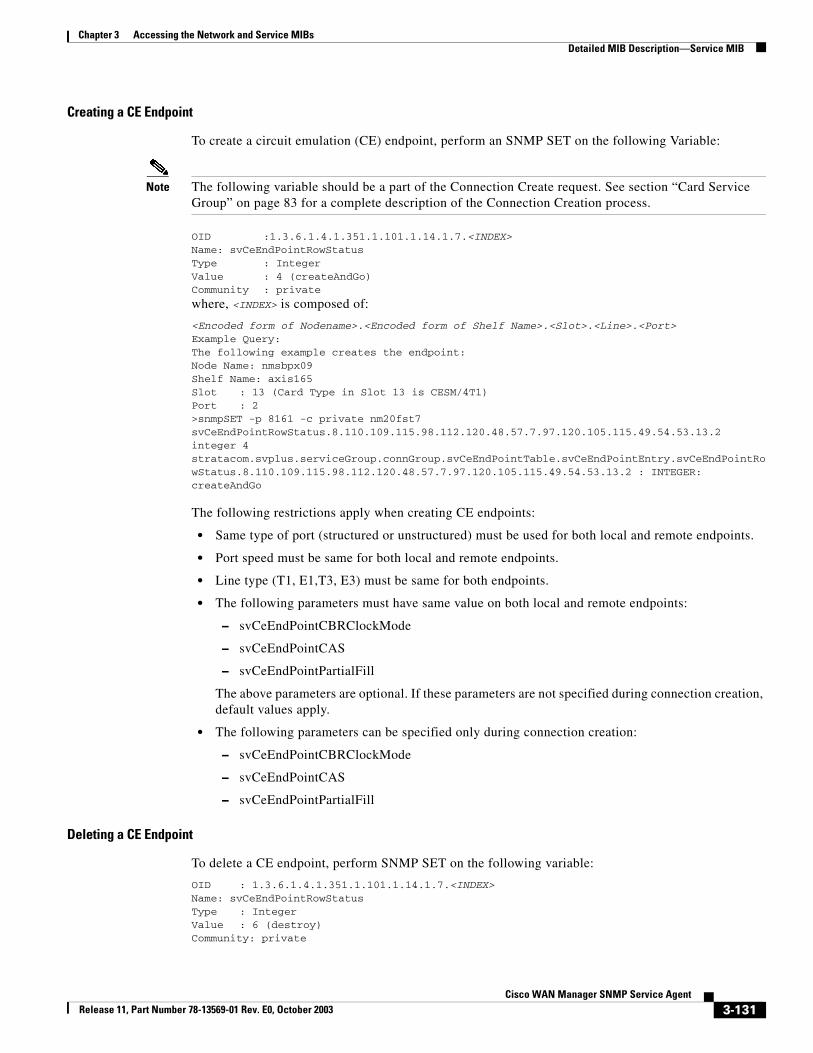
Chapter 3 Accessing the Network and Service MIBsDetailed MIB Description—Service MIB
Creating a CE Endpoint
To create a circuit emulation (CE) endpoint, perform an SNMP SET on the following Variable:
Note The following variable should be a part of the Connection Create request. See section “Card Service Group” on page 83 for a complete description of the Connection Creation process.
OID :1.3.6.1.4.1.351.1.101.1.14.1.7.<INDEX>Name: svCeEndPointRowStatusType : IntegerValue : 4 (createAndGo)Community : private
where, <INDEX> is composed of:
<Encoded form of Nodename>.<Encoded form of Shelf Name>.<Slot>.<Line>.<Port>Example Query:The following example creates the endpoint:Node Name: nmsbpx09Shelf Name: axis165Slot : 13 (Card Type in Slot 13 is CESM/4T1)Port : 2>snmpSET -p 8161 -c private nm20fst7 svCeEndPointRowStatus.8.110.109.115.98.112.120.48.57.7.97.120.105.115.49.54.53.13.2 integer 4stratacom.svplus.serviceGroup.connGroup.svCeEndPointTable.svCeEndPointEntry.svCeEndPointRowStatus.8.110.109.115.98.112.120.48.57.7.97.120.105.115.49.54.53.13.2 : INTEGER: createAndGo
The following restrictions apply when creating CE endpoints:
• Same type of port (structured or unstructured) must be used for both local and remote endpoints.
• Port speed must be same for both local and remote endpoints.
• Line type (T1, E1,T3, E3) must be same for both endpoints.
• The following parameters must have same value on both local and remote endpoints:
– svCeEndPointCBRClockMode
– svCeEndPointCAS
– svCeEndPointPartialFill
The above parameters are optional. If these parameters are not specified during connection creation, default values apply.
• The following parameters can be specified only during connection creation:
– svCeEndPointCBRClockMode
– svCeEndPointCAS
– svCeEndPointPartialFill
Deleting a CE Endpoint
To delete a CE endpoint, perform SNMP SET on the following variable:
OID : 1.3.6.1.4.1.351.1.101.1.14.1.7.<INDEX>Name: svCeEndPointRowStatusType : IntegerValue : 6 (destroy)Community: private
3-131Cisco WAN Manager SNMP Service Agent
Release 11, Part Number 78-13569-01 Rev. E0, October 2003
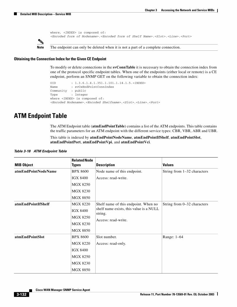
Chapter 3 Accessing the Network and Service MIBsDetailed MIB Description—Service MIB
where, <INDEX> is composed of:<Encoded form of Nodename>.<Encoded form of Shelf Name>.<Slot>.<Line>.<Port>
Note The endpoint can only be deleted when it is not a part of a complete connection.
Obtaining the Connection Index for the Given CE Endpoint
To modify or delete connections in the svConnTable it is necessary to obtain the connection index from one of the protocol specific endpoint tables. When one of the endpoints (either local or remote) is a CE endpoint, perform an SNMP GET on the following variable to obtain the connection index:
OID : 1.3.6.1.4.1.351.1.101.1.14.1.5.<INDEX>Name : svCeEndPointConnIndexCommunity : publicType : Integerwhere <INDEX> is composed of:<Encoded Nodename>.<Encoded Shelfname>.<Slot>.<Line>.<Port>
ATM Endpoint TableThe ATM Endpoint table (atmEndPointTable) contains a list of the ATM endpoints. This table contains the traffic parameters for an ATM endpoint with the different service types: CBR, VBR, ABR and UBR.
This table is indexed by atmEndPointNodeName, atmEndPointIfShelf, atmEndPointSlot, atmEndPointPort, atmEndPointVpi, and atmEndPointVci.
Table 3-18 ATM Endpoint Table
MIB ObjectRelated Node Types Description Values
atmEndPointNodeName BPX 8600
IGX 8400
MGX 8250
MGX 8230
MGX 8850
Node name of this endpoint.
Access: read-write.
String from 1–32 characters
atmEndPointIfShelf MGX 8220
IGX 8400
MGX 8250
MGX 8230
MGX 8850
Shelf name of this endpoint. When no shelf name exists, this value is a NULL string.
Access: read-write.
String from 0–32 characters
atmEndPointSlot BPX 8600
MGX 8220
IGX 8400
MGX 8250
MGX 8230
MGX 8850
Slot number.
Access: read-only.
Range: 1–64
3-132Cisco WAN Manager SNMP Service Agent
Release 11, Part Number 78-13569-01 Rev. E0, October 2003
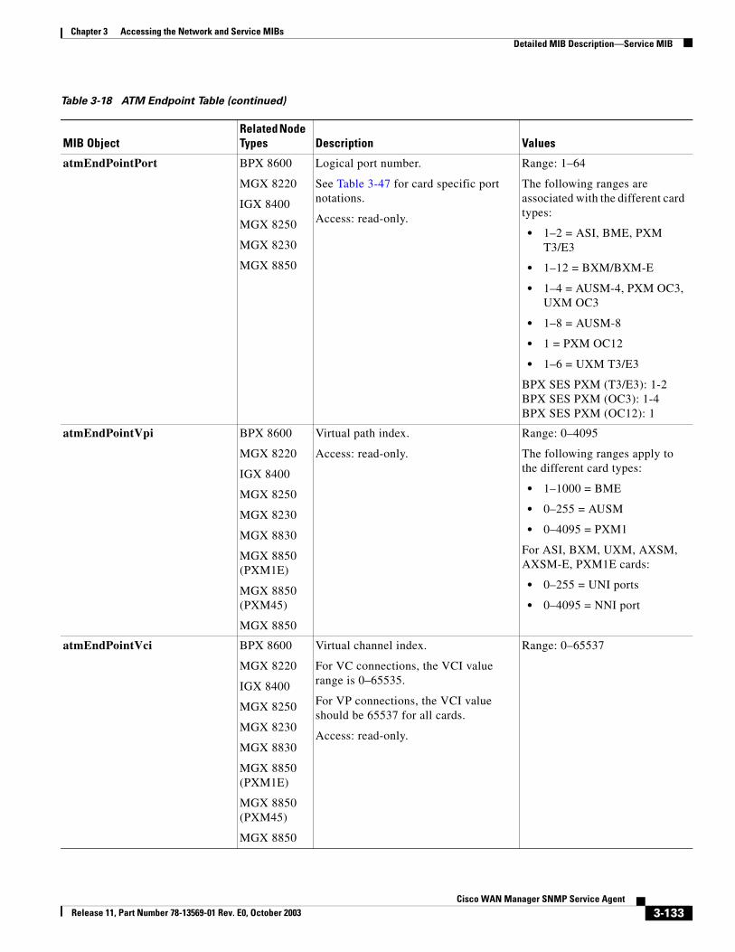
Chapter 3 Accessing the Network and Service MIBsDetailed MIB Description—Service MIB
atmEndPointPort BPX 8600
MGX 8220
IGX 8400
MGX 8250
MGX 8230
MGX 8850
Logical port number.
See Table 3-47 for card specific port notations.
Access: read-only.
Range: 1–64
The following ranges are associated with the different card types:
• 1–2 = ASI, BME, PXM T3/E3
• 1–12 = BXM/BXM-E
• 1–4 = AUSM-4, PXM OC3, UXM OC3
• 1–8 = AUSM-8
• 1 = PXM OC12
• 1–6 = UXM T3/E3
BPX SES PXM (T3/E3): 1-2BPX SES PXM (OC3): 1-4BPX SES PXM (OC12): 1
atmEndPointVpi BPX 8600
MGX 8220
IGX 8400
MGX 8250
MGX 8230
MGX 8830
MGX 8850 (PXM1E)
MGX 8850 (PXM45)
MGX 8850
Virtual path index.
Access: read-only.
Range: 0–4095
The following ranges apply to the different card types:
• 1–1000 = BME
• 0–255 = AUSM
• 0–4095 = PXM1
For ASI, BXM, UXM, AXSM, AXSM-E, PXM1E cards:
• 0–255 = UNI ports
• 0–4095 = NNI port
atmEndPointVci BPX 8600
MGX 8220
IGX 8400
MGX 8250
MGX 8230
MGX 8830
MGX 8850 (PXM1E)
MGX 8850 (PXM45)
MGX 8850
Virtual channel index.
For VC connections, the VCI value range is 0–65535.
For VP connections, the VCI value should be 65537 for all cards.
Access: read-only.
Range: 0–65537
Table 3-18 ATM Endpoint Table (continued)
MIB ObjectRelated Node Types Description Values
3-133Cisco WAN Manager SNMP Service Agent
Release 11, Part Number 78-13569-01 Rev. E0, October 2003
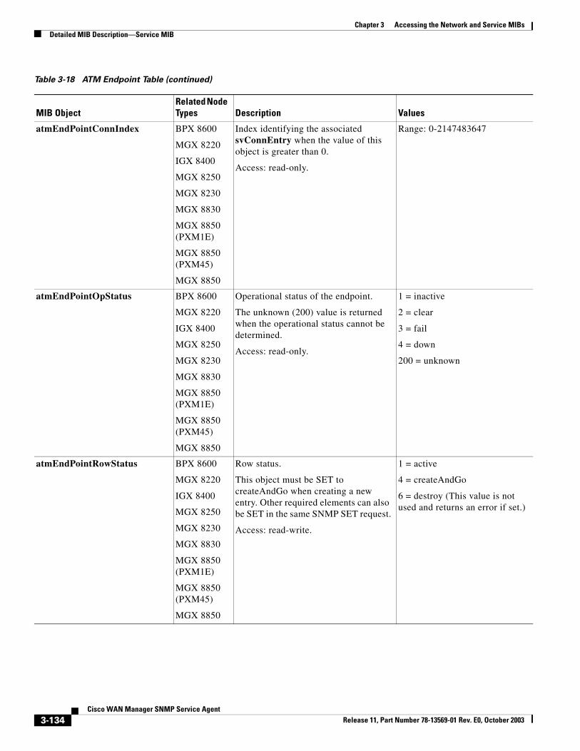
Chapter 3 Accessing the Network and Service MIBsDetailed MIB Description—Service MIB
atmEndPointConnIndex BPX 8600
MGX 8220
IGX 8400
MGX 8250
MGX 8230
MGX 8830
MGX 8850 (PXM1E)
MGX 8850 (PXM45)
MGX 8850
Index identifying the associated svConnEntry when the value of this object is greater than 0.
Access: read-only.
Range: 0-2147483647
atmEndPointOpStatus BPX 8600
MGX 8220
IGX 8400
MGX 8250
MGX 8230
MGX 8830
MGX 8850 (PXM1E)
MGX 8850 (PXM45)
MGX 8850
Operational status of the endpoint.
The unknown (200) value is returned when the operational status cannot be determined.
Access: read-only.
1 = inactive
2 = clear
3 = fail
4 = down
200 = unknown
atmEndPointRowStatus BPX 8600
MGX 8220
IGX 8400
MGX 8250
MGX 8230
MGX 8830
MGX 8850 (PXM1E)
MGX 8850 (PXM45)
MGX 8850
Row status.
This object must be SET to createAndGo when creating a new entry. Other required elements can also be SET in the same SNMP SET request.
Access: read-write.
1 = active
4 = createAndGo
6 = destroy (This value is not used and returns an error if set.)
Table 3-18 ATM Endpoint Table (continued)
MIB ObjectRelated Node Types Description Values
3-134Cisco WAN Manager SNMP Service Agent
Release 11, Part Number 78-13569-01 Rev. E0, October 2003
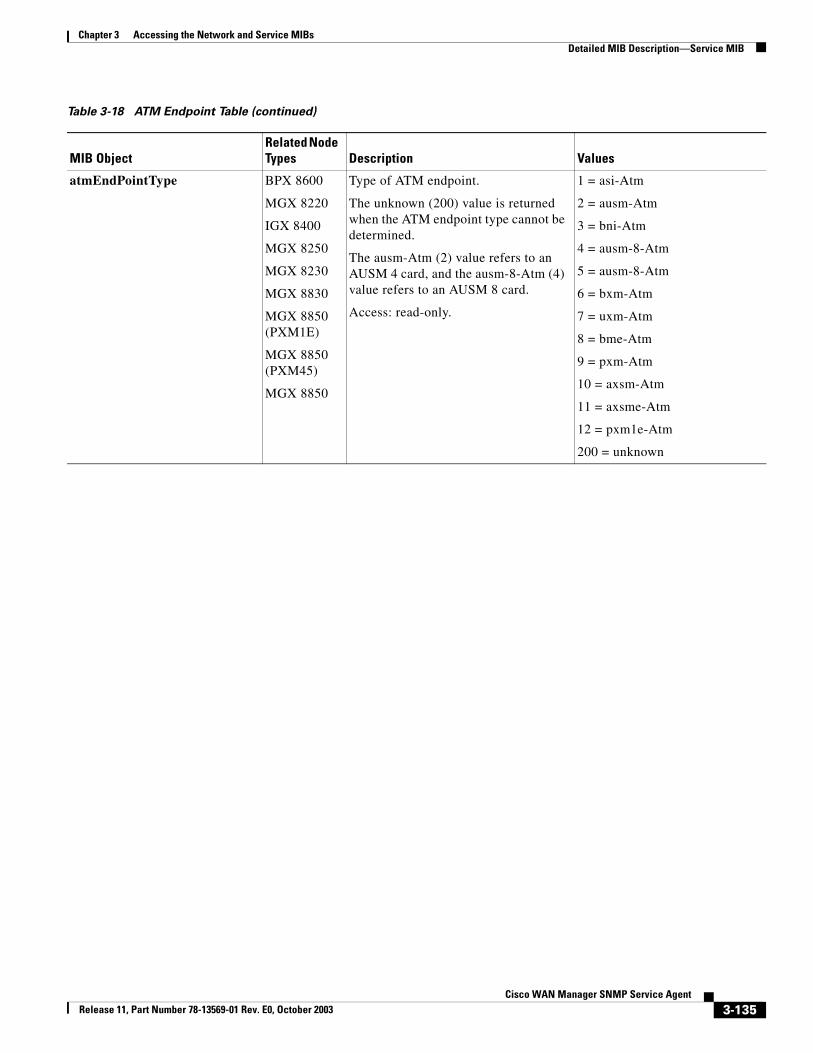
Chapter 3 Accessing the Network and Service MIBsDetailed MIB Description—Service MIB
atmEndPointType BPX 8600
MGX 8220
IGX 8400
MGX 8250
MGX 8230
MGX 8830
MGX 8850 (PXM1E)
MGX 8850 (PXM45)
MGX 8850
Type of ATM endpoint.
The unknown (200) value is returned when the ATM endpoint type cannot be determined.
The ausm-Atm (2) value refers to an AUSM 4 card, and the ausm-8-Atm (4) value refers to an AUSM 8 card.
Access: read-only.
1 = asi-Atm
2 = ausm-Atm
3 = bni-Atm
4 = ausm-8-Atm
5 = ausm-8-Atm
6 = bxm-Atm
7 = uxm-Atm
8 = bme-Atm
9 = pxm-Atm
10 = axsm-Atm
11 = axsme-Atm
12 = pxm1e-Atm
200 = unknown
Table 3-18 ATM Endpoint Table (continued)
MIB ObjectRelated Node Types Description Values
3-135Cisco WAN Manager SNMP Service Agent
Release 11, Part Number 78-13569-01 Rev. E0, October 2003
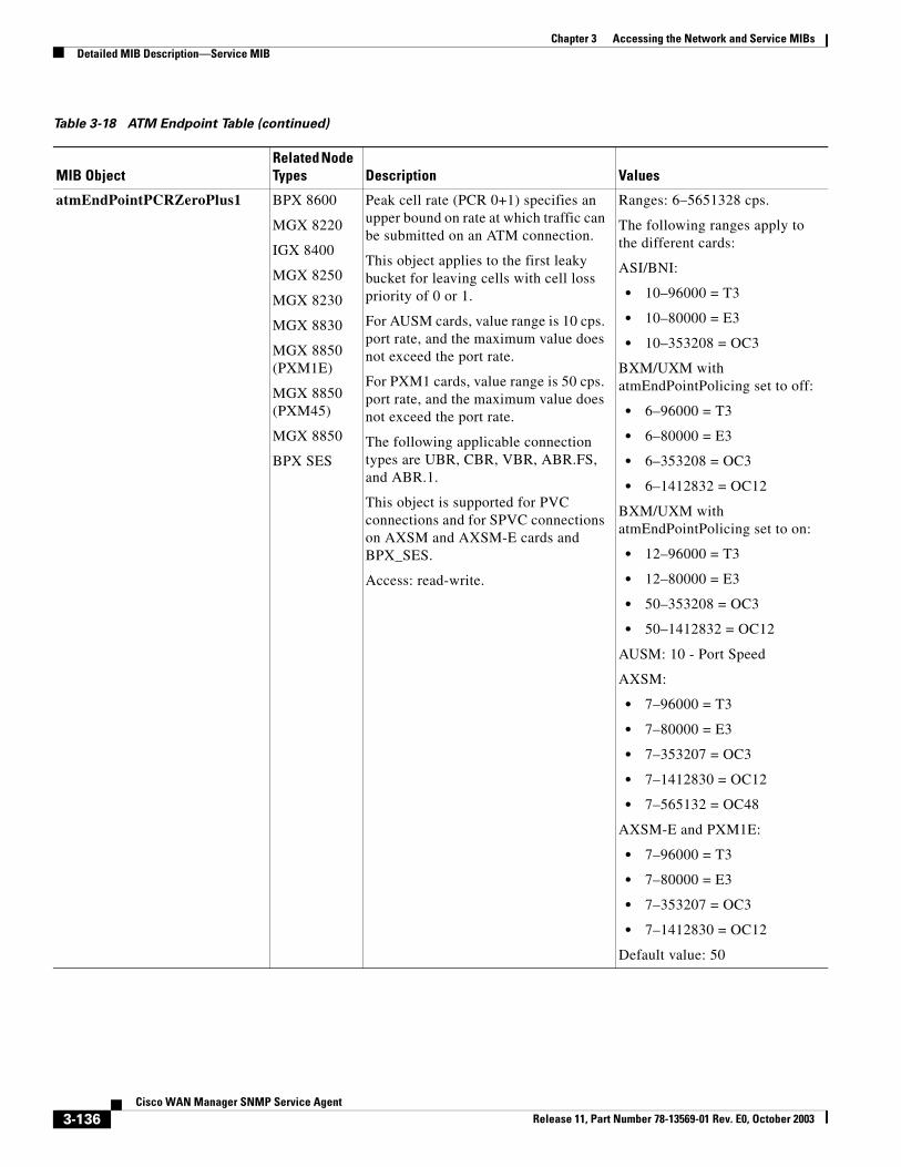
Chapter 3 Accessing the Network and Service MIBsDetailed MIB Description—Service MIB
atmEndPointPCRZeroPlus1 BPX 8600
MGX 8220
IGX 8400
MGX 8250
MGX 8230
MGX 8830
MGX 8850 (PXM1E)
MGX 8850 (PXM45)
MGX 8850
BPX SES
Peak cell rate (PCR 0+1) specifies an upper bound on rate at which traffic can be submitted on an ATM connection.
This object applies to the first leaky bucket for leaving cells with cell loss priority of 0 or 1.
For AUSM cards, value range is 10 cps. port rate, and the maximum value does not exceed the port rate.
For PXM1 cards, value range is 50 cps. port rate, and the maximum value does not exceed the port rate.
The following applicable connection types are UBR, CBR, VBR, ABR.FS, and ABR.1.
This object is supported for PVC connections and for SPVC connections on AXSM and AXSM-E cards and BPX_SES.
Access: read-write.
Ranges: 6–5651328 cps.
The following ranges apply to the different cards:
ASI/BNI:
• 10–96000 = T3
• 10–80000 = E3
• 10–353208 = OC3
BXM/UXM with atmEndPointPolicing set to off:
• 6–96000 = T3
• 6–80000 = E3
• 6–353208 = OC3
• 6–1412832 = OC12
BXM/UXM with atmEndPointPolicing set to on:
• 12–96000 = T3
• 12–80000 = E3
• 50–353208 = OC3
• 50–1412832 = OC12
AUSM: 10 - Port Speed
AXSM:
• 7–96000 = T3
• 7–80000 = E3
• 7–353207 = OC3
• 7–1412830 = OC12
• 7–565132 = OC48
AXSM-E and PXM1E:
• 7–96000 = T3
• 7–80000 = E3
• 7–353207 = OC3
• 7–1412830 = OC12
Default value: 50
Table 3-18 ATM Endpoint Table (continued)
MIB ObjectRelated Node Types Description Values
3-136Cisco WAN Manager SNMP Service Agent
Release 11, Part Number 78-13569-01 Rev. E0, October 2003
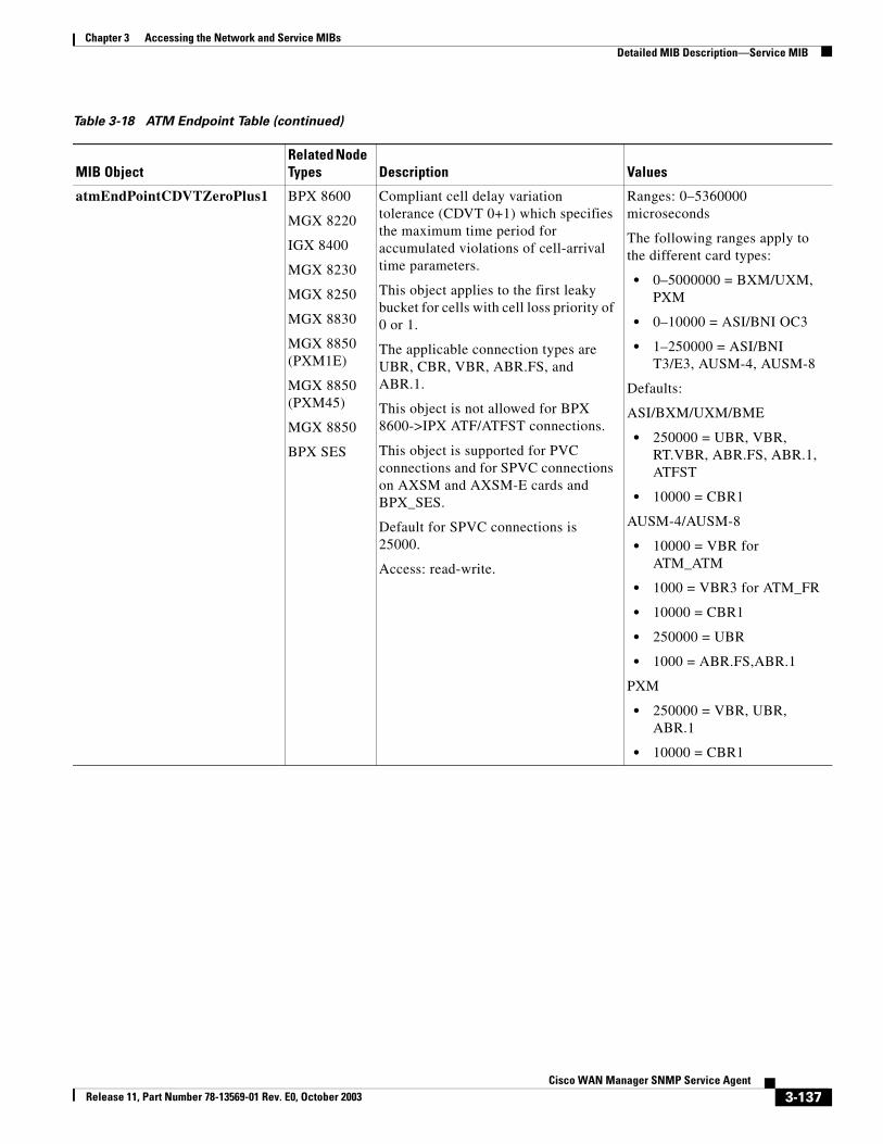
Chapter 3 Accessing the Network and Service MIBsDetailed MIB Description—Service MIB
atmEndPointCDVTZeroPlus1 BPX 8600
MGX 8220
IGX 8400
MGX 8230
MGX 8250
MGX 8830
MGX 8850 (PXM1E)
MGX 8850 (PXM45)
MGX 8850
BPX SES
Compliant cell delay variation tolerance (CDVT 0+1) which specifies the maximum time period for accumulated violations of cell-arrival time parameters.
This object applies to the first leaky bucket for cells with cell loss priority of 0 or 1.
The applicable connection types are UBR, CBR, VBR, ABR.FS, and ABR.1.
This object is not allowed for BPX 8600->IPX ATF/ATFST connections.
This object is supported for PVC connections and for SPVC connections on AXSM and AXSM-E cards and BPX_SES.
Default for SPVC connections is 25000.
Access: read-write.
Ranges: 0–5360000 microseconds
The following ranges apply to the different card types:
• 0–5000000 = BXM/UXM, PXM
• 0–10000 = ASI/BNI OC3
• 1–250000 = ASI/BNI T3/E3, AUSM-4, AUSM-8
Defaults:
ASI/BXM/UXM/BME
• 250000 = UBR, VBR, RT.VBR, ABR.FS, ABR.1, ATFST
• 10000 = CBR1
AUSM-4/AUSM-8
• 10000 = VBR for ATM_ATM
• 1000 = VBR3 for ATM_FR
• 10000 = CBR1
• 250000 = UBR
• 1000 = ABR.FS,ABR.1
PXM
• 250000 = VBR, UBR, ABR.1
• 10000 = CBR1
Table 3-18 ATM Endpoint Table (continued)
MIB ObjectRelated Node Types Description Values
3-137Cisco WAN Manager SNMP Service Agent
Release 11, Part Number 78-13569-01 Rev. E0, October 2003
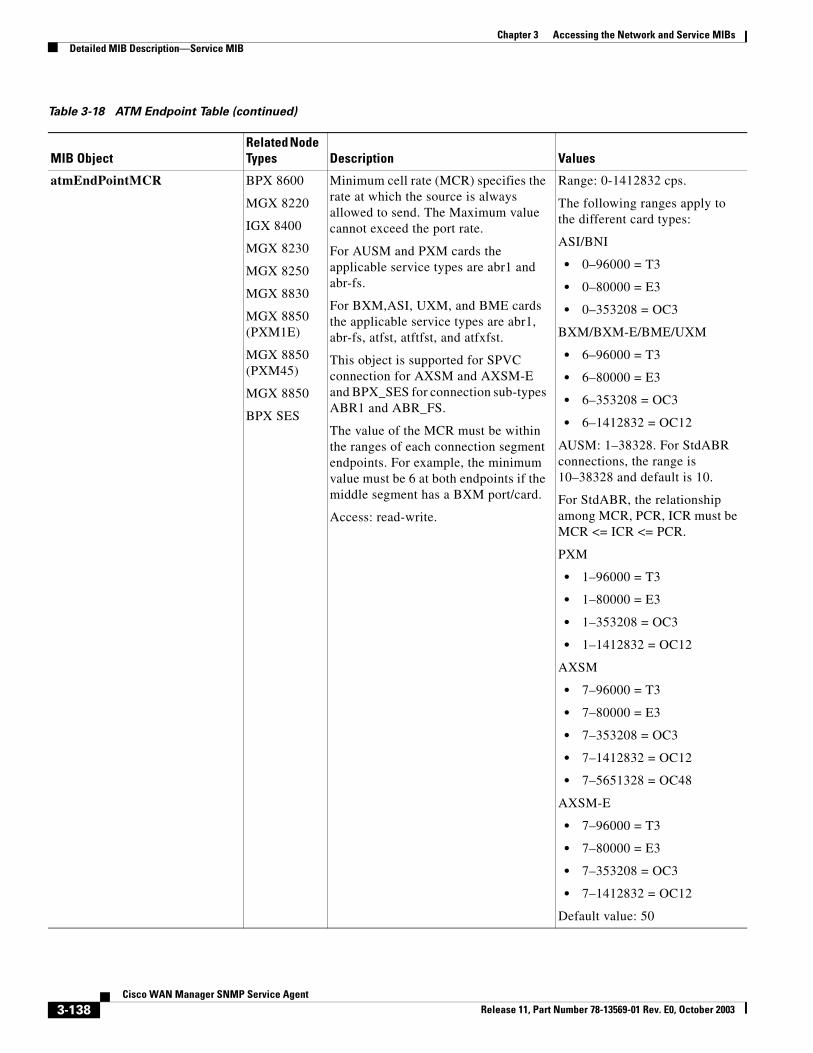
Chapter 3 Accessing the Network and Service MIBsDetailed MIB Description—Service MIB
atmEndPointMCR BPX 8600
MGX 8220
IGX 8400
MGX 8230
MGX 8250
MGX 8830
MGX 8850 (PXM1E)
MGX 8850 (PXM45)
MGX 8850
BPX SES
Minimum cell rate (MCR) specifies the rate at which the source is always allowed to send. The Maximum value cannot exceed the port rate.
For AUSM and PXM cards the applicable service types are abr1 and abr-fs.
For BXM,ASI, UXM, and BME cards the applicable service types are abr1, abr-fs, atfst, atftfst, and atfxfst.
This object is supported for SPVC connection for AXSM and AXSM-E and BPX_SES for connection sub-types ABR1 and ABR_FS.
The value of the MCR must be within the ranges of each connection segment endpoints. For example, the minimum value must be 6 at both endpoints if the middle segment has a BXM port/card.
Access: read-write.
Range: 0-1412832 cps.
The following ranges apply to the different card types:
ASI/BNI
• 0–96000 = T3
• 0–80000 = E3
• 0–353208 = OC3
BXM/BXM-E/BME/UXM
• 6–96000 = T3
• 6–80000 = E3
• 6–353208 = OC3
• 6–1412832 = OC12
AUSM: 1–38328. For StdABR connections, the range is 10–38328 and default is 10.
For StdABR, the relationship among MCR, PCR, ICR must be MCR <= ICR <= PCR.
PXM
• 1–96000 = T3
• 1–80000 = E3
• 1–353208 = OC3
• 1–1412832 = OC12
AXSM
• 7–96000 = T3
• 7–80000 = E3
• 7–353208 = OC3
• 7–1412832 = OC12
• 7–5651328 = OC48
AXSM-E
• 7–96000 = T3
• 7–80000 = E3
• 7–353208 = OC3
• 7–1412832 = OC12
Default value: 50
Table 3-18 ATM Endpoint Table (continued)
MIB ObjectRelated Node Types Description Values
3-138Cisco WAN Manager SNMP Service Agent
Release 11, Part Number 78-13569-01 Rev. E0, October 2003
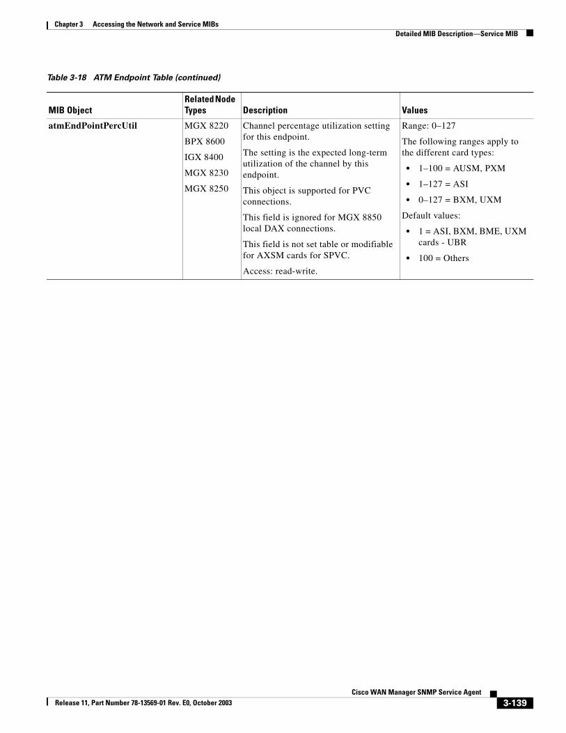
Chapter 3 Accessing the Network and Service MIBsDetailed MIB Description—Service MIB
atmEndPointPercUtil MGX 8220
BPX 8600
IGX 8400
MGX 8230
MGX 8250
Channel percentage utilization setting for this endpoint.
The setting is the expected long-term utilization of the channel by this endpoint.
This object is supported for PVC connections.
This field is ignored for MGX 8850 local DAX connections.
This field is not set table or modifiable for AXSM cards for SPVC.
Access: read-write.
Range: 0–127
The following ranges apply to the different card types:
• 1–100 = AUSM, PXM
• 1–127 = ASI
• 0–127 = BXM, UXM
Default values:
• 1 = ASI, BXM, BME, UXM cards - UBR
• 100 = Others
Table 3-18 ATM Endpoint Table (continued)
MIB ObjectRelated Node Types Description Values
3-139Cisco WAN Manager SNMP Service Agent
Release 11, Part Number 78-13569-01 Rev. E0, October 2003
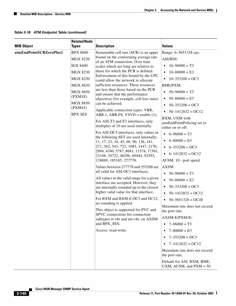
Chapter 3 Accessing the Network and Service MIBsDetailed MIB Description—Service MIB
atmEndPointSCRZeroPlus1 BPX 8600
MGX 8220
IGX 8400
MGX 8230
MGX 8250
MGX 8830
MGX 8850 (PXM1E)
MGX 8850 (PXM45)
BPX SES
Sustainable cell rate (SCR) is an upper bound on the conforming average rate of an ATM connection. Over time scales which are long are relative to those for which the PCR is defined. Enforcement of this bound by the UPC could allow the network to allocate sufficient resources. These resources are less than those based on the PCR and ensure that the performance objectives (for example, cell loss ratio) can be achieved.
Applicable connection types: VBR, ABR.1, ABR.FS: VSVD = enable (1).
For ASI-T3 and E3 interfaces, only multiples of 10 are used internally.
For ASI-OC3 interfaces, only values in the following SET are used internally: 11, 17, 23, 34, 45, 68, 90, 136, 181, 271, 362, 543, 723, 1085, 1447, 2170, 2894, 4340, 5787, 8681, 11574, 17361, 23148, 34722, 46296, 69444, 92593, 138889, 185185, 277778.
Values between 277778 and 353208 are all valid for ASI-OC3 interfaces.
All values in the valid range for a given interface are accepted. However, they are internally rounded up to the closest higher valid value for that interface.
For BXM and BXM-E OC3 and OC12, no rounding is applied.
This object is supported for PVC and SPVC connections for connection subtypes rt-vbr and nrt-vbr. on AXSM and BPX_SES.
Access: read-write.
Range: 6–5651328 cps.
ASI/BNI:
• 10–96000 = T3
• 10–80000 = E3
• 10–353208 = OC3
BME/PXM:
• 50–96000 = T3
• 50–80000 = E3
• 50–353208 = OC3
• 50–1412832 = OC12
BXM, UXM with atmEndPointPolicing set to either on or off:
• 6–96000 = T3
• 6–80000 = E3
• 6–353208 = OC3
• 6–1412832 = OC12
AUSM: 10 - port speed
AXSM
• 50–96000 = T3
• 50–80000 = E3
• 50–353208 = OC3
• 50–1412832 = OC12
• 50–5651328 = OC48
Maximum rate does not exceed the port rate.
AXSM-E/PXM1E:
• 7–96000 = T3
• 7–80000 = E3
• 7–353208 = OC3
• 7–1412832 = OC12
Maximum rate does not exceed the port rate.
Default for ASI, BXM, BME, UXM, AUSM, and PXM = 50
Table 3-18 ATM Endpoint Table (continued)
MIB ObjectRelated Node Types Description Values
3-140Cisco WAN Manager SNMP Service Agent
Release 11, Part Number 78-13569-01 Rev. E0, October 2003
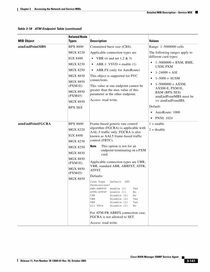
Chapter 3 Accessing the Network and Service MIBsDetailed MIB Description—Service MIB
atmEndPointMBS BPX 8600
MGX 8220
IGX 8400
MGX 8230
MGX 8250
MGX 8830
MGX 8850 (PXM1E)
MGX 8850 (PXM45)
MGX 8850
BPX SES
Committed burst size (CBS).
Applicable connection types are
• VBR (rt and nrt 1,2 & 3)
• ABR.1: VSVD = enable (1)
• ABR.FS (only for AutoRoute)
This object is supported for PVC connections.
This value at one endpoint cannot be greater than the max value of this parameter at the other endpoint.
Access: read-write.
Range: 1–5000000 cells
The following ranges apply to different card types:
• 1–5000000 = BXM, BME, UXM, PXM
• 1–24000 = ASI
• 1–5000 = AUSM
• 1–5000000 = AXSM, AXSM-E, PXM1E, BXM (BPX-SES) atmEndPointMBS must be >= atmEndPointIBS.
Default:
• AutoRoute: 1000
• PNNI: 1024
atmEndPointFGCRA BPX 8600
MGX 8220
IGX 8400
MGX 8230
MGX 8250
MGX 8830
MGX 8850 (PXM1E)
MGX 8850 (PXM45)
MGX 8850
Frame-based generic rate control algorithm (FGCRA) is applicable with AAL-5 traffic only. FGCRA is also known as AAL5 frame-based traffic control (FBTC).
Note This option is not for an endpoint terminating on a PXM card.
Applicable connection types are UBR, VBR, standard ABR, ABRFST, ATFR, ATFST.
Defaults:
Conn Type Default SET Permissions?ABR/ABRFST enable (1) YesATFR/ATFST enable (1) NoCBR disable (2) NoUBR disable (2) YesVBR disable (2) YesAll VPCs disable (2) No
For ATM-FR ABRFS connection case, FGCRA is not allowed to SET.
Access: read-write.
1 = enable
2 = disable
Table 3-18 ATM Endpoint Table (continued)
MIB ObjectRelated Node Types Description Values
3-141Cisco WAN Manager SNMP Service Agent
Release 11, Part Number 78-13569-01 Rev. E0, October 2003
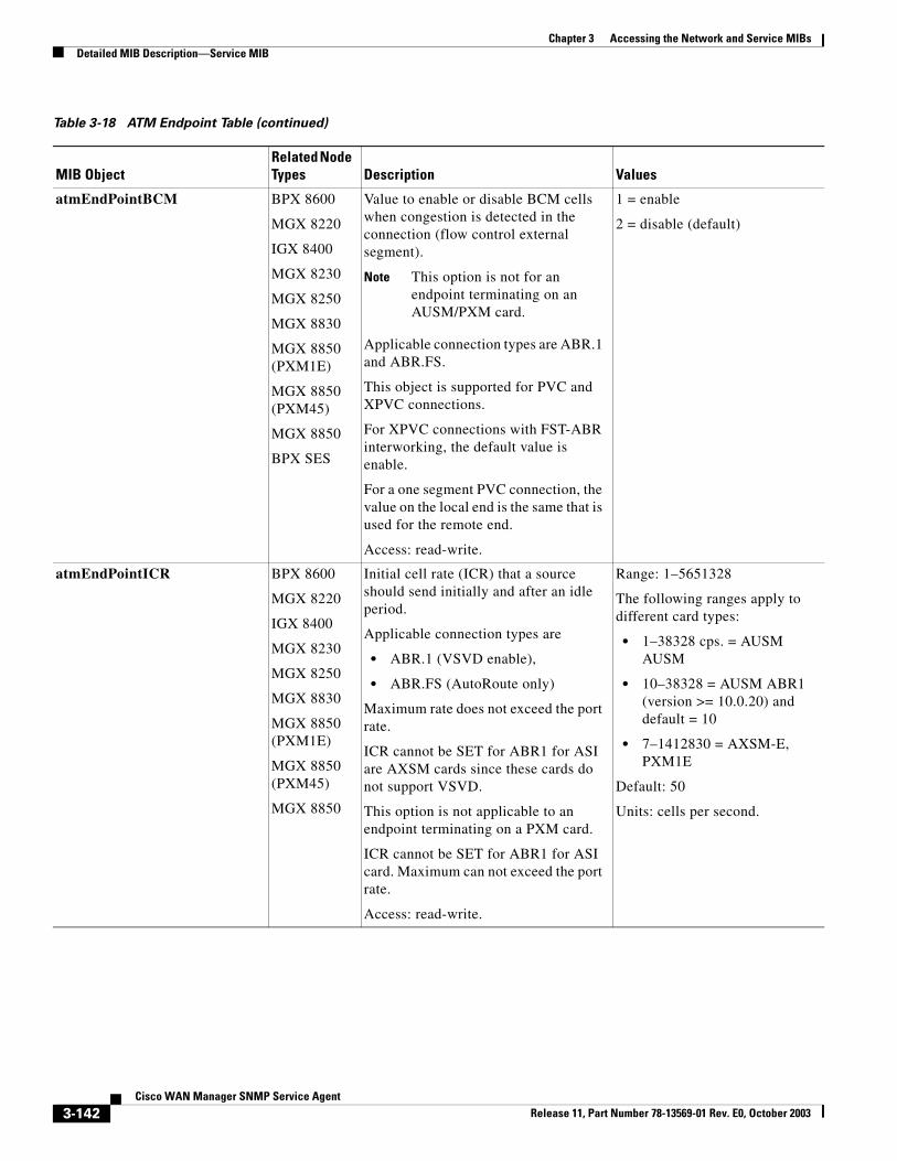
Chapter 3 Accessing the Network and Service MIBsDetailed MIB Description—Service MIB
atmEndPointBCM BPX 8600
MGX 8220
IGX 8400
MGX 8230
MGX 8250
MGX 8830
MGX 8850 (PXM1E)
MGX 8850 (PXM45)
MGX 8850
BPX SES
Value to enable or disable BCM cells when congestion is detected in the connection (flow control external segment).
Note This option is not for an endpoint terminating on an AUSM/PXM card.
Applicable connection types are ABR.1 and ABR.FS.
This object is supported for PVC and XPVC connections.
For XPVC connections with FST-ABR interworking, the default value is enable.
For a one segment PVC connection, the value on the local end is the same that is used for the remote end.
Access: read-write.
1 = enable
2 = disable (default)
atmEndPointICR BPX 8600
MGX 8220
IGX 8400
MGX 8230
MGX 8250
MGX 8830
MGX 8850 (PXM1E)
MGX 8850 (PXM45)
MGX 8850
Initial cell rate (ICR) that a source should send initially and after an idle period.
Applicable connection types are
• ABR.1 (VSVD enable),
• ABR.FS (AutoRoute only)
Maximum rate does not exceed the port rate.
ICR cannot be SET for ABR1 for ASI are AXSM cards since these cards do not support VSVD.
This option is not applicable to an endpoint terminating on a PXM card.
ICR cannot be SET for ABR1 for ASI card. Maximum can not exceed the port rate.
Access: read-write.
Range: 1–5651328
The following ranges apply to different card types:
• 1–38328 cps. = AUSM AUSM
• 10–38328 = AUSM ABR1 (version >= 10.0.20) and default = 10
• 7–1412830 = AXSM-E, PXM1E
Default: 50
Units: cells per second.
Table 3-18 ATM Endpoint Table (continued)
MIB ObjectRelated Node Types Description Values
3-142Cisco WAN Manager SNMP Service Agent
Release 11, Part Number 78-13569-01 Rev. E0, October 2003
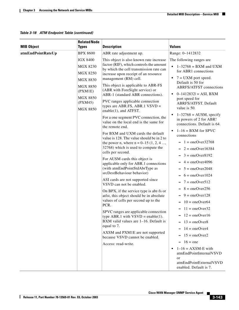
Chapter 3 Accessing the Network and Service MIBsDetailed MIB Description—Service MIB
atmEndPointRateUp BPX 8600
IGX 8400
MGX 8230
MGX 8250
MGX 8830
MGX 8850 (PXM1E)
MGX 8850 (PXM45)
MGX 8850
ABR rate adjustment up.
This object is also known rate increase factor (RIF), which controls the amount by which the cell transmission rate can increase upon receipt of an resource management (RM) cell.
This object is applicable to ABR-FS (ABR with ForeSight service) or ABR-1 (standard ABR connections).
PVC ranges applicable connection types are ABR.FS, ABR.1 VSVD = enable(1), and ATFST.
For a one segment PVC connection, the value on the local end is the same for the remote end.
For BXM and UXM cards the default value is 128. The value should be in 2 to the power n, where n = 0–15 (1, 2, 4 ..., 32768) which is used to compute the cells per second.
For AUSM cards this object is applicable only for ABR.1 connections (with atmEndPointStdAbrType as srcDestBehaviour behavior)
ASI cards are not supported since VSVD can not be enabled.
On BPX, if the service type is abr-fs or atfst, this object should be in absolute values of cells per second up to the PCR.
SPVC ranges are applicable connection type ABR.1 with VSVD = enable(1). BXM valid values are 1–16. Default is equal to 7.
AXSM and PXM1E are not supported because VSVD cannot be enabled.
Access: read-write.
Range: 0–1412832
The following ranges are
• 1–32768 = BXM and UXM for ABR1 connections
• 7 = UXM port speed. Default is 50 for ABRFS/ATFST connections
• 0–1412832| = ASI, BXM port speed for ABRFS/ATFST. Default value is 50.
• 1–32768 = AUSM, specify in powers of 2 for ABR! connections. Default is 64.
• 1–16 = BXM for SPVC connections
– 1 = oneOver32768
– 2 = oneOver16384
– 3 = oneOver8192
– 4 = oneOver4096
– 5 = oneOver2048
– 6 = oneOver1024
– 7 = oneOver512
– 8 = oneOver256
– 9 = oneOver128
– 10 = oneOver64
– 11 = oneOver32
– 12 = oneOver16
– 13 = oneOver8
– 14 = oneOver4
– 15 = oneOver2
– 16 = one
• 1–16 = AXSM-E with atmEndPointInternalVSVDor atmEndPointExternalVSVD enabled. Default is 7.
Table 3-18 ATM Endpoint Table (continued)
MIB ObjectRelated Node Types Description Values
3-143Cisco WAN Manager SNMP Service Agent
Release 11, Part Number 78-13569-01 Rev. E0, October 2003
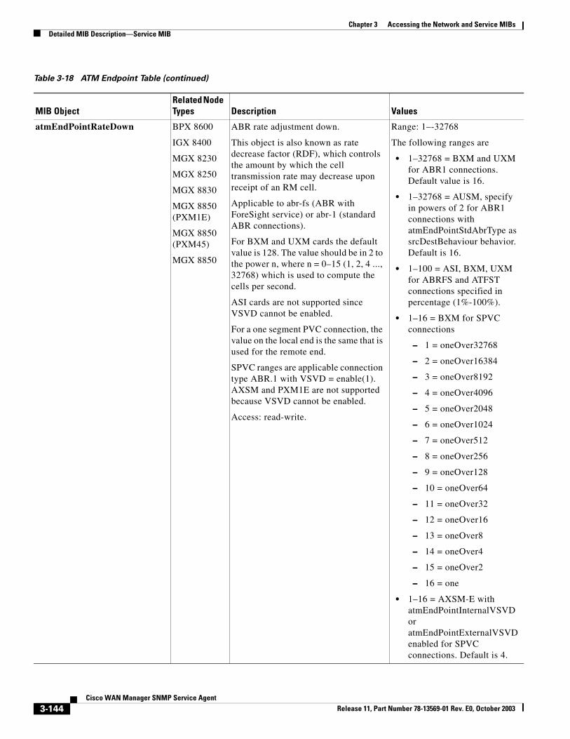
Chapter 3 Accessing the Network and Service MIBsDetailed MIB Description—Service MIB
atmEndPointRateDown BPX 8600
IGX 8400
MGX 8230
MGX 8250
MGX 8830
MGX 8850 (PXM1E)
MGX 8850 (PXM45)
MGX 8850
ABR rate adjustment down.
This object is also known as rate decrease factor (RDF), which controls the amount by which the cell transmission rate may decrease upon receipt of an RM cell.
Applicable to abr-fs (ABR with ForeSight service) or abr-1 (standard ABR connections).
For BXM and UXM cards the default value is 128. The value should be in 2 to the power n, where n = 0–15 (1, 2, 4 ..., 32768) which is used to compute the cells per second.
ASI cards are not supported since VSVD cannot be enabled.
For a one segment PVC connection, the value on the local end is the same that is used for the remote end.
SPVC ranges are applicable connection type ABR.1 with VSVD = enable(1). AXSM and PXM1E are not supported because VSVD cannot be enabled.
Access: read-write.
Range: 1–-32768
The following ranges are
• 1–32768 = BXM and UXM for ABR1 connections. Default value is 16.
• 1–32768 = AUSM, specify in powers of 2 for ABR1 connections with atmEndPointStdAbrType as srcDestBehaviour behavior. Default is 16.
• 1–100 = ASI, BXM, UXM for ABRFS and ATFST connections specified in percentage (1%-100%).
• 1–16 = BXM for SPVC connections
– 1 = oneOver32768
– 2 = oneOver16384
– 3 = oneOver8192
– 4 = oneOver4096
– 5 = oneOver2048
– 6 = oneOver1024
– 7 = oneOver512
– 8 = oneOver256
– 9 = oneOver128
– 10 = oneOver64
– 11 = oneOver32
– 12 = oneOver16
– 13 = oneOver8
– 14 = oneOver4
– 15 = oneOver2
– 16 = one
• 1–16 = AXSM-E with atmEndPointInternalVSVDor atmEndPointExternalVSVD enabled for SPVC connections. Default is 4.
Table 3-18 ATM Endpoint Table (continued)
MIB ObjectRelated Node Types Description Values
3-144Cisco WAN Manager SNMP Service Agent
Release 11, Part Number 78-13569-01 Rev. E0, October 2003
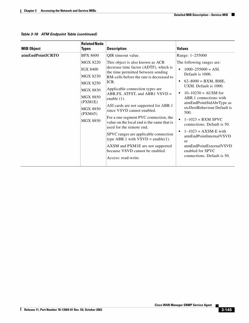
Chapter 3 Accessing the Network and Service MIBsDetailed MIB Description—Service MIB
atmEndPointICRTO BPX 8600
MGX 8220
IGX 8400
MGX 8230
MGX 8250
MGX 8830
MGX 8850 (PXM1E)
MGX 8850 (PXM45)
MGX 8850
QIR timeout value.
This object is also known as ACR decrease time factor (ADTF), which is the time permitted between sending RM-cells before the rate is decreased to ICR.
Applicable connection types are ABR.FS, ATFST, and ABR1 VSVD = enable (1).
ASI cards are not supported for ABR.1 since VSVD cannot enabled.
For a one segment PVC connection, the value on the local end is the same that is used for the remote end.
SPVC ranges are applicable connection type ABR.1 with VSVD = enable(1).
AXSM and PXM1E are not supported because VSVD cannot be enabled.
Access: read-write.
Range: 1–255000
The following ranges are:
• 1000–255000 = ASI. Default is 1000.
• 62–8000 = BXM, BME, UXM. Default is 1000.
• 10–10230 = AUSM for ABR.1 connections with atmEndPointStdAbrType as srcDestBehaviour Default is 500.
• 1–1023 = BXM SPVC connections. Default is 50.
• 1–1023 = AXSM-E with atmEndPointInternalVSVDor atmEndPointExternalVSVD enabled for SPVC connections. Default is 50.
Table 3-18 ATM Endpoint Table (continued)
MIB ObjectRelated Node Types Description Values
3-145Cisco WAN Manager SNMP Service Agent
Release 11, Part Number 78-13569-01 Rev. E0, October 2003
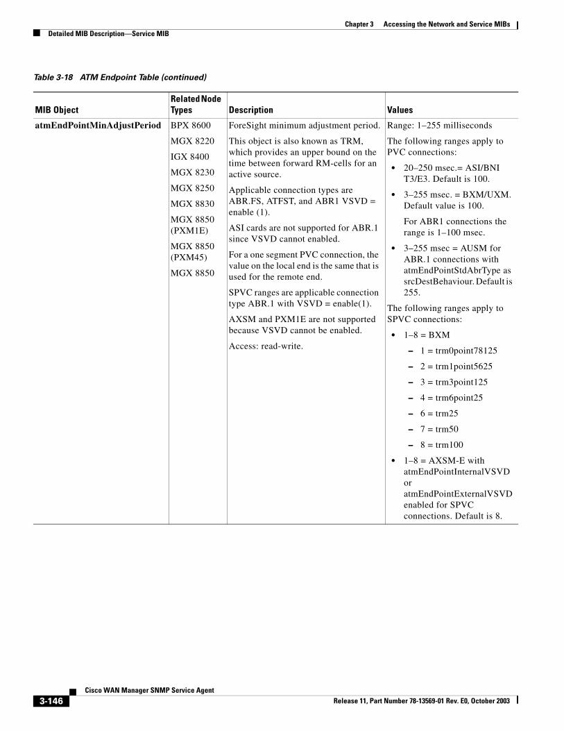
Chapter 3 Accessing the Network and Service MIBsDetailed MIB Description—Service MIB
atmEndPointMinAdjustPeriod BPX 8600
MGX 8220
IGX 8400
MGX 8230
MGX 8250
MGX 8830
MGX 8850 (PXM1E)
MGX 8850 (PXM45)
MGX 8850
ForeSight minimum adjustment period.
This object is also known as TRM, which provides an upper bound on the time between forward RM-cells for an active source.
Applicable connection types are ABR.FS, ATFST, and ABR1 VSVD = enable (1).
ASI cards are not supported for ABR.1 since VSVD cannot enabled.
For a one segment PVC connection, the value on the local end is the same that is used for the remote end.
SPVC ranges are applicable connection type ABR.1 with VSVD = enable(1).
AXSM and PXM1E are not supported because VSVD cannot be enabled.
Access: read-write.
Range: 1–255 milliseconds
The following ranges apply to PVC connections:
• 20–250 msec.= ASI/BNI T3/E3. Default is 100.
• 3–255 msec. = BXM/UXM. Default value is 100.
For ABR1 connections the range is 1–100 msec.
• 3–255 msec = AUSM for ABR.1 connections with atmEndPointStdAbrType as srcDestBehaviour. Default is 255.
The following ranges apply to SPVC connections:
• 1–8 = BXM
– 1 = trm0point78125
– 2 = trm1point5625
– 3 = trm3point125
– 4 = trm6point25
– 6 = trm25
– 7 = trm50
– 8 = trm100
• 1–8 = AXSM-E with atmEndPointInternalVSVDor atmEndPointExternalVSVD enabled for SPVC connections. Default is 8.
Table 3-18 ATM Endpoint Table (continued)
MIB ObjectRelated Node Types Description Values
3-146Cisco WAN Manager SNMP Service Agent
Release 11, Part Number 78-13569-01 Rev. E0, October 2003
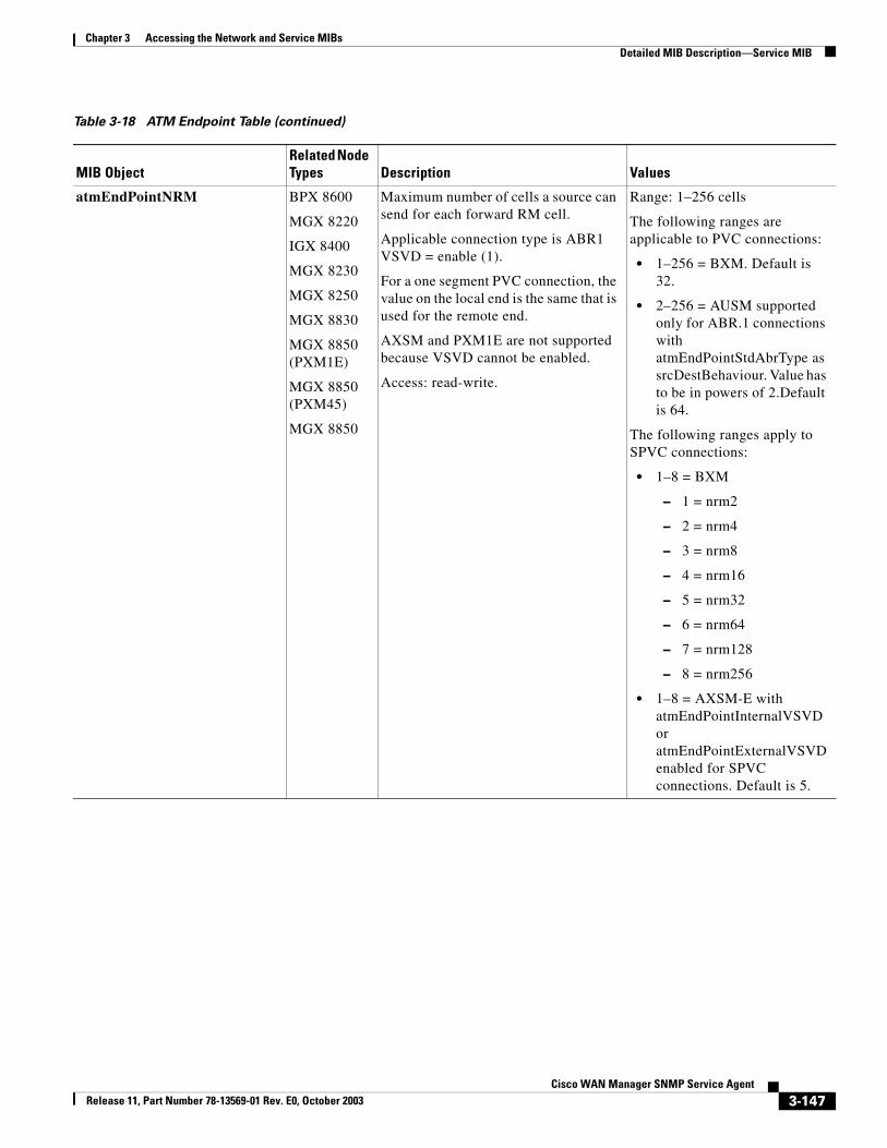
Chapter 3 Accessing the Network and Service MIBsDetailed MIB Description—Service MIB
atmEndPointNRM BPX 8600
MGX 8220
IGX 8400
MGX 8230
MGX 8250
MGX 8830
MGX 8850 (PXM1E)
MGX 8850 (PXM45)
MGX 8850
Maximum number of cells a source can send for each forward RM cell.
Applicable connection type is ABR1 VSVD = enable (1).
For a one segment PVC connection, the value on the local end is the same that is used for the remote end.
AXSM and PXM1E are not supported because VSVD cannot be enabled.
Access: read-write.
Range: 1–256 cells
The following ranges are applicable to PVC connections:
• 1–256 = BXM. Default is 32.
• 2–256 = AUSM supported only for ABR.1 connections with atmEndPointStdAbrType as srcDestBehaviour. Value has to be in powers of 2.Default is 64.
The following ranges apply to SPVC connections:
• 1–8 = BXM
– 1 = nrm2
– 2 = nrm4
– 3 = nrm8
– 4 = nrm16
– 5 = nrm32
– 6 = nrm64
– 7 = nrm128
– 8 = nrm256
• 1–8 = AXSM-E with atmEndPointInternalVSVDor atmEndPointExternalVSVD enabled for SPVC connections. Default is 5.
Table 3-18 ATM Endpoint Table (continued)
MIB ObjectRelated Node Types Description Values
3-147Cisco WAN Manager SNMP Service Agent
Release 11, Part Number 78-13569-01 Rev. E0, October 2003
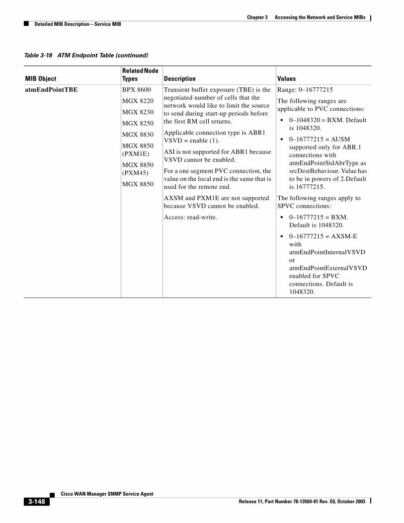
Chapter 3 Accessing the Network and Service MIBsDetailed MIB Description—Service MIB
atmEndPointTBE BPX 8600
MGX 8220
MGX 8230
MGX 8250
MGX 8830
MGX 8850 (PXM1E)
MGX 8850 (PXM45)
MGX 8850
Transient buffer exposure (TBE) is the negotiated number of cells that the network would like to limit the source to send during start-up periods before the first RM cell returns.
Applicable connection type is ABR1 VSVD = enable (1).
ASI is not supported for ABR1 because VSVD cannot be enabled.
For a one segment PVC connection, the value on the local end is the same that is used for the remote end.
AXSM and PXM1E are not supported because VSVD cannot be enabled.
Access: read-write.
Range: 0–16777215
The following ranges are applicable to PVC connections:
• 0–1048320 = BXM. Default is 1048320.
• 0–16777215 = AUSM supported only for ABR.1 connections with atmEndPointStdAbrType as srcDestBehaviour. Value has to be in powers of 2.Default is 16777215.
The following ranges apply to SPVC connections:
• 0–16777215 = BXM. Default is 1048320.
• 0–16777215 = AXSM-E with atmEndPointInternalVSVDor atmEndPointExternalVSVD enabled for SPVC connections. Default is 1048320.
Table 3-18 ATM Endpoint Table (continued)
MIB ObjectRelated Node Types Description Values
3-148Cisco WAN Manager SNMP Service Agent
Release 11, Part Number 78-13569-01 Rev. E0, October 2003
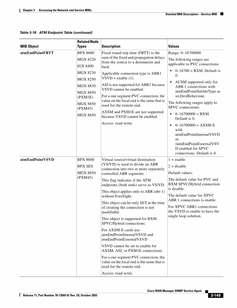
Chapter 3 Accessing the Network and Service MIBsDetailed MIB Description—Service MIB
atmEndPointFRTT BPX 8600
MGX 8220
IGX 8400
MGX 8230
MGX 8250
MGX 8830
MGX 8850 (PXM1E)
MGX 8850 (PXM45)
MGX 8850
Fixed round-trip time (FRTT) is the sum of the fixed and propagation delays from the source to a destination and back.
Applicable connection type is ABR1 VSVD = enable (1).
ASI is not supported for ABR1 because VSVD cannot be enabled.
For a one segment PVC connection, the value on the local end is the same that is used for the remote end.
AXSM and PXM1E are not supported because VSVD cannot be enabled.
Access: read-write.
Range: 0–16700000
The following ranges are applicable to PVC connections:
• 0–16700 = BXM. Default is 0.
• AUSM supported only for ABR.1 connections with atmEndPointStdAbrType as srcDestBehaviour.
The following ranges apply to SPVC connections:
• 0–16700000 = BXM. Default is 0.
• 0–16700000 = AXSM-E with atmEndPointInternalVSVDor /atmEndPointExternalVSVD enabled for SPVC connections. Default is 0.
atmEndPointVSVD BPX 8600
BPX SES
MGX 8850 (PXM45)
Virtual source/virtual destination (VS/VD) is used to divide an ABR connection into two or more separately controlled ABR segments.
This flag indicates if the ATM endpoints (both ends) serve as VS/VD.
This object applies only to ABR (abr-1) without ForeSight.
This object can be only SET at the time of creating the connection is not modifiable.
This object is supported for BXM SPVC/Hybrid connections.
For AXSM-E cards use atmEndPointInternalVSVD and atmEndPointExternalVSVD
VSVD cannot be set to enable for AXSM, ASI, or PXM1E connections.
For a one segment PVC connection, the value on the local end is the same that is used for the remote end.
Access: read-write.
1 = enable
2 = disable
Default values:
The default value for PVC and BXM SPVC/Hybrid connection is disable.
The default value for XPVC ABR.1 connections is enable.
For XPVC ABR1 connections the VSVD is enable to have the single loop solution.
Table 3-18 ATM Endpoint Table (continued)
MIB ObjectRelated Node Types Description Values
3-149Cisco WAN Manager SNMP Service Agent
Release 11, Part Number 78-13569-01 Rev. E0, October 2003
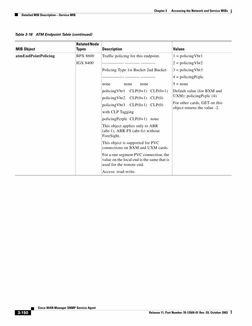
Chapter 3 Accessing the Network and Service MIBsDetailed MIB Description—Service MIB
atmEndPointPolicing BPX 8600
IGX 8400
Traffic policing for this endpoint.
--------------- ---------- ----------
Policing Type 1st Bucket 2nd Bucket
--------------- ---------- ----------
none none none
policingVbr1 CLP(0+1) CLP(0+1)
policingVbr2 CLP(0+1) CLP(0)
policingVbr3 CLP(0+1) CLP(0)
with CLP Tagging
policingPcrplc CLP(0+1) none
This object applies only to ABR (abr-1), ABR-FS (abr-fs) without ForeSight.
This object is supported for PVC connections on BXM and UXM cards.
For a one segment PVC connection, the value on the local end is the same that is used for the remote end.
Access: read-write.
1 = policingVbr1
2 = policingVbr2
3 = policingVbr3
4 = policingPcplc
5 = none
Default value (for BXM and UXM): policingPcplc (4).
For other cards, GET on this object returns the value -2.
Table 3-18 ATM Endpoint Table (continued)
MIB ObjectRelated Node Types Description Values
3-150Cisco WAN Manager SNMP Service Agent
Release 11, Part Number 78-13569-01 Rev. E0, October 2003
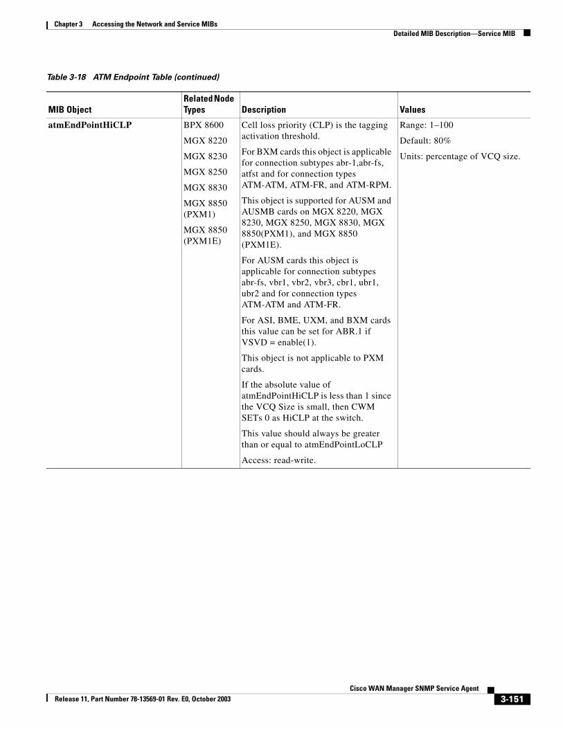
Chapter 3 Accessing the Network and Service MIBsDetailed MIB Description—Service MIB
atmEndPointHiCLP BPX 8600
MGX 8220
MGX 8230
MGX 8250
MGX 8830
MGX 8850 (PXM1)
MGX 8850 (PXM1E)
Cell loss priority (CLP) is the tagging activation threshold.
For BXM cards this object is applicable for connection subtypes abr-1,abr-fs, atfst and for connection types ATM-ATM, ATM-FR, and ATM-RPM.
This object is supported for AUSM and AUSMB cards on MGX 8220, MGX 8230, MGX 8250, MGX 8830, MGX 8850(PXM1), and MGX 8850 (PXM1E).
For AUSM cards this object is applicable for connection subtypes abr-fs, vbr1, vbr2, vbr3, cbr1, ubr1, ubr2 and for connection types ATM-ATM and ATM-FR.
For ASI, BME, UXM, and BXM cards this value can be set for ABR.1 if VSVD = enable(1).
This object is not applicable to PXM cards.
If the absolute value of atmEndPointHiCLP is less than 1 since the VCQ Size is small, then CWM SETs 0 as HiCLP at the switch.
This value should always be greater than or equal to atmEndPointLoCLP
Access: read-write.
Range: 1–100
Default: 80%
Units: percentage of VCQ size.
Table 3-18 ATM Endpoint Table (continued)
MIB ObjectRelated Node Types Description Values
3-151Cisco WAN Manager SNMP Service Agent
Release 11, Part Number 78-13569-01 Rev. E0, October 2003
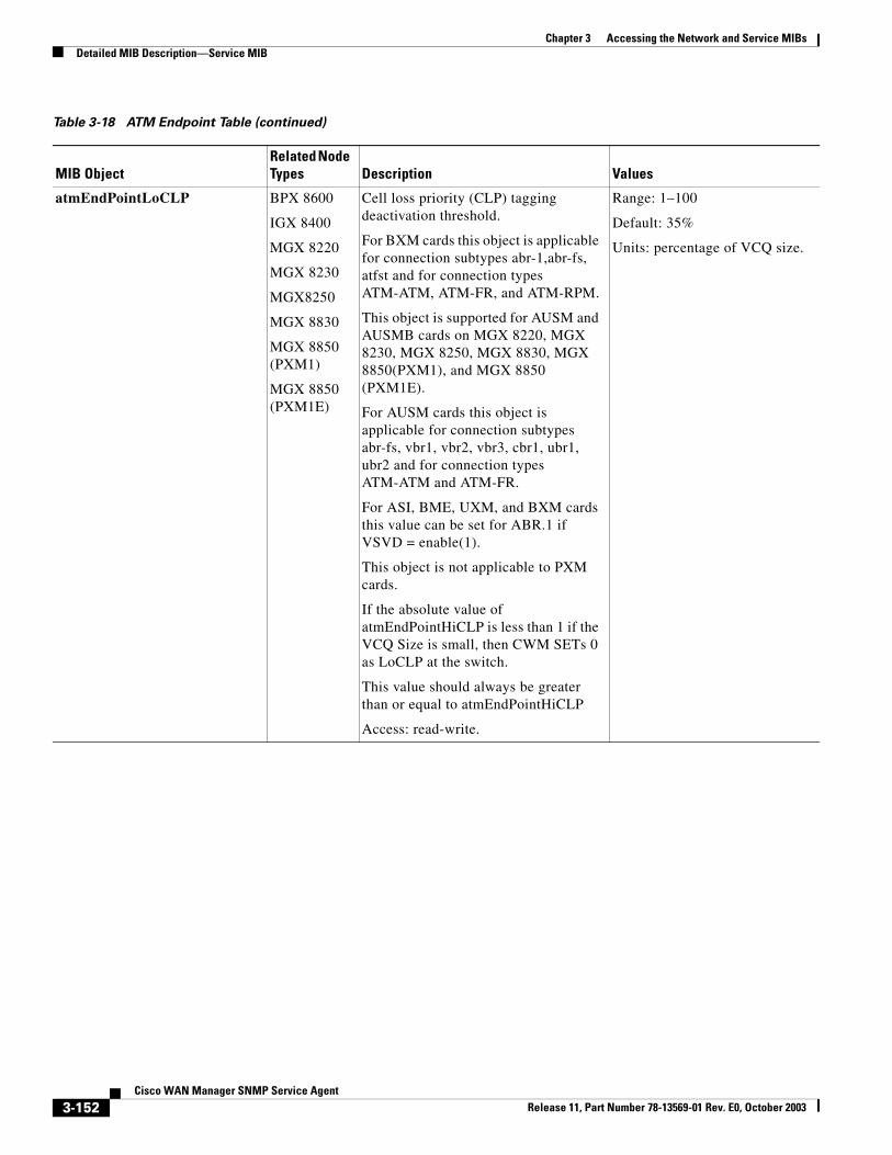
Chapter 3 Accessing the Network and Service MIBsDetailed MIB Description—Service MIB
atmEndPointLoCLP BPX 8600
IGX 8400
MGX 8220
MGX 8230
MGX8250
MGX 8830
MGX 8850 (PXM1)
MGX 8850 (PXM1E)
Cell loss priority (CLP) tagging deactivation threshold.
For BXM cards this object is applicable for connection subtypes abr-1,abr-fs, atfst and for connection types ATM-ATM, ATM-FR, and ATM-RPM.
This object is supported for AUSM and AUSMB cards on MGX 8220, MGX 8230, MGX 8250, MGX 8830, MGX 8850(PXM1), and MGX 8850 (PXM1E).
For AUSM cards this object is applicable for connection subtypes abr-fs, vbr1, vbr2, vbr3, cbr1, ubr1, ubr2 and for connection types ATM-ATM and ATM-FR.
For ASI, BME, UXM, and BXM cards this value can be set for ABR.1 if VSVD = enable(1).
This object is not applicable to PXM cards.
If the absolute value of atmEndPointHiCLP is less than 1 if the VCQ Size is small, then CWM SETs 0 as LoCLP at the switch.
This value should always be greater than or equal to atmEndPointHiCLP
Access: read-write.
Range: 1–100
Default: 35%
Units: percentage of VCQ size.
Table 3-18 ATM Endpoint Table (continued)
MIB ObjectRelated Node Types Description Values
3-152Cisco WAN Manager SNMP Service Agent
Release 11, Part Number 78-13569-01 Rev. E0, October 2003
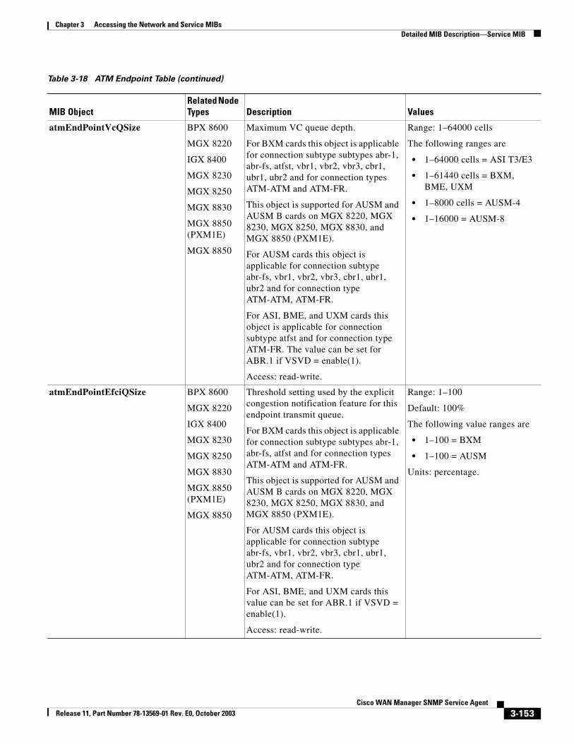
Chapter 3 Accessing the Network and Service MIBsDetailed MIB Description—Service MIB
atmEndPointVcQSize BPX 8600
MGX 8220
IGX 8400
MGX 8230
MGX 8250
MGX 8830
MGX 8850 (PXM1E)
MGX 8850
Maximum VC queue depth.
For BXM cards this object is applicable for connection subtype subtypes abr-1, abr-fs, atfst, vbr1, vbr2, vbr3, cbr1, ubr1, ubr2 and for connection types ATM-ATM and ATM-FR.
This object is supported for AUSM and AUSM B cards on MGX 8220, MGX 8230, MGX 8250, MGX 8830, and MGX 8850 (PXM1E).
For AUSM cards this object is applicable for connection subtype abr-fs, vbr1, vbr2, vbr3, cbr1, ubr1, ubr2 and for connection type ATM-ATM, ATM-FR.
For ASI, BME, and UXM cards this object is applicable for connection subtype atfst and for connection type ATM-FR. The value can be set for ABR.1 if VSVD = enable(1).
Access: read-write.
Range: 1–64000 cells
The following ranges are
• 1–64000 cells = ASI T3/E3
• 1–61440 cells = BXM, BME, UXM
• 1–8000 cells = AUSM-4
• 1–16000 = AUSM-8
atmEndPointEfciQSize BPX 8600
MGX 8220
IGX 8400
MGX 8230
MGX 8250
MGX 8830
MGX 8850 (PXM1E)
MGX 8850
Threshold setting used by the explicit congestion notification feature for this endpoint transmit queue.
For BXM cards this object is applicable for connection subtype subtypes abr-1, abr-fs, atfst and for connection types ATM-ATM and ATM-FR.
This object is supported for AUSM and AUSM B cards on MGX 8220, MGX 8230, MGX 8250, MGX 8830, and MGX 8850 (PXM1E).
For AUSM cards this object is applicable for connection subtype abr-fs, vbr1, vbr2, vbr3, cbr1, ubr1, ubr2 and for connection type ATM-ATM, ATM-FR.
For ASI, BME, and UXM cards this value can be set for ABR.1 if VSVD = enable(1).
Access: read-write.
Range: 1–100
Default: 100%
The following value ranges are
• 1–100 = BXM
• 1–100 = AUSM
Units: percentage.
Table 3-18 ATM Endpoint Table (continued)
MIB ObjectRelated Node Types Description Values
3-153Cisco WAN Manager SNMP Service Agent
Release 11, Part Number 78-13569-01 Rev. E0, October 2003
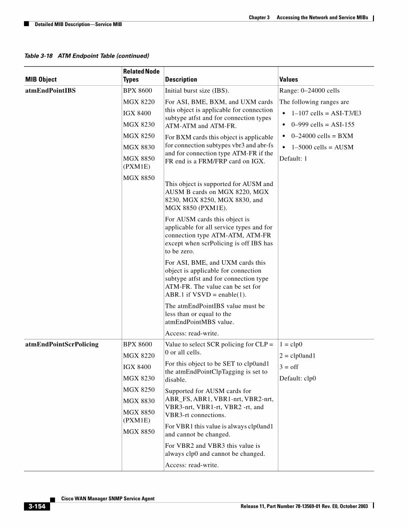
Chapter 3 Accessing the Network and Service MIBsDetailed MIB Description—Service MIB
atmEndPointIBS BPX 8600
MGX 8220
IGX 8400
MGX 8230
MGX 8250
MGX 8830
MGX 8850 (PXM1E)
MGX 8850
Initial burst size (IBS).
For ASI, BME, BXM, and UXM cards this object is applicable for connection subtype atfst and for connection types ATM-ATM and ATM-FR.
For BXM cards this object is applicable for connection subtypes vbr3 and abr-fs and for connection type ATM-FR if the FR end is a FRM/FRP card on IGX.
This object is supported for AUSM and AUSM B cards on MGX 8220, MGX 8230, MGX 8250, MGX 8830, and MGX 8850 (PXM1E).
For AUSM cards this object is applicable for all service types and for connection type ATM-ATM, ATM-FR except when scrPolicing is off IBS has to be zero.
For ASI, BME, and UXM cards this object is applicable for connection subtype atfst and for connection type ATM-FR. The value can be set for ABR.1 if VSVD = enable(1).
The atmEndPointIBS value must be less than or equal to the atmEndPointMBS value.
Access: read-write.
Range: 0–24000 cells
The following ranges are
• 1–107 cells = ASI-T3/E3
• 0–999 cells = ASI-155
• 0–24000 cells = BXM
• 1–5000 cells = AUSM
Default: 1
atmEndPointScrPolicing BPX 8600
MGX 8220
IGX 8400
MGX 8230
MGX 8250
MGX 8830
MGX 8850 (PXM1E)
MGX 8850
Value to select SCR policing for CLP = 0 or all cells.
For this object to be SET to clp0and1 the atmEndPointClpTagging is set to disable.
Supported for AUSM cards for ABR_FS, ABR1, VBR1-nrt, VBR2-nrt, VBR3-nrt, VBR1-rt, VBR2 -rt, and VBR3-rt connections.
For VBR1 this value is always clp0and1 and cannot be changed.
For VBR2 and VBR3 this value is always clp0 and cannot be changed.
Access: read-write.
1 = clp0
2 = clp0and1
3 = off
Default: clp0
Table 3-18 ATM Endpoint Table (continued)
MIB ObjectRelated Node Types Description Values
3-154Cisco WAN Manager SNMP Service Agent
Release 11, Part Number 78-13569-01 Rev. E0, October 2003
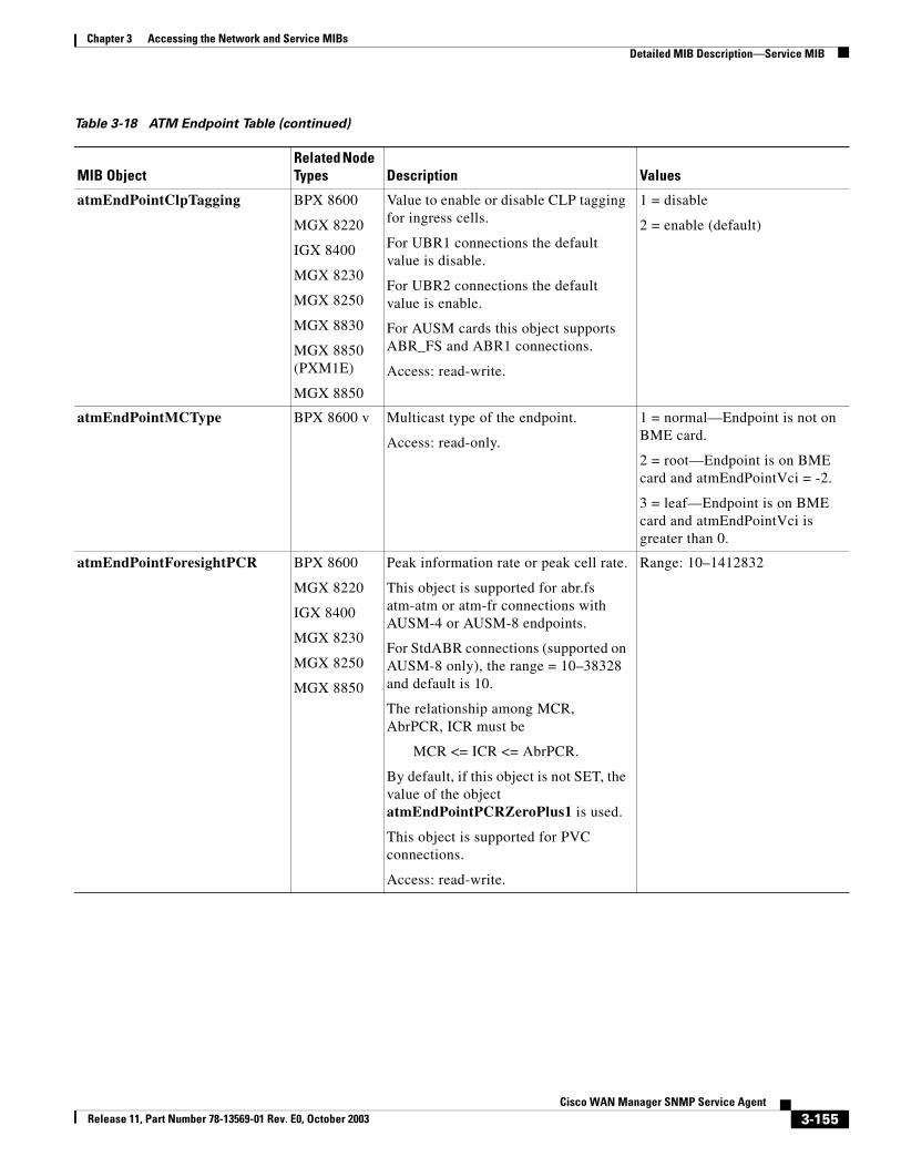
Chapter 3 Accessing the Network and Service MIBsDetailed MIB Description—Service MIB
atmEndPointClpTagging BPX 8600
MGX 8220
IGX 8400
MGX 8230
MGX 8250
MGX 8830
MGX 8850 (PXM1E)
MGX 8850
Value to enable or disable CLP tagging for ingress cells.
For UBR1 connections the default value is disable.
For UBR2 connections the default value is enable.
For AUSM cards this object supports ABR_FS and ABR1 connections.
Access: read-write.
1 = disable
2 = enable (default)
atmEndPointMCType BPX 8600 v Multicast type of the endpoint.
Access: read-only.
1 = normal—Endpoint is not on BME card.
2 = root—Endpoint is on BME card and atmEndPointVci = -2.
3 = leaf—Endpoint is on BME card and atmEndPointVci is greater than 0.
atmEndPointForesightPCR BPX 8600
MGX 8220
IGX 8400
MGX 8230
MGX 8250
MGX 8850
Peak information rate or peak cell rate.
This object is supported for abr.fs atm-atm or atm-fr connections with AUSM-4 or AUSM-8 endpoints.
For StdABR connections (supported on AUSM-8 only), the range = 10–38328 and default is 10.
The relationship among MCR, AbrPCR, ICR must be
MCR <= ICR <= AbrPCR.
By default, if this object is not SET, the value of the object atmEndPointPCRZeroPlus1 is used.
This object is supported for PVC connections.
Access: read-write.
Range: 10–1412832
Table 3-18 ATM Endpoint Table (continued)
MIB ObjectRelated Node Types Description Values
3-155Cisco WAN Manager SNMP Service Agent
Release 11, Part Number 78-13569-01 Rev. E0, October 2003
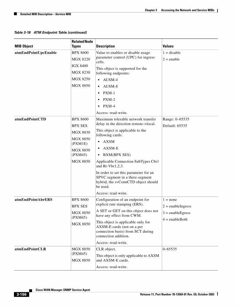
Chapter 3 Accessing the Network and Service MIBsDetailed MIB Description—Service MIB
atmEndPointUpcEnable BPX 8600
MGX 8220
IGX 8400
MGX 8230
MGX 8250
MGX 8850
Value to enables or disable usage parameter control (UPC) for ingress cells.
This object is supported for the following endpoints:
• AUSM-4
• AUSM-8
• PXM-1
• PXM-2
• PXM-4
Access: read-write.
1 = disable
2 = enable
atmEndPointCTD BPX 8600
BPX SES
MGX 8830
MGX 8850 (PXM1E)
MGX 8850 (PXM45)
MGX 8850
Maximum tolerable network transfer delay in the direction remote->local.
This object is applicable to the following cards:
• AXSM
• AXSM-E
• BXM(BPX SES)
Applicable Connection SubTypes Cbr1 and Rt-Vbr1,2,3.
In order to set this parameter for an SPVC segment in a three-segment hybrid, the svConnCTD object should be used.
Access: read-write.
Range: 0–65535
Default: 65535
atmEndPointAbrERS BPX 8600
BPX SES
MGX 8850 (PXM45)
MGX 8850
Configuration of an endpoint for explicit rate stamping (ERS).
A SET or GET on this object does not have any effect from CWM.
This object is applicable only for AXSM-E cards (not on a per connection basis) from SCT during connection addition.
Access: read-write.
1 = none
2 = enableIngress
3 = enableEgress
4 = enableBoth
atmEndPointCLR MGX 8850 (PXM45)
MGX 8850
CLR object.
This object is only applicable to AXSM and AXSM-E cards.
Access: read-write.
0–65535
Table 3-18 ATM Endpoint Table (continued)
MIB ObjectRelated Node Types Description Values
3-156Cisco WAN Manager SNMP Service Agent
Release 11, Part Number 78-13569-01 Rev. E0, October 2003
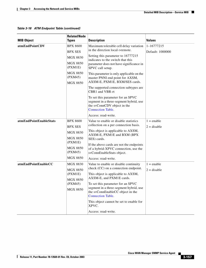
Chapter 3 Accessing the Network and Service MIBsDetailed MIB Description—Service MIB
atmEndPointCDV BPX 8600
BPX SES
MGX 8830
MGX 8850 (PXM1E)
MGX 8850 (PXM45)
MGX 8850
Maximum tolerable cell delay variation in the direction local->remote.
Setting this parameter to 16777215 indicates to the switch that this parameter does not have significance in SPVC call setup.
This parameter is only applicable on the master PNNI end point for AXSM, AXSM-E, PXM1E, BXM/SES cards.
The supported connection subtypes are CBR1 and VBR-rt
To set this parameter for an SPVC segment in a three-segment hybrid, use the svConnCDV object in the Connection Table.
Access: read-write.
1–16777215
Default: 1000000
atmEndPointEnableStats BPX 8600
BPX SES
MGX 8830
MGX 8850 (PXM1E)
MGX 8850 (PXM45)
MGX 8850
Value to enable or disable statistics collection on a per connection basis.
This object is applicable to AXSM, AXSM-E, PXM1E and BXM (BPX SES) cards.
If the above cards are not the endpoints of a hybrid-XPVC connection, use the svConnEnableStats object.
Access: read-write.
1 = enable
2 = disable
atmEndPointEnableCC MGX 8830
MGX 8850 (PXM1E)
MGX 8850 (PXM45)
MGX 8850
Value to enable or disable continuity check (CC) on a connection endpoint.
This object is applicable to AXSM, AXSM-E, and PXM1E cards.
To set this parameter for an SPVC segment in a three-segment hybrid, use the svConnEnableCC object in the Connection Table.
This object cannot be set to enable for XPVC.
Access: read-write.
1 = enable
2 = disable
Table 3-18 ATM Endpoint Table (continued)
MIB ObjectRelated Node Types Description Values
3-157Cisco WAN Manager SNMP Service Agent
Release 11, Part Number 78-13569-01 Rev. E0, October 2003
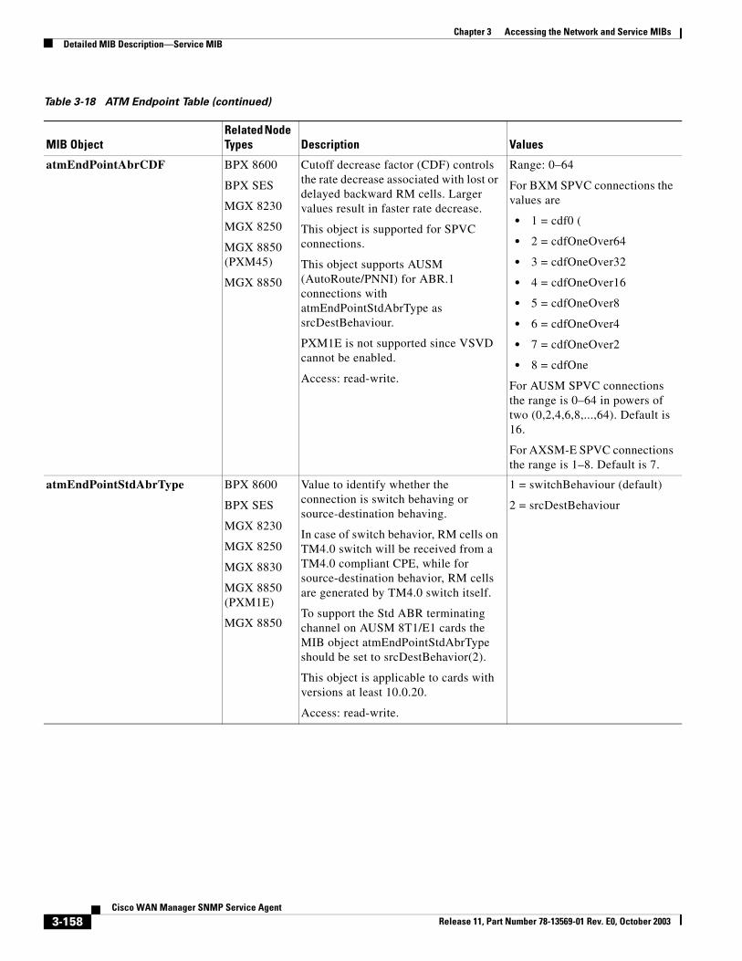
Chapter 3 Accessing the Network and Service MIBsDetailed MIB Description—Service MIB
atmEndPointAbrCDF BPX 8600
BPX SES
MGX 8230
MGX 8250
MGX 8850 (PXM45)
MGX 8850
Cutoff decrease factor (CDF) controls the rate decrease associated with lost or delayed backward RM cells. Larger values result in faster rate decrease.
This object is supported for SPVC connections.
This object supports AUSM (AutoRoute/PNNI) for ABR.1 connections with atmEndPointStdAbrType as srcDestBehaviour.
PXM1E is not supported since VSVD cannot be enabled.
Access: read-write.
Range: 0–64
For BXM SPVC connections the values are
• 1 = cdf0 (
• 2 = cdfOneOver64
• 3 = cdfOneOver32
• 4 = cdfOneOver16
• 5 = cdfOneOver8
• 6 = cdfOneOver4
• 7 = cdfOneOver2
• 8 = cdfOne
For AUSM SPVC connections the range is 0–64 in powers of two (0,2,4,6,8,...,64). Default is 16.
For AXSM-E SPVC connections the range is 1–8. Default is 7.
atmEndPointStdAbrType BPX 8600
BPX SES
MGX 8230
MGX 8250
MGX 8830
MGX 8850 (PXM1E)
MGX 8850
Value to identify whether the connection is switch behaving or source-destination behaving.
In case of switch behavior, RM cells on TM4.0 switch will be received from a TM4.0 compliant CPE, while for source-destination behavior, RM cells are generated by TM4.0 switch itself.
To support the Std ABR terminating channel on AUSM 8T1/E1 cards the MIB object atmEndPointStdAbrType should be set to srcDestBehavior(2).
This object is applicable to cards with versions at least 10.0.20.
Access: read-write.
1 = switchBehaviour (default)
2 = srcDestBehaviour
Table 3-18 ATM Endpoint Table (continued)
MIB ObjectRelated Node Types Description Values
3-158Cisco WAN Manager SNMP Service Agent
Release 11, Part Number 78-13569-01 Rev. E0, October 2003
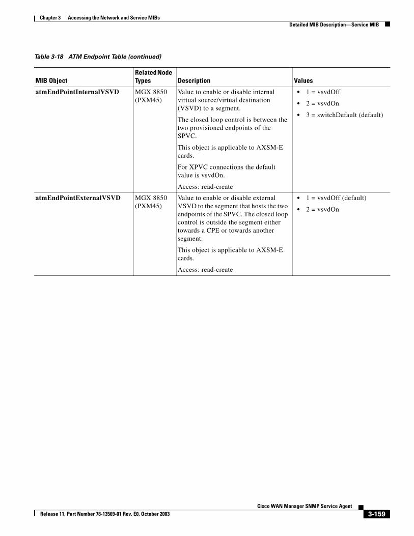
Chapter 3 Accessing the Network and Service MIBsDetailed MIB Description—Service MIB
atmEndPointInternalVSVD MGX 8850 (PXM45)
Value to enable or disable internal virtual source/virtual destination (VSVD) to a segment.
The closed loop control is between the two provisioned endpoints of the SPVC.
This object is applicable to AXSM-E cards.
For XPVC connections the default value is vsvdOn.
Access: read-create
• 1 = vsvdOff
• 2 = vsvdOn
• 3 = switchDefault (default)
atmEndPointExternalVSVD MGX 8850 (PXM45)
Value to enable or disable external VSVD to the segment that hosts the two endpoints of the SPVC. The closed loop control is outside the segment either towards a CPE or towards another segment.
This object is applicable to AXSM-E cards.
Access: read-create
• 1 = vsvdOff (default)
• 2 = vsvdOn
Table 3-18 ATM Endpoint Table (continued)
MIB ObjectRelated Node Types Description Values
3-159Cisco WAN Manager SNMP Service Agent
Release 11, Part Number 78-13569-01 Rev. E0, October 2003
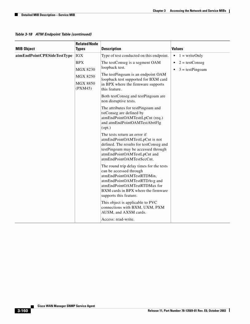
Chapter 3 Accessing the Network and Service MIBsDetailed MIB Description—Service MIB
atmEndPointCPESideTestType IGX
BPX
MGX 8230
MGX 8250
MGX 8850 (PXM45)
Type of test conducted on this endpoint.
The testConseg is a segment OAM loopback test.
The testPingoam is an endpoint OAM loopback test supported for BXM card in BPX where the firmware supports this feature.
Both testConseg and testPingoam are non disruptive tests.
The attributes for testPingoam and tstConseg are defined by atmEndPointOAMTesttLpCnt (req.) and atmEndPointOAMTestAbrtFlg (opt.)
The tests return an error if atmEndPointOAMTestLpCnt is not defined. The results for testConseg and testPingoam may be accessed through atmEndPointOAMTestLpCnt and atmEndPointOAMTestSccCnt.
The round trip delay times for the tests can be accessed through atmEndPointOAMTestRTDMin, atmEndPointOAMTestRTDAvg and atmEndPointOAMTestRTDMax for BXM cards in BPX where the firmware supports this feature.
This object is applicable to PVC connections with BXM, UXM, PXM AUSM, and AXSM cards.
Access: read-write.
• 1 = writeOnly
• 2 = testConseg
• 3 = testPingoam
Table 3-18 ATM Endpoint Table (continued)
MIB ObjectRelated Node Types Description Values
3-160Cisco WAN Manager SNMP Service Agent
Release 11, Part Number 78-13569-01 Rev. E0, October 2003
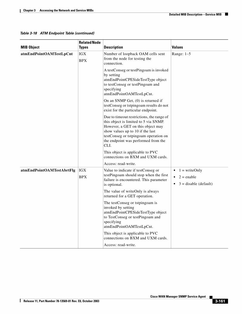
Chapter 3 Accessing the Network and Service MIBsDetailed MIB Description—Service MIB
atmEndPointOAMTestLpCnt IGX
BPX
Number of loopback OAM cells sent from the node for testing the connection.
A testConseg or testPingoam is invoked by setting atmEndPointCPESideTestType object to testConseg or testPingoam and specifying atmEndPointOAMTestLpCnt.
On an SNMP Get, (0) is returned if testConseg or tstpingoam results do not exist for the particular endpoint.
Due to timeout restrictions, the range of this object is limited to 5 via SNMP. However, a GET on this object may show values up to 10 if the last testConseg or tstpingoam operation on the endpoint was performed from the CLI.
This object is applicable to PVC connections on BXM and UXM cards.
Access: read-write.
Range: 1–5
atmEndPointOAMTestAbrtFlg IGX
BPX
Value to indicate if testConseg or testPingoam should stop when the first failure is encountered. This parameter is optional.
The value of writeOnly is always returned for a GET operation.
The testConseg or tstpingoam is invoked by setting atmEndPointCPESideTestType object to TestConseg or testPingoam and specifying atmEndPointOAMTestLpCnt.
This object is applicable to PVC connections on BXM and UXM cards.
Access: read-write.
• 1 = writeOnly
• 2 = enable
• 3 = disable (default)
Table 3-18 ATM Endpoint Table (continued)
MIB ObjectRelated Node Types Description Values
3-161Cisco WAN Manager SNMP Service Agent
Release 11, Part Number 78-13569-01 Rev. E0, October 2003
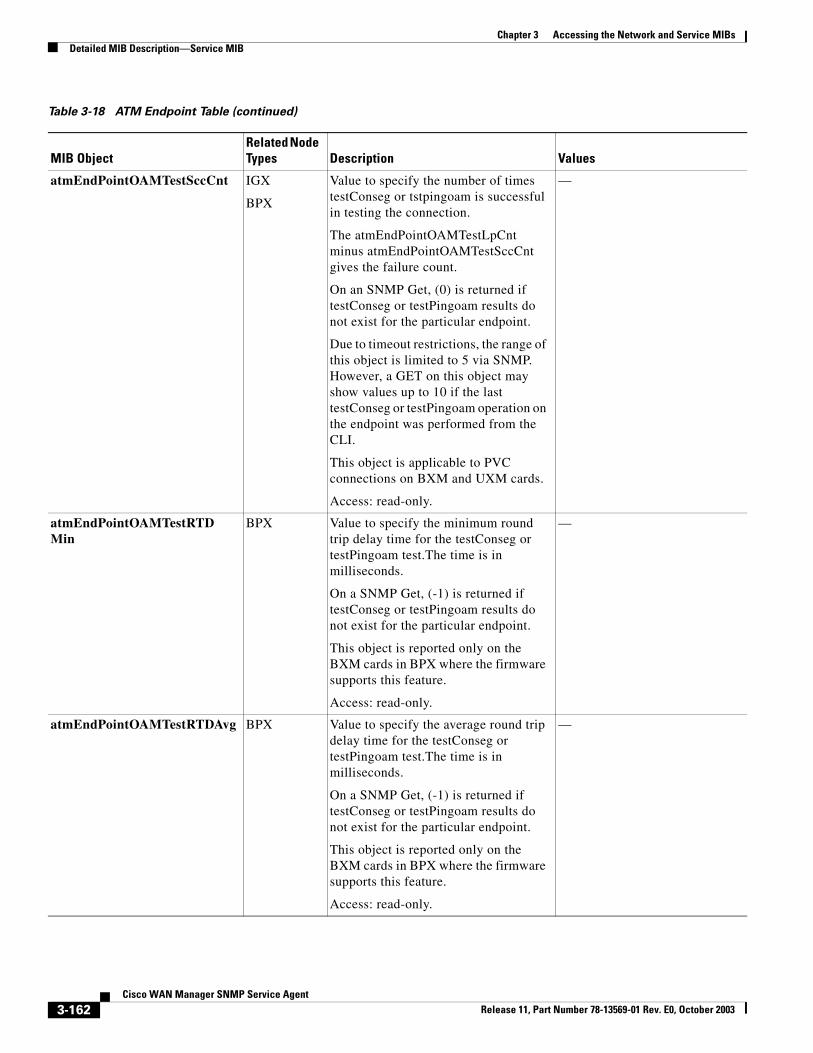
Chapter 3 Accessing the Network and Service MIBsDetailed MIB Description—Service MIB
atmEndPointOAMTestSccCnt IGX
BPX
Value to specify the number of times testConseg or tstpingoam is successful in testing the connection.
The atmEndPointOAMTestLpCnt minus atmEndPointOAMTestSccCnt gives the failure count.
On an SNMP Get, (0) is returned if testConseg or testPingoam results do not exist for the particular endpoint.
Due to timeout restrictions, the range of this object is limited to 5 via SNMP. However, a GET on this object may show values up to 10 if the last testConseg or testPingoam operation on the endpoint was performed from the CLI.
This object is applicable to PVC connections on BXM and UXM cards.
Access: read-only.
—
atmEndPointOAMTestRTDMin
BPX Value to specify the minimum round trip delay time for the testConseg or testPingoam test.The time is in milliseconds.
On a SNMP Get, (-1) is returned if testConseg or testPingoam results do not exist for the particular endpoint.
This object is reported only on the BXM cards in BPX where the firmware supports this feature.
Access: read-only.
—
atmEndPointOAMTestRTDAvg BPX Value to specify the average round trip delay time for the testConseg or testPingoam test.The time is in milliseconds.
On a SNMP Get, (-1) is returned if testConseg or testPingoam results do not exist for the particular endpoint.
This object is reported only on the BXM cards in BPX where the firmware supports this feature.
Access: read-only.
—
Table 3-18 ATM Endpoint Table (continued)
MIB ObjectRelated Node Types Description Values
3-162Cisco WAN Manager SNMP Service Agent
Release 11, Part Number 78-13569-01 Rev. E0, October 2003
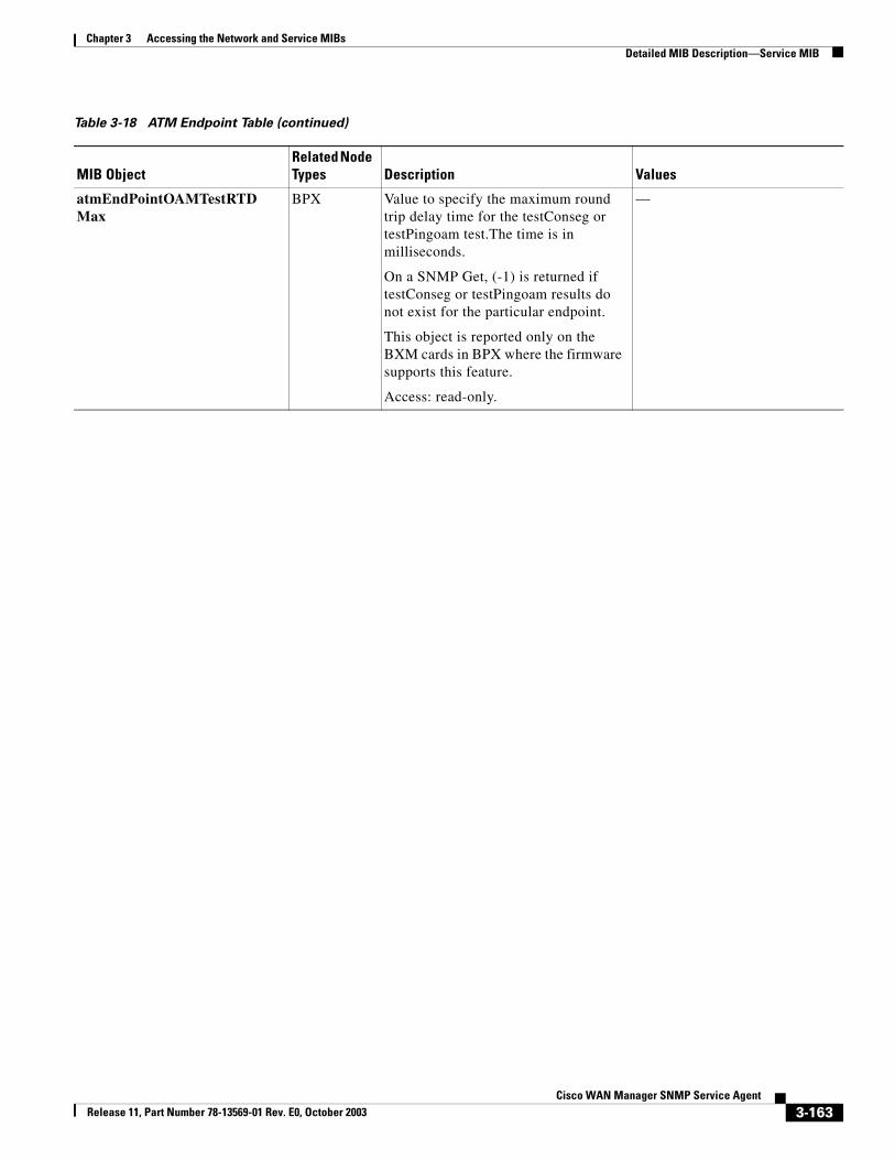
Chapter 3 Accessing the Network and Service MIBsDetailed MIB Description—Service MIB
atmEndPointOAMTestRTDMax
BPX Value to specify the maximum round trip delay time for the testConseg or testPingoam test.The time is in milliseconds.
On a SNMP Get, (-1) is returned if testConseg or testPingoam results do not exist for the particular endpoint.
This object is reported only on the BXM cards in BPX where the firmware supports this feature.
Access: read-only.
—
Table 3-18 ATM Endpoint Table (continued)
MIB ObjectRelated Node Types Description Values
3-163Cisco WAN Manager SNMP Service Agent
Release 11, Part Number 78-13569-01 Rev. E0, October 2003
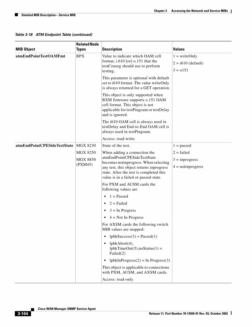
Chapter 3 Accessing the Network and Service MIBsDetailed MIB Description—Service MIB
atmEndPointTestOAMFmt BPX Value to indicate which OAM cell format, i.610 [or] o.151 that the testConseg should use to perform testing.
This parameter is optional with default set to i610 format. The value writeOnly is always returned for a GET operation.
This object is only supported when BXM firmware supports o.151 OAM cell format. This object is not applicable for testPingoam or testDelay and is ignored.
The i610 OAM cell is always used in testDelay and End-to-End OAM cell is always used in testPingoam.
Access: read-write.
1 = writeOnly
2 = i610 (default)
3 = o151
atmEndPointCPESideTestState MGX 8230
MGX 8250
MGX 8850 (PXM45)
State of the test.
When adding a connection the atmEndPointCPESideTestState becomes notinprogress. When selecting any test, this object returns inprogress state. After the test is completed this value is in a failed or passed state.
For PXM and AUSM cards the following values are
• 1 = Passed
• 2 = Failed
• 3 = In Progress
• 4 = Not In Progress
For AXSM cards the following switch MIB values are mapped:
• lpbkSuccess(3) = Passed(1)
• lpbkAbort(4), lpbkTimeOut(5),noStatus(1) = Failed(2)
• lpbkInProgress(2) = In Progress(3)
This object is applicable to connections with PXM, AUSM, and AXSM cards.
Access: read-only.
1 = passed
2 = failed
3 = inprogress
4 = notinprogress
Table 3-18 ATM Endpoint Table (continued)
MIB ObjectRelated Node Types Description Values
3-164Cisco WAN Manager SNMP Service Agent
Release 11, Part Number 78-13569-01 Rev. E0, October 2003
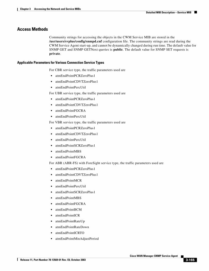
Chapter 3 Accessing the Network and Service MIBsDetailed MIB Description—Service MIB
Access Methods
Community strings for accessing the objects in the CWM Service MIB are stored in the /usr/users/svplus/config/snmpd.cnf configuration file. The community strings are read during the CWM Service Agent start-up, and cannot be dynamically changed during run time. The default value for SNMP GET and SNMP GETNext queries is public. The default value for SNMP SET requests is private.
Applicable Parameters for Various Connection Service Types
For CBR service type, the traffic parameters used are
• atmEndPointPCRZeroPlus1
• atmEndPointCDVTZeroPlus1
• atmEndPointPercUtil
For UBR service type, the traffic parameters used are
• atmEndPointPCRZeroPlus1
• atmEndPointCDVTZeroPlus1
• atmEndPointFGCRA
• atmEndPointPercUtil
For VBR service type, the traffic parameters used are
• atmEndPointPCRZeroPlus1
• atmEndPointCDVTZeroPlus1
• atmEndPointPercUtil
• atmEndPointSCRZeroPlus1
• atmEndPointMBS
• atmEndPointFGCRA
For ABR (ABR-FS) with ForeSight service type, the traffic parameters used are
• atmEndPointPCRZeroPlus1
• atmEndPointCDVTZeroPlus1
• atmEndPointMCR
• atmEndPointPercUtil
• atmEndPointSCRZeroPlus1
• atmEndPointMBS
• atmEndPointFGCRA
• atmEndPointBCM
• atmEndPointICR
• atmEndPointRateUp
• atmEndPointRateDown
• atmEndPointICRTO
• atmEndPointMinAdjustPeriod
3-165Cisco WAN Manager SNMP Service Agent
Release 11, Part Number 78-13569-01 Rev. E0, October 2003
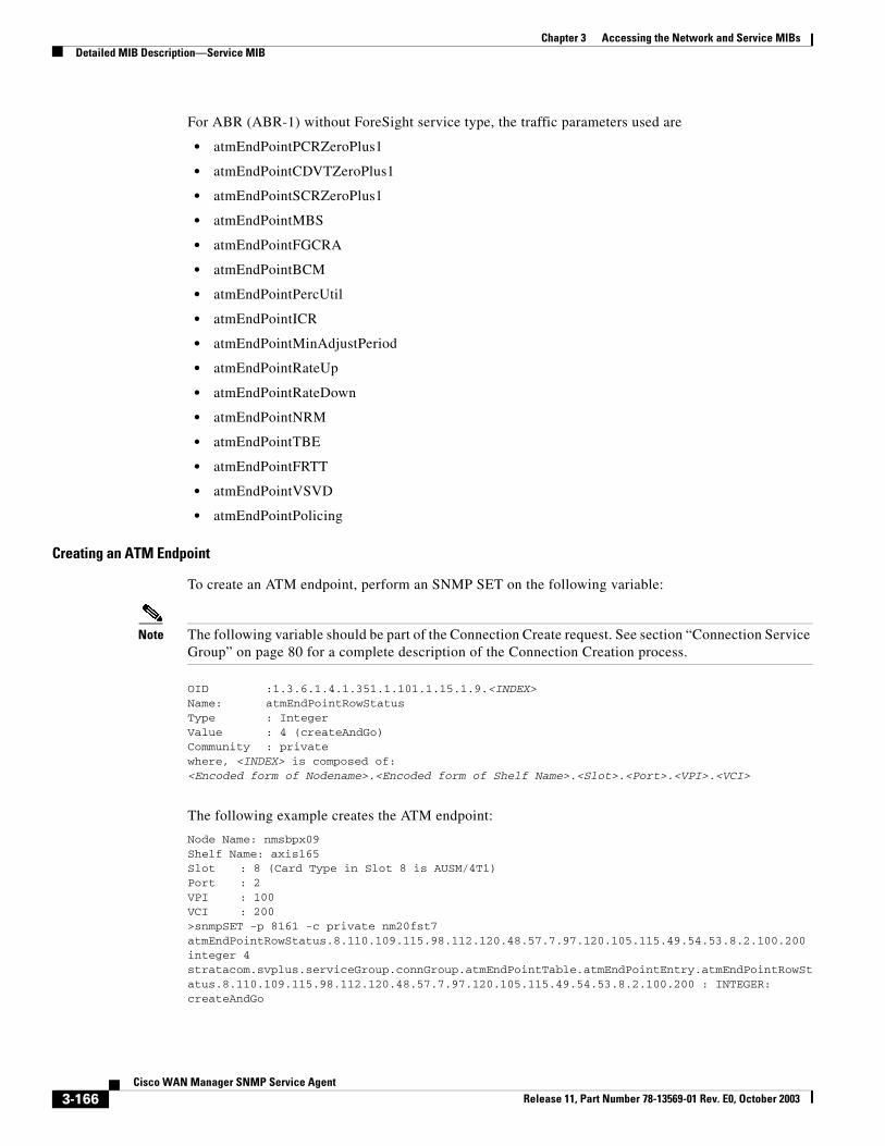
Chapter 3 Accessing the Network and Service MIBsDetailed MIB Description—Service MIB
For ABR (ABR-1) without ForeSight service type, the traffic parameters used are
• atmEndPointPCRZeroPlus1
• atmEndPointCDVTZeroPlus1
• atmEndPointSCRZeroPlus1
• atmEndPointMBS
• atmEndPointFGCRA
• atmEndPointBCM
• atmEndPointPercUtil
• atmEndPointICR
• atmEndPointMinAdjustPeriod
• atmEndPointRateUp
• atmEndPointRateDown
• atmEndPointNRM
• atmEndPointTBE
• atmEndPointFRTT
• atmEndPointVSVD
• atmEndPointPolicing
Creating an ATM Endpoint
To create an ATM endpoint, perform an SNMP SET on the following variable:
Note The following variable should be part of the Connection Create request. See section “Connection Service Group” on page 80 for a complete description of the Connection Creation process.
OID :1.3.6.1.4.1.351.1.101.1.15.1.9.<INDEX>Name: atmEndPointRowStatusType : IntegerValue : 4 (createAndGo)Community : privatewhere, <INDEX> is composed of:<Encoded form of Nodename>.<Encoded form of Shelf Name>.<Slot>.<Port>.<VPI>.<VCI>
The following example creates the ATM endpoint:
Node Name: nmsbpx09Shelf Name: axis165Slot : 8 (Card Type in Slot 8 is AUSM/4T1)Port : 2 VPI : 100VCI : 200>snmpSET -p 8161 -c private nm20fst7 atmEndPointRowStatus.8.110.109.115.98.112.120.48.57.7.97.120.105.115.49.54.53.8.2.100.200 integer 4stratacom.svplus.serviceGroup.connGroup.atmEndPointTable.atmEndPointEntry.atmEndPointRowStatus.8.110.109.115.98.112.120.48.57.7.97.120.105.115.49.54.53.8.2.100.200 : INTEGER: createAndGo
3-166Cisco WAN Manager SNMP Service Agent
Release 11, Part Number 78-13569-01 Rev. E0, October 2003
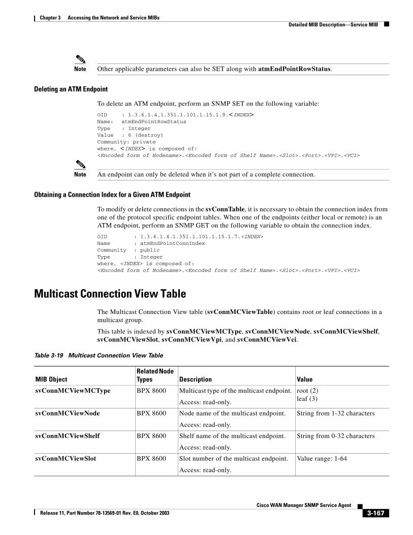
Chapter 3 Accessing the Network and Service MIBsDetailed MIB Description—Service MIB
Note Other applicable parameters can also be SET along with atmEndPointRowStatus.
Deleting an ATM Endpoint
To delete an ATM endpoint, perform an SNMP SET on the following variable:
OID : 1.3.6.1.4.1.351.1.101.1.15.1.9.<INDEX>Name: atmEndPointRowStatusType : IntegerValue : 6 (destroy)Community: privatewhere, <INDEX> is composed of:<Encoded form of Nodename>.<Encoded form of Shelf Name>.<Slot>.<Port>.<VPI>.<VCI>
Note An endpoint can only be deleted when it’s not part of a complete connection.
Obtaining a Connection Index for a Given ATM Endpoint
To modify or delete connections in the svConnTable, it is necessary to obtain the connection index from one of the protocol specific endpoint tables. When one of the endpoints (either local or remote) is an ATM endpoint, perform an SNMP GET on the following variable to obtain the connection index.
OID : 1.3.6.1.4.1.351.1.101.1.15.1.7.<INDEX>Name : atmEndPointConnIndexCommunity : publicType : Integerwhere, <INDEX> is composed of:<Encoded form of Nodename>.<Encoded form of Shelf Name>.<Slot>.<Port>.<VPI>.<VCI>
Multicast Connection View TableThe Multicast Connection View table (svConnMCViewTable) contains root or leaf connections in a multicast group.
This table is indexed by svConnMCViewMCType, svConnMCViewNode, svConnMCViewShelf, svConnMCViewSlot, svConnMCViewVpi, and svConnMCViewVci.
Table 3-19 Multicast Connection View Table
MIB ObjectRelated Node Types Description Value
svConnMCViewMCType BPX 8600 Multicast type of the multicast endpoint.
Access: read-only.
root (2)leaf (3)
svConnMCViewNode BPX 8600 Node name of the multicast endpoint.
Access: read-only.
String from 1-32 characters
svConnMCViewShelf BPX 8600 Shelf name of the multicast endpoint.
Access: read-only.
String from 0-32 characters
svConnMCViewSlot BPX 8600 Slot number of the multicast endpoint.
Access: read-only.
Value range: 1-64
3-167Cisco WAN Manager SNMP Service Agent
Release 11, Part Number 78-13569-01 Rev. E0, October 2003
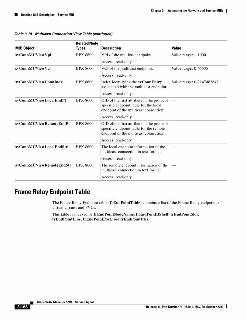
Chapter 3 Accessing the Network and Service MIBsDetailed MIB Description—Service MIB
Frame Relay Endpoint TableThe Frame Relay Endpoint table (frEndPointTable) contains a list of the Frame Relay endpoints of virtual circuits and PVCs.
This table is indexed by frEndPointNodeName, frEndPointIfShelf, frEndPointSlot, frEndPointLine, frEndPointPort, and frEndPointDlci.
svConnMCViewVpi BPX 8600 VPI of the multicast endpoint.
Access: read-only.
Value range: 1-1000
svConnMCViewVci BPX 8600 VCI of the multicast endpoint.
Access: read-only.
Value range: 0-65535
svConnMCViewConnIndx BPX 8600 Index identifying the svConnEntry associated with the multicast endpoint.
Access: read-only.
Value range: 0-2147483647
svConnMCViewLocalEndPt BPX 8600 OID of the first attribute in the protocol specific endpoint table for the local endpoint of the multicast connection.
Access: read-only.
—
svConnMCViewRemoteEndPt BPX 8600 OID of the first attribute in the protocol specific endpoint table for the remote endpoint of the multicast connection.
Access: read-only.
—
svConnMCViewLocalEndStr BPX 8600 The local endpoint information of the multicast connection in text format.
Access: read-only.
—
svConnMCViewRemoteEndStr BPX 8600 The remote endpoint information of the multicast connection in text format.
Access: read-only.
—
Table 3-19 Multicast Connection View Table (continued)
MIB ObjectRelated Node Types Description Value
3-168Cisco WAN Manager SNMP Service Agent
Release 11, Part Number 78-13569-01 Rev. E0, October 2003
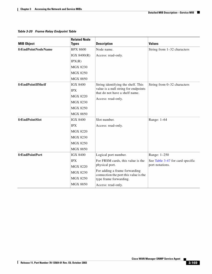
Chapter 3 Accessing the Network and Service MIBsDetailed MIB Description—Service MIB
Table 3-20 Frame Relay Endpoint Table
MIB ObjectRelated Node Types Description Values
frEndPointNodeName BPX 8600
IGX 8400(R)
IPX(R)
MGX 8230
MGX 8250
MGX 8850
Node name.
Access: read-only.
String from 1–32 characters
frEndPointIfShelf IGX 8400
IPX
MGX 8220
MGX 8230
MGX 8250
MGX 8850
String identifying the shelf. This value is a null string for endpoints that do not have a shelf name.
Access: read-only.
String from 0–32 characters
frEndPointSlot IGX 8400
IPX
MGX 8220
MGX 8230
MGX 8250
MGX 8850
Slot number.
Access: read-only.
Range: 1–64
frEndPointPort IGX 8400
IPX
MGX 8220
MGX 8230
MGX 8250
MGX 8850
Logical port number.
For FRSM cards, this value is the physical port.
For adding a frame forwarding connection the port this value is the type frame forwarding.
Access: read-only.
Range: 1–250
See Table 3-47 for card specific port notations.
3-169Cisco WAN Manager SNMP Service Agent
Release 11, Part Number 78-13569-01 Rev. E0, October 2003
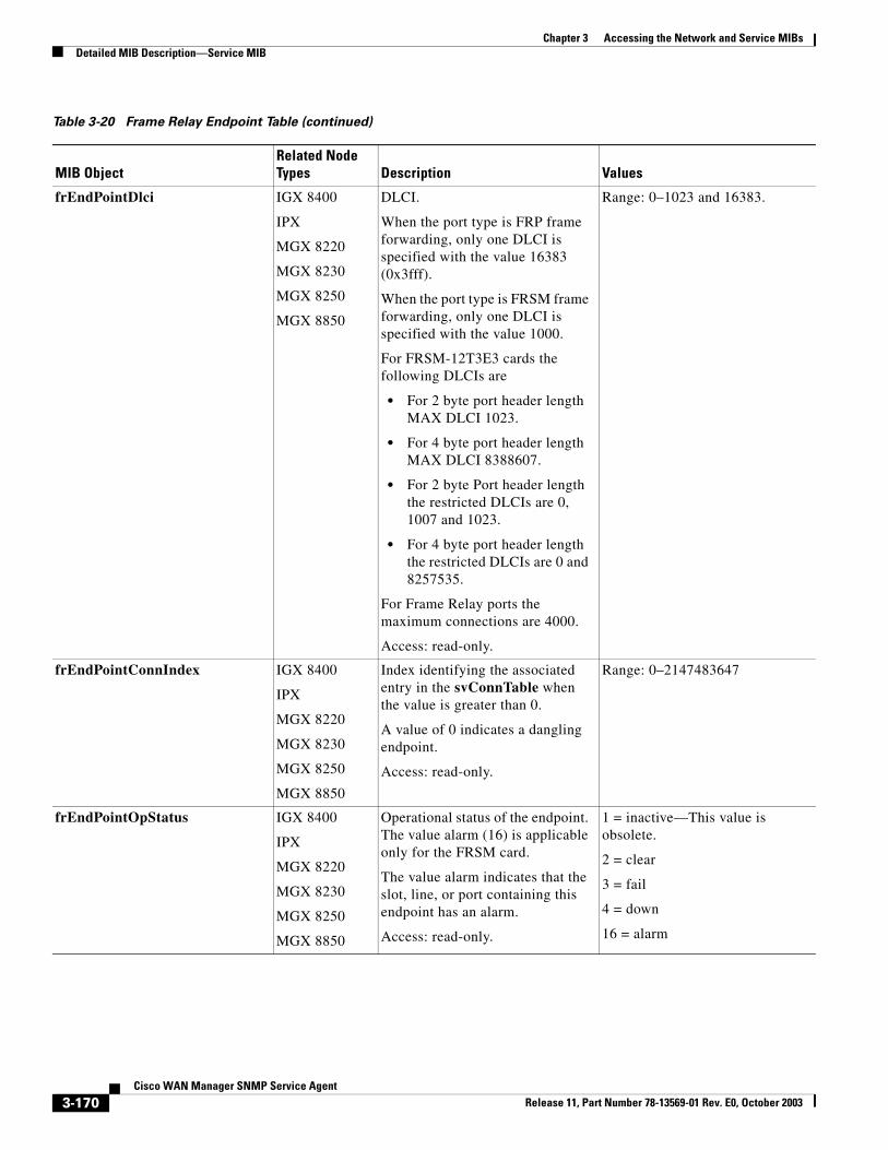
Chapter 3 Accessing the Network and Service MIBsDetailed MIB Description—Service MIB
frEndPointDlci IGX 8400
IPX
MGX 8220
MGX 8230
MGX 8250
MGX 8850
DLCI.
When the port type is FRP frame forwarding, only one DLCI is specified with the value 16383 (0x3fff).
When the port type is FRSM frame forwarding, only one DLCI is specified with the value 1000.
For FRSM-12T3E3 cards the following DLCIs are
• For 2 byte port header length MAX DLCI 1023.
• For 4 byte port header length MAX DLCI 8388607.
• For 2 byte Port header length the restricted DLCIs are 0, 1007 and 1023.
• For 4 byte port header length the restricted DLCIs are 0 and 8257535.
For Frame Relay ports the maximum connections are 4000.
Access: read-only.
Range: 0–1023 and 16383.
frEndPointConnIndex IGX 8400
IPX
MGX 8220
MGX 8230
MGX 8250
MGX 8850
Index identifying the associated entry in the svConnTable when the value is greater than 0.
A value of 0 indicates a dangling endpoint.
Access: read-only.
Range: 0–2147483647
frEndPointOpStatus IGX 8400
IPX
MGX 8220
MGX 8230
MGX 8250
MGX 8850
Operational status of the endpoint. The value alarm (16) is applicable only for the FRSM card.
The value alarm indicates that the slot, line, or port containing this endpoint has an alarm.
Access: read-only.
1 = inactive—This value is obsolete.
2 = clear
3 = fail
4 = down
16 = alarm
Table 3-20 Frame Relay Endpoint Table (continued)
MIB ObjectRelated Node Types Description Values
3-170Cisco WAN Manager SNMP Service Agent
Release 11, Part Number 78-13569-01 Rev. E0, October 2003
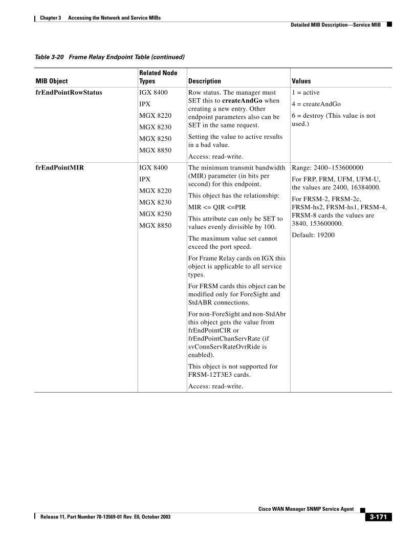
Chapter 3 Accessing the Network and Service MIBsDetailed MIB Description—Service MIB
frEndPointRowStatus IGX 8400
IPX
MGX 8220
MGX 8230
MGX 8250
MGX 8850
Row status. The manager must SET this to createAndGo when creating a new entry. Other endpoint parameters also can be SET in the same request.
Setting the value to active results in a bad value.
Access: read-write.
1 = active
4 = createAndGo
6 = destroy (This value is not used.)
frEndPointMIR IGX 8400
IPX
MGX 8220
MGX 8230
MGX 8250
MGX 8850
The minimum transmit bandwidth (MIR) parameter (in bits per second) for this endpoint.
This object has the relationship:
MIR <= QIR <=PIR
This attribute can only be SET to values evenly divisible by 100.
The maximum value set cannot exceed the port speed.
For Frame Relay cards on IGX this object is applicable to all service types.
For FRSM cards this object can be modified only for ForeSight and StdABR connections.
For non-ForeSight and non-StdAbr this object gets the value from frEndPointCIR or frEndPointChanServRate (if svConnServRateOvrRide is enabled).
This object is not supported for FRSM-12T3E3 cards.
Access: read-write.
Range: 2400–153600000
For FRP, FRM, UFM, UFM-U, the values are 2400, 16384000.
For FRSM-2, FRSM-2c, FRSM-hs2, FRSM-hs1, FRSM-4, FRSM-8 cards the values are 3840, 153600000.
Default: 19200
Table 3-20 Frame Relay Endpoint Table (continued)
MIB ObjectRelated Node Types Description Values
3-171Cisco WAN Manager SNMP Service Agent
Release 11, Part Number 78-13569-01 Rev. E0, October 2003
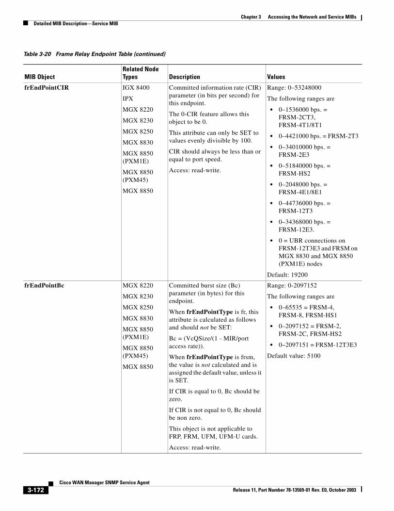
Chapter 3 Accessing the Network and Service MIBsDetailed MIB Description—Service MIB
frEndPointCIR IGX 8400
IPX
MGX 8220
MGX 8230
MGX 8250
MGX 8830
MGX 8850 (PXM1E)
MGX 8850 (PXM45)
MGX 8850
Committed information rate (CIR) parameter (in bits per second) for this endpoint.
The 0-CIR feature allows this object to be 0.
This attribute can only be SET to values evenly divisible by 100.
CIR should always be less than or equal to port speed.
Access: read-write.
Range: 0–53248000
The following ranges are
• 0–1536000 bps. = FRSM-2CT3, FRSM-4T1/8T1
• 0–4421000 bps. = FRSM-2T3
• 0–34010000 bps. = FRSM-2E3
• 0–51840000 bps. = FRSM-HS2
• 0–2048000 bps. = FRSM-4E1/8E1
• 0–44736000 bps. = FRSM-12T3
• 0–34368000 bps. = FRSM-12E3.
• 0 = UBR connections on FRSM-12T3E3 and FRSM on MGX 8830 and MGX 8850 (PXM1E) nodes
Default: 19200
frEndPointBc MGX 8220
MGX 8230
MGX 8250
MGX 8830
MGX 8850 (PXM1E)
MGX 8850 (PXM45)
MGX 8850
Committed burst size (Bc) parameter (in bytes) for this endpoint.
When frEndPointType is fr, this attribute is calculated as follows and should not be SET:
Bc = (VcQSize/(1 - MIR/port access rate)).
When frEndPointType is frsm, the value is not calculated and is assigned the default value, unless it is SET.
If CIR is equal to 0, Bc should be zero.
If CIR is not equal to 0, Bc should be non zero.
This object is not applicable to FRP, FRM, UFM, UFM-U cards.
Access: read-write.
Range: 0-2097152
The following ranges are
• 0–65535 = FRSM-4, FRSM-8, FRSM-HS1
• 0–2097152 = FRSM-2, FRSM-2C, FRSM-HS2
• 0–2097151 = FRSM-12T3E3
Default value: 5100
Table 3-20 Frame Relay Endpoint Table (continued)
MIB ObjectRelated Node Types Description Values
3-172Cisco WAN Manager SNMP Service Agent
Release 11, Part Number 78-13569-01 Rev. E0, October 2003
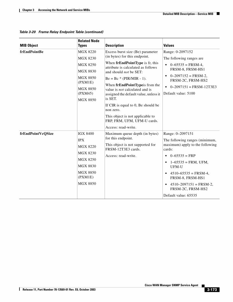
Chapter 3 Accessing the Network and Service MIBsDetailed MIB Description—Service MIB
frEndPointBe MGX 8220
MGX 8230
MGX 8250
MGX 8830
MGX 8850 (PXM1E)
MGX 8850 (PXM45)
MGX 8850
Excess burst size (Be) parameter (in bytes) for this endpoint.
When frEndPointType is fr, this attribute is calculated as follows and should not be SET:
Be = Bc * (PIR/MIR - 1).
When frEndPointTypeis frsm the value is not calculated and is assigned the default value, unless it is SET.
If CIR is equal to 0, Be should be non zero.
This object is not applicable to FRP, FRM, UFM, UFM-U cards.
Access: read-write.
Range: 0-2097152
The following ranges are
• 0–65535 = FRSM-4, FRSM-8, FRSM-HS1
• 0–2097152 = FRSM-2, FRSM-2C, FRSM-HS2
• 0–2097151 = FRSM-12T3E3
Default value: 5100
frEndPointVcQSize IGX 8400
IPX
MGX 8220
MGX 8230
MGX 8250
MGX 8830
MGX 8850 (PXM1E)
MGX 8850
Maximum queue depth (in bytes) for this endpoint.
This object is not supported for FRSM-12T3E3 cards.
Access: read-write.
Range: 0–2097151
The following ranges (minimum, maximum) apply to the following cards:
• 0–65535 = FRP
• 1–65535 = FRM, UFM, UFM-U
• 4510–65535 = FRSM-4, FRSM-8, FRSM-HS1
• 4510–2097151 = FRSM-2, FRSM-2C, FRSM-HS2
Default value: 65535
Table 3-20 Frame Relay Endpoint Table (continued)
MIB ObjectRelated Node Types Description Values
3-173Cisco WAN Manager SNMP Service Agent
Release 11, Part Number 78-13569-01 Rev. E0, October 2003
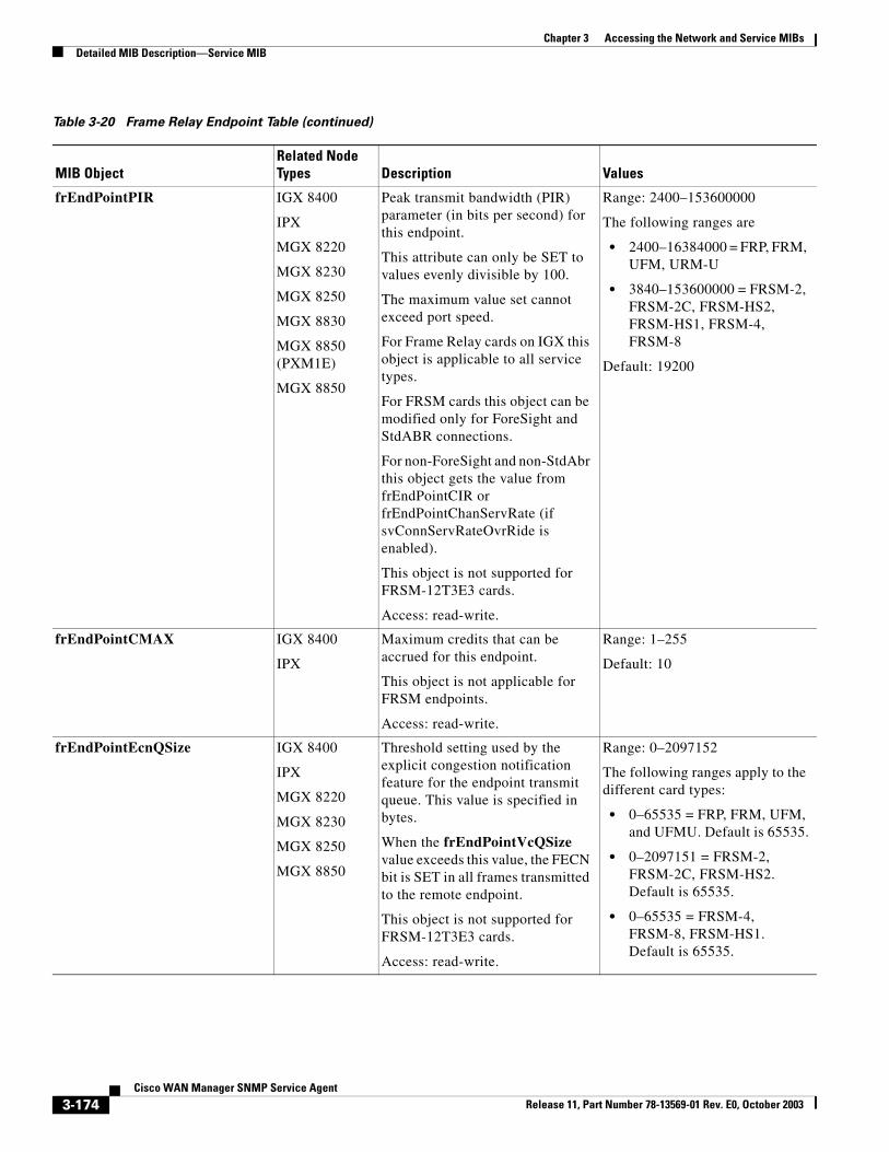
Chapter 3 Accessing the Network and Service MIBsDetailed MIB Description—Service MIB
frEndPointPIR IGX 8400
IPX
MGX 8220
MGX 8230
MGX 8250
MGX 8830
MGX 8850 (PXM1E)
MGX 8850
Peak transmit bandwidth (PIR) parameter (in bits per second) for this endpoint.
This attribute can only be SET to values evenly divisible by 100.
The maximum value set cannot exceed port speed.
For Frame Relay cards on IGX this object is applicable to all service types.
For FRSM cards this object can be modified only for ForeSight and StdABR connections.
For non-ForeSight and non-StdAbr this object gets the value from frEndPointCIR or frEndPointChanServRate (if svConnServRateOvrRide is enabled).
This object is not supported for FRSM-12T3E3 cards.
Access: read-write.
Range: 2400–153600000
The following ranges are
• 2400–16384000 = FRP, FRM, UFM, URM-U
• 3840–153600000 = FRSM-2, FRSM-2C, FRSM-HS2, FRSM-HS1, FRSM-4, FRSM-8
Default: 19200
frEndPointCMAX IGX 8400
IPX
Maximum credits that can be accrued for this endpoint.
This object is not applicable for FRSM endpoints.
Access: read-write.
Range: 1–255
Default: 10
frEndPointEcnQSize IGX 8400
IPX
MGX 8220
MGX 8230
MGX 8250
MGX 8850
Threshold setting used by the explicit congestion notification feature for the endpoint transmit queue. This value is specified in bytes.
When the frEndPointVcQSize value exceeds this value, the FECN bit is SET in all frames transmitted to the remote endpoint.
This object is not supported for FRSM-12T3E3 cards.
Access: read-write.
Range: 0–2097152
The following ranges apply to the different card types:
• 0–65535 = FRP, FRM, UFM, and UFMU. Default is 65535.
• 0–2097151 = FRSM-2, FRSM-2C, FRSM-HS2. Default is 65535.
• 0–65535 = FRSM-4, FRSM-8, FRSM-HS1. Default is 65535.
Table 3-20 Frame Relay Endpoint Table (continued)
MIB ObjectRelated Node Types Description Values
3-174Cisco WAN Manager SNMP Service Agent
Release 11, Part Number 78-13569-01 Rev. E0, October 2003
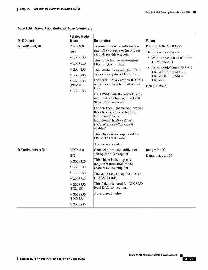
Chapter 3 Accessing the Network and Service MIBsDetailed MIB Description—Service MIB
frEndPointQIR IGX 8400
IPX
MGX 8220
MGX 8230
MGX 8250
MGX 8830
MGX 8850 (PXM1E)
MGX 8850
Transmit quiescent information rate (QIR) parameter (in bits per second) for this endpoint.
This value has the relationship:MIR <= QIR <= PIR.
This attribute can only be SET to values evenly divisible by 100.
For Frame Relay cards on IGX this object is applicable to all service types.
For FRSM cards this object can be modified only for ForeSight and StdABR connections.
For non-ForeSight and non-StdAbr this object gets the value from frEndPointCIR or frEndPointChanServRate(if svConnServRateOvrRide is enabled).
This object is not supported for FRSM-12T3E3 cards.
Access: read-write.
Range: 2400-153600000
The following ranges are
• 2400–16384000 = FRP, FRM, UFM, URM-U
• 3840–153600000 = FRSM-2, FRSM-2C, FRSM-HS2, FRSM-HS1, FRSM-4, FRSM-8
Default: 19200
frEndPointPercUtil IGX 8400
IPX
MGX 8220
MGX 8230
MGX 8250
MGX 8830
MGX 8850 (PXM1E)
MGX 8850 (PMX45)
MGX 8850
Channel percentage utilization setting for this endpoint.
This object is the expected long-term utilization of the channel by the endpoint.
The value range is applicable for all FRSM cards.
This field is ignored for IGX 8850 local DAX connections.
Access: read-write.
Range: 0-100
Default value: 100
Table 3-20 Frame Relay Endpoint Table (continued)
MIB ObjectRelated Node Types Description Values
3-175Cisco WAN Manager SNMP Service Agent
Release 11, Part Number 78-13569-01 Rev. E0, October 2003
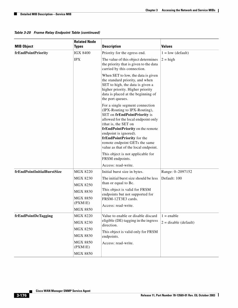
Chapter 3 Accessing the Network and Service MIBsDetailed MIB Description—Service MIB
frEndPointPriority IGX 8400
IPX
Priority for the egress end.
The value of this object determines the priority that is given to the data carried by this connection.
When SET to low, the data is given the standard priority, and when SET to high, the data is given a higher priority. Higher priority data is placed at the beginning of the port queues.
For a single segment connection (IPX-Routing to IPX-Routing), SET on frEndPointPriority is allowed for the local endpoint only (that is, the SET on frEndPointPriority on the remote endpoint is ignored). frEndPointPriority for the remote endpoint GETs the same value as that of the local endpoint.
This object is not applicable for FRSM endpoints.
Access: read-write.
1 = low (default)
2 = high
frEndPointInitialBurstSize MGX 8220
MGX 8230
MGX 8250
MGX 8830
MGX 8850 (PXM1E)
MGX 8850
Initial burst size in bytes.
The initial burst size should be less than or equal to Bc.
This object is valid for FRSM endpoints but not supported for FRSM-12T3E3 cards.
Access: read-write.
Range: 0–2097152
Default: 100
frEndPointDeTagging MGX 8220
MGX 8230
MGX 8250
MGX 8830
MGX 8850 (PXM1E)
MGX 8850
Value to enable or disable discard eligible (DE) tagging in the ingress direction.
This object is valid only for FRSM endpoints.
Access: read-write.
1 = enable
2 = disable (default)
Table 3-20 Frame Relay Endpoint Table (continued)
MIB ObjectRelated Node Types Description Values
3-176Cisco WAN Manager SNMP Service Agent
Release 11, Part Number 78-13569-01 Rev. E0, October 2003
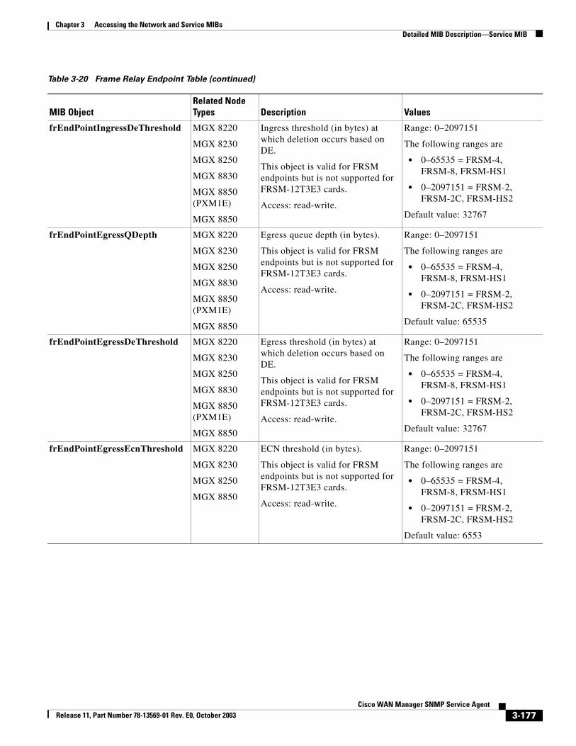
Chapter 3 Accessing the Network and Service MIBsDetailed MIB Description—Service MIB
frEndPointIngressDeThreshold MGX 8220
MGX 8230
MGX 8250
MGX 8830
MGX 8850 (PXM1E)
MGX 8850
Ingress threshold (in bytes) at which deletion occurs based on DE.
This object is valid for FRSM endpoints but is not supported for FRSM-12T3E3 cards.
Access: read-write.
Range: 0–2097151
The following ranges are
• 0–65535 = FRSM-4, FRSM-8, FRSM-HS1
• 0–2097151 = FRSM-2, FRSM-2C, FRSM-HS2
Default value: 32767
frEndPointEgressQDepth MGX 8220
MGX 8230
MGX 8250
MGX 8830
MGX 8850 (PXM1E)
MGX 8850
Egress queue depth (in bytes).
This object is valid for FRSM endpoints but is not supported for FRSM-12T3E3 cards.
Access: read-write.
Range: 0–2097151
The following ranges are
• 0–65535 = FRSM-4, FRSM-8, FRSM-HS1
• 0–2097151 = FRSM-2, FRSM-2C, FRSM-HS2
Default value: 65535
frEndPointEgressDeThreshold MGX 8220
MGX 8230
MGX 8250
MGX 8830
MGX 8850 (PXM1E)
MGX 8850
Egress threshold (in bytes) at which deletion occurs based on DE.
This object is valid for FRSM endpoints but is not supported for FRSM-12T3E3 cards.
Access: read-write.
Range: 0–2097151
The following ranges are
• 0–65535 = FRSM-4, FRSM-8, FRSM-HS1
• 0–2097151 = FRSM-2, FRSM-2C, FRSM-HS2
Default value: 32767
frEndPointEgressEcnThreshold MGX 8220
MGX 8230
MGX 8250
MGX 8850
ECN threshold (in bytes).
This object is valid for FRSM endpoints but is not supported for FRSM-12T3E3 cards.
Access: read-write.
Range: 0–2097151
The following ranges are
• 0–65535 = FRSM-4, FRSM-8, FRSM-HS1
• 0–2097151 = FRSM-2, FRSM-2C, FRSM-HS2
Default value: 6553
Table 3-20 Frame Relay Endpoint Table (continued)
MIB ObjectRelated Node Types Description Values
3-177Cisco WAN Manager SNMP Service Agent
Release 11, Part Number 78-13569-01 Rev. E0, October 2003
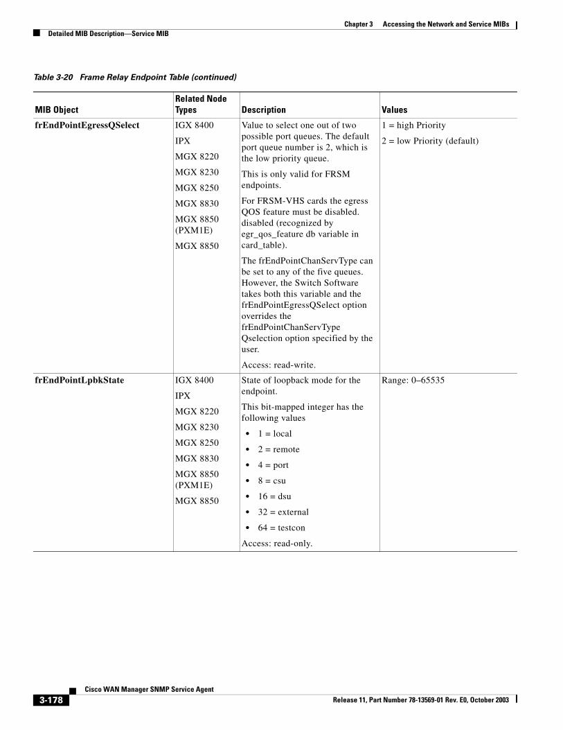
Chapter 3 Accessing the Network and Service MIBsDetailed MIB Description—Service MIB
frEndPointEgressQSelect IGX 8400
IPX
MGX 8220
MGX 8230
MGX 8250
MGX 8830
MGX 8850 (PXM1E)
MGX 8850
Value to select one out of two possible port queues. The default port queue number is 2, which is the low priority queue.
This is only valid for FRSM endpoints.
For FRSM-VHS cards the egress QOS feature must be disabled. disabled (recognized by egr_qos_feature db variable in card_table).
The frEndPointChanServType can be set to any of the five queues. However, the Switch Software takes both this variable and the frEndPointEgressQSelect option overrides the frEndPointChanServType Qselection option specified by the user.
Access: read-write.
1 = high Priority
2 = low Priority (default)
frEndPointLpbkState IGX 8400
IPX
MGX 8220
MGX 8230
MGX 8250
MGX 8830
MGX 8850 (PXM1E)
MGX 8850
State of loopback mode for the endpoint.
This bit-mapped integer has the following values
• 1 = local
• 2 = remote
• 4 = port
• 8 = csu
• 16 = dsu
• 32 = external
• 64 = testcon
Access: read-only.
Range: 0–65535
Table 3-20 Frame Relay Endpoint Table (continued)
MIB ObjectRelated Node Types Description Values
3-178Cisco WAN Manager SNMP Service Agent
Release 11, Part Number 78-13569-01 Rev. E0, October 2003
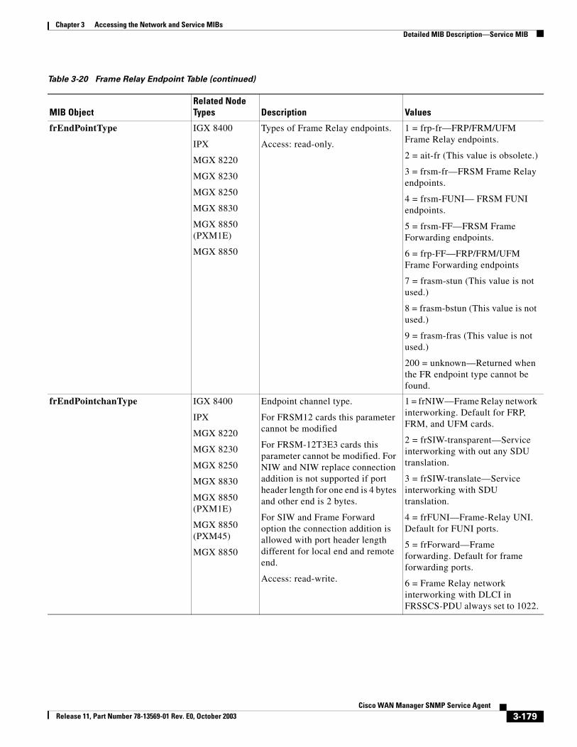
Chapter 3 Accessing the Network and Service MIBsDetailed MIB Description—Service MIB
frEndPointType IGX 8400
IPX
MGX 8220
MGX 8230
MGX 8250
MGX 8830
MGX 8850 (PXM1E)
MGX 8850
Types of Frame Relay endpoints.
Access: read-only.
1 = frp-fr—FRP/FRM/UFM Frame Relay endpoints.
2 = ait-fr (This value is obsolete.)
3 = frsm-fr—FRSM Frame Relay endpoints.
4 = frsm-FUNI— FRSM FUNI endpoints.
5 = frsm-FF—FRSM Frame Forwarding endpoints.
6 = frp-FF—FRP/FRM/UFM Frame Forwarding endpoints
7 = frasm-stun (This value is not used.)
8 = frasm-bstun (This value is not used.)
9 = frasm-fras (This value is not used.)
200 = unknown—Returned when the FR endpoint type cannot be found.
frEndPointchanType IGX 8400
IPX
MGX 8220
MGX 8230
MGX 8250
MGX 8830
MGX 8850 (PXM1E)
MGX 8850 (PXM45)
MGX 8850
Endpoint channel type.
For FRSM12 cards this parameter cannot be modified
For FRSM-12T3E3 cards this parameter cannot be modified. For NIW and NIW replace connection addition is not supported if port header length for one end is 4 bytes and other end is 2 bytes.
For SIW and Frame Forward option the connection addition is allowed with port header length different for local end and remote end.
Access: read-write.
1 = frNIW—Frame Relay network interworking. Default for FRP, FRM, and UFM cards.
2 = frSIW-transparent—Service interworking with out any SDU translation.
3 = frSIW-translate—Service interworking with SDU translation.
4 = frFUNI—Frame-Relay UNI. Default for FUNI ports.
5 = frForward—Frame forwarding. Default for frame forwarding ports.
6 = Frame Relay network interworking with DLCI in FRSSCS-PDU always set to 1022.
Table 3-20 Frame Relay Endpoint Table (continued)
MIB ObjectRelated Node Types Description Values
3-179Cisco WAN Manager SNMP Service Agent
Release 11, Part Number 78-13569-01 Rev. E0, October 2003
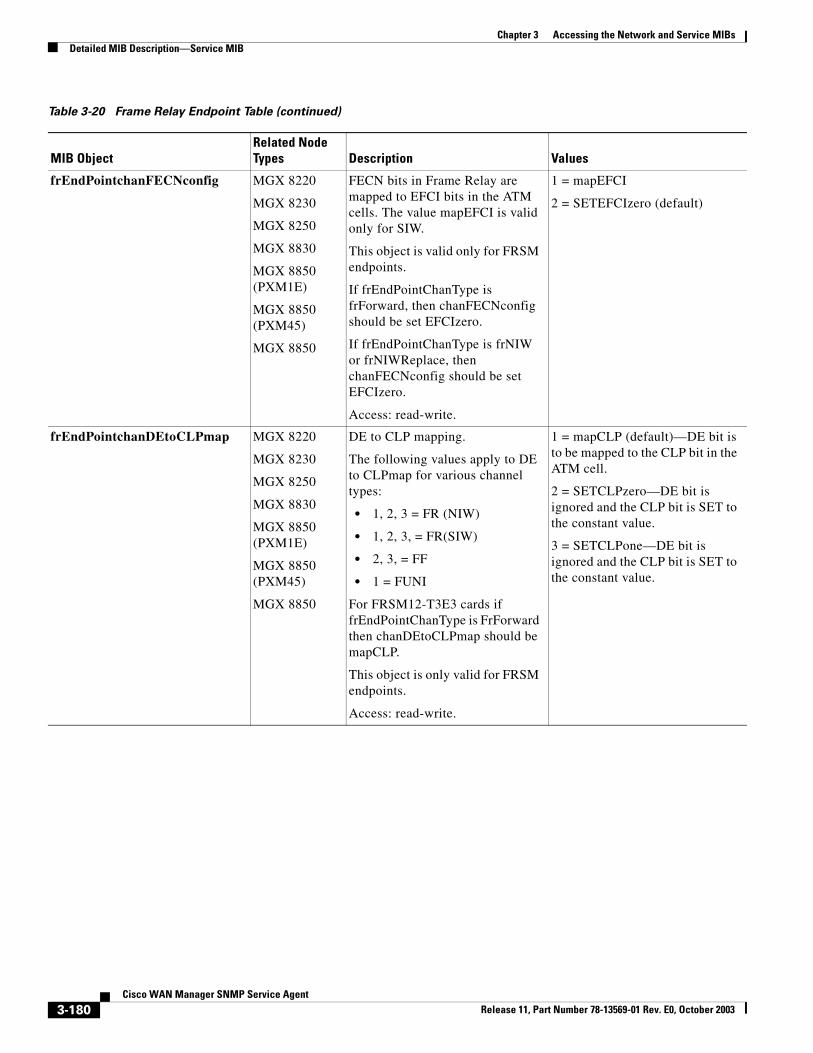
Chapter 3 Accessing the Network and Service MIBsDetailed MIB Description—Service MIB
frEndPointchanFECNconfig MGX 8220
MGX 8230
MGX 8250
MGX 8830
MGX 8850 (PXM1E)
MGX 8850 (PXM45)
MGX 8850
FECN bits in Frame Relay are mapped to EFCI bits in the ATM cells. The value mapEFCI is valid only for SIW.
This object is valid only for FRSM endpoints.
If frEndPointChanType is frForward, then chanFECNconfig should be set EFCIzero.
If frEndPointChanType is frNIW or frNIWReplace, then chanFECNconfig should be set EFCIzero.
Access: read-write.
1 = mapEFCI
2 = SETEFCIzero (default)
frEndPointchanDEtoCLPmap MGX 8220
MGX 8230
MGX 8250
MGX 8830
MGX 8850 (PXM1E)
MGX 8850 (PXM45)
MGX 8850
DE to CLP mapping.
The following values apply to DE to CLPmap for various channel types:
• 1, 2, 3 = FR (NIW)
• 1, 2, 3, = FR(SIW)
• 2, 3, = FF
• 1 = FUNI
For FRSM12-T3E3 cards if frEndPointChanType is FrForward then chanDEtoCLPmap should be mapCLP.
This object is only valid for FRSM endpoints.
Access: read-write.
1 = mapCLP (default)—DE bit is to be mapped to the CLP bit in the ATM cell.
2 = SETCLPzero—DE bit is ignored and the CLP bit is SET to the constant value.
3 = SETCLPone—DE bit is ignored and the CLP bit is SET to the constant value.
Table 3-20 Frame Relay Endpoint Table (continued)
MIB ObjectRelated Node Types Description Values
3-180Cisco WAN Manager SNMP Service Agent
Release 11, Part Number 78-13569-01 Rev. E0, October 2003
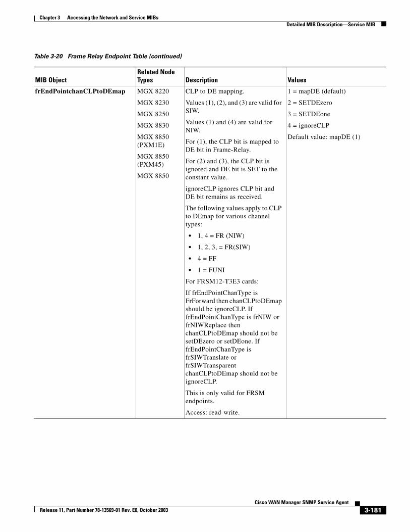
Chapter 3 Accessing the Network and Service MIBsDetailed MIB Description—Service MIB
frEndPointchanCLPtoDEmap MGX 8220
MGX 8230
MGX 8250
MGX 8830
MGX 8850 (PXM1E)
MGX 8850 (PXM45)
MGX 8850
CLP to DE mapping.
Values (1), (2), and (3) are valid for SIW.
Values (1) and (4) are valid for NIW.
For (1), the CLP bit is mapped to DE bit in Frame-Relay.
For (2) and (3), the CLP bit is ignored and DE bit is SET to the constant value.
ignoreCLP ignores CLP bit and DE bit remains as received.
The following values apply to CLP to DEmap for various channel types:
• 1, 4 = FR (NIW)
• 1, 2, 3, = FR(SIW)
• 4 = FF
• 1 = FUNI
For FRSM12-T3E3 cards:
If frEndPointChanType is FrForward then chanCLPtoDEmap should be ignoreCLP. If frEndPointChanType is frNIW or frNIWReplace then chanCLPtoDEmap should not be setDEzero or setDEone. If frEndPointChanType is frSIWTranslate or frSIWTransparent chanCLPtoDEmap should not be ignoreCLP.
This is only valid for FRSM endpoints.
Access: read-write.
1 = mapDE (default)
2 = SETDEzero
3 = SETDEone
4 = ignoreCLP
Default value: mapDE (1)
Table 3-20 Frame Relay Endpoint Table (continued)
MIB ObjectRelated Node Types Description Values
3-181Cisco WAN Manager SNMP Service Agent
Release 11, Part Number 78-13569-01 Rev. E0, October 2003
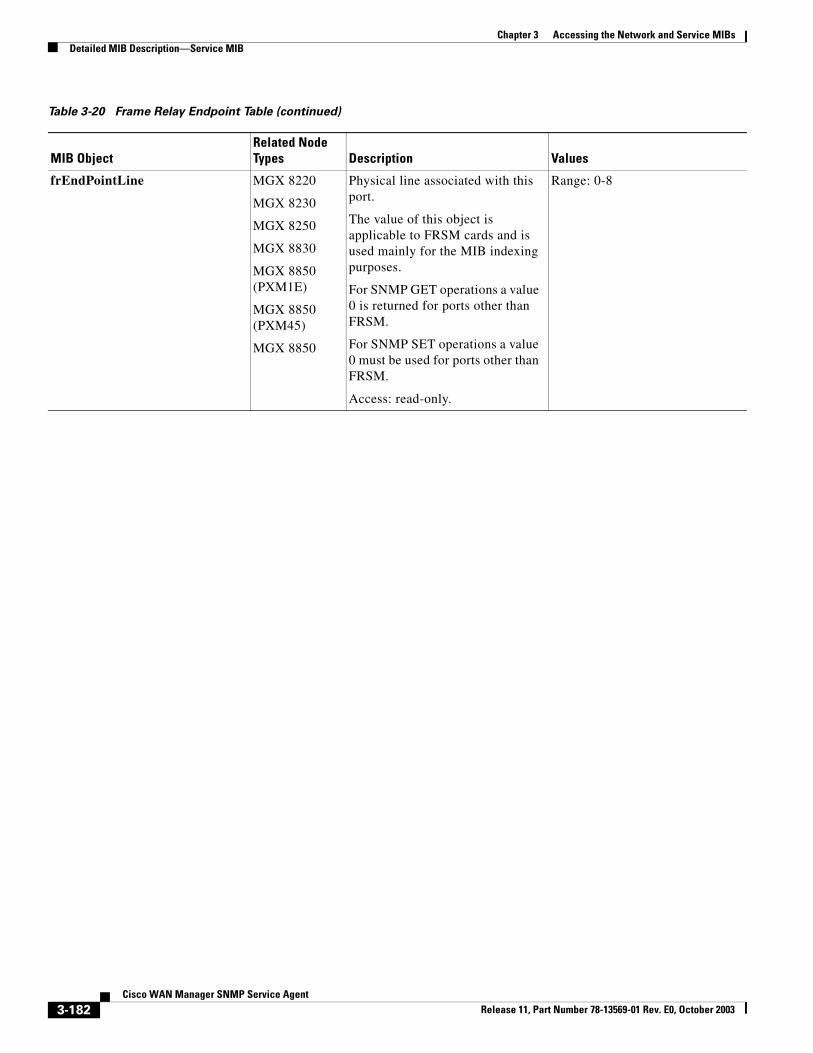
Chapter 3 Accessing the Network and Service MIBsDetailed MIB Description—Service MIB
frEndPointLine MGX 8220
MGX 8230
MGX 8250
MGX 8830
MGX 8850 (PXM1E)
MGX 8850 (PXM45)
MGX 8850
Physical line associated with this port.
The value of this object is applicable to FRSM cards and is used mainly for the MIB indexing purposes.
For SNMP GET operations a value 0 is returned for ports other than FRSM.
For SNMP SET operations a value 0 must be used for ports other than FRSM.
Access: read-only.
Range: 0-8
Table 3-20 Frame Relay Endpoint Table (continued)
MIB ObjectRelated Node Types Description Values
3-182Cisco WAN Manager SNMP Service Agent
Release 11, Part Number 78-13569-01 Rev. E0, October 2003
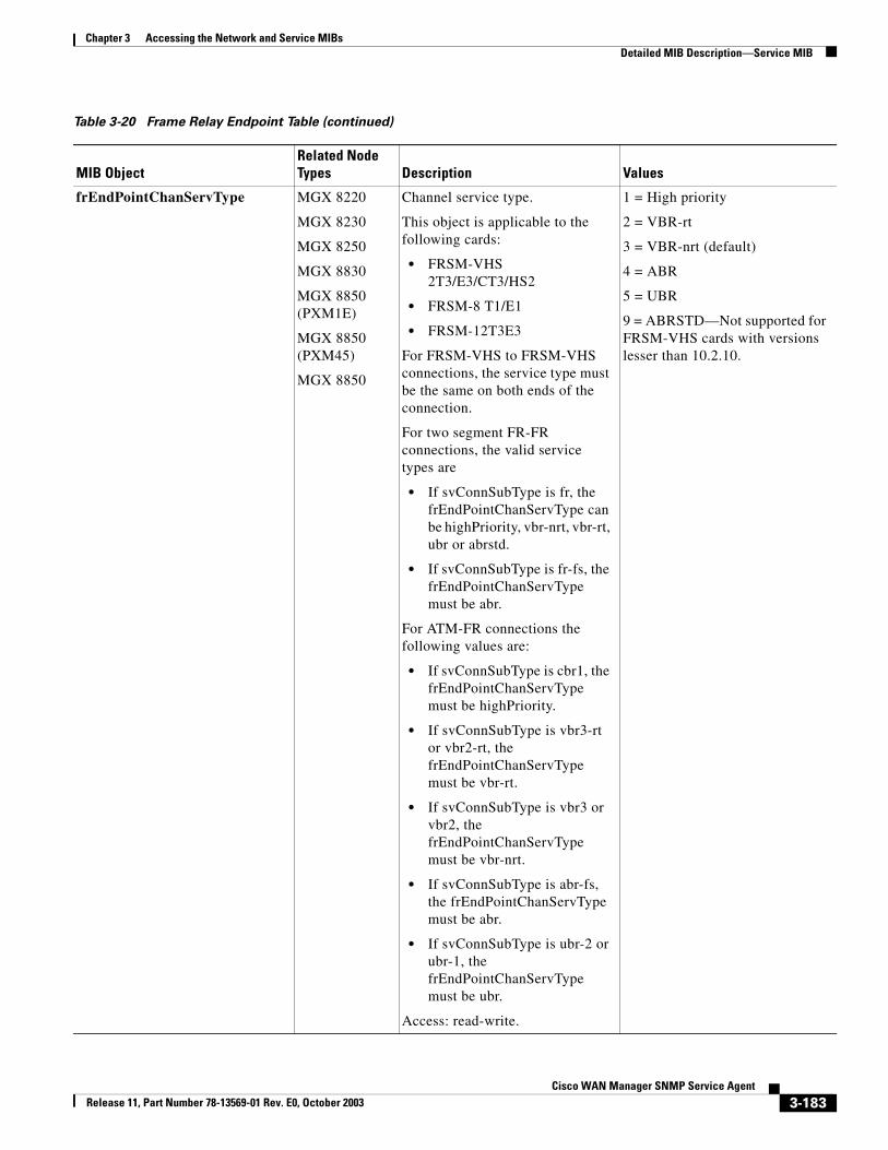
Chapter 3 Accessing the Network and Service MIBsDetailed MIB Description—Service MIB
frEndPointChanServType MGX 8220
MGX 8230
MGX 8250
MGX 8830
MGX 8850 (PXM1E)
MGX 8850 (PXM45)
MGX 8850
Channel service type.
This object is applicable to the following cards:
• FRSM-VHS 2T3/E3/CT3/HS2
• FRSM-8 T1/E1
• FRSM-12T3E3
For FRSM-VHS to FRSM-VHS connections, the service type must be the same on both ends of the connection.
For two segment FR-FR connections, the valid service types are
• If svConnSubType is fr, the frEndPointChanServType can be highPriority, vbr-nrt, vbr-rt, ubr or abrstd.
• If svConnSubType is fr-fs, the frEndPointChanServType must be abr.
For ATM-FR connections the following values are:
• If svConnSubType is cbr1, the frEndPointChanServType must be highPriority.
• If svConnSubType is vbr3-rt or vbr2-rt, the frEndPointChanServType must be vbr-rt.
• If svConnSubType is vbr3 or vbr2, the frEndPointChanServType must be vbr-nrt.
• If svConnSubType is abr-fs, the frEndPointChanServType must be abr.
• If svConnSubType is ubr-2 or ubr-1, the frEndPointChanServType must be ubr.
Access: read-write.
1 = High priority
2 = VBR-rt
3 = VBR-nrt (default)
4 = ABR
5 = UBR
9 = ABRSTD—Not supported for FRSM-VHS cards with versions lesser than 10.2.10.
Table 3-20 Frame Relay Endpoint Table (continued)
MIB ObjectRelated Node Types Description Values
3-183Cisco WAN Manager SNMP Service Agent
Release 11, Part Number 78-13569-01 Rev. E0, October 2003
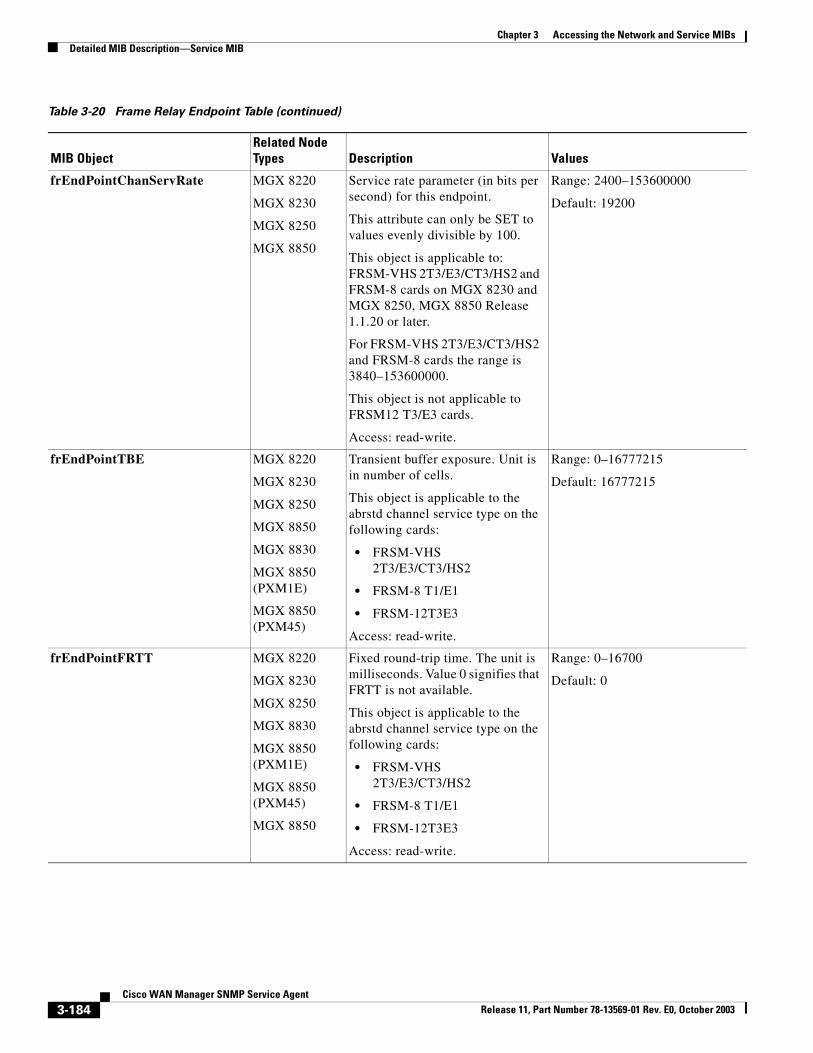
Chapter 3 Accessing the Network and Service MIBsDetailed MIB Description—Service MIB
frEndPointChanServRate MGX 8220
MGX 8230
MGX 8250
MGX 8850
Service rate parameter (in bits per second) for this endpoint.
This attribute can only be SET to values evenly divisible by 100.
This object is applicable to: FRSM-VHS 2T3/E3/CT3/HS2 and FRSM-8 cards on MGX 8230 and MGX 8250, MGX 8850 Release 1.1.20 or later.
For FRSM-VHS 2T3/E3/CT3/HS2 and FRSM-8 cards the range is 3840–153600000.
This object is not applicable to FRSM12 T3/E3 cards.
Access: read-write.
Range: 2400–153600000
Default: 19200
frEndPointTBE MGX 8220
MGX 8230
MGX 8250
MGX 8850
MGX 8830
MGX 8850 (PXM1E)
MGX 8850 (PXM45)
Transient buffer exposure. Unit is in number of cells.
This object is applicable to the abrstd channel service type on the following cards:
• FRSM-VHS 2T3/E3/CT3/HS2
• FRSM-8 T1/E1
• FRSM-12T3E3
Access: read-write.
Range: 0–16777215
Default: 16777215
frEndPointFRTT MGX 8220
MGX 8230
MGX 8250
MGX 8830
MGX 8850 (PXM1E)
MGX 8850 (PXM45)
MGX 8850
Fixed round-trip time. The unit is milliseconds. Value 0 signifies that FRTT is not available.
This object is applicable to the abrstd channel service type on the following cards:
• FRSM-VHS 2T3/E3/CT3/HS2
• FRSM-8 T1/E1
• FRSM-12T3E3
Access: read-write.
Range: 0–16700
Default: 0
Table 3-20 Frame Relay Endpoint Table (continued)
MIB ObjectRelated Node Types Description Values
3-184Cisco WAN Manager SNMP Service Agent
Release 11, Part Number 78-13569-01 Rev. E0, October 2003
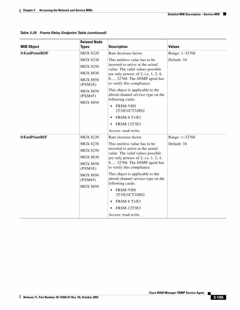
Chapter 3 Accessing the Network and Service MIBsDetailed MIB Description—Service MIB
frEndPointRDF MGX 8220
MGX 8230
MGX 8250
MGX 8830
MGX 8850 (PXM1E)
MGX 8850 (PXM45)
MGX 8850
Rate decrease factor.
This unitless value has to be inverted to arrive at the actual value. The valid values possible are only powers of 2; i.e. 1, 2, 4, 8..... 32768. The SNMP agent has to verify this compliance.
This object is applicable to the abrstd channel service type on the following cards:
• FRSM-VHS 2T3/E3/CT3/HS2
• FRSM-8 T1/E1
• FRSM-12T3E3
Access: read-write.
Range: 1–32768
Default: 16
frEndPointRIF MGX 8220
MGX 8230
MGX 8250
MGX 8830
MGX 8850 (PXM1E)
MGX 8850 (PXM45)
MGX 8850
Rate increase factor.
This unitless value has to be inverted to arrive at the actual value. The valid values possible are only powers of 2; i.e. 1, 2, 4, 8..... 32768. The SNMP agent has to verify this compliance.
This object is applicable to the abrstd channel service type on the following cards:
• FRSM-VHS 2T3/E3/CT3/HS2
• FRSM-8 T1/E1
• FRSM-12T3E3
Access: read-write.
Range: 1–32768
Default: 16
Table 3-20 Frame Relay Endpoint Table (continued)
MIB ObjectRelated Node Types Description Values
3-185Cisco WAN Manager SNMP Service Agent
Release 11, Part Number 78-13569-01 Rev. E0, October 2003
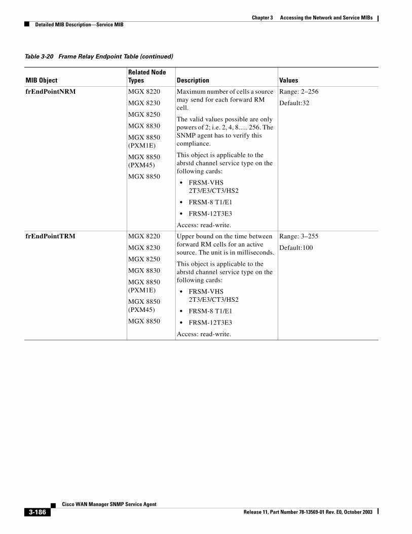
Chapter 3 Accessing the Network and Service MIBsDetailed MIB Description—Service MIB
frEndPointNRM MGX 8220
MGX 8230
MGX 8250
MGX 8830
MGX 8850 (PXM1E)
MGX 8850 (PXM45)
MGX 8850
Maximum number of cells a source may send for each forward RM cell.
The valid values possible are only powers of 2; i.e. 2, 4, 8..... 256. The SNMP agent has to verify this compliance.
This object is applicable to the abrstd channel service type on the following cards:
• FRSM-VHS 2T3/E3/CT3/HS2
• FRSM-8 T1/E1
• FRSM-12T3E3
Access: read-write.
Range: 2–256
Default:32
frEndPointTRM MGX 8220
MGX 8230
MGX 8250
MGX 8830
MGX 8850 (PXM1E)
MGX 8850 (PXM45)
MGX 8850
Upper bound on the time between forward RM cells for an active source. The unit is in milliseconds.
This object is applicable to the abrstd channel service type on the following cards:
• FRSM-VHS 2T3/E3/CT3/HS2
• FRSM-8 T1/E1
• FRSM-12T3E3
Access: read-write.
Range: 3–255
Default:100
Table 3-20 Frame Relay Endpoint Table (continued)
MIB ObjectRelated Node Types Description Values
3-186Cisco WAN Manager SNMP Service Agent
Release 11, Part Number 78-13569-01 Rev. E0, October 2003
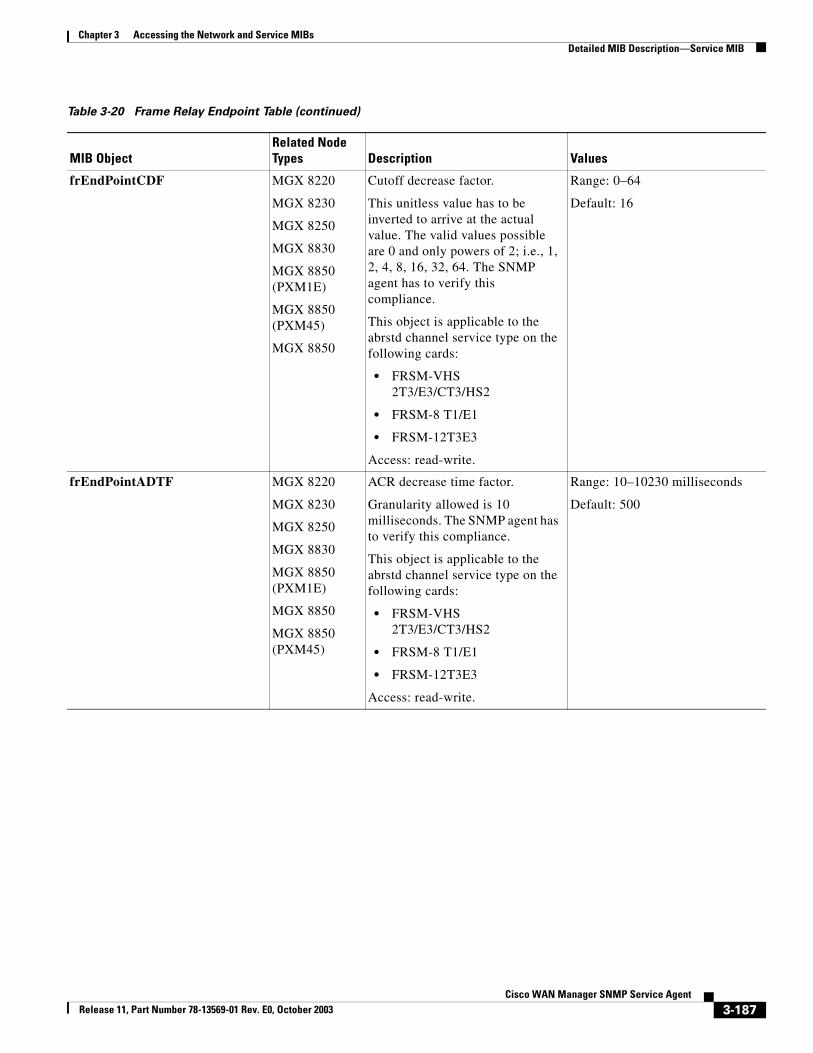
Chapter 3 Accessing the Network and Service MIBsDetailed MIB Description—Service MIB
frEndPointCDF MGX 8220
MGX 8230
MGX 8250
MGX 8830
MGX 8850 (PXM1E)
MGX 8850 (PXM45)
MGX 8850
Cutoff decrease factor.
This unitless value has to be inverted to arrive at the actual value. The valid values possible are 0 and only powers of 2; i.e., 1, 2, 4, 8, 16, 32, 64. The SNMP agent has to verify this compliance.
This object is applicable to the abrstd channel service type on the following cards:
• FRSM-VHS 2T3/E3/CT3/HS2
• FRSM-8 T1/E1
• FRSM-12T3E3
Access: read-write.
Range: 0–64
Default: 16
frEndPointADTF MGX 8220
MGX 8230
MGX 8250
MGX 8830
MGX 8850 (PXM1E)
MGX 8850
MGX 8850 (PXM45)
ACR decrease time factor.
Granularity allowed is 10 milliseconds. The SNMP agent has to verify this compliance.
This object is applicable to the abrstd channel service type on the following cards:
• FRSM-VHS 2T3/E3/CT3/HS2
• FRSM-8 T1/E1
• FRSM-12T3E3
Access: read-write.
Range: 10–10230 milliseconds
Default: 500
Table 3-20 Frame Relay Endpoint Table (continued)
MIB ObjectRelated Node Types Description Values
3-187Cisco WAN Manager SNMP Service Agent
Release 11, Part Number 78-13569-01 Rev. E0, October 2003
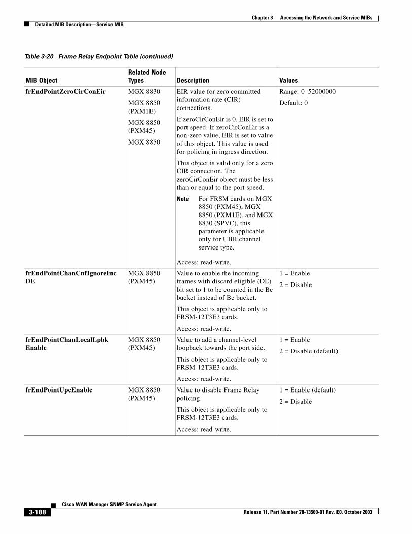
Chapter 3 Accessing the Network and Service MIBsDetailed MIB Description—Service MIB
frEndPointZeroCirConEir MGX 8830
MGX 8850 (PXM1E)
MGX 8850 (PXM45)
MGX 8850
EIR value for zero committed information rate (CIR) connections.
If zeroCirConEir is 0, EIR is set to port speed. If zeroCirConEir is a non-zero value, EIR is set to value of this object. This value is used for policing in ingress direction.
This object is valid only for a zero CIR connection. The zeroCirConEir object must be less than or equal to the port speed.
Note For FRSM cards on MGX 8850 (PXM45), MGX 8850 (PXM1E), and MGX 8830 (SPVC), this parameter is applicable only for UBR channel service type.
Access: read-write.
Range: 0–52000000
Default: 0
frEndPointChanCnfIgnoreIncDE
MGX 8850 (PXM45)
Value to enable the incoming frames with discard eligible (DE) bit set to 1 to be counted in the Bc bucket instead of Be bucket.
This object is applicable only to FRSM-12T3E3 cards.
Access: read-write.
1 = Enable
2 = Disable
frEndPointChanLocalLpbkEnable
MGX 8850 (PXM45)
Value to add a channel-level loopback towards the port side.
This object is applicable only to FRSM-12T3E3 cards.
Access: read-write.
1 = Enable
2 = Disable (default)
frEndPointUpcEnable MGX 8850 (PXM45)
Value to disable Frame Relay policing.
This object is applicable only to FRSM-12T3E3 cards.
Access: read-write.
1 = Enable (default)
2 = Disable
Table 3-20 Frame Relay Endpoint Table (continued)
MIB ObjectRelated Node Types Description Values
3-188Cisco WAN Manager SNMP Service Agent
Release 11, Part Number 78-13569-01 Rev. E0, October 2003
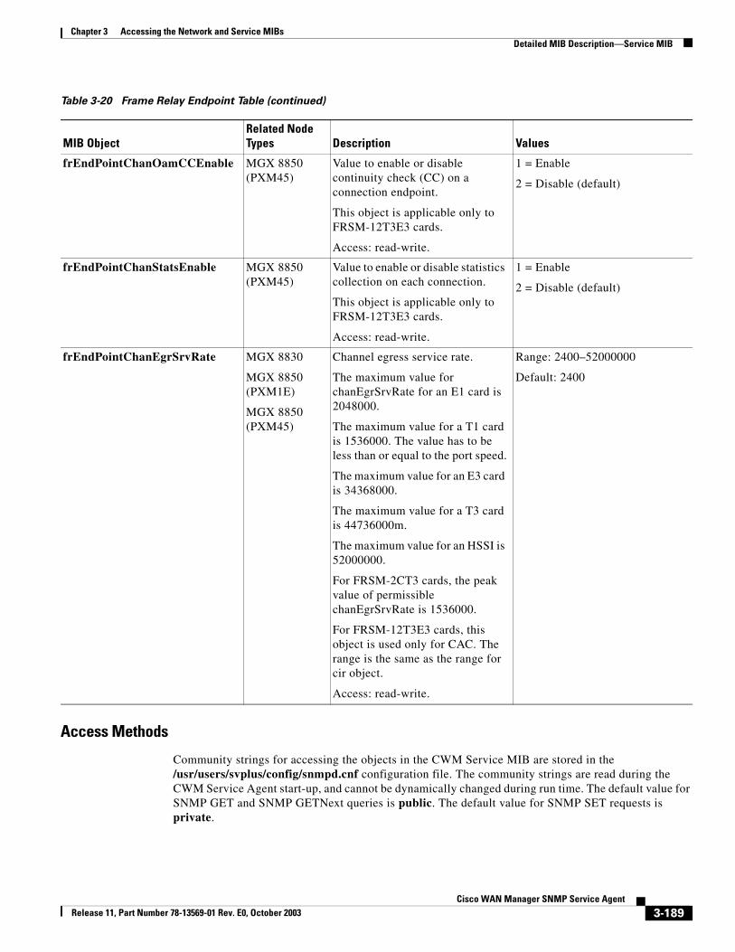
Chapter 3 Accessing the Network and Service MIBsDetailed MIB Description—Service MIB
Access Methods
Community strings for accessing the objects in the CWM Service MIB are stored in the /usr/users/svplus/config/snmpd.cnf configuration file. The community strings are read during the CWM Service Agent start-up, and cannot be dynamically changed during run time. The default value for SNMP GET and SNMP GETNext queries is public. The default value for SNMP SET requests is private.
frEndPointChanOamCCEnable MGX 8850 (PXM45)
Value to enable or disable continuity check (CC) on a connection endpoint.
This object is applicable only to FRSM-12T3E3 cards.
Access: read-write.
1 = Enable
2 = Disable (default)
frEndPointChanStatsEnable MGX 8850 (PXM45)
Value to enable or disable statistics collection on each connection.
This object is applicable only to FRSM-12T3E3 cards.
Access: read-write.
1 = Enable
2 = Disable (default)
frEndPointChanEgrSrvRate MGX 8830
MGX 8850 (PXM1E)
MGX 8850 (PXM45)
Channel egress service rate.
The maximum value for chanEgrSrvRate for an E1 card is 2048000.
The maximum value for a T1 card is 1536000. The value has to be less than or equal to the port speed.
The maximum value for an E3 card is 34368000.
The maximum value for a T3 card is 44736000m.
The maximum value for an HSSI is 52000000.
For FRSM-2CT3 cards, the peak value of permissible chanEgrSrvRate is 1536000.
For FRSM-12T3E3 cards, this object is used only for CAC. The range is the same as the range for cir object.
Access: read-write.
Range: 2400–52000000
Default: 2400
Table 3-20 Frame Relay Endpoint Table (continued)
MIB ObjectRelated Node Types Description Values
3-189Cisco WAN Manager SNMP Service Agent
Release 11, Part Number 78-13569-01 Rev. E0, October 2003
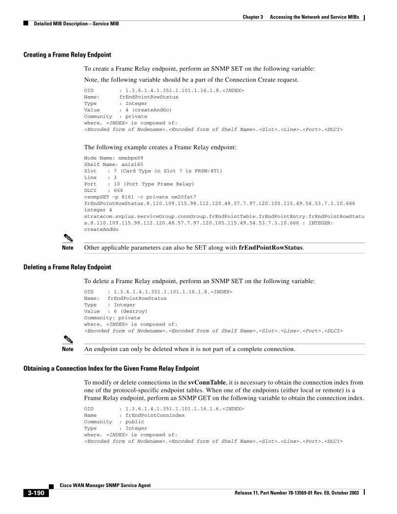
Chapter 3 Accessing the Network and Service MIBsDetailed MIB Description—Service MIB
Creating a Frame Relay Endpoint
To create a Frame Relay endpoint, perform an SNMP SET on the following variable:
Note, the following variable should be a part of the Connection Create request.
OID : 1.3.6.1.4.1.351.1.101.1.16.1.8.<INDEX>Name: frEndPointRowStatusType : IntegerValue : 4 (createAndGo)Community : privatewhere, <INDEX> is composed of:<Encoded form of Nodename>.<Encoded form of Shelf Name>.<Slot>.<Line>.<Port>.<DLCI>
The following example creates a Frame Relay endpoint:
Node Name: nmsbpx09Shelf Name: axis165Slot : 7 (Card Type in Slot 7 is FRSM/4T1)Line : 3 Port : 10 (Port Type Frame Relay)DLCI : 666>snmpSET -p 8161 -c private nm20fst7 frEndPointRowStatus.8.110.109.115.98.112.120.48.57.7.97.120.105.115.49.54.53.7.3.10.666 integer 4stratacom.svplus.serviceGroup.connGroup.frEndPointTable.frEndPointEntry.frEndPointRowStatus.8.110.109.115.98.112.120.48.57.7.97.120.105.115.49.54.53.7.3.10.666 : INTEGER: createAndGo
Note Other applicable parameters can also be SET along with frEndPointRowStatus.
Deleting a Frame Relay Endpoint
To delete a Frame Relay endpoint, perform an SNMP SET on the following variable:
OID : 1.3.6.1.4.1.351.1.101.1.16.1.8.<INDEX>Name: frEndPointRowStatusType : IntegerValue : 6 (destroy)Community: privatewhere, <INDEX> is composed of:<Encoded form of Nodename>.<Encoded form of Shelf Name>.<Slot>.<Line>.<Port>.<DLCI>
Note An endpoint can only be deleted when it is not part of a complete connection.
Obtaining a Connection Index for the Given Frame Relay Endpoint
To modify or delete connections in the svConnTable, it is necessary to obtain the connection index from one of the protocol-specific endpoint tables. When one of the endpoints (either local or remote) is a Frame Relay endpoint, perform an SNMP GET on the following variable to obtain the connection index.
OID : 1.3.6.1.4.1.351.1.101.1.16.1.6.<INDEX>Name : frEndPointConnIndexCommunity : publicType : Integerwhere, <INDEX> is composed of:<Encoded form of Nodename>.<Encoded form of Shelf Name>.<Slot>.<Line>.<Port>.<DLCI>
3-190Cisco WAN Manager SNMP Service Agent
Release 11, Part Number 78-13569-01 Rev. E0, October 2003
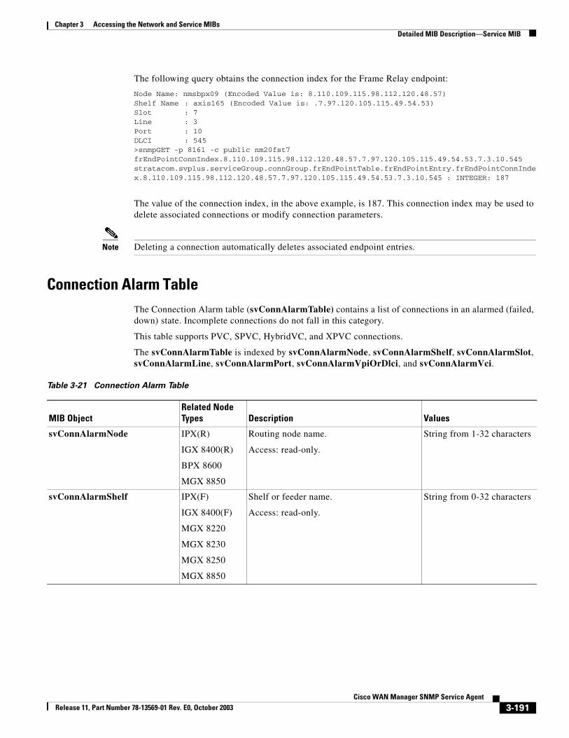
Chapter 3 Accessing the Network and Service MIBsDetailed MIB Description—Service MIB
The following query obtains the connection index for the Frame Relay endpoint:
Node Name: nmsbpx09 (Encoded Value is: 8.110.109.115.98.112.120.48.57)Shelf Name : axis165 (Encoded Value is: .7.97.120.105.115.49.54.53)Slot : 7Line : 3Port : 10DLCI : 545>snmpGET -p 8161 -c public nm20fst7 frEndPointConnIndex.8.110.109.115.98.112.120.48.57.7.97.120.105.115.49.54.53.7.3.10.545stratacom.svplus.serviceGroup.connGroup.frEndPointTable.frEndPointEntry.frEndPointConnIndex.8.110.109.115.98.112.120.48.57.7.97.120.105.115.49.54.53.7.3.10.545 : INTEGER: 187
The value of the connection index, in the above example, is 187. This connection index may be used to delete associated connections or modify connection parameters.
Note Deleting a connection automatically deletes associated endpoint entries.
Connection Alarm TableThe Connection Alarm table (svConnAlarmTable) contains a list of connections in an alarmed (failed, down) state. Incomplete connections do not fall in this category.
This table supports PVC, SPVC, HybridVC, and XPVC connections.
The svConnAlarmTable is indexed by svConnAlarmNode, svConnAlarmShelf, svConnAlarmSlot, svConnAlarmLine, svConnAlarmPort, svConnAlarmVpiOrDlci, and svConnAlarmVci.
Table 3-21 Connection Alarm Table
MIB ObjectRelated Node Types Description Values
svConnAlarmNode IPX(R)
IGX 8400(R)
BPX 8600
MGX 8850
Routing node name.
Access: read-only.
String from 1-32 characters
svConnAlarmShelf IPX(F)
IGX 8400(F)
MGX 8220
MGX 8230
MGX 8250
MGX 8850
Shelf or feeder name.
Access: read-only.
String from 0-32 characters
3-191Cisco WAN Manager SNMP Service Agent
Release 11, Part Number 78-13569-01 Rev. E0, October 2003
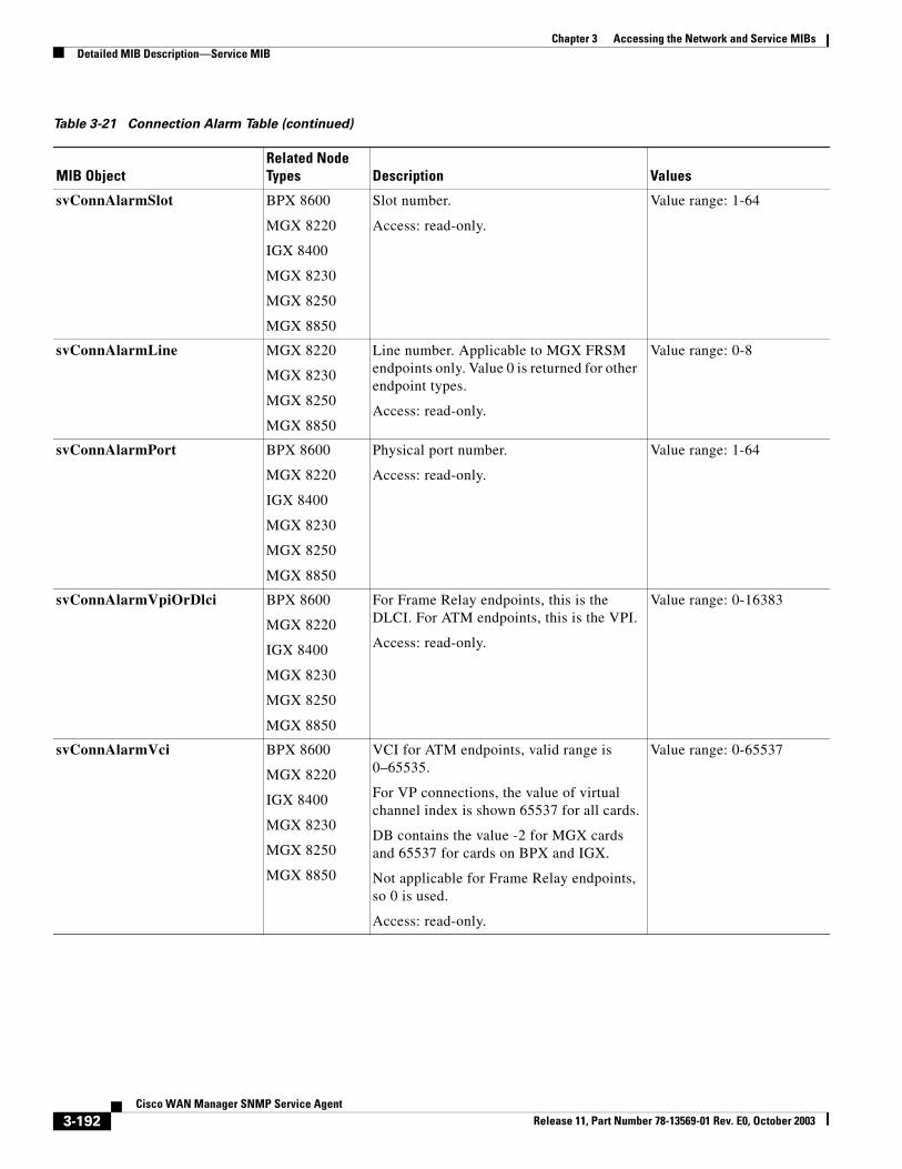
Chapter 3 Accessing the Network and Service MIBsDetailed MIB Description—Service MIB
svConnAlarmSlot BPX 8600
MGX 8220
IGX 8400
MGX 8230
MGX 8250
MGX 8850
Slot number.
Access: read-only.
Value range: 1-64
svConnAlarmLine MGX 8220
MGX 8230
MGX 8250
MGX 8850
Line number. Applicable to MGX FRSM endpoints only. Value 0 is returned for other endpoint types.
Access: read-only.
Value range: 0-8
svConnAlarmPort BPX 8600
MGX 8220
IGX 8400
MGX 8230
MGX 8250
MGX 8850
Physical port number.
Access: read-only.
Value range: 1-64
svConnAlarmVpiOrDlci BPX 8600
MGX 8220
IGX 8400
MGX 8230
MGX 8250
MGX 8850
For Frame Relay endpoints, this is the DLCI. For ATM endpoints, this is the VPI.
Access: read-only.
Value range: 0-16383
svConnAlarmVci BPX 8600
MGX 8220
IGX 8400
MGX 8230
MGX 8250
MGX 8850
VCI for ATM endpoints, valid range is 0–65535.
For VP connections, the value of virtual channel index is shown 65537 for all cards.
DB contains the value -2 for MGX cards and 65537 for cards on BPX and IGX.
Not applicable for Frame Relay endpoints, so 0 is used.
Access: read-only.
Value range: 0-65537
Table 3-21 Connection Alarm Table (continued)
MIB ObjectRelated Node Types Description Values
3-192Cisco WAN Manager SNMP Service Agent
Release 11, Part Number 78-13569-01 Rev. E0, October 2003
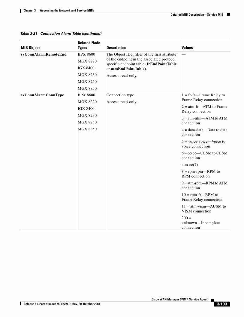
Chapter 3 Accessing the Network and Service MIBsDetailed MIB Description—Service MIB
svConnAlarmRemoteEnd BPX 8600
MGX 8220
IGX 8400
MGX 8230
MGX 8250
MGX 8850
The Object IDentifier of the first attribute of the endpoint in the associated protocol specific endpoint table (frEndPointTable or atmEndPointTable).
Access: read-only.
—
svConnAlarmConnType BPX 8600
MGX 8220
IGX 8400
MGX 8230
MGX 8250
MGX 8850
Connection type.
Access: read-only.
1 = fr-fr—Frame Relay to Frame Relay connection
2 = atm-fr—ATM to Frame Relay connection
3 = atm-atm—ATM to ATM connection
4 = data-data—Data to data connection
5 = voice-voice—Voice to voice connection
6 = ce-ce—CESM to CESM connection
atm-ce(7)
8 = rpm-rpm—RPM to RPM connection
9 = atm-rpm—RPM to ATM connection
10 = rpm-fr—RPM to Frame Relay connection
11 = atm-vism—AUSM to VISM connection
200 = unknown—Incomplete connection
Table 3-21 Connection Alarm Table (continued)
MIB ObjectRelated Node Types Description Values
3-193Cisco WAN Manager SNMP Service Agent
Release 11, Part Number 78-13569-01 Rev. E0, October 2003
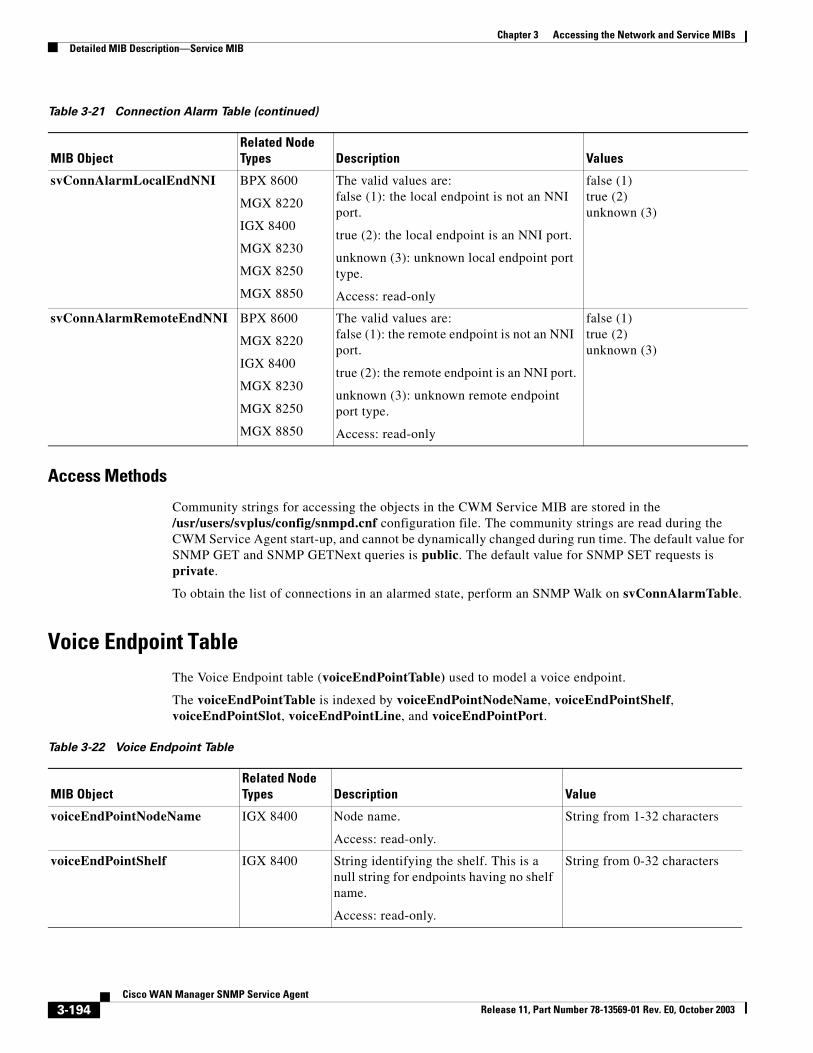
Chapter 3 Accessing the Network and Service MIBsDetailed MIB Description—Service MIB
Access Methods
Community strings for accessing the objects in the CWM Service MIB are stored in the /usr/users/svplus/config/snmpd.cnf configuration file. The community strings are read during the CWM Service Agent start-up, and cannot be dynamically changed during run time. The default value for SNMP GET and SNMP GETNext queries is public. The default value for SNMP SET requests is private.
To obtain the list of connections in an alarmed state, perform an SNMP Walk on svConnAlarmTable.
Voice Endpoint TableThe Voice Endpoint table (voiceEndPointTable) used to model a voice endpoint.
The voiceEndPointTable is indexed by voiceEndPointNodeName, voiceEndPointShelf, voiceEndPointSlot, voiceEndPointLine, and voiceEndPointPort.
svConnAlarmLocalEndNNI BPX 8600
MGX 8220
IGX 8400
MGX 8230
MGX 8250
MGX 8850
The valid values are:false (1): the local endpoint is not an NNI port.
true (2): the local endpoint is an NNI port.
unknown (3): unknown local endpoint port type.
Access: read-only
false (1)true (2)unknown (3)
svConnAlarmRemoteEndNNI BPX 8600
MGX 8220
IGX 8400
MGX 8230
MGX 8250
MGX 8850
The valid values are:false (1): the remote endpoint is not an NNI port.
true (2): the remote endpoint is an NNI port.
unknown (3): unknown remote endpoint port type.
Access: read-only
false (1)true (2)unknown (3)
Table 3-21 Connection Alarm Table (continued)
MIB ObjectRelated Node Types Description Values
Table 3-22 Voice Endpoint Table
MIB ObjectRelated Node Types Description Value
voiceEndPointNodeName IGX 8400 Node name.
Access: read-only.
String from 1-32 characters
voiceEndPointShelf IGX 8400 String identifying the shelf. This is a null string for endpoints having no shelf name.
Access: read-only.
String from 0-32 characters
3-194Cisco WAN Manager SNMP Service Agent
Release 11, Part Number 78-13569-01 Rev. E0, October 2003
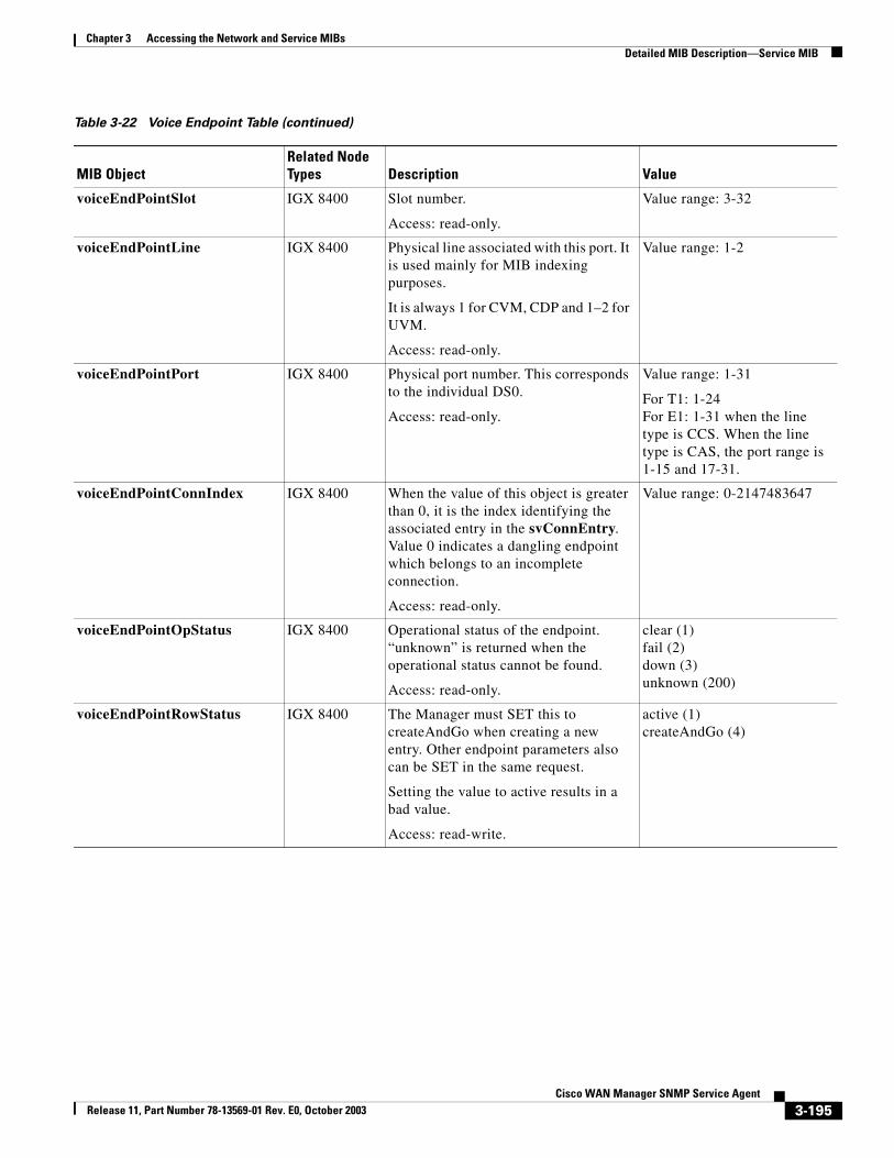
Chapter 3 Accessing the Network and Service MIBsDetailed MIB Description—Service MIB
voiceEndPointSlot IGX 8400 Slot number.
Access: read-only.
Value range: 3-32
voiceEndPointLine IGX 8400 Physical line associated with this port. It is used mainly for MIB indexing purposes.
It is always 1 for CVM, CDP and 1–2 for UVM.
Access: read-only.
Value range: 1-2
voiceEndPointPort IGX 8400 Physical port number. This corresponds to the individual DS0.
Access: read-only.
Value range: 1-31
For T1: 1-24For E1: 1-31 when the line type is CCS. When the line type is CAS, the port range is 1-15 and 17-31.
voiceEndPointConnIndex IGX 8400 When the value of this object is greater than 0, it is the index identifying the associated entry in the svConnEntry. Value 0 indicates a dangling endpoint which belongs to an incomplete connection.
Access: read-only.
Value range: 0-2147483647
voiceEndPointOpStatus IGX 8400 Operational status of the endpoint. “unknown” is returned when the operational status cannot be found.
Access: read-only.
clear (1) fail (2)down (3)unknown (200)
voiceEndPointRowStatus IGX 8400 The Manager must SET this to createAndGo when creating a new entry. Other endpoint parameters also can be SET in the same request.
Setting the value to active results in a bad value.
Access: read-write.
active (1)createAndGo (4)
Table 3-22 Voice Endpoint Table (continued)
MIB ObjectRelated Node Types Description Value
3-195Cisco WAN Manager SNMP Service Agent
Release 11, Part Number 78-13569-01 Rev. E0, October 2003
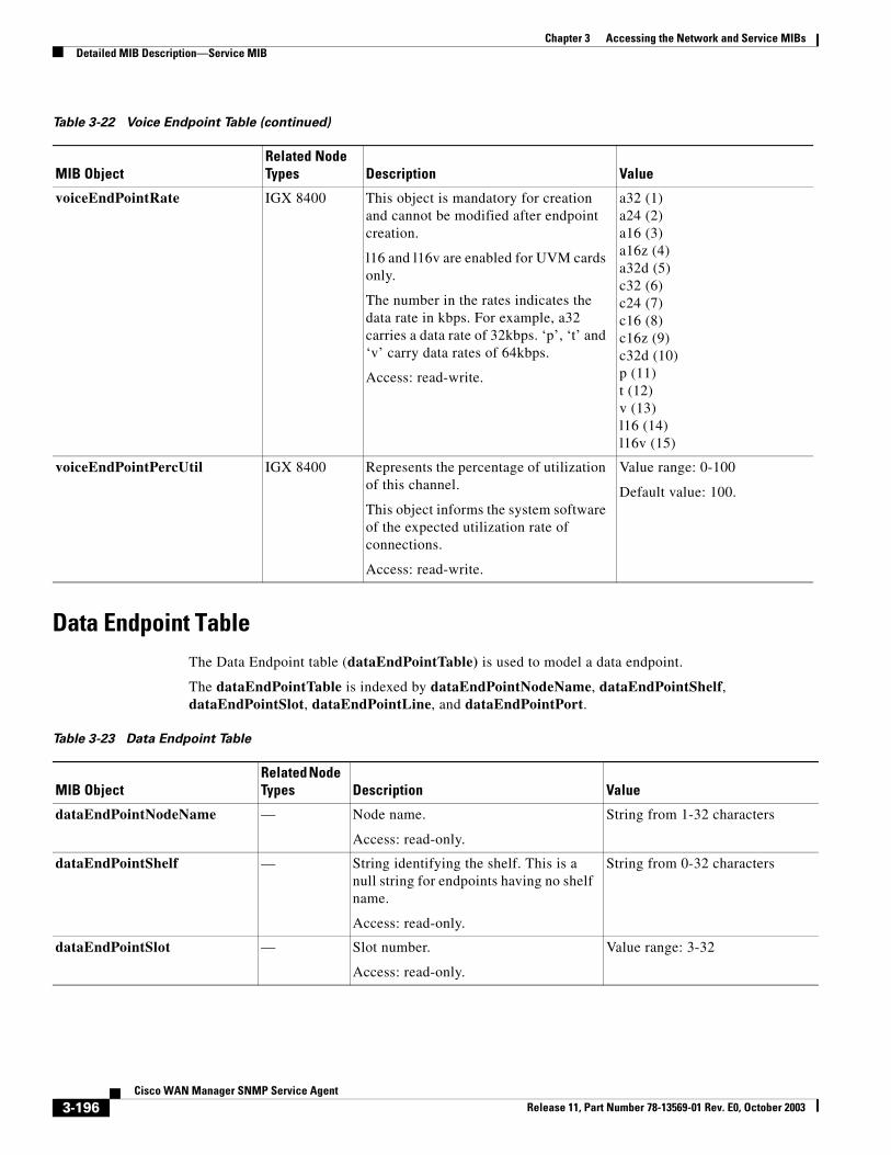
Chapter 3 Accessing the Network and Service MIBsDetailed MIB Description—Service MIB
Data Endpoint TableThe Data Endpoint table (dataEndPointTable) is used to model a data endpoint.
The dataEndPointTable is indexed by dataEndPointNodeName, dataEndPointShelf, dataEndPointSlot, dataEndPointLine, and dataEndPointPort.
voiceEndPointRate IGX 8400 This object is mandatory for creation and cannot be modified after endpoint creation.
l16 and l16v are enabled for UVM cards only.
The number in the rates indicates the data rate in kbps. For example, a32 carries a data rate of 32kbps. ‘p’, ‘t’ and ‘v’ carry data rates of 64kbps.
Access: read-write.
a32 (1)a24 (2)a16 (3)a16z (4)a32d (5)c32 (6)c24 (7)c16 (8)c16z (9)c32d (10)p (11)t (12)v (13)l16 (14)l16v (15)
voiceEndPointPercUtil IGX 8400 Represents the percentage of utilization of this channel.
This object informs the system software of the expected utilization rate of connections.
Access: read-write.
Value range: 0-100
Default value: 100.
Table 3-22 Voice Endpoint Table (continued)
MIB ObjectRelated Node Types Description Value
Table 3-23 Data Endpoint Table
MIB ObjectRelated Node Types Description Value
dataEndPointNodeName — Node name.
Access: read-only.
String from 1-32 characters
dataEndPointShelf — String identifying the shelf. This is a null string for endpoints having no shelf name.
Access: read-only.
String from 0-32 characters
dataEndPointSlot — Slot number.
Access: read-only.
Value range: 3-32
3-196Cisco WAN Manager SNMP Service Agent
Release 11, Part Number 78-13569-01 Rev. E0, October 2003
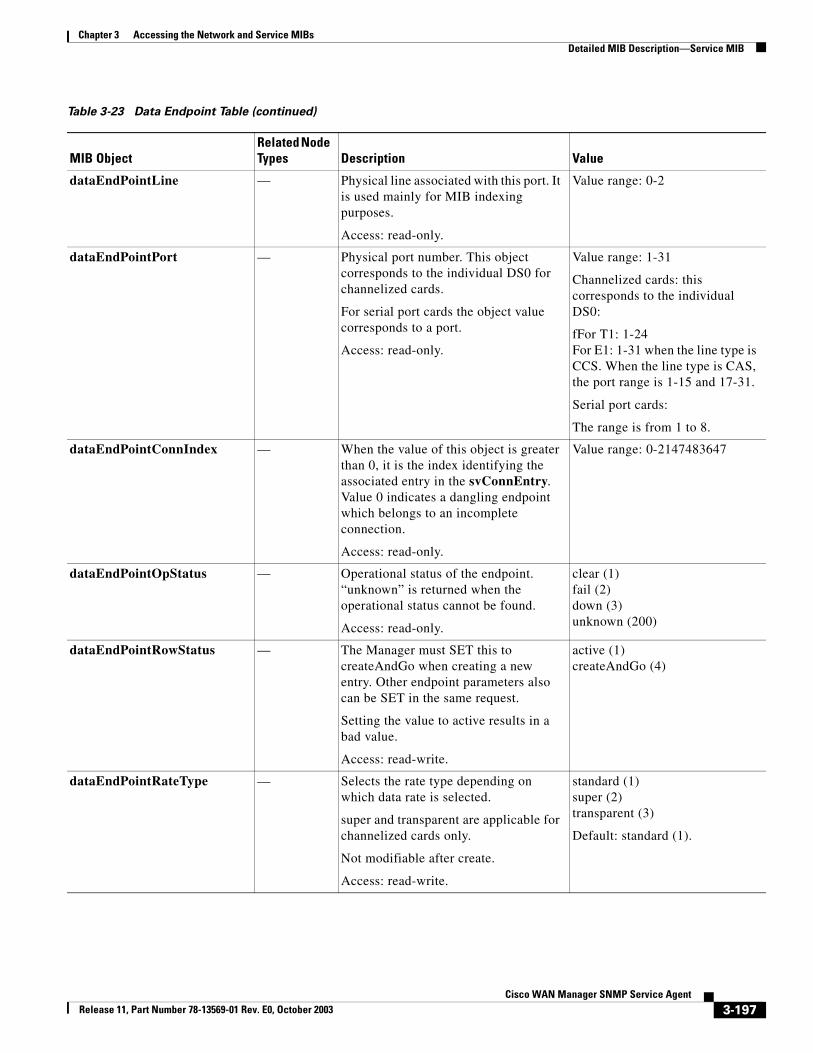
Chapter 3 Accessing the Network and Service MIBsDetailed MIB Description—Service MIB
dataEndPointLine — Physical line associated with this port. It is used mainly for MIB indexing purposes.
Access: read-only.
Value range: 0-2
dataEndPointPort — Physical port number. This object corresponds to the individual DS0 for channelized cards.
For serial port cards the object value corresponds to a port.
Access: read-only.
Value range: 1-31
Channelized cards: this corresponds to the individual DS0:
fFor T1: 1-24For E1: 1-31 when the line type is CCS. When the line type is CAS, the port range is 1-15 and 17-31.
Serial port cards:
The range is from 1 to 8.
dataEndPointConnIndex — When the value of this object is greater than 0, it is the index identifying the associated entry in the svConnEntry. Value 0 indicates a dangling endpoint which belongs to an incomplete connection.
Access: read-only.
Value range: 0-2147483647
dataEndPointOpStatus — Operational status of the endpoint. “unknown” is returned when the operational status cannot be found.
Access: read-only.
clear (1) fail (2)down (3)unknown (200)
dataEndPointRowStatus — The Manager must SET this to createAndGo when creating a new entry. Other endpoint parameters also can be SET in the same request.
Setting the value to active results in a bad value.
Access: read-write.
active (1)createAndGo (4)
dataEndPointRateType — Selects the rate type depending on which data rate is selected.
super and transparent are applicable for channelized cards only.
Not modifiable after create.
Access: read-write.
standard (1)super (2)transparent (3)
Default: standard (1).
Table 3-23 Data Endpoint Table (continued)
MIB ObjectRelated Node Types Description Value
3-197Cisco WAN Manager SNMP Service Agent
Release 11, Part Number 78-13569-01 Rev. E0, October 2003
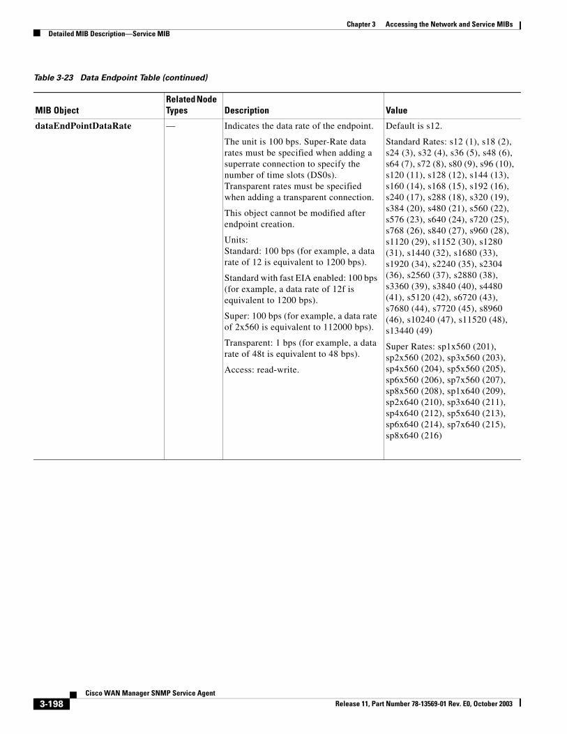
Chapter 3 Accessing the Network and Service MIBsDetailed MIB Description—Service MIB
dataEndPointDataRate — Indicates the data rate of the endpoint.
The unit is 100 bps. Super-Rate data rates must be specified when adding a superrate connection to specify the number of time slots (DS0s). Transparent rates must be specified when adding a transparent connection.
This object cannot be modified after endpoint creation.
Units:Standard: 100 bps (for example, a data rate of 12 is equivalent to 1200 bps).
Standard with fast EIA enabled: 100 bps (for example, a data rate of 12f is equivalent to 1200 bps).
Super: 100 bps (for example, a data rate of 2x560 is equivalent to 112000 bps).
Transparent: 1 bps (for example, a data rate of 48t is equivalent to 48 bps).
Access: read-write.
Default is s12.
Standard Rates: s12 (1), s18 (2),s24 (3), s32 (4), s36 (5), s48 (6),s64 (7), s72 (8), s80 (9), s96 (10), s120 (11), s128 (12), s144 (13),s160 (14), s168 (15), s192 (16),s240 (17), s288 (18), s320 (19),s384 (20), s480 (21), s560 (22),s576 (23), s640 (24), s720 (25),s768 (26), s840 (27), s960 (28),s1120 (29), s1152 (30), s1280 (31), s1440 (32), s1680 (33), s1920 (34), s2240 (35), s2304 (36), s2560 (37), s2880 (38), s3360 (39), s3840 (40), s4480 (41), s5120 (42), s6720 (43), s7680 (44), s7720 (45), s8960 (46), s10240 (47), s11520 (48),s13440 (49)
Super Rates: sp1x560 (201), sp2x560 (202), sp3x560 (203), sp4x560 (204), sp5x560 (205), sp6x560 (206), sp7x560 (207), sp8x560 (208), sp1x640 (209), sp2x640 (210), sp3x640 (211),sp4x640 (212), sp5x640 (213), sp6x640 (214), sp7x640 (215), sp8x640 (216)
Table 3-23 Data Endpoint Table (continued)
MIB ObjectRelated Node Types Description Value
3-198Cisco WAN Manager SNMP Service Agent
Release 11, Part Number 78-13569-01 Rev. E0, October 2003
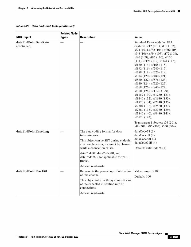
Chapter 3 Accessing the Network and Service MIBsDetailed MIB Description—Service MIB
dataEndPointDataRate (continued)
— — Standard Rates with fast EIA enabled: sf12 (101), sf18 (102),sf24 (103), sf32 (104), sf36 (105),sf48 (106), sf64 (107), sf72 (108), sf80 (109), sf96 (110), sf120 (111), sf128 (112), sf144 (113),sf160 (114), sf168 (115),sf192 (116), sf240 (117),sf288 (118), sf320 (119),sf384 (120), sf480 (121),sf560 (122), sf576 (123),sf640 (124), sf720 (125),sf768 (126), sf840 (127),sf960 (128), sf1120 (129),sf1152 (130), sf1280 (131),sf1440 (132), sf1680 (133),sf1920 (134), sf2240 (135),sf2304 (136), sf2560 (137),sf2880 (138), sf3360 (139),sf3840 (140), sf4480 (141),sf5120 (142),
Transparent Subrates: t24 (301),t48 (302), t96 (303), t560 (304)
dataEndPointEncoding — The data coding format for data transmissions.
This object can be SET during endpoint creation, however, it cannot be changed while a connection exists.
dataCode88, dataCode88I, and dataCode78E not applicable for ZCS trunks.
Access: read-write.
dataCode78 (1)dataCode88 (2)dataCode88I (3)dataCode78E (4)
Default: dataCode78 (1)
dataEndPointPercUtil — Represents the percentage of utilization of this channel.
This object informs the system software of the expected utilization rate of connections.
Access: read-write.
Value range: 0-100
Default: 100
Table 3-23 Data Endpoint Table (continued)
MIB ObjectRelated Node Types Description Value
3-199Cisco WAN Manager SNMP Service Agent
Release 11, Part Number 78-13569-01 Rev. E0, October 2003
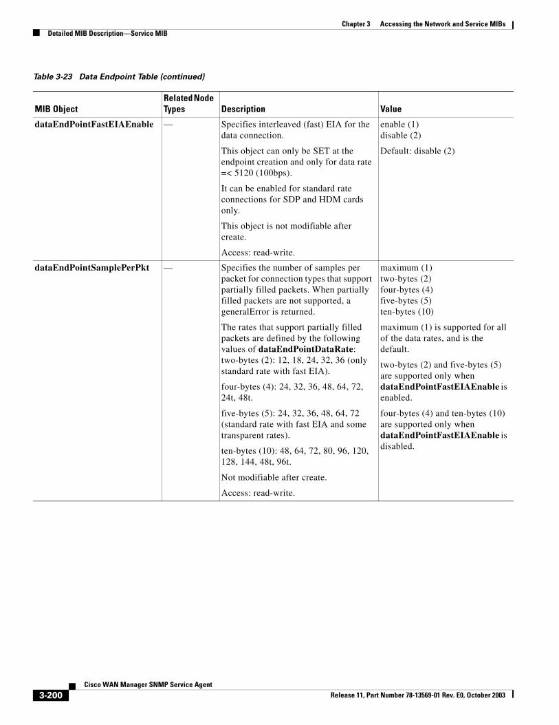
Chapter 3 Accessing the Network and Service MIBsDetailed MIB Description—Service MIB
dataEndPointFastEIAEnable — Specifies interleaved (fast) EIA for the data connection.
This object can only be SET at the endpoint creation and only for data rate =< 5120 (100bps).
It can be enabled for standard rate connections for SDP and HDM cards only.
This object is not modifiable after create.
Access: read-write.
enable (1)disable (2)
Default: disable (2)
dataEndPointSamplePerPkt — Specifies the number of samples per packet for connection types that support partially filled packets. When partially filled packets are not supported, a generalError is returned.
The rates that support partially filled packets are defined by the following values of dataEndPointDataRate:two-bytes (2): 12, 18, 24, 32, 36 (only standard rate with fast EIA).
four-bytes (4): 24, 32, 36, 48, 64, 72, 24t, 48t.
five-bytes (5): 24, 32, 36, 48, 64, 72 (standard rate with fast EIA and some transparent rates).
ten-bytes (10): 48, 64, 72, 80, 96, 120, 128, 144, 48t, 96t.
Not modifiable after create.
Access: read-write.
maximum (1)two-bytes (2)four-bytes (4)five-bytes (5)ten-bytes (10)
maximum (1) is supported for all of the data rates, and is the default.
two-bytes (2) and five-bytes (5) are supported only when dataEndPointFastEIAEnable is enabled.
four-bytes (4) and ten-bytes (10) are supported only when dataEndPointFastEIAEnable is disabled.
Table 3-23 Data Endpoint Table (continued)
MIB ObjectRelated Node Types Description Value
3-200Cisco WAN Manager SNMP Service Agent
Release 11, Part Number 78-13569-01 Rev. E0, October 2003
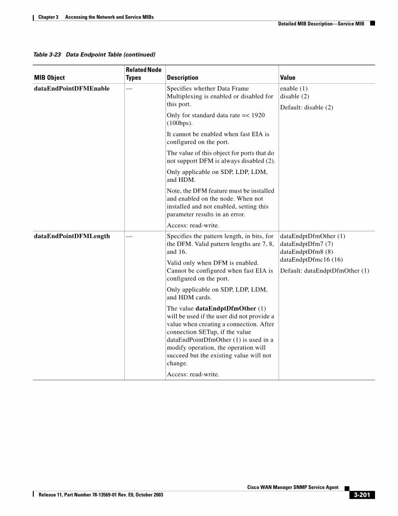
Chapter 3 Accessing the Network and Service MIBsDetailed MIB Description—Service MIB
dataEndPointDFMEnable — Specifies whether Data Frame Multiplexing is enabled or disabled for this port.
Only for standard data rate =< 1920 (100bps).
It cannot be enabled when fast EIA is configured on the port.
The value of this object for ports that do not support DFM is always disabled (2).
Only applicable on SDP, LDP, LDM, and HDM.
Note, the DFM feature must be installed and enabled on the node. When not installed and not enabled, setting this parameter results in an error.
Access: read-write.
enable (1)disable (2)
Default: disable (2)
dataEndPointDFMLength — Specifies the pattern length, in bits, for the DFM. Valid pattern lengths are 7, 8, and 16.
Valid only when DFM is enabled. Cannot be configured when fast EIA is configured on the port.
Only applicable on SDP, LDP, LDM, and HDM cards.
The value dataEndptDfmOther (1) will be used if the user did not provide a value when creating a connection. After connection SETup, if the value dataEndPointDfmOther (1) is used in a modify operation, the operation will succeed but the existing value will not change.
Access: read-write.
dataEndptDfmOther (1)dataEndptDfm7 (7)dataEndptDfm8 (8)dataEndptDfmc16 (16)
Default: dataEndptDfmOther (1)
Table 3-23 Data Endpoint Table (continued)
MIB ObjectRelated Node Types Description Value
3-201Cisco WAN Manager SNMP Service Agent
Release 11, Part Number 78-13569-01 Rev. E0, October 2003
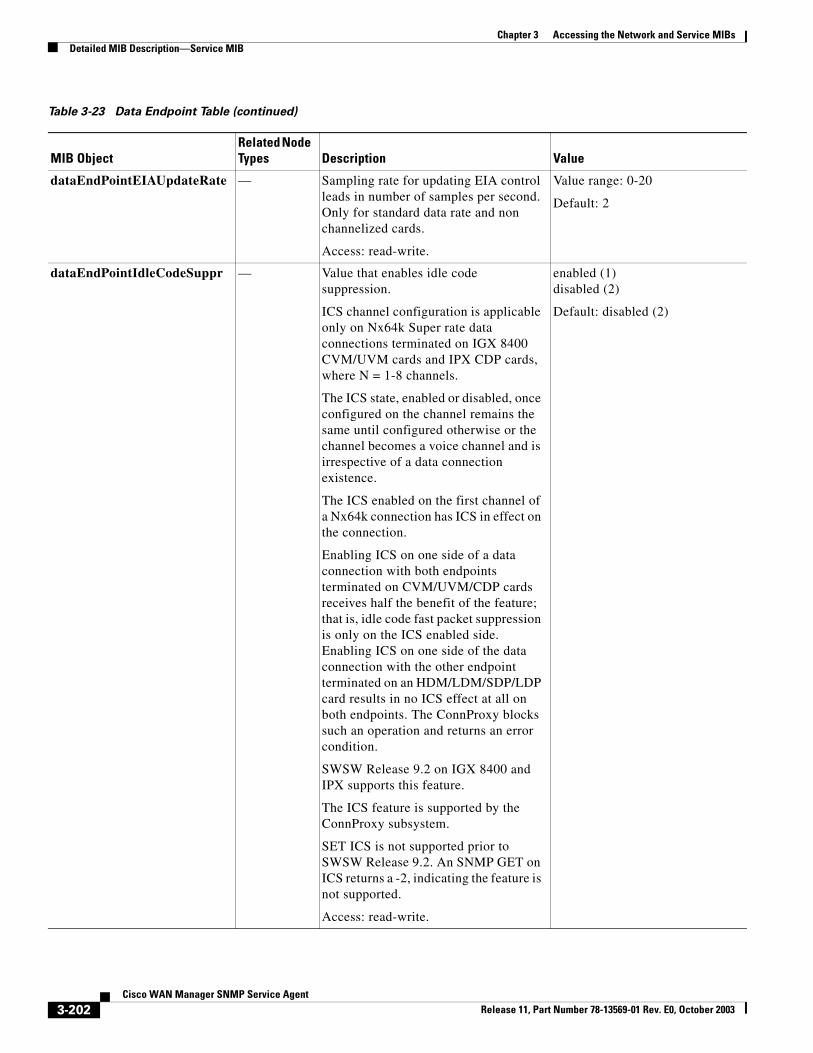
Chapter 3 Accessing the Network and Service MIBsDetailed MIB Description—Service MIB
dataEndPointEIAUpdateRate — Sampling rate for updating EIA control leads in number of samples per second. Only for standard data rate and non channelized cards.
Access: read-write.
Value range: 0-20
Default: 2
dataEndPointIdleCodeSuppr — Value that enables idle code suppression.
ICS channel configuration is applicable only on Nx64k Super rate data connections terminated on IGX 8400 CVM/UVM cards and IPX CDP cards, where N = 1-8 channels.
The ICS state, enabled or disabled, once configured on the channel remains the same until configured otherwise or the channel becomes a voice channel and is irrespective of a data connection existence.
The ICS enabled on the first channel of a Nx64k connection has ICS in effect on the connection.
Enabling ICS on one side of a data connection with both endpoints terminated on CVM/UVM/CDP cards receives half the benefit of the feature; that is, idle code fast packet suppression is only on the ICS enabled side. Enabling ICS on one side of the data connection with the other endpoint terminated on an HDM/LDM/SDP/LDP card results in no ICS effect at all on both endpoints. The ConnProxy blocks such an operation and returns an error condition.
SWSW Release 9.2 on IGX 8400 and IPX supports this feature.
The ICS feature is supported by the ConnProxy subsystem.
SET ICS is not supported prior to SWSW Release 9.2. An SNMP GET on ICS returns a -2, indicating the feature is not supported.
Access: read-write.
enabled (1)disabled (2)
Default: disabled (2)
Table 3-23 Data Endpoint Table (continued)
MIB ObjectRelated Node Types Description Value
3-202Cisco WAN Manager SNMP Service Agent
Release 11, Part Number 78-13569-01 Rev. E0, October 2003
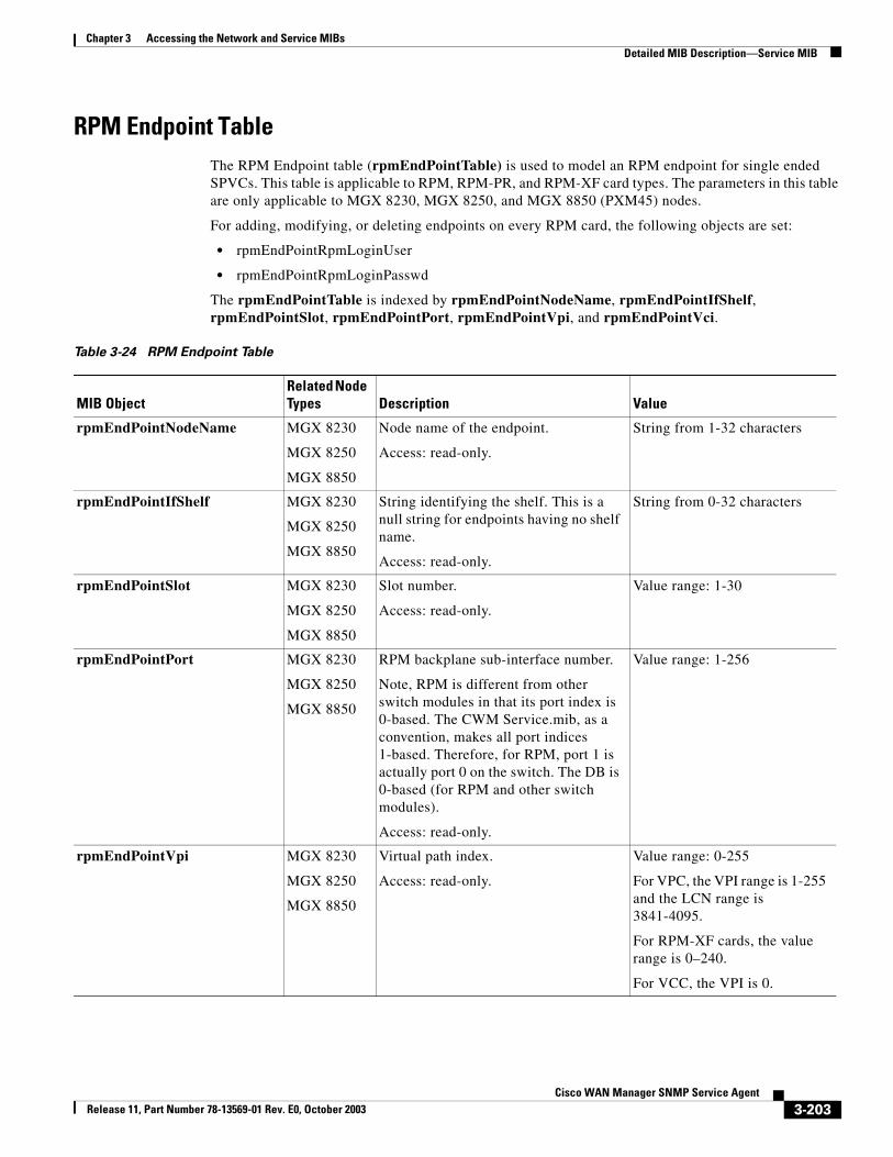
Chapter 3 Accessing the Network and Service MIBsDetailed MIB Description—Service MIB
RPM Endpoint TableThe RPM Endpoint table (rpmEndPointTable) is used to model an RPM endpoint for single ended SPVCs. This table is applicable to RPM, RPM-PR, and RPM-XF card types. The parameters in this table are only applicable to MGX 8230, MGX 8250, and MGX 8850 (PXM45) nodes.
For adding, modifying, or deleting endpoints on every RPM card, the following objects are set:
• rpmEndPointRpmLoginUser
• rpmEndPointRpmLoginPasswd
The rpmEndPointTable is indexed by rpmEndPointNodeName, rpmEndPointIfShelf, rpmEndPointSlot, rpmEndPointPort, rpmEndPointVpi, and rpmEndPointVci.
Table 3-24 RPM Endpoint Table
MIB ObjectRelated Node Types Description Value
rpmEndPointNodeName MGX 8230
MGX 8250
MGX 8850
Node name of the endpoint.
Access: read-only.
String from 1-32 characters
rpmEndPointIfShelf MGX 8230
MGX 8250
MGX 8850
String identifying the shelf. This is a null string for endpoints having no shelf name.
Access: read-only.
String from 0-32 characters
rpmEndPointSlot MGX 8230
MGX 8250
MGX 8850
Slot number.
Access: read-only.
Value range: 1-30
rpmEndPointPort MGX 8230
MGX 8250
MGX 8850
RPM backplane sub-interface number.
Note, RPM is different from other switch modules in that its port index is 0-based. The CWM Service.mib, as a convention, makes all port indices 1-based. Therefore, for RPM, port 1 is actually port 0 on the switch. The DB is 0-based (for RPM and other switch modules).
Access: read-only.
Value range: 1-256
rpmEndPointVpi MGX 8230
MGX 8250
MGX 8850
Virtual path index.
Access: read-only.
Value range: 0-255
For VPC, the VPI range is 1-255 and the LCN range is 3841-4095.
For RPM-XF cards, the value range is 0–240.
For VCC, the VPI is 0.
3-203Cisco WAN Manager SNMP Service Agent
Release 11, Part Number 78-13569-01 Rev. E0, October 2003
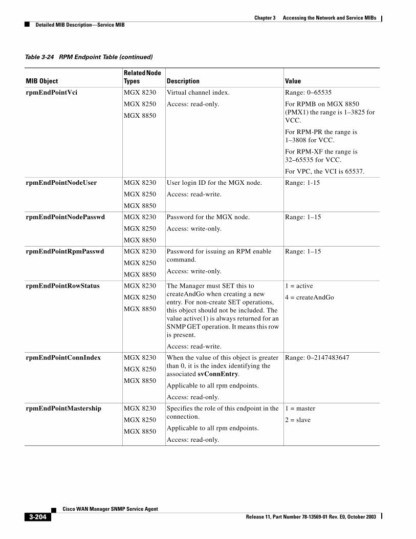
Chapter 3 Accessing the Network and Service MIBsDetailed MIB Description—Service MIB
rpmEndPointVci MGX 8230
MGX 8250
MGX 8850
Virtual channel index.
Access: read-only.
Range: 0–65535
For RPMB on MGX 8850 (PMX1) the range is 1–3825 for VCC.
For RPM-PR the range is 1–3808 for VCC.
For RPM-XF the range is 32–65535 for VCC.
For VPC, the VCI is 65537.
rpmEndPointNodeUser MGX 8230
MGX 8250
MGX 8850
User login ID for the MGX node.
Access: read-write.
Range: 1-15
rpmEndPointNodePasswd MGX 8230
MGX 8250
MGX 8850
Password for the MGX node.
Access: write-only.
Range: 1–15
rpmEndPointRpmPasswd MGX 8230
MGX 8250
MGX 8850
Password for issuing an RPM enable command.
Access: write-only.
Range: 1–15
rpmEndPointRowStatus MGX 8230
MGX 8250
MGX 8850
The Manager must SET this to createAndGo when creating a new entry. For non-create SET operations, this object should not be included. The value active(1) is always returned for an SNMP GET operation. It means this row is present.
Access: read-write.
1 = active
4 = createAndGo
rpmEndPointConnIndex MGX 8230
MGX 8250
MGX 8850
When the value of this object is greater than 0, it is the index identifying the associated svConnEntry.
Applicable to all rpm endpoints.
Access: read-only.
Range: 0–2147483647
rpmEndPointMastership MGX 8230
MGX 8250
MGX 8850
Specifies the role of this endpoint in the connection.
Applicable to all rpm endpoints.
Access: read-only.
1 = master
2 = slave
Table 3-24 RPM Endpoint Table (continued)
MIB ObjectRelated Node Types Description Value
3-204Cisco WAN Manager SNMP Service Agent
Release 11, Part Number 78-13569-01 Rev. E0, October 2003
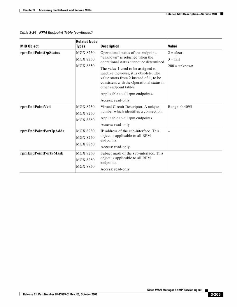
Chapter 3 Accessing the Network and Service MIBsDetailed MIB Description—Service MIB
rpmEndPointOpStatus MGX 8230
MGX 8250
MGX 8850
Operational status of the endpoint. “unknown” is returned when the operational status cannot be determined.
The value 1 used to be assigned to inactive; however, it is obsolete. The value starts from 2 instead of 1, to be consistent with the Operational status in other endpoint tables
Applicable to all rpm endpoints.
Access: read-only.
2 = clear
3 = fail
200 = unknown
rpmEndPointVcd MGX 8230
MGX 8250
MGX 8850
Virtual Circuit Descriptor. A unique number which identifies a connection.
Applicable to all rpm endpoints.
Access: read-only.
Range: 0-4095
rpmEndPointPortIpAddr MGX 8230
MGX 8250
MGX 8850
IP address of the sub-interface. This object is applicable to all RPM endpoints.
Access: read-only.
–
rpmEndPointPortSMask MGX 8230
MGX 8250
MGX 8850
Subnet mask of the sub-interface. This object is applicable to all RPM endpoints.
Access: read-only.
Table 3-24 RPM Endpoint Table (continued)
MIB ObjectRelated Node Types Description Value
3-205Cisco WAN Manager SNMP Service Agent
Release 11, Part Number 78-13569-01 Rev. E0, October 2003
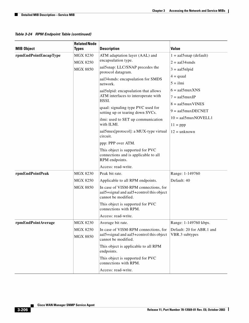
Chapter 3 Accessing the Network and Service MIBsDetailed MIB Description—Service MIB
rpmEndPointEncapType MGX 8230
MGX 8250
MGX 8850
ATM adaptation layer (AAL) and encapsulation type.
aal5snap: LLC/SNAP precedes the protocol datagram.
aal34smds: encapsulation for SMDS network.
aal5nlpid: encapsulation that allows ATM interfaces to interoperate with HSSI.
qsaal: signaling type PVC used for setting up or tearing down SVCs.
ilmi: used to SET up communication with ILMI.
aal5mux[protocol]: a MUX-type virtual circuit.
ppp: PPP over ATM.
This object is supported for PVC connections and is applicable to all RPM endpoints.
Access: read-write.
1 = aal5snap (default)
2 = aal34smds
3 = aal5nlpid
4 = qsaal
5 = ilmi
6 = aal5muxXNS
7 = aal5muxIP
8 = aal5muxVINES
9 = aal5muxDECNET
10 = aal5muxNOVELL1
11 = ppp
12 = unknown
rpmEndPointPeak MGX 8230
MGX 8250
MGX 8850
Peak bit rate.
Applicable to all RPM endpoints.
In case of VISM-RPM connections, for aal5+signal and aal5+control this object cannot be modified.
This object is supported for PVC connections with RPM.
Access: read-write.
Range: 1-149760
Default: 40
rpmEndPointAverage MGX 8230
MGX 8250
MGX 8850
Average bit rate.
In case of VISM-RPM connections, for aal5+signal and aal5+control this object cannot be modified.
This object is applicable to all RPM endpoints.
This object is supported for PVC connections with RPM.
Access: read-write.
Range: 1-149760 kbps.
Default: 20 for ABR.1 and VBR.3 subtypes
Table 3-24 RPM Endpoint Table (continued)
MIB ObjectRelated Node Types Description Value
3-206Cisco WAN Manager SNMP Service Agent
Release 11, Part Number 78-13569-01 Rev. E0, October 2003
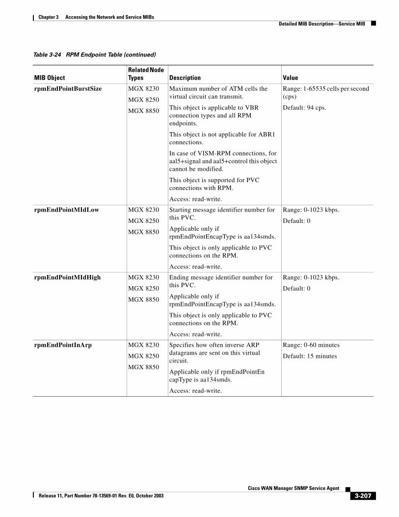
Chapter 3 Accessing the Network and Service MIBsDetailed MIB Description—Service MIB
rpmEndPointBurstSize MGX 8230
MGX 8250
MGX 8850
Maximum number of ATM cells the virtual circuit can transmit.
This object is applicable to VBR connection types and all RPM endpoints.
This object is not applicable for ABR1 connections.
In case of VISM-RPM connections, for aal5+signal and aal5+control this object cannot be modified.
This object is supported for PVC connections with RPM.
Access: read-write.
Range: 1-65535 cells per second (cps)
Default: 94 cps.
rpmEndPointMIdLow MGX 8230
MGX 8250
MGX 8850
Starting message identifier number for this PVC.
Applicable only if rpmEndPointEncapType is aa134smds.
This object is only applicable to PVC connections on the RPM.
Access: read-write.
Range: 0-1023 kbps.
Default: 0
rpmEndPointMIdHigh MGX 8230
MGX 8250
MGX 8850
Ending message identifier number for this PVC.
Applicable only if rpmEndPointEncapType is aa134smds.
This object is only applicable to PVC connections on the RPM.
Access: read-write.
Range: 0-1023 kbps.
Default: 0
rpmEndPointInArp MGX 8230
MGX 8250
MGX 8850
Specifies how often inverse ARP datagrams are sent on this virtual circuit.
Applicable only if rpmEndPointEn capType is aa134smds.
Access: read-write.
Range: 0-60 minutes
Default: 15 minutes
Table 3-24 RPM Endpoint Table (continued)
MIB ObjectRelated Node Types Description Value
3-207Cisco WAN Manager SNMP Service Agent
Release 11, Part Number 78-13569-01 Rev. E0, October 2003
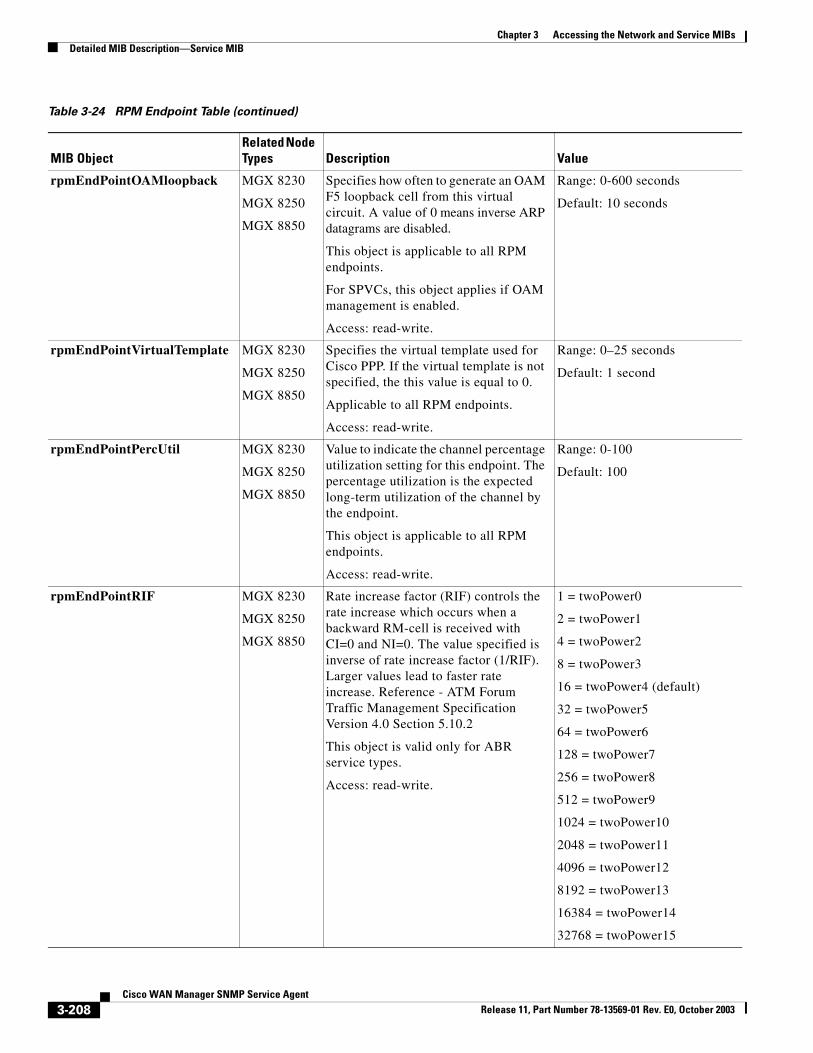
Chapter 3 Accessing the Network and Service MIBsDetailed MIB Description—Service MIB
rpmEndPointOAMloopback MGX 8230
MGX 8250
MGX 8850
Specifies how often to generate an OAM F5 loopback cell from this virtual circuit. A value of 0 means inverse ARP datagrams are disabled.
This object is applicable to all RPM endpoints.
For SPVCs, this object applies if OAM management is enabled.
Access: read-write.
Range: 0-600 seconds
Default: 10 seconds
rpmEndPointVirtualTemplate MGX 8230
MGX 8250
MGX 8850
Specifies the virtual template used for Cisco PPP. If the virtual template is not specified, the this value is equal to 0.
Applicable to all RPM endpoints.
Access: read-write.
Range: 0–25 seconds
Default: 1 second
rpmEndPointPercUtil MGX 8230
MGX 8250
MGX 8850
Value to indicate the channel percentage utilization setting for this endpoint. The percentage utilization is the expected long-term utilization of the channel by the endpoint.
This object is applicable to all RPM endpoints.
Access: read-write.
Range: 0-100
Default: 100
rpmEndPointRIF MGX 8230
MGX 8250
MGX 8850
Rate increase factor (RIF) controls the rate increase which occurs when a backward RM-cell is received with CI=0 and NI=0. The value specified is inverse of rate increase factor (1/RIF). Larger values lead to faster rate increase. Reference - ATM Forum Traffic Management Specification Version 4.0 Section 5.10.2
This object is valid only for ABR service types.
Access: read-write.
1 = twoPower0
2 = twoPower1
4 = twoPower2
8 = twoPower3
16 = twoPower4 (default)
32 = twoPower5
64 = twoPower6
128 = twoPower7
256 = twoPower8
512 = twoPower9
1024 = twoPower10
2048 = twoPower11
4096 = twoPower12
8192 = twoPower13
16384 = twoPower14
32768 = twoPower15
Table 3-24 RPM Endpoint Table (continued)
MIB ObjectRelated Node Types Description Value
3-208Cisco WAN Manager SNMP Service Agent
Release 11, Part Number 78-13569-01 Rev. E0, October 2003
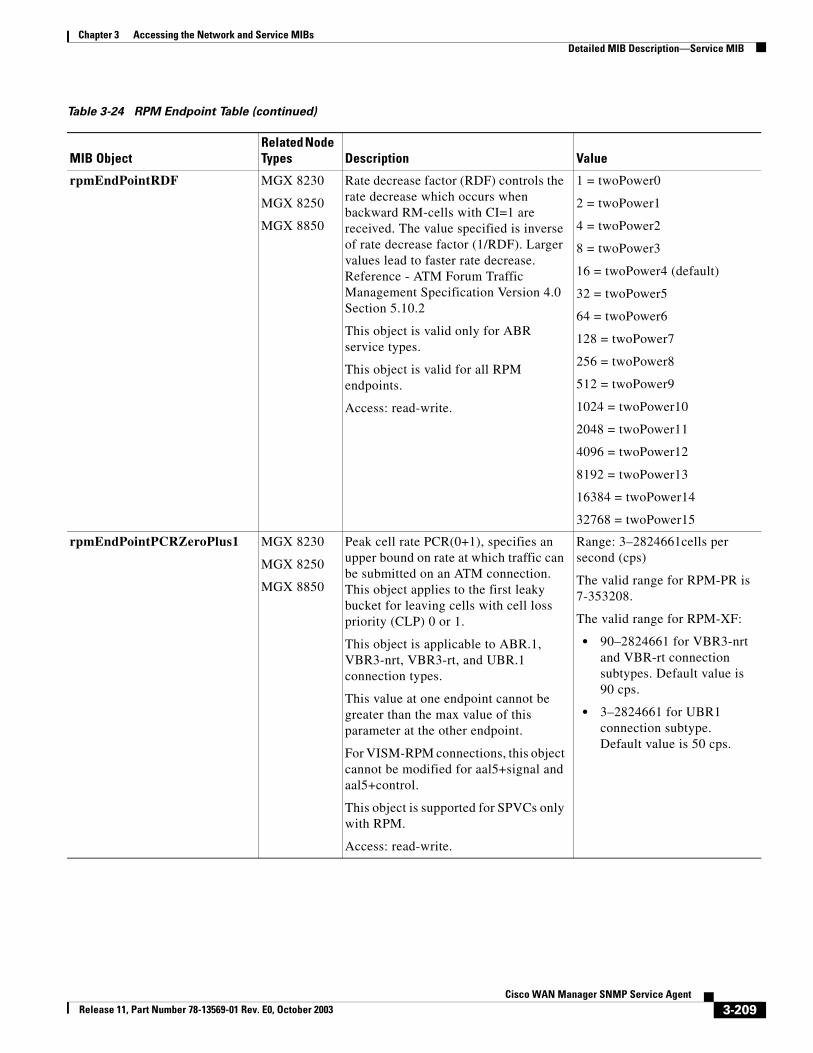
Chapter 3 Accessing the Network and Service MIBsDetailed MIB Description—Service MIB
rpmEndPointRDF MGX 8230
MGX 8250
MGX 8850
Rate decrease factor (RDF) controls the rate decrease which occurs when backward RM-cells with CI=1 are received. The value specified is inverse of rate decrease factor (1/RDF). Larger values lead to faster rate decrease. Reference - ATM Forum Traffic Management Specification Version 4.0 Section 5.10.2
This object is valid only for ABR service types.
This object is valid for all RPM endpoints.
Access: read-write.
1 = twoPower0
2 = twoPower1
4 = twoPower2
8 = twoPower3
16 = twoPower4 (default)
32 = twoPower5
64 = twoPower6
128 = twoPower7
256 = twoPower8
512 = twoPower9
1024 = twoPower10
2048 = twoPower11
4096 = twoPower12
8192 = twoPower13
16384 = twoPower14
32768 = twoPower15
rpmEndPointPCRZeroPlus1 MGX 8230
MGX 8250
MGX 8850
Peak cell rate PCR(0+1), specifies an upper bound on rate at which traffic can be submitted on an ATM connection. This object applies to the first leaky bucket for leaving cells with cell loss priority (CLP) 0 or 1.
This object is applicable to ABR.1, VBR3-nrt, VBR3-rt, and UBR.1 connection types.
This value at one endpoint cannot be greater than the max value of this parameter at the other endpoint.
For VISM-RPM connections, this object cannot be modified for aal5+signal and aal5+control.
This object is supported for SPVCs only with RPM.
Access: read-write.
Range: 3–2824661cells per second (cps)
The valid range for RPM-PR is 7-353208.
The valid range for RPM-XF:
• 90–2824661 for VBR3-nrt and VBR-rt connection subtypes. Default value is 90 cps.
• 3–2824661 for UBR1 connection subtype. Default value is 50 cps.
Table 3-24 RPM Endpoint Table (continued)
MIB ObjectRelated Node Types Description Value
3-209Cisco WAN Manager SNMP Service Agent
Release 11, Part Number 78-13569-01 Rev. E0, October 2003
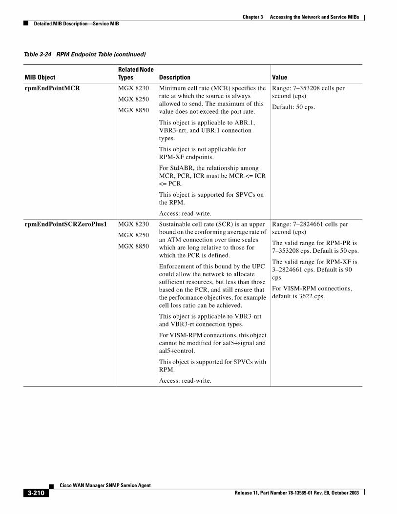
Chapter 3 Accessing the Network and Service MIBsDetailed MIB Description—Service MIB
rpmEndPointMCR MGX 8230
MGX 8250
MGX 8850
Minimum cell rate (MCR) specifies the rate at which the source is always allowed to send. The maximum of this value does not exceed the port rate.
This object is applicable to ABR.1, VBR3-nrt, and UBR.1 connection types.
This object is not applicable for RPM-XF endpoints.
For StdABR, the relationship among MCR, PCR, ICR must be MCR <= ICR <= PCR.
This object is supported for SPVCs on the RPM.
Access: read-write.
Range: 7–353208 cells per second (cps)
Default: 50 cps.
rpmEndPointSCRZeroPlus1 MGX 8230
MGX 8250
MGX 8850
Sustainable cell rate (SCR) is an upper bound on the conforming average rate of an ATM connection over time scales which are long relative to those for which the PCR is defined.
Enforcement of this bound by the UPC could allow the network to allocate sufficient resources, but less than those based on the PCR, and still ensure that the performance objectives, for example cell loss ratio can be achieved.
This object is applicable to VBR3-nrt and VBR3-rt connection types.
For VISM-RPM connections, this object cannot be modified for aal5+signal and aal5+control.
This object is supported for SPVCs with RPM.
Access: read-write.
Range: 7–2824661 cells per second (cps)
The valid range for RPM-PR is 7–353208 cps. Default is 50 cps.
The valid range for RPM-XF is 3–2824661 cps. Default is 90 cps.
For VISM-RPM connections, default is 3622 cps.
Table 3-24 RPM Endpoint Table (continued)
MIB ObjectRelated Node Types Description Value
3-210Cisco WAN Manager SNMP Service Agent
Release 11, Part Number 78-13569-01 Rev. E0, October 2003
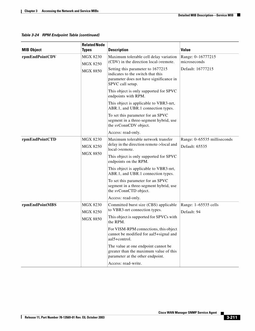
Chapter 3 Accessing the Network and Service MIBsDetailed MIB Description—Service MIB
rpmEndPointCDV MGX 8230
MGX 8250
MGX 8850
Maximum tolerable cell delay variation (CDV) in the direction local->remote.
Setting this parameter to 1677215 indicates to the switch that this parameter does not have significance in SPVC call setup.
This object is only supported for SPVC endpoints with RPM.
This object is applicable to VBR3-nrt, ABR.1, and UBR.1 connection types.
To set this parameter for an SPVC segment in a three-segment hybrid, use the svConnCDV object.
Access: read-only.
Range: 0–16777215 microseconds
Default: 16777215
rpmEndPointCTD MGX 8230
MGX 8250
MGX 8850
Maximum tolerable network transfer delay in the direction remote->local and local->remote.
This object is only supported for SPVC endpoints on the RPM.
This object is applicable to VBR3-nrt, ABR.1, and UBR.1 connection types.
To set this parameter for an SPVC segment in a three-segment hybrid, use the svConnCTD object.
Access: read-only.
Range: 0–65535 milliseconds
Default: 65535
rpmEndPointMBS MGX 8230
MGX 8250
MGX 8850
Committed burst size (CBS) applicable to VBR3-nrt connection types.
This object is supported for SPVCs with the RPM.
For VISM-RPM connections, this object cannot be modified for aal5+signal and aal5+control.
The value at one endpoint cannot be greater than the maximum value of this parameter at the other endpoint.
Access: read-write.
Range: 1–65535 cells
Default: 94
Table 3-24 RPM Endpoint Table (continued)
MIB ObjectRelated Node Types Description Value
3-211Cisco WAN Manager SNMP Service Agent
Release 11, Part Number 78-13569-01 Rev. E0, October 2003
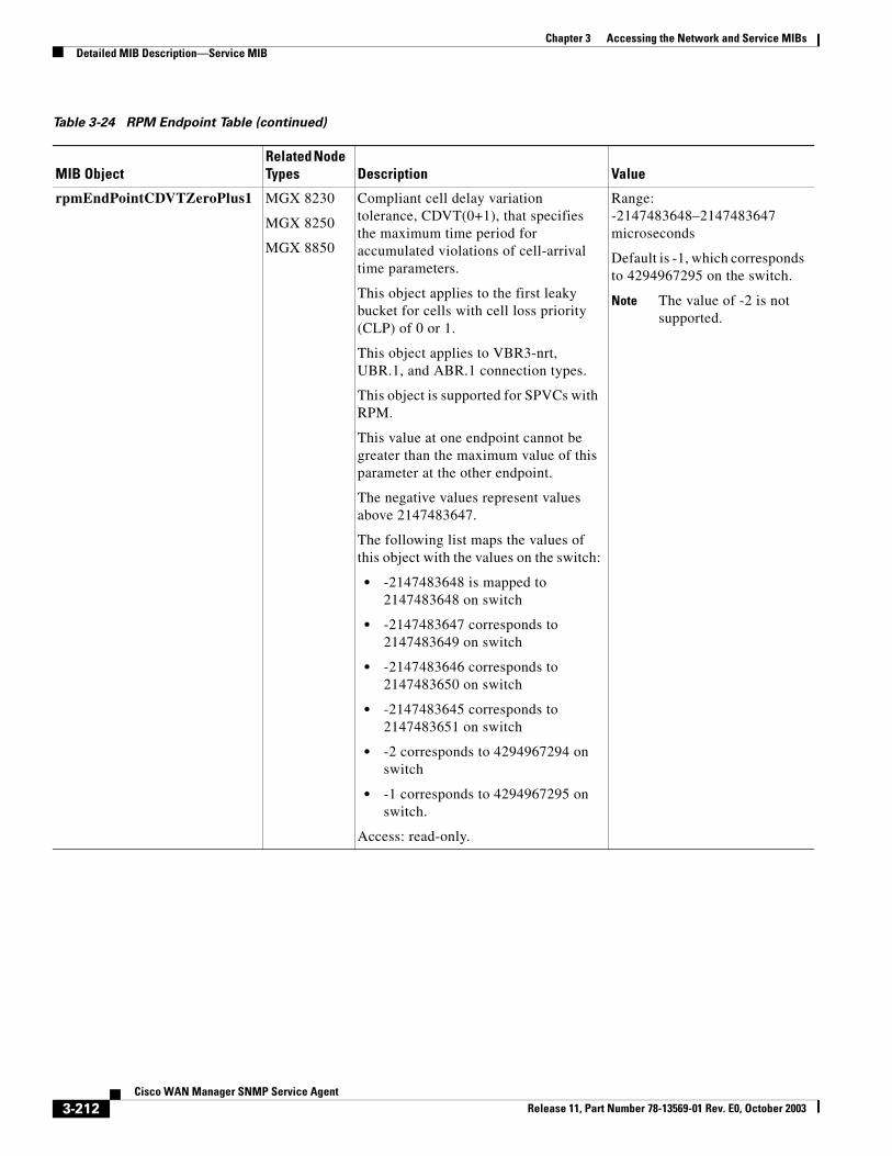
Chapter 3 Accessing the Network and Service MIBsDetailed MIB Description—Service MIB
rpmEndPointCDVTZeroPlus1 MGX 8230
MGX 8250
MGX 8850
Compliant cell delay variation tolerance, CDVT(0+1), that specifies the maximum time period for accumulated violations of cell-arrival time parameters.
This object applies to the first leaky bucket for cells with cell loss priority (CLP) of 0 or 1.
This object applies to VBR3-nrt, UBR.1, and ABR.1 connection types.
This object is supported for SPVCs with RPM.
This value at one endpoint cannot be greater than the maximum value of this parameter at the other endpoint.
The negative values represent values above 2147483647.
The following list maps the values of this object with the values on the switch:
• -2147483648 is mapped to 2147483648 on switch
• -2147483647 corresponds to 2147483649 on switch
• -2147483646 corresponds to 2147483650 on switch
• -2147483645 corresponds to 2147483651 on switch
• -2 corresponds to 4294967294 on switch
• -1 corresponds to 4294967295 on switch.
Access: read-only.
Range: -2147483648–2147483647 microseconds
Default is -1, which corresponds to 4294967295 on the switch.
Note The value of -2 is not supported.
Table 3-24 RPM Endpoint Table (continued)
MIB ObjectRelated Node Types Description Value
3-212Cisco WAN Manager SNMP Service Agent
Release 11, Part Number 78-13569-01 Rev. E0, October 2003
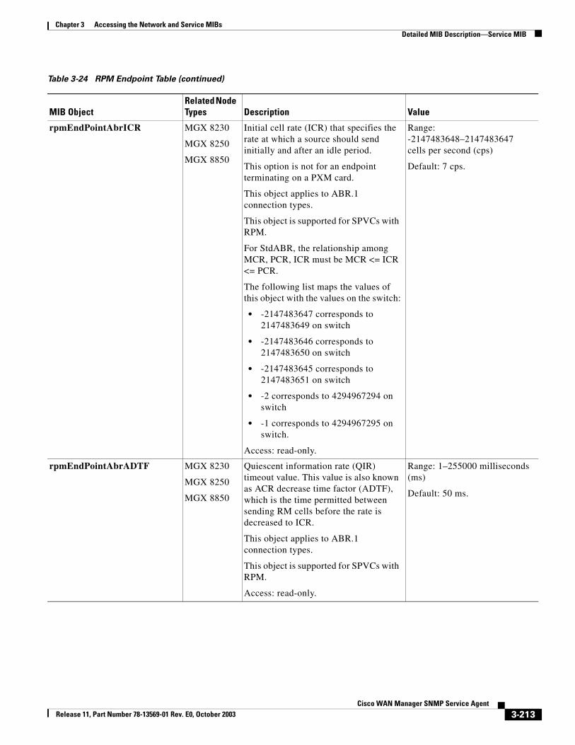
Chapter 3 Accessing the Network and Service MIBsDetailed MIB Description—Service MIB
rpmEndPointAbrICR MGX 8230
MGX 8250
MGX 8850
Initial cell rate (ICR) that specifies the rate at which a source should send initially and after an idle period.
This option is not for an endpoint terminating on a PXM card.
This object applies to ABR.1 connection types.
This object is supported for SPVCs with RPM.
For StdABR, the relationship among MCR, PCR, ICR must be MCR <= ICR <= PCR.
The following list maps the values of this object with the values on the switch:
• -2147483647 corresponds to 2147483649 on switch
• -2147483646 corresponds to 2147483650 on switch
• -2147483645 corresponds to 2147483651 on switch
• -2 corresponds to 4294967294 on switch
• -1 corresponds to 4294967295 on switch.
Access: read-only.
Range: -2147483648–2147483647 cells per second (cps)
Default: 7 cps.
rpmEndPointAbrADTF MGX 8230
MGX 8250
MGX 8850
Quiescent information rate (QIR) timeout value. This value is also known as ACR decrease time factor (ADTF), which is the time permitted between sending RM cells before the rate is decreased to ICR.
This object applies to ABR.1 connection types.
This object is supported for SPVCs with RPM.
Access: read-only.
Range: 1–255000 milliseconds (ms)
Default: 50 ms.
Table 3-24 RPM Endpoint Table (continued)
MIB ObjectRelated Node Types Description Value
3-213Cisco WAN Manager SNMP Service Agent
Release 11, Part Number 78-13569-01 Rev. E0, October 2003
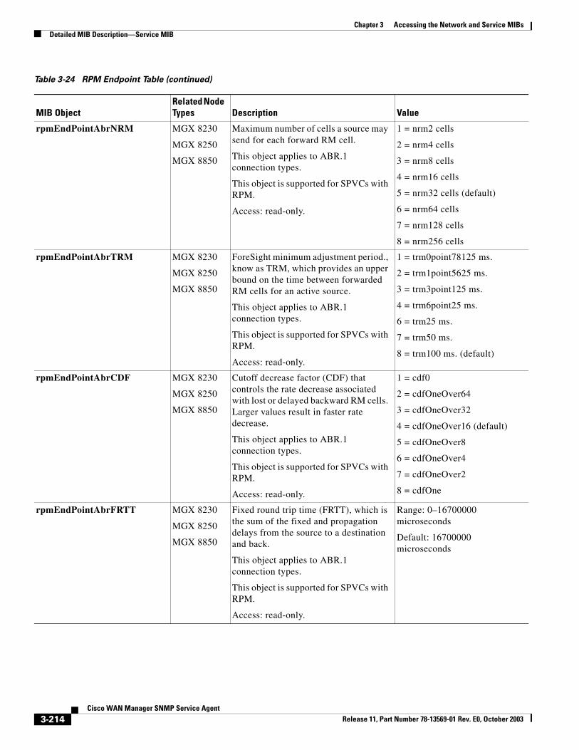
Chapter 3 Accessing the Network and Service MIBsDetailed MIB Description—Service MIB
rpmEndPointAbrNRM MGX 8230
MGX 8250
MGX 8850
Maximum number of cells a source may send for each forward RM cell.
This object applies to ABR.1 connection types.
This object is supported for SPVCs with RPM.
Access: read-only.
1 = nrm2 cells
2 = nrm4 cells
3 = nrm8 cells
4 = nrm16 cells
5 = nrm32 cells (default)
6 = nrm64 cells
7 = nrm128 cells
8 = nrm256 cells
rpmEndPointAbrTRM MGX 8230
MGX 8250
MGX 8850
ForeSight minimum adjustment period., know as TRM, which provides an upper bound on the time between forwarded RM cells for an active source.
This object applies to ABR.1 connection types.
This object is supported for SPVCs with RPM.
Access: read-only.
1 = trm0point78125 ms.
2 = trm1point5625 ms.
3 = trm3point125 ms.
4 = trm6point25 ms.
6 = trm25 ms.
7 = trm50 ms.
8 = trm100 ms. (default)
rpmEndPointAbrCDF MGX 8230
MGX 8250
MGX 8850
Cutoff decrease factor (CDF) that controls the rate decrease associated with lost or delayed backward RM cells. Larger values result in faster rate decrease.
This object applies to ABR.1 connection types.
This object is supported for SPVCs with RPM.
Access: read-only.
1 = cdf0
2 = cdfOneOver64
3 = cdfOneOver32
4 = cdfOneOver16 (default)
5 = cdfOneOver8
6 = cdfOneOver4
7 = cdfOneOver2
8 = cdfOne
rpmEndPointAbrFRTT MGX 8230
MGX 8250
MGX 8850
Fixed round trip time (FRTT), which is the sum of the fixed and propagation delays from the source to a destination and back.
This object applies to ABR.1 connection types.
This object is supported for SPVCs with RPM.
Access: read-only.
Range: 0–16700000 microseconds
Default: 16700000 microseconds
Table 3-24 RPM Endpoint Table (continued)
MIB ObjectRelated Node Types Description Value
3-214Cisco WAN Manager SNMP Service Agent
Release 11, Part Number 78-13569-01 Rev. E0, October 2003
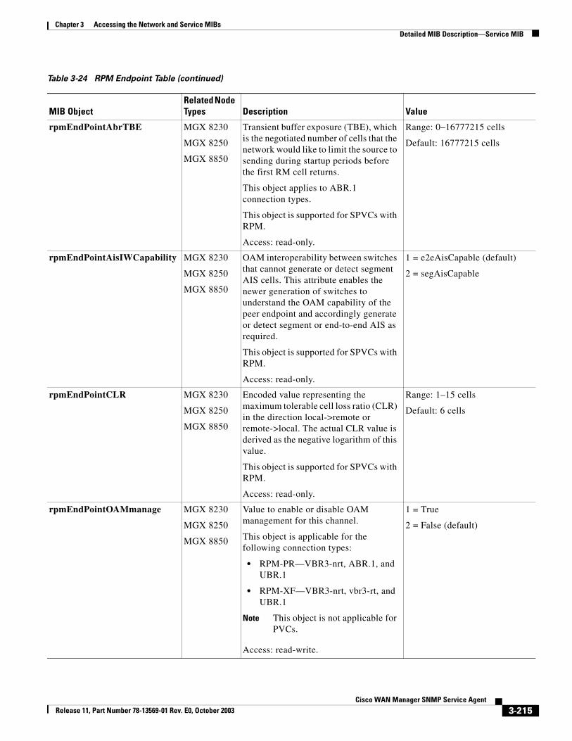
Chapter 3 Accessing the Network and Service MIBsDetailed MIB Description—Service MIB
rpmEndPointAbrTBE MGX 8230
MGX 8250
MGX 8850
Transient buffer exposure (TBE), which is the negotiated number of cells that the network would like to limit the source to sending during startup periods before the first RM cell returns.
This object applies to ABR.1 connection types.
This object is supported for SPVCs with RPM.
Access: read-only.
Range: 0–16777215 cells
Default: 16777215 cells
rpmEndPointAisIWCapability MGX 8230
MGX 8250
MGX 8850
OAM interoperability between switches that cannot generate or detect segment AIS cells. This attribute enables the newer generation of switches to understand the OAM capability of the peer endpoint and accordingly generate or detect segment or end-to-end AIS as required.
This object is supported for SPVCs with RPM.
Access: read-only.
1 = e2eAisCapable (default)
2 = segAisCapable
rpmEndPointCLR MGX 8230
MGX 8250
MGX 8850
Encoded value representing the maximum tolerable cell loss ratio (CLR) in the direction local->remote or remote->local. The actual CLR value is derived as the negative logarithm of this value.
This object is supported for SPVCs with RPM.
Access: read-only.
Range: 1–15 cells
Default: 6 cells
rpmEndPointOAMmanage MGX 8230
MGX 8250
MGX 8850
Value to enable or disable OAM management for this channel.
This object is applicable for the following connection types:
• RPM-PR—VBR3-nrt, ABR.1, and UBR.1
• RPM-XF—VBR3-nrt, vbr3-rt, and UBR.1
Note This object is not applicable for PVCs.
Access: read-write.
1 = True
2 = False (default)
Table 3-24 RPM Endpoint Table (continued)
MIB ObjectRelated Node Types Description Value
3-215Cisco WAN Manager SNMP Service Agent
Release 11, Part Number 78-13569-01 Rev. E0, October 2003
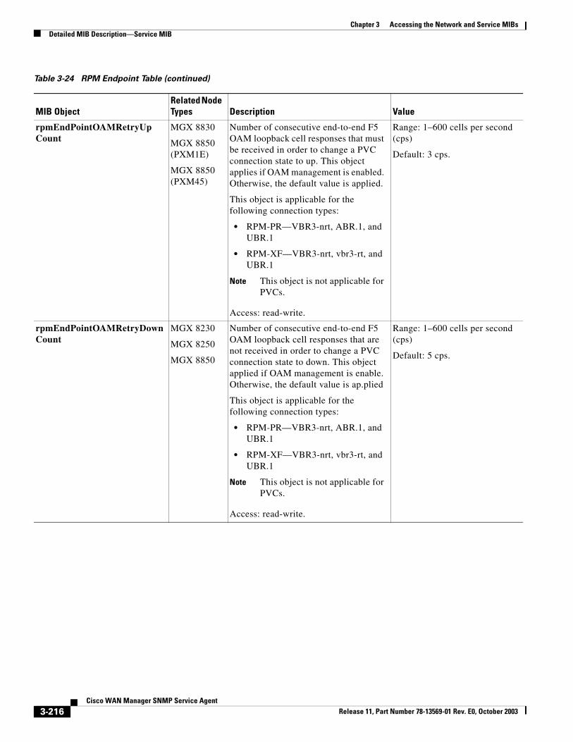
Chapter 3 Accessing the Network and Service MIBsDetailed MIB Description—Service MIB
rpmEndPointOAMRetryUpCount
MGX 8830
MGX 8850 (PXM1E)
MGX 8850 (PXM45)
Number of consecutive end-to-end F5 OAM loopback cell responses that must be received in order to change a PVC connection state to up. This object applies if OAM management is enabled. Otherwise, the default value is applied.
This object is applicable for the following connection types:
• RPM-PR—VBR3-nrt, ABR.1, and UBR.1
• RPM-XF—VBR3-nrt, vbr3-rt, and UBR.1
Note This object is not applicable for PVCs.
Access: read-write.
Range: 1–600 cells per second (cps)
Default: 3 cps.
rpmEndPointOAMRetryDownCount
MGX 8230
MGX 8250
MGX 8850
Number of consecutive end-to-end F5 OAM loopback cell responses that are not received in order to change a PVC connection state to down. This object applied if OAM management is enable. Otherwise, the default value is ap.plied
This object is applicable for the following connection types:
• RPM-PR—VBR3-nrt, ABR.1, and UBR.1
• RPM-XF—VBR3-nrt, vbr3-rt, and UBR.1
Note This object is not applicable for PVCs.
Access: read-write.
Range: 1–600 cells per second (cps)
Default: 5 cps.
Table 3-24 RPM Endpoint Table (continued)
MIB ObjectRelated Node Types Description Value
3-216Cisco WAN Manager SNMP Service Agent
Release 11, Part Number 78-13569-01 Rev. E0, October 2003
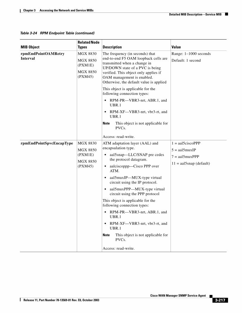
Chapter 3 Accessing the Network and Service MIBsDetailed MIB Description—Service MIB
rpmEndPointOAMRetryInterval
MGX 8830
MGX 8850 (PXM1E)
MGX 8850 (PXM45)
The frequency (in seconds) that end-to-end F5 OAM loopback cells are transmitted when a change in UP/DOWN state of a PVC is being verified. This object only applies if OAM management is enabled. Otherwise, the default value is applied
This object is applicable for the following connection types:
• RPM-PR—VBR3-nrt, ABR.1, and UBR.1
• RPM-XF—VBR3-nrt, vbr3-rt, and UBR.1
Note This object is not applicable for PVCs.
Access: read-write.
Range: 1–1000 seconds
Default: 1 second
rpmEndPointSpvcEncapType MGX 8830
MGX 8850 (PXM1E)
MGX 8850 (PXM45)
ATM adaptation layer (AAL) and encapsulation type.
• aal5snap—LLC/SNAP pre cedes the protocol datagram.
• aalciscoppp—Cisco PPP over ATM.
• aal5muxIP—MUX-type virtual circuit using the IP protocol.
• aal5muxPPP—MUX-type virtual circuit using the PPP protocol
This object is applicable for the following connection types:
• RPM-PR—VBR3-nrt, ABR.1, and UBR.1
• RPM-XF—VBR3-nrt, vbr3-rt, and UBR.1
Note This object is not applicable for PVCs.
Access: read-write.
1 = aal5ciscoPPP
5 = aal5muxIP
7 = aal5muxPPP
11 = aal5snap (default)
Table 3-24 RPM Endpoint Table (continued)
MIB ObjectRelated Node Types Description Value
3-217Cisco WAN Manager SNMP Service Agent
Release 11, Part Number 78-13569-01 Rev. E0, October 2003
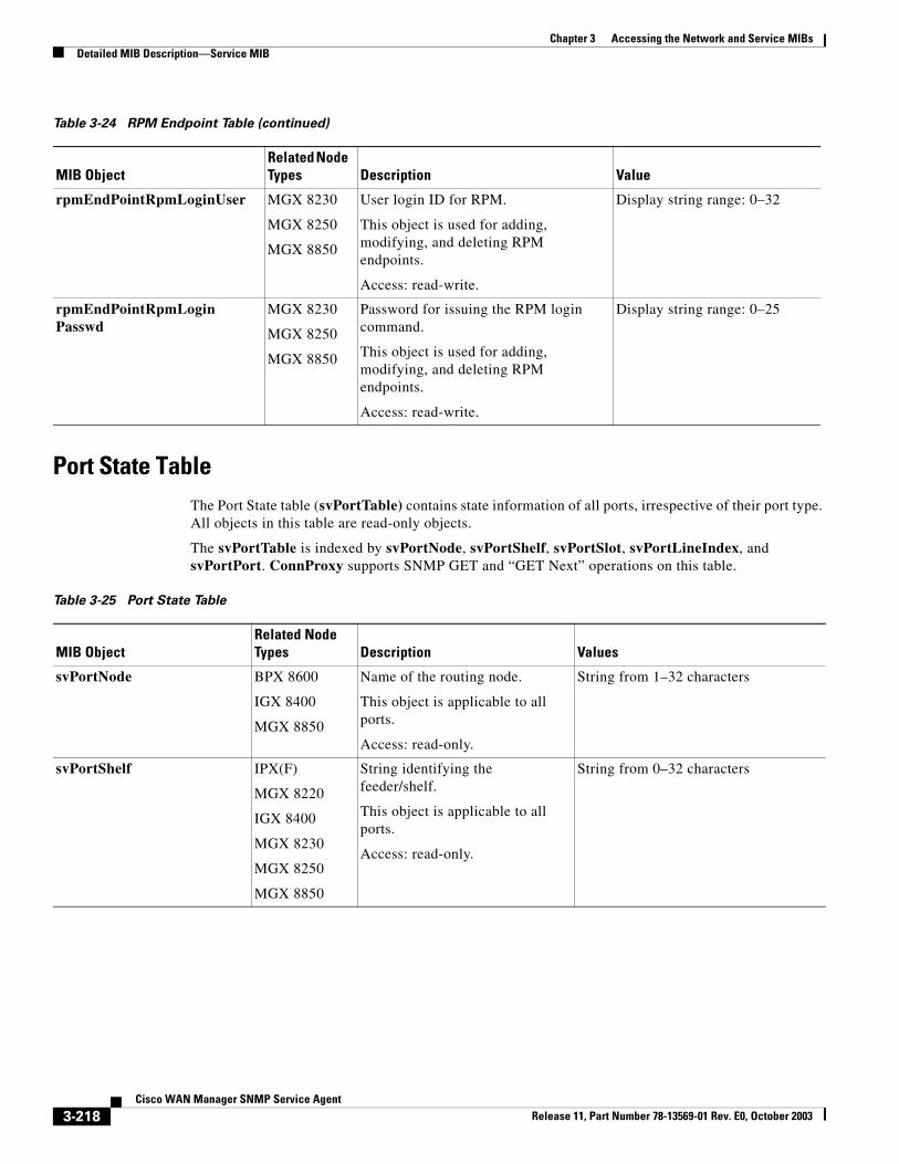
Chapter 3 Accessing the Network and Service MIBsDetailed MIB Description—Service MIB
Port State TableThe Port State table (svPortTable) contains state information of all ports, irrespective of their port type. All objects in this table are read-only objects.
The svPortTable is indexed by svPortNode, svPortShelf, svPortSlot, svPortLineIndex, and svPortPort. ConnProxy supports SNMP GET and “GET Next” operations on this table.
rpmEndPointRpmLoginUser MGX 8230
MGX 8250
MGX 8850
User login ID for RPM.
This object is used for adding, modifying, and deleting RPM endpoints.
Access: read-write.
Display string range: 0–32
rpmEndPointRpmLoginPasswd
MGX 8230
MGX 8250
MGX 8850
Password for issuing the RPM login command.
This object is used for adding, modifying, and deleting RPM endpoints.
Access: read-write.
Display string range: 0–25
Table 3-24 RPM Endpoint Table (continued)
MIB ObjectRelated Node Types Description Value
Table 3-25 Port State Table
MIB ObjectRelated Node Types Description Values
svPortNode BPX 8600
IGX 8400
MGX 8850
Name of the routing node.
This object is applicable to all ports.
Access: read-only.
String from 1–32 characters
svPortShelf IPX(F)
MGX 8220
IGX 8400
MGX 8230
MGX 8250
MGX 8850
String identifying the feeder/shelf.
This object is applicable to all ports.
Access: read-only.
String from 0–32 characters
3-218Cisco WAN Manager SNMP Service Agent
Release 11, Part Number 78-13569-01 Rev. E0, October 2003
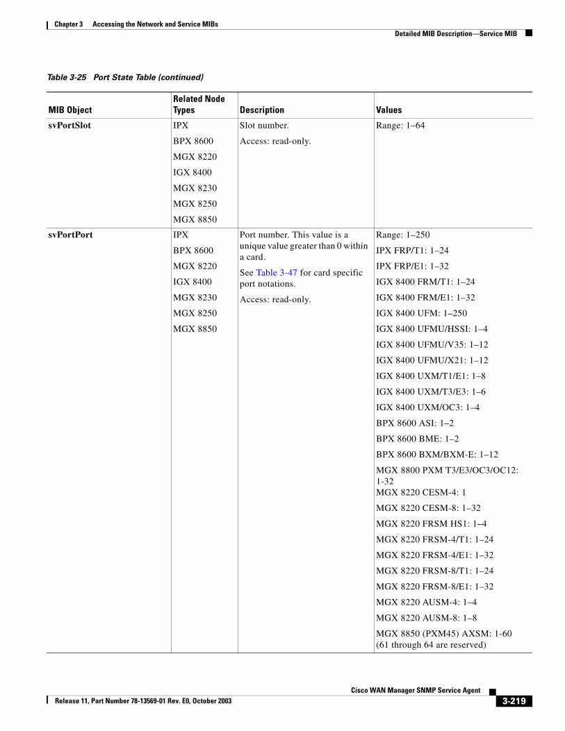
Chapter 3 Accessing the Network and Service MIBsDetailed MIB Description—Service MIB
svPortSlot IPX
BPX 8600
MGX 8220
IGX 8400
MGX 8230
MGX 8250
MGX 8850
Slot number.
Access: read-only.
Range: 1–64
svPortPort IPX
BPX 8600
MGX 8220
IGX 8400
MGX 8230
MGX 8250
MGX 8850
Port number. This value is a unique value greater than 0 within a card.
See Table 3-47 for card specific port notations.
Access: read-only.
Range: 1–250
IPX FRP/T1: 1–24
IPX FRP/E1: 1–32
IGX 8400 FRM/T1: 1–24
IGX 8400 FRM/E1: 1–32
IGX 8400 UFM: 1–250
IGX 8400 UFMU/HSSI: 1–4
IGX 8400 UFMU/V35: 1–12
IGX 8400 UFMU/X21: 1–12
IGX 8400 UXM/T1/E1: 1–8
IGX 8400 UXM/T3/E3: 1–6
IGX 8400 UXM/OC3: 1–4
BPX 8600 ASI: 1–2
BPX 8600 BME: 1–2
BPX 8600 BXM/BXM-E: 1–12
MGX 8800 PXM T3/E3/OC3/OC12: 1-32MGX 8220 CESM-4: 1
MGX 8220 CESM-8: 1–32
MGX 8220 FRSM HS1: 1–4
MGX 8220 FRSM-4/T1: 1–24
MGX 8220 FRSM-4/E1: 1–32
MGX 8220 FRSM-8/T1: 1–24
MGX 8220 FRSM-8/E1: 1–32
MGX 8220 AUSM-4: 1–4
MGX 8220 AUSM-8: 1–8
MGX 8850 (PXM45) AXSM: 1-60 (61 through 64 are reserved)
Table 3-25 Port State Table (continued)
MIB ObjectRelated Node Types Description Values
3-219Cisco WAN Manager SNMP Service Agent
Release 11, Part Number 78-13569-01 Rev. E0, October 2003
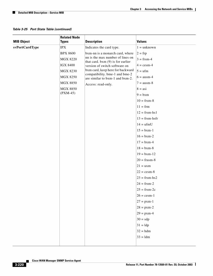
Chapter 3 Accessing the Network and Service MIBsDetailed MIB Description—Service MIB
svPortCardType IPX
BPX 8600
MGX 8220
IGX 8400
MGX 8230
MGX 8250
MGX 8850
MGX 8850 (PXM-45)
Indicates the card type.
bxm-nn is a monarch card, where nn is the max number of lines on that card. bxm (9) is for earlier version of switch software on bxm card, keep here for backward compatibility. bme-1 and bme-2 are similar to bxm-1 and bxm-2.
Access: read-only.
1 = unknown
2 = frp
3 = frsm-4
4 = cesm-4
5 = ufm
6 = ausm-4
7 = ausm-8
8 = asi
9 = bxm
10 = frsm-8
11 = frm
12 = frsm-hs1
13 = frsm-hsfr
14 = ufmU
15 = bxm-1
16 = bxm-2
17 = bxm-4
18 = bxm-8
19 = bxm-12
20 = frasm-8
21 = uxm
22 = cesm-8
23 = frsm-hs2
24 = frsm-2
25 = frsm-2c
26 = cesm-1
27 = pxm-1
28 = pxm-2
29 = pxm-4
30 = sdp
31 = ldp
32 = hdm
33 = ldm
Table 3-25 Port State Table (continued)
MIB ObjectRelated Node Types Description Values
3-220Cisco WAN Manager SNMP Service Agent
Release 11, Part Number 78-13569-01 Rev. E0, October 2003
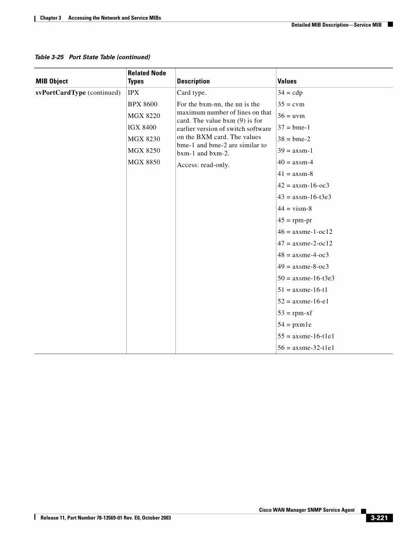
Chapter 3 Accessing the Network and Service MIBsDetailed MIB Description—Service MIB
svPortCardType (continued) IPX
BPX 8600
MGX 8220
IGX 8400
MGX 8230
MGX 8250
MGX 8850
Card type.
For the bxm-nn, the nn is the maximum number of lines on that card. The value bxm (9) is for earlier version of switch software on the BXM card. The values bme-1 and bme-2 are similar to bxm-1 and bxm-2.
Access: read-only.
34 = cdp
35 = cvm
36 = uvm
37 = bme-1
38 = bme-2
39 = axsm-1
40 = axsm-4
41 = axsm-8
42 = axsm-16-oc3
43 = axsm-16-t3e3
44 = vism-8
45 = rpm-pr
46 = axsme-1-oc12
47 = axsme-2-oc12
48 = axsme-4-oc3
49 = axsme-8-oc3
50 = axsme-16-t3e3
51 = axsme-16-t1
52 = axsme-16-e1
53 = rpm-xf
54 = pxm1e
55 = axsme-16-t1e1
56 = axsme-32-t1e1
Table 3-25 Port State Table (continued)
MIB ObjectRelated Node Types Description Values
3-221Cisco WAN Manager SNMP Service Agent
Release 11, Part Number 78-13569-01 Rev. E0, October 2003
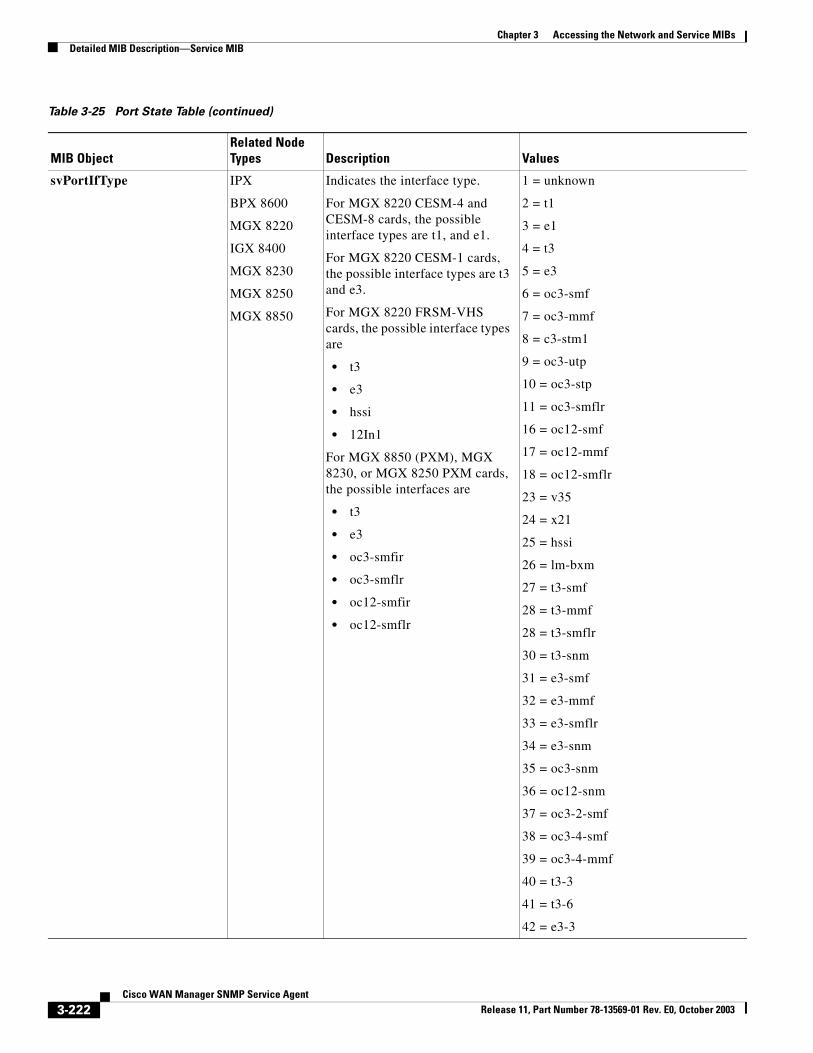
Chapter 3 Accessing the Network and Service MIBsDetailed MIB Description—Service MIB
svPortIfType IPX
BPX 8600
MGX 8220
IGX 8400
MGX 8230
MGX 8250
MGX 8850
Indicates the interface type.
For MGX 8220 CESM-4 and CESM-8 cards, the possible interface types are t1, and e1.
For MGX 8220 CESM-1 cards, the possible interface types are t3 and e3.
For MGX 8220 FRSM-VHS cards, the possible interface types are
• t3
• e3
• hssi
• 12In1
For MGX 8850 (PXM), MGX 8230, or MGX 8250 PXM cards, the possible interfaces are
• t3
• e3
• oc3-smfir
• oc3-smflr
• oc12-smfir
• oc12-smflr
1 = unknown
2 = t1
3 = e1
4 = t3
5 = e3
6 = oc3-smf
7 = oc3-mmf
8 = c3-stm1
9 = oc3-utp
10 = oc3-stp
11 = oc3-smflr
16 = oc12-smf
17 = oc12-mmf
18 = oc12-smflr
23 = v35
24 = x21
25 = hssi
26 = lm-bxm
27 = t3-smf
28 = t3-mmf
28 = t3-smflr
30 = t3-snm
31 = e3-smf
32 = e3-mmf
33 = e3-smflr
34 = e3-snm
35 = oc3-snm
36 = oc12-snm
37 = oc3-2-smf
38 = oc3-4-smf
39 = oc3-4-mmf
40 = t3-3
41 = t3-6
42 = e3-3
Table 3-25 Port State Table (continued)
MIB ObjectRelated Node Types Description Values
3-222Cisco WAN Manager SNMP Service Agent
Release 11, Part Number 78-13569-01 Rev. E0, October 2003
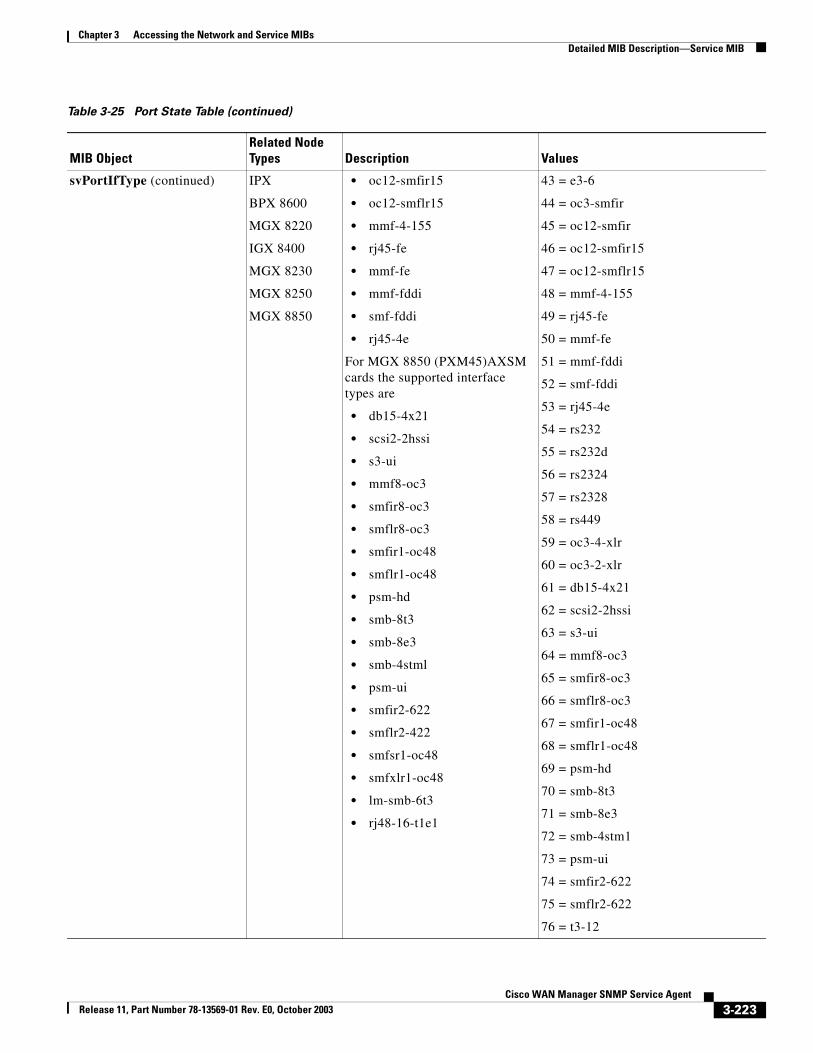
Chapter 3 Accessing the Network and Service MIBsDetailed MIB Description—Service MIB
svPortIfType (continued) IPX
BPX 8600
MGX 8220
IGX 8400
MGX 8230
MGX 8250
MGX 8850
• oc12-smfir15
• oc12-smflr15
• mmf-4-155
• rj45-fe
• mmf-fe
• mmf-fddi
• smf-fddi
• rj45-4e
For MGX 8850 (PXM45)AXSM cards the supported interface types are
• db15-4x21
• scsi2-2hssi
• s3-ui
• mmf8-oc3
• smfir8-oc3
• smflr8-oc3
• smfir1-oc48
• smflr1-oc48
• psm-hd
• smb-8t3
• smb-8e3
• smb-4stml
• psm-ui
• smfir2-622
• smflr2-422
• smfsr1-oc48
• smfxlr1-oc48
• lm-smb-6t3
• rj48-16-t1e1
43 = e3-6
44 = oc3-smfir
45 = oc12-smfir
46 = oc12-smfir15
47 = oc12-smflr15
48 = mmf-4-155
49 = rj45-fe
50 = mmf-fe
51 = mmf-fddi
52 = smf-fddi
53 = rj45-4e
54 = rs232
55 = rs232d
56 = rs2324
57 = rs2328
58 = rs449
59 = oc3-4-xlr
60 = oc3-2-xlr
61 = db15-4x21
62 = scsi2-2hssi
63 = s3-ui
64 = mmf8-oc3
65 = smfir8-oc3
66 = smflr8-oc3
67 = smfir1-oc48
68 = smflr1-oc48
69 = psm-hd
70 = smb-8t3
71 = smb-8e3
72 = smb-4stm1
73 = psm-ui
74 = smfir2-622
75 = smflr2-622
76 = t3-12
Table 3-25 Port State Table (continued)
MIB ObjectRelated Node Types Description Values
3-223Cisco WAN Manager SNMP Service Agent
Release 11, Part Number 78-13569-01 Rev. E0, October 2003
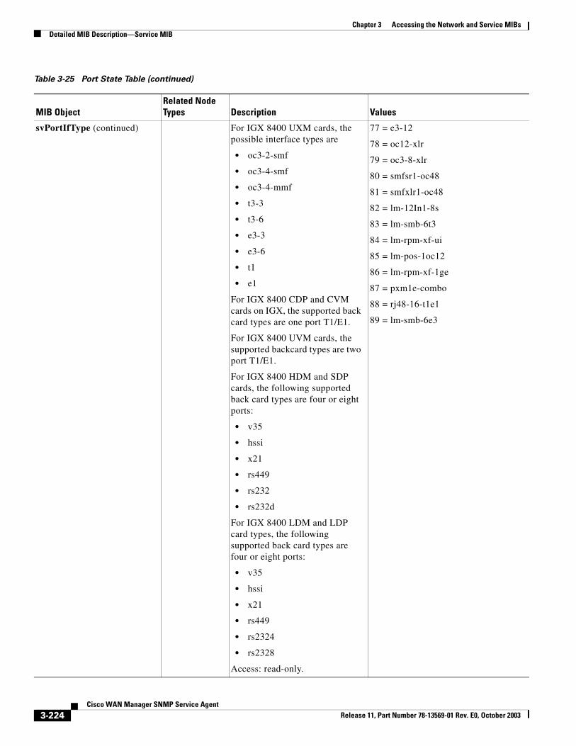
Chapter 3 Accessing the Network and Service MIBsDetailed MIB Description—Service MIB
svPortIfType (continued) For IGX 8400 UXM cards, the possible interface types are
• oc3-2-smf
• oc3-4-smf
• oc3-4-mmf
• t3-3
• t3-6
• e3-3
• e3-6
• t1
• e1
For IGX 8400 CDP and CVM cards on IGX, the supported back card types are one port T1/E1.
For IGX 8400 UVM cards, the supported backcard types are two port T1/E1.
For IGX 8400 HDM and SDP cards, the following supported back card types are four or eight ports:
• v35
• hssi
• x21
• rs449
• rs232
• rs232d
For IGX 8400 LDM and LDP card types, the following supported back card types are four or eight ports:
• v35
• hssi
• x21
• rs449
• rs2324
• rs2328
Access: read-only.
77 = e3-12
78 = oc12-xlr
79 = oc3-8-xlr
80 = smfsr1-oc48
81 = smfxlr1-oc48
82 = lm-12In1-8s
83 = lm-smb-6t3
84 = lm-rpm-xf-ui
85 = lm-pos-1oc12
86 = lm-rpm-xf-1ge
87 = pxm1e-combo
88 = rj48-16-t1e1
89 = lm-smb-6e3
Table 3-25 Port State Table (continued)
MIB ObjectRelated Node Types Description Values
3-224Cisco WAN Manager SNMP Service Agent
Release 11, Part Number 78-13569-01 Rev. E0, October 2003
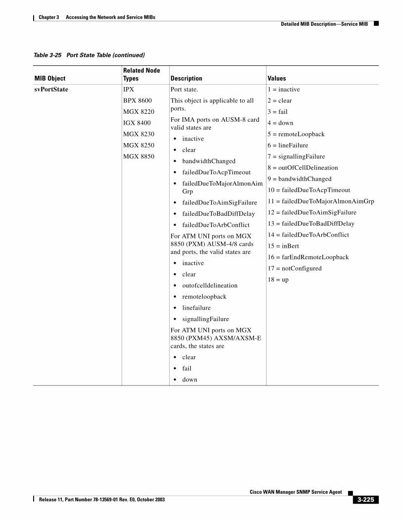
Chapter 3 Accessing the Network and Service MIBsDetailed MIB Description—Service MIB
svPortState IPX
BPX 8600
MGX 8220
IGX 8400
MGX 8230
MGX 8250
MGX 8850
Port state.
This object is applicable to all ports.
For IMA ports on AUSM-8 card valid states are
• inactive
• clear
• bandwidthChanged
• failedDueToAcpTimeout
• failedDueToMajorAlmonAimGrp
• failedDueToAimSigFailure
• failedDueToBadDiffDelay
• failedDueToArbConflict
For ATM UNI ports on MGX 8850 (PXM) AUSM-4/8 cards and ports, the valid states are
• inactive
• clear
• outofcelldelineation
• remoteloopback
• linefailure
• signallingFailure
For ATM UNI ports on MGX 8850 (PXM45) AXSM/AXSM-E cards, the states are
• clear
• fail
• down
1 = inactive
2 = clear
3 = fail
4 = down
5 = remoteLoopback
6 = lineFailure
7 = signallingFailure
8 = outOfCellDelineation
9 = bandwidthChanged
10 = failedDueToAcpTimeout
11 = failedDueToMajorAlmonAimGrp
12 = failedDueToAimSigFailure
13 = failedDueToBadDiffDelay
14 = failedDueToArbConflict
15 = inBert
16 = farEndRemoteLoopback
17 = notConfigured
18 = up
Table 3-25 Port State Table (continued)
MIB ObjectRelated Node Types Description Values
3-225Cisco WAN Manager SNMP Service Agent
Release 11, Part Number 78-13569-01 Rev. E0, October 2003
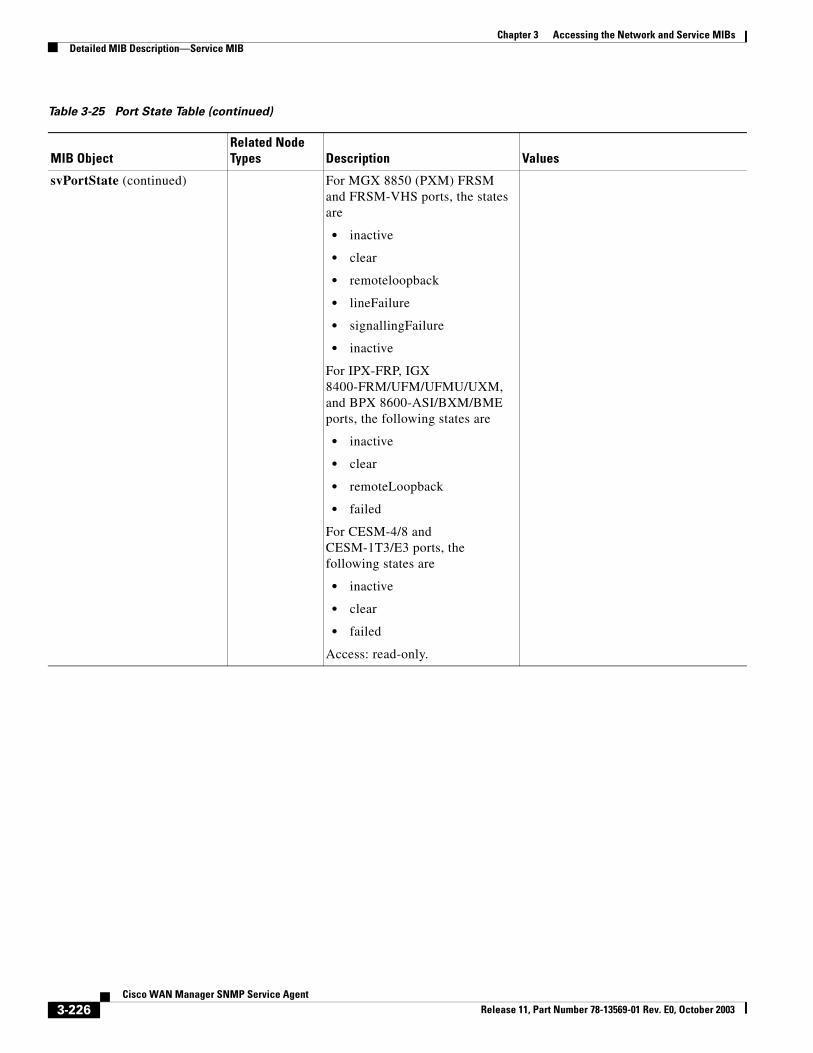
Chapter 3 Accessing the Network and Service MIBsDetailed MIB Description—Service MIB
svPortState (continued) For MGX 8850 (PXM) FRSM and FRSM-VHS ports, the states are
• inactive
• clear
• remoteloopback
• lineFailure
• signallingFailure
• inactive
For IPX-FRP, IGX 8400-FRM/UFM/UFMU/UXM, and BPX 8600-ASI/BXM/BME ports, the following states are
• inactive
• clear
• remoteLoopback
• failed
For CESM-4/8 andCESM-1T3/E3 ports, the following states are
• inactive
• clear
• failed
Access: read-only.
Table 3-25 Port State Table (continued)
MIB ObjectRelated Node Types Description Values
3-226Cisco WAN Manager SNMP Service Agent
Release 11, Part Number 78-13569-01 Rev. E0, October 2003
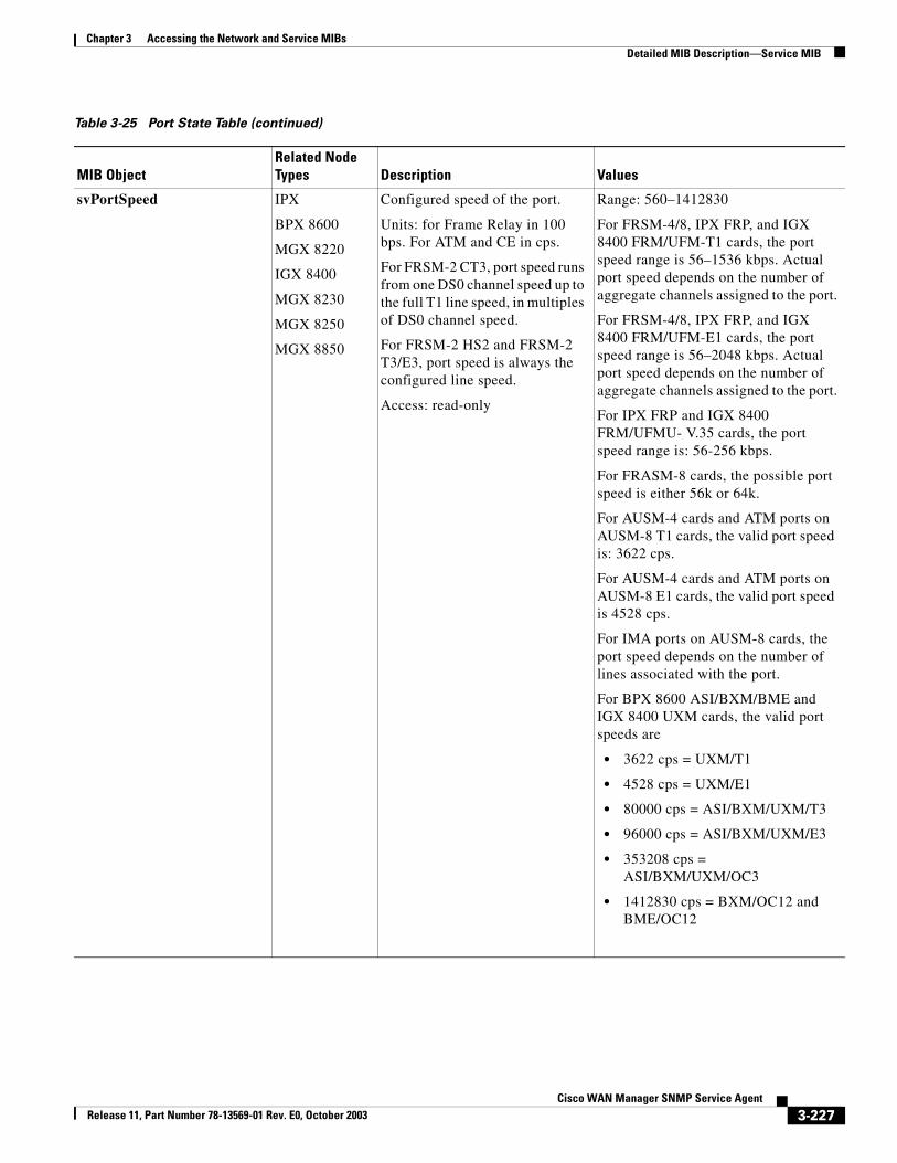
Chapter 3 Accessing the Network and Service MIBsDetailed MIB Description—Service MIB
svPortSpeed IPX
BPX 8600
MGX 8220
IGX 8400
MGX 8230
MGX 8250
MGX 8850
Configured speed of the port.
Units: for Frame Relay in 100 bps. For ATM and CE in cps.
For FRSM-2 CT3, port speed runs from one DS0 channel speed up to the full T1 line speed, in multiples of DS0 channel speed.
For FRSM-2 HS2 and FRSM-2 T3/E3, port speed is always the configured line speed.
Access: read-only
Range: 560–1412830
For FRSM-4/8, IPX FRP, and IGX 8400 FRM/UFM-T1 cards, the port speed range is 56–1536 kbps. Actual port speed depends on the number of aggregate channels assigned to the port.
For FRSM-4/8, IPX FRP, and IGX 8400 FRM/UFM-E1 cards, the port speed range is 56–2048 kbps. Actual port speed depends on the number of aggregate channels assigned to the port.
For IPX FRP and IGX 8400 FRM/UFMU- V.35 cards, the port speed range is: 56-256 kbps.
For FRASM-8 cards, the possible port speed is either 56k or 64k.
For AUSM-4 cards and ATM ports on AUSM-8 T1 cards, the valid port speed is: 3622 cps.
For AUSM-4 cards and ATM ports on AUSM-8 E1 cards, the valid port speed is 4528 cps.
For IMA ports on AUSM-8 cards, the port speed depends on the number of lines associated with the port.
For BPX 8600 ASI/BXM/BME and IGX 8400 UXM cards, the valid port speeds are
• 3622 cps = UXM/T1
• 4528 cps = UXM/E1
• 80000 cps = ASI/BXM/UXM/T3
• 96000 cps = ASI/BXM/UXM/E3
• 353208 cps = ASI/BXM/UXM/OC3
• 1412830 cps = BXM/OC12 and BME/OC12
Table 3-25 Port State Table (continued)
MIB ObjectRelated Node Types Description Values
3-227Cisco WAN Manager SNMP Service Agent
Release 11, Part Number 78-13569-01 Rev. E0, October 2003
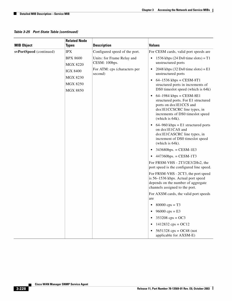
Chapter 3 Accessing the Network and Service MIBsDetailed MIB Description—Service MIB
svPortSpeed (continued) IPX
BPX 8600
MGX 8220
IGX 8400
MGX 8230
MGX 8250
MGX 8850
Configured speed of the port.
Units: for Frame Relay and CESM: 100bps.
For ATM: cps (characters per second)
For CESM cards, valid port speeds are
• 1536 kbps (24 Ds0 time slots) = T1 unstructured ports
• 2048 kbps (32 Ds0 time slots) = E1 unstructured ports
• 64–1536 kbps = CESM-8T1 structured ports in increments of DS0 timeslot speed (which is 64k)
• 64–1984 kbps = CESM-8E1 structured ports. For E1 structured ports on dsx1E1CCS and dsx1E1CCSCRC line types, in increments of DS0 timeslot speed (which is 64k).
• 64–960 kbps = E1 structured ports on dsx1E1CAS and dsx1E1CASCRC line types, in increment of DS0 timeslot speed (which is 64k).
• 343680bps. = CESM-1E3
• 447360bps. = CESM-1T3
For FRSM-VHS - 2T3/2E3/2Hs2, the port speed is the configured line speed.
For FRSM-VHS - 2CT3, the port speed is 56–1536 kbps. Actual port speed depends on the number of aggregate channels assigned to the port.
For AXSM cards, the valid port speeds are
• 80000 cps = T3
• 96000 cps = E3
• 353208 cps = OC3
• 1412832 cps = OC12
• 5651328 cps = OC48 (not applicable for AXSM-E)
Table 3-25 Port State Table (continued)
MIB ObjectRelated Node Types Description Values
3-228Cisco WAN Manager SNMP Service Agent
Release 11, Part Number 78-13569-01 Rev. E0, October 2003
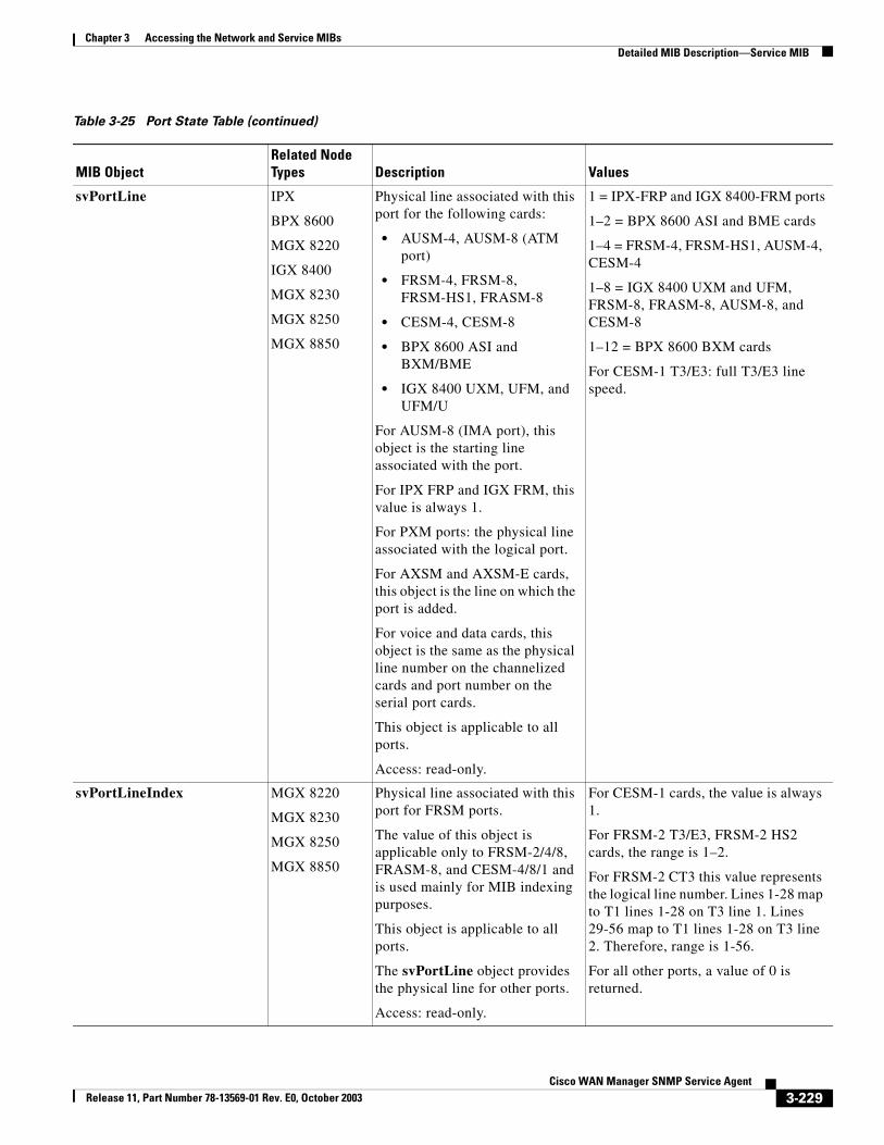
Chapter 3 Accessing the Network and Service MIBsDetailed MIB Description—Service MIB
svPortLine IPX
BPX 8600
MGX 8220
IGX 8400
MGX 8230
MGX 8250
MGX 8850
Physical line associated with this port for the following cards:
• AUSM-4, AUSM-8 (ATM port)
• FRSM-4, FRSM-8, FRSM-HS1, FRASM-8
• CESM-4, CESM-8
• BPX 8600 ASI and BXM/BME
• IGX 8400 UXM, UFM, and UFM/U
For AUSM-8 (IMA port), this object is the starting line associated with the port.
For IPX FRP and IGX FRM, this value is always 1.
For PXM ports: the physical line associated with the logical port.
For AXSM and AXSM-E cards, this object is the line on which the port is added.
For voice and data cards, this object is the same as the physical line number on the channelized cards and port number on the serial port cards.
This object is applicable to all ports.
Access: read-only.
1 = IPX-FRP and IGX 8400-FRM ports
1–2 = BPX 8600 ASI and BME cards
1–4 = FRSM-4, FRSM-HS1, AUSM-4, CESM-4
1–8 = IGX 8400 UXM and UFM, FRSM-8, FRASM-8, AUSM-8, and CESM-8
1–12 = BPX 8600 BXM cards
For CESM-1 T3/E3: full T3/E3 linespeed.
svPortLineIndex MGX 8220
MGX 8230
MGX 8250
MGX 8850
Physical line associated with this port for FRSM ports.
The value of this object is applicable only to FRSM-2/4/8, FRASM-8, and CESM-4/8/1 and is used mainly for MIB indexing purposes.
This object is applicable to all ports.
The svPortLine object provides the physical line for other ports.
Access: read-only.
For CESM-1 cards, the value is always 1.
For FRSM-2 T3/E3, FRSM-2 HS2 cards, the range is 1–2.
For FRSM-2 CT3 this value represents the logical line number. Lines 1-28 map to T1 lines 1-28 on T3 line 1. Lines 29-56 map to T1 lines 1-28 on T3 line 2. Therefore, range is 1-56.
For all other ports, a value of 0 is returned.
Table 3-25 Port State Table (continued)
MIB ObjectRelated Node Types Description Values
3-229Cisco WAN Manager SNMP Service Agent
Release 11, Part Number 78-13569-01 Rev. E0, October 2003
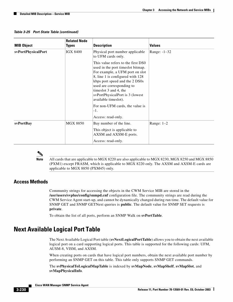
Chapter 3 Accessing the Network and Service MIBsDetailed MIB Description—Service MIB
Note All cards that are applicable to MGX 8220 are also applicable to MGX 8230, MGX 8250 and MGX 8850 (PXM1) except FRASM, which is applicable to MGX 8220 only. The AXSM and AXSM-E cards are applicable to MGX 8850 (PXM45) only.
Access Methods
Community strings for accessing the objects in the CWM Service MIB are stored in the /usr/users/svplus/config/snmpd.cnf configuration file. The community strings are read during the CWM Service Agent start-up, and cannot be dynamically changed during run time. The default value for SNMP GET and SNMP GETNext queries is public. The default value for SNMP SET requests is private.
To obtain the list of all ports, perform an SNMP Walk on svPortTable.
Next Available Logical Port TableThe Next Available Logical Port table (svNextLogicalPortTable) allows you to obtain the next available logical port on a card supporting logical ports. This table is supported for the following cards: UFM, AUSM-8, VISM, and AXSM.
When creating ports on cards that have logical port numbers, obtain the next available port number by performing an SNMP GET on this table. This table only supports SNMP GET commands.
The svPhysicalToLogicalMapTable is indexed by svMapNode, svMapShelf, svMapSlot, and svMapPhysicalInfo.
svPortPhysicalPort IGX 8400 Physical port number applicable to UFM cards only.
This value refers to the first DS0 used in the port timeslot bitmap. For example, a UFM port on slot 8, line 1 is configured with 128 kbps port speed and the 2 DS0s used are corresponding to timeslot 3 and 4, the svPortPhysicalPort is 3 (lowest available timeslot).
For non-UFM cards, the value is -1.
Access: read-only.
Range: -1–32
svPortBay MGX 8850 Bay number of the line.
This object is applicable to AXSM and AXSM-E ports.
Access: read-only.
Range: 1–2
Table 3-25 Port State Table (continued)
MIB ObjectRelated Node Types Description Values
3-230Cisco WAN Manager SNMP Service Agent
Release 11, Part Number 78-13569-01 Rev. E0, October 2003
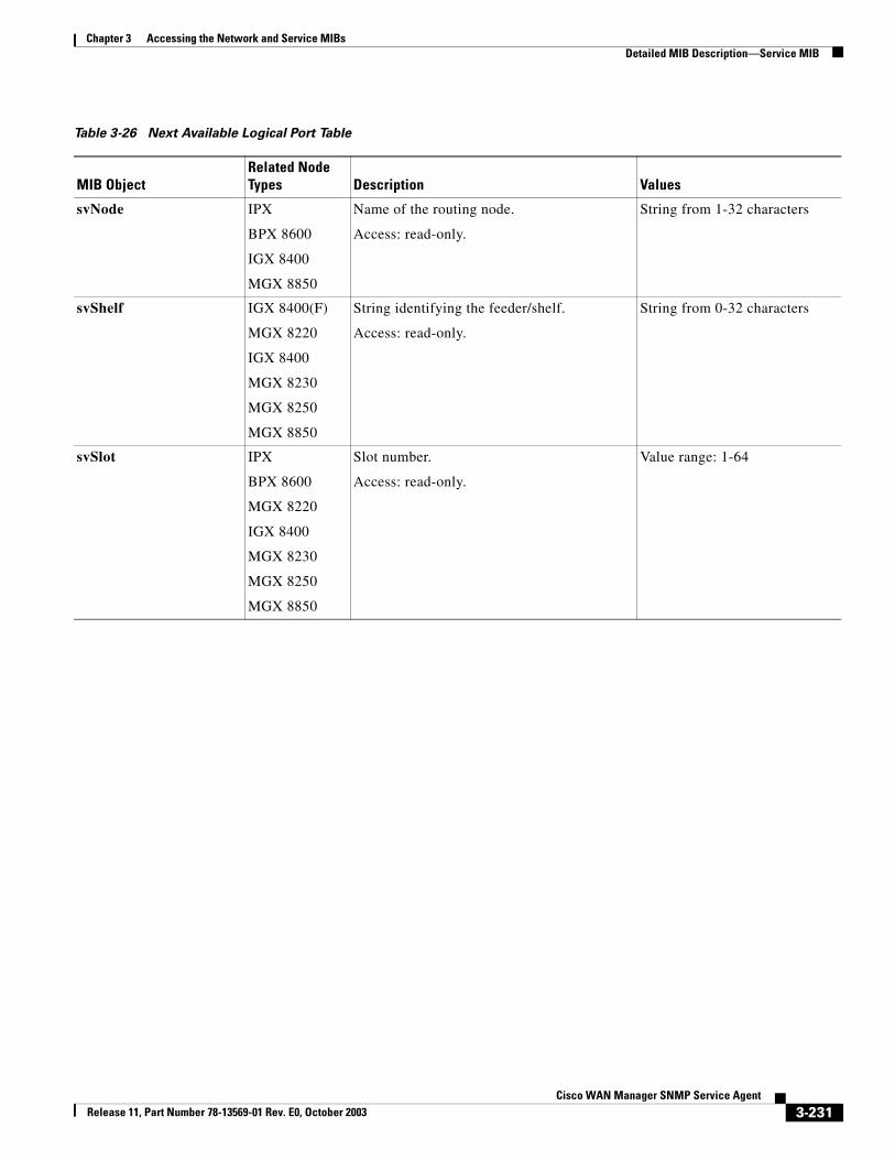
Chapter 3 Accessing the Network and Service MIBsDetailed MIB Description—Service MIB
Table 3-26 Next Available Logical Port Table
MIB ObjectRelated Node Types Description Values
svNode IPX
BPX 8600
IGX 8400
MGX 8850
Name of the routing node.
Access: read-only.
String from 1-32 characters
svShelf IGX 8400(F)
MGX 8220
IGX 8400
MGX 8230
MGX 8250
MGX 8850
String identifying the feeder/shelf.
Access: read-only.
String from 0-32 characters
svSlot IPX
BPX 8600
MGX 8220
IGX 8400
MGX 8230
MGX 8250
MGX 8850
Slot number.
Access: read-only.
Value range: 1-64
3-231Cisco WAN Manager SNMP Service Agent
Release 11, Part Number 78-13569-01 Rev. E0, October 2003
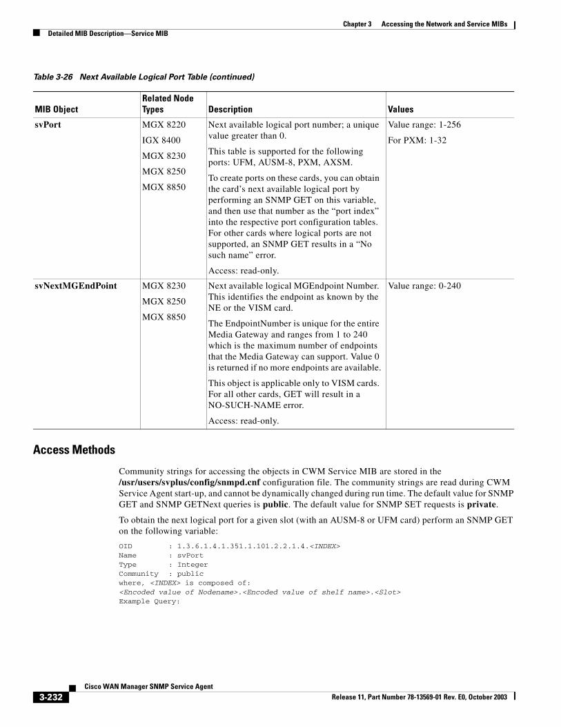
Chapter 3 Accessing the Network and Service MIBsDetailed MIB Description—Service MIB
Access Methods
Community strings for accessing the objects in CWM Service MIB are stored in the /usr/users/svplus/config/snmpd.cnf configuration file. The community strings are read during CWM Service Agent start-up, and cannot be dynamically changed during run time. The default value for SNMP GET and SNMP GETNext queries is public. The default value for SNMP SET requests is private.
To obtain the next logical port for a given slot (with an AUSM-8 or UFM card) perform an SNMP GET on the following variable:
OID : 1.3.6.1.4.1.351.1.101.2.2.1.4.<INDEX>Name : svPortType : IntegerCommunity : publicwhere, <INDEX> is composed of:<Encoded value of Nodename>.<Encoded value of shelf name>.<Slot>Example Query:
svPort MGX 8220
IGX 8400
MGX 8230
MGX 8250
MGX 8850
Next available logical port number; a unique value greater than 0.
This table is supported for the following ports: UFM, AUSM-8, PXM, AXSM.
To create ports on these cards, you can obtain the card’s next available logical port by performing an SNMP GET on this variable, and then use that number as the “port index” into the respective port configuration tables. For other cards where logical ports are not supported, an SNMP GET results in a “No such name” error.
Access: read-only.
Value range: 1-256
For PXM: 1-32
svNextMGEndPoint MGX 8230
MGX 8250
MGX 8850
Next available logical MGEndpoint Number. This identifies the endpoint as known by the NE or the VISM card.
The EndpointNumber is unique for the entire Media Gateway and ranges from 1 to 240 which is the maximum number of endpoints that the Media Gateway can support. Value 0 is returned if no more endpoints are available.
This object is applicable only to VISM cards. For all other cards, GET will result in a NO-SUCH-NAME error.
Access: read-only.
Value range: 0-240
Table 3-26 Next Available Logical Port Table (continued)
MIB ObjectRelated Node Types Description Values
3-232Cisco WAN Manager SNMP Service Agent
Release 11, Part Number 78-13569-01 Rev. E0, October 2003
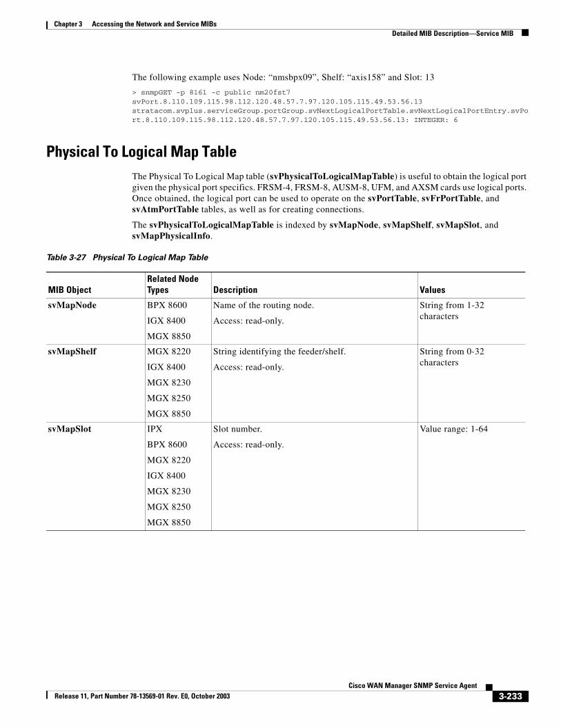
Chapter 3 Accessing the Network and Service MIBsDetailed MIB Description—Service MIB
The following example uses Node: “nmsbpx09”, Shelf: “axis158” and Slot: 13
> snmpGET -p 8161 -c public nm20fst7 svPort.8.110.109.115.98.112.120.48.57.7.97.120.105.115.49.53.56.13stratacom.svplus.serviceGroup.portGroup.svNextLogicalPortTable.svNextLogicalPortEntry.svPort.8.110.109.115.98.112.120.48.57.7.97.120.105.115.49.53.56.13: INTEGER: 6
Physical To Logical Map TableThe Physical To Logical Map table (svPhysicalToLogicalMapTable) is useful to obtain the logical port given the physical port specifics. FRSM-4, FRSM-8, AUSM-8, UFM, and AXSM cards use logical ports. Once obtained, the logical port can be used to operate on the svPortTable, svFrPortTable, and svAtmPortTable tables, as well as for creating connections.
The svPhysicalToLogicalMapTable is indexed by svMapNode, svMapShelf, svMapSlot, and svMapPhysicalInfo.
Table 3-27 Physical To Logical Map Table
MIB ObjectRelated Node Types Description Values
svMapNode BPX 8600
IGX 8400
MGX 8850
Name of the routing node.
Access: read-only.
String from 1-32 characters
svMapShelf MGX 8220
IGX 8400
MGX 8230
MGX 8250
MGX 8850
String identifying the feeder/shelf.
Access: read-only.
String from 0-32 characters
svMapSlot IPX
BPX 8600
MGX 8220
IGX 8400
MGX 8230
MGX 8250
MGX 8850
Slot number.
Access: read-only.
Value range: 1-64
3-233Cisco WAN Manager SNMP Service Agent
Release 11, Part Number 78-13569-01 Rev. E0, October 2003
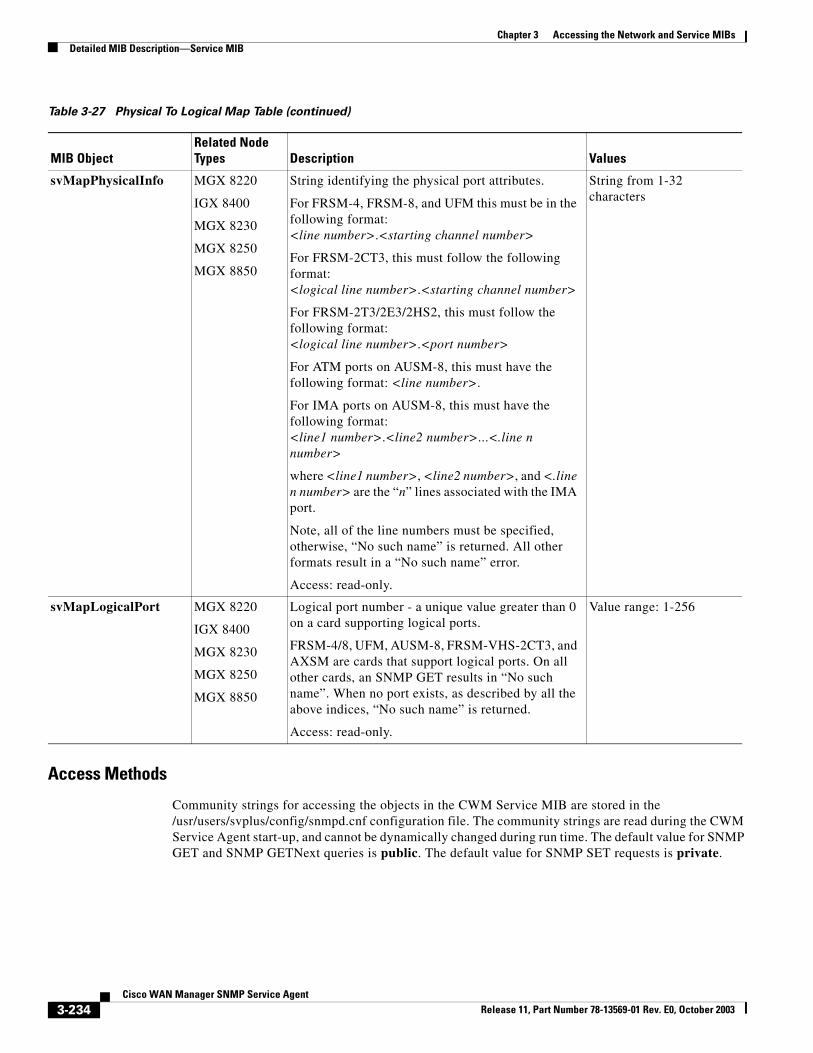
Chapter 3 Accessing the Network and Service MIBsDetailed MIB Description—Service MIB
Access Methods
Community strings for accessing the objects in the CWM Service MIB are stored in the /usr/users/svplus/config/snmpd.cnf configuration file. The community strings are read during the CWM Service Agent start-up, and cannot be dynamically changed during run time. The default value for SNMP GET and SNMP GETNext queries is public. The default value for SNMP SET requests is private.
svMapPhysicalInfo MGX 8220
IGX 8400
MGX 8230
MGX 8250
MGX 8850
String identifying the physical port attributes.
For FRSM-4, FRSM-8, and UFM this must be in the following format:<line number>.<starting channel number>
For FRSM-2CT3, this must follow the following format:<logical line number>.<starting channel number>
For FRSM-2T3/2E3/2HS2, this must follow the following format:<logical line number>.<port number>
For ATM ports on AUSM-8, this must have the following format: <line number>.
For IMA ports on AUSM-8, this must have the following format:<line1 number>.<line2 number>...<.line n number>
where <line1 number>, <line2 number>, and <.line n number> are the “n” lines associated with the IMA port.
Note, all of the line numbers must be specified, otherwise, “No such name” is returned. All other formats result in a “No such name” error.
Access: read-only.
String from 1-32 characters
svMapLogicalPort MGX 8220
IGX 8400
MGX 8230
MGX 8250
MGX 8850
Logical port number - a unique value greater than 0 on a card supporting logical ports.
FRSM-4/8, UFM, AUSM-8, FRSM-VHS-2CT3, and AXSM are cards that support logical ports. On all other cards, an SNMP GET results in “No such name”. When no port exists, as described by all the above indices, “No such name” is returned.
Access: read-only.
Value range: 1-256
Table 3-27 Physical To Logical Map Table (continued)
MIB ObjectRelated Node Types Description Values
3-234Cisco WAN Manager SNMP Service Agent
Release 11, Part Number 78-13569-01 Rev. E0, October 2003
Chapter 3 Accessing the Network and Service MIBsDetailed MIB Description—Service MIB
To obtain the list of logical port-to-physical port mappings, perform an SNMP Walk on the svPhysicalToLogicalMapTable. To obtain the logical-to-physical mapping for a particular port, perform an SNMP GET on the following variable:
OID : 1.3.6.1.4.1.351.1.101.2.3.1.5.<INDEX>Name : svMapLogicalPortType : IntegerCommunity : publicwhere, <INDEX> is composed of:<Encoded Nodename>.<Encoded Shelfname>.<Slot>.<Encoded value of Physical Info String>.Example Query:
The following example uses Node: “nmsbpx02”, Shelf: “axis164”, Slot 11 and Physical Info string “03.01”.
>snmpGET -p 8161 nm20fst7 svMapLogicalPort.8.110.109.115.98.112.120.48.50.7.97.120.105.115.49.54.52.11.5.48.51.46.48.49stratacom.svplus.serviceGroup.portGroup.svPhysicalToLogicalMapTable.svPhysicalToLogicalMapEntry.svMapLogicalPort.8.110.109.115.98.112.120.48.50.7.97.120.105.115.49.54.52.11.5.48.51.46.48.49 : INTEGER: 6
ATM Port TableThe ATM Port table (svAtmPortTable) allows you to configure ATM and IMA ports. This table supports creating and modifying ATM ports on the following cards:
• BXM, BME, ASI
• UXM
• AUSM-4
• AUSM-8T1/E1
• AXSM
• AXSM-E
Objects with an svAtmIma prefix are applicable to IMA ports only. Objects with an svAtmBx prefix are applicable to ports on BPX 8600 nodes only.
This table is indexed by svAtmPortNode, svAtmPortShelf, svAtmPortSlot, and svAtmPortPort.
3-235Cisco WAN Manager SNMP Service Agent
Release 11, Part Number 78-13569-01 Rev. E0, October 2003
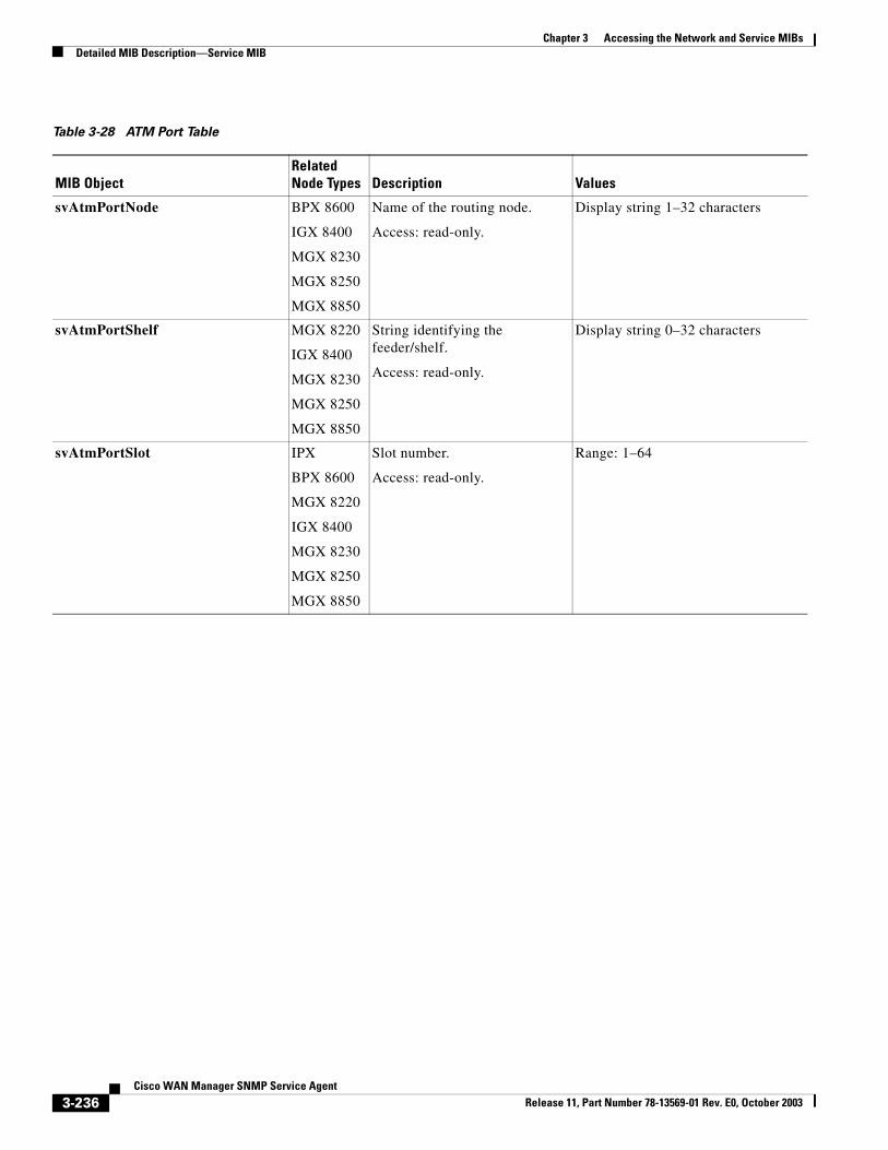
Chapter 3 Accessing the Network and Service MIBsDetailed MIB Description—Service MIB
Table 3-28 ATM Port Table
MIB ObjectRelated Node Types Description Values
svAtmPortNode BPX 8600
IGX 8400
MGX 8230
MGX 8250
MGX 8850
Name of the routing node.
Access: read-only.
Display string 1–32 characters
svAtmPortShelf MGX 8220
IGX 8400
MGX 8230
MGX 8250
MGX 8850
String identifying the feeder/shelf.
Access: read-only.
Display string 0–32 characters
svAtmPortSlot IPX
BPX 8600
MGX 8220
IGX 8400
MGX 8230
MGX 8250
MGX 8850
Slot number.
Access: read-only.
Range: 1–64
3-236Cisco WAN Manager SNMP Service Agent
Release 11, Part Number 78-13569-01 Rev. E0, October 2003
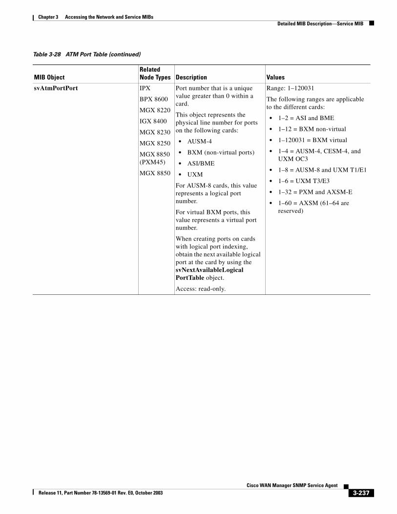
Chapter 3 Accessing the Network and Service MIBsDetailed MIB Description—Service MIB
svAtmPortPort IPX
BPX 8600
MGX 8220
IGX 8400
MGX 8230
MGX 8250
MGX 8850 (PXM45)
MGX 8850
Port number that is a unique value greater than 0 within a card.
This object represents the physical line number for ports on the following cards:
• AUSM-4
• BXM (non-virtual ports)
• ASI/BME
• UXM
For AUSM-8 cards, this value represents a logical port number.
For virtual BXM ports, this value represents a virtual port number.
When creating ports on cards with logical port indexing, obtain the next available logical port at the card by using the svNextAvailableLogicalPortTable object.
Access: read-only.
Range: 1–120031
The following ranges are applicable to the different cards:
• 1–2 = ASI and BME
• 1–12 = BXM non-virtual
• 1–120031 = BXM virtual
• 1–4 = AUSM-4, CESM-4, and UXM OC3
• 1–8 = AUSM-8 and UXM T1/E1
• 1–6 = UXM T3/E3
• 1–32 = PXM and AXSM-E
• 1–60 = AXSM (61–64 are reserved)
Table 3-28 ATM Port Table (continued)
MIB ObjectRelated Node Types Description Values
3-237Cisco WAN Manager SNMP Service Agent
Release 11, Part Number 78-13569-01 Rev. E0, October 2003
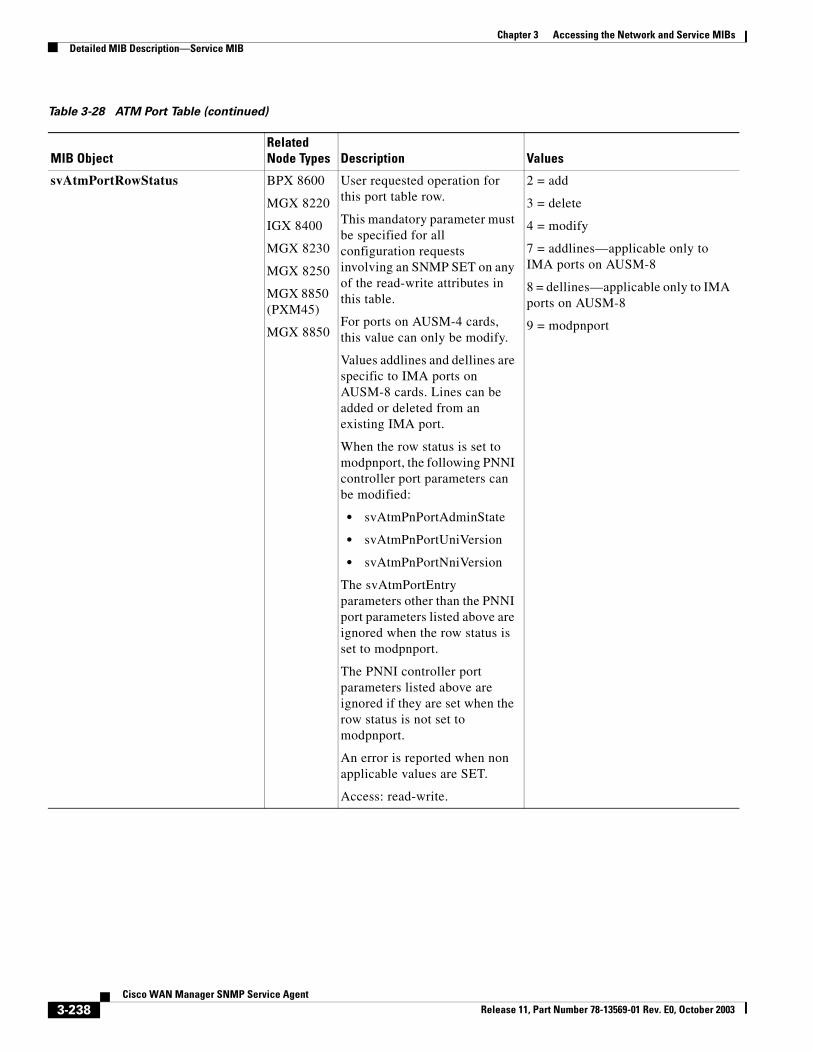
Chapter 3 Accessing the Network and Service MIBsDetailed MIB Description—Service MIB
svAtmPortRowStatus BPX 8600
MGX 8220
IGX 8400
MGX 8230
MGX 8250
MGX 8850 (PXM45)
MGX 8850
User requested operation for this port table row.
This mandatory parameter must be specified for all configuration requests involving an SNMP SET on any of the read-write attributes in this table.
For ports on AUSM-4 cards, this value can only be modify.
Values addlines and dellines are specific to IMA ports on AUSM-8 cards. Lines can be added or deleted from an existing IMA port.
When the row status is set to modpnport, the following PNNI controller port parameters can be modified:
• svAtmPnPortAdminState
• svAtmPnPortUniVersion
• svAtmPnPortNniVersion
The svAtmPortEntry parameters other than the PNNI port parameters listed above are ignored when the row status is set to modpnport.
The PNNI controller port parameters listed above are ignored if they are set when the row status is not set to modpnport.
An error is reported when non applicable values are SET.
Access: read-write.
2 = add
3 = delete
4 = modify
7 = addlines—applicable only to IMA ports on AUSM-8
8 = dellines—applicable only to IMA ports on AUSM-8
9 = modpnport
Table 3-28 ATM Port Table (continued)
MIB ObjectRelated Node Types Description Values
3-238Cisco WAN Manager SNMP Service Agent
Release 11, Part Number 78-13569-01 Rev. E0, October 2003
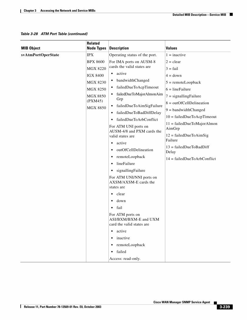
Chapter 3 Accessing the Network and Service MIBsDetailed MIB Description—Service MIB
svAtmPortOperState IPX
BPX 8600
MGX 8220
IGX 8400
MGX 8230
MGX 8250
MGX 8850 (PXM45)
MGX 8850
Operating status of the port.
For IMA ports on AUSM-8 cards the valid states are
• active
• bandwidthChanged
• failedDueToAcpTimeout
• failedDueToMajorAlmonAimGrp
• failedDueToAimSigFailure
• failedDueToBadDiffDelay
• failedDueToArbConflict
For ATM UNI ports on AUSM-4/8 and PXM cards the valid states are
• active
• outOfCellDelineation
• remoteLoopback
• lineFailure
• signallingFailure
For ATM UNI/NNI ports on AXSM/AXSM-E cards the states are
• clear
• down
• fail
For ATM ports on ASI/BXM/BXM-E and UXM card the valid states are
• active
• inactive
• remoteLoopback
• failed
Access: read-only.
1 = inactive
2 = clear
3 = fail
4 = down
5 = remoteLoopback
6 = lineFailure
7 = signallingFailure
8 = outOfCellDelineation
9 = bandwidthChanged
10 = failedDueToAcpTimeout
11 = failedDueToMajorAlmonAimGrp
12 = failedDueToAimSigFailure
13 = failedDueToBadDiffDelay
14 = failedDueToArbConflict
Table 3-28 ATM Port Table (continued)
MIB ObjectRelated Node Types Description Values
3-239Cisco WAN Manager SNMP Service Agent
Release 11, Part Number 78-13569-01 Rev. E0, October 2003
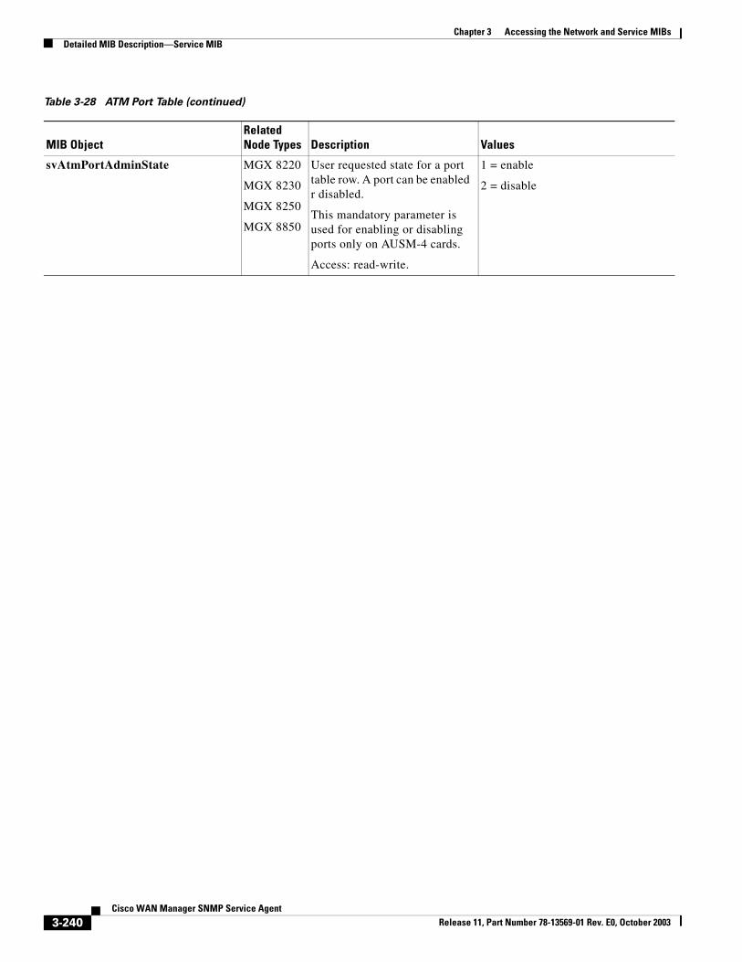
Chapter 3 Accessing the Network and Service MIBsDetailed MIB Description—Service MIB
svAtmPortAdminState MGX 8220
MGX 8230
MGX 8250
MGX 8850
User requested state for a port table row. A port can be enabled r disabled.
This mandatory parameter is used for enabling or disabling ports only on AUSM-4 cards.
Access: read-write.
1 = enable
2 = disable
Table 3-28 ATM Port Table (continued)
MIB ObjectRelated Node Types Description Values
3-240Cisco WAN Manager SNMP Service Agent
Release 11, Part Number 78-13569-01 Rev. E0, October 2003
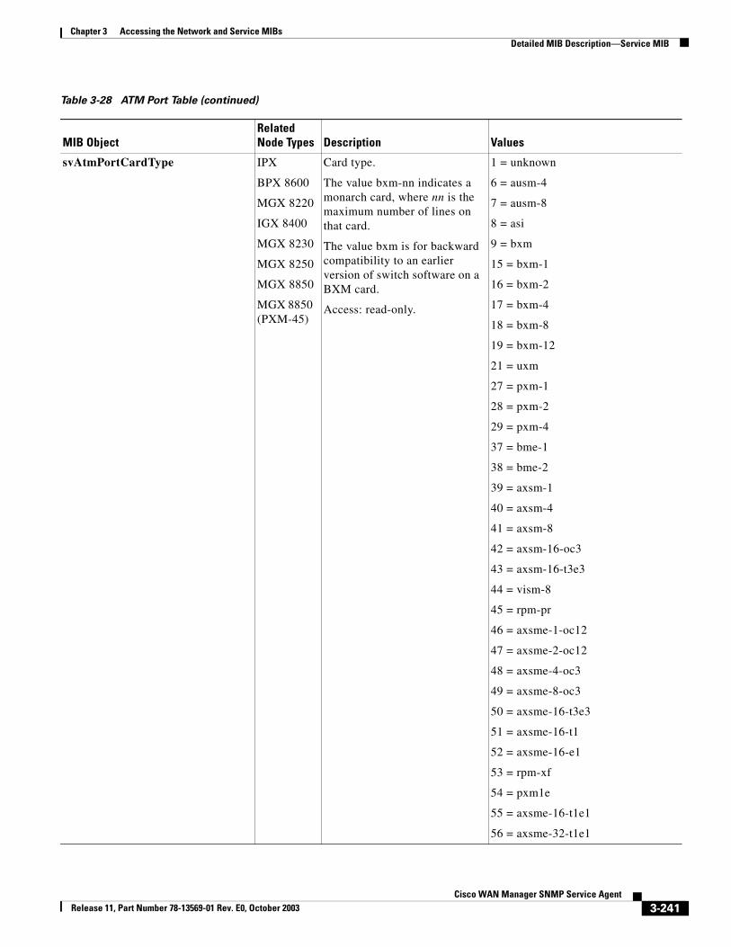
Chapter 3 Accessing the Network and Service MIBsDetailed MIB Description—Service MIB
svAtmPortCardType IPX
BPX 8600
MGX 8220
IGX 8400
MGX 8230
MGX 8250
MGX 8850
MGX 8850 (PXM-45)
Card type.
The value bxm-nn indicates a monarch card, where nn is the maximum number of lines on that card.
The value bxm is for backward compatibility to an earlier version of switch software on a BXM card.
Access: read-only.
1 = unknown
6 = ausm-4
7 = ausm-8
8 = asi
9 = bxm
15 = bxm-1
16 = bxm-2
17 = bxm-4
18 = bxm-8
19 = bxm-12
21 = uxm
27 = pxm-1
28 = pxm-2
29 = pxm-4
37 = bme-1
38 = bme-2
39 = axsm-1
40 = axsm-4
41 = axsm-8
42 = axsm-16-oc3
43 = axsm-16-t3e3
44 = vism-8
45 = rpm-pr
46 = axsme-1-oc12
47 = axsme-2-oc12
48 = axsme-4-oc3
49 = axsme-8-oc3
50 = axsme-16-t3e3
51 = axsme-16-t1
52 = axsme-16-e1
53 = rpm-xf
54 = pxm1e
55 = axsme-16-t1e1
56 = axsme-32-t1e1
Table 3-28 ATM Port Table (continued)
MIB ObjectRelated Node Types Description Values
3-241Cisco WAN Manager SNMP Service Agent
Release 11, Part Number 78-13569-01 Rev. E0, October 2003
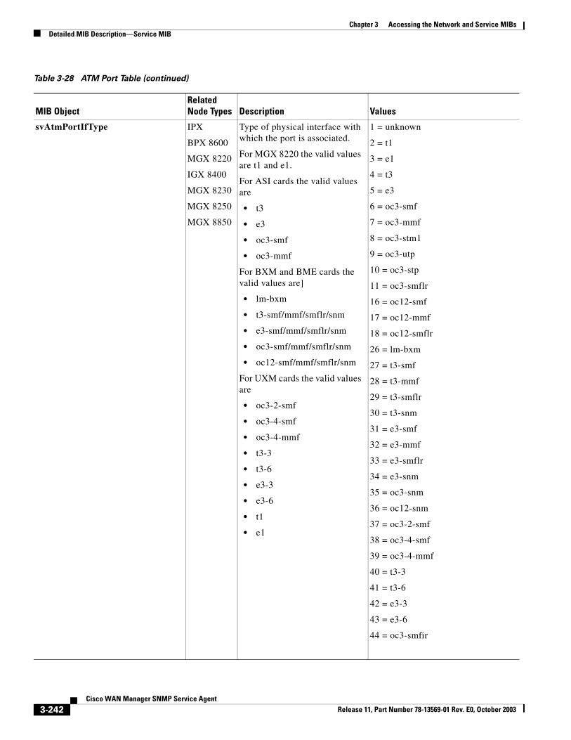
Chapter 3 Accessing the Network and Service MIBsDetailed MIB Description—Service MIB
svAtmPortIfType IPX
BPX 8600
MGX 8220
IGX 8400
MGX 8230
MGX 8250
MGX 8850
Type of physical interface with which the port is associated.
For MGX 8220 the valid values are t1 and e1.
For ASI cards the valid values are
• t3
• e3
• oc3-smf
• oc3-mmf
For BXM and BME cards the valid values are]
• lm-bxm
• t3-smf/mmf/smflr/snm
• e3-smf/mmf/smflr/snm
• oc3-smf/mmf/smflr/snm
• oc12-smf/mmf/smflr/snm
For UXM cards the valid values are
• oc3-2-smf
• oc3-4-smf
• oc3-4-mmf
• t3-3
• t3-6
• e3-3
• e3-6
• t1
• e1
1 = unknown
2 = t1
3 = e1
4 = t3
5 = e3
6 = oc3-smf
7 = oc3-mmf
8 = oc3-stm1
9 = oc3-utp
10 = oc3-stp
11 = oc3-smflr
16 = oc12-smf
17 = oc12-mmf
18 = oc12-smflr
26 = lm-bxm
27 = t3-smf
28 = t3-mmf
29 = t3-smflr
30 = t3-snm
31 = e3-smf
32 = e3-mmf
33 = e3-smflr
34 = e3-snm
35 = oc3-snm
36 = oc12-snm
37 = oc3-2-smf
38 = oc3-4-smf
39 = oc3-4-mmf
40 = t3-3
41 = t3-6
42 = e3-3
43 = e3-6
44 = oc3-smfir
Table 3-28 ATM Port Table (continued)
MIB ObjectRelated Node Types Description Values
3-242Cisco WAN Manager SNMP Service Agent
Release 11, Part Number 78-13569-01 Rev. E0, October 2003
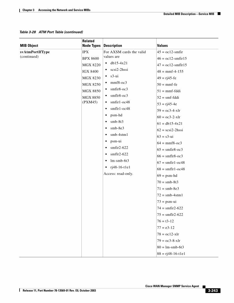
Chapter 3 Accessing the Network and Service MIBsDetailed MIB Description—Service MIB
svAtmPortIfType (continued)
IPX
BPX 8600
MGX 8220
IGX 8400
MGX 8230
MGX 8250
MGX 8850
MGX 8850 (PXM45)
For AXSM cards the valid values are
• db15-4x21
• scsi2-2hssi
• s3-ui
• mmf8-oc3
• smfir8-oc3
• smflr8-oc3
• smfir1-oc48
• smflr1-oc48
• psm-hd
• smb-8t3
• smb-8e3
• smb-4stm1
• psm-ui
• smfir2-622
• smflr2-622
• lm-smb-6t3
• rj48-16-t1e1
Access: read-only.
45 = oc12-smfir
46 = oc12-smfir15
47 = oc12-smflr15
48 = mmf-4-155
49 = rj45-fe
50 = mmf-fe
51 = mmf-fddi
52 = smf-fddi
53 = rj45-4e
59 = oc3-4-xlr
60 = oc3-2-xlr
61 = db15-4x21
62 = scsi2-2hssi
63 = s3-ui
64 = mmf8-oc3
65 = smfir8-oc3
66 = smflr8-oc3
67 = smfir1-oc48
68 = smflr1-oc48
69 = psm-hd
70 = smb-8t3
71 = smb-8e3
72 = smb-4stm1
73 = psm-ui
74 = smfir2-622
75 = smflr2-622
76 = t3-12
77 = e3-12
78 = oc12-xlr
79 = oc3-8-xlr
80 = lm-smb-6t3
88 = rj48-16-t1e1
Table 3-28 ATM Port Table (continued)
MIB ObjectRelated Node Types Description Values
3-243Cisco WAN Manager SNMP Service Agent
Release 11, Part Number 78-13569-01 Rev. E0, October 2003
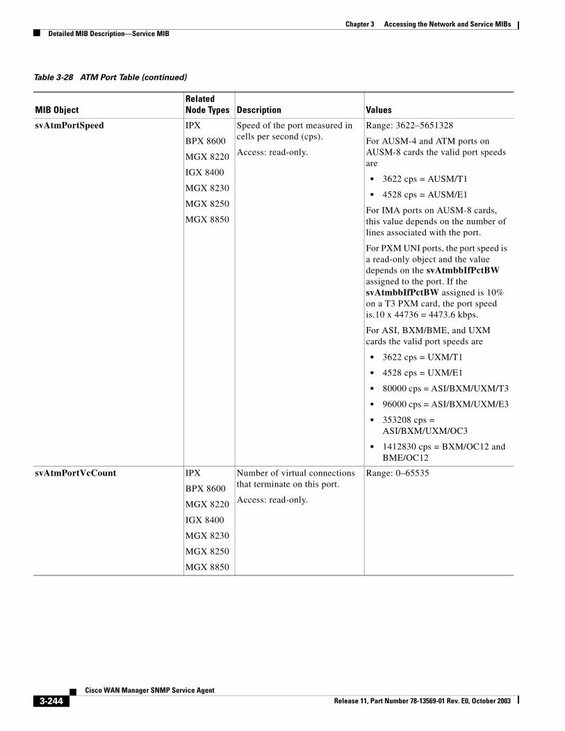
Chapter 3 Accessing the Network and Service MIBsDetailed MIB Description—Service MIB
svAtmPortSpeed IPX
BPX 8600
MGX 8220
IGX 8400
MGX 8230
MGX 8250
MGX 8850
Speed of the port measured in cells per second (cps).
Access: read-only.
Range: 3622–5651328
For AUSM-4 and ATM ports on AUSM-8 cards the valid port speeds are
• 3622 cps = AUSM/T1
• 4528 cps = AUSM/E1
For IMA ports on AUSM-8 cards, this value depends on the number of lines associated with the port.
For PXM UNI ports, the port speed is a read-only object and the value depends on the svAtmbbIfPctBW assigned to the port. If the svAtmbbIfPctBW assigned is 10% on a T3 PXM card, the port speed is.10 x 44736 = 4473.6 kbps.
For ASI, BXM/BME, and UXM cards the valid port speeds are
• 3622 cps = UXM/T1
• 4528 cps = UXM/E1
• 80000 cps = ASI/BXM/UXM/T3
• 96000 cps = ASI/BXM/UXM/E3
• 353208 cps = ASI/BXM/UXM/OC3
• 1412830 cps = BXM/OC12 and BME/OC12
svAtmPortVcCount IPX
BPX 8600
MGX 8220
IGX 8400
MGX 8230
MGX 8250
MGX 8850
Number of virtual connections that terminate on this port.
Access: read-only.
Range: 0–65535
Table 3-28 ATM Port Table (continued)
MIB ObjectRelated Node Types Description Values
3-244Cisco WAN Manager SNMP Service Agent
Release 11, Part Number 78-13569-01 Rev. E0, October 2003
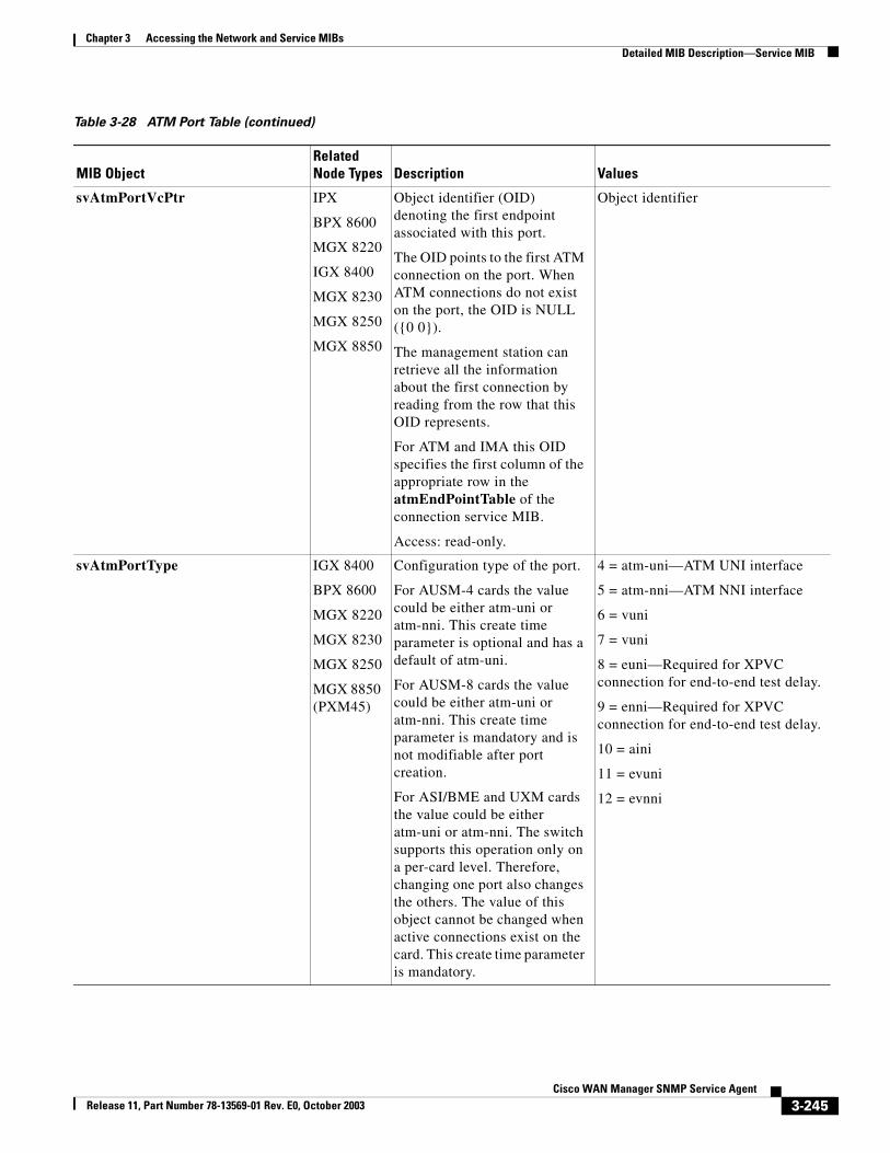
Chapter 3 Accessing the Network and Service MIBsDetailed MIB Description—Service MIB
svAtmPortVcPtr IPX
BPX 8600
MGX 8220
IGX 8400
MGX 8230
MGX 8250
MGX 8850
Object identifier (OID) denoting the first endpoint associated with this port.
The OID points to the first ATM connection on the port. When ATM connections do not exist on the port, the OID is NULL ({0 0}).
The management station can retrieve all the information about the first connection by reading from the row that this OID represents.
For ATM and IMA this OID specifies the first column of the appropriate row in the atmEndPointTable of the connection service MIB.
Access: read-only.
Object identifier
svAtmPortType IGX 8400
BPX 8600
MGX 8220
MGX 8230
MGX 8250
MGX 8850 (PXM45)
Configuration type of the port.
For AUSM-4 cards the value could be either atm-uni or atm-nni. This create time parameter is optional and has a default of atm-uni.
For AUSM-8 cards the value could be either atm-uni or atm-nni. This create time parameter is mandatory and is not modifiable after port creation.
For ASI/BME and UXM cards the value could be either atm-uni or atm-nni. The switch supports this operation only on a per-card level. Therefore, changing one port also changes the others. The value of this object cannot be changed when active connections exist on the card. This create time parameter is mandatory.
4 = atm-uni—ATM UNI interface
5 = atm-nni—ATM NNI interface
6 = vuni
7 = vuni
8 = euni—Required for XPVC connection for end-to-end test delay.
9 = enni—Required for XPVC connection for end-to-end test delay.
10 = aini
11 = evuni
12 = evnni
Table 3-28 ATM Port Table (continued)
MIB ObjectRelated Node Types Description Values
3-245Cisco WAN Manager SNMP Service Agent
Release 11, Part Number 78-13569-01 Rev. E0, October 2003
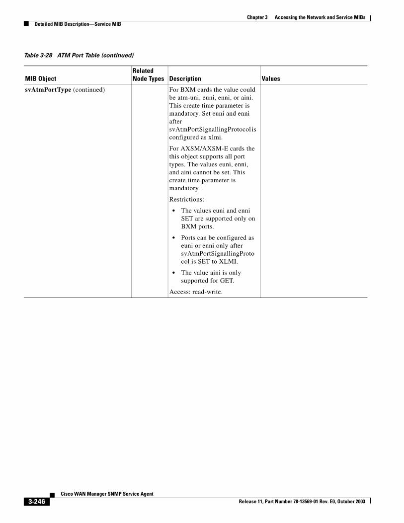
Chapter 3 Accessing the Network and Service MIBsDetailed MIB Description—Service MIB
svAtmPortType (continued) For BXM cards the value could be atm-uni, euni, enni, or aini. This create time parameter is mandatory. Set euni and enni after svAtmPortSignallingProtocol is configured as xlmi.
For AXSM/AXSM-E cards the this object supports all port types. The values euni, enni, and aini cannot be set. This create time parameter is mandatory.
Restrictions:
• The values euni and enni SET are supported only on BXM ports.
• Ports can be configured as euni or enni only after svAtmPortSignallingProtocol is SET to XLMI.
• The value aini is only supported for GET.
Access: read-write.
Table 3-28 ATM Port Table (continued)
MIB ObjectRelated Node Types Description Values
3-246Cisco WAN Manager SNMP Service Agent
Release 11, Part Number 78-13569-01 Rev. E0, October 2003
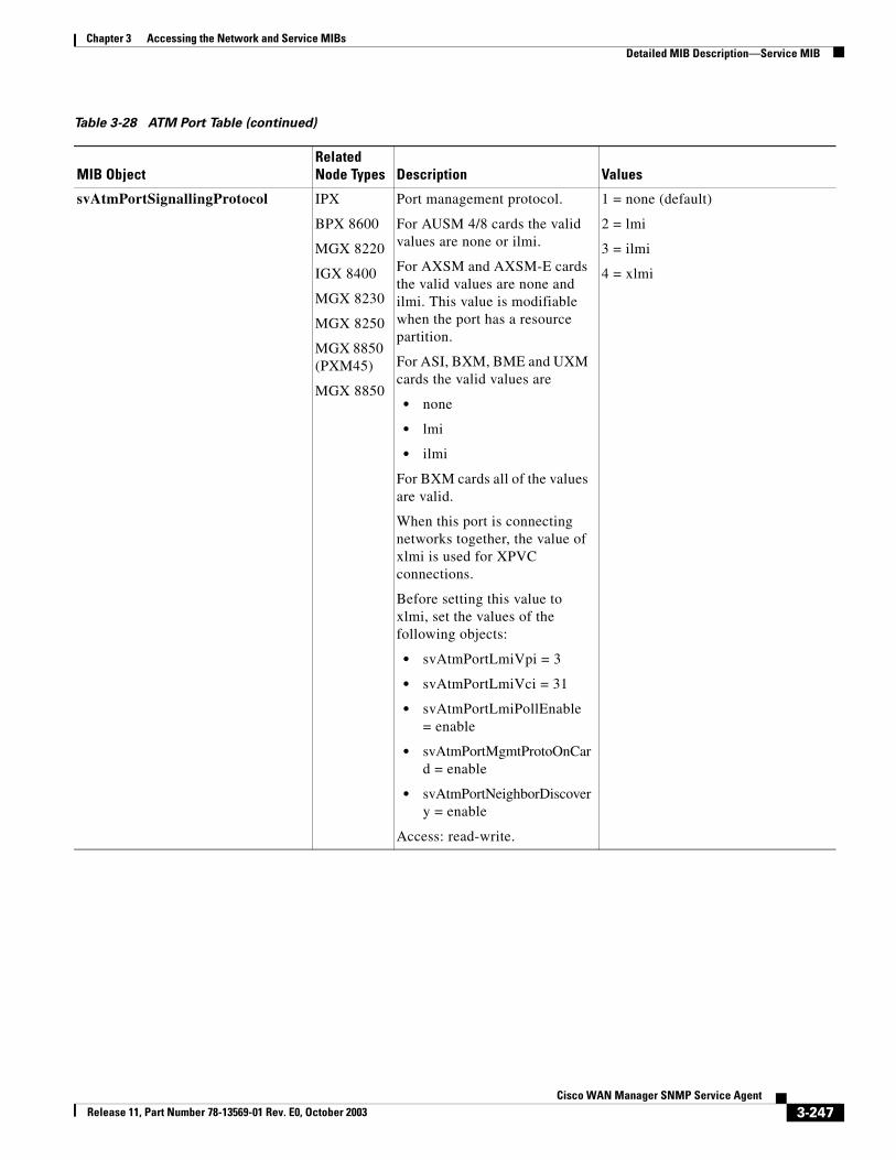
Chapter 3 Accessing the Network and Service MIBsDetailed MIB Description—Service MIB
svAtmPortSignallingProtocol IPX
BPX 8600
MGX 8220
IGX 8400
MGX 8230
MGX 8250
MGX 8850 (PXM45)
MGX 8850
Port management protocol.
For AUSM 4/8 cards the valid values are none or ilmi.
For AXSM and AXSM-E cards the valid values are none and ilmi. This value is modifiable when the port has a resource partition.
For ASI, BXM, BME and UXM cards the valid values are
• none
• lmi
• ilmi
For BXM cards all of the values are valid.
When this port is connecting networks together, the value of xlmi is used for XPVC connections.
Before setting this value to xlmi, set the values of the following objects:
• svAtmPortLmiVpi = 3
• svAtmPortLmiVci = 31
• svAtmPortLmiPollEnable = enable
• svAtmPortMgmtProtoOnCard = enable
• svAtmPortNeighborDiscovery = enable
Access: read-write.
1 = none (default)
2 = lmi
3 = ilmi
4 = xlmi
Table 3-28 ATM Port Table (continued)
MIB ObjectRelated Node Types Description Values
3-247Cisco WAN Manager SNMP Service Agent
Release 11, Part Number 78-13569-01 Rev. E0, October 2003
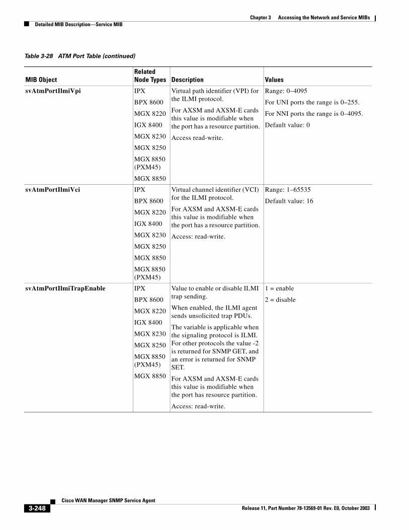
Chapter 3 Accessing the Network and Service MIBsDetailed MIB Description—Service MIB
svAtmPortIlmiVpi IPX
BPX 8600
MGX 8220
IGX 8400
MGX 8230
MGX 8250
MGX 8850 (PXM45)
MGX 8850
Virtual path identifier (VPI) for the ILMI protocol.
For AXSM and AXSM-E cards this value is modifiable when the port has a resource partition.
Access read-write.
Range: 0–4095
For UNI ports the range is 0–255.
For NNI ports the range is 0–4095.
Default value: 0
svAtmPortIlmiVci IPX
BPX 8600
MGX 8220
IGX 8400
MGX 8230
MGX 8250
MGX 8850
MGX 8850 (PXM45)
Virtual channel identifier (VCI) for the ILMI protocol.
For AXSM and AXSM-E cards this value is modifiable when the port has a resource partition.
Access: read-write.
Range: 1–65535
Default value: 16
svAtmPortIlmiTrapEnable IPX
BPX 8600
MGX 8220
IGX 8400
MGX 8230
MGX 8250
MGX 8850 (PXM45)
MGX 8850
Value to enable or disable ILMI trap sending.
When enabled, the ILMI agent sends unsolicited trap PDUs.
The variable is applicable when the signaling protocol is ILMI. For other protocols the value -2 is returned for SNMP GET, and an error is returned for SNMP SET.
For AXSM and AXSM-E cards this value is modifiable when the port has resource partition.
Access: read-write.
1 = enable
2 = disable
Table 3-28 ATM Port Table (continued)
MIB ObjectRelated Node Types Description Values
3-248Cisco WAN Manager SNMP Service Agent
Release 11, Part Number 78-13569-01 Rev. E0, October 2003
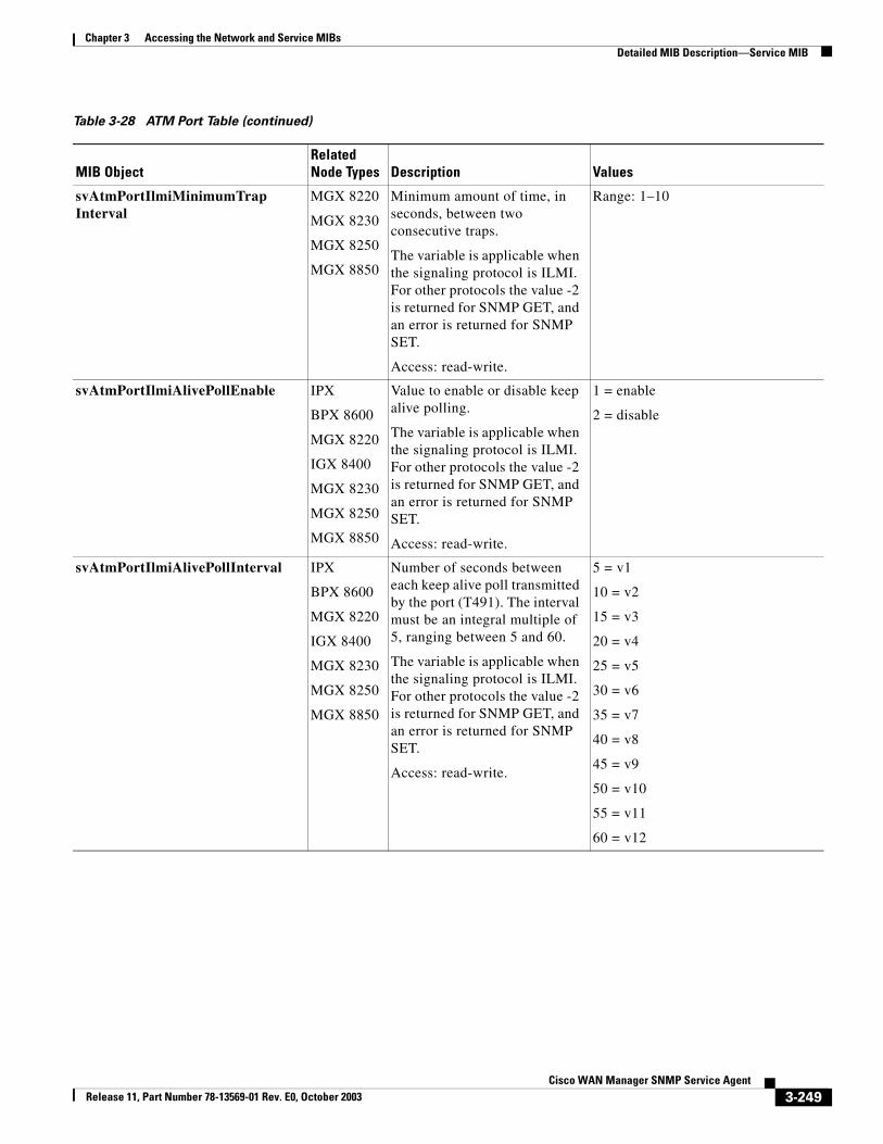
Chapter 3 Accessing the Network and Service MIBsDetailed MIB Description—Service MIB
svAtmPortIlmiMinimumTrapInterval
MGX 8220
MGX 8230
MGX 8250
MGX 8850
Minimum amount of time, in seconds, between two consecutive traps.
The variable is applicable when the signaling protocol is ILMI. For other protocols the value -2 is returned for SNMP GET, and an error is returned for SNMP SET.
Access: read-write.
Range: 1–10
svAtmPortIlmiAlivePollEnable IPX
BPX 8600
MGX 8220
IGX 8400
MGX 8230
MGX 8250
MGX 8850
Value to enable or disable keep alive polling.
The variable is applicable when the signaling protocol is ILMI. For other protocols the value -2 is returned for SNMP GET, and an error is returned for SNMP SET.
Access: read-write.
1 = enable
2 = disable
svAtmPortIlmiAlivePollInterval IPX
BPX 8600
MGX 8220
IGX 8400
MGX 8230
MGX 8250
MGX 8850
Number of seconds between each keep alive poll transmitted by the port (T491). The interval must be an integral multiple of 5, ranging between 5 and 60.
The variable is applicable when the signaling protocol is ILMI. For other protocols the value -2 is returned for SNMP GET, and an error is returned for SNMP SET.
Access: read-write.
5 = v1
10 = v2
15 = v3
20 = v4
25 = v5
30 = v6
35 = v7
40 = v8
45 = v9
50 = v10
55 = v11
60 = v12
Table 3-28 ATM Port Table (continued)
MIB ObjectRelated Node Types Description Values
3-249Cisco WAN Manager SNMP Service Agent
Release 11, Part Number 78-13569-01 Rev. E0, October 2003
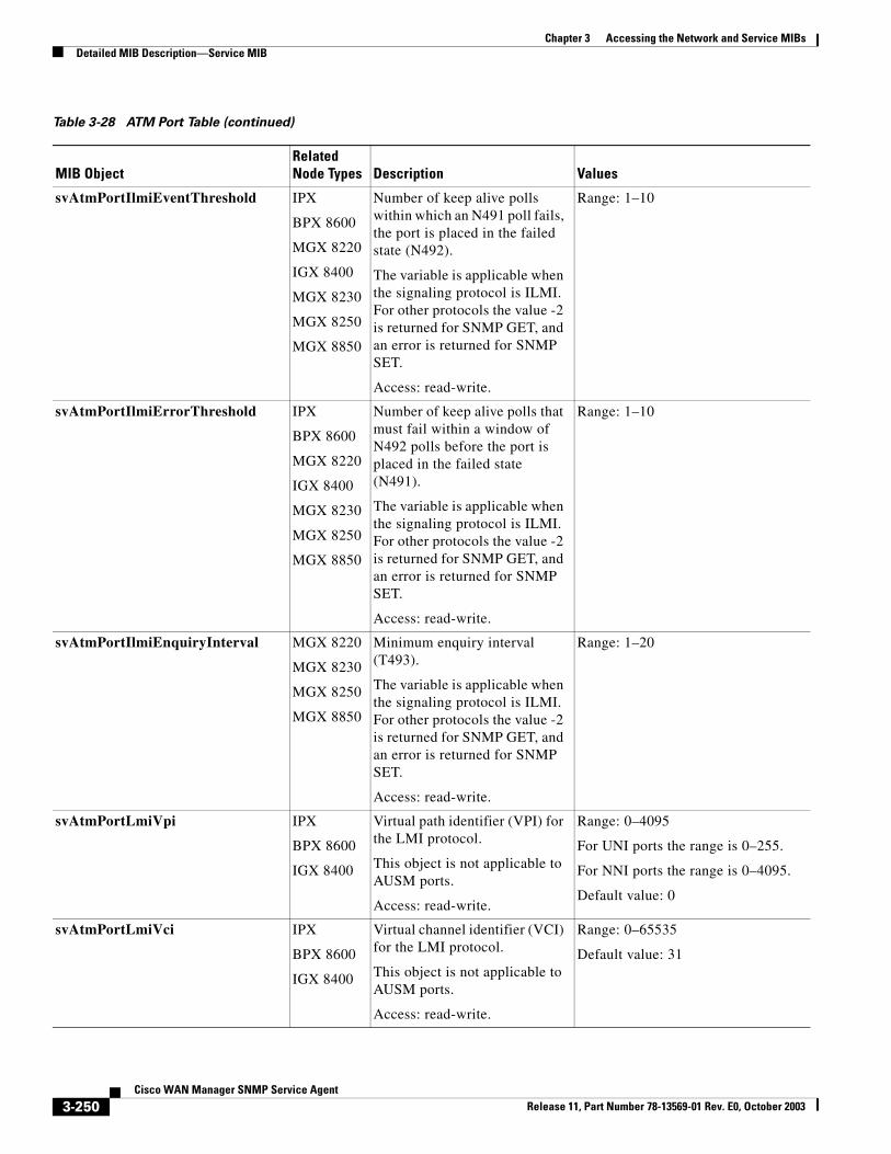
Chapter 3 Accessing the Network and Service MIBsDetailed MIB Description—Service MIB
svAtmPortIlmiEventThreshold IPX
BPX 8600
MGX 8220
IGX 8400
MGX 8230
MGX 8250
MGX 8850
Number of keep alive polls within which an N491 poll fails, the port is placed in the failed state (N492).
The variable is applicable when the signaling protocol is ILMI. For other protocols the value -2 is returned for SNMP GET, and an error is returned for SNMP SET.
Access: read-write.
Range: 1–10
svAtmPortIlmiErrorThreshold IPX
BPX 8600
MGX 8220
IGX 8400
MGX 8230
MGX 8250
MGX 8850
Number of keep alive polls that must fail within a window of N492 polls before the port is placed in the failed state (N491).
The variable is applicable when the signaling protocol is ILMI. For other protocols the value -2 is returned for SNMP GET, and an error is returned for SNMP SET.
Access: read-write.
Range: 1–10
svAtmPortIlmiEnquiryInterval MGX 8220
MGX 8230
MGX 8250
MGX 8850
Minimum enquiry interval (T493).
The variable is applicable when the signaling protocol is ILMI. For other protocols the value -2 is returned for SNMP GET, and an error is returned for SNMP SET.
Access: read-write.
Range: 1–20
svAtmPortLmiVpi IPX
BPX 8600
IGX 8400
Virtual path identifier (VPI) for the LMI protocol.
This object is not applicable to AUSM ports.
Access: read-write.
Range: 0–4095
For UNI ports the range is 0–255.
For NNI ports the range is 0–4095.
Default value: 0
svAtmPortLmiVci IPX
BPX 8600
IGX 8400
Virtual channel identifier (VCI) for the LMI protocol.
This object is not applicable to AUSM ports.
Access: read-write.
Range: 0–65535
Default value: 31
Table 3-28 ATM Port Table (continued)
MIB ObjectRelated Node Types Description Values
3-250Cisco WAN Manager SNMP Service Agent
Release 11, Part Number 78-13569-01 Rev. E0, October 2003
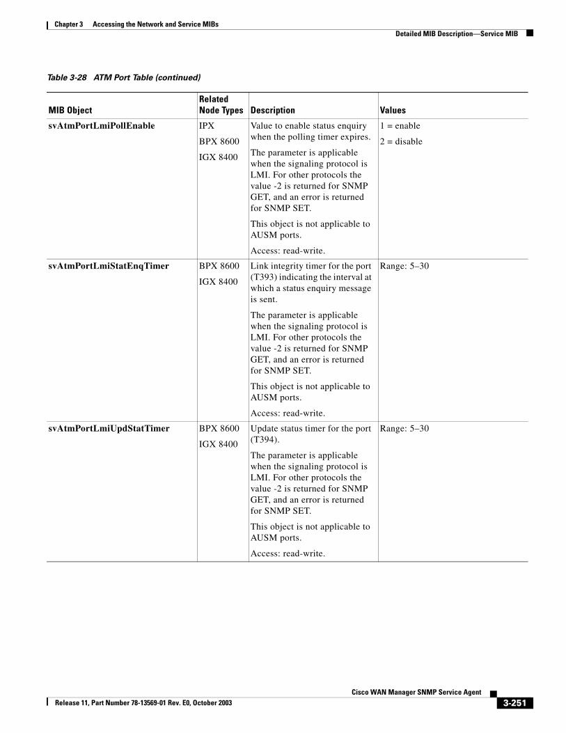
Chapter 3 Accessing the Network and Service MIBsDetailed MIB Description—Service MIB
svAtmPortLmiPollEnable IPX
BPX 8600
IGX 8400
Value to enable status enquiry when the polling timer expires.
The parameter is applicable when the signaling protocol is LMI. For other protocols the value -2 is returned for SNMP GET, and an error is returned for SNMP SET.
This object is not applicable to AUSM ports.
Access: read-write.
1 = enable
2 = disable
svAtmPortLmiStatEnqTimer BPX 8600
IGX 8400
Link integrity timer for the port (T393) indicating the interval at which a status enquiry message is sent.
The parameter is applicable when the signaling protocol is LMI. For other protocols the value -2 is returned for SNMP GET, and an error is returned for SNMP SET.
This object is not applicable to AUSM ports.
Access: read-write.
Range: 5–30
svAtmPortLmiUpdStatTimer BPX 8600
IGX 8400
Update status timer for the port (T394).
The parameter is applicable when the signaling protocol is LMI. For other protocols the value -2 is returned for SNMP GET, and an error is returned for SNMP SET.
This object is not applicable to AUSM ports.
Access: read-write.
Range: 5–30
Table 3-28 ATM Port Table (continued)
MIB ObjectRelated Node Types Description Values
3-251Cisco WAN Manager SNMP Service Agent
Release 11, Part Number 78-13569-01 Rev. E0, October 2003
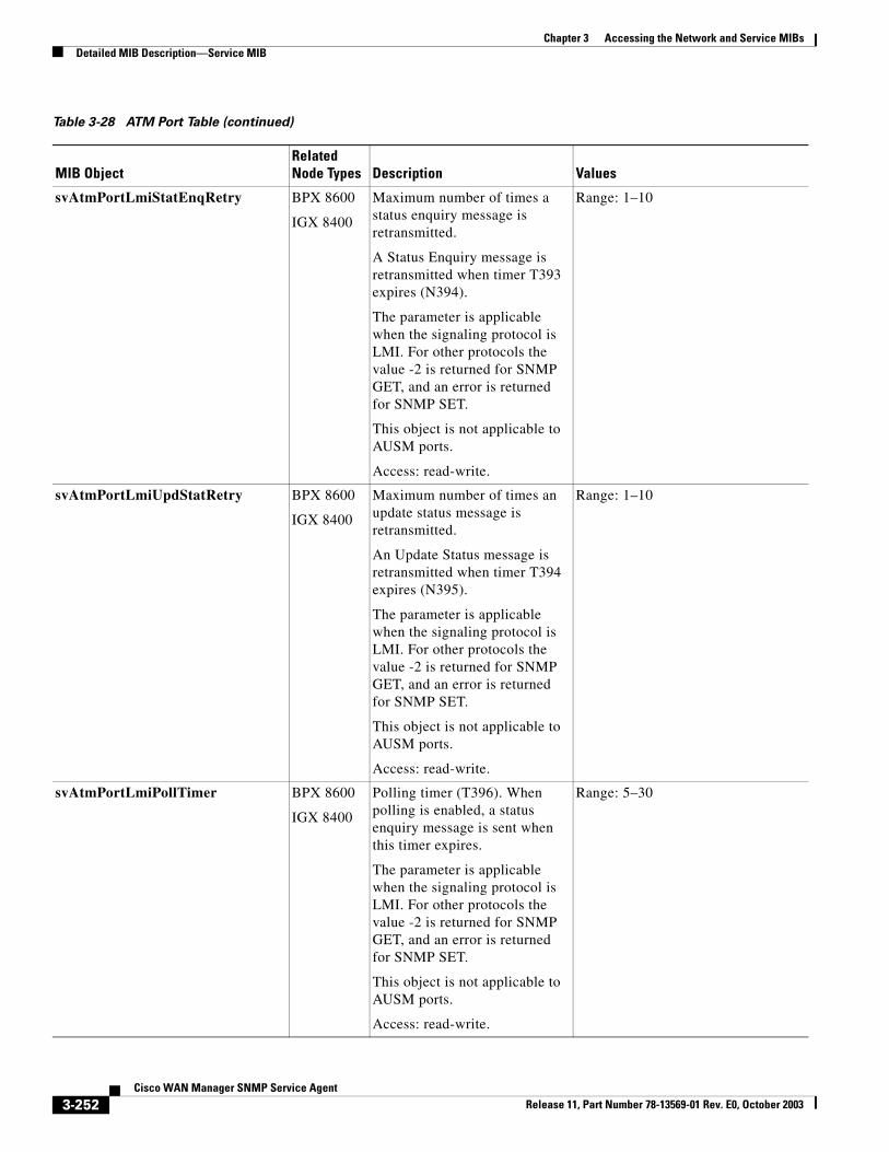
Chapter 3 Accessing the Network and Service MIBsDetailed MIB Description—Service MIB
svAtmPortLmiStatEnqRetry BPX 8600
IGX 8400
Maximum number of times a status enquiry message is retransmitted.
A Status Enquiry message is retransmitted when timer T393 expires (N394).
The parameter is applicable when the signaling protocol is LMI. For other protocols the value -2 is returned for SNMP GET, and an error is returned for SNMP SET.
This object is not applicable to AUSM ports.
Access: read-write.
Range: 1–10
svAtmPortLmiUpdStatRetry BPX 8600
IGX 8400
Maximum number of times an update status message is retransmitted.
An Update Status message is retransmitted when timer T394 expires (N395).
The parameter is applicable when the signaling protocol is LMI. For other protocols the value -2 is returned for SNMP GET, and an error is returned for SNMP SET.
This object is not applicable to AUSM ports.
Access: read-write.
Range: 1–10
svAtmPortLmiPollTimer BPX 8600
IGX 8400
Polling timer (T396). When polling is enabled, a status enquiry message is sent when this timer expires.
The parameter is applicable when the signaling protocol is LMI. For other protocols the value -2 is returned for SNMP GET, and an error is returned for SNMP SET.
This object is not applicable to AUSM ports.
Access: read-write.
Range: 5–30
Table 3-28 ATM Port Table (continued)
MIB ObjectRelated Node Types Description Values
3-252Cisco WAN Manager SNMP Service Agent
Release 11, Part Number 78-13569-01 Rev. E0, October 2003
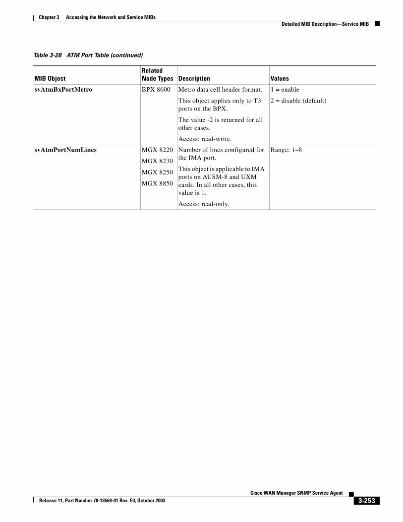
Chapter 3 Accessing the Network and Service MIBsDetailed MIB Description—Service MIB
svAtmBxPortMetro BPX 8600 Metro data cell header format.
This object applies only to T3 ports on the BPX.
The value -2 is returned for all other cases.
Access: read-write.
1 = enable
2 = disable (default)
svAtmPortNumLines MGX 8220
MGX 8230
MGX 8250
MGX 8850
Number of lines configured for the IMA port.
This object is applicable to IMA ports on AUSM-8 and UXM cards. In all other cases, this value is 1.
Access: read-only.
Range: 1–8
Table 3-28 ATM Port Table (continued)
MIB ObjectRelated Node Types Description Values
3-253Cisco WAN Manager SNMP Service Agent
Release 11, Part Number 78-13569-01 Rev. E0, October 2003
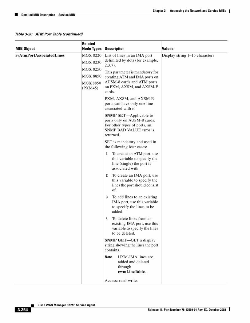
Chapter 3 Accessing the Network and Service MIBsDetailed MIB Description—Service MIB
svAtmPortAssociatedLines MGX 8220
MGX 8230
MGX 8250
MGX 8850
MGX 8850 (PXM45)
List of lines in an IMA port delimited by dots (for example, 2.3.7).
This parameter is mandatory for creating ATM and IMA ports on AUSM-8 cards and ATM ports on PXM, AXSM, and AXSM-E cards.
PXM, AXSM, and AXSM-E ports can have only one line associated with it.
SNMP SET—Applicable to ports only on AUSM-8 cards. For other types of ports, an SNMP BAD VALUE error is returned.
SET is mandatory and used in the following four cases:
1. To create an ATM port, use this variable to specify the line (single) the port is associated with.
2. To create an IMA port, use this variable to specify the lines the port should consist of.
3. To add lines to an existing IMA port, use this variable to specify the lines to be added.
4. To delete lines from an existing IMA port, use this variable to specify the lines to be deleted.
SNMP GET—GET a display string showing the lines the port contains.
Note UXM-IMA lines are added and deleted through cwmLineTable.
Access: read-write.
Display string 1–15 characters
Table 3-28 ATM Port Table (continued)
MIB ObjectRelated Node Types Description Values
3-254Cisco WAN Manager SNMP Service Agent
Release 11, Part Number 78-13569-01 Rev. E0, October 2003
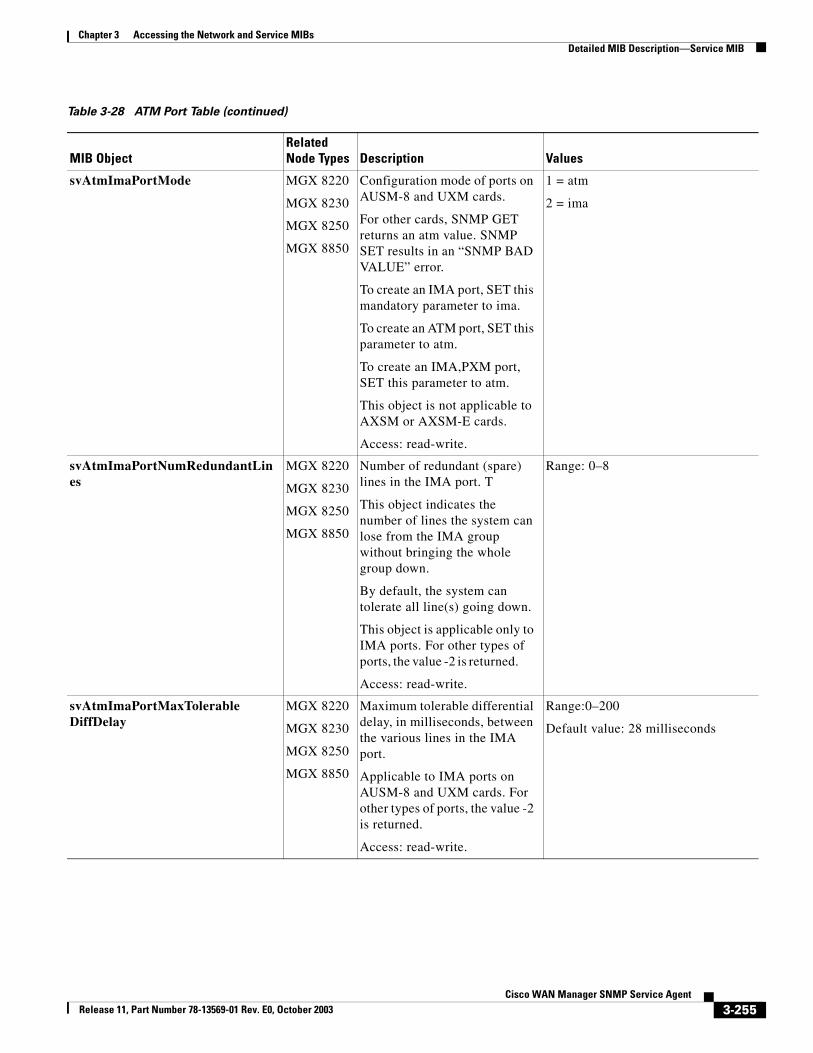
Chapter 3 Accessing the Network and Service MIBsDetailed MIB Description—Service MIB
svAtmImaPortMode MGX 8220
MGX 8230
MGX 8250
MGX 8850
Configuration mode of ports on AUSM-8 and UXM cards.
For other cards, SNMP GET returns an atm value. SNMP SET results in an “SNMP BAD VALUE” error.
To create an IMA port, SET this mandatory parameter to ima.
To create an ATM port, SET this parameter to atm.
To create an IMA,PXM port, SET this parameter to atm.
This object is not applicable to AXSM or AXSM-E cards.
Access: read-write.
1 = atm
2 = ima
svAtmImaPortNumRedundantLines
MGX 8220
MGX 8230
MGX 8250
MGX 8850
Number of redundant (spare) lines in the IMA port. T
This object indicates the number of lines the system can lose from the IMA group without bringing the whole group down.
By default, the system can tolerate all line(s) going down.
This object is applicable only to IMA ports. For other types of ports, the value -2 is returned.
Access: read-write.
Range: 0–8
svAtmImaPortMaxTolerableDiffDelay
MGX 8220
MGX 8230
MGX 8250
MGX 8850
Maximum tolerable differential delay, in milliseconds, between the various lines in the IMA port.
Applicable to IMA ports on AUSM-8 and UXM cards. For other types of ports, the value -2 is returned.
Access: read-write.
Range:0–200
Default value: 28 milliseconds
Table 3-28 ATM Port Table (continued)
MIB ObjectRelated Node Types Description Values
3-255Cisco WAN Manager SNMP Service Agent
Release 11, Part Number 78-13569-01 Rev. E0, October 2003
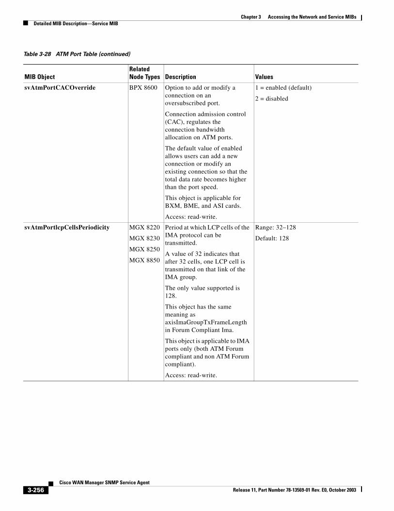
Chapter 3 Accessing the Network and Service MIBsDetailed MIB Description—Service MIB
svAtmPortCACOverride BPX 8600 Option to add or modify a connection on an oversubscribed port.
Connection admission control (CAC), regulates the connection bandwidth allocation on ATM ports.
The default value of enabled allows users can add a new connection or modify an existing connection so that the total data rate becomes higher than the port speed.
This object is applicable for BXM, BME, and ASI cards.
Access: read-write.
1 = enabled (default)
2 = disabled
svAtmPortlcpCellsPeriodicity MGX 8220
MGX 8230
MGX 8250
MGX 8850
Period at which LCP cells of the IMA protocol can be transmitted.
A value of 32 indicates that after 32 cells, one LCP cell is transmitted on that link of the IMA group.
The only value supported is 128.
This object has the same meaning as axisImaGroupTxFrameLength in Forum Compliant Ima.
This object is applicable to IMA ports only (both ATM Forum compliant and non ATM Forum compliant).
Access: read-write.
Range: 32–128
Default: 128
Table 3-28 ATM Port Table (continued)
MIB ObjectRelated Node Types Description Values
3-256Cisco WAN Manager SNMP Service Agent
Release 11, Part Number 78-13569-01 Rev. E0, October 2003
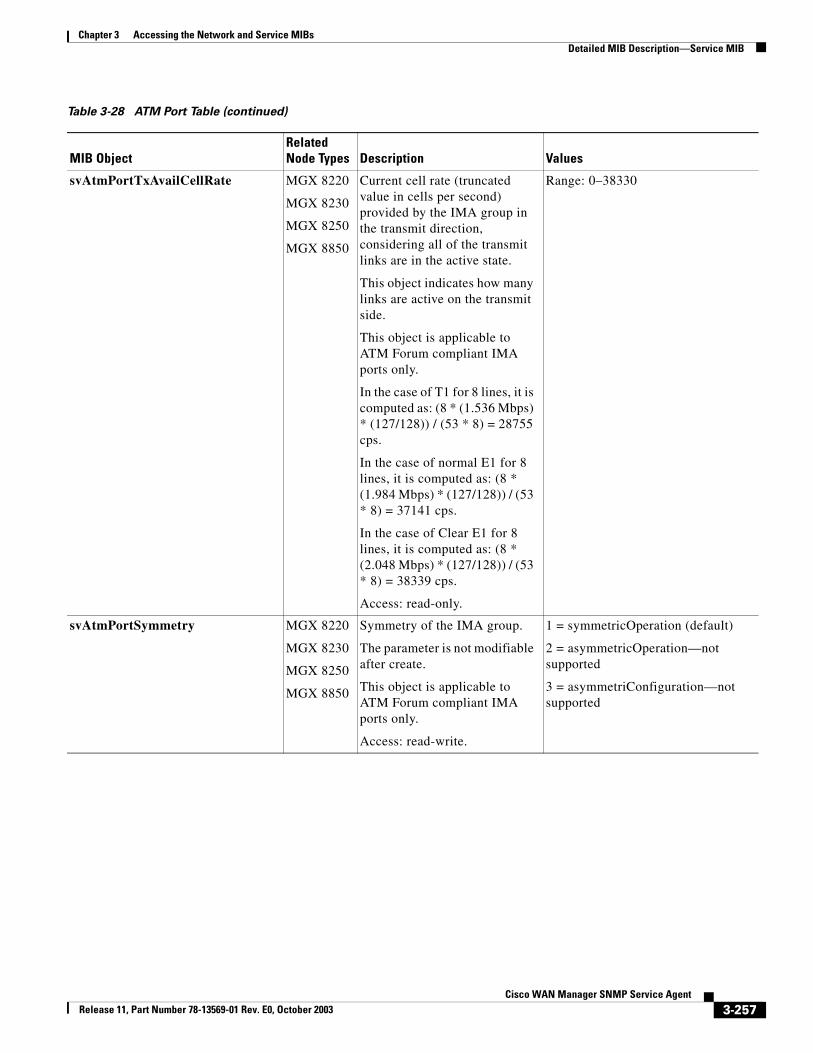
Chapter 3 Accessing the Network and Service MIBsDetailed MIB Description—Service MIB
svAtmPortTxAvailCellRate MGX 8220
MGX 8230
MGX 8250
MGX 8850
Current cell rate (truncated value in cells per second) provided by the IMA group in the transmit direction, considering all of the transmit links are in the active state.
This object indicates how many links are active on the transmit side.
This object is applicable to ATM Forum compliant IMA ports only.
In the case of T1 for 8 lines, it is computed as: (8 * (1.536 Mbps) * (127/128)) / (53 * 8) = 28755 cps.
In the case of normal E1 for 8 lines, it is computed as: (8 * (1.984 Mbps) * (127/128)) / (53 * 8) = 37141 cps.
In the case of Clear E1 for 8 lines, it is computed as: (8 * (2.048 Mbps) * (127/128)) / (53 * 8) = 38339 cps.
Access: read-only.
Range: 0–38330
svAtmPortSymmetry MGX 8220
MGX 8230
MGX 8250
MGX 8850
Symmetry of the IMA group.
The parameter is not modifiable after create.
This object is applicable to ATM Forum compliant IMA ports only.
Access: read-write.
1 = symmetricOperation (default)
2 = asymmetricOperation—not supported
3 = asymmetriConfiguration—not supported
Table 3-28 ATM Port Table (continued)
MIB ObjectRelated Node Types Description Values
3-257Cisco WAN Manager SNMP Service Agent
Release 11, Part Number 78-13569-01 Rev. E0, October 2003
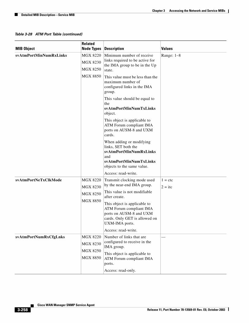
Chapter 3 Accessing the Network and Service MIBsDetailed MIB Description—Service MIB
svAtmPortMinNumRxLinks MGX 8220
MGX 8230
MGX 8250
MGX 8850
Minimum number of receive links required to be active for the IMA group to be in the Up state.
This value must be less than the maximum number of configured links in the IMA group.
This value should be equal to the svAtmPortMinNumTxLinks object.
This object is applicable to ATM Forum compliant IMA ports on AUSM-8 and UXM cards.
When adding or modifying links, SET both the svAtmPortMinNumRxLinks and svAtmPortMinNumTxLinks objects to the same value.
Access: read-write.
Range: 1–8
svAtmPortNeTxClkMode MGX 8220
MGX 8230
MGX 8250
MGX 8850
Transmit clocking mode used by the near-end IMA group.
This value is not modifiable after create.
This object is applicable to ATM Forum compliant IMA ports on AUSM-8 and UXM cards. Only GET is allowed on UXM-IMA ports.
Access: read-write.
1 = ctc
2 = itc
svAtmPortNumRxCfgLnks MGX 8220
MGX 8230
MGX 8250
MGX 8850
Number of links that are configured to receive in the IMA group.
This object is applicable to ATM Forum compliant IMA ports.
Access: read-only.
—
Table 3-28 ATM Port Table (continued)
MIB ObjectRelated Node Types Description Values
3-258Cisco WAN Manager SNMP Service Agent
Release 11, Part Number 78-13569-01 Rev. E0, October 2003
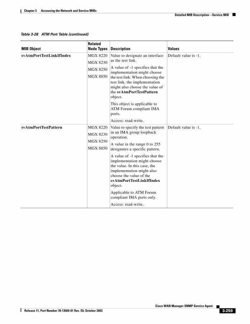
Chapter 3 Accessing the Network and Service MIBsDetailed MIB Description—Service MIB
svAtmPortTestLinkIfIndex MGX 8220
MGX 8230
MGX 8250
MGX 8850
Value to designate an interface as the test link.
A value of -1 specifies that the implementation might choose the test link. When choosing the test link, the implementation might also choose the value of the svAtmPortTestPattern object.
This object is applicable to ATM Forum compliant IMA ports.
Access: read-write.
Default value is -1.
svAtmPortTestPattern MGX 8220
MGX 8230
MGX 8250
MGX 8850
Value to specify the test pattern in an IMA group loopback operation.
A value in the range 0 to 255 designates a specific pattern.
A value of -1 specifies that the implementation might choose the value. In this case, the implementation might also choose the value of the svAtmPortTestLinkIfIndex object.
Applicable to ATM Forum compliant IMA ports only.
Access: read-write.
Default value is -1.
Table 3-28 ATM Port Table (continued)
MIB ObjectRelated Node Types Description Values
3-259Cisco WAN Manager SNMP Service Agent
Release 11, Part Number 78-13569-01 Rev. E0, October 2003
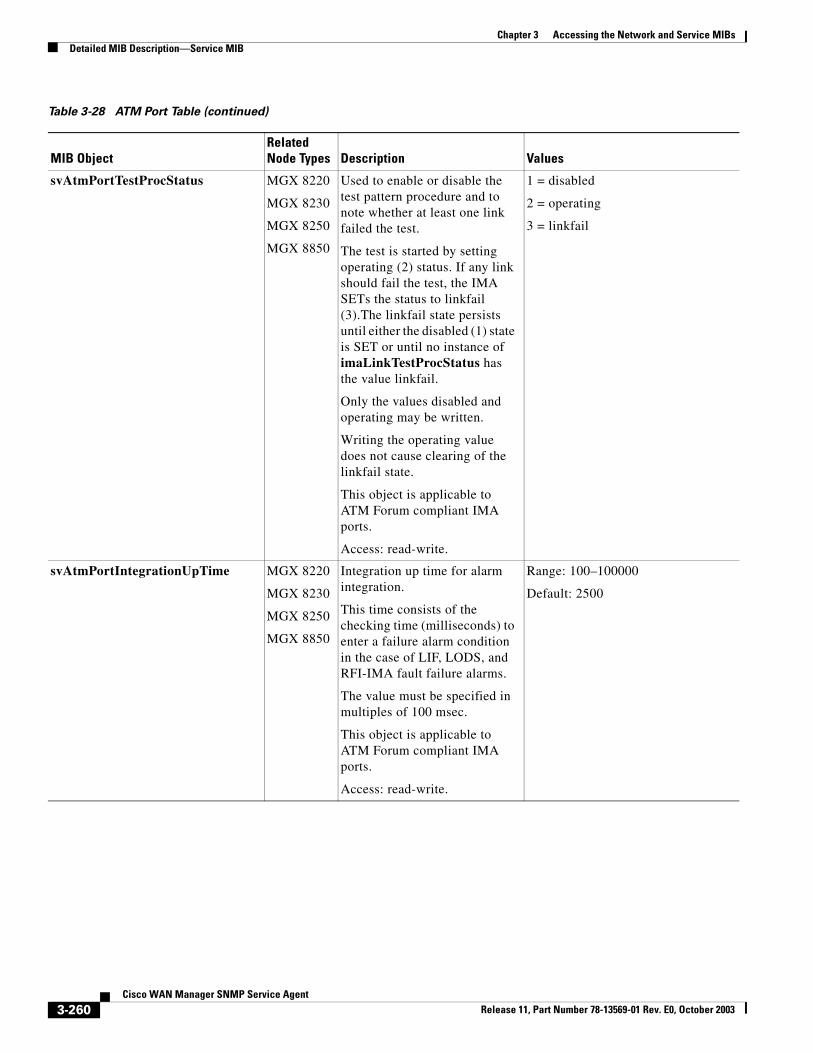
Chapter 3 Accessing the Network and Service MIBsDetailed MIB Description—Service MIB
svAtmPortTestProcStatus MGX 8220
MGX 8230
MGX 8250
MGX 8850
Used to enable or disable the test pattern procedure and to note whether at least one link failed the test.
The test is started by setting operating (2) status. If any link should fail the test, the IMA SETs the status to linkfail (3).The linkfail state persists until either the disabled (1) state is SET or until no instance of imaLinkTestProcStatus has the value linkfail.
Only the values disabled and operating may be written.
Writing the operating value does not cause clearing of the linkfail state.
This object is applicable to ATM Forum compliant IMA ports.
Access: read-write.
1 = disabled
2 = operating
3 = linkfail
svAtmPortIntegrationUpTime MGX 8220
MGX 8230
MGX 8250
MGX 8850
Integration up time for alarm integration.
This time consists of the checking time (milliseconds) to enter a failure alarm condition in the case of LIF, LODS, and RFI-IMA fault failure alarms.
The value must be specified in multiples of 100 msec.
This object is applicable to ATM Forum compliant IMA ports.
Access: read-write.
Range: 100–100000
Default: 2500
Table 3-28 ATM Port Table (continued)
MIB ObjectRelated Node Types Description Values
3-260Cisco WAN Manager SNMP Service Agent
Release 11, Part Number 78-13569-01 Rev. E0, October 2003
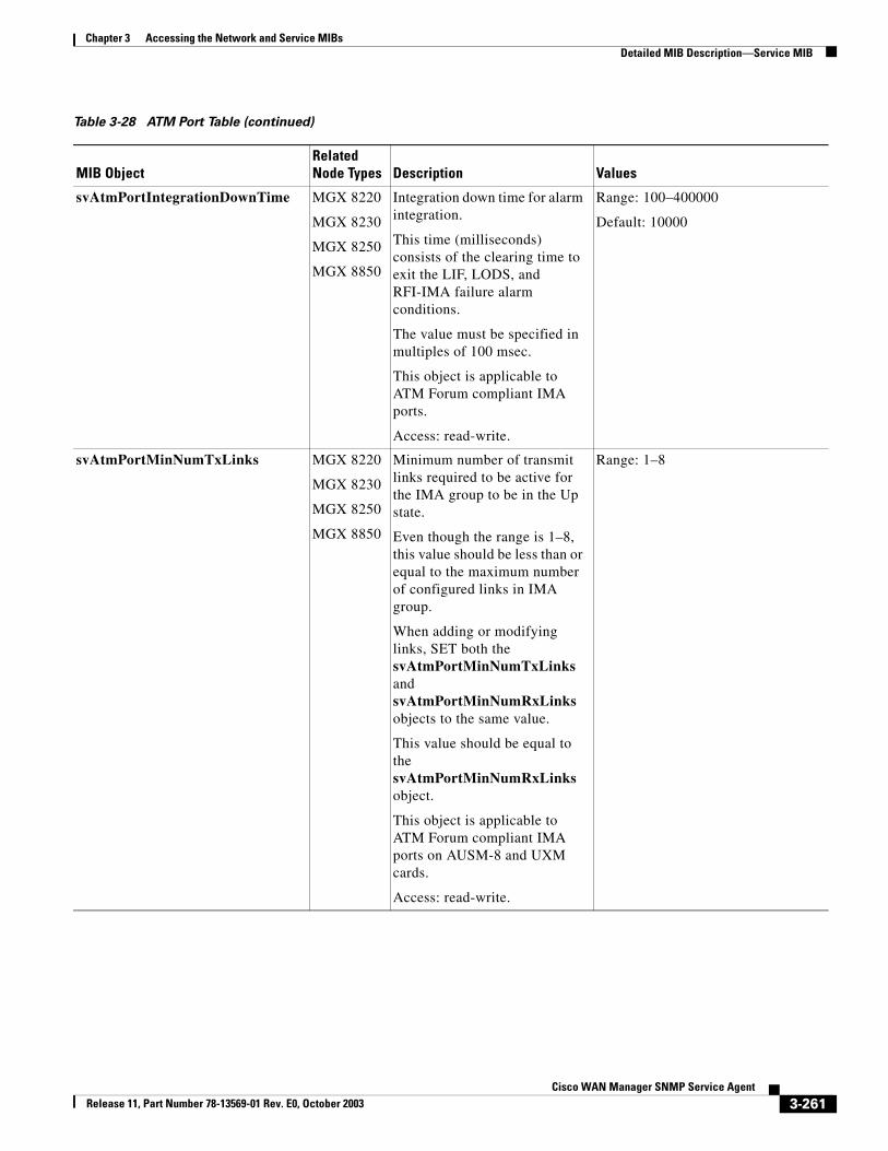
Chapter 3 Accessing the Network and Service MIBsDetailed MIB Description—Service MIB
svAtmPortIntegrationDownTime MGX 8220
MGX 8230
MGX 8250
MGX 8850
Integration down time for alarm integration.
This time (milliseconds) consists of the clearing time to exit the LIF, LODS, and RFI-IMA failure alarm conditions.
The value must be specified in multiples of 100 msec.
This object is applicable to ATM Forum compliant IMA ports.
Access: read-write.
Range: 100–400000
Default: 10000
svAtmPortMinNumTxLinks MGX 8220
MGX 8230
MGX 8250
MGX 8850
Minimum number of transmit links required to be active for the IMA group to be in the Up state.
Even though the range is 1–8, this value should be less than or equal to the maximum number of configured links in IMA group.
When adding or modifying links, SET both the svAtmPortMinNumTxLinks and svAtmPortMinNumRxLinks objects to the same value.
This value should be equal to the svAtmPortMinNumRxLinks object.
This object is applicable to ATM Forum compliant IMA ports on AUSM-8 and UXM cards.
Access: read-write.
Range: 1–8
Table 3-28 ATM Port Table (continued)
MIB ObjectRelated Node Types Description Values
3-261Cisco WAN Manager SNMP Service Agent
Release 11, Part Number 78-13569-01 Rev. E0, October 2003
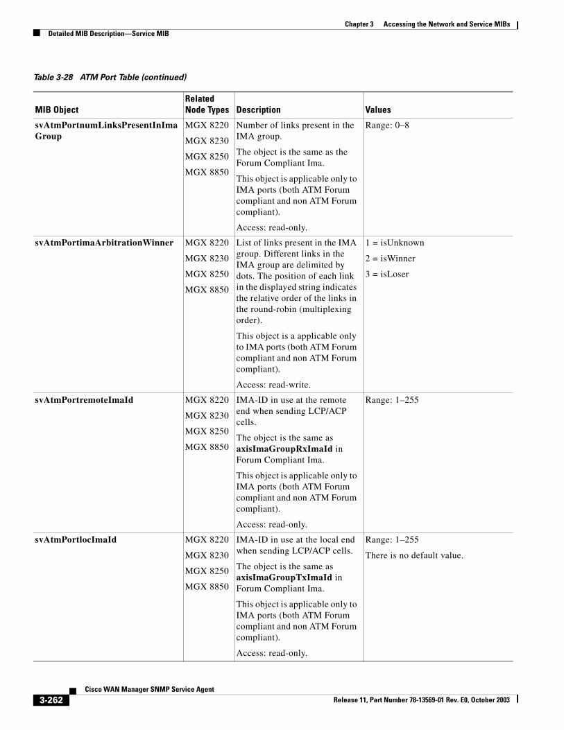
Chapter 3 Accessing the Network and Service MIBsDetailed MIB Description—Service MIB
svAtmPortnumLinksPresentInImaGroup
MGX 8220
MGX 8230
MGX 8250
MGX 8850
Number of links present in the IMA group.
The object is the same as the Forum Compliant Ima.
This object is applicable only to IMA ports (both ATM Forum compliant and non ATM Forum compliant).
Access: read-only.
Range: 0–8
svAtmPortimaArbitrationWinner MGX 8220
MGX 8230
MGX 8250
MGX 8850
List of links present in the IMA group. Different links in the IMA group are delimited by dots. The position of each link in the displayed string indicates the relative order of the links in the round-robin (multiplexing order).
This object is a applicable only to IMA ports (both ATM Forum compliant and non ATM Forum compliant).
Access: read-write.
1 = isUnknown
2 = isWinner
3 = isLoser
svAtmPortremoteImaId MGX 8220
MGX 8230
MGX 8250
MGX 8850
IMA-ID in use at the remote end when sending LCP/ACP cells.
The object is the same as axisImaGroupRxImaId in Forum Compliant Ima.
This object is applicable only to IMA ports (both ATM Forum compliant and non ATM Forum compliant).
Access: read-only.
Range: 1–255
svAtmPortlocImaId MGX 8220
MGX 8230
MGX 8250
MGX 8850
IMA-ID in use at the local end when sending LCP/ACP cells.
The object is the same as axisImaGroupTxImaId in Forum Compliant Ima.
This object is applicable only to IMA ports (both ATM Forum compliant and non ATM Forum compliant).
Access: read-only.
Range: 1–255
There is no default value.
Table 3-28 ATM Port Table (continued)
MIB ObjectRelated Node Types Description Values
3-262Cisco WAN Manager SNMP Service Agent
Release 11, Part Number 78-13569-01 Rev. E0, October 2003
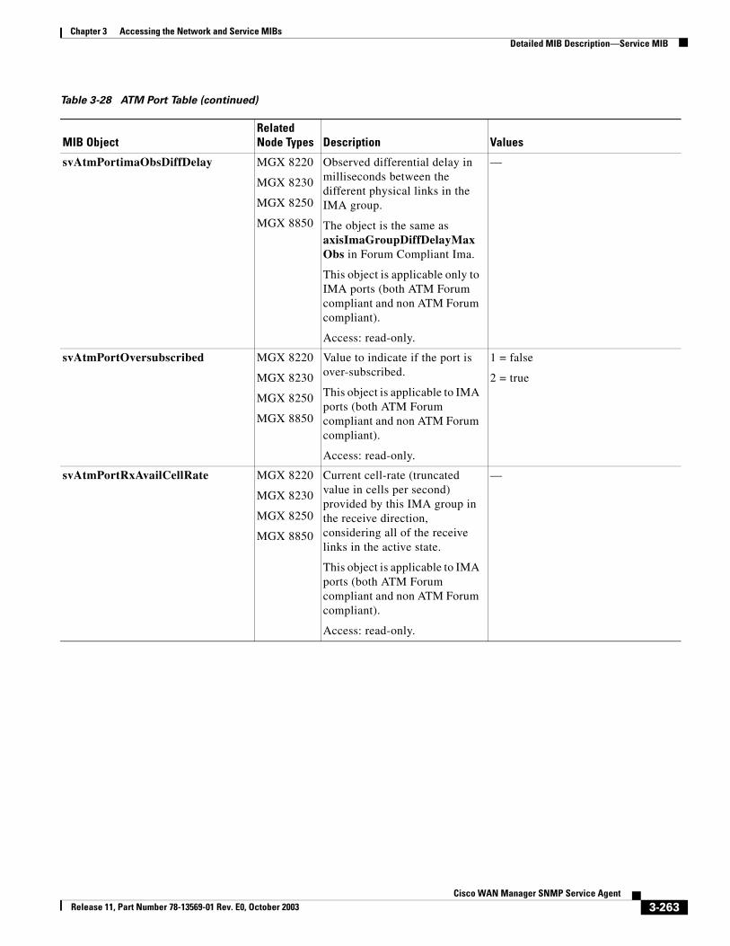
Chapter 3 Accessing the Network and Service MIBsDetailed MIB Description—Service MIB
svAtmPortimaObsDiffDelay MGX 8220
MGX 8230
MGX 8250
MGX 8850
Observed differential delay in milliseconds between the different physical links in the IMA group.
The object is the same as axisImaGroupDiffDelayMaxObs in Forum Compliant Ima.
This object is applicable only to IMA ports (both ATM Forum compliant and non ATM Forum compliant).
Access: read-only.
—
svAtmPortOversubscribed MGX 8220
MGX 8230
MGX 8250
MGX 8850
Value to indicate if the port is over-subscribed.
This object is applicable to IMA ports (both ATM Forum compliant and non ATM Forum compliant).
Access: read-only.
1 = false
2 = true
svAtmPortRxAvailCellRate MGX 8220
MGX 8230
MGX 8250
MGX 8850
Current cell-rate (truncated value in cells per second) provided by this IMA group in the receive direction, considering all of the receive links in the active state.
This object is applicable to IMA ports (both ATM Forum compliant and non ATM Forum compliant).
Access: read-only.
—
Table 3-28 ATM Port Table (continued)
MIB ObjectRelated Node Types Description Values
3-263Cisco WAN Manager SNMP Service Agent
Release 11, Part Number 78-13569-01 Rev. E0, October 2003
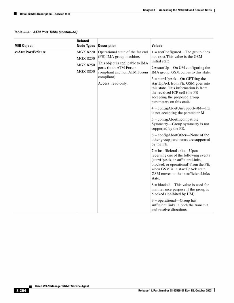
Chapter 3 Accessing the Network and Service MIBsDetailed MIB Description—Service MIB
svAtmPortFeState MGX 8220
MGX 8230
MGX 8250
MGX 8850
Operational state of the far end (FE) IMA group machine.
This object is applicable to IMA ports (both ATM Forum compliant and non ATM Forum compliant).
Access: read-only.
1 = notConfigured—The group does not exist.This value is the GSM initial state.
2 = startUp—On UM configuring the IMA group, GSM comes to this state.
3 = startUpAck—On GETting the startUpAck from FE, GSM goes into this state. This information is from the received ICP cell (the FE accepting the proposed group parameters on this end).
4 = configAbortUnsupportedM—FE is not accepting the parameter M.
5 = configAbortIncompatibleSymmetry—Group symmetry is not supported by the FE.
6 = configAbortOther—None of the other group parameters are supported by the FE.
7 = insufficientLinks—Upon receiving one of the following events (startUpAck, insufficientLinks, blocked, or operational) from the FE, when GSM is in startUpAck state, GSM moves to the insufficientLinks state.
8 = blocked—This value is used for maintenance purpose if the group is blocked (inhibited by UM).
9 = operational—Group has sufficient links in both the transmit and receive directions.
Table 3-28 ATM Port Table (continued)
MIB ObjectRelated Node Types Description Values
3-264Cisco WAN Manager SNMP Service Agent
Release 11, Part Number 78-13569-01 Rev. E0, October 2003
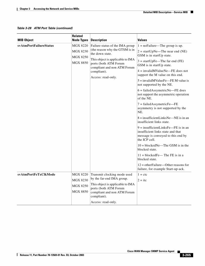
Chapter 3 Accessing the Network and Service MIBsDetailed MIB Description—Service MIB
svAtmPortFailureStatus MGX 8220
MGX 8230
MGX 8250
MGX 8850
Failure status of the IMA group (the reason why the GTSM is in the down state.
This object is applicable to IMA ports (both ATM Forum compliant and non ATM Forum compliant).
Access: read-only.
1 = noFailure—The group is up.
2 = startUpNe—The near end (NE) GSM is in startUp state.
3 = startUpFe—The far end (FE) GSM is in startUp state.
4 = invalidMValueNe—FE does not support the M value on this end.
5 = invalidMValueFe—FE M value is not supported by the NE.
6 = failedAssymetricNe—FE does not support the asymmetric operation of the NE.
7 = failedAssymetricFe—FE asymmetry is not supported by the NE.
8 = insufficientLinksNe—NE is in an insufficient links state.
9 = insufficientLinksFe—FE is in an insufficient links state and that message is conveyed to this end by the ICP cell.
10 = blockedNe—The GSM is in the blocked state.
11 = blockedFe— The FE is in a blocked state.
12 = otherFailure—Other reasons for failure, for example Start-up-ack.
svAtmPortFeTxClkMode MGX 8220
MGX 8230
MGX 8250
MGX 8850
Transmit clocking mode used by the far-end IMA group.
This object is applicable to IMA ports (both ATM Forum compliant and non ATM Forum compliant).
Access: read-only.
1 = ctc
2 = itc
Table 3-28 ATM Port Table (continued)
MIB ObjectRelated Node Types Description Values
3-265Cisco WAN Manager SNMP Service Agent
Release 11, Part Number 78-13569-01 Rev. E0, October 2003
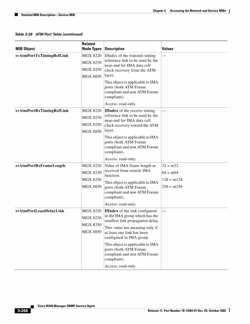
Chapter 3 Accessing the Network and Service MIBsDetailed MIB Description—Service MIB
svAtmPortTxTimingRefLink MGX 8220
MGX 8230
MGX 8250
MGX 8850
IfIndex of the transmit timing reference link to be used by the near-end for IMA data cell clock recovery from the ATM layer.
This object is applicable to IMA ports (both ATM Forum compliant and non ATM Forum compliant).
Access: read-only.
—
svAtmPortRxTimingRefLink MGX 8220
MGX 8230
MGX 8250
MGX 8850
IfIndex of the receive timing reference link to be used by the near-end for IMA data cell clock recovery toward the ATM layer.
This object is applicable to IMA ports (both ATM Forum compliant and non ATM Forum compliant).
Access: read-only.
—
svAtmPortRxFrameLength MGX 8220
MGX 8230
MGX 8250
MGX 8850
Value of IMA frame length as received from remote IMA function.
This object is applicable to IMA ports (both ATM Forum compliant and non ATM Forum compliant).
Access: read-only.
32 = m32
64 = m64
128 = m128
256 = m256
svAtmPortLeastDelayLink MGX 8220
MGX 8230
MGX 8250
MGX 8850
IfIndex of the link configured in the IMA group which has the smallest link propagation delay.
This value has meaning only if at least one link has been configured in IMA group.
This object is applicable to IMA ports (both ATM Forum compliant and non ATM Forum compliant).
Access: read-only.
—
Table 3-28 ATM Port Table (continued)
MIB ObjectRelated Node Types Description Values
3-266Cisco WAN Manager SNMP Service Agent
Release 11, Part Number 78-13569-01 Rev. E0, October 2003
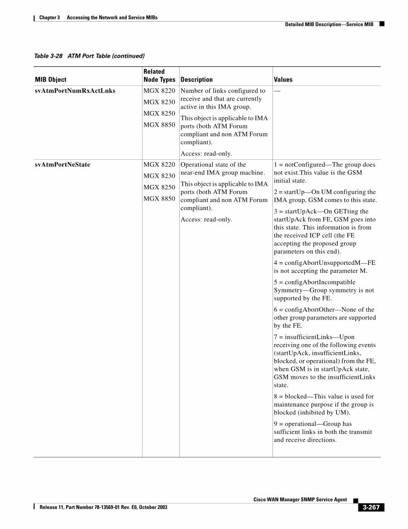
Chapter 3 Accessing the Network and Service MIBsDetailed MIB Description—Service MIB
svAtmPortNumRxActLnks MGX 8220
MGX 8230
MGX 8250
MGX 8850
Number of links configured to receive and that are currently active in this IMA group.
This object is applicable to IMA ports (both ATM Forum compliant and non ATM Forum compliant).
Access: read-only.
—
svAtmPortNeState MGX 8220
MGX 8230
MGX 8250
MGX 8850
Operational state of the near-end IMA group machine.
This object is applicable to IMA ports (both ATM Forum compliant and non ATM Forum compliant).
Access: read-only.
1 = notConfigured—The group does not exist.This value is the GSM initial state.
2 = startUp—On UM configuring the IMA group, GSM comes to this state.
3 = startUpAck—On GETting the startUpAck from FE, GSM goes into this state. This information is from the received ICP cell (the FE accepting the proposed group parameters on this end).
4 = configAbortUnsupportedM—FE is not accepting the parameter M.
5 = configAbortIncompatibleSymmetry—Group symmetry is not supported by the FE.
6 = configAbortOther—None of the other group parameters are supported by the FE.
7 = insufficientLinks—Upon receiving one of the following events (startUpAck, insufficientLinks, blocked, or operational) from the FE, when GSM is in startUpAck state, GSM moves to the insufficientLinks state.
8 = blocked—This value is used for maintenance purpose if the group is blocked (inhibited by UM).
9 = operational—Group has sufficient links in both the transmit and receive directions.
Table 3-28 ATM Port Table (continued)
MIB ObjectRelated Node Types Description Values
3-267Cisco WAN Manager SNMP Service Agent
Release 11, Part Number 78-13569-01 Rev. E0, October 2003
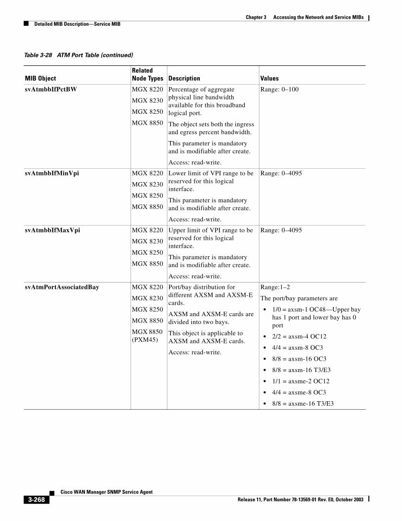
Chapter 3 Accessing the Network and Service MIBsDetailed MIB Description—Service MIB
svAtmbbIfPctBW MGX 8220
MGX 8230
MGX 8250
MGX 8850
Percentage of aggregate physical line bandwidth available for this broadband logical port.
The object sets both the ingress and egress percent bandwidth.
This parameter is mandatory and is modifiable after create.
Access: read-write.
Range: 0–100
svAtmbbIfMinVpi MGX 8220
MGX 8230
MGX 8250
MGX 8850
Lower limit of VPI range to be reserved for this logical interface.
This parameter is mandatory and is modifiable after create.
Access: read-write.
Range: 0–4095
svAtmbbIfMaxVpi MGX 8220
MGX 8230
MGX 8250
MGX 8850
Upper limit of VPI range to be reserved for this logical interface.
This parameter is mandatory and is modifiable after create.
Access: read-write.
Range: 0–4095
svAtmPortAssociatedBay MGX 8220
MGX 8230
MGX 8250
MGX 8850
MGX 8850 (PXM45)
Port/bay distribution for different AXSM and AXSM-E cards.
AXSM and AXSM-E cards are divided into two bays.
This object is applicable to AXSM and AXSM-E cards.
Access: read-write.
Range:1–2
The port/bay parameters are
• 1/0 = axsm-1 OC48—Upper bay has 1 port and lower bay has 0 port
• 2/2 = axsm-4 OC12
• 4/4 = axsm-8 OC3
• 8/8 = axsm-16 OC3
• 8/8 = axsm-16 T3/E3
• 1/1 = axsme-2 OC12
• 4/4 = axsme-8 OC3
• 8/8 = axsme-16 T3/E3
Table 3-28 ATM Port Table (continued)
MIB ObjectRelated Node Types Description Values
3-268Cisco WAN Manager SNMP Service Agent
Release 11, Part Number 78-13569-01 Rev. E0, October 2003
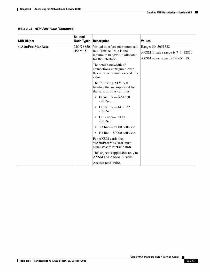
Chapter 3 Accessing the Network and Service MIBsDetailed MIB Description—Service MIB
svAtmPortMaxRate MGX 8850 (PXM45)
Virtual interface maximum cell rate. This cell rate is the maximum bandwidth allocated for the interface.
The total bandwidth of connections configured over this interface cannot exceed this value.
The following ATM cell bandwidths are supported for the various physical lines:
• OC48 line—5651328 cells/sec
• OC12 line—1412832 cells/sec
• OC3 line—353208 cells/sec
• T3 line—96000 cells/sec
• E3 line—80000 cells/sec.
For AXSM cards the svAtmPortMaxRate must equal svAtmPortMinRate.
This object is applicable only to AXSM and AXSM-E cards.
Access: read-write.
Range: 50–5651328
AXSM-E value range is 7–1412830.
AXSM value range is 7–5651328.
Table 3-28 ATM Port Table (continued)
MIB ObjectRelated Node Types Description Values
3-269Cisco WAN Manager SNMP Service Agent
Release 11, Part Number 78-13569-01 Rev. E0, October 2003
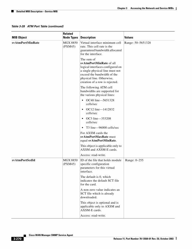
Chapter 3 Accessing the Network and Service MIBsDetailed MIB Description—Service MIB
svAtmPortMinRate MGX 8850 (PXM45)
Virtual interface minimum cell rate. This cell rate is the guaranteed bandwidth allocated for the interface.
The sum of svAtmPortMinRate of all logical interfaces configured on a single physical line must not exceed the bandwidth of the physical line. Otherwise, creation of a row is rejected.
The following ATM cell bandwidths are supported for the various physical lines:
• OC48 line—5651328 cells/sec
• OC12 line—1412832 cells/sec
• OC3 line—353208 cells/sec
• T3 line—96000 cells/sec
For AXSM cards the svAtmPortMaxRate must equal svAtmPortMinRate.
This object is applicable only to AXSM and AXSM-E cards.
Access: read-write.
Range: 50–5651328
svAtmPortScdId MGX 8850 (PXM45)
ID of the file that holds module specific configuration parameters for this virtual interface.
The default is 0, which indicates the default SCT file for the card.
A non-zero value indicates an SCT file which is already downloaded.
This object is optional and is applicable only to AXSM and AXSM-E cards.
Access: read-write.
Range: 0–255
Table 3-28 ATM Port Table (continued)
MIB ObjectRelated Node Types Description Values
3-270Cisco WAN Manager SNMP Service Agent
Release 11, Part Number 78-13569-01 Rev. E0, October 2003
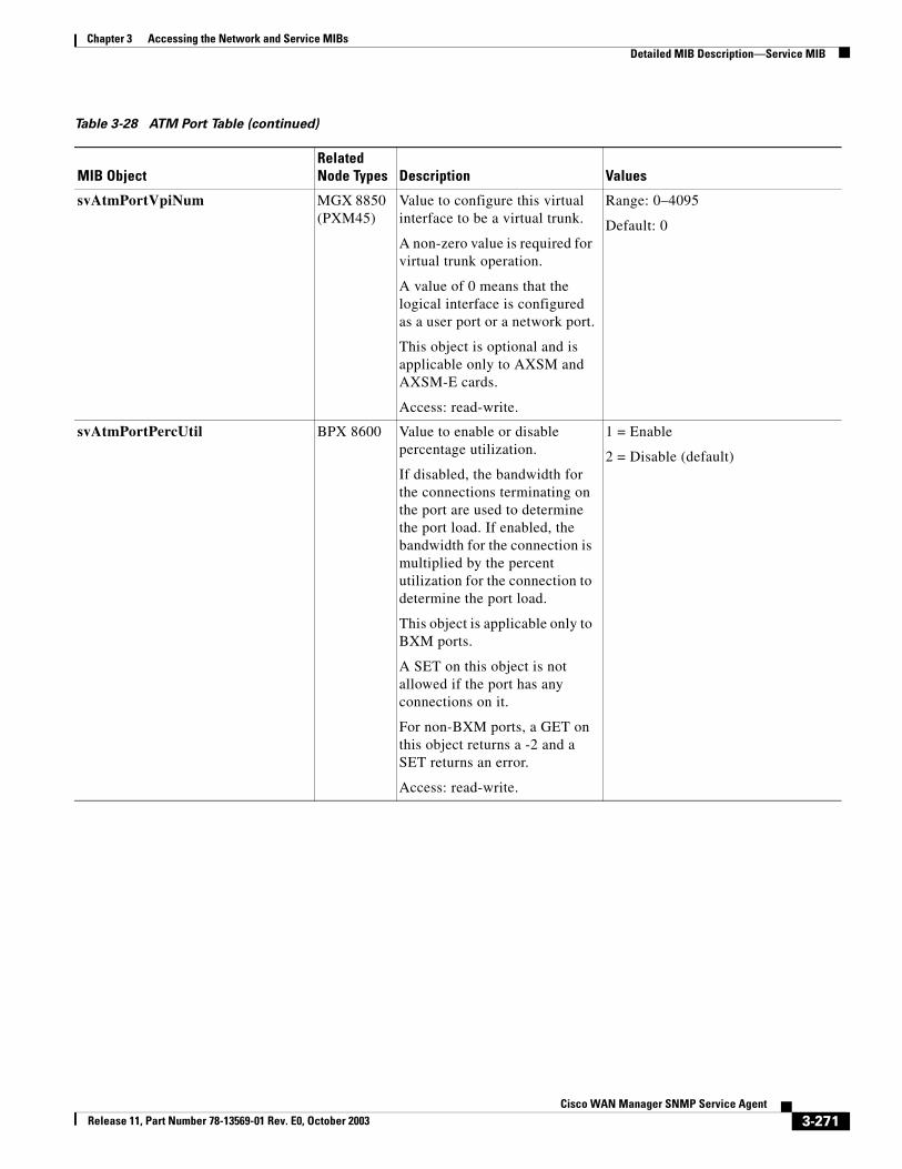
Chapter 3 Accessing the Network and Service MIBsDetailed MIB Description—Service MIB
svAtmPortVpiNum MGX 8850 (PXM45)
Value to configure this virtual interface to be a virtual trunk.
A non-zero value is required for virtual trunk operation.
A value of 0 means that the logical interface is configured as a user port or a network port.
This object is optional and is applicable only to AXSM and AXSM-E cards.
Access: read-write.
Range: 0–4095
Default: 0
svAtmPortPercUtil BPX 8600 Value to enable or disable percentage utilization.
If disabled, the bandwidth for the connections terminating on the port are used to determine the port load. If enabled, the bandwidth for the connection is multiplied by the percent utilization for the connection to determine the port load.
This object is applicable only to BXM ports.
A SET on this object is not allowed if the port has any connections on it.
For non-BXM ports, a GET on this object returns a -2 and a SET returns an error.
Access: read-write.
1 = Enable
2 = Disable (default)
Table 3-28 ATM Port Table (continued)
MIB ObjectRelated Node Types Description Values
3-271Cisco WAN Manager SNMP Service Agent
Release 11, Part Number 78-13569-01 Rev. E0, October 2003
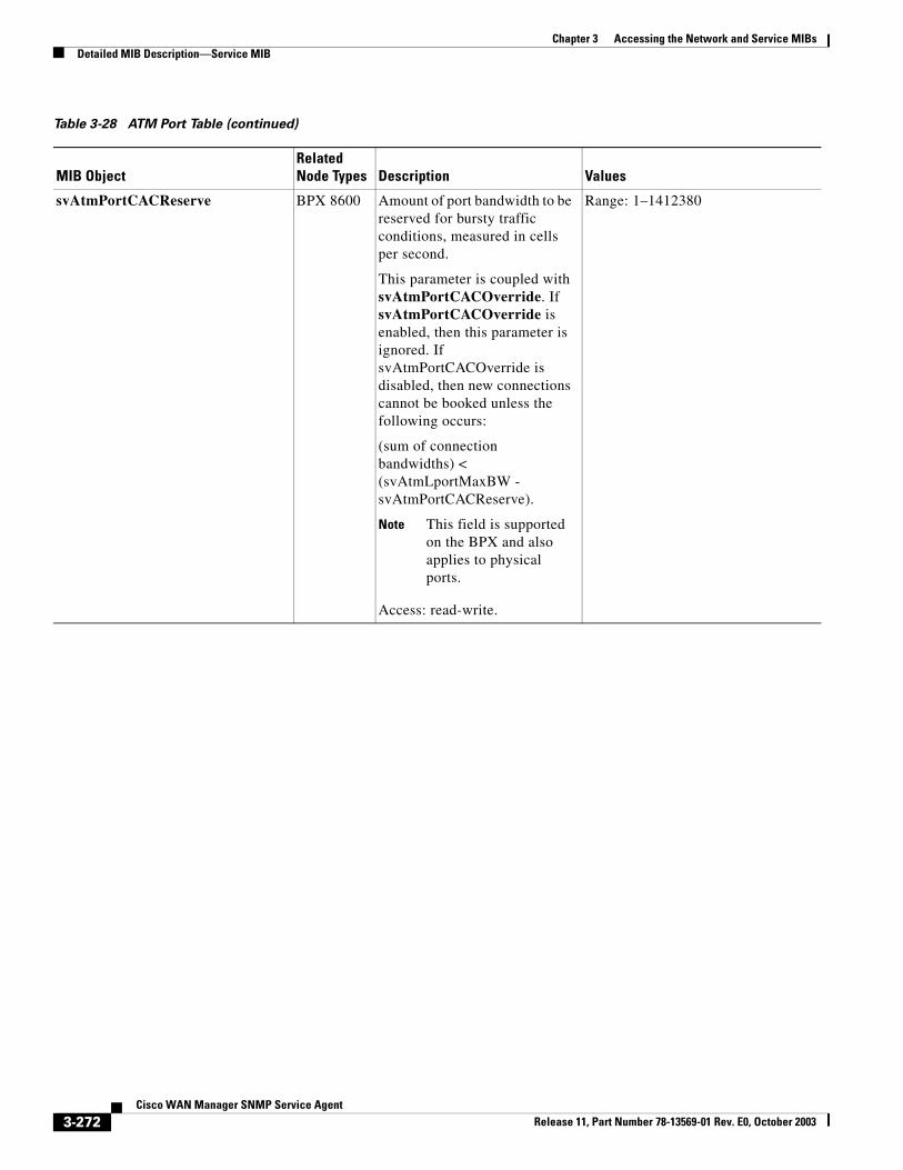
Chapter 3 Accessing the Network and Service MIBsDetailed MIB Description—Service MIB
svAtmPortCACReserve BPX 8600 Amount of port bandwidth to be reserved for bursty traffic conditions, measured in cells per second.
This parameter is coupled with svAtmPortCACOverride. If svAtmPortCACOverride is enabled, then this parameter is ignored. If svAtmPortCACOverride is disabled, then new connections cannot be booked unless the following occurs:
(sum of connection bandwidths) < (svAtmLportMaxBW - svAtmPortCACReserve).
Note This field is supported on the BPX and also applies to physical ports.
Access: read-write.
Range: 1–1412380
Table 3-28 ATM Port Table (continued)
MIB ObjectRelated Node Types Description Values
3-272Cisco WAN Manager SNMP Service Agent
Release 11, Part Number 78-13569-01 Rev. E0, October 2003
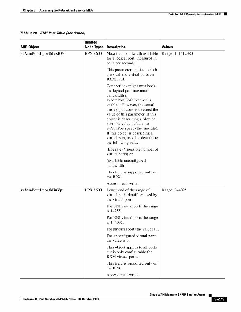
Chapter 3 Accessing the Network and Service MIBsDetailed MIB Description—Service MIB
svAtmPortLportMaxBW BPX 8600 Maximum bandwidth available for a logical port, measured in cells per second.
This parameter applies to both physical and virtual ports on BXM cards.
Connections might over book the logical port maximum bandwidth if svAtmPortCACOverride is enabled. However, the actual throughput does not exceed the value of this parameter. If this object is describing a physical port, the value defaults to svAtmPortSpeed (the line rate). If this object is describing a virtual port, its value defaults to the following value:
(line rate) / (possible number of virtual ports) or
(available unconfigured bandwidth)
This field is supported only on the BPX.
Access: read-write.
Range: 1–1412380
svAtmPortLportMinVpi BPX 8600 Lower end of the range of virtual path identifiers used by the virtual port.
For UNI virtual ports the range is 1–255.
For NNI virtual ports the range is 1–4095.
For physical ports the value is 1.
For unconfigured virtual ports the value is 0.
This object applies to all ports but is only configurable for BXM virtual ports.
This field is supported only on the BPX.
Access: read-write.
Range: 0–4095
Table 3-28 ATM Port Table (continued)
MIB ObjectRelated Node Types Description Values
3-273Cisco WAN Manager SNMP Service Agent
Release 11, Part Number 78-13569-01 Rev. E0, October 2003
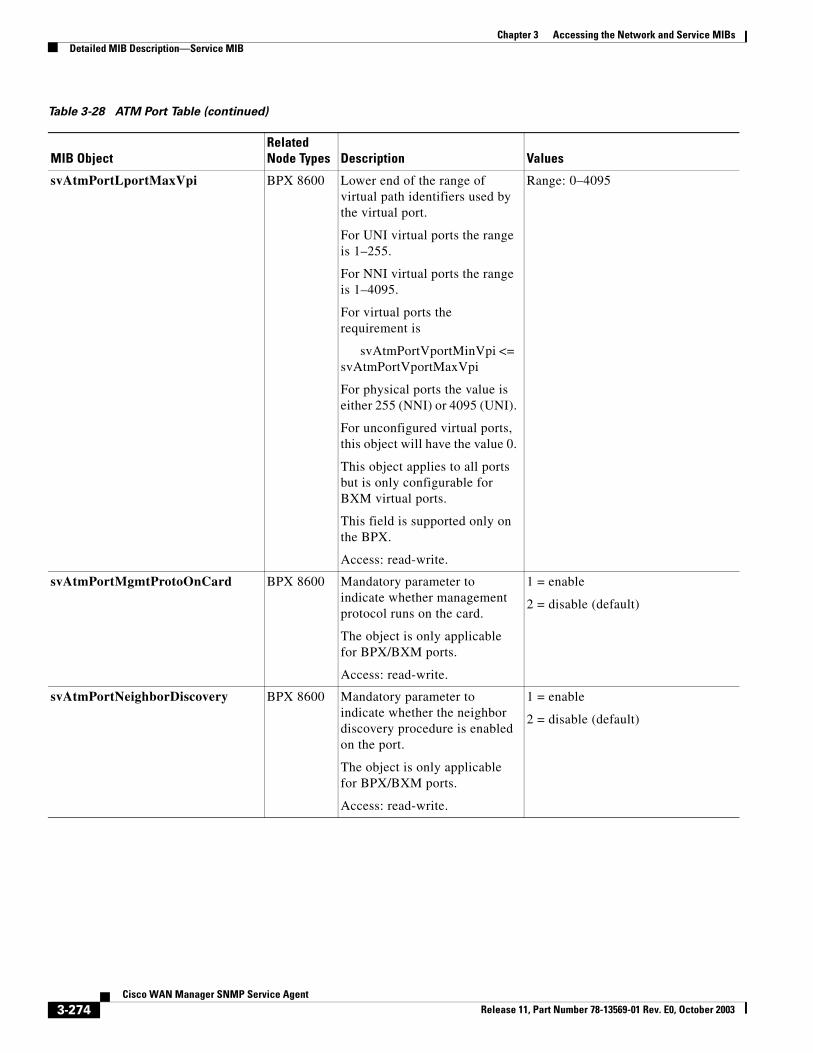
Chapter 3 Accessing the Network and Service MIBsDetailed MIB Description—Service MIB
svAtmPortLportMaxVpi BPX 8600 Lower end of the range of virtual path identifiers used by the virtual port.
For UNI virtual ports the range is 1–255.
For NNI virtual ports the range is 1–4095.
For virtual ports the requirement is
svAtmPortVportMinVpi <= svAtmPortVportMaxVpi
For physical ports the value is either 255 (NNI) or 4095 (UNI).
For unconfigured virtual ports, this object will have the value 0.
This object applies to all ports but is only configurable for BXM virtual ports.
This field is supported only on the BPX.
Access: read-write.
Range: 0–4095
svAtmPortMgmtProtoOnCard BPX 8600 Mandatory parameter to indicate whether management protocol runs on the card.
The object is only applicable for BPX/BXM ports.
Access: read-write.
1 = enable
2 = disable (default)
svAtmPortNeighborDiscovery BPX 8600 Mandatory parameter to indicate whether the neighbor discovery procedure is enabled on the port.
The object is only applicable for BPX/BXM ports.
Access: read-write.
1 = enable
2 = disable (default)
Table 3-28 ATM Port Table (continued)
MIB ObjectRelated Node Types Description Values
3-274Cisco WAN Manager SNMP Service Agent
Release 11, Part Number 78-13569-01 Rev. E0, October 2003
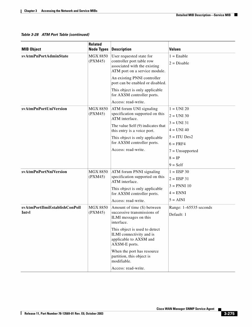
Chapter 3 Accessing the Network and Service MIBsDetailed MIB Description—Service MIB
svAtmPnPortAdminState MGX 8850 (PXM45)
User requested state for controller port table row associated with the existing ATM port on a service module.
An existing PNNI controller port can be enabled or disabled.
This object is only applicable for AXSM controller ports.
Access: read-write.
1 = Enable
2 = Disable
svAtmPnPortUniVersion MGX 8850 (PXM45)
ATM forum UNI signaling specification supported on this ATM interface.
The value Self (9) indicates that this entry is a voice port.
This object is only applicable for AXSM controller ports.
Access: read-write.
1 = UNI 20
2 = UNI 30
3 = UNI 31
4 = UNI 40
5 = ITU Des2
6 = FRF4
7 = Unsupported
8 = IP
9 = Self
svAtmPnPortNniVersion MGX 8850 (PXM45)
ATM forum PNNI signaling specification supported on this ATM interface.
This object is only applicable for AXSM controller ports.
Access: read-write.
1 = IISP 30
2 = IISP 31
3 = PNNI 10
4 = ENNI
5 = AINI
svAtmPortIlmiEstablishConPollIntvl
MGX 8850 (PXM45)
Amount of time (S) between successive transmissions of ILMI messages on this interface.
This object is used to detect ILMI connectivity and is applicable to AXSM and AXSM-E ports.
When the port has resource partition, this object is modifiable.
Access: read-write.
Range: 1–65535 seconds
Default: 1
Table 3-28 ATM Port Table (continued)
MIB ObjectRelated Node Types Description Values
3-275Cisco WAN Manager SNMP Service Agent
Release 11, Part Number 78-13569-01 Rev. E0, October 2003
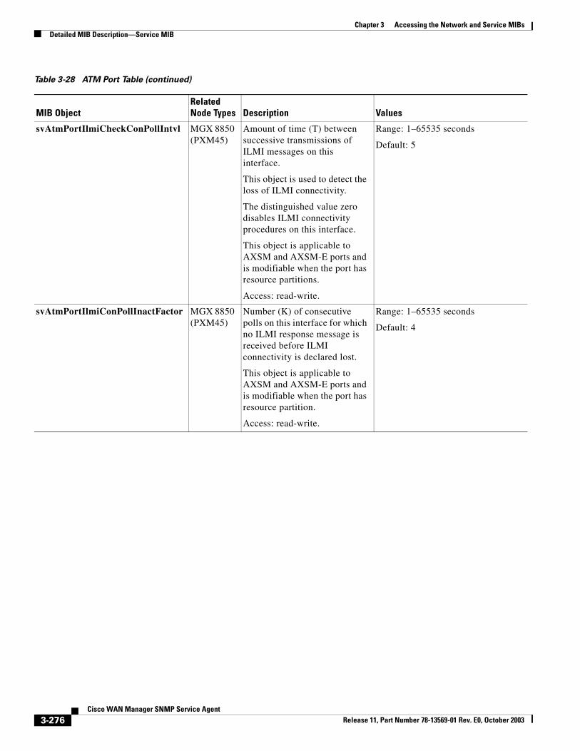
Chapter 3 Accessing the Network and Service MIBsDetailed MIB Description—Service MIB
svAtmPortIlmiCheckConPollIntvl MGX 8850 (PXM45)
Amount of time (T) between successive transmissions of ILMI messages on this interface.
This object is used to detect the loss of ILMI connectivity.
The distinguished value zero disables ILMI connectivity procedures on this interface.
This object is applicable to AXSM and AXSM-E ports and is modifiable when the port has resource partitions.
Access: read-write.
Range: 1–65535 seconds
Default: 5
svAtmPortIlmiConPollInactFactor MGX 8850 (PXM45)
Number (K) of consecutive polls on this interface for which no ILMI response message is received before ILMI connectivity is declared lost.
This object is applicable to AXSM and AXSM-E ports and is modifiable when the port has resource partition.
Access: read-write.
Range: 1–65535 seconds
Default: 4
Table 3-28 ATM Port Table (continued)
MIB ObjectRelated Node Types Description Values
3-276Cisco WAN Manager SNMP Service Agent
Release 11, Part Number 78-13569-01 Rev. E0, October 2003
Chapter 3 Accessing the Network and Service MIBsDetailed MIB Description—Service MIB
Access Methods
Community strings for accessing the objects in the CWM Service MIB are stored in the /usr/users/svplus/config/snmpd.cnf configuration file. The community strings are read during the CWM Service Agent start-up and cannot be dynamically changed during run time. The default value for SNMP GET and SNMP GETNext queries is public. The default value for SNMP SET requests is private.
This section contains the card specific requirements for configuring ports in the ATM Port table.
AUSM-4 Enable ATM Port
Use index svAtmPortPort = Physical Line number.
Specify:
• svAtmPortRowStatus = modify (Mandatory)
• svAtmPortAdminState = enable (Mandatory)
• svAtmPortType = atm-uni or atm-nni only (optional: Default = atm-uni)
AUSM-4 Modify ATM Port
Use index svAtmPortPort = Physical Line number.
Specify:
• svAtmPortRowStatus = modify (Mandatory)
Cannot change svAtmPortType.
AUSM-4 Disable ATM Port
Use index svAtmPortPort = Physical Line number.
Specify:
• svAtmPortRowStatus = modify (Mandatory)
• svAtmPortAdminState = disable (Mandatory)
AUSM-8 Create ATM Port
Use index svAtmPortPort = number gotten from the svNextLogicalPort table.
Specify:
• svAtmPortRowStatus = add (Mandatory)
• svAtmPortAssociatedLines = “<Line Number>” (Mandatory)
• svAtmPortType = atm-uni or atm-nni only (Mandatory)
3-277Cisco WAN Manager SNMP Service Agent
Release 11, Part Number 78-13569-01 Rev. E0, October 2003
Chapter 3 Accessing the Network and Service MIBsDetailed MIB Description—Service MIB
AUSM-8 Modify ATM Port
Use index svAtmPortPort = number used during Create.
Specify:
• svAtmPortRowStatus = modify (Mandatory)
Other attributes: Cannot change svAtmPortAssociatedLines or svAtmPortType.
AUSM-8 Delete ATM Port
Use index svAtmPortPort = number used during Create.
Specify:
• svAtmPortRowStatus = delete (Mandatory)
AUSM-8 Create IMA Port
Use index svAtmPortPort = number gotten from the svNextLogicalPort table.
Specify:
• svAtmPortRowStatus = add (Mandatory)
• svAtmPortAssociatedLines = “<Line1>.<Line2>.....” (Mandatory)
• svAtmPortMode = ima (Mandatory)
• svAtmPortType = atm-uni or atm-nni or atm-sti (Mandatory)
AUSM-8 Modify IMA Port
Use index svAtmPortPort = number used during Create.
Specify:
• svAtmPortRowStatus = modify (Mandatory)
Other attributes: Cannot change svAtmPortAssociatedLines, svAtmPortType, or svAtmPortMode.
AUSM-8 Delete IMA Port
Use index svAtmPortPort = number used during Create.
Specify:
• svAtmPortRowStatus = delete (Mandatory)
AUSM-8 Add lines IMA Port
Use index svAtmPortPort = number used during Create.
Specify:
• svAtmPortRowStatus = add-lines (Mandatory)
• svAtmPortAssociatedLines = string of lines to be added (Mandatory)
AUSM-8 Delete Lines IMA Port
Use index svAtmPortPort = number used during Create.
3-278Cisco WAN Manager SNMP Service Agent
Release 11, Part Number 78-13569-01 Rev. E0, October 2003
Chapter 3 Accessing the Network and Service MIBsDetailed MIB Description—Service MIB
Specify:
• svAtmPortRowStatus = del-lines (Mandatory)
• svAtmPortAssociatedLines = string of lines to be deleted (Mandatory)
IGX-UXM Create IMA Port
svAtmPortAdminState is not applicable.
svAtmImaPortMode can be "atm" or "ima"
Use index svAtmPortPort = Primary line group Line number.
IGX-UXM Modify IMA Port
Use index svAtmPortPort = Primary line group number.
Specify:
• svAtmPortRowStatus = modify (Mandatory)
Other attributes: Port parameters such as svAtmPortMinNumTxLinks and svAtmPortMinNumRxLinks
need to be equal. Any modification done to one of them should be done to the other at the same time.
IGX-UXM Delete IMA Port:
Use index svAtmPortPort = Primary line group number.
PXM-UNI Create ATM Port
Use index svAtmPortPort = number gotten from the svNextLogicalPort table.
Specify:
• svAtmPortRowStatus = add (Mandatory)
• svAtmPortAssociatedLines = “<Line Number>” (Mandatory)
• svAtmPortType must not be SET
PXM-UNI Modify ATM Port
Use index svAtmPortPort = number used during Create.
Specify:
• svAtmPortRowStatus = modify (Mandatory)
Other attributes: (Cannot change svAtmPortAssociatedLines or svAtmPortType.
PXM-UNI Delete ATM Port
Use index svAtmPortPort = number used during Create.
Specify:
• svAtmPortRowStatus = delete (Mandatory)
ASI and UXM Create ATM Port
"svAtmPortAdminState" is not applicable.
3-279Cisco WAN Manager SNMP Service Agent
Release 11, Part Number 78-13569-01 Rev. E0, October 2003
Chapter 3 Accessing the Network and Service MIBsDetailed MIB Description—Service MIB
"svAtmImaPortMode" is not writable and always has a value of "atm".
Use index svAtmPortPort = Physical Line number.
Specify:
• svAtmPortRowStatus = add (Mandatory)
• svAtmPortType = atm-uni or atm-nni only (Mandatory)
ASI and UXM Modify ATM Port
Use index svAtmPortPort = Physical Line number.
Specify:
• svAtmPortRowStatus = modify (Mandatory)
ASI and UXM Delete ATM Port
Use index svAtmPortPort = Physical Line number.
Specify:
• svAtmPortRowStatus = delete (Mandatory)
BXM Create ATM Port
svAtmPortAdminState is not applicable.
svAtmPortMode is not writable and always has a value of "atm".
svAtmPortPort is set between 1–120031 to support virtual ports.
For Physical Port, svAtmPortPort = Physical Line/Port Number.
For Virtual Port, svAtmPortPort = (Physical Port Num * 10000)+ (Virtual Port Num)
Specify:
• svAtmPortRowStatus = add (Mandatory)
• svAtmPortType = atm-uni or atm-nni only (Mandatory)
BXM Modify ATM Port
For Physical Port, svAtmPortPort = Physical Line/Port Number
For Virtual Port, svAtmPortPort = (Physical Port Num * 10000)
+ (Virtual Port Num)
Specify:
• svAtmPortRowStatus = modify (Mandatory)
BXM Delete ATM Port
For Physical Port, svAtmPortPort = Physical Line/Port Number
For Virtual Port, svAtmPortPort = (Physical Port Num * 10000) + (Virtual Port Num)
Specify:
• svAtmPortRowStatus = delete (Mandatory)
3-280Cisco WAN Manager SNMP Service Agent
Release 11, Part Number 78-13569-01 Rev. E0, October 2003
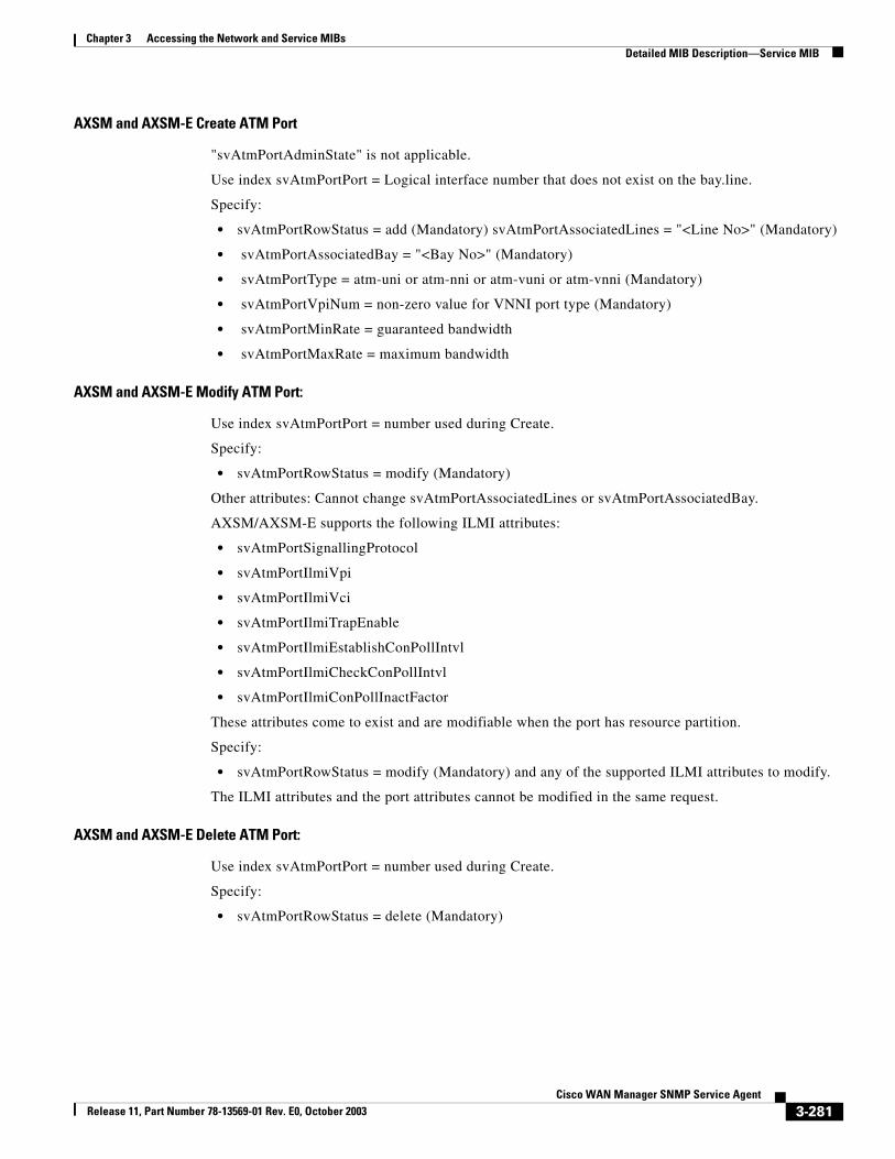
Chapter 3 Accessing the Network and Service MIBsDetailed MIB Description—Service MIB
AXSM and AXSM-E Create ATM Port
"svAtmPortAdminState" is not applicable.
Use index svAtmPortPort = Logical interface number that does not exist on the bay.line.
Specify:
• svAtmPortRowStatus = add (Mandatory) svAtmPortAssociatedLines = "<Line No>" (Mandatory)
• svAtmPortAssociatedBay = "<Bay No>" (Mandatory)
• svAtmPortType = atm-uni or atm-nni or atm-vuni or atm-vnni (Mandatory)
• svAtmPortVpiNum = non-zero value for VNNI port type (Mandatory)
• svAtmPortMinRate = guaranteed bandwidth
• svAtmPortMaxRate = maximum bandwidth
AXSM and AXSM-E Modify ATM Port:
Use index svAtmPortPort = number used during Create.
Specify:
• svAtmPortRowStatus = modify (Mandatory)
Other attributes: Cannot change svAtmPortAssociatedLines or svAtmPortAssociatedBay.
AXSM/AXSM-E supports the following ILMI attributes:
• svAtmPortSignallingProtocol
• svAtmPortIlmiVpi
• svAtmPortIlmiVci
• svAtmPortIlmiTrapEnable
• svAtmPortIlmiEstablishConPollIntvl
• svAtmPortIlmiCheckConPollIntvl
• svAtmPortIlmiConPollInactFactor
These attributes come to exist and are modifiable when the port has resource partition.
Specify:
• svAtmPortRowStatus = modify (Mandatory) and any of the supported ILMI attributes to modify.
The ILMI attributes and the port attributes cannot be modified in the same request.
AXSM and AXSM-E Delete ATM Port:
Use index svAtmPortPort = number used during Create.
Specify:
• svAtmPortRowStatus = delete (Mandatory)
3-281Cisco WAN Manager SNMP Service Agent
Release 11, Part Number 78-13569-01 Rev. E0, October 2003
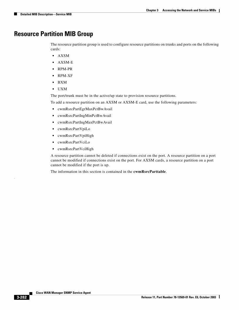
Chapter 3 Accessing the Network and Service MIBsDetailed MIB Description—Service MIB
Resource Partition MIB GroupThe resource partition group is used to configure resource partitions on trunks and ports on the following cards:
• AXSM
• AXSM-E
• RPM-PR
• RPM-XF
• BXM
• UXM
The port/trunk must be in the active/up state to provision resource partitions.
To add a resource partition on an AXSM or AXSM-E card, use the following parameters:
• cwmRsrcPartEgrMaxPctBwAvail
• cwmRsrcPartIngMinPctBwAvail
• cwmRsrcPartIngMaxPctBwAvail
• cwmRsrcPartVpiLo
• cwmRsrcPartVpiHigh
• cwmRsrcPartVciLo
• cwmRsrcPartVciHigh
A resource partition cannot be deleted if connections exist on the port. A resource partition on a port cannot be modified if connections exist on the port. For AXSM cards, a resource partition on a port cannot be modified if the port is up.
The information in this section is contained in the cwmRsrcParttable.
.
3-282Cisco WAN Manager SNMP Service Agent
Release 11, Part Number 78-13569-01 Rev. E0, October 2003
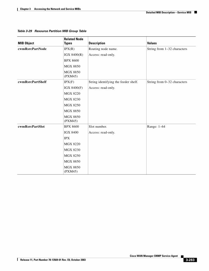
Chapter 3 Accessing the Network and Service MIBsDetailed MIB Description—Service MIB
Table 3-29 Resource Partition MIB Group Table
MIB ObjectRelated Node Types Description Values
cwmRsrcPartNode IPX(R)
IGX 8400(R)
BPX 8600
MGX 8850
MGX 8850 (PXM45)
Routing node name.
Access: read-only.
String from 1–32 characters
cwmRsrcPartShelf IPX(F)
IGX 8400(F)
MGX 8220
MGX 8230
MGX 8250
MGX 8850
MGX 8850 (PXM45)
String identifying the feeder shelf.
Access: read-only.
String from 0–32 characters
cwmRsrcPartSlot BPX 8600
IGX 8400
IPX
MGX 8220
MGX 8230
MGX 8250
MGX 8850
MGX 8850 (PXM45)
Slot number.
Access: read-only.
Range: 1–64
3-283Cisco WAN Manager SNMP Service Agent
Release 11, Part Number 78-13569-01 Rev. E0, October 2003
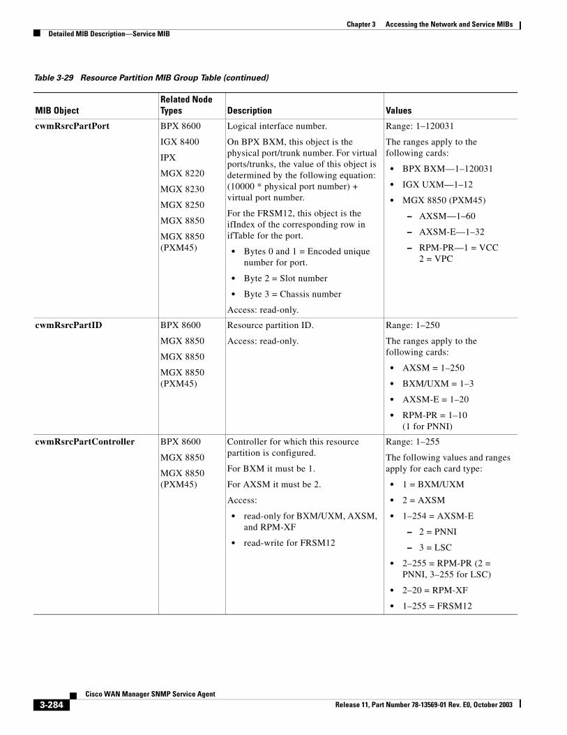
Chapter 3 Accessing the Network and Service MIBsDetailed MIB Description—Service MIB
cwmRsrcPartPort BPX 8600
IGX 8400
IPX
MGX 8220
MGX 8230
MGX 8250
MGX 8850
MGX 8850 (PXM45)
Logical interface number.
On BPX BXM, this object is the physical port/trunk number. For virtual ports/trunks, the value of this object is determined by the following equation: (10000 * physical port number) + virtual port number.
For the FRSM12, this object is the ifIndex of the corresponding row in ifTable for the port.
• Bytes 0 and 1 = Encoded unique number for port.
• Byte 2 = Slot number
• Byte 3 = Chassis number
Access: read-only.
Range: 1–120031
The ranges apply to the following cards:
• BPX BXM—1–120031
• IGX UXM—1–12
• MGX 8850 (PXM45)
– AXSM—1–60
– AXSM-E—1–32
– RPM-PR—1 = VCC2 = VPC
cwmRsrcPartID BPX 8600
MGX 8850
MGX 8850
MGX 8850 (PXM45)
Resource partition ID.
Access: read-only.
Range: 1–250
The ranges apply to the following cards:
• AXSM = 1–250
• BXM/UXM = 1–3
• AXSM-E = 1–20
• RPM-PR = 1–10 (1 for PNNI)
cwmRsrcPartController BPX 8600
MGX 8850
MGX 8850 (PXM45)
Controller for which this resource partition is configured.
For BXM it must be 1.
For AXSM it must be 2.
Access:
• read-only for BXM/UXM, AXSM, and RPM-XF
• read-write for FRSM12
Range: 1–255
The following values and ranges apply for each card type:
• 1 = BXM/UXM
• 2 = AXSM
• 1–254 = AXSM-E
– 2 = PNNI
– 3 = LSC
• 2–255 = RPM-PR (2 = PNNI, 3–255 for LSC)
• 2–20 = RPM-XF
• 1–255 = FRSM12
Table 3-29 Resource Partition MIB Group Table (continued)
MIB ObjectRelated Node Types Description Values
3-284Cisco WAN Manager SNMP Service Agent
Release 11, Part Number 78-13569-01 Rev. E0, October 2003
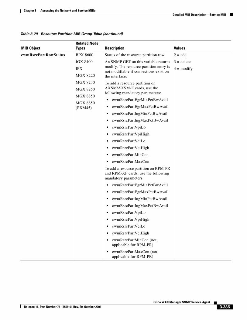
Chapter 3 Accessing the Network and Service MIBsDetailed MIB Description—Service MIB
cwmRsrcPartRowStatus BPX 8600
IGX 8400
IPX
MGX 8220
MGX 8230
MGX 8250
MGX 8850
MGX 8850 (PXM45)
Status of the resource partition row.
An SNMP GET on this variable returns modify. The resource partition entry is not modifiable if connections exist on the interface.
To add a resource partition on AXSM/AXSM-E cards, use the following mandatory parameters:
• cwmRsrcPartEgrMinPctBwAvail
• cwmRsrcPartEgrMaxPctBwAvail
• cwmRsrcPartIngMinPctBwAvail
• cwmRsrcPartIngMaxPctBwAvail
• cwmRsrcPartVpiLo
• cwmRsrcPartVpiHigh
• cwmRsrcPartVciLo
• cwmRsrcPartVciHigh
• cwmRsrcPartMinCon
• cwmRsrcPartMaxCon
To add a resource partition on RPM-PR and RPM-XF cards, use the following mandatory parameters:
• cwmRsrcPartEgrMinPctBwAvail
• cwmRsrcPartEgrMaxPctBwAvail
• cwmRsrcPartIngMinPctBwAvail
• cwmRsrcPartIngMaxPctBwAvail
• cwmRsrcPartVpiLo
• cwmRsrcPartVpiHigh
• cwmRsrcPartVciLo
• cwmRsrcPartVciHigh
• cwmRsrcPartMinCon (not applicable for RPM-PR)
• cwmRsrcPartMaxCon (not applicable for RPM-PR)
2 = add
3 = delete
4 = modify
Table 3-29 Resource Partition MIB Group Table (continued)
MIB ObjectRelated Node Types Description Values
3-285Cisco WAN Manager SNMP Service Agent
Release 11, Part Number 78-13569-01 Rev. E0, October 2003
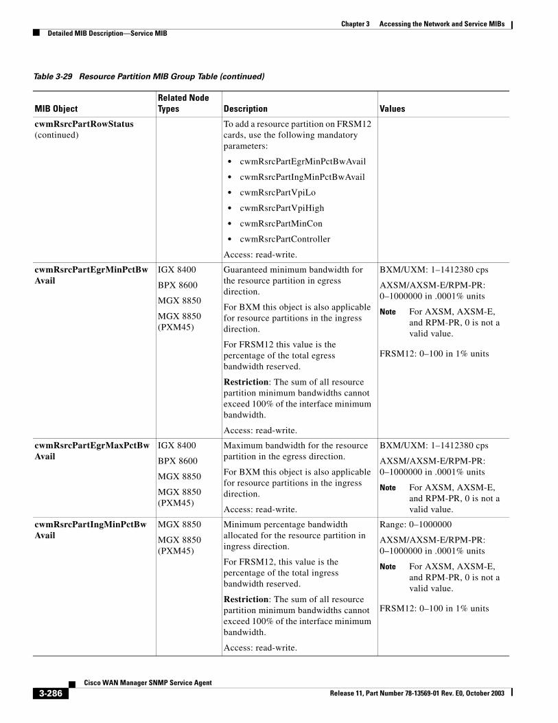
Chapter 3 Accessing the Network and Service MIBsDetailed MIB Description—Service MIB
cwmRsrcPartRowStatus (continued)
To add a resource partition on FRSM12 cards, use the following mandatory parameters:
• cwmRsrcPartEgrMinPctBwAvail
• cwmRsrcPartIngMinPctBwAvail
• cwmRsrcPartVpiLo
• cwmRsrcPartVpiHigh
• cwmRsrcPartMinCon
• cwmRsrcPartController
Access: read-write.
cwmRsrcPartEgrMinPctBwAvail
IGX 8400
BPX 8600
MGX 8850
MGX 8850 (PXM45)
Guaranteed minimum bandwidth for the resource partition in egress direction.
For BXM this object is also applicable for resource partitions in the ingress direction.
For FRSM12 this value is the percentage of the total egress bandwidth reserved.
Restriction: The sum of all resource partition minimum bandwidths cannot exceed 100% of the interface minimum bandwidth.
Access: read-write.
BXM/UXM: 1–1412380 cps
AXSM/AXSM-E/RPM-PR: 0–1000000 in .0001% units
Note For AXSM, AXSM-E, and RPM-PR, 0 is not a valid value.
FRSM12: 0–100 in 1% units
cwmRsrcPartEgrMaxPctBwAvail
IGX 8400
BPX 8600
MGX 8850
MGX 8850 (PXM45)
Maximum bandwidth for the resource partition in the egress direction.
For BXM this object is also applicable for resource partitions in the ingress direction.
Access: read-write.
BXM/UXM: 1–1412380 cps
AXSM/AXSM-E/RPM-PR: 0–1000000 in .0001% units
Note For AXSM, AXSM-E, and RPM-PR, 0 is not a valid value.
cwmRsrcPartIngMinPctBwAvail
MGX 8850
MGX 8850 (PXM45)
Minimum percentage bandwidth allocated for the resource partition in ingress direction.
For FRSM12, this value is the percentage of the total ingress bandwidth reserved.
Restriction: The sum of all resource partition minimum bandwidths cannot exceed 100% of the interface minimum bandwidth.
Access: read-write.
Range: 0–1000000
AXSM/AXSM-E/RPM-PR: 0–1000000 in .0001% units
Note For AXSM, AXSM-E, and RPM-PR, 0 is not a valid value.
FRSM12: 0–100 in 1% units
Table 3-29 Resource Partition MIB Group Table (continued)
MIB ObjectRelated Node Types Description Values
3-286Cisco WAN Manager SNMP Service Agent
Release 11, Part Number 78-13569-01 Rev. E0, October 2003
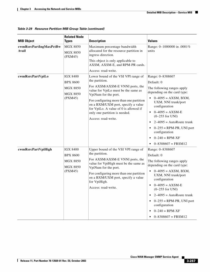
Chapter 3 Accessing the Network and Service MIBsDetailed MIB Description—Service MIB
cwmRsrcPartIngMaxPctBwAvail
MGX 8850
MGX 8850 (PXM45)
Maximum percentage bandwidth allocated for the resource partition in ingress direction.
This object is only applicable to AXSM, AXSM-E, and RPM-PR cards.
Access: read-write.
Range: 0–1000000 in .0001% units
cwmRsrcPartVpiLo IGX 8400
BPX 8600
MGX 8850
MGX 8850 (PXM45)
Lower bound of the VSI VPI range of the partition.
For AXSM/AXSM-E VNNI ports, the value for VpiLo must be the same as VpiNum for the port.
For configuring more than one partition on a BXM/UXM port, specify a value for VpiLo. A value of 0 is allowed if only one partition is needed.
Access: read-write.
Range: 0–8388607
Default: 0
The following ranges apply depending on the card type:
• 0–4095 = AXSM, BXM, UXM, NNI trunk/port configuration
• 0–4095 = AXSM-E(0–255 for UNI)
• 2–4095 = AutoRoute trunk
• 0–255 = RPM-PR, UNI port configuration
• 0–240 = RPM-XF
• 0–8388607 = FRSM12
cwmRsrcPartVpiHigh IGX 8400
BPX 8600
MGX 8850
MGX 8850 (PXM45)
Upper bound of the VSI VPI range of the partition.
For AXSM/AXSM-E VNNI ports, the value for VpiHigh must be the same as VpiNum for the port.
For configuring more than one partition on a BXM/UXM port, specify a value for VpiHigh.
Access: read-write.
Range: 0–8388607
Default: 0
The following ranges apply depending on the card type:
• 0–4095 = AXSM, BXM, UXM, NNI trunk/port configuration
• 0–4095 = AXSM-E(0–255 for UNI)
• 2–4095 = AutoRoute trunk
• 0–255 = RPM-PR, UNI port configuration
• 0–240 = RPM-XF
• 0–8388607 = FRSM12
Table 3-29 Resource Partition MIB Group Table (continued)
MIB ObjectRelated Node Types Description Values
3-287Cisco WAN Manager SNMP Service Agent
Release 11, Part Number 78-13569-01 Rev. E0, October 2003
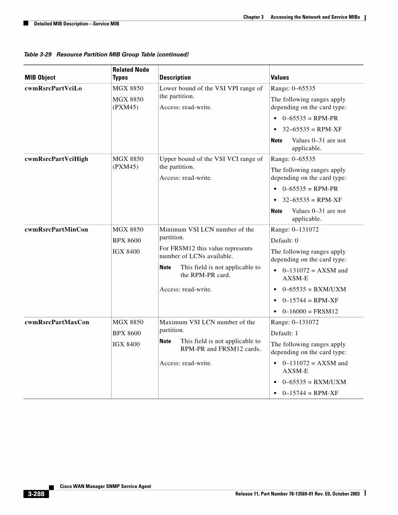
Chapter 3 Accessing the Network and Service MIBsDetailed MIB Description—Service MIB
cwmRsrcPartVciLo MGX 8850
MGX 8850 (PXM45)
Lower bound of the VSI VPI range of the partition.
Access: read-write.
Range: 0–65535
The following ranges apply depending on the card type:
• 0–65535 = RPM-PR
• 32–65535 = RPM-XF
Note Values 0–31 are not applicable.
cwmRsrcPartVciHigh MGX 8850 (PXM45)
Upper bound of the VSI VCI range of the partition.
Access: read-write.
Range: 0–65535
The following ranges apply depending on the card type:
• 0–65535 = RPM-PR
• 32–65535 = RPM-XF
Note Values 0–31 are not applicable.
cwmRsrcPartMinCon MGX 8850
BPX 8600
IGX 8400
Minimum VSI LCN number of the partition.
For FRSM12 this value represents number of LCNs available.
Note This field is not applicable to the RPM-PR card.
Access: read-write.
Range: 0–131072
Default: 0
The following ranges apply depending on the card type:
• 0–131072 = AXSM and AXSM-E
• 0–65535 = BXM/UXM
• 0–15744 = RPM-XF
• 0–16000 = FRSM12
cwmRsrcPartMaxCon MGX 8850
BPX 8600
IGX 8400
Maximum VSI LCN number of the partition.
Note This field is not applicable to RPM-PR and FRSM12 cards.
Access: read-write.
Range: 0–131072
Default: 1
The following ranges apply depending on the card type:
• 0–131072 = AXSM and AXSM-E
• 0–65535 = BXM/UXM
• 0–15744 = RPM-XF
Table 3-29 Resource Partition MIB Group Table (continued)
MIB ObjectRelated Node Types Description Values
3-288Cisco WAN Manager SNMP Service Agent
Release 11, Part Number 78-13569-01 Rev. E0, October 2003
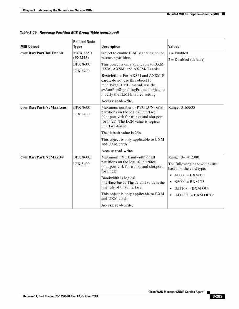
Chapter 3 Accessing the Network and Service MIBsDetailed MIB Description—Service MIB
cwmRsrcPartIlmiEnable MGX 8850 (PXM45)
BPX 8600
IGX 8400
Object to enable ILMI signaling on the resource partition.
This object is only applicable to BXM, UXM, AXSM, and AXSM-E cards.
Restriction: For AXSM and AXSM-E cards, do not use this object for modifying ILMI. Instead, use the svAtmPortSignallingProtocol object to modify the ILMI Enabled setting.
Access: read-write.
1 = Enabled
2 = Disabled (default)
cwmRsrcPartPvcMaxLcns BPX 8600
IGX 8400
Maximum number of PVC LCNs of all partitions on the logical interface (slot.port.vtrk for trunks and slot.port for lines). The LCN value is logical interface-based.
The default value is 256.
This object is only applicable to BXM and UXM cards.
Access: read-write.
Range: 0–65535
cwmRsrcPartPvcMaxBw BPX 8600
IGX 8400
Maximum PVC bandwidth of all partitions on the logical interface (slot.port.vtrk for trunks and slot.port for lines).
Bandwidth is logical interface-based.The default value is the line rate of this interface.
This object is only applicable to BXM and UXM cards.
Access: read-write.
Range: 0–1412380
The following bandwidths are based on the card type:
• 80000 = BXM E3
• 96000 = BXM T3
• 353208 = BXM OC3
• 1412830 = BXM OC12
Table 3-29 Resource Partition MIB Group Table (continued)
MIB ObjectRelated Node Types Description Values
3-289Cisco WAN Manager SNMP Service Agent
Release 11, Part Number 78-13569-01 Rev. E0, October 2003
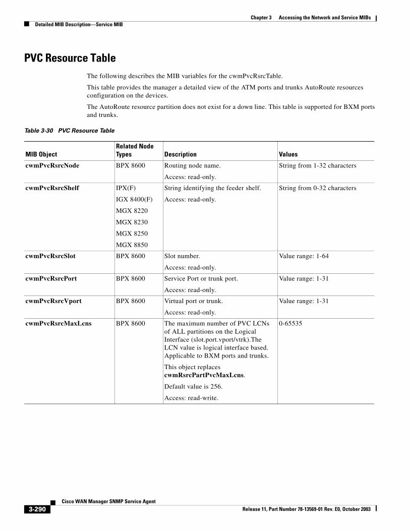
Chapter 3 Accessing the Network and Service MIBsDetailed MIB Description—Service MIB
PVC Resource TableThe following describes the MIB variables for the cwmPvcRsrcTable.
This table provides the manager a detailed view of the ATM ports and trunks AutoRoute resources configuration on the devices.
The AutoRoute resource partition does not exist for a down line. This table is supported for BXM ports and trunks.
Table 3-30 PVC Resource Table
MIB ObjectRelated Node Types Description Values
cwmPvcRsrcNode BPX 8600 Routing node name.
Access: read-only.
String from 1-32 characters
cwmPvcRsrcShelf IPX(F)
IGX 8400(F)
MGX 8220
MGX 8230
MGX 8250
MGX 8850
String identifying the feeder shelf.
Access: read-only.
String from 0-32 characters
cwmPvcRsrcSlot BPX 8600 Slot number.
Access: read-only.
Value range: 1-64
cwmPvcRsrcPort BPX 8600 Service Port or trunk port.
Access: read-only.
Value range: 1-31
cwmPvcRsrcVport BPX 8600 Virtual port or trunk.
Access: read-only.
Value range: 1-31
cwmPvcRsrcMaxLcns BPX 8600 The maximum number of PVC LCNs of ALL partitions on the Logical Interface (slot.port.vport/vtrk).The LCN value is logical interface based. Applicable to BXM ports and trunks.
This object replaces cwmRsrcPartPvcMaxLcns.
Default value is 256.
Access: read-write.
0-65535
3-290Cisco WAN Manager SNMP Service Agent
Release 11, Part Number 78-13569-01 Rev. E0, October 2003
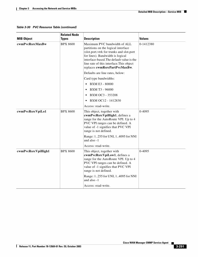
Chapter 3 Accessing the Network and Service MIBsDetailed MIB Description—Service MIB
cwmPvcRsrcMaxBw BPX 8600 Maximum PVC bandwidth of ALL partitions on the logical interface (slot.port.vtrk for trunks and slot.port for lines). Bandwidth is logical interface-based.The default value is the line rate of this interface.This object replaces cwmRsrcPartPvcMaxBw.
Defaults are line rates, below:
Card type bandwidths:
• BXM E3 - 80000
• BXM T3 - 96000
• BXM OC3 - 353208
• BXM OC12 - 1412830
Access: read-write.
0-1412380
cwmPvcRsrcVpiLo1 BPX 8600 This object, together with cwmPvcRsrcVpiHigh1, defines a range for the AutoRoute VPI. Up to 4 PVC VPI ranges can be defined. A value of -1 signifies that PVC VPI range is not defined.
Range: 1..255 for UNI, 1..4095 for NNI and also -1
Access: read-write.
0-4095
cwmPvcRsrcVpiHigh1 BPX 8600 This object, together with cwmPvcRsrcVpiLow1, defines a range for the AutoRoute VPI. Up to 4 PVC VPI ranges can be defined. A value of -1 signifies that PVC VPI range is not defined.
Range: 1..255 for UNI, 1..4095 for NNI and also -1
Access: read-write.
0-4095
Table 3-30 PVC Resource Table (continued)
MIB ObjectRelated Node Types Description Values
3-291Cisco WAN Manager SNMP Service Agent
Release 11, Part Number 78-13569-01 Rev. E0, October 2003
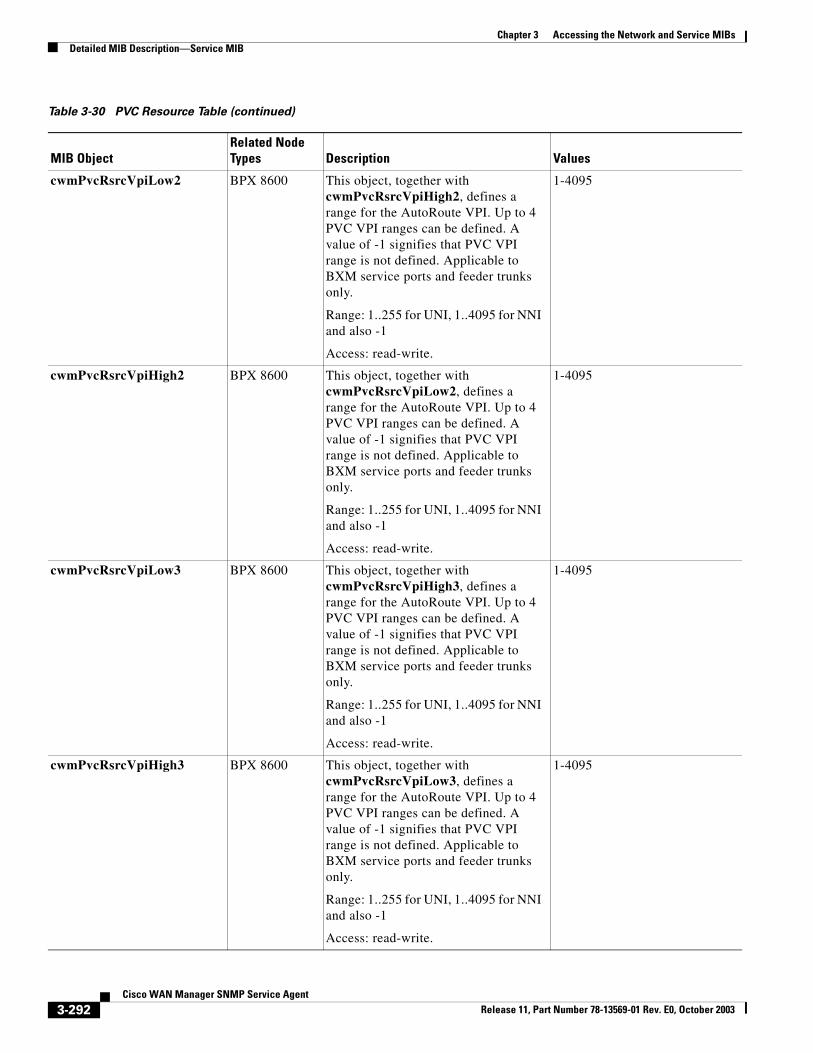
Chapter 3 Accessing the Network and Service MIBsDetailed MIB Description—Service MIB
cwmPvcRsrcVpiLow2 BPX 8600 This object, together with cwmPvcRsrcVpiHigh2, defines a range for the AutoRoute VPI. Up to 4 PVC VPI ranges can be defined. A value of -1 signifies that PVC VPI range is not defined. Applicable to BXM service ports and feeder trunks only.
Range: 1..255 for UNI, 1..4095 for NNI and also -1
Access: read-write.
1-4095
cwmPvcRsrcVpiHigh2 BPX 8600 This object, together with cwmPvcRsrcVpiLow2, defines a range for the AutoRoute VPI. Up to 4 PVC VPI ranges can be defined. A value of -1 signifies that PVC VPI range is not defined. Applicable to BXM service ports and feeder trunks only.
Range: 1..255 for UNI, 1..4095 for NNI and also -1
Access: read-write.
1-4095
cwmPvcRsrcVpiLow3 BPX 8600 This object, together with cwmPvcRsrcVpiHigh3, defines a range for the AutoRoute VPI. Up to 4 PVC VPI ranges can be defined. A value of -1 signifies that PVC VPI range is not defined. Applicable to BXM service ports and feeder trunks only.
Range: 1..255 for UNI, 1..4095 for NNI and also -1
Access: read-write.
1-4095
cwmPvcRsrcVpiHigh3 BPX 8600 This object, together with cwmPvcRsrcVpiLow3, defines a range for the AutoRoute VPI. Up to 4 PVC VPI ranges can be defined. A value of -1 signifies that PVC VPI range is not defined. Applicable to BXM service ports and feeder trunks only.
Range: 1..255 for UNI, 1..4095 for NNI and also -1
Access: read-write.
1-4095
Table 3-30 PVC Resource Table (continued)
MIB ObjectRelated Node Types Description Values
3-292Cisco WAN Manager SNMP Service Agent
Release 11, Part Number 78-13569-01 Rev. E0, October 2003
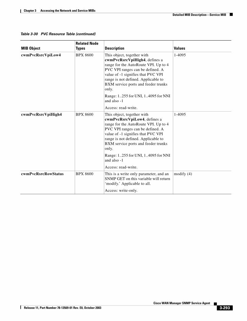
Chapter 3 Accessing the Network and Service MIBsDetailed MIB Description—Service MIB
cwmPvcRsrcVpiLow4 BPX 8600 This object, together with cwmPvcRsrcVpiHigh4, defines a range for the AutoRoute VPI. Up to 4 PVC VPI ranges can be defined. A value of -1 signifies that PVC VPI range is not defined. Applicable to BXM service ports and feeder trunks only.
Range: 1..255 for UNI, 1..4095 for NNI and also -1
Access: read-write.
1-4095
cwmPvcRsrcVpiHigh4 BPX 8600 This object, together with cwmPvcRsrcVpiLow4, defines a range for the AutoRoute VPI. Up to 4 PVC VPI ranges can be defined. A value of -1 signifies that PVC VPI range is not defined. Applicable to BXM service ports and feeder trunks only.
Range: 1..255 for UNI, 1..4095 for NNI and also -1
Access: read-write.
1-4095
cwmPvcRsrcRowStatus BPX 8600 This is a write only parameter, and an SNMP GET on this variable will return ‘modify.’ Applicable to all.
Access: write-only.
modify (4)
Table 3-30 PVC Resource Table (continued)
MIB ObjectRelated Node Types Description Values
3-293Cisco WAN Manager SNMP Service Agent
Release 11, Part Number 78-13569-01 Rev. E0, October 2003
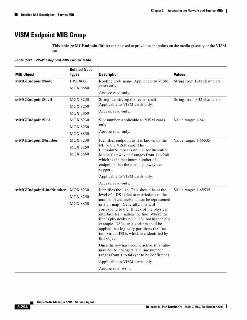
Chapter 3 Accessing the Network and Service MIBsDetailed MIB Description—Service MIB
VISM Endpoint MIB GroupThis table (svMGEndpointTable) can be used to provision endpoints on the media gateway or the VISM card.
Table 3-31 VISM Endpoint MIB Group Table
MIB ObjectRelated Node Types Description Values
svMGEndpointNode BPX 8600
MGX 8850
Routing node name. Applicable to VISM cards only.
Access: read-only.
String from 1-32 characters
svMGEndpointShelf MGX 8230
MGX 8250
MGX 8850
String identifying the feeder shelf. Applicable to VISM cards only.
Access: read-only.
String from 0-32 characters
svMGEndpointSlot MGX 8230
MGX 8250
MGX 8850
Slot number.Applicable to VISM cards only.
Access: read-only.
Value range: 1-64
svMGEndpointNumber MGX 8230
MGX 8250
MGX 8850
Identifies endpoint as it is known by the NE or the VISM card. The EndpointNumber is unique for the entire Media Gateway and ranges from 1 to 240 which is the maximum number of endpoints that the media gateway can support.
Applicable to VISM cards only.
Access: read-only.
Value range: 1-65535
svMGEndpointLineNumber MGX 8230
MGX 8250
MGX 8850
Identifies the line. This should be at the level of a DS1 (due to restrictions to the number of channels that can be represented in a bit map). Generally, this will correspond to the ifIndex of the physical interface terminating the line. Where the line is physically not a DS1 but higher (for example, DS3), an algorithm shall be applied that logically partitions the line into virtual DS1s which are identified by this object.
Once the row has become active, this value may not be changed. The line number ranges from 1 to 64 (yet to be confirmed).
Applicable to VISM cards only.
Access: read-write.
Value range: 1-65535
3-294Cisco WAN Manager SNMP Service Agent
Release 11, Part Number 78-13569-01 Rev. E0, October 2003
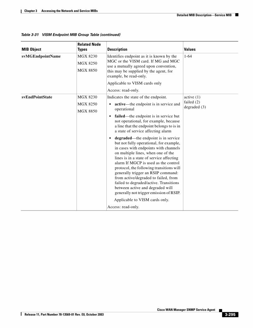
Chapter 3 Accessing the Network and Service MIBsDetailed MIB Description—Service MIB
svMGEndpointName MGX 8230
MGX 8250
MGX 8850
Identifies endpoint as it is known by the MGC or the VISM card. If MG and MGC use a mutually agreed upon convention, this may be supplied by the agent, for example, be read-only.
Applicable to VISM cards only
Access: read-only.
1-64
svEndPointState MGX 8230
MGX 8250
MGX 8850
Indicates the state of the endpoint.
• active—the endpoint is in service and operational
• failed—the endpoint is in service but not operational, for example, because a line that the endpoint belongs to is in a state of service affecting alarm
• degraded—the endpoint is in service but not fully operational, for example, in cases with endpoints with channels on multiple lines, when one of the lines is in a state of service affecting alarm If MGCP is used as the control protocol, the following transitions will generally trigger an RSIP command: from active/degraded to failed, from failed to degraded/active. Transitions between active and degraded will generally not trigger emission of RSIP.
Applicable to VISM cards only.
Access: read-only.
active (1)failed (2)degraded (3)
Table 3-31 VISM Endpoint MIB Group Table (continued)
MIB ObjectRelated Node Types Description Values
3-295Cisco WAN Manager SNMP Service Agent
Release 11, Part Number 78-13569-01 Rev. E0, October 2003
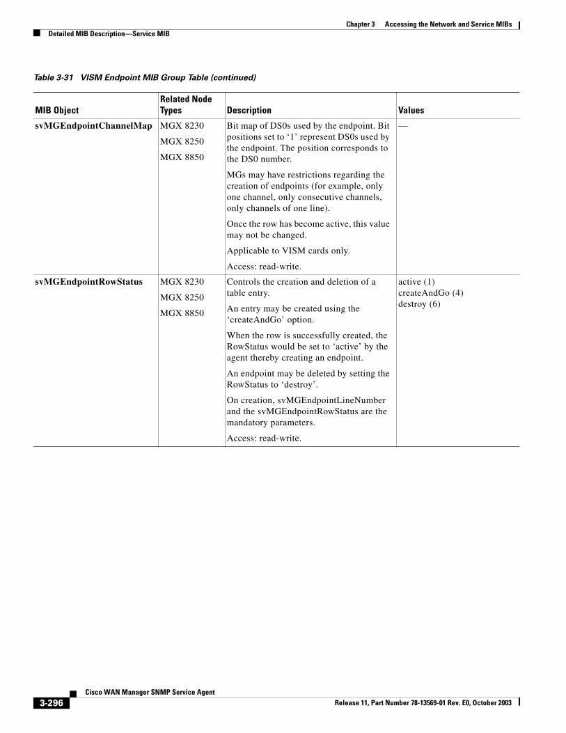
Chapter 3 Accessing the Network and Service MIBsDetailed MIB Description—Service MIB
svMGEndpointChannelMap MGX 8230
MGX 8250
MGX 8850
Bit map of DS0s used by the endpoint. Bit positions set to ‘1’ represent DS0s used by the endpoint. The position corresponds to the DS0 number.
MGs may have restrictions regarding the creation of endpoints (for example, only one channel, only consecutive channels, only channels of one line).
Once the row has become active, this value may not be changed.
Applicable to VISM cards only.
Access: read-write.
—
svMGEndpointRowStatus MGX 8230
MGX 8250
MGX 8850
Controls the creation and deletion of a table entry.
An entry may be created using the ‘createAndGo’ option.
When the row is successfully created, the RowStatus would be set to ‘active’ by the agent thereby creating an endpoint.
An endpoint may be deleted by setting the RowStatus to ‘destroy’.
On creation, svMGEndpointLineNumber and the svMGEndpointRowStatus are the mandatory parameters.
Access: read-write.
active (1)createAndGo (4)destroy (6)
Table 3-31 VISM Endpoint MIB Group Table (continued)
MIB ObjectRelated Node Types Description Values
3-296Cisco WAN Manager SNMP Service Agent
Release 11, Part Number 78-13569-01 Rev. E0, October 2003
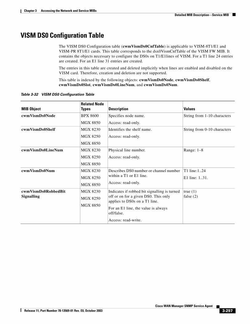
Chapter 3 Accessing the Network and Service MIBsDetailed MIB Description—Service MIB
VISM DS0 Configuration TableThe VISM DS0 Configuration table (cwmVismDs0CnfTable) is applicable to VISM-8T1/E1 and VISM-PR 8T1/E1 cards. This table corresponds to the dsx0VismCnfTable of the VISM FW MIB. It contains the objects necessary to configure the DS0s on T1/E1lines of VISM. For a T1 line 24 entries are created. For an E1 line 31 entries are created.
The entries in this table are created and deleted implicitly when lines are enabled and disabled on the VISM card. Therefore, creation and deletion are not supported.
This table is indexed by the following objects: cwmVismDs0Node, cwmVismDs0Shelf, cwmVismDs0Slot, cwmVismDs0LineNum, and cwmVismDs0Num.
Table 3-32 VISM DS0 Configuration Table
MIB ObjectRelated Node Types Description Values
cwmVismDs0Node BPX 8600
MGX 8850
Specifies node name.
Access: read-only.
String from 1-10 characters
cwmVismDs0Shelf MGX 8230
MGX 8250
MGX 8850
Identifies the shelf name.
Access: read-only.
String from 0-10 characters
cwmVismDs0LineNum MGX 8230
MGX 8250
MGX 8850
Physical line number.
Access: read-only.
Range: 1–8
cwmVismDs0Num MGX 8230
MGX 8250
MGX 8850
Describes DS0 number or channel number within a T1 or E1 line.
Access: read-only.
T1 line:1..24
E1 line: 1..31.
cwmVismDs0RobbedBitSignalling
MGX 8230
MGX 8250
MGX 8850
Indicates if robbed bit signalling is turned off or on for a given DS0. This only applies to DS0s on a T1 line.
For an E1 line, the value is always off/false.
Access: read-write.
true (1)false (2)
3-297Cisco WAN Manager SNMP Service Agent
Release 11, Part Number 78-13569-01 Rev. E0, October 2003
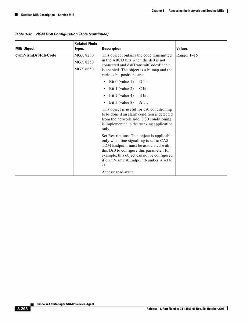
Chapter 3 Accessing the Network and Service MIBsDetailed MIB Description—Service MIB
cwmVismDs0IdleCode MGX 8230
MGX 8250
MGX 8850
This object contains the code transmitted in the ABCD bits when the ds0 is not connected and ds0TransmitCodesEnable is enabled. The object is a bitmap and the various bit positions are:
• Bit 0 (value 1) D bit
• Bit 1 (value 2) C bit
• Bit 2 (value 4) B bit
• Bit 3 (value 8) A bit
This object is useful for ds0 conditioning to be done if an alarm condition is detected from the network side. DS0 conditioning is implemented in the trunking application only.
Set Restrictions: This object is applicable only when line signalling is set to CAS. TDM Endpoint must be associated with this Ds0 to configure this parameter. for example, this object can not be configured if cwmVismDs0EndpointNumber is set to -1.
Access: read-write.
Range: 1–15
Table 3-32 VISM DS0 Configuration Table (continued)
MIB ObjectRelated Node Types Description Values
3-298Cisco WAN Manager SNMP Service Agent
Release 11, Part Number 78-13569-01 Rev. E0, October 2003
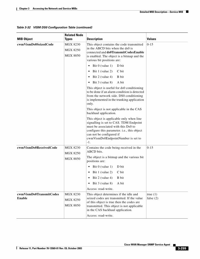
Chapter 3 Accessing the Network and Service MIBsDetailed MIB Description—Service MIB
cwmVismDs0SeizedCode MGX 8230
MGX 8250
MGX 8850
This object contains the code transmitted in the ABCD bits when the ds0 is connected and ds0TransmitCodesEnable is enabled. The object is a bitmap and the various bit positions are:
• Bit 0 (value 1) D bit
• Bit 1 (value 2) C bit
• Bit 2 (value 4) B bit
• Bit 3 (value 8) A bit
This object is useful for ds0 conditioning to be done if an alarm condition is detected from the network side. DS0 conditioning is implemented in the trunking application only.
This object is not applicable in the CAS backhaul application.
This object is applicable only when line signalling is set to CAS. TDM Endpoint must be associated with this Ds0 to configure this parameter. i.e., this object can not be configured if cwmVismDs0EndpointNumber is set to -1.
0-15
cwmVismDs0ReceivedCode MGX 8230
MGX 8250
MGX 8850
Contains the code being received in the ABCD bits.
The object is a bitmap and the various bit positions are:
• Bit 0 (value 1) D bit
• Bit 1 (value 2) C bit
• Bit 2 (value 4) B bit
• Bit 3 (value 8) A bit
Access: read-write.
0-15
cwmVismDs0TransmitCodesEnable
MGX 8230
MGX 8250
MGX 8850
This object determines if the idle and seized codes are transmitted. If the value of this object is true then the codes are transmitted. This object is not applicable in the CAS backhaul application.
Access: read-write.
true (1)false (2)
Table 3-32 VISM DS0 Configuration Table (continued)
MIB ObjectRelated Node Types Description Values
3-299Cisco WAN Manager SNMP Service Agent
Release 11, Part Number 78-13569-01 Rev. E0, October 2003
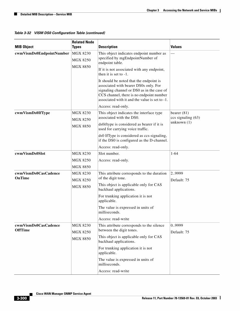
Chapter 3 Accessing the Network and Service MIBsDetailed MIB Description—Service MIB
cwmVismDs0EndpointNumber MGX 8230
MGX 8250
MGX 8850
This object indicates endpoint number as specified by mgEndpointNumber of endpoint table.
If it is not associated with any endpoint, then it is set to -1.
It should be noted that the endpoint is associated with bearer DS0s only. For signaling channel or DS0 as in the case of CCS channel, there is no endpoint number associated with it and the value is set to -1.
Access: read-only.
—
cwmVismDs0IfType MGX 8230
MGX 8250
MGX 8850
This object indicates the interface type associated with the DS0.
ds0iftype is considered as bearer if it is used for carrying voice traffic.
ds0 IfType is considered as ccs-signaling, if the DS0 is configured as the D-channel.
Access: read-only.
bearer (81)ccs signaling (63)unknown (1)
cwmVismDs0Slot MGX 8230
MGX 8250
MGX 8850
Slot number.
Access: read-only.
1-64
cwmVismDs0CasCadenceOnTime
MGX 8230
MGX 8250
MGX 8850
This attribute corresponds to the duration of the digit tone.
This object is applicable only for CAS backhaul applications.
For trunking application it is not applicable.
The value is expressed in units of milliseconds.
Access: read-write
2..9999
Default: 75
cwmVismDs0CasCadenceOffTime
MGX 8230
MGX 8250
MGX 8850
This attribute corresponds to the silence between the digit tones.
This object is applicable only for CAS backhaul applications.
For trunking application it is not applicable.
The value is expressed in units of milliseconds.
Access: read-write
0..9999
Default: 75
Table 3-32 VISM DS0 Configuration Table (continued)
MIB ObjectRelated Node Types Description Values
3-300Cisco WAN Manager SNMP Service Agent
Release 11, Part Number 78-13569-01 Rev. E0, October 2003
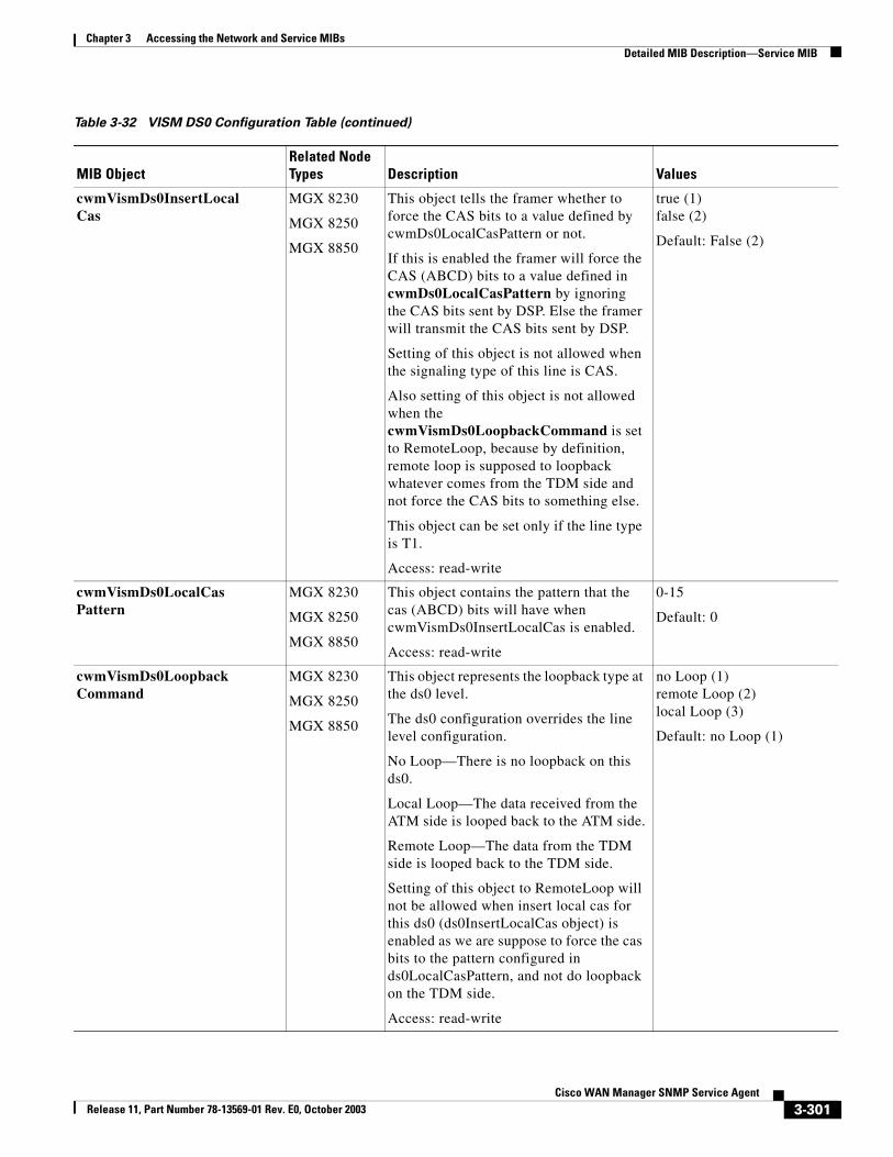
Chapter 3 Accessing the Network and Service MIBsDetailed MIB Description—Service MIB
cwmVismDs0InsertLocalCas
MGX 8230
MGX 8250
MGX 8850
This object tells the framer whether to force the CAS bits to a value defined by cwmDs0LocalCasPattern or not.
If this is enabled the framer will force the CAS (ABCD) bits to a value defined in cwmDs0LocalCasPattern by ignoring the CAS bits sent by DSP. Else the framer will transmit the CAS bits sent by DSP.
Setting of this object is not allowed when the signaling type of this line is CAS.
Also setting of this object is not allowed when the cwmVismDs0LoopbackCommand is set to RemoteLoop, because by definition, remote loop is supposed to loopback whatever comes from the TDM side and not force the CAS bits to something else.
This object can be set only if the line type is T1.
Access: read-write
true (1)false (2)
Default: False (2)
cwmVismDs0LocalCasPattern
MGX 8230
MGX 8250
MGX 8850
This object contains the pattern that the cas (ABCD) bits will have when cwmVismDs0InsertLocalCas is enabled.
Access: read-write
0-15
Default: 0
cwmVismDs0LoopbackCommand
MGX 8230
MGX 8250
MGX 8850
This object represents the loopback type at the ds0 level.
The ds0 configuration overrides the line level configuration.
No Loop—There is no loopback on this ds0.
Local Loop—The data received from the ATM side is looped back to the ATM side.
Remote Loop—The data from the TDM side is looped back to the TDM side.
Setting of this object to RemoteLoop will not be allowed when insert local cas for this ds0 (ds0InsertLocalCas object) is enabled as we are suppose to force the cas bits to the pattern configured in ds0LocalCasPattern, and not do loopback on the TDM side.
Access: read-write
no Loop (1)remote Loop (2)local Loop (3)
Default: no Loop (1)
Table 3-32 VISM DS0 Configuration Table (continued)
MIB ObjectRelated Node Types Description Values
3-301Cisco WAN Manager SNMP Service Agent
Release 11, Part Number 78-13569-01 Rev. E0, October 2003
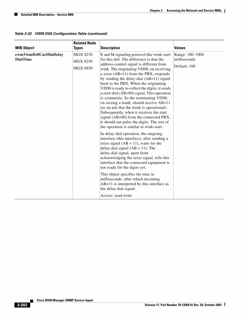
Chapter 3 Accessing the Network and Service MIBsDetailed MIB Description—Service MIB
cwmVismDs0CasMinDelayDialTime
MGX 8230
MGX 8250
MGX 8850
E and M signaling protocol like wink-start for this ds0. The difference is that the address-control signal is different from wink. The originating VISM, on receiving a seize (AB=11) from the PBX, responds by sending the delay-dial (AB=11) signal back to the PBX. When the originating VISM is ready to collect the digits, it sends a start-dial (AB=00) signal. This operation is symmetric. So the terminating VISM, on seizing a trunk, should receive AB=11 (as an ack that the trunk is operational). Subsequently, when it receives the start signal (AB=00) from the connected PBX, it should out pulse the digits. The rest of the operation is similar to wink-start.
In delay-dial operation, the outgoing interface (this interface), after sending a seize signal (AB = 11), waits for the delay-dial signal (AB = 11). The delay-dial signal, apart from acknowledging the seize signal, tells this interface that the connected equipment is not ready for the digits yet.
This object specifies the time in milliseconds, after which incoming AB=11 is interpreted by this interface as the delay-dial signal.
Access: read-write
Range: 100–1000 milliseconds
Default: 100
Table 3-32 VISM DS0 Configuration Table (continued)
MIB ObjectRelated Node Types Description Values
3-302Cisco WAN Manager SNMP Service Agent
Release 11, Part Number 78-13569-01 Rev. E0, October 2003
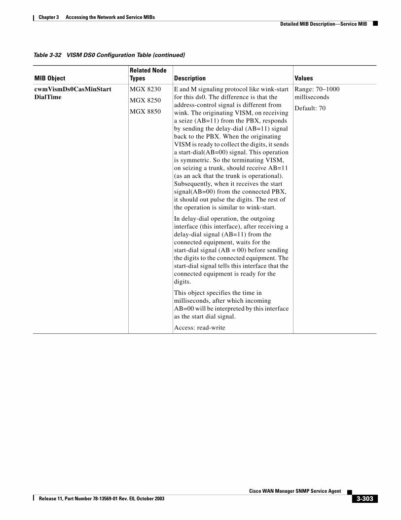
Chapter 3 Accessing the Network and Service MIBsDetailed MIB Description—Service MIB
cwmVismDs0CasMinStartDialTime
MGX 8230
MGX 8250
MGX 8850
E and M signaling protocol like wink-start for this ds0. The difference is that the address-control signal is different from wink. The originating VISM, on receiving a seize (AB=11) from the PBX, responds by sending the delay-dial (AB=11) signal back to the PBX. When the originating VISM is ready to collect the digits, it sends a start-dial(AB=00) signal. This operation is symmetric. So the terminating VISM, on seizing a trunk, should receive AB=11 (as an ack that the trunk is operational). Subsequently, when it receives the start signal(AB=00) from the connected PBX, it should out pulse the digits. The rest of the operation is similar to wink-start.
In delay-dial operation, the outgoing interface (this interface), after receiving a delay-dial signal (AB=11) from the connected equipment, waits for the start-dial signal (AB = 00) before sending the digits to the connected equipment. The start-dial signal tells this interface that the connected equipment is ready for the digits.
This object specifies the time in milliseconds, after which incoming AB=00 will be interpreted by this interface as the start dial signal.
Access: read-write
Range: 70–1000 milliseconds
Default: 70
Table 3-32 VISM DS0 Configuration Table (continued)
MIB ObjectRelated Node Types Description Values
3-303Cisco WAN Manager SNMP Service Agent
Release 11, Part Number 78-13569-01 Rev. E0, October 2003
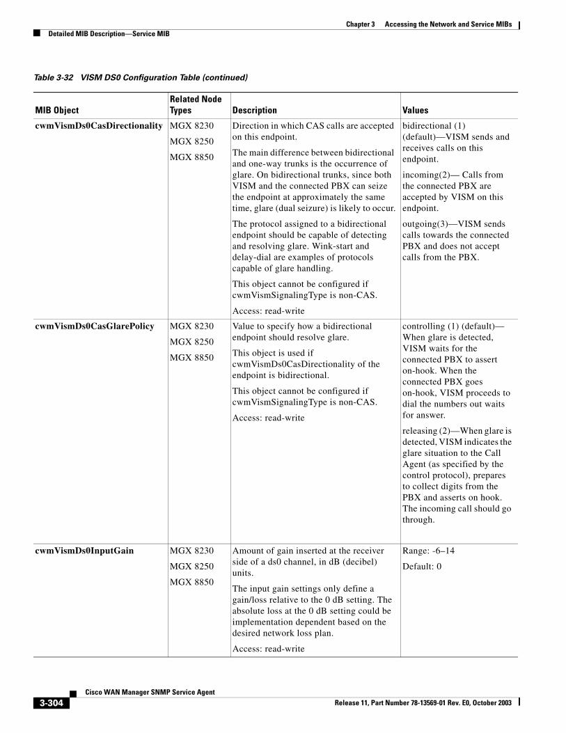
Chapter 3 Accessing the Network and Service MIBsDetailed MIB Description—Service MIB
cwmVismDs0CasDirectionality MGX 8230
MGX 8250
MGX 8850
Direction in which CAS calls are accepted on this endpoint.
The main difference between bidirectional and one-way trunks is the occurrence of glare. On bidirectional trunks, since both VISM and the connected PBX can seize the endpoint at approximately the same time, glare (dual seizure) is likely to occur.
The protocol assigned to a bidirectional endpoint should be capable of detecting and resolving glare. Wink-start and delay-dial are examples of protocols capable of glare handling.
This object cannot be configured if cwmVismSignalingType is non-CAS.
Access: read-write
bidirectional (1) (default)—VISM sends and receives calls on this endpoint.
incoming(2)— Calls from the connected PBX are accepted by VISM on this endpoint.
outgoing(3)—VISM sends calls towards the connected PBX and does not accept calls from the PBX.
cwmVismDs0CasGlarePolicy MGX 8230
MGX 8250
MGX 8850
Value to specify how a bidirectional endpoint should resolve glare.
This object is used if cwmVismDs0CasDirectionality of the endpoint is bidirectional.
This object cannot be configured if cwmVismSignalingType is non-CAS.
Access: read-write
controlling (1) (default)— When glare is detected, VISM waits for the connected PBX to assert on-hook. When the connected PBX goes on-hook, VISM proceeds to dial the numbers out waits for answer.
releasing (2)—When glare is detected, VISM indicates the glare situation to the Call Agent (as specified by the control protocol), prepares to collect digits from the PBX and asserts on hook. The incoming call should go through.
cwmVismDs0InputGain MGX 8230
MGX 8250
MGX 8850
Amount of gain inserted at the receiver side of a ds0 channel, in dB (decibel) units.
The input gain settings only define a gain/loss relative to the 0 dB setting. The absolute loss at the 0 dB setting could be implementation dependent based on the desired network loss plan.
Access: read-write
Range: -6–14
Default: 0
Table 3-32 VISM DS0 Configuration Table (continued)
MIB ObjectRelated Node Types Description Values
3-304Cisco WAN Manager SNMP Service Agent
Release 11, Part Number 78-13569-01 Rev. E0, October 2003
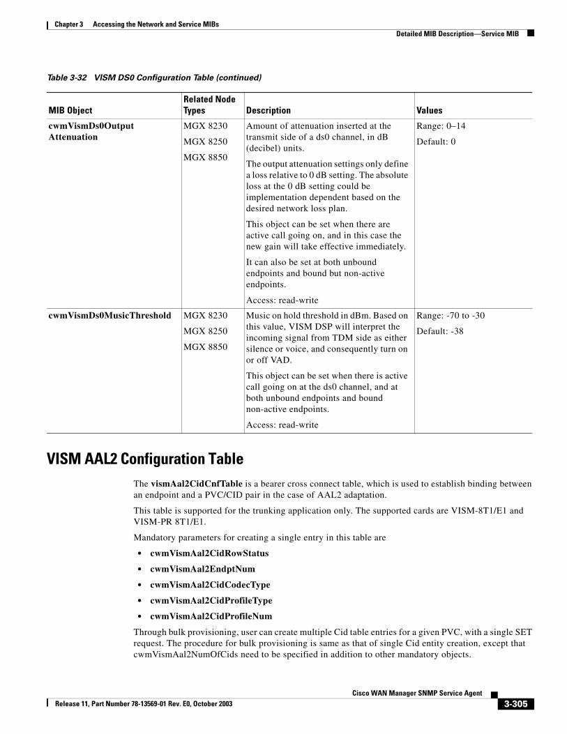
Chapter 3 Accessing the Network and Service MIBsDetailed MIB Description—Service MIB
VISM AAL2 Configuration TableThe vismAal2CidCnfTable is a bearer cross connect table, which is used to establish binding between an endpoint and a PVC/CID pair in the case of AAL2 adaptation.
This table is supported for the trunking application only. The supported cards are VISM-8T1/E1 and VISM-PR 8T1/E1.
Mandatory parameters for creating a single entry in this table are
• cwmVismAal2CidRowStatus
• cwmVismAal2EndptNum
• cwmVismAal2CidCodecType
• cwmVismAal2CidProfileType
• cwmVismAal2CidProfileNum
Through bulk provisioning, user can create multiple Cid table entries for a given PVC, with a single SET request. The procedure for bulk provisioning is same as that of single Cid entity creation, except that cwmVismAal2NumOfCids need to be specified in addition to other mandatory objects.
cwmVismDs0OutputAttenuation
MGX 8230
MGX 8250
MGX 8850
Amount of attenuation inserted at the transmit side of a ds0 channel, in dB (decibel) units.
The output attenuation settings only define a loss relative to 0 dB setting. The absolute loss at the 0 dB setting could be implementation dependent based on the desired network loss plan.
This object can be set when there are active call going on, and in this case the new gain will take effective immediately.
It can also be set at both unbound endpoints and bound but non-active endpoints.
Access: read-write
Range: 0–14
Default: 0
cwmVismDs0MusicThreshold MGX 8230
MGX 8250
MGX 8850
Music on hold threshold in dBm. Based on this value, VISM DSP will interpret the incoming signal from TDM side as either silence or voice, and consequently turn on or off VAD.
This object can be set when there is active call going on at the ds0 channel, and at both unbound endpoints and bound non-active endpoints.
Access: read-write
Range: -70 to -30
Default: -38
Table 3-32 VISM DS0 Configuration Table (continued)
MIB ObjectRelated Node Types Description Values
3-305Cisco WAN Manager SNMP Service Agent
Release 11, Part Number 78-13569-01 Rev. E0, October 2003
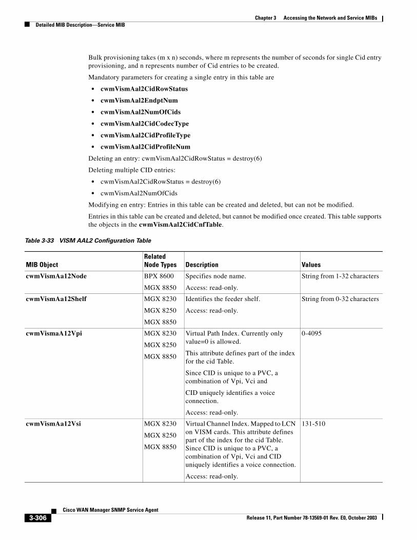
Chapter 3 Accessing the Network and Service MIBsDetailed MIB Description—Service MIB
Bulk provisioning takes (m x n) seconds, where m represents the number of seconds for single Cid entry provisioning, and n represents number of Cid entries to be created.
Mandatory parameters for creating a single entry in this table are
• cwmVismAal2CidRowStatus
• cwmVismAal2EndptNum
• cwmVismAal2NumOfCids
• cwmVismAal2CidCodecType
• cwmVismAal2CidProfileType
• cwmVismAal2CidProfileNum
Deleting an entry: cwmVismAal2CidRowStatus = destroy(6)
Deleting multiple CID entries:
• cwmVismAal2CidRowStatus = destroy(6)
• cwmVismAal2NumOfCids
Modifying en entry: Entries in this table can be created and deleted, but can not be modified.
Entries in this table can be created and deleted, but cannot be modified once created. This table supports the objects in the cwmVismAal2CidCnfTable.
Table 3-33 VISM AAL2 Configuration Table
MIB ObjectRelated Node Types Description Values
cwmVismAa12Node BPX 8600
MGX 8850
Specifies node name.
Access: read-only.
String from 1-32 characters
cwmVismAa12Shelf MGX 8230
MGX 8250
MGX 8850
Identifies the feeder shelf.
Access: read-only.
String from 0-32 characters
cwmVismaA12Vpi MGX 8230
MGX 8250
MGX 8850
Virtual Path Index. Currently only value=0 is allowed.
This attribute defines part of the index for the cid Table.
Since CID is unique to a PVC, a combination of Vpi, Vci and
CID uniquely identifies a voice connection.
Access: read-only.
0-4095
cwmVismAa12Vsi MGX 8230
MGX 8250
MGX 8850
Virtual Channel Index. Mapped to LCN on VISM cards. This attribute defines part of the index for the cid Table. Since CID is unique to a PVC, a combination of Vpi, Vci and CID uniquely identifies a voice connection.
Access: read-only.
131-510
3-306Cisco WAN Manager SNMP Service Agent
Release 11, Part Number 78-13569-01 Rev. E0, October 2003
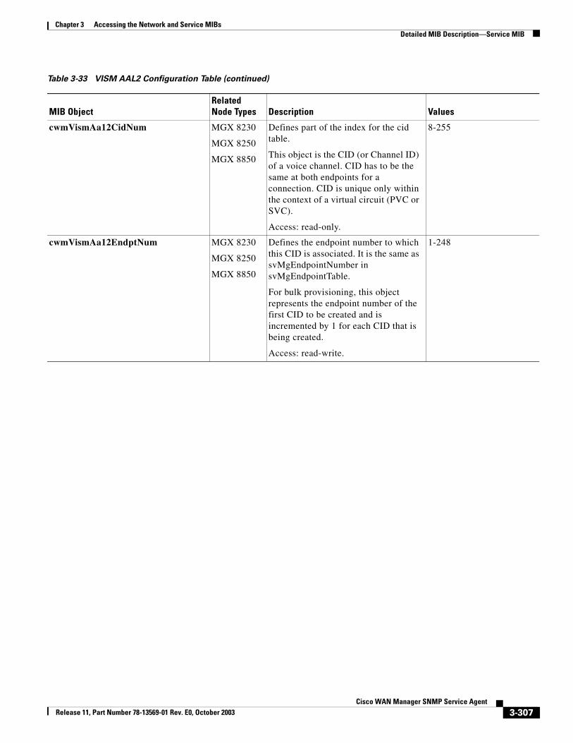
Chapter 3 Accessing the Network and Service MIBsDetailed MIB Description—Service MIB
cwmVismAa12CidNum MGX 8230
MGX 8250
MGX 8850
Defines part of the index for the cid table.
This object is the CID (or Channel ID) of a voice channel. CID has to be the same at both endpoints for a connection. CID is unique only within the context of a virtual circuit (PVC or SVC).
Access: read-only.
8-255
cwmVismAa12EndptNum MGX 8230
MGX 8250
MGX 8850
Defines the endpoint number to which this CID is associated. It is the same as svMgEndpointNumber in svMgEndpointTable.
For bulk provisioning, this object represents the endpoint number of the first CID to be created and is incremented by 1 for each CID that is being created.
Access: read-write.
1-248
Table 3-33 VISM AAL2 Configuration Table (continued)
MIB ObjectRelated Node Types Description Values
3-307Cisco WAN Manager SNMP Service Agent
Release 11, Part Number 78-13569-01 Rev. E0, October 2003
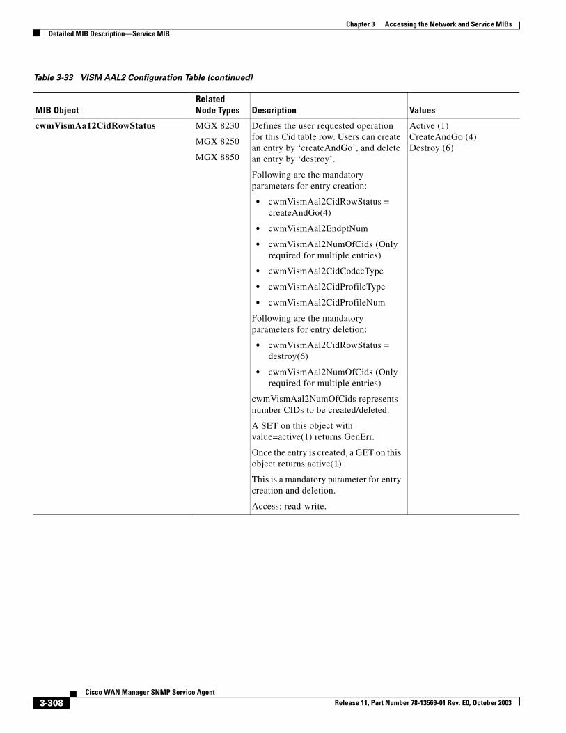
Chapter 3 Accessing the Network and Service MIBsDetailed MIB Description—Service MIB
cwmVismAa12CidRowStatus MGX 8230
MGX 8250
MGX 8850
Defines the user requested operation for this Cid table row. Users can create an entry by ‘createAndGo’, and delete an entry by ‘destroy’.
Following are the mandatory parameters for entry creation:
• cwmVismAal2CidRowStatus = createAndGo(4)
• cwmVismAal2EndptNum
• cwmVismAal2NumOfCids (Only required for multiple entries)
• cwmVismAal2CidCodecType
• cwmVismAal2CidProfileType
• cwmVismAal2CidProfileNum
Following are the mandatory parameters for entry deletion:
• cwmVismAal2CidRowStatus = destroy(6)
• cwmVismAal2NumOfCids (Only required for multiple entries)
cwmVismAal2NumOfCids represents number CIDs to be created/deleted.
A SET on this object with value=active(1) returns GenErr.
Once the entry is created, a GET on this object returns active(1).
This is a mandatory parameter for entry creation and deletion.
Access: read-write.
Active (1)CreateAndGo (4)Destroy (6)
Table 3-33 VISM AAL2 Configuration Table (continued)
MIB ObjectRelated Node Types Description Values
3-308Cisco WAN Manager SNMP Service Agent
Release 11, Part Number 78-13569-01 Rev. E0, October 2003
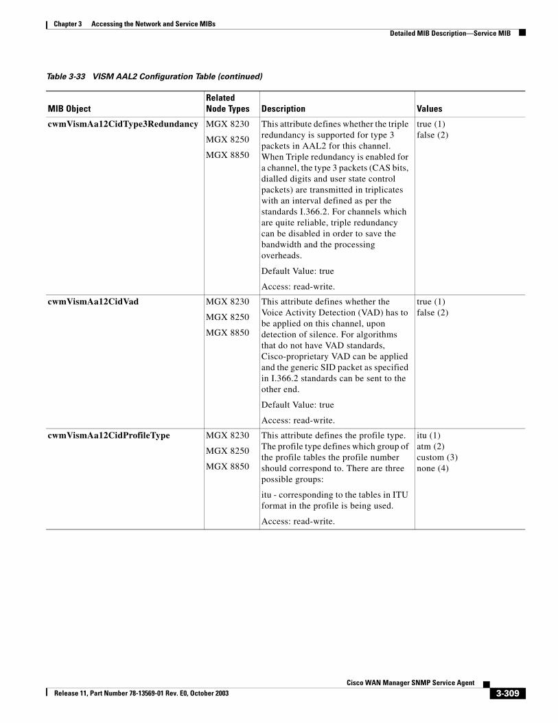
Chapter 3 Accessing the Network and Service MIBsDetailed MIB Description—Service MIB
cwmVismAa12CidType3Redundancy MGX 8230
MGX 8250
MGX 8850
This attribute defines whether the triple redundancy is supported for type 3 packets in AAL2 for this channel. When Triple redundancy is enabled for a channel, the type 3 packets (CAS bits, dialled digits and user state control packets) are transmitted in triplicates with an interval defined as per the standards I.366.2. For channels which are quite reliable, triple redundancy can be disabled in order to save the bandwidth and the processing overheads.
Default Value: true
Access: read-write.
true (1) false (2)
cwmVismAa12CidVad MGX 8230
MGX 8250
MGX 8850
This attribute defines whether the Voice Activity Detection (VAD) has to be applied on this channel, upon detection of silence. For algorithms that do not have VAD standards, Cisco-proprietary VAD can be applied and the generic SID packet as specified in I.366.2 standards can be sent to the other end.
Default Value: true
Access: read-write.
true (1)false (2)
cwmVismAa12CidProfileType MGX 8230
MGX 8250
MGX 8850
This attribute defines the profile type. The profile type defines which group of the profile tables the profile number should correspond to. There are three possible groups:
itu - corresponding to the tables in ITU format in the profile is being used.
Access: read-write.
itu (1)atm (2)custom (3)none (4)
Table 3-33 VISM AAL2 Configuration Table (continued)
MIB ObjectRelated Node Types Description Values
3-309Cisco WAN Manager SNMP Service Agent
Release 11, Part Number 78-13569-01 Rev. E0, October 2003
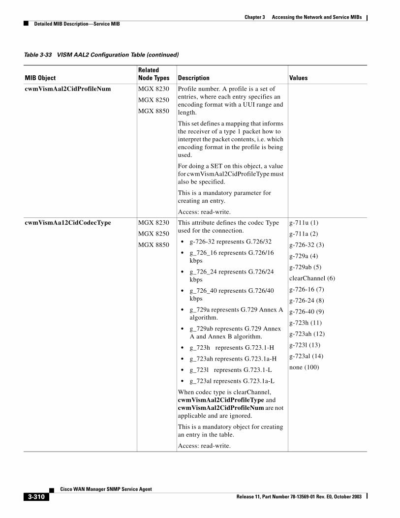
Chapter 3 Accessing the Network and Service MIBsDetailed MIB Description—Service MIB
cwmVismAal2CidProfileNum MGX 8230
MGX 8250
MGX 8850
Profile number. A profile is a set of entries, where each entry specifies an encoding format with a UUI range and length.
This set defines a mapping that informs the receiver of a type 1 packet how to interpret the packet contents, i.e. which encoding format in the profile is being used.
For doing a SET on this object, a value for cwmVismAal2CidProfileType must also be specified.
This is a mandatory parameter for creating an entry.
Access: read-write.
cwmVismAa12CidCodecType MGX 8230
MGX 8250
MGX 8850
This attribute defines the codec Type used for the connection.
• g-726-32 represents G.726/32
• g_726_16 represents G.726/16 kbps
• g_726_24 represents G.726/24 kbps
• g_726_40 represents G.726/40 kbps
• g_729a represents G.729 Annex A algorithm.
• g_729ab represents G.729 Annex A and Annex B algorithm.
• g_723h represents G.723.1-H
• g_723ah represents G.723.1a-H
• g_723l represents G.723.1-L
• g_723al represents G.723.1a-L
When codec type is clearChannel, cwmVismAal2CidProfileType and cwmVismAal2CidProfileNum are not applicable and are ignored.
This is a mandatory object for creating an entry in the table.
Access: read-write.
g-711u (1)
g-711a (2)
g-726-32 (3)
g-729a (4)
g-729ab (5)
clearChannel (6)
g-726-16 (7)
g-726-24 (8)
g-726-40 (9)
g-723h (11)
g-723ah (12)
g-723l (13)
g-723al (14)
none (100)
Table 3-33 VISM AAL2 Configuration Table (continued)
MIB ObjectRelated Node Types Description Values
3-310Cisco WAN Manager SNMP Service Agent
Release 11, Part Number 78-13569-01 Rev. E0, October 2003
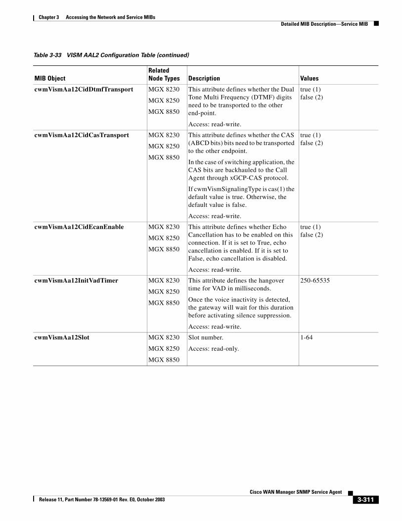
Chapter 3 Accessing the Network and Service MIBsDetailed MIB Description—Service MIB
cwmVismAa12CidDtmfTransport MGX 8230
MGX 8250
MGX 8850
This attribute defines whether the Dual Tone Multi Frequency (DTMF) digits need to be transported to the other end-point.
Access: read-write.
true (1)false (2)
cwmVismAa12CidCasTransport MGX 8230
MGX 8250
MGX 8850
This attribute defines whether the CAS (ABCD bits) bits need to be transported to the other endpoint.
In the case of switching application, the CAS bits are backhauled to the Call Agent through xGCP-CAS protocol.
If cwmVismSignalingType is cas(1) the default value is true. Otherwise, the default value is false.
Access: read-write.
true (1)false (2)
cwmVismAa12CidEcanEnable MGX 8230
MGX 8250
MGX 8850
This attribute defines whether Echo Cancellation has to be enabled on this connection. If it is set to True, echo cancellation is enabled. If it is set to False, echo cancellation is disabled.
Access: read-write.
true (1)false (2)
cwmVismAa12InitVadTimer MGX 8230
MGX 8250
MGX 8850
This attribute defines the hangover time for VAD in milliseconds.
Once the voice inactivity is detected, the gateway will wait for this duration before activating silence suppression.
Access: read-write.
250-65535
cwmVismAa12Slot MGX 8230
MGX 8250
MGX 8850
Slot number.
Access: read-only.
1-64
Table 3-33 VISM AAL2 Configuration Table (continued)
MIB ObjectRelated Node Types Description Values
3-311Cisco WAN Manager SNMP Service Agent
Release 11, Part Number 78-13569-01 Rev. E0, October 2003
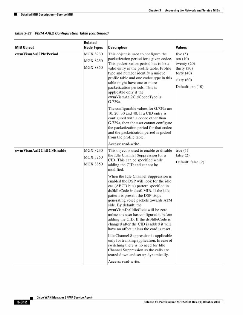
Chapter 3 Accessing the Network and Service MIBsDetailed MIB Description—Service MIB
cwmVismAal2PktPeriod MGX 8230
MGX 8250
MGX 8850
This object is used to configure the packetization period for a given codec. This packetization period has to be a valid entry in the profile table. Profile type and number identify a unique profile table and one codec type in this table might have one or more packetization periods. This is applicable only if the cwmVismAal2CidCodecType is G.729a.
The configurable values for G.729a are 10, 20, 30 and 40. If a CID entry is configured with a codec other than G.729a, then the user cannot configure the packetization period for that codec and the packetization period is picked from the profile table.
Access: read-write.
five (5)ten (10)twenty (20)thirty (30)forty (40)
sixty (60)
Default: ten (10)
cwmVismAal2CidICSEnable MGX 8230
MGX 8250
MGX 8850
This object is used to enable or disable the Idle Channel Suppression for a CID. This can be specified while adding the CID and cannot be modified.
When the Idle Channel Suppression is enabled the DSP will look for the idle cas (ABCD bits) pattern specified in ds0IdleCode in dsx0 MIB. If the idle pattern is present the DSP stops generating voice packets towards ATM side. By default, the cwmVismDs0IdleCode will be zero unless the user has configured it before adding the CID. If the ds0IdleCode is changed after the CID is added it will have no affect unless the card is reset.
Idle Channel Suppression is applicable only for trunking application. In case of switching there is no need for Idle Channel Suppression as the calls are teared down and set up dynamically.
Access: read-write.
true (1)false (2)
Default: false (2)
Table 3-33 VISM AAL2 Configuration Table (continued)
MIB ObjectRelated Node Types Description Values
3-312Cisco WAN Manager SNMP Service Agent
Release 11, Part Number 78-13569-01 Rev. E0, October 2003
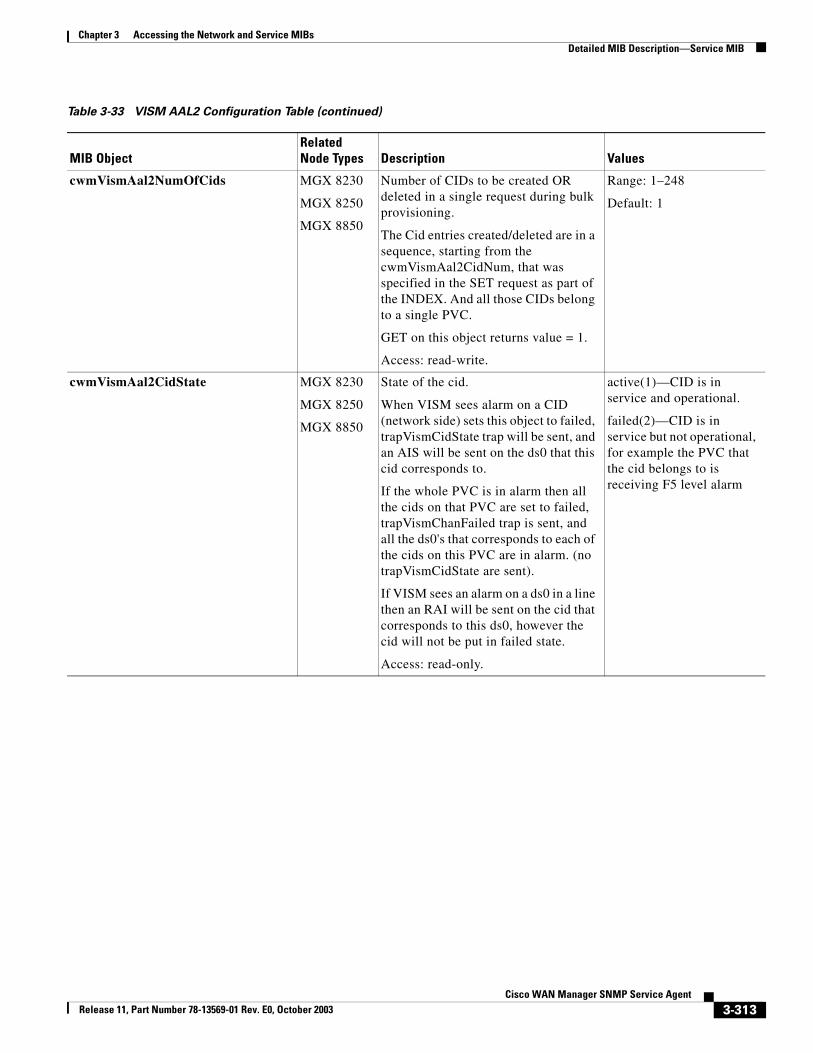
Chapter 3 Accessing the Network and Service MIBsDetailed MIB Description—Service MIB
cwmVismAal2NumOfCids MGX 8230
MGX 8250
MGX 8850
Number of CIDs to be created OR deleted in a single request during bulk provisioning.
The Cid entries created/deleted are in a sequence, starting from the cwmVismAal2CidNum, that was specified in the SET request as part of the INDEX. And all those CIDs belong to a single PVC.
GET on this object returns value = 1.
Access: read-write.
Range: 1–248
Default: 1
cwmVismAal2CidState MGX 8230
MGX 8250
MGX 8850
State of the cid.
When VISM sees alarm on a CID (network side) sets this object to failed, trapVismCidState trap will be sent, and an AIS will be sent on the ds0 that this cid corresponds to.
If the whole PVC is in alarm then all the cids on that PVC are set to failed, trapVismChanFailed trap is sent, and all the ds0's that corresponds to each of the cids on this PVC are in alarm. (no trapVismCidState are sent).
If VISM sees an alarm on a ds0 in a line then an RAI will be sent on the cid that corresponds to this ds0, however the cid will not be put in failed state.
Access: read-only.
active(1)—CID is in service and operational.
failed(2)—CID is in service but not operational, for example the PVC that the cid belongs to is receiving F5 level alarm
Table 3-33 VISM AAL2 Configuration Table (continued)
MIB ObjectRelated Node Types Description Values
3-313Cisco WAN Manager SNMP Service Agent
Release 11, Part Number 78-13569-01 Rev. E0, October 2003
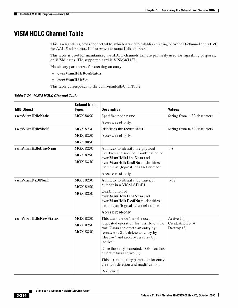
Chapter 3 Accessing the Network and Service MIBsDetailed MIB Description—Service MIB
VISM HDLC Channel TableThis is a signalling cross connect table, which is used to establish binding between D-channel and a PVC for AAL-5 adaptation. It also provides some Hdlc counters.
This table is used for maintaining the HDLC channels that are primarily used for signalling purposes, on VISM cards. The supported card is VISM-8T1/E1.
Mandatory parameters for creating an entry:
• cwmVismHdlcRowStatus
• cwmVismHdlcVci
This table corresponds to the cwmVismHdlcChanTable.
Table 3-34 VISM HDLC Channel Table
MIB ObjectRelated Node Types Description Values
cwmVismHdlcNode MGX 8850 Specifies node name.
Access: read-only.
String from 1-32 characters
cwmVismHdlcShelf MGX 8230
MGX 8250
MGX 8850
Identifies the feeder shelf.
Access: read-only.
String from 0-32 characters
cwmVismHdlcLineNum MGX 8230
MGX 8250
MGX 8850
An index to identify the physical interface and service. Combination of cwmVismHdlcLineNum and cwmVismHdlcDsx0Num identifies the unique (logical) channel number.
Access: read-only.
1-8
cwmVismDsx0Num MGX 8230
MGX 8250
MGX 8850
An index to identify the timeslot number in a VISM-8T1/E1.
Combination of cwmVismHdlcLineNum and cwmVismHdlcDsx0Num identifies the unique (logical) channel number.
Access: read-only.
1-32
cwmVismHdlcRowStatus MGX 8230
MGX 8250
MGX 8850
This attribute defines the user requested operation for this Hdlc table row. Users can create an entry by ‘createAndGo’, delete an entry by ‘destroy’ and modify an entry by ‘active’.
Once the entry is created, a GET on this object returns active (1).
This is a mandatory parameter for entry creation, deletion and modification.
Read-write
Active (1)CreateAndGo (4)Destroy (6)
3-314Cisco WAN Manager SNMP Service Agent
Release 11, Part Number 78-13569-01 Rev. E0, October 2003
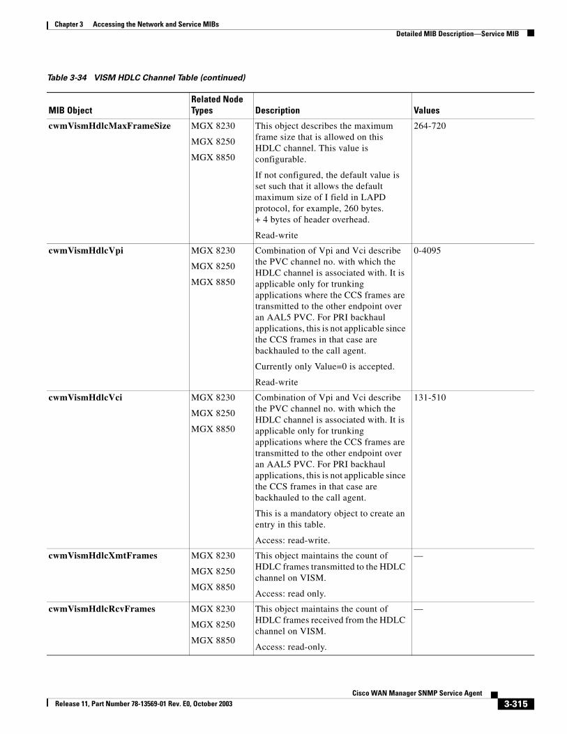
Chapter 3 Accessing the Network and Service MIBsDetailed MIB Description—Service MIB
cwmVismHdlcMaxFrameSize MGX 8230
MGX 8250
MGX 8850
This object describes the maximum frame size that is allowed on this HDLC channel. This value is configurable.
If not configured, the default value is set such that it allows the default maximum size of I field in LAPD protocol, for example, 260 bytes. + 4 bytes of header overhead.
Read-write
264-720
cwmVismHdlcVpi MGX 8230
MGX 8250
MGX 8850
Combination of Vpi and Vci describe the PVC channel no. with which the HDLC channel is associated with. It is applicable only for trunking applications where the CCS frames are transmitted to the other endpoint over an AAL5 PVC. For PRI backhaul applications, this is not applicable since the CCS frames in that case are backhauled to the call agent.
Currently only Value=0 is accepted.
Read-write
0-4095
cwmVismHdlcVci MGX 8230
MGX 8250
MGX 8850
Combination of Vpi and Vci describe the PVC channel no. with which the HDLC channel is associated with. It is applicable only for trunking applications where the CCS frames are transmitted to the other endpoint over an AAL5 PVC. For PRI backhaul applications, this is not applicable since the CCS frames in that case are backhauled to the call agent.
This is a mandatory object to create an entry in this table.
Access: read-write.
131-510
cwmVismHdlcXmtFrames MGX 8230
MGX 8250
MGX 8850
This object maintains the count of HDLC frames transmitted to the HDLC channel on VISM.
Access: read only.
—
cwmVismHdlcRcvFrames MGX 8230
MGX 8250
MGX 8850
This object maintains the count of HDLC frames received from the HDLC channel on VISM.
Access: read-only.
—
Table 3-34 VISM HDLC Channel Table (continued)
MIB ObjectRelated Node Types Description Values
3-315Cisco WAN Manager SNMP Service Agent
Release 11, Part Number 78-13569-01 Rev. E0, October 2003
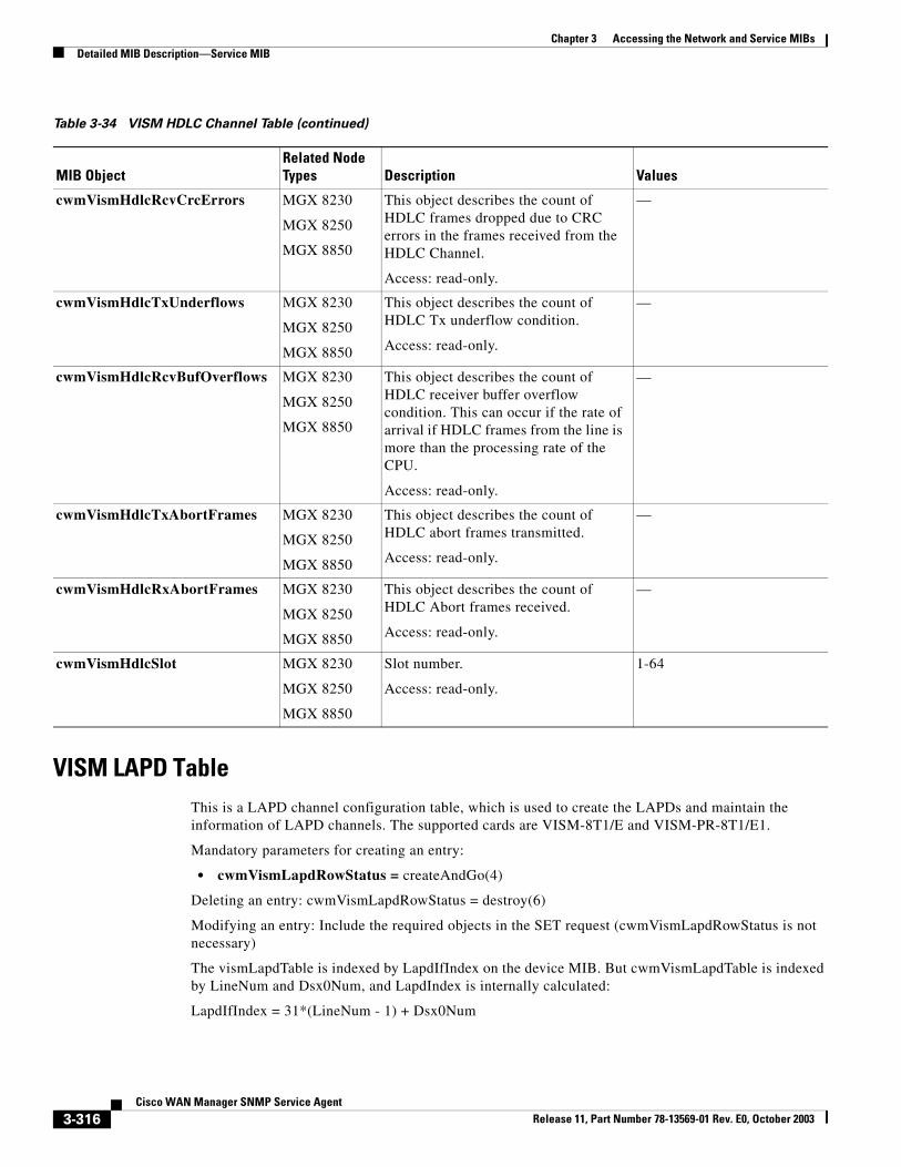
Chapter 3 Accessing the Network and Service MIBsDetailed MIB Description—Service MIB
VISM LAPD TableThis is a LAPD channel configuration table, which is used to create the LAPDs and maintain the information of LAPD channels. The supported cards are VISM-8T1/E and VISM-PR-8T1/E1.
Mandatory parameters for creating an entry:
• cwmVismLapdRowStatus = createAndGo(4)
Deleting an entry: cwmVismLapdRowStatus = destroy(6)
Modifying an entry: Include the required objects in the SET request (cwmVismLapdRowStatus is not necessary)
The vismLapdTable is indexed by LapdIfIndex on the device MIB. But cwmVismLapdTable is indexed by LineNum and Dsx0Num, and LapdIndex is internally calculated:
LapdIfIndex = 31*(LineNum - 1) + Dsx0Num
cwmVismHdlcRcvCrcErrors MGX 8230
MGX 8250
MGX 8850
This object describes the count of HDLC frames dropped due to CRC errors in the frames received from the HDLC Channel.
Access: read-only.
—
cwmVismHdlcTxUnderflows MGX 8230
MGX 8250
MGX 8850
This object describes the count of HDLC Tx underflow condition.
Access: read-only.
—
cwmVismHdlcRcvBufOverflows MGX 8230
MGX 8250
MGX 8850
This object describes the count of HDLC receiver buffer overflow condition. This can occur if the rate of arrival if HDLC frames from the line is more than the processing rate of the CPU.
Access: read-only.
—
cwmVismHdlcTxAbortFrames MGX 8230
MGX 8250
MGX 8850
This object describes the count of HDLC abort frames transmitted.
Access: read-only.
—
cwmVismHdlcRxAbortFrames MGX 8230
MGX 8250
MGX 8850
This object describes the count of HDLC Abort frames received.
Access: read-only.
—
cwmVismHdlcSlot MGX 8230
MGX 8250
MGX 8850
Slot number.
Access: read-only.
1-64
Table 3-34 VISM HDLC Channel Table (continued)
MIB ObjectRelated Node Types Description Values
3-316Cisco WAN Manager SNMP Service Agent
Release 11, Part Number 78-13569-01 Rev. E0, October 2003
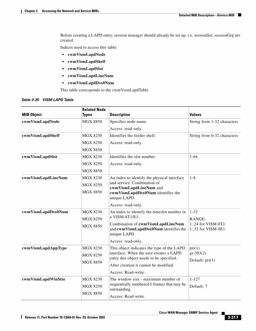
Chapter 3 Accessing the Network and Service MIBsDetailed MIB Description—Service MIB
Before creating a LAPD entry, session manager should already be set up. i.e. sessionSet, sessionGrp are created.
Indices used to access this table:
• cwmVismLapdNode
• cwmVismLapdShelf
• cwmVismLapdSlot
• cwmVismLapdLineNum
• cwmVismLapdDsx0Num
This table corresponds to the cwmVismLapdTable.
Table 3-35 VISM LAPD Table
MIB ObjectRelated Node Types Description Values
cwmVismLapdNode MGX 8850 Specifies node name.
Access: read-only.
String from 1-32 characters
cwmVismLapdShelf MGX 8230
MGX 8250
MGX 8850
Identifies the feeder shelf.
Access: read-only.
String from 0-32 characters
cwmVismLapdSlot MGX 8230
MGX 8250
MGX 8850
Identifies the slot number.
Access: read-only.
1-64
cwmVismLapdLineNum MGX 8230
MGX 8250
MGX 8850
An index to identify the physical interface and service. Combination of cwmVismLapdLineNum and cwmVismLapdDsx0Num identifies the unique LAPD.
Access: read-only.
1-8
cwmVismLapdDsx0Num MGX 8230
MGX 8250
MGX 8850
An index to identify the timeslot number in a VISM-8T1/E1.
Combination of cwmVismLapdLineNum and cwmVismLapdDsx0Num identifies the unique LAPD.
Access: read-only.
1-32
RANGE: 1..24 for VISM-8T11..32 for VISM-8E1.
cwmVismLapdAppType MGX 8230
MGX 8250
MGX 8850
This object indicates the type of the LAPD interface. When the user creates a LAPD entry this object needs to be specified.
After creation it cannot be modified.
Access: Read-write.
pri(1)gr-303(2)
Default: pri(1)
cwmVismLapdWinSize MGX 8230
MGX 8250
MGX 8850
The window size - maximum number of sequentially numbered I-frames that may be outstanding.
Access: Read-write.
1-127
Default: 7
3-317Cisco WAN Manager SNMP Service Agent
Release 11, Part Number 78-13569-01 Rev. E0, October 2003
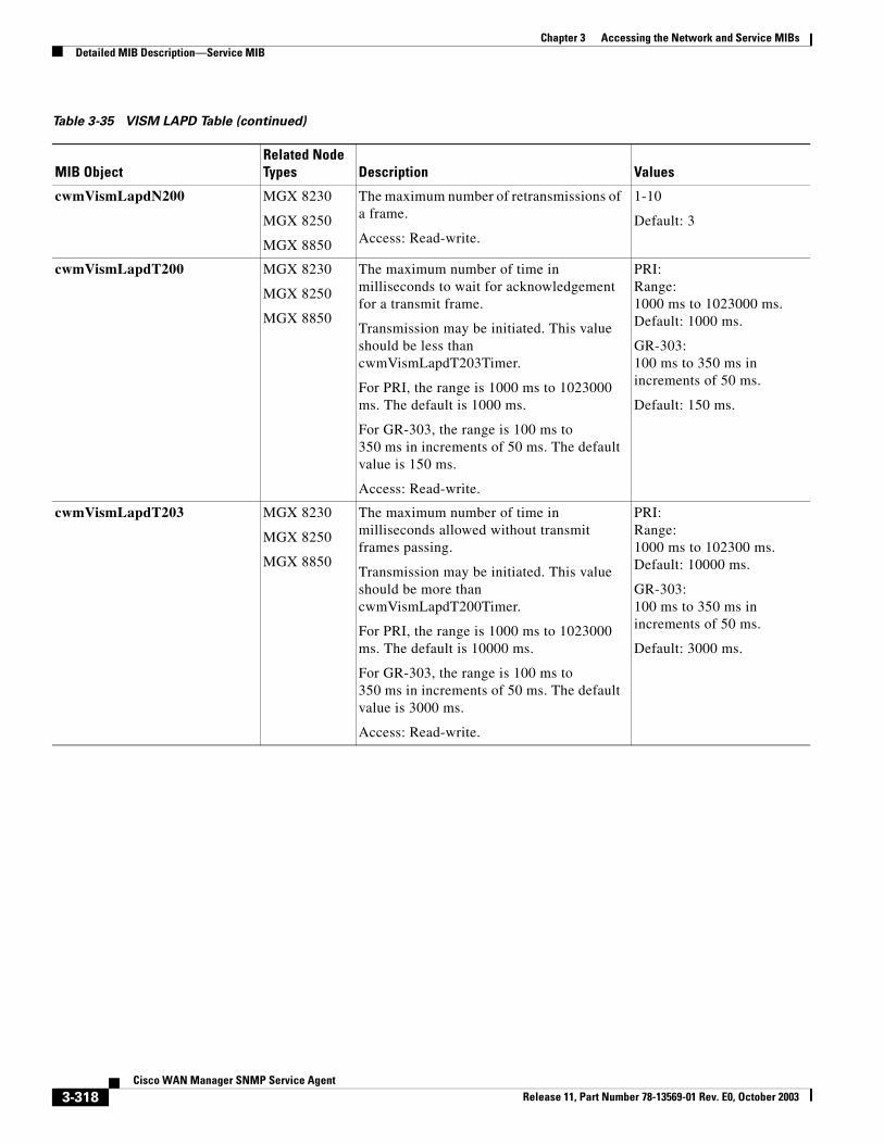
Chapter 3 Accessing the Network and Service MIBsDetailed MIB Description—Service MIB
cwmVismLapdN200 MGX 8230
MGX 8250
MGX 8850
The maximum number of retransmissions of a frame.
Access: Read-write.
1-10
Default: 3
cwmVismLapdT200 MGX 8230
MGX 8250
MGX 8850
The maximum number of time in milliseconds to wait for acknowledgement for a transmit frame.
Transmission may be initiated. This value should be less than cwmVismLapdT203Timer.
For PRI, the range is 1000 ms to 1023000 ms. The default is 1000 ms.
For GR-303, the range is 100 ms to 350 ms in increments of 50 ms. The default value is 150 ms.
Access: Read-write.
PRI:Range:1000 ms to 1023000 ms. Default: 1000 ms.
GR-303:100 ms to 350 ms in increments of 50 ms.
Default: 150 ms.
cwmVismLapdT203 MGX 8230
MGX 8250
MGX 8850
The maximum number of time in milliseconds allowed without transmit frames passing.
Transmission may be initiated. This value should be more than cwmVismLapdT200Timer.
For PRI, the range is 1000 ms to 1023000 ms. The default is 10000 ms.
For GR-303, the range is 100 ms to 350 ms in increments of 50 ms. The default value is 3000 ms.
Access: Read-write.
PRI:Range:1000 ms to 102300 ms. Default: 10000 ms.
GR-303:100 ms to 350 ms in increments of 50 ms.
Default: 3000 ms.
Table 3-35 VISM LAPD Table (continued)
MIB ObjectRelated Node Types Description Values
3-318Cisco WAN Manager SNMP Service Agent
Release 11, Part Number 78-13569-01 Rev. E0, October 2003
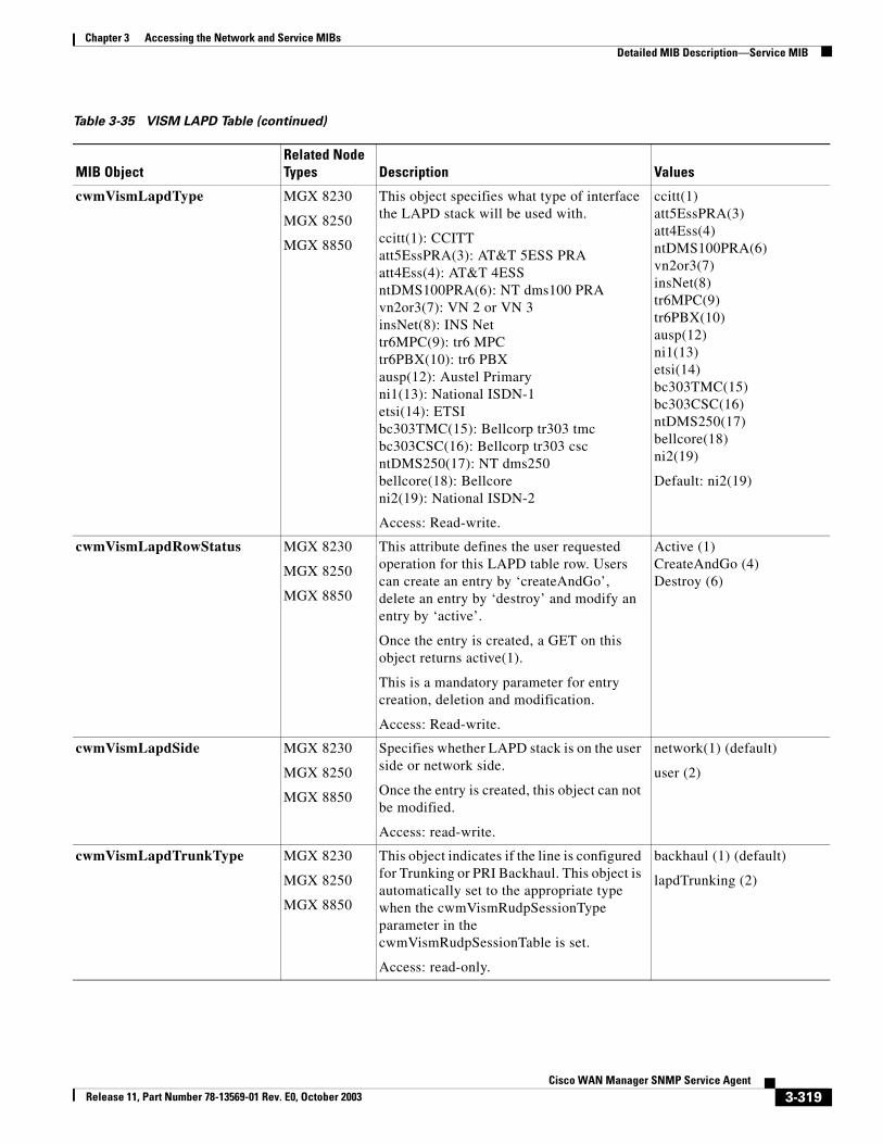
Chapter 3 Accessing the Network and Service MIBsDetailed MIB Description—Service MIB
cwmVismLapdType MGX 8230
MGX 8250
MGX 8850
This object specifies what type of interface the LAPD stack will be used with.
ccitt(1): CCITTatt5EssPRA(3): AT&T 5ESS PRAatt4Ess(4): AT&T 4ESSntDMS100PRA(6): NT dms100 PRAvn2or3(7): VN 2 or VN 3insNet(8): INS Nettr6MPC(9): tr6 MPCtr6PBX(10): tr6 PBXausp(12): Austel Primaryni1(13): National ISDN-1etsi(14): ETSIbc303TMC(15): Bellcorp tr303 tmcbc303CSC(16): Bellcorp tr303 cscntDMS250(17): NT dms250bellcore(18): Bellcoreni2(19): National ISDN-2
Access: Read-write.
ccitt(1)att5EssPRA(3)att4Ess(4)ntDMS100PRA(6)vn2or3(7)insNet(8)tr6MPC(9)tr6PBX(10)ausp(12)ni1(13)etsi(14)bc303TMC(15)bc303CSC(16)ntDMS250(17)bellcore(18)ni2(19)
Default: ni2(19)
cwmVismLapdRowStatus MGX 8230
MGX 8250
MGX 8850
This attribute defines the user requested operation for this LAPD table row. Users can create an entry by ‘createAndGo’, delete an entry by ‘destroy’ and modify an entry by ‘active’.
Once the entry is created, a GET on this object returns active(1).
This is a mandatory parameter for entry creation, deletion and modification.
Access: Read-write.
Active (1)CreateAndGo (4)Destroy (6)
cwmVismLapdSide MGX 8230
MGX 8250
MGX 8850
Specifies whether LAPD stack is on the user side or network side.
Once the entry is created, this object can not be modified.
Access: read-write.
network(1) (default)
user (2)
cwmVismLapdTrunkType MGX 8230
MGX 8250
MGX 8850
This object indicates if the line is configured for Trunking or PRI Backhaul. This object is automatically set to the appropriate type when the cwmVismRudpSessionType parameter in the cwmVismRudpSessionTable is set.
Access: read-only.
backhaul (1) (default)
lapdTrunking (2)
Table 3-35 VISM LAPD Table (continued)
MIB ObjectRelated Node Types Description Values
3-319Cisco WAN Manager SNMP Service Agent
Release 11, Part Number 78-13569-01 Rev. E0, October 2003
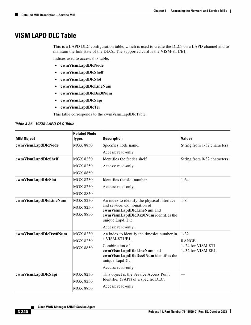
Chapter 3 Accessing the Network and Service MIBsDetailed MIB Description—Service MIB
VISM LAPD DLC TableThis is a LAPD DLC configuration table, which is used to create the DLCs on a LAPD channel and to maintain the link state of the DLCs. The supported card is the VISM-8T1/E1.
Indices used to access this table:
• cwmVismLapdDlcNode
• cwmVismLapdDlcShelf
• cwmVismLapdDlcSlot
• cwmVismLapdDlcLineNum
• cwmVismLapdDlcDsx0Num
• cwmVismLapdDlcSapi
• cwmVismLapdDlcTei
This table corresponds to the cwmVismLapdDlcTable.
Table 3-36 VISM LAPD DLC Table
MIB ObjectRelated Node Types Description Values
cwmVismLapdDlcNode MGX 8850 Specifies node name.
Access: read-only.
String from 1-32 characters
cwmVismLapdDlcShelf MGX 8230
MGX 8250
MGX 8850
Identifies the feeder shelf.
Access: read-only.
String from 0-32 characters
cwmVismLapdDlcSlot MGX 8230
MGX 8250
MGX 8850
Identifies the slot number.
Access: read-only.
1-64
cwmVismLapdDlcLineNum MGX 8230
MGX 8250
MGX 8850
An index to identify the physical interface and service. Combination of cwmVismLapdDlcLineNum and cwmVismLapdDlcDsx0Num identifies the unique Lapd, Dlc.
Access: read-only.
1-8
cwmVismLapdDlcDsx0Num MGX 8230
MGX 8250
MGX 8850
An index to identify the timeslot number in a VISM-8T1/E1.
Combination of cwmVismLapdDlcLineNum and cwmVismLapdDlcDsx0Num identifies the unique LapdDlc.
Access: read-only.
1-32
RANGE: 1..24 for VISM-8T11..32 for VISM-8E1.
cwmVismLapdDlcSapi MGX 8230
MGX 8250
MGX 8850
This object is the Service Access Point Identifier (SAPI) of a specific DLC.
Access: read-only.
—
3-320Cisco WAN Manager SNMP Service Agent
Release 11, Part Number 78-13569-01 Rev. E0, October 2003
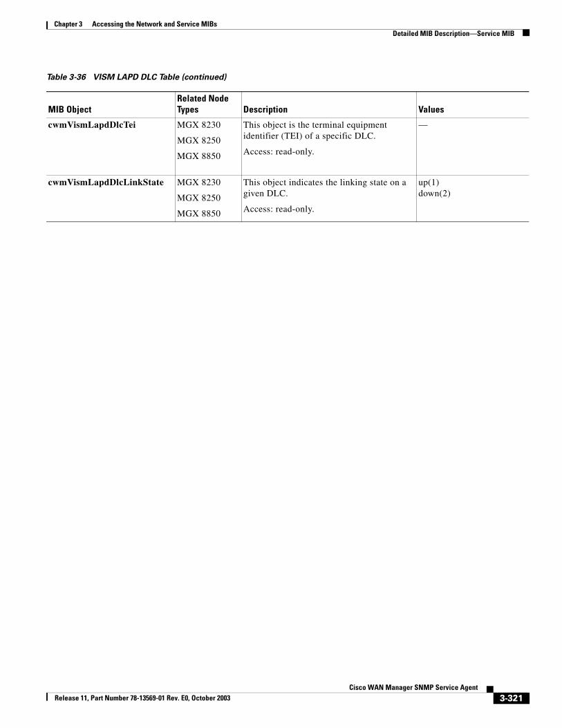
Chapter 3 Accessing the Network and Service MIBsDetailed MIB Description—Service MIB
cwmVismLapdDlcTei MGX 8230
MGX 8250
MGX 8850
This object is the terminal equipment identifier (TEI) of a specific DLC.
Access: read-only.
—
cwmVismLapdDlcLinkState MGX 8230
MGX 8250
MGX 8850
This object indicates the linking state on a given DLC.
Access: read-only.
up(1)down(2)
Table 3-36 VISM LAPD DLC Table (continued)
MIB ObjectRelated Node Types Description Values
3-321Cisco WAN Manager SNMP Service Agent
Release 11, Part Number 78-13569-01 Rev. E0, October 2003
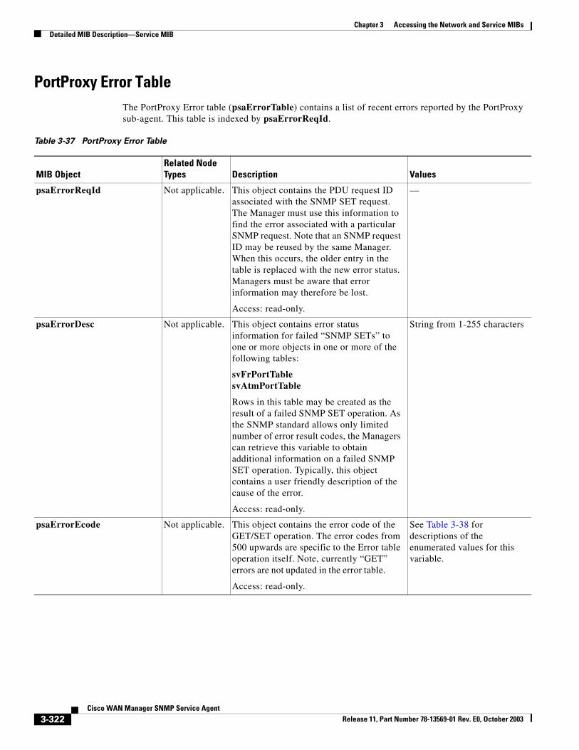
Chapter 3 Accessing the Network and Service MIBsDetailed MIB Description—Service MIB
PortProxy Error TableThe PortProxy Error table (psaErrorTable) contains a list of recent errors reported by the PortProxy sub-agent. This table is indexed by psaErrorReqId.
Table 3-37 PortProxy Error Table
MIB ObjectRelated Node Types Description Values
psaErrorReqId Not applicable. This object contains the PDU request ID associated with the SNMP SET request. The Manager must use this information to find the error associated with a particular SNMP request. Note that an SNMP request ID may be reused by the same Manager. When this occurs, the older entry in the table is replaced with the new error status. Managers must be aware that error information may therefore be lost.
Access: read-only.
—
psaErrorDesc Not applicable. This object contains error status information for failed “SNMP SETs” to one or more objects in one or more of the following tables:
svFrPortTablesvAtmPortTable
Rows in this table may be created as the result of a failed SNMP SET operation. As the SNMP standard allows only limited number of error result codes, the Managers can retrieve this variable to obtain additional information on a failed SNMP SET operation. Typically, this object contains a user friendly description of the cause of the error.
Access: read-only.
String from 1-255 characters
psaErrorEcode Not applicable. This object contains the error code of the GET/SET operation. The error codes from 500 upwards are specific to the Error table operation itself. Note, currently “GET” errors are not updated in the error table.
Access: read-only.
See Table 3-38 for descriptions of the enumerated values for this variable.
3-322Cisco WAN Manager SNMP Service Agent
Release 11, Part Number 78-13569-01 Rev. E0, October 2003
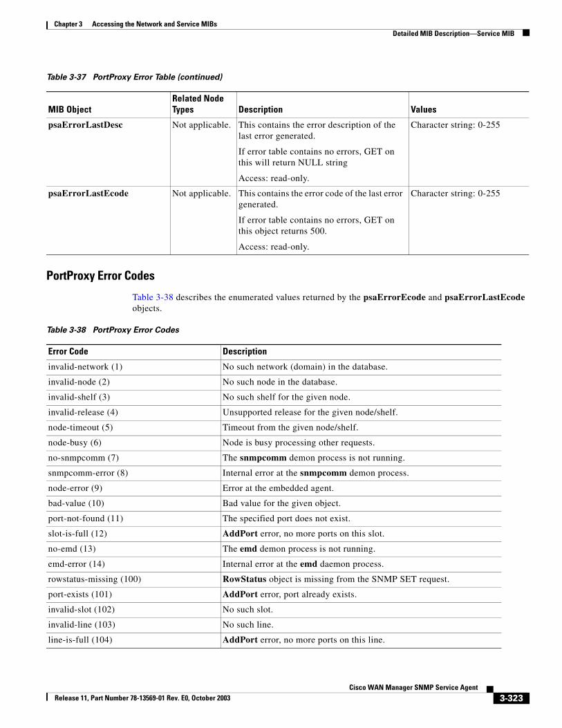
Chapter 3 Accessing the Network and Service MIBsDetailed MIB Description—Service MIB
PortProxy Error Codes
Table 3-38 describes the enumerated values returned by the psaErrorEcode and psaErrorLastEcode objects.
psaErrorLastDesc Not applicable. This contains the error description of the last error generated.
If error table contains no errors, GET on this will return NULL string
Access: read-only.
Character string: 0-255
psaErrorLastEcode Not applicable. This contains the error code of the last error generated.
If error table contains no errors, GET on this object returns 500.
Access: read-only.
Character string: 0-255
Table 3-37 PortProxy Error Table (continued)
MIB ObjectRelated Node Types Description Values
Table 3-38 PortProxy Error Codes
Error Code Description
invalid-network (1) No such network (domain) in the database.
invalid-node (2) No such node in the database.
invalid-shelf (3) No such shelf for the given node.
invalid-release (4) Unsupported release for the given node/shelf.
node-timeout (5) Timeout from the given node/shelf.
node-busy (6) Node is busy processing other requests.
no-snmpcomm (7) The snmpcomm demon process is not running.
snmpcomm-error (8) Internal error at the snmpcomm demon process.
node-error (9) Error at the embedded agent.
bad-value (10) Bad value for the given object.
port-not-found (11) The specified port does not exist.
slot-is-full (12) AddPort error, no more ports on this slot.
no-emd (13) The emd demon process is not running.
emd-error (14) Internal error at the emd daemon process.
rowstatus-missing (100) RowStatus object is missing from the SNMP SET request.
port-exists (101) AddPort error, port already exists.
invalid-slot (102) No such slot.
invalid-line (103) No such line.
line-is-full (104) AddPort error, no more ports on this line.
3-323Cisco WAN Manager SNMP Service Agent
Release 11, Part Number 78-13569-01 Rev. E0, October 2003
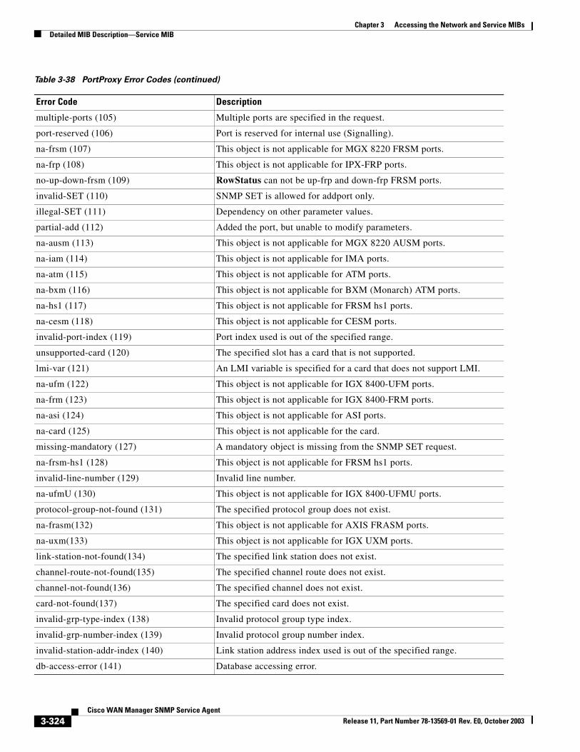
Chapter 3 Accessing the Network and Service MIBsDetailed MIB Description—Service MIB
multiple-ports (105) Multiple ports are specified in the request.
port-reserved (106) Port is reserved for internal use (Signalling).
na-frsm (107) This object is not applicable for MGX 8220 FRSM ports.
na-frp (108) This object is not applicable for IPX-FRP ports.
no-up-down-frsm (109) RowStatus can not be up-frp and down-frp FRSM ports.
invalid-SET (110) SNMP SET is allowed for addport only.
illegal-SET (111) Dependency on other parameter values.
partial-add (112) Added the port, but unable to modify parameters.
na-ausm (113) This object is not applicable for MGX 8220 AUSM ports.
na-iam (114) This object is not applicable for IMA ports.
na-atm (115) This object is not applicable for ATM ports.
na-bxm (116) This object is not applicable for BXM (Monarch) ATM ports.
na-hs1 (117) This object is not applicable for FRSM hs1 ports.
na-cesm (118) This object is not applicable for CESM ports.
invalid-port-index (119) Port index used is out of the specified range.
unsupported-card (120) The specified slot has a card that is not supported.
lmi-var (121) An LMI variable is specified for a card that does not support LMI.
na-ufm (122) This object is not applicable for IGX 8400-UFM ports.
na-frm (123) This object is not applicable for IGX 8400-FRM ports.
na-asi (124) This object is not applicable for ASI ports.
na-card (125) This object is not applicable for the card.
missing-mandatory (127) A mandatory object is missing from the SNMP SET request.
na-frsm-hs1 (128) This object is not applicable for FRSM hs1 ports.
invalid-line-number (129) Invalid line number.
na-ufmU (130) This object is not applicable for IGX 8400-UFMU ports.
protocol-group-not-found (131) The specified protocol group does not exist.
na-frasm(132) This object is not applicable for AXIS FRASM ports.
na-uxm(133) This object is not applicable for IGX UXM ports.
link-station-not-found(134) The specified link station does not exist.
channel-route-not-found(135) The specified channel route does not exist.
channel-not-found(136) The specified channel does not exist.
card-not-found(137) The specified card does not exist.
invalid-grp-type-index (138) Invalid protocol group type index.
invalid-grp-number-index (139) Invalid protocol group number index.
invalid-station-addr-index (140) Link station address index used is out of the specified range.
db-access-error (141) Database accessing error.
Table 3-38 PortProxy Error Codes (continued)
Error Code Description
3-324Cisco WAN Manager SNMP Service Agent
Release 11, Part Number 78-13569-01 Rev. E0, October 2003
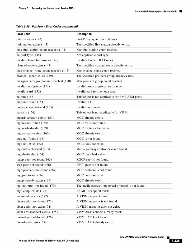
Chapter 3 Accessing the Network and Service MIBsDetailed MIB Description—Service MIB
internal-error (142) Port Proxy agent Internal error.
link-station-exists (143) The specified link station already exists.
max-link-station-count-reached (144) Max link station count reached.
na-port-type (145) Not applicable port type.
invalid-channel-dlci-index 146) Invalid channel DLCI index.
channel-route-exists (147) The specified channel route already exists.
max-channel-route-count-reached (148) Max channel route count reached.
protocol-group-exists (149) The specified protocol group already exists.
max-protocol-group-count-reached (150) Max protocol group count reached.
invalid-config-type (151) Invalid protocol group config type.
invalid_card (152) Invalid card for the node type.
na-bme (153) This object is not applicable for BME ATM ports.
plcp-not-found (154) Invalid PLCP.
port-queue-not-found (155) Invalid port queue.
na-vism (156) This object is not applicable for VISM.
mgcrds-already-exists (157) MGC already exists.
mgcres-not-found (158) MGC res is not found.
mgcres-bad-value (159) MGC res has a bad value.
mgc-already-exists (160) MGC already exists.
mgc-not-found (161) MGC is not found.
mgc-not-exist (162) MGC does not exist.
mg-cntlr-not-found (163) Media gateway controller is not found.
mgc-bad-value (164) MGC has a bad value.
xgcp-peer-not-found(165) XGCP peer is not found.
srcp-peer-not-found (166) SRCP peer is not found.
mgc-protocol-not-found (167) MGC protocol is not found.
mgcp-not-exist (168) MGC does not exist.
mgcp-already-exists (169) MGC already exists.
mg-sup-prtcl-not-found (170) The media gateway supported protocol is not found.
mgc-endpt-exists (171) An MGC endpoint exists.
vism-endpt-exists (172) A VISM endpoint exists.
vism-endpt-not-found(173) A VISM endpoint is not found.
vism-endpt-not-exist(174) A VISM endpoint does not exist.
vism-crossconnect-exists (175) VISM cross connect already exists.
vism-lapd-not-found (176) VISM LAPD not found.
vism-lapd-exists (177) VISM LAPD already exists.
Table 3-38 PortProxy Error Codes (continued)
Error Code Description
3-325Cisco WAN Manager SNMP Service Agent
Release 11, Part Number 78-13569-01 Rev. E0, October 2003
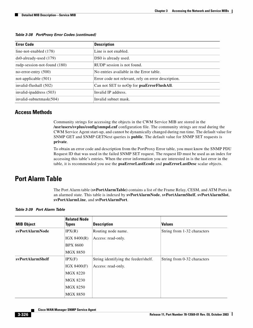
Chapter 3 Accessing the Network and Service MIBsDetailed MIB Description—Service MIB
Access Methods
Community strings for accessing the objects in the CWM Service MIB are stored in the /usr/users/svplus/config/snmpd.cnf configuration file. The community strings are read during the CWM Service Agent start-up, and cannot be dynamically changed during run time. The default value for SNMP GET and SNMP GETNext queries is public. The default value for SNMP SET requests is private.
To obtain an error code and description from the PortProxy Error table, you must know the SNMP PDU Request ID that was used in the failed SNMP SET request. The request ID must be used as an index for accessing this table’s entries. When the error information you are interested in is the last error in the table, it is recommended you use the psaErrorLastEcode and psaErrorLastDesc scalar objects.
Port Alarm TableThe Port Alarm table (svPortAlarmTable) contains a list of the Frame Relay, CESM, and ATM Ports in an alarmed state. This table is indexed by svPortAlarmNode, svPortAlarmShelf, svPortAlarmSlot, svPortAlarmLine, and svPortAlarmPort.
line-not-enabled (178) Line is not enabled.
ds0-already-used (179) DS0 is already used.
rudp-session-not-found (180) RUDP session is not found.
no-error-entry (500) No entries available in the Error table.
not-applicable (501) Error code not relevant, rely on error description.
invalid-flushall (502) Can not SET to noOp for psaErrorFlushAll.
invalid-ipaddress (503) Invalid IP address.
invalid-subnetmask(504) Invalid subnet mask.
Table 3-38 PortProxy Error Codes (continued)
Error Code Description
Table 3-39 Port Alarm Table
MIB ObjectRelated Node Types Description Values
svPortAlarmNode IPX(R)
IGX 8400(R)
BPX 8600
MGX 8850
Routing node name.
Access: read-only.
String from 1-32 characters
svPortAlarmShelf IPX(F)
IGX 8400(F)
MGX 8220
MGX 8230
MGX 8250
MGX 8850
String identifying the feeder/shelf.
Access: read-only.
String from 0-32 characters
3-326Cisco WAN Manager SNMP Service Agent
Release 11, Part Number 78-13569-01 Rev. E0, October 2003
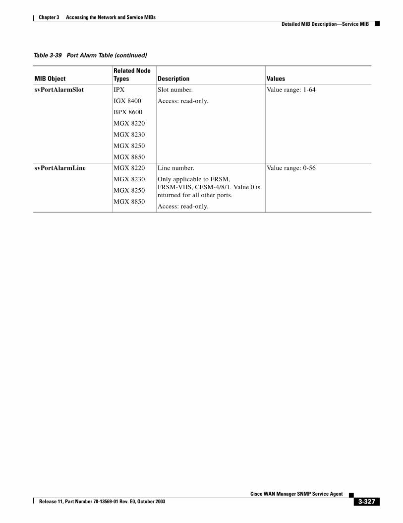
Chapter 3 Accessing the Network and Service MIBsDetailed MIB Description—Service MIB
svPortAlarmSlot IPX
IGX 8400
BPX 8600
MGX 8220
MGX 8230
MGX 8250
MGX 8850
Slot number.
Access: read-only.
Value range: 1-64
svPortAlarmLine MGX 8220
MGX 8230
MGX 8250
MGX 8850
Line number.
Only applicable to FRSM, FRSM-VHS, CESM-4/8/1. Value 0 is returned for all other ports.
Access: read-only.
Value range: 0-56
Table 3-39 Port Alarm Table (continued)
MIB ObjectRelated Node Types Description Values
3-327Cisco WAN Manager SNMP Service Agent
Release 11, Part Number 78-13569-01 Rev. E0, October 2003
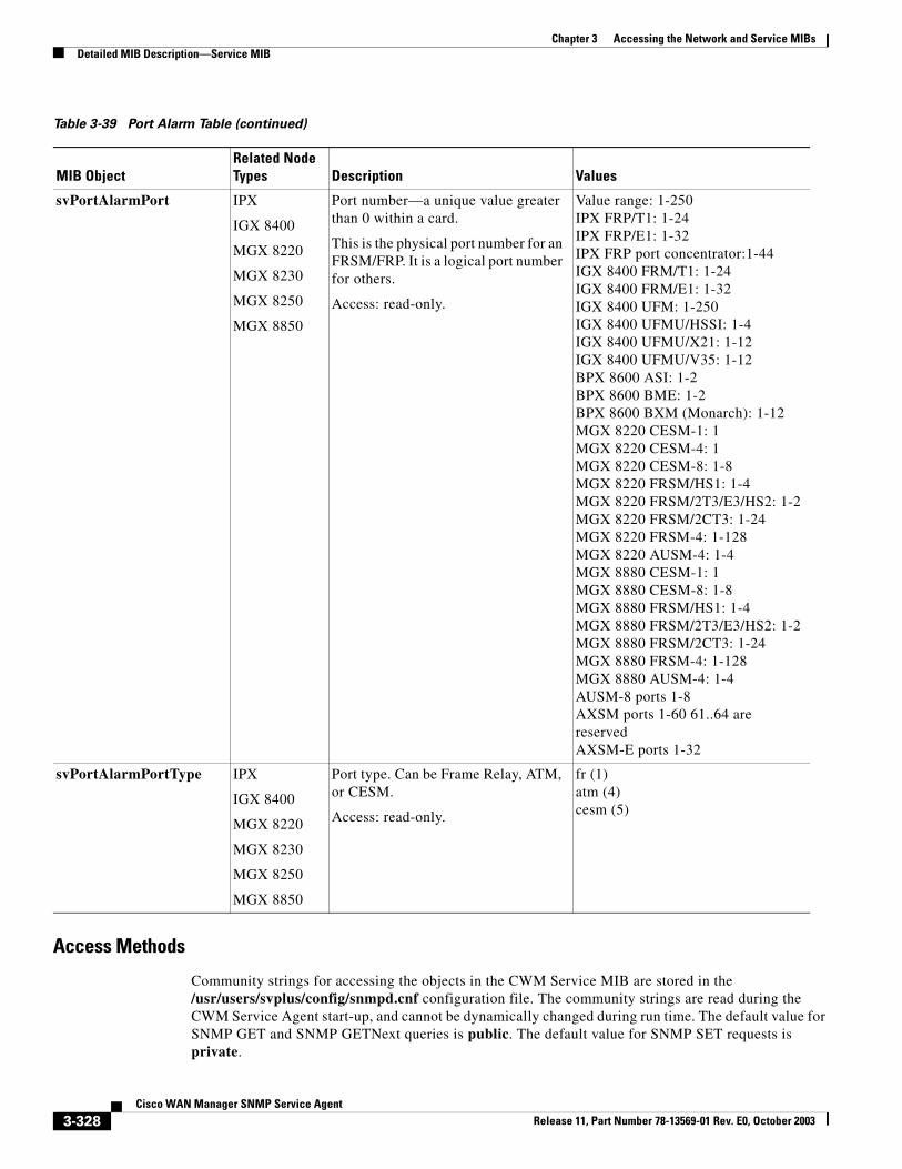
Chapter 3 Accessing the Network and Service MIBsDetailed MIB Description—Service MIB
Access Methods
Community strings for accessing the objects in the CWM Service MIB are stored in the /usr/users/svplus/config/snmpd.cnf configuration file. The community strings are read during the CWM Service Agent start-up, and cannot be dynamically changed during run time. The default value for SNMP GET and SNMP GETNext queries is public. The default value for SNMP SET requests is private.
svPortAlarmPort IPX
IGX 8400
MGX 8220
MGX 8230
MGX 8250
MGX 8850
Port number—a unique value greater than 0 within a card.
This is the physical port number for an FRSM/FRP. It is a logical port number for others.
Access: read-only.
Value range: 1-250IPX FRP/T1: 1-24IPX FRP/E1: 1-32IPX FRP port concentrator:1-44IGX 8400 FRM/T1: 1-24IGX 8400 FRM/E1: 1-32IGX 8400 UFM: 1-250IGX 8400 UFMU/HSSI: 1-4IGX 8400 UFMU/X21: 1-12IGX 8400 UFMU/V35: 1-12BPX 8600 ASI: 1-2BPX 8600 BME: 1-2BPX 8600 BXM (Monarch): 1-12MGX 8220 CESM-1: 1MGX 8220 CESM-4: 1MGX 8220 CESM-8: 1-8MGX 8220 FRSM/HS1: 1-4MGX 8220 FRSM/2T3/E3/HS2: 1-2MGX 8220 FRSM/2CT3: 1-24MGX 8220 FRSM-4: 1-128MGX 8220 AUSM-4: 1-4MGX 8880 CESM-1: 1MGX 8880 CESM-8: 1-8MGX 8880 FRSM/HS1: 1-4MGX 8880 FRSM/2T3/E3/HS2: 1-2MGX 8880 FRSM/2CT3: 1-24MGX 8880 FRSM-4: 1-128MGX 8880 AUSM-4: 1-4AUSM-8 ports 1-8AXSM ports 1-60 61..64 are reservedAXSM-E ports 1-32
svPortAlarmPortType IPX
IGX 8400
MGX 8220
MGX 8230
MGX 8250
MGX 8850
Port type. Can be Frame Relay, ATM, or CESM.
Access: read-only.
fr (1)atm (4)cesm (5)
Table 3-39 Port Alarm Table (continued)
MIB ObjectRelated Node Types Description Values
3-328Cisco WAN Manager SNMP Service Agent
Release 11, Part Number 78-13569-01 Rev. E0, October 2003
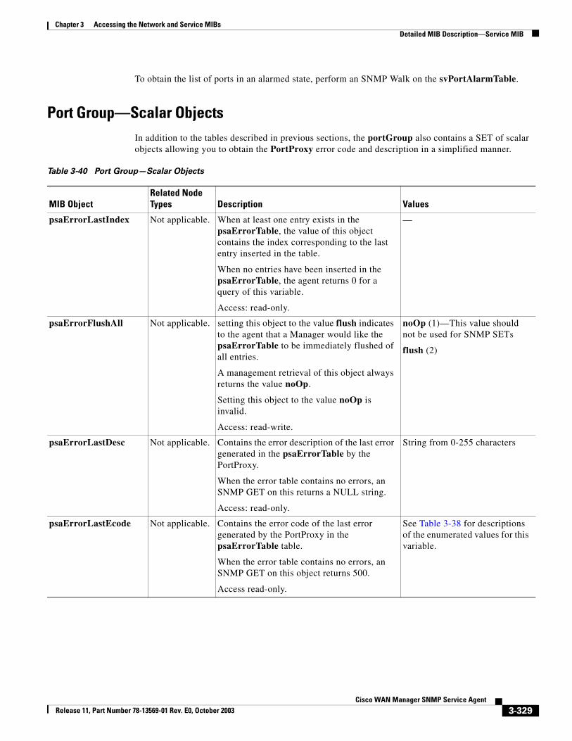
Chapter 3 Accessing the Network and Service MIBsDetailed MIB Description—Service MIB
To obtain the list of ports in an alarmed state, perform an SNMP Walk on the svPortAlarmTable.
Port Group—Scalar ObjectsIn addition to the tables described in previous sections, the portGroup also contains a SET of scalar objects allowing you to obtain the PortProxy error code and description in a simplified manner.
Table 3-40 Port Group—Scalar Objects
MIB ObjectRelated Node Types Description Values
psaErrorLastIndex Not applicable. When at least one entry exists in the psaErrorTable, the value of this object contains the index corresponding to the last entry inserted in the table.
When no entries have been inserted in the psaErrorTable, the agent returns 0 for a query of this variable.
Access: read-only.
—
psaErrorFlushAll Not applicable. setting this object to the value flush indicates to the agent that a Manager would like the psaErrorTable to be immediately flushed of all entries.
A management retrieval of this object always returns the value noOp.
Setting this object to the value noOp is invalid.
Access: read-write.
noOp (1)—This value should not be used for SNMP SETs
flush (2)
psaErrorLastDesc Not applicable. Contains the error description of the last error generated in the psaErrorTable by the PortProxy.
When the error table contains no errors, an SNMP GET on this returns a NULL string.
Access: read-only.
String from 0-255 characters
psaErrorLastEcode Not applicable. Contains the error code of the last error generated by the PortProxy in the psaErrorTable table.
When the error table contains no errors, an SNMP GET on this object returns 500.
Access read-only.
See Table 3-38 for descriptions of the enumerated values for this variable.
3-329Cisco WAN Manager SNMP Service Agent
Release 11, Part Number 78-13569-01 Rev. E0, October 2003
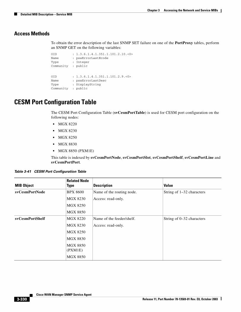
Chapter 3 Accessing the Network and Service MIBsDetailed MIB Description—Service MIB
Access Methods
To obtain the error description of the last SNMP SET failure on one of the PortProxy tables, perform an SNMP GET on the following variables:
OID : 1.3.6.1.4.1.351.1.101.2.10.<0>Name : psaErrorLastEcodeType : IntegerCommunity : public
OID : 1.3.6.1.4.1.351.1.101.2.9.<0>Name : psaErrorLastDescType : DisplayStringCommunity : public
CESM Port Configuration TableThe CESM Port Configuration Table (svCesmPortTable) is used for CESM port configuration on the following nodes:
• MGX 8220
• MGX 8230
• MGX 8250
• MGX 8830
• MGX 8850 (PXM1E)
This table is indexed by svCesmPortNode, svCesmPortSlot, svCesmPortShelf, svCesmPortLine and svCesmPortPort.
Table 3-41 CESM Port Configuration Table
MIB ObjectRelated Node Type Description Value
svCesmPortNode BPX 8600
MGX 8230
MGX 8250
MGX 8850
Name of the routing node.
Access: read-only.
String of 1–32 characters
svCesmPortShelf MGX 8220
MGX 8230
MGX 8250
MGX 8830
MGX 8850 (PXM1E)
MGX 8850
Name of the feeder/shelf.
Access: read-only.
String of 0–32 characters
3-330Cisco WAN Manager SNMP Service Agent
Release 11, Part Number 78-13569-01 Rev. E0, October 2003
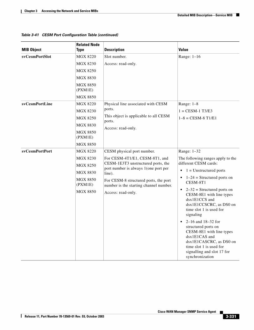
Chapter 3 Accessing the Network and Service MIBsDetailed MIB Description—Service MIB
svCesmPortSlot MGX 8220
MGX 8230
MGX 8250
MGX 8830
MGX 8850 (PXM1E)
MGX 8850
Slot number.
Access: read-only.
Range: 1–16
svCesmPortLine MGX 8220
MGX 8230
MGX 8250
MGX 8830
MGX 8850 (PXM1E)
MGX 8850
Physical line associated with CESM ports.
This object is applicable to all CESM ports.
Access: read-only.
Range: 1–8
1 = CESM-1 T3/E3
1–8 = CESM-8 T1/E1
svCesmPortPort MGX 8220
MGX 8230
MGX 8250
MGX 8830
MGX 8850 (PXM1E)
MGX 8850
CESM physical port number.
For CESM-4T1/E1, CESM-8T1, and CESM-1E3T3 unstructured ports, the port number is always 1(one port per line).
For CESM-8 structured ports, the port number is the starting channel number.
Access: read-only.
Range: 1–32
The following ranges apply to the different CESM cards:
• 1 = Unstructured ports
• 1–24 = Structured ports on CESM-8T1
• 2–32 = Structured ports on CESM-8E1 with line types dsx1E1CCS and dsx1E1CCSCRC, as DS0 on time slot 1 is used for signaling
• 2–16 and 18–32 for structured ports on CESM-8E1 with line types dsx1E1CAS and dsx1E1CASCRC, as DS0 on time slot 1 is used for signalling and slot 17 for synchronization
Table 3-41 CESM Port Configuration Table (continued)
MIB ObjectRelated Node Type Description Value
3-331Cisco WAN Manager SNMP Service Agent
Release 11, Part Number 78-13569-01 Rev. E0, October 2003
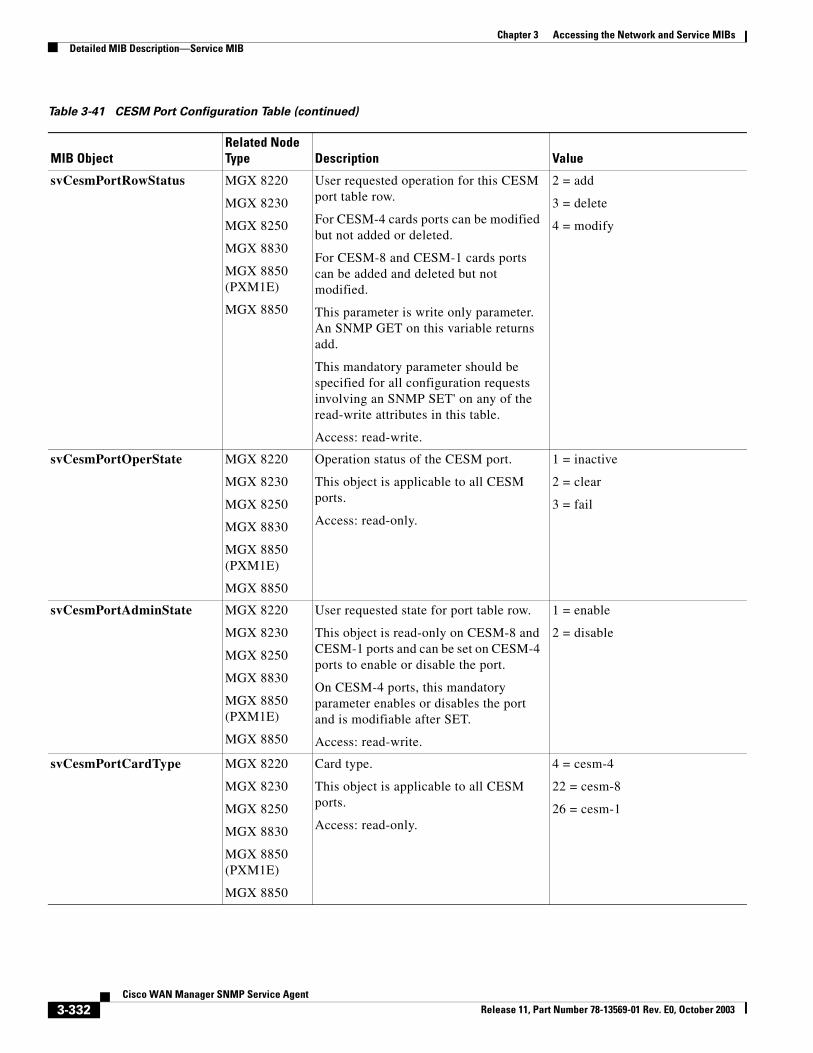
Chapter 3 Accessing the Network and Service MIBsDetailed MIB Description—Service MIB
svCesmPortRowStatus MGX 8220
MGX 8230
MGX 8250
MGX 8830
MGX 8850 (PXM1E)
MGX 8850
User requested operation for this CESM port table row.
For CESM-4 cards ports can be modified but not added or deleted.
For CESM-8 and CESM-1 cards ports can be added and deleted but not modified.
This parameter is write only parameter. An SNMP GET on this variable returns add.
This mandatory parameter should be specified for all configuration requests involving an SNMP SET' on any of the read-write attributes in this table.
Access: read-write.
2 = add
3 = delete
4 = modify
svCesmPortOperState MGX 8220
MGX 8230
MGX 8250
MGX 8830
MGX 8850 (PXM1E)
MGX 8850
Operation status of the CESM port.
This object is applicable to all CESM ports.
Access: read-only.
1 = inactive
2 = clear
3 = fail
svCesmPortAdminState MGX 8220
MGX 8230
MGX 8250
MGX 8830
MGX 8850 (PXM1E)
MGX 8850
User requested state for port table row.
This object is read-only on CESM-8 and CESM-1 ports and can be set on CESM-4 ports to enable or disable the port.
On CESM-4 ports, this mandatory parameter enables or disables the port and is modifiable after SET.
Access: read-write.
1 = enable
2 = disable
svCesmPortCardType MGX 8220
MGX 8230
MGX 8250
MGX 8830
MGX 8850 (PXM1E)
MGX 8850
Card type.
This object is applicable to all CESM ports.
Access: read-only.
4 = cesm-4
22 = cesm-8
26 = cesm-1
Table 3-41 CESM Port Configuration Table (continued)
MIB ObjectRelated Node Type Description Value
3-332Cisco WAN Manager SNMP Service Agent
Release 11, Part Number 78-13569-01 Rev. E0, October 2003
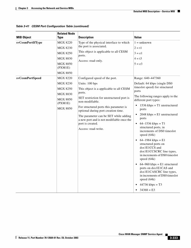
Chapter 3 Accessing the Network and Service MIBsDetailed MIB Description—Service MIB
svCesmPortIfType MGX 8220
MGX 8230
MGX 8250
MGX 8830
MGX 8850 (PXM1E)
MGX 8850
Type of the physical interface to which the port is associated.
This object is applicable to all CESM ports.
Access: read-only.
1 = unknown
2 = t1
3 = e1
4 = t3
5 = e3
svCesmPortSpeed MGX 8220
MGX 8230
MGX 8250
MGX 8830
MGX 8850 (PXM1E)
MGX 8850
Configured speed of the port.
Units: 100 bps
This object is a applicable to all CESM ports.
SET restriction for unstructured port is non-modifiable.
For structured ports this parameter is optional during port creation time.
The parameter can be SET while adding a new port and is not modifiable once the port is created.
Access: read-write.
Range: 640–447360
Default: 64 kbps (single DS0 timeslot speed) for structured ports
The following ranges apply to the different port types:
• 1536 kbps = T1 unstructured ports
• 2048 kbps = E1 unstructured ports
• 64–1536 kbps = T1 structured ports, in increments of DS0 timeslot speed (64k)
• 64–1984 kbps = E1 structured ports on dsx1E1CCS and dsx1E1CCSCRC line types, in increments of DS0 timeslot speed (64k)
• 64–960 kbps = E1 structured ports on dsx1E1CAS and dsx1E1CASCRC line types, in increments of DS0 timeslot speed (64k)
• 44736 kbps = T3
• 34368 = E3
Table 3-41 CESM Port Configuration Table (continued)
MIB ObjectRelated Node Type Description Value
3-333Cisco WAN Manager SNMP Service Agent
Release 11, Part Number 78-13569-01 Rev. E0, October 2003
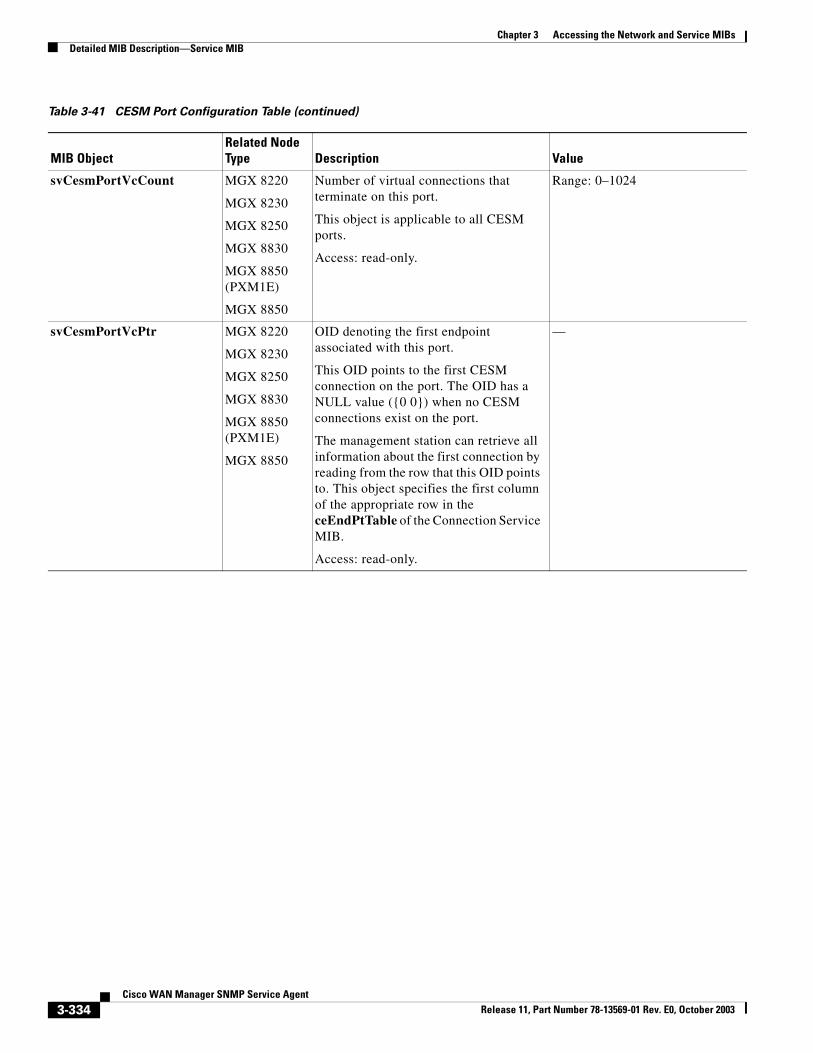
Chapter 3 Accessing the Network and Service MIBsDetailed MIB Description—Service MIB
svCesmPortVcCount MGX 8220
MGX 8230
MGX 8250
MGX 8830
MGX 8850 (PXM1E)
MGX 8850
Number of virtual connections that terminate on this port.
This object is applicable to all CESM ports.
Access: read-only.
Range: 0–1024
svCesmPortVcPtr MGX 8220
MGX 8230
MGX 8250
MGX 8830
MGX 8850 (PXM1E)
MGX 8850
OID denoting the first endpoint associated with this port.
This OID points to the first CESM connection on the port. The OID has a NULL value ({0 0}) when no CESM connections exist on the port.
The management station can retrieve all information about the first connection by reading from the row that this OID points to. This object specifies the first column of the appropriate row in the ceEndPtTable of the Connection Service MIB.
Access: read-only.
—
Table 3-41 CESM Port Configuration Table (continued)
MIB ObjectRelated Node Type Description Value
3-334Cisco WAN Manager SNMP Service Agent
Release 11, Part Number 78-13569-01 Rev. E0, October 2003
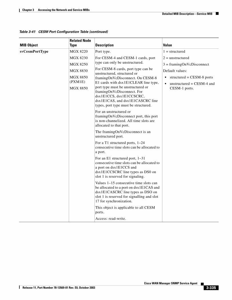
Chapter 3 Accessing the Network and Service MIBsDetailed MIB Description—Service MIB
svCesmPortType MGX 8220
MGX 8230
MGX 8250
MGX 8830
MGX 8850 (PXM1E)
MGX 8850
Port type.
For CESM-4 and CESM-1 cards, port type can only be unstructured.
For CESM-8 cards, port type can be unstructured, structured or framingOnVcDisconnect. On CESM-8 E1 cards with dsx1E1CLEAR line type, port type must be unstructured or framingOnVcDisconnect. For dsx1E1CCS, dsx1E1CCSCRC, dsx1E1CAS, and dsx1E1CASCRC line types, port type must be structured.
For an unstructured or framingOnVcDisconnect port, this port is non-channelized. All time slots are allocated to that port.
The framingOnVcDisconnect is an unstructured port.
For a T1 structured ports, 1–24 consecutive time slots can be allocated to a port.
For an E1 structured port, 1–31 consecutive time slots can be allocated to a port on dsx1E1CCS and dsx1E1CCSCRC line types as DS0 on slot 1 is reserved for signaling.
Values 1–15 consecutive time slots can be allocated to a port on dsx1E1CAS and dsx1E1CASCRC line types as DSO on slot 1 is reserved for signalling and slot 17 for synchronization.
This object is applicable to all CESM ports.
Access: read-write.
1 = structured
2 = unstructured
3 = framingOnVcDisconnect
Default values:
• structured = CESM-8 ports
• unstructured = CESM-4 and CESM-1 ports.
Table 3-41 CESM Port Configuration Table (continued)
MIB ObjectRelated Node Type Description Value
3-335Cisco WAN Manager SNMP Service Agent
Release 11, Part Number 78-13569-01 Rev. E0, October 2003
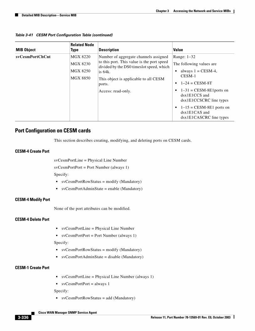
Chapter 3 Accessing the Network and Service MIBsDetailed MIB Description—Service MIB
Port Configuration on CESM cards
This section describes creating, modifying, and deleting ports on CESM cards.
CESM-4 Create Port
svCesmPortLine = Physical Line Number
svCesmPortPort = Port Number (always 1)
Specify:
• svCesmPortRowStatus = modify (Mandatory)
• svCesmPortAdminState = enable (Mandatory)
CESM-4 Modify Port
None of the port attributes can be modified.
CESM-4 Delete Port
• svCesmPortLine = Physical Line Number
• svCesmPortPort = Port Number (always 1)
Specify:
• svCesmPortRowStatus = modify (Mandatory)
• svCesmPortAdminState = disable (Mandatory)
CESM-1 Create Port
• svCesmPortLine = Physical Line Number (always 1)
• svCesmPortPort = always 1
Specify:
• svCesmPortRowStatus = add (Mandatory)
svCesmPortChCnt MGX 8220
MGX 8230
MGX 8250
MGX 8850
Number of aggregate channels assigned to this port. This value is the port speed divided by the DS0 timeslot speed, which is 64k.
This object is applicable to all CESM ports.
Access: read-only.
Range: 1–32
The following values are
• always 1 = CESM-4, CESM-1
• 1–24 = CESM-8T
• 1–31 = CESM-8E1ports on dsx1E1CCS and dsx1E1CCSCRC line types
• 1–15 = CESM-8E1 ports on dsx1E1CAS and dsx1E1CASCRC line types
Table 3-41 CESM Port Configuration Table (continued)
MIB ObjectRelated Node Type Description Value
3-336Cisco WAN Manager SNMP Service Agent
Release 11, Part Number 78-13569-01 Rev. E0, October 2003
Chapter 3 Accessing the Network and Service MIBsDetailed MIB Description—Service MIB
CESM-1 Modify Port
None of the port attributes can be modified once the port is created.
CESM-1 Delete Port
• svCesmPortLine = Physical Line Number (always 1)
• svCesmPortPort = always 1
Specify:
• svCesmPortRowStatus = delete (Mandatory)
CESM-8 Create Port
• svCesmPortLine = Physical Line Number
• svCesmPortPort = Starting Channel Number
Specify:
• svCesmPortRowStatus = add (Mandatory)
SNMP request is rejected if svCesmPortType is specified as unstructured and svCesmPortSpeed is specified.
CESM-8 Modify Port
None of the port attributes can be modified once the port is created.
CESM-8 Delete Port
• svCesmPortLine = Physical Line Number used during creation
• svCesmPortPort = Port Number used during creation
Specify
• svCesmPortRowStatus = delete (Mandatory)
FRSM VHS Service Queue Configuration TableThe FRSM VHS Service Queue Configuration table (svFrsmVhsServiceQTable) maintains configuration information about all of the service queues on FRSM-VHS ports. This table is indexed by svFrsmVhsServiceQNode, svFrsmVhsServiceQShelf, svFrsmVhsServiceQSlot, svFrsmVhsServiceQLine, and svFrsmVhsServiceQPort, and svFrsmVhsServiceQNumber.
3-337Cisco WAN Manager SNMP Service Agent
Release 11, Part Number 78-13569-01 Rev. E0, October 2003
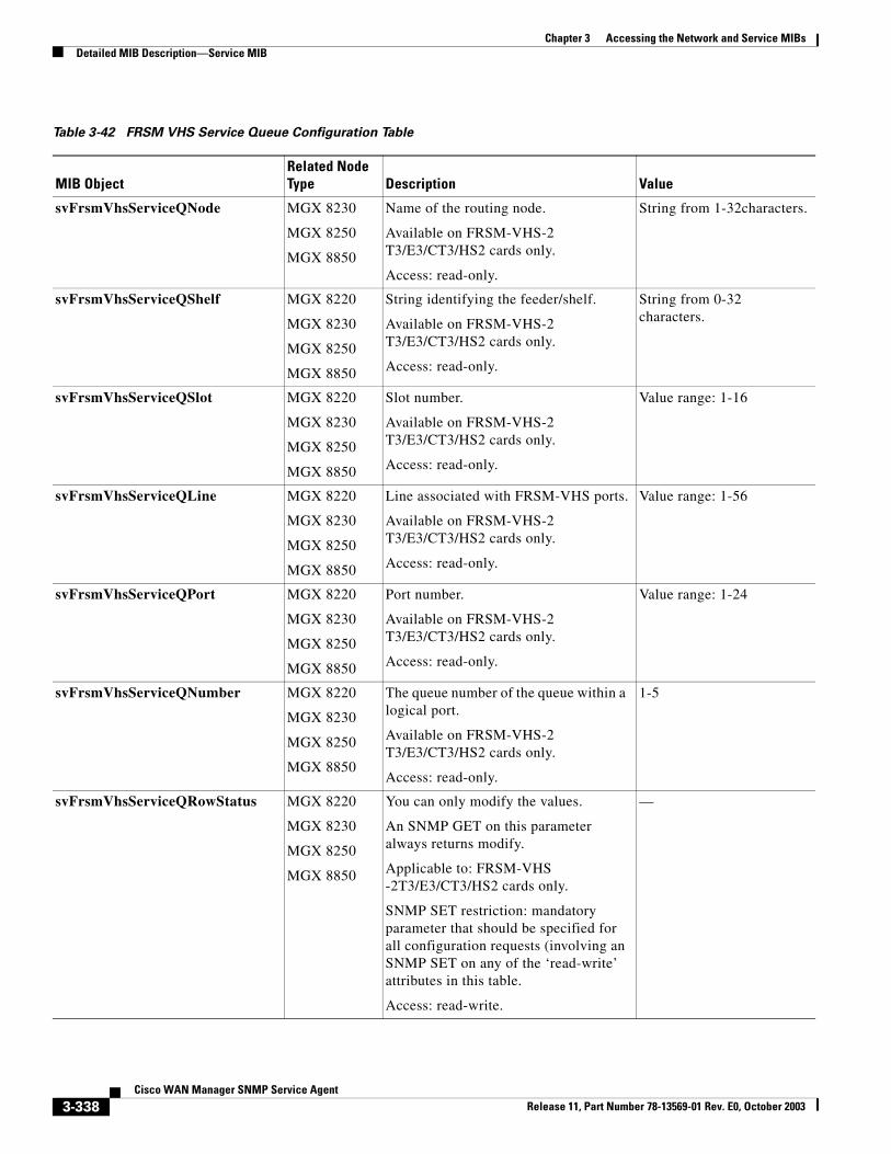
Chapter 3 Accessing the Network and Service MIBsDetailed MIB Description—Service MIB
Table 3-42 FRSM VHS Service Queue Configuration Table
MIB ObjectRelated Node Type Description Value
svFrsmVhsServiceQNode MGX 8230
MGX 8250
MGX 8850
Name of the routing node.
Available on FRSM-VHS-2 T3/E3/CT3/HS2 cards only.
Access: read-only.
String from 1-32characters.
svFrsmVhsServiceQShelf MGX 8220
MGX 8230
MGX 8250
MGX 8850
String identifying the feeder/shelf.
Available on FRSM-VHS-2 T3/E3/CT3/HS2 cards only.
Access: read-only.
String from 0-32 characters.
svFrsmVhsServiceQSlot MGX 8220
MGX 8230
MGX 8250
MGX 8850
Slot number.
Available on FRSM-VHS-2 T3/E3/CT3/HS2 cards only.
Access: read-only.
Value range: 1-16
svFrsmVhsServiceQLine MGX 8220
MGX 8230
MGX 8250
MGX 8850
Line associated with FRSM-VHS ports.
Available on FRSM-VHS-2 T3/E3/CT3/HS2 cards only.
Access: read-only.
Value range: 1-56
svFrsmVhsServiceQPort MGX 8220
MGX 8230
MGX 8250
MGX 8850
Port number.
Available on FRSM-VHS-2 T3/E3/CT3/HS2 cards only.
Access: read-only.
Value range: 1-24
svFrsmVhsServiceQNumber MGX 8220
MGX 8230
MGX 8250
MGX 8850
The queue number of the queue within a logical port.
Available on FRSM-VHS-2 T3/E3/CT3/HS2 cards only.
Access: read-only.
1-5
svFrsmVhsServiceQRowStatus MGX 8220
MGX 8230
MGX 8250
MGX 8850
You can only modify the values.
An SNMP GET on this parameter always returns modify.
Applicable to: FRSM-VHS -2T3/E3/CT3/HS2 cards only.
SNMP SET restriction: mandatory parameter that should be specified for all configuration requests (involving an SNMP SET on any of the ‘read-write’ attributes in this table.
Access: read-write.
—
3-338Cisco WAN Manager SNMP Service Agent
Release 11, Part Number 78-13569-01 Rev. E0, October 2003
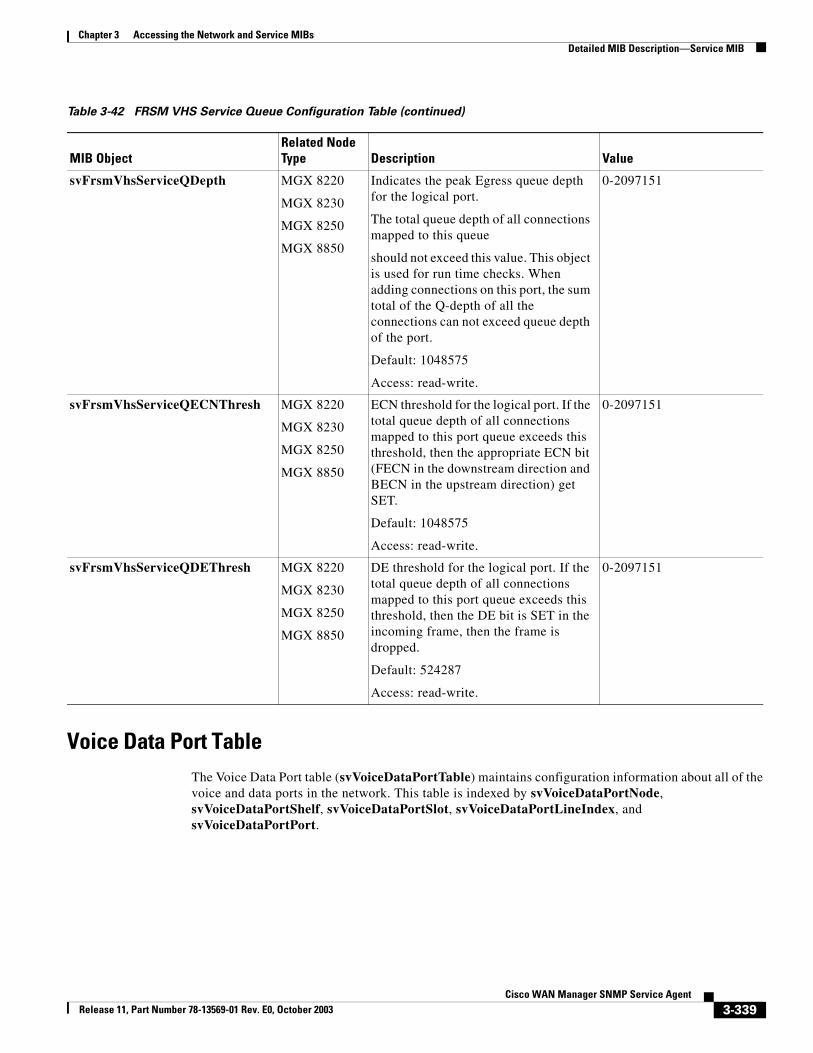
Chapter 3 Accessing the Network and Service MIBsDetailed MIB Description—Service MIB
Voice Data Port TableThe Voice Data Port table (svVoiceDataPortTable) maintains configuration information about all of the voice and data ports in the network. This table is indexed by svVoiceDataPortNode, svVoiceDataPortShelf, svVoiceDataPortSlot, svVoiceDataPortLineIndex, and svVoiceDataPortPort.
svFrsmVhsServiceQDepth MGX 8220
MGX 8230
MGX 8250
MGX 8850
Indicates the peak Egress queue depth for the logical port.
The total queue depth of all connections mapped to this queue
should not exceed this value. This object is used for run time checks. When adding connections on this port, the sum total of the Q-depth of all the connections can not exceed queue depth of the port.
Default: 1048575
Access: read-write.
0-2097151
svFrsmVhsServiceQECNThresh MGX 8220
MGX 8230
MGX 8250
MGX 8850
ECN threshold for the logical port. If the total queue depth of all connections mapped to this port queue exceeds this threshold, then the appropriate ECN bit (FECN in the downstream direction and BECN in the upstream direction) get SET.
Default: 1048575
Access: read-write.
0-2097151
svFrsmVhsServiceQDEThresh MGX 8220
MGX 8230
MGX 8250
MGX 8850
DE threshold for the logical port. If the total queue depth of all connections mapped to this port queue exceeds this threshold, then the DE bit is SET in the incoming frame, then the frame is dropped.
Default: 524287
Access: read-write.
0-2097151
Table 3-42 FRSM VHS Service Queue Configuration Table (continued)
MIB ObjectRelated Node Type Description Value
3-339Cisco WAN Manager SNMP Service Agent
Release 11, Part Number 78-13569-01 Rev. E0, October 2003
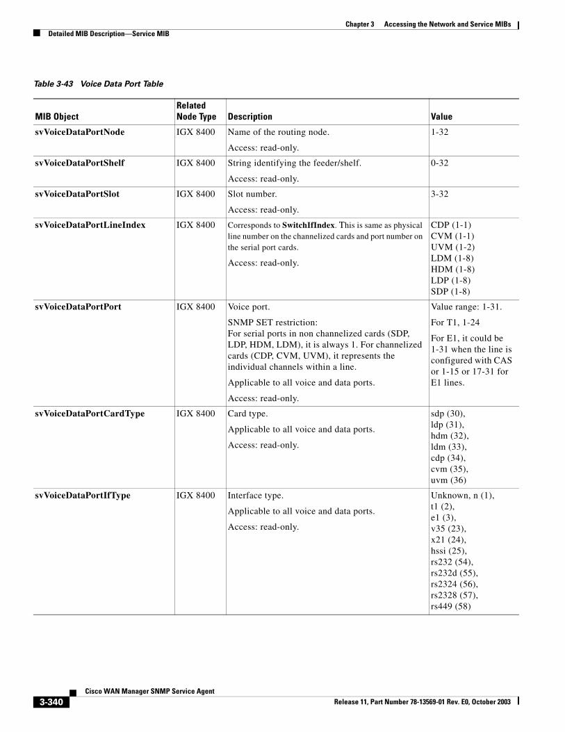
Chapter 3 Accessing the Network and Service MIBsDetailed MIB Description—Service MIB
Table 3-43 Voice Data Port Table
MIB ObjectRelated Node Type Description Value
svVoiceDataPortNode IGX 8400 Name of the routing node.
Access: read-only.
1-32
svVoiceDataPortShelf IGX 8400 String identifying the feeder/shelf.
Access: read-only.
0-32
svVoiceDataPortSlot IGX 8400 Slot number.
Access: read-only.
3-32
svVoiceDataPortLineIndex IGX 8400 Corresponds to SwitchIfIndex. This is same as physical line number on the channelized cards and port number on the serial port cards.
Access: read-only.
CDP (1-1)CVM (1-1)UVM (1-2)LDM (1-8)HDM (1-8)LDP (1-8)SDP (1-8)
svVoiceDataPortPort IGX 8400 Voice port.
SNMP SET restriction:For serial ports in non channelized cards (SDP, LDP, HDM, LDM), it is always 1. For channelized cards (CDP, CVM, UVM), it represents the individual channels within a line.
Applicable to all voice and data ports.
Access: read-only.
Value range: 1-31.
For T1, 1-24
For E1, it could be 1-31 when the line is configured with CAS or 1-15 or 17-31 for E1 lines.
svVoiceDataPortCardType IGX 8400 Card type.
Applicable to all voice and data ports.
Access: read-only.
sdp (30),ldp (31),hdm (32),ldm (33),cdp (34),cvm (35),uvm (36)
svVoiceDataPortIfType IGX 8400 Interface type.
Applicable to all voice and data ports.
Access: read-only.
Unknown, n (1),t1 (2),e1 (3),v35 (23),x21 (24),hssi (25),rs232 (54),rs232d (55),rs2324 (56),rs2328 (57),rs449 (58)
3-340Cisco WAN Manager SNMP Service Agent
Release 11, Part Number 78-13569-01 Rev. E0, October 2003
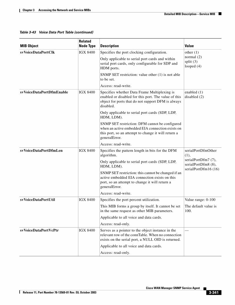
Chapter 3 Accessing the Network and Service MIBsDetailed MIB Description—Service MIB
svVoiceDataPortClk IGX 8400 Specifies the port clocking configuration.
Only applicable to serial port cards and within serial port cards, only configurable for SDP and HDM ports.
SNMP SET restriction: value other (1) is not able to be set.
Access: read-write.
other (1)normal (2)split (3)looped (4)
svVoiceDataPortDfmEnable IGX 8400 Specifies whether Data Frame Multiplexing is enabled or disabled for this port. The value of this object for ports that do not support DFM is always disabled.
Only applicable to serial port cards (SDP, LDP, HDM, LDM).
SNMP SET restriction: DFM cannot be configured when an active embedded EIA connection exists on this port, so an attempt to change it will return a generalError.
Access: read-write.
enabled (1)disabled (2)
svVoiceDataPortDfmLen IGX 8400 Specifies the pattern length in bits for the DFM algorithm.
Only applicable to serial port cards (SDP, LDP, HDM, LDM).
SNMP SET restriction: this cannot be changed if an active embedded EIA connection exists on this port, so an attempt to change it will return a generalError.
Access: read-write.
serialPortDfmOther (1),serialPortDfm7 (7),serialPortDfm8 (8),serialPortDfm16 (16)
svVoiceDataPortUtil IGX 8400 Specifies the port percent utilization.
This MIB forms a group by itself. It cannot be set in the same request as other MIB parameters.
Applicable to all voice and data cards.
Access: read-only.
Value range: 0-100
The default value is 100.
svVoiceDataPortVcPtr IGX 8400 Serves as a pointer to the object instance in the relevant row of the connTable. When no connection exists on the serial port, a NULL OID is returned.
Applicable to all voice and data cards.
Access: read-only.
—
Table 3-43 Voice Data Port Table (continued)
MIB ObjectRelated Node Type Description Value
3-341Cisco WAN Manager SNMP Service Agent
Release 11, Part Number 78-13569-01 Rev. E0, October 2003
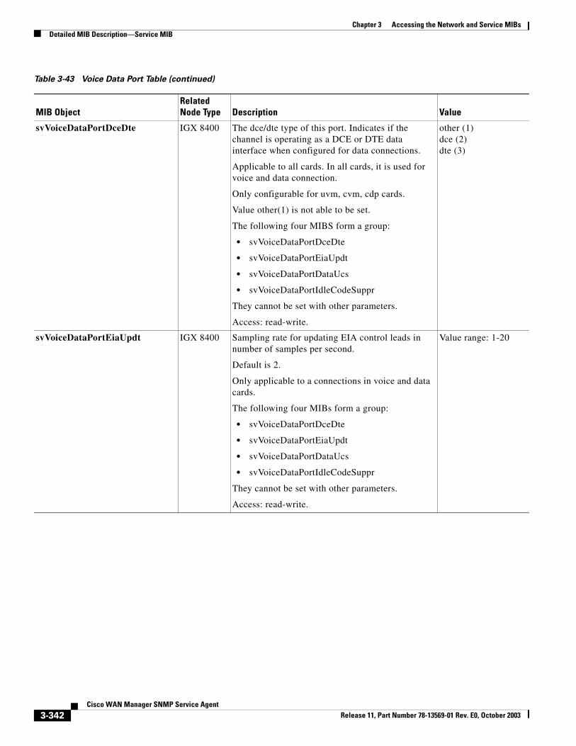
Chapter 3 Accessing the Network and Service MIBsDetailed MIB Description—Service MIB
svVoiceDataPortDceDte IGX 8400 The dce/dte type of this port. Indicates if the channel is operating as a DCE or DTE data interface when configured for data connections.
Applicable to all cards. In all cards, it is used for voice and data connection.
Only configurable for uvm, cvm, cdp cards.
Value other(1) is not able to be set.
The following four MIBS form a group:
• svVoiceDataPortDceDte
• svVoiceDataPortEiaUpdt
• svVoiceDataPortDataUcs
• svVoiceDataPortIdleCodeSuppr
They cannot be set with other parameters.
Access: read-write.
other (1)dce (2)dte (3)
svVoiceDataPortEiaUpdt IGX 8400 Sampling rate for updating EIA control leads in number of samples per second.
Default is 2.
Only applicable to a connections in voice and data cards.
The following four MIBs form a group:
• svVoiceDataPortDceDte
• svVoiceDataPortEiaUpdt
• svVoiceDataPortDataUcs
• svVoiceDataPortIdleCodeSuppr
They cannot be set with other parameters.
Access: read-write.
Value range: 1-20
Table 3-43 Voice Data Port Table (continued)
MIB ObjectRelated Node Type Description Value
3-342Cisco WAN Manager SNMP Service Agent
Release 11, Part Number 78-13569-01 Rev. E0, October 2003
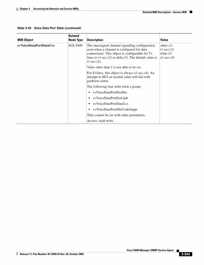
Chapter 3 Accessing the Network and Service MIBsDetailed MIB Description—Service MIB
svVoiceDataPortDataUcs IGX 8400 The unassigned channel signalling configuration used when a channel is configured for data connections. This object is configurable for T1 lines to t1-ucs (2) or ds0a (3). The default value is t1-ucs (2).
Value other than 1 is not able to be set.
For E1lines, this object is always e1-ucs (4). An attempt to SET an invalid value will fail with genError status.
The following four mibs form a group:
• svVoiceDataPortDceDte
• svVoiceDataPortEiaUpdt
• svVoiceDataPortDataUcs
• svVoiceDataPortIdleCodeSuppr
They cannot be set with other parameters.
Access: read-write.
other (1)t1-ucs (2)ds0a (3)e1-ucs (4)
Table 3-43 Voice Data Port Table (continued)
MIB ObjectRelated Node Type Description Value
3-343Cisco WAN Manager SNMP Service Agent
Release 11, Part Number 78-13569-01 Rev. E0, October 2003
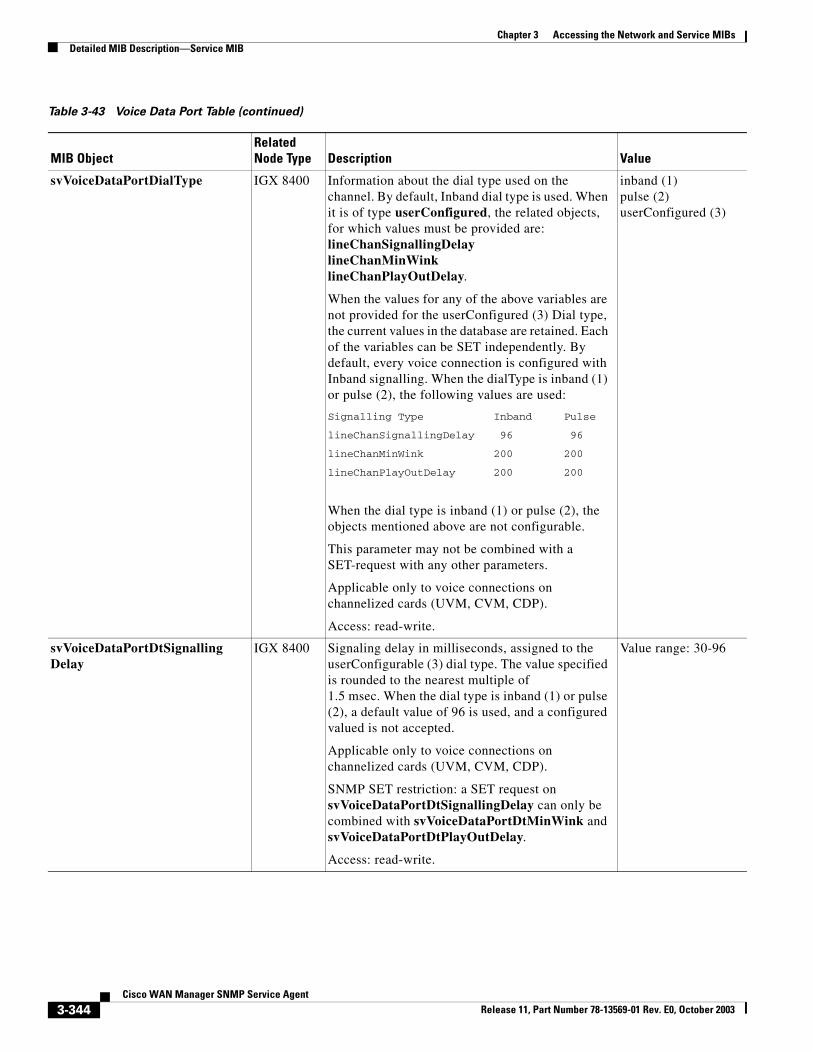
Chapter 3 Accessing the Network and Service MIBsDetailed MIB Description—Service MIB
svVoiceDataPortDialType IGX 8400 Information about the dial type used on the channel. By default, Inband dial type is used. When it is of type userConfigured, the related objects, for which values must be provided are:lineChanSignallingDelaylineChanMinWinklineChanPlayOutDelay.
When the values for any of the above variables are not provided for the userConfigured (3) Dial type, the current values in the database are retained. Each of the variables can be SET independently. By default, every voice connection is configured with Inband signalling. When the dialType is inband (1) or pulse (2), the following values are used:
Signalling Type Inband Pulse
lineChanSignallingDelay 96 96
lineChanMinWink 200 200
lineChanPlayOutDelay 200 200
When the dial type is inband (1) or pulse (2), the objects mentioned above are not configurable.
This parameter may not be combined with a SET-request with any other parameters.
Applicable only to voice connections on channelized cards (UVM, CVM, CDP).
Access: read-write.
inband (1)pulse (2)userConfigured (3)
svVoiceDataPortDtSignallingDelay
IGX 8400 Signaling delay in milliseconds, assigned to the userConfigurable (3) dial type. The value specified is rounded to the nearest multiple of 1.5 msec. When the dial type is inband (1) or pulse (2), a default value of 96 is used, and a configured valued is not accepted.
Applicable only to voice connections on channelized cards (UVM, CVM, CDP).
SNMP SET restriction: a SET request on svVoiceDataPortDtSignallingDelay can only be combined with svVoiceDataPortDtMinWink and svVoiceDataPortDtPlayOutDelay.
Access: read-write.
Value range: 30-96
Table 3-43 Voice Data Port Table (continued)
MIB ObjectRelated Node Type Description Value
3-344Cisco WAN Manager SNMP Service Agent
Release 11, Part Number 78-13569-01 Rev. E0, October 2003
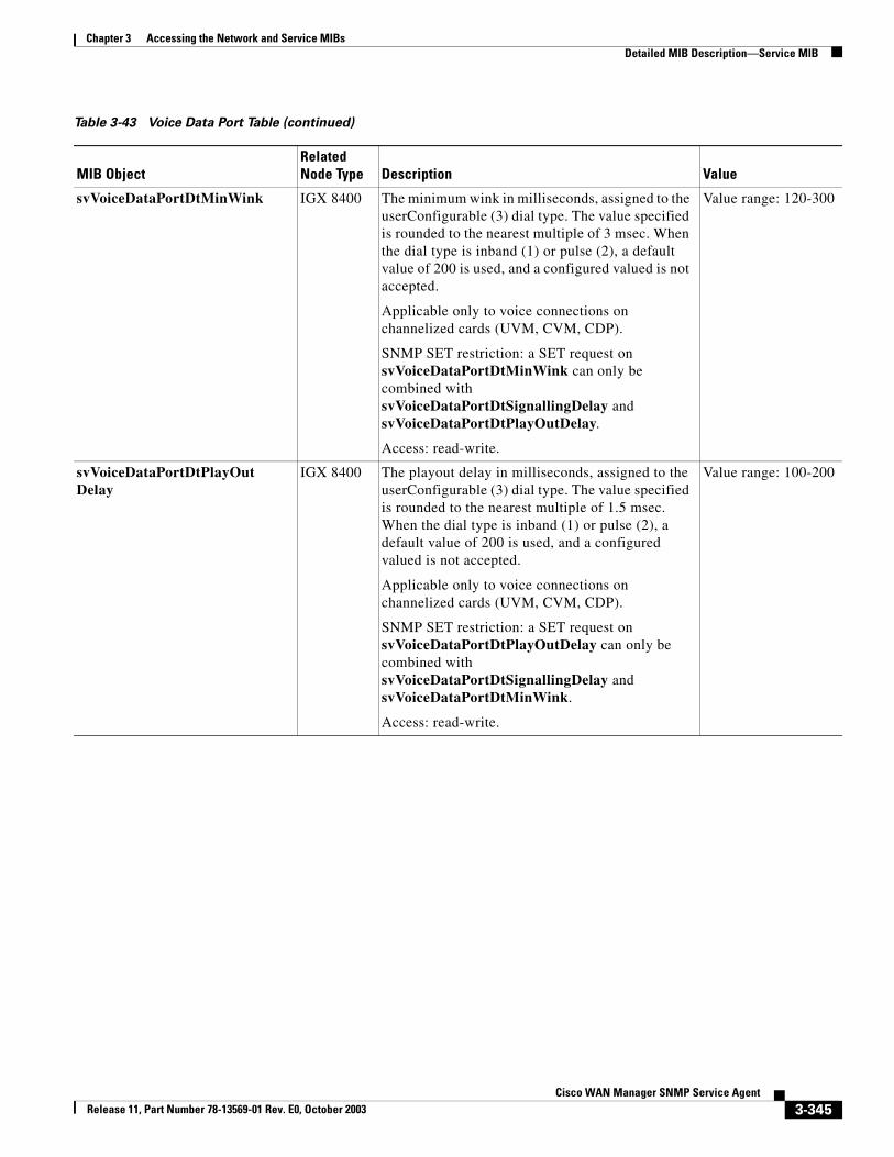
Chapter 3 Accessing the Network and Service MIBsDetailed MIB Description—Service MIB
svVoiceDataPortDtMinWink IGX 8400 The minimum wink in milliseconds, assigned to the userConfigurable (3) dial type. The value specified is rounded to the nearest multiple of 3 msec. When the dial type is inband (1) or pulse (2), a default value of 200 is used, and a configured valued is not accepted.
Applicable only to voice connections on channelized cards (UVM, CVM, CDP).
SNMP SET restriction: a SET request on svVoiceDataPortDtMinWink can only be combined with svVoiceDataPortDtSignallingDelay and svVoiceDataPortDtPlayOutDelay.
Access: read-write.
Value range: 120-300
svVoiceDataPortDtPlayOutDelay
IGX 8400 The playout delay in milliseconds, assigned to the userConfigurable (3) dial type. The value specified is rounded to the nearest multiple of 1.5 msec. When the dial type is inband (1) or pulse (2), a default value of 200 is used, and a configured valued is not accepted.
Applicable only to voice connections on channelized cards (UVM, CVM, CDP).
SNMP SET restriction: a SET request on svVoiceDataPortDtPlayOutDelay can only be combined with svVoiceDataPortDtSignallingDelay and svVoiceDataPortDtMinWink.
Access: read-write.
Value range: 100-200
Table 3-43 Voice Data Port Table (continued)
MIB ObjectRelated Node Type Description Value
3-345Cisco WAN Manager SNMP Service Agent
Release 11, Part Number 78-13569-01 Rev. E0, October 2003
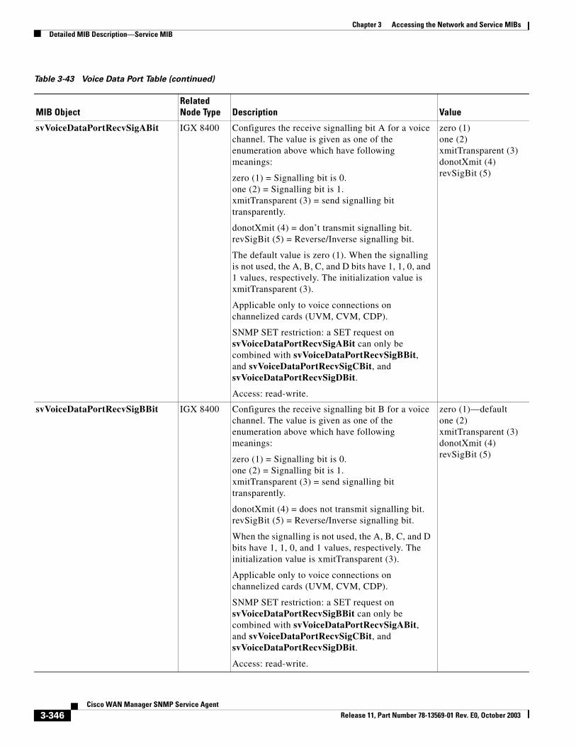
Chapter 3 Accessing the Network and Service MIBsDetailed MIB Description—Service MIB
svVoiceDataPortRecvSigABit IGX 8400 Configures the receive signalling bit A for a voice channel. The value is given as one of the enumeration above which have following meanings:
zero (1) = Signalling bit is 0.one (2) = Signalling bit is 1.xmitTransparent (3) = send signalling bit transparently.
donotXmit (4) = don’t transmit signalling bit. revSigBit (5) = Reverse/Inverse signalling bit.
The default value is zero (1). When the signalling is not used, the A, B, C, and D bits have 1, 1, 0, and 1 values, respectively. The initialization value is xmitTransparent (3).
Applicable only to voice connections on channelized cards (UVM, CVM, CDP).
SNMP SET restriction: a SET request on svVoiceDataPortRecvSigABit can only be combined with svVoiceDataPortRecvSigBBit, and svVoiceDataPortRecvSigCBit, and svVoiceDataPortRecvSigDBit.
Access: read-write.
zero (1)one (2)xmitTransparent (3)donotXmit (4)revSigBit (5)
svVoiceDataPortRecvSigBBit IGX 8400 Configures the receive signalling bit B for a voice channel. The value is given as one of the enumeration above which have following meanings:
zero (1) = Signalling bit is 0.one (2) = Signalling bit is 1.xmitTransparent (3) = send signalling bit transparently.
donotXmit (4) = does not transmit signalling bit. revSigBit (5) = Reverse/Inverse signalling bit.
When the signalling is not used, the A, B, C, and D bits have 1, 1, 0, and 1 values, respectively. The initialization value is xmitTransparent (3).
Applicable only to voice connections on channelized cards (UVM, CVM, CDP).
SNMP SET restriction: a SET request on svVoiceDataPortRecvSigBBit can only be combined with svVoiceDataPortRecvSigABit, and svVoiceDataPortRecvSigCBit, and svVoiceDataPortRecvSigDBit.
Access: read-write.
zero (1)—defaultone (2)xmitTransparent (3)donotXmit (4)revSigBit (5)
Table 3-43 Voice Data Port Table (continued)
MIB ObjectRelated Node Type Description Value
3-346Cisco WAN Manager SNMP Service Agent
Release 11, Part Number 78-13569-01 Rev. E0, October 2003
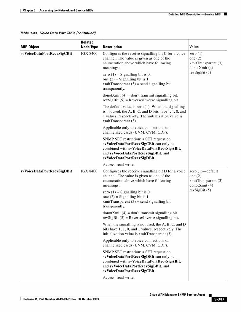
Chapter 3 Accessing the Network and Service MIBsDetailed MIB Description—Service MIB
svVoiceDataPortRecvSigCBit IGX 8400 Configures the receive signalling bit C for a voice channel. The value is given as one of the enumeration above which have following meanings:
zero (1) = Signalling bit is 0.one (2) = Signalling bit is 1.xmitTransparent (3) = send signalling bit transparently.
donotXmit (4) = don’t transmit signalling bit. revSigBit (5) = Reverse/Inverse signalling bit.
The default value is zero (1). When the signalling is not used, the A, B, C, and D bits have 1, 1, 0, and 1 values, respectively. The initialization value is xmitTransparent (3).
Applicable only to voice connections on channelized cards (UVM, CVM, CDP).
SNMP SET restriction: a SET request on svVoiceDataPortRecvSigCBit can only be combined with svVoiceDataPortRecvSigABit, and svVoiceDataPortRecvSigBBit, and svVoiceDataPortRecvSigDBit.
Access: read-write.
zero (1)one (2)xmitTransparent (3)donotXmit (4)revSigBit (5)
svVoiceDataPortRecvSigDBit IGX 8400 Configures the receive signalling bit D for a voice channel. The value is given as one of the enumeration above which have following meanings:
zero (1) = Signalling bit is 0.one (2) = Signalling bit is 1.xmitTransparent (3) = send signalling bit transparently.
donotXmit (4) = don’t transmit signalling bit. revSigBit (5) = Reverse/Inverse signalling bit.
When the signalling is not used, the A, B, C, and D bits have 1, 1, 0, and 1 values, respectively. The initialization value is xmitTransparent (3).
Applicable only to voice connections on channelized cards (UVM, CVM, CDP).
SNMP SET restriction: a SET request on svVoiceDataPortRecvSigDBit can only be combined with svVoiceDataPortRecvSigABit, and svVoiceDataPortRecvSigBBit, and svVoiceDataPortRecvSigCBit.
Access: read-write.
zero (1)—defaultone (2)xmitTransparent (3)donotXmit (4)revSigBit (5)
Table 3-43 Voice Data Port Table (continued)
MIB ObjectRelated Node Type Description Value
3-347Cisco WAN Manager SNMP Service Agent
Release 11, Part Number 78-13569-01 Rev. E0, October 2003
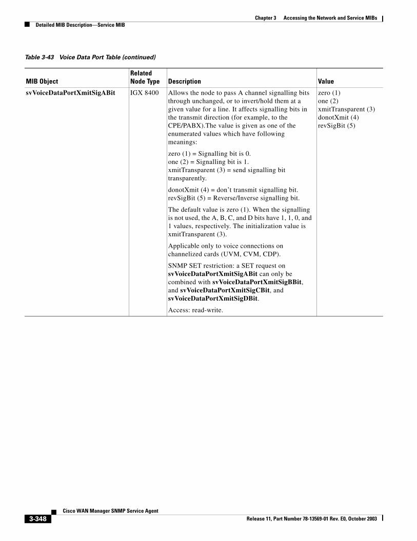
Chapter 3 Accessing the Network and Service MIBsDetailed MIB Description—Service MIB
svVoiceDataPortXmitSigABit IGX 8400 Allows the node to pass A channel signalling bits through unchanged, or to invert/hold them at a given value for a line. It affects signalling bits in the transmit direction (for example, to the CPE/PABX).The value is given as one of the enumerated values which have following meanings:
zero (1) = Signalling bit is 0.one (2) = Signalling bit is 1.xmitTransparent (3) = send signalling bit transparently.
donotXmit (4) = don’t transmit signalling bit. revSigBit (5) = Reverse/Inverse signalling bit.
The default value is zero (1). When the signalling is not used, the A, B, C, and D bits have 1, 1, 0, and 1 values, respectively. The initialization value is xmitTransparent (3).
Applicable only to voice connections on channelized cards (UVM, CVM, CDP).
SNMP SET restriction: a SET request on svVoiceDataPortXmitSigABit can only be combined with svVoiceDataPortXmitSigBBit, and svVoiceDataPortXmitSigCBit, and svVoiceDataPortXmitSigDBit.
Access: read-write.
zero (1)one (2)xmitTransparent (3)donotXmit (4)revSigBit (5)
Table 3-43 Voice Data Port Table (continued)
MIB ObjectRelated Node Type Description Value
3-348Cisco WAN Manager SNMP Service Agent
Release 11, Part Number 78-13569-01 Rev. E0, October 2003
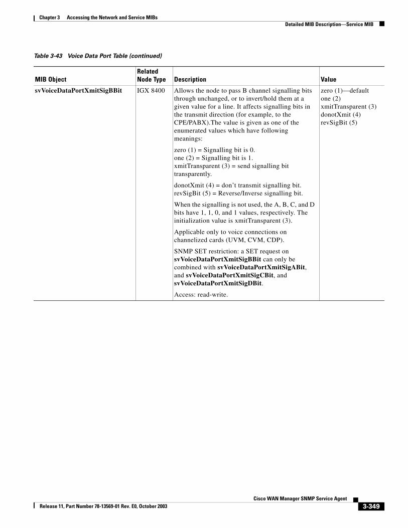
Chapter 3 Accessing the Network and Service MIBsDetailed MIB Description—Service MIB
svVoiceDataPortXmitSigBBit IGX 8400 Allows the node to pass B channel signalling bits through unchanged, or to invert/hold them at a given value for a line. It affects signalling bits in the transmit direction (for example, to the CPE/PABX).The value is given as one of the enumerated values which have following meanings:
zero (1) = Signalling bit is 0.one (2) = Signalling bit is 1.xmitTransparent (3) = send signalling bit transparently.
donotXmit (4) = don’t transmit signalling bit. revSigBit (5) = Reverse/Inverse signalling bit.
When the signalling is not used, the A, B, C, and D bits have 1, 1, 0, and 1 values, respectively. The initialization value is xmitTransparent (3).
Applicable only to voice connections on channelized cards (UVM, CVM, CDP).
SNMP SET restriction: a SET request on svVoiceDataPortXmitSigBBit can only be combined with svVoiceDataPortXmitSigABit, and svVoiceDataPortXmitSigCBit, and svVoiceDataPortXmitSigDBit.
Access: read-write.
zero (1)—defaultone (2)xmitTransparent (3)donotXmit (4)revSigBit (5)
Table 3-43 Voice Data Port Table (continued)
MIB ObjectRelated Node Type Description Value
3-349Cisco WAN Manager SNMP Service Agent
Release 11, Part Number 78-13569-01 Rev. E0, October 2003

Chapter 3 Accessing the Network and Service MIBsDetailed MIB Description—Service MIB
svVoiceDataPortXmitSigCBit IGX 8400 Allows the node to pass C channel signalling bits through unchanged, or to invert/hold them at a given value for a line. It affects signalling bits in the transmit direction (for example, to the CPE/PABX).The value is given as one of the enumerated values which have following meanings:
zero (1) = Signalling bit is 0.one (2) = Signalling bit is 1.xmitTransparent (3) = send signalling bit transparently.
donotXmit (4) = don’t transmit signalling bit. revSigBit (5) = Reverse/Inverse signalling bit.
The default value is zero (1). When the signalling is not used, the A, B, C, and D bits have 1, 1, 0, and 1 values, respectively. The initialization value is xmitTransparent (3).
Applicable only to voice connections on channelized cards (UVM, CVM, CDP).
SNMP SET restriction: a SET request on svVoiceDataPortXmitSigCBit can only be combined with svVoiceDataPortXmitSigABit, and svVoiceDataPortXmitSigBBit, and svVoiceDataPortXmitSigDBit.
Access: read-write.
zero (1)one (2)xmitTransparent (3)donotXmit (4)revSigBit (5)
Table 3-43 Voice Data Port Table (continued)
MIB ObjectRelated Node Type Description Value
3-350Cisco WAN Manager SNMP Service Agent
Release 11, Part Number 78-13569-01 Rev. E0, October 2003
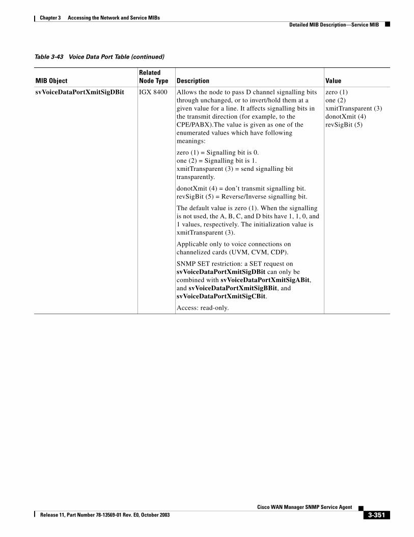
Chapter 3 Accessing the Network and Service MIBsDetailed MIB Description—Service MIB
svVoiceDataPortXmitSigDBit IGX 8400 Allows the node to pass D channel signalling bits through unchanged, or to invert/hold them at a given value for a line. It affects signalling bits in the transmit direction (for example, to the CPE/PABX).The value is given as one of the enumerated values which have following meanings:
zero (1) = Signalling bit is 0.one (2) = Signalling bit is 1.xmitTransparent (3) = send signalling bit transparently.
donotXmit (4) = don’t transmit signalling bit. revSigBit (5) = Reverse/Inverse signalling bit.
The default value is zero (1). When the signalling is not used, the A, B, C, and D bits have 1, 1, 0, and 1 values, respectively. The initialization value is xmitTransparent (3).
Applicable only to voice connections on channelized cards (UVM, CVM, CDP).
SNMP SET restriction: a SET request on svVoiceDataPortXmitSigDBit can only be combined with svVoiceDataPortXmitSigABit, and svVoiceDataPortXmitSigBBit, and svVoiceDataPortXmitSigCBit.
Access: read-only.
zero (1)one (2)xmitTransparent (3)donotXmit (4)revSigBit (5)
Table 3-43 Voice Data Port Table (continued)
MIB ObjectRelated Node Type Description Value
3-351Cisco WAN Manager SNMP Service Agent
Release 11, Part Number 78-13569-01 Rev. E0, October 2003
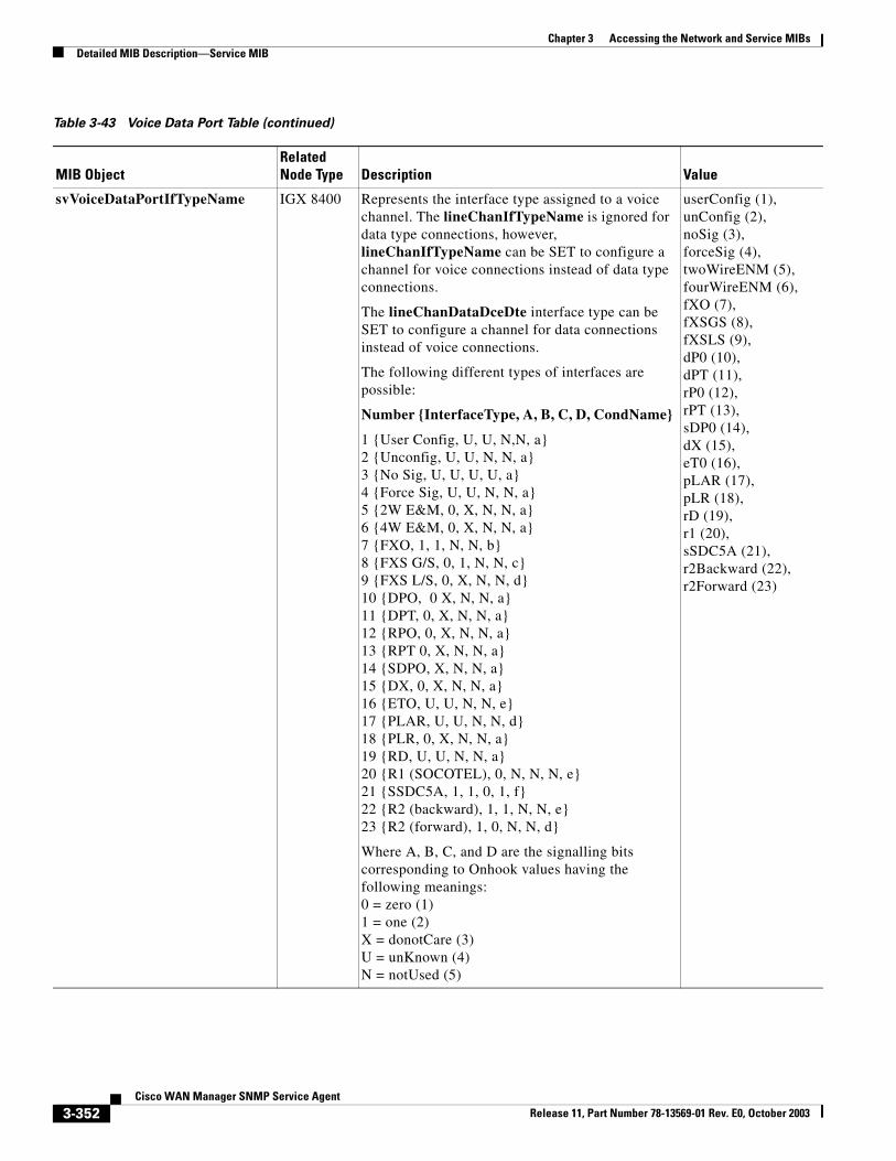
Chapter 3 Accessing the Network and Service MIBsDetailed MIB Description—Service MIB
svVoiceDataPortIfTypeName IGX 8400 Represents the interface type assigned to a voice channel. The lineChanIfTypeName is ignored for data type connections, however, lineChanIfTypeName can be SET to configure a channel for voice connections instead of data type connections.
The lineChanDataDceDte interface type can be SET to configure a channel for data connections instead of voice connections.
The following different types of interfaces are possible:
Number {InterfaceType, A, B, C, D, CondName}
1 {User Config, U, U, N,N, a}2 {Unconfig, U, U, N, N, a}3 {No Sig, U, U, U, U, a}4 {Force Sig, U, U, N, N, a}5 {2W E&M, 0, X, N, N, a}6 {4W E&M, 0, X, N, N, a}7 {FXO, 1, 1, N, N, b}8 {FXS G/S, 0, 1, N, N, c}9 {FXS L/S, 0, X, N, N, d}10 {DPO, 0 X, N, N, a}11 {DPT, 0, X, N, N, a}12 {RPO, 0, X, N, N, a}13 {RPT 0, X, N, N, a}14 {SDPO, X, N, N, a}15 {DX, 0, X, N, N, a}16 {ETO, U, U, N, N, e}17 {PLAR, U, U, N, N, d}18 {PLR, 0, X, N, N, a}19 {RD, U, U, N, N, a}20 {R1 (SOCOTEL), 0, N, N, N, e}21 {SSDC5A, 1, 1, 0, 1, f}22 {R2 (backward), 1, 1, N, N, e}23 {R2 (forward), 1, 0, N, N, d}
Where A, B, C, and D are the signalling bits corresponding to Onhook values having the following meanings:0 = zero (1)1 = one (2)X = donotCare (3)U = unKnown (4)N = notUsed (5)
userConfig (1),unConfig (2),noSig (3),forceSig (4),twoWireENM (5),fourWireENM (6),fXO (7),fXSGS (8),fXSLS (9),dP0 (10),dPT (11),rP0 (12),rPT (13),sDP0 (14),dX (15),eT0 (16),pLAR (17),pLR (18),rD (19),r1 (20),sSDC5A (21),r2Backward (22),r2Forward (23)
Table 3-43 Voice Data Port Table (continued)
MIB ObjectRelated Node Type Description Value
3-352Cisco WAN Manager SNMP Service Agent
Release 11, Part Number 78-13569-01 Rev. E0, October 2003
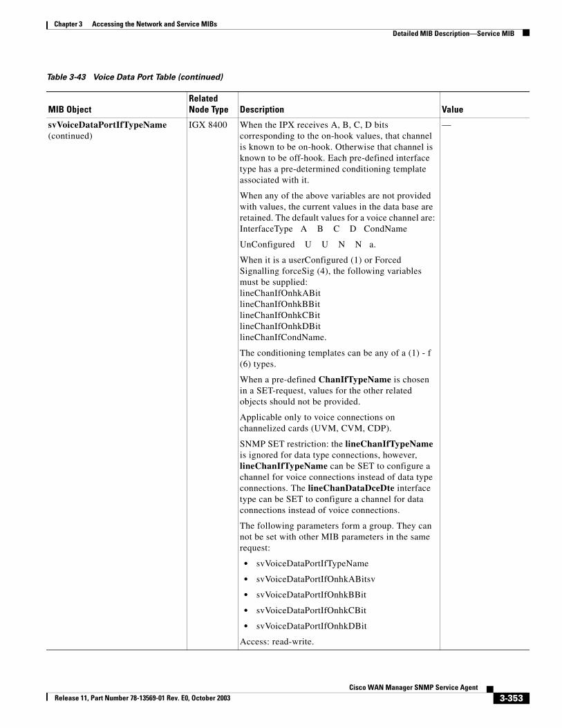
Chapter 3 Accessing the Network and Service MIBsDetailed MIB Description—Service MIB
svVoiceDataPortIfTypeName(continued)
IGX 8400 When the IPX receives A, B, C, D bits corresponding to the on-hook values, that channel is known to be on-hook. Otherwise that channel is known to be off-hook. Each pre-defined interface type has a pre-determined conditioning template associated with it.
When any of the above variables are not provided with values, the current values in the data base are retained. The default values for a voice channel are:InterfaceType A B C D CondName
UnConfigured U U N N a.
When it is a userConfigured (1) or Forced Signalling forceSig (4), the following variables must be supplied:lineChanIfOnhkABitlineChanIfOnhkBBitlineChanIfOnhkCBitlineChanIfOnhkDBitlineChanIfCondName.
The conditioning templates can be any of a (1) - f (6) types.
When a pre-defined ChanIfTypeName is chosen in a SET-request, values for the other related objects should not be provided.
Applicable only to voice connections on channelized cards (UVM, CVM, CDP).
SNMP SET restriction: the lineChanIfTypeName is ignored for data type connections, however, lineChanIfTypeName can be SET to configure a channel for voice connections instead of data type connections. The lineChanDataDceDte interface type can be SET to configure a channel for data connections instead of voice connections.
The following parameters form a group. They can not be set with other MIB parameters in the same request:
• svVoiceDataPortIfTypeName
• svVoiceDataPortIfOnhkABitsv
• svVoiceDataPortIfOnhkBBit
• svVoiceDataPortIfOnhkCBit
• svVoiceDataPortIfOnhkDBit
Access: read-write.
—
Table 3-43 Voice Data Port Table (continued)
MIB ObjectRelated Node Type Description Value
3-353Cisco WAN Manager SNMP Service Agent
Release 11, Part Number 78-13569-01 Rev. E0, October 2003

Chapter 3 Accessing the Network and Service MIBsDetailed MIB Description—Service MIB
svVoiceDataPortIfOnhkABit IGX 8400 Represents the value of A signalling bit, for which the IPX shall recognize an on-hook condition. The default value is unKnown (4).
The value corresponding to pre-defined Interface types are provided in the table in the “Description” clause of the object lineChanIfTypeName.
When the interface type is a pre-defined type, a value is not accepted for this object.
Applicable only to voice connections on channelized cards (UVM, CVM, CDP).
SNMP SET restriction: a SET request on svVoiceDataPortIfOnhkABit can only be combined with svVoiceDataPortIfTypeName, svVoiceDataPortIfOnhkBBit, svVoiceDataPortIfOnhkCBit, and svVoiceDataPortIfOnhkDBit.
The following parameters form a group. They can not be set with other MIB parameters in the same request:
• svVoiceDataPortIfTypeName
• svVoiceDataPortIfOnhkABitsv
• svVoiceDataPortIfOnhkBBit
• svVoiceDataPortIfOnhkCBit
• svVoiceDataPortIfOnhkDBit
Access: read-write.
zero (1)one (2)donotCare (3)unKnown (4)notUsed (5)
Table 3-43 Voice Data Port Table (continued)
MIB ObjectRelated Node Type Description Value
3-354Cisco WAN Manager SNMP Service Agent
Release 11, Part Number 78-13569-01 Rev. E0, October 2003

Chapter 3 Accessing the Network and Service MIBsDetailed MIB Description—Service MIB
svVoiceDataPortIfOnhkBBit IGX 8400 Represents the value of B signalling bit, for which the IPX shall recognize an on-hook condition. The default value is unKnown (4).
The value corresponding to pre-defined Interface types are provided in the table in the “Description” clause of the object lineChanIfTypeName.
When the interface type is a pre-defined type, a value is not accepted for this object.
Applicable only to voice connections on channelized cards (UVM, CVM, CDP).
SNMP SET restriction: a SET request on svVoiceDataPortIfOnhkBBit can only be combined with svVoiceDataPortIfTypeName, svVoiceDataPortIfOnhkABit, svVoiceDataPortIfOnhkCBit, and svVoiceDataPortIfOnhkDBit.
The following parameters form a group. They can not be set with other MIB parameters in the same request:
• svVoiceDataPortIfTypeName
• svVoiceDataPortIfOnhkABitsv
• svVoiceDataPortIfOnhkBBit
• svVoiceDataPortIfOnhkCBit
• svVoiceDataPortIfOnhkDBit
Access: read-write.
zero (1)one (2)donotCare (3)unKnown (4)notUsed (5)
Table 3-43 Voice Data Port Table (continued)
MIB ObjectRelated Node Type Description Value
3-355Cisco WAN Manager SNMP Service Agent
Release 11, Part Number 78-13569-01 Rev. E0, October 2003
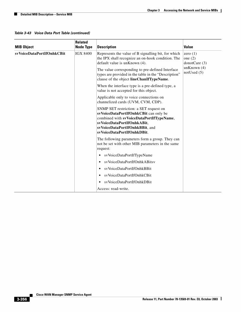
Chapter 3 Accessing the Network and Service MIBsDetailed MIB Description—Service MIB
svVoiceDataPortIfOnhkCBit IGX 8400 Represents the value of B signalling bit, for which the IPX shall recognize an on-hook condition. The default value is unKnown (4).
The value corresponding to pre-defined Interface types are provided in the table in the “Description” clause of the object lineChanIfTypeName.
When the interface type is a pre-defined type, a value is not accepted for this object.
Applicable only to voice connections on channelized cards (UVM, CVM, CDP).
SNMP SET restriction: a SET request on svVoiceDataPortIfOnhkCBit can only be combined with svVoiceDataPortIfTypeName, svVoiceDataPortIfOnhkABit, svVoiceDataPortIfOnhkBBit, and svVoiceDataPortIfOnhkDBit.
The following parameters form a group. They can not be set with other MIB parameters in the same request:
• svVoiceDataPortIfTypeName
• svVoiceDataPortIfOnhkABitsv
• svVoiceDataPortIfOnhkBBit
• svVoiceDataPortIfOnhkCBit
• svVoiceDataPortIfOnhkDBit
Access: read-write.
zero (1)one (2)donotCare (3)unKnown (4)notUsed (5)
Table 3-43 Voice Data Port Table (continued)
MIB ObjectRelated Node Type Description Value
3-356Cisco WAN Manager SNMP Service Agent
Release 11, Part Number 78-13569-01 Rev. E0, October 2003
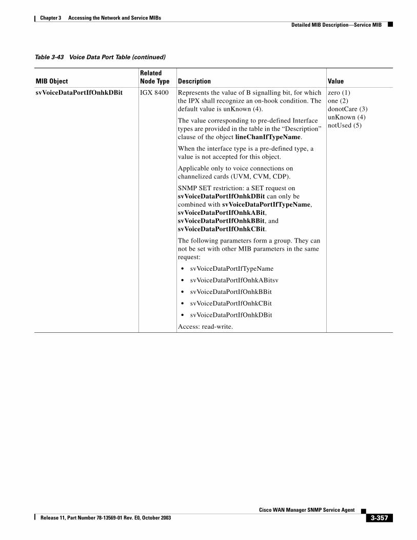
Chapter 3 Accessing the Network and Service MIBsDetailed MIB Description—Service MIB
svVoiceDataPortIfOnhkDBit IGX 8400 Represents the value of B signalling bit, for which the IPX shall recognize an on-hook condition. The default value is unKnown (4).
The value corresponding to pre-defined Interface types are provided in the table in the “Description” clause of the object lineChanIfTypeName.
When the interface type is a pre-defined type, a value is not accepted for this object.
Applicable only to voice connections on channelized cards (UVM, CVM, CDP).
SNMP SET restriction: a SET request on svVoiceDataPortIfOnhkDBit can only be combined with svVoiceDataPortIfTypeName, svVoiceDataPortIfOnhkABit, svVoiceDataPortIfOnhkBBit, and svVoiceDataPortIfOnhkCBit.
The following parameters form a group. They can not be set with other MIB parameters in the same request:
• svVoiceDataPortIfTypeName
• svVoiceDataPortIfOnhkABitsv
• svVoiceDataPortIfOnhkBBit
• svVoiceDataPortIfOnhkCBit
• svVoiceDataPortIfOnhkDBit
Access: read-write.
zero (1)one (2)donotCare (3)unKnown (4)notUsed (5)
Table 3-43 Voice Data Port Table (continued)
MIB ObjectRelated Node Type Description Value
3-357Cisco WAN Manager SNMP Service Agent
Release 11, Part Number 78-13569-01 Rev. E0, October 2003
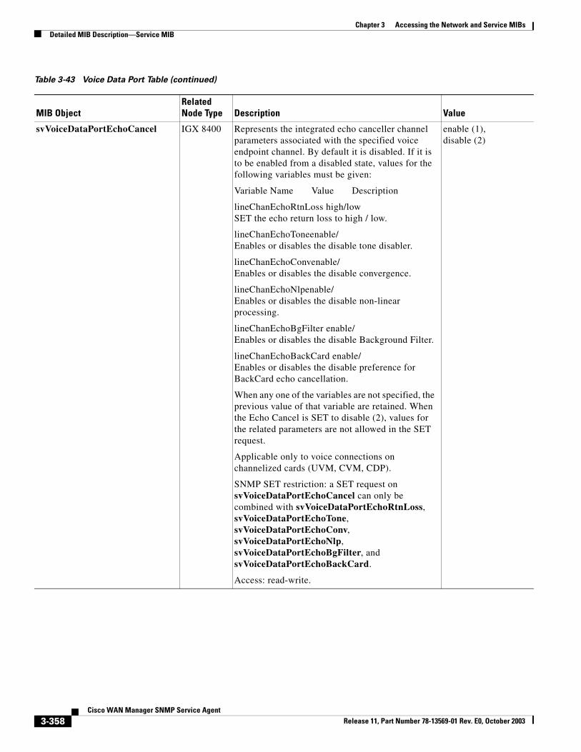
Chapter 3 Accessing the Network and Service MIBsDetailed MIB Description—Service MIB
svVoiceDataPortEchoCancel IGX 8400 Represents the integrated echo canceller channel parameters associated with the specified voice endpoint channel. By default it is disabled. If it is to be enabled from a disabled state, values for the following variables must be given:
Variable Name Value Description
lineChanEchoRtnLoss high/low SET the echo return loss to high / low.
lineChanEchoToneenable/ Enables or disables the disable tone disabler.
lineChanEchoConvenable/ Enables or disables the disable convergence.
lineChanEchoNlpenable/ Enables or disables the disable non-linear processing.
lineChanEchoBgFilter enable/ Enables or disables the disable Background Filter.
lineChanEchoBackCard enable/ Enables or disables the disable preference for BackCard echo cancellation.
When any one of the variables are not specified, the previous value of that variable are retained. When the Echo Cancel is SET to disable (2), values for the related parameters are not allowed in the SET request.
Applicable only to voice connections on channelized cards (UVM, CVM, CDP).
SNMP SET restriction: a SET request on svVoiceDataPortEchoCancel can only be combined with svVoiceDataPortEchoRtnLoss, svVoiceDataPortEchoTone, svVoiceDataPortEchoConv, svVoiceDataPortEchoNlp, svVoiceDataPortEchoBgFilter, and svVoiceDataPortEchoBackCard.
Access: read-write.
enable (1),disable (2)
Table 3-43 Voice Data Port Table (continued)
MIB ObjectRelated Node Type Description Value
3-358Cisco WAN Manager SNMP Service Agent
Release 11, Part Number 78-13569-01 Rev. E0, October 2003
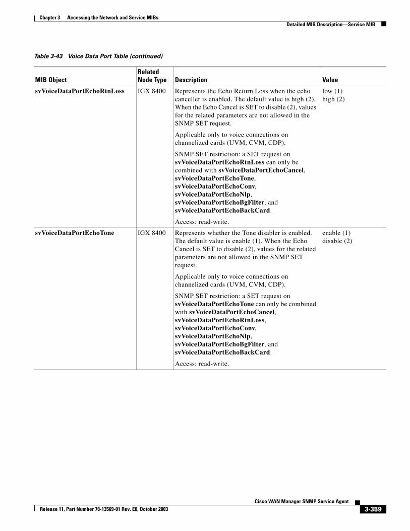
Chapter 3 Accessing the Network and Service MIBsDetailed MIB Description—Service MIB
svVoiceDataPortEchoRtnLoss IGX 8400 Represents the Echo Return Loss when the echo canceller is enabled. The default value is high (2). When the Echo Cancel is SET to disable (2), values for the related parameters are not allowed in the SNMP SET request.
Applicable only to voice connections on channelized cards (UVM, CVM, CDP).
SNMP SET restriction: a SET request on svVoiceDataPortEchoRtnLoss can only be combined with svVoiceDataPortEchoCancel, svVoiceDataPortEchoTone, svVoiceDataPortEchoConv, svVoiceDataPortEchoNlp, svVoiceDataPortEchoBgFilter, and svVoiceDataPortEchoBackCard.
Access: read-write.
low (1)high (2)
svVoiceDataPortEchoTone IGX 8400 Represents whether the Tone disabler is enabled. The default value is enable (1). When the Echo Cancel is SET to disable (2), values for the related parameters are not allowed in the SNMP SET request.
Applicable only to voice connections on channelized cards (UVM, CVM, CDP).
SNMP SET restriction: a SET request on svVoiceDataPortEchoTone can only be combined with svVoiceDataPortEchoCancel, svVoiceDataPortEchoRtnLoss, svVoiceDataPortEchoConv, svVoiceDataPortEchoNlp, svVoiceDataPortEchoBgFilter, and svVoiceDataPortEchoBackCard.
Access: read-write.
enable (1)disable (2)
Table 3-43 Voice Data Port Table (continued)
MIB ObjectRelated Node Type Description Value
3-359Cisco WAN Manager SNMP Service Agent
Release 11, Part Number 78-13569-01 Rev. E0, October 2003
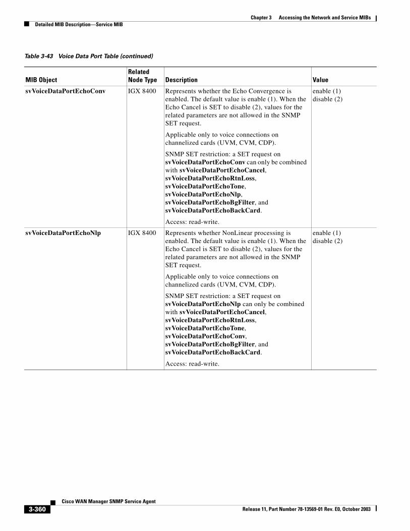
Chapter 3 Accessing the Network and Service MIBsDetailed MIB Description—Service MIB
svVoiceDataPortEchoConv IGX 8400 Represents whether the Echo Convergence is enabled. The default value is enable (1). When the Echo Cancel is SET to disable (2), values for the related parameters are not allowed in the SNMP SET request.
Applicable only to voice connections on channelized cards (UVM, CVM, CDP).
SNMP SET restriction: a SET request on svVoiceDataPortEchoConv can only be combined with svVoiceDataPortEchoCancel, svVoiceDataPortEchoRtnLoss, svVoiceDataPortEchoTone, svVoiceDataPortEchoNlp, svVoiceDataPortEchoBgFilter, and svVoiceDataPortEchoBackCard.
Access: read-write.
enable (1)disable (2)
svVoiceDataPortEchoNlp IGX 8400 Represents whether NonLinear processing is enabled. The default value is enable (1). When the Echo Cancel is SET to disable (2), values for the related parameters are not allowed in the SNMP SET request.
Applicable only to voice connections on channelized cards (UVM, CVM, CDP).
SNMP SET restriction: a SET request on svVoiceDataPortEchoNlp can only be combined with svVoiceDataPortEchoCancel, svVoiceDataPortEchoRtnLoss, svVoiceDataPortEchoTone, svVoiceDataPortEchoConv, svVoiceDataPortEchoBgFilter, and svVoiceDataPortEchoBackCard.
Access: read-write.
enable (1)disable (2)
Table 3-43 Voice Data Port Table (continued)
MIB ObjectRelated Node Type Description Value
3-360Cisco WAN Manager SNMP Service Agent
Release 11, Part Number 78-13569-01 Rev. E0, October 2003
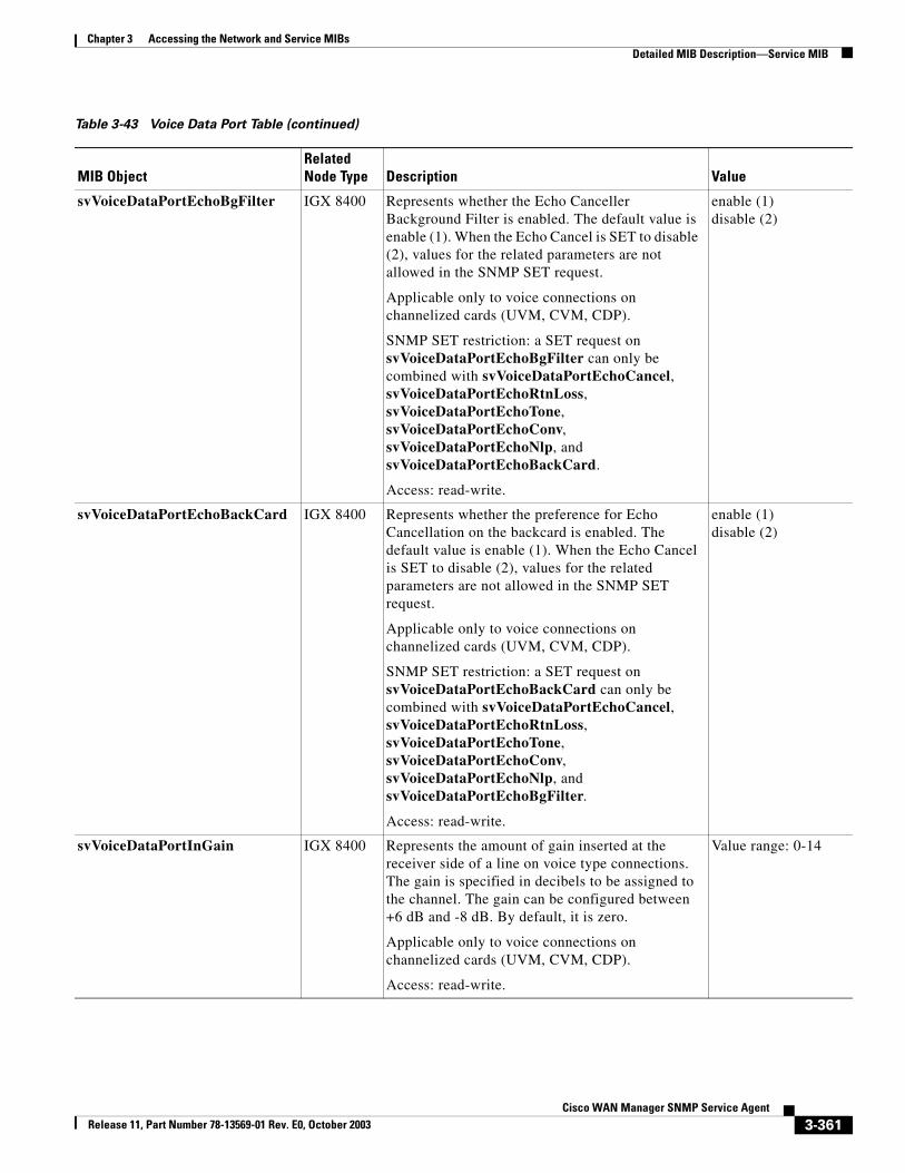
Chapter 3 Accessing the Network and Service MIBsDetailed MIB Description—Service MIB
svVoiceDataPortEchoBgFilter IGX 8400 Represents whether the Echo Canceller Background Filter is enabled. The default value is enable (1). When the Echo Cancel is SET to disable (2), values for the related parameters are not allowed in the SNMP SET request.
Applicable only to voice connections on channelized cards (UVM, CVM, CDP).
SNMP SET restriction: a SET request on svVoiceDataPortEchoBgFilter can only be combined with svVoiceDataPortEchoCancel, svVoiceDataPortEchoRtnLoss, svVoiceDataPortEchoTone, svVoiceDataPortEchoConv, svVoiceDataPortEchoNlp, and svVoiceDataPortEchoBackCard.
Access: read-write.
enable (1)disable (2)
svVoiceDataPortEchoBackCard IGX 8400 Represents whether the preference for Echo Cancellation on the backcard is enabled. The default value is enable (1). When the Echo Cancel is SET to disable (2), values for the related parameters are not allowed in the SNMP SET request.
Applicable only to voice connections on channelized cards (UVM, CVM, CDP).
SNMP SET restriction: a SET request on svVoiceDataPortEchoBackCard can only be combined with svVoiceDataPortEchoCancel, svVoiceDataPortEchoRtnLoss, svVoiceDataPortEchoTone, svVoiceDataPortEchoConv, svVoiceDataPortEchoNlp, and svVoiceDataPortEchoBgFilter.
Access: read-write.
enable (1)disable (2)
svVoiceDataPortInGain IGX 8400 Represents the amount of gain inserted at the receiver side of a line on voice type connections. The gain is specified in decibels to be assigned to the channel. The gain can be configured between +6 dB and -8 dB. By default, it is zero.
Applicable only to voice connections on channelized cards (UVM, CVM, CDP).
Access: read-write.
Value range: 0-14
Table 3-43 Voice Data Port Table (continued)
MIB ObjectRelated Node Type Description Value
3-361Cisco WAN Manager SNMP Service Agent
Release 11, Part Number 78-13569-01 Rev. E0, October 2003
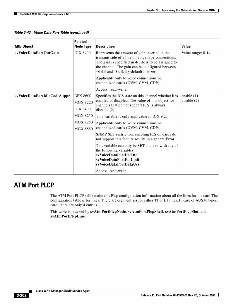
Chapter 3 Accessing the Network and Service MIBsDetailed MIB Description—Service MIB
ATM Port PLCP The ATM Port PLCP table maintains Plcp configuration information about all the lines for the card.The configuration table is for lines. There are eight entries for either T1 or E1 lines. In case of AUSM 4-port card, there are only 4 entries.
This table is indexed by svAtmPortPlcpNode, svAtmPortPlcpShelf, svAtmPortPlcpSlot, and svAtmPortPlcpLine.
svVoiceDataPortOutGain IGX 8400 Represents the amount of gain inserted at the transmit side of a line on voice type connections. The gain is specified in decibels to be assigned to the channel. The gain can be configured between +6 dB and -8 dB. By default it is zero.
Applicable only to voice connections on channelized cards (UVM, CVM, CDP).
Access: read-write.
Value range: 0-14
svVoiceDataPortIdleCodeSuppr BPX 8600
MGX 8220
IGX 8400
MGX 8230
MGX 8250
MGX 8850
Specifies the ICS state on this channel whether it is enabled or disabled. The value of this object for channels that do not support ICS is always disbaled(2).
This variable is only applicable in IGX 9.2.
Applicable only to voice connections on channelized cards (UVM, CVM, CDP).
SNMP SET restriction: enabling ICS on cards do not support this feature results in a generalError.
This variable can only be SET alone or with any of the following variables:svVoiceDataPortDceDtesvVoiceDataPortEiaUpdtsvVoiceDataPortDataUcs
Access: read-write.
enable (1)disable (2)
Table 3-43 Voice Data Port Table (continued)
MIB ObjectRelated Node Type Description Value
3-362Cisco WAN Manager SNMP Service Agent
Release 11, Part Number 78-13569-01 Rev. E0, October 2003
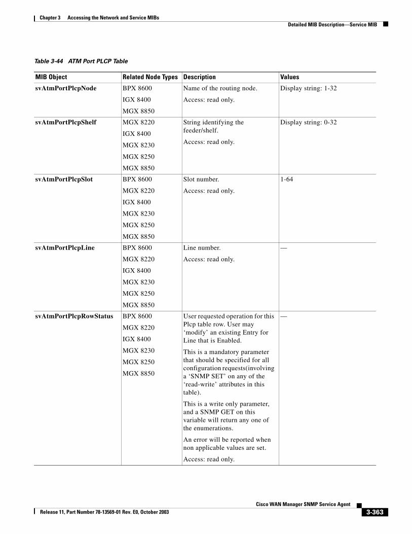
Chapter 3 Accessing the Network and Service MIBsDetailed MIB Description—Service MIB
Table 3-44 ATM Port PLCP Table
MIB Object Related Node Types Description Values
svAtmPortPlcpNode BPX 8600
IGX 8400
MGX 8850
Name of the routing node.
Access: read only.
Display string: 1-32
svAtmPortPlcpShelf MGX 8220
IGX 8400
MGX 8230
MGX 8250
MGX 8850
String identifying the feeder/shelf.
Access: read only.
Display string: 0-32
svAtmPortPlcpSlot BPX 8600
MGX 8220
IGX 8400
MGX 8230
MGX 8250
MGX 8850
Slot number.
Access: read only.
1-64
svAtmPortPlcpLine BPX 8600
MGX 8220
IGX 8400
MGX 8230
MGX 8250
MGX 8850
Line number.
Access: read only.
—
svAtmPortPlcpRowStatus BPX 8600
MGX 8220
IGX 8400
MGX 8230
MGX 8250
MGX 8850
User requested operation for this Plcp table row. User may ‘modify’ an existing Entry for Line that is Enabled.
This is a mandatory parameter that should be specified for all configuration requests(involving a ‘SNMP SET’ on any of the ‘read-write’ attributes in this table).
This is a write only parameter, and a SNMP GET on this variable will return any one of the enumerations.
An error will be reported when non applicable values are set.
Access: read only.
—
3-363Cisco WAN Manager SNMP Service Agent
Release 11, Part Number 78-13569-01 Rev. E0, October 2003
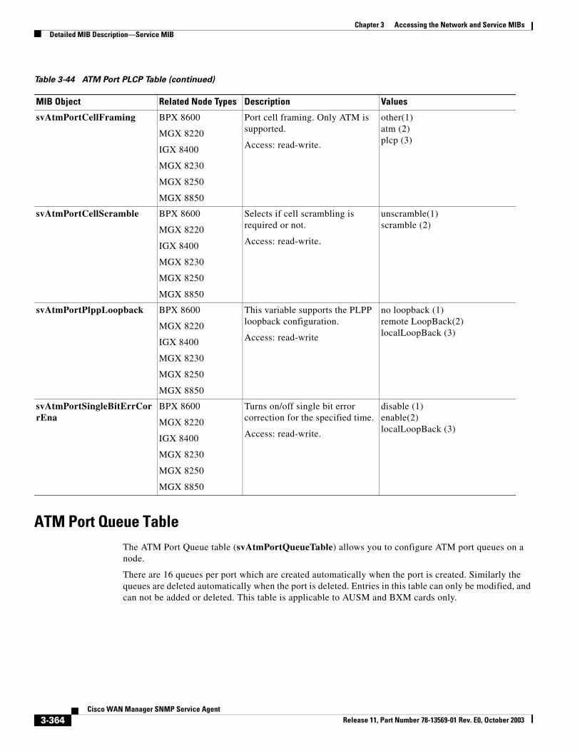
Chapter 3 Accessing the Network and Service MIBsDetailed MIB Description—Service MIB
ATM Port Queue TableThe ATM Port Queue table (svAtmPortQueueTable) allows you to configure ATM port queues on a node.
There are 16 queues per port which are created automatically when the port is created. Similarly the queues are deleted automatically when the port is deleted. Entries in this table can only be modified, and can not be added or deleted. This table is applicable to AUSM and BXM cards only.
svAtmPortCellFraming BPX 8600
MGX 8220
IGX 8400
MGX 8230
MGX 8250
MGX 8850
Port cell framing. Only ATM is supported.
Access: read-write.
other(1)atm (2)plcp (3)
svAtmPortCellScramble BPX 8600
MGX 8220
IGX 8400
MGX 8230
MGX 8250
MGX 8850
Selects if cell scrambling is required or not.
Access: read-write.
unscramble(1)scramble (2)
svAtmPortPlppLoopback BPX 8600
MGX 8220
IGX 8400
MGX 8230
MGX 8250
MGX 8850
This variable supports the PLPP loopback configuration.
Access: read-write
no loopback (1)remote LoopBack(2)localLoopBack (3)
svAtmPortSingleBitErrCorrEna
BPX 8600
MGX 8220
IGX 8400
MGX 8230
MGX 8250
MGX 8850
Turns on/off single bit error correction for the specified time.
Access: read-write.
disable (1)enable(2)localLoopBack (3)
Table 3-44 ATM Port PLCP Table (continued)
MIB Object Related Node Types Description Values
3-364Cisco WAN Manager SNMP Service Agent
Release 11, Part Number 78-13569-01 Rev. E0, October 2003
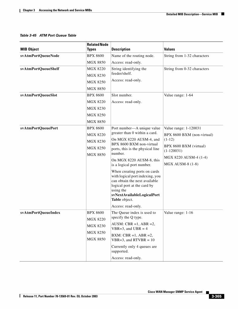
Chapter 3 Accessing the Network and Service MIBsDetailed MIB Description—Service MIB
Table 3-45 ATM Port Queue Table
MIB ObjectRelated Node Types Description Values
svAtmPortQueueNode BPX 8600
MGX 8850
Name of the routing node.
Access: read-only.
String from 1-32 characters
svAtmPortQueueShelf MGX 8220
MGX 8230
MGX 8250
MGX 8850
String identifying the feeder/shelf.
Access: read-only.
String from 0-32 characters
svAtmPortQueueSlot BPX 8600
MGX 8220
MGX 8230
MGX 8250
MGX 8850
Slot number.
Access: read-only.
Value range: 1-64
svAtmPortQueuePort BPX 8600
MGX 8220
MGX 8230
MGX 8250
MGX 8850
Port number—A unique value greater than 0 within a card.
On MGX 8220 AUSM-4, and BPX 8600 BXM non-virtual ports, this is the physical line number.
On MGX 8220 AUSM-8, this is a logical port number.
When creating ports on cards with logical port indexing, you can obtain the next available logical port at the card by using the svNextAvailableLogicalPortTable object.
Access: read-only.
Value range: 1-120031
BPX 8600 BXM (non-virtual) (1-12)
BPX 8600 BXM (virtual) (1-120031)
MGX 8220 AUSM-4 (1-4)
MGX AUSM-8 (1-8)
svAtmPortQueueIndex BPX 8600
MGX 8220
MGX 8230
MGX 8250
MGX 8850
The Queue index is used to specify the Q type.
AUSM: CBR =1, ABR =2, VBR=3, and UBR = 4
BXM: CBR =1, ABR =2, VBR=3, and RTVBR = 10
Currently only 4 queues are supported.
Access: read-only.
Value range: 1-16
3-365Cisco WAN Manager SNMP Service Agent
Release 11, Part Number 78-13569-01 Rev. E0, October 2003
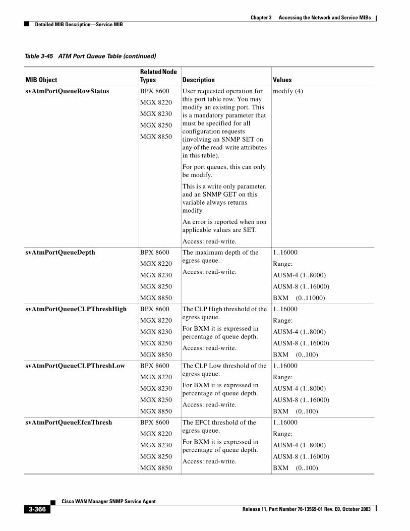
Chapter 3 Accessing the Network and Service MIBsDetailed MIB Description—Service MIB
svAtmPortQueueRowStatus BPX 8600
MGX 8220
MGX 8230
MGX 8250
MGX 8850
User requested operation for this port table row. You may modify an existing port. This is a mandatory parameter that must be specified for all configuration requests (involving an SNMP SET on any of the read-write attributes in this table).
For port queues, this can only be modify.
This is a write only parameter, and an SNMP GET on this variable always returns modify.
An error is reported when non applicable values are SET.
Access: read-write.
modify (4)
svAtmPortQueueDepth BPX 8600
MGX 8220
MGX 8230
MGX 8250
MGX 8850
The maximum depth of the egress queue.
Access: read-write.
1..16000
Range:
AUSM-4 (1..8000)
AUSM-8 (1..16000)
BXM (0..11000)
svAtmPortQueueCLPThreshHigh BPX 8600
MGX 8220
MGX 8230
MGX 8250
MGX 8850
The CLP High threshold of the egress queue.
For BXM it is expressed in percentage of queue depth.
Access: read-write.
1..16000
Range:
AUSM-4 (1..8000)
AUSM-8 (1..16000)
BXM (0..100)
svAtmPortQueueCLPThreshLow BPX 8600
MGX 8220
MGX 8230
MGX 8250
MGX 8850
The CLP Low threshold of the egress queue.
For BXM it is expressed in percentage of queue depth.
Access: read-write.
1..16000
Range:
AUSM-4 (1..8000)
AUSM-8 (1..16000)
BXM (0..100)
svAtmPortQueueEfcnThresh BPX 8600
MGX 8220
MGX 8230
MGX 8250
MGX 8850
The EFCI threshold of the egress queue.
For BXM it is expressed in percentage of queue depth.
Access: read-write.
1..16000
Range:
AUSM-4 (1..8000)
AUSM-8 (1..16000)
BXM (0..100)
Table 3-45 ATM Port Queue Table (continued)
MIB ObjectRelated Node Types Description Values
3-366Cisco WAN Manager SNMP Service Agent
Release 11, Part Number 78-13569-01 Rev. E0, October 2003
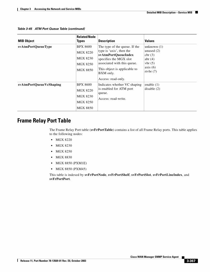
Chapter 3 Accessing the Network and Service MIBsDetailed MIB Description—Service MIB
Frame Relay Port TableThe Frame Relay Port table (svFrPortTable) contains a list of all Frame Relay ports. This table applies to the following nodes:
• MGX 8220
• MGX 8230
• MGX 8250
• MGX 8830
• MGX 8850 (PXM1E)
• MGX 8850 (PXM45)
This table is indexed by svFrPortNode, svFrPortShelf, svFrPortSlot, svFrPortLineIndex, and svFrPortPort.
svAtmPortQueueType BPX 8600
MGX 8220
MGX 8230
MGX 8250
MGX 8850
The type of the queue. If the type is ‘axis’, then the svAtmPortQueueIndex specifies the MGX slot associated with this queue.
This object is applicable to BXM only.
Access: read-only.
unknown (1)unused (2)cbr (3)abr (4)vbr (5)axis (6)rtvbr (7)
svAtmPortQueueVcShaping BPX 8600
MGX 8220
MGX 8230
MGX 8250
MGX 8850
Indicates whether VC shaping is enabled for ATM port queue.
Access: read-write.
enable (1)disable (2)
Table 3-45 ATM Port Queue Table (continued)
MIB ObjectRelated Node Types Description Values
3-367Cisco WAN Manager SNMP Service Agent
Release 11, Part Number 78-13569-01 Rev. E0, October 2003
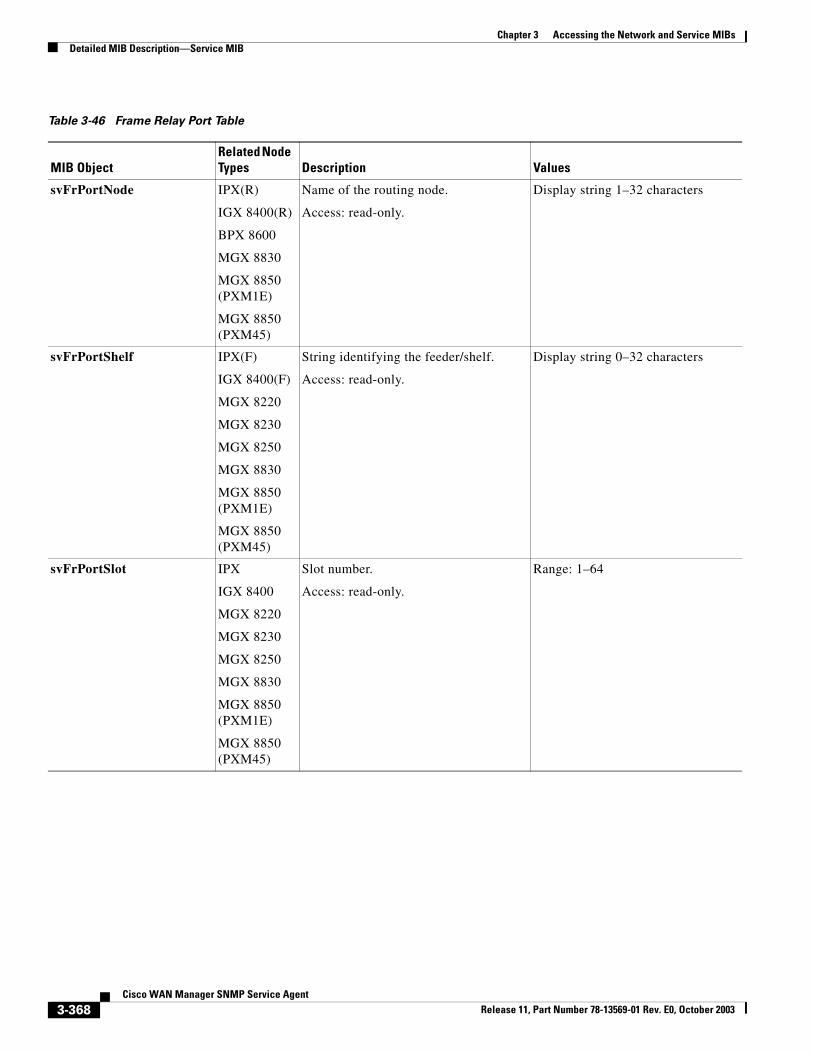
Chapter 3 Accessing the Network and Service MIBsDetailed MIB Description—Service MIB
Table 3-46 Frame Relay Port Table
MIB ObjectRelated Node Types Description Values
svFrPortNode IPX(R)
IGX 8400(R)
BPX 8600
MGX 8830
MGX 8850 (PXM1E)
MGX 8850 (PXM45)
Name of the routing node.
Access: read-only.
Display string 1–32 characters
svFrPortShelf IPX(F)
IGX 8400(F)
MGX 8220
MGX 8230
MGX 8250
MGX 8830
MGX 8850 (PXM1E)
MGX 8850 (PXM45)
String identifying the feeder/shelf.
Access: read-only.
Display string 0–32 characters
svFrPortSlot IPX
IGX 8400
MGX 8220
MGX 8230
MGX 8250
MGX 8830
MGX 8850 (PXM1E)
MGX 8850 (PXM45)
Slot number.
Access: read-only.
Range: 1–64
3-368Cisco WAN Manager SNMP Service Agent
Release 11, Part Number 78-13569-01 Rev. E0, October 2003
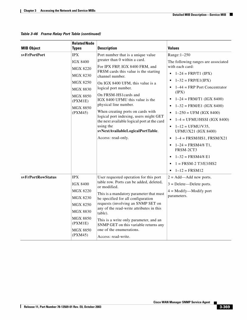
Chapter 3 Accessing the Network and Service MIBsDetailed MIB Description—Service MIB
svFrPortPort IPX
IGX 8400
MGX 8220
MGX 8230
MGX 8250
MGX 8830
MGX 8850 (PXM1E)
MGX 8850 (PXM45)
Port number that is a unique value greater than 0 within a card.
For IPX FRP, IGX 8400 FRM, andFRSM cards this value is the starting channel number.
On IGX 8400 UFM, this value is a logical port number.
On FRSM-HS1cards and IGX 8400 UFMU this value is the physical line number.
When creating ports on cards with logical port indexing, users might GET the next available logical port at the card using the svNextAvailableLogicalPortTable.
Access: read-only.
Range:1–250
The following ranges are associated with each card:
• 1–24 = FRP/T1 (IPX)
• 1–32 = FRP/E1(IPX)
• 1–44 = FRP Port Concentrator (IPX)
• 1–24 = FRM/T1 (IGX 8400)
• 1–32 = FRM/E1 (IGX 8400)
• 1–250 = UFM (IGX 8400)
• 1–4 = UFMU/HSSI (IGX 8400)
• 1–12 = UFMU/V35, UFMU/X21 (IGX 8400)
• 1–4 = FRSM/HS1, FRSM/X21
• 1–24 = FRSM4/8 T1, FRSM-2CT3
• 1–32 = FRSM4/8 E1
• 1 = FRSM-2 T3/E3/HS2
• 1–12 = FRSM12
svFrPortRowStatus IPX
IGX 8400
MGX 8220
MGX 8230
MGX 8250
MGX 8830
MGX 8850 (PXM1E)
MGX 8850 (PXM45)
User requested operation for this port table row. Ports can be added, deleted, or modified.
This is a mandatory parameter that must be specified for all configuration requests (involving an SNMP SET on any of the read-write attributes in this table).
This is a write only parameter, and an SNMP GET on this variable returns any one of the enumerations.
Access: read-write.
2 = Add—Add new ports.
3 = Delete—Delete ports.
4 = Modify—Modify port parameters.
Table 3-46 Frame Relay Port Table (continued)
MIB ObjectRelated Node Types Description Values
3-369Cisco WAN Manager SNMP Service Agent
Release 11, Part Number 78-13569-01 Rev. E0, October 2003
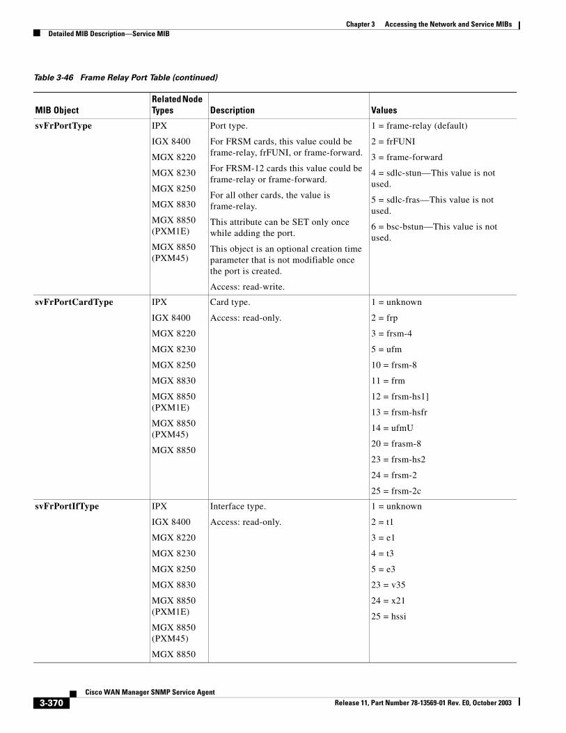
Chapter 3 Accessing the Network and Service MIBsDetailed MIB Description—Service MIB
svFrPortType IPX
IGX 8400
MGX 8220
MGX 8230
MGX 8250
MGX 8830
MGX 8850 (PXM1E)
MGX 8850 (PXM45)
Port type.
For FRSM cards, this value could be frame-relay, frFUNI, or frame-forward.
For FRSM-12 cards this value could be frame-relay or frame-forward.
For all other cards, the value is frame-relay.
This attribute can be SET only once while adding the port.
This object is an optional creation time parameter that is not modifiable once the port is created.
Access: read-write.
1 = frame-relay (default)
2 = frFUNI
3 = frame-forward
4 = sdlc-stun—This value is not used.
5 = sdlc-fras—This value is not used.
6 = bsc-bstun—This value is not used.
svFrPortCardType IPX
IGX 8400
MGX 8220
MGX 8230
MGX 8250
MGX 8830
MGX 8850 (PXM1E)
MGX 8850 (PXM45)
MGX 8850
Card type.
Access: read-only.
1 = unknown
2 = frp
3 = frsm-4
5 = ufm
10 = frsm-8
11 = frm
12 = frsm-hs1]
13 = frsm-hsfr
14 = ufmU
20 = frasm-8
23 = frsm-hs2
24 = frsm-2
25 = frsm-2c
svFrPortIfType IPX
IGX 8400
MGX 8220
MGX 8230
MGX 8250
MGX 8830
MGX 8850 (PXM1E)
MGX 8850 (PXM45)
MGX 8850
Interface type.
Access: read-only.
1 = unknown
2 = t1
3 = e1
4 = t3
5 = e3
23 = v35
24 = x21
25 = hssi
Table 3-46 Frame Relay Port Table (continued)
MIB ObjectRelated Node Types Description Values
3-370Cisco WAN Manager SNMP Service Agent
Release 11, Part Number 78-13569-01 Rev. E0, October 2003
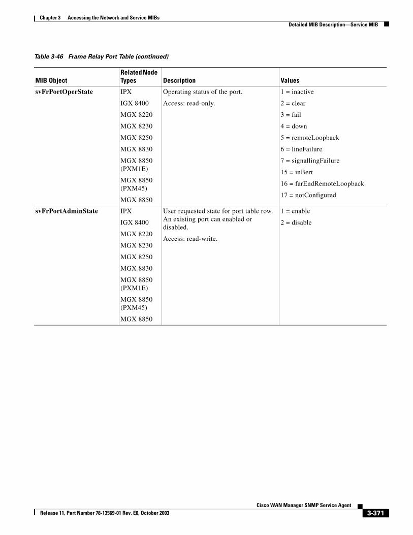
Chapter 3 Accessing the Network and Service MIBsDetailed MIB Description—Service MIB
svFrPortOperState IPX
IGX 8400
MGX 8220
MGX 8230
MGX 8250
MGX 8830
MGX 8850 (PXM1E)
MGX 8850 (PXM45)
MGX 8850
Operating status of the port.
Access: read-only.
1 = inactive
2 = clear
3 = fail
4 = down
5 = remoteLoopback
6 = lineFailure
7 = signallingFailure
15 = inBert
16 = farEndRemoteLoopback
17 = notConfigured
svFrPortAdminState IPX
IGX 8400
MGX 8220
MGX 8230
MGX 8250
MGX 8830
MGX 8850 (PXM1E)
MGX 8850 (PXM45)
MGX 8850
User requested state for port table row. An existing port can enabled or disabled.
Access: read-write.
1 = enable
2 = disable
Table 3-46 Frame Relay Port Table (continued)
MIB ObjectRelated Node Types Description Values
3-371Cisco WAN Manager SNMP Service Agent
Release 11, Part Number 78-13569-01 Rev. E0, October 2003
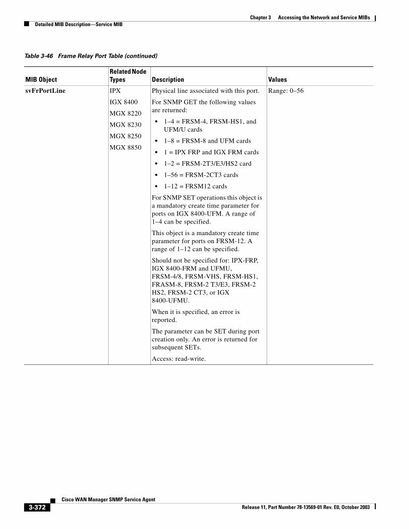
Chapter 3 Accessing the Network and Service MIBsDetailed MIB Description—Service MIB
svFrPortLine IPX
IGX 8400
MGX 8220
MGX 8230
MGX 8250
MGX 8850
Physical line associated with this port.
For SNMP GET the following values are returned:
• 1–4 = FRSM-4, FRSM-HS1, and UFM/U cards
• 1–8 = FRSM-8 and UFM cards
• 1 = IPX FRP and IGX FRM cards
• 1–2 = FRSM-2T3/E3/HS2 card
• 1–56 = FRSM-2CT3 cards
• 1–12 = FRSM12 cards
For SNMP SET operations this object is a mandatory create time parameter for ports on IGX 8400-UFM. A range of 1–4 can be specified.
This object is a mandatory create time parameter for ports on FRSM-12. A range of 1–12 can be specified.
Should not be specified for: IPX-FRP,IGX 8400-FRM and UFMU,FRSM-4/8, FRSM-VHS, FRSM-HS1, FRASM-8, FRSM-2 T3/E3, FRSM-2 HS2, FRSM-2 CT3, or IGX 8400-UFMU.
When it is specified, an error is reported.
The parameter can be SET during port creation only. An error is returned for subsequent SETs.
Access: read-write.
Range: 0–56
Table 3-46 Frame Relay Port Table (continued)
MIB ObjectRelated Node Types Description Values
3-372Cisco WAN Manager SNMP Service Agent
Release 11, Part Number 78-13569-01 Rev. E0, October 2003
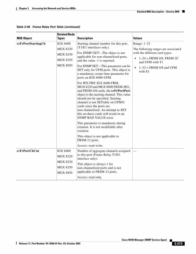
Chapter 3 Accessing the Network and Service MIBsDetailed MIB Description—Service MIB
svFrPortStartingCh IGX 8400
MGX 8220
MGX 8230
MGX 8250
MGX 8850
Starting channel number for this port. (T1/E1 interfaces only).
For SNMP GET—The object is not applicable for non-channelized ports, and the value -1 is reported.
For SNMP SET—This parameter can be SET only for UFM ports. This object is a mandatory create time parameter for ports on IGX 8400-UFM.
For IPX-FRP, IGX 8400-FRM, MGX 8220 and MGX 8800 FRSM-HS1, and FRSM-4/8 cards, the svFrPortPort object is the starting channel. This value should not be specified. Starting channel is not SETtable on UFM/U cards since the ports are non-channelized. An attempt to SET this on these cards will result in an SNMP BAD VALUE error.
This parameter is mandatory during creation. It is not modifiable after creation.
This object is not applicable to FRSM-12 ports.
Access: read-write.
Range: 1–32
The following ranges are associated with the different card types:
• 1–24 = FRSM 4/8, FRSM-2C and UFM with T1
• 1–32 = FRSM 4/8 and UFM with E1
svFrPortChCnt IGX 8400
MGX 8220
MGX 8230
MGX 8250
MGX 8850
Number of aggregate channels assigned to this port (Frame Relay T1/E1 interface only).
This object is always 1 for non-channelized ports and is not applicable to FRSM-12 ports.
Access: read-only.
—
Table 3-46 Frame Relay Port Table (continued)
MIB ObjectRelated Node Types Description Values
3-373Cisco WAN Manager SNMP Service Agent
Release 11, Part Number 78-13569-01 Rev. E0, October 2003
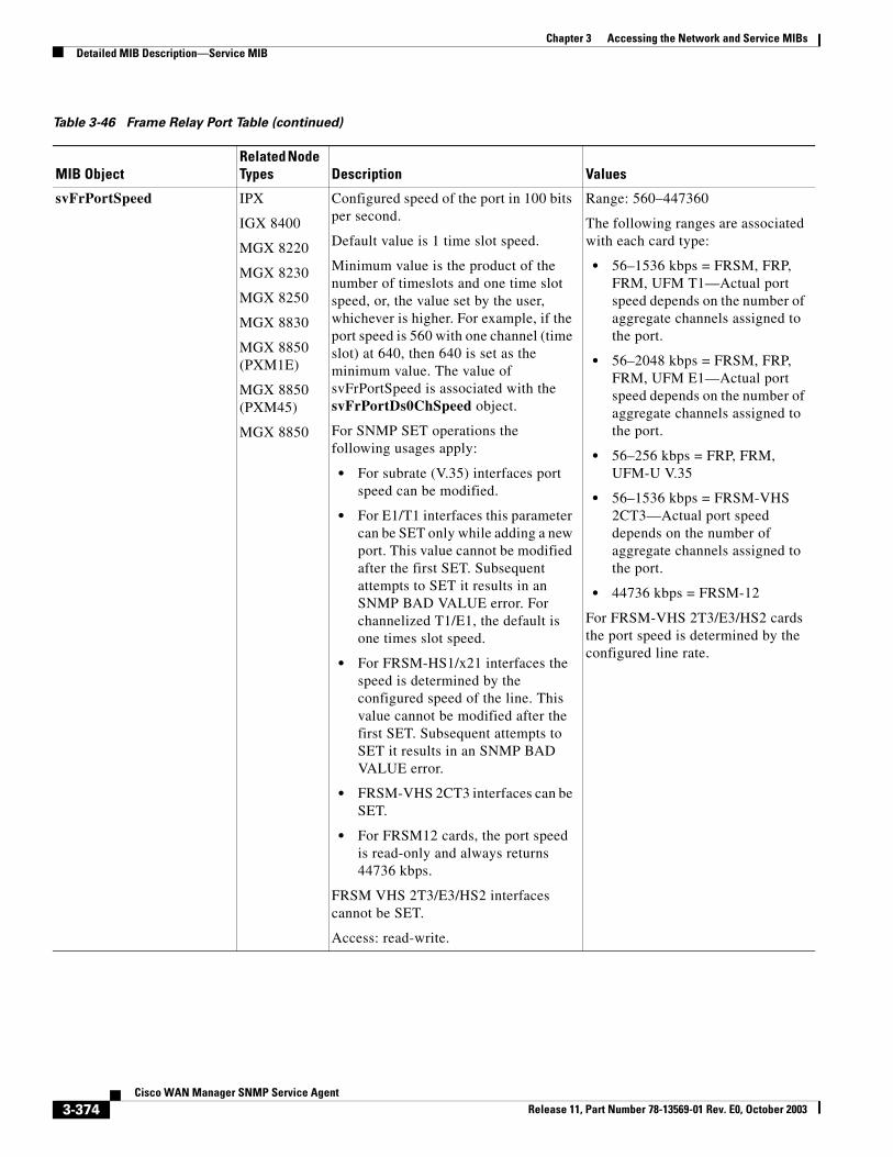
Chapter 3 Accessing the Network and Service MIBsDetailed MIB Description—Service MIB
svFrPortSpeed IPX
IGX 8400
MGX 8220
MGX 8230
MGX 8250
MGX 8830
MGX 8850 (PXM1E)
MGX 8850 (PXM45)
MGX 8850
Configured speed of the port in 100 bits per second.
Default value is 1 time slot speed.
Minimum value is the product of the number of timeslots and one time slot speed, or, the value set by the user, whichever is higher. For example, if the port speed is 560 with one channel (time slot) at 640, then 640 is set as the minimum value. The value of svFrPortSpeed is associated with the svFrPortDs0ChSpeed object.
For SNMP SET operations the following usages apply:
• For subrate (V.35) interfaces port speed can be modified.
• For E1/T1 interfaces this parameter can be SET only while adding a new port. This value cannot be modified after the first SET. Subsequent attempts to SET it results in an SNMP BAD VALUE error. For channelized T1/E1, the default is one times slot speed.
• For FRSM-HS1/x21 interfaces the speed is determined by the configured speed of the line. This value cannot be modified after the first SET. Subsequent attempts to SET it results in an SNMP BAD VALUE error.
• FRSM-VHS 2CT3 interfaces can be SET.
• For FRSM12 cards, the port speed is read-only and always returns 44736 kbps.
FRSM VHS 2T3/E3/HS2 interfaces cannot be SET.
Access: read-write.
Range: 560–447360
The following ranges are associated with each card type:
• 56–1536 kbps = FRSM, FRP, FRM, UFM T1—Actual port speed depends on the number of aggregate channels assigned to the port.
• 56–2048 kbps = FRSM, FRP, FRM, UFM E1—Actual port speed depends on the number of aggregate channels assigned to the port.
• 56–256 kbps = FRP, FRM, UFM-U V.35
• 56–1536 kbps = FRSM-VHS 2CT3—Actual port speed depends on the number of aggregate channels assigned to the port.
• 44736 kbps = FRSM-12
For FRSM-VHS 2T3/E3/HS2 cards the port speed is determined by the configured line rate.
Table 3-46 Frame Relay Port Table (continued)
MIB ObjectRelated Node Types Description Values
3-374Cisco WAN Manager SNMP Service Agent
Release 11, Part Number 78-13569-01 Rev. E0, October 2003
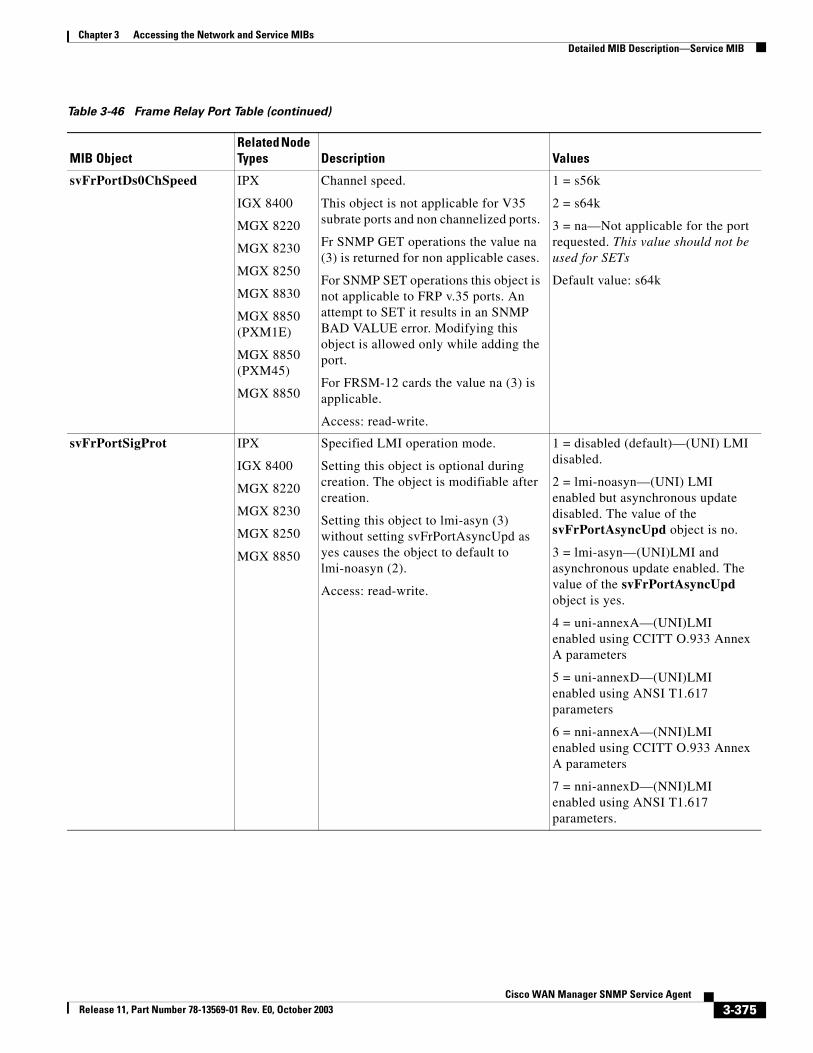
Chapter 3 Accessing the Network and Service MIBsDetailed MIB Description—Service MIB
svFrPortDs0ChSpeed IPX
IGX 8400
MGX 8220
MGX 8230
MGX 8250
MGX 8830
MGX 8850 (PXM1E)
MGX 8850 (PXM45)
MGX 8850
Channel speed.
This object is not applicable for V35 subrate ports and non channelized ports.
Fr SNMP GET operations the value na (3) is returned for non applicable cases.
For SNMP SET operations this object is not applicable to FRP v.35 ports. An attempt to SET it results in an SNMP BAD VALUE error. Modifying this object is allowed only while adding the port.
For FRSM-12 cards the value na (3) is applicable.
Access: read-write.
1 = s56k
2 = s64k
3 = na—Not applicable for the port requested. This value should not be used for SETs
Default value: s64k
svFrPortSigProt IPX
IGX 8400
MGX 8220
MGX 8230
MGX 8250
MGX 8850
Specified LMI operation mode.
Setting this object is optional during creation. The object is modifiable after creation.
Setting this object to lmi-asyn (3) without setting svFrPortAsyncUpd as yes causes the object to default to lmi-noasyn (2).
Access: read-write.
1 = disabled (default)—(UNI) LMI disabled.
2 = lmi-noasyn—(UNI) LMI enabled but asynchronous update disabled. The value of the svFrPortAsyncUpd object is no.
3 = lmi-asyn—(UNI)LMI and asynchronous update enabled. The value of the svFrPortAsyncUpd object is yes.
4 = uni-annexA—(UNI)LMI enabled using CCITT O.933 Annex A parameters
5 = uni-annexD—(UNI)LMI enabled using ANSI T1.617 parameters
6 = nni-annexA—(NNI)LMI enabled using CCITT O.933 Annex A parameters
7 = nni-annexD—(NNI)LMI enabled using ANSI T1.617 parameters.
Table 3-46 Frame Relay Port Table (continued)
MIB ObjectRelated Node Types Description Values
3-375Cisco WAN Manager SNMP Service Agent
Release 11, Part Number 78-13569-01 Rev. E0, October 2003
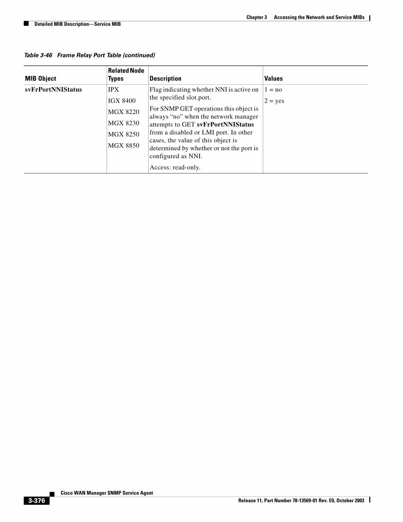
Chapter 3 Accessing the Network and Service MIBsDetailed MIB Description—Service MIB
svFrPortNNIStatus IPX
IGX 8400
MGX 8220
MGX 8230
MGX 8250
MGX 8850
Flag indicating whether NNI is active on the specified slot.port.
For SNMP GET operations this object is always “no” when the network manager attempts to GET svFrPortNNIStatus from a disabled or LMI port. In other cases, the value of this object is determined by whether or not the port is configured as NNI.
Access: read-only.
1 = no
2 = yes
Table 3-46 Frame Relay Port Table (continued)
MIB ObjectRelated Node Types Description Values
3-376Cisco WAN Manager SNMP Service Agent
Release 11, Part Number 78-13569-01 Rev. E0, October 2003
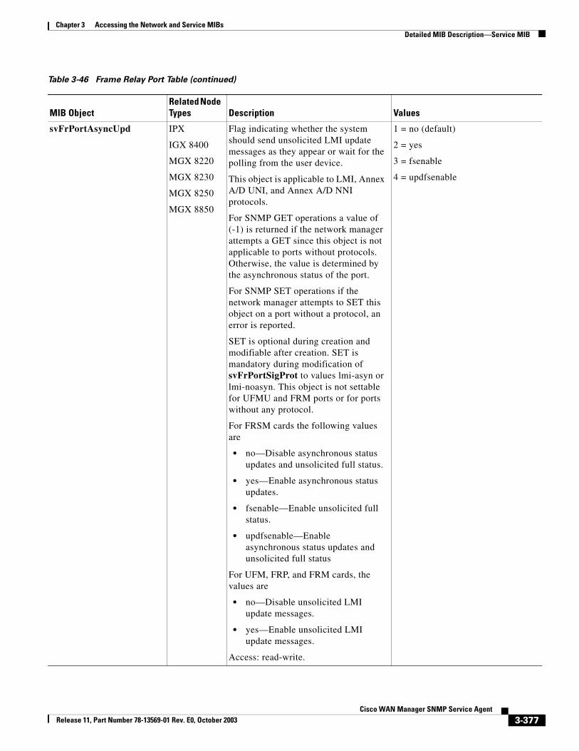
Chapter 3 Accessing the Network and Service MIBsDetailed MIB Description—Service MIB
svFrPortAsyncUpd IPX
IGX 8400
MGX 8220
MGX 8230
MGX 8250
MGX 8850
Flag indicating whether the system should send unsolicited LMI update messages as they appear or wait for the polling from the user device.
This object is applicable to LMI, Annex A/D UNI, and Annex A/D NNI protocols.
For SNMP GET operations a value of (-1) is returned if the network manager attempts a GET since this object is not applicable to ports without protocols. Otherwise, the value is determined by the asynchronous status of the port.
For SNMP SET operations if the network manager attempts to SET this object on a port without a protocol, an error is reported.
SET is optional during creation and modifiable after creation. SET is mandatory during modification of svFrPortSigProt to values lmi-asyn or lmi-noasyn. This object is not settable for UFMU and FRM ports or for ports without any protocol.
For FRSM cards the following values are
• no—Disable asynchronous status updates and unsolicited full status.
• yes—Enable asynchronous status updates.
• fsenable—Enable unsolicited full status.
• updfsenable—Enable asynchronous status updates and unsolicited full status
For UFM, FRP, and FRM cards, the values are
• no—Disable unsolicited LMI update messages.
• yes—Enable unsolicited LMI update messages.
Access: read-write.
1 = no (default)
2 = yes
3 = fsenable
4 = updfsenable
Table 3-46 Frame Relay Port Table (continued)
MIB ObjectRelated Node Types Description Values
3-377Cisco WAN Manager SNMP Service Agent
Release 11, Part Number 78-13569-01 Rev. E0, October 2003
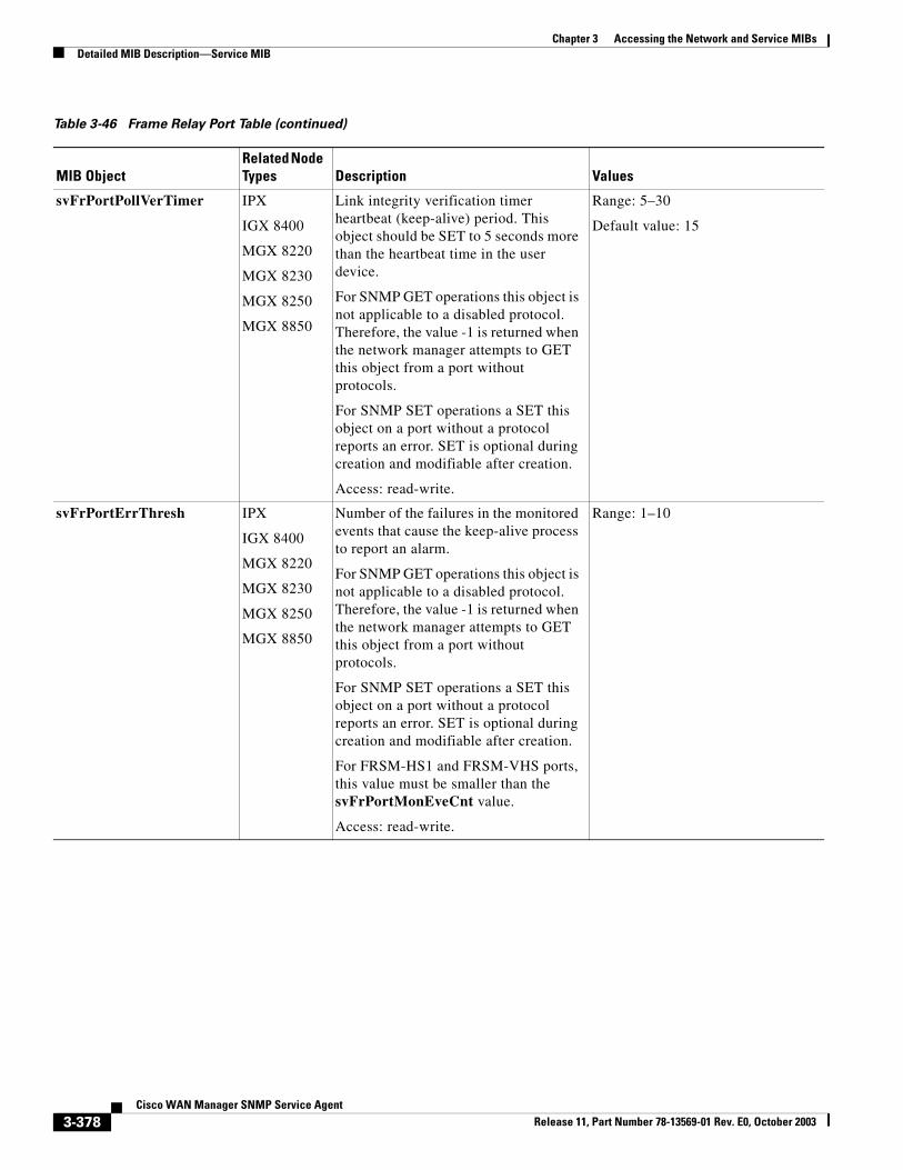
Chapter 3 Accessing the Network and Service MIBsDetailed MIB Description—Service MIB
svFrPortPollVerTimer IPX
IGX 8400
MGX 8220
MGX 8230
MGX 8250
MGX 8850
Link integrity verification timer heartbeat (keep-alive) period. This object should be SET to 5 seconds more than the heartbeat time in the user device.
For SNMP GET operations this object is not applicable to a disabled protocol. Therefore, the value -1 is returned when the network manager attempts to GET this object from a port without protocols.
For SNMP SET operations a SET this object on a port without a protocol reports an error. SET is optional during creation and modifiable after creation.
Access: read-write.
Range: 5–30
Default value: 15
svFrPortErrThresh IPX
IGX 8400
MGX 8220
MGX 8230
MGX 8250
MGX 8850
Number of the failures in the monitored events that cause the keep-alive process to report an alarm.
For SNMP GET operations this object is not applicable to a disabled protocol. Therefore, the value -1 is returned when the network manager attempts to GET this object from a port without protocols.
For SNMP SET operations a SET this object on a port without a protocol reports an error. SET is optional during creation and modifiable after creation.
For FRSM-HS1 and FRSM-VHS ports, this value must be smaller than the svFrPortMonEveCnt value.
Access: read-write.
Range: 1–10
Table 3-46 Frame Relay Port Table (continued)
MIB ObjectRelated Node Types Description Values
3-378Cisco WAN Manager SNMP Service Agent
Release 11, Part Number 78-13569-01 Rev. E0, October 2003
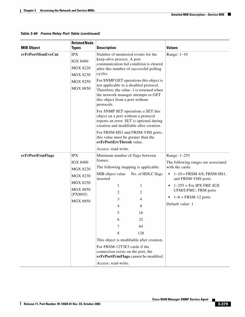
Chapter 3 Accessing the Network and Service MIBsDetailed MIB Description—Service MIB
svFrPortMonEveCnt IPX
IGX 8400
MGX 8220
MGX 8230
MGX 8250
MGX 8850
Number of monitored events for the keep-alive process. A port communication fail condition is cleared after this number of successful polling cycles.
For SNMP GET operations this object is not applicable to a disabled protocol. Therefore, the value -1 is returned when the network manager attempts to GET this object from a port without protocols.
For SNMP SET operations a SET this object on a port without a protocol reports an error. SET is optional during creation and modifiable after creation.
For FRSM-HS1 and FRSM-VHS ports, this value must be greater than the svFrPortErrThresh value.
Access: read-write.
Range: 1–10
svFrPortFrmFlags IPX
IGX 8400
MGX 8220
MGX 8230
MGX 8250
MGX 8850 (PXM45)
MGX 8850
Minimum number of flags between frames.
The following mapping is applicable:
MIB object value No. of HDLC flags inserted
1 1
2 2
3 4
4 8
5 16
6 32
7 64
8 128
This object is modifiable after creation.
For FRSM-12T3E3 cards if the connection exists on the port, the svFrPortFrmFlags cannot be modified.
Access: read-write.
Range: 1–255
The following ranges are associated with the cards:
• 1–10 = FRSM-4/8, FRSM-HS1, and FRSM-VHS ports
• 1–255 = For IPX FRP, IGX UFM/UFMU, FRM ports
• 1–8 = FRSM-12 ports
Default value: 1
Table 3-46 Frame Relay Port Table (continued)
MIB ObjectRelated Node Types Description Values
3-379Cisco WAN Manager SNMP Service Agent
Release 11, Part Number 78-13569-01 Rev. E0, October 2003
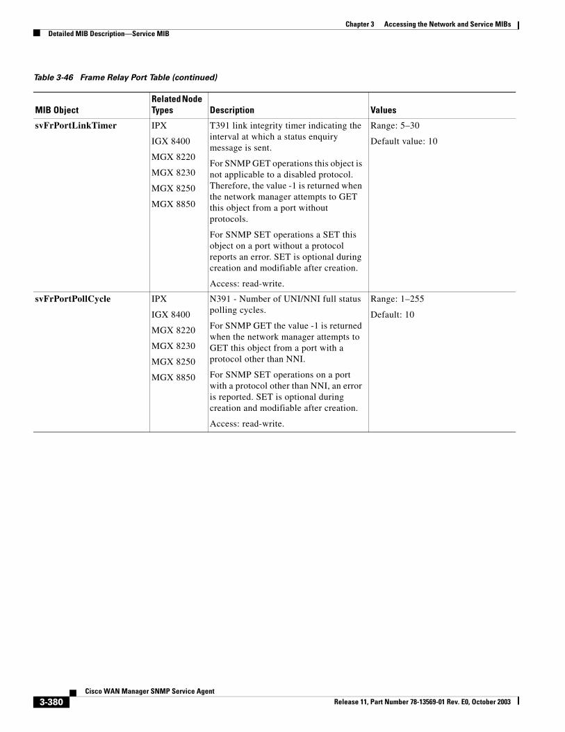
Chapter 3 Accessing the Network and Service MIBsDetailed MIB Description—Service MIB
svFrPortLinkTimer IPX
IGX 8400
MGX 8220
MGX 8230
MGX 8250
MGX 8850
T391 link integrity timer indicating the interval at which a status enquiry message is sent.
For SNMP GET operations this object is not applicable to a disabled protocol. Therefore, the value -1 is returned when the network manager attempts to GET this object from a port without protocols.
For SNMP SET operations a SET this object on a port without a protocol reports an error. SET is optional during creation and modifiable after creation.
Access: read-write.
Range: 5–30
Default value: 10
svFrPortPollCycle IPX
IGX 8400
MGX 8220
MGX 8230
MGX 8250
MGX 8850
N391 - Number of UNI/NNI full status polling cycles.
For SNMP GET the value -1 is returned when the network manager attempts to GET this object from a port with a protocol other than NNI.
For SNMP SET operations on a port with a protocol other than NNI, an error is reported. SET is optional during creation and modifiable after creation.
Access: read-write.
Range: 1–255
Default: 10
Table 3-46 Frame Relay Port Table (continued)
MIB ObjectRelated Node Types Description Values
3-380Cisco WAN Manager SNMP Service Agent
Release 11, Part Number 78-13569-01 Rev. E0, October 2003
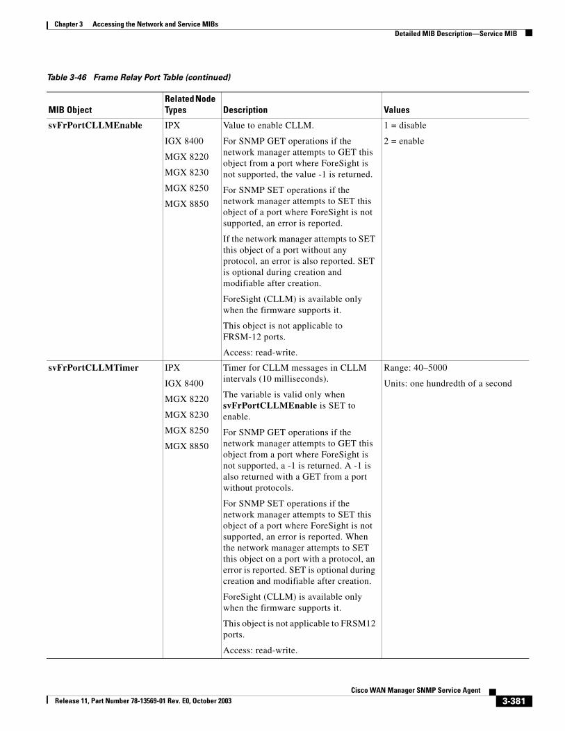
Chapter 3 Accessing the Network and Service MIBsDetailed MIB Description—Service MIB
svFrPortCLLMEnable IPX
IGX 8400
MGX 8220
MGX 8230
MGX 8250
MGX 8850
Value to enable CLLM.
For SNMP GET operations if the network manager attempts to GET this object from a port where ForeSight is not supported, the value -1 is returned.
For SNMP SET operations if the network manager attempts to SET this object of a port where ForeSight is not supported, an error is reported.
If the network manager attempts to SET this object of a port without any protocol, an error is also reported. SET is optional during creation and modifiable after creation.
ForeSight (CLLM) is available only when the firmware supports it.
This object is not applicable to FRSM-12 ports.
Access: read-write.
1 = disable
2 = enable
svFrPortCLLMTimer IPX
IGX 8400
MGX 8220
MGX 8230
MGX 8250
MGX 8850
Timer for CLLM messages in CLLM intervals (10 milliseconds).
The variable is valid only when svFrPortCLLMEnable is SET to enable.
For SNMP GET operations if the network manager attempts to GET this object from a port where ForeSight is not supported, a -1 is returned. A -1 is also returned with a GET from a port without protocols.
For SNMP SET operations if the network manager attempts to SET this object of a port where ForeSight is not supported, an error is reported. When the network manager attempts to SET this object on a port with a protocol, an error is reported. SET is optional during creation and modifiable after creation.
ForeSight (CLLM) is available only when the firmware supports it.
This object is not applicable to FRSM12 ports.
Access: read-write.
Range: 40–5000
Units: one hundredth of a second
Table 3-46 Frame Relay Port Table (continued)
MIB ObjectRelated Node Types Description Values
3-381Cisco WAN Manager SNMP Service Agent
Release 11, Part Number 78-13569-01 Rev. E0, October 2003
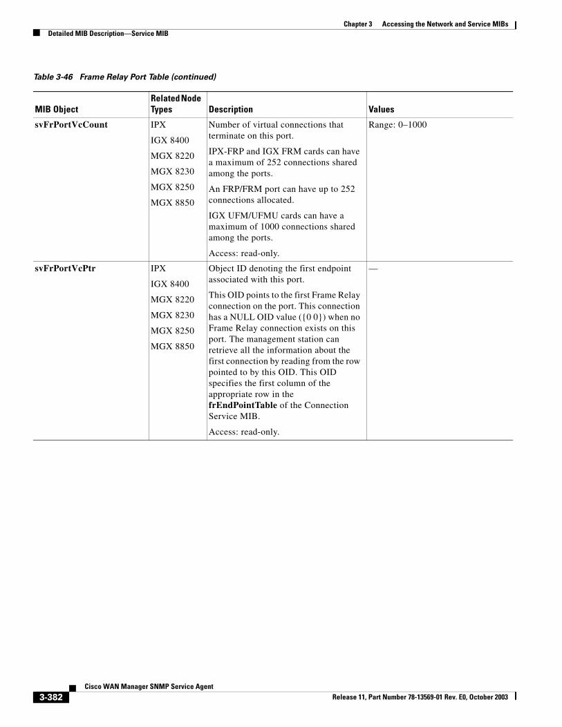
Chapter 3 Accessing the Network and Service MIBsDetailed MIB Description—Service MIB
svFrPortVcCount IPX
IGX 8400
MGX 8220
MGX 8230
MGX 8250
MGX 8850
Number of virtual connections that terminate on this port.
IPX-FRP and IGX FRM cards can have a maximum of 252 connections shared among the ports.
An FRP/FRM port can have up to 252 connections allocated.
IGX UFM/UFMU cards can have a maximum of 1000 connections shared among the ports.
Access: read-only.
Range: 0–1000
svFrPortVcPtr IPX
IGX 8400
MGX 8220
MGX 8230
MGX 8250
MGX 8850
Object ID denoting the first endpoint associated with this port.
This OID points to the first Frame Relay connection on the port. This connection has a NULL OID value ({0 0}) when no Frame Relay connection exists on this port. The management station can retrieve all the information about the first connection by reading from the row pointed to by this OID. This OID specifies the first column of the appropriate row in the frEndPointTable of the Connection Service MIB.
Access: read-only.
—
Table 3-46 Frame Relay Port Table (continued)
MIB ObjectRelated Node Types Description Values
3-382Cisco WAN Manager SNMP Service Agent
Release 11, Part Number 78-13569-01 Rev. E0, October 2003
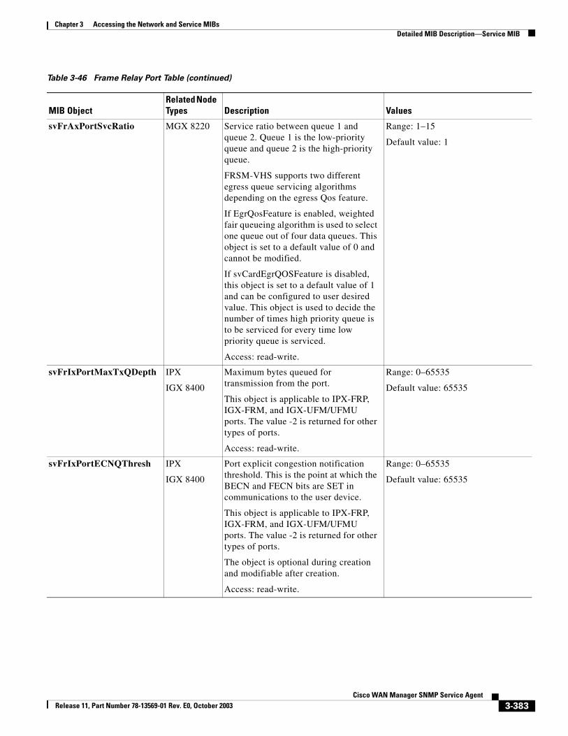
Chapter 3 Accessing the Network and Service MIBsDetailed MIB Description—Service MIB
svFrAxPortSvcRatio MGX 8220 Service ratio between queue 1 and queue 2. Queue 1 is the low-priority queue and queue 2 is the high-priority queue.
FRSM-VHS supports two different egress queue servicing algorithms depending on the egress Qos feature.
If EgrQosFeature is enabled, weighted fair queueing algorithm is used to select one queue out of four data queues. This object is set to a default value of 0 and cannot be modified.
If svCardEgrQOSFeature is disabled, this object is set to a default value of 1 and can be configured to user desired value. This object is used to decide the number of times high priority queue is to be serviced for every time low priority queue is serviced.
Access: read-write.
Range: 1–15
Default value: 1
svFrIxPortMaxTxQDepth IPX
IGX 8400
Maximum bytes queued for transmission from the port.
This object is applicable to IPX-FRP, IGX-FRM, and IGX-UFM/UFMU ports. The value -2 is returned for other types of ports.
Access: read-write.
Range: 0–65535
Default value: 65535
svFrIxPortECNQThresh IPX
IGX 8400
Port explicit congestion notification threshold. This is the point at which the BECN and FECN bits are SET in communications to the user device.
This object is applicable to IPX-FRP, IGX-FRM, and IGX-UFM/UFMU ports. The value -2 is returned for other types of ports.
The object is optional during creation and modifiable after creation.
Access: read-write.
Range: 0–65535
Default value: 65535
Table 3-46 Frame Relay Port Table (continued)
MIB ObjectRelated Node Types Description Values
3-383Cisco WAN Manager SNMP Service Agent
Release 11, Part Number 78-13569-01 Rev. E0, October 2003
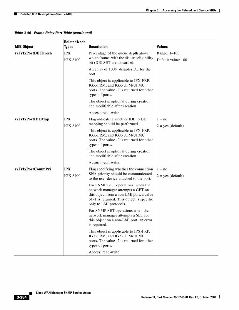
Chapter 3 Accessing the Network and Service MIBsDetailed MIB Description—Service MIB
svFrIxPortDEThresh IPX
IGX 8400
Percentage of the queue depth above which frames with the discard eligibility bit (DE) SET are discarded.
An entry of 100% disables DE for the port.
This object is applicable to IPX-FRP, IGX-FRM, and IGX-UFM/UFMU ports. The value -2 is returned for other types of ports.
The object is optional during creation and modifiable after creation.
Access: read-write.
Range: 1–100
Default value: 100
svFrIxPortIDEMap IPX
IGX 8400
Flag indicating whether IDE to DE mapping should be performed.
This object is applicable to IPX-FRP, IGX-FRM, and IGX-UFM/UFMU ports. The value -2 is returned for other types of ports.
The object is optional during creation and modifiable after creation.
Access: read-write.
1 = no
2 = yes (default)
svFrIxPortCommPri IPX
IGX 8400
Flag specifying whether the connection SNA priority should be communicated to the user device attached to the port.
For SNMP GET operations, when the network manager attempts a GET on this object from a non-LMI port, a value of -1 is returned. This object is specific only to LMI protocols.
For SNMP SET operations when the network manager attempts a SET for this object on a non-LMI port, an error is reported.
This object is applicable to IPX-FRP, IGX-FRM, and IGX-UFM/UFMU ports. The value -2 is returned for other types of ports.
Access: read-write.
1 = no
2 = yes (default)
Table 3-46 Frame Relay Port Table (continued)
MIB ObjectRelated Node Types Description Values
3-384Cisco WAN Manager SNMP Service Agent
Release 11, Part Number 78-13569-01 Rev. E0, October 2003
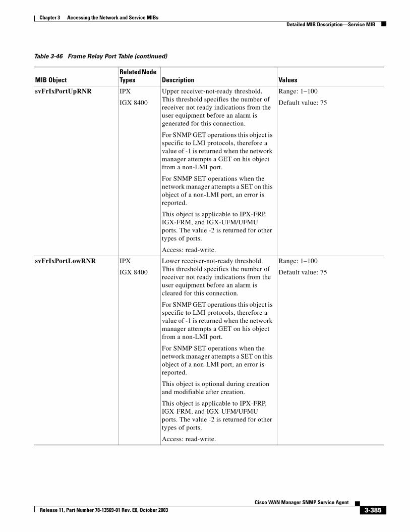
Chapter 3 Accessing the Network and Service MIBsDetailed MIB Description—Service MIB
svFrIxPortUpRNR IPX
IGX 8400
Upper receiver-not-ready threshold. This threshold specifies the number of receiver not ready indications from the user equipment before an alarm is generated for this connection.
For SNMP GET operations this object is specific to LMI protocols, therefore a value of -1 is returned when the network manager attempts a GET on his object from a non-LMI port.
For SNMP SET operations when the network manager attempts a SET on this object of a non-LMI port, an error is reported.
This object is applicable to IPX-FRP, IGX-FRM, and IGX-UFM/UFMU ports. The value -2 is returned for other types of ports.
Access: read-write.
Range: 1–100
Default value: 75
svFrIxPortLowRNR IPX
IGX 8400
Lower receiver-not-ready threshold. This threshold specifies the number of receiver not ready indications from the user equipment before an alarm is cleared for this connection.
For SNMP GET operations this object is specific to LMI protocols, therefore a value of -1 is returned when the network manager attempts a GET on his object from a non-LMI port.
For SNMP SET operations when the network manager attempts a SET on this object of a non-LMI port, an error is reported.
This object is optional during creation and modifiable after creation.
This object is applicable to IPX-FRP, IGX-FRM, and IGX-UFM/UFMU ports. The value -2 is returned for other types of ports.
Access: read-write.
Range: 1–100
Default value: 75
Table 3-46 Frame Relay Port Table (continued)
MIB ObjectRelated Node Types Description Values
3-385Cisco WAN Manager SNMP Service Agent
Release 11, Part Number 78-13569-01 Rev. E0, October 2003
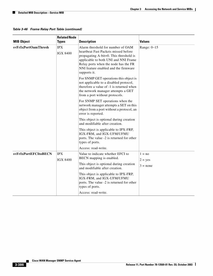
Chapter 3 Accessing the Network and Service MIBsDetailed MIB Description—Service MIB
svFrIxPortOamThresh IPX
IGX 8400
Alarm threshold for number of OAM heartbeat Fast Packets missed before propagating A-bit=0. This threshold is applicable to both UNI and NNI Frame Relay ports when the node has the FR NNI feature enabled and the firmware supports it.
For SNMP GET operations this object is not applicable to a disabled protocol, therefore a value of -1 is returned when the network manager attempts a GET from a port without protocols.
For SNMP SET operations when the network manager attempts a SET on this object from a port without a protocol, an error is reported.
This object is optional during creation and modifiable after creation.
This object is applicable to IPX-FRP, IGX-FRM, and IGX-UFM/UFMU ports. The value -2 is returned for other types of ports.
Access: read-write.
Range: 0–15
svFrIxPortEFCItoBECN IPX
IGX 8400
Value to indicate whether EFCI to BECN mapping is enabled.
This object is optional during creation and modifiable after creation.
This object is applicable to IPX-FRP, IGX-FRM, and IGX-UFM/UFMU ports. The value -2 is returned for other types of ports.
Access: read-write.
1 = no
2 = yes
3 = none
Table 3-46 Frame Relay Port Table (continued)
MIB ObjectRelated Node Types Description Values
3-386Cisco WAN Manager SNMP Service Agent
Release 11, Part Number 78-13569-01 Rev. E0, October 2003
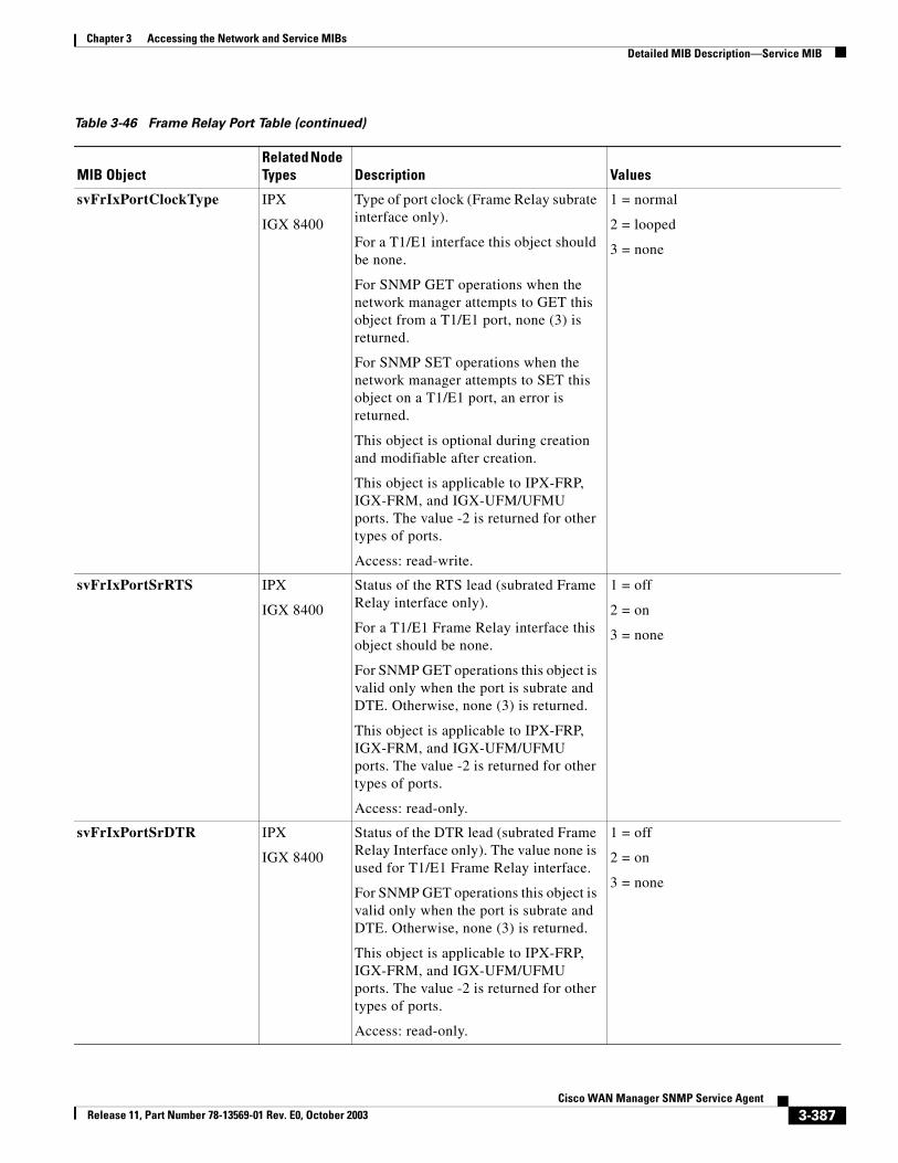
Chapter 3 Accessing the Network and Service MIBsDetailed MIB Description—Service MIB
svFrIxPortClockType IPX
IGX 8400
Type of port clock (Frame Relay subrate interface only).
For a T1/E1 interface this object should be none.
For SNMP GET operations when the network manager attempts to GET this object from a T1/E1 port, none (3) is returned.
For SNMP SET operations when the network manager attempts to SET this object on a T1/E1 port, an error is returned.
This object is optional during creation and modifiable after creation.
This object is applicable to IPX-FRP, IGX-FRM, and IGX-UFM/UFMU ports. The value -2 is returned for other types of ports.
Access: read-write.
1 = normal
2 = looped
3 = none
svFrIxPortSrRTS IPX
IGX 8400
Status of the RTS lead (subrated Frame Relay interface only).
For a T1/E1 Frame Relay interface this object should be none.
For SNMP GET operations this object is valid only when the port is subrate and DTE. Otherwise, none (3) is returned.
This object is applicable to IPX-FRP, IGX-FRM, and IGX-UFM/UFMU ports. The value -2 is returned for other types of ports.
Access: read-only.
1 = off
2 = on
3 = none
svFrIxPortSrDTR IPX
IGX 8400
Status of the DTR lead (subrated Frame Relay Interface only). The value none is used for T1/E1 Frame Relay interface.
For SNMP GET operations this object is valid only when the port is subrate and DTE. Otherwise, none (3) is returned.
This object is applicable to IPX-FRP, IGX-FRM, and IGX-UFM/UFMU ports. The value -2 is returned for other types of ports.
Access: read-only.
1 = off
2 = on
3 = none
Table 3-46 Frame Relay Port Table (continued)
MIB ObjectRelated Node Types Description Values
3-387Cisco WAN Manager SNMP Service Agent
Release 11, Part Number 78-13569-01 Rev. E0, October 2003
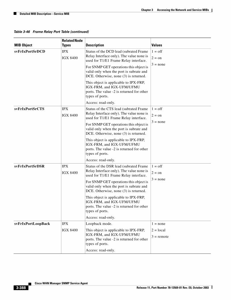
Chapter 3 Accessing the Network and Service MIBsDetailed MIB Description—Service MIB
svFrIxPortSrDCD IPX
IGX 8400
Status of the DCD lead (subrated Frame Relay Interface only). The value none is used for T1/E1 Frame Relay interface.
For SNMP GET operations this object is valid only when the port is subrate and DCE. Otherwise, none (3) is returned.
This object is applicable to IPX-FRP, IGX-FRM, and IGX-UFM/UFMU ports. The value -2 is returned for other types of ports.
Access: read-only.
1 = off
2 = on
3 = none
svFrIxPortSrCTS IPX
IGX 8400
Status of the CTS lead (subrated Frame Relay Interface only). The value none is used for T1/E1 Frame Relay interface.
For SNMP GET operations this object is valid only when the port is subrate and DCE. Otherwise, none (3) is returned.
This object is applicable to IPX-FRP, IGX-FRM, and IGX-UFM/UFMU ports. The value -2 is returned for other types of ports.
Access: read-only.
1 = off
2 = on
3 = none
svFrIxPortSrDSR IPX
IGX 8400
Status of the DSR lead (subrated Frame Relay Interface only). The value none is used for T1/E1 Frame Relay interface.
For SNMP GET operations this object is valid only when the port is subrate and DCE. Otherwise, none (3) is returned.
This object is applicable to IPX-FRP, IGX-FRM, and IGX-UFM/UFMU ports. The value -2 is returned for other types of ports.
Access: read-only.
1 = off
2 = on
3 = none
svFrIxPortLoopBack IPX
IGX 8400
Loopback mode.
This object is applicable to IPX-FRP, IGX-FRM, and IGX-UFM/UFMU ports. The value -2 is returned for other types of ports.
Access: read-only.
1 = none
2 = local
3 = remote
Table 3-46 Frame Relay Port Table (continued)
MIB ObjectRelated Node Types Description Values
3-388Cisco WAN Manager SNMP Service Agent
Release 11, Part Number 78-13569-01 Rev. E0, October 2003
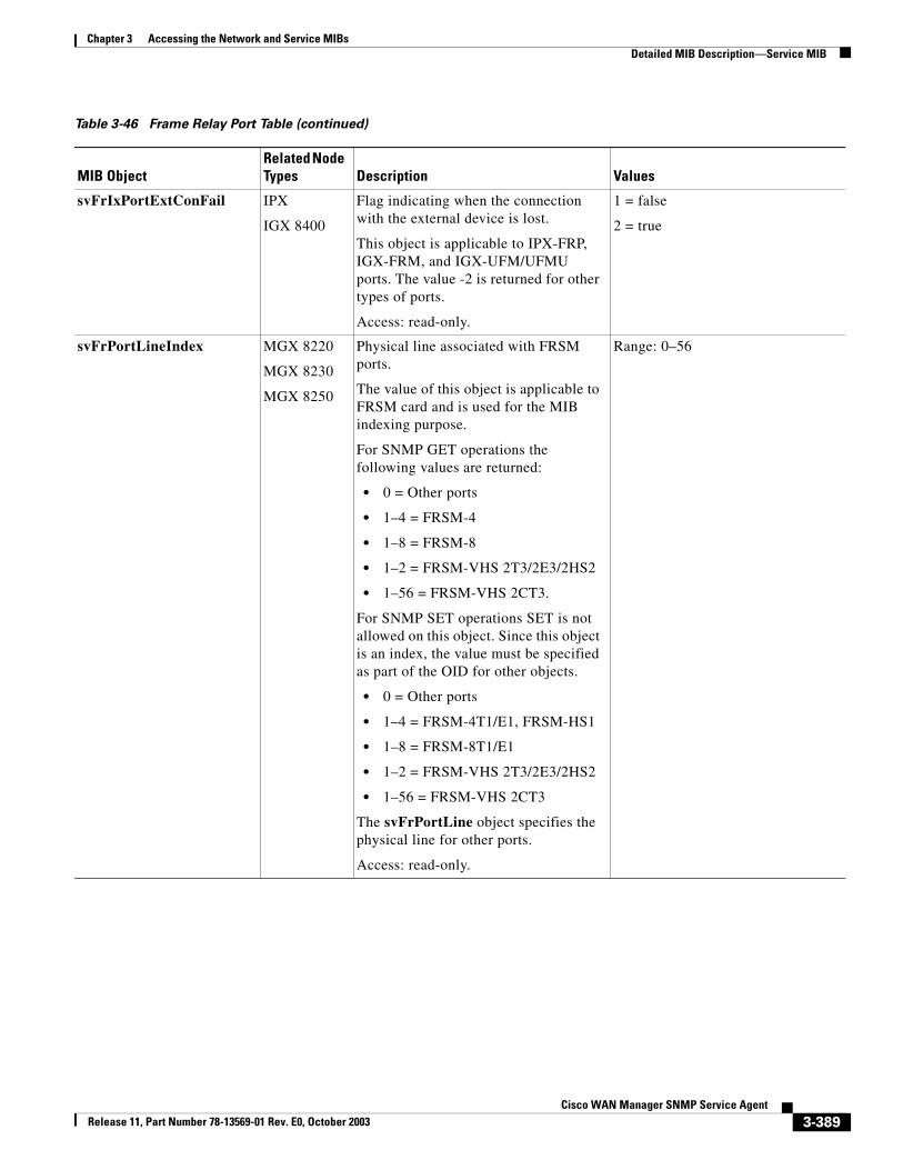
Chapter 3 Accessing the Network and Service MIBsDetailed MIB Description—Service MIB
svFrIxPortExtConFail IPX
IGX 8400
Flag indicating when the connection with the external device is lost.
This object is applicable to IPX-FRP, IGX-FRM, and IGX-UFM/UFMU ports. The value -2 is returned for other types of ports.
Access: read-only.
1 = false
2 = true
svFrPortLineIndex MGX 8220
MGX 8230
MGX 8250
Physical line associated with FRSM ports.
The value of this object is applicable to FRSM card and is used for the MIB indexing purpose.
For SNMP GET operations the following values are returned:
• 0 = Other ports
• 1–4 = FRSM-4
• 1–8 = FRSM-8
• 1–2 = FRSM-VHS 2T3/2E3/2HS2
• 1–56 = FRSM-VHS 2CT3.
For SNMP SET operations SET is not allowed on this object. Since this object is an index, the value must be specified as part of the OID for other objects.
• 0 = Other ports
• 1–4 = FRSM-4T1/E1, FRSM-HS1
• 1–8 = FRSM-8T1/E1
• 1–2 = FRSM-VHS 2T3/2E3/2HS2
• 1–56 = FRSM-VHS 2CT3
The svFrPortLine object specifies the physical line for other ports.
Access: read-only.
Range: 0–56
Table 3-46 Frame Relay Port Table (continued)
MIB ObjectRelated Node Types Description Values
3-389Cisco WAN Manager SNMP Service Agent
Release 11, Part Number 78-13569-01 Rev. E0, October 2003
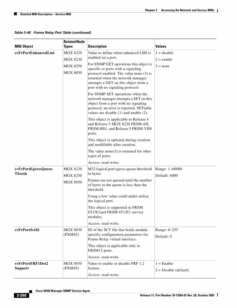
Chapter 3 Accessing the Network and Service MIBsDetailed MIB Description—Service MIB
svFrPortEnhancedLmi MGX 8220
MGX 8230
MGX 8250
MGX 8850
Value to define when enhanced LMI is enabled on a port.
For SNMP GET operations this object is specific to ports with a signaling protocol enabled. The value none (3) is returned when the network manager attempts a GET on this object from a port with no signaling protocol.
For SNMP SET operations when the network manager attempts a SET on this object from a port with no signaling protocol, an error is reported. SETtable values are disable (1) and enable (2).
This object is applicable to Release 4 and Release 5 MGX 8220 FRSM-4/8, FRSM-HS1, and Release 5 FRSM-VHS ports.
This object is optional during creation and modifiable after creation.
The value none(3) is returned for other types of ports.
Access: read-write.
1 = disable
2 = enable
3 = none
svFrPortEgressQueueThresh
MGX 8230
MGX 8250
MGX 8850
M32 logical port egress queue threshold in bytes.
Frames are not queued until the number of bytes in the queue is less than the threshold.
Using a low value could under utilize the logical port.
This object is supported in FRSM 8T1/E1and FRSM 4T1/E1 service modules.
Access: read-write.
Range: 1–60000
Default: 6000
svFrPortSctId MGX 8850 (PXM45)
ID of the SCT file that holds module specific configuration parameters for Frame Relay virtual interface.
This object is applicable only to FRSM12 ports.
Access: read-write.
Range: 0–255
Default: 0
svFrPortFRF1Dot2Support
MGX 8850 (PXM45)
Value to enable or disable FRF 1.2 feature.
Access: read-write.
1 = Enable
2 = Disable (default)
Table 3-46 Frame Relay Port Table (continued)
MIB ObjectRelated Node Types Description Values
3-390Cisco WAN Manager SNMP Service Agent
Release 11, Part Number 78-13569-01 Rev. E0, October 2003
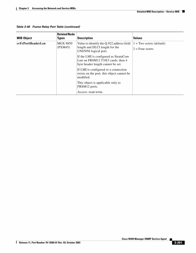
Chapter 3 Accessing the Network and Service MIBsDetailed MIB Description—Service MIB
svFrPortHeaderLen MGX 8850 (PXM45)
Value to identify the Q.922 address field length and DLCI length for the UNI/NNI logical port.
If the LMI is configured as StrataCom Lmi on FRSM12 T3/E3 cards, then 4 byte header length cannot be set.
If LMI is configured or a connection exists on the port, this object cannot be modified.
This object is applicable only to FRSM12 ports.
Access: read-write.
1 = Two octets (default)
2 = Four octets
Table 3-46 Frame Relay Port Table (continued)
MIB ObjectRelated Node Types Description Values
3-391Cisco WAN Manager SNMP Service Agent
Release 11, Part Number 78-13569-01 Rev. E0, October 2003
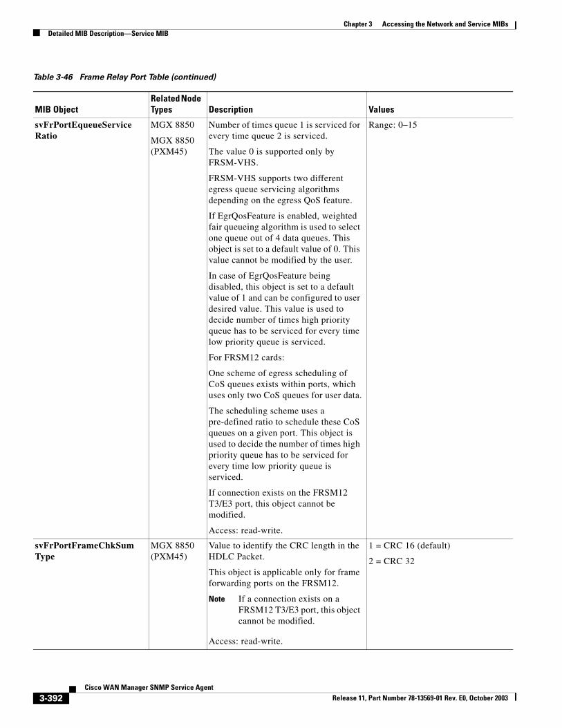
Chapter 3 Accessing the Network and Service MIBsDetailed MIB Description—Service MIB
svFrPortEqueueServiceRatio
MGX 8850
MGX 8850 (PXM45)
Number of times queue 1 is serviced for every time queue 2 is serviced.
The value 0 is supported only by FRSM-VHS.
FRSM-VHS supports two different egress queue servicing algorithms depending on the egress QoS feature.
If EgrQosFeature is enabled, weighted fair queueing algorithm is used to select one queue out of 4 data queues. This object is set to a default value of 0. This value cannot be modified by the user.
In case of EgrQosFeature being disabled, this object is set to a default value of 1 and can be configured to user desired value. This value is used to decide number of times high priority queue has to be serviced for every time low priority queue is serviced.
For FRSM12 cards:
One scheme of egress scheduling of CoS queues exists within ports, which uses only two CoS queues for user data.
The scheduling scheme uses a pre-defined ratio to schedule these CoS queues on a given port. This object is used to decide the number of times high priority queue has to be serviced for every time low priority queue is serviced.
If connection exists on the FRSM12 T3/E3 port, this object cannot be modified.
Access: read-write.
Range: 0–15
svFrPortFrameChkSumType
MGX 8850 (PXM45)
Value to identify the CRC length in the HDLC Packet.
This object is applicable only for frame forwarding ports on the FRSM12.
Note If a connection exists on a FRSM12 T3/E3 port, this object cannot be modified.
Access: read-write.
1 = CRC 16 (default)
2 = CRC 32
Table 3-46 Frame Relay Port Table (continued)
MIB ObjectRelated Node Types Description Values
3-392Cisco WAN Manager SNMP Service Agent
Release 11, Part Number 78-13569-01 Rev. E0, October 2003
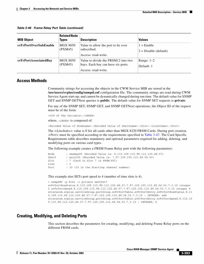
Chapter 3 Accessing the Network and Service MIBsDetailed MIB Description—Service MIB
Access Methods
Community strings for accessing the objects in the CWM Service MIB are stored in the /usr/users/svplus/config/snmpd.cnf configuration file. The community strings are read during CWM Service Agent start-up, and cannot be dynamically changed during run time. The default value for SNMP GET and SNMP GETNext queries is public. The default value for SNMP SET requests is private.
For any of the SNMP SET, SNMP GET, and SNMP GETNext operations, the Object ID of the request must be of the form:
<OID Of The Variable>,<INDEX>
where, <INDEX> is composed of:
<Encoded Value of Nodename>.<Encoded Value of Shelfname>.<Slot>.<LineIndex>.<Port>
The <LineIndex> value is 0 for all cards other than MGX 8220 FRSM Cards. During port creation, <Port> must be specified according to the requirements specified in Table 3-47. The Card Specific Requirements table describes mandatory and optional parameters required for adding, deleting, and modifying ports on various card types.
The following example creates a FRSM Frame Relay port with the following parameters:
Node : nmsbpx09 (Encoded Value is: 8.110.109.115.98.112.120.48.57) Shelf : axis165 (Encoded Value is: 7.97.120.105.115.49.54.53) Slot : 7 (Card in Slot 7 is FRSM/4T1) Line : 3Port : 10 (10 is the Starting channel number)
This example also SETs port speed to 4 (number of time slots is 4).
> snmpSET -p 8161 -c private nm20fst7 svFrPortRowStatus.8.110.109.115.98.112.120.48.57.7.97.120.105.115.49.54.53.7.3.10 integer 2 svFrPortSpeed.8.110.109.115.98.112.120.48.57.7.97.120.105.115.49.54.53.7.3.10 integer 4stratacom.svplus.serviceGroup.portGroup.svFrPortTable.svFrPortEntry.svFrPortRowStatus.8.110.109.115.98.112.120.48.57.7.97.120.105.115.49.54.53.7.3.10 : INTEGER: addstratacom.svplus.serviceGroup.portGroup.svFrPortTable.svFrPortEntry.svFrPortSpeed.8.110.109.115.98.112.120.48.57.7.97.120.105.115.49.54.53.7.3.10 : INTEGER: 4
Creating, Modifying, and Deleting Ports
This section describes the parameters for creating, modifying, and deleting Frame Relay ports on the different FRSM cards.
svFrPortOverSubEnable MGX 8850 (PXM45)
Value to allow the port to be over subscribed.
Access: read-write.
1 = Enable
2 = Disable (default)
svFrPortAssociatedBay MGX 8850 (PXM45)
Value to divide the FRSM12 into two bays. Each bay can have six ports.
Access: read-write.
Range: 1–2
Default: 1
Table 3-46 Frame Relay Port Table (continued)
MIB ObjectRelated Node Types Description Values
3-393Cisco WAN Manager SNMP Service Agent
Release 11, Part Number 78-13569-01 Rev. E0, October 2003
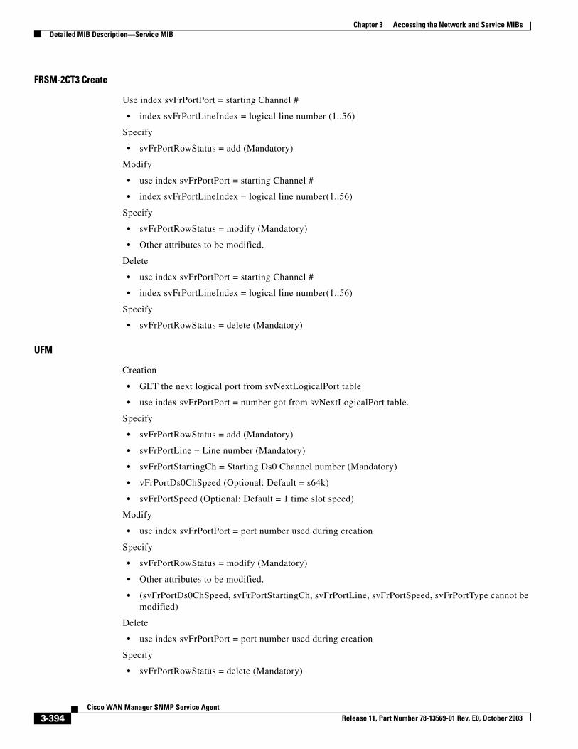
Chapter 3 Accessing the Network and Service MIBsDetailed MIB Description—Service MIB
FRSM-2CT3 Create
Use index svFrPortPort = starting Channel #
• index svFrPortLineIndex = logical line number (1..56)
Specify
• svFrPortRowStatus = add (Mandatory)
Modify
• use index svFrPortPort = starting Channel #
• index svFrPortLineIndex = logical line number(1..56)
Specify
• svFrPortRowStatus = modify (Mandatory)
• Other attributes to be modified.
Delete
• use index svFrPortPort = starting Channel #
• index svFrPortLineIndex = logical line number(1..56)
Specify
• svFrPortRowStatus = delete (Mandatory)
UFM
Creation
• GET the next logical port from svNextLogicalPort table
• use index svFrPortPort = number got from svNextLogicalPort table.
Specify
• svFrPortRowStatus = add (Mandatory)
• svFrPortLine = Line number (Mandatory)
• svFrPortStartingCh = Starting Ds0 Channel number (Mandatory)
• vFrPortDs0ChSpeed (Optional: Default = s64k)
• svFrPortSpeed (Optional: Default = 1 time slot speed)
Modify
• use index svFrPortPort = port number used during creation
Specify
• svFrPortRowStatus = modify (Mandatory)
• Other attributes to be modified.
• (svFrPortDs0ChSpeed, svFrPortStartingCh, svFrPortLine, svFrPortSpeed, svFrPortType cannot be modified)
Delete
• use index svFrPortPort = port number used during creation
Specify
• svFrPortRowStatus = delete (Mandatory)
3-394Cisco WAN Manager SNMP Service Agent
Release 11, Part Number 78-13569-01 Rev. E0, October 2003
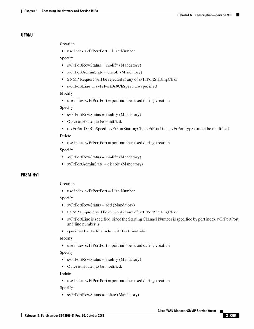
Chapter 3 Accessing the Network and Service MIBsDetailed MIB Description—Service MIB
UFM/U
Creation
• use index svFrPortPort = Line Number
Specify
• svFrPortRowStatus = modify (Mandatory)
• svFrPortAdminState = enable (Mandatory)
• SNMP Request will be rejected if any of svFrPortStartingCh or
• svFrPortLine or svFrPortDs0ChSpeed are specified
Modify
• use index svFrPortPort = port number used during creation
Specify
• svFrPortRowStatus = modify (Mandatory)
• Other attributes to be modified.
• (svFrPortDs0ChSpeed, svFrPortStartingCh, svFrPortLine, svFrPortType cannot be modified)
Delete
• use index svFrPortPort = port number used during creation
Specify
• svFrPortRowStatus = modify (Mandatory)
• svFrPortAdminState = disable (Mandatory)
FRSM-Hs1
Creation
• use index svFrPortPort = Line Number
Specify
• svFrPortRowStatus = add (Mandatory)
• SNMP Request will be rejected if any of svFrPortStartingCh or
• svFrPortLine is specified, since the Starting Channel Number is specified by port index svFrPortPort and line number is
• specified by the line index svFrPortLineIndex
Modify
• use index svFrPortPort = port number used during creation
Specify
• svFrPortRowStatus = modify (Mandatory)
• Other attributes to be modified.
Delete
• use index svFrPortPort = port number used during creation
Specify
• svFrPortRowStatus = delete (Mandatory)
3-395Cisco WAN Manager SNMP Service Agent
Release 11, Part Number 78-13569-01 Rev. E0, October 2003
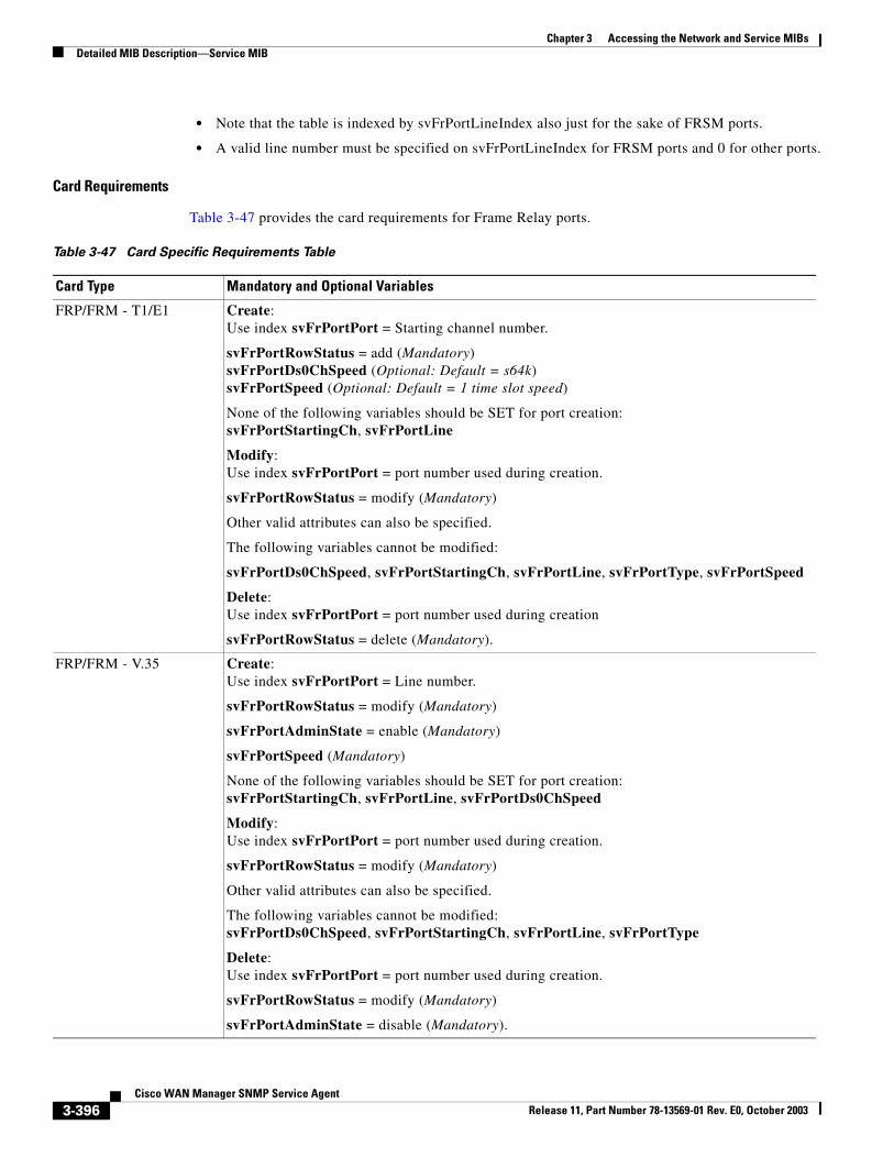
Chapter 3 Accessing the Network and Service MIBsDetailed MIB Description—Service MIB
• Note that the table is indexed by svFrPortLineIndex also just for the sake of FRSM ports.
• A valid line number must be specified on svFrPortLineIndex for FRSM ports and 0 for other ports.
Card Requirements
Table 3-47 provides the card requirements for Frame Relay ports.
Table 3-47 Card Specific Requirements Table
Card Type Mandatory and Optional Variables
FRP/FRM - T1/E1 Create:Use index svFrPortPort = Starting channel number.
svFrPortRowStatus = add (Mandatory)svFrPortDs0ChSpeed (Optional: Default = s64k)svFrPortSpeed (Optional: Default = 1 time slot speed)
None of the following variables should be SET for port creation:svFrPortStartingCh, svFrPortLine
Modify:Use index svFrPortPort = port number used during creation.
svFrPortRowStatus = modify (Mandatory)
Other valid attributes can also be specified.
The following variables cannot be modified:
svFrPortDs0ChSpeed, svFrPortStartingCh, svFrPortLine, svFrPortType, svFrPortSpeed
Delete:Use index svFrPortPort = port number used during creation
svFrPortRowStatus = delete (Mandatory).
FRP/FRM - V.35 Create:Use index svFrPortPort = Line number.
svFrPortRowStatus = modify (Mandatory)
svFrPortAdminState = enable (Mandatory)
svFrPortSpeed (Mandatory)
None of the following variables should be SET for port creation:svFrPortStartingCh, svFrPortLine, svFrPortDs0ChSpeed
Modify:Use index svFrPortPort = port number used during creation.
svFrPortRowStatus = modify (Mandatory)
Other valid attributes can also be specified.
The following variables cannot be modified:svFrPortDs0ChSpeed, svFrPortStartingCh, svFrPortLine, svFrPortType
Delete: Use index svFrPortPort = port number used during creation.
svFrPortRowStatus = modify (Mandatory)
svFrPortAdminState = disable (Mandatory).
3-396Cisco WAN Manager SNMP Service Agent
Release 11, Part Number 78-13569-01 Rev. E0, October 2003
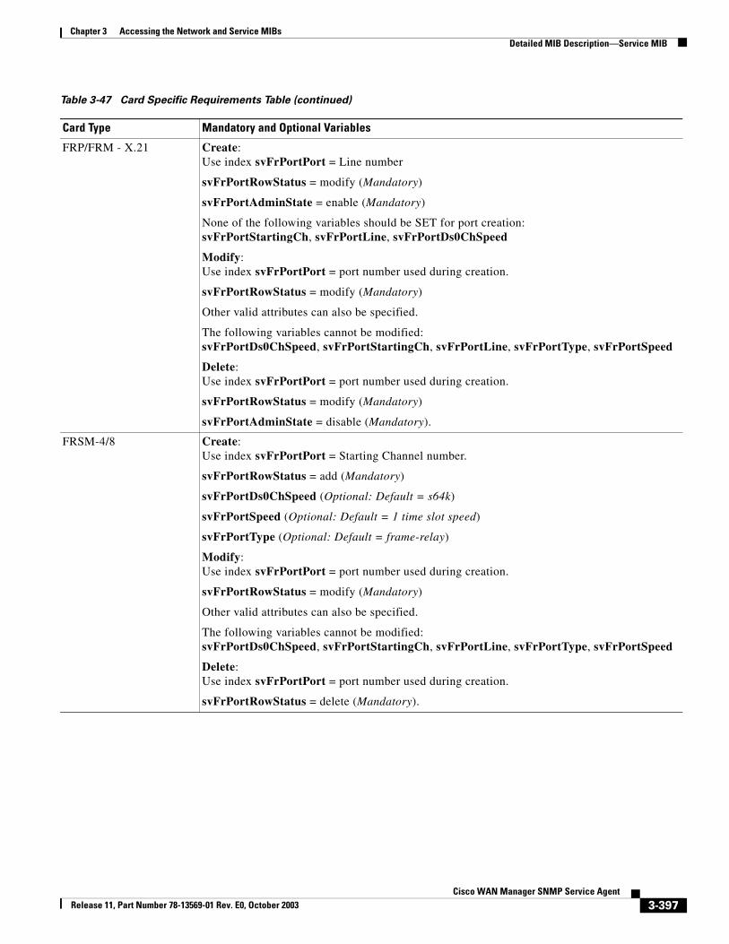
Chapter 3 Accessing the Network and Service MIBsDetailed MIB Description—Service MIB
FRP/FRM - X.21 Create:Use index svFrPortPort = Line number
svFrPortRowStatus = modify (Mandatory)
svFrPortAdminState = enable (Mandatory)
None of the following variables should be SET for port creation:svFrPortStartingCh, svFrPortLine, svFrPortDs0ChSpeed
Modify:Use index svFrPortPort = port number used during creation.
svFrPortRowStatus = modify (Mandatory)
Other valid attributes can also be specified.
The following variables cannot be modified:svFrPortDs0ChSpeed, svFrPortStartingCh, svFrPortLine, svFrPortType, svFrPortSpeed
Delete: Use index svFrPortPort = port number used during creation.
svFrPortRowStatus = modify (Mandatory)
svFrPortAdminState = disable (Mandatory).
FRSM-4/8 Create:Use index svFrPortPort = Starting Channel number.
svFrPortRowStatus = add (Mandatory)
svFrPortDs0ChSpeed (Optional: Default = s64k)
svFrPortSpeed (Optional: Default = 1 time slot speed)
svFrPortType (Optional: Default = frame-relay)
Modify:Use index svFrPortPort = port number used during creation.
svFrPortRowStatus = modify (Mandatory)
Other valid attributes can also be specified.
The following variables cannot be modified:svFrPortDs0ChSpeed, svFrPortStartingCh, svFrPortLine, svFrPortType, svFrPortSpeed
Delete:Use index svFrPortPort = port number used during creation.
svFrPortRowStatus = delete (Mandatory).
Table 3-47 Card Specific Requirements Table (continued)
Card Type Mandatory and Optional Variables
3-397Cisco WAN Manager SNMP Service Agent
Release 11, Part Number 78-13569-01 Rev. E0, October 2003
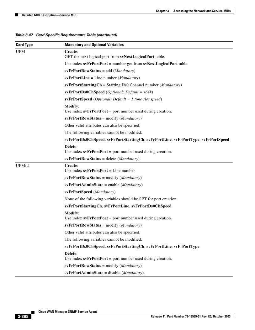
Chapter 3 Accessing the Network and Service MIBsDetailed MIB Description—Service MIB
UFM Create:GET the next logical port from svNextLogicalPort table.
Use index svFrPortPort = number got from svNextLogicalPort table.
svFrPortRowStatus = add (Mandatory)
svFrPortLine = Line number (Mandatory)
svFrPortStartingCh = Starting Ds0 Channel number (Mandatory)
svFrPortDs0ChSpeed (Optional: Default = s64k)
svFrPortSpeed (Optional: Default = 1 time slot speed)
Modify:Use index svFrPortPort = port number used during creation.
svFrPortRowStatus = modify (Mandatory)
Other valid attributes can also be specified.
The following variables cannot be modified:
svFrPortDs0ChSpeed, svFrPortStartingCh, svFrPortLine, svFrPortType, svFrPortSpeed
Delete: Use index svFrPortPort = port number used during creation.
svFrPortRowStatus = delete (Mandatory).
UFM/U Create:Use index svFrPortPort = Line number
svFrPortRowStatus = modify (Mandatory)
svFrPortAdminState = enable (Mandatory)
svFrPortSpeed (Mandatory)
None of the following variables should be SET for port creation:
svFrPortStartingCh, svFrPortLine, svFrPortDs0ChSpeed
Modify:Use index svFrPortPort = port number used during creation.
svFrPortRowStatus = modify (Mandatory)
Other valid attributes can also be specified.
The following variables cannot be modified:
svFrPortDs0ChSpeed, svFrPortStartingCh, svFrPortLine, svFrPortType
Delete: Use index svFrPortPort = port number used during creation.
svFrPortRowStatus = modify (Mandatory)
svFrPortAdminState = disable (Mandatory).
Table 3-47 Card Specific Requirements Table (continued)
Card Type Mandatory and Optional Variables
3-398Cisco WAN Manager SNMP Service Agent
Release 11, Part Number 78-13569-01 Rev. E0, October 2003
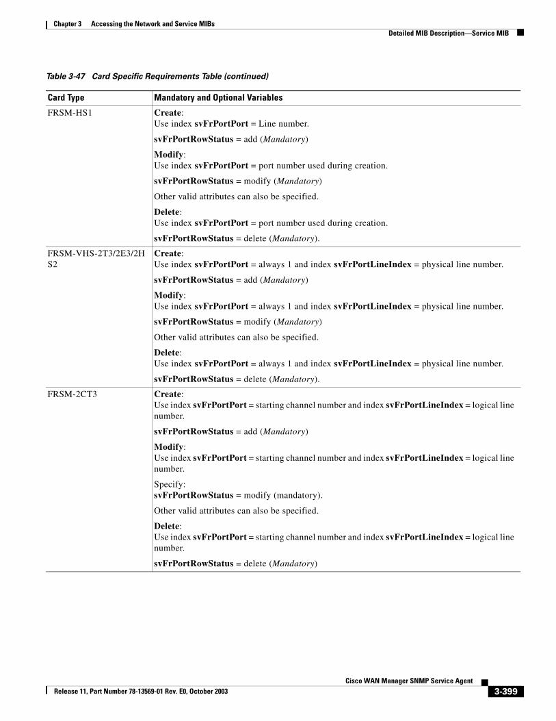
Chapter 3 Accessing the Network and Service MIBsDetailed MIB Description—Service MIB
FRSM-HS1 Create:Use index svFrPortPort = Line number.
svFrPortRowStatus = add (Mandatory)
Modify:Use index svFrPortPort = port number used during creation.
svFrPortRowStatus = modify (Mandatory)
Other valid attributes can also be specified.
Delete:Use index svFrPortPort = port number used during creation.
svFrPortRowStatus = delete (Mandatory).
FRSM-VHS-2T3/2E3/2HS2
Create:Use index svFrPortPort = always 1 and index svFrPortLineIndex = physical line number.
svFrPortRowStatus = add (Mandatory)
Modify:Use index svFrPortPort = always 1 and index svFrPortLineIndex = physical line number.
svFrPortRowStatus = modify (Mandatory)
Other valid attributes can also be specified.
Delete:Use index svFrPortPort = always 1 and index svFrPortLineIndex = physical line number.
svFrPortRowStatus = delete (Mandatory).
FRSM-2CT3 Create:Use index svFrPortPort = starting channel number and index svFrPortLineIndex = logical line number.
svFrPortRowStatus = add (Mandatory)
Modify:Use index svFrPortPort = starting channel number and index svFrPortLineIndex = logical line number.
Specify:svFrPortRowStatus = modify (mandatory).
Other valid attributes can also be specified.
Delete:Use index svFrPortPort = starting channel number and index svFrPortLineIndex = logical line number.
svFrPortRowStatus = delete (Mandatory)
Table 3-47 Card Specific Requirements Table (continued)
Card Type Mandatory and Optional Variables
3-399Cisco WAN Manager SNMP Service Agent
Release 11, Part Number 78-13569-01 Rev. E0, October 2003
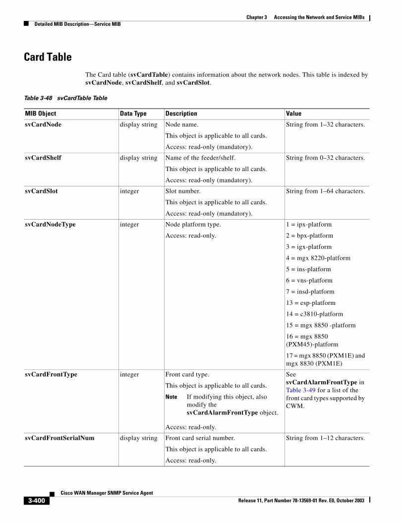
Chapter 3 Accessing the Network and Service MIBsDetailed MIB Description—Service MIB
Card TableThe Card table (svCardTable) contains information about the network nodes. This table is indexed by svCardNode, svCardShelf, and svCardSlot.
Table 3-48 svCardTable Table
MIB Object Data Type Description Value
svCardNode display string Node name.
This object is applicable to all cards.
Access: read-only (mandatory).
String from 1–32 characters.
svCardShelf display string Name of the feeder/shelf.
This object is applicable to all cards.
Access: read-only (mandatory).
String from 0–32 characters.
svCardSlot integer Slot number.
This object is applicable to all cards.
Access: read-only (mandatory).
String from 1–64 characters.
svCardNodeType integer Node platform type.
Access: read-only.
1 = ipx-platform
2 = bpx-platform
3 = igx-platform
4 = mgx 8220-platform
5 = ins-platform
6 = vns-platform
7 = insd-platform
13 = esp-platform
14 = c3810-platform
15 = mgx 8850 -platform
16 = mgx 8850 (PXM45)-platform
17 = mgx 8850 (PXM1E) and mgx 8830 (PXM1E)
svCardFrontType integer Front card type.
This object is applicable to all cards.
Note If modifying this object, also modify the svCardAlarmFrontType object.
Access: read-only.
See svCardAlarmFrontType in Table 3-49 for a list of the front card types supported by CWM.
svCardFrontSerialNum display string Front card serial number.
This object is applicable to all cards.
Access: read-only.
String from 1–12 characters.
3-400Cisco WAN Manager SNMP Service Agent
Release 11, Part Number 78-13569-01 Rev. E0, October 2003
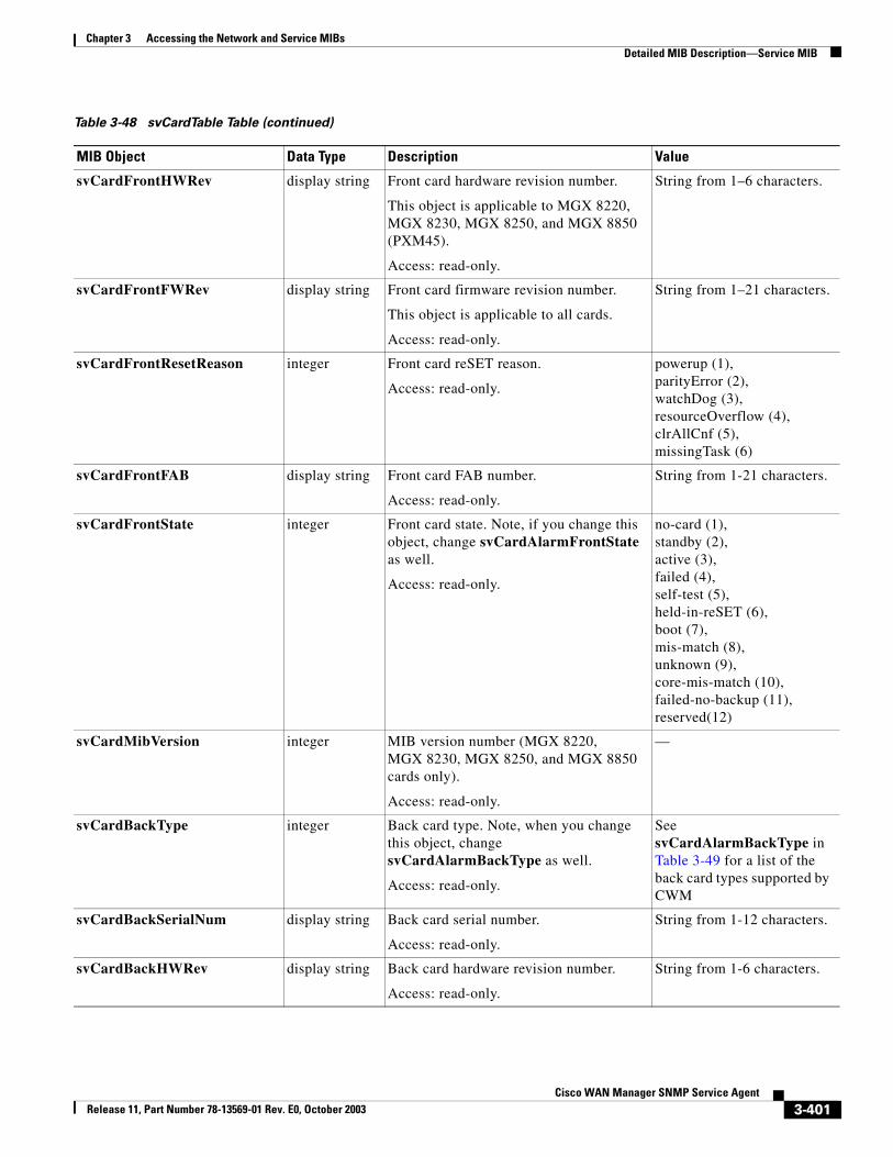
Chapter 3 Accessing the Network and Service MIBsDetailed MIB Description—Service MIB
svCardFrontHWRev display string Front card hardware revision number.
This object is applicable to MGX 8220, MGX 8230, MGX 8250, and MGX 8850 (PXM45).
Access: read-only.
String from 1–6 characters.
svCardFrontFWRev display string Front card firmware revision number.
This object is applicable to all cards.
Access: read-only.
String from 1–21 characters.
svCardFrontResetReason integer Front card reSET reason.
Access: read-only.
powerup (1),parityError (2),watchDog (3),resourceOverflow (4),clrAllCnf (5),missingTask (6)
svCardFrontFAB display string Front card FAB number.
Access: read-only.
String from 1-21 characters.
svCardFrontState integer Front card state. Note, if you change this object, change svCardAlarmFrontState as well.
Access: read-only.
no-card (1),standby (2),active (3),failed (4),self-test (5),held-in-reSET (6),boot (7),mis-match (8),unknown (9),core-mis-match (10),failed-no-backup (11),reserved(12)
svCardMibVersion integer MIB version number (MGX 8220, MGX 8230, MGX 8250, and MGX 8850 cards only).
Access: read-only.
—
svCardBackType integer Back card type. Note, when you change this object, change svCardAlarmBackType as well.
Access: read-only.
See svCardAlarmBackType in Table 3-49 for a list of the back card types supported by CWM
svCardBackSerialNum display string Back card serial number.
Access: read-only.
String from 1-12 characters.
svCardBackHWRev display string Back card hardware revision number.
Access: read-only.
String from 1-6 characters.
Table 3-48 svCardTable Table (continued)
MIB Object Data Type Description Value
3-401Cisco WAN Manager SNMP Service Agent
Release 11, Part Number 78-13569-01 Rev. E0, October 2003
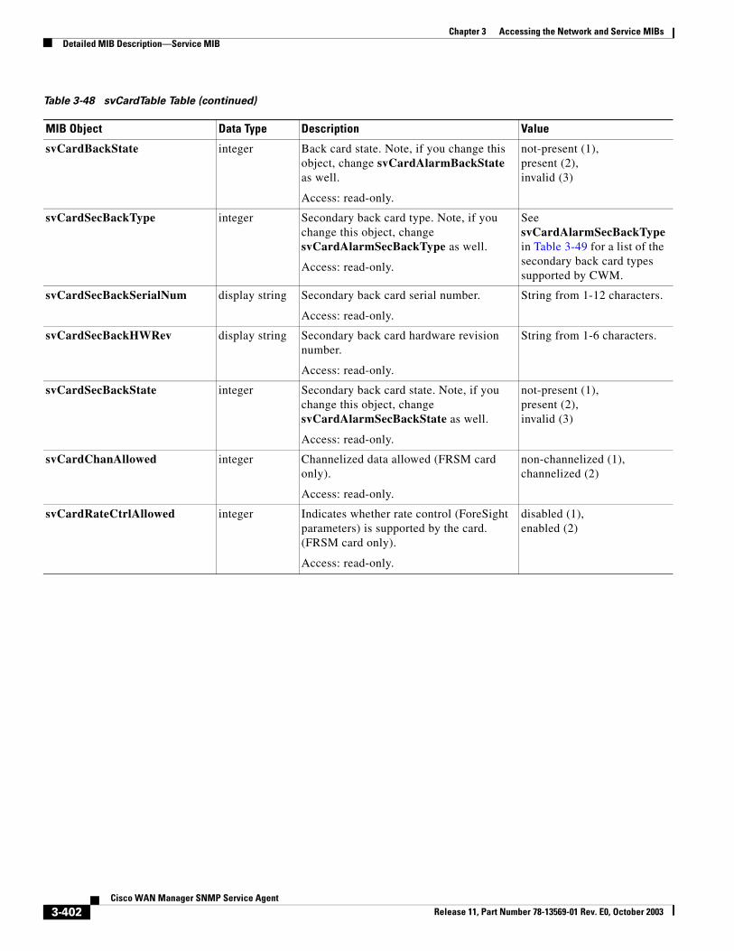
Chapter 3 Accessing the Network and Service MIBsDetailed MIB Description—Service MIB
svCardBackState integer Back card state. Note, if you change this object, change svCardAlarmBackState as well.
Access: read-only.
not-present (1),present (2),invalid (3)
svCardSecBackType integer Secondary back card type. Note, if you change this object, change svCardAlarmSecBackType as well.
Access: read-only.
See svCardAlarmSecBackType in Table 3-49 for a list of the secondary back card types supported by CWM.
svCardSecBackSerialNum display string Secondary back card serial number.
Access: read-only.
String from 1-12 characters.
svCardSecBackHWRev display string Secondary back card hardware revision number.
Access: read-only.
String from 1-6 characters.
svCardSecBackState integer Secondary back card state. Note, if you change this object, change svCardAlarmSecBackState as well.
Access: read-only.
not-present (1),present (2),invalid (3)
svCardChanAllowed integer Channelized data allowed (FRSM card only).
Access: read-only.
non-channelized (1),channelized (2)
svCardRateCtrlAllowed integer Indicates whether rate control (ForeSight parameters) is supported by the card. (FRSM card only).
Access: read-only.
disabled (1),enabled (2)
Table 3-48 svCardTable Table (continued)
MIB Object Data Type Description Value
3-402Cisco WAN Manager SNMP Service Agent
Release 11, Part Number 78-13569-01 Rev. E0, October 2003
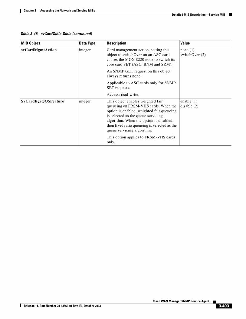
Chapter 3 Accessing the Network and Service MIBsDetailed MIB Description—Service MIB
svCardMgmtAction integer Card management action. setting this object to switchOver on an ASC card causes the MGX 8220 node to switch its core card SET (ASC, BNM and SRM).
An SNMP GET request on this object always returns none.
Applicable to ASC cards only for SNMP SET requests.
Access: read-write.
none (1)switchOver (2)
SvCardEgrQOSFeature integer This object enables weighted fair queueing on FRSM-VHS cards. When the option is enabled, weighted fair queueing is selected as the queue servicing algorithm. When the option is disabled, then fixed ratio queueing is selected as the queue servicing algorithm.
This option applies to FRSM-VHS cards only.
enable (1)disable (2)
Table 3-48 svCardTable Table (continued)
MIB Object Data Type Description Value
3-403Cisco WAN Manager SNMP Service Agent
Release 11, Part Number 78-13569-01 Rev. E0, October 2003
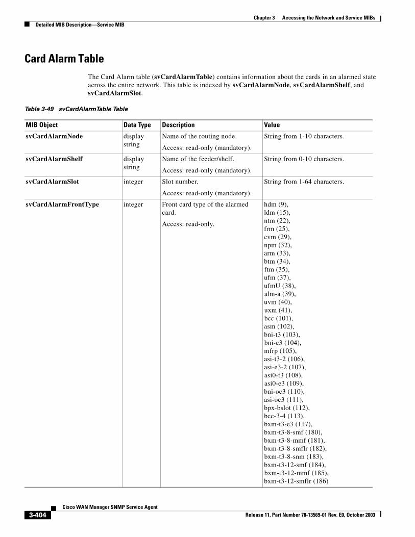
Chapter 3 Accessing the Network and Service MIBsDetailed MIB Description—Service MIB
Card Alarm TableThe Card Alarm table (svCardAlarmTable) contains information about the cards in an alarmed state across the entire network. This table is indexed by svCardAlarmNode, svCardAlarmShelf, and svCardAlarmSlot.
Table 3-49 svCardAlarmTable Table
MIB Object Data Type Description Value
svCardAlarmNode display string
Name of the routing node.
Access: read-only (mandatory).
String from 1-10 characters.
svCardAlarmShelf display string
Name of the feeder/shelf.
Access: read-only (mandatory).
String from 0-10 characters.
svCardAlarmSlot integer Slot number.
Access: read-only (mandatory).
String from 1-64 characters.
svCardAlarmFrontType integer Front card type of the alarmed card.
Access: read-only.
hdm (9),ldm (15),ntm (22),frm (25),cvm (29),npm (32),arm (33),btm (34),ftm (35),ufm (37),ufmU (38),alm-a (39),uvm (40),uxm (41),bcc (101),asm (102),bni-t3 (103),bni-e3 (104),mfrp (105),asi-t3-2 (106),asi-e3-2 (107),asi0-t3 (108),asi0-e3 (109),bni-oc3 (110),asi-oc3 (111),bpx-bslot (112),bcc-3-4 (113),bxm-t3-e3 (117),bxm-t3-8-smf (180),bxm-t3-8-mmf (181),bxm-t3-8-smflr (182),bxm-t3-8-snm (183),bxm-t3-12-smf (184),bxm-t3-12-mmf (185),bxm-t3-12-smflr (186)
3-404Cisco WAN Manager SNMP Service Agent
Release 11, Part Number 78-13569-01 Rev. E0, October 2003
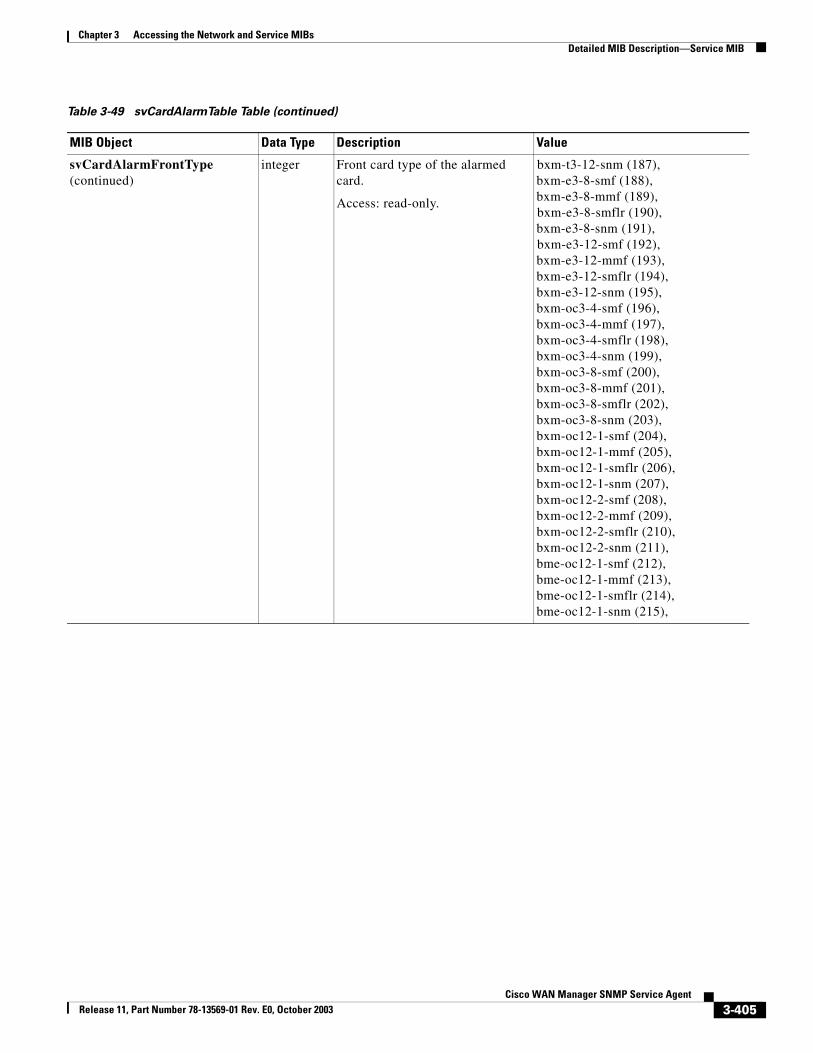
Chapter 3 Accessing the Network and Service MIBsDetailed MIB Description—Service MIB
svCardAlarmFrontType (continued)
integer Front card type of the alarmed card.
Access: read-only.
bxm-t3-12-snm (187),bxm-e3-8-smf (188),bxm-e3-8-mmf (189),bxm-e3-8-smflr (190),bxm-e3-8-snm (191),bxm-e3-12-smf (192),bxm-e3-12-mmf (193),bxm-e3-12-smflr (194),bxm-e3-12-snm (195),bxm-oc3-4-smf (196),bxm-oc3-4-mmf (197),bxm-oc3-4-smflr (198),bxm-oc3-4-snm (199),bxm-oc3-8-smf (200),bxm-oc3-8-mmf (201),bxm-oc3-8-smflr (202),bxm-oc3-8-snm (203),bxm-oc12-1-smf (204),bxm-oc12-1-mmf (205),bxm-oc12-1-smflr (206),bxm-oc12-1-snm (207),bxm-oc12-2-smf (208),bxm-oc12-2-mmf (209),bxm-oc12-2-smflr (210),bxm-oc12-2-snm (211),bme-oc12-1-smf (212),bme-oc12-1-mmf (213),bme-oc12-1-smflr (214),bme-oc12-1-snm (215),
Table 3-49 svCardAlarmTable Table (continued)
MIB Object Data Type Description Value
3-405Cisco WAN Manager SNMP Service Agent
Release 11, Part Number 78-13569-01 Rev. E0, October 2003
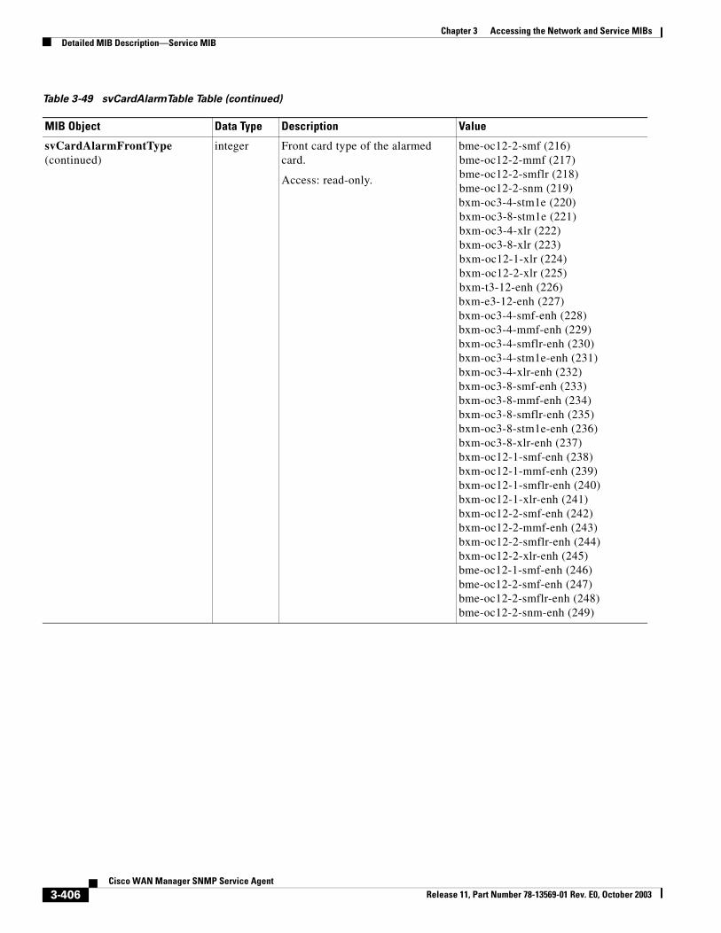
Chapter 3 Accessing the Network and Service MIBsDetailed MIB Description—Service MIB
svCardAlarmFrontType (continued)
integer Front card type of the alarmed card.
Access: read-only.
bme-oc12-2-smf (216)bme-oc12-2-mmf (217)bme-oc12-2-smflr (218)bme-oc12-2-snm (219)bxm-oc3-4-stm1e (220)bxm-oc3-8-stm1e (221)bxm-oc3-4-xlr (222)bxm-oc3-8-xlr (223)bxm-oc12-1-xlr (224)bxm-oc12-2-xlr (225)bxm-t3-12-enh (226)bxm-e3-12-enh (227)bxm-oc3-4-smf-enh (228)bxm-oc3-4-mmf-enh (229)bxm-oc3-4-smflr-enh (230)bxm-oc3-4-stm1e-enh (231)bxm-oc3-4-xlr-enh (232)bxm-oc3-8-smf-enh (233)bxm-oc3-8-mmf-enh (234)bxm-oc3-8-smflr-enh (235)bxm-oc3-8-stm1e-enh (236)bxm-oc3-8-xlr-enh (237)bxm-oc12-1-smf-enh (238)bxm-oc12-1-mmf-enh (239)bxm-oc12-1-smflr-enh (240)bxm-oc12-1-xlr-enh (241)bxm-oc12-2-smf-enh (242)bxm-oc12-2-mmf-enh (243)bxm-oc12-2-smflr-enh (244)bxm-oc12-2-xlr-enh (245)bme-oc12-1-smf-enh (246)bme-oc12-2-smf-enh (247)bme-oc12-2-smflr-enh (248)bme-oc12-2-snm-enh (249)
Table 3-49 svCardAlarmTable Table (continued)
MIB Object Data Type Description Value
3-406Cisco WAN Manager SNMP Service Agent
Release 11, Part Number 78-13569-01 Rev. E0, October 2003
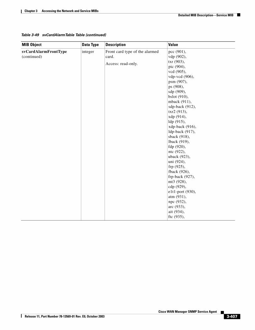
Chapter 3 Accessing the Network and Service MIBsDetailed MIB Description—Service MIB
svCardAlarmFrontType (continued)
integer Front card type of the alarmed card.
Access: read-only.
pcc (901),vdp (902),txr (903),pic (904),vcd (905),vdp-vcd (906),psm (907),ps (908),sdp (909),bslot (910),mback (911),sdp-back (912),txr2 (913),xdp (914),ldp (915),xdp-back (916),ldp-back (917),sback (918),lback (919),fdp (920),ntc (922),uback (923),uni (924),frp (925),fback (926),frp-back (927),mt3 (928),cdp (929),e1t1-port (930),atm (931),npc (932),arc (933),ait (934),ftc (935),
Table 3-49 svCardAlarmTable Table (continued)
MIB Object Data Type Description Value
3-407Cisco WAN Manager SNMP Service Agent
Release 11, Part Number 78-13569-01 Rev. E0, October 2003
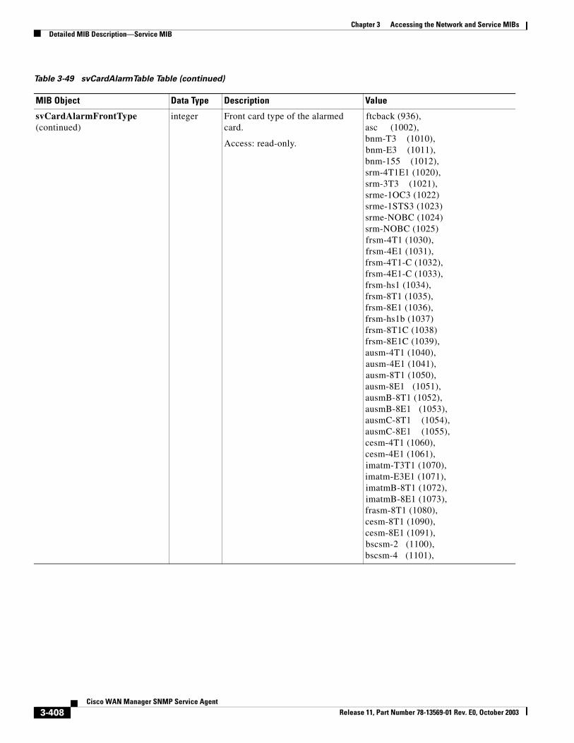
Chapter 3 Accessing the Network and Service MIBsDetailed MIB Description—Service MIB
svCardAlarmFrontType (continued)
integer Front card type of the alarmed card.
Access: read-only.
ftcback (936),asc (1002),bnm-T3 (1010),bnm-E3 (1011),bnm-155 (1012),srm-4T1E1 (1020),srm-3T3 (1021),srme-1OC3 (1022)srme-1STS3 (1023)srme-NOBC (1024)srm-NOBC (1025)frsm-4T1 (1030),frsm-4E1 (1031),frsm-4T1-C (1032),frsm-4E1-C (1033),frsm-hs1 (1034),frsm-8T1 (1035),frsm-8E1 (1036),frsm-hs1b (1037)frsm-8T1C (1038)frsm-8E1C (1039),ausm-4T1 (1040),ausm-4E1 (1041),ausm-8T1 (1050),ausm-8E1 (1051),ausmB-8T1 (1052),ausmB-8E1 (1053),ausmC-8T1 (1054),ausmC-8E1 (1055),cesm-4T1 (1060),cesm-4E1 (1061),imatm-T3T1 (1070),imatm-E3E1 (1071),imatmB-8T1 (1072),imatmB-8E1 (1073),frasm-8T1 (1080),cesm-8T1 (1090),cesm-8E1 (1091),bscsm-2 (1100),bscsm-4 (1101),
Table 3-49 svCardAlarmTable Table (continued)
MIB Object Data Type Description Value
3-408Cisco WAN Manager SNMP Service Agent
Release 11, Part Number 78-13569-01 Rev. E0, October 2003
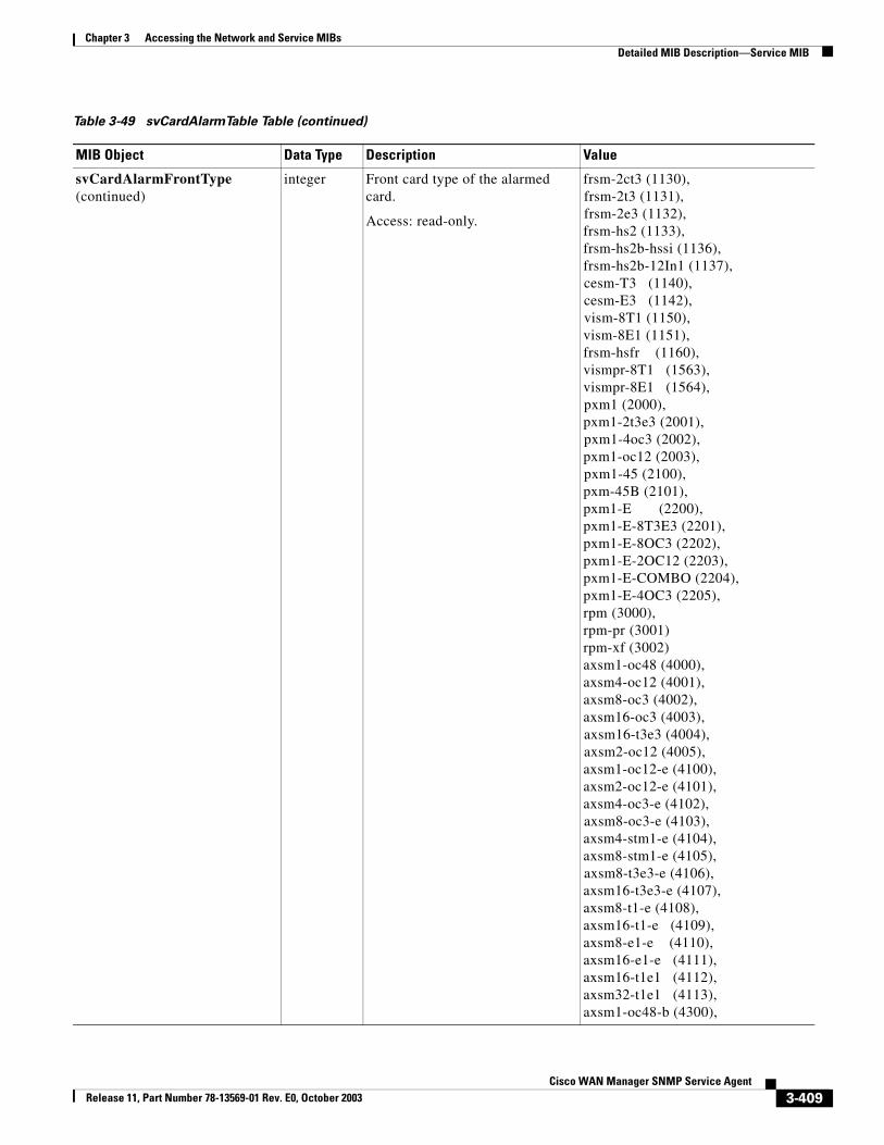
Chapter 3 Accessing the Network and Service MIBsDetailed MIB Description—Service MIB
svCardAlarmFrontType (continued)
integer Front card type of the alarmed card.
Access: read-only.
frsm-2ct3 (1130),frsm-2t3 (1131),frsm-2e3 (1132),frsm-hs2 (1133),frsm-hs2b-hssi (1136),frsm-hs2b-12In1 (1137),cesm-T3 (1140),cesm-E3 (1142),vism-8T1 (1150),vism-8E1 (1151),frsm-hsfr (1160),vismpr-8T1 (1563),vismpr-8E1 (1564),pxm1 (2000),pxm1-2t3e3 (2001),pxm1-4oc3 (2002),pxm1-oc12 (2003),pxm1-45 (2100),pxm-45B (2101),pxm1-E (2200),pxm1-E-8T3E3 (2201),pxm1-E-8OC3 (2202),pxm1-E-2OC12 (2203),pxm1-E-COMBO (2204),pxm1-E-4OC3 (2205),rpm (3000),rpm-pr (3001)rpm-xf (3002)axsm1-oc48 (4000),axsm4-oc12 (4001),axsm8-oc3 (4002),axsm16-oc3 (4003),axsm16-t3e3 (4004),axsm2-oc12 (4005),axsm1-oc12-e (4100),axsm2-oc12-e (4101),axsm4-oc3-e (4102),axsm8-oc3-e (4103),axsm4-stm1-e (4104),axsm8-stm1-e (4105), axsm8-t3e3-e (4106),axsm16-t3e3-e (4107),axsm8-t1-e (4108),axsm16-t1-e (4109),axsm8-e1-e (4110),axsm16-e1-e (4111),axsm16-t1e1 (4112),axsm32-t1e1 (4113),axsm1-oc48-b (4300),
Table 3-49 svCardAlarmTable Table (continued)
MIB Object Data Type Description Value
3-409Cisco WAN Manager SNMP Service Agent
Release 11, Part Number 78-13569-01 Rev. E0, October 2003
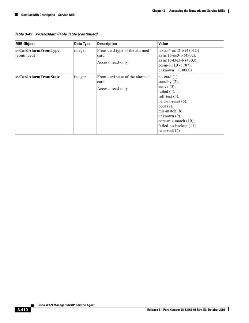
Chapter 3 Accessing the Network and Service MIBsDetailed MIB Description—Service MIB
svCardAlarmFrontType (continued)
integer Front card type of the alarmed card.
Access: read-only.
axsm4-oc12-b (4301),}axsm16-oc3-b (4302),axsm16-t3e3-b (4303),cesm-8T1B (1787),unknown (10000)
svCardAlarmFrontState integer Front card state of the alarmed card.
Access: read-only.
no-card (1),standby (2),active (3),failed (4),self-test (5),held-in-reset (6),boot (7),mis-match (8),unknown (9),core-mis-match (10),failed-no-backup (11),reserved(12)
Table 3-49 svCardAlarmTable Table (continued)
MIB Object Data Type Description Value
3-410Cisco WAN Manager SNMP Service Agent
Release 11, Part Number 78-13569-01 Rev. E0, October 2003
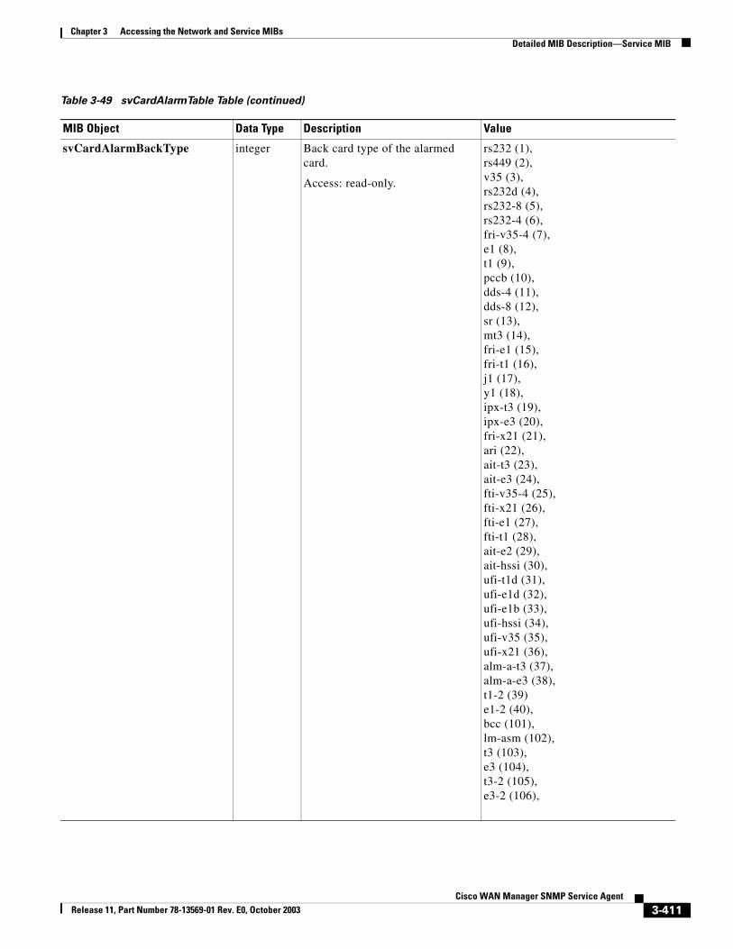
Chapter 3 Accessing the Network and Service MIBsDetailed MIB Description—Service MIB
svCardAlarmBackType integer Back card type of the alarmed card.
Access: read-only.
rs232 (1),rs449 (2),v35 (3),rs232d (4),rs232-8 (5),rs232-4 (6),fri-v35-4 (7),e1 (8),t1 (9),pccb (10),dds-4 (11),dds-8 (12),sr (13),mt3 (14),fri-e1 (15),fri-t1 (16),j1 (17),y1 (18),ipx-t3 (19),ipx-e3 (20),fri-x21 (21),ari (22),ait-t3 (23),ait-e3 (24),fti-v35-4 (25),fti-x21 (26),fti-e1 (27),fti-t1 (28),ait-e2 (29),ait-hssi (30),ufi-t1d (31),ufi-e1d (32),ufi-e1b (33),ufi-hssi (34),ufi-v35 (35),ufi-x21 (36),alm-a-t3 (37),alm-a-e3 (38),t1-2 (39)e1-2 (40),bcc (101),lm-asm (102),t3 (103),e3 (104),t3-2 (105),e3-2 (106),
Table 3-49 svCardAlarmTable Table (continued)
MIB Object Data Type Description Value
3-411Cisco WAN Manager SNMP Service Agent
Release 11, Part Number 78-13569-01 Rev. E0, October 2003
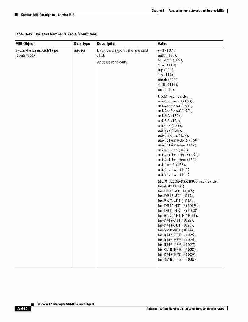
Chapter 3 Accessing the Network and Service MIBsDetailed MIB Description—Service MIB
svCardAlarmBackType (continued)
integer Back card type of the alarmed card.
Access: read-only
smf (107),mmf (108),bcc-lm2 (109),stm1 (110),utp (111),stp (112),nmch (113),smflr (114),init (116),
UXM back cards:uai-4oc3-mmf (150),uai-4oc3-smf (151),uai-2oc3-smf (152),uai-6t3 (153),uai-3t3 (154),uai-6e3 (155),uai-3e3 (156),uai-8t1-ima (157),uai-8e1-ima-db15 (158),uai-8e1-ima-bnc (159),uai-4t1-ima (160),uai-4e1-ima-db15 (161),uai-4e1-ima-bnc (162),uai-4stm1 (163),uai-4oc3-xlr (164)uai-2oc3-xlr (165)
MGX 8220/MGX 8800 back cards:lm-ASC (1002),lm-DB15-4T1 (1016),lm-DB15-4E1 1017),lm-BNC-4E1 (1018),lm-DB15-4T1-R(1019),lm-DB15-4E1-R(1020),lm-BNC-4E1-R (1021),lm-RJ48-8T1 (1022),lm-RJ48-8E1 (1023),lm-SMB-8E1 (1024),lm-RJ48-T3T1 (1025),lm-RJ48-E3E1 (1026),lm-RJ48-T3E1 (1027),lm-SMB-E3E1 (1028),lm-RJ48-E3T1 (1029),lm-SMB-T3E1 (1030),
Table 3-49 svCardAlarmTable Table (continued)
MIB Object Data Type Description Value
3-412Cisco WAN Manager SNMP Service Agent
Release 11, Part Number 78-13569-01 Rev. E0, October 2003
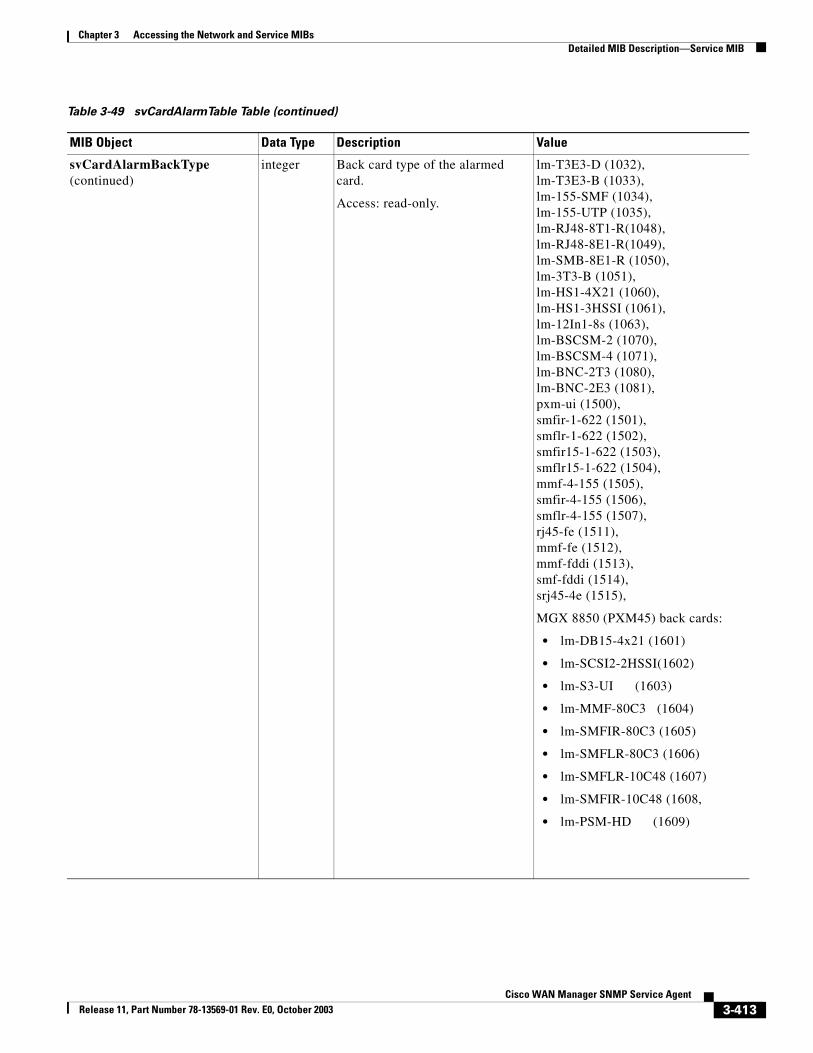
Chapter 3 Accessing the Network and Service MIBsDetailed MIB Description—Service MIB
svCardAlarmBackType (continued)
integer Back card type of the alarmed card.
Access: read-only.
lm-T3E3-D (1032),lm-T3E3-B (1033),lm-155-SMF (1034),lm-155-UTP (1035),lm-RJ48-8T1-R(1048),lm-RJ48-8E1-R(1049),lm-SMB-8E1-R (1050),lm-3T3-B (1051),lm-HS1-4X21 (1060),lm-HS1-3HSSI (1061),lm-12In1-8s (1063),lm-BSCSM-2 (1070),lm-BSCSM-4 (1071),lm-BNC-2T3 (1080),lm-BNC-2E3 (1081),pxm-ui (1500),smfir-1-622 (1501),smflr-1-622 (1502),smfir15-1-622 (1503),smflr15-1-622 (1504),mmf-4-155 (1505),smfir-4-155 (1506),smflr-4-155 (1507),rj45-fe (1511),mmf-fe (1512),mmf-fddi (1513),smf-fddi (1514),srj45-4e (1515),
MGX 8850 (PXM45) back cards:
• lm-DB15-4x21 (1601)
• lm-SCSI2-2HSSI(1602)
• lm-S3-UI (1603)
• lm-MMF-80C3 (1604)
• lm-SMFIR-80C3 (1605)
• lm-SMFLR-80C3 (1606)
• lm-SMFLR-10C48 (1607)
• lm-SMFIR-10C48 (1608,
• lm-PSM-HD (1609)
Table 3-49 svCardAlarmTable Table (continued)
MIB Object Data Type Description Value
3-413Cisco WAN Manager SNMP Service Agent
Release 11, Part Number 78-13569-01 Rev. E0, October 2003
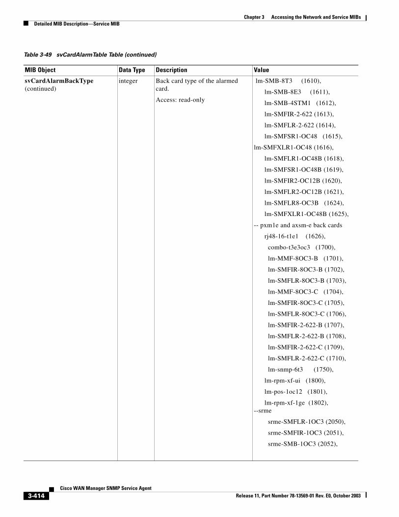
Chapter 3 Accessing the Network and Service MIBsDetailed MIB Description—Service MIB
svCardAlarmBackType (continued)
integer Back card type of the alarmed card.
Access: read-only
lm-SMB-8T3 (1610),
lm-SMB-8E3 (1611),
lm-SMB-4STM1 (1612),
lm-SMFIR-2-622 (1613),
lm-SMFLR-2-622 (1614),
lm-SMFSR1-OC48 (1615),
lm-SMFXLR1-OC48 (1616),
lm-SMFLR1-OC48B (1618),
lm-SMFSR1-OC48B (1619),
lm-SMFIR2-OC12B (1620),
lm-SMFLR2-OC12B (1621),
lm-SMFLR8-OC3B (1624),
lm-SMFXLR1-OC48B (1625),
-- pxm1e and axsm-e back cards
rj48-16-t1e1 (1626),
combo-t3e3oc3 (1700),
lm-MMF-8OC3-B (1701),
lm-SMFIR-8OC3-B (1702),
lm-SMFLR-8OC3-B (1703),
lm-MMF-8OC3-C (1704),
lm-SMFIR-8OC3-C (1705),
lm-SMFLR-8OC3-C (1706),
lm-SMFIR-2-622-B (1707),
lm-SMFLR-2-622-B (1708),
lm-SMFIR-2-622-C (1709),
lm-SMFLR-2-622-C (1710),
lm-snmp-6t3 (1750),
lm-rpm-xf-ui (1800),
lm-pos-1oc12 (1801),
lm-rpm-xf-1ge (1802),--srme
srme-SMFLR-1OC3 (2050),
srme-SMFIR-1OC3 (2051),
srme-SMB-1OC3 (2052),
Table 3-49 svCardAlarmTable Table (continued)
MIB Object Data Type Description Value
3-414Cisco WAN Manager SNMP Service Agent
Release 11, Part Number 78-13569-01 Rev. E0, October 2003
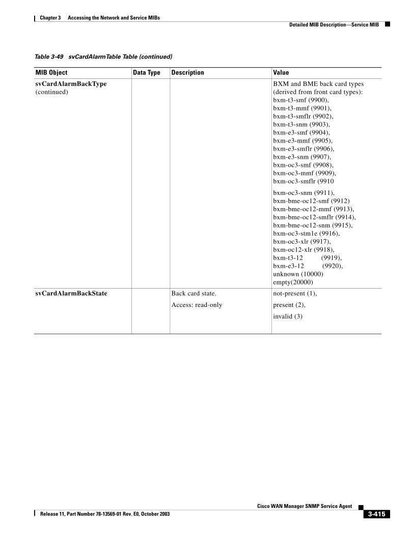
Chapter 3 Accessing the Network and Service MIBsDetailed MIB Description—Service MIB
svCardAlarmBackType (continued)
BXM and BME back card types (derived from front card types):bxm-t3-smf (9900),bxm-t3-mmf (9901),bxm-t3-smflr (9902),bxm-t3-snm (9903),bxm-e3-smf (9904),bxm-e3-mmf (9905),bxm-e3-smflr (9906),bxm-e3-snm (9907),bxm-oc3-smf (9908),bxm-oc3-mmf (9909),bxm-oc3-smflr (9910
bxm-oc3-snm (9911),bxm-bme-oc12-smf (9912)bxm-bme-oc12-mmf (9913),bxm-bme-oc12-smflr (9914),bxm-bme-oc12-snm (9915),bxm-oc3-stm1e (9916),bxm-oc3-xlr (9917),bxm-oc12-xlr (9918),bxm-t3-12 (9919),bxm-e3-12 (9920),unknown (10000)empty(20000)
svCardAlarmBackState Back card state.
Access: read-only
not-present (1),
present (2),
invalid (3)
Table 3-49 svCardAlarmTable Table (continued)
MIB Object Data Type Description Value
3-415Cisco WAN Manager SNMP Service Agent
Release 11, Part Number 78-13569-01 Rev. E0, October 2003
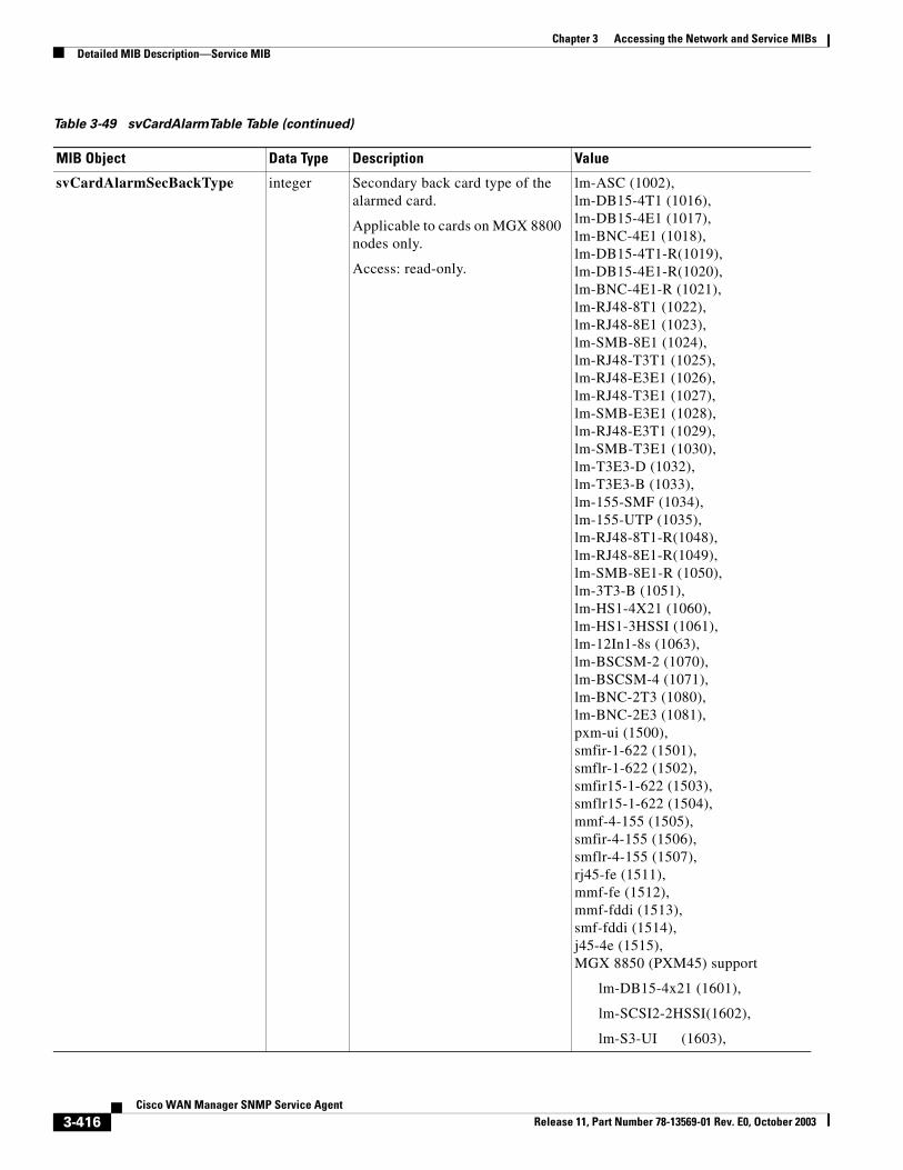
Chapter 3 Accessing the Network and Service MIBsDetailed MIB Description—Service MIB
svCardAlarmSecBackType integer Secondary back card type of the alarmed card.
Applicable to cards on MGX 8800 nodes only.
Access: read-only.
lm-ASC (1002),lm-DB15-4T1 (1016),lm-DB15-4E1 (1017),lm-BNC-4E1 (1018),lm-DB15-4T1-R(1019),lm-DB15-4E1-R(1020),lm-BNC-4E1-R (1021),lm-RJ48-8T1 (1022),lm-RJ48-8E1 (1023),lm-SMB-8E1 (1024),lm-RJ48-T3T1 (1025),lm-RJ48-E3E1 (1026),lm-RJ48-T3E1 (1027),lm-SMB-E3E1 (1028),lm-RJ48-E3T1 (1029),lm-SMB-T3E1 (1030),lm-T3E3-D (1032),lm-T3E3-B (1033),lm-155-SMF (1034),lm-155-UTP (1035),lm-RJ48-8T1-R(1048),lm-RJ48-8E1-R(1049),lm-SMB-8E1-R (1050),lm-3T3-B (1051),lm-HS1-4X21 (1060),lm-HS1-3HSSI (1061),lm-12In1-8s (1063),lm-BSCSM-2 (1070),lm-BSCSM-4 (1071),lm-BNC-2T3 (1080),lm-BNC-2E3 (1081),pxm-ui (1500),smfir-1-622 (1501),smflr-1-622 (1502),smfir15-1-622 (1503),smflr15-1-622 (1504),mmf-4-155 (1505),smfir-4-155 (1506),smflr-4-155 (1507),rj45-fe (1511),mmf-fe (1512),mmf-fddi (1513),smf-fddi (1514),j45-4e (1515),MGX 8850 (PXM45) support
lm-DB15-4x21 (1601),
lm-SCSI2-2HSSI(1602),
lm-S3-UI (1603),
Table 3-49 svCardAlarmTable Table (continued)
MIB Object Data Type Description Value
3-416Cisco WAN Manager SNMP Service Agent
Release 11, Part Number 78-13569-01 Rev. E0, October 2003
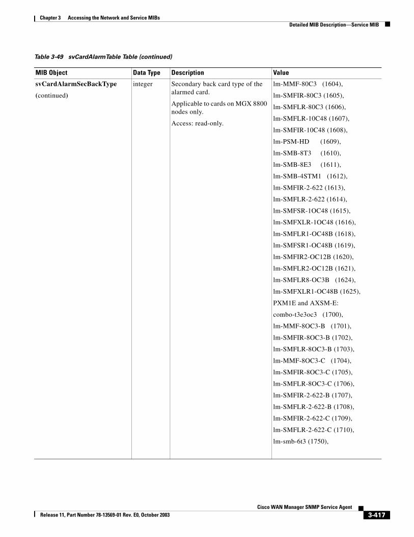
Chapter 3 Accessing the Network and Service MIBsDetailed MIB Description—Service MIB
svCardAlarmSecBackType
(continued)
integer Secondary back card type of the alarmed card.
Applicable to cards on MGX 8800 nodes only.
Access: read-only.
lm-MMF-80C3 (1604),
lm-SMFIR-80C3 (1605),
lm-SMFLR-80C3 (1606),
lm-SMFLR-10C48 (1607),
lm-SMFIR-10C48 (1608),
lm-PSM-HD (1609),
lm-SMB-8T3 (1610),
lm-SMB-8E3 (1611),
lm-SMB-4STM1 (1612),
lm-SMFIR-2-622 (1613),
lm-SMFLR-2-622 (1614),
lm-SMFSR-1OC48 (1615),
lm-SMFXLR-1OC48 (1616),
lm-SMFLR1-OC48B (1618),
lm-SMFSR1-OC48B (1619),
lm-SMFIR2-OC12B (1620),
lm-SMFLR2-OC12B (1621),
lm-SMFLR8-OC3B (1624),
lm-SMFXLR1-OC48B (1625),
PXM1E and AXSM-E:
combo-t3e3oc3 (1700),
lm-MMF-8OC3-B (1701),
lm-SMFIR-8OC3-B (1702),
lm-SMFLR-8OC3-B (1703),
lm-MMF-8OC3-C (1704),
lm-SMFIR-8OC3-C (1705),
lm-SMFLR-8OC3-C (1706),
lm-SMFIR-2-622-B (1707),
lm-SMFLR-2-622-B (1708),
lm-SMFIR-2-622-C (1709),
lm-SMFLR-2-622-C (1710),
lm-smb-6t3 (1750),
Table 3-49 svCardAlarmTable Table (continued)
MIB Object Data Type Description Value
3-417Cisco WAN Manager SNMP Service Agent
Release 11, Part Number 78-13569-01 Rev. E0, October 2003
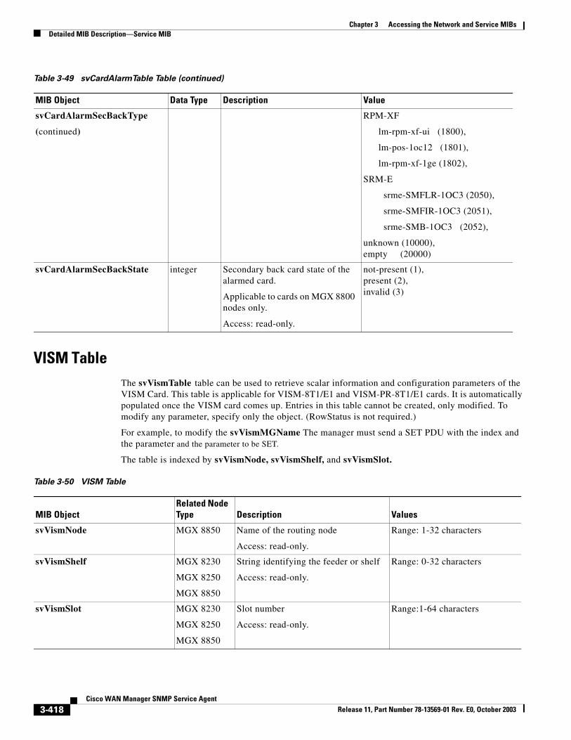
Chapter 3 Accessing the Network and Service MIBsDetailed MIB Description—Service MIB
VISM TableThe svVismTable table can be used to retrieve scalar information and configuration parameters of the VISM Card. This table is applicable for VISM-8T1/E1 and VISM-PR-8T1/E1 cards. It is automatically populated once the VISM card comes up. Entries in this table cannot be created, only modified. To modify any parameter, specify only the object. (RowStatus is not required.)
For example, to modify the svVismMGName The manager must send a SET PDU with the index and the parameter and the parameter to be SET.
The table is indexed by svVismNode, svVismShelf, and svVismSlot.
svCardAlarmSecBackType
(continued)
RPM-XF
lm-rpm-xf-ui (1800),
lm-pos-1oc12 (1801),
lm-rpm-xf-1ge (1802),
SRM-E
srme-SMFLR-1OC3 (2050),
srme-SMFIR-1OC3 (2051),
srme-SMB-1OC3 (2052),
unknown (10000),empty (20000)
svCardAlarmSecBackState integer Secondary back card state of the alarmed card.
Applicable to cards on MGX 8800 nodes only.
Access: read-only.
not-present (1),present (2),invalid (3)
Table 3-49 svCardAlarmTable Table (continued)
MIB Object Data Type Description Value
Table 3-50 VISM Table
MIB ObjectRelated Node Type Description Values
svVismNode MGX 8850 Name of the routing node
Access: read-only.
Range: 1-32 characters
svVismShelf MGX 8230
MGX 8250
MGX 8850
String identifying the feeder or shelf
Access: read-only.
Range: 0-32 characters
svVismSlot MGX 8230
MGX 8250
MGX 8850
Slot number
Access: read-only.
Range:1-64 characters
3-418Cisco WAN Manager SNMP Service Agent
Release 11, Part Number 78-13569-01 Rev. E0, October 2003
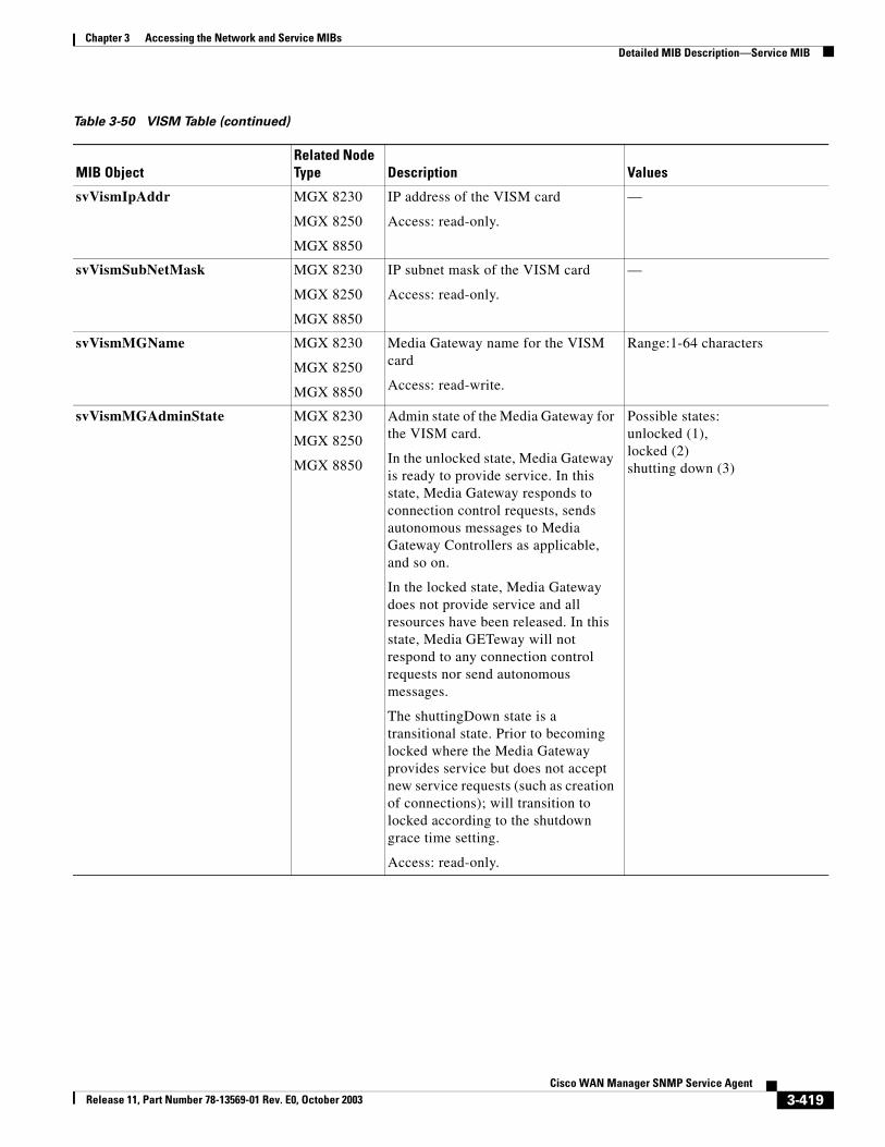
Chapter 3 Accessing the Network and Service MIBsDetailed MIB Description—Service MIB
svVismIpAddr MGX 8230
MGX 8250
MGX 8850
IP address of the VISM card
Access: read-only.
—
svVismSubNetMask MGX 8230
MGX 8250
MGX 8850
IP subnet mask of the VISM card
Access: read-only.
—
svVismMGName MGX 8230
MGX 8250
MGX 8850
Media Gateway name for the VISM card
Access: read-write.
Range:1-64 characters
svVismMGAdminState MGX 8230
MGX 8250
MGX 8850
Admin state of the Media Gateway for the VISM card.
In the unlocked state, Media Gateway is ready to provide service. In this state, Media Gateway responds to connection control requests, sends autonomous messages to Media Gateway Controllers as applicable, and so on.
In the locked state, Media Gateway does not provide service and all resources have been released. In this state, Media GETeway will not respond to any connection control requests nor send autonomous messages.
The shuttingDown state is a transitional state. Prior to becoming locked where the Media Gateway provides service but does not accept new service requests (such as creation of connections); will transition to locked according to the shutdown grace time setting.
Access: read-only.
Possible states: unlocked (1), locked (2)shutting down (3)
Table 3-50 VISM Table (continued)
MIB ObjectRelated Node Type Description Values
3-419Cisco WAN Manager SNMP Service Agent
Release 11, Part Number 78-13569-01 Rev. E0, October 2003
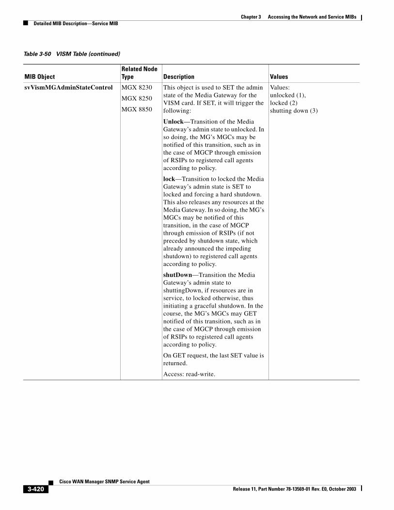
Chapter 3 Accessing the Network and Service MIBsDetailed MIB Description—Service MIB
svVismMGAdminStateControl MGX 8230
MGX 8250
MGX 8850
This object is used to SET the admin state of the Media Gateway for the VISM card. If SET, it will trigger the following:
Unlock—Transition of the Media Gateway’s admin state to unlocked. In so doing, the MG’s MGCs may be notified of this transition, such as in the case of MGCP through emission of RSIPs to registered call agents according to policy.
lock—Transition to locked the Media Gateway’s admin state is SET to locked and forcing a hard shutdown. This also releases any resources at the Media Gateway. In so doing, the MG’s MGCs may be notified of this transition, in the case of MGCP through emission of RSIPs (if not preceded by shutdown state, which already announced the impeding shutdown) to registered call agents according to policy.
shutDown—Transition the Media Gateway’s admin state to shuttingDown, if resources are in service, to locked otherwise, thus initiating a graceful shutdown. In the course, the MG’s MGCs may GET notified of this transition, such as in the case of MGCP through emission of RSIPs to registered call agents according to policy.
On GET request, the last SET value is returned.
Access: read-write.
Values: unlocked (1), locked (2)shutting down (3)
Table 3-50 VISM Table (continued)
MIB ObjectRelated Node Type Description Values
3-420Cisco WAN Manager SNMP Service Agent
Release 11, Part Number 78-13569-01 Rev. E0, October 2003
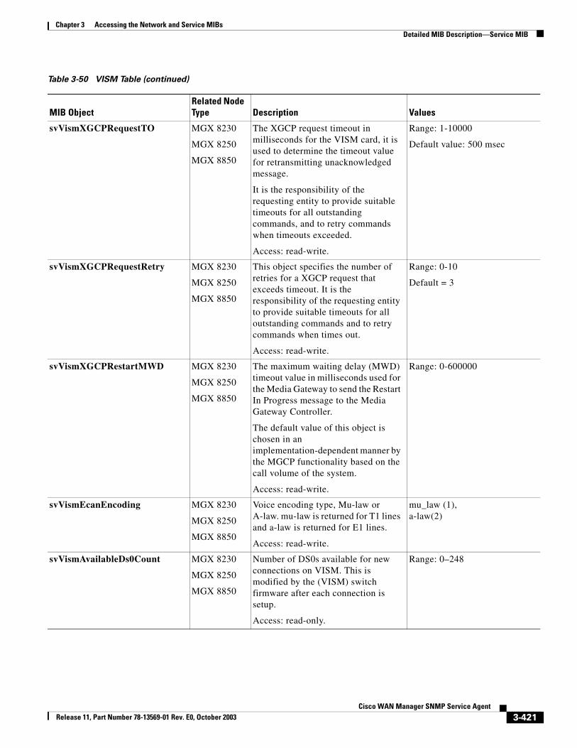
Chapter 3 Accessing the Network and Service MIBsDetailed MIB Description—Service MIB
svVismXGCPRequestTO MGX 8230
MGX 8250
MGX 8850
The XGCP request timeout in milliseconds for the VISM card, it is used to determine the timeout value for retransmitting unacknowledged message.
It is the responsibility of the requesting entity to provide suitable timeouts for all outstanding commands, and to retry commands when timeouts exceeded.
Access: read-write.
Range: 1-10000
Default value: 500 msec
svVismXGCPRequestRetry MGX 8230
MGX 8250
MGX 8850
This object specifies the number of retries for a XGCP request that exceeds timeout. It is the responsibility of the requesting entity to provide suitable timeouts for all outstanding commands and to retry commands when times out.
Access: read-write.
Range: 0-10
Default = 3
svVismXGCPRestartMWD MGX 8230
MGX 8250
MGX 8850
The maximum waiting delay (MWD) timeout value in milliseconds used for the Media Gateway to send the Restart In Progress message to the Media Gateway Controller.
The default value of this object is chosen in an implementation-dependent manner by the MGCP functionality based on the call volume of the system.
Access: read-write.
Range: 0-600000
svVismEcanEncoding MGX 8230
MGX 8250
MGX 8850
Voice encoding type, Mu-law or A-law. mu-law is returned for T1 lines and a-law is returned for E1 lines.
Access: read-write.
mu_law (1),a-law(2)
svVismAvailableDs0Count MGX 8230
MGX 8250
MGX 8850
Number of DS0s available for new connections on VISM. This is modified by the (VISM) switch firmware after each connection is setup.
Access: read-only.
Range: 0–248
Table 3-50 VISM Table (continued)
MIB ObjectRelated Node Type Description Values
3-421Cisco WAN Manager SNMP Service Agent
Release 11, Part Number 78-13569-01 Rev. E0, October 2003
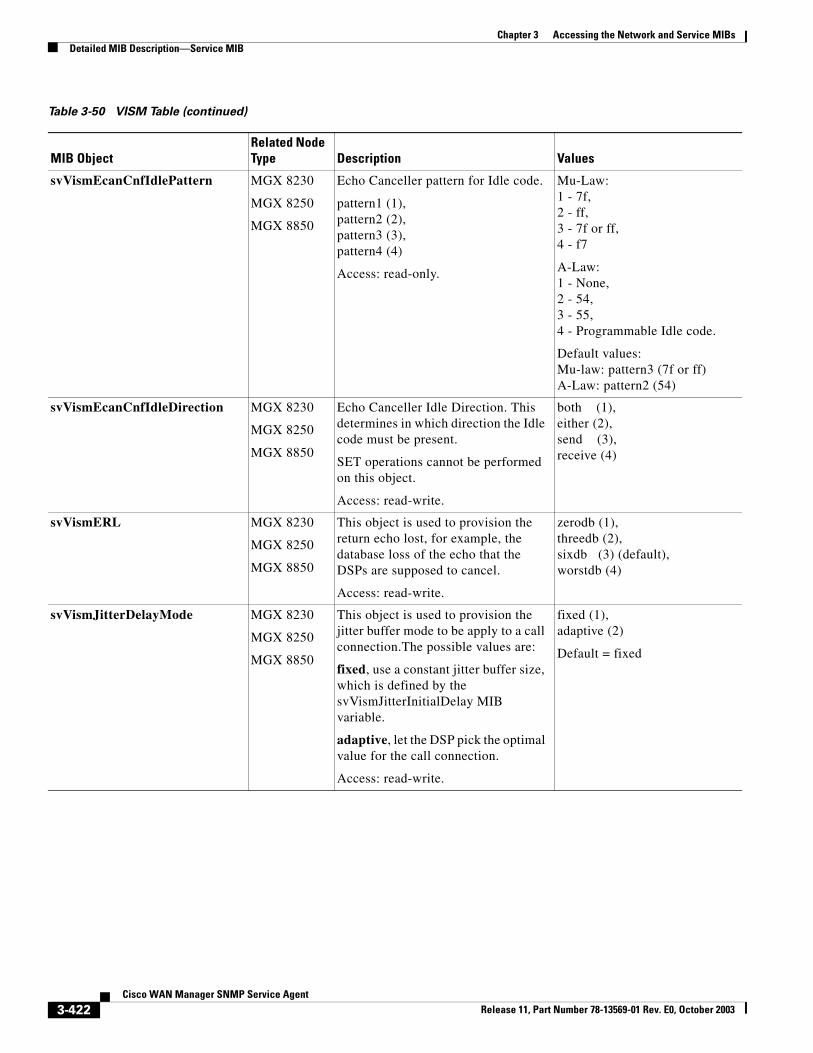
Chapter 3 Accessing the Network and Service MIBsDetailed MIB Description—Service MIB
svVismEcanCnfIdlePattern MGX 8230
MGX 8250
MGX 8850
Echo Canceller pattern for Idle code.
pattern1 (1), pattern2 (2),pattern3 (3),pattern4 (4)
Access: read-only.
Mu-Law:1 - 7f,2 - ff,3 - 7f or ff, 4 - f7
A-Law: 1 - None, 2 - 54, 3 - 55, 4 - Programmable Idle code.
Default values: Mu-law: pattern3 (7f or ff) A-Law: pattern2 (54)
svVismEcanCnfIdleDirection MGX 8230
MGX 8250
MGX 8850
Echo Canceller Idle Direction. This determines in which direction the Idle code must be present.
SET operations cannot be performed on this object.
Access: read-write.
both (1),either (2),send (3),receive (4)
svVismERL MGX 8230
MGX 8250
MGX 8850
This object is used to provision the return echo lost, for example, the database loss of the echo that the DSPs are supposed to cancel.
Access: read-write.
zerodb (1),threedb (2),sixdb (3) (default),worstdb (4)
svVismJitterDelayMode MGX 8230
MGX 8250
MGX 8850
This object is used to provision the jitter buffer mode to be apply to a call connection.The possible values are:
fixed, use a constant jitter buffer size, which is defined by the svVismJitterInitialDelay MIB variable.
adaptive, let the DSP pick the optimal value for the call connection.
Access: read-write.
fixed (1),adaptive (2)
Default = fixed
Table 3-50 VISM Table (continued)
MIB ObjectRelated Node Type Description Values
3-422Cisco WAN Manager SNMP Service Agent
Release 11, Part Number 78-13569-01 Rev. E0, October 2003
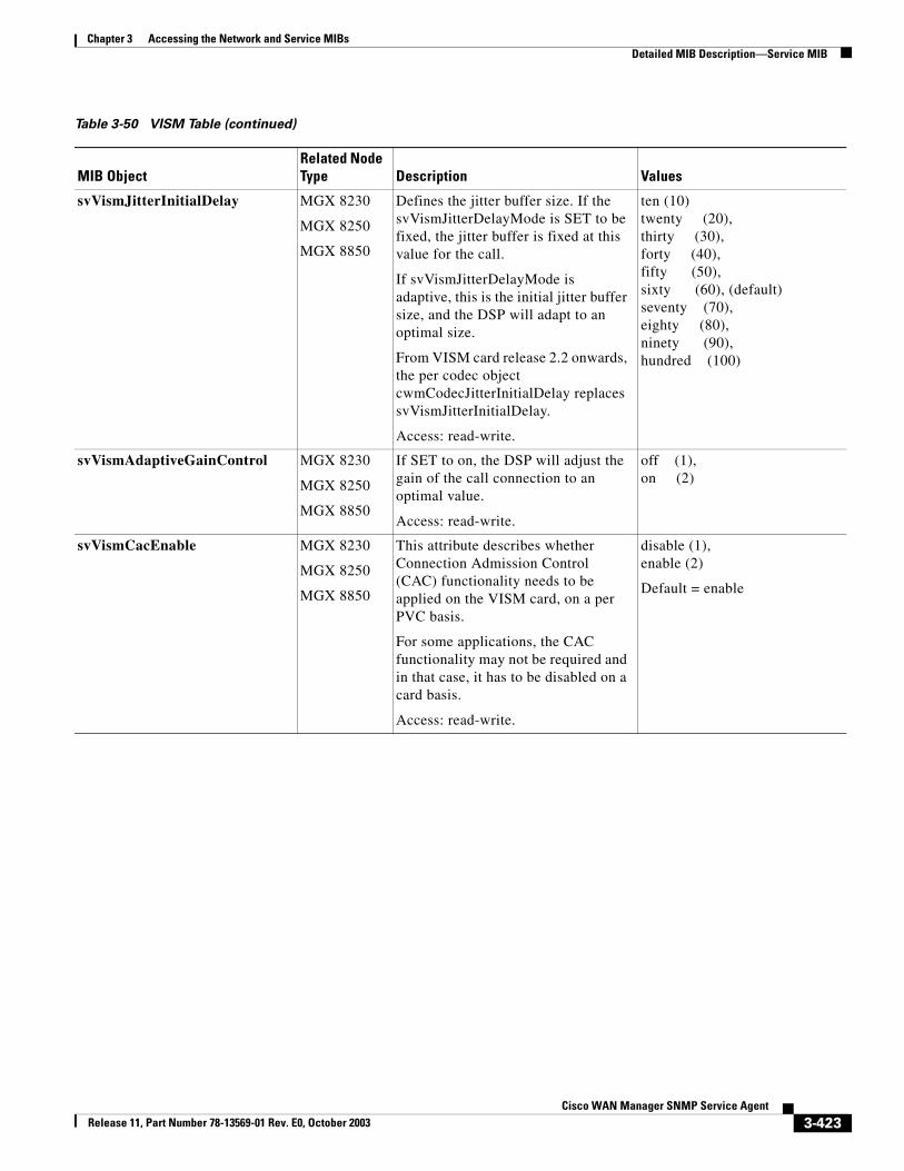
Chapter 3 Accessing the Network and Service MIBsDetailed MIB Description—Service MIB
svVismJitterInitialDelay MGX 8230
MGX 8250
MGX 8850
Defines the jitter buffer size. If the svVismJitterDelayMode is SET to be fixed, the jitter buffer is fixed at this value for the call.
If svVismJitterDelayMode is adaptive, this is the initial jitter buffer size, and the DSP will adapt to an optimal size.
From VISM card release 2.2 onwards, the per codec object cwmCodecJitterInitialDelay replaces svVismJitterInitialDelay.
Access: read-write.
ten (10)twenty (20), thirty (30), forty (40), fifty (50), sixty (60), (default)seventy (70), eighty (80), ninety (90), hundred (100)
svVismAdaptiveGainControl MGX 8230
MGX 8250
MGX 8850
If SET to on, the DSP will adjust the gain of the call connection to an optimal value.
Access: read-write.
off (1), on (2)
svVismCacEnable MGX 8230
MGX 8250
MGX 8850
This attribute describes whether Connection Admission Control (CAC) functionality needs to be applied on the VISM card, on a per PVC basis.
For some applications, the CAC functionality may not be required and in that case, it has to be disabled on a card basis.
Access: read-write.
disable (1), enable (2)
Default = enable
Table 3-50 VISM Table (continued)
MIB ObjectRelated Node Type Description Values
3-423Cisco WAN Manager SNMP Service Agent
Release 11, Part Number 78-13569-01 Rev. E0, October 2003
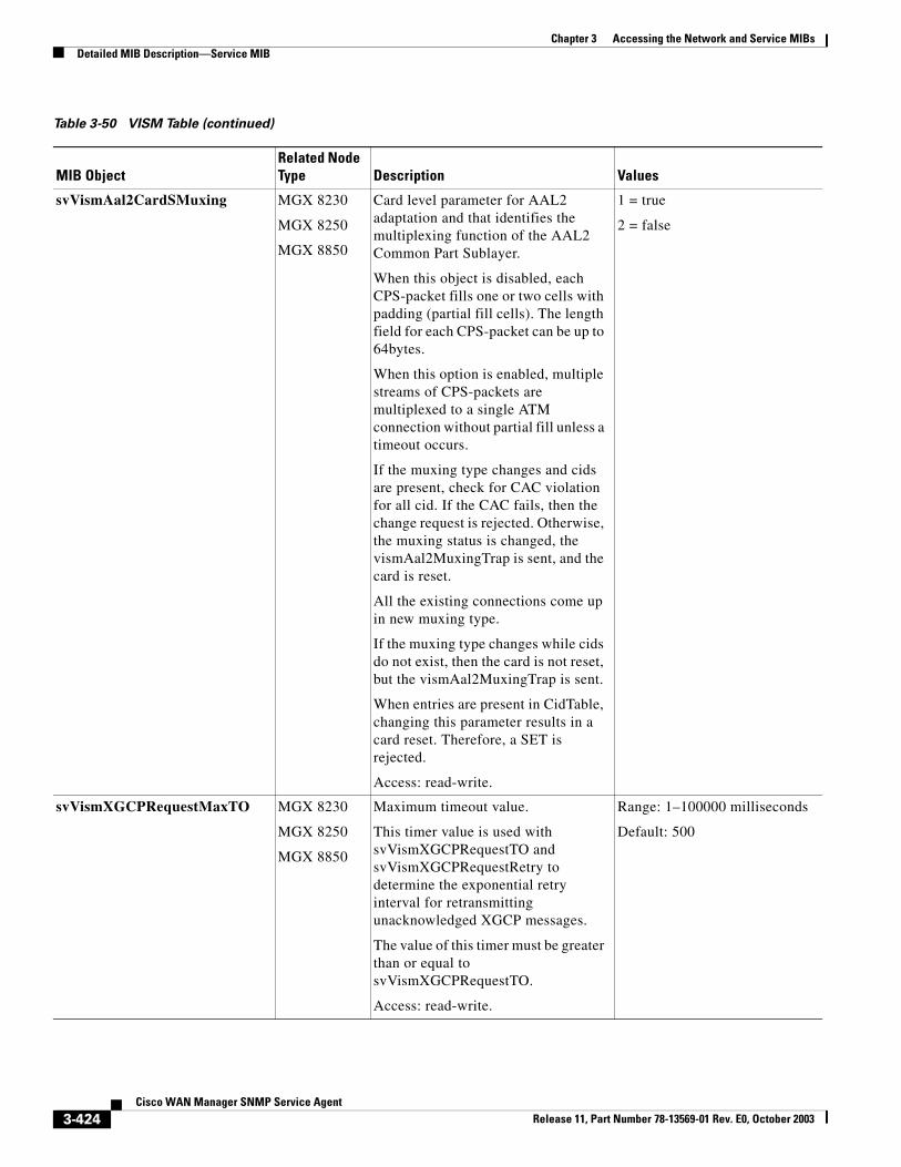
Chapter 3 Accessing the Network and Service MIBsDetailed MIB Description—Service MIB
svVismAal2CardSMuxing MGX 8230
MGX 8250
MGX 8850
Card level parameter for AAL2 adaptation and that identifies the multiplexing function of the AAL2 Common Part Sublayer.
When this object is disabled, each CPS-packet fills one or two cells with padding (partial fill cells). The length field for each CPS-packet can be up to 64bytes.
When this option is enabled, multiple streams of CPS-packets are multiplexed to a single ATM connection without partial fill unless a timeout occurs.
If the muxing type changes and cids are present, check for CAC violation for all cid. If the CAC fails, then the change request is rejected. Otherwise, the muxing status is changed, the vismAal2MuxingTrap is sent, and the card is reset.
All the existing connections come up in new muxing type.
If the muxing type changes while cids do not exist, then the card is not reset, but the vismAal2MuxingTrap is sent.
When entries are present in CidTable, changing this parameter results in a card reset. Therefore, a SET is rejected.
Access: read-write.
1 = true
2 = false
svVismXGCPRequestMaxTO MGX 8230
MGX 8250
MGX 8850
Maximum timeout value.
This timer value is used with svVismXGCPRequestTO and svVismXGCPRequestRetry to determine the exponential retry interval for retransmitting unacknowledged XGCP messages.
The value of this timer must be greater than or equal to svVismXGCPRequestTO.
Access: read-write.
Range: 1–100000 milliseconds
Default: 500
Table 3-50 VISM Table (continued)
MIB ObjectRelated Node Type Description Values
3-424Cisco WAN Manager SNMP Service Agent
Release 11, Part Number 78-13569-01 Rev. E0, October 2003
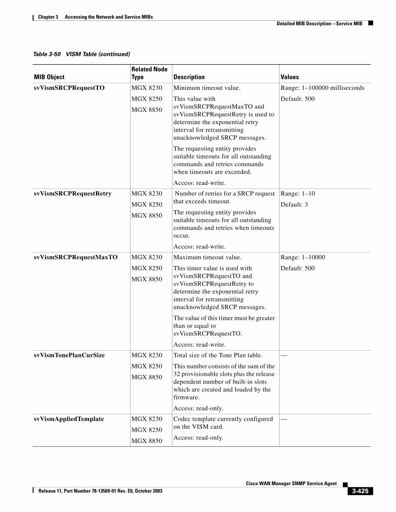
Chapter 3 Accessing the Network and Service MIBsDetailed MIB Description—Service MIB
svVismSRCPRequestTO MGX 8230
MGX 8250
MGX 8850
Minimum timeout value.
This value with svVismSRCPRequestMaxTO and svVismSRCPRequestRetry is used to determine the exponential retry interval for retransmitting unacknowledged SRCP messages.
The requesting entity provides suitable timeouts for all outstanding commands and retries commands when timeouts are exceeded.
Access: read-write.
Range: 1–100000 milliseconds
Default: 500
svVismSRCPRequestRetry MGX 8230
MGX 8250
MGX 8850
Number of retries for a SRCP request that exceeds timeout.
The requesting entity provides suitable timeouts for all outstanding commands and retries when timeouts occur.
Access: read-write.
Range: 1–10
Default: 3
svVismSRCPRequestMaxTO MGX 8230
MGX 8250
MGX 8850
Maximum timeout value.
This timer value is used with svVismSRCPRequestTO and svVismSRCPRequestRetry to determine the exponential retry interval for retransmitting unacknowledged SRCP messages.
The value of this timer must be greater than or equal to svVismSRCPRequestTO.
Access: read-write.
Range: 1–10000
Default: 500
svVismTonePlanCurSize MGX 8230
MGX 8250
MGX 8850
Total size of the Tone Plan table.
This number consists of the sum of the 32 provisionable slots plus the release dependent number of built-in slots which are created and loaded by the firmware.
Access: read-only.
—
svVismAppliedTemplate MGX 8230
MGX 8250
MGX 8850
Codec template currently configured on the VISM card.
Access: read-only.
—
Table 3-50 VISM Table (continued)
MIB ObjectRelated Node Type Description Values
3-425Cisco WAN Manager SNMP Service Agent
Release 11, Part Number 78-13569-01 Rev. E0, October 2003
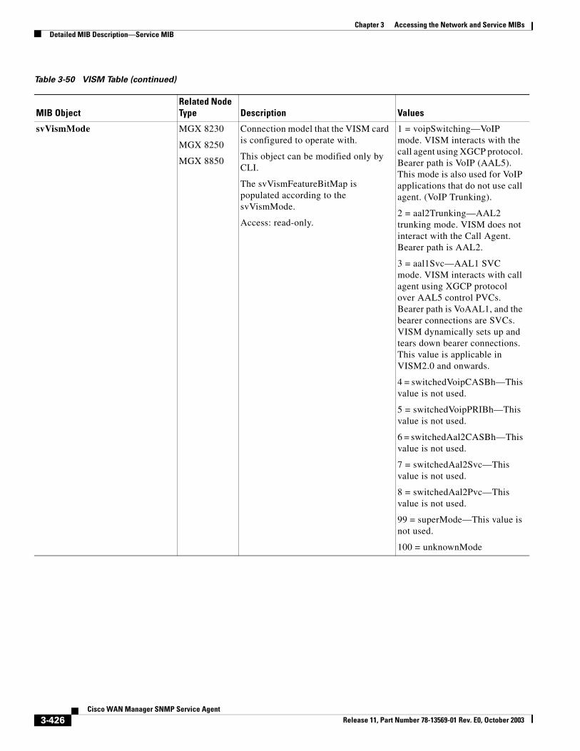
Chapter 3 Accessing the Network and Service MIBsDetailed MIB Description—Service MIB
svVismMode MGX 8230
MGX 8250
MGX 8850
Connection model that the VISM card is configured to operate with.
This object can be modified only by CLI.
The svVismFeatureBitMap is populated according to the svVismMode.
Access: read-only.
1 = voipSwitching—VoIP mode. VISM interacts with the call agent using XGCP protocol. Bearer path is VoIP (AAL5). This mode is also used for VoIP applications that do not use call agent. (VoIP Trunking).
2 = aal2Trunking—AAL2 trunking mode. VISM does not interact with the Call Agent. Bearer path is AAL2.
3 = aal1Svc—AAL1 SVC mode. VISM interacts with call agent using XGCP protocol over AAL5 control PVCs. Bearer path is VoAAL1, and the bearer connections are SVCs. VISM dynamically sets up and tears down bearer connections. This value is applicable in VISM2.0 and onwards.
4 = switchedVoipCASBh—This value is not used.
5 = switchedVoipPRIBh—This value is not used.
6 = switchedAal2CASBh—This value is not used.
7 = switchedAal2Svc—This value is not used.
8 = switchedAal2Pvc—This value is not used.
99 = superMode—This value is not used.
100 = unknownMode
Table 3-50 VISM Table (continued)
MIB ObjectRelated Node Type Description Values
3-426Cisco WAN Manager SNMP Service Agent
Release 11, Part Number 78-13569-01 Rev. E0, October 2003
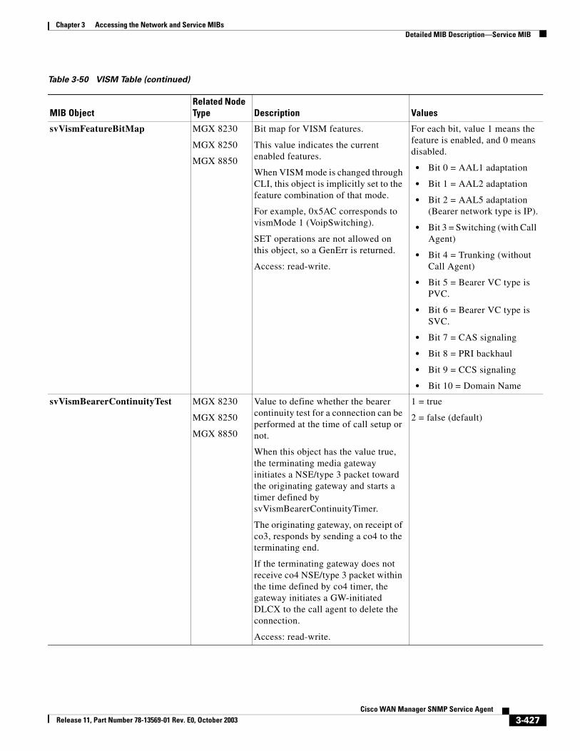
Chapter 3 Accessing the Network and Service MIBsDetailed MIB Description—Service MIB
svVismFeatureBitMap MGX 8230
MGX 8250
MGX 8850
Bit map for VISM features.
This value indicates the current enabled features.
When VISM mode is changed through CLI, this object is implicitly set to the feature combination of that mode.
For example, 0x5AC corresponds to vismMode 1 (VoipSwitching).
SET operations are not allowed on this object, so a GenErr is returned.
Access: read-write.
For each bit, value 1 means the feature is enabled, and 0 means disabled.
• Bit 0 = AAL1 adaptation
• Bit 1 = AAL2 adaptation
• Bit 2 = AAL5 adaptation (Bearer network type is IP).
• Bit 3 = Switching (with Call Agent)
• Bit 4 = Trunking (without Call Agent)
• Bit 5 = Bearer VC type is PVC.
• Bit 6 = Bearer VC type is SVC.
• Bit 7 = CAS signaling
• Bit 8 = PRI backhaul
• Bit 9 = CCS signaling
• Bit 10 = Domain Name
svVismBearerContinuityTest MGX 8230
MGX 8250
MGX 8850
Value to define whether the bearer continuity test for a connection can be performed at the time of call setup or not.
When this object has the value true, the terminating media gateway initiates a NSE/type 3 packet toward the originating gateway and starts a timer defined by svVismBearerContinuityTimer.
The originating gateway, on receipt of co3, responds by sending a co4 to the terminating end.
If the terminating gateway does not receive co4 NSE/type 3 packet within the time defined by co4 timer, the gateway initiates a GW-initiated DLCX to the call agent to delete the connection.
Access: read-write.
1 = true
2 = false (default)
Table 3-50 VISM Table (continued)
MIB ObjectRelated Node Type Description Values
3-427Cisco WAN Manager SNMP Service Agent
Release 11, Part Number 78-13569-01 Rev. E0, October 2003
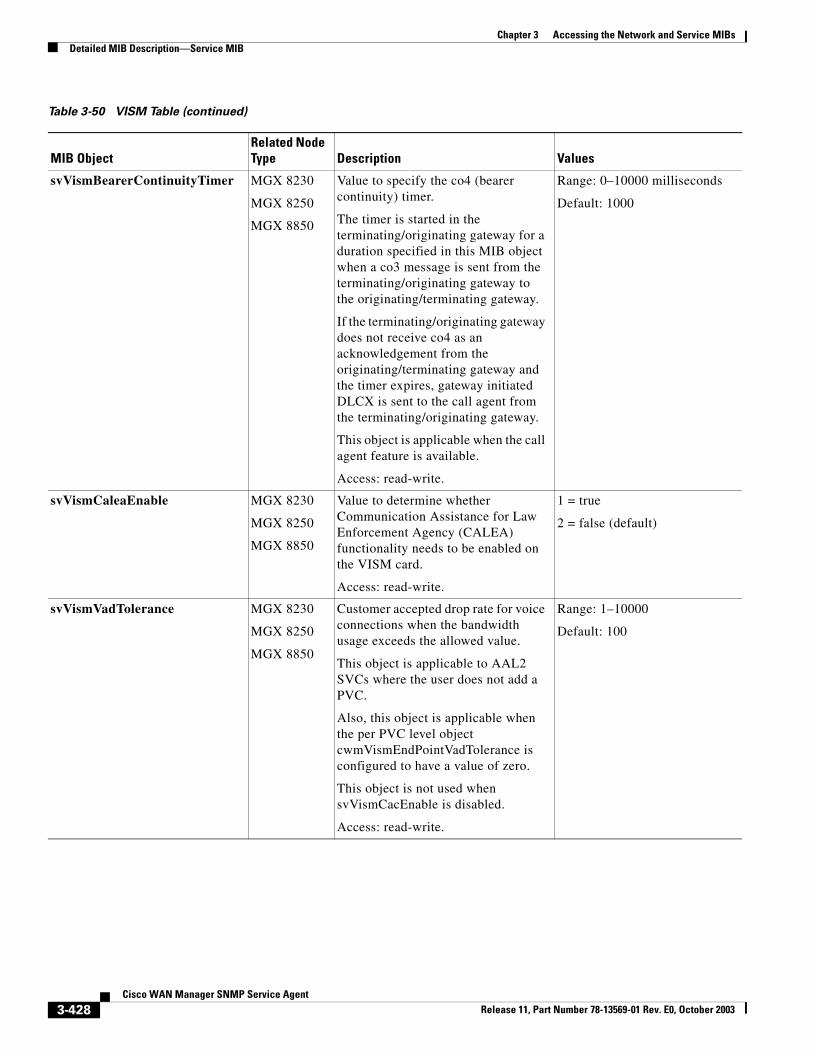
Chapter 3 Accessing the Network and Service MIBsDetailed MIB Description—Service MIB
svVismBearerContinuityTimer MGX 8230
MGX 8250
MGX 8850
Value to specify the co4 (bearer continuity) timer.
The timer is started in the terminating/originating gateway for a duration specified in this MIB object when a co3 message is sent from the terminating/originating gateway to the originating/terminating gateway.
If the terminating/originating gateway does not receive co4 as an acknowledgement from the originating/terminating gateway and the timer expires, gateway initiated DLCX is sent to the call agent from the terminating/originating gateway.
This object is applicable when the call agent feature is available.
Access: read-write.
Range: 0–10000 milliseconds
Default: 1000
svVismCaleaEnable MGX 8230
MGX 8250
MGX 8850
Value to determine whether Communication Assistance for Law Enforcement Agency (CALEA) functionality needs to be enabled on the VISM card.
Access: read-write.
1 = true
2 = false (default)
svVismVadTolerance MGX 8230
MGX 8250
MGX 8850
Customer accepted drop rate for voice connections when the bandwidth usage exceeds the allowed value.
This object is applicable to AAL2 SVCs where the user does not add a PVC.
Also, this object is applicable when the per PVC level object cwmVismEndPointVadTolerance is configured to have a value of zero.
This object is not used when svVismCacEnable is disabled.
Access: read-write.
Range: 1–10000
Default: 100
Table 3-50 VISM Table (continued)
MIB ObjectRelated Node Type Description Values
3-428Cisco WAN Manager SNMP Service Agent
Release 11, Part Number 78-13569-01 Rev. E0, October 2003
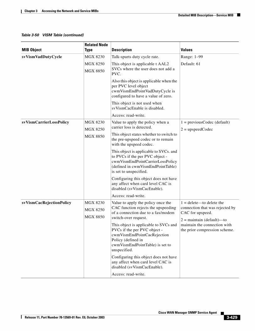
Chapter 3 Accessing the Network and Service MIBsDetailed MIB Description—Service MIB
svVismVadDutyCycle MGX 8230
MGX 8250
MGX 8850
Talk-spurts duty cycle rate.
This object is applicable t AAL2 SVCs where the user does not add a PVC.
Also this object is applicable when the per PVC level object cwmVismEndPointVadDutyCycle is configured to have a value of zero.
This object is not used when svVismCacEnable is disabled.
Access: read-write.
Range: 1–99
Default: 61
svVismCarrierLossPolicy MGX 8230
MGX 8250
MGX 8850
Value to apply the policy when a carrier loss is detected.
This object states whether to switch to the pre-upspeed codec or to remain with the upspeed codec.
This object is applicable to SVCs. and to PVCs if the per PVC object - cwmVismEndPointCarrierLossPolicy (defined in cwmVismEndPointTable) is set to unspecified.
Configuring this object does not have any affect when card level CAC is disabled (svVismCacEnable).
Access: read-write.
1 = previousCodec (default)
2 = upspeedCodec
svVismCacRejectionPolicy MGX 8230
MGX 8250
MGX 8850
Value to apply the policy once the CAC function rejects the upspeeding of a connection due to a fax/modem switch-over request.
This object is applicable to SVCs and PVCs if the per PVC object - cwmVismEndPointCacRejectionPolicy (defined in cwmVismEndPointTable) is set to unspecified.
Configuring this object does not have any affect when card level CAC is disabled (svVismCacEnable).
Access: read-write.
1 = delete—to delete the connection that was rejected by CAC for upspeed.
2 = maintain (default)—to maintain the connection with the prior compression scheme.
Table 3-50 VISM Table (continued)
MIB ObjectRelated Node Type Description Values
3-429Cisco WAN Manager SNMP Service Agent
Release 11, Part Number 78-13569-01 Rev. E0, October 2003
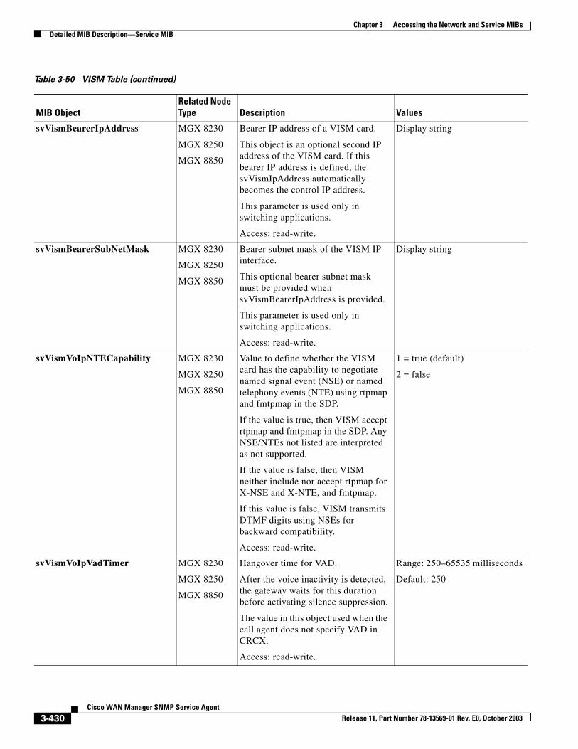
Chapter 3 Accessing the Network and Service MIBsDetailed MIB Description—Service MIB
svVismBearerIpAddress MGX 8230
MGX 8250
MGX 8850
Bearer IP address of a VISM card.
This object is an optional second IP address of the VISM card. If this bearer IP address is defined, the svVismIpAddress automatically becomes the control IP address.
This parameter is used only in switching applications.
Access: read-write.
Display string
svVismBearerSubNetMask MGX 8230
MGX 8250
MGX 8850
Bearer subnet mask of the VISM IP interface.
This optional bearer subnet mask must be provided when svVismBearerIpAddress is provided.
This parameter is used only in switching applications.
Access: read-write.
Display string
svVismVoIpNTECapability MGX 8230
MGX 8250
MGX 8850
Value to define whether the VISM card has the capability to negotiate named signal event (NSE) or named telephony events (NTE) using rtpmap and fmtpmap in the SDP.
If the value is true, then VISM accept rtpmap and fmtpmap in the SDP. Any NSE/NTEs not listed are interpreted as not supported.
If the value is false, then VISM neither include nor accept rtpmap for X-NSE and X-NTE, and fmtpmap.
If this value is false, VISM transmits DTMF digits using NSEs for backward compatibility.
Access: read-write.
1 = true (default)
2 = false
svVismVoIpVadTimer MGX 8230
MGX 8250
MGX 8850
Hangover time for VAD.
After the voice inactivity is detected, the gateway waits for this duration before activating silence suppression.
The value in this object used when the call agent does not specify VAD in CRCX.
Access: read-write.
Range: 250–65535 milliseconds
Default: 250
Table 3-50 VISM Table (continued)
MIB ObjectRelated Node Type Description Values
3-430Cisco WAN Manager SNMP Service Agent
Release 11, Part Number 78-13569-01 Rev. E0, October 2003
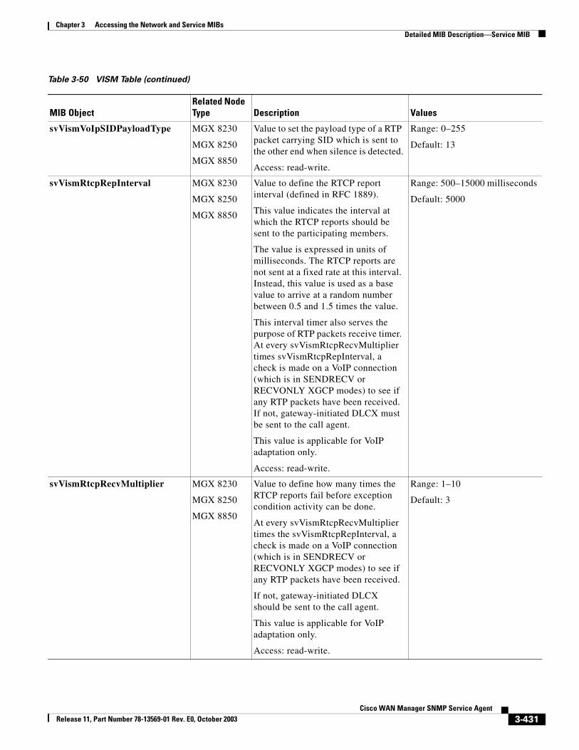
Chapter 3 Accessing the Network and Service MIBsDetailed MIB Description—Service MIB
svVismVoIpSIDPayloadType MGX 8230
MGX 8250
MGX 8850
Value to set the payload type of a RTP packet carrying SID which is sent to the other end when silence is detected.
Access: read-write.
Range: 0–255
Default: 13
svVismRtcpRepInterval MGX 8230
MGX 8250
MGX 8850
Value to define the RTCP report interval (defined in RFC 1889).
This value indicates the interval at which the RTCP reports should be sent to the participating members.
The value is expressed in units of milliseconds. The RTCP reports are not sent at a fixed rate at this interval. Instead, this value is used as a base value to arrive at a random number between 0.5 and 1.5 times the value.
This interval timer also serves the purpose of RTP packets receive timer. At every svVismRtcpRecvMultiplier times svVismRtcpRepInterval, a check is made on a VoIP connection (which is in SENDRECV or RECVONLY XGCP modes) to see if any RTP packets have been received. If not, gateway-initiated DLCX must be sent to the call agent.
This value is applicable for VoIP adaptation only.
Access: read-write.
Range: 500–15000 milliseconds
Default: 5000
svVismRtcpRecvMultiplier MGX 8230
MGX 8250
MGX 8850
Value to define how many times the RTCP reports fail before exception condition activity can be done.
At every svVismRtcpRecvMultiplier times the svVismRtcpRepInterval, a check is made on a VoIP connection (which is in SENDRECV or RECVONLY XGCP modes) to see if any RTP packets have been received.
If not, gateway-initiated DLCX should be sent to the call agent.
This value is applicable for VoIP adaptation only.
Access: read-write.
Range: 1–10
Default: 3
Table 3-50 VISM Table (continued)
MIB ObjectRelated Node Type Description Values
3-431Cisco WAN Manager SNMP Service Agent
Release 11, Part Number 78-13569-01 Rev. E0, October 2003
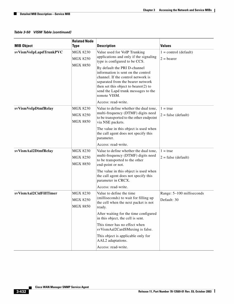
Chapter 3 Accessing the Network and Service MIBsDetailed MIB Description—Service MIB
svVismVoIpLapdTrunkPVC MGX 8230
MGX 8250
MGX 8850
Value used for VoIP Trunking applications and only if the signaling type is configured to be CCS.
By default the PRI D-channel information is sent on the control channel. If the control network is separated from the bearer network then set this object to bearer(2) to send the Lapd trunk messages to the remote VISM.
Access: read-write.
1 = control (default)
2 = bearer
svVismVoIpDtmfRelay MGX 8230
MGX 8250
MGX 8850
Value to define whether the dual tone, multi-frequency (DTMF) digits need to be transported to the other endpoint via NSE packets.
The value in this object is used when the call agent does not specify this parameter.
Access: read-write.
1 = true
2 = false (default)
svVismAal2DtmfRelay MGX 8230
MGX 8250
MGX 8850
Value to define whether the dual tone, multi-frequency (DTMF) digits need to be transported to the other end-point or not.
The value in this object is used when the call agent does not specify this parameter in CRCX.
Access: read-write.
1 = true
2 = false (default)
svVismAal2CidFillTimer MGX 8230
MGX 8250
MGX 8850
Value to define the time (milliseconds) to wait for filling up the cell when the next packet is not ready.
After waiting for the time configured in this object, the cell is sent.
This timer has no effect when svVismAal2CardSMuxing is false.
This object is applicable only for AAL2 adaptations.
Access: read-write.
Range: 5–100 milliseconds
Default: 30
Table 3-50 VISM Table (continued)
MIB ObjectRelated Node Type Description Values
3-432Cisco WAN Manager SNMP Service Agent
Release 11, Part Number 78-13569-01 Rev. E0, October 2003
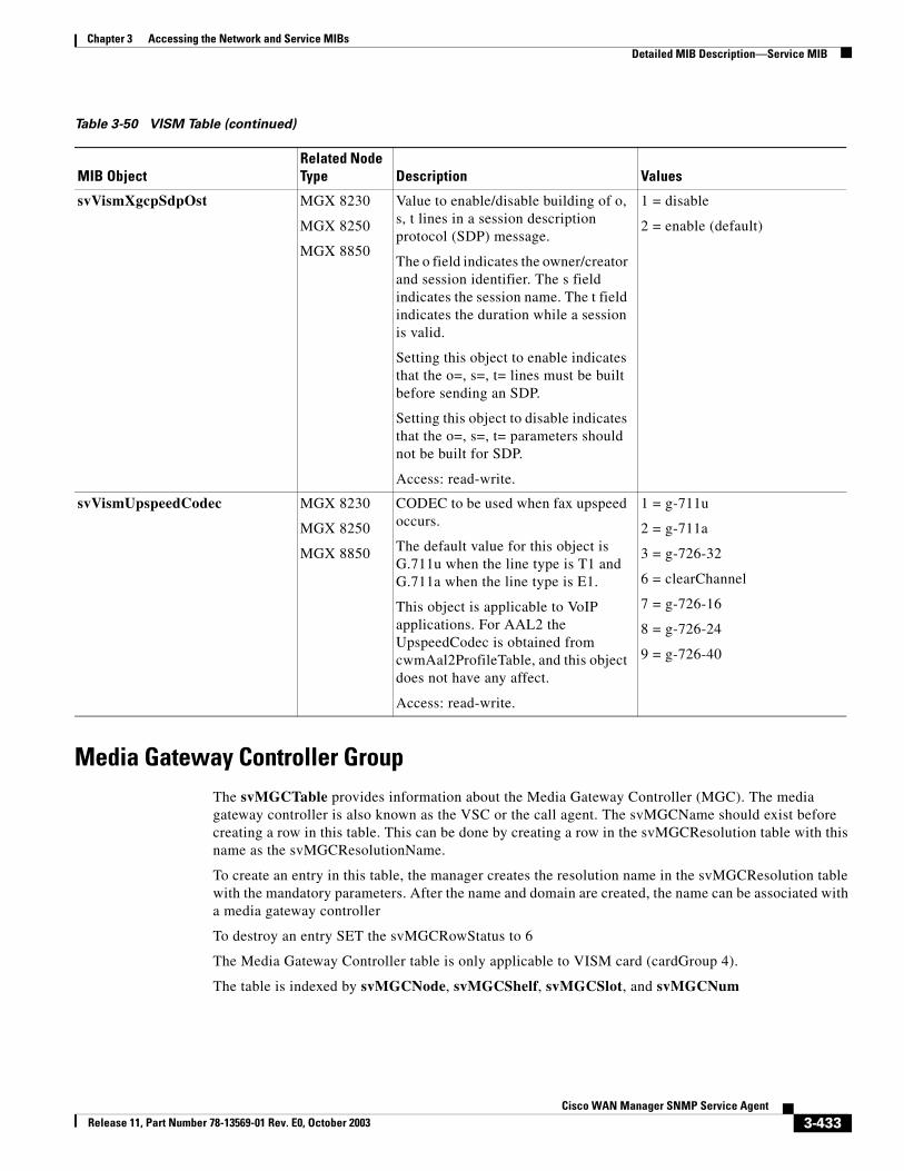
Chapter 3 Accessing the Network and Service MIBsDetailed MIB Description—Service MIB
Media Gateway Controller GroupThe svMGCTable provides information about the Media Gateway Controller (MGC). The media gateway controller is also known as the VSC or the call agent. The svMGCName should exist before creating a row in this table. This can be done by creating a row in the svMGCResolution table with this name as the svMGCResolutionName.
To create an entry in this table, the manager creates the resolution name in the svMGCResolution table with the mandatory parameters. After the name and domain are created, the name can be associated with a media gateway controller
To destroy an entry SET the svMGCRowStatus to 6
The Media Gateway Controller table is only applicable to VISM card (cardGroup 4).
The table is indexed by svMGCNode, svMGCShelf, svMGCSlot, and svMGCNum
svVismXgcpSdpOst MGX 8230
MGX 8250
MGX 8850
Value to enable/disable building of o, s, t lines in a session description protocol (SDP) message.
The o field indicates the owner/creator and session identifier. The s field indicates the session name. The t field indicates the duration while a session is valid.
Setting this object to enable indicates that the o=, s=, t= lines must be built before sending an SDP.
Setting this object to disable indicates that the o=, s=, t= parameters should not be built for SDP.
Access: read-write.
1 = disable
2 = enable (default)
svVismUpspeedCodec MGX 8230
MGX 8250
MGX 8850
CODEC to be used when fax upspeed occurs.
The default value for this object is G.711u when the line type is T1 and G.711a when the line type is E1.
This object is applicable to VoIP applications. For AAL2 the UpspeedCodec is obtained from cwmAal2ProfileTable, and this object does not have any affect.
Access: read-write.
1 = g-711u
2 = g-711a
3 = g-726-32
6 = clearChannel
7 = g-726-16
8 = g-726-24
9 = g-726-40
Table 3-50 VISM Table (continued)
MIB ObjectRelated Node Type Description Values
3-433Cisco WAN Manager SNMP Service Agent
Release 11, Part Number 78-13569-01 Rev. E0, October 2003
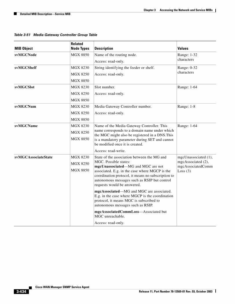
Chapter 3 Accessing the Network and Service MIBsDetailed MIB Description—Service MIB
Table 3-51 Media Gateway Controller Group Table
MIB ObjectRelated Node Types Description Values
svMGCNode MGX 8850 Name of the routing node.
Access: read-only.
Range: 1-32 characters
svMGCShelf MGX 8230
MGX 8250
MGX 8850
String identifying the feeder or shelf.
Access: read-only.
Range: 0-32 characters
svMGCSlot MGX 8230
MGX 8250
MGX 8850
Slot number.
Access: read-only.
Range: 1-64
svMGCNum MGX 8230
MGX 8250
MGX 8850
Media Gateway Controller number.
Access: read-only.
Range: 1-8
svMGCName MGX 8230
MGX 8250
MGX 8850
Name of the Media Gateway Controller. This name corresponds to a domain name under which the MGC might also be registered in a DNS.This is a mandatory parameter during SET and cannot be modified once it is created.
Access: read-write.
Range: 1-64
svMGCAssociateState MGX 8230
MGX 8250
MGX 8850
State of the association between the MG and MGC. Possible states:mgcUnassociated—MG and MGC are not associated. E.g. in the case where MGCP is the coordination protocol, it means no subscription to autonomous messages such as RSIP but control requests would be answered.
mgcAssociated—MG and MGC are associated. E.g. in the case where MGCP is the coordination protocol, it means MGC is subscribed to autonomous messages such as RSIP.
mgcAssociatedCommLoss—Associated but MGC unreachable.
Access: read-only.
mgcUnassociated (1),mgcAssociated (2),mgcAssociatedCommLoss (3)
3-434Cisco WAN Manager SNMP Service Agent
Release 11, Part Number 78-13569-01 Rev. E0, October 2003
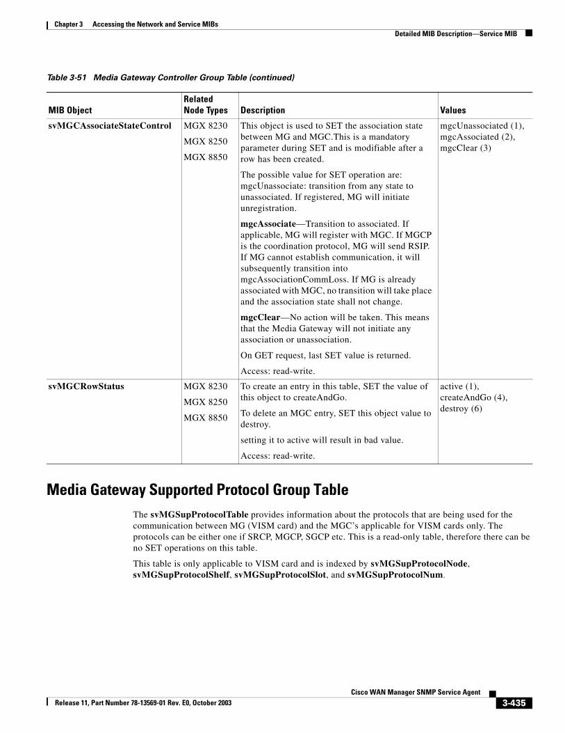
Chapter 3 Accessing the Network and Service MIBsDetailed MIB Description—Service MIB
Media Gateway Supported Protocol Group TableThe svMGSupProtocolTable provides information about the protocols that are being used for the communication between MG (VISM card) and the MGC’s applicable for VISM cards only. The protocols can be either one if SRCP, MGCP, SGCP etc. This is a read-only table, therefore there can be no SET operations on this table.
This table is only applicable to VISM card and is indexed by svMGSupProtocolNode, svMGSupProtocolShelf, svMGSupProtocolSlot, and svMGSupProtocolNum.
svMGCAssociateStateControl MGX 8230
MGX 8250
MGX 8850
This object is used to SET the association state between MG and MGC.This is a mandatory parameter during SET and is modifiable after a row has been created.
The possible value for SET operation are: mgcUnassociate: transition from any state to unassociated. If registered, MG will initiate unregistration.
mgcAssociate—Transition to associated. If applicable, MG will register with MGC. If MGCP is the coordination protocol, MG will send RSIP. If MG cannot establish communication, it will subsequently transition into mgcAssociationCommLoss. If MG is already associated with MGC, no transition will take place and the association state shall not change.
mgcClear—No action will be taken. This means that the Media Gateway will not initiate any association or unassociation.
On GET request, last SET value is returned.
Access: read-write.
mgcUnassociated (1),mgcAssociated (2),mgcClear (3)
svMGCRowStatus MGX 8230
MGX 8250
MGX 8850
To create an entry in this table, SET the value of this object to createAndGo.
To delete an MGC entry, SET this object value to destroy.
setting it to active will result in bad value.
Access: read-write.
active (1),createAndGo (4),destroy (6)
Table 3-51 Media Gateway Controller Group Table (continued)
MIB ObjectRelated Node Types Description Values
3-435Cisco WAN Manager SNMP Service Agent
Release 11, Part Number 78-13569-01 Rev. E0, October 2003
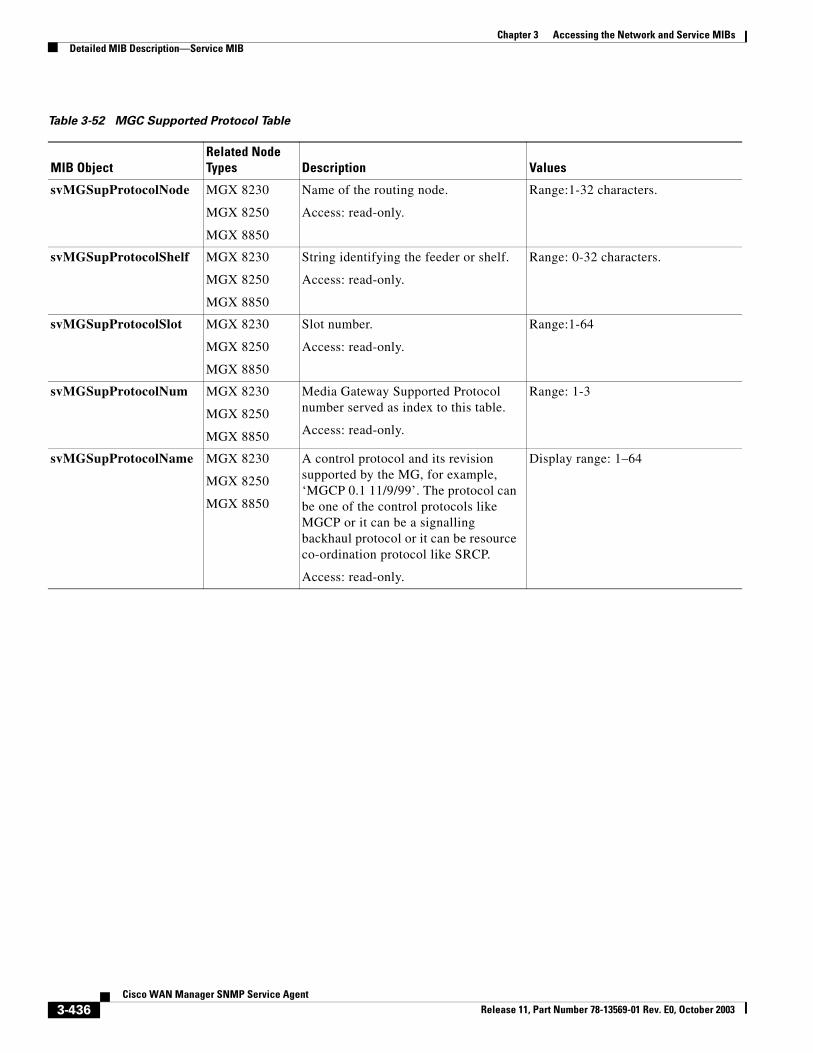
Chapter 3 Accessing the Network and Service MIBsDetailed MIB Description—Service MIB
Table 3-52 MGC Supported Protocol Table
MIB ObjectRelated Node Types Description Values
svMGSupProtocolNode MGX 8230
MGX 8250
MGX 8850
Name of the routing node.
Access: read-only.
Range:1-32 characters.
svMGSupProtocolShelf MGX 8230
MGX 8250
MGX 8850
String identifying the feeder or shelf.
Access: read-only.
Range: 0-32 characters.
svMGSupProtocolSlot MGX 8230
MGX 8250
MGX 8850
Slot number.
Access: read-only.
Range:1-64
svMGSupProtocolNum MGX 8230
MGX 8250
MGX 8850
Media Gateway Supported Protocol number served as index to this table.
Access: read-only.
Range: 1-3
svMGSupProtocolName MGX 8230
MGX 8250
MGX 8850
A control protocol and its revision supported by the MG, for example, ‘MGCP 0.1 11/9/99’. The protocol can be one of the control protocols like MGCP or it can be a signalling backhaul protocol or it can be resource co-ordination protocol like SRCP.
Access: read-only.
Display range: 1–64
3-436Cisco WAN Manager SNMP Service Agent
Release 11, Part Number 78-13569-01 Rev. E0, October 2003
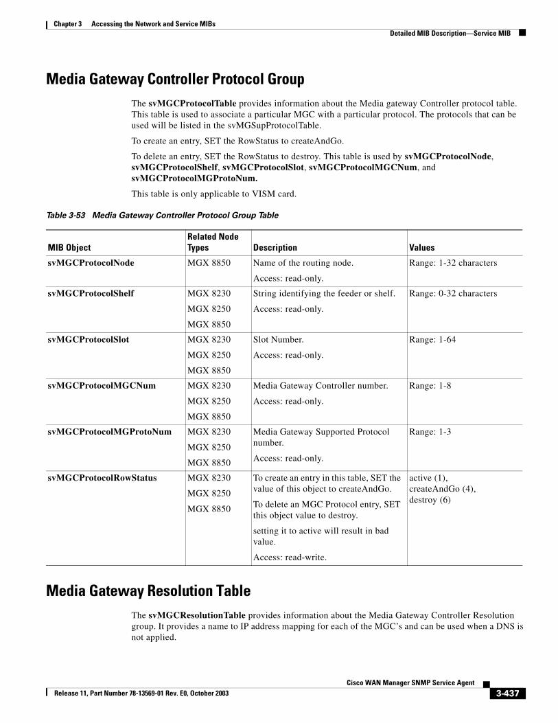
Chapter 3 Accessing the Network and Service MIBsDetailed MIB Description—Service MIB
Media Gateway Controller Protocol GroupThe svMGCProtocolTable provides information about the Media gateway Controller protocol table. This table is used to associate a particular MGC with a particular protocol. The protocols that can be used will be listed in the svMGSupProtocolTable.
To create an entry, SET the RowStatus to createAndGo.
To delete an entry, SET the RowStatus to destroy. This table is used by svMGCProtocolNode, svMGCProtocolShelf, svMGCProtocolSlot, svMGCProtocolMGCNum, and svMGCProtocolMGProtoNum.
This table is only applicable to VISM card.
Media Gateway Resolution TableThe svMGCResolutionTable provides information about the Media Gateway Controller Resolution group. It provides a name to IP address mapping for each of the MGC’s and can be used when a DNS is not applied.
Table 3-53 Media Gateway Controller Protocol Group Table
MIB ObjectRelated Node Types Description Values
svMGCProtocolNode MGX 8850 Name of the routing node.
Access: read-only.
Range: 1-32 characters
svMGCProtocolShelf MGX 8230
MGX 8250
MGX 8850
String identifying the feeder or shelf.
Access: read-only.
Range: 0-32 characters
svMGCProtocolSlot MGX 8230
MGX 8250
MGX 8850
Slot Number.
Access: read-only.
Range: 1-64
svMGCProtocolMGCNum MGX 8230
MGX 8250
MGX 8850
Media Gateway Controller number.
Access: read-only.
Range: 1-8
svMGCProtocolMGProtoNum MGX 8230
MGX 8250
MGX 8850
Media Gateway Supported Protocol number.
Access: read-only.
Range: 1-3
svMGCProtocolRowStatus MGX 8230
MGX 8250
MGX 8850
To create an entry in this table, SET the value of this object to createAndGo.
To delete an MGC Protocol entry, SET this object value to destroy.
setting it to active will result in bad value.
Access: read-write.
active (1), createAndGo (4), destroy (6)
3-437Cisco WAN Manager SNMP Service Agent
Release 11, Part Number 78-13569-01 Rev. E0, October 2003
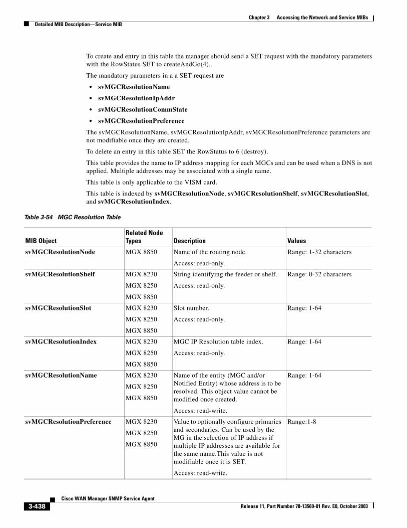
Chapter 3 Accessing the Network and Service MIBsDetailed MIB Description—Service MIB
To create and entry in this table the manager should send a SET request with the mandatory parameters with the RowStatus SET to createAndGo(4).
The mandatory parameters in a a SET request are
• svMGCResolutionName
• svMGCResolutionIpAddr
• svMGCResolutionCommState
• svMGCResolutionPreference
The svMGCResolutionName, svMGCResolutionIpAddr, svMGCResolutionPreference parameters are not modifiable once they are created.
To delete an entry in this table SET the RowStatus to 6 (destroy).
This table provides the name to IP address mapping for each MGCs and can be used when a DNS is not applied. Multiple addresses may be associated with a single name.
This table is only applicable to the VISM card.
This table is indexed by svMGCResolutionNode, svMGCResolutionShelf, svMGCResolutionSlot, and svMGCResolutionIndex.
Table 3-54 MGC Resolution Table
MIB ObjectRelated Node Types Description Values
svMGCResolutionNode MGX 8850 Name of the routing node.
Access: read-only.
Range: 1-32 characters
svMGCResolutionShelf MGX 8230
MGX 8250
MGX 8850
String identifying the feeder or shelf.
Access: read-only.
Range: 0-32 characters
svMGCResolutionSlot MGX 8230
MGX 8250
MGX 8850
Slot number.
Access: read-only.
Range: 1-64
svMGCResolutionIndex MGX 8230
MGX 8250
MGX 8850
MGC IP Resolution table index.
Access: read-only.
Range: 1-64
svMGCResolutionName MGX 8230
MGX 8250
MGX 8850
Name of the entity (MGC and/or Notified Entity) whose address is to be resolved. This object value cannot be modified once created.
Access: read-write.
Range: 1-64
svMGCResolutionPreference MGX 8230
MGX 8250
MGX 8850
Value to optionally configure primaries and secondaries. Can be used by the MG in the selection of IP address if multiple IP addresses are available for the same name.This value is not modifiable once it is SET.
Access: read-write.
Range:1-8
3-438Cisco WAN Manager SNMP Service Agent
Release 11, Part Number 78-13569-01 Rev. E0, October 2003
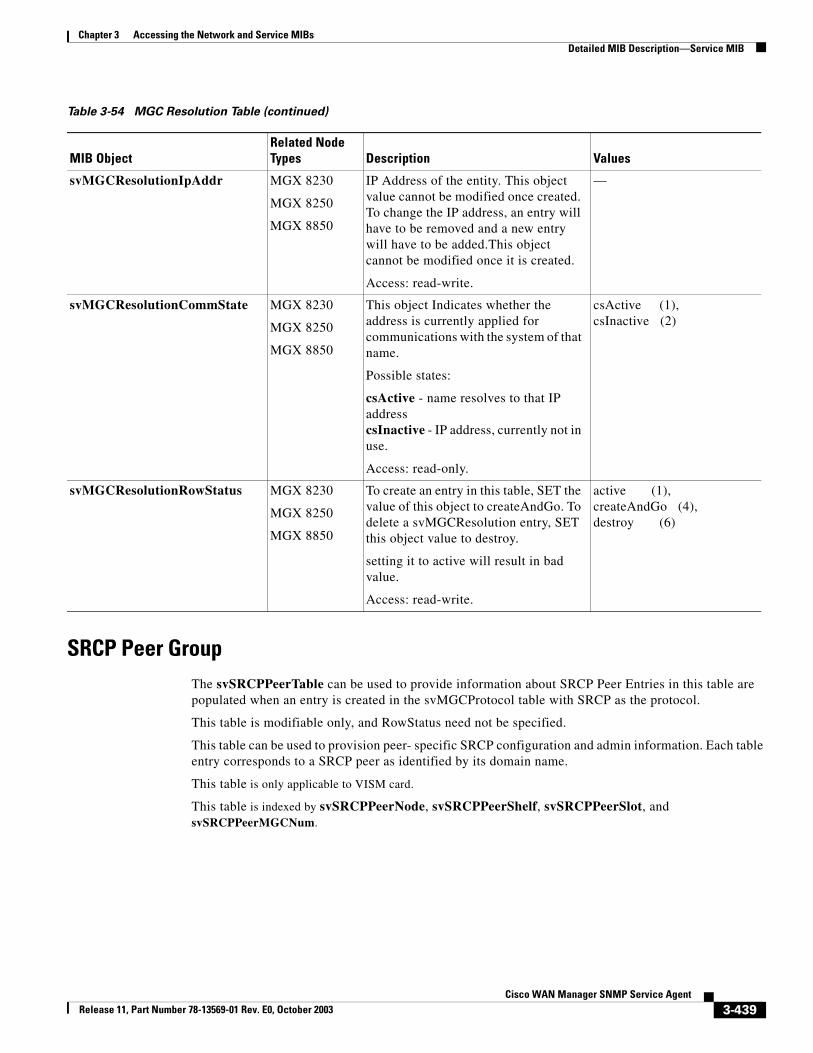
Chapter 3 Accessing the Network and Service MIBsDetailed MIB Description—Service MIB
SRCP Peer Group The svSRCPPeerTable can be used to provide information about SRCP Peer Entries in this table are populated when an entry is created in the svMGCProtocol table with SRCP as the protocol.
This table is modifiable only, and RowStatus need not be specified.
This table can be used to provision peer- specific SRCP configuration and admin information. Each table entry corresponds to a SRCP peer as identified by its domain name.
This table is only applicable to VISM card.
This table is indexed by svSRCPPeerNode, svSRCPPeerShelf, svSRCPPeerSlot, and svSRCPPeerMGCNum.
svMGCResolutionIpAddr MGX 8230
MGX 8250
MGX 8850
IP Address of the entity. This object value cannot be modified once created. To change the IP address, an entry will have to be removed and a new entry will have to be added.This object cannot be modified once it is created.
Access: read-write.
—
svMGCResolutionCommState MGX 8230
MGX 8250
MGX 8850
This object Indicates whether the address is currently applied for communications with the system of that name.
Possible states:
csActive - name resolves to that IP addresscsInactive - IP address, currently not in use.
Access: read-only.
csActive (1), csInactive (2)
svMGCResolutionRowStatus MGX 8230
MGX 8250
MGX 8850
To create an entry in this table, SET the value of this object to createAndGo. To delete a svMGCResolution entry, SET this object value to destroy.
setting it to active will result in bad value.
Access: read-write.
active (1), createAndGo (4),destroy (6)
Table 3-54 MGC Resolution Table (continued)
MIB ObjectRelated Node Types Description Values
3-439Cisco WAN Manager SNMP Service Agent
Release 11, Part Number 78-13569-01 Rev. E0, October 2003
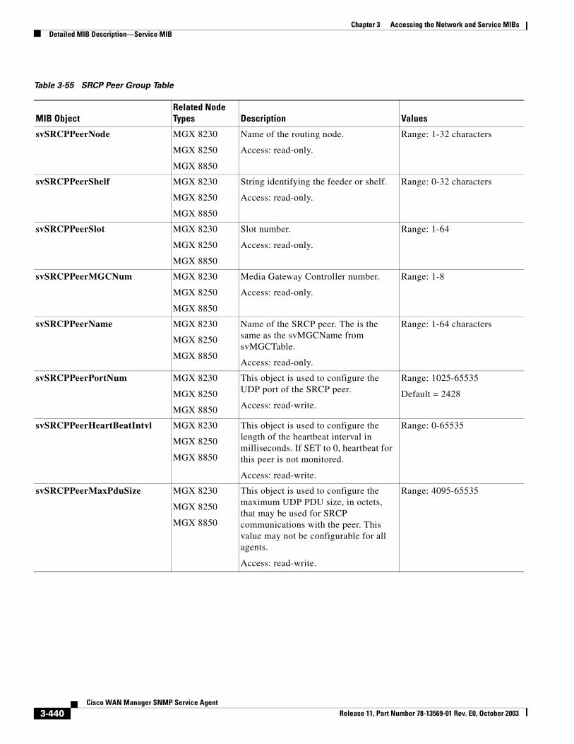
Chapter 3 Accessing the Network and Service MIBsDetailed MIB Description—Service MIB
Table 3-55 SRCP Peer Group Table
MIB ObjectRelated Node Types Description Values
svSRCPPeerNode MGX 8230
MGX 8250
MGX 8850
Name of the routing node.
Access: read-only.
Range: 1-32 characters
svSRCPPeerShelf MGX 8230
MGX 8250
MGX 8850
String identifying the feeder or shelf.
Access: read-only.
Range: 0-32 characters
svSRCPPeerSlot MGX 8230
MGX 8250
MGX 8850
Slot number.
Access: read-only.
Range: 1-64
svSRCPPeerMGCNum MGX 8230
MGX 8250
MGX 8850
Media Gateway Controller number.
Access: read-only.
Range: 1-8
svSRCPPeerName MGX 8230
MGX 8250
MGX 8850
Name of the SRCP peer. The is the same as the svMGCName from svMGCTable.
Access: read-only.
Range: 1-64 characters
svSRCPPeerPortNum MGX 8230
MGX 8250
MGX 8850
This object is used to configure the UDP port of the SRCP peer.
Access: read-write.
Range: 1025-65535
Default = 2428
svSRCPPeerHeartBeatIntvl MGX 8230
MGX 8250
MGX 8850
This object is used to configure the length of the heartbeat interval in milliseconds. If SET to 0, heartbeat for this peer is not monitored.
Access: read-write.
Range: 0-65535
svSRCPPeerMaxPduSize MGX 8230
MGX 8250
MGX 8850
This object is used to configure the maximum UDP PDU size, in octets, that may be used for SRCP communications with the peer. This value may not be configurable for all agents.
Access: read-write.
Range: 4095-65535
3-440Cisco WAN Manager SNMP Service Agent
Release 11, Part Number 78-13569-01 Rev. E0, October 2003
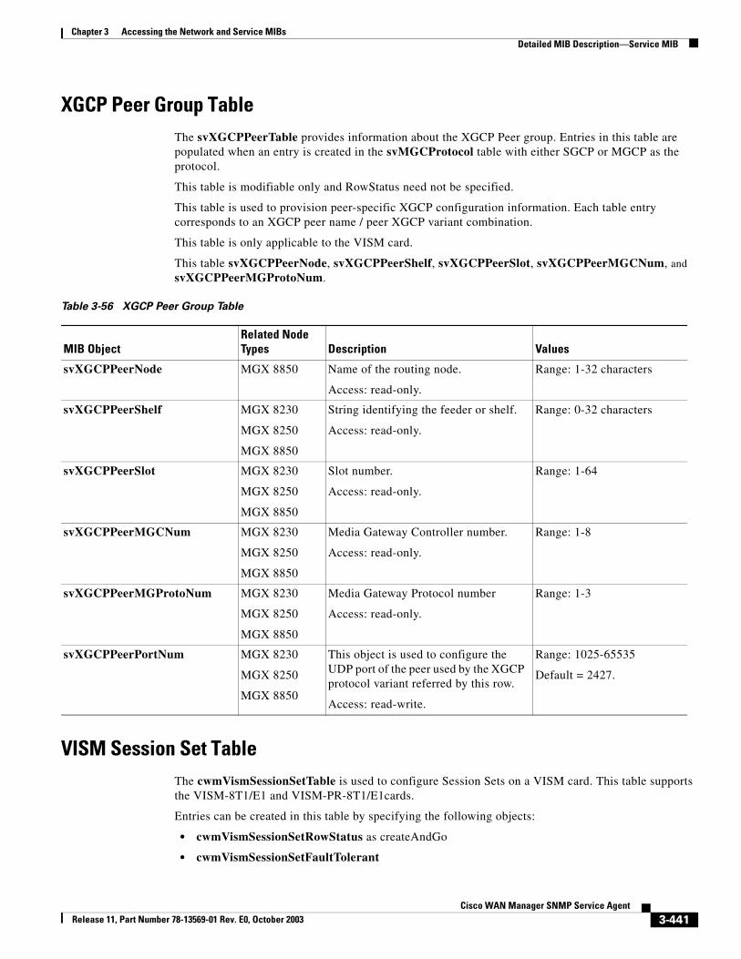
Chapter 3 Accessing the Network and Service MIBsDetailed MIB Description—Service MIB
XGCP Peer Group TableThe svXGCPPeerTable provides information about the XGCP Peer group. Entries in this table are populated when an entry is created in the svMGCProtocol table with either SGCP or MGCP as the protocol.
This table is modifiable only and RowStatus need not be specified.
This table is used to provision peer-specific XGCP configuration information. Each table entry corresponds to an XGCP peer name / peer XGCP variant combination.
This table is only applicable to the VISM card.
This table svXGCPPeerNode, svXGCPPeerShelf, svXGCPPeerSlot, svXGCPPeerMGCNum, and svXGCPPeerMGProtoNum.
VISM Session Set TableThe cwmVismSessionSetTable is used to configure Session Sets on a VISM card. This table supports the VISM-8T1/E1 and VISM-PR-8T1/E1cards.
Entries can be created in this table by specifying the following objects:
• cwmVismSessionSetRowStatus as createAndGo
• cwmVismSessionSetFaultTolerant
Table 3-56 XGCP Peer Group Table
MIB ObjectRelated Node Types Description Values
svXGCPPeerNode MGX 8850 Name of the routing node.
Access: read-only.
Range: 1-32 characters
svXGCPPeerShelf MGX 8230
MGX 8250
MGX 8850
String identifying the feeder or shelf.
Access: read-only.
Range: 0-32 characters
svXGCPPeerSlot MGX 8230
MGX 8250
MGX 8850
Slot number.
Access: read-only.
Range: 1-64
svXGCPPeerMGCNum MGX 8230
MGX 8250
MGX 8850
Media Gateway Controller number.
Access: read-only.
Range: 1-8
svXGCPPeerMGProtoNum MGX 8230
MGX 8250
MGX 8850
Media Gateway Protocol number
Access: read-only.
Range: 1-3
svXGCPPeerPortNum MGX 8230
MGX 8250
MGX 8850
This object is used to configure the UDP port of the peer used by the XGCP protocol variant referred by this row.
Access: read-write.
Range: 1025-65535
Default = 2427.
3-441Cisco WAN Manager SNMP Service Agent
Release 11, Part Number 78-13569-01 Rev. E0, October 2003
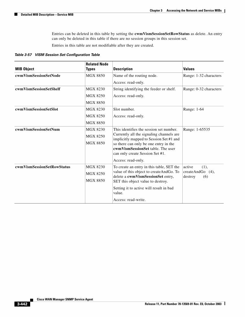
Chapter 3 Accessing the Network and Service MIBsDetailed MIB Description—Service MIB
Entries can be deleted in this table by setting the cwmVismSessionSetRowStatus as delete. An entry can only be deleted in this table if there are no session groups in this session set.
Entries in this table are not modifiable after they are created.
Table 3-57 VISM Session Set Configuration Table
MIB ObjectRelated Node Types Description Values
cwmVismSessionSetNode MGX 8850 Name of the routing node.
Access: read-only.
Range: 1-32 characters
cwmVismSessionSetShelf MGX 8230
MGX 8250
MGX 8850
String identifying the feeder or shelf.
Access: read-only.
Range: 0-32 characters
cwmVismSessionSetSlot MGX 8230
MGX 8250
MGX 8850
Slot number.
Access: read-only.
Range: 1-64
cwmVismSessionSetNum MGX 8230
MGX 8250
MGX 8850
This identifies the session set number. Currently all the signaling channels are implicitly mapped to Session Set #1 and so there can only be one entry in the cwmVismSessionSet table. The user can only create Session Set #1.
Access: read-only.
Range: 1-65535
cwmVismSessionSetRowStatus MGX 8230
MGX 8250
MGX 8850
To create an entry in this table, SET the value of this object to createAndGo. To delete a cwmVismSessionSet entry, SET this object value to destroy.
Setting it to active will result in bad value.
Access: read-write.
active (1), createAndGo (4),destroy (6)
3-442Cisco WAN Manager SNMP Service Agent
Release 11, Part Number 78-13569-01 Rev. E0, October 2003
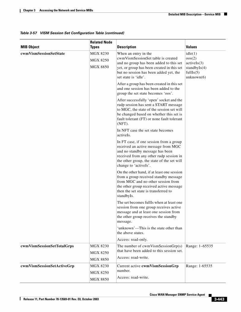
Chapter 3 Accessing the Network and Service MIBsDetailed MIB Description—Service MIB
cwmVismSessionSetState MGX 8230
MGX 8250
MGX 8850
When an entry in the cwmVismSessionSet table is created and no group has been added to this set yet, or group has been created in this set but no session has been added yet, the set state is ‘idle’.
After a group has been created in this set and one session has been added to the group the set state becomes ‘oos’.
After successfully ‘open’ socket and the rudp session has sent a START message to MGC, the state of the session set will be changed based on whether this set is fault tolerant (FT) or none fault tolerant (NFT).
In NFT case the set state becomes activeIs.
In FT case, if one session from a group received an active message from MGC and no standby message has been received from any other rudp session in the other group, the state of the set will change to ‘activeIs’.
On the other hand, if at least one session from a group received standby message from MGC and no other session from the other group received active message then the set state is transferred to standbyIs.
The set becomes fullIs when at least one session from one group receives active message and at least one session from the other group receives the standby message.
‘unknown’—This is the state other than the above states.
Access: read-only.
idle(1)oos(2)activeIs(3)standbyIs(4)fullIs(5)unknown(6)
cwmVismSessionSetTotalGrps MGX 8230
MGX 8250
MGX 8850
The number of cwmVismSessionGrp(s) that have been added to this session set.
Access: read-write.
Range: 1–65535
cwmVismSessionSetActiveGrp MGX 8230
MGX 8250
MGX 8850
Current active cwmVismSessionGrp number.
Access: read-write.
Range: 1-65535
Table 3-57 VISM Session Set Configuration Table (continued)
MIB ObjectRelated Node Types Description Values
3-443Cisco WAN Manager SNMP Service Agent
Release 11, Part Number 78-13569-01 Rev. E0, October 2003
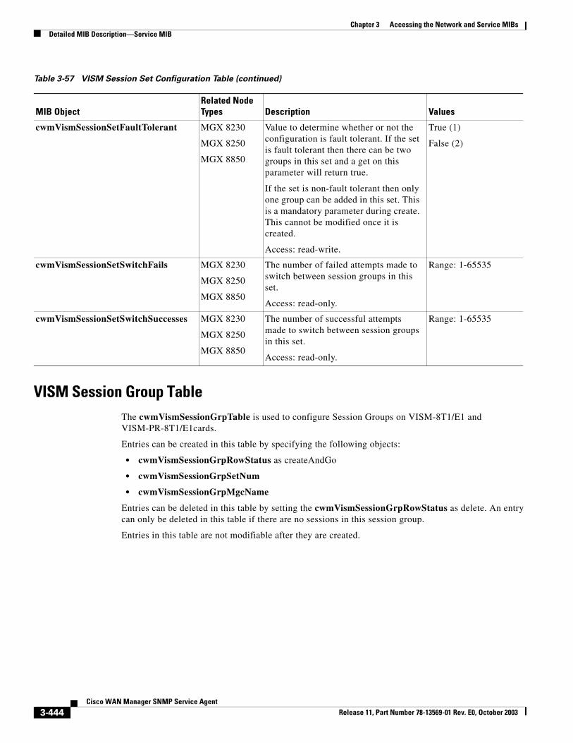
Chapter 3 Accessing the Network and Service MIBsDetailed MIB Description—Service MIB
VISM Session Group TableThe cwmVismSessionGrpTable is used to configure Session Groups on VISM-8T1/E1 and VISM-PR-8T1/E1cards.
Entries can be created in this table by specifying the following objects:
• cwmVismSessionGrpRowStatus as createAndGo
• cwmVismSessionGrpSetNum
• cwmVismSessionGrpMgcName
Entries can be deleted in this table by setting the cwmVismSessionGrpRowStatus as delete. An entry can only be deleted in this table if there are no sessions in this session group.
Entries in this table are not modifiable after they are created.
cwmVismSessionSetFaultTolerant MGX 8230
MGX 8250
MGX 8850
Value to determine whether or not the configuration is fault tolerant. If the set is fault tolerant then there can be two groups in this set and a get on this parameter will return true.
If the set is non-fault tolerant then only one group can be added in this set. This is a mandatory parameter during create. This cannot be modified once it is created.
Access: read-write.
True (1)
False (2)
cwmVismSessionSetSwitchFails MGX 8230
MGX 8250
MGX 8850
The number of failed attempts made to switch between session groups in this set.
Access: read-only.
Range: 1-65535
cwmVismSessionSetSwitchSuccesses MGX 8230
MGX 8250
MGX 8850
The number of successful attempts made to switch between session groups in this set.
Access: read-only.
Range: 1-65535
Table 3-57 VISM Session Set Configuration Table (continued)
MIB ObjectRelated Node Types Description Values
3-444Cisco WAN Manager SNMP Service Agent
Release 11, Part Number 78-13569-01 Rev. E0, October 2003
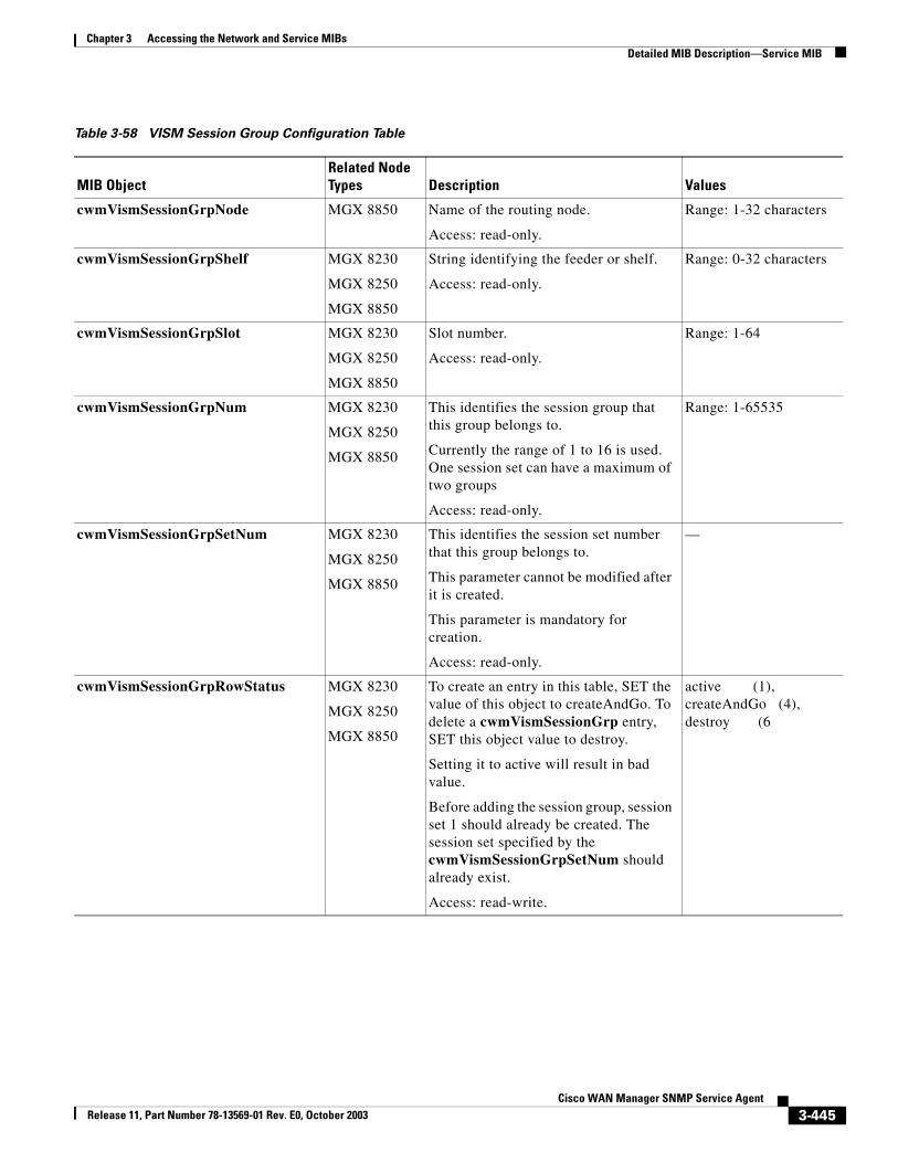
Chapter 3 Accessing the Network and Service MIBsDetailed MIB Description—Service MIB
Table 3-58 VISM Session Group Configuration Table
MIB ObjectRelated Node Types Description Values
cwmVismSessionGrpNode MGX 8850 Name of the routing node.
Access: read-only.
Range: 1-32 characters
cwmVismSessionGrpShelf MGX 8230
MGX 8250
MGX 8850
String identifying the feeder or shelf.
Access: read-only.
Range: 0-32 characters
cwmVismSessionGrpSlot MGX 8230
MGX 8250
MGX 8850
Slot number.
Access: read-only.
Range: 1-64
cwmVismSessionGrpNum MGX 8230
MGX 8250
MGX 8850
This identifies the session group that this group belongs to.
Currently the range of 1 to 16 is used. One session set can have a maximum of two groups
Access: read-only.
Range: 1-65535
cwmVismSessionGrpSetNum MGX 8230
MGX 8250
MGX 8850
This identifies the session set number that this group belongs to.
This parameter cannot be modified after it is created.
This parameter is mandatory for creation.
Access: read-only.
—
cwmVismSessionGrpRowStatus MGX 8230
MGX 8250
MGX 8850
To create an entry in this table, SET the value of this object to createAndGo. To delete a cwmVismSessionGrp entry, SET this object value to destroy.
Setting it to active will result in bad value.
Before adding the session group, session set 1 should already be created. The session set specified by the cwmVismSessionGrpSetNum should already exist.
Access: read-write.
active (1), createAndGo (4),destroy (6
3-445Cisco WAN Manager SNMP Service Agent
Release 11, Part Number 78-13569-01 Rev. E0, October 2003
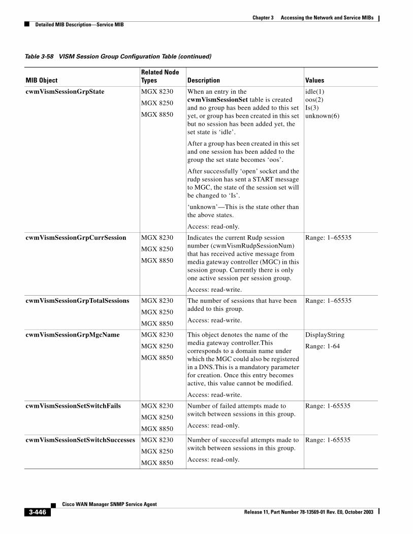
Chapter 3 Accessing the Network and Service MIBsDetailed MIB Description—Service MIB
cwmVismSessionGrpState MGX 8230
MGX 8250
MGX 8850
When an entry in the cwmVismSessionSet table is created and no group has been added to this set yet, or group has been created in this set but no session has been added yet, the set state is ‘idle’.
After a group has been created in this set and one session has been added to the group the set state becomes ‘oos’.
After successfully ‘open’ socket and the rudp session has sent a START message to MGC, the state of the session set will be changed to ‘Is’.
‘unknown’—This is the state other than the above states.
Access: read-only.
idle(1)oos(2)Is(3)unknown(6)
cwmVismSessionGrpCurrSession MGX 8230
MGX 8250
MGX 8850
Indicates the current Rudp session number (cwmVismRudpSessionNum) that has received active message from media gateway controller (MGC) in this session group. Currently there is only one active session per session group.
Access: read-write.
Range: 1–65535
cwmVismSessionGrpTotalSessions MGX 8230
MGX 8250
MGX 8850
The number of sessions that have been added to this group.
Access: read-write.
Range: 1–65535
cwmVismSessionGrpMgcName MGX 8230
MGX 8250
MGX 8850
This object denotes the name of the media gateway controller.This corresponds to a domain name under which the MGC could also be registered in a DNS.This is a mandatory parameter for creation. Once this entry becomes active, this value cannot be modified.
Access: read-write.
DisplayString
Range: 1-64
cwmVismSessionSetSwitchFails MGX 8230
MGX 8250
MGX 8850
Number of failed attempts made to switch between sessions in this group.
Access: read-only.
Range: 1-65535
cwmVismSessionSetSwitchSuccesses MGX 8230
MGX 8250
MGX 8850
Number of successful attempts made to switch between sessions in this group.
Access: read-only.
Range: 1-65535
Table 3-58 VISM Session Group Configuration Table (continued)
MIB ObjectRelated Node Types Description Values
3-446Cisco WAN Manager SNMP Service Agent
Release 11, Part Number 78-13569-01 Rev. E0, October 2003
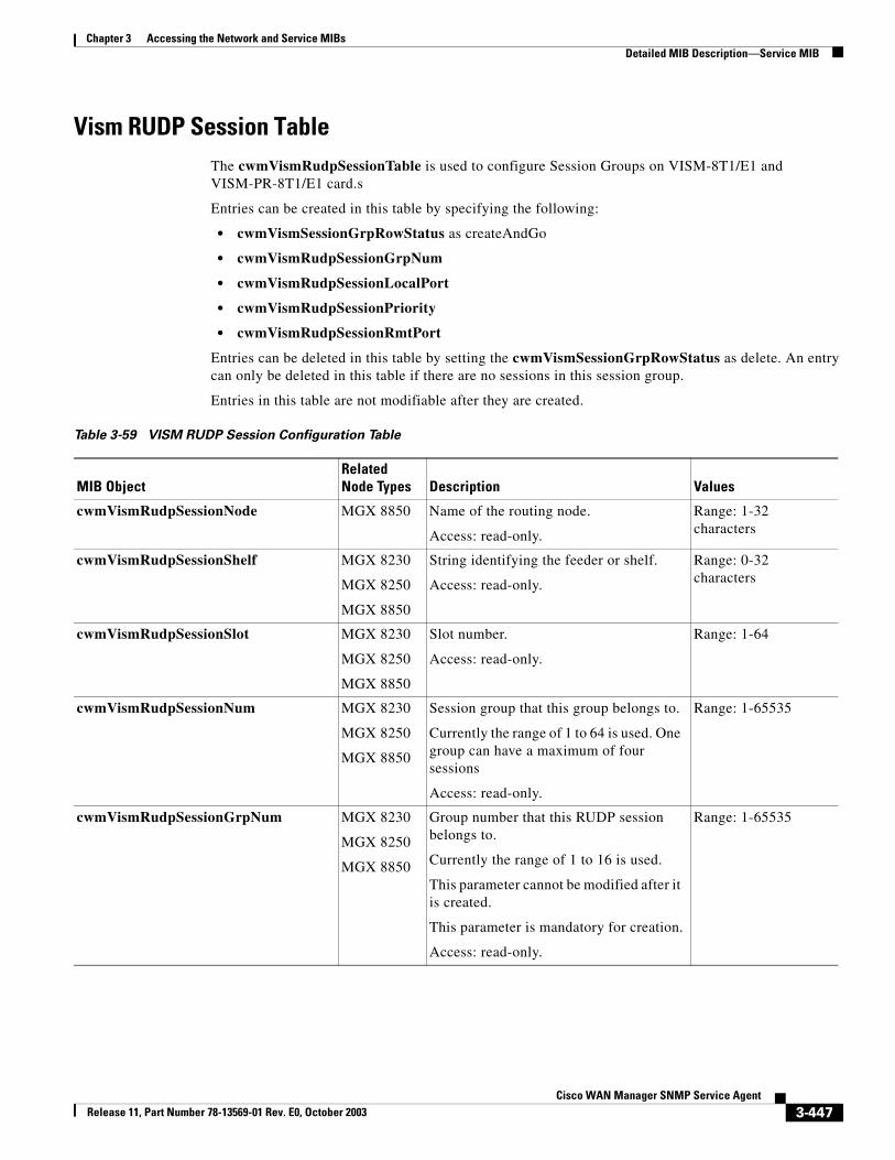
Chapter 3 Accessing the Network and Service MIBsDetailed MIB Description—Service MIB
Vism RUDP Session TableThe cwmVismRudpSessionTable is used to configure Session Groups on VISM-8T1/E1 and VISM-PR-8T1/E1 card.s
Entries can be created in this table by specifying the following:
• cwmVismSessionGrpRowStatus as createAndGo
• cwmVismRudpSessionGrpNum
• cwmVismRudpSessionLocalPort
• cwmVismRudpSessionPriority
• cwmVismRudpSessionRmtPort
Entries can be deleted in this table by setting the cwmVismSessionGrpRowStatus as delete. An entry can only be deleted in this table if there are no sessions in this session group.
Entries in this table are not modifiable after they are created.
Table 3-59 VISM RUDP Session Configuration Table
MIB ObjectRelated Node Types Description Values
cwmVismRudpSessionNode MGX 8850 Name of the routing node.
Access: read-only.
Range: 1-32 characters
cwmVismRudpSessionShelf MGX 8230
MGX 8250
MGX 8850
String identifying the feeder or shelf.
Access: read-only.
Range: 0-32 characters
cwmVismRudpSessionSlot MGX 8230
MGX 8250
MGX 8850
Slot number.
Access: read-only.
Range: 1-64
cwmVismRudpSessionNum MGX 8230
MGX 8250
MGX 8850
Session group that this group belongs to.
Currently the range of 1 to 64 is used. One group can have a maximum of four sessions
Access: read-only.
Range: 1-65535
cwmVismRudpSessionGrpNum MGX 8230
MGX 8250
MGX 8850
Group number that this RUDP session belongs to.
Currently the range of 1 to 16 is used.
This parameter cannot be modified after it is created.
This parameter is mandatory for creation.
Access: read-only.
Range: 1-65535
3-447Cisco WAN Manager SNMP Service Agent
Release 11, Part Number 78-13569-01 Rev. E0, October 2003
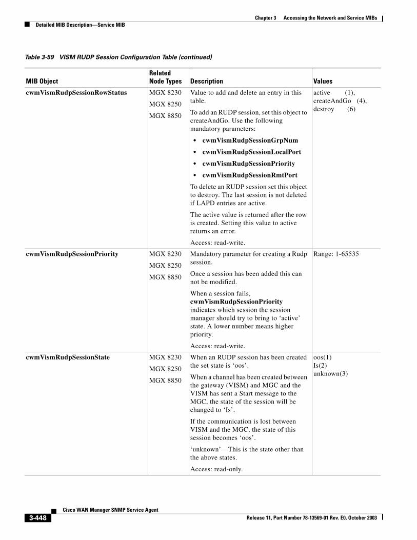
Chapter 3 Accessing the Network and Service MIBsDetailed MIB Description—Service MIB
cwmVismRudpSessionRowStatus MGX 8230
MGX 8250
MGX 8850
Value to add and delete an entry in this table.
To add an RUDP session, set this object to createAndGo. Use the following mandatory parameters:
• cwmVismRudpSessionGrpNum
• cwmVismRudpSessionLocalPort
• cwmVismRudpSessionPriority
• cwmVismRudpSessionRmtPort
To delete an RUDP session set this object to destroy. The last session is not deleted if LAPD entries are active.
The active value is returned after the row is created. Setting this value to active returns an error.
Access: read-write.
active (1), createAndGo (4),destroy (6)
cwmVismRudpSessionPriority MGX 8230
MGX 8250
MGX 8850
Mandatory parameter for creating a Rudp session.
Once a session has been added this can not be modified.
When a session fails, cwmVismRudpSessionPriority indicates which session the session manager should try to bring to ‘active’ state. A lower number means higher priority.
Access: read-write.
Range: 1-65535
cwmVismRudpSessionState MGX 8230
MGX 8250
MGX 8850
When an RUDP session has been created the set state is ‘oos’.
When a channel has been created between the gateway (VISM) and MGC and the VISM has sent a Start message to the MGC, the state of the session will be changed to ‘Is’.
If the communication is lost between VISM and the MGC, the state of this session becomes ‘oos’.
‘unknown’—This is the state other than the above states.
Access: read-only.
oos(1)Is(2)unknown(3)
Table 3-59 VISM RUDP Session Configuration Table (continued)
MIB ObjectRelated Node Types Description Values
3-448Cisco WAN Manager SNMP Service Agent
Release 11, Part Number 78-13569-01 Rev. E0, October 2003
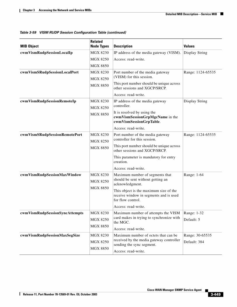
Chapter 3 Accessing the Network and Service MIBsDetailed MIB Description—Service MIB
cwmVismRudpSessionLocalIp MGX 8230
MGX 8250
MGX 8850
IP address of the media gateway (VISM).
Access: read-write.
Display String
cwmVismSRudpSessionLocalPort MGX 8230
MGX 8250
MGX 8850
Port number of the media gateway (VISM) for this session.
This port number should be unique across other sessions and XGCP/SRCP.
Access: read-write.
Range: 1124-65535
cwmVismRudpSessionRemoteIp MGX 8230
MGX 8250
MGX 8850
IP address of the media gateway controller.
It is resolved by using the cwmVismSessionGrpMgcName in the cwmVismSessionGrpTable.
Access: read-write.
Display String
cwmVismSRudpSessionRemotePort MGX 8230
MGX 8250
MGX 8850
Port number of the media gateway controller for this session.
This port number should be unique across other sessions and XGCP/SRCP.
This parameter is mandatory for entry creation.
Access: read-write.
Range: 1124-65535
cwmVismRudpSessionMaxWindow MGX 8230
MGX 8250
MGX 8850
Maximum number of segments that should be sent without getting an acknowledgment.
This object is the maximum size of the receive window in segments and is used for flow control.
Access: read-write.
Range: 1-64
cwmVismRudpSessionSyncAttempts MGX 8230
MGX 8250
MGX 8850
Maximum number of attempts the VISM card makes in trying to synchronize with the MGC.
Access: read-write.
Range: 1-32
Default: 5
cwmVismRudpSessionMaxSegSize MGX 8230
MGX 8250
MGX 8850
Maximum number of octets that can be received by the media gateway controller sending the sync segment.
Access: read-write.
Range: 30-65535
Default: 384
Table 3-59 VISM RUDP Session Configuration Table (continued)
MIB ObjectRelated Node Types Description Values
3-449Cisco WAN Manager SNMP Service Agent
Release 11, Part Number 78-13569-01 Rev. E0, October 2003
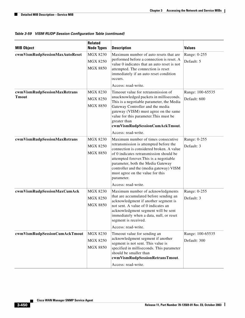
Chapter 3 Accessing the Network and Service MIBsDetailed MIB Description—Service MIB
cwmVismRudpSessionMaxAutoReset MGX 8230
MGX 8250
MGX 8850
Maximum number of auto resets that are performed before a connection is reset. A value 0 indicates that an auto reset is not attempted. The connection is reset immediately if an auto reset condition occurs.
Access: read-write.
Range: 0-255
Default: 5
cwmVismRudpSessionMaxRetransTmout
MGX 8230
MGX 8250
MGX 8850
Timeout value for retransmission of unacknowledged packets in milliseconds. This is a negotiable parameter, the Media Gateway Controller and the media gateway (VISM) must agree on the same value for this parameter.This must be greater than cwmVismRudpSessionCumAckTmout.
Access: read-write.
Range: 100-65535
Default: 600
cwmVismRudpSessionMaxRetrans MGX 8230
MGX 8250
MGX 8850
Maximum number of times consecutive retransmission is attempted before the connection is considered broken. A value of 0 indicates retransmission should be attempted forever.This is a negotiable parameter, both the Media Gateway controller and the (media gateway) VISM must agree on the value for this parameter.
Access: read-write.
Range: 0-255
Default: 3
cwmVismRudpSessionMaxCumAck MGX 8230
MGX 8250
MGX 8850
Maximum number of acknowledgments that are accumulated before sending an acknowledgment if another segment is not sent. A value of 0 indicates an acknowledgment segment will be sent immediately when a data, null, or reset segment is received.
Access: read-write.
Range: 0-255
Default: 3
cwmVismRudpSessionCumAckTmout MGX 8230
MGX 8250
MGX 8850
Timeout value for sending an acknowledgment segment if another segment is not sent. This value is specified in milliseconds. This parameter should be smaller than cwmVismRudpSessionRetransTmout.
Access: read-write.
Range: 100-65535
Default: 300
Table 3-59 VISM RUDP Session Configuration Table (continued)
MIB ObjectRelated Node Types Description Values
3-450Cisco WAN Manager SNMP Service Agent
Release 11, Part Number 78-13569-01 Rev. E0, October 2003
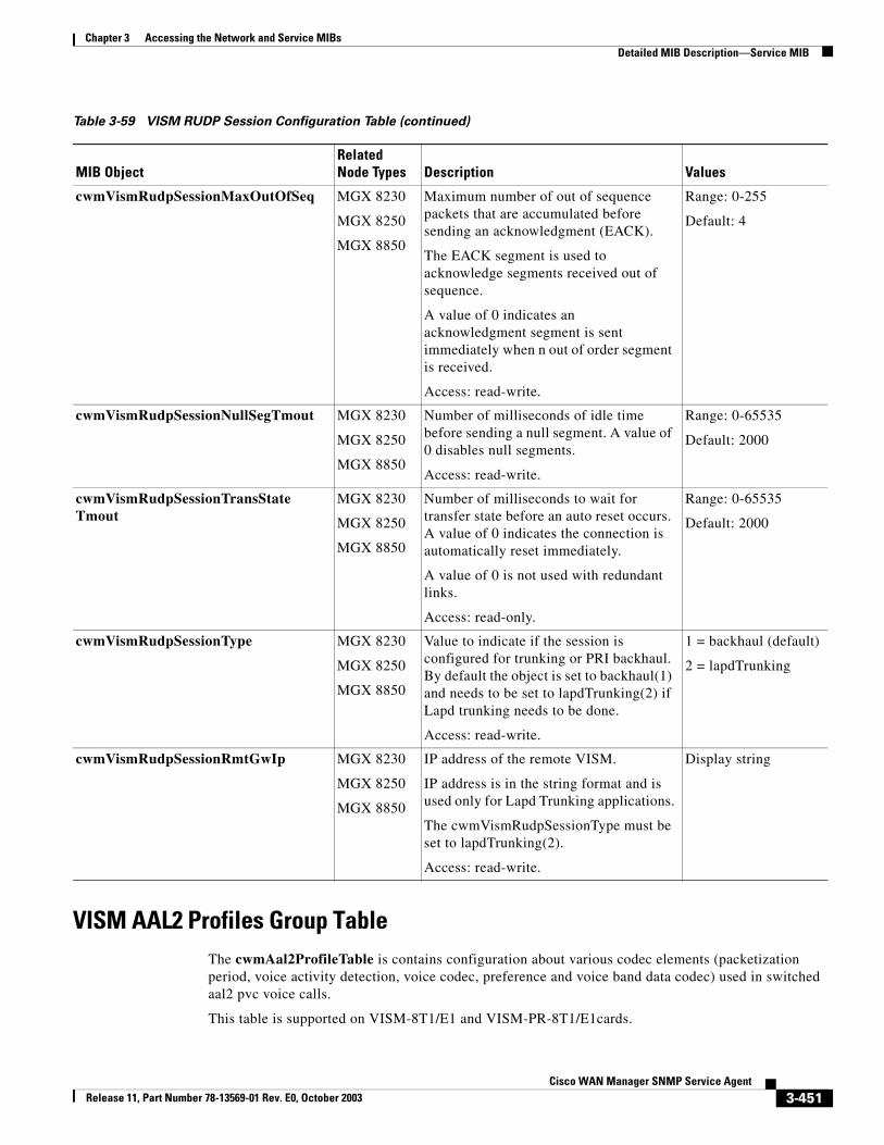
Chapter 3 Accessing the Network and Service MIBsDetailed MIB Description—Service MIB
VISM AAL2 Profiles Group TableThe cwmAal2ProfileTable is contains configuration about various codec elements (packetization period, voice activity detection, voice codec, preference and voice band data codec) used in switched aal2 pvc voice calls.
This table is supported on VISM-8T1/E1 and VISM-PR-8T1/E1cards.
cwmVismRudpSessionMaxOutOfSeq MGX 8230
MGX 8250
MGX 8850
Maximum number of out of sequence packets that are accumulated before sending an acknowledgment (EACK).
The EACK segment is used to acknowledge segments received out of sequence.
A value of 0 indicates an acknowledgment segment is sent immediately when n out of order segment is received.
Access: read-write.
Range: 0-255
Default: 4
cwmVismRudpSessionNullSegTmout MGX 8230
MGX 8250
MGX 8850
Number of milliseconds of idle time before sending a null segment. A value of 0 disables null segments.
Access: read-write.
Range: 0-65535
Default: 2000
cwmVismRudpSessionTransStateTmout
MGX 8230
MGX 8250
MGX 8850
Number of milliseconds to wait for transfer state before an auto reset occurs. A value of 0 indicates the connection is automatically reset immediately.
A value of 0 is not used with redundant links.
Access: read-only.
Range: 0-65535
Default: 2000
cwmVismRudpSessionType MGX 8230
MGX 8250
MGX 8850
Value to indicate if the session is configured for trunking or PRI backhaul. By default the object is set to backhaul(1) and needs to be set to lapdTrunking(2) if Lapd trunking needs to be done.
Access: read-write.
1 = backhaul (default)
2 = lapdTrunking
cwmVismRudpSessionRmtGwIp MGX 8230
MGX 8250
MGX 8850
IP address of the remote VISM.
IP address is in the string format and is used only for Lapd Trunking applications.
The cwmVismRudpSessionType must be set to lapdTrunking(2).
Access: read-write.
Display string
Table 3-59 VISM RUDP Session Configuration Table (continued)
MIB ObjectRelated Node Types Description Values
3-451Cisco WAN Manager SNMP Service Agent
Release 11, Part Number 78-13569-01 Rev. E0, October 2003
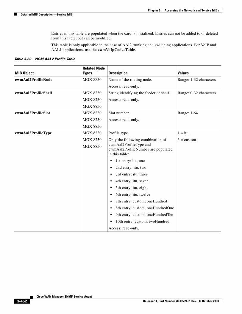
Chapter 3 Accessing the Network and Service MIBsDetailed MIB Description—Service MIB
Entries in this table are populated when the card is initialized. Entries can not be added to or deleted from this table, but can be modified.
This table is only applicable in the case of AAl2 trunking and switching applications. For VoIP and AAL1 applications, use the cwmVoIpCodecTable.
Table 3-60 VISM AAL2 Profile Table
MIB ObjectRelated Node Types Description Values
cwmAal2ProfileNode MGX 8850 Name of the routing node.
Access: read-only.
Range: 1-32 characters
cwmAal2ProfileShelf MGX 8230
MGX 8250
MGX 8850
String identifying the feeder or shelf.
Access: read-only.
Range: 0-32 characters
cwmAal2ProfileSlot MGX 8230
MGX 8250
MGX 8850
Slot number.
Access: read-only.
Range: 1-64
cwmAal2ProfileType MGX 8230
MGX 8250
MGX 8850
Profile type.
Only the following combination of cwmAal2ProfileType and cwmAal2ProfileNumber are populated in this table:
• 1st entry: itu, one
• 2nd entry: itu, two
• 3rd entry: itu, three
• 4th entry: itu, seven
• 5th entry: itu, eight
• 6th entry: itu, twelve
• 7th entry: custom, oneHundred
• 8th entry: custom, oneHundredOne
• 9th entry: custom, oneHundredTen
• 10th entry: custom, twoHundred
Access: read-only.
1 = itu
3 = custom
3-452Cisco WAN Manager SNMP Service Agent
Release 11, Part Number 78-13569-01 Rev. E0, October 2003
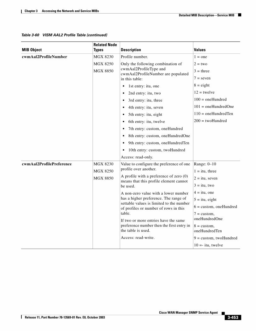
Chapter 3 Accessing the Network and Service MIBsDetailed MIB Description—Service MIB
cwmAal2ProfileNumber MGX 8230
MGX 8250
MGX 8850
Profile number.
Only the following combination of cwmAal2ProfileType and cwmAal2ProfileNumber are populated in this table:
• 1st entry: itu, one
• 2nd entry: itu, two
• 3rd entry: itu, three
• 4th entry: itu, seven
• 5th entry: itu, eight
• 6th entry: itu, twelve
• 7th entry: custom, oneHundred
• 8th entry: custom, oneHundredOne
• 9th entry: custom, oneHundredTen
• 10th entry: custom, twoHundred
Access: read-only.
1 = one
2 = two
3 = three
7 = seven
8 = eight
12 = twelve
100 = oneHundred
101 = oneHundredOne
110 = oneHundredTen
200 = twoHundred
cwmAal2ProfilePreference MGX 8230
MGX 8250
MGX 8850
Value to configure the preference of one profile over another.
A profile with a preference of zero (0) means that this profile element cannot be used.
A non-zero value with a lower number has a higher preference. The range of settable values is limited to the number of profiles or number of rows in this table.
If two or more entries have the same preference number then the first entry in the table is used.
Access: read-write.
Range: 0–10
1 = itu, three
2 = itu, seven
3 = itu, two
4 = itu, one
5 = itu, eight
6 = custom, oneHundred
7 = custom, oneHundredOne
8 = custom, oneHundredTen
9 = custom, twoHundred
10 =- itu, twelve
Table 3-60 VISM AAL2 Profile Table (continued)
MIB ObjectRelated Node Types Description Values
3-453Cisco WAN Manager SNMP Service Agent
Release 11, Part Number 78-13569-01 Rev. E0, October 2003
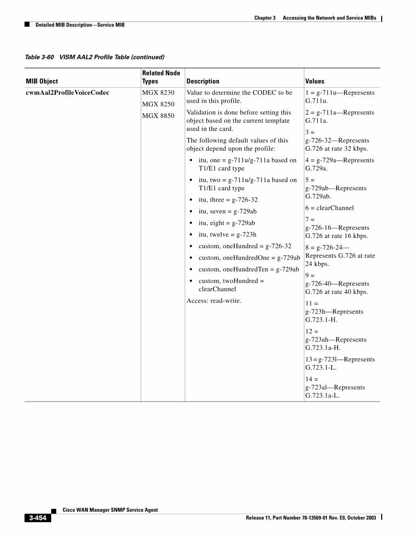
Chapter 3 Accessing the Network and Service MIBsDetailed MIB Description—Service MIB
cwmAal2ProfileVoiceCodec MGX 8230
MGX 8250
MGX 8850
Value to determine the CODEC to be used in this profile.
Validation is done before setting this object based on the current template used in the card.
The following default values of this object depend upon the profile:
• itu, one = g-711u/g-711a based on T1/E1 card type
• itu, two = g-711u/g-711a based on T1/E1 card type
• itu, three = g-726-32
• itu, seven = g-729ab
• itu, eight = g-729ab
• itu, twelve = g-723h
• custom, oneHundred = g-726-32
• custom, oneHundredOne = g-729ab
• custom, oneHundredTen = g-729ab
• custom, twoHundred = clearChannel
Access: read-write.
1 = g-711u—Represents G.711u.
2 = g-711a—Represents G.711a.
3 = g-726-32—Represents G.726 at rate 32 kbps.
4 = g-729a—Represents G.729a.
5 = g-729ab—Represents G.729ab.
6 = clearChannel
7 = g-726-16—Represents G.726 at rate 16 kbps.
8 = g-726-24— Represents G.726 at rate 24 kbps.
9 = g-726-40—Represents G.726 at rate 40 kbps.
11 = g-723h—Represents G.723.1-H.
12 = g-723ah—Represents G.723.1a-H.
13 = g-723l—Represents G.723.1-L.
14 = g-723al—Represents G.723.1a-L.
Table 3-60 VISM AAL2 Profile Table (continued)
MIB ObjectRelated Node Types Description Values
3-454Cisco WAN Manager SNMP Service Agent
Release 11, Part Number 78-13569-01 Rev. E0, October 2003
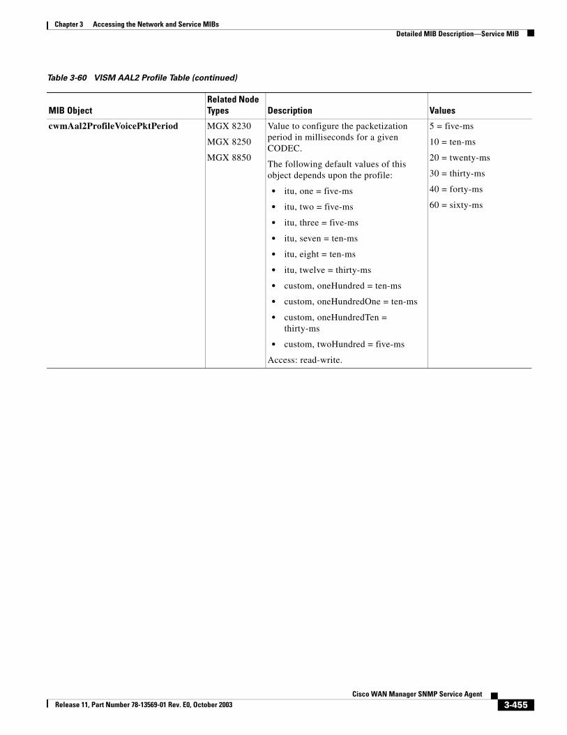
Chapter 3 Accessing the Network and Service MIBsDetailed MIB Description—Service MIB
cwmAal2ProfileVoicePktPeriod MGX 8230
MGX 8250
MGX 8850
Value to configure the packetization period in milliseconds for a given CODEC.
The following default values of this object depends upon the profile:
• itu, one = five-ms
• itu, two = five-ms
• itu, three = five-ms
• itu, seven = ten-ms
• itu, eight = ten-ms
• itu, twelve = thirty-ms
• custom, oneHundred = ten-ms
• custom, oneHundredOne = ten-ms
• custom, oneHundredTen = thirty-ms
• custom, twoHundred = five-ms
Access: read-write.
5 = five-ms
10 = ten-ms
20 = twenty-ms
30 = thirty-ms
40 = forty-ms
60 = sixty-ms
Table 3-60 VISM AAL2 Profile Table (continued)
MIB ObjectRelated Node Types Description Values
3-455Cisco WAN Manager SNMP Service Agent
Release 11, Part Number 78-13569-01 Rev. E0, October 2003
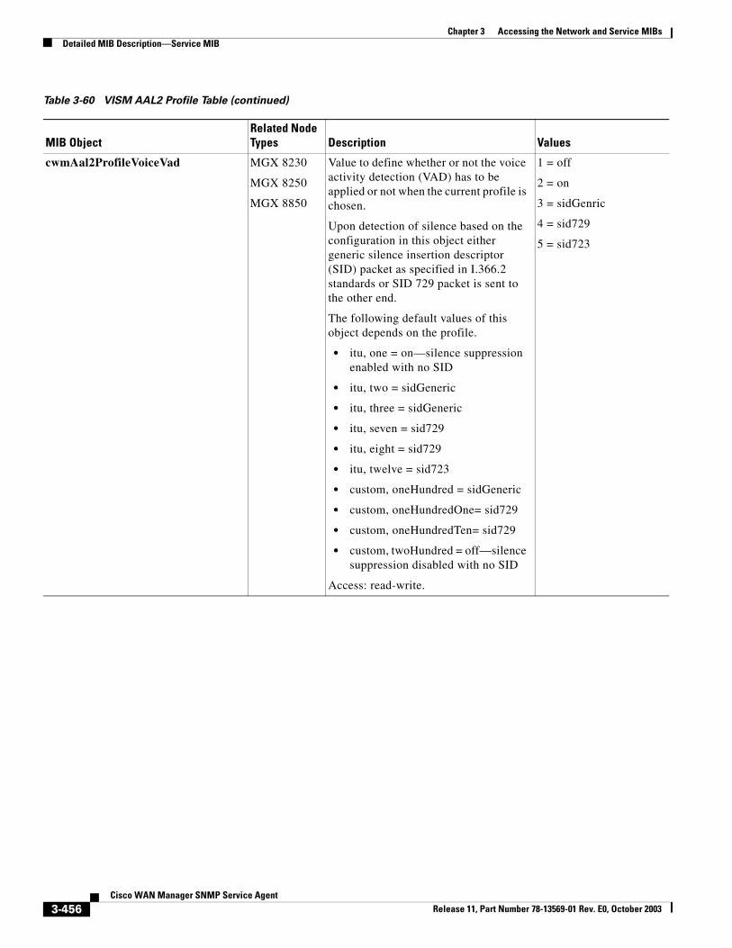
Chapter 3 Accessing the Network and Service MIBsDetailed MIB Description—Service MIB
cwmAal2ProfileVoiceVad MGX 8230
MGX 8250
MGX 8850
Value to define whether or not the voice activity detection (VAD) has to be applied or not when the current profile is chosen.
Upon detection of silence based on the configuration in this object either generic silence insertion descriptor (SID) packet as specified in I.366.2 standards or SID 729 packet is sent to the other end.
The following default values of this object depends on the profile.
• itu, one = on—silence suppression enabled with no SID
• itu, two = sidGeneric
• itu, three = sidGeneric
• itu, seven = sid729
• itu, eight = sid729
• itu, twelve = sid723
• custom, oneHundred = sidGeneric
• custom, oneHundredOne= sid729
• custom, oneHundredTen= sid729
• custom, twoHundred = off—silence suppression disabled with no SID
Access: read-write.
1 = off
2 = on
3 = sidGenric
4 = sid729
5 = sid723
Table 3-60 VISM AAL2 Profile Table (continued)
MIB ObjectRelated Node Types Description Values
3-456Cisco WAN Manager SNMP Service Agent
Release 11, Part Number 78-13569-01 Rev. E0, October 2003
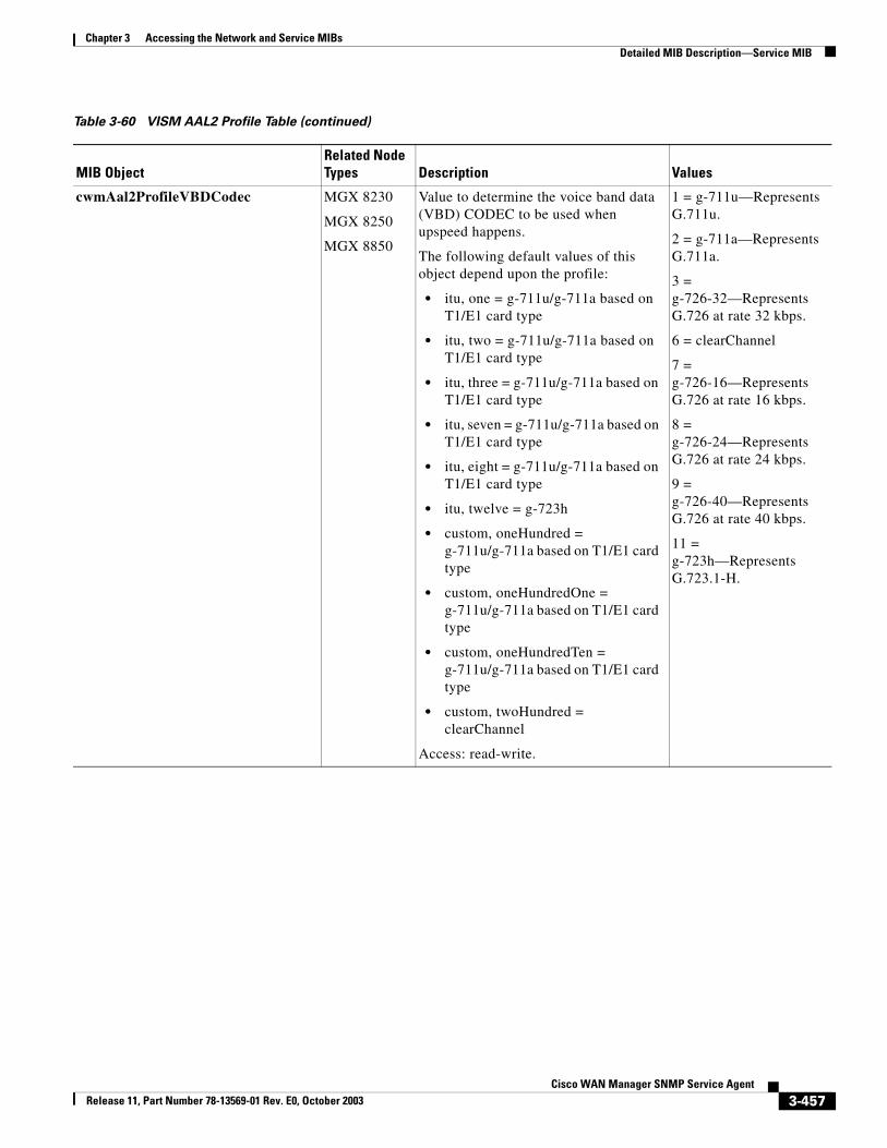
Chapter 3 Accessing the Network and Service MIBsDetailed MIB Description—Service MIB
cwmAal2ProfileVBDCodec MGX 8230
MGX 8250
MGX 8850
Value to determine the voice band data (VBD) CODEC to be used when upspeed happens.
The following default values of this object depend upon the profile:
• itu, one = g-711u/g-711a based on T1/E1 card type
• itu, two = g-711u/g-711a based on T1/E1 card type
• itu, three = g-711u/g-711a based on T1/E1 card type
• itu, seven = g-711u/g-711a based on T1/E1 card type
• itu, eight = g-711u/g-711a based on T1/E1 card type
• itu, twelve = g-723h
• custom, oneHundred = g-711u/g-711a based on T1/E1 card type
• custom, oneHundredOne = g-711u/g-711a based on T1/E1 card type
• custom, oneHundredTen = g-711u/g-711a based on T1/E1 card type
• custom, twoHundred = clearChannel
Access: read-write.
1 = g-711u—Represents G.711u.
2 = g-711a—Represents G.711a.
3 = g-726-32—Represents G.726 at rate 32 kbps.
6 = clearChannel
7 = g-726-16—Represents G.726 at rate 16 kbps.
8 = g-726-24—Represents G.726 at rate 24 kbps.
9 = g-726-40—Represents G.726 at rate 40 kbps.
11 = g-723h—Represents G.723.1-H.
Table 3-60 VISM AAL2 Profile Table (continued)
MIB ObjectRelated Node Types Description Values
3-457Cisco WAN Manager SNMP Service Agent
Release 11, Part Number 78-13569-01 Rev. E0, October 2003
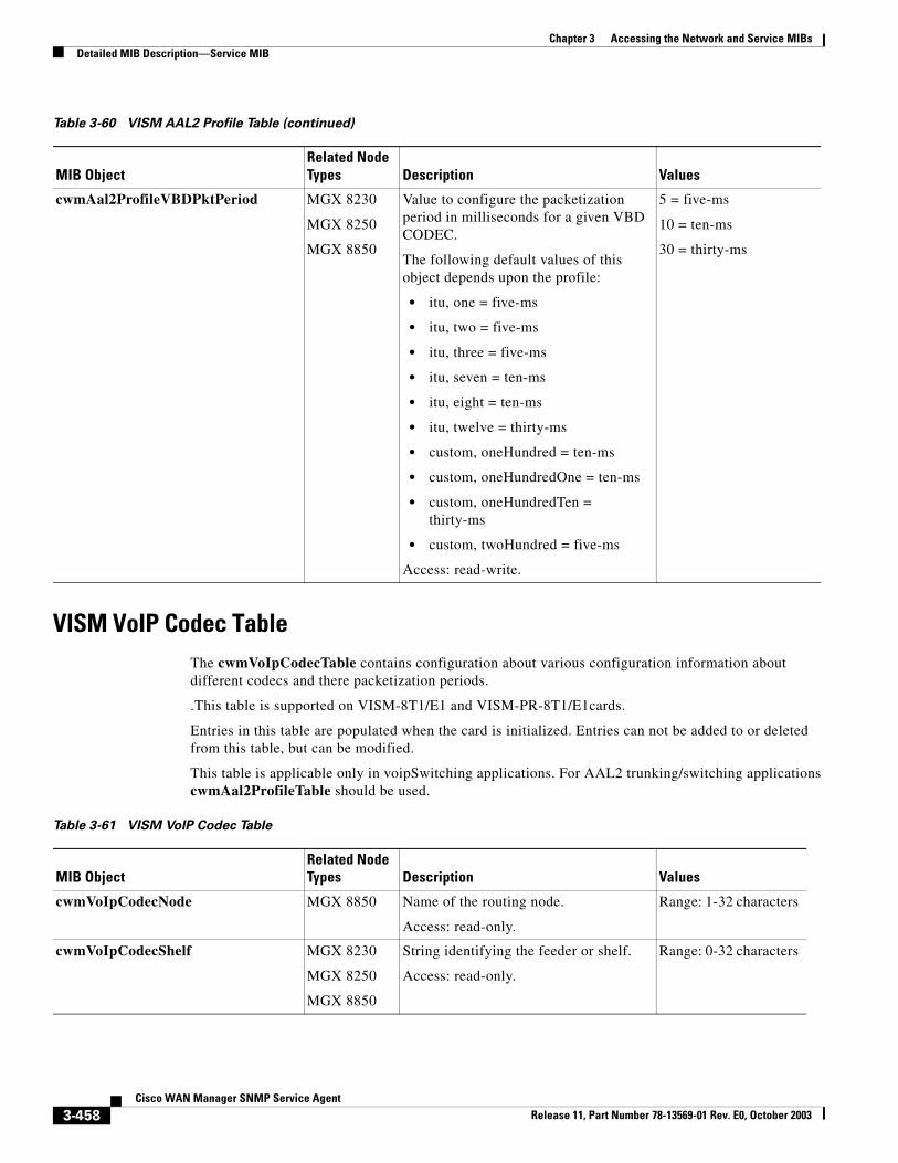
Chapter 3 Accessing the Network and Service MIBsDetailed MIB Description—Service MIB
VISM VoIP Codec TableThe cwmVoIpCodecTable contains configuration about various configuration information about different codecs and there packetization periods.
.This table is supported on VISM-8T1/E1 and VISM-PR-8T1/E1cards.
Entries in this table are populated when the card is initialized. Entries can not be added to or deleted from this table, but can be modified.
This table is applicable only in voipSwitching applications. For AAL2 trunking/switching applications cwmAal2ProfileTable should be used.
cwmAal2ProfileVBDPktPeriod MGX 8230
MGX 8250
MGX 8850
Value to configure the packetization period in milliseconds for a given VBD CODEC.
The following default values of this object depends upon the profile:
• itu, one = five-ms
• itu, two = five-ms
• itu, three = five-ms
• itu, seven = ten-ms
• itu, eight = ten-ms
• itu, twelve = thirty-ms
• custom, oneHundred = ten-ms
• custom, oneHundredOne = ten-ms
• custom, oneHundredTen = thirty-ms
• custom, twoHundred = five-ms
Access: read-write.
5 = five-ms
10 = ten-ms
30 = thirty-ms
Table 3-60 VISM AAL2 Profile Table (continued)
MIB ObjectRelated Node Types Description Values
Table 3-61 VISM VoIP Codec Table
MIB ObjectRelated Node Types Description Values
cwmVoIpCodecNode MGX 8850 Name of the routing node.
Access: read-only.
Range: 1-32 characters
cwmVoIpCodecShelf MGX 8230
MGX 8250
MGX 8850
String identifying the feeder or shelf.
Access: read-only.
Range: 0-32 characters
3-458Cisco WAN Manager SNMP Service Agent
Release 11, Part Number 78-13569-01 Rev. E0, October 2003
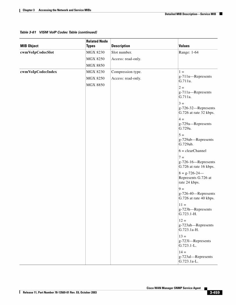
Chapter 3 Accessing the Network and Service MIBsDetailed MIB Description—Service MIB
cwmVoIpCodecSlot MGX 8230
MGX 8250
MGX 8850
Slot number.
Access: read-only.
Range: 1-64
cwmVoIpCodecIndex MGX 8230
MGX 8250
MGX 8850
Compression type.
Access: read-only.
1 = g-711u—Represents G.711u.
2 = g-711a—Represents G.711a.
3 = g-726-32—Represents G.726 at rate 32 kbps.
4 = g-729a—Represents G.729a.
5 = g-729ab—Represents G.729ab.
6 = clearChannel
7 = g-726-16—Represents G.726 at rate 16 kbps.
8 = g-726-24— Represents G.726 at rate 24 kbps.
9 = g-726-40—Represents G.726 at rate 40 kbps.
11 = g-723h—Represents G.723.1-H.
12 = g-723ah—Represents G.723.1a-H.
13 = g-723l—Represents G.723.1-L.
14 = g-723al—Represents G.723.1a-L.
Table 3-61 VISM VoIP Codec Table (continued)
MIB ObjectRelated Node Types Description Values
3-459Cisco WAN Manager SNMP Service Agent
Release 11, Part Number 78-13569-01 Rev. E0, October 2003
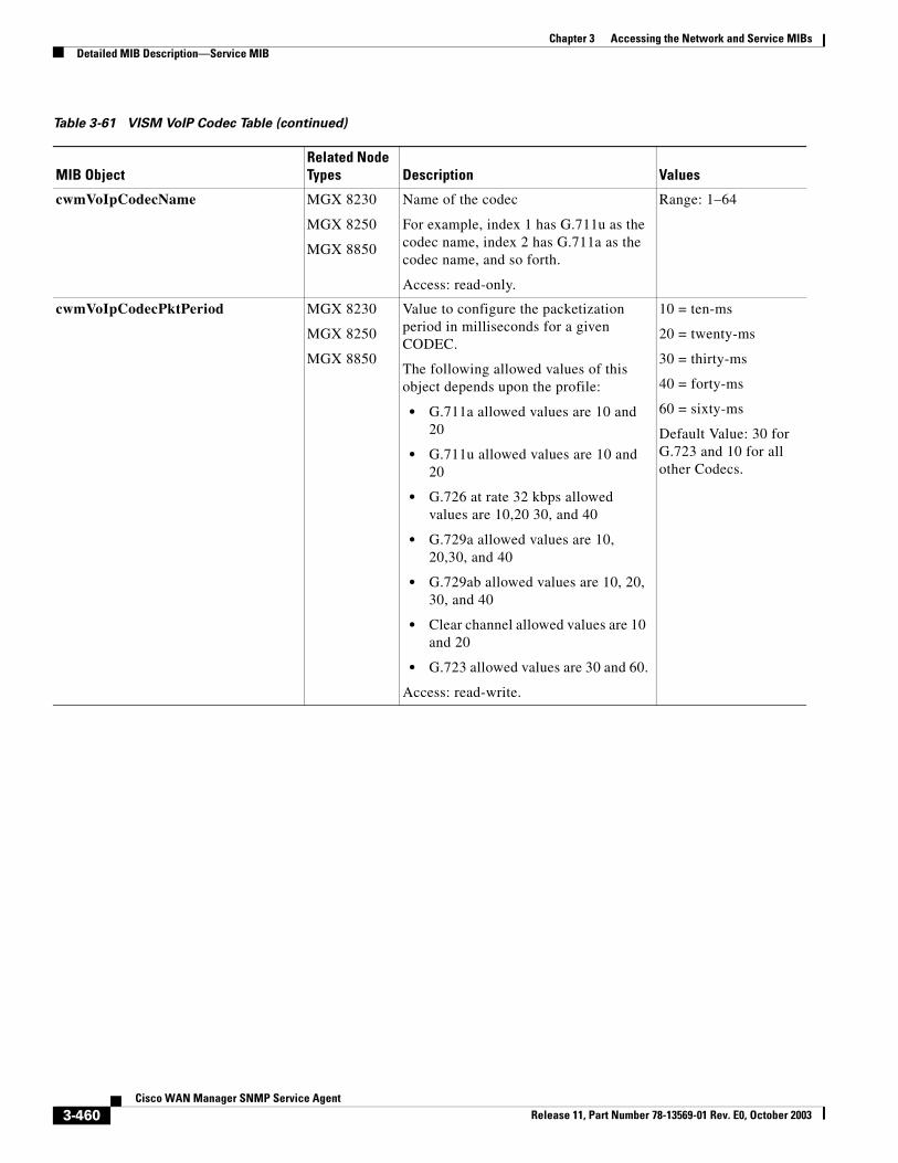
Chapter 3 Accessing the Network and Service MIBsDetailed MIB Description—Service MIB
cwmVoIpCodecName MGX 8230
MGX 8250
MGX 8850
Name of the codec
For example, index 1 has G.711u as the codec name, index 2 has G.711a as the codec name, and so forth.
Access: read-only.
Range: 1–64
cwmVoIpCodecPktPeriod MGX 8230
MGX 8250
MGX 8850
Value to configure the packetization period in milliseconds for a given CODEC.
The following allowed values of this object depends upon the profile:
• G.711a allowed values are 10 and 20
• G.711u allowed values are 10 and 20
• G.726 at rate 32 kbps allowed values are 10,20 30, and 40
• G.729a allowed values are 10, 20,30, and 40
• G.729ab allowed values are 10, 20, 30, and 40
• Clear channel allowed values are 10 and 20
• G.723 allowed values are 30 and 60.
Access: read-write.
10 = ten-ms
20 = twenty-ms
30 = thirty-ms
40 = forty-ms
60 = sixty-ms
Default Value: 30 for G.723 and 10 for all other Codecs.
Table 3-61 VISM VoIP Codec Table (continued)
MIB ObjectRelated Node Types Description Values
3-460Cisco WAN Manager SNMP Service Agent
Release 11, Part Number 78-13569-01 Rev. E0, October 2003
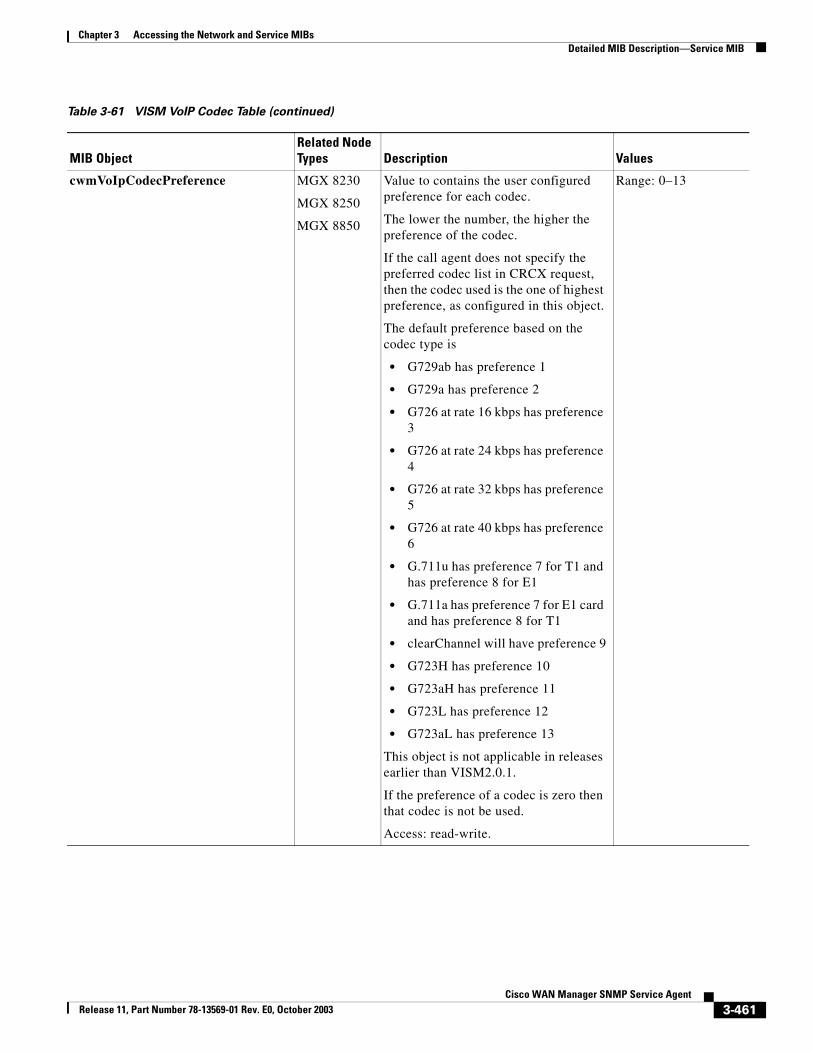
Chapter 3 Accessing the Network and Service MIBsDetailed MIB Description—Service MIB
cwmVoIpCodecPreference MGX 8230
MGX 8250
MGX 8850
Value to contains the user configured preference for each codec.
The lower the number, the higher the preference of the codec.
If the call agent does not specify the preferred codec list in CRCX request, then the codec used is the one of highest preference, as configured in this object.
The default preference based on the codec type is
• G729ab has preference 1
• G729a has preference 2
• G726 at rate 16 kbps has preference 3
• G726 at rate 24 kbps has preference 4
• G726 at rate 32 kbps has preference 5
• G726 at rate 40 kbps has preference 6
• G.711u has preference 7 for T1 and has preference 8 for E1
• G.711a has preference 7 for E1 card and has preference 8 for T1
• clearChannel will have preference 9
• G723H has preference 10
• G723aH has preference 11
• G723L has preference 12
• G723aL has preference 13
This object is not applicable in releases earlier than VISM2.0.1.
If the preference of a codec is zero then that codec is not be used.
Access: read-write.
Range: 0–13
Table 3-61 VISM VoIP Codec Table (continued)
MIB ObjectRelated Node Types Description Values
3-461Cisco WAN Manager SNMP Service Agent
Release 11, Part Number 78-13569-01 Rev. E0, October 2003
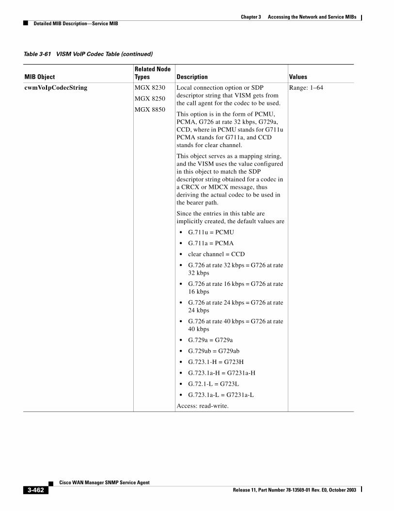
Chapter 3 Accessing the Network and Service MIBsDetailed MIB Description—Service MIB
cwmVoIpCodecString MGX 8230
MGX 8250
MGX 8850
Local connection option or SDP descriptor string that VISM gets from the call agent for the codec to be used.
This option is in the form of PCMU, PCMA, G726 at rate 32 kbps, G729a, CCD, where in PCMU stands for G711u PCMA stands for G711a, and CCD stands for clear channel.
This object serves as a mapping string, and the VISM uses the value configured in this object to match the SDP descriptor string obtained for a codec in a CRCX or MDCX message, thus deriving the actual codec to be used in the bearer path.
Since the entries in this table are implicitly created, the default values are
• G.711u = PCMU
• G.711a = PCMA
• clear channel = CCD
• G.726 at rate 32 kbps = G726 at rate 32 kbps
• G.726 at rate 16 kbps = G726 at rate 16 kbps
• G.726 at rate 24 kbps = G726 at rate 24 kbps
• G.726 at rate 40 kbps = G726 at rate 40 kbps
• G.729a = G729a
• G.729ab = G729ab
• G.723.1-H = G723H
• G.723.1a-H = G7231a-H
• G.72.1-L = G723L
• G.723.1a-L = G7231a-L
Access: read-write.
Range: 1–64
Table 3-61 VISM VoIP Codec Table (continued)
MIB ObjectRelated Node Types Description Values
3-462Cisco WAN Manager SNMP Service Agent
Release 11, Part Number 78-13569-01 Rev. E0, October 2003
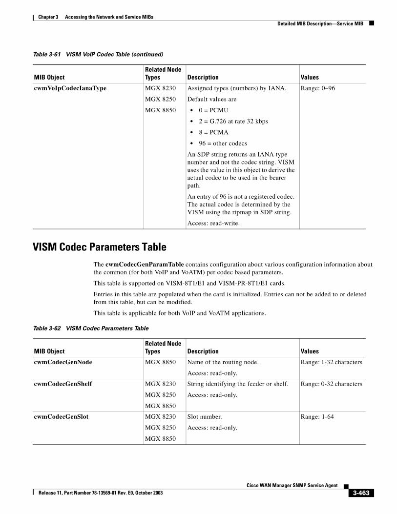
Chapter 3 Accessing the Network and Service MIBsDetailed MIB Description—Service MIB
VISM Codec Parameters TableThe cwmCodecGenParamTable contains configuration about various configuration information about the common (for both VoIP and VoATM) per codec based parameters.
This table is supported on VISM-8T1/E1 and VISM-PR-8T1/E1 cards.
Entries in this table are populated when the card is initialized. Entries can not be added to or deleted from this table, but can be modified.
This table is applicable for both VoIP and VoATM applications.
cwmVoIpCodecIanaType MGX 8230
MGX 8250
MGX 8850
Assigned types (numbers) by IANA.
Default values are
• 0 = PCMU
• 2 = G.726 at rate 32 kbps
• 8 = PCMA
• 96 = other codecs
An SDP string returns an IANA type number and not the codec string. VISM uses the value in this object to derive the actual codec to be used in the bearer path.
An entry of 96 is not a registered codec. The actual codec is determined by the VISM using the rtpmap in SDP string.
Access: read-write.
Range: 0–96
Table 3-61 VISM VoIP Codec Table (continued)
MIB ObjectRelated Node Types Description Values
Table 3-62 VISM Codec Parameters Table
MIB ObjectRelated Node Types Description Values
cwmCodecGenNode MGX 8850 Name of the routing node.
Access: read-only.
Range: 1-32 characters
cwmCodecGenShelf MGX 8230
MGX 8250
MGX 8850
String identifying the feeder or shelf.
Access: read-only.
Range: 0-32 characters
cwmCodecGenSlot MGX 8230
MGX 8250
MGX 8850
Slot number.
Access: read-only.
Range: 1-64
3-463Cisco WAN Manager SNMP Service Agent
Release 11, Part Number 78-13569-01 Rev. E0, October 2003
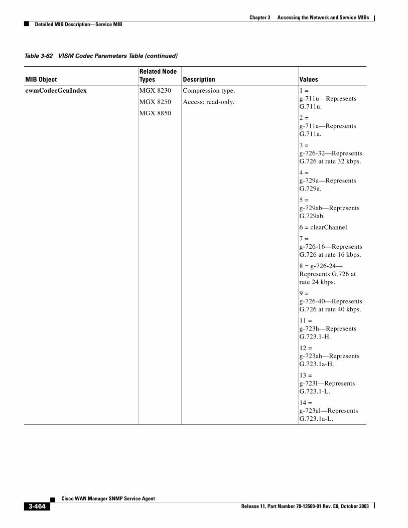
Chapter 3 Accessing the Network and Service MIBsDetailed MIB Description—Service MIB
cwmCodecGenIndex MGX 8230
MGX 8250
MGX 8850
Compression type.
Access: read-only.
1 = g-711u—Represents G.711u.
2 = g-711a—Represents G.711a.
3 = g-726-32—Represents G.726 at rate 32 kbps.
4 = g-729a—Represents G.729a.
5 = g-729ab—Represents G.729ab.
6 = clearChannel
7 = g-726-16—Represents G.726 at rate 16 kbps.
8 = g-726-24— Represents G.726 at rate 24 kbps.
9 = g-726-40—Represents G.726 at rate 40 kbps.
11 = g-723h—Represents G.723.1-H.
12 = g-723ah—Represents G.723.1a-H.
13 = g-723l—Represents G.723.1-L.
14 = g-723al—Represents G.723.1a-L.
Table 3-62 VISM Codec Parameters Table (continued)
MIB ObjectRelated Node Types Description Values
3-464Cisco WAN Manager SNMP Service Agent
Release 11, Part Number 78-13569-01 Rev. E0, October 2003
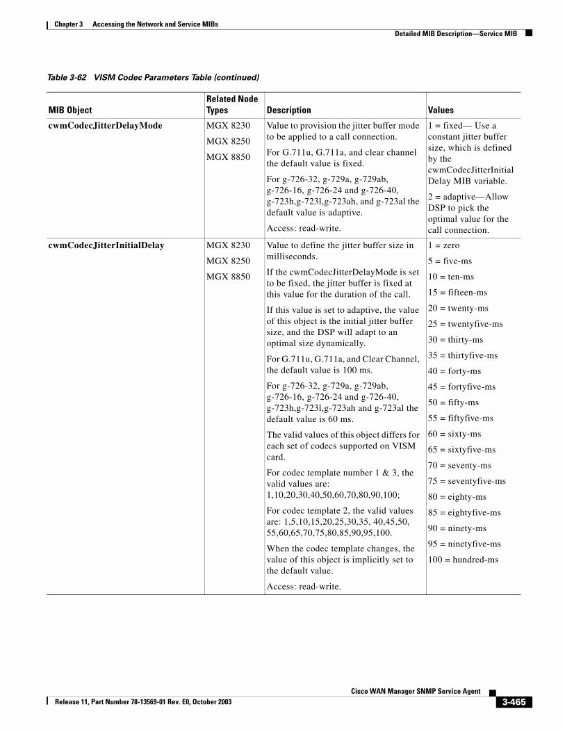
Chapter 3 Accessing the Network and Service MIBsDetailed MIB Description—Service MIB
cwmCodecJitterDelayMode MGX 8230
MGX 8250
MGX 8850
Value to provision the jitter buffer mode to be applied to a call connection.
For G.711u, G.711a, and clear channel the default value is fixed.
For g-726-32, g-729a, g-729ab, g-726-16, g-726-24 and g-726-40, g-723h,g-723l,g-723ah, and g-723al the default value is adaptive.
Access: read-write.
1 = fixed— Use a constant jitter buffer size, which is defined by the cwmCodecJitterInitialDelay MIB variable.
2 = adaptive—Allow DSP to pick the optimal value for the call connection.
cwmCodecJitterInitialDelay MGX 8230
MGX 8250
MGX 8850
Value to define the jitter buffer size in milliseconds.
If the cwmCodecJitterDelayMode is set to be fixed, the jitter buffer is fixed at this value for the duration of the call.
If this value is set to adaptive, the value of this object is the initial jitter buffer size, and the DSP will adapt to an optimal size dynamically.
For G.711u, G.711a, and Clear Channel, the default value is 100 ms.
For g-726-32, g-729a, g-729ab, g-726-16, g-726-24 and g-726-40, g-723h,g-723l,g-723ah and g-723al the default value is 60 ms.
The valid values of this object differs for each set of codecs supported on VISM card.
For codec template number 1 & 3, the valid values are: 1,10,20,30,40,50,60,70,80,90,100;
For codec template 2, the valid values are: 1,5,10,15,20,25,30,35, 40,45,50, 55,60,65,70,75,80,85,90,95,100.
When the codec template changes, the value of this object is implicitly set to the default value.
Access: read-write.
1 = zero
5 = five-ms
10 = ten-ms
15 = fifteen-ms
20 = twenty-ms
25 = twentyfive-ms
30 = thirty-ms
35 = thirtyfive-ms
40 = forty-ms
45 = fortyfive-ms
50 = fifty-ms
55 = fiftyfive-ms
60 = sixty-ms
65 = sixtyfive-ms
70 = seventy-ms
75 = seventyfive-ms
80 = eighty-ms
85 = eightyfive-ms
90 = ninety-ms
95 = ninetyfive-ms
100 = hundred-ms
Table 3-62 VISM Codec Parameters Table (continued)
MIB ObjectRelated Node Types Description Values
3-465Cisco WAN Manager SNMP Service Agent
Release 11, Part Number 78-13569-01 Rev. E0, October 2003
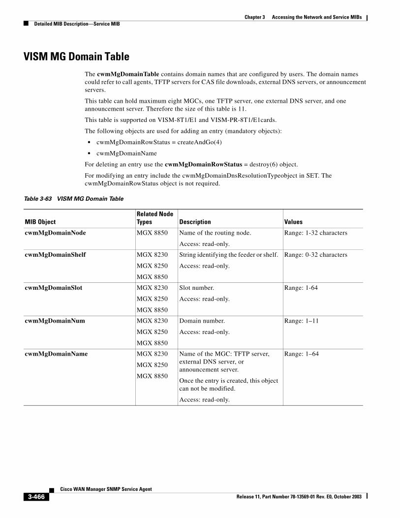
Chapter 3 Accessing the Network and Service MIBsDetailed MIB Description—Service MIB
VISM MG Domain TableThe cwmMgDomainTable contains domain names that are configured by users. The domain names could refer to call agents, TFTP servers for CAS file downloads, external DNS servers, or announcement servers.
This table can hold maximum eight MGCs, one TFTP server, one external DNS server, and one announcement server. Therefore the size of this table is 11.
This table is supported on VISM-8T1/E1 and VISM-PR-8T1/E1cards.
The following objects are used for adding an entry (mandatory objects):
• cwmMgDomainRowStatus = createAndGo(4)
• cwmMgDomainName
For deleting an entry use the cwmMgDomainRowStatus = destroy(6) object.
For modifying an entry include the cwmMgDomainDnsResolutionTypeobject in SET. The cwmMgDomainRowStatus object is not required.
Table 3-63 VISM MG Domain Table
MIB ObjectRelated Node Types Description Values
cwmMgDomainNode MGX 8850 Name of the routing node.
Access: read-only.
Range: 1-32 characters
cwmMgDomainShelf MGX 8230
MGX 8250
MGX 8850
String identifying the feeder or shelf.
Access: read-only.
Range: 0-32 characters
cwmMgDomainSlot MGX 8230
MGX 8250
MGX 8850
Slot number.
Access: read-only.
Range: 1-64
cwmMgDomainNum MGX 8230
MGX 8250
MGX 8850
Domain number.
Access: read-only.
Range: 1–11
cwmMgDomainName MGX 8230
MGX 8250
MGX 8850
Name of the MGC: TFTP server, external DNS server, or announcement server.
Once the entry is created, this object can not be modified.
Access: read-only.
Range: 1–64
3-466Cisco WAN Manager SNMP Service Agent
Release 11, Part Number 78-13569-01 Rev. E0, October 2003
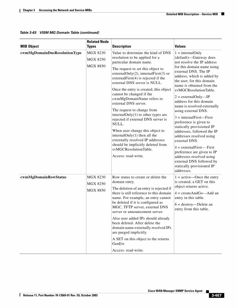
Chapter 3 Accessing the Network and Service MIBsDetailed MIB Description—Service MIB
cwmMgDomainDnsResolutionType MGX 8230
MGX 8250
MGX 8850
Value to determine the kind of DNS resolution to be applied for a particular domain name.
The request to set this object to externalOnly(2), internalFirst(3) or externalFirst(4) is rejected if the external DNS server is NULL.
Once the entry is created, this object cannot be changed if the cwmMgDomainName refers to external DNS server.
The request to change from internalOnly(1) to other types are rejected if external DNS server is NULL.
When user change this object to internalOnly(1) then all the externally resolved IP addresses should be implicitly deleted from svMGCResolutionTable.
Access: read-write.
1 = internalOnly (default)—Gateway does not resolve the IP address for this domain name using external DNS. The IP address, which is added by the user, for this domain name is obtained from the svMGCResolutionTable.
2 = externalOnly—IP address for this domain name is resolved externally using external DNS.
3 = internalFirst—First preference is given to statically provisioned IP addresses, followed the IP addresses resolved using external DNS.
4 = externalFirst— First preference are given to IP addresses resolved using external DNS followed by statically provisioned IP addresses.
cwmMgDomainRowStatus MGX 8230
MGX 8250
MGX 8850
Row status to create or delete the domain entry.
The deletion of an entry is rejected if there is still reference to this domain name. For example, an entry cannot be deleted if it is configured as MGC, TFTP server, external DNS server or announcement server.
Also user added IPs should already been deleted. After delete the domain name externally resolved IPs are purged implicitly.
A SET on this object to the returns GenErr.
Access: read-write.
1 = active—Once the entry is created, a GET on this object returns active.
4 = createAndGo—Add an entry in this table.
6 = destroy—Delete an entry from this table.
Table 3-63 VISM MG Domain Table (continued)
MIB ObjectRelated Node Types Description Values
3-467Cisco WAN Manager SNMP Service Agent
Release 11, Part Number 78-13569-01 Rev. E0, October 2003
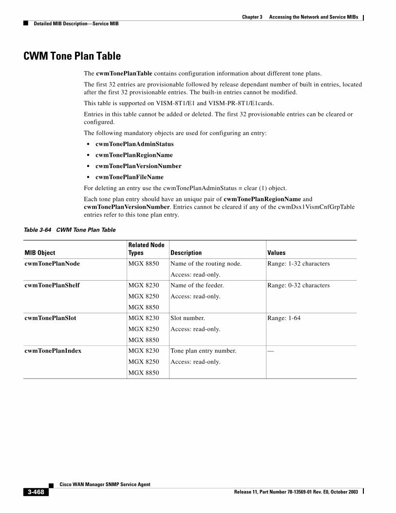
Chapter 3 Accessing the Network and Service MIBsDetailed MIB Description—Service MIB
CWM Tone Plan TableThe cwmTonePlanTable contains configuration information about different tone plans.
The first 32 entries are provisionable followed by release dependant number of built in entries, located after the first 32 provisionable entries. The built-in entries cannot be modified.
This table is supported on VISM-8T1/E1 and VISM-PR-8T1/E1cards.
Entries in this table cannot be added or deleted. The first 32 provisionable entries can be cleared or configured.
The following mandatory objects are used for configuring an entry:
• cwmTonePlanAdminStatus
• cwmTonePlanRegionName
• cwmTonePlanVersionNumber
• cwmTonePlanFileName
For deleting an entry use the cwmTonePlanAdminStatus = clear (1) object.
Each tone plan entry should have an unique pair of cwmTonePlanRegionName and cwmTonePlanVersionNumber. Entries cannot be cleared if any of the cwmDsx1VismCnfGrpTable entries refer to this tone plan entry.
Table 3-64 CWM Tone Plan Table
MIB ObjectRelated Node Types Description Values
cwmTonePlanNode MGX 8850 Name of the routing node.
Access: read-only.
Range: 1-32 characters
cwmTonePlanShelf MGX 8230
MGX 8250
MGX 8850
Name of the feeder.
Access: read-only.
Range: 0-32 characters
cwmTonePlanSlot MGX 8230
MGX 8250
MGX 8850
Slot number.
Access: read-only.
Range: 1-64
cwmTonePlanIndex MGX 8230
MGX 8250
MGX 8850
Tone plan entry number.
Access: read-only.
—
3-468Cisco WAN Manager SNMP Service Agent
Release 11, Part Number 78-13569-01 Rev. E0, October 2003
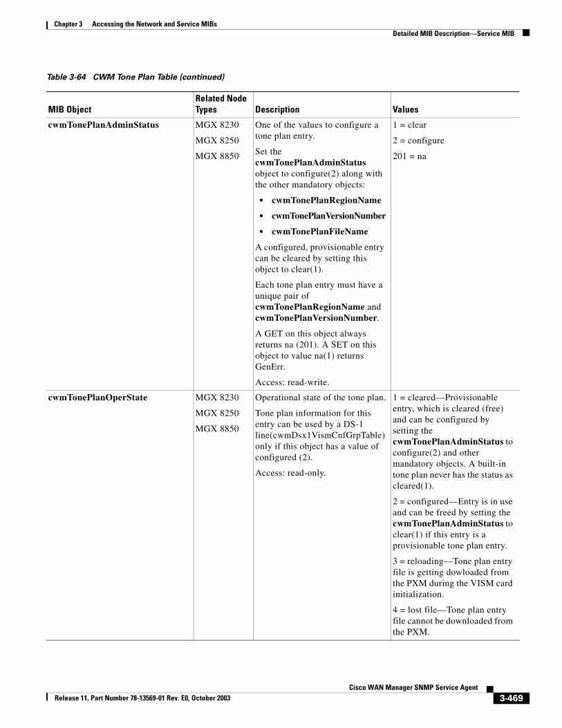
Chapter 3 Accessing the Network and Service MIBsDetailed MIB Description—Service MIB
cwmTonePlanAdminStatus MGX 8230
MGX 8250
MGX 8850
One of the values to configure a tone plan entry.
Set the cwmTonePlanAdminStatus object to configure(2) along with the other mandatory objects:
• cwmTonePlanRegionName
• cwmTonePlanVersionNumber
• cwmTonePlanFileName
A configured, provisionable entry can be cleared by setting this object to clear(1).
Each tone plan entry must have a unique pair of cwmTonePlanRegionName and cwmTonePlanVersionNumber.
A GET on this object always returns na (201). A SET on this object to value na(1) returns GenErr.
Access: read-write.
1 = clear
2 = configure
201 = na
cwmTonePlanOperState MGX 8230
MGX 8250
MGX 8850
Operational state of the tone plan.
Tone plan information for this entry can be used by a DS-1 line(cwmDsx1VismCnfGrpTable) only if this object has a value of configured (2).
Access: read-only.
1 = cleared—Provisionable entry, which is cleared (free) and can be configured by setting the cwmTonePlanAdminStatus to configure(2) and other mandatory objects. A built-in tone plan never has the status as cleared(1).
2 = configured—Entry is in use and can be freed by setting the cwmTonePlanAdminStatus to clear(1) if this entry is a provisionable tone plan entry.
3 = reloading—Tone plan entry file is getting dowloaded from the PXM during the VISM card initialization.
4 = lost file—Tone plan entry file cannot be downloaded from the PXM.
Table 3-64 CWM Tone Plan Table (continued)
MIB ObjectRelated Node Types Description Values
3-469Cisco WAN Manager SNMP Service Agent
Release 11, Part Number 78-13569-01 Rev. E0, October 2003
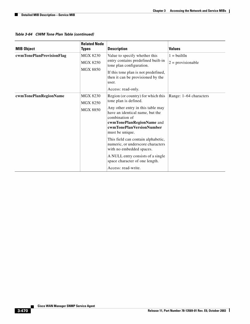
Chapter 3 Accessing the Network and Service MIBsDetailed MIB Description—Service MIB
cwmTonePlanProvisionFlag MGX 8230
MGX 8250
MGX 8850
Value to specify whether this entry contains predefined built-in tone plan configuration.
If this tone plan is not predefined, then it can be provisioned by the user.
Access: read-only.
1 = builtIn
2 = provisionable
cwmTonePlanRegionName MGX 8230
MGX 8250
MGX 8850
Region (or country) for which this tone plan is defined.
Any other entry in this table may have an identical name, but the combination of cwmTonePlanRegionName and cwmTonePlanVersionNumber must be unique.
This field can contain alphabetic, numeric, or underscore characters with no embedded spaces.
A NULL entry consists of a single space character of one length.
Access: read-write.
Range: 1–64 characters
Table 3-64 CWM Tone Plan Table (continued)
MIB ObjectRelated Node Types Description Values
3-470Cisco WAN Manager SNMP Service Agent
Release 11, Part Number 78-13569-01 Rev. E0, October 2003
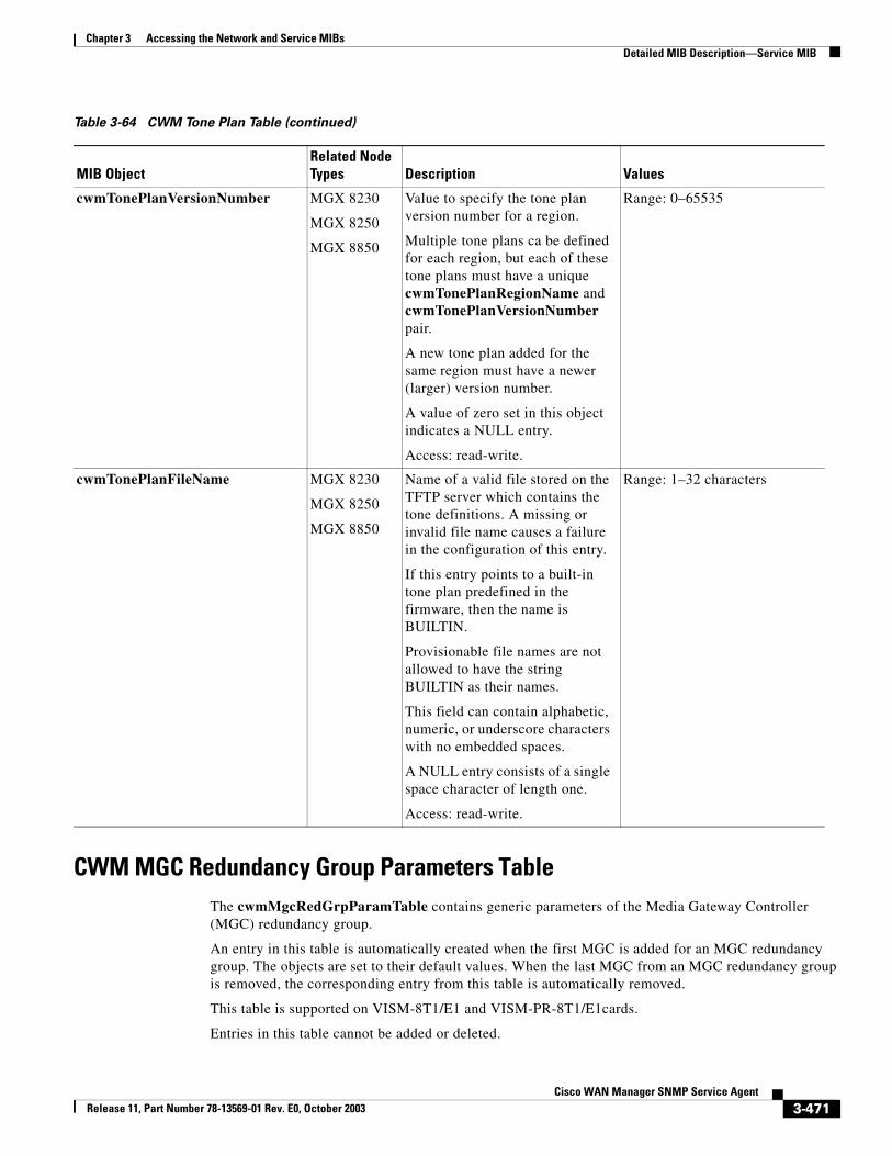
Chapter 3 Accessing the Network and Service MIBsDetailed MIB Description—Service MIB
CWM MGC Redundancy Group Parameters TableThe cwmMgcRedGrpParamTable contains generic parameters of the Media Gateway Controller (MGC) redundancy group.
An entry in this table is automatically created when the first MGC is added for an MGC redundancy group. The objects are set to their default values. When the last MGC from an MGC redundancy group is removed, the corresponding entry from this table is automatically removed.
This table is supported on VISM-8T1/E1 and VISM-PR-8T1/E1cards.
Entries in this table cannot be added or deleted.
cwmTonePlanVersionNumber MGX 8230
MGX 8250
MGX 8850
Value to specify the tone plan version number for a region.
Multiple tone plans ca be defined for each region, but each of these tone plans must have a unique cwmTonePlanRegionName and cwmTonePlanVersionNumber pair.
A new tone plan added for the same region must have a newer (larger) version number.
A value of zero set in this object indicates a NULL entry.
Access: read-write.
Range: 0–65535
cwmTonePlanFileName MGX 8230
MGX 8250
MGX 8850
Name of a valid file stored on the TFTP server which contains the tone definitions. A missing or invalid file name causes a failure in the configuration of this entry.
If this entry points to a built-in tone plan predefined in the firmware, then the name is BUILTIN.
Provisionable file names are not allowed to have the string BUILTIN as their names.
This field can contain alphabetic, numeric, or underscore characters with no embedded spaces.
A NULL entry consists of a single space character of length one.
Access: read-write.
Range: 1–32 characters
Table 3-64 CWM Tone Plan Table (continued)
MIB ObjectRelated Node Types Description Values
3-471Cisco WAN Manager SNMP Service Agent
Release 11, Part Number 78-13569-01 Rev. E0, October 2003
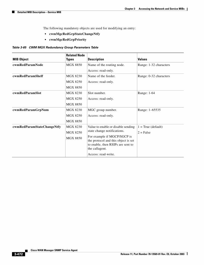
Chapter 3 Accessing the Network and Service MIBsDetailed MIB Description—Service MIB
The following mandatory objects are used for modifying an entry:
• cwmMgcRedGrpStateChangeNtfy
• cwmMgcRedGrpPriority
Table 3-65 CWM MGX Redundancy Group Parameters Table
MIB ObjectRelated Node Types Description Values
cwmRedParamNode MGX 8850 Name of the routing node.
Access: read-only.
Range: 1-32 characters
cwmRedParamShelf MGX 8230
MGX 8250
MGX 8850
Name of the feeder.
Access: read-only.
Range: 0-32 characters
cwmRedParamSlot MGX 8230
MGX 8250
MGX 8850
Slot number.
Access: read-only.
Range: 1-64
cwmRedParamGrpNum MGX 8230
MGX 8250
MGX 8850
MGC group number.
Access: read-only.
Range: 1–65535
cwmRedParamStateChangeNtfy MGX 8230
MGX 8250
MGX 8850
Value to enable or disable sending state change notifications.
For example if MGCP/SGCP is the protocol and this object is set to enable, then RSIPs are sent to the callagent.
Access: read-write.
1 = True (default)
2 = False
3-472Cisco WAN Manager SNMP Service Agent
Release 11, Part Number 78-13569-01 Rev. E0, October 2003
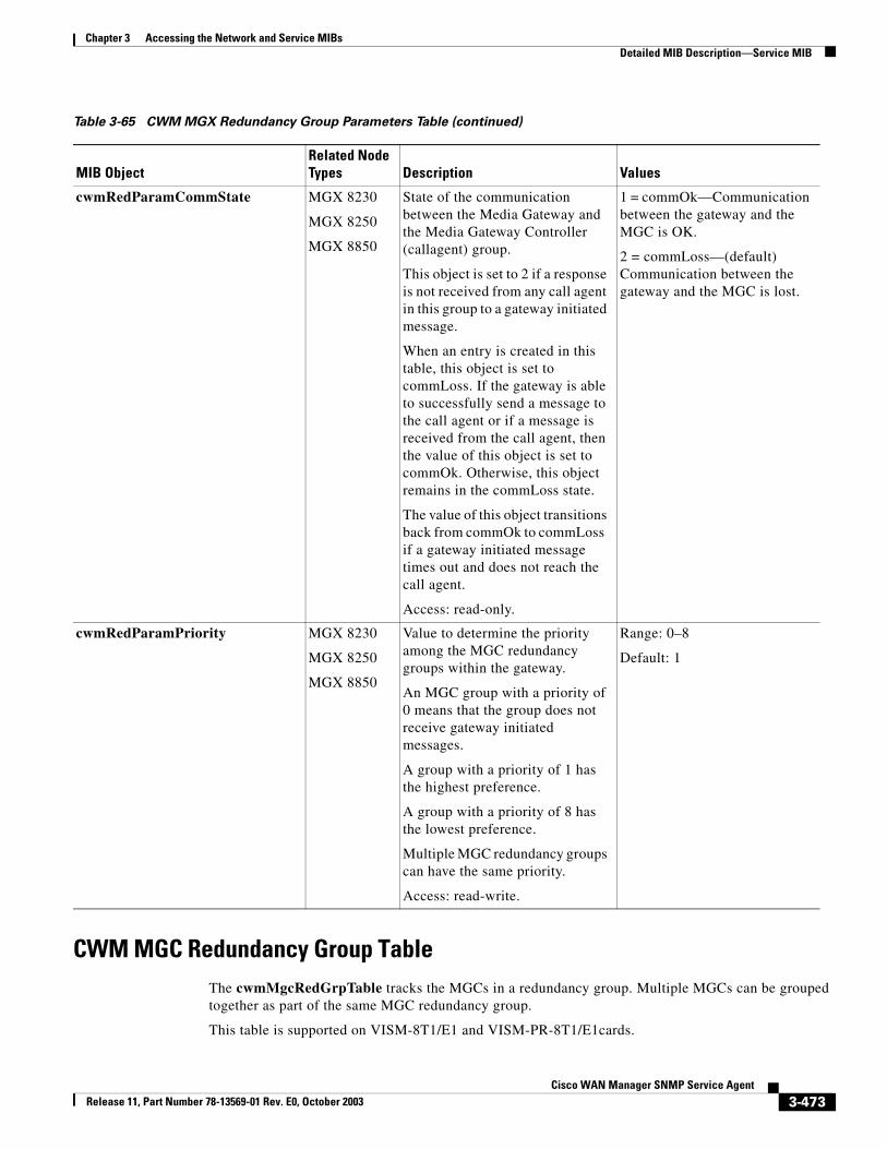
Chapter 3 Accessing the Network and Service MIBsDetailed MIB Description—Service MIB
CWM MGC Redundancy Group TableThe cwmMgcRedGrpTable tracks the MGCs in a redundancy group. Multiple MGCs can be grouped together as part of the same MGC redundancy group.
This table is supported on VISM-8T1/E1 and VISM-PR-8T1/E1cards.
cwmRedParamCommState MGX 8230
MGX 8250
MGX 8850
State of the communication between the Media Gateway and the Media Gateway Controller (callagent) group.
This object is set to 2 if a response is not received from any call agent in this group to a gateway initiated message.
When an entry is created in this table, this object is set to commLoss. If the gateway is able to successfully send a message to the call agent or if a message is received from the call agent, then the value of this object is set to commOk. Otherwise, this object remains in the commLoss state.
The value of this object transitions back from commOk to commLoss if a gateway initiated message times out and does not reach the call agent.
Access: read-only.
1 = commOk—Communication between the gateway and the MGC is OK.
2 = commLoss—(default) Communication between the gateway and the MGC is lost.
cwmRedParamPriority MGX 8230
MGX 8250
MGX 8850
Value to determine the priority among the MGC redundancy groups within the gateway.
An MGC group with a priority of 0 means that the group does not receive gateway initiated messages.
A group with a priority of 1 has the highest preference.
A group with a priority of 8 has the lowest preference.
Multiple MGC redundancy groups can have the same priority.
Access: read-write.
Range: 0–8
Default: 1
Table 3-65 CWM MGX Redundancy Group Parameters Table (continued)
MIB ObjectRelated Node Types Description Values
3-473Cisco WAN Manager SNMP Service Agent
Release 11, Part Number 78-13569-01 Rev. E0, October 2003
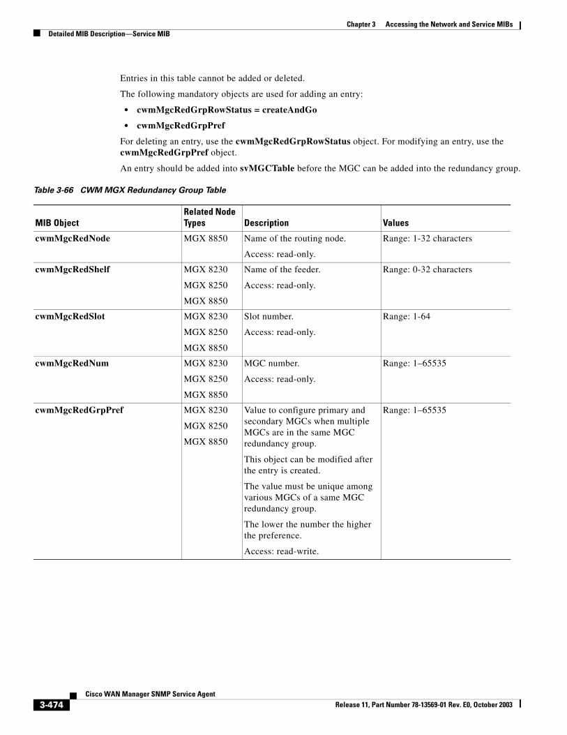
Chapter 3 Accessing the Network and Service MIBsDetailed MIB Description—Service MIB
Entries in this table cannot be added or deleted.
The following mandatory objects are used for adding an entry:
• cwmMgcRedGrpRowStatus = createAndGo
• cwmMgcRedGrpPref
For deleting an entry, use the cwmMgcRedGrpRowStatus object. For modifying an entry, use the cwmMgcRedGrpPref object.
An entry should be added into svMGCTable before the MGC can be added into the redundancy group.
Table 3-66 CWM MGX Redundancy Group Table
MIB ObjectRelated Node Types Description Values
cwmMgcRedNode MGX 8850 Name of the routing node.
Access: read-only.
Range: 1-32 characters
cwmMgcRedShelf MGX 8230
MGX 8250
MGX 8850
Name of the feeder.
Access: read-only.
Range: 0-32 characters
cwmMgcRedSlot MGX 8230
MGX 8250
MGX 8850
Slot number.
Access: read-only.
Range: 1-64
cwmMgcRedNum MGX 8230
MGX 8250
MGX 8850
MGC number.
Access: read-only.
Range: 1–65535
cwmMgcRedGrpPref MGX 8230
MGX 8250
MGX 8850
Value to configure primary and secondary MGCs when multiple MGCs are in the same MGC redundancy group.
This object can be modified after the entry is created.
The value must be unique among various MGCs of a same MGC redundancy group.
The lower the number the higher the preference.
Access: read-write.
Range: 1–65535
3-474Cisco WAN Manager SNMP Service Agent
Release 11, Part Number 78-13569-01 Rev. E0, October 2003
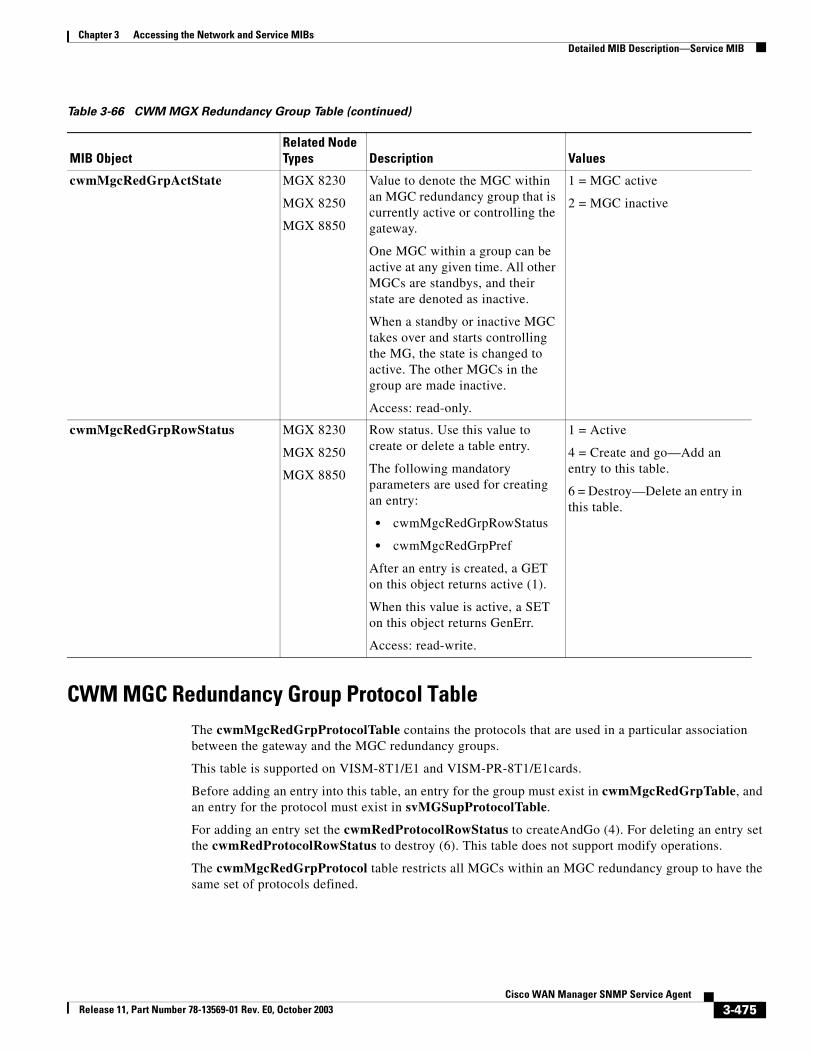
Chapter 3 Accessing the Network and Service MIBsDetailed MIB Description—Service MIB
CWM MGC Redundancy Group Protocol TableThe cwmMgcRedGrpProtocolTable contains the protocols that are used in a particular association between the gateway and the MGC redundancy groups.
This table is supported on VISM-8T1/E1 and VISM-PR-8T1/E1cards.
Before adding an entry into this table, an entry for the group must exist in cwmMgcRedGrpTable, and an entry for the protocol must exist in svMGSupProtocolTable.
For adding an entry set the cwmRedProtocolRowStatus to createAndGo (4). For deleting an entry set the cwmRedProtocolRowStatus to destroy (6). This table does not support modify operations.
The cwmMgcRedGrpProtocol table restricts all MGCs within an MGC redundancy group to have the same set of protocols defined.
cwmMgcRedGrpActState MGX 8230
MGX 8250
MGX 8850
Value to denote the MGC within an MGC redundancy group that is currently active or controlling the gateway.
One MGC within a group can be active at any given time. All other MGCs are standbys, and their state are denoted as inactive.
When a standby or inactive MGC takes over and starts controlling the MG, the state is changed to active. The other MGCs in the group are made inactive.
Access: read-only.
1 = MGC active
2 = MGC inactive
cwmMgcRedGrpRowStatus MGX 8230
MGX 8250
MGX 8850
Row status. Use this value to create or delete a table entry.
The following mandatory parameters are used for creating an entry:
• cwmMgcRedGrpRowStatus
• cwmMgcRedGrpPref
After an entry is created, a GET on this object returns active (1).
When this value is active, a SET on this object returns GenErr.
Access: read-write.
1 = Active
4 = Create and go—Add an entry to this table.
6 = Destroy—Delete an entry in this table.
Table 3-66 CWM MGX Redundancy Group Table (continued)
MIB ObjectRelated Node Types Description Values
3-475Cisco WAN Manager SNMP Service Agent
Release 11, Part Number 78-13569-01 Rev. E0, October 2003
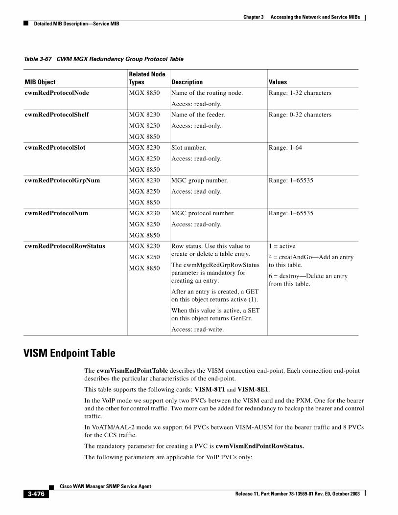
Chapter 3 Accessing the Network and Service MIBsDetailed MIB Description—Service MIB
VISM Endpoint TableThe cwmVismEndPointTable describes the VISM connection end-point. Each connection end-point describes the particular characteristics of the end-point.
This table supports the following cards: VISM-8T1 and VISM-8E1.
In the VoIP mode we support only two PVCs between the VISM card and the PXM. One for the bearer and the other for control traffic. Two more can be added for redundancy to backup the bearer and control traffic.
In VoATM/AAL-2 mode we support 64 PVCs between VISM-AUSM for the bearer traffic and 8 PVCs for the CCS traffic.
The mandatory parameter for creating a PVC is cwmVismEndPointRowStatus.
The following parameters are applicable for VoIP PVCs only:
Table 3-67 CWM MGX Redundancy Group Protocol Table
MIB ObjectRelated Node Types Description Values
cwmRedProtocolNode MGX 8850 Name of the routing node.
Access: read-only.
Range: 1-32 characters
cwmRedProtocolShelf MGX 8230
MGX 8250
MGX 8850
Name of the feeder.
Access: read-only.
Range: 0-32 characters
cwmRedProtocolSlot MGX 8230
MGX 8250
MGX 8850
Slot number.
Access: read-only.
Range: 1-64
cwmRedProtocolGrpNum MGX 8230
MGX 8250
MGX 8850
MGC group number.
Access: read-only.
Range: 1–65535
cwmRedProtocolNum MGX 8230
MGX 8250
MGX 8850
MGC protocol number.
Access: read-only.
Range: 1–65535
cwmRedProtocolRowStatus MGX 8230
MGX 8250
MGX 8850
Row status. Use this value to create or delete a table entry.
The cwmMgcRedGrpRowStatus parameter is mandatory for creating an entry:
After an entry is created, a GET on this object returns active (1).
When this value is active, a SET on this object returns GenErr.
Access: read-write.
1 = active
4 = creatAndGo—Add an entry to this table.
6 = destroy—Delete an entry from this table.
3-476Cisco WAN Manager SNMP Service Agent
Release 11, Part Number 78-13569-01 Rev. E0, October 2003
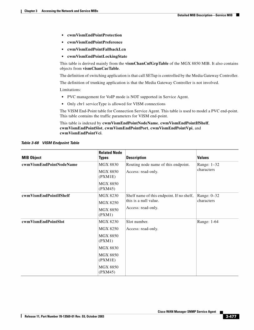
Chapter 3 Accessing the Network and Service MIBsDetailed MIB Description—Service MIB
• cwmVismEndPointProtection
• cwmVismEndPointPreference
• cwmVismEndPointFallbackLcn
• cwmVismEndPointLockingState
This table is derived mainly from the vismChanCnfGrpTable of the MGX 8850 MIB. It also contains objects from vismChanCacTable.
The definition of switching application is that call SETup is controlled by the Media Gateway Controller.
The definition of trunking application is that the Media Gateway Controller is not involved.
Limitations:
• PVC management for VoIP mode is NOT supported in Service Agent.
• Only cbr1 serviceType is allowed for VISM connections
The VISM End-Point table for Connection Service Agent. This table is used to model a PVC end-point. This table contains the traffic parameters for VISM end-point.
This table is indexed by cwmVismEndPointNodeName, cwmVismEndPointIfShelf, cwmVismEndPointSlot, cwmVismEndPointPort, cwmVismEndPointVpi, and cwmVismEndPointVci.
Table 3-68 VISM Endpoint Table
MIB ObjectRelated Node Types Description Values
cwmVismEndPointNodeName MGX 8830
MGX 8850 (PXM1E)
MGX 8850 (PXM45)
Routing node name of this endpoint.
Access: read-only.
Range: 1–32 characters
cwmVismEndPointIfShelf MGX 8230
MGX 8250
MGX 8850 (PXM1)
Shelf name of this endpoint. If no shelf, this is a null value.
Access: read-only.
Range: 0–32 characters
cwmVismEndPointSlot MGX 8230
MGX 8250
MGX 8850 (PXM1)
MGX 8830
MGX 8850 (PXM1E)
MGX 8850 (PXM45)
Slot number.
Access: read-only.
Range: 1-64
3-477Cisco WAN Manager SNMP Service Agent
Release 11, Part Number 78-13569-01 Rev. E0, October 2003
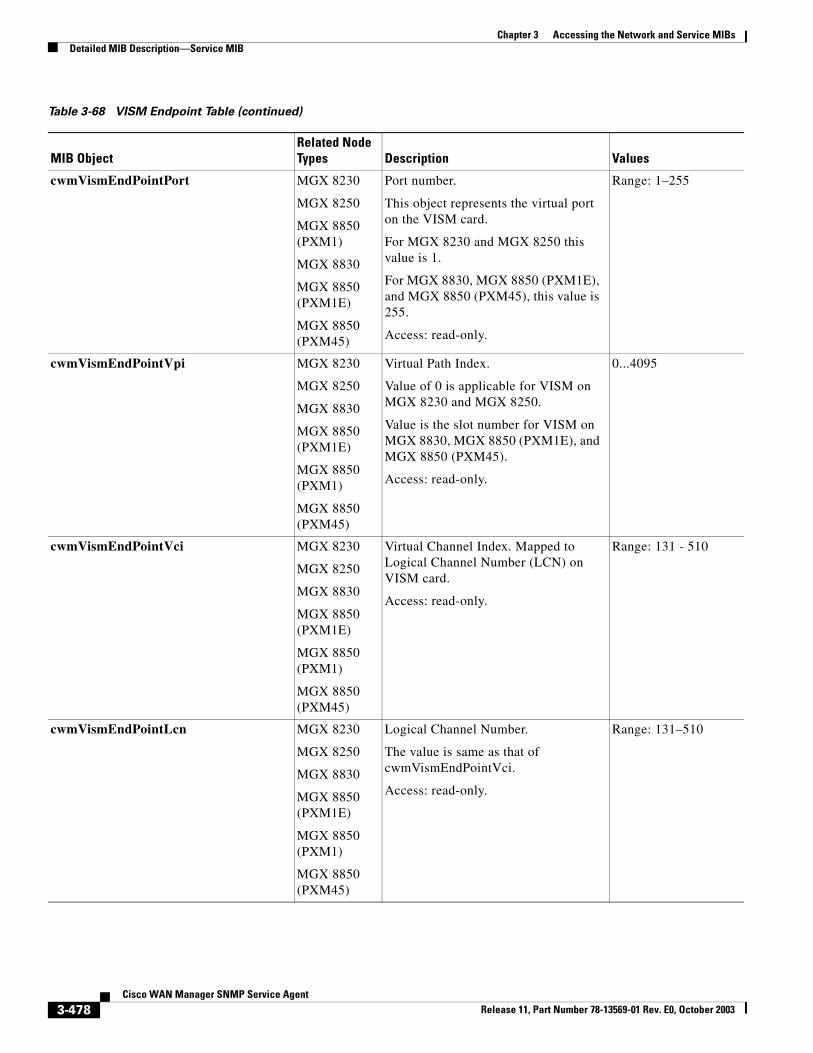
Chapter 3 Accessing the Network and Service MIBsDetailed MIB Description—Service MIB
cwmVismEndPointPort MGX 8230
MGX 8250
MGX 8850 (PXM1)
MGX 8830
MGX 8850 (PXM1E)
MGX 8850 (PXM45)
Port number.
This object represents the virtual port on the VISM card.
For MGX 8230 and MGX 8250 this value is 1.
For MGX 8830, MGX 8850 (PXM1E), and MGX 8850 (PXM45), this value is 255.
Access: read-only.
Range: 1–255
cwmVismEndPointVpi MGX 8230
MGX 8250
MGX 8830
MGX 8850 (PXM1E)
MGX 8850 (PXM1)
MGX 8850 (PXM45)
Virtual Path Index.
Value of 0 is applicable for VISM on MGX 8230 and MGX 8250.
Value is the slot number for VISM on MGX 8830, MGX 8850 (PXM1E), and MGX 8850 (PXM45).
Access: read-only.
0...4095
cwmVismEndPointVci MGX 8230
MGX 8250
MGX 8830
MGX 8850 (PXM1E)
MGX 8850 (PXM1)
MGX 8850 (PXM45)
Virtual Channel Index. Mapped to Logical Channel Number (LCN) on VISM card.
Access: read-only.
Range: 131 - 510
cwmVismEndPointLcn MGX 8230
MGX 8250
MGX 8830
MGX 8850 (PXM1E)
MGX 8850 (PXM1)
MGX 8850 (PXM45)
Logical Channel Number.
The value is same as that of cwmVismEndPointVci.
Access: read-only.
Range: 131–510
Table 3-68 VISM Endpoint Table (continued)
MIB ObjectRelated Node Types Description Values
3-478Cisco WAN Manager SNMP Service Agent
Release 11, Part Number 78-13569-01 Rev. E0, October 2003
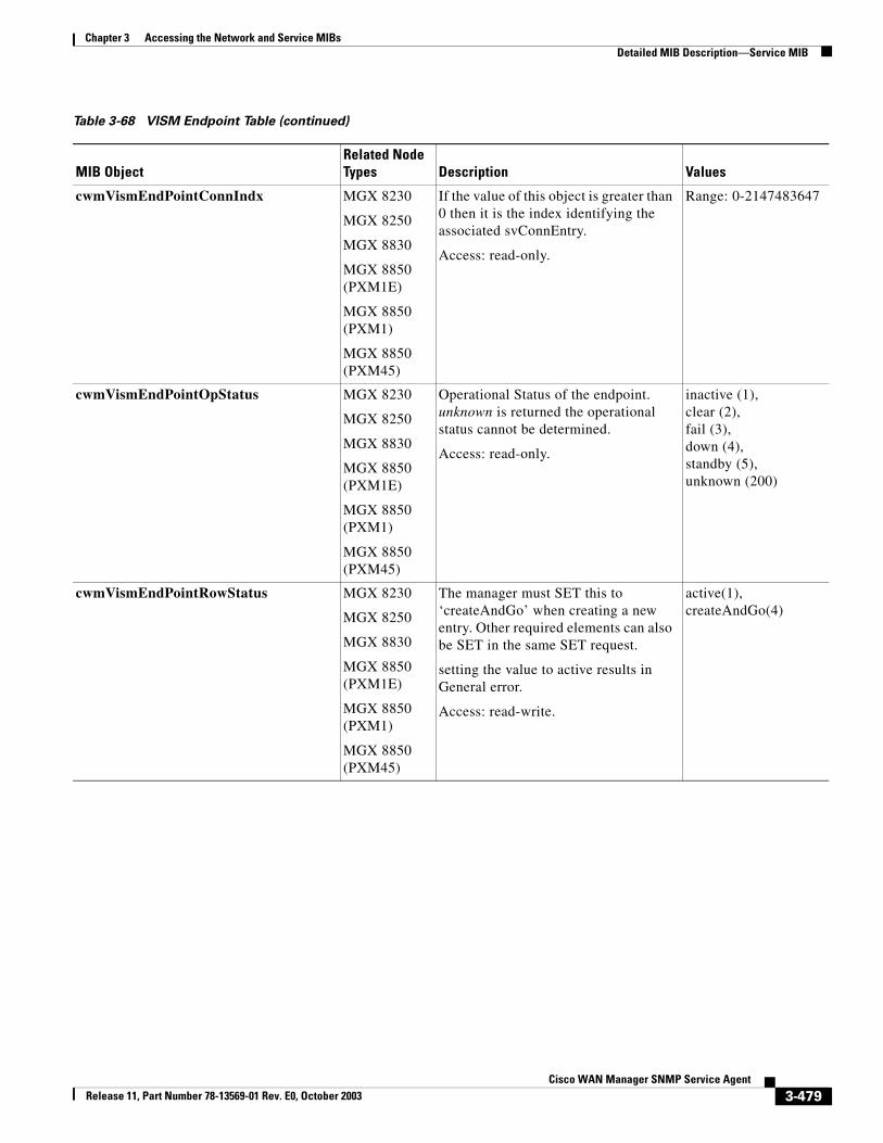
Chapter 3 Accessing the Network and Service MIBsDetailed MIB Description—Service MIB
cwmVismEndPointConnIndx MGX 8230
MGX 8250
MGX 8830
MGX 8850 (PXM1E)
MGX 8850 (PXM1)
MGX 8850 (PXM45)
If the value of this object is greater than 0 then it is the index identifying the associated svConnEntry.
Access: read-only.
Range: 0-2147483647
cwmVismEndPointOpStatus MGX 8230
MGX 8250
MGX 8830
MGX 8850 (PXM1E)
MGX 8850 (PXM1)
MGX 8850 (PXM45)
Operational Status of the endpoint. unknown is returned the operational status cannot be determined.
Access: read-only.
inactive (1), clear (2),fail (3),down (4),standby (5),unknown (200)
cwmVismEndPointRowStatus MGX 8230
MGX 8250
MGX 8830
MGX 8850 (PXM1E)
MGX 8850 (PXM1)
MGX 8850 (PXM45)
The manager must SET this to ‘createAndGo’ when creating a new entry. Other required elements can also be SET in the same SET request.
setting the value to active results in General error.
Access: read-write.
active(1), createAndGo(4)
Table 3-68 VISM Endpoint Table (continued)
MIB ObjectRelated Node Types Description Values
3-479Cisco WAN Manager SNMP Service Agent
Release 11, Part Number 78-13569-01 Rev. E0, October 2003
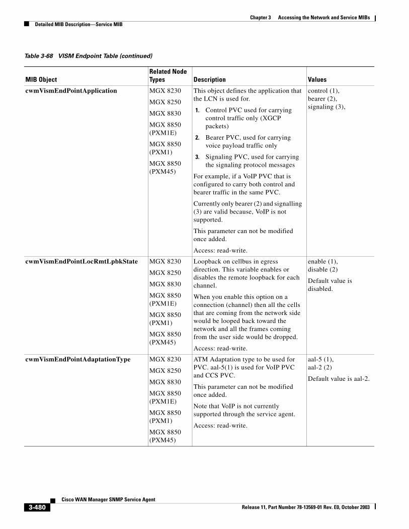
Chapter 3 Accessing the Network and Service MIBsDetailed MIB Description—Service MIB
cwmVismEndPointApplication MGX 8230
MGX 8250
MGX 8830
MGX 8850 (PXM1E)
MGX 8850 (PXM1)
MGX 8850 (PXM45)
This object defines the application that the LCN is used for.
1. Control PVC used for carrying control traffic only (XGCP packets)
2. Bearer PVC, used for carrying voice payload traffic only
3. Signaling PVC, used for carrying the signaling protocol messages
For example, if a VoIP PVC that is configured to carry both control and bearer traffic in the same PVC.
Currently only bearer (2) and signalling (3) are valid because, VoIP is not supported.
This parameter can not be modified once added.
Access: read-write.
control (1), bearer (2),signaling (3),
cwmVismEndPointLocRmtLpbkState MGX 8230
MGX 8250
MGX 8830
MGX 8850 (PXM1E)
MGX 8850 (PXM1)
MGX 8850 (PXM45)
Loopback on cellbus in egress direction. This variable enables or disables the remote loopback for each channel.
When you enable this option on a connection (channel) then all the cells that are coming from the network side would be looped back toward the network and all the frames coming from the user side would be dropped.
Access: read-write.
enable (1), disable (2)
Default value is disabled.
cwmVismEndPointAdaptationType MGX 8230
MGX 8250
MGX 8830
MGX 8850 (PXM1E)
MGX 8850 (PXM1)
MGX 8850 (PXM45)
ATM Adaptation type to be used for PVC. aal-5(1) is used for VoIP PVC and CCS PVC.
This parameter can not be modified once added.
Note that VoIP is not currently supported through the service agent.
Access: read-write.
aal-5 (1), aal-2 (2)
Default value is aal-2.
Table 3-68 VISM Endpoint Table (continued)
MIB ObjectRelated Node Types Description Values
3-480Cisco WAN Manager SNMP Service Agent
Release 11, Part Number 78-13569-01 Rev. E0, October 2003
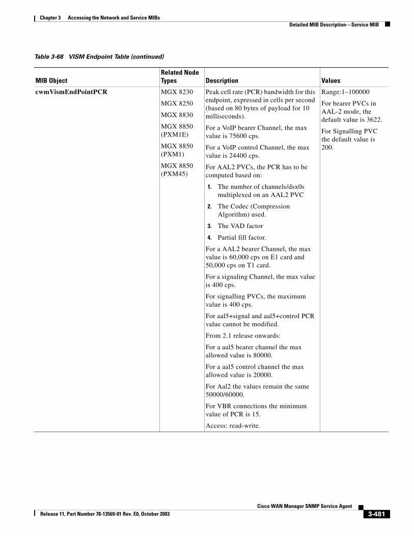
Chapter 3 Accessing the Network and Service MIBsDetailed MIB Description—Service MIB
cwmVismEndPointPCR MGX 8230
MGX 8250
MGX 8830
MGX 8850 (PXM1E)
MGX 8850 (PXM1)
MGX 8850 (PXM45)
Peak cell rate (PCR) bandwidth for this endpoint, expressed in cells per second (based on 80 bytes of payload for 10 milliseconds).
For a VoIP bearer Channel, the max value is 75600 cps.
For a VoIP control Channel, the max value is 24400 cps.
For AAL2 PVCs, the PCR has to be computed based on:
1. The number of channels/dsx0s multiplexed on an AAL2 PVC
2. The Codec (Compression Algorithm) used.
3. The VAD factor
4. Partial fill factor.
For a AAL2 bearer Channel, the max value is 60,000 cps on E1 card and 50,000 cps on T1 card.
For a signaling Channel, the max value is 400 cps.
For signalling PVCs, the maximum value is 400 cps.
For aal5+signal and aal5+control PCR value cannot be modified.
From 2.1 release onwards:
For a aal5 bearer channel the max allowed value is 80000.
For a aal5 control channel the max allowed value is 20000.
For Aal2 the values remain the same 50000/60000.
For VBR connections the minimum value of PCR is 15.
Access: read-write.
Range:1–100000
For bearer PVCs in AAL-2 mode, the default value is 3622.
For Signalling PVC the default value is 200.
Table 3-68 VISM Endpoint Table (continued)
MIB ObjectRelated Node Types Description Values
3-481Cisco WAN Manager SNMP Service Agent
Release 11, Part Number 78-13569-01 Rev. E0, October 2003
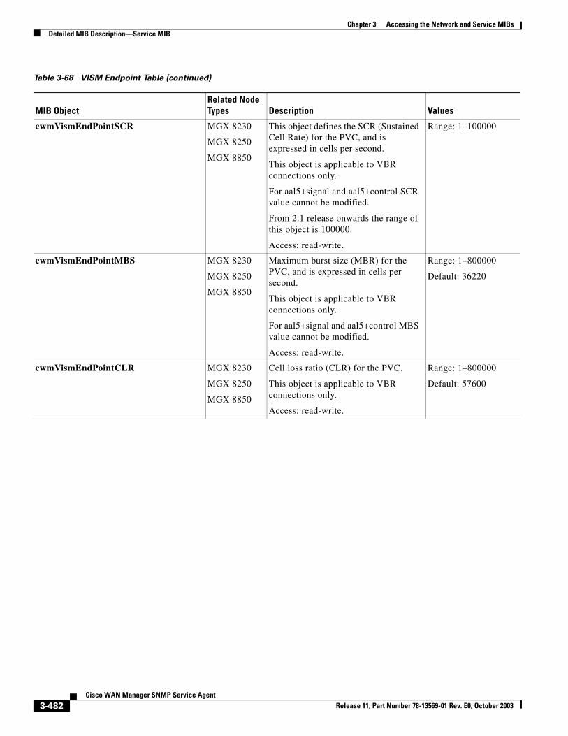
Chapter 3 Accessing the Network and Service MIBsDetailed MIB Description—Service MIB
cwmVismEndPointSCR MGX 8230
MGX 8250
MGX 8850
This object defines the SCR (Sustained Cell Rate) for the PVC, and is expressed in cells per second.
This object is applicable to VBR connections only.
For aal5+signal and aal5+control SCR value cannot be modified.
From 2.1 release onwards the range of this object is 100000.
Access: read-write.
Range: 1–100000
cwmVismEndPointMBS MGX 8230
MGX 8250
MGX 8850
Maximum burst size (MBR) for the PVC, and is expressed in cells per second.
This object is applicable to VBR connections only.
For aal5+signal and aal5+control MBS value cannot be modified.
Access: read-write.
Range: 1–800000
Default: 36220
cwmVismEndPointCLR MGX 8230
MGX 8250
MGX 8850
Cell loss ratio (CLR) for the PVC.
This object is applicable to VBR connections only.
Access: read-write.
Range: 1–800000
Default: 57600
Table 3-68 VISM Endpoint Table (continued)
MIB ObjectRelated Node Types Description Values
3-482Cisco WAN Manager SNMP Service Agent
Release 11, Part Number 78-13569-01 Rev. E0, October 2003
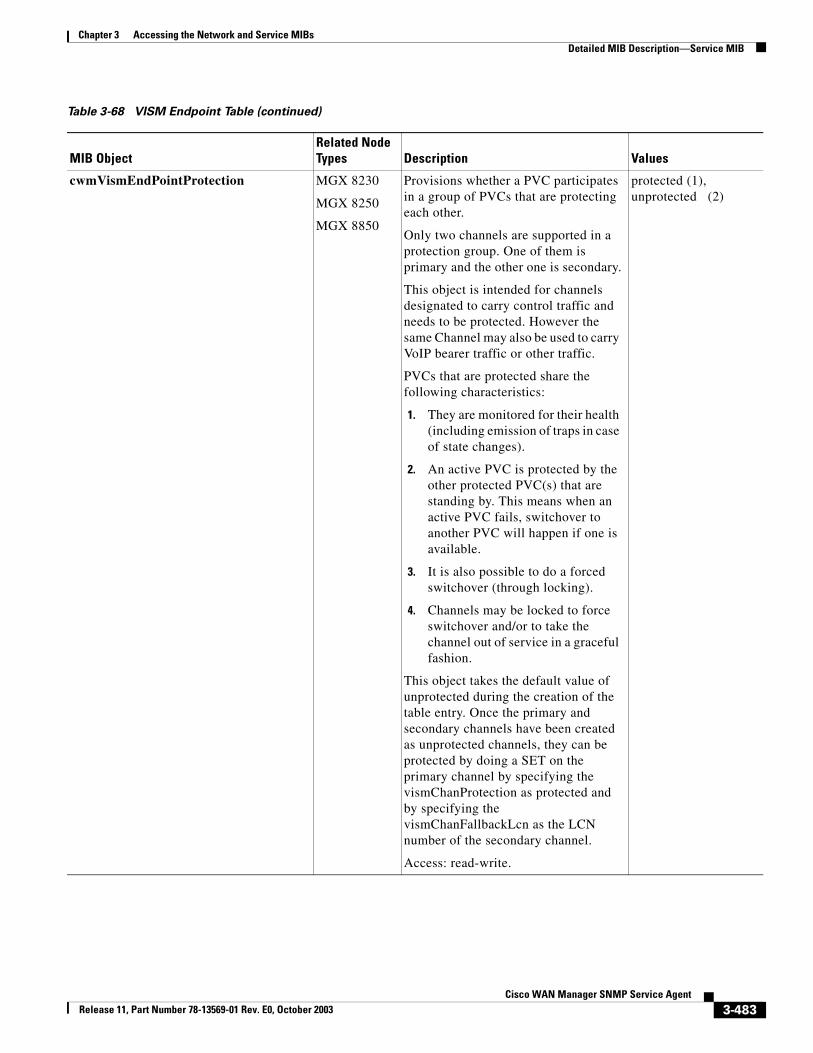
Chapter 3 Accessing the Network and Service MIBsDetailed MIB Description—Service MIB
cwmVismEndPointProtection MGX 8230
MGX 8250
MGX 8850
Provisions whether a PVC participates in a group of PVCs that are protecting each other.
Only two channels are supported in a protection group. One of them is primary and the other one is secondary.
This object is intended for channels designated to carry control traffic and needs to be protected. However the same Channel may also be used to carry VoIP bearer traffic or other traffic.
PVCs that are protected share the following characteristics:
1. They are monitored for their health (including emission of traps in case of state changes).
2. An active PVC is protected by the other protected PVC(s) that are standing by. This means when an active PVC fails, switchover to another PVC will happen if one is available.
3. It is also possible to do a forced switchover (through locking).
4. Channels may be locked to force switchover and/or to take the channel out of service in a graceful fashion.
This object takes the default value of unprotected during the creation of the table entry. Once the primary and secondary channels have been created as unprotected channels, they can be protected by doing a SET on the primary channel by specifying the vismChanProtection as protected and by specifying the vismChanFallbackLcn as the LCN number of the secondary channel.
Access: read-write.
protected (1), unprotected (2)
Table 3-68 VISM Endpoint Table (continued)
MIB ObjectRelated Node Types Description Values
3-483Cisco WAN Manager SNMP Service Agent
Release 11, Part Number 78-13569-01 Rev. E0, October 2003
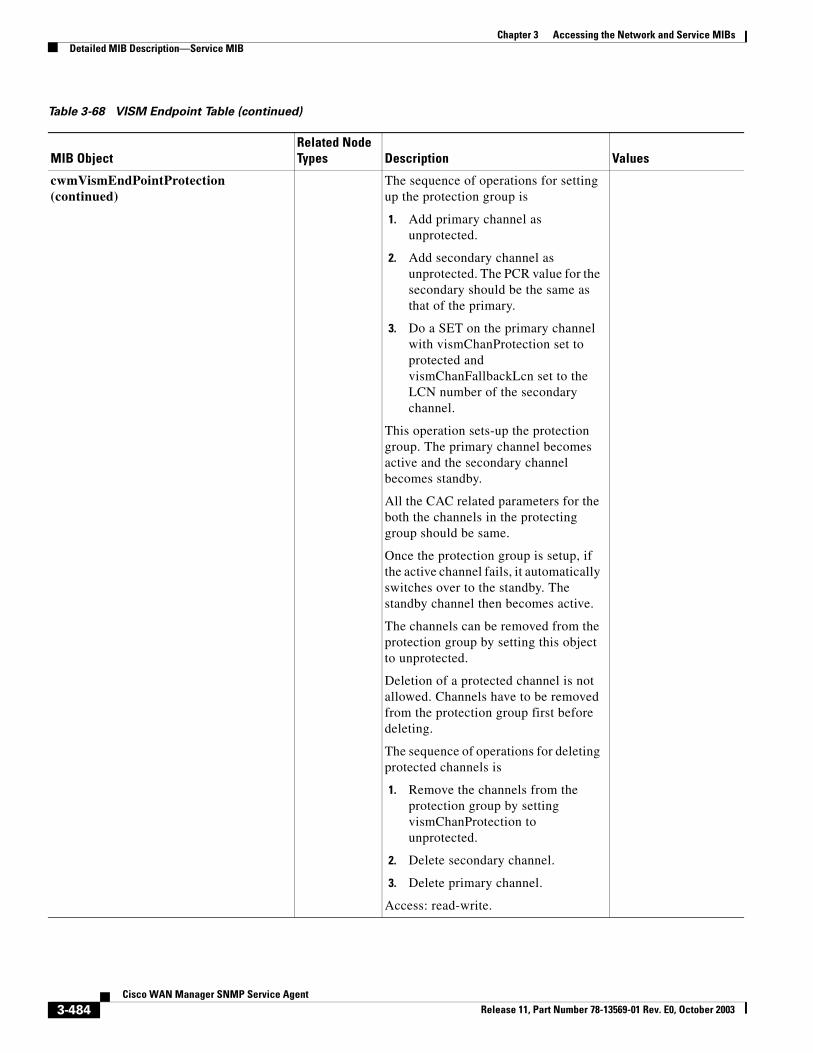
Chapter 3 Accessing the Network and Service MIBsDetailed MIB Description—Service MIB
cwmVismEndPointProtection (continued)
The sequence of operations for setting up the protection group is
1. Add primary channel as unprotected.
2. Add secondary channel as unprotected. The PCR value for the secondary should be the same as that of the primary.
3. Do a SET on the primary channel with vismChanProtection set to protected and vismChanFallbackLcn set to the LCN number of the secondary channel.
This operation sets-up the protection group. The primary channel becomes active and the secondary channel becomes standby.
All the CAC related parameters for the both the channels in the protecting group should be same.
Once the protection group is setup, if the active channel fails, it automatically switches over to the standby. The standby channel then becomes active.
The channels can be removed from the protection group by setting this object to unprotected.
Deletion of a protected channel is not allowed. Channels have to be removed from the protection group first before deleting.
The sequence of operations for deleting protected channels is
1. Remove the channels from the protection group by setting vismChanProtection to unprotected.
2. Delete secondary channel.
3. Delete primary channel.
Access: read-write.
Table 3-68 VISM Endpoint Table (continued)
MIB ObjectRelated Node Types Description Values
3-484Cisco WAN Manager SNMP Service Agent
Release 11, Part Number 78-13569-01 Rev. E0, October 2003
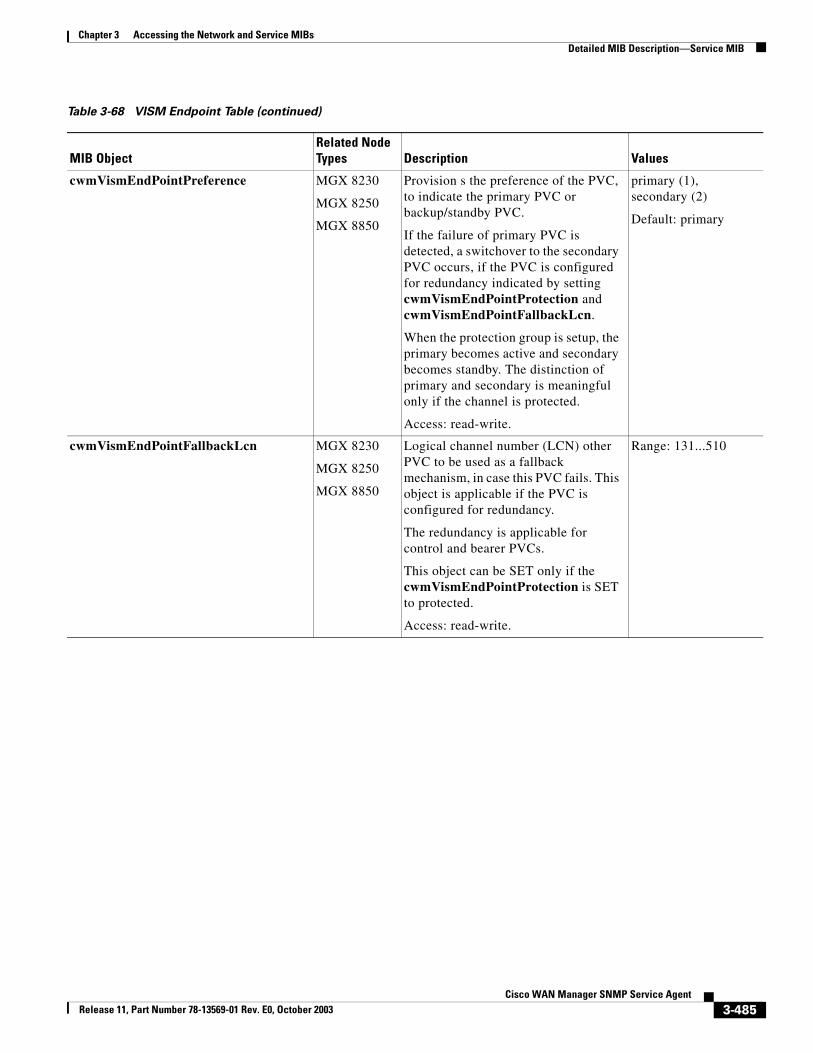
Chapter 3 Accessing the Network and Service MIBsDetailed MIB Description—Service MIB
cwmVismEndPointPreference MGX 8230
MGX 8250
MGX 8850
Provision s the preference of the PVC, to indicate the primary PVC or backup/standby PVC.
If the failure of primary PVC is detected, a switchover to the secondary PVC occurs, if the PVC is configured for redundancy indicated by setting cwmVismEndPointProtection and cwmVismEndPointFallbackLcn.
When the protection group is setup, the primary becomes active and secondary becomes standby. The distinction of primary and secondary is meaningful only if the channel is protected.
Access: read-write.
primary (1), secondary (2)
Default: primary
cwmVismEndPointFallbackLcn MGX 8230
MGX 8250
MGX 8850
Logical channel number (LCN) other PVC to be used as a fallback mechanism, in case this PVC fails. This object is applicable if the PVC is configured for redundancy.
The redundancy is applicable for control and bearer PVCs.
This object can be SET only if the cwmVismEndPointProtection is SET to protected.
Access: read-write.
Range: 131...510
Table 3-68 VISM Endpoint Table (continued)
MIB ObjectRelated Node Types Description Values
3-485Cisco WAN Manager SNMP Service Agent
Release 11, Part Number 78-13569-01 Rev. E0, October 2003
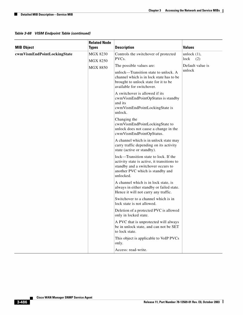
Chapter 3 Accessing the Network and Service MIBsDetailed MIB Description—Service MIB
cwmVismEndPointLockingState MGX 8230
MGX 8250
MGX 8850
Controls the switchover of protected PVCs.
The possible values are:
unlock—Transition state to unlock. A channel which is in lock state has to be brought to unlock state for it to be available for switchover.
A switchover is allowed if its cwmVismEndPointOpStatus is standby and its cwmVismEndPointLockingState is unlock.
Changing the cwmVismEndPointLockingState to unlock does not cause a change in the cwmVismEndPointOpStatus.
A channel which is in unlock state may carry traffic depending on its activity state (active or standby).
lock—Transition state to lock. If the activity state is active, it transitions to standby and a switchover occurs to another PVC which is standby and unlocked.
A channel which is in lock state, is always in either standby or failed state. Hence it will not carry any traffic.
Switchover to a channel which is in lock state is not allowed.
Deletion of a protected PVC is allowed only in locked state.
A PVC that is unprotected will always be in unlock state, and can not be SET to lock state.
This object is applicable to VoIP PVCs only.
Access: read-write.
unlock (1), lock (2)
Default value is unlock
Table 3-68 VISM Endpoint Table (continued)
MIB ObjectRelated Node Types Description Values
3-486Cisco WAN Manager SNMP Service Agent
Release 11, Part Number 78-13569-01 Rev. E0, October 2003
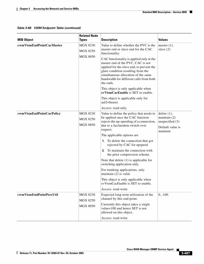
Chapter 3 Accessing the Network and Service MIBsDetailed MIB Description—Service MIB
cwmVismEndPointCacMaster MGX 8230
MGX 8250
MGX 8850
Value to define whether the PVC is the master end or slave end for the CAC functionality.
CAC functionality is applied only at the master end of the PVC, CAC is not applied for the slave end, to prevent the glare condition resulting from the simultaneous allocation of the same bandwidth for different calls from both the ends.
This object is only applicable when svVismCacEnable is SET to enable.
This object is applicable only for aal2+bearer.
Access: read-only.
master (1), slave (2)
cwmVismEndPointCacPolicy MGX 8230
MGX 8250
MGX 8850
Value to define the policy that needs to be applied once the CAC function rejects the up-speeding of a connection, due to a fax/modem switch-over request.
The applicable options are
1. To delete the connection that got rejected by CAC for upspeed
2. To maintain the connection with the prior compression scheme.
Note that delete (1) is applicable for switching application only.
For trunking applications, only maintain (2) is valid.
This object is only applicable when svVismCacEnable is SET to enable.
Access: read-write.
delete (1),maintain (2) unspecified (3)
Default value is maintain
cwmVismEndPointPercUtil MGX 8230
MGX 8250
MGX 8850
Expected long-term utilization of the channel by this end-point.
Currently this object takes a single value=100 and hence SET is not allowed on this object.
Access: read-write.
0...100.
Table 3-68 VISM Endpoint Table (continued)
MIB ObjectRelated Node Types Description Values
3-487Cisco WAN Manager SNMP Service Agent
Release 11, Part Number 78-13569-01 Rev. E0, October 2003
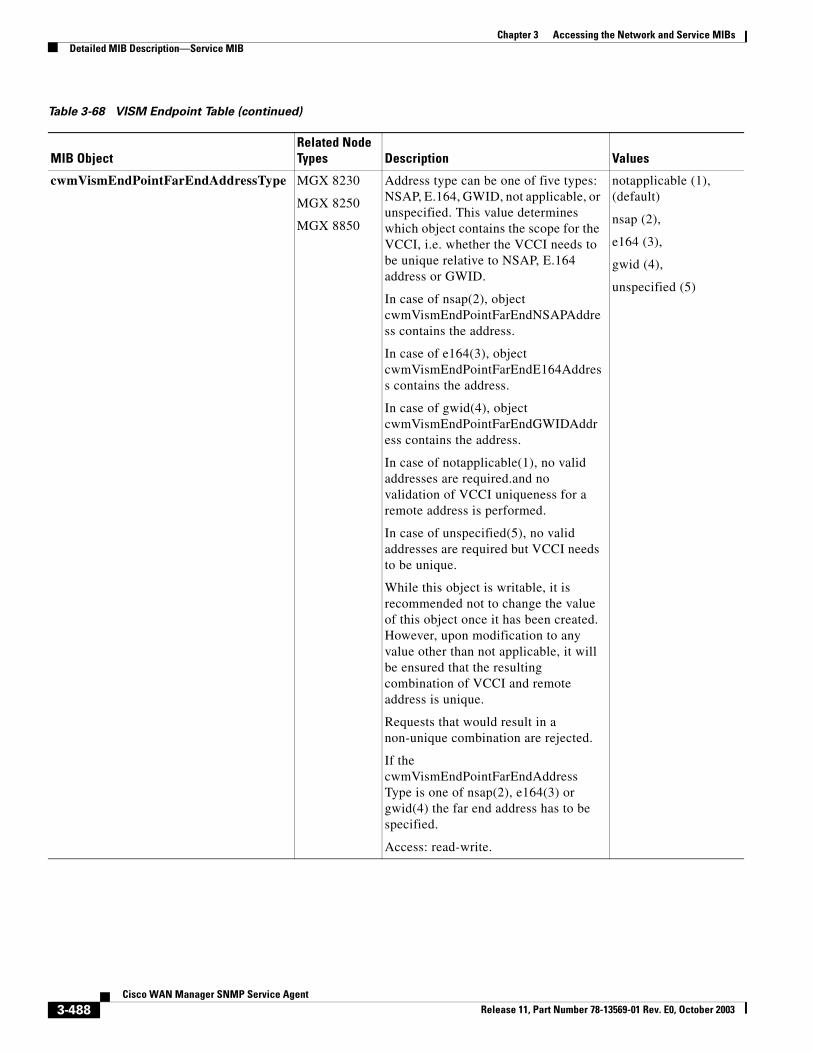
Chapter 3 Accessing the Network and Service MIBsDetailed MIB Description—Service MIB
cwmVismEndPointFarEndAddressType MGX 8230
MGX 8250
MGX 8850
Address type can be one of five types: NSAP, E.164, GWID, not applicable, or unspecified. This value determines which object contains the scope for the VCCI, i.e. whether the VCCI needs to be unique relative to NSAP, E.164 address or GWID.
In case of nsap(2), object cwmVismEndPointFarEndNSAPAddress contains the address.
In case of e164(3), object cwmVismEndPointFarEndE164Address contains the address.
In case of gwid(4), object cwmVismEndPointFarEndGWIDAddress contains the address.
In case of notapplicable(1), no valid addresses are required.and no validation of VCCI uniqueness for a remote address is performed.
In case of unspecified(5), no valid addresses are required but VCCI needs to be unique.
While this object is writable, it is recommended not to change the value of this object once it has been created. However, upon modification to any value other than not applicable, it will be ensured that the resulting combination of VCCI and remote address is unique.
Requests that would result in a non-unique combination are rejected.
If the cwmVismEndPointFarEndAddressType is one of nsap(2), e164(3) or gwid(4) the far end address has to be specified.
Access: read-write.
notapplicable (1), (default)
nsap (2),
e164 (3),
gwid (4),
unspecified (5)
Table 3-68 VISM Endpoint Table (continued)
MIB ObjectRelated Node Types Description Values
3-488Cisco WAN Manager SNMP Service Agent
Release 11, Part Number 78-13569-01 Rev. E0, October 2003
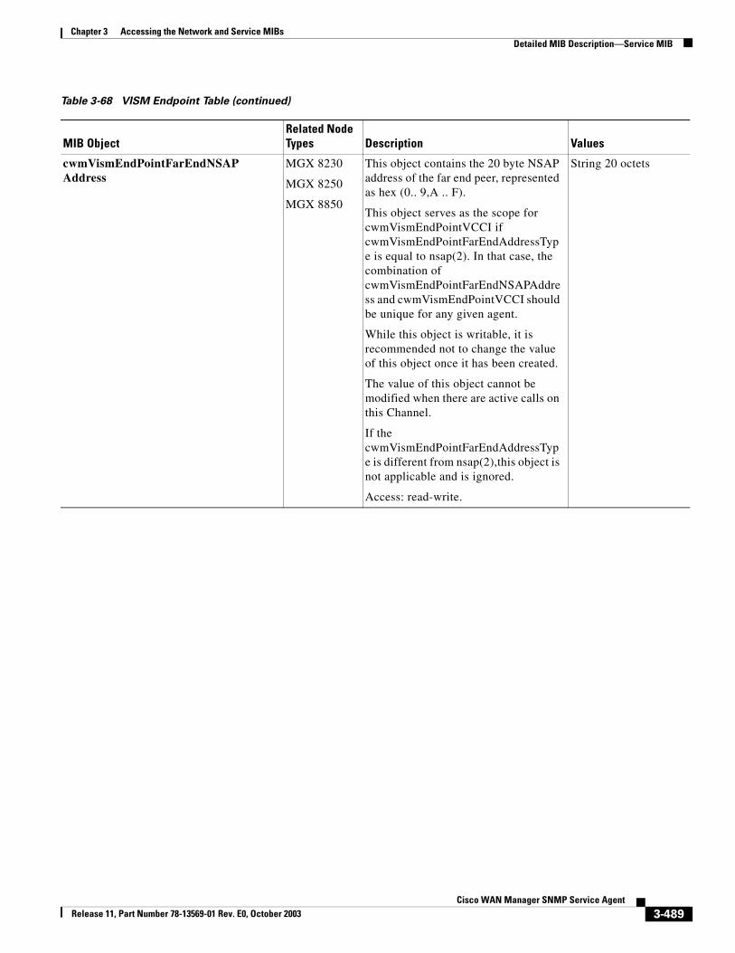
Chapter 3 Accessing the Network and Service MIBsDetailed MIB Description—Service MIB
cwmVismEndPointFarEndNSAPAddress
MGX 8230
MGX 8250
MGX 8850
This object contains the 20 byte NSAP address of the far end peer, represented as hex (0.. 9,A .. F).
This object serves as the scope for cwmVismEndPointVCCI if cwmVismEndPointFarEndAddressType is equal to nsap(2). In that case, the combination of cwmVismEndPointFarEndNSAPAddress and cwmVismEndPointVCCI should be unique for any given agent.
While this object is writable, it is recommended not to change the value of this object once it has been created.
The value of this object cannot be modified when there are active calls on this Channel.
If the cwmVismEndPointFarEndAddressType is different from nsap(2),this object is not applicable and is ignored.
Access: read-write.
String 20 octets
Table 3-68 VISM Endpoint Table (continued)
MIB ObjectRelated Node Types Description Values
3-489Cisco WAN Manager SNMP Service Agent
Release 11, Part Number 78-13569-01 Rev. E0, October 2003
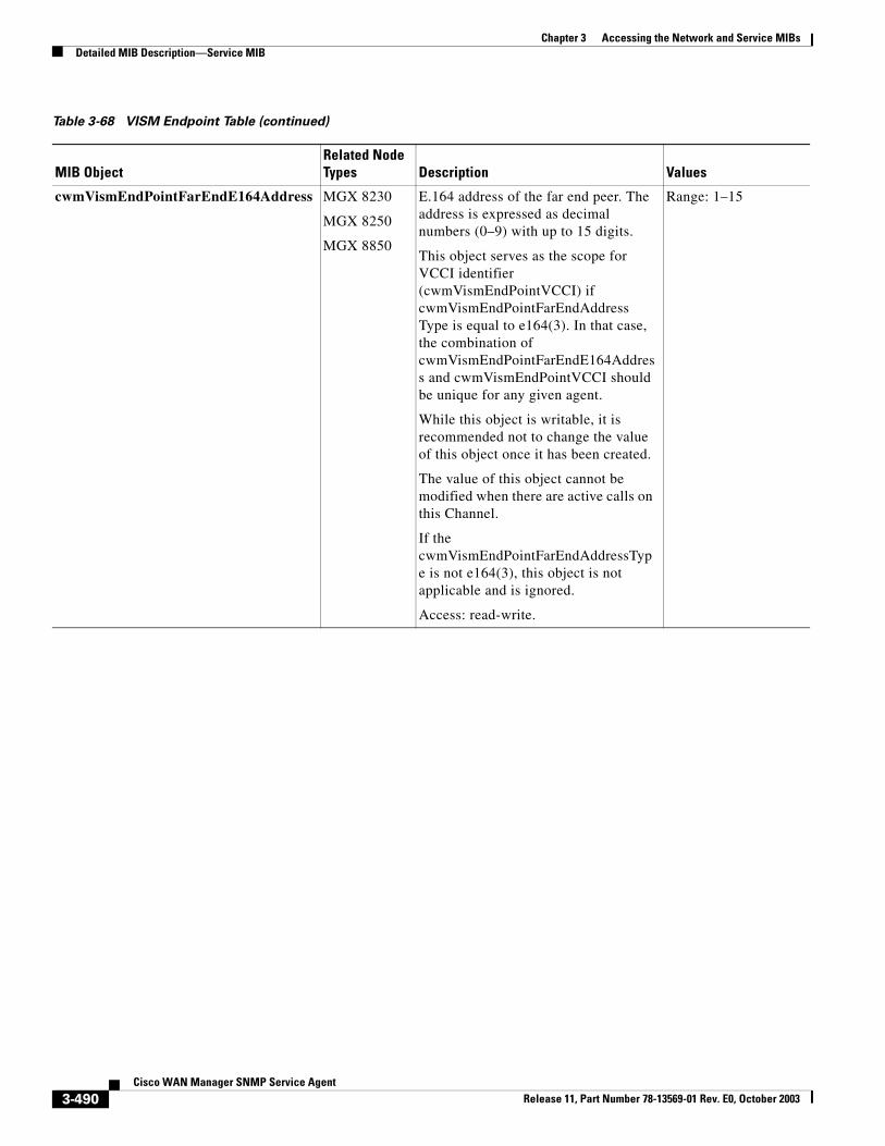
Chapter 3 Accessing the Network and Service MIBsDetailed MIB Description—Service MIB
cwmVismEndPointFarEndE164Address MGX 8230
MGX 8250
MGX 8850
E.164 address of the far end peer. The address is expressed as decimal numbers (0–9) with up to 15 digits.
This object serves as the scope for VCCI identifier (cwmVismEndPointVCCI) if cwmVismEndPointFarEndAddressType is equal to e164(3). In that case, the combination of cwmVismEndPointFarEndE164Address and cwmVismEndPointVCCI should be unique for any given agent.
While this object is writable, it is recommended not to change the value of this object once it has been created.
The value of this object cannot be modified when there are active calls on this Channel.
If the cwmVismEndPointFarEndAddressType is not e164(3), this object is not applicable and is ignored.
Access: read-write.
Range: 1–15
Table 3-68 VISM Endpoint Table (continued)
MIB ObjectRelated Node Types Description Values
3-490Cisco WAN Manager SNMP Service Agent
Release 11, Part Number 78-13569-01 Rev. E0, October 2003
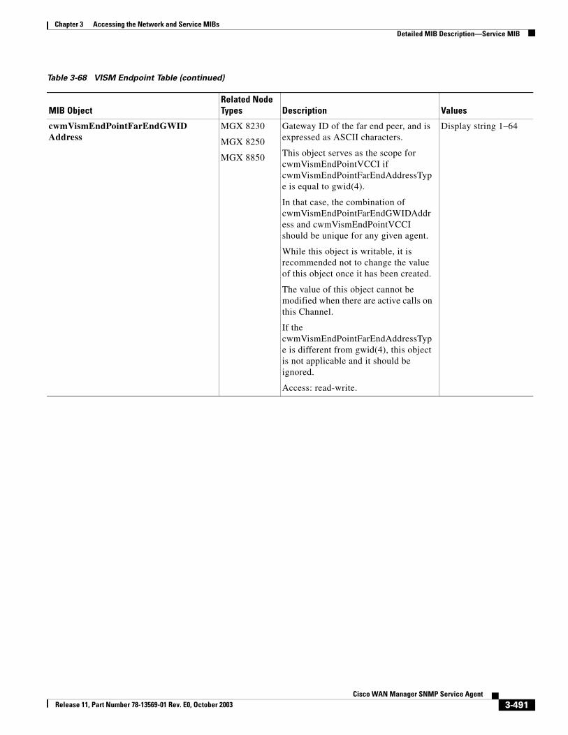
Chapter 3 Accessing the Network and Service MIBsDetailed MIB Description—Service MIB
cwmVismEndPointFarEndGWIDAddress
MGX 8230
MGX 8250
MGX 8850
Gateway ID of the far end peer, and is expressed as ASCII characters.
This object serves as the scope for cwmVismEndPointVCCI if cwmVismEndPointFarEndAddressType is equal to gwid(4).
In that case, the combination of cwmVismEndPointFarEndGWIDAddress and cwmVismEndPointVCCI should be unique for any given agent.
While this object is writable, it is recommended not to change the value of this object once it has been created.
The value of this object cannot be modified when there are active calls on this Channel.
If the cwmVismEndPointFarEndAddressType is different from gwid(4), this object is not applicable and it should be ignored.
Access: read-write.
Display string 1–64
Table 3-68 VISM Endpoint Table (continued)
MIB ObjectRelated Node Types Description Values
3-491Cisco WAN Manager SNMP Service Agent
Release 11, Part Number 78-13569-01 Rev. E0, October 2003
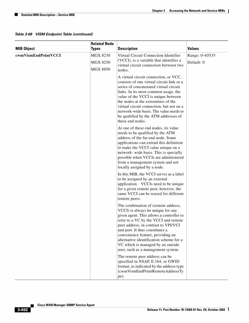
Chapter 3 Accessing the Network and Service MIBsDetailed MIB Description—Service MIB
cwmVismEndPointVCCI MGX 8230
MGX 8250
MGX 8850
Virtual Circuit Connection Identifier (VCCI), is a variable that identifies a virtual circuit connection between two nodes.
A virtual circuit connection, or VCC, consists of one virtual circuit link or a series of concatenated virtual circuit links. In its most common usage, the value of the VCCI is unique between the nodes at the extremities of the virtual circuit connection, but not on a network-wide basis. The value needs to be qualified by the ATM addresses of these end nodes.
At one of these end nodes, its value needs to be qualified by the ATM address of the far-end node. Some applications can extend this definition to make the VCCI value unique on a network- wide basis. This is specially possible when VCCIs are administered from a management system and not locally assigned by a node.
In this MIB, the VCCI serves as a label to be assigned by an external application. VCCIs need to be unique for a given remote peer, however, the same VCCI can be reused for different remote peers.
The combination of (remote address, VCCI) is always be unique for any given agent. This allows a controller to refer to a VC by the VCCI and remote peer address, in contrast to VPI/VCI and port. It thus constitutes a convenience feature, providing an alternative identification scheme for a VC which is managed by an outside user, such as a management system.
The remote peer address can be specified in NSAP, E.164, or GWID format, as indicated by the address type (cwmVismEndPointRemoteAddressType).
Range: 0–65535
Default: 0
Table 3-68 VISM Endpoint Table (continued)
MIB ObjectRelated Node Types Description Values
3-492Cisco WAN Manager SNMP Service Agent
Release 11, Part Number 78-13569-01 Rev. E0, October 2003
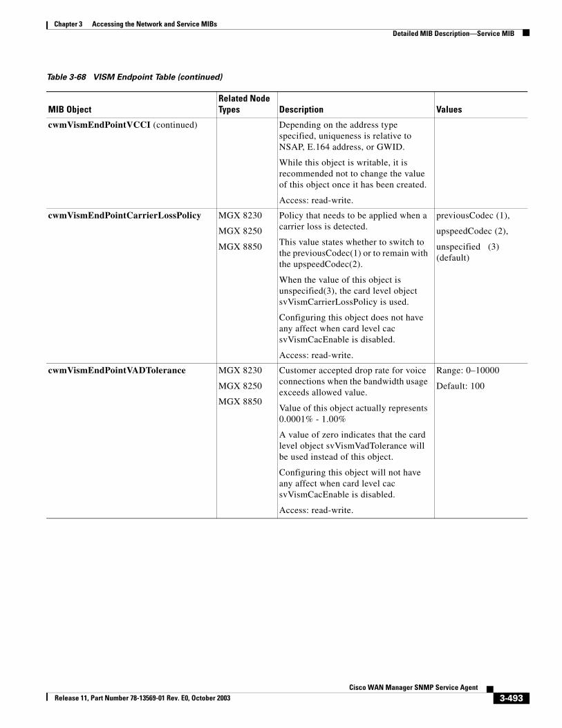
Chapter 3 Accessing the Network and Service MIBsDetailed MIB Description—Service MIB
cwmVismEndPointVCCI (continued) Depending on the address type specified, uniqueness is relative to NSAP, E.164 address, or GWID.
While this object is writable, it is recommended not to change the value of this object once it has been created.
Access: read-write.
cwmVismEndPointCarrierLossPolicy MGX 8230
MGX 8250
MGX 8850
Policy that needs to be applied when a carrier loss is detected.
This value states whether to switch to the previousCodec(1) or to remain with the upspeedCodec(2).
When the value of this object is unspecified(3), the card level object svVismCarrierLossPolicy is used.
Configuring this object does not have any affect when card level cac svVismCacEnable is disabled.
Access: read-write.
previousCodec (1),
upspeedCodec (2),
unspecified (3) (default)
cwmVismEndPointVADTolerance MGX 8230
MGX 8250
MGX 8850
Customer accepted drop rate for voice connections when the bandwidth usage exceeds allowed value.
Value of this object actually represents 0.0001% - 1.00%
A value of zero indicates that the card level object svVismVadTolerance will be used instead of this object.
Configuring this object will not have any affect when card level cac svVismCacEnable is disabled.
Access: read-write.
Range: 0–10000
Default: 100
Table 3-68 VISM Endpoint Table (continued)
MIB ObjectRelated Node Types Description Values
3-493Cisco WAN Manager SNMP Service Agent
Release 11, Part Number 78-13569-01 Rev. E0, October 2003
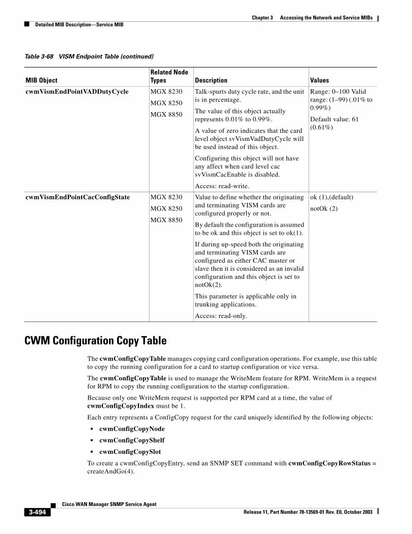
Chapter 3 Accessing the Network and Service MIBsDetailed MIB Description—Service MIB
CWM Configuration Copy TableThe cwmConfigCopyTable manages copying card configuration operations. For example, use this table to copy the running configuration for a card to startup configuration or vice versa.
The cwmConfigCopyTable is used to manage the WriteMem feature for RPM. WriteMem is a request for RPM to copy the running configuration to the startup configuration.
Because only one WriteMem request is supported per RPM card at a time, the value of cwmConfigCopyIndex must be 1.
Each entry represents a ConfigCopy request for the card uniquely identified by the following objects:
• cwmConfigCopyNode
• cwmConfigCopyShelf
• cwmConfigCopySlot
To create a cwmConfigCopyEntry, send an SNMP SET command with cwmConfigCopyRowStatus = createAndGo(4).
cwmVismEndPointVADDutyCycle MGX 8230
MGX 8250
MGX 8850
Talk-spurts duty cycle rate, and the unit is in percentage.
The value of this object actually represents 0.01% to 0.99%.
A value of zero indicates that the card level object svVismVadDutyCycle will be used instead of this object.
Configuring this object will not have any affect when card level cac svVismCacEnable is disabled.
Access: read-write.
Range: 0–100 Valid range: (1–99) (.01% to 0.99%)
Default value: 61 (0.61%)
cwmVismEndPointCacConfigState MGX 8230
MGX 8250
MGX 8850
Value to define whether the originating and terminating VISM cards are configured properly or not.
By default the configuration is assumed to be ok and this object is set to ok(1).
If during up-speed both the originating and terminating VISM cards are configured as either CAC master or slave then it is considered as an invalid configuration and this object is set to notOk(2).
This parameter is applicable only in trunking applications.
Access: read-only.
ok (1),(default)
notOk (2)
Table 3-68 VISM Endpoint Table (continued)
MIB ObjectRelated Node Types Description Values
3-494Cisco WAN Manager SNMP Service Agent
Release 11, Part Number 78-13569-01 Rev. E0, October 2003
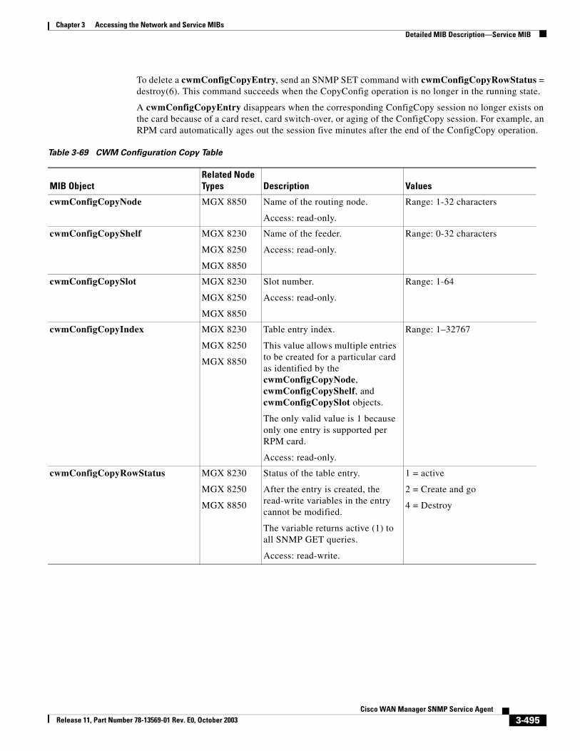
Chapter 3 Accessing the Network and Service MIBsDetailed MIB Description—Service MIB
To delete a cwmConfigCopyEntry, send an SNMP SET command with cwmConfigCopyRowStatus = destroy(6). This command succeeds when the CopyConfig operation is no longer in the running state.
A cwmConfigCopyEntry disappears when the corresponding ConfigCopy session no longer exists on the card because of a card reset, card switch-over, or aging of the ConfigCopy session. For example, an RPM card automatically ages out the session five minutes after the end of the ConfigCopy operation.
Table 3-69 CWM Configuration Copy Table
MIB ObjectRelated Node Types Description Values
cwmConfigCopyNode MGX 8850 Name of the routing node.
Access: read-only.
Range: 1-32 characters
cwmConfigCopyShelf MGX 8230
MGX 8250
MGX 8850
Name of the feeder.
Access: read-only.
Range: 0-32 characters
cwmConfigCopySlot MGX 8230
MGX 8250
MGX 8850
Slot number.
Access: read-only.
Range: 1-64
cwmConfigCopyIndex MGX 8230
MGX 8250
MGX 8850
Table entry index.
This value allows multiple entries to be created for a particular card as identified by the cwmConfigCopyNode, cwmConfigCopyShelf, and cwmConfigCopySlot objects.
The only valid value is 1 because only one entry is supported per RPM card.
Access: read-only.
Range: 1–32767
cwmConfigCopyRowStatus MGX 8230
MGX 8250
MGX 8850
Status of the table entry.
After the entry is created, the read-write variables in the entry cannot be modified.
The variable returns active (1) to all SNMP GET queries.
Access: read-write.
1 = active
2 = Create and go
4 = Destroy
3-495Cisco WAN Manager SNMP Service Agent
Release 11, Part Number 78-13569-01 Rev. E0, October 2003
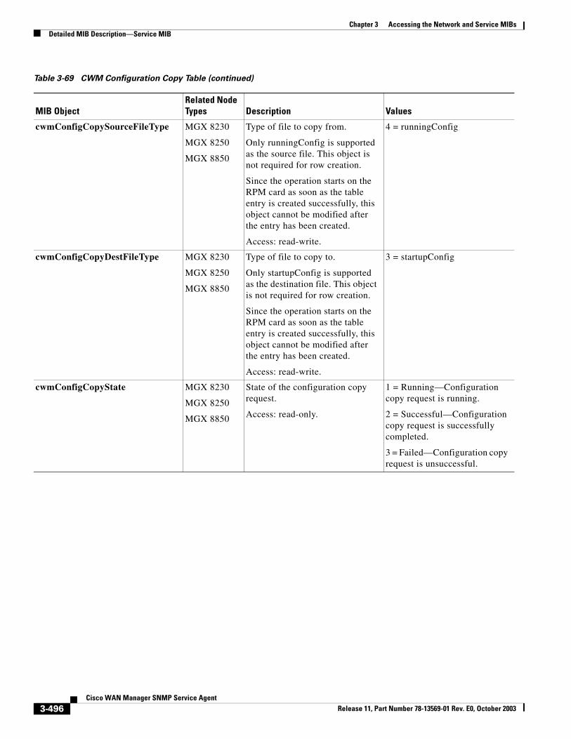
Chapter 3 Accessing the Network and Service MIBsDetailed MIB Description—Service MIB
cwmConfigCopySourceFileType MGX 8230
MGX 8250
MGX 8850
Type of file to copy from.
Only runningConfig is supported as the source file. This object is not required for row creation.
Since the operation starts on the RPM card as soon as the table entry is created successfully, this object cannot be modified after the entry has been created.
Access: read-write.
4 = runningConfig
cwmConfigCopyDestFileType MGX 8230
MGX 8250
MGX 8850
Type of file to copy to.
Only startupConfig is supported as the destination file. This object is not required for row creation.
Since the operation starts on the RPM card as soon as the table entry is created successfully, this object cannot be modified after the entry has been created.
Access: read-write.
3 = startupConfig
cwmConfigCopyState MGX 8230
MGX 8250
MGX 8850
State of the configuration copy request.
Access: read-only.
1 = Running—Configuration copy request is running.
2 = Successful—Configuration copy request is successfully completed.
3 = Failed—Configuration copy request is unsuccessful.
Table 3-69 CWM Configuration Copy Table (continued)
MIB ObjectRelated Node Types Description Values
3-496Cisco WAN Manager SNMP Service Agent
Release 11, Part Number 78-13569-01 Rev. E0, October 2003
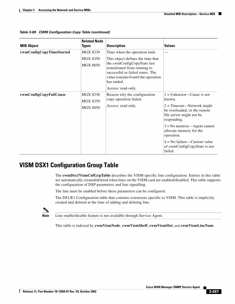
Chapter 3 Accessing the Network and Service MIBsDetailed MIB Description—Service MIB
VISM DSX1 Configuration Group TableThe cwmDsx1VismCnfGrpTable describes the VISM specific line configuration. Entries in this table are automatically created/deleted when lines on the VISM card are enabled/disabled. This table supports the configuration of DSP parameters and line signalling.
The line must be enabled before these parameters can be configured.
The DS1/E1 Configuration table that contains extensions specific to VISM. This table is implicitly created and deleted at the time of adding and deleting line.
Note Line enable/disable feature is not available through Service Agent.
This table is indexed by cwmVismNode, cwmVismShelf, cwmVismSlot, and cwmVismLineNum.
cwmConfigCopyTimeStarted MGX 8230
MGX 8250
MGX 8850
Time when the operation ends.
This object defines the time that the cwmConfigCopyState last transitioned from running to successful or failed states. The value remains 0 until the operation has ended.
Access: read-only.
—
cwmConfigCopyFailCause MGX 8230
MGX 8250
MGX 8850
Reason why the configuration copy operation failed.
Access: read-only.
1 = Unknown—Cause is not known.
2 = Timeout—Network might be overloaded, or the remote file server might not be responding.
3 = No memory—Agent cannot allocate memory for the operation.
4 = No failure—Current value of cwmConfigCopyState is not failed.
Table 3-69 CWM Configuration Copy Table (continued)
MIB ObjectRelated Node Types Description Values
3-497Cisco WAN Manager SNMP Service Agent
Release 11, Part Number 78-13569-01 Rev. E0, October 2003
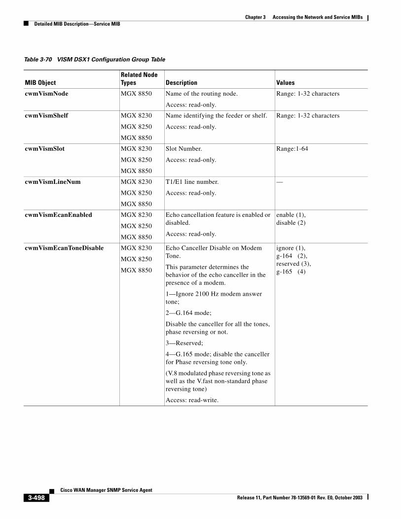
Chapter 3 Accessing the Network and Service MIBsDetailed MIB Description—Service MIB
Table 3-70 VISM DSX1 Configuration Group Table
MIB ObjectRelated Node Types Description Values
cwmVismNode MGX 8850 Name of the routing node.
Access: read-only.
Range: 1-32 characters
cwmVismShelf MGX 8230
MGX 8250
MGX 8850
Name identifying the feeder or shelf.
Access: read-only.
Range: 1-32 characters
cwmVismSlot MGX 8230
MGX 8250
MGX 8850
Slot Number.
Access: read-only.
Range:1-64
cwmVismLineNum MGX 8230
MGX 8250
MGX 8850
T1/E1 line number.
Access: read-only.
—
cwmVismEcanEnabled MGX 8230
MGX 8250
MGX 8850
Echo cancellation feature is enabled or disabled.
Access: read-only.
enable (1),disable (2)
cwmVismEcanToneDisable MGX 8230
MGX 8250
MGX 8850
Echo Canceller Disable on Modem Tone.
This parameter determines the behavior of the echo canceller in the presence of a modem.
1—Ignore 2100 Hz modem answer tone;
2—G.164 mode;
Disable the canceller for all the tones, phase reversing or not.
3—Reserved;
4—G.165 mode; disable the canceller for Phase reversing tone only.
(V.8 modulated phase reversing tone as well as the V.fast non-standard phase reversing tone)
Access: read-write.
ignore (1), g-164 (2),reserved (3),g-165 (4)
3-498Cisco WAN Manager SNMP Service Agent
Release 11, Part Number 78-13569-01 Rev. E0, October 2003
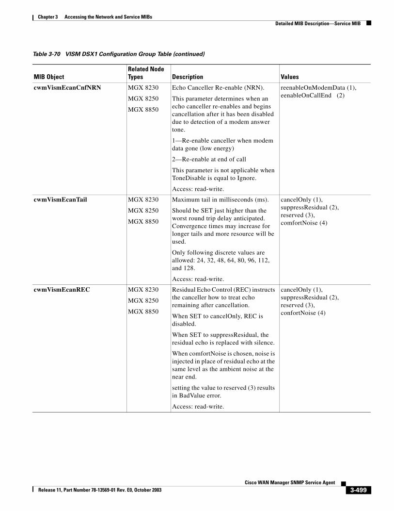
Chapter 3 Accessing the Network and Service MIBsDetailed MIB Description—Service MIB
cwmVismEcanCnfNRN MGX 8230
MGX 8250
MGX 8850
Echo Canceller Re-enable (NRN).
This parameter determines when an echo canceller re-enables and begins cancellation after it has been disabled due to detection of a modem answer tone.
1—Re-enable canceller when modem data gone (low energy)
2—Re-enable at end of call
This parameter is not applicable when ToneDisable is equal to Ignore.
Access: read-write.
reenableOnModemData (1), eenableOnCallEnd (2)
cwmVismEcanTail MGX 8230
MGX 8250
MGX 8850
Maximum tail in milliseconds (ms).
Should be SET just higher than the worst round trip delay anticipated. Convergence times may increase for longer tails and more resource will be used.
Only following discrete values are allowed: 24, 32, 48, 64, 80, 96, 112, and 128.
Access: read-write.
cancelOnly (1), suppressResidual (2), reserved (3), comfortNoise (4)
cwmVismEcanREC MGX 8230
MGX 8250
MGX 8850
Residual Echo Control (REC) instructs the canceller how to treat echo remaining after cancellation.
When SET to cancelOnly, REC is disabled.
When SET to suppressResidual, the residual echo is replaced with silence.
When comfortNoise is chosen, noise is injected in place of residual echo at the same level as the ambient noise at the near end.
setting the value to reserved (3) results in BadValue error.
Access: read-write.
cancelOnly (1), suppressResidual (2),reserved (3), confortNoise (4)
Table 3-70 VISM DSX1 Configuration Group Table (continued)
MIB ObjectRelated Node Types Description Values
3-499Cisco WAN Manager SNMP Service Agent
Release 11, Part Number 78-13569-01 Rev. E0, October 2003
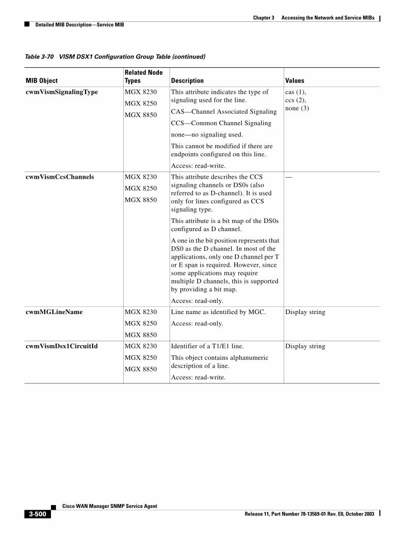
Chapter 3 Accessing the Network and Service MIBsDetailed MIB Description—Service MIB
cwmVismSignalingType MGX 8230
MGX 8250
MGX 8850
This attribute indicates the type of signaling used for the line.
CAS—Channel Associated Signaling
CCS—Common Channel Signaling
none—no signaling used.
This cannot be modified if there are endpoints configured on this line.
Access: read-write.
cas (1),ccs (2),none (3)
cwmVismCcsChannels MGX 8230
MGX 8250
MGX 8850
This attribute describes the CCS signaling channels or DS0s (also referred to as D-channel). It is used only for lines configured as CCS signaling type.
This attribute is a bit map of the DS0s configured as D channel.
A one in the bit position represents that DS0 as the D channel. In most of the applications, only one D channel per T or E span is required. However, since some applications may require multiple D channels, this is supported by providing a bit map.
Access: read-only.
—
cwmMGLineName MGX 8230
MGX 8250
MGX 8850
Line name as identified by MGC.
Access: read-only.
Display string
cwmVismDsx1CircuitId MGX 8230
MGX 8250
MGX 8850
Identifier of a T1/E1 line.
This object contains alphanumeric description of a line.
Access: read-write.
Display string
Table 3-70 VISM DSX1 Configuration Group Table (continued)
MIB ObjectRelated Node Types Description Values
3-500Cisco WAN Manager SNMP Service Agent
Release 11, Part Number 78-13569-01 Rev. E0, October 2003
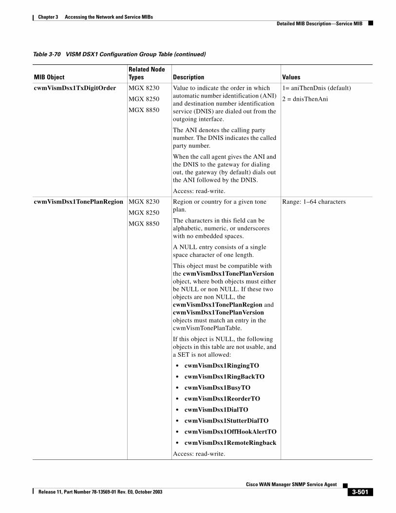
Chapter 3 Accessing the Network and Service MIBsDetailed MIB Description—Service MIB
cwmVismDsx1TxDigitOrder MGX 8230
MGX 8250
MGX 8850
Value to indicate the order in which automatic number identification (ANI) and destination number identification service (DNIS) are dialed out from the outgoing interface.
The ANI denotes the calling party number. The DNIS indicates the called party number.
When the call agent gives the ANI and the DNIS to the gateway for dialing out, the gateway (by default) dials out the ANI followed by the DNIS.
Access: read-write.
1= aniThenDnis (default)
2 = dnisThenAni
cwmVismDsx1TonePlanRegion MGX 8230
MGX 8250
MGX 8850
Region or country for a given tone plan.
The characters in this field can be alphabetic, numeric, or underscores with no embedded spaces.
A NULL entry consists of a single space character of one length.
This object must be compatible with the cwmVismDsx1TonePlanVersion object, where both objects must either be NULL or non NULL. If these two objects are non NULL, the cwmVismDsx1TonePlanRegion and cwmVismDsx1TonePlanVersion objects must match an entry in the cwmVismTonePlanTable.
If this object is NULL, the following objects in this table are not usable, and a SET is not allowed:
• cwmVismDsx1RingingTO
• cwmVismDsx1RingBackTO
• cwmVismDsx1BusyTO
• cwmVismDsx1ReorderTO
• cwmVismDsx1DialTO
• cwmVismDsx1StutterDialTO
• cwmVismDsx1OffHookAlertTO
• cwmVismDsx1RemoteRingback
Access: read-write.
Range: 1–64 characters
Table 3-70 VISM DSX1 Configuration Group Table (continued)
MIB ObjectRelated Node Types Description Values
3-501Cisco WAN Manager SNMP Service Agent
Release 11, Part Number 78-13569-01 Rev. E0, October 2003
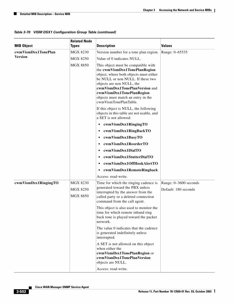
Chapter 3 Accessing the Network and Service MIBsDetailed MIB Description—Service MIB
cwmVismDsx1TonePlanVersion
MGX 8230
MGX 8250
MGX 8850
Version number for a tone plan region.
Value of 0 indicates NULL.
This object must be compatible with the cwmVismDsx1TonePlanRegion object, where both objects must either be NULL or non NULL. If these two objects are non NULL, the cwmVismDsx1TonePlanVersion and cwmVismDsx1TonePlanRegion objects must match an entry in the cwmVismTonePlanTable.
If this object is NULL, the following objects in this table are not usable, and a SET is not allowed:
• cwmVismDsx1RingingTO
• cwmVismDsx1RingBackTO
• cwmVismDsx1BusyTO
• cwmVismDsx1ReorderTO
• cwmVismDsx1DialTO
• cwmVismDsx1StutterDialTO
• cwmVismDsx1OffHookAlertTO
• cwmVismDsx1RemoteRingback
Access: read-write.
Range: 0–65535
cwmVismDsx1RingingTO MGX 8230
MGX 8250
MGX 8850
Time for which the ringing cadence is generated toward the PBX unless interrupted by the answer from the called party or a deleted connection command from the call agent.
This object is also used to monitor the time for which remote inband ring back tone is played toward the packet network.
The value 0 indicates that the cadence is generated indefinitely unless interrupted.
A SET is not allowed on this object when either the cwmVismDsx1TonePlanRegion or cwmVismDsx1TonePlanVersion objects are NULL.
Access: read-write.
Range: 0–3600 seconds
Default: 180 seconds
Table 3-70 VISM DSX1 Configuration Group Table (continued)
MIB ObjectRelated Node Types Description Values
3-502Cisco WAN Manager SNMP Service Agent
Release 11, Part Number 78-13569-01 Rev. E0, October 2003
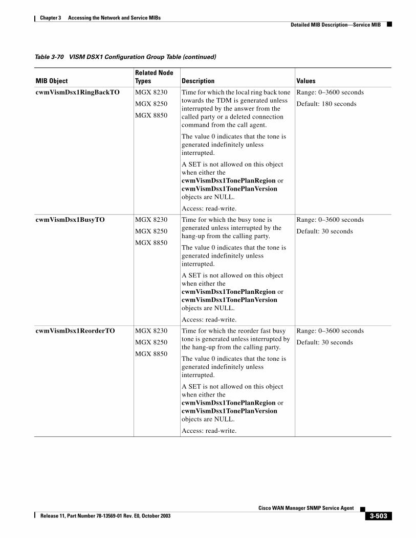
Chapter 3 Accessing the Network and Service MIBsDetailed MIB Description—Service MIB
cwmVismDsx1RingBackTO MGX 8230
MGX 8250
MGX 8850
Time for which the local ring back tone towards the TDM is generated unless interrupted by the answer from the called party or a deleted connection command from the call agent.
The value 0 indicates that the tone is generated indefinitely unless interrupted.
A SET is not allowed on this object when either the cwmVismDsx1TonePlanRegion or cwmVismDsx1TonePlanVersion objects are NULL.
Access: read-write.
Range: 0–3600 seconds
Default: 180 seconds
cwmVismDsx1BusyTO MGX 8230
MGX 8250
MGX 8850
Time for which the busy tone is generated unless interrupted by the hang-up from the calling party.
The value 0 indicates that the tone is generated indefinitely unless interrupted.
A SET is not allowed on this object when either the cwmVismDsx1TonePlanRegion or cwmVismDsx1TonePlanVersion objects are NULL.
Access: read-write.
Range: 0–3600 seconds
Default: 30 seconds
cwmVismDsx1ReorderTO MGX 8230
MGX 8250
MGX 8850
Time for which the reorder fast busy tone is generated unless interrupted by the hang-up from the calling party.
The value 0 indicates that the tone is generated indefinitely unless interrupted.
A SET is not allowed on this object when either the cwmVismDsx1TonePlanRegion or cwmVismDsx1TonePlanVersion objects are NULL.
Access: read-write.
Range: 0–3600 seconds
Default: 30 seconds
Table 3-70 VISM DSX1 Configuration Group Table (continued)
MIB ObjectRelated Node Types Description Values
3-503Cisco WAN Manager SNMP Service Agent
Release 11, Part Number 78-13569-01 Rev. E0, October 2003
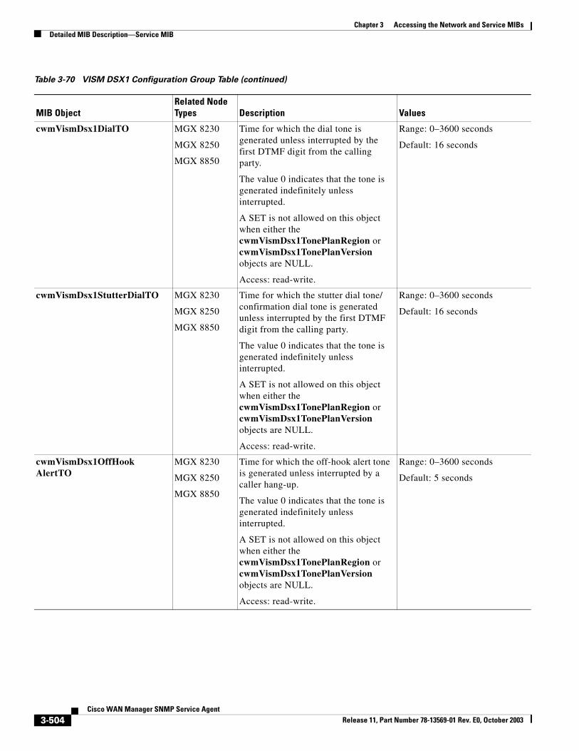
Chapter 3 Accessing the Network and Service MIBsDetailed MIB Description—Service MIB
cwmVismDsx1DialTO MGX 8230
MGX 8250
MGX 8850
Time for which the dial tone is generated unless interrupted by the first DTMF digit from the calling party.
The value 0 indicates that the tone is generated indefinitely unless interrupted.
A SET is not allowed on this object when either the cwmVismDsx1TonePlanRegion or cwmVismDsx1TonePlanVersion objects are NULL.
Access: read-write.
Range: 0–3600 seconds
Default: 16 seconds
cwmVismDsx1StutterDialTO MGX 8230
MGX 8250
MGX 8850
Time for which the stutter dial tone/ confirmation dial tone is generated unless interrupted by the first DTMF digit from the calling party.
The value 0 indicates that the tone is generated indefinitely unless interrupted.
A SET is not allowed on this object when either the cwmVismDsx1TonePlanRegion or cwmVismDsx1TonePlanVersion objects are NULL.
Access: read-write.
Range: 0–3600 seconds
Default: 16 seconds
cwmVismDsx1OffHookAlertTO
MGX 8230
MGX 8250
MGX 8850
Time for which the off-hook alert tone is generated unless interrupted by a caller hang-up.
The value 0 indicates that the tone is generated indefinitely unless interrupted.
A SET is not allowed on this object when either the cwmVismDsx1TonePlanRegion or cwmVismDsx1TonePlanVersion objects are NULL.
Access: read-write.
Range: 0–3600 seconds
Default: 5 seconds
Table 3-70 VISM DSX1 Configuration Group Table (continued)
MIB ObjectRelated Node Types Description Values
3-504Cisco WAN Manager SNMP Service Agent
Release 11, Part Number 78-13569-01 Rev. E0, October 2003
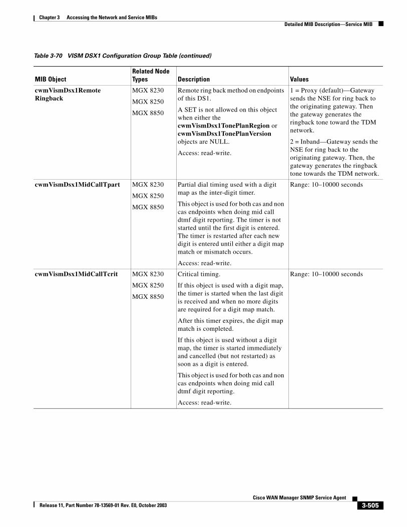
Chapter 3 Accessing the Network and Service MIBsDetailed MIB Description—Service MIB
cwmVismDsx1RemoteRingback
MGX 8230
MGX 8250
MGX 8850
Remote ring back method on endpoints of this DS1.
A SET is not allowed on this object when either the cwmVismDsx1TonePlanRegion or cwmVismDsx1TonePlanVersion objects are NULL.
Access: read-write.
1 = Proxy (default)—Gateway sends the NSE for ring back to the originating gateway. Then the gateway generates the ringback tone toward the TDM network.
2 = Inband—Gateway sends the NSE for ring back to the originating gateway. Then, the gateway generates the ringback tone towards the TDM network.
cwmVismDsx1MidCallTpart MGX 8230
MGX 8250
MGX 8850
Partial dial timing used with a digit map as the inter-digit timer.
This object is used for both cas and non cas endpoints when doing mid call dtmf digit reporting. The timer is not started until the first digit is entered. The timer is restarted after each new digit is entered until either a digit map match or mismatch occurs.
Access: read-write.
Range: 10–10000 seconds
cwmVismDsx1MidCallTcrit MGX 8230
MGX 8250
MGX 8850
Critical timing.
If this object is used with a digit map, the timer is started when the last digit is received and when no more digits are required for a digit map match.
After this timer expires, the digit map match is completed.
If this object is used without a digit map, the timer is started immediately and cancelled (but not restarted) as soon as a digit is entered.
This object is used for both cas and non cas endpoints when doing mid call dtmf digit reporting.
Access: read-write.
Range: 10–10000 seconds
Table 3-70 VISM DSX1 Configuration Group Table (continued)
MIB ObjectRelated Node Types Description Values
3-505Cisco WAN Manager SNMP Service Agent
Release 11, Part Number 78-13569-01 Rev. E0, October 2003
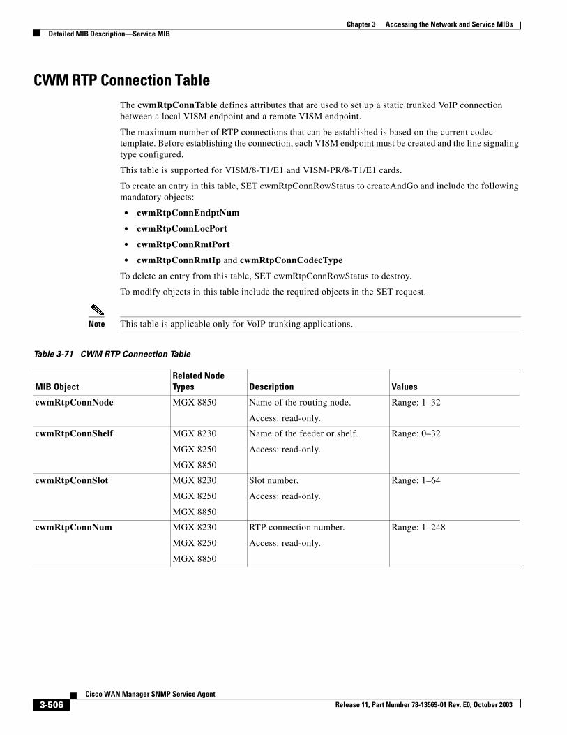
Chapter 3 Accessing the Network and Service MIBsDetailed MIB Description—Service MIB
CWM RTP Connection TableThe cwmRtpConnTable defines attributes that are used to set up a static trunked VoIP connection between a local VISM endpoint and a remote VISM endpoint.
The maximum number of RTP connections that can be established is based on the current codec template. Before establishing the connection, each VISM endpoint must be created and the line signaling type configured.
This table is supported for VISM/8-T1/E1 and VISM-PR/8-T1/E1 cards.
To create an entry in this table, SET cwmRtpConnRowStatus to createAndGo and include the following mandatory objects:
• cwmRtpConnEndptNum
• cwmRtpConnLocPort
• cwmRtpConnRmtPort
• cwmRtpConnRmtIp and cwmRtpConnCodecType
To delete an entry from this table, SET cwmRtpConnRowStatus to destroy.
To modify objects in this table include the required objects in the SET request.
Note This table is applicable only for VoIP trunking applications.
Table 3-71 CWM RTP Connection Table
MIB ObjectRelated Node Types Description Values
cwmRtpConnNode MGX 8850 Name of the routing node.
Access: read-only.
Range: 1–32
cwmRtpConnShelf MGX 8230
MGX 8250
MGX 8850
Name of the feeder or shelf.
Access: read-only.
Range: 0–32
cwmRtpConnSlot MGX 8230
MGX 8250
MGX 8850
Slot number.
Access: read-only.
Range: 1–64
cwmRtpConnNum MGX 8230
MGX 8250
MGX 8850
RTP connection number.
Access: read-only.
Range: 1–248
3-506Cisco WAN Manager SNMP Service Agent
Release 11, Part Number 78-13569-01 Rev. E0, October 2003
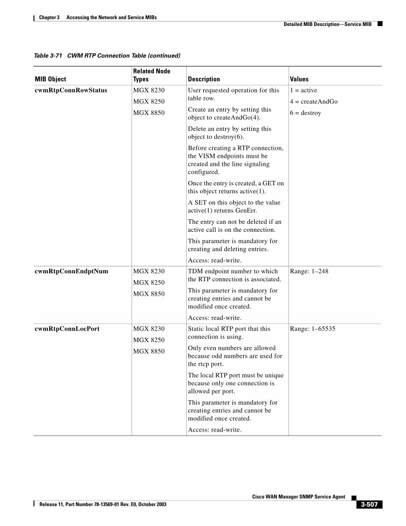
Chapter 3 Accessing the Network and Service MIBsDetailed MIB Description—Service MIB
cwmRtpConnRowStatus MGX 8230
MGX 8250
MGX 8850
User requested operation for this table row.
Create an entry by setting this object to createAndGo(4).
Delete an entry by setting this object to destroy(6).
Before creating a RTP connection, the VISM endpoints must be created and the line signaling configured.
Once the entry is created, a GET on this object returns active(1).
A SET on this object to the value active(1) returns GenErr.
The entry can not be deleted if an active call is on the connection.
This parameter is mandatory for creating and deleting entries.
Access: read-write.
1 = active
4 = createAndGo
6 = destroy
cwmRtpConnEndptNum MGX 8230
MGX 8250
MGX 8850
TDM endpoint number to which the RTP connection is associated.
This parameter is mandatory for creating entries and cannot be modified once created.
Access: read-write.
Range: 1–248
cwmRtpConnLocPort MGX 8230
MGX 8250
MGX 8850
Static local RTP port that this connection is using.
Only even numbers are allowed because odd numbers are used for the rtcp port.
The local RTP port must be unique because only one connection is allowed per port.
This parameter is mandatory for creating entries and cannot be modified once created.
Access: read-write.
Range: 1–65535
Table 3-71 CWM RTP Connection Table (continued)
MIB ObjectRelated Node Types Description Values
3-507Cisco WAN Manager SNMP Service Agent
Release 11, Part Number 78-13569-01 Rev. E0, October 2003
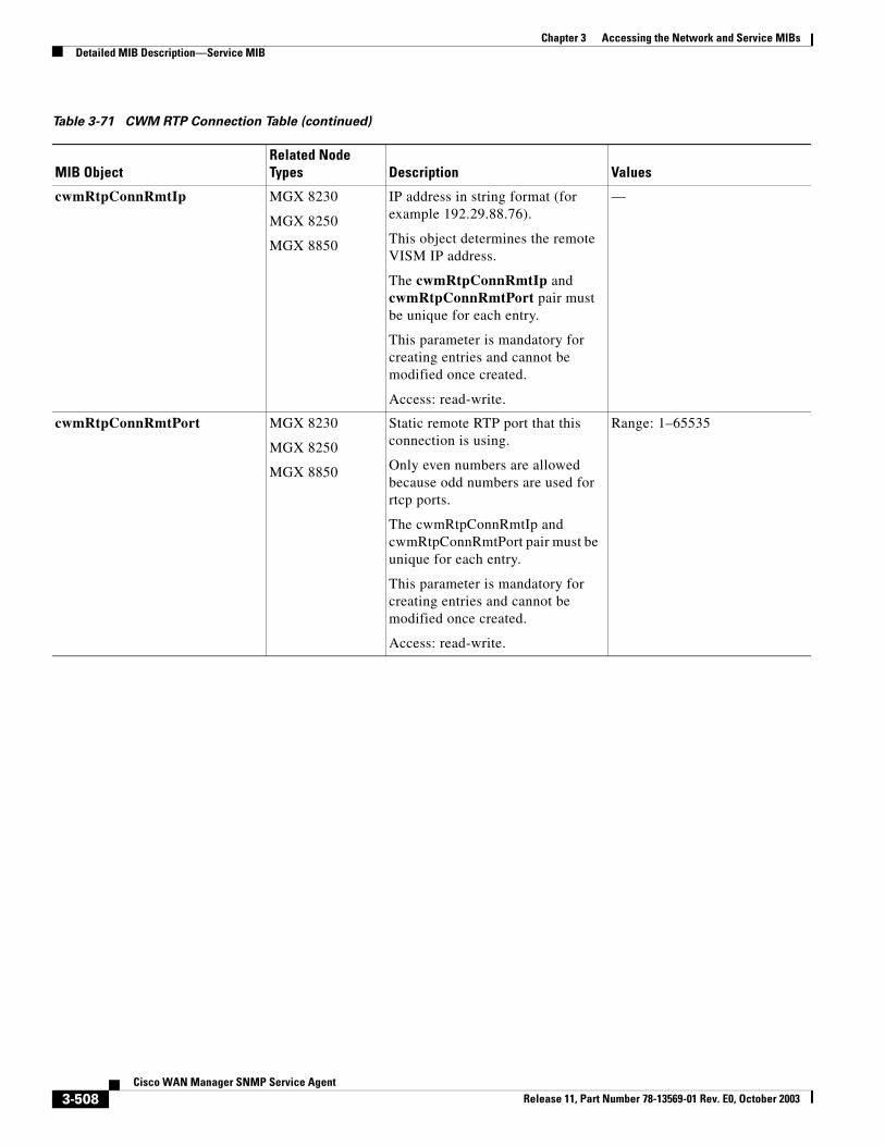
Chapter 3 Accessing the Network and Service MIBsDetailed MIB Description—Service MIB
cwmRtpConnRmtIp MGX 8230
MGX 8250
MGX 8850
IP address in string format (for example 192.29.88.76).
This object determines the remote VISM IP address.
The cwmRtpConnRmtIp and cwmRtpConnRmtPort pair must be unique for each entry.
This parameter is mandatory for creating entries and cannot be modified once created.
Access: read-write.
—
cwmRtpConnRmtPort MGX 8230
MGX 8250
MGX 8850
Static remote RTP port that this connection is using.
Only even numbers are allowed because odd numbers are used for rtcp ports.
The cwmRtpConnRmtIp and cwmRtpConnRmtPort pair must be unique for each entry.
This parameter is mandatory for creating entries and cannot be modified once created.
Access: read-write.
Range: 1–65535
Table 3-71 CWM RTP Connection Table (continued)
MIB ObjectRelated Node Types Description Values
3-508Cisco WAN Manager SNMP Service Agent
Release 11, Part Number 78-13569-01 Rev. E0, October 2003
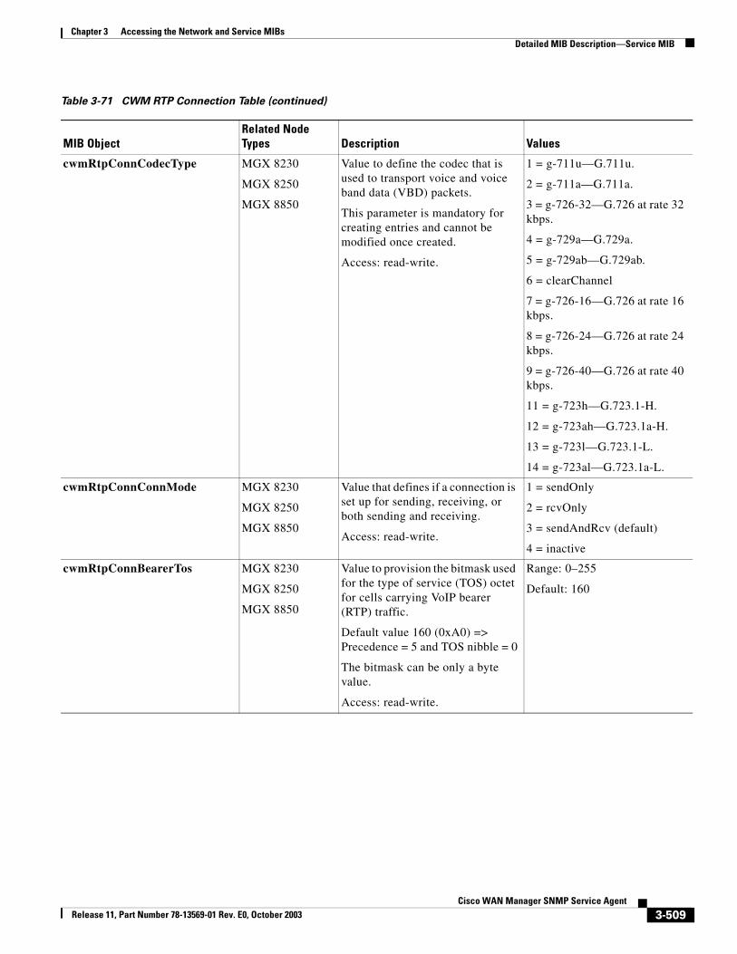
Chapter 3 Accessing the Network and Service MIBsDetailed MIB Description—Service MIB
cwmRtpConnCodecType MGX 8230
MGX 8250
MGX 8850
Value to define the codec that is used to transport voice and voice band data (VBD) packets.
This parameter is mandatory for creating entries and cannot be modified once created.
Access: read-write.
1 = g-711u—G.711u.
2 = g-711a—G.711a.
3 = g-726-32—G.726 at rate 32 kbps.
4 = g-729a—G.729a.
5 = g-729ab—G.729ab.
6 = clearChannel
7 = g-726-16—G.726 at rate 16 kbps.
8 = g-726-24—G.726 at rate 24 kbps.
9 = g-726-40—G.726 at rate 40 kbps.
11 = g-723h—G.723.1-H.
12 = g-723ah—G.723.1a-H.
13 = g-723l—G.723.1-L.
14 = g-723al—G.723.1a-L.
cwmRtpConnConnMode MGX 8230
MGX 8250
MGX 8850
Value that defines if a connection is set up for sending, receiving, or both sending and receiving.
Access: read-write.
1 = sendOnly
2 = rcvOnly
3 = sendAndRcv (default)
4 = inactive
cwmRtpConnBearerTos MGX 8230
MGX 8250
MGX 8850
Value to provision the bitmask used for the type of service (TOS) octet for cells carrying VoIP bearer (RTP) traffic.
Default value 160 (0xA0) => Precedence = 5 and TOS nibble = 0
The bitmask can be only a byte value.
Access: read-write.
Range: 0–255
Default: 160
Table 3-71 CWM RTP Connection Table (continued)
MIB ObjectRelated Node Types Description Values
3-509Cisco WAN Manager SNMP Service Agent
Release 11, Part Number 78-13569-01 Rev. E0, October 2003
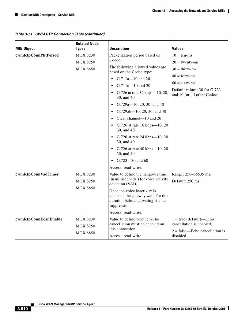
Chapter 3 Accessing the Network and Service MIBsDetailed MIB Description—Service MIB
cwmRtpConnPktPeriod MGX 8230
MGX 8250
MGX 8850
Packetization period based on Codec.
The following allowed values are based on the Codec type:
• G.711a—10 and 20
• G.711u—10 and 20
• G.726 at rate 32 kbps—10, 20, 30, and 40
• G.729a—10, 20, 30, and 40
• G.729ab—10, 20, 30, and 40
• Clear channel—10 and 20
• G.726 at rate 16 kbps—10, 20 30, and 40
• G.726 at rate 24 kbps—10, 20 30, and 40
• G.726 at rate 40 kbps—10, 20 30, and 40
• G.723—30 and 60
Access: read-write.
10 = ten-ms
20 = twenty-ms
30 = thirty-ms
40 = forty-ms
60 = sixty-ms
Default values: 30 for G.723 and 10 for all other Codecs.
cwmRtpConnVadTimer MGX 8230
MGX 8250
MGX 8850
Value to define the hangover time (in milliseconds.) for voice activity detection (VAD).
Once the voice inactivity is detected, the gateway waits for this duration before activating silence suppression.
Access: read-write.
Range: 250–65535 ms.
Default: 250 ms.
cwmRtpConnEcanEnable MGX 8230
MGX 8250
MGX 8850
Value to define whether echo cancellation must be enabled on this connection.
Access: read-write.
1 = true (default)—Echo cancellation is enabled.
2 = false—Echo cancellation is disabled.
Table 3-71 CWM RTP Connection Table (continued)
MIB ObjectRelated Node Types Description Values
3-510Cisco WAN Manager SNMP Service Agent
Release 11, Part Number 78-13569-01 Rev. E0, October 2003
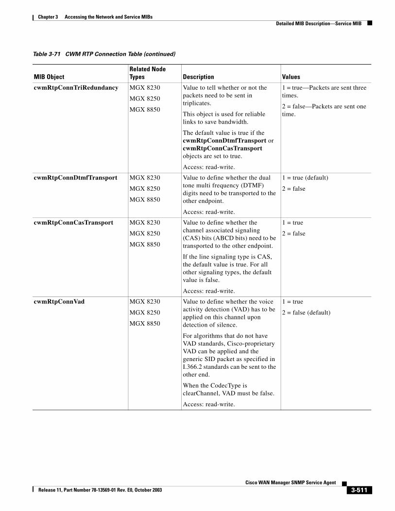
Chapter 3 Accessing the Network and Service MIBsDetailed MIB Description—Service MIB
cwmRtpConnTriRedundancy MGX 8230
MGX 8250
MGX 8850
Value to tell whether or not the packets need to be sent in triplicates.
This object is used for reliable links to save bandwidth.
The default value is true if the cwmRtpConnDtmfTransport or cwmRtpConnCasTransport objects are set to true.
Access: read-write.
1 = true—Packets are sent three times.
2 = false—Packets are sent one time.
cwmRtpConnDtmfTransport MGX 8230
MGX 8250
MGX 8850
Value to define whether the dual tone multi frequency (DTMF) digits need to be transported to the other endpoint.
Access: read-write.
1 = true (default)
2 = false
cwmRtpConnCasTransport MGX 8230
MGX 8250
MGX 8850
Value to define whether the channel associated signaling (CAS) bits (ABCD bits) need to be transported to the other endpoint.
If the line signaling type is CAS, the default value is true. For all other signaling types, the default value is false.
Access: read-write.
1 = true
2 = false
cwmRtpConnVad MGX 8230
MGX 8250
MGX 8850
Value to define whether the voice activity detection (VAD) has to be applied on this channel upon detection of silence.
For algorithms that do not have VAD standards, Cisco-proprietary VAD can be applied and the generic SID packet as specified in I.366.2 standards can be sent to the other end.
When the CodecType is clearChannel, VAD must be false.
Access: read-write.
1 = true
2 = false (default)
Table 3-71 CWM RTP Connection Table (continued)
MIB ObjectRelated Node Types Description Values
3-511Cisco WAN Manager SNMP Service Agent
Release 11, Part Number 78-13569-01 Rev. E0, October 2003
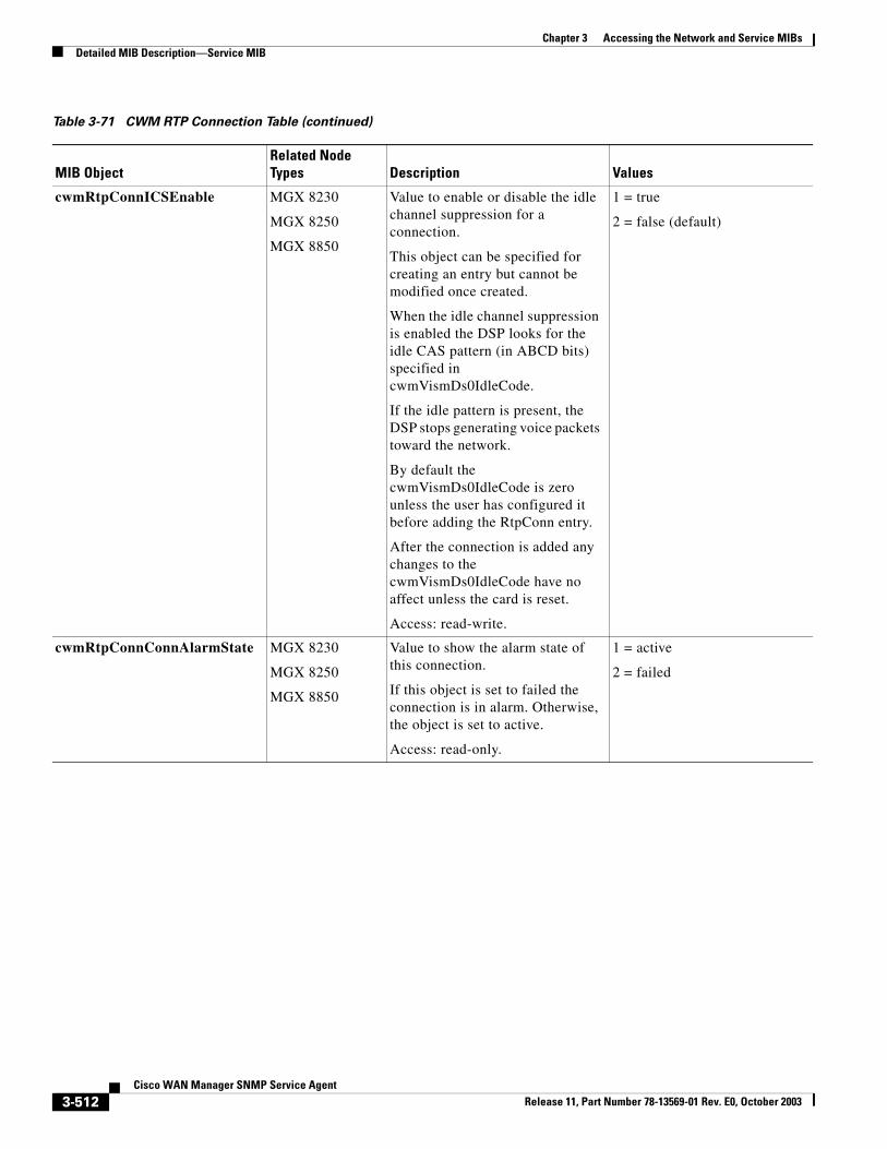
Chapter 3 Accessing the Network and Service MIBsDetailed MIB Description—Service MIB
cwmRtpConnICSEnable MGX 8230
MGX 8250
MGX 8850
Value to enable or disable the idle channel suppression for a connection.
This object can be specified for creating an entry but cannot be modified once created.
When the idle channel suppression is enabled the DSP looks for the idle CAS pattern (in ABCD bits) specified in cwmVismDs0IdleCode.
If the idle pattern is present, the DSP stops generating voice packets toward the network.
By default the cwmVismDs0IdleCode is zero unless the user has configured it before adding the RtpConn entry.
After the connection is added any changes to the cwmVismDs0IdleCode have no affect unless the card is reset.
Access: read-write.
1 = true
2 = false (default)
cwmRtpConnConnAlarmState MGX 8230
MGX 8250
MGX 8850
Value to show the alarm state of this connection.
If this object is set to failed the connection is in alarm. Otherwise, the object is set to active.
Access: read-only.
1 = active
2 = failed
Table 3-71 CWM RTP Connection Table (continued)
MIB ObjectRelated Node Types Description Values
3-512Cisco WAN Manager SNMP Service Agent
Release 11, Part Number 78-13569-01 Rev. E0, October 2003
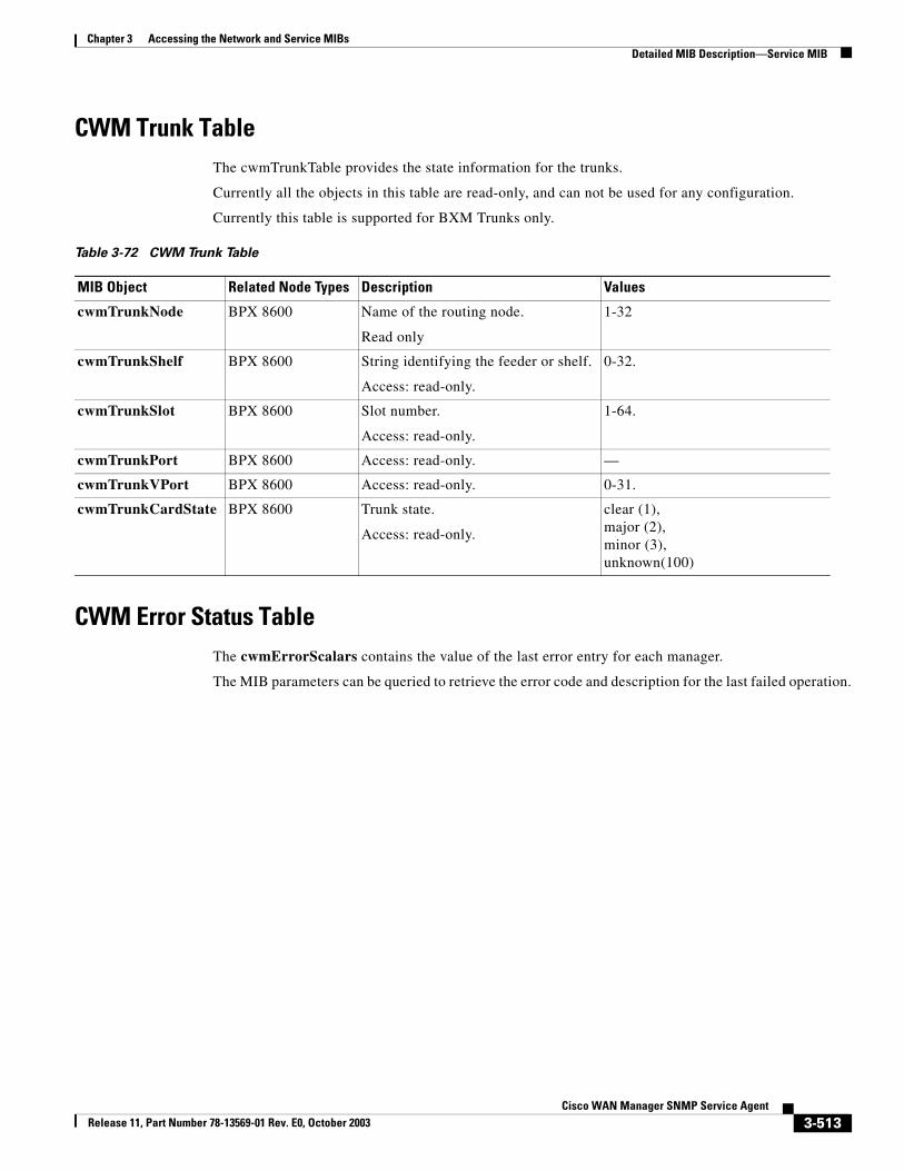
Chapter 3 Accessing the Network and Service MIBsDetailed MIB Description—Service MIB
CWM Trunk TableThe cwmTrunkTable provides the state information for the trunks.
Currently all the objects in this table are read-only, and can not be used for any configuration.
Currently this table is supported for BXM Trunks only.
CWM Error Status TableThe cwmErrorScalars contains the value of the last error entry for each manager.
The MIB parameters can be queried to retrieve the error code and description for the last failed operation.
Table 3-72 CWM Trunk Table
MIB Object Related Node Types Description Values
cwmTrunkNode BPX 8600 Name of the routing node.
Read only
1-32
cwmTrunkShelf BPX 8600 String identifying the feeder or shelf.
Access: read-only.
0-32.
cwmTrunkSlot BPX 8600 Slot number.
Access: read-only.
1-64.
cwmTrunkPort BPX 8600 Access: read-only. —
cwmTrunkVPort BPX 8600 Access: read-only. 0-31.
cwmTrunkCardState BPX 8600 Trunk state.
Access: read-only.
clear (1),major (2),minor (3),unknown(100)
3-513Cisco WAN Manager SNMP Service Agent
Release 11, Part Number 78-13569-01 Rev. E0, October 2003
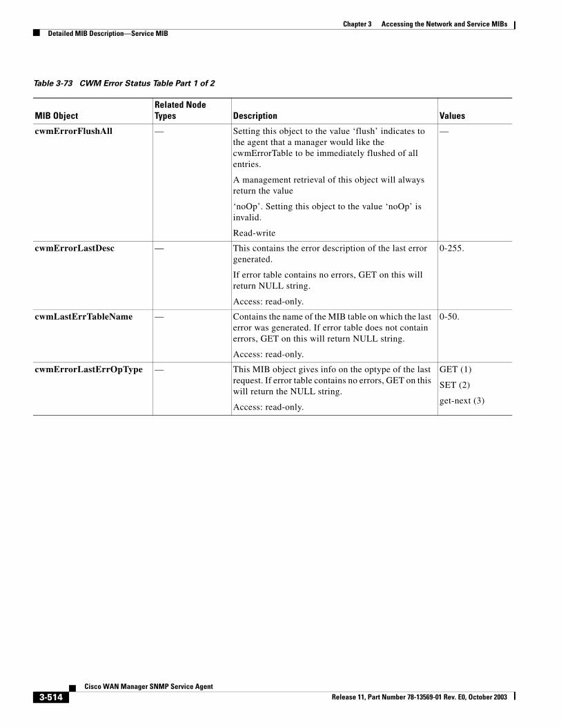
Chapter 3 Accessing the Network and Service MIBsDetailed MIB Description—Service MIB
Table 3-73 CWM Error Status Table Part 1 of 2
MIB ObjectRelated Node Types Description Values
cwmErrorFlushAll — Setting this object to the value ‘flush’ indicates to the agent that a manager would like the cwmErrorTable to be immediately flushed of all entries.
A management retrieval of this object will always return the value
‘noOp’. Setting this object to the value ‘noOp’ is invalid.
Read-write
—
cwmErrorLastDesc — This contains the error description of the last error generated.
If error table contains no errors, GET on this will return NULL string.
Access: read-only.
0-255.
cwmLastErrTableName — Contains the name of the MIB table on which the last error was generated. If error table does not contain errors, GET on this will return NULL string.
Access: read-only.
0-50.
cwmErrorLastErrOpType — This MIB object gives info on the optype of the last request. If error table contains no errors, GET on this will return the NULL string.
Access: read-only.
GET (1)
SET (2)
get-next (3)
3-514Cisco WAN Manager SNMP Service Agent
Release 11, Part Number 78-13569-01 Rev. E0, October 2003
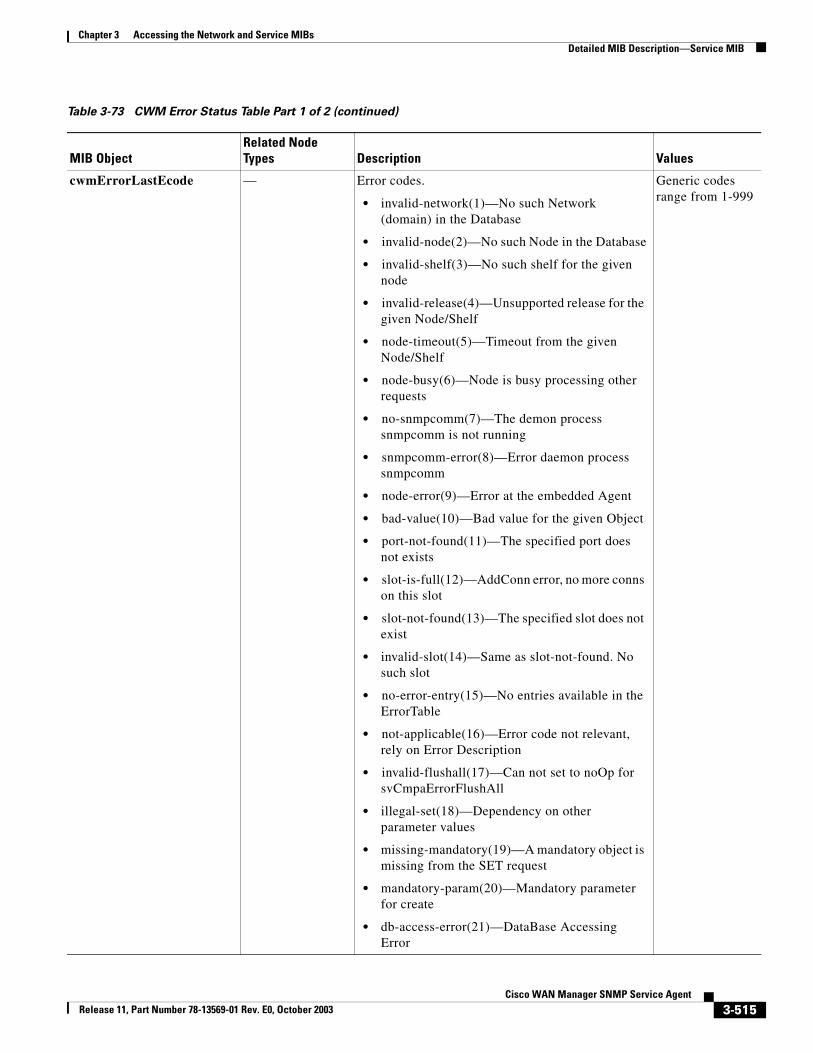
Chapter 3 Accessing the Network and Service MIBsDetailed MIB Description—Service MIB
cwmErrorLastEcode — Error codes.
• invalid-network(1)—No such Network (domain) in the Database
• invalid-node(2)—No such Node in the Database
• invalid-shelf(3)—No such shelf for the given node
• invalid-release(4)—Unsupported release for the given Node/Shelf
• node-timeout(5)—Timeout from the given Node/Shelf
• node-busy(6)—Node is busy processing other requests
• no-snmpcomm(7)—The demon process snmpcomm is not running
• snmpcomm-error(8)—Error daemon process snmpcomm
• node-error(9)—Error at the embedded Agent
• bad-value(10)—Bad value for the given Object
• port-not-found(11)—The specified port does not exists
• slot-is-full(12)—AddConn error, no more conns on this slot
• slot-not-found(13)—The specified slot does not exist
• invalid-slot(14)—Same as slot-not-found. No such slot
• no-error-entry(15)—No entries available in the ErrorTable
• not-applicable(16)—Error code not relevant, rely on Error Description
• invalid-flushall(17)—Can not set to noOp for svCmpaErrorFlushAll
• illegal-set(18)—Dependency on other parameter values
• missing-mandatory(19)—A mandatory object is missing from the SET request
• mandatory-param(20)—Mandatory parameter for create
• db-access-error(21)—DataBase Accessing Error
Generic codes range from 1-999
Table 3-73 CWM Error Status Table Part 1 of 2 (continued)
MIB ObjectRelated Node Types Description Values
3-515Cisco WAN Manager SNMP Service Agent
Release 11, Part Number 78-13569-01 Rev. E0, October 2003
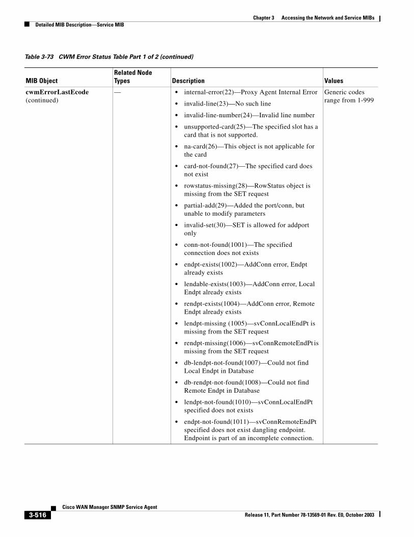
Chapter 3 Accessing the Network and Service MIBsDetailed MIB Description—Service MIB
cwmErrorLastEcode (continued)
— • internal-error(22)—Proxy Agent Internal Error
• invalid-line(23)—No such line
• invalid-line-number(24)—Invalid line number
• unsupported-card(25)—The specified slot has a card that is not supported.
• na-card(26)—This object is not applicable for the card
• card-not-found(27)—The specified card does not exist
• rowstatus-missing(28)—RowStatus object is missing from the SET request
• partial-add(29)—Added the port/conn, but unable to modify parameters
• invalid-set(30)—SET is allowed for addport only
• conn-not-found(1001)—The specified connection does not exists
• endpt-exists(1002)—AddConn error, Endpt already exists
• lendable-exists(1003)—AddConn error, Local Endpt already exists
• rendpt-exists(1004)—AddConn error, Remote Endpt already exists
• lendpt-missing (1005)—svConnLocalEndPt is missing from the SET request
• rendpt-missing(1006)—svConnRemoteEndPt is missing from the SET request
• db-lendpt-not-found(1007)—Could not find Local Endpt in Database
• db-rendpt-not-found(1008)—Could not find Remote Endpt in Database
• lendpt-not-found(1010)—svConnLocalEndPt specified does not exists
• endpt-not-found(1011)—svConnRemoteEndPt specified does not exist dangling endpoint. Endpoint is part of an incomplete connection.
Generic codes range from 1-999
Table 3-73 CWM Error Status Table Part 1 of 2 (continued)
MIB ObjectRelated Node Types Description Values
3-516Cisco WAN Manager SNMP Service Agent
Release 11, Part Number 78-13569-01 Rev. E0, October 2003
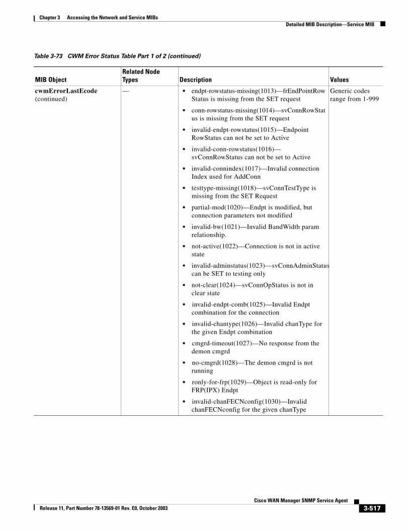
Chapter 3 Accessing the Network and Service MIBsDetailed MIB Description—Service MIB
cwmErrorLastEcode (continued)
— • endpt-rowstatus-missing(1013)—frEndPointRowStatus is missing from the SET request
• conn-rowstatus-missing(1014)—svConnRowStatus is missing from the SET request
• invalid-endpt-rowstatus(1015)—Endpoint RowStatus can not be set to Active
• invalid-conn-rowstatus(1016)—svConnRowStatus can not be set to Active
• invalid-connindex(1017)—Invalid connection Index used for AddConn
• testtype-missing(1018)—svConnTestType is missing from the SET Request
• partial-mod(1020)—Endpt is modified, but connection parameters not modified
• invalid-bw(1021)—Invalid BandWidth param relationship.
• not-active(1022)—Connection is not in active state
• invalid-adminstatus(1023)—svConnAdminStatus can be SET to testing only
• not-clear(1024)—svConnOpStatus is not in clear state
• invalid-endpt-comb(1025)—Invalid Endpt combination for the connection
• invalid-chantype(1026)—Invalid chanType for the given Endpt combination
• cmgrd-timeout(1027)—No response from the demon cmgrd
• no-cmgrd(1028)—The demon cmgrd is not running
• ronly-for-frp(1029)—Object is read-only for FRP(IPX) Endpt
• invalid-chanFECNconfig(1030)—Invalid chanFECNconfig for the given chanType
Generic codes range from 1-999
Table 3-73 CWM Error Status Table Part 1 of 2 (continued)
MIB ObjectRelated Node Types Description Values
3-517Cisco WAN Manager SNMP Service Agent
Release 11, Part Number 78-13569-01 Rev. E0, October 2003
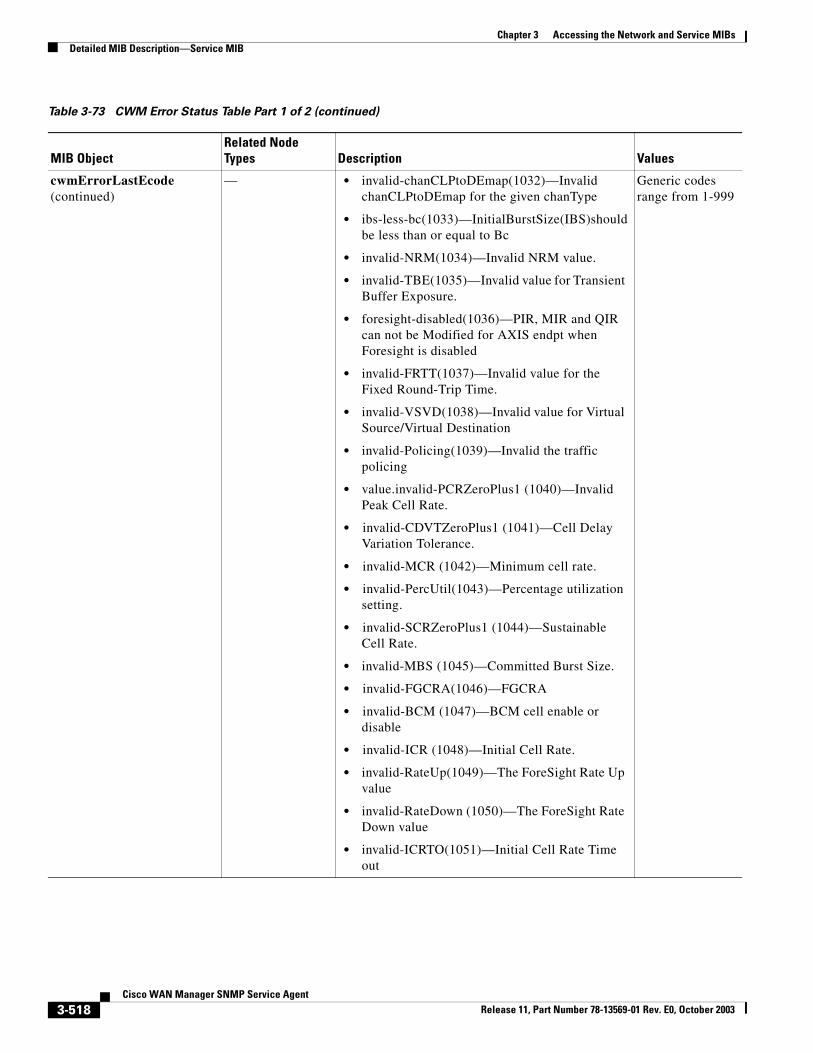
Chapter 3 Accessing the Network and Service MIBsDetailed MIB Description—Service MIB
cwmErrorLastEcode (continued)
— • invalid-chanCLPtoDEmap(1032)—Invalid chanCLPtoDEmap for the given chanType
• ibs-less-bc(1033)—InitialBurstSize(IBS)should be less than or equal to Bc
• invalid-NRM(1034)—Invalid NRM value.
• invalid-TBE(1035)—Invalid value for Transient Buffer Exposure.
• foresight-disabled(1036)—PIR, MIR and QIR can not be Modified for AXIS endpt when Foresight is disabled
• invalid-FRTT(1037)—Invalid value for the Fixed Round-Trip Time.
• invalid-VSVD(1038)—Invalid value for Virtual Source/Virtual Destination
• invalid-Policing(1039)—Invalid the traffic policing
• value.invalid-PCRZeroPlus1 (1040)—Invalid Peak Cell Rate.
• invalid-CDVTZeroPlus1 (1041)—Cell Delay Variation Tolerance.
• invalid-MCR (1042)—Minimum cell rate.
• invalid-PercUtil(1043)—Percentage utilization setting.
• invalid-SCRZeroPlus1 (1044)—Sustainable Cell Rate.
• invalid-MBS (1045)—Committed Burst Size.
• invalid-FGCRA(1046)—FGCRA
• invalid-BCM (1047)—BCM cell enable or disable
• invalid-ICR (1048)—Initial Cell Rate.
• invalid-RateUp(1049)—The ForeSight Rate Up value
• invalid-RateDown (1050)—The ForeSight Rate Down value
• invalid-ICRTO(1051)—Initial Cell Rate Time out
Generic codes range from 1-999
Table 3-73 CWM Error Status Table Part 1 of 2 (continued)
MIB ObjectRelated Node Types Description Values
3-518Cisco WAN Manager SNMP Service Agent
Release 11, Part Number 78-13569-01 Rev. E0, October 2003
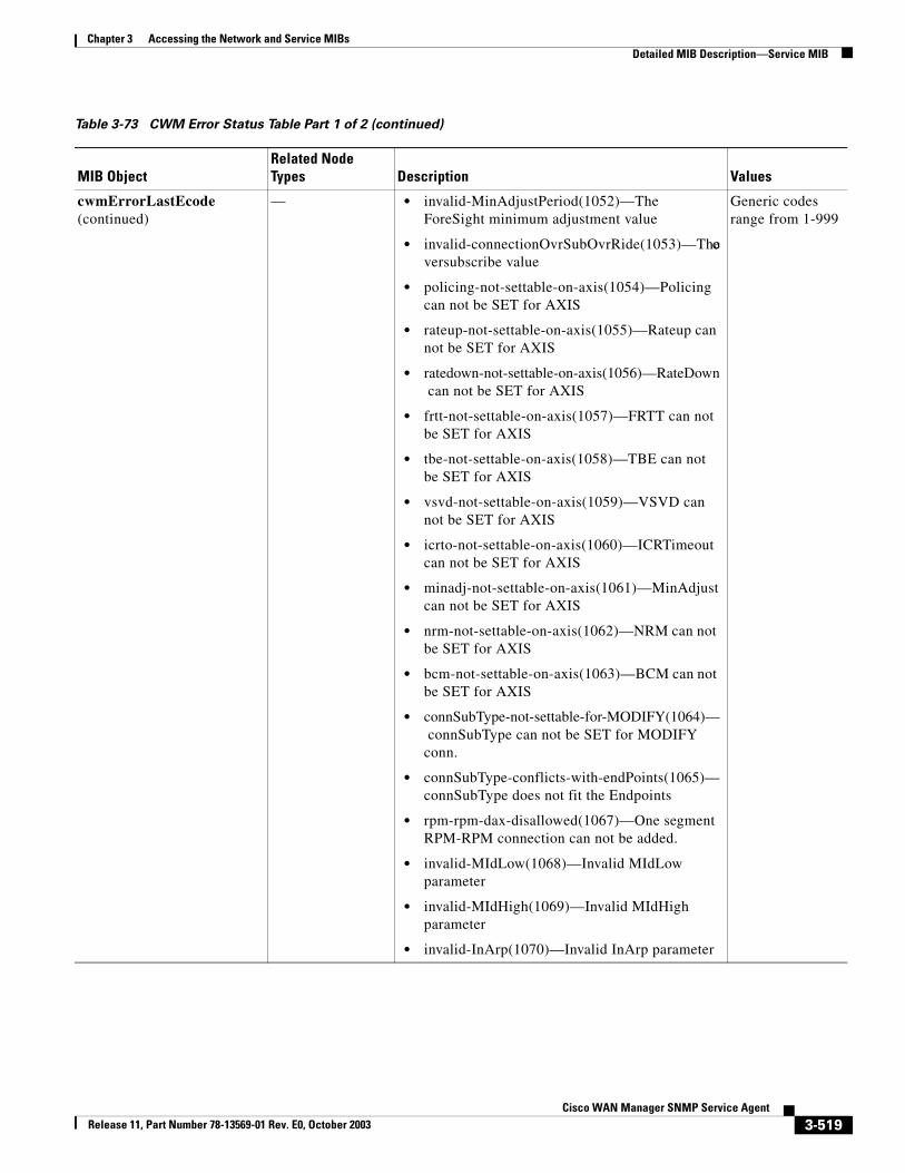
Chapter 3 Accessing the Network and Service MIBsDetailed MIB Description—Service MIB
cwmErrorLastEcode (continued)
— • invalid-MinAdjustPeriod(1052)—The ForeSight minimum adjustment value
• invalid-connectionOvrSubOvrRide(1053)—The oversubscribe value
• policing-not-settable-on-axis(1054)—Policing can not be SET for AXIS
• rateup-not-settable-on-axis(1055)—Rateup can not be SET for AXIS
• ratedown-not-settable-on-axis(1056)—RateDown can not be SET for AXIS
• frtt-not-settable-on-axis(1057)—FRTT can not be SET for AXIS
• tbe-not-settable-on-axis(1058)—TBE can not be SET for AXIS
• vsvd-not-settable-on-axis(1059)—VSVD can not be SET for AXIS
• icrto-not-settable-on-axis(1060)—ICRTimeout can not be SET for AXIS
• minadj-not-settable-on-axis(1061)—MinAdjust can not be SET for AXIS
• nrm-not-settable-on-axis(1062)—NRM can not be SET for AXIS
• bcm-not-settable-on-axis(1063)—BCM can not be SET for AXIS
• connSubType-not-settable-for-MODIFY(1064)— connSubType can not be SET for MODIFY conn.
• connSubType-conflicts-with-endPoints(1065)—connSubType does not fit the Endpoints
• rpm-rpm-dax-disallowed(1067)—One segment RPM-RPM connection can not be added.
• invalid-MIdLow(1068)—Invalid MIdLow parameter
• invalid-MIdHigh(1069)—Invalid MIdHigh parameter
• invalid-InArp(1070)—Invalid InArp parameter
Generic codes range from 1-999
Table 3-73 CWM Error Status Table Part 1 of 2 (continued)
MIB ObjectRelated Node Types Description Values
3-519Cisco WAN Manager SNMP Service Agent
Release 11, Part Number 78-13569-01 Rev. E0, October 2003
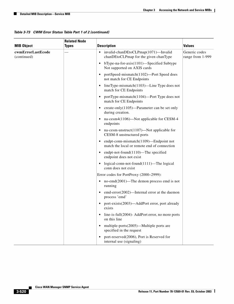
Chapter 3 Accessing the Network and Service MIBsDetailed MIB Description—Service MIB
cwmErrorLastEcode (continued)
— • invalid-chanDEtoCLPmap(1071)—Invalid chanDEtoCLPmap for the given chanType
• bType-na-for-axis(1101)—Specified Subtype Not supported on AXIS cards
• portSpeed-mismatch(1102)—Port Speed does not match for CE Endpoints
• lineType-mismatch(1103)—Line Type does not match for CE Endpoints
• portType-mismatch(1104)—Port Type does not match for CE Endpoints
• create-only(1105)—Parameter can be set only during creation.
• na-cesm4(1106)—Not applicable for CESM-4 endpoints
• na-cesm-unstruct(1107)—Not applicable for CESM-8 unstructured ports
• endpt-conn-mismatch(1109)—Endpoint not match the local or remote end of connection
• endpt-not-found(1110)—The specified endpoint does not exist
• logical-conn-not-found(1111)—The logical conn does not exist
Error codes for PortProxy (2000–2999):
• no-emd(2001)—The demon process emd is not running
• emd-error(2002)—Internal error at the daemon process ’emd’
• port-exists(2003)—AddPort error, port already exists
• line-is-full(2004)- AddPort error, no more ports on this line
• multiple-ports(2005)—Multiple ports are specified in the request
• port-reserved(2006), Port is Reserved for internal use (signaling)
Generic codes range from 1-999
Table 3-73 CWM Error Status Table Part 1 of 2 (continued)
MIB ObjectRelated Node Types Description Values
3-520Cisco WAN Manager SNMP Service Agent
Release 11, Part Number 78-13569-01 Rev. E0, October 2003
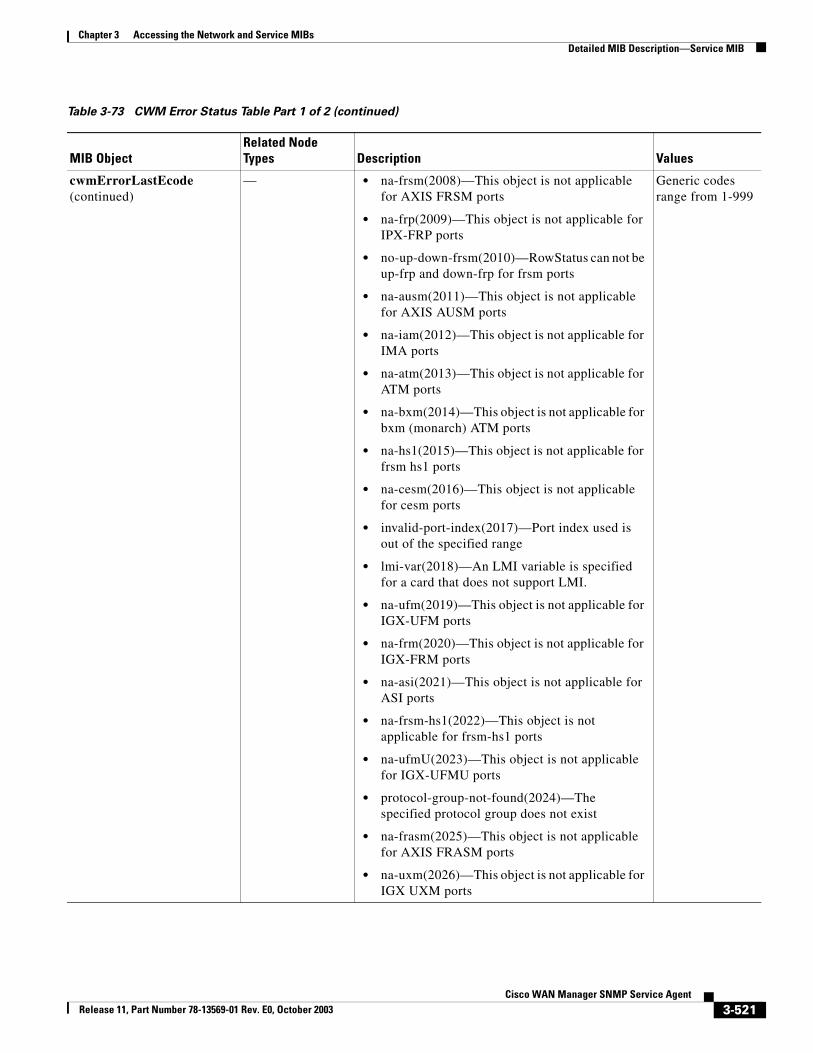
Chapter 3 Accessing the Network and Service MIBsDetailed MIB Description—Service MIB
cwmErrorLastEcode (continued)
— • na-frsm(2008)—This object is not applicable for AXIS FRSM ports
• na-frp(2009)—This object is not applicable for IPX-FRP ports
• no-up-down-frsm(2010)—RowStatus can not be up-frp and down-frp for frsm ports
• na-ausm(2011)—This object is not applicable for AXIS AUSM ports
• na-iam(2012)—This object is not applicable for IMA ports
• na-atm(2013)—This object is not applicable for ATM ports
• na-bxm(2014)—This object is not applicable for bxm (monarch) ATM ports
• na-hs1(2015)—This object is not applicable for frsm hs1 ports
• na-cesm(2016)—This object is not applicable for cesm ports
• invalid-port-index(2017)—Port index used is out of the specified range
• lmi-var(2018)—An LMI variable is specified for a card that does not support LMI.
• na-ufm(2019)—This object is not applicable for IGX-UFM ports
• na-frm(2020)—This object is not applicable for IGX-FRM ports
• na-asi(2021)—This object is not applicable for ASI ports
• na-frsm-hs1(2022)—This object is not applicable for frsm-hs1 ports
• na-ufmU(2023)—This object is not applicable for IGX-UFMU ports
• protocol-group-not-found(2024)—The specified protocol group does not exist
• na-frasm(2025)—This object is not applicable for AXIS FRASM ports
• na-uxm(2026)—This object is not applicable for IGX UXM ports
Generic codes range from 1-999
Table 3-73 CWM Error Status Table Part 1 of 2 (continued)
MIB ObjectRelated Node Types Description Values
3-521Cisco WAN Manager SNMP Service Agent
Release 11, Part Number 78-13569-01 Rev. E0, October 2003
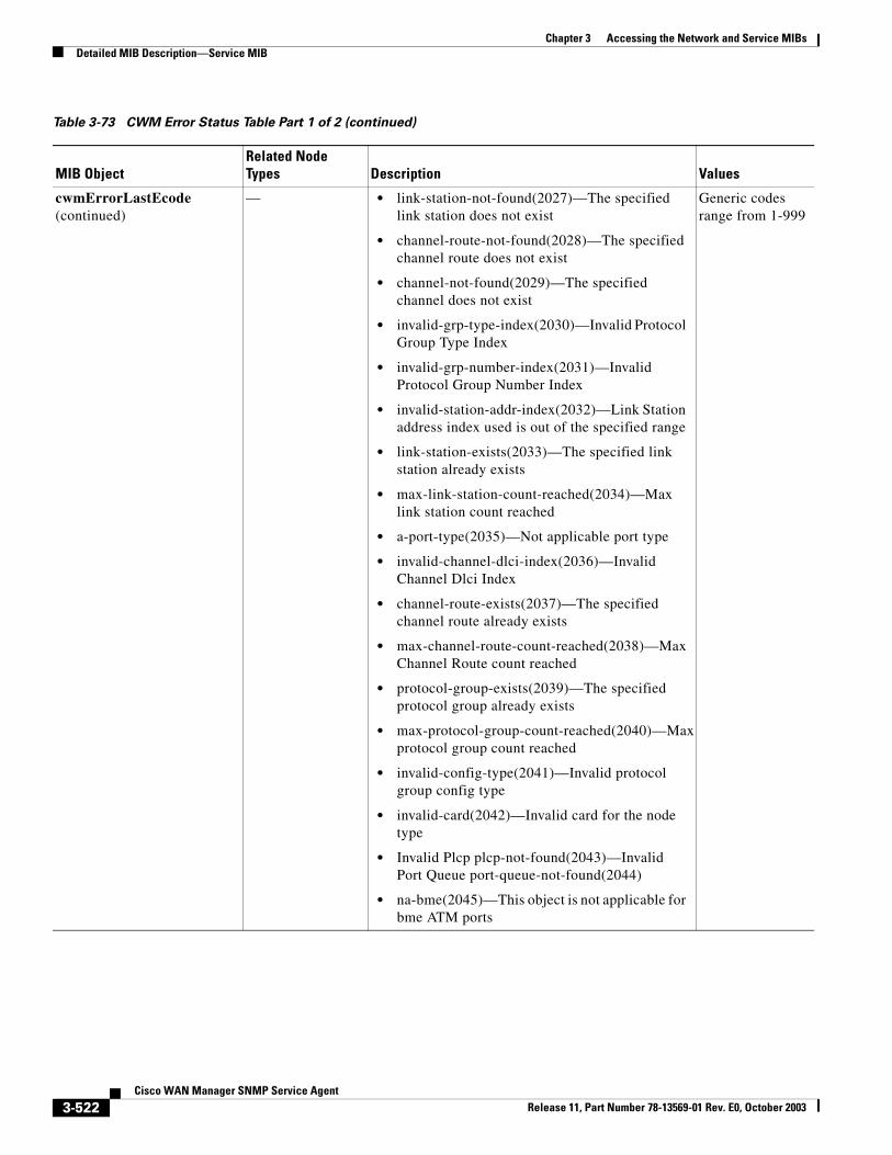
Chapter 3 Accessing the Network and Service MIBsDetailed MIB Description—Service MIB
cwmErrorLastEcode (continued)
— • link-station-not-found(2027)—The specified link station does not exist
• channel-route-not-found(2028)—The specified channel route does not exist
• channel-not-found(2029)—The specified channel does not exist
• invalid-grp-type-index(2030)—Invalid Protocol Group Type Index
• invalid-grp-number-index(2031)—Invalid Protocol Group Number Index
• invalid-station-addr-index(2032)—Link Station address index used is out of the specified range
• link-station-exists(2033)—The specified link station already exists
• max-link-station-count-reached(2034)—Max link station count reached
• a-port-type(2035)—Not applicable port type
• invalid-channel-dlci-index(2036)—Invalid Channel Dlci Index
• channel-route-exists(2037)—The specified channel route already exists
• max-channel-route-count-reached(2038)—Max Channel Route count reached
• protocol-group-exists(2039)—The specified protocol group already exists
• max-protocol-group-count-reached(2040)—Max protocol group count reached
• invalid-config-type(2041)—Invalid protocol group config type
• invalid-card(2042)—Invalid card for the node type
• Invalid Plcp plcp-not-found(2043)—Invalid Port Queue port-queue-not-found(2044)
• na-bme(2045)—This object is not applicable for bme ATM ports
Generic codes range from 1-999
Table 3-73 CWM Error Status Table Part 1 of 2 (continued)
MIB ObjectRelated Node Types Description Values
3-522Cisco WAN Manager SNMP Service Agent
Release 11, Part Number 78-13569-01 Rev. E0, October 2003
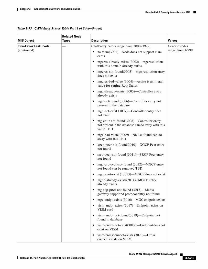
Chapter 3 Accessing the Network and Service MIBsDetailed MIB Description—Service MIB
cwmErrorLastEcode (continued)
— CardProxy errors range from 3000–3999:
• na-vism(3001)—Node does not support vism cards
• mgcres-already-exists (3002)—mgcresolution with this domain already exists
• mgcres-not-found(3003)—mgc resolution entry does not exist
• mgcres-bad-value (3004)—Active is an illegal value for setting Row Status
• mgc-already-exists (3005)—Controller entry already exists
• mgc-not-found (3006)—Controller entry not present in the database
• mgc-not-exist (3007)—Controller entry does not exist
• mg-cntlr-not-found(3008)—Controller entry not present in the database can do away with this value TBD
• mgc-bad-value (3009)—No use found can do away with this TBD
• xgcp-peer-not-found(3010)—XGCP Peer entry not found
• srcp-peer-not-found (3011)—SRCP Peer entry not found
• mgc-protocol-not-found (3012)—MGCP entry not found can be removed TBD
• mgcp-not-exist (13013)—MGCP does not exist
• mgcp-already-exists(3014)--MGCP entry already exists
• mg-sup-prtcl-not-found (3015)—Media gateway supported protocol entry not found
• mgc-endpt-exists (3016)—MGC endpoint exists
• vism-endpt-exists (3017)—Endpoint exists on VISM card
• vism-endpt-not-found(3018)—Endpoint not found in database
• vism-endpt-not-exist(3019)—Endpoint does not exist on VISM
• vism-crossconnect-exists (3020)—Cross connect exists on VISM
Generic codes range from 1-999
Table 3-73 CWM Error Status Table Part 1 of 2 (continued)
MIB ObjectRelated Node Types Description Values
3-523Cisco WAN Manager SNMP Service Agent
Release 11, Part Number 78-13569-01 Rev. E0, October 2003
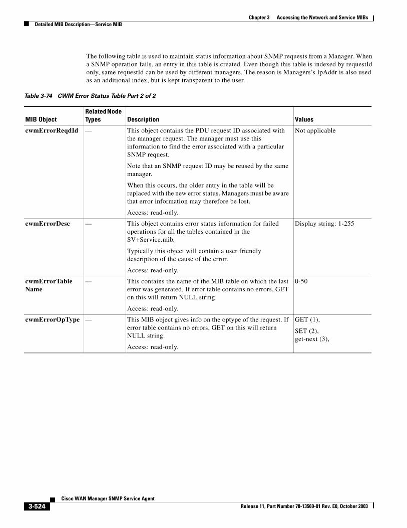
Chapter 3 Accessing the Network and Service MIBsDetailed MIB Description—Service MIB
The following table is used to maintain status information about SNMP requests from a Manager. When a SNMP operation fails, an entry in this table is created. Even though this table is indexed by requestId only, same requestId can be used by different managers. The reason is Managers’s IpAddr is also used as an additional index, but is kept transparent to the user.
Table 3-74 CWM Error Status Table Part 2 of 2
MIB ObjectRelated Node Types Description Values
cwmErrorReqdId — This object contains the PDU request ID associated with the manager request. The manager must use this information to find the error associated with a particular SNMP request.
Note that an SNMP request ID may be reused by the same manager.
When this occurs, the older entry in the table will be replaced with the new error status. Managers must be aware that error information may therefore be lost.
Access: read-only.
Not applicable
cwmErrorDesc — This object contains error status information for failed operations for all the tables contained in the SV+Service.mib.
Typically this object will contain a user friendly description of the cause of the error.
Access: read-only.
Display string: 1-255
cwmErrorTable Name
— This contains the name of the MIB table on which the last error was generated. If error table contains no errors, GET on this will return NULL string.
Access: read-only.
0-50
cwmErrorOpType — This MIB object gives info on the optype of the request. If error table contains no errors, GET on this will return NULL string.
Access: read-only.
GET (1),
SET (2),get-next (3),
3-524Cisco WAN Manager SNMP Service Agent
Release 11, Part Number 78-13569-01 Rev. E0, October 2003
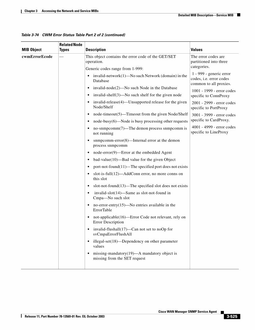
Chapter 3 Accessing the Network and Service MIBsDetailed MIB Description—Service MIB
cwmErrorEcode — This object contains the error code of the GET/SET operation.
Generic codes range from 1-999:
• invalid-network(1)—No such Network (domain) in the Database
• invalid-node(2)—No such Node in the Database
• invalid-shelf(3)—No such shelf for the given node
• invalid-release(4)—Unsupported release for the given Node/Shelf
• node-timeout(5)—Timeout from the given Node/Shelf
• node-busy(6)—Node is busy processing other requests
• no-snmpcomm(7)—The demon process snmpcomm is not running
• snmpcomm-error(8)—Internal error at the demon process snmpcomm
• node-error(9)—Error at the embedded Agent
• bad-value(10)—Bad value for the given Object
• port-not-found(11)—The specified port does not exists
• slot-is-full(12)—AddConn error, no more conns on this slot
• slot-not-found(13)—The specified slot does not exists
• invalid-slot(14)—Same as slot-not-found in Cmpa—No such slot
• no-error-entry(15)—No entries available in the ErrorTable
• not-applicable(16)—Error Code not relevant, rely on Error Description
• invalid-flushall(17)—Can not set to noOp for svCmpaErrorFlushAll
• illegal-set(18)—Dependency on other parameter values
• missing-mandatory(19)—A mandatory object is missing from the SET request
The error codes are partitioned into three categories.
1 - 999 - generic error codes, i.e. error codes common to all proxies.
1001 - 1999 - error codes specific to ConnProxy
2001 - 2999 - error codes specific to PortProxy
3001 - 3999 - error codes specific to CardProxy.
4001 - 4999 - error codes specific to LineProxy
Table 3-74 CWM Error Status Table Part 2 of 2 (continued)
MIB ObjectRelated Node Types Description Values
3-525Cisco WAN Manager SNMP Service Agent
Release 11, Part Number 78-13569-01 Rev. E0, October 2003
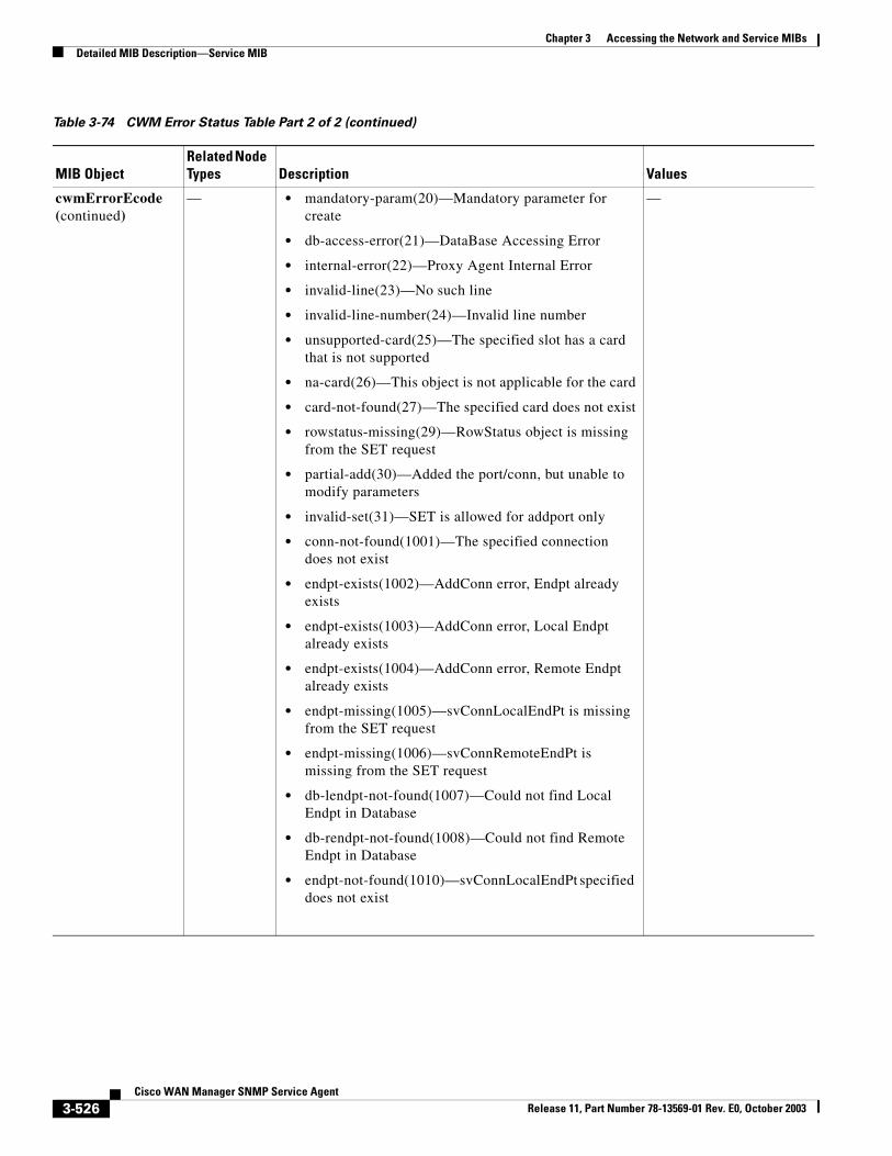
Chapter 3 Accessing the Network and Service MIBsDetailed MIB Description—Service MIB
cwmErrorEcode (continued)
— • mandatory-param(20)—Mandatory parameter for create
• db-access-error(21)—DataBase Accessing Error
• internal-error(22)—Proxy Agent Internal Error
• invalid-line(23)—No such line
• invalid-line-number(24)—Invalid line number
• unsupported-card(25)—The specified slot has a card that is not supported
• na-card(26)—This object is not applicable for the card
• card-not-found(27)—The specified card does not exist
• rowstatus-missing(29)—RowStatus object is missing from the SET request
• partial-add(30)—Added the port/conn, but unable to modify parameters
• invalid-set(31)—SET is allowed for addport only
• conn-not-found(1001)—The specified connection does not exist
• endpt-exists(1002)—AddConn error, Endpt already exists
• endpt-exists(1003)—AddConn error, Local Endpt already exists
• endpt-exists(1004)—AddConn error, Remote Endpt already exists
• endpt-missing(1005)—svConnLocalEndPt is missing from the SET request
• endpt-missing(1006)—svConnRemoteEndPt is missing from the SET request
• db-lendpt-not-found(1007)—Could not find Local Endpt in Database
• db-rendpt-not-found(1008)—Could not find Remote Endpt in Database
• endpt-not-found(1010)—svConnLocalEndPt specified does not exist
—
Table 3-74 CWM Error Status Table Part 2 of 2 (continued)
MIB ObjectRelated Node Types Description Values
3-526Cisco WAN Manager SNMP Service Agent
Release 11, Part Number 78-13569-01 Rev. E0, October 2003
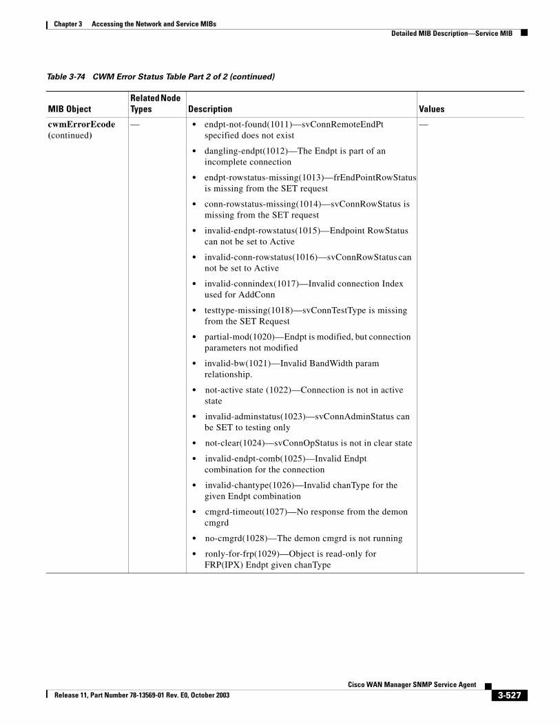
Chapter 3 Accessing the Network and Service MIBsDetailed MIB Description—Service MIB
cwmErrorEcode (continued)
— • endpt-not-found(1011)—svConnRemoteEndPt specified does not exist
• dangling-endpt(1012)—The Endpt is part of an incomplete connection
• endpt-rowstatus-missing(1013)—frEndPointRowStatus is missing from the SET request
• conn-rowstatus-missing(1014)—svConnRowStatus is missing from the SET request
• invalid-endpt-rowstatus(1015)—Endpoint RowStatus can not be set to Active
• invalid-conn-rowstatus(1016)—svConnRowStatus can not be set to Active
• invalid-connindex(1017)—Invalid connection Index used for AddConn
• testtype-missing(1018)—svConnTestType is missing from the SET Request
• partial-mod(1020)—Endpt is modified, but connection parameters not modified
• invalid-bw(1021)—Invalid BandWidth param relationship.
• not-active state (1022)—Connection is not in active state
• invalid-adminstatus(1023)—svConnAdminStatus can be SET to testing only
• not-clear(1024)—svConnOpStatus is not in clear state
• invalid-endpt-comb(1025)—Invalid Endpt combination for the connection
• invalid-chantype(1026)—Invalid chanType for the given Endpt combination
• cmgrd-timeout(1027)—No response from the demon cmgrd
• no-cmgrd(1028)—The demon cmgrd is not running
• ronly-for-frp(1029)—Object is read-only for FRP(IPX) Endpt given chanType
—
Table 3-74 CWM Error Status Table Part 2 of 2 (continued)
MIB ObjectRelated Node Types Description Values
3-527Cisco WAN Manager SNMP Service Agent
Release 11, Part Number 78-13569-01 Rev. E0, October 2003
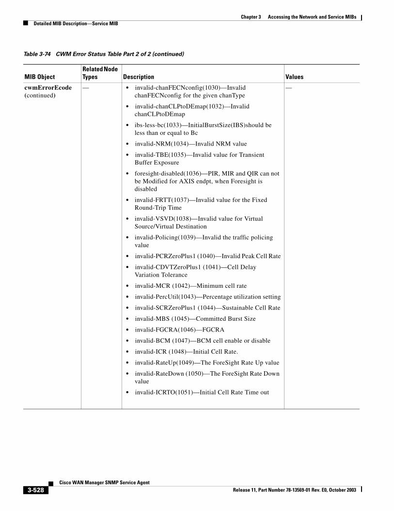
Chapter 3 Accessing the Network and Service MIBsDetailed MIB Description—Service MIB
cwmErrorEcode (continued)
— • invalid-chanFECNconfig(1030)—Invalid chanFECNconfig for the given chanType
• invalid-chanCLPtoDEmap(1032)—Invalid chanCLPtoDEmap
• ibs-less-bc(1033)—InitialBurstSize(IBS)should be less than or equal to Bc
• invalid-NRM(1034)—Invalid NRM value
• invalid-TBE(1035)—Invalid value for Transient Buffer Exposure
• foresight-disabled(1036)—PIR, MIR and QIR can not be Modified for AXIS endpt, when Foresight is disabled
• invalid-FRTT(1037)—Invalid value for the Fixed Round-Trip Time
• invalid-VSVD(1038)—Invalid value for Virtual Source/Virtual Destination
• invalid-Policing(1039)—Invalid the traffic policing value
• invalid-PCRZeroPlus1 (1040)—Invalid Peak Cell Rate
• invalid-CDVTZeroPlus1 (1041)—Cell Delay Variation Tolerance
• invalid-MCR (1042)—Minimum cell rate
• invalid-PercUtil(1043)—Percentage utilization setting
• invalid-SCRZeroPlus1 (1044)—Sustainable Cell Rate
• invalid-MBS (1045)—Committed Burst Size
• invalid-FGCRA(1046)—FGCRA
• invalid-BCM (1047)—BCM cell enable or disable
• invalid-ICR (1048)—Initial Cell Rate.
• invalid-RateUp(1049)—The ForeSight Rate Up value
• invalid-RateDown (1050)—The ForeSight Rate Down value
• invalid-ICRTO(1051)—Initial Cell Rate Time out
—
Table 3-74 CWM Error Status Table Part 2 of 2 (continued)
MIB ObjectRelated Node Types Description Values
3-528Cisco WAN Manager SNMP Service Agent
Release 11, Part Number 78-13569-01 Rev. E0, October 2003
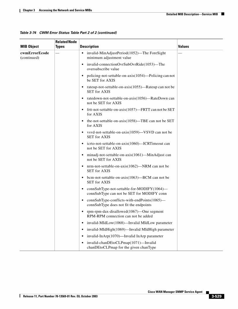
Chapter 3 Accessing the Network and Service MIBsDetailed MIB Description—Service MIB
cwmErrorEcode (continued)
— • invalid-MinAdjustPeriod(1052)—The ForeSight minimum adjustment value
• invalid-connectionOvrSubOvrRide(1053)—The oversubscribe value
• policing-not-settable-on-axis(1054)—Policing can not be SET for AXIS
• rateup-not-settable-on-axis(1055)—Rateup can not be SET for AXIS
• ratedown-not-settable-on-axis(1056)—RateDown can not be SET for AXIS
• frtt-not-settable-on-axis(1057)—FRTT can not be SET for AXIS
• tbe-not-settable-on-axis(1058)—TBE can not be SET for AXIS
• vsvd-not-settable-on-axis(1059)—VSVD can not be SET for AXIS
• icrto-not-settable-on-axis(1060)—ICRTimeout can not be SET for AXIS
• minadj-not-settable-on-axis(1061)—MinAdjust can not be SET for AXIS
• nrm-not-settable-on-axis(1062)—NRM can not be SET for AXIS
• bcm-not-settable-on-axis(1063)—BCM can not be SET for AXIS
• connSubType-not-settable-for-MODIFY(1064)— connSubType can not be SET for MODIFY conn
• connSubType-conflicts-with-endPoints(1065)— connSubType does not fit the endpoints
• rpm-rpm-dax-disallowed(1067)—One segment RPM-RPM connection can not be added
• invalid-MIdLow(1068)—Invalid MIdLow parameter
• invalid-MIdHigh(1069)—Invalid MIdHigh parameter
• invalid-InArp(1070)—Invalid InArp parameter
• invalid-chanDEtoCLPmap(1071)—Invalid chanDEtoCLPmap for the given chanType
—
Table 3-74 CWM Error Status Table Part 2 of 2 (continued)
MIB ObjectRelated Node Types Description Values
3-529Cisco WAN Manager SNMP Service Agent
Release 11, Part Number 78-13569-01 Rev. E0, October 2003
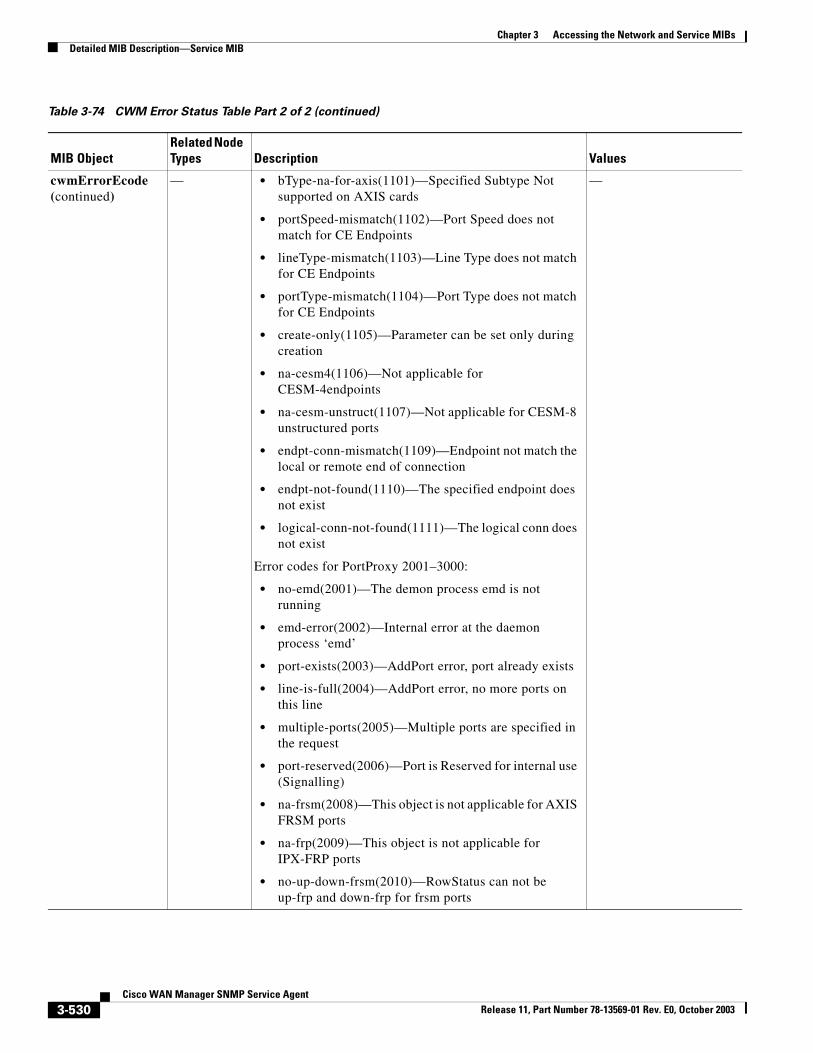
Chapter 3 Accessing the Network and Service MIBsDetailed MIB Description—Service MIB
cwmErrorEcode (continued)
— • bType-na-for-axis(1101)—Specified Subtype Not supported on AXIS cards
• portSpeed-mismatch(1102)—Port Speed does not match for CE Endpoints
• lineType-mismatch(1103)—Line Type does not match for CE Endpoints
• portType-mismatch(1104)—Port Type does not match for CE Endpoints
• create-only(1105)—Parameter can be set only during creation
• na-cesm4(1106)—Not applicable for CESM-4endpoints
• na-cesm-unstruct(1107)—Not applicable for CESM-8 unstructured ports
• endpt-conn-mismatch(1109)—Endpoint not match the local or remote end of connection
• endpt-not-found(1110)—The specified endpoint does not exist
• logical-conn-not-found(1111)—The logical conn does not exist
Error codes for PortProxy 2001–3000:
• no-emd(2001)—The demon process emd is not running
• emd-error(2002)—Internal error at the daemon process ‘emd’
• port-exists(2003)—AddPort error, port already exists
• line-is-full(2004)—AddPort error, no more ports on this line
• multiple-ports(2005)—Multiple ports are specified in the request
• port-reserved(2006)—Port is Reserved for internal use (Signalling)
• na-frsm(2008)—This object is not applicable for AXIS FRSM ports
• na-frp(2009)—This object is not applicable for IPX-FRP ports
• no-up-down-frsm(2010)—RowStatus can not be up-frp and down-frp for frsm ports
—
Table 3-74 CWM Error Status Table Part 2 of 2 (continued)
MIB ObjectRelated Node Types Description Values
3-530Cisco WAN Manager SNMP Service Agent
Release 11, Part Number 78-13569-01 Rev. E0, October 2003
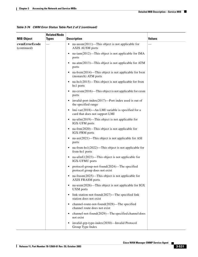
Chapter 3 Accessing the Network and Service MIBsDetailed MIB Description—Service MIB
cwmErrorEcode (continued)
— • na-ausm(2011)—This object is not applicable for AXIS AUSM ports
• na-iam(2012)—This object is not applicable for IMA ports
• na-atm(2013)—This object is not applicable for ATM ports
• na-bxm(2014)—This object is not applicable for bxm (monarch) ATM ports
• na-hs1(2015)—This object is not applicable for frsm hs1 ports
• na-cesm(2016)—This object is not applicable for cesm ports
• invalid-port-index(2017)—Port index used is out of the specified range
• lmi-var(2018)—An LMI variable is specified for a card that does not support LMI
• na-ufm(2019)—This object is not applicable for IGX-UFM ports
• na-frm(2020)—This object is not applicable for IGX-FRM ports
• na-asi(2021)—This object is not applicable for ASI ports
• na-frsm-hs1(2022)—This object is not applicable for frsm-hs1 ports
• na-ufmU(2023)—This object is not applicable for IGX-UFMU ports
• protocol-group-not-found(2024)—The specified protocol group does not exist
• na-frasm(2025)—This object is not applicable for AXIS FRASM ports
• na-uxm(2026)—This object is not applicable for IGX UXM ports
• link-station-not-found(2027)—The specified link station does not exist
• channel-route-not-found(2028)—The specified channel route does not exist
• channel-not-found(2029)—The specified channel does not exist
• invalid-grp-type-index(2030)—Invalid Protocol Group Type Index
—
Table 3-74 CWM Error Status Table Part 2 of 2 (continued)
MIB ObjectRelated Node Types Description Values
3-531Cisco WAN Manager SNMP Service Agent
Release 11, Part Number 78-13569-01 Rev. E0, October 2003
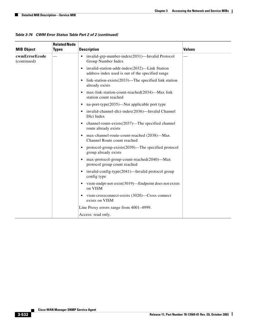
Chapter 3 Accessing the Network and Service MIBsDetailed MIB Description—Service MIB
cwmErrorEcode (continued)
— • invalid-grp-number-index(2031)—Invalid Protocol Group Number Index
• invalid-station-addr-index(2032)—Link Station address index used is out of the specified range
• link-station-exists(2033)—The specified link station already exists
• max-link-station-count-reached(2034)—Max link station count reached
• na-port-type(2035)—Not applicable port type
• invalid-channel-dlci-index(2036)—Invalid Channel Dlci Index
• channel-route-exists(2037)—The specified channel route already exists
• max-channel-route-count-reached (2038)—Max Channel Route count reached
• protocol-group-exists(2039)—The specified protocol group already exists
• max-protocol-group-count-reached(2040)—Max protocol group count reached
• invalid-config-type(2041)—Invalid protocol group config type
• vism-endpt-not-exist(3019)—Endpoint does not exists on VISM
• vism-crossconnect-exists (3020)—Cross connect exists on VISM
Line Proxy errors range from 4001–4999.
Access: read only.
—
Table 3-74 CWM Error Status Table Part 2 of 2 (continued)
MIB ObjectRelated Node Types Description Values
3-532Cisco WAN Manager SNMP Service Agent
Release 11, Part Number 78-13569-01 Rev. E0, October 2003
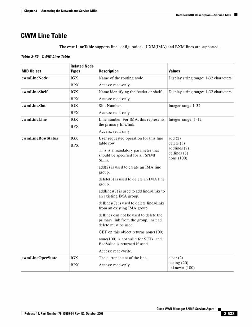
Chapter 3 Accessing the Network and Service MIBsDetailed MIB Description—Service MIB
CWM Line TableThe cwmLineTable supports line configurations. UXM(IMA) and BXM lines are supported.
Table 3-75 CWM Line Table
MIB ObjectRelated Node Types Description Values
cwmLineNode IGX
BPX
Name of the routing node.
Access: read-only.
Display string range: 1-32 characters
cwmLineShelf IGX
BPX
Name identifying the feeder or shelf.
Access: read-only.
Display string range: 1-32 characters
cwmLineSlot IGX
BPX
Slot Number.
Access: read-only.
Integer range:1-32
cwmLineLine IGX
BPX
Line number. For IMA, this represents the primary line/link.
Access: read-only.
Integer range: 1-12
cwmLineRowStatus IGX
BPX
User requested operation for this line table row.
This is a mandatory parameter that should be specified for all SNMP SETs.
add(2) is used to create an IMA line group.
delete(3) is used to delete an IMA line group.
addlines(7) is used to add lines/links to an existing IMA group.
dellines(7) is used to delete lines/links from an existing IMA group.
dellines can not be used to delete the primary link from the group, instead delete must be used.
GET on this object returns none(100).
none(100) is not valid for SETs, and BadValue is returned if used.
Access: read-write.
add (2)delete (3)addlines (7)dellines (8)none (100)
cwmLineOperState IGX
BPX
The current state of the line.
Access: read-only.
clear (2)testing (20)unknown (100)
3-533Cisco WAN Manager SNMP Service Agent
Release 11, Part Number 78-13569-01 Rev. E0, October 2003
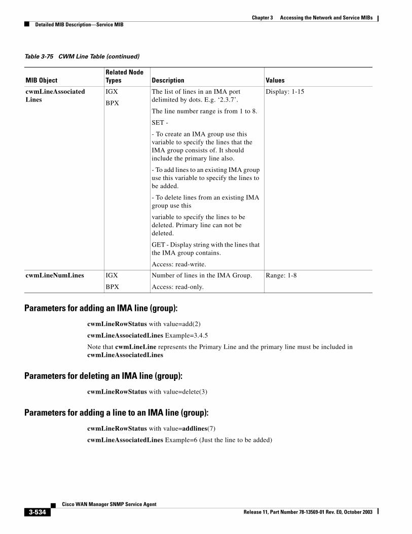
Chapter 3 Accessing the Network and Service MIBsDetailed MIB Description—Service MIB
Parameters for adding an IMA line (group):
cwmLineRowStatus with value=add(2)
cwmLineAssociatedLines Example=3.4.5
Note that cwmLineLine represents the Primary Line and the primary line must be included in cwmLineAssociatedLines
Parameters for deleting an IMA line (group):
cwmLineRowStatus with value=delete(3)
Parameters for adding a line to an IMA line (group):
cwmLineRowStatus with value=addlines(7)
cwmLineAssociatedLines Example=6 (Just the line to be added)
cwmLineAssociatedLines
IGX
BPX
The list of lines in an IMA port delimited by dots. E.g. ‘2.3.7’.
The line number range is from 1 to 8.
SET -
- To create an IMA group use this variable to specify the lines that the IMA group consists of. It should include the primary line also.
- To add lines to an existing IMA group use this variable to specify the lines to be added.
- To delete lines from an existing IMA group use this
variable to specify the lines to be deleted. Primary line can not be deleted.
GET - Display string with the lines that the IMA group contains.
Access: read-write.
Display: 1-15
cwmLineNumLines IGX
BPX
Number of lines in the IMA Group.
Access: read-only.
Range: 1-8
Table 3-75 CWM Line Table (continued)
MIB ObjectRelated Node Types Description Values
3-534Cisco WAN Manager SNMP Service Agent
Release 11, Part Number 78-13569-01 Rev. E0, October 2003
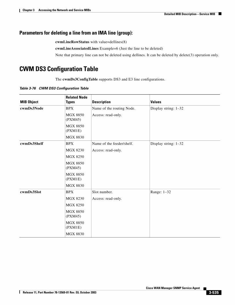
Chapter 3 Accessing the Network and Service MIBsDetailed MIB Description—Service MIB
Parameters for deleting a line from an IMA line (group):
cwmLineRowStatus with value=dellines(8)
cwmLineAssociatedLines Example=6 (Just the line to be deleted)
Note that primary line can not be deleted using dellines. It can be deleted by delete(3) operation only.
CWM DS3 Configuration TableThe cwmDs3ConfigTable supports DS3 and E3 line configurations.
Table 3-76 CWM DS3 Configuration Table
MIB ObjectRelated Node Types Description Values
cwmDs3Node BPX
MGX 8850 (PXM45)
MGX 8850 (PXM1E)
MGX 8830
Name of the routing Node.
Access: read-only.
Display string: 1–32
cwmDs3Shelf BPX
MGX 8230
MGX 8250
MGX 8850 (PXM45)
MGX 8850 (PXM1E)
MGX 8830
Name of the feeder/shelf.
Access: read-only.
Display string: 1–32
cwmDs3Slot BPX
MGX 8230
MGX 8250
MGX 8850 (PXM45)
MGX 8850 (PXM1E)
MGX 8830
Slot number.
Access: read-only.
Range: 1–32
3-535Cisco WAN Manager SNMP Service Agent
Release 11, Part Number 78-13569-01 Rev. E0, October 2003
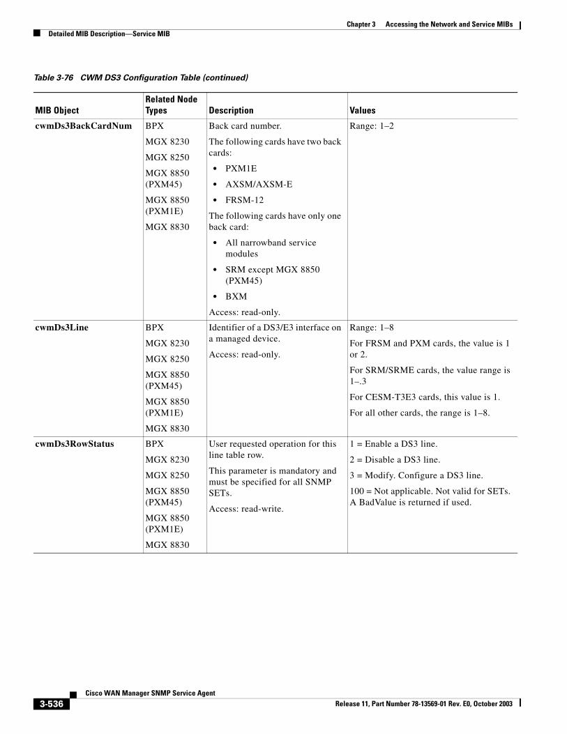
Chapter 3 Accessing the Network and Service MIBsDetailed MIB Description—Service MIB
cwmDs3BackCardNum BPX
MGX 8230
MGX 8250
MGX 8850 (PXM45)
MGX 8850 (PXM1E)
MGX 8830
Back card number.
The following cards have two back cards:
• PXM1E
• AXSM/AXSM-E
• FRSM-12
The following cards have only one back card:
• All narrowband service modules
• SRM except MGX 8850 (PXM45)
• BXM
Access: read-only.
Range: 1–2
cwmDs3Line BPX
MGX 8230
MGX 8250
MGX 8850 (PXM45)
MGX 8850 (PXM1E)
MGX 8830
Identifier of a DS3/E3 interface on a managed device.
Access: read-only.
Range: 1–8
For FRSM and PXM cards, the value is 1 or 2.
For SRM/SRME cards, the value range is 1–.3
For CESM-T3E3 cards, this value is 1.
For all other cards, the range is 1–8.
cwmDs3RowStatus BPX
MGX 8230
MGX 8250
MGX 8850 (PXM45)
MGX 8850 (PXM1E)
MGX 8830
User requested operation for this line table row.
This parameter is mandatory and must be specified for all SNMP SETs.
Access: read-write.
1 = Enable a DS3 line.
2 = Disable a DS3 line.
3 = Modify. Configure a DS3 line.
100 = Not applicable. Not valid for SETs. A BadValue is returned if used.
Table 3-76 CWM DS3 Configuration Table (continued)
MIB ObjectRelated Node Types Description Values
3-536Cisco WAN Manager SNMP Service Agent
Release 11, Part Number 78-13569-01 Rev. E0, October 2003
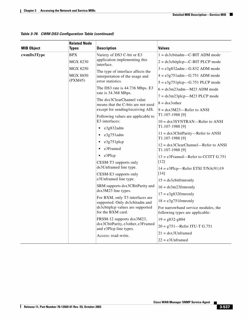
Chapter 3 Accessing the Network and Service MIBsDetailed MIB Description—Service MIB
cwmDs3Type BPX
MGX 8230
MGX 8250
MGX 8850 (PXM45)
Variety of DS3 C-bit or E3 application implementing this interface.
The type of interface affects the interpretation of the usage and error statistics.
The DS3 rate is 44.736 Mbps. E3 rate is 34.368 Mbps.
The dsx3ClearChannel value means that the C-bits are not used except for sending/receiving AIS.
Following values are applicable to E3 interfaces:
• e3g832adm
• e3g751adm
• e3g751plcp
• e3Framed
• e3Plcp
CESM-T3 supports only ds3Unframed line type.
CESM-E3 supports only e3Unframed line type.
SRM supports dsx3CBitParity and dsx3M23 line types.
For BXM, only T3 interfaces are supported. Only ds3cbitadm and ds3cbitplcp values are supported for the BXM card.
FRSM-12 supports dsx3M23, dsx3CbitParity, e3other, e3Framed and e3Plcp line types.
Access: read-write.
1 = ds3cbitadm—C-BIT ADM mode
2 = ds3cbitplcp—C-BIT PLCP mode
3 = e3g832adm—G.832 ADM mode
4 = e3g751adm—G.751 ADM mode
5 = e3g751plcp—G.751 PLCP mode
6 = ds3m23adm—M23 ADM mode
7 = ds3m23plcp—M23 PLCP mode
8 = dsx3other
9 = dsx3M23—Refer to ANSI T1.107-1988 [9]
10 = dsx3SYNTRAN—Refer to ANSI T1.107-1988 [9]
11 = dsx3CbitParity—Refer to ANSI T1.107-1988 [9]
12 = dsx3ClearChannel—Refer to ANSI T1.107-1988 [9]
13 = e3Framed—Refer to CCITT G.751 [12]
14 = e3Plcp—Refer ETSI T/NA(91)19 [14]
15 = ds3cbitfrmronly
16 = ds3m23frmronly
17 = e3g832frmronly
18 = e3g751frmronly
For narrowband service modules, the following types are applicable:
19 = g832-g804
20 = g751—Refer ITU-T G.751
21 = dsx3Unframed
22 = e3Unframed
Table 3-76 CWM DS3 Configuration Table (continued)
MIB ObjectRelated Node Types Description Values
3-537Cisco WAN Manager SNMP Service Agent
Release 11, Part Number 78-13569-01 Rev. E0, October 2003
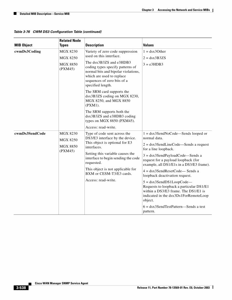
Chapter 3 Accessing the Network and Service MIBsDetailed MIB Description—Service MIB
cwmDs3Coding MGX 8230
MGX 8250
MGX 8850 (PXM45)
Variety of zero code suppression used on this interface.
The dsx3B3ZS and e3HDB3 coding types specify patterns of normal bits and bipolar violations, which are used to replace sequences of zero bits of a specified length.
The SRM card supports the dsx3B3ZS coding on MGX 8230, MGX 8250, and MGX 8850 (PXM1).
The SRM supports both the dsx3B3ZS and e3HDB3 coding types on MGX 8850 (PXM45).
Access: read-write.
1 = dsx3Other
2 = dsx3B3ZS
3 = e3HDB3
cwmDs3SendCode MGX 8230
MGX 8250
MGX 8850 (PXM45)
Type of code sent across the DS3/E3 interface by the device. This object is optional for E3 interfaces.
Setting this variable causes the interface to begin sending the code requested.
This object is not applicable for BXM or CESM-T3/E3 cards.
Access: read-write.
1 = dsx3SendNoCode—Sends looped or normal data.
2 = dsx3SendLineCode—Sends a request for a line loopback.
3 = dsx3SendPayloadCode—Sends a request for a payload loopback (for example, all DS1/E1s in a DS3/E3 frame).
4 = dsx3SendResetCode— Sends a loopback deactivation request.
5 = dsx3SendDS1LoopCode—Requests to loopback a particular DS1/E1 within a DS3/E3 frame. The DS1/E1 is indicated in the dsx3Ds1ForRemoteLoop object.
6 = dsx3SendTestPattern—Sends a test pattern.
Table 3-76 CWM DS3 Configuration Table (continued)
MIB ObjectRelated Node Types Description Values
3-538Cisco WAN Manager SNMP Service Agent
Release 11, Part Number 78-13569-01 Rev. E0, October 2003
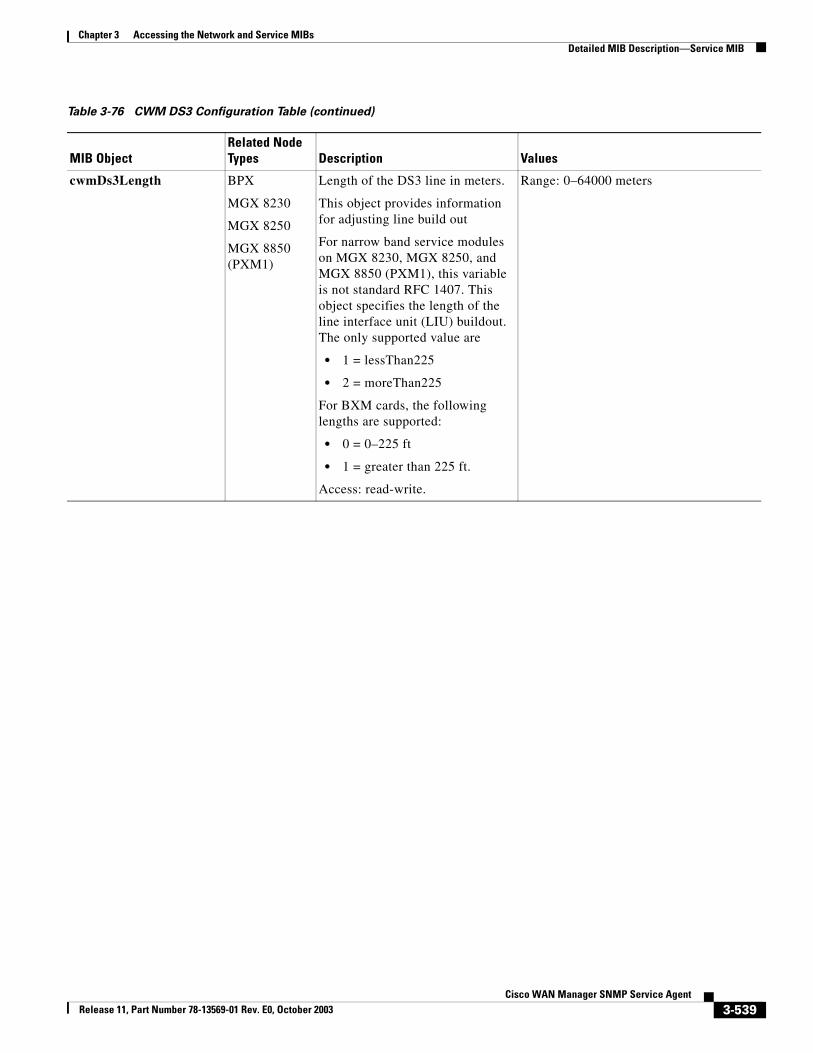
Chapter 3 Accessing the Network and Service MIBsDetailed MIB Description—Service MIB
cwmDs3Length BPX
MGX 8230
MGX 8250
MGX 8850 (PXM1)
Length of the DS3 line in meters.
This object provides information for adjusting line build out
For narrow band service modules on MGX 8230, MGX 8250, and MGX 8850 (PXM1), this variable is not standard RFC 1407. This object specifies the length of the line interface unit (LIU) buildout. The only supported value are
• 1 = lessThan225
• 2 = moreThan225
For BXM cards, the following lengths are supported:
• 0 = 0–225 ft
• 1 = greater than 225 ft.
Access: read-write.
Range: 0–64000 meters
Table 3-76 CWM DS3 Configuration Table (continued)
MIB ObjectRelated Node Types Description Values
3-539Cisco WAN Manager SNMP Service Agent
Release 11, Part Number 78-13569-01 Rev. E0, October 2003
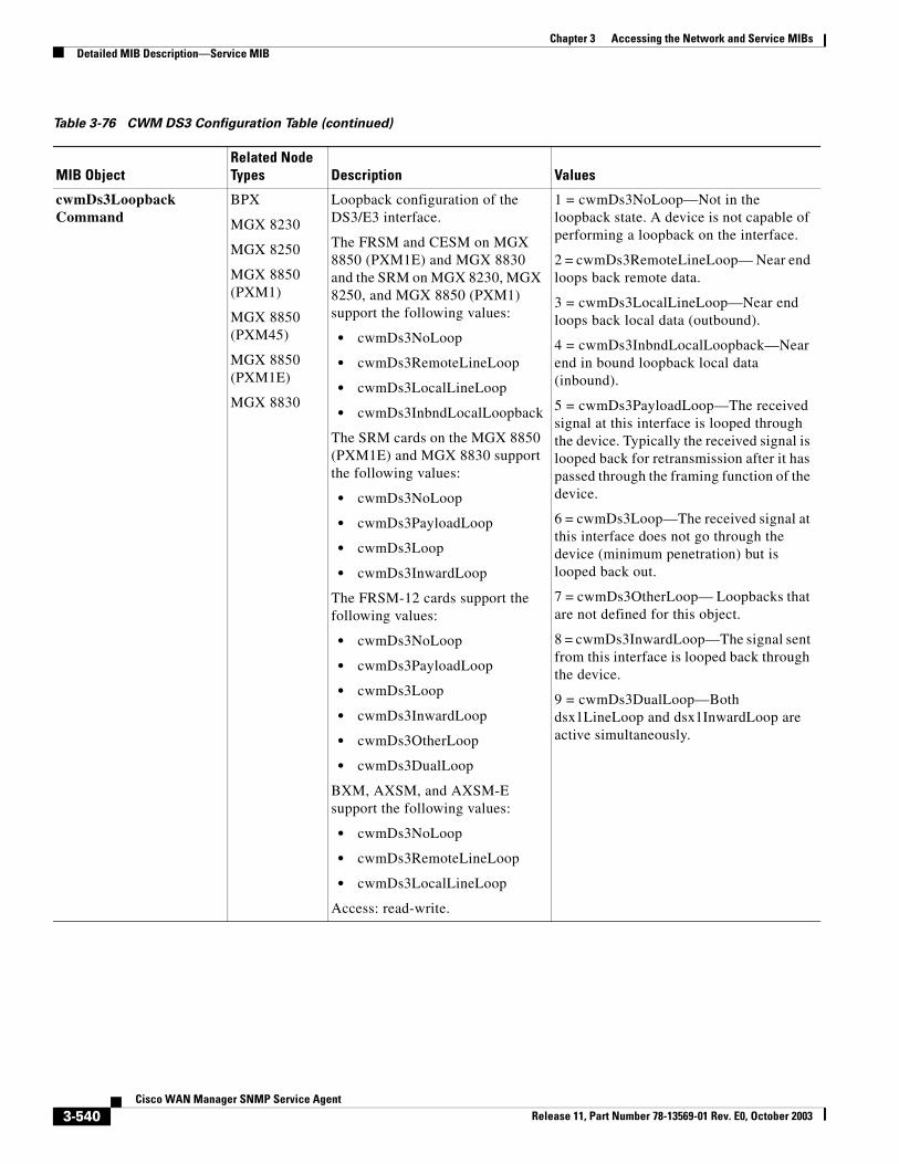
Chapter 3 Accessing the Network and Service MIBsDetailed MIB Description—Service MIB
cwmDs3LoopbackCommand
BPX
MGX 8230
MGX 8250
MGX 8850 (PXM1)
MGX 8850 (PXM45)
MGX 8850 (PXM1E)
MGX 8830
Loopback configuration of the DS3/E3 interface.
The FRSM and CESM on MGX 8850 (PXM1E) and MGX 8830 and the SRM on MGX 8230, MGX 8250, and MGX 8850 (PXM1) support the following values:
• cwmDs3NoLoop
• cwmDs3RemoteLineLoop
• cwmDs3LocalLineLoop
• cwmDs3InbndLocalLoopback
The SRM cards on the MGX 8850 (PXM1E) and MGX 8830 support the following values:
• cwmDs3NoLoop
• cwmDs3PayloadLoop
• cwmDs3Loop
• cwmDs3InwardLoop
The FRSM-12 cards support the following values:
• cwmDs3NoLoop
• cwmDs3PayloadLoop
• cwmDs3Loop
• cwmDs3InwardLoop
• cwmDs3OtherLoop
• cwmDs3DualLoop
BXM, AXSM, and AXSM-E support the following values:
• cwmDs3NoLoop
• cwmDs3RemoteLineLoop
• cwmDs3LocalLineLoop
Access: read-write.
1 = cwmDs3NoLoop—Not in the loopback state. A device is not capable of performing a loopback on the interface.
2 = cwmDs3RemoteLineLoop— Near end loops back remote data.
3 = cwmDs3LocalLineLoop—Near end loops back local data (outbound).
4 = cwmDs3InbndLocalLoopback—Near end in bound loopback local data (inbound).
5 = cwmDs3PayloadLoop—The received signal at this interface is looped through the device. Typically the received signal is looped back for retransmission after it has passed through the framing function of the device.
6 = cwmDs3Loop—The received signal at this interface does not go through the device (minimum penetration) but is looped back out.
7 = cwmDs3OtherLoop— Loopbacks that are not defined for this object.
8 = cwmDs3InwardLoop—The signal sent from this interface is looped back through the device.
9 = cwmDs3DualLoop—Both dsx1LineLoop and dsx1InwardLoop are active simultaneously.
Table 3-76 CWM DS3 Configuration Table (continued)
MIB ObjectRelated Node Types Description Values
3-540Cisco WAN Manager SNMP Service Agent
Release 11, Part Number 78-13569-01 Rev. E0, October 2003
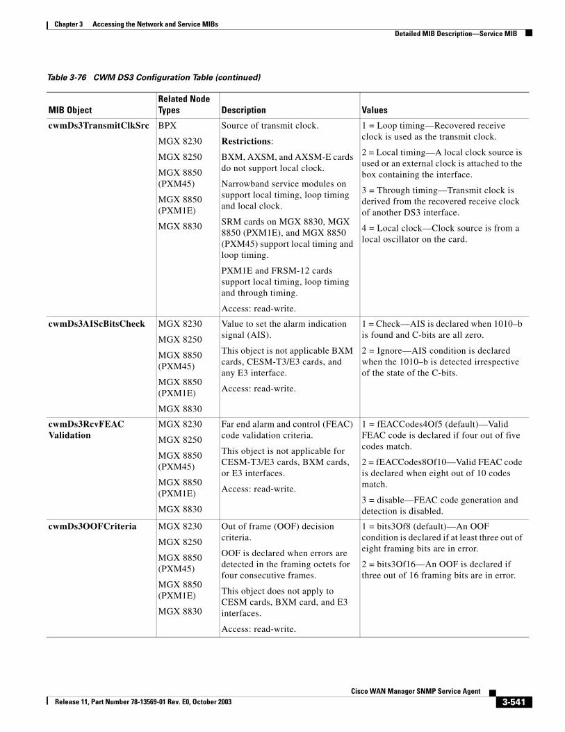
Chapter 3 Accessing the Network and Service MIBsDetailed MIB Description—Service MIB
cwmDs3TransmitClkSrc BPX
MGX 8230
MGX 8250
MGX 8850 (PXM45)
MGX 8850 (PXM1E)
MGX 8830
Source of transmit clock.
Restrictions:
BXM, AXSM, and AXSM-E cards do not support local clock.
Narrowband service modules on support local timing, loop timing and local clock.
SRM cards on MGX 8830, MGX 8850 (PXM1E), and MGX 8850 (PXM45) support local timing and loop timing.
PXM1E and FRSM-12 cards support local timing, loop timing and through timing.
Access: read-write.
1 = Loop timing—Recovered receive clock is used as the transmit clock.
2 = Local timing—A local clock source is used or an external clock is attached to the box containing the interface.
3 = Through timing—Transmit clock is derived from the recovered receive clock of another DS3 interface.
4 = Local clock—Clock source is from a local oscillator on the card.
cwmDs3AIScBitsCheck MGX 8230
MGX 8250
MGX 8850 (PXM45)
MGX 8850 (PXM1E)
MGX 8830
Value to set the alarm indication signal (AIS).
This object is not applicable BXM cards, CESM-T3/E3 cards, and any E3 interface.
Access: read-write.
1 = Check—AIS is declared when 1010–b is found and C-bits are all zero.
2 = Ignore—AIS condition is declared when the 1010–b is detected irrespective of the state of the C-bits.
cwmDs3RcvFEACValidation
MGX 8230
MGX 8250
MGX 8850 (PXM45)
MGX 8850 (PXM1E)
MGX 8830
Far end alarm and control (FEAC) code validation criteria.
This object is not applicable for CESM-T3/E3 cards, BXM cards, or E3 interfaces.
Access: read-write.
1 = fEACCodes4Of5 (default)—Valid FEAC code is declared if four out of five codes match.
2 = fEACCodes8Of10—Valid FEAC code is declared when eight out of 10 codes match.
3 = disable—FEAC code generation and detection is disabled.
cwmDs3OOFCriteria MGX 8230
MGX 8250
MGX 8850 (PXM45)
MGX 8850 (PXM1E)
MGX 8830
Out of frame (OOF) decision criteria.
OOF is declared when errors are detected in the framing octets for four consecutive frames.
This object does not apply to CESM cards, BXM card, and E3 interfaces.
Access: read-write.
1 = bits3Of8 (default)—An OOF condition is declared if at least three out of eight framing bits are in error.
2 = bits3Of16—An OOF is declared if three out of 16 framing bits are in error.
Table 3-76 CWM DS3 Configuration Table (continued)
MIB ObjectRelated Node Types Description Values
3-541Cisco WAN Manager SNMP Service Agent
Release 11, Part Number 78-13569-01 Rev. E0, October 2003
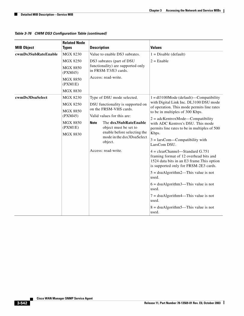
Chapter 3 Accessing the Network and Service MIBsDetailed MIB Description—Service MIB
cwmDs3SubRateEnable MGX 8230
MGX 8250
MGX 8850 (PXM45)
MGX 8850 (PXM1E)
MGX 8830
Value to enable DS3 subrates.
DS3 subrates (part of DSU functionality) are supported only in FRSM-T3/E3 cards.
Access: read-write.
1 = Disable (default)
2 = Enable
cwmDs3DsuSelect MGX 8230
MGX 8250
MGX 8850 (PXM45)
MGX 8850 (PXM1E)
MGX 8830
Type of DSU mode selected.
DSU functionality is supported on on the FRSM-VHS cards.
Valid values for this are:
Note The dsx3SubRateEnable object must be set to enable before selecting the mode in the dsx3DsuSelect object.
Access: read-write.
1 = dl3100Mode (default)—Compatibility with Digital Link Inc. DL3100 DSU mode of operation. This mode permits line rates to be in multiples of 300 Kbps.
2 = adcKentroxMode—Compatibility with ADC Kentrox's DSU. This mode permits line rates to be in multiples of 500 Kbps.
3 = larsCom—Compatibility with LarsCom DSU.
4 = clearChannel—Standard G.751 framing format of 12 overhead bits and 1524 data bits in an E3 frame.This option is supported only for FRSM-2E3 cards.
5 = dsuAlgorithm2—This value is not used.
6 = dsuAlgorithm3—This value is not used.
7 = dsuAlgorithm4—This value is not used.
8 = dsuAlgorithm5—This value is not used.
Table 3-76 CWM DS3 Configuration Table (continued)
MIB ObjectRelated Node Types Description Values
3-542Cisco WAN Manager SNMP Service Agent
Release 11, Part Number 78-13569-01 Rev. E0, October 2003
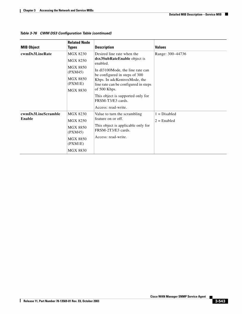
Chapter 3 Accessing the Network and Service MIBsDetailed MIB Description—Service MIB
cwmDs3LineRate MGX 8230
MGX 8250
MGX 8850 (PXM45)
MGX 8850 (PXM1E)
MGX 8830
Desired line rate when the dsx3SubRateEnable object is enabled.
In dl3100Mode, the line rate can be configured in steps of 300 Kbps. In adcKentroxMode, the line rate can be configured in steps of 500 Kbps.
This object is supported only for FRSM-T3/E3 cards.
Access: read-write.
Range: 300–44736
cwmDs3LineScrambleEnable
MGX 8230
MGX 8250
MGX 8850 (PXM45)
MGX 8850 (PXM1E)
MGX 8830
Value to turn the scrambling feature on or off.
This object is applicable only for FRSM-2T3/E3 cards.
Access: read-write.
1 = Disabled
2 = Enabled
Table 3-76 CWM DS3 Configuration Table (continued)
MIB ObjectRelated Node Types Description Values
3-543Cisco WAN Manager SNMP Service Agent
Release 11, Part Number 78-13569-01 Rev. E0, October 2003
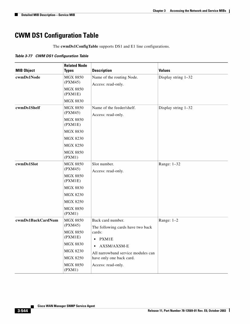
Chapter 3 Accessing the Network and Service MIBsDetailed MIB Description—Service MIB
CWM DS1 Configuration TableThe cwmDs1ConfigTable supports DS1 and E1 line configurations.
Table 3-77 CWM DS1 Configuration Table
MIB ObjectRelated Node Types Description Values
cwmDs1Node MGX 8850 (PXM45)
MGX 8850 (PXM1E)
MGX 8830
Name of the routing Node.
Access: read-only.
Display string 1–32
cwmDs1Shelf MGX 8850 (PXM45)
MGX 8850 (PXM1E)
MGX 8830
MGX 8230
MGX 8250
MGX 8850 (PXM1)
Name of the feeder/shelf.
Access: read-only.
Display string 1–32
cwmDs1Slot MGX 8850 (PXM45)
MGX 8850 (PXM1E)
MGX 8830
MGX 8230
MGX 8250
MGX 8850 (PXM1)
Slot number.
Access: read-only.
Range: 1–32
cwmDs1BackCardNum MGX 8850 (PXM45)
MGX 8850 (PXM1E)
MGX 8830
MGX 8230
MGX 8250
MGX 8850 (PXM1)
Back card number.
The following cards have two back cards:
• PXM1E
• AXSM/AXSM-E
All narrowband service modules can have only one back card.
Access: read-only.
Range: 1–2
3-544Cisco WAN Manager SNMP Service Agent
Release 11, Part Number 78-13569-01 Rev. E0, October 2003
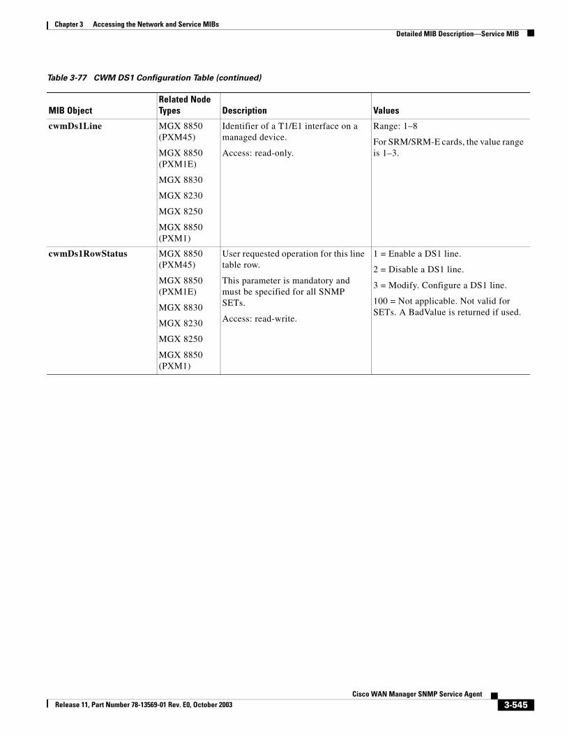
Chapter 3 Accessing the Network and Service MIBsDetailed MIB Description—Service MIB
cwmDs1Line MGX 8850 (PXM45)
MGX 8850 (PXM1E)
MGX 8830
MGX 8230
MGX 8250
MGX 8850 (PXM1)
Identifier of a T1/E1 interface on a managed device.
Access: read-only.
Range: 1–8
For SRM/SRM-E cards, the value range is 1–3.
cwmDs1RowStatus MGX 8850 (PXM45)
MGX 8850 (PXM1E)
MGX 8830
MGX 8230
MGX 8250
MGX 8850 (PXM1)
User requested operation for this line table row.
This parameter is mandatory and must be specified for all SNMP SETs.
Access: read-write.
1 = Enable a DS1 line.
2 = Disable a DS1 line.
3 = Modify. Configure a DS1 line.
100 = Not applicable. Not valid for SETs. A BadValue is returned if used.
Table 3-77 CWM DS1 Configuration Table (continued)
MIB ObjectRelated Node Types Description Values
3-545Cisco WAN Manager SNMP Service Agent
Release 11, Part Number 78-13569-01 Rev. E0, October 2003
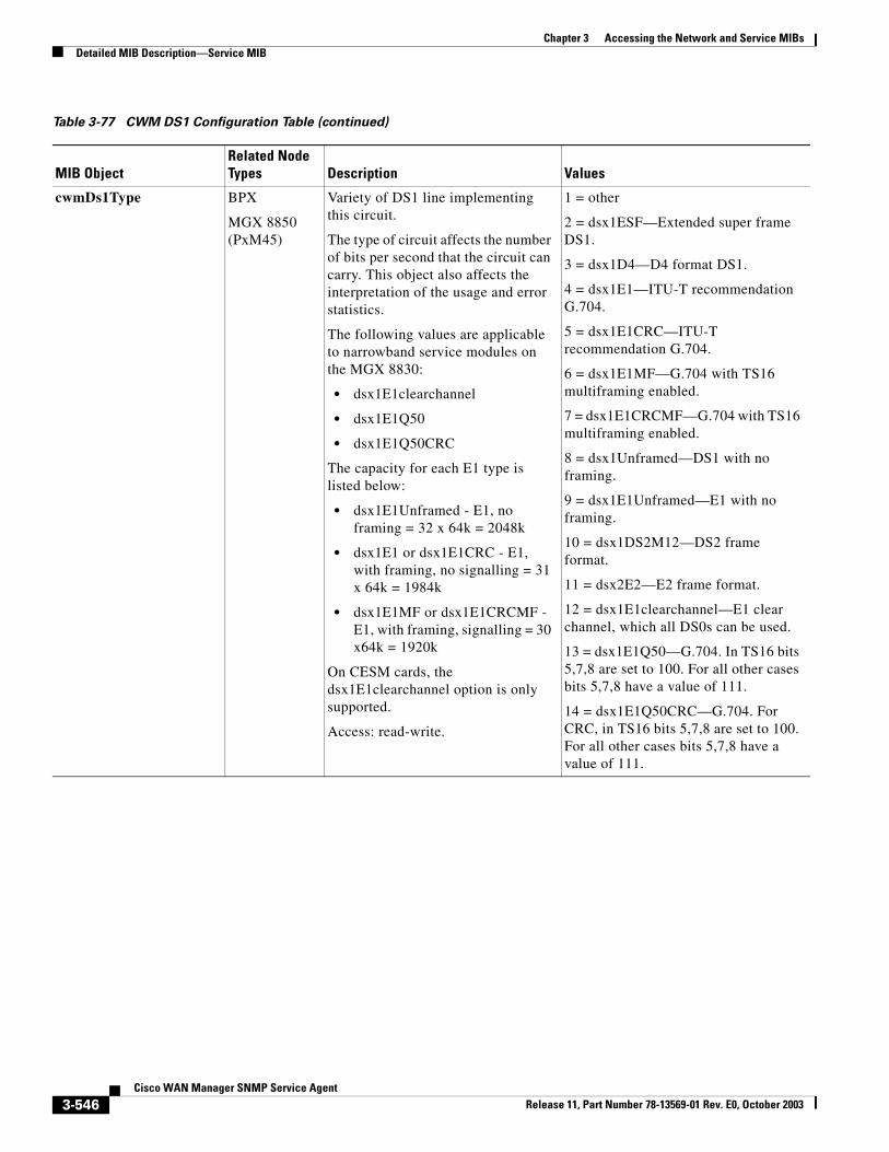
Chapter 3 Accessing the Network and Service MIBsDetailed MIB Description—Service MIB
cwmDs1Type BPX
MGX 8850 (PxM45)
Variety of DS1 line implementing this circuit.
The type of circuit affects the number of bits per second that the circuit can carry. This object also affects the interpretation of the usage and error statistics.
The following values are applicable to narrowband service modules on the MGX 8830:
• dsx1E1clearchannel
• dsx1E1Q50
• dsx1E1Q50CRC
The capacity for each E1 type is listed below:
• dsx1E1Unframed - E1, no framing = 32 x 64k = 2048k
• dsx1E1 or dsx1E1CRC - E1, with framing, no signalling = 31 x 64k = 1984k
• dsx1E1MF or dsx1E1CRCMF - E1, with framing, signalling = 30 x64k = 1920k
On CESM cards, the dsx1E1clearchannel option is only supported.
Access: read-write.
1 = other
2 = dsx1ESF—Extended super frame DS1.
3 = dsx1D4—D4 format DS1.
4 = dsx1E1—ITU-T recommendation G.704.
5 = dsx1E1CRC—ITU-T recommendation G.704.
6 = dsx1E1MF—G.704 with TS16 multiframing enabled.
7 = dsx1E1CRCMF—G.704 with TS16 multiframing enabled.
8 = dsx1Unframed—DS1 with no framing.
9 = dsx1E1Unframed—E1 with no framing.
10 = dsx1DS2M12—DS2 frame format.
11 = dsx2E2—E2 frame format.
12 = dsx1E1clearchannel—E1 clear channel, which all DS0s can be used.
13 = dsx1E1Q50—G.704. In TS16 bits 5,7,8 are set to 100. For all other cases bits 5,7,8 have a value of 111.
14 = dsx1E1Q50CRC—G.704. For CRC, in TS16 bits 5,7,8 are set to 100. For all other cases bits 5,7,8 have a value of 111.
Table 3-77 CWM DS1 Configuration Table (continued)
MIB ObjectRelated Node Types Description Values
3-546Cisco WAN Manager SNMP Service Agent
Release 11, Part Number 78-13569-01 Rev. E0, October 2003
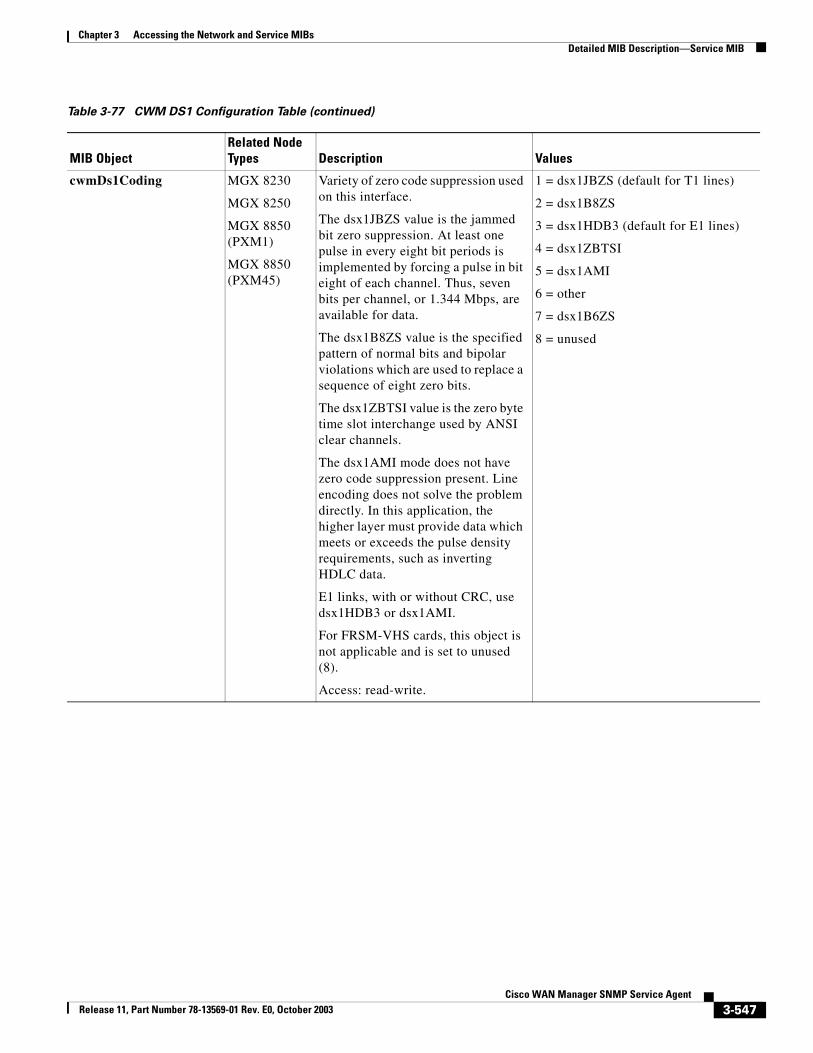
Chapter 3 Accessing the Network and Service MIBsDetailed MIB Description—Service MIB
cwmDs1Coding MGX 8230
MGX 8250
MGX 8850 (PXM1)
MGX 8850 (PXM45)
Variety of zero code suppression used on this interface.
The dsx1JBZS value is the jammed bit zero suppression. At least one pulse in every eight bit periods is implemented by forcing a pulse in bit eight of each channel. Thus, seven bits per channel, or 1.344 Mbps, are available for data.
The dsx1B8ZS value is the specified pattern of normal bits and bipolar violations which are used to replace a sequence of eight zero bits.
The dsx1ZBTSI value is the zero byte time slot interchange used by ANSI clear channels.
The dsx1AMI mode does not have zero code suppression present. Line encoding does not solve the problem directly. In this application, the higher layer must provide data which meets or exceeds the pulse density requirements, such as inverting HDLC data.
E1 links, with or without CRC, use dsx1HDB3 or dsx1AMI.
For FRSM-VHS cards, this object is not applicable and is set to unused (8).
Access: read-write.
1 = dsx1JBZS (default for T1 lines)
2 = dsx1B8ZS
3 = dsx1HDB3 (default for E1 lines)
4 = dsx1ZBTSI
5 = dsx1AMI
6 = other
7 = dsx1B6ZS
8 = unused
Table 3-77 CWM DS1 Configuration Table (continued)
MIB ObjectRelated Node Types Description Values
3-547Cisco WAN Manager SNMP Service Agent
Release 11, Part Number 78-13569-01 Rev. E0, October 2003
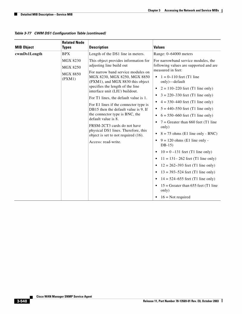
Chapter 3 Accessing the Network and Service MIBsDetailed MIB Description—Service MIB
cwmDs1Length BPX
MGX 8230
MGX 8250
MGX 8850 (PXM1)
Length of the DS1 line in meters.
This object provides information for adjusting line build out
For narrow band service modules on MGX 8230, MGX 8250, MGX 8850 (PXM1), and MGX 8830 this object specifies the length of the line interface unit (LIU) buildout.
For T1 lines, the default value is 1.
For E1 lines if the connector type is DB15 then the default value is 9. If the connector type is BNC, the default value is 8.
FRSM-2CT3 cards do not have physical DS1 lines. Therefore, this object is set to not required (16).
Access: read-write.
Range: 0–64000 meters
For narrowband service modules, the following values are supported and are measured in feet:
• 1 = 0–110 feet (T1 line only)—default
• 2 = 110–220 feet (T1 line only)
• 3 = 220–330 feet (T1 line only)
• 4 = 330–440 feet (T1 line only)
• 5 = 440–550 feet (T1 line only)
• 6 = 550–660 feet (T1 line only)
• 7 = Greater than 660 feet (T1 line only)
• 8 = 75 ohms (E1 line only - BNC)
• 9 = 120 ohms (E1 line only - DB-15)
• 10 = 0 –131 feet (T1 line only)
• 11 = 131– 262 feet (T1 line only)
• 12 = 262–393 feet (T1 line only)
• 13 = 393–524 feet (T1 line only)
• 14 = 524–655 feet (T1 line only)
• 15 = Greater than 655 feet (T1 line only)
• 16 = Not required
Table 3-77 CWM DS1 Configuration Table (continued)
MIB ObjectRelated Node Types Description Values
3-548Cisco WAN Manager SNMP Service Agent
Release 11, Part Number 78-13569-01 Rev. E0, October 2003
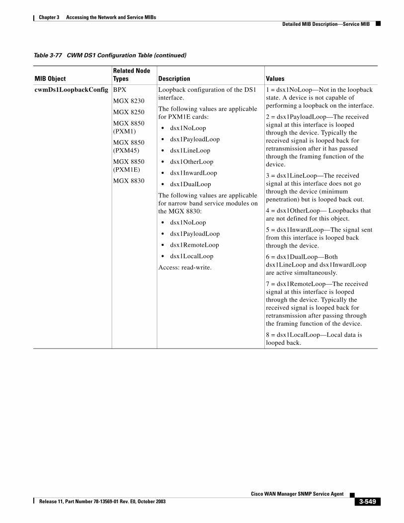
Chapter 3 Accessing the Network and Service MIBsDetailed MIB Description—Service MIB
cwmDs1LoopbackConfig BPX
MGX 8230
MGX 8250
MGX 8850 (PXM1)
MGX 8850 (PXM45)
MGX 8850 (PXM1E)
MGX 8830
Loopback configuration of the DS1 interface.
The following values are applicable for PXM1E cards:
• dsx1NoLoop
• dsx1PayloadLoop
• dsx1LineLoop
• dsx1OtherLoop
• dsx1InwardLoop
• dsx1DualLoop
The following values are applicable for narrow band service modules on the MGX 8830:
• dsx1NoLoop
• dsx1PayloadLoop
• dsx1RemoteLoop
• dsx1LocalLoop
Access: read-write.
1 = dsx1NoLoop—Not in the loopback state. A device is not capable of performing a loopback on the interface.
2 = dsx1PayloadLoop—The received signal at this interface is looped through the device. Typically the received signal is looped back for retransmission after it has passed through the framing function of the device.
3 = dsx1LineLoop—The received signal at this interface does not go through the device (minimum penetration) but is looped back out.
4 = dsx1OtherLoop— Loopbacks that are not defined for this object.
5 = dsx1InwardLoop—The signal sent from this interface is looped back through the device.
6 = dsx1DualLoop—Both dsx1LineLoop and dsx1InwardLoop are active simultaneously.
7 = dsx1RemoteLoop—The received signal at this interface is looped through the device. Typically the received signal is looped back for retransmission after passing through the framing function of the device.
8 = dsx1LocalLoop—Local data is looped back.
Table 3-77 CWM DS1 Configuration Table (continued)
MIB ObjectRelated Node Types Description Values
3-549Cisco WAN Manager SNMP Service Agent
Release 11, Part Number 78-13569-01 Rev. E0, October 2003
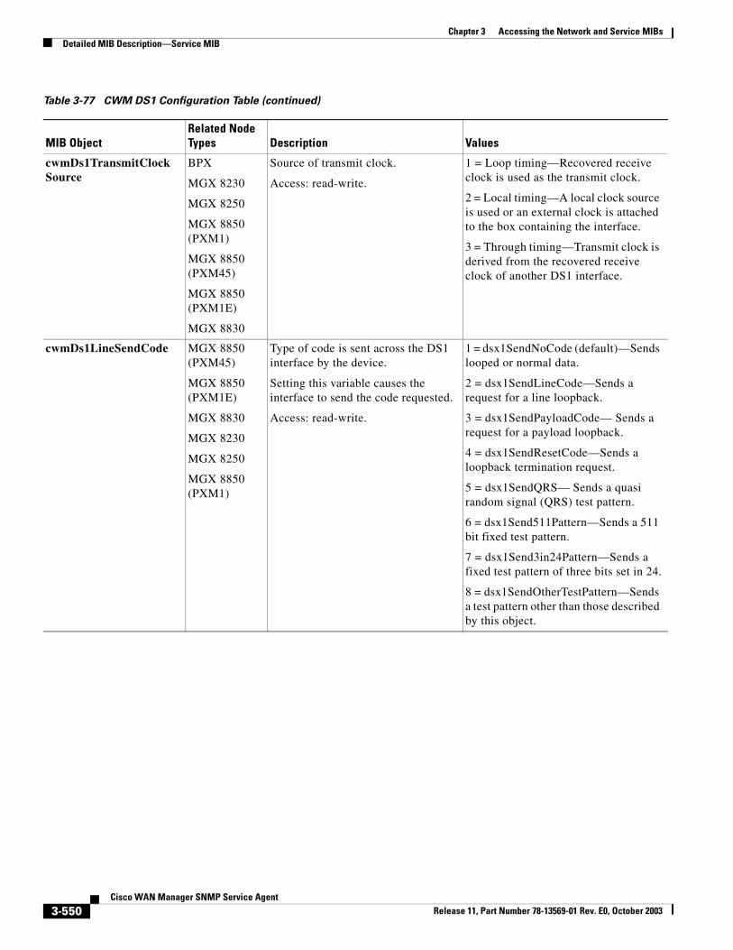
Chapter 3 Accessing the Network and Service MIBsDetailed MIB Description—Service MIB
cwmDs1TransmitClockSource
BPX
MGX 8230
MGX 8250
MGX 8850 (PXM1)
MGX 8850 (PXM45)
MGX 8850 (PXM1E)
MGX 8830
Source of transmit clock.
Access: read-write.
1 = Loop timing—Recovered receive clock is used as the transmit clock.
2 = Local timing—A local clock source is used or an external clock is attached to the box containing the interface.
3 = Through timing—Transmit clock is derived from the recovered receive clock of another DS1 interface.
cwmDs1LineSendCode MGX 8850 (PXM45)
MGX 8850 (PXM1E)
MGX 8830
MGX 8230
MGX 8250
MGX 8850 (PXM1)
Type of code is sent across the DS1 interface by the device.
Setting this variable causes the interface to send the code requested.
Access: read-write.
1 = dsx1SendNoCode (default)—Sends looped or normal data.
2 = dsx1SendLineCode—Sends a request for a line loopback.
3 = dsx1SendPayloadCode— Sends a request for a payload loopback.
4 = dsx1SendResetCode—Sends a loopback termination request.
5 = dsx1SendQRS— Sends a quasi random signal (QRS) test pattern.
6 = dsx1Send511Pattern—Sends a 511 bit fixed test pattern.
7 = dsx1Send3in24Pattern—Sends a fixed test pattern of three bits set in 24.
8 = dsx1SendOtherTestPattern—Sends a test pattern other than those described by this object.
Table 3-77 CWM DS1 Configuration Table (continued)
MIB ObjectRelated Node Types Description Values
3-550Cisco WAN Manager SNMP Service Agent
Release 11, Part Number 78-13569-01 Rev. E0, October 2003
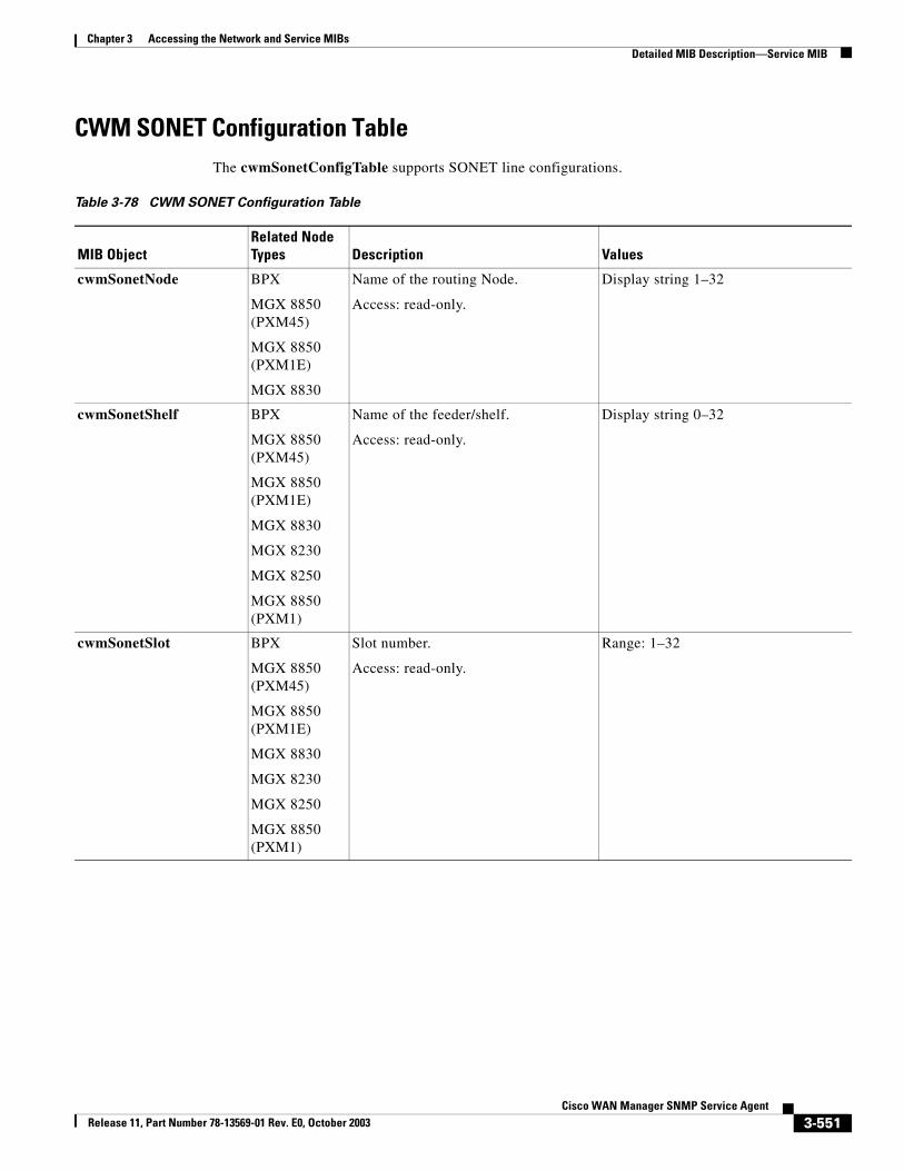
Chapter 3 Accessing the Network and Service MIBsDetailed MIB Description—Service MIB
CWM SONET Configuration TableThe cwmSonetConfigTable supports SONET line configurations.
Table 3-78 CWM SONET Configuration Table
MIB ObjectRelated Node Types Description Values
cwmSonetNode BPX
MGX 8850 (PXM45)
MGX 8850 (PXM1E)
MGX 8830
Name of the routing Node.
Access: read-only.
Display string 1–32
cwmSonetShelf BPX
MGX 8850 (PXM45)
MGX 8850 (PXM1E)
MGX 8830
MGX 8230
MGX 8250
MGX 8850 (PXM1)
Name of the feeder/shelf.
Access: read-only.
Display string 0–32
cwmSonetSlot BPX
MGX 8850 (PXM45)
MGX 8850 (PXM1E)
MGX 8830
MGX 8230
MGX 8250
MGX 8850 (PXM1)
Slot number.
Access: read-only.
Range: 1–32
3-551Cisco WAN Manager SNMP Service Agent
Release 11, Part Number 78-13569-01 Rev. E0, October 2003
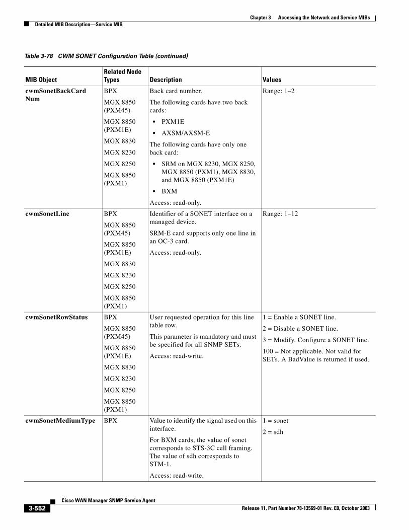
Chapter 3 Accessing the Network and Service MIBsDetailed MIB Description—Service MIB
cwmSonetBackCardNum
BPX
MGX 8850 (PXM45)
MGX 8850 (PXM1E)
MGX 8830
MGX 8230
MGX 8250
MGX 8850 (PXM1)
Back card number.
The following cards have two back cards:
• PXM1E
• AXSM/AXSM-E
The following cards have only one back card:
• SRM on MGX 8230, MGX 8250, MGX 8850 (PXM1), MGX 8830, and MGX 8850 (PXM1E)
• BXM
Access: read-only.
Range: 1–2
cwmSonetLine BPX
MGX 8850 (PXM45)
MGX 8850 (PXM1E)
MGX 8830
MGX 8230
MGX 8250
MGX 8850 (PXM1)
Identifier of a SONET interface on a managed device.
SRM-E card supports only one line in an OC-3 card.
Access: read-only.
Range: 1–12
cwmSonetRowStatus BPX
MGX 8850 (PXM45)
MGX 8850 (PXM1E)
MGX 8830
MGX 8230
MGX 8250
MGX 8850 (PXM1)
User requested operation for this line table row.
This parameter is mandatory and must be specified for all SNMP SETs.
Access: read-write.
1 = Enable a SONET line.
2 = Disable a SONET line.
3 = Modify. Configure a SONET line.
100 = Not applicable. Not valid for SETs. A BadValue is returned if used.
cwmSonetMediumType BPX Value to identify the signal used on this interface.
For BXM cards, the value of sonet corresponds to STS-3C cell framing. The value of sdh corresponds to STM-1.
Access: read-write.
1 = sonet
2 = sdh
Table 3-78 CWM SONET Configuration Table (continued)
MIB ObjectRelated Node Types Description Values
3-552Cisco WAN Manager SNMP Service Agent
Release 11, Part Number 78-13569-01 Rev. E0, October 2003
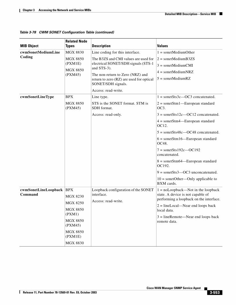
Chapter 3 Accessing the Network and Service MIBsDetailed MIB Description—Service MIB
cwmSonetMediumLineCoding
MGX 8830
MGX 8850 (PXM1E)
MGX 8850 (PXM45)
Line coding for this interface.
The B3ZS and CMI values are used for electrical SONET/SDH signals (STS-1 and STS-3).
The non-return to Zero (NRZ) and return to zero (RZ) are used for optical SONET/SDH signals.
Access: read-write.
1 = sonetMediumOther
2 = sonetMediumB3ZS
3 = sonetMediumCMI
4 = sonetMediumNRZ
5 = sonetMediumRZ
cwmSonetLineType BPX
MGX 8850 (PXM45)
Line type.
STS is the SONET format. STM is SDH format.
Access: read-only.
1 = sonetSts3c—OC3 concatenated.
2 = sonetStm1—European standard OC3.
3 = sonetSts12c—OC12 concatenated.
4 = sonetStm4—European standard OC12.
5 = sonetSts48c—OC48 concatenated.
6 = sonetStm16—European standard OC48.
7 = sonetSts192c—OC192 concatenated.
8 = sonetStm64—European standard OC192.
9 = sonetSts3—OC3 unconcatenated.
10 = sonetOther—Only applicable to BXM cards.
cwmSonetLineLoopbackCommand
BPX
MGX 8230
MGX 8250
MGX 8850 (PXM1)
MGX 8850 (PXM45)
MGX 8850 (PXM1E)
MGX 8830
Loopback configuration of the SONET interface.
Access: read-write.
1 = noLoopback—Not in the loopback state. A device is not capable of performing a loopback on the interface.
2 = lineLocal—Near end loops back local data.
3 = lineRemote—Near end loops back remote data.
Table 3-78 CWM SONET Configuration Table (continued)
MIB ObjectRelated Node Types Description Values
3-553Cisco WAN Manager SNMP Service Agent
Release 11, Part Number 78-13569-01 Rev. E0, October 2003
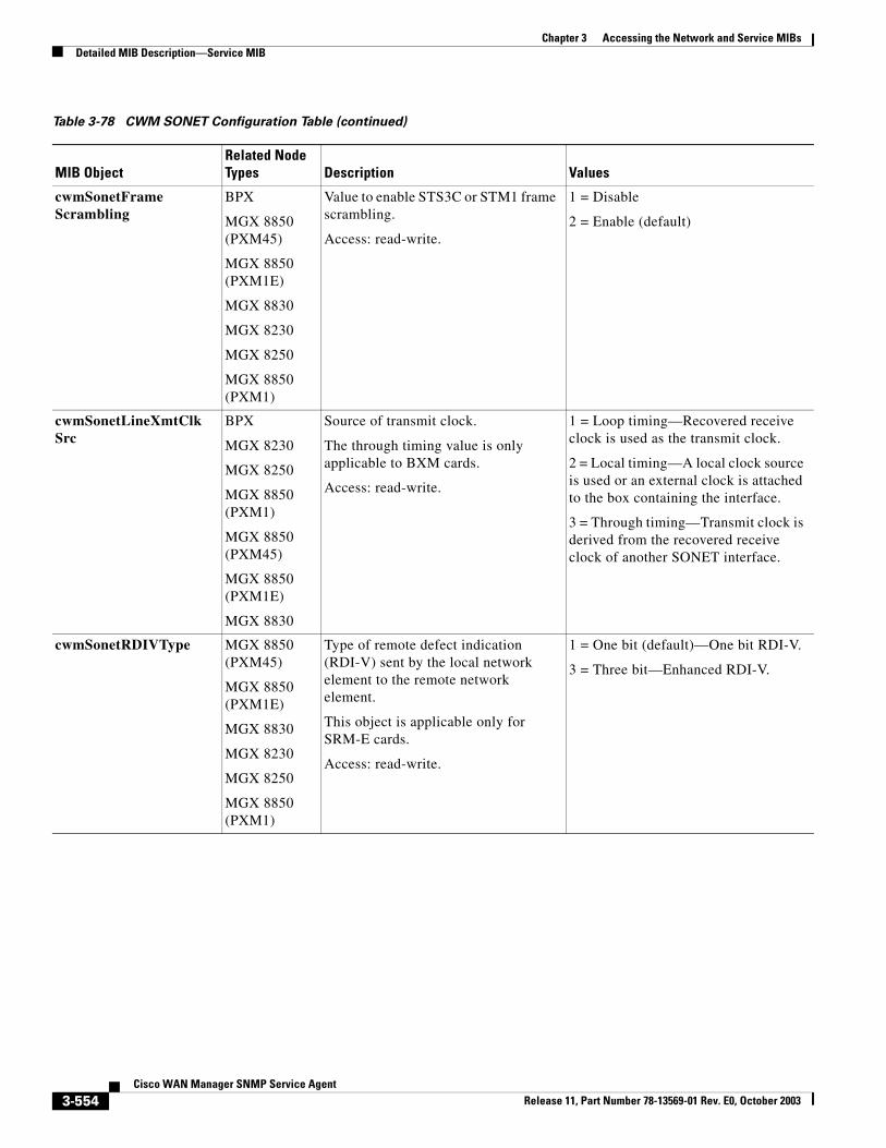
Chapter 3 Accessing the Network and Service MIBsDetailed MIB Description—Service MIB
cwmSonetFrameScrambling
BPX
MGX 8850 (PXM45)
MGX 8850 (PXM1E)
MGX 8830
MGX 8230
MGX 8250
MGX 8850 (PXM1)
Value to enable STS3C or STM1 frame scrambling.
Access: read-write.
1 = Disable
2 = Enable (default)
cwmSonetLineXmtClkSrc
BPX
MGX 8230
MGX 8250
MGX 8850 (PXM1)
MGX 8850 (PXM45)
MGX 8850 (PXM1E)
MGX 8830
Source of transmit clock.
The through timing value is only applicable to BXM cards.
Access: read-write.
1 = Loop timing—Recovered receive clock is used as the transmit clock.
2 = Local timing—A local clock source is used or an external clock is attached to the box containing the interface.
3 = Through timing—Transmit clock is derived from the recovered receive clock of another SONET interface.
cwmSonetRDIVType MGX 8850 (PXM45)
MGX 8850 (PXM1E)
MGX 8830
MGX 8230
MGX 8250
MGX 8850 (PXM1)
Type of remote defect indication (RDI-V) sent by the local network element to the remote network element.
This object is applicable only for SRM-E cards.
Access: read-write.
1 = One bit (default)—One bit RDI-V.
3 = Three bit—Enhanced RDI-V.
Table 3-78 CWM SONET Configuration Table (continued)
MIB ObjectRelated Node Types Description Values
3-554Cisco WAN Manager SNMP Service Agent
Release 11, Part Number 78-13569-01 Rev. E0, October 2003
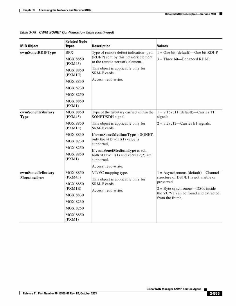
Chapter 3 Accessing the Network and Service MIBsDetailed MIB Description—Service MIB
cwmSonetRDIPType BPX
MGX 8850 (PXM45)
MGX 8850 (PXM1E)
MGX 8830
MGX 8230
MGX 8250
MGX 8850 (PXM1)
Type of remote defect indication- path (RDI-P) sent by this network element to the remote network element.
This object is applicable only for SRM-E cards.
Access: read-write.
1 = One bit (default)—One bit RDI-P.
3 = Three bit—Enhanced RDI-P.
cwmSonetTributaryType
MGX 8850 (PXM45)
MGX 8850 (PXM1E)
MGX 8830
MGX 8230
MGX 8250
MGX 8850 (PXM1)
Type of the tributary carried within the SONET/SDH signal.
This object is applicable only for SRM-E cards.
If cwmSonetMediumType is SONET, only the vt15vc11(1) value is supported,
If cwmSonetMediumType is sdh, both vt15vc11(1) and vt2vc12(2) are supported.
Access: read-write.
1 = vt15vc11 (default)—Carries T1 signals.
2 = vt2vc12—Carries E1 signals.
cwmSonetTributaryMappingType
MGX 8850 (PXM45)
MGX 8850 (PXM1E)
MGX 8830
MGX 8230
MGX 8250
MGX 8850 (PXM1)
VT/VC mapping type.
This object is applicable only for SRM-E cards.
Access: read-write.
1 = Asynchronous (default)—Channel structure of DS1/E1 is not visible or preserved.
2 = Byte synchronous—DS0s inside the VC/VT can be found and extracted from the frame.
Table 3-78 CWM SONET Configuration Table (continued)
MIB ObjectRelated Node Types Description Values
3-555Cisco WAN Manager SNMP Service Agent
Release 11, Part Number 78-13569-01 Rev. E0, October 2003
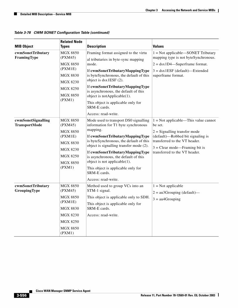
Chapter 3 Accessing the Network and Service MIBsDetailed MIB Description—Service MIB
cwmSonetTributaryFramingType
MGX 8850 (PXM45)
MGX 8850 (PXM1E)
MGX 8830
MGX 8230
MGX 8250
MGX 8850 (PXM1)
Framing format assigned to the virtu
al tributaries in byte-sync mapping mode.
If cwmSonetTributaryMappingType is byteSynchronous, the default of this object is dsx1ESF (2).
If cwmSonetTributaryMappingType is asynchronous, the default of this object is notApplicable(1).
This object is applicable only for SRM-E cards.
Access: read-write.
1 = Not applicable—SONET Tributary mapping type is not byteSynchronous.
2 = dsx1D4—Superframe format.
3 = dsx1ESF (default)—Extended superframe format.
cwmSonetSignallingTransportMode
MGX 8850 (PXM45)
MGX 8850 (PXM1E)
MGX 8830
MGX 8230
MGX 8250
MGX 8850 (PXM1)
Mode used to transport DS0 signalling information for T1 byte synchronous mapping.
If cwmSonetTributaryMappingType is byteSynchronous, the default of this object is signalling transfer mode (2).
If cwmSonetTributaryMappingType is asynchronous, the default of this object is not applicable(1).
This object is applicable only for SRM-E cards.
Access: read-write.
1 = Not applicable—This value cannot be set.
2 = Signalling transfer mode (default)—Robbed bit signaling is transferred to the VT header.
3 = Clear mode—Framing bit is transferred to the VT header.
cwmSonetTributaryGroupingType
MGX 8850 (PXM45)
MGX 8850 (PXM1E)
MGX 8830
MGX 8230
MGX 8250
MGX 8850 (PXM1)
Method used to group VCs into an STM-1 signal.
This object is applicable only to SDH.
This object is applicable only for SRM-E cards.
Access: read-write.
1 = Not applicable
2 = au3Grouping (default)—
3 = au4Grouping
Table 3-78 CWM SONET Configuration Table (continued)
MIB ObjectRelated Node Types Description Values
3-556Cisco WAN Manager SNMP Service Agent
Release 11, Part Number 78-13569-01 Rev. E0, October 2003
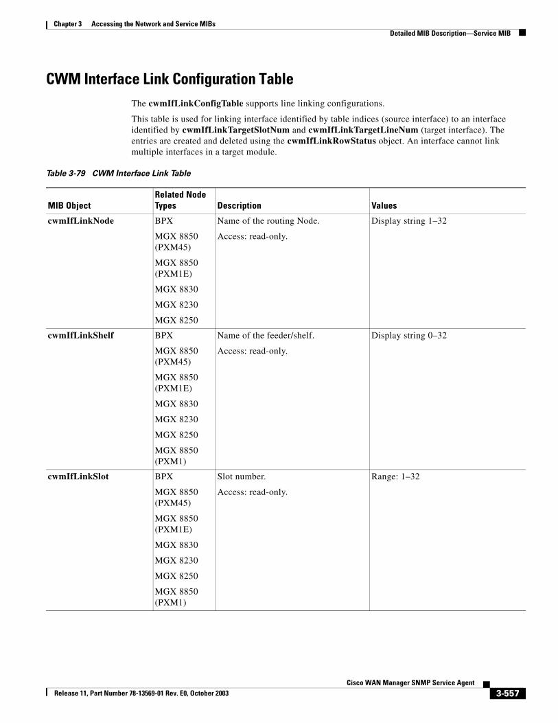
Chapter 3 Accessing the Network and Service MIBsDetailed MIB Description—Service MIB
CWM Interface Link Configuration TableThe cwmIfLinkConfigTable supports line linking configurations.
This table is used for linking interface identified by table indices (source interface) to an interface identified by cwmIfLinkTargetSlotNum and cwmIfLinkTargetLineNum (target interface). The entries are created and deleted using the cwmIfLinkRowStatus object. An interface cannot link multiple interfaces in a target module.
Table 3-79 CWM Interface Link Table
MIB ObjectRelated Node Types Description Values
cwmIfLinkNode BPX
MGX 8850 (PXM45)
MGX 8850 (PXM1E)
MGX 8830
MGX 8230
MGX 8250
Name of the routing Node.
Access: read-only.
Display string 1–32
cwmIfLinkShelf BPX
MGX 8850 (PXM45)
MGX 8850 (PXM1E)
MGX 8830
MGX 8230
MGX 8250
MGX 8850 (PXM1)
Name of the feeder/shelf.
Access: read-only.
Display string 0–32
cwmIfLinkSlot BPX
MGX 8850 (PXM45)
MGX 8850 (PXM1E)
MGX 8830
MGX 8230
MGX 8250
MGX 8850 (PXM1)
Slot number.
Access: read-only.
Range: 1–32
3-557Cisco WAN Manager SNMP Service Agent
Release 11, Part Number 78-13569-01 Rev. E0, October 2003
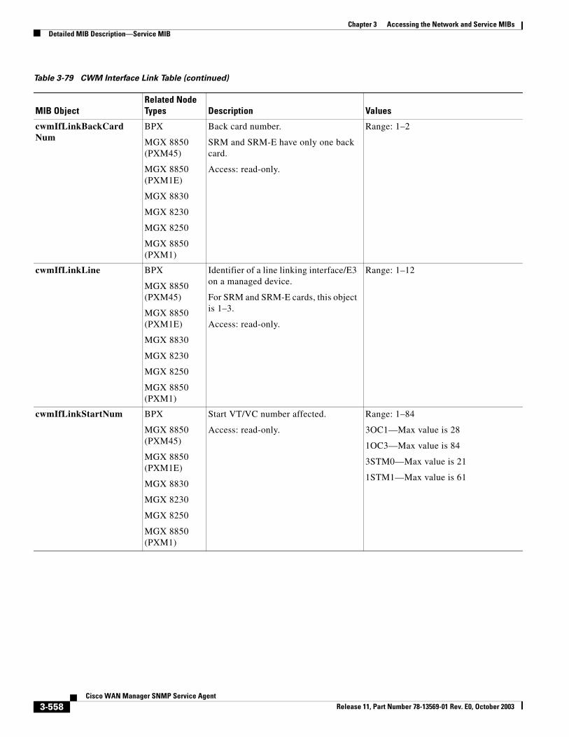
Chapter 3 Accessing the Network and Service MIBsDetailed MIB Description—Service MIB
cwmIfLinkBackCardNum
BPX
MGX 8850 (PXM45)
MGX 8850 (PXM1E)
MGX 8830
MGX 8230
MGX 8250
MGX 8850 (PXM1)
Back card number.
SRM and SRM-E have only one back card.
Access: read-only.
Range: 1–2
cwmIfLinkLine BPX
MGX 8850 (PXM45)
MGX 8850 (PXM1E)
MGX 8830
MGX 8230
MGX 8250
MGX 8850 (PXM1)
Identifier of a line linking interface/E3 on a managed device.
For SRM and SRM-E cards, this object is 1–3.
Access: read-only.
Range: 1–12
cwmIfLinkStartNum BPX
MGX 8850 (PXM45)
MGX 8850 (PXM1E)
MGX 8830
MGX 8230
MGX 8250
MGX 8850 (PXM1)
Start VT/VC number affected.
Access: read-only.
Range: 1–84
3OC1—Max value is 28
1OC3—Max value is 84
3STM0—Max value is 21
1STM1—Max value is 61
Table 3-79 CWM Interface Link Table (continued)
MIB ObjectRelated Node Types Description Values
3-558Cisco WAN Manager SNMP Service Agent
Release 11, Part Number 78-13569-01 Rev. E0, October 2003
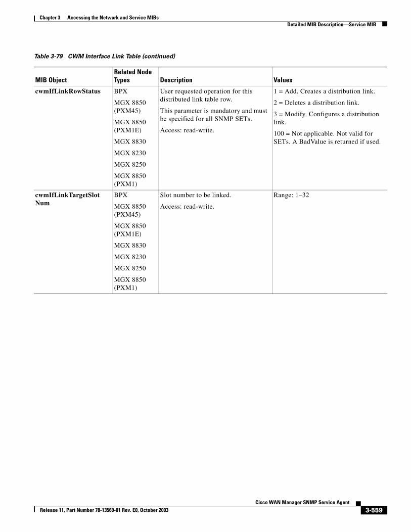
Chapter 3 Accessing the Network and Service MIBsDetailed MIB Description—Service MIB
cwmIfLinkRowStatus BPX
MGX 8850 (PXM45)
MGX 8850 (PXM1E)
MGX 8830
MGX 8230
MGX 8250
MGX 8850 (PXM1)
User requested operation for this distributed link table row.
This parameter is mandatory and must be specified for all SNMP SETs.
Access: read-write.
1 = Add. Creates a distribution link.
2 = Deletes a distribution link.
3 = Modify. Configures a distribution link.
100 = Not applicable. Not valid for SETs. A BadValue is returned if used.
cwmIfLinkTargetSlotNum
BPX
MGX 8850 (PXM45)
MGX 8850 (PXM1E)
MGX 8830
MGX 8230
MGX 8250
MGX 8850 (PXM1)
Slot number to be linked.
Access: read-write.
Range: 1–32
Table 3-79 CWM Interface Link Table (continued)
MIB ObjectRelated Node Types Description Values
3-559Cisco WAN Manager SNMP Service Agent
Release 11, Part Number 78-13569-01 Rev. E0, October 2003
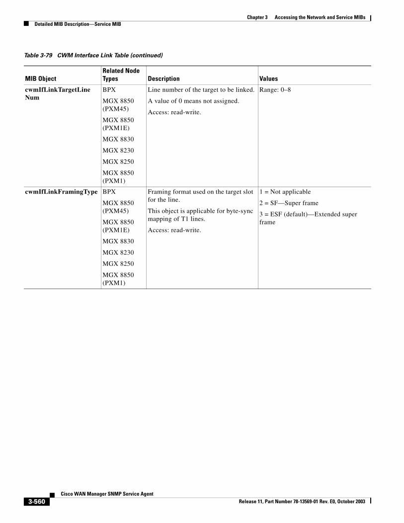
Chapter 3 Accessing the Network and Service MIBsDetailed MIB Description—Service MIB
cwmIfLinkTargetLineNum
BPX
MGX 8850 (PXM45)
MGX 8850 (PXM1E)
MGX 8830
MGX 8230
MGX 8250
MGX 8850 (PXM1)
Line number of the target to be linked.
A value of 0 means not assigned.
Access: read-write.
Range: 0–8
cwmIfLinkFramingType BPX
MGX 8850 (PXM45)
MGX 8850 (PXM1E)
MGX 8830
MGX 8230
MGX 8250
MGX 8850 (PXM1)
Framing format used on the target slot for the line.
This object is applicable for byte-sync mapping of T1 lines.
Access: read-write.
1 = Not applicable
2 = SF—Super frame
3 = ESF (default)—Extended super frame
Table 3-79 CWM Interface Link Table (continued)
MIB ObjectRelated Node Types Description Values
3-560Cisco WAN Manager SNMP Service Agent
Release 11, Part Number 78-13569-01 Rev. E0, October 2003
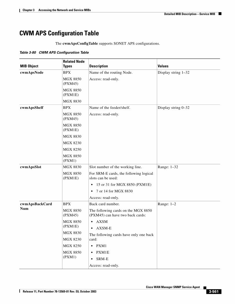
Chapter 3 Accessing the Network and Service MIBsDetailed MIB Description—Service MIB
CWM APS Configuration TableThe cwmApsConfigTable supports SONET APS configurations.
Table 3-80 CWM APS Configuration Table
MIB ObjectRelated Node Types Description Values
cwmApsNode BPX
MGX 8850 (PXM45)
MGX 8850 (PXM1E)
MGX 8830
Name of the routing Node.
Access: read-only.
Display string 1–32
cwmApsShelf BPX
MGX 8850 (PXM45)
MGX 8850 (PXM1E)
MGX 8830
MGX 8230
MGX 8250
MGX 8850 (PXM1)
Name of the feeder/shelf.
Access: read-only.
Display string 0–32
cwmApsSlot MGX 8830
MGX 8850 (PXM1E)
Slot number of the working line.
For SRM-E cards, the following logical slots can be used:
• 15 or 31 for MGX 8850 (PXM1E)
• 7 or 14 for MGX 8830
Access: read-only.
Range: 1–32
cwmApsBackCardNum
BPX
MGX 8850 (PXM45)
MGX 8850 (PXM1E)
MGX 8830
MGX 8230
MGX 8250
MGX 8850 (PXM1)
Back card number.
The following cards on the MGX 8850 (PXM45) can have two back cards:
• AXSM
• AXSM-E
The following cards have only one back card:
• PXM1
• PXM1E
• SRM-E
Access: read-only.
Range: 1–2
3-561Cisco WAN Manager SNMP Service Agent
Release 11, Part Number 78-13569-01 Rev. E0, October 2003
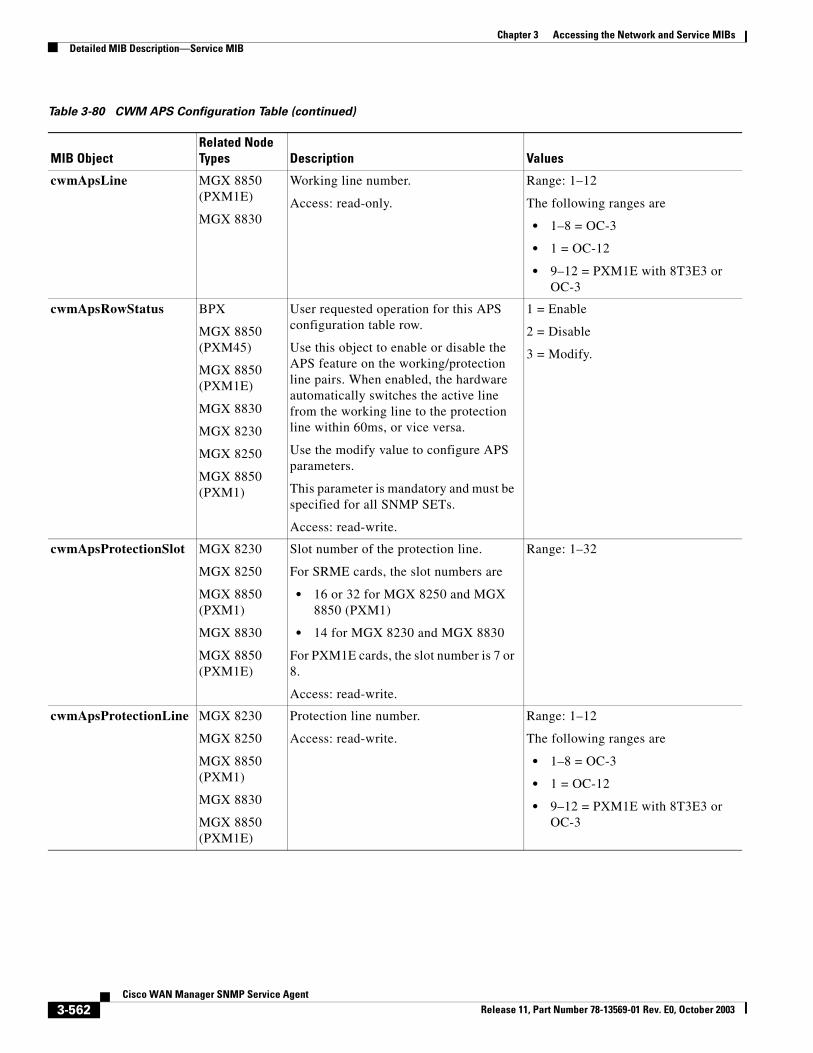
Chapter 3 Accessing the Network and Service MIBsDetailed MIB Description—Service MIB
cwmApsLine MGX 8850 (PXM1E)
MGX 8830
Working line number.
Access: read-only.
Range: 1–12
The following ranges are
• 1–8 = OC-3
• 1 = OC-12
• 9–12 = PXM1E with 8T3E3 or OC-3
cwmApsRowStatus BPX
MGX 8850 (PXM45)
MGX 8850 (PXM1E)
MGX 8830
MGX 8230
MGX 8250
MGX 8850 (PXM1)
User requested operation for this APS configuration table row.
Use this object to enable or disable the APS feature on the working/protection line pairs. When enabled, the hardware automatically switches the active line from the working line to the protection line within 60ms, or vice versa.
Use the modify value to configure APS parameters.
This parameter is mandatory and must be specified for all SNMP SETs.
Access: read-write.
1 = Enable
2 = Disable
3 = Modify.
cwmApsProtectionSlot MGX 8230
MGX 8250
MGX 8850 (PXM1)
MGX 8830
MGX 8850 (PXM1E)
Slot number of the protection line.
For SRME cards, the slot numbers are
• 16 or 32 for MGX 8250 and MGX 8850 (PXM1)
• 14 for MGX 8230 and MGX 8830
For PXM1E cards, the slot number is 7 or 8.
Access: read-write.
Range: 1–32
cwmApsProtectionLine MGX 8230
MGX 8250
MGX 8850 (PXM1)
MGX 8830
MGX 8850 (PXM1E)
Protection line number.
Access: read-write.
Range: 1–12
The following ranges are
• 1–8 = OC-3
• 1 = OC-12
• 9–12 = PXM1E with 8T3E3 or OC-3
Table 3-80 CWM APS Configuration Table (continued)
MIB ObjectRelated Node Types Description Values
3-562Cisco WAN Manager SNMP Service Agent
Release 11, Part Number 78-13569-01 Rev. E0, October 2003
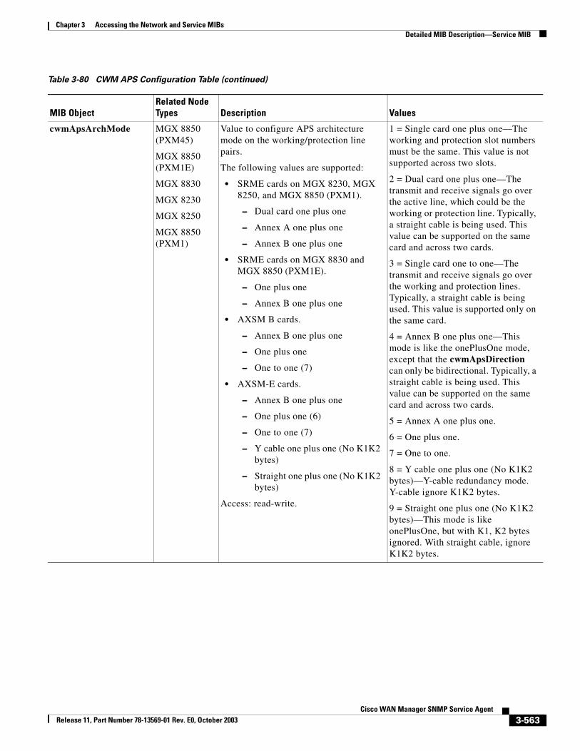
Chapter 3 Accessing the Network and Service MIBsDetailed MIB Description—Service MIB
cwmApsArchMode MGX 8850 (PXM45)
MGX 8850 (PXM1E)
MGX 8830
MGX 8230
MGX 8250
MGX 8850 (PXM1)
Value to configure APS architecture mode on the working/protection line pairs.
The following values are supported:
• SRME cards on MGX 8230, MGX 8250, and MGX 8850 (PXM1).
– Dual card one plus one
– Annex A one plus one
– Annex B one plus one
• SRME cards on MGX 8830 and MGX 8850 (PXM1E).
– One plus one
– Annex B one plus one
• AXSM B cards.
– Annex B one plus one
– One plus one
– One to one (7)
• AXSM-E cards.
– Annex B one plus one
– One plus one (6)
– One to one (7)
– Y cable one plus one (No K1K2 bytes)
– Straight one plus one (No K1K2 bytes)
Access: read-write.
1 = Single card one plus one—The working and protection slot numbers must be the same. This value is not supported across two slots.
2 = Dual card one plus one—The transmit and receive signals go over the active line, which could be the working or protection line. Typically, a straight cable is being used. This value can be supported on the same card and across two cards.
3 = Single card one to one—The transmit and receive signals go over the working and protection lines. Typically, a straight cable is being used. This value is supported only on the same card.
4 = Annex B one plus one—This mode is like the onePlusOne mode, except that the cwmApsDirection can only be bidirectional. Typically, a straight cable is being used. This value can be supported on the same card and across two cards.
5 = Annex A one plus one.
6 = One plus one.
7 = One to one.
8 = Y cable one plus one (No K1K2 bytes)—Y-cable redundancy mode. Y-cable ignore K1K2 bytes.
9 = Straight one plus one (No K1K2 bytes)—This mode is like onePlusOne, but with K1, K2 bytes ignored. With straight cable, ignore K1K2 bytes.
Table 3-80 CWM APS Configuration Table (continued)
MIB ObjectRelated Node Types Description Values
3-563Cisco WAN Manager SNMP Service Agent
Release 11, Part Number 78-13569-01 Rev. E0, October 2003
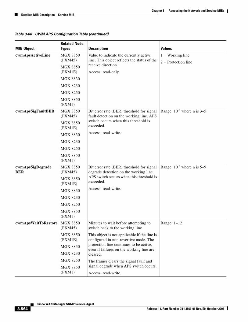
Chapter 3 Accessing the Network and Service MIBsDetailed MIB Description—Service MIB
cwmApsActiveLine MGX 8850 (PXM45)
MGX 8850 (PXM1E)
MGX 8830
MGX 8230
MGX 8250
MGX 8850 (PXM1)
Value to indicate the currently active line. This object reflects the status of the receive direction.
Access: read-only.
1 = Working line
2 = Protection line
cwmApsSigFaultBER MGX 8850 (PXM45)
MGX 8850 (PXM1E)
MGX 8830
MGX 8230
MGX 8250
MGX 8850 (PXM1)
Bit error rate (BER) threshold for signal fault detection on the working line. APS switch occurs when this threshold is exceeded.
Access: read-write.
Range: 10-n where n is 3–5
cwmApsSigDegradeBER
MGX 8850 (PXM45)
MGX 8850 (PXM1E)
MGX 8830
MGX 8230
MGX 8250
MGX 8850 (PXM1)
Bit error rate (BER) threshold for signal degrade detection on the working line. APS switch occurs when this threshold is exceeded.
Access: read-write.
Range: 10-n where n is 5–9
cwmApsWaitToRestore MGX 8850 (PXM45)
MGX 8850 (PXM1E)
MGX 8830
MGX 8230
MGX 8250
MGX 8850 (PXM1)
Minutes to wait before attempting to switch back to the working line.
This object is not applicable if the line is configured in non-revertive mode. The protection line continues to be active, even if failures on the working line are cleared.
The framer clears the signal fault and signal degrade when APS switch occurs.
Access: read-write.
Range: 1–12
Table 3-80 CWM APS Configuration Table (continued)
MIB ObjectRelated Node Types Description Values
3-564Cisco WAN Manager SNMP Service Agent
Release 11, Part Number 78-13569-01 Rev. E0, October 2003
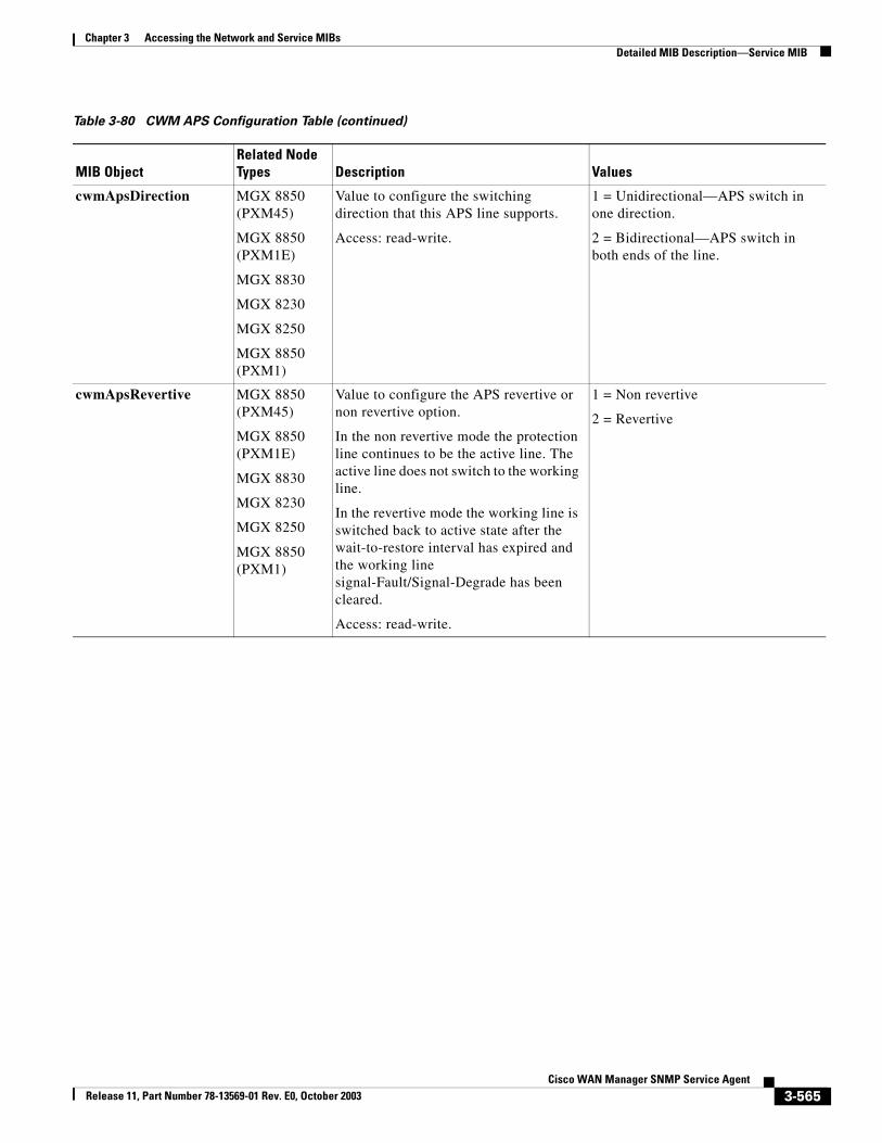
Chapter 3 Accessing the Network and Service MIBsDetailed MIB Description—Service MIB
cwmApsDirection MGX 8850 (PXM45)
MGX 8850 (PXM1E)
MGX 8830
MGX 8230
MGX 8250
MGX 8850 (PXM1)
Value to configure the switching direction that this APS line supports.
Access: read-write.
1 = Unidirectional—APS switch in one direction.
2 = Bidirectional—APS switch in both ends of the line.
cwmApsRevertive MGX 8850 (PXM45)
MGX 8850 (PXM1E)
MGX 8830
MGX 8230
MGX 8250
MGX 8850 (PXM1)
Value to configure the APS revertive or non revertive option.
In the non revertive mode the protection line continues to be the active line. The active line does not switch to the working line.
In the revertive mode the working line is switched back to active state after the wait-to-restore interval has expired and the working line signal-Fault/Signal-Degrade has been cleared.
Access: read-write.
1 = Non revertive
2 = Revertive
Table 3-80 CWM APS Configuration Table (continued)
MIB ObjectRelated Node Types Description Values
3-565Cisco WAN Manager SNMP Service Agent
Release 11, Part Number 78-13569-01 Rev. E0, October 2003
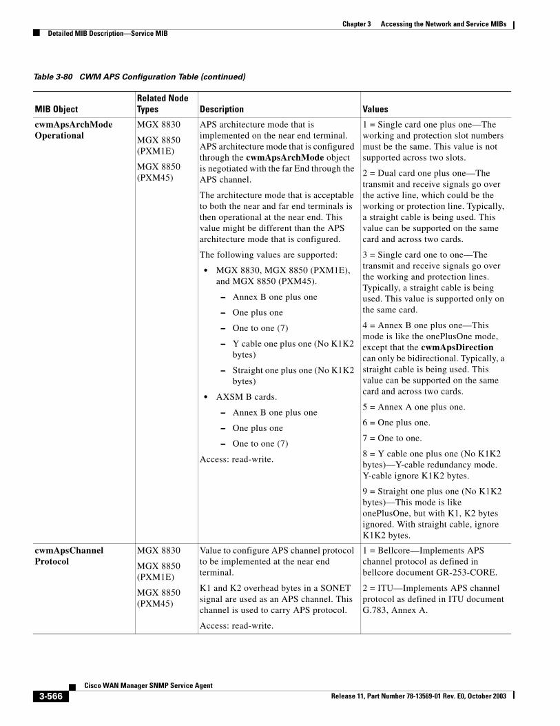
Chapter 3 Accessing the Network and Service MIBsDetailed MIB Description—Service MIB
cwmApsArchModeOperational
MGX 8830
MGX 8850 (PXM1E)
MGX 8850 (PXM45)
APS architecture mode that is implemented on the near end terminal. APS architecture mode that is configured through the cwmApsArchMode object is negotiated with the far End through the APS channel.
The architecture mode that is acceptable to both the near and far end terminals is then operational at the near end. This value might be different than the APS architecture mode that is configured.
The following values are supported:
• MGX 8830, MGX 8850 (PXM1E), and MGX 8850 (PXM45).
– Annex B one plus one
– One plus one
– One to one (7)
– Y cable one plus one (No K1K2 bytes)
– Straight one plus one (No K1K2 bytes)
• AXSM B cards.
– Annex B one plus one
– One plus one
– One to one (7)
Access: read-write.
1 = Single card one plus one—The working and protection slot numbers must be the same. This value is not supported across two slots.
2 = Dual card one plus one—The transmit and receive signals go over the active line, which could be the working or protection line. Typically, a straight cable is being used. This value can be supported on the same card and across two cards.
3 = Single card one to one—The transmit and receive signals go over the working and protection lines. Typically, a straight cable is being used. This value is supported only on the same card.
4 = Annex B one plus one—This mode is like the onePlusOne mode, except that the cwmApsDirection can only be bidirectional. Typically, a straight cable is being used. This value can be supported on the same card and across two cards.
5 = Annex A one plus one.
6 = One plus one.
7 = One to one.
8 = Y cable one plus one (No K1K2 bytes)—Y-cable redundancy mode. Y-cable ignore K1K2 bytes.
9 = Straight one plus one (No K1K2 bytes)—This mode is like onePlusOne, but with K1, K2 bytes ignored. With straight cable, ignore K1K2 bytes.
cwmApsChannelProtocol
MGX 8830
MGX 8850 (PXM1E)
MGX 8850 (PXM45)
Value to configure APS channel protocol to be implemented at the near end terminal.
K1 and K2 overhead bytes in a SONET signal are used as an APS channel. This channel is used to carry APS protocol.
Access: read-write.
1 = Bellcore—Implements APS channel protocol as defined in bellcore document GR-253-CORE.
2 = ITU—Implements APS channel protocol as defined in ITU document G.783, Annex A.
Table 3-80 CWM APS Configuration Table (continued)
MIB ObjectRelated Node Types Description Values
3-566Cisco WAN Manager SNMP Service Agent
Release 11, Part Number 78-13569-01 Rev. E0, October 2003
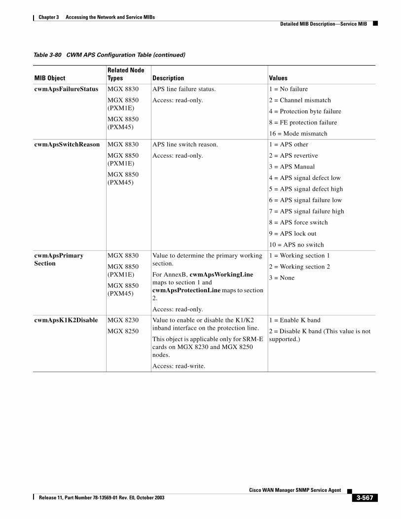
Chapter 3 Accessing the Network and Service MIBsDetailed MIB Description—Service MIB
cwmApsFailureStatus MGX 8830
MGX 8850 (PXM1E)
MGX 8850 (PXM45)
APS line failure status.
Access: read-only.
1 = No failure
2 = Channel mismatch
4 = Protection byte failure
8 = FE protection failure
16 = Mode mismatch
cwmApsSwitchReason MGX 8830
MGX 8850 (PXM1E)
MGX 8850 (PXM45)
APS line switch reason.
Access: read-only.
1 = APS other
2 = APS revertive
3 = APS Manual
4 = APS signal defect low
5 = APS signal defect high
6 = APS signal failure low
7 = APS signal failure high
8 = APS force switch
9 = APS lock out
10 = APS no switch
cwmApsPrimarySection
MGX 8830
MGX 8850 (PXM1E)
MGX 8850 (PXM45)
Value to determine the primary working section.
For AnnexB, cwmApsWorkingLine maps to section 1 and cwmApsProtectionLine maps to section 2.
Access: read-only.
1 = Working section 1
2 = Working section 2
3 = None
cwmApsK1K2Disable MGX 8230
MGX 8250
Value to enable or disable the K1/K2 inband interface on the protection line.
This object is applicable only for SRM-E cards on MGX 8230 and MGX 8250 nodes.
Access: read-write.
1 = Enable K band
2 = Disable K band (This value is not supported.)
Table 3-80 CWM APS Configuration Table (continued)
MIB ObjectRelated Node Types Description Values
3-567Cisco WAN Manager SNMP Service Agent
Release 11, Part Number 78-13569-01 Rev. E0, October 2003
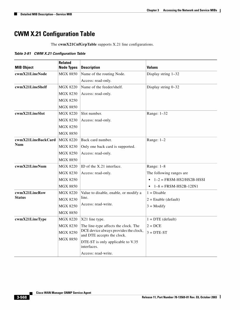
Chapter 3 Accessing the Network and Service MIBsDetailed MIB Description—Service MIB
CWM X.21 Configuration TableThe cwmX21CnfGrpTable supports X.21 line configurations.
Table 3-81 CWM X.21 Configuration Table
MIB ObjectRelated Node Types Description Values
cwmX21LineNode MGX 8850 Name of the routing Node.
Access: read-only.
Display string 1–32
cwmX21LineShelf MGX 8220
MGX 8230
MGX 8250
MGX 8850
Name of the feeder/shelf.
Access: read-only.
Display string 0–32
cwmX21LineSlot MGX 8220
MGX 8230
MGX 8250
MGX 8850
Slot number.
Access: read-only.
Range: 1–32
cwmX21LineBackCardNum
MGX 8220
MGX 8230
MGX 8250
MGX 8850
Back card number.
Only one back card is supported.
Access: read-only.
Range: 1–2
cwmX21LineNum MGX 8220
MGX 8230
MGX 8250
MGX 8850
ID of the X.21 interface.
Access: read-only.
Range: 1–8
The following ranges are
• 1–2 = FRSM-HS2/HS2B-HSSI
• 1–8 = FRSM-HS2B-12IN1
cwmX21LineRowStatus
MGX 8220
MGX 8230
MGX 8250
MGX 8850
Value to disable, enable, or modify a line.
Access: read-write.
1 = Disable
2 = Enable (default)
3 = Modify
cwmX21LineType MGX 8220
MGX 8230
MGX 8250
MGX 8850
X21 line type.
The line-type affects the clock. The DCE device always provides the clock, and DTE accepts the clock.
DTE-ST is only applicable to V.35 interfaces.
Access: read-write.
1 = DTE (default)
2 = DCE
3 = DTE-ST
3-568Cisco WAN Manager SNMP Service Agent
Release 11, Part Number 78-13569-01 Rev. E0, October 2003
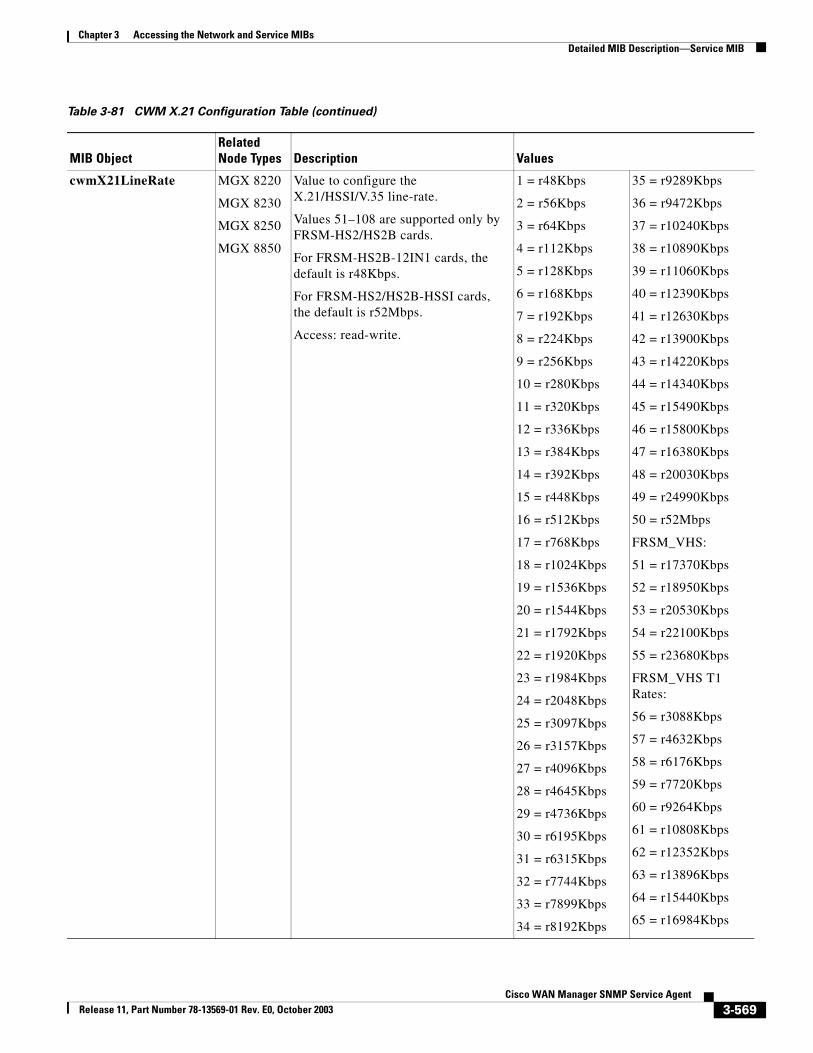
Chapter 3 Accessing the Network and Service MIBsDetailed MIB Description—Service MIB
cwmX21LineRate MGX 8220
MGX 8230
MGX 8250
MGX 8850
Value to configure the X.21/HSSI/V.35 line-rate.
Values 51–108 are supported only by FRSM-HS2/HS2B cards.
For FRSM-HS2B-12IN1 cards, the default is r48Kbps.
For FRSM-HS2/HS2B-HSSI cards, the default is r52Mbps.
Access: read-write.
1 = r48Kbps
2 = r56Kbps
3 = r64Kbps
4 = r112Kbps
5 = r128Kbps
6 = r168Kbps
7 = r192Kbps
8 = r224Kbps
9 = r256Kbps
10 = r280Kbps
11 = r320Kbps
12 = r336Kbps
13 = r384Kbps
14 = r392Kbps
15 = r448Kbps
16 = r512Kbps
17 = r768Kbps
18 = r1024Kbps
19 = r1536Kbps
20 = r1544Kbps
21 = r1792Kbps
22 = r1920Kbps
23 = r1984Kbps
24 = r2048Kbps
25 = r3097Kbps
26 = r3157Kbps
27 = r4096Kbps
28 = r4645Kbps
29 = r4736Kbps
30 = r6195Kbps
31 = r6315Kbps
32 = r7744Kbps
33 = r7899Kbps
34 = r8192Kbps
35 = r9289Kbps
36 = r9472Kbps
37 = r10240Kbps
38 = r10890Kbps
39 = r11060Kbps
40 = r12390Kbps
41 = r12630Kbps
42 = r13900Kbps
43 = r14220Kbps
44 = r14340Kbps
45 = r15490Kbps
46 = r15800Kbps
47 = r16380Kbps
48 = r20030Kbps
49 = r24990Kbps
50 = r52Mbps
FRSM_VHS:
51 = r17370Kbps
52 = r18950Kbps
53 = r20530Kbps
54 = r22100Kbps
55 = r23680Kbps
FRSM_VHS T1 Rates:
56 = r3088Kbps
57 = r4632Kbps
58 = r6176Kbps
59 = r7720Kbps
60 = r9264Kbps
61 = r10808Kbps
62 = r12352Kbps
63 = r13896Kbps
64 = r15440Kbps
65 = r16984Kbps
Table 3-81 CWM X.21 Configuration Table (continued)
MIB ObjectRelated Node Types Description Values
3-569Cisco WAN Manager SNMP Service Agent
Release 11, Part Number 78-13569-01 Rev. E0, October 2003
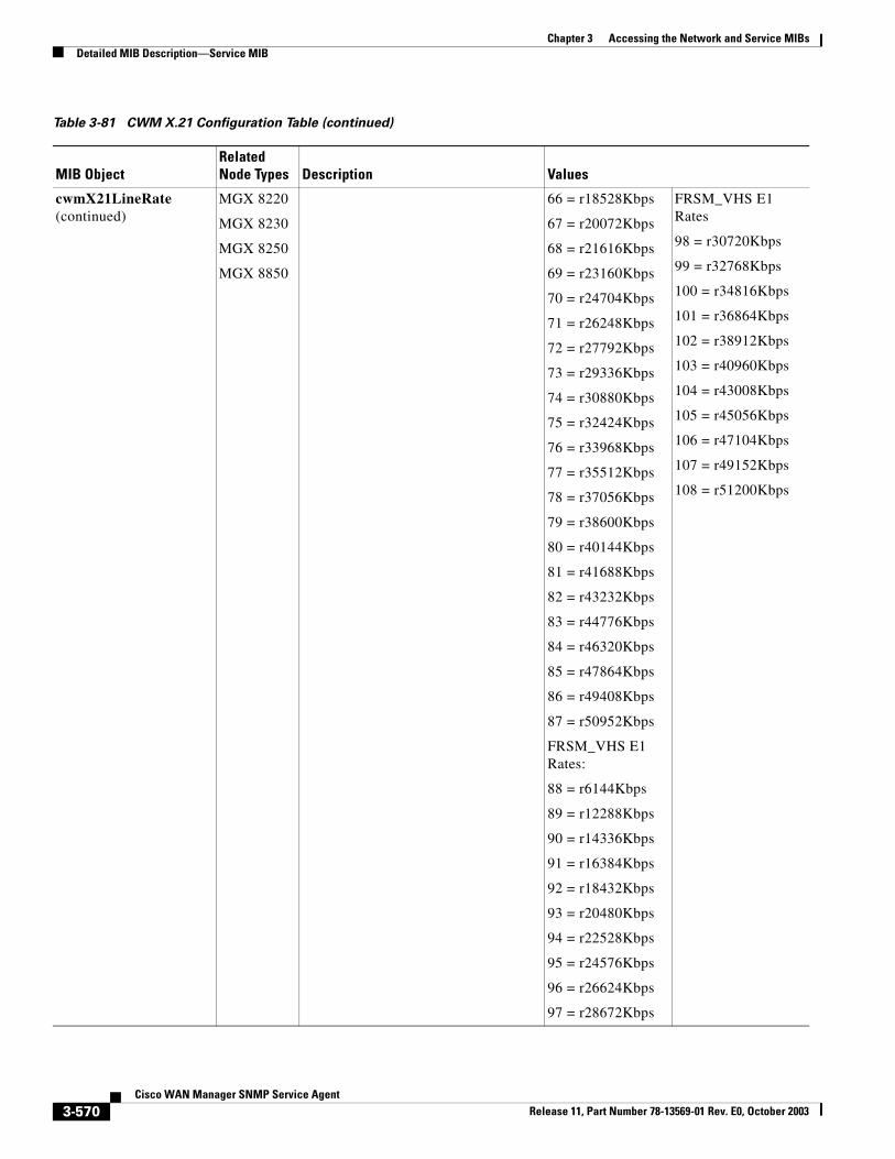
Chapter 3 Accessing the Network and Service MIBsDetailed MIB Description—Service MIB
cwmX21LineRate (continued)
MGX 8220
MGX 8230
MGX 8250
MGX 8850
66 = r18528Kbps
67 = r20072Kbps
68 = r21616Kbps
69 = r23160Kbps
70 = r24704Kbps
71 = r26248Kbps
72 = r27792Kbps
73 = r29336Kbps
74 = r30880Kbps
75 = r32424Kbps
76 = r33968Kbps
77 = r35512Kbps
78 = r37056Kbps
79 = r38600Kbps
80 = r40144Kbps
81 = r41688Kbps
82 = r43232Kbps
83 = r44776Kbps
84 = r46320Kbps
85 = r47864Kbps
86 = r49408Kbps
87 = r50952Kbps
FRSM_VHS E1 Rates:
88 = r6144Kbps
89 = r12288Kbps
90 = r14336Kbps
91 = r16384Kbps
92 = r18432Kbps
93 = r20480Kbps
94 = r22528Kbps
95 = r24576Kbps
96 = r26624Kbps
97 = r28672Kbps
FRSM_VHS E1 Rates
98 = r30720Kbps
99 = r32768Kbps
100 = r34816Kbps
101 = r36864Kbps
102 = r38912Kbps
103 = r40960Kbps
104 = r43008Kbps
105 = r45056Kbps
106 = r47104Kbps
107 = r49152Kbps
108 = r51200Kbps
Table 3-81 CWM X.21 Configuration Table (continued)
MIB ObjectRelated Node Types Description Values
3-570Cisco WAN Manager SNMP Service Agent
Release 11, Part Number 78-13569-01 Rev. E0, October 2003
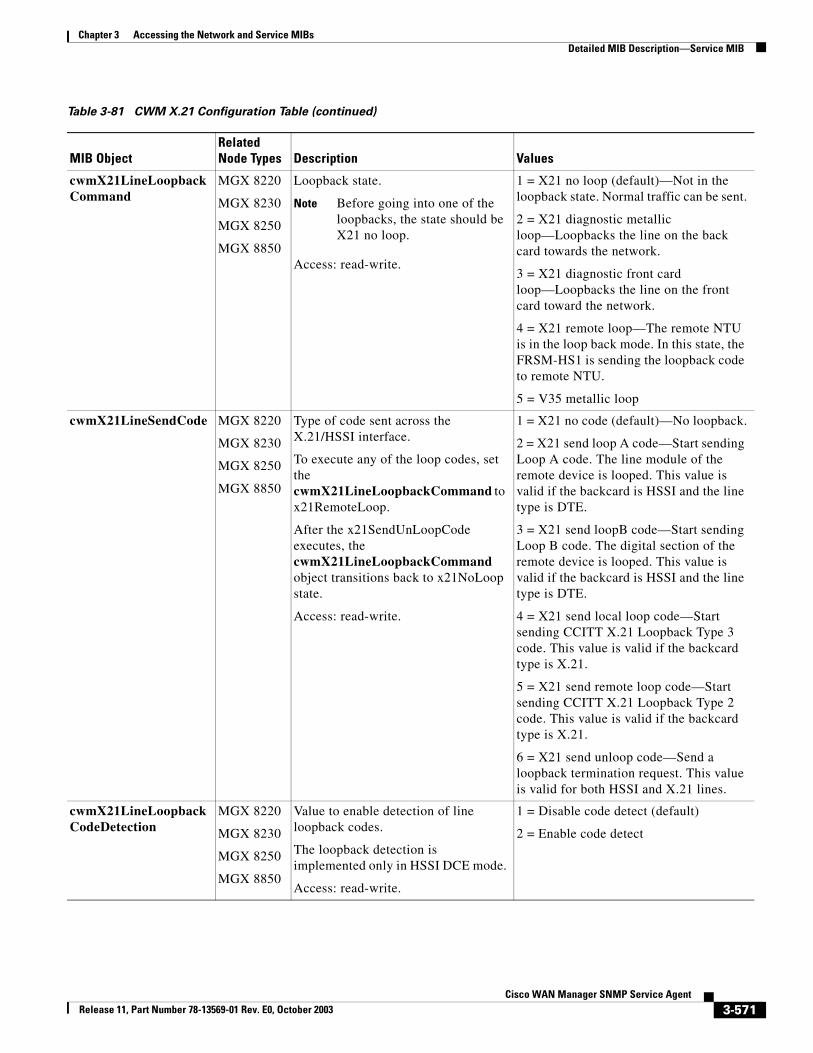
Chapter 3 Accessing the Network and Service MIBsDetailed MIB Description—Service MIB
cwmX21LineLoopbackCommand
MGX 8220
MGX 8230
MGX 8250
MGX 8850
Loopback state.
Note Before going into one of the loopbacks, the state should be X21 no loop.
Access: read-write.
1 = X21 no loop (default)—Not in the loopback state. Normal traffic can be sent.
2 = X21 diagnostic metallic loop—Loopbacks the line on the back card towards the network.
3 = X21 diagnostic front card loop—Loopbacks the line on the front card toward the network.
4 = X21 remote loop—The remote NTU is in the loop back mode. In this state, the FRSM-HS1 is sending the loopback code to remote NTU.
5 = V35 metallic loop
cwmX21LineSendCode MGX 8220
MGX 8230
MGX 8250
MGX 8850
Type of code sent across the X.21/HSSI interface.
To execute any of the loop codes, set the cwmX21LineLoopbackCommand to x21RemoteLoop.
After the x21SendUnLoopCode executes, the cwmX21LineLoopbackCommand object transitions back to x21NoLoop state.
Access: read-write.
1 = X21 no code (default)—No loopback.
2 = X21 send loop A code—Start sending Loop A code. The line module of the remote device is looped. This value is valid if the backcard is HSSI and the line type is DTE.
3 = X21 send loopB code—Start sending Loop B code. The digital section of the remote device is looped. This value is valid if the backcard is HSSI and the line type is DTE.
4 = X21 send local loop code—Start sending CCITT X.21 Loopback Type 3 code. This value is valid if the backcard type is X.21.
5 = X21 send remote loop code—Start sending CCITT X.21 Loopback Type 2 code. This value is valid if the backcard type is X.21.
6 = X21 send unloop code—Send a loopback termination request. This value is valid for both HSSI and X.21 lines.
cwmX21LineLoopbackCodeDetection
MGX 8220
MGX 8230
MGX 8250
MGX 8850
Value to enable detection of line loopback codes.
The loopback detection is implemented only in HSSI DCE mode.
Access: read-write.
1 = Disable code detect (default)
2 = Enable code detect
Table 3-81 CWM X.21 Configuration Table (continued)
MIB ObjectRelated Node Types Description Values
3-571Cisco WAN Manager SNMP Service Agent
Release 11, Part Number 78-13569-01 Rev. E0, October 2003
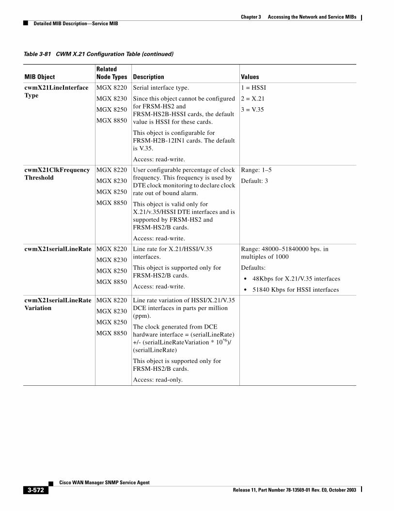
Chapter 3 Accessing the Network and Service MIBsDetailed MIB Description—Service MIB
cwmX21LineInterfaceType
MGX 8220
MGX 8230
MGX 8250
MGX 8850
Serial interface type.
Since this object cannot be configured for FRSM-HS2 and FRSM-HS2B-HSSI cards, the default value is HSSI for these cards.
This object is configurable for FRSM-H2B-12IN1 cards. The default is V.35.
Access: read-write.
1 = HSSI
2 = X.21
3 = V.35
cwmX21ClkFrequencyThreshold
MGX 8220
MGX 8230
MGX 8250
MGX 8850
User configurable percentage of clock frequency. This frequency is used by DTE clock monitoring to declare clock rate out of bound alarm.
This object is valid only for X.21/v.35/HSSI DTE interfaces and is supported by FRSM-HS2 and FRSM-HS2/B cards.
Access: read-write.
Range: 1–5
Default: 3
cwmX21serialLineRate MGX 8220
MGX 8230
MGX 8250
MGX 8850
Line rate for X.21/HSSI/V.35 interfaces.
This object is supported only for FRSM-HS2/B cards.
Access: read-write.
Range: 48000–51840000 bps. in multiples of 1000
Defaults:
• 48Kbps for X.21/V.35 interfaces
• 51840 Kbps for HSSI interfaces
cwmX21serialLineRateVariation
MGX 8220
MGX 8230
MGX 8250
MGX 8850
Line rate variation of HSSI/X.21/V.35 DCE interfaces in parts per million (ppm).
The clock generated from DCE hardware interface = (serialLineRate) +/- (serialLineRateVariation * 10^6)/ (serialLineRate)
This object is supported only for FRSM-HS2/B cards.
Access: read-only.
Table 3-81 CWM X.21 Configuration Table (continued)
MIB ObjectRelated Node Types Description Values
3-572Cisco WAN Manager SNMP Service Agent
Release 11, Part Number 78-13569-01 Rev. E0, October 2003
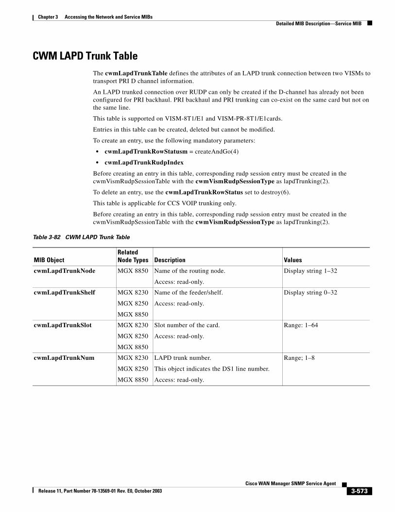
Chapter 3 Accessing the Network and Service MIBsDetailed MIB Description—Service MIB
CWM LAPD Trunk TableThe cwmLapdTrunkTable defines the attributes of an LAPD trunk connection between two VISMs to transport PRI D channel information.
An LAPD trunked connection over RUDP can only be created if the D-channel has already not been configured for PRI backhaul. PRI backhaul and PRI trunking can co-exist on the same card but not on the same line.
This table is supported on VISM-8T1/E1 and VISM-PR-8T1/E1cards.
Entries in this table can be created, deleted but cannot be modified.
To create an entry, use the following mandatory parameters:
• cwmLapdTrunkRowStatusm = createAndGo(4)
• cwmLapdTrunkRudpIndex
Before creating an entry in this table, corresponding rudp session entry must be created in the cwmVismRudpSessionTable with the cwmVismRudpSessionType as lapdTrunking(2).
To delete an entry, use the cwmLapdTrunkRowStatus set to destroy(6).
This table is applicable for CCS VOIP trunking only.
Before creating an entry in this table, corresponding rudp session entry must be created in the cwmVismRudpSessionTable with the cwmVismRudpSessionType as lapdTrunking(2).
Table 3-82 CWM LAPD Trunk Table
MIB ObjectRelated Node Types Description Values
cwmLapdTrunkNode MGX 8850 Name of the routing node.
Access: read-only.
Display string 1–32
cwmLapdTrunkShelf MGX 8230
MGX 8250
MGX 8850
Name of the feeder/shelf.
Access: read-only.
Display string 0–32
cwmLapdTrunkSlot MGX 8230
MGX 8250
MGX 8850
Slot number of the card.
Access: read-only.
Range: 1–64
cwmLapdTrunkNum MGX 8230
MGX 8250
MGX 8850
LAPD trunk number.
This object indicates the DS1 line number.
Access: read-only.
Range; 1–8
3-573Cisco WAN Manager SNMP Service Agent
Release 11, Part Number 78-13569-01 Rev. E0, October 2003
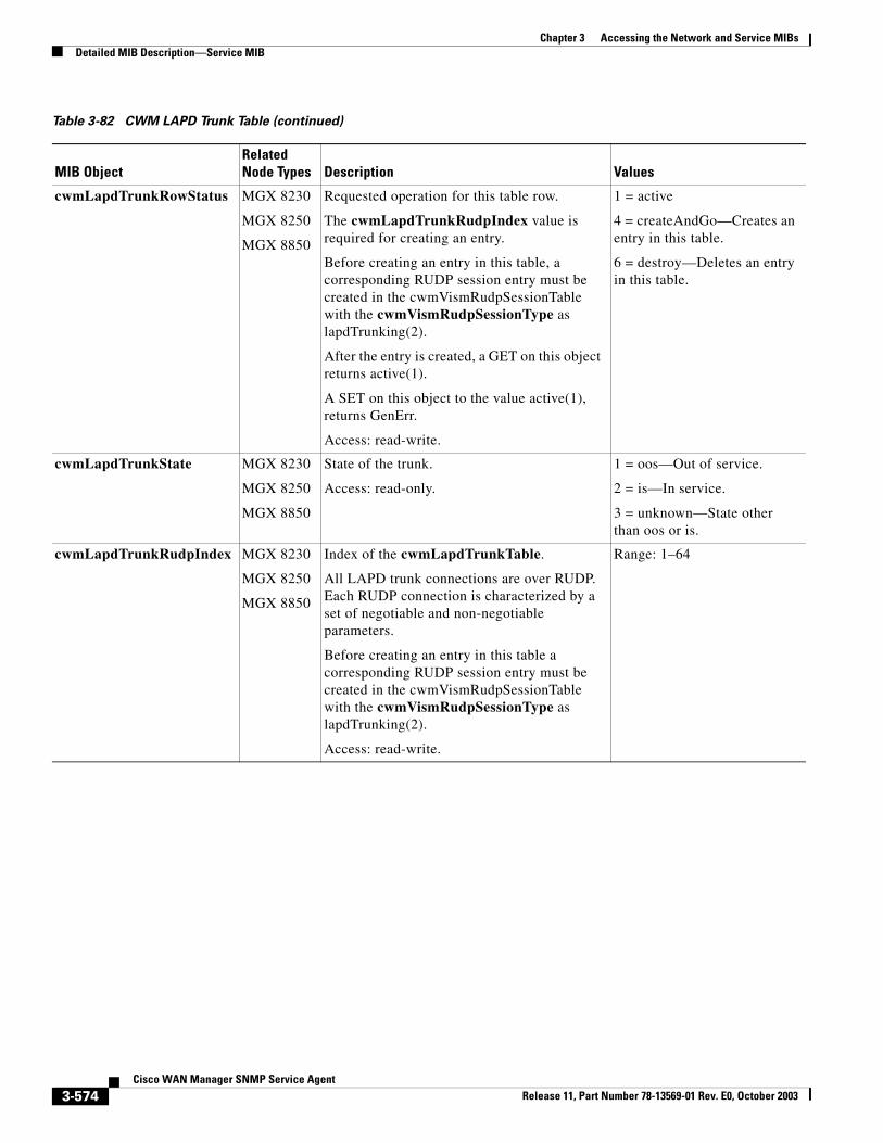
Chapter 3 Accessing the Network and Service MIBsDetailed MIB Description—Service MIB
cwmLapdTrunkRowStatus MGX 8230
MGX 8250
MGX 8850
Requested operation for this table row.
The cwmLapdTrunkRudpIndex value is required for creating an entry.
Before creating an entry in this table, a corresponding RUDP session entry must be created in the cwmVismRudpSessionTable with the cwmVismRudpSessionType as lapdTrunking(2).
After the entry is created, a GET on this object returns active(1).
A SET on this object to the value active(1), returns GenErr.
Access: read-write.
1 = active
4 = createAndGo—Creates an entry in this table.
6 = destroy—Deletes an entry in this table.
cwmLapdTrunkState MGX 8230
MGX 8250
MGX 8850
State of the trunk.
Access: read-only.
1 = oos—Out of service.
2 = is—In service.
3 = unknown—State other than oos or is.
cwmLapdTrunkRudpIndex MGX 8230
MGX 8250
MGX 8850
Index of the cwmLapdTrunkTable.
All LAPD trunk connections are over RUDP. Each RUDP connection is characterized by a set of negotiable and non-negotiable parameters.
Before creating an entry in this table a corresponding RUDP session entry must be created in the cwmVismRudpSessionTable with the cwmVismRudpSessionType as lapdTrunking(2).
Access: read-write.
Range: 1–64
Table 3-82 CWM LAPD Trunk Table (continued)
MIB ObjectRelated Node Types Description Values
3-574Cisco WAN Manager SNMP Service Agent
Release 11, Part Number 78-13569-01 Rev. E0, October 2003
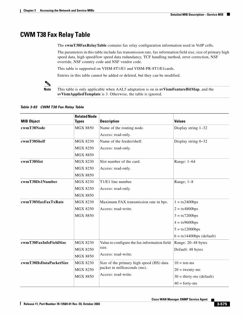
Chapter 3 Accessing the Network and Service MIBsDetailed MIB Description—Service MIB
CWM T38 Fax Relay TableThe cwmT38FaxRelayTable contains fax relay configuration information used in VoIP cells.
The parameters in this table include fax transmission rate, fax information field size, size of primary high speed data, high speed/low speed data redundancy, TCF handling method, error correction, NSF override, NSF country code and NSF vendor code.
This table is supported on VISM-8T1/E1 and VISM-PR-8T1/E1cards.
Entries in this table cannot be added or deleted, but they can be modified.
Note This table is only applicable when AAL5 adaptation is on in svVismFeatureBitMap, and the svVismAppliedTemplate is 3. Otherwise, the table is ignored.
Table 3-83 CWM T38 Fax Relay Table
MIB ObjectRelated Node Types Description Values
cwmT38Node MGX 8850 Name of the routing node.
Access: read-only.
Display string 1–32
cwmT38Shelf MGX 8230
MGX 8250
MGX 8850
Name of the feeder/shelf.
Access: read-only.
Display string 0–32
cwmT38Slot MGX 8230
MGX 8250
MGX 8850
Slot number of the card.
Access: read-only.
Range: 1–64
cwmT38Ds1Number MGX 8230
MGX 8250
MGX 8850
T1/E1 line number.
Access: read-only.
Range; 1–8
cwmT38MaxFaxTxRate MGX 8230
MGX 8250
MGX 8850
Maximum FAX transmission rate in bps.
Access: read-write.
1 = tx2400bps
2 = tx4800bps
3 = tx7200bps
4 = tx9600bps
5 = tx12000bps
6 = tx14400bps (default)
cwmT38FaxInfoFieldSize MGX 8230
MGX 8250
MGX 8850
Value to configure the fax information field size.
Access: read-write.
Range: 20–48 bytes
Default: 48 bytes
cwmT38HsDataPacketSize MGX 8230
MGX 8250
MGX 8850
Size of the primary high speed (HS) data packet in milliseconds (ms).
Access: read-write.
10 = ten-ms
20 = twenty-ms
30 = thirty-ms (default)
40 = forty-ms
3-575Cisco WAN Manager SNMP Service Agent
Release 11, Part Number 78-13569-01 Rev. E0, October 2003
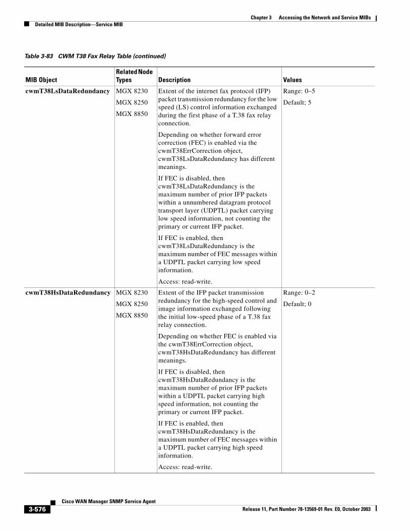
Chapter 3 Accessing the Network and Service MIBsDetailed MIB Description—Service MIB
cwmT38LsDataRedundancy MGX 8230
MGX 8250
MGX 8850
Extent of the internet fax protocol (IFP) packet transmission redundancy for the low speed (LS) control information exchanged during the first phase of a T.38 fax relay connection.
Depending on whether forward error correction (FEC) is enabled via the cwmT38ErrCorrection object, cwmT38LsDataRedundancy has different meanings.
If FEC is disabled, then cwmT38LsDataRedundancy is the maximum number of prior IFP packets within a unnumbered datagram protocol transport layer (UDPTL) packet carrying low speed information, not counting the primary or current IFP packet.
If FEC is enabled, then cwmT38LsDataRedundancy is the maximum number of FEC messages within a UDPTL packet carrying low speed information.
Access: read-write.
Range: 0–5
Default; 5
cwmT38HsDataRedundancy MGX 8230
MGX 8250
MGX 8850
Extent of the IFP packet transmission redundancy for the high-speed control and image information exchanged following the initial low-speed phase of a T.38 fax relay connection.
Depending on whether FEC is enabled via the cwmT38ErrCorrection object, cwmT38HsDataRedundancy has different meanings.
If FEC is disabled, then cwmT38HsDataRedundancy is the maximum number of prior IFP packets within a UDPTL packet carrying high speed information, not counting the primary or current IFP packet.
If FEC is enabled, then cwmT38HsDataRedundancy is the maximum number of FEC messages within a UDPTL packet carrying high speed information.
Access: read-write.
Range: 0–2
Default; 0
Table 3-83 CWM T38 Fax Relay Table (continued)
MIB ObjectRelated Node Types Description Values
3-576Cisco WAN Manager SNMP Service Agent
Release 11, Part Number 78-13569-01 Rev. E0, October 2003
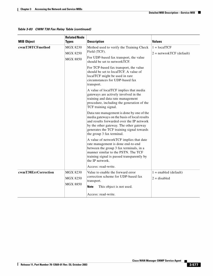
Chapter 3 Accessing the Network and Service MIBsDetailed MIB Description—Service MIB
cwmT38TCFmethod MGX 8230
MGX 8250
MGX 8850
Method used to verify the Training Check Field (TCF).
For UDP-based fax transport, the value should be set to networkTCF.
For TCP-based fax transport, the value should be set to localTCF. A value of localTCF might be used in rare circumstances for UDP-based fax transport.
A value of localTCF implies that media gateways are actively involved in the training and data rate management procedure, including the generation of the TCF training signal.
Data rate management is done by one of the media gateways on the basis of local results and results forwarded over the IP network by the other gateway. The other gateway generates the TCF training signal towards the group 3 fax terminal.
A value of networkTCF implies that date rate management is done end-to-end between the group 3 fax terminals, in a manner similar to the PSTN. The TCF training signal is passed transparently by the IP network.
Access: read-write.
1 = localTCF
2 = netwrokTCF (default)
cwmT38ErrCorrection MGX 8230
MGX 8250
MGX 8850
Value to enable the forward error correction scheme for UDP-based fax transport.
Note This object is not used.
Access: read-write.
1 = enabled (default)
2 = disabled
Table 3-83 CWM T38 Fax Relay Table (continued)
MIB ObjectRelated Node Types Description Values
3-577Cisco WAN Manager SNMP Service Agent
Release 11, Part Number 78-13569-01 Rev. E0, October 2003
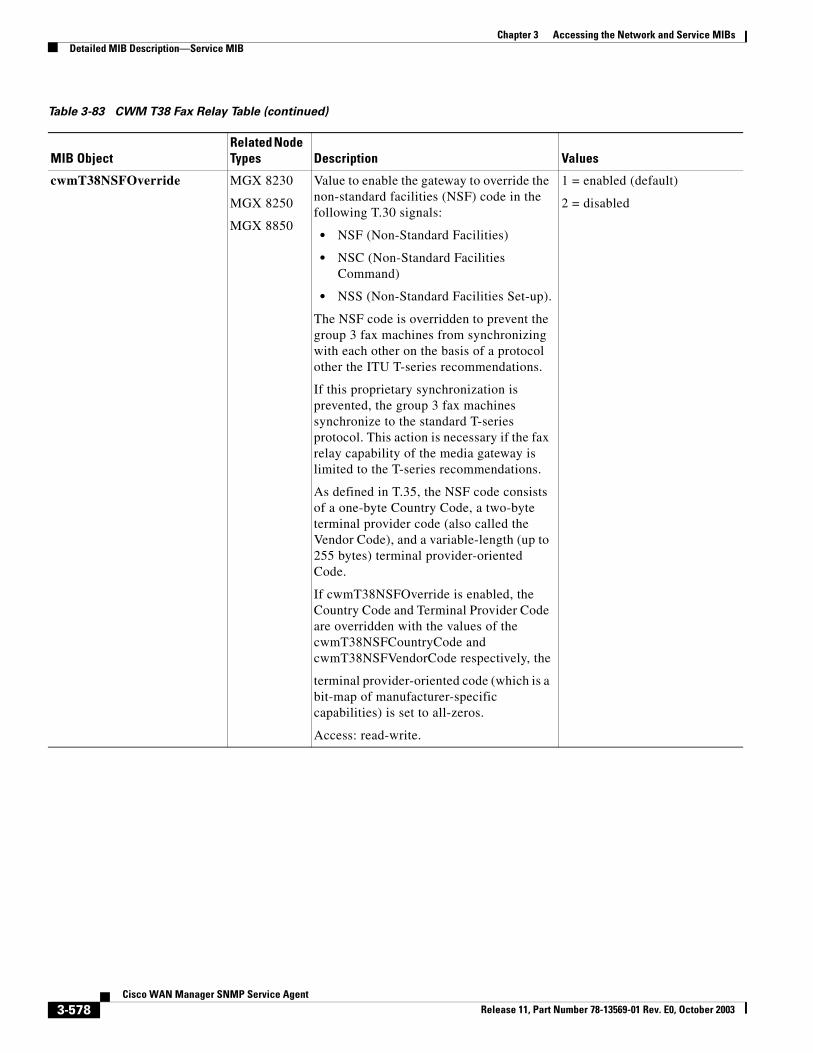
Chapter 3 Accessing the Network and Service MIBsDetailed MIB Description—Service MIB
cwmT38NSFOverride MGX 8230
MGX 8250
MGX 8850
Value to enable the gateway to override the non-standard facilities (NSF) code in the following T.30 signals:
• NSF (Non-Standard Facilities)
• NSC (Non-Standard Facilities Command)
• NSS (Non-Standard Facilities Set-up).
The NSF code is overridden to prevent the group 3 fax machines from synchronizing with each other on the basis of a protocol other the ITU T-series recommendations.
If this proprietary synchronization is prevented, the group 3 fax machines synchronize to the standard T-series protocol. This action is necessary if the fax relay capability of the media gateway is limited to the T-series recommendations.
As defined in T.35, the NSF code consists of a one-byte Country Code, a two-byte terminal provider code (also called the Vendor Code), and a variable-length (up to 255 bytes) terminal provider-oriented Code.
If cwmT38NSFOverride is enabled, the Country Code and Terminal Provider Code are overridden with the values of the cwmT38NSFCountryCode and cwmT38NSFVendorCode respectively, the
terminal provider-oriented code (which is a bit-map of manufacturer-specific capabilities) is set to all-zeros.
Access: read-write.
1 = enabled (default)
2 = disabled
Table 3-83 CWM T38 Fax Relay Table (continued)
MIB ObjectRelated Node Types Description Values
3-578Cisco WAN Manager SNMP Service Agent
Release 11, Part Number 78-13569-01 Rev. E0, October 2003
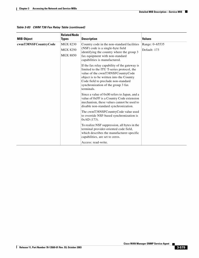
Chapter 3 Accessing the Network and Service MIBsDetailed MIB Description—Service MIB
cwmT38NSFCountryCode MGX 8230
MGX 8250
MGX 8850
Country code in the non-standard facilities (NSF) code is a single-byte field identifying the country where the group 3 fax equipment with non-standard capabilities is manufactured.
If the fax relay capability of the gateway is limited to the ITU T-series protocol, the value of the cwmT38NSFCountryCode object is to be written into the Country Code field to preclude non-standard synchronization of the group 3 fax terminals.
Since a value of 0x00 refers to Japan, and a value of 0xFF is a Country Code extension mechanism, these values cannot be used to disable non-standard synchronization.
The cwmT38NSFCountryCode value used to override NSF-based synchronization is 0xAD (173).
To realize NSF suppression, all bytes in the terminal provider-oriented code field, which describes the manufacturer-specific capabilities, are set to zeros.
Access: read-write.
Range: 0–65535
Default: 173
Table 3-83 CWM T38 Fax Relay Table (continued)
MIB ObjectRelated Node Types Description Values
3-579Cisco WAN Manager SNMP Service Agent
Release 11, Part Number 78-13569-01 Rev. E0, October 2003
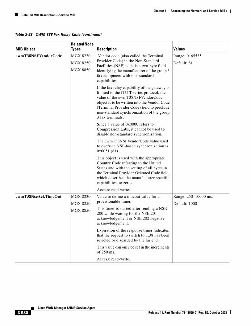
Chapter 3 Accessing the Network and Service MIBsDetailed MIB Description—Service MIB
cwmT38NSFVendorCode MGX 8230
MGX 8250
MGX 8850
Vendor code (also called the Terminal Provider Code) in the Non-Standard Facilities (NSF) code is a two-byte field identifying the manufacturer of the group 3 fax equipment with non-standard capabilities.
If the fax relay capability of the gateway is limited to the ITU T-series protocol, the value of the cwmT38NSFVendorCode object is to be written into the Vendor Code (Terminal Provider Code) field to preclude non-standard synchronization of the group 3 fax terminals.
Since a value of 0x0000 refers to Compression Labs, it cannot be used to disable non-standard synchronization.
The cwmT38NSFVendorCode value used to override NSF-based synchronization is 0x0051 (81).
This object is used with the appropriate Country Code referring to the United States and with the setting of all bytes in the Terminal Provider-Oriented Code field, which describes the manufacturer-specific capabilities, to zeros.
Access: read-write.
Range: 0–65535
Default: 81
cwmT38NseAckTimeOut MGX 8230
MGX 8250
MGX 8850
Value to define a timeout value for a provisionable timer.
This timer is started after sending a NSE 200 while waiting for the NSE 201 acknowledgement or NSE 202 negative acknowledgement.
Expiration of the response timer indicates that the request to switch to T.38 has been rejected or discarded by the far end.
This value can only be set in the increments of 250 ms.
Access: read-write.
Range: 250–10000 ms.
Default: 1000
Table 3-83 CWM T38 Fax Relay Table (continued)
MIB ObjectRelated Node Types Description Values
3-580Cisco WAN Manager SNMP Service Agent
Release 11, Part Number 78-13569-01 Rev. E0, October 2003
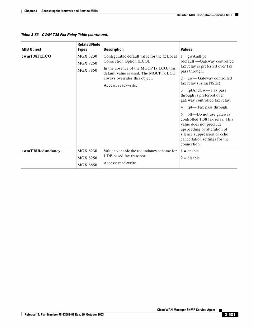
Chapter 3 Accessing the Network and Service MIBsDetailed MIB Description—Service MIB
cwmT38FxLCO MGX 8230
MGX 8250
MGX 8850
Configurable default value for the fx Local Connection Option (LCO).
In the absence of the MGCP fx LCO, this default value is used. The MGCP fx LCO always overrides this object.
Access: read-write.
1 = gwAndFpt (default)—Gateway controlled fax relay is preferred over fax pass through.
2 = gw— Gateway controlled fax relay (using NSEs).
3 = fptAndGw— Fax pass through is preferred over gateway controlled fax relay.
4 = fpt— Fax pass through.
5 = off—Do not use gateway controlled T.38 fax relay. This value does not preclude upspeeding or alteration of silence suppression or echo cancellation settings for the connection.
cwmT38Redundancy MGX 8230
MGX 8250
MGX 8850
Value to enable the redundancy scheme for UDP-based fax transport.
Access: read-write.
1 = enable
2 = disable
Table 3-83 CWM T38 Fax Relay Table (continued)
MIB ObjectRelated Node Types Description Values
3-581Cisco WAN Manager SNMP Service Agent
Release 11, Part Number 78-13569-01 Rev. E0, October 2003
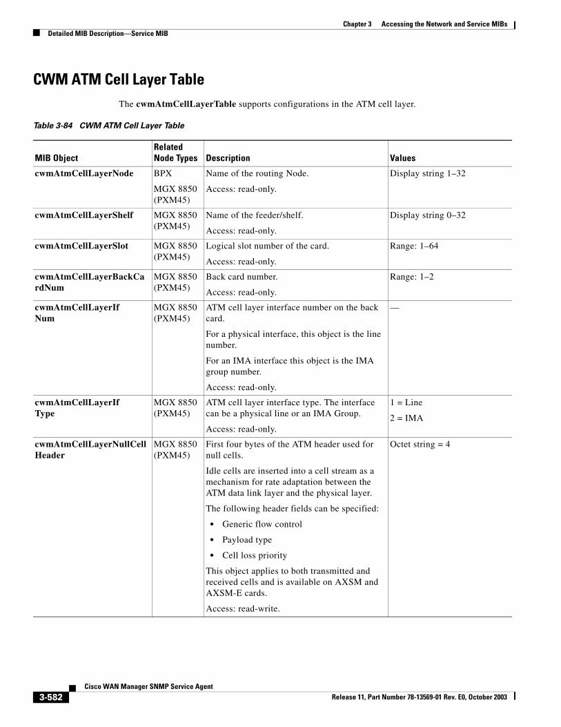
Chapter 3 Accessing the Network and Service MIBsDetailed MIB Description—Service MIB
CWM ATM Cell Layer TableThe cwmAtmCellLayerTable supports configurations in the ATM cell layer.
Table 3-84 CWM ATM Cell Layer Table
MIB ObjectRelated Node Types Description Values
cwmAtmCellLayerNode BPX
MGX 8850 (PXM45)
Name of the routing Node.
Access: read-only.
Display string 1–32
cwmAtmCellLayerShelf MGX 8850 (PXM45)
Name of the feeder/shelf.
Access: read-only.
Display string 0–32
cwmAtmCellLayerSlot MGX 8850 (PXM45)
Logical slot number of the card.
Access: read-only.
Range: 1–64
cwmAtmCellLayerBackCardNum
MGX 8850 (PXM45)
Back card number.
Access: read-only.
Range: 1–2
cwmAtmCellLayerIfNum
MGX 8850 (PXM45)
ATM cell layer interface number on the back card.
For a physical interface, this object is the line number.
For an IMA interface this object is the IMA group number.
Access: read-only.
—
cwmAtmCellLayerIfType
MGX 8850 (PXM45)
ATM cell layer interface type. The interface can be a physical line or an IMA Group.
Access: read-only.
1 = Line
2 = IMA
cwmAtmCellLayerNullCellHeader
MGX 8850 (PXM45)
First four bytes of the ATM header used for null cells.
Idle cells are inserted into a cell stream as a mechanism for rate adaptation between the ATM data link layer and the physical layer.
The following header fields can be specified:
• Generic flow control
• Payload type
• Cell loss priority
This object applies to both transmitted and received cells and is available on AXSM and AXSM-E cards.
Access: read-write.
Octet string = 4
3-582Cisco WAN Manager SNMP Service Agent
Release 11, Part Number 78-13569-01 Rev. E0, October 2003
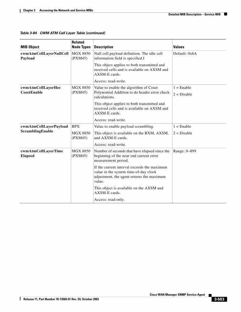
Chapter 3 Accessing the Network and Service MIBsDetailed MIB Description—Service MIB
cwmAtmCellLayerNullCellPayload
MGX 8850 (PXM45)
Null cell payload definition. The idle cell information field is specified.I
This object applies to both transmitted and received cells and is available on AXSM and AXSM-E cards.
Access: read-write.
Default: 0x6A
cwmAtmCellLayerHecCosetEnable
MGX 8850 (PXM45)
Value to enable the algorithm of Coset Polynomial Addition to do header error check calculations.
This object applies to both transmitted and received cells and is available on AXSM and AXSM-E cards.
Access: read-write.
1 = Enable
2 = Disable
cwmAtmCellLayerPayloadScramblingEnable
BPX
MGX 8850 (PXM45)
Value to enable payload scrambling.
This object is available on the BXM, AXSM, and AXSM-E cards.
Access: read-write.
1 = Enable
2 = Disable
cwmAtmCellLayerTimeElapsed
MGX 8850 (PXM45)
Number of seconds that have elapsed since the beginning of the near end current error measurement period.
If the current interval exceeds the maximum value in the system time-of-day clock adjustment, the agent returns the maximum value.
This object is available on the AXSM and AXSM-E cards.
Access: read-only.
Range: 0–899
Table 3-84 CWM ATM Cell Layer Table (continued)
MIB ObjectRelated Node Types Description Values
3-583Cisco WAN Manager SNMP Service Agent
Release 11, Part Number 78-13569-01 Rev. E0, October 2003
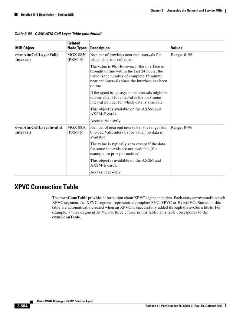
Chapter 3 Accessing the Network and Service MIBsDetailed MIB Description—Service MIB
XPVC Connection TableThe cwmConnTable provides information about XPVC segment entries. Each entry corresponds to each XPVC segment. An XPVC segment represents a complete PVC, SPVC or HybridVC. Entries in this table are automatically created when an XPVC is successfully added through the svConnTable. For example, a three-segment XPVC has three entries in this table. This table corresponds to the cwmConnTable.
cwmAtmCellLayerValidIntervals
MGX 8850 (PXM45)
Number of previous near end intervals for which data was collected.
The value is 96. However, if the interface is brought online within the last 24 hours, the value is the number of complete 15 minute near end intervals since the interface has been online.
If the agent is a proxy, some intervals might be unavailable. This interval is the maximum interval number for which data is available.
This object is available on the AXSM and AXSM-E cards.
Access: read-only.
Range: 0–96
cwmAtmCellLayerInvalidIntervals
MGX 8850 (PXM45)
Number of near end intervals in the range from 0 to caclValidIntervals for which no data is available.
The value is typically zero except if the data for some intervals are not available (for example, in proxy situations).
This object is available on the AXSM and AXSM-E cards.
Access: read-only.
Range: 0–96
Table 3-84 CWM ATM Cell Layer Table (continued)
MIB ObjectRelated Node Types Description Values
3-584Cisco WAN Manager SNMP Service Agent
Release 11, Part Number 78-13569-01 Rev. E0, October 2003
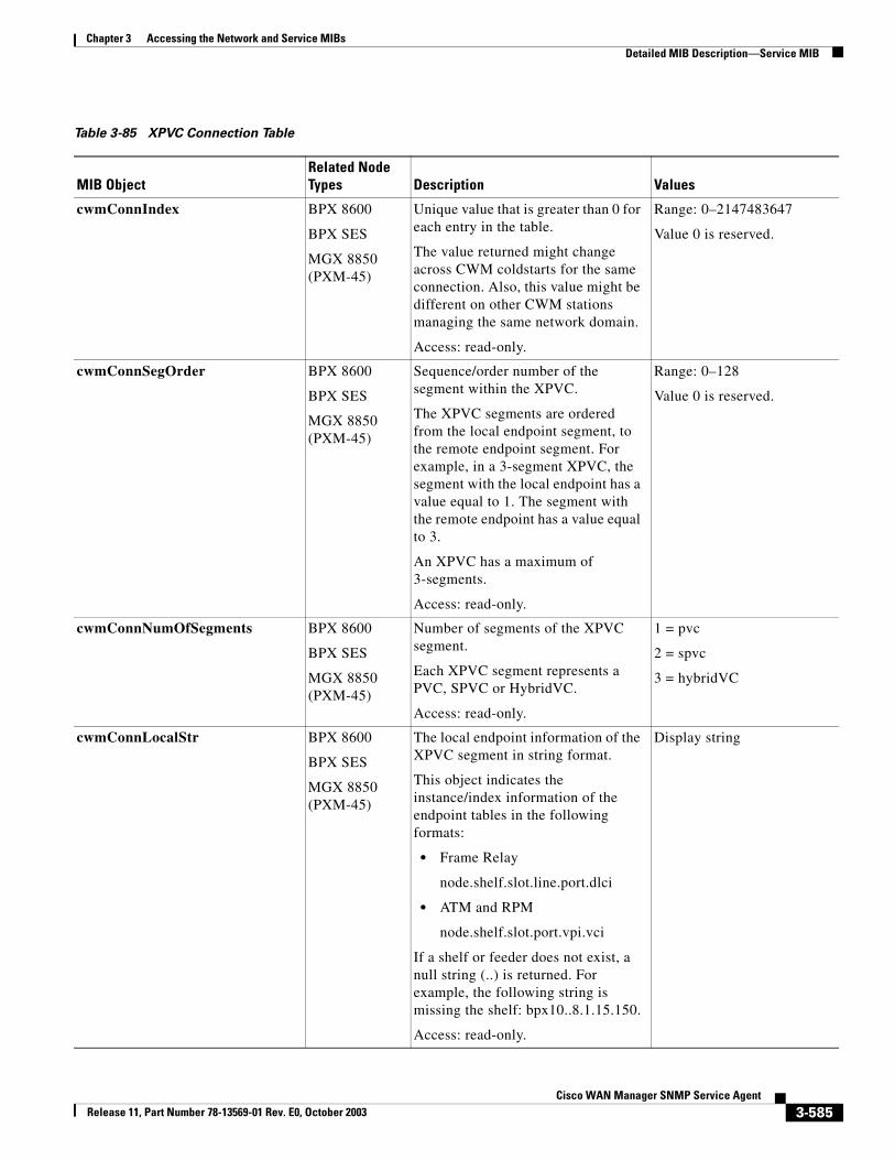
Chapter 3 Accessing the Network and Service MIBsDetailed MIB Description—Service MIB
Table 3-85 XPVC Connection Table
MIB ObjectRelated Node Types Description Values
cwmConnIndex BPX 8600
BPX SES
MGX 8850 (PXM-45)
Unique value that is greater than 0 for each entry in the table.
The value returned might change across CWM coldstarts for the same connection. Also, this value might be different on other CWM stations managing the same network domain.
Access: read-only.
Range: 0–2147483647
Value 0 is reserved.
cwmConnSegOrder BPX 8600
BPX SES
MGX 8850 (PXM-45)
Sequence/order number of the segment within the XPVC.
The XPVC segments are ordered from the local endpoint segment, to the remote endpoint segment. For example, in a 3-segment XPVC, the segment with the local endpoint has a value equal to 1. The segment with the remote endpoint has a value equal to 3.
An XPVC has a maximum of 3-segments.
Access: read-only.
Range: 0–128
Value 0 is reserved.
cwmConnNumOfSegments BPX 8600
BPX SES
MGX 8850 (PXM-45)
Number of segments of the XPVC segment.
Each XPVC segment represents a PVC, SPVC or HybridVC.
Access: read-only.
1 = pvc
2 = spvc
3 = hybridVC
cwmConnLocalStr BPX 8600
BPX SES
MGX 8850 (PXM-45)
The local endpoint information of the XPVC segment in string format.
This object indicates the instance/index information of the endpoint tables in the following formats:
• Frame Relay
node.shelf.slot.line.port.dlci
• ATM and RPM
node.shelf.slot.port.vpi.vci
If a shelf or feeder does not exist, a null string (..) is returned. For example, the following string is missing the shelf: bpx10..8.1.15.150.
Access: read-only.
Display string
3-585Cisco WAN Manager SNMP Service Agent
Release 11, Part Number 78-13569-01 Rev. E0, October 2003
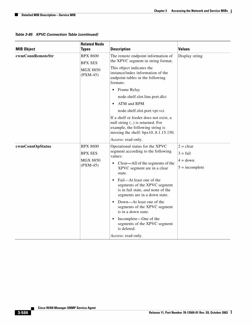
Chapter 3 Accessing the Network and Service MIBsDetailed MIB Description—Service MIB
cwmConnRemoteStr BPX 8600
BPX SES
MGX 8850 (PXM-45)
The remote endpoint information of the XPVC segment in string format.
This object indicates the instance/index information of the endpoint tables in the following formats:
• Frame Relay
node.shelf.slot.line.port.dlci
• ATM and RPM
node.shelf.slot.port.vpi.vci
If a shelf or feeder does not exist, a null string (..) is returned. For example, the following string is missing the shelf: bpx10..8.1.15.150.
Access: read-only.
Display string
cwmConnOpStatus BPX 8600
BPX SES
MGX 8850 (PXM-45)
Operational status for the XPVC segment according to the following values:
• Clear—All of the segments of the XPVC segment are in a clear state.
• Fail—At least one of the segments of the XPVC segment is in fail state, and none of the segments are in a down state.
• Down—At least one of the segments of the XPVC segment is in a down state.
• Incomplete—One of the segments of the XPVC segment is deleted.
Access: read-only.
2 = clear
3 = fail
4 = down
5 = incomplete
Table 3-85 XPVC Connection Table (continued)
MIB ObjectRelated Node Types Description Values
3-586Cisco WAN Manager SNMP Service Agent
Release 11, Part Number 78-13569-01 Rev. E0, October 2003
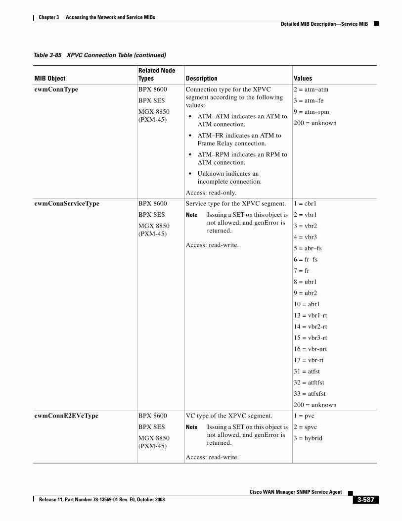
Chapter 3 Accessing the Network and Service MIBsDetailed MIB Description—Service MIB
cwmConnType BPX 8600
BPX SES
MGX 8850 (PXM-45)
Connection type for the XPVC segment according to the following values:
• ATM–ATM indicates an ATM to ATM connection.
• ATM–FR indicates an ATM to Frame Relay connection.
• ATM–RPM indicates an RPM to ATM connection.
• Unknown indicates an incomplete connection.
Access: read-only.
2 = atm–atm
3 = atm–fe
9 = atm–rpm
200 = unknown
cwmConnServiceType BPX 8600
BPX SES
MGX 8850 (PXM-45)
Service type for the XPVC segment.
Note Issuing a SET on this object is not allowed, and genError is returned.
Access: read-write.
1 = cbr1
2 = vbr1
3 = vbr2
4 = vbr3
5 = abr–fs
6 = fr–fs
7 = fr
8 = ubr1
9 = ubr2
10 = abr1
13 = vbr1-rt
14 = vbr2-rt
15 = vbr3-rt
16 = vbr-nrt
17 = vbr-rt
31 = atfst
32 = atftfst
33 = atfxfst
200 = unknown
cwmConnE2EVcType BPX 8600
BPX SES
MGX 8850 (PXM-45)
VC type of the XPVC segment.
Note Issuing a SET on this object is not allowed, and genError is returned.
Access: read-write.
1 = pvc
2 = spvc
3 = hybrid
Table 3-85 XPVC Connection Table (continued)
MIB ObjectRelated Node Types Description Values
3-587Cisco WAN Manager SNMP Service Agent
Release 11, Part Number 78-13569-01 Rev. E0, October 2003
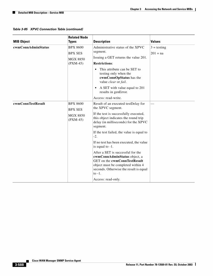
Chapter 3 Accessing the Network and Service MIBsDetailed MIB Description—Service MIB
cwmConnAdminStatus BPX 8600
BPX SES
MGX 8850 (PXM-45)
Administrative status of the XPVC segment.
Issuing a GET returns the value 201.
Restrictions:
• This attribute can be SET to testing only when the cwmConnOpStatus has the value clear or fail.
• A SET with value equal to 201 results in genError.
Access: read-write.
3 = testing
201 = na
cwmConnTestResult BPX 8600
BPX SES
MGX 8850 (PXM-45)
Result of an executed testDelay for the XPVC segment.
If the test is successfully executed, this object indicates the round trip delay (in milliseconds) for the XPVC segment.
If the test failed, the value is equal to -2.
If no test has been executed, the value is equal to -1.
After a SET is successful for the cwmConnAdminStatus object, a GET on the cwmConnTestResult object must be completed within 4 seconds. Otherwise the result is equal to -1.
Access: read-only.
—
Table 3-85 XPVC Connection Table (continued)
MIB ObjectRelated Node Types Description Values
3-588Cisco WAN Manager SNMP Service Agent
Release 11, Part Number 78-13569-01 Rev. E0, October 2003
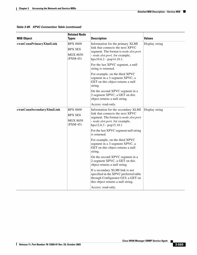
Chapter 3 Accessing the Network and Service MIBsDetailed MIB Description—Service MIB
cwmConnPrimaryXlmiLink BPX 8600
BPX SES
MGX 8850 (PXM-45)
Information for the primary XLMI link that connects the next XPVC segment. The format is node.slot.port - node.slot.port, for example, bpx10.6.2 - pop14.10.1.
For the last XPVC segment, a null string is returned.
For example, on the third XPVC segment in a 3-segment XPVC, a GET on this object returns a null string.
On the second XPVC segment in a 2-segment XPVC, a GET on this object returns a null string.
Access: read-only.
Display string
cwmConnSecondaryXlmiLink BPX 8600
BPX SES
MGX 8850 (PXM-45)
Information for the secondary XLMI link that connects the next XPVC segment. The format is node.slot.port - node.slot.port, for example, bpx12.6.3 - pop15.10.1
For the last XPVC segment null string is returned.
For example, on the third XPVC segment in a 3-segment XPVC, a GET on this object returns a null string.
On the second XPVC segment in a 2-segment XPVC, a GET on this object returns a null string.
If a secondary XLMI link is not specified in the XPVC preferred table through Configurator GUI, a GET on this object returns a null string.
Access: read-only.
Display string
Table 3-85 XPVC Connection Table (continued)
MIB ObjectRelated Node Types Description Values
3-589Cisco WAN Manager SNMP Service Agent
Release 11, Part Number 78-13569-01 Rev. E0, October 2003
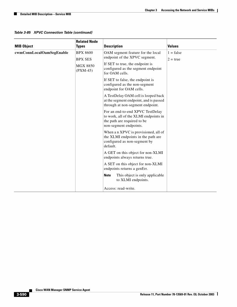
Chapter 3 Accessing the Network and Service MIBsDetailed MIB Description—Service MIB
cwmConnLocalOamSegEnable BPX 8600
BPX SES
MGX 8850 (PXM-45)
OAM segment feature for the local endpoint of the XPVC segment.
If SET to true, the endpoint is configured as the segment endpoint for OAM cells.
If SET to false, the endpoint is configured as the non-segment endpoint for OAM cells.
A TestDelay OAM cell is looped back at the segment endpoint, and is passed through at non-segment endpoint.
For an end-to-end XPVC TestDelay to work, all of the XLMI endpoints in the path are required to be non-segment endpoints.
When a n XPVC is provisioned, all of the XLMI endpoints in the path are configured as non-segment by default.
A GET on this object for non-XLMI endpoints always returns true.
A SET on this object for non-XLMI endpoints returns a genErr.
Note This object is only applicable to XLMI endpoints.
Access: read-write.
1 = false
2 = true
Table 3-85 XPVC Connection Table (continued)
MIB ObjectRelated Node Types Description Values
3-590Cisco WAN Manager SNMP Service Agent
Release 11, Part Number 78-13569-01 Rev. E0, October 2003
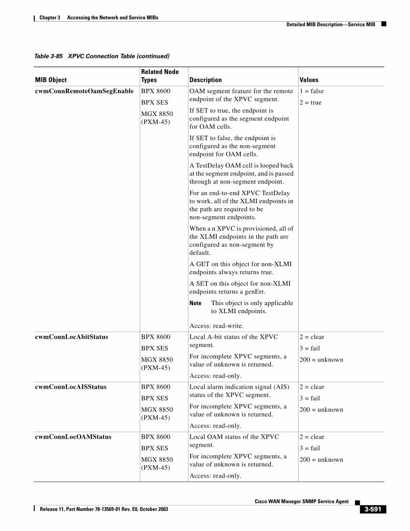
Chapter 3 Accessing the Network and Service MIBsDetailed MIB Description—Service MIB
cwmConnRemoteOamSegEnable BPX 8600
BPX SES
MGX 8850 (PXM-45)
OAM segment feature for the remote endpoint of the XPVC segment.
If SET to true, the endpoint is configured as the segment endpoint for OAM cells.
If SET to false, the endpoint is configured as the non-segment endpoint for OAM cells.
A TestDelay OAM cell is looped back at the segment endpoint, and is passed through at non-segment endpoint.
For an end-to-end XPVC TestDelay to work, all of the XLMI endpoints in the path are required to be non-segment endpoints.
When a n XPVC is provisioned, all of the XLMI endpoints in the path are configured as non-segment by default.
A GET on this object for non-XLMI endpoints always returns true.
A SET on this object for non-XLMI endpoints returns a genErr.
Note This object is only applicable to XLMI endpoints.
Access: read-write.
1 = false
2 = true
cwmConnLocAbitStatus BPX 8600
BPX SES
MGX 8850 (PXM-45)
Local A-bit status of the XPVC segment.
For incomplete XPVC segments, a value of unknown is returned.
Access: read-only.
2 = clear
3 = fail
200 = unknown
cwmConnLocAISStatus BPX 8600
BPX SES
MGX 8850 (PXM-45)
Local alarm indication signal (AIS) status of the XPVC segment.
For incomplete XPVC segments, a value of unknown is returned.
Access: read-only.
2 = clear
3 = fail
200 = unknown
cwmConnLocOAMStatus BPX 8600
BPX SES
MGX 8850 (PXM-45)
Local OAM status of the XPVC segment.
For incomplete XPVC segments, a value of unknown is returned.
Access: read-only.
2 = clear
3 = fail
200 = unknown
Table 3-85 XPVC Connection Table (continued)
MIB ObjectRelated Node Types Description Values
3-591Cisco WAN Manager SNMP Service Agent
Release 11, Part Number 78-13569-01 Rev. E0, October 2003
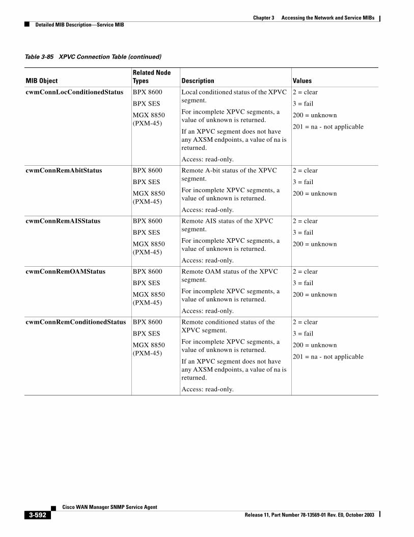
Chapter 3 Accessing the Network and Service MIBsDetailed MIB Description—Service MIB
cwmConnLocConditionedStatus BPX 8600
BPX SES
MGX 8850 (PXM-45)
Local conditioned status of the XPVC segment.
For incomplete XPVC segments, a value of unknown is returned.
If an XPVC segment does not have any AXSM endpoints, a value of na is returned.
Access: read-only.
2 = clear
3 = fail
200 = unknown
201 = na - not applicable
cwmConnRemAbitStatus BPX 8600
BPX SES
MGX 8850 (PXM-45)
Remote A-bit status of the XPVC segment.
For incomplete XPVC segments, a value of unknown is returned.
Access: read-only.
2 = clear
3 = fail
200 = unknown
cwmConnRemAISStatus BPX 8600
BPX SES
MGX 8850 (PXM-45)
Remote AIS status of the XPVC segment.
For incomplete XPVC segments, a value of unknown is returned.
Access: read-only.
2 = clear
3 = fail
200 = unknown
cwmConnRemOAMStatus BPX 8600
BPX SES
MGX 8850 (PXM-45)
Remote OAM status of the XPVC segment.
For incomplete XPVC segments, a value of unknown is returned.
Access: read-only.
2 = clear
3 = fail
200 = unknown
cwmConnRemConditionedStatus BPX 8600
BPX SES
MGX 8850 (PXM-45)
Remote conditioned status of the XPVC segment.
For incomplete XPVC segments, a value of unknown is returned.
If an XPVC segment does not have any AXSM endpoints, a value of na is returned.
Access: read-only.
2 = clear
3 = fail
200 = unknown
201 = na - not applicable
Table 3-85 XPVC Connection Table (continued)
MIB ObjectRelated Node Types Description Values
3-592Cisco WAN Manager SNMP Service Agent
Release 11, Part Number 78-13569-01 Rev. E0, October 2003
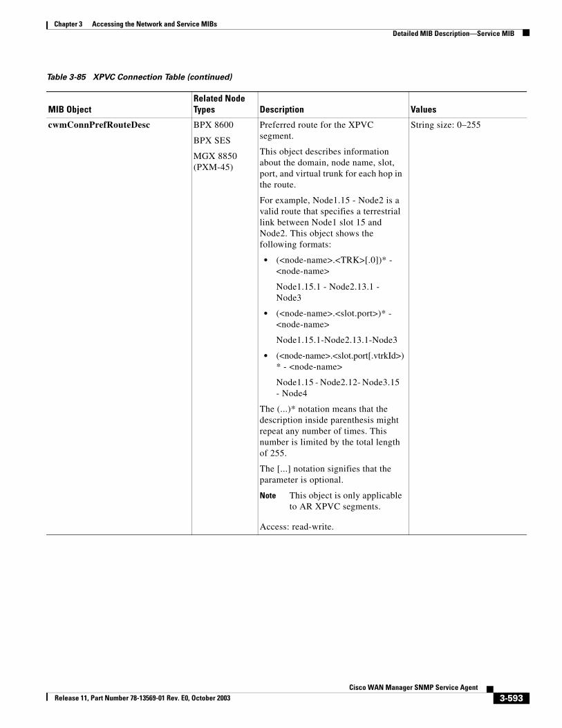
Chapter 3 Accessing the Network and Service MIBsDetailed MIB Description—Service MIB
cwmConnPrefRouteDesc BPX 8600
BPX SES
MGX 8850 (PXM-45)
Preferred route for the XPVC segment.
This object describes information about the domain, node name, slot, port, and virtual trunk for each hop in the route.
For example, Node1.15 - Node2 is a valid route that specifies a terrestrial link between Node1 slot 15 and Node2. This object shows the following formats:
• (<node-name>.<TRK>[.0])* - <node-name>
Node1.15.1 - Node2.13.1 - Node3
• (<node-name>.<slot.port>)* - <node-name>
Node1.15.1-Node2.13.1-Node3
• (<node-name>.<slot.port[.vtrkId>)* - <node-name>
Node1.15 - Node2.12- Node3.15 - Node4
The (...)* notation means that the description inside parenthesis might repeat any number of times. This number is limited by the total length of 255.
The [...] notation signifies that the parameter is optional.
Note This object is only applicable to AR XPVC segments.
Access: read-write.
String size: 0–255
Table 3-85 XPVC Connection Table (continued)
MIB ObjectRelated Node Types Description Values
3-593Cisco WAN Manager SNMP Service Agent
Release 11, Part Number 78-13569-01 Rev. E0, October 2003
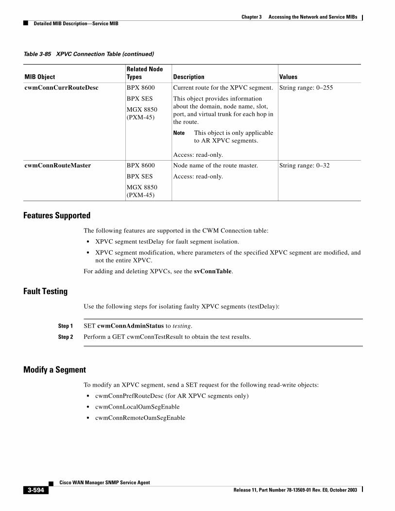
Chapter 3 Accessing the Network and Service MIBsDetailed MIB Description—Service MIB
Features Supported
The following features are supported in the CWM Connection table:
• XPVC segment testDelay for fault segment isolation.
• XPVC segment modification, where parameters of the specified XPVC segment are modified, and not the entire XPVC.
For adding and deleting XPVCs, see the svConnTable.
Fault Testing
Use the following steps for isolating faulty XPVC segments (testDelay):
Step 1 SET cwmConnAdminStatus to testing.
Step 2 Perform a GET cwmConnTestResult to obtain the test results.
Modify a Segment
To modify an XPVC segment, send a SET request for the following read-write objects:
• cwmConnPrefRouteDesc (for AR XPVC segments only)
• cwmConnLocalOamSegEnable
• cwmConnRemoteOamSegEnable
cwmConnCurrRouteDesc BPX 8600
BPX SES
MGX 8850 (PXM-45)
Current route for the XPVC segment.
This object provides information about the domain, node name, slot, port, and virtual trunk for each hop in the route.
Note This object is only applicable to AR XPVC segments.
Access: read-only.
String range: 0–255
cwmConnRouteMaster BPX 8600
BPX SES
MGX 8850 (PXM-45)
Node name of the route master.
Access: read-only.
String range: 0–32
Table 3-85 XPVC Connection Table (continued)
MIB ObjectRelated Node Types Description Values
3-594Cisco WAN Manager SNMP Service Agent
Release 11, Part Number 78-13569-01 Rev. E0, October 2003
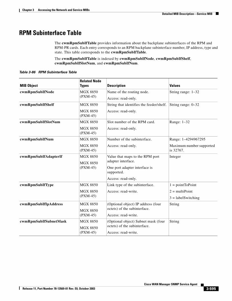
Chapter 3 Accessing the Network and Service MIBsDetailed MIB Description—Service MIB
RPM Subinterface TableThe cwmRpmSubIfTable provides information about the backplane subinterfaces of the RPM and RPM-PR cards. Each entry corresponds to an RPM backplane subinterface number, IP address, type and state. This table corresponds to the cwmRpmSubIfTable.
The cwmRpmSubIfTable is indexed by cwmRpmSubIfNode, cwmRpmSubIfShelf, cwmRpmSubIfSlotNum, and cwmRpmSubIfNum.
Table 3-86 RPM Subinterface Table
MIB ObjectRelated Node Types Description Values
cwmRpmSubIfNode MGX 8850 (PXM-45)
Name of the routing node.
Access: read-only.
String range: 1–32
cwmRpmSubIfShelf MGX 8850
MGX 8850 (PXM-45)
String that identifies the feeder/shelf.
Access: read-only.
String range: 0–32
cwmRpmSubIfSlotNum MGX 8850
MGX 8850 (PXM-45)
Slot number of the RPM card.
Access: read-only.
Range: 1–32
cwmRpmSubIfNum MGX 8850
MGX 8850 (PXM-45)
Number of the subinterface.
Access: read-only.
Range: 1–4294967295
Maximum number supported is 32767.
cwmRpmSubIfAdapterIf MGX 8850
MGX 8850 (PXM-45)
Value that maps to the RPM port adapter interface.
One port adapter interface is supported.
Access: read-only.
Integer
cwmRpmSubIfType MGX 8850
MGX 8850 (PXM-45)
Link type of the subinterface.
Access: read-write.
1 = pointToPoint
2 = multiPoint
3 = labelSwitching
cwmRpmSubIfIpAddress MGX 8850
MGX 8850 (PXM-45)
(Optional object) IP address (four octets) of the subinterface.
Access: read-write.
String
cwmRpmSubIfSubnetMask MGX 8850
MGX 8850 (PXM-45)
(Optional object) Subnet mask (four octets) of the subinterface.
Access: read-write.
String
3-595Cisco WAN Manager SNMP Service Agent
Release 11, Part Number 78-13569-01 Rev. E0, October 2003
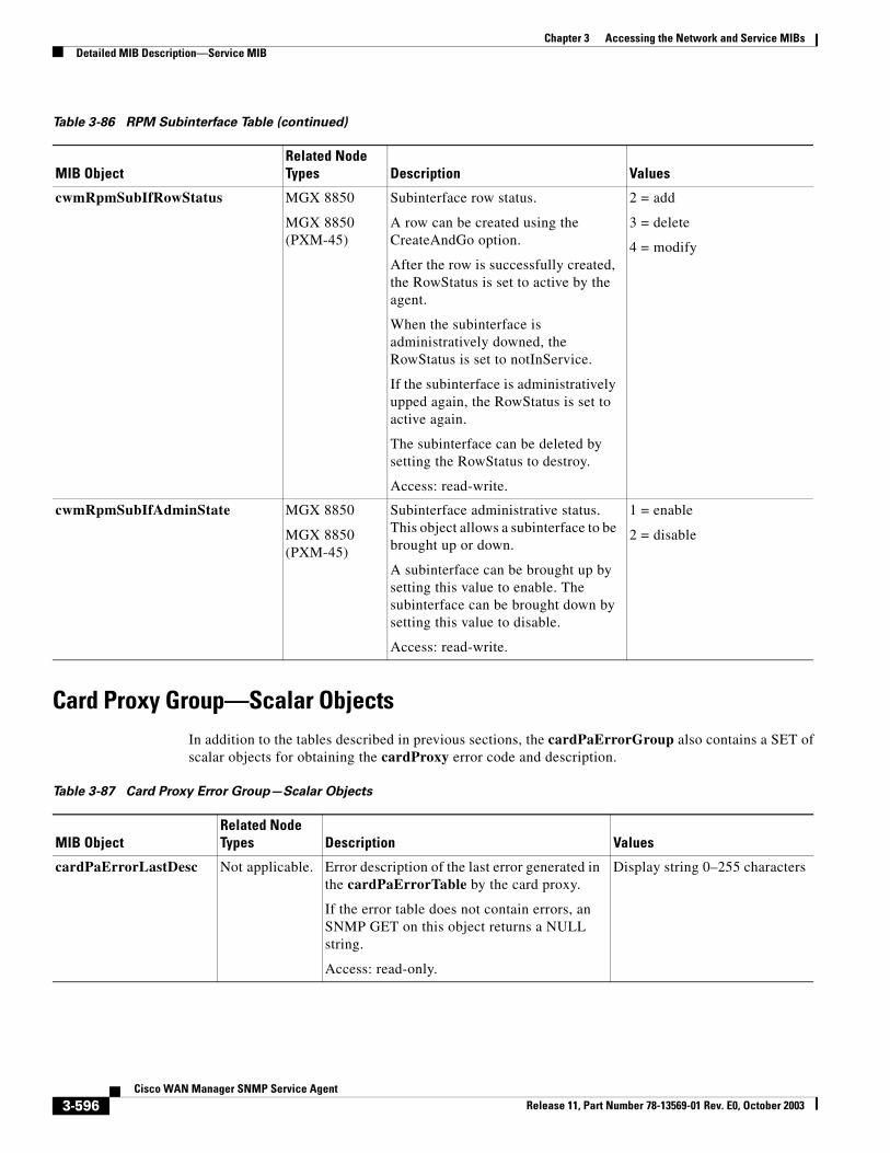
Chapter 3 Accessing the Network and Service MIBsDetailed MIB Description—Service MIB
Card Proxy Group—Scalar ObjectsIn addition to the tables described in previous sections, the cardPaErrorGroup also contains a SET of scalar objects for obtaining the cardProxy error code and description.
cwmRpmSubIfRowStatus MGX 8850
MGX 8850 (PXM-45)
Subinterface row status.
A row can be created using the CreateAndGo option.
After the row is successfully created, the RowStatus is set to active by the agent.
When the subinterface is administratively downed, the RowStatus is set to notInService.
If the subinterface is administratively upped again, the RowStatus is set to active again.
The subinterface can be deleted by setting the RowStatus to destroy.
Access: read-write.
2 = add
3 = delete
4 = modify
cwmRpmSubIfAdminState MGX 8850
MGX 8850 (PXM-45)
Subinterface administrative status. This object allows a subinterface to be brought up or down.
A subinterface can be brought up by setting this value to enable. The subinterface can be brought down by setting this value to disable.
Access: read-write.
1 = enable
2 = disable
Table 3-86 RPM Subinterface Table (continued)
MIB ObjectRelated Node Types Description Values
Table 3-87 Card Proxy Error Group—Scalar Objects
MIB ObjectRelated Node Types Description Values
cardPaErrorLastDesc Not applicable. Error description of the last error generated in the cardPaErrorTable by the card proxy.
If the error table does not contain errors, an SNMP GET on this object returns a NULL string.
Access: read-only.
Display string 0–255 characters
3-596Cisco WAN Manager SNMP Service Agent
Release 11, Part Number 78-13569-01 Rev. E0, October 2003
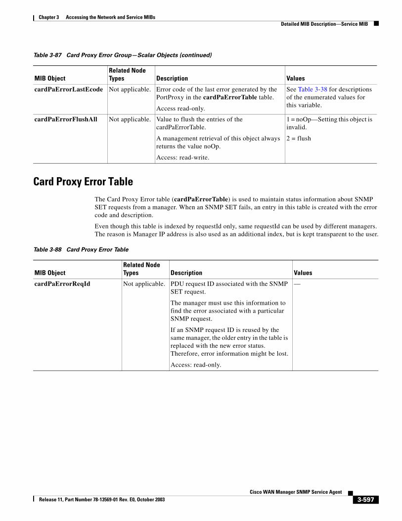
Chapter 3 Accessing the Network and Service MIBsDetailed MIB Description—Service MIB
Card Proxy Error TableThe Card Proxy Error table (cardPaErrorTable) is used to maintain status information about SNMP SET requests from a manager. When an SNMP SET fails, an entry in this table is created with the error code and description.
Even though this table is indexed by requestId only, same requestId can be used by different managers. The reason is Manager IP address is also used as an additional index, but is kept transparent to the user.
cardPaErrorLastEcode Not applicable. Error code of the last error generated by the PortProxy in the cardPaErrorTable table.
Access read-only.
See Table 3-38 for descriptions of the enumerated values for this variable.
cardPaErrorFlushAll Not applicable. Value to flush the entries of the cardPaErrorTable.
A management retrieval of this object always returns the value noOp.
Access: read-write.
1 = noOp—Setting this object is invalid.
2 = flush
Table 3-87 Card Proxy Error Group—Scalar Objects (continued)
MIB ObjectRelated Node Types Description Values
Table 3-88 Card Proxy Error Table
MIB ObjectRelated Node Types Description Values
cardPaErrorReqId Not applicable. PDU request ID associated with the SNMP SET request.
The manager must use this information to find the error associated with a particular SNMP request.
If an SNMP request ID is reused by the same manager, the older entry in the table is replaced with the new error status. Therefore, error information might be lost.
Access: read-only.
—
3-597Cisco WAN Manager SNMP Service Agent
Release 11, Part Number 78-13569-01 Rev. E0, October 2003
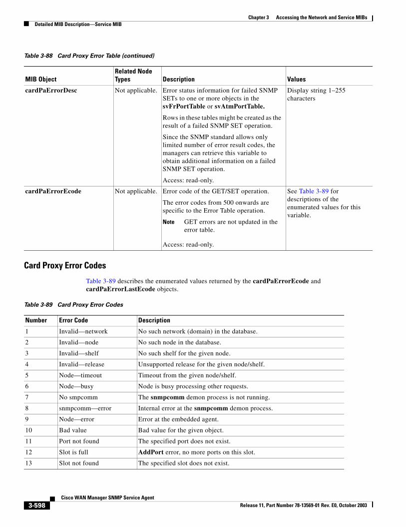
Chapter 3 Accessing the Network and Service MIBsDetailed MIB Description—Service MIB
Card Proxy Error Codes
Table 3-89 describes the enumerated values returned by the cardPaErrorEcode and cardPaErrorLastEcode objects.
cardPaErrorDesc Not applicable. Error status information for failed SNMP SETs to one or more objects in the svFrPortTable or svAtmPortTable.
Rows in these tables might be created as the result of a failed SNMP SET operation.
Since the SNMP standard allows only limited number of error result codes, the managers can retrieve this variable to obtain additional information on a failed SNMP SET operation.
Access: read-only.
Display string 1–255 characters
cardPaErrorEcode Not applicable. Error code of the GET/SET operation.
The error codes from 500 onwards are specific to the Error Table operation.
Note GET errors are not updated in the error table.
Access: read-only.
See Table 3-89 for descriptions of the enumerated values for this variable.
Table 3-88 Card Proxy Error Table (continued)
MIB ObjectRelated Node Types Description Values
Table 3-89 Card Proxy Error Codes
Number Error Code Description
1 Invalid—network No such network (domain) in the database.
2 Invalid—node No such node in the database.
3 Invalid—shelf No such shelf for the given node.
4 Invalid—release Unsupported release for the given node/shelf.
5 Node—timeout Timeout from the given node/shelf.
6 Node—busy Node is busy processing other requests.
7 No smpcomm The snmpcomm demon process is not running.
8 snmpcomm—error Internal error at the snmpcomm demon process.
9 Node—error Error at the embedded agent.
10 Bad value Bad value for the given object.
11 Port not found The specified port does not exist.
12 Slot is full AddPort error, no more ports on this slot.
13 Slot not found The specified slot does not exist.
3-598Cisco WAN Manager SNMP Service Agent
Release 11, Part Number 78-13569-01 Rev. E0, October 2003
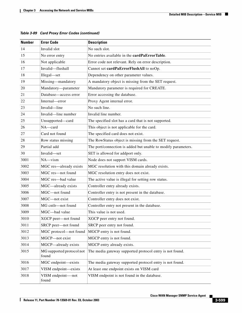
Chapter 3 Accessing the Network and Service MIBsDetailed MIB Description—Service MIB
14 Invalid slot No such slot.
15 No error entry No entries available in the cardPaErrorTable.
16 Not applicable Error code not relevant. Rely on error description.
17 Invalid—flushall Cannot set cardPaErrorFlushAll to noOp.
18 Illegal—set Dependency on other parameter values.
19 Missing—mandatory A mandatory object is missing from the SET request.
20 Mandatory—parameter Mandatory parameter is required for CREATE.
21 Database—access error Error accessing the database.
22 Internal—error Proxy Agent internal error.
23 Invalid—line No such line.
24 Invalid—line number Invalid line number.
25 Unsupported—card The specified slot has a card that is not supported.
26 NA—card This object is not applicable for the card.
27 Card not found The specified card does not exist.
28 Row status missing The RowStatus object is missing from the SET request.
29 Partial add The port/connection is added but unable to modify parameters.
30 Invalid—set SET is allowed for addport only.
3001 NA—vism Node does not support VISM cards.
3002 MGC res—already exists MGC resolution with this domain already exists.
3003 MGC res—not found MGC resolution entry does not exist.
3004 MGC res—bad value The active value is illegal for setting row status.
3005 MGC—already exists Controller entry already exists.
3006 MGC—not found Controller entry is not present in the database.
3007 MGC—not exist Controller entry does not exist.
3008 MG cntlr—not found Controller entry not present in the database.
3009 MGC—bad value This value is not used.
3010 XGCP peer—not found XGCP peer entry not found.
3011 SRCP peer—not found SRCP peer entry not found.
3012 MGC protocol—not found MGCP entry is not found.
3013 MGCP—not exist MGCP entry is not found.
3014 MGCP—already exists MGCP entry already exists.
3015 MG supported protocol not found
The media gateway supported protocol entry is not found.
3016 MGC endpoint—exists The media gateway supported protocol entry is not found.
3017 VISM endpoint—exists At least one endpoint exists on VISM card
3018 VISM endpoint—-not found
VISM endpoint is not found in the database.
Table 3-89 Card Proxy Error Codes (continued)
Number Error Code Description
3-599Cisco WAN Manager SNMP Service Agent
Release 11, Part Number 78-13569-01 Rev. E0, October 2003
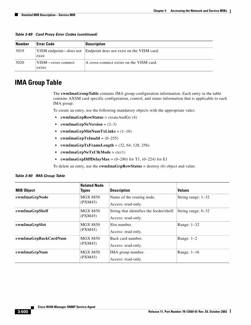
Chapter 3 Accessing the Network and Service MIBsDetailed MIB Description—Service MIB
IMA Group TableThe cwmImaGroupTable contains IMA group configuration information. Each entry in the table contains AXSM card specific configuration, control, and status information that is applicable to each IMA group.
To create an entry, use the following mandatory objects with the appropriate vales:
• cwmImaGrpRowStatus = createAndGo (4)
• cwmImaGrpNeVersion = (2–3)
• cwmImaGrpMinNumTxLinks = (1–16)
• cwmImaGrpTxImaId = (0–255)
• cwmImaGrpTxFrameLength = (32, 64, 128, 256)
• cwmImaGrpNeTxClkMode = ctc(1)
• cwmImaGrpDiffDelayMax = (0–280) for T1, (0–224) for E1
To delete an entry, use the cwmImaGrpRowStatus = destroy (6) object and value.
3019 VISM endpoint—does not exist
Endpoint does not exist on the VISM card.
3020 VISM—cross connect exists
A cross-connect exists on the VISM card.
Table 3-89 Card Proxy Error Codes (continued)
Number Error Code Description
Table 3-90 IMA Group Table
MIB ObjectRelated Node Types Description Values
cwmImaGrpNode MGX 8850 (PXM45)
Name of the routing node.
Access: read-only.
String range: 1–32
cwmImaGrpShelf MGX 8850 (PXM45)
String that identifies the feeder/shelf.
Access: read-only.
String range: 0–32
cwmImaGrpSlot MGX 8850 (PXM45)
Slot number.
Access: read-only.
Range: 1–32
cwmImaGrpBackCardNum MGX 8850 (PXM45)
Back card number.
Access: read-only.
Range: 1–2
cwmImaGrpNum MGX 8850 (PXM45)
IMA group number.
Access: read-only.
Range: 1–16
3-600Cisco WAN Manager SNMP Service Agent
Release 11, Part Number 78-13569-01 Rev. E0, October 2003
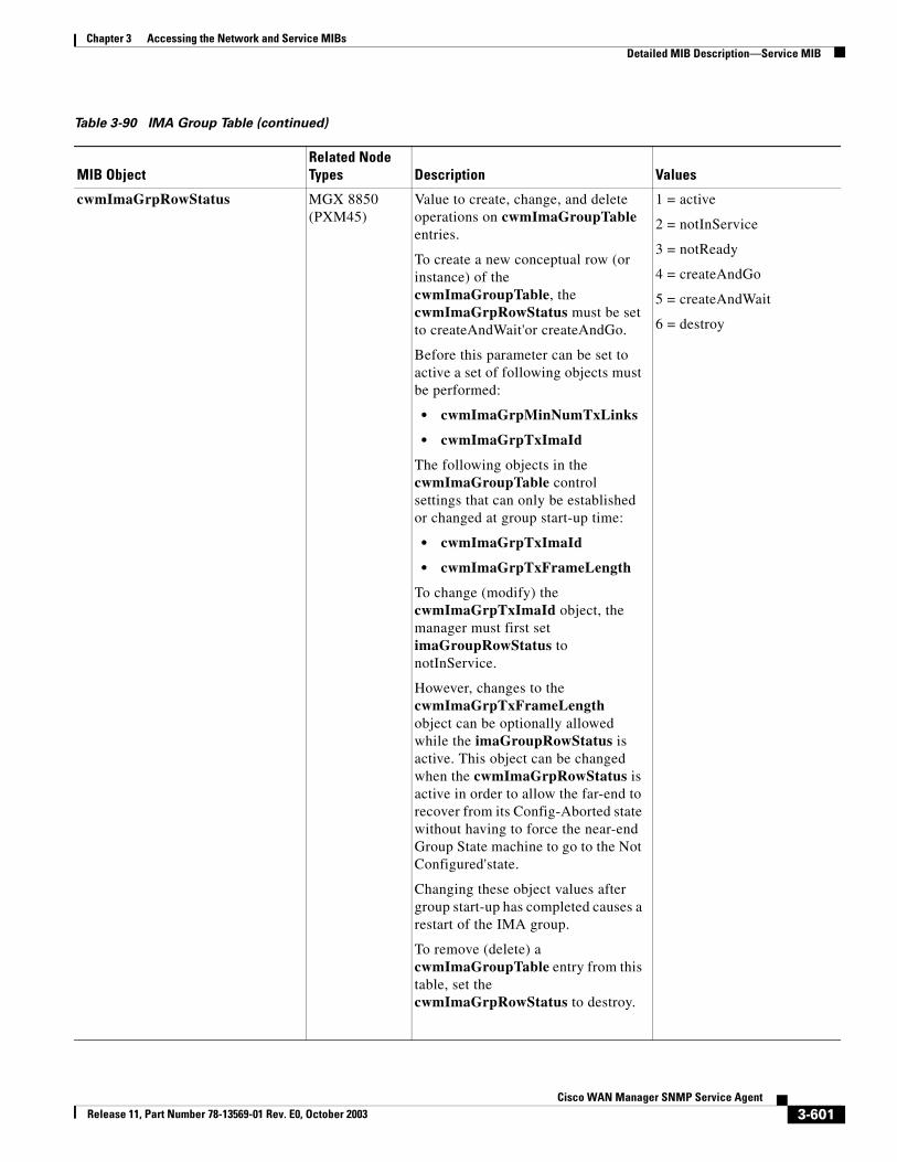
Chapter 3 Accessing the Network and Service MIBsDetailed MIB Description—Service MIB
cwmImaGrpRowStatus MGX 8850 (PXM45)
Value to create, change, and delete operations on cwmImaGroupTable entries.
To create a new conceptual row (or instance) of the cwmImaGroupTable, the cwmImaGrpRowStatus must be set to createAndWait'or createAndGo.
Before this parameter can be set to active a set of following objects must be performed:
• cwmImaGrpMinNumTxLinks
• cwmImaGrpTxImaId
The following objects in the cwmImaGroupTable control settings that can only be established or changed at group start-up time:
• cwmImaGrpTxImaId
• cwmImaGrpTxFrameLength
To change (modify) the cwmImaGrpTxImaId object, the manager must first set imaGroupRowStatus to notInService.
However, changes to the cwmImaGrpTxFrameLength object can be optionally allowed while the imaGroupRowStatus is active. This object can be changed when the cwmImaGrpRowStatus is active in order to allow the far-end to recover from its Config-Aborted state without having to force the near-end Group State machine to go to the Not Configured'state.
Changing these object values after group start-up has completed causes a restart of the IMA group.
To remove (delete) a cwmImaGroupTable entry from this table, set the cwmImaGrpRowStatus to destroy.
1 = active
2 = notInService
3 = notReady
4 = createAndGo
5 = createAndWait
6 = destroy
Table 3-90 IMA Group Table (continued)
MIB ObjectRelated Node Types Description Values
3-601Cisco WAN Manager SNMP Service Agent
Release 11, Part Number 78-13569-01 Rev. E0, October 2003
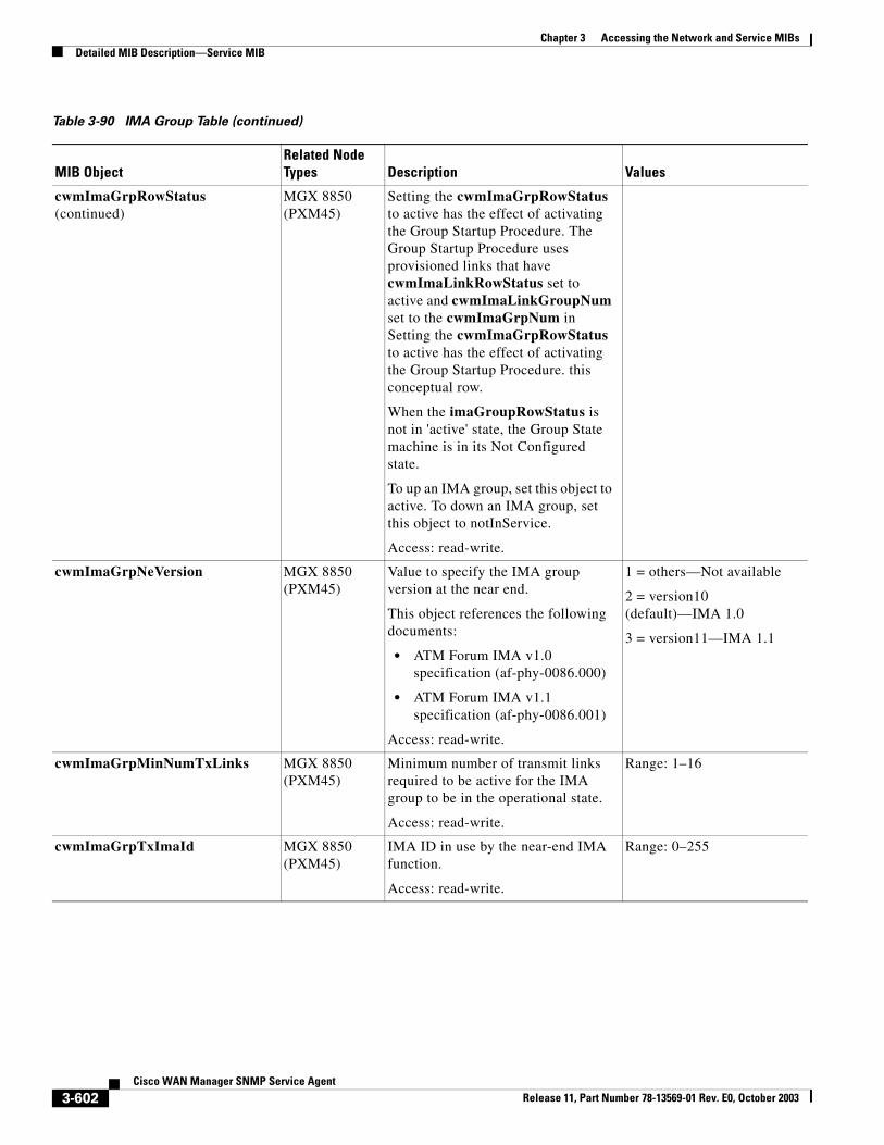
Chapter 3 Accessing the Network and Service MIBsDetailed MIB Description—Service MIB
cwmImaGrpRowStatus (continued)
MGX 8850 (PXM45)
Setting the cwmImaGrpRowStatus to active has the effect of activating the Group Startup Procedure. The Group Startup Procedure uses provisioned links that have cwmImaLinkRowStatus set to active and cwmImaLinkGroupNum set to the cwmImaGrpNum in Setting the cwmImaGrpRowStatus to active has the effect of activating the Group Startup Procedure. this conceptual row.
When the imaGroupRowStatus is not in 'active' state, the Group State machine is in its Not Configured state.
To up an IMA group, set this object to active. To down an IMA group, set this object to notInService.
Access: read-write.
cwmImaGrpNeVersion MGX 8850 (PXM45)
Value to specify the IMA group version at the near end.
This object references the following documents:
• ATM Forum IMA v1.0 specification (af-phy-0086.000)
• ATM Forum IMA v1.1 specification (af-phy-0086.001)
Access: read-write.
1 = others—Not available
2 = version10 (default)—IMA 1.0
3 = version11—IMA 1.1
cwmImaGrpMinNumTxLinks MGX 8850 (PXM45)
Minimum number of transmit links required to be active for the IMA group to be in the operational state.
Access: read-write.
Range: 1–16
cwmImaGrpTxImaId MGX 8850 (PXM45)
IMA ID in use by the near-end IMA function.
Access: read-write.
Range: 0–255
Table 3-90 IMA Group Table (continued)
MIB ObjectRelated Node Types Description Values
3-602Cisco WAN Manager SNMP Service Agent
Release 11, Part Number 78-13569-01 Rev. E0, October 2003
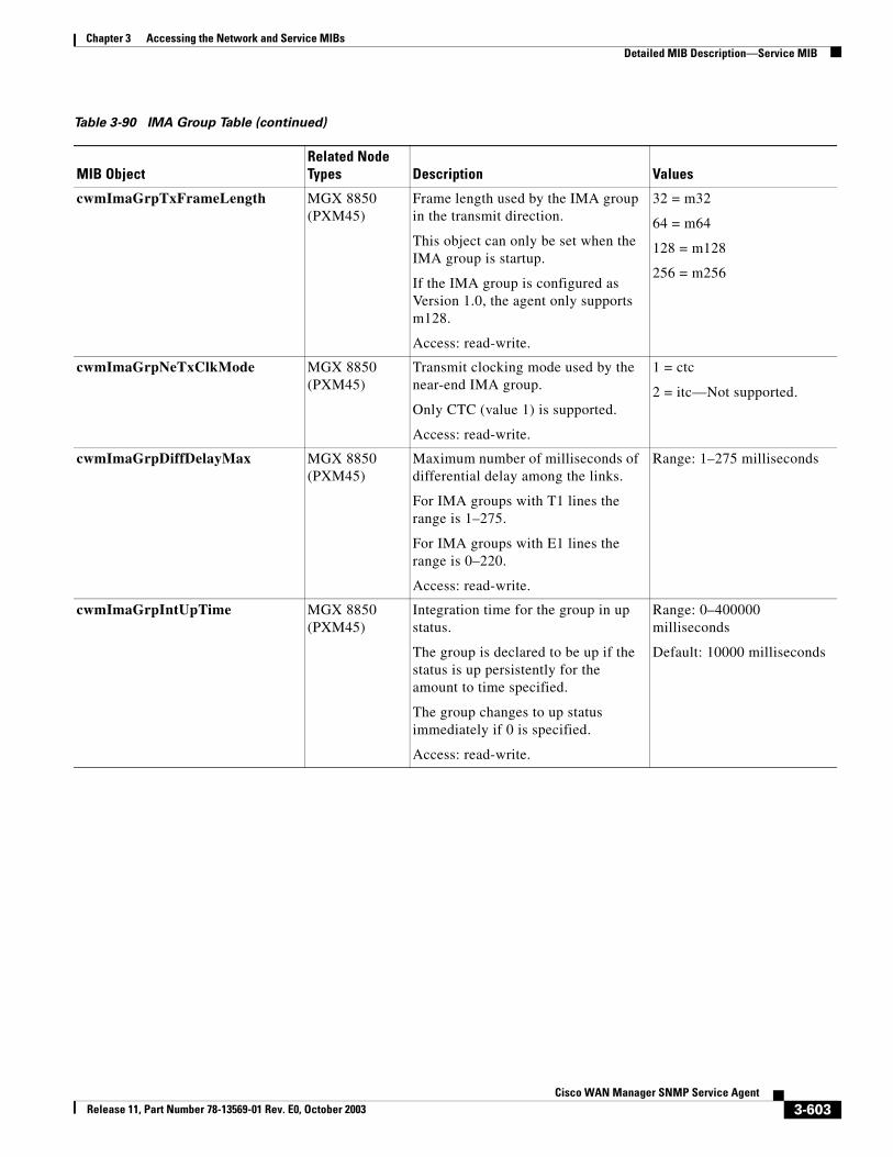
Chapter 3 Accessing the Network and Service MIBsDetailed MIB Description—Service MIB
cwmImaGrpTxFrameLength MGX 8850 (PXM45)
Frame length used by the IMA group in the transmit direction.
This object can only be set when the IMA group is startup.
If the IMA group is configured as Version 1.0, the agent only supports m128.
Access: read-write.
32 = m32
64 = m64
128 = m128
256 = m256
cwmImaGrpNeTxClkMode MGX 8850 (PXM45)
Transmit clocking mode used by the near-end IMA group.
Only CTC (value 1) is supported.
Access: read-write.
1 = ctc
2 = itc—Not supported.
cwmImaGrpDiffDelayMax MGX 8850 (PXM45)
Maximum number of milliseconds of differential delay among the links.
For IMA groups with T1 lines the range is 1–275.
For IMA groups with E1 lines the range is 0–220.
Access: read-write.
Range: 1–275 milliseconds
cwmImaGrpIntUpTime MGX 8850 (PXM45)
Integration time for the group in up status.
The group is declared to be up if the status is up persistently for the amount to time specified.
The group changes to up status immediately if 0 is specified.
Access: read-write.
Range: 0–400000 milliseconds
Default: 10000 milliseconds
Table 3-90 IMA Group Table (continued)
MIB ObjectRelated Node Types Description Values
3-603Cisco WAN Manager SNMP Service Agent
Release 11, Part Number 78-13569-01 Rev. E0, October 2003
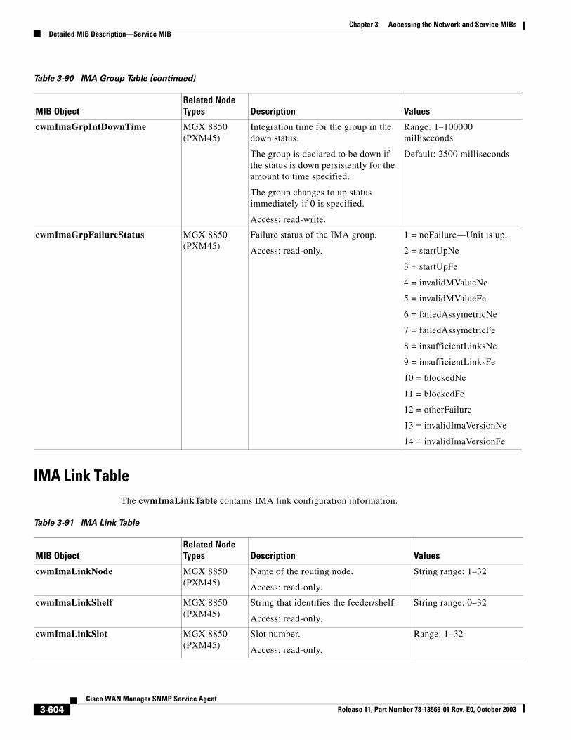
Chapter 3 Accessing the Network and Service MIBsDetailed MIB Description—Service MIB
IMA Link TableThe cwmImaLinkTable contains IMA link configuration information.
cwmImaGrpIntDownTime MGX 8850 (PXM45)
Integration time for the group in the down status.
The group is declared to be down if the status is down persistently for the amount to time specified.
The group changes to up status immediately if 0 is specified.
Access: read-write.
Range: 1–100000 milliseconds
Default: 2500 milliseconds
cwmImaGrpFailureStatus MGX 8850 (PXM45)
Failure status of the IMA group.
Access: read-only.
1 = noFailure—Unit is up.
2 = startUpNe
3 = startUpFe
4 = invalidMValueNe
5 = invalidMValueFe
6 = failedAssymetricNe
7 = failedAssymetricFe
8 = insufficientLinksNe
9 = insufficientLinksFe
10 = blockedNe
11 = blockedFe
12 = otherFailure
13 = invalidImaVersionNe
14 = invalidImaVersionFe
Table 3-90 IMA Group Table (continued)
MIB ObjectRelated Node Types Description Values
Table 3-91 IMA Link Table
MIB ObjectRelated Node Types Description Values
cwmImaLinkNode MGX 8850 (PXM45)
Name of the routing node.
Access: read-only.
String range: 1–32
cwmImaLinkShelf MGX 8850 (PXM45)
String that identifies the feeder/shelf.
Access: read-only.
String range: 0–32
cwmImaLinkSlot MGX 8850 (PXM45)
Slot number.
Access: read-only.
Range: 1–32
3-604Cisco WAN Manager SNMP Service Agent
Release 11, Part Number 78-13569-01 Rev. E0, October 2003
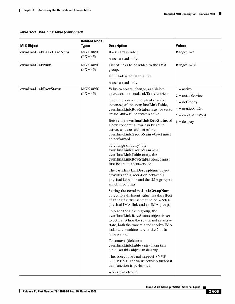
Chapter 3 Accessing the Network and Service MIBsDetailed MIB Description—Service MIB
cwmImaLinkBackCardNum MGX 8850 (PXM45)
Back card number.
Access: read-only.
Range: 1–2
cwmImaLinkNum MGX 8850 (PXM45)
List of links to be added to the IMA group.
Each link is equal to a line.
Access: read-only.
Range: 1–16
cwmImaLinkRowStatus MGX 8850 (PXM45)
Value to create, change, and delete operations on imaLinkTable entries.
To create a new conceptual row (or instance) of the cwmImaLinkTable, cwmImaLinkRowStatus must be set to createAndWait or createAndGo.
Before the cwmImaLinkRowStatus of a new conceptual row can be set to active, a successful set of the cwmImaLinkGroupNum object must be performed.
To change (modify) the cwmImaLinkGroupNum in a cwmImaLinkTable entry, the cwmImaLinkRowStatus object must first be set to notInService.
The cwmImaLinkGroupNum object provides the association between a physical IMA link and the IMA group to which it belongs.
Setting the cwmImaLinkGroupNum object to a different value has the effect of changing the association between a physical IMA link and an IMA group.
To place the link in group, the cwmImaLinkRowStatus object is set to active. While the row is not in active state, both the transmit and receive IMA link state machines are in the Not In Group state.
To remove (delete) a cwmImaLinkTable entry from this table, set this object to destroy.
This object does not support SNMP GET NEXT. The value active returned if this function is performed.
Access: read-write.
1 = active
2 = notInService
3 = notReady
4 = createAndGo
5 = createAndWait
6 = destroy
Table 3-91 IMA Link Table (continued)
MIB ObjectRelated Node Types Description Values
3-605Cisco WAN Manager SNMP Service Agent
Release 11, Part Number 78-13569-01 Rev. E0, October 2003
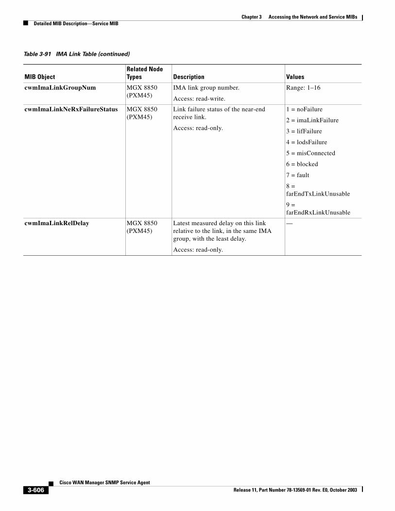
Chapter 3 Accessing the Network and Service MIBsDetailed MIB Description—Service MIB
cwmImaLinkGroupNum MGX 8850 (PXM45)
IMA link group number.
Access: read-write.
Range: 1–16
cwmImaLinkNeRxFailureStatus MGX 8850 (PXM45)
Link failure status of the near-end receive link.
Access: read-only.
1 = noFailure
2 = imaLinkFailure
3 = lifFailure
4 = lodsFailure
5 = misConnected
6 = blocked
7 = fault
8 = farEndTxLinkUnusable
9 = farEndRxLinkUnusable
cwmImaLinkRelDelay MGX 8850 (PXM45)
Latest measured delay on this link relative to the link, in the same IMA group, with the least delay.
Access: read-only.
—
Table 3-91 IMA Link Table (continued)
MIB ObjectRelated Node Types Description Values
3-606Cisco WAN Manager SNMP Service Agent
Release 11, Part Number 78-13569-01 Rev. E0, October 2003