Embed Size (px)
Citation preview
CISCO SYSTEMS PUBLICATION HISTORY 170 WEST TASMAN DR. SAN JOSE, CA, 95134 REV A.11 August 29, 2018WWW.CISCO.COM
Spec Sheet
Cisco UCS B260 M4 Blade Server (with Intel® Xeon® E7 v4 CPU)
Cisco UCS B260 M4 Blade Server (with Intel® Xeon® E7 v4 CPU) 2
CONTENTS
OVERVIEW . . . . . . . . . . . . . . . . . . . . . . . . . . . . . . . . . . . . . . . . . . . . . . . 3DETAILED VIEWS . . . . . . . . . . . . . . . . . . . . . . . . . . . . . . . . . . . . . . . . . . . 4
Chassis Front View . . . . . . . . . . . . . . . . . . . . . . . . . . . . . . . . . . . . . . . . . . . . . . . . . . .4BASE SERVER STANDARD CAPABILITIES and FEATURES . . . . . . . . . . . . . . . . . 5CONFIGURING the SERVER . . . . . . . . . . . . . . . . . . . . . . . . . . . . . . . . . . . . 7
STEP 1 VERIFY BASE SKU . . . . . . . . . . . . . . . . . . . . . . . . . . . . . . . . . . . . . . . . . . . . . .8STEP 2 CHOOSE CPU(S) . . . . . . . . . . . . . . . . . . . . . . . . . . . . . . . . . . . . . . . . . . . . . .9STEP 3 CHOOSE MEMORY . . . . . . . . . . . . . . . . . . . . . . . . . . . . . . . . . . . . . . . . . . . . 11STEP 4 CHOOSE SOLID STATE DRIVES (SSDs) . . . . . . . . . . . . . . . . . . . . . . . . . . . . . . . . 17STEP 5 CHOOSE RAID CONFIGURATION . . . . . . . . . . . . . . . . . . . . . . . . . . . . . . . . . . . 18STEP 6 CHOOSE ADAPTERS . . . . . . . . . . . . . . . . . . . . . . . . . . . . . . . . . . . . . . . . . . . 19STEP 7 ORDER OPTIONAL KVM CABLE . . . . . . . . . . . . . . . . . . . . . . . . . . . . . . . . . . . . 23STEP 8 ORDER TRUSTED PLATFORM MODULE (OPTIONAL) . . . . . . . . . . . . . . . . . . . . . . . 24STEP 9 ORDER CISCO FLEXIBLE FLASH SECURE DIGITAL CARDS . . . . . . . . . . . . . . . . . . . . 25STEP 10 ORDER OPTIONAL INTERNAL USB 2.0 DRIVE . . . . . . . . . . . . . . . . . . . . . . . . . . 26STEP 11 CHOOSE OPERATING SYSTEM AND VALUE-ADDED SOFTWARE . . . . . . . . . . . . . . . 27STEP 12 CHOOSE OPERATING SYSTEM MEDIA KIT . . . . . . . . . . . . . . . . . . . . . . . . . . . . . 30STEP 13 CHOOSE SERVICE and SUPPORT LEVEL . . . . . . . . . . . . . . . . . . . . . . . . . . . . . . 31
SUPPLEMENTAL MATERIAL . . . . . . . . . . . . . . . . . . . . . . . . . . . . . . . . . . . 36Motherboard . . . . . . . . . . . . . . . . . . . . . . . . . . . . . . . . . . . . . . . . . . . . . . . . . . . . . . 36DIMM and CPU Layout . . . . . . . . . . . . . . . . . . . . . . . . . . . . . . . . . . . . . . . . . . . . . . . . 38Memory Population Recommendations . . . . . . . . . . . . . . . . . . . . . . . . . . . . . . . . . . . . . 39Memory Mixing Guidelines . . . . . . . . . . . . . . . . . . . . . . . . . . . . . . . . . . . . . . . . . . . . . 40Upgrade and Servicing-Related Parts . . . . . . . . . . . . . . . . . . . . . . . . . . . . . . . . . . . . . . 41
Drive and Blade Server Blanking Panels . . . . . . . . . . . . . . . . . . . . . . . . . . . . . . . . 41Replacing a CPU (with CPU heat sink) . . . . . . . . . . . . . . . . . . . . . . . . . . . . . . . . . 41CPU Removal and Installation (“pick n place”) Tool Set . . . . . . . . . . . . . . . . . . . . . 41Thermal Grease (with syringe applicator) for CPU to Heatsink Seal . . . . . . . . . . . . . . 42CPU Heat Sink Cleaning Kit . . . . . . . . . . . . . . . . . . . . . . . . . . . . . . . . . . . . . . . . 42
Network Connectivity . . . . . . . . . . . . . . . . . . . . . . . . . . . . . . . . . . . . . . . . . . . . . . . . 43VIC 1340 and Port Expander . . . . . . . . . . . . . . . . . . . . . . . . . . . . . . . . . . . . . . . . 45Connectivity Using the Cisco UCS 2208XP/2204XP Fabric Extender . . . . . . . . . . . . . . 46
TECHNICAL SPECIFICATIONS . . . . . . . . . . . . . . . . . . . . . . . . . . . . . . . . . . 52Dimensions and Weight . . . . . . . . . . . . . . . . . . . . . . . . . . . . . . . . . . . . . . . . . . . . . . . 52Power Specifications . . . . . . . . . . . . . . . . . . . . . . . . . . . . . . . . . . . . . . . . . . . . . . . . 52
OVERVIEW
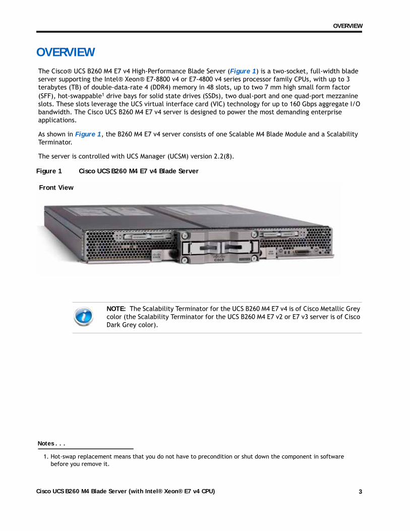
OVERVIEWThe Cisco® UCS B260 M4 E7 v4 High-Performance Blade Server (Figure 1) is a two-socket, full-width blade server supporting the Intel® Xeon® E7-8800 v4 or E7-4800 v4 series processor family CPUs, with up to 3 terabytes (TB) of double-data-rate 4 (DDR4) memory in 48 slots, up to two 7 mm high small form factor (SFF), hot-swappable1 drive bays for solid state drives (SSDs), two dual-port and one quad-port mezzanine slots. These slots leverage the UCS virtual interface card (VIC) technology for up to 160 Gbps aggregate I/O bandwidth. The Cisco UCS B260 M4 E7 v4 server is designed to power the most demanding enterprise applications.
As shown in Figure 1, the B260 M4 E7 v4 server consists of one Scalable M4 Blade Module and a Scalability Terminator.
The server is controlled with UCS Manager (UCSM) version 2.2(8).
Figure 1 Cisco UCS B260 M4 E7 v4 Blade Server
Notes . . .
1. Hot-swap replacement means that you do not have to precondition or shut down the component in softwarebefore you remove it.
NOTE: The Scalability Terminator for the UCS B260 M4 E7 v4 is of Cisco Metallic Grey color (the Scalability Terminator for the UCS B260 M4 E7 v2 or E7 v3 server is of Cisco Dark Grey color).
Front View
Cisco UCS B260 M4 Blade Server (with Intel® Xeon® E7 v4 CPU) 3
DETAILED VIEWS
DETAILED VIEWS
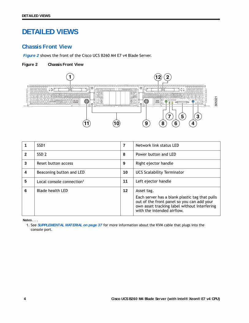
Chassis Front ViewFigure 2 shows the front of the Cisco UCS B260 M4 E7 v4 Blade Server.
Figure 2 Chassis Front View
1 SSD1 7 Network link status LED
2 SSD 2 8 Power button and LED
3 Reset button access 9 Right ejector handle
4 Beaconing button and LED 10 UCS Scalability Terminator
5 Local console connection1
Notes . . .1. See SUPPLEMENTAL MATERIAL on page 37 for more information about the KVM cable that plugs into the
console port.
11 Left ejector handle
6 Blade health LED 12 Asset tag.
Each server has a blank plastic tag that pulls out of the front panel so you can add your own asset tracking label without interfering with the intended airflow.
305321
10 97 56 4
38
212
11
1
Cisco UCS B260 M4 Blade Server (with Intel® Xeon® E7 v4 CPU)4
BASE SERVER STANDARD CAPABILITIES and FEATURES
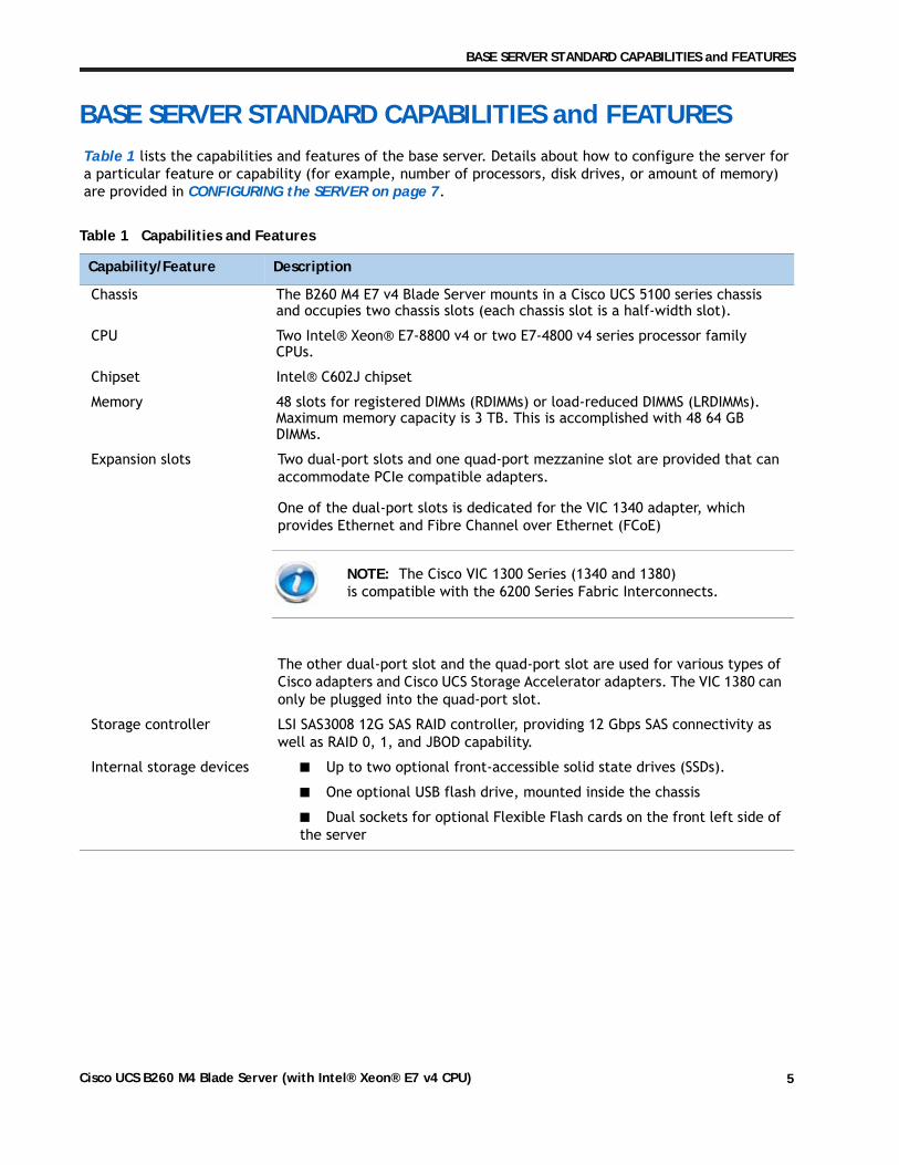
BASE SERVER STANDARD CAPABILITIES and FEATURESTable 1 lists the capabilities and features of the base server. Details about how to configure the server for a particular feature or capability (for example, number of processors, disk drives, or amount of memory) are provided in CONFIGURING the SERVER on page 7.
Table 1 Capabilities and Features
Capability/Feature Description
Chassis The B260 M4 E7 v4 Blade Server mounts in a Cisco UCS 5100 series chassis and occupies two chassis slots (each chassis slot is a half-width slot).
CPU Two Intel® Xeon® E7-8800 v4 or two E7-4800 v4 series processor family CPUs.
Chipset Intel® C602J chipset
Memory 48 slots for registered DIMMs (RDIMMs) or load-reduced DIMMS (LRDIMMs). Maximum memory capacity is 3 TB. This is accomplished with 48 64 GB DIMMs.
Expansion slots Two dual-port slots and one quad-port mezzanine slot are provided that can accommodate PCIe compatible adapters.
One of the dual-port slots is dedicated for the VIC 1340 adapter, which provides Ethernet and Fibre Channel over Ethernet (FCoE)
The other dual-port slot and the quad-port slot are used for various types of Cisco adapters and Cisco UCS Storage Accelerator adapters. The VIC 1380 can only be plugged into the quad-port slot.
Storage controller LSI SAS3008 12G SAS RAID controller, providing 12 Gbps SAS connectivity as well as RAID 0, 1, and JBOD capability.
Internal storage devices ■ Up to two optional front-accessible solid state drives (SSDs).
■ One optional USB flash drive, mounted inside the chassis
■ Dual sockets for optional Flexible Flash cards on the front left side ofthe server
NOTE: The Cisco VIC 1300 Series (1340 and 1380) is compatible with the 6200 Series Fabric Interconnects.
Cisco UCS B260 M4 Blade Server (with Intel® Xeon® E7 v4 CPU) 5
BASE SERVER STANDARD CAPABILITIES and FEATURES
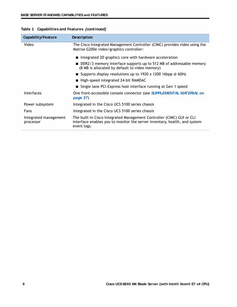
Video The Cisco Integrated Management Controller (CIMC) provides video using the Matrox G200e video/graphics controller:
■ Integrated 2D graphics core with hardware acceleration
■ DDR2/3 memory interface supports up to 512 MB of addressable memory(8 MB is allocated by default to video memory)
■ Supports display resolutions up to 1920 x 1200 16bpp @ 60Hz
■ High-speed integrated 24-bit RAMDAC
■ Single lane PCI-Express host interface running at Gen 1 speed
Interfaces One front-accessible console connector (see SUPPLEMENTAL MATERIAL on page 37)
Power subsystem Integrated in the Cisco UCS 5100 series chassis
Fans Integrated in the Cisco UCS 5100 series chassis
Integrated management processor
The built-in Cisco Integrated Management Controller (CIMC) GUI or CLI interface enables you to monitor the server inventory, health, and system event logs.
Table 1 Capabilities and Features (continued)
Capability/Feature Description
Cisco UCS B260 M4 Blade Server (with Intel® Xeon® E7 v4 CPU)6
CONFIGURING the SERVER
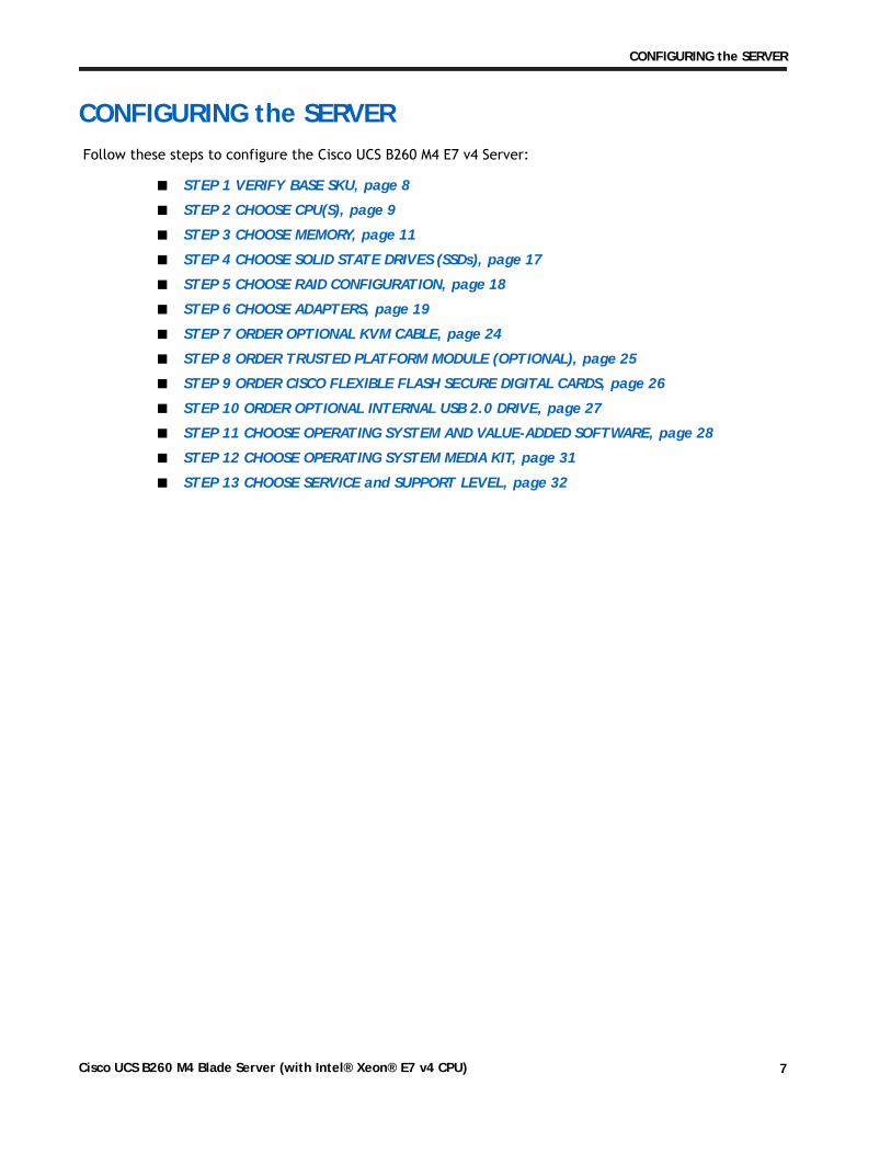
CONFIGURING the SERVERFollow these steps to configure the Cisco UCS B260 M4 E7 v4 Server:
■ STEP 1 VERIFY BASE SKU, page 8
■ STEP 2 CHOOSE CPU(S), page 9
■ STEP 3 CHOOSE MEMORY, page 11
■ STEP 4 CHOOSE SOLID STATE DRIVES (SSDs), page 17
■ STEP 5 CHOOSE RAID CONFIGURATION, page 18
■ STEP 6 CHOOSE ADAPTERS, page 19
■ STEP 7 ORDER OPTIONAL KVM CABLE, page 24
■ STEP 8 ORDER TRUSTED PLATFORM MODULE (OPTIONAL), page 25
■ STEP 9 ORDER CISCO FLEXIBLE FLASH SECURE DIGITAL CARDS, page 26
■ STEP 10 ORDER OPTIONAL INTERNAL USB 2.0 DRIVE, page 27
■ STEP 11 CHOOSE OPERATING SYSTEM AND VALUE-ADDED SOFTWARE, page 28
■ STEP 12 CHOOSE OPERATING SYSTEM MEDIA KIT, page 31
■ STEP 13 CHOOSE SERVICE and SUPPORT LEVEL, page 32
Cisco UCS B260 M4 Blade Server (with Intel® Xeon® E7 v4 CPU) 7
CONFIGURING the SERVER
STEP 1 VERIFY BASE SKU
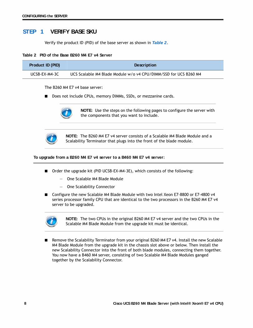
Verify the product ID (PID) of the base server as shown in Table 2.
The B260 M4 E7 v4 base server:
■ Does not include CPUs, memory DIMMs, SSDs, or mezzanine cards.
To upgrade from a B260 M4 E7 v4 server to a B460 M4 E7 v4 server:
■ Order the upgrade kit (PID UCSB-EX-M4-3E), which consists of the following:
— One Scalable M4 Blade Module
— One Scalability Connector
■ Configure the new Scalable M4 Blade Module with two Intel Xeon E7-8800 or E7-4800 v4series processor family CPU that are identical to the two processors in the B260 M4 E7 v4server to be upgraded.
■ Remove the Scalability Terminator from your original B260 M4 E7 v4. Install the new ScalableM4 Blade Module from the upgrade kit in the chassis slot above or below. Then install thenew Scalability Connector into the front of both blade modules, connecting them together.You now have a B460 M4 server, consisting of two Scalable M4 Blade Modules gangedtogether by the Scalability Connector.
Table 2 PID of the Base B260 M4 E7 v4 Server
Product ID (PID) Description
UCSB-EX-M4-3C UCS Scalable M4 Blade Module w/o v4 CPU/DIMM/SSD for UCS B260 M4
NOTE: Use the steps on the following pages to configure the server with the components that you want to include.
NOTE: The B260 M4 E7 v4 server consists of a Scalable M4 Blade Module and a Scalability Terminator that plugs into the front of the blade module.
NOTE: The two CPUs in the original B260 M4 E7 v4 server and the two CPUs in the Scalable M4 Blade Module from the upgrade kit must be identical.
Cisco UCS B260 M4 Blade Server (with Intel® Xeon® E7 v4 CPU)8
CONFIGURING the SERVER
STEP 2 CHOOSE CPU(S)
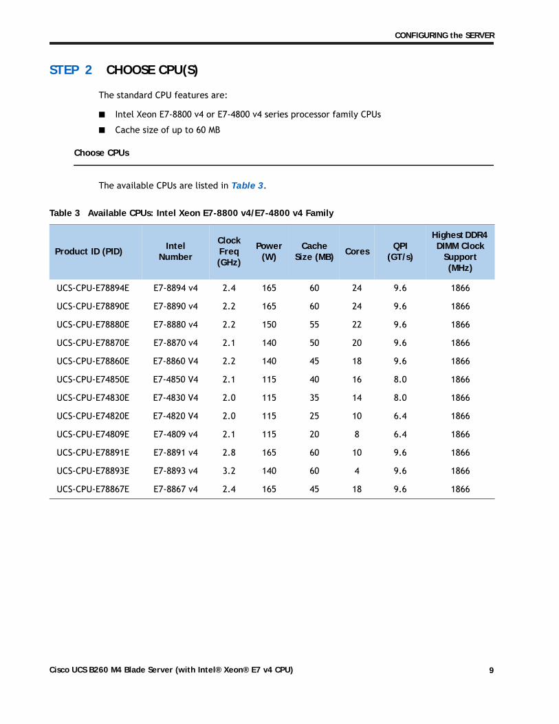
The standard CPU features are:
■ Intel Xeon E7-8800 v4 or E7-4800 v4 series processor family CPUs
■ Cache size of up to 60 MB
Choose CPUs
The available CPUs are listed in Table 3.
Table 3 Available CPUs: Intel Xeon E7-8800 v4/E7-4800 v4 Family
Product ID (PID) Intel Number
Clock Freq(GHz)
Power (W)
CacheSize (MB) Cores QPI
(GT/s)
Highest DDR4 DIMM Clock
Support (MHz)
UCS-CPU-E78894E E7-8894 v4 2.4 165 60 24 9.6 1866
UCS-CPU-E78890E E7-8890 v4 2.2 165 60 24 9.6 1866
UCS-CPU-E78880E E7-8880 v4 2.2 150 55 22 9.6 1866
UCS-CPU-E78870E E7-8870 v4 2.1 140 50 20 9.6 1866
UCS-CPU-E78860E E7-8860 V4 2.2 140 45 18 9.6 1866
UCS-CPU-E74850E E7-4850 V4 2.1 115 40 16 8.0 1866
UCS-CPU-E74830E E7-4830 V4 2.0 115 35 14 8.0 1866
UCS-CPU-E74820E E7-4820 V4 2.0 115 25 10 6.4 1866
UCS-CPU-E74809E E7-4809 v4 2.1 115 20 8 6.4 1866
UCS-CPU-E78891E E7-8891 v4 2.8 165 60 10 9.6 1866
UCS-CPU-E78893E E7-8893 v4 3.2 140 60 4 9.6 1866
UCS-CPU-E78867E E7-8867 v4 2.4 165 45 18 9.6 1866
Cisco UCS B260 M4 Blade Server (with Intel® Xeon® E7 v4 CPU) 9
CONFIGURING the SERVER
Approved Configurations
(1) Two-CPU Configuration
■ Choose two identical CPUs from any one row in Table 3.
Caveats
■ You must choose two identical CPUs.
NOTE: The B260 M4 E7 v4 server consists of a Scalable M4 Blade Module and a Scalability Terminator that plugs into the front of the blade module.
You can upgrade a B260 M4 E7 v4 blade server later to a B460 M4 E7 v4 server. See To upgrade from a B260 M4 E7 v4 server to a B460 M4 E7 v4 server: on page 8 for details on upgrading.
Cisco UCS B260 M4 Blade Server (with Intel® Xeon® E7 v4 CPU)10
CONFIGURING the SERVER
STEP 3 CHOOSE MEMORY
The standard memory features are:
■ DIMMs
— Clock speed: 2400 or 2133 MHz
— Ranks per DIMM: single, dual, or quad
— Operational voltage: 1.2 V
— Registered DIMM (RDIMM) or load-reduced DIMM (LRDIMM)
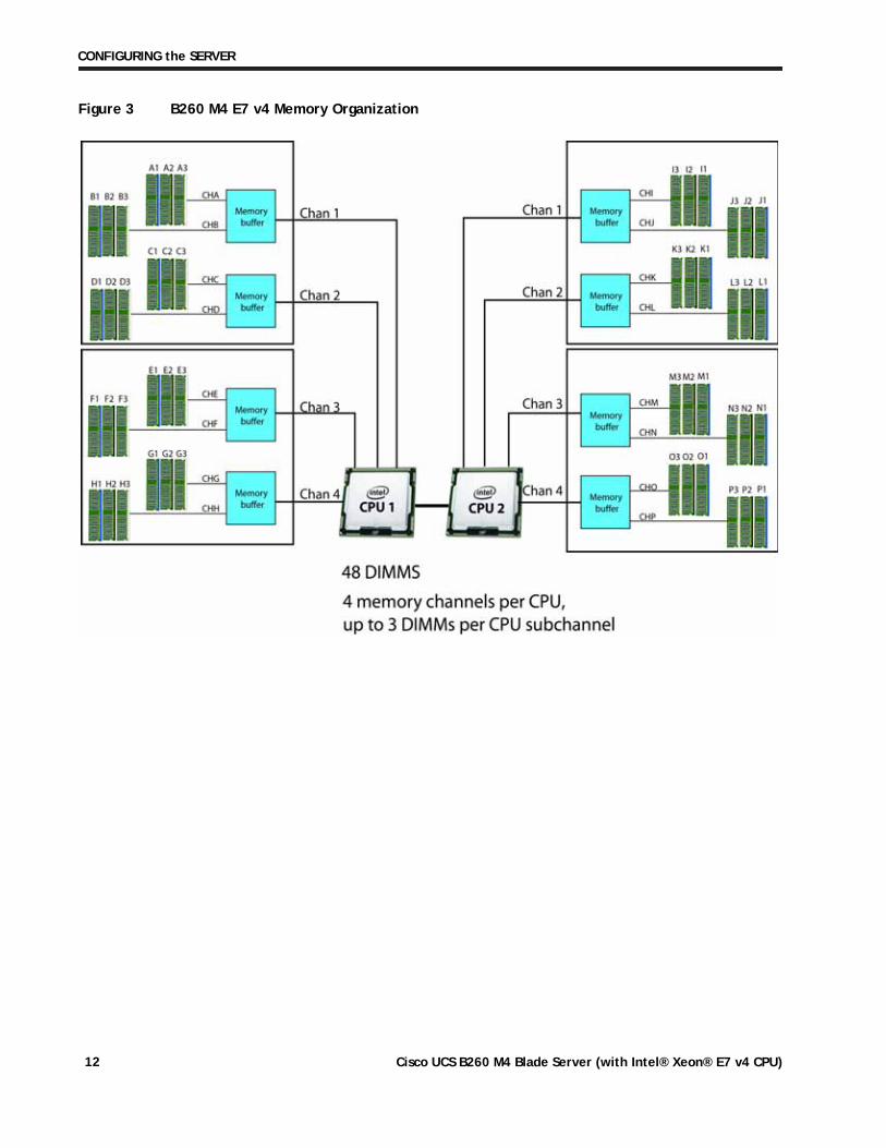
■ Each CPU controls four serial memory interface 2 (SMI-2) channels. Memory buffers converteach SMI-2 channel into two DDR4 subchannels. Memory is organized as 3 DIMMs persubchannel, totaling 6 DIMMs per SMI-2 channel. See Figure 3
NOTE: You cannot mix RDIMMs with LRDIMMs within the same server.
NOTE: Memory mirroring is supported and settable using the UCSM Service Profile “Memory RAS Configuration” setting.
Cisco UCS B260 M4 Blade Server (with Intel® Xeon® E7 v4 CPU) 11
CONFIGURING the SERVER
Figure 3 B260 M4 E7 v4 Memory Organization
Cisco UCS B260 M4 Blade Server (with Intel® Xeon® E7 v4 CPU)12
CONFIGURING the SERVER
Select DIMMs
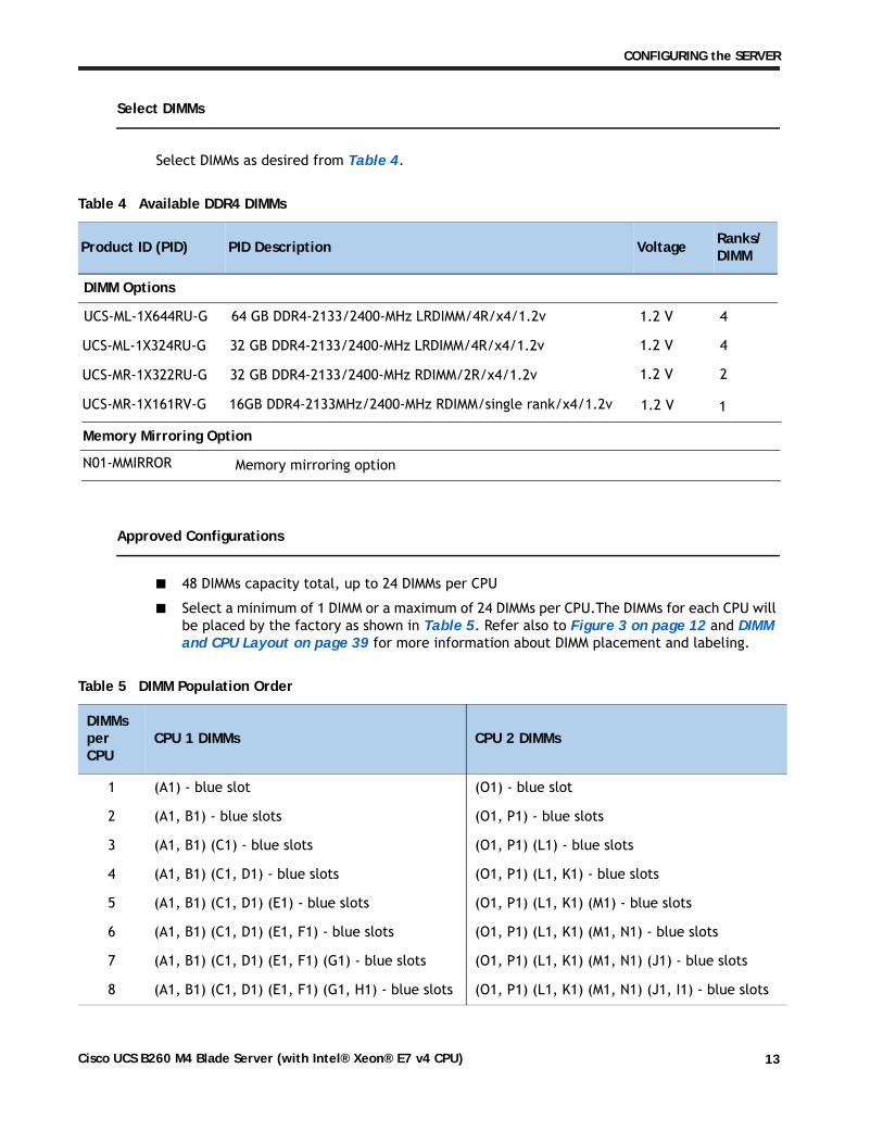
Select DIMMs as desired from Table 4.
Approved Configurations
■ 48 DIMMs capacity total, up to 24 DIMMs per CPU
■ Select a minimum of 1 DIMM or a maximum of 24 DIMMs per CPU.The DIMMs for each CPU willbe placed by the factory as shown in Table 5. Refer also to Figure 3 on page 12 and DIMMand CPU Layout on page 39 for more information about DIMM placement and labeling.
Table 4 Available DDR4 DIMMs
Product ID (PID) PID Description Voltage Ranks/ DIMM
DIMM Options
1.2 V 4
1.2 V 4
1.2 V 2
1
Memory Mirroring Option
N01-MMIRROR
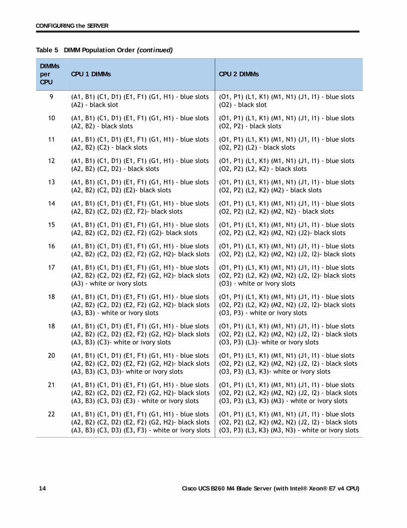
Table 5 DIMM Population Order
DIMMs per CPU
CPU 1 DIMMs CPU 2 DIMMs
1 (A1) - blue slot (O1) - blue slot
2 (A1, B1) - blue slots (O1, P1) - blue slots
3 (A1, B1) (C1) - blue slots (O1, P1) (L1) - blue slots
4 (A1, B1) (C1, D1) - blue slots (O1, P1) (L1, K1) - blue slots
5 (A1, B1) (C1, D1) (E1) - blue slots (O1, P1) (L1, K1) (M1) - blue slots
6 (A1, B1) (C1, D1) (E1, F1) - blue slots (O1, P1) (L1, K1) (M1, N1) - blue slots
7 (A1, B1) (C1, D1) (E1, F1) (G1) - blue slots (O1, P1) (L1, K1) (M1, N1) (J1) - blue slots
8 (A1, B1) (C1, D1) (E1, F1) (G1, H1) - blue slots (O1, P1) (L1, K1) (M1, N1) (J1, I1) - blue slots
UCS-ML-1X644RU-G 64 GB DDR4-2133/2400-MHz LRDIMM/4R/x4/1.2v
UCS-ML-1X324RU-G 32 GB DDR4-2133/2400-MHz LRDIMM/4R/x4/1.2v
UCS-MR-1X322RU-G 32 GB DDR4-2133/2400-MHz RDIMM/2R/x4/1.2v
UCS-MR-1X161RV-G 16GB DDR4-2133MHz/2400-MHz RDIMM/single rank/x4/1.2v 1.2 V
Memory mirroring option
Cisco UCS B260 M4 Blade Server (with Intel® Xeon® E7 v4 CPU) 13
CONFIGURING the SERVER
9 (A1, B1) (C1, D1) (E1, F1) (G1, H1) - blue slots(A2) - black slot
(O1, P1) (L1, K1) (M1, N1) (J1, I1) - blue slots(O2) - black slot
10 (A1, B1) (C1, D1) (E1, F1) (G1, H1) - blue slots(A2, B2) - black slots
(O1, P1) (L1, K1) (M1, N1) (J1, I1) - blue slots(O2, P2) - black slots
11 (A1, B1) (C1, D1) (E1, F1) (G1, H1) - blue slots(A2, B2) (C2) - black slots
(O1, P1) (L1, K1) (M1, N1) (J1, I1) - blue slots(O2, P2) (L2) - black slots
12 (A1, B1) (C1, D1) (E1, F1) (G1, H1) - blue slots(A2, B2) (C2, D2) - black slots
(O1, P1) (L1, K1) (M1, N1) (J1, I1) - blue slots(O2, P2) (L2, K2) - black slots
13 (A1, B1) (C1, D1) (E1, F1) (G1, H1) - blue slots(A2, B2) (C2, D2) (E2)- black slots
(O1, P1) (L1, K1) (M1, N1) (J1, I1) - blue slots(O2, P2) (L2, K2) (M2) - black slots
14 (A1, B1) (C1, D1) (E1, F1) (G1, H1) - blue slots(A2, B2) (C2, D2) (E2, F2)- black slots
(O1, P1) (L1, K1) (M1, N1) (J1, I1) - blue slots(O2, P2) (L2, K2) (M2, N2) - black slots
15 (A1, B1) (C1, D1) (E1, F1) (G1, H1) - blue slots(A2, B2) (C2, D2) (E2, F2) (G2)- black slots
(O1, P1) (L1, K1) (M1, N1) (J1, I1) - blue slots(O2, P2) (L2, K2) (M2, N2) (J2)- black slots
16 (A1, B1) (C1, D1) (E1, F1) (G1, H1) - blue slots(A2, B2) (C2, D2) (E2, F2) (G2, H2)- black slots
(O1, P1) (L1, K1) (M1, N1) (J1, I1) - blue slots(O2, P2) (L2, K2) (M2, N2) (J2, I2)- black slots
17 (A1, B1) (C1, D1) (E1, F1) (G1, H1) - blue slots(A2, B2) (C2, D2) (E2, F2) (G2, H2)- black slots(A3) - white or ivory slots
(O1, P1) (L1, K1) (M1, N1) (J1, I1) - blue slots(O2, P2) (L2, K2) (M2, N2) (J2, I2)- black slots(O3) - white or ivory slots
18 (A1, B1) (C1, D1) (E1, F1) (G1, H1) - blue slots(A2, B2) (C2, D2) (E2, F2) (G2, H2)- black slots(A3, B3) - white or ivory slots
(O1, P1) (L1, K1) (M1, N1) (J1, I1) - blue slots(O2, P2) (L2, K2) (M2, N2) (J2, I2)- black slots(O3, P3) - white or ivory slots
18 (A1, B1) (C1, D1) (E1, F1) (G1, H1) - blue slots(A2, B2) (C2, D2) (E2, F2) (G2, H2)- black slots(A3, B3) (C3)- white or ivory slots
(O1, P1) (L1, K1) (M1, N1) (J1, I1) - blue slots(O2, P2) (L2, K2) (M2, N2) (J2, I2) - black slots(O3, P3) (L3)- white or ivory slots
20 (A1, B1) (C1, D1) (E1, F1) (G1, H1) - blue slots(A2, B2) (C2, D2) (E2, F2) (G2, H2)- black slots(A3, B3) (C3, D3)- white or ivory slots
(O1, P1) (L1, K1) (M1, N1) (J1, I1) - blue slots(O2, P2) (L2, K2) (M2, N2) (J2, I2) - black slots(O3, P3) (L3, K3)- white or ivory slots
21 (A1, B1) (C1, D1) (E1, F1) (G1, H1) - blue slots(A2, B2) (C2, D2) (E2, F2) (G2, H2)- black slots(A3, B3) (C3, D3) (E3) - white or ivory slots
(O1, P1) (L1, K1) (M1, N1) (J1, I1) - blue slots(O2, P2) (L2, K2) (M2, N2) (J2, I2) - black slots(O3, P3) (L3, K3) (M3) - white or ivory slots
22 (A1, B1) (C1, D1) (E1, F1) (G1, H1) - blue slots(A2, B2) (C2, D2) (E2, F2) (G2, H2)- black slots(A3, B3) (C3, D3) (E3, F3) - white or ivory slots
(O1, P1) (L1, K1) (M1, N1) (J1, I1) - blue slots(O2, P2) (L2, K2) (M2, N2) (J2, I2) - black slots(O3, P3) (L3, K3) (M3, N3) - white or ivory slots
Table 5 DIMM Population Order (continued)
DIMMs per CPU
CPU 1 DIMMs CPU 2 DIMMs
Cisco UCS B260 M4 Blade Server (with Intel® Xeon® E7 v4 CPU)14
CONFIGURING the SERVER
Caveats
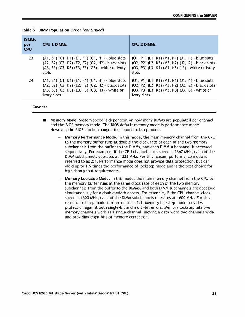
■ Memory Mode. System speed is dependent on how many DIMMs are populated per channel and the BIOS memory mode. The BIOS default memory mode is performance mode. However, the BIOS can be changed to support lockstep mode.
— Memory Performance Mode. In this mode, the main memory channel from the CPU to the memory buffer runs at double the clock rate of each of the two memory subchannels from the buffer to the DIMMs, and each DIMM subchannel is accessed sequentially. For example, if the CPU channel clock speed is 2667 MHz, each of the DIMM subchannels operates at 1333 MHz. For this reason, performance mode is referred to as 2:1. Performance mode does not provide data protection, but can yield up to 1.5 times the performance of lockstep mode and is the best choice for high throughput requirements.
— Memory Lockstep Mode. In this mode, the main memory channel from the CPU to the memory buffer runs at the same clock rate of each of the two memory subchannels from the buffer to the DIMMs, and both DIMM subchannels are accessed simultaneously for a double-width access. For example, if the CPU channel clock speed is 1600 MHz, each of the DIMM subchannels operates at 1600 MHz. For this reason, lockstep mode is referred to as 1:1. Memory lockstep mode provides protection against both single-bit and multi-bit errors. Memory lockstep lets two memory channels work as a single channel, moving a data word two channels wide and providing eight bits of memory correction.
23 (A1, B1) (C1, D1) (E1, F1) (G1, H1) - blue slots(A2, B2) (C2, D2) (E2, F2) (G2, H2)- black slots(A3, B3) (C3, D3) (E3, F3) (G3) - white or ivory slots
(O1, P1) (L1, K1) (M1, N1) (J1, I1) - blue slots(O2, P2) (L2, K2) (M2, N2) (J2, I2) - black slots(O3, P3) (L3, K3) (M3, N3) (J3) - white or ivory slots
24 (A1, B1) (C1, D1) (E1, F1) (G1, H1) - blue slots(A2, B2) (C2, D2) (E2, F2) (G2, H2)- black slots(A3, B3) (C3, D3) (E3, F3) (G3, H3) - white or ivory slots
(O1, P1) (L1, K1) (M1, N1) (J1, I1) - blue slots(O2, P2) (L2, K2) (M2, N2) (J2, I2) - black slots(O3, P3) (L3, K3) (M3, N3) (J3, I3) - white or ivory slots
Table 5 DIMM Population Order (continued)
DIMMs per CPU
CPU 1 DIMMs CPU 2 DIMMs
Cisco UCS B260 M4 Blade Server (with Intel® Xeon® E7 v4 CPU) 15
CONFIGURING the SERVER
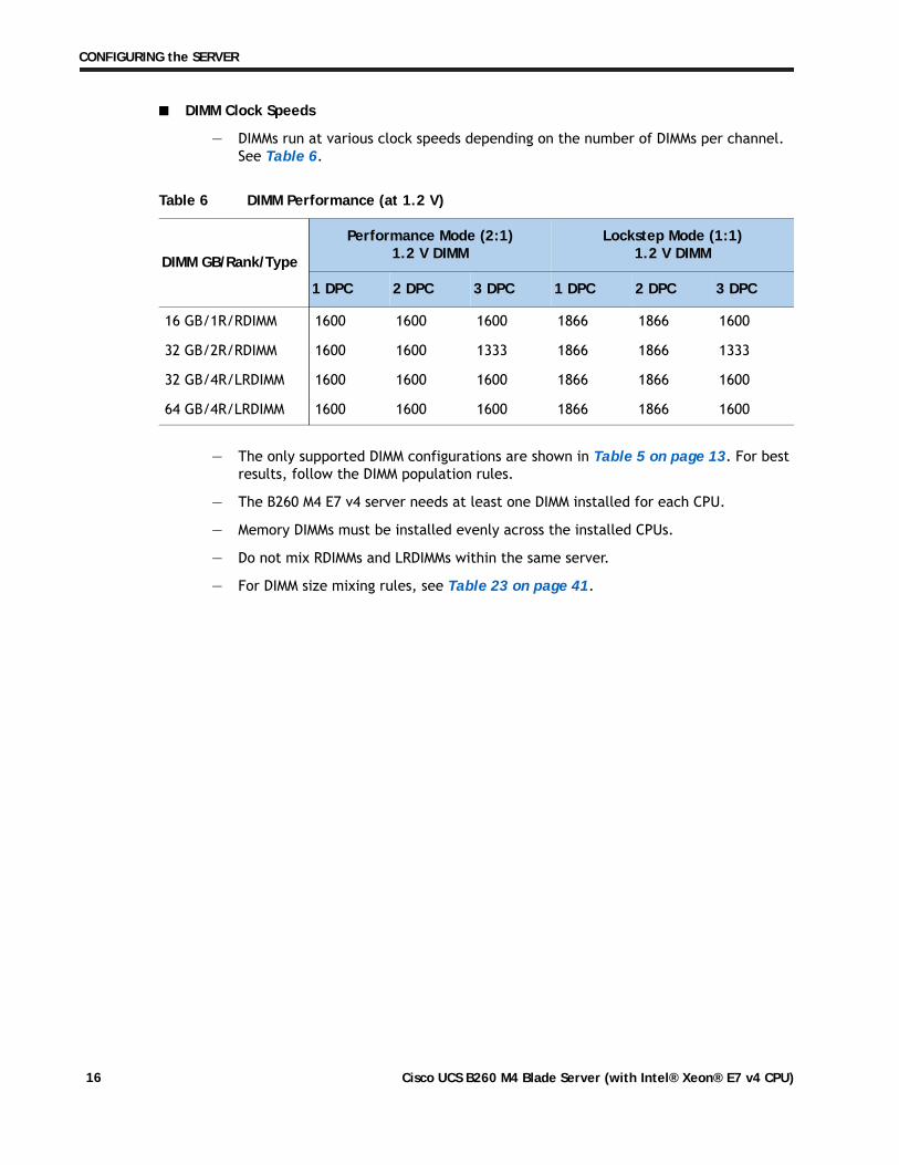
■ DIMM Clock Speeds
— DIMMs run at various clock speeds depending on the number of DIMMs per channel. See Table 6.
— The only supported DIMM configurations are shown in Table 5 on page 13. For best results, follow the DIMM population rules.
— The B260 M4 E7 v4 server needs at least one DIMM installed for each CPU.
— Memory DIMMs must be installed evenly across the installed CPUs.
— Do not mix RDIMMs and LRDIMMs within the same server.
— For DIMM size mixing rules, see Table 23 on page 41.
Table 6 DIMM Performance (at 1.2 V)
DIMM GB/Rank/Type
Performance Mode (2:1)1.2 V DIMM
Lockstep Mode (1:1)1.2 V DIMM
1 DPC 2 DPC 3 DPC 1 DPC 2 DPC 3 DPC
16 GB/1R/RDIMM 1600 1600 1600 1866 1866 1600
32 GB/2R/RDIMM 1600 1600 1333 1866 1866 1333
32 GB/4R/LRDIMM 1600 1600 1600 1866 1866 1600
64 GB/4R/LRDIMM 1600 1600 1600 1866 1866 1600
Cisco UCS B260 M4 Blade Server (with Intel® Xeon® E7 v4 CPU)16
CONFIGURING the SERVER
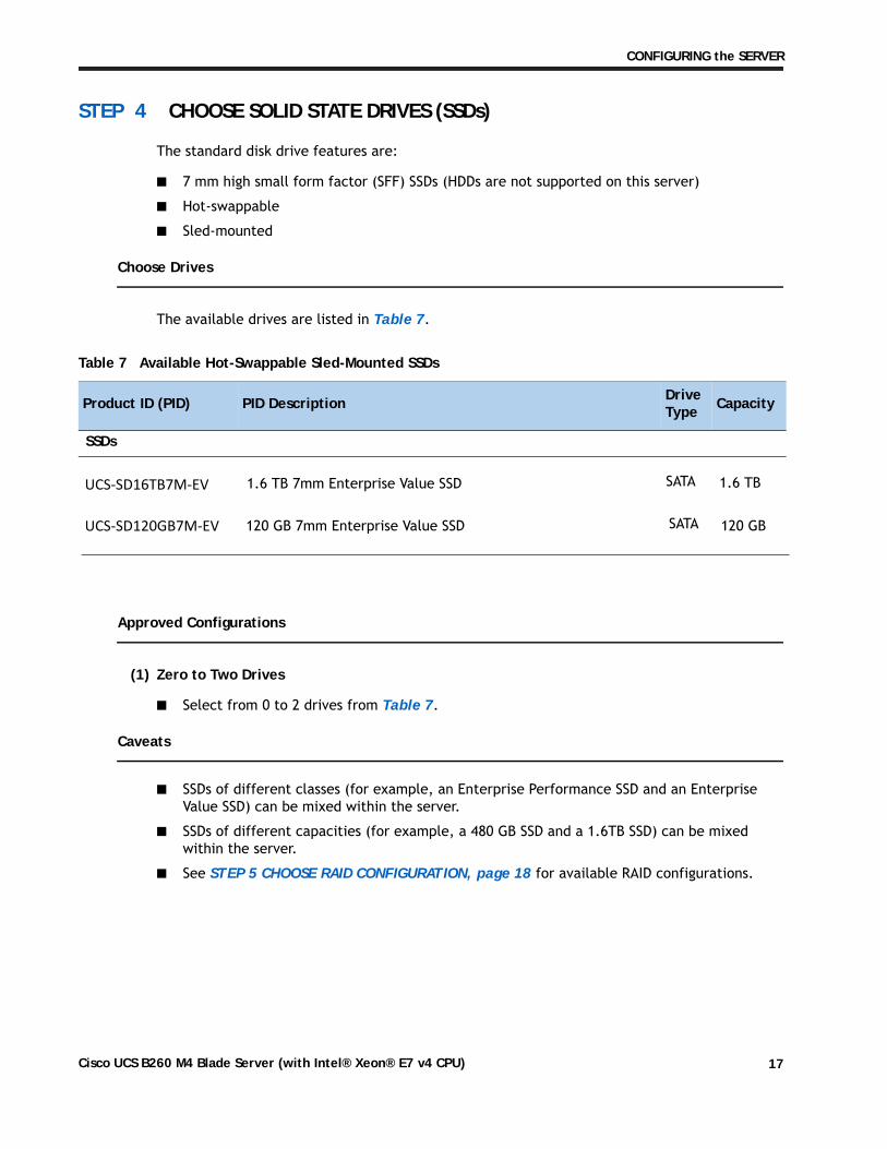
STEP 4 CHOOSE SOLID STATE DRIVES (SSDs)
The standard disk drive features are:
■ 7 mm high small form factor (SFF) SSDs (HDDs are not supported on this server)
■ Hot-swappable
■ Sled-mounted
Choose Drives
The available drives are listed in Table 7.
Approved Configurations
(1) Zero to Two Drives
■ Select from 0 to 2 drives from Table 7.
Caveats
■ SSDs of different classes (for example, an Enterprise Performance SSD and an EnterpriseValue SSD) can be mixed within the server.
■ SSDs of different capacities (for example, a 480 GB SSD and a 1.6TB SSD) can be mixedwithin the server.
■ See STEP 5 CHOOSE RAID CONFIGURATION, page 18 for available RAID configurations.
Table 7 Available Hot-Swappable Sled-Mounted SSDs
Product ID (PID) PID Description Drive Type Capacity
SSDs
SATA 1.6 TB1.6 TB 7mm Enterprise Value SSD
UCS-SD120GB7M-EV 120 GB 7mm Enterprise Value SSD SATA 120 GB
UCS-SD16TB7M-EV
Cisco UCS B260 M4 Blade Server (with Intel® Xeon® E7 v4 CPU) 17
CONFIGURING the SERVER
STEP 5 CHOOSE RAID CONFIGURATION
The B260 M4 E7 v4 server integrates the LSI SAS3008 12G SAS RAID controller, which provides RAID 0/1 capability.
Caveats
■ RAID configuration is possible if you have two identical drives. Otherwise, a JBOD configuration is supported.
Cisco UCS B260 M4 Blade Server (with Intel® Xeon® E7 v4 CPU)18
CONFIGURING the SERVER
STEP 6 CHOOSE ADAPTERS
The adapter offerings are:
■ Cisco Virtual Interface Cards (VICs)
Cisco has developed 1300 Series Virtual Interface Cards (VICs) to provide flexibility to create multiple NIC and HBA devices. The VICs also support adapter Fabric Extender and Virtual Machine Fabric Extender technologies. The VIC features are listed here:
— 1300 Series VICs include all of the 1200 Series features plus additional enhancements including network overlay offload support for NVGRE and VXLAN, and RoCE services.
— In addition, 1300 Series VICs support PCIe Gen 3.0 for greater bandwidth than 1200 Series VICs
— Two Converged Network Adapter (CNA) ports, supporting both Ethernet and FCoE
— Delivers 80 Gbps total I/O throughput to the server
• VIC 1340 supports dual 4x 10 Gbps Unified I/O ports or 2x40 (native) Gbps Unified I/O ports
— Creates up to 256 fully functional unique and independent PCIe adapters and interfaces (NICs or HBAs) without requiring single-root I/O virtualization (SR-IOV) support from operating systems or hypervisors
— Provides virtual machine visibility from the physical network and a consistent network operations model for physical and virtual servers
— Supports customer requirements for a wide range of operating systems and hypervisors
■ Cisco UCS Storage Accelerator Adapters
Cisco UCS Storage Accelerator adapters are designed specifically for the Cisco UCS B-series M4 blade servers and integrate seamlessly to allow improvement in performance and relief of I/O bottlenecks.
Cisco UCS B260 M4 Blade Server (with Intel® Xeon® E7 v4 CPU) 19
CONFIGURING the SERVER
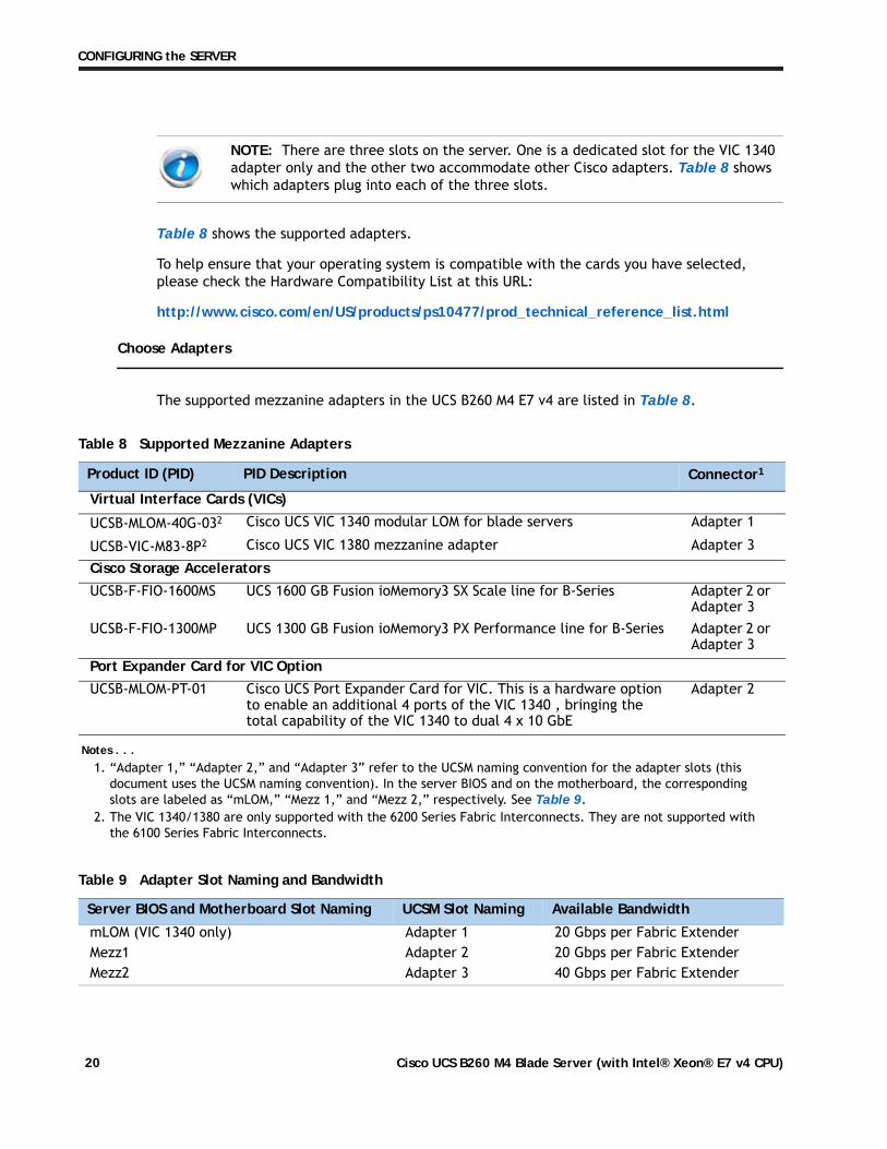
Table 8 shows the supported adapters.
To help ensure that your operating system is compatible with the cards you have selected, please check the Hardware Compatibility List at this URL:
http://www.cisco.com/en/US/products/ps10477/prod_technical_reference_list.html
Choose Adapters
The supported mezzanine adapters in the UCS B260 M4 E7 v4 are listed in Table 8.
NOTE: There are three slots on the server. One is a dedicated slot for the VIC 1340 adapter only and the other two accommodate other Cisco adapters. Table 8 shows which adapters plug into each of the three slots.
Table 8 Supported Mezzanine Adapters
Product ID (PID) PID Description Connector1
Notes . . .1. “Adapter 1,” “Adapter 2,” and “Adapter 3” refer to the UCSM naming convention for the adapter slots (this
document uses the UCSM naming convention). In the server BIOS and on the motherboard, the corresponding slots are labeled as “mLOM,” “Mezz 1,” and “Mezz 2,” respectively. See Table 9.
Virtual Interface Cards (VICs)
UCSB-MLOM-40G-032
2. The VIC 1340/1380 are only supported with the 6200 Series Fabric Interconnects. They are not supported with the 6100 Series Fabric Interconnects.
Cisco UCS VIC 1340 modular LOM for blade servers Adapter 1
UCSB-VIC-M83-8P2 Cisco UCS VIC 1380 mezzanine adapter Adapter 3
Cisco Storage Accelerators
UCSB-F-FIO-1600MS UCS 1600 GB Fusion ioMemory3 SX Scale line for B-Series Adapter 2 or Adapter 3
UCSB-F-FIO-1300MP UCS 1300 GB Fusion ioMemory3 PX Performance line for B-Series Adapter 2 or Adapter 3
Port Expander Card for VIC Option
UCSB-MLOM-PT-01 Cisco UCS Port Expander Card for VIC. This is a hardware option to enable an additional 4 ports of the VIC 1340 , bringing the total capability of the VIC 1340 to dual 4 x 10 GbE
Adapter 2
Table 9 Adapter Slot Naming and Bandwidth
Server BIOS and Motherboard Slot Naming UCSM Slot Naming Available Bandwidth
mLOM (VIC 1340 only) Adapter 1 20 Gbps per Fabric ExtenderMezz1 Adapter 2 20 Gbps per Fabric ExtenderMezz2 Adapter 3 40 Gbps per Fabric Extender
Cisco UCS B260 M4 Blade Server (with Intel® Xeon® E7 v4 CPU)20
CONFIGURING the SERVER
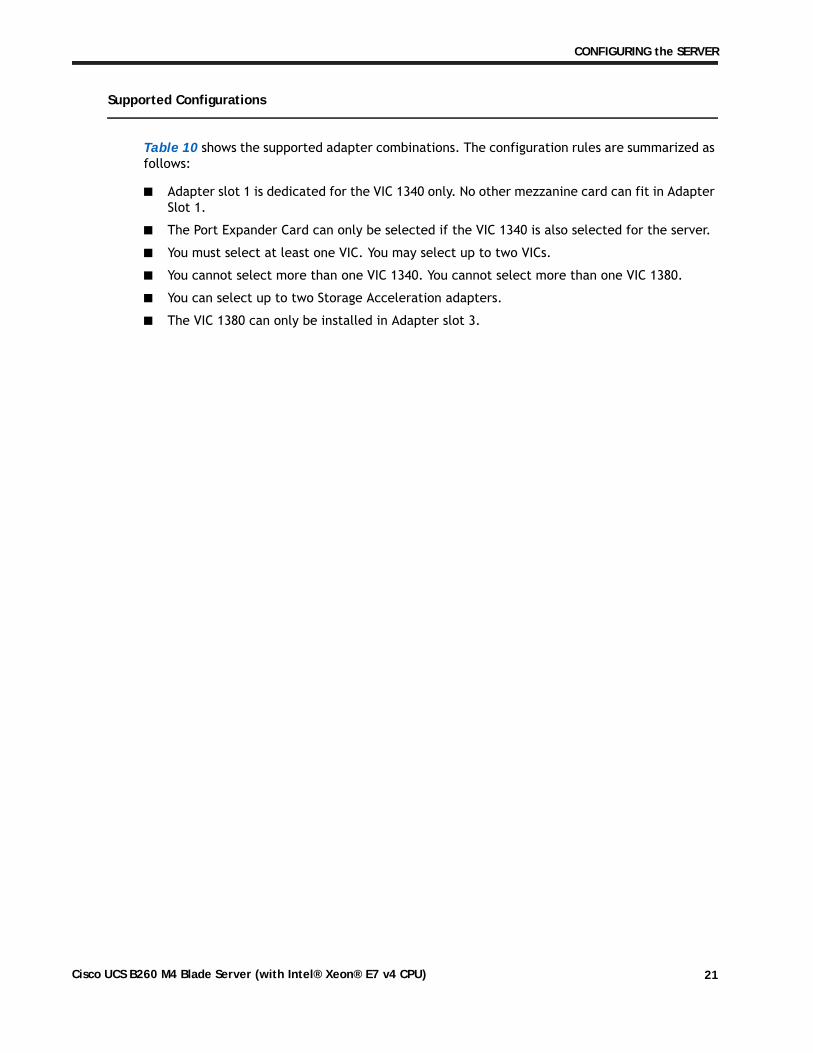
Supported Configurations
Table 10 shows the supported adapter combinations. The configuration rules are summarized as follows:
■ Adapter slot 1 is dedicated for the VIC 1340 only. No other mezzanine card can fit in Adapter Slot 1.
■ The Port Expander Card can only be selected if the VIC 1340 is also selected for the server.
■ You must select at least one VIC. You may select up to two VICs.
■ You cannot select more than one VIC 1340. You cannot select more than one VIC 1380.
■ You can select up to two Storage Acceleration adapters.
■ The VIC 1380 can only be installed in Adapter slot 3.
Cisco UCS B260 M4 Blade Server (with Intel® Xeon® E7 v4 CPU) 21
CONFIGURING the SERVER
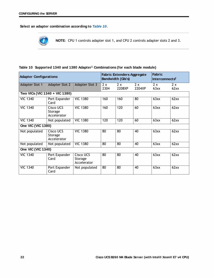
Select an adapter combination according to Table 10.
NOTE: CPU 1 controls adapter slot 1, and CPU 2 controls adapter slots 2 and 3.
Table 10 Supported 1340 and 1380 Adapter1 Combinations (for each blade module)
Adapter Configurations Fabric Extenders Aggregate Bandwidth (Gb/s)
Fabric Interconnects2
Adapter Slot 1 Adapter Slot 2 Adapter Slot 3 2 x 2304
2 x 2208XP
2 x 2204XP
2 x 63xx
2 x 62xx
Two VICs (VIC 1340 + VIC 1380)
VIC 1340 Port Expander Card
VIC 1380 160 160 80 63xx 62xx
VIC 1340 Cisco UCS Storage Accelerator
VIC 1380 160 120 60 63xx 62xx
VIC 1340 Not populated VIC 1380 120 120 60 63xx 62xx
One VIC (VIC 1380)
Not populated Cisco UCS Storage Accelerator
VIC 1380 80 80 40 63xx 62xx
Not populated Not populated VIC 1380 80 80 40 63xx 62xx
One VIC (VIC 1340)
VIC 1340 Port Expander Card
Cisco UCS Storage Accelerator
80 80 40 63xx 62xx
VIC 1340 Port Expander Card
Not populated 80 80 40 63xx 62xx
Cisco UCS B260 M4 Blade Server (with Intel® Xeon® E7 v4 CPU)22
CONFIGURING the SERVER
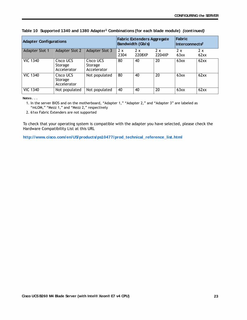
To check that your operating system is compatible with the adapter you have selected, please check the Hardware Compatibility List at this URL
http://www.cisco.com/en/US/products/ps10477/prod_technical_reference_list.html
Adapter Slot 1 Adapter Slot 2 Adapter Slot 3 2 x 2304
2 x 2208XP
2 x 2204XP
2 x 63xx
2 x 62xx
VIC 1340 Cisco UCS Storage Accelerator
Cisco UCS Storage Accelerator
80 40 20 63xx 62xx
VIC 1340 Cisco UCS Storage Accelerator
Not populated 80 40 20 63xx 62xx
VIC 1340 Not populated Not populated 40 40 20 63xx 62xx
Notes . . .1. In the server BIOS and on the motherboard, “Adapter 1,” “Adapter 2,” and “Adapter 3” are labeled as
“mLOM,” “Mezz 1,” and “Mezz 2,” respectively2. 61xx Fabric Extenders are not supported
Table 10 Supported 1340 and 1380 Adapter1 Combinations (for each blade module) (continued)
Adapter Configurations Fabric Extenders Aggregate Bandwidth (Gb/s)
Fabric Interconnects2
Cisco UCS B260 M4 Blade Server (with Intel® Xeon® E7 v4 CPU) 23
CONFIGURING the SERVER
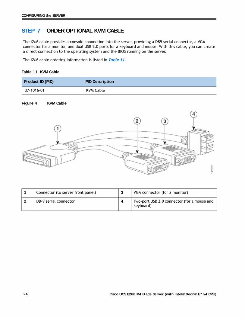
STEP 7 ORDER OPTIONAL KVM CABLE
The KVM cable provides a console connection into the server, providing a DB9 serial connector, a VGA connector for a monitor, and dual USB 2.0 ports for a keyboard and mouse. With this cable, you can create a direct connection to the operating system and the BIOS running on the server.
The KVM cable ordering information is listed in Table 11.
Figure 4 KVM Cable
Table 11 KVM Cable
Product ID (PID) PID Description
37-1016-01 KVM Cable
1 Connector (to server front panel) 3 VGA connector (for a monitor)
2 DB-9 serial connector 4 Two-port USB 2.0 connector (for a mouse and keyboard)
Cisco UCS B260 M4 Blade Server (with Intel® Xeon® E7 v4 CPU)24
CONFIGURING the SERVER
STEP 8 ORDER TRUSTED PLATFORM MODULE (OPTIONAL)
Trusted Platform Module (TPM) is a computer chip or microcontroller that can securely store artifacts used to authenticate the platform or server. These artifacts can include passwords, certificates, or encryption keys. A TPM can also be used to store platform measurements that help ensure that the platform remains trustworthy. Authentication (ensuring that the platform can prove that it is what it claims to be) and attestation (a process helping to prove that a platform is trustworthy and has not been breached) are necessary steps to ensure safer computing in all environments. See Figure 6 on page 38 for the mounting location of the TPM.
The TPM ordering information is listed in Table 12.
Table 12 Trusted Platform Module
Product ID (PID) PID Description
UCSX-TPM1-001 Trusted Platform Module 1.2 for UCS
UCSX-TPM1-002 Trusted Platform Module 2.0 for UCS servers (LPC based)
NOTE: The module used in this server conforms to TPM v1.2/2.0, as defined by the Trusted Computing Group (TCG).
NOTE: TPM installation is supported after-factory. However, a TPM installs with a one-way screw and cannot be replaced, upgraded, or moved to another server. If a server with a TPM is returned, the replacement server must be ordered with a new TPM."
Cisco UCS B260 M4 Blade Server (with Intel® Xeon® E7 v4 CPU) 25
CONFIGURING the SERVER
STEP 9 ORDER CISCO FLEXIBLE FLASH SECURE DIGITAL CARDS
Dual SDHC Flexible Flash card sockets are provided on the left side of the server, near the front.
The SDHC card ordering information is listed in Table 13. Order one or two identical SD cards.
Caveats
■ Do not mix 32 GB SD cards with 64 GB SD cards.
NOTE: Dual card support (mirroring) is supported with UCS Manager 2.2.x and later.
Table 13 Supported Configurations - Flexible Flash Card(s)
Product ID (PID) PID Description
UCS-SD-32G-S 32 GB SD Card module for UCS Servers
UCS-SD-64G-S 64 GB SD card for UCS servers
Cisco UCS B260 M4 Blade Server (with Intel® Xeon® E7 v4 CPU)26
CONFIGURING the SERVER
STEP 10 ORDER OPTIONAL INTERNAL USB 2.0 DRIVE
You may order one optional internal USB 2.0 drive. The USB drive ordering information is listed in Table 14.
See Figure 5 on page 37 for the location of the USB connector.
Table 14 USB 2.0 Drive
Product ID (PID) PID Description
UCS-USBFLSHB-16GB UCS Servers 16 GB Flash USB Drive
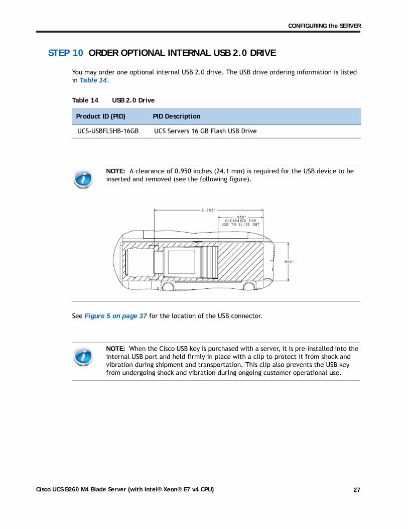
NOTE: A clearance of 0.950 inches (24.1 mm) is required for the USB device to be inserted and removed (see the following figure).
NOTE: When the Cisco USB key is purchased with a server, it is pre-installed into the internal USB port and held firmly in place with a clip to protect it from shock and vibration during shipment and transportation. This clip also prevents the USB key from undergoing shock and vibration during ongoing customer operational use.
Cisco UCS B260 M4 Blade Server (with Intel® Xeon® E7 v4 CPU) 27
CONFIGURING the SERVER
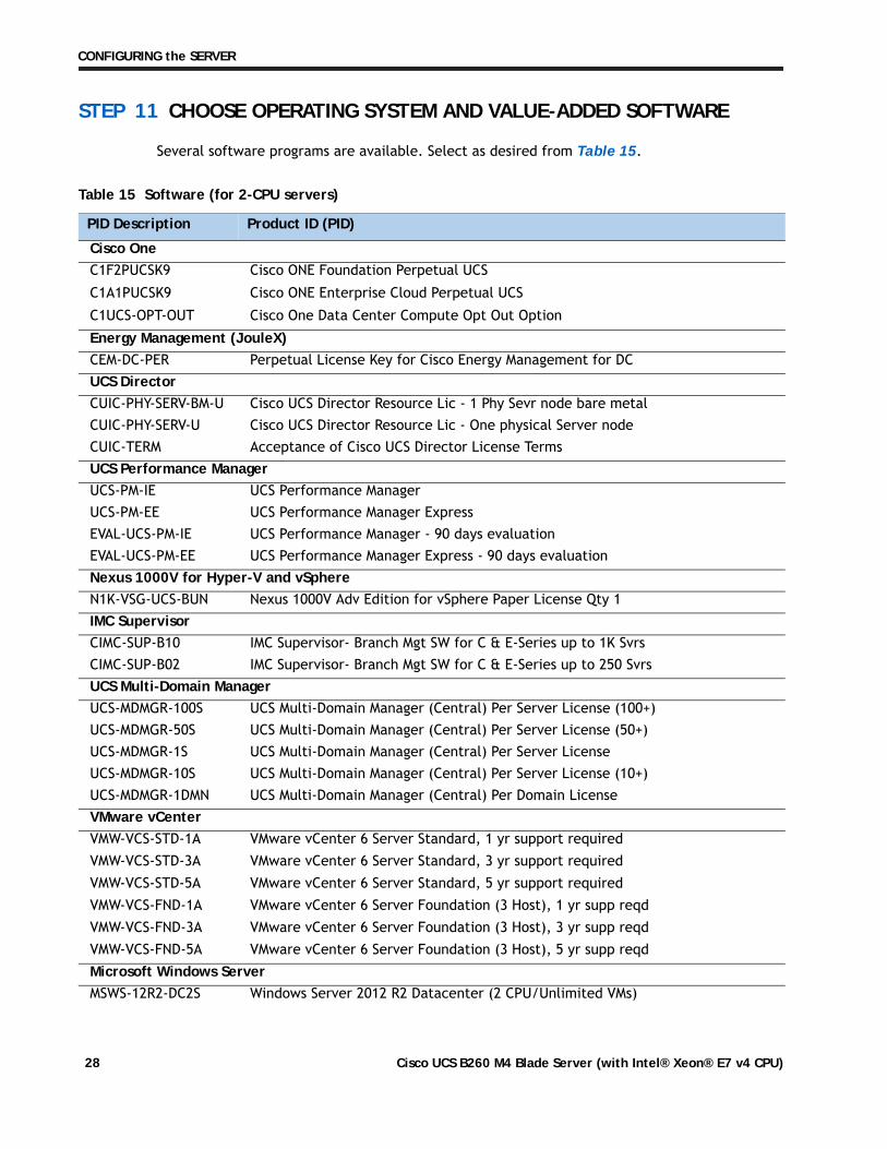
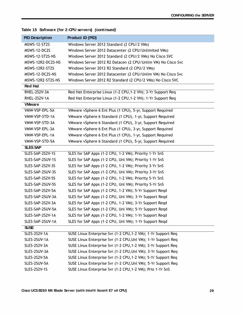
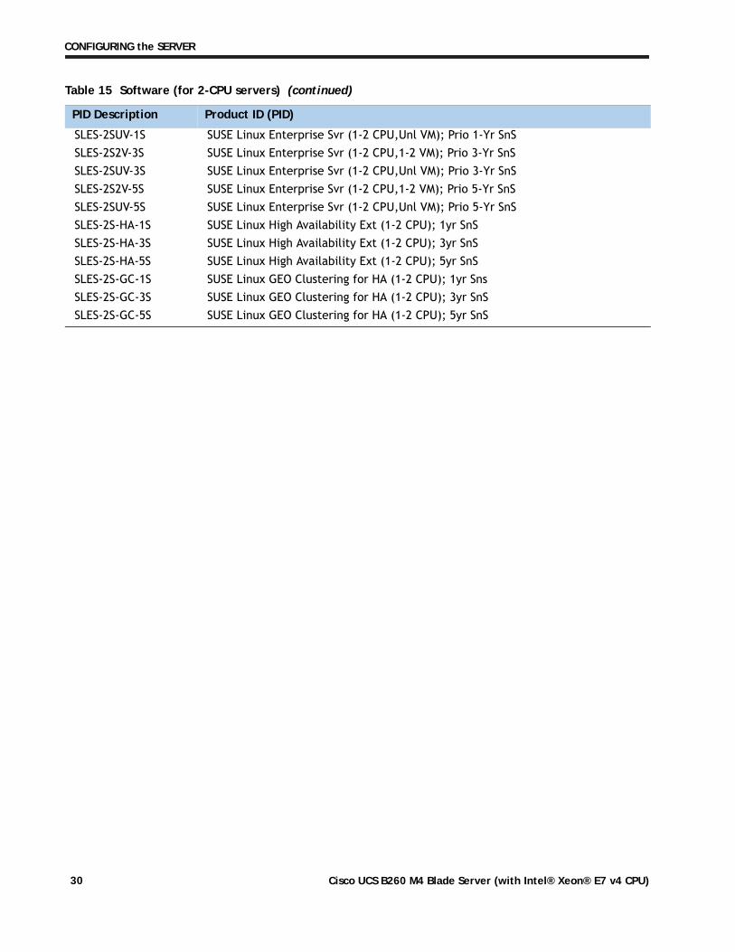
STEP 11 CHOOSE OPERATING SYSTEM AND VALUE-ADDED SOFTWARE
Several software programs are available. Select as desired from Table 15.
Table 15 Software (for 2-CPU servers)
PID Description Product ID (PID)
Cisco OneC1F2PUCSK9 Cisco ONE Foundation Perpetual UCS
C1A1PUCSK9 Cisco ONE Enterprise Cloud Perpetual UCS
C1UCS-OPT-OUT Cisco One Data Center Compute Opt Out Option
Energy Management (JouleX)CEM-DC-PER Perpetual License Key for Cisco Energy Management for DC UCS DirectorCUIC-PHY-SERV-BM-U Cisco UCS Director Resource Lic - 1 Phy Sevr node bare metal CUIC-PHY-SERV-U Cisco UCS Director Resource Lic - One physical Server node CUIC-TERM Acceptance of Cisco UCS Director License Terms UCS Performance ManagerUCS-PM-IE UCS Performance Manager UCS-PM-EE UCS Performance Manager Express EVAL-UCS-PM-IE UCS Performance Manager - 90 days evaluation EVAL-UCS-PM-EE UCS Performance Manager Express - 90 days evaluation Nexus 1000V for Hyper-V and vSphereN1K-VSG-UCS-BUN Nexus 1000V Adv Edition for vSphere Paper License Qty 1 IMC SupervisorCIMC-SUP-B10 IMC Supervisor- Branch Mgt SW for C & E-Series up to 1K Svrs CIMC-SUP-B02 IMC Supervisor- Branch Mgt SW for C & E-Series up to 250 Svrs UCS Multi-Domain ManagerUCS-MDMGR-100S UCS Multi-Domain Manager (Central) Per Server License (100+) UCS-MDMGR-50S UCS Multi-Domain Manager (Central) Per Server License (50+) UCS-MDMGR-1S UCS Multi-Domain Manager (Central) Per Server License UCS-MDMGR-10S UCS Multi-Domain Manager (Central) Per Server License (10+) UCS-MDMGR-1DMN UCS Multi-Domain Manager (Central) Per Domain License VMware vCenterVMW-VCS-STD-1A VMware vCenter 6 Server Standard, 1 yr support required VMW-VCS-STD-3A VMware vCenter 6 Server Standard, 3 yr support required VMW-VCS-STD-5A VMware vCenter 6 Server Standard, 5 yr support required VMW-VCS-FND-1A VMware vCenter 6 Server Foundation (3 Host), 1 yr supp reqd VMW-VCS-FND-3A VMware vCenter 6 Server Foundation (3 Host), 3 yr supp reqd VMW-VCS-FND-5A VMware vCenter 6 Server Foundation (3 Host), 5 yr supp reqd Microsoft Windows ServerMSWS-12R2-DC2S Windows Server 2012 R2 Datacenter (2 CPU/Unlimited VMs)
Cisco UCS B260 M4 Blade Server (with Intel® Xeon® E7 v4 CPU)28
CONFIGURING the SERVER
MSWS-12-ST2S Windows Server 2012 Standard (2 CPU/2 VMs)MSWS-12-DC2S Windows Server 2012 Datacenter (2 CPU/Unlimited VMs)MSWS-12-ST2S-NS Windows Server 2012 Standard (2 CPU/2 VMs) No Cisco SVC MSWS-12R2-DC2S-NS Windows Server 2012 R2 Datacen (2 CPU/Unlim VM) No Cisco Svc MSWS-12R2-ST2S Windows Server 2012 R2 Standard (2 CPU/2 VMs) MSWS-12-DC2S-NS Windows Server 2012 Datacenter (2 CPU/Unlim VM) No Cisco Svc MSWS-12R2-ST2S-NS Windows Server 2012 R2 Standard (2 CPU/2 VMs) No Cisco SVC Red HatRHEL-2S2V-3A Red Hat Enterprise Linux (1-2 CPU,1-2 VN); 3-Yr Support Req
RHEL-2S2V-1A Red Hat Enterprise Linux (1-2 CPU,1-2 VN); 1-Yr Support Req
VMwareVMW-VSP-EPL-5A VMware vSphere 6 Ent Plus (1 CPU), 5-yr, Support Required
VMW-VSP-STD-1A VMware vSphere 6 Standard (1 CPU), 1-yr, Support Required
VMW-VSP-STD-3A VMware vSphere 6 Standard (1 CPU), 3-yr, Support Required
VMW-VSP-EPL-3A VMware vSphere 6 Ent Plus (1 CPU), 3-yr, Support Required
VMW-VSP-EPL-1A VMware vSphere 6 Ent Plus (1 CPU), 1-yr, Support Required
VMW-VSP-STD-5A VMware vSphere 6 Standard (1 CPU), 5-yr, Support Required
SLES SAPSLES-SAP-2S2V-1S SLES for SAP Apps (1-2 CPU, 1-2 VM); Priority 1-Yr SnS
SLES-SAP-2SUV-1S SLES for SAP Apps (1-2 CPU, Unl VM); Priority 1-Yr SnS
SLES-SAP-2S2V-3S SLES for SAP Apps (1-2 CPU, 1-2 VM); Priority 3-Yr SnS
SLES-SAP-2SUV-3S SLES for SAP Apps (1-2 CPU, Unl VM); Priority 3-Yr SnS
SLES-SAP-2S2V-5S SLES for SAP Apps (1-2 CPU, 1-2 VM); Priority 5-Yr SnS
SLES-SAP-2SUV-5S SLES for SAP Apps (1-2 CPU, Unl VM); Priority 5-Yr SnS
SLES-SAP-2S2V-5A SLES for SAP Apps (1-2 CPU, 1-2 VM); 5-Yr Support Reqd
SLES-SAP-2SUV-3A SLES for SAP Apps (1-2 CPU, Unl VM); 3-Yr Support Reqd
SLES-SAP-2S2V-3A SLES for SAP Apps (1-2 CPU, 1-2 VM); 3-Yr Support Reqd
SLES-SAP-2SUV-5A SLES for SAP Apps (1-2 CPU, Unl VM); 5-Yr Support Reqd
SLES-SAP-2S2V-1A SLES for SAP Apps (1-2 CPU, 1-2 VM); 1-Yr Support Reqd
SLES-SAP-2SUV-1A SLES for SAP Apps (1-2 CPU, Unl VM); 1-Yr Support Reqd
SUSESLES-2S2V-1A SUSE Linux Enterprise Svr (1-2 CPU,1-2 VM); 1-Yr Support Req SLES-2SUV-1A SUSE Linux Enterprise Svr (1-2 CPU,Unl VM); 1-Yr Support Req SLES-2S2V-3A SUSE Linux Enterprise Svr (1-2 CPU,1-2 VM); 3-Yr Support Req SLES-2SUV-3A SUSE Linux Enterprise Svr (1-2 CPU,Unl VM); 3-Yr Support Req SLES-2S2V-5A SUSE Linux Enterprise Svr (1-2 CPU,1-2 VM); 5-Yr Support Req SLES-2SUV-5A SUSE Linux Enterprise Svr (1-2 CPU,Unl VM); 5-Yr Support Req SLES-2S2V-1S SUSE Linux Enterprise Svr (1-2 CPU,1-2 VM); Prio 1-Yr SnS
Table 15 Software (for 2-CPU servers) (continued)
PID Description Product ID (PID)
Cisco UCS B260 M4 Blade Server (with Intel® Xeon® E7 v4 CPU) 29
CONFIGURING the SERVER
SLES-2SUV-1S SUSE Linux Enterprise Svr (1-2 CPU,Unl VM); Prio 1-Yr SnS SLES-2S2V-3S SUSE Linux Enterprise Svr (1-2 CPU,1-2 VM); Prio 3-Yr SnS SLES-2SUV-3S SUSE Linux Enterprise Svr (1-2 CPU,Unl VM); Prio 3-Yr SnS SLES-2S2V-5S SUSE Linux Enterprise Svr (1-2 CPU,1-2 VM); Prio 5-Yr SnS SLES-2SUV-5S SUSE Linux Enterprise Svr (1-2 CPU,Unl VM); Prio 5-Yr SnS SLES-2S-HA-1S SUSE Linux High Availability Ext (1-2 CPU); 1yr SnSSLES-2S-HA-3S SUSE Linux High Availability Ext (1-2 CPU); 3yr SnS SLES-2S-HA-5S SUSE Linux High Availability Ext (1-2 CPU); 5yr SnSSLES-2S-GC-1S SUSE Linux GEO Clustering for HA (1-2 CPU); 1yr Sns SLES-2S-GC-3S SUSE Linux GEO Clustering for HA (1-2 CPU); 3yr SnS SLES-2S-GC-5S SUSE Linux GEO Clustering for HA (1-2 CPU); 5yr SnS
Table 15 Software (for 2-CPU servers) (continued)
PID Description Product ID (PID)
Cisco UCS B260 M4 Blade Server (with Intel® Xeon® E7 v4 CPU)30
CONFIGURING the SERVER
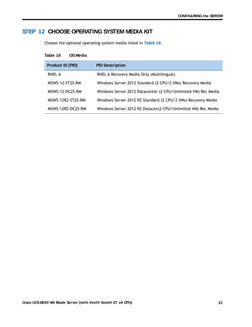
STEP 12 CHOOSE OPERATING SYSTEM MEDIA KIT
Choose the optional operating system media listed in Table 16.
Table 16 OS Media
Product ID (PID) PID Description
RHEL-6 RHEL 6 Recovery Media Only (Multilingual)
MSWS-12-ST2S-RM Windows Server 2012 Standard (2 CPU/2 VMs) Recovery Media
MSWS-12-DC2S-RM Windows Server 2012 Datacenter (2 CPU/Unlimited VM) Rec Media
MSWS-12R2-ST2S-RM Windows Server 2012 R2 Standard (2 CPU/2 VMs) Recovery Media
MSWS-12R2-DC2S-RM Windows Server 2012 R2 Datacen(2 CPU/Unlimited VM) Rec Media
Cisco UCS B260 M4 Blade Server (with Intel® Xeon® E7 v4 CPU) 31
CONFIGURING the SERVER
STEP 13 CHOOSE SERVICE and SUPPORT LEVEL
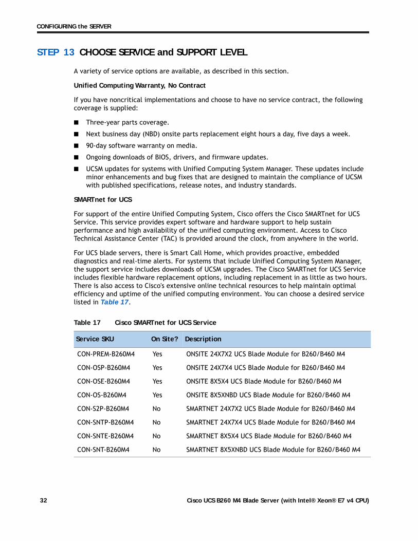
A variety of service options are available, as described in this section.
Unified Computing Warranty, No Contract
If you have noncritical implementations and choose to have no service contract, the following coverage is supplied:
■ Three-year parts coverage.
■ Next business day (NBD) onsite parts replacement eight hours a day, five days a week.
■ 90-day software warranty on media.
■ Ongoing downloads of BIOS, drivers, and firmware updates.
■ UCSM updates for systems with Unified Computing System Manager. These updates include minor enhancements and bug fixes that are designed to maintain the compliance of UCSM with published specifications, release notes, and industry standards.
SMARTnet for UCS
For support of the entire Unified Computing System, Cisco offers the Cisco SMARTnet for UCS Service. This service provides expert software and hardware support to help sustain performance and high availability of the unified computing environment. Access to Cisco Technical Assistance Center (TAC) is provided around the clock, from anywhere in the world.
For UCS blade servers, there is Smart Call Home, which provides proactive, embedded diagnostics and real-time alerts. For systems that include Unified Computing System Manager, the support service includes downloads of UCSM upgrades. The Cisco SMARTnet for UCS Service includes flexible hardware replacement options, including replacement in as little as two hours. There is also access to Cisco's extensive online technical resources to help maintain optimal efficiency and uptime of the unified computing environment. You can choose a desired service listed in Table 17.
Table 17 Cisco SMARTnet for UCS Service
Service SKU On Site? Description
CON-PREM-B260M4 Yes ONSITE 24X7X2 UCS Blade Module for B260/B460 M4
CON-OSP-B260M4 Yes ONSITE 24X7X4 UCS Blade Module for B260/B460 M4
CON-OSE-B260M4 Yes ONSITE 8X5X4 UCS Blade Module for B260/B460 M4
CON-OS-B260M4 Yes ONSITE 8X5XNBD UCS Blade Module for B260/B460 M4
CON-S2P-B260M4 No SMARTNET 24X7X2 UCS Blade Module for B260/B460 M4
CON-SNTP-B260M4 No SMARTNET 24X7X4 UCS Blade Module for B260/B460 M4
CON-SNTE-B260M4 No SMARTNET 8X5X4 UCS Blade Module for B260/B460 M4
CON-SNT-B260M4 No SMARTNET 8X5XNBD UCS Blade Module for B260/B460 M4
Cisco UCS B260 M4 Blade Server (with Intel® Xeon® E7 v4 CPU)32
CONFIGURING the SERVER
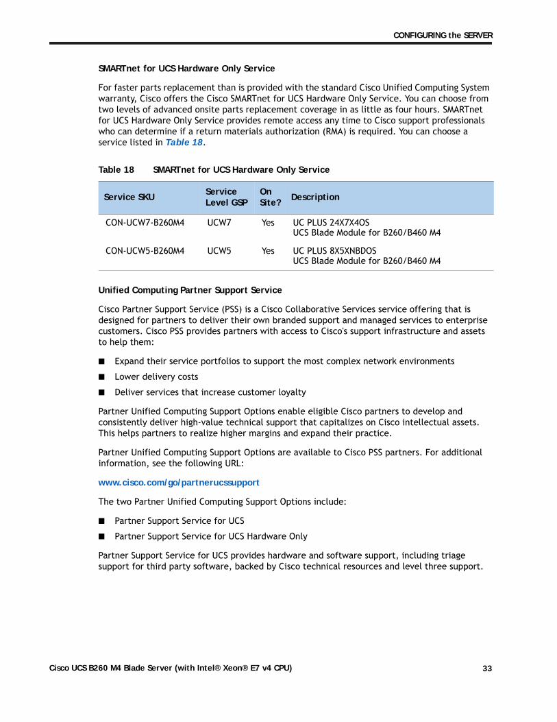
SMARTnet for UCS Hardware Only Service
For faster parts replacement than is provided with the standard Cisco Unified Computing System warranty, Cisco offers the Cisco SMARTnet for UCS Hardware Only Service. You can choose from two levels of advanced onsite parts replacement coverage in as little as four hours. SMARTnet for UCS Hardware Only Service provides remote access any time to Cisco support professionals who can determine if a return materials authorization (RMA) is required. You can choose a service listed in Table 18.
Unified Computing Partner Support Service
Cisco Partner Support Service (PSS) is a Cisco Collaborative Services service offering that is designed for partners to deliver their own branded support and managed services to enterprise customers. Cisco PSS provides partners with access to Cisco's support infrastructure and assets to help them:
■ Expand their service portfolios to support the most complex network environments
■ Lower delivery costs
■ Deliver services that increase customer loyalty
Partner Unified Computing Support Options enable eligible Cisco partners to develop and consistently deliver high-value technical support that capitalizes on Cisco intellectual assets. This helps partners to realize higher margins and expand their practice.
Partner Unified Computing Support Options are available to Cisco PSS partners. For additional information, see the following URL:
www.cisco.com/go/partnerucssupport
The two Partner Unified Computing Support Options include:
■ Partner Support Service for UCS
■ Partner Support Service for UCS Hardware Only
Partner Support Service for UCS provides hardware and software support, including triage support for third party software, backed by Cisco technical resources and level three support.
Table 18 SMARTnet for UCS Hardware Only Service
Service SKU Service Level GSP
OnSite? Description
CON-UCW7-B260M4 UCW7 Yes UC PLUS 24X7X4OS UCS Blade Module for B260/B460 M4
CON-UCW5-B260M4 UCW5 Yes UC PLUS 8X5XNBDOS UCS Blade Module for B260/B460 M4
Cisco UCS B260 M4 Blade Server (with Intel® Xeon® E7 v4 CPU) 33
CONFIGURING the SERVER
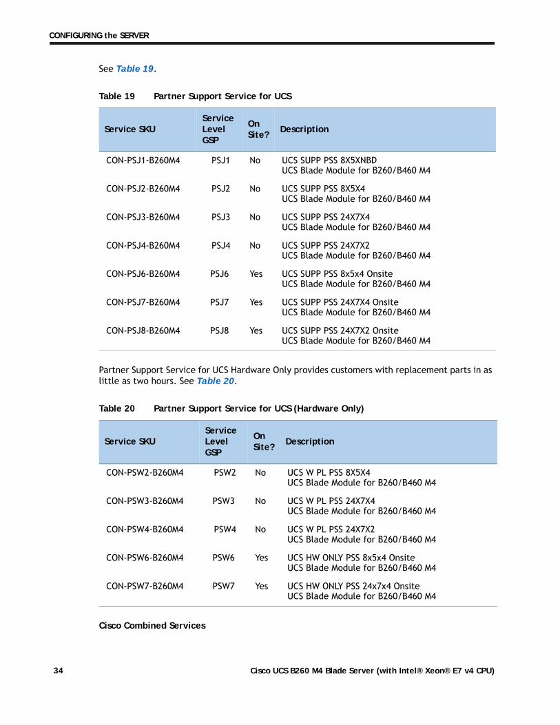
See Table 19.
Partner Support Service for UCS Hardware Only provides customers with replacement parts in as little as two hours. See Table 20.
Cisco Combined Services
Table 19 Partner Support Service for UCS
Service SKUService Level GSP
OnSite? Description
CON-PSJ1-B260M4 PSJ1 No UCS SUPP PSS 8X5XNBD UCS Blade Module for B260/B460 M4
CON-PSJ2-B260M4 PSJ2 No UCS SUPP PSS 8X5X4 UCS Blade Module for B260/B460 M4
CON-PSJ3-B260M4 PSJ3 No UCS SUPP PSS 24X7X4 UCS Blade Module for B260/B460 M4
CON-PSJ4-B260M4 PSJ4 No UCS SUPP PSS 24X7X2 UCS Blade Module for B260/B460 M4
CON-PSJ6-B260M4 PSJ6 Yes UCS SUPP PSS 8x5x4 Onsite UCS Blade Module for B260/B460 M4
CON-PSJ7-B260M4 PSJ7 Yes UCS SUPP PSS 24X7X4 Onsite UCS Blade Module for B260/B460 M4
CON-PSJ8-B260M4 PSJ8 Yes UCS SUPP PSS 24X7X2 Onsite UCS Blade Module for B260/B460 M4
Table 20 Partner Support Service for UCS (Hardware Only)
Service SKUService Level GSP
OnSite? Description
CON-PSW2-B260M4 PSW2 No UCS W PL PSS 8X5X4 UCS Blade Module for B260/B460 M4
CON-PSW3-B260M4 PSW3 No UCS W PL PSS 24X7X4 UCS Blade Module for B260/B460 M4
CON-PSW4-B260M4 PSW4 No UCS W PL PSS 24X7X2 UCS Blade Module for B260/B460 M4
CON-PSW6-B260M4 PSW6 Yes UCS HW ONLY PSS 8x5x4 Onsite UCS Blade Module for B260/B460 M4
CON-PSW7-B260M4 PSW7 Yes UCS HW ONLY PSS 24x7x4 Onsite UCS Blade Module for B260/B460 M4
Cisco UCS B260 M4 Blade Server (with Intel® Xeon® E7 v4 CPU)34
CONFIGURING the SERVER
Combined Services makes it easier to purchase and manage required services under one contract. SMARTnet services for UCS help increase the availability of your vital data center infrastructure and realize the most value from your unified computing investment. The more benefits you realize from the Cisco Unified Computing System (Cisco UCS), the more important the technology becomes to your business. These services allow you to:
■ Optimize the uptime, performance, and efficiency of your UCS
■ Protect your vital business applications by rapidly identifying and addressing issues
■ Strengthen in-house expertise through knowledge transfer and mentoring
■ Improve operational efficiency by allowing UCS experts to augment your internal staff resources
■ Enhance business agility by diagnosing potential issues before they affect your operations
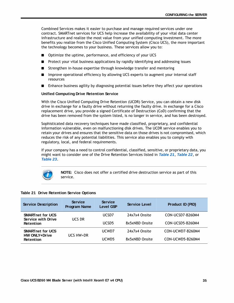
Unified Computing Drive Retention Service
With the Cisco Unified Computing Drive Retention (UCDR) Service, you can obtain a new disk drive in exchange for a faulty drive without returning the faulty drive. In exchange for a Cisco replacement drive, you provide a signed Certificate of Destruction (CoD) confirming that the drive has been removed from the system listed, is no longer in service, and has been destroyed.
Sophisticated data recovery techniques have made classified, proprietary, and confidential information vulnerable, even on malfunctioning disk drives. The UCDR service enables you to retain your drives and ensures that the sensitive data on those drives is not compromised, which reduces the risk of any potential liabilities. This service also enables you to comply with regulatory, local, and federal requirements.
If your company has a need to control confidential, classified, sensitive, or proprietary data, you might want to consider one of the Drive Retention Services listed in Table 21, Table 22, or Table 23.
NOTE: Cisco does not offer a certified drive destruction service as part of this service.
Table 21 Drive Retention Service Options
Service Description Service Program Name
Service Level GSP Service Level Product ID (PID)
SMARTnet for UCS Service with Drive Retention
UCS DRUCSD7 24x7x4 Onsite CON-UCSD7-B260M4
UCSD5 8x5xNBD Onsite CON-UCSD5-B260M4
SMARTnet for UCS HW ONLY+Drive Retention
UCS HW+DR UCWD7 24x7x4 Onsite CON-UCWD7-B260M4
UCWD5 8x5xNBD Onsite CON-UCWD5-B260M4
Cisco UCS B260 M4 Blade Server (with Intel® Xeon® E7 v4 CPU) 35
CONFIGURING the SERVER
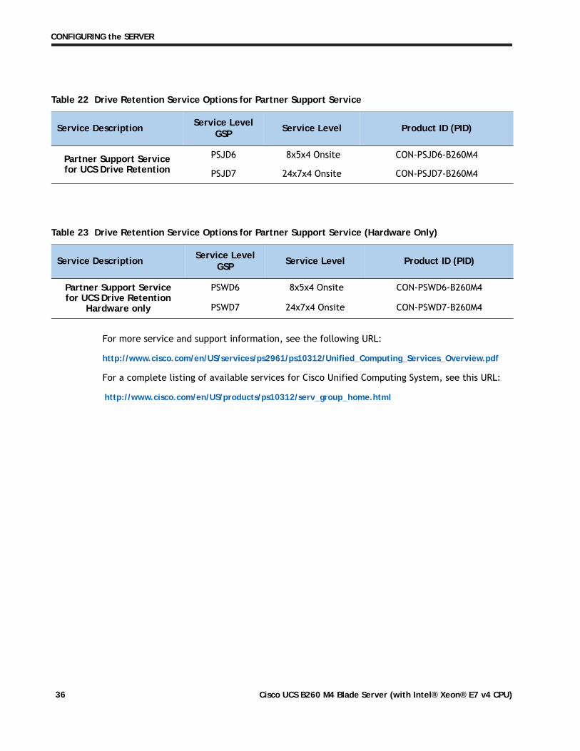
For more service and support information, see the following URL:
http://www.cisco.com/en/US/services/ps2961/ps10312/Unified_Computing_Services_Overview.pdf
For a complete listing of available services for Cisco Unified Computing System, see this URL:
http://www.cisco.com/en/US/products/ps10312/serv_group_home.html
Table 22 Drive Retention Service Options for Partner Support Service
Service Description Service Level GSP Service Level Product ID (PID)
Partner Support Service for UCS Drive Retention
PSJD6 8x5x4 Onsite CON-PSJD6-B260M4
PSJD7 24x7x4 Onsite CON-PSJD7-B260M4
Table 23 Drive Retention Service Options for Partner Support Service (Hardware Only)
Service Description Service Level GSP Service Level Product ID (PID)
Partner Support Service for UCS Drive Retention
Hardware only
PSWD6 8x5x4 Onsite CON-PSWD6-B260M4
PSWD7 24x7x4 Onsite CON-PSWD7-B260M4
Cisco UCS B260 M4 Blade Server (with Intel® Xeon® E7 v4 CPU)36
SUPPLEMENTAL MATERIAL
SUPPLEMENTAL MATERIAL
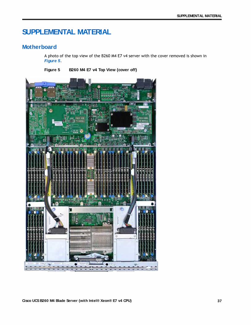
MotherboardA photo of the top view of the B260 M4 E7 v4 server with the cover removed is shown in Figure 5.
Figure 5 B260 M4 E7 v4 Top View (cover off)
Cisco UCS B260 M4 Blade Server (with Intel® Xeon® E7 v4 CPU) 37
SUPPLEMENTAL MATERIAL
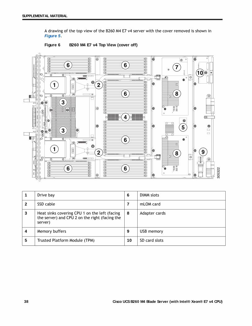
A drawing of the top view of the B260 M4 E7 v4 server with the cover removed is shown in Figure 5.
Figure 6 B260 M4 E7 v4 Top View (cover off)
1 Drive bay 6 DIMM slots
2 SSD cable 7 mLOM card
3 Heat sinks covering CPU 1 on the left (facing the server) and CPU 2 on the right (facing the server)
8 Adapter cards
4 Memory buffers 9 USB memory
5 Trusted Platform Module (TPM) 10 SD card slots
6 6
6
4
6
66
1
1
2
3
3 5
8
8
710
9
2
305322
Cisco UCS B260 M4 Blade Server (with Intel® Xeon® E7 v4 CPU)38
SUPPLEMENTAL MATERIAL
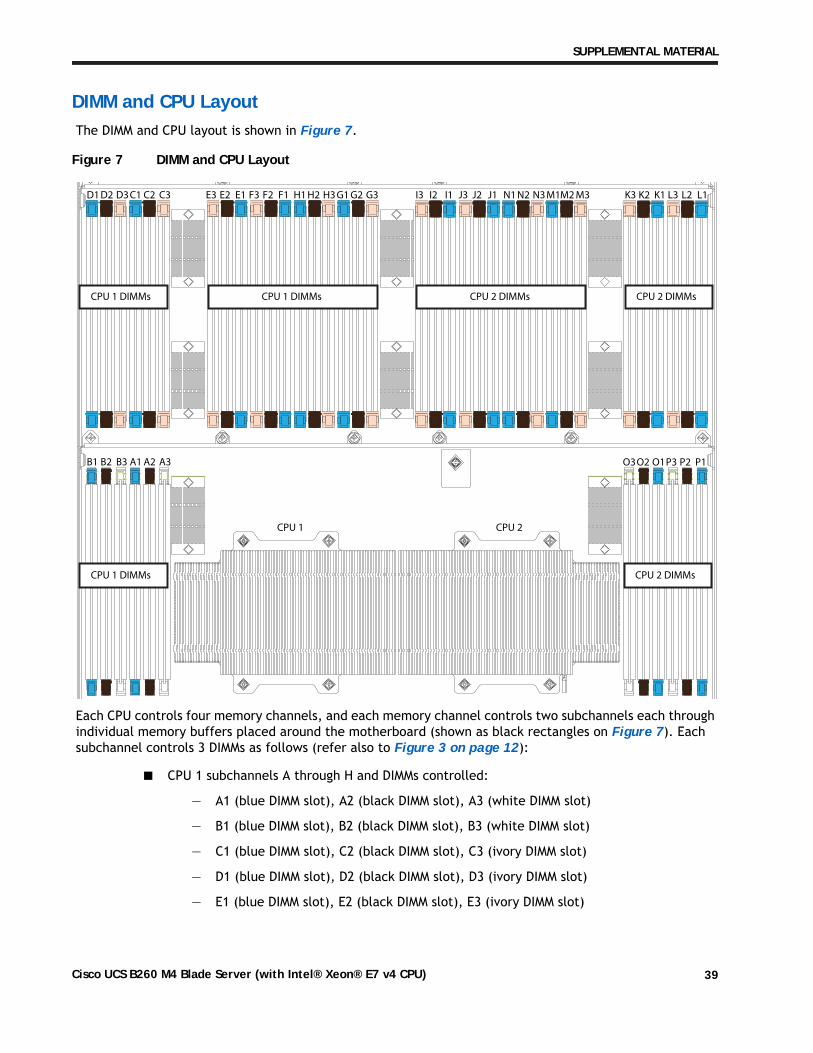
DIMM and CPU LayoutThe DIMM and CPU layout is shown in Figure 7.
Figure 7 DIMM and CPU Layout
Each CPU controls four memory channels, and each memory channel controls two subchannels each through individual memory buffers placed around the motherboard (shown as black rectangles on Figure 7). Each subchannel controls 3 DIMMs as follows (refer also to Figure 3 on page 12):
■ CPU 1 subchannels A through H and DIMMs controlled:
— A1 (blue DIMM slot), A2 (black DIMM slot), A3 (white DIMM slot)
— B1 (blue DIMM slot), B2 (black DIMM slot), B3 (white DIMM slot)
— C1 (blue DIMM slot), C2 (black DIMM slot), C3 (ivory DIMM slot)
— D1 (blue DIMM slot), D2 (black DIMM slot), D3 (ivory DIMM slot)
— E1 (blue DIMM slot), E2 (black DIMM slot), E3 (ivory DIMM slot)
A1 A2 A3B1 B2 B3
C1 C2 C3D1 D2 D3 F3 F2 F1E3 E2 E1 G1 G2 G3H1 H2 H3 J3 J2 J1I3 I2 I1 L3 L2 L1K3 K2 K1
P3 P2 P1O3
CPU 1 CPU 2
O2 O1
M1M2 M3N1 N2 N3
CPU 1 DIMMs CPU 2 DIMMs
CPU 1 DIMMs CPU 2 DIMMs
CPU 1 DIMMs CPU 2 DIMMs
Cisco UCS B260 M4 Blade Server (with Intel® Xeon® E7 v4 CPU) 39
SUPPLEMENTAL MATERIAL
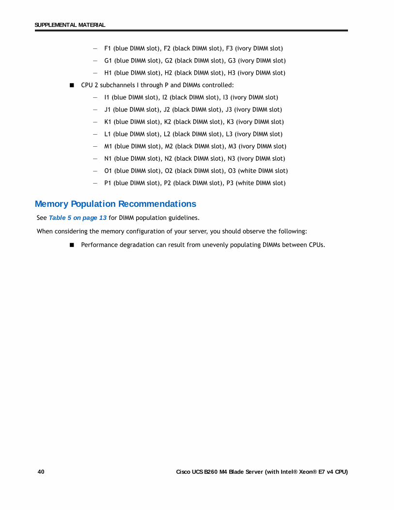
— F1 (blue DIMM slot), F2 (black DIMM slot), F3 (ivory DIMM slot)
— G1 (blue DIMM slot), G2 (black DIMM slot), G3 (ivory DIMM slot)
— H1 (blue DIMM slot), H2 (black DIMM slot), H3 (ivory DIMM slot)
■ CPU 2 subchannels I through P and DIMMs controlled:
— I1 (blue DIMM slot), I2 (black DIMM slot), I3 (ivory DIMM slot)
— J1 (blue DIMM slot), J2 (black DIMM slot), J3 (ivory DIMM slot)
— K1 (blue DIMM slot), K2 (black DIMM slot), K3 (ivory DIMM slot)
— L1 (blue DIMM slot), L2 (black DIMM slot), L3 (ivory DIMM slot)
— M1 (blue DIMM slot), M2 (black DIMM slot), M3 (ivory DIMM slot)
— N1 (blue DIMM slot), N2 (black DIMM slot), N3 (ivory DIMM slot)
— O1 (blue DIMM slot), O2 (black DIMM slot), O3 (white DIMM slot)
— P1 (blue DIMM slot), P2 (black DIMM slot), P3 (white DIMM slot)
Memory Population RecommendationsSee Table 5 on page 13 for DIMM population guidelines.
When considering the memory configuration of your server, you should observe the following:
■ Performance degradation can result from unevenly populating DIMMs between CPUs.
Cisco UCS B260 M4 Blade Server (with Intel® Xeon® E7 v4 CPU)40
SUPPLEMENTAL MATERIAL
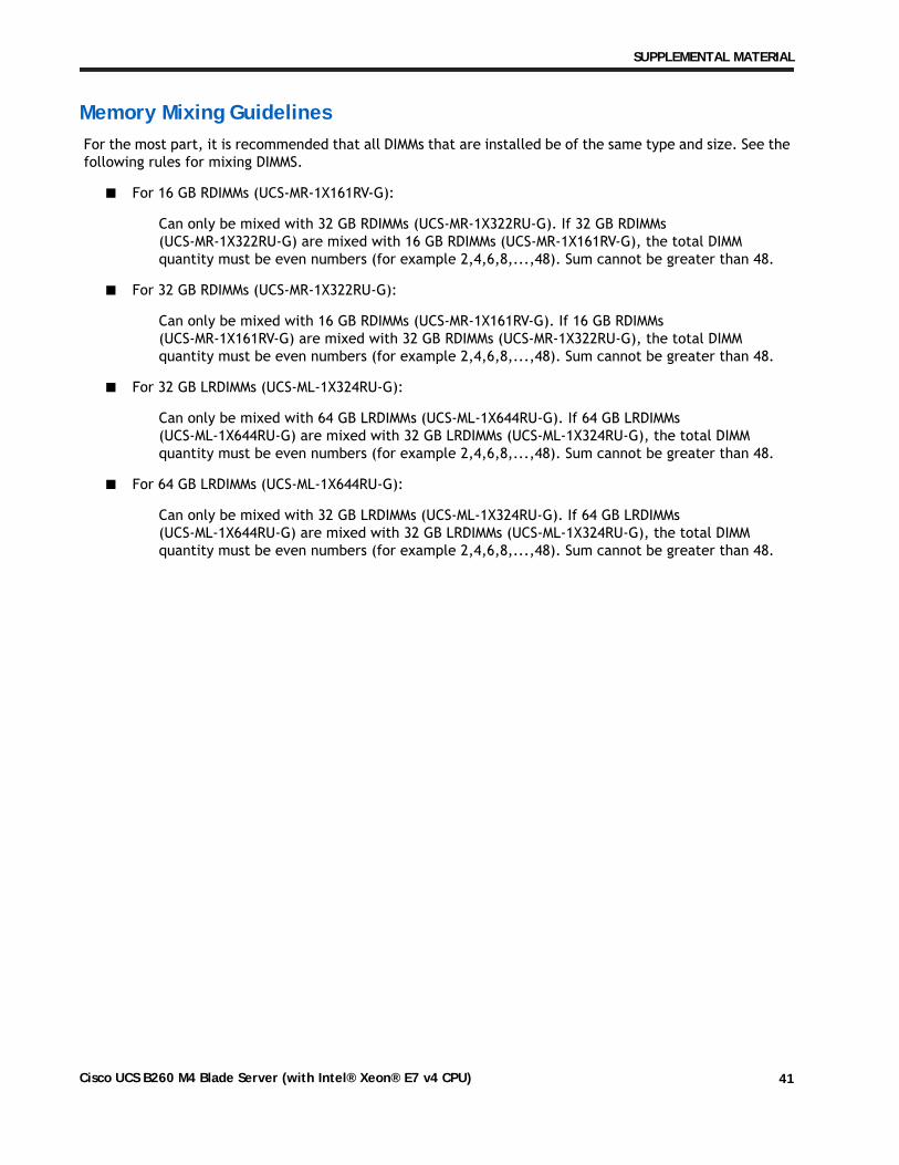
Memory Mixing GuidelinesFor the most part, it is recommended that all DIMMs that are installed be of the same type and size. See the following rules for mixing DIMMS.
■ For 16 GB RDIMMs (UCS-MR-1X161RV-G):
Can only be mixed with 32 GB RDIMMs (UCS-MR-1X322RU-G). If 32 GB RDIMMs (UCS-MR-1X322RU-G) are mixed with 16 GB RDIMMs (UCS-MR-1X161RV-G), the total DIMM quantity must be even numbers (for example 2,4,6,8,...,48). Sum cannot be greater than 48.
■ For 32 GB RDIMMs (UCS-MR-1X322RU-G):
Can only be mixed with 16 GB RDIMMs (UCS-MR-1X161RV-G). If 16 GB RDIMMs (UCS-MR-1X161RV-G) are mixed with 32 GB RDIMMs (UCS-MR-1X322RU-G), the total DIMM quantity must be even numbers (for example 2,4,6,8,...,48). Sum cannot be greater than 48.
■ For 32 GB LRDIMMs (UCS-ML-1X324RU-G):
Can only be mixed with 64 GB LRDIMMs (UCS-ML-1X644RU-G). If 64 GB LRDIMMs (UCS-ML-1X644RU-G) are mixed with 32 GB LRDIMMs (UCS-ML-1X324RU-G), the total DIMM quantity must be even numbers (for example 2,4,6,8,...,48). Sum cannot be greater than 48.
■ For 64 GB LRDIMMs (UCS-ML-1X644RU-G):
Can only be mixed with 32 GB LRDIMMs (UCS-ML-1X324RU-G). If 64 GB LRDIMMs (UCS-ML-1X644RU-G) are mixed with 32 GB LRDIMMs (UCS-ML-1X324RU-G), the total DIMM quantity must be even numbers (for example 2,4,6,8,...,48). Sum cannot be greater than 48.
Cisco UCS B260 M4 Blade Server (with Intel® Xeon® E7 v4 CPU) 41
SUPPLEMENTAL MATERIAL
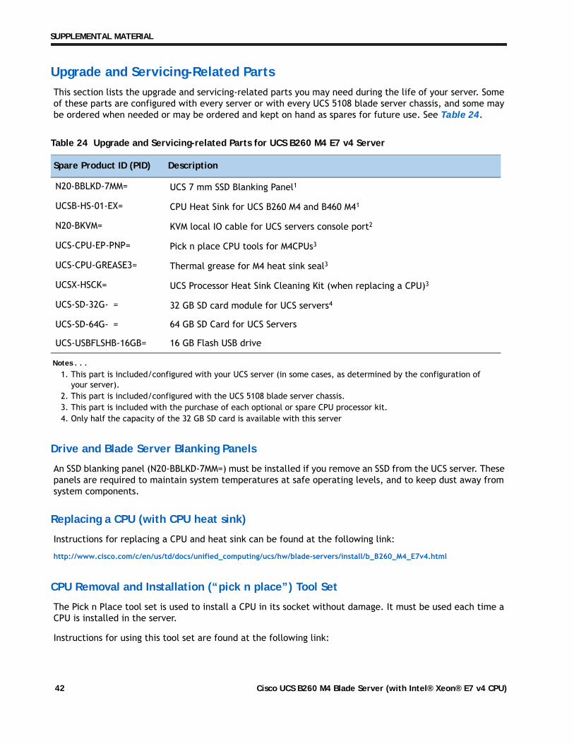
Upgrade and Servicing-Related PartsThis section lists the upgrade and servicing-related parts you may need during the life of your server. Some of these parts are configured with every server or with every UCS 5108 blade server chassis, and some may be ordered when needed or may be ordered and kept on hand as spares for future use. See Table 24.
Drive and Blade Server Blanking Panels
An SSD blanking panel (N20-BBLKD-7MM=) must be installed if you remove an SSD from the UCS server. These panels are required to maintain system temperatures at safe operating levels, and to keep dust away from system components.
Replacing a CPU (with CPU heat sink)
Instructions for replacing a CPU and heat sink can be found at the following link:
http://www.cisco.com/c/en/us/td/docs/unified_computing/ucs/hw/blade-servers/install/b_B260_M4_E7v4.html
CPU Removal and Installation (“pick n place”) Tool Set
The Pick n Place tool set is used to install a CPU in its socket without damage. It must be used each time a CPU is installed in the server.
Instructions for using this tool set are found at the following link:
Table 24 Upgrade and Servicing-related Parts for UCS B260 M4 E7 v4 Server
Spare Product ID (PID) Description
N20-BBLKD-7MM= UCS 7 mm SSD Blanking Panel1
Notes . . .1. This part is included/configured with your UCS server (in some cases, as determined by the configuration of
your server).
UCSB-HS-01-EX= CPU Heat Sink for UCS B260 M4 and B460 M41
N20-BKVM= KVM local IO cable for UCS servers console port2
2. This part is included/configured with the UCS 5108 blade server chassis.
UCS-CPU-EP-PNP= Pick n place CPU tools for M4CPUs3
3. This part is included with the purchase of each optional or spare CPU processor kit.
UCS-CPU-GREASE3= Thermal grease for M4 heat sink seal3
UCSX-HSCK= UCS Processor Heat Sink Cleaning Kit (when replacing a CPU)3
UCS-SD-32G-S= 32 GB SD card module for UCS servers4
4. Only half the capacity of the 32 GB SD card is available with this server
UCS-SD-64G-S= 64 GB SD Card for UCS Servers
UCS-USBFLSHB-16GB= 16 GB Flash USB drive
Cisco UCS B260 M4 Blade Server (with Intel® Xeon® E7 v4 CPU)42
SUPPLEMENTAL MATERIAL
.html
.html
.html
http://www.cisco.com/c/en/us/td/docs/unified_computing/ucs/hw/blade-servers/install/b_B260_M4_E7v4
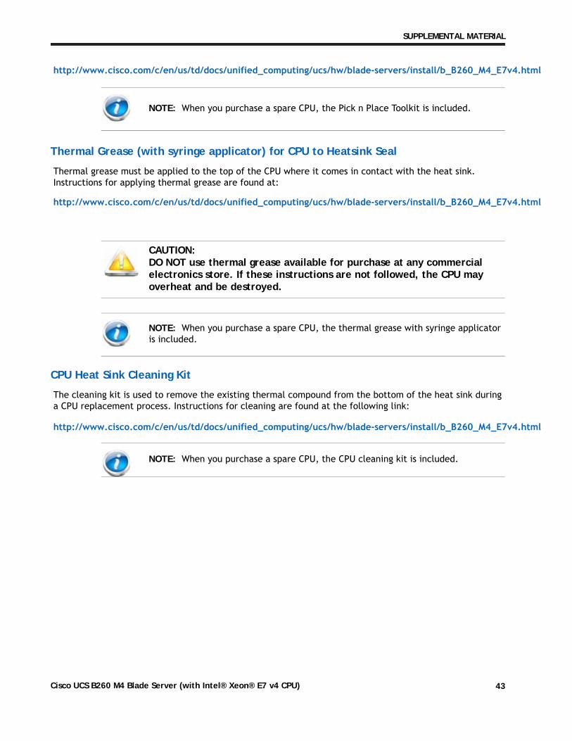
Thermal Grease (with syringe applicator) for CPU to Heatsink Seal
Thermal grease must be applied to the top of the CPU where it comes in contact with the heat sink. Instructions for applying thermal grease are found at:
http://www.cisco.com/c/en/us/td/docs/unified_computing/ucs/hw/blade-servers/install/b_B260_M4_E7v4
CPU Heat Sink Cleaning Kit
The cleaning kit is used to remove the existing thermal compound from the bottom of the heat sink during a CPU replacement process. Instructions for cleaning are found at the following link:
http://www.cisco.com/c/en/us/td/docs/unified_computing/ucs/hw/blade-servers/install/b_B260_M4_E7v4
NOTE: When you purchase a spare CPU, the Pick n Place Toolkit is included.
CAUTION: DO NOT use thermal grease available for purchase at any commercial electronics store. If these instructions are not followed, the CPU may overheat and be destroyed.
NOTE: When you purchase a spare CPU, the thermal grease with syringe applicator is included.
NOTE: When you purchase a spare CPU, the CPU cleaning kit is included.
Cisco UCS B260 M4 Blade Server (with Intel® Xeon® E7 v4 CPU) 43
SUPPLEMENTAL MATERIAL
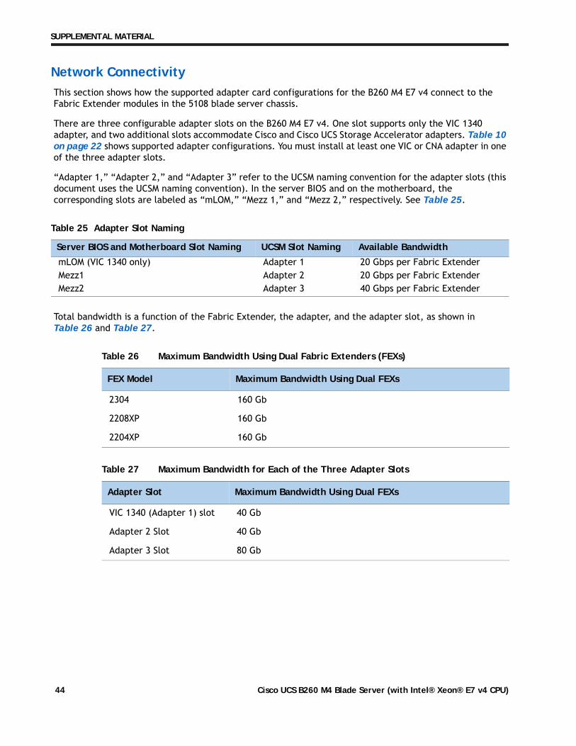
Network ConnectivityThis section shows how the supported adapter card configurations for the B260 M4 E7 v4 connect to the Fabric Extender modules in the 5108 blade server chassis.
There are three configurable adapter slots on the B260 M4 E7 v4. One slot supports only the VIC 1340 adapter, and two additional slots accommodate Cisco and Cisco UCS Storage Accelerator adapters. Table 10 on page 22 shows supported adapter configurations. You must install at least one VIC or CNA adapter in one of the three adapter slots.
“Adapter 1,” “Adapter 2,” and “Adapter 3” refer to the UCSM naming convention for the adapter slots (this document uses the UCSM naming convention). In the server BIOS and on the motherboard, the corresponding slots are labeled as “mLOM,” “Mezz 1,” and “Mezz 2,” respectively. See Table 25.
Total bandwidth is a function of the Fabric Extender, the adapter, and the adapter slot, as shown in Table 26 and Table 27.
Table 25 Adapter Slot Naming
Server BIOS and Motherboard Slot Naming UCSM Slot Naming Available Bandwidth
mLOM (VIC 1340 only) Adapter 1 20 Gbps per Fabric ExtenderMezz1 Adapter 2 20 Gbps per Fabric ExtenderMezz2 Adapter 3 40 Gbps per Fabric Extender
Table 26 Maximum Bandwidth Using Dual Fabric Extenders (FEXs)
FEX Model Maximum Bandwidth Using Dual FEXs
2304 160 Gb
2208XP 160 Gb
2204XP 160 Gb
Table 27 Maximum Bandwidth for Each of the Three Adapter Slots
Adapter Slot Maximum Bandwidth Using Dual FEXs
VIC 1340 (Adapter 1) slot 40 Gb
Adapter 2 Slot 40 Gb
Adapter 3 Slot 80 Gb
Cisco UCS B260 M4 Blade Server (with Intel® Xeon® E7 v4 CPU)44
SUPPLEMENTAL MATERIAL
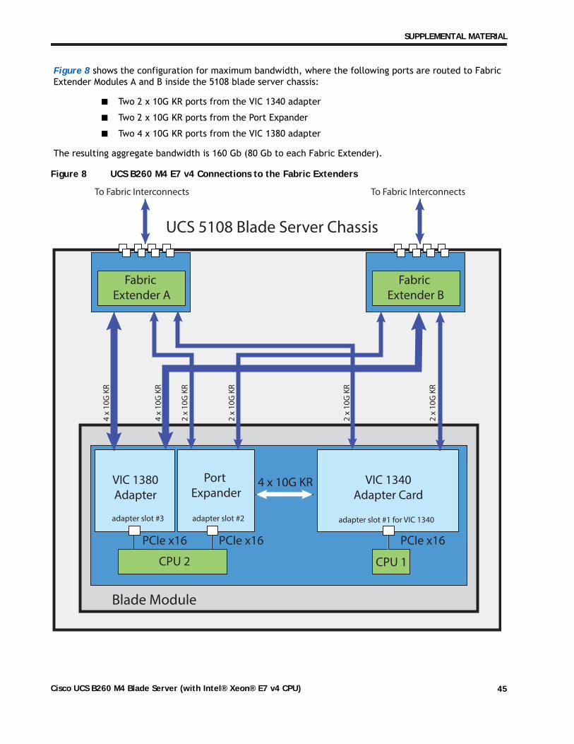
Figure 8 shows the configuration for maximum bandwidth, where the following ports are routed to Fabric Extender Modules A and B inside the 5108 blade server chassis:
■ Two 2 x 10G KR ports from the VIC 1340 adapter
■ Two 2 x 10G KR ports from the Port Expander
■ Two 4 x 10G KR ports from the VIC 1380 adapter
The resulting aggregate bandwidth is 160 Gb (80 Gb to each Fabric Extender).
Figure 8 UCS B260 M4 E7 v4 Connections to the Fabric Extenders
VIC 1340Adapter Card
Port Expander
VIC 1380Adapter
CPU 1CPU 2
PCIe x16PCIe x16PCIe x16
4 x 10G KR
4 x
10
G K
R
4 x
10
G K
R
2 x
10
G K
R
2 x
10
G K
R
2 x
10
G K
R
2 x
10
G K
R
adapter slot #1 for VIC 1340adapter slot #2adapter slot #3
Fabric Extender A
UCS 5108 Blade Server Chassis
To Fabric Interconnects To Fabric Interconnects
Blade Module
Fabric Extender B
Cisco UCS B260 M4 Blade Server (with Intel® Xeon® E7 v4 CPU) 45
SUPPLEMENTAL MATERIAL
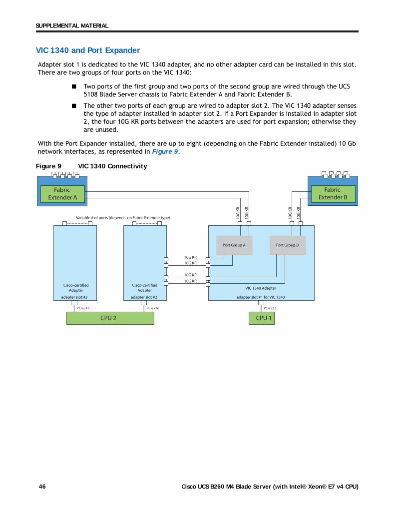
VIC 1340 and Port Expander
Adapter slot 1 is dedicated to the VIC 1340 adapter, and no other adapter card can be installed in this slot. There are two groups of four ports on the VIC 1340:
■ Two ports of the first group and two ports of the second group are wired through the UCS5108 Blade Server chassis to Fabric Extender A and Fabric Extender B.
■ The other two ports of each group are wired to adapter slot 2. The VIC 1340 adapter sensesthe type of adapter installed in adapter slot 2. If a Port Expander is installed in adapter slot2, the four 10G KR ports between the adapters are used for port expansion; otherwise theyare unused.
With the Port Expander installed, there are up to eight (depending on the Fabric Extender installed) 10 Gb network interfaces, as represented in Figure 9.
Figure 9 VIC 1340 Connectivity
VIC 1340 Adapter
adapter slot #2 adapter slot #1 for VIC 1340
Port Group A Port Group B
CPU 1
PCIe x16PCIe x16
Fabric Extender B
Fabric Extender A
Cisco-certifiedAdapter
Cisco-certifiedAdapter
adapter slot #3
CPU 2
PCIe x16
10
G K
R
10G KR
10G KR
10G KR
10G KR
10
G K
R
10
G K
R
10
G K
R
Variable # of ports (depends on Fabric Extender type)
Cisco UCS B260 M4 Blade Server (with Intel® Xeon® E7 v4 CPU)46
SUPPLEMENTAL MATERIAL
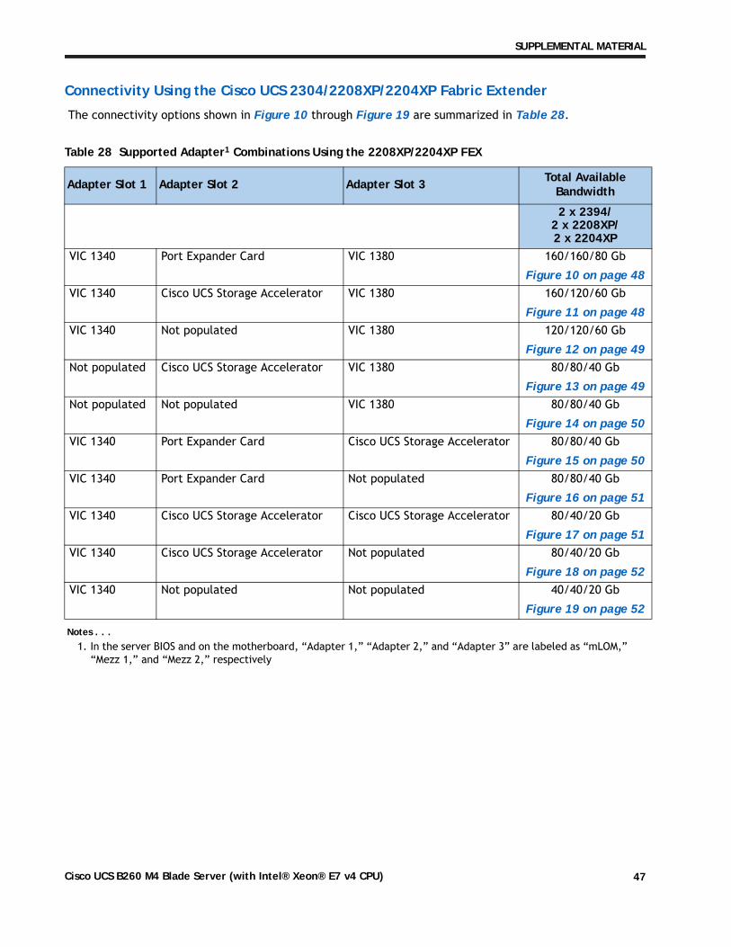
Connectivity Using the Cisco UCS 2304/2208XP/2204XP Fabric Extender
The connectivity options shown in Figure 10 through Figure 19 are summarized in Table 28.
Table 28 Supported Adapter1 Combinations Using the 2208XP/2204XP FEX
Notes . . .1. In the server BIOS and on the motherboard, “Adapter 1,” “Adapter 2,” and “Adapter 3” are labeled as “mLOM,”
“Mezz 1,” and “Mezz 2,” respectively
Adapter Slot 1 Adapter Slot 2 Adapter Slot 3 Total Available Bandwidth
2 x 2394/2 x 2208XP/2 x 2204XP
VIC 1340 Port Expander Card VIC 1380 160/160/80 Gb
Figure 10 on page 48VIC 1340 Cisco UCS Storage Accelerator VIC 1380 160/120/60 Gb
Figure 11 on page 48VIC 1340 Not populated VIC 1380 120/120/60 Gb
Figure 12 on page 49Not populated Cisco UCS Storage Accelerator VIC 1380 80/80/40 Gb
Figure 13 on page 49Not populated Not populated VIC 1380 80/80/40 Gb
Figure 14 on page 50VIC 1340 Port Expander Card Cisco UCS Storage Accelerator 80/80/40 Gb
Figure 15 on page 50VIC 1340 Port Expander Card Not populated 80/80/40 Gb
Figure 16 on page 51VIC 1340 Cisco UCS Storage Accelerator Cisco UCS Storage Accelerator 80/40/20 Gb
Figure 17 on page 51VIC 1340 Cisco UCS Storage Accelerator Not populated 80/40/20 Gb
Figure 18 on page 52VIC 1340 Not populated Not populated 40/40/20 Gb
Figure 19 on page 52
Cisco UCS B260 M4 Blade Server (with Intel® Xeon® E7 v4 CPU) 47
SUPPLEMENTAL MATERIAL
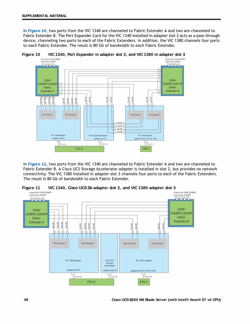
In Figure 10, two ports from the VIC 1340 are channeled to Fabric Extender A and two are channeled to Fabric Extender B. The Port Expander Card for the VIC 1340 installed in adapter slot 2 acts as a pass-through device, channeling two ports to each of the Fabric Extenders. In addition, the VIC 1380 channels four ports to each Fabric Extender. The result is 80 Gb of bandwidth to each Fabric Extender.
Figure 10 VIC 1340, Port Expander in adapter slot 2, and VIC 1380 in adapter slot 3
In Figure 11, two ports from the VIC 1340 are channeled to Fabric Extender A and two are channeled to Fabric Extender B. A Cisco UCS Storage Accelerator adapter is installed in slot 2, but provides no network connectivity. The VIC 1380 installed in adapter slot 3 channels four ports to each of the Fabric Extenders. The result is 80 Gb of bandwidth to each Fabric Extender.
Figure 11 VIC 1340, Cisco UCS SA adapter slot 2, and VIC 1380 adapter slot 3
2304/2208XP/2204XP
Fabric Extender A
VIC 1340 AdapterPort Expander Adapter
Port Group A Port Group B
CPU 1
PCIe x16 PCIe x16
10
G K
R
10
G K
R
8 ports for 2304/2208XP4 ports for 2204XP
8 ports for 2304/2208XP4 ports for 2204XP
10
G K
R
10
G K
R
10
G K
R
10
G K
R
10
G K
R
10
G K
R
10
G K
R
10
G K
R
10
G K
R
10
G K
R
10G KR
10G KR
10G KR
10G KR1
0G
KR
10
G K
R
10
G K
R
10
G K
R
adapter slot #2 adapter slot #1 for VIC 1340
VIC 1380 Adapter
adapter slot #3
PCIe x16
CPU 2
Port Group A Port Group B
2304/2208XP/2204 XP
Fabric Extender B
2304/2208XP/2204XP
Fabric Extender B
2304/2208XP/2204XP
Fabric Extender A
VIC 1340 AdapterVIC 1380 Adapter Cisco UCSStorage
Accelerator
adapter slot #3 adapter slot #2 adapter slot #1 for VIC 1340
Port Group A Port Group B
CPU 1
PCIe x16 PCIe x16
CPU 2
PCIe x16
10
G K
R
10
G K
R
10
G K
R
10
G K
R
10
G K
R
10
G K
R
10
G K
R
10
G K
R
10
G K
R
10
G K
R
10
G K
R
10
G K
R
Port Group A Port Group B
8 ports for 2304/2208XP4 ports for 2204XP
8 ports for 2304/2208XP4 ports for 2204XP
Cisco UCS B260 M4 Blade Server (with Intel® Xeon® E7 v4 CPU)48
SUPPLEMENTAL MATERIAL
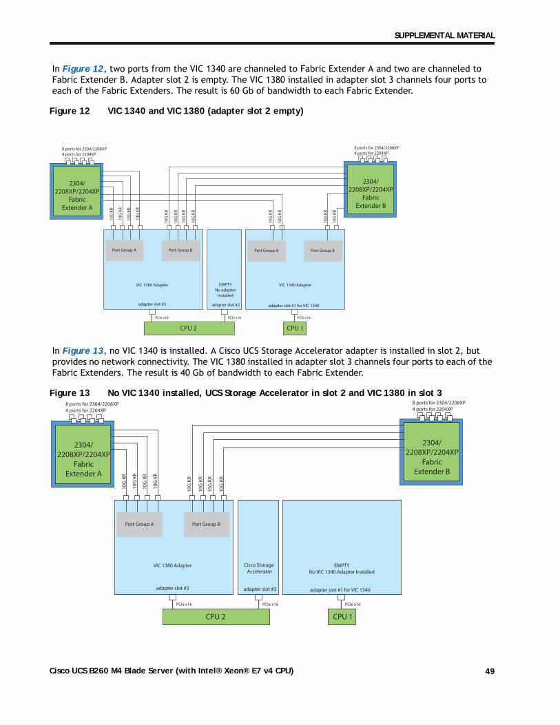
In Figure 12, two ports from the VIC 1340 are channeled to Fabric Extender A and two are channeled to Fabric Extender B. Adapter slot 2 is empty. The VIC 1380 installed in adapter slot 3 channels four ports to each of the Fabric Extenders. The result is 60 Gb of bandwidth to each Fabric Extender.
Figure 12 VIC 1340 and VIC 1380 (adapter slot 2 empty)
In Figure 13, no VIC 1340 is installed. A Cisco UCS Storage Accelerator adapter is installed in slot 2, but provides no network connectivity. The VIC 1380 installed in adapter slot 3 channels four ports to each of the Fabric Extenders. The result is 40 Gb of bandwidth to each Fabric Extender.
Figure 13 No VIC 1340 installed, UCS Storage Accelerator in slot 2 and VIC 1380 in slot 3
2304/2208XP/2204XP
Fabric Extender B
2304/2208XP/2204XP
Fabric Extender A
VIC 1380 Adapter EMPTYNo adapter
installed
adapter slot #3 adapter slot #2
CPU 1
PCIe x16 PCIe x16
CPU 2
PCIe x16
10
G K
R
10
G K
R
10
G K
R
10
G K
R
10
G K
R
10
G K
R
10
G K
R
10
G K
R
Port Group A Port Group B
8 ports for 2304/2208XP4 ports for 2204XP
8 ports for 2304/2208XP4 ports for 2204XP
VIC 1340 Adapter
adapter slot #1 for VIC 1340
Port Group A Port Group B
10
G K
R
10
G K
R
10
G K
R
10
G K
R
2304/2208XP/2204XP
Fabric Extender B
2304/2208XP/2204XP
Fabric Extender A
EMPTYNo VIC 1340 Adapter Installed
VIC 1380 Adapter Cisco Storage Accelerator
adapter slot #3 adapter slot #2 adapter slot #1 for VIC 1340
CPU 1
PCIe x16 PCIe x16
CPU 2
PCIe x16
10
G K
R
10
G K
R
10
G K
R
10
G K
R
10
G K
R
10
G K
R
10
G K
R
10
G K
R
Port Group A Port Group B
8 ports for 2304/2208XP4 ports for 2204XP
8 ports for 2304/2208XP4 ports for 2204XP
Cisco UCS B260 M4 Blade Server (with Intel® Xeon® E7 v4 CPU) 49
SUPPLEMENTAL MATERIAL
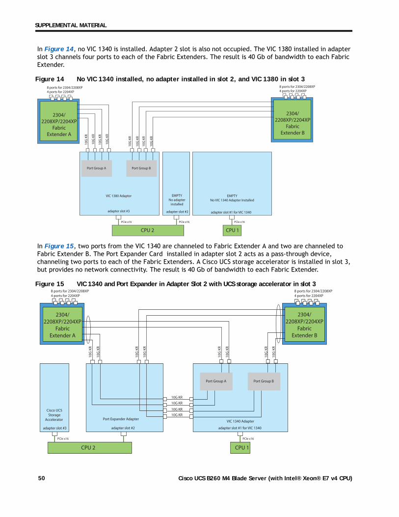
In Figure 14, no VIC 1340 is installed. Adapter 2 slot is also not occupied. The VIC 1380 installed in adapter slot 3 channels four ports to each of the Fabric Extenders. The result is 40 Gb of bandwidth to each Fabric Extender.
Figure 14 No VIC 1340 installed, no adapter installed in slot 2, and VIC 1380 in slot 3
In Figure 15, two ports from the VIC 1340 are channeled to Fabric Extender A and two are channeled to Fabric Extender B. The Port Expander Card installed in adapter slot 2 acts as a pass-through device, channeling two ports to each of the Fabric Extenders. A Cisco UCS storage accelerator is installed in slot 3, but provides no network connectivity. The result is 40 Gb of bandwidth to each Fabric Extender.
Figure 15 VIC 1340 and Port Expander in Adapter Slot 2 with UCS storage accelerator in slot 3
2304/2208XP/2204XP
Fabric Extender B
2304/2208XP/2204XP
Fabric Extender A
EMPTYNo VIC 1340 Adapter Installed
VIC 1380 Adapter EMPTYNo adapter
installed
adapter slot #3 adapter slot #2 adapter slot #1 for VIC 1340
CPU 1
PCIe x16 PCIe x16
CPU 2
PCIe x16
10
G K
R
10
G K
R
10
G K
R
10
G K
R
10
G K
R
10
G K
R
10
G K
R
10
G K
R
Port Group A Port Group B
8 ports for 2304/2208XP4 ports for 2204XP
8 ports for 2304/2208XP4 ports for 2204XP
2304/2208XP/2204XP
Fabric Extender B
2304/2208XP/2204XP
Fabric Extender A
VIC 1340 AdapterPort Expander Adapter
Port Group A Port Group B
CPU 1
PCIe x16
10
G K
R
10
G K
R
10
G K
R
10
G K
R
10G KR
10G KR
10G KR
10G KR
10
G K
R
10
G K
R
10
G K
R
10
G K
R
Cisco UCSStorage
Accelerator
adapter slot #3 adapter slot #2 adapter slot #1 for VIC 1340
PCIe x16
CPU 2
8 ports for 2304/2208XP4 ports for 2204XP
8 ports for 2304/2208XP4 ports for 2204XP
Cisco UCS B260 M4 Blade Server (with Intel® Xeon® E7 v4 CPU)50
SUPPLEMENTAL MATERIAL
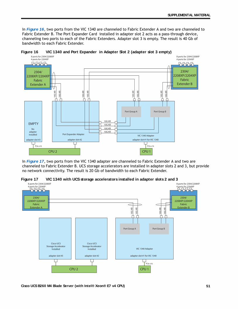
In Figure 16, two ports from the VIC 1340 are channeled to Fabric Extender A and two are channeled to Fabric Extender B. The Port Expander Card installed in adapter slot 2 acts as a pass-through device, channeling two ports to each of the Fabric Extenders. Adapter slot 3 is empty. The result is 40 Gb of bandwidth to each Fabric Extender.
Figure 16 VIC 1340 and Port Expander in Adapter Slot 2 (adapter slot 3 empty)
In Figure 17, two ports from the VIC 1340 adapter are channeled to Fabric Extender A and two are channeled to Fabric Extender B. UCS storage accelerators are installed in adapter slots 2 and 3, but provide no network connectivity. The result is 20 Gb of bandwidth to each Fabric Extender.
Figure 17 VIC 1340 with UCS storage accelerators installed in adapter slots 2 and 3
2304/2208XP/2204XP
Fabric Extender B
2304/2208XP/2204XP
Fabric Extender A
VIC 1340 AdapterPort Expander Adapter
Port Group A Port Group B
CPU 1
PCIe x16
10
G K
R
10
G K
R
10
G K
R
10
G K
R
10G KR
10G KR
10G KR
10G KR
10
G K
R
10
G K
R
10
G K
R
10
G K
R
No adapter installed
adapter slot #3 adapter slot #2 adapter slot #1 for VIC 1340
PCIe x16
CPU 2
EMPTY
8 ports for 2304/2208XP4 ports for 2204XP
8 ports for 2304/2208XP4 ports for 2204XP
VIC 1340 Adapter
adapter slot #2 adapter slot #1 for VIC 1340
Port Group A Port Group B
CPU 1
PCIe x16
Cisco UCSStorage Accelerator
Installed
Cisco UCSStorage Accelerator
Installed
adapter slot #3
CPU 2
2304/2208XP/2204XP
Fabric Extender B
2304/2208XP/2204XP
Fabric Extender A
10
G K
R
10
G K
R
10
G K
R
10
G K
R
8 ports for 2304/2208XP4 ports for 2204XP
8 ports for 2304/2208XP4 ports for 2204XP
Cisco UCS B260 M4 Blade Server (with Intel® Xeon® E7 v4 CPU) 51
SUPPLEMENTAL MATERIAL
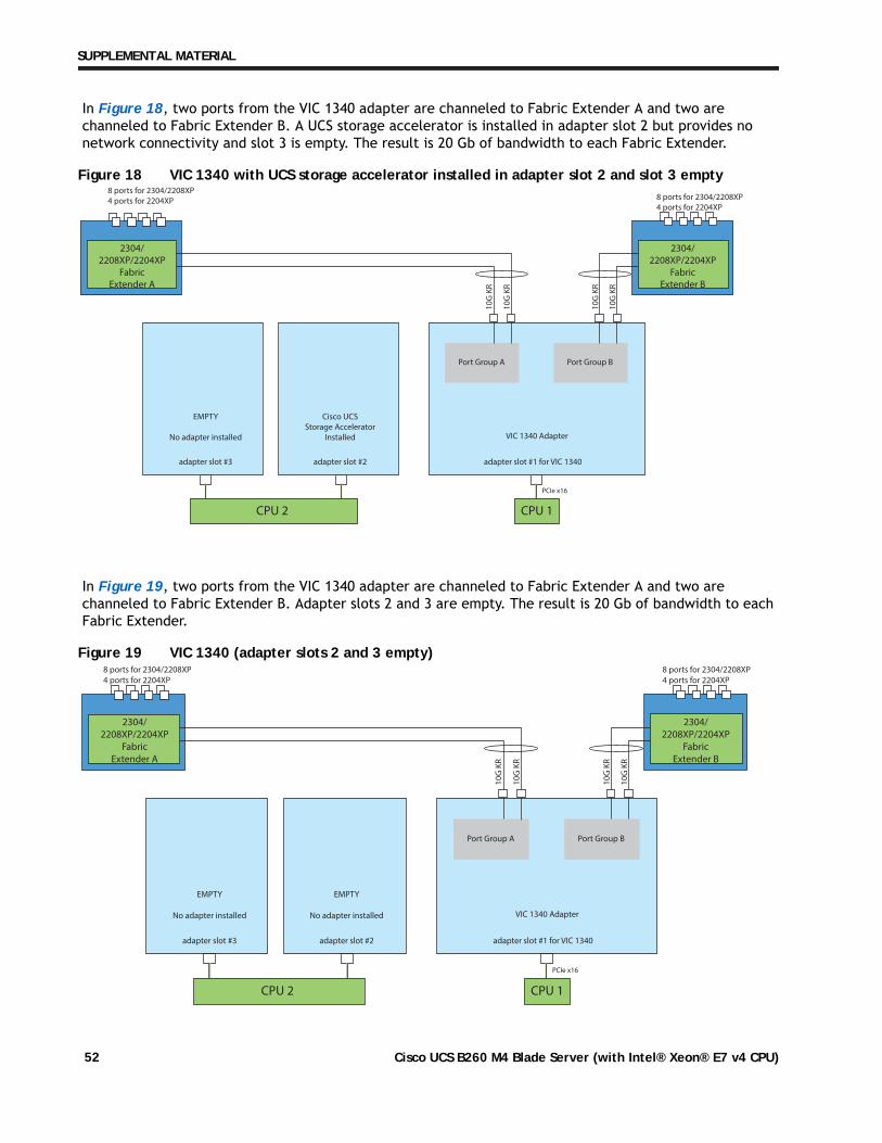
In Figure 18, two ports from the VIC 1340 adapter are channeled to Fabric Extender A and two are channeled to Fabric Extender B. A UCS storage accelerator is installed in adapter slot 2 but provides no network connectivity and slot 3 is empty. The result is 20 Gb of bandwidth to each Fabric Extender.
Figure 18 VIC 1340 with UCS storage accelerator installed in adapter slot 2 and slot 3 empty
In Figure 19, two ports from the VIC 1340 adapter are channeled to Fabric Extender A and two are channeled to Fabric Extender B. Adapter slots 2 and 3 are empty. The result is 20 Gb of bandwidth to each Fabric Extender.
Figure 19 VIC 1340 (adapter slots 2 and 3 empty)
VIC 1340 Adapter
adapter slot #2 adapter slot #1 for VIC 1340
Port Group A Port Group B
CPU 1
PCIe x16
EMPTY
No adapter installed
Cisco UCSStorage Accelerator
Installed
adapter slot #3
CPU 2
2304/2208XP/2204XP
Fabric Extender B
2304/2208XP/2204XP
Fabric Extender A
10
G K
R
10
G K
R
10
G K
R
10
G K
R
8 ports for 2304/2208XP4 ports for 2204XP 8 ports for 2304/2208XP
4 ports for 2204XP
VIC 1340 Adapter
adapter slot #2 adapter slot #1 for VIC 1340
Port Group A Port Group B
CPU 1
PCIe x16
EMPTY
No adapter installed
EMPTY
No adapter installed
adapter slot #3
CPU 2
2304/2208XP/2204XP
Fabric Extender B
2304/2208XP/2204XP
Fabric Extender A
10
G K
R
10
G K
R
10
G K
R
10
G K
R
8 ports for 2304/2208XP4 ports for 2204XP
8 ports for 2304/2208XP4 ports for 2204XP
Cisco UCS B260 M4 Blade Server (with Intel® Xeon® E7 v4 CPU)52
TECHNICAL SPECIFICATIONS
TECHNICAL SPECIFICATIONS
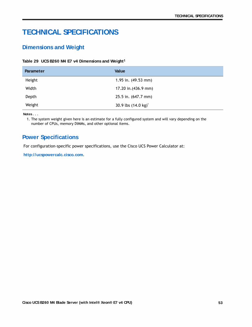
Dimensions and Weight
Power SpecificationsFor configuration-specific power specifications, use the Cisco UCS Power Calculator at:
http://ucspowercalc.cisco.com.
Table 29 UCS B260 M4 E7 v4 Dimensions and Weight1
Notes . . .1. The system weight given here is an estimate for a fully configured system and will vary depending on the
number of CPUs, memory DIMMs, and other optional items.
Parameter Value
Height 1.95 in. (49.53 mm)
Width 17.20 in.(436.9 mm)
Depth 25.5 in. (647.7 mm)
Weight 30.9 lbs (14.0 kg)*
Cisco UCS B260 M4 Blade Server (with Intel® Xeon® E7 v4 CPU) 53
TECHNICAL SPECIFICATIONS
Cisco UCS B260 M4 Blade Server (with Intel® Xeon® E7 v4 CPU)54