Embed Size (px)
Citation preview

Cisco UCS B420 M4 Blade Server Installation and Service NoteFirst Published: 2015-05-12
Last Modified: 2018-05-22
Americas HeadquartersCisco Systems, Inc.170 West Tasman DriveSan Jose, CA 95134-1706USAhttp://www.cisco.comTel: 408 526-4000
800 553-NETS (6387)Fax: 408 527-0883

THE SPECIFICATIONS AND INFORMATION REGARDING THE PRODUCTS IN THIS MANUAL ARE SUBJECT TO CHANGE WITHOUT NOTICE. ALL STATEMENTS,INFORMATION, AND RECOMMENDATIONS IN THIS MANUAL ARE BELIEVED TO BE ACCURATE BUT ARE PRESENTED WITHOUT WARRANTY OF ANY KIND,EXPRESS OR IMPLIED. USERS MUST TAKE FULL RESPONSIBILITY FOR THEIR APPLICATION OF ANY PRODUCTS.
THE SOFTWARE LICENSE AND LIMITED WARRANTY FOR THE ACCOMPANYING PRODUCT ARE SET FORTH IN THE INFORMATION PACKET THAT SHIPPED WITHTHE PRODUCT AND ARE INCORPORATED HEREIN BY THIS REFERENCE. IF YOU ARE UNABLE TO LOCATE THE SOFTWARE LICENSE OR LIMITED WARRANTY,CONTACT YOUR CISCO REPRESENTATIVE FOR A COPY.
The following information is for FCC compliance of Class A devices: This equipment has been tested and found to comply with the limits for a Class A digital device, pursuant to part 15of the FCC rules. These limits are designed to provide reasonable protection against harmful interference when the equipment is operated in a commercial environment. This equipmentgenerates, uses, and can radiate radio-frequency energy and, if not installed and used in accordance with the instruction manual, may cause harmful interference to radio communications.Operation of this equipment in a residential area is likely to cause harmful interference, in which case users will be required to correct the interference at their own expense.
The following information is for FCC compliance of Class B devices: This equipment has been tested and found to comply with the limits for a Class B digital device, pursuant to part 15 ofthe FCC rules. These limits are designed to provide reasonable protection against harmful interference in a residential installation. This equipment generates, uses and can radiate radiofrequency energy and, if not installed and used in accordance with the instructions, may cause harmful interference to radio communications. However, there is no guarantee that interferencewill not occur in a particular installation. If the equipment causes interference to radio or television reception, which can be determined by turning the equipment off and on, users areencouraged to try to correct the interference by using one or more of the following measures:
• Reorient or relocate the receiving antenna.
• Increase the separation between the equipment and receiver.
• Connect the equipment into an outlet on a circuit different from that to which the receiver is connected.
• Consult the dealer or an experienced radio/TV technician for help.
Modifications to this product not authorized by Cisco could void the FCC approval and negate your authority to operate the product
The Cisco implementation of TCP header compression is an adaptation of a program developed by the University of California, Berkeley (UCB) as part of UCB’s public domain version ofthe UNIX operating system. All rights reserved. Copyright © 1981, Regents of the University of California.
NOTWITHSTANDING ANY OTHERWARRANTY HEREIN, ALL DOCUMENT FILES AND SOFTWARE OF THESE SUPPLIERS ARE PROVIDED "AS IS" WITH ALL FAULTS.CISCO AND THE ABOVE-NAMED SUPPLIERS DISCLAIM ALL WARRANTIES, EXPRESSED OR IMPLIED, INCLUDING, WITHOUT LIMITATION, THOSE OFMERCHANTABILITY, FITNESS FOR A PARTICULAR PURPOSE AND NONINFRINGEMENT OR ARISING FROM A COURSE OF DEALING, USAGE, OR TRADE PRACTICE.
IN NO EVENT SHALL CISCO OR ITS SUPPLIERS BE LIABLE FOR ANY INDIRECT, SPECIAL, CONSEQUENTIAL, OR INCIDENTAL DAMAGES, INCLUDING, WITHOUTLIMITATION, LOST PROFITS OR LOSS OR DAMAGE TO DATA ARISING OUT OF THE USE OR INABILITY TO USE THIS MANUAL, EVEN IF CISCO OR ITS SUPPLIERSHAVE BEEN ADVISED OF THE POSSIBILITY OF SUCH DAMAGES.
Any Internet Protocol (IP) addresses and phone numbers used in this document are not intended to be actual addresses and phone numbers. Any examples, command display output, networktopology diagrams, and other figures included in the document are shown for illustrative purposes only. Any use of actual IP addresses or phone numbers in illustrative content is unintentionaland coincidental.
Cisco and the Cisco logo are trademarks or registered trademarks of Cisco and/or its affiliates in the U.S. and other countries. To view a list of Cisco trademarks, go to this URL:https://www.cisco.com/go/trademarks. Third-party trademarks mentioned are the property of their respective owners. The use of the word partner does not imply a partnership relationshipbetween Cisco and any other company. (1721R)
© 2015 Cisco Systems, Inc. All rights reserved.

C H A P T E R 1Overview
This chapter contains the following sections:
• Cisco UCS B420 M4 High Performance Blade Server, on page 1• Local Console Connection, on page 4• Secure Digital Cards, on page 4• Modular Storage Subsystem, on page 5• Drive Bay and RAID Controller Configurations, on page 5
Cisco UCS B420 M4 High Performance Blade ServerThis document describes how to install and service the Cisco UCS B420 M4 high performance blade server,a full-width, high-density blade server that supports the following features:
• Up to four Intel Xeon E5-4600 v4 or v3 CPUs, interconnected with Intel QuickPath Interconnect (QPI)links. Two- and four-CPU configurations are supported.
• 48 DDR4 DIMMs, either RDIMMs, LRDIMMs, or TSV-RDIMMs.
• 3 mezzanine adapter slots.
• Up to 4 SAS or SATA hard disk drives (HDDs) or solid state drives (SSDs).
Up to four Cisco UCS B420 M4 blade servers can reside in a Cisco UCS 5108 Blade Server chassis.Figure 1: Cisco UCS B420 M4 Blade Server Front Panel
Power button and LED8Hard drive bay 11
Network link status LED9Hard drive bay 22
Cisco UCS B420 M4 Blade Server Installation and Service Note1

Blade health LED10Hard drive bay 33
Local console connector11Hard drive bay 44
Reset button access12Left ejector handle5
Locator button LED13Asset pull tab6
Ejector captive screw14Right ejector handle7
LEDsServer LEDs indicate whether the blade server is in active or standby mode, the status of the network link,the overall health of the blade server, and whether the server is set to give a flashing blue locator light fromthe locator button.
The removable drives also have LEDs indicating hard disk access activity and disk health.
Table 1: Blade Server LEDs
DescriptionColorLED
Power off.OffPower
Main power state. Power issupplied to all server componentsand the server is operatingnormally.
Green
Standby power state. Power issupplied only to the serviceprocessor of the server so that theserver can still be managed.
Of you press and releasethe front-panel powerbutton, the serverperforms an orderlyshutdown of the 12 Vmain power and goes tostandby power state.You cannot shut downstandby power from thefront-panel powerbutton. See the CiscoUCS ManagerConfiguration Guide forinformation aboutcompletely power offthe server from thesoftware interface.
Note
Amber
Cisco UCS B420 M4 Blade Server Installation and Service Note2
OverviewLEDs

DescriptionColorLED
None of the network links are up.OffLink
At least one network link is up.Green
Power off.OffHealth
Normal operation.Green
Minor error.Amber
Critical error.Blinking Amber
Blinking is not enabled.OffBlue locator button and LED
Blinking to locate a selectedblade—If the LED is not blinking,the blade is not selected. You cancontrol the blinking in UCSManager or by using the bluelocator button/LED.
Blinking blue 1 Hz
Inactive.OffActivity
(Disk Drive) Outstanding I/O to disk drive.Green
Rebuild in progress. Health LEDwill flash in unison.
Flashing Green 1 Hz
Identify drive as active.Flashing Green 4 Hz
Either no fault is detected or thedrive is not installed.
OffHealth
(Disk Drive)Fault detected.Amber
Rebuild drive active. If the ActivityLED is also flashing green, a driverebuild is in progress.
Flashing Amber 4 Hz
ButtonsThe Reset button is recessed in the front panel of the server. You can press the button with the tip of a paperclip or a similar item. Hold the button down for five seconds, and then release it to restart the server if othermethods of restarting do not work.
The locator function for an individual server may get turned on or off by pressing the locator button/LED.
The power button allows you to manually take a server temporarily out of service but leave it in a state whereit can be restarted quickly. If the desired power state for a service profile associated with a blade server is setto "off," using the power button or Cisco UCS Manager to reset the server will cause the desired power stateof the server to become out-of-sync with the actual power state and the server may unexpectedly shut down
Cisco UCS B420 M4 Blade Server Installation and Service Note3
OverviewButtons

at a later time. To safely reboot a server from a power-down state, use the Boot Server action in Cisco UCSManager.
Local Console ConnectionThe local console connector allows a direct connection to a blade server to allow operating system installationand other management tasks to be done directly rather than remotely. The port uses the KVM dongle cablethat provides a connection into a Cisco UCS blade server; it has a DB9 serial connector, a VGA connectorfor a monitor, and dual USB ports for a keyboard andmouse.With this cable, you can create a direct connectionto the operating system and the BIOS running on a blade server. A KVM cable ships standard with each bladechassis accessory kit.Figure 2: KVM Cable for Blade Servers
DB9 serial connector2Connector to blade serverlocal console connection
1
2-port USB connector fora mouse and keyboard
4VGA connector for amonitor
3
Secure Digital CardsSecure Digital (SD) card slots are provided and one or two SD cards can be populated. If two SD cards arepopulated, they can be used in a mirrored mode.
Do not mix different capacity cards in the same server.Note
Cisco UCS B420 M4 Blade Server Installation and Service Note4
OverviewLocal Console Connection

Figure 3: SD Card Slots
Modular Storage SubsystemThe Cisco UCS B420 M4 blade server has two optional FlexStorage modular storage subsystems that can beconfigured with SAS or SATA hard disk drives (HDDs) or solid state disks (SSDs). The product IDs for themodular storage subsystems are as follows:
• UCSB-MRAID12G, Cisco FlexStorage 12G SAS RAID controller with drive bays
• UCSB-MRAID12G-HE, Cisco FlexStorage 12G SASRAID controller with 2 GB flash-backwrite cacheand drive bays
• UCSB-LSTOR-PT, passthrough module with drive bays
• UCSB-LSTOR-BK, Cisco FlexStorage blanking panels without controller or drive bays
Because the blade server can be used without disk drives, it does not comewith anymodular storage subsystemsinstalled. Blanking panels should be used on a diskless UCS B420 M4 blade server to ensure proper airflow.Order the same number of blanking panels as there are empty drive bays.
There are two RAID controller options for the modular storage subsystems. One supports RAID 0, 1, 10 andthe other supports RAID 0, 1, 10, 5, 6, with optional 2 GB flash-backed write cache, when four drives arepresent.
Drive Bay and RAID Controller ConfigurationsTheCiscoUCSB420M4 blade server supports the following configurations of drive bays and RAID controllers.
Cisco UCS B420 M4 Blade Server Installation and Service Note5
OverviewModular Storage Subsystem

DescriptionConfiguration
This configuration includes:
• One UCSB-MRAID12G that provides two drives bays on theleft side of the blade server (when facing the front). The RAIDcontroller is integrated in the drive bays and provides RAID 0,1, 10.
• One UCSB-LSTOR-PT that provides two drive bays installedon the right (when facing the front) and includes a passthroughconnector that allows the drives to be managed from the RAIDcontroller in UCSB-MRAID12G.
Four drive bays with RAID 0, 1, 10
This configuration includes:
• One UCSB-MRAID12G-HE that provides two drives bays onthe left side of the blade server (when facing the front). TheRAID controller has a 2 GB flash-backed write cache (FBWC)for high performance, is integrated in the drive bays and providesRAID 0, 1, 10, 5, 6.
• One UCSB-LSTOR-PT that provides two drive bays installedon the right (when facing the front) and includes a passthroughconnector that allows the drives to be managed from the RAIDcontroller in UCSB-MRAID12G-HE.
Four drive bays with RAID 0, 1, 10,5, 6
This configuration includes:
• One UCSB-MRAID12G that provides two drives bays on theleft side of the blade server (when facing the front). The RAIDcontroller is integrated in the drive bays and provides RAID 0,1, 10. The right-hand bays have blanking panels installed tomaintain proper airflow.
Two drive bays with RAID 0, 1, 10
This configuration includes:
• One UCSB-MRAID12G-HE that provides two drives bays onthe left side of the blade server (when facing the front). TheRAID controller has a 2 GB flash-backed write cache (FBWC)for high performance, is integrated in the drive bays and providesRAID 0, 1, 10. The right-hand bays have blanking panels installedto maintain proper airflow.
Two drive bays with RAID 0, 1, 10
This configuration does not include drive bays or RAID controllers.The diskless server must be booted from a network. Blanking panelsmust be installed in the empty drive bays.
No drive bays
Cisco UCS B420 M4 Blade Server Installation and Service Note6
OverviewDrive Bay and RAID Controller Configurations

C H A P T E R 2Installing a Blade Server
This chapter contains the following sections:
• Installing a Blade Server, on page 7• Server Configuration, on page 9• Powering Off the Blade Server, on page 9• Removing a Blade Server, on page 9• Server Troubleshooting, on page 9
Installing a Blade ServerFor installations of UCS blades with differing widths and heights in a chassis, the guideline is to load theheaviest and largest blades at the bottom of the chassis. Therefore, if a UCS B460 blade server is present, itshould be installed at the bottom, followed by full-width blades such as the UCS B420 or UCS B480 abovethe UCS B460, and then half-width blades such as the UCS B200 at the top of the chassis.
Before you begin
The blade server must have its cover installed before installing it into the chassis to ensure adequate airflow.
Procedure
Step 1 If necessary, remove the slot divider from the chassis.a) Simultaneously pull up on the left side catch and push down on the right side catch as shown in callout 1
of the following figure.b) Pull the slot divider out of the chassis as shown in callout 2 of the following figure. Keep the slot divider
in case it is needed at another time.
Cisco UCS B420 M4 Blade Server Installation and Service Note7

Figure 4: Removing a Slot Divider
To reinstall the slot divider, align it with the dimples in the slot top and bottom and slide it backin until it clicks into place.
Tip
Step 2 Grasp the front of the blade server and place your other hand under the blade to support it.Figure 5: Positioning a Blade Server in the Chassis
Step 3 Open the ejector levers in the front of the blade server.Step 4 Gently slide the blade into the opening until you cannot push it any farther.Step 5 Press the ejectors so that they catch the edge of the chassis and press the blade server all the way in.Step 6 Tighten the captive screw on the front of the blade to no more than 3 in-lbs. Tightening only with bare fingers
is unlikely to lead to stripped or damaged captive screws.
Cisco UCS B420 M4 Blade Server Installation and Service Note8
Installing a Blade ServerInstalling a Blade Server

Cisco UCS Manager automatically reacknowledges, reassociates, and recommissions the server, providedany hardware changes are allowed by the service profile.
Server ConfigurationCisco UCS blade servers should be configured and managed using Cisco UCS Manager. For details, see theConfiguration Guide for the version of Cisco UCS Manager that you are using. The configuration guides areavailable at the following URL:http://www.cisco.com/en/US/products/ps10281/products_installation_and_configuration_guides_list.html
Powering Off the Blade ServerUse Cisco UCS Manager to shut down the server. For detailed steps on how to perform this operation, seethe Configuration Guide for the version of Cisco UCS Manager that you are using. The configuration guidesare available at the followingURL: http://www.cisco.com/en/US/products/ps10281/products_installation_and_configuration_guides_list.html
Removing a Blade ServerYou must decommission the server using Cisco UCS Manager before physically removing the blade server.
Procedure
Step 1 Turn off the blade server using either Cisco UCS Manager.Step 2 Completely loosen the captive screws on the front of the blade.Step 3 Remove the blade from the chassis by pulling the ejector levers on the blade until it unseats the blade server.Step 4 Slide the blade part of the way out of the chassis, and place your other hand under the blade to support its
weight.Step 5 Once removed, place the blade on an antistatic mat or antistatic foam if you are not immediately reinstalling
it.Step 6 If the blade server slot is to remain empty, reinstall the slot divider and install two blade server blanking panels
to maintain proper thermal temperatures and to keep dust out of the chassis.
Server TroubleshootingFor general troubleshooting information, see the Cisco UCS Manager Troubleshooting Reference Guide.
Cisco UCS B420 M4 Blade Server Installation and Service Note9
Installing a Blade ServerServer Configuration

Cisco UCS B420 M4 Blade Server Installation and Service Note10
Installing a Blade ServerServer Troubleshooting

C H A P T E R 3Servicing the Blade Server
This chapter contains the following sections:
• Removing a Blade Server Cover, on page 11• Drive Replacement, on page 11• Air Baffles, on page 15• Internal Components, on page 17• Diagnostics Button and LEDs, on page 18• Installing a CMOS Battery, on page 18• Installing a Modular Storage Subsystem, on page 19• Upgrading to Intel Xeon E5-4600 v4 Series CPUs, on page 20• Removing a Heat Sink and CPU, on page 20• Installing a New CPU and Heat Sink, on page 22• Installing Memory, on page 24• Installing a Virtual Interface Card Adapter, on page 29• Installing an Adapter Card in Slots 2 or 3, on page 30• Enabling the Trusted Platform Module, on page 31
Removing a Blade Server CoverProcedure
Step 1 Press and hold the button down as shown in the figure below.Step 2 While holding the back end of the cover, pull the cover back and then up.
Drive ReplacementYou can remove and install hard drives without removing the blade server from the chassis.
The drives supported in this blade server comewith the drive sled attached. Spare drive sleds are not available.A list of currently supported drives is in the Cisco UCS B420 M4 Blade Server Specification Sheet.
Cisco UCS B420 M4 Blade Server Installation and Service Note11

Before upgrading or adding a drive to a running blade server, check the service profile in Cisco UCSManagerand make sure the new hardware configuration will be within the parameters allowed by the service profile.
To prevent ESD damage, wear grounding wrist straps during these procedures.Caution
See also 4K Sector Format SAS/SATA Drives Considerations, on page 14.Note
Removing a Blade Server Hard DriveTo remove a hard drive from a blade server, follow these steps:
Procedure
Step 1 Push the button to release the ejector, and then pull the hard drive from its slot.Step 2 Place the hard drive on an antistatic mat or antistatic foam if you are not immediately reinstalling it in another
server.Step 3 Install a hard disk drive blank faceplate to keep dust out of the blade server if the slot will remain empty.
Cisco UCS B420 M4 Blade Server Installation and Service Note12
Servicing the Blade ServerRemoving a Blade Server Hard Drive

Figure 6: Removing and Installing a Drive
Installing a Blade Server DriveTo install a drive in a blade server, follow these steps:
Procedure
Step 1 Place the drive ejector into the open position by pushing the release button.Step 2 Gently slide the drive into the opening in the blade server until it seats into place.Step 3 Push the drive ejector into the closed position.
You can use Cisco UCS Manager to format and configure RAID services. For details, see the ConfigurationGuide for the version of Cisco UCS Manager that you are using. The configuration guides are available atthe following URL:http://www.cisco.com/en/US/products/ps10281/products_installation_and_configuration_guides_list.html
Cisco UCS B420 M4 Blade Server Installation and Service Note13
Servicing the Blade ServerInstalling a Blade Server Drive

If you need to move a RAID cluster, see the Cisco UCS Manager Troubleshooting Reference Guide.
4K Sector Format SAS/SATA Drives Considerations• You must boot 4K sector format drives in UEFI mode, not legacy mode. See the procedure in this sectionfor setting UEFI boot mode in the boot policy.
• Do not configure 4K sector format and 512-byte sector format drives as part of the same RAID volume.
• Operating system support on 4K sector drives is as follows:Windows:Win2012 andWin2012R2; Linux:RHEL 6.5, 6.6, 6.7, 7.0, 7.2, 7.3; SLES 11 SP3, and SLES 12. ESXi/VMWare is not supported.
Setting Up UEFI Mode Booting in the UCS Manager Boot Policy
Procedure
Step 1 In the Navigation pane, click Servers.Step 2 Expand Servers > Policies.Step 3 Expand the node for the organization where you want to create the policy.
If the system does not include multitenancy, expand the root node.
Step 4 Right-click Boot Policies and select Create Boot Policy.
The Create Boot Policy wizard displays.
Step 5 Enter a unique name and description for the policy.
This name can be between 1 and 16 alphanumeric characters. You cannot use spaces or any special charactersother than - (hyphen), _ (underscore), : (colon), and . (period). You cannot change this name after the objectis saved.
Step 6 (Optional) After you make changes to the boot order, check the Reboot on Boot Order Change check boxto reboot all servers that use this boot policy.
For boot policies applied to a server with a non-Cisco VIC adapter, even if the Reboot on Boot Order Changecheck box is not checked, when SAN devices are added, deleted, or their order is changed, the server alwaysreboots when boot policy changes are saved.
Step 7 (Optional) If desired, check the Enforce vNIC/vHBA/iSCSI Name check box.
• If checked, Cisco UCS Manager displays a configuration error and reports whether one or more of thevNICs, vHBAs, or iSCSI vNICs listed in the Boot Order table match the server configuration in theservice profile.
• If not checked, Cisco UCS Manager uses the vNICs or vHBAs (as appropriate for the boot option) fromthe service profile.
Step 8 In the Boot Mode field, choose the UEFI radio button.Step 9 Check the Boot Security check box if you want to enable UEFI boot security.
Cisco UCS B420 M4 Blade Server Installation and Service Note14
Servicing the Blade Server4K Sector Format SAS/SATA Drives Considerations

Step 10 Configure one or more of the following boot options for the boot policy and set their boot order:
• Local Devices boot—To boot from local devices, such as local disks on the server, virtual media, orremote virtual disks, continue with Configuring a Local Disk Boot for a Boot Policy in the Cisco UCSManager Server Management Guide for your release.
• SAN boot—To boot from an operating system image on the SAN, continue with Configuring a SANBoot for a Boot Policy in the Cisco UCS Manager Server Management Guide for your release.
You can specify a primary and a secondary SAN boot. If the primary boot fails, the server attempts to bootfrom the secondary.
• LAN boot—To boot from a centralized provisioning server, continue with Configuring a LAN Boot Fora Boot Policy in the Cisco UCS Manager Server Management Guide for your release.
• iSCSI boot—To boot from an iSCSI LUN, continue with Creating an iSCSI Boot Policy in the CiscoUCS Manager Server Management Guide for your release.
Air BafflesThe air baffles shown below ship with this server; they direct and improve air flow for the server components.No tools are necessary to install them. Place them over the DIMMs and align them to the standoffs.
Be sure that the tabs on the baffles are set in the slots provided on the motherboard; otherwise, it may bedifficult to replace the server cover or damage to the motherboard might occur.
Caution
Cisco UCS B420 M4 Blade Server Installation and Service Note15
Servicing the Blade ServerAir Baffles

Cisco UCS B420 M4 Blade Server Installation and Service Note16
Servicing the Blade ServerAir Baffles

Internal ComponentsFigure 7: Inside View of the Blade Server
Heat sink and CPU (underneath)7Ejector captive screw1
CPU heat sink install guide pins8SD card slots2
Trusted Platform Module (TPM)9Modular storage subsystem connector3
Adapter 1 supports only the Cisco VIC 1340adapter and the Cisco VIC 1240 adapter
10USB memory4
Adapter cards:
• Adapter 2 is the slot on the left (facing theserver) and partially covers Adapter 1
• Adapter 3 is the slot on the right (facingthe server)
11CMOS battery5
Diagnostic button12DIMM slots6
Cisco UCS B420 M4 Blade Server Installation and Service Note17
Servicing the Blade ServerInternal Components

The heat sinks and CPUs are numbered as follows:
• Left front heat sink and CPU 1• Right front heat sink and CPU 2• Right rear heat sink and CPU 3• Left rear heat sink and CPU 4
Note
Diagnostics Button and LEDsAt blade start-up, POST diagnostics test the CPUs, DIMMs, HDDs, and adapter cards, and any failurenotifications are sent to UCS Manager. You can view these notifications in the Cisco UCS Manager SystemError Log or in the output of the show tech-support command. If errors are found, an amber diagnostic LEDalso lights up next to the failed component. During run time, the blade BIOS and component drivers monitorfor hardware faults and will light up the amber diagnostic LED as needed.
LED states are saved, and if you remove the blade from the chassis the LED values will persist for up to 10minutes. Press and hold the diagnostics button on the motherboard for 30 seconds to display component faults.LED fault values are reset when the blade is reinserted into the chassis and booted, and the process beginsfrom its start.
If DIMM insertion errors are detected, they may cause the blade discovery process to fail and errors will bereported in the server POST information, which is viewable using the UCS Manager GUI or CLI. DIMMsmust be populated according to specific rules. The rules depend on the blade server model. Refer to the CiscoUCS B420 M4 Blade Server Specification Sheet for the DIMM population rules.
Faults on the DIMMs or adapter cards also cause the server health LED to light solid amber for minor errorconditions or blinking amber for critical error conditions.
Installing a CMOS BatteryAll Cisco UCS blade servers use a CR2032 battery to preserve BIOS settings while the server is not installedin a powered-on chassis. Cisco supports the industry standard CR2032 battery that is available at mostelectronics stores.
There is danger of explosion if the battery is replaced incorrectly. Replace the battery only with the same orequivalent type recommended by the manufacturer. Dispose of used batteries according to the manufacturer’sinstructions.
Warning
To install or replace the battery, follow these steps:
Procedure
Step 1 Remove the existing battery:a) Power off the blade, remove it from the chassis, and remove the top cover.
Cisco UCS B420 M4 Blade Server Installation and Service Note18
Servicing the Blade ServerDiagnostics Button and LEDs
b) Push the battery socket retaining clip away from the battery.c) Lift the battery from the socket. Use needle-nose pliers to grasp the battery if there is not enough clearance
for your fingers.
Step 2 Install the replacement battery:a) Push the battery socket retaining clip away from where the battery fits in the housing.b) Insert the new battery into the socket with the battery’s positive (+) marking facing away from the retaining
clip. Ensure that the retaining clip can click over the top of the battery to secure it in the housing.c) Replace the top cover.d) Replace the blade server in the chassis.
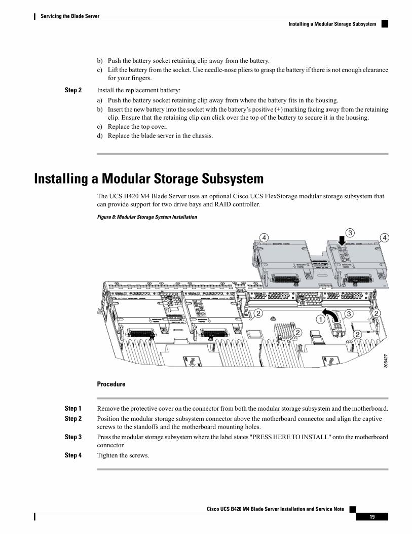
Installing a Modular Storage SubsystemThe UCS B420 M4 Blade Server uses an optional Cisco UCS FlexStorage modular storage subsystem thatcan provide support for two drive bays and RAID controller.
Figure 8: Modular Storage System Installation
Procedure
Step 1 Remove the protective cover on the connector from both the modular storage subsystem and the motherboard.Step 2 Position the modular storage subsystem connector above the motherboard connector and align the captive
screws to the standoffs and the motherboard mounting holes.Step 3 Press themodular storage subsystemwhere the label states "PRESSHERETO INSTALL" onto themotherboard
connector.Step 4 Tighten the screws.
Cisco UCS B420 M4 Blade Server Installation and Service Note19
Servicing the Blade ServerInstalling a Modular Storage Subsystem
Upgrading to Intel Xeon E5-4600 v4 Series CPUsBefore upgrading to Intel Xeon E5-4600 v4 Series CPUs, ensure that the server is running the requiredminimum software and firmware versions that support Intel E5-4600 v4 Series CPUs, as listed in the followingtable.
Minimum VersionSoftware or Firmware
Release 3.1(2) or Release 2.2(8) (See the following Note for additionalsupported versions.)
Cisco UCS Manager
Release 3.1(2) or Release 2.2(8)Cisco IMC
Release 3.1(2) or Release 2.2(8)BIOS
Cisco UCS Manager Release 2.2(4) introduced a server pack feature that allows Intel E5-4600 v4 CPUs torun with Cisco UCS Manager Release 2.2(4) or later, provided that the Cisco IMC, BIOS and CapabilityCatalog are all running Release 2.2(8) or later.
Note
Ensure that the server is running the required software and firmware before installing the Intel E5-4600 v4Series CPUs. Failure to do so can result in a non-bootable CPU.
Caution
Do one of the following actions:
• If the server software and firmware are already at the required minimum version as shown in the precedingtable, replace the CPUs by using the procedure in the following section.
• If the server software or firmware is not at the required minimum version, follow the instructions in theCisco UCS B420 M4 Server Upgrade Guide for E5-4600 v4 Series CPUs to upgrade it. Then replacethe CPUs by using the procedure in the following section.
Removing a Heat Sink and CPUProcedure
Step 1 Unscrew the four captive screws.Step 2 Remove the heat sink.
Cisco UCS B420 M4 Blade Server Installation and Service Note20
Servicing the Blade ServerUpgrading to Intel Xeon E5-4600 v4 Series CPUs

Figure 9: Removing the Heat Sink and CPU
Step 3 Unhook the self-loading socket (SLS) lever that has the unlock icon .Step 4 Unhook the SLS lever that has the lock icon .Step 5 Grasp the sides of the CPU carrier (indicated by the arrows in the illustration) and swing it into a standing
position in the SLS plug seat.Figure 10: CPU Carrier and SLS Plug Seat
Step 6 Pull the CPU carrier up and out of the SLS plug seat.
Cisco UCS B420 M4 Blade Server Installation and Service Note21
Servicing the Blade ServerRemoving a Heat Sink and CPU

Installing a New CPU and Heat SinkBefore installing a new CPU in a server, verify the following:
• .
The CPU is supported for the given server model. Refer to the Cisco UCS B420 M4 Server specificationsheet for the list of supported CPUs:
Cisco UCS B420 M4 Blade Server Specification Sheet.• A BIOS update is available and installed that supports the CPU and the given server configuration.
• The service profile for this server in Cisco UCS Manager will recognize and allow the new CPU.
• The CPUs and heat sinks are different and must be installed in the correct location. The front heat sinksand CPU 1 and CPU 2 must be installed in the front of the blade server. The rear heat sinks and CPU 3and CPU 4 must be installed in the rear of the blade server
Procedure
Step 1 Hold the CPU carrier by its sides (indicated by the arrows). Insert and align the two CPU carrier pegs intothe self-loading socket (SLS) plug seat. To ensure proper seating, verify that the horizontal yellow line belowthe word ALIGN is straight.Figure 11: Inserting the CPU Carrier
Step 2 Press gently on the top of the CPU carrier from the exterior side until it snaps into place.Step 3 Close the socket latch.Step 4 Hook the self-loading socket (SLS) lever that has the lock icon .Step 5 Hook the SLS lever that has the unlock icon .
Cisco UCS B420 M4 Blade Server Installation and Service Note22
Servicing the Blade ServerInstalling a New CPU and Heat Sink

Step 6 Thermally bond the CPU and heat sink. Using the syringe of thermal grease provided with the replacementCPU, apply 2 cubic centimeters of thermal grease to the top of the CPU where it will contact the heat sink.Apply the grease in the pattern shown in the following figure, which should use approximately half the contentsof the syringe.Figure 12: Thermal Grease Application Pattern
Step 7 Replace the heat sink. The yellow CPU heat sink install guide pins that are attached to the motherboard mustalign with the cutout on the heat sink to ensure proper installation of the heat sink.Figure 13: Replacing the Heat Sink
Cisco UCS B420 M4 Blade Server Installation and Service Note23
Servicing the Blade ServerInstalling a New CPU and Heat Sink

Step 8 Tighten the four captive screws in the order shown.
Installing MemoryTo install a DIMM into the blade server, follow these steps:
Procedure
Step 1 Press the DIMM into its slot evenly on both ends until it clicks into place.
DIMMs are keyed. If a gentle force is not sufficient, make sure the notch on the DIMM is correctly aligned.
Be sure that the notch in the DIMM aligns with the slot. If the notch is misaligned you may damagethe DIMM, the slot, or both.
Note
Step 2 Press the DIMM connector latches inward slightly to seat them fully.
Supported DIMMsThe DIMMs supported in this blade server are constantly being updated. A list of currently supported andavailable DIMMs is in the Cisco UCS B420 M4 Blade Server Specification Sheet.
Do not use any memory DIMMs other than those listed in the specification sheet. Doing so may irreparablydamage the server and require down time.
Memory ArrangementThe Cisco UCS B420 high-performance blade server contains 48 slots for installing DIMMs—12 for eachCPU. Each CPU has 12 DIMM slots spread over 4 channels. This blade server needs at least one DIMMattached to all populated CPUs. DIMMs installed in slots for an absent CPU will not be recognized. Foroptimal performance, distribute DIMMs evenly across all CPUs. DIMM connector latches are color codedblue, black, and white, and the DIMMs must be installed in that order.
Cisco UCS B420 M4 Blade Server Installation and Service Note24
Servicing the Blade ServerInstalling Memory

Figure 14: Memory Slots Within the Blade Server
DIMMs for CPU 33DIMMs for CPU 11
DIMMs for CPU 44DIMMs for CPU 22
ChannelsEach CPU has 4 channels, consisting of 3 DIMMs. Each channel is identified by a letter. Each channel memberis identified by numbers, 1, 2 or 3.
The DIMM slots are contiguous to their associated CPU. When installing DIMMs, you must add them in theconfigurations shown in the following table.
Table 2: UCS B420 M4 DIMM Slot Population
Color CodingPopulate CPU 4Slots
Populate CPU 3Slots
Populate CPU 2Slots
Populate CPU 1Slots
DIMMs per CPU
BlueM1I1E1A11
Cisco UCS B420 M4 Blade Server Installation and Service Note25
Servicing the Blade ServerChannels

Color CodingPopulate CPU 4Slots
Populate CPU 3Slots
Populate CPU 2Slots
Populate CPU 1Slots
DIMMs per CPU
BlueM1, N1I1, J1E1, F1A1, B12
BlueM1, N1, O1I1, J1, K1E1, F1, G1A1, B1, C13
BlueM1, N1, O1, P1I1, J1, K1, L1E1, F1, G1, H1A1, B1, C1, D14
Not recommended for performance reasons.5
Blue, BlackM1, N1, O1,M2, N2, O2
I1, J1, K1, I2,J2, K2
E1, F1, G1, E2,F2, G2
A1, B1, C1, A2,B2, C2
6
Not recommended for performance reasons.7
Blue, BlackM1, N1, O1, P1,M2, N2, O2, P2
I1, J1, K1, L1,I2, J2, K2, L2
E1, F1, G1, H1,E2, F2, G2, H2
A1, B1, C1, D1,A2, B2, C2, D2
8
Blue, Black,White
M1, N1, O1,M2, N2, O2,M3, N3, O3
I1, J1, K1, I2,J2, K2, I3, J3,K3
E1, F1, G1, E2,F2, G2, E3, F3,G3
A1, B1, C1, A2,B2, C2, A3, B3,C3
9
Not recommended for performance reasons.10
Not recommended for performance reasons.11
Blue, Black,White
M1, N1, O1, P1,M2, N2, O2, P2,M3, N3, O3, P3
I1, J1, K1, L1,I2, J2, K2, L2,I3, J3, K3, L3
E1, F1, G1, H1,E2, F2, G2, H2,E3, F3, G3, H3
A1, B1, C1, D1,A2, B2, C2, D2,A3, B3, C3, D3
12
Cisco UCS B420 M4 Blade Server Installation and Service Note26
Servicing the Blade ServerChannels

Figure 15: Physical Representation of DIMMs and CPUs
Cisco UCS B420 M4 Blade Server Installation and Service Note27
Servicing the Blade ServerChannels

Figure 16: Logical Representation of Channels
Memory PerformanceWhen configuring your server, consider the following:
• DIMMs within the blade can be of different speeds, but all DIMMs will run at the speed of the DIMMwith the lowest speed.
• No mixing of DIMM type (LRDIMM, RDIMM, TSV-RDIMM) is allowed.
• Your selected CPU(s) can have some affect on performance. CPUs used must be of the same type.
• Mixing DIMM ranks and densities can lower performance.
• Unevenly populating DIMMs between CPUs can lower performance.
Cisco UCS B420 M4 Blade Server Installation and Service Note28
Servicing the Blade ServerMemory Performance

Installing a Virtual Interface Card AdapterThe Cisco Virtual Interface Card (VIC) 1340 and VIC 1240 are specialized adapters that provide dual 2 x 10Gb of Ethernet or Fiber Channel over Ethernet (FCoE) connectivity to each blade server. They plug into thededicated VIC connector, and they are the only adapters that can be plugged into the slot 1 connector. Theyprovide connectivity through Cisco UCS 6200 and 6300 Series Fabric Interconnects. The Cisco VIC 1200Series (1240 and 1280) is compatible in UCS domains that implement UCS 6100, UCS 6200, and 6300 SeriesFabric Interconnects. The Cisco VIC 1300 Series (1340 and 1380) is compatible with the UCS 6200 SeriesFabric Interconnects and UCS 6300 Series Fabric Interconnects.
You must remove the adapter card to service it.Note
To install a Cisco VIC 1340 or VIC 1240 in the blade server, follow these steps:
Procedure
Step 1 Position the VIC board connector above the motherboard connector and align the captive screw to the standoffpost on the motherboard.
Step 2 Firmly press the VIC board connector into the motherboard connector.Step 3 Tighten the captive screw.
To remove a VIC, reverse the above procedure. You might find it helpful when removing theconnector from the motherboard to gently rock the board along the length of the connector until itloosens.
Tip
Figure 17: Installing a VIC mLOM Adapter
Cisco UCS B420 M4 Blade Server Installation and Service Note29
Servicing the Blade ServerInstalling a Virtual Interface Card Adapter

Installing an Adapter Card in Slots 2 or 3The network adapters and interface cards share a common installation process. These cards are updatedfrequently. Currently supported models that are available for this server are listed in the specification sheetsat this URL:
http://www.cisco.com/en/US/products/ps10280/products_data_sheets_list.html
• Adapter slot 1 (4 x 10 Gb) is for the VIC 1340 or VIC 1240 adapter. No other adapter card can be installedin slot 1.
• Adapter slot 2 (4 x 10 Gb) is for the VIC port expander card or the storage accelerator cards. The portexpander can only be used if the VIC 1340 or VIC 1240 is installed.
• Adapter slot 3 (8 x 10 Gb) is for the VIC 1380 or VIC 1280 adapter or the storage accelerator cards.
The VIC 1340 and VIC 1380 adapters require a Cisco UCS 6200 Series Fabric Interconnect or Cisco UCS6300 Series Fabric Interconnect, and they support the Cisco Nexus 2208XP, 2204XP, and 2348UPQ FabricExtender (FEX) modules.
The VIC 1240 and VIC 1280 adapters support Cisco UCS 6100, 6200, and 6300 Series Fabric Interconnects,and they support the Cisco Nexus 2104XP, 2204XP, 2208XP, and 2304XP FEX modules.
If you switch from one type of adapter card to another, download the latest device drivers and load them intothe server’s operating system before you physically switch the adapters. For more information, see the firmwaremanagement chapter of one of the Cisco UCS Manager software configuration guides.
Procedure
Step 1 Position the adapter board connector above the motherboard connector and align the two adapter captivescrews to the standoff posts on the motherboard (callout 1).
Step 2 Firmly press the adapter connector into the motherboard connector (callout 2).Step 3 Tighten the captive screws (callout 3).
Figure 18: Installing an Adapter Card
Cisco UCS B420 M4 Blade Server Installation and Service Note30
Servicing the Blade ServerInstalling an Adapter Card in Slots 2 or 3

Enabling the Trusted Platform ModuleThe Trusted Platform Module (TPM) is a component that can securely store artifacts used to authenticate theserver. These artifacts can include passwords, certificates, or encryption keys. A TPM can also be used tostore platformmeasurements that help ensure that the platform remains trustworthy. Authentication (ensuringthat the platform can prove that it is what it claims to be) and attestation (a process helping to prove that aplatform is trustworthy and has not been breached) are necessary steps to ensure safer computing in allenvironments. It is a requirement for the Intel Trusted Execution Technology (TXT) security feature, whichmust be enabled in the BIOS settings for a server equipped with a TPM.
TPM installation is supported after-factory. However, a TPM installs with a one-way screw and cannot bereplaced, upgraded, or moved to another server. If a server with a TPM is returned, the replacement servermust be ordered with a new TPM.
If there is no existing TPM in the server, you can install TPM 2.0. You must first upgrade to UCS firmwarethat supports Intel E5-4600 v4 CPUs, which is Cisco UCSManager Release 2.2(8) and later or Release 3.1(2)and later (because Cisco aligned support for TPM 2.0 with these CPUs).
Note
Although TPM 2.0 can be installed in servers that are running Intel Xeon Processor E5-4600 v3 or v4 CPUs,TPM 2.0 requires UCS firmware that supports Intel E5-4600 v4 CPUs, either Cisco UCS Manager Release2.2(8) and later or Release 3.1(2) and later.
If the Cisco UCS B420 M4 server (with Intel E5-4600 v4 or v3 CPUs) is running UCS firmware that addedsupport for Intel E5-4600 v4 CPUs, then it will work with TPM version 2.0. However, if you downgrade thefirmware and BIOS to a version earlier than Release 2.2(8) or earlier than Release 3.1(2), then you arevulnerable to a potential security exposure. See the following support matrix for TPM versions.
Caution
Table 3: TPM Support Matrix by Intel CPU Version
Minimum UCS Manager (UCSM) VersionTPM Version SupportedIntel CPU
Release 2.2(5)TPM 1.2Intel E5-4600 v3
Release 2.2(8) or Release 3.1(2)TPM 2.0
Release 2.2(8) or Release 3.1(2)TPM 1.2Intel E5-4600 v4
Release 2.2(8) or Release 3.1(2)TPM 2.0
Procedure
Step 1 Install the TPM hardware.a) Decommission and remove the blade server from the chassis.b) Remove the blade server cover.
Cisco UCS B420 M4 Blade Server Installation and Service Note31
Servicing the Blade ServerEnabling the Trusted Platform Module

c) Install the TPM to the TPM socket on the server motherboard and secure it using the one-way screw thatis provided. See the figure below for the location of the TPM socket.
d) Return the blade server to the chassis and allow it to be automatically reacknowledged, reassociated, andrecommissioned.
e) Continue with enabling TPM support in the server BIOS in the next step.Figure 19: TPM Socket Location
TPM socket onmotherboard
2Front of server1
Step 2 Enable TPM Support in the BIOS.
TPM 2.0 support is enabled by default in Cisco UCS Manager Release 3.1(2) and Release 2.2(8)and later BIOS policy. If your Cisco UCSManager Release 3.1(2) or Release 2.2(8) and later BIOSpolicy is using the default setting and TPM 2.0 support is already enabled, skip this procedure andgo to the next step.
TPM 1.2 support is disabled by default in Cisco UCSManager Release 2.2(5) and later BIOS policy.If your Cisco UCS Manager Release 2.2(5) and later BIOS policy is using the default setting andTPM 1.2 support is already enabled, skip this procedure and go to the next step.
Note
If TPM support was disabled for any reason, use the following procedure to enable it.
a) In the Cisco UCS Manager Navigation pane, click the Servers tab.
Cisco UCS B420 M4 Blade Server Installation and Service Note32
Servicing the Blade ServerEnabling the Trusted Platform Module

b) On the Servers tab, expand Servers > Policies.c) Expand the node for the organization where you want to configure the TPM.d) Expand BIOS Policies and select the BIOS policy for which you want to configure the TPM.e) In the Work pane, click the Advanced tab.f) Click the Trusted Platform sub-tab.g) To enable TPM support, click Enable or Platform Default.h) Click Save Changes.i) Continue with the next step.
Step 3 Enable TXT Support in the BIOS Policy.
Follow the procedures in the Cisco UCS Manager Configuration Guide for the release that is running on theserver.
Cisco UCS B420 M4 Blade Server Installation and Service Note33
Servicing the Blade ServerEnabling the Trusted Platform Module

Cisco UCS B420 M4 Blade Server Installation and Service Note34
Servicing the Blade ServerEnabling the Trusted Platform Module
A P P E N D I X ATechnical Specifications
This chapter contains the following section:
• Physical Specifications for the B420 M4 Blade Server, on page 35
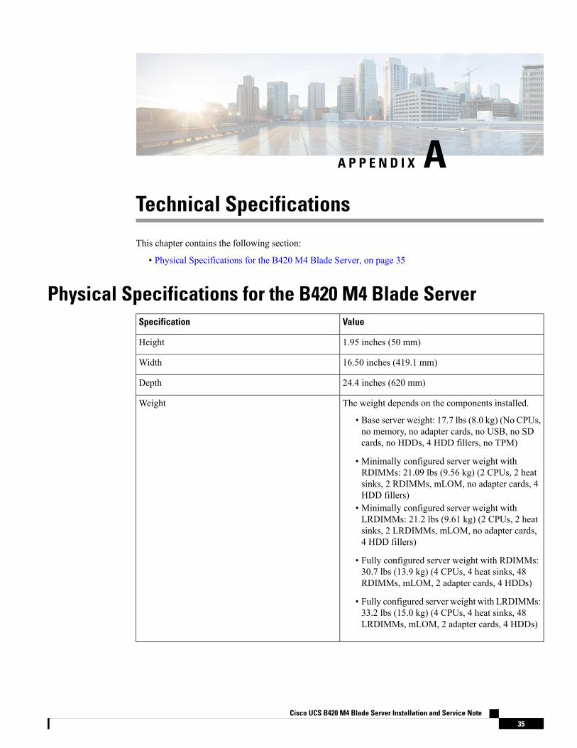
Physical Specifications for the B420 M4 Blade ServerValueSpecification
1.95 inches (50 mm)Height
16.50 inches (419.1 mm)Width
24.4 inches (620 mm)Depth
The weight depends on the components installed.
• Base server weight: 17.7 lbs (8.0 kg) (No CPUs,no memory, no adapter cards, no USB, no SDcards, no HDDs, 4 HDD fillers, no TPM)
• Minimally configured server weight withRDIMMs: 21.09 lbs (9.56 kg) (2 CPUs, 2 heatsinks, 2 RDIMMs, mLOM, no adapter cards, 4HDD fillers)
• Minimally configured server weight withLRDIMMs: 21.2 lbs (9.61 kg) (2 CPUs, 2 heatsinks, 2 LRDIMMs, mLOM, no adapter cards,4 HDD fillers)
• Fully configured server weight with RDIMMs:30.7 lbs (13.9 kg) (4 CPUs, 4 heat sinks, 48RDIMMs, mLOM, 2 adapter cards, 4 HDDs)
• Fully configured server weight with LRDIMMs:33.2 lbs (15.0 kg) (4 CPUs, 4 heat sinks, 48LRDIMMs, mLOM, 2 adapter cards, 4 HDDs)
Weight
Cisco UCS B420 M4 Blade Server Installation and Service Note35

Cisco UCS B420 M4 Blade Server Installation and Service Note36
Technical SpecificationsTechnical Specifications


![Zggh]hPH>new.groteck.ru/images/catalog/40429/9deec18637ee6ecbb5a6ae0a1… · UCS 6200 Series Fabric Interconnect UCS Manager UCS C240 M3/M4 Series Rack Server UCS Integrated Infrastructure](https://img.pdfslide.net/doc/110x75/5fcc7e22130a463bbb0b3c57/zgghhphnew-ucs-6200-series-fabric-interconnect-ucs-manager-ucs-c240-m3m4.jpg)