Embed Size (px)
Citation preview

CISCO SYSTEMS PUBLICATION HISTORY170 WEST TASMAN DR.SAN JOSE, CA, 95134 REV A.07 FEBRUARY 07, 2020 WWW.CISCO.COM
Spec Sheet
Cisco UCS C480 ML M5Purpose Built Server for Deep Learning

CONTENTS
OVERVIEW . . . . . . . . . . . . . . . . . . . . . . . . . . . . . . . . . . . . . . . . . . . . . . . 5DETAILED VIEWS . . . . . . . . . . . . . . . . . . . . . . . . . . . . . . . . . . . . . . . . . . . 6
Chassis Front View . . . . . . . . . . . . . . . . . . . . . . . . . . . . . . . . . . . . . . . . . . . . . . . . . . .6UCS C480 ML M5 Server Rear Panel Features . . . . . . . . . . . . . . . . . . . . . . . . . . . . . . . . . .8
BASE SERVER STANDARD CAPABILITIES and FEATURES . . . . . . . . . . . . . . . . . 9CONFIGURING the SERVER . . . . . . . . . . . . . . . . . . . . . . . . . . . . . . . . . . . 12
STEP 1 VERIFY BASE SKU . . . . . . . . . . . . . . . . . . . . . . . . . . . . . . . . . . . . . . . . . . . . . 13STEP 2 CHOOSE CPU(S) . . . . . . . . . . . . . . . . . . . . . . . . . . . . . . . . . . . . . . . . . . . . . 14STEP 3 CHOOSE MEMORY . . . . . . . . . . . . . . . . . . . . . . . . . . . . . . . . . . . . . . . . . . . . 16DIMM Memory Mirroring . . . . . . . . . . . . . . . . . . . . . . . . . . . . . . . . . . . . . . . . . . . . . . . 17
CPU Configuration Without Memory Mirroring . . . . . . . . . . . . . . . . . . . . . . . . . . . . 18CPU Configuration With Memory Mirroring . . . . . . . . . . . . . . . . . . . . . . . . . . . . . . 18
System Speeds . . . . . . . . . . . . . . . . . . . . . . . . . . . . . . . . . . . . . . . . . . . . . . . . . . . . 19Memory Configurations and Modes . . . . . . . . . . . . . . . . . . . . . . . . . . . . . . . . . . . . . . . 20
DIMM Guidelines . . . . . . . . . . . . . . . . . . . . . . . . . . . . . . . . . . . . . . . . . . . . . . . 20DCPMM Guidelines . . . . . . . . . . . . . . . . . . . . . . . . . . . . . . . . . . . . . . . . . . . . . . 21
STEP 4 CHOOSE DRIVE MODULES and DRIVES (OPTIONAL) . . . . . . . . . . . . . . . . . . . . . . . 23STEP 5 CHOOSE RAID CONFIGURATION . . . . . . . . . . . . . . . . . . . . . . . . . . . . . . . . . . . 27STEP 6 CHOOSE PCIe OPTION CARD(S) . . . . . . . . . . . . . . . . . . . . . . . . . . . . . . . . . . . 29STEP 7 ORDER OPTICAL DRIVE (OPTIONAL) . . . . . . . . . . . . . . . . . . . . . . . . . . . . . . . . 30STEP 8 ORDER SECURE DIGITAL CARDS M.2 DEVICES (OPTIONAL) . . . . . . . . . . . . . . . . . . 31STEP 9 ORDER INTERNAL MICRO-SD CARD MODULE (OPTIONAL) . . . . . . . . . . . . . . . . . . . 33STEP 10 ORDER POWER SUPPLIES . . . . . . . . . . . . . . . . . . . . . . . . . . . . . . . . . . . . . . . 34STEP 11 SELECT AC POWER CORD(s) . . . . . . . . . . . . . . . . . . . . . . . . . . . . . . . . . . . . . 35STEP 12 ORDER OPTIONAL CABLE MANAGEMENT ARM . . . . . . . . . . . . . . . . . . . . . . . . . . 37STEP 13 ORDER SECURITY DEVICES (OPTIONAL) . . . . . . . . . . . . . . . . . . . . . . . . . . . . . 38STEP 14 SELECT MANAGEMENT CONFIGURATION (OPTIONAL) . . . . . . . . . . . . . . . . . . . . 39STEP 15 SELECT SERVER BOOT MODE (OPTIONAL) . . . . . . . . . . . . . . . . . . . . . . . . . . . . 40STEP 16 CHOOSE OPERATING SYSTEM AND VALUE-ADDED SOFTWARE . . . . . . . . . . . . . 41STEP 17 SELECT SERVICE and SUPPORT LEVEL . . . . . . . . . . . . . . . . . . . . . . . . . . . . . . 44
OPTIONAL STEP - ORDER RACKS . . . . . . . . . . . . . . . . . . . . . . . . . . . . . . . 50OPTIONAL STEP - ORDER PDU . . . . . . . . . . . . . . . . . . . . . . . . . . . . . . . . . 51SUPPLEMENTAL MATERIAL . . . . . . . . . . . . . . . . . . . . . . . . . . . . . . . . . . . 52
CHASSIS . . . . . . . . . . . . . . . . . . . . . . . . . . . . . . . . . . . . . . . . . . . . . . . . . . . . . . . . . 52Serviceable Component Locations Inside the Main Chassis . . . . . . . . . . . . . . . . . . . . . . . . 53Serviceable Components Inside a CPU Module . . . . . . . . . . . . . . . . . . . . . . . . . . . . . . . . 55Serviceable Components Inside an I/O Module . . . . . . . . . . . . . . . . . . . . . . . . . . . . . . . . 56CPUs and DIMMs . . . . . . . . . . . . . . . . . . . . . . . . . . . . . . . . . . . . . . . . . . . . . . . . . . . . 57
Physical Layout . . . . . . . . . . . . . . . . . . . . . . . . . . . . . . . . . . . . . . . . . . . . . . . . 57Memory Population Rules . . . . . . . . . . . . . . . . . . . . . . . . . . . . . . . . . . . . . . . . . 58Memory Mirroring . . . . . . . . . . . . . . . . . . . . . . . . . . . . . . . . . . . . . . . . . . . . . . 59
Memory Support for CPU Classes and CPU Modes . . . . . . . . . . . . . . . . . . . . . . . . . . . . . . 60For 2nd Generation Intel® Xeon® Scalable Processors: . . . . . . . . . . . . . . . . . . . . . . 60For Intel® Xeon® Scalable Processors: . . . . . . . . . . . . . . . . . . . . . . . . . . . . . . . . . 61DIMM Population Order . . . . . . . . . . . . . . . . . . . . . . . . . . . . . . . . . . . . . . . . . . . 61
RACKS . . . . . . . . . . . . . . . . . . . . . . . . . . . . . . . . . . . . . . . . . . . . . . . . . . . . . . . . . . 62PDUs . . . . . . . . . . . . . . . . . . . . . . . . . . . . . . . . . . . . . . . . . . . . . . . . . . . . . . . . . . . 64KVM CABLE . . . . . . . . . . . . . . . . . . . . . . . . . . . . . . . . . . . . . . . . . . . . . . . . . . . . . . . 65
DISCONTINUED EOL PRODUCTS . . . . . . . . . . . . . . . . . . . . . . . . . . . . . . . . 66
Cisco UCS C480 ML Purpose Built Deep Learning Server2

CONTENTS
TECHNICAL SPECIFICATIONS . . . . . . . . . . . . . . . . . . . . . . . . . . . . . . . . . . 68Dimensions and Weight . . . . . . . . . . . . . . . . . . . . . . . . . . . . . . . . . . . . . . . . . . . . . . . 68Power Specifications . . . . . . . . . . . . . . . . . . . . . . . . . . . . . . . . . . . . . . . . . . . . . . . . 69Environmental Specifications . . . . . . . . . . . . . . . . . . . . . . . . . . . . . . . . . . . . . . . . . . . 70Compliance Requirements . . . . . . . . . . . . . . . . . . . . . . . . . . . . . . . . . . . . . . . . . . . . . 71
Cisco UCS C480 ML Purpose Built Deep Learning Server3

Cisco UCS C480 M5 High-Performance Rack-Mount Server4

OVERVIEW
OVERVIEWThe Cisco UCS C480 ML, a purpose-built Server for Deep Learning, is a four-rack-unit (4RU) server supporting Intel® Xeon® processor scalable family CPUs with 8 NVIDIA Tesla V100-32GB Tensor Core GPUs with NVLink Interconnect. It supports up to 3 terabytes (TB) of double-data-rate 4 (DDR4) memory1 in 24 slots, up to 24 small form factor (SFF) hot-swappable2 SAS/SATA SSD/HDD, up to 6 PCIe NVMe disk drives and upto two internal M.2 drives.
The latest update includes support for 2nd Generation Intel® Xeon® Scalable Processors, 2933-MHz DDR4 memory, and the new Intel® OptaneTM DC Persistent Memory Modules (DCPMMs). With this combination of features, up to 7.5 TB of memory is possible (using 12 x 128 GB DDR4 DIMMs and 12 x 512 GB DCPMMs).
4 PCI Express (PCIe) expansion slots support Cisco UCS C-Series and partner network adapters, with additional I/O provided by two 10Gbase-T LOM ports and one 1GbE dedicated out-of-band (OOB) management port. A separate PCIe slot is reserved inside the chassis for a RAID controller card
Figure 1 Cisco UCS C480 ML M5 Purpose Built Deep Learning Server
Front View
Rear View
NOTES:
Cisco UCS C480 ML Purpose Built Deep Learning Server 5

DETAILED VIEWS
1. A maximum of 3 TB memory is available using 128 GB DIMMs.
2. Hot-swap replacement means that you do not have to precondition or shut down the component in software before you remove it.
DETAILED VIEWS
Chassis Front View
Figure 2 is a detailed front view of the Cisco UCS C480 ML M5 Deep Learning Rack Server.
Figure 2 Chassis Front View
1 Power button/LED 8 Left bay module (drive bays 1 - 8)
■ All 8 bays supports SAS/SATA drives.
■ Bays 1, 2, 7, 8 also support NVMe drives.
3068
48
UCSC480 ML
M5
1
2
34
56
7
Driv
e B
ay 0
1
Driv
e B
ay 0
2
Driv
e B
ay 0
3
Driv
e B
ay 0
4
Driv
e B
ay 0
5
Driv
e B
ay 0
6
Driv
e B
ay 0
7
Driv
e B
ay 0
8
Driv
e B
ay 0
9
Driv
e B
ay 1
0
Driv
e B
ay 1
1
Driv
e B
ay 1
2
Driv
e B
ay 1
3
Driv
e B
ay 1
4
Driv
e B
ay 1
5
Driv
e B
ay 1
6
CPU Module 1
CPU Module Filler
Driv
e B
ay 1
7
Driv
e B
ay 1
8
Driv
e B
ay 1
9
Driv
e B
ay 2
0
Driv
e B
ay 2
1
Driv
e B
ay 2
2
Driv
e B
ay 2
3
Driv
e B
ay 2
4
14
13
12
11
8 9 10
Cisco UCS C480 ML Purpose Built Deep Learning Server6

DETAILED VIEWS
2 Identification button/LED 9 Center bay module (drive bays 9 - 16)
■ All 8 bays supports SAS/SATA drives.
■ Bay 9 also supports NVMe drives.
3 System status LED 10 Right bay module, supports either:
■ Optional DVD drive module
■ Drive bays 17 - 24 (shown)
• All 8 bays supports SAS/SATA drives.
• Bay 17 also supports NVMe drives.
4 Fan status LED 11 KVM console connector (used with a KVM cable that provides two USBs, one VGA, and one serial connector)1
5 Temperature status LED 12 Pull-out asset tag
6 Power supply status LED 13 CPU module bay 1
The system must have one CPU module in lower bay 1 to boot.
7 Network link activity LED 14 CPU module bay 2 (blank with filler module)
There must be a blank filler module in upper bay 2 or the system will not boot.
Notes:
1. For more details on the KVM connector, see KVM CABLE on page 64.
Cisco UCS C480 ML Purpose Built Deep Learning Server 7
DETAILED VIEWS
UCS C480 ML M5 Server Rear Panel Features
Figure 3 shows the features of the rear panel.
Figure 3 UCS C480 ML M5 Server Rear Panel
1 Serial port COM 1 (DB-9 connector) 7 Rear identification button/LED
2 VGA video port (DB-15 connector) 8 USB 3.0 ports (three)
3 Not used at this time 9 Power supplies 1-4 (hot-swappable, redundant as 3+1)
4 1-Gb/10-Gb Ethernet ports (LAN1 upper, LAN2 lower)
The dual LAN ports can support 1 Gbps and 10 Gbps, depending on the link-partner capability.
10 PCIe slots 11-14 for Network Adapter
5 10/100/1000 Ethernet dedicated management port (Base-T)
_ _
6 Not used at this time _ _
PC
Ie 1
1
PC
Ie 1
2
PC
Ie 1
3
PC
Ie 1
4
PSU 1 PSU 2 PSU 3 PSU 4
PC
Ie 1
1
PC
Ie 1
2
PC
Ie 1
3
PC
Ie 1
4
1
3 4 5 7 8
2
6 9
1010
3068
49
Cisco UCS C480 ML Purpose Built Deep Learning Server8

BASE SERVER STANDARD CAPABILITIES and FEATURES
BASE SERVER STANDARD CAPABILITIES and FEATURESTable 1 lists the capabilities and features of the base server. Details about how to configure the server for a particular feature or capability (for example, number of processors, disk drives, or amount of memory) are provided in CONFIGURING the SERVER on page 12.
Table 1 Capabilities and Features
Capability/Feature Description
Chassis Four rack unit (4RU) chassis
GPUs 8 NVIDIA Tesla V100-32GB Tensor Core GPUs with NVLink Interconnect
CPU Two Intel® Xeon® processor scalable family CPUs or 2nd Generation Intel® Xeon® scalable processor family CPUs.
Chipset Intel® C620 series chipset
Memory 24 DIMM slots and support for Intel®OptaneTM DC Persistent Memory Modules (DCPMMs)
Mullti-bit error protection
This server supports multi-bit error protection
Expansion slots There are 4 full-height full-length PCIe expansion slots:
■ Slot Marked 11: CPU1 controlled, Gen-3 x16, FL, FH, NCSI, VIC
■ Slot Marked 12: CPU1 controlled, Gen-3 x16, FL, FH, NCSI, VIC
■ Slot Marked 13: CPU2 controlled, Gen-3 x16, FL, FH, NCSI, VIC
■ Slot Marked 14: CPU2 controlled, Gen-3 x16, FL, FH, NCSI, VIC
NOTE: UCS C480 ML M5 ships with dual CPUs
Storage controller For front-loading drives:
■ UCSC-RAID-M5HD is an internally mounted Cisco 12G Modular RAID controller with a 4GB cache with a supercap cache backup (UCSC-SCAP-M5). It is used for controlling the SAS/SATA drives in the front drive bays. It cannot control NVMe drives in the front drive bays.
■ NVMe drives in the front drive bays are controlled directly from the PCIe interfaces on the CPUs.
RAID backup The system supports supercap power modules (SCPMs):
■ Front-loading drive bay controller (UCSC-RAID-M5H)—the SCPM mounting bracket is on the chassis wall near the front RAID controller socket.
DVD drive option Front-loading drive bay 3 can optionally be replaced with a DVD drive module.
Cisco UCS C480 ML Purpose Built Deep Learning Server 9

BASE SERVER STANDARD CAPABILITIES and FEATURES
Internal storage devices The server can hold up to 24 2.5-inch drives:
■ Front drive bays are divided across three removable drive bay modules. Each drive bay module has 8 drive bays for a total of 24 front-loading drive bays.
• All 24 front drive bays support SAS/SATA drives.
• Each of the three drive bay modules has slots that support NVMe SSDs as well as SAS/SATA drives, for a total of 6 bays that support NVMe SSDs.
• Drive Bay 1 can have upto 4 NVMe drives while Drive Bay 2 and Drive Bay3 can have 1 NVMe drive each at designated slots.
SAS and SATA drives are hot-swappable1; NVMe drives are hot-pluggable2
Internal removable media
■ A mini-storage module connector on the motherboard supports either:
• An M.2 module with two SATA M.2 SSD slots. Mixing different capacity modules is not supported.
• An SD card module with two SD card slots. Mixing different capacity SD cards is not Supported
■ One USB 2.0 port on the chassis motherboard.
ACPI This server supports the advanced configuration and power interface (ACPI) 4.0 standard.
Video ■ Resolution up to 1600 x1200, 16 bpp at 60 Hz. Up to 256 MB of video memory.
Interfaces ■ Rear panel
• One 10/100/1000 dedicated management Ethernet port
• Two 10 Base-T Gbps Ethernet ports
• One RS-232 serial port (DB-9 connector)
• One VGA video port (DB-15 connector)
• Three USB 3.0 connectors
■ Front panel
• One KVM connector (used with the included KVM cable, which provides two USB, one VGA, and one serial connector)
Power subsystem ■ Power supplies are hot-swappable and rear-accessible. Default to redundant 3+1
■ 1600 W AC power supply
For more information about your server’s power consumption, use the power calculator accessible at
http://ucspowercalc.cisco.com
Table 1 Capabilities and Features (continued)
Capability/Feature Description
Cisco UCS C480 ML Purpose Built Deep Learning Server10

BASE SERVER STANDARD CAPABILITIES and FEATURES
Fans Chassis:
■ 4 fans modules with 2 fans each, hot-swappable
Power supply:
■ Each power supply is equipped with a fan.
Baseboard management Cisco Integrated Management Controller (Cisco IMC) firmware.
Depending on your settings, the Cisco IMC can be accessed through the 10/100/1000 dedicated management ports, the 10 GBase-T LOM ports, or a Cisco virtual interface card.
Integrated management processor
The built-in Cisco Integrated Management Controller (CIMC) GUI or CLI interface enables you to monitor the server inventory, health, and system event logs.
Notes:
1. Hot-swappable = No preconditioning of the component is required before removal while the server is powered on.
2. Hot-pluggable = The component must be shut down in the operating system before removal while the server is powered on.
Table 1 Capabilities and Features (continued)
Capability/Feature Description
Cisco UCS C480 ML Purpose Built Deep Learning Server 11

CONFIGURING the SERVER
CONFIGURING the SERVERFollow these steps to configure the Cisco UCS C480 ML M5 Purpose Built Deep Learning Server
■ STEP 1 VERIFY BASE SKU, page 13
■ STEP 2 CHOOSE CPU(S), page 14
■ STEP 3 CHOOSE MEMORY, page 16
■ STEP 4 CHOOSE DRIVE MODULES and DRIVES (OPTIONAL), page 23
■ STEP 5 CHOOSE RAID CONFIGURATION, page 26
■ STEP 6 CHOOSE PCIe OPTION CARD(S), page 28
■ STEP 7 ORDER OPTICAL DRIVE (OPTIONAL), page 29
■ STEP 8 ORDER SECURE DIGITAL CARDS M.2 DEVICES (OPTIONAL), page 30
■ STEP 9 ORDER INTERNAL MICRO-SD CARD MODULE (OPTIONAL), page 32
■ STEP 10 ORDER POWER SUPPLIES, page 33
■ STEP 11 SELECT AC POWER CORD(s), page 34
■ STEP 12 ORDER OPTIONAL CABLE MANAGEMENT ARM, page 36
■ STEP 13 ORDER SECURITY DEVICES (OPTIONAL), page 37
■ STEP 14 SELECT MANAGEMENT CONFIGURATION (OPTIONAL), page 38
■ STEP 15 SELECT SERVER BOOT MODE (OPTIONAL), page 39
■ STEP 16 CHOOSE OPERATING SYSTEM AND VALUE-ADDED SOFTWARE, page 40
■ OPTIONAL STEP - ORDER RACKS on page 49
■ OPTIONAL STEP - ORDER PDU on page 50
Cisco UCS C480 ML Purpose Built Deep Learning Server12

CONFIGURING the SERVER
STEP 1 VERIFY BASE SKU
Verify the product ID (PID) of the base server as shown in Table 2.
Table 2 PID of the Base C480 ML M5 Rack Server
Product ID (PID) Description
UCSC-C480-M5ML8 Chassis w/8GPU, NoPSU, NoRAID/cable, NoHDDmod, NoCPUmod
The base server:
■ Includes:
— 8 NVIDIA Tesla V100-32GB Tensor Core GPUs with NVLink Interconnect
— Blanking panels for empty drive locations (to maintain cooling air flow)
— Rail kit
■ Does not include:
— CPUs
— DIMMs
— Intel®OptaneTM DC Persistent Memory (DCPMMs)
— Power supplies
— Hard disk drives (HDDs)
— Solid-state Drives (SSDs)
— Plug-in PCIe cards
NOTE: Use the steps on the following pages to configure the server with the components that you want to include.
Cisco UCS C480 ML Purpose Built Deep Learning Server 13

CONFIGURING the SERVER
STEP 2 CHOOSE CPU(S)
The standard CPU features are:
■ Intel® Xeon® processor Scalable Family CPUs and 2nd Generation Intel® Xeon® scalable processor family CPUs.
■ Intel C620 series chipset
■ Up to 28 cores per processor, for a total of up to 56 cores per server
Product ID (PID) Description
UCSC-C480-CM UCS C480 ML M5 CPU Module w/o CPU, mem
Select One CPU Module and Two CPUs
The available CPUs are listed in Table 3.
Table 3 Available Intel CPUs
Product ID (PID)Clock Freq(GHz)
Power (W)
Cache Size (MB)
Cores UPI1Links (GT/s)
Highest DDR4 DIMM Clock Support (MHz)2
Processor Type
Cisco Recommended Processors3 (2nd Generation Intel® Xeon® Processors)
UCS-CPU-I6248 2.5 150 27.50 20 3 x 10.4 2993 VDI, Oracle, SQL,
UCS-CPU-I5218 2.3 125 22.00 16 3 x 10.4 2666 Virtualization, Microsoft Azure Stack, Splunk, Data Protection
UCS-CPU-I6230 2.1 125 27.50 20 3 x 10.4 2933 Big Data, Virtualization
UCS-CPU-I5220 2.2 125 24.75 18 3 x 10.4 2666 HCI
8000 Series Processor
UCS-CPU-I8280M 2.7 205 38.50 28 3 x 10.4 2933 2nd Gen Intel® Xeon®
UCS-CPU-I8280 2.7 205 38.50 28 3 x 10.4 2933 2nd Gen Intel® Xeon®
UCS-CPU-I8260M 2.4 165 35.75 24 3 x 10.4 2933 2nd Gen Intel® Xeon®
UCS-CPU-8180M 2.5 205 38.50 28 3 x 10.4 2666 Intel® Xeon®
UCS-CPU-8180 2.5 205 38.50 28 3 x 10.4 2666 Intel® Xeon®
UCS-CPU-8160 2.1 150 33.00 24 3 x 10.4 2666 Intel® Xeon®
6000 Series Processor
UCS-CPU-I6254 3.1 200 24.75 18 3 x 10.4 2933 2nd Gen Intel® Xeon®
UCS-CPU-I6248 2.5 150 27.50 20 3 x 10.4 2993 2nd Gen Intel® Xeon®4
UCS-CPU-I6244 3.6 150 24.75 8 3 x 10.4 2933 2nd Gen Intel® Xeon®
UCS-CPU-I6242 2.8 150 22.00 16 3 x 10.4 2933 2nd Gen Intel® Xeon®
UCS-CPU-I6230 2.1 125 27.50 20 3 x 10.4 2933 2nd Gen Intel® Xeon®
Cisco UCS C480 ML Purpose Built Deep Learning Server14

CONFIGURING the SERVER
Approved Configurations
(1) Two-CPU Configuration Only
■ Must choose two identical CPUs from any one of the rows of Table 3 on page 14
■ CPUs 1 and 2 should always will be populated.
UCS-CPU-6154 3.0 200 24.75 18 3 x 10.4 2666 Intel® Xeon®
UCS-CPU-6152 2.1 140 30.25 22 3 x 10.4 2666 Intel® Xeon®
UCS-CPU-6148 2.4 150 27.50 20 3 x 10.4 2666 Intel® Xeon®
UCS-CPU-6144 3.5 150 24.75 8 3 x 10.4 2666 Intel® Xeon®
UCS-CPU-6142M 2.6 150 22.00 16 3 x 10.4 2666 Intel® Xeon®
UCS-CPU-6142 2.6 150 22.00 16 3 x 10.4 2666 Intel® Xeon®
UCS-CPU-6140 2.3 140 24.75 18 3 x 10.4 2666 Intel® Xeon®
UCS-CPU-6138 2.0 125 27.50 20 3 x 10.4 2666 Intel® Xeon®
UCS-CPU-6136 3.0 150 24.75 12 3 x 10.4 2666 Intel® Xeon®
5000 Series Processor
UCS-CPU-I5220 2.2 125 24.75 18 3 x 10.4 2666 2nd Gen Intel® Xeon®
UCS-CPU-I5218 2.3 125 22.00 16 3 x 10.4 2666 2nd Gen Intel® Xeon®
UCS-CPU-5122 3.6 105 16.50 4 2 x 10.4 2666 Intel® Xeon®
4000 Series Processor
UCS-CPU-4116 2.1 85 16.50 12 2 x 9.6 2400 Intel® Xeon®
Notes:
1. UPI = Ultra Path Interconnect2. If higher or lower speed DIMMs are selected than what is shown in the table for a given CPU, the DIMMs will be
clocked at the lowest common denominator of CPU clock and DIMM clock.3. For details on memory support for processor classes and CPU modes, see Memory Support for CPU Classes and CPU
Modes on page 59.4. For 2nd Generation Intel® Xeon® Scalable Processor, UCSM 4.0(4b) software release is required.
Table 3 Available Intel CPUs
Product ID (PID)Clock Freq(GHz)
Power (W)
Cache Size (MB)
Cores UPI1Links (GT/s)
Highest DDR4 DIMM Clock Support (MHz)2
Processor Type
Cisco UCS C480 ML Purpose Built Deep Learning Server 15

CONFIGURING the SERVER
STEP 3 CHOOSE MEMORY
The standard memory features are:
■ Clock speed: 2666 MHz or 2933 MHz depending on CPU type
■ Ranks per DIMM: 1, 2, 4, or 8
■ Operational voltage: 1.2 V
■ Registered ECC DDR4 DIMMS (RDIMMs), Load-reduced DIMMs (LRDIMMs) or Intel® OptaneTM DC Persistent Memory Modules (DCPMMs).
■ New purchases with 2nd Generation Intel Scalable CPUs need to be configured with 2933-MHz DIMMs.
Memory is organized with six memory channels per CPU, with up to two DIMMs per channel, as shown in Figure 4.
Figure 4 C480 M5 Memory Organization
CPU 1/3 CPU 2/4
24 DIMMS 6 memory channels per CPU 2 DIMMs per channel
Channel A
Channel B
Channel C
Channel D
Channel E
Channel F
Channel G
Channel H
Channel J
Channel K
Channel L
Channel M
A1A2
B2
C2
D2
G2
H2
J2
K2
B1
C1
D1
E2 E1
F2 F1
Bank
1Ba
nk 2
G1
H1
J1
K1
L2L1
M2M1
Bank
1Ba
nk 2
Cisco UCS C480 ML Purpose Built Deep Learning Server16

CONFIGURING the SERVER
Select DIMMs and Memory Mirroring
Select the memory configuration and whether or not you want the memory mirroring option. The supported memory DIMMs and the mirroring option are listed in Table 4
Table 4 Available DDR4 DIMMs
Product ID (PID) PID Description VoltageRanks/DIMM
2666-MHz
UCS-MR-128G8RS-H 128 GB DDR4-2666-MHz TSV-RDIMM/8R/x4 1.2 V 8
UCS-MR-X64G4RS-H 64 GB DDR4-2666-MHz TSV-RDIMM/4R/x4 1.2 V 4
UCS-ML-X64G4RS-H 64 GB DDR4-2666-MHz LRDIMM/4R/x4 1.2 V 4
UCS-MR-X32G2RS-H 32 GB DDR4-2666-MHz RDIMM/2R/x4 1.2 V 2
UCS-ML-X32G2RS-H 32 GB DDR4-2666-MHz LDIMM/2R/x4 1.2 V 2
UCS-MR-X16G1RS-H 16 GB DDR4-2666-MHz RDIMM/1R/x4 1.2 V 1
2933-MHz
UCS-ML-128G4RT-H 128 GB DDR4-2933-MHz LRDIMM/4Rx4 (16Gb) 1.2v 1.2 V 4
UCS-ML-X64G4RT-H 64 GB DDR4-2933-MHz LRDIMM/4Rx4 (8Gb) 1.2v 1.2 V 4
UCS-MR-X64G2RT-H 64 GB DDR4-2933-MHz RDIMM/2Rx4 (16Gb) 1.2v 1.2 V 2
UCS-MR-X32G2RT-H 32GB DDR4-2933-MHz RDIMM/2Rx4 (8Gb) 1.2v 1.2 V 2
Intel® OptaneTM DC Persistent Memory Product
UCS-MP-128GS-A0 Intel® OptaneTM DC Persistent Memory, 128GB, 2666MHz
UCS-MP-256GS-A0 Intel® OptaneTM DC Persistent Memory, 256GB, 2666MHz
Intel® OptaneTM DC Persistent Memory Product Operational Modes
UCS-DCPMM-AD App Direct Mode
UCS-DCPMM-MM Memory Mode
Memory Mirroring Option
N01-MMIRROR Memory mirroring option
.
DIMM Memory Mirroring
When memory mirroring is enabled, the memory subsystem simultaneously writes identical data to two adjacent channels. If a memory read from one of the channels returns incorrect data due to an uncorrectable memory error, the system automatically retrieves the data from the other channel. A transient or soft error in one channel does not affect the mirrored data, and operation continues unless there is a simultaneous error in exactly the same location on a DIMM and its mirrored DIMM. Memory mirroring reduces the amount of memory available to the operating system by 50% because only one of the two populated channels provides data.
Cisco UCS C480 ML Purpose Built Deep Learning Server 17

CONFIGURING the SERVER
CPU Configuration Without Memory Mirroring
Select from 4, 6, 8, or 12 DIMMs per CPU (DIMMs for all four CPUs must be configured identically). The DIMMs will be placed in each CPU module by the factory as shown in the following tables.
#DIMMs CPU 1/3 DIMM Placement in Channels (for identically ranked DIMMs)
4 (A1, B1); (D1, E1)
6 (A1, B1, C1); (D1, E1, F1)
8 (A1, A2, B1, B2); (D1, D2, E1, E2)
12 (A1, A2, B1, B2, C1, C2); (D1, D2, E1, E2, F1, F2)
#DIMMs CPU 2/4 DIMM Placement in Channels (for identically ranked DIMMs)
4 (G1, H1); (K1, L1)
6 (G1, H1, J1); (K1, L1, M1)
8 (G1, G2, H1, H2); (K1, K2, L1, L2)
12 (G1, G2, H1, H2, J1, J2); (K1, K2, L1, L2, M1, M2)
CPU Configuration With Memory Mirroring
Select from 4, 6, 8, or 12 DIMMs per CPU (DIMMs for all four CPUs must be configured identically). In addition, the memory mirroring option (N01-MMIRROR) as shown in Table 4 on page 17 must be selected.
The DIMMs will be placed by the factory as shown in the following tables.
#DIMMs
CPU 1/3 DIMM Placement in Channels (for identical ranked DIMMs)
CPU 2/4 DIMM Placement in Channels (for identical ranked DIMMs)
CPU 1 CPU 2
8 (A1,B1); (D1,E1) (G1, H1); (K1, L1)
12 (A1, B1, C1); (D1, E1, F1) (G1, H1, J1); (K1, L1, M1)
16 (A1, A2, B1, B2); (D1, D2, E1, E2) (G1, G2, H1, H2); (K1, K2, L1, L2)
24 (A1, A2, B1, B2, C1, C2); (D1, D2, E1, E2, F1, F2)
(G1, G2, H1, H2, J1, J2); (K1, K2, L1, L2, M1, M2)
NOTE: System performance is optimized when the DIMM type and quantity are equal for both CPUs, and when all channels are filled equally across the CPUs in the server.
Cisco UCS C480 ML Purpose Built Deep Learning Server18
CONFIGURING the SERVER
System Speeds
System speed is dependent on how many DIMMs are populated per channel and the CPU DIMM speed support. See Table 5 for details.
Table 5 2666-MHz DIMM Memory Speeds with Different Intel® Xeon® Scalable Processors
DIMM and CPU Frequencies (MHz)
DPC
TSV-RDIMM (8Rx4) - 128 GB (MHz)
TSV-RDIMM (4Rx4) - 64 GB (MHz)
LRDIMM (4Rx4) - 64 GB (MHz)
RDIMM (2Rx4) - 32 GB (MHz)
LRDIMM (2Rx4) - 32 GB (MHz)
1.2 V 1.2 V 1.2 V 1.2 V 1.2 V
DIMM = 2666CPU = 2666
1DPC 2666 2666 2666 2666 2666
2DPC 2666 2666 2666 2666 2666
DIMM = 2666CPU = 2400
1DPC 2400 2400 2400 2400 2400
2DPC 2400 2400 2400 2400 2400
DIMM = 2666CPU = 2133
1DPC 2133 2133 2133 2133 2133
2DPC 2133 2133 2133 2133 2133
Table 6 2933-MHz DIMM Memory Speeds with Different 2nd Generation Intel®Xeon® Scalable Processors
DIMM and CPU Frequencies (MHz)
DPCLRDIMM (4Rx4)-128 GB (MHz)
LRDIMM (4Rx4) - 64 GB (MHz)
RDIMM(2Rx4) - 64 GB (MHz)
RDIMM (2Rx4) - 32 GB (MHz)
1.2 V 1.2 V 1.2 V 1.2 V
DIMM = 2933CPU = 2933
1DPC 2933 2933 2933 2933
2DPC 2933 2933 2933 2933
DIMM = 2933CPU = 2666
1DPC 2666 2666 2666 2666
2DPC 2666 2666 2666 2666
DIMM = 2933CPU = 2400
1DPC 2400 2400 2400 2400
2DPC 2400 2400 2400 2400
DIMM = 2933CPU = 2133
1DPC 2133 2133 2133 2133
2DPC 2133 2133 2133 2133
Cisco UCS C480 ML Purpose Built Deep Learning Server 19
CONFIGURING the SERVER
Memory Configurations and Modes
DIMM Guidelines
■ System speed is dependent on the CPU DIMM speed support. Refer to Table 4 on page 17 for DIMM Speeds
■ The C480 M5 server supports four different memory reliability, availability, and serviceability (RAS) modes:
— Independent Channel Mode
— Mirrored Channel Mode
— Lockstep Channel Mode
— Rank Sparing Mode
NOTE: Mixing of Non-Mirrored and Mirrored mode is not allowed.
■ Do not mix RDIMMs, LRDIMMs, and TSV-RDIMMs.
■ Single-rank DIMMs can be mixed with dual-rank DIMMs in the same channel
■ For best performance, observe the following:
— DIMMs with different timing parameters can be installed on different slots within the same channel, but only timings that support the slowest DIMM will be applied to all. As a consequence, faster DIMMs will be operated at timings supported by the slowest DIMM populated.
— When one DIMM is used, it must be populated in DIMM slot 1 (farthest away from the CPU) of a given channel.
— When single or dual rank DIMMs are populated for 2DPC, always populate the higher number rank DIMM first (starting from the farthest slot). For a 2DPC example, first populate with dual rank DIMMs in the DIMM slot 1. Then single-rank DIMMs in the DIMM 2 slot.
■ DIMMs for all four CPUs must always be configured identically.
■ Cisco memory from previous generation servers (DDR3 and DDR4) is not compatible with UCS C480 M5 server.
NOTE: System performance is optimized when the DIMM type and quantity are equal for both CPUs, and when all channels are filled equally across the CPUs in the server.
■ Memory can be configured in any number of DIMMs as pairs, though for optimal performance, refer to the C480 Memory Guide at Cisco.com.
Cisco UCS C480 ML Purpose Built Deep Learning Server20

CONFIGURING the SERVER
DCPMM Guidelines
■ DCPMMs require second generation Intel Xeon Scalable Family processors. First generation Xeon Scalable processors do not support DCPMMs.
■ All installed DCPMMs must be the same size. Mixing DCPMMs of different capacities is not supported.
■ The use of 1Rx8 DIMMs with DCPMMs is not supported.
■ DCPMMs and DIMMs must be populated as shown in Table 7 (6 DIMMs per CPU with 2, 4, or 6 DCPMMs per CPU, as shown).
■ Two CPUs must be installed in each CPU module when using DCPMMs.
■ For Memory Mode, install a minimum 2 DCPMMs and 6 DIMMs per CPU
■ For App Direct Mode, install a minimum of 2 DCPMMs and 6 DIMMs per CPU
■ When either Memory Mode or Mixed Mode is used, the ratio of DIMM capacity to DCPMM capacity per CPU must be between 1:16 and 1:4, and the recommended ratio is 1:4 for the best performance. For example, 6x 16GB DIMMs + 2x 256GB DCPMMs is a ratio of 1:5.33 (96GB:512GB). In Mixed Mode, the ratio is between memory and only the volatile portion of the DCPMMs. This ratio requirement does not apply to App Direct mode. See Table 8 for DCCPM memory modes.
Table 7 2nd Generation Intel® Xeon® Scalable Processor DIMM and DCPMM1 Physical Configurations (quad socket)
Notes:
1. All systems must be fully populated with four CPUs when using DCPMMs at this time.
DIMM to DCPMM Count
CPU 1/3
iMC1 iMC0
Channel 2 Channel 1 Channel 0 Channel 2 Channel 1 Channel 0
F2 F1 E2 E1 D2 D1 C2 C1 B2 B1 A2 A1
6 to 2 DIMM DIMM DCPMM DIMM DIMM DIMM DCPMM DIMM
6 to 4 DIMM DCPMM DIMM DCPMM DIMM DIMM DCPMM DIMM DCPMM DIMM
6 to 6 DCPMM DIMM DCPMM DIMM DCPMM DIMM DCPMM DIMM DCPMM DIMM DCPMM DIMM
DIMM to DCPMM Count
CPU 2/4
iMC1 iMC0
Channel 2 Channel 1 Channel 0 Channel 2 Channel 1 Channel 0
M2 M1 L2 L1 K2 K1 J2 J1 H2 H1 G2 G1
6 to 2 DIMM DIMM DCPMM DIMM DIMM DIMM DCPMM DIMM
6 to 4 DIMM DCPMM DIMM DCPMM DIMM DIMM DCPMM DIMM DCPMM DIMM
6 to 6 DCPMM DIMM DCPMM DIMM DCPMM DIMM DCPMM DIMM DCPMM DIMM DCPMM DIMM
Cisco UCS C480 ML Purpose Built Deep Learning Server 21

CONFIGURING the SERVER
Table 8
Intel® OptaneTM DC Persistent Memory Modes
App Direct Mode: DCPMM operates as a solid-state disk storage device. Data is saved and is non-volatile. Both DCPMM and DIMM capacity counts towards CPU tiering (both DCPMM and DIMM capacities count towards the CPU capacity limit)
Memory Mode:1 DCPMM operates as a 100% memory module. Data is volatile and DRAM acts as a cache for DCPMMs. Only DCPMM capacity counts towards CPU tiering (only the DCPMM capacity counts towards the CPU capacity limit). This is the factory default mode.
Mix Mode: DRAM as cache. Only DCPMM capacity counts towards CPU tiering (only the DCPMM capacity counts towards the CPU capacity limit).
Intel® OptaneTM DC Persistent Memory Modes
■ For each memory channel with both a DCPMM and a DIMM installed, the DCPMM is installed in channel slot 2 (closest) and the DIMM is installed in channel slot 1.
■ To maximize performance, balance all memory channels
■ In configurations with DCPMMs installed, memory mirroring is supported, with two restrictions:
■ Mirroring is only enabled on the DIMMs installed in the server; The DCPMMs themselves do not support mirroring.
■ Only App Direct mode is supported. Memory mirroring cannot be enabled when DCPMMs are in Memory Mode or Mixed Mode.
■ Memory sparing is not supported with DCPMMs installed
For detailed Intel DCPMM configurations, refer to the following link:
Cisco UCS C480 M5 ML Server Installation and Service Guide
Notes:
1. For Memory Mode, the Intel-recommended DIMM to DCPMM capacity ratio in the same CPU socket is from 1:4 to 1:16.
Cisco UCS C480 ML Purpose Built Deep Learning Server22

CONFIGURING the SERVER
STEP 4
Table 9 Intel® OptaneTM DC Persistent Memory Modes
Intel® OptaneTM DC Persistent Memory Modes
App Direct Mode: DCPMM operates as a solid-state disk storage device. Data is saved and is non-volatile. Both DCPMM and DIMM capacity counts towards CPU tiering (both DCPMM and DIMM capacities count towards the CPU capacity limit)
Memory Mode:1 DCPMM operates as a 100% memory module. Data is volatile and DRAM acts as a cache for DCPMMs. Only DCPMM capacity counts towards CPU tiering (only the DCPMM capacity counts towards the CPU capacity limit). This is the factory default mode.
Mix Mode: DRAM as cache. Only DCPMM capacity counts towards CPU tiering (only the DCPMM capacity counts towards the CPU capacity limit).
CHOOSE DRIVE MODULES and DRIVES (OPTIONAL)
Choose Drive Modules
You can choose the following drive modules:
■ Up to three Drive Modules. This is a front-mounting drive cage that accommodates 8 drives as follows:
— Up to 8 SAS/SATA HDDs or SSDs per module
— Up to four NVMe drives for left module and one NVMe drive each for rest of the other two modules.
■ Up to three drive modules for 6 x NVMe. This is a front-mounting drive cage accommodating up to 6 NVMe
The available drive cages are listed in Table 10
Table 10 Available Drive Modules
Product ID (PID) PID Description
Drive Modules
UCSC-C480-8HDD UCS C480 M5 Drive Module for 8x HDD (standard cage front facing)
.
Approved Configurations
■ The NVMe drives in the left most Module are restricted to the first two and last two slots only
■ The NVMe drives in the middle and right most Modules are restricted to the first slot only.
Notes:
1. For Memory Mode, the Intel-recommended DIMM to DCPMM capacity ratio in the same CPU socket is from 1:4 to 1:16. So if you use a 128 GB DIMM in a channel, you could use a 512 GB DCPMM for a 1:4 capacity ratio. if you use a 32 GB DIMM in a channel, you could use a 512 GB DCPMM for a 1:16 capacity ration. There are several other combinations possible.
Cisco UCS C480 ML Purpose Built Deep Learning Server 23

CONFIGURING the SERVER
Choose HDDS and SSDs
The standard hard disk drive (HDD) and solid-state drive (SSD) features are:
■ 2.5-inch small form factor
■ Hot-swappable
■ Sled-mounted
The available drives are listed in Table 11.
Table 11 Supported HDDs and NVMe SSDs
Product ID (PID) PID DescriptionDrive Type
Capacity
HDDs
HDDs(15K RPM)
UCS-HD900G15K12N 900 GB 12G SAS 15K RPM SFF HDD SAS 900 GB
HDDs(10K RPM)
UCS-HD12TB10K12N 1.2 TB 12G SAS 10K RPM SFF HDD SAS 1.2 TB
UCS-HD18TB10K4KN 1.8 TB 12G SAS 10K RPM SFF HDD (4K) SAS 1.8 TB
HDDs(7K RPM)
UCS-HD2T7K12N 2.0 TB 12G SAS 7.2K RPM SFF HDD SAS 2.0 TB
SAS/SATA SSDs
Enterprise Performance SSDs (High endurance, supports up to 10X or 3X DWPD (drive writes per day))
SAS SSDs
UCS-SD16T123X-EP 1.6 TB 2.5 inch Enterprise performance 12G SAS SSD(3X endurance)
SAS 1.6 TB
UCS-SD32T123X-EP 3.2 TB 2.5 inch Enterprise performance 12G SAS SSD(3X endurance)
SAS 3.2 TB
Enterprise Value SSDs (Supports up to 1X DWPD (drive writes per day))
SATA SSDs
UCS-SD120GM1X-EV 120 GB 2.5 inch Enterprise Value 6G SATA SSD (Micron 5100 ECO) SATA 120 GB
UCS-SD240GM1X-EV 240 GB 2.5 inch Enterprise Value 6G SATA SSD (Micron 5100 ECO) SATA 240 GB
UCS-SD480GM1X-EV 480 GB 2.5 inch Enterprise Value 6G SATA SSD (Micron 5100 ECO) SATA 480 GB
UCS-SD960GM1X-EV 960 GB 2.5 inch Enterprise Value 6G SATA SSD (Micron 5100 ECO) SATA 960 GB
UCS-SD16TM1X-EV 1.6 TB 2.5 inch Enterprise Value 6G SATA SSD (Micron 5100 ECO) SATA 1.6 TB
UCS-SD19TM1X-EV 1.9 TB 2.5 inch Enterprise Value 6G SATA SSD (Micron 5100 ECO) SATA 1.9 TB
UCS-SD38TM1X-EV 3.8 TB 2.5 inch Enterprise Value 6G SATA SSD (Micron 5100 ECO) SATA 3.8 TB
UCS-SD76TM1X-EV 7.6 TB 2.5 inch Enterprise Value 6G SATA SSD (Micron 5100 ECO) SATA 7.6 TB
PCIe/NVMe
UCSC-NVMEHW-H3200 3.2 TB 2.5in U.2 HGST SN200 NVMe High Perf. High Endurance NVMe 3.2 TB
Cisco UCS C480 ML Purpose Built Deep Learning Server24

CONFIGURING the SERVER
Approved Configurations
Many configurations are possible. Some will be shown here.
(1) Three Drive Modules for 8x HDD
■ Option 1: Fill all three drive modules with all SAS/SATA HDDs or SSDs for a total of 24 drives
■ Option 2: Fill first drive module (left most) with 4 NVMe and 2 SAS/SATA HDDs or SSDs and the other two with 8 SAS/SATA HDDs/SSDs. You will then have 20 SAS/SATA drives and 4 NVMe drives.
■ Option 3: Fill first drive module (left most) with 4 NVMe and 2 SAS/SATA HDDs or SSDs and the other two with 7 SAS/SATA HDDs/SSDs and 1 NVMe drive. You will then have 18 SAS/SATA drives and 6 NVMe drives.
Caveats
— You can mix SAS/SATA drives. You can also mix HDD and SSD drives, as long as all the HDDs are in the same RAID volume and all the SSDs are in the same RAID volume.
— SSDs and HDDs should not be mixed in the same RAID volume.
— You can mix SAS/SATA and NVMe drives in the front facing HDD drive module.
UCSC-NVMEHW-H1600 1.6 TB 2.5in U.2 HGST SN200 NVMe High Perf. High Endurance NVMe 1.6 TB
UCSC-NVMEHW-H6400 6.4 TB 2.5in U.2 HGST SN200 NVMe High Perf. High Endurance NVMe 6.4 TB
UCSC-NVMEHW-H7680 7.7 TB 2.5in U.2 HGST SN200 NVMe High Perf. Value Endurance NVMe 7.7 TB
UCSC-NVMEHW-H800 800 GB 2.5in U.2 HGST SN200 NVMe High Perf. High Endurance NVMe 800 GB
UCSC-NVMEHW-I1600 1.6 TB 2.5in U.2 Intel P4600 NVMe High Perf. High Endurance NVMe 1.6 TB
UCSC-NVMEHW-I2000 2 TB 2.5in U.2 Intel P4600 NVMe High Perf. High Endurance NVMe 2 TB
UCSC-NVMEHW-I2TBV 2 TB 2.5in U.2 Intel P4500 NVMe High Perf. Value Endurance NVMe 2 TB
UCSC-NVMEHW-I3200 3.2 TB 2.5in U.2 Intel P4600 NVMe High Perf. High Endurance NVMe 3.2 TB
UCSC-NVMEHW-I8000 Cisco 2.5" U.2 8TB Intel P4510 NVMe High Perf. Value Endurance NVMe 8 TB
UCSC-NVMEXPB-I375* 375GB 2.5in Intel Optane NVMe Extreme Performance SSD NVMe 375 GB
UCSC-NVMEXP-I750* 750GB 2.5in Intel Optane NVMe Extreme Performance NVMe 750 GB
NOTE:
■ Intel and HGST NVMe drives may NOT be mixed anywhere in a C480 ML M5.(*UCSC-NVMEXP-I750 and UCSC-NVMEXPB-I375 can be mixed for HGST)
■ Cisco uses solid state drives (SSDs) from a number of vendors. All solid state drives are subject to physical write limits and have varying maximum usage limitation specifications set by the manufacturer. Cisco will not replace any solid state drives that have exceeded any maximum usage specifications set by Cisco or the manufacturer, as determined solely by Cisco.
Table 11 Supported HDDs and NVMe SSDs (continued)
Product ID (PID) PID DescriptionDrive Type
Capacity
Cisco UCS C480 ML Purpose Built Deep Learning Server 25

CONFIGURING the SERVER
STEP 5 CHOOSE RAID CONFIGURATION
The C480 ML M5 server accommodates any one of the following RAID controllers for internal drives:
■ Cisco 12G Modular RAID controller with 4GB cache
The C480 ML M5 chassis contains three front drive modules, each housing up to 8 HDD/SSD drives
Cisco can provide factory-configured RAID 0, 1, 5, 6, and 10 systems depending on the RAID implementation chosen, the RAID controller chosen, and the number of drives ordered. Factory-configured RAID options are listed at the end of Table 12. Note that RAID levels 50 and 60 are supported on the Cisco 12G SAS Modular 12-port RAID controller, but are not factory configurable
SSD and HDD requires a RAID controller.
Choose Internal Drive RAID Controller
Choose one internal RAID controller with a desired RAID configuration option from Table 12.
Table 12 Available Internal Drive RAID Options
Product ID (PID) PID Description
RAID Controllers
UCSC-RAID-M5HD Cisco 12G Modular RAID controller with 4GB cache (RAID 0, 1, 5, 6, 10, 50, 60 supported)
■ Plugs into a dedicated PCIe slot on the server motherboard
■ Supports from 1 to 24 internal SAS or SATA drives.
■ Must be ordered with a UCSC-SCAP-M5 supercap cache backup.
■ Factory-configured RAID options: RAID 0, 1, 5, 6, 10 (see the RAID PIDs section in this table).
■ This RAID controller supports only SAS/SATA drives in the front-facing HDD card cages.
RAID Configuration
R2XX-RAID0 Factory pre-configured RAID striping optionEnable RAID 0 Setting. Requires a minimum of 1 hard drive.
R2XX-RAID1 Factory pre-configured RAID mirroring optionEnable RAID 1 Setting. Requires exactly 2 drives, with same size, speed, capacity.
R2XX-RAID5 Factory pre-configured RAID optionEnable RAID 5 Setting. Requires minimum 3 drives of same size, speed, capacity.
R2XX-RAID6 Factory pre-configured RAID optionEnable RAID 6 Setting. Requires minimum 4 drives of same size, speed, capacity.
Cisco UCS C480 ML Purpose Built Deep Learning Server26

CONFIGURING the SERVER
Approved Configurations
(1) One RAID controller card for drive module for 8x HDD SAS/SATA drives
■ Choose the UCSC-RAID-M5HD Cisco 12G Modular RAID controller with 4GB cache if you have SAS/SATA drives mounted in any drive module for 8x HDD.
NOTE: NVMe drives in either of the front facing cage options are controlled directly from the PCIe interfaces on the CPUs.
Caveats
— You can choose an optional RAID configuration for the internal drive SAS/SATA RAID controller (RAID 0, 1, 5, 6, or 10), which is pre-configured at the factory. If you do not choose a RAID configuration, the disks will be configured as a JBOD.
R2XX-RAID10 Factory pre-configured RAID optionEnable RAID 10 Setting. Requires an even number of drives (minimum 4 drives) of same size, speed, capacity.
NOTE:
■ No RAID option can be chosen if you have one of the following configurations:
• A mix of SAS and SATA drives
• No drives
Table 12 Available Internal Drive RAID Options (continued)
Product ID (PID) PID Description
Cisco UCS C480 ML Purpose Built Deep Learning Server 27

CONFIGURING the SERVER
STEP 6 CHOOSE PCIe OPTION CARD(S)
The standard PCIe card offerings are:
■ Virtual Interface Cards (VIC)
■ Network Interface Cards (NICs)
Choose PCIe Option Cards
The available PCIe option cards are listed in Table 13
Table 13 Available PCIe Option Cards
Product ID (PID) PID DescriptionCard Height
Virtual Interface Cards (VIC)
25 Gb
UCSC-PCIE-C25Q-04 Cisco UCS VIC 1455 Quad Port 10/25G SFP28 CNA PCIE (Brentwood) HHHL*
100 Gb
UCSC-PCIE-C100-04 Cisco UCS VIC 1495 Dual Port 100G QSFP28 CNA PCIe (Benicia) HHHL*
Network Interface Cards (NICs)
100 Gb NICs
UCSC-PCIE-QS100GF Qlogic QL45611HLCU single port 100G NIC HHHL*
* HHHL= Half Height Half length
.
Caveats
■ Cisco VIC card is installed in PCIe slot marked 11, 12, 13, 14
— Only one Cisco VIC can be used for both UCSM management and data traffic in the C480 ML M5 server
— The Cisco VIC in slot 11 handles management and data traffic.
— Only two VICs total are supported in UCSM mode
■ All PCIe slots are standard-height and require a standard-height mounting bracket on the PCIe card.
■ To help ensure that your operating system is compatible with the cards you have selected, please check the Hardware Compatibility List at this URL:
http://www.cisco.com/en/US/products/ps10477/prod_technical_reference_list.htML M5
Cisco UCS C480 ML Purpose Built Deep Learning Server28

CONFIGURING the SERVER
STEP 7 ORDER OPTICAL DRIVE (OPTIONAL)
You can order an optional front facing optical drive (DVDRW). If you do, it displaces drive bay module 3 in the front facing drive cage.
Select Optical Drive
The available optical drive is listed in Table 14
Table 14 Available Optical Drive
Product ID (PID) PID Description
UCSC-C480-DVD UCS C480 M5 Optional DVD drive
.
Cisco UCS C480 ML Purpose Built Deep Learning Server 29
CONFIGURING the SERVER
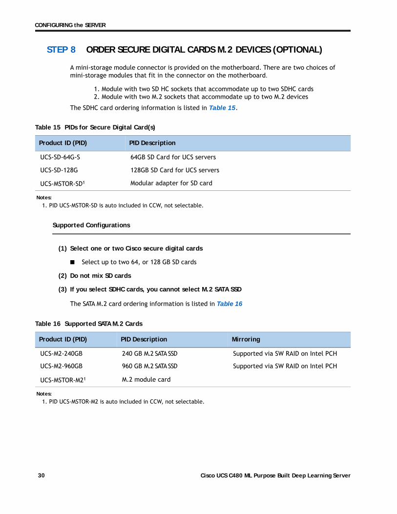
STEP 8 ORDER SECURE DIGITAL CARDS M.2 DEVICES (OPTIONAL)
A mini-storage module connector is provided on the motherboard. There are two choices of mini-storage modules that fit in the connector on the motherboard.
1. Module with two SD HC sockets that accommodate up to two SDHC cards2. Module with two M.2 sockets that accommodate up to two M.2 devices
The SDHC card ordering information is listed in Table 15
Table 15 PIDs for Secure Digital Card(s)
Product ID (PID) PID Description
UCS-SD-64G-S 64GB SD Card for UCS servers
UCS-SD-128G 128GB SD Card for UCS servers
UCS-MSTOR-SD1 Modular adapter for SD card
.
Supported Configurations
(1) Select one or two Cisco secure digital cards
■ Select up to two 64, or 128 GB SD cards
(2) Do not mix SD cards
(3) If you select SDHC cards, you cannot select M.2 SATA SSD
The SATA M.2 card ordering information is listed in
Table 16 Supported SATA M.2 Cards
Product ID (PID) PID Description Mirroring
UCS-M2-240GB 240 GB M.2 SATA SSD Supported via SW RAID on Intel PCH
UCS-M2-960GB 960 GB M.2 SATA SSD Supported via SW RAID on Intel PCH
UCS-MSTOR-M21 M.2 module card
Table 16
Notes:
1. PID UCS-MSTOR-SD is auto included in CCW, not selectable.
Notes:
1. PID UCS-MSTOR-M2 is auto included in CCW, not selectable.
Cisco UCS C480 ML Purpose Built Deep Learning Server30

CONFIGURING the SERVER
Supported Configurations
(1) Select either one or two SATA M.2 cards. Do not mix M.2.
(2) If you select M.2 SATA SSDs, you cannot select SDHC cards
(3) VMware does not support SW RAID. Drive can still be used as a boot device without mirroring.
Cisco UCS C480 ML Purpose Built Deep Learning Server 31

CONFIGURING the SERVER
STEP 9 ORDER INTERNAL MICRO-SD CARD MODULE (OPTIONAL)
Order a 32 GB micro-SD card. The micro-SD card serves as a dedicated local resource for utilities such as HUU. Images can be pulled from a files hare (NFS/CIFS) and uploaded to the cards for future use.
Table 17 Secure Digital (SD) Card
Product ID (PID) PID Description
UCS-MSD-32G 32GB Micro-SD Card for UCS servers
—
Cisco UCS C480 ML Purpose Built Deep Learning Server32

CONFIGURING the SERVER
STEP 10 ORDER POWER SUPPLIES
The available power supplies are listed in Table 18.
Table 18 Power Supplies
Product ID (PID) PID Description
UCSC-PSU1-1600W Cisco UCS 1600W AC Power Supply for Rack Server
Caveats
— All four power supplies are required
Cisco UCS C480 ML Purpose Built Deep Learning Server 33

CONFIGURING the SERVER
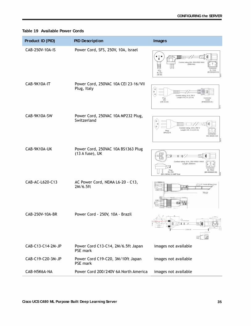
STEP 11 SELECT AC POWER CORD(s)
Select the appropriate AC power cords listed in Table 19. You may select a minimum of no power cords and a maximum of two power cords. If you select the option R2XX-DMYMPWRCORD, no power cord is shipped with the server.
Table 19 Available Power Cords
Product ID (PID) PID Description Images
R2XX-DMYMPWRCORD No power cord (dummy PID to allow for a no power cord option)
Not applicable
CAB-C13-C14-2M CABASY,WIRE,JUMPER CORD, PWR, 2 Meter, C13/C14,10A/250V
CAB-250V-10A-AR Power Cord, SFS, 250V, 10A, Argentina
1865
71
2500 mm
Cordset rating: 10 A, 250/500 V MAXLength: 8.2 ft
Plug:EL 219
(IRAM 2073) Connector:EL 701
(IEC60320/C13)
CAB-9K10A-AU Power Cord, 250VAC 10A 3112 Plug, Australia
Plug:
Cordset rating: 10 A, 250 V/500 V MAXLength: 2500mm
1865
80
Connector:EL 701C
(EN 60320/C15)EL 210(BS 1363A) 13 AMP fuse
CAB-250V-10A-CN AC Power Cord - 250V, 10A - PRC
CAB-9K10A-EU Power Cord, 250VAC 10A CEE 7/7 Plug, EU
Connector:VSCC15
Cordset rating: 10A/16 A, 250 VLength: 8 ft 2 in. (2.5 m)Plug:
M2511
1865
76
CAB-250V-10A-ID Power Cord, SFS, 250V, 10A, India
OVE
Cordset rating 16A, 250V(2500mm)
Plug:EL 208
1874
90
Connector:EL 701
Cisco UCS C480 ML Purpose Built Deep Learning Server34
CONFIGURING the SERVER
CAB-250V-10A-IS Power Cord, SFS, 250V, 10A, Israel
Cordset rating 10A, 250V/500V MAX(2500 mm)
Plug:EL 212(SI-32)
1865
74
Connector:EL 701B
(IEC60320/C13)
EL-21216A250V
CAB-9K10A-IT Power Cord, 250VAC 10A CEI 23-16/VII Plug, Italy
Plug: I/3G
(CEI 23-16)
Connector C15M
(EN60320/C15 )
Cordset rating: 10 A, 250 VLength: 8 ft 2 in. (2.5 m)
1865
75
CAB-9K10A-SW Power Cord, 250VAC 10A MP232 Plug, Switzerland
Plug:MP232-R
Cordset rating: 10 A, 250 VLength: 8 ft. 2 in (2.5 m)
1865
78
Connector:IEC 60320 C15
CAB-9K10A-UK Power Cord, 250VAC 10A BS1363 Plug (13 A fuse), UK
Plug:
Cordset rating: 10 A, 250 V/500 V MAXLength: 2500mm
1865
80
Connector:EL 701C
(EN 60320/C15)EL 210(BS 1363A) 13 AMP fuse
CAB-AC-L620-C13 AC Power Cord, NEMA L6-20 - C13, 2M/6.5ft
CAB-250V-10A-BR Power Cord - 250V, 10A - Brazil
CAB-C13-C14-2M-JP Power Cord C13-C14, 2M/6.5ft Japan PSE mark
images not available
CAB-C19-C20-3M-JP Power Cord C19-C20, 3M/10ft Japan PSE mark
images not available
CAB-N5K6A-NA Power Cord 200/240V 6A North America images not available
Table 19 Available Power Cords
Product ID (PID) PID Description Images
1 76.2 From Plug End
2,133.6 ± 25
Cisco UCS C480 ML Purpose Built Deep Learning Server 35
CONFIGURING the SERVER
STEP 12 ORDER OPTIONAL CABLE MANAGEMENT ARM
A cable management arm is available for the tool-less slide rail kit (PID UCSC-RAIL-4U-M5). The cable management arm attaches to the left and right slide rails at the rear of the server and is used for cable management. You can order the cable management arm listed in Table 20.
Table 20 Cable Management Arm
Product ID (PID) PID Description
UCSC-CMA-4U-M5 Cable Management Arm for UCS C480 ML
Cisco UCS C480 ML Purpose Built Deep Learning Server36

CONFIGURING the SERVER
STEP 13 ORDER SECURITY DEVICES (OPTIONAL)
Trusted Platform Module (TPM) is a computer chip (microcontroller) that can securely store artifacts used to authenticate the platform (server). These artifacts can include passwords, certificates, or encryption keys. A TPM can also be used to store platform measurements that help ensure that the platform remains trustworthy. Authentication (ensuring that the platform can prove that it is what it claims to be) and attestation (a process helping to prove that a platform is trustworthy and has not been breached) are necessary steps to ensure safer computing in all environments.
A safety intrusion switch gives a notification of any unauthorized mechanical access into the server
The security device ordering information listed in Table 21.
Table 21 Security Devices
Product ID (PID) PID Description
UCSX-TPM2-002 Trusted Platform Module 2.0 for UCS servers
UCS-C480-INT-SW UCS C480 Safety Intrusion Switch
NOTE: The module used in this server conforms to TPM v2.0, as defined by the Trusted Computing Group (TCG).
Cisco UCS C480 ML Purpose Built Deep Learning Server 37

CONFIGURING the SERVER
STEP 14 SELECT MANAGEMENT CONFIGURATION (OPTIONAL)
By default, the C480 ML M5 server NIC mode is configured to be Shared LOM Extended. This NIC mode allows any LOM port or adapter card port to be used to access the Cisco Integrated Management Controller (CIMC). The Cisco VIC card must be installed in a slot with NCSI support.
To change the default NIC mode to Dedicated, select the UCSC-DLOM-01 PID shown in Table 22. In Dedicated NIC mode, the CIMC can be accessed only through the dedicated management port. See UCS C480 ML M5 Server Rear Panel on page 8 for the location of the management port.
To change the default NIC mode to Cisco Card Mode, select the UCSC-CCARD-01 PID shown in Table 22. In this mode, you can assign an IP address to the CIMC using DHCP and from there you can fully automate your deployment.
For more details on all the NIC mode settings, see
http://www.cisco.com/c/en/us/td/docs/unified_computing/ucs/c/sw/gui/config/guide/2-0/b_Cisco_UCS_C-series_GUI_Configuration_Guide_201.pdf
Table 22 Management Configuration Ordering Information
Product ID (PID) PID Description
UCSC-DLOM-01 Dedicated Mode BIOS setting for C-Series ServersUCSC-CCARD-01 Cisco Card Mode BIOS setting for C-Series Servers
Cisco UCS C480 ML Purpose Built Deep Learning Server38

CONFIGURING the SERVER
STEP 15 SELECT SERVER BOOT MODE (OPTIONAL)
By default, the C480 ML M5 server will ship with UEFI as the default boot mode. To have a server shipped with the Legacy BIOS mode (which was standard on M4 and previous generation servers), select the Legacy BIOS PID
Table 23 Server Boot Mode Ordering Information
Product ID (PID) PID Description
UCSC-LBIOS-01 Legacy Boot Mode BIOS setting for C-Series Servers
Cisco UCS C480 ML Purpose Built Deep Learning Server 39

CONFIGURING the SERVER
STEP 16 CHOOSE OPERATING SYSTEM AND VALUE-ADDED SOFTWARE
Several software programs are available. Select as desired from Table 24
Table 24 OSs and vale added software
Product ID (PID) PID Description
Microsoft
MSWS-19-ST16C Windows Server 2019 Standard (16 Cores/2 VMs)
MSWS-19-ST16C-NS Windows Server 2019 Standard (16 Cores/2 VMs) - No Cisco SVC
MSWS-19-DC16C Windows Server 2019 Data Center (16 Cores/Unlimited VMs)
MSWS-19-DC16C-NS Windows Server 2019 DC (16 Cores/Unlim VMs) - No Cisco SVC
Red Hat
RHEL-2S2V-3A Red Hat Enterprise Linux (1-2 CPU,1-2 VN); 3-Yr Support Req
RHEL-2S2V-5A Red Hat Enterprise Linux (1-2 CPU,1-2 VN); 5-Yr Support Req
RHEL-VDC-2SUV-1A RHEL for Virt Datacenters (1-2 CPU, Unlim VN) 1 Yr Supp Req
RHEL-VDC-2SUV-3A RHEL for Virt Datacenters (1-2 CPU, Unlim VN) 3 Yr Supp Req
RHEL-VDC-2SUV-5A RHEL for Virt Datacenters (1-2 CPU, Unlim VN) 5 Yr Supp Req
RHEL-2S2V-1A Red Hat Enterprise Linux (1-2 CPU,1-2 VN); 1-Yr Support Req
RHEL-2S2V-1S Red Hat Enterprise Linux (1-2 CPU,1-2 VN); Prem 1Yr SnS Reqd
RHEL-2S2V-3S Red Hat Enterprise Linux (1-2 CPU,1-2 VN); Prem 3Yr SnS Reqd
RHEL-2S-HA-1S RHEL High Availability (1-2 CPU); Premium 1-yr SnS Reqd
RHEL-2S-HA-3S RHEL High Availability (1-2 CPU); Premium 3-yr SnS Reqd
RHEL-2S-RS-1S RHEL Resilent Storage (1-2 CPU); Premium 1-yr SnS Reqd
RHEL-2S-RS-3S RHEL Resilent Storage (1-2 CPU); Premium 3-yr SnS Reqd
RHEL-2S-SFS-1S RHEL Scalable File System (1-2 CPU); Premium 1-yr SnS Reqd
RHEL-2S-SFS-3S RHEL Scalable File System (1-2 CPU); Premium 3-yr SnS Reqd
RHEL-VDC-2SUV-1S RHEL for Virt Datacenters (1-2 CPU, Unlim VN) 1 Yr SnS Reqd
RHEL-VDC-2SUV-3S RHEL for Virt Datacenters (1-2 CPU, Unlim VN) 3 Yr SnS Reqd
VMware
VMW-VSP-EPL-5A VMware vSphere 6 Ent Plus (1 CPU), 5-yr, Support Required
VMW-VSP-STD-1A VMware vSphere 6 Standard (1 CPU), 1-yr, Support Required
VMW-VSP-STD-3A VMware vSphere 6 Standard (1 CPU), 3-yr, Support Required
Cisco UCS C480 ML Purpose Built Deep Learning Server40

CONFIGURING the SERVER
VMW-VSP-EPL-3A VMware vSphere 6 Ent Plus (1 CPU), 3-yr, Support Required
VMW-VSP-EPL-1A VMware vSphere 6 Ent Plus (1 CPU), 1-yr, Support Required
VMW-VSP-STD-5A VMware vSphere 6 Standard (1 CPU), 5-yr, Support Required
SUSE
SLES-2S2V-1A SUSE Linux Enterprise Svr (1-2 CPU,1-2 VM); 1-Yr Support Req
SLES-2SUV-1A SUSE Linux Enterprise Svr (1-2 CPU,Unl VM); 1-Yr Support Req
SLES-2S2V-3A SUSE Linux Enterprise Svr (1-2 CPU,1-2 VM); 3-Yr Support Req
SLES-2SUV-3A SUSE Linux Enterprise Svr (1-2 CPU,Unl VM); 3-Yr Support Req
SLES-2S2V-5A SUSE Linux Enterprise Svr (1-2 CPU,1-2 VM); 5-Yr Support Req
SLES-2SUV-5A SUSE Linux Enterprise Svr (1-2 CPU,Unl VM); 5-Yr Support Req
SLES-2S2V-1S
SUSE Linux Enterprise Svr (1-2 CPU,1-2 VM); Prio 1-Yr SnS
SLES-2SUV-1S
SUSE Linux Enterprise Svr (1-2 CPU,Unl VM); Prio 1-Yr SnS
SLES-2S2V-3S SUSE Linux Enterprise Svr (1-2 CPU,1-2 VM); Prio 3-Yr SnS
SLES-2SUV-3S SUSE Linux Enterprise Svr (1-2 CPU,Unl VM); Prio 3-Yr SnS
SLES-2S2V-5S SUSE Linux Enterprise Svr (1-2 CPU,1-2 VM); Prio 5-Yr SnS
SLES-2SUV-5S SUSE Linux Enterprise Svr (1-2 CPU,Unl VM); Prio 5-Yr SnS
SLES-2S-HA-1S SUSE Linux High Availability Ext (1-2 CPU); 1yr SnS
SLES-2S-HA-3S SUSE Linux High Availability Ext (1-2 CPU); 3yr SnS
SLES-2S-HA-5S SUSE Linux High Availability Ext (1-2 CPU); 5yr SnS
SLES-2S-GC-1S
SUSE Linux GEO Clustering for HA (1-2 CPU); 1yr Sns
SLES-2S-GC-3S SUSE Linux GEO Clustering for HA (1-2 CPU); 3yr SnS
SLES-2S-GC-5S SUSE Linux GEO Clustering for HA (1-2 CPU); 5yr SnS
SLES-2S-LP-1S SUSE Linux Live Patching Add-on (1-2 CPU); 1yr SnS Required
SLES-2S-LP-3S SUSE Linux Live Patching Add-on (1-2 CPU); 3yr SnS Required
SLES-2S-LP-1A SUSE Linux Live Patching Add-on (1-2 CPU); 1yr Support Req
SLES-2S-LP-3A SUSE Linux Live Patching Add-on (1-2 CPU); 3yr Support Req
Nvidia NGC Support
Table 24 OSs and vale added software
Product ID (PID) PID Description
Cisco UCS C480 ML Purpose Built Deep Learning Server 41

CONFIGURING the SERVER
NV-NGC-S-1YR Nvidia NGC Support Services For C480 ML; 1 Year
NV-NGC-S-3YR Nvidia NGC Support Services For C480 ML; 3 Year
NV-NGC-S-5YR Nvidia NGC Support Services For C480 ML; 5 Year
NV-NGC-S-R-1YR Nvidia NGC Support Services For C480 ML; 1 Year, RENEW
Table 24 OSs and vale added software
Product ID (PID) PID Description
Cisco UCS C480 ML Purpose Built Deep Learning Server42

CONFIGURING the SERVER
STEP 17 SELECT SERVICE and SUPPORT LEVEL
A variety of service options are available, as described in this section.
Smart Net Total Care
For support of the C480 ML Server, Cisco offers the Cisco Smart Net Total Care Service. This service provides expert software and hardware support to help sustain performance and high availability of the unified computing environment. Access to Cisco Technical Assistance Center (TAC) is provided around the clock, from anywhere in the world.
For systems that include Unified Computing System Manager, the support service includes downloads of UCSM upgrades. The Cisco Smart Net Total Care for UCS Service includes flexible hardware replacement options, including replacement in as little as two hours. There is also access to Cisco's extensive online technical resources to help maintain optimal efficiency and uptime of the unified computing environment. For more information please refer to the following url: http://www.cisco.com/c/en/us/services/technical/smart-net-total-care.htML M5?stickynav=1
You can choose a desired service listed in Table 25.
Table 25 Cisco SNTC Service (PID UCSC-C480-M5ML8)
Service SKU Service Level GSP On Site? Description
CON-3OSP-480M5ML8 3C4P Yes 3YR SNTC 24X7X4OS
CON-3SNT-480M5ML8 3SNT No 3YR SNTC 8X5XNBD
CON-3SNTP-480M5ML8 3SNTP No 3YR SNTC 24X7X4
CON-PREM-480M5ML8 C2P Yes SNTC 24X7X2OS
CON-UCSD8-480M5ML8 UCSD8 Yes UC SUPP DR 24X7X2OS*
CON-C2PL-480M5ML8 C2PL Yes LL 24X7X2OS**
CON-OSP-480M5ML8 C4P Yes SNTC 24X7X4OS
CON-UCSD7-480M5ML8 UCSD7 Yes UCS DR 24X7X4OS*
CON-C4PL-480M5ML8 C4PL Yes LL 24X7X4OS**
CON-USD7L-480M5ML8 USD7L Yes LLUCS HW DR 24X7X4OS***
CON-OSE-480M5ML8 C4S Yes SNTC 8X5X4OS
CON-UCSD6-480M5ML8 UCSD6 Yes UC SUPP DR 8X5X4OS*
CON-SNCO-480M5ML8 SNCO Yes SNTC 8x7xNCDOS****
CON-OS-480M5ML8 CS Yes SNTC 8X5XNBDOS
CON-UCSD5-480M5ML8 UCSD5 Yes UCS DR 8X5XNBDOS*
CON-S2P-480M5ML8 S2P No SNTC 24X7X2
CON-S2PL-480M5ML8 S2PL No LL 24X7X2**
CON-SNTP-480M5ML8 SNTP No SNTC 24X7X4
Cisco UCS C480 ML Purpose Built Deep Learning Server 43

CONFIGURING the SERVER
Smart Net Total Care with Onsite Troubleshooting Service
An enhanced offer over traditional Smart Net Total Care which provides onsite-troubleshooting expertise to aid in the diagnostics and isolation of hardware issue within our customers’ Cisco Unified Computing System (UCS) environment. It is delivered by a Cisco Certified field engineer (FE) in collaboration with remote TAC engineer and Virtual Internet working Support Engineer (VISE). You can choose a desired service listed in
Table 26 SNTC With UCS Onsite Troubleshooting Service (PID UCSC-C480-M5ML8)
Service SKU Service Level GSP On Site? Description
CON-OSPT-480M5ML8 OSPT Yes 24X7X4OS Trblshtg
CON-OSPTD-480M5ML8 OSPTD Yes 24X7X4OS TrblshtgDR*
CON-OSPTL-480M5ML8 OSPTL Yes 24X7X4OS TrblshtgLL**
CON-OPTLD-480M5ML8 OPTLD Yes 24X7X4OS TrblshtgLLD***
*Includes Drive Retention (see below for full description)
**Includes Local Language Support (see below for full description) – Only available in China and Japan
***Includes Local Language Support and Drive Retention – Only available in China and Japan
Table 26
Solution Support
Solution Support includes both Cisco product support and solution-level support, resolving complex issues in multivendor environments, on average, 43% more quickly than product support alone. Solution Support is a critical element in data center administration, to help rapidly resolve any issue encountered, while maintaining performance, reliability, and return on investment.
CON-SNTPL-480M5ML8 SNTPL No LL 24X7X4**
CON-SNTE-480M5ML8 SNTE No SNTC 8X5X4
CON-SNC-480M5ML8 SNC No SNTC 8x7xNCD****
CON-SNT-480M5ML8 SNT No SNTC 8X5XNBD
CON-SW-480M5ML8 SW No SNTC NO RMA
*Includes Drive Retention (see below for full description)
**Includes Local Language Support (see below for full description) – Only available in China and Japan
***Includes Local Language Support and Drive Retention – Only available in China and Japan
****Available in China Only
Table 25 Cisco SNTC Service (PID UCSC-C480-M5ML8)
Service SKU Service Level GSP On Site? Description
Cisco UCS C480 ML Purpose Built Deep Learning Server44

CONFIGURING the SERVER
This service centralizes support across your multivendor Cisco environment for both our products and solution partner products you've deployed in your ecosystem. Whether there is an issue with a Cisco or solution partner product, just call us. Our experts are the primary point of contact and own the case from first call to resolution. For more information please refer to the following url:http://www.cisco.com/c/en/us/services/technical/solution-support.htML M5?stickynav=1You can choose a desired service listed in
Table 27 Solution Support Service (PID UCSC-C480-M5ML8)
Service SKU Service Level GSP On Site? Description
CON-SSC2P-480M5ML8 SSC2P Yes SOLN SUPP 24X7X2OS
CON-SSC4P-480M5ML8 SSC4P Yes SOLN SUPP 24X7X4OS
CON-SSC4S-480M5ML8 SSC4S Yes SOLN SUPP 8X5X4OS
CON-SSCS-480M5ML8 SSCS Yes SOLN SUPP 8X5XNBDOS
CON-SSDR7-480M5ML8 SSDR7 Yes SSPT DR 24X7X4OS*
CON-SSDR5-480M5ML8 SSDR5 Yes SSPT DR 8X5XNBDOS*
CON-SSS2P-480M5ML8 SSS2P No SOLN SUPP 24X7X2
CON-SSSNP-480M5ML8 SSSNP No SOLN SUPP 24X7X4
CON-SSSNE-480M5ML8 SSSNE No SOLN SUPP 8X5X4
CON-SSSNC-480M5ML8 SSSNC No SOLN SUPP NCD**
CON-SSSNT-480M5ML8 SSSNT No SOLN SUPP 8X5XNBD
Table 27
Table 28 Solution Support Service provider Service(PID UCSC-C480-M5ML8)
Service SKU Service Level GSP On Site? Description
SP-SSC2P-480M5ML8 SSC2P Yes SOLN SUPP 24X7X2OS
SP-SSC4P-480M5ML8 SSC4P Yes SOLN SUPP 24X7X4OS
SP-SSC4S-480M5ML8 SSC4S Yes SOLN SUPP 8X5X4OS
SP-SSCS-480M5ML8 SSCS Yes SOLN SUPP 8X5XNBDOS
SP-SSS2P-480M5ML8 SSS2P No SOLN SUPP 24X7X2
SP-SSS4P-480M5ML8 SSS4P No SOLN SUPP 24X7X4
SP-SSSNE-480M5ML8 SSSNE No SOLN SUPP 8X5X4
SP-SSSNT-480M5ML8 SSSNT No SOLN SUPP 8X5XNBD
CON-SSSNT-480M5ML8 SSSNT No SOLN SUPP 8X5XNBD
Includes Drive Retention (see below for description)
**Available in China only
Cisco UCS C480 ML Purpose Built Deep Learning Server 45

CONFIGURING the SERVER
Partner Support Service for UCS
Cisco Partner Support Service (PSS) is a Cisco Collaborative Services service offering that is designed for partners to deliver their own branded support and managed services to enterprise customers. Cisco PSS provides partners with access to Cisco's support infrastructure and assets to help them:
■ Expand their service portfolios to support the most complex network environments
■ Lower delivery costs
■ Deliver services that increase customer loyalty
PSS options enable eligible Cisco partners to develop and consistently deliver high-value technical support that capitalizes on Cisco intellectual assets. This helps partners to realize higher margins and expand their practice.
PSS is available to all Cisco PSS partners.
PSS provides hardware and software support, including triage support for third party software, backed by Cisco technical resources and level three support. You can choose a desired service listed in Table 29.
Table 29 PSS (PID UCSC-C480-M5ML8)
Service SKU Service Level GSP On Site? Description
CON-PSJ8- 480M5ML8 PSJ8 Yes UCS PSS 24X7X2 OS
CON-PSJ7- 480M5ML8 PSJ7 Yes UCS PSS 24X7X4 OS
CON-PSJD7- 480M5ML8 PSJD7 Yes UCS PSS 24X7X4 DR*
CON-PSJ6- 480M5ML8 PSJ6 Yes UCS PSS 8X5X4 OS
CON-PSJD6- 480M5ML8 PSJD6 Yes UCS PSS 8X5X4 DR*
CON-PSJ4- 480M5ML8 PSJ4 No UCS SUPP PSS 24X7X2
CON-PSJ3- 480M5ML8 PSJ3 No UCS SUPP PSS 24X7X4
CON-PSJ2- 480M5ML8 PSJ2 No UCS SUPP PSS 8X5X4
CON-PSJ1- 480M5ML8 PSJ1 No UCS SUPP PSS 8X5XNBD
Combined Support Service
Combined Services makes it easier to purchase and manage required services under one contract. The more benefits you realize from the Cisco UCS environment, the more important the technology becomes to your business. These services allow you to:
■ Optimize the uptime, performance, and efficiency of your UCS
■ Protect your vital business applications by rapidly identifying and addressing issues
■ Strengthen in-house expertise through knowledge transfer and mentoring
*Includes Drive Retention (see below for description)
Cisco UCS C480 ML Purpose Built Deep Learning Server46

CONFIGURING the SERVER
■ Improve operational efficiency by allowing UCS experts to augment your internal staff resources
■ Enhance business agility by diagnosing potential issues before they affect your operations,
You can choose a desired service listed in
Table 30 Combined Support Service for UCS (PID UCSC-C480-M5ML8)
Service SKU Service Level GSP On Site? Description
CON-NCF2P-480M5ML8 NCF2P Yes CMB SVC 24X7X2OSCON-NCF4P-480M5ML8 NCF4P Yes CMB SVC 24X7X4OSCON-NCF4S-480M5ML8 NCF4S Yes CMB SVC 8X5X4OSCON-NCFCS-480M5ML8 NCFCS Yes CMB SVC 8X5XNBDOSCON-NCF2-480M5ML8 NCF2 No CMB SVC 24X7X2CON-NCFP-480M5ML8 NCFP No CMB SVC 24X7X4CON-NCFE-480M5ML8 NCFE No CMB SVC 8X5X4CON-NCFT-480M5ML8 NCFT No CMB SVC 8X5XNBDCON-NCFW-480M5ML8 NCFW No CMB SVC SW
Table 30
SP Base Service
Cisco SP Base is Cisco's core foundational product support offer for service provider customers. This device-level service helps reduce downtime with fast, expert technical support and flexible hardware coverage provided by the Cisco Technical Assistance Center (TAC). It also offers integrated smart capabilities, providing current information about installed base, contracts, and security alerts to enhance the efficiency of support workflows. You can choose a service listed in
Table 31 SP Base Service (PID UCSC-C480-M5ML8)
Service SKU Service Level GSP On Site? Description
SP-OS4-480M5ML8 SPC2P Yes SP Base 24X7X2OS
SP-OS3-480M5ML8 SPC4P Yes SP Base 24X7X4OS
SP-OS2-480M5ML8 SPC4S Yes SP Base 8X5X4OS
SP-OS1-480M5ML8 SPCS Yes SP Base 8X5XNBDOS
SP-AR4-480M5ML8 SPAR4 No SP Base 24X7X2
SP-AR3-480M5ML8 SPAR3 No SP Base 24X7X4
SP-AR2-480M5ML8 SPAR2 No SP Base 8X5X4
SP-AR1-480M5ML8 SPAR1 No SP Base 8X5XNBD
Table 30.
Cisco UCS C480 ML Purpose Built Deep Learning Server 47

CONFIGURING the SERVER
UCS Drive Retention Service
With the Cisco Drive Retention Service, you can obtain a new disk drive in exchange for a faulty drive without returning the faulty drive.
Sophisticated data recovery techniques have made classified, proprietary, and confidential information vulnerable, even on malfunctioning disk drives. The Drive Retention service enables you to retain your drives and ensures that the sensitive data on those drives is not compromised, which reduces the risk of any potential liabilities. This service also enables you to comply with regulatory, local, and federal requirements.
If your company has a need to control confidential, classified, sensitive, or proprietary data, you might want to consider one of the Drive Retention Services listed in the above tables (where available)
NOTE: Cisco does not offer a certified drive destruction service as part of this service.
Local Language Technical Support for UCS
Where available, and subject to an additional fee, local language support for calls on all assigned severity levels may be available for specific product(s) – see tables above.
For a complete listing of available services for Cisco Unified Computing System, see the following URL:
http://www.cisco.com/en/US/products/ps10312/serv_group_home.htML M5
Cisco UCS C480 ML Purpose Built Deep Learning Server48

OPTIONAL STEP - ORDER RACKS
OPTIONAL STEP - ORDER RACKSThe optional R42612 rack is available from Cisco for the C-Series servers, including the C480 ML M5 server. This rack is a standard 19-inch rack and can be ordered with a variety of options, as listed in Table 32.
Table 32 Racks and Rack Options
Product ID (PID) PID Description
RACK2-UCS Cisco R42612 expansion rack, no side panels. This type of rack is used for multiple-rack deployments.
RACK2-UCS2 Cisco R42612 static (standard) rack, with side panels. This type of rack is used for single-rack and end of row deployments. Side panels are needed for racks at the ends of multiple-rack deployments. For example, when configuring a row of 5 racks, order 1 standard rack plus 4 expansion racks. Apply the side panels from the standard rack to the racks at each end of the row.
RACK-BLANK-001 Blanking panels (qty 12), 1U, plastic, toolless.Recommended to ensure proper airflow. Fill all empty RU spaces in the front of the rack. Because each blanking panel PID includes 12 panels, use the following calculation: 42RU - occupied RU = available RU. Divide available RU by 12 to determine PID order quantity.
RACK-CBLMGT-001 Cable mgt D rings (qty 10), metal.Use the D rings to bundle system cables to ensure proper airflow.
RACK-CBLMGT-003 Brush strip (qty 1), 1 U.The brush strip promotes proper airflow while allowing cables to be passed from the front to the rear of the rack.
RACK-CBLMGT-011 Cable mgt straps (qty 10), Velcro.Use the Velcro straps to bundle system cables to ensure proper airflow.
RACK-FASTEN-001 Mounting screws (qty 100), M6.The rack ships with nuts and screws, but extras may be ordered.
RACK-FASTEN-002 Cage nuts (qty 50), M6.The rack ships with nuts and screws, but extras may be ordered.
RACK2-JOIN-001 Rack joining kit.Use the kit to connect adjacent racks within a row. Order 1 unit less than the number of racks in the row.
RACK2-GRND-001 Cisco R42612 grounding kit
Racks are shipped separately from the C480 ML M5 server.
For more information about the R42612 rack, see RACKS on page 61.
Cisco UCS C480 ML Purpose Built Deep Learning Server 49
OPTIONAL STEP - ORDER PDU
OPTIONAL STEP - ORDER PDUAn optional power distribution unit (PDU) is available from Cisco for the C-Series rack servers. This PDU is available in a zero rack unit (RU) style or horizontal PDU style.
see Cisco RP-Series Rack and Rack PDU specification for more details at:
http://www.cisco.com/c/dam/en/us/products/collateral/servers-unified-computing/r-series-racks/rack-pdu-specsheet.pdf
Cisco UCS C480 ML Purpose Built Deep Learning Server50

SUPPLEMENTAL MATERIAL
SUPPLEMENTAL MATERIAL
CHASSIS
An internal view of the C480 ML M5 chassis with the top cover removed is shown in Figure 5.
Figure 5 C480 ML M5 With Top Cover Removed
FAN 04
FAN 03
FAN 02
FAN 01
GPU 08
GPU 06
GPU 04
GPU 02
GPU 07
GPU 05
GPU 03
GPU 01
PCIe 11PCIe 12
PCIe 13PCIe 14
6
3068
50
5
7
89
42 31
1 RAID controller card for front-loading SAS/SATA drives.
(not visible in this view; position is near chassis floor under the CPU module
6 Power supplies 1-4 (hot-swappable, redundant as 2+2 (default) or 3+1
2 Supercap (RAID backup) for front RAID controller
(not visible in this view; mounting bracket position is on chassis wall under the CPU module)
7 PCIe slots 11 and 12 (Gen-3 x16)
■ Slots 11 and 12 support standby power.
■ Slot 11 is the primary slot for a Cisco UCS VIC card, slot 12 is the secondary slot
3 Fan modules (four modules with two fans each; hot-swappable)
8 Internal, vertical USB 2.0 socket on motherboard
4 NVIDIA V100 SXM2 GPUs and heatsinks (eight), Each GPU socket provides a x16 PCIe lane
Note: The GPUs are not customer serviceable. Contact Cisco Support if you need service for the GPUs or their heatsinks.
9 Trusted platform module socket (TPM) on motherboard
5 PCIe slots 13 and 14 (Gen-3 x16) _ _
Cisco UCS C480 ML Purpose Built Deep Learning Server 51

SUPPLEMENTAL MATERIAL
Serviceable Component Locations Inside the Main Chassis
Figure 6 Serviceable Component Locations Inside the Main Chassis (Front and Rear Views)
10 CPU module bay 2 (blank with filler module)
There must be a blank filler module in upper bay 2 or the system will not boot
14 Right bay module, supports either:
■ Optional DVD drive module
■ Drive bays 17 - 24 (shown)
• All 8 bays supports SAS/SATA drives.
• Bay 17 also supports NVMe drives.
11 CPU module bay 1
The system must have one CPU module in lower bay 1 to boot
15 PCIe slots 11 through 14, rear panel openings
Fan 01Bay 29
Bay 30
Bay 31
Bay 32
Bay 25
Bay 26
Bay 27
Bay 28Fan 02
Fan 03
Fan 04
PCIe 12PCIe 11
PCIe 10
PCIe 09PCIe 08PCIe 07PCIe 06PCIe 05PCIe 04PCIe 03PCIe 02
PCIe 01
7
3
1112
4 5
6
8
10
9
21
UCSC480 ML
M5
PC
Ie 1
1
PC
Ie 1
2
PC
Ie 1
3
PC
Ie 1
4
PSU 1 PSU 2 PSU 3 PSU 4
Driv
e B
ay 0
1
Driv
e B
ay 0
2
Driv
e B
ay 0
3
Driv
e B
ay 0
4
Driv
e B
ay 0
5
Driv
e B
ay 0
6
Driv
e B
ay 0
7
Driv
e B
ay 0
8
Driv
e B
ay 0
9
Driv
e B
ay 1
0
Driv
e B
ay 1
1
Driv
e B
ay 1
2
Driv
e B
ay 1
3
Driv
e B
ay 1
4
Driv
e B
ay 1
5
Driv
e B
ay 1
6
CPU Module 1
CPU Module Filler
Driv
e B
ay 1
7
Driv
e B
ay 1
8
Driv
e B
ay 1
9
Driv
e B
ay 2
0
Driv
e B
ay 2
1
Driv
e B
ay 2
2
Driv
e B
ay 2
3
Driv
e B
ay 2
4
10
11
12 13 14
3068
75
1515
1716
PC
Ie 1
1
PC
Ie 1
2
PC
Ie 1
3
PC
Ie 1
4
PSU 1 PSU 2 PSU 3 PSU 4
Cisco UCS C480 ML Purpose Built Deep Learning Server52

SUPPLEMENTAL MATERIAL
12 Left bay module (drive bays 1 - 8)
■ All 8 bays supports SAS/SATA drives.
■ Bays 1, 2, 7, 8 also support NVMe drives
16 I/O module
Note: The I/O module is not field replaceable, nor can you move an I/O module from one chassis to another. This module contains a security chip that requires it to stay with the PCIe module in the same chassis, as shipped from the factory.
13 Center bay module (drive bays 9 - 16)
■ All 8 bays supports SAS/SATA drives.
■ Bay 9 also supports NVMe drives.
17 Power supplies 1-4 (hot-swappable, redundant as 2+2 (default) or 3+1)
All power supplies in the system must be identical (no mixing).
Cisco UCS C480 ML Purpose Built Deep Learning Server 53

SUPPLEMENTAL MATERIAL
Serviceable Components Inside a CPU Module
Figure 7 Serviceable Component Locations Inside a CPU Module
3068
51
CPU 2 CPU 1
2
1
4
3
5
CPU 2 CPU 1
1 CPU 2 4 DIMM sockets controlled by CPU 1 (channels A, B, C, D, E, F.)
2 DIMM sockets controlled by CPU 2 (channels G, H, J, K, L, M.)
See Memory Population Rules on page 57 for DIMM slot numbering
5 Release levers for module (two each module)
3 CPU 1 _ _
Cisco UCS C480 ML Purpose Built Deep Learning Server54

SUPPLEMENTAL MATERIAL
Serviceable Components Inside an I/O Module
Figure 8 Serviceable Component Locations Inside a I/O Module
3060
15
2 31
1 Micro SD card socket 3 RTC battery vertical socket
2 Mini storage module connector
Supports either an SD card carrier with two SD card slots or an M.2 SSD carrier with two SATA M.2 SSD slots
_ _
Cisco UCS C480 ML Purpose Built Deep Learning Server 55

SUPPLEMENTAL MATERIAL
CPUs and DIMMs
Physical Layout
Each CPU has six DIMM channels:
■ CPU1 has channels A, B, C, D, E, and F
■ CPU2 has channels G, H, J, K, L, and M
Each DIMM channel has two slots: slot 1 and slot 2. The blue-colored DIMM slots are for slot 1 and the black slots for slot 2.
As an example, DIMM slots A1, B1, C1, D1, E1, and F1 belong to slot 1, while A2, B2, C2, D2, E2, and F2 belong to slot 2.
Figure 9 shows how slots and channels are physically laid out on the motherboard. The DIMM slots on the right half of the motherboard (channels A, B, C, D, E, and F) are associated with CPU 1, while the DIMM slots on the left half of the motherboard (channels G, H, J, K, L, and M) are associated with CPU 2. The slot 1 (blue) DIMM slots are always located farther away from a CPU than the corresponding slot 2 (black) slots.
Figure 9 Physical Layout of CPU DIMM Channels and Slots
Memory Configuration Best Practices available at https://www.cisco.com/c/dam/en/us/products/collateral/servers-unified-computing/ucs-c-series-rack-servers/memory-guide-c220-c240-b200-m5.pdf
Front of Server
CPU 2/4 CPU 1/3
A2
A1
B2
B1
C2
C1
F1 F2 E1 E2 D1
D2G2
G1
H2
H1
J2 J1M1
M2
L1 L2 K1
K2
3059
83
Cisco UCS C480 ML Purpose Built Deep Learning Server56

SUPPLEMENTAL MATERIAL
Memory Population Rules
When considering the memory configuration of your server, consider the following items:
■ Each channel has two DIMM slots (for example, channel A = slots A1 and A2).
— A channel can operate with one or two DIMMs installed.
■ Populate the DIMM slots of each CPU identically.
— Fill black slots in the channels second: C2, F2, B2, E2, A2, D2
Table 33 DIMM Rules for C480 ML M5 Servers
DIMM Parameter DIMMs in the Same Channel DIMM in the Same Slot1
DIMM Capacity
RDIMM = 8, 16, 32, 64, or 128 GB
LRDIMM = 64 GB
TSV-RDIMM = 64 GB
DIMMs in the same channel (for example, A1 and A2) can have different capacities.
Do not mix TSV-RDIMMS with LRDIMMs nor RDIMMs
For best performance, DIMMs in the same slot (for example, A1, B1, C1, D1, E1, F1) should have the same capacity.
Do not mix TSV-RDIMMS with LRDIMMs nor RDIMMs
DIMM Speed
2666-MHz DIMMs will run at the lowest speed of the CPU installed
DIMMs will run at the lowest speed of the CPU installed
DIMM Type
TSV-RDIMMS, RDIMMs, or LRDIMMs
Do not mix DIMM types in a channel Do not mix DIMM types in a slot
DIMMs per Channel (DPC)1 DPC or 2 DPC
Ensure valid LRDIMM and RDIMM 1 DPC and 2 DPC memory configurations
Notes:
1. Although different DIMM capacities can exist in the same slot, this will result in less than optimal performance. For optimal performance, all DIMMs in the same slot should be identical.
Cisco UCS C480 ML Purpose Built Deep Learning Server 57

SUPPLEMENTAL MATERIAL
Memory Mirroring
When Memory Mirroring PID (N01-MMIRROR) is selected in STEP 3 CHOOSE MEMORY, the DIMMS will be placed as shown in the below table by the factory
■ Select 4, 6,8,12 identical DIMMS per CPU.
(1) 1 CPU config for memory mirroring:
(2) 4 CPU Config for Memory Mirroring - duplicate table above for 2 CPU Config in second Compute Module
CPU 1 DIMM Placement in Channels (for identical ranked DIMMs)
CPU 2 DIMM Placement in Channels (for identical ranked DIMMs)
CPU 1 CPU 2
8 (A1,B1); (D1,E1) (G1, H1); (K1, L1)
12 (A1, B1, C1); (D1, E1, F1) (G1, H1, J1); (K1, L1, M1)
16 (A1, A2, B1, B2); (D1, D2, E1, E2) (G1, G2, H1, H2); (K1, K2, L1, L2)
24 (A1, A2, B1, B2, C1, C2); (D1, D2, E1, E2, F1, F2)
(G1, G2, H1, H2, J1, J2); (K1, K2, L1, L2, M1, M2)
Cisco UCS C480 ML Purpose Built Deep Learning Server58

SUPPLEMENTAL MATERIAL
Memory Support for CPU Classes and CPU Modes
For 2nd Generation Intel® Xeon® Scalable Processors:
■ DIMMs and DCPMMs are supported
■ CPU PIDs ending in “M” support up to a limit of 2048 GB per CPU
■ CPU PIDs ending in “L” support up to a limit of 4608 GB per CPU
■ All other CPU PIDs support up to a limit of 1024 GB per CPU
■ For the App Direct Mode, both DCPMM and DIMM capacities count towards the CPU capacity limit
■ For the Memory Mode and Mixed Mode only the DCPMM capacity counts towards the CPU capacity limit
For Configurations Using Only DIMMs
■ CPU PIDs ending in “M” support DIMM capacities up to 1536 GB per CPU (using 12 x 128 GB DIMMs) and DIMM capacities up to 2048 GB per CPU (using 8 x 256 GB DIMMs).
■ CPU PIDs ending in “L” support DIMM capacities up to 1536 GB per CPU (using 12 x 128 GB DIMMs) and DIMM capacities up to 3072 GB per CPU (using 12 x 256 GB DIMMs). The 4608 GB limit cannot be reached with these capacity DIMMs.
■ CPU PIDs not ending in “L” or “M” support DIMM capacities up to 1024 GB per CPU (using 8 x 128 GB DIMMs or 4 x 256 GB DIMMs).
For Configurations Using DIMMs and DCPMMs in App Direct Mode
■ CPU PIDs ending in “M” support capacities up to 1792 GB per CPU (using 6 x 128 GB DIMMS and 2 x 512 GB DCPMMs or 4 x 256 GB DCPMMs) or up to 2048 GB per CPU (using 6 x 256 GB DIMMs and 2 x 256 GB DCPMMs or 6 x 256 GB DIMMs and 4 x 128 GB DCPMMs)
■ CPU PIDs ending in “L” support capacities up to 3840 GB per CPU (using 6 x 128 GB DIMMs and 6 x 512 GB DCPMMs) or up to 4608 GB per CPU (using 6 x 256 GB DIMMs and 6 x 512 GB DCPMMs)
■ CPU PIDs not ending in “L” or “M” support capacities up to 1024 GB per CPU (using 6 x 128 GB DIMMs and 2 x 128 GB DCPMMs).
For Configurations Using DIMMs and DCPMMs in Memory or Mixed Mode
■ CPU PIDs ending in “M” support capacities up to 2816 GB per CPU (using 6 x 128 GB DIMMs and 4 x 512 GB DCPMMs) or up to 3584 GB per CPU (using 6 x 256 GB DIMMs and 4 x 512 GB DCPMMs)
■ CPU PIDs ending in “L” support capacities up to 3840 GB (using 6 x 128 GB DIMMs and 6 x 512 GB DCPMMs) or up to 4608 GB per CPU (using 6 x 256 GB DIMMs and 6 x 512 GB DCPMMs). The allowable 4608 limit for DCPMM capacity is not reached in this case.
■ CPU PIDs not ending in “L” or “M” support capacities up to 1024 GB per CPU (using 6 x 128 GB DIMMs and 2 x 128 GB DCPMMs).
Cisco UCS C480 ML Purpose Built Deep Learning Server 59

SUPPLEMENTAL MATERIAL
For Intel® Xeon® Scalable Processors:
■ DIMMs are supported; DCPMMs are not supported
■ CPU PIDs ending in “M' support DIMM capacities up to 1536 GB per CPU (using 12 x 128 GB DIMMs).
■ All other CPU PIDs support DIMM capacities up to 768 GB per CPU (using 6 x 128 GB DIMMs or 12 x 64 GB DIMMs)
DIMM Population Order
Populate the DIMMs for a CPU according to Table 34.
Table 34 DIMM Population Order
Populate CPU 1 or CPU 3 Slot Populate CPU 2 or CPU 4 Slots
Blue #1 Slots Black #2 Slots Blue #1 Slots Black #2 Slots
1 (A1) - (G1) -
2 (A1, B1) - (G1, H1) -
3 (A1, B1, C1) - (G1, H1, J1) -
4 (A1, B1); (D1, E1) - (G1, H1); (K1, L1) -
8 (A1, B1); (D1, E1) (A2, B2); (D2, E2) (G1, H1); (K1, L1) (G2, H2); (K2, L2)
12 (A1, B1); (C1, D1); (E1, F1)
(A2, B2); (C2, D2); (E2, F2)
(G1, H1); (J1, K1); (L1, M1)
(G2, H2); (J2, K2); (L2, M2)
Cisco UCS C480 ML Purpose Built Deep Learning Server60

SUPPLEMENTAL MATERIAL
RACKS
The Cisco R42612 rack (see Figure 10 on page 62) is certified for Cisco UCS installation at customer sites and is suitable for the following equipment:
■ Cisco UCS B-Series servers and fabric interconnects
■ Cisco UCS C-Series and select Nexus switches
The rack is compatible with hardware designed for EIA-standard 19-inch racks. Rack specifications are listed in Table 35.
Table 35 R42612 Specifications
Cisco R42612 RackStandard (Static with side panels)
Expansion (Static without Side Panels)
Dimensions (H x W x D)
79.25 x 23.50 x 49.84 in.(2013 x 597 x 1266 mm)
79.25 x 23.50 x 49.84 in.(2013 x 597 x 1266 mm)
Dimensions (H x W x D)
with packaging
84.25 x 32 x 54.84 in.(2140 x 813 x 1393 mm)
84.25 x 32 x 54.84 in.(2140 x 813 x 1393 mm)
Distance from front mounting rail to rear mounting rail
29.19 in. (741.5 mm) 29.19 in. (741.5 mm)
Weight 339.51 lb (154 kg) 264.55 lb (120 kg)
Weight with packaging 410.06 lb (186 kg) 335.10 lb (152 kg)
Side panels included Yes No
Equipment mounting capacity 42 RU 42 RU
Static load capacity 2700 lb (1224.7 kg) 2700 lb (1224.7 kg)
Dynamic load capacity N/A N/A
Cisco UCS C480 ML Purpose Built Deep Learning Server 61

SUPPLEMENTAL MATERIAL
Figure 10 Cisco R42612 Rack
Front View Rear View
Cisco UCS C480 ML Purpose Built Deep Learning Server62

SUPPLEMENTAL MATERIAL
PDUs
Cisco RP Series Power Distribution Units (PDUs) offer power distribution with branch circuit protection.
Cisco RP Series PDU models distribute power to up to 42 outlets. The architecture organizes power distribution, simplifies cable management, and enables you to move, add, and change rack equipment without an electrician.
With a Cisco RP Series PDU in the rack, you can replace up to two dozen input power cords with just one. The fixed input cord connects to the power source from overhead or under-floor distribution. Your IT equipment is then powered by PDU outlets in the rack using short, easy-to-manage power cords.
The C-series severs accept the zero-rack-unit (0RU) or horizontal PDU. See Figure 11 for one example of a zero rack unit PDU.
Figure 11 RP208-30M1P-6-36 PDU
1 = Ground
2 = 20 A circuit breakers
3 = IEC 60320 C13 outlets
4 = EC 60320 C19 outlets
5 = NEMA L6-30P plug
Cisco UCS C480 ML Purpose Built Deep Learning Server 63

SUPPLEMENTAL MATERIAL
KVM CABLE
The KVM cable provides a connection into the server, providing a DB9 serial connector, a VGA connector for a monitor, and dual USB 2.0 ports for a keyboard and mouse. With this cable, you can create a direct connection to the operating system and the BIOS running on the server.
The KVM cable ordering information is listed in Table 36.
Table 36 KVM Cable
Product ID (PID) PID Description
N20-BKVM KVM cable for server console port
Figure 12 KVM Cable
1 Connector (to server front panel) 3 VGA connector (for a monitor)
2 DB-9 serial connector 4 Two-port USB 2.0 connector (for a mouse and keyboard)
Cisco UCS C480 ML Purpose Built Deep Learning Server64

DISCONTINUED EOL PRODUCTS
ral/seeos-e
unifitice-c
unifitice-c
unifitice-c
unifitice-c
unifitice-c
unifitice-c
unifitice-c
unifitice-c
al/sers-eol
al/sers-eol
al/sers-eol
al/sers-eol
DISCONTINUED EOL PRODUCTSBelow is the list of parts were previously available for this product and are no longer sold. Please refer to the EOL Bulletin Links via the Table 37 below to determine if still supported.
Table 37 EOL Products
EOS option PID Description EOL bulletin link
MEMORYUCS-MR-X16G2RS-H 16GB DDR4-2666-MHz
RDIMM/PC4-21300/dual rank/x4/1.2v
NVMeUCSC-NVMELW-I1000 Cisco 2.5" U.2 1TB Intel P4501 NVMe
Med. Perf. Value Endur (Intel)
UCSC-NVMEHW-I1000 1 TB 2.5in U.2 Intel P4500 NVMe High Perf. Value Endurance
https://www.cisco.com/c/en/us/products/collatervers-unified-computing/ucs-c-series-rack-servers/ol-notice-c51-742509.html
UCSC-NVMELW-I500 500GB 2.5in U.2 Intel P4501 NVMe Med. Perf. Value Endurance
UCSC-NVMEHW-I4000 4 TB 2.5in U.2 Intel P4500 NVMe High Perf. Value Endurance
Microsoft Windows serverMSWS-16-ST16C Windows Server 2016 Standard (16
Cores/2 VMs)https://www.cisco.com/c/en/us/products/servers-ed-computing/ucs-c-series-rack-servers/eos-eol-no51-743145.html
MSWS-16-ST24C Windows Server 2016 Standard (24 Cores/2 VMs)
https://www.cisco.com/c/en/us/products/servers-ed-computing/ucs-c-series-rack-servers/eos-eol-no51-743145.html
MSWS-16-ST16C-NS Windows Server 2016 Standard (16 Cores/2 VMs) - No Cisco SVC
https://www.cisco.com/c/en/us/products/servers-ed-computing/ucs-c-series-rack-servers/eos-eol-no51-743145.html
MSWS-16-ST24C-NS Windows Server 2016 Standard (24 Cores/2 VMs) - No Cisco SVC
https://www.cisco.com/c/en/us/products/servers-ed-computing/ucs-c-series-rack-servers/eos-eol-no51-743145.html
MSWS-16-DC16C Windows Server 2016 Data Center (16 Cores/Unlimited VMs)
https://www.cisco.com/c/en/us/products/servers-ed-computing/ucs-c-series-rack-servers/eos-eol-no51-743145.html
MSWS-16-DC24C Windows Server 2016 Data Center (24 Cores/Unlimited VMs)
https://www.cisco.com/c/en/us/products/servers-ed-computing/ucs-c-series-rack-servers/eos-eol-no51-743145.html
MSWS-16-DC16C-NS Windows Server 2016 DC (16 Cores/Unlim VMs) - No Cisco SVC
https://www.cisco.com/c/en/us/products/servers-ed-computing/ucs-c-series-rack-servers/eos-eol-no51-743145.html
MSWS-16-DC24C-NS Windows Server 2016 DC (24 Cores/Unlim VMs) - No Cisco SVC
https://www.cisco.com/c/en/us/products/servers-ed-computing/ucs-c-series-rack-servers/eos-eol-no51-743145.html
https://www.cisco.com/c/en/us/products/collatervers-unified-computing/ucs-c-series-rack-servers/eo-notice-c51-740780.html
https://www.cisco.com/c/en/us/products/collatervers-unified-computing/ucs-c-series-rack-servers/eo-notice-c51-742509.html
https://www.cisco.com/c/en/us/products/collatervers-unified-computing/ucs-c-series-rack-servers/eo-notice-c51-742509.html
https://www.cisco.com/c/en/us/products/collatervers-unified-computing/ucs-c-series-rack-servers/eo-notice-c51-742509.html
Cisco UCS C480 ML Purpose Built Deep Learning Server 65
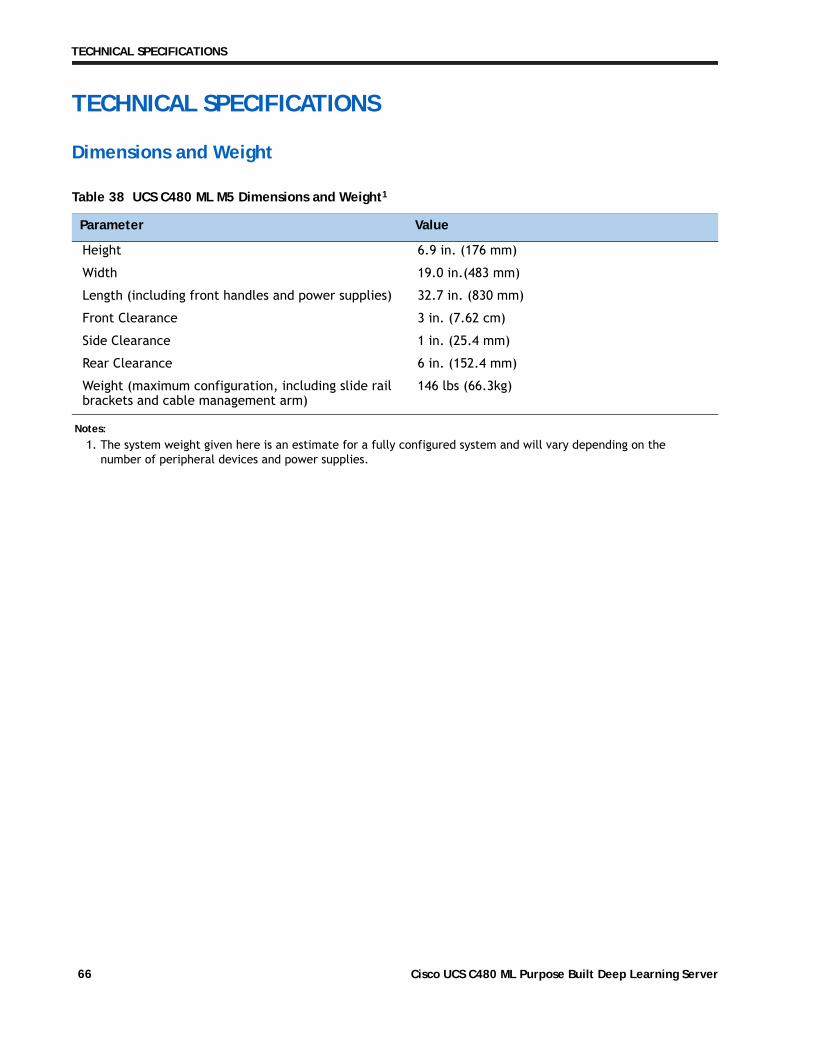
TECHNICAL SPECIFICATIONS
TECHNICAL SPECIFICATIONS
Dimensions and Weight
Table 38 UCS C480 ML M5 Dimensions and Weight1
Parameter Value
Height 6.9 in. (176 mm)
Width 19.0 in.(483 mm)
Length (including front handles and power supplies) 32.7 in. (830 mm)
Front Clearance 3 in. (7.62 cm)
Side Clearance 1 in. (25.4 mm)
Rear Clearance 6 in. (152.4 mm)
Weight (maximum configuration, including slide rail brackets and cable management arm)
146 lbs (66.3kg)
Notes:
1. The system weight given here is an estimate for a fully configured system and will vary depending on the number of peripheral devices and power supplies.
Cisco UCS C480 ML Purpose Built Deep Learning Server66

TECHNICAL SPECIFICATIONS
Power Specifications
Table 39 Power Supplies
Product ID (PID) PID Description
UCSC-PSU1-1600W Cisco UCS 1600W AC Power Supply for Rack Server
The general power specifications for the C480 ML M5 server are listed in Table 40.
Table 40 UCS C480 ML M5 1600 W (AC) Power Supply Specifications
Description Specification
AC input voltage
AC input frequency
Max AC Input current
Maximum Input VA
Maximum output power per power supply
Maximum inrush current
Maximum hold up time
Power supply output voltage
Power supply standby voltage
Efficiency rating
Form Factor
Input connector
For configuration-specific power specifications, use the Cisco UCS Power Calculator at:
http://ucspowercalc.cisco.com
Voltage Range 180 - 264 VAC
50 to 60 Hz nominal (range: 47 to 63 Hz)
< 9.5 A maximum at 200 VAC
1600 VA @200 VAC
In the 180-265 VAC range the maximum rated output power is
1600 W, not including the standby 12V power.
< 30A Peak at +35 degrees C
(charging current for EMI-X capacitors is not considered to be
inrush current)
Greater than 12 ms with 2,200 uF of load capacitance
12 VDC
12 VDC
Climate Savers Platinum Efficiency (80Plus Platinum Certified)
RSP2
IEC60320 C14 type connector
Cisco UCS C480 ML Purpose Built Deep Learning Server 67

TECHNICAL SPECIFICATIONS
Environmental Specifications
The power specifications for the C480 ML M5 server are listed in Table 41.
Table 41 UCS C480 ML M5 Environmental Specifications
Parameter Minimum
Temperature operating 10°C to 35°C (50°F to 95°F)
Temperature non-operating -40°C to 70°C (-40°F to 158°F)
Altitude -30 m to 1500 m (-100 ft to 5000 ft)
Humidity non-operating 95%, noncondensing at temperatures of 25ºC (77ºF) to 30ºC (86ºF)
Cisco UCS C480 ML Purpose Built Deep Learning Server68

TECHNICAL SPECIFICATIONS
Compliance Requirements
The regulatory compliance requirements for C-Series servers are listed in Table 42.
Table 42 UCS C-Series Regulatory Compliance Requirements
Parameter Description
Regulatory Compliance Products should comply with CE Markings per directives 2004/108/EC and 2006/95/EC
Safety UL 60950-1 Second EditionCAN/CSA-C22.2 No. 60950-1 Second EditionEN 60950-1 Second EditionIEC 60950-1 Second EditionAS/NZS 60950-1GB4943 2001
EMC - Emissions 47CFR Part 15 (CFR 47) Class A AS/NZS CISPR22 Class A CISPR22 Class AEN55022 Class A ICES003 Class A VCCI Class A EN61000-3-2EN61000-3-3KN22 Class A CNS13438 Class A
EMC - Immunity EN55024CISPR24EN300386KN24
Cisco UCS C480 ML Purpose Built Deep Learning Server 69

TECHNICAL SPECIFICATIONS
Cisco UCS C480 ML Purpose Built Deep Learning Server70