Embed Size (px)
Citation preview
Americas HeadquartersCisco Systems, Inc.170 West Tasman DriveSan Jose, CA 95134-1706 USAhttp://www.cisco.comTel: 408 526-4000
800 553-NETS (6387)Fax: 408 527-0883
Cisco Video Surveillance IP Camera User GuideCisco Video Surveillance 2421 IP Dome Model CIVS-IPC-2421
Text Part Number: OL-19960-01

NOTICE. ALL STATEMENTS, INFORMATION, AND RECOMMENDATIONS IN THIS MANUAL ARE BELIEVED TO BE ACCURATE BUT ARE PRESENTED WITHOUT WARRANTY OF ANY KIND, EXPRESS OR IMPLIED. USERS MUST TAKE FULL RESPONSIBILITY FOR THEIR APPLICATION OF ANY PRODUCTS.
THE SOFTWARE LICENSE AND LIMITED WARRANTY FOR THE ACCOMPANYING PRODUCT ARE SET FORTH IN THE INFORMATION PACKET THAT SHIPPED WITH THE PRODUCT AND ARE INCORPORATED HEREIN BY THIS REFERENCE. IF YOU ARE UNABLE TO LOCATE THE SOFTWARE LICENSE OR LIMITED WARRANTY, CONTACT YOUR CISCO REPRESENTATIVE FOR A COPY.
The Cisco implementation of TCP header compression is an adaptation of a program developed by the University of California, Berkeley (UCB) as part of UCB’s public domain version of the UNIX operating system. All rights reserved. Copyright © 1981, Regents of the University of California.
NOTWITHSTANDING ANY OTHER WARRANTY HEREIN, ALL DOCUMENT FILES AND SOFTWARE OF THESE SUPPLIERS ARE PROVIDED “AS IS” WITH ALL FAULTS. CISCO AND THE ABOVE-NAMED SUPPLIERS DISCLAIM ALL WARRANTIES, EXPRESSED OR IMPLIED, INCLUDING, WITHOUT LIMITATION, THOSE OF MERCHANTABILITY, FITNESS FOR A PARTICULAR PURPOSE AND NONINFRINGEMENT OR ARISING FROM A COURSE OF DEALING, USAGE, OR TRADE PRACTICE.
IN NO EVENT SHALL CISCO OR ITS SUPPLIERS BE LIABLE FOR ANY INDIRECT, SPECIAL, CONSEQUENTIAL, OR INCIDENTAL DAMAGES, INCLUDING, WITHOUT LIMITATION, LOST PROFITS OR LOSS OR DAMAGE TO DATA ARISING OUT OF THE USE OR INABILITY TO USE THIS MANUAL, EVEN IF CISCO OR ITS SUPPLIERS HAVE BEEN ADVISED OF THE POSSIBILITY OF SUCH DAMAGES.
CCDE, CCENT, Cisco Eos, Cisco Lumin, Cisco Nexus, Cisco StadiumVision, Cisco TelePresence, Cisco WebEx, the Cisco logo, DCE, and Welcome to the Human Network are trademarks; Changing the Way We Work, Live, Play, and Learn and Cisco Store are service marks; and Access Registrar, Aironet, AsyncOS, Bringing the Meeting To You, Catalyst, CCDA, CCDP, CCIE, CCIP, CCNA, CCNP, CCSP, CCVP, Cisco, the Cisco Certified Internetwork Expert logo, Cisco IOS, Cisco Press, Cisco Systems, Cisco Systems Capital, the Cisco Systems logo, Cisco Unity, Collaboration Without Limitation, EtherFast, EtherSwitch, Event Center, Fast Step, Follow Me Browsing, FormShare, GigaDrive, HomeLink, Internet Quotient, IOS, iPhone, iQuick Study, IronPort, the IronPort logo, LightStream, Linksys, MediaTone, MeetingPlace, MeetingPlace Chime Sound, MGX, Networkers, Networking Academy, Network Registrar, PCNow, PIX, PowerPanels, ProConnect, ScriptShare, SenderBase, SMARTnet, Spectrum Expert, StackWise, The Fastest Way to Increase Your Internet Quotient, TransPath, WebEx, and the WebEx logo are registered trademarks of Cisco Systems, Inc. and/or its affiliates in the United States and certain other countries.
All other trademarks mentioned in this document or website are the property of their respective owners. The use of the word partner does not imply a partnership relationship between Cisco and any other company. (0809R)
Cisco Video Surveillance System IP Camera User Guide, Cisco Video Surveillance 2421 IP Dome Model CIVS-IPC-2421 Copyright © 2008, 2009 Cisco Systems, Inc. All rights reserved.
Cisco Video Surveillance System IP CaOL-19960-01
C O N T E N T S
Preface 1-v
C H A P T E R 1 Overview 1-1
Features 1-1
IP Camera Overview 1-2
Physical Details 1-2
Package Contents 1-5
C H A P T E R 2 Getting Started 2-1
Before Your Begin 2-1
Installing the Cisco Video Surveillance 2421 IP Dome 2-2
Preparing for Installation 2-3
Recessed Mounting in a Ceiling Tile 2-3
Surface Mounting on a Solid Surface 2-6
Performing the Initial Setup of the IP Camera 2-9
Accessing the IP Camera Windows 2-11
Adjusting the Video Image 2-12
Powering the IP Camera On or Off 2-14
Resetting the IP Camera 2-14
Cleaning the IP Camera 2-15
C H A P T E R 3 Configuring and Managing the IP Camera 3-1
Configuration Overview 3-1
Navigating the Configuration Windows 3-3
Setup Windows 3-4
Basic Setup Window 3-5
Advanced Setup Window 3-6
IP Filter Window 3-8
EAPOL Window 3-9
Administration Windows 3-10
Users Window 3-10
Maintenance Window 3-12
iiimera User Guide, Cisco Video Surveillance 2421 IP Dome Model CIVS-IPC-2421
Contents
Firmware Window 3-13
Audio/Video Window 3-14
Security Windows 3-18
Product Process Window 3-18
Initialization Window 3-19
Complexity Window 3-19
Applications Windows 3-20
Mail & FTP Window 3-20
Motion Detection Window 3-23
Event Window 3-23
SNMP Window 3-26
Status Windows 3-26
System Window 3-26
Audio/Video Window 3-27
Network Window 3-28
Syslog & Log Window 3-28
Video Log Window 3-33
C H A P T E R 4 Viewing and Live Video 4-1
Viewing Video through the Home Window Overview 4-1
Home Window Overview 4-1
Home Window Controls 4-3
Viewing Video through Third-Party Devices or Software 4-4
C H A P T E R 5 Troubleshooting 5-1
A P P E N D I X A Using the IP Camera with Cisco VSM 1-1
I N D E X
ivCisco Video Surveillance System IP Camera User Guide, Cisco Video Surveillance 2421 IP Dome Model CIVS-IPC-2421
OL-19960-01
Preface
This document, Cisco Video Surveillance IP Camera User Guide provides information about installing, configuring, using, managing, and troubleshooting the Cisco Video Surveillance 2421 IP Dome model CIVS-IPC-2421.
OrganizationThis manual is organized as follows:
Obtaining Documentation, Obtaining Support, and Security Guidelines
For information about obtaining documentation, submitting a service request, and gathering additional information, see the monthly What’s New in Cisco Product Documentation, which also lists all new and revised Cisco technical documentation, at:
http://www.cisco.com/en/US/docs/general/whatsnew/whatsnew.html
Subscribe to the What’s New in Cisco Product Documentation as a Really Simple Syndication (RSS) feed and set content to be delivered directly to your desktop using a reader application. The RSS feeds are a free service and Cisco currently supports RSS version 2.0.
Chapter 1, “Overview” Provides an overview of the IP camera and its features
Chapter 2, “Getting Started” Provides instructions for installing and performing the initial setup of the IP camera, connecting to the IP camera so that you can configure it or view video from it, powering the IP camera on and off, resetting the IP camera, and adjusting its back focus
Chapter 3, “Configuring and Managing the IP Camera”
Explains how to configure, manage, and administer the IP camera through the web-based interface
Chapter 4, “Viewing and Live Video” Explains how to view live video from the IP camera
Chapter 5, “Troubleshooting” Provides basic troubleshooting information
Appendix A, “Using the IP Camera with Cisco VSM”
Provides information about using the IP camera with Cisco Video Surveillance Manager (VSM)
vCisco Video Surveillance System IP Camera User Guide, Cisco Video Surveillance 2421 IP Dome Model CIVS-IPC-2421
OL-19960-01

Preface
viCisco Video Surveillance System IP Camera User Guide, Cisco Video Surveillance 2421 IP Dome Model CIVS-IPC-2421
OL-19960-01
Cisco Video Surveillance System IP Camera User Guide, Cisco VidOL-19960-01
C H A P T E R 1
OverviewThis chapter provides an overview of the Cisco Video Surveillance 2421 IP Dome model CIVS-IPC-2421 features. It includes these topics:
• Features, page 1-1
• IP Camera Overview, page 1-2
FeaturesThe Cisco Video Surveillance IP cameras offer a feature-rich digital camera solution for a video surveillance system. They provide high-quality, bandwidth-efficient video capture and transmission, with support for D1 resolution, motion-triggered viewing, and MPEG-4 encoding. The IP camera can be powered through an external power supply or by integrated Power over Ethernet (PoE).
In addition, the devices provide networking and security capabilities, including multicast support, hardware-based Advanced Encryption Standard (AES), and hardware-based Data Encryption Standard/Triple Data Encryption Standard (DES/3DES) encryption.
The IP camera includes the following key features:
• Built-in MPEG4 encoder—An internal MPEG4 encoder can generate up to two video streams.
• Built-in MJPEG encoder—An internal MJPEG encoder can generate the primary or secondary video stream.
• Day/night switch support—An IR-cut filter provides increased sensitivity in low-light conditions.
• Multi-protocol support—Supports these protocols: DHCP, FTP, HTTP, HTTPS, NTP, RTP, RTSP, SMTP, SSL/TLS, and TCP/IP.
• Web-based management—You perform ongoing administration and management of the IP camera through web-based configuration menus.
• Motion detection—The IP camera can detect motion in up to three designated fields of view by analyzing changes in pixels and generate an alert if motion is detected.
• Flexible scheduling—You can configure the IP camera to respond to events that occur within a designated schedule.
• Syslog support—The IP camera can send log data to a Syslog server.
• IP address filter—You can designate IP addresses that can access the IP camera and IP addresses that cannot access the IP camera.
• User-definable HTTP/ HTTPS port number—Allows you to define the port that is used to connect to the camera through the Internet.
1-1eo Surveillance 2421 IP Dome Model CIVS-IPC-2421
Chapter 1 OverviewIP Camera Overview
• DHCP support—The IP camera can automatically obtain its IP addresses in a network in which DHCP is enabled.
• Network Time Protocol (NTP) support—Allows the IP camera to calibrate its internal clock with a local or Internet time server.
• Power options—The IP camera model can be powered with 12 volts DC, which is provided through an optional external power adapter, or through PoE (802.3af), which is provided through a supported switch. The IP camera can also be powered with 24 volts AC, provided through an optional external power adapter.
• Camera access control—You can control access to IP camera configuration windows and live video by configuring various user types and log in credentials.
• Cisco Media API—The IP camera supports the open, standards based, Cisco Media Application Programming Interface.
IP Camera OverviewThe following sections provide information about the Cisco Video Surveillance IP Camera:
• Physical Details, page 1-2
• Package Contents, page 1-5
Physical DetailsFigure 1-1 and the table that follows describe the items on the top of the 2421 IP dome.
1-2Cisco Video Surveillance System IP Camera User Guide, Cisco Video Surveillance 2421 IP Dome Model CIVS-IPC-2421
OL-19960-01
Chapter 1 OverviewIP Camera Overview
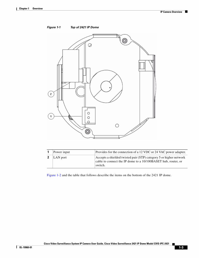
Figure 1-1 Top of 2421 IP Dome
Figure 1-2 and the table that follows describe the items on the bottom of the 2421 IP dome.
1 Power input Provides for the connection of a 12 VDC or 24 VAC power adapter.
2 LAN port Accepts a shielded twisted pair (STP) category 5 or higher network cable to connect the IP dome to a 10/100BASET hub, router, or switch.
1-3Cisco Video Surveillance System IP Camera User Guide, Cisco Video Surveillance 2421 IP Dome Model CIVS-IPC-2421
OL-19960-01
Chapter 1 OverviewIP Camera Overview
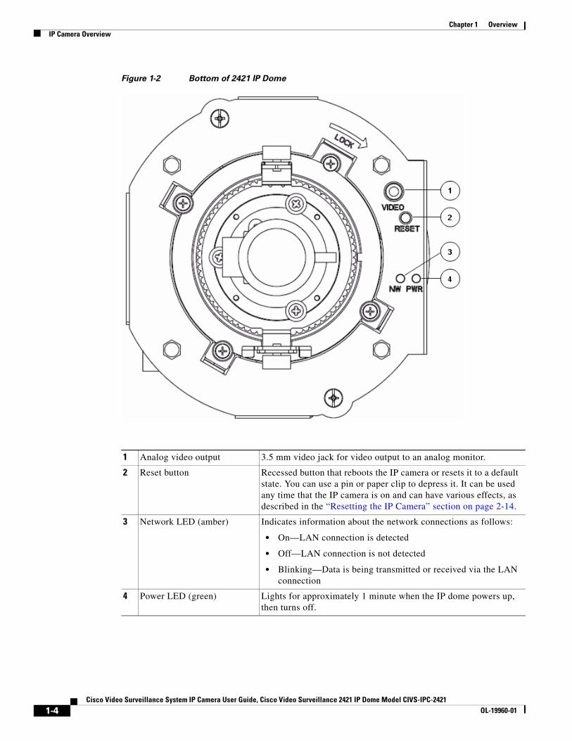
Figure 1-2 Bottom of 2421 IP Dome
1 Analog video output 3.5 mm video jack for video output to an analog monitor.
2 Reset button Recessed button that reboots the IP camera or resets it to a default state. You can use a pin or paper clip to depress it. It can be used any time that the IP camera is on and can have various effects, as described in the “Resetting the IP Camera” section on page 2-14.
3 Network LED (amber) Indicates information about the network connections as follows:
• On—LAN connection is detected
• Off—LAN connection is not detected
• Blinking—Data is being transmitted or received via the LAN connection
4 Power LED (green) Lights for approximately 1 minute when the IP dome powers up, then turns off.
1-4Cisco Video Surveillance System IP Camera User Guide, Cisco Video Surveillance 2421 IP Dome Model CIVS-IPC-2421
OL-19960-01
Chapter 1 OverviewIP Camera Overview
Package ContentsThe 2421 IP Dome camera package includes these items:
• Camera
• 0.9 mm Allen wrench for adjusting back focus
• Mini cable with BNC adapter
• Snap-on ferrite core
• Regulatory Compliance and Safety Information
• Quick Start Guide
1-5Cisco Video Surveillance System IP Camera User Guide, Cisco Video Surveillance 2421 IP Dome Model CIVS-IPC-2421
OL-19960-01

Chapter 1 OverviewIP Camera Overview
1-6Cisco Video Surveillance System IP Camera User Guide, Cisco Video Surveillance 2421 IP Dome Model CIVS-IPC-2421
OL-19960-01
Cisco Video Surveillance System IP Camera User Guide, Cisco VidOL-19960-01
C H A P T E R 2
Getting StartedThis chapter provides instructions for installing and performing the initial setup of the Cisco Video Surveillance IP Camera. It also describes how to access the IP camera through a web browser so that you can configure it or view video from it, and how to perform other important tasks.
This chapter includes these topics:
• Before Your Begin, page 2-1
• Installing the Cisco Video Surveillance 2421 IP Dome, page 2-2
• Performing the Initial Setup of the IP Camera, page 2-9
• Accessing the IP Camera Windows, page 2-11
• Adjusting the Video Image, page 2-12
• Powering the IP Camera On or Off, page 2-14
• Resetting the IP Camera, page 2-14
• Cleaning the IP Camera, page 2-15
Before Your BeginBefore you install the IP camera, review these guidelines:
• The IP camera requires a shielded twisted pair (STP) category 5 or higher network cable and a connection to a standard 10/100BaseT hub, router, or switch. To power the IP camera with Power over Ethernet (PoE), a switch must be 802.3af compliant.
• If you are using the on a network connection that does not provide PoE, you must use a 12 VDC or 24 VAC source that is isolated from the ground (floating output).
Warning Installation of the equipment must comply with local and national electrical codes. Statement 1074
Warning The power supply must be placed indoors. Statement 331
Note If you use the IP camera outdoors, place the camera and the power supply in a suitable NEMA enclosure.
2-1eo Surveillance 2421 IP Dome Model CIVS-IPC-2421
Chapter 2 Getting StartedInstalling the Cisco Video Surveillance 2421 IP Dome
Warning This product requires short-circuit (overcurrent) protection, to be provided as part of the building installation. Install only in accordance with national and local wiring regulations. Statement 1045
Warning This product must be connected to a power-over-ethernet (PoE) IEEE 802.3af compliant power source or an IEC60950 compliant limited power source. Statement 353
Warning The plug-socket combination must be accessible at all times, because it serves as the main disconnecting device. Statement 1019
Caution Inline power circuits provide current through the communication cable. Use the Cisco provided cable or a minimum 24AWG communication cable
Warning This product requires short-circuit (overcurrent) protection, to be provided as part of the building installation. Install only in accordance with national and local wiring regulations. Statement 1045
Preventing Electrostatic Discharge Damage
• Camera components can be damaged by static electricity. Not exercising the proper electrostatic discharge (ESD) precautions can result in intermittent or complete component failures, and cause the camera to malfunction.
• To minimize the potential for ESD damage:
– Before you install the IP camera, touch a metal object with your hand to release any static electricity that is in your body.
– Always use an ESD-preventive antistatic wrist strap (or ankle strap) and ensure that it makes good skin contact.
– For safety, periodically check the resistance value of the antistatic strap. The measurement should be between 1 and 10 megohm (Mohm).
In addition, follow these guidelines during installation:
• Handle camera unit by holding the edges only; avoid touching the printed circuit boards
• Never attempt to remove the printed circuit board
Installing the Cisco Video Surveillance 2421 IP DomeThe following sections describes how to install the Cisco Video Surveillance 2421 IP dome. Installing involves mounting the IP dome by using the procedure that is appropriate for your deployment.
• Preparing for Installation, page 2-3
• Recessed Mounting in a Ceiling Tile, page 2-3
• Surface Mounting on a Solid Surface, page 2-6
2-2Cisco Video Surveillance System IP Camera User Guide, Cisco Video Surveillance 2421 IP Dome Model CIVS-IPC-2421
OL-19960-01
Chapter 2 Getting StartedInstalling the Cisco Video Surveillance 2421 IP Dome
Preparing for InstallationBefore you install the 2421 IP dome, take these actions:
• Carefully unpack the IP dome and its components.
• Run an STP category 5 or higher network cable to the mounting location.
• If the IP dome will not be powered from POE, run a power cable from a 12 VDC or 24 VAC power adapter to the mounting location.
Use a cable gauge that is appropriate for the distance from the IP dome to the power supply (consult a qualified electrician for more information). The terminal connectors on the IP dome support gauges from 14 AWG to 24 AWG. At the end of the wire that attaches to the IP dome, strip enough cable housing to allow each wire to be stripped to 1/4 inch (6.25 mm).
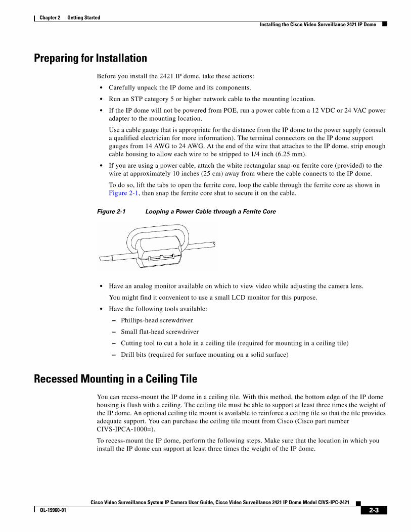
• If you are using a power cable, attach the white rectangular snap-on ferrite core (provided) to the wire at approximately 10 inches (25 cm) away from where the cable connects to the IP dome.
To do so, lift the tabs to open the ferrite core, loop the cable through the ferrite core as shown in Figure 2-1, then snap the ferrite core shut to secure it on the cable.
Figure 2-1 Looping a Power Cable through a Ferrite Core
• Have an analog monitor available on which to view video while adjusting the camera lens.
You might find it convenient to use a small LCD monitor for this purpose.
• Have the following tools available:
– Phillips-head screwdriver
– Small flat-head screwdriver
– Cutting tool to cut a hole in a ceiling tile (required for mounting in a ceiling tile)
– Drill bits (required for surface mounting on a solid surface)
Recessed Mounting in a Ceiling TileYou can recess-mount the IP dome in a ceiling tile. With this method, the bottom edge of the IP dome housing is flush with a ceiling. The ceiling tile must be able to support at least three times the weight of the IP dome. An optional ceiling tile mount is available to reinforce a ceiling tile so that the tile provides adequate support. You can purchase the ceiling tile mount from Cisco (Cisco part number CIVS-IPCA-1000=).
To recess-mount the IP dome, perform the following steps. Make sure that the location in which you install the IP dome can support at least three times the weight of the IP dome.
2-3Cisco Video Surveillance System IP Camera User Guide, Cisco Video Surveillance 2421 IP Dome Model CIVS-IPC-2421
OL-19960-01
Chapter 2 Getting StartedInstalling the Cisco Video Surveillance 2421 IP Dome
Note When you disassemble the IP dome for mounting as described in these steps, make sure to remove any protective packing material that is installed between components.
Procedure
Step 1 Remove the ceiling tile from the location at which you want to mount the IP dome and cut a 5-13/16 inch (14.76 cm) diameter hole in the center of the tile.
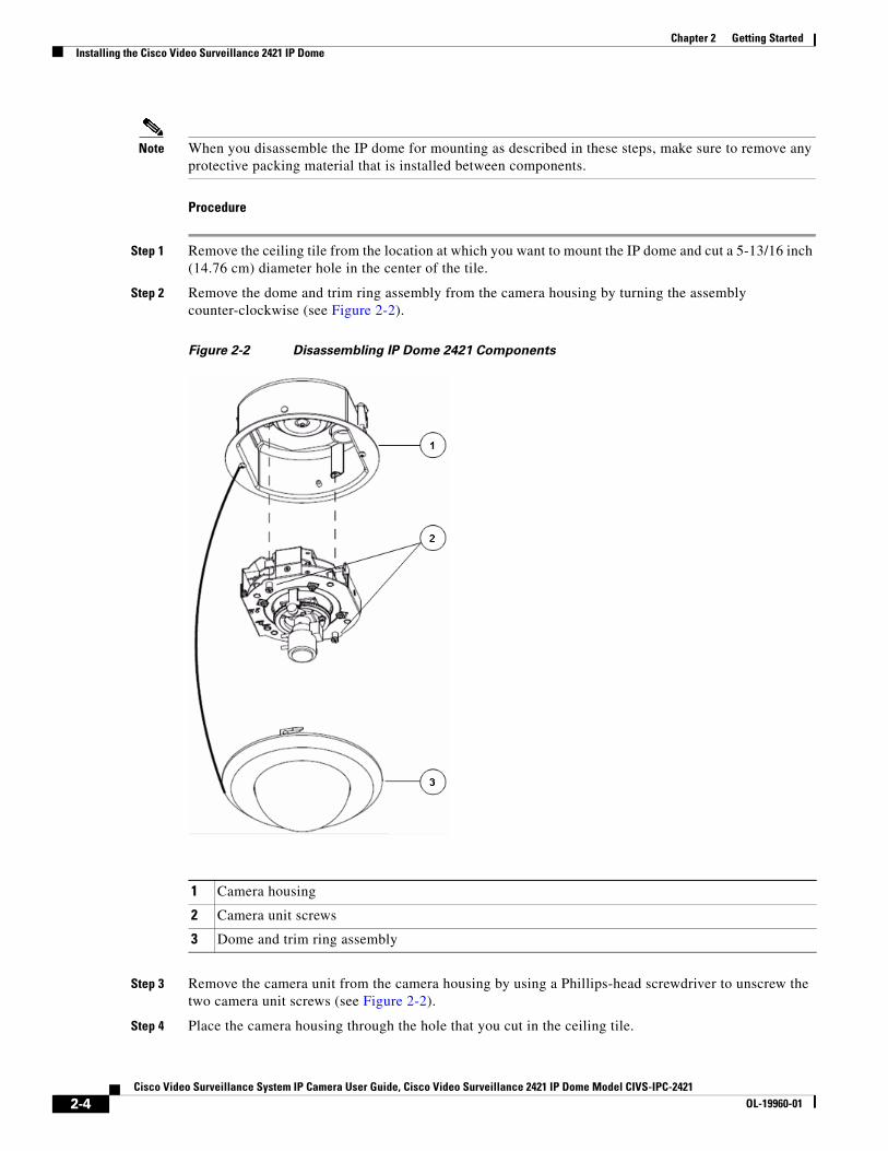
Step 2 Remove the dome and trim ring assembly from the camera housing by turning the assembly counter-clockwise (see Figure 2-2).
Figure 2-2 Disassembling IP Dome 2421 Components
Step 3 Remove the camera unit from the camera housing by using a Phillips-head screwdriver to unscrew the two camera unit screws (see Figure 2-2).
Step 4 Place the camera housing through the hole that you cut in the ceiling tile.
1 Camera housing
2 Camera unit screws
3 Dome and trim ring assembly
2-4Cisco Video Surveillance System IP Camera User Guide, Cisco Video Surveillance 2421 IP Dome Model CIVS-IPC-2421
OL-19960-01
Chapter 2 Getting StartedInstalling the Cisco Video Surveillance 2421 IP Dome
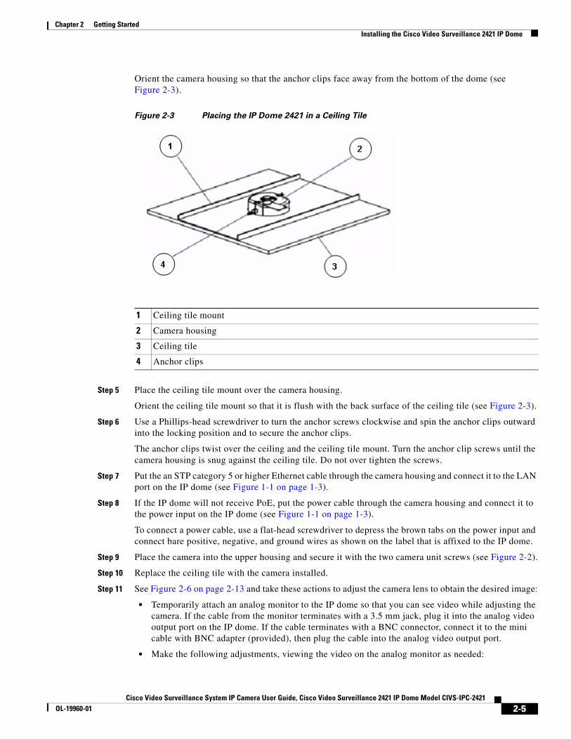
Orient the camera housing so that the anchor clips face away from the bottom of the dome (see Figure 2-3).
Figure 2-3 Placing the IP Dome 2421 in a Ceiling Tile
Step 5 Place the ceiling tile mount over the camera housing.
Orient the ceiling tile mount so that it is flush with the back surface of the ceiling tile (see Figure 2-3).
Step 6 Use a Phillips-head screwdriver to turn the anchor screws clockwise and spin the anchor clips outward into the locking position and to secure the anchor clips.
The anchor clips twist over the ceiling and the ceiling tile mount. Turn the anchor clip screws until the camera housing is snug against the ceiling tile. Do not over tighten the screws.
Step 7 Put the an STP category 5 or higher Ethernet cable through the camera housing and connect it to the LAN port on the IP dome (see Figure 1-1 on page 1-3).
Step 8 If the IP dome will not receive PoE, put the power cable through the camera housing and connect it to the power input on the IP dome (see Figure 1-1 on page 1-3).
To connect a power cable, use a flat-head screwdriver to depress the brown tabs on the power input and connect bare positive, negative, and ground wires as shown on the label that is affixed to the IP dome.
Step 9 Place the camera into the upper housing and secure it with the two camera unit screws (see Figure 2-2).
Step 10 Replace the ceiling tile with the camera installed.
Step 11 See Figure 2-6 on page 2-13 and take these actions to adjust the camera lens to obtain the desired image:
• Temporarily attach an analog monitor to the IP dome so that you can see video while adjusting the camera. If the cable from the monitor terminates with a 3.5 mm jack, plug it into the analog video output port on the IP dome. If the cable terminates with a BNC connector, connect it to the mini cable with BNC adapter (provided), then plug the cable into the analog video output port.
• Make the following adjustments, viewing the video on the analog monitor as needed:
1 Ceiling tile mount
2 Camera housing
3 Ceiling tile
4 Anchor clips
2-5Cisco Video Surveillance System IP Camera User Guide, Cisco Video Surveillance 2421 IP Dome Model CIVS-IPC-2421
OL-19960-01
Chapter 2 Getting StartedInstalling the Cisco Video Surveillance 2421 IP Dome
– Back focus—If needed, use the 0.9 mm Allen wrench that is supplied with the IP camera to loosen the back focus hex screw, then adjust the back focus by aiming the IP camera at an object that is at least 15 feet (4.5 meters) away and gently sliding the lens toward or away from the camera. Take care not to pull the lens completely away from the camera.Obtain a sharp picture in both wide-angle and telephoto positions. When the focus is set as desired, use the Allen wrench to tighten the back focus hex screw.
– Pan—Use a Phillips-head to loosen the panning lock screw, then rotate the camera to obtain the desired image, then tighten the panning lock screw.
– Tilt—Loosen the two tilt lock screws, adjust the lens to obtain the desired image, then tighten the screws.
– Zoom—Loosen the zoom lock screw, rotate the collar to obtain the desired image, then tighten the screw.
– Focus—Loosen the focus lock screw, rotate the collar to obtain the desired image, then tighten the screw.
Make sure to adjust the privacy shield inside the dome and trim ring assembly so that it does not block the lens from capturing video.
Step 12 Attach the dome and trim ring assembly by positioning the open end of the hooks toward the steel pegs on the camera unit, lifting it into onto the camera unit, and twisting clockwise.
Make sure that the security strap that connects the dome assembly to the camera housing is in place.
Surface Mounting on a Solid SurfaceYou can surface-mount the IP dome on any surface to which you can attach appropriate fasteners. This method requires the surface shroud, which you can purchase from Cisco (Cisco part number CIVS-IPCS-1003=).
For surfaces that are up to 2 inches (53.34 cm) thick, use the toggle bolts that are provided with the surface shroud. For thicker surfaces, you must obtain and use the appropriate anchor screws.
To surface-mount the IP dome, perform the following steps.
Note When you disassemble the IP dome for mounting as described in these steps, make sure to remove any protective packing material that is installed between components.
Procedure
Step 1 At the location where you want to install the IP dome, use the surface shroud as a template to mark two screw holes and a hole for cabling.
Step 2 Drill screw holes and cabling hole at the locations that you marked.
The screw holes should be the appropriate size for the mounting hardware that you are using. The cabling hole should be large enough to accommodate the cables that will attache to the IP dome.
Step 3 Remove dome and trim ring assembly from the camera housing by turning assembly counter-clockwise (see Figure 2-4).
2-6Cisco Video Surveillance System IP Camera User Guide, Cisco Video Surveillance 2421 IP Dome Model CIVS-IPC-2421
OL-19960-01
Chapter 2 Getting StartedInstalling the Cisco Video Surveillance 2421 IP Dome
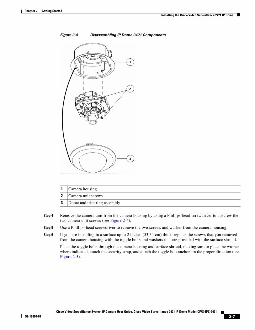
Figure 2-4 Disassembling IP Dome 2421 Components
Step 4 Remove the camera unit from the camera housing by using a Phillips-head screwdriver to unscrew the two camera unit screws (see Figure 2-4).
Step 5 Use a Phillips-head screwdriver to remove the two screws and washer from the camera housing.
Step 6 If you are installing in a surface up to 2 inches (53.34 cm) thick, replace the screws that you removed from the camera housing with the toggle bolts and washers that are provided with the surface shroud.
Place the toggle bolts through the camera housing and surface shroud, making sure to place the washer where indicated, attach the security strap, and attach the toggle bolt anchors in the proper direction (see Figure 2-5).
1 Camera housing
2 Camera unit screws
3 Dome and trim ring assembly
2-7Cisco Video Surveillance System IP Camera User Guide, Cisco Video Surveillance 2421 IP Dome Model CIVS-IPC-2421
OL-19960-01
Chapter 2 Getting StartedInstalling the Cisco Video Surveillance 2421 IP Dome
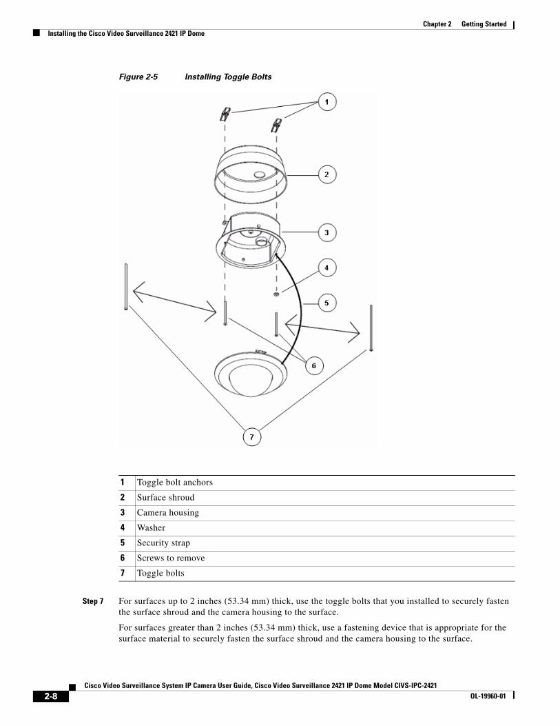
Figure 2-5 Installing Toggle Bolts
Step 7 For surfaces up to 2 inches (53.34 mm) thick, use the toggle bolts that you installed to securely fasten the surface shroud and the camera housing to the surface.
For surfaces greater than 2 inches (53.34 mm) thick, use a fastening device that is appropriate for the surface material to securely fasten the surface shroud and the camera housing to the surface.
1 Toggle bolt anchors
2 Surface shroud
3 Camera housing
4 Washer
5 Security strap
6 Screws to remove
7 Toggle bolts
2-8Cisco Video Surveillance System IP Camera User Guide, Cisco Video Surveillance 2421 IP Dome Model CIVS-IPC-2421
OL-19960-01
Chapter 2 Getting StartedPerforming the Initial Setup of the IP Camera
Step 8 Put the an STP category 5 or higher Ethernet cable through the camera housing and connect it to the LAN port on the IP dome (see Figure 1-1 on page 1-3).
Step 9 If the IP dome will not receive PoE, put the power cable through the camera housing and connect it to the power input on the IP dome (see Figure 1-1 on page 1-3).
To connect a power cable, use a flat-head screwdriver to depress the brown tabs on the power input and connect bare positive, negative, and ground wires as shown on the label that is affixed to the IP dome.
Step 10 Place the camera into the upper housing and secure it with the two camera unit screws (see Figure 2-2).
Step 11 See Figure 2-6 on page 2-13 and take these actions to adjust the camera lens to obtain the desired image:
• Temporarily attach an analog monitor to the IP dome so that you can see video while adjusting the camera. If the cable from the monitor terminates with a 3.5 mm jack, plug it into the analog video output port on the IP dome. If the cable terminates with a BNC connector, connect it to the mini cable with BNC adapter (provided), then plug the cable into the analog video output port.
• Make the following adjustments, viewing the video on the analog monitor as needed:
– Back focus—If needed, use the 0.9 mm Allen wrench that is supplied with the IP camera to loosen the back focus hex screw, then adjust the back focus by aiming the IP camera at an object that is at least 15 feet (4.5 meters) away and gently sliding the lens toward or away from the camera. Take care not to pull the lens completely away from the camera.Obtain a sharp picture in both wide-angle and telephoto positions. When the focus is set as desired, use the Allen wrench to tighten the back focus hex screw.
– Pan—Use a Phillips-head to loosen the panning lock screw, then rotate the camera to obtain the desired image, then tighten the panning lock screw.
– Tilt—Loosen the two tilt lock screws, adjust the lens to obtain the desired image, then tighten the screws.
– Zoom—Loosen the zoom lock screw, rotate the collar to obtain the desired image, then tighten the screw.
– Focus—Loosen the focus lock screw, rotate the collar to obtain the desired image, then tighten the screw.
Make sure to adjust the privacy shield inside the dome and trim ring assembly so that it does not block the lens from capturing video.
Step 12 Attach the dome and trim ring assembly by positioning the open end of the hooks toward the steel pegs on the camera unit, lifting it into onto the camera unit, and twisting clockwise.
Make sure that the security strap that connects the dome assembly to the camera housing is in place.
Performing the Initial Setup of the IP CameraAfter you install IP camera, or after you perform a factory reset procedure, you must access the IP camera and make initial configuration settings. These settings include administrator and root passwords, and whether the IP camera can be accessed through an HTTP connection in addition to the default HTTPS (HTTP secure) connection.
To make these configuration settings, you connect to the IP camera from any PC that is on the same network as the IP camera. The PC must meet these requirements:
• Operating system—Microsoft Windows 2000, XP, or Vista
• Browser—Internet Explorer 6.x with Service Pack 2, or later
2-9Cisco Video Surveillance System IP Camera User Guide, Cisco Video Surveillance 2421 IP Dome Model CIVS-IPC-2421
OL-19960-01
Chapter 2 Getting StartedPerforming the Initial Setup of the IP Camera
In addition, you must know the IP address of the IP camera. By default, when the IP camera powers on, it attempts to obtain an IP address from a DHCP server in your network. If the camera cannot obtain an IP address through DCHP within 90 seconds, it uses a default IP address of 192.168.0.100.
To connect to the IP camera for the first time and make initial configuration settings, perform the following steps. You can change these configuration settings in the future as described in the “Initialization Window” section on page 3-19.
Procedure
Step 1 Start Internet Explorer, enter HTTPS://ip_address in the address field, and press Enter.
Replace ip_address with the IP address that the IP camera obtained through DHCP or, if the camera is unable to obtain this IP address, enter 192.168.0.100.
The Account window appears.
Step 2 In the Set Password and Verify Password fields in the Admin column, enter a password for the IP camera administrator.
You must enter the same password in both fields. The password is case sensitive and must contain at least eight characters, which can be letters, numbers, and special characters, but no spaces. Special characters are: ! " # $ % & ' ( ) * + , - . : ; < = > ? @ [ \ ] ^ _ ` { | } ~.
Step 3 In the Set Password and Verify Password fields in the Root column, enter a password that is used when accessing the IP camera through a Secure Shell (SSH) connection.
You must enter the same password in both fields. The password is case sensitive and must contain at least eight characters, which can be letters, numbers, and special characters, but no spaces. Special characters are: ! " # $ % & ' ( ) * + , - . : ; < = > ? @ [ \ ] ^ _ ` { | } ~.
You use the root password if you need to troubleshoot the IP camera through a SSH connection with the assistance of the Cisco Technical Assistance Center.
Step 4 In the HTTP area, click the HTTP radio button if you want to allow both HTTP and HTTPS connections to the IP camera.
The default setting is HTTPS, which allows only HTTPS (secure) connections to the IP camera.
Step 5 Click Apply.
The IP camera reboots.
Step 6 After the IP camera reboots, start Internet Explorer and, in the Address field, enter the following:
protocol://ip_address
where:
• protocol is HTTPS or HTTP. (You can use HTTP only if you enabled it in Step 4.)
• ip_address is the IP address that you used in Step 1.
Step 7 If you are prompted to install ActiveX controls, which are required to view video from the IP camera, follow the on-screen prompts to do so.
The Main window appears and video from the IP camera starts playing automatically.
You can take these actions in the Main window:
• Click the Setup link to access configuration menus for the camera. For detailed information about these menus, see Chapter 3, “Configuring and Managing the IP Camera.”
• Click the Home link to view and control live video from the camera. For detailed information about these actions, see Chapter 4, “Viewing and Live Video.”
2-10Cisco Video Surveillance System IP Camera User Guide, Cisco Video Surveillance 2421 IP Dome Model CIVS-IPC-2421
OL-19960-01
Chapter 2 Getting StartedAccessing the IP Camera Windows
• Click the Logout button to exit the window.
Accessing the IP Camera WindowsAfter you perform the initial configuration as described in the “Performing the Initial Setup of the IP Camera” section on page 2-9, follow the steps in this section each time that you want to access the IP camera windows to make configuration settings or view live video.
You access these windows by connecting to the IP camera from any PC that is on the same network as the IP camera and that meets these requirements:
• Operating system—Microsoft Windows 2000, Windows XP, or Vista
• Browser—Internet Explorer 6.x with Service Pack 2, or later
You need this information to access the IP camera windows:
• IP address of the IP camera. By default, the IP camera attempts to obtain an IP address from a DHCP server in your network. If the IP camera cannot obtain an IP address through DHCP within 90 seconds of powering up or resetting, it uses the default IP address of 192.168.0.100.
• Port number, if other than the default value. Default port numbers for the IP camera are 443 for HTTPS and 80 for HTTP. The IP camera administrator can enable an alternative HTTPS port and an alternative HTTP port as described in the “Advanced Setup Window” section on page 3-6.
• Your user name and password for the IP camera. The IP camera administrator configures user names and passwords as described in the “Users Window” section on page 3-10.
To access the IP camera windows, follow these steps:
Procedure
Step 1 Start Internet Explorer and enter the following in the address field:
protocol://ip_address:port_number
where:
• protocol is HTTPS for a secure connection or HTTP for a non-secure connection. You can use HTTP only if you configure the camera to accept non-secure HTTP connections as described in the “Performing the Initial Setup of the IP Camera” section on page 2-9.
• ip_address is the IP address of the IP camera. The default IP address is 192.168.0.100.
• port_number is the port number that is used for HTTPS or HTTP connections to the IP camera. You do not need to enter a port number if you are connecting through the default HTTPS port 443 or the default HTTP port 80.
For example,
• Enter the following for a secure connection if the IP address is 192.168.0.100 and the HTTPS port number is 443:
https://192.168.0.100
• Enter the following for a secure connection if the IP address is 203.70.212.52 and the HTTPS port number is 1024:
https://203.70.212.52:1024
2-11Cisco Video Surveillance System IP Camera User Guide, Cisco Video Surveillance 2421 IP Dome Model CIVS-IPC-2421
OL-19960-01
Chapter 2 Getting StartedAdjusting the Video Image
• Enter the following for a non-secure connection if the IP address is 203.70.212.52 and the HTTP port number is 80:
http://203.70.212.52
• Enter the following for a non-secure connection if the IP address is 203.70.212.52 and the HTTP port number is 1024:
http://203.70.212.52:1024
Step 2 Enter your IP camera user name and password when prompted, then click OK.
To log in as the IP camera administrator, enter the user name admin (all lower case) and the password that is configured for the administrator. To log in as a user, enter the user name and password that are configured for the user.
The Main window appears and video from the IP camera starts playing automatically. You can take these actions in the Main window:
• Click the Setup link to access configuration menus for the camera. For detailed information about these menus, see Chapter 3, “Configuring and Managing the IP Camera.”
• Click the Home link to view and control live video from the camera. For detailed information about these actions, see Chapter 4, “Viewing and Live Video.”
• Click the Logout button to exit the window.
Adjusting the Video ImageAs part of the IP camera installation process, you make back focus, pan, tilt, zoom, and focus settings for the camera in the dome. If you ever need to change these settings, follow these steps:
Procedure
Step 1 Remove the IP dome assembly by twisting the dome and trim ring assembly counter-clockwise and pulling it away from the camera housing
Step 2 See Figure 2-6 and take these actions to adjust the camera lens to obtain the desired image:
• Temporarily attach an analog monitor to the IP dome so that you can see video while adjusting the camera. If the cable from the monitor terminates with a 3.5 mm jack, plug it into the analog video output port on the IP dome. If the cable terminates with a BNC connector, connect it to the mini cable with BNC adapter (provided), then plug the cable into the analog video output port.
• Make the following adjustments, viewing the video on the analog monitor as needed:
– Back focus—If needed, use the 0.9 mm Allen wrench that is supplied with the IP camera to loosen the back focus hex screw, then adjust the back focus by aiming the IP camera at an object that is at least 15 feet (4.5 meters) away and gently sliding the lens toward or away from the camera. Take care not to pull the lens completely away from the camera.Obtain a sharp picture in both wide-angle and telephoto positions. When the focus is set as desired, use the Allen wrench to tighten the back focus hex screw.
– Pan—Use a Phillips-head to loosen the panning lock screw, then rotate the camera to obtain the desired image, then tighten the panning lock screw.
– Tilt—Loosen the two tilt lock screws, adjust the lens to obtain the desired image, then tighten the screws.
2-12Cisco Video Surveillance System IP Camera User Guide, Cisco Video Surveillance 2421 IP Dome Model CIVS-IPC-2421
OL-19960-01
Chapter 2 Getting StartedAdjusting the Video Image
– Zoom—Loosen the zoom lock screw, rotate the collar to obtain the desired image, then tighten the screw.
– Focus—Loosen the focus lock screw, rotate the collar to obtain the desired image, then tighten the screw.
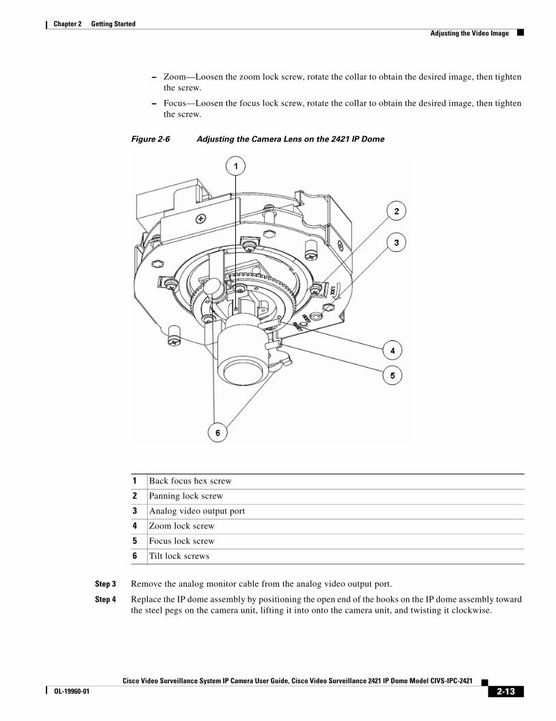
Figure 2-6 Adjusting the Camera Lens on the 2421 IP Dome
Step 3 Remove the analog monitor cable from the analog video output port.
Step 4 Replace the IP dome assembly by positioning the open end of the hooks on the IP dome assembly toward the steel pegs on the camera unit, lifting it into onto the camera unit, and twisting it clockwise.
1 Back focus hex screw
2 Panning lock screw
3 Analog video output port
4 Zoom lock screw
5 Focus lock screw
6 Tilt lock screws
2-13Cisco Video Surveillance System IP Camera User Guide, Cisco Video Surveillance 2421 IP Dome Model CIVS-IPC-2421
OL-19960-01
Chapter 2 Getting StartedPowering the IP Camera On or Off
Powering the IP Camera On or OffThe IP camera does not include an on/off switch. You power it on or off by connecting it to or disconnecting it from a power source. When you power off the IP camera, it retains configuration information.
To power on the IP camera, take either of these actions:
• Use an STP category 5 or higher network cable to connect the IP camera to a network switch that provides 802.3af compliant PoE
• Use the appropriate power adapter to connect the IP camera to a wall outlet
To power off the IP camera, take either of these actions:
• If the IP camera is receiving PoE, disconnect the network cable
• If the IP camera is receiving power through the power adapter, unplug the adapter from the wall or disconnect it from the camera
Resetting the IP CameraYou can reset the IP camera by disassembling it and pressing the Reset button on the camera unit (see Figure 1-2 on page 1-4).
There are various reset types, as described in Table 2-1.
You also can perform some reset operations from the Maintenance window as described in the “Maintenance Window” section on page 3-12.
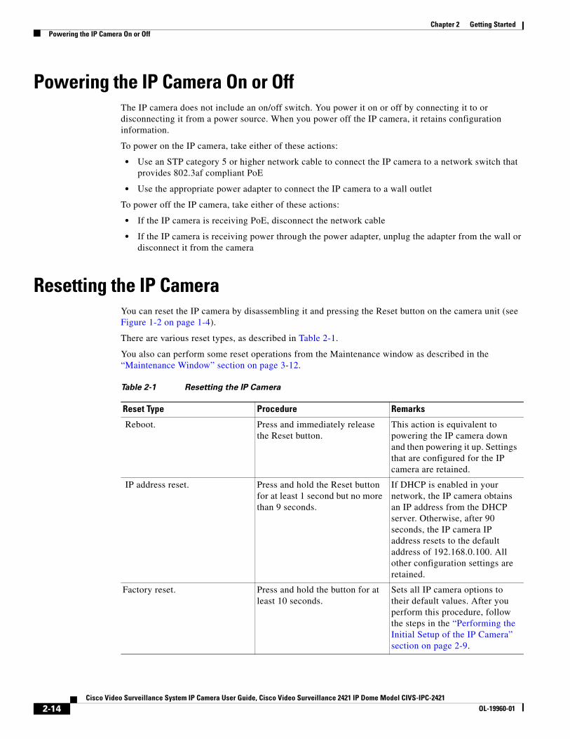
Table 2-1 Resetting the IP Camera
Reset Type Procedure Remarks
Reboot. Press and immediately release the Reset button.
This action is equivalent to powering the IP camera down and then powering it up. Settings that are configured for the IP camera are retained.
IP address reset. Press and hold the Reset button for at least 1 second but no more than 9 seconds.
If DHCP is enabled in your network, the IP camera obtains an IP address from the DHCP server. Otherwise, after 90 seconds, the IP camera IP address resets to the default address of 192.168.0.100. All other configuration settings are retained.
Factory reset. Press and hold the button for at least 10 seconds.
Sets all IP camera options to their default values. After you perform this procedure, follow the steps in the “Performing the Initial Setup of the IP Camera” section on page 2-9.
2-14Cisco Video Surveillance System IP Camera User Guide, Cisco Video Surveillance 2421 IP Dome Model CIVS-IPC-2421
OL-19960-01
Chapter 2 Getting StartedCleaning the IP Camera
Cleaning the IP CameraTo clean and IP camera, follow these guidelines:
• To clean components, use a clean, dry, soft cloth to gently wipe the components. Do not use liquid cleaners on the dome assembly, except for cleaners that are designed specifically for optical-grade acrylic.
• To clean the lens, use only tissue paper or solution that is designed for high quality optical lenses.
2-15Cisco Video Surveillance System IP Camera User Guide, Cisco Video Surveillance 2421 IP Dome Model CIVS-IPC-2421
OL-19960-01

Chapter 2 Getting StartedCleaning the IP Camera
2-16Cisco Video Surveillance System IP Camera User Guide, Cisco Video Surveillance 2421 IP Dome Model CIVS-IPC-2421
OL-19960-01
Cisco Video Surveillance System IP Camera User Guide, Cisco VidOL-19960-01
C H A P T E R 3
Configuring and Managing the IP CameraThe Cisco Video Surveillance IP Camera provides configuration windows that you use to configure and manage the IP camera. This chapter explains how to access the configuration windows, describes each window, and provides detailed information about the options that are available in each window.
When configuring the IP camera, be aware of these guidelines:
• You must install and set up the Cisco Video Surveillance IP camera as described in Chapter 2, “Getting Started,” before you can access the configuration menus.
• You must be an IP camera administrator or an IP camera user with administrator privileges to access the configuration windows.
• For security, the configuration windows time out after 2 minutes of no activity. If a time out occurs, a pop-up window prompts you to log back in by entering your user name and password when you next press a key or click an item. When you log back in, the configuration window that you were displaying remains on your screen, but all settings revert to their last saved values.
This chapter includes these topics:
• Configuration Overview, page 3-1
• Navigating the Configuration Windows, page 3-3
• Setup Windows, page 3-4
• Administration Windows, page 3-10
• Audio/Video Window, page 3-14
• Security Windows, page 3-18
• Applications Windows, page 3-20
• Status Windows, page 3-26
Configuration OverviewThere are many settings and options that you can configure for the IP camera. The items that you configure depend on several factors, including your camera model, operational requirements, and connected external devices.
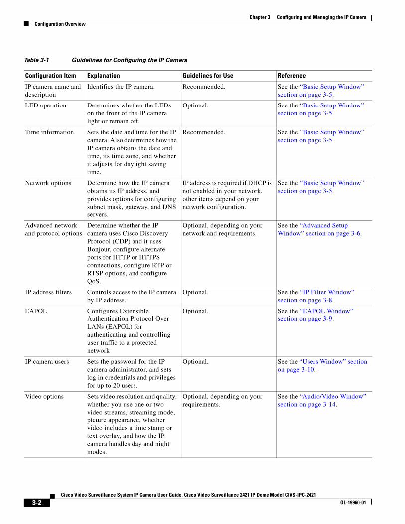
Table 3-1 provides general information to help you determine what items you need to configure for your situation. Use this table as a guide as you configure your IP camera and as a reference if you need to change configurations in the future.
3-1eo Surveillance 2421 IP Dome Model CIVS-IPC-2421
Chapter 3 Configuring and Managing the IP CameraConfiguration Overview
Table 3-1 Guidelines for Configuring the IP Camera
Configuration Item Explanation Guidelines for Use Reference
IP camera name and description
Identifies the IP camera. Recommended. See the “Basic Setup Window” section on page 3-5.
LED operation Determines whether the LEDs on the front of the IP camera light or remain off.
Optional. See the “Basic Setup Window” section on page 3-5.
Time information Sets the date and time for the IP camera. Also determines how the IP camera obtains the date and time, its time zone, and whether it adjusts for daylight saving time.
Recommended. See the “Basic Setup Window” section on page 3-5.
Network options Determine how the IP camera obtains its IP address, and provides options for configuring subnet mask, gateway, and DNS servers.
IP address is required if DHCP is not enabled in your network, other items depend on your network configuration.
See the “Basic Setup Window” section on page 3-5.
Advanced network and protocol options
Determine whether the IP camera uses Cisco Discovery Protocol (CDP) and it uses Bonjour, configure alternate ports for HTTP or HTTPS connections, configure RTP or RTSP options, and configure QoS.
Optional, depending on your network and requirements.
See the “Advanced Setup Window” section on page 3-6.
IP address filters Controls access to the IP camera by IP address.
Optional. See the “IP Filter Window” section on page 3-8.
EAPOL Configures Extensible Authentication Protocol Over LANs (EAPOL) for authenticating and controlling user traffic to a protected network
Optional. See the “EAPOL Window” section on page 3-9.
IP camera users Sets the password for the IP camera administrator, and sets log in credentials and privileges for up to 20 users.
Optional. See the “Users Window” section on page 3-10.
Video options Sets video resolution and quality, whether you use one or two video streams, streaming mode, picture appearance, whether video includes a time stamp or text overlay, and how the IP camera handles day and night modes.
Optional, depending on your requirements.
See the “Audio/Video Window” section on page 3-14.
3-2Cisco Video Surveillance System IP Camera User Guide, Cisco Video Surveillance 2421 IP Dome Model CIVS-IPC-2421
OL-19960-01
Chapter 3 Configuring and Managing the IP CameraNavigating the Configuration Windows
Navigating the Configuration WindowsAfter you access the configuration windows as described in the “Accessing the IP Camera Windows” section on page 2-11, a window appears that includes the following components:
• Navigation tree—Appears at the left of the window and provides links to each configuration window
• Basic Setup window—Appears at the right of the window
The navigation tree always appears. The right area varies depending on the configuration window that you choose from the navigation tree.
You can perform the following activities from when any configuration window is displayed:
• Click the Home link at the top of the Navigation Tree to display live video from the IP camera. For related information, see Chapter 4, “Viewing and Live Video.”
• Click the Logout button to exit the Main window and close your web browser.
• Use the Navigation Tree to access each configuration window. To do so, click the link or the plus sign (+) next to the link for the group of configuration windows that you want. The name of each associated window appears as a link. Then click the link for the desired window.
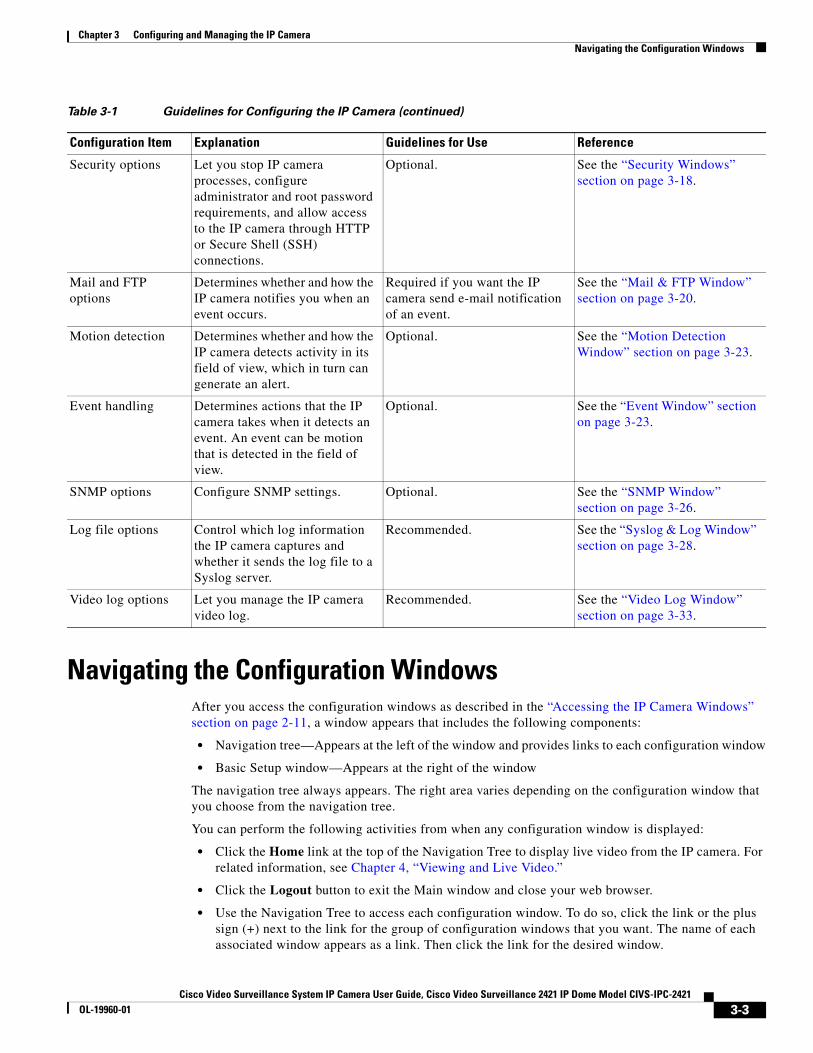
Security options Let you stop IP camera processes, configure administrator and root password requirements, and allow access to the IP camera through HTTP or Secure Shell (SSH) connections.
Optional. See the “Security Windows” section on page 3-18.
Mail and FTP options
Determines whether and how the IP camera notifies you when an event occurs.
Required if you want the IP camera send e-mail notification of an event.
See the “Mail & FTP Window” section on page 3-20.
Motion detection Determines whether and how the IP camera detects activity in its field of view, which in turn can generate an alert.
Optional. See the “Motion Detection Window” section on page 3-23.
Event handling Determines actions that the IP camera takes when it detects an event. An event can be motion that is detected in the field of view.
Optional. See the “Event Window” section on page 3-23.
SNMP options Configure SNMP settings. Optional. See the “SNMP Window” section on page 3-26.
Log file options Control which log information the IP camera captures and whether it sends the log file to a Syslog server.
Recommended. See the “Syslog & Log Window” section on page 3-28.
Video log options Let you manage the IP camera video log.
Recommended. See the “Video Log Window” section on page 3-33.
Table 3-1 Guidelines for Configuring the IP Camera (continued)
Configuration Item Explanation Guidelines for Use Reference
3-3Cisco Video Surveillance System IP Camera User Guide, Cisco Video Surveillance 2421 IP Dome Model CIVS-IPC-2421
OL-19960-01
Chapter 3 Configuring and Managing the IP CameraSetup Windows
To collapse a set of links, click the minus sign (-) next to the top-level link.
The configuration windows are organized as follows:
• Setup
– Basic Setup
– Advanced Setup
– IP Filter
– EAPOL
• Administration
– Users
– Maintenance
– Firmware
• Audio/Video
– Video
• Security
– Product Process
– Initialization
– Complexity
• Applications
– Mail & FTP
– Motion Detection
– Event
– SNMP
• Status
– System
– Audio/Video
– Network
– Syslog & Log
– Video Log
Setup WindowsThe Setup windows let you configure a variety of basic and advanced settings for the IP camera, and to designate IP addresses that are allowed or denied access to the IP camera.
The following sections describe the Setup windows in detail:
• Basic Setup Window, page 3-5
• Advanced Setup Window, page 3-6
• IP Filter Window, page 3-8
• EAPOL Window, page 3-9
3-4Cisco Video Surveillance System IP Camera User Guide, Cisco Video Surveillance 2421 IP Dome Model CIVS-IPC-2421
OL-19960-01
Chapter 3 Configuring and Managing the IP CameraSetup Windows
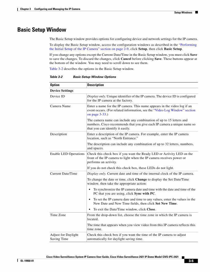
Basic Setup WindowThe Basic Setup window provides options for configuring device and network settings for the IP camera.
To display the Basic Setup window, access the configuration windows as described in the “Performing the Initial Setup of the IP Camera” section on page 2-9, click Setup, then click Basic Setup.
If you change any options except the Current Date/Time in the Basic Setup window, you must click Save to save the changes. To discard the changes, click Cancel before clicking Save. These buttons appear at the bottom of the window. You may need to scroll down to see them.
Table 3-2 describes the options in the Basic Setup window.
Table 3-2 Basic Setup Window Options
Option Description
Device Settings
Device ID Display only. Unique identifier of the IP camera. The device ID is configured for the IP camera at the factory.
Camera Name Enter a name for the IP camera. This name appears in the video log if an event occurs. (For related information, see the “Video Log Window” section on page 3-33.)
The camera name can include any combination of up to 15 letters and numbers. Cisco recommends that you give each IP camera a unique name so that you can identify it easily.
Description Enter a description of the IP camera. For example, enter the IP camera location, such as “North Entrance.”
The description can include any combination of up to 32 letters, numbers, and spaces.
Enable LED Operations Check this check box if you want the Ready LED or Activity LED on the front of the IP camera to light when the IP camera receives power or performs an activity.
If you do not check this check box, these LEDs do not light.
Current Date/Time Display only. Current date and time of the internal clock of the IP camera.
To change the date or time, click Change to display the Set Date/Time window, then take the appropriate action:
• To synchronize the IP camera date and time with the date and time of the PC that you are using, click Sync with PC.
• To set the IP camera date and time to any values, enter the values in the New Date and New Time fields, then click Set New Time.
• To exit the Date/Time window, click Close.
Time Zone From the drop-down list, choose the time zone in which the IP camera is located.
The time that appears when you view video from this IP camera reflects this time zone.
Adjust for Daylight Saving Time
Check this check box if you want the time of the IP camera to adjust automatically for daylight saving time.
3-5Cisco Video Surveillance System IP Camera User Guide, Cisco Video Surveillance 2421 IP Dome Model CIVS-IPC-2421
OL-19960-01
Chapter 3 Configuring and Managing the IP CameraSetup Windows
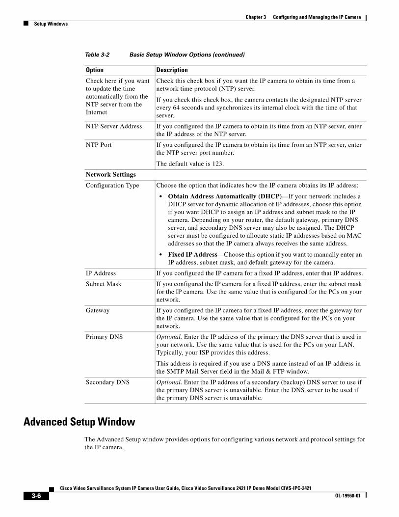
Advanced Setup WindowThe Advanced Setup window provides options for configuring various network and protocol settings for the IP camera.
Check here if you want to update the time automatically from the NTP server from the Internet
Check this check box if you want the IP camera to obtain its time from a network time protocol (NTP) server.
If you check this check box, the camera contacts the designated NTP server every 64 seconds and synchronizes its internal clock with the time of that server.
NTP Server Address If you configured the IP camera to obtain its time from an NTP server, enter the IP address of the NTP server.
NTP Port If you configured the IP camera to obtain its time from an NTP server, enter the NTP server port number.
The default value is 123.
Network Settings
Configuration Type Choose the option that indicates how the IP camera obtains its IP address:
• Obtain Address Automatically (DHCP)—If your network includes a DHCP server for dynamic allocation of IP addresses, choose this option if you want DHCP to assign an IP address and subnet mask to the IP camera. Depending on your router, the default gateway, primary DNS server, and secondary DNS server may also be assigned. The DHCP server must be configured to allocate static IP addresses based on MAC addresses so that the IP camera always receives the same address.
• Fixed IP Address—Choose this option if you want to manually enter an IP address, subnet mask, and default gateway for the camera.
IP Address If you configured the IP camera for a fixed IP address, enter that IP address.
Subnet Mask If you configured the IP camera for a fixed IP address, enter the subnet mask for the IP camera. Use the same value that is configured for the PCs on your network.
Gateway If you configured the IP camera for a fixed IP address, enter the gateway for the IP camera. Use the same value that is configured for the PCs on your network.
Primary DNS Optional. Enter the IP address of the primary the DNS server that is used in your network. Use the same value that is used for the PCs on your LAN. Typically, your ISP provides this address.
This address is required if you use a DNS name instead of an IP address in the SMTP Mail Server field in the Mail & FTP window.
Secondary DNS Optional. Enter the IP address of a secondary (backup) DNS server to use if the primary DNS server is unavailable. Enter the DNS server to be used if the primary DNS server is unavailable.
Table 3-2 Basic Setup Window Options (continued)
Option Description
3-6Cisco Video Surveillance System IP Camera User Guide, Cisco Video Surveillance 2421 IP Dome Model CIVS-IPC-2421
OL-19960-01
Chapter 3 Configuring and Managing the IP CameraSetup Windows
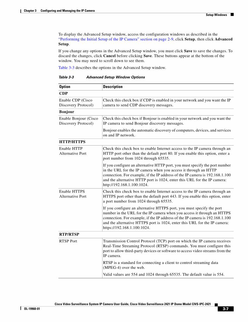
To display the Advanced Setup window, access the configuration windows as described in the “Performing the Initial Setup of the IP Camera” section on page 2-9, click Setup, then click Advanced Setup.
If you change any options in the Advanced Setup window, you must click Save to save the changes. To discard the changes, click Cancel before clicking Save. These buttons appear at the bottom of the window. You may need to scroll down to see them.
Table 3-3 describes the options in the Advanced Setup window.
Table 3-3 Advanced Setup Window Options
Option Description
CDP
Enable CDP (Cisco Discovery Protocol)
Check this check box if CDP is enabled in your network and you want the IP camera to send CDP discovery messages.
Bonjour
Enable Bonjour (Cisco Discovery Protocol)
Check this check box if Bonjour is enabled in your network and you want the IP camera to send Bonjour discovery messages.
Bonjour enables the automatic discovery of computers, devices, and services on and IP network.
HTTP/HTTPS
Enable HTTP Alternative Port
Check this check box to enable Internet access to the IP camera through an HTTP port other than the default port 80. If you enable this option, enter a port number from 1024 through 65535.
If you configure an alternative HTTP port, you must specify the port number in the URL for the IP camera when you access it through an HTTP connection. For example, if the IP address of the IP camera is 192.168.1.100 and the alternative HTTP port is 1024, enter this URL for the IP camera: http://192.168.1.100:1024.
Enable HTTPS Alternative Port
Check this check box to enable Internet access to the IP camera through an HTTPS port other than the default port 443. If you enable this option, enter a port number from 1024 through 65535.
If you configure an alternative HTTPS port, you must specify the port number in the URL for the IP camera when you access it through an HTTPS connection. For example, if the IP address of the IP camera is 192.168.1.100 and the alternative HTTPS port is 1024, enter this URL for the IP camera: https://192.168.1.100:1024.
RTP/RTSP
RTSP Port Transmission Control Protocol (TCP) port on which the IP camera receives Real-Time Streaming Protocol (RTSP) commands. You must configure this port to allow third-party devices or software to access video streams from the IP camera.
RTSP is a standard for connecting a client to control streaming data (MPEG-4) over the web.
Valid values are 554 and 1024 through 65535. The default value is 554.
3-7Cisco Video Surveillance System IP Camera User Guide, Cisco Video Surveillance 2421 IP Dome Model CIVS-IPC-2421
OL-19960-01
Chapter 3 Configuring and Managing the IP CameraSetup Windows
IP Filter WindowThe IP Filter window provides options for controlling access to the IP camera by designating a list of IP addresses that can access the IP camera and a list of IP addresses that cannot access the IP camera.
To display the IP Filter window, access the configuration windows as described in the “Performing the Initial Setup of the IP Camera” section on page 2-9, click Setup, then click IP Filter.
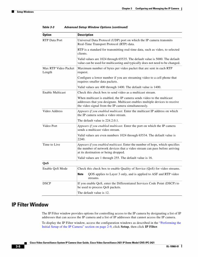
RTP Data Port Universal Data Protocol (UDP) port on which the IP camera transmits Real-Time Transport Protocol (RTP) data.
RTP is a standard for transmitting real-time data, such as video, to selected clients.
Valid values are 1024 through 65535. The default value is 5000. The default value can be used for multicasting and typically does not need to be changed.
Max RTP Video Packet Length
Maximum number of bytes per video packet that are sent in each RTP request.
Configure a lower number if you are streaming video to a cell phone that requires smaller data packets.
Valid values are 400 through 1400. The default value is 1400.
Enable Multicast Check this check box to send video as a multicast stream.
When multicast is enabled, the IP camera sends video to the multicast addresses that you designate. Multicast enables multiple devices to receive the video signal from the IP camera simultaneously.
Video Address Appears if you enabled multicast. Enter the multicast IP address on which the IP camera sends a video stream.
The default value is 224.2.0.1.
Video Port Appears if you enabled multicast. Enter the port on which the IP camera sends a multicast video stream.
Valid values are even numbers 1024 through 65534. The default value is 2240.
Time to Live Appears if you enabled multicast. Enter the number of hops, which specifies the number of network devices that a video stream can pass before arriving at its destination or being dropped.
Valid values are 1 through 255. The default value is 16.
QoS
Enable QoS Mode Check this check box to enable Quality of Service (QoS) for video streams.
Note QOS applies to Layer 3 only, and is applied to ASF and RTP video streams.
DSCP If you enable QoS, enter the Differentiated Services Code Point (DSCP) to be used to process QoS packets.
The default value is 12.
Table 3-3 Advanced Setup Window Options (continued)
Option Description
3-8Cisco Video Surveillance System IP Camera User Guide, Cisco Video Surveillance 2421 IP Dome Model CIVS-IPC-2421
OL-19960-01
Chapter 3 Configuring and Managing the IP CameraSetup Windows
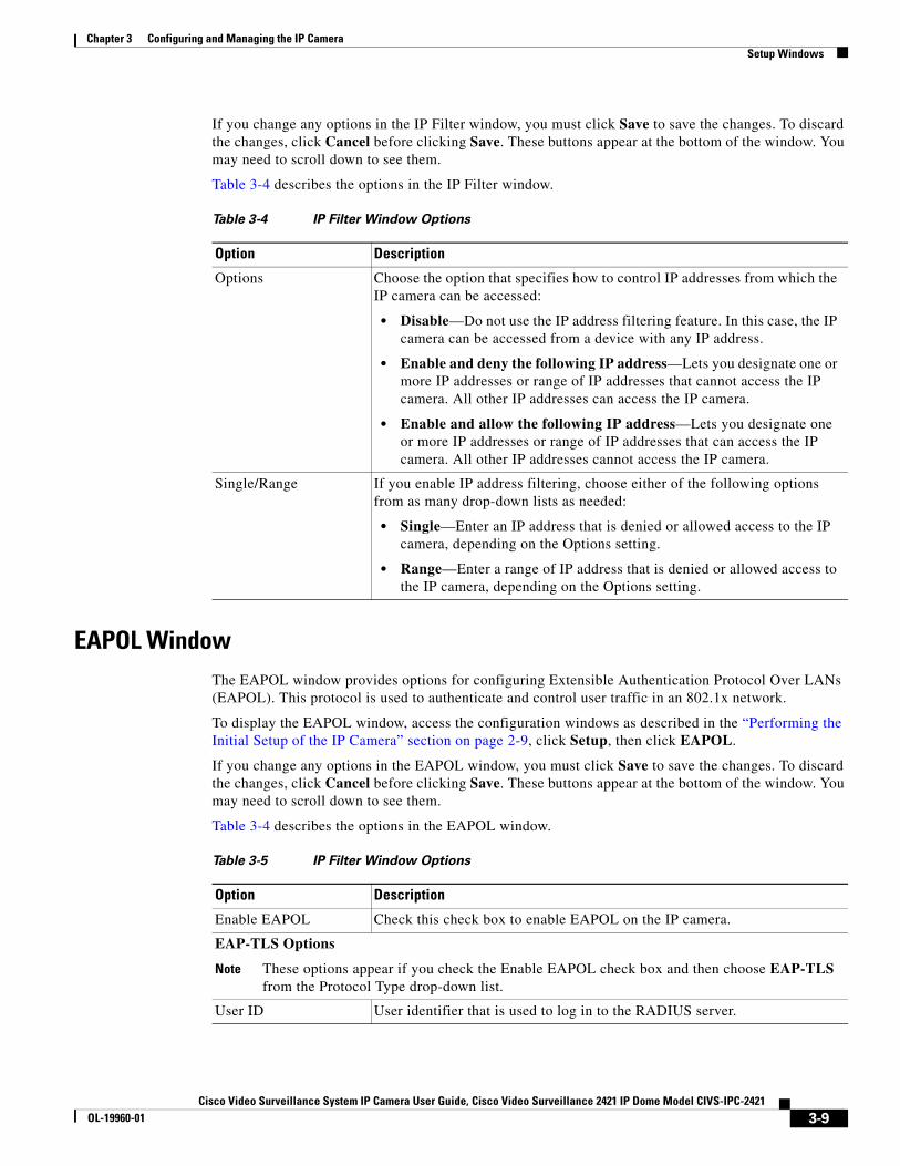
If you change any options in the IP Filter window, you must click Save to save the changes. To discard the changes, click Cancel before clicking Save. These buttons appear at the bottom of the window. You may need to scroll down to see them.
Table 3-4 describes the options in the IP Filter window.
EAPOL WindowThe EAPOL window provides options for configuring Extensible Authentication Protocol Over LANs (EAPOL). This protocol is used to authenticate and control user traffic in an 802.1x network.
To display the EAPOL window, access the configuration windows as described in the “Performing the Initial Setup of the IP Camera” section on page 2-9, click Setup, then click EAPOL.
If you change any options in the EAPOL window, you must click Save to save the changes. To discard the changes, click Cancel before clicking Save. These buttons appear at the bottom of the window. You may need to scroll down to see them.
Table 3-4 describes the options in the EAPOL window.
Table 3-4 IP Filter Window Options
Option Description
Options Choose the option that specifies how to control IP addresses from which the IP camera can be accessed:
• Disable—Do not use the IP address filtering feature. In this case, the IP camera can be accessed from a device with any IP address.
• Enable and deny the following IP address—Lets you designate one or more IP addresses or range of IP addresses that cannot access the IP camera. All other IP addresses can access the IP camera.
• Enable and allow the following IP address—Lets you designate one or more IP addresses or range of IP addresses that can access the IP camera. All other IP addresses cannot access the IP camera.
Single/Range If you enable IP address filtering, choose either of the following options from as many drop-down lists as needed:
• Single—Enter an IP address that is denied or allowed access to the IP camera, depending on the Options setting.
• Range—Enter a range of IP address that is denied or allowed access to the IP camera, depending on the Options setting.
Table 3-5 IP Filter Window Options
Option Description
Enable EAPOL Check this check box to enable EAPOL on the IP camera.
EAP-TLS Options
Note These options appear if you check the Enable EAPOL check box and then choose EAP-TLS from the Protocol Type drop-down list.
User ID User identifier that is used to log in to the RADIUS server.
3-9Cisco Video Surveillance System IP Camera User Guide, Cisco Video Surveillance 2421 IP Dome Model CIVS-IPC-2421
OL-19960-01
Chapter 3 Configuring and Managing the IP CameraAdministration Windows
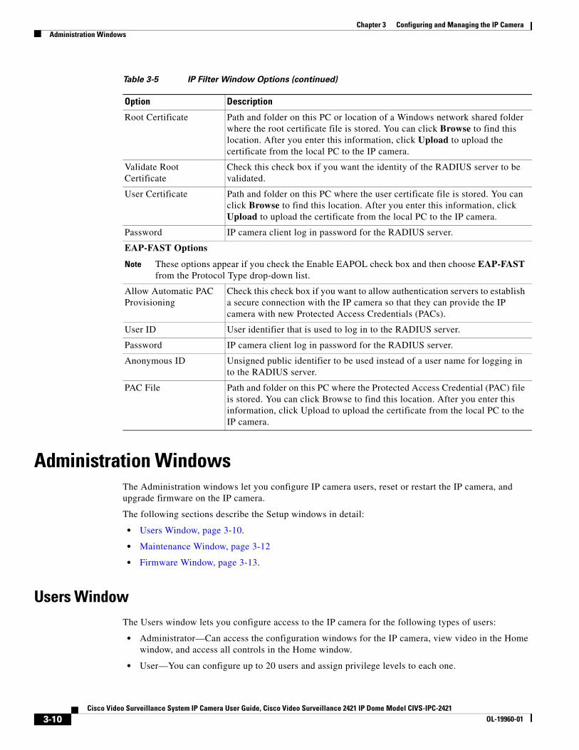
Administration WindowsThe Administration windows let you configure IP camera users, reset or restart the IP camera, and upgrade firmware on the IP camera.
The following sections describe the Setup windows in detail:
• Users Window, page 3-10.
• Maintenance Window, page 3-12
• Firmware Window, page 3-13.
Users WindowThe Users window lets you configure access to the IP camera for the following types of users:
• Administrator—Can access the configuration windows for the IP camera, view video in the Home window, and access all controls in the Home window.
• User—You can configure up to 20 users and assign privilege levels to each one.
Root Certificate Path and folder on this PC or location of a Windows network shared folder where the root certificate file is stored. You can click Browse to find this location. After you enter this information, click Upload to upload the certificate from the local PC to the IP camera.
Validate Root Certificate
Check this check box if you want the identity of the RADIUS server to be validated.
User Certificate Path and folder on this PC where the user certificate file is stored. You can click Browse to find this location. After you enter this information, click Upload to upload the certificate from the local PC to the IP camera.
Password IP camera client log in password for the RADIUS server.
EAP-FAST Options
Note These options appear if you check the Enable EAPOL check box and then choose EAP-FAST from the Protocol Type drop-down list.
Allow Automatic PAC Provisioning
Check this check box if you want to allow authentication servers to establish a secure connection with the IP camera so that they can provide the IP camera with new Protected Access Credentials (PACs).
User ID User identifier that is used to log in to the RADIUS server.
Password IP camera client log in password for the RADIUS server.
Anonymous ID Unsigned public identifier to be used instead of a user name for logging in to the RADIUS server.
PAC File Path and folder on this PC where the Protected Access Credential (PAC) file is stored. You can click Browse to find this location. After you enter this information, click Upload to upload the certificate from the local PC to the IP camera.
Table 3-5 IP Filter Window Options (continued)
Option Description
3-10Cisco Video Surveillance System IP Camera User Guide, Cisco Video Surveillance 2421 IP Dome Model CIVS-IPC-2421
OL-19960-01
Chapter 3 Configuring and Managing the IP CameraAdministration Windows
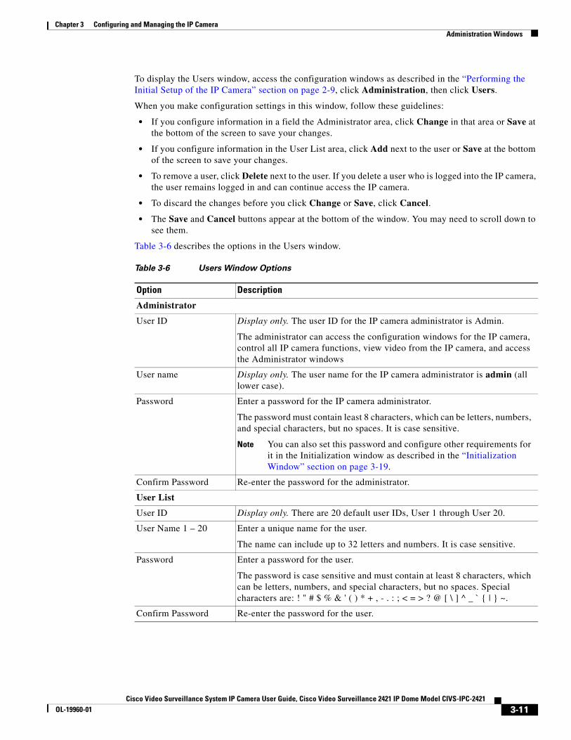
To display the Users window, access the configuration windows as described in the “Performing the Initial Setup of the IP Camera” section on page 2-9, click Administration, then click Users.
When you make configuration settings in this window, follow these guidelines:
• If you configure information in a field the Administrator area, click Change in that area or Save at the bottom of the screen to save your changes.
• If you configure information in the User List area, click Add next to the user or Save at the bottom of the screen to save your changes.
• To remove a user, click Delete next to the user. If you delete a user who is logged into the IP camera, the user remains logged in and can continue access the IP camera.
• To discard the changes before you click Change or Save, click Cancel.
• The Save and Cancel buttons appear at the bottom of the window. You may need to scroll down to see them.
Table 3-6 describes the options in the Users window.
Table 3-6 Users Window Options
Option Description
Administrator
User ID Display only. The user ID for the IP camera administrator is Admin.
The administrator can access the configuration windows for the IP camera, control all IP camera functions, view video from the IP camera, and access the Administrator windows
User name Display only. The user name for the IP camera administrator is admin (all lower case).
Password Enter a password for the IP camera administrator.
The password must contain least 8 characters, which can be letters, numbers, and special characters, but no spaces. It is case sensitive.
Note You can also set this password and configure other requirements for it in the Initialization window as described in the “Initialization Window” section on page 3-19.
Confirm Password Re-enter the password for the administrator.
User List
User ID Display only. There are 20 default user IDs, User 1 through User 20.
User Name 1 – 20 Enter a unique name for the user.
The name can include up to 32 letters and numbers. It is case sensitive.
Password Enter a password for the user.
The password is case sensitive and must contain at least 8 characters, which can be letters, numbers, and special characters, but no spaces. Special characters are: ! " # $ % & ' ( ) * + , - . : ; < = > ? @ [ \ ] ^ _ ` { | } ~.
Confirm Password Re-enter the password for the user.
3-11Cisco Video Surveillance System IP Camera User Guide, Cisco Video Surveillance 2421 IP Dome Model CIVS-IPC-2421
OL-19960-01
Chapter 3 Configuring and Managing the IP CameraAdministration Windows
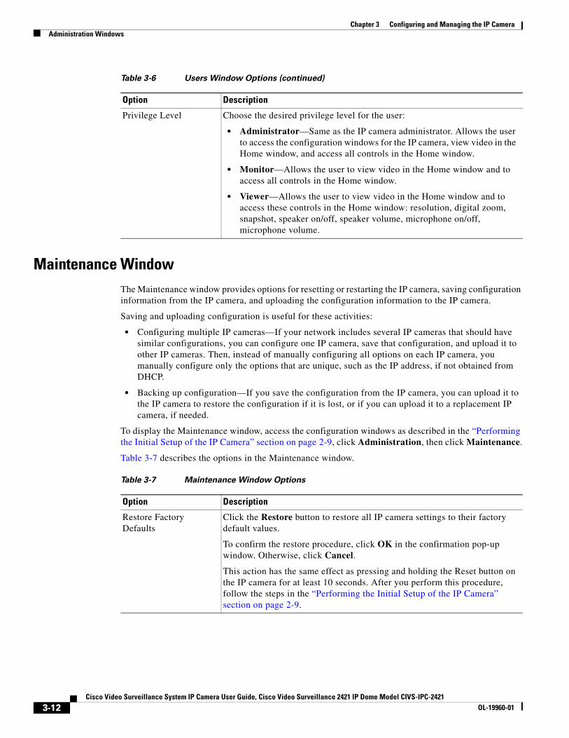
Maintenance WindowThe Maintenance window provides options for resetting or restarting the IP camera, saving configuration information from the IP camera, and uploading the configuration information to the IP camera.
Saving and uploading configuration is useful for these activities:
• Configuring multiple IP cameras—If your network includes several IP cameras that should have similar configurations, you can configure one IP camera, save that configuration, and upload it to other IP cameras. Then, instead of manually configuring all options on each IP camera, you manually configure only the options that are unique, such as the IP address, if not obtained from DHCP.
• Backing up configuration—If you save the configuration from the IP camera, you can upload it to the IP camera to restore the configuration if it is lost, or if you can upload it to a replacement IP camera, if needed.
To display the Maintenance window, access the configuration windows as described in the “Performing the Initial Setup of the IP Camera” section on page 2-9, click Administration, then click Maintenance.
Table 3-7 describes the options in the Maintenance window.
Privilege Level Choose the desired privilege level for the user:
• Administrator—Same as the IP camera administrator. Allows the user to access the configuration windows for the IP camera, view video in the Home window, and access all controls in the Home window.
• Monitor—Allows the user to view video in the Home window and to access all controls in the Home window.
• Viewer—Allows the user to view video in the Home window and to access these controls in the Home window: resolution, digital zoom, snapshot, speaker on/off, speaker volume, microphone on/off, microphone volume.
Table 3-6 Users Window Options (continued)
Option Description
Table 3-7 Maintenance Window Options
Option Description
Restore Factory Defaults
Click the Restore button to restore all IP camera settings to their factory default values.
To confirm the restore procedure, click OK in the confirmation pop-up window. Otherwise, click Cancel.
This action has the same effect as pressing and holding the Reset button on the IP camera for at least 10 seconds. After you perform this procedure, follow the steps in the “Performing the Initial Setup of the IP Camera” section on page 2-9.
3-12Cisco Video Surveillance System IP Camera User Guide, Cisco Video Surveillance 2421 IP Dome Model CIVS-IPC-2421
OL-19960-01
Chapter 3 Configuring and Managing the IP CameraAdministration Windows
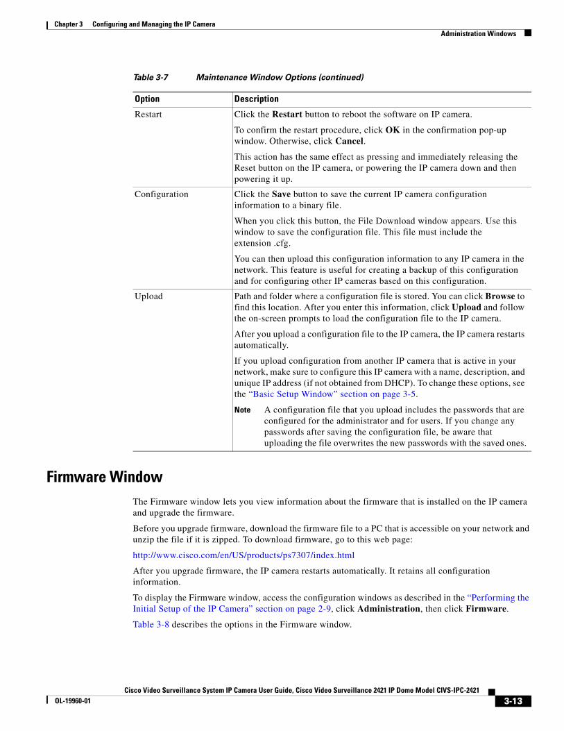
Firmware WindowThe Firmware window lets you view information about the firmware that is installed on the IP camera and upgrade the firmware.
Before you upgrade firmware, download the firmware file to a PC that is accessible on your network and unzip the file if it is zipped. To download firmware, go to this web page:
http://www.cisco.com/en/US/products/ps7307/index.html
After you upgrade firmware, the IP camera restarts automatically. It retains all configuration information.
To display the Firmware window, access the configuration windows as described in the “Performing the Initial Setup of the IP Camera” section on page 2-9, click Administration, then click Firmware.
Table 3-8 describes the options in the Firmware window.
Restart Click the Restart button to reboot the software on IP camera.
To confirm the restart procedure, click OK in the confirmation pop-up window. Otherwise, click Cancel.
This action has the same effect as pressing and immediately releasing the Reset button on the IP camera, or powering the IP camera down and then powering it up.
Configuration Click the Save button to save the current IP camera configuration information to a binary file.
When you click this button, the File Download window appears. Use this window to save the configuration file. This file must include the extension .cfg.
You can then upload this configuration information to any IP camera in the network. This feature is useful for creating a backup of this configuration and for configuring other IP cameras based on this configuration.
Upload Path and folder where a configuration file is stored. You can click Browse to find this location. After you enter this information, click Upload and follow the on-screen prompts to load the configuration file to the IP camera.
After you upload a configuration file to the IP camera, the IP camera restarts automatically.
If you upload configuration from another IP camera that is active in your network, make sure to configure this IP camera with a name, description, and unique IP address (if not obtained from DHCP). To change these options, see the “Basic Setup Window” section on page 3-5.
Note A configuration file that you upload includes the passwords that are configured for the administrator and for users. If you change any passwords after saving the configuration file, be aware that uploading the file overwrites the new passwords with the saved ones.
Table 3-7 Maintenance Window Options (continued)
Option Description
3-13Cisco Video Surveillance System IP Camera User Guide, Cisco Video Surveillance 2421 IP Dome Model CIVS-IPC-2421
OL-19960-01
Chapter 3 Configuring and Managing the IP CameraAudio/Video Window
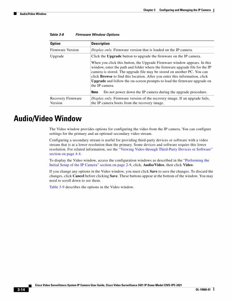
Audio/Video WindowThe Video window provides options for configuring the video from the IP camera. You can configure settings for the primary and an optional secondary video stream.
Configuring a secondary stream is useful for providing third-party devices or software with a video stream that is at a lower resolution than the primary. Some devices and software require this lower resolution. For related information, see the “Viewing Video through Third-Party Devices or Software” section on page 4-4.
To display the Video window, access the configuration windows as described in the “Performing the Initial Setup of the IP Camera” section on page 2-9, click, Audio/Video, then click Video.
If you change any options in the Video window, you must click Save to save the changes. To discard the changes, click Cancel before clicking Save. These buttons appear at the bottom of the window. You may need to scroll down to see them.
Table 3-9 describes the options in the Video window.
Table 3-8 Firmware Window Options
Option Description
Firmware Version Display only. Firmware version that is loaded on the IP camera.
Upgrade Click the Upgrade button to upgrade the firmware on the IP camera.
When you click this button, the Upgrade Firmware window appears. In this window, enter the path and folder where the firmware upgrade file for the IP camera is stored. The upgrade file may be stored on another PC. You can click Browse to find this location. After you enter this information, click Upgrade and follow the on-screen prompts to load the firmware upgrade on the IP camera.
Note Do not power down the IP camera during the upgrade procedure.
Recovery Firmware Version
Display only. Firmware version of the recovery image. If an upgrade fails, the IP camera boots from the recovery image.
3-14Cisco Video Surveillance System IP Camera User Guide, Cisco Video Surveillance 2421 IP Dome Model CIVS-IPC-2421
OL-19960-01
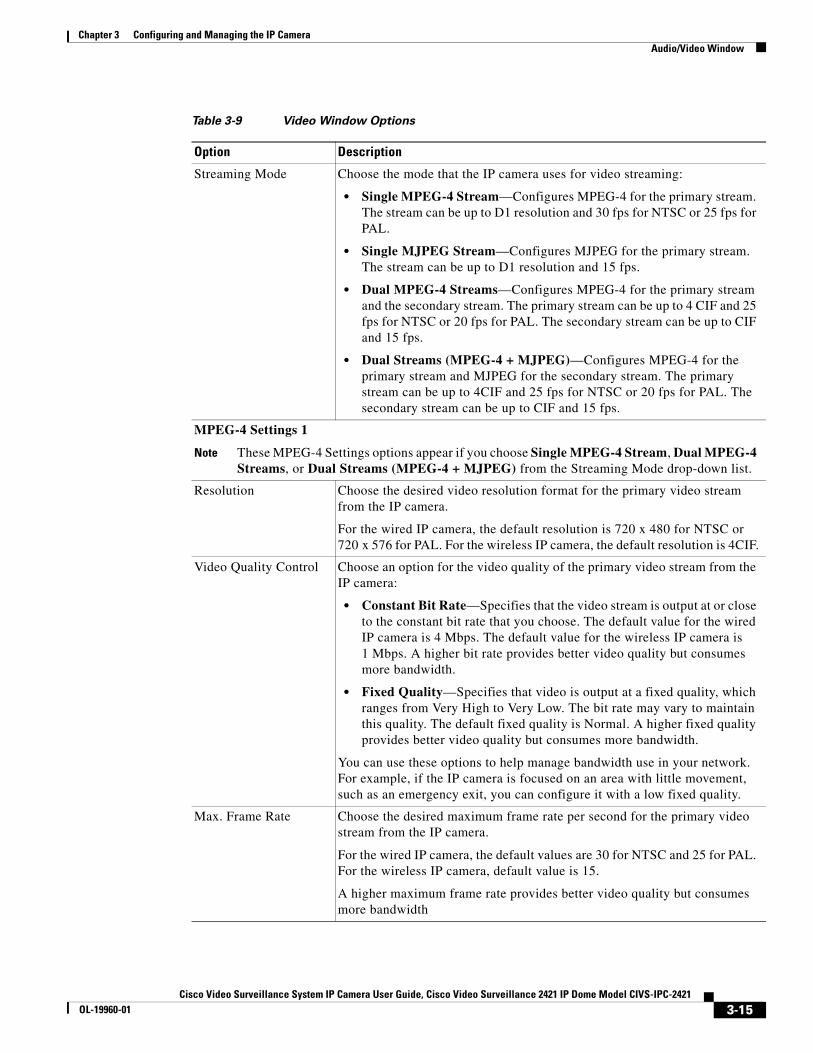
Chapter 3 Configuring and Managing the IP CameraAudio/Video Window
Table 3-9 Video Window Options
Option Description
Streaming Mode Choose the mode that the IP camera uses for video streaming:
• Single MPEG-4 Stream—Configures MPEG-4 for the primary stream. The stream can be up to D1 resolution and 30 fps for NTSC or 25 fps for PAL.
• Single MJPEG Stream—Configures MJPEG for the primary stream. The stream can be up to D1 resolution and 15 fps.
• Dual MPEG-4 Streams—Configures MPEG-4 for the primary stream and the secondary stream. The primary stream can be up to 4 CIF and 25 fps for NTSC or 20 fps for PAL. The secondary stream can be up to CIF and 15 fps.
• Dual Streams (MPEG-4 + MJPEG)—Configures MPEG-4 for the primary stream and MJPEG for the secondary stream. The primary stream can be up to 4CIF and 25 fps for NTSC or 20 fps for PAL. The secondary stream can be up to CIF and 15 fps.
MPEG-4 Settings 1
Note These MPEG-4 Settings options appear if you choose Single MPEG-4 Stream, Dual MPEG-4 Streams, or Dual Streams (MPEG-4 + MJPEG) from the Streaming Mode drop-down list.
Resolution Choose the desired video resolution format for the primary video stream from the IP camera.
For the wired IP camera, the default resolution is 720 x 480 for NTSC or 720 x 576 for PAL. For the wireless IP camera, the default resolution is 4CIF.
Video Quality Control Choose an option for the video quality of the primary video stream from the IP camera:
• Constant Bit Rate—Specifies that the video stream is output at or close to the constant bit rate that you choose. The default value for the wired IP camera is 4 Mbps. The default value for the wireless IP camera is 1 Mbps. A higher bit rate provides better video quality but consumes more bandwidth.
• Fixed Quality—Specifies that video is output at a fixed quality, which ranges from Very High to Very Low. The bit rate may vary to maintain this quality. The default fixed quality is Normal. A higher fixed quality provides better video quality but consumes more bandwidth.
You can use these options to help manage bandwidth use in your network. For example, if the IP camera is focused on an area with little movement, such as an emergency exit, you can configure it with a low fixed quality.
Max. Frame Rate Choose the desired maximum frame rate per second for the primary video stream from the IP camera.
For the wired IP camera, the default values are 30 for NTSC and 25 for PAL. For the wireless IP camera, default value is 15.
A higher maximum frame rate provides better video quality but consumes more bandwidth
3-15Cisco Video Surveillance System IP Camera User Guide, Cisco Video Surveillance 2421 IP Dome Model CIVS-IPC-2421
OL-19960-01
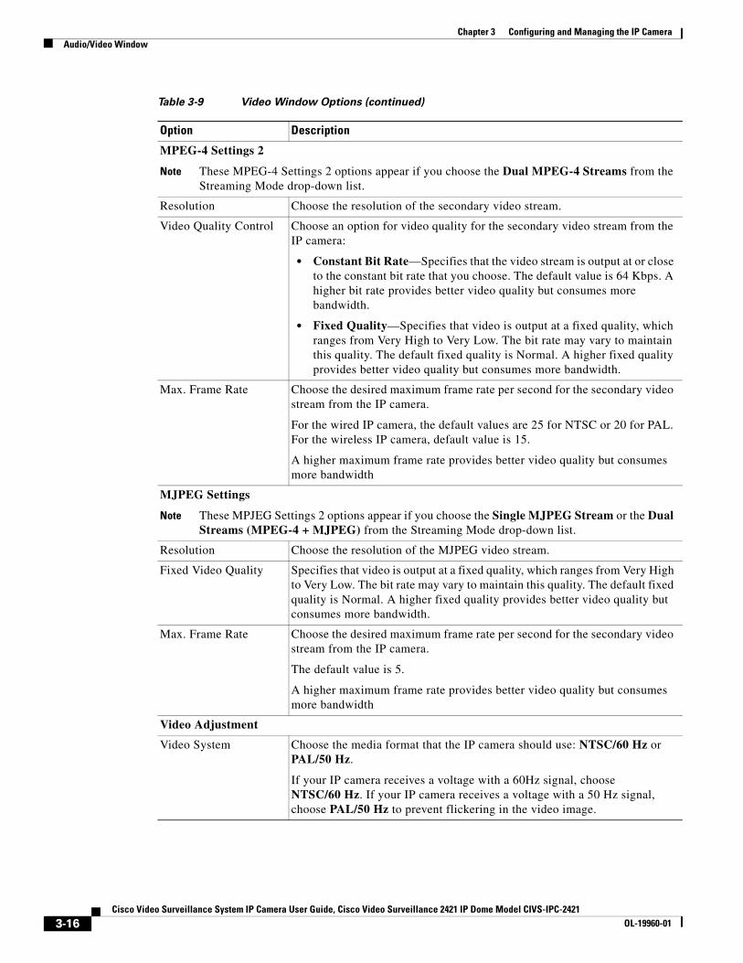
Chapter 3 Configuring and Managing the IP CameraAudio/Video Window
MPEG-4 Settings 2
Note These MPEG-4 Settings 2 options appear if you choose the Dual MPEG-4 Streams from the Streaming Mode drop-down list.
Resolution Choose the resolution of the secondary video stream.
Video Quality Control Choose an option for video quality for the secondary video stream from the IP camera:
• Constant Bit Rate—Specifies that the video stream is output at or close to the constant bit rate that you choose. The default value is 64 Kbps. A higher bit rate provides better video quality but consumes more bandwidth.
• Fixed Quality—Specifies that video is output at a fixed quality, which ranges from Very High to Very Low. The bit rate may vary to maintain this quality. The default fixed quality is Normal. A higher fixed quality provides better video quality but consumes more bandwidth.
Max. Frame Rate Choose the desired maximum frame rate per second for the secondary video stream from the IP camera.
For the wired IP camera, the default values are 25 for NTSC or 20 for PAL. For the wireless IP camera, default value is 15.
A higher maximum frame rate provides better video quality but consumes more bandwidth
MJPEG Settings
Note These MPJEG Settings 2 options appear if you choose the Single MJPEG Stream or the Dual Streams (MPEG-4 + MJPEG) from the Streaming Mode drop-down list.
Resolution Choose the resolution of the MJPEG video stream.
Fixed Video Quality Specifies that video is output at a fixed quality, which ranges from Very High to Very Low. The bit rate may vary to maintain this quality. The default fixed quality is Normal. A higher fixed quality provides better video quality but consumes more bandwidth.
Max. Frame Rate Choose the desired maximum frame rate per second for the secondary video stream from the IP camera.
The default value is 5.
A higher maximum frame rate provides better video quality but consumes more bandwidth
Video Adjustment
Video System Choose the media format that the IP camera should use: NTSC/60 Hz or PAL/50 Hz.
If your IP camera receives a voltage with a 60Hz signal, choose NTSC/60 Hz. If your IP camera receives a voltage with a 50 Hz signal, choose PAL/50 Hz to prevent flickering in the video image.
Table 3-9 Video Window Options (continued)
Option Description
3-16Cisco Video Surveillance System IP Camera User Guide, Cisco Video Surveillance 2421 IP Dome Model CIVS-IPC-2421
OL-19960-01
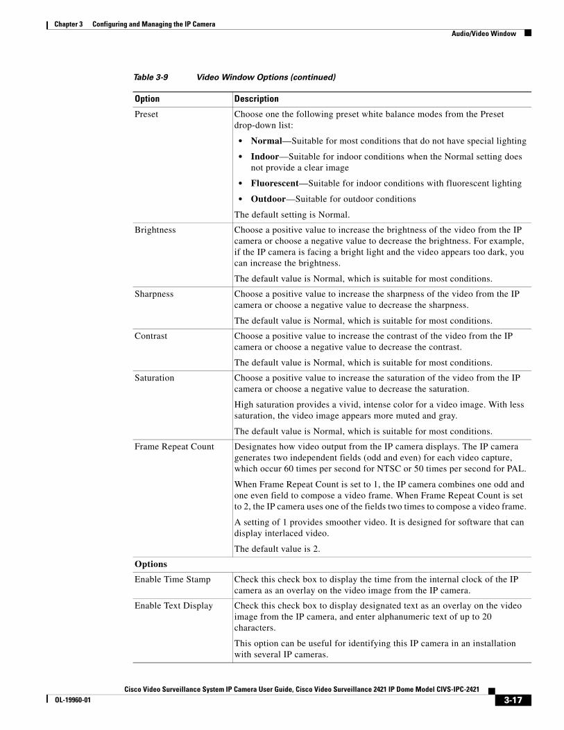
Chapter 3 Configuring and Managing the IP CameraAudio/Video Window
Preset Choose one the following preset white balance modes from the Preset drop-down list:
• Normal—Suitable for most conditions that do not have special lighting
• Indoor—Suitable for indoor conditions when the Normal setting does not provide a clear image
• Fluorescent—Suitable for indoor conditions with fluorescent lighting
• Outdoor—Suitable for outdoor conditions
The default setting is Normal.
Brightness Choose a positive value to increase the brightness of the video from the IP camera or choose a negative value to decrease the brightness. For example, if the IP camera is facing a bright light and the video appears too dark, you can increase the brightness.
The default value is Normal, which is suitable for most conditions.
Sharpness Choose a positive value to increase the sharpness of the video from the IP camera or choose a negative value to decrease the sharpness.
The default value is Normal, which is suitable for most conditions.
Contrast Choose a positive value to increase the contrast of the video from the IP camera or choose a negative value to decrease the contrast.
The default value is Normal, which is suitable for most conditions.
Saturation Choose a positive value to increase the saturation of the video from the IP camera or choose a negative value to decrease the saturation.
High saturation provides a vivid, intense color for a video image. With less saturation, the video image appears more muted and gray.
The default value is Normal, which is suitable for most conditions.
Frame Repeat Count Designates how video output from the IP camera displays. The IP camera generates two independent fields (odd and even) for each video capture, which occur 60 times per second for NTSC or 50 times per second for PAL.
When Frame Repeat Count is set to 1, the IP camera combines one odd and one even field to compose a video frame. When Frame Repeat Count is set to 2, the IP camera uses one of the fields two times to compose a video frame.
A setting of 1 provides smoother video. It is designed for software that can display interlaced video.
The default value is 2.
Options
Enable Time Stamp Check this check box to display the time from the internal clock of the IP camera as an overlay on the video image from the IP camera.
Enable Text Display Check this check box to display designated text as an overlay on the video image from the IP camera, and enter alphanumeric text of up to 20 characters.
This option can be useful for identifying this IP camera in an installation with several IP cameras.
Table 3-9 Video Window Options (continued)
Option Description
3-17Cisco Video Surveillance System IP Camera User Guide, Cisco Video Surveillance 2421 IP Dome Model CIVS-IPC-2421
OL-19960-01
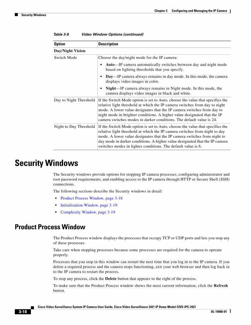
Chapter 3 Configuring and Managing the IP CameraSecurity Windows
Security WindowsThe Security windows provide options for stopping IP camera processes, configuring administrator and root password requirements, and enabling access to the IP camera through HTTP or Secure Shell (SSH) connections.
The following sections describe the Security windows in detail:
• Product Process Window, page 3-18
• Initialization Window, page 3-19
• Complexity Window, page 3-19
Product Process WindowThe Product Process window displays the processes that occupy TCP or UDP ports and lets you stop any of these processes.
Take care when stopping processes because some processes are required for the camera to operate properly.
Processes that you stop in this window can restart the next time that you log in to the IP camera. If you delete a required process and the camera stops functioning, exit your web browser and then log back in to the IP camera to restart the process.
To stop any process, click the Delete button that appears to the right of the process.
To make sure that the Product Process window shows the most current information, click the Refresh button.
Day/Night Vision
Switch Mode Choose the day/night mode for the IP camera:
• Auto—IP camera automatically switches between day and night mode based on lighting thresholds that you specify.
• Day—IP camera always remains in day mode. In this mode, the camera displays video images in color.
• Night—IP camera always remains in Night mode. In this mode, the camera displays video images in black and white.
Day to Night Threshold If the Switch Mode option is set to Auto, choose the value that specifies the relative light threshold at which the IP camera switches from day to night mode. A lower value designates that the IP camera switches from day to night mode in brighter conditions. A higher value designated that the IP camera switches modes in darker conditions. The default value is 24.
Night to Day Threshold If the Switch Mode option is set to Auto, choose the value that specifies the relative light threshold at which the IP camera switches from night to day mode. A lower value designates that the IP camera switches from night to day mode in darker conditions. A higher value designated that the IP camera switches modes in lighter conditions. The default value is 6.
Table 3-9 Video Window Options (continued)
Option Description
3-18Cisco Video Surveillance System IP Camera User Guide, Cisco Video Surveillance 2421 IP Dome Model CIVS-IPC-2421
OL-19960-01
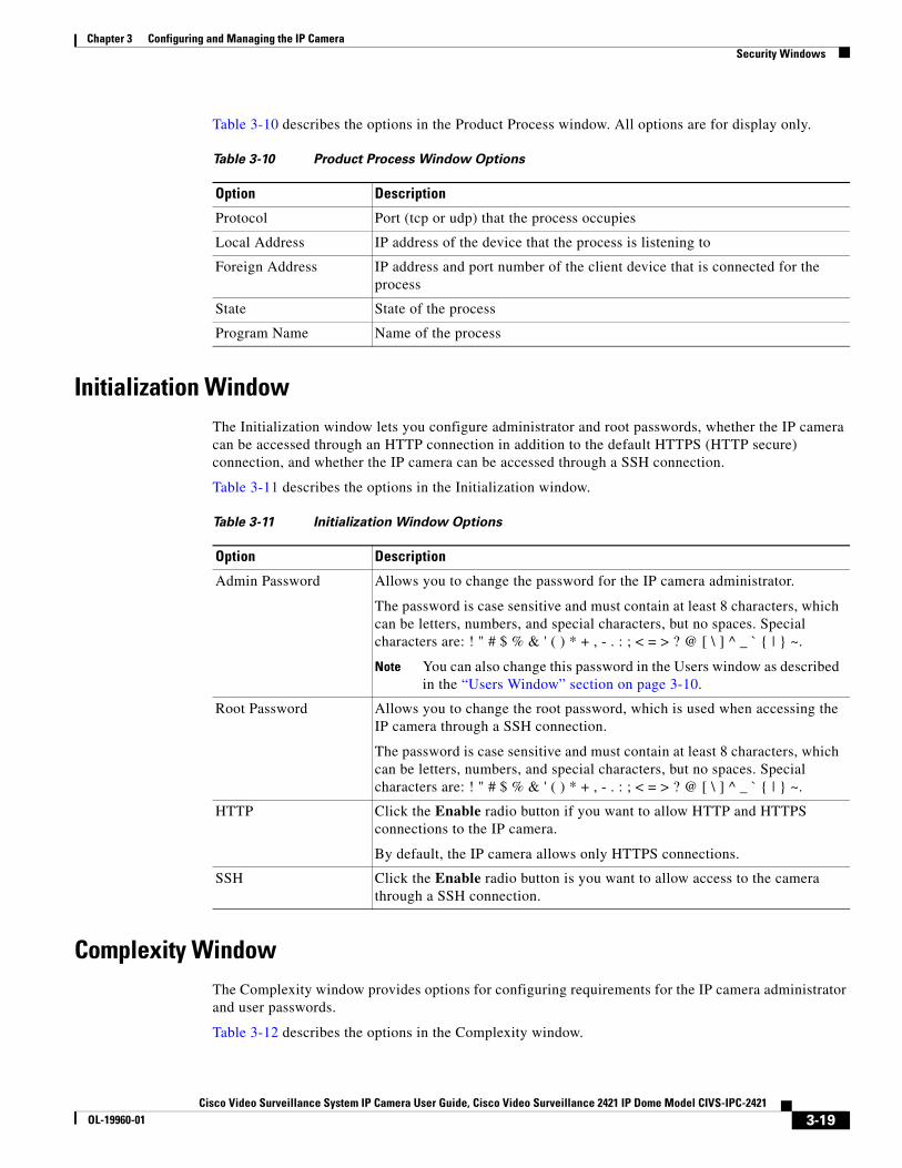
Chapter 3 Configuring and Managing the IP CameraSecurity Windows
Table 3-10 describes the options in the Product Process window. All options are for display only.
Initialization WindowThe Initialization window lets you configure administrator and root passwords, whether the IP camera can be accessed through an HTTP connection in addition to the default HTTPS (HTTP secure) connection, and whether the IP camera can be accessed through a SSH connection.
Table 3-11 describes the options in the Initialization window.
Complexity WindowThe Complexity window provides options for configuring requirements for the IP camera administrator and user passwords.
Table 3-12 describes the options in the Complexity window.
Table 3-10 Product Process Window Options
Option Description
Protocol Port (tcp or udp) that the process occupies
Local Address IP address of the device that the process is listening to
Foreign Address IP address and port number of the client device that is connected for the process
State State of the process
Program Name Name of the process
Table 3-11 Initialization Window Options
Option Description
Admin Password Allows you to change the password for the IP camera administrator.
The password is case sensitive and must contain at least 8 characters, which can be letters, numbers, and special characters, but no spaces. Special characters are: ! " # $ % & ' ( ) * + , - . : ; < = > ? @ [ \ ] ^ _ ` { | } ~.
Note You can also change this password in the Users window as described in the “Users Window” section on page 3-10.
Root Password Allows you to change the root password, which is used when accessing the IP camera through a SSH connection.
The password is case sensitive and must contain at least 8 characters, which can be letters, numbers, and special characters, but no spaces. Special characters are: ! " # $ % & ' ( ) * + , - . : ; < = > ? @ [ \ ] ^ _ ` { | } ~.
HTTP Click the Enable radio button if you want to allow HTTP and HTTPS connections to the IP camera.
By default, the IP camera allows only HTTPS connections.
SSH Click the Enable radio button is you want to allow access to the camera through a SSH connection.
3-19Cisco Video Surveillance System IP Camera User Guide, Cisco Video Surveillance 2421 IP Dome Model CIVS-IPC-2421
OL-19960-01
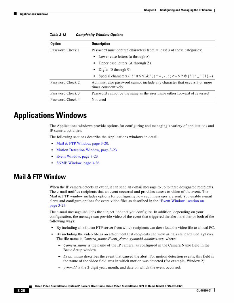
Chapter 3 Configuring and Managing the IP CameraApplications Windows
Applications WindowsThe Applications windows provide options for configuring and managing a variety of applications and IP camera activities.
The following sections describe the Applications windows in detail:
• Mail & FTP Window, page 3-20.
• Motion Detection Window, page 3-23
• Event Window, page 3-23
• SNMP Window, page 3-26
Mail & FTP WindowWhen the IP camera detects an event, it can send an e-mail message to up to three designated recipients. The e-mail notifies recipients that an event occurred and provides access to video of the event. The Mail & FTP window includes options for configuring how such messages are sent. You enable e-mail alerts and configure options for event video files as described in the “Event Window” section on page 3-23.
The e-mail message includes the subject line that you configure. In addition, depending on your configuration, the message can provide video of the event that triggered the alert in either or both of the following ways:
• By including a link to an FTP server from which recipients can download the video file to a local PC.
• By including the video file as an attachment that recipients can view using a standard media player. The file name is Camera_name-Event_Name-yymmdd-hhmmss.xxx, where:
– Camera_name is the name of the IP camera, as configured in the Camera Name field in the Basic Setup window.
– Event_name describes the event that caused the alert. For motion detection events, this field is the name of the video field area in which motion was detected (for example, Window 2).
– yymmdd is the 2-digit year, month, and date on which the event occurred.
Table 3-12 Complexity Window Options
Option Description
Password Check 1 Password must contain characters from at least 3 of these categories:
• Lower case letters (a through z)
• Upper case letters (A through Z)
• Digits (0 through 9)
• Special characters (: ! " # $ % & ' ( ) * + , - . : ; < = > ? @ [ \ ] ^ _ ` { | } ~)
Password Check 2 Administrator password cannot include any character that occurs 3 or more times consecutively
Password Check 3 Password cannot be the same as the user name either forward of reversed
Password Check 4 Not used
3-20Cisco Video Surveillance System IP Camera User Guide, Cisco Video Surveillance 2421 IP Dome Model CIVS-IPC-2421
OL-19960-01
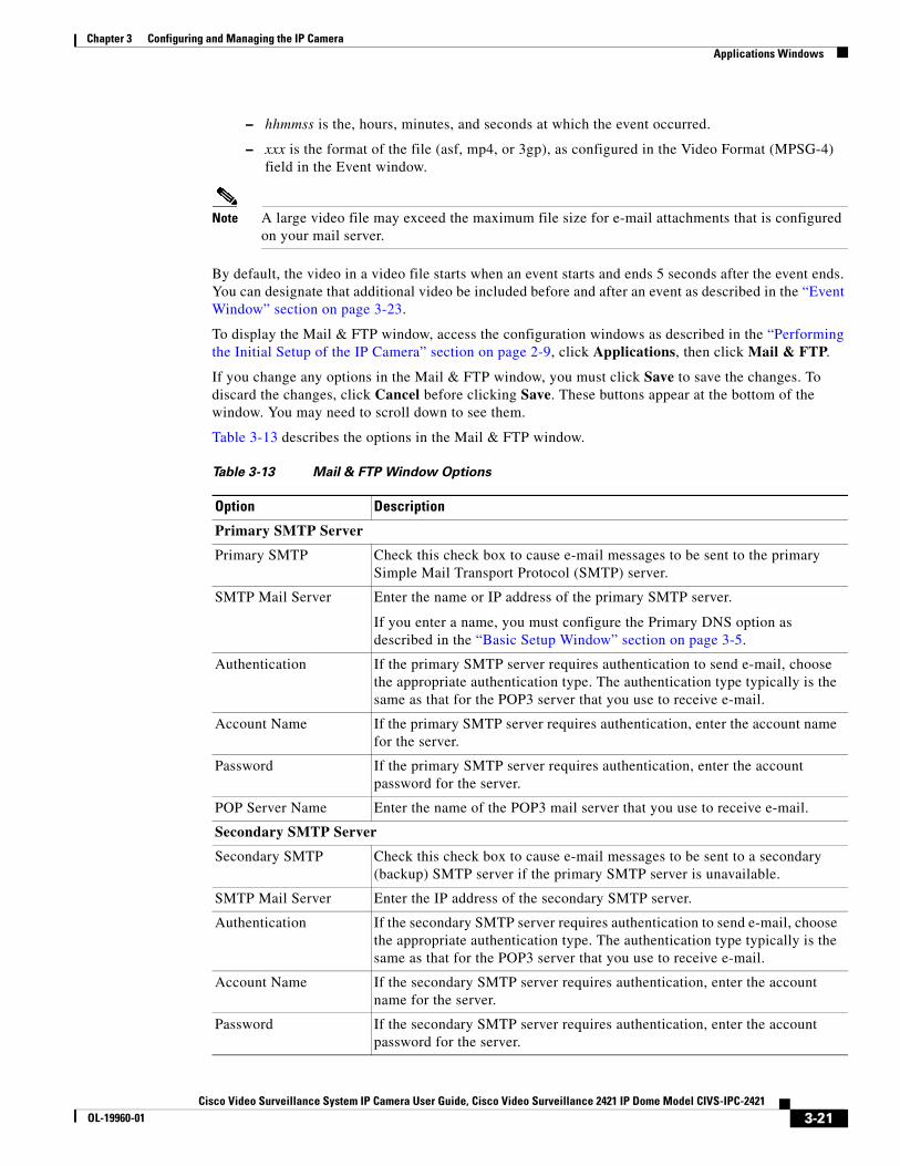
Chapter 3 Configuring and Managing the IP CameraApplications Windows
– hhmmss is the, hours, minutes, and seconds at which the event occurred.
– xxx is the format of the file (asf, mp4, or 3gp), as configured in the Video Format (MPSG-4) field in the Event window.
Note A large video file may exceed the maximum file size for e-mail attachments that is configured on your mail server.
By default, the video in a video file starts when an event starts and ends 5 seconds after the event ends. You can designate that additional video be included before and after an event as described in the “Event Window” section on page 3-23.
To display the Mail & FTP window, access the configuration windows as described in the “Performing the Initial Setup of the IP Camera” section on page 2-9, click Applications, then click Mail & FTP.
If you change any options in the Mail & FTP window, you must click Save to save the changes. To discard the changes, click Cancel before clicking Save. These buttons appear at the bottom of the window. You may need to scroll down to see them.
Table 3-13 describes the options in the Mail & FTP window.
Table 3-13 Mail & FTP Window Options
Option Description
Primary SMTP Server
Primary SMTP Check this check box to cause e-mail messages to be sent to the primary Simple Mail Transport Protocol (SMTP) server.
SMTP Mail Server Enter the name or IP address of the primary SMTP server.
If you enter a name, you must configure the Primary DNS option as described in the “Basic Setup Window” section on page 3-5.
Authentication If the primary SMTP server requires authentication to send e-mail, choose the appropriate authentication type. The authentication type typically is the same as that for the POP3 server that you use to receive e-mail.
Account Name If the primary SMTP server requires authentication, enter the account name for the server.
Password If the primary SMTP server requires authentication, enter the account password for the server.
POP Server Name Enter the name of the POP3 mail server that you use to receive e-mail.
Secondary SMTP Server
Secondary SMTP Check this check box to cause e-mail messages to be sent to a secondary (backup) SMTP server if the primary SMTP server is unavailable.
SMTP Mail Server Enter the IP address of the secondary SMTP server.
Authentication If the secondary SMTP server requires authentication to send e-mail, choose the appropriate authentication type. The authentication type typically is the same as that for the POP3 server that you use to receive e-mail.
Account Name If the secondary SMTP server requires authentication, enter the account name for the server.
Password If the secondary SMTP server requires authentication, enter the account password for the server.
3-21Cisco Video Surveillance System IP Camera User Guide, Cisco Video Surveillance 2421 IP Dome Model CIVS-IPC-2421
OL-19960-01
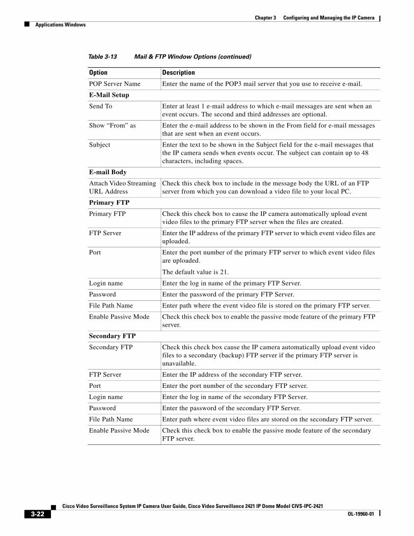
Chapter 3 Configuring and Managing the IP CameraApplications Windows
POP Server Name Enter the name of the POP3 mail server that you use to receive e-mail.
E-Mail Setup
Send To Enter at least 1 e-mail address to which e-mail messages are sent when an event occurs. The second and third addresses are optional.
Show “From” as Enter the e-mail address to be shown in the From field for e-mail messages that are sent when an event occurs.
Subject Enter the text to be shown in the Subject field for the e-mail messages that the IP camera sends when events occur. The subject can contain up to 48 characters, including spaces.
E-mail Body
Attach Video Streaming URL Address
Check this check box to include in the message body the URL of an FTP server from which you can download a video file to your local PC.
Primary FTP
Primary FTP Check this check box to cause the IP camera automatically upload event video files to the primary FTP server when the files are created.
FTP Server Enter the IP address of the primary FTP server to which event video files are uploaded.
Port Enter the port number of the primary FTP server to which event video files are uploaded.
The default value is 21.
Login name Enter the log in name of the primary FTP Server.
Password Enter the password of the primary FTP Server.
File Path Name Enter path where the event video file is stored on the primary FTP server.
Enable Passive Mode Check this check box to enable the passive mode feature of the primary FTP server.
Secondary FTP
Secondary FTP Check this check box cause the IP camera automatically upload event video files to a secondary (backup) FTP server if the primary FTP server is unavailable.
FTP Server Enter the IP address of the secondary FTP server.
Port Enter the port number of the secondary FTP server.
Login name Enter the log in name of the secondary FTP Server.
Password Enter the password of the secondary FTP Server.
File Path Name Enter path where event video files are stored on the secondary FTP server.
Enable Passive Mode Check this check box to enable the passive mode feature of the secondary FTP server.
Table 3-13 Mail & FTP Window Options (continued)
Option Description
3-22Cisco Video Surveillance System IP Camera User Guide, Cisco Video Surveillance 2421 IP Dome Model CIVS-IPC-2421
OL-19960-01
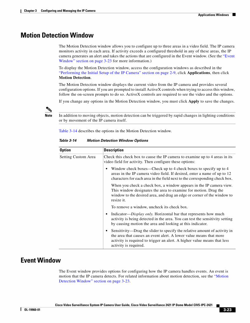
Chapter 3 Configuring and Managing the IP CameraApplications Windows
Motion Detection WindowThe Motion Detection window allows you to configure up to three areas in a video field. The IP camera monitors activity in each area. If activity exceeds a configured threshold in any of these areas, the IP camera generates an alert and takes the actions that are configured in the Event window. (See the “Event Window” section on page 3-23 for more information.)
To display the Motion Detection window, access the configuration windows as described in the “Performing the Initial Setup of the IP Camera” section on page 2-9, click Applications, then click Motion Detection.
The Motion Detection window displays the current video from the IP camera and provides several configuration options. If you are prompted to install ActiveX controls when trying to access this window, follow the on-screen prompts to do so. ActiveX controls are required to see the video and the options.
If you change any options in the Motion Detection window, you must click Apply to save the changes.
Note In addition to moving objects, motion detection can be triggered by rapid changes in lighting conditions or by movement of the IP camera itself.
Table 3-14 describes the options in the Motion Detection window.
Event WindowThe Event window provides options for configuring how the IP camera handles events. An event is motion that the IP camera detects. For related information about motion detection, see the “Motion Detection Window” section on page 3-23.
Table 3-14 Motion Detection Window Options
Option Description
Setting Custom Area Check this check box to cause the IP camera to examine up to 4 areas in its video field for activity. Then configure these options:
• Window check boxes—Check up to 4 check boxes to specify up to 4 areas in the IP camera video field. If desired, enter a name of up to 12 characters for each area in the field next to the corresponding check box.
When you check a check box, a window appears in the IP camera view. This window designates the area to examine for motion. Drag the window to the desired area, and drag an edge or corner of the window to resize it.
To remove a window, uncheck its check box.
• Indicator—Display only. Horizontal bar that represents how much activity is being detected in the area. You can test the sensitivity setting by causing motion the area and looking at this indicator.
• Sensitivity—Drag the slider to specify the relative amount of activity in the area that causes an event alert. A lower value means that more activity is required to trigger an alert. A higher value means that less activity is required.
3-23Cisco Video Surveillance System IP Camera User Guide, Cisco Video Surveillance 2421 IP Dome Model CIVS-IPC-2421
OL-19960-01
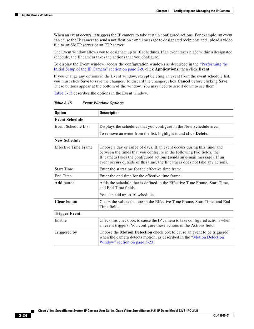
Chapter 3 Configuring and Managing the IP CameraApplications Windows
When an event occurs, it triggers the IP camera to take certain configured actions. For example, an event can cause the IP camera to send a notification e-mail message to designated recipients and upload a video file to an SMTP server or an FTP server.
The Event window allows you to designate up to 10 schedules. If an event takes place within a designated schedule, the IP camera takes the actions that you configure.
To display the Event window, access the configuration windows as described in the “Performing the Initial Setup of the IP Camera” section on page 2-9, click Applications, then click Event.
If you change any options in the Event window, except deleting an event from the event schedule list, you must click Save to save the changes. To discard the changes, click Cancel before clicking Save. These buttons appear at the bottom of the window. You may need to scroll down to see them.
Table 3-15 describes the options in the Event window.
Table 3-15 Event Window Options
Option Description
Event Schedule
Event Schedule List Displays the schedules that you configure in the New Schedule area.
To remove an event from the list, highlight it and click Delete.
New Schedule
Effective Time Frame Choose a day or range of days. If an event occurs during this time, and between the times that you configure in the following two fields, the IP camera takes the configured actions (sends an e-mail message). If an event occurs outside of this time, the IP camera does not take any actions.
Start Time Enter the start time for the effective time frame.
End Time Enter the end time for the effective time frame.
Add button Adds the schedule that is defined in the Effective Time Frame, Start Time, and End Time fields.
You can add up to 10 schedules.
Clear button Clears the values that are in the Effective Time Frame, Start Time, and End Time fields.
Trigger Event
Enable Check this check box to cause the IP camera to take configured actions when an event triggers. You configure these actions in the Actions field.
Triggered by Choose the Motion Detection check box to cause an event to be triggered when the camera detects motion, as described in the “Motion Detection Window” section on page 3-23.
3-24Cisco Video Surveillance System IP Camera User Guide, Cisco Video Surveillance 2421 IP Dome Model CIVS-IPC-2421
OL-19960-01
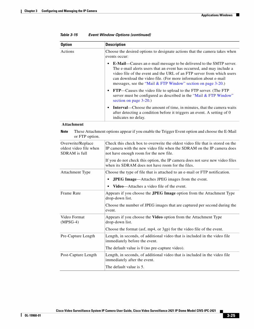
Chapter 3 Configuring and Managing the IP CameraApplications Windows
Actions Choose the desired options to designate actions that the camera takes when events occur:
• E-Mail—Causes an e-mail message to be delivered to the SMTP server. The e-mail alerts users that an event has occurred, and may include a video file of the event and the URL of an FTP server from which users can download the video file. (For more information about e-mail messages, see the “Mail & FTP Window” section on page 3-20.)
• FTP—Causes the video file to upload to the FTP server. (The FTP server must be configured as described in the “Mail & FTP Window” section on page 3-20.)
• Interval—Choose the amount of time, in minutes, that the camera waits after detecting a condition before it triggers an event. A setting of 0 indicates no delay.
Attachment
Note These Attachment options appear if you enable the Trigger Event option and choose the E-Mail or FTP option.
Overwrite/Replace oldest video file when SDRAM is full
Check this check box to overwrite the oldest video file that is stored on the IP camera with the new video file when the SDRAM on the IP camera does not have enough room for the new file.
If you do not check this option, the IP camera does not save new video files when its SDRAM does not have room for the files.
Attachment Type Choose the type of file that is attached to an e-mail or FTP notification.
• JPEG Image—Attaches JPEG images from the event.
• Video—Attaches a video file of the event.
Frame Rate Appears if you choose the JPEG Image option from the Attachment Type drop-down list.
Choose the number of JPEG images that are captured per second during the event.
Video Format (MPSG-4)
Appears if you choose the Video option from the Attachment Type drop-down list.
Choose the format (asf, mp4, or 3gp) for the video file of the event.
Pre-Capture Length Length, in seconds, of additional video that is included in the video file immediately before the event.
The default value is 0 (no pre-capture video).
Post-Capture Length Length, in seconds, of additional video that is included in the video file immediately after the event.
The default value is 5.
Table 3-15 Event Window Options (continued)
Option Description
3-25Cisco Video Surveillance System IP Camera User Guide, Cisco Video Surveillance 2421 IP Dome Model CIVS-IPC-2421
OL-19960-01
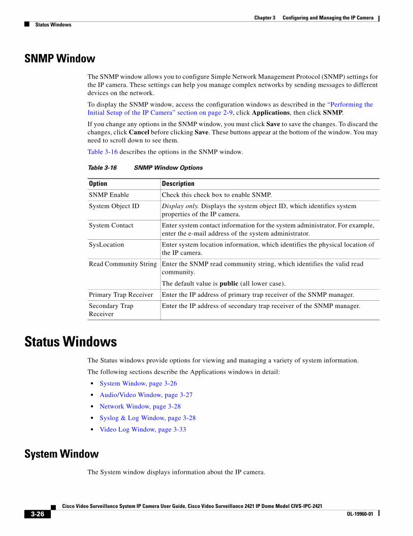
Chapter 3 Configuring and Managing the IP CameraStatus Windows
SNMP WindowThe SNMP window allows you to configure Simple Network Management Protocol (SNMP) settings for the IP camera. These settings can help you manage complex networks by sending messages to different devices on the network.
To display the SNMP window, access the configuration windows as described in the “Performing the Initial Setup of the IP Camera” section on page 2-9, click Applications, then click SNMP.
If you change any options in the SNMP window, you must click Save to save the changes. To discard the changes, click Cancel before clicking Save. These buttons appear at the bottom of the window. You may need to scroll down to see them.
Table 3-16 describes the options in the SNMP window.
Status WindowsThe Status windows provide options for viewing and managing a variety of system information.
The following sections describe the Applications windows in detail:
• System Window, page 3-26
• Audio/Video Window, page 3-27
• Network Window, page 3-28
• Syslog & Log Window, page 3-28
• Video Log Window, page 3-33
System WindowThe System window displays information about the IP camera.
Table 3-16 SNMP Window Options
Option Description
SNMP Enable Check this check box to enable SNMP.
System Object ID Display only. Displays the system object ID, which identifies system properties of the IP camera.
System Contact Enter system contact information for the system administrator. For example, enter the e-mail address of the system administrator.
SysLocation Enter system location information, which identifies the physical location of the IP camera.
Read Community String Enter the SNMP read community string, which identifies the valid read community.
The default value is public (all lower case).
Primary Trap Receiver Enter the IP address of primary trap receiver of the SNMP manager.
Secondary Trap Receiver
Enter the IP address of secondary trap receiver of the SNMP manager.
3-26Cisco Video Surveillance System IP Camera User Guide, Cisco Video Surveillance 2421 IP Dome Model CIVS-IPC-2421
OL-19960-01
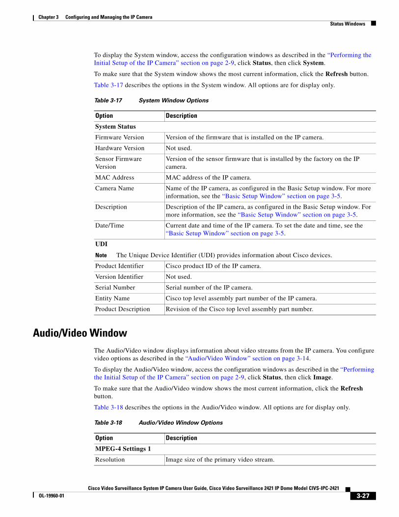
Chapter 3 Configuring and Managing the IP CameraStatus Windows
To display the System window, access the configuration windows as described in the “Performing the Initial Setup of the IP Camera” section on page 2-9, click Status, then click System.
To make sure that the System window shows the most current information, click the Refresh button.
Table 3-17 describes the options in the System window. All options are for display only.
Audio/Video WindowThe Audio/Video window displays information about video streams from the IP camera. You configure video options as described in the “Audio/Video Window” section on page 3-14.
To display the Audio/Video window, access the configuration windows as described in the “Performing the Initial Setup of the IP Camera” section on page 2-9, click Status, then click Image.
To make sure that the Audio/Video window shows the most current information, click the Refresh button.
Table 3-18 describes the options in the Audio/Video window. All options are for display only.
Table 3-17 System Window Options
Option Description
System Status
Firmware Version Version of the firmware that is installed on the IP camera.
Hardware Version Not used.
Sensor Firmware Version
Version of the sensor firmware that is installed by the factory on the IP camera.
MAC Address MAC address of the IP camera.
Camera Name Name of the IP camera, as configured in the Basic Setup window. For more information, see the “Basic Setup Window” section on page 3-5.
Description Description of the IP camera, as configured in the Basic Setup window. For more information, see the “Basic Setup Window” section on page 3-5.
Date/Time Current date and time of the IP camera. To set the date and time, see the “Basic Setup Window” section on page 3-5.
UDI
Note The Unique Device Identifier (UDI) provides information about Cisco devices.
Product Identifier Cisco product ID of the IP camera.
Version Identifier Not used.
Serial Number Serial number of the IP camera.
Entity Name Cisco top level assembly part number of the IP camera.
Product Description Revision of the Cisco top level assembly part number.
Table 3-18 Audio/Video Window Options
Option Description
MPEG-4 Settings 1
Resolution Image size of the primary video stream.
3-27Cisco Video Surveillance System IP Camera User Guide, Cisco Video Surveillance 2421 IP Dome Model CIVS-IPC-2421
OL-19960-01
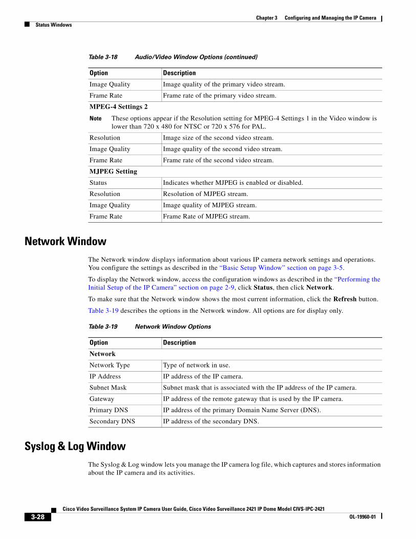
Chapter 3 Configuring and Managing the IP CameraStatus Windows
Network WindowThe Network window displays information about various IP camera network settings and operations. You configure the settings as described in the “Basic Setup Window” section on page 3-5.
To display the Network window, access the configuration windows as described in the “Performing the Initial Setup of the IP Camera” section on page 2-9, click Status, then click Network.
To make sure that the Network window shows the most current information, click the Refresh button.
Table 3-19 describes the options in the Network window. All options are for display only.
Syslog & Log WindowThe Syslog & Log window lets you manage the IP camera log file, which captures and stores information about the IP camera and its activities.
Image Quality Image quality of the primary video stream.
Frame Rate Frame rate of the primary video stream.
MPEG-4 Settings 2
Note These options appear if the Resolution setting for MPEG-4 Settings 1 in the Video window is lower than 720 x 480 for NTSC or 720 x 576 for PAL.
Resolution Image size of the second video stream.
Image Quality Image quality of the second video stream.
Frame Rate Frame rate of the second video stream.
MJPEG Setting
Status Indicates whether MJPEG is enabled or disabled.
Resolution Resolution of MJPEG stream.
Image Quality Image quality of MJPEG stream.
Frame Rate Frame Rate of MJPEG stream.
Table 3-18 Audio/Video Window Options (continued)
Option Description
Table 3-19 Network Window Options
Option Description
Network
Network Type Type of network in use.
IP Address IP address of the IP camera.
Subnet Mask Subnet mask that is associated with the IP address of the IP camera.
Gateway IP address of the remote gateway that is used by the IP camera.
Primary DNS IP address of the primary Domain Name Server (DNS).
Secondary DNS IP address of the secondary DNS.
3-28Cisco Video Surveillance System IP Camera User Guide, Cisco Video Surveillance 2421 IP Dome Model CIVS-IPC-2421
OL-19960-01
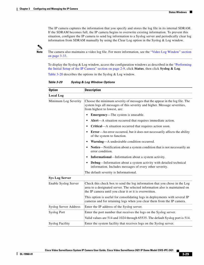
Chapter 3 Configuring and Managing the IP CameraStatus Windows
The IP camera captures the information that you specify and stores the log file in its internal SDRAM. If the SDRAM becomes full, the IP camera begins to overwrite existing information. To prevent this situation, configure the IP camera to send log information to a Syslog server and periodically clear log information from SDRAM manually by using the Clear Log option in the Syslog & Log window.
Note The camera also maintains a video log file. For more information, see the “Video Log Window” section on page 3-33.
To display the Syslog & Log window, access the configuration windows as described in the “Performing the Initial Setup of the IP Camera” section on page 2-9, click Status, then click Syslog & Log.
Table 3-20 describes the options in the Syslog & Log window.
Table 3-20 Syslog & Log Window Options
Option Description
Local Log
Minimum Log Severity Choose the minimum severity of messages that the appear in the log file. The system logs all messages of this severity and higher. Message severities, from highest to lowest, are:
• Emergency—The system is unusable.
• Alert—A situation occurred that requires immediate action.
• Critical—A situation occurred that requires action soon.
• Error—An error occurred, but it does not necessarily affects the ability of the system to function.
• Warning—A undesirable condition occurred.
• Notice—Notification about a system condition that is not necessarily an error condition.
• Informational—Information about a system activity.
• Debug—Information about a system activity with detailed technical information. Includes messages of every other severity.
The default severity is Informational.
Sys Log Server
Enable Syslog Server Check this check box to send the log information that you chose in the Log area to a designated server. The selected information also is maintained on the IP camera until you clear it or it is overwritten.
This option is useful for consolidating logs in deployments with several IP cameras and for retaining logs when you clear them from the IP camera.
Syslog Server Address Enter the IP address of the Syslog server.
Syslog Port Enter the port number that receives the logs on the Syslog server.
Valid values are 514 and 1024 through 65535. The default Syslog port is 514.
Syslog Facility Enter the system facility that receives logs on the Syslog server.
3-29Cisco Video Surveillance System IP Camera User Guide, Cisco Video Surveillance 2421 IP Dome Model CIVS-IPC-2421
OL-19960-01
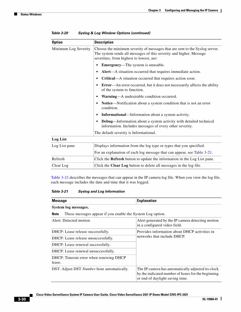
Chapter 3 Configuring and Managing the IP CameraStatus Windows
Table 3-21 describes the messages that can appear in the IP camera log file. When you view the log file, each message includes the date and time that it was logged.
Minimum Log Severity Choose the minimum severity of messages that are sent to the Syslog server. The system sends all messages of this severity and higher. Message severities, from highest to lowest, are:
• Emergency—The system is unusable.
• Alert—A situation occurred that requires immediate action.
• Critical—A situation occurred that requires action soon.
• Error—An error occurred, but it does not necessarily affects the ability of the system to function.
• Warning—A undesirable condition occurred.
• Notice—Notification about a system condition that is not an error condition.
• Informational—Information about a system activity.
• Debug—Information about a system activity with detailed technical information. Includes messages of every other severity.
The default severity is Informational.
Log List
Log List pane Displays information from the log type or types that you specified.
For an explanation of each log message that can appear, see Table 3-21.
Refresh Click the Refresh button to update the information in the Log List pane.
Clear Log Click the Clear Log button to delete all messages in the log file.
Table 3-20 Syslog & Log Window Options (continued)
Option Description
Table 3-21 Syslog and Log Information
Message Explanation
System log messages.
Note These messages appear if you enable the System Log option.
Alert: Detected motion Alert generated by the IP camera detecting motion in a configured video field.
DHCP: Lease release successfully. Provides information about DHCP activities in networks that include DHCP.DHCP: Lease release unsuccessfully.
DHCP: Lease renewal successfully.
DHCP: Lease renewal unsuccessfully.
DHCP: Timeout error when renewing DHCP lease.
DST: Adjust DST Number hour automatically. The IP camera has automatically adjusted its clock by the indicated number of hours for the beginning or end of daylight saving time.
3-30Cisco Video Surveillance System IP Camera User Guide, Cisco Video Surveillance 2421 IP Dome Model CIVS-IPC-2421
OL-19960-01
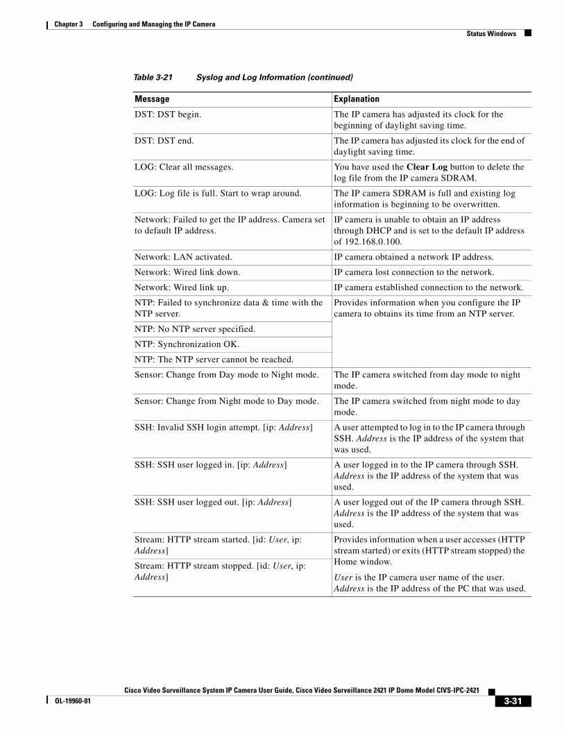
Chapter 3 Configuring and Managing the IP CameraStatus Windows
DST: DST begin. The IP camera has adjusted its clock for the beginning of daylight saving time.
DST: DST end. The IP camera has adjusted its clock for the end of daylight saving time.
LOG: Clear all messages. You have used the Clear Log button to delete the log file from the IP camera SDRAM.
LOG: Log file is full. Start to wrap around. The IP camera SDRAM is full and existing log information is beginning to be overwritten.
Network: Failed to get the IP address. Camera set to default IP address.
IP camera is unable to obtain an IP address through DHCP and is set to the default IP address of 192.168.0.100.
Network: LAN activated. IP camera obtained a network IP address.
Network: Wired link down. IP camera lost connection to the network.
Network: Wired link up. IP camera established connection to the network.
NTP: Failed to synchronize data & time with the NTP server.
Provides information when you configure the IP camera to obtains its time from an NTP server.
NTP: No NTP server specified.
NTP: Synchronization OK.
NTP: The NTP server cannot be reached.
Sensor: Change from Day mode to Night mode. The IP camera switched from day mode to night mode.
Sensor: Change from Night mode to Day mode. The IP camera switched from night mode to day mode.
SSH: Invalid SSH login attempt. [ip: Address] A user attempted to log in to the IP camera through SSH. Address is the IP address of the system that was used.
SSH: SSH user logged in. [ip: Address] A user logged in to the IP camera through SSH. Address is the IP address of the system that was used.
SSH: SSH user logged out. [ip: Address] A user logged out of the IP camera through SSH. Address is the IP address of the system that was used.
Stream: HTTP stream started. [id: User, ip: Address]
Provides information when a user accesses (HTTP stream started) or exits (HTTP stream stopped) the Home window.
User is the IP camera user name of the user. Address is the IP address of the PC that was used.
Stream: HTTP stream stopped. [id: User, ip: Address]
Table 3-21 Syslog and Log Information (continued)
Message Explanation
3-31Cisco Video Surveillance System IP Camera User Guide, Cisco Video Surveillance 2421 IP Dome Model CIVS-IPC-2421
OL-19960-01
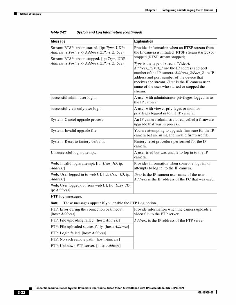
Chapter 3 Configuring and Managing the IP CameraStatus Windows
Stream: RTSP stream started. [ip: Type, UDP: Address_1:Port_1 -> Address_2:Port_2, User]
Provides information when an RTSP stream from the IP camera is initiated (RTSP stream started) or stopped (RTSP stream stopped).
Type is the type of stream (Video). Address_1:Port_1 are the IP address and port number of the IP camera. Address_2:Port_2 are IP address and port number of the device that receives the stream. User is the IP camera user name of the user who started or stopped the stream.
Stream: RTSP stream stopped. [ip: Type, UDP: Address_1:Port_1 -> Address_2:Port_2, User]
successful admin user login. A user with administrator privileges logged in to the IP camera.
successful view only user login. A user with viewer privileges or monitor privileges logged in to the IP camera.
System: Cancel upgrade process An IP camera administrator cancelled a firmware upgrade that was in process.
System: Invalid upgrade file You are attempting to upgrade firmware for the IP camera but are using and invalid firmware file.
System: Reset to factory defaults. Factory reset procedure performed for the IP camera.
Unsuccessful login attempt. A user tried but was unable to log in to the IP camera.
Web: Invalid login attempt. [id: User_ID, ip: Address]
Provides information when someone logs in, or attempts to log in, to the IP camera.
User is the IP camera user name of the user. Address is the IP address of the PC that was used.
Web: User logged in to web UI. [id: User_ID, ip: Address]
Web: User logged out from web UI. [id: User_ID, ip: Address]
FTP log messages.
Note These messages appear if you enable the FTP Log option.
FTP: Error during the connection or timeout. [host: Address]
Provide information when the camera uploads a video file to the FTP server.
Address is the IP address of the FTP server.FTP: File uploading failed. [host: Address]
FTP: File uploaded successfully. [host: Address]
FTP: Login failed. [host: Address]
FTP: No such remote path. [host: Address]
FTP: Unknown FTP server. [host: Address]
Table 3-21 Syslog and Log Information (continued)
Message Explanation
3-32Cisco Video Surveillance System IP Camera User Guide, Cisco Video Surveillance 2421 IP Dome Model CIVS-IPC-2421
OL-19960-01
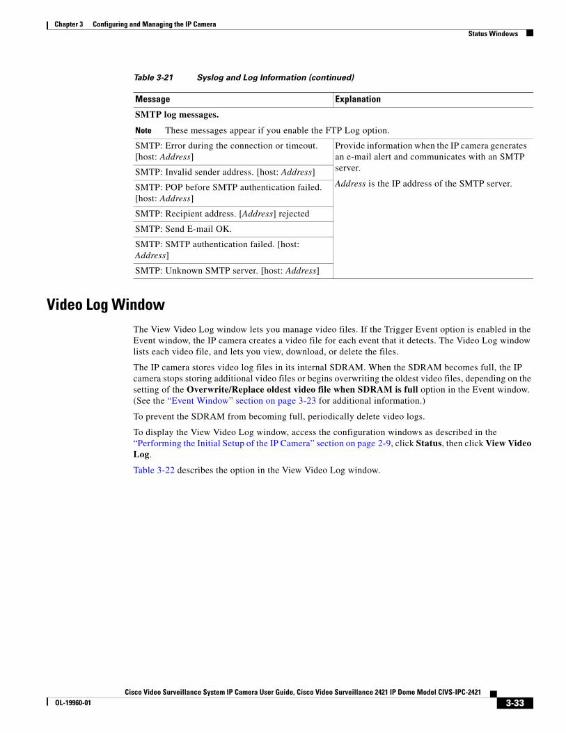
Chapter 3 Configuring and Managing the IP CameraStatus Windows
Video Log WindowThe View Video Log window lets you manage video files. If the Trigger Event option is enabled in the Event window, the IP camera creates a video file for each event that it detects. The Video Log window lists each video file, and lets you view, download, or delete the files.
The IP camera stores video log files in its internal SDRAM. When the SDRAM becomes full, the IP camera stops storing additional video files or begins overwriting the oldest video files, depending on the setting of the Overwrite/Replace oldest video file when SDRAM is full option in the Event window. (See the “Event Window” section on page 3-23 for additional information.)
To prevent the SDRAM from becoming full, periodically delete video logs.
To display the View Video Log window, access the configuration windows as described in the “Performing the Initial Setup of the IP Camera” section on page 2-9, click Status, then click View Video Log.
Table 3-22 describes the option in the View Video Log window.
SMTP log messages.
Note These messages appear if you enable the FTP Log option.
SMTP: Error during the connection or timeout. [host: Address]
Provide information when the IP camera generates an e-mail alert and communicates with an SMTP server.
Address is the IP address of the SMTP server.SMTP: Invalid sender address. [host: Address]
SMTP: POP before SMTP authentication failed. [host: Address]
SMTP: Recipient address. [Address] rejected
SMTP: Send E-mail OK.
SMTP: SMTP authentication failed. [host: Address]
SMTP: Unknown SMTP server. [host: Address]
Table 3-21 Syslog and Log Information (continued)
Message Explanation
3-33Cisco Video Surveillance System IP Camera User Guide, Cisco Video Surveillance 2421 IP Dome Model CIVS-IPC-2421
OL-19960-01
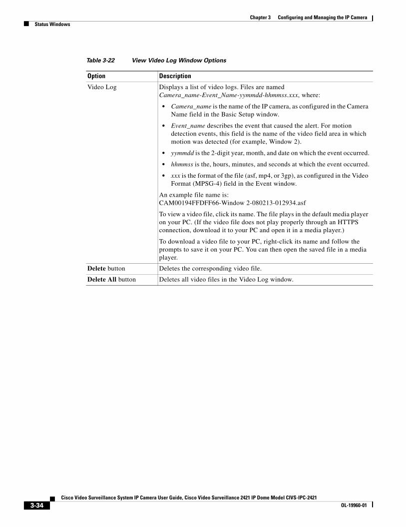
Chapter 3 Configuring and Managing the IP CameraStatus Windows
Table 3-22 View Video Log Window Options
Option Description
Video Log Displays a list of video logs. Files are named Camera_name-Event_Name-yymmdd-hhmmss.xxx, where:
• Camera_name is the name of the IP camera, as configured in the Camera Name field in the Basic Setup window.
• Event_name describes the event that caused the alert. For motion detection events, this field is the name of the video field area in which motion was detected (for example, Window 2).
• yymmdd is the 2-digit year, month, and date on which the event occurred.
• hhmmss is the, hours, minutes, and seconds at which the event occurred.
• xxx is the format of the file (asf, mp4, or 3gp), as configured in the Video Format (MPSG-4) field in the Event window.
An example file name is: CAM00194FFDFF66-Window 2-080213-012934.asf
To view a video file, click its name. The file plays in the default media player on your PC. (If the video file does not play properly through an HTTPS connection, download it to your PC and open it in a media player.)
To download a video file to your PC, right-click its name and follow the prompts to save it on your PC. You can then open the saved file in a media player.
Delete button Deletes the corresponding video file.
Delete All button Deletes all video files in the Video Log window.
3-34Cisco Video Surveillance System IP Camera User Guide, Cisco Video Surveillance 2421 IP Dome Model CIVS-IPC-2421
OL-19960-01
Cisco Video Surveillance System IP Camera User Guide, Cisco VidOL-19960-01
C H A P T E R 4
Viewing and Live VideoAfter you install and set up the Cisco Video Surveillance IP Camera as described in Chapter 2, “Getting Started,” users can connect to the IP camera through Internet Explorer and access the Home window to view live video from the IP camera. The home window also provides for controlling the video display and certain IP camera functions.
You also can configure the IP camera to allow access to its video through a mobile device, or through the VLC media player or equivalent software.
This chapter includes these topics:
• Viewing Video through the Home Window Overview, page 4-1
• Viewing Video through Third-Party Devices or Software, page 4-4
Viewing Video through the Home Window OverviewTo view live video, access the Home window as described in the “Accessing the IP Camera Windows” section on page 2-11. This window displays live video from the camera and lets you control a variety of camera and display functions.
Home Window OverviewFigure 4-1 describes the main features of the Home window.
4-1eo Surveillance 2421 IP Dome Model CIVS-IPC-2421
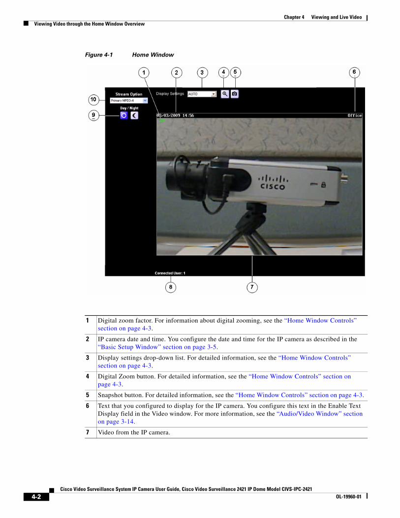
Chapter 4 Viewing and Live VideoViewing Video through the Home Window Overview
Figure 4-1 Home Window
1 Digital zoom factor. For information about digital zooming, see the “Home Window Controls” section on page 4-3.
2 IP camera date and time. You configure the date and time for the IP camera as described in the “Basic Setup Window” section on page 3-5.
3 Display settings drop-down list. For detailed information, see the “Home Window Controls” section on page 4-3.
4 Digital Zoom button. For detailed information, see the “Home Window Controls” section on page 4-3.
5 Snapshot button. For detailed information, see the “Home Window Controls” section on page 4-3.
6 Text that you configured to display for the IP camera. You configure this text in the Enable Text Display field in the Video window. For more information, see the “Audio/Video Window” section on page 3-14.
7 Video from the IP camera.
4-2Cisco Video Surveillance System IP Camera User Guide, Cisco Video Surveillance 2421 IP Dome Model CIVS-IPC-2421
OL-19960-01
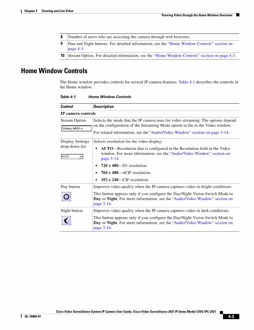
Chapter 4 Viewing and Live VideoViewing Video through the Home Window Overview
Home Window ControlsThe Home window provides controls for several IP camera features. Table 4-1 describes the controls in the Home window.
8 Number of users who are accessing the camera through web browsers.
9 Dan and Night buttons. For detailed information, see the “Home Window Controls” section on page 4-3.
10 Stream Option. For detailed information, see the “Home Window Controls” section on page 4-3.
Table 4-1 Home Window Controls
Control Description
IP camera controls
Stream Option Selects the mode that the IP camera uses for video streaming. The options depend on the configuration of the Streaming Mode option in the in the Video window.
For related information, see the “Audio/Video Window” section on page 3-14.
Display Settings drop-down list
Selects resolution for the video display:
• AUTO—Resolution that is configured in the Resolution field in the Video window. For more information, see the “Audio/Video Window” section on page 3-14.
• 720 x 480—D1 resolution.
• 704 x 480—4CIF resolution.
• 352 x 240—CIF resolution.
Day button Improves video quality when the IP camera captures video in bright conditions.
This button appears only if you configure the Day/Night Vision Switch Mode to Day or Night. For more information, see the “Audio/Video Window” section on page 3-14.
Night button Improves video quality when the IP camera captures video in dark conditions.
This button appears only if you configure the Day/Night Vision Switch Mode to Day or Night. For more information, see the “Audio/Video Window” section on page 3-14.
4-3Cisco Video Surveillance System IP Camera User Guide, Cisco Video Surveillance 2421 IP Dome Model CIVS-IPC-2421
OL-19960-01
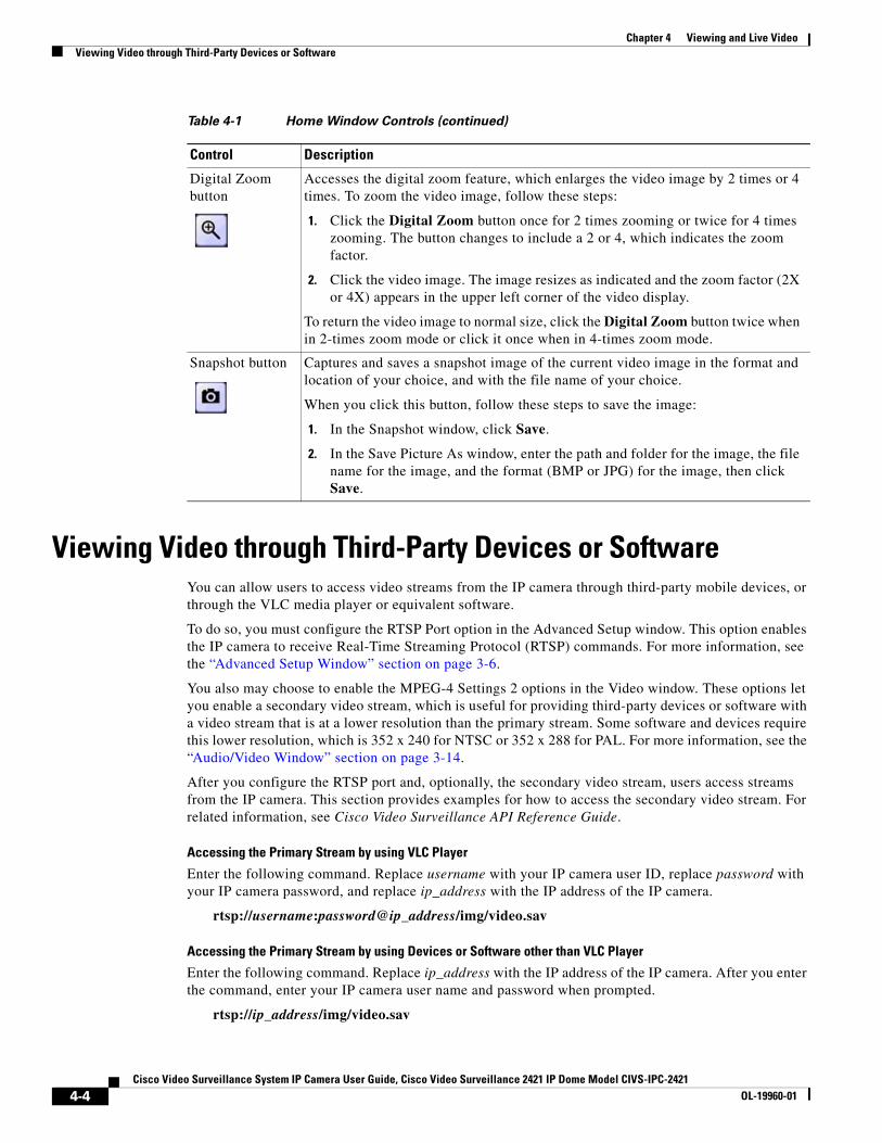
Chapter 4 Viewing and Live VideoViewing Video through Third-Party Devices or Software
Viewing Video through Third-Party Devices or SoftwareYou can allow users to access video streams from the IP camera through third-party mobile devices, or through the VLC media player or equivalent software.
To do so, you must configure the RTSP Port option in the Advanced Setup window. This option enables the IP camera to receive Real-Time Streaming Protocol (RTSP) commands. For more information, see the “Advanced Setup Window” section on page 3-6.
You also may choose to enable the MPEG-4 Settings 2 options in the Video window. These options let you enable a secondary video stream, which is useful for providing third-party devices or software with a video stream that is at a lower resolution than the primary stream. Some software and devices require this lower resolution, which is 352 x 240 for NTSC or 352 x 288 for PAL. For more information, see the “Audio/Video Window” section on page 3-14.
After you configure the RTSP port and, optionally, the secondary video stream, users access streams from the IP camera. This section provides examples for how to access the secondary video stream. For related information, see Cisco Video Surveillance API Reference Guide.
Accessing the Primary Stream by using VLC Player
Enter the following command. Replace username with your IP camera user ID, replace password with your IP camera password, and replace ip_address with the IP address of the IP camera.
rtsp://username:password@ip_address/img/video.sav
Accessing the Primary Stream by using Devices or Software other than VLC Player
Enter the following command. Replace ip_address with the IP address of the IP camera. After you enter the command, enter your IP camera user name and password when prompted.
rtsp://ip_address/img/video.sav
Digital Zoom button
Accesses the digital zoom feature, which enlarges the video image by 2 times or 4 times. To zoom the video image, follow these steps:
1. Click the Digital Zoom button once for 2 times zooming or twice for 4 times zooming. The button changes to include a 2 or 4, which indicates the zoom factor.
2. Click the video image. The image resizes as indicated and the zoom factor (2X or 4X) appears in the upper left corner of the video display.
To return the video image to normal size, click the Digital Zoom button twice when in 2-times zoom mode or click it once when in 4-times zoom mode.
Snapshot button Captures and saves a snapshot image of the current video image in the format and location of your choice, and with the file name of your choice.
When you click this button, follow these steps to save the image:
1. In the Snapshot window, click Save.
2. In the Save Picture As window, enter the path and folder for the image, the file name for the image, and the format (BMP or JPG) for the image, then click Save.
Table 4-1 Home Window Controls (continued)
Control Description
4-4Cisco Video Surveillance System IP Camera User Guide, Cisco Video Surveillance 2421 IP Dome Model CIVS-IPC-2421
OL-19960-01
Chapter 4 Viewing and Live VideoViewing Video through Third-Party Devices or Software
Accessing the Primary Stream by using VLC Player
In the following command, replace username with your IP camera user ID, replace password with your IP camera password, replace ip_address with the IP address of the IP camera, and replace code with the Access Code that you configured for the secondary stream in the Video window.
rtsp//username:password@ip_address/code
Accessing the Secondary Stream by using Devices or Software other than VLC Player
In the following command, replace ip_address with the IP address of the IP camera, and replace code with the Access Code that you configured for the secondary stream in the Video window. After you enter the command, enter your IP camera user name and password when prompted.
rtsp//ip_address/code
4-5Cisco Video Surveillance System IP Camera User Guide, Cisco Video Surveillance 2421 IP Dome Model CIVS-IPC-2421
OL-19960-01

Chapter 4 Viewing and Live VideoViewing Video through Third-Party Devices or Software
4-6Cisco Video Surveillance System IP Camera User Guide, Cisco Video Surveillance 2421 IP Dome Model CIVS-IPC-2421
OL-19960-01
Cisco Video Surveillance System IP Camera User Guide, Cisco VidOL-19960-01
C H A P T E R 5
TroubleshootingThis chapter describes some common problems that may be encountered while using the IP camera and provides possible solutions.
Symptom Cannot connect to an IP camera through a web browser.
Possible Cause You are not using a supported PC operating system or web browser, you entered an incorrect IP address for the IP camera, the PC that you are using is not on the same LAN as the IP camera, you are entering an invalid port number for an HTTP or HTTPS connection, or you are trying to access the IP camera from a device with an IP address that is restricted from access.
Recommended Action Make sure that you are using a PC that is running Microsoft Windows 2000, XP, or Vista and that your are using Internet Explorer 6.x with Service Pack 2, or later. Make sure that you enter the correct IP address. If you are connecting through a LAN, make sure that the PC is on the same network as the IP camera. If you are connecting through the Internet, make sure to enter the correct port number. Make sure that the device does not have an IP address that is restricted from access (see the “IP Filter Window” section on page 3-8.)
Symptom Cannot log in to the IP camera as the administrator.
Possible Cause You are entering the log in credentials incorrectly or have forgotten the administrator password.
Recommended Action The administrator user name is admin and the password is the one that you configured. Both credentials are case sensitive, so make sure to enter them exactly as they are configured. If you forget the administrator password, you must perform a factory reset as described in the “Resetting the IP Camera” procedure on page 2-14, then reconfigure the IP camera. If you take these actions, do not use the Upload option in the Maintenance window to reload a saved configuration file because that process restores the password that you forgot.
Symptom Configuration windows do not display when you click the Setup link in the Main window.
Possible Cause You or another user recently exited the configuration windows by exiting a browser without first clicking the Logout button. In this case, it can take up to 2 minutes before the configuration windows become available.
Recommended Action Wait 2 minutes and try again.
5-1eo Surveillance 2421 IP Dome Model CIVS-IPC-2421
Chapter 5 Troubleshooting
Symptom The motion detection feature does not send e-mail alerts.
Possible Cause The e-mail alert feature is not properly configured or the SMTP server that the IP camera uses to send the e-mail may be filtering e-mail to prevent spam from being sent from your server.
Recommended Action Configure e-mail alerts as described in the “Basic Setup Window” section on page 3-5, the “Mail & FTP Window” section on page 3-20, and the “Event Window” section on page 3-23. Try using a different SMTP server or contact your ISP to see if SMTP access is being blocked.
Symptom The motion detection feature is configured but video files that are provided in e-mail alerts do not show moving objects.
Possible Cause The motion detection feature does not actually detect motion. It compares frames to see if they are different. Major differences between frames are assumed to be caused by moving objects, but the motion detector can also be triggered by sudden changes in light level or movement of the IP camera itself.
Recommended Action Try to avoid situations with sudden changes in light level and do not bump or move the IP camera. The motion detection feature works best when the IP camera is mounted securely in locations where there is steady. This feature may not work properly if the IP camera is outdoors.
Symptom Blurry images when viewing video.
Possible Cause The lens may be dirty, back focus may not be adjusted properly, or video settings may not be configured for optimal clarity.
Recommended Action Clean the lens on the IP camera. Adjust the back focus as described in the “Adjusting the Video Image” procedure on page 2-12. Configure options for video as described in the “Audio/Video Window” section on page 3-14.
5-2Cisco Video Surveillance System IP Camera User Guide, Cisco Video Surveillance 2421 IP Dome Model CIVS-IPC-2421
OL-19960-01
Cisco Video Surveillance System IP Camera User Guide, Cisco Video SurvOL-19960-01
A
P P E N D I X A Using the IP Camera with Cisco VSMCisco Video Surveillance Manager (VSM) is a suite of powerful and flexible video surveillance applications that interoperate with a wide range of devices and cameras to provide a complete, standards-based video surveillance solution. VSM consists of modules to manage, archive, view, and distribute video.
The following guidelines apply when you use the IP camera with VSM:
• Obtaining the Required Driver Pack
To use the IP camera with VSM, you must download and install a driver pack. For information about this driver pack, refer to your VSM documentation, which is available here:
http://www.cisco.com/web/solutions/ps/products.html#netcentric
• The IP camera must be installed and configured as described in Chapter 2, “Getting Started.”
• You must to create a separate user account with administrator privileges for each Media Server. Configuration connections for a Media Server are limited just as they are for user sessions. Viewing and managing video streams from VSM requires administrator-level privileges.
For information about how to configure a user account, see the “Users Window” section on page 3-10.
• A user with administrator privileges cannot be logged in to the IP camera and use VSM at the same time
• Cisco recommends that you configure video resolution (NTSC or PAL) from the IP camera configuration windows.
For instructions, see the “Audio/Video Window” section on page 3-14.
A-1eillance 2421 IP Dome Model CIVS-IPC-2421

Appendix A Using the IP Camera with Cisco VSM
A-2Cisco Video Surveillance System IP Camera User Guide, Cisco Video Surveillance 2421 IP Dome Model CIVS-IPC-2421
OL-19960-01
Cisco Video Surveillance System IP Camera User Guide, Cisco VidOL-19960-01
I N D E X
A
action
configuring 3-25
overview 3-24
triggered by event 3-24
ActiveX controls 3-23
Administration windows 3-10
Administrator user type
configuring 3-11
description 3-10
password
recovering 5-1
setting 3-11, 3-19
user name 3-11
Advanced Setup window
options 3-7
overview 3-6
Applications windows 3-20
Audio/Video windows 3-14
B
back focus
adjusting 2-12
focus ring 2-6, 2-9, 2-12
backing up, configuration of IP camera 3-12
Basic Setup window
options 3-5
overview 3-5
bit rate, of video 3-15
Bonjour, enabling on camera 3-7
brightness, of video 3-17
C
camera
See IP camera
CDP (Cisco Discovery Protocol), enabling on camera 3-7
Cisco Video Surveillance IP Camera
See IP camera
Cisco Video Surveillance Manager (VSM), using IP camera with 1-1
cleaning, IP camera 2-15
Complexity window
options 3-20
overview 3-19
configuration
guidelines 3-1
overview 3-1
requirements 3-1
configuration, of IP camera
backing up 3-12
copying to camera 3-12
saving 3-12
uploading 3-12
configuration file
saving 3-13
uploading 3-13
configuration windows
accessing 2-11
Administration windows 3-10
Advanced Setup window 3-6
Applications windows 3-20
Audio/Video windows 3-14
Basic Setup window 3-5
Complexity window 3-19
IN-1eo Surveillance 2421 IP Dome Model CIVS-IPC-2421
Index
EAPOL window 3-9
Event window 3-23
Firmware window 3-13
Image window 3-27
Initialization window 3-19
IP Filter window 3-8
Mail & FTP window 3-20
Maintenance window 3-12
Motion Detection window 3-23
navigating 3-3
Network window 3-28
options 3-4
overview 3-1
Product Process window 3-18
Security windows 3-18
Setup windows 3-4
SNMP window 3-26
Status windows 3-26
Syslog& Log window 3-28
System window 3-26
time out 3-1
Users window 3-10
Video Log window 3-33
Video window 3-14
connecting, to the IP camera
after the first time 2-11
for the first time 2-9
PC requirements for 2-9, 2-11
secure connection 2-11
contrast, of video 3-17
D
date and time
of IP camera 3-5
update through NTP server 3-6
day/night
mode 3-18
threshold 3-18
IN-2Cisco Video Surveillance System IP Camera User Guide, Cisco Vid
Day button 4-3
daylight saving time, adjustment for 3-5
day mode 3-18
description, for IP camera 3-5
DHCP, obtaining IP address through 2-10, 2-14, 3-6
DNS server
primary 3-6, 3-28
secondary 3-6, 3-28
dome
See IP camera
DSCP, for QoS 3-8
dual streaming 3-14, 4-4
E
EAPOL window
options 3-9
overview 3-9
e-mail notification
configuring 3-22
enabling 3-25
From field 3-22
FTP server link 3-20, 3-22
log file 3-33
of event 3-20
primary FTP server 3-22
recipients list 3-22
secondary FTP server 3-22
Subject field 3-22
video file attachment 3-20
event
actions 3-24
configuring 3-24
enabling trigger 3-24
interval before triggering 3-25
notification of 3-20
overview 3-20, 3-23
scheduling 3-24
trigger types 3-24
eo Surveillance 2421 IP Dome Model CIVS-IPC-2421OL-19960-01
Index
video of 3-20
Event window
options 3-24
overview 3-23
F
factory default configurations, restoring 3-12
factory reset 2-14
firmware
upgrading 3-14
version in IP camera 3-13, 3-27
Firmware window
options 3-14
overview 3-13
focus
adjusting 2-13
FTP log
description 3-32
FTP server
enabling uploading video file to 3-25
link to in notification e-mail 3-20, 3-22
log of upload activities 3-32
primary 3-22
secondary 3-22
G
gateway, for IP camera 3-6, 3-28
H
hardware version, of IP camera 3-27
Home link, in Main window 2-10, 2-12
Home window
accessing 2-11
controls in 4-3
figure 4-2
Cisco Video Surveillance System IP Camera User Guide, COL-19960-01
overview 4-1
HTTP
accessing camera through 2-11
allowing access through 2-10, 3-19
alternative port 3-7
default port 3-7
HTTPS
accessing camera through 2-11
alternative port 3-7
default port 3-7
I
Image window
options 3-27
overview 3-27
Initialization window
options 3-19
overview 3-19
installing
guidelines 2-1
IP camera 2-2
preparing for 2-3
recess mounting 2-3
surface mounting 2-6
IP address
controlling access by 3-9
default for IP camera 2-10, 2-11
fixed 3-6
obtaining from DCHP server 2-10
obtaining from DHCP server 2-14
obtaining through DHCP 2-14, 3-6
of IP camera 3-6, 3-28
IP camera
accessing through a web browser 2-9, 2-11
cleaning 2-15
configuration file 3-13
connecting to after the first time 2-11
connecting to for the first time 2-9
IN-3isco Video Surveillance 2421 IP Dome Model CIVS-IPC-2421
Index
controlling access to 3-9
date and time of 3-5
description 3-5
firmware 3-13
installation
guidelines 2-1
overview 2-2
preparing for 2-3
recess mounting 2-3
surface mounting 2-6
IP address 3-6, 3-28
LAN port on 1-3
name 3-5
overview 1-1
package contents 1-5
power connection 1-3
powering off 2-14
powering on 2-14
resetting 1-4
restarting 3-13
restoring factory default configurations 3-12
SDRAM 3-25, 3-29, 3-33
serial number 3-27
time zone 3-5
troubleshooting 5-1
Unique Device Identifier (UDI) 3-27
user types 3-10
windows 2-11
zoom
digital 4-4
ip camera
zoom
adjusting 2-12
IP dome
See IP camera
IP Filter window
options 3-9
overview 3-8
IN-4Cisco Video Surveillance System IP Camera User Guide, Cisco Vid
L
LAN port 1-3
LED
controlling operation of 3-5
disabling 3-5
enabling 3-5
Network 1-4
PoE 1-4
lens, adjusting focus, pan, zoom, tilt 2-12
live video
controlling through Home window 4-1
viewing
through Home window 4-3
through home window 4-1
through third-party device or software 4-1, 4-4
See also video
log
FTP 3-32
SMTP 3-33
system 3-30
log file
clearing 3-30
storage of 3-29
video 3-33
viewing 3-30
Logout button, in Main window 2-11, 2-12
M
MAC address, of IP camera 3-27
Mail & FTP window
options 3-21
overview 3-20
Maintenance window
options 3-12
overview 3-12
Main window
description 2-10, 2-12
eo Surveillance 2421 IP Dome Model CIVS-IPC-2421OL-19960-01
Index
Home link 2-10, 2-12
Logout button 2-11, 2-12
Setup link 2-10, 2-12
mobile device, viewing video through 4-4
motion detection
custom area 3-23
event trigger 3-24
overview 3-23
triggers 3-23
Motion Detection window
options 3-23
overview 3-23
multicast
enabling 3-8
video address 3-8
video port 3-8
N
name, of IP camera 3-5, 3-27
network
activity 1-4
type 3-28
viewing information about 3-28
Network LED 1-4
Network window
options 3-28
overview 3-28
Night button 4-3
night mode 3-18
P
package contents 1-5
pan, adjusting 2-12
password
complexity 3-19
configuring requirements for 3-19
Cisco Video Surveillance System IP Camera User Guide, COL-19960-01
for Administrator user type 3-11, 3-19
for primary FTP server 3-22
for primary SMTP server 3-21
for secondary FTP server 3-22
for secondary SMTP server 3-21
for User user type 3-11
hardening 3-19
requirements for 2-10, 3-11
root 3-19
PoE LED 1-4
port number 2-11
power
port for power adapter 1-3
powering off the IP camera 2-14
powering on the IP camera 2-14
Power over Ethernet (PoE) 2-1
Power over Ethernet (PoE) 2-1
privilege level, for users 3-12
processes
descriptions 3-19
stopping 3-18
Product Process window
options 3-19
overview 3-18
Q
Quality of Service (QoS), enabling 3-8
R
rebooting, IP camera 2-14
reset
factory default values 2-14
IP address 2-14
Reset button 1-4
resetting the IP camera 1-4
IN-5isco Video Surveillance 2421 IP Dome Model CIVS-IPC-2421
Index
resolution
See video, resolution
restarting, IP camera 3-13
restoring, factory default configurations 3-12
root password 3-19
RTP data port 3-8
RTSP port 3-7
S
saturation, of video 3-17
scheduling, events 3-24
SDRAM 3-25, 3-29, 3-33
secure connection 2-11
security
controlling processes 3-18
password hardening 3-19
stopping processes 3-18
Security windows 3-18
sensor firmware version, of IP camera 3-27
serial number 3-27
Setup link, in Main window 2-10, 2-12
Setup windows 3-4
sharpness, of video 3-17
SMTP log
description 3-33
SMTP server
configuring for e-mail notification 3-21
primary 3-21
secondary 3-21
snapshot, of video image 4-4
SNMP, configuring 3-26
SNMP window
options 3-26
overview 3-26
SSH, allowing access through 3-19
Status windows 3-26
subnet mask, of IP camera 3-6
Syslog 3-28
IN-6Cisco Video Surveillance System IP Camera User Guide, Cisco Vid
Syslog & Log window
options 3-29
overview 3-28
Syslog server 3-29
system log
description 3-30
System window
options 3-27
overview 3-26
T
text overlay, on video 3-17
tilt, adjusting 2-13
time out, of configuration windows 3-1
time stamp, on video 3-17
time zone, of IP camera 3-5
trigger, for event 3-24
troubleshooting
administrator password recovery 5-1
alerts 5-2
cannot access IP camera through browser 5-1
motion detection 5-2
U
Unique Device Identifier (UDI) 3-27
upgrading firmware 3-14
user name
for Administrator user type 3-11
requirements for 3-11
Users window
options 3-11
overview 3-10
user type
Administrator 3-10, 3-11
configuring 3-11
privilege level 3-12
eo Surveillance 2421 IP Dome Model CIVS-IPC-2421OL-19960-01
Index
User 3-10, 3-11
User user type
configuring 3-11
description 3-10
password 3-11
V
video
bit rate 3-15
brightness 3-17
contrast 3-17
format 3-16
frame rate 3-15, 3-28
image, adjusting 2-12
image, viewing information about 3-27
image quality 3-28
of event 3-20
primary stream 3-14, 3-15, 4-4
quality 3-15
resolution 3-15, 3-27, 3-28, 4-3
saturation 3-17
secondary stream 3-14, 3-16, 4-4
sharpness 3-17
stream 1 settings 3-15
stream 2 settings 3-16
text overlay 3-17
time stamp on 3-17
viewing live
through Home window 4-1, 4-3
through third-party device or software 4-1, 4-4
See also live video
video file
deleting 3-34
description 3-33
displaying 3-34
duration 3-21
e-mail attachment 3-20
file name description 3-20, 3-34
Cisco Video Surveillance System IP Camera User Guide, COL-19960-01
format 3-25
managing 3-34
overwriting 3-25
post-capture length 3-25
pre-capture length 3-25
saving 3-25
storage of 3-33
viewing 3-34
Video Log window
deleting files in 3-34
downloading files in 3-34
options 3-34
overview 3-33
viewing files in 3-34
Video window
options 3-15
overview 3-14
VLC media player, viewing video through 4-4
W
white balance, preset modes 3-17
Z
zoom
adjusting 2-12
digital 4-4
IN-7isco Video Surveillance 2421 IP Dome Model CIVS-IPC-2421

Index
IN-8Cisco Video Surveillance System IP Camera User Guide, Cisco Vid
eo Surveillance 2421 IP Dome Model CIVS-IPC-2421OL-19960-01