Embed Size (px)
Citation preview
CHAPTER 10ICE AND RAIN PROTECTION
CITATION MUSTANG OPERATING MANUAL
510OM-00 10-1
GENERALFlight into known icing is the intentional flightinto icing conditions that are known to existby either visual observation or pilot weatherreport information. Icing conditions exist anytime the indicated ram air temperature (RAT)is +10°C or below, and visible moisture inany form is present.
Engine anti-ice should be selected ON anytimethe indicated ram RAT is +10°C or below, and
visible moisture in any form is present .WING/STAB DEICE should be selected assoon as ice is observed to accrue anywhere onthe airplane. If ice remains on the airplaneduring approach and landing, maximum flapextension is limited to the TO/APR position.
Ice accumulations significantly alter theshape of airfoils and increase the weight ofthe airplane. Flight with ice accumulated on
INTRODUCTIONThis chapter describes the ice and rain protection systems for the Citation Mustang. Anti-icing is provided for the engine inlets, instrument external sensors, and windshields.Deicing is provided for the wings as well as the horizontal and vertical stabilizers. Rainprotection is also provided for the windshield.
the airplane will increase stall speeds andalter the speeds for optimum performance.Flight at high angle-of-attack (low airspeed)can result in ice building on the underside ofthe wings and the horizontal stabilizer aft ofareas protected by deice boots. Minimumsustained airspeed for flight in icing condi-tions (except approach and landing) is 160KIAS. Prolonged flight with the flaps and/orlanding gear extended is not permitted exceptas required for approach and landing. Use ofFlaps LAND (30°) is prohibited when anyice is observed adhering to the outside of theairplane. Trace or light amounts of icing onthe horizontal stabilizer can significantlyalter airfoil characteristics which will affectstability and control of the airplane.
NOTEWith residual ice on the airplane,stall characteristics are degraded andstall speeds are increased.
Freezing rain and clear ice will be depositedin layers over the entire surface of the air-plane and can “run back” over control sur-faces before freezing. Rime ice is an opaque,granular, and rough deposit of ice that usuallyforms on the leading edges of wings, tail sur-faces, pylons, engine inlets, and antennas, etc.Flight crews are to make sure that the airplaneis free from ice prior to dispatch.
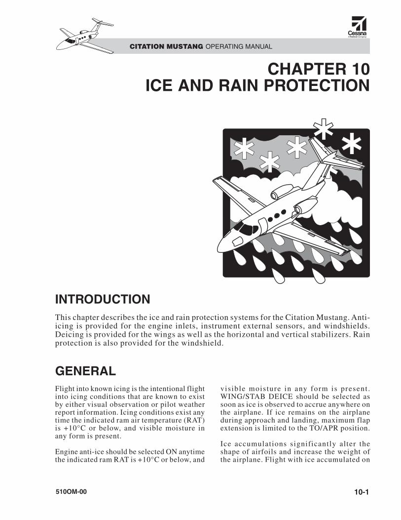
The Mustang uses conventional methods of iceprotection. The engine inlets are anti-icedusing engine bleed air. The wing as well as thehorizontal and vertical stabilizer leading edgesare protected using pneumatic deice boots.Electrical power protects the windshield, pitotprobes, static ports, stall warning vane, and en-gine T2 probes. A passive rain repellent coat-ing on the windshield provides clear vision inprecipitation conditions. An overview of theselocations is in Figure 10-1.
CITATION MUSTANG OPERATING MANUAL
510OM-0010-2
HORIZONTAL AND VERTICAL STABILIZERDEICE SYSTEM (PNEUMATIC BOOTS)
ENGINE ANTI-ICE SYSTEM (BLEED AIR) T2 PROBES (ELECTRIC HEAT)
WINDSHIELD ANTI-ICESYSTEM (ELECTRIC HEAT)
WING DEICE SYSTEM(PNEUMATIC BOOTS)
PITOT-STATICSENSORS (ELECTRIC HEAT)
WING DEICE SYSTEM(PNEUMATIC BOOTS)
STALL WARNING TRANSDUCER(ELECTRIC HEAT)
PITOT-STATICSENSORS (ELECTRIC HEAT)
Figure 10-1. Citation Mustang Ice-Protection Systems
Each engine has two bleed-air ports: one in-board and one outboard. The inboard portprovides bleed air for interior air condition-ing and pressurization. The outboard port pro-vides bleed air for engine inlet anti-ice and forinflating the deice boots. During single-engineoperation, check valves in the supply linesfrom each engine prevent bleed air from oneengine back-flowing to the opposite engine.
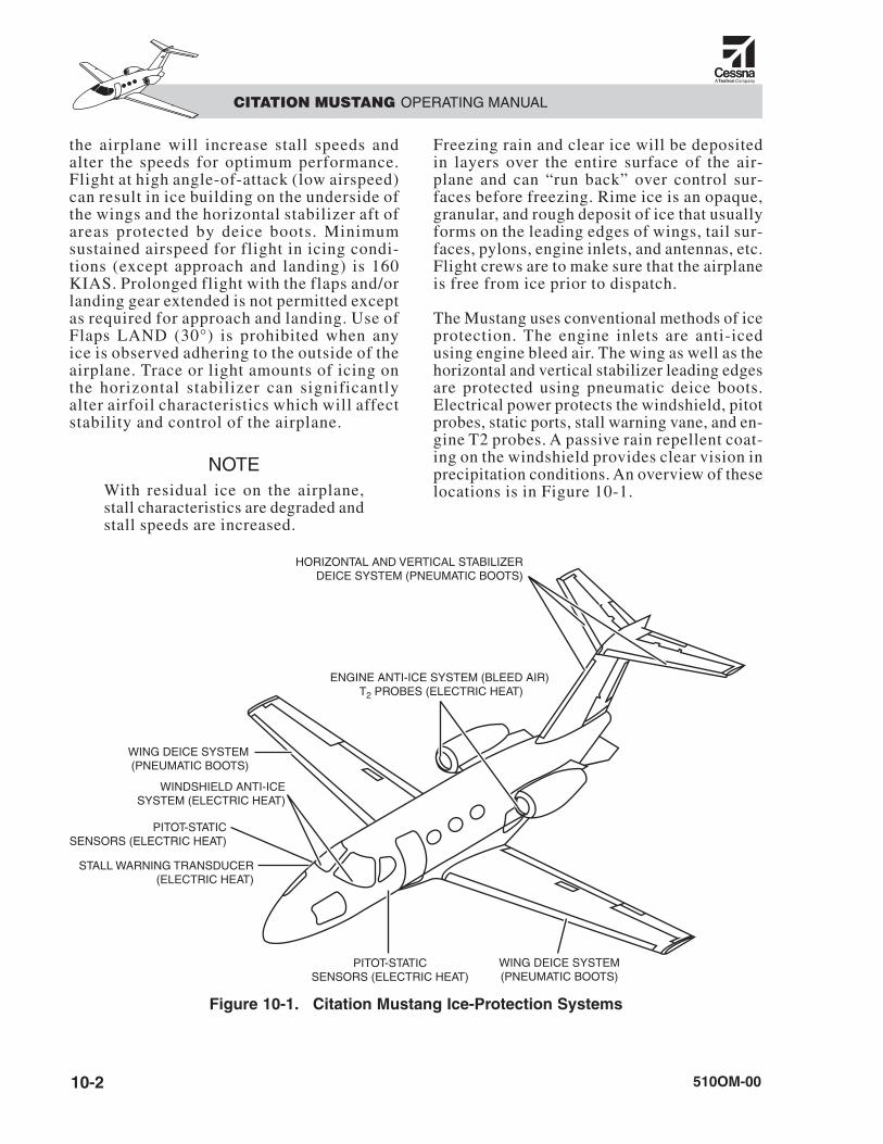
The ice protection system is controlled bygreen-capped switches on the pilot tilt panel,which is to the left of the LANDING GEARhandle (Figure 10-2). The status of ice pro-tection systems is displayed by messages onthe crew alerting system (CAS).
ENGINE INLETS
DESCRIPTIONEach engine inlet and the inlet of the genera-tor-cooling scoop is heated by regulated enginebleed air. Temperature of the bleed air is di-rectly related to throttle position. Spent bleedair exits via a vent in the bottom of the inlet.This vent is inspected during preflight.
NOTEThere is no crossfeed between en-gines for inlet heating. If an enginefails, its inlet is no longer heated.
DC power is provided through an L or R A/Icircuit breaker on its respective side ELE #2bus. If DC power fails, the engine anti-icevalves automatically open, allowing hot airinto the nacelle leading edges.
COMPONENTS
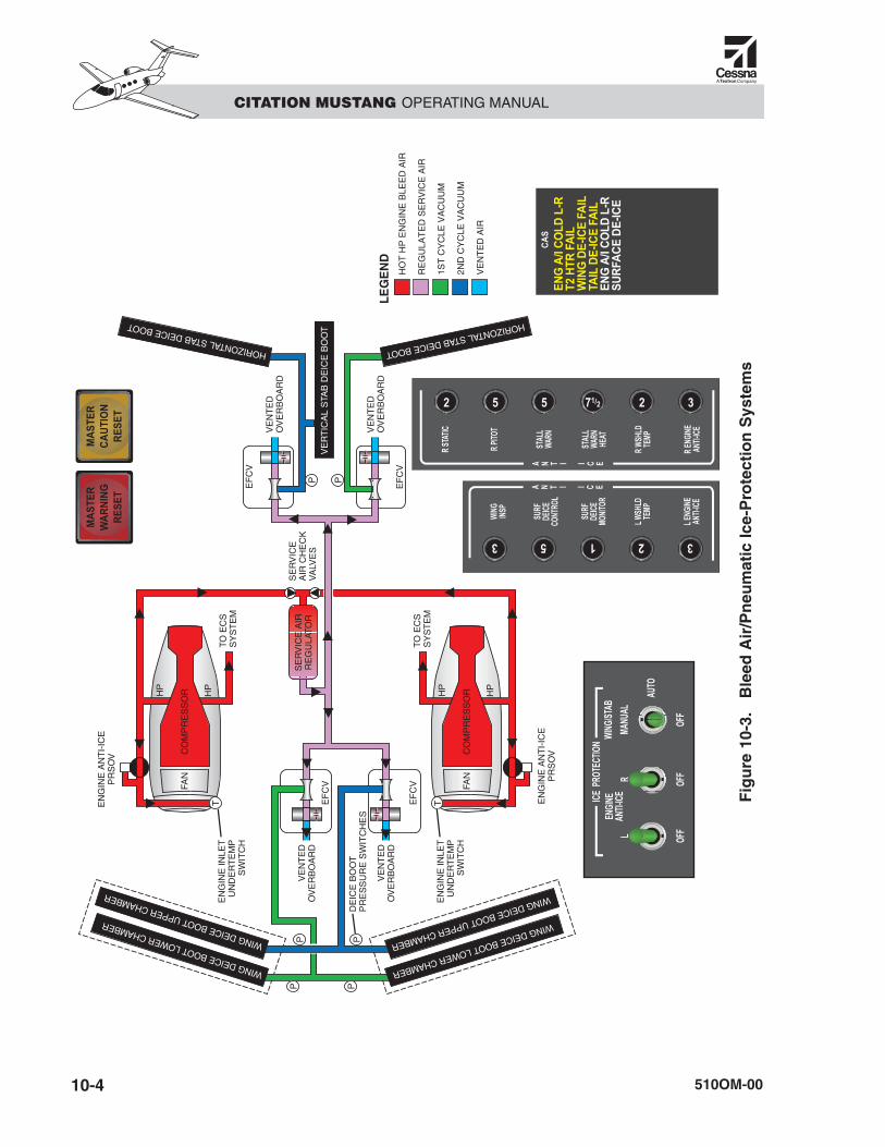
Engine Anti-Ice Shutoff ValvesThe hot bleed air flows into each engine inletthrough the engine anti-ice pressure-regulat-ing shutoff valve (PRSOV) (Figure 10-3).When the valve energizes closed, the inlet isnot anti-iced. The engine inlet PRSOVs are op-erated by the ENGINE ANTI-ICE switchesand are electrically actuated.
In the absence of electrical power, the valvesare pushed open by bleed-air pressure. Whenelectrical power is applied, a solenoid powersthe PRSOV closed. The PRSOVs control theair pressure downstream of the valve. Thesevalves regulate the airflow of the engine anti-ice system.
Engine Inlet Anti-IceUndertemperature SwitchesThe engine inlet undertemperature switchesare inside the nacelle leading edge. Theseswitches provide information through themonitoring circuits in the left and right ice pro-tection system printed circuit boards (PCBs)to drive the white and amber ENG A/I COLDL or R messages.
Engine Inlet Anti-Ice AssemblyThe engine inlet leading edge is hollow.Inside the leading edge, a circular piccolotube is immediately behind the forward sur-face of the inlet. The hot bleed air enters thepiccolo tube, sprays out of holes in the tube
CITATION MUSTANG OPERATING MANUAL
510OM-00 10-3
Figure 10-2. Ice-Protection Switches
CITATION MUSTANG OPERATING MANUAL
510OM-0010-4
EN
GIN
E A
NT
I-IC
EP
RS
OV
EF
CV
EF
CV
HP
HP
HP
HP
EF
CV
EF
CV
VE
RT
ICA
L S
TAB
DE
ICE
BO
OT
HORIZONTAL STAB DEICE BOOT
WING DEICE BOOT LOWER CHAMBER
WING DEICE BOOT UPPER CHAMBER
WING DEICE BOOT LOWER CHAMBER
WING DEICE BOOT UPPER CHAMBER
HORIZONTAL STAB DEICE BOOT
PP
P
PPP
TT
SE
RV
ICE
AIR
RE
GU
LATO
R
FAN
CO
MP
RE
SS
OR
FAN
CO
MP
RE
SS
OR
TO E
CS
SY
ST
EM
EN
GIN
E IN
LET
UN
DE
RT
EM
PS
WIT
CH
TO E
CS
SY
ST
EM
SE
RV
ICE
A
IR C
HE
CK
VA
LVE
SV
EN
TE
DO
VE
RB
OA
RD
VE
NT
ED
OV
ER
BO
AR
D
DE
ICE
BO
OT
PR
ES
SU
RE
SW
ITC
HE
S
EN
GIN
E A
NT
I-IC
EP
RS
OV
EN
GIN
E IN
LET
UN
DE
RT
EM
PS
WIT
CH
VE
NT
ED
OV
ER
BO
AR
D
VE
NT
ED
OV
ER
BO
AR
DL
EG
EN
DH
OT
HP
EN
GIN
E B
LEE
D A
IR
RE
GU
LAT
ED
SE
RV
ICE
AIR
1ST
CY
CLE
VA
CU
UM
2ND
CY
CLE
VA
CU
UM
VE
NT
ED
AIR
EN
G A
/I C
OLD
L-R
T2
HTR
FA
IL
WIN
G D
E-IC
E F
AIL
TAIL
DE
-ICE
FA
ILE
NG
A/I
CO
LD L
-RS
UR
FAC
E D
E-IC
E
Fig
ure
10-
3.B
leed
Air
/Pn
eum
atic
Ice-
Pro
tect
ion
Sys
tem
s
CITATION MUSTANG OPERATING MANUAL
510OM-00 10-5
to circulate through the inlet leading edge,then exhausts overboard through a vent in thebottom of each inlet assembly.
CONTROLS AND INDICATIONSControls for the engine anti-ice system areon the pilot tilt panel with the other ICEPROTECTION controls (see Figure 10-2).
L and R ENGINE ANTI-ICESwitchesThe L and R ENGINE ANTI-ICE switches con-trol the flow of anti-icing bleed air to the engineinlet leading edges. Each ENGINE ANTI-ICEswitch has two positions: L (or R) and OFF.
With the switches in the L or R (up) position,bleed air is directed to the engine inlet foreach respective engine. In the OFF position,bleed air is blocked at the PRSOV.
With either ENGINE ANTI-ICE switch in theON position, the undertemperature warningsystem is enabled for both engines.
ThrottlesThe temperature of the air supplied to the en-gine inlets is varied only by engine powersettings.
ENG A/I COLD L or R MessageIf the inlet leading edges do not receive ade-quate bleed air during use, the cold conditionis annunciated by the respective ENG A/ICOLD message. Undertemperature switchesare inside the hollow engine inlet leadingedges. After initial switch activation, the re-spective white ENG A/I COLD message ap-pears while the undertemperature switchesare below the temperature setpoint. As eachinlet warms up, the respective ENG A/I COLDmessage disappears.
NOTEAt ambient temperatures above ap-proximately 10°C (50°F), the whiteENG A/I COLD messages may notdisplay. In this case, satisfactory op-eration of the engine anti-ice systemcan be verified by a small momentarydrop in N2 and a slight increase inITT when the respective ENG ANTI-ICE switch is turned ON.
If an engine inlet does not heat up within 2 min-utes of initial switch activation or has cooledbelow a safe level, the respective amber ENGA/I COLD message appears.
OPERATIONWhen in icing conditions or when anticipatingicing conditions, set the ENGINE ANTI-ICEswitches to the L and R (up) positions. Thisdeenergizes the shutoff valves, allowing hotbleed air to flow through and heat the engine.
When not in (or anticipating) icing condi-tions, set the ENGINE ANTI-ICE switches tothe OFF positions. This energizes the shutoffvalves closed, stopping the flow of bleed airto the engine inlets. This also increases engineefficiency and available power.
SURFACE DEICE (WINGAND STABILIZERS)
DESCRIPTIONThe Mustang uses pressure-regulated enginebleed air (via the service air system) to oper-ate conventional pneumatic deicing boots. Thefull-span boots protect the wing, vertical, andhorizontal stabilizer leading edges.
Service Air SystemThe pressurized air for inflating the pneu-matic boots is supplied by the service air sys-tem. The service air is regulated to 20 psig by
a service air regulator (see Figure 10-3). Theservice air system is always active during op-eration of the aircraft. Bleed air from both en-gines is routed to the service air regulatorthrough a check valve on each engine out-board bleed-air supply duct. The check valveskeep bleed air from backflowing into either en-gine. The service air system provides regulatedbleed air to the deice boot system. If one en-gine fails, the operating engine can supplyenough bleed air to operate the wing, vertical,and horizontal stabilizer deice system.
Surface Deice SystemThe Mustang has a surface deice system on thewing, vertical, and horizontal stabilizers. Thissystem uses regulated bleed air to inflate pneu-matic boots to remove the ice. The boots, wheninflated, normally crack and separate the icefrom the leading edge of the protected surface,allowing aerodynamic forces to remove the ice.During normal operation, adequate pressuresupplied to the boots is annunciated by the whiteSURFACE DEICE message. An amber WINGor TAIL DE-ICE FAIL message appears in theCAS window if boot pressure is inadequate orboot inflation cycle is not normal.
The deice boot pressure switches are imme-diately downstream of each ejector flow con-trol valve (EFCV).
The regulated service air is supplied to thewing and tail EFCVs, which supply eitherpressure or vacuum to the deice boots. Thereis one EFCV for each of the following fourboot sets (see Figure 10-1):
• Wing upper deice boots (left and right)
• Wing lower deice boots (left and right)
• Left horizontal stabilizer deice boot
• Right horizontal deice boot and verticalstabilizer deice boots
The EFCVs are electrically powered closed toinflate the boots and spring-loaded open.
The surface deice system operates in one ofthree modes:
• Manual
• Automatic
• Inactive
COMPONENTS
Service Air RegulatorThe service air regulator reduces the pressureof the engine bleed air to 20 psig from a vari-able of 25–200 psi. The pressure relief settingof the valve is 27 psig. If the service air regu-lator regulates too low, the failure is detectedby the deice system monitors. If the service airregulator regulates too high, the pressure sup-plied to the boots is limited to 27 psig by the re-lief port of the valve.
Surface Deice BootsThe wing, horizontal stabilizer, and verticaltail are deiced by pneumatic boots controlledby the WING/STAB switch. The wing bootsare separated into two independent pneumaticchambers: one for the upper surface and onefor the lower surface. Each stabilizer boot hasone pneumatic chamber. All boots have span-wise tube configurations.
Surface Deice Control ValvesThe wing and stabilizer EFCVs are electricallycontrolled switching valves. When the deicesystem is turned off or not being inflated, vac-uum is applied to the boots by the EFCVs. Thisis done by passing the supplied service air overa venturi in the valve and is then vented over-board. The other end of the venturi is connectedto the boot and the flow created in the venturicreates the vacuum at the boot. When an infla-tion is triggered, a solenoid closes the EFCV ventand the service air then routes through the ven-turi to inflate the boot.
CITATION MUSTANG OPERATING MANUAL
510OM-0010-6
Surface Deice PressureSwitchesThe boot pressure switches are immediatelybetween the EFCV and their boots. There arefour switches for the wing (two per side) andtwo switches for the vertical and horizontal sta-bilizers. The switches are set to close at 16 psigand open when the pressure decreases to below10 psig. They provide information control-ling the CAS messages for this system.
CONTROLS AND INDICATIONS
WING/STAB SwitchThe control switch for the surface deice sys-tem is on the pilot side of the instrument panelwith the other ICE PROTECTION controls(see Figure 10-2). The WING/STAB switch hasthree positions: OFF, AUTO and MANUAL.
In the OFF position, no power is supplied to theEFCVs and service air flows through the valvesto create a vacuum that holds the boots deflated.
The AUTO position activates the deice controland monitor boards which run the 2-minuteboot cycle.
The MANUAL position is spring-loaded andis active only while held in that position. Whenthe switch is in the MANUAL position, poweris supplied to the EFCVs to apply pressure tothe boots. It also supplies a signal to the deicemonitor board to check for adequate pressuresupplied to the boots.
System Monitoring andIndicationsDeice boot inflation is monitored by a seriesof pressure switches. One switch is providedfor each deice boot chamber. The right iceprotection system PCB monitors the pressureswitches to verify the deice boots inflate whencommanded by the left ice protection systemPCB. If the deice boots fail to inflate, a dis-crete output is provided to the CAS to an-nounce the failure.
SURFACE DE-ICE MessageIn AUTO mode, a white SURFACE DE-ICECAS message indicates when all pressureswitches for the inflation sequence (lowerwing/left tail or upper wing/right and verticaltail) are indicating deice boot inflation. In MAN-UAL mode, the white message displays only ifall pressure switches indicate deice boot infla-tion. The pilot must verify the appearance of thewhite SURFACE DE-ICE message following ac-tivation of the surface deice system to protectagainst failures of the WING/STAB switch.
WING DE-ICE FAIL MessageThe amber WING DE-ICE FAIL message ap-pears if one or more of the pressure switchesin the wing deice system does not receive ad-equate pressure.
This message also appears if pressure is sensedin the boot with the switch in the OFF position.
TAIL DE-ICE FAIL MessageThe amber TAIL DE-ICE FAIL message ap-pears when one or more of the pressureswitches in the tail deice system does not re-ceive adequate pressure.
This message also appears if pressure is sensedwith the switch in the OFF position (i.e., bootis inflated when it should not be).
OPERATIONThe wing and stabilizer deice system operatesunder electrical control when set with theWING/STAB switch in MANUAL or AUTO.
Manual ModeDuring operation in manual mode, the pilotholds the WING/STAB switch the MANUALposition to inflate all of the deice boots. Aslong as the pilot holds the switch, the deiceboots remain inflated. If all of the boot pres-sure switches receive adequate pressure, awhite SURFACE DE-ICE message appears.
CITATION MUSTANG OPERATING MANUAL
510OM-00 10-7
If one or more of the pressure switches doesnot receive adequate pressure, the appropri-ate amber WING DE-ICE FAIL and/or TAILDE-ICE FAIL message appears.
Following release of the MANUAL switch,the spring-loaded switch immediately returnsto the AUTO position, but the automatic cycleis delayed for 2 minutes before restarting theinflation sequence. This prevents the lowerwing/left horizontal stabilizer deice boots fromimmediately inflating after the pilot releasesthe switch from the MANUAL position.
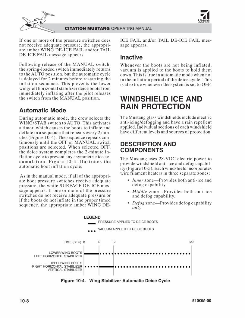
Automatic ModeDuring automatic mode, the crew selects theWING/STAB switch to AUTO. This activatesa timer, which causes the boots to inflate anddeflate in a sequence that repeats every 2 min-utes (Figure 10-4). The sequence repeats con-tinuously until the OFF or MANUAL switchpositions are selected. When selected OFF,the deice system completes the 2-minute in-flation cycle to prevent any asymmetric ice ac-cumula t ion . F igure 10-4 i l lus t ra tes theautomatic boot inflation cycle.
As in the manual mode, if all of the appropri-ate boot pressure switches receive adequatepressure, the white SURFACE DE-ICE mes-sage appears. If one or more of the pressureswitches do not receive adequate pressure orif the boots do not inflate in the proper timedsequence, the appropriate amber WING DE-
ICE FAIL and/or TAIL DE-ICE FAIL mes-sage appears.
InactiveWhenever the boots are not being inflated,vacuum is applied to the boots to hold themdown. This is true in automatic mode when notin the inflation period of the deice cycle. Thisis also true whenever the system is set to OFF.
WINDSHIELD ICE ANDRAIN PROTECTIONThe Mustang glass windshields include electricanti-icing/defogging and have a rain repellentapplied. Individual sections of each windshieldhave different levels and sources of protection.
DESCRIPTION ANDCOMPONENTSThe Mustang uses 28-VDC electric power toprovide windshield anti-ice and defog capabil-ity (Figure 10-5). Each windshield incorporateswire filament heaters in three separate zones:
• Inner zone—Provides both anti-ice anddefog capability.
• Middle zone—Provides both anti-iceand defog capability.
• Defog zone—Provides defog capabilityonly.
CITATION MUSTANG OPERATING MANUAL
510OM-0010-8
PRESSURE APPLIED TO DEICE BOOTS
VACUUM APPLIED TO DEICE BOOTS
LEGEND
TIME (SEC)
LOWER WING BOOTSLEFT HORIZONTAL STABILIZER
UPPER WING BOOTSRIGHT HORIZONTAL STABILIZER
VERTICAL STABILIZER
0 6 12 120
Figure 10-4. Wing Stabilizer Automatic Deice Cycle
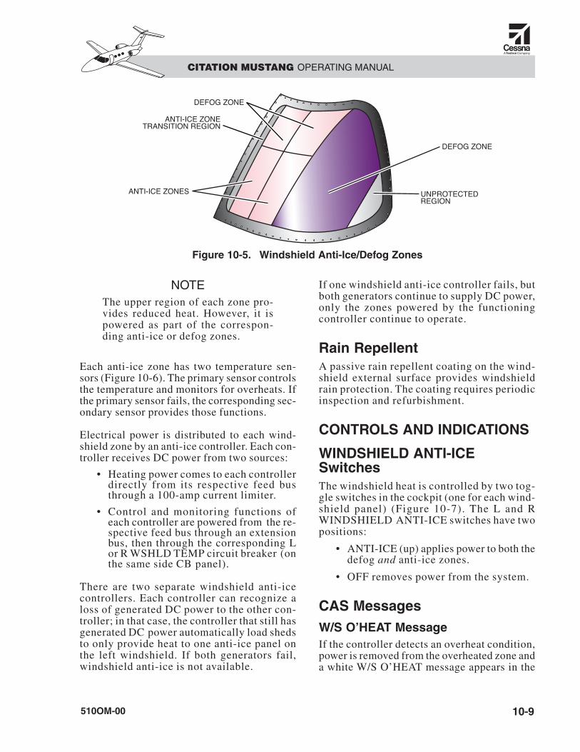
NOTEThe upper region of each zone pro-vides reduced heat. However, it ispowered as part of the correspon-ding anti-ice or defog zones.
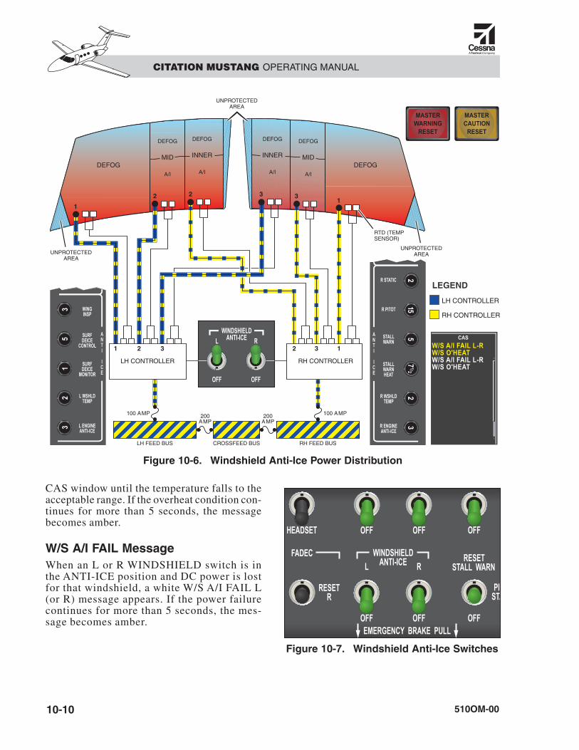
Each anti-ice zone has two temperature sen-sors (Figure 10-6). The primary sensor controlsthe temperature and monitors for overheats. Ifthe primary sensor fails, the corresponding sec-ondary sensor provides those functions.
Electrical power is distributed to each wind-shield zone by an anti-ice controller. Each con-troller receives DC power from two sources:
• Heating power comes to each controllerdirectly from its respective feed busthrough a 100-amp current limiter.
• Control and monitoring functions ofeach controller are powered from the re-spective feed bus through an extensionbus, then through the corresponding Lor R WSHLD TEMP circuit breaker (onthe same side CB panel).
There are two separate windshield anti-icecontrollers. Each controller can recognize aloss of generated DC power to the other con-troller; in that case, the controller that still hasgenerated DC power automatically load shedsto only provide heat to one anti-ice panel onthe left windshield. If both generators fail,windshield anti-ice is not available.
If one windshield anti-ice controller fails, butboth generators continue to supply DC power,only the zones powered by the functioningcontroller continue to operate.
Rain RepellentA passive rain repellent coating on the wind-shield external surface provides windshieldrain protection. The coating requires periodicinspection and refurbishment.
CONTROLS AND INDICATIONS
WINDSHIELD ANTI-ICESwitchesThe windshield heat is controlled by two tog-gle switches in the cockpit (one for each wind-shield panel) (Figure 10-7). The L and RWINDSHIELD ANTI-ICE switches have twopositions:
• ANTI-ICE (up) applies power to both thedefog and anti-ice zones.
• OFF removes power from the system.
CAS MessagesW/S O’HEAT MessageIf the controller detects an overheat condition,power is removed from the overheated zone anda white W/S O’HEAT message appears in the
CITATION MUSTANG OPERATING MANUAL
510OM-00 10-9
ANTI-ICE ZONETRANSITION REGION
DEFOG ZONE
DEFOG ZONE
UNPROTECTEDREGION
ANTI-ICE ZONES
Figure 10-5. Windshield Anti-Ice/Defog Zones
CAS window until the temperature falls to theacceptable range. If the overheat condition con-tinues for more than 5 seconds, the messagebecomes amber.
W/S A/I FAIL MessageWhen an L or R WINDSHIELD switch is inthe ANTI-ICE position and DC power is lostfor that windshield, a white W/S A/I FAIL L(or R) message appears. If the power failurecontinues for more than 5 seconds, the mes-sage becomes amber.
CITATION MUSTANG OPERATING MANUAL
510OM-0010-10
LH CONTROLLER
LEGEND
RH CONTROLLER
LH CONTROLLER RH CONTROLLER
1
11
2 32 3
12 23 3
DEFOG
DEFOG
MID
A/I
DEFOG
MID
A/I
DEFOG
INNER
A/I
DEFOG
INNER
A/IDEFOG
UNPROTECTEDAREA
UNPROTECTEDAREA
RTD (TEMPSENSOR)
UNPROTECTEDAREA
100 AMP 200AMP
200AMP
100 AMP
CROSSFEED BUSLH FEED BUS RH FEED BUS
W/S A/I FAIL L-RW/S O'HEATW/S A/I FAIL L-R W/S O'HEAT
Figure 10-6. Windshield Anti-Ice Power Distribution
Figure 10-7. Windshield Anti-Ice Switches
OPERATIONWhen WINDSHIELD ANTI-ICE is selected,the windshield controllers provide a slow in-crease in temperature to avoid thermal shockto the windshield panels.
Each windshield controller monitors the wind-shield temperature sensors in the zones it con-trols. Using this information, it providesdiscrete outputs to the CAS for annunciationof controller failures or windshield overheats.
SENSOR ANTI-ICE SYSTEMS
DESCRIPTION ANDCOMPONENTSElectric heat is provided to anti-ice the follow-ing sensors:
• Pitot probes
• Static ports
• Stall warning vane
• T2 probes
The heating element for each sensor is mon-itored by a current sensor to detect failures.Failure of any heating element is indicated onthe CAS display.
CONTROLS AND INDICATIONS
Sensor Anti-Ice SwitchThe pitot probes, static ports, and stall warn-ing vane heaters are all controlled by a singleswitch on the ICE PROTECTION panel imme-diately left of the landing gear handle (seeFigure 10-2). This switch has three positions:
• RESET STALL WARN—A momentary-contact position. Resets the stall warn-ing to the normal stall airspeed. (UseRESET STALL WARN only when wingsare verified free of ice).
• PITOT STATIC—Applies power to thesensors (both pitot probes, all four staticports, and the stall warning vane).
• OFF—Removes all power from thosesensors.
ENGINE ANTI-ICE SwitchesThe T2 probes are electrically heated when theirrespective ENGINE ANTI-ICE switches are inthe L or R position and the engine is running.
CAS MessagesThe following amber CAS messages indicatefailure of the heating circuits for the correspon-ding sensors:
• P/S HTR L-R—Pitot-static systems
• STALL WARN HTR—Stall-warning vane
• T2 HTR FAIL L-R—T2 probes
OPERATIONThe pitot probe, static port, and stall warn-ing vane heaters are powered by selection ofthe PITOT STATIC position on the sensoranti-ice switch.
In flight, the sensor anti-ice switch should bein the PITOT STATIC position, which heats theexternal sensors.
On ground, except in icing conditions or whenready for takeoff, the switch should normallybe OFF to prevent overheating of the sensorsand their heating elements.
During preflight, the switch may be set toPITOT STATIC for 30 seconds to verify thesensors are heating properly.
Limit ground operation of pitot-staticheat to 2 minutes to preclude damageto the pitot-static and stall warningheaters.
CAUTION
CITATION MUSTANG OPERATING MANUAL
510OM-00 10-11
Stall-Warning System ModeWhen surface deice is enabled at any time (theWING/STAB switch is selected to MANUALor AUTO), the stall-warning system changesits mode to a higher airspeed, and does not resetwhen surface deice is switched OFF. The sys-tem remains at this ice-contamination air-speed mode setting until the end of the flightor until RESET STALL WARN is selected.
Selecting RESET STALL WARN on the PITOTSTATIC switch overrides the automatic ice-contamination setting, and returns stall-warn-ing mode to the normal stalling airspeed, ifsurface deice is selected OFF.
The white STALL WARN HI message indi-cates that the stall-warning system is operatingon the ice-contamination airspeed mode. Referto the “Landing Performance” ANTI-ICE-ONlanding performance charts in the AirplaneFlight Manual (AFM.)
EMERGENCY/ABNORMALFor specific information on emergency/abnor-mal procedures, refer to the appropriate abbre-viated checklists or the FAA-approved AFM.
CITATION MUSTANG OPERATING MANUAL
510OM-0010-12