Embed Size (px)
Citation preview
SPECIFICATION AND DESCRIPTION
CITATION X+
October 2015 Revision FUnits 750-0524 to TBD

CITATION X+
SPECIFICATION
AND DESCRIPTION
UNITS 750-0524 TO TBD
OCTOBER 2015
REVISION F
Cessna Aircraf t Company
P.O. Box 7706
Wichi ta , Kansas 67277-7706

October 2015, Revision F1
CITATION X+
INTRODUCTION
This document is published for the purpose of providing general information for the evaluation of the design, per-formance, and equipment of the Cessna Citation X+, Units 750-0524 to TBD. This document supersedes all previous Specification and Description documents applicable to Units 750-0524 and On and describes only the Cessna Ci-tation X+, Model 750, its powerplants and equipment.
Due to the time span between the date of this Specification and Description and the scheduled delivery date of the Air-craft, Cessna reserves the right to revise the Specification whenever occasioned by product improvements, govern-ment regulations or other good cause as long as such revi-sions do not result in a material reduction in performance.
In the event of any conflict or discrepancy between this document and the terms and conditions of the Purchase Agreement to which it is incorporated, the terms and condi-tions of the Purchase Agreement govern.
For additional information contact:
Cessna Aircraft Company
P.O. Box 7706
Wichita, Kansas 67277-7706
Telephone: 316-517-6449
Telefax: 316-517-6640
WARNING: This product contains Halon 1211 and Halon 1301. Furthermore, the product is manufactured with 1-1-1 Trichlo-roethane, substances which harm public health and environment by destroying ozone in the upper atmosphere.
October 2015, Revision F2
CITATION X+
CESSNA CITATION X+ SPECIFICATION AND DESCRIPTION
SECTION PAGE
1. General Description .......................................................................................................................................................... 1.1 Certification ......................................................................................................................................................... 1.2 Approximate Dimensions ................................................................................................................................ 1.3 Design Weights and Capacities ..................................................................................................................... 2. Performance ......................................................................................................................................................................... 3. Structural Design Criteria .................................................................................................................................................. 4. Fuselage ................................................................................................................................................................................ 5. Wing ....................................................................................................................................................................................... 6. Empennage .......................................................................................................................................................................... 7. Landing Gear ........................................................................................................................................................................ 8. Powerplants .......................................................................................................................................................................... 9. Systems ................................................................................................................................................................................. 9.1 Flight Controls .................................................................................................................................................... 9.2 Fuel System ......................................................................................................................................................... 9.3 Hydraulic System ............................................................................................................................................... 9.4 Electrical System ................................................................................................................................................ 9.5 Autothrottle System .......................................................................................................................................... 9.6 Pressurization and Environmental System .................................................................................................. 9.7 Oxygen System .................................................................................................................................................. 9.8 Ice Protection ...................................................................................................................................................... 10. Avionics ................................................................................................................................................................................. 10.1 General ................................................................................................................................................................. 10.2 Instrument and Control Panels ....................................................................................................................... 10.3 Avionics ................................................................................................................................................................ 11. Interior .................................................................................................................................................................................... 11.1 General ................................................................................................................................................................. 11.2 Cabin ..................................................................................................................................................................... 11.3 Baggage Compartments .................................................................................................................................. 12. Exterior ................................................................................................................................................................................... 13. Additional Equipment ........................................................................................................................................................ 14. Emergency Equipment ...................................................................................................................................................... 15. Documentation and Technical Publications ................................................................................................................. 16. Computerized Maintenance Record Service ............................................................................................................... 17. Limited Warranties .............................................................................................................................................................. 17.1 Cessna Citation X+ Limited Warranty ........................................................................................................... 17.2 Rolls-Royce Engine Warranty .......................................................................................................................... 17.3 Summary of Honeywell APU Warranty ......................................................................................................... 18. Citation X+ Crew Training Agreement ...........................................................................................................................FIGURE I — CITATION X+ EXTERIOR DIMENSIONS ................................................................................................................FIGURE II — CITATION X+ DIMENSIONS ....................................................................................................................................FIGURE III — CITATION X+ INSTRUMENT PANEL AND PEDESTAL LAYOUT ....................................................................FIGURE IV — CITATION X+ STANDARD FLOORPLAN .............................................................................................................
TABLE OF CONTENTS
3366778888999999
10101010111212121616161717171818191919
202324
451118
October 2015, Revision F3
CITATION X+
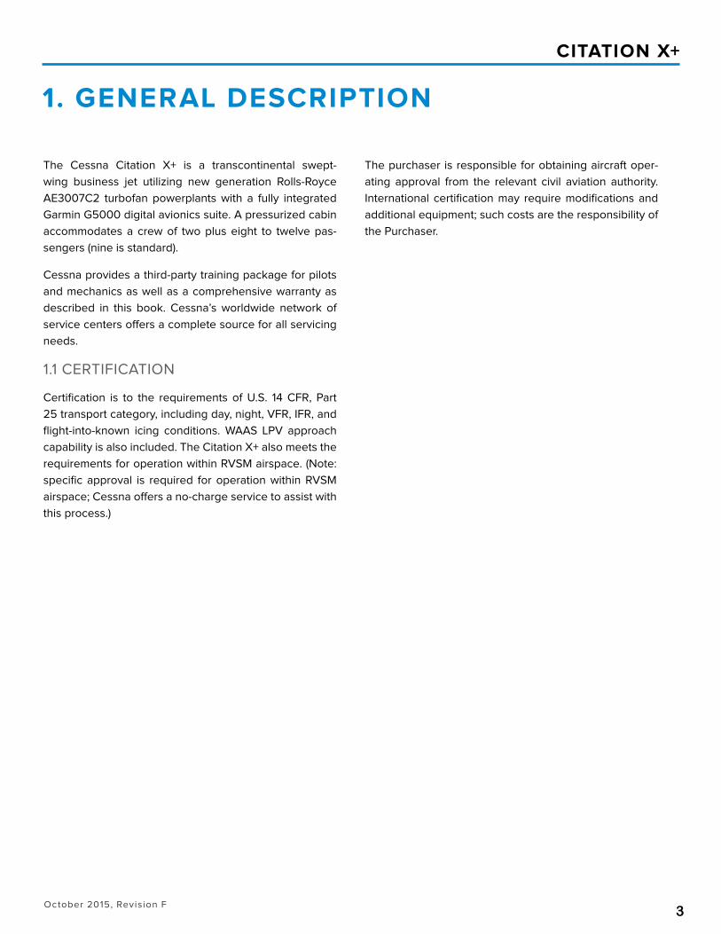
The Cessna Citation X+ is a transcontinental swept-wing business jet utilizing new generation Rolls-Royce AE3007C2 turbofan powerplants with a fully integrated Garmin G5000 digital avionics suite. A pressurized cabin accommodates a crew of two plus eight to twelve pas-sengers (nine is standard).
Cessna provides a third-party training package for pilots and mechanics as well as a comprehensive warranty as described in this book. Cessna’s worldwide network of service centers offers a complete source for all servicing needs.
1.1 CERTIFICATION
Certification is to the requirements of U.S. 14 CFR, Part 25 transport category, including day, night, VFR, IFR, and flight-into-known icing conditions. WAAS LPV approach capability is also included. The Citation X+ also meets the requirements for operation within RVSM airspace. (Note: specific approval is required for operation within RVSM airspace; Cessna offers a no-charge service to assist with this process.)
The purchaser is responsible for obtaining aircraft oper-ating approval from the relevant civil aviation authority. International certification may require modifications and additional equipment; such costs are the responsibility of the Purchaser.
1. GENERAL DESCRIPTION
October 2015, Revision F4
CITATION X+
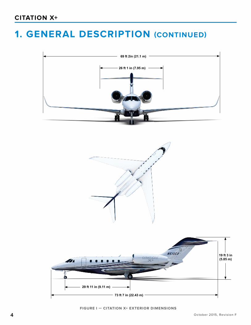
FIGURE I — CITATION X+ EXTERIOR DIMENSIONS
1. GENERAL DESCRIPTION (CONTINUED)
26 ft 1 in (7.95 m)
69 ft 2in (21.1 m)
73 ft 7 in (22.43 m)
19 ft 3 in(5.85 m)
29 ft 11 in (9.11 m)
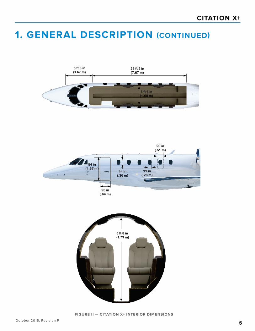
5 ft 6 in(1.68 m)
25 in(.64 m)
5 ft 8 in (1.73 m)
54 in(1.37 m)
14 in(.36 m)
20 in(.51 m)
25 ft 2 in(7.67 m)
11 in(.28 m)
5 ft 6 in (1.67 m)
October 2015, Revision F5
CITATION X+
FIGURE II — CITATION X+ INTERIOR DIMENSIONS
1. GENERAL DESCRIPTION (CONTINUED)
26 ft 1 in (7.95 m)
69 ft 2in (21.1 m)
73 ft 7 in (22.43 m)
19 ft 3 in(5.85 m)
29 ft 11 in (9.11 m)
5 ft 6 in(1.68 m)
25 in(.64 m)
5 ft 8 in (1.73 m)
54 in(1.37 m)
14 in(.36 m)
20 in(.51 m)
25 ft 2 in(7.67 m)
11 in(.28 m)
5 ft 6 in (1.67 m)
October 2015, Revision F6
CITATION X+
1.3 DESIGN WEIGHTS AND CAPACITIESMaximum Ramp Weight ...................................................................................................................................................
Maximum Takeoff Weight ................................................................................................................................................
Maximum Landing Weight ...............................................................................................................................................
Maximum Zero Fuel Weight ............................................................................................................................................
Fuel Capacity (useable) at 6.70 lbs/gal ........................................................................................................................
Base Operating Weight (2 crew, 200 lbs each) .........................................................................................................
36,900 lb (16,737 kg)
36,600 lb (16,602 kg)
32,000 lb (14,515 kg)
24,978 lb (11,330 kg)
12,931 lb (5,865 kg)
22,030 lb (9,993 kg)
1. GENERAL DESCRIPTION (CONTINUED)
1.2 APPROXIMATE DIMENSIONSOverall Height ...........................................................................................................................................................................
Overall Width .............................................................................................................................................................................
Overall Length .......................................................................................................................................................................
WINGSpan (overall) .............................................................................................................................................................................
Area ..............................................................................................................................................................................................
Sweepback (at 25% chord) .............................................................................................................................................................
HORIZONTAL TAILSpan (overall) ............................................................................................................................................................................
Area ..................................................................................................................................................................................................
Sweepback (at 25% chord) .............................................................................................................................................................
VERTICAL TAILSpan ............................................................................................................................................................................................
Area ..................................................................................................................................................................................................
Sweepback (at 25% chord) ..............................................................................................................................................................
CABIN INTERIORHeight (maximum over aisle) ...................................................................................................................................................
Width (max) .................................................................................................................................................................................
Length (forward pressure bulkhead to mid pressure bulkhead) ...............................................................................
LANDING GEARTread (main to main) .................................................................................................................................................................
Wheelbase (nose to main) ......................................................................................................................................................
19 ft 3 in (5.85 m)
69 ft 2 in (21.1 m)
73 ft 7 in (22.43 m)
69 ft 2 in (21.1 m)
527 ft2 (48.9 m2)
37 degrees
26 ft 1 in (7.95 m)
120 ft2 (11.1 m2)
40 degrees
10 ft 7 in (3.23 m)
111 ft2 (10.3 m2)
52 degrees
5 ft 8 in (1.73 m)
5 ft 6 in (1.68 m)
30 ft 8 in (9.32 m)
10 ft 7in (3.23 m)
29 ft 11in (9.11 m)
October 2015, Revision F7
CITATION X+
Takeoff Runway Length .........................................................................................................................................................
(Maximum Takeoff Weight, Sea Level, ISA
Balanced Field Length per FAR 25, Flap Position 2)
Climb Performance ......………………...................................................…..............................................…………..
(Maximum Takeoff Weight, Sea Level, ISA)
Maximum Altitude ...............................................................................................................................................................
Maximum Cruise Speed (± 3%) ............................................................................................................
NBAA IFR Range (200 nm alternate) (± 4%) .......................................................................................
(Maximum Takeoff Weight, Full Fuel, Optimal Climb
and Descent, Mach 0.82 Cruise Thrust)
Landing Runway Length ..........................................................................................................................................................
Certified Noise Levels
Flyover ..............................................................................................................................................................................
Lateral ...............................................................................................................................................................................
Approach ..........................................................................................................................................................................
5,250 ft (1,600 m)
22 min to 45,000 ft (13,716 m)
51,000 ft (15,545 m)
528 KTAS (978 km/hr) at FL350
3,240 nm (6,000 km)
3,330 ft (1,015 m)
72.4 EPNdB
87.7 EPNdB
89.3 EPNdB
All performance data is based on a standard aircraft configuration, operating in International Standard Atmosphere (ISA) con-ditions with zero wind. Takeoff and landing field lengths are based on a level, hard surface, dry runway. Actual performance will vary with individual airplanes and other factors such as environmental conditions, aircraft configuration, and operational/ATC procedures.
2. PERFORMANCE
270 KIAS (500 km/hr, 311 mph)
3505 KIAS (649 km/hr, 403 mph)
Mach 0.935
250 KIAS (463km/hr, 288 mph)
210 KIAS (389 km/hr, 242 mph)
180 KIAS (333 km/hr, 207 mph)
210 KIAS (389 km/hr, 242 mph)
210 KIAS (389 km/hr, 242 mph)
3. STRUCTURAL DESIGN CRITERIA
Limit Speeds
VMO at Sea Level to 8,000 ft (2,438 m) .....................................................................................
VMO at 8,000 ft (2,438 m) to 30,650 ft (9,342 m) ...................................................................
MMO at 30,650 ft (9,342 m) to 51,000 ft (15,545 m) ...................................................................................................
Flap Extension Speeds
VFE Position 1 .................................................................................................................................
VFE Position 2 ..............................................................................................................................
VFE Full Flaps ...................................................................................................................................
Landing Gear Operating and Extended Speeds
VLO ....................................................................................................................................................
VLE ....................................................................................................................................................
October 2015, Revision F8
CITATION X+
A highly swept wing utilizing super critical airfoil technology tailored to the Model 750 is incorporated. Speed brakes and spoiler design are optimized for drag control with mini-mum pitching moments.
Dual hydraulically-powered non-reversible controls are incorporated.
The wing incorporates fuselage attachment points and a dropped carry-through which permits a continuous dropped aisle throughout the passenger cabin and lavatory.
A large aerodynamic fairing is optimized for low drag.
The empennage incorporates a highly swept T-tail with a moveable horizontal stabilizer for trim. Elevators and the lower portion of a two-piece rudder are hydraulically powered.
The upper portion of the rudder is electrically powered. An elevator control column shaker barrier is installed.
5. WING
6. E M P E N N A G E
7. L A N D I N G G E A R
4. FUSELAGE
A circular fuselage section is utilized with an internal cabin width of 5 ft 6 in (1.68 m). A continuous dropped aisle in the passenger cabin provides approximately 5 ft 8 in (1.73 m) of standup headroom measured softgoods to softgoods, with a cabin length (excluding cockpit) of 25 ft 2 in (7.67 m): an additional 15 inches of length compared to aircraft prior to Unit 750-0501.
The nose section incorporates a contoured radome. The windshields are designed to meet bird resistance require-ments of Part 25, and are all-glass design and electrically heated and defogged.
The aft fuselage incorporates a 72.0 cubic feet (2.04 m3) heated and pressurized baggage compartment. A door in the left hand side of the fuselage provides access. An addi-tional 10.0 cubic feet (.28 m3) utility cargo area is accessed through the lower tailcone door. This cargo area is 83.0 inches (2.11 m) long and provides storage for cargo such as skis. Area rule design is utilized for the aft fuselage area, consistent with low-drag characteristics. The aft fuselage also incorporates servicing ports for the hydraulic system and for external toilet servicing.
The main landing gear is a trailing link design utilizing dual wheels, tires and powered anti-skid carbon brakes.
The nose gear is a conventional strut design with dual
wheels and tires. Nose gear steering is provided by a hy-draulic power steering system.
October 2015, Revision F9
CITATION X+
9. SYSTEMS
9.1 FLIGHT CONTROLS
The primary flight controls are hydraulically powered with a dual, isolated hydraulic system and manual backup. All con-trol surfaces, spoilers, speedbrakes and flaps are of com-posite construction. Dual independant yaw damper systems are incorporated. There are three flap panels per side which are electrically operated by a DC system.
9.2 FUEL SYSTEM
Three separate fuel tanks are incorporated, two wing tanks and one center tank (in both wing and forward fairing). The fuel supply systems are two independent systems located in the wing tanks. The center tank transfers fuel to the wing tanks. The total usable fuel is 12,931 pounds (5,865 kg). Both single point and over wing refueling are provided.
9.3 HYDRAULIC SYSTEM
A dual isolated hydraulic system utilizes pressure compen-sated pumps which maintain a continuous pressure of ap-proximately 3,000 psi (206.8 bar).
9.4 ELECTRICAL SYSTEM
The electrical system is a split-bus system powered by two engine-driven, 400 amp, brushless DC generators. In addi-tion, a third generator is driven by the APU when the APU is operating. Two 44-amp hour Nickel-Cadmium batteries are provided.
Each engine also drives an alternator in support of an al-ternating current (AC) system for electrical anti-icing and defogging of the glass windshields. In the unlikely event of a dual generator loss, the alternators can also provide backup electrical power through transformer-rectifier units to an essential electrical bus. The essential bus can power components of the G5000 system that are essential for flight, including two display units and the flight director func-tionality. This essential bus design and its multiple power sources provide much higher reliability and a greater situ-ational awareness in the event of an electrical emergency. If all engine-driven power sources are lost, the aircraft main batteries provide power to the emergency bus for a limited period of time.
Interconnect wiring for the electrical components is de-signed to minimize susceptibility of critical and essential systems to High Intensity Radiated Fields (HIRF). Cabin electrical grounds have been organized to centralize and simplify access.
Standard exterior lighting consists of two pulsing red LED lights for ground recognition, LED anti-collision lights and two downwash lights located in the winglets, two wing in-spection lights, LED position lights, two landing/recognition lights (including the Precise Flight pulselite system which, when activated, pulses the landing/recognition lights), windshield ice detection lights and taxi lights (located on the nose landing gear). Two LED tail logo lights are located on the aft end of the engine pylon illuminating the vertical stabilizer surfaces.
8. POWERPLANTSThe aircraft is powered by two modular design Rolls-Royce AE3007C2 turbofan engines installed on the rear fuselage.
The AE3007C2 engines incorporate dual channel Full Au-thority Digital Electronic Controls (FADEC) which are fully compatible with the Autothrottle (A/T) system. The engine is a modular design and features six large access panels for Line Replacement Unit (LRU) maintenance and multiple borescope inspection ports.
An APU is incorporated for engine start and other benefits, and is certified for in-flight use up to 31,000 feet. The APU is located in the tailcone stinger for ease of maintenance.
Hydraulically actuated, target-type thrust reversers compat-ible with the engine nacelles and powerplants are included.
October 2015, Revision F10
CITATION X+
9. SYSTEMS (CONTINUED)
9.5 AUTOTHROTTLE SYSTEM
The autothrottle (A/T) is fully integrated with the Automatic Flight Control System (AFCS) and the Flight Management Systems (FMS) to control the engine thrust throughout the flight from takeoff to landing. The A/T includes speed as well as thrust modes and may be selected prior to initiating take-off roll and remain engaged throughout the flight, approach, flare and landing touchdown (Aircraft does not incorporate autoland capability). The A/T may be disengaged for manual throttle control.
9.6 PRESSURIZATION AND ENVIRONMEN-TAL SYSTEM
Cabin pressurization is supplied by bleed air from each en-gine. The system has a 9.3 psi (.64 bar) nominal maximum pressure differential and provides an 8,000 foot (2,438 m) cabin altitude at 51,000 feet (15,540 m). Cabin pressure and cabin rate of climb are displayed on the multifunction display (MFD).
9.7 OXYGEN SYSTEM
A 76.0 cubic foot (2.15 m3) oxygen bottle and a 49 cubic foot (1.38 m3) oxygen bottle are provided. Oxygen pressure readout is available on the MFD. An automatic dropout oxy-gen mask is provided for each passenger. Pressure demand masks are provided for the crew.
9.8 ICE PROTECTION
The wing leading edge, horizontal stabilizer leading edge and engine inlets are heated by bleed air. Electric heat is used for the windshield, wing cuff, pitot/static system, AOA systems and RAT probe.
October 2015, Revision F11
CITATION X+
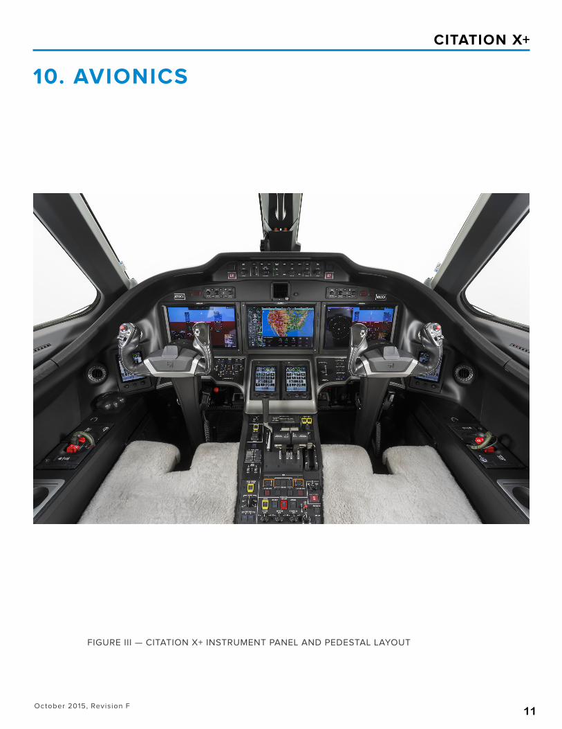
FIGURE III — CITATION X+ INSTRUMENT PANEL AND PEDESTAL LAYOUT
10. AVIONICS
October 2015, Revision F12
CITATION X+
10. AVIONICS (CONTINUED)
10.1 GENERAL
The Garmin G5000 system is the featured avionics suite on the Citation X+. It includes an integrated Flight Director/ Auto-pilot and Electronic Flight Instrument System (EFIS) utilizing three fourteen-inch (diagonal) high-resolution Liquid Crystal Displays (LCD) in widescreen, landscape orientation. The two outer displays are Primary Flight Displays (PFDs) and the centrally located Multifunction Display (MFD) incorporates engine and systems information as well as detailed charts, moving map, synoptics, traffic, and TAWS functionality.
Four full-color, touchscreen control panels provide the crew with the ability to control G5000 system features such as radio tuning, transponders, intercom, flight planning and dis-play information as desired. The control panels also provide control of selected aircraft systems such as environmental control and external lighting. The outboard touchscreen controllers are primarily utilized for PFD control while the inboard two touchscreen controllers are primarily used for MFD control. In the unlikely event a touchscreen controller becomes inoperative, the remaining controllers can take on additional control responsibility.
Two complete crew stations are provided with dual controls including control columns, adjustable rudder pedals, and brakes. The crew seats are fully adjustable and include five-point restraint harnesses.
LED illuminated panels, instrument floodlights, and blue-white background lighting are provided for all cockpit instru-ments and switches. Illuminated LED pushbutton switches, overhead map lights and floodlights are also provided. The emergency oxygen system provides two pressure demand masks with microphones for the crew members. Circuit breakers are installed on circuit breaker panels located on the pilot’s and copilot’s sidewalls.
10.2 INSTRUMENT AND CONTROL PANELS
The instrument layout includes a tilt panel below the verti-cal instrument panel across the width of the cockpit. The tilt panel improves visibility of components mounted low in the panel. Oxygen mask stowage has been incorporated in the lower sidewall.
A. Installed on Left-Hand Panel (pilot):
• Touchscreen LCD Control Panel• Primary Flight Display (PFD)• Secondary PFD Controller
B. Installed on Right-Hand Panel (copilot):
• Touchscreen LCD Control Panel• Primary Flight Display (PFD)• Secondary PFD Controller
C. Installed on Center Panel:
• Multifunction Display (MFD)• Dual Touchscreen LCD Control Panels• Electronic Standby Flight Display - ESFD
D. Installed Beneath Glareshield:
• Flight Guidance Panel - FGP
E. Installed on LH Tilt Panel:
• Electrical Power Panel
F. Installed on RH Tilt Panel:
• Anti-Ice/De-Ice Panel• Landing Gear Control Panel
G. Installed on Pedestal:
• Engine power levers - Autothrottle assembly• Flaps/Slats control• Speed Brake Control Lever• Pressurization Panel• Engine Control/Start Panel
10.3 AVIONICS
Described below is the Citation X+ standard avionics suite as referred to in section 17, Limited Warranties.
A. FLIGHT DISPLAYS
The Garmin G5000 avionics system in the Citation X+ fea-tures three fourteen-inch (diagonal), widescreen-format liquid crystal displays (LCDs). Two Primary Flight Displays (PFDs) are located on the pilot’s and copilot’s instrument
October 2015, Revision F13
CITATION X+
panels, and one Multi-Function Display (MFD) is located on the center panel. In addition to flight display information, the PFDs can display an inset window with moving map imag-ery. Color-coded Crew Alerting System (CAS) messages are displayed on the PFD. The MFD displays detailed moving map, terrain, traffic, and weather information as well as a dedicated engine and systems information window. Display of electronic charts and taxi diagrams with aircraft position shown is included. (Applicable subscription services are the responsibility of the Purchaser.) In addition, aircraft system synoptic diagrams are available for display on the MFD. The PFDs and the MFD can operate in full-screen or split-screen mode. Multiple reversionary display formats provide for redundancy.
B. SYNTHETIC VISION TECHNOLOGY
Garmin Synthetic Vision Technology (SVT) is included. The system presents terrain and obstacle information on the PFDs in a dynamic, three-dimensional format, providing for increased situational awareness. Airports, runways, head-ing, traffic, color-coded terrain alerts, and a flight path indi-cator are displayed on the SVT presentation.
C. TOUCHSCREEN CONTROL PANELS
Four full-color, touchscreen LCD control panels provide the primary user interface with the G5000 system. Two control panels are located on the center pedestal, and two addi-tional panels occupy positions outboard of each PFD. The control panels provide pilots with the ability to arrange and tailor display information, tune communication and naviga-tion radios, and manage specific aircraft systems. Multiple reversionary modes provide for control redundancy.
D. AUTOMATIC FLIGHT CONTROL SYSTEM
The G5000 system includes a full-featured Automatic Flight Control System (AFCS) that supports dual flight directors and a three-axis autopilot. Multiple computational paths in the system provide for a high level of redundancy. The AFCS also provides yaw damping as well as mach trim functionality. Pilot control is provided through a single AFCS mode controller centrally located in the glareshield. The AFCS integrates with the autothrottle system and includes an Emergency Descent Mode that provides automatic air-craft descent to 15,000 feet should the aircraft cabin experi-
ence depressurization at high altitude.
E. INERTIAL NAVIGATION SYSTEM (INS)
Dual Inertial Navigation Systems (INS) provide attitude and heading reference as well as inertial navigation information, including the capability to support Required Navigation Per-formance (RNP) operations.
F. INTEGRATED AVIONICS UNITS
Dual Integrated Avionics Units include Global Positioning System (GPS) Wide Area Augmentation System (WAAS) re-ceivers, Very High Frequency (VHF) communication radios, VHF navigation radios, and glideslope receivers in addition to supporting input/output processing, aural alert genera-tion, and flight director functions.
G. DISTANCE MEASURING EQUIPMENT
Dual scanning Distance Measuring Equipment (DME) units are installed to provide DME information to the pilots as well as to provide scanning DME/DME input capability for the Flight Management Systems.
H. FLIGHT MANAGEMENT SYSTEMS
Dual Flight Management Systems (FMS) provide extensive navigation and flight planning capabilities as well as enroute, takeoff, and landing performance calculations. Supported navigation capabilities include the following (among others):
• Enroute and terminal operations
• Precision and non-precision approach operations, in-cluding LNAV/VNAV and Localizer Performance with Vertical Guidance (LPV) approaches
• Required Navigation Performance (RNP) 0.3 approach-es with radius-to-fix (RF) legs, including those requiring Approval Required (AR) capability and having a missed approach segment RNP value less than 1 nautical mile.
The FMSs calculate aircraft position based upon GPS/WAAS, INS, as well as scanning DME/DME input. (Appli-cable FMS database subscription services are the responsi-bility of the Purchaser.)
10. AVIONICS (CONTINUED)
October 2015, Revision F14
CITATION X+
10. AVIONICS (CONTINUED)
I. WEATHER RADAR
A Garmin GWX 70 weather radar system with a 12-inch an-tenna is included. Solid-state electronics (i.e. no magnetron) and a transmitter power of 40 Watts provide for improved safety and reliability compared with traditional radar sys-tems having higher output power. WATCHTM automatic range limiting, vertical scan capability, Doppler turbulence detection capability in rain cells, and weather target alerting and are included.
J. TRAFFIC COLLISION AVOIDANCE SYS-TEM (TCAS II)
A Garmin GTS 8000 TCAS II system is included, providing traffic advisories and resolution advisories. This system is compliant with Change 7.1 requirements.
K. TERRAIN AWARENESS WARNING SYS-TEM (TAWS)
The G5000 system includes a Class A Terrain Awareness Warning System (TAWS) system. The TAWS function is allo-cated to the flight display units, providing weight and hard-ware resource savings as well as increased redundancy and availability. Reactive windshear alerting capability is also included.
L. TRANSPONDERS WITH ADS-B OUT CA-PABILITY
Dual Mode S transponders with antenna diversity and 1090 MHz Extended Squitter (ES) Automatic Dependent Surveil-lance - Broadcast Out (ADS-B Out) transmission capability in accordance with FAA TSO-166B are included. The tran-sponders meet European Mode S mandates for Enhanced Surveillance (EHS).
M. VHF ACARS CAPABILITY
A datalink (VDL Mode 2) radio provides for the sending and receiving of Aircraft Communications Addressing and Reporting System (ACARS) information, flight plans, weath-er graphics, and text via a datalink service provider. (Ap-plicable subscription services are the responsibility of the Purchaser.)
N. LINK 2000 + CONTROLLER PILOT DATA-LINK COMMUNICATIONS
The Aircraft will include Link 2000+ Controller Pilot Datalink Communications (CPDLC) capability in accordance with the European mandate.
O. STANDBY INSTRUMENTATION
An Electronic Standby Flight Display (ESFD) powered by the emergency bus and having its own backup battery provides standby airspeed, attitude, altitude, and VOR/ILS navigation information.
P. RADIO ALTIMETER
A radio altimeter is included with the Aircraft for PFD dis-play and in support of TCAS II and TAWS A.
Q. COCKPIT VOICE RECORDER
A Cockpit Voice Recorder (CVR) is included with the aircraft. The CVR will also record Controller-Pilot Data Link Commu-nications (CPDLC) when equipped with an applicable data-link system.
R. HIGH-FREQUENCY RADIO
A standard high-frequency (HF) radio with selective calling (SELCAL) decoding is included. Provisions Only for a sec-ond HF system are also installed.
S. EMERGENCY LOCATOR TRANSMITTER
A 406 MHz Emergency Locator Transmitter (ELT) with navi-gation interface is installed. (Note: Some authorities may not permit the use of navigation interface capability.)
T. MAINTENANCE DIAGNOSTICS
The G5000 system includes the capability to record spe-cific maintenance diagnostic information, which can be re-viewed on the MFD while on the ground and downloaded for review off the Aircraft. In addition, the Citation X+ incor-porates full time data storage through a Cessna Aircraft Recording System (AReS). AReS records useful data during the previous 25+ flight hours in non-volatile memory for ad-
October 2015, Revision F15
CITATION X+
10. AVIONICS (CONTINUED)
vanced troubleshooting and analysis by systems specialists from the Seller Service and Support network.
Purchaser agrees that Seller has a perpetual license to use all information contained in the Aircraft recording and/or di-agnostic system for any reason, including maintenance and accident investigation. Purchaser expressly provides Seller with licensed permission to download, use, and/or read such information at any time. Purchaser further agrees this perpet-ual license runs with and is automatically transferred with the title to the Aircraft and is binding on any and all subsequent purchasers of the Aircraft.
U. COCKPIT VOICE/DATA SATELLITE TRANSCEIVER (IRIDIUM) – GARMIN
Single-channel Iridium satcom system to enable voice call-ing capability via crew headsets as well as specific cock-pit data communications. Available data communication services include request/response-based Garmin Connext Worldwide Weather with graphical and text weather servic-es (where available), sending and receiving of in-flight text messages, aircraft position reporting, and in flight transmis-sion of specific aircraft diagnostics data to ground based maintenance/support operations, enabling remote support prior to landing. Seller will cover costs associated with air-craft diagnostics data transmission through the Iridium sat-com system (GSR56) for an introductory period of 2 years from the date of delivery of a new Citation X+. Subscription/Data charges for other services associated with the Iridium satcom system still apply.
October 2015, Revision F16
CITATION X+
11. INTERIOR
FIGURE IV — CITATION X+ STANDARD FLOORPLAN
11.1 GENERAL
The cockpit has been designed for maximum comfort on long flights. The flight compartment bulkhead location has been designed to easily accommodate crew members in the 95th percentile. A wide variety of custom seating config-urations can be specified, from low density executive suites to high density (up to 12 passenger) configurations.
The cabin is separated from the flight compartment by a closet and refreshment center. A one-piece half-length cockpit curtain is mounted on the RH foward side of the cabinets and may be pulled across the aisle and fastened on the LH side.The cabin is sized to offer passenger com-fort and flexibility for a variety of interior arrangements. The cabin is approximately 25 ft 2 in (7.67 m) long and extends from the flight compartment dividers to the mid pressure bulkhead. The constant section of the cabin provides a con-tinuous width of 5 ft 6 in (1.68 m).
A dropped aisle, extending from the cockpit divider aft to the aft wall of the lavatory, provides a cabin height of 5 ft 8 in (1.73 m) from softgoods to softgoods.
All passenger seats are equipped with a seat belt, a shoul-der harness strap with inertia reel and an over water life vest stored nearby.
Bagged insulation and soundproofing are consistent with this category of aircraft, given its operating speeds and environment. Certified burn-resistant materials are used throughout the cockpit and cabin.
Thirteen elliptical windows are provided in the cabin with dual-mode pleated electric window shades. A drop-down, constant-flow oxygen mask is furnished for each passenger for emergency use. Individual air outlets and LED task lights are provided for each passenger. General LED lighting with variable adjustment settings, dropped aisle LED lighting, entrance and emergency exit lights are also provided in the passenger cabin.
11.2 CABIN
The cabin supports a variety of seating configurations most typically represented by eight passenger double club seat-ing with a right hand forward refreshment center and left hand forward closet.
Included in the typical interior offering are the following:
• A left hand coat closet forward of the cabin entry door with navigation chart, flight manual and briefcase stor-age and a 12.1” display;
• A right hand refreshment center with hot and cold bev-erage capability, large ice drawer, numerous storage ar-eas, large trash receptacle, glassware storage capability and provisions for catering;
• Eight pedestal mounted seats with full berthing, swivel and pedestal tracking features,
• Four executive tables with ample work area;
• The customer will be provided with one iPad that in-
CABIN DOOR
EMERGENCY EXIT
October 2015, Revision F17
CITATION X+
cludes the new Clairity Wireless Application (which can also be installed on the customer’s personal device). The Clairity Wireless system provides passengers with VIP functions such as light and temperature control as well as audio, video, and moving map entertainment. The VIP functions are also available in a VIP switch pan-el at the refreshment center.
• Axxess II Iridium Satellite Telephone – Includes two Iridi-um satellite telephone channels. The system offers PBX functionality, including call waiting, call forwarding, and conference calling capability. Service charges apply.
• Indirect/accent lighting in the continuous dropped aisle;
• Five individual Universal 110 VAC outlets to operate var-ious personal electronic devices located in the cabin;
• An aft lavatory with externally serviceable flushing toilet (belted), a vanity sink with running temperature controlled water and numerous storage compartments across from the toilet;
• A large centerline closet to accommodate hanging clothes bags, coats, briefcases or additional storage for
passenger amenities, as well as designated storage ar-eas for life rafts and a ground use only 110V outlet; and
• A full range of fabrics, leathers, carpets, laminates, se-lected wood veneers and metal finishes are available to custom configure the interior furnishings to meet a wide variety of customer tastes.
11.3 BAGGAGE COMPARTMENTS
A pressurized, heated baggage compartment, approxi-mately 72.0 cubic feet (2.04 m3), is located in the tailcone. The compartment is accessible through a 27 inch (.69 m) wide lockable door with an integral step.
An additional 10.0 cubic feet (.28m3) utility cargo area is ac-cessed through the lower tailcone door. This cargo area is approximately 83.0 inches (2.11 m) long x 25.0 inches (0.64 m) wide x 8.0 inches (0.20 m) high and provides storage for cargo such as skis.
11. INTERIOR (CONTINUED)
Distinctive exterior styling featuring polyurethane paint in a variety of colors is provided.
12. EXTERIOR
13. ADDITIONAL EQUIPMENT
• Screwdriver• Jack Pads• Emergency Exit Locking Pin• Thrust Reverser Stow Kit• Pitot Covers• Coat Hangers• Single Insertable Ashtray• Engine Inlet Covers• Communication Headsets
• Door Lock Keys• Fuel Sump Sample Cup• Cargo Net• Center Aisle Carpet Assembly• Foldable Threshold Carpet Assembly
CABIN DOOR
EMERGENCY EXIT
October 2015, Revision F18
CITATION X+
15. DOCUMENTATION AND TECHNICAL PUBLICATONS
• U.S. Standard Airworthiness Certificate, FAA8100-2; Export Certificate of Airworthiness, FAA8130-4 or Special Airworthiness Certificate FAA8130-7 as appropriate
• Airplane Flight Manual• Pilot’s Operating Manual• Abbreviated Procedures Checklist• Weight and Balance Manual• Cabin Equipment Operation Manual• Passenger Briefing Cards• Log Books (Aircraft and Engines)• Service Bulletins and Service Letters - Engine **• Maintenance Manual - Airframe *• Maintenance Manual - Interior CD• Maintenance Manual - Engine **• Illustrated Parts Catalog - Airframe *• Illustrated Parts Catalog - Interior CD• Illustrated Parts Catalog - Engine **• Wiring Diagram Manual - Airframe *
• Component Maintenance Manual *• Structural Repair Manual *• Nondestructive Testing Manual *• Illustrated Tool and Equipment Manual *
Seller will provide technical manual revisions for docu-ments published by Seller for five years beginning from the start date of airframe warranty. Service Bulletins, Ser-vice Letters, and Instructions for Continued Airworthiness documents provided via www.txtavsupport.com
*These publications are provided via Windows based computer Download or Online, and via the Apple iPad.
Note: Registration at www.txtavsupport.com required, up to 4 additional user access available.
** These publications/revisions are provided by the supplier following delivery.
• Fire Extinguisher in Cockpit and Cabin• Individual Overwater Life Vests For All Seats• Crew and Passenger Oxygen System• Emergency Exit Lighting (Interior and Over Wing)• Emergency Lighting Battery Pack
14. EMERGENCY EQUIPMENT
October 2015, Revision F19
CITATION X+
Seller will provide an online computerized maintenance re-cord service for one (1) full year from the date of delivery of a Citation X+ to the Purchaser.
This service will provide management and operations per-sonnel with the reports necessary for the efficient control of maintenance activities. The service provides an accurate and simple method of keeping up with aircraft components, inspections, service bulletins and airworthiness directives while providing permanent aircraft records of maintenance performed.
Reports, available on demand, show the current status, up-coming scheduled maintenance activity and the history of
the aircraft maintenance activity in an online format which is printable locally. Semi-annual reports concerning projected annual maintenance requirements, component removal his-tory and fleet-wide component reliability are provided as part of the service.
Services are provided through a secure Internet Site requir-ing a computer with Internet connectivity. A local printer is required to print paper versions of the online reports and documentation. If receiving these services through the In-ternet is not feasible for an operation, a paper based ser-vice delivered through the U.S. mail is available at an ad-ditional fee.
16. COMPUTERIZED MAINTENANCE RECORD SERVICE
The standard Citation X+ Aircraft Limited Warranty which covers the aircraft, other than Rolls-Royce engines and as-sociated engine accessories and the Honeywell auxiliary power unit (APU) and associated APU accessories which are separately warranted, is set forth below. Seller specifi-cally excludes vendor subscription services and the avail-ability of vendor service providers for Optional, and Cus-tomer Requested Equipment (CRQ) from Seller’s Limited Aircraft Warranty. Following Seller’s Limited Warranty, the engine and engine accessory warranty of Rolls-Royce and the APU and APU accessory warranty of Honeywell is set forth. All warranties are incorporated by reference and made part of the Purchase Agreement. All warranties are administered by Seller’s Citation Warranty Department.
17.1 CESSNA CITATION X+ LIMITED WAR-RANTY (LIMITED WARRANTY)
Seller expressly warrants each new Citation X+ Aircraft (exclusive of engines and engine accessories supplied by Rolls-Royce and APU and APU accessories supplied by Honeywell which are covered by their separate warranty), including factory-installed avionics and other factory-in-stalled optional equipment to be free from defects in mate-rial and workmanship under normal use and service for the
following periods after delivery:
(a) Five years or 5,000 operating hours, whichever occurs first, for Aircraft components manufactured by Seller;
(b) Five years or 5,000 operating hours, whichever occurs first, for Garmin Standard and Optional Avionics;
(c) Five years or 3,000 hours, whichever occurs first, for other Standard Avionics and Optional Avionics, Actuators, ACMs, Brakes, GCUs, Oleos, Starter Generators, Valves, Windshields, and Vendor items including engine acces-sories supplied by Seller unless otherwise stated in the Optional Equipment Selection Guide;
(d) Two years for Interior Furnishings and Paint;
(e) One year for Customer Requests (CRQs);
Any remaining term of this Limited Warranty is automatically transferred to subsequent purchasers of the aircraft.
Seller’s obligation under this Limited Warranty is limited to repairing or replacing, in Seller’s sole discretion, any part or parts which: (1) within the applicable warranty period and 120 days of failure, (2) are returned at the owner’s expense to the facility, where the replacement part is procured,
17. LIMITED WARRANTIES
October 2015, Revision F20
CITATION X+
17. LIMITED WARRANTIES (CONTINUED)
whether through Textron Aviation Service Parts & Programs or a Textron Aviation-owned Citation service facility or a Ci-tation service facility authorized by Seller to perform service on the aircraft (collectively “Support Facility”), (3) are accom-panied by a completed claim form containing the following information: aircraft model, aircraft serial number, customer number, failed part number and serial number if applicable, failure date, sales order number, purchased part number and serial number if applicable, failure codes, and action codes, and (4) are found by Seller or its designee to be defective. Replacement parts must be procured through a Support Facility and are only warranted for the remainder of the applicable original aircraft warranty period. A new war-ranty period is not established for replacement parts. The repair or replacement of defective parts under this Limited Warranty will be made by any Textron Aviation-owned Cita-tion service facility or a Citation service facility authorized by Seller to perform service on the aircraft without charge for parts and/or labor for removal, installation, and/or repair. All expedited freight transportation expenses, import du-ties, customs brokerage fees, sales taxes and use taxes, if any, on such warranty repairs or replacement parts are the warranty recipient’s sole responsibility. (Location of Textron Aviation-owned and Textron Aviation-authorized Citation service facilities will be furnished by Seller upon request.)
This Limited Warranty applies to only items detailed herein which have been used, maintained, and operated in accor-dance with Seller and other applicable manuals, bulletins, and other written instructions. However, this Limited War-ranty does not apply to items that have been subjected to misuse, abuse, negligence, accident, or neglect; to items that have been installed, repaired, or altered by repair fa-cilities not authorized by Seller; or to items that, in the sole judgment of Seller, have been installed, repaired, or altered by other than Textron Aviation-owned service facilities con-trary to applicable manuals, bulletins, and/or other written instructions provided by Seller so that the performance, stability, or reliability of such items are adversely affected. Limited Warranty does not apply to normal maintenance services (such as engine adjustments, cleaning, control rig-ging, brake and other mechanical adjustments, and mainte-nance inspections); or to the replacement of service items (such as brake linings, lights, filters, de-ice boots, hoses, belts, tires, and rubber-like items); or to normal deterioration
of appurtenances (such as paint, cabinetry, and upholstery), corrosion or structural components due to wear, exposure, and neglect.
WITH THE EXCEPTION OF THE WARRANTY OF TITLE AND TO THE EXTENT ALLOWED BY APPLICABLE LAW, THIS LIMITED WARRANTY IS EXPRESSLY IN LIEU OF ANY OTHER WARRANTIES, EXPRESSED OR IMPLIED, IN FACT OR BY LAW, APPLICABLE TO THE AIRCRAFT. SELLER SPECIFICALLY DISCLAIMS AND EXCLUDES ALL OTHER WARRANTIES, INCLUDING, BUT NOT LIMITED TO, ANY IMPLIED WARRANTY OF MERCHANTABILITY OR FITNESS FOR A PARTICULAR PURPOSE. THE AFORE-MENTIONED REMEDIES OF REPAIR OR REPLACEMENT ARE THE ONLY REMEDIES UNDER THIS LIMITED WAR-RANTY. SELLER EXPRESSLY AND SPECIFICALLY DIS-CLAIMS ALL OTHER REMEDIES, OBLIGATIONS, AND LI-ABILITIES, INCLUDING, BUT NOT LIMITED TO, LOSS OF AIRCRAFT USE, LOSS OF TIME, INCONVENIENCE, COM-MERCIAL LOSS, LOSS OF PROFITS, LOSS OF GOODWILL, AND ANY AND ALL OTHER CONSEQUENTIAL AND IN-CIDENTAL DAMAGES. SELLER NEITHER ASSUMES NOR AUTHORIZES ANYONE ELSE TO ASSUME ON ITS BE-HALF ANY FURTHER OBLIGATIONS OR LIABILITIES PER-TAINING TO THE AIRCRAFT NOT CONTAINED IN THIS LIMITED WARRANTY. THIS LIMITED WARRANTY SHALL BE CONSTRUED UNDER THE LAWS OF THE STATE OF KANSAS AND ANY DISPUTES AND/OR CLAIMS ARISING THEREFROM SHALL BE EXCLUSIVELY RESOLVED IN THE STATE AND/OR FEDERAL COURTS LOCATED IN WICHI-TA, KANSAS. THE PARTIES HERETO CONSENT TO PER-SONAL JURISDICTION IN THE FORUM CHOSEN.
17.2 ROLLS-ROYCE ENGINE WARRANTY
The Rolls-Royce warrants each new Engine against failure due to defects in material and workmanship, nonconfor-mance with the Engine specification and unsuitability for its intended use. Failure means the breakage, malfunction or injury to a part, rendering it unserviceable for any reason within SELLER’s control. Parts worn but still within service-able limits (to reach next scheduled Engine opening) will not be replaced under warranty. For the first 2,500 hours of operation or sixty (60) months following aircraft delivery or Engine installation as a spare, whichever occurs first, Rolls-Royce shall:
October 2015, Revision F21
CITATION X+
• Arrange to have the failed Engine, or parts thereof, repaired as appropriate at a Rolls-Royce-authorized facility at no charge to the operator.
• Issue a credit memo to Seller for warranted parts as appropriate. Such credit memos shall be at the Seller price in effect at time of incidence. The price shall consider the category of parts supplied by Rolls-Royce, i.e., new, exchange, or overhauled.
• Grant a labor allowance, at Seller posted shop rates. The labor allowance includes the man-hours required to remove the failed Engine, or parts thereof (including man-hours required for rigging, setup or functional/operational checks).
• Pay freight costs for the return of the failed Engine, or parts thereof, from Textron Aviation Service Facilities to Rolls-Royce-authorized facilities and freight costs for the shipment of replacement parts or repaired Engine from Rolls-Royce-authorized facilities to the Textron Aviation Service Facilities. Freight cost reimbursement shall be limited to prior-ity air freight from Rolls-Royce-authorized facilities to Seller and surface cheapest domestically and air cheapest internationally from Seller to Rolls-Royce-authorized facilities unless Rolls-Royce directs that another method of shipment be used. In such case reimbursement shall be at that cost.
Warranty term for new Engine parts sold as sparesfrom Rolls-Royce-authorized facilities shall be Twelve (12) months from delivery to retail purchaser or first operator.
Warranty term for exchanged or overhauled Engine parts sold as spares from Rolls-Royce-authorized facilities shall be Six (6) months from delivery to retail purchaser or first operator.
Seller will provide warranty start date information.
Ultimate Life Guarantee
Ultimate Life means the approved limitation on use of a part, in cumulative flight hours or flight cycles, which either Rolls-Royce or an FAA authority establishes as the maxi-mum period of allowed operational time for such parts in service, with periodic repair and restoration. The term does
not include individual failure from wear and tear or other cause not related to the total usage capability of all such parts in service.
Rolls-Royce warrants an Ultimate Life limit of 12,000 part cycles on the following parts:
• Compressor Disks
• Turbine Disks
• Turbine Spacers
Rolls-Royce will grant a prorata parts credit allowance for such parts which are permanently removed from service by Rolls-Royce-imposed or FAA-imposed Ultimate Life Limit of less than 12,000 part cycles from 100% at zero cycles to zero percent at 12,000 part cycles.
The basis of prorata credit (outside warranty) to Seller will include (1) if at an Engine opening, the part cost at the cur-rent prorata cost and the labor to effect the change and, (2) if not at an Engine opening, the additional removal and installation labor of the Engine and the freight to and from the overhaul facility. The prorata credit will decrease from 100% at zero cycles to zero percent at 12,000 part cycles.
In the event such parts do not achieve the 12,000 cycle life limit, Rolls-Royce agrees to initiate a program to achieve this limit.
General Conditions
Operator shall maintain adequate operational and mainte-nance records and EMS data (if applicable) and make these available to Rolls-Royce inspection.
Rolls-Royce shall have no Warranty or Guarantee obligation if it has been reasonably determined by Rolls-Royce that the Engine or parts thereof:
• Has not been properly installed or maintained; or
• Has been operated contrary to applicable Rolls-Royce recommendations as contained in its Manu-als, Bulletins, or other written instructions; or
• Has been repaired or altered outside of Rolls-Royce’s authorized facilities in such a way as to im-pair its safety of operation or efficiency; or
17. LIMITED WARRANTIES (CONTINUED)
October 2015, Revision F22
CITATION X+
• Has been subjected to misuse, neglect, accident or acts of God; or
• Has been subjected to Foreign Object Damage re-sulting from:
(i) Ingestion of material not resident with the Engine.
(ii) Material deposited inadvertently at time of main-tenance such as tools, towels, rags, nuts, bolts, clamps, brackets, spacers, bushings, fittings, and other hardware. If these items were inadvertently deposited by the Rolls-Royce or Rolls-Royce’s au-thorized facilities, the repair of the Engine damage shall be at Rolls-Royce expense; or
• Has been subjected to any other defect or cause not within the control of Rolls-Royce.
Duration of the Warranty of repaired Engine or replacement parts provided under the terms of the applicable Warranty shall be for the unused portion of the new Engine or spares Warranties. A new Warranty period is not established.
Rolls-Royce will provide Standard Labor Hours to be used for determining the removal/installation labor allowance. The labor allowance is based on actual labor hours within the Standard Labor Hours providing a not to exceed guide.
All warranty reimbursement for parts, removal/installation labor, and freight shall be in the form of issuance of a credit memo to Seller by Rolls-Royce. Credit shall be based on the prices and rates in effect at the time warrantable re-pairs are accomplished. Rolls-Royce reserves the right to audit warranty claims for a period of two (2) years after the occurrence.
Any part for which credit is requested by Seller shall be re-turned to Rolls-Royce upon specific request by Rolls-Royce. Upon return to Rolls-Royce, such part shall become the prop-erty of Rolls-Royce unless Rolls-Royce directs otherwise. Transportation expenses shall be borne by Rolls-Royce.
LIMITATION OF LIABILITY
1. OPERATOR ACCEPTS AND AGREES THAT THE WAR-RANTIES GRANTED TO THE OPERATOR UNDER THIS
AGREEMENT AND, SO FAR AS THEY RELATE TO THE PRODUCTS, ARE EXCLUSIVE AND ARE EXPRESSLY IN LIEU OF AND OPERATOR HEREBY WAIVES, RELEASES AND DISCLAIMS (I) ALL OTHER CONDITIONS AND WAR-RANTIES, EXPRESS OR IMPLIED, INCLUDING, WITHOUT LIMITATION, ANY IMPLIED WARRANTY OF MERCHANT-ABILITY OR OF FITNESS, AND ANY IMPLIED WARRANTY ARISING FROM COURSE OF PERFORMANCE, COURSE OF DEALING OR USAGE OF TRADE, (II) ALL OTHER OB-LIGATIONS AND LIABILITIES WHATSOEVER OF ROLLS-ROYCE CORPORATION WHETHER IN CONTRACT, WAR-RANTY OR TORT (INCLUDING WITHOUT LIMITATION, NEGLIGENCE, ACTIVE, PASSIVE OR IMPUTED LIABILITY OR STRICT LIABILITY) OR BY STATUTE OR OTHERWISE FOR ANY NONCONFORMANCE, DEFECT, DEFICIENCY, FAILURE, MALFUNCTIONING, OR FAILURE TO FUNC-TION OF ANY ITEM OF THE PRODUCTS REFERRED TO IN THIS AGREEMENT. (III) STRICT LIABILITY OR PROD-UCT LIABILITY, AND (IV) ALL DIRECT, INDIRECT, SPE-CIAL, CONSEQUENTIAL AND INCIDENTAL DAMAGES OF ANY NATURE WHATSOEVER, AND OPERATOR AGREES THAT ROLLS-ROYCE CORPORATION SHALL NOT BE LI-ABLE TO OPERATOR UPON ANY CLAIM THEREFORE OR UPON ANY CLAIM HOWSOEVER ARISING OUT OF THE MANUFACTURE OR SUPPLY OR INSPECTION BY ROLLS-ROYCE CORPORATION OR ANY OF ITS AFFILIATES OF ANY ITEM OF THE PRODUCTS OF THIS AGREEMENT WHETHER IN CONTRACT, WARRANTY OR TORT (IN-CLUDING WITHOUT LIMITATION, NEGLIGENCE, ACTIVE, PASSIVE OR IMPUTED LIABILITY OR STRICT LIABILITY) OR BY STATUTE OR OTHERWISE EXCEPT AS EXPRESS-LY PROVIDED IN THE WARRANTIES AND GUARANTEES, AND OPERATOR ASSUMES ALL RISK AND LIABILITY WHATSOEVER NOT EXPRESSLY ASSUMED BY ROLLS-ROYCE CORPORATION IN THE WARRANTIES AND GUARANTEES.
2. OPERATOR AGREES THAT THIS LIMITATION OF LI-ABILITY STATEMENT IS FULLY UNDERSTOOD AND THE PRICE OF THE PRODUCTS AND OTHER MUTUAL AGREE-MENTS OF THE PARTIES SET FORTH IN THE AGREE-MENT ARE ARRIVED AT HAVING DUE REGARD TO:
A. THE EXPRESS WARRANTIES AND GUARANTEES OF ROLLS-ROYCE CORPORATION AND OPERA-TOR’S RIGHTS THEREUNDER; AND
17. LIMITED WARRANTIES (CONTINUED)
October 2015, Revision F23
CITATION X+
B. THE EXCLUSIONS, WAIVERS AND LIMITATIONS SET FORTH IN ARTICLE 1 ABOVE.
3. IN CASE OF ANY CONFLICT BETWEEN THIS STATE-MENT REGARDING ENGINE WARRANTY AND ANY OTH-ER ARTICLE OF THIS AGREEMENT REGARDING ENGINE WARRANTY, THE PROVISIONS OF THIS STATEMENT SHALL PREVAIL.
17.3 SUMMARY OF HONEYWELL APU WAR-RANTY
The following is an outline of the Honeywell warranty for the GTCP36-150(CX) APU.
Each GTCP36-150(CX) APU sold for installation as original equipment on new aircraft will, at the time of delivery to the first user, be free from defects in material and workmanship and shall conform to the applicable specifications. Warranty shall expire Five (5) years from date of shipment to Owner or 2,000 APU operating hours, whichever occurs first.
The above APU warranty is provided as a general de-scription only; specific terms and conditions are available through Honeywell (Engines, Systems and Services Divi-sion) or Seller. For complete information on how this war-ranty may apply and for more complete warranty details, please write to:
Honeywell Engines
Post Office Box 29003
Phoenix, Arizona 85038-9003
17. LIMITED WARRANTIES (CONTINUED)
October 2015, Revision F24
CITATION X+
18. CITATION X+ CREW TRAINING AGREEMENT
Training will be furnished to First Retail Purchaser (hereinaf-ter called the “Purchaser”), subject to the following:
1. A crew shall consist of up to two (2) licensed pilots with current private or commercial, instrument and multi-engine ratings and a minimum of 1,500 hours total air-plane pilot time and up to two (2) mechanics with A&P licenses or equivalent experience.
2. Training shall be conducted by Seller or by its desig-nated training organization, at Seller’s option.
a. A simulator shall be utilized which is FAA certified to provide training for the CE-750 FAA type rating.
b. In lieu of a model specific simulator, training may be provided in the most appropriate type simulator avail-able capable of accomplishing the FAA type rating, with differences training provided.
c. Additional training as requested by the customer, shall be conducted in the customer’s aircraft.
d. Location of training to be Wichita, Kansas, unless mu-tually agreed otherwise. The organization conducting the training is hereinafter called the “Trainer.”
3. Training furnished shall consist of the following:
a. Flight training to flight proficiency in accordance with Trainer’s standards aimed toward type certification of two (2) Captains under applicable Federal Air Regula-tions not to exceed five (5) total hours for the two (2) pilots.
b. Flight simulation training to simulator proficiency in accordance with Trainer’s standards but not to exceed fifty (50) total hours for both pilots.
c. Ground School training for each pilot and theoretical classroom instruction for each mechanic in accordance with Trainer’s standards.
4. Purchaser shall be responsible for:
a. Transportation of crew to and from training site and for living expenses during training.
b. Providing an interpreter during the course of train-ing for any of Purchaser’s crew not conversant with the English language.
c. Payment to Trainer for additional simulator or flight training beyond that required to attain proficiency in accordance with Trainer’s standards for the course in which the pilot is enrolled.
d. All aircraft required for flight training as well as all landing fees, fuel costs, aircraft maintenance and insur-ance and all other direct costs of operation, including applicable taxes required in connection with the opera-tion of said aircraft during such flight training.
e. Extra charges, if any, for scheduling pilots in separate training classes.
f. Reimbursing to Seller the retail rate for training in the event of training before actual sale/delivery, if sale/de-livery is cancelled.
g. Due to TSA regulations, all current United States citi-zens must present a current United States passport be-fore training will be able to commence.
5. Seller or Trainer shall schedule all training, furnish Pur-
chaser schedules of training and endeavor to schedule
training at a convenient time for Purchaser. A cancellation
fee of Two Hundred Dollars ($200) will be paid to Seller by Purchaser if crew fails to appear for scheduled train-
ing, except for reasons beyond its reasonable control, un-
less Purchaser gives Seller written notice of cancellation
received at Wichita, Kansas, at least seven (7) days prior to
scheduled training. In the event of such cancellation Seller
shall reschedule training for the next available class.
6. Neither Seller nor Trainer shall be responsible for the
competency of Purchaser’s crew during and after training.
Trainer will make the same efforts to qualify Purchaser’s
crew as it makes in training of other Citation X+ crews;
however, Seller and Trainer cannot guarantee Purchaser’s
crew shall qualify for any license, certificate or rating.
7. Neither Seller nor Trainer shall be responsible for any de-
October 2015, Revision F25
CITATION X+
18. CITATION X+ CREW TRAINING AGREEMENT (CONTINUED)
lay in providing training due to causes beyond its or their
reasonable control.
8. All Training furnished to Purchaser under the Agreement
will be scheduled to commence no earlier than three (3)
months prior to delivery and will be completed within
twelve (12) months after delivery of the Aircraft unless mu-
tually agreed otherwise.
Signature of the Purchaser to the Purchase Agree ment to which
this Training Agreement is attached as a part of the Specifica-
tion and Description shall constitute acceptance by Purchaser
of the foregoing terms and conditions relative to training to be
furnished by Seller. Purchaser agrees that Seller can provide
Purchaser’s name and address to the training organization for
the purpose of coordinating training.


U.S. + 1.844.44.TXTAV | INTERNATIONAL +1.316.517.8270 | TXTAV.COM
© 2015 Textron Aviation Inc. The names of aircraft manufactured by Textron Aviation Inc. (“TAI”) (or formerly by its subsidiaries Cessna Aircraft Company (“Cessna”) and Beechcraft Corporation (“Beechcraft”) including Hawker aircraft); some names for products or services of TAI, Cessna, Beechcraft or their subsidiaries, and logos are registered trademarks or registered service marks or trademarks or service marks of Textron Innovation Inc., used by permission, or Beechcraft whether or not appearing in large print, with trade marking symbols or otherwise denoting rights to or ownership of the same. Third party products names, marks, etc., whether or not appearing in large print or with trade marking symbols or otherwise denoting right or ownership of the same, belong to their respective owners.
October 2015SD-JET-750-1015