Embed Size (px)
Citation preview
City Energy Analyst DocumentationRelease 3.26.0
Architecture and Building Systems
Jan 04, 2022

User Documentation:
1 Installation 31.1 Installation guide for Windows . . . . . . . . . . . . . . . . . . . . . . . . . . . . . . . . . . . . . 31.2 Installation guide for the Euler cluster . . . . . . . . . . . . . . . . . . . . . . . . . . . . . . . . . . 41.3 Installation guide for Mac OS . . . . . . . . . . . . . . . . . . . . . . . . . . . . . . . . . . . . . . 6
2 Cite 11
3 Tutorials 133.1 Users . . . . . . . . . . . . . . . . . . . . . . . . . . . . . . . . . . . . . . . . . . . . . . . . . . . 133.2 Developers . . . . . . . . . . . . . . . . . . . . . . . . . . . . . . . . . . . . . . . . . . . . . . . . 133.3 LEGACY . . . . . . . . . . . . . . . . . . . . . . . . . . . . . . . . . . . . . . . . . . . . . . . . . 14
4 Known issues 154.1 Report a new issue . . . . . . . . . . . . . . . . . . . . . . . . . . . . . . . . . . . . . . . . . . . . 15
5 Glossary 175.1 Input . . . . . . . . . . . . . . . . . . . . . . . . . . . . . . . . . . . . . . . . . . . . . . . . . . . 175.2 Output . . . . . . . . . . . . . . . . . . . . . . . . . . . . . . . . . . . . . . . . . . . . . . . . . . 19
6 Legal 996.1 License . . . . . . . . . . . . . . . . . . . . . . . . . . . . . . . . . . . . . . . . . . . . . . . . . . 996.2 Disclaimer . . . . . . . . . . . . . . . . . . . . . . . . . . . . . . . . . . . . . . . . . . . . . . . . 100
7 Being Agile with CEA 1017.1 Roles and Responsibilities . . . . . . . . . . . . . . . . . . . . . . . . . . . . . . . . . . . . . . . . 1017.2 User Personas . . . . . . . . . . . . . . . . . . . . . . . . . . . . . . . . . . . . . . . . . . . . . . 1047.3 User Stories . . . . . . . . . . . . . . . . . . . . . . . . . . . . . . . . . . . . . . . . . . . . . . . 1047.4 Activities . . . . . . . . . . . . . . . . . . . . . . . . . . . . . . . . . . . . . . . . . . . . . . . . . 1067.5 Communication channels . . . . . . . . . . . . . . . . . . . . . . . . . . . . . . . . . . . . . . . . 108
8 Contributing to City Energy Analyst (CEA) 1118.1 Step 1. Let us know about it . . . . . . . . . . . . . . . . . . . . . . . . . . . . . . . . . . . . . . . 1118.2 Step 2. Install our development version . . . . . . . . . . . . . . . . . . . . . . . . . . . . . . . . . 1118.3 Step 3. Branch out and code . . . . . . . . . . . . . . . . . . . . . . . . . . . . . . . . . . . . . . . 1118.4 Step 4. Check style . . . . . . . . . . . . . . . . . . . . . . . . . . . . . . . . . . . . . . . . . . . . 1128.5 Step 5. Run some local tests . . . . . . . . . . . . . . . . . . . . . . . . . . . . . . . . . . . . . . . 1128.6 Step 6. Create a Pull request . . . . . . . . . . . . . . . . . . . . . . . . . . . . . . . . . . . . . . . 112
i
8.7 Step 7. Claim your CEA T-shirt! . . . . . . . . . . . . . . . . . . . . . . . . . . . . . . . . . . . . . 112
9 Developer walkthrough 1139.1 The Configuration File . . . . . . . . . . . . . . . . . . . . . . . . . . . . . . . . . . . . . . . . . . 1139.2 Configuration File Details . . . . . . . . . . . . . . . . . . . . . . . . . . . . . . . . . . . . . . . . 1149.3 User Interfaces . . . . . . . . . . . . . . . . . . . . . . . . . . . . . . . . . . . . . . . . . . . . . . 1169.4 Architecture . . . . . . . . . . . . . . . . . . . . . . . . . . . . . . . . . . . . . . . . . . . . . . . 1189.5 How to add a heating/cooling system in CEA . . . . . . . . . . . . . . . . . . . . . . . . . . . . . . 1199.6 How to create a new release? . . . . . . . . . . . . . . . . . . . . . . . . . . . . . . . . . . . . . . . 1209.7 How to set up the Jenkins server on a new PC . . . . . . . . . . . . . . . . . . . . . . . . . . . . . . 1249.8 Running the CEA in Docker . . . . . . . . . . . . . . . . . . . . . . . . . . . . . . . . . . . . . . . 129
10 API reference 13310.1 cea package . . . . . . . . . . . . . . . . . . . . . . . . . . . . . . . . . . . . . . . . . . . . . . . . 133
Python Module Index 157
Index 159
ii

City Energy Analyst Documentation, Release 3.26.0
City Energy Analyst (CEA) is an open-source software for the analysis of energy systems in cities. CEA helps you toanalyse the effects of building retrofits, land-use planning, district heating and cooling and renewable energy on thefuture costs, emissions and energy consumption of neighbourhoods and districts. In Addition CEA helps you to findthe optimal location, size and operation of energy generation and distribution technologies for a neighbourhood or adistrict of your choice.
For the moment, CEA supports neighbourhoods and districts in Temperate (e.g., Switzerland) and Tropical climates(e.g., Singapore).
Learn more..
Visit www.cityenergyanalyst.com for more information on the CEA.
User Documentation: 1

City Energy Analyst Documentation, Release 3.26.0
2 User Documentation:

CHAPTER 1
Installation
CEA can be installed in Windows, Mac OS, Ubuntu and on the computer cluster of the ETH Zurich Euler. The latteris only available for students and faculty of the ETH Zurich.
1.1 Installation guide for Windows
Follow these instructions to install the CityEnergyAnalyst (CEA) on a Windows system (tested with Windows 10).
1. Download the latest version of CEA in here.
2. Open the installer and follow the instructions
Note: For installing the development version of CEA, tick the box “development version” during the installation.
Note: For previous releases check here.
Note: To install from the source check installation-on-windows-manual
1.1.1 Interfaces
There are different ways in which you can interact with the code of CEA.
1. The command line interface: This is the command line to all the commands of CEA from your computerterminal
2. The dashboard: This a web-based interface to CEA, open source and developed by the CEA team.
3. The pycharm interface: this interface provides access to all the source code of CEA.
3
City Energy Analyst Documentation, Release 3.26.0
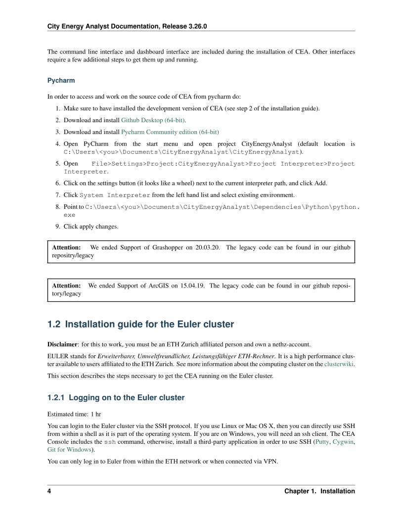
The command line interface and dashboard interface are included during the installation of CEA. Other interfacesrequire a few additional steps to get them up and running.
Pycharm
In order to access and work on the source code of CEA from pycharm do:
1. Make sure to have installed the development version of CEA (see step 2 of the installation guide).
2. Download and install Github Desktop (64-bit).
3. Download and install Pycharm Community edition (64-bit)
4. Open PyCharm from the start menu and open project CityEnergyAnalyst (default location isC:\Users\<you>\Documents\CityEnergyAnalyst\CityEnergyAnalyst).
5. Open File>Settings>Project:CityEnergyAnalyst>Project Interpreter>ProjectInterpreter.
6. Click on the settings button (it looks like a wheel) next to the current interpreter path, and click Add.
7. Click System Interpreter from the left hand list and select existing environment.
8. Point to C:\Users\<you>\Documents\CityEnergyAnalyst\Dependencies\Python\python.exe
9. Click apply changes.
Attention: We ended Support of Grashopper on 20.03.20. The legacy code can be found in our githubrepositry/legacy
Attention: We ended Support of ArcGIS on 15.04.19. The legacy code can be found in our github reposi-tory/legacy
1.2 Installation guide for the Euler cluster
Disclaimer: for this to work, you must be an ETH Zurich affiliated person and own a nethz-account.
EULER stands for Erweiterbarer, Umweltfreundlicher, Leistungsfähiger ETH-Rechner. It is a high performance clus-ter available to users affiliated to the ETH Zurich. See more information about the computing cluster on the clusterwiki.
This section describes the steps necessary to get the CEA running on the Euler cluster.
1.2.1 Logging on to the Euler cluster
Estimated time: 1 hr
You can login to the Euler cluster via the SSH protocol. If you use Linux or Mac OS X, then you can directly use SSHfrom within a shell as it is part of the operating system. If you are on Windows, you will need an ssh client. The CEAConsole includes the ssh command, otherwise, install a third-party application in order to use SSH (Putty, Cygwin,Git for Windows).
You can only log in to Euler from within the ETH network or when connected via VPN.
4 Chapter 1. Installation

City Energy Analyst Documentation, Release 3.26.0
Once in the terminal in Linux or Mac OS X or in a terminal of thrid-party application of your choicse, do:
ssh <your nethz-name>@euler.ethz.ch
After entering the above command in the shell, you will be asked for a password. Enter your nethz password. You arethen greeted with the Euler welcome message.
Detailed steps are described in the Euler wiki of the Scientific Computing Service in ETHZ. For Windows users, itis recomendded to download WinSCP and MobaXterm. Please follow the steps in the wiki carefully, and consult thecluster support when Troubleshooting section (2.9) is not enough to solve your problwm.
1.2.2 Build a CEA Singularity container
Estimated time: 20 mins
You need to build a Singularity container via a cea docker image. The latest docker image of cea is published here.Please login to Euler and conduct the following steps.
• Request a compute node with Singularity
$ bsub -n 1 -R singularity -R light -Is bash
• Load eth_proxy to connect to the internet from compute nodes
$ module load eth_proxy
• Go to the scratch folder
$ cd $SCRATCH
• Build a Singularity container based on the cea docker image
$ singularity pull docker://cityenergyanalyst/cea
• Check if Singularity has been built
$ ls
You should find the CEA Singularity container, cea_latest.sif, in the list of files. Congratulations! You canstart running CEA on Euler!
• If wish to run cea test to test the CEA Singularity container:
$ SINGULARITY_HOME=/projects singularity shell -B $SCRATCH cea_latest.sifSingularity> source /venv/bin/activate(venv) Singularity> cea test
1.2.3 Running the CEA
You need to run the CEA scripts with their command line interface (CLI). Be sure to learn how to use the job systemon Euler, as the login nodes are not intended for running simulations. See clusterwiki.
• Upload your CEA projects to /cluster/scratch/nethz-username.
• Upload a workflow.yml to /cluster/scratch/nethz-username.
• Open workflow.yml, point the project path to /cluster/scratch/ethz-username/PATH_TO_PROJECT (be aware of the linux path format).
1.2. Installation guide for the Euler cluster 5
City Energy Analyst Documentation, Release 3.26.0
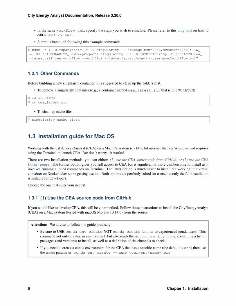
• In the same workflow.yml, specify the steps you wish to simulate. Please refer to this blog post on how toedit workflow.yml.
• Submit a batch job following this example command:
$ bsub -n 1 -R "span[host=1]" -R singularity -R "rusage[mem=2048,scratch=2048]" -W→˓1:00 "SINGULARITY_HOME=/projects singularity run -B \$TMPDIR:/tmp -B $SCRATCH cea_→˓latest.sif cea workflow --workflow /cluster/scratch/nethz-username/workflow.yml"
1.2.4 Other Commands
Before building a new singularity container, it is suggested to clean up the folders first.
• To remove a singularity container (e.g., a container named cea_latest.sif that is in $SCRATCH)
$ cd $SCRATCH$ rm cea_latest.sif
• To clean up cache files
$ singularity cache clean
1.3 Installation guide for Mac OS
Working with the CityEnergyAnalyst (CEA) on a Mac OS system is a little bit messier than on Windows and requiresusing the Terminal to launch CEA. But don’t worry - it works!
There are two installation methods, you can either: (1) use the CEA source code from GitHub, or (2) use the CEADocker image. The former option gives you full access to CEA but is significantly more cumbersome to install as itinvolves running a lot of commands on Terminal. The latter option is much easier to install but working in a virtualcontainer on Docker takes some getting used to. Both options are perfectly suited for users, but only the full installationis suitable for developers.
Choose the one that suits your needs!
1.3.1 (1) Use the CEA source code from GitHub
If you would like to develop CEA, this will be your method. Follow these instructions to install the CityEnergyAnalyst(CEA) on a Mac system (tested with macOS Mojave 10.14.6) from the source
Attention: We advise to follow the guide precisely:
• Be sure to USE conda env create NOT conda create familiar to experienced conda users. Thiscommand not only creates an environment, but also reads the environment.yml file, containing a list ofpackages (and versions) to install, as well as a definition of the channels to check.
• If you need to create a conda environment for the CEA that has a specific name (the default is cea) then usethe name parameter: conda env create --name your-env-name-here
6 Chapter 1. Installation

City Energy Analyst Documentation, Release 3.26.0
Prerequisites
• Download and install Github Desktop (64-bit).
• Download and install Miniconda(64-bit) for Python 3.9.
• Download and install Homebrew.
• Download and install Xcode. During installation, you will be asked whether you would like to install thecommand line tool (CLT). Make sure you do!
Installation of the code base
Excluding the above software, CEA installation requires approximately 13 GB of storage (depending on your existingPython library) and 1 hour of your time.
1. Open GitHub Desktop from the start menu.
2. Clone the CEA repository:
1. Press Cmd+Shift+O (clone repository) and select the URL tab.
2. Paste the CEA GitHub address: https://github.com/architecture-building-systems/CityEnergyAnalyst
3. Click Clone, this will take ~ 5-10 minutes (Size 1.65 GB).
3. Clone the CEA GUI repository:
1. Press Cmd+Shift+O (clone repository) and select the URL tab.
2. Paste the CEA GUI GitHub address: https://github.com/architecture-building-systems/CityEnergyAnalyst-GUI
3. Click Clone, this will take ~ 5 minutes (Size 600MB).
4. Install CEA:
1. Open a Terminal console (you can find it in your Mac’s Applications folder).
2. Type cd Documents/GitHub/CityEnergyAnalyst and press ENTER.
3. Type conda env create --name cea and press ENTER.
4. Grab a cup of tea and some toast, this will take ~45 minutes.
5. Type conda activate cea and press ENTER.
6. Type pip install -e . and press ENTER (mind the dot ‘.’ included in this command!).
5. Build the CEA dashboard GUI:
1. Type cd .. and press ENTER, then type cd CityEnergyAnalyst-GUI and press ENTER.
2. Install Yarn by typing brew install yarn and press ENTER.
3. Type yarn and press ENTER.
4. Type yarn dist:dir and press ENTER.
5. You will find the CEA application in the folder /Users/your_name/Documents/GitHub/CityEnergyAnalyst-GUI/dist/mac
6. Running CEA:
• You can run CEA a few different ways (see Mac Interfaces below).
1.3. Installation guide for Mac OS 7
City Energy Analyst Documentation, Release 3.26.0
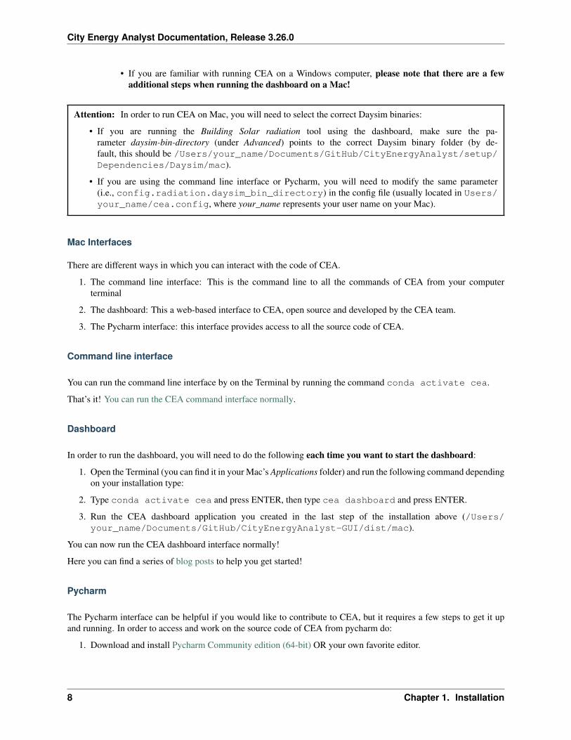
• If you are familiar with running CEA on a Windows computer, please note that there are a fewadditional steps when running the dashboard on a Mac!
Attention: In order to run CEA on Mac, you will need to select the correct Daysim binaries:
• If you are running the Building Solar radiation tool using the dashboard, make sure the pa-rameter daysim-bin-directory (under Advanced) points to the correct Daysim binary folder (by de-fault, this should be /Users/your_name/Documents/GitHub/CityEnergyAnalyst/setup/Dependencies/Daysim/mac).
• If you are using the command line interface or Pycharm, you will need to modify the same parameter(i.e., config.radiation.daysim_bin_directory) in the config file (usually located in Users/your_name/cea.config, where your_name represents your user name on your Mac).
Mac Interfaces
There are different ways in which you can interact with the code of CEA.
1. The command line interface: This is the command line to all the commands of CEA from your computerterminal
2. The dashboard: This a web-based interface to CEA, open source and developed by the CEA team.
3. The Pycharm interface: this interface provides access to all the source code of CEA.
Command line interface
You can run the command line interface by on the Terminal by running the command conda activate cea.
That’s it! You can run the CEA command interface normally.
Dashboard
In order to run the dashboard, you will need to do the following each time you want to start the dashboard:
1. Open the Terminal (you can find it in your Mac’s Applications folder) and run the following command dependingon your installation type:
2. Type conda activate cea and press ENTER, then type cea dashboard and press ENTER.
3. Run the CEA dashboard application you created in the last step of the installation above (/Users/your_name/Documents/GitHub/CityEnergyAnalyst-GUI/dist/mac).
You can now run the CEA dashboard interface normally!
Here you can find a series of blog posts to help you get started!
Pycharm
The Pycharm interface can be helpful if you would like to contribute to CEA, but it requires a few steps to get it upand running. In order to access and work on the source code of CEA from pycharm do:
1. Download and install Pycharm Community edition (64-bit) OR your own favorite editor.
8 Chapter 1. Installation

City Energy Analyst Documentation, Release 3.26.0
2. Open PyCharm from the start menu and open project CityEnergyAnalyst (stored where you downloaded CityEn-ergyAnalyst).
3. Open File>Settings>Project:CityEnergyAnalyst>Project Interpreter>ProjectInterpreter.
4. Click on the settings button (it looks like a wheel) next to the current interpreter path, and click Add.
5. Click Conda Environment from the left hand list and select existing environment.
6. Point to the location of your conda environment. It should look something like Users/your_name/Miniconda2/envs/cea/python.exe or Users/your_name/AppData/Local/conda/conda/envs/cea/python.exe where your_name represents your user name on your Mac.
7. Click apply changes.
1.3.2 (2) Use the CEA docker image
If you would like using docker containers, follow these instructions to run CEA on a Mac OS system (tested with MacOS Catalina). This method is suitable for users, but not developers. For developers, please refer to the second methodbelow.
1. Install Docker and run CEA:
1. You can find instructions on how to do that here.
2. If you only plan to run CEA from the command line interface, you’re done!
2. If you would like to use the CEA dashboard, you will need to download and build it manually:
1. Download and install Github Desktop (64-bit).
2. Download and install Miniconda(64-bit) for Python 3.8.
3. Download and install Homebrew.
4. Clone the CEA GUI repository:
1. Press Cmd+Shift+O (clone repository) and select the URL tab.
2. Paste the CEA GUI GitHub address: https://github.com/architecture-building-systems/CityEnergyAnalyst-GUI
3. Click Clone, this will take ~ 5 minutes (Size 600MB).
5. Build the CEA dashboard GUI:
1. Open a Terminal console (you can find it in your Mac’s Applications folder).
2. Type cd Documents/GitHub/CityEnergyAnalyst-GUI and press ENTER.
6. Install Yarn by typing brew install yarn and press ENTER.
7. Type yarn and press ENTER.
8. Type yarn package and press ENTER.
9. You will find the CEA application in the folder /Users/your_name/Documents/GitHub/CityEnergyAnalyst-GUI/dist/mac
3. Running CEA:
• You can run CEA a couple of different ways (see Docker Interfaces below).
• If you are familiar with running CEA on a Windows computer, please note that there are a fewadditional steps when running the dashboard on a Mac!
1.3. Installation guide for Mac OS 9
City Energy Analyst Documentation, Release 3.26.0
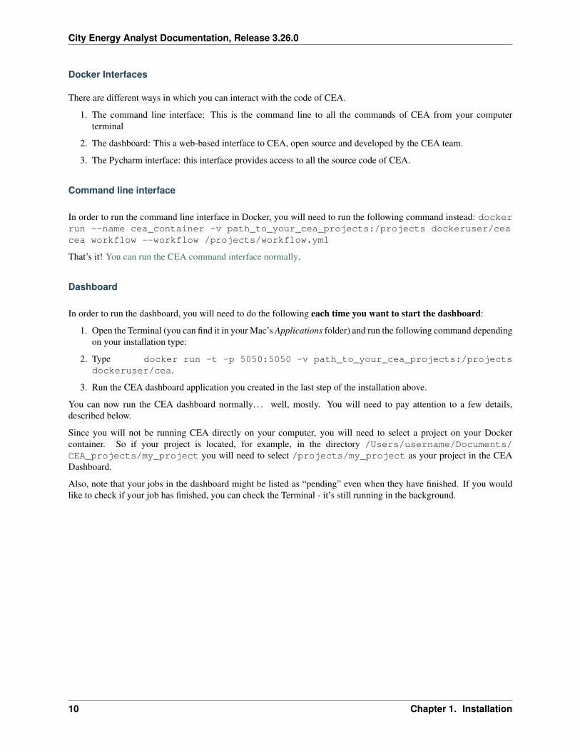
Docker Interfaces
There are different ways in which you can interact with the code of CEA.
1. The command line interface: This is the command line to all the commands of CEA from your computerterminal
2. The dashboard: This a web-based interface to CEA, open source and developed by the CEA team.
3. The Pycharm interface: this interface provides access to all the source code of CEA.
Command line interface
In order to run the command line interface in Docker, you will need to run the following command instead: dockerrun --name cea_container -v path_to_your_cea_projects:/projects dockeruser/ceacea workflow --workflow /projects/workflow.yml
That’s it! You can run the CEA command interface normally.
Dashboard
In order to run the dashboard, you will need to do the following each time you want to start the dashboard:
1. Open the Terminal (you can find it in your Mac’s Applications folder) and run the following command dependingon your installation type:
2. Type docker run -t -p 5050:5050 -v path_to_your_cea_projects:/projectsdockeruser/cea.
3. Run the CEA dashboard application you created in the last step of the installation above.
You can now run the CEA dashboard normally. . . well, mostly. You will need to pay attention to a few details,described below.
Since you will not be running CEA directly on your computer, you will need to select a project on your Dockercontainer. So if your project is located, for example, in the directory /Users/username/Documents/CEA_projects/my_project you will need to select /projects/my_project as your project in the CEADashboard.
Also, note that your jobs in the dashboard might be listed as “pending” even when they have finished. If you wouldlike to check if your job has finished, you can check the Terminal - it’s still running in the background.
10 Chapter 1. Installation

CHAPTER 2
Cite
Please cite us like this in your publications:
The CEA team. The City Energy Analyst (Version 3.26.0). Zenodo. https://doi.org/10.5281/zenodo.598221
You can see a list of our own publications here: https://cityenergyanalyst.com/publications
11

City Energy Analyst Documentation, Release 3.26.0
12 Chapter 2. Cite
CHAPTER 3
Tutorials
3.1 Users
General tutorials are constantly updated through blogs or videos.
• Blog posts
• Video tutorials
3.2 Developers
These are a collection of tutorials we consider essential for any new developer of CEA. We suggest to take them inorder for a better learning experience.
1. Contributing to City Energy Analyst (CEA)
2. User Stories
3. how-to-report-bugs
4. how-to-use-github
5. how-to-name-variables
6. how-to-add-a-new-script-to-the-cea
7. how-to-test-the-cea
8. how-to-set-up-nsis
9. how-to-create-a-new-release
10. how-to-publish-cea
11. how-trace-inputlocator-works
12. how-to-document-cea
13
City Energy Analyst Documentation, Release 3.26.0
13. run-the-cea-in-docker
3.3 LEGACY
Collection of outdated information about past functionality of CEA (use at your own risk)
1. script-data-flow
2. How are databases classified in CEA?
3. What are the input databases of CEA?
4. What are the default databases of CEA?
5. How to edit the input databases of CEA?
6. new-project-guide
7. cea-workflow-guide
8. How to create your own input geometry?
9. how-are-schedules-defined
10. How does the Urban Solar Radiation tool work?
11. How does the Dynamic Demand Forecast feature work?
12. How does the Renewable Energy Assessment tool work?
13. How does the Life Cycle Assessment tool work?
14. How does the 2000-Watt Bench-marking tool work?
15. How to study building retrofits in the CEA?
16. How does the Sensitivity Analysis tool work?
17. how-to-prepare-inputs-for-network-simulation
18. how-to-run-thermal-network-optimization
19. how-to-run-thermal-electrical-grid-planning
20. how-to-run-MPC-building
21. how-to-run-MPC-district
22. how-to-run-CEA-optimization
14 Chapter 3. Tutorials
CHAPTER 4
Known issues
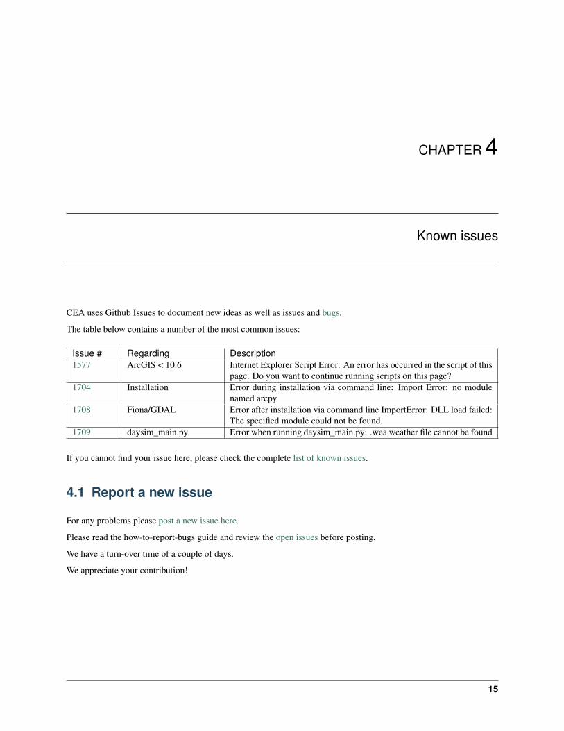
CEA uses Github Issues to document new ideas as well as issues and bugs.
The table below contains a number of the most common issues:
Issue # Regarding Description1577 ArcGIS < 10.6 Internet Explorer Script Error: An error has occurred in the script of this
page. Do you want to continue running scripts on this page?1704 Installation Error during installation via command line: Import Error: no module
named arcpy1708 Fiona/GDAL Error after installation via command line ImportError: DLL load failed:
The specified module could not be found.1709 daysim_main.py Error when running daysim_main.py: .wea weather file cannot be found
If you cannot find your issue here, please check the complete list of known issues.
4.1 Report a new issue
For any problems please post a new issue here.
Please read the how-to-report-bugs guide and review the open issues before posting.
We have a turn-over time of a couple of days.
We appreciate your contribution!
15

City Energy Analyst Documentation, Release 3.26.0
16 Chapter 4. Known issues
CHAPTER 5
Glossary
This glossary contains all the written input and output variables used by CEA. These variables are stored in databases,themed by the type of information they contain. There are two main types of databases in CEA: input and output. Thisglossary is organised through the cea’s inputlocator method, which is used to retrieve the information within each file.
5.1 Input
Inputlocator methods:
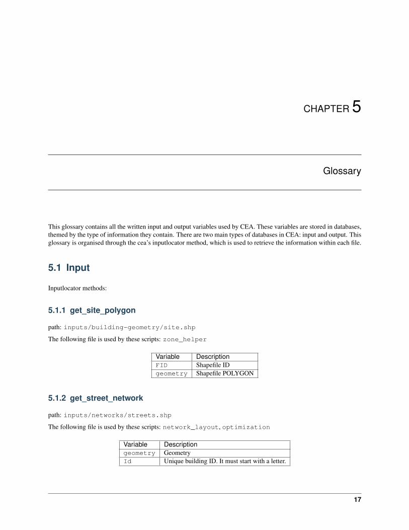
5.1.1 get_site_polygon
path: inputs/building-geometry/site.shp
The following file is used by these scripts: zone_helper
Variable DescriptionFID Shapefile IDgeometry Shapefile POLYGON
5.1.2 get_street_network
path: inputs/networks/streets.shp
The following file is used by these scripts: network_layout, optimization
Variable Descriptiongeometry GeometryId Unique building ID. It must start with a letter.
17
City Energy Analyst Documentation, Release 3.26.0
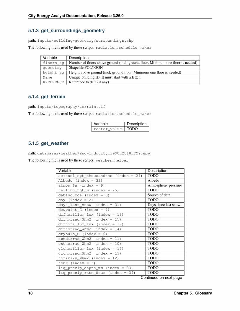
5.1.3 get_surroundings_geometry
path: inputs/building-geometry/surroundings.shp
The following file is used by these scripts: radiation, schedule_maker
Variable Descriptionfloors_ag Number of floors above ground (incl. ground floor, Minimum one floor is needed)geometry Shapefile POLYGONheight_ag Height above ground (incl. ground floor, Minimum one floor is needed)Name Unique building ID. It must start with a letter.REFERENCE Reference to data (if any)
5.1.4 get_terrain
path: inputs/topography/terrain.tif
The following file is used by these scripts: radiation, schedule_maker
Variable Descriptionraster_value TODO
5.1.5 get_weather
path: databases/weather/Zug-inducity_1990_2010_TMY.epw
The following file is used by these scripts: weather_helper
Variable Descriptionaerosol_opt_thousandths (index = 29) TODOAlbedo (index = 32) Albedoatmos_Pa (index = 9) Atmospheric pressureceiling_hgt_m (index = 25) TODOdatasource (index = 5) Source of dataday (index = 2) TODOdays_last_snow (index = 31) Days since last snowdewpoint_C (index = 7) TODOdifhorillum_lux (index = 18) TODOdifhorrad_Whm2 (index = 15) TODOdirnorillum_lux (index = 17) TODOdirnorrad_Whm2 (index = 14) TODOdrybulb_C (index = 6) TODOextdirrad_Whm2 (index = 11) TODOexthorrad_Whm2 (index = 10) TODOglohorillum_lux (index = 16) TODOglohorrad_Whm2 (index = 13) TODOhorirsky_Whm2 (index = 12) TODOhour (index = 3) TODOliq_precip_depth_mm (index = 33) TODOliq_precip_rate_Hour (index = 34) TODO
Continued on next page
18 Chapter 5. Glossary
City Energy Analyst Documentation, Release 3.26.0
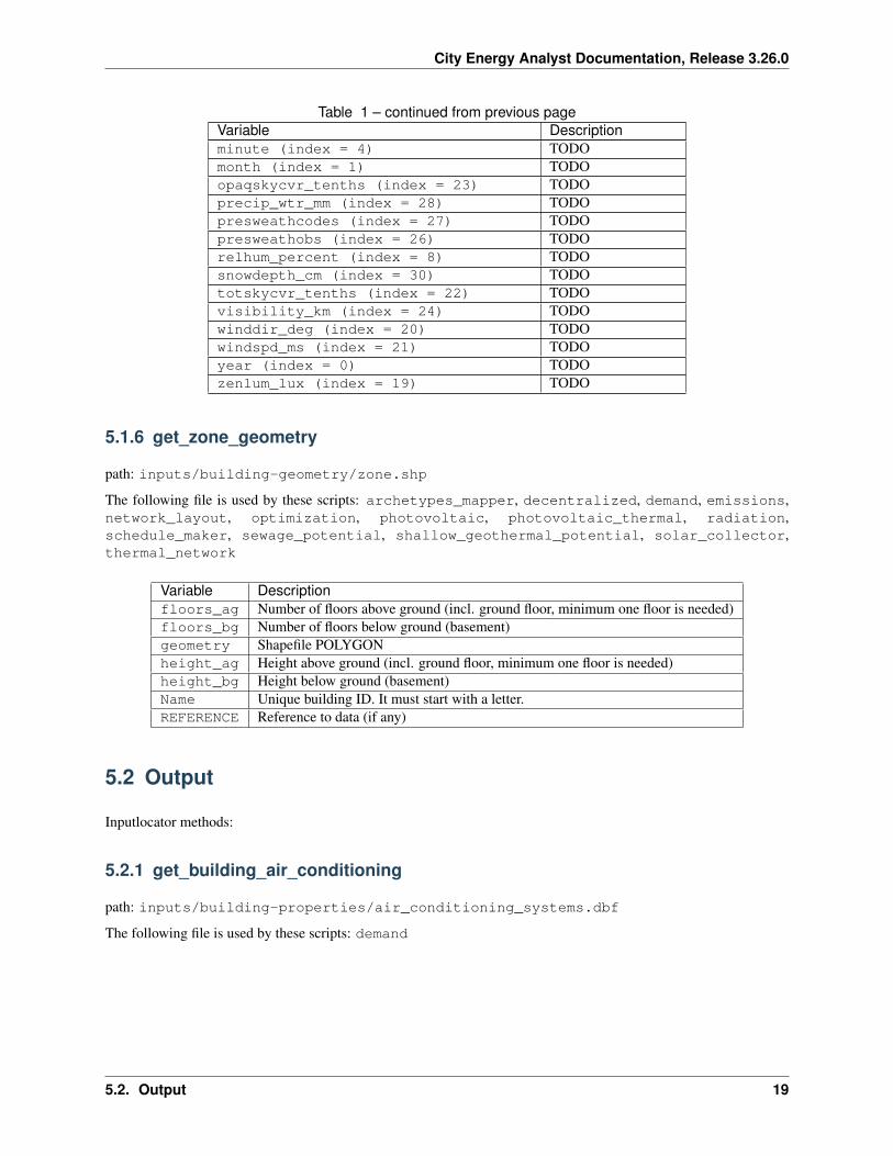
Table 1 – continued from previous pageVariable Descriptionminute (index = 4) TODOmonth (index = 1) TODOopaqskycvr_tenths (index = 23) TODOprecip_wtr_mm (index = 28) TODOpresweathcodes (index = 27) TODOpresweathobs (index = 26) TODOrelhum_percent (index = 8) TODOsnowdepth_cm (index = 30) TODOtotskycvr_tenths (index = 22) TODOvisibility_km (index = 24) TODOwinddir_deg (index = 20) TODOwindspd_ms (index = 21) TODOyear (index = 0) TODOzenlum_lux (index = 19) TODO
5.1.6 get_zone_geometry
path: inputs/building-geometry/zone.shp
The following file is used by these scripts: archetypes_mapper, decentralized, demand, emissions,network_layout, optimization, photovoltaic, photovoltaic_thermal, radiation,schedule_maker, sewage_potential, shallow_geothermal_potential, solar_collector,thermal_network
Variable Descriptionfloors_ag Number of floors above ground (incl. ground floor, minimum one floor is needed)floors_bg Number of floors below ground (basement)geometry Shapefile POLYGONheight_ag Height above ground (incl. ground floor, minimum one floor is needed)height_bg Height below ground (basement)Name Unique building ID. It must start with a letter.REFERENCE Reference to data (if any)
5.2 Output
Inputlocator methods:
5.2.1 get_building_air_conditioning
path: inputs/building-properties/air_conditioning_systems.dbf
The following file is used by these scripts: demand
5.2. Output 19
City Energy Analyst Documentation, Release 3.26.0
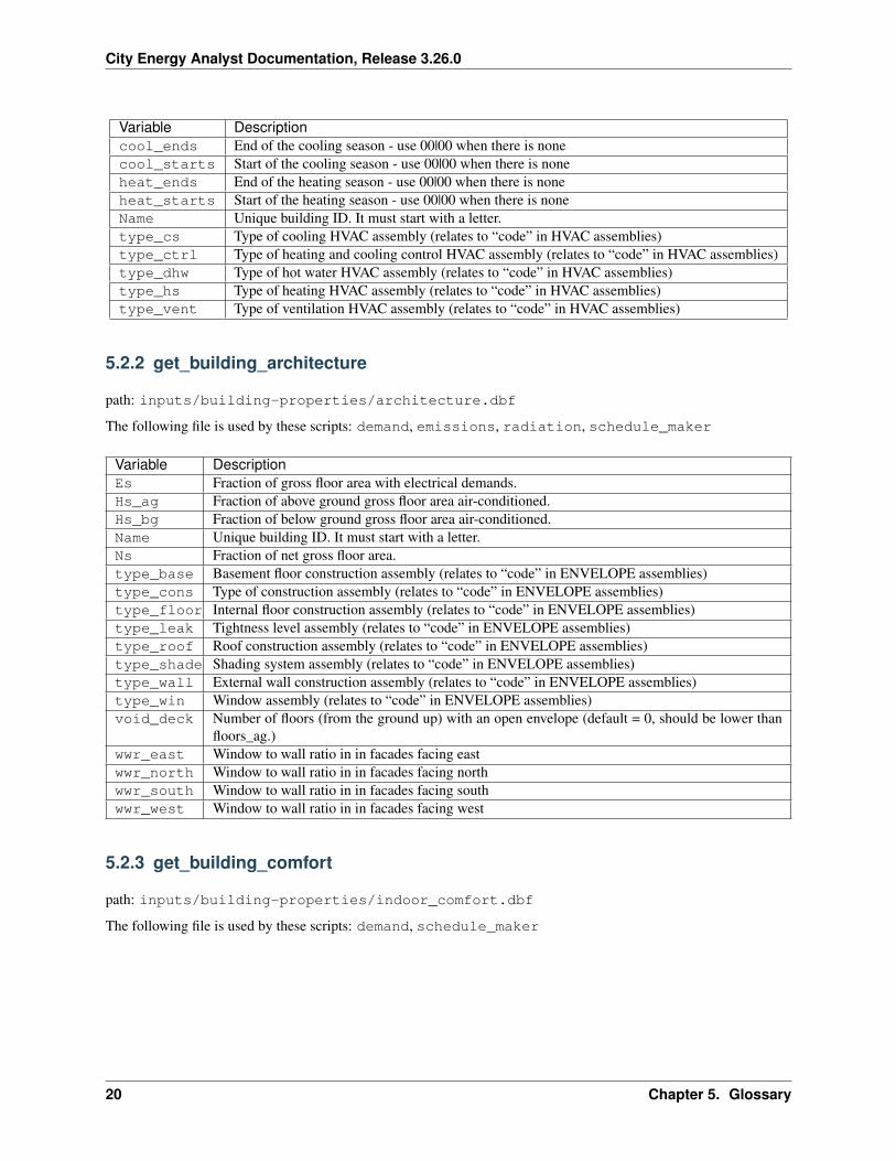
Variable Descriptioncool_ends End of the cooling season - use 00|00 when there is nonecool_starts Start of the cooling season - use 00|00 when there is noneheat_ends End of the heating season - use 00|00 when there is noneheat_starts Start of the heating season - use 00|00 when there is noneName Unique building ID. It must start with a letter.type_cs Type of cooling HVAC assembly (relates to “code” in HVAC assemblies)type_ctrl Type of heating and cooling control HVAC assembly (relates to “code” in HVAC assemblies)type_dhw Type of hot water HVAC assembly (relates to “code” in HVAC assemblies)type_hs Type of heating HVAC assembly (relates to “code” in HVAC assemblies)type_vent Type of ventilation HVAC assembly (relates to “code” in HVAC assemblies)
5.2.2 get_building_architecture
path: inputs/building-properties/architecture.dbf
The following file is used by these scripts: demand, emissions, radiation, schedule_maker
Variable DescriptionEs Fraction of gross floor area with electrical demands.Hs_ag Fraction of above ground gross floor area air-conditioned.Hs_bg Fraction of below ground gross floor area air-conditioned.Name Unique building ID. It must start with a letter.Ns Fraction of net gross floor area.type_base Basement floor construction assembly (relates to “code” in ENVELOPE assemblies)type_cons Type of construction assembly (relates to “code” in ENVELOPE assemblies)type_floor Internal floor construction assembly (relates to “code” in ENVELOPE assemblies)type_leak Tightness level assembly (relates to “code” in ENVELOPE assemblies)type_roof Roof construction assembly (relates to “code” in ENVELOPE assemblies)type_shade Shading system assembly (relates to “code” in ENVELOPE assemblies)type_wall External wall construction assembly (relates to “code” in ENVELOPE assemblies)type_win Window assembly (relates to “code” in ENVELOPE assemblies)void_deck Number of floors (from the ground up) with an open envelope (default = 0, should be lower than
floors_ag.)wwr_east Window to wall ratio in in facades facing eastwwr_north Window to wall ratio in in facades facing northwwr_south Window to wall ratio in in facades facing southwwr_west Window to wall ratio in in facades facing west
5.2.3 get_building_comfort
path: inputs/building-properties/indoor_comfort.dbf
The following file is used by these scripts: demand, schedule_maker
20 Chapter 5. Glossary
City Energy Analyst Documentation, Release 3.26.0
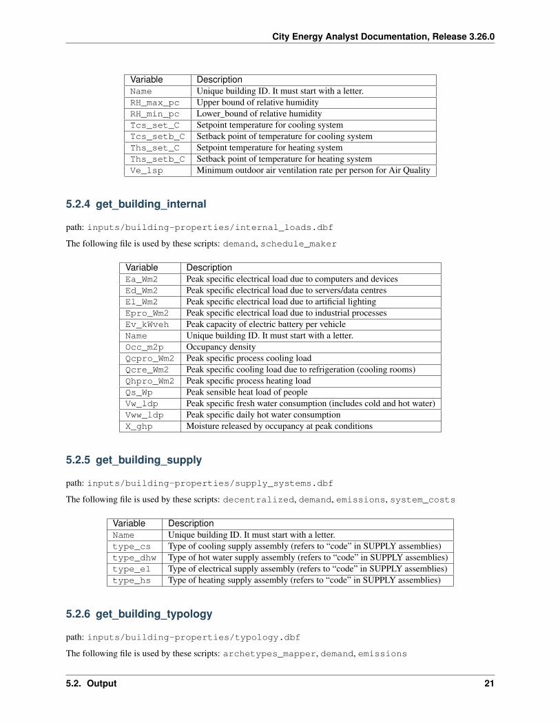
Variable DescriptionName Unique building ID. It must start with a letter.RH_max_pc Upper bound of relative humidityRH_min_pc Lower_bound of relative humidityTcs_set_C Setpoint temperature for cooling systemTcs_setb_C Setback point of temperature for cooling systemThs_set_C Setpoint temperature for heating systemThs_setb_C Setback point of temperature for heating systemVe_lsp Minimum outdoor air ventilation rate per person for Air Quality
5.2.4 get_building_internal
path: inputs/building-properties/internal_loads.dbf
The following file is used by these scripts: demand, schedule_maker
Variable DescriptionEa_Wm2 Peak specific electrical load due to computers and devicesEd_Wm2 Peak specific electrical load due to servers/data centresEl_Wm2 Peak specific electrical load due to artificial lightingEpro_Wm2 Peak specific electrical load due to industrial processesEv_kWveh Peak capacity of electric battery per vehicleName Unique building ID. It must start with a letter.Occ_m2p Occupancy densityQcpro_Wm2 Peak specific process cooling loadQcre_Wm2 Peak specific cooling load due to refrigeration (cooling rooms)Qhpro_Wm2 Peak specific process heating loadQs_Wp Peak sensible heat load of peopleVw_ldp Peak specific fresh water consumption (includes cold and hot water)Vww_ldp Peak specific daily hot water consumptionX_ghp Moisture released by occupancy at peak conditions
5.2.5 get_building_supply
path: inputs/building-properties/supply_systems.dbf
The following file is used by these scripts: decentralized, demand, emissions, system_costs
Variable DescriptionName Unique building ID. It must start with a letter.type_cs Type of cooling supply assembly (refers to “code” in SUPPLY assemblies)type_dhw Type of hot water supply assembly (refers to “code” in SUPPLY assemblies)type_el Type of electrical supply assembly (refers to “code” in SUPPLY assemblies)type_hs Type of heating supply assembly (refers to “code” in SUPPLY assemblies)
5.2.6 get_building_typology
path: inputs/building-properties/typology.dbf
The following file is used by these scripts: archetypes_mapper, demand, emissions
5.2. Output 21
City Energy Analyst Documentation, Release 3.26.0
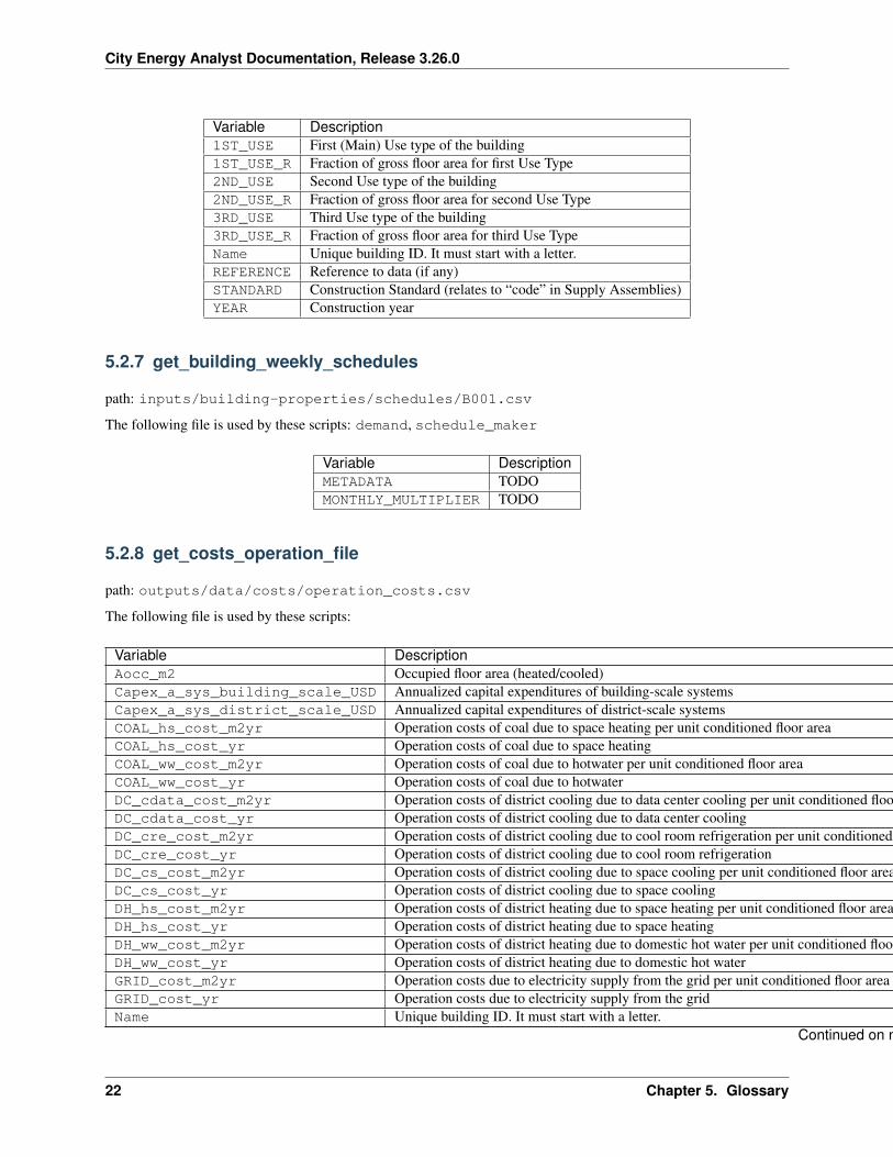
Variable Description1ST_USE First (Main) Use type of the building1ST_USE_R Fraction of gross floor area for first Use Type2ND_USE Second Use type of the building2ND_USE_R Fraction of gross floor area for second Use Type3RD_USE Third Use type of the building3RD_USE_R Fraction of gross floor area for third Use TypeName Unique building ID. It must start with a letter.REFERENCE Reference to data (if any)STANDARD Construction Standard (relates to “code” in Supply Assemblies)YEAR Construction year
5.2.7 get_building_weekly_schedules
path: inputs/building-properties/schedules/B001.csv
The following file is used by these scripts: demand, schedule_maker
Variable DescriptionMETADATA TODOMONTHLY_MULTIPLIER TODO
5.2.8 get_costs_operation_file
path: outputs/data/costs/operation_costs.csv
The following file is used by these scripts:
Variable DescriptionAocc_m2 Occupied floor area (heated/cooled)Capex_a_sys_building_scale_USD Annualized capital expenditures of building-scale systemsCapex_a_sys_district_scale_USD Annualized capital expenditures of district-scale systemsCOAL_hs_cost_m2yr Operation costs of coal due to space heating per unit conditioned floor areaCOAL_hs_cost_yr Operation costs of coal due to space heatingCOAL_ww_cost_m2yr Operation costs of coal due to hotwater per unit conditioned floor areaCOAL_ww_cost_yr Operation costs of coal due to hotwaterDC_cdata_cost_m2yr Operation costs of district cooling due to data center cooling per unit conditioned floor areaDC_cdata_cost_yr Operation costs of district cooling due to data center coolingDC_cre_cost_m2yr Operation costs of district cooling due to cool room refrigeration per unit conditioned floor areaDC_cre_cost_yr Operation costs of district cooling due to cool room refrigerationDC_cs_cost_m2yr Operation costs of district cooling due to space cooling per unit conditioned floor areaDC_cs_cost_yr Operation costs of district cooling due to space coolingDH_hs_cost_m2yr Operation costs of district heating due to space heating per unit conditioned floor areaDH_hs_cost_yr Operation costs of district heating due to space heatingDH_ww_cost_m2yr Operation costs of district heating due to domestic hot water per unit conditioned floor areaDH_ww_cost_yr Operation costs of district heating due to domestic hot waterGRID_cost_m2yr Operation costs due to electricity supply from the grid per unit conditioned floor areaGRID_cost_yr Operation costs due to electricity supply from the gridName Unique building ID. It must start with a letter.
Continued on next page
22 Chapter 5. Glossary
City Energy Analyst Documentation, Release 3.26.0
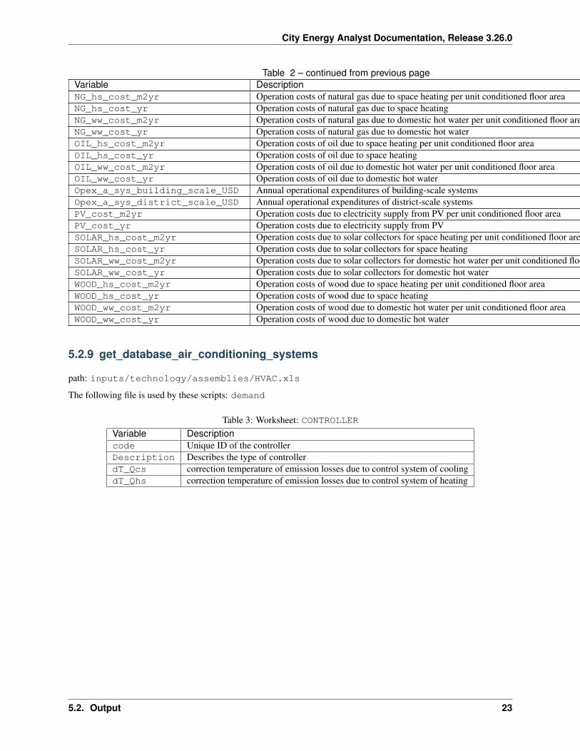
Table 2 – continued from previous pageVariable DescriptionNG_hs_cost_m2yr Operation costs of natural gas due to space heating per unit conditioned floor areaNG_hs_cost_yr Operation costs of natural gas due to space heatingNG_ww_cost_m2yr Operation costs of natural gas due to domestic hot water per unit conditioned floor areaNG_ww_cost_yr Operation costs of natural gas due to domestic hot waterOIL_hs_cost_m2yr Operation costs of oil due to space heating per unit conditioned floor areaOIL_hs_cost_yr Operation costs of oil due to space heatingOIL_ww_cost_m2yr Operation costs of oil due to domestic hot water per unit conditioned floor areaOIL_ww_cost_yr Operation costs of oil due to domestic hot waterOpex_a_sys_building_scale_USD Annual operational expenditures of building-scale systemsOpex_a_sys_district_scale_USD Annual operational expenditures of district-scale systemsPV_cost_m2yr Operation costs due to electricity supply from PV per unit conditioned floor areaPV_cost_yr Operation costs due to electricity supply from PVSOLAR_hs_cost_m2yr Operation costs due to solar collectors for space heating per unit conditioned floor areaSOLAR_hs_cost_yr Operation costs due to solar collectors for space heatingSOLAR_ww_cost_m2yr Operation costs due to solar collectors for domestic hot water per unit conditioned floor areaSOLAR_ww_cost_yr Operation costs due to solar collectors for domestic hot waterWOOD_hs_cost_m2yr Operation costs of wood due to space heating per unit conditioned floor areaWOOD_hs_cost_yr Operation costs of wood due to space heatingWOOD_ww_cost_m2yr Operation costs of wood due to domestic hot water per unit conditioned floor areaWOOD_ww_cost_yr Operation costs of wood due to domestic hot water
5.2.9 get_database_air_conditioning_systems
path: inputs/technology/assemblies/HVAC.xls
The following file is used by these scripts: demand
Table 3: Worksheet: CONTROLLERVariable Descriptioncode Unique ID of the controllerDescription Describes the type of controllerdT_Qcs correction temperature of emission losses due to control system of coolingdT_Qhs correction temperature of emission losses due to control system of heating
5.2. Output 23
City Energy Analyst Documentation, Release 3.26.0
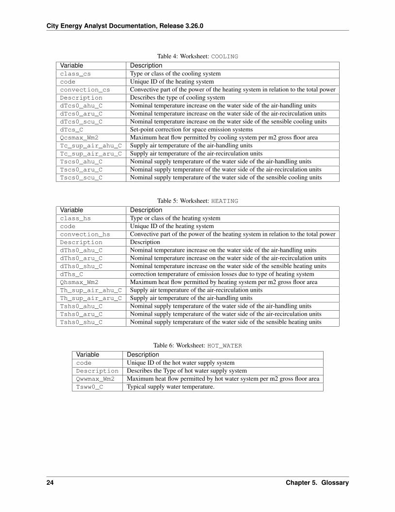
Table 4: Worksheet: COOLINGVariable Descriptionclass_cs Type or class of the cooling systemcode Unique ID of the heating systemconvection_cs Convective part of the power of the heating system in relation to the total powerDescription Describes the type of cooling systemdTcs0_ahu_C Nominal temperature increase on the water side of the air-handling unitsdTcs0_aru_C Nominal temperature increase on the water side of the air-recirculation unitsdTcs0_scu_C Nominal temperature increase on the water side of the sensible cooling unitsdTcs_C Set-point correction for space emission systemsQcsmax_Wm2 Maximum heat flow permitted by cooling system per m2 gross floor areaTc_sup_air_ahu_C Supply air temperature of the air-handling unitsTc_sup_air_aru_C Supply air temperature of the air-recirculation unitsTscs0_ahu_C Nominal supply temperature of the water side of the air-handling unitsTscs0_aru_C Nominal supply temperature of the water side of the air-recirculation unitsTscs0_scu_C Nominal supply temperature of the water side of the sensible cooling units
Table 5: Worksheet: HEATINGVariable Descriptionclass_hs Type or class of the heating systemcode Unique ID of the heating systemconvection_hs Convective part of the power of the heating system in relation to the total powerDescription DescriptiondThs0_ahu_C Nominal temperature increase on the water side of the air-handling unitsdThs0_aru_C Nominal temperature increase on the water side of the air-recirculation unitsdThs0_shu_C Nominal temperature increase on the water side of the sensible heating unitsdThs_C correction temperature of emission losses due to type of heating systemQhsmax_Wm2 Maximum heat flow permitted by heating system per m2 gross floor areaTh_sup_air_ahu_C Supply air temperature of the air-recirculation unitsTh_sup_air_aru_C Supply air temperature of the air-handling unitsTshs0_ahu_C Nominal supply temperature of the water side of the air-handling unitsTshs0_aru_C Nominal supply temperature of the water side of the air-recirculation unitsTshs0_shu_C Nominal supply temperature of the water side of the sensible heating units
Table 6: Worksheet: HOT_WATERVariable Descriptioncode Unique ID of the hot water supply systemDescription Describes the Type of hot water supply systemQwwmax_Wm2 Maximum heat flow permitted by hot water system per m2 gross floor areaTsww0_C Typical supply water temperature.
24 Chapter 5. Glossary
City Energy Analyst Documentation, Release 3.26.0
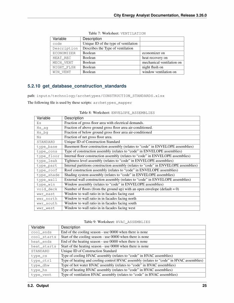
Table 7: Worksheet: VENTILATIONVariable Descriptioncode Unique ID of the type of ventilationDescription Describes the Type of ventilationECONOMIZER Boolean economizer onHEAT_REC Boolean heat recovery onMECH_VENT Boolean mechanical ventilation onNIGHT_FLSH Boolean night flush onWIN_VENT Boolean window ventilation on
5.2.10 get_database_construction_standards
path: inputs/technology/archetypes/CONSTRUCTION_STANDARDS.xlsx
The following file is used by these scripts: archetypes_mapper
Table 8: Worksheet: ENVELOPE_ASSEMBLIESVariable DescriptionEs Fraction of gross floor area with electrical demands.Hs_ag Fraction of above ground gross floor area air-conditioned.Hs_bg Fraction of below ground gross floor area air-conditionedNs Fraction of net gross floor area.STANDARD Unique ID of Construction Standardtype_base Basement floor construction assembly (relates to “code” in ENVELOPE assemblies)type_cons Type of construction assembly (relates to “code” in ENVELOPE assemblies)type_floor Internal floor construction assembly (relates to “code” in ENVELOPE assemblies)type_leak Tightness level assembly (relates to “code” in ENVELOPE assemblies)type_part Internal partitions construction assembly (relates to “code” in ENVELOPE assemblies)type_roof Roof construction assembly (relates to “code” in ENVELOPE assemblies)type_shade Shading system assembly (relates to “code” in ENVELOPE assemblies)type_wall External wall construction assembly (relates to “code” in ENVELOPE assemblies)type_win Window assembly (relates to “code” in ENVELOPE assemblies)void_deck Number of floors (from the ground up) with an open envelope (default = 0)wwr_east Window to wall ratio in in facades facing eastwwr_north Window to wall ratio in in facades facing northwwr_south Window to wall ratio in in facades facing southwwr_west Window to wall ratio in in facades facing west
Table 9: Worksheet: HVAC_ASSEMBLIESVariable Descriptioncool_ends End of the cooling season - use 00|00 when there is nonecool_starts Start of the cooling season - use 00|00 when there is noneheat_ends End of the heating season - use 00|00 when there is noneheat_starts Start of the heating season - use 00|00 when there is noneSTANDARD Unique ID of Construction Standardtype_cs Type of cooling HVAC assembly (relates to “code” in HVAC assemblies)type_ctrl Type of heating and cooling control HVAC assembly (relates to “code” in HVAC assemblies)type_dhw Type of hot water HVAC assembly (relates to “code” in HVAC assemblies)type_hs Type of heating HVAC assembly (relates to “code” in HVAC assemblies)type_vent Type of ventilation HVAC assembly (relates to “code” in HVAC assemblies)
5.2. Output 25
City Energy Analyst Documentation, Release 3.26.0
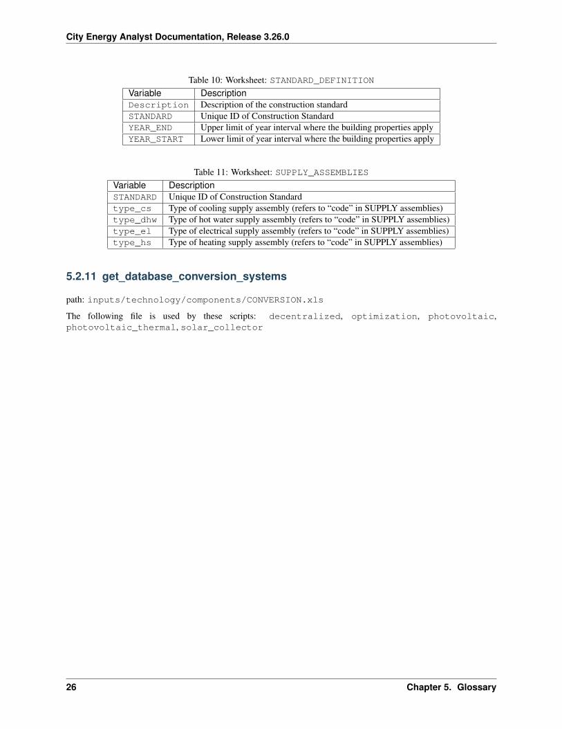
Table 10: Worksheet: STANDARD_DEFINITIONVariable DescriptionDescription Description of the construction standardSTANDARD Unique ID of Construction StandardYEAR_END Upper limit of year interval where the building properties applyYEAR_START Lower limit of year interval where the building properties apply
Table 11: Worksheet: SUPPLY_ASSEMBLIESVariable DescriptionSTANDARD Unique ID of Construction Standardtype_cs Type of cooling supply assembly (refers to “code” in SUPPLY assemblies)type_dhw Type of hot water supply assembly (refers to “code” in SUPPLY assemblies)type_el Type of electrical supply assembly (refers to “code” in SUPPLY assemblies)type_hs Type of heating supply assembly (refers to “code” in SUPPLY assemblies)
5.2.11 get_database_conversion_systems
path: inputs/technology/components/CONVERSION.xls
The following file is used by these scripts: decentralized, optimization, photovoltaic,photovoltaic_thermal, solar_collector
26 Chapter 5. Glossary
City Energy Analyst Documentation, Release 3.26.0
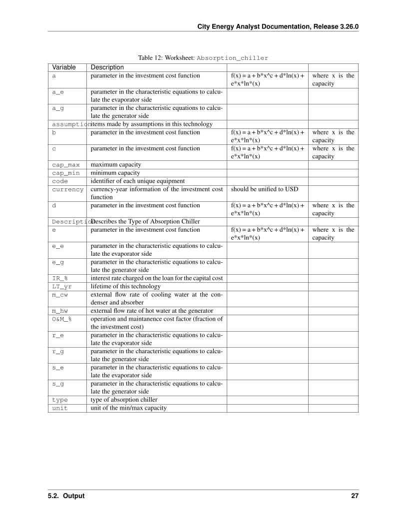
Table 12: Worksheet: Absorption_chillerVariable Descriptiona parameter in the investment cost function f(x) = a + b*x^c + d*ln(x) +
e*x*ln*(x)where x is thecapacity
a_e parameter in the characteristic equations to calcu-late the evaporator side
a_g parameter in the characteristic equations to calcu-late the generator side
assumptionitems made by assumptions in this technologyb parameter in the investment cost function f(x) = a + b*x^c + d*ln(x) +
e*x*ln*(x)where x is thecapacity
c parameter in the investment cost function f(x) = a + b*x^c + d*ln(x) +e*x*ln*(x)
where x is thecapacity
cap_max maximum capacitycap_min minimum capacitycode identifier of each unique equipmentcurrency currency-year information of the investment cost
functionshould be unified to USD
d parameter in the investment cost function f(x) = a + b*x^c + d*ln(x) +e*x*ln*(x)
where x is thecapacity
DescriptionDescribes the Type of Absorption Chillere parameter in the investment cost function f(x) = a + b*x^c + d*ln(x) +
e*x*ln*(x)where x is thecapacity
e_e parameter in the characteristic equations to calcu-late the evaporator side
e_g parameter in the characteristic equations to calcu-late the generator side
IR_% interest rate charged on the loan for the capital costLT_yr lifetime of this technologym_cw external flow rate of cooling water at the con-
denser and absorberm_hw external flow rate of hot water at the generatorO&M_% operation and maintanence cost factor (fraction of
the investment cost)r_e parameter in the characteristic equations to calcu-
late the evaporator sider_g parameter in the characteristic equations to calcu-
late the generator sides_e parameter in the characteristic equations to calcu-
late the evaporator sides_g parameter in the characteristic equations to calcu-
late the generator sidetype type of absorption chillerunit unit of the min/max capacity
5.2. Output 27
City Energy Analyst Documentation, Release 3.26.0
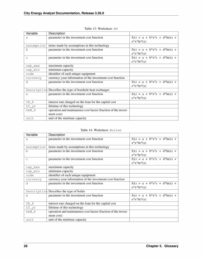
Table 13: Worksheet: BHVariable Descriptiona parameter in the investment cost function f(x) = a + b*x^c + d*ln(x) +
e*x*ln*(x)assumption items made by assumptions in this technologyb parameter in the investment cost function f(x) = a + b*x^c + d*ln(x) +
e*x*ln*(x)c parameter in the investment cost function f(x) = a + b*x^c + d*ln(x) +
e*x*ln*(x)cap_max maximum capacitycap_min minimum capacitycode identifier of each unique equipmentcurrency currency-year information of the investment cost functiond parameter in the investment cost function f(x) = a + b*x^c + d*ln(x) +
e*x*ln*(x)Description Describes the type of borehole heat exchangere parameter in the investment cost function f(x) = a + b*x^c + d*ln(x) +
e*x*ln*(x)IR_% interest rate charged on the loan for the capital costLT_yr lifetime of this technologyO&M_% operation and maintanence cost factor (fraction of the invest-
ment cost)unit unit of the min/max capacity
Table 14: Worksheet: BoilerVariable Descriptiona parameter in the investment cost function f(x) = a + b*x^c + d*ln(x) +
e*x*ln*(x)assumption items made by assumptions in this technologyb parameter in the investment cost function f(x) = a + b*x^c + d*ln(x) +
e*x*ln*(x)c parameter in the investment cost function f(x) = a + b*x^c + d*ln(x) +
e*x*ln*(x)cap_max maximum capacitycap_min minimum capacitycode identifier of each unique equipmentcurrency currency-year information of the investment cost functiond parameter in the investment cost function f(x) = a + b*x^c + d*ln(x) +
e*x*ln*(x)Description Describes the type of boilere parameter in the investment cost function f(x) = a + b*x^c + d*ln(x) +
e*x*ln*(x)IR_% interest rate charged on the loan for the capital costLT_yr lifetime of this technologyO&M_% operation and maintanence cost factor (fraction of the invest-
ment cost)unit unit of the min/max capacity
28 Chapter 5. Glossary
City Energy Analyst Documentation, Release 3.26.0
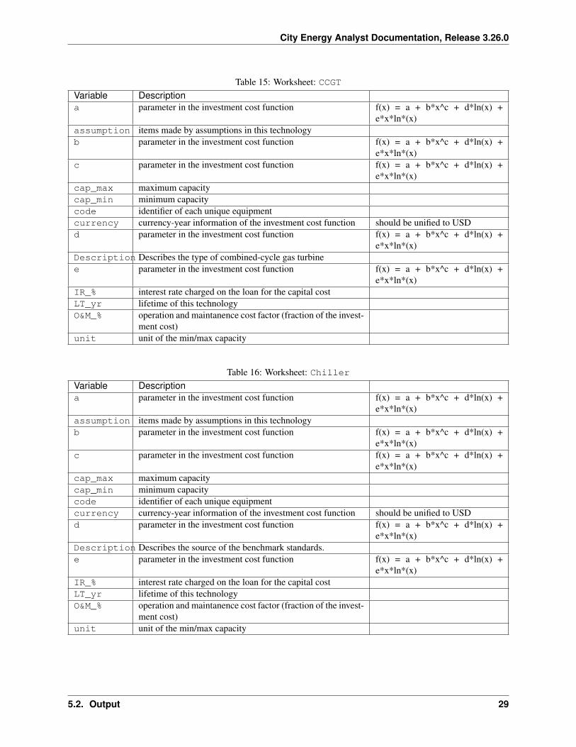
Table 15: Worksheet: CCGTVariable Descriptiona parameter in the investment cost function f(x) = a + b*x^c + d*ln(x) +
e*x*ln*(x)assumption items made by assumptions in this technologyb parameter in the investment cost function f(x) = a + b*x^c + d*ln(x) +
e*x*ln*(x)c parameter in the investment cost function f(x) = a + b*x^c + d*ln(x) +
e*x*ln*(x)cap_max maximum capacitycap_min minimum capacitycode identifier of each unique equipmentcurrency currency-year information of the investment cost function should be unified to USDd parameter in the investment cost function f(x) = a + b*x^c + d*ln(x) +
e*x*ln*(x)Description Describes the type of combined-cycle gas turbinee parameter in the investment cost function f(x) = a + b*x^c + d*ln(x) +
e*x*ln*(x)IR_% interest rate charged on the loan for the capital costLT_yr lifetime of this technologyO&M_% operation and maintanence cost factor (fraction of the invest-
ment cost)unit unit of the min/max capacity
Table 16: Worksheet: ChillerVariable Descriptiona parameter in the investment cost function f(x) = a + b*x^c + d*ln(x) +
e*x*ln*(x)assumption items made by assumptions in this technologyb parameter in the investment cost function f(x) = a + b*x^c + d*ln(x) +
e*x*ln*(x)c parameter in the investment cost function f(x) = a + b*x^c + d*ln(x) +
e*x*ln*(x)cap_max maximum capacitycap_min minimum capacitycode identifier of each unique equipmentcurrency currency-year information of the investment cost function should be unified to USDd parameter in the investment cost function f(x) = a + b*x^c + d*ln(x) +
e*x*ln*(x)Description Describes the source of the benchmark standards.e parameter in the investment cost function f(x) = a + b*x^c + d*ln(x) +
e*x*ln*(x)IR_% interest rate charged on the loan for the capital costLT_yr lifetime of this technologyO&M_% operation and maintanence cost factor (fraction of the invest-
ment cost)unit unit of the min/max capacity
5.2. Output 29
City Energy Analyst Documentation, Release 3.26.0
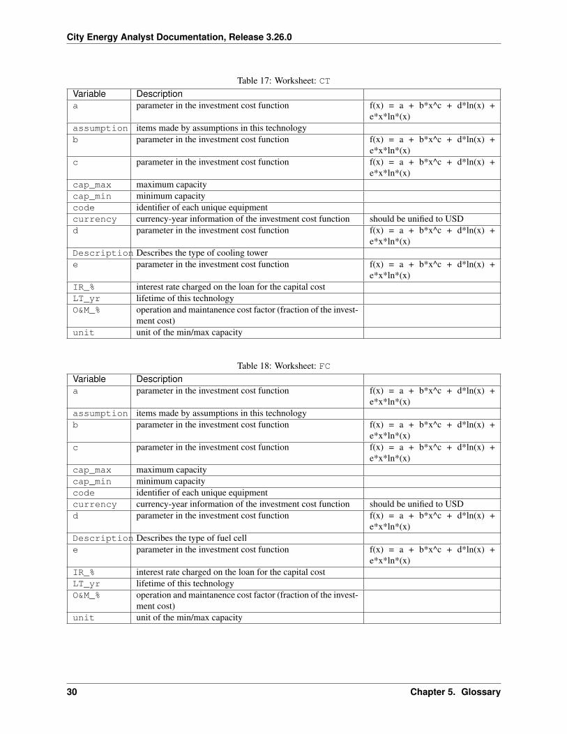
Table 17: Worksheet: CTVariable Descriptiona parameter in the investment cost function f(x) = a + b*x^c + d*ln(x) +
e*x*ln*(x)assumption items made by assumptions in this technologyb parameter in the investment cost function f(x) = a + b*x^c + d*ln(x) +
e*x*ln*(x)c parameter in the investment cost function f(x) = a + b*x^c + d*ln(x) +
e*x*ln*(x)cap_max maximum capacitycap_min minimum capacitycode identifier of each unique equipmentcurrency currency-year information of the investment cost function should be unified to USDd parameter in the investment cost function f(x) = a + b*x^c + d*ln(x) +
e*x*ln*(x)Description Describes the type of cooling towere parameter in the investment cost function f(x) = a + b*x^c + d*ln(x) +
e*x*ln*(x)IR_% interest rate charged on the loan for the capital costLT_yr lifetime of this technologyO&M_% operation and maintanence cost factor (fraction of the invest-
ment cost)unit unit of the min/max capacity
Table 18: Worksheet: FCVariable Descriptiona parameter in the investment cost function f(x) = a + b*x^c + d*ln(x) +
e*x*ln*(x)assumption items made by assumptions in this technologyb parameter in the investment cost function f(x) = a + b*x^c + d*ln(x) +
e*x*ln*(x)c parameter in the investment cost function f(x) = a + b*x^c + d*ln(x) +
e*x*ln*(x)cap_max maximum capacitycap_min minimum capacitycode identifier of each unique equipmentcurrency currency-year information of the investment cost function should be unified to USDd parameter in the investment cost function f(x) = a + b*x^c + d*ln(x) +
e*x*ln*(x)Description Describes the type of fuel celle parameter in the investment cost function f(x) = a + b*x^c + d*ln(x) +
e*x*ln*(x)IR_% interest rate charged on the loan for the capital costLT_yr lifetime of this technologyO&M_% operation and maintanence cost factor (fraction of the invest-
ment cost)unit unit of the min/max capacity
30 Chapter 5. Glossary
City Energy Analyst Documentation, Release 3.26.0
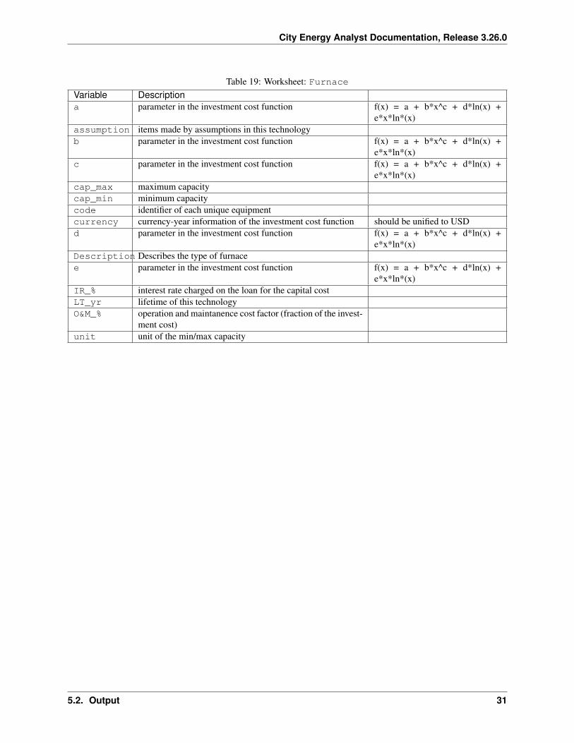
Table 19: Worksheet: FurnaceVariable Descriptiona parameter in the investment cost function f(x) = a + b*x^c + d*ln(x) +
e*x*ln*(x)assumption items made by assumptions in this technologyb parameter in the investment cost function f(x) = a + b*x^c + d*ln(x) +
e*x*ln*(x)c parameter in the investment cost function f(x) = a + b*x^c + d*ln(x) +
e*x*ln*(x)cap_max maximum capacitycap_min minimum capacitycode identifier of each unique equipmentcurrency currency-year information of the investment cost function should be unified to USDd parameter in the investment cost function f(x) = a + b*x^c + d*ln(x) +
e*x*ln*(x)Description Describes the type of furnacee parameter in the investment cost function f(x) = a + b*x^c + d*ln(x) +
e*x*ln*(x)IR_% interest rate charged on the loan for the capital costLT_yr lifetime of this technologyO&M_% operation and maintanence cost factor (fraction of the invest-
ment cost)unit unit of the min/max capacity
5.2. Output 31
City Energy Analyst Documentation, Release 3.26.0
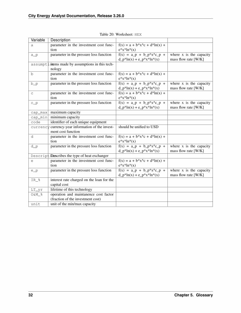
Table 20: Worksheet: HEXVariable Descriptiona parameter in the investment cost func-
tionf(x) = a + b*x^c + d*ln(x) +e*x*ln*(x)
a_p parameter in the pressure loss function f(x) = a_p + b_p*x^c_p +d_p*ln(x) + e_p*x*ln*(x)
where x is the capacitymass flow rate [W/K]
assumptionitems made by assumptions in this tech-nology
b parameter in the investment cost func-tion
f(x) = a + b*x^c + d*ln(x) +e*x*ln*(x)
b_p parameter in the pressure loss function f(x) = a_p + b_p*x^c_p +d_p*ln(x) + e_p*x*ln*(x)
where x is the capacitymass flow rate [W/K]
c parameter in the investment cost func-tion
f(x) = a + b*x^c + d*ln(x) +e*x*ln*(x)
c_p parameter in the pressure loss function f(x) = a_p + b_p*x^c_p +d_p*ln(x) + e_p*x*ln*(x)
where x is the capacitymass flow rate [W/K]
cap_max maximum capacitycap_min minimum capacitycode identifier of each unique equipmentcurrency currency-year information of the invest-
ment cost functionshould be unified to USD
d parameter in the investment cost func-tion
f(x) = a + b*x^c + d*ln(x) +e*x*ln*(x)
d_p parameter in the pressure loss function f(x) = a_p + b_p*x^c_p +d_p*ln(x) + e_p*x*ln*(x)
where x is the capacitymass flow rate [W/K]
DescriptionDescribes the type of heat exchangere parameter in the investment cost func-
tionf(x) = a + b*x^c + d*ln(x) +e*x*ln*(x)
e_p parameter in the pressure loss function f(x) = a_p + b_p*x^c_p +d_p*ln(x) + e_p*x*ln*(x)
where x is the capacitymass flow rate [W/K]
IR_% interest rate charged on the loan for thecapital cost
LT_yr lifetime of this technologyO&M_% operation and maintanence cost factor
(fraction of the investment cost)unit unit of the min/max capacity
32 Chapter 5. Glossary
City Energy Analyst Documentation, Release 3.26.0
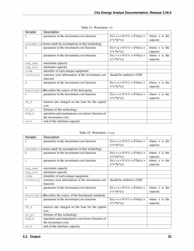
Table 21: Worksheet: HPVariable Descriptiona parameter in the investment cost function f(x) = a + b*x^c + d*ln(x) +
e*x*ln*(x)where x is thecapacity
assumptionitems made by assumptions in this technologyb parameter in the investment cost function f(x) = a + b*x^c + d*ln(x) +
e*x*ln*(x)where x is thecapacity
c parameter in the investment cost function f(x) = a + b*x^c + d*ln(x) +e*x*ln*(x)
where x is thecapacity
cap_max maximum capacitycap_min minimum capacitycode identifier of each unique equipmentcurrency currency-year information of the investment cost
functionshould be unified to USD
d parameter in the investment cost function f(x) = a + b*x^c + d*ln(x) +e*x*ln*(x)
where x is thecapacity
DescriptionDescribes the source of the heat pumpe parameter in the investment cost function f(x) = a + b*x^c + d*ln(x) +
e*x*ln*(x)where x is thecapacity
IR_% interest rate charged on the loan for the capitalcost
LT_yr lifetime of this technologyO&M_% operation and maintanence cost factor (fraction of
the investment cost)unit unit of the min/max capacity
Table 22: Worksheet: PumpVariable Descriptiona parameter in the investment cost function f(x) = a + b*x^c + d*ln(x) +
e*x*ln*(x)where x is thecapacity
assumptionitems made by assumptions in this technologyb parameter in the investment cost function f(x) = a + b*x^c + d*ln(x) +
e*x*ln*(x)where x is thecapacity
c parameter in the investment cost function f(x) = a + b*x^c + d*ln(x) +e*x*ln*(x)
where x is thecapacity
cap_max maximum capacitycap_min minimum capacitycode identifier of each unique equipmentcurrency currency-year information of the investment cost
functionshould be unified to USD
d parameter in the investment cost function f(x) = a + b*x^c + d*ln(x) +e*x*ln*(x)
where x is thecapacity
DescriptionDescribes the source of the benchmark standards.e parameter in the investment cost function f(x) = a + b*x^c + d*ln(x) +
e*x*ln*(x)where x is thecapacity
IR_% interest rate charged on the loan for the capitalcost
LT_yr lifetime of this technologyO&M_% operation and maintanence cost factor (fraction of
the investment cost)unit unit of the min/max capacity
5.2. Output 33
City Energy Analyst Documentation, Release 3.26.0
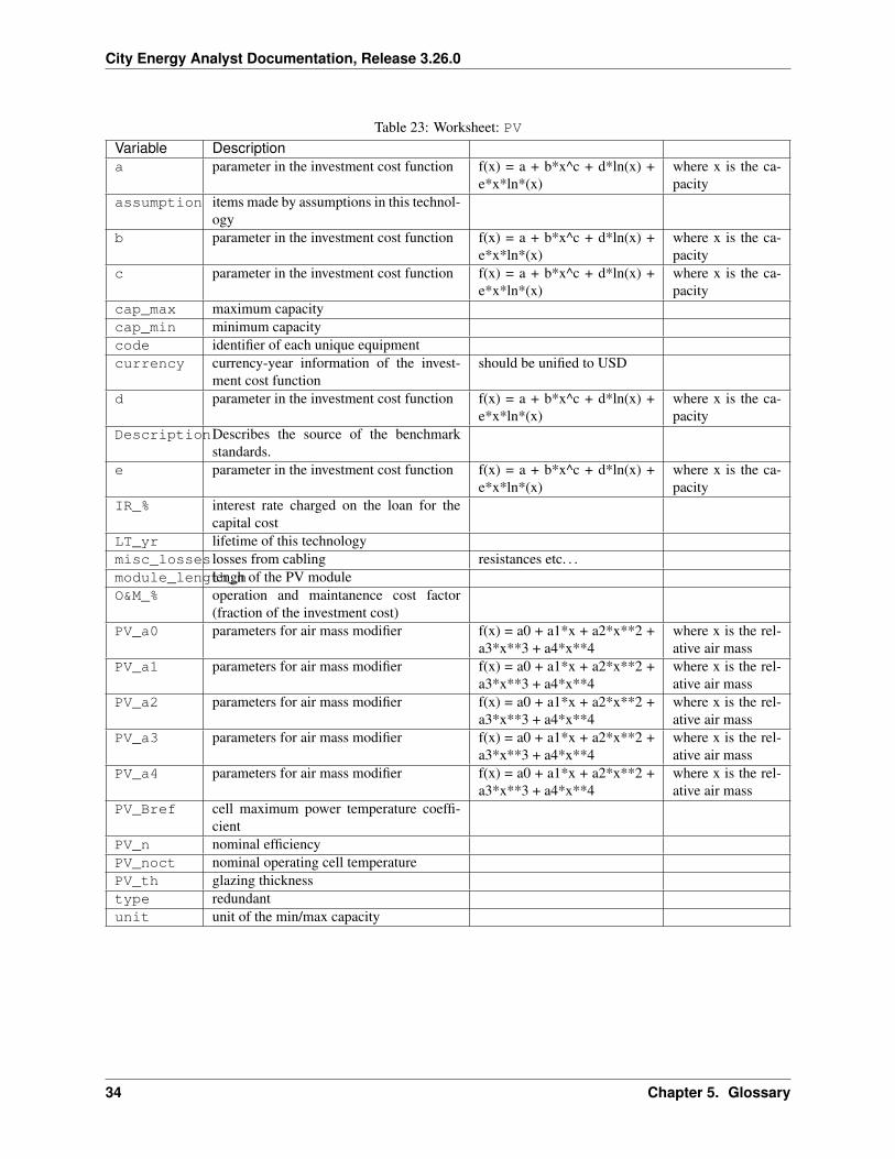
Table 23: Worksheet: PVVariable Descriptiona parameter in the investment cost function f(x) = a + b*x^c + d*ln(x) +
e*x*ln*(x)where x is the ca-pacity
assumption items made by assumptions in this technol-ogy
b parameter in the investment cost function f(x) = a + b*x^c + d*ln(x) +e*x*ln*(x)
where x is the ca-pacity
c parameter in the investment cost function f(x) = a + b*x^c + d*ln(x) +e*x*ln*(x)
where x is the ca-pacity
cap_max maximum capacitycap_min minimum capacitycode identifier of each unique equipmentcurrency currency-year information of the invest-
ment cost functionshould be unified to USD
d parameter in the investment cost function f(x) = a + b*x^c + d*ln(x) +e*x*ln*(x)
where x is the ca-pacity
DescriptionDescribes the source of the benchmarkstandards.
e parameter in the investment cost function f(x) = a + b*x^c + d*ln(x) +e*x*ln*(x)
where x is the ca-pacity
IR_% interest rate charged on the loan for thecapital cost
LT_yr lifetime of this technologymisc_losses losses from cabling resistances etc. . .module_length_mlengh of the PV moduleO&M_% operation and maintanence cost factor
(fraction of the investment cost)PV_a0 parameters for air mass modifier f(x) = a0 + a1*x + a2*x**2 +
a3*x**3 + a4*x**4where x is the rel-ative air mass
PV_a1 parameters for air mass modifier f(x) = a0 + a1*x + a2*x**2 +a3*x**3 + a4*x**4
where x is the rel-ative air mass
PV_a2 parameters for air mass modifier f(x) = a0 + a1*x + a2*x**2 +a3*x**3 + a4*x**4
where x is the rel-ative air mass
PV_a3 parameters for air mass modifier f(x) = a0 + a1*x + a2*x**2 +a3*x**3 + a4*x**4
where x is the rel-ative air mass
PV_a4 parameters for air mass modifier f(x) = a0 + a1*x + a2*x**2 +a3*x**3 + a4*x**4
where x is the rel-ative air mass
PV_Bref cell maximum power temperature coeffi-cient
PV_n nominal efficiencyPV_noct nominal operating cell temperaturePV_th glazing thicknesstype redundantunit unit of the min/max capacity
34 Chapter 5. Glossary
City Energy Analyst Documentation, Release 3.26.0
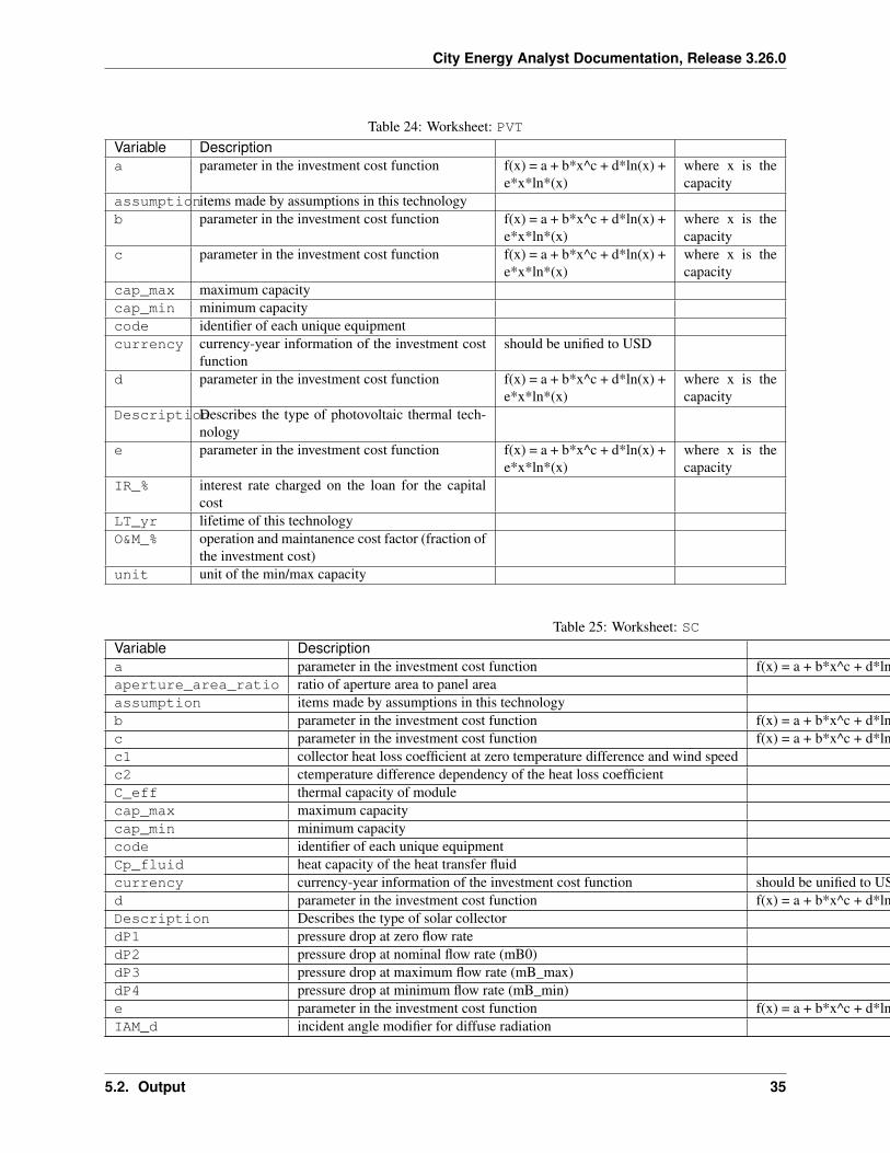
Table 24: Worksheet: PVTVariable Descriptiona parameter in the investment cost function f(x) = a + b*x^c + d*ln(x) +
e*x*ln*(x)where x is thecapacity
assumptionitems made by assumptions in this technologyb parameter in the investment cost function f(x) = a + b*x^c + d*ln(x) +
e*x*ln*(x)where x is thecapacity
c parameter in the investment cost function f(x) = a + b*x^c + d*ln(x) +e*x*ln*(x)
where x is thecapacity
cap_max maximum capacitycap_min minimum capacitycode identifier of each unique equipmentcurrency currency-year information of the investment cost
functionshould be unified to USD
d parameter in the investment cost function f(x) = a + b*x^c + d*ln(x) +e*x*ln*(x)
where x is thecapacity
DescriptionDescribes the type of photovoltaic thermal tech-nology
e parameter in the investment cost function f(x) = a + b*x^c + d*ln(x) +e*x*ln*(x)
where x is thecapacity
IR_% interest rate charged on the loan for the capitalcost
LT_yr lifetime of this technologyO&M_% operation and maintanence cost factor (fraction of
the investment cost)unit unit of the min/max capacity
Table 25: Worksheet: SCVariable Descriptiona parameter in the investment cost function f(x) = a + b*x^c + d*ln(x) + e*x*ln*(x) where x is the capacityaperture_area_ratio ratio of aperture area to panel areaassumption items made by assumptions in this technologyb parameter in the investment cost function f(x) = a + b*x^c + d*ln(x) + e*x*ln*(x) where x is the capacityc parameter in the investment cost function f(x) = a + b*x^c + d*ln(x) + e*x*ln*(x) where x is the capacityc1 collector heat loss coefficient at zero temperature difference and wind speedc2 ctemperature difference dependency of the heat loss coefficientC_eff thermal capacity of modulecap_max maximum capacitycap_min minimum capacitycode identifier of each unique equipmentCp_fluid heat capacity of the heat transfer fluidcurrency currency-year information of the investment cost function should be unified to USDd parameter in the investment cost function f(x) = a + b*x^c + d*ln(x) + e*x*ln*(x) where x is the capacityDescription Describes the type of solar collectordP1 pressure drop at zero flow ratedP2 pressure drop at nominal flow rate (mB0)dP3 pressure drop at maximum flow rate (mB_max)dP4 pressure drop at minimum flow rate (mB_min)e parameter in the investment cost function f(x) = a + b*x^c + d*ln(x) + e*x*ln*(x) where x is the capacityIAM_d incident angle modifier for diffuse radiation
Continued on next page
5.2. Output 35
City Energy Analyst Documentation, Release 3.26.0
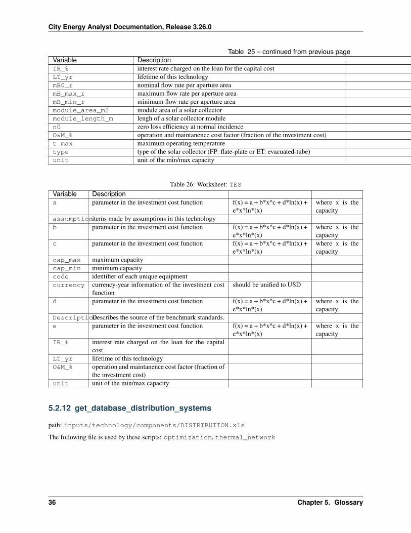
Table 25 – continued from previous pageVariable DescriptionIR_% interest rate charged on the loan for the capital costLT_yr lifetime of this technologymB0_r nominal flow rate per aperture areamB_max_r maximum flow rate per aperture areamB_min_r minimum flow rate per aperture areamodule_area_m2 module area of a solar collectormodule_length_m lengh of a solar collector modulen0 zero loss efficiency at normal incidenceO&M_% operation and maintanence cost factor (fraction of the investment cost)t_max maximum operating temperaturetype type of the solar collector (FP: flate-plate or ET: evacuated-tube)unit unit of the min/max capacity
Table 26: Worksheet: TESVariable Descriptiona parameter in the investment cost function f(x) = a + b*x^c + d*ln(x) +
e*x*ln*(x)where x is thecapacity
assumptionitems made by assumptions in this technologyb parameter in the investment cost function f(x) = a + b*x^c + d*ln(x) +
e*x*ln*(x)where x is thecapacity
c parameter in the investment cost function f(x) = a + b*x^c + d*ln(x) +e*x*ln*(x)
where x is thecapacity
cap_max maximum capacitycap_min minimum capacitycode identifier of each unique equipmentcurrency currency-year information of the investment cost
functionshould be unified to USD
d parameter in the investment cost function f(x) = a + b*x^c + d*ln(x) +e*x*ln*(x)
where x is thecapacity
DescriptionDescribes the source of the benchmark standards.e parameter in the investment cost function f(x) = a + b*x^c + d*ln(x) +
e*x*ln*(x)where x is thecapacity
IR_% interest rate charged on the loan for the capitalcost
LT_yr lifetime of this technologyO&M_% operation and maintanence cost factor (fraction of
the investment cost)unit unit of the min/max capacity
5.2.12 get_database_distribution_systems
path: inputs/technology/components/DISTRIBUTION.xls
The following file is used by these scripts: optimization, thermal_network
36 Chapter 5. Glossary
City Energy Analyst Documentation, Release 3.26.0
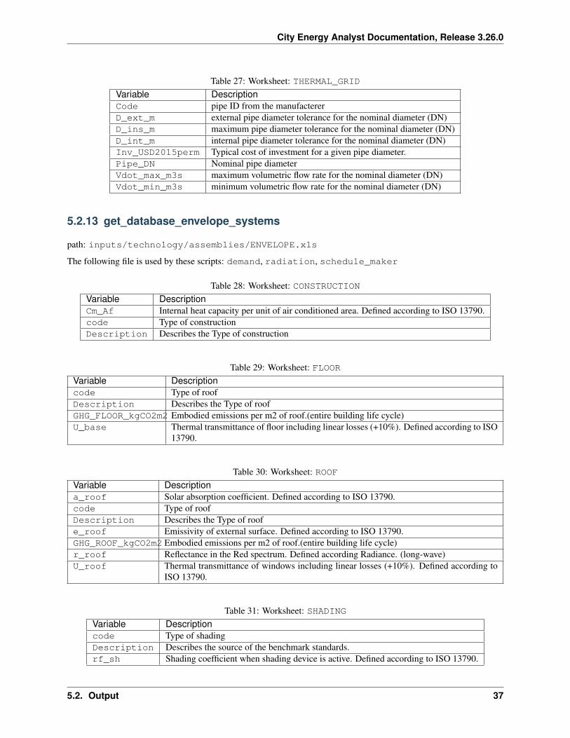
Table 27: Worksheet: THERMAL_GRIDVariable DescriptionCode pipe ID from the manufactererD_ext_m external pipe diameter tolerance for the nominal diameter (DN)D_ins_m maximum pipe diameter tolerance for the nominal diameter (DN)D_int_m internal pipe diameter tolerance for the nominal diameter (DN)Inv_USD2015perm Typical cost of investment for a given pipe diameter.Pipe_DN Nominal pipe diameterVdot_max_m3s maximum volumetric flow rate for the nominal diameter (DN)Vdot_min_m3s minimum volumetric flow rate for the nominal diameter (DN)
5.2.13 get_database_envelope_systems
path: inputs/technology/assemblies/ENVELOPE.xls
The following file is used by these scripts: demand, radiation, schedule_maker
Table 28: Worksheet: CONSTRUCTIONVariable DescriptionCm_Af Internal heat capacity per unit of air conditioned area. Defined according to ISO 13790.code Type of constructionDescription Describes the Type of construction
Table 29: Worksheet: FLOORVariable Descriptioncode Type of roofDescription Describes the Type of roofGHG_FLOOR_kgCO2m2 Embodied emissions per m2 of roof.(entire building life cycle)U_base Thermal transmittance of floor including linear losses (+10%). Defined according to ISO
13790.
Table 30: Worksheet: ROOFVariable Descriptiona_roof Solar absorption coefficient. Defined according to ISO 13790.code Type of roofDescription Describes the Type of roofe_roof Emissivity of external surface. Defined according to ISO 13790.GHG_ROOF_kgCO2m2 Embodied emissions per m2 of roof.(entire building life cycle)r_roof Reflectance in the Red spectrum. Defined according Radiance. (long-wave)U_roof Thermal transmittance of windows including linear losses (+10%). Defined according to
ISO 13790.
Table 31: Worksheet: SHADINGVariable Descriptioncode Type of shadingDescription Describes the source of the benchmark standards.rf_sh Shading coefficient when shading device is active. Defined according to ISO 13790.
5.2. Output 37
City Energy Analyst Documentation, Release 3.26.0
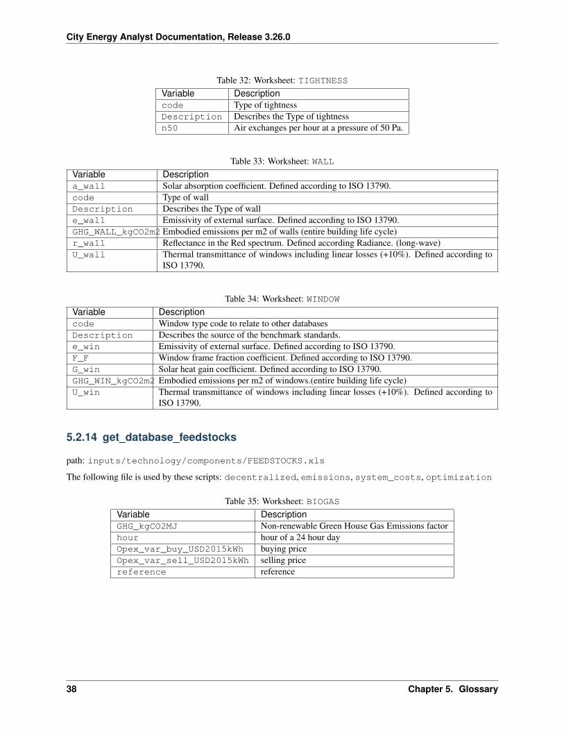
Table 32: Worksheet: TIGHTNESSVariable Descriptioncode Type of tightnessDescription Describes the Type of tightnessn50 Air exchanges per hour at a pressure of 50 Pa.
Table 33: Worksheet: WALLVariable Descriptiona_wall Solar absorption coefficient. Defined according to ISO 13790.code Type of wallDescription Describes the Type of walle_wall Emissivity of external surface. Defined according to ISO 13790.GHG_WALL_kgCO2m2 Embodied emissions per m2 of walls (entire building life cycle)r_wall Reflectance in the Red spectrum. Defined according Radiance. (long-wave)U_wall Thermal transmittance of windows including linear losses (+10%). Defined according to
ISO 13790.
Table 34: Worksheet: WINDOWVariable Descriptioncode Window type code to relate to other databasesDescription Describes the source of the benchmark standards.e_win Emissivity of external surface. Defined according to ISO 13790.F_F Window frame fraction coefficient. Defined according to ISO 13790.G_win Solar heat gain coefficient. Defined according to ISO 13790.GHG_WIN_kgCO2m2 Embodied emissions per m2 of windows.(entire building life cycle)U_win Thermal transmittance of windows including linear losses (+10%). Defined according to
ISO 13790.
5.2.14 get_database_feedstocks
path: inputs/technology/components/FEEDSTOCKS.xls
The following file is used by these scripts: decentralized, emissions, system_costs, optimization
Table 35: Worksheet: BIOGASVariable DescriptionGHG_kgCO2MJ Non-renewable Green House Gas Emissions factorhour hour of a 24 hour dayOpex_var_buy_USD2015kWh buying priceOpex_var_sell_USD2015kWh selling pricereference reference
38 Chapter 5. Glossary
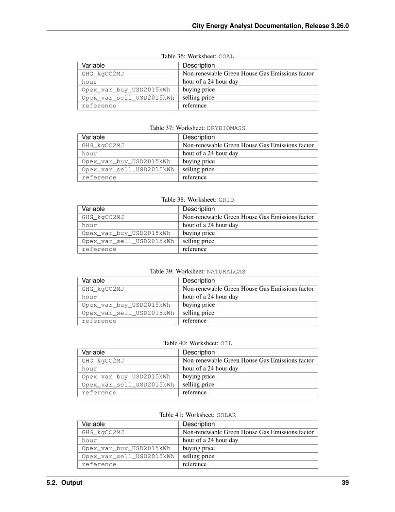
City Energy Analyst Documentation, Release 3.26.0
Table 36: Worksheet: COALVariable DescriptionGHG_kgCO2MJ Non-renewable Green House Gas Emissions factorhour hour of a 24 hour dayOpex_var_buy_USD2015kWh buying priceOpex_var_sell_USD2015kWh selling pricereference reference
Table 37: Worksheet: DRYBIOMASSVariable DescriptionGHG_kgCO2MJ Non-renewable Green House Gas Emissions factorhour hour of a 24 hour dayOpex_var_buy_USD2015kWh buying priceOpex_var_sell_USD2015kWh selling pricereference reference
Table 38: Worksheet: GRIDVariable DescriptionGHG_kgCO2MJ Non-renewable Green House Gas Emissions factorhour hour of a 24 hour dayOpex_var_buy_USD2015kWh buying priceOpex_var_sell_USD2015kWh selling pricereference reference
Table 39: Worksheet: NATURALGASVariable DescriptionGHG_kgCO2MJ Non-renewable Green House Gas Emissions factorhour hour of a 24 hour dayOpex_var_buy_USD2015kWh buying priceOpex_var_sell_USD2015kWh selling pricereference reference
Table 40: Worksheet: OILVariable DescriptionGHG_kgCO2MJ Non-renewable Green House Gas Emissions factorhour hour of a 24 hour dayOpex_var_buy_USD2015kWh buying priceOpex_var_sell_USD2015kWh selling pricereference reference
Table 41: Worksheet: SOLARVariable DescriptionGHG_kgCO2MJ Non-renewable Green House Gas Emissions factorhour hour of a 24 hour dayOpex_var_buy_USD2015kWh buying priceOpex_var_sell_USD2015kWh selling pricereference reference
5.2. Output 39
City Energy Analyst Documentation, Release 3.26.0
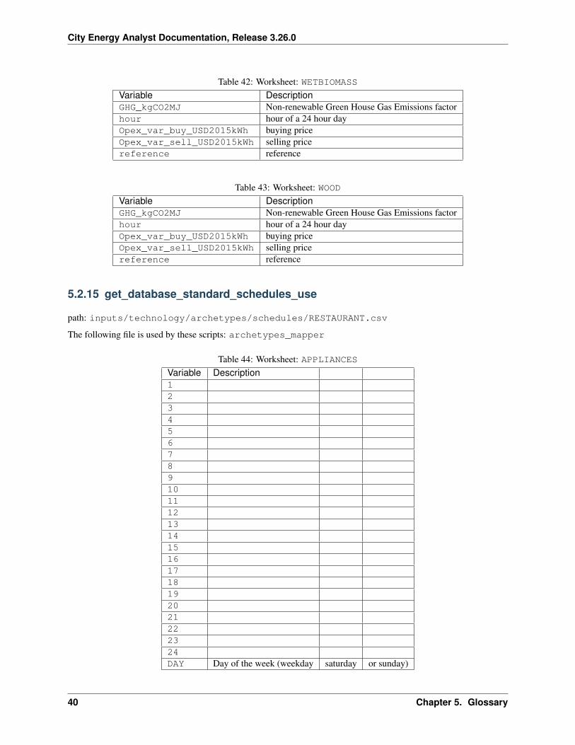
Table 42: Worksheet: WETBIOMASSVariable DescriptionGHG_kgCO2MJ Non-renewable Green House Gas Emissions factorhour hour of a 24 hour dayOpex_var_buy_USD2015kWh buying priceOpex_var_sell_USD2015kWh selling pricereference reference
Table 43: Worksheet: WOODVariable DescriptionGHG_kgCO2MJ Non-renewable Green House Gas Emissions factorhour hour of a 24 hour dayOpex_var_buy_USD2015kWh buying priceOpex_var_sell_USD2015kWh selling pricereference reference
5.2.15 get_database_standard_schedules_use
path: inputs/technology/archetypes/schedules/RESTAURANT.csv
The following file is used by these scripts: archetypes_mapper
Table 44: Worksheet: APPLIANCESVariable Description123456789101112131415161718192021222324DAY Day of the week (weekday saturday or sunday)
40 Chapter 5. Glossary

City Energy Analyst Documentation, Release 3.26.0
Table 45: Worksheet: COOLINGVariable Description123456789101112131415161718192021222324DAY Day of the week (weekday saturday or sunday)
5.2. Output 41
City Energy Analyst Documentation, Release 3.26.0
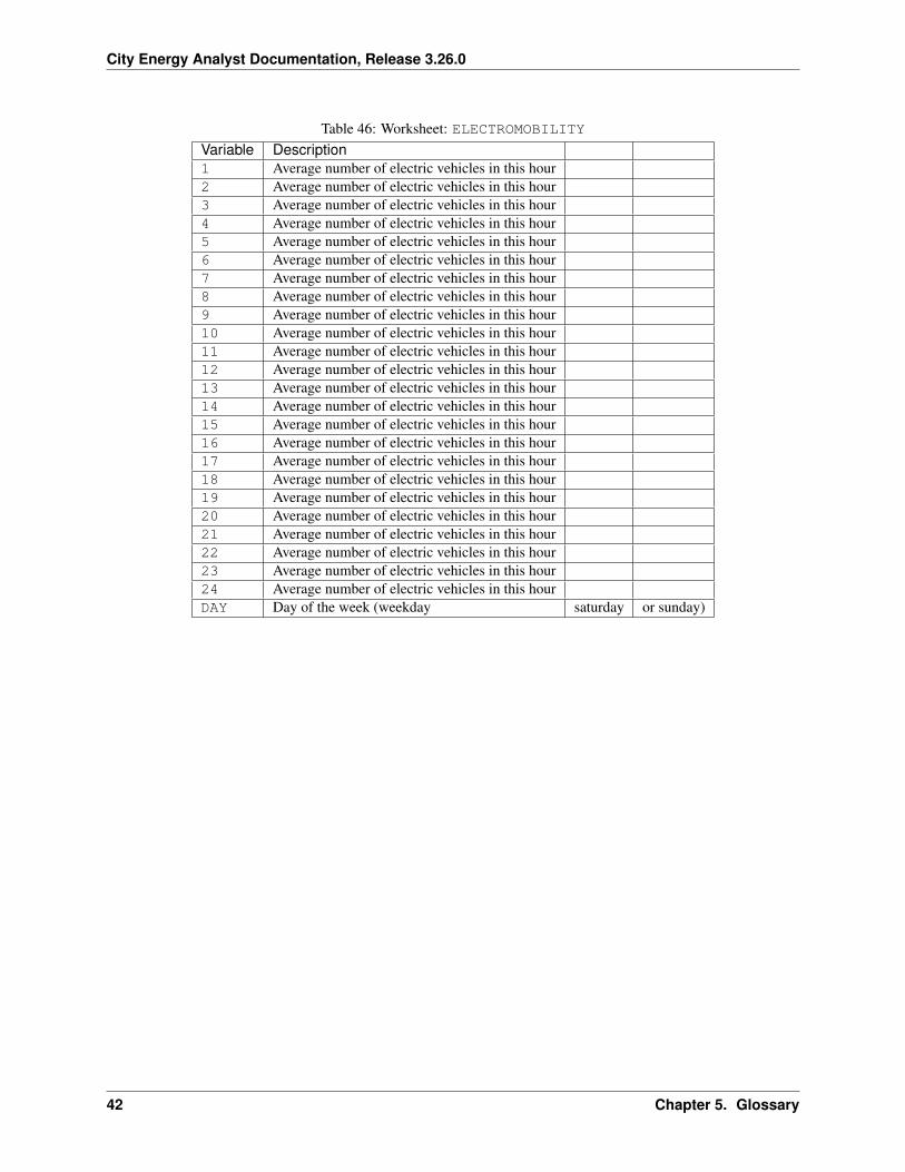
Table 46: Worksheet: ELECTROMOBILITYVariable Description1 Average number of electric vehicles in this hour2 Average number of electric vehicles in this hour3 Average number of electric vehicles in this hour4 Average number of electric vehicles in this hour5 Average number of electric vehicles in this hour6 Average number of electric vehicles in this hour7 Average number of electric vehicles in this hour8 Average number of electric vehicles in this hour9 Average number of electric vehicles in this hour10 Average number of electric vehicles in this hour11 Average number of electric vehicles in this hour12 Average number of electric vehicles in this hour13 Average number of electric vehicles in this hour14 Average number of electric vehicles in this hour15 Average number of electric vehicles in this hour16 Average number of electric vehicles in this hour17 Average number of electric vehicles in this hour18 Average number of electric vehicles in this hour19 Average number of electric vehicles in this hour20 Average number of electric vehicles in this hour21 Average number of electric vehicles in this hour22 Average number of electric vehicles in this hour23 Average number of electric vehicles in this hour24 Average number of electric vehicles in this hourDAY Day of the week (weekday saturday or sunday)
42 Chapter 5. Glossary

City Energy Analyst Documentation, Release 3.26.0
Table 47: Worksheet: HEATINGVariable Description123456789101112131415161718192021222324DAY Day of the week (weekday saturday or sunday)
5.2. Output 43
City Energy Analyst Documentation, Release 3.26.0
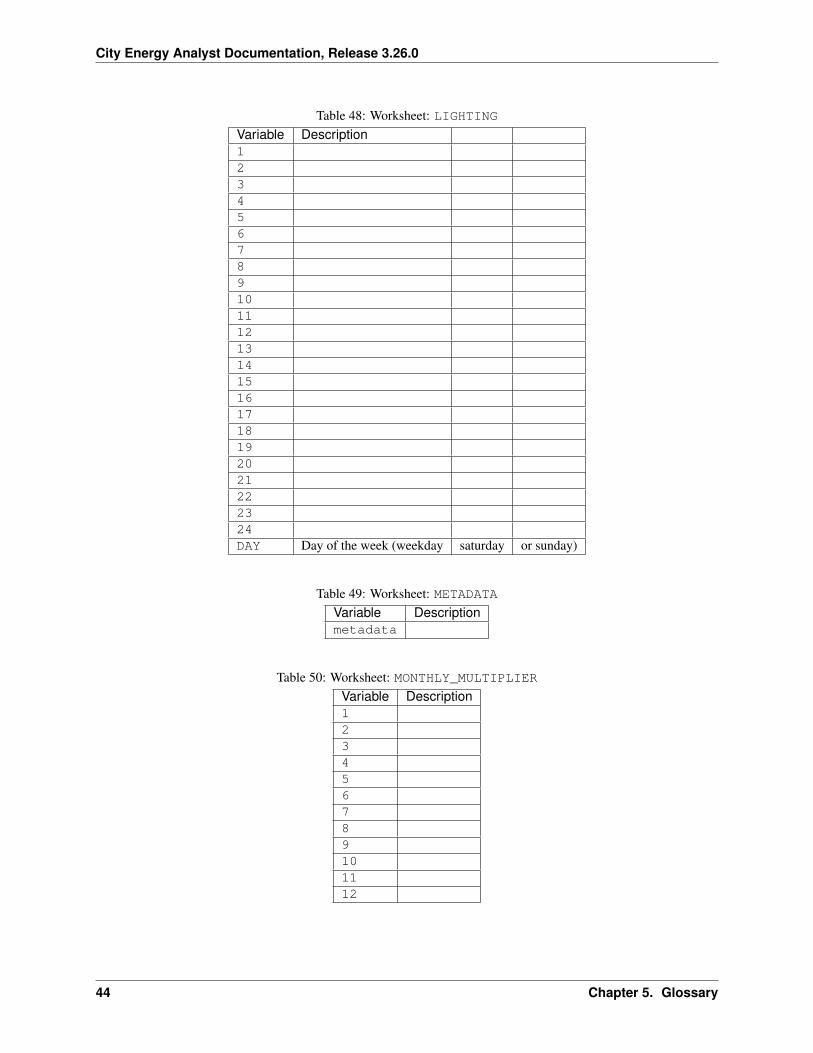
Table 48: Worksheet: LIGHTINGVariable Description123456789101112131415161718192021222324DAY Day of the week (weekday saturday or sunday)
Table 49: Worksheet: METADATAVariable Descriptionmetadata
Table 50: Worksheet: MONTHLY_MULTIPLIERVariable Description123456789101112
44 Chapter 5. Glossary
City Energy Analyst Documentation, Release 3.26.0
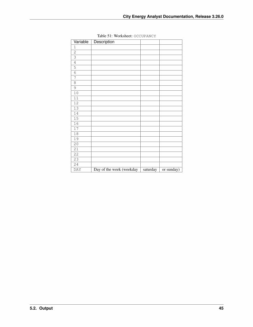
Table 51: Worksheet: OCCUPANCYVariable Description123456789101112131415161718192021222324DAY Day of the week (weekday saturday or sunday)
5.2. Output 45
City Energy Analyst Documentation, Release 3.26.0
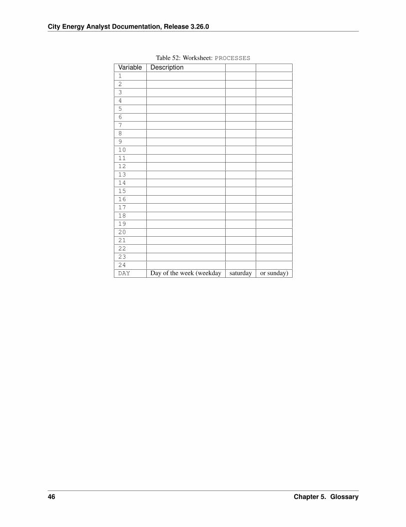
Table 52: Worksheet: PROCESSESVariable Description123456789101112131415161718192021222324DAY Day of the week (weekday saturday or sunday)
46 Chapter 5. Glossary
City Energy Analyst Documentation, Release 3.26.0
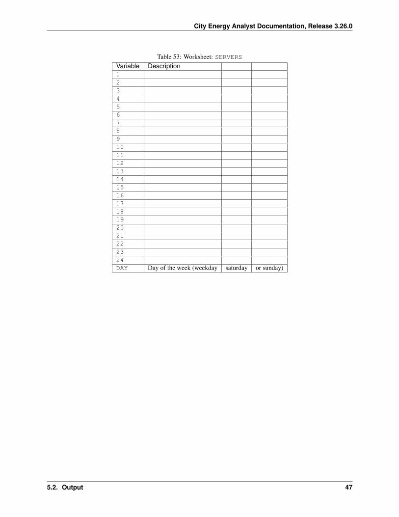
Table 53: Worksheet: SERVERSVariable Description123456789101112131415161718192021222324DAY Day of the week (weekday saturday or sunday)
5.2. Output 47
City Energy Analyst Documentation, Release 3.26.0
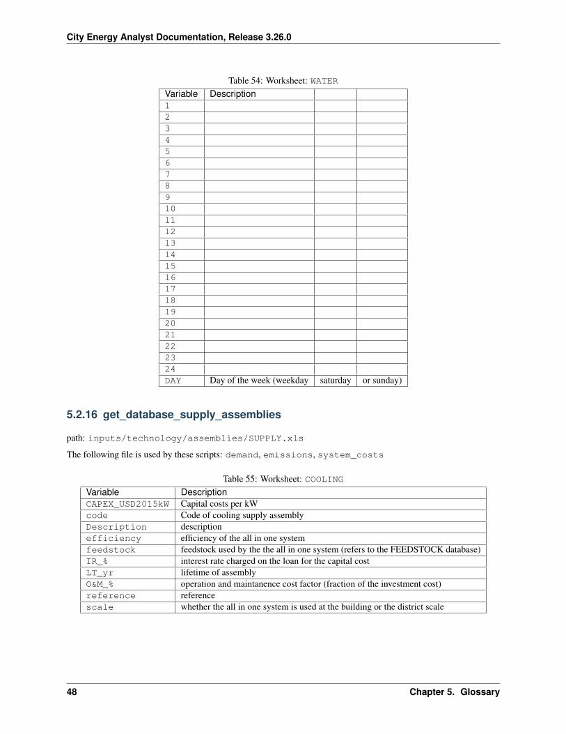
Table 54: Worksheet: WATERVariable Description123456789101112131415161718192021222324DAY Day of the week (weekday saturday or sunday)
5.2.16 get_database_supply_assemblies
path: inputs/technology/assemblies/SUPPLY.xls
The following file is used by these scripts: demand, emissions, system_costs
Table 55: Worksheet: COOLINGVariable DescriptionCAPEX_USD2015kW Capital costs per kWcode Code of cooling supply assemblyDescription descriptionefficiency efficiency of the all in one systemfeedstock feedstock used by the the all in one system (refers to the FEEDSTOCK database)IR_% interest rate charged on the loan for the capital costLT_yr lifetime of assemblyO&M_% operation and maintanence cost factor (fraction of the investment cost)reference referencescale whether the all in one system is used at the building or the district scale
48 Chapter 5. Glossary
City Energy Analyst Documentation, Release 3.26.0
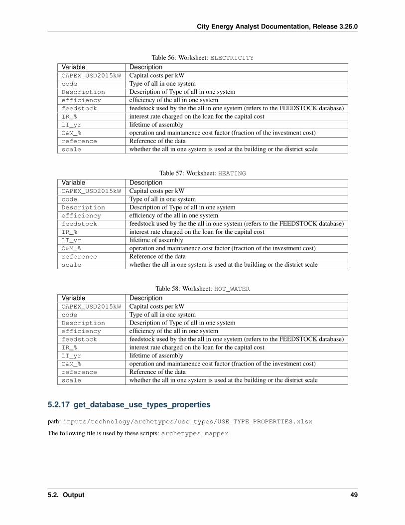
Table 56: Worksheet: ELECTRICITYVariable DescriptionCAPEX_USD2015kW Capital costs per kWcode Type of all in one systemDescription Description of Type of all in one systemefficiency efficiency of the all in one systemfeedstock feedstock used by the the all in one system (refers to the FEEDSTOCK database)IR_% interest rate charged on the loan for the capital costLT_yr lifetime of assemblyO&M_% operation and maintanence cost factor (fraction of the investment cost)reference Reference of the datascale whether the all in one system is used at the building or the district scale
Table 57: Worksheet: HEATINGVariable DescriptionCAPEX_USD2015kW Capital costs per kWcode Type of all in one systemDescription Description of Type of all in one systemefficiency efficiency of the all in one systemfeedstock feedstock used by the the all in one system (refers to the FEEDSTOCK database)IR_% interest rate charged on the loan for the capital costLT_yr lifetime of assemblyO&M_% operation and maintanence cost factor (fraction of the investment cost)reference Reference of the datascale whether the all in one system is used at the building or the district scale
Table 58: Worksheet: HOT_WATERVariable DescriptionCAPEX_USD2015kW Capital costs per kWcode Type of all in one systemDescription Description of Type of all in one systemefficiency efficiency of the all in one systemfeedstock feedstock used by the the all in one system (refers to the FEEDSTOCK database)IR_% interest rate charged on the loan for the capital costLT_yr lifetime of assemblyO&M_% operation and maintanence cost factor (fraction of the investment cost)reference Reference of the datascale whether the all in one system is used at the building or the district scale
5.2.17 get_database_use_types_properties
path: inputs/technology/archetypes/use_types/USE_TYPE_PROPERTIES.xlsx
The following file is used by these scripts: archetypes_mapper
5.2. Output 49
City Energy Analyst Documentation, Release 3.26.0
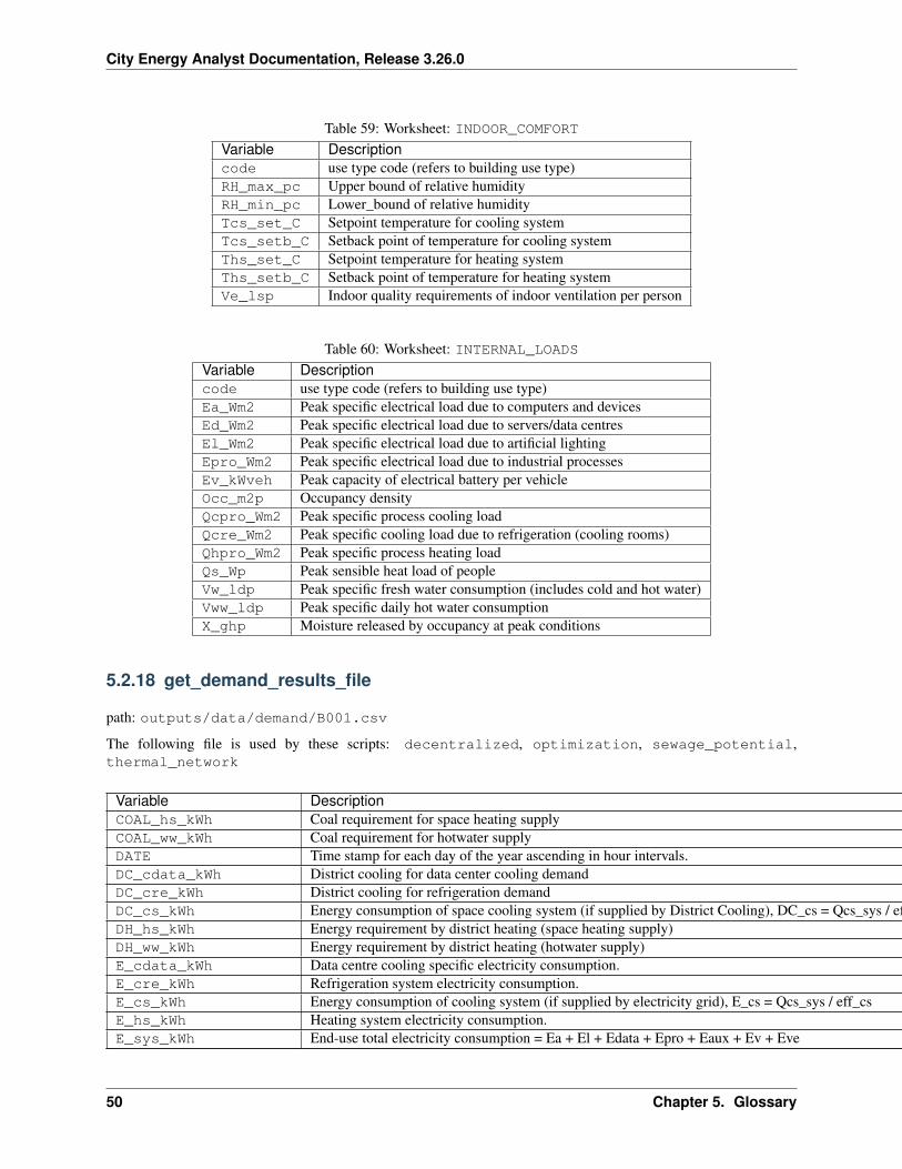
Table 59: Worksheet: INDOOR_COMFORTVariable Descriptioncode use type code (refers to building use type)RH_max_pc Upper bound of relative humidityRH_min_pc Lower_bound of relative humidityTcs_set_C Setpoint temperature for cooling systemTcs_setb_C Setback point of temperature for cooling systemThs_set_C Setpoint temperature for heating systemThs_setb_C Setback point of temperature for heating systemVe_lsp Indoor quality requirements of indoor ventilation per person
Table 60: Worksheet: INTERNAL_LOADSVariable Descriptioncode use type code (refers to building use type)Ea_Wm2 Peak specific electrical load due to computers and devicesEd_Wm2 Peak specific electrical load due to servers/data centresEl_Wm2 Peak specific electrical load due to artificial lightingEpro_Wm2 Peak specific electrical load due to industrial processesEv_kWveh Peak capacity of electrical battery per vehicleOcc_m2p Occupancy densityQcpro_Wm2 Peak specific process cooling loadQcre_Wm2 Peak specific cooling load due to refrigeration (cooling rooms)Qhpro_Wm2 Peak specific process heating loadQs_Wp Peak sensible heat load of peopleVw_ldp Peak specific fresh water consumption (includes cold and hot water)Vww_ldp Peak specific daily hot water consumptionX_ghp Moisture released by occupancy at peak conditions
5.2.18 get_demand_results_file
path: outputs/data/demand/B001.csv
The following file is used by these scripts: decentralized, optimization, sewage_potential,thermal_network
Variable DescriptionCOAL_hs_kWh Coal requirement for space heating supplyCOAL_ww_kWh Coal requirement for hotwater supplyDATE Time stamp for each day of the year ascending in hour intervals.DC_cdata_kWh District cooling for data center cooling demandDC_cre_kWh District cooling for refrigeration demandDC_cs_kWh Energy consumption of space cooling system (if supplied by District Cooling), DC_cs = Qcs_sys / eff_csDH_hs_kWh Energy requirement by district heating (space heating supply)DH_ww_kWh Energy requirement by district heating (hotwater supply)E_cdata_kWh Data centre cooling specific electricity consumption.E_cre_kWh Refrigeration system electricity consumption.E_cs_kWh Energy consumption of cooling system (if supplied by electricity grid), E_cs = Qcs_sys / eff_csE_hs_kWh Heating system electricity consumption.E_sys_kWh End-use total electricity consumption = Ea + El + Edata + Epro + Eaux + Ev + Eve
Continued on next page
50 Chapter 5. Glossary
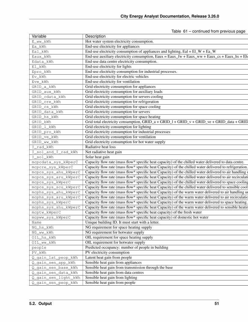
City Energy Analyst Documentation, Release 3.26.0
Table 61 – continued from previous pageVariable DescriptionE_ww_kWh Hot water system electricity consumption.Ea_kWh End-use electricity for appliancesEal_kWh End-use electricity consumption of appliances and lighting, Eal = El_W + Ea_WEaux_kWh End-use auxiliary electricity consumption, Eaux = Eaux_fw + Eaux_ww + Eaux_cs + Eaux_hs + Ehs_lat_auxEdata_kWh End-use data centre electricity consumption.El_kWh End-use electricity for lightsEpro_kWh End-use electricity consumption for industrial processes.Ev_kWh End-use electricity for electric vehiclesEve_kWh End-use electricity for ventilationGRID_a_kWh Grid electricity consumption for appliancesGRID_aux_kWh Grid electricity consumption for auxiliary loadsGRID_cdata_kWh Grid electricity consumption for servers coolingGRID_cre_kWh Grid electricity consumption for refrigerationGRID_cs_kWh Grid electricity consumption for space coolingGRID_data_kWh Grid electricity consumption for serversGRID_hs_kWh Grid electricity consumption for space heatingGRID_kWh Grid total electricity consumption, GRID_a + GRID_l + GRID_v + GRID_ve + GRID_data + GRID_pro + GRID_aux + GRID_ww + GRID_cs + GRID_hs + GRID_cdata + GRID_creGRID_l_kWh Grid electricity consumption for lightingGRID_pro_kWh Grid electricity consumption for industrial processesGRID_ve_kWh Grid electricity consumption for ventilationGRID_ww_kWh Grid electricity consumption for hot water supplyI_rad_kWh Radiative heat lossI_sol_and_I_rad_kWh Net radiative heat gainI_sol_kWh Solar heat gainmcpcdata_sys_kWperC Capacity flow rate (mass flow* specific heat capacity) of the chilled water delivered to data centre.mcpcre_sys_kWperC Capacity flow rate (mass flow* specific heat Capacity) of the chilled water delivered to refrigeration.mcpcs_sys_ahu_kWperC Capacity flow rate (mass flow* specific heat Capacity) of the chilled water delivered to air handling units (space cooling).mcpcs_sys_aru_kWperC Capacity flow rate (mass flow* specific heat Capacity) of the chilled water delivered to air recirculation units (space cooling).mcpcs_sys_kWperC Capacity flow rate (mass flow* specific heat Capacity) of the chilled water delivered to space cooling.mcpcs_sys_scu_kWperC Capacity flow rate (mass flow* specific heat Capacity) of the chilled water delivered to sensible cooling units (space cooling).mcphs_sys_ahu_kWperC Capacity flow rate (mass flow* specific heat Capacity) of the warm water delivered to air handling units (space heating).mcphs_sys_aru_kWperC Capacity flow rate (mass flow* specific heat Capacity) of the warm water delivered to air recirculation units (space heating).mcphs_sys_kWperC Capacity flow rate (mass flow* specific heat Capacity) of the warm water delivered to space heating.mcphs_sys_shu_kWperC Capacity flow rate (mass flow* specific heat Capacity) of the warm water delivered to sensible heating units (space heating).mcptw_kWperC Capacity flow rate (mass flow* specific heat capacity) of the fresh watermcpww_sys_kWperC Capacity flow rate (mass flow* specific heat capacity) of domestic hot waterName Unique building ID. It must start with a letter.NG_hs_kWh NG requirement for space heating supplyNG_ww_kWh NG requirement for hotwater supplyOIL_hs_kWh OIL requirement for space heating supplyOIL_ww_kWh OIL requirement for hotwater supplypeople Predicted occupancy: number of people in buildingPV_kWh PV electricity consumptionQ_gain_lat_peop_kWh Latent heat gain from peopleQ_gain_sen_app_kWh Sensible heat gain from appliancesQ_gain_sen_base_kWh Sensible heat gain from transmission through the baseQ_gain_sen_data_kWh Sensible heat gain from data centresQ_gain_sen_light_kWh Sensible heat gain from lightingQ_gain_sen_peop_kWh Sensible heat gain from people
Continued on next page
5.2. Output 51
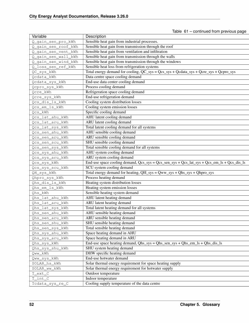
City Energy Analyst Documentation, Release 3.26.0
Table 61 – continued from previous pageVariable DescriptionQ_gain_sen_pro_kWh Sensible heat gain from industrial processes.Q_gain_sen_roof_kWh Sensible heat gain from transmission through the roofQ_gain_sen_vent_kWh Sensible heat gain from ventilation and infiltrationQ_gain_sen_wall_kWh Sensible heat gain from transmission through the wallsQ_gain_sen_wind_kWh Sensible heat gain from transmission through the windowsQ_loss_sen_ref_kWh Sensible heat loss from refrigeration systemsQC_sys_kWh Total energy demand for cooling, QC_sys = Qcs_sys + Qcdata_sys + Qcre_sys + Qcpro_sysQcdata_kWh Data centre space cooling demandQcdata_sys_kWh End-use data center cooling demandQcpro_sys_kWh Process cooling demandQcre_kWh Refrigeration space cooling demandQcre_sys_kWh End-use refrigeration demandQcs_dis_ls_kWh Cooling system distribution lossesQcs_em_ls_kWh Cooling system emission lossesQcs_kWh Specific cooling demandQcs_lat_ahu_kWh AHU latent cooling demandQcs_lat_aru_kWh ARU latent cooling demandQcs_lat_sys_kWh Total latent cooling demand for all systemsQcs_sen_ahu_kWh AHU sensible cooling demandQcs_sen_aru_kWh ARU sensible cooling demandQcs_sen_scu_kWh SHU sensible cooling demandQcs_sen_sys_kWh Total sensible cooling demand for all systemsQcs_sys_ahu_kWh AHU system cooling demandQcs_sys_aru_kWh ARU system cooling demandQcs_sys_kWh End-use space cooling demand, Qcs_sys = Qcs_sen_sys + Qcs_lat_sys + Qcs_em_ls + Qcs_dis_lsQcs_sys_scu_kWh SCU system cooling demandQH_sys_kWh Total energy demand for heating, QH_sys = Qww_sys + Qhs_sys + Qhpro_sysQhpro_sys_kWh Process heating demandQhs_dis_ls_kWh Heating system distribution lossesQhs_em_ls_kWh Heating system emission lossesQhs_kWh Sensible heating system demandQhs_lat_ahu_kWh AHU latent heating demandQhs_lat_aru_kWh ARU latent heating demandQhs_lat_sys_kWh Total latent heating demand for all systemsQhs_sen_ahu_kWh AHU sensible heating demandQhs_sen_aru_kWh ARU sensible heating demandQhs_sen_shu_kWh SHU sensible heating demandQhs_sen_sys_kWh Total sensible heating demandQhs_sys_ahu_kWh Space heating demand in AHUQhs_sys_aru_kWh Space heating demand in ARUQhs_sys_kWh End-use space heating demand, Qhs_sys = Qhs_sen_sys + Qhs_em_ls + Qhs_dis_lsQhs_sys_shu_kWh SHU system heating demandQww_kWh DHW specific heating demandQww_sys_kWh End-use hotwater demandSOLAR_hs_kWh Solar thermal energy requirement for space heating supplySOLAR_ww_kWh Solar thermal energy requirement for hotwater supplyT_ext_C Outdoor temperatureT_int_C Indoor temperatureTcdata_sys_re_C Cooling supply temperature of the data centre
Continued on next page
52 Chapter 5. Glossary
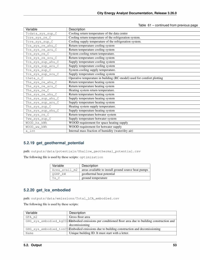
City Energy Analyst Documentation, Release 3.26.0
Table 61 – continued from previous pageVariable DescriptionTcdata_sys_sup_C Cooling return temperature of the data centreTcre_sys_re_C Cooling return temperature of the refrigeration system.Tcre_sys_sup_C Cooling supply temperature of the refrigeration system.Tcs_sys_re_ahu_C Return temperature cooling systemTcs_sys_re_aru_C Return temperature cooling systemTcs_sys_re_C System cooling return temperature.Tcs_sys_re_scu_C Return temperature cooling systemTcs_sys_sup_ahu_C Supply temperature cooling systemTcs_sys_sup_aru_C Supply temperature cooling systemTcs_sys_sup_C System cooling supply temperature.Tcs_sys_sup_scu_C Supply temperature cooling systemtheta_o_C Operative temperature in building (RC-model) used for comfort plottingThs_sys_re_ahu_C Return temperature heating systemThs_sys_re_aru_C Return temperature heating systemThs_sys_re_C Heating system return temperature.Ths_sys_re_shu_C Return temperature heating systemThs_sys_sup_ahu_C Supply temperature heating systemThs_sys_sup_aru_C Supply temperature heating systemThs_sys_sup_C Heating system supply temperature.Ths_sys_sup_shu_C Supply temperature heating systemTww_sys_re_C Return temperature hotwater systemTww_sys_sup_C Supply temperature hotwater systemWOOD_hs_kWh WOOD requirement for space heating supplyWOOD_ww_kWh WOOD requirement for hotwater supplyx_int Internal mass fraction of humidity (water/dry air)
5.2.19 get_geothermal_potential
path: outputs/data/potentials/Shallow_geothermal_potential.csv
The following file is used by these scripts: optimization
Variable DescriptionArea_avail_m2 areas available to install ground source heat pumpsQGHP_kW geothermal heat potentialTs_C ground temperature
5.2.20 get_lca_embodied
path: outputs/data/emissions/Total_LCA_embodied.csv
The following file is used by these scripts:
Variable DescriptionGFA_m2 Gross floor areaGHG_sys_embodied_kgCO2m2Embodied emissions per conditioned floor area due to building construction and
decomissioningGHG_sys_embodied_tonCO2Embodied emissions due to building construction and decomissioningName Unique building ID. It must start with a letter.
5.2. Output 53
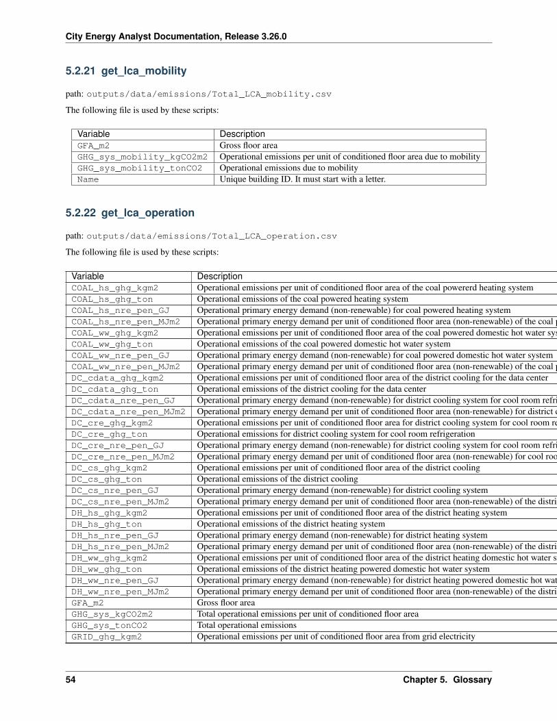
City Energy Analyst Documentation, Release 3.26.0
5.2.21 get_lca_mobility
path: outputs/data/emissions/Total_LCA_mobility.csv
The following file is used by these scripts:
Variable DescriptionGFA_m2 Gross floor areaGHG_sys_mobility_kgCO2m2 Operational emissions per unit of conditioned floor area due to mobilityGHG_sys_mobility_tonCO2 Operational emissions due to mobilityName Unique building ID. It must start with a letter.
5.2.22 get_lca_operation
path: outputs/data/emissions/Total_LCA_operation.csv
The following file is used by these scripts:
Variable DescriptionCOAL_hs_ghg_kgm2 Operational emissions per unit of conditioned floor area of the coal powererd heating systemCOAL_hs_ghg_ton Operational emissions of the coal powered heating systemCOAL_hs_nre_pen_GJ Operational primary energy demand (non-renewable) for coal powered heating systemCOAL_hs_nre_pen_MJm2 Operational primary energy demand per unit of conditioned floor area (non-renewable) of the coal powered heating systemCOAL_ww_ghg_kgm2 Operational emissions per unit of conditioned floor area of the coal powered domestic hot water systemCOAL_ww_ghg_ton Operational emissions of the coal powered domestic hot water systemCOAL_ww_nre_pen_GJ Operational primary energy demand (non-renewable) for coal powered domestic hot water systemCOAL_ww_nre_pen_MJm2 Operational primary energy demand per unit of conditioned floor area (non-renewable) of the coal powered domestic hot water systemDC_cdata_ghg_kgm2 Operational emissions per unit of conditioned floor area of the district cooling for the data centerDC_cdata_ghg_ton Operational emissions of the district cooling for the data centerDC_cdata_nre_pen_GJ Operational primary energy demand (non-renewable) for district cooling system for cool room refrigerationDC_cdata_nre_pen_MJm2 Operational primary energy demand per unit of conditioned floor area (non-renewable) for district cooling for cool room refrigerationDC_cre_ghg_kgm2 Operational emissions per unit of conditioned floor area for district cooling system for cool room refrigerationDC_cre_ghg_ton Operational emissions for district cooling system for cool room refrigerationDC_cre_nre_pen_GJ Operational primary energy demand (non-renewable) for district cooling system for cool room refrigerationDC_cre_nre_pen_MJm2 Operational primary energy demand per unit of conditioned floor area (non-renewable) for cool room refrigerationDC_cs_ghg_kgm2 Operational emissions per unit of conditioned floor area of the district coolingDC_cs_ghg_ton Operational emissions of the district coolingDC_cs_nre_pen_GJ Operational primary energy demand (non-renewable) for district cooling systemDC_cs_nre_pen_MJm2 Operational primary energy demand per unit of conditioned floor area (non-renewable) of the district coolingDH_hs_ghg_kgm2 Operational emissions per unit of conditioned floor area of the district heating systemDH_hs_ghg_ton Operational emissions of the district heating systemDH_hs_nre_pen_GJ Operational primary energy demand (non-renewable) for district heating systemDH_hs_nre_pen_MJm2 Operational primary energy demand per unit of conditioned floor area (non-renewable) of the district heating systemDH_ww_ghg_kgm2 Operational emissions per unit of conditioned floor area of the district heating domestic hot water systemDH_ww_ghg_ton Operational emissions of the district heating powered domestic hot water systemDH_ww_nre_pen_GJ Operational primary energy demand (non-renewable) for district heating powered domestic hot water systemDH_ww_nre_pen_MJm2 Operational primary energy demand per unit of conditioned floor area (non-renewable) of the district heating domestic hot water systemGFA_m2 Gross floor areaGHG_sys_kgCO2m2 Total operational emissions per unit of conditioned floor areaGHG_sys_tonCO2 Total operational emissionsGRID_ghg_kgm2 Operational emissions per unit of conditioned floor area from grid electricity
Continued on next page
54 Chapter 5. Glossary
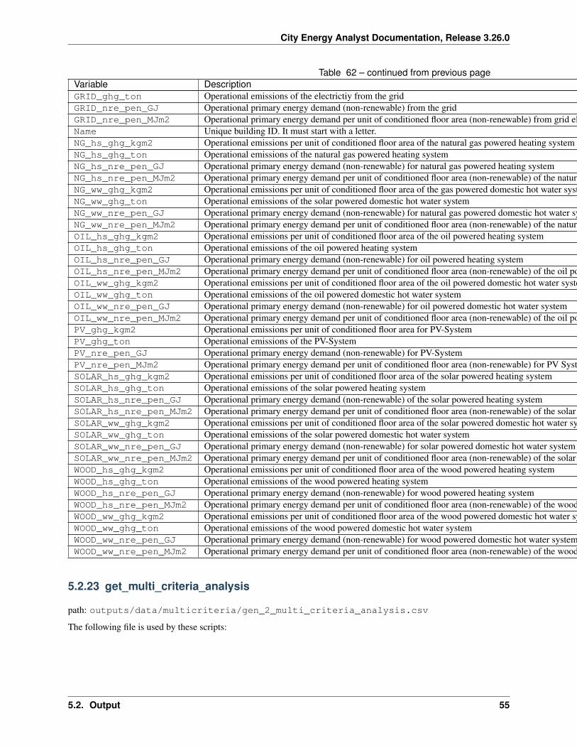
City Energy Analyst Documentation, Release 3.26.0
Table 62 – continued from previous pageVariable DescriptionGRID_ghg_ton Operational emissions of the electrictiy from the gridGRID_nre_pen_GJ Operational primary energy demand (non-renewable) from the gridGRID_nre_pen_MJm2 Operational primary energy demand per unit of conditioned floor area (non-renewable) from grid electricityName Unique building ID. It must start with a letter.NG_hs_ghg_kgm2 Operational emissions per unit of conditioned floor area of the natural gas powered heating systemNG_hs_ghg_ton Operational emissions of the natural gas powered heating systemNG_hs_nre_pen_GJ Operational primary energy demand (non-renewable) for natural gas powered heating systemNG_hs_nre_pen_MJm2 Operational primary energy demand per unit of conditioned floor area (non-renewable) of the natural gas powered heating systemNG_ww_ghg_kgm2 Operational emissions per unit of conditioned floor area of the gas powered domestic hot water systemNG_ww_ghg_ton Operational emissions of the solar powered domestic hot water systemNG_ww_nre_pen_GJ Operational primary energy demand (non-renewable) for natural gas powered domestic hot water systemNG_ww_nre_pen_MJm2 Operational primary energy demand per unit of conditioned floor area (non-renewable) of the natural gas powered domestic hot water systemOIL_hs_ghg_kgm2 Operational emissions per unit of conditioned floor area of the oil powered heating systemOIL_hs_ghg_ton Operational emissions of the oil powered heating systemOIL_hs_nre_pen_GJ Operational primary energy demand (non-renewable) for oil powered heating systemOIL_hs_nre_pen_MJm2 Operational primary energy demand per unit of conditioned floor area (non-renewable) of the oil powered heating systemOIL_ww_ghg_kgm2 Operational emissions per unit of conditioned floor area of the oil powered domestic hot water systemOIL_ww_ghg_ton Operational emissions of the oil powered domestic hot water systemOIL_ww_nre_pen_GJ Operational primary energy demand (non-renewable) for oil powered domestic hot water systemOIL_ww_nre_pen_MJm2 Operational primary energy demand per unit of conditioned floor area (non-renewable) of the oil powered domestic hot water systemPV_ghg_kgm2 Operational emissions per unit of conditioned floor area for PV-SystemPV_ghg_ton Operational emissions of the PV-SystemPV_nre_pen_GJ Operational primary energy demand (non-renewable) for PV-SystemPV_nre_pen_MJm2 Operational primary energy demand per unit of conditioned floor area (non-renewable) for PV SystemSOLAR_hs_ghg_kgm2 Operational emissions per unit of conditioned floor area of the solar powered heating systemSOLAR_hs_ghg_ton Operational emissions of the solar powered heating systemSOLAR_hs_nre_pen_GJ Operational primary energy demand (non-renewable) of the solar powered heating systemSOLAR_hs_nre_pen_MJm2 Operational primary energy demand per unit of conditioned floor area (non-renewable) of the solar powered heating systemSOLAR_ww_ghg_kgm2 Operational emissions per unit of conditioned floor area of the solar powered domestic hot water systemSOLAR_ww_ghg_ton Operational emissions of the solar powered domestic hot water systemSOLAR_ww_nre_pen_GJ Operational primary energy demand (non-renewable) for solar powered domestic hot water systemSOLAR_ww_nre_pen_MJm2 Operational primary energy demand per unit of conditioned floor area (non-renewable) of the solar poweed domestic hot water systemWOOD_hs_ghg_kgm2 Operational emissions per unit of conditioned floor area of the wood powered heating systemWOOD_hs_ghg_ton Operational emissions of the wood powered heating systemWOOD_hs_nre_pen_GJ Operational primary energy demand (non-renewable) for wood powered heating systemWOOD_hs_nre_pen_MJm2 Operational primary energy demand per unit of conditioned floor area (non-renewable) of the wood powered heating systemWOOD_ww_ghg_kgm2 Operational emissions per unit of conditioned floor area of the wood powered domestic hot water systemWOOD_ww_ghg_ton Operational emissions of the wood powered domestic hot water systemWOOD_ww_nre_pen_GJ Operational primary energy demand (non-renewable) for wood powered domestic hot water systemWOOD_ww_nre_pen_MJm2 Operational primary energy demand per unit of conditioned floor area (non-renewable) of the wood powered domestic hot water system
5.2.23 get_multi_criteria_analysis
path: outputs/data/multicriteria/gen_2_multi_criteria_analysis.csv
The following file is used by these scripts:
5.2. Output 55
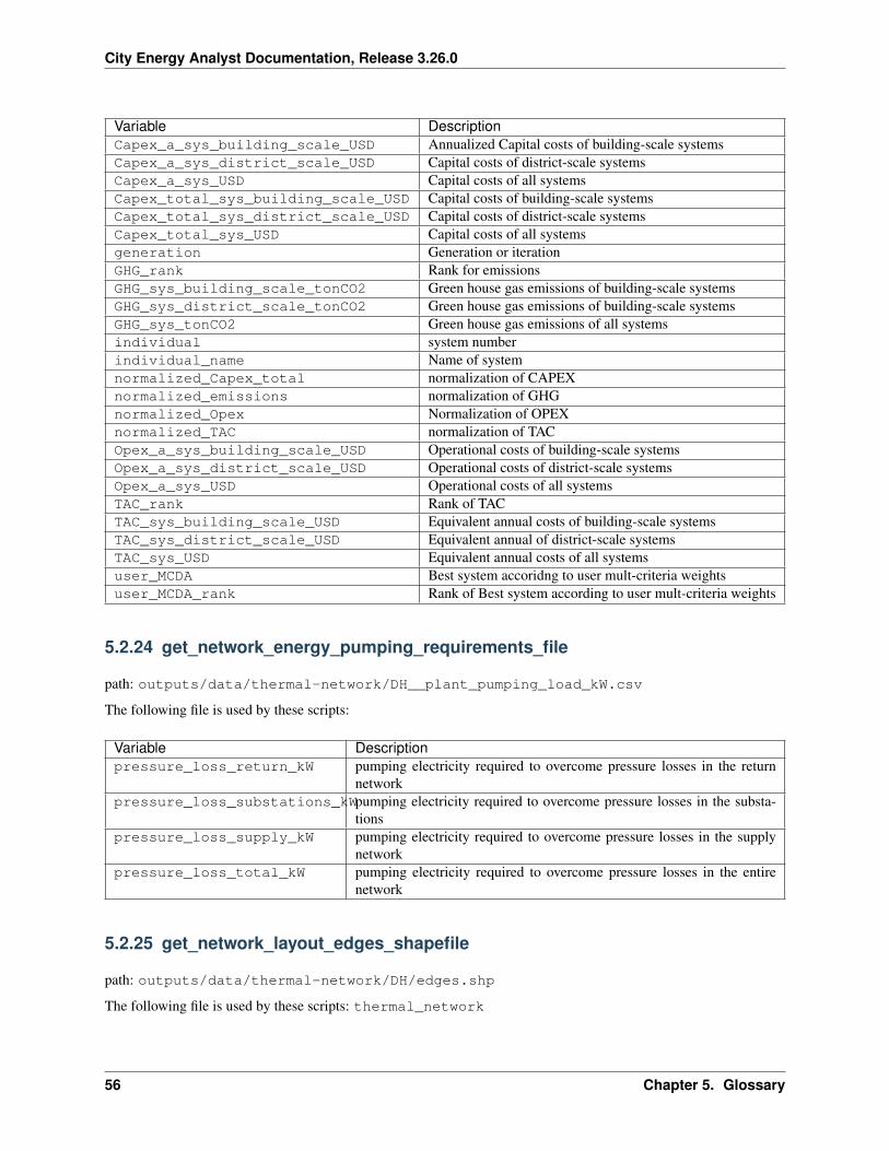
City Energy Analyst Documentation, Release 3.26.0
Variable DescriptionCapex_a_sys_building_scale_USD Annualized Capital costs of building-scale systemsCapex_a_sys_district_scale_USD Capital costs of district-scale systemsCapex_a_sys_USD Capital costs of all systemsCapex_total_sys_building_scale_USD Capital costs of building-scale systemsCapex_total_sys_district_scale_USD Capital costs of district-scale systemsCapex_total_sys_USD Capital costs of all systemsgeneration Generation or iterationGHG_rank Rank for emissionsGHG_sys_building_scale_tonCO2 Green house gas emissions of building-scale systemsGHG_sys_district_scale_tonCO2 Green house gas emissions of building-scale systemsGHG_sys_tonCO2 Green house gas emissions of all systemsindividual system numberindividual_name Name of systemnormalized_Capex_total normalization of CAPEXnormalized_emissions normalization of GHGnormalized_Opex Normalization of OPEXnormalized_TAC normalization of TACOpex_a_sys_building_scale_USD Operational costs of building-scale systemsOpex_a_sys_district_scale_USD Operational costs of district-scale systemsOpex_a_sys_USD Operational costs of all systemsTAC_rank Rank of TACTAC_sys_building_scale_USD Equivalent annual costs of building-scale systemsTAC_sys_district_scale_USD Equivalent annual of district-scale systemsTAC_sys_USD Equivalent annual costs of all systemsuser_MCDA Best system accoridng to user mult-criteria weightsuser_MCDA_rank Rank of Best system according to user mult-criteria weights
5.2.24 get_network_energy_pumping_requirements_file
path: outputs/data/thermal-network/DH__plant_pumping_load_kW.csv
The following file is used by these scripts:
Variable Descriptionpressure_loss_return_kW pumping electricity required to overcome pressure losses in the return
networkpressure_loss_substations_kWpumping electricity required to overcome pressure losses in the substa-
tionspressure_loss_supply_kW pumping electricity required to overcome pressure losses in the supply
networkpressure_loss_total_kW pumping electricity required to overcome pressure losses in the entire
network
5.2.25 get_network_layout_edges_shapefile
path: outputs/data/thermal-network/DH/edges.shp
The following file is used by these scripts: thermal_network
56 Chapter 5. Glossary
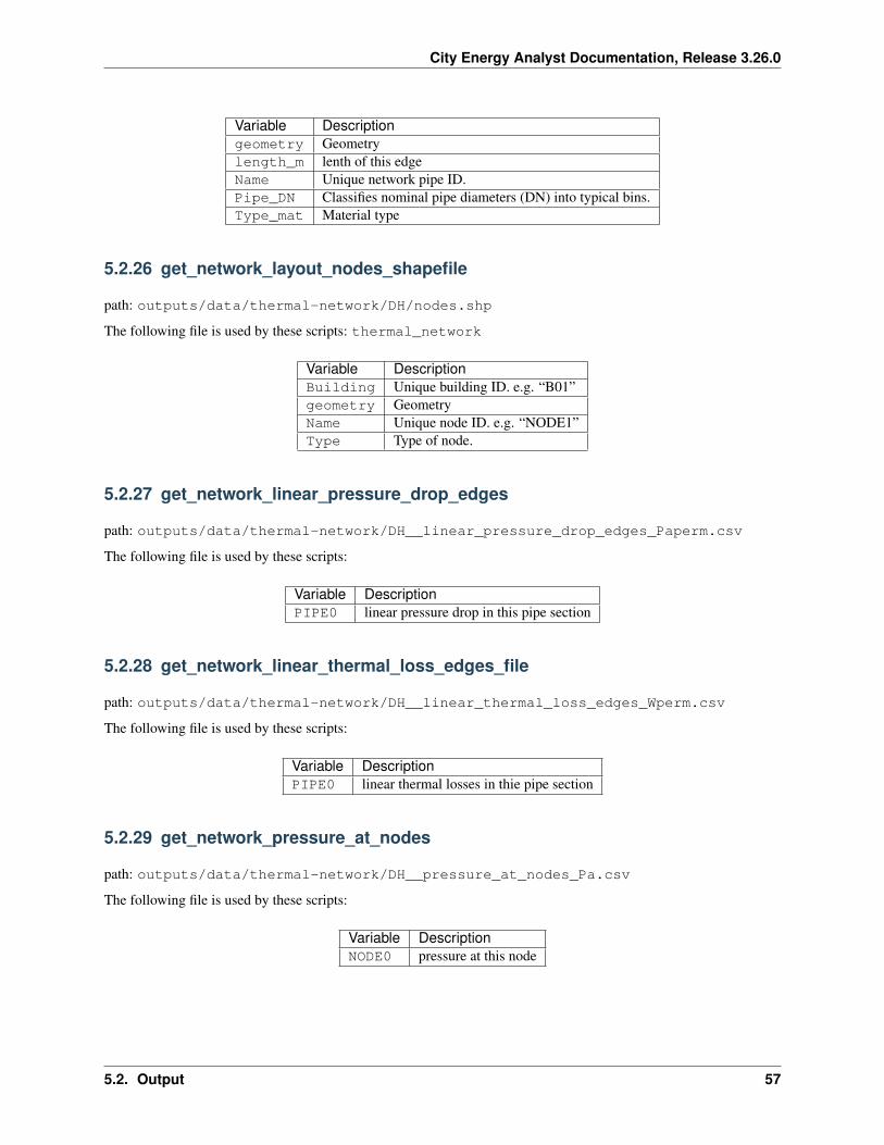
City Energy Analyst Documentation, Release 3.26.0
Variable Descriptiongeometry Geometrylength_m lenth of this edgeName Unique network pipe ID.Pipe_DN Classifies nominal pipe diameters (DN) into typical bins.Type_mat Material type
5.2.26 get_network_layout_nodes_shapefile
path: outputs/data/thermal-network/DH/nodes.shp
The following file is used by these scripts: thermal_network
Variable DescriptionBuilding Unique building ID. e.g. “B01”geometry GeometryName Unique node ID. e.g. “NODE1”Type Type of node.
5.2.27 get_network_linear_pressure_drop_edges
path: outputs/data/thermal-network/DH__linear_pressure_drop_edges_Paperm.csv
The following file is used by these scripts:
Variable DescriptionPIPE0 linear pressure drop in this pipe section
5.2.28 get_network_linear_thermal_loss_edges_file
path: outputs/data/thermal-network/DH__linear_thermal_loss_edges_Wperm.csv
The following file is used by these scripts:
Variable DescriptionPIPE0 linear thermal losses in thie pipe section
5.2.29 get_network_pressure_at_nodes
path: outputs/data/thermal-network/DH__pressure_at_nodes_Pa.csv
The following file is used by these scripts:
Variable DescriptionNODE0 pressure at this node
5.2. Output 57
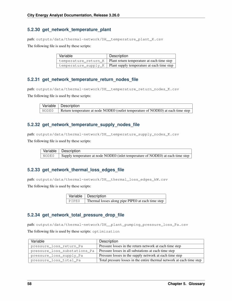
City Energy Analyst Documentation, Release 3.26.0
5.2.30 get_network_temperature_plant
path: outputs/data/thermal-network/DH__temperature_plant_K.csv
The following file is used by these scripts:
Variable Descriptiontemperature_return_K Plant return temperature at each time steptemperature_supply_K Plant supply temperature at each time step
5.2.31 get_network_temperature_return_nodes_file
path: outputs/data/thermal-network/DH__temperature_return_nodes_K.csv
The following file is used by these scripts:
Variable DescriptionNODE0 Return temperature at node NODE0 (outlet temperature of NODE0) at each time step
5.2.32 get_network_temperature_supply_nodes_file
path: outputs/data/thermal-network/DH__temperature_supply_nodes_K.csv
The following file is used by these scripts:
Variable DescriptionNODE0 Supply temperature at node NODE0 (inlet temperature of NODE0) at each time step
5.2.33 get_network_thermal_loss_edges_file
path: outputs/data/thermal-network/DH__thermal_loss_edges_kW.csv
The following file is used by these scripts:
Variable DescriptionPIPE0 Thermal losses along pipe PIPE0 at each time step
5.2.34 get_network_total_pressure_drop_file
path: outputs/data/thermal-network/DH__plant_pumping_pressure_loss_Pa.csv
The following file is used by these scripts: optimization
Variable Descriptionpressure_loss_return_Pa Pressure losses in the return network at each time steppressure_loss_substations_Pa Pressure losses in all substations at each time steppressure_loss_supply_Pa Pressure losses in the supply network at each time steppressure_loss_total_Pa Total pressure losses in the entire thermal network at each time step
58 Chapter 5. Glossary
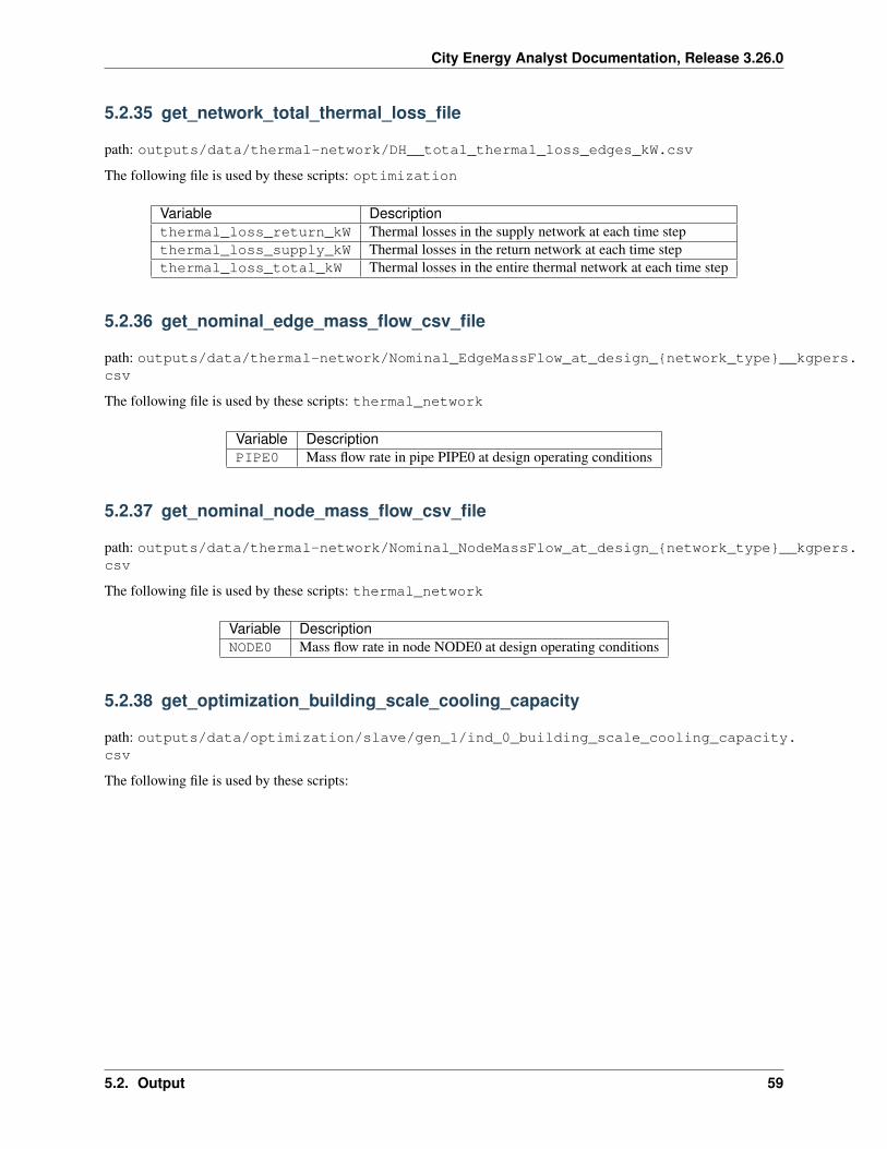
City Energy Analyst Documentation, Release 3.26.0
5.2.35 get_network_total_thermal_loss_file
path: outputs/data/thermal-network/DH__total_thermal_loss_edges_kW.csv
The following file is used by these scripts: optimization
Variable Descriptionthermal_loss_return_kW Thermal losses in the supply network at each time stepthermal_loss_supply_kW Thermal losses in the return network at each time stepthermal_loss_total_kW Thermal losses in the entire thermal network at each time step
5.2.36 get_nominal_edge_mass_flow_csv_file
path: outputs/data/thermal-network/Nominal_EdgeMassFlow_at_design_{network_type}__kgpers.csv
The following file is used by these scripts: thermal_network
Variable DescriptionPIPE0 Mass flow rate in pipe PIPE0 at design operating conditions
5.2.37 get_nominal_node_mass_flow_csv_file
path: outputs/data/thermal-network/Nominal_NodeMassFlow_at_design_{network_type}__kgpers.csv
The following file is used by these scripts: thermal_network
Variable DescriptionNODE0 Mass flow rate in node NODE0 at design operating conditions
5.2.38 get_optimization_building_scale_cooling_capacity
path: outputs/data/optimization/slave/gen_1/ind_0_building_scale_cooling_capacity.csv
The following file is used by these scripts:
5.2. Output 59
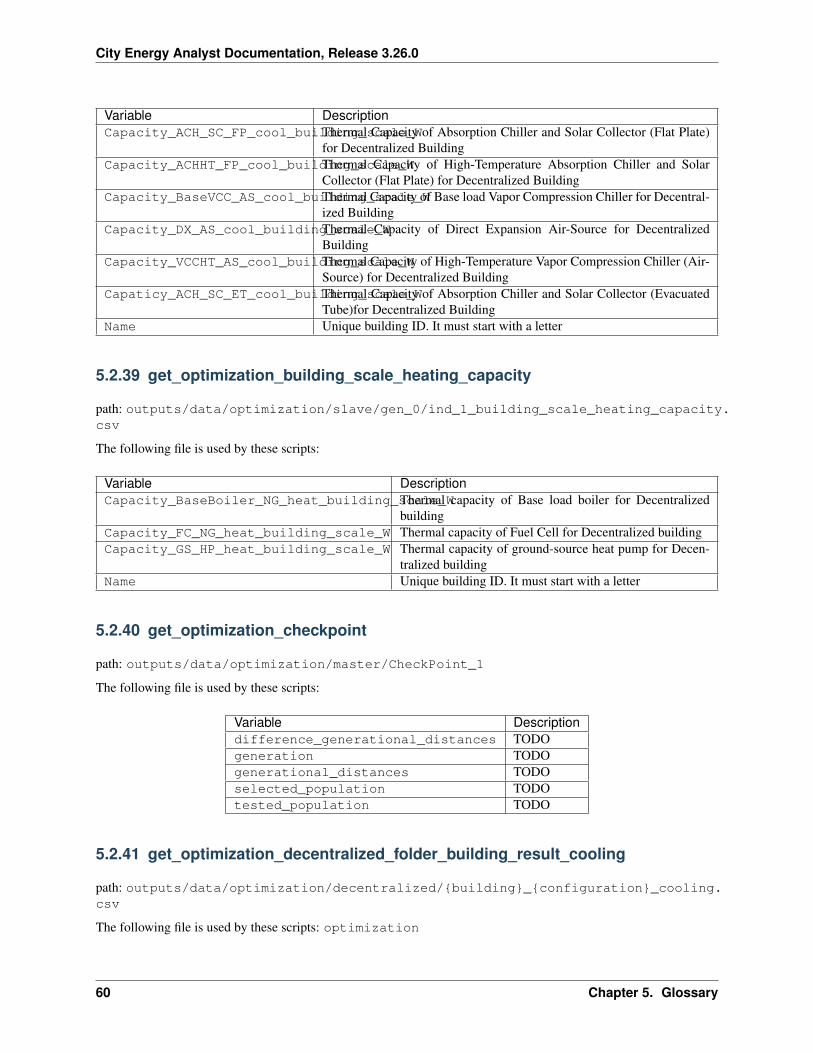
City Energy Analyst Documentation, Release 3.26.0
Variable DescriptionCapacity_ACH_SC_FP_cool_building_scale_WThermal Capacity of Absorption Chiller and Solar Collector (Flat Plate)
for Decentralized BuildingCapacity_ACHHT_FP_cool_building_scale_WThermal Capacity of High-Temperature Absorption Chiller and Solar
Collector (Flat Plate) for Decentralized BuildingCapacity_BaseVCC_AS_cool_building_scale_WThermal Capacity of Base load Vapor Compression Chiller for Decentral-
ized BuildingCapacity_DX_AS_cool_building_scale_WThermal Capacity of Direct Expansion Air-Source for Decentralized
BuildingCapacity_VCCHT_AS_cool_building_scale_WThermal Capacity of High-Temperature Vapor Compression Chiller (Air-
Source) for Decentralized BuildingCapaticy_ACH_SC_ET_cool_building_scale_WThermal Capacity of Absorption Chiller and Solar Collector (Evacuated
Tube)for Decentralized BuildingName Unique building ID. It must start with a letter
5.2.39 get_optimization_building_scale_heating_capacity
path: outputs/data/optimization/slave/gen_0/ind_1_building_scale_heating_capacity.csv
The following file is used by these scripts:
Variable DescriptionCapacity_BaseBoiler_NG_heat_building_scale_WThermal capacity of Base load boiler for Decentralized
buildingCapacity_FC_NG_heat_building_scale_W Thermal capacity of Fuel Cell for Decentralized buildingCapacity_GS_HP_heat_building_scale_W Thermal capacity of ground-source heat pump for Decen-
tralized buildingName Unique building ID. It must start with a letter
5.2.40 get_optimization_checkpoint
path: outputs/data/optimization/master/CheckPoint_1
The following file is used by these scripts:
Variable Descriptiondifference_generational_distances TODOgeneration TODOgenerational_distances TODOselected_population TODOtested_population TODO
5.2.41 get_optimization_decentralized_folder_building_result_cooling
path: outputs/data/optimization/decentralized/{building}_{configuration}_cooling.csv
The following file is used by these scripts: optimization
60 Chapter 5. Glossary
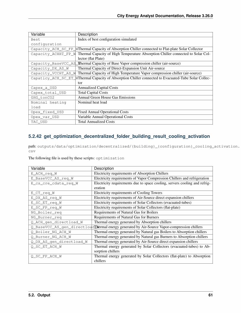
City Energy Analyst Documentation, Release 3.26.0
Variable DescriptionBestconfiguration
Index of best configuration simulated
Capacity_ACH_SC_FP_WThermal Capacity of Absorption Chiller connected to Flat-plate Solar CollectorCapacity_ACHHT_FP_W Thermal Capacity of High Temperature Absorption Chiller connected to Solar Col-
lector (flat Plate)Capacity_BaseVCC_AS_WThermal Capacity of Base Vapor compression chiller (air-source)Capacity_DX_AS_W Thermal Capacity of Direct-Expansion Unit Air-sourceCapacity_VCCHT_AS_W Thermal Capacity of High Temperature Vapor compression chiller (air-source)Capaticy_ACH_SC_ET_WThermal Capacity of Absorption Chiller connected to Evacuated-Tube Solar Collec-
torCapex_a_USD Annualized Capital CostsCapex_total_USD Total Capital CostsGHG_tonCO2 Annual Green House Gas EmissionsNominal heatingload
Nominal heat load
Opex_fixed_USD Fixed Annual Operational CostsOpex_var_USD Variable Annual Operational CostsTAC_USD Total Annualized Costs
5.2.42 get_optimization_decentralized_folder_building_result_cooling_activation
path: outputs/data/optimization/decentralized/{building}_{configuration}_cooling_activation.csv
The following file is used by these scripts: optimization
Variable DescriptionE_ACH_req_W Electricity requirements of Absorption ChillersE_BaseVCC_AS_req_W Electricity requirements of Vapor Compression Chillers and refrigerationE_cs_cre_cdata_req_W Electricity requirements due to space cooling, servers cooling and refrig-
erationE_CT_req_W Electricity requirements of Cooling TowersE_DX_AS_req_W Electricity requirements of Air-Source direct expansion chillersE_SC_ET_req_W Electricity requirements of Solar Collectors (evacuated-tubes)E_SC_FP_req_W Electricity requirements of Solar Collectors (flat-plate)NG_Boiler_req Requirements of Natural Gas for BoilersNG_Burner_req Requirements of Natural Gas for BurnersQ_ACH_gen_directload_W Thermal energy generated by Absorption chillersQ_BaseVCC_AS_gen_directload_WThermal energy generated by Air-Source Vapor-compression chillersQ_Boiler_NG_ACH_W Thermal energy generated by Natural gas Boilers to Absorption chillersQ_Burner_NG_ACH_W Thermal energy generated by Natural gas Burners to Absorption chillersQ_DX_AS_gen_directload_W Thermal energy generated by Air-Source direct expansion chillersQ_SC_ET_ACH_W Thermal energy generated by Solar Collectors (evacuated-tubes) to Ab-
sorption chillersQ_SC_FP_ACH_W Thermal energy generated by Solar Collectors (flat-plate) to Absorption
chillers
5.2. Output 61
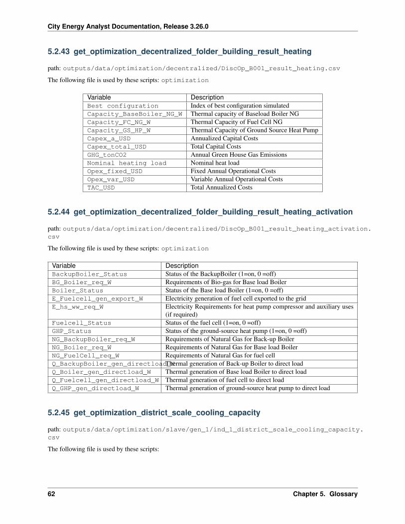
City Energy Analyst Documentation, Release 3.26.0
5.2.43 get_optimization_decentralized_folder_building_result_heating
path: outputs/data/optimization/decentralized/DiscOp_B001_result_heating.csv
The following file is used by these scripts: optimization
Variable DescriptionBest configuration Index of best configuration simulatedCapacity_BaseBoiler_NG_W Thermal capacity of Baseload Boiler NGCapacity_FC_NG_W Thermal Capacity of Fuel Cell NGCapacity_GS_HP_W Thermal Capacity of Ground Source Heat PumpCapex_a_USD Annualized Capital CostsCapex_total_USD Total Capital CostsGHG_tonCO2 Annual Green House Gas EmissionsNominal heating load Nominal heat loadOpex_fixed_USD Fixed Annual Operational CostsOpex_var_USD Variable Annual Operational CostsTAC_USD Total Annualized Costs
5.2.44 get_optimization_decentralized_folder_building_result_heating_activation
path: outputs/data/optimization/decentralized/DiscOp_B001_result_heating_activation.csv
The following file is used by these scripts: optimization
Variable DescriptionBackupBoiler_Status Status of the BackupBoiler (1=on, 0 =off)BG_Boiler_req_W Requirements of Bio-gas for Base load BoilerBoiler_Status Status of the Base load Boiler (1=on, 0 =off)E_Fuelcell_gen_export_W Electricity generation of fuel cell exported to the gridE_hs_ww_req_W Electricity Requirements for heat pump compressor and auxiliary uses
(if required)Fuelcell_Status Status of the fuel cell (1=on, 0 =off)GHP_Status Status of the ground-source heat pump (1=on, 0 =off)NG_BackupBoiler_req_W Requirements of Natural Gas for Back-up BoilerNG_Boiler_req_W Requirements of Natural Gas for Base load BoilerNG_FuelCell_req_W Requirements of Natural Gas for fuel cellQ_BackupBoiler_gen_directload_WThermal generation of Back-up Boiler to direct loadQ_Boiler_gen_directload_W Thermal generation of Base load Boiler to direct loadQ_Fuelcell_gen_directload_W Thermal generation of fuel cell to direct loadQ_GHP_gen_directload_W Thermal generation of ground-source heat pump to direct load
5.2.45 get_optimization_district_scale_cooling_capacity
path: outputs/data/optimization/slave/gen_1/ind_1_district_scale_cooling_capacity.csv
The following file is used by these scripts:
62 Chapter 5. Glossary
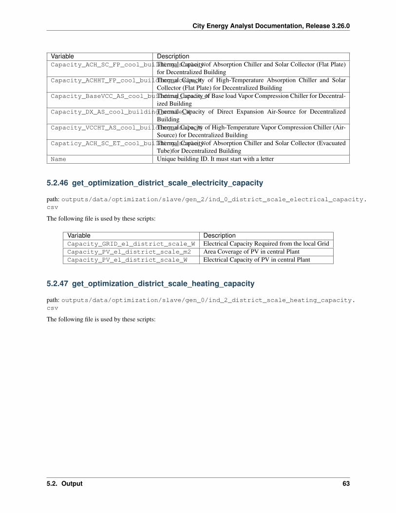
City Energy Analyst Documentation, Release 3.26.0
Variable DescriptionCapacity_ACH_SC_FP_cool_building_scale_WThermal Capacity of Absorption Chiller and Solar Collector (Flat Plate)
for Decentralized BuildingCapacity_ACHHT_FP_cool_building_scale_WThermal Capacity of High-Temperature Absorption Chiller and Solar
Collector (Flat Plate) for Decentralized BuildingCapacity_BaseVCC_AS_cool_building_scale_WThermal Capacity of Base load Vapor Compression Chiller for Decentral-
ized BuildingCapacity_DX_AS_cool_building_scale_WThermal Capacity of Direct Expansion Air-Source for Decentralized
BuildingCapacity_VCCHT_AS_cool_building_scale_WThermal Capacity of High-Temperature Vapor Compression Chiller (Air-
Source) for Decentralized BuildingCapaticy_ACH_SC_ET_cool_building_scale_WThermal Capacity of Absorption Chiller and Solar Collector (Evacuated
Tube)for Decentralized BuildingName Unique building ID. It must start with a letter
5.2.46 get_optimization_district_scale_electricity_capacity
path: outputs/data/optimization/slave/gen_2/ind_0_district_scale_electrical_capacity.csv
The following file is used by these scripts:
Variable DescriptionCapacity_GRID_el_district_scale_W Electrical Capacity Required from the local GridCapacity_PV_el_district_scale_m2 Area Coverage of PV in central PlantCapacity_PV_el_district_scale_W Electrical Capacity of PV in central Plant
5.2.47 get_optimization_district_scale_heating_capacity
path: outputs/data/optimization/slave/gen_0/ind_2_district_scale_heating_capacity.csv
The following file is used by these scripts:
5.2. Output 63
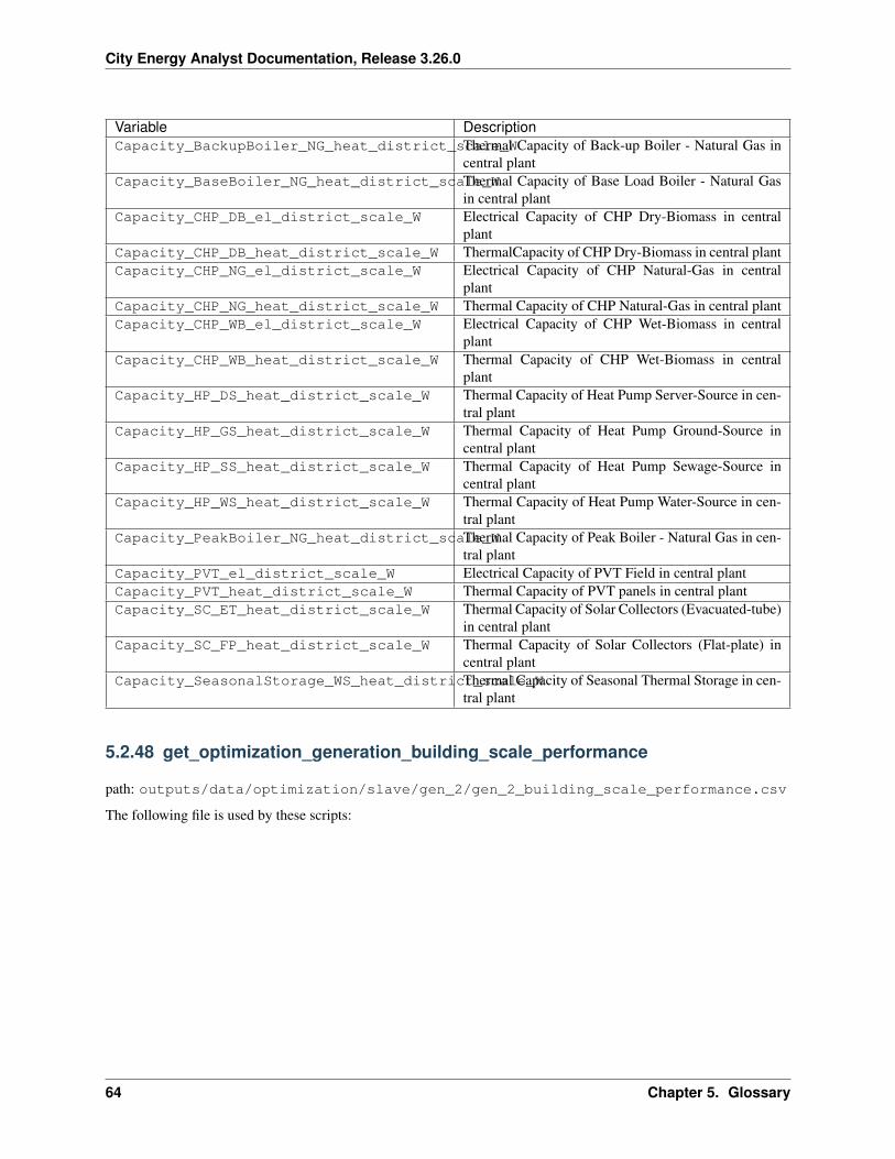
City Energy Analyst Documentation, Release 3.26.0
Variable DescriptionCapacity_BackupBoiler_NG_heat_district_scale_WThermal Capacity of Back-up Boiler - Natural Gas in
central plantCapacity_BaseBoiler_NG_heat_district_scale_WThermal Capacity of Base Load Boiler - Natural Gas
in central plantCapacity_CHP_DB_el_district_scale_W Electrical Capacity of CHP Dry-Biomass in central
plantCapacity_CHP_DB_heat_district_scale_W ThermalCapacity of CHP Dry-Biomass in central plantCapacity_CHP_NG_el_district_scale_W Electrical Capacity of CHP Natural-Gas in central
plantCapacity_CHP_NG_heat_district_scale_W Thermal Capacity of CHP Natural-Gas in central plantCapacity_CHP_WB_el_district_scale_W Electrical Capacity of CHP Wet-Biomass in central
plantCapacity_CHP_WB_heat_district_scale_W Thermal Capacity of CHP Wet-Biomass in central
plantCapacity_HP_DS_heat_district_scale_W Thermal Capacity of Heat Pump Server-Source in cen-
tral plantCapacity_HP_GS_heat_district_scale_W Thermal Capacity of Heat Pump Ground-Source in
central plantCapacity_HP_SS_heat_district_scale_W Thermal Capacity of Heat Pump Sewage-Source in
central plantCapacity_HP_WS_heat_district_scale_W Thermal Capacity of Heat Pump Water-Source in cen-
tral plantCapacity_PeakBoiler_NG_heat_district_scale_WThermal Capacity of Peak Boiler - Natural Gas in cen-
tral plantCapacity_PVT_el_district_scale_W Electrical Capacity of PVT Field in central plantCapacity_PVT_heat_district_scale_W Thermal Capacity of PVT panels in central plantCapacity_SC_ET_heat_district_scale_W Thermal Capacity of Solar Collectors (Evacuated-tube)
in central plantCapacity_SC_FP_heat_district_scale_W Thermal Capacity of Solar Collectors (Flat-plate) in
central plantCapacity_SeasonalStorage_WS_heat_district_scale_WThermal Capacity of Seasonal Thermal Storage in cen-
tral plant
5.2.48 get_optimization_generation_building_scale_performance
path: outputs/data/optimization/slave/gen_2/gen_2_building_scale_performance.csv
The following file is used by these scripts:
64 Chapter 5. Glossary
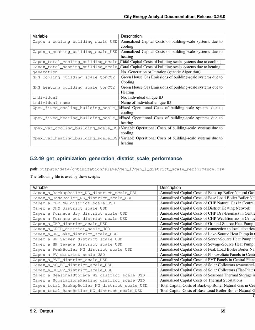
City Energy Analyst Documentation, Release 3.26.0
Variable DescriptionCapex_a_cooling_building_scale_USD Annualized Capital Costs of building-scale systems due to
coolingCapex_a_heating_building_scale_USD Annualized Capital Costs of building-scale systems due to
heatingCapex_total_cooling_building_scale_USDTotal Capital Costs of building-scale systems due to coolingCapex_total_heating_building_scale_USDTotal Capital Costs of building-scale systems due to heatinggeneration No. Generation or Iteration (genetic Algorithm)GHG_cooling_building_scale_tonCO2 Green House Gas Emissions of building-scale systems due to
CoolingGHG_heating_building_scale_tonCO2 Green House Gas Emissions of building-scale systems due to
Heatingindividual No. Individual unique IDindividual_name Name of Individual unique IDOpex_fixed_cooling_building_scale_USDFixed Operational Costs of building-scale systems due to
coolingOpex_fixed_heating_building_scale_USDFixed Operational Costs of building-scale systems due to
heatingOpex_var_cooling_building_scale_USDVariable Operational Costs of building-scale systems due to
coolingOpex_var_heating_building_scale_USDVariable Operational Costs of building-scale systems due to
heating
5.2.49 get_optimization_generation_district_scale_performance
path: outputs/data/optimization/slave/gen_1/gen_1_district_scale_performance.csv
The following file is used by these scripts:
Variable DescriptionCapex_a_BackupBoiler_NG_district_scale_USD Annualized Capital Costs of Back-up Boiler Natural Gas in Central PlantCapex_a_BaseBoiler_NG_district_scale_USD Annualized Capital Costs of Base Load Boiler Boiler Natural Gas in Central PlantCapex_a_CHP_NG_district_scale_USD Annualized Capital Costs of CHP Natural Gas in Central PlantCapex_a_DHN_district_scale_USD Annualized Capital Costs of District Heating NetworkCapex_a_Furnace_dry_district_scale_USD Annualized Capital Costs of CHP Dry-Biomass in Central PlantCapex_a_Furnace_wet_district_scale_USD Annualized Capital Costs of CHP Wet-Biomass in Central PlantCapex_a_GHP_district_scale_USD Annualized Capital Costs of Ground-Source Heat Pump in Central PlantCapex_a_GRID_district_scale_USD Annualized Capital Costs of connection to local electrical gridCapex_a_HP_Lake_district_scale_USD Annualized Capital Costs of Lake-Source Heat Pump in Central PlantCapex_a_HP_Server_district_scale_USD Annualized Capital Costs of Server-Source Heat Pump in Central PlantCapex_a_HP_Sewage_district_scale_USD Annualized Capital Costs of Sewage-Source Heat Pump in Central PlantCapex_a_PeakBoiler_NG_district_scale_USD Annualized Capital Costs of Peak Load Boiler Boiler Natural Gas in Central PlantCapex_a_PV_district_scale_USD Annualized Capital Costs of Photovoltaic Panels in Central PlantCapex_a_PVT_district_scale_USD Annualized Capital Costs of PVT Panels in Central PlantCapex_a_SC_ET_district_scale_USD Annualized Capital Costs of Solar Collectors (evacuated-Tube) in Central PlantCapex_a_SC_FP_district_scale_USD Annualized Capital Costs of Solar Collectors (Flat-Plate) in Central PlantCapex_a_SeasonalStorage_WS_district_scale_USD Annualized Capital Costs of Seasonal Thermal Storage in Central PlantCapex_a_SubstationsHeating_district_scale_USD Annualized Capital Costs of Thermal SubstationsCapex_total_BackupBoiler_NG_district_scale_USD Total Capital Costs of Back-up Boiler Natural Gas in Central PlantCapex_total_BaseBoiler_NG_district_scale_USD Total Capital Costs of Base Load Boiler Boiler Natural Gas in Central Plant
Continued on next page
5.2. Output 65
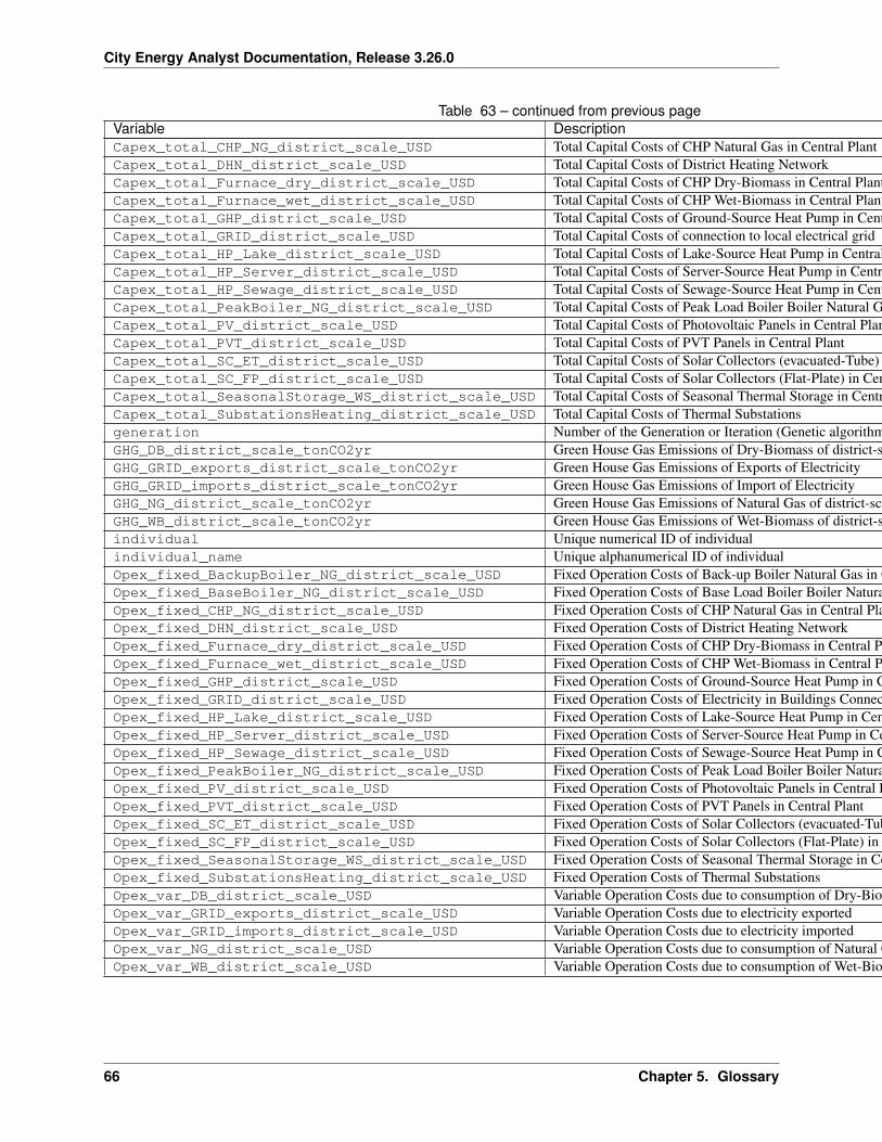
City Energy Analyst Documentation, Release 3.26.0
Table 63 – continued from previous pageVariable DescriptionCapex_total_CHP_NG_district_scale_USD Total Capital Costs of CHP Natural Gas in Central PlantCapex_total_DHN_district_scale_USD Total Capital Costs of District Heating NetworkCapex_total_Furnace_dry_district_scale_USD Total Capital Costs of CHP Dry-Biomass in Central PlantCapex_total_Furnace_wet_district_scale_USD Total Capital Costs of CHP Wet-Biomass in Central PlantCapex_total_GHP_district_scale_USD Total Capital Costs of Ground-Source Heat Pump in Central PlantCapex_total_GRID_district_scale_USD Total Capital Costs of connection to local electrical gridCapex_total_HP_Lake_district_scale_USD Total Capital Costs of Lake-Source Heat Pump in Central PlantCapex_total_HP_Server_district_scale_USD Total Capital Costs of Server-Source Heat Pump in Central PlantCapex_total_HP_Sewage_district_scale_USD Total Capital Costs of Sewage-Source Heat Pump in Central PlantCapex_total_PeakBoiler_NG_district_scale_USD Total Capital Costs of Peak Load Boiler Boiler Natural Gas in Central PlantCapex_total_PV_district_scale_USD Total Capital Costs of Photovoltaic Panels in Central PlantCapex_total_PVT_district_scale_USD Total Capital Costs of PVT Panels in Central PlantCapex_total_SC_ET_district_scale_USD Total Capital Costs of Solar Collectors (evacuated-Tube) in Central PlantCapex_total_SC_FP_district_scale_USD Total Capital Costs of Solar Collectors (Flat-Plate) in Central PlantCapex_total_SeasonalStorage_WS_district_scale_USD Total Capital Costs of Seasonal Thermal Storage in Central PlantCapex_total_SubstationsHeating_district_scale_USD Total Capital Costs of Thermal Substationsgeneration Number of the Generation or Iteration (Genetic algorithm)GHG_DB_district_scale_tonCO2yr Green House Gas Emissions of Dry-Biomass of district-scale systemsGHG_GRID_exports_district_scale_tonCO2yr Green House Gas Emissions of Exports of ElectricityGHG_GRID_imports_district_scale_tonCO2yr Green House Gas Emissions of Import of ElectricityGHG_NG_district_scale_tonCO2yr Green House Gas Emissions of Natural Gas of district-scale systemsGHG_WB_district_scale_tonCO2yr Green House Gas Emissions of Wet-Biomass of district-scale systemsindividual Unique numerical ID of individualindividual_name Unique alphanumerical ID of individualOpex_fixed_BackupBoiler_NG_district_scale_USD Fixed Operation Costs of Back-up Boiler Natural Gas in Central PlantOpex_fixed_BaseBoiler_NG_district_scale_USD Fixed Operation Costs of Base Load Boiler Boiler Natural Gas in Central PlantOpex_fixed_CHP_NG_district_scale_USD Fixed Operation Costs of CHP Natural Gas in Central PlantOpex_fixed_DHN_district_scale_USD Fixed Operation Costs of District Heating NetworkOpex_fixed_Furnace_dry_district_scale_USD Fixed Operation Costs of CHP Dry-Biomass in Central PlantOpex_fixed_Furnace_wet_district_scale_USD Fixed Operation Costs of CHP Wet-Biomass in Central PlantOpex_fixed_GHP_district_scale_USD Fixed Operation Costs of Ground-Source Heat Pump in Central PlantOpex_fixed_GRID_district_scale_USD Fixed Operation Costs of Electricity in Buildings Connected to Central PlantOpex_fixed_HP_Lake_district_scale_USD Fixed Operation Costs of Lake-Source Heat Pump in Central PlantOpex_fixed_HP_Server_district_scale_USD Fixed Operation Costs of Server-Source Heat Pump in Central PlantOpex_fixed_HP_Sewage_district_scale_USD Fixed Operation Costs of Sewage-Source Heat Pump in Central PlantOpex_fixed_PeakBoiler_NG_district_scale_USD Fixed Operation Costs of Peak Load Boiler Boiler Natural Gas in Central PlantOpex_fixed_PV_district_scale_USD Fixed Operation Costs of Photovoltaic Panels in Central PlantOpex_fixed_PVT_district_scale_USD Fixed Operation Costs of PVT Panels in Central PlantOpex_fixed_SC_ET_district_scale_USD Fixed Operation Costs of Solar Collectors (evacuated-Tube) in Central PlantOpex_fixed_SC_FP_district_scale_USD Fixed Operation Costs of Solar Collectors (Flat-Plate) in Central PlantOpex_fixed_SeasonalStorage_WS_district_scale_USD Fixed Operation Costs of Seasonal Thermal Storage in Central PlantOpex_fixed_SubstationsHeating_district_scale_USD Fixed Operation Costs of Thermal SubstationsOpex_var_DB_district_scale_USD Variable Operation Costs due to consumption of Dry-Biomass in Central PlantOpex_var_GRID_exports_district_scale_USD Variable Operation Costs due to electricity exportedOpex_var_GRID_imports_district_scale_USD Variable Operation Costs due to electricity importedOpex_var_NG_district_scale_USD Variable Operation Costs due to consumption of Natural Gas in Central PlantOpex_var_WB_district_scale_USD Variable Operation Costs due to consumption of Wet-Biomass in Central Plant
66 Chapter 5. Glossary
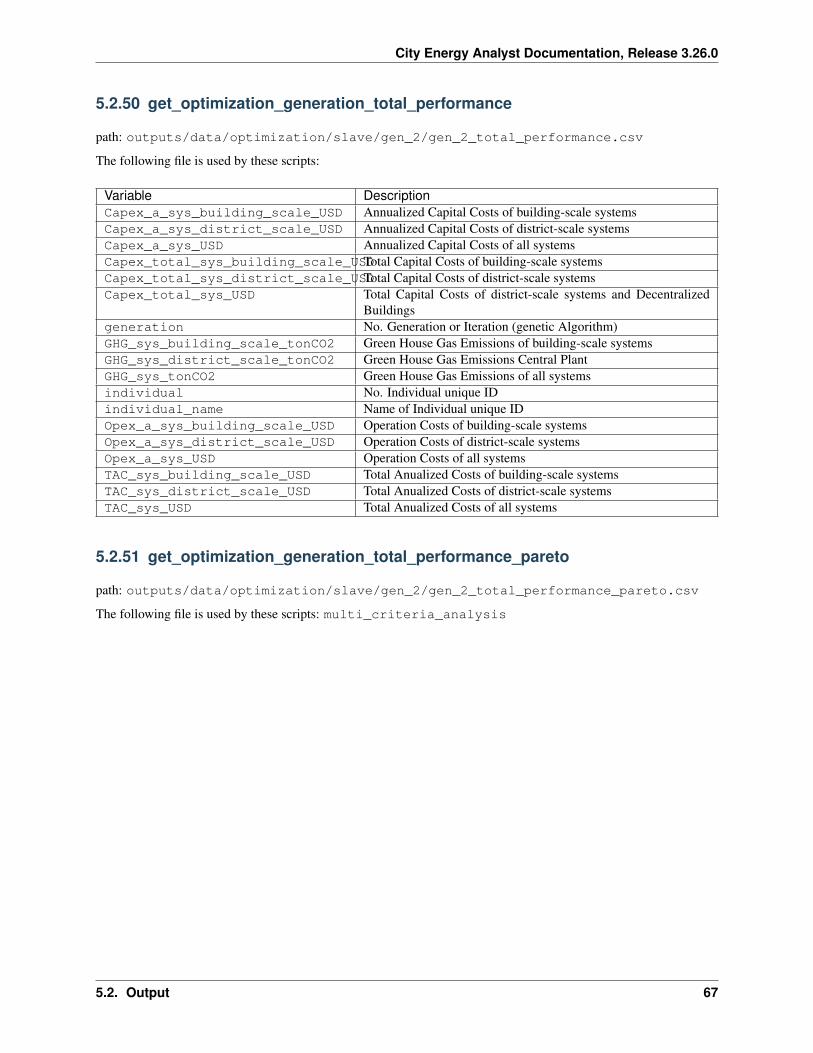
City Energy Analyst Documentation, Release 3.26.0
5.2.50 get_optimization_generation_total_performance
path: outputs/data/optimization/slave/gen_2/gen_2_total_performance.csv
The following file is used by these scripts:
Variable DescriptionCapex_a_sys_building_scale_USD Annualized Capital Costs of building-scale systemsCapex_a_sys_district_scale_USD Annualized Capital Costs of district-scale systemsCapex_a_sys_USD Annualized Capital Costs of all systemsCapex_total_sys_building_scale_USDTotal Capital Costs of building-scale systemsCapex_total_sys_district_scale_USDTotal Capital Costs of district-scale systemsCapex_total_sys_USD Total Capital Costs of district-scale systems and Decentralized
Buildingsgeneration No. Generation or Iteration (genetic Algorithm)GHG_sys_building_scale_tonCO2 Green House Gas Emissions of building-scale systemsGHG_sys_district_scale_tonCO2 Green House Gas Emissions Central PlantGHG_sys_tonCO2 Green House Gas Emissions of all systemsindividual No. Individual unique IDindividual_name Name of Individual unique IDOpex_a_sys_building_scale_USD Operation Costs of building-scale systemsOpex_a_sys_district_scale_USD Operation Costs of district-scale systemsOpex_a_sys_USD Operation Costs of all systemsTAC_sys_building_scale_USD Total Anualized Costs of building-scale systemsTAC_sys_district_scale_USD Total Anualized Costs of district-scale systemsTAC_sys_USD Total Anualized Costs of all systems
5.2.51 get_optimization_generation_total_performance_pareto
path: outputs/data/optimization/slave/gen_2/gen_2_total_performance_pareto.csv
The following file is used by these scripts: multi_criteria_analysis
5.2. Output 67
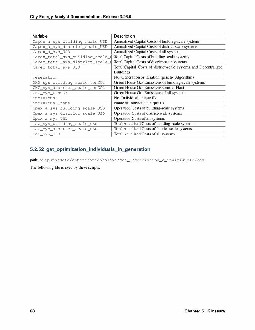
City Energy Analyst Documentation, Release 3.26.0
Variable DescriptionCapex_a_sys_building_scale_USD Annualized Capital Costs of building-scale systemsCapex_a_sys_district_scale_USD Annualized Capital Costs of district-scale systemsCapex_a_sys_USD Annualized Capital Costs of all systemsCapex_total_sys_building_scale_USDTotal Capital Costs of building-scale systemsCapex_total_sys_district_scale_USDTotal Capital Costs of district-scale systemsCapex_total_sys_USD Total Capital Costs of district-scale systems and Decentralized
Buildingsgeneration No. Generation or Iteration (genetic Algorithm)GHG_sys_building_scale_tonCO2 Green House Gas Emissions of building-scale systemsGHG_sys_district_scale_tonCO2 Green House Gas Emissions Central PlantGHG_sys_tonCO2 Green House Gas Emissions of all systemsindividual No. Individual unique IDindividual_name Name of Individual unique IDOpex_a_sys_building_scale_USD Operation Costs of building-scale systemsOpex_a_sys_district_scale_USD Operation Costs of district-scale systemsOpex_a_sys_USD Operation Costs of all systemsTAC_sys_building_scale_USD Total Anualized Costs of building-scale systemsTAC_sys_district_scale_USD Total Anualized Costs of district-scale systemsTAC_sys_USD Total Anualized Costs of all systems
5.2.52 get_optimization_individuals_in_generation
path: outputs/data/optimization/slave/gen_2/generation_2_individuals.csv
The following file is used by these scripts:
68 Chapter 5. Glossary
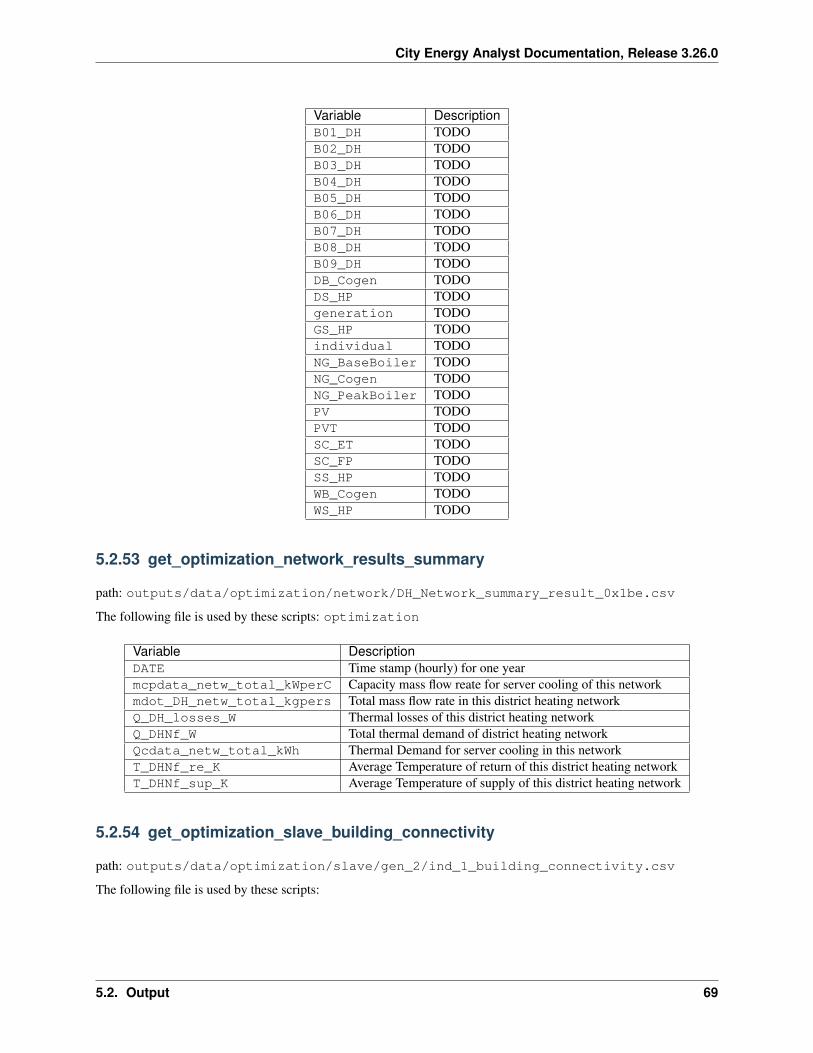
City Energy Analyst Documentation, Release 3.26.0
Variable DescriptionB01_DH TODOB02_DH TODOB03_DH TODOB04_DH TODOB05_DH TODOB06_DH TODOB07_DH TODOB08_DH TODOB09_DH TODODB_Cogen TODODS_HP TODOgeneration TODOGS_HP TODOindividual TODONG_BaseBoiler TODONG_Cogen TODONG_PeakBoiler TODOPV TODOPVT TODOSC_ET TODOSC_FP TODOSS_HP TODOWB_Cogen TODOWS_HP TODO
5.2.53 get_optimization_network_results_summary
path: outputs/data/optimization/network/DH_Network_summary_result_0x1be.csv
The following file is used by these scripts: optimization
Variable DescriptionDATE Time stamp (hourly) for one yearmcpdata_netw_total_kWperC Capacity mass flow reate for server cooling of this networkmdot_DH_netw_total_kgpers Total mass flow rate in this district heating networkQ_DH_losses_W Thermal losses of this district heating networkQ_DHNf_W Total thermal demand of district heating networkQcdata_netw_total_kWh Thermal Demand for server cooling in this networkT_DHNf_re_K Average Temperature of return of this district heating networkT_DHNf_sup_K Average Temperature of supply of this district heating network
5.2.54 get_optimization_slave_building_connectivity
path: outputs/data/optimization/slave/gen_2/ind_1_building_connectivity.csv
The following file is used by these scripts:
5.2. Output 69
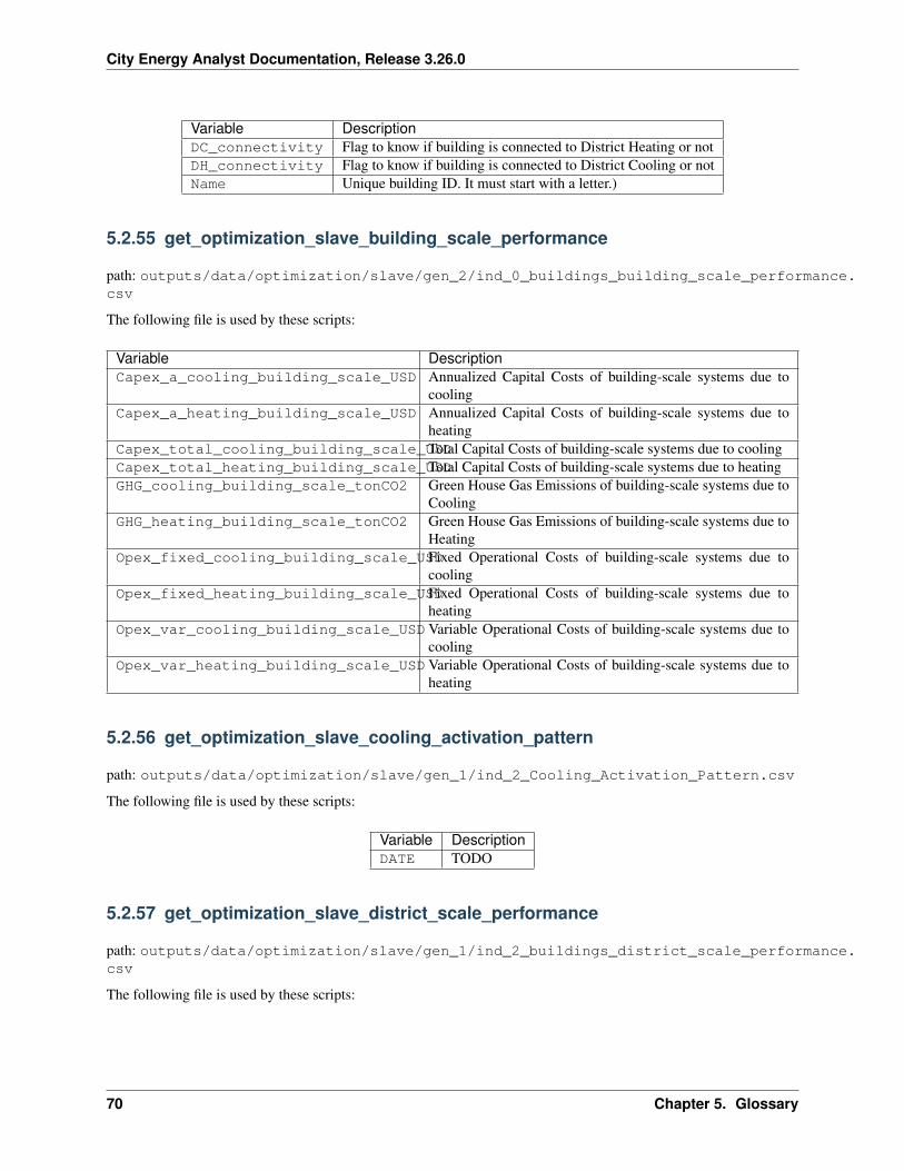
City Energy Analyst Documentation, Release 3.26.0
Variable DescriptionDC_connectivity Flag to know if building is connected to District Heating or notDH_connectivity Flag to know if building is connected to District Cooling or notName Unique building ID. It must start with a letter.)
5.2.55 get_optimization_slave_building_scale_performance
path: outputs/data/optimization/slave/gen_2/ind_0_buildings_building_scale_performance.csv
The following file is used by these scripts:
Variable DescriptionCapex_a_cooling_building_scale_USD Annualized Capital Costs of building-scale systems due to
coolingCapex_a_heating_building_scale_USD Annualized Capital Costs of building-scale systems due to
heatingCapex_total_cooling_building_scale_USDTotal Capital Costs of building-scale systems due to coolingCapex_total_heating_building_scale_USDTotal Capital Costs of building-scale systems due to heatingGHG_cooling_building_scale_tonCO2 Green House Gas Emissions of building-scale systems due to
CoolingGHG_heating_building_scale_tonCO2 Green House Gas Emissions of building-scale systems due to
HeatingOpex_fixed_cooling_building_scale_USDFixed Operational Costs of building-scale systems due to
coolingOpex_fixed_heating_building_scale_USDFixed Operational Costs of building-scale systems due to
heatingOpex_var_cooling_building_scale_USDVariable Operational Costs of building-scale systems due to
coolingOpex_var_heating_building_scale_USDVariable Operational Costs of building-scale systems due to
heating
5.2.56 get_optimization_slave_cooling_activation_pattern
path: outputs/data/optimization/slave/gen_1/ind_2_Cooling_Activation_Pattern.csv
The following file is used by these scripts:
Variable DescriptionDATE TODO
5.2.57 get_optimization_slave_district_scale_performance
path: outputs/data/optimization/slave/gen_1/ind_2_buildings_district_scale_performance.csv
The following file is used by these scripts:
70 Chapter 5. Glossary
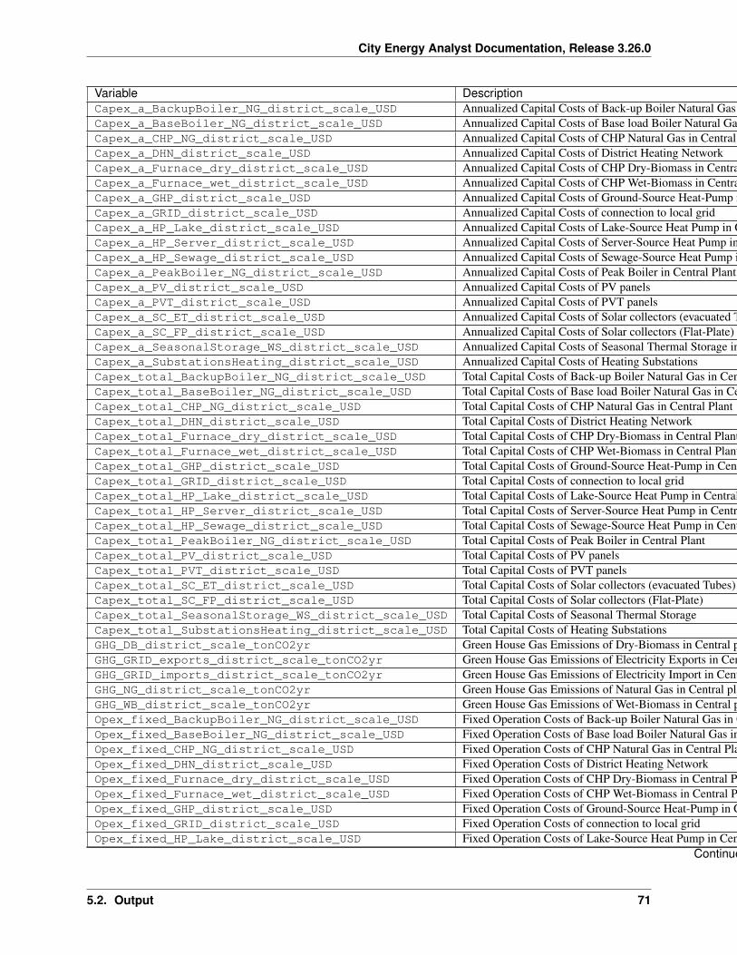
City Energy Analyst Documentation, Release 3.26.0
Variable DescriptionCapex_a_BackupBoiler_NG_district_scale_USD Annualized Capital Costs of Back-up Boiler Natural Gas in Central PlantCapex_a_BaseBoiler_NG_district_scale_USD Annualized Capital Costs of Base load Boiler Natural Gas in Central PlantCapex_a_CHP_NG_district_scale_USD Annualized Capital Costs of CHP Natural Gas in Central PlantCapex_a_DHN_district_scale_USD Annualized Capital Costs of District Heating NetworkCapex_a_Furnace_dry_district_scale_USD Annualized Capital Costs of CHP Dry-Biomass in Central PlantCapex_a_Furnace_wet_district_scale_USD Annualized Capital Costs of CHP Wet-Biomass in Central PlantCapex_a_GHP_district_scale_USD Annualized Capital Costs of Ground-Source Heat-Pump in Central PlantCapex_a_GRID_district_scale_USD Annualized Capital Costs of connection to local gridCapex_a_HP_Lake_district_scale_USD Annualized Capital Costs of Lake-Source Heat Pump in Central PlantCapex_a_HP_Server_district_scale_USD Annualized Capital Costs of Server-Source Heat Pump in Central PlantCapex_a_HP_Sewage_district_scale_USD Annualized Capital Costs of Sewage-Source Heat Pump in Central PlantCapex_a_PeakBoiler_NG_district_scale_USD Annualized Capital Costs of Peak Boiler in Central PlantCapex_a_PV_district_scale_USD Annualized Capital Costs of PV panelsCapex_a_PVT_district_scale_USD Annualized Capital Costs of PVT panelsCapex_a_SC_ET_district_scale_USD Annualized Capital Costs of Solar collectors (evacuated Tubes)Capex_a_SC_FP_district_scale_USD Annualized Capital Costs of Solar collectors (Flat-Plate)Capex_a_SeasonalStorage_WS_district_scale_USD Annualized Capital Costs of Seasonal Thermal Storage in Central PlantCapex_a_SubstationsHeating_district_scale_USD Annualized Capital Costs of Heating SubstationsCapex_total_BackupBoiler_NG_district_scale_USD Total Capital Costs of Back-up Boiler Natural Gas in Central PlantCapex_total_BaseBoiler_NG_district_scale_USD Total Capital Costs of Base load Boiler Natural Gas in Central PlantCapex_total_CHP_NG_district_scale_USD Total Capital Costs of CHP Natural Gas in Central PlantCapex_total_DHN_district_scale_USD Total Capital Costs of District Heating NetworkCapex_total_Furnace_dry_district_scale_USD Total Capital Costs of CHP Dry-Biomass in Central PlantCapex_total_Furnace_wet_district_scale_USD Total Capital Costs of CHP Wet-Biomass in Central PlantCapex_total_GHP_district_scale_USD Total Capital Costs of Ground-Source Heat-Pump in Central PlantCapex_total_GRID_district_scale_USD Total Capital Costs of connection to local gridCapex_total_HP_Lake_district_scale_USD Total Capital Costs of Lake-Source Heat Pump in Central PlantCapex_total_HP_Server_district_scale_USD Total Capital Costs of Server-Source Heat Pump in Central PlantCapex_total_HP_Sewage_district_scale_USD Total Capital Costs of Sewage-Source Heat Pump in Central PlantCapex_total_PeakBoiler_NG_district_scale_USD Total Capital Costs of Peak Boiler in Central PlantCapex_total_PV_district_scale_USD Total Capital Costs of PV panelsCapex_total_PVT_district_scale_USD Total Capital Costs of PVT panelsCapex_total_SC_ET_district_scale_USD Total Capital Costs of Solar collectors (evacuated Tubes)Capex_total_SC_FP_district_scale_USD Total Capital Costs of Solar collectors (Flat-Plate)Capex_total_SeasonalStorage_WS_district_scale_USD Total Capital Costs of Seasonal Thermal StorageCapex_total_SubstationsHeating_district_scale_USD Total Capital Costs of Heating SubstationsGHG_DB_district_scale_tonCO2yr Green House Gas Emissions of Dry-Biomass in Central plantGHG_GRID_exports_district_scale_tonCO2yr Green House Gas Emissions of Electricity Exports in Central PlantGHG_GRID_imports_district_scale_tonCO2yr Green House Gas Emissions of Electricity Import in Central PlantGHG_NG_district_scale_tonCO2yr Green House Gas Emissions of Natural Gas in Central plantGHG_WB_district_scale_tonCO2yr Green House Gas Emissions of Wet-Biomass in Central plantOpex_fixed_BackupBoiler_NG_district_scale_USD Fixed Operation Costs of Back-up Boiler Natural Gas in Central PlantOpex_fixed_BaseBoiler_NG_district_scale_USD Fixed Operation Costs of Base load Boiler Natural Gas in Central PlantOpex_fixed_CHP_NG_district_scale_USD Fixed Operation Costs of CHP Natural Gas in Central PlantOpex_fixed_DHN_district_scale_USD Fixed Operation Costs of District Heating NetworkOpex_fixed_Furnace_dry_district_scale_USD Fixed Operation Costs of CHP Dry-Biomass in Central PlantOpex_fixed_Furnace_wet_district_scale_USD Fixed Operation Costs of CHP Wet-Biomass in Central PlantOpex_fixed_GHP_district_scale_USD Fixed Operation Costs of Ground-Source Heat-Pump in Central PlantOpex_fixed_GRID_district_scale_USD Fixed Operation Costs of connection to local gridOpex_fixed_HP_Lake_district_scale_USD Fixed Operation Costs of Lake-Source Heat Pump in Central Plant
Continued on next page
5.2. Output 71
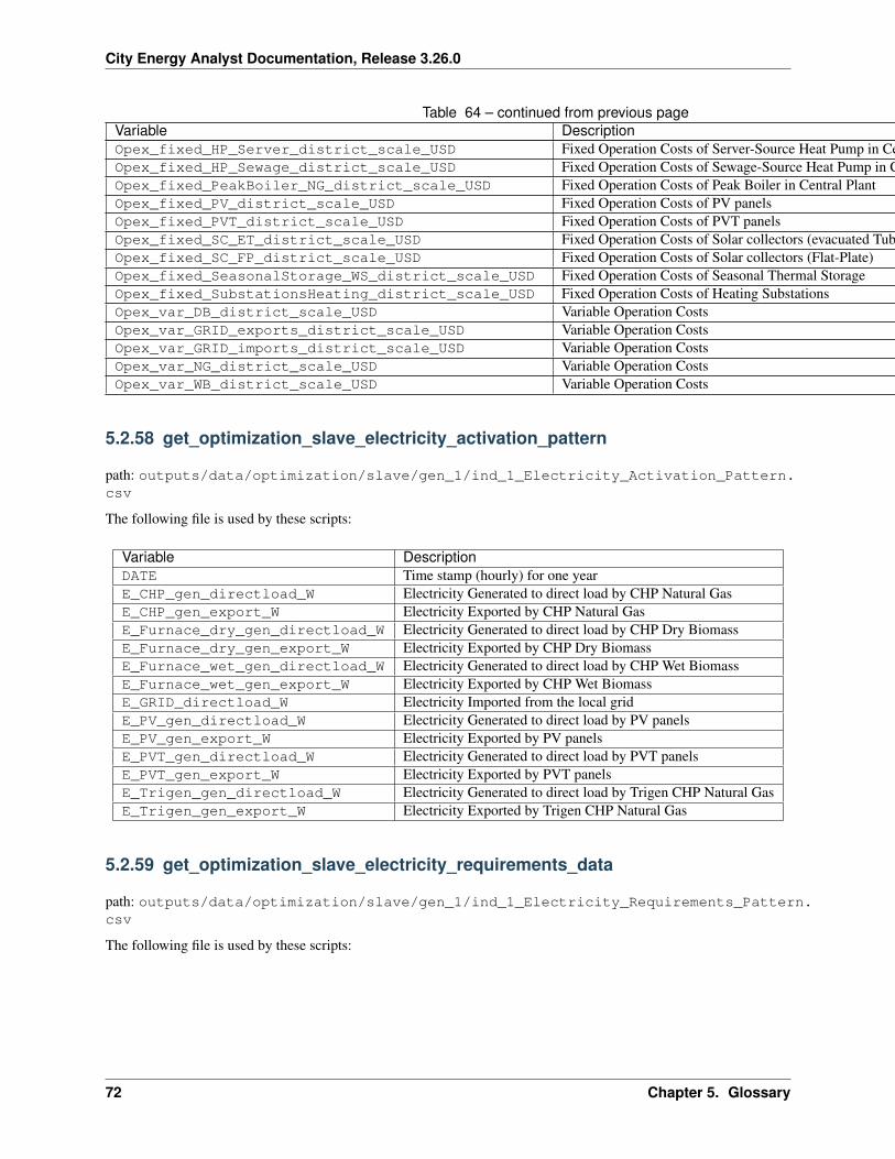
City Energy Analyst Documentation, Release 3.26.0
Table 64 – continued from previous pageVariable DescriptionOpex_fixed_HP_Server_district_scale_USD Fixed Operation Costs of Server-Source Heat Pump in Central PlantOpex_fixed_HP_Sewage_district_scale_USD Fixed Operation Costs of Sewage-Source Heat Pump in Central PlantOpex_fixed_PeakBoiler_NG_district_scale_USD Fixed Operation Costs of Peak Boiler in Central PlantOpex_fixed_PV_district_scale_USD Fixed Operation Costs of PV panelsOpex_fixed_PVT_district_scale_USD Fixed Operation Costs of PVT panelsOpex_fixed_SC_ET_district_scale_USD Fixed Operation Costs of Solar collectors (evacuated Tubes)Opex_fixed_SC_FP_district_scale_USD Fixed Operation Costs of Solar collectors (Flat-Plate)Opex_fixed_SeasonalStorage_WS_district_scale_USD Fixed Operation Costs of Seasonal Thermal StorageOpex_fixed_SubstationsHeating_district_scale_USD Fixed Operation Costs of Heating SubstationsOpex_var_DB_district_scale_USD Variable Operation CostsOpex_var_GRID_exports_district_scale_USD Variable Operation CostsOpex_var_GRID_imports_district_scale_USD Variable Operation CostsOpex_var_NG_district_scale_USD Variable Operation CostsOpex_var_WB_district_scale_USD Variable Operation Costs
5.2.58 get_optimization_slave_electricity_activation_pattern
path: outputs/data/optimization/slave/gen_1/ind_1_Electricity_Activation_Pattern.csv
The following file is used by these scripts:
Variable DescriptionDATE Time stamp (hourly) for one yearE_CHP_gen_directload_W Electricity Generated to direct load by CHP Natural GasE_CHP_gen_export_W Electricity Exported by CHP Natural GasE_Furnace_dry_gen_directload_W Electricity Generated to direct load by CHP Dry BiomassE_Furnace_dry_gen_export_W Electricity Exported by CHP Dry BiomassE_Furnace_wet_gen_directload_W Electricity Generated to direct load by CHP Wet BiomassE_Furnace_wet_gen_export_W Electricity Exported by CHP Wet BiomassE_GRID_directload_W Electricity Imported from the local gridE_PV_gen_directload_W Electricity Generated to direct load by PV panelsE_PV_gen_export_W Electricity Exported by PV panelsE_PVT_gen_directload_W Electricity Generated to direct load by PVT panelsE_PVT_gen_export_W Electricity Exported by PVT panelsE_Trigen_gen_directload_W Electricity Generated to direct load by Trigen CHP Natural GasE_Trigen_gen_export_W Electricity Exported by Trigen CHP Natural Gas
5.2.59 get_optimization_slave_electricity_requirements_data
path: outputs/data/optimization/slave/gen_1/ind_1_Electricity_Requirements_Pattern.csv
The following file is used by these scripts:
72 Chapter 5. Glossary
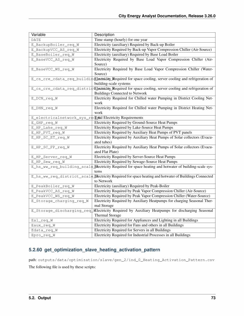
City Energy Analyst Documentation, Release 3.26.0
Variable DescriptionDATE Time stamp (hourly) for one yearE_BackupBoiler_req_W Electricity (auxiliary) Required by Back-up BoilerE_BackupVCC_AS_req_W Electricity Required by Back-up Vapor Compression Chiller (Air-Source)E_BaseBoiler_req_W Electricity (auxiliary) Required by Base Load BoilerE_BaseVCC_AS_req_W Electricity Required by Base Load Vapor Compression Chiller (Air-
Source)E_BaseVCC_WS_req_W Electricity Required by Base Load Vapor Compression Chiller (Water-
Source)E_cs_cre_cdata_req_building_scale_WElectricity Required for space cooling, server cooling and refrigeration of
building-scale systemsE_cs_cre_cdata_req_district_scale_WElectricity Required for space cooling, server cooling and refrigeration of
Buildings Connected to NetworkE_DCN_req_W Electricity Required for Chilled water Pumping in District Cooling Net-
workE_DHN_req_W Electricity Required for Chilled water Pumping in District Heating Net-
workE_electricalnetwork_sys_req_WTotal Electricity RequirementsE_GHP_req_W Electricity Required by Ground-Source Heat PumpsE_HP_Lake_req_W Electricity Required by Lake-Source Heat PumpsE_HP_PVT_req_W Electricity Required by Auxiliary Heat Pumps of PVT panelsE_HP_SC_ET_req_W Electricity Required by Auxiliary Heat Pumps of Solar collectors (Evacu-
ated tubes)E_HP_SC_FP_req_W Electricity Required by Auxiliary Heat Pumps of Solar collectors (Evacu-
ated Flat Plate)E_HP_Server_req_W Electricity Required by Server-Source Heat PumpsE_HP_Sew_req_W Electricity Required by Sewage-Source Heat PumpsE_hs_ww_req_building_scale_WElectricity Required for space heating and hotwater of building-scale sys-
temsE_hs_ww_req_district_scale_WElectricity Required for space heating and hotwater of Buildings Connected
to NetworkE_PeakBoiler_req_W Electricity (auxiliary) Required by Peak-BoilerE_PeakVCC_AS_req_W Electricity Required by Peak Vapor Compression Chiller (Air-Source)E_PeakVCC_WS_req_W Electricity Required by Peak Vapor Compression Chiller (Water-Source)E_Storage_charging_req_W Electricity Required by Auxiliary Heatpumps for charging Seasonal Ther-
mal StorageE_Storage_discharging_req_WElectricity Required by Auxiliary Heatpumps for discharging Seasonal
Thermal StorageEal_req_W Electricity Required for Appliances and Lighting in all BuildingsEaux_req_W Electricity Required for Fans and others in all BuildingsEdata_req_W Electricity Required for Servers in all BuildingsEpro_req_W Electricity Required for Industrial Processes in all Buildings
5.2.60 get_optimization_slave_heating_activation_pattern
path: outputs/data/optimization/slave/gen_2/ind_0_Heating_Activation_Pattern.csv
The following file is used by these scripts:
5.2. Output 73
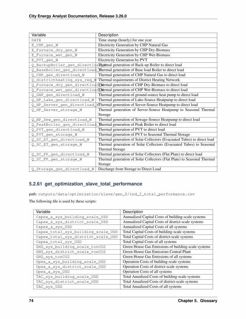
City Energy Analyst Documentation, Release 3.26.0
Variable DescriptionDATE Time stamp (hourly) for one yearE_CHP_gen_W Electricity Generation by CHP Natural GasE_Furnace_dry_gen_W Electricity Generation by CHP Dry-BiomassE_Furnace_wet_gen_W Electricity Generation by CHP Wet-BiomassE_PVT_gen_W Electricity Generation by PVTQ_BackupBoiler_gen_directload_WThermal generation of Back-up Boiler to direct loadQ_BaseBoiler_gen_directload_WThermal generation of Base load Boiler to direct loadQ_CHP_gen_directload_W Thermal generation of CHP Natural Gas to direct loadQ_districtheating_sys_req_W Thermal requirements of District Heating NetworkQ_Furnace_dry_gen_directload_WThermal generation of CHP Dry-Biomass to direct loadQ_Furnace_wet_gen_directload_WThermal generation of CHP Wet-Biomass to direct loadQ_GHP_gen_directload_W Thermal generation of ground-source heat pump to direct loadQ_HP_Lake_gen_directload_W Thermal generation of Lake-Source Heatpump to direct loadQ_HP_Server_gen_directload_WThermal generation of Server-Source Heatpump to direct loadQ_HP_Server_storage_W Thermal generation of Server-Source Heatpump to Seasonal Thermal
StorageQ_HP_Sew_gen_directload_W Thermal generation of Sewage-Source Heatpump to direct loadQ_PeakBoiler_gen_directload_WThermal generation of Peak Boiler to direct loadQ_PVT_gen_directload_W Thermal generation of PVT to direct loadQ_PVT_gen_storage_W Thermal generation of PVT to Seasonal Thermal StorageQ_SC_ET_gen_directload_W Thermal generation of Solar Collectors (Evacuated Tubes) to direct loadQ_SC_ET_gen_storage_W Thermal generation of Solar Collectors (Evacuated Tubes) to Seasonal
Thermal StorageQ_SC_FP_gen_directload_W Thermal generation of Solar Collectors (Flat Plate) to direct loadQ_SC_FP_gen_storage_W Thermal generation of Solar Collectors (Flat Plate) to Seasonal Thermal
StorageQ_Storage_gen_directload_W Discharge from Storage to Direct Load
5.2.61 get_optimization_slave_total_performance
path: outputs/data/optimization/slave/gen_0/ind_2_total_performance.csv
The following file is used by these scripts:
Variable DescriptionCapex_a_sys_building_scale_USD Annualized Capital Costs of building-scale systemsCapex_a_sys_district_scale_USD Annualized Capital Costs of district-scale systemsCapex_a_sys_USD Annualized Capital Costs of all systemsCapex_total_sys_building_scale_USD Total Capital Costs of building-scale systemsCapex_total_sys_district_scale_USD Total Capital Costs of district-scale systemsCapex_total_sys_USD Total Capital Costs of all systemsGHG_sys_building_scale_tonCO2 Green House Gas Emissions of building-scale systemsGHG_sys_district_scale_tonCO2 Green House Gas Emissions Central PlantGHG_sys_tonCO2 Green House Gas Emissions of all systemsOpex_a_sys_building_scale_USD Operation Costs of building-scale systemsOpex_a_sys_district_scale_USD Operation Costs of district-scale systemsOpex_a_sys_USD Operation Costs of all systemsTAC_sys_building_scale_USD Total Anualized Costs of building-scale systemsTAC_sys_district_scale_USD Total Anualized Costs of district-scale systemsTAC_sys_USD Total Anualized Costs of all systems
74 Chapter 5. Glossary
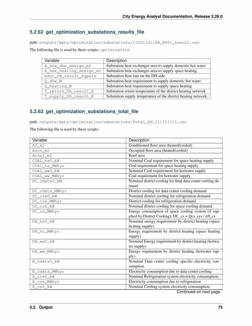
City Energy Analyst Documentation, Release 3.26.0
5.2.62 get_optimization_substations_results_file
path: outputs/data/optimization/substations/110011011DH_B001_result.csv
The following file is used by these scripts: optimization
Variable DescriptionA_hex_dhw_design_m2 Substation heat exchanger area to supply domestic hot waterA_hex_heating_design_m2 Substation heat exchanger area to supply space heatingmdot_DH_result_kgpers Substation flow rate on the DH side.Q_dhw_W Substation heat requirement to supply domestic hot waterQ_heating_W Substation heat requirement to supply space heatingT_return_DH_result_K Substation return temperature of the district heating networkT_supply_DH_result_K Substation supply temperature of the district heating network.
5.2.63 get_optimization_substations_total_file
path: outputs/data/optimization/substations/Total_DH_111111111.csv
The following file is used by these scripts:
Variable DescriptionAf_m2 Conditioned floor area (heated/cooled)Aocc_m2 Occupied floor area (heated/cooled)Aroof_m2 Roof areaCOAL_hs0_kW Nominal Coal requirement for space heating supplyCOAL_hs_MWhyr Coal requirement for space heating supplyCOAL_ww0_kW Nominal Coal requirement for hotwater supplyCOAL_ww_MWhyr Coal requirement for hotwater supplyDC_cdata0_kW Nominal district cooling for final data center cooling de-
mandDC_cdata_MWhyr District cooling for data center cooling demandDC_cre0_kW Nominal district cooling for refrigeration demandDC_cre_MWhyr District cooling for refrigeration demandDC_cs0_kW Nominal district cooling for space cooling demandDC_cs_MWhyr Energy consumption of space cooling system (if sup-
plied by District Cooling), DC_cs = Qcs_sys / eff_csDH_hs0_kW Nominal energy requirement by district heating (space
heating supply)DH_hs_MWhyr Energy requirement by district heating (space heating
supply)DH_ww0_kW Nominal Energy requirement by district heating (hotwa-
ter supply)DH_ww_MWhyr Energy requirement by district heating (hotwater sup-
ply)E_cdata0_kW Nominal Data centre cooling specific electricity con-
sumption.E_cdata_MWhyr Electricity consumption due to data center coolingE_cre0_kW Nominal Refrigeration system electricity consumption.E_cre_MWhyr Electricity consumption due to refrigerationE_cs0_kW Nominal Cooling system electricity consumption.
Continued on next page
5.2. Output 75
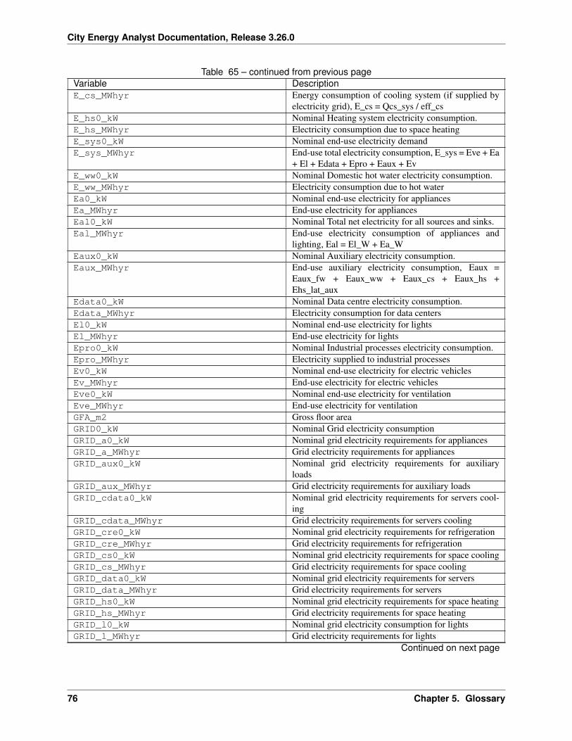
City Energy Analyst Documentation, Release 3.26.0
Table 65 – continued from previous pageVariable DescriptionE_cs_MWhyr Energy consumption of cooling system (if supplied by
electricity grid), E_cs = Qcs_sys / eff_csE_hs0_kW Nominal Heating system electricity consumption.E_hs_MWhyr Electricity consumption due to space heatingE_sys0_kW Nominal end-use electricity demandE_sys_MWhyr End-use total electricity consumption, E_sys = Eve + Ea
+ El + Edata + Epro + Eaux + EvE_ww0_kW Nominal Domestic hot water electricity consumption.E_ww_MWhyr Electricity consumption due to hot waterEa0_kW Nominal end-use electricity for appliancesEa_MWhyr End-use electricity for appliancesEal0_kW Nominal Total net electricity for all sources and sinks.Eal_MWhyr End-use electricity consumption of appliances and
lighting, Eal = El_W + Ea_WEaux0_kW Nominal Auxiliary electricity consumption.Eaux_MWhyr End-use auxiliary electricity consumption, Eaux =
Eaux_fw + Eaux_ww + Eaux_cs + Eaux_hs +Ehs_lat_aux
Edata0_kW Nominal Data centre electricity consumption.Edata_MWhyr Electricity consumption for data centersEl0_kW Nominal end-use electricity for lightsEl_MWhyr End-use electricity for lightsEpro0_kW Nominal Industrial processes electricity consumption.Epro_MWhyr Electricity supplied to industrial processesEv0_kW Nominal end-use electricity for electric vehiclesEv_MWhyr End-use electricity for electric vehiclesEve0_kW Nominal end-use electricity for ventilationEve_MWhyr End-use electricity for ventilationGFA_m2 Gross floor areaGRID0_kW Nominal Grid electricity consumptionGRID_a0_kW Nominal grid electricity requirements for appliancesGRID_a_MWhyr Grid electricity requirements for appliancesGRID_aux0_kW Nominal grid electricity requirements for auxiliary
loadsGRID_aux_MWhyr Grid electricity requirements for auxiliary loadsGRID_cdata0_kW Nominal grid electricity requirements for servers cool-
ingGRID_cdata_MWhyr Grid electricity requirements for servers coolingGRID_cre0_kW Nominal grid electricity requirements for refrigerationGRID_cre_MWhyr Grid electricity requirements for refrigerationGRID_cs0_kW Nominal grid electricity requirements for space coolingGRID_cs_MWhyr Grid electricity requirements for space coolingGRID_data0_kW Nominal grid electricity requirements for serversGRID_data_MWhyr Grid electricity requirements for serversGRID_hs0_kW Nominal grid electricity requirements for space heatingGRID_hs_MWhyr Grid electricity requirements for space heatingGRID_l0_kW Nominal grid electricity consumption for lightsGRID_l_MWhyr Grid electricity requirements for lights
Continued on next page
76 Chapter 5. Glossary
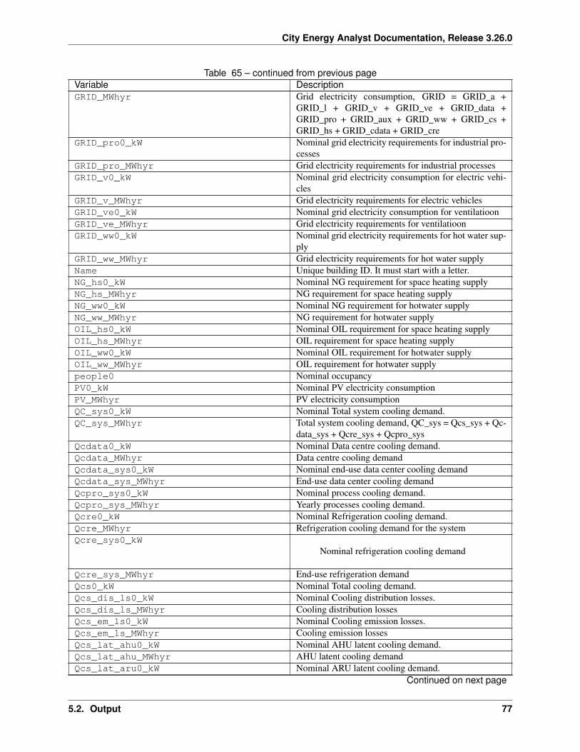
City Energy Analyst Documentation, Release 3.26.0
Table 65 – continued from previous pageVariable DescriptionGRID_MWhyr Grid electricity consumption, GRID = GRID_a +
GRID_l + GRID_v + GRID_ve + GRID_data +GRID_pro + GRID_aux + GRID_ww + GRID_cs +GRID_hs + GRID_cdata + GRID_cre
GRID_pro0_kW Nominal grid electricity requirements for industrial pro-cesses
GRID_pro_MWhyr Grid electricity requirements for industrial processesGRID_v0_kW Nominal grid electricity consumption for electric vehi-
clesGRID_v_MWhyr Grid electricity requirements for electric vehiclesGRID_ve0_kW Nominal grid electricity consumption for ventilatioonGRID_ve_MWhyr Grid electricity requirements for ventilatioonGRID_ww0_kW Nominal grid electricity requirements for hot water sup-
plyGRID_ww_MWhyr Grid electricity requirements for hot water supplyName Unique building ID. It must start with a letter.NG_hs0_kW Nominal NG requirement for space heating supplyNG_hs_MWhyr NG requirement for space heating supplyNG_ww0_kW Nominal NG requirement for hotwater supplyNG_ww_MWhyr NG requirement for hotwater supplyOIL_hs0_kW Nominal OIL requirement for space heating supplyOIL_hs_MWhyr OIL requirement for space heating supplyOIL_ww0_kW Nominal OIL requirement for hotwater supplyOIL_ww_MWhyr OIL requirement for hotwater supplypeople0 Nominal occupancyPV0_kW Nominal PV electricity consumptionPV_MWhyr PV electricity consumptionQC_sys0_kW Nominal Total system cooling demand.QC_sys_MWhyr Total system cooling demand, QC_sys = Qcs_sys + Qc-
data_sys + Qcre_sys + Qcpro_sysQcdata0_kW Nominal Data centre cooling demand.Qcdata_MWhyr Data centre cooling demandQcdata_sys0_kW Nominal end-use data center cooling demandQcdata_sys_MWhyr End-use data center cooling demandQcpro_sys0_kW Nominal process cooling demand.Qcpro_sys_MWhyr Yearly processes cooling demand.Qcre0_kW Nominal Refrigeration cooling demand.Qcre_MWhyr Refrigeration cooling demand for the systemQcre_sys0_kW
Nominal refrigeration cooling demand
Qcre_sys_MWhyr End-use refrigeration demandQcs0_kW Nominal Total cooling demand.Qcs_dis_ls0_kW Nominal Cooling distribution losses.Qcs_dis_ls_MWhyr Cooling distribution lossesQcs_em_ls0_kW Nominal Cooling emission losses.Qcs_em_ls_MWhyr Cooling emission lossesQcs_lat_ahu0_kW Nominal AHU latent cooling demand.Qcs_lat_ahu_MWhyr AHU latent cooling demandQcs_lat_aru0_kW Nominal ARU latent cooling demand.
Continued on next page
5.2. Output 77
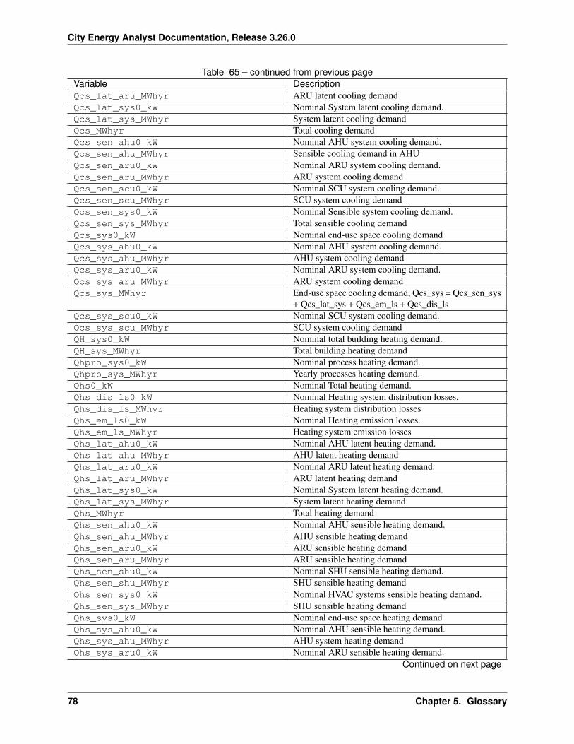
City Energy Analyst Documentation, Release 3.26.0
Table 65 – continued from previous pageVariable DescriptionQcs_lat_aru_MWhyr ARU latent cooling demandQcs_lat_sys0_kW Nominal System latent cooling demand.Qcs_lat_sys_MWhyr System latent cooling demandQcs_MWhyr Total cooling demandQcs_sen_ahu0_kW Nominal AHU system cooling demand.Qcs_sen_ahu_MWhyr Sensible cooling demand in AHUQcs_sen_aru0_kW Nominal ARU system cooling demand.Qcs_sen_aru_MWhyr ARU system cooling demandQcs_sen_scu0_kW Nominal SCU system cooling demand.Qcs_sen_scu_MWhyr SCU system cooling demandQcs_sen_sys0_kW Nominal Sensible system cooling demand.Qcs_sen_sys_MWhyr Total sensible cooling demandQcs_sys0_kW Nominal end-use space cooling demandQcs_sys_ahu0_kW Nominal AHU system cooling demand.Qcs_sys_ahu_MWhyr AHU system cooling demandQcs_sys_aru0_kW Nominal ARU system cooling demand.Qcs_sys_aru_MWhyr ARU system cooling demandQcs_sys_MWhyr End-use space cooling demand, Qcs_sys = Qcs_sen_sys
+ Qcs_lat_sys + Qcs_em_ls + Qcs_dis_lsQcs_sys_scu0_kW Nominal SCU system cooling demand.Qcs_sys_scu_MWhyr SCU system cooling demandQH_sys0_kW Nominal total building heating demand.QH_sys_MWhyr Total building heating demandQhpro_sys0_kW Nominal process heating demand.Qhpro_sys_MWhyr Yearly processes heating demand.Qhs0_kW Nominal Total heating demand.Qhs_dis_ls0_kW Nominal Heating system distribution losses.Qhs_dis_ls_MWhyr Heating system distribution lossesQhs_em_ls0_kW Nominal Heating emission losses.Qhs_em_ls_MWhyr Heating system emission lossesQhs_lat_ahu0_kW Nominal AHU latent heating demand.Qhs_lat_ahu_MWhyr AHU latent heating demandQhs_lat_aru0_kW Nominal ARU latent heating demand.Qhs_lat_aru_MWhyr ARU latent heating demandQhs_lat_sys0_kW Nominal System latent heating demand.Qhs_lat_sys_MWhyr System latent heating demandQhs_MWhyr Total heating demandQhs_sen_ahu0_kW Nominal AHU sensible heating demand.Qhs_sen_ahu_MWhyr AHU sensible heating demandQhs_sen_aru0_kW ARU sensible heating demandQhs_sen_aru_MWhyr ARU sensible heating demandQhs_sen_shu0_kW Nominal SHU sensible heating demand.Qhs_sen_shu_MWhyr SHU sensible heating demandQhs_sen_sys0_kW Nominal HVAC systems sensible heating demand.Qhs_sen_sys_MWhyr SHU sensible heating demandQhs_sys0_kW Nominal end-use space heating demandQhs_sys_ahu0_kW Nominal AHU sensible heating demand.Qhs_sys_ahu_MWhyr AHU system heating demandQhs_sys_aru0_kW Nominal ARU sensible heating demand.
Continued on next page
78 Chapter 5. Glossary
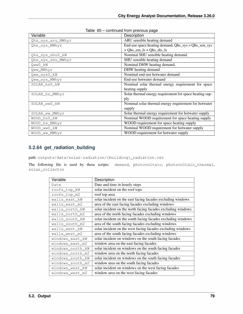
City Energy Analyst Documentation, Release 3.26.0
Table 65 – continued from previous pageVariable DescriptionQhs_sys_aru_MWhyr ARU sensible heating demandQhs_sys_MWhyr End-use space heating demand, Qhs_sys = Qhs_sen_sys
+ Qhs_em_ls + Qhs_dis_lsQhs_sys_shu0_kW Nominal SHU sensible heating demand.Qhs_sys_shu_MWhyr SHU sensible heating demandQww0_kW Nominal DHW heating demand.Qww_MWhyr DHW heating demandQww_sys0_kW Nominal end-use hotwater demandQww_sys_MWhyr End-use hotwater demandSOLAR_hs0_kW Nominal solar thermal energy requirement for space
heating supplySOLAR_hs_MWhyr Solar thermal energy requirement for space heating sup-
plySOLAR_ww0_kW Nominal solar thermal energy requirement for hotwater
supplySOLAR_ww_MWhyr Solar thermal energy requirement for hotwater supplyWOOD_hs0_kW Nominal WOOD requirement for space heating supplyWOOD_hs_MWhyr WOOD requirement for space heating supplyWOOD_ww0_kW Nominal WOOD requirement for hotwater supplyWOOD_ww_MWhyr WOOD requirement for hotwater supply
5.2.64 get_radiation_building
path: outputs/data/solar-radiation/{building}_radiation.csv
The following file is used by these scripts: demand, photovoltaic, photovoltaic_thermal,solar_collector
Variable DescriptionDate Date and time in hourly stepsroofs_top_kW solar incident on the roof topsroofs_top_m2 roof top areawalls_east_kW solar incident on the east facing facades excluding windowswalls_east_m2 area of the east facing facades excluding windowswalls_north_kW solar incident on the north facing facades excluding windowswalls_north_m2 area of the north facing facades excluding windowswalls_south_kW solar incident on the south facing facades excluding windowswalls_south_m2 area of the south facing facades excluding windowswalls_west_kW solar incident on the west facing facades excluding windowswalls_west_m2 area of the south facing facades excluding windowswindows_east_kW solar incident on windows on the south facing facadeswindows_east_m2 window area on the east facing facadeswindows_north_kW solar incident on windows on the south facing facadeswindows_north_m2 window area on the north facing facadeswindows_south_kW solar incident on windows on the south facing facadeswindows_south_m2 window area on the south facing facadeswindows_west_kW solar incident on windows on the west facing facadeswindows_west_m2 window area on the west facing facades
5.2. Output 79
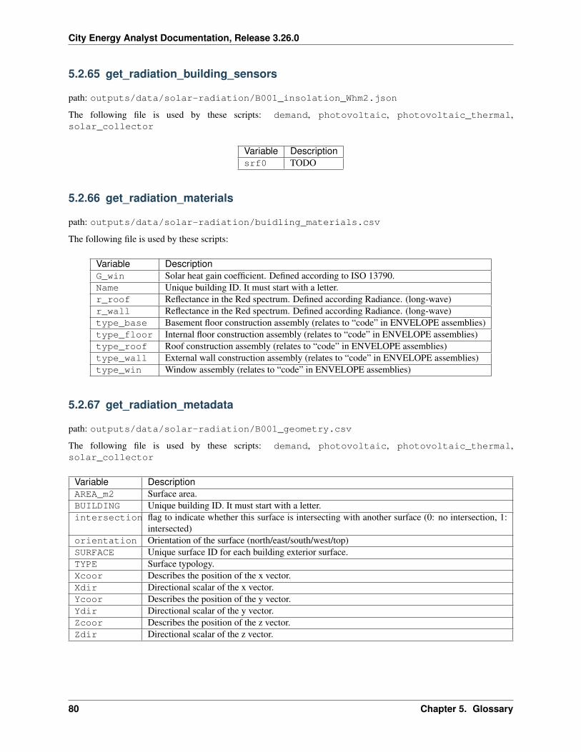
City Energy Analyst Documentation, Release 3.26.0
5.2.65 get_radiation_building_sensors
path: outputs/data/solar-radiation/B001_insolation_Whm2.json
The following file is used by these scripts: demand, photovoltaic, photovoltaic_thermal,solar_collector
Variable Descriptionsrf0 TODO
5.2.66 get_radiation_materials
path: outputs/data/solar-radiation/buidling_materials.csv
The following file is used by these scripts:
Variable DescriptionG_win Solar heat gain coefficient. Defined according to ISO 13790.Name Unique building ID. It must start with a letter.r_roof Reflectance in the Red spectrum. Defined according Radiance. (long-wave)r_wall Reflectance in the Red spectrum. Defined according Radiance. (long-wave)type_base Basement floor construction assembly (relates to “code” in ENVELOPE assemblies)type_floor Internal floor construction assembly (relates to “code” in ENVELOPE assemblies)type_roof Roof construction assembly (relates to “code” in ENVELOPE assemblies)type_wall External wall construction assembly (relates to “code” in ENVELOPE assemblies)type_win Window assembly (relates to “code” in ENVELOPE assemblies)
5.2.67 get_radiation_metadata
path: outputs/data/solar-radiation/B001_geometry.csv
The following file is used by these scripts: demand, photovoltaic, photovoltaic_thermal,solar_collector
Variable DescriptionAREA_m2 Surface area.BUILDING Unique building ID. It must start with a letter.intersection flag to indicate whether this surface is intersecting with another surface (0: no intersection, 1:
intersected)orientation Orientation of the surface (north/east/south/west/top)SURFACE Unique surface ID for each building exterior surface.TYPE Surface typology.Xcoor Describes the position of the x vector.Xdir Directional scalar of the x vector.Ycoor Describes the position of the y vector.Ydir Directional scalar of the y vector.Zcoor Describes the position of the z vector.Zdir Directional scalar of the z vector.
80 Chapter 5. Glossary
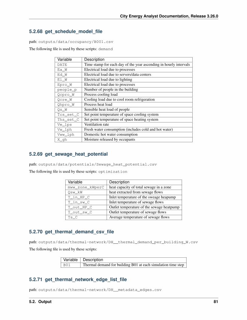
City Energy Analyst Documentation, Release 3.26.0
5.2.68 get_schedule_model_file
path: outputs/data/occupancy/B001.csv
The following file is used by these scripts: demand
Variable DescriptionDATE Time stamp for each day of the year ascending in hourly intervalsEa_W Electrical load due to processesEd_W Electrical load due to servers/data centersEl_W Electrical load due to lightingEpro_W Electrical load due to processespeople_p Number of people in the buildingQcpro_W Process cooling loadQcre_W Cooling load due to cool room refrigerationQhpro_W Process heat loadQs_W Sensible heat load of peopleTcs_set_C Set point temperature of space cooling systemThs_set_C Set point temperature of space heating systemVe_lps Ventilation rateVw_lph Fresh water consumption (includes cold and hot water)Vww_lph Domestic hot water consumptionX_gh Moisture released by occupants
5.2.69 get_sewage_heat_potential
path: outputs/data/potentials/Sewage_heat_potential.csv
The following file is used by these scripts: optimization
Variable Descriptionmww_zone_kWperC heat capacity of total sewage in a zoneQsw_kW heat extracted from sewage flowsT_in_HP_C Inlet temperature of the sweage heapumpT_in_sw_C Inlet temperature of sewage flowsT_out_HP_C Outlet temperature of the sewage heatpumpT_out_sw_C Outlet temperature of sewage flowsTs_C Average temperature of sewage flows
5.2.70 get_thermal_demand_csv_file
path: outputs/data/thermal-network/DH__thermal_demand_per_building_W.csv
The following file is used by these scripts:
Variable DescriptionB01 Thermal demand for building B01 at each simulation time step
5.2.71 get_thermal_network_edge_list_file
path: outputs/data/thermal-network/DH__metadata_edges.csv
5.2. Output 81
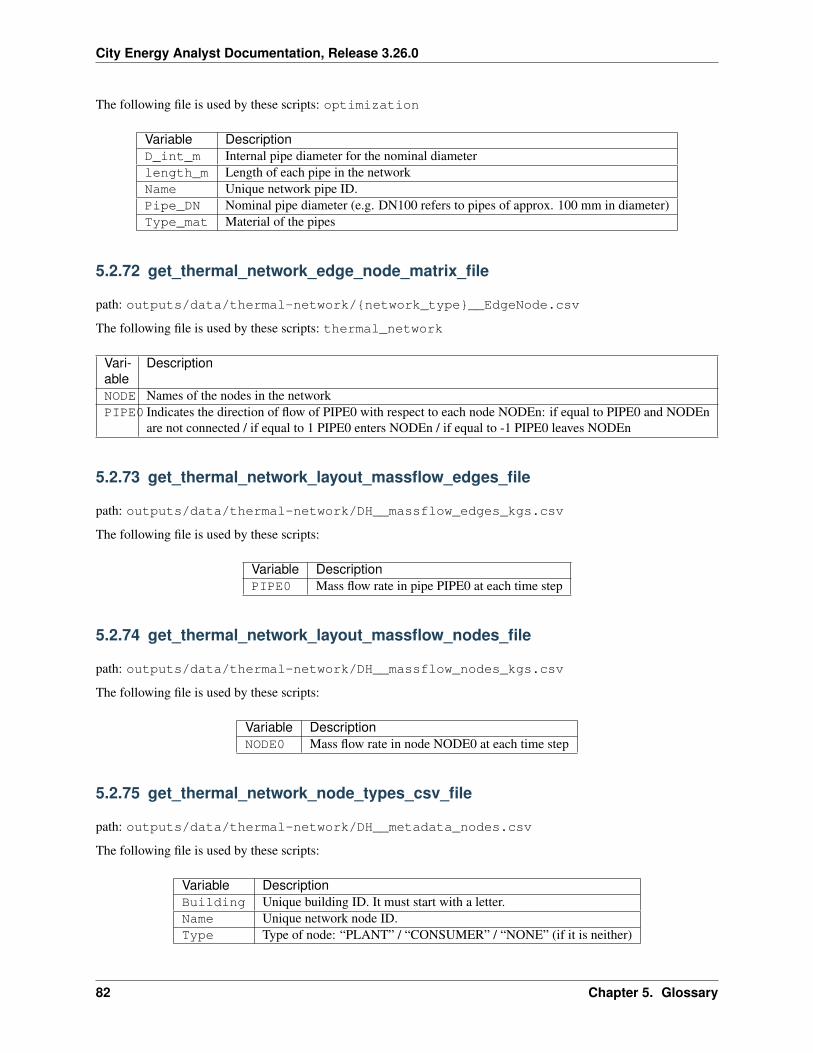
City Energy Analyst Documentation, Release 3.26.0
The following file is used by these scripts: optimization
Variable DescriptionD_int_m Internal pipe diameter for the nominal diameterlength_m Length of each pipe in the networkName Unique network pipe ID.Pipe_DN Nominal pipe diameter (e.g. DN100 refers to pipes of approx. 100 mm in diameter)Type_mat Material of the pipes
5.2.72 get_thermal_network_edge_node_matrix_file
path: outputs/data/thermal-network/{network_type}__EdgeNode.csv
The following file is used by these scripts: thermal_network
Vari-able
Description
NODE Names of the nodes in the networkPIPE0 Indicates the direction of flow of PIPE0 with respect to each node NODEn: if equal to PIPE0 and NODEn
are not connected / if equal to 1 PIPE0 enters NODEn / if equal to -1 PIPE0 leaves NODEn
5.2.73 get_thermal_network_layout_massflow_edges_file
path: outputs/data/thermal-network/DH__massflow_edges_kgs.csv
The following file is used by these scripts:
Variable DescriptionPIPE0 Mass flow rate in pipe PIPE0 at each time step
5.2.74 get_thermal_network_layout_massflow_nodes_file
path: outputs/data/thermal-network/DH__massflow_nodes_kgs.csv
The following file is used by these scripts:
Variable DescriptionNODE0 Mass flow rate in node NODE0 at each time step
5.2.75 get_thermal_network_node_types_csv_file
path: outputs/data/thermal-network/DH__metadata_nodes.csv
The following file is used by these scripts:
Variable DescriptionBuilding Unique building ID. It must start with a letter.Name Unique network node ID.Type Type of node: “PLANT” / “CONSUMER” / “NONE” (if it is neither)
82 Chapter 5. Glossary
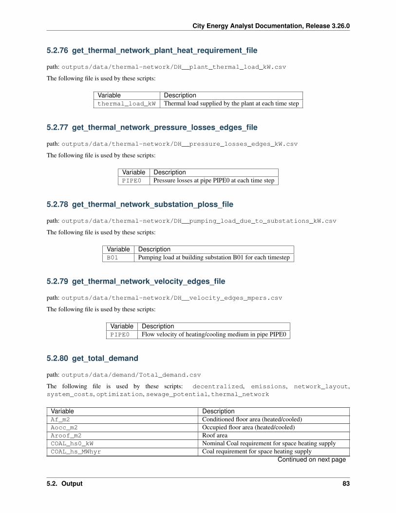
City Energy Analyst Documentation, Release 3.26.0
5.2.76 get_thermal_network_plant_heat_requirement_file
path: outputs/data/thermal-network/DH__plant_thermal_load_kW.csv
The following file is used by these scripts:
Variable Descriptionthermal_load_kW Thermal load supplied by the plant at each time step
5.2.77 get_thermal_network_pressure_losses_edges_file
path: outputs/data/thermal-network/DH__pressure_losses_edges_kW.csv
The following file is used by these scripts:
Variable DescriptionPIPE0 Pressure losses at pipe PIPE0 at each time step
5.2.78 get_thermal_network_substation_ploss_file
path: outputs/data/thermal-network/DH__pumping_load_due_to_substations_kW.csv
The following file is used by these scripts:
Variable DescriptionB01 Pumping load at building substation B01 for each timestep
5.2.79 get_thermal_network_velocity_edges_file
path: outputs/data/thermal-network/DH__velocity_edges_mpers.csv
The following file is used by these scripts:
Variable DescriptionPIPE0 Flow velocity of heating/cooling medium in pipe PIPE0
5.2.80 get_total_demand
path: outputs/data/demand/Total_demand.csv
The following file is used by these scripts: decentralized, emissions, network_layout,system_costs, optimization, sewage_potential, thermal_network
Variable DescriptionAf_m2 Conditioned floor area (heated/cooled)Aocc_m2 Occupied floor area (heated/cooled)Aroof_m2 Roof areaCOAL_hs0_kW Nominal Coal requirement for space heating supplyCOAL_hs_MWhyr Coal requirement for space heating supply
Continued on next page
5.2. Output 83
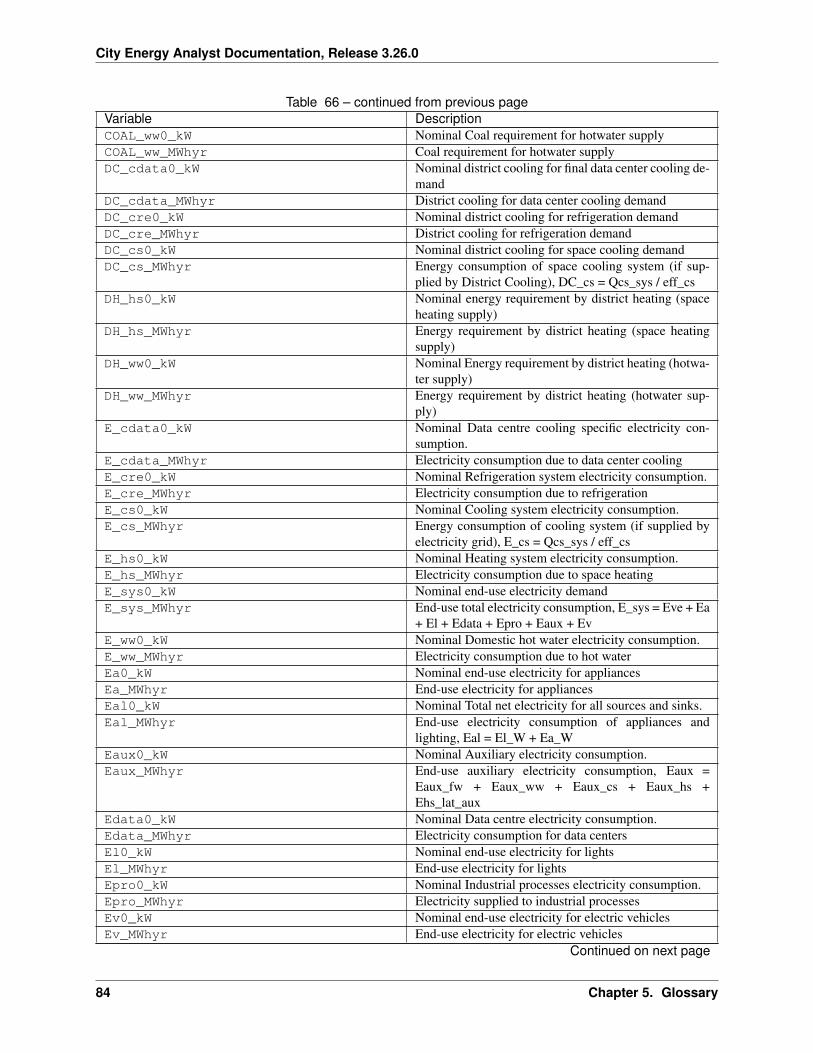
City Energy Analyst Documentation, Release 3.26.0
Table 66 – continued from previous pageVariable DescriptionCOAL_ww0_kW Nominal Coal requirement for hotwater supplyCOAL_ww_MWhyr Coal requirement for hotwater supplyDC_cdata0_kW Nominal district cooling for final data center cooling de-
mandDC_cdata_MWhyr District cooling for data center cooling demandDC_cre0_kW Nominal district cooling for refrigeration demandDC_cre_MWhyr District cooling for refrigeration demandDC_cs0_kW Nominal district cooling for space cooling demandDC_cs_MWhyr Energy consumption of space cooling system (if sup-
plied by District Cooling), DC_cs = Qcs_sys / eff_csDH_hs0_kW Nominal energy requirement by district heating (space
heating supply)DH_hs_MWhyr Energy requirement by district heating (space heating
supply)DH_ww0_kW Nominal Energy requirement by district heating (hotwa-
ter supply)DH_ww_MWhyr Energy requirement by district heating (hotwater sup-
ply)E_cdata0_kW Nominal Data centre cooling specific electricity con-
sumption.E_cdata_MWhyr Electricity consumption due to data center coolingE_cre0_kW Nominal Refrigeration system electricity consumption.E_cre_MWhyr Electricity consumption due to refrigerationE_cs0_kW Nominal Cooling system electricity consumption.E_cs_MWhyr Energy consumption of cooling system (if supplied by
electricity grid), E_cs = Qcs_sys / eff_csE_hs0_kW Nominal Heating system electricity consumption.E_hs_MWhyr Electricity consumption due to space heatingE_sys0_kW Nominal end-use electricity demandE_sys_MWhyr End-use total electricity consumption, E_sys = Eve + Ea
+ El + Edata + Epro + Eaux + EvE_ww0_kW Nominal Domestic hot water electricity consumption.E_ww_MWhyr Electricity consumption due to hot waterEa0_kW Nominal end-use electricity for appliancesEa_MWhyr End-use electricity for appliancesEal0_kW Nominal Total net electricity for all sources and sinks.Eal_MWhyr End-use electricity consumption of appliances and
lighting, Eal = El_W + Ea_WEaux0_kW Nominal Auxiliary electricity consumption.Eaux_MWhyr End-use auxiliary electricity consumption, Eaux =
Eaux_fw + Eaux_ww + Eaux_cs + Eaux_hs +Ehs_lat_aux
Edata0_kW Nominal Data centre electricity consumption.Edata_MWhyr Electricity consumption for data centersEl0_kW Nominal end-use electricity for lightsEl_MWhyr End-use electricity for lightsEpro0_kW Nominal Industrial processes electricity consumption.Epro_MWhyr Electricity supplied to industrial processesEv0_kW Nominal end-use electricity for electric vehiclesEv_MWhyr End-use electricity for electric vehicles
Continued on next page
84 Chapter 5. Glossary
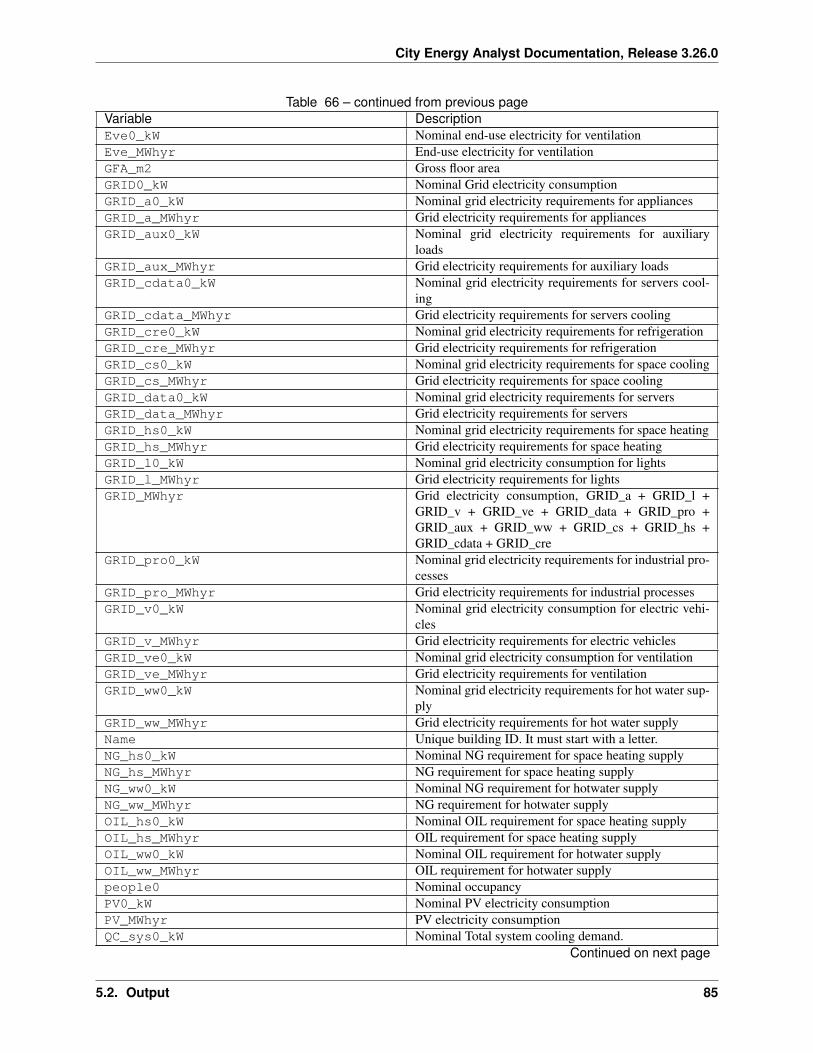
City Energy Analyst Documentation, Release 3.26.0
Table 66 – continued from previous pageVariable DescriptionEve0_kW Nominal end-use electricity for ventilationEve_MWhyr End-use electricity for ventilationGFA_m2 Gross floor areaGRID0_kW Nominal Grid electricity consumptionGRID_a0_kW Nominal grid electricity requirements for appliancesGRID_a_MWhyr Grid electricity requirements for appliancesGRID_aux0_kW Nominal grid electricity requirements for auxiliary
loadsGRID_aux_MWhyr Grid electricity requirements for auxiliary loadsGRID_cdata0_kW Nominal grid electricity requirements for servers cool-
ingGRID_cdata_MWhyr Grid electricity requirements for servers coolingGRID_cre0_kW Nominal grid electricity requirements for refrigerationGRID_cre_MWhyr Grid electricity requirements for refrigerationGRID_cs0_kW Nominal grid electricity requirements for space coolingGRID_cs_MWhyr Grid electricity requirements for space coolingGRID_data0_kW Nominal grid electricity requirements for serversGRID_data_MWhyr Grid electricity requirements for serversGRID_hs0_kW Nominal grid electricity requirements for space heatingGRID_hs_MWhyr Grid electricity requirements for space heatingGRID_l0_kW Nominal grid electricity consumption for lightsGRID_l_MWhyr Grid electricity requirements for lightsGRID_MWhyr Grid electricity consumption, GRID_a + GRID_l +
GRID_v + GRID_ve + GRID_data + GRID_pro +GRID_aux + GRID_ww + GRID_cs + GRID_hs +GRID_cdata + GRID_cre
GRID_pro0_kW Nominal grid electricity requirements for industrial pro-cesses
GRID_pro_MWhyr Grid electricity requirements for industrial processesGRID_v0_kW Nominal grid electricity consumption for electric vehi-
clesGRID_v_MWhyr Grid electricity requirements for electric vehiclesGRID_ve0_kW Nominal grid electricity consumption for ventilationGRID_ve_MWhyr Grid electricity requirements for ventilationGRID_ww0_kW Nominal grid electricity requirements for hot water sup-
plyGRID_ww_MWhyr Grid electricity requirements for hot water supplyName Unique building ID. It must start with a letter.NG_hs0_kW Nominal NG requirement for space heating supplyNG_hs_MWhyr NG requirement for space heating supplyNG_ww0_kW Nominal NG requirement for hotwater supplyNG_ww_MWhyr NG requirement for hotwater supplyOIL_hs0_kW Nominal OIL requirement for space heating supplyOIL_hs_MWhyr OIL requirement for space heating supplyOIL_ww0_kW Nominal OIL requirement for hotwater supplyOIL_ww_MWhyr OIL requirement for hotwater supplypeople0 Nominal occupancyPV0_kW Nominal PV electricity consumptionPV_MWhyr PV electricity consumptionQC_sys0_kW Nominal Total system cooling demand.
Continued on next page
5.2. Output 85
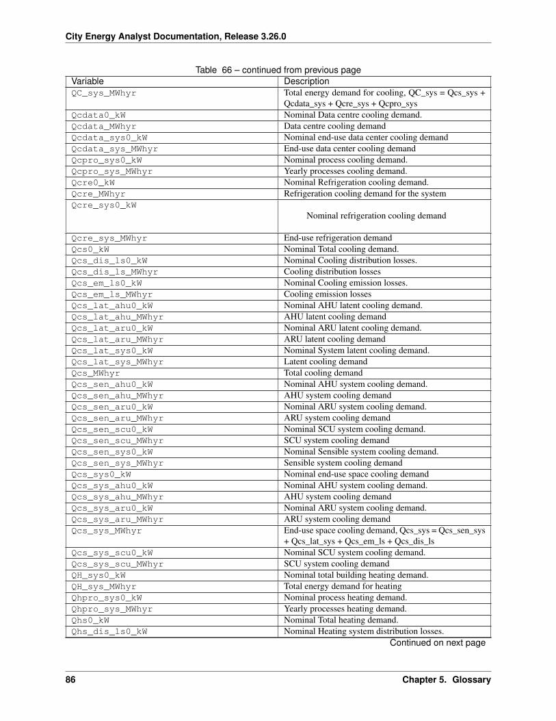
City Energy Analyst Documentation, Release 3.26.0
Table 66 – continued from previous pageVariable DescriptionQC_sys_MWhyr Total energy demand for cooling, QC_sys = Qcs_sys +
Qcdata_sys + Qcre_sys + Qcpro_sysQcdata0_kW Nominal Data centre cooling demand.Qcdata_MWhyr Data centre cooling demandQcdata_sys0_kW Nominal end-use data center cooling demandQcdata_sys_MWhyr End-use data center cooling demandQcpro_sys0_kW Nominal process cooling demand.Qcpro_sys_MWhyr Yearly processes cooling demand.Qcre0_kW Nominal Refrigeration cooling demand.Qcre_MWhyr Refrigeration cooling demand for the systemQcre_sys0_kW
Nominal refrigeration cooling demand
Qcre_sys_MWhyr End-use refrigeration demandQcs0_kW Nominal Total cooling demand.Qcs_dis_ls0_kW Nominal Cooling distribution losses.Qcs_dis_ls_MWhyr Cooling distribution lossesQcs_em_ls0_kW Nominal Cooling emission losses.Qcs_em_ls_MWhyr Cooling emission lossesQcs_lat_ahu0_kW Nominal AHU latent cooling demand.Qcs_lat_ahu_MWhyr AHU latent cooling demandQcs_lat_aru0_kW Nominal ARU latent cooling demand.Qcs_lat_aru_MWhyr ARU latent cooling demandQcs_lat_sys0_kW Nominal System latent cooling demand.Qcs_lat_sys_MWhyr Latent cooling demandQcs_MWhyr Total cooling demandQcs_sen_ahu0_kW Nominal AHU system cooling demand.Qcs_sen_ahu_MWhyr AHU system cooling demandQcs_sen_aru0_kW Nominal ARU system cooling demand.Qcs_sen_aru_MWhyr ARU system cooling demandQcs_sen_scu0_kW Nominal SCU system cooling demand.Qcs_sen_scu_MWhyr SCU system cooling demandQcs_sen_sys0_kW Nominal Sensible system cooling demand.Qcs_sen_sys_MWhyr Sensible system cooling demandQcs_sys0_kW Nominal end-use space cooling demandQcs_sys_ahu0_kW Nominal AHU system cooling demand.Qcs_sys_ahu_MWhyr AHU system cooling demandQcs_sys_aru0_kW Nominal ARU system cooling demand.Qcs_sys_aru_MWhyr ARU system cooling demandQcs_sys_MWhyr End-use space cooling demand, Qcs_sys = Qcs_sen_sys
+ Qcs_lat_sys + Qcs_em_ls + Qcs_dis_lsQcs_sys_scu0_kW Nominal SCU system cooling demand.Qcs_sys_scu_MWhyr SCU system cooling demandQH_sys0_kW Nominal total building heating demand.QH_sys_MWhyr Total energy demand for heatingQhpro_sys0_kW Nominal process heating demand.Qhpro_sys_MWhyr Yearly processes heating demand.Qhs0_kW Nominal Total heating demand.Qhs_dis_ls0_kW Nominal Heating system distribution losses.
Continued on next page
86 Chapter 5. Glossary
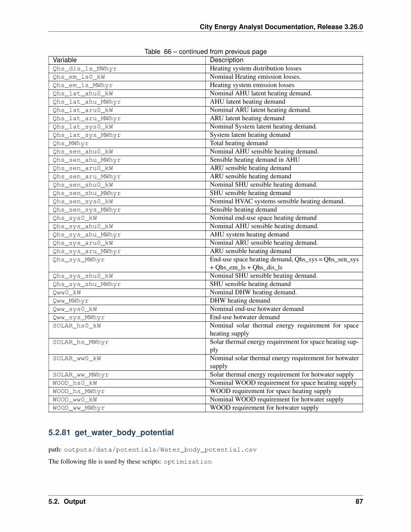
City Energy Analyst Documentation, Release 3.26.0
Table 66 – continued from previous pageVariable DescriptionQhs_dis_ls_MWhyr Heating system distribution lossesQhs_em_ls0_kW Nominal Heating emission losses.Qhs_em_ls_MWhyr Heating system emission lossesQhs_lat_ahu0_kW Nominal AHU latent heating demand.Qhs_lat_ahu_MWhyr AHU latent heating demandQhs_lat_aru0_kW Nominal ARU latent heating demand.Qhs_lat_aru_MWhyr ARU latent heating demandQhs_lat_sys0_kW Nominal System latent heating demand.Qhs_lat_sys_MWhyr System latent heating demandQhs_MWhyr Total heating demandQhs_sen_ahu0_kW Nominal AHU sensible heating demand.Qhs_sen_ahu_MWhyr Sensible heating demand in AHUQhs_sen_aru0_kW ARU sensible heating demandQhs_sen_aru_MWhyr ARU sensible heating demandQhs_sen_shu0_kW Nominal SHU sensible heating demand.Qhs_sen_shu_MWhyr SHU sensible heating demandQhs_sen_sys0_kW Nominal HVAC systems sensible heating demand.Qhs_sen_sys_MWhyr Sensible heating demandQhs_sys0_kW Nominal end-use space heating demandQhs_sys_ahu0_kW Nominal AHU sensible heating demand.Qhs_sys_ahu_MWhyr AHU system heating demandQhs_sys_aru0_kW Nominal ARU sensible heating demand.Qhs_sys_aru_MWhyr ARU sensible heating demandQhs_sys_MWhyr End-use space heating demand, Qhs_sys = Qhs_sen_sys
+ Qhs_em_ls + Qhs_dis_lsQhs_sys_shu0_kW Nominal SHU sensible heating demand.Qhs_sys_shu_MWhyr SHU sensible heating demandQww0_kW Nominal DHW heating demand.Qww_MWhyr DHW heating demandQww_sys0_kW Nominal end-use hotwater demandQww_sys_MWhyr End-use hotwater demandSOLAR_hs0_kW Nominal solar thermal energy requirement for space
heating supplySOLAR_hs_MWhyr Solar thermal energy requirement for space heating sup-
plySOLAR_ww0_kW Nominal solar thermal energy requirement for hotwater
supplySOLAR_ww_MWhyr Solar thermal energy requirement for hotwater supplyWOOD_hs0_kW Nominal WOOD requirement for space heating supplyWOOD_hs_MWhyr WOOD requirement for space heating supplyWOOD_ww0_kW Nominal WOOD requirement for hotwater supplyWOOD_ww_MWhyr WOOD requirement for hotwater supply
5.2.81 get_water_body_potential
path: outputs/data/potentials/Water_body_potential.csv
The following file is used by these scripts: optimization
5.2. Output 87
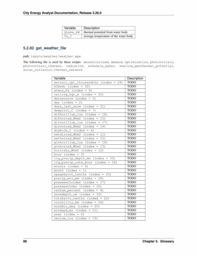
City Energy Analyst Documentation, Release 3.26.0
Variable DescriptionQLake_kW thermal potential from water bodyTs_C average temperature of the water body
5.2.82 get_weather_file
path: inputs/weather/weather.epw
The following file is used by these scripts: decentralized, demand, optimization, photovoltaic,photovoltaic_thermal, radiation, schedule_maker, shallow_geothermal_potential,solar_collector, thermal_network
Variable Descriptionaerosol_opt_thousandths (index = 29) TODOAlbedo (index = 32) TODOatmos_Pa (index = 9) TODOceiling_hgt_m (index = 25) TODOdatasource (index = 5) TODOday (index = 2) TODOdays_last_snow (index = 31) TODOdewpoint_C (index = 7) TODOdifhorillum_lux (index = 18) TODOdifhorrad_Whm2 (index = 15) TODOdirnorillum_lux (index = 17) TODOdirnorrad_Whm2 (index = 14) TODOdrybulb_C (index = 6) TODOextdirrad_Whm2 (index = 11) TODOexthorrad_Whm2 (index = 10) TODOglohorillum_lux (index = 16) TODOglohorrad_Whm2 (index = 13) TODOhorirsky_Whm2 (index = 12) TODOhour (index = 3) TODOliq_precip_depth_mm (index = 33) TODOliq_precip_rate_Hour (index = 34) TODOminute (index = 4) TODOmonth (index = 1) TODOopaqskycvr_tenths (index = 23) TODOprecip_wtr_mm (index = 28) TODOpresweathcodes (index = 27) TODOpresweathobs (index = 26) TODOrelhum_percent (index = 8) TODOsnowdepth_cm (index = 30) TODOtotskycvr_tenths (index = 22) TODOvisibility_km (index = 24) TODOwinddir_deg (index = 20) TODOwindspd_ms (index = 21) TODOyear (index = 0) TODOzenlum_lux (index = 19) TODO
88 Chapter 5. Glossary
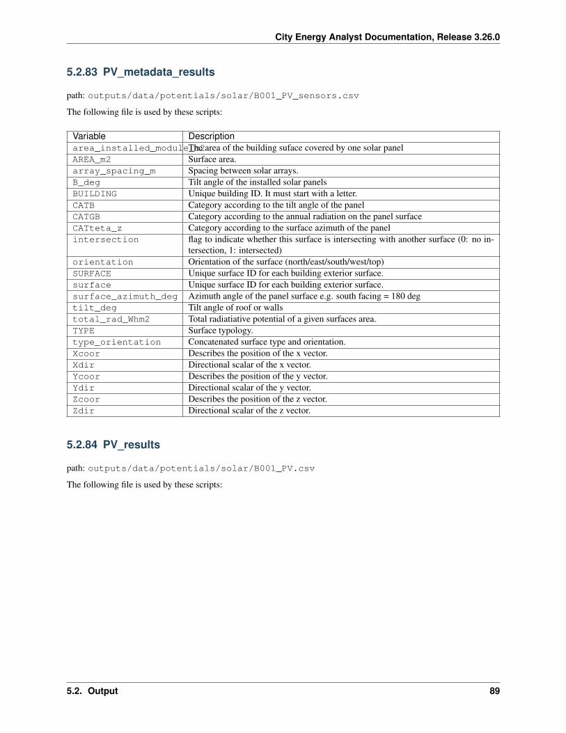
City Energy Analyst Documentation, Release 3.26.0
5.2.83 PV_metadata_results
path: outputs/data/potentials/solar/B001_PV_sensors.csv
The following file is used by these scripts:
Variable Descriptionarea_installed_module_m2The area of the building suface covered by one solar panelAREA_m2 Surface area.array_spacing_m Spacing between solar arrays.B_deg Tilt angle of the installed solar panelsBUILDING Unique building ID. It must start with a letter.CATB Category according to the tilt angle of the panelCATGB Category according to the annual radiation on the panel surfaceCATteta_z Category according to the surface azimuth of the panelintersection flag to indicate whether this surface is intersecting with another surface (0: no in-
tersection, 1: intersected)orientation Orientation of the surface (north/east/south/west/top)SURFACE Unique surface ID for each building exterior surface.surface Unique surface ID for each building exterior surface.surface_azimuth_deg Azimuth angle of the panel surface e.g. south facing = 180 degtilt_deg Tilt angle of roof or wallstotal_rad_Whm2 Total radiatiative potential of a given surfaces area.TYPE Surface typology.type_orientation Concatenated surface type and orientation.Xcoor Describes the position of the x vector.Xdir Directional scalar of the x vector.Ycoor Describes the position of the y vector.Ydir Directional scalar of the y vector.Zcoor Describes the position of the z vector.Zdir Directional scalar of the z vector.
5.2.84 PV_results
path: outputs/data/potentials/solar/B001_PV.csv
The following file is used by these scripts:
5.2. Output 89
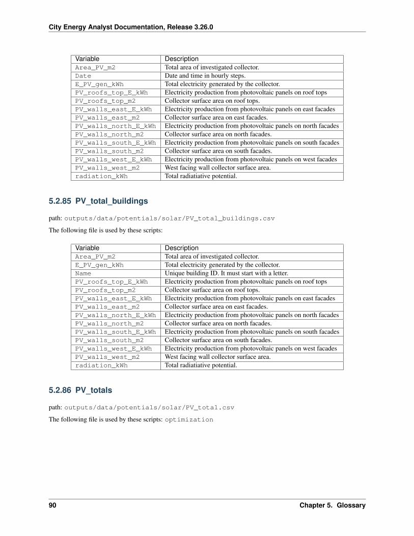
City Energy Analyst Documentation, Release 3.26.0
Variable DescriptionArea_PV_m2 Total area of investigated collector.Date Date and time in hourly steps.E_PV_gen_kWh Total electricity generated by the collector.PV_roofs_top_E_kWh Electricity production from photovoltaic panels on roof topsPV_roofs_top_m2 Collector surface area on roof tops.PV_walls_east_E_kWh Electricity production from photovoltaic panels on east facadesPV_walls_east_m2 Collector surface area on east facades.PV_walls_north_E_kWh Electricity production from photovoltaic panels on north facadesPV_walls_north_m2 Collector surface area on north facades.PV_walls_south_E_kWh Electricity production from photovoltaic panels on south facadesPV_walls_south_m2 Collector surface area on south facades.PV_walls_west_E_kWh Electricity production from photovoltaic panels on west facadesPV_walls_west_m2 West facing wall collector surface area.radiation_kWh Total radiatiative potential.
5.2.85 PV_total_buildings
path: outputs/data/potentials/solar/PV_total_buildings.csv
The following file is used by these scripts:
Variable DescriptionArea_PV_m2 Total area of investigated collector.E_PV_gen_kWh Total electricity generated by the collector.Name Unique building ID. It must start with a letter.PV_roofs_top_E_kWh Electricity production from photovoltaic panels on roof topsPV_roofs_top_m2 Collector surface area on roof tops.PV_walls_east_E_kWh Electricity production from photovoltaic panels on east facadesPV_walls_east_m2 Collector surface area on east facades.PV_walls_north_E_kWh Electricity production from photovoltaic panels on north facadesPV_walls_north_m2 Collector surface area on north facades.PV_walls_south_E_kWh Electricity production from photovoltaic panels on south facadesPV_walls_south_m2 Collector surface area on south facades.PV_walls_west_E_kWh Electricity production from photovoltaic panels on west facadesPV_walls_west_m2 West facing wall collector surface area.radiation_kWh Total radiatiative potential.
5.2.86 PV_totals
path: outputs/data/potentials/solar/PV_total.csv
The following file is used by these scripts: optimization
90 Chapter 5. Glossary
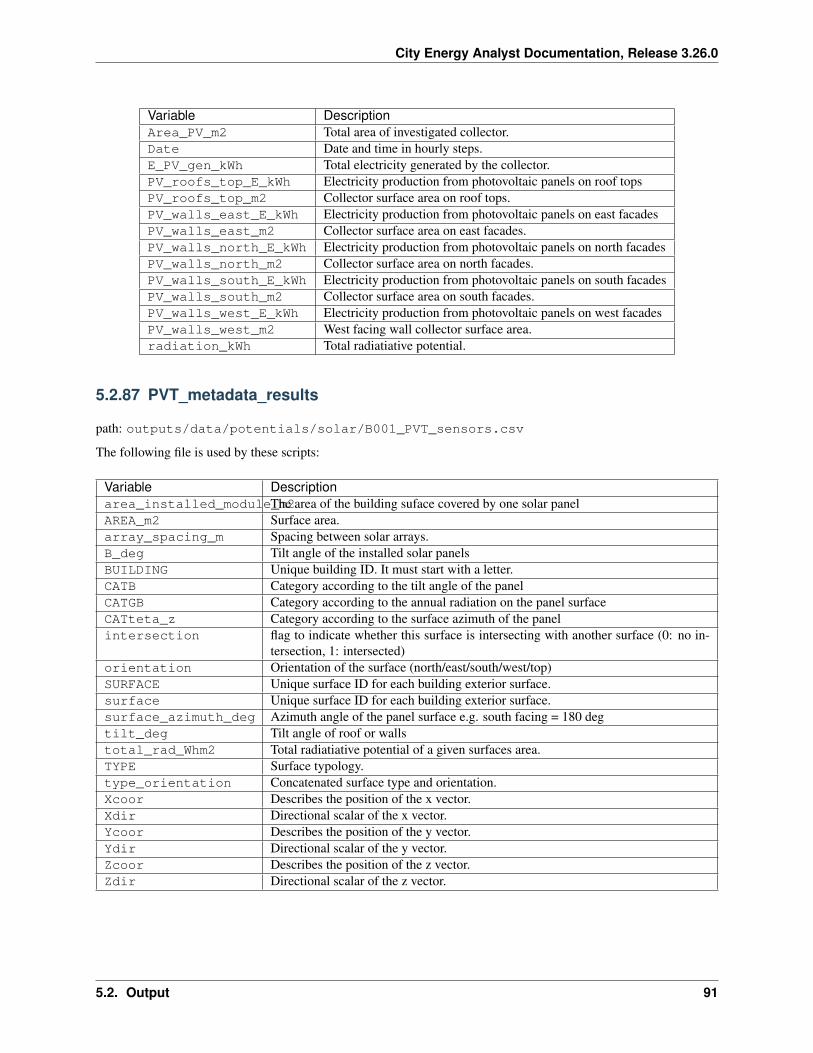
City Energy Analyst Documentation, Release 3.26.0
Variable DescriptionArea_PV_m2 Total area of investigated collector.Date Date and time in hourly steps.E_PV_gen_kWh Total electricity generated by the collector.PV_roofs_top_E_kWh Electricity production from photovoltaic panels on roof topsPV_roofs_top_m2 Collector surface area on roof tops.PV_walls_east_E_kWh Electricity production from photovoltaic panels on east facadesPV_walls_east_m2 Collector surface area on east facades.PV_walls_north_E_kWh Electricity production from photovoltaic panels on north facadesPV_walls_north_m2 Collector surface area on north facades.PV_walls_south_E_kWh Electricity production from photovoltaic panels on south facadesPV_walls_south_m2 Collector surface area on south facades.PV_walls_west_E_kWh Electricity production from photovoltaic panels on west facadesPV_walls_west_m2 West facing wall collector surface area.radiation_kWh Total radiatiative potential.
5.2.87 PVT_metadata_results
path: outputs/data/potentials/solar/B001_PVT_sensors.csv
The following file is used by these scripts:
Variable Descriptionarea_installed_module_m2The area of the building suface covered by one solar panelAREA_m2 Surface area.array_spacing_m Spacing between solar arrays.B_deg Tilt angle of the installed solar panelsBUILDING Unique building ID. It must start with a letter.CATB Category according to the tilt angle of the panelCATGB Category according to the annual radiation on the panel surfaceCATteta_z Category according to the surface azimuth of the panelintersection flag to indicate whether this surface is intersecting with another surface (0: no in-
tersection, 1: intersected)orientation Orientation of the surface (north/east/south/west/top)SURFACE Unique surface ID for each building exterior surface.surface Unique surface ID for each building exterior surface.surface_azimuth_deg Azimuth angle of the panel surface e.g. south facing = 180 degtilt_deg Tilt angle of roof or wallstotal_rad_Whm2 Total radiatiative potential of a given surfaces area.TYPE Surface typology.type_orientation Concatenated surface type and orientation.Xcoor Describes the position of the x vector.Xdir Directional scalar of the x vector.Ycoor Describes the position of the y vector.Ydir Directional scalar of the y vector.Zcoor Describes the position of the z vector.Zdir Directional scalar of the z vector.
5.2. Output 91
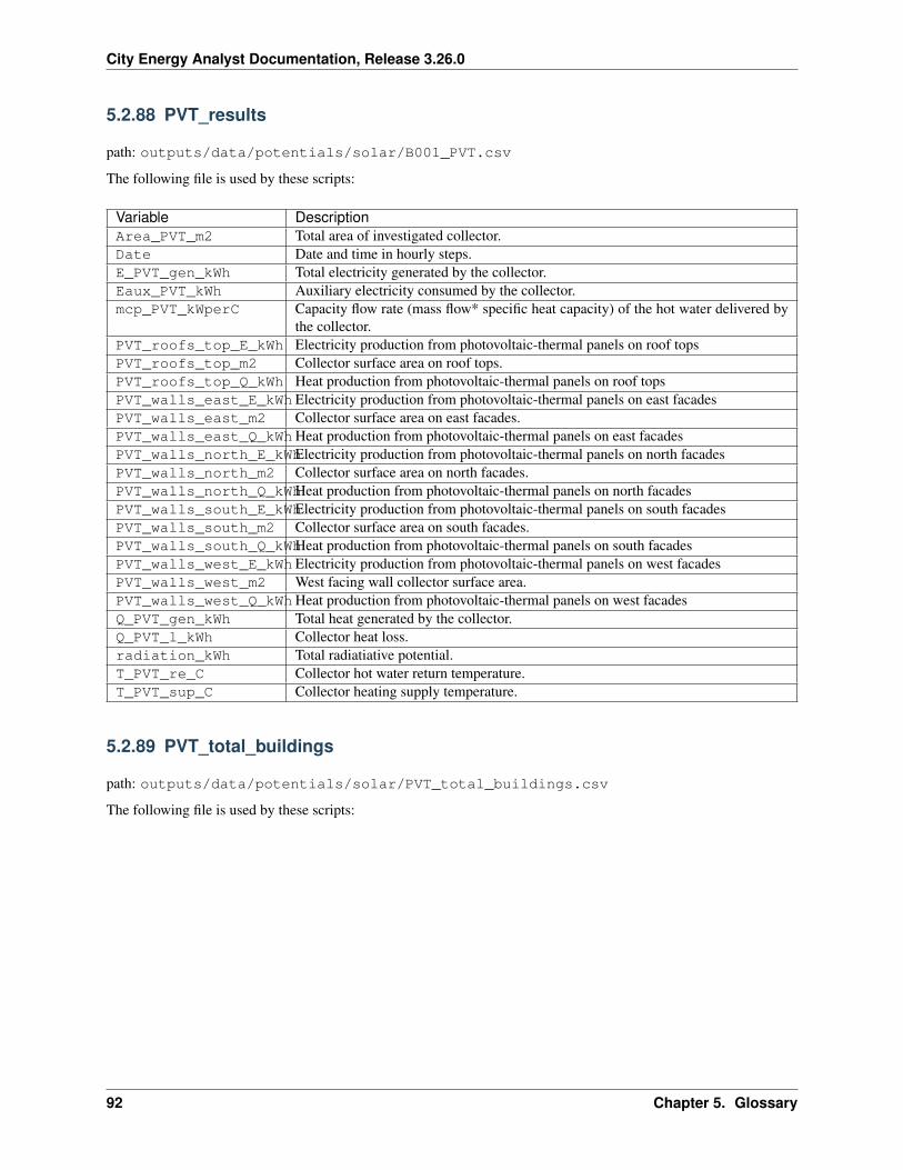
City Energy Analyst Documentation, Release 3.26.0
5.2.88 PVT_results
path: outputs/data/potentials/solar/B001_PVT.csv
The following file is used by these scripts:
Variable DescriptionArea_PVT_m2 Total area of investigated collector.Date Date and time in hourly steps.E_PVT_gen_kWh Total electricity generated by the collector.Eaux_PVT_kWh Auxiliary electricity consumed by the collector.mcp_PVT_kWperC Capacity flow rate (mass flow* specific heat capacity) of the hot water delivered by
the collector.PVT_roofs_top_E_kWh Electricity production from photovoltaic-thermal panels on roof topsPVT_roofs_top_m2 Collector surface area on roof tops.PVT_roofs_top_Q_kWh Heat production from photovoltaic-thermal panels on roof topsPVT_walls_east_E_kWh Electricity production from photovoltaic-thermal panels on east facadesPVT_walls_east_m2 Collector surface area on east facades.PVT_walls_east_Q_kWhHeat production from photovoltaic-thermal panels on east facadesPVT_walls_north_E_kWhElectricity production from photovoltaic-thermal panels on north facadesPVT_walls_north_m2 Collector surface area on north facades.PVT_walls_north_Q_kWhHeat production from photovoltaic-thermal panels on north facadesPVT_walls_south_E_kWhElectricity production from photovoltaic-thermal panels on south facadesPVT_walls_south_m2 Collector surface area on south facades.PVT_walls_south_Q_kWhHeat production from photovoltaic-thermal panels on south facadesPVT_walls_west_E_kWh Electricity production from photovoltaic-thermal panels on west facadesPVT_walls_west_m2 West facing wall collector surface area.PVT_walls_west_Q_kWhHeat production from photovoltaic-thermal panels on west facadesQ_PVT_gen_kWh Total heat generated by the collector.Q_PVT_l_kWh Collector heat loss.radiation_kWh Total radiatiative potential.T_PVT_re_C Collector hot water return temperature.T_PVT_sup_C Collector heating supply temperature.
5.2.89 PVT_total_buildings
path: outputs/data/potentials/solar/PVT_total_buildings.csv
The following file is used by these scripts:
92 Chapter 5. Glossary
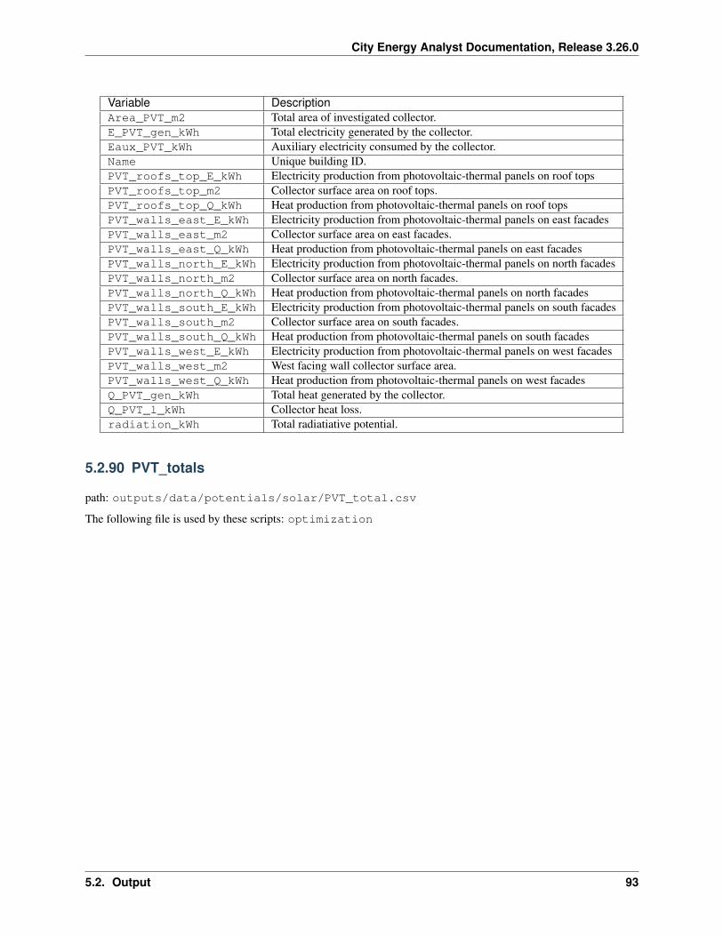
City Energy Analyst Documentation, Release 3.26.0
Variable DescriptionArea_PVT_m2 Total area of investigated collector.E_PVT_gen_kWh Total electricity generated by the collector.Eaux_PVT_kWh Auxiliary electricity consumed by the collector.Name Unique building ID.PVT_roofs_top_E_kWh Electricity production from photovoltaic-thermal panels on roof topsPVT_roofs_top_m2 Collector surface area on roof tops.PVT_roofs_top_Q_kWh Heat production from photovoltaic-thermal panels on roof topsPVT_walls_east_E_kWh Electricity production from photovoltaic-thermal panels on east facadesPVT_walls_east_m2 Collector surface area on east facades.PVT_walls_east_Q_kWh Heat production from photovoltaic-thermal panels on east facadesPVT_walls_north_E_kWh Electricity production from photovoltaic-thermal panels on north facadesPVT_walls_north_m2 Collector surface area on north facades.PVT_walls_north_Q_kWh Heat production from photovoltaic-thermal panels on north facadesPVT_walls_south_E_kWh Electricity production from photovoltaic-thermal panels on south facadesPVT_walls_south_m2 Collector surface area on south facades.PVT_walls_south_Q_kWh Heat production from photovoltaic-thermal panels on south facadesPVT_walls_west_E_kWh Electricity production from photovoltaic-thermal panels on west facadesPVT_walls_west_m2 West facing wall collector surface area.PVT_walls_west_Q_kWh Heat production from photovoltaic-thermal panels on west facadesQ_PVT_gen_kWh Total heat generated by the collector.Q_PVT_l_kWh Collector heat loss.radiation_kWh Total radiatiative potential.
5.2.90 PVT_totals
path: outputs/data/potentials/solar/PVT_total.csv
The following file is used by these scripts: optimization
5.2. Output 93
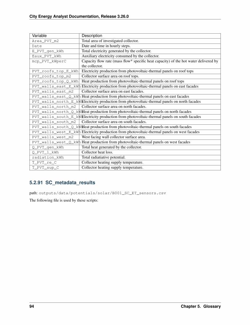
City Energy Analyst Documentation, Release 3.26.0
Variable DescriptionArea_PVT_m2 Total area of investigated collector.Date Date and time in hourly steps.E_PVT_gen_kWh Total electricity generated by the collector.Eaux_PVT_kWh Auxiliary electricity consumed by the collector.mcp_PVT_kWperC Capacity flow rate (mass flow* specific heat capacity) of the hot water delivered by
the collector.PVT_roofs_top_E_kWh Electricity production from photovoltaic-thermal panels on roof topsPVT_roofs_top_m2 Collector surface area on roof tops.PVT_roofs_top_Q_kWh Heat production from photovoltaic-thermal panels on roof topsPVT_walls_east_E_kWh Electricity production from photovoltaic-thermal panels on east facadesPVT_walls_east_m2 Collector surface area on east facades.PVT_walls_east_Q_kWhHeat production from photovoltaic-thermal panels on east facadesPVT_walls_north_E_kWhElectricity production from photovoltaic-thermal panels on north facadesPVT_walls_north_m2 Collector surface area on north facades.PVT_walls_north_Q_kWhHeat production from photovoltaic-thermal panels on north facadesPVT_walls_south_E_kWhElectricity production from photovoltaic-thermal panels on south facadesPVT_walls_south_m2 Collector surface area on south facades.PVT_walls_south_Q_kWhHeat production from photovoltaic-thermal panels on south facadesPVT_walls_west_E_kWh Electricity production from photovoltaic-thermal panels on west facadesPVT_walls_west_m2 West facing wall collector surface area.PVT_walls_west_Q_kWhHeat production from photovoltaic-thermal panels on west facadesQ_PVT_gen_kWh Total heat generated by the collector.Q_PVT_l_kWh Collector heat loss.radiation_kWh Total radiatiative potential.T_PVT_re_C Collector heating supply temperature.T_PVT_sup_C Collector heating supply temperature.
5.2.91 SC_metadata_results
path: outputs/data/potentials/solar/B001_SC_ET_sensors.csv
The following file is used by these scripts:
94 Chapter 5. Glossary
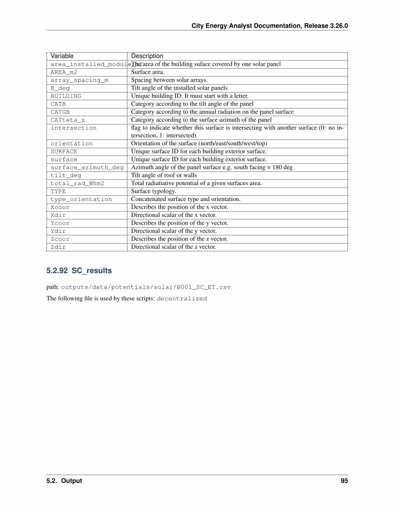
City Energy Analyst Documentation, Release 3.26.0
Variable Descriptionarea_installed_module_m2The area of the building suface covered by one solar panelAREA_m2 Surface area.array_spacing_m Spacing between solar arrays.B_deg Tilt angle of the installed solar panelsBUILDING Unique building ID. It must start with a letter.CATB Category according to the tilt angle of the panelCATGB Category according to the annual radiation on the panel surfaceCATteta_z Category according to the surface azimuth of the panelintersection flag to indicate whether this surface is intersecting with another surface (0: no in-
tersection, 1: intersected)orientation Orientation of the surface (north/east/south/west/top)SURFACE Unique surface ID for each building exterior surface.surface Unique surface ID for each building exterior surface.surface_azimuth_deg Azimuth angle of the panel surface e.g. south facing = 180 degtilt_deg Tilt angle of roof or wallstotal_rad_Whm2 Total radiatiative potential of a given surfaces area.TYPE Surface typology.type_orientation Concatenated surface type and orientation.Xcoor Describes the position of the x vector.Xdir Directional scalar of the x vector.Ycoor Describes the position of the y vector.Ydir Directional scalar of the y vector.Zcoor Describes the position of the z vector.Zdir Directional scalar of the z vector.
5.2.92 SC_results
path: outputs/data/potentials/solar/B001_SC_ET.csv
The following file is used by these scripts: decentralized
5.2. Output 95
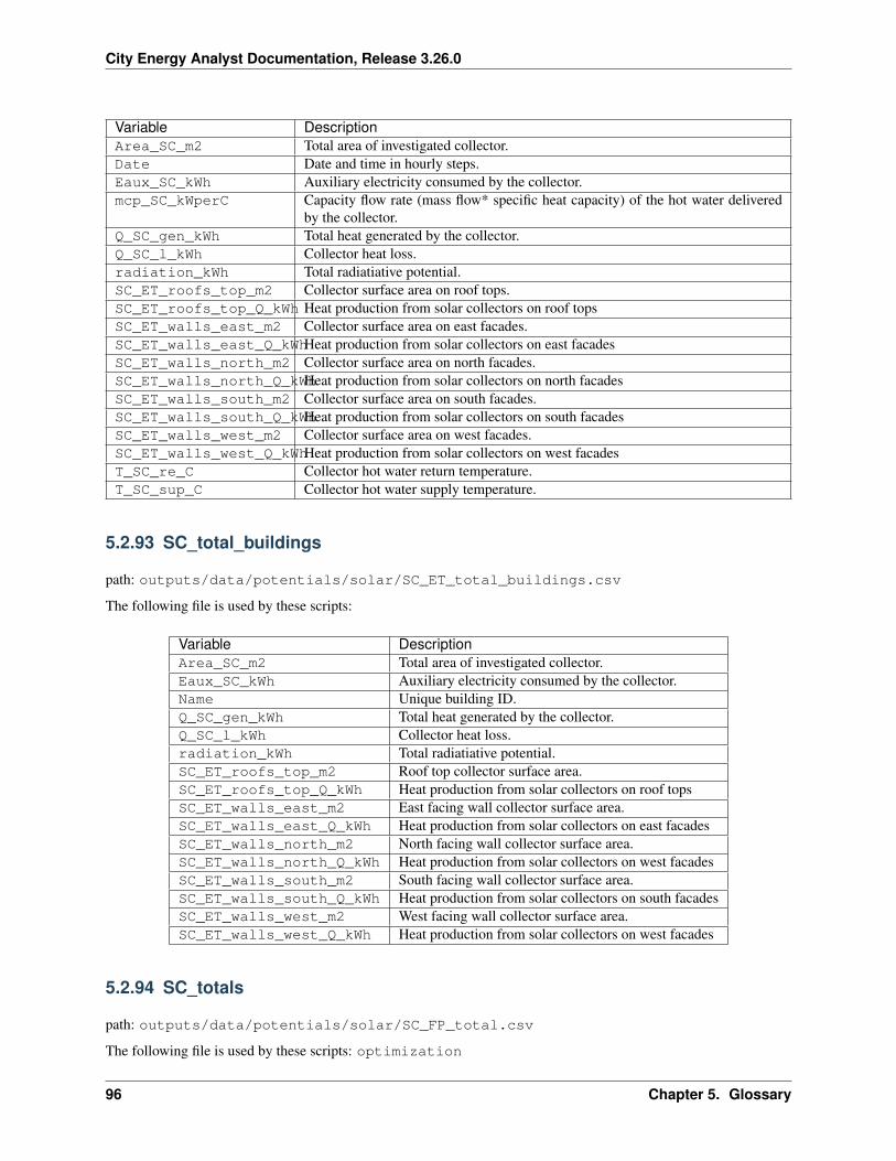
City Energy Analyst Documentation, Release 3.26.0
Variable DescriptionArea_SC_m2 Total area of investigated collector.Date Date and time in hourly steps.Eaux_SC_kWh Auxiliary electricity consumed by the collector.mcp_SC_kWperC Capacity flow rate (mass flow* specific heat capacity) of the hot water delivered
by the collector.Q_SC_gen_kWh Total heat generated by the collector.Q_SC_l_kWh Collector heat loss.radiation_kWh Total radiatiative potential.SC_ET_roofs_top_m2 Collector surface area on roof tops.SC_ET_roofs_top_Q_kWh Heat production from solar collectors on roof topsSC_ET_walls_east_m2 Collector surface area on east facades.SC_ET_walls_east_Q_kWhHeat production from solar collectors on east facadesSC_ET_walls_north_m2 Collector surface area on north facades.SC_ET_walls_north_Q_kWhHeat production from solar collectors on north facadesSC_ET_walls_south_m2 Collector surface area on south facades.SC_ET_walls_south_Q_kWhHeat production from solar collectors on south facadesSC_ET_walls_west_m2 Collector surface area on west facades.SC_ET_walls_west_Q_kWhHeat production from solar collectors on west facadesT_SC_re_C Collector hot water return temperature.T_SC_sup_C Collector hot water supply temperature.
5.2.93 SC_total_buildings
path: outputs/data/potentials/solar/SC_ET_total_buildings.csv
The following file is used by these scripts:
Variable DescriptionArea_SC_m2 Total area of investigated collector.Eaux_SC_kWh Auxiliary electricity consumed by the collector.Name Unique building ID.Q_SC_gen_kWh Total heat generated by the collector.Q_SC_l_kWh Collector heat loss.radiation_kWh Total radiatiative potential.SC_ET_roofs_top_m2 Roof top collector surface area.SC_ET_roofs_top_Q_kWh Heat production from solar collectors on roof topsSC_ET_walls_east_m2 East facing wall collector surface area.SC_ET_walls_east_Q_kWh Heat production from solar collectors on east facadesSC_ET_walls_north_m2 North facing wall collector surface area.SC_ET_walls_north_Q_kWh Heat production from solar collectors on west facadesSC_ET_walls_south_m2 South facing wall collector surface area.SC_ET_walls_south_Q_kWh Heat production from solar collectors on south facadesSC_ET_walls_west_m2 West facing wall collector surface area.SC_ET_walls_west_Q_kWh Heat production from solar collectors on west facades
5.2.94 SC_totals
path: outputs/data/potentials/solar/SC_FP_total.csv
The following file is used by these scripts: optimization
96 Chapter 5. Glossary
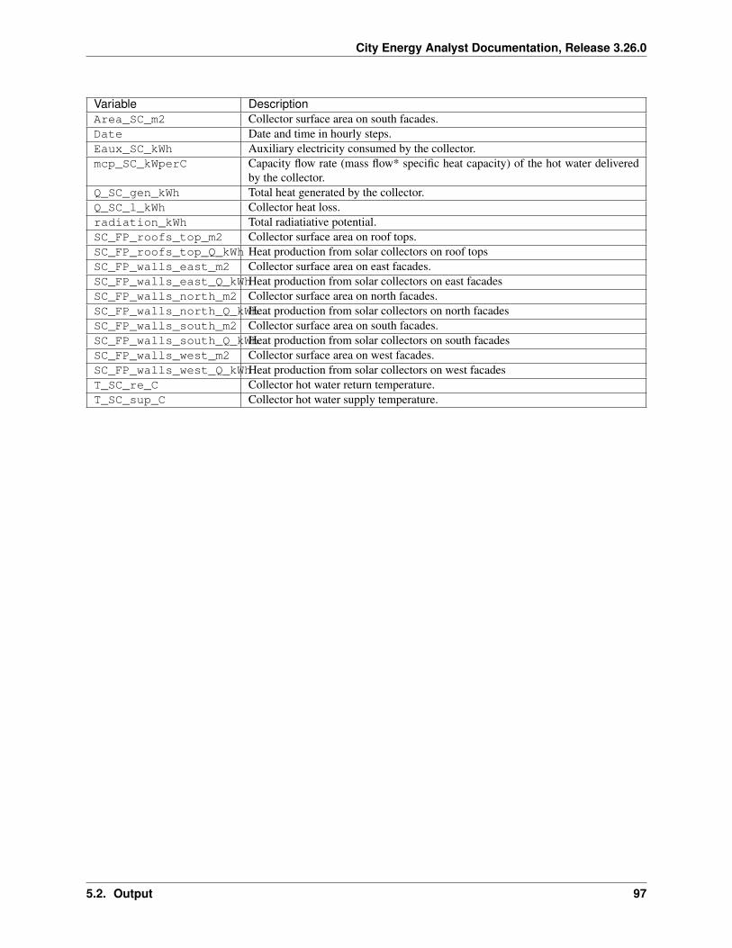
City Energy Analyst Documentation, Release 3.26.0
Variable DescriptionArea_SC_m2 Collector surface area on south facades.Date Date and time in hourly steps.Eaux_SC_kWh Auxiliary electricity consumed by the collector.mcp_SC_kWperC Capacity flow rate (mass flow* specific heat capacity) of the hot water delivered
by the collector.Q_SC_gen_kWh Total heat generated by the collector.Q_SC_l_kWh Collector heat loss.radiation_kWh Total radiatiative potential.SC_FP_roofs_top_m2 Collector surface area on roof tops.SC_FP_roofs_top_Q_kWh Heat production from solar collectors on roof topsSC_FP_walls_east_m2 Collector surface area on east facades.SC_FP_walls_east_Q_kWhHeat production from solar collectors on east facadesSC_FP_walls_north_m2 Collector surface area on north facades.SC_FP_walls_north_Q_kWhHeat production from solar collectors on north facadesSC_FP_walls_south_m2 Collector surface area on south facades.SC_FP_walls_south_Q_kWhHeat production from solar collectors on south facadesSC_FP_walls_west_m2 Collector surface area on west facades.SC_FP_walls_west_Q_kWhHeat production from solar collectors on west facadesT_SC_re_C Collector hot water return temperature.T_SC_sup_C Collector hot water supply temperature.
5.2. Output 97

City Energy Analyst Documentation, Release 3.26.0
98 Chapter 5. Glossary
CHAPTER 6
Legal
6.1 License
The core of the City Energy Analyst is registered under The MIT License (MIT).
6.1.1 for V0.3c
Copyright (c) 2016, ‘Jimeno A. Fonseca <http://www.fcl.ethz.ch/person/dr-jimeno-a-fonseca/>‘__, ‘DarenThomas <http://www.systems.arch.ethz.ch/about-us/team/team-zurich/daren-thomas.html>‘__, ‘Gabriel Happle<http://www.fcl.ethz.ch/person/gabriel-happle/>‘__, ‘Shanshan Hsieh <http://www.fcl.ethz.ch/person/hsieh-shan-shan/>‘__, ‘Martin Mosteiro <http://www.systems.arch.ethz.ch/about-us/team/team-zurich/martin-mosteiro-romero.html>‘__, ‘Amr Elesawy <http://www.systems.arch.ethz.ch/about-us/team/team-zurich/amr-elesawy.html>‘__, ‘Architecture and Building Systems - ETH Zurich <http://www.systems.arch.ethz.ch>‘__
Permission is hereby granted, free of charge, to any person obtaining a copy of this software and associated documen-tation files (the “Software”), to deal in the Software without restriction, including without limitation the rights to use,copy, modify, merge, publish, distribute, sublicense, and/or sell copies of the Software, and to permit persons to whomthe Software is furnished to do so, subject to the following conditions:
The above copyright notice and this permission notice shall be included in all copies or substantial portions ofthe Software.
6.1.2 for V0.1
Copyright (c) 2015, ‘Jimeno A. Fonseca <http://www.fcl.ethz.ch/person/dr-jimeno-a-fonseca/>‘__, ‘Daren Thomas<http://www.systems.arch.ethz.ch/about-us/team/team-zurich/daren-thomas.html>‘__, ‘Architecture and BuildingSystems - ETH Zurich <http://www.systems.arch.ethz.ch>‘__
Permission is hereby granted, free of charge, to any person obtaining a copy of this software and associated documen-tation files (the “Software”), to deal in the Software without restriction, including without limitation the rights to use,copy, modify, merge, publish, distribute, sublicense, and/or sell copies of the Software, and to permit persons to whomthe Software is furnished to do so, subject to the following conditions:
99

City Energy Analyst Documentation, Release 3.26.0
The above copyright notice and this permission notice shall be included in all copies or substantial portions ofthe Software.
6.2 Disclaimer
The City Energy Analyst is provided “as is”, without warranty of any kind, express orimplied, including but not limited to the warranties of merchantability,fitness for a particular purpose and noninfringement. In no event shall theauthors or copyright holders be liable for any claim, damages or otherliability, whether in an action of contract, tort or otherwise, arising from,out of or in connection with the software or the use or other dealings in thesoftware.
100 Chapter 6. Legal
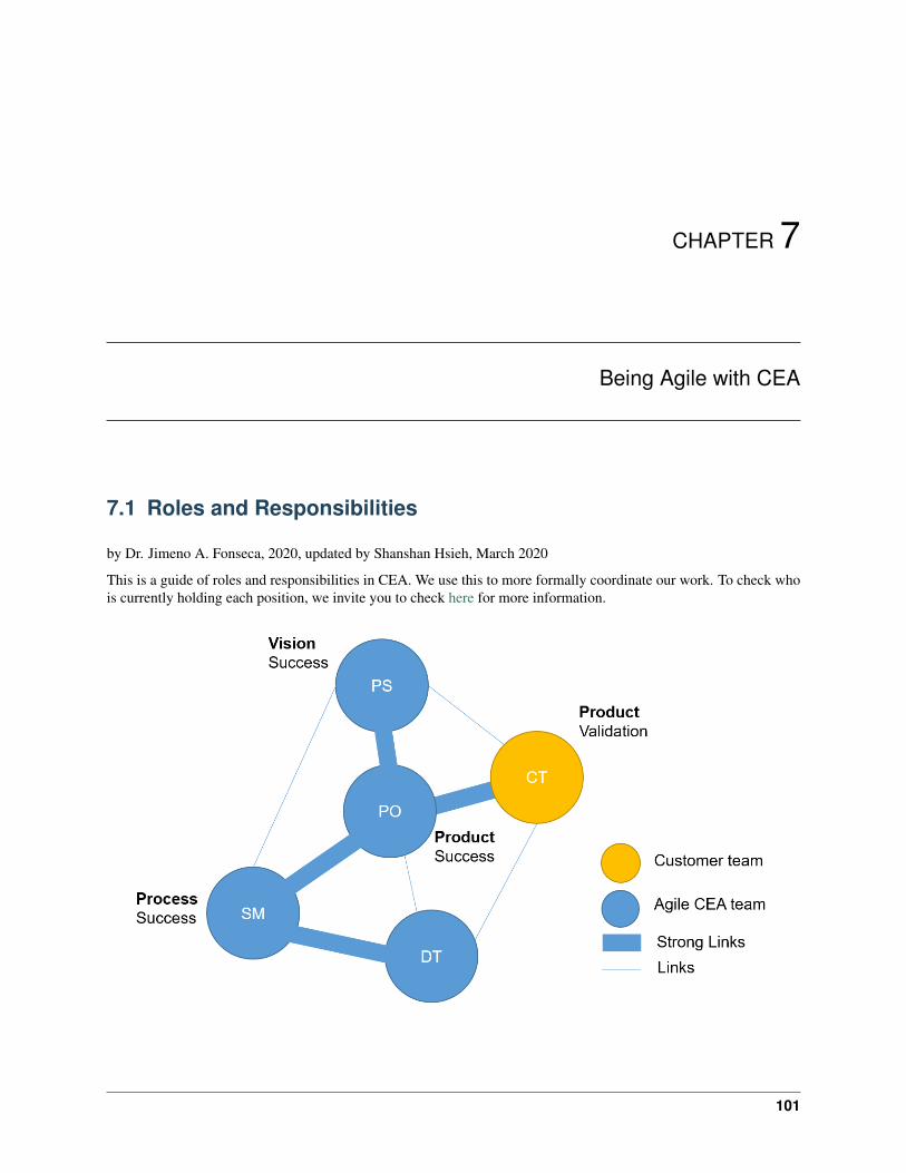
CHAPTER 7
Being Agile with CEA
7.1 Roles and Responsibilities
by Dr. Jimeno A. Fonseca, 2020, updated by Shanshan Hsieh, March 2020
This is a guide of roles and responsibilities in CEA. We use this to more formally coordinate our work. To check whois currently holding each position, we invite you to check here for more information.
101
City Energy Analyst Documentation, Release 3.26.0
7.1.1 Product Sponsor (PS)
The Project Sponsor is the person that has overall responsibility and accountability.
Responsibilities
1. Guarantee that our vision be successful by finding and securing the budget and ensuring that high-level organi-zational risks are mitigated.
2. Champion the project based on whether the work fits our research needs and overall strategy.
3. Empower the Product Owner to act for him/her on a more tactical basis.
Engagement
1. Participate in the Roadmap planning and review event (see Activities).
7.1.2 Product Owner (PO)
The Product Owner is the voice of the customer and performs all tactical operations.
PO Responsibilities
1. Guarantee our product success by acting as a conduit/facilitator for communication between the team and thecustomers.
The means to communication to the customers include:
• Conducting Usability Tests
• Organizing Teaching Activities
• Maintaining Documentation
• Maintaining CEA website
• Maintaining [email protected]
• Distributing Newsletters
2. Coordinate the Roadmap planning and review event (see Activities).
3. Break down the overall vision into feasible and tactical pieces of work for the development team to understandand create.
4. Prioritizing and selecting user stories. This entails grooming the product backlogs with the help of the SrcumMaster.
The product backlogs contains issues that is labelled as Must-have and Should-have. Here are the details of the labelsused to categorize new issues in the CEA:
102 Chapter 7. Being Agile with CEA
City Energy Analyst Documentation, Release 3.26.0
Label DescriptionMust-have
• Features defined in the roadmap.• Bugs.
Should-have• Issues that can’t be categorized for the moment.
Won’t have• Features that are not in the roadmap.• Features that are hard to maintain. These features
can become external modules of the CEA.
PO Engagement
1. Participate in all Activities.
2. One day per week on communication to the customer team and event coordination.
7.1.3 Scrum Master (SM)
The Scrum Master is the servant leader and maintainer of agile practices.
SM Responsibilities
1. Coordinate all Activities that form the agile practices of the CEA.
2. Coordinate the training of new developers.
1. Introduce the functionalities in the CEA.
2. Introduce the CEA-ecosystem
3. Coordinate the training of the team
1. Pair-programming sessions
2. Refresher course on programming
4. Support the Product Owner on setting priorities and grooming the product backlog.
5. Maintaining the internal communication channel (slack).
7.1.4 Development Team (DT)
The Development team is the group of individuals who build CEA. His/her main responsibilities are:
1. Create the best working software possible.
2. Design, analyze, develop, test and document new features in CEA.
3. Be self-organized and self-directed.
4. Participate in all agile practices led by the Scrum Master (Activities).
7.1. Roles and Responsibilities 103
City Energy Analyst Documentation, Release 3.26.0
7.1.5 Customer Team (CT)
The Customer team is the group of individuals who use CEA. They are not part of the CEA team, but their function isextremely important for the succes of the project.
1. Represent one or more User Personas in CEA.
2. Validate CEA and give feedback to the Product Owner
3. Communicate issues and new features to the Product Owner.
7.2 User Personas
This is a guide of User Personas in CEA. These are potential end-users of CEA. We describe the goals and prioritiesof these user personas hereafter. We use this information to build User Stories / Report bugs / Develop new features.It is of utmost importance for every developer to know this by heart.
7.2.1 Researcher
The priorities of this User Persona are:
1. To find an answer to a unique research question/hypothesis
2. To build upon the state-of-the-art, saving time in coding newly established algorithms.
3. To conduct experiments quickly.
4. to generate replicable and transparent results.
7.2.2 Student
The priorities of this User Persona are:
1. To understand the trade-offs of planning cities for energy efficiency.
2. To build intuition about the mechanics of different analysis and modeling techniques.
3. To generate replicable and transparent results.
7.2.3 Practitioner
The priorities of this User Persona are:
1. To analyze real case studies quickly.
2. To generate great visualizations which aid communication to stakeholders.
3. To generate standard, replicable and transparent results.
7.3 User Stories
User stories define WHAT (need), WHY (reason) and for WHOM (User persona) we aim to solve a new bug orimplement a new feature. This helps our Project Owner to better prioritize issues around CEA.
104 Chapter 7. Being Agile with CEA

City Energy Analyst Documentation, Release 3.26.0
We have a standard yet simple way to define these user stories. This guide walks you through defining your first userstory.
7.3.1 Step 1. define a user persona
At CEA we differentiate four (4) potential USERs for creating an user story. These are key groups of users we wantCEA to serve and are defined as user personas. The first step in creating a new story is to select a User Persona fromthe following list:
1. Researcher: A member of the CEA research team or network of contributors.
2. Student or Practitioner: An active user of CEA.
For more information about the goals and priorities of the different user personas check: User Personas
7.3.2 Step 2. define its needs
Think about the NEED this user persona has. Is it about a problem/bug or rather about a new feature you want to beimplemented? It is important that you think about the NEED from the point of view of the user persona.
7.3.3 Step 3. define a reason
Now think about why the user persona needs that.
7.3.4 Step 4. put the story together
Now put it all together using the following template:
As a USER PERSONA I want to NEED so I can REASON
Here is an example:
USER PERSONA Researcher
NEED know how to define user stories
REASON add new bugs and features to the pipeline of CEA
The result will be the title of your user story:
As a Researcher I want to know how to define user stories so I can add new bugs and features to the pipeline of CEA.
One more example:
USER PERSONA Student
NEED understand how the dynamic tool works
REASON use CEA more effectively
The result will be the title of your user story:
As a Student I want to understand how the dynamic tool works so I can use CEA more effectively.
7.3. User Stories 105
City Energy Analyst Documentation, Release 3.26.0
7.3.5 Step 5. submit a new user story
Now it is time to submit a new user story in CEA. For this:
1. Go to the CEA repository in Github.
2. Click New Issue
3. in Title, add the name of the user story
4. Finally, in description, give a more detailed description of the problem.
5. In the description you can directly connect to other user stories using # or connect to other people using @ inthe text.
7.4 Activities
This is a guide of Activities carried out during the development of CEA. This activities are part of our concept ofoperation under responsibilities of the Scrum Master.
As the project evolves, so do the activities: We try to keep them as lean as possible and expect to adapt this documentas needed.
One important aspect of the team is how it is distributed between (mainly) 2 timezones (Singapore, Switzerland) anda large part of the team has other responsibilities (e.g. writing their PhD thesis) that needs to be accounted for andimpacts the amount of “ceremony” we can sustain.
7.4.1 The Kanban board
The written record of these activities is reflected in the GitHub issues and are maintained using ZenHub to produce aKanban view of our process. The columns on our Kanban board are:
• New Issues
• Project Backlog
• Sprint Backlog
• In Progress
• In Review
• Closed
The different events focus on different parts of the process and their respective Kanban columns are mentioned below.
7.4.2 Pre-Planning event
• Duration: 1 - 2 hours.
• Frequency: Before each Planning event (bi-weekly)
• Scope: Prepare the Kanban board to streamline the Planning event.
• Kanban:
– Move User stories from “New Issues” to either “Product Backlog” (if in scope) or close them with thelabel “wont-fix” or “known issue”.
106 Chapter 7. Being Agile with CEA
City Energy Analyst Documentation, Release 3.26.0
– Make sure each User story in Product backlog has a (preliminary) time estimation (measured in storypoints, each story point is roughly 1 day of work)
– Make sure each User story in Product backlog has a priority label: “Must have” or “Should have”
– Order the Product backlog with most important issues at the top of the column
NOTE: Currently, the Pre-Planning event is held every second Wednesday at 9am Zurich time on Zoom, the day beforethe Planning event.
Attendees: Product Owner, Scrum Master
7.4.3 Planning event
• Duration: 1 - 2 hours.
• Frequency: After every block of work (sprint, bi-weekly)
• Scope: Define what User stories should go in the next block of work (sprint). These stories are attached to anew time-bounded milestone.
• Kanban: User stories are moved from the Product Backlog and to the Sprint Backlog and assigned to a memberof the Development team. Each User story requires a time estimate and the developer the issue is assigned to isresponsible for updating this estimate based on his/her experience.
Currently, the Planning event is held every second Thursday at 9am Zurich time on Zoom. Subject to change.
Attendees: Scrum Master, Product Owner, Product Sponsor, and Development Team.
7.4.4 Daily stand-up
• Duration: 15 min.
• Frequency: daily
• Scope: Provide early support and mentoring
• Kanban: Main focus is on User stories in the “In Progress” and “In Review” columns. This is also time to pointout important “New Issues” and discuss problems blocking “Sprint Backlog” issues from being moved to “InProgress”.
NOTE: Currently this is being held every morning at 9am (Switzerland time) on Zoom with the SM and a reduced setof the DT.
Attendees: Scrum Master and Development Team.
7.4.5 Roadmap planning and review event
• Duration: 1 - 2 hours.
• Frequency: quarterly
• Scope:
1. Demonstration of the newest development in the CEA.
2. Bottlenecks that are faced by the development team.
3. Planning for the next quarter.
7.4. Activities 107

City Energy Analyst Documentation, Release 3.26.0
Attendees: Scrum Master, Product Owner, Product Sponsor, and Development Team.
NOTE: While this event is mainly an update to the product sponsors, it is also open to the entire CEA team and thecustomer team.
7.4.6 Retrospective
• Duration: 1 hour.
• Frequency: After every review event
• Scope: Discuss what was wrong and set next steps to follow.
NOTE: This activity is currently not part of our repertoire. We are trying to figure out the right parameters for this.
Attendees: Scrum Master and Development Team.
7.5 Communication channels
This is a guide of Communication channels in CEA. These are maintained by our Scrum Master.
7.5.1 CEA website
• Host: squarespace.com
• Credentials: Ask the Product Owner
• Administrator: Product Owner
• Access granted to: Scrum Master, Product Owner, Development Team
7.5.2 CEA e-mail
• Host: arch.ethz.ch
• Credentials: Ask the Product Owner
• Administrator: Product Owner
• Access granted to: Scrum Master, Product Owner
7.5.3 CEA messenger
• Host: ceadev.slack.com
• Credential: Ask the Scrum Master
• Administrator: Scrum Master
• Access granted to: Scrum Master, Product Owner, Development team
108 Chapter 7. Being Agile with CEA

City Energy Analyst Documentation, Release 3.26.0
7.5.4 CEA newsletter
• Host: mailchimp.com
• Credentials: Ask the Product Owner
• Administrator: Product Owner
• Access granted to: Scrum Master, Product Owner
7.5.5 CEA documents
• Host: gmail.com
• Credentials: Ask the Scrum Master Daren Thomas
• Administrator: Scrum Master
• Access granted to: Scrum Master, Product Owner, Development Team
7.5. Communication channels 109

City Energy Analyst Documentation, Release 3.26.0
110 Chapter 7. Being Agile with CEA
CHAPTER 8
Contributing to City Energy Analyst (CEA)
First off, thank you for taking the time to contribute!
The following is a set of guidelines for contributing to CEA, which is hosted on GitHub. These are mostly guidelines,not rules. Use your best judgment, and feel free to propose changes to this document in a pull request.
8.1 Step 1. Let us know about it
Whether you would like to implement a new feature or fix a bug, let the CEA team know. This will help us tocoordinate efforts across network of developers. It will also help us to better support your work.
You can let us know by reporting a new issue https://github.com/architecture-building-systems/CityEnergyAnalyst/issues/new/choose
8.2 Step 2. Install our development version
If you have not done it yet, please install the development version of CEA. Make sure you have the CEA repository(included in the development version) connected via github and your favorite python editor (ours is PyCharm). Youcan download the development version with the same link as the one used www.cityenergyanalyst.com/tryit.
Here we tell you how to do it https://cityenergyanalyst.com/blog/2019/6/3/how-to-install-the-cea-on-windows-part-2
8.3 Step 3. Branch out and code
Branch out from out main ‘Master branch” of our github repository and start coding. This can be done with the CEAdevelopment version. For this make sure to use one of our template scripts and follow the documentation guide. Thiscould help to maintain an homogenous structure, and help us to acknowledge you.
Check these guides for more details: how-to-use-github, how-to-add-a-new-script-to-the-cea.
111

City Energy Analyst Documentation, Release 3.26.0
8.4 Step 4. Check style
If you have not done it yet, take some time to get acquainted with variable names in CEA. This would make easier foryou to understand and develop consistent code.
Here we tell some basic hints how-to-name-variables.
8.5 Step 5. Run some local tests
Now test if your creation does not brake CEA’s functionality.
The next guide explains how to run local unittests in CEA how-to-test-the-cea.
8.6 Step 6. Create a Pull request
Now it is time to ask other developer of CEA to review your code so we get to make it part of the CEA main core. Wedo this by creating a Pull Request in github.
Check this guide for more details on how to do it: how-to-use-github.
8.7 Step 7. Claim your CEA T-shirt!
What happens after that? We will check the code, and if all is correct we will proceed to make it part of CEA’s mainsource code. If your work has been merged, give yourself an applause. You have just made part of the growing networkof developers of CEA.
Your are entitled to claim a CEA T-shirt after this to [email protected]
112 Chapter 8. Contributing to City Energy Analyst (CEA)
CHAPTER 9
Developer walkthrough
9.1 The Configuration File
The City Energy Analyst uses a configuration file for storing user preferences. User preferences are inputs to simula-tion runs like what weather file to use, what scenario to use and script-specific inputs.
When you first run the cea tool (e.g. with cea install-toolbox during the installation process), the defaultconfiguration file is copied to your home folder.
On Windows systems, the home folder is usually something like C:\Users\YourUserName, so the configurationfile would be stored in C:\Users\michelle\cea.config, assuming that your username is michelle.
9.1.1 Setting values in the configuration file
The most important values to set when working with the CEA are probably those under the [general] section,specifically scenario, and weather
Open the cea.config file with a text editor (notebook.exe will do just fine) and update the values.
Note: We expect to implement an editor for the configuration file soon.
9.1.2 The configuration file and the command line interface
When you run the CEA from the command line (with the cea command), then the values to use as inputs to the scriptsare taken from the configuration file. You can override each value by adding it as a parameter to the cea command,using the syntax -- + parameter-name + ‘‘ ‘‘ + value. Example:
$ cea demand --scenario C:\scenario\baseline --weather Brussels
113
City Energy Analyst Documentation, Release 3.26.0
9.1.3 The configuration file and the ArcGIS interface
The values in the configuration file are used as the default values when you open up a cea tool in the ArcGIS interface.
9.2 Configuration File Details
Let’s explore the details of how the configuration file works!
The configuration file edited by the user (~/cea.config) is only the tip of the iceberg, resting on a foundation of thedefault configuraiton file default.config file and the class cea.config.Configuration, which reads inthe default configuration file as well as the user configuration file and makes those parameters available to the scripts.Each script is provided with an instance of cea.config.Configuration called config.
Each parameter is defined in a section. Each parameter has a type, which specifies the range of values allowed for thatparameter and also how to read and write them to the configuration file.
Access to parameters through the config variable happens by section. Since all section names and parameter namesin the configuration file follow the kebab-case naming convention, and these are not valid python identifiers, a transla-tion is made to the snake_case naming convention: All hyphens (-) are replaced by underscores (_).
The syntax is simple:
"config." + [section] + "." + parameter
The section name is optional for the section general, so config.general.scenario refers to the same pa-rameter as config.scenario. Note that these parameters can also be set:
config.scenario = r'C:\hoenggerberg\baseline'
If you want to persist these changes to disk, you need to explicitly save them with cea.config.Configuration.save().
Note: It is a bad idea to have multiple instances of cea.config.Configuration, as if one part of a scriptchanges a parameter, this will not be reflected in the other instances. Each CEA script accepts a config argument toit’s main function and should only use that.
114 Chapter 9. Developer walkthrough
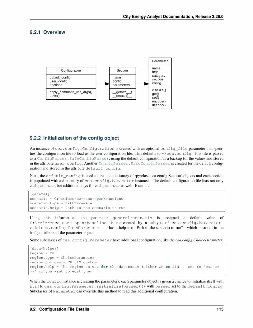
City Energy Analyst Documentation, Release 3.26.0
9.2.1 Overview
Configuration
default_configuser_configsections
apply_command_line_args()save()
Section
nameconfigparameters
__getattr__()__setattr()__
Parameter
namehelpcategorysectionconfig
initialize()get()set()encode()decode()
9.2.2 Initialization of the config object
An instance of cea.config.Configuration is created with an optional config_file parameter that speci-fies the configuration file to load as the user configuration file. This defaults to ~/cea.config. This file is parsedas a ConfigParser.SafeConfigParser, using the default configuration as a backup for the values and storedin the attribute user_config. Another ConfigParser.SafeConfigParser is created for the default config-uration and stored in the attribute default_config.
Next, the default_config is used to create a dictionary of :py:class‘cea.config.Section‘ objects and each sectionis populated with a dictionary of cea.config.Parameter instances. The default configuration file lists not onlyeach parameter, but additional keys for each parameter as well. Example:
[general]scenario = C:\reference-case-open\baselinescenario.type = PathParameterscenario.help = Path to the scenario to run
Using this information, the parameter general:scenario is assigned a default value ofC:\reference-case-open\baseline, is represented by a subtype of cea.config.Parameter`called cea.config.PathParameter and has a help text “Path to the scenario to run” - which is stored in thehelp attribute of the parameter object.
Some subclasses of cea.config.Parameter have additional configuration, like the cea.config.ChoiceParameter:
[data-helper]region = CHregion.type = ChoiceParameterregion.choices = CH SIN customregion.help = The region to use for the databases (either CH or SIN) - set to "custom→˓" if you want to edit them
When the config instance is creating the parameters, each parameter object is given a chance to initialize itself witha call to cea.config.Parameter.initialize(parser)() with parser set to the default_config.Subclasses of Parameter can override this method to read this additional configuration.
9.2. Configuration File Details 115
City Energy Analyst Documentation, Release 3.26.0
9.2.3 How a value is read from the config file
When a script does something like config.general.weather, the config.sections dictionary is checkedfor the section named general and the parameters dictionary in that section is checked for a parameter namedweather. The cea.config.Parameter.get() method is called on that parameter and the result of this callis returned.
Based on the default configuration file, this is defined as:
[general]weather = Zug-inducity_1990_2010_TMYweather.type = WeatherPathParameterweather.help = either a full path to a weather file or the name of one of the weather→˓files shipped with the CEA
So the parameter is of type cea.config.WeatherPathParameter.
Inside the cea.config.Parameter.get() method, a call is made to cea.config.Parameter.decode(), passing in the value read from the user configuration file. Subclasses of Parameter specify how toencode and decode values to the configuration file. The semantics are:
• decode takes a string from a configuration file (or from the command line) and returns a typed value (e.g. abool if the parameter type is cea.config.BooleanParameter).
• encode takes a typed value (e.g. a boolean value) and encodes it to a string that can be stored in the configu-ration file.
In the case of cea.config.WeatherPathParameter, decode will ensure that the path to theweather file exists and, if just the name of a weather file in the CEA weather file database is returned,resolves that to the full path to that file. Hence, on my system, the value of config.weather isC:\Users\darthoma\Documents\GitHub\CityEnergyAnalyst\cea\databases\weather\Zurich.epw.
9.2.4 How a value is saved to the config file
The mechanism for saving a value to the config file works similarly: cea.config.Parameter.set() is called,which in turn calls cea.config.Parameter.encode() - subclasses can override this to provide type specificbehaviour.
9.2.5 How to create new parameter types
Steps:
1. subclass cea.config.Parameter
2. optional: override initialize to settings
3. optional: override encode to format the parameter value as a string
4. optional: override decode to read the parameter value from a string
Check the existing parameter types for ideas!
9.3 User Interfaces
The CEA code exposes multiple interfaces as an API:
116 Chapter 9. Developer walkthrough
City Energy Analyst Documentation, Release 3.26.0
• CLI (Command Line Interface) - each module in the CEA implements a CLI for calling it from the commandline.
• euler - a set of scripts for running the CEA sensitivity analysis on the ETH Euler cluster is provided in the foldereuler and can be used as a starting point for running the analysis on similar clusters and / or linux machines.
9.3.1 The Command Line Interface
The most portable way to interact with the CEA is via the CLI. Type the following command in your shell to see thelist of commands available:
> cea --helpusage: cea SCRIPT [OPTIONS]
to run a specific scriptusage: cea --help SCRIPT
to get additional help specific to a script
SCRIPT can be one of: benchmark-graphs, compile, data-helper,dbf-to-excel, demand, demand-graphs, embodied-energy, emissions,excel-to-dbf, extract-reference-case, install-toolbox,latitude, list-demand-graphs-fields, locate, longitude, mobility,operation-costs, photovoltaic, photovoltaic-thermal, read-config, read-config-
→˓section,retrofit-potential, scenario-plots, sensitivity-demand-analyze,sensitivity-demand-samples, sensitivity-demand-simulate,solar-collector, test, weather-files, weather-path, write-config
All scripts use the configuration file as the default source of parameters. See the Configuration File Details forinformation on the configuration file.
The parameters in the configuration file relevant to a script can be overridden. To see which parameters are used by acertain script, use the syntax cea --help SCRIPT:
> cea --help data-helper
building properties algorithm
OPTIONS for data-helper:--scenario: C:/reference-case-open/baseline
Path to the scenario to run--archetypes: ['comfort', 'architecture', 'HVAC', 'internal-loads']
List of archetypes to process
This displays some documentation on the script as well as a list of parameters, their default values and a descriptionof the parameter. Using this information, the data-helper script can be run like this:
> cea data-helper --scenario C:/reference-case-open/scenario1 --archetypes HVAC
Note: All options are optional and have default values as defined in the configuration file!
9.3. User Interfaces 117
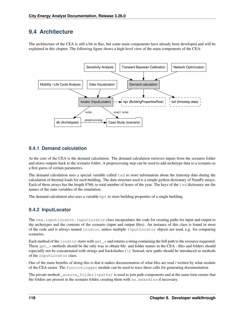
City Energy Analyst Documentation, Release 3.26.0
9.4 Architecture
The architecture of the CEA is still a bit in flux, but some main components have already been developed and will beexplained in this chapter. The following figure shows a high-level view of the main components of the CEA:
Demand calculation
bpr (BuildingPropertiesRow) tsd (timestep data)locator (InputLocator)
Sensitivity Analysis Transient Bayesian Calibration Network Optimization
Mobility / Life Cycle Analysis Data Visualization
db (Archetypes)
write
Case Study (scenario)
read / write
preprocessing
9.4.1 Demand calculation
At the core of the CEA is the demand calculation. The demand calculation retrieves inputs from the scenario folderand stores outputs back to the scenario folder. A preprocessing step can be used to add archetype data to a scenario asa first guess of certain parameters.
The demand calculation uses a special variable called tsd to store information about the timestep data during thecalculation of thermal loads for each building. The data structure used is a simple python dictionary of NumPy arrays.Each of these arrays has the length 8760, to total number of hours of the year. The keys of the tsd dictionary are thenames of the state variables of the simulation.
The demand calculation also uses a variable bpr to store building properties of a single building.
9.4.2 InputLocator
The cea.inputlocator.InputLocator class encapsulates the code for creating paths for input and output tothe archetypes and the contents of the scenario (input and output files). An instance of this class is found in mostof the code and is always named locator, unless multiple InputLocator objects are used, e.g. for comparingscenarios.
Each method of the locator starts with get_* and returns a string containing the full path to the resource requested.These get_* methods should be the only way to obtain file- and folder names in the CEA - files and folders shouldespecially not be concatenated with strings and backslashes (\). Instead, new paths should be introduced as methodsof the InputLocator class.
One of the main benefits of doing this is that it makes documentation of what files are read / written by what moduleof the CEA easier. The funcionlogger module can be used to trace these calls for generating documentation.
The private method _ensure_folder(*paths) is used to join path components and at the same time ensure thatthe folders are present in the scenario folder, creating them with os.makedirs if necessary.
118 Chapter 9. Developer walkthrough

City Energy Analyst Documentation, Release 3.26.0
NOTE: The list of get_*methods is getting very long. We might end up creating a namespace hierarchy for groupingrelated paths together.
9.4.3 Analysis and Visualization
Separate modules exist for analyzing different aspects of a scenario. Some of the analysis modules operate only onthe input data (LCA for embedded emissions, mobility) and others operate on the output of the demand module (LCAfor emissions due to operation). These modules are grouped in the folder cea/analysis.
The folder cea/plots contains modules for plotting outputs of the calculations.
9.4.4 “Higher order” modules
Some of the modules in the CEA use the demand calculation to calculate variants of a scenario. This includes thesensitivity analysis, the calibration and the network optimization code. All these modules call the demand calculationas part of their process.
9.5 How to add a heating/cooling system in CEA
9.5.1 Step 0: Make an issue and create a branch
As this procedure requires adding scripts in CEA master, please make a branch before performing the changes.
9.5.2 Step 1: Add the new system to the database
1. Open cea/databases/systems/emission_systems.xls
2. In the tab heating or cooling, add a row for the new system.
3. Specify the operating conditions of the new system, for cooling systems:
• code: add a new code Tx that has not been used.
• Qcsmax_Wm2: maximum cooling capacity of the system.
• dTcs_C:
For Air Handling Units (ahu), if applicable:
• Tscs0_ahu_C: coolant (water) supply temperature at the primary side
• dTcs0_ahu_C: temperature change of the coolant at the primary side
• Tc_sup_air_ahu_C: air supply temperature from ahu to the room
For Air Recirculation Units (aru), if applicable:
• Tscs0_aru_C: coolant (water) supply temperature at the primary side
• dTcs0_aru_C: temperature change of the coolant at the primary side
• Tc_sup_air_aru_C: air supply temperature from ahu to the room
For Sensible Cooling Units (scu), if applicable:
• Tscs0_scu_C: coolant (water) supply temperature at the primary side
• dTcs0_scu_C: temperature change of the coolant at the primary side
9.5. How to add a heating/cooling system in CEA 119
City Energy Analyst Documentation, Release 3.26.0
9.5.3 Step 2: Add the new system to the options
1. Go to script cea/demand/control_heating_cooling_systems.py
2. Add the code of the new systems (Tx) to function has_cooling_systems or has_heating_systems
3. Add a new function that check the type of the system, similar to has_3for2_cooling_systems
9.5.4 Step 3: Add a new function to model new technologies
Currently, there are models for AHU, ARU, SCU running wiht heating/cooling coil. If the new systems is utilizingdifferent technologies, the models should be added to airconditioning_model.py.
9.5.5 Step 3: Add a new function to calculate cooling/heating loads
1. Go to script cea/demand/hourly_procedure_heating_cooling_system_load.py
2. Add a new function to set up the calculation procedure for cooling/heating loads, similar tocalc_cool_loads_3for2
9.5.6 Step 4: Add distribution losses
1. Go to cea/demand/sensible_loads.py
2. Update calc_Qhs_Qcs_loss
9.5.7 Step 5: Calculate temperature and mass flow primary supply systems
1. Go to cea/demand/sensible_loads.py
2. Update calc_temperatures_emission_systems
9.5.8 Step 6: Calculate auxiliary electricity
calc_Eauxf_cs_dis calc_Eauxf_hs_dis
9.6 How to create a new release?
This section describes the steps necessary to create a new release of the City Energy Analyst (CEA).
9.6.1 Versioning
Each release of the CEA needs a version number. Version numbers need to increase for PyPI. The relevant docu-mentation for python version numbers is documented in PEP440. The CEA uses the following versioning scheme incompliance with PEP440:
major.minor[.revision][pre-release]
120 Chapter 9. Developer walkthrough
City Energy Analyst Documentation, Release 3.26.0
Major and minor version segments in this scheme refer to the milestone (sprint) the release was developed for. Themajor version segment works on roughly a yearly time scale while the minor version segment tracks sprints inside themajor release. Each such pair (major.minor) refers to a “milestone” in the GitHub issues milestones list.
If a release needs to be updated after publishing, an optional revision can be used, starting at 1 and incrementing.
During the sprint, the pre-release section is used to represent the current state of the master branch. At the beginningof the sprint, alpha versions are used. Examples: 2.2a0, 2.2a1, 2.2a2, etc. In this phase the issues belonging to themilestone are being added.
Once the code base settles down, beta versions can be used. Examples: 2.2b0, 2.2b1, 2.2b2, etc. In this phase, newfeatures should not be added anymore and instead testing / bug fixing activities should dominate.
Before releasing a milestone, the release candidates can be used. Examples: 2.2rc0, 2.2rc1, 2.2rc2, etc. In this phasethe software is just being tested with show-stopping bugs being fixed if possible.
Where to find the current version number
The current version number can be found in the module cea (actually, since cea is a package, you need to look intothe file __init__.py) in the variable __version__.
All code requiring knowledge of the current version number should read the version from here.
In python modules this can be achieved by:
import ceaversion_number = cea.__version__
The NSIS installer (see section Creating the installer) uses the helper tool setup/get_version.exe to extractthe version and write it to the file setup/cea_version.txt - if importing cea is not an option, you couldexplore this avenue too. . .
Responsibility for version numbers
The repository admin merging a pull request to master is responsible for updating the version number.
9.6.2 Create a Release Branch
• Create a branch Release-x.x.x from master.
9.6.3 Update the CREDITS.md file
For each minor release (2.2, 2.3, . . . ) the CREDITS.md file needs to be updated to include all the authors that workedon that release.
9.6.4 Update CHANGELOG
• Run create-changelog.py in CityEnergyAnalyst\bin.
• Update CHANGELOG.md with the latest changes from the outputs.
9.6. How to create a new release? 121
City Energy Analyst Documentation, Release 3.26.0
9.6.5 Merge the Release Branch
• Merge the branch Release-x.x.x into master.
9.6.6 Create a Release Draft on GitHub
• Tag the release with the correct version number.
9.6.7 Updating the CEA GUI interface
You’ll need yarn installed.
For the installer to be able to pick up the newest version of the CEA GUI interface, make sure you
• Pull the newest version of the CityEnergyAnalyst-GUI repository
• Open CEA Console, navigate to the GitHub repo of the CityEnergyAnalyst-GUI repository
• Type yarn, wait for the command to complete (this will update packages if necessary)
9.6.8 Creating the installer
• First, make sure you have the Nullsoft Scriptable Installation System (NSIS) installed. See how-to-set-up-nsis
• Next, make sure the command cea-dev build is configured properly. The configuration should look somethinglike this:
(CEA) 𝜆 cea-config buildCity Energy Analyst version 3.11.0Configuring `cea build` with the following parameters:- development:nsis = C:\Program Files (x86)\NSIS\Bin\makensis.exe(default: )
- development:conda = C:\Users\darthoma\Miniconda2\condabin\conda.bat(default: )
- development:gui = c:\Users\darthoma\Documents\GitHub\CityEnergyAnalyst-GUI(default: )
- development:yarn = C:\Users\darthoma\AppData\Roaming\npm\yarn.cmd(default: )
You can either edit the cea.config file directly or use cea-config build --nsis C:\...\makensis.exe --conda ....
Note: The paths will be different on your system. Use the conda.bat in condabin of your Anaconda/Minicondainstallation. The path to gui should be set to the repository folder of the CityEnergyAnalyst-GUI repository.
• Install conda-pack by typing conda install conda-pack.
• Creating the installer is then as easy as cea-dev build. This will run quite some time as it will create a newconda environment for the version, conda-pack it, and do a lot of compressing.
• Locate the installer in the CityEnergyAnalyst repository under setup/Output.
122 Chapter 9. Developer walkthrough

City Energy Analyst Documentation, Release 3.26.0
9.6.9 Testing in a virtual machine
In order to test the release, it is a good idea to run the installation guide / installer on a clean virtual machine, e.g. withVirtualBox.
This test should go as far as running cea test --workflow slow just to be sure everything is still working.This test goes a bit further than the regular test in that it makes sure the installation instructions still work on a newinstallation. This is important because it can find missing packages in the dependency lists etc.
It’s a good idea to use a different username on the VM as the one you used to create the installer - some pip bugs canbe found that way.
9.6.10 Publish the Release on GitHub
The release should be published so that it could be found on GitHub for testing (the next step). Add the installer youcreated in the previous step.
9.6.11 Building the documentation
Well documented code is an essential part of the release, allowing your code’s legacy to only grow in glory andadmiration.
The documentation will be rendered via the readthedocs site, allowing future developers, practitioners, researchersand students to understand and build upon your work. CEA uses sphinx to document all module code, and GraphVizto render flow charts (please install Graphviz to view graphs).
First, launch the CEA Console created by the installer and call (please address any errors (red text) which appearsduring the sphinx build):
cea-doc html
This tool will:
• Remove any outdated module rst files
• Rebuild all module rst files
• Render all rst files to html
• Open any documentation html’s for files identified by a Gitdiff.
Finally, any changes to the conda environment need to be reflected in the CityEnergyAnalyst/environment.yml file and if your code writes any new output variables or files, the CityEnergyAnalyst/cea/schemas.ymlshould be updated accordingly.
For more information, check out the how-to-document-cea.
9.6.12 Updating Link in www.cityenergyanalyst.com/try-cea
• Go to http://www.cityenergyanalyst.com
• Press Esc and try logging into squarespace
• Go to Pages/Try CEA (it is the last page in the list)
• Go to edit ‘Page content’
• Go to edit ‘Form’
9.6. How to create a new release? 123
City Energy Analyst Documentation, Release 3.26.0
• Change ‘Form Name’ to the name of the new version of CEA you just released
• Go to the tab ‘Advanced’
• Change ‘POST-SUBMIT REDIRECT’ to the link where the .exe of CEA can be downloaded from
• Change ‘POST-SUBMIT MESSAGE’/here, to the link where the .exe of CEA can be downloaded from
• Click ‘Apply’
• Click ‘Save’
9.6.13 Uploading to PyPI
Note: This step is not necessary anymore for installation.
• Check long-description with this commandline:
python setup.py --long-description | for /f %i in ('where rst2html.py') do python→˓%i > %temp%\ld.html && start %temp%\ld.html
– make sure the output is valid / no errors, as this will be the text of the CEA on PyPI
• Delete any old distributions from dist folder (you can just delete the whole dist folder if you like)
• Do python setup.py sdist bdist_wheel
– this will recreate the dist folder with two files that look similar to these:
* cityenergyanalyst-2.2-py2-none-any.whl
* cityenergyanalyst-2.2.tar.gz
• Use twine to upload to PyPI (twine upload dist/*)
– you can get twine with pip install twine (it should be pre-installed in the CEA Console)
– the command above assumes you have set the TWINE_PASSWORD and TWINE_USERNAME environmentvariables if not, use the --username and --password positional arguments
– ask the repository admins for username and password
9.7 How to set up the Jenkins server on a new PC
Note: you only need to do this when the current Jenkins server dies
Note: this guide assumes you are installing on a Windows 10 Professional system. Adjust accordingly for othersystems, but keep in mind that some functionality of the CEA is dependant on Windows.
There are a few steps to take to setting up a Jenkins server:
• installation of some prerequisites
• installation of Jenkins
• installation of a tunnel to the Jenkins server
124 Chapter 9. Developer walkthrough

City Energy Analyst Documentation, Release 3.26.0
• global configuration of Jenkins
• configuration of the Jenkins items
– cea test for new pull requests
– cea test for merges to master
9.7.1 Installation of some prerequisites
You will need to install these softwares:
• CityEnergyAnalyst (install with the Setup_CityEnergyAnalyst_<VERSION>.exe installer)
– we’ll be using the Python environment shipped with the CEA to test the CEA
– we’ll also be using the git.exe shipped with the CEA
9.7.2 Installation of Jenkins
• Download & install jenkins from https://jenkins.io
– LTS version Jenkins for Windows (last time this document was used, it was version 2.204.4)
– just double click the installer, next, next, next (all default values)
– set jenkins service to use local user
* Open up the Services Manager (search for “Services” in the Windows menu)
* locate and open the “Jenkins” service
* make sure the Startup type is set to “Automatic” so the Jenkins starts up again after reboots
* on the tab “Log On”, select “This account” instead of “Local System account” and enter in yourcredentials
· this will allow the Jenkins to have access to your user profile. You can create an account just forthis service and use that for the rest of this guide.
• open browser to http://localhost:8080 (NOTE: the installer did this automatically last time tried)
– follow instructions to enter initial admin password
* click “install suggested plugins”
* create first admin user
· Username: cea
· Password: (same as cityea user in outlook, ask Jimeno or Daren for the password)
· Full name: City Energy Analyst
· E-mail address: [email protected]
* Click “Manage Jenkins”
· click “Configure System” (following this guide here: https://wiki.jenkins.io/display/JENKINS/Github+Plugin#GitHubPlugin-GitHubhooktriggerforGITScmpolling)
· set “# of executors” to 1 (let’s just make it dead simple, no concurrency, less headache)
9.7. How to set up the Jenkins server on a new PC 125
City Energy Analyst Documentation, Release 3.26.0
9.7.3 Installation of a tunnel to the Jenkins server
This guide assumes you’re running the Jenkins on a Windows PC inside a corporate network. We use the ngrok serviceto tunnel webhooks triggered by GitHub back to the Jenkins server.
• download ngrok for Windows (https://ngrok.com/download)
• extract ngrok.exe to %PROGRAMDATA%\ceajenkins\ngrok.exe
– (you might need to create the folder ceajenkins first)
• create a file ngrok.yml in the folder %PROGRAMDATA%\ceajenkins with the following contents:
authtoken: XXXXXXXXXXXXXXXXXXXXXXXXXXXXXXXXXXXXXXXXXXXtunnels:ceajenkins:
proto: httpaddr: 8080subdomain: ceajenkins
– (replace the authtoken variable with the authtoken obtained from ngrok
• test it with this command: %PROGRAMDATA%\ceajenkins\ngrok.exe start --config%PROGRAMDATA%\ceajenkins\ngrok.yml ceajenkins
– you should now be able to access your Jenkins installation by going to https://ceajenkins.ngrok.io fromany computer with access to the internet
– press CTRL+C to shutdown the tunnel
• copy the CityEnergyAnalyst\bin\ceajenkins.py file to %PROGRAMDATA%\ceajenkins
– if you haven’t checked out the CEA, download it from the CEA GitHub repository
• copy the CEA Dependencies folder (after installing CEA, it should be in%USERPROFILE%\Documents\CityEnergyAnalysts\Dependencies) twice
– once to C:\ProgramData\ceajenkins\ceatest
– once to C:\ProgramData\ceajenkins\ceatestall
– (actually rename the folder Dependencies to ceatest and ceatestall respectively)
• in order for the service to find required DLL’s, ensure the PATH includes the following folders (use the windowssearch function to find the control panel item “Edit System Environment Variables”):
– C:\ProgramData\ceajenkins\ceatestall\Python\
– C:\ProgramData\ceajenkins\ceatestall\Python\lib\site-packages\win32
– C:\ProgramData\ceajenkins\ceatestall\Python\lib\site-packages\pywin32_system32
– make sure you edit the System Variables, not the User Environment Variables
• open cmd.exe with admin rights (right click, then “Run as Administrator”)
• run python %PROGRAMDATA%\ceajenkins\ceajenkins.py install
• open the windows services panel (just search for “Services” in the windows menu)
– locate “CEA Jenkins keepalive”, right click, “Properties”
– set Startup type to “Automatic”
– set the account in the “Log On” tab to your user account (the one that you used to install all of the abovestuff)
126 Chapter 9. Developer walkthrough

City Energy Analyst Documentation, Release 3.26.0
– start the service!
– you should now be able to access your Jenkins installation by going to https://ceajenkins.ngrok.io fromany computer with access to the internet (test this)
9.7.4 Global configuration of Jenkins
Now that we have a tunnel set up, we can start configuring the Jenkins server, mainly following this guide:
• open browser to http://ceajenkins.ngrok.io and log in
• click “Manage Jenkins” and then “Configure System”
– set “# of executors” to 1 (let’s just make it dead simple, no concurrency, less headache)
– in the “Jenkins Location” section set Jenkins URL to “https://ceajenkins.ngrok.io”
* (Jenkins might be smart enough to figure this out and has filled it in for you already)
– scroll to “GitHub” section
– click “Advanced”
– dropdown “Manage additional GitHub actions”, click “Convert login and password to token”
– choose “From login and password”, enter GitHub user and password, click “Create token credentials”
– Click “Add GitHub Server”
* Name: (leave blank)
* Credentials: (choose the GitHub credentials auto-generated for your username)
* click “Test connection” - expect this message: “Credentials verified for user <username>”
* check “Override Hook URL”
* enter hook url https://ceajenkins.ngrok.io
– click “Save”
Next, we make sure all the required Jenkins plugins are installed
• open browser to http://ceajenkins.ngrok.io and log in
• click “Manage Jenkins” and then “Manage Plugins”
– install the following plugin:
* GitHub Pull Request Builder Plugin (https://github.com/jenkinsci/ghprb-plugin)
Next, we configure the GitHub Pull Request Builder plugin, following the instructions here: https://github.com/jenkinsci/ghprb-plugin
• open browser to http://ceajenkins.ngrok.io and log in
• click “Manage Jenkins” and then “Configure System”
• scroll down to the “GitHub Pull Request Builder” section
– leave the GitHub Server API URL: https://api.github.com
– set the Jenkins URL overrride: https://ceajenkins.ngrok.io
– leave the Shared secret: (bunch of *’s. . . idk. . . )
– select the credentials (This should be the GitHub auto generated token credentials you created above)
– select Auto-manage webhooks
9.7. How to set up the Jenkins server on a new PC 127
City Energy Analyst Documentation, Release 3.26.0
– set the Admin list to the two lines daren-thomas and JIMENOFONSECA
• click Save
Finally, make sure Jenkins knows where to find git.exe - if it’s not in %PATH%:
• open browser to https://ceajenkins.ngrok.io and log in
• click “Manage Jenkins” and then “Global Tool Configuration”
• set “Path to Git executable” to C:\ProgramData\ceajenkins\ceatestall\cmder\vendor\git-for-windows\bin\git.exe
9.7.5 Configuration of the Jenkins items
First, we configure a Jenkins item for pull requests:
• open browser to https://ceajenkins.ngrok.io and log in
• click “New Item”
• Enter an item name: run cea test for pull requests
– Choose “Freestyle project”
– Project name: “run cea test for pull requests”
– Description: “Check out the CityEnergyAnalyst, and run binceatest.bat”
– check “Discard old builds”
* Strategy: “Log Rotation”
* Max # of builds to keep: 10
– check “GitHub project”
– Project url: “https://github.com/architecture-building-systems/CityEnergyAnalyst”
– section “Source Code Management”:
* select “Git”
* Repository URL: https://github.com/architecture-building-systems/CityEnergyAnalyst.git
* Credentials: (add a new username/password credential)
* Branches to build: ${ghprbActualCommit}
– section “Build Triggers”:
* check “GitHub Pull Request Builder”
* GitHub API credentials: choose your credentials from the list
* check “Use github hooks for build triggering”
* click “Advanced”
* List of organizations. Their members will be whitelisted: architecture-building-systems
– section “Build”
* Execute Windows batch command: bin\ceatest.bat
– section “Build Environment”
* select “Delete workspace before build starts”
128 Chapter 9. Developer walkthrough
City Energy Analyst Documentation, Release 3.26.0
Next, we configure a Jenkins item for merging to master:
• open browser to https://ceajenkins.ngrok.io and log in
• click “New Item”
• Enter an item name: run cea test on merge to master
– Choose “Freestyle project”
– Project name: “run cea test on merge to master”
– Description: “Check out the CityEnergyAnalyst, and run binceatestall.bat”
– check “Discard old builds”
* Strategy: “Log Rotation”
* Max # of builds to keep: 10
– check “GitHub project”
– Project url: “https://github.com/architecture-building-systems/CityEnergyAnalyst”
– section “Source Code Management”:
* select “Git”
* Repository URL: https://github.com/architecture-building-systems/CityEnergyAnalyst.git
* Credentials: (use the ones created above)
* Branches to build: refs/heads/master
– section “Build Triggers”:
* check “GitHub hook trigger for GITScm polling”
* check “Poll SCM”
– section “Build”
* Execute Windows batch command: bin\ceatestall.bat
– section “Build Environment”
* select “Delete workspace before build starts”
• open GitHub Webhooks
– (NOTE: This should already be set up for the CEA Repository, but here’s how to configure it just in case)
– dropdown “Add webhook”
* Payload URL: http://ceajenkins.ngrok.io/git/notifyCommit?url=https://github.com/architecture-building-systems/CityEnergyAnalyst
* under “Which events would you like to trigger this webhook?” select “Let me select individual events.”
* select “Just the push event”
9.8 Running the CEA in Docker
Docker is an open-source project for automating the deployment of applications as portable, self-sufficientcontainers that can run on the cloud or on-premises. (Source)
9.8. Running the CEA in Docker 129

City Energy Analyst Documentation, Release 3.26.0
The CEA can be run in docker. The main steps are:
• install Docker on your computer (out of scope of this document)
• build the image
• run the image
Note, that “CEA” in this context refers to the backend (server, cli) part of the CEA and not the GUI.
9.8.1 Building the image
Set server host to 0.0.0.0. You can do it by editing default.config in the cea folder. In the [server]section, change the default address from 127.0.0.1 to 0.0.0.0.
To build the docker image, navigate to CityEnergyAnalyst repository where the Dockerfile is located. Execute thefollowing command:
> docker build -t dockeruser/cea:latest .
Notice the . at the end of the command - be sure to include it, as it tells docker where to find the Dockerfile.
The docker image should show up in your local computer:
> docker imagesREPOSITORY TAG IMAGE ID CREATED SIZEdockeruser/cea latest 9963cd876a48 19 minutes ago 3.06GB
To share the docker image, push the image to Dockerhub:
> docker loginusername: dockeruserpassword:
> docker push dockeruser/cea:latest
9.8.2 Pull docker image
If you wish to use the latest cea image without building it on your own, you can pull it from our dockerhub.
To pull a docker image from Dockerhub:
> docker pull dockeruser/cea
9.8.3 Running the image in a new container
1. To test the docker image:
> docker run --rm dockeruser/cea cea test
• The --rm flag removes the container after it finishes running. This is useful when running the cea test
command so that the container does not persist after it exits after running the tests.
2. To run the docker container via shell (as the CEA Console):
130 Chapter 9. Developer walkthrough
City Energy Analyst Documentation, Release 3.26.0
> docker run -it -v /home/cea_projects:/projects dockeruser/cea /bin/bashroot@df9d4b16e5c0:> source /venv/bin/activate(venv) root@df9d4b16e5c0:> cea --help
• The -it flag sets up interactive and tty so you can actually _do_ something there. Note, in order to useany of the CEA functionality, you’ll need to type source /venv/bin/activate.
• The -v /home/cea_projects:/projects binds the folder /home/cea_projects in host to the folder /projects inside the container. Files saved in /home/cea_projects will be shared with the con-tainer.
3. To run cea workflow. First make sure the project folder and workflow.yml are in the correct path, in theexample is /home/cea_projects.:
> docker run --name cea_container -v /home/cea_projects:/projects dockeruser/cea→˓cea workflow --workflow /projects/workflow.yml
4. To connect the GUI, CEA Dashboard, to a container
> docker run -t -p 5050:5050 dockeruser/cea
This command will start the CEA server and display it’s output. You should see something like this:
City Energy Analyst version 3.24.0Running `cea dashboard` with the following parameters:- general:debug = False(default: False)
start socketio.run
There’s quite a lot going on here and if this is seems daunting, I suggest reading up on some Dockertutorials - I don’t understand it well enough myself to feel confident enough to explain. But here are someobservations:
• The -t flag connects the container to your terminal, so you can see the output. You can drop thisargument, but then you’ll not be able to see any error messages etc. of the backend.
• The -p 5050:5050 flag connects the port 5050 on the host machine (your computer) to the port5050 in the container (an instance of the cea-server docker image).
• If you browse to http://localhost:5050/api/ you will see a description of the api you can use. This isthe same api used by the CityEnergyAnalyst-GUI project, so you can essentially do anything thatcan be done in the GUI programmatically using this api.
9.8. Running the CEA in Docker 131

City Energy Analyst Documentation, Release 3.26.0
132 Chapter 9. Developer walkthrough
CHAPTER 10
API reference
10.1 cea package
exception cea.ConfigErrorBases: exceptions.Exception
Raised when the configuration of a tool contains some invalid values.
rc = 100
exception cea.CustomDatabaseNotFoundBases: exceptions.Exception
Raised when the InputLocator can’t find a user-provided database (region==’custom’)
rc = 101
exception cea.InvalidOccupancyNameExceptionBases: exceptions.Exception
Raised when the occupancy.dbf has an invalid / unknown occupancy column
rc = 104
exception cea.MissingInputDataExceptionBases: exceptions.Exception
Raised when a script can’t run because some information is missing
rc = 103
exception cea.ScriptNotFoundExceptionBases: exceptions.Exception
Raised when an invalid script name is used.
rc = 102
cea.suppress_3rd_party_debug_loggers()set logging level to WARN for fiona and shapely and others
133
City Energy Analyst Documentation, Release 3.26.0
10.1.1 Subpackages
cea.analysis package
Subpackages
cea.analysis.costs package
Submodules
cea.analysis.costs.equations module
cea.analysis.costs.system_costs module
cea.analysis.lca package
Submodules
cea.analysis.lca.embodied module
cea.analysis.lca.main module
cea.analysis.lca.operation module
cea.analysis.multicriteria package
Submodules
cea.analysis.multicriteria.main module
cea.datamanagement package
Submodules
cea.datamanagement.archetypes_mapper module
cea.datamanagement.constants module
This file contains the constants used in the data management tools
cea.datamanagement.create_new_scenario module
cea.datamanagement.data_initializer module
cea.datamanagement.data_migrator module
134 Chapter 10. API reference
City Energy Analyst Documentation, Release 3.26.0
cea.datamanagement.databases_verification module
cea.datamanagement.schedule_helper module
cea.datamanagement.streets_helper module
cea.datamanagement.surroundings_helper module
cea.datamanagement.terrain_helper module
cea.datamanagement.weather_helper module
cea.datamanagement.zone_helper module
cea.demand package
Subpackages
cea.demand.schedule_maker package
Submodules
cea.demand.schedule_maker.schedule_maker module
Submodules
cea.demand.airconditioning_model module
cea.demand.building_properties module
cea.demand.calc_tm module
cea.demand.constants module
This file contains the constants used in the building energy demand calculations
cea.demand.control_heating_cooling_systems module
cea.demand.control_ventilation_systems module
cea.demand.datacenter_loads module
cea.demand.demand_main module
cea.demand.demand_writers module
10.1. cea package 135
City Energy Analyst Documentation, Release 3.26.0
cea.demand.electrical_loads module
cea.demand.hotwater_loads module
cea.demand.hourly_procedure_heating_cooling_system_load module
cea.demand.latent_loads module
cea.demand.rc_model_SIA module
cea.demand.rc_model_sia_cc module
cea.demand.refrigeration_loads module
cea.demand.sensible_loads module
cea.demand.space_emission_systems module
cea.demand.thermal_loads module
cea.demand.ventilation_air_flows_detailed module
cea.demand.ventilation_air_flows_simple module
cea.dev package
Submodules
cea.dev.build module
cea.examples package
Submodules
cea.examples.extract_reference_case module
cea.examples.template module
cea.interfaces package
Subpackages
cea.interfaces.cli package
Submodules
136 Chapter 10. API reference
City Energy Analyst Documentation, Release 3.26.0
cea.interfaces.cli.cea_config module
cea.interfaces.cli.cea_dev module
cea.interfaces.cli.cea_doc module
cea.interfaces.cli.cli module
cea.interfaces.cli.dbf_to_excel module
cea.interfaces.cli.excel_to_dbf module
cea.interfaces.cli.excel_to_shapefile module
cea.interfaces.cli.list_demand_graphs_fields module
cea.interfaces.cli.shapefile_to_excel module
cea.interfaces.dashboard package
Subpackages
cea.interfaces.dashboard.api package
Submodules
cea.interfaces.dashboard.api.dashboard module
cea.interfaces.dashboard.api.databases module
cea.interfaces.dashboard.api.glossary module
cea.interfaces.dashboard.api.inputs module
cea.interfaces.dashboard.api.project module
cea.interfaces.dashboard.api.tools module
cea.interfaces.dashboard.api.utils module
cea.interfaces.dashboard.plots package
Submodules
cea.interfaces.dashboard.plots.routes module
10.1. cea package 137
City Energy Analyst Documentation, Release 3.26.0
cea.interfaces.dashboard.server package
Submodules
cea.interfaces.dashboard.server.jobs module
cea.interfaces.dashboard.server.streams module
Submodules
cea.interfaces.dashboard.dashboard module
cea.optimization package
Subpackages
cea.optimization.distribution package
Submodules
cea.optimization.distribution.network_optimization_features module
cea.optimization.master package
Submodules
cea.optimization.master.cost_model module
cea.optimization.master.crossover module
Crossover routines
class cea.optimization.master.crossover.CrossOverMethodsContinuous(crossover_method)Bases: object
mutation methods for integers
__init__(crossover_method)x.__init__(. . . ) initializes x; see help(type(x)) for signature
crossover(individual_1, individual_2, probability)
class cea.optimization.master.crossover.CrossOverMethodsInteger(crossover_method)Bases: object
mutation methods for integers
__init__(crossover_method)x.__init__(. . . ) initializes x; see help(type(x)) for signature
crossover(individual_1, individual_2, probability)
138 Chapter 10. API reference
City Energy Analyst Documentation, Release 3.26.0
cea.optimization.master.crossover.crossover_main(ind1, ind2, indpb, column_names,heating_unit_names_share, cool-ing_unit_names_share, col-umn_names_buildings_heating,column_names_buildings_cooling,district_heating_network, dis-trict_cooling_network, tech-nologies_heating_allowed,technologies_cooling_allowed,crossover_method_integer,crossover_method_continuous)
cea.optimization.master.data_saver module
cea.optimization.master.emissions_model module
cea.optimization.master.emissions_model.calc_emissions_Whyr_to_tonCO2yr(E_Wh_yr,fac-tor_kgCO2_to_MJ)
cea.optimization.master.emissions_model.calc_pen_Whyr_to_MJoilyr(E_Wh_yr,fac-tor_MJ_to_MJ)
cea.optimization.master.evaluation module
cea.optimization.master.generation module
Create individuals
cea.optimization.master.generation.calc_building_connectivity_dict(building_names_all,build-ing_names_heating,build-ing_names_cooling,DHN_barcode,DCN_barcode)
cea.optimization.master.generation.generate_main(individual_with_names_dict,column_names, col-umn_names_buildings_heating,column_names_buildings_cooling,district_heating_network, dis-trict_cooling_network, technolo-gies_heating_allowed, technolo-gies_cooling_allowed)
Creates an individual configuration for the evolutionary algorithm. The individual is divided into four partsnamely Heating technologies, Cooling Technologies, Heating Network and Cooling Network Heating Tech-nologies: This block consists of heating technologies associated with % of the peak capacity each technology isgoing to supply, i.e. 10.1520.2030, which translates into technology 1 corresponding to 15% of peak capacity,technology 2 corresponding to 20% and technology 3 corresponding to 0%. 0% can also be just done by replac-ing 3 with 0. The technologies block is then followed by supply temperature of the DHN and the number ofunits it is supplied to among AHU, ARU, SHU. So if it is 6 degrees C supplied by DHN to AHU and ARU, it isrepresented as 6.02. The temperature is represented with 1 decimal point. Cooling Technologies: This follows
10.1. cea package 139
City Energy Analyst Documentation, Release 3.26.0
the same syntax as heating technologies, but will be represented with cooling technologies. The block length ofheating and cooling can be different. Heating Network: Network of buildings connected to centralized heatingCooling Network: Network of buildings connected to centralized cooling. Both these networks can be different,and will always have a fixed length corresponding to the total number of buildings in the neighborhood :paramnBuildings: number of buildings :type nBuildings: int :return: individual: representation of values taken by theindividual :rtype: list
cea.optimization.master.generation.individual_to_barcode(individual, build-ing_names_all, build-ing_names_heating,building_names_cooling,column_names, col-umn_names_buildings_heating,col-umn_names_buildings_cooling)
Reads the 0-1 combination of connected/disconnected buildings and creates a list of strings type barcode i.e.(“12311111123012”) :param individual: list containing the combination of connected/disconnected buildings:type individual: list :return: indCombi: list of strings :rtype: list
cea.optimization.master.generation.populate_individual(empty_individual_with_names_dict,name_share_conversion_technologies,technologies_allowed,columns_buildings_name)
cea.optimization.master.master_main module
cea.optimization.master.master_to_slave module
cea.optimization.master.mutations module
Mutation routines
class cea.optimization.master.mutations.MutationMethodContinuos(mutation_method)Bases: object
mutation methods for continuos variables
__init__(mutation_method)x.__init__(. . . ) initializes x; see help(type(x)) for signature
mutate(individual, probability)
class cea.optimization.master.mutations.MutationMethodInteger(mutation_method)Bases: object
mutation methods for integers
__init__(mutation_method)x.__init__(. . . ) initializes x; see help(type(x)) for signature
mutate(individual, probability)
140 Chapter 10. API reference
City Energy Analyst Documentation, Release 3.26.0
cea.optimization.master.mutations.mutation_main(individual, indpb, column_names,heating_unit_names_share, cool-ing_unit_names_share, col-umn_names_buildings_heating,column_names_buildings_cooling,district_heating_network, dis-trict_cooling_network, tech-nologies_heating_allowed, tech-nologies_cooling_allowed, mu-tation_method_integer, muta-tion_method_continuous)
cea.optimization.master.normalization module
cea.optimization.master.normalization.minmax_scaler(value, min_value, max_value)
cea.optimization.master.normalization.normalize_fitnesses(scaler_dict, fit-nesses_population)
cea.optimization.master.normalization.scaler_for_normalization(number_of_objectives,fitnesses)
cea.optimization.master.performance_aggregation module
cea.optimization.master.summarize_network module
cea.optimization.master.validation module
Validation
cea.optimization.master.validation.validation_main(individual_with_name_dict, col-umn_names_buildings_heating,col-umn_names_buildings_cooling,district_heating_network, dis-trict_cooling_network, technolo-gies_heating_allowed, technolo-gies_cooling_allowed)
cea.optimization.preprocessing package
Submodules
cea.optimization.preprocessing.decentralized_building_main module
cea.optimization.preprocessing.decentralized_buildings_cooling module
cea.optimization.preprocessing.decentralized_buildings_heating module
cea.optimization.preprocessing.preprocessing_main module
10.1. cea package 141
City Energy Analyst Documentation, Release 3.26.0
cea.optimization.preprocessing.processheat module
cea.optimization.slave package
Subpackages
cea.optimization.slave.daily_storage package
Submodules
cea.optimization.slave.daily_storage.load_leveling module
cea.optimization.slave.seasonal_storage package
Submodules
cea.optimization.slave.seasonal_storage.Import_Network_Data_functions module
cea.optimization.slave.seasonal_storage.SolarPowerHandler_incl_Losses module
cea.optimization.slave.seasonal_storage.design_operation module
cea.optimization.slave.seasonal_storage.storage_main module
Submodules
cea.optimization.slave.cooling_main module
cea.optimization.slave.cooling_resource_activation module
cea.optimization.slave.electricity_main module
cea.optimization.slave.heating_main module
cea.optimization.slave.heating_resource_activation module
cea.optimization.slave.natural_gas_main module
cea.optimization.slave.test module
cea.optimization.slave.test.main()
Submodules
142 Chapter 10. API reference
City Energy Analyst Documentation, Release 3.26.0
cea.optimization.constants module
This file contains the constants used in objective function calculation in optimization
cea.optimization.lca_calculations module
cea.optimization.optimization_main module
cea.optimization.prices module
cea.optimization.slave_data module
cea.plots package
Subpackages
cea.plots.comparisons package
Submodules
cea.plots.comparisons.Annual_costs module
cea.plots.comparisons.Annual_emissions module
cea.plots.demand package
Submodules
cea.plots.demand.comfort_chart module
cea.plots.demand.energy_balance module
cea.plots.demand.energy_end_use module
cea.plots.demand.energy_end_use_intensity module
cea.plots.demand.energy_final_use module
cea.plots.demand.energy_use_intensity module
cea.plots.demand.heating_reset_schedule module
cea.plots.demand.load_curve module
cea.plots.demand.load_curve_supply module
10.1. cea package 143
City Energy Analyst Documentation, Release 3.26.0
cea.plots.demand.load_duration_curve module
cea.plots.demand.load_duration_curve_supply module
cea.plots.demand.peak_load module
cea.plots.demand.peak_load_supply module
cea.plots.optimization package
Submodules
cea.plots.optimization.a_pareto_curve module
cea.plots.optimization.b_parallel_coordinates module
cea.plots.optimization.c_annual_costs module
cea.plots.optimization.d_annual_emissions module
cea.plots.optimization.e_Investment_costs module
cea.plots.optimization.f_paretocurve_convergence module
cea.plots.solar_potential package
Submodules
cea.plots.solar_potential.a_solar_radiation module
cea.plots.supply_system package
Submodules
cea.plots.supply_system.a_supply_system_map module
cea.plots.supply_system.b_installed_capacities module
cea.plots.supply_system.c_requirements_curve_electricity module
cea.plots.supply_system.d_dispatch_curve_electricity module
cea.plots.supply_system.e_dispatch_curve_heating_plant module
cea.plots.supply_system.f_dispatch_curve_cooling_plant module
144 Chapter 10. API reference
City Energy Analyst Documentation, Release 3.26.0
cea.plots.supply_system.g_grid_ramping_capacity module
cea.plots.technology_potentials package
Submodules
cea.plots.technology_potentials.a_photovoltaic_potential module
cea.plots.technology_potentials.b_photovoltaic_thermal_potential module
cea.plots.technology_potentials.c_solar_collector_ET_potential module
cea.plots.thermal_networks package
Submodules
cea.plots.thermal_networks.a_network_design module
cea.plots.thermal_networks.b_demand_curve module
cea.plots.thermal_networks.c_annual_energy_consumption module
cea.plots.thermal_networks.d_energy_loss_bar module
cea.plots.thermal_networks.e_heating_reset_curve module
cea.plots.thermal_networks.f_pump_duration_curve module
Submodules
cea.plots.base module
cea.plots.cache module
cea.plots.categories module
cea.plots.colors module
cea.plots.plot_cli module
cea.plots.variable_naming module
cea.resources package
Subpackages
10.1. cea package 145
City Energy Analyst Documentation, Release 3.26.0
cea.resources.radiation_daysim package
Submodules
cea.resources.radiation_daysim.daysim_main module
cea.resources.radiation_daysim.geometry_generator module
cea.resources.radiation_daysim.radiance module
cea.resources.radiation_daysim.radiation_main module
cea.resources.radiation_daysim.visualization module
Submodules
cea.resources.geothermal module
cea.resources.natural_gas module
natural gas
cea.resources.natural_gas.calc_Cinv_gas(PnomGas)Calculate investment cost of natural gas connections.
Parameters PnomGas (float) – peak natural gas supply in [W]
Returns InvCa
Rtype InvCa
cea.resources.sewage_heat_exchanger module
cea.resources.water_body_potential module
cea.technologies package
Subpackages
cea.technologies.network_layout package
Submodules
cea.technologies.network_layout.connectivity_potential module
cea.technologies.network_layout.main module
cea.technologies.network_layout.minimum_spanning_tree module
146 Chapter 10. API reference
City Energy Analyst Documentation, Release 3.26.0
cea.technologies.network_layout.steiner_spanning_tree module
cea.technologies.network_layout.substations_location module
cea.technologies.network_layout.utility module
Shapefile
Generates a networkx.DiGraph from point and line shapefiles.
“The Esri Shapefile or simply a shapefile is a popular geospatial vector data format for geographic information systemssoftware. It is developed and regulated by Esri as a (mostly) open specification for data interoperability among Esriand other software products.” See https://en.wikipedia.org/wiki/Shapefile for additional information.
cea.technologies.network_layout.utility.read_shp(path, simplify=True,geom_attrs=True, strict=True)
Generates a networkx.DiGraph from shapefiles. Point geometries are translated into nodes, lines into edges.Coordinate tuples are used as keys. Attributes are preserved, line geometries are simplified into start and endcoordinates. Accepts a single shapefile or directory of many shapefiles.
“The Esri Shapefile or simply a shapefile is a popular geospatial vector data format for geographic informationsystems software1.”
Parameters
• path (str) – File, directory, or filename to read.
• simplify (bool) – If True, simplify line geometries to start and end coordinates. IfFalse, and line feature geometry has multiple segments, the non-geometric attributes forthat feature will be repeated for each edge comprising that feature.
• geom_attrs (bool) – If True, include the Wkb, Wkt and Json geometry attributes witheach edge. NOTE: if these attributes are available, write_shp will use them to write thegeometry. If nodes store the underlying coordinates for the edge geometry as well (as theydo when they are read via this method) and they change, your geomety will be out of sync.
• strict (bool) – If True, raise NetworkXError when feature geometry is missing or Ge-ometryType is not supported. If False, silently ignore missing or unsupported geometry infeatures.
Returns the NetworkX graph
Raises
• ImportError – If ogr module is not available.
• RuntimeError – If file cannot be open or read.
• NetworkXError – If strict=True and feature is missing geometry or GeometryType is notsupported.
cea.technologies.network_layout.utility.write_shp(G, outdir)Writes a networkx.DiGraph to two shapefiles, edges and nodes. Nodes and edges are expected to have a WellKnown Binary (Wkb) or Well Known Text (Wkt) key in order to generate geometries. Also acceptable are nodeswith a numeric tuple key (x,y).
“The Esri Shapefile or simply a shapefile is a popular geospatial vector data format for geographic informationsystems software2.”
1 https://en.wikipedia.org/wiki/Shapefile2 https://en.wikipedia.org/wiki/Shapefile
10.1. cea package 147
City Energy Analyst Documentation, Release 3.26.0
:param str outdir : directory path, Output directory for the two shapefiles. :rtype: None
Examples:
nx.write_shp(digraph, '/shapefiles') # doctest +SKIP
cea.technologies.solar package
Submodules
cea.technologies.solar.constants module
Parameters used for solar technologies
cea.technologies.solar.photovoltaic module
cea.technologies.solar.photovoltaic_thermal module
cea.technologies.solar.solar_collector module
cea.technologies.thermal_network package
Submodules
cea.technologies.thermal_network.simplified_thermal_network module
cea.technologies.thermal_network.substation_matrix module
cea.technologies.thermal_network.thermal_network module
cea.technologies.thermal_network.thermal_network_costs module
cea.technologies.thermal_network.thermal_network_loss module
Hydraulic - thermal network
cea.technologies.thermal_network.thermal_network_loss.calc_temperature_out_per_pipe(t_in,m,k,t_ground)
Parameters
• t_in – in Kelvin
• m – in kg/s
• k – in kW/K
• t_ground – in Kelvin
Returns
148 Chapter 10. API reference

City Energy Analyst Documentation, Release 3.26.0
cea.technologies.thermal_network.thermal_network_optimization module
Submodules
cea.technologies.blinds module
blinds
cea.technologies.blinds.calc_blinds_activation(radiation, g_gl, Rf_sh)This function calculates the blind operation according to ISO 13790.
Parameters
• radiation – radiation in [W/m2]
• g_gl – window g value
• Rf_sh – shading factor
cea.technologies.boiler module
cea.technologies.burner module
cea.technologies.chiller_absorption module
cea.technologies.chiller_vapor_compression module
cea.technologies.cogeneration module
cea.technologies.constants module
Constants used throughout the cea.technologies package.
History lesson: This is a first step at removing the cea.globalvars.GlobalVariables object.
cea.technologies.cooling_tower module
cea.technologies.direct_expansion_units module
cea.technologies.furnace module
cea.technologies.heat_exchangers module
cea.technologies.heating_coils module
cea.technologies.heatpumps module
cea.technologies.pumps module
10.1. cea package 149
City Energy Analyst Documentation, Release 3.26.0
cea.technologies.radiators module
cea.technologies.storage_tank module
cea.technologies.storagetank_cc module
cea.technologies.substation module
cea.technologies.supply_systems_database module
cea.technologies.tabs module
cea.technologies.thermal_storage module
cea.tests package
Subpackages
cea.tests.datamanagement package
Submodules
cea.tests.datamanagement.test_zone_helper module
Submodules
cea.tests.create_unittest_data module
cea.tests.run_all_plots module
cea.tests.run_unit_tests module
cea.tests.test_calc_thermal_loads module
cea.tests.test_check_for_radiation_input_in_demand_script module
cea.tests.test_chiller_vapor_compression module
cea.tests.test_config module
cea.tests.test_dbf module
cea.tests.test_inputlocator module
cea.tests.test_inputs_setup_workflow module
150 Chapter 10. API reference
City Energy Analyst Documentation, Release 3.26.0
cea.tests.test_plots module
cea.tests.test_schedules module
cea.tests.test_schemas module
cea.tests.test_technologies module
cea.tests.trace_inputlocator module
cea.utilities package
class cea.utilities.devnullBases: object
Suppress sys.stdout so that it goes to devnull for duration of the with block
__enter__()
__exit__(exc_type, exc_val, exc_tb)
__init__()x.__init__(. . . ) initializes x; see help(type(x)) for signature
write(_)
cea.utilities.identifier(s, sep=’-’)First, all characters are lowercased, then, any character that is not in ascii_lowercase is replaced with sep.
Parameters
• s (str) – the string to create an identifier of
• use_underscores (str) – if set to true, underscores (“_”) will be used instead of dashes(“-“)
Return type str
class cea.utilities.pushd(path)Bases: object
Manage an os.chdir so that at the end of a with block, the path is set back to what it was
__enter__()
__exit__(exc_type, exc_val, exc_tb)
__init__(path)x.__init__(. . . ) initializes x; see help(type(x)) for signature
cea.utilities.remap(x, in_min, in_max, out_min, out_max)Scale x from range [in_min, in_max] to [out_min, out_max] Based on this StackOverflow answer: https://stackoverflow.com/a/43567380/2260
cea.utilities.simple_memoize(obj)
cea.utilities.unique(sequence)Return only the unique elements in sequence, preserving order.
Parameters sequence (Sequence[T]) – the sequence to unique-ify
Return type List[T]
10.1. cea package 151
City Energy Analyst Documentation, Release 3.26.0
Submodules
cea.utilities.color_fader module
cea.utilities.compile_pyd_files module
Compile the .pyd files using Numba pycc to speed up the calculation of certain modules. Currently used for:
• calc_tm.pyd (used in demand/sensible_loads.py)
• calc_radiator.pyd (used in technologies/radiators.py)
In order to run this script, you will need to install Numba. Try: conda install numba
cea.utilities.compile_pyd_files.compile_radiators()
cea.utilities.compile_pyd_files.compile_rc_model_sia()
cea.utilities.compile_pyd_files.compile_storagetank()
cea.utilities.compile_pyd_files.copy_pyd(source, destination)
cea.utilities.compile_pyd_files.delete_pyd(*pathspec)Delete the file with the pathspec. pathspec is an array of path segments.
cea.utilities.compile_pyd_files.main()
cea.utilities.create_mixed_use_type module
cea.utilities.create_polygon module
cea.utilities.date module
cea.utilities.dbf module
cea.utilities.doc_glossary module
cea.utilities.doc_graphviz module
cea.utilities.doc_html module
cea.utilities.doc_schemas module
cea.utilities.epwreader module
cea.utilities.latin_hypercube module
cea.utilities.parallel module
Standardizes multiprocessing use. In the CEA, some functions are run using the standard multiprocessinglibrary. They are run by map``ing the function to a list of arguments (see``multiprocessing.Pool.map_async) and waiting for the processes to finish, while at the same time
152 Chapter 10. API reference
City Energy Analyst Documentation, Release 3.26.0
piping STDOUT, STDERR through cea.utilities.workerstream.QueueWorkerStream - this ensuresthat the dashboard interface can read the output from the sub-processes.
The way this was done in CEA < v2.23 included boiler plate code that needed to be repeated every time multiprocess-ing was used. Issue [#2344](https://github.com/architecture-building-systems/CityEnergyAnalyst/issues/2344) was aresult of not applying this technique to the demand script.
This module exports the function map which is intended to replace both map_async and the builtin map function(which was used when config.multiprocessing == False). This simplifies multiprocessing.
cea.utilities.parallel.__apply_func_with_worker_stream(args)Call func, using queue to redirect stdout and stderr, with a tuple of args because multiprocessing.Pool.maponly accepts one argument for the function.
This function is called _inside_ a separate process.
cea.utilities.parallel.__multiprocess_wrapper(func, processes, on_complete)Create a worker pool to map the function, taking care to set up STDOUT and STDERR
cea.utilities.parallel.single_process_wrapper(func, on_complete)The simplest form of vectorization: Just loop
cea.utilities.parallel.test(a, b)
cea.utilities.parallel.vectorize(func, processes=1, on_complete=None)Similar to numpy.vectorize, this function wraps func so that it operates on sequences (of same length) ofinputs and outputs a sequence of results, similar to map(func, *args).
The main point of using vectorize is to unify single-processing with multi-processing - if processes > 1,then multiprocessing is used and the function will be run on a pool of processes. STDOUT and STDERR ofthese processes are fed through a cea.workerstream.QueueWorkerStream so it can be shown in thedashboard job output.
The parameter on_complete is an optional callable that is called for each completed call of func. It takes 4arguments:
• i: the 0-based order in which this call was completed
• n: the total number of function calls to be made
• args: the arguments passed to this call to func
• result: the return value of this call to func
Parameters
• func – The function to vectorize
• processes (int) – The number of processes to use (use config.get_number_of_processes())
• on_complete – An optional function to call for each completed call to func.
cea.utilities.physics module
Physical functions
cea.utilities.physics.calc_rho_air(temp_air)Calculation of density of air according to 6.4.2.1 in [1]
temp_air : air temperature in (°C)
rho_air : air density in (kg/m3)
10.1. cea package 153
City Energy Analyst Documentation, Release 3.26.0
cea.utilities.physics.kelvin_to_fahrenheit(T_Kelvin)
cea.utilities.rename_building module
cea.utilities.reporting module
cea.utilities.schedule_reader module
cea.utilities.solar_equations module
cea.utilities.standardize_coordinates module
cea.utilities.workerstream module
This file implements WorkerStream for capturing stdout and stderr.
class cea.utilities.workerstream.HttpWorkerStream(name, jobid, url)Bases: object
__init__(name, jobid, url)x.__init__(. . . ) initializes x; see help(type(x)) for signature
class cea.utilities.workerstream.QueueWorkerStream(name, q)Bases: object
File-like object for wrapping the output of the scripts with queues - to be created in child process
__init__(name, q)x.__init__(. . . ) initializes x; see help(type(x)) for signature
__repr__() <==> repr(x)
close()
flush()
isatty()
write(str)
class cea.utilities.workerstream.WorkerStream(name, connection)Bases: object
File-like object for wrapping the output of the scripts into connection messages
__init__(name, connection)x.__init__(. . . ) initializes x; see help(type(x)) for signature
__repr__() <==> repr(x)
close()
flush()
isatty()
write(str)
cea.utilities.workerstream.stream_from_queue(q)Stream the contents from the queue to STDOUT / STDERR - to be called from parent process
154 Chapter 10. API reference
City Energy Analyst Documentation, Release 3.26.0
cea.workflows package
Submodules
cea.workflows.workflow module
10.1.2 Submodules
10.1.3 cea.api module
10.1.4 cea.config module
10.1.5 cea.constants module
This file contains the constants used in many folders in CEA. IF few constants are only used in a subfolder, it is highlyrecommended to keep those constants in a separate file in the subfolder. This is to make sure we declare the constantsclosest to the point of usage.
10.1.6 cea.glossary module
10.1.7 cea.inputlocator module
10.1.8 cea.plugin module
10.1.9 cea.schemas module
10.1.10 cea.scripts module
10.1.11 cea.worker module
10.1. cea package 155

City Energy Analyst Documentation, Release 3.26.0
156 Chapter 10. API reference
Python Module Index
acea.analysis, 134cea.analysis.costs, 134cea.analysis.lca, 134cea.analysis.multicriteria, 134
ccea, 133cea.constants, 155
dcea.datamanagement, 134cea.datamanagement.constants, 134cea.demand, 135cea.demand.constants, 135cea.demand.schedule_maker, 135cea.dev, 136
ecea.examples, 136
icea.interfaces, 136cea.interfaces.cli, 136cea.interfaces.dashboard, 137cea.interfaces.dashboard.plots, 137
ocea.optimization, 138cea.optimization.constants, 143cea.optimization.distribution, 138cea.optimization.master, 138cea.optimization.master.crossover, 138cea.optimization.master.emissions_model,
139cea.optimization.master.generation, 139cea.optimization.master.mutations, 140cea.optimization.master.normalization,
141
cea.optimization.master.validation, 141cea.optimization.preprocessing, 141cea.optimization.slave, 142cea.optimization.slave.daily_storage,
142cea.optimization.slave.seasonal_storage,
142cea.optimization.slave.test, 142
rcea.resources, 145cea.resources.natural_gas, 146cea.resources.radiation_daysim, 146
tcea.technologies, 146cea.technologies.blinds, 149cea.technologies.constants, 149cea.technologies.network_layout, 146cea.technologies.network_layout.utility,
147cea.technologies.solar, 148cea.technologies.solar.constants, 148cea.technologies.thermal_network, 148cea.technologies.thermal_network.thermal_network_loss,
148
ucea.utilities, 151cea.utilities.compile_pyd_files, 152cea.utilities.parallel, 152cea.utilities.physics, 153cea.utilities.workerstream, 154
wcea.workflows, 155
157

City Energy Analyst Documentation, Release 3.26.0
158 Python Module Index
Index
Symbols__apply_func_with_worker_stream() (in
module cea.utilities.parallel), 153__enter__() (cea.utilities.devnull method), 151__enter__() (cea.utilities.pushd method), 151__exit__() (cea.utilities.devnull method), 151__exit__() (cea.utilities.pushd method), 151__init__() (cea.optimization.master.crossover.CrossOverMethodsContinuous
method), 138__init__() (cea.optimization.master.crossover.CrossOverMethodsInteger
method), 138__init__() (cea.optimization.master.mutations.MutationMethodContinuos
method), 140__init__() (cea.optimization.master.mutations.MutationMethodInteger
method), 140__init__() (cea.utilities.devnull method), 151__init__() (cea.utilities.pushd method), 151__init__() (cea.utilities.workerstream.HttpWorkerStream
method), 154__init__() (cea.utilities.workerstream.QueueWorkerStream
method), 154__init__() (cea.utilities.workerstream.WorkerStream
method), 154__multiprocess_wrapper() (in module
cea.utilities.parallel), 153__repr__() (cea.utilities.workerstream.QueueWorkerStream
method), 154__repr__() (cea.utilities.workerstream.WorkerStream
method), 154
Ccalc_blinds_activation() (in module
cea.technologies.blinds), 149calc_building_connectivity_dict() (in
module cea.optimization.master.generation),139
calc_Cinv_gas() (in modulecea.resources.natural_gas), 146
calc_emissions_Whyr_to_tonCO2yr() (in
module cea.optimization.master.emissions_model),139
calc_pen_Whyr_to_MJoilyr() (in modulecea.optimization.master.emissions_model), 139
calc_rho_air() (in module cea.utilities.physics),153
calc_temperature_out_per_pipe() (in mod-ule cea.technologies.thermal_network.thermal_network_loss),148
cea (module), 133cea.analysis (module), 134cea.analysis.costs (module), 134cea.analysis.lca (module), 134cea.analysis.multicriteria (module), 134cea.constants (module), 155cea.datamanagement (module), 134cea.datamanagement.constants (module), 134cea.demand (module), 135cea.demand.constants (module), 135cea.demand.schedule_maker (module), 135cea.dev (module), 136cea.examples (module), 136cea.interfaces (module), 136cea.interfaces.cli (module), 136cea.interfaces.dashboard (module), 137cea.interfaces.dashboard.plots (module),
137cea.optimization (module), 138cea.optimization.constants (module), 143cea.optimization.distribution (module),
138cea.optimization.master (module), 138cea.optimization.master.crossover (mod-
ule), 138cea.optimization.master.emissions_model
(module), 139cea.optimization.master.generation (mod-
ule), 139cea.optimization.master.mutations (mod-
ule), 140
159
City Energy Analyst Documentation, Release 3.26.0
cea.optimization.master.normalization(module), 141
cea.optimization.master.validation (mod-ule), 141
cea.optimization.preprocessing (module),141
cea.optimization.slave (module), 142cea.optimization.slave.daily_storage
(module), 142cea.optimization.slave.seasonal_storage
(module), 142cea.optimization.slave.test (module), 142cea.resources (module), 145cea.resources.natural_gas (module), 146cea.resources.radiation_daysim (module),
146cea.technologies (module), 146cea.technologies.blinds (module), 149cea.technologies.constants (module), 149cea.technologies.network_layout (module),
146cea.technologies.network_layout.utility
(module), 147cea.technologies.solar (module), 148cea.technologies.solar.constants (mod-
ule), 148cea.technologies.thermal_network (mod-
ule), 148cea.technologies.thermal_network.thermal_network_loss
(module), 148cea.utilities (module), 151cea.utilities.compile_pyd_files (module),
152cea.utilities.parallel (module), 152cea.utilities.physics (module), 153cea.utilities.workerstream (module), 154cea.workflows (module), 155close() (cea.utilities.workerstream.QueueWorkerStream
method), 154close() (cea.utilities.workerstream.WorkerStream
method), 154compile_radiators() (in module
cea.utilities.compile_pyd_files), 152compile_rc_model_sia() (in module
cea.utilities.compile_pyd_files), 152compile_storagetank() (in module
cea.utilities.compile_pyd_files), 152ConfigError, 133copy_pyd() (in module
cea.utilities.compile_pyd_files), 152crossover() (cea.optimization.master.crossover.CrossOverMethodsContinuous
method), 138crossover() (cea.optimization.master.crossover.CrossOverMethodsInteger
method), 138
crossover_main() (in modulecea.optimization.master.crossover), 138
CrossOverMethodsContinuous (class incea.optimization.master.crossover), 138
CrossOverMethodsInteger (class incea.optimization.master.crossover), 138
CustomDatabaseNotFound, 133
Ddelete_pyd() (in module
cea.utilities.compile_pyd_files), 152devnull (class in cea.utilities), 151
Fflush() (cea.utilities.workerstream.QueueWorkerStream
method), 154flush() (cea.utilities.workerstream.WorkerStream
method), 154
Ggenerate_main() (in module
cea.optimization.master.generation), 139
HHttpWorkerStream (class in
cea.utilities.workerstream), 154
Iidentifier() (in module cea.utilities), 151individual_to_barcode() (in module
cea.optimization.master.generation), 140InvalidOccupancyNameException, 133isatty() (cea.utilities.workerstream.QueueWorkerStream
method), 154isatty() (cea.utilities.workerstream.WorkerStream
method), 154
Kkelvin_to_fahrenheit() (in module
cea.utilities.physics), 153
Mmain() (in module cea.optimization.slave.test), 142main() (in module cea.utilities.compile_pyd_files), 152minmax_scaler() (in module
cea.optimization.master.normalization), 141MissingInputDataException, 133mutate() (cea.optimization.master.mutations.MutationMethodContinuos
method), 140mutate() (cea.optimization.master.mutations.MutationMethodInteger
method), 140mutation_main() (in module
cea.optimization.master.mutations), 140
160 Index
City Energy Analyst Documentation, Release 3.26.0
MutationMethodContinuos (class incea.optimization.master.mutations), 140
MutationMethodInteger (class incea.optimization.master.mutations), 140
Nnormalize_fitnesses() (in module
cea.optimization.master.normalization), 141
Ppopulate_individual() (in module
cea.optimization.master.generation), 140pushd (class in cea.utilities), 151
QQueueWorkerStream (class in
cea.utilities.workerstream), 154
Rrc (cea.ConfigError attribute), 133rc (cea.CustomDatabaseNotFound attribute), 133rc (cea.InvalidOccupancyNameException attribute), 133rc (cea.MissingInputDataException attribute), 133rc (cea.ScriptNotFoundException attribute), 133read_shp() (in module
cea.technologies.network_layout.utility),147
remap() (in module cea.utilities), 151
Sscaler_for_normalization() (in module
cea.optimization.master.normalization), 141ScriptNotFoundException, 133simple_memoize() (in module cea.utilities), 151single_process_wrapper() (in module
cea.utilities.parallel), 153stream_from_queue() (in module
cea.utilities.workerstream), 154suppress_3rd_party_debug_loggers() (in
module cea), 133
Ttest() (in module cea.utilities.parallel), 153
Uunique() (in module cea.utilities), 151
Vvalidation_main() (in module
cea.optimization.master.validation), 141vectorize() (in module cea.utilities.parallel), 153
WWorkerStream (class in cea.utilities.workerstream),
154write() (cea.utilities.devnull method), 151write() (cea.utilities.workerstream.QueueWorkerStream
method), 154write() (cea.utilities.workerstream.WorkerStream
method), 154write_shp() (in module
cea.technologies.network_layout.utility),147
Index 161