Embed Size (px)
Citation preview
City of Columbus Department of Public Utilities
Division of Water
Danella D. Pettenski, P.E. Administrator
Design Guidelines For
Columbus Water Distribution System
Version: May 17, 2021
Table of Contents Preface 1 Water Main Design 2 – 4 Valves 5 Fire Hydrants 6 Water Taps 7 Restoration 8 – 9 Maintenance of Traffic 10 Quantities 11 – 12 Survey 13– 14 Constructability 15 Utilities 16 Miscellaneous 17-18 Record Plan Preparation 19 – 21 Appendix A – Survey Coordinates Table Example Appendix B – Cross Connection Detail

1
Preface The following document shall serve as a guideline for water main design for the City of Columbus Water Distribution System. It was prepared to assist engineering consultants in the design of water main distribution improvements. These guidelines are not all inclusive and do not replace good engineering judgment. All technical details shall remain the responsibility of the Engineer preparing the plans.
2
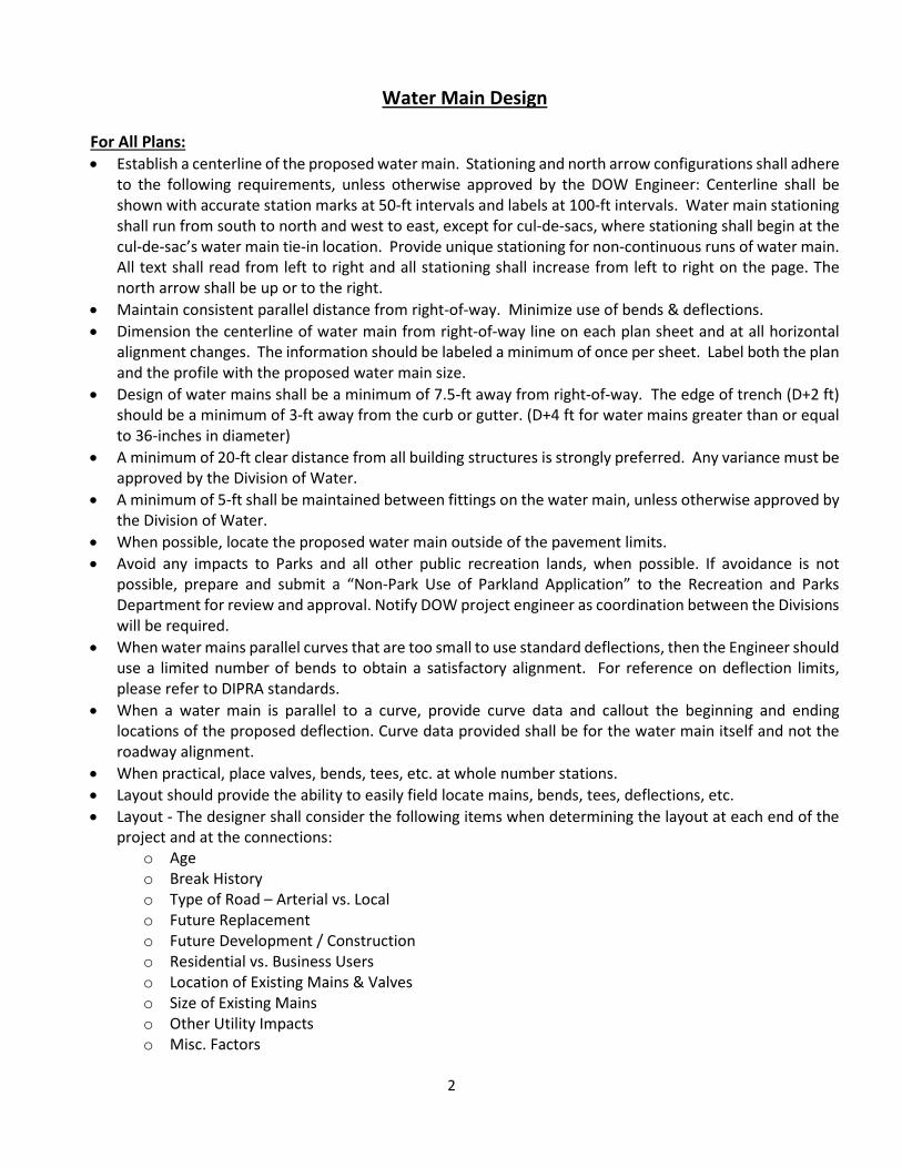
Water Main Design For All Plans: • Establish a centerline of the proposed water main. Stationing and north arrow configurations shall adhere
to the following requirements, unless otherwise approved by the DOW Engineer: Centerline shall be shown with accurate station marks at 50-ft intervals and labels at 100-ft intervals. Water main stationing shall run from south to north and west to east, except for cul-de-sacs, where stationing shall begin at the cul-de-sac’s water main tie-in location. Provide unique stationing for non-continuous runs of water main. All text shall read from left to right and all stationing shall increase from left to right on the page. The north arrow shall be up or to the right.
• Maintain consistent parallel distance from right-of-way. Minimize use of bends & deflections. • Dimension the centerline of water main from right-of-way line on each plan sheet and at all horizontal
alignment changes. The information should be labeled a minimum of once per sheet. Label both the plan and the profile with the proposed water main size.
• Design of water mains shall be a minimum of 7.5-ft away from right-of-way. The edge of trench (D+2 ft) should be a minimum of 3-ft away from the curb or gutter. (D+4 ft for water mains greater than or equal to 36-inches in diameter)
• A minimum of 20-ft clear distance from all building structures is strongly preferred. Any variance must be approved by the Division of Water.
• A minimum of 5-ft shall be maintained between fittings on the water main, unless otherwise approved by the Division of Water.
• When possible, locate the proposed water main outside of the pavement limits. • Avoid any impacts to Parks and all other public recreation lands, when possible. If avoidance is not
possible, prepare and submit a “Non-Park Use of Parkland Application” to the Recreation and Parks Department for review and approval. Notify DOW project engineer as coordination between the Divisions will be required.
• When water mains parallel curves that are too small to use standard deflections, then the Engineer should use a limited number of bends to obtain a satisfactory alignment. For reference on deflection limits, please refer to DIPRA standards.
• When a water main is parallel to a curve, provide curve data and callout the beginning and ending locations of the proposed deflection. Curve data provided shall be for the water main itself and not the roadway alignment.
• When practical, place valves, bends, tees, etc. at whole number stations. • Layout should provide the ability to easily field locate mains, bends, tees, deflections, etc. • Layout - The designer shall consider the following items when determining the layout at each end of the
project and at the connections: o Age o Break History o Type of Road – Arterial vs. Local o Future Replacement o Future Development / Construction o Residential vs. Business Users o Location of Existing Mains & Valves o Size of Existing Mains o Other Utility Impacts o Misc. Factors
3
If a future extension or replacement is anticipated through these factors, the water main design should extend through the intersection with a valve placed on the right-of-way line. The main should extend 20-ft past valve, and bend back into the existing water main.
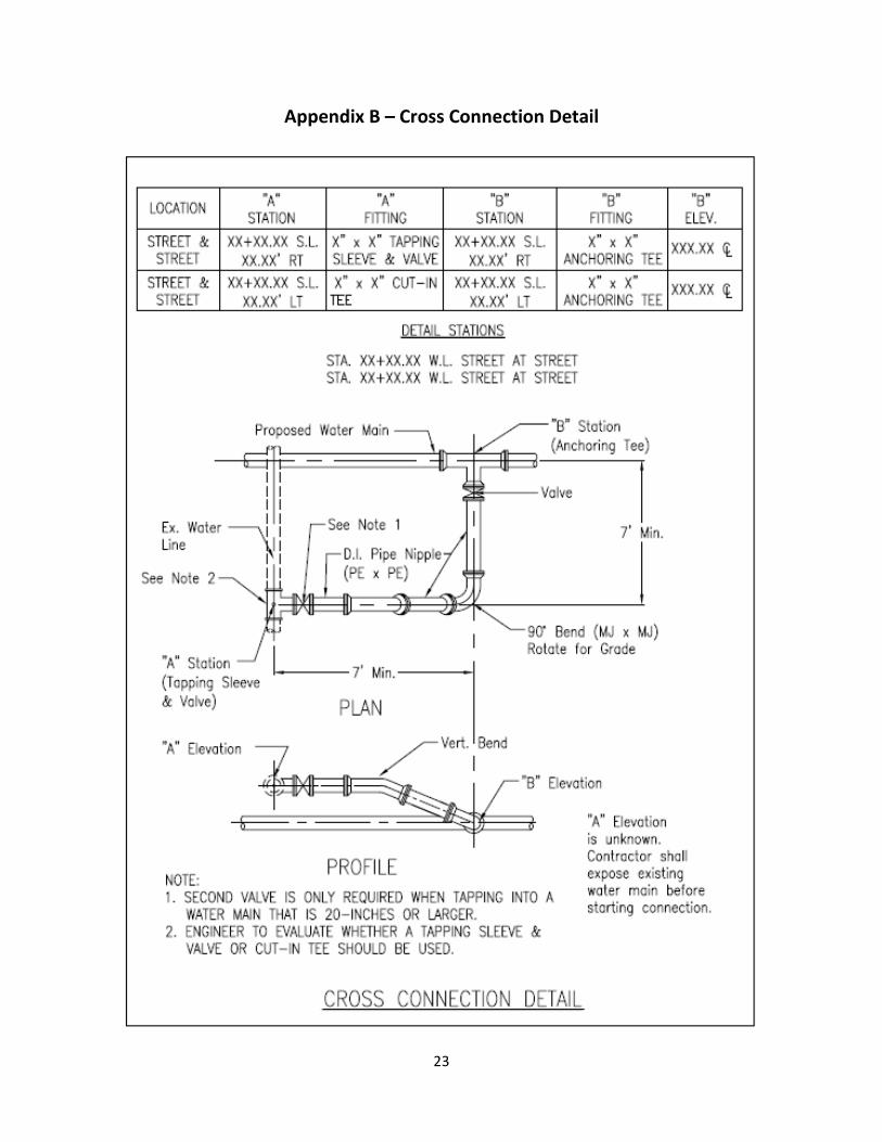
• Use a cross connection in areas where a proposed main crosses an existing main that is not being abandoned. Refer to Appendix B for cross connection detail.
• Projects replacing existing water mains: For side street connections or stub-outs for future expansion, a minimum pipe size of 8-inch diameter is required, unless the trunk main is smaller than 8-inches in diameter. If the side street pipe is smaller than 8-inches, a reducer is required after the 90° bend or first horizontal 45° bend for the branch connection.
o If at all possible, avoid going across the adjacent traffic lane and, instead, connect the proposed water main to the existing/perpendicular side-street main using a short branch connection or cross connection (with 90 degree horizontal bend). The valve shall be at the tee on the trunk main.
• The Engineer is responsible for locating utilities from record drawings, field survey, and/or other detectable methods.
• Proposed water mains (less than 20-inches in diameter) should be shown a minimum of four feet (4-ft) below existing or proposed grades for streets with curb. When installing a new water main where an existing main is to be abandoned, generally maintain a minimum 4.5 feet of cover for the proposed main. Proposed water mains (20-inches and larger) should be shown a minimum of six feet (6-ft) below existing or proposed grades. For projects where final grading has not occurred, provide required cover for the proposed water main. For unimproved streets (i.e. no curb or gutter), maintain a minimum of 6-ft of cover, unless otherwise directed by the Division of Water. For unimproved streets, the cover may vary due to certain circumstances.
• All mains must have 10-ft horizontal and 18-in vertical separation from sanitary and storm sewer piping (outside diameter to outside diameter). Maintain 3-ft horizontal and 12-in vertical separation from all other utilities unless the utility requires additional separation. In the City of Columbus, maintain a minimum of 8-ft horizontal separation from traffic signal foundations. Refer to the Columbus Traffic Signal Design Manual.
• When lowering is required to avoid utilities, the layout should conform to L-7401 (Typical Water Main Lowering). All lowerings shall attempt to be less than or equal to 20 feet in length. Any lowering longer than 20 feet will require chlorination. If greater than 20 feet in length, the consultant shall consider the timing of chlorination and the impacts to customers with their proposed recommendation.
• Proposed water main grade breaks shall be kept to a minimum. Proposed water mains can be deeper than the minimum depth in order to minimize grade breaks.
• Design water mains to minimize locations where air can be trapped. Strategically space hydrants to use for air release. If still unsuccessful, use air release valves for 12-in mains and larger. Air release valves are not required for mains less than 12-inches in diameter unless requested by the Division of Water.
• Elevation of centerline of proposed water main shall also be given at all horizontal bends and deflections, vertical grade breaks, and all other fittings.
• Provide steel casing pipe at railroad crossings, if directed by Division of Water. Casing pipe shall be designed per the applicable railroad’s design guidelines. Coordinate with the Division of Water if those requirements are less stringent than the DOW requirements. Casing pipes should extend 5-ft past the railroad right-of-way line where the crossing is perpendicular. At locations where the crossing is skewed, the casing pipe should extend 10-ft past the railroad right-of-way. Casing pipe should be designed at a flat grade (0-2%).
• Provide steel casing pipe at locations where water mains are required to be constructed below sewers 54-inches or greater in diameter. The casing pipe should extend 5-ft past the O.D. of the sewer.
4
• No grade breaks, bends (horizontal or vertical), tees or other fittings should be within 5’ of the end of casing pipe.
• For locations where water main is designed with restrained joints, indicate the limits of the restrained joints in the profile view
• When abandoning mains, it is preferred to replace tees with sleeves in lieu of cut and plugs. The ultimate decision should be based on the factors listed under “Layout” within this Water Main Design section.
• For transmission mains, if fire hydrants are not required due to parallel mains, add a fire hydrant at the low point of the main for draining purposes. Hydrants shall also be added for air release purposes, if necessary.
• Any water service connection that provides water to a hospital, nursing home, or any other facility where 24-hour services is critical, shall have a main line valve placed at each side of the tap to avoid service disruption.
• For proposed 20-inch or larger water mains, show the required restrained joint lengths and flange isolation kit locations. Access ports (Tees with blind flanges) shall be shown on the main, as directed by the Division of Water Engineer.
• For proposed 20-inch or larger water mains, coordinate with Division of Water on any desired Pitometer Tap locations.
• A geotechnical investigation with corrosivity testing shall be performed at locations where proposed 20-inch or larger water mains are being installed. Coordinate with the Division of Water to determine the location and number of bores to be performed
• When water main is crossing a river or a creek, the design shall follow the “Ten State Standards” in regards to surface water crossings. This includes items such as providing a minimum of 5-feet of cover, using flexible and restrained joints, installing valves at both ends, and provisions for leak detection capability. Coordinate with Division of Water on these requirements.
• Where desired backfill differs from the specifications, the type and limits of the backfill shall be clearly denoted in the profile.
• Surface elevations, elevations of centerline of proposed water main, and cut depth shall be given every fifty feet (50-ft). For water mains that are 20-in and larger, account for 6-inches of stone bedding when listing the “cut to invert” elevations
For Division of Water Capital Improvement Plans: • A list of critical users that will be affected by a shut shall be provided on the plans. DOW will assist with
developing this list of users. • The Engineer shall consult with the City, County and/or State Offices to inquire about any existing or future
roadway projects that may affect the location or gradient of the proposed water mains. Due regard shall be given to the location of water mains so that the lines will be protected from damage by future construction or land use based upon the information provided by the authorities.
• Show the full width of right-of-way on the plan view, including a distance of 25 feet outside of the right-of-way.
• Minimize the impact of construction on curb ramps wherever possible.
5
Valves
For All Plans: • In general, locate valves where right-of-way lines intersect with proposed water mains (i.e. street
intersections). • When possible and practical, valves shall be located at a minimum depth and on a 0% grade (2% max). • Do NOT call out where heavy duty valve boxes or ferrule boxes are required. • Use butterfly valves for all mains 20-in and greater. Note: The operator shall be set on either the south
or east side of the proposed water main in plan view. The engineer shall ensure that adequate room is available to install and operate the valve at this location and in this configuration.
• Main line valves should be placed a maximum of 1,000-ft apart for distribution mains and 2,000-ft apart for transmission mains (at the nearest intersections), unless otherwise directed by the Division of Water Engineer.
• Additional valves may be required in areas where a high volume of customers could be affected by future maintenance and construction. The Engineer should determine the optimum location of the valves so as to reduce the disturbance to customers when future construction occurs.
• Distinguish between field located valves and valves located per records by adding a label in plan view. • The Engineer shall consider the factors under “Layout” within the Water Main Design section to determine
whether to use a tapping sleeve & valve or to cut-in a tee at connections to existing mains. • When connecting to a 16-in water main or larger, a second valve is required and should be shown where
the right-of-way line intersects the main.
6
Fire Hydrants
For All Plans: • When feasible, fire hydrants shall be located at high points on the water main profile to allow for air
release. • For transmission mains, if fire hydrants are not required due to parallel mains, add a fire hydrant at the
low point of the main for draining purposes. • Fire hydrant locations shall minimize the impact to existing parking and pull off areas. • Fire hydrant valves
o One (1) valve should always be located at the anchoring tee on a Type “A” hydrant. o If fire hydrant lead is greater than 15-ft, a second valve is required. This valve should be located
within 2-ft of the fire hydrant. • Type “A” fire hydrant settings are preferred over Type “B” fire hydrant settings • The following are examples of acceptable call-outs: Fire Hydrant, Type “A” Setting or Fire Hydrant, Type
“A” Setting with second 6” valve • In the profile, an anchoring tee should be called out for Type “A” fire hydrants. A tee should be called out
for Type “B” fire hydrants. • Use a standard hydrant setting (per DOW Standard Drawings) for hydrants that occur on a dead end main.
The valve shall always be restrained no matter which configuration is utilized. • For Fire Hydrants located at the dead-end of a main, a Type A or Type B hydrant setting shall be used with
a plugged tee and thrust block.
For Plans within City of Columbus Limits: • Confirm hydrants and required distances from roads can be met per L-6637 and L-6409. • All public fire hydrants shall be located within the road right-of-way, unless otherwise approved by the
Director of Public Utilities, as per Rule and Regulation No. 17-01. • The spacing between fire hydrants is 400 ft maximum for single family residential areas and 300 ft
maximum for commercial, industrial, and multi-family residential areas. • When replacing a water main within Township jurisdiction: New fire hydrants shall replace the existing
hydrants in the same location as the existing hydrants. The number of new hydrants shall match the number of existing hydrants.
• The location of fire hydrants should minimize the impact on existing trees. They should be placed a minimum of 6-ft away from driveway returns (minimum of 10-ft away from commercial driveway returns). The fire hydrants should not be placed on sharp curves in streets.
• The designer should confirm that all fire hydrants have a maximum bury depth of 7-ft. In locations where bury depths exceed 7-ft, standard detail L-7601 should be used first to obtain the required depths. If hydrant lead is between 5-ft and 7-ft deep, fire hydrant extensions may be used. In no case may fire hydrant extensions be more than 2-ft high.
• If a fire hydrant lead crosses existing utilities, determine if vertical bends are required. If vertical bends are required, a profile of the hydrant lead shall be provided from the main to the hydrant.
• If fire hydrant extensions are required, the quantity of fire hydrant extensions should be calculated by the Engineer for each length based on the design depth of the fire hydrant at each specific location. The quantity of each extension with the applicable size should be provided in the “Table of Estimated Quantities”.
7
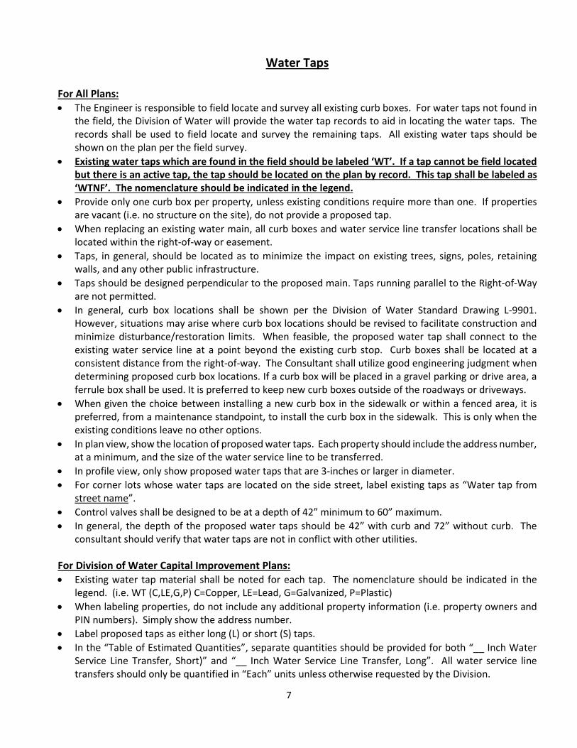
Water Taps
For All Plans: • The Engineer is responsible to field locate and survey all existing curb boxes. For water taps not found in
the field, the Division of Water will provide the water tap records to aid in locating the water taps. The records shall be used to field locate and survey the remaining taps. All existing water taps should be shown on the plan per the field survey.
• Existing water taps which are found in the field should be labeled ‘WT’. If a tap cannot be field located but there is an active tap, the tap should be located on the plan by record. This tap shall be labeled as ‘WTNF’. The nomenclature should be indicated in the legend.
• Provide only one curb box per property, unless existing conditions require more than one. If properties are vacant (i.e. no structure on the site), do not provide a proposed tap.
• When replacing an existing water main, all curb boxes and water service line transfer locations shall be located within the right-of-way or easement.
• Taps, in general, should be located as to minimize the impact on existing trees, signs, poles, retaining walls, and any other public infrastructure.
• Taps should be designed perpendicular to the proposed main. Taps running parallel to the Right-of-Way are not permitted.
• In general, curb box locations shall be shown per the Division of Water Standard Drawing L-9901. However, situations may arise where curb box locations should be revised to facilitate construction and minimize disturbance/restoration limits. When feasible, the proposed water tap shall connect to the existing water service line at a point beyond the existing curb stop. Curb boxes shall be located at a consistent distance from the right-of-way. The Consultant shall utilize good engineering judgment when determining proposed curb box locations. If a curb box will be placed in a gravel parking or drive area, a ferrule box shall be used. It is preferred to keep new curb boxes outside of the roadways or driveways.
• When given the choice between installing a new curb box in the sidewalk or within a fenced area, it is preferred, from a maintenance standpoint, to install the curb box in the sidewalk. This is only when the existing conditions leave no other options.
• In plan view, show the location of proposed water taps. Each property should include the address number, at a minimum, and the size of the water service line to be transferred.
• In profile view, only show proposed water taps that are 3-inches or larger in diameter. • For corner lots whose water taps are located on the side street, label existing taps as “Water tap from
street name”. • Control valves shall be designed to be at a depth of 42” minimum to 60” maximum. • In general, the depth of the proposed water taps should be 42” with curb and 72” without curb. The
consultant should verify that water taps are not in conflict with other utilities. For Division of Water Capital Improvement Plans: • Existing water tap material shall be noted for each tap. The nomenclature should be indicated in the
legend. (i.e. WT (C,LE,G,P) C=Copper, LE=Lead, G=Galvanized, P=Plastic) • When labeling properties, do not include any additional property information (i.e. property owners and
PIN numbers). Simply show the address number. • Label proposed taps as either long (L) or short (S) taps. • In the “Table of Estimated Quantities”, separate quantities should be provided for both “__ Inch Water
Service Line Transfer, Short)” and “__ Inch Water Service Line Transfer, Long”. All water service line transfers should only be quantified in “Each” units unless otherwise requested by the Division.
8
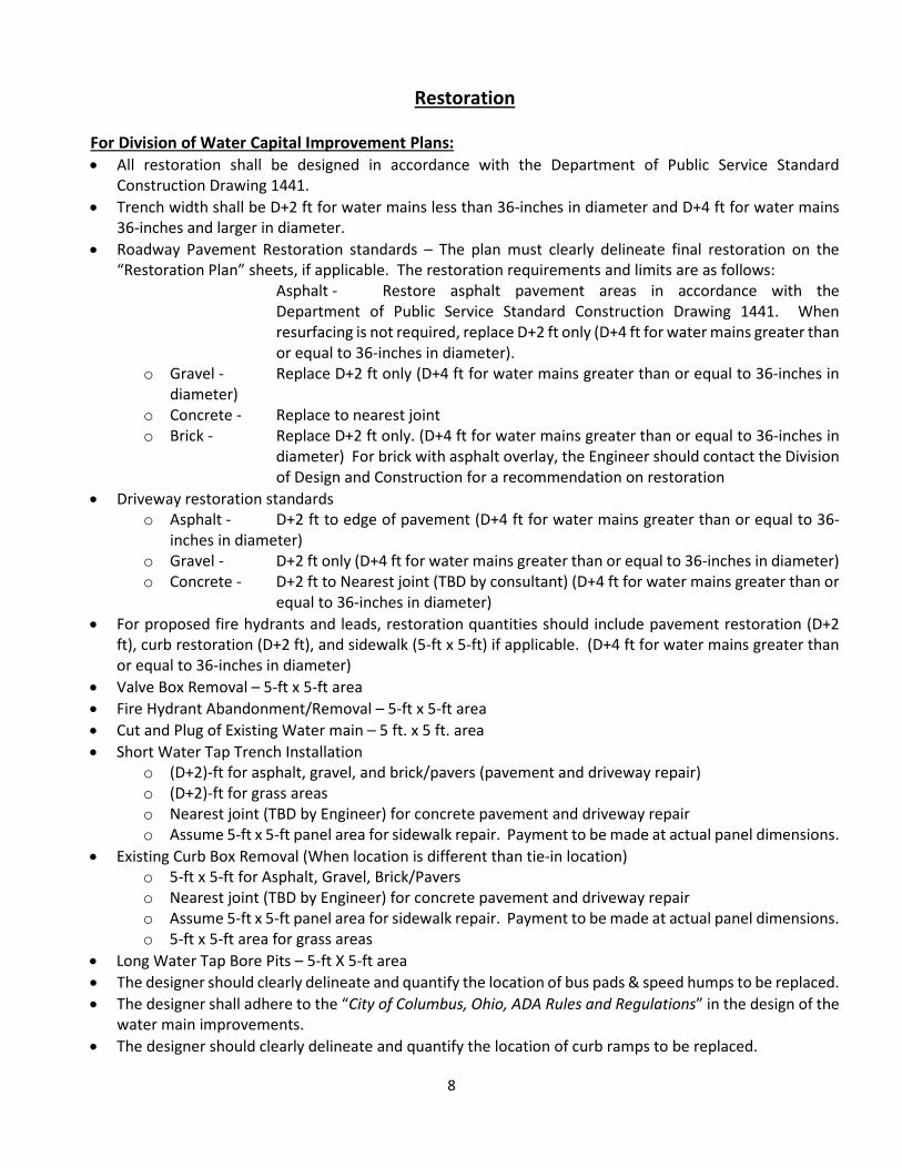
Restoration For Division of Water Capital Improvement Plans: • All restoration shall be designed in accordance with the Department of Public Service Standard
Construction Drawing 1441. • Trench width shall be D+2 ft for water mains less than 36-inches in diameter and D+4 ft for water mains
36-inches and larger in diameter. • Roadway Pavement Restoration standards – The plan must clearly delineate final restoration on the
“Restoration Plan” sheets, if applicable. The restoration requirements and limits are as follows: Asphalt - Restore asphalt pavement areas in accordance with the Department of Public Service Standard Construction Drawing 1441. When resurfacing is not required, replace D+2 ft only (D+4 ft for water mains greater than or equal to 36-inches in diameter).
o Gravel - Replace D+2 ft only (D+4 ft for water mains greater than or equal to 36-inches in diameter)
o Concrete - Replace to nearest joint o Brick - Replace D+2 ft only. (D+4 ft for water mains greater than or equal to 36-inches in
diameter) For brick with asphalt overlay, the Engineer should contact the Division of Design and Construction for a recommendation on restoration
• Driveway restoration standards o Asphalt - D+2 ft to edge of pavement (D+4 ft for water mains greater than or equal to 36-
inches in diameter) o Gravel - D+2 ft only (D+4 ft for water mains greater than or equal to 36-inches in diameter) o Concrete - D+2 ft to Nearest joint (TBD by consultant) (D+4 ft for water mains greater than or
equal to 36-inches in diameter) • For proposed fire hydrants and leads, restoration quantities should include pavement restoration (D+2
ft), curb restoration (D+2 ft), and sidewalk (5-ft x 5-ft) if applicable. (D+4 ft for water mains greater than or equal to 36-inches in diameter)
• Valve Box Removal – 5-ft x 5-ft area • Fire Hydrant Abandonment/Removal – 5-ft x 5-ft area • Cut and Plug of Existing Water main – 5 ft. x 5 ft. area • Short Water Tap Trench Installation
o (D+2)-ft for asphalt, gravel, and brick/pavers (pavement and driveway repair) o (D+2)-ft for grass areas o Nearest joint (TBD by Engineer) for concrete pavement and driveway repair o Assume 5-ft x 5-ft panel area for sidewalk repair. Payment to be made at actual panel dimensions.
• Existing Curb Box Removal (When location is different than tie-in location) o 5-ft x 5-ft for Asphalt, Gravel, Brick/Pavers o Nearest joint (TBD by Engineer) for concrete pavement and driveway repair o Assume 5-ft x 5-ft panel area for sidewalk repair. Payment to be made at actual panel dimensions. o 5-ft x 5-ft area for grass areas
• Long Water Tap Bore Pits – 5-ft X 5-ft area • The designer should clearly delineate and quantify the location of bus pads & speed humps to be replaced. • The designer shall adhere to the “City of Columbus, Ohio, ADA Rules and Regulations” in the design of the
water main improvements. • The designer should clearly delineate and quantify the location of curb ramps to be replaced.

9
• If water main trench is within 2 feet of the curb/edge of pavement and will require additional pavement replacement outside of the trench limits, the designer shall call this out on the plan sheet and clearly identify the limits of where this will occur.
• Designer shall provide a separate restoration plan (roadway, driveways, sidewalk) within the documents. Restoration areas shall NOT be shown on the water main plan and profile sheets. Display all existing pavement markings. Utilize a scale of 1-inch = 40 feet for these sheets.
• No walk restoration will be paid for water taps constructed in the curb lawn, unless the existing curb box is located within the sidewalk. The division will not pay for curb replacement when constructing water taps.
10
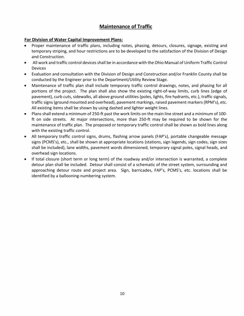
Maintenance of Traffic
For Division of Water Capital Improvement Plans: • Proper maintenance of traffic plans, including notes, phasing, detours, closures, signage, existing and
temporary striping, and hour restrictions are to be developed to the satisfaction of the Division of Design and Construction.
• All work and traffic control devices shall be in accordance with the Ohio Manual of Uniform Traffic Control Devices
• Evaluation and consultation with the Division of Design and Construction and/or Franklin County shall be conducted by the Engineer prior to the Department/Utility Review Stage.
• Maintenance of traffic plan shall include temporary traffic control drawings, notes, and phasing for all portions of the project. The plan shall also show the existing right-of-way limits, curb lines (edge of pavement), curb cuts, sidewalks, all above ground utilities (poles, lights, fire hydrants, etc.), traffic signals, traffic signs (ground mounted and overhead), pavement markings, raised pavement markers (RPM’s), etc. All existing items shall be shown by using dashed and lighter weight lines.
• Plans shall extend a minimum of 250-ft past the work limits on the main line street and a minimum of 100-ft on side streets. At major intersections, more than 250-ft may be required to be shown for the maintenance of traffic plan. The proposed or temporary traffic control shall be shown as bold lines along with the existing traffic control.
• All temporary traffic control signs, drums, flashing arrow panels (FAP’s), portable changeable message signs (PCMS’s), etc., shall be shown at appropriate locations (stations, sign legends, sign codes, sign sizes shall be included), lane widths, pavement words dimensioned, temporary signal poles, signal heads, and overhead sign locations.
• If total closure (short term or long term) of the roadway and/or intersection is warranted, a complete detour plan shall be included. Detour shall consist of a schematic of the street system, surrounding and approaching detour route and project area. Sign, barricades, FAP’s, PCMS’s, etc. locations shall be identified by a ballooning-numbering system.
11
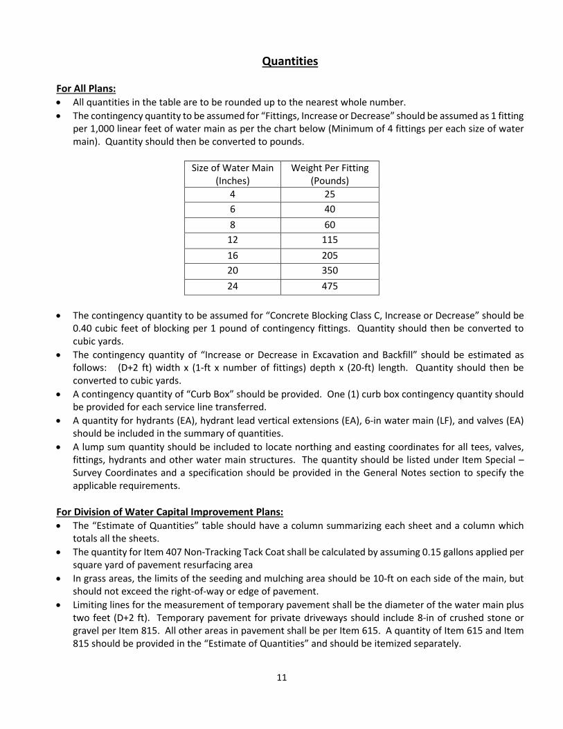
Quantities For All Plans: • All quantities in the table are to be rounded up to the nearest whole number. • The contingency quantity to be assumed for “Fittings, Increase or Decrease” should be assumed as 1 fitting
per 1,000 linear feet of water main as per the chart below (Minimum of 4 fittings per each size of water main). Quantity should then be converted to pounds.
Size of Water Main
(Inches) Weight Per Fitting
(Pounds) 4 25 6 40 8 60
12 115 16 205 20 350 24 475
• The contingency quantity to be assumed for “Concrete Blocking Class C, Increase or Decrease” should be
0.40 cubic feet of blocking per 1 pound of contingency fittings. Quantity should then be converted to cubic yards.
• The contingency quantity of “Increase or Decrease in Excavation and Backfill” should be estimated as follows: (D+2 ft) width x (1-ft x number of fittings) depth x (20-ft) length. Quantity should then be converted to cubic yards.
• A contingency quantity of “Curb Box” should be provided. One (1) curb box contingency quantity should be provided for each service line transferred.
• A quantity for hydrants (EA), hydrant lead vertical extensions (EA), 6-in water main (LF), and valves (EA) should be included in the summary of quantities.
• A lump sum quantity should be included to locate northing and easting coordinates for all tees, valves, fittings, hydrants and other water main structures. The quantity should be listed under Item Special – Survey Coordinates and a specification should be provided in the General Notes section to specify the applicable requirements.
For Division of Water Capital Improvement Plans: • The “Estimate of Quantities” table should have a column summarizing each sheet and a column which
totals all the sheets. • The quantity for Item 407 Non-Tracking Tack Coat shall be calculated by assuming 0.15 gallons applied per
square yard of pavement resurfacing area • In grass areas, the limits of the seeding and mulching area should be 10-ft on each side of the main, but
should not exceed the right-of-way or edge of pavement. • Limiting lines for the measurement of temporary pavement shall be the diameter of the water main plus
two feet (D+2 ft). Temporary pavement for private driveways should include 8-in of crushed stone or gravel per Item 815. All other areas in pavement shall be per Item 615. A quantity of Item 615 and Item 815 should be provided in the “Estimate of Quantities” and should be itemized separately.
12
• A separate quantity of permanent pavement restoration should be provided for each different type of material being replaced in the plans. See Item 259 for types.
• When a water main is proposed to be constructed under an existing bus pad, the pad must be completely removed and replaced. The thickness of pavement replacement will be determined by the Division of Design and Construction.
• Loop detectors that are expected to be damaged during construction should be called out for removal and replacement. An “each” quantity of Item 632 – Detector Loop shall be provided.
• Notes should provide for temporary traffic signals as required by the Division of Design and Construction. A drawing may also be required at the request of the Department of Public Service. Separate quantities should be indicated on the plan as applicable.
13
Survey For All Plans: • Prior to any field survey, the Engineer shall acquire all available records (i.e. plans, tap cards, etc.)
pertaining to the project. • Establishment of location of all existing water mains and structures shall be collected by means of field
survey and Division of Water records. The Engineer shall make diligent efforts to locate all valves, fire hydrants, curb boxes, etc. If a conflict between the field survey and records exist, the field survey shall govern. If necessary, the Engineer should also use underground pipe detectors and exploratory excavation if authorized by the Division of Water.
• All work should be designed on the Ohio State Plane Coordinate System (South) using the NORTH AMERICAN DATUM OF 1983 (NAD 83) WITH THE (NSRS2011) ADJUSTMENT.
• The establishment of existing right-of-way lines is a critical task of the consultant. The use of the Franklin County Auditor’s GIS should only be utilized as a tool in depicting the existing right-of-way. It is the responsibility of the consultant to research State, County, and local right-of-way records and property records to establish the current existing right-of-way for the project limits.
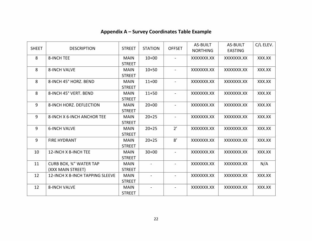
• Provide a chart which includes the applicable water main feature; water main station information and blank boxes for northing, easting and centerline elevation record information. The chart should provide the information for all bends, tees, horizontal deflections, valves, crosses, water taps, air release valves, fire hydrants, etc. from both the plan and profile views. Water taps shall include the size and address listed in the description, and the coordinate shall be for the curb box itself. Fire hydrants shall include separate items for the tee, watch valve(s), and the hydrant itself. Refer to Appendix A for an example of the required coordinate table.
• Show and label corporate boundaries (City of Columbus, Franklin County, Townships, Other Municipalities, etc.).
• When working within the right-of-way, contact all utility companies, both public and privately owned, for the purpose of obtaining the location and extent of utility lines (both existing and proposed), and take such information into account in the survey, design, and preparation of the detailed plans. Such information should be shown on the plans.
• All infrastructure data requests regarding DPU owned utilities shall be requested through a general email address or phone number. The email address is [email protected] and the phone number is 614-645-5825. All requests shall include the type of data being requested (Water, Sewer, Electric, or All) and a summarized purpose of the data request.
For Division of Water Capital Improvement Plans: • Benchmarks shall be referenced to the applicable County Engineer’s Monuments. Elevations shall be
based on the NAVD 88 datum and specified on the plans. The plans should show northing and easting information on all benchmarks & control.
• The Engineer shall set two permanent survey control monuments (iron pins) at the beginning and end of each section of water main. The survey control monuments shall be visible between each other. If visibility is restricted between the two, then additional monuments shall be installed. The plans should show northing and easting information on all survey control monuments.
• The Engineer must obtain a permit from the City of Columbus for their surveyors to work in the right-of-way. There is no charge for this permit; however the Division of Design and Construction may require police officers for traffic control. The cost associated with providing police officers, where required, shall be at the Engineer’s expense.
14
• A survey shall be conducted to locate topographic features, such as, but not limited to: pavement, curbs, fence, culvert pipes, water valves, water service boxes, gas service boxes, manholes, vaults, utility poles, trees, and landscaping amenities within the project limits. The field survey should include the area inside the right-of-way and 10’ outside the right-of-way limits. The survey should extend 100’ past the project limits as well as at each side street. For those areas where the water main is planned to be outside the right-of-way, the area of survey should be agreed upon with the DOW Engineer prior to the start of survey.
• Buildings shall be indicated per the current Franklin County Auditor’s GIS and verified in the field. Vacant lots shall be indicated as such on the plans.
• Show the address ONLY for each property adjacent and/or affected by project. Do not show the parcel ID number or resident names.
• Fire hydrants that are designated to be removed with the project are NOT permitted to be used as Benchmarks.
15
Constructability For All Plans: • The consultant shall review the plans for constructability. • Ensure that tees, bends, crosses and valves are not located below existing utilities. • Verify blocking has sufficient space to be constructed at the applicable locations. • When calling for tees to be rotated, a callout shall be provided at the tee noting that the concrete blocking
shall be installed as per Standard Drawing L-6310 or L-6311 (depending on the direction of rotation), as the forces acting on the tee are now the same as a vertical bend.
• Verify the locations of fire hydrants relative to driveways, slopes of ground, guard rails, etc. • Ensure fire hydrant depths do not exceed the maximum bury depth of 7 feet. • Review clearances – overhead, horizontal and vertical. Determine if any notes need to be added for those
areas where the work will be hindered during construction or maintenance. • In no case shall a customer be without service for more than two times during any project. The length of
time to construct the improvements shall be considered in the design of the improvements. In any case, the length of time to construct the improvements shall be held to a minimum. If any customer is expected to be out of water longer than 8 hours, the design engineer may be required to include in the plans a method of providing temporary water service to the affected customer. Coordinate this with the DOW.
• Verify that the distance from the water main to the curb is adequate and can be installed without disturbing the curb and/or curb and gutter.
• Verify that trench limits will, when possible, remain within one travel lane. Avoid crossing lane lines or the centerline to minimize the limits for pavement resurfacing.
• Verify that valves are not located under existing or proposed curbs. Review the distance of the valves from the curb.
• Verify that valves are located on flat (0-2%) water main slopes. • Review construction methods during design to reduce the impact on trees. The impact on existing trees
shall be held to a minimum. Place fire hydrants away from trees. • Ensure that the size of the proposed tapping sleeve does not exceed the size of the existing water main.
If possible, avoid the use of size on size tapping sleeves (i.e. 6” x 6”) unless no other option is available.
16
Utilities For All Plans: • Reference all existing water mains with the Division of Water plan by which they were installed, material
type, year of installation, and dimension from right-of way. The information should be labeled on the pipe and a minimum of one location per sheet.
• Show all existing and proposed utilities (public and private) in the plan view and profile. Label the size and type of all utilities. The plan should include record plan information for all sewers. The type of material should be called out if the existing sewer line is brick material type. The information should be labeled on the pipe and a minimum of one location per sheet.
• For those sewers that are found to be brick material, the consultant should evaluate the constructability methods to ensure work will not affect the integrity of the sewer. The consultant should note the brick sewers and proposed methods of construction in the preliminary design report so adequate time is available to address the issue prior to construction.
• When necessary, call out for existing utility poles to be supported due to proposed work. • Maintain a minimum of 8-ft horizontal separation from traffic signal foundations. Refer to the Columbus
Traffic Signal Design Manual. • In the plan view, all existing utilities greater than 24-in should be shown with two lines to delineate the
actual size. In the profile, all utility crossings should be shown as actual size. • Show existing water taps that are 3-inches or larger in the profile view. All existing water taps shall be
shown in the plan view. • The Engineer should ensure that construction of the water main and all other applicable construction is
an adequate distance away from utility poles and other above ground structures. • Existing utilities that are critical to the horizontal and vertical alignment should be located via non-
destructive vacuum utility investigation (i.e. pothole) or other method approved by the DOW. The locations should be identified by the consultant and the DOW Engineer shall review and approve the locations prior to the start of this work.
For Division of Water Capital Improvement Plans: • Do not show gas services in the plan view or profile view. Gas service boxes may be shown in the plan
view. • The symbol to be used for a gas valve in the plan view should be a circle with a single diagonal line through
the center. Gas valves should be labeled with the letters “GV” above the symbol. • Do not call out existing utility crossings to be exposed on the plan or profile view. • Sanitary sewer records should be researched and a copy obtained at the Division of Sewerage and
Drainage permit office. These records should be reviewed to ensure that the sanitary sewer services are not in conflict with the proposed water main.
17
Miscellaneous For All Plans: • Do NOT call out minimum cover required for the waterline in the profile view. • Plan and Profile sheets should be shown at 1-in = 30-ft horizontal and 1-in = 5-ft vertical, unless otherwise
approved by the Division. • A current set of notes to be placed on the plans will be provided during back check review. The general
notes supplied by the City should be shown in the same order as provided. Additional notes required to construct the improvements should be included at the end of the notes. Any “Item Special” quantity shall include a note on the plans to explain the requirements of that item.
• It is the Engineer’s responsibility to show or reference all details required to construct the project improvements.
• It is the Engineer’s responsibility to show or reference any additional details on the plans beyond the standard drawings indicated above.
• Water services that are not perpendicular to the water main will require two survey coordinates each in the survey table. One will be for the Curb Box and the other for the Corporation Stop.
• A legend must be provided on the plan that defines plan symbology and abbreviations. • At the 30% and 100% (Final Approval Plans) Stages, please provide the following items via email, ftp, or
sharing file website to the Project Manager for all DOW CIP projects or to [email protected] for all other projects:
o TIFF Images (Black and White, Group 4, 300 DPI). The TIFFs should be submitted as individual sheets and use the following naming convention:
• DOW Project Number_001, DOW Project Number_002, etc. For example, 20-046_001, 20-046_002, and so forth.
o CAD Basemap (DWG or DXF Format). The basemap should be submitted with the proposed waterline infrastructure only (main line, valves, taps, curb boxes, hydrants, and any other proposed items). Please remove all Xrefs and include linework in basemap only.
• Layer naming and linetype/lineweight requirements shall follow the requirements listed in Section 3.1 and Appendix A of the “City of Columbus Digital Submission Standards” located here: https://www.columbus.gov/bzs/primary/Building-and-Zoning-Services-Document-Library/
• Some of the naming conventions are listed below for reference: • COC_UWAT_MAIN • COC_UWAT_HYD_PR • COC_UWAT_VALVE
• PDF plans must be flattened prior to submitting to DOW electronically, at every stage. For City of Columbus Plans: • Plans shall be prepared according to the current version of the City of Columbus CAD Standards • If a project involves acquisition of Right-of-Way, the DOW water meters should be relocated outside of
the R/W onto private property (if applicable). This work will require a submission of a separate Water Service plan to the Water Distribution Engineering office.
• If a Railroad crossing is planned as part of a project, coordination with the DOW will be required to formulate a plan for submission to the Railroad Company. It shall be expected that a plan review fee will be required to submit to the Railroad, and an electronic application shall be submitted by the Design Consultant following the requirements of the Railroad. Extensive coordination efforts shall be anticipated
18
in order to receive plan approval. General notes and quantities will be included in the plan to discuss the Railroad crossing work.
For Division of Water Capital Improvement Plans: • Construction drawings shall be prepared on 12-in x 36-in sheets. • Plans shall be prepared according to the current version of the Division of Water Plan Presentation
Standards • The plans shall contain, but are not limited to, the following items:
o Title Sheet o General Notes & Quantities o Miscellaneous Details o Survey Coordinate Chart & layout information o Plan and Profile sheets o Restoration Plan (Roadway, Driveways, Sidewalk) that includes existing pavement markings o Maintenance of Traffic
• Place match lines at 25-ft station intervals. • Only the proposed water main should be shown as bold. Water mains that are proposed as part of same
project, but with detailed design information shown on different sheet(s), should be labeled “Proposed __” W.M. See sheet ___”.
• Label surface features (i.e. EP, C&G, Ex. Curb, etc.) on each sheet and a minimum of one location per sheet.
• Any void spaces on a construction drawing shall be kept to the left side of the drawing adjacent to the binding edge.
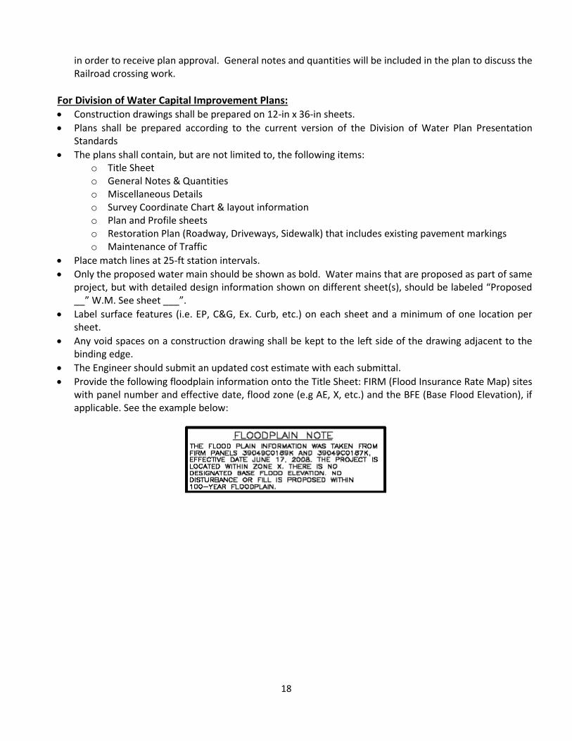
• The Engineer should submit an updated cost estimate with each submittal. • Provide the following floodplain information onto the Title Sheet: FIRM (Flood Insurance Rate Map) sites
with panel number and effective date, flood zone (e.g AE, X, etc.) and the BFE (Base Flood Elevation), if applicable. See the example below:
19
Record Plan Preparation
For Division of Water Capital Improvement Plans: • Record drawings should be prepared using AutoCAD, construction drawing images in .TIF Group 4 format,
field book notes, and progress plan data furnished by the City. All record plan drawings shall be created in accordance with “CAD Standards for Creation and Submittal of Digital Drawing”. All revisions to the plans shall also be made in accordance with the Submittal manual.
• All survey information to be used for record plan purposes shall be provided by construction inspectors, DOW’s notes and records, and contractor supplied survey coordinates.
• Incorporate the As-Built Plan stationing into the original design stationing. Use station equations where the alignment differs.
• Record Drawing information shall first be incorporated from the As-Built Plans and Construction Inspection Reports. Coordinates, with the exception of curb box locations, shall only be used as a check against this information. Do not develop record plans solely from coordinates.
• Curb box locations shall be shown on the plan using the survey coordinates. If the location appears unreasonable, refer to the dimensions on the water service reports, as well as any inspection reports or field sketches, to determine the actual location.
• Provide a full, complete set of record drawings with all sheets included, with the exception of the maintenance of traffic (MOT) sheets. Remove all sheets pertaining to maintenance of traffic and re-number the plan set accordingly.
• Provide a CD with a complete set of drawing images in .TIF Group 4 format, a final AutoCAD base drawing of the plans in .DWG format, and a final complete coordinate table in Microsoft Excel format. Include all of the files on one (1) CD.
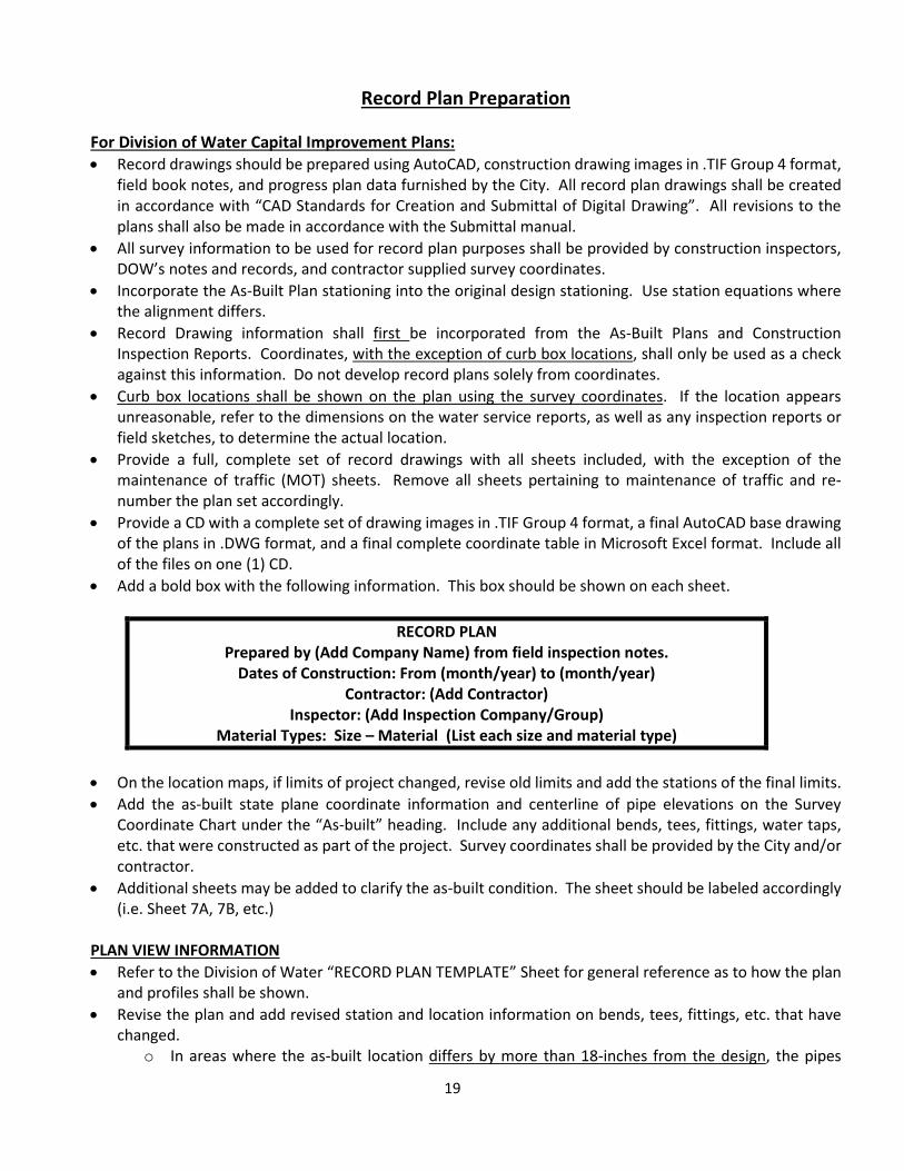
• Add a bold box with the following information. This box should be shown on each sheet.
RECORD PLAN Prepared by (Add Company Name) from field inspection notes.
Dates of Construction: From (month/year) to (month/year) Contractor: (Add Contractor)
Inspector: (Add Inspection Company/Group) Material Types: Size – Material (List each size and material type)
• On the location maps, if limits of project changed, revise old limits and add the stations of the final limits. • Add the as-built state plane coordinate information and centerline of pipe elevations on the Survey
Coordinate Chart under the “As-built” heading. Include any additional bends, tees, fittings, water taps, etc. that were constructed as part of the project. Survey coordinates shall be provided by the City and/or contractor.
• Additional sheets may be added to clarify the as-built condition. The sheet should be labeled accordingly (i.e. Sheet 7A, 7B, etc.)
PLAN VIEW INFORMATION • Refer to the Division of Water “RECORD PLAN TEMPLATE” Sheet for general reference as to how the plan
and profiles shall be shown. • Revise the plan and add revised station and location information on bends, tees, fittings, etc. that have
changed. o In areas where the as-built location differs by more than 18-inches from the design, the pipes

20
should be redrawn to show actual location. o In areas where the as-built location differs by 18-inches or less from the design, then the design
stations and locations shall remain as shown. • For those areas that have changed, add adequate dimensions from the right of way. • Cross out those fire hydrants that were abandoned. • Revise the “To be Abandoned/Removed” callout/label for the existing items that were
abandoned/removed to now say “Abandoned/Removed” to reflect the current condition. • Add the station and location where the contractor cut and plugged water mains to be abandoned. Include
the elevation at this location. • For work that was non-performed, remove any original design information and associated notes/callouts. • For properties that had an existing water tap shown but are now vacant with no structure, please note on
the plan view that this water tap installation was a non-performed but did previously contain a water tap. This will assist our permit office during future requests for water service to be provided.
• Add updated water tap and water service line transfer information to the plans. Show the location and size of all water taps.
• Add station, location, size, and material type for existing utilities affected by construction. o Label information to be modified and then add the updated information. o Add any new information discovered during construction. o In areas where the as-built location differs by more than 18-inches from the elevation listed on
the plan, the utility should be redrawn to show the actual location. o For those areas where the location differs by 18-inches or less from the location listed on the
plans, then the original location shall remain as shown. • Cross out those utilities that are found to be abandoned during construction. Add contact information for
the utility that verified its abandonment, if available. • Verify the additional information that was added to the profile is shown in the plan view. • Where requested by the Engineer, show enlarged details of hydrant leads labeling bends, fittings, and
utility crossings. Show dimensions where necessary. • Remove all pavement/sidewalk/driveway replacement hatching and callouts/labels relating to proposed
pavement/sidewalk/driveway work. • Do not show chlorination taps or blowoffs • Do not show installation dates on the plans
PROFILE VIEW INFORMATION • Remove all slope information • Show locations and elevations where rock was encountered during excavation, if available. • Where applicable, show restrained joint lengths. • All water main elevations provided shall be to the centerline of the pipe • Revise all elevation information on grade breaks, bends, tees, fittings, etc.
o In those areas where as-built elevations differ by more than 12-inches from design elevations, the pipes should be redrawn to show actual elevation, and the profile elevation shall be updated.
o For those areas where as-built elevations differ by 12-inches or less from the design elevations, then the design elevations shall be revised.
• Add station and elevation information for existing utilities affected by construction. o Add any new information discovered during construction. o In those areas where the elevation differs by more than 12-inches from the elevation listed on the
plan, the utility should be redrawn to show the actual elevation, and the profile elevation shall be
21
updated. o For those areas where the elevation differs by 12-inches or less from the elevation listed on the
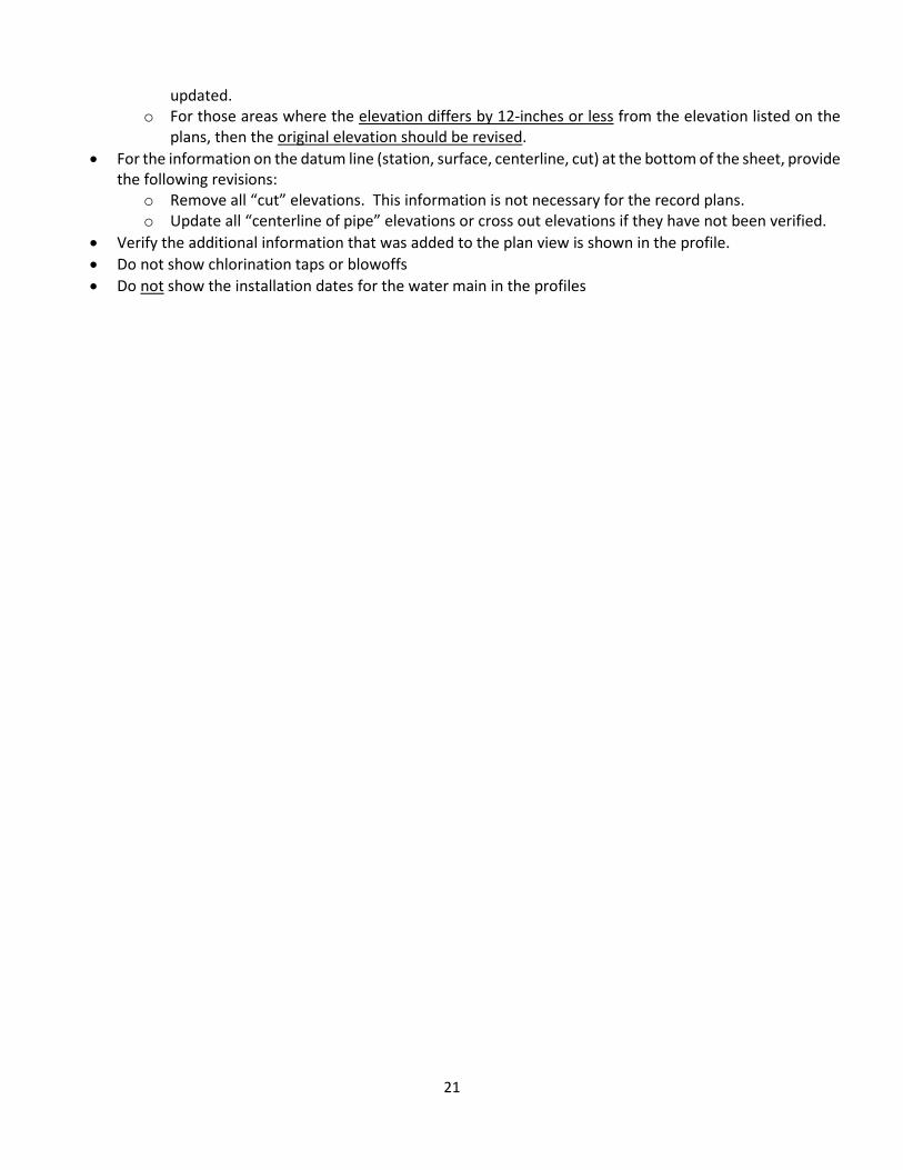
plans, then the original elevation should be revised. • For the information on the datum line (station, surface, centerline, cut) at the bottom of the sheet, provide
the following revisions: o Remove all “cut” elevations. This information is not necessary for the record plans. o Update all “centerline of pipe” elevations or cross out elevations if they have not been verified.
• Verify the additional information that was added to the plan view is shown in the profile. • Do not show chlorination taps or blowoffs • Do not show the installation dates for the water main in the profiles
22
Appendix A – Survey Coordinates Table Example
SHEET DESCRIPTION STREET STATION OFFSET AS-BUILT
NORTHING AS-BUILT EASTING
C/L ELEV.
8 8-INCH TEE MAIN STREET
10+00 - XXXXXXX.XX XXXXXXX.XX XXX.XX
8 8-INCH VALVE MAIN STREET
10+50 - XXXXXXX.XX XXXXXXX.XX XXX.XX
8 8-INCH 45° HORZ. BEND MAIN STREET
11+00 - XXXXXXX.XX XXXXXXX.XX XXX.XX
8 8-INCH 45° VERT. BEND MAIN STREET
11+50 - XXXXXXX.XX XXXXXXX.XX XXX.XX
9 8-INCH HORZ. DEFLECTION MAIN STREET
20+00 - XXXXXXX.XX XXXXXXX.XX XXX.XX
9 8-INCH X 6-INCH ANCHOR TEE MAIN STREET
20+25 - XXXXXXX.XX XXXXXXX.XX XXX.XX
9 6-INCH VALVE MAIN STREET
20+25 2’ XXXXXXX.XX XXXXXXX.XX XXX.XX
9 FIRE HYDRANT MAIN STREET
20+25 8’ XXXXXXX.XX XXXXXXX.XX XXX.XX
10 12-INCH X 8-INCH TEE MAIN STREET
30+00 - XXXXXXX.XX XXXXXXX.XX XXX.XX
11 CURB BOX, ¾” WATER TAP (XXX MAIN STREET)
MAIN STREET
- - XXXXXXX.XX XXXXXXX.XX N/A
12 12-INCH X 8-INCH TAPPING SLEEVE MAIN STREET
- - XXXXXXX.XX XXXXXXX.XX XXX.XX
12 8-INCH VALVE MAIN STREET
- - XXXXXXX.XX XXXXXXX.XX XXX.XX
23
Appendix B – Cross Connection Detail