Embed Size (px)
Citation preview
CITY OF HOUSTON DEPARTMENT OF PUBLIC WORKS
AND ENGINEERING
ENGINEERING DESIGN MANUAL FOR
SUBMERSIBLE LIFT STATIONS
Dale A. Rudick, P.E. Director
J. Timothy Lincoln, P.E. City Engineer
July 2016
CITY OF HOUSTON CITY OF HOUSTON DESIGN GUIDELINES MANUAL FOR SUBMERSIBLE LIFT STATIONS Department of Public Works and Engineering TABLE OF CONTENTS
i 06/15/2016
TABLE OF CONTENTS
SECTION 1: INTRODUCTION ............................................................................................ 1
1.01 Purpose ......................................................................................................................... 1
1.02 General .......................................................................................................................... 1
D. Influent Flows .................................................................................................................. 1
1.03 Standards and Codes ..................................................................................................... 2
1.04 Definitions .................................................................................................................... 2
SECTION 2: LIFT STATION CONFIGURATION .............................................................. 6
2.01 Lift Station New Construction and Replacement Design ............................................. 6
SECTION 3: SITE REQUIREMENTS .................................................................................. 8
3.01 Lift Station Site Selection and Use ............................................................................... 8
3.02 Access ........................................................................................................................... 9
3.03 Security ....................................................................................................................... 10
3.04 Landscaping ................................................................................................................ 11
3.05 Flood Plain/Floodway................................................................................................. 11
3.06 Site Drainage .............................................................................................................. 11
3.07 Odor Control ............................................................................................................... 11
3.08 Corrosion Control ....................................................................................................... 14
SECTION 4: LIFT STATION HYDRAULIC DESIGN ...................................................... 15
4.01 System Head and Pump Capacity Curves .................................................................. 15
4.02 Wet Well Design ........................................................................................................ 16
4.03 Wet Well Levels ......................................................................................................... 17
4.04 Lift Station Bypass ..................................................................................................... 17
SECTION 5: MECHANICAL DESIGN .............................................................................. 18
5.01 General ........................................................................................................................ 18
5.02 Pump Selection ........................................................................................................... 18
5.03 Valves ......................................................................................................................... 19
5.04 Plumbing ..................................................................................................................... 20
5.05 Air Conditioning (A/C) .............................................................................................. 21
5.06 Ventilation .................................................................................................................. 22
SECTION 6: STRUCTURAL DESIGN ............................................................................... 24
6.01 General ........................................................................................................................ 24
CITY OF HOUSTON CITY OF HOUSTON DESIGN GUIDELINES MANUAL FOR SUBMERSIBLE LIFT STATIONS Department of Public Works and Engineering TABLE OF CONTENTS
ii 06/15/2016
6.02 Design Standards ........................................................................................................ 24
6.03 Geotechnical Coordination ......................................................................................... 25
6.04 Loads .......................................................................................................................... 25
6.05 Buoyancy .................................................................................................................... 26
6.06 Design Stresses ........................................................................................................... 26
6.07 Design Considerations ................................................................................................ 27
6.08 Detailing ..................................................................................................................... 29
6.09 Handrails ..................................................................................................................... 29
SECTION 7: ELECTRICAL DESIGN ................................................................................ 31
7.01 Design Standards ........................................................................................................ 31
7.02 Basis of Design ........................................................................................................... 31
7.03 Electrical Drawing Set ................................................................................................ 32
7.04 Indoor Electrical Symbols, Legend, Lighting Fixture Schedule & Abbreviations Sheet 34
7.05 Site Plan ...................................................................................................................... 34
7.06 Electrical Plans and Sections ...................................................................................... 34
7.07 Typical Details ............................................................................................................ 35
7.08 Control Building Plan ................................................................................................. 35
7.09 Control Cabinet Layout .............................................................................................. 36
7.10 Process and Instrumentation Diagrams ...................................................................... 36
7.11 Control System Wiring Diagrams .............................................................................. 36
7.12 Wireless Communication and Site Monitoring Equipment ........................................ 36
7.13 MCC & Power Wiring Diagram ................................................................................. 36
7.14 Single Line Diagrams ................................................................................................. 36
7.15 Conduit Schedule ........................................................................................................ 36
7.16 Device Ratings Schedule ............................................................................................ 37
7.17 MCC Elevations (Drawing View) .............................................................................. 37
SECTION 8: FORCE MAIN DESIGN ................................................................................ 38
8.01 Sizing Limitations....................................................................................................... 38
8.02 Flow Velocity ............................................................................................................. 38
8.03 Detention Time ........................................................................................................... 38
8.04 Alignment Criteria ...................................................................................................... 38
8.05 Discharge Manhole ..................................................................................................... 38
8.06 Pipe Material............................................................................................................... 39
CITY OF HOUSTON CITY OF HOUSTON DESIGN GUIDELINES MANUAL FOR SUBMERSIBLE LIFT STATIONS Department of Public Works and Engineering TABLE OF CONTENTS
iii 06/15/2016
8.07 Water Hammer and Surge Analysis ........................................................................... 39
8.08 Force Main Pipe Valves and Drains ........................................................................... 39
8.09 Downstream Hydraulic Capacity ................................................................................ 39
APPENDIX A – Design Guideline Drawing Sheet List
APPENDIX B – List of Design Requirements and Considerations
APPENDIX C – Sample Calculations
APPENDIX D – Basis of Design Report Requirements for ETJ
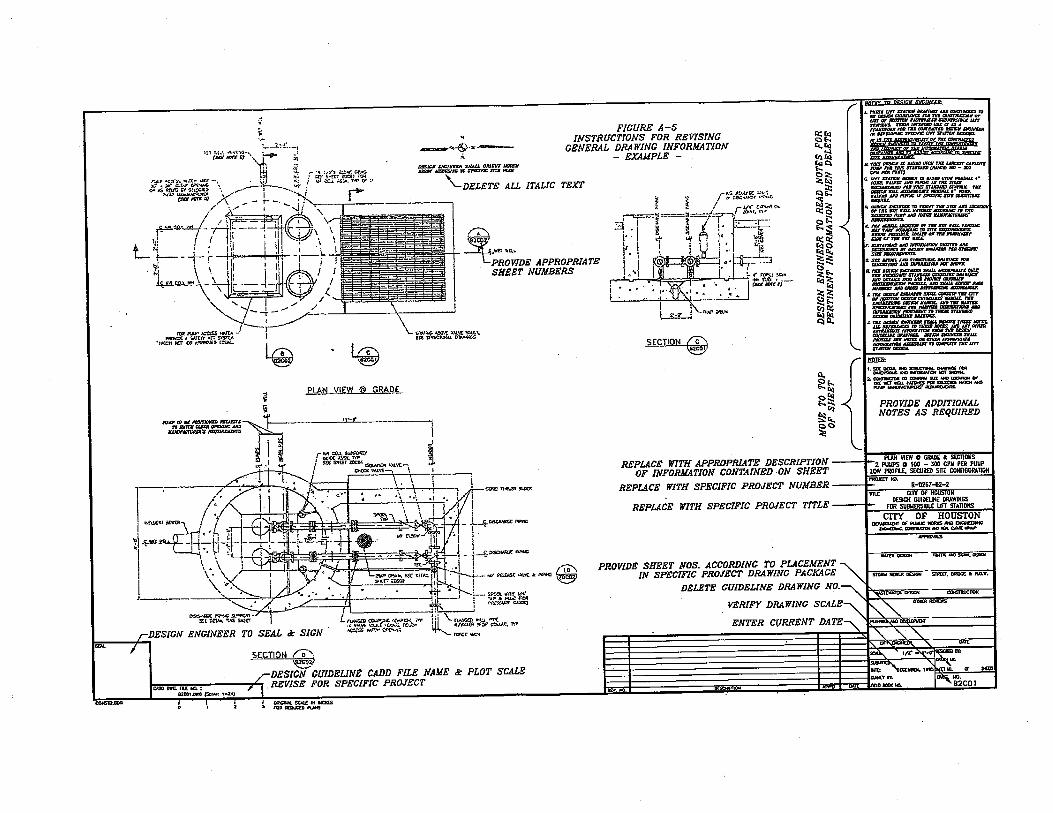
APPENDIX E – Sample Drawing Markup
CITY OF HOUSTON CITY OF HOUSTON DESIGN GUIDELINES MANUAL FOR SUBMERSIBLE LIFT STATIONS Department of Public Works and Engineering TABLE OF CONTENTS
iv 06/15/2016
List of Tables Table 1. Submersible Lift Station Sizing ........................................................................................ 7 Table 2. Biofilter Design Values .................................................................................................. 13 Table 3. Chemical Feed System Design Values ........................................................................... 14 Table 4. Design Values for Cycle Time........................................................................................ 16
CITY OF HOUSTON DESIGN GUIDELINES MANUAL FOR SUBMERSIBLE LIFT STATIONS Department of Public Works and Engineering INTRODUCTION
1 06/15/2016
SECTION 1: INTRODUCTION
1.01 Purpose
A. The Design Guidelines Manual for Submersible Lift Stations provides requirements, criteria, and considerations for the consistent and uniform design of lift stations and force mains for the City of Houston (COH). These guidelines apply to the design of new COH Capital Improvement Plan (CIP) lift station and force main projects constructed within the COH city limits, and lift stations and force mains constructed within the COH Extraterritorial Jurisdiction (ETJ). The guidelines represent COH minimum design requirements and are to be used with the Design Guideline Drawings for Submersible Lift Stations. The Design Guideline Drawings sheet index is included as Appendix A. The Design Engineer is responsible for use of these guidelines and application to specific project conditions and requirements.
1.02 General
A. The Design Engineer is responsible as the Engineer of Record (EOR) for a complete and coordinated set of drawings. The Design Guideline Drawings for Submersible Lift Stations must be customized by the EOR to be project-specific. The drawings cannot be used without additional engineering and drafting by the EOR and without supplemental drawings prepared by the EOR.
B. COH lift station and force main CIP projects shall be planned and designed utilizing planning data, empirical flow data, and information provided by the COH Infrastructure Planning Branch (IPB). COH CIP projects shall be designed per specific contract requirements. Appendix B is included as a list of design requirements and considerations for use by the Design Engineer, in addition to the requirements of this Design Guidelines Manual. Lift stations and force mains shall comply with the requirements of the latest Texas Commission on Environmental Quality (TCEQ) 30 TAC Chapter 217, Design Criteria for Wastewater Systems.
C. For private development in the COH ETJ, a basis of design report shall be submitted for all lift station and force main projects and shall address the design requirements listed in Appendix C.
D. Influent Flows
1. Determination of design flows for the current and future conditions shall be coordinated with the IPB through COH project manager for all CIP projects.
2. For other lift station projects, flow determination shall be described in the basis of design report.
CITY OF HOUSTON DESIGN GUIDELINES MANUAL FOR SUBMERSIBLE LIFT STATIONS Department of Public Works and Engineering INTRODUCTION
2 06/15/2016
1.03 Standards and Codes
A. Lift station and force main designs shall be in compliance with the latest editions of the COH Infrastructure Design Manual, Standard Details, and Standard Specifications.
B. Design of lift stations, force mains, and ancillary facilities shall conform to all applicable local, state, and federal regulations and national standards including but not limited to those of:
1. American Association of State Highway and Transportation Officials (AASHTO)
2. American Concrete Institute (ACI)
3. American Institute for Steel Construction (AISC)
4. American National Standards Institute (ANSI)
5. American Society of Mechanical Engineers (ASME)
6. American Society for Testing and Materials (ASTM)
7. American Water Works Association (AWWA)
8. City of Houston Code of Ordinances
9. Environmental Protection Agency (EPA)
10. Hydraulic Institute (HI)
11. Institute of Electrical and Electronics Engineers (IEEE)
12. National Electrical Code (NEC)
13. National Electrical Manufacturers Association (NEMA)
14. National Fire Protection Association (NFPA)
15. Occupational Safety and Health Act (OSHA)
16. Texas Commission on Environmental Quality (TCEQ)
1.04 Definitions
A. The following terms used in this guideline are defined as below unless the context clearly states otherwise.
1. Alternate High Lift Station Configuration – Lift station configuration with discharge piping and valves located above grade.
CITY OF HOUSTON DESIGN GUIDELINES MANUAL FOR SUBMERSIBLE LIFT STATIONS Department of Public Works and Engineering INTRODUCTION
3 06/15/2016
2. Alternate Low Lift Station Configuration – Lift station configuration with discharge piping and valves located in a below grade, enclosed valve vault.
3. Backflow Preventer – A device installed in potable water piping to prevent the flow of nonpotable water into a potable system.
4. Best Efficiency Point – The discharge rate at which an impeller of a given diameter rotating at a given speed operates at maximum efficiency.
5. Bypass – The intentional diversion of a waste stream.
6. Collection System – Pipes, conduits, lift stations, force mains, and all other constructions, devices, and appurtenant appliances used to transport domestic wastewater to a wastewater treatment facility.
7. Control Building/ Room – The superstructure of a pumping station, which usually includes electrical equipment and may also include motors.
8. Design Engineer – Engineer of Record and/or engineering firm selected for the project design.
9. Design Life – The length of time that an engineering structure or device is intended to function without failing.
10. Discharge Head – Static head plus friction headloss (in discharge piping) plus velocity headloss at the end of the discharge piping.
11. Fillet – Concrete in the bottom of the wet well shaped to smooth liquid flow into the pump suction openings and to prevent the accumulation of solids.
12. Firm Capacity – The maximum flow rate achievable, under design conditions, with the largest pumping unit out of service.
13. Flooded Suction – Condition in which the pump volute is below the low water level of the wet well.
14. Force Main – Piping, external to the lift station and filled with liquid under pressure, through which the station discharges.
15. High Water Level – Water surface elevation corresponding with “All Pumps On” level and shall be no higher than the elevation required to prevent sanitary sewer overflows in the upstream collection system. Note: This elevation will be provided for COH CIP projects by the IPB.
16. Influent – Liquid that flows into a process or confined space. This term may also be used to identify items or properties associated with influent.
CITY OF HOUSTON DESIGN GUIDELINES MANUAL FOR SUBMERSIBLE LIFT STATIONS Department of Public Works and Engineering INTRODUCTION
4 06/15/2016
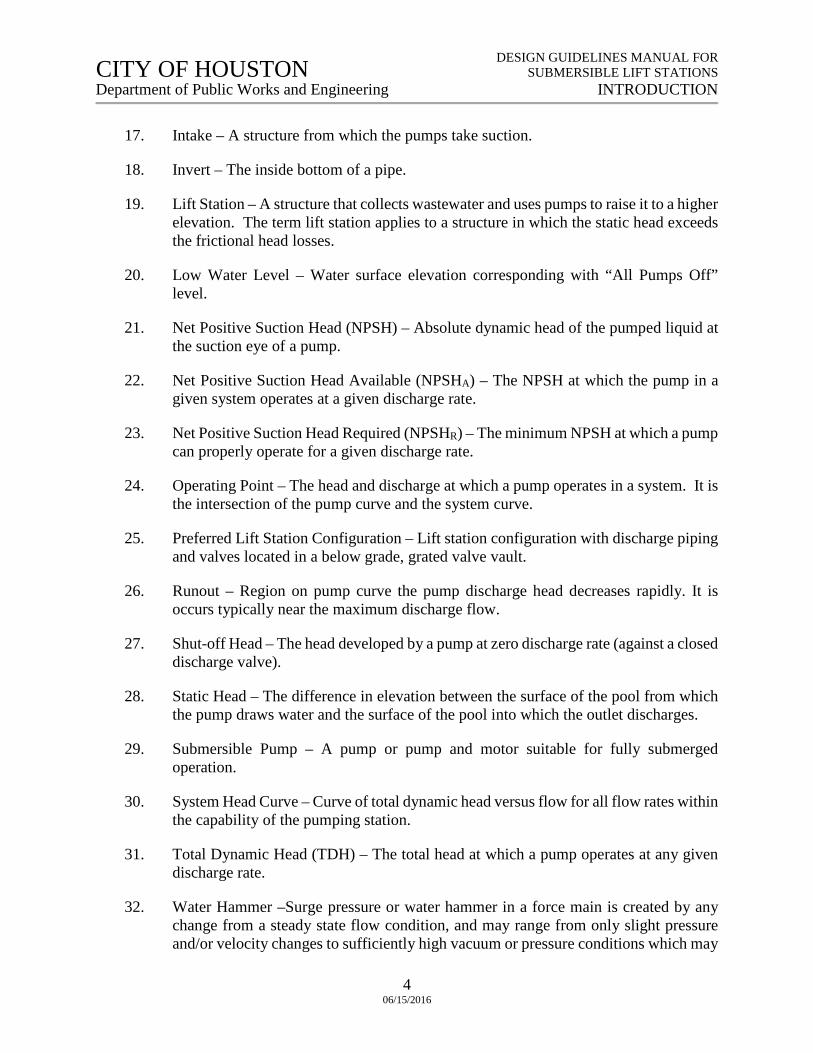
17. Intake – A structure from which the pumps take suction.
18. Invert – The inside bottom of a pipe.
19. Lift Station – A structure that collects wastewater and uses pumps to raise it to a higher elevation. The term lift station applies to a structure in which the static head exceeds the frictional head losses.
20. Low Water Level – Water surface elevation corresponding with “All Pumps Off” level.
21. Net Positive Suction Head (NPSH) – Absolute dynamic head of the pumped liquid at the suction eye of a pump.
22. Net Positive Suction Head Available (NPSHA) – The NPSH at which the pump in a given system operates at a given discharge rate.
23. Net Positive Suction Head Required (NPSHR) – The minimum NPSH at which a pump can properly operate for a given discharge rate.
24. Operating Point – The head and discharge at which a pump operates in a system. It is the intersection of the pump curve and the system curve.
25. Preferred Lift Station Configuration – Lift station configuration with discharge piping and valves located in a below grade, grated valve vault.
26. Runout – Region on pump curve the pump discharge head decreases rapidly. It is occurs typically near the maximum discharge flow.
27. Shut-off Head – The head developed by a pump at zero discharge rate (against a closed discharge valve).
28. Static Head – The difference in elevation between the surface of the pool from which the pump draws water and the surface of the pool into which the outlet discharges.
29. Submersible Pump – A pump or pump and motor suitable for fully submerged operation.
30. System Head Curve – Curve of total dynamic head versus flow for all flow rates within the capability of the pumping station.
31. Total Dynamic Head (TDH) – The total head at which a pump operates at any given discharge rate.
32. Water Hammer –Surge pressure or water hammer in a force main is created by any change from a steady state flow condition, and may range from only slight pressure and/or velocity changes to sufficiently high vacuum or pressure conditions which may
CITY OF HOUSTON DESIGN GUIDELINES MANUAL FOR SUBMERSIBLE LIFT STATIONS Department of Public Works and Engineering INTRODUCTION
5 06/15/2016
cause the collapse or rupture of the pipeline, or cause damage to pumps and/or valves. Water hammer is typically caused by the opening, closing or regulating of valves, by the normal operation of starting and/or stopping of pumps, pump power failure, or a major pipeline rupture.
33. Wet well – A pumping station or a portion of a pumping station that stores the wastewater being pumped.
CITY OF HOUSTON DESIGN GUIDELINES MANUAL FOR SUBMERSIBLE LIFT STATIONS Department of Public Works and Engineering LIFT STATION CONFIGURATION
6 06/15/2016
SECTION 2: LIFT STATION CONFIGURATION
2.01 Lift Station New Construction and Replacement Design
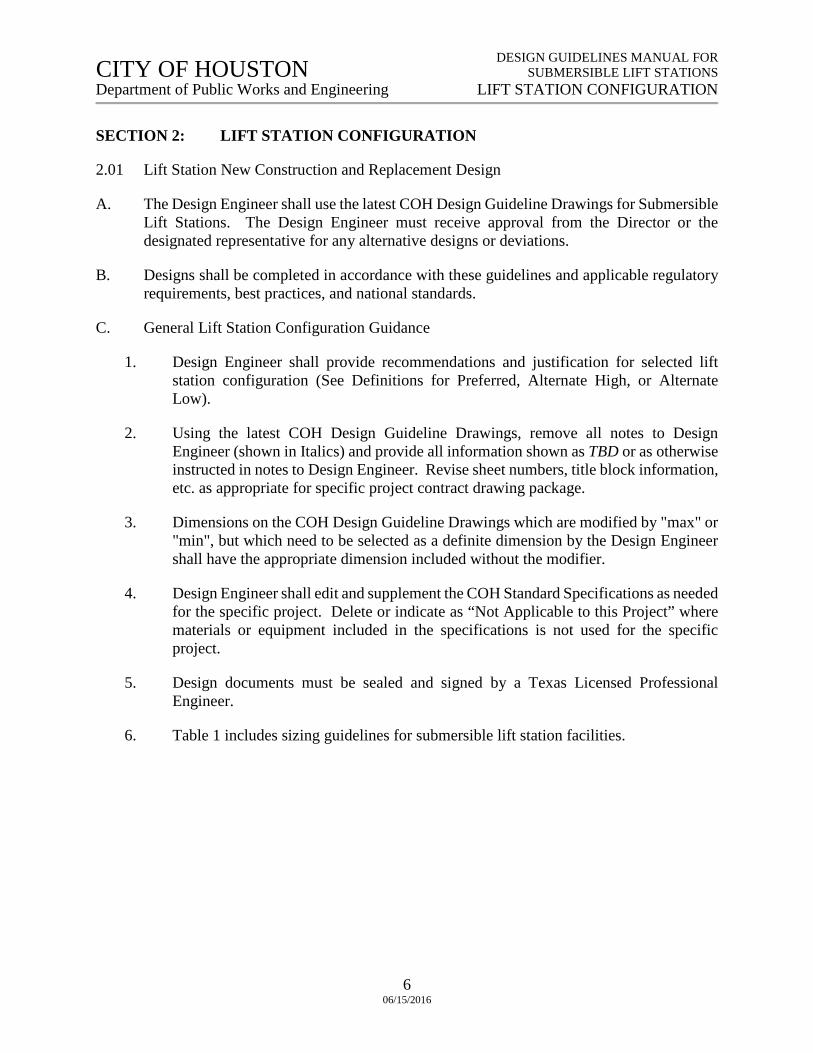
A. The Design Engineer shall use the latest COH Design Guideline Drawings for Submersible Lift Stations. The Design Engineer must receive approval from the Director or the designated representative for any alternative designs or deviations.
B. Designs shall be completed in accordance with these guidelines and applicable regulatory requirements, best practices, and national standards.
C. General Lift Station Configuration Guidance
1. Design Engineer shall provide recommendations and justification for selected lift station configuration (See Definitions for Preferred, Alternate High, or Alternate Low).
2. Using the latest COH Design Guideline Drawings, remove all notes to Design Engineer (shown in Italics) and provide all information shown as TBD or as otherwise instructed in notes to Design Engineer. Revise sheet numbers, title block information, etc. as appropriate for specific project contract drawing package.
3. Dimensions on the COH Design Guideline Drawings which are modified by "max" or "min", but which need to be selected as a definite dimension by the Design Engineer shall have the appropriate dimension included without the modifier.
4. Design Engineer shall edit and supplement the COH Standard Specifications as needed for the specific project. Delete or indicate as “Not Applicable to this Project” where materials or equipment included in the specifications is not used for the specific project.
5. Design documents must be sealed and signed by a Texas Licensed Professional Engineer.
6. Table 1 includes sizing guidelines for submersible lift station facilities.
CITY OF HOUSTON DESIGN GUIDELINES MANUAL FOR SUBMERSIBLE LIFT STATIONS Department of Public Works and Engineering LIFT STATION CONFIGURATION
7 06/15/2016
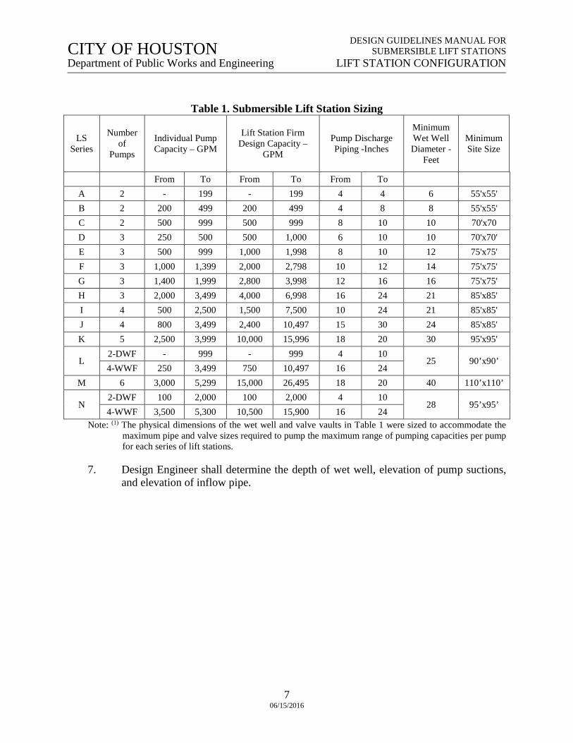
Table 1. Submersible Lift Station Sizing
LS Series
Number of
Pumps
Individual Pump Capacity – GPM
Lift Station Firm Design Capacity –
GPM
Pump Discharge Piping -Inches
Minimum Wet Well Diameter -
Feet
Minimum Site Size
From To From To From To A 2 - 199 - 199 4 4 6 55'x55' B 2 200 499 200 499 4 8 8 55'x55' C 2 500 999 500 999 8 10 10 70'x70 D 3 250 500 500 1,000 6 10 10 70'x70' E 3 500 999 1,000 1,998 8 10 12 75'x75' F 3 1,000 1,399 2,000 2,798 10 12 14 75'x75' G 3 1,400 1,999 2,800 3,998 12 16 16 75'x75' H 3 2,000 3,499 4,000 6,998 16 24 21 85'x85' I 4 500 2,500 1,500 7,500 10 24 21 85'x85' J 4 800 3,499 2,400 10,497 15 30 24 85'x85' K 5 2,500 3,999 10,000 15,996 18 20 30 95'x95'
L 2-DWF - 999 - 999 4 10
25 90’x90’ 4-WWF 250 3,499 750 10,497 16 24
M 6 3,000 5,299 15,000 26,495 18 20 40 110’x110’
N 2-DWF 100 2,000 100 2,000 4 10
28 95’x95’ 4-WWF 3,500 5,300 10,500 15,900 16 24
Note: (1) The physical dimensions of the wet well and valve vaults in Table 1 were sized to accommodate the maximum pipe and valve sizes required to pump the maximum range of pumping capacities per pump for each series of lift stations.
7. Design Engineer shall determine the depth of wet well, elevation of pump suctions, and elevation of inflow pipe.
CITY OF HOUSTON CITY OF HOUSTON DESIGN GUIDELINES MANUAL FOR SUBMERSIBLE LIFT STATIONS Department of Public Works and Engineering SITE REQUIREMENTS
8 06/15/2016
SECTION 3: SITE REQUIREMENTS
3.01 Lift Station Site Selection and Use
A. The evaluation for selection and use of lift station sites shall address the following:
1. Visual impact on the neighborhood. Sufficient setback from the property line to the fence line should be provided to accommodate the required landscape buffer. In all cases, setback from property lines as governed by COH ordinances should be followed.
2. Access to areas of the site to allow for staging and positioning of vehicles and equipment used to remove pumping equipment from wet well, including adequate access roadway widths and turning radii. Site pavement areas shall be sufficient to accommodate lifting and maintenance equipment.
3. Fencing location. Generally, the entire site within the fenced area is paved. Locate the fence one foot inside the paved area. Where adjacent to existing structures, locate the fence further in the site to provide a minimum 6-foot clearance for grounds maintenance.
4. For facilities that require chemical feed and storage equipment, site access road geometry shall be designed to accommodate movement of largest vehicle required for operation and maintenance of odor control systems.
5. Clearance for operation and maintenance activities.
6. Site safety and security.
7. Odor potential and impact to the neighborhood. Odor control measures shall be provided for all lift stations on an as needed basis.
8. Structure depth and its potential impact on adjacent areas, including construction activities such as excavation and driving piling.
9. Location of site with respect to FEMA floodplain and floodway zones.
B. Refer to Section 2: “Lift Station Configuration” for minimum site dimensions.
C. The site of the lift station should generally be located on a full parcel. Lift stations should not be located in :
1. Street rights-of-way
2. Easements
CITY OF HOUSTON CITY OF HOUSTON DESIGN GUIDELINES MANUAL FOR SUBMERSIBLE LIFT STATIONS Department of Public Works and Engineering SITE REQUIREMENTS
9 06/15/2016
3. Areas where future maintenance access, security, or odor mitigation could become difficult.
4. Sites where topography will not allow the top or main floor of the station to meet the COH Code of Ordinances, Chapter 19.
5. Site cannot be made accessible during a flood event as per latest TCEQ regulations.
D. At least 20 feet clearance between all sides of the lift station facilities and fence line should be provided where feasible.
E. To the extent possible, lift stations should be oriented such that sources of potential odor release, such as wet well vents, do not adversely affect adjacent areas or sensitive equipment, such as electrical equipment and building air intakes.
F. Lift stations located in a residential area should acquire an entire residential lot for the site. Subdividing the lot should be avoided.
3.02 Access
A. Locate site security fence and entrance gate to allow a minimum 25-ft long vehicle to access site without blocking main roadway. Pavement of area from main roadway to entrance gate shall be 24 feet wide.
B. Design site paving geometry to provide an area that will allow a 25-ft long vehicle to turn around within the fenced site area.
C. Sites with proposed chemical storage tanks should include the following:
1. Provide roadway turnout of appropriate geometry such that chemical delivery truck does not block the main roadway when making a delivery. Truck turnout inside radius should not be less than 50 feet.
D. Access roadway width should not be less than 20 feet and turnout radius should not be less than 30 feet inside (50 feet preferred) or such greater dimension as necessary to prevent truck or crane wheel overrun from the pavement.
E. Crane access and setting location to be used for lifting out submersible pumps or other equipment should be specifically addressed in the facilities layouts.
1. Site size, facilities locations, clearance areas, and orientation of hatches should be coordinated with crane type, dimensions, and capacity necessary to remove and replace the largest pump and motor to be installed at the lift station for ultimate capacity conditions. Lift station shall be located on site such that overhead power lines will not interfere with use of cranes for removal of pumps.
CITY OF HOUSTON CITY OF HOUSTON DESIGN GUIDELINES MANUAL FOR SUBMERSIBLE LIFT STATIONS Department of Public Works and Engineering SITE REQUIREMENTS
10 06/15/2016
F. Provide reinforced concrete paving into and within the site meeting H-20 loading requirements.
1. Provide parking spaces only inside the secure site area.
2. Low maintenance paving is defined as reinforced concrete pavement of sufficient design and thickness for loads to be encountered for all operation and maintenance activities. At a minimum, pavement thickness should be 7-inches. For projects in the ETJ areas outside of the COH, an all-weather surface may be acceptable.
3. Turf paver systems should only be used when required by neighborhood for aesthetics.
4. Provide reinforced concrete pavement and/or pervious concrete pavement as required, at uniform elevation, adjacent to and around the lift station. Width should be as necessary for proper mobility of the appropriate vehicle and not less than 20 feet.
5. In order to minimize grounds maintenance and such items as grass and weeds cutting, it is preferred that the reinforced concrete pavement extend one foot beyond the fence line to provide a “mow” strip and minimize maintenance.
3.03 Security
A. The security system should meet all requirements of the latest version of TCEQ Chapter 217, and requirements of the COH Public Works and Engineering Department.
B. Site security should be provided by a full-perimeter 6-foot high fence topped with 3 strands of barbed wire or an 8-foot high fence. Site access will be through one 16-foot wide, double leaf, inward-opening swing gate secured with a chain and padlock. The fence should also include a pedestrian gate, easily accessed from the entrance drive with the same chain and padlock system described above.
C. Other intrusion security measures will be considered on a case-by-case basis if special conditions or requirements dictate.
D. Preferred fence is green PVC-coated, minimum No. 9 gauge galvanized woven wire, 6-foot-high fabric, 2-inch open-diamond mesh pattern, cyclone-type fence with green PVC slats topped with 3 strands of barbed wire.
E. If determined necessary that fencing materials should match those used in the neighborhood, installing such matching materials on the exterior of the chain link fence for decoration should be considered, as opposed to using an alternative fencing system.
F. Where necessary to avoid subsidence of fence system based on soil conditions, consider use of a concrete grade beam in which the steel line posts are set. Use minimum 24-inch-deep beam with 6-foot-long concrete support piles spaced not greater than 16 feet on center.
CITY OF HOUSTON CITY OF HOUSTON DESIGN GUIDELINES MANUAL FOR SUBMERSIBLE LIFT STATIONS Department of Public Works and Engineering SITE REQUIREMENTS
11 06/15/2016
3.04 Landscaping
A. If required, provide landscaping to meet the requirements of the latest COH Code of Ordinances, Chapter 33 “Planning and Development.” As a minimum, provide landscaping that meets the requirements described below.
1. Lift station landscaping design needs to be safe, simple and aesthetically blend into the surrounding landscape. Prefer the use of drought resistant, native plants.
2. All disturbed areas should be grass-sodded with drought-tolerant species instead of hydro-mulched.
3. Landscaping shall not be within the security fence.
4. If landscaping is requested by a local neighborhood association, the association shall be notified that the association is responsible for the landscaping maintenance.
3.05 Flood Plain/Floodway
A. Design Engineer shall design the lift station to comply with the requirements of the latest version of COH Code of Ordinance, Chapter 19 Flood Plain. Lift stations are considered critical facilities.
3.06 Site Drainage
A. Adhere to stormwater drainage and mitigation requirements listed in Chapter 9 of COH Infrastructure Design Manual, latest revision.
B. Identify and contact agency responsible for approval of stormwater facilities design, detention requirements, and discharges from site, including discharges to storm sewers or open channels.
3.07 Odor Control
A. Odor control at lift stations may not be required but should be considered and addressed in the Preliminary Engineering Report. In general, odor control for City of Houston lift stations will only be required if requested by Project Manager. Odor control for non-COH lift stations will be at the discretion of the Design Engineer. The following methods and criteria should be considered as a minimum guideline.
1. Chemical feed systems should be considered for new lift stations that have discharge force mains longer than 2,000 feet.
2. The standard treatment for odor control is ferrous sulfate and/or calcium nitrate fed directly into the upstream manhole, lift station wet well, or force main, in that order of preference.
CITY OF HOUSTON CITY OF HOUSTON DESIGN GUIDELINES MANUAL FOR SUBMERSIBLE LIFT STATIONS Department of Public Works and Engineering SITE REQUIREMENTS
12 06/15/2016
3. The use of activated carbon canister devices on the wet well vent pipe may be applicable.
4. Biofilter/ Bioscrubber systems can be considered for lift station odor control.
B. Air Treatment Systems
1. Duct work should be designed based on the following criteria.
a. Material of Construction
(1) Below Grade – Sch 80 or SDR 35 PVC, or DR 32.5 HDPE
(2) Above Grade – FRP coated for UV protection or 304 stainless Steel
b. Air Velocity – 1500 to 30,000 SCFM
c. Ventilation Rate – the air changes per hour should be based on NFPA 820-Fire Protection in Wastewater Treatment Plants (current edition) issued by the National Fire Protection Association but should not be less than 8-12 changes per hour.
2. Exhaust Fan
a. Fan should be corrosion-resistant with slide mount motor to allow sheave replacement.
b. Fans located outside should be noise suppressed.
c. Flexible connectors should be used for inlet and outlet connections.
d. Provide fan volute with a drain to remove liquids
3. Air Treatment Unit
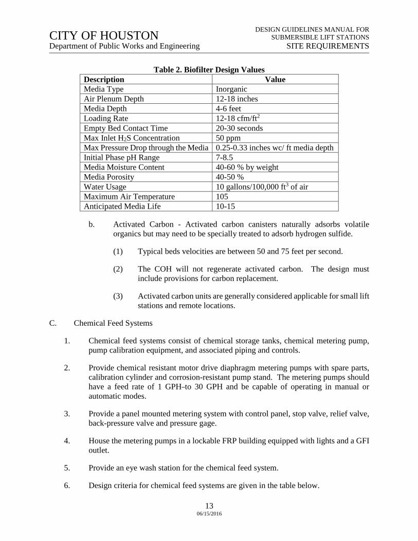
a. Biofilter criteria shown in Table 2 are for guidance only. This criteria may be modified with appropriate engineering justification and/or manufacturer’s recommendations. Please note the following design criteria is applicable for hydrogen sulfide concentrations of less than 50 ppm. Concentrations greater than 50 ppm requires lower loading rates and special consideration.
CITY OF HOUSTON CITY OF HOUSTON DESIGN GUIDELINES MANUAL FOR SUBMERSIBLE LIFT STATIONS Department of Public Works and Engineering SITE REQUIREMENTS
13 06/15/2016
Table 2. Biofilter Design Values Description Value Media Type Inorganic Air Plenum Depth 12-18 inches Media Depth 4-6 feet Loading Rate 12-18 cfm/ft2 Empty Bed Contact Time 20-30 seconds Max Inlet H2S Concentration 50 ppm Max Pressure Drop through the Media 0.25-0.33 inches wc/ ft media depth Initial Phase pH Range 7-8.5 Media Moisture Content 40-60 % by weight Media Porosity 40-50 % Water Usage 10 gallons/100,000 ft3 of air Maximum Air Temperature 105 Anticipated Media Life 10-15
b. Activated Carbon - Activated carbon canisters naturally adsorbs volatile organics but may need to be specially treated to adsorb hydrogen sulfide.
(1) Typical beds velocities are between 50 and 75 feet per second.
(2) The COH will not regenerate activated carbon. The design must include provisions for carbon replacement.
(3) Activated carbon units are generally considered applicable for small lift stations and remote locations.
C. Chemical Feed Systems
1. Chemical feed systems consist of chemical storage tanks, chemical metering pump, pump calibration equipment, and associated piping and controls.
2. Provide chemical resistant motor drive diaphragm metering pumps with spare parts, calibration cylinder and corrosion-resistant pump stand. The metering pumps should have a feed rate of 1 GPH to 30 GPH and be capable of operating in manual or automatic modes.
3. Provide a panel mounted metering system with control panel, stop valve, relief valve, back-pressure valve and pressure gage.
4. House the metering pumps in a lockable FRP building equipped with lights and a GFI outlet.
5. Provide an eye wash station for the chemical feed system.
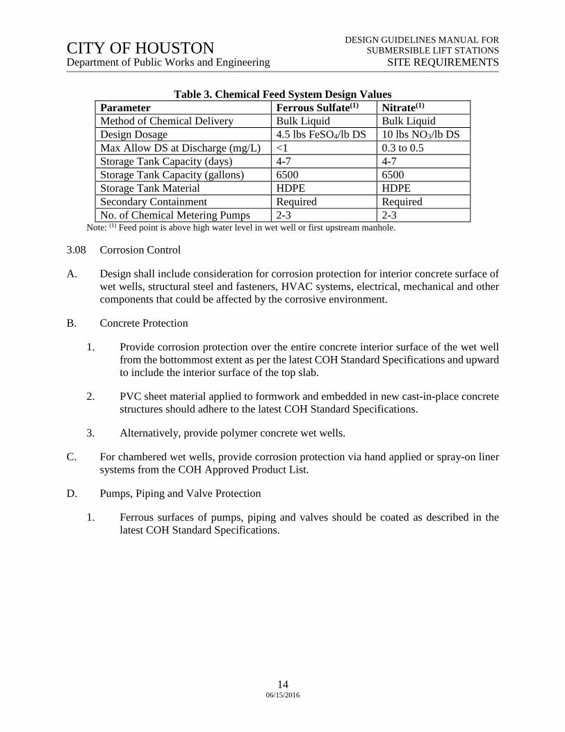
6. Design criteria for chemical feed systems are given in the table below.
CITY OF HOUSTON CITY OF HOUSTON DESIGN GUIDELINES MANUAL FOR SUBMERSIBLE LIFT STATIONS Department of Public Works and Engineering SITE REQUIREMENTS
14 06/15/2016
Table 3. Chemical Feed System Design Values Parameter Ferrous Sulfate(1) Nitrate(1)
Method of Chemical Delivery Bulk Liquid Bulk Liquid Design Dosage 4.5 lbs FeSO4/lb DS 10 lbs NO3/lb DS Max Allow DS at Discharge (mg/L) <1 0.3 to 0.5 Storage Tank Capacity (days) 4-7 4-7 Storage Tank Capacity (gallons) 6500 6500 Storage Tank Material HDPE HDPE Secondary Containment Required Required No. of Chemical Metering Pumps 2-3 2-3
Note: (1) Feed point is above high water level in wet well or first upstream manhole.
3.08 Corrosion Control
A. Design shall include consideration for corrosion protection for interior concrete surface of wet wells, structural steel and fasteners, HVAC systems, electrical, mechanical and other components that could be affected by the corrosive environment.
B. Concrete Protection
1. Provide corrosion protection over the entire concrete interior surface of the wet well from the bottommost extent as per the latest COH Standard Specifications and upward to include the interior surface of the top slab.
2. PVC sheet material applied to formwork and embedded in new cast-in-place concrete structures should adhere to the latest COH Standard Specifications.
3. Alternatively, provide polymer concrete wet wells.
C. For chambered wet wells, provide corrosion protection via hand applied or spray-on liner systems from the COH Approved Product List.
D. Pumps, Piping and Valve Protection
1. Ferrous surfaces of pumps, piping and valves should be coated as described in the latest COH Standard Specifications.
CITY OF HOUSTON CITY OF HOUSTON DESIGN GUIDELINES MANUAL FOR SUBMERSIBLE LIFT STATIONS Department of Public Works and Engineering LIFT STATION HYDRAULIC DESIGN
15 06/15/2016
SECTION 4: LIFT STATION HYDRAULIC DESIGN
4.01 System Head and Pump Capacity Curves
A. System Head Curves
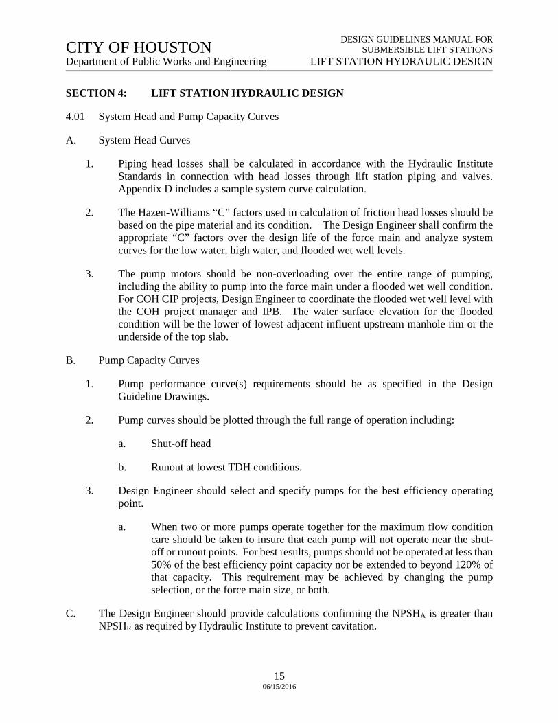
1. Piping head losses shall be calculated in accordance with the Hydraulic Institute Standards in connection with head losses through lift station piping and valves. Appendix D includes a sample system curve calculation.
2. The Hazen-Williams “C” factors used in calculation of friction head losses should be based on the pipe material and its condition. The Design Engineer shall confirm the appropriate “C” factors over the design life of the force main and analyze system curves for the low water, high water, and flooded wet well levels.
3. The pump motors should be non-overloading over the entire range of pumping, including the ability to pump into the force main under a flooded wet well condition. For COH CIP projects, Design Engineer to coordinate the flooded wet well level with the COH project manager and IPB. The water surface elevation for the flooded condition will be the lower of lowest adjacent influent upstream manhole rim or the underside of the top slab.
B. Pump Capacity Curves
1. Pump performance curve(s) requirements should be as specified in the Design Guideline Drawings.
2. Pump curves should be plotted through the full range of operation including:
a. Shut-off head
b. Runout at lowest TDH conditions.
3. Design Engineer should select and specify pumps for the best efficiency operating point.
a. When two or more pumps operate together for the maximum flow condition care should be taken to insure that each pump will not operate near the shut-off or runout points. For best results, pumps should not be operated at less than 50% of the best efficiency point capacity nor be extended to beyond 120% of that capacity. This requirement may be achieved by changing the pump selection, or the force main size, or both.
C. The Design Engineer should provide calculations confirming the NPSHA is greater than NPSHR as required by Hydraulic Institute to prevent cavitation.
CITY OF HOUSTON CITY OF HOUSTON DESIGN GUIDELINES MANUAL FOR SUBMERSIBLE LIFT STATIONS Department of Public Works and Engineering LIFT STATION HYDRAULIC DESIGN
16 06/15/2016
4.02 Wet Well Design
A. Refer to Section 3.05 for wet well top of slab elevation requirements.
B. The wet well design must allow for a flooded suction condition of the pump motor regardless of pump motor design under all operating conditions.
C. Preferably, wet wells should have one influent sewer entering the wet well, with an upstream influent manhole on the lift station site within 100 feet of the wet well. The inflow pipe shall be straight for a length of five pipe diameters before entering the wet well. Gravity sewer from this upstream manhole to wet well shall be the next larger nominal diameter above the gravity sewer entering the influent manhole.
D. The bottom of wet wells shall have a minimum slope of 10 percent towards the pump(s) intake and shall have a smooth finish.
E. Size ports such that the velocity through all ports at firm capacity is greater than 4.5 fps and less than 6.5 fps.
F. Minimum Wet Well Volume
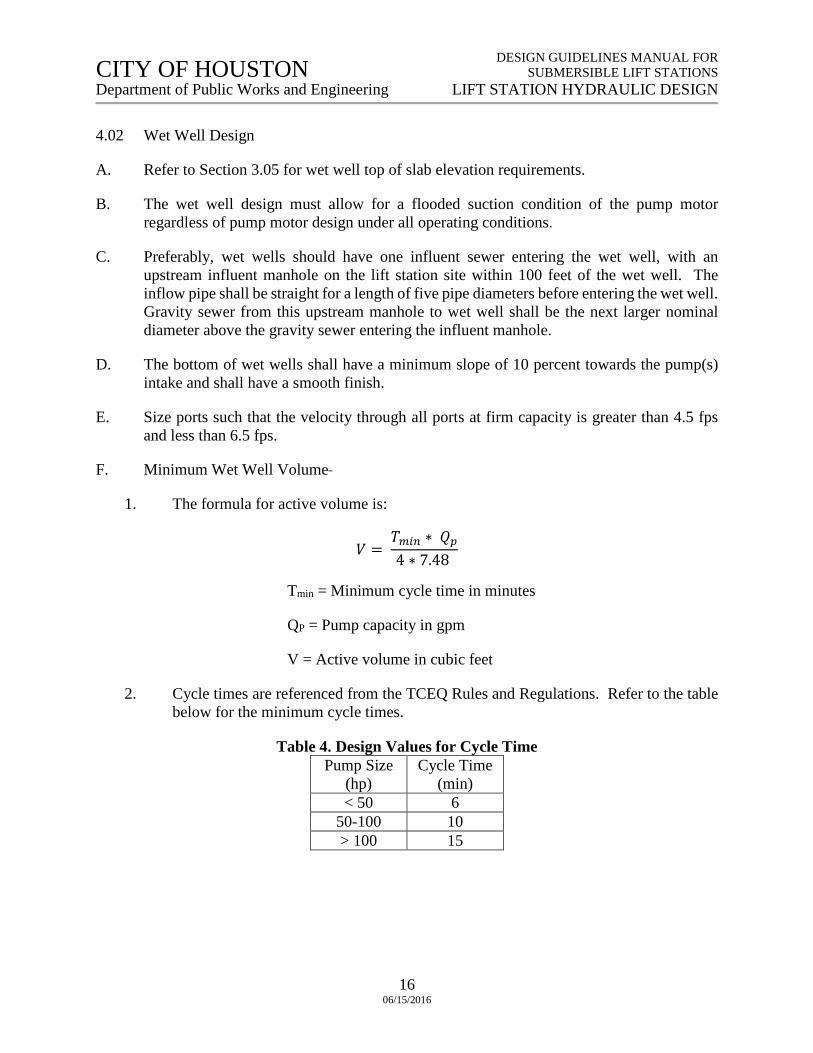
1. The formula for active volume is:
𝑉𝑉 = 𝑇𝑇𝑚𝑚𝑚𝑚𝑚𝑚 ∗ 𝑄𝑄𝑝𝑝4 ∗ 7.48
Tmin = Minimum cycle time in minutes
QP = Pump capacity in gpm
V = Active volume in cubic feet
2. Cycle times are referenced from the TCEQ Rules and Regulations. Refer to the table below for the minimum cycle times.
Table 4. Design Values for Cycle Time Pump Size
(hp) Cycle Time
(min) < 50 6
50-100 10 > 100 15
CITY OF HOUSTON CITY OF HOUSTON DESIGN GUIDELINES MANUAL FOR SUBMERSIBLE LIFT STATIONS Department of Public Works and Engineering LIFT STATION HYDRAULIC DESIGN
17 06/15/2016
4.03 Wet Well Levels
A. Wet well levels for pump operation should be set to minimize the vertical drop of wastewater into the wet well. The “Lead Pump On” level shall be set below the invert of the influent sewer as to not surcharge the influent sewer.
B. Minimum cycle times shall be accomplished without the water surface elevation (“All Pumps Off” level) dropping below the top of the pump motor.
4.04 Lift Station Bypass
A. Provide a connection to the discharge force main to permit connection of a portable pump discharge for use in emergency conditions or lift station maintenance.
1. Provide an influent manhole within the lift station site located within 100 feet of the wet well to serve as dewatering pump suction well.
2. Design Engineer shall provide a bypass “Tee” and valve in a manhole on the lift station site. In cases where bypass manholes cannot be provided, provide a “Tee” and extend it up to the grating with blind flange and isolation valve on the upstream end of the header pipe in Preferred Configurations.
CITY OF HOUSTON CITY OF HOUSTON DESIGN GUIDELINES MANUAL FOR SUBMERSIBLE LIFT STATIONS Department of Public Works and Engineering MECHANICAL DESIGN
18 06/15/2016
SECTION 5: MECHANICAL DESIGN
5.01 General
A. This section of the Design Guidelines Manual describes procedures for designing cooling, ventilation and plumbing systems for lift stations.
B. The wet well is a strictly unoccupied structure. The submersible pumps shall be capable of removal through the use of a rail guide removal system without the necessity of entering the structure. Pump removal by use of guide cables is not allowed.
C. The valve vault is intended to contain isolation valves, check valves, and other appurtenances as required for a specific site. Valve vault must have adequate size and provisions for operator access and a permanently mounted access ladder or stairway. Isolation and check valves shall not be located in the wet well.
D. Because of high ambient temperatures and heat gains from electrical equipment, the building must be provided with proper cooling to prevent overheating and possible malfunction of electrical devices.
E. The design should comply with applicable criteria of the latest versions of TCEQ Chapter 217 and NFPA 820, Standard for Fire Protection in Wastewater Treatment and Collection Facilities.
F. All piping from the isolation valve to discharge header should be flanged without thrust-rod tie elements.
5.02 Pump Selection
A. Design Engineer shall select and specify the pumps based on the project specific requirements. Refer to Section 4: Lift Station Hydraulic Design for guidelines used in determining these pump characteristics.
B. Design Engineer to provide life cycle cost comparisons for candidate lift station configurations. For COH CIP projects, Design Engineer to coordinate with the COH project manager for maintenance, replacement, and other criteria associated with lift stations.
C. For COH CIP projects, it is recommended the Design Engineer include at least three different pump manufacturers and provisions for product substitutions of an “approved equal” in the specifications, in coordination with Wastewater Engineering Section and Wastewater Operations Branch.
D. Pump selection shall include consideration of:
1. Overall serviceability record of pumps
CITY OF HOUSTON CITY OF HOUSTON DESIGN GUIDELINES MANUAL FOR SUBMERSIBLE LIFT STATIONS Department of Public Works and Engineering MECHANICAL DESIGN
19 06/15/2016
2. Cost of outside maintenance service contracts
3. Outside maintenance service performance records
4. Submersible pump power cable serviceability record and replacement costs
NOTE: The above information can be requested from COH Wastewater Operations Branch, Attn: Maintenance Group (located at 4545 Groveway Drive, Houston, TX, 77087). For COH CIP projects, Design Engineer shall coordinate with COH project manager.
5.03 Valves
A. Isolation Valves
1. Plug valves or resilient-seat, solid-wedge gate valves should be used for shut-off service in a force main application when the liquid being pumped contains gritty material.
B. Check Valves
1. Only full-body flanged check valves should be utilized. Wafer body valves are not acceptable for wastewater lift stations.
2. Ball-type check valves are not allowed.
3. For pump system head of 30 psi or less, the maximum velocity through a non-spring loaded or counter-weighted check valve should not exceed 3 fps. It may be increased to 5 fps for check valves which are spring loaded or counter weighted to prevent valve slamming. For pump system head higher than 30 psi, cushioned swing check valves should be used. However, cushioned swing check valves do not eliminate pressure surges when the valve closes suddenly. It only reduces the slamming noise.
C. Air/Vacuum Release Valves
1. The location and sizing of air/vacuum release valves along force main routes and at the lift station discharge piping shall be determined by the Design Engineer and described in the PER or Basis of Design Report.
2. Air/vacuum release valves shall be installed per the Design Guideline Drawings.
D. Surge Relief Valves
1. Surge relief valves are typically installed at lift stations to protect the pumps, piping, valves and other equipment from potential damage from surge pressures. If required, surge relief valves should be sized to release the excess surge flows through the valve either on the basis of system flow or so that the inlet pressure measured at the relief valve will be lower than the lowest pressure rating of the pumping equipment.
CITY OF HOUSTON CITY OF HOUSTON DESIGN GUIDELINES MANUAL FOR SUBMERSIBLE LIFT STATIONS Department of Public Works and Engineering MECHANICAL DESIGN
20 06/15/2016
2. Surge relief valves are to be located downstream of the pump control valve/check valve or on the main discharge header as close to the pump(s) as practical. Surge relief valves typically discharge back into the wet well.
3. Consideration should be given to providing two or more, smaller sized valves having a total combined relieving capacity equal to or greater than a single larger sized valve, especially when there is more than one pump discharging into a common header. A surge relief valve may be utilized on each pump discharge line or several valves may be provided on the common discharge header.
4. When several valves are provided, it is advisable that each valve's pressure setting be slightly higher than the adjacent valve allowing the valves to open in sequence instead of all at once. It should be noted that all surge relief valves are field adjustable and their relief pressure setting range is determined when the valves are ordered from the manufacturer.
5.04 Plumbing
A. Valve vaults shall have provisions to continuously drain. The valve vault floor should be sloped toward the draining device. Based on the lift station configuration, the valve vault should be drained by two methods:
1. For the “Preferred Low Profile” configuration, a floor drain should be provided. The floor drain should have a "P" trap and a floating ball-type backwater valve to prevent fumes and liquids from entering the vault from the wet well.
2. For the “Alternative Low Profile” configuration, valve vaults should be equipped with a submersible electric sump pump discharging to the wet well through a check valve. The sump pump should be activated by an integral float switch.
B. A potable water supply shall be provided for use during repairs, for washing down equipment, valve vault and grade slabs. Water should be provided through a minimum ¾ inch diameter supply line and non-freeze type hose bib located near the wet well.
C. All water should be metered and supplied through a reduced pressure type backflow preventer for protection of the city water mains from possible contamination due to cross-connections.
D. The above grade water supply system pipe, fitting, valves, and water meter should be insulated and protected against freezing. The complete backflow preventer assembly shall be provided with a Hot Box-type vandal proof enclosure (alternatively stainless steel or carbon steel cage painted green may be used) and equipped with access provisions for servicing and checking of the equipment.
CITY OF HOUSTON CITY OF HOUSTON DESIGN GUIDELINES MANUAL FOR SUBMERSIBLE LIFT STATIONS Department of Public Works and Engineering MECHANICAL DESIGN
21 06/15/2016
5.05 Air Conditioning (A/C)
A. Control Buildings house motor control centers, electrical panel's, transformers, and other equipment for operating pumps located in wet wells.
B. The temperature in the buildings will be affected by high ambient temperatures and by heat radiated from electrical equipment. If the excess heat is not removed either with ventilation air or by mechanical cooling, the temperature in the building will rise to a point where electrical devices will malfunction and disrupt operation of the pumping station.
C. Where clean outdoor air at suitable temperatures is available, forced ventilation is the least expensive and simplest way of removing heat from a building. Removing heat by forced ventilation should be considered when it is possible to maintain indoor temperatures not exceeding 105 degrees Fahrenheit at all times. In Houston, outdoor air may at times be very saline, and when drawn through a building, will cause corrosion and adversely affect delicate electrical instruments and devices. Therefore, controlling building temperature in such atmospheres is best accomplished by providing mechanical cooling units, where minimum or no outdoor air is circulated through the building, thus avoiding possible corrosion of equipment.
D. The mechanical cooling units are also susceptible to corrosion from the saline atmosphere. The useful life of such units will be much shorter in a saline atmosphere than in normal atmospheric conditions. However, the operating life of mechanical units can be extended by specifying the units will be provided with a protective coating application. Heat transfer capacity of protectively coated coils is not significantly affected (normally a reduction in capacity of less than 10 percent). The coating should cover all parts that come in contact with outdoor air, which includes the casing, heat transfer coils, refrigerant tubing and electrical devices. Mechanical cooling units should be wall mounted package type, heat type, units.
E. When sizing the cooling unit, all instantaneous sources of heat gain must be accounted. The worst scenario would be with all pumps running and the outdoor temperature 100oF, or higher, and staying within this range for a number of consecutive days. Mechanical cooling units shall be sized to maintain a building indoor temperature of 85 degrees Fahrenheit or less at a 40 percent specific humidity at maximum heat gain.
F. Solar and transmitted heat gain calculations must be in accordance with the ASHRAE Handbook of Fundamentals. The outdoor temperature listed in the ASHRAE Guide must be adjusted for outdoor air temperature encountered in Houston, if such maximum temperature continues within that range for more than 4 hours. Maximum temperatures for the particular area must be obtained locally.
G. Unit selection should be based on a terminal wall mounted heat pump type mechanical cooling unit having a minimum 13,000 BTUH sensible cooling capacity at 105oF outdoor air temperature at 77oF wet bulb temperature and an air temperature of 85oF dry bulb and 66oF wet bulb entering the cooling coil.
CITY OF HOUSTON CITY OF HOUSTON DESIGN GUIDELINES MANUAL FOR SUBMERSIBLE LIFT STATIONS Department of Public Works and Engineering MECHANICAL DESIGN
22 06/15/2016
H. The above selected unit is sized for a 4-pump system. The same unit can also be used for stations with fewer pumps and smaller heat gains.
I. The air conditioning unit should be controlled through a room type thermostat set to maintain the room air temperature at approximately 80oF. The unit fan shall run continuously when the unit control switch is in the "on" position.
5.06 Ventilation
A. Avoid ventilation through panels because of resulting corrosion problems. Use stainless-steel panels instead of aluminum at exterior locations. All ventilation fans should be coated with corrosion-resistant material.
B. Wet Well Ventilation
1. Since the wet well is unattended and must not be entered without special provisions, a permanent type mechanical ventilation system is not required. Mechanical ventilation must be provided when the wet well is to be entered for any reason. A portable type engine or electrically driven air supply fan should be used. A quantity of outdoor air, equal to at least thirty complete air exchanges per hour of the wet well volume must be blown into the well through a flexible pipe. The point of discharge of the air into the well must be where people are present. The air supply fan must be in operation for a minimum of two minutes before anyone enters the well. Entrance hatches must be kept open to allow foul air to escape from the well while outdoor air is being blown in.
2. The ventilation for a wet well should be designed as a passive gravity ventilation system (breather type), where the air volume in the well is either increased or decreased and outdoor air is pulled into the wet well and wet well air is pushed outdoors through the vent pipe, as sewage flows into or is pumped out of the wet well. The passive ventilation pipe should be sized to allow an inflow of make-up air volume to the wet well, at a rate equal to the maximum liquid pumping rate out of the wet well, with an air velocity through the vent pipe not to exceed 600 fpm. The vent size and discharge elevation should comply with the latest TCEQ requirements. In no case shall the vent pipe be less than six inches in size. Vents shall have stainless steel insect screen that is easily replaceable, prevent rain water from entering, and be corrosion-resistant.
C. Valve Vault Ventilation
1. The valve vault is normally unattended. However, on occasion it must be entered to service valves and other devices. Access shall be provided using stairways or ladders utilizing corrosion-resistant non-slip steps or rungs conforming to OSHA requirements.
CITY OF HOUSTON CITY OF HOUSTON DESIGN GUIDELINES MANUAL FOR SUBMERSIBLE LIFT STATIONS Department of Public Works and Engineering MECHANICAL DESIGN
23 06/15/2016
2. Since odors are not normally generated in the vault, continuous ventilation and odor control are not required for valve vaults opened on top with grating and less than 15 feet in depth. There is a possibility, however, that harmful or explosive fumes may enter the vault through cracks in walls or leaking valves. For this reason, the vault must be properly ventilated before anyone enters it. Use the same ventilation requirements as described for entering wet wells.
DESIGN GUIDELINES MANUAL FORSUBMERSIBLE LIFT STATIONS
STRUCTURAL DESIGNCITY OF HOUSTON Department of Public Works and Engineering
2406/15/2016
CITY OF HOUSTON
SECTION 6: STRUCTURAL DESIGN
6.01 General
A. This design guide describes the structural design criteria and code compliance for lift stations. The lift stations include a wet well, and may include either a control building or an outdoor control panel. The valves and discharge piping may be above grade or in a vault below ground depending on specific site requirements.
6.02 Design Standards
A. The following codes, specifications, recommendations, allowable stresses, and loadings
will be used as a minimum in designing the project structures, latest editions:
1. International Building Code (IBC) with City of Houston Amendments.
2. American Concrete Institute (ACI) 318-14: Building Code Requirements for Reinforced Concrete.
3. ACI 315: Details and Detailing of Concrete Reinforcement.
4. ACI 315R: Manual of Engineering and Placing Drawings for Reinforced Concrete
Structures.
5. ACI 350R: Environmental Engineering Concrete Structures.
6. American Institute of Steel Construction (AISC) Manual of Steel Construction with updated editions.
7. American Association of State Highway and Transportation Officials (AASHTO)
Standard Specifications for Highway Bridges.
8. Aluminum Design Manual, The Aluminum Association
9. Project specific Geotechnical Investigation Report.
10. Theory of Plates and Shells, by Timoshenko
11. Reinforced Masonry Design by Schneider & Dickey
12. Reinforced Masonry Engineering Handbook, by Masonry Institute of America
13. Concrete Masonry Design Tables, National Concrete Masonry Association
14. City of Houston Infrastructure Design Manual
15. Occupation Safety and Health Administration (OSHA) Publication 3124-12R 2003
DESIGN GUIDELINES MANUAL FORSUBMERSIBLE LIFT STATIONS
STRUCTURAL DESIGNCITY OF HOUSTON Department of Public Works and Engineering
2506/15/2016
CITY OF HOUSTON
16. Crane Manufacturers Association of America, Inc.
6.03 Geotechnical Coordination
A. Refer to the project specific geotechnical design requirements prepared in accordance with the latest version of the City of Houston Infrastructure Design Manual.
6.04 Loads
A. Lift Station and Valve Vault Structures Below Grade
1. Hydrostatic liquid pressure due to maximum internal operating liquid level with no
balancing external lateral pressure: 63 pounds per cubic foot (pcf)
2. Poorly draining sand or sand and gravel, lateral pressure: 80 pcf, minimum (min), or per project specific geotechnical investigation.
3. Compacted silty clay, lateral pressure: 100 pcf, min, or per project specific
geotechnical investigation.
4. Top Slab at or above Grade:
a. Dead Load (DL): Weight of Concrete Slab
b. Superimposed Dead Load (SDL): Backfill or other Superimposed Dead Loads
c. Live Load (LL): 300 pounds per square foot (psf) or equipment weight plus 50 psf.
5. Fiber Reinforced Plastic, Aluminum cover, platform, and walkways at or below grade.
a. LL: 150 psf
6. Lateral load due to surcharge loading of the construction crane and HS-20 truck shall be added to loads in Sections 6.04.A.4.b and 6.04.A.4.c or per project specific geotechnical investigation.
7. All Structures shall be designed to resist buoyancy to the finished top slab.
B. Buildings and Miscellaneous Structures
1. Loadings for design of buildings to be obtained from appropriate codes. However, certain minimum loads shall be used as follows:
Minimum Uniform Live Loads:
Grating 150 psf
DESIGN GUIDELINES MANUAL FORSUBMERSIBLE LIFT STATIONS
STRUCTURAL DESIGNCITY OF HOUSTON Department of Public Works and Engineering
2606/15/2016
CITY OF HOUSTON
Stairs and catwalks 150 psf
Electrical control rooms 250 psf
(Estimate support area and equipment weights and assume loads applied anywhere in area in question)
Wind: As per IBC for basic wind speed = 110 mph. Exposure BB and Importance factor = 1.15
6.05 Buoyancy
A. The below grade wet wells and valve vaults will be subject to buoyant forces as defined in
Section 6.04. Since a bentonite slurry may be used in the caisson excavation, the safety factor for soil friction reflects its presence. Verify that the required factors given by the geotechnical consultant are consistent with this. The structure weight shall only include the walls and slabs. The weight of fillets, baffle walls, pads, and equipment shall not be included as these could be changed in the future or may not be in place during construction.
B. Structural design and buoyancy calculations must show a minimum Factor of Safety equal
to or greater than 1.5 against Flotation (Buoyancy) for an empty structure with groundwater elevation at ground surface. The minimum Factor of Safety may be reduced based on recommendations included within a project specific geotechnical report that is sealed and signed by an engineer registered in the State of Texas, but may be no lower than 1.10. Allowances for soil friction are not allowed, unless justification
included within a project specific geotechnical report sealed and signed by an engineer registered in the State of Texas provides a soil friction factor and Factor of Safety for soil friction and structural calculations are submitted by the Engineer of Record.
6.06 Design Stresses
A. Concrete and Reinforcing Steel
1. Liquid Containing Structures:
Use Strength Design Method of ACI 318,
Building Code Requirements for Reinforced Concrete, with durability factor per the latest version of ACI 350 Environmental Engineering Concrete Structures, and base crack control on a maximum Z of 115 (The minimum concrete cover for steel reinforcement shall be 4 – inches where in contact with raw sewage.)
Concrete compressive strength at 28 days f’c= 4,000 pounds per square inch (psi)
Reinforcing steel (A 615, Gr. 60) fy = 60,000 psi
DESIGN GUIDELINES MANUAL FORSUBMERSIBLE LIFT STATIONS
STRUCTURAL DESIGNCITY OF HOUSTON Department of Public Works and Engineering
2706/15/2016
CITY OF HOUSTON
2. Building and Non-Liquid Containing Structures:
Use Strength Design Method of ACI 318
Concrete compressive strength at 28 days f’c = 4,000 psi
Reinforcing steel (A 615, Gr. 60) fy = 60,000 psi
B. Structural Steel
1. Follow AISC Specification for the Design, Fabrication and Erection of Structural Steel for Building, latest edition, and use following materials:
a. ASTM A36 unless otherwise specified
b. ASTM A325 H.S. bolts
c. ASTM A449 OR F1554 or A36 bar stock for anchor bolts
6.07 Design Considerations
A. Wet Well Load Cases:
1. Wet well empty with full lateral exterior load.
2. Wet well filled to the maximum level possible during a power outage, while disregarding exterior soil pressures.
3. Wet well buoyancy when wet well shell is empty, absent any equipment or metal
components and ground water elevation set at adjacent ground surface.
B. Differential Soil Movement:
1. Due to the significant difference in foundation elevations between the wet well and the valve slab or vault, there is a potential for differential soil movement resulting from settlement, expansive clays, or movement needed to develop soil friction. This potential movement is most severe where wet wells are constructed by the caisson method. The open cut construction method allows for placing cement-stabilized sand so as to minimize the movement potential. The Design Guideline Drawings include expansion or rotation joints.
C. Wet Well Design:
1. Pre–cast manhole risers and reinforced concrete pipes (RCP) are not acceptable for
wet well design/construction; except for ASTM C76, Class IV Wall C, RCP, 6–foot diameter wet wells, less than 30–feet deep.
DESIGN GUIDELINES MANUAL FORSUBMERSIBLE LIFT STATIONS
STRUCTURAL DESIGNCITY OF HOUSTON Department of Public Works and Engineering
2806/15/2016
CITY OF HOUSTON
2. The circular wet well shall be designed using a recognized shell theory or by using the Portland Cement Association publication, "Circular Concrete Tanks without Prestressing."
3. The Design Guideline Drawing indicates dowels connecting the wall to the base slab
for the caisson construction method. Structural connections between base slab and caisson shall be designed to transfer full base reactions from slab to wall. Full base
reactions are:
a. For downward load: weight of components supported on the slab plus the weight of liquid at maximum elevation in the wet well;
b. For upward load: (1) soil bearing reactions; and (2) hydrostatic uplift pressures,
together with any potential soil uplift pressure caused by instability, for empty well. Hydrostatic pressure shall be as defined in Section 6.04, Soil Uplift Pressures shall be based on geotechnical analysis.
4. Wall Base Cutting Shoe Details
a. The minimum depth of the cutting shoe base below the final excavation bottom
shall be shown on the drawings. The required depth to maintain bottom stability shall be based on geotechnical analysis. In no case shall the required minimum depth of shoe penetration below the final excavation bottom be less than 1.5-feet.
b. Under no circumstances shall the excavation depth shown on the drawings
require excavation below the top of the inside bevel of the cutting shoe.
D. Additional Stresses Due to Caisson Construction:
1. Caisson and/or Open Cut types of construction should be designed and shown on the drawings.
2. Tilting or out of plumbness may occur during sinking of caisson. Tilting shall be not
more than 1-inch per 5-foot depth of caisson. Tilting causes bending stresses in the caisson wall. These additional stresses shall be included in the design of caisson wall.
3. Sudden sinking causes axial tension in caisson wall. When frictional and adhesion
forces on upper length of caisson are equal to total weight of caisson, caisson sinking stops. This stoppage causes hang-up forces resulting in axial tension in caisson wall. Minimum hang-up force equal to one half the weight of caisson shall be used in design of longitudinal reinforcement in caisson wall.
E. Control Building Design
1. Follow the recommendations of the geotechnical report for the type and depth of the
foundation.
DESIGN GUIDELINES MANUAL FORSUBMERSIBLE LIFT STATIONS
STRUCTURAL DESIGNCITY OF HOUSTON Department of Public Works and Engineering
2906/15/2016
CITY OF HOUSTON
2. Verify structural design of the Control Building included in the Design Guideline Drawings for compliance with applicable building codes and permitting requirements.
F. Valve Vaults
1. Access shall be provided to underground valve vaults. Stairways shall have corrosion- resistant, non-slip steps and conform to OSHA regulations.
2. Access over pipes, which extend to greater than 30-inches above the floor, shall be as
detailed in the Design Guideline Drawings.
3. Use of vault-type or above ground valves and piping is permitted. Valves shall be mounted in a concrete vault, or on an above ground concrete foundation.
4. The dimensions of the valve vaults associated with each standard configuration shall
be based on OSHA standard clearances for entrance ladders, piping, valves, and walls or beams.
5. Minimum vertical distance from valve vault floor or grate walking surface to bottom
of top slab or beam equals 6 feet - 8 inches minimum.
6.08 Detailing
A. Detailing of the reinforcement shall follow the requirements of the latest version of ACI 315, ACI 315R, ACI 318, and ACI 350R.
B. All construction joints in water containing and below grade elements shall be provided
with a 6-inch PVC water stop. All expansion joints shall be provided with a minimum 9- inch PVC center bulb water stop and shall extend the full width of wall. Where construction requirement or joint geometry will not allow a 6-inch PVC water stop, a surface applied water stop which forms a positive seal by adhesion or expanding in the presence of water may be used. Notes and/or details shall be added to insure that all joints and joint intersections are continuously sealed.
6.09 Handrails
A. Provide 3-rail type handrails as indicated in Design Guideline Drawings. Handrails shall
comply with OSHA and IBC requirements and be designed to sustain a 200-pound load in any direction.
B. Handrails must provide an adequate handhold to grasp and prevent falls.
C. Aluminum or UV-stabilized Fiberglass handrails may be used.
D. Fiberglass gratings and handrails must be UV-stabilized for exterior use to prevent their significant deterioration resulting from extensive ultraviolet exposure.
DESIGN GUIDELINES MANUAL FORSUBMERSIBLE LIFT STATIONS
STRUCTURAL DESIGNCITY OF HOUSTON Department of Public Works and Engineering
3006/15/2016
CITY OF HOUSTON
E. Provide storage spaces along the wall inside the control building for all removable handrail
sections. Provide stainless steel tieback chains to prevent units from falling.
F. Coordinate spacing of stanchions and concrete insert anchors to minimize the number of different handrail section configurations required. Provide removable sections sufficient to guard at least three hatch openings.
CITY OF HOUSTON CITY OF HOUSTON DESIGN GUIDELINES MANUAL FOR SUBMERSIBLE LIFT STATIONS Department of Public Works and Engineering ELECTRICAL DESIGN
31 06/15/2016
SECTION 7: ELECTRICAL DESIGN
7.01 Design Standards
A. Design electrical systems in conformance with the National Electrical Code (NEC) as adopted by the City.
B. Design electrical systems in conformance with the City of Houston Building Code.
C. Design facilities in accordance with National Fire Protection Association (NFPA) 820 for ventilation according to NEC area hazardous classification requirements.
D. Design lightning protection in accordance with NFPA 780.
E. Design lighting system in accordance with Illuminating Engineering Society (IES) handbook.
7.02 Basis of Design
A. Prior to assembling a drawing package, the following site specific data must be established and calculations performed. Refer to the current applicable Design Guideline Drawings for Submersible Lift Stations as the basis for design.
1. Number and size of pumps (gpm & HP/KW)
2. Lift Station configuration (Preferred, Alternate Low, Alternate High lift station configuration).
3. Location of electrical junction box(s) above grade or in valve vault
4. For projects within the ETJ area, the City owned and operated WiMAX wireless communication radio may be replaced by Auto dialer for remote alarm notifications. The control system for the station shall remain unchanged. Refer to the latest Design Guideline Drawings. This design document is to be used for all lift stations as a basis for designs within the City of Houston and ETJ area.
5. Fencing requirements
6. Manual transfer switch system for alternate power distribution in emergency.
7. Full load calculations
8. Provide motor starting analysis and maximum short circuit calculations. List maximum short circuit amperage on the drawings and specify the method of calculation. (i.e. point to point or IEEE)
CITY OF HOUSTON CITY OF HOUSTON DESIGN GUIDELINES MANUAL FOR SUBMERSIBLE LIFT STATIONS Department of Public Works and Engineering ELECTRICAL DESIGN
32 06/15/2016
9. Design Engineer shall specify the Contractor to provide Power System Study and arc fault labeling according to NEC 110.24. The Power System Study specification section shall be included with the construction bid documents.
B. Approval of designs for ETJ lift station control system packages serving utility districts in the ETJ shall be allowed if one or more of the following conditions are met:
1. The district where the lift station is located has a minimum of 15 years remaining under an executed Strategic Partnership Agreement with the City of Houston,
2. The project includes a temporary lift station at a wastewater treatment plant,
3. The project includes a temporary lift station while the permanent lift station is under rehabilitation, or construction,
4. The plans show future expansion of the City of Houston lift station control system package.
5. The Owner has executed an agreement with the City of Houston stating the area being served by the lift station location will not be annexed.
6. The Owner has executed an agreement with the City of Houston with a term not to exceed 15 years, stating that the lift station electrical controls will be upgraded before annexation to the future current design criteria and the Owners shall, subject to the availability of funds from a legally available source, pay for those upgrades without extending the term of the outstanding the indebtedness of the Owner.
7.03 Electrical Drawing Set
A. Each design package shall contain the following minimum electrical drawings:
1. Electrical Symbols Legend, Lighting Fixture Schedule & Abbreviations
2. Site Plan, including grounding and outdoor yard lighting around the property
3. Power and Control Rack Plan and Details
4. Underground Conduit Routing Plan
5. Underground Conduit Section Details
6. Electrical Design Details
7. Control Building Plan and details (for sites with control buildings)
8. Control Cabinet Enclosure
CITY OF HOUSTON CITY OF HOUSTON DESIGN GUIDELINES MANUAL FOR SUBMERSIBLE LIFT STATIONS Department of Public Works and Engineering ELECTRICAL DESIGN
33 06/15/2016
9. Control Cabinet Elevation
10. Control Cabinet Equipment Layout and Schedule
11. Process and Instrumentation Diagram
12. Control System Wiring Diagrams
13. MCC & PLC Power Schematic Wiring
14. Communication Diagram
15. Single Line Diagram
16. Cable and Conduit Schedule
17. Device Rating Schedule
18. MCC Elevation (for sites with a building)
B. The electrical drawing set is arranged with a control system and instrumentation for packages up to 6 pumps. The electrical and instrumentation are designed as packages to correspond with the civil, structural, mechanical, and electrical drawings for lift station configuration series A to N (refer to the latest Design Guideline Drawings for Submersible Lift Stations).
1. Eight electrical and control system packages were developed for configurations sized from 2-125 HP ratings providing control panels and buildings sized adequately to house all equipment.
a. Control System Package Types
(1) 2 Pump Constant Speed Indoor and Outdoor
(2) 3 Pump Constant Speed Indoor and Outdoor
(3) 4 Pump Constant Speed Indoor and Outdoor
(4) 5 Pump Constant Speed Indoor
(5) 5 Pump Constant Speed Indoor (3 Wet Weather and 2 Dry Weather)
(6) 6 Pump Constant Speed Indoor
(7) 6 Pump Constant Indoor (4 Wet Weather and 2 Dry Weather)
(8) 6 Pump Variable Frequency Drive (VFD)
CITY OF HOUSTON CITY OF HOUSTON DESIGN GUIDELINES MANUAL FOR SUBMERSIBLE LIFT STATIONS Department of Public Works and Engineering ELECTRICAL DESIGN
34 06/15/2016
7.04 Indoor Electrical Symbols, Legend, Lighting Fixture Schedule & Abbreviations Sheet
A. This sheet defines the symbols and abbreviations utilized in the preparation of the contract drawing package, and schedules the lighting fixtures used. Prepare this sheet for the site specific requirements using the Design Guide line drawing as a basis for design.
B. Include this sheet in each design package. Do not delete symbols or abbreviations from this sheet. Add any special items used in preparation of the final package. Delete any lighting fixtures not applicable.
7.05 Site Plan
A. In addition to the Design Guideline Drawings required, a site specific electrical site plan shall be created. After attaining the basic civil site plan, the following electrical information shall be established and/or added:
1. Locate the electrical building or electrical panel in accordance with the COH latest Design Guidelines.
2. Locate the electrical service entrance point.
3. Orient the electrical plans to coincide with the civil plans.
4. Route conduits from electrical service and communication pole locations to the control building/cabinet.
5. Locate all yard lights (preferred one at each corner of property) and route conduit from control building/cabinet. Provide a manual light switch for perimeter lights and inside the building or control panel. The light mounted on the WiMAX pole shall operate via photo sensor.
6. Establish site grounding and provide ground connections for service entrance, control building/cabinet, handrails, above grade electrical junction boxes, yard lights, piping and all metal parts of fencing and entrance gate.
B. Note: An example of a typical electrical site plan is included in the Design Guideline Drawing packages as referenced material for the Design Engineer. Do not include this drawing in the project drawing package without site specific modifications.
7.06 Electrical Plans and Sections
A. From the Design Guideline Drawings, select drawings for the appropriate lift station configuration and size. Review all drawings and details and revise to accommodate specific site and facility requirements. Design Engineer shall review and remove all notes referenced to Design Engineer. Refer to Appendix E for an example of the note removal. At a minimum, the following review and revisions are required:
CITY OF HOUSTON CITY OF HOUSTON DESIGN GUIDELINES MANUAL FOR SUBMERSIBLE LIFT STATIONS Department of Public Works and Engineering ELECTRICAL DESIGN
35 06/15/2016
1. Verify structural dimensions of the valve vault and the wet well. Revise the electrical plans accordingly.
2. Provide quantities and locations of level transmitters, sensors and instrumentation interface system as required per package used.
3. Verify drawing number cross references for section callouts.
4. Verify all sections referenced are included in the document set.
5. Verify all electrical details conform to the latest NEC requirements.
6. Orient electrical plans and conduit layout sheets to correspond with the site plan.
7. Adjust north arrow on each plan sheet according to the site north.
8. Add any special or extra features required at this specific site. Do not use conduits designated as "future space" for undesignated additions.
9. Provide power factor correction capacitors per COH latest Design Guideline Drawings for horse power requirements (20 HP and greater) and specify location on the drawings. Connect capacitors to the motor starter leads ahead of the motor overload relay. Exercise caution to specify capacitors with over-current fuses and indicating lights. Locate capacitors adjacent to the motor controller and terminate according to the NEC Article 240-21.
7.07 Typical Details
A. The typical electrical details are to be revised and combined as necessary to meet specific site conditions. The latest Design Guideline Drawings includes a manual transfer switch for portable generator connection per TCEQ chapter 217. In general, the details are located in drawing series X (outdoor control panel), Y (indoor control panel), and Z (details apply to both outdoor and indoor drawing sheets). Refer to list of drawings per latest Design Guideline Drawings for Submersible Lift Stations.
7.08 Control Building Plan
A. Include this sheet in each lift station package with a control building. Revise building dimensions, number of MCC sections, utility service and conduit plan based on the specific lift station configuration and size (control building dimensions as shown on the Device Rating Schedules drawing). Orient the building plans and add a north arrow to coordinate with the site plan. Revise lightning protection details to coordinate with actual building construction and materials. Relocate alarm light to provide visibility from access road.
CITY OF HOUSTON CITY OF HOUSTON DESIGN GUIDELINES MANUAL FOR SUBMERSIBLE LIFT STATIONS Department of Public Works and Engineering ELECTRICAL DESIGN
36 06/15/2016
7.09 Control Cabinet Layout
A. Based on the size of the station and the intended location of the control cabinet (indoor or outdoor), select the appropriate control package from the latest Design Guideline Drawings. Revise the dimensions, elevation, and device layout based on the actual number of pumps. The outdoor power and control cabinets are shown back-to-back in a single four door enclosure. For installations where this approach is not feasible, the designer shall separate the two sections (shown as the front control panel and the back power panel), adjust enclosure depth, and provide interconnecting wiring required for the number of pumps used.
7.10 Process and Instrumentation Diagrams
A. Based on the number of pumps and system configuration, select the appropriate process and instrumentation diagrams (P&ID). Revise P&ID based on number of pumps.
7.11 Control System Wiring Diagrams
A. Based on the number of pumps and system configuration, select the appropriate control system package.
7.12 Wireless Communication and Site Monitoring Equipment
A. Wireless communication and site monitoring equipment is required for all lift station configurations. Refer to applicable Design Guideline Drawings for detailed design.
7.13 MCC & Power Wiring Diagram
A. Select the appropriate diagram and revise to reflect actual number of pumps, valve vault exhaust fans, service voltage, and other site specific conditions.
7.14 Single Line Diagrams
A. Based on the location of the motor controls, select the appropriate diagram. Revise the selected single line diagram to reflect actual number of pumps, service voltage, use of a valve vault, use of a lighting transformer, etc. Coordinate service entrance voltage, transformer rating/type, fault current, and metering requirements with utility service provider.
7.15 Conduit Schedule
A. Prepare a project specific conduit schedule with the following columns from the appropriate Design Guideline Drawing:
1. Conduit Number
2. Description
CITY OF HOUSTON CITY OF HOUSTON DESIGN GUIDELINES MANUAL FOR SUBMERSIBLE LIFT STATIONS Department of Public Works and Engineering ELECTRICAL DESIGN
37 06/15/2016
3. Service (Voltage, Amps, and HP)
4. Routing (From, To, Via)
5. Conduit, Cable or Wire Sizes
B. Revise the table to provide conduit and wire sizes and descriptions in accordance with NEC requirements for actual site conditions. Conduits not necessary at a specific site should be deleted from the schedule. Show conduits to be installed for future use as "Installed Spare" or “Future Space" on the Schedule.
C. Notes to the Design Engineer are provided to assist the designer in selecting conduits for certain special installations. Revise the conduit schedule selected based on the appropriate notes. Delete the notes from the final document.
7.16 Device Ratings Schedule
A. Prepare a site specific device ratings schedule by including the following columns from the appropriate sheets:
1. Item
2. Circuit
3. Description
4. Rating (Select the column that corresponds to the actual pump rating.)
B. All pump sizes are specified in standard motor horsepower. For submersible pumps that do not precisely correspond with standard horsepower, select the next higher horsepower.
C. Verify that device ratings selected are in accordance with current NEC specified requirements.
7.17 MCC Elevations (Drawing View)
A. For projects that include a MCC, include the MCC elevation view specified on the device rating schedule from the Design Guideline Drawings for the appropriate number of pumps, and horsepower ratings required.
CITY OF HOUSTON CITY OF HOUSTON DESIGN GUIDELINES MANUAL FOR SUBMERSIBLE LIFT STATIONS Department of Public Works and Engineering FORCE MAIN DESIGN
38 06/15/2016
SECTION 8: FORCE MAIN DESIGN
8.01 Sizing Limitations
A. Refer to TCEQ Rules and Regulations, latest version, for minimum force main size.
B. Dual force mains should be evaluated and considered for lift stations with large flow variations resulting from wet weather events. One force main should be considered to handle wet-weather flow either singularly or in parallel with the dry-weather force main.
8.02 Flow Velocity
A. Design Engineer must provide calculations that establish low and high flow force main velocities. COH design criteria for normal force main applications are a minimum velocity of 3 feet per second (fps) for lift stations with two pumps with one pump in operation. For a lift station with three or more pumps, the minimum velocity in a force main is 3 fps with only the smallest pump operating at full speed, and a minimum flushing velocity of 5 fps or greater occurring in the force main at least twice in a 24-hour period. Velocity in force mains shall not exceed 8 fps at any time.
B. The PER and Basis of Design Report must certify that a pipeline with a velocity greater than 6 fps can withstand high and low negative surge pressures in the event of sudden pumping system failure.
8.03 Detention Time
A. Force mains shall be designed to minimize detention times.
B. Per TCEQ Chapter 217, force main detention calculations must be performed using a range of flow rates that represent the flows expected to be delivered to a force main by the upstream lift station during any 24-hour period.
8.04 Alignment Criteria
A. Refer to COH Infrastructure Design Manual (IDM), latest revision, for minimum horizontal and vertical clearance requirements.
8.05 Discharge Manhole
A. For force mains discharging to manholes, the force main invert elevation should match that of the manhole invert. Force mains entering manholes above the manhole invert shall enter through an internal manhole drop structure per COH Standard Drawings.
B. Force main discharges should be designed to minimize turbulence and, thus, hydrogen sulfide and odor stripping. A new manhole receiving a force main discharge must be specified and shown on the drawings as a "corrosion-resistant manhole". Refer to COH Standard Drawing, “Corrosion Resistant Manhole for Force Main Discharge.”
CITY OF HOUSTON CITY OF HOUSTON DESIGN GUIDELINES MANUAL FOR SUBMERSIBLE LIFT STATIONS Department of Public Works and Engineering FORCE MAIN DESIGN
39 06/15/2016
8.06 Pipe Material
A. Refer to the COH Standard Specification “Sanitary Sewer Force Mains”, latest version, for piping material requirements.
8.07 Water Hammer and Surge Analysis
A. Rapid changes in flow can lead to pipe pressure upsurges or downsurges that can cause rupture or water column separation and collapse of pipe. Refer to Section 5.03 for surge relief valve requirements at lift stations.
B. Force main design shall include effective surge control measures to manage pressure due to water hammer that may exceed the working strength of the pipeline. Surge pressure control shall be addressed in the PER.
8.08 Force Main Pipe Valves and Drains
A. Low points in a force main should be provided with a blow-off valve, especially when the sewage contains grit and other inorganic solids and the pipe slopes of the falling and rising legs are steep. The blow-off liquid may be drained to a nearby gravity sewer or be removed by a tank truck.
B. A blow-off valve should be installed between isolation valves on force mains for maintenance and repairs. TCEQ requires isolation valves to be placed at least every 2,000 feet. Isolation valves shall be installed at the downstream side of air release valves when possible. Valves shall be of a non-clog design and suitable for use in highly corrosive environments, internally and externally.
C. Blow-off valves should be a minimum size of 4-inches. The Design Engineer shall provide calculations to size the blow-off valve.
8.09 Downstream Hydraulic Capacity
A. Gravity sewers receiving force main discharge flows shall have sufficient capacity to operate, without surcharging, to handle flows from the force main and any other discharges entering at or upstream of the point of force main discharge. For COH CIP projects, Design Engineer shall coordinate with IPB to determine the hydraulic capacity of the collection system downstream of the force main discharge.
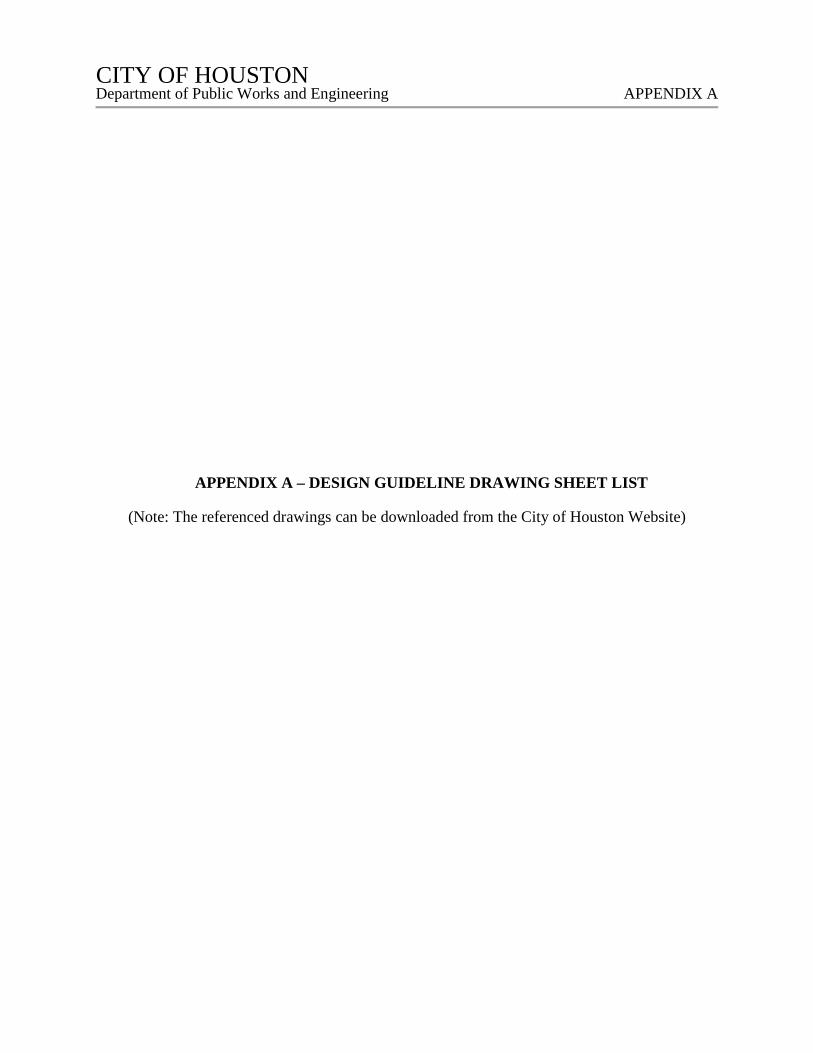
CITY OF HOUSTON CITY OF HOUSTON Department of Public Works and Engineering APPENDIX A
APPENDIX A – DESIGN GUIDELINE DRAWING SHEET LIST
(Note: The referenced drawings can be downloaded from the City of Houston Website)
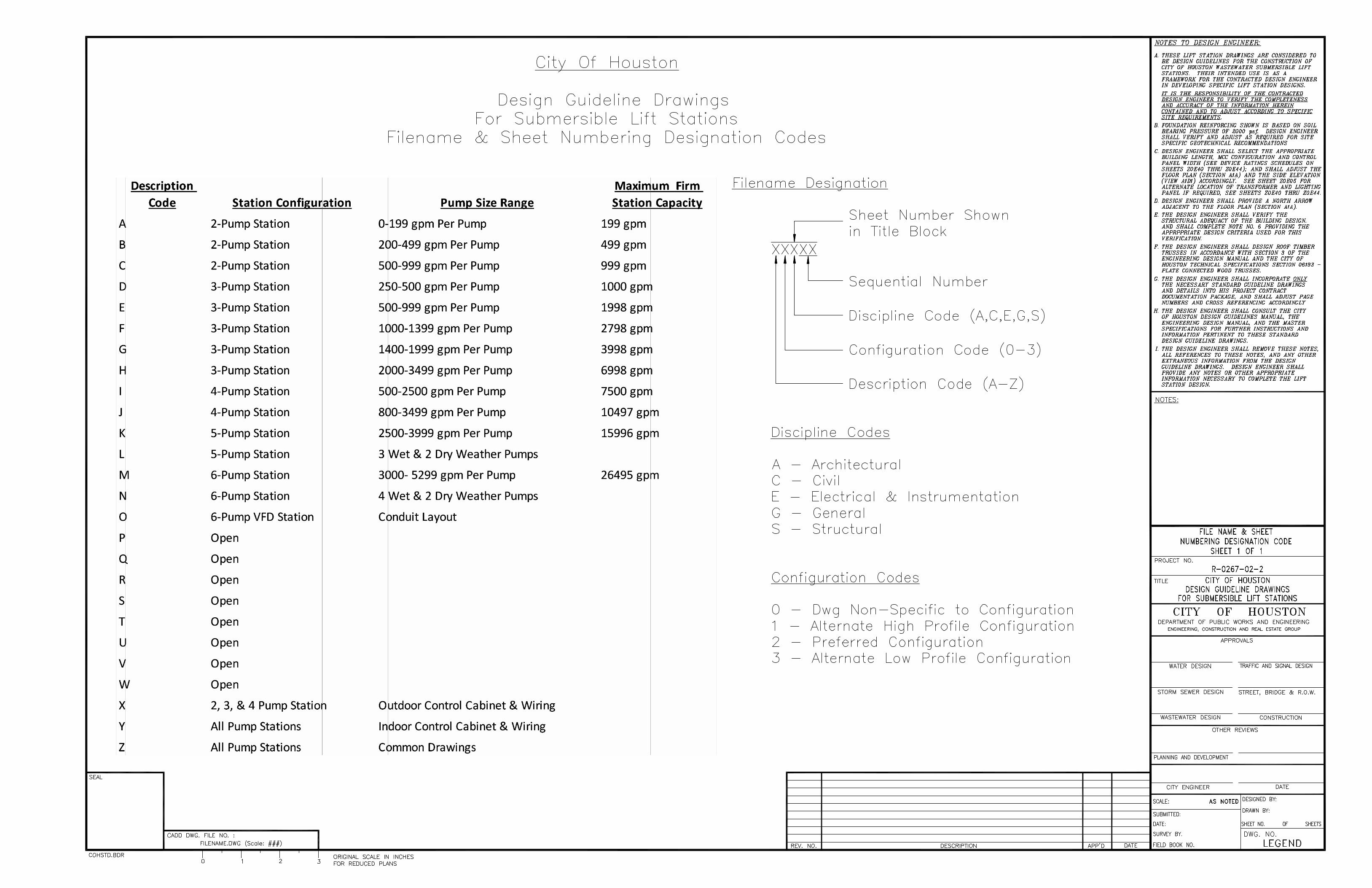
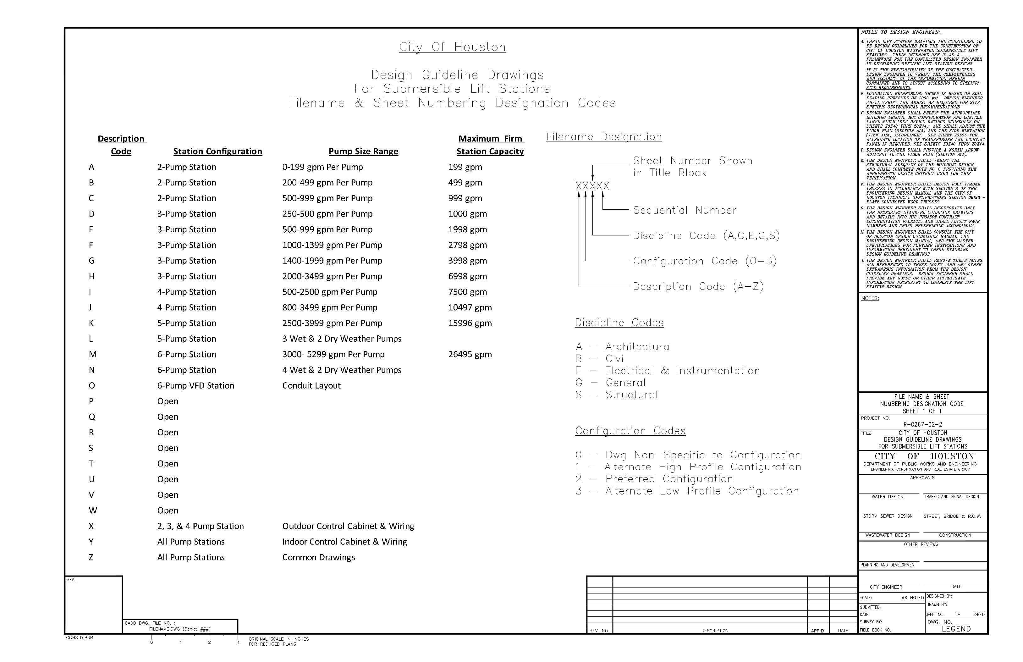
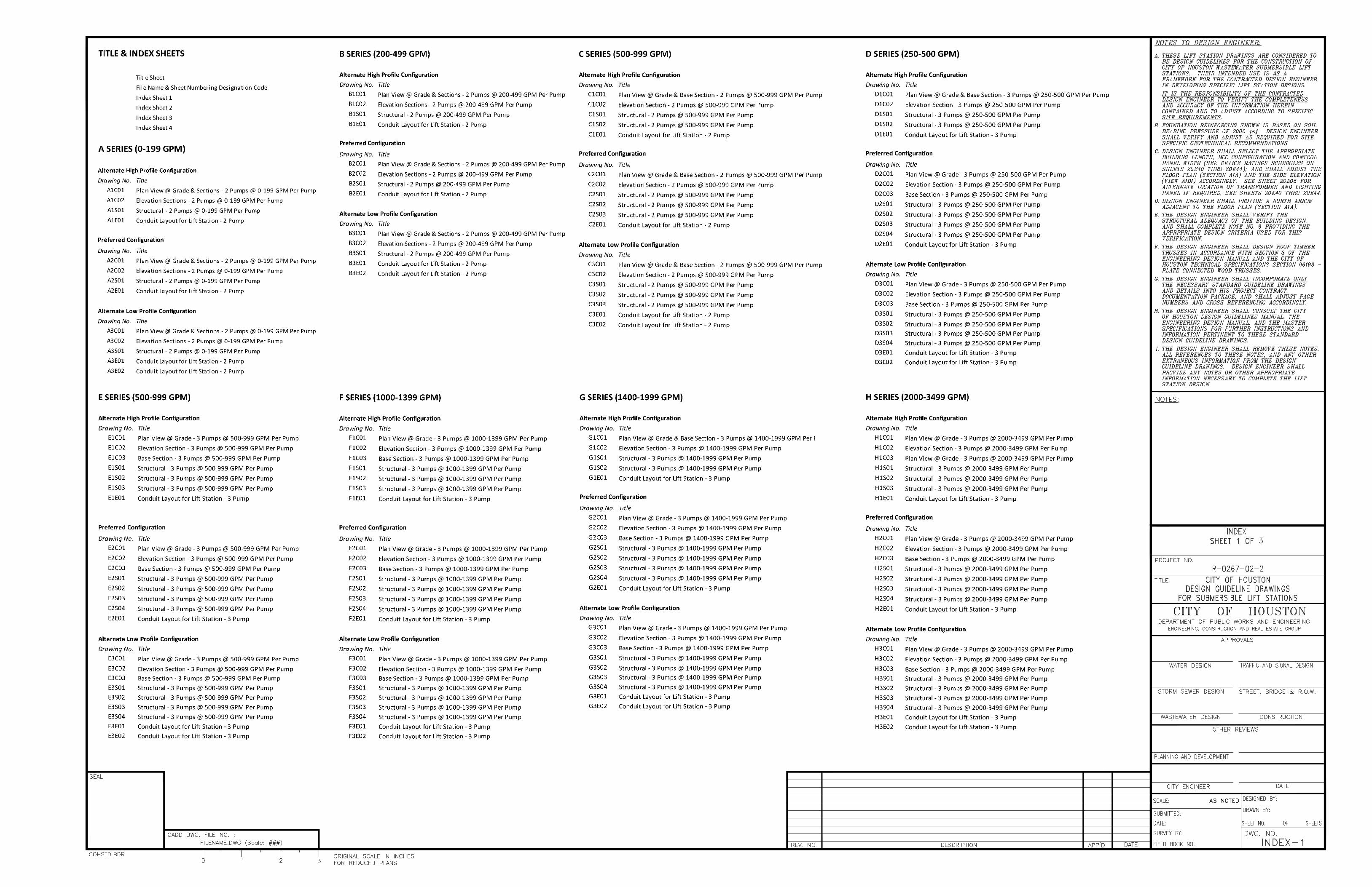
3
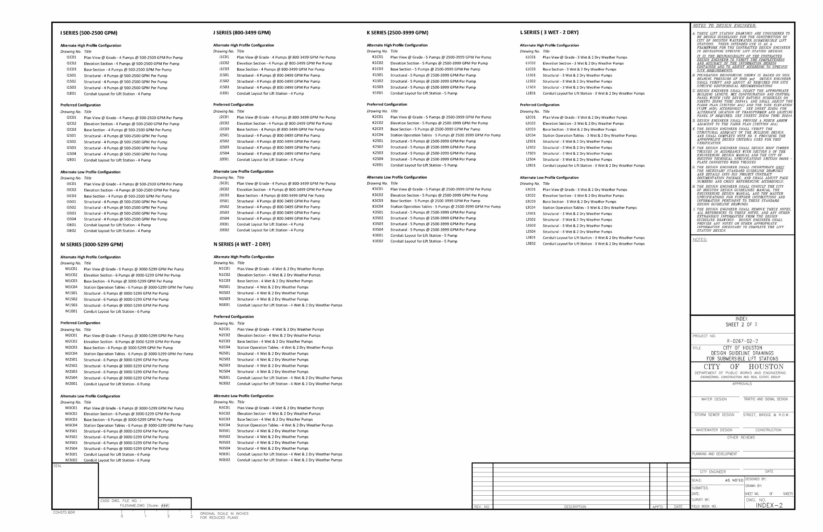
3
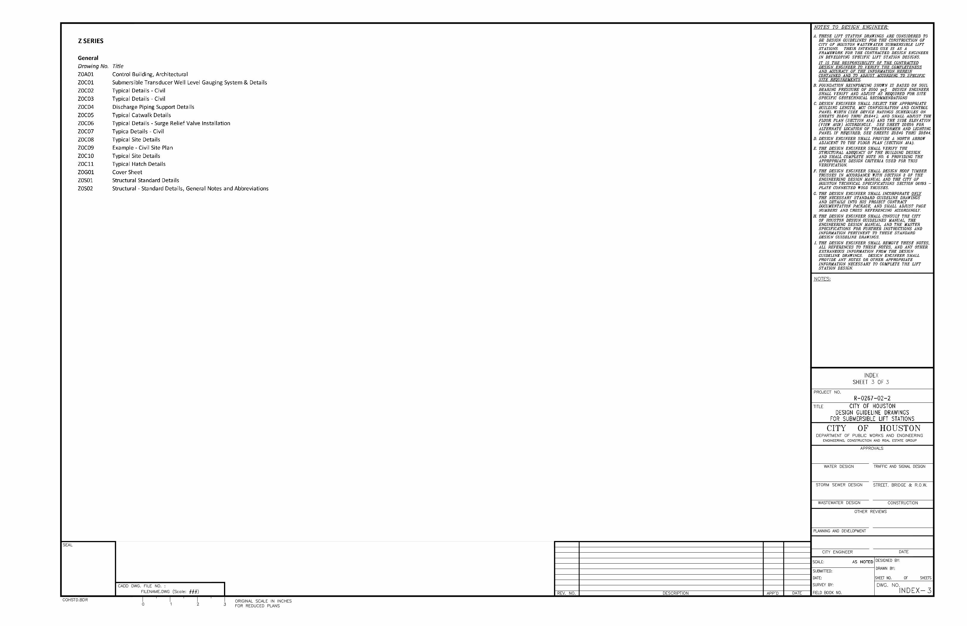
3 3
3
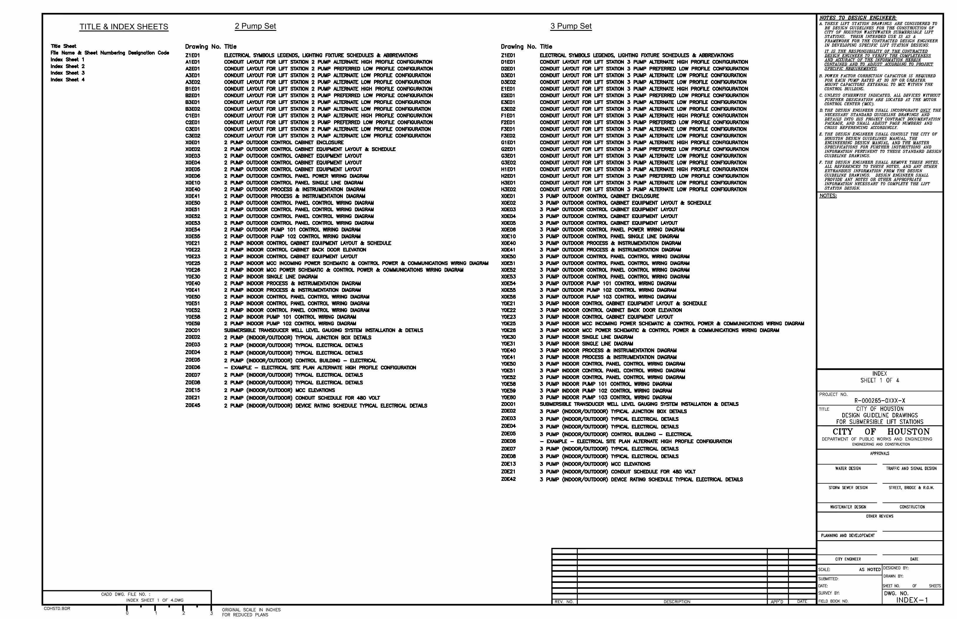
TITLE & INDEX SHEETS
2 Pump Set 3 Pump Set
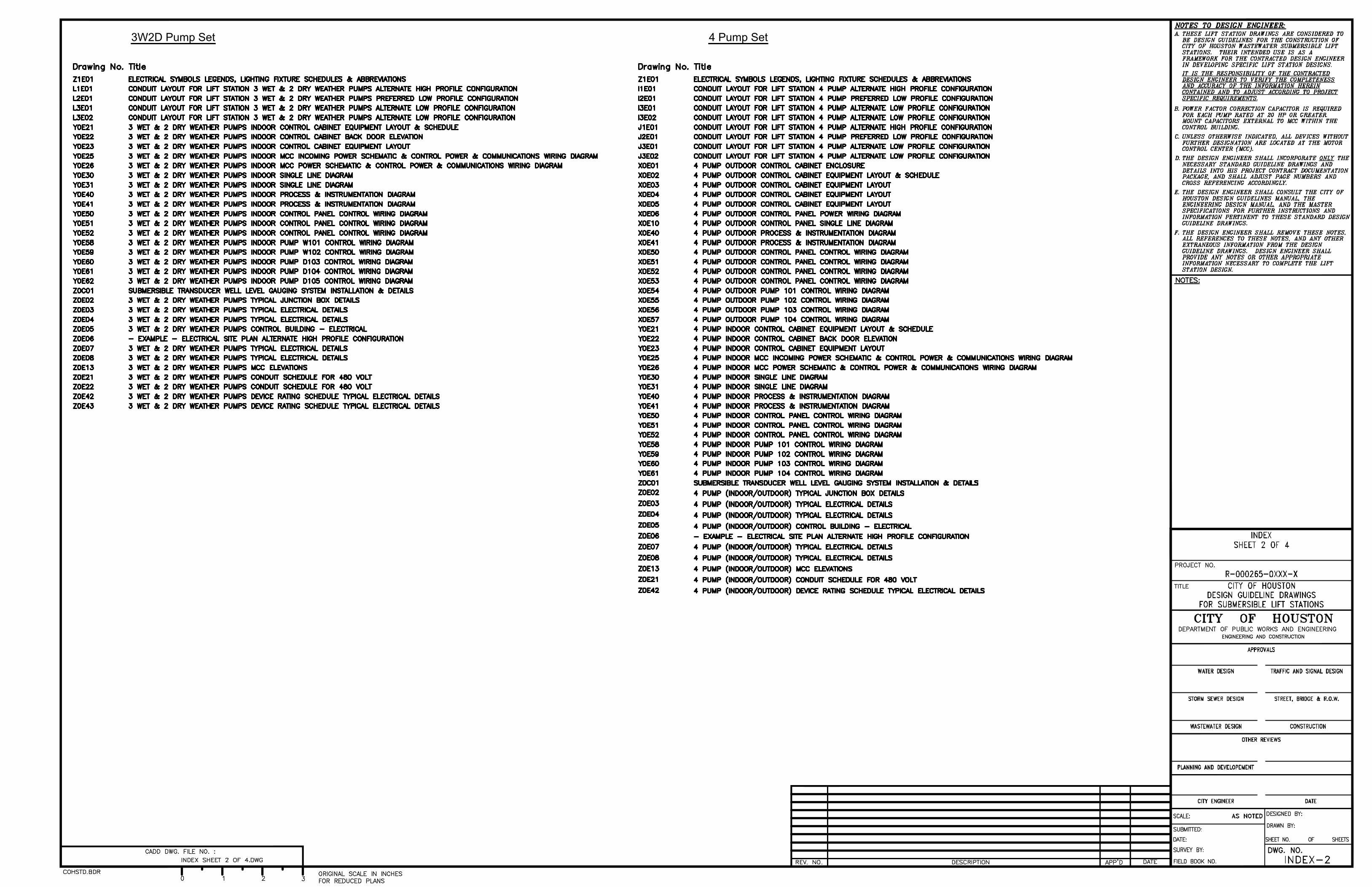
3W2D Pump Set 4 Pump Set
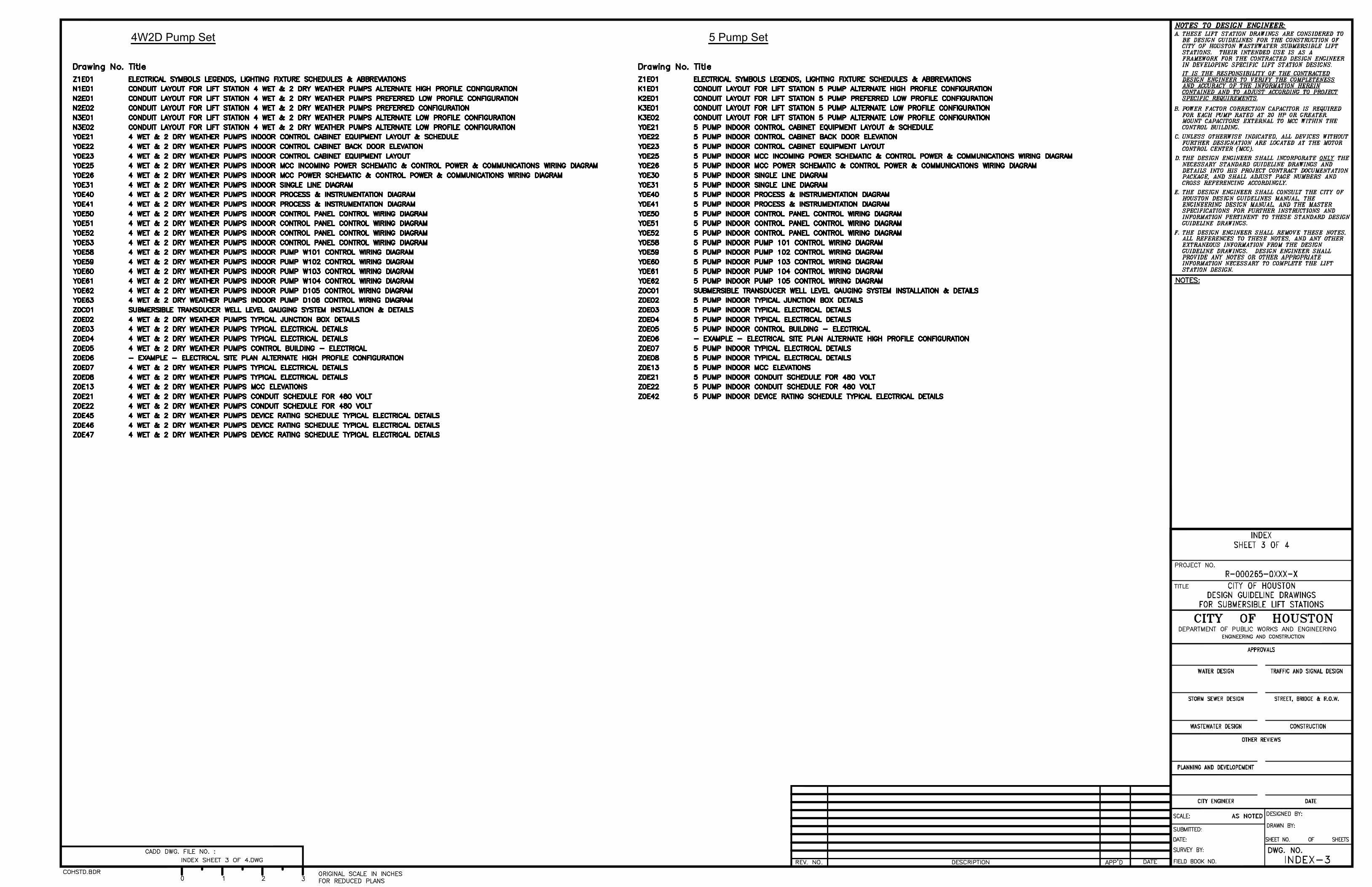
4W2D Pump Set 5 Pump Set
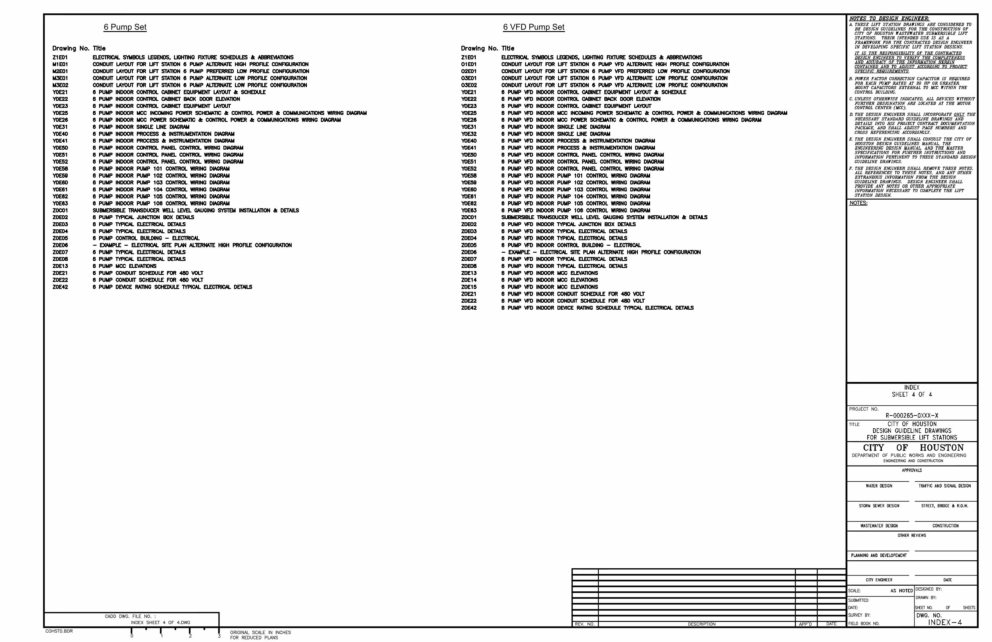
6 Pump Set 6 VFD Pump Set
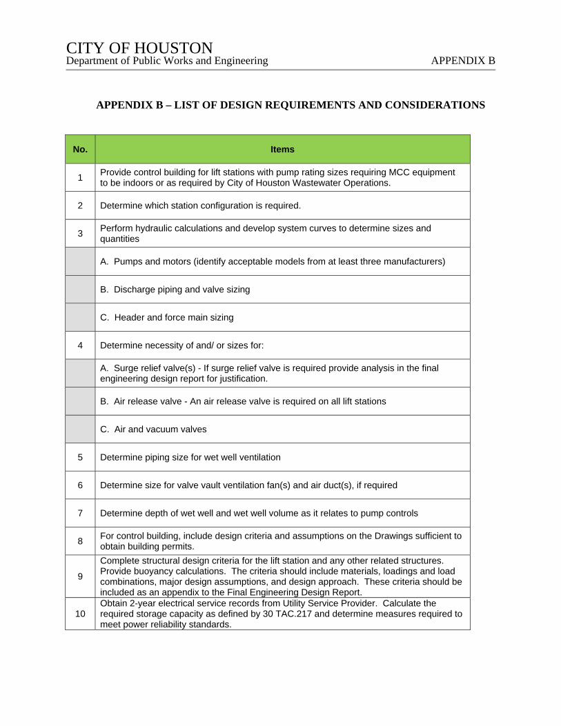
CITY OF HOUSTON CITY OF HOUSTON Department of Public Works and Engineering APPENDIX B
APPENDIX B – LIST OF DESIGN REQUIREMENTS AND CONSIDERATIONS
No. Items
1 Provide control building for lift stations with pump rating sizes requiring MCC equipment to be indoors or as required by City of Houston Wastewater Operations.
2 Determine which station configuration is required.
3 Perform hydraulic calculations and develop system curves to determine sizes and quantities
A. Pumps and motors (identify acceptable models from at least three manufacturers)
B. Discharge piping and valve sizing
C. Header and force main sizing
4 Determine necessity of and/ or sizes for:
A. Surge relief valve(s) - If surge relief valve is required provide analysis in the final engineering design report for justification.
B. Air release valve - An air release valve is required on all lift stations
C. Air and vacuum valves
5 Determine piping size for wet well ventilation
6 Determine size for valve vault ventilation fan(s) and air duct(s), if required
7 Determine depth of wet well and wet well volume as it relates to pump controls
8 For control building, include design criteria and assumptions on the Drawings sufficient to obtain building permits.
9
Complete structural design criteria for the lift station and any other related structures. Provide buoyancy calculations. The criteria should include materials, loadings and load combinations, major design assumptions, and design approach. These criteria should be included as an appendix to the Final Engineering Design Report.
10 Obtain 2-year electrical service records from Utility Service Provider. Calculate the required storage capacity as defined by 30 TAC.217 and determine measures required to meet power reliability standards.
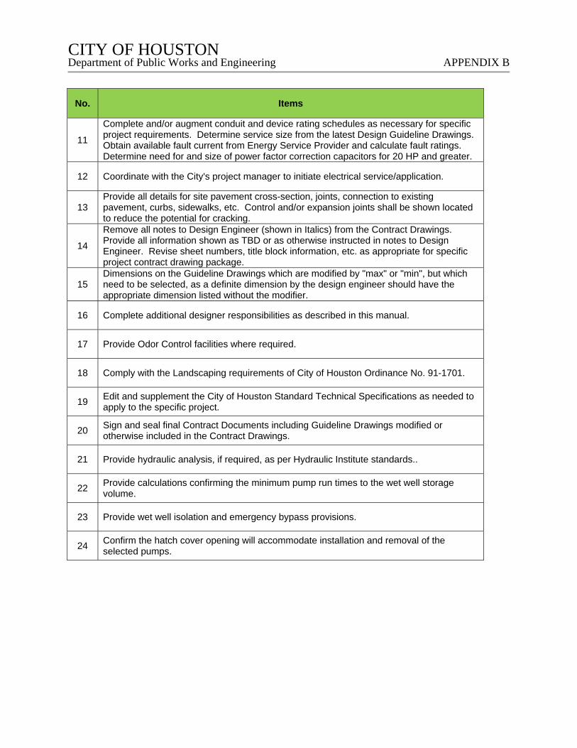
CITY OF HOUSTON CITY OF HOUSTON Department of Public Works and Engineering APPENDIX B
No. Items
11
Complete and/or augment conduit and device rating schedules as necessary for specific project requirements. Determine service size from the latest Design Guideline Drawings. Obtain available fault current from Energy Service Provider and calculate fault ratings. Determine need for and size of power factor correction capacitors for 20 HP and greater.
12 Coordinate with the City's project manager to initiate electrical service/application.
13 Provide all details for site pavement cross-section, joints, connection to existing pavement, curbs, sidewalks, etc. Control and/or expansion joints shall be shown located to reduce the potential for cracking.
14
Remove all notes to Design Engineer (shown in Italics) from the Contract Drawings. Provide all information shown as TBD or as otherwise instructed in notes to Design Engineer. Revise sheet numbers, title block information, etc. as appropriate for specific project contract drawing package.
15 Dimensions on the Guideline Drawings which are modified by "max" or "min", but which need to be selected, as a definite dimension by the design engineer should have the appropriate dimension listed without the modifier.
16 Complete additional designer responsibilities as described in this manual.
17 Provide Odor Control facilities where required.
18 Comply with the Landscaping requirements of City of Houston Ordinance No. 91-1701.
19 Edit and supplement the City of Houston Standard Technical Specifications as needed to apply to the specific project.
20 Sign and seal final Contract Documents including Guideline Drawings modified or otherwise included in the Contract Drawings.
21 Provide hydraulic analysis, if required, as per Hydraulic Institute standards..
22 Provide calculations confirming the minimum pump run times to the wet well storage volume.
23 Provide wet well isolation and emergency bypass provisions.
24 Confirm the hatch cover opening will accommodate installation and removal of the selected pumps.
CITY OF HOUSTON CITY OF HOUSTON Department of Public Works and Engineering APPENDIX C
APPENDIX C – BASIS OF DESIGN REPORT REQUIREMENTS FOR ETJ
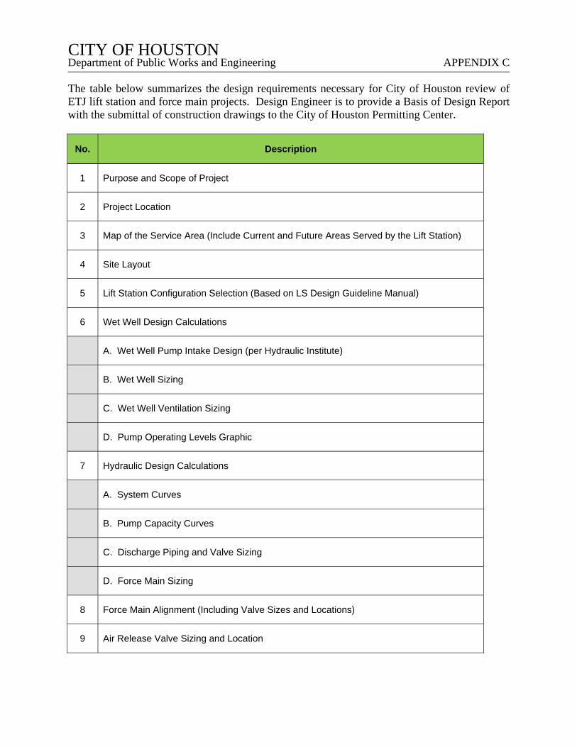
CITY OF HOUSTON CITY OF HOUSTON Department of Public Works and Engineering APPENDIX C
The table below summarizes the design requirements necessary for City of Houston review of ETJ lift station and force main projects. Design Engineer is to provide a Basis of Design Report with the submittal of construction drawings to the City of Houston Permitting Center.
No. Description
1 Purpose and Scope of Project
2 Project Location
3 Map of the Service Area (Include Current and Future Areas Served by the Lift Station)
4 Site Layout
5 Lift Station Configuration Selection (Based on LS Design Guideline Manual)
6 Wet Well Design Calculations
A. Wet Well Pump Intake Design (per Hydraulic Institute)
B. Wet Well Sizing
C. Wet Well Ventilation Sizing
D. Pump Operating Levels Graphic
7 Hydraulic Design Calculations
A. System Curves
B. Pump Capacity Curves
C. Discharge Piping and Valve Sizing
D. Force Main Sizing
8 Force Main Alignment (Including Valve Sizes and Locations)
9 Air Release Valve Sizing and Location
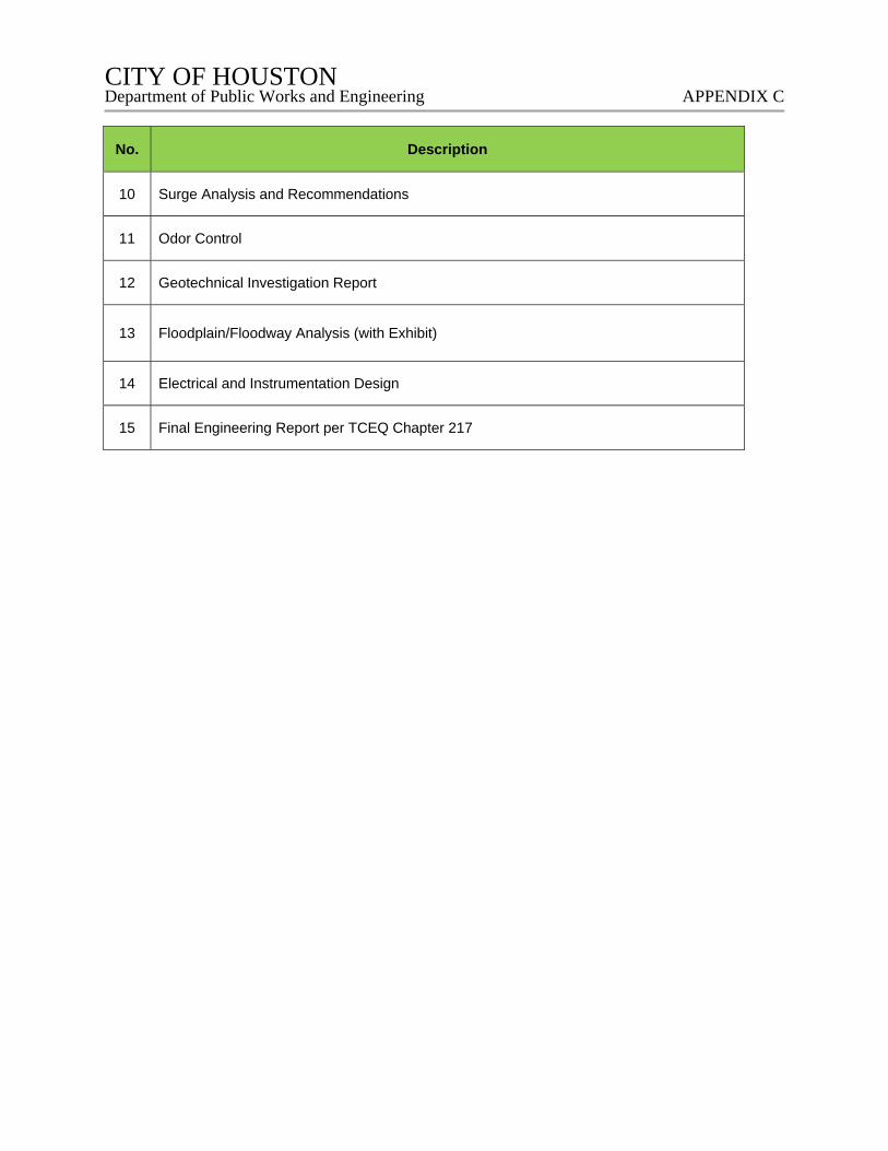
CITY OF HOUSTON CITY OF HOUSTON Department of Public Works and Engineering APPENDIX C
No. Description
10 Surge Analysis and Recommendations
11 Odor Control
12 Geotechnical Investigation Report
13 Floodplain/Floodway Analysis (with Exhibit)
14 Electrical and Instrumentation Design
15 Final Engineering Report per TCEQ Chapter 217
CITY OF HOUSTON CITY OF HOUSTON Department of Public Works and Engineering APPENDIX D
APPENDIX D – SAMPLE CALCULATIONS
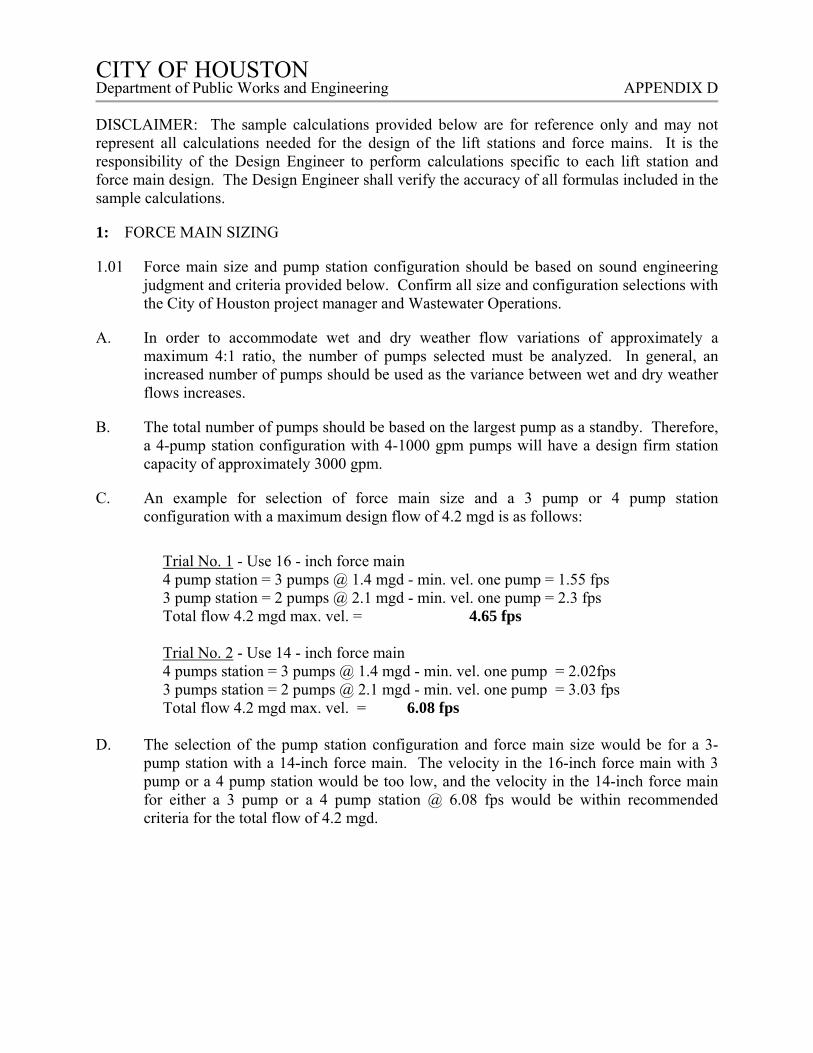
CITY OF HOUSTON CITY OF HOUSTON Department of Public Works and Engineering APPENDIX D
DISCLAIMER: The sample calculations provided below are for reference only and may not represent all calculations needed for the design of the lift stations and force mains. It is the responsibility of the Design Engineer to perform calculations specific to each lift station and force main design. The Design Engineer shall verify the accuracy of all formulas included in the sample calculations.
1: FORCE MAIN SIZING
1.01 Force main size and pump station configuration should be based on sound engineering judgment and criteria provided below. Confirm all size and configuration selections with the City of Houston project manager and Wastewater Operations.
A. In order to accommodate wet and dry weather flow variations of approximately a maximum 4:1 ratio, the number of pumps selected must be analyzed. In general, an increased number of pumps should be used as the variance between wet and dry weather flows increases.
B. The total number of pumps should be based on the largest pump as a standby. Therefore, a 4-pump station configuration with 4-1000 gpm pumps will have a design firm station capacity of approximately 3000 gpm.
C. An example for selection of force main size and a 3 pump or 4 pump station configuration with a maximum design flow of 4.2 mgd is as follows:
Trial No. 1 - Use 16 - inch force main 4 pump station = 3 pumps @ 1.4 mgd - min. vel. one pump = 1.55 fps 3 pump station = 2 pumps @ 2.1 mgd - min. vel. one pump = 2.3 fps Total flow 4.2 mgd max. vel. = 4.65 fps Trial No. 2 - Use 14 - inch force main 4 pumps station = 3 pumps @ 1.4 mgd - min. vel. one pump = 2.02fps 3 pumps station = 2 pumps @ 2.1 mgd - min. vel. one pump = 3.03 fps Total flow 4.2 mgd max. vel. = 6.08 fps
D. The selection of the pump station configuration and force main size would be for a 3-pump station with a 14-inch force main. The velocity in the 16-inch force main with 3 pump or a 4 pump station would be too low, and the velocity in the 14-inch force main for either a 3 pump or a 4 pump station @ 6.08 fps would be within recommended criteria for the total flow of 4.2 mgd.
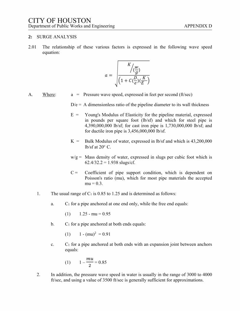
CITY OF HOUSTON CITY OF HOUSTON Department of Public Works and Engineering APPENDIX D
2: SURGE ANALYSIS
2.01 The relationship of these various factors is expressed in the following wave speed equation:
1
A. Where: a = Pressure wave speed, expressed in feet per second (ft/sec)
D/e = A dimensionless ratio of the pipeline diameter to its wall thickness
E = Young's Modulus of Elasticity for the pipeline material, expressed in pounds per square foot (lb/sf) and which for steel pipe is 4,390,000,000 lb/sf; for cast iron pipe is 1,730,000,000 lb/sf; and for ductile iron pipe is 3,456,000,000 lb/sf.
K = Bulk Modulus of water, expressed in lb/sf and which is 43,200,000 lb/sf at 20 C.
w/g = Mass density of water, expressed in slugs per cubic foot which is 62.4/32.2 = 1.938 slugs/cf.
C = Coefficient of pipe support condition, which is dependent on Poisson's ratio (mu), which for most pipe materials the accepted mu = 0.3.
1. The usual range of C1 is 0.85 to 1.25 and is determined as follows:
a. C1 for a pipe anchored at one end only, while the free end equals:
(1) 1.25 - mu = 0.95
b. C1 for a pipe anchored at both ends equals:
(1) 1 - (mu)2 = 0.91
c. C1 for a pipe anchored at both ends with an expansion joint between anchors equals:
(1) 1 – = 0.85
2. In addition, the pressure wave speed in water is usually in the range of 3000 to 4000 ft/sec, and using a value of 3500 ft/sec is generally sufficient for approximations.
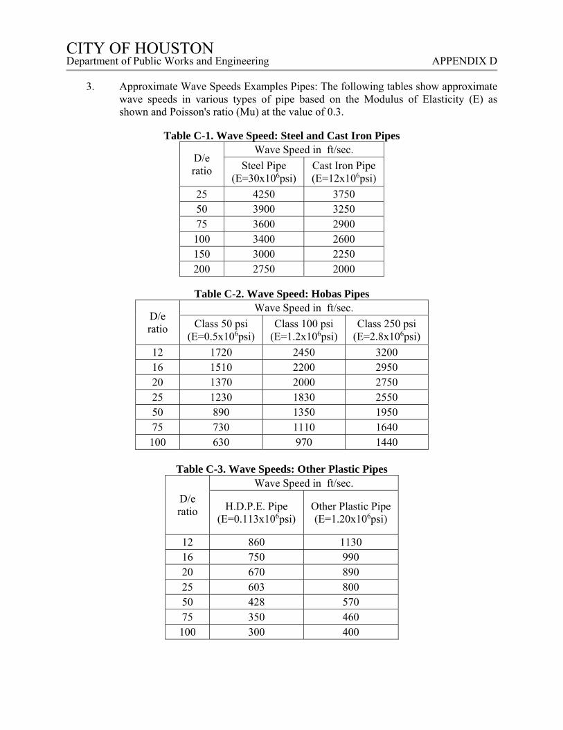
CITY OF HOUSTON CITY OF HOUSTON Department of Public Works and Engineering APPENDIX D
3. Approximate Wave Speeds Examples Pipes: The following tables show approximate
wave speeds in various types of pipe based on the Modulus of Elasticity (E) as shown and Poisson's ratio (Mu) at the value of 0.3.
Table C-1. Wave Speed: Steel and Cast Iron Pipes
D/e ratio
Wave Speed in ft/sec.
Steel Pipe (E=30x106psi)
Cast Iron Pipe (E=12x106psi)
25 4250 3750 50 3900 3250 75 3600 2900 100 3400 2600 150 3000 2250 200 2750 2000
Table C-2. Wave Speed: Hobas Pipes
D/e ratio
Wave Speed in ft/sec.
Class 50 psi (E=0.5x10⁶psi)
Class 100 psi (E=1.2x10⁶psi)
Class 250 psi (E=2.8x10⁶psi)
12 1720 2450 3200 16 1510 2200 2950 20 1370 2000 2750 25 1230 1830 2550 50 890 1350 1950 75 730 1110 1640 100 630 970 1440
Table C-3. Wave Speeds: Other Plastic Pipes
D/e ratio
Wave Speed in ft/sec.
H.D.P.E. Pipe (E=0.113x10⁶psi)
Other Plastic Pipe (E=1.20x10⁶psi)
12 860 1130 16 750 990 20 670 890 25 603 800 50 428 570 75 350 460 100 300 400

CITY OF HOUSTON CITY OF HOUSTON Department of Public Works and Engineering APPENDIX D
B. Surge Pressure - Sudden Flow Stoppage: The magnitude of surge pressure per unit
change in the velocity of flow is expressed by the following equation, for the sudden or instantaneous stoppage of flow:
hw = av g Where: hw = pressure rise expressed in feet
a = pressure wave speed expressed in ft/sec v = flow velocity of the pumped fluid in ft/sec g = 32.2 ft/sec2
Thus, if a liquid is flowing at a velocity of 10 ft/sec through a pipeline and is brought to a sudden stop, the increase in pressure, or surge pressure, using a pressure wave speed of 3500 ft/sec is determined as follows:
hw = av g = 3500 ft/sec x 10 ft/sec 32.2 ft/sec2
= 35,000 ft2/sec2 32.2 ft/sec2 = 1087 ft
1087 ft 2.31 ft/psi = 470.56 psi
C. Surge Pressure - Change in Flow: The magnitude of surge pressure per unit change in the velocity of flow is expressed by the following equation, for the sudden or instantaneous stoppage of flow:
hw = a/g (v1 - v2)
Where: v1 = original steady flow velocity expressed in ft/sec v2 = final steady flow velocity expressed in ft/sec
Thus, if a liquid is flowing at a velocity of 8 ft/sec while being pumped by two pumps, then one pump is stopped resulting in a flow velocity of 4 ft/sec, the increase in pressure or surge pressure, using a pressure wave speed of 3500 ft/sec is determined as follows:
hw = a/g (v1 - v2) = 3500 ft/sec * (8ft/sec - 4 ft/sec)
32.2ft/sec2
= 108.7 1/sec (4 ft/sec) = 434.8 ft
434.8 ft 2.31 ft/psi = 188 psi +
1. It should be noted that as a "Rule of Thumb" the above equations will yield a surge pressure of approximately 100 ft of water (43.3 psi) per each 1 fps change in velocity.
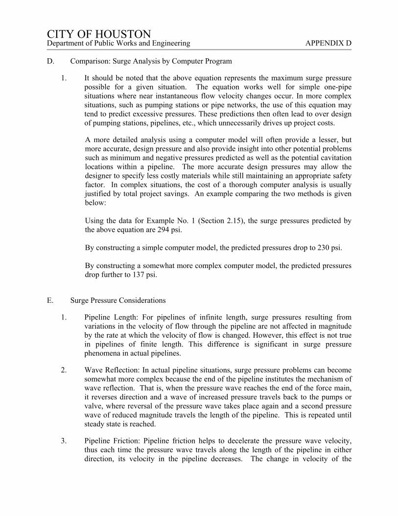
CITY OF HOUSTON CITY OF HOUSTON Department of Public Works and Engineering APPENDIX D
D. Comparison: Surge Analysis by Computer Program
1. It should be noted that the above equation represents the maximum surge pressure possible for a given situation. The equation works well for simple one-pipe situations where near instantaneous flow velocity changes occur. In more complex situations, such as pumping stations or pipe networks, the use of this equation may tend to predict excessive pressures. These predictions then often lead to over design of pumping stations, pipelines, etc., which unnecessarily drives up project costs.
A more detailed analysis using a computer model will often provide a lesser, but more accurate, design pressure and also provide insight into other potential problems such as minimum and negative pressures predicted as well as the potential cavitation locations within a pipeline. The more accurate design pressures may allow the designer to specify less costly materials while still maintaining an appropriate safety factor. In complex situations, the cost of a thorough computer analysis is usually justified by total project savings. An example comparing the two methods is given below: Using the data for Example No. 1 (Section 2.15), the surge pressures predicted by the above equation are 294 psi. By constructing a simple computer model, the predicted pressures drop to 230 psi. By constructing a somewhat more complex computer model, the predicted pressures drop further to 137 psi.
E. Surge Pressure Considerations
1. Pipeline Length: For pipelines of infinite length, surge pressures resulting from variations in the velocity of flow through the pipeline are not affected in magnitude by the rate at which the velocity of flow is changed. However, this effect is not true in pipelines of finite length. This difference is significant in surge pressure phenomena in actual pipelines.
2. Wave Reflection: In actual pipeline situations, surge pressure problems can become somewhat more complex because the end of the pipeline institutes the mechanism of wave reflection. That is, when the pressure wave reaches the end of the force main, it reverses direction and a wave of increased pressure travels back to the pumps or valve, where reversal of the pressure wave takes place again and a second pressure wave of reduced magnitude travels the length of the pipeline. This is repeated until steady state is reached.
3. Pipeline Friction: Pipeline friction helps to decelerate the pressure wave velocity, thus each time the pressure wave travels along the length of the pipeline in either direction, its velocity in the pipeline decreases. The change in velocity of the
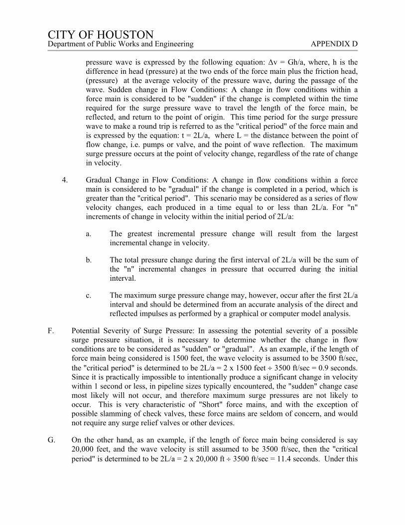
CITY OF HOUSTON CITY OF HOUSTON Department of Public Works and Engineering APPENDIX D
pressure wave is expressed by the following equation: Δv = Gh/a, where, h is the difference in head (pressure) at the two ends of the force main plus the friction head, (pressure) at the average velocity of the pressure wave, during the passage of the wave. Sudden change in Flow Conditions: A change in flow conditions within a force main is considered to be "sudden" if the change is completed within the time required for the surge pressure wave to travel the length of the force main, be reflected, and return to the point of origin. This time period for the surge pressure wave to make a round trip is referred to as the "critical period" of the force main and is expressed by the equation: t = 2L/a, where L = the distance between the point of flow change, i.e. pumps or valve, and the point of wave reflection. The maximum surge pressure occurs at the point of velocity change, regardless of the rate of change in velocity.
4. Gradual Change in Flow Conditions: A change in flow conditions within a force main is considered to be "gradual" if the change is completed in a period, which is greater than the "critical period". This scenario may be considered as a series of flow velocity changes, each produced in a time equal to or less than 2L/a. For "n" increments of change in velocity within the initial period of 2L/a:
a. The greatest incremental pressure change will result from the largest incremental change in velocity.
b. The total pressure change during the first interval of 2L/a will be the sum of the "n" incremental changes in pressure that occurred during the initial interval.
c. The maximum surge pressure change may, however, occur after the first 2L/a interval and should be determined from an accurate analysis of the direct and reflected impulses as performed by a graphical or computer model analysis.
F. Potential Severity of Surge Pressure: In assessing the potential severity of a possible surge pressure situation, it is necessary to determine whether the change in flow conditions are to be considered as "sudden" or "gradual". As an example, if the length of force main being considered is 1500 feet, the wave velocity is assumed to be 3500 ft/sec, the "critical period" is determined to be 2L/a = 2 x 1500 feet 3500 ft/sec = 0.9 seconds. Since it is practically impossible to intentionally produce a significant change in velocity within 1 second or less, in pipeline sizes typically encountered, the "sudden" change case most likely will not occur, and therefore maximum surge pressures are not likely to occur. This is very characteristic of "Short" force mains, and with the exception of possible slamming of check valves, these force mains are seldom of concern, and would not require any surge relief valves or other devices.
G. On the other hand, as an example, if the length of force main being considered is say 20,000 feet, and the wave velocity is still assumed to be 3500 ft/sec, then the "critical period" is determined to be 2L/a = 2 x 20,000 ft 3500 ft/sec = 11.4 seconds. Under this
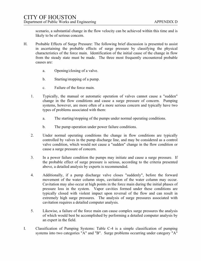
CITY OF HOUSTON CITY OF HOUSTON Department of Public Works and Engineering APPENDIX D
scenario, a substantial change in the flow velocity can be achieved within this time and is likely to be of serious concern.
H. Probable Effects of Surge Pressure: The following brief discussion is presented to assist in ascertaining the probable effects of surge pressure by classifying the physical characteristics of the force main. Identification of the initial cause of the change in flow from the steady state must be made. The three most frequently encountered probable causes are:
a. Opening/closing of a valve.
b. Starting/stopping of a pump.
c. Failure of the force main.
1. Typically, the manual or automatic operation of valves cannot cause a "sudden" change in the flow conditions and cause a surge pressure of concern. Pumping systems, however, are more often of a more serious concern and typically have two types of problems associated with them:
a. The starting/stopping of the pumps under normal operating conditions.
b. The pump operation under power failure conditions.
2. Under normal operating conditions the change in flow conditions are typically controlled by valves in the pump discharge line, and may be considered as a control valve condition, which would not cause a "sudden" change in the flow condition or cause a surge pressure of concern.
3. In a power failure condition the pumps may initiate and cause a surge pressure. If the probable effect of surge pressure is serious, according to the criteria presented above, a detailed analysis by experts is recommended.
4. Additionally, if a pump discharge valve closes "suddenly", before the forward movement of the water column stops, cavitation of the water column may occur. Cavitation may also occur at high points in the force main during the initial phases of pressure loss in the system. Vapor cavities formed under these conditions are typically closed with violent impact upon reversal of the flow and can result in extremely high surge pressures. The analysis of surge pressures associated with cavitation requires a detailed computer analysis.
5. Likewise, a failure of the force main can cause complex surge pressures the analysis of which would best be accomplished by performing a detailed computer analysis by an expert in the field.
I. Classification of Pumping Systems: Table C-4 is a simple classification of pumping systems into two categories "A" and "B". Surge problems occurring under category "A"

CITY OF HOUSTON CITY OF HOUSTON Department of Public Works and Engineering APPENDIX D
situations are typically of minor concern and usually occur with great frequency in actual practice. The severity of the surge problems associated with the category "A" situations may be determined from the checklist presented as Table C-5.
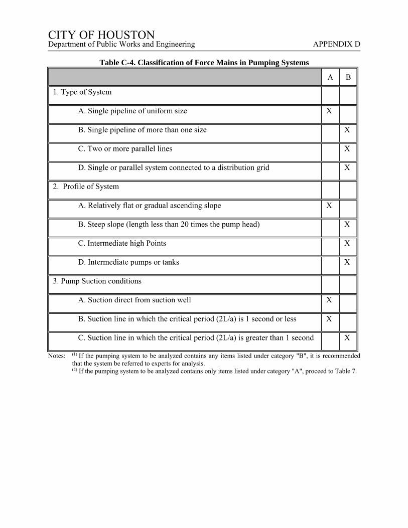
CITY OF HOUSTON CITY OF HOUSTON Department of Public Works and Engineering APPENDIX D
Table C-4. Classification of Force Mains in Pumping Systems
A B
1. Type of System
A. Single pipeline of uniform size X
B. Single pipeline of more than one size X
C. Two or more parallel lines X
D. Single or parallel system connected to a distribution grid X
2. Profile of System
A. Relatively flat or gradual ascending slope X
B. Steep slope (length less than 20 times the pump head) X
C. Intermediate high Points X
D. Intermediate pumps or tanks X
3. Pump Suction conditions
A. Suction direct from suction well X
B. Suction line in which the critical period (2L/a) is 1 second or less X
C. Suction line in which the critical period (2L/a) is greater than 1 second X
Notes: (1) If the pumping system to be analyzed contains any items listed under category "B", it is recommended that the system be referred to experts for analysis. (2) If the pumping system to be analyzed contains only items listed under category "A", proceed to Table 7.
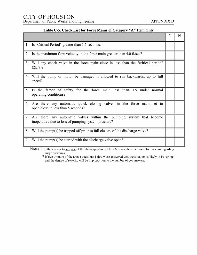
CITY OF HOUSTON CITY OF HOUSTON Department of Public Works and Engineering APPENDIX D
Table C-5. Check List for Force Mains of Category "A" Item Only
Y N
1. Is "Critical Period" greater than 1.5 seconds?
2. Is the maximum flow velocity in the force main greater than 4.0 ft/sec?
3. Will any check valve in the force main close in less than the "critical period" (2L/a)?
4. Will the pump or motor be damaged if allowed to run backwards, up to full speed?
5. Is the factor of safety for the force main less than 3.5 under normal operating conditions?
6. Are there any automatic quick closing valves in the force main set to open/close in less than 5 seconds?
7. Are there any automatic valves within the pumping system that become inoperative due to loss of pumping system pressure?
8. Will the pump(s) be tripped off prior to full closure of the discharge valve?
9. Will the pump(s) be started with the discharge valve open?
Notes: (1) If the answer to any one of the above questions 1 thru 6 is yes, there is reason for concern regarding surge pressures.
(2) If two or more of the above questions 1 thru 9 are answered yes, the situation is likely to be serious and the degree of severity will be in proportion to the number of yes answers.
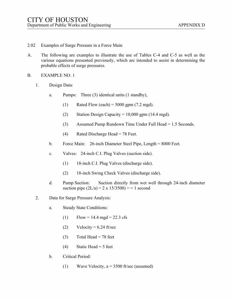
CITY OF HOUSTON CITY OF HOUSTON Department of Public Works and Engineering APPENDIX D
2.02 Examples of Surge Pressure in a Force Main
A. The following are examples to illustrate the use of Tables C-4 and C-5 as well as the various equations presented previously, which are intended to assist in determining the probable effects of surge pressures.
B. EXAMPLE NO. 1
1. Design Data:
a. Pumps: Three (3) identical units (1 standby),
(1) Rated Flow (each) = 5000 gpm (7.2 mgd).
(2) Station Design Capacity = 10,000 gpm (14.4 mgd).
(3) Assumed Pump Rundown Time Under Full Head = 1.5 Seconds.
(4) Rated Discharge Head = 78 Feet.
b. Force Main: 26-inch Diameter Steel Pipe, Length = 8000 Feet.
c. Valves: 24-inch C.I. Plug Valves (suction side).
(1) 18-inch C.I. Plug Valves (discharge side).
(2) 18-inch Swing Check Valves (discharge side).
d. Pump Suction: Suction directly from wet well through 24-inch diameter suction pipe (2L/a) = 2 x 15/3500) = < 1 second
2. Data for Surge Pressure Analysis:
a. Steady State Conditions:
(1) Flow = 14.4 mgd = 22.3 cfs
(2) Velocity = 6.24 ft/sec
(3) Total Head = 78 feet
(4) Static Head = 5 feet
b. Critical Period:
(1) Wave Velocity, a = 3500 ft/sec (assumed)
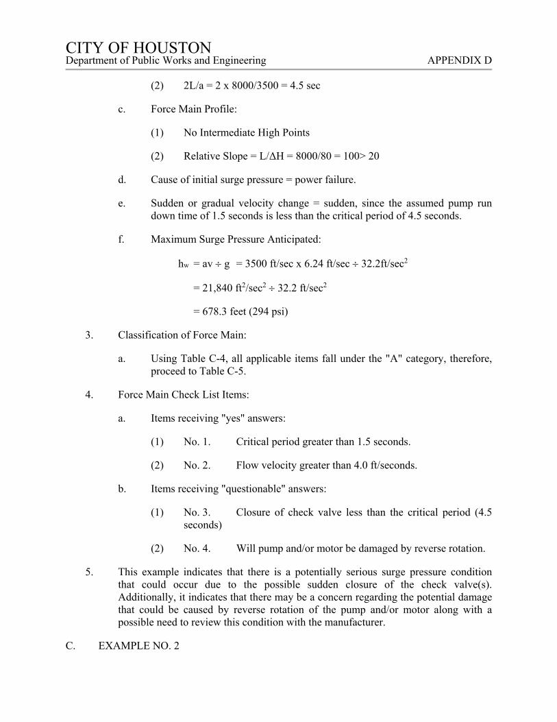
CITY OF HOUSTON CITY OF HOUSTON Department of Public Works and Engineering APPENDIX D
(2) 2L/a = 2 x 8000/3500 = 4.5 sec
c. Force Main Profile:
(1) No Intermediate High Points
(2) Relative Slope = L/ΔH = 8000/80 = 100> 20
d. Cause of initial surge pressure = power failure.
e. Sudden or gradual velocity change = sudden, since the assumed pump run down time of 1.5 seconds is less than the critical period of 4.5 seconds.
f. Maximum Surge Pressure Anticipated:
hw = av g = 3500 ft/sec x 6.24 ft/sec 32.2ft/sec2
= 21,840 ft2/sec2 32.2 ft/sec2
= 678.3 feet (294 psi)
3. Classification of Force Main:
a. Using Table C-4, all applicable items fall under the "A" category, therefore, proceed to Table C-5.
4. Force Main Check List Items:
a. Items receiving "yes" answers:
(1) No. 1. Critical period greater than 1.5 seconds.
(2) No. 2. Flow velocity greater than 4.0 ft/seconds.
b. Items receiving "questionable" answers:
(1) No. 3. Closure of check valve less than the critical period (4.5 seconds)
(2) No. 4. Will pump and/or motor be damaged by reverse rotation.
5. This example indicates that there is a potentially serious surge pressure condition that could occur due to the possible sudden closure of the check valve(s). Additionally, it indicates that there may be a concern regarding the potential damage that could be caused by reverse rotation of the pump and/or motor along with a possible need to review this condition with the manufacturer.
C. EXAMPLE NO. 2
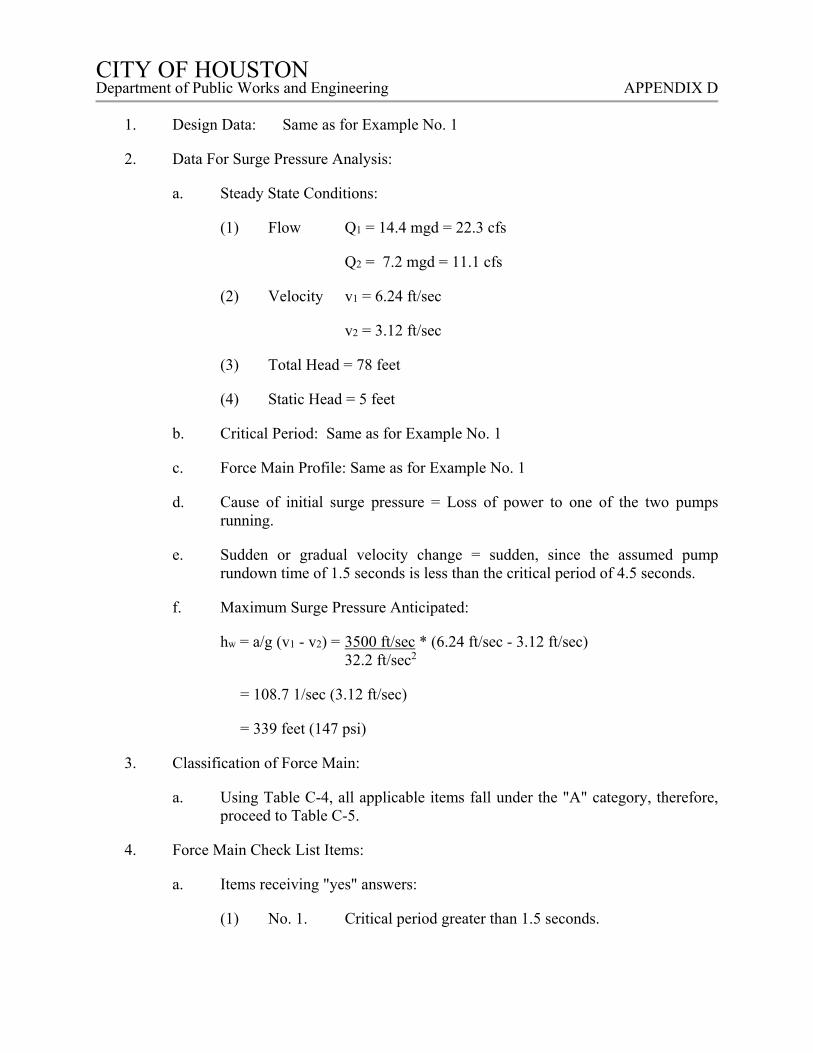
CITY OF HOUSTON CITY OF HOUSTON Department of Public Works and Engineering APPENDIX D
1. Design Data: Same as for Example No. 1
2. Data For Surge Pressure Analysis:
a. Steady State Conditions:
(1) Flow Q1 = 14.4 mgd = 22.3 cfs
Q2 = 7.2 mgd = 11.1 cfs
(2) Velocity v1 = 6.24 ft/sec
v2 = 3.12 ft/sec
(3) Total Head = 78 feet
(4) Static Head = 5 feet
b. Critical Period: Same as for Example No. 1
c. Force Main Profile: Same as for Example No. 1
d. Cause of initial surge pressure = Loss of power to one of the two pumps running.
e. Sudden or gradual velocity change = sudden, since the assumed pump rundown time of 1.5 seconds is less than the critical period of 4.5 seconds.
f. Maximum Surge Pressure Anticipated:
hw = a/g (v1 - v2) = 3500 ft/sec * (6.24 ft/sec - 3.12 ft/sec) 32.2 ft/sec2
= 108.7 1/sec (3.12 ft/sec)
= 339 feet (147 psi)
3. Classification of Force Main:
a. Using Table C-4, all applicable items fall under the "A" category, therefore, proceed to Table C-5.
4. Force Main Check List Items:
a. Items receiving "yes" answers:
(1) No. 1. Critical period greater than 1.5 seconds.

CITY OF HOUSTON CITY OF HOUSTON Department of Public Works and Engineering APPENDIX D
(2) No. 2. Flow velocity greater than 4.0 ft/sec initially.
b. Items receiving "questionable" answers:
(1) No. 3. Closure of check valve in less than the critical period of 4.5 seconds.
(2) No. 4. Will pump or motor be damaged by reverse rotation.
5. This example indicates that there is a potentially serious surge pressure condition that could occur due to the possible sudden closure of the check valve(s). Additionally it indicates that the severity of the surge pressure will be less than if both pumps were suddenly shut down. It also indicates that there may be a concern regarding the potential damage that could be caused by reverse rotation of the pump and/or motor along with a possible need to review this condition with the manufacturer.
D. EXAMPLE NO. 3
1. Design Data:
a. Pumps: Two (2) identical units (1 standby)
(1) Rated Flow (each) = 3000 gpm (4.3 mgd)
(2) Station Design Capacity = 3000 gpm (4.3 mgd)
(3) Assumed Pump Rundown Time under full head = 1.5 seconds.
(4) Rated Discharge Head = 55 feet
b. Force Main: 26-inch diameter steel pipe Length = 6500 feet
c. Valves: 16-inch C.I. plug valves, manually operated on suction and discharge of pumps.
d. Pump Suction: Suction directly from wet well through 16-inch diameter suction pipe (2L/a) = (2 x 15/3500) = <1 second.
2. Data For Surge Pressure Analysis:
a. Steady State Conditions:
(1) Flow = 4.3 mgd = 6.65 cfs
(2) Velocity = 1.87 ft/sec
(3) Total Head = 55 feet
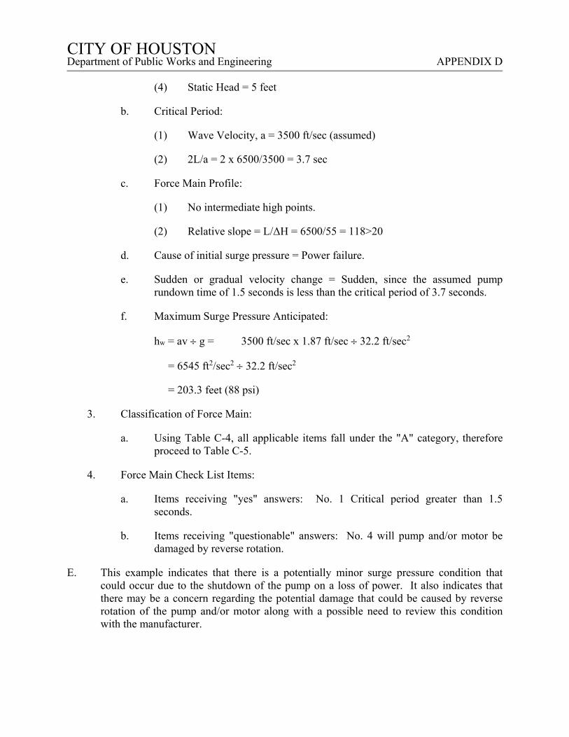
CITY OF HOUSTON CITY OF HOUSTON Department of Public Works and Engineering APPENDIX D
(4) Static Head = 5 feet
b. Critical Period:
(1) Wave Velocity, a = 3500 ft/sec (assumed)
(2) 2L/a = 2 x 6500/3500 = 3.7 sec
c. Force Main Profile:
(1) No intermediate high points.
(2) Relative slope = L/ΔH = 6500/55 = 118>20
d. Cause of initial surge pressure = Power failure.
e. Sudden or gradual velocity change = Sudden, since the assumed pump rundown time of 1.5 seconds is less than the critical period of 3.7 seconds.
f. Maximum Surge Pressure Anticipated:
hw = av g = 3500 ft/sec x 1.87 ft/sec 32.2 ft/sec2
= 6545 ft2/sec2 32.2 ft/sec2
= 203.3 feet (88 psi)
3. Classification of Force Main:
a. Using Table C-4, all applicable items fall under the "A" category, therefore proceed to Table C-5.
4. Force Main Check List Items:
a. Items receiving "yes" answers: No. 1 Critical period greater than 1.5 seconds.
b. Items receiving "questionable" answers: No. 4 will pump and/or motor be damaged by reverse rotation.
E. This example indicates that there is a potentially minor surge pressure condition that could occur due to the shutdown of the pump on a loss of power. It also indicates that there may be a concern regarding the potential damage that could be caused by reverse rotation of the pump and/or motor along with a possible need to review this condition with the manufacturer.
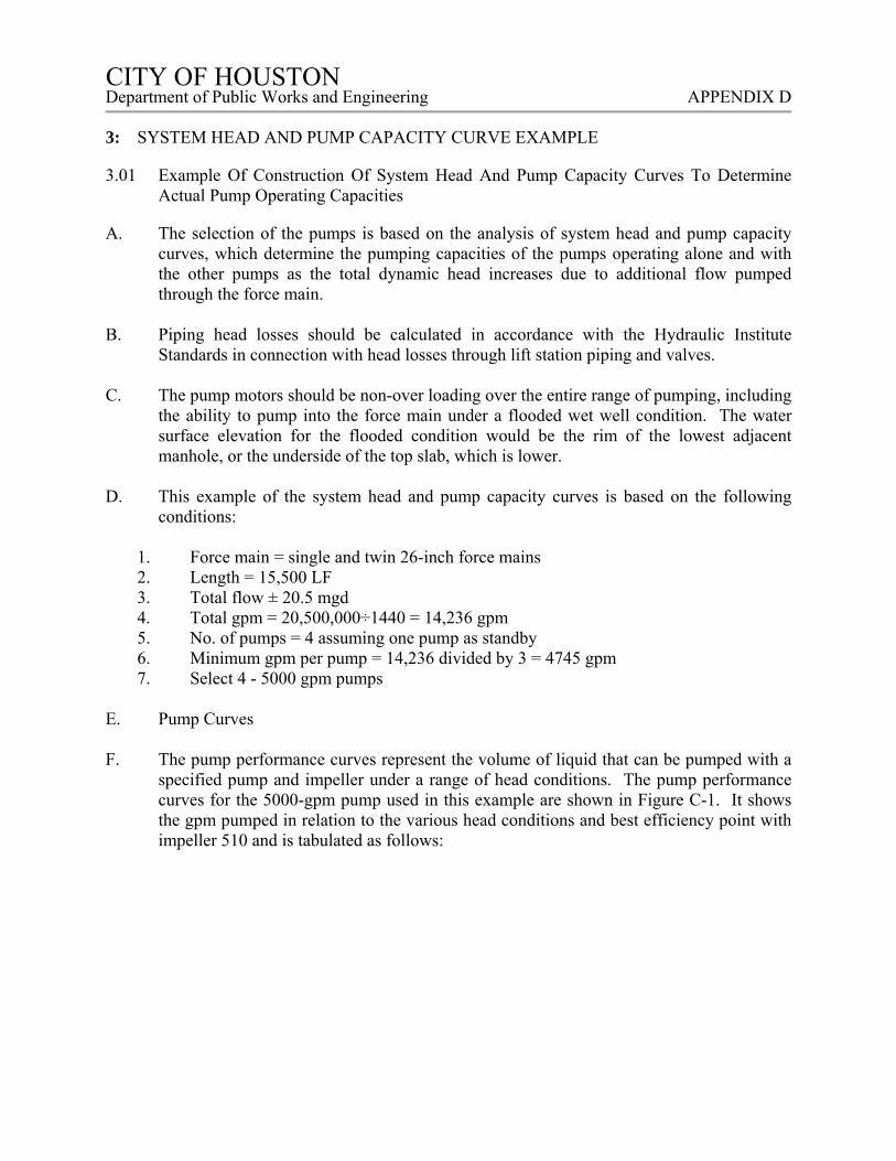
CITY OF HOUSTON CITY OF HOUSTON Department of Public Works and Engineering APPENDIX D
3: SYSTEM HEAD AND PUMP CAPACITY CURVE EXAMPLE
3.01 Example Of Construction Of System Head And Pump Capacity Curves To Determine Actual Pump Operating Capacities
A. The selection of the pumps is based on the analysis of system head and pump capacity curves, which determine the pumping capacities of the pumps operating alone and with the other pumps as the total dynamic head increases due to additional flow pumped through the force main.
B. Piping head losses should be calculated in accordance with the Hydraulic Institute
Standards in connection with head losses through lift station piping and valves. C. The pump motors should be non-over loading over the entire range of pumping, including
the ability to pump into the force main under a flooded wet well condition. The water surface elevation for the flooded condition would be the rim of the lowest adjacent manhole, or the underside of the top slab, which is lower.
D. This example of the system head and pump capacity curves is based on the following
conditions:
1. Force main = single and twin 26-inch force mains 2. Length = 15,500 LF 3. Total flow ± 20.5 mgd 4. Total gpm = 20,500,000÷1440 = 14,236 gpm 5. No. of pumps = 4 assuming one pump as standby 6. Minimum gpm per pump = 14,236 divided by 3 = 4745 gpm 7. Select 4 - 5000 gpm pumps
E. Pump Curves F. The pump performance curves represent the volume of liquid that can be pumped with a
specified pump and impeller under a range of head conditions. The pump performance curves for the 5000-gpm pump used in this example are shown in Figure C-1. It shows the gpm pumped in relation to the various head conditions and best efficiency point with impeller 510 and is tabulated as follows:
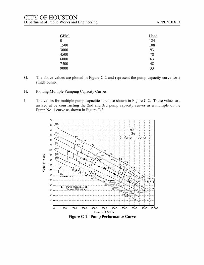
CITY OF HOUSTON CITY OF HOUSTON Department of Public Works and Engineering APPENDIX D
GPM Head 0 124 1500 108 3000 93 4500 78 6000 63 7500 48 9000 33
G. The above values are plotted in Figure C-2 and represent the pump capacity curve for a
single pump. H. Plotting Multiple Pumping Capacity Curves I. The values for multiple pump capacities are also shown in Figure C-2. These values are
arrived at by constructing the 2nd and 3rd pump capacity curves as a multiple of the Pump No. 1 curve as shown in Figure C-3:
Figure C-1 - Pump Performance Curve
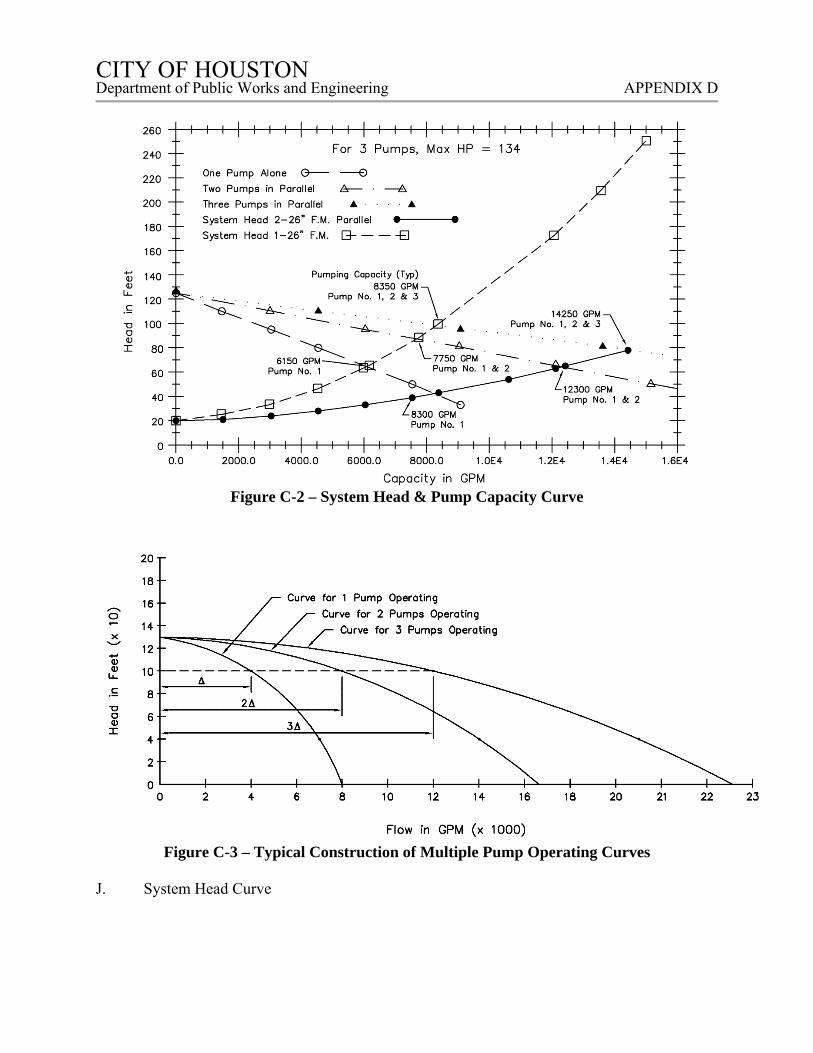
CITY OF HOUSTON CITY OF HOUSTON Department of Public Works and Engineering APPENDIX D
Figure C-2 – System Head & Pump Capacity Curve
Figure C-3 – Typical Construction of Multiple Pump Operating Curves
J. System Head Curve
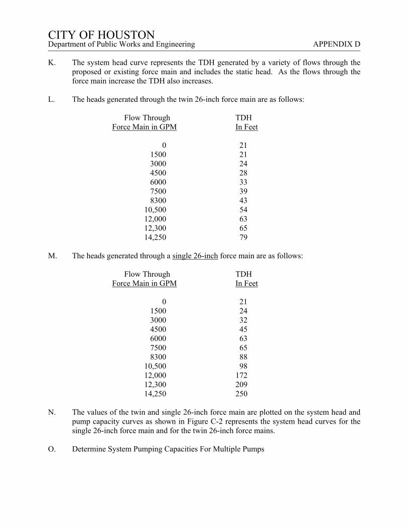
CITY OF HOUSTON CITY OF HOUSTON Department of Public Works and Engineering APPENDIX D
K. The system head curve represents the TDH generated by a variety of flows through the
proposed or existing force main and includes the static head. As the flows through the force main increase the TDH also increases.
L. The heads generated through the twin 26-inch force main are as follows:
Flow Through TDH
Force Main in GPM In Feet
0 21 1500 21 3000 24 4500 28 6000 33 7500 39 8300 43 10,500 54 12,000 63 12,300 65 14,250 79
M. The heads generated through a single 26-inch force main are as follows:
Flow Through TDH
Force Main in GPM In Feet
0 21 1500 24 3000 32 4500 45 6000 63 7500 65 8300 88 10,500 98 12,000 172 12,300 209 14,250 250
N. The values of the twin and single 26-inch force main are plotted on the system head and
pump capacity curves as shown in Figure C-2 represents the system head curves for the single 26-inch force main and for the twin 26-inch force mains.
O. Determine System Pumping Capacities For Multiple Pumps
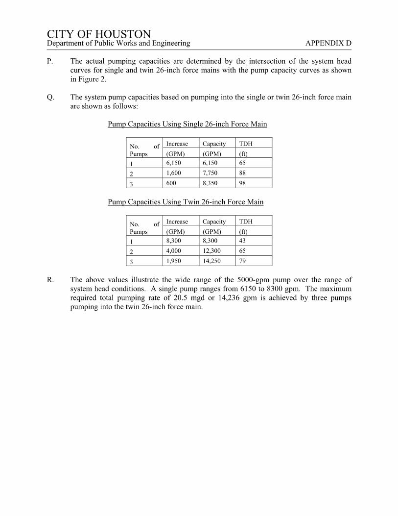
CITY OF HOUSTON CITY OF HOUSTON Department of Public Works and Engineering APPENDIX D
P. The actual pumping capacities are determined by the intersection of the system head
curves for single and twin 26-inch force mains with the pump capacity curves as shown in Figure 2.
Q. The system pump capacities based on pumping into the single or twin 26-inch force main
are shown as follows:
Pump Capacities Using Single 26-inch Force Main
No. of Pumps
Increase Capacity TDH
(GPM) (GPM) (ft)
1 6,150 6,150 65
2 1,600 7,750 88
3 600 8,350 98
Pump Capacities Using Twin 26-inch Force Main
No. of Pumps
Increase Capacity TDH
(GPM) (GPM) (ft)
1 8,300 8,300 43
2 4,000 12,300 65
3 1,950 14,250 79
R. The above values illustrate the wide range of the 5000-gpm pump over the range of
system head conditions. A single pump ranges from 6150 to 8300 gpm. The maximum required total pumping rate of 20.5 mgd or 14,236 gpm is achieved by three pumps pumping into the twin 26-inch force main.
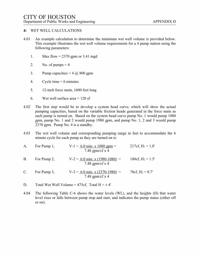
CITY OF HOUSTON CITY OF HOUSTON Department of Public Works and Engineering APPENDIX D
4: WET WELL CALCULATIONS
4.01 An example calculation to determine the minimum wet well volume is provided below. This example illustrates the wet well volume requirements for a 4 pump station using the following parameters:
1. Max flow = 2370 gpm or 3.41 mgd
2. No. of pumps = 4
3. Pump capacities = 4 @ 800 gpm
4. Cycle time = 6 minutes
5. 12-inch force main, 1600 feet long
6. Wet well surface area = 120 sf
4.02 The first step would be to develop a system head curve, which will show the actual pumping capacities, based on the variable friction heads generated in the force main as each pump is turned on. Based on the system head curve pump No. 1 would pump 1080 gpm, pump No. 1 and 2 would pump 1980 gpm, and pump No. 1, 2 and 3 would pump 2370 gpm. Pump No. 4 is a standby.
4.03 The wet well volume and corresponding pumping range in feet to accommodate the 6 minute cycle for each pump as they are turned on is:
A. For Pump 1, V-1 = 6.0 min. x 1080 gpm = 217cf, H1 = 1.8' 7.48 gpm/cf x 4
B. For Pump 2, V-2 = 6.0 min. x (1980-1080) = 180cf, H2 = 1.5' 7.48 gpm/cf x 4
C. For Pump 3, V-3 = 6.0 min. x (2370-1980) = 78cf, H2 = 0.7' 7.48 gpm/cf x 4
D. Total Wet Well Volume = 475cf, Total H = ± 4'
4.04 The following Table C-6 shows the water levels (WL), and the heights (H) that water level rises or falls between pump stop and start, and indicates the pump status (either off or on).
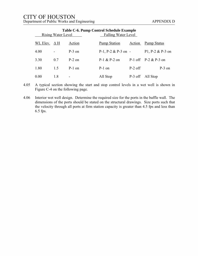
CITY OF HOUSTON CITY OF HOUSTON Department of Public Works and Engineering APPENDIX D
Table C-6. Pump Control Schedule Example
Rising Water Level Falling Water Level
WL Elev. Δ H Action Pump Station Action Pump Status
4.00 - P-3 on P-1, P-2 & P-3 on - P1, P-2 & P-3 on
3.30 0.7 P-2 on P-1 & P-2 on P-1 off P-2 & P-3 on
1.80 1.5 P-1 on P-1 on P-2 off P-3 on
0.00 1.8 - All Stop P-3 off All Stop
4.05 A typical section showing the start and stop control levels in a wet well is shown in Figure C-4 on the following page.
4.06 Interior wet well design. Determine the required size for the ports in the baffle wall. The dimensions of the ports should be stated on the structural drawings. Size ports such that the velocity through all ports at firm station capacity is greater than 4.5 fps and less than 6.5 fps.
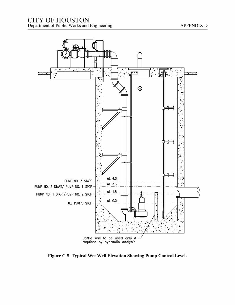
CITY OF HOUSTON CITY OF HOUSTON Department of Public Works and Engineering APPENDIX D
Figure C-5. Typical Wet Well Elevation Showing Pump Control Levels
CITY OF HOUSTON CITY OF HOUSTON Department of Public Works and Engineering APPENDIX D
ELECTRICAL SAMPLE CALCULATIONS
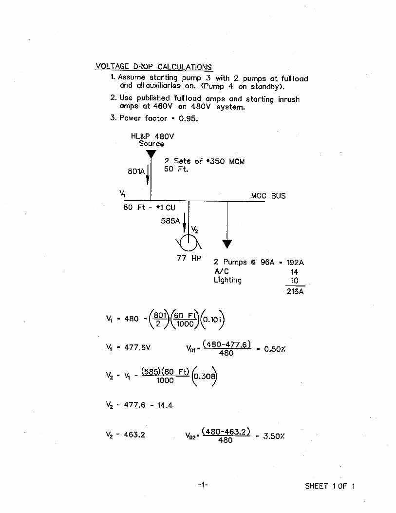
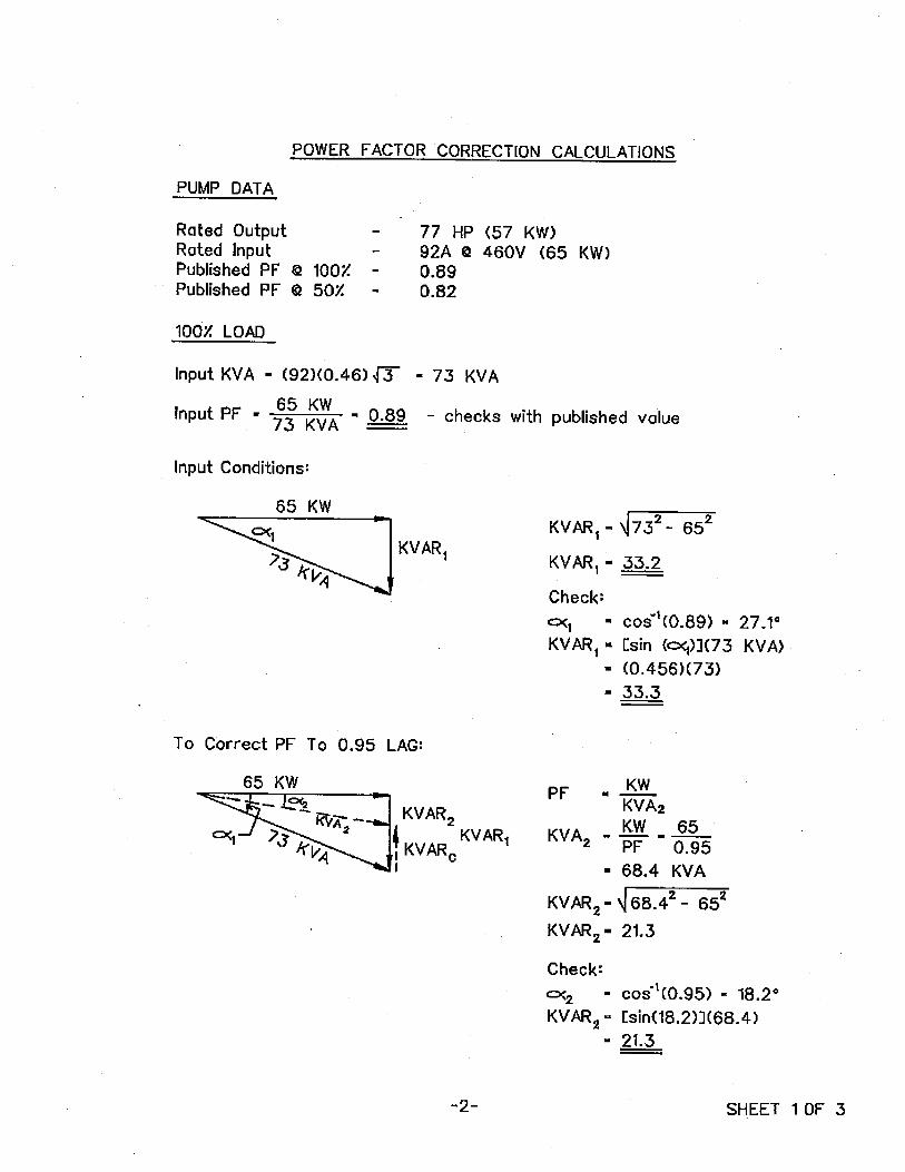
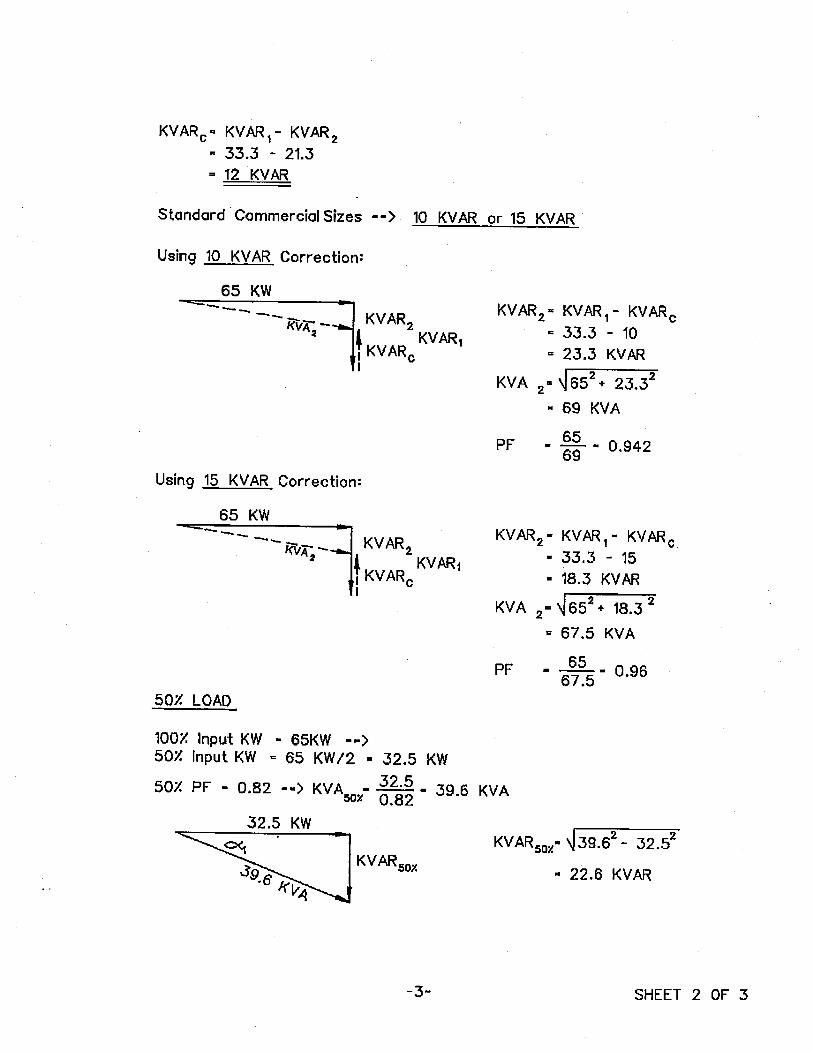
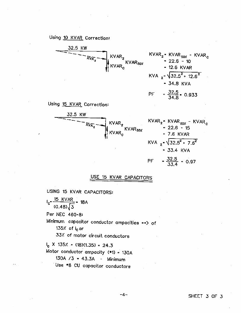
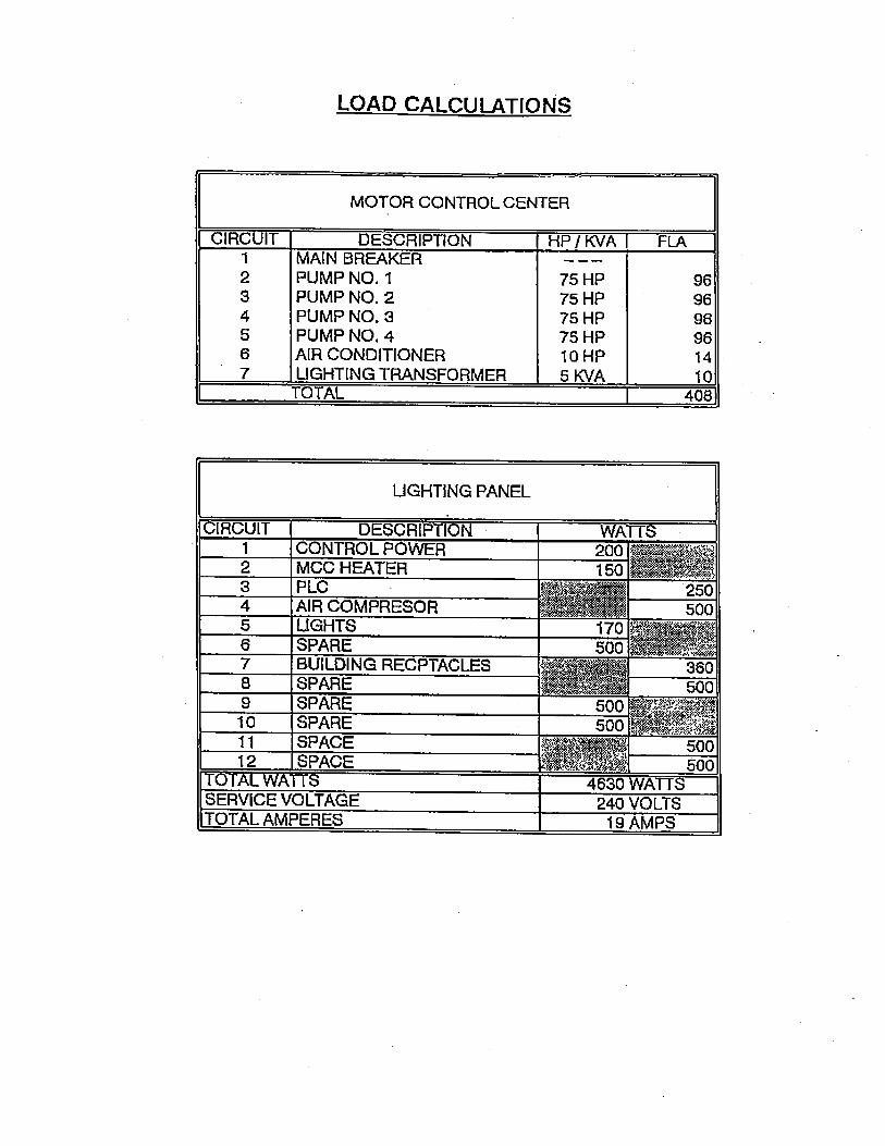
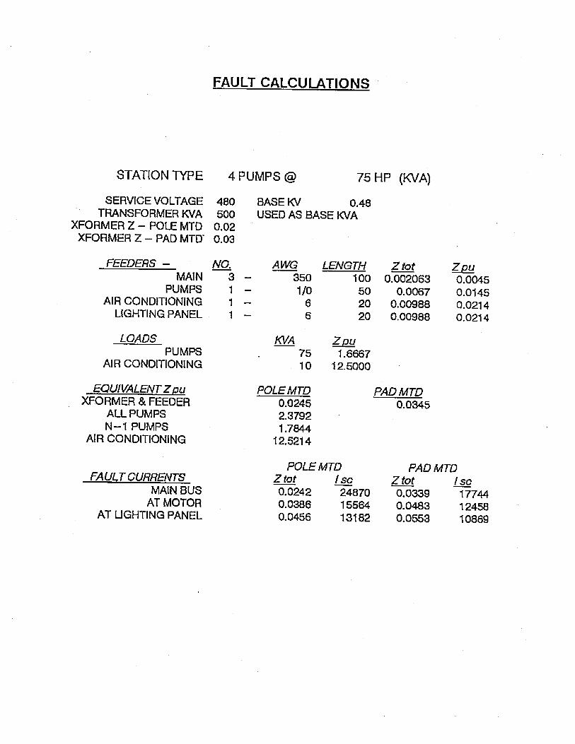
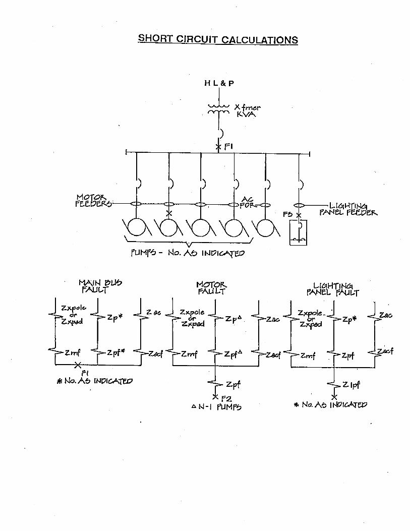
CITY OF HOUSTON CITY OF HOUSTON Department of Public Works and Engineering APPENDIX E
APPENDIX E – SAMPLE DRAWING MARKUP