Embed Size (px)
Citation preview
City of South Bend Phase II Wellhead Protection Plan Five Year Update
City of South Bend Utilities 830 N. Michigan Street South Bend, IN 46601 November 2019
2019.00828 Page i
Table of Contents 1.0 Executive Summary ............................................................................................................................... 1
2.0 Introduction ........................................................................................................................................... 2
3.0 Delineations ........................................................................................................................................... 3
3.1 Summary of Regional and Local Hydrogeology .............................................................................................. 3
3.2 Current Production Wells ................................................................................................................................ 4
3.3 Well Field Pumping Analysis ............................................................................................................................ 5
4.0 Local Planning Team .............................................................................................................................. 6
5.0 Potential Contaminant Source (PCS) Inventory ................................................................................... 7
5.1 Methods for Identification of Potential Sources of Contamination .............................................................. 7
5.2 Land Use Within the Wellfield Protection Areas ............................................................................................ 7
6.0 Management Plan ................................................................................................................................. 9
6.1 Sanitary Set-Back Area .................................................................................................................................... 9
6.2 Wellhead Protection Area Management ........................................................................................................ 9
6.3 Notification of Property Owners ................................................................................................................... 10
6.4 Public Outreach .............................................................................................................................................. 10
6.5 Management Actions Taken .......................................................................................................................... 11
7.0 Contingency Plan ................................................................................................................................. 12
7.1 Contingency Plan Mission and Goals ............................................................................................................ 12
7.2 Training and Response Simulations .............................................................................................................. 15
7.3 Types and Severities of Emergencies ............................................................................................................ 15
7.4 Preparedness ................................................................................................................................................. 16
7.5 Chain of Command ........................................................................................................................................ 17
7.6 Partnerships and Outside Contacts ............................................................................................................... 17
7.7 Effective Communication .............................................................................................................................. 19
7.7.1 Notification of Critical Water Users ...................................................................................................... 19
7.8 Water Quality Testing .................................................................................................................................... 21
7.9 Alternative Water Sources ............................................................................................................................ 22
Appendices ..................................................................................................................................................... 23
2019.00828 Page ii
ABBREVIATIONS
AST Aboveground Storage Tank
BMP Best Management Practice
CPWSS Community Public Water Supply System
DRASTIC Depth to water; Recharge; Aquifer media; Soil media; Topography; Impact of the vadose
zone; Conductivity of the aquifer
EPA Environmental Protection Agency
FEMA Federal Emergency Management Agency
GIS Geographic Information System
HAZMAT Hazardous Materials
IAC Indiana Administrative Code
IDEM Indiana Department of Environmental Management
LEPC Local Emergency Planning Committee
LPT Local Planning Team
LUST Leaking Underground Storage Tank
NA Not Available
NFA No Further Action
NPDES National Pollutant Discharge Elimination System
ORD Ordinance
PCB Polychlorinated Biphenyl
PCE Tetrachloroethylene
PCS Potential Contaminant Source
PSI Potential Source Inventory
PWSID Public Water System Identification
RCRA Resource Conservation and Recovery Act
SBFD South Bend Fire Department
SBWW South Bend Water Works
SJCHD St. Joseph County Health Department
SSA Sole Source Aquifer
SQG Small Quantity Generator
SVOC Semi-Volatile Organic Compound
TCE Trichloroethylene
TQP Technically Qualified Person
USGS United States Geological Survey
UST Underground Storage Tank
VOC Volatile Organic Compound
VFC Virtual File Cabinet
VRP Voluntary Remediation Program
WHPA Wellhead Protection Area
WHPP Wellhead Protection Plan
2019.00828 Page 1
1.0 Executive Summary American Structurepoint, Inc., on behalf of South Bend Water Works (PWSID No. IN5271014), has prepared this update to the City’s Wellhead Protection Plan, in accordance with the regulations outlined at 327 IAC 8-4.1 (the “Indiana Wellhead Protection Rule”) for the South Bend Wellfields. The wellfields are located in northeastern St. Joseph County, in and around the City of South Bend. The previous wellhead protection plan update was prepared by American Structurepoint, Inc. and submitted to IDEM on behalf of South Bend Water Works (SBWW), on November 10, 2014. No redelineations were required during the prior 5 year wellhead protection plan update and all the wellfields remained the same as those approved in 2003 and 2008. Due to the addition of high capacity wells at Memorial Hospital, located just to the west of the North Station Well Field, and a replacement well (North Station #1B) being installed, a new delineation was required for the North Station well field. IDEM determined no other well field required redelineation as part of this 5 year wellhead plan update (Appendix A). Similar to the previous models completed for the other well fields in 2008 and prior, MODFLOW was used to model the new North Station capture zone. Due to the high pumping rates of the Memorial Hospital wells, the shape of the North Station wellhead delineation changed significantly. The new delineation area is included in Appendix B with figures of all of the current well field delineations and active production wells. IDEM approved the new North Station well field delineation September 10, 2019 (Appendix C). South Bend Water Works has remained active in implementing their wellhead protection plan through the most recent 5 year update period and met numerous times including holding two combined LPT and public meetings about wellhead protection and the well fields. Action items outlined from LPT included securing, monitoring wells, verifying the location and condition of wellhead signs placed in 2000, monitoring for additional constituents based on detections and potential contaminant sources (PCSs), and a commodities flow study for the county transportation routes. Other actions taken were trainings completed by utility staff regarding incident management system (Federal Emergency Management Agency, FEMA), emergency planning (FEMA), introduction to exercises (FEMA), introduction to incident command system (FEMA), all hazards preparedness (FEMA), and water and wastewater all hazards boot camp (EPA). Copies of the completed training certificates are included in Appendix H. The potential contaminant source inventories were revisited for each well field. A desktop review was first completed using IDEM hazardous material database layers and Google Maps. These sites were compared to the previous PCS inventory that was completed to assess if any new sites listed in the state databases were located within the wellhead protection areas. One new PCS was identified by South Bend that is partially within their South Well Field protection area. One new PCS was in the Edison wellhead protection area during the desktop survey. Three new PCSs were identified within the new north station delineation area. Additional PCS were identified during the windshield survey completed on September 18th and 19th, 2019. The newly identified PCSs are listed and highlighted in the tables in Appendix F.
2019.00828 Page 2
2.0 Introduction The Indiana Wellhead Protection Program and rule (327 IAC 8-4.1) outlines five basic categories for Community Public Water Supply System (CPWSS) wellhead protection plans. These areas include the following:
1. Local Planning Team (LPT) 2. WHPA Delineation 3. Identification of Potential Contaminant Sources (PCS) 4. Potential Source Management 5. Contingency Planning
This report serves to document the wellhead protection implementation and five year update by the SBWW and to outline the plan for continued protection of the wellfields with respect to the components outlined by IDEM. Wellfield Description
The Carriage Hills Wellfield includes Wells 3 and 4, and is located within a residential subdivision, approximately 0.17-mile east of Ironwood Drive.
The Cleveland South and Cleveland North Wellfields include Wells 1 through 6. Cleveland North Wellfield is located approximately 0.10-mile north of Cleveland Road along Patricia Lane. Cleveland South Wellfield is located approximately 150-feet south of Cleveland Road, north of Interstate 80.
The Edison Station Wellfield includes Wells 1A, 2A 3A, and 4, and is located within Edison Park, just east of North Ironwood Drive.
The Erskine Wellfield includes Well 2 and is located approximately 0.56-mile north of US Highway 20 on the western portion of the Erskine Park Golf Course.
The North Station Wellfield is located west and south of a meander of the St. Joseph River, approximately 300-feet east of State Road 933. The North Station Wellfield includes Wells 1B, 2A, 3A and 5A.
The Olive Station Wellfield is located in the southwestern portion of South Bend, on the southwest corner of Olive Street and Sample Street. Olive Station Wellfield includes Wells 1A, 2A, 3A, 4, 5 and 6.
The Pinhook Station Wellfield is located in the northwestern portion of South Bend, just west of the St. Joseph River and approximately 0.57-mile south of Interstate 80. The Pinhook Station Wellfield includes Wells 1 through 5.
The South Wellfield includes Wells 4A and 5 and is located approximately 0.8-mile north of the St. Joseph Valley Parkway and approximately 900-feet west of Main Street.
Appendix B provides the location of the wellfields and additional detailed aerial maps of the wellfields and production well locations.
2019.00828 Page 3
3.0 Delineations The WHPA delineations were completed as part of the 2003 Phase I plan and updated as part of the 2008
Phase II plan. IDEM agreed, in correspondence dated October 6, 2014, the delineations did not require an
update as part of the 2014 5-year Phase II WHPP update submittal. Additionally, Peerless-Midwest, Inc.
completed an evaluation of the South Bend delineation as part of their 2008 Phase II WHPP and found the
delineated area was conservative enough to allow for significant wellfield expansion. Appendix B provides
an aerial display of each of the South Bend WHPAs.
The WHPA delineations were completed in 2003 (Phase I), 2008 (Phase II) and 2019 (North Station Only – 5
year update). The delineations include 1-year and 5-year time-of-travel boundaries for each well field. The
models were completed using MODFLOW, a USGS created modular hydraulic modeling program.
MODFLOW is the standard for moderate to complex three dimensional multi-layer models.
The newest delineation completed for only the North Station well field was approved by IDEM on September
10, 2019. The approval letter for the new delineation is included in Appendix C.
Additional and more detailed information regarding the delineations, models, geology, and hydrology is
available in the delineation reports, on file with South Bend water Works and IDEM.
3.1 Summary of Regional and Local Hydrogeology
Unconsolidated deposits derived from Wisconsin-aged glaciation cover St. Joseph County (Gray, 2002).
These deposits include glacial till interspersed with sand and gravel outwash formations. Glacial till deposits
are incised by an outwash valley that generally coincides with the St. Joseph drainage network. The
unconsolidated deposits in St. Joseph County overlay the Ellsworth Shale bedrock of Devonian age.
The project area is located in the Plymouth Morainal Complex and St. Joseph Drainageways sections of the
Northern Moraine and Lake Region of Northern Indiana (Gray, 2000). This physiographic province is
characterized by an extensive alluvial plain along the St. Joseph River corridor. The section has little
topographic relief and is drained axially by the Pigeon, Elkhart, and St. Joseph Rivers.
Locally, the project area resides within the regional St. Joseph River Basin Hydrogeologic Setting (Fowler,
1994). Productive aquifers within this basin include unconsolidated deposits comprised of surficial sand and
gravel, buried sand and gravel, sand and gravel within buried pre-glacial bedrock valleys, and discontinuous
sand and gravel (Fowler, 1994). The sand and gravel aquifers beneath the project area include the (shallow)
surficial sand and gravel and the (deep) buried sand and gravel bodies, interpreted collectively as the St.
Joseph Aquifer System (Dean, 2010).
2019.00828 Page 4
According to Dean (2010), the St. Joseph Aquifer System is comprised primarily of fine to medium sand, with
some zones of coarse sand and gravel; the granular aquifer formations are interspersed with clay or till units
of limited areal extent. Numerous high capacity wells are completed in the St. Joseph Aquifer, which
constitutes one of the major aquifer systems in the State (Dean, 2010).
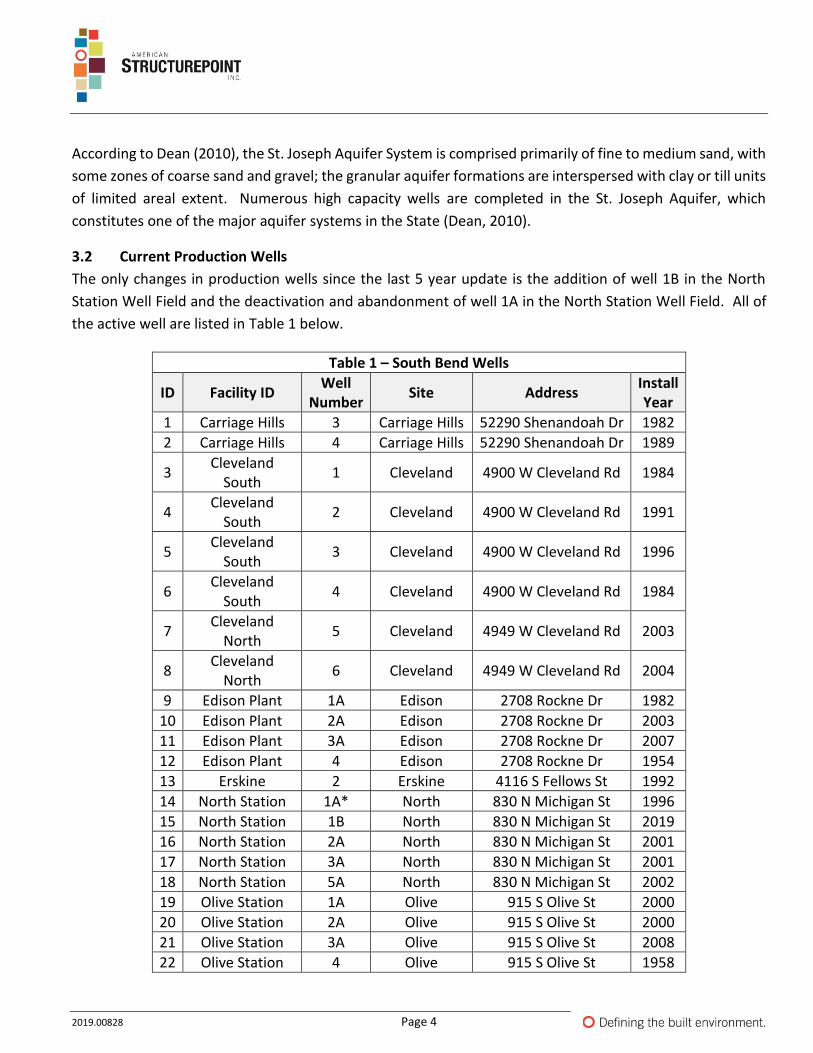
3.2 Current Production Wells
The only changes in production wells since the last 5 year update is the addition of well 1B in the North
Station Well Field and the deactivation and abandonment of well 1A in the North Station Well Field. All of
the active well are listed in Table 1 below.
Table 1 – South Bend Wells
ID Facility ID Well
Number Site Address
Install Year
1 Carriage Hills 3 Carriage Hills 52290 Shenandoah Dr 1982
2 Carriage Hills 4 Carriage Hills 52290 Shenandoah Dr 1989
3 Cleveland
South 1 Cleveland 4900 W Cleveland Rd 1984
4 Cleveland
South 2 Cleveland 4900 W Cleveland Rd 1991
5 Cleveland
South 3 Cleveland 4900 W Cleveland Rd 1996
6 Cleveland
South 4 Cleveland 4900 W Cleveland Rd 1984
7 Cleveland
North 5 Cleveland 4949 W Cleveland Rd 2003
8 Cleveland
North 6 Cleveland 4949 W Cleveland Rd 2004
9 Edison Plant 1A Edison 2708 Rockne Dr 1982
10 Edison Plant 2A Edison 2708 Rockne Dr 2003
11 Edison Plant 3A Edison 2708 Rockne Dr 2007
12 Edison Plant 4 Edison 2708 Rockne Dr 1954
13 Erskine 2 Erskine 4116 S Fellows St 1992
14 North Station 1A* North 830 N Michigan St 1996
15 North Station 1B North 830 N Michigan St 2019
16 North Station 2A North 830 N Michigan St 2001
17 North Station 3A North 830 N Michigan St 2001
18 North Station 5A North 830 N Michigan St 2002
19 Olive Station 1A Olive 915 S Olive St 2000
20 Olive Station 2A Olive 915 S Olive St 2000
21 Olive Station 3A Olive 915 S Olive St 2008
22 Olive Station 4 Olive 915 S Olive St 1958
2019.00828 Page 5
Table 1 – South Bend Wells
ID Facility ID Well
Number Site Address
Install Year
23 Olive Station 5 Olive 915 S Olive St 1966
24 Olive Station 6 Olive 915 S Olive St 1966
25 Pinhook Plant 1 Pinhook 2801 Riverside Dr 1961
26 Pinhook Plant 2 Pinhook 2801 Riverside Dr 1961
27 Pinhook Plant 3 Pinhook 2801 Riverside Dr 1961
28 Pinhook Plant 4 Pinhook 2801 Riverside Dr 1961
29 Pinhook Plant 5 Pinhook 2801 Riverside Dr 2004
30 South Well
Field 4A South 3600 S Main St 2000
31 South Well
Field 5 South 3600 S Main St 2007
*Well abandoned in 2019 (Abandonment log included in Appendix D)
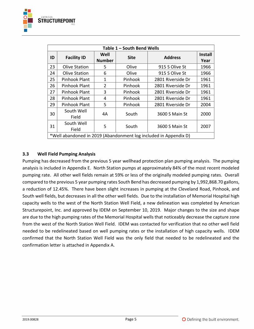
3.3 Well Field Pumping Analysis
Pumping has decreased from the previous 5 year wellhead protection plan pumping analysis. The pumping
analysis is included in Appendix E. North Station pumps at approximately 84% of the most recent modeled
pumping rate. All other well fields remain at 59% or less of the originally modeled pumping rates. Overall
compared to the previous 5 year pumping rates South Bend has decreased pumping by 1,992,868.70 gallons,
a reduction of 12.45%. There have been slight increases in pumping at the Cleveland Road, Pinhook, and
South well fields, but decreases in all the other well fields. Due to the installation of Memorial Hospital high
capacity wells to the west of the North Station Well Field, a new delineation was completed by American
Structurepoint, Inc. and approved by IDEM on September 10, 2019. Major changes to the size and shape
are due to the high pumping rates of the Memorial Hospital wells that noticeably decrease the capture zone
from the west of the North Station Well Field. IDEM was contacted for verification that no other well field
needed to be redelineated based on well pumping rates or the installation of high capacity wells. IDEM
confirmed that the North Station Well Field was the only field that needed to be redelineated and the
confirmation letter is attached in Appendix A.
2019.00828 Page 6
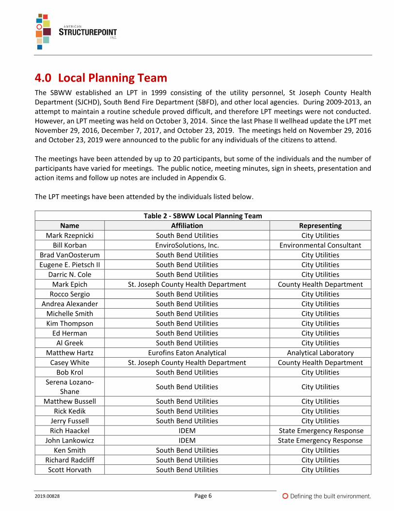
4.0 Local Planning Team The SBWW established an LPT in 1999 consisting of the utility personnel, St Joseph County Health Department (SJCHD), South Bend Fire Department (SBFD), and other local agencies. During 2009-2013, an attempt to maintain a routine schedule proved difficult, and therefore LPT meetings were not conducted. However, an LPT meeting was held on October 3, 2014. Since the last Phase II wellhead update the LPT met November 29, 2016, December 7, 2017, and October 23, 2019. The meetings held on November 29, 2016 and October 23, 2019 were announced to the public for any individuals of the citizens to attend. The meetings have been attended by up to 20 participants, but some of the individuals and the number of participants have varied for meetings. The public notice, meeting minutes, sign in sheets, presentation and action items and follow up notes are included in Appendix G. The LPT meetings have been attended by the individuals listed below.
Table 2 - SBWW Local Planning Team
Name Affiliation Representing
Mark Rzepnicki South Bend Utilities City Utilities
Bill Korban EnviroSolutions, Inc. Environmental Consultant
Brad VanOosterum South Bend Utilities City Utilities
Eugene E. Pietsch II South Bend Utilities City Utilities
Darric N. Cole South Bend Utilities City Utilities
Mark Epich St. Joseph County Health Department County Health Department
Rocco Sergio South Bend Utilities City Utilities
Andrea Alexander South Bend Utilities City Utilities
Michelle Smith South Bend Utilities City Utilities
Kim Thompson South Bend Utilities City Utilities
Ed Herman South Bend Utilities City Utilities
Al Greek South Bend Utilities City Utilities
Matthew Hartz Eurofins Eaton Analytical Analytical Laboratory
Casey White St. Joseph County Health Department County Health Department
Bob Krol South Bend Utilities City Utilities
Serena Lozano-Shane
South Bend Utilities City Utilities
Matthew Bussell South Bend Utilities City Utilities
Rick Kedik South Bend Utilities City Utilities
Jerry Fussell South Bend Utilities City Utilities
Rich Haackel IDEM State Emergency Response
John Lankowicz IDEM State Emergency Response
Ken Smith South Bend Utilities City Utilities
Richard Radcliff South Bend Utilities City Utilities
Scott Horvath South Bend Utilities City Utilities
2019.00828 Page 7
Table 2 - SBWW Local Planning Team
Name Affiliation Representing
Travis Cole American Structurepoint, Inc. Environmental Consultant
Jennifer Kedik South Bend Citizen Public Attendee
Sue Kesim South Bend Citizen Public Attendee
5.0 Potential Contaminant Source (PCS) Inventory An integral part of protecting the public water supply wellfields is to identify all potential sources of
groundwater contamination within the WHPAs. The following provides an overview of the general and
specific land uses within the WHPAs and methodology used to identify potential contaminant sources.
5.1 Methods for Identification of Potential Sources of Contamination
To update the PCS inventory a desktop review was first conducted. Using the previous PCS inventory
information, the data was overlaid with the most recent IDEM HAZMAT database information. This database
includes locations and descriptions of a variety of environmentally regulated facilities around the state (i.e.,
UST, LUST, RCRA, VRP sites, and landfill sites). Additionally the City of South Bend had previously identified
a PCS near the South Well Field. Because of the new delineation of the North Station Well Field, many of
the previous PCSs were no longer within the wellhead protection area. Four new PCSs were identified in
the additional new area of the North Station delineated area. The PCS maps and corresponding tables are
included in Appendix F.
After completing the desktop survey and review, a windshield survey was completed to identify and
inventory any additional PCSs that might be located within the wellhead protection areas. During the
desktop reviews and the windshield survey, eighteen new PCSs were identified. Several of the PCS are
adjacent to the wellhead protection area boundaries, but it was decided to include these as well.
5.2 Land Use Within the Wellfield Protection Areas
The area within the South Bend WHPAs is urban and primarily developed as residential and commercial with
some industrial facilities (primarily in the Olive Station and South WHPAs). Review of aerial photography
identified some agricultural land use within the Olive, Pinhook, and Cleveland well field delineation areas.
Contaminant sources from residential areas would likely be in the form of typical household chemicals (i.e.,
chlorine bleach, lawn chemicals, fuel, etc.). Leachate from septic systems (if present) could introduce
nitrates, phosphates, or coliform bacteria to the aquifer. See tables 3-1 through 3-7 in Appendix F for further
information and locations of the industrial properties located within the WHPAs.
Major roads within the South Bend WHPAs include Interstate 80, US Highway 20, US Highway 31, Michigan
Street, and multiple three to four lane thoroughfares. These transportation routes could be a potential
source of contamination in the form of roadway runoff; however, of greater concern is the possibility of a
2019.00828 Page 8
hazardous materials spill, especially for Interstate 80. Jim Lopez of the Michiana Area Council of
Governments completed a commodity flow study for St. Joseph County in September 2016 (Appendix I).
The report details hazardous chemicals transported in and out of the county by way of rail or roadways. The
report shows the types of chemicals transported throughout the county and by what means they are
transported. Although all of the major roadways are not listed as point source PCSs, transportation routes
and rail ways can be considered PCSs if a spill or accident were to occur. Consideration of these has been
taken into account in the emergency management and contingency plan.
2019.00828 Page 9
6.0 Management Plan 6.1 Sanitary Set-Back Area
SBWW well sites are surrounded by a 100 foot radius controlled by direct land ownership or easement, and
are all subject to disinfection prior to distribution.
All SBWW wells have been installed following approval by IDEM or IDEM’s predecessor, the Indiana State
Board of Health, and therefore, meet the construction standards set forth in 327 IAC 8-3.4. The mixing and
storage of any chemical, except those required for operation, treatment, or maintenance of the wells are
prohibited within the well isolation areas. No roads or parking areas are permitted within 50 feet of any
well except for those necessary for well access. All wells possess adequate security measures to prevent the
unauthorized access or tampering with wells, pumping equipment, controls, and power feed. There are no
major transportation routes within the well isolation areas, only minor arterial streets and access drives to
the wells. Management of the well isolation areas (or at least the immediate area surrounding the wells)
has proved adequate during the Phase I and Phase II, and last 5 year update implementation periods.
6.2 Wellhead Protection Area Management
City and County ordinances have appointed the St. Joseph County Health Department (SJCHD) to manage
and monitor the PSCs. All facilities that meet or exceed base quantities of hazardous chemicals or petroleum
substances are regulated through a permitting and inspection process.
The SJCHD approach to Wellhead Protection is one of engagement and education, with a goal of cooperation
and compliance. It attempts to work together with PSCs to protect the environment and groundwater. The
program focuses on groundwater contamination prevention rather than remediation.
After an initial review of a Wellhead Permit application, the SJCHD conducts a thorough site inspection, and
works with businesses to develop ways, if appropriate, to manage potential threats to the groundwater.
After a permit is issued, the SJCHD conducts annual routine inspections of regular permittees and inspects
drywell-only facilities every three years unless there are issues found. A copy of the SJCHD Wellhead
Protection Permit Application and list of currently permitted facilities can be found in Appendix J. The county
also implements a county wide code, county code 52, which deals with surface and groundwater protection,
well drilling and water supply systems, and wellhead protection.
https://www.sjcindiana.com/DocumentCenter/View/19694/County-Code-52-Water-Regulations
The PSCs are managed through routine inspections by the SJCHD, letters to the PSC property owners,
informational materials, and presentations. Failure to comply with the requirements of the ordinances by
a PSC property may result in legal action and penalties.
Much of the South Bend WHPAs fall within the EPA federally designated sole source aquifer (SSA) shown in
Appendix K. This designation is applied to aquifers that supply at least 50 percent of the drinking water for
2019.00828 Page 10
a service area where no other reasonably available water source exists. This designation provides the
following protections for areas within the SSA: “After the publication of any such notice, no commitment for
federal financial assistance (through a grant, contract, loan guarantee, or otherwise) may be entered into
for any project which the Administrator determines may contaminate such aquifer through a recharge zone
so as to create a significant hazard to public health, but a commitment for federal assistance may, if
authorized under another provision of law, be entered into to plan or design the project to assure that it will
not so contaminate the aquifer.”
6.3 Notification of Property Owners
Property owners were originally notified in 2003 and 2008 when the previous delineations were completed.
Notification letters were mailed to newly identified property owners within the new North Station
delineated protection area on November 15, 2019. A copy of the notification letter and wellhead protection
informational insert are included in Appendix L.
6.4 Public Outreach
South Bend currently utilizes several wellhead protection mechanisms. The utility created an article for the
city’s South Bend 311 knowledge center service portal. The article can be found at
https://311.southbendin.gov/knowledgecenter/article/?id=KA-04641. South Bend includes information on
wellhead protection and water quality in their consumer confidence report (CCR). A copy of the 2018 CCR
can be found in Appendix L. Although individuals from the public did not attend the meeting, a public notice
was sent out to advertise the wellhead protection meeting on November 29, 2016. The meeting on October
23, 2019 was also announced to the public. A copy of the public notice for the November 29, 2016 meeting
can be found in Appendix G.
In 2018 a 4th grade class from Madison STEAM Academy, which is nearby the water facility at 830 North
Michigan Street, were provided a tour of the facility and learned about water and wellhead protection.
The 2019 LPT meeting was combined with a national event called “Imagine a Day Without Water” on
October 23, 2019, organized by the Value of Water campaign. South Bend announced the meeting by public
notice, on their Facebook page and on Nextdoor. Two members of the public attended along with 18 other
individuals from the City of South Bend, St. Joseph County Health Department, and IDEM emergency
response. Three local news crews were also present and reported on the meeting in the following days
news stories. Details of the meeting including the meeting notices, sign in sheets, power point presentation
and news story coverage can be found in Appendix G.
As part of the 2019 5-year update South Bend created an informational rack card to be distributed at
educational events and to have on hand at the utility buildings for interested residents. The rack card was
also mailed with the new wellhead notification letters for residents located in the newly delineated area of
the North Station well field. A copy of the rack card can be found in Appendix L.
2019.00828 Page 11
6.5 Management Actions Taken
South Bend Water Works has remained active in implementing their WHPP through the most recent 5 year
update period, meeting numerous times including a combined LPT and public meeting about wellhead
protection and the well fields. Action items outlined after the LPT meetings included securing monitoring
wells, verifying the location and condition of wellhead signs placed in 2000, monitoring for additional
constituents based on detections and PCSs, and a commodities flow study for the county transportation
routes. Other actions taken included trainings completed by utility staff regarding incident management
system (FEMA), emergency planning (FEMA), introduction to exercises (FEMA), introduction to incident
command system (FEMA), all hazards preparedness (FEMA), and water and wastewater all hazards boot
camp (EPA). Copies of the completed training certificates are included in Appendix H.
South Bend identified two unsecured monitoring wells near the Olive Street well field. The wells belonged
to Ashland Chemical, who repaired and secured the wells after being contacted by South Bend. Information
regarding the securing of these wells can be found in Appendix M.
South Bend and Memorial Hospital entered into a shared well field and discharge agreement on November
10, 2015. This agreement limited the placement of the production wells and the amount of water that
Memorial Hospital would pump from their wells as to not significantly impact the South Bend Community
production wells. This agreement can be found in Appendix O.
South Bend also plans to create new wellhead protection area road signs to replace the old versions that
were previously installed. The signs will be installed during the next wellhead protection plan update period.