Embed Size (px)
Citation preview

City Printing: For cover use file named: Strut CoverNEW copy.psd

onesty
ride
edication 44018 Columbiana-Waterford Road
Columbiana, Ohio 44408
Phone: (800) 321-2736 ▪ (330) 482-9256
Fax: (330) 482-2763 ▪ www.phd-mfg.com
www.phd-mfg.com
3
GENERAL NOTES
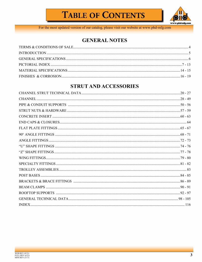
TERMS & CONDITIONS OF SALE.............................................................................................................................. 4
INTRODUCTION ........................................................................................................................................................... 5
GENERAL SPECIFICATIONS ...................................................................................................................................... 6
PICTORIAL INDEX ................................................................................................................................................ 7 - 13
MATERIAL SPECIFICATIONS ........................................................................................................................... 14 - 15
FINISHES & CORROSION .................................................................................................................................. 16 - 19
STRUT AND ACCESSORIES
CHANNEL STRUT TECHNICAL DATA ............................................................................................................ 20 - 27
CHANNEL ............................................................................................................................................................. 28 - 49
PIPE & CONDUIT SUPPORTS ........................................................................................................................... 50 - 56
STRUT NUTS & HARDWARE ............................................................................................................................ 57 - 59
CONCRETE INSERT ............................................................................................................................................ 60 - 63
END CAPS & CLOSURES ........................................................................................................................................... 64
FLAT PLATE FITTINGS ...................................................................................................................................... 65 - 67
90 ANGLE FITTINGS ......................................................................................................................................... 68 - 71
ANGLE FITTINGS ................................................................................................................................................ 72 - 73
“U” SHAPE FITTINGS ......................................................................................................................................... 74 - 76
“Z” SHAPE FITTINGS .......................................................................................................................................... 77 - 78
WING FITTINGS ................................................................................................................................................... 79 - 80
SPECIALTY FITTINGS ........................................................................................................................................ 81 - 82
TROLLEY ASSEMBLIES ............................................................................................................................................ 83
POST BASES ......................................................................................................................................................... 84 - 85
BRACKETS & BRACE FITTINGS ..................................................................................................................... 86 - 89
BEAM CLAMPS ................................................................................................................................................... 90 - 91
ROOFTOP SUPPORTS ........................................................................................................................................ 92 - 97
GENERAL TECHNICAL DATA ........................................................................................................................ 98 - 105
INDEX ......................................................................................................................................................................... 116
WEB REV (8/21) FULL REV (6/21) MINI REV (3/17)
For the most updated version of our catalog, please visit our website at www.phd-mfg.com

www.phd-mfg.com
4
AGREEMENTS: All agreements are subject to availability of material, strikes, accidents, or other causes beyond our control.
WARRANTY:
We warrant for one year from date of shipment our manufactured products to the extent that we will replace those having manufacturing defects when used for the purpose which we recommended. If goods are defective, the amount of damage is the price of the defective goods only and no allowance will be made for labor or expense of repairing defective goods or damage resulting from the same. We warrant the products we sell of other manufacturers to the extent of the warranties of their respective maker. This is the seller’s sole warranty. Seller makes no other warranty of any kind, expressed or implied; and all implied warranties of merchantability and fitness for a particular purpose which exceed seller’s afore stated obligation are hereby disclaimed by seller and excluded from this warranty. For special order products made to the customer’s specification, warranty is not valid and we are not responsible for load requirements or liable for damages incurred from product failure.
CLAIMS:
No claims for shortages allowed unless made in writing within ten days of receipt of goods. All goods sent out will be carefully examined, counted and packed. Claims for goods damaged or lost in transit should be made on the carrier, as our responsibility ceases on delivery to the carrier.
SPECIAL ORDERS:
Orders covering special or nonstandard goods are not subject to cancellation except on such terms as may be agreed upon.
TERMS AND DESIGN:
Subject to change without notice. Refer to current price list for terms of sale. PHD Manufacturing, Inc. reserves the right to revise product design without notification.
RETURNS: We cannot accept return of any goods unless PHD Manufacturing, Inc.'s written permission has been first obtained, in which case same will be credited as follows:
1) All goods must be received in our plant in first class condition, if not, the cost of putting in sal-able condition will be deducted from credit. 2) Twenty-five percent (25%) will be deducted from credit memoranda issued for handling and restocking, less any charges allowed or paid by PHD Manufacturing, Inc. 3) Goods must be returned prepaid. 4) P.O.A. items cannot be returned. 5) There will be no returns of goods after one year from purchase date. Customer must provide invoice number. 6) There will be no return of goods under $50.00, unless it is the result of PHD Manufacturing, Inc.'s error.
TAXES: To the price and terms quoted, there will be added any manufacturer’s or sales taxes payable on the transaction under any effective statute.
MINIMUM INVOICE: $50.00 plus transportation.
FREIGHT ALLOWANCE: All prices are F.O.B. point of shipment. On shipments of 2500 lbs. or more, rail freight or motor freight at the lowest published price is allowed to all U.S. highway points listed in published tariffs (Hawaii and Alaska excluded).
TERMS: Net 30 days. Monthly settlements on all accounts. One and-a-half percent (11⁄2%) per month or eighteen percent (18%) per annum will be charged on all past due accounts, starting on the 31st day after the date of invoice.
DIMENSIONS & WEIGHTS: Although PHD Manufacturing, Inc. tries to be as accurate as possible, all listed dimensions and weights are an approximation and are not guaranteed.

www.phd-mfg.com
5
PHD Manufacturing, Inc. was founded in 1972 by a group of industry veterans with strong management,
financial, sales and manufacturing backgrounds. The entrepreneurial vision of this close group used the talents
they acquired over the years to forge something special in a business that needed a different purpose. This core
group continues to manage PHD Manufacturing, Inc. today, ensuring the original commitment to quality and
excellence.
Our 30 professional sales representatives supporting the plumbing, mechanical and electrical industries are
ready to serve your needs. Our manufacturing plant in Columbiana, Ohio, together with our 24 stocking
warehouses throughout the United States, gives us one of the largest inventories in the industry.
Many of our products are Underwriter’s Laboratories listed and Factory Mutual Approved. All PHD
Manufacturing, Inc. products are manufactured to meet or exceed industry standards set for their design and
manufacture. If you need a product not listed in this catalog, please call the factory or your local PHD
Manufacturing, Inc. representative to check availability and pricing.
PLUMING/MECHANICAL
PLUMING/MECHANICAL (NO WAREHOUSE)
ELECTRICAL
ELECTRICAL (NO WAREHOUSE)

www.phd-mfg.com
6
References: a. Federal, State, and Local codes. b. ANSI/MSS SP-58 - Manufacturers Standardization Society: Pipe Hangers and Supports - Materials, Design, and Manufacture. c. ANSI/MSS SP-69 - Manufacturers Standardization Society: Pipe Hangers and Supports – Selection and Application. ANSI/MSS SP-69 has been superseded by ANSI/MSS SP-58. d. NFPA 13 - Installation of Sprinkler Systems. e. ASTM - American Society for Testing and Materials. f. MFMA - Metal Framing Manufacturers Association. g. RWMA - Resistance Welding Manufacturing Alliance
Product Delivery, Handling, and Storage: a. All material is to be delivered in original factory packaging to avoid any damage to the product. (i.e. denting, scratching, bending) b. All PHD Manufacturing, Inc. products are to be stored in a sheltered area where they will be protected from the elements and construction equipment. c. Installation of damaged product is not recommended.
Acceptable Manufacturers: a. All hangers and supports to be installed shall be as manufactured by PHD Manufacturing, Inc. or engineer approved equal.
Quality Assurance: a. Many of our products are Underwriters Laboratories Listed, Factory Mutual Approved, comply with Federal Specification A-A-1192A and Manufacturer’s Standardization Society ANSI/MSS SP-58 which supersedes ANSI/MSS SP-69. b. All PHD Manufacturing, Inc. products are produced to meet or exceed industry standards set for their design and manufacture.
Execution: -Examination
a. The installer shall inspect the work area prior to installation. If work area conditions are unsatisfactory, installation shall not proceed until satisfactory corrections are completed.
-Installation a. Installation shall be completed by a fully trained installer. b. Set hangers and supports into final position in accordance with job specifications and shop drawings. c. Anchor material firmly in place ensuring all connections are tightened appropriately.
-Protection a. During installation, it is the installer’s responsibility to protect this work from damage. b. It shall become the responsibility of the end user to protect this work from damage during the remainder of construction on the project upon completion of work.
-Cleanup a. Remove all protective wraps and debris upon completion of this section of work. b. Repair any cosmetic damage due to installation.
Disclaimer: a. PHD Manufacturing, Inc. has little or no control over such factors as environmental conditions, total system design, product selection, and maintenance. b. The installer is responsible for the application to conform to all applicable codes, the integrity of attaching structure, and the use of proper fasteners. c. All load ratings are for static conditions and neglect dynamic loading of any kind.
www.phd-mfg.com
7
Fig. 7530
60 Separate Rollers Page 55
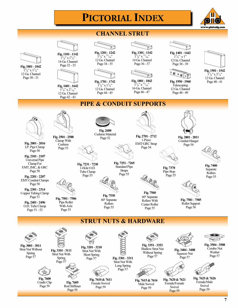
CHANNEL STRUT
PIPE & CONDUIT SUPPORTS
Fig. 1101 - 1142 15/8” x 15/8”
14 Ga. Channel Page 32 - 33 Fig. 1001 - 1042
15/8” x 15/8” 12 Ga. Channel
Page 30 - 31
Fig. 1301 - 1342 15/8” x 13/16”
14 Ga. Channel Page 36 - 37
Fig. 1201 - 1242 15/8” x 13/16”
12 Ga. Channel Page 34 - 35
Fig. 1501 - 1542 15/8” x 31/4”
12 Ga. Channel Page 40 - 41
Fig. 1401 - 1442 15/8” x 1”
12 Ga. Channel Page 38 - 39
Fig. 1950 - 1960 Telescoping
12 Ga. Channel Page 48 - 49
Fig. 1801 - 1842 15/8” x 13/16”
16 Ga. Channel Page 46 - 47
Fig. 1701 - 1742 15/8” x 13/8”
12 Ga. Channel Page 44 - 45
Fig. 1601 - 1642 15/8” x 27/16”
12 Ga. Channel Page 42 - 43
Fig. 2501 - 2588 Clamp With
Cushion Page 53
Fig. 2600 Cushion Material
Page 52
Fig. 7370 Pipe Stop
Page 55
Fig. 2701 - 2712 1-Piece
EMT/GRC Strap Page 54
Fig. 7501 - 7506 Pipe Roller With Axle Page 55
Fig. 7251 - 7265 Standard Pipe
Straps Page 55
Fig. 7231 - 7238 1-Hole O.D. Tube Clamp
Page 55
Fig. 7560
60 Separate Rollers With Center Roller
Page 55
Fig. 7400 Separate Rollers Page 55
Fig. 7581 - 7585 Roller Support
Page 56
Fig. 2001 - 2016 I.P. Pipe Clamp
Page 50
Fig. 2101 - 2107 Universal Pipe
Clamp For EMT, IMC, & GRC
Page 50
Fig. 2201 - 2207 EMT Conduit Clamps
Page 50
Fig. 2301 - 2314 Copper Tubing Clamp
Page 51
Fig. 2401 - 2496 O.D. Tube Clamp
Page 51 - 52
STRUT NUTS & HARDWARE
Fig. 3001 - 3011 Strut Nut Without
Spring Page 57 Fig. 3301 - 3311
Strut Nut With Long Spring
Page 57
Fig. 3201 - 3210 Strut Nut With Short Spring
Page 57
Fig. 3404 - 3408 Squeeze Nut
Page 57
Fig. 3351 - 3353 Shallow Strut Nut Without Spring
Page 57
Fig. 7600 Cradle Clip
Page 59
Fig. 3504 - 3508 Combo Nut
Washer Page 57
Fig. 7610 & 7611 Female Swivel
Page 59
Fig. 3101 - 3111 Strut Nut With
Spring Page 57
Fig. 7605 Rod Stiffener
Page 59
Fig. 7620 & 7621 Female/Female
Swivel Page 59
Fig. 7615 & 7616 Male Swivel
Page 59
Fig. 7625 & 7626 Female/Male
Swivel Page 59
Fig. 2801 - 2811 Conduit Hanger
Page 54
www.phd-mfg.com
8
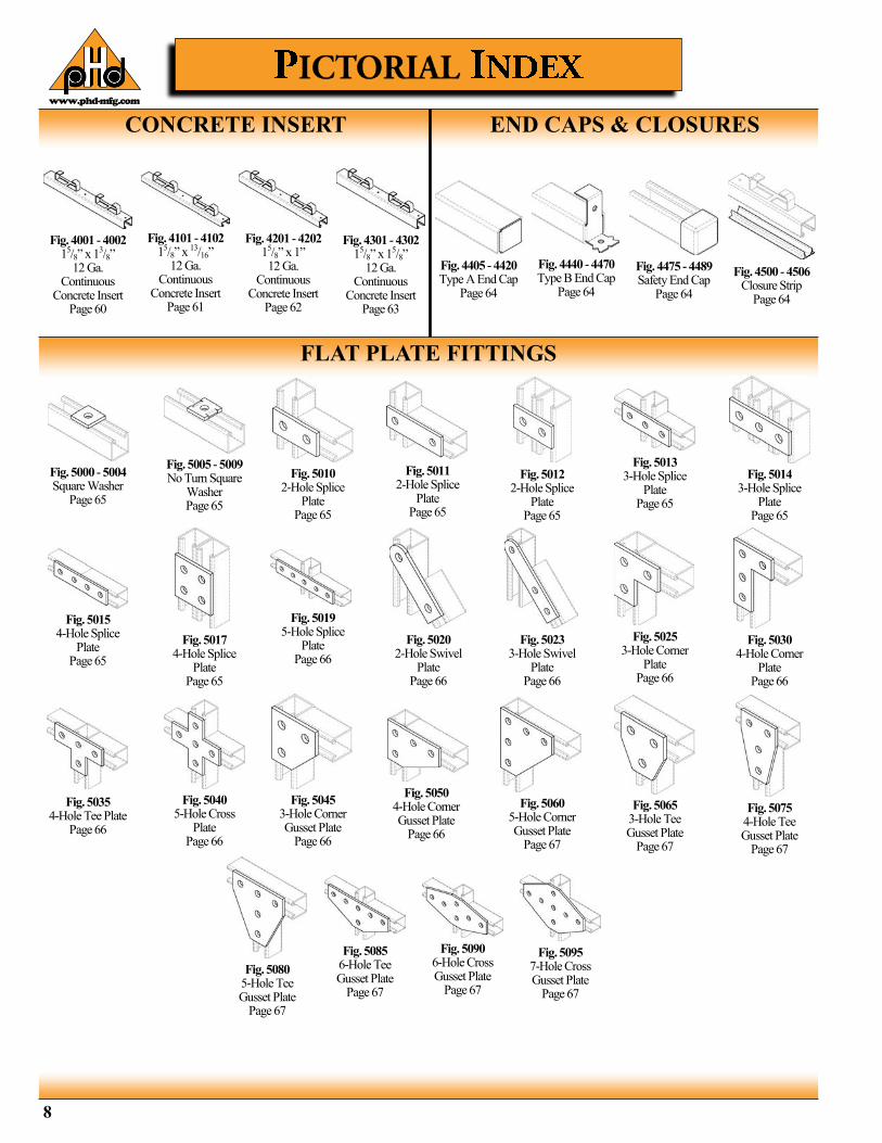
CONCRETE INSERT
FLAT PLATE FITTINGS
Fig. 4405 - 4420 Type A End Cap
Page 64
Fig. 4001 - 4002 15/8” x 13/8”
12 Ga. Continuous
Concrete Insert Page 60
Fig. 4475 - 4489 Safety End Cap
Page 64
Fig. 4440 - 4470 Type B End Cap
Page 64
Fig. 4500 - 4506 Closure Strip
Page 64
Fig. 4101 - 4102 15/8” x 13/16”
12 Ga. Continuous
Concrete Insert Page 61
Fig. 4201 - 4202 15/8” x 1” 12 Ga.
Continuous Concrete Insert
Page 62
Fig. 4301 - 4302 15/8” x 15/8”
12 Ga. Continuous
Concrete Insert Page 63
Fig. 5005 - 5009 No Turn Square
Washer Page 65
Fig. 5000 - 5004 Square Washer
Page 65
Fig. 5010 2-Hole Splice
Plate Page 65
Fig. 5013 3-Hole Splice
Plate Page 65
Fig. 5015 4-Hole Splice
Plate Page 65
Fig. 5014 3-Hole Splice
Plate Page 65
Fig. 5019 5-Hole Splice
Plate Page 66
Fig. 5017 4-Hole Splice
Plate Page 65
Fig. 5012 2-Hole Splice
Plate Page 65
Fig. 5023 3-Hole Swivel
Plate Page 66
Fig. 5011 2-Hole Splice
Plate Page 65
Fig. 5020 2-Hole Swivel
Plate Page 66
Fig. 5030 4-Hole Corner
Plate Page 66
Fig. 5025 3-Hole Corner
Plate Page 66
Fig. 5040 5-Hole Cross
Plate Page 66
Fig. 5035 4-Hole Tee Plate
Page 66
Fig. 5050 4-Hole Corner Gusset Plate
Page 66
Fig. 5045 3-Hole Corner Gusset Plate
Page 66
Fig. 5065 3-Hole Tee Gusset Plate
Page 67
Fig. 5060 5-Hole Corner Gusset Plate
Page 67
Fig. 5080 5-Hole Tee Gusset Plate
Page 67
Fig. 5075 4-Hole Tee Gusset Plate
Page 67
Fig. 5090 6-Hole Cross Gusset Plate
Page 67
Fig. 5085 6-Hole Tee Gusset Plate
Page 67
Fig. 5095 7-Hole Cross Gusset Plate
Page 67
END CAPS & CLOSURES
www.phd-mfg.com
9
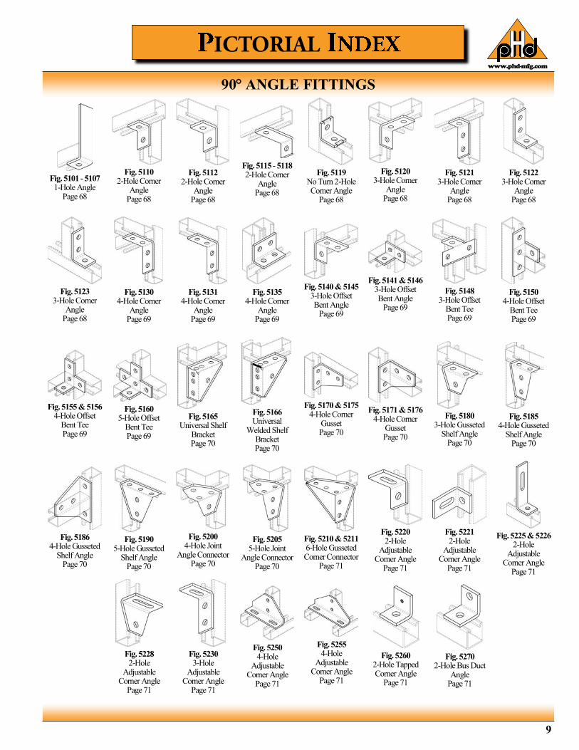
90 ANGLE FITTINGS
Fig. 5101 - 5107 1-Hole Angle
Page 68
Fig. 5110 2-Hole Corner
Angle Page 68
Fig. 5112 2-Hole Corner
Angle Page 68
Fig. 5115 - 5118 2-Hole Corner
Angle Page 68
Fig. 5119 No Turn 2-Hole Corner Angle
Page 68
Fig. 5120 3-Hole Corner
Angle Page 68
Fig. 5121 3-Hole Corner
Angle Page 68
Fig. 5122 3-Hole Corner
Angle Page 68
Fig. 5131 4-Hole Corner
Angle Page 69
Fig. 5135 4-Hole Corner
Angle Page 69
Fig. 5140 & 5145 3-Hole Offset Bent Angle
Page 69
Fig. 5141 & 5146 3-Hole Offset Bent Angle
Page 69
Fig. 5148 3-Hole Offset
Bent Tee Page 69
Fig. 5150 4-Hole Offset
Bent Tee Page 69
Fig. 5155 & 5156 4-Hole Offset
Bent Tee Page 69
Fig. 5160 5-Hole Offset
Bent Tee Page 69
Fig. 5165 Universal Shelf
Bracket Page 70
Fig. 5166 Universal
Welded Shelf Bracket Page 70
Fig. 5170 & 5175 4-Hole Corner
Gusset Page 70
Fig. 5171 & 5176 4-Hole Corner
Gusset Page 70
Fig. 5180 3-Hole Gusseted
Shelf Angle Page 70
Fig. 5185 4-Hole Gusseted
Shelf Angle Page 70
Fig. 5186 4-Hole Gusseted
Shelf Angle Page 70
Fig. 5190 5-Hole Gusseted
Shelf Angle Page 70
Fig. 5200 4-Hole Joint
Angle Connector Page 70
Fig. 5205 5-Hole Joint
Angle Connector Page 70
Fig. 5210 & 5211 6-Hole Gusseted Corner Connector
Page 71
Fig. 5220 2-Hole
Adjustable Corner Angle
Page 71
Fig. 5221 2-Hole
Adjustable Corner Angle
Page 71
Fig. 5225 & 5226 2-Hole
Adjustable Corner Angle
Page 71
Fig. 5228 2-Hole
Adjustable Corner Angle
Page 71
Fig. 5230 3-Hole
Adjustable Corner Angle
Page 71
Fig. 5250 4-Hole
Adjustable Corner Angle
Page 71
Fig. 5255 4-Hole
Adjustable Corner Angle
Page 71
Fig. 5260 2-Hole Tapped Corner Angle
Page 71
Fig. 5270 2-Hole Bus Duct
Angle Page 71
Fig. 5123 3-Hole Corner
Angle Page 68
Fig. 5130 4-Hole Corner
Angle Page 69
www.phd-mfg.com
10
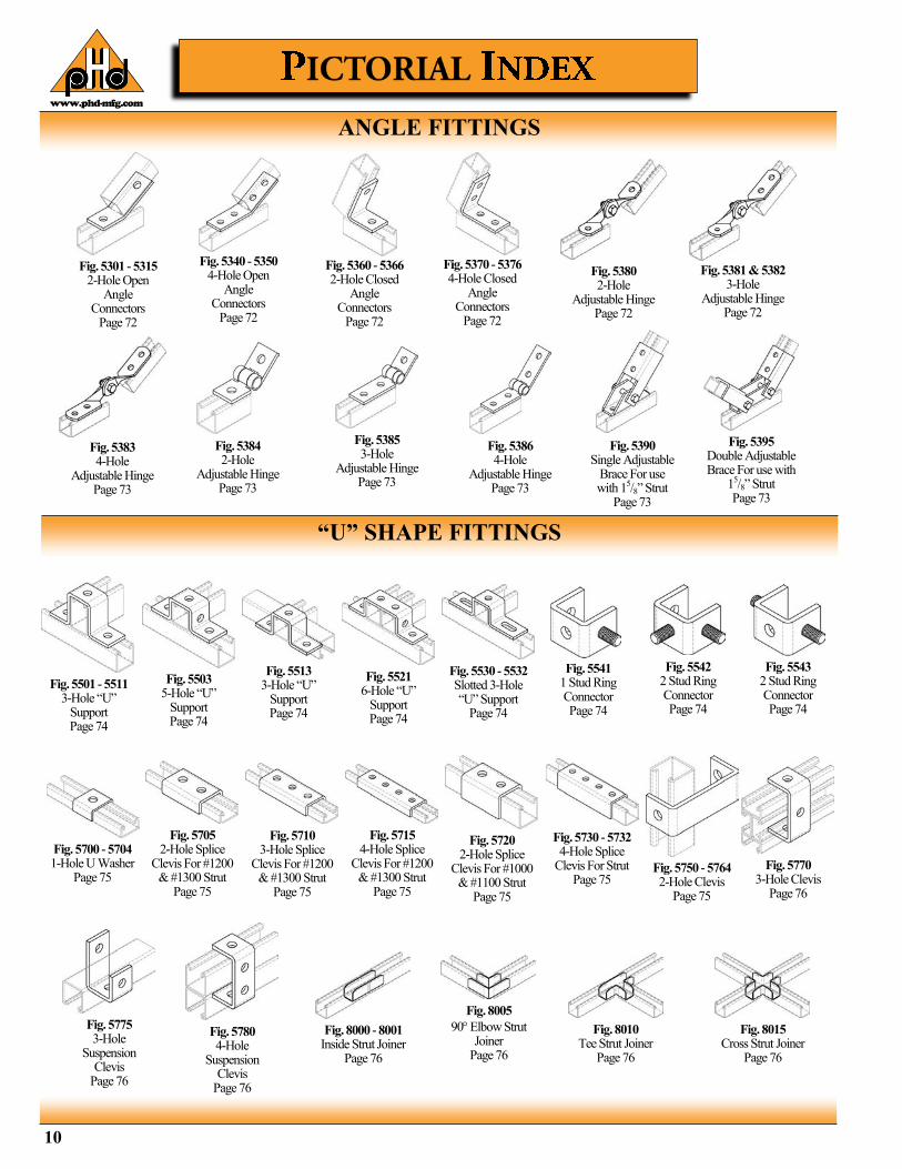
ANGLE FITTINGS
“U” SHAPE FITTINGS
Fig. 5340 - 5350 4-Hole Open
Angle Connectors
Page 72
Fig. 5301 - 5315 2-Hole Open
Angle Connectors
Page 72
Fig. 5370 - 5376 4-Hole Closed
Angle Connectors
Page 72
Fig. 5360 - 5366 2-Hole Closed
Angle Connectors
Page 72
Fig. 5381 & 5382 3-Hole
Adjustable Hinge Page 72
Fig. 5380 2-Hole
Adjustable Hinge Page 72
Fig. 5383 4-Hole
Adjustable Hinge Page 73
Fig. 5385 3-Hole
Adjustable Hinge Page 73
Fig. 5384 2-Hole
Adjustable Hinge Page 73
Fig. 5390 Single Adjustable
Brace For use with 15/8” Strut
Page 73
Fig. 5386 4-Hole
Adjustable Hinge Page 73
Fig. 5395 Double Adjustable Brace For use with
15/8” Strut Page 73
Fig. 5501 - 5511 3-Hole “U”
Support Page 74
Fig. 5513 3-Hole “U”
Support Page 74
Fig. 5503 5-Hole “U”
Support Page 74
Fig. 5530 - 5532 Slotted 3-Hole “U” Support
Page 74
Fig. 5521 6-Hole “U”
Support Page 74
Fig. 5541 1 Stud Ring Connector Page 74
Fig. 5720 2-Hole Splice
Clevis For #1000 & #1100 Strut
Page 75
Fig. 5750 - 5764 2-Hole Clevis
Page 75
Fig. 5730 - 5732 4-Hole Splice
Clevis For Strut Page 75
Fig. 5775 3-Hole
Suspension Clevis
Page 76
Fig. 5770 3-Hole Clevis
Page 76
Fig. 5780 4-Hole
Suspension Clevis
Page 76
Fig. 5542 2 Stud Ring Connector Page 74
Fig. 5700 - 5704 1-Hole U Washer
Page 75
Fig. 5543 2 Stud Ring Connector Page 74
Fig. 5710 3-Hole Splice
Clevis For #1200 & #1300 Strut
Page 75
Fig. 5705 2-Hole Splice
Clevis For #1200 & #1300 Strut
Page 75
Fig. 5715 4-Hole Splice
Clevis For #1200 & #1300 Strut
Page 75
Fig. 8000 - 8001 Inside Strut Joiner
Page 76
Fig. 8005
90 Elbow Strut Joiner
Page 76
Fig. 8010 Tee Strut Joiner
Page 76
Fig. 8015 Cross Strut Joiner
Page 76
www.phd-mfg.com
11
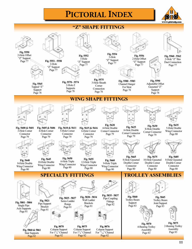
“Z” SHAPE FITTINGS
WING SHAPE FITTINGS
Fig. 5565 Tapped “Z”
Support Page 78
Fig. 5550 2-Hole Offset “Z” Support
Page 77
Fig. 5570 - 5574 2-Hole Z Supports Page 78
Fig. 5551 - 5558 2-Hole
“Z” Support Page 77
Fig. 5575 3-Hole Sheath
Corner Connection
Page 78
Fig. 5580 - 5583 Channel Hanger
For Strut Page 78
Fig. 5554 3-Hole
“Z” Support Page 77
Fig. 5590 Adjustable Offset
Gusseted “Z” Support Page 78
Fig. 5556 2-Hole Offset “Z” Support
Page 77
Fig. 5560 - 5562 2-Hole “Z” Bus Duct Connection
Page 77
Fig. 5552 3-Hole
“Z” Support Page 77
SPECIALTY FITTINGS TROLLEY ASSEMBLIES
Fig. 5660 9-Hole Triple
Wing Connector Page 80
Fig. 5605 & 5606 4-Hole Corner
Connector Page 79
Fig. 5610 & 5611 5-Hole Corner
Connector Page 79
Fig. 5615 & 5616 6-Hole Corner
Connector Page 79
Fig. 5620 4-Hole Double
Corner Connector Page 79
Fig. 5625 6-Hole Double
Corner Connector Page 79
Fig. 5630 8-Hole Double
Corner Connector Page 79
Fig. 5635 5-Hole Double
Wing Connector Page 80
Fig. 5640 8-Hole Double
Wing Connector Page 80
Fig. 5600 & 5601 3-Hole Corner
Connector Page 79
Fig. 5645 10-Hole Double Wing Connector
Page 80
Fig. 5650 6-Hole Triple
Wing Connector Page 80
Fig. 5655 12-Hole Triple
Wing Connector Page 80
Fig. 5665 8-Hole Gusseted Double Corner
Connector Page 80
Fig. 5675 10-Hole Gusseted
Double Corner Connector Page 80
Fig. 5685 8-Hole Gusseted Double Corner
Connector Page 80
Fig. 5860 & 5861 Stair Supports
Page 82
Fig. 8070 Column Support For 15/8” Channel
Page 82
Fig. 5821 Pipe Support
Bracket Page 81
Fig. 5801 - 5804 Single Pipe
Axle Supports Page 81
Fig. 5835 - 5837 Pipe Coupling
Fittings Page 82
Fig. 8076 Column Support For 13/16” Channel
Page 82
Fig. 8075 Column Support For 15/8” Channel
Page 82
Fig. 5830 - 5834 Wall Ladder
Brackets Page 81
Fig. 5825 - 5827 Series Ladder
Rungs Page 81
Fig. 5875 2-Bearing Trolley
Assembly Page 83
Fig. 5870 4-Bearing Trolley
Assembly Page 83
Fig. 5845 Trolley Beam Joint Support
Page 83
Fig. 5840 Trolley Beam
Support Page 83
www.phd-mfg.com
12
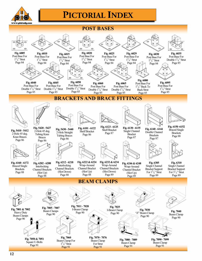
POST BASES
Fig. 6040 Post Base For
Double 15/8” Strut Page 85
Fig. 6005 Post Base For
15/8” Strut Page 84
Fig. 6045 Post Base For
Double 15/8” Strut Page 85
Fig. 6010 Post Base For
15/8” Strut Page 84
Fig. 6050 Post Base For
Double 15/8” Strut Page 85
Fig. 6015 Post Base For
15/8” Strut Page 84
Fig. 6060 Post Base For
Double 15/8” Strut Page 85
Fig. 6020 Post Base For
15/8” Strut Page 84
Fig. 6065 Post Base For
Double 15/8” Strut Page 85
Fig. 6080 Post Base For 15/8” Back To
Back Strut Page 85
Fig. 6025 Post Base For
15/8” Strut Page 84
Fig. 6029 Post Base For
15/8” Strut Page 84
Fig. 6095 Post Base For
15/8” Strut Page 85
BRACKETS AND BRACE FITTINGS
Fig. 6030 Post Base For
15/8” Strut Page 84
Fig. 6035 Post Base For
Double 15/8” Strut Page 85
Fig. 5410 - 5412 2-Hole 45 deg. Knee Braces
Page 86
Fig. 6202 - 6208 Interlocking
Channel Brackets (Slot Up) Page 88
Fig. 5420 - 5427 2-Hole 45 deg. Tubing Knee
Braces Page 86
Fig. 5430 - 5440 2-Hole Straight Tubing Braces
Page 86
Fig. 6101 - 6122 Shelf Bracket
Page 86
Fig. 6123 - 6125 Shelf Bracket
Page 87
Fig. 6150 -6152 Braced Single
Brackets Page 88
Fig. 6160 - 6172 Braced Single
Brackets Page 88
Fig. 6212 - 6218 Interlocking
Channel Brackets (Slot Down)
Page 88
Fig. 6222 & 6224 Wrap-Around
Channel Bracket (Slot Up) Page 88
Fig. 6140 - 6144 Double Channel
Brackets Page 87
Fig. 6232 & 6234 Wrap-Around
Channel Brackets (Slot Down)
Page 89
Fig. 6246 & 6248 Wrap-Around
Channel Bracket (Slot Up) Page 89
Fig. 6305 Single Channel Bracket Support For 15/8” Strut
Page 89
Fig. 6310 Single Channel Bracket Support For 31/4” Strut
Page 89
BEAM CLAMPS
Fig. 6130 - 6135 Single Channel
Bracket Page 87
Fig. 7050 & 7051 Square U-Bolts
Page 91
Fig. 7001 & 7002 Heavy Duty
Beam Clamps Page 90
Fig. 7060 Beam Clamp For
15/8″ Strut Page 91
Fig. 7005 - 7007 Beam Clamps
Page 90
Fig. 7070 - 7076 Beam Clamp
For Strut Page 91
Fig. 7011 - 7020 I-Beam Clamp
Page 90
Fig. 7080 - 7089 Beam Clamp
Page 91
Fig. 7090 - 7099 Beam Clamp
Page 91
Fig. 7030 “Z” Beam Clamp
Page 90
Fig. 7040 Beam Clamp
Page 90
Fig. 7025 I-Beam Clamp
Page 90
www.phd-mfg.com
13
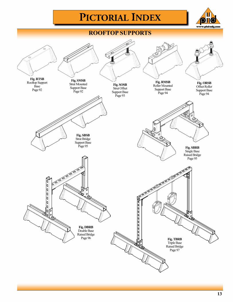
ROOFTOP SUPPORTS
Fig. SBRB Single Base
Raised Bridge Page 95
Fig. DBRB Double Base Raised Bridge
Page 96
Fig. SOSB Strut Offset
Support Base Page 93
Fig. TBRB Triple Base
Raised Bridge Page 97
Fig. RMSB Roller Mounted Support Base
Page 94
Fig. ORSB Offset Roller Support Base
Page 94
Fig. SMSB Strut Mounted Support Base
Page 92
Fig. RTSB Rooftop Support
Base Page 92
Fig. SBSB Strut Bridge Support Base
Page 95
www.phd-mfg.com
14
STRUT CHANNEL & ACCESSORIES CHANNEL
Pre-Galvanized -ASTM A653 Grade 33 SS, Zinc Coated by Hot Dip
Process
Plain, Powder Coated, or Hot Dip Galvanized -ASTM A1011/A1011M Grade 33 SS
Stainless Steel -ASTM A240, Type 304 -ASTM A240, Type 316
Aluminum -Aluminum alloy 6005-T5
CHANNEL NUTS
Steel -ASTM A576, Grade M1015, Case Hardened to RC25
min.
Stainless Steel -ASTM A240, Type 304 -ASTM A240, Type 316 -Sintered Nuts: MPIF 35 Type 316 (Domestic only)
Aluminum -Aluminum alloy 5052-H32
PIPE CLAMPS & ACCESSORIES
Pre-Galvanized Steel: -ASTM A653 Grade 33 SS, Zinc Coated by Hot Dip
Process
Carbon Steel: (3 Gauge Thickness and Below) -ASTM A1011 CS Type A, B, or C
Carbon Steel: (1/4” Thickness and Above) -ASTM A36, Structural Quality
Stainless Steel: -ASTM A240, Type 304 -ASTM A240, Type 316
Aluminum -Aluminum alloy 6005-T5 Structural Grade
Cast Iron: -Grey Cast Iron, ANSI/ASTM A48, Class #20
Malleable Iron: -ANSI/ASTM A47, Grade Number 32510
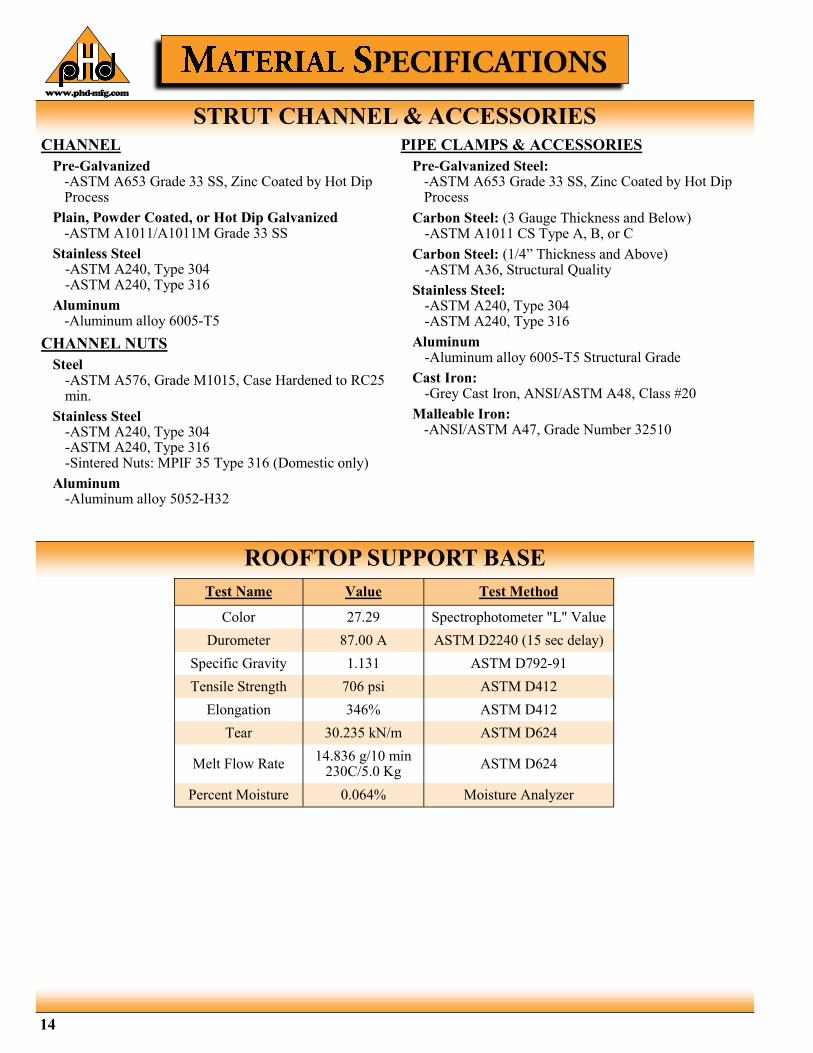
ROOFTOP SUPPORT BASE
Test Name Value Test Method
Color 27.29 Spectrophotometer "L" Value
Durometer 87.00 A ASTM D2240 (15 sec delay)
Specific Gravity 1.131 ASTM D792-91
Tensile Strength 706 psi ASTM D412
Elongation 346% ASTM D412
Tear 30.235 kN/m ASTM D624
Melt Flow Rate 14.836 g/10 min
230C/5.0 Kg ASTM D624
Percent Moisture 0.064% Moisture Analyzer
www.phd-mfg.com
15
The high strength to weight ratio of PHD Manufacturing, Inc. products made of aluminum greatly reduces the overall cost of installation through ease of handling and field cutting. Aluminum owes its excellent corrosion resistance to its ability to form an aluminum oxide film that immediately reforms when scratched or cut. In most outdoor applications, aluminum has excellent resistance to “weathering”. The resistance to chemicals, indoor or outdoor, can best be determined by tests conducted by the user with exposure to the specific conditions for which it is intended. To determine the approximate load data for strut, multiply the load data found in this catalog by a factor of 0.38.
Because of its corrosion resistance, stainless steel is recommended for applications where corrosion is a problem. Load data for PHD Manufacturing, Inc. products is the same as the load data in this catalog. Stainless steel products are available in ASTM A-240, Type 304 or 316 material. Both are low-magnetic and belong to the austenitic stainless steels group, based on alloy content and crystallographic structure. Like carbon steel, stainless steel exhibits increased strength when cold worked. Several conditions make the use of stainless steel ideal. These include reducing long term maintenance costs, high ambient temperatures, appearance, and stable structural properties such as yield strength, and high creep strength. Type 304 resists most organic chemicals, dyestuffs and a wide variety of inorganic chemicals at elevated or cryogenic temperatures. Type 316 contains slightly more nickel and adds molybdenum to give it better corrosion resistance in chloride and sulfuric acid environments.
PHD Manufacturing, Inc. products made from high-quality carbon steel are cold formed to precise dimensions. By cold working the steel mechanical properties are increased, allowing lightweight structures to carry the required load. Corrosion resistance of carbon steel varies widely with coating and alloy. See “Finishes” for more detailed information.
ALUMINUM
STAINLESS STEEL
CARBON STEEL
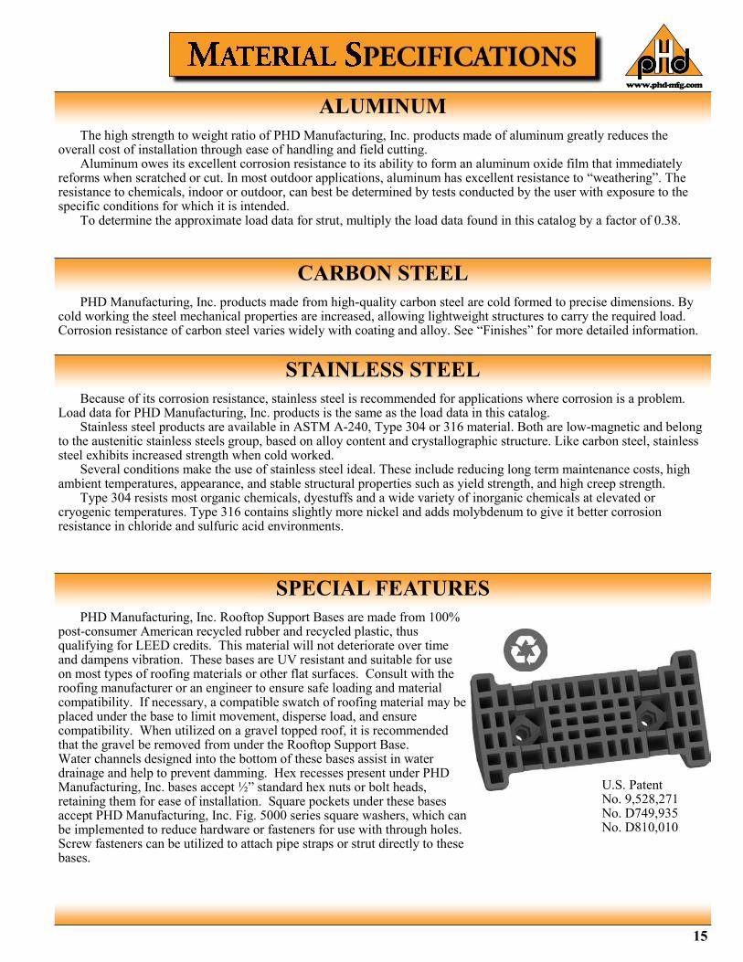
PHD Manufacturing, Inc. Rooftop Support Bases are made from 100% post-consumer American recycled rubber and recycled plastic, thus qualifying for LEED credits. This material will not deteriorate over time and dampens vibration. These bases are UV resistant and suitable for use on most types of roofing materials or other flat surfaces. Consult with the roofing manufacturer or an engineer to ensure safe loading and material compatibility. If necessary, a compatible swatch of roofing material may be placed under the base to limit movement, disperse load, and ensure compatibility. When utilized on a gravel topped roof, it is recommended that the gravel be removed from under the Rooftop Support Base. Water channels designed into the bottom of these bases assist in water drainage and help to prevent damming. Hex recesses present under PHD Manufacturing, Inc. bases accept ½” standard hex nuts or bolt heads, retaining them for ease of installation. Square pockets under these bases accept PHD Manufacturing, Inc. Fig. 5000 series square washers, which can be implemented to reduce hardware or fasteners for use with through holes. Screw fasteners can be utilized to attach pipe straps or strut directly to these bases.
SPECIAL FEATURES
U.S. Patent No. 9,528,271 No. D749,935 No. D810,010

www.phd-mfg.com
16
PLAIN (PL)
Plain finish designation means that the product retains the oiled surface applied to the raw steel during the forming process. The fittings have the original oiled surface of the bar-stock material.
PHD Manufacturing, Inc. offers a polyester powder coating that utilizes powder material conforming to ASTM D3451. It is applied by means of an electrostatic spray at ambient temperature.
PVC coating helps reduce noise and protect the pipe or tubing from the metal surface of the hanger. Corrosion resistance protection is minimal. PVC coating is not compatible with CPVC pipe.
Designed for use with copper tubing. This coating provides a better level of corrosion resistance than the traditional copper plated finish. It also acts as a protective barrier, avoiding contact between dissimilar metals. The copper color epoxy powder is applied by an electrostatic method, and the coated parts are baked at 180 degrees for 20 minutes.
POWDER PROPERTIES
Test Method Powder Properties Tolerances
ASTM D3451 (18.30) Specific Gravity 1.33 ± 0.03
ASTM D3451 (18.30) Theoretical Coverage 144.58 ± 4.0 FT2/Lb./Mil.
ASTM D3451 (13) Volatile Content Max. 2.5%
ASTM D3451 (13) Storage Temperature Max 80F
COATING PROPERTIES All tests performed on substrate 0.032 CRS Pretreatment
Bonderite 1000
Test Method Coating Properties Tolerances/Specifications
ASTM D523 Gloss 20/60 70-80
ASTM D2454 Over Bake Resistance Time 100%
ASTM D3363 Pencil Hardness H - 2H
ASTM D2794 (Modified) Direct Impact (Gardner) 80 in. Lbs.
ASTM D2794 (Modified) Reverse Impact (Gardner) 80 in. Lbs.
ASTM D3359 Adhesion (Cross Hatch) Pass No Adhesion Loss
ASTM D522 Flexibility (Mandrel) 1/8 Bend No Fracture
ASTM B117 Salt Spray 1000 Hrs.
ASTM D2247 Humidity 500 Hrs.
APPLICATION
Test Method Application Cure Schedule
Ambient Temperature 15’ @ 375F (190C )
Electrostatic Spray Recommended Minimum Film Thickness 1.5
POWDER COATING (PTD)
PVC COATING (PVC)
COPPER COLOR EPOXY FINISH (CCEF)
CHANNEL GREEN: POLYESTER EPOXY E-COAT
PHD Manufacturing’s epoxy E-Coat offers state of the art corrosion resistance without the use of heavy metals such as lead, chrome, and zinc. It is applied to our products by a controlled cathodic electro-deposition process. This process is accomplished by transporting the product through several cleaning, phosphatizing, rinsing, and application stages prior to being baked for 20 minutes at
375F (190C ).
Property Substrate /
Pretreatment Salt Spray*
500 hrs. Salt Spray* 1000 hrs.
20 Cycle** Scab
Corrosion Resistance
CRS/Zinc Phos/Non-Chrome
0 in. (0 mm)
0 - 0.039 in. (0 - 1 mm)
0.039 - 0.079 in. (1 - 2 mm)
(Average Total Scribe Creep), * Salt Spray - ASTM B117 ** Cycle Scab - GM9511P, Cold Rolled Steel Lab Panels
Cure 20 Minutes @ 375F (190C )
EPOXY PROPERTIES Property Test Method Performance
Color --- Various
Film Thickness --- 0.5 - 1.5 Mils
Gloss - 60 Degree ASTM D523 65 - 85
Pencil Hardness ASTM D3363 2H Minimum
Direct Impact ASTM D2794 120 in-lb. Minimum
Reverse Impact ASTM D2794 100 in-lb. Minimum
Cross-Hatch Adhesion ASTM D3359 4B - 5B
Humidity ASTM D1735 1000 Hours Minimum
Water Immersion ASTM D870 250 Hours Minimum
Gravelometer GM 9508P 6 Minimum
Throwpower GM 9535P 12 - 15 Inches
All tests performed on Cold Rolled Steel Lab Panels, Zinc Phosphate Pretreatment, 0.6 Mil Average Film Thickness,
Cure 20 Minutes @ 375°F
www.phd-mfg.com
17
PHD offers 3 basic forms of zinc coating on its products: 1) Electro-Galvanized (Electro-Plated Zinc) 2) Pre-Galvanized 3) Hot-Dipped Galvanized
For best results, a zinc rich paint should be applied to field cuts. The zinc rich paint will provide immediate protection for these areas and eliminate the short time period for galvanic action to “heal” the damaged coating.
Note: The corrosion resistance of zinc is based on its thickness, the environment, and the coating process used. The acceptability of galvanized coatings at temperatures above 450°F is at the discretion of the end user.
Zinc offers two types of protection: • Barrier: The zinc coating protects the steel substrate from direct contact with the environment
• Sacrificial: The zinc coating will protect scratches, cut edges, etc… through an anodic sacrificial process.
This type of coating is recommended for use indoors in relatively dry areas. The steel is submersed in a bath of zinc salts, through the process of electrolysis, a coating of pure zinc adheres to the steel with a molecular bond. A maximum of 0.5 mils of zinc per side can be applied using this method. SC1 (Mild) is the standard finish thickness which has a zinc coating of 0.2 mils per side. SC3 (Severe) has a zinc coating of 0.5 mils per side.
This type of coating is suitable for extended exposure in dry or mildly corrosive atmospheres but not generally recommended for use outdoors in industrial environments. Also known as “mill galvanized” or “hot-dipped mill galvanized” pre-galvanized zinc coatings are produced by rolling the steel coils or sheets through molten zinc, at the steel mill, the material is then cut or slit to size. Zinc near the uncoated edges or weld areas becomes a sacrificial anode which protects the bare areas. The pre-galvanized material conforms to ASTM A653 with a G90 zinc coating. The zinc thickness per side is nominally 0.75 mils thick or 0.45 oz /sq. ft.
Recommended for prolonged outdoor exposure and will usually protect steel in most atmospheric environments. After fabrication the part is immersed in a bath of molten zinc. A metallurgical bond is formed resulting in a zinc coating that coats all surfaces including edges. Please note that some items cannot be hot-dipped galvanized due to design,
tolerances, or threaded components. Check with the PHD factory or your local representative when questionable. Threaded components on hot dipped galvanized products will be electro-galvanized. The hot-dip galvanized coating is typically 2.6 mils or 1.5 oz /sq. ft per side.
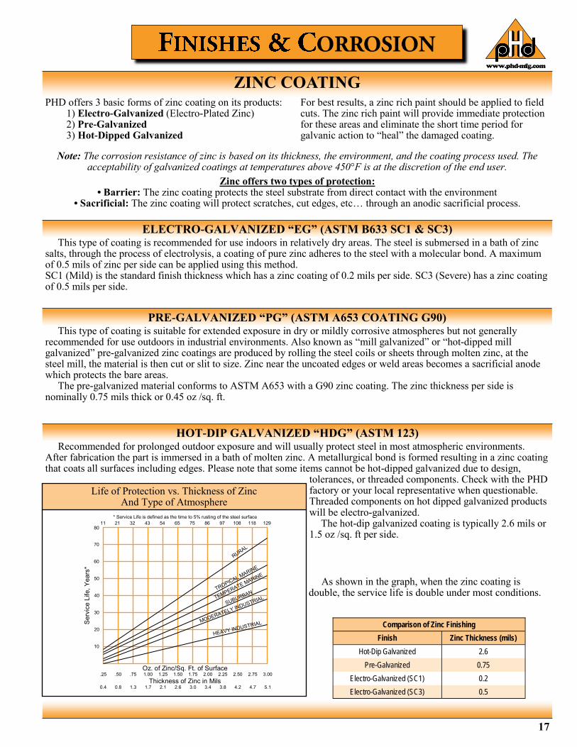
Comparison of Zinc Finishing
Finish Zinc Thickness (mils)
Hot-Dip Galvanized 2.6
Pre-Galvanized 0.75
Electro-Galvanized (SC1) 0.2
Electro-Galvanized (SC3) 0.5
ZINC COATING
ELECTRO-GALVANIZED “EG” (ASTM B633 SC1 & SC3)
PRE-GALVANIZED “PG” (ASTM A653 COATING G90)
HOT-DIP GALVANIZED “HDG” (ASTM 123)
As shown in the graph, when the zinc coating is double, the service life is double under most conditions.
11 21 32 43 54 65 75 86 97 108 118 129
.25 .50 .75 1.00 1.25 1.50 1.75 2.00 2.25 2.50 2.75 3.00 Oz. of Zinc/Sq. Ft. of Surface
Thickness of Zinc in Mils 0.4 0.8 1.3 1.7 2.1 2.6 3.0 3.4 3.8 4.2 4.7 5.1
70
80
60
50
40
30
20
10
Serv
ice L
ife,
Years
*
* Service Life is defined as the time to 5% rusting of the steel surface
Life of Protection vs. Thickness of Zinc And Type of Atmosphere

www.phd-mfg.com
18
All metal surfaces are affected by corrosion. Depending on the physical properties of the metal and the environment to which it is exposed, chemical or electromechanical corrosion may occur.
Atmospheric Corrosion Atmospheric corrosion occurs when metal is exposed to airborne liquids, solids or gases. Some sources of atmospheric corrosion are moisture, salt, dirt and sulphuric acid. This form of corrosion is typically more severe outdoors, especially near marine environments.
Chemical Corrosion Chemical corrosion takes place when metal comes in direct contact with a corrosive solution. Some factors which affect the severity of chemical corrosion include: chemical concentration level, duration of contact, frequency of washing, and operating temperature.
Galvanic Corrosion Galvanic corrosion occurs when two or more dissimilar metals are in contact in the presence of an electrolyte (i.e. moisture). An electrolytic cell is created and the metals form an anode or a cathode depending on their relative position on the Galvanic Series Table. The anodic material will be the one to corrode. Anodic or cathodic characteristics of two dissimilar metals will depend on the type of each material. For example: If zinc and steel are in contact, the zinc acts as the anode and will corrode; the steel acts as the cathode, and will be protected. If steel and copper are in contact, the steel is now the anode and will corrode. The rate at which galvanic corrosion occurs depends on several factors: 1. The relative position on the Galvanic Series Table - the further apart materials are in the Galvanic Series Table, the greater the potential for corrosion of the anodic material. 2. The amount and concentration of electrolyte present - an indoor, dry environment will have little or no galvanic corrosion compared to a wet atmosphere. 3. The relative size of the materials – a small amount of anodic material in contact with a large cathodic material will result in greater corrosion. Likewise, a large anode in contact with a small cathode will decrease the rate of attack.
Storage Corrosion
Wet storage stain (white rust) is caused by the entrapment of moisture between surfaces of closely packed and poorly ventilated material for an extended period. Wet storage stain is usually superficial, having no affect on the properties of the metal. Light staining normally disappears with weathering. Medium to heavy buildup should be removed in order to allow the formation of normal protective film. Proper handling and storage will help to assure stain-free material. If product arrives wet, it should be unpacked and dried before storage. Dry material should be stored in a well ventilated “low moisture” environment to avoid condensation formation. Outdoor storage is undesirable, and should be avoided whenever possible.
GALVANIC SERIES IN SEA WATER
Anodic End Magnesium
Magnesium Alloys
Zinc (Galvanized Coating)
Beryllium
Aluminum - Zinc Alloys
Aluminum - Magnesium Alloys
Aluminum
Aluminum - Magnesium Alloys
Aluminum - Magnesium - Silicon Alloys
Cadmium
Aluminum - Copper Alloys
Low Carbon Steel, Cast Iron, Wrought Iron
Austenitic Nickel Cast Iron
Type 410 Stainless Steel (active)
Type 316 Stainless Steel (active)
Type 304 Stainless Steel (active)
Naval Brass, Yellow Brass, Red Brass
Tin
Copper
Lead-Tin Solders
Admiralty Brass, Aluminum Brass
Manganese Bronze
Silicon Bronze
Tin Bronze
Type 410 Stainless Steel (passive)
Nickel - Silver
Copper Nickel Alloys
Lead
Nickel - Aluminum Bronze
Silver Solder
Nickel 200
Silver
Type 316 Stainless Steel (passive)
Type 304 Stainless Steel (passive)
Incoloy 825
Hastelloy B
Titanium
Hastelloy C
Platinum
Graphite
Cathodic End
Metals in descending order of activity in the presence of an electrolyte.
Mo
re A
no
dic
CORROSION
www.phd-mfg.com
19
Chemical Aluminum Channel Green
Type 304 Stainless
Type 316 Stainless
Zinc Coated Steel
Acetic Acid 10% R NR R R NR
Acetic Acid 2% R F R R NR
Acetone R R R R R
Ammonium Hydroxide-Conc, R R R R -
Ammonium Hydroxide 10% F R R R -
Ammonium Hydroxide 2% R R R R -
Benzene R R R R -
Bromine Water NR R NR NR -
Butanol (Butyl Alcohol) R R R R R
Carbon Disulfide R R R R -
Carbon Tetrachloride F R R R -
Chlorine Water R R NR F R
Cutting Oil - R - - -
Diethanolamine R R - - NR
Ethanol R R R R R
Ethyl Acetate R R - - R
Ethylene Dichloride F R - - R
Formaldehyde 20% R R R R R
Gasoline R R R R R
Glycerine R R R R R
Household Detergent 10% F R R R -
Hydrochloric Acid 40% NR NR NR NR NR
Hydrochloric Acid 10% NR F NR NR NR
Hydrochloric Acid 2% NR F NR NR NR
Hydrogen Peroxide 30% R NR R R -
Hydrogen Peroxide 3% R R R R -
Hydrogen Sulfide (Gas) R R F R -
JP-4 Jet Fuel R R R R -
Lactic Acid 85% F R NR - -
Latex R R R R NR
Linseed Oil Fatty Acid R F R R -
Methanol R R R R R
Methyl Ethyl Ketone R R - - R
Methyl Isobutyl Ketone R R - - R
Mineral Spirits R R - - -
Motor Oil - 10W R R R R R
Naphtha, VM&P R R R R R
Nitric Acid 2% F NR R R -
Perchloroethylene R R - - NR
Petroleum Ether - R R R R
Phenol 10% R R R R R
Phosphoric Acid 2% F NR R R NR
Potassium Hydroxide 50% NR R R R -
Potassium Hydroxide 10% NR R R R -
Potassium Hydroxide 2% NR R R R -
Sodium Chloride 25% F R R R F
Sodium Hydroxide 50% NR R R R NR
Sodium Hydroxide 10% NR R R R F
Sodium Hydroxide 2% NR R - - -
Sodium Hypochlorite-C1. 10% F R - - -
Sodium Hypochlorite-C1. 6% F R NR R -
Sulfuric Acid 50% F NR NR R NR
Tall Oil Fatty Acid 50% R R - - -
Tannic Acid 50% F R R R -
Water-Deionized R R R R F
Water-Sea F F R R F
Water-Tap R R F F R
Xyol R R - - -
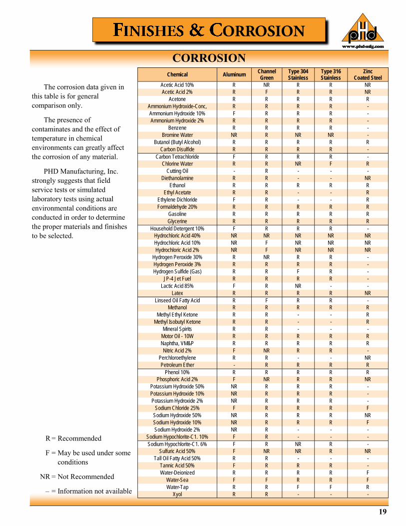
The corrosion data given in
this table is for general
comparison only.
The presence of
contaminates and the effect of
temperature in chemical
environments can greatly affect
the corrosion of any material.
PHD Manufacturing, Inc.
strongly suggests that field
service tests or simulated
laboratory tests using actual
environmental conditions are
conducted in order to determine
the proper materials and finishes
to be selected.
R = Recommended
F = May be used under some
conditions
NR = Not Recommended
– = Information not available
CORROSION
www.phd-mfg.com
20
DESIGN OF STRUT SYSTEMS
BEAMS
PHD Manufacturing, Inc. follows the guidelines of the Metal Framing Manufacturers Association (MFMA) in the manufacture and recommended use of strut systems. In all design applications using strut systems and accessories, proper engineering design practices should be applied and load limits observed. The following pages include helpful information to assist the user in the proper design of strut systems. Appropriate beam and column loading information is provided with the dimensional tables accompanying each channel. In addition, the following discussion and tables are designed to assist in the proper selection and use of PHD strut products. Basic engineering information is provided to define the concepts needed to design a safe and economical strut installation. PHD channel strut is often installed to serve either as beams or columns in structural applications. A brief discussion of these types of structural elements and their safe design follows:
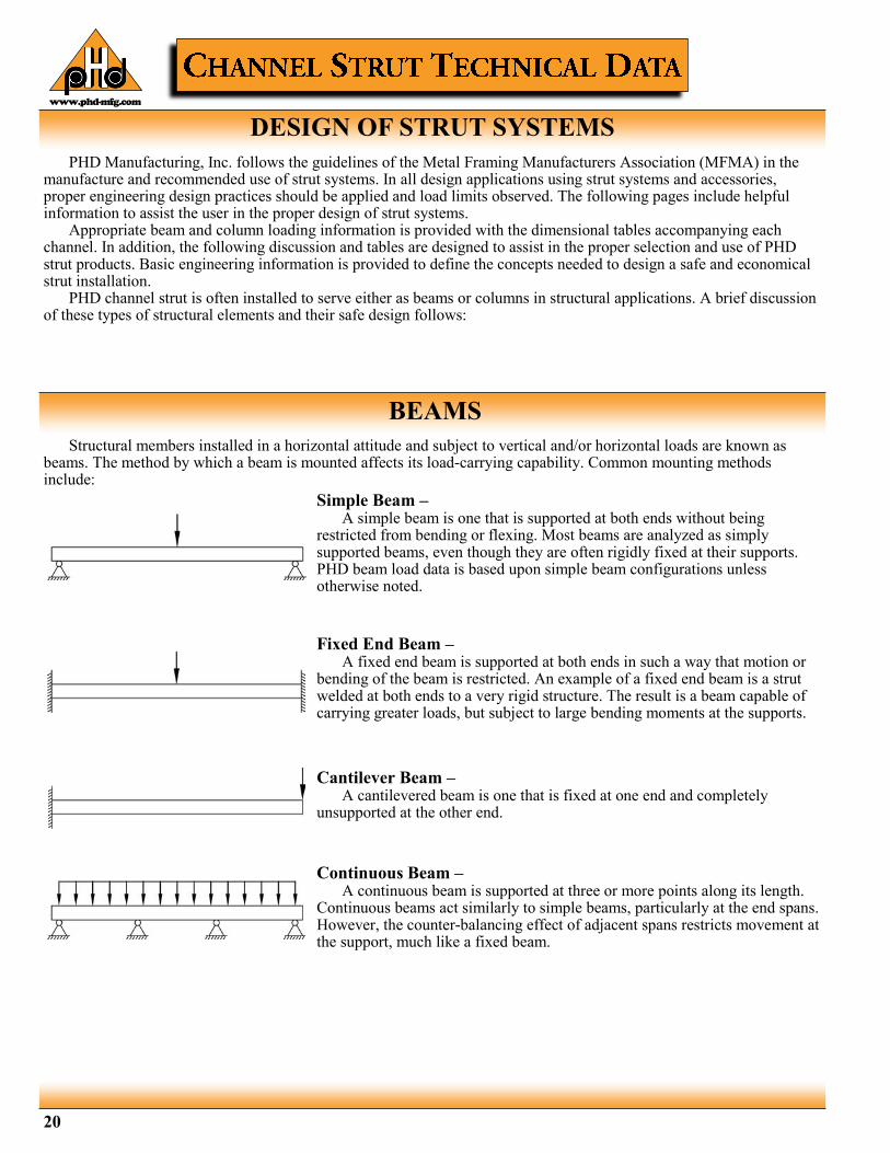
Structural members installed in a horizontal attitude and subject to vertical and/or horizontal loads are known as beams. The method by which a beam is mounted affects its load-carrying capability. Common mounting methods include:
Simple Beam – A simple beam is one that is supported at both ends without being restricted from bending or flexing. Most beams are analyzed as simply supported beams, even though they are often rigidly fixed at their supports. PHD beam load data is based upon simple beam configurations unless otherwise noted.
Fixed End Beam – A fixed end beam is supported at both ends in such a way that motion or bending of the beam is restricted. An example of a fixed end beam is a strut welded at both ends to a very rigid structure. The result is a beam capable of carrying greater loads, but subject to large bending moments at the supports.
Cantilever Beam – A cantilevered beam is one that is fixed at one end and completely unsupported at the other end.
Continuous Beam – A continuous beam is supported at three or more points along its length. Continuous beams act similarly to simple beams, particularly at the end spans. However, the counter-balancing effect of adjacent spans restricts movement at the support, much like a fixed beam.
www.phd-mfg.com
21
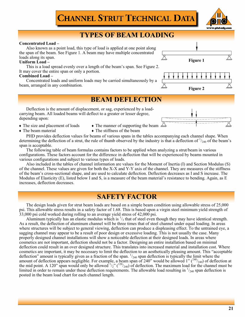
TYPES OF BEAM LOADING Concentrated Load – Also known as a point load, this type of load is applied at one point along the span of the beam. See Figure 1. A beam may have multiple concentrated loads along its span. Uniform Load – This is a load spread evenly over a length of the beam’s span. See Figure 2. It may cover the entire span or only a portion. Combined Load – Concentrated loads and uniform loads may be carried simultaneously by a beam, arranged in any combination.
Figure 1
Figure 2
SAFETY FACTOR The design loads given for strut beam loads are based on a simple beam condition using allowable stress of 25,000 psi. This allowable stress results in a safety factor of 1.68. This is based upon a virgin steel minimum yield strength of 33,000 psi cold worked during rolling to an average yield stress of 42,000 psi. Aluminum typically has an elastic modulus which is 1/3 that of steel even though they may have identical strength. As a result, the deflection of aluminum channel will be three times that of steel channel under equal loading. In areas where structures will be subject to general viewing, deflection can produce a displeasing effect. To the untrained eye, a sagging channel may appear to be a result of poor design or excessive loading. This is not usually the case. Many properly designed channel installations will show a noticeable deflection at their designed loads. In areas where cosmetics are not important, deflection should not be a factor. Designing an entire installation based on minimal deflection could result in an over designed structure. This translates into increased material and installation cost. Where cosmetics are important, it may be necessary to limit the deflection to an aesthetically pleasing amount. This “acceptable deflection” amount is typically given as a fraction of the span. 1/240 span deflection is typically the limit where the amount of deflection appears negligible. For example, a beam span of 240” would be allowed 1” (240/240) of deflection at the mid point. A 120” span would only be allowed 1/2” (120/240) of deflection. The maximum load for the channel must be limited in order to remain under these deflection requirements. The allowable load resulting in 1/240 span deflection is posted in the beam load chart for each channel length.
PHD provides deflection values for beams of various spans in the tables accompanying each channel shape. When determining the deflection of a strut, the rule of thumb observed by the industry is that a deflection of 1/240 of the beam’s span is acceptable. The following table of beam formulas contains factors to be applied when analyzing a strut/beam in various configurations. These factors account for the difference in deflection that will be experienced by beams mounted in various configurations and subject to various types of loads. Also included in the tables of channel information are values for the Moment of Inertia (I) and Section Modulus (S) of the channel. These values are given for both the X-X and Y-Y axis of the channel. They are measures of the stiffness of the beam’s cross-sectional shape, and are used to calculate deflection. Deflection decreases as I and S increase. The Modulus of Elasticity (E), listed below I and S, is a measure of the beam material’s resistance to bending. Again, as E increases, deflection decreases.
Deflection is the amount of displacement, or sag, experienced by a load-carrying beam. All loaded beams will deflect to a greater or lesser degree, depending upon:
The size and placement of loads The beam material
The manner of supporting the beam The stiffness of the beam
BEAM DEFLECTION
22
Unless otherwise specified, all dimensions on drawings and in charts are in inches and dimensions shown in parentheses are in millimeters.
www.phd-mfg.com
For long spans and when loads are apt to cause torsion on the beam, it is a good practice to brace the beam to prevent twisting or lateral bending. PHD offers various types of braces for this purpose. Loading of strut on long spans can cause torsional stress, resulting in the tendency of the strut to twist or bend laterally. This phenomenon reduces the allowable beam loads as shown in the beam loading charts. It is recommended that long spans be supported in a manner to prevent twisting (fixed ends), and that the channel have adequate lateral bracing. Many typical strut applications provide this support and bracing inherently. Piping, tubing, cable trays, or conduits mounted to the strut with straps and clamps prevent twisting or lateral movement.
TWISTING & LATERAL BRACING
WELDING
When loads are placed on a beam, the effect is to flex the beam across its unsupported span. The measure of this effect is called the bending moment. Formulas for bending moments created by various load and beam support combinations are given in the beam diagrams & common formulas section. When the bending moment of a loaded beam is divided by the Section Modulus of the beam, the resulting value is called bending stress. It is this bending stress that is most commonly evaluated to determine whether a beam is strong enough for the loads it must support. The maximum bending stress prescribed by structural codes is 25,000 psi (172.37 mPa), and this is the stress upon which PHD load figures are based. Again, the method of supporting a beam affects the maximum bending moment of the beam. The following table gives modifying factors based upon types of beam supports. Users of PHD struts should take care to apply the proper load factor for the specific beam support configuration in order to determine the proper maximum load that the strut will safely support.
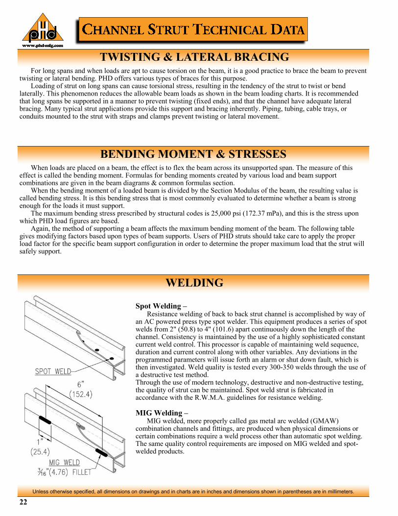
Spot Welding – Resistance welding of back to back strut channel is accomplished by way of an AC powered press type spot welder. This equipment produces a series of spot welds from 2" (50.8) to 4" (101.6) apart continuously down the length of the channel. Consistency is maintained by the use of a highly sophisticated constant current weld control. This processor is capable of maintaining weld sequence, duration and current control along with other variables. Any deviations in the programmed parameters will issue forth an alarm or shut down fault, which is then investigated. Weld quality is tested every 300-350 welds through the use of a destructive test method. Through the use of modern technology, destructive and non-destructive testing, the quality of strut can be maintained. Spot weld strut is fabricated in accordance with the R.W.M.A. guidelines for resistance welding. MIG Welding – MIG welded, more properly called gas metal arc welded (GMAW) combination channels and fittings, are produced when physical dimensions or certain combinations require a weld process other than automatic spot welding. The same quality control requirements are imposed on MIG welded and spot-welded products.
BENDING MOMENT & STRESSES
www.phd-mfg.com
23
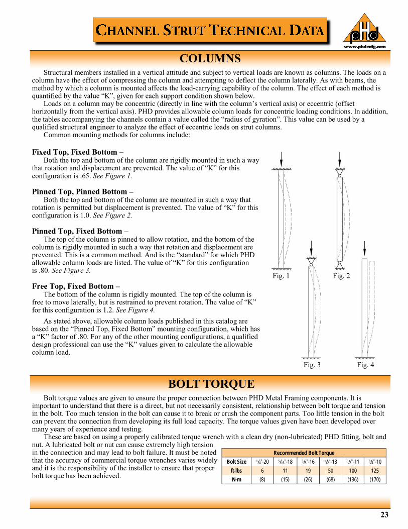
COLUMNS Structural members installed in a vertical attitude and subject to vertical loads are known as columns. The loads on a column have the effect of compressing the column and attempting to deflect the column laterally. As with beams, the method by which a column is mounted affects the load-carrying capability of the column. The effect of each method is quantified by the value “K”, given for each support condition shown below. Loads on a column may be concentric (directly in line with the column’s vertical axis) or eccentric (offset horizontally from the vertical axis). PHD provides allowable column loads for concentric loading conditions. In addition, the tables accompanying the channels contain a value called the “radius of gyration”. This value can be used by a qualified structural engineer to analyze the effect of eccentric loads on strut columns. Common mounting methods for columns include:
BOLT TORQUE Bolt torque values are given to ensure the proper connection between PHD Metal Framing components. It is important to understand that there is a direct, but not necessarily consistent, relationship between bolt torque and tension in the bolt. Too much tension in the bolt can cause it to break or crush the component parts. Too little tension in the bolt can prevent the connection from developing its full load capacity. The torque values given have been developed over many years of experience and testing. These are based on using a properly calibrated torque wrench with a clean dry (non-lubricated) PHD fitting, bolt and nut. A lubricated bolt or nut can cause extremely high tension in the connection and may lead to bolt failure. It must be noted that the accuracy of commercial torque wrenches varies widely and it is the responsibility of the installer to ensure that proper bolt torque has been achieved.
Fixed Top, Fixed Bottom – Both the top and bottom of the column are rigidly mounted in such a way that rotation and displacement are prevented. The value of “K” for this configuration is .65. See Figure 1. Pinned Top, Pinned Bottom – Both the top and bottom of the column are mounted in such a way that rotation is permitted but displacement is prevented. The value of “K” for this configuration is 1.0. See Figure 2. Pinned Top, Fixed Bottom – The top of the column is pinned to allow rotation, and the bottom of the column is rigidly mounted in such a way that rotation and displacement are prevented. This is a common method. And is the “standard” for which PHD allowable column loads are listed. The value of “K” for this configuration is .80. See Figure 3. Free Top, Fixed Bottom – The bottom of the column is rigidly mounted. The top of the column is free to move laterally, but is restrained to prevent rotation. The value of “K” for this configuration is 1.2. See Figure 4.
As stated above, allowable column loads published in this catalog are based on the “Pinned Top, Fixed Bottom” mounting configuration, which has a “K” factor of .80. For any of the other mounting configurations, a qualified design professional can use the “K” values given to calculate the allowable column load.
Recommended Bolt Torque
Bolt Size 1/4”-20 5/16”-18 3/8”-16 1/2”-13 5/8”-11 3/4”-10
ft-lbs 6 11 19 50 100 125
N-m (8) (15) (26) (68) (136) (170)
Fig. 1 Fig. 2
Fig. 3 Fig. 4
www.phd-mfg.com
24
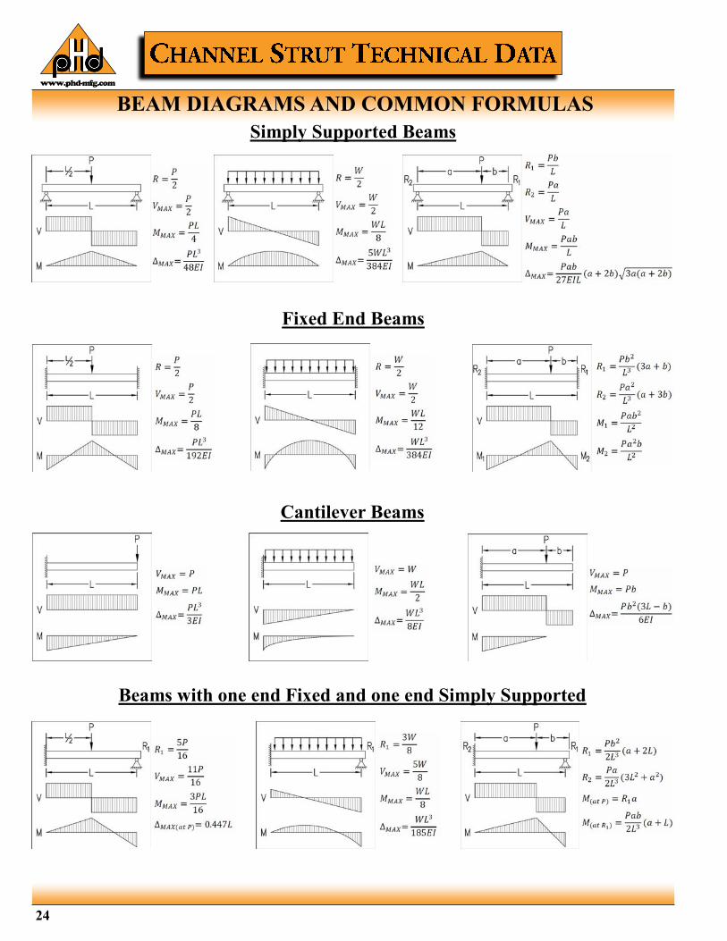
BEAM DIAGRAMS AND COMMON FORMULAS
Simply Supported Beams
Fixed End Beams
Cantilever Beams
Beams with one end Fixed and one end Simply Supported

www.phd-mfg.com
25
LATERAL BRACING LOAD REDUCTION FACTORS
BEARING LOADS ON CHANNEL
Beam Span or Unbraced Length
Single Channel Series Welded Double Channel Series
1000 1100 1200 1300 1400 1500 1600 1700 1800 1000 1100 1200 1300 1400 1500 1600 1700 1800
24 (609.6) 1.00 1.00 1.00 1.00 1.00 0.98 0.99 1.00 1.00 1.00 1.00 1.00 1.00 1.00 1.00 1.00 1.00 1.00
36 (914.4) 0.94 0.89 1.00 0.98 1.00 0.85 0.89 0.96 0.94 1.00 1.00 1.00 1.00 1.00 1.00 1.00 1.00 1.00
48 (1219.2) 0.88 0.78 1.00 0.94 0.98 0.70 0.77 0.91 0.88 1.00 0.98 1.00 1.00 1.00 0.97 0.98 1.00 0.98
60 (1524.0) 0.82 0.68 1.00 0.91 0.96 0.55 0.67 0.88 0.83 0.97 0.93 1.00 0.96 1.00 0.90 0.93 0.98 0.93
72 (1828.8) 0.78 0.59 0.98 0.89 0.94 0.44 0.58 0.84 0.79 0.93 0.87 0.97 0.92 0.97 0.83 0.87 0.95 0.88
84 (2133.6) 0.75 0.52 0.97 0.86 0.92 0.38 0.51 0.82 0.75 0.89 0.82 0.95 0.89 0.95 0.76 0.81 0.92 0.83
96 (2438.4) 0.71 0.47 0.96 0.84 0.91 0.33 0.46 0.79 0.72 0.85 0.76 0.92 0.85 0.92 0.68 0.76 0.88 0.79
108 (2743.2) 0.69 0.43 0.95 0.82 0.89 0.30 0.42 0.77 0.69 0.81 0.70 0.90 0.81 0.90 0.61 0.70 0.85 0.74
120 (3048.0) 0.66 0.40 0.94 0.80 0.87 0.28 0.40 0.75 0.66 0.78 0.65 0.87 0.78 0.87 0.54 0.64 0.82 0.69
144 (3657.6) 0.61 0.36 0.91 0.76 0.84 0.24 0.36 0.70 0.60 0.70 0.54 0.83 0.71 0.82 0.43 0.53 0.76 0.60
168 (4267.2) 0.55 0.32 0.89 0.73 0.81 0.22 0.32 0.66 0.55 0.63 0.45 0.78 0.64 0.77 0.35 0.45 0.70 0.51
192 (4876.8) 0.51 0.30 0.87 0.69 0.78 0.21 0.30 0.62 0.50 0.56 0.39 0.73 0.57 0.72 0.30 0.39 0.64 0.44
216 (5486.4) 0.47 0.28 0.84 0.65 0.75 0.19 0.28 0.58 0.47 0.49 0.34 0.68 0.50 0.67 0.27 0.34 0.58 0.39
240 (6096.0) 0.44 0.26 0.82 0.61 0.72 0.18 0.26 0.54 0.43 0.44 0.31 0.63 0.45 0.62 0.24 0.30 0.52 0.35
Channel
Bearing Length = 15/8 (41.3) Maximum Allowable Loads
Bearing Length = 15/8 (41.3) Maximum Allowable Loads
Bearing Length = 31/4 (82.6) Maximum Allowable Loads
Lbs. kN Lbs. kN Lbs. kN
1000 6700 (29.8) 3100 (13.8) 7700 (34.3)
1100 3500 (15.6) 1700 (7.6) 4000 (17.8)
1200 7300 (32.5) 3400 (15.1) 8400 (37.4)
1300 3500 (15.6) 1800 (8.0) 4100 (18.2)
1400 7300 (32.5) 3400 (15.1) 8400 (37.4)
1500 6500 (28.9) 3000 (13.3) 7500 (33.4)
1600 6600 (29.4) 3100 (13.8) 7600 (33.8)
1700 6700 (29.8) 3200 (14.2) 7700 (34.3)
1800 2600 (11.6) 1200 (5.3) 3000 (13.3)
Loads are calculated based on Specification For The Design Of Cold Formed Steel Structural Members published by AISI.

www.phd-mfg.com
26
BEAM LOAD & DEFLECTION CONVERSION FACTORS The allowable beam loads listed for various spans of each channel assume that the beam is a simply supported, single span beam. Although this is the most common condition, it is not always true. For other support conditions, multiply the listed allowable load by the factors in this table to obtain the proper load for the given mounting type.
Load & Support Configuration Diagram Deflection
Factor Load
Factor
1) Simply Supported Beam, Uniform Load 1.00 1.00
2) Simply Supported Beam, Concentrated Load at Mid-span
.80 .50
3) Simply Supported Beam, Two Equal Concentrated Loads at 1/4
Points 1.10 1.00
4) Fixed End Beam, Uniform Load
.30 1.50
5) Fixed End Beam, Concentrated Load at Mid-span
.40 1.00
6) Cantilever Beam, Uniform Load
2.40 .25
7) Cantilever Beam, Concentrated Load at End
3.20 .12
8) Continuous Beam, Two Equal Spans, Uniform Load Both Spans
.42 1.00
9) Continuous Beam, Two Equal Spans, Uniform Load on One Span
.92 1.30
10) Continuous Beam, Two Equal Spans, Concentrated Load at Mid-span of Each
.71 .62
11) Continuous Beam, Two Equal Spans, Concentrated Load at Mid-span of One
.48 .66

www.phd-mfg.com
27
SAMPLE PROBLEMS
Problem 1 – The beam at right is a PHD 1001 Channel, simply supported. What is the maximum allowable load P? How much will the beam deflect under that load?
Answer – From the table of Beam and Column Loads for 1001 Channel, the load for this span is 851 lbs. and the deflection is .22". From the table of load factors, the load conversion factor is .50 and the deflection factor is .80. Therefore, the maximum load P = 851 X .50 = 425 lbs., and the deflection is .22" x .80 = .176".
Problem 2 – A PHD 1001 Channel is supported at 3 points as shown, making it a continuous beam with 2 spans. The required loading condition is a uniform load of 7 lbs. per inch over both spans. Is the Channel able to safely support this load?
Answer – The entire load on one span of this beam is 7 lbs./in. X 84" = 588 lbs. The allowable load is 486, and the load factor is 1.00, so the allowable load remains 486 lbs. Therefore the beam is not acceptable, since the required load exceeds the allowable load. A different PHD channel must be used, or the load must be decreased.
Problem 3 – The cantilever beam shown at right carries a concentrated load of 180 lbs. at the end of the 24" PHD 1001 Channel. Is the load acceptable? Calculate the maximum bending moment and deflection.
Answer – The maximum load is 1702 lbs., and the load factor is .12, so the maximum load is 1702 X .12 = 204 lbs. The desired 180 lb. load is within the allowable. From the table of beam formulas, the maximum bending moment for this support condition is M = PL. For the beam show, then, M = 180 lb. X 24" = 4320 inch-pounds. Deflection for this cantilever beam = PL3 /3EI. E = Modulus of Elasticity, which is 30 X 106 for steel. I is the Moment of Inertia, listed in the channel information as .189 in4 . The deflection then, is found by the equation [180(24)3]/[3(30 X 106)(.189)] = .146".
Problem 4 – Determine the maximum load and deflection of a PHD 1001 Channel fixed at both ends and carrying a uniform load over its entire 60" span.
Answer – The maximum load from the chart is 681 lbs., and the load factor is 1.50, so the maximum load for this beam is 681 X 1.50 = 1021.5 lbs. Similarly, the deflection for this beam is .35" and the deflection factor is .30, so the deflection = .35 X .30 = .105".
28
Unless otherwise specified, all dimensions on drawings and in charts are in inches and dimensions shown in parentheses are in millimeters.
www.phd-mfg.com
SELECTION CHART
LONG SLOTS SLOTS
HOLES KNOCKOUTS
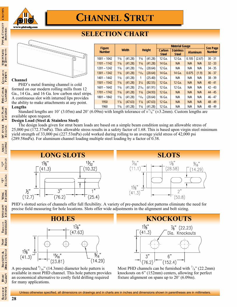
Channel PHD’s metal framing channel is cold formed on our modern rolling mills from 12 Ga., 14 Ga., and 16 Ga. low carbon steel strips. A continuous slot with inturned lips provides the ability to make attachments at any point. Lengths Standard lengths are 10’ (3.05m) and 20’ (6.09m) with length tolerance of ±1/8” (±3.2mm). Custom lengths are available upon request. Design Load (Steel & Stainless Steel) The design loads given for strut beam loads are based on a simple beam condition using an allowable stress of 25,000 psi (172.37mPa). This allowable stress results in a safety factor of 1.68. This is based upon virgin steel minimum yield strength of 33,000 psi (227.53mPa) cold worked during rolling to an average yield stress of 42,000 psi (289.58mPa). For aluminum channel loading multiple steel loading by a factor of 0.38.
Figure Number
Width Height
Material Gauge See Page Number Carbon
Steel Stainless
Steel Aluminum
1001 – 1042 15/8 (41.28) 15/8 (41.28) 12 Ga. 12 Ga. 0.105 (2.67) 30 - 31
1101 – 1142 15/8 (41.28) 15/8 (41.28) 14 Ga. N/A N/A N/A 32 - 33
1201 – 1242 15/8 (41.28) 13/16 (20.64) 12 Ga. N/A N/A N/A 34 - 35
1301 – 1342 15/8 (41.28) 13/16 (20.64) 14 Ga. 14 Ga. 0.075 (1.9) 36 - 37
1401 – 1442 15/8 (41.28) 1 (25.40) 12 Ga. N/A N/A N/A 38 - 39
1501 – 1542 15/8 (41.28) 31/4 (82.55) 12 Ga. 12 Ga. N/A N/A 40 - 41
1601 – 1642 15/8 (41.28) 27/16 (61.91) 12 Ga. 12 Ga. N/A N/A 42 - 43
1701 – 1742 15/8 (41.28) 13/8 (34.93) 12 Ga. N/A N/A N/A 44 - 45
1801 – 1842 15/8 (41.28) 13/16 (20.64) 16 Ga. N/A N/A N/A 46 - 47
1950 17/8 (47.63) 17/8 (47.63) 12 Ga. N/A N/A N/A 48 - 49
1960 15/8 (41.28) 15/8 (41.28) 12 Ga. N/A N/A N/A 48 - 49
PHD’s slotted series of channels offer full flexibility. A variety of pre-punched slot patterns eliminate the need for precise field measuring for hole locations. Slots offer wide adjustments in the alignment and bolt sizing.
A pre-punched 9/16” (14.3mm) diameter hole pattern is available in most PHD channel. This hole pattern provides an economical alternative to costly field drilling required for many applications.
Most PHD channels can be furnished with 7/8” (22.2mm) knockouts on 6” (152mm) centers, allowing for perfect fixture alignment on spans up to 20’ (6.09m).

29
Unless otherwise specified, all dimensions on drawings and in charts are in inches and dimensions shown in parentheses are in millimeters.
www.phd-mfg.com
CHANNEL COMBINATIONS

30
Unless otherwise specified, all dimensions on drawings and in charts are in inches and dimensions shown in parentheses are in millimeters.
www.phd-mfg.com
Material: Carbon steel (Aluminum and
Type 304 or 316 Stainless Steel upon request)
Finish: Plain, pre-galvanized, channel
green, e-coat, or hot dipped galvanized
Ordering: Specify figure number, material,
finish, and number of feet.
FIG. 1001-1042 15/8” X 1
5/8” X 12 GAUGE
1011-1012 1021-1022
1031-1032 1041-1042
Fig. No. Type - Description
Bundle Qty. Weight
10ft. (3.05m) 20ft. (6.1m) lbs./ft. kg/m 10ft. 6.1m 3.05m 20ft.
1001 1002 No Openings 1.77 (2.63) 500 (152.4) (152.4) 500
1001A 1002A Welded Back to Back 3.54 (5.27) 300 (91.4) (91.4) 300
1011 1012 With 11/8" X 9/16" (28.58 X 14.29) slots on 2" (50.8) centers 1.70 (2.53) 500 (152.4) (152.4) 500
1011A 1012A Welded Back to Back 3.40 (5.06) 300 (91.4) (91.4) 300
1021 1022 With 9/16" (14.29) dia. holes on 17/8" (47.63) centers 1.70 (2.53) 500 (152.4) (152.4) 500
1021A 1022A Welded Back to Back 3.40 (5.06) 300 (91.4) (91.4) 300
1031 1032 With 3" (76.20) slots 1.68 (2.50) 500 (152.4) (152.4) 500
1041 1042 With 7/8" (22.23) Knockouts on 6" (152.40) centers 1.77 (2.63) 500 (152.4) (152.4) 500

31
Unless otherwise specified, all dimensions on drawings and in charts are in inches and dimensions shown in parentheses are in millimeters.
www.phd-mfg.com
15/8” X 1
5/8” X 12 GAUGE FIG. 1001-1042
Fig. No.
X-X Axis Y-Y Axis
Area of Section
Moment Of Inertia
Section Modulus
Radius of Gyration
Moment Of Inertia
Section Modulus
Radius of Gyration
in.2 cm2 in.4 cm4 in.3 cm3 in. cm in.4 cm4 in.3 cm3 in. cm
1001 0.562 (3.626) 0.1912 (7.961) 0.2125 (3.482) 0.583 (1.481) 0.2399 (9.988) 0.2953 (4.839) 0.653 (1.659)
1001A 1.124 (7.252) 0.9732 (40.519) 0.5989 (9.814) 0.931 (2.365) 0.4798 (19.977) 0.5905 (9.677) 0.653 (1.659)
Modules of Elasticity: 29,500,000 psi (203,395.3 mPa)
Section Properties
Beam & Column Load Table
Beam Loads: Published loads are given in total uniform load (lbs.) not uniform load (lbs./ft.). For loads concentrated at center of span multiply uniform load by 0.5 and multiply the deflection by 0.8 (refer to page 26 for reduction factors on other beam configurations.). When deflection is not a factor use stress of 25,000 PSI (172.37 mPa). When deflection is a factor use deflection of 1/240 span. *Failure determined by weld shear.
Column Loads: Column loadings are for allowable axial loads for the unsupported heights listed and include a K value of .80. If eccentric, loads should be reduced according to standard practice.
For pierced Channels, reduce beam load values as follows: 1011 & 1012 = 15% 1021 & 1022 = 10% 1031 & 1032 = 30% 1041 & 1042 = 5%
SPOT WELDING Resistance welding of back to back strut channel is accomplished by way of an AC powered press type spot welder. This equipment produces a series of spot welds from 2" (50.8) to 4" (101.6) apart continuously down the length of the channel. Consistency is maintained by the use of a highly sophisticated constant current weld control. This processor is capable of maintaining weld sequence, duration and current control along with other variables. Any deviations in the programmed parameters will issue forth an alarm or shut down fault, which is then investigated. Weld quality is tested every 300-350 welds through the use of a destructive test method. Through the use of modern technology, destructive and non-destructive testing, the quality of strut can be maintained. Spot weld strut is fabricated in accordance with the R.W.M.A. guidelines for resistance welding.
Fig. No.
Beam Span or Unbraced
Column Height
Maximum Column Load
Uniform Load @25,000 psi
Deflection @25,000 psi
Uniform Load @1/240 Span
lbs. kN lbs. kN lbs. kN
1001 12 (304.8)
10454 (46.50) 2610 (11.61) 0.01 (0.25) 2610 (11.61)
1001A 21625 (96.19) 2610* (11.61) 0.01 (0.25) 2610* (11.61)
1001 24 (609.6)
9311 (41.42) 1702 (7.57) 0.06 (1.52) 1702 (7.57)
1001A 21164 (94.14) 2610* (11.61) 0.02 (0.51) 2610* (11.61)
1001 36 (914.4)
7801 (34.70) 1135 (5.05) 0.13 (3.30) 1135 (5.05)
1001A 20397 (90.73) 2610* (11.61) 0.06 (1.52) 2610* (11.61)
1001 48 (1219.2)
6193 (27.55) 851 (3.79) 0.22 (5.59) 758 (3.37)
1001A 19322 (85.95) 2405 (10.70) 0.13 (3.30) 2405 (10.70)
1001 60 (1524.0)
4718 (20.99) 681 (3.03) 0.35 (8.89) 485 (2.16)
1001A 17940 (79.80) 1924 (8.56) 0.20 (5.08) 1924 (8.56)
1001 72 (1828.8)
3791 (16.86) 567 (2.52) 0.51 (12.95) 337 (1.50)
1001A 16251 (72.29) 1603 (7.13) 0.28 (7.11) 1603 (7.13)
1001 84 (2133.6)
3176 (14.13) 486 (2.16) 0.69 (17.53) 248 (1.10)
1001A 14255 (63.41) 1374 (6.11) 0.38 (9.65) 1255 (5.58)
1001 96 (2438.4)
2728 (12.13) 425 (1.89) 0.90 (22.86) 190 (0.85)
1001A 11951 (53.16) 1202 (5.35) 0.50 (12.70) 961 (4.27)
1001 108 (2743.2)
2381 (10.59) 378 (1.68) 1.13 (28.70) 150 (0.67)
1001A 9524 (42.36) 1069 (4.76) 0.63 (16.00) 759 (3.38)
1001 120 (3048.0)
2101 (9.35) 340 (1.51) 1.40 (35.56) 121 (0.54)
1001A 7715 (34.32) 962 (4.28) 0.78 (19.81) 615 (2.74)
1001 144 (3657.6)
1660 (7.38) 280 (1.25) 2.00 (50.80) 80 (0.36)
1001A 5040 (22.42) 800 (3.56) 1.14 (28.96) 420 (1.87)
1001 168 (4267.2)
- - 240 (1.07) 2.72 (69.09) 60 (0.27)
1001A - - 680 (3.02) 1.53 (38.86) 310 (1.38)
1001 192 (4876.8)
- - 210 (0.93) 3.55 (90.17) 50 (0.22)
1001A - - 600 (2.67) 2.02 (51.31) 240 (1.07)
1001 216 (5486.4)
- - 190 (0.85) 4.58 (116.33) 40 (0.18)
1001A - - 530 (2.36) 2.54 (64.52) 190 (0.85)
1001 240 (6096.0)
- - 170 (0.76) 5.62 (142.75) - -
1001A - - 480 (2.14) 3.16 (80.26) 150 (0.67)

32
Unless otherwise specified, all dimensions on drawings and in charts are in inches and dimensions shown in parentheses are in millimeters.
www.phd-mfg.com
FIG. 1101-1142 15/8” X 1
5/8” X 14 GAUGE
1111-1112 1121-1122
1131-1132 1141-1142
Fig. No. Type - Description
Bundle Qty. Weight
10ft. (3.05m) 20ft. (6.1m) lbs./ft. kg/m 10ft. 6.1m 3.05m 20ft.
1101 1102 No Openings 1.30 (1.93) 500 (152.4) (152.4) 500
1101A 1102A Welded Back to Back 2.60 (3.87) 300 (91.4) (91.4) 300
1111 1112 With 11/8" X 9/16" (28.58 X 14.29) slots on 2" (50.8) centers 1.28 (1.90) 500 (152.4) (152.4) 500
1111A 1112A Welded Back to Back 2.56 (3.81) 300 (91.4) (91.4) 300
1121 1122 With 9/16" (14.29) dia. holes on 17/8" (47.63) centers 1.30 (1.93) 500 (152.4) (152.4) 500
1121A 1122A Welded Back to Back 2.74 (4.08) 300 (91.4) (91.4) 300
1131 1132 With 3" (76.20) slots 1.29 (1.92) 500 (152.4) (152.4) 500
1141 1142 With 7/8" (22.23) Knockouts on 6" (152.40) centers 1.30 (1.93) 500 (152.4) (152.4) 500
Material: Carbon steel Finish: Plain, pre-galvanized, channel
green, e-coat, or hot dipped galvanized
Ordering: Specify figure number, finish,
and number of feet.

33
Unless otherwise specified, all dimensions on drawings and in charts are in inches and dimensions shown in parentheses are in millimeters.
www.phd-mfg.com
15/8” X 1
5/8” X 14 GAUGE FIG. 1101-1142
Fig. No.
X-X Axis Y-Y Axis
Area of Section
Moment Of Inertia
Section Modulus
Radius of Gyration
Moment Of Inertia
Section Modulus
Radius of Gyration
in.2 cm2 in.4 cm4 in.3 cm3 in. cm in.4 cm4 in.3 cm3 in. cm
1101 0.417 (2.690) 0.149 (6.204) 0.166 (2.720) 0.597 (1.516) 0.183 (7.619) 0.225 (3.687) 0.662 (1.681)
1101A 0.834 (5.381) 0.741 (30.852) 0.456 (7.472) 0.942 (2.393) 0.366 (15.238) 0.45 (7.374) 0.662 (1.681)
Modules of Elasticity: 29,500,000 psi (203,395.3 mPa)
For pierced Channels, reduce beam load values as follows: 1111 & 1112 = 15% 1121 & 1122 = 10% 1131 & 1132 = 30% 1141 & 1142 = 5%
Section Properties
Beam & Column Load Table
Fig. No.
Beam Span or Unbraced
Column Height
Maximum Column Load
Uniform Load @25,000 psi
Deflection @25,000 psi
Uniform Load @1/240 Span
lbs. kN lbs. kN lbs. kN
1101 12 (304.8)
6441 (28.65) 1750 (7.78) 0.01 (0.25) 1750 (7.78)
1101A 13212 (58.77) 1750* (7.78) 0.01 (0.25) 1750* (7.78)
1101 24 (609.6)
5874 (26.13) 1379 (6.13) 0.06 (1.52) 1379 (6.13)
1101A 12993 (57.80) 1750* (7.78) 0.01 (0.25) 1750* (7.78)
1101 36 (914.4)
5038 (22.41) 919 (4.09) 0.13 (3.30) 919 (4.09)
1101A 12627 (56.17) 1750* (7.78) 0.05 (1.27) 1750* (7.78)
1101 48 (1219.2)
4043 (17.98) 689 (3.06) 0.23 (5.84) 607 (2.70)
1101A 12115 (53.89) 1750* (7.78) 0.12 (3.05) 1750* (7.78)
1101 60 (1524.0)
3008 (13.38) 551 (2.45) 0.36 (9.14) 389 (1.73)
1101A 11456 (50.96) 1518 (6.75) 0.20 (5.08) 1518 (6.75)
1101 72 (1828.8)
2324 (10.34) 460 (2.05) 0.51 (12.95) 270 (1.20)
1101A 10651 (47.38) 1265 (5.63) 0.28 (7.11) 1265 (5.63)
1101 84 (2133.6)
1898 (8.44) 394 (1.75) 0.70 (17.78) 198 (0.88)
1101A 9700 (43.15) 1084 (4.82) 0.38 (9.65) 990 (4.40)
1101 96 (2438.4)
1608 (7.15) 345 (1.53) 0.91 (23.11) 152 (0.68)
1101A 8602 (38.26) 949 (4.22) 0.50 (12.70) 758 (3.37)
1101 108 (2743.2)
1397 (6.21) 306 (1.36) 1.15 (29.21) 120 (0.53)
1101A 7358 (32.73) 843 (3.75) 0.63 (16.00) 599 (2.66)
1101 120 (3048.0)
1263 (5.62) 276 (1.23) 1.42 (36.07) 97 (0.43)
1101A 6024 (26.80) 759 (3.38) 0.78 (19.81) 485 (2.16)
1101 144 (3657.6)
950 (4.23) 230 (1.02) 2.03 (51.56) 70 (0.31)
1101A 3770 (16.77) 640 (2.85) 1.14 (28.96) 340 (1.51)
1101 168 (4267.2)
- - 200 (0.89) 2.81 (71.37) 50 (0.22)
1101A - - 550 (2.45) 1.55 (39.37) 250 (1.11)
1101 192 (4876.8)
- - 170 (0.76) 3.56 (90.42) 40 (0.18)
1101A - - 480 (2.14) 2.02 (51.31) 190 (0.85)
1101 216 (5486.4)
- - 150 (0.67) 4.48 (113.79) 30 (0.13)
1101A - - 420 (1.87) 2.52 (64.01) 150 (0.67)
1101 240 (6096.0)
- - 140 (0.62) 5.73 (145.54) - -
1101A - - 380 (1.69) 3.13 (79.50) 120 (0.53)
Beam Loads: Published loads are given in total uniform load (lbs.) not uniform load (lbs./ft.). For loads concentrated at center of span multiply uniform load by 0.5 and multiply the deflection by 0.8 (refer to page 26 for reduction factors on other beam configurations.). When deflection is not a factor use stress of 25,000 PSI (172.37 mPa). When deflection is a factor use deflection of 1/240 span. *Failure determined by weld shear.
Column Loads: Column loadings are for allowable axial loads for the unsupported heights listed and include a K value of .80. If eccentric, loads should be reduced according to standard practice.
SPOT WELDING Resistance welding of back to back strut channel is accomplished by way of an AC powered press type spot welder. This equipment produces a series of spot welds from 2" (50.8) to 4" (101.6) apart continuously down the length of the channel. Consistency is maintained by the use of a highly sophisticated constant current weld control. This processor is capable of maintaining weld sequence, duration and current control along with other variables. Any deviations in the programmed parameters will issue forth an alarm or shut down fault, which is then investigated. Weld quality is tested every 300-350 welds through the use of a destructive test method. Through the use of modern technology, destructive and non-destructive testing, the quality of strut can be maintained. Spot weld strut is fabricated in accordance with the R.W.M.A. guidelines for resistance welding.
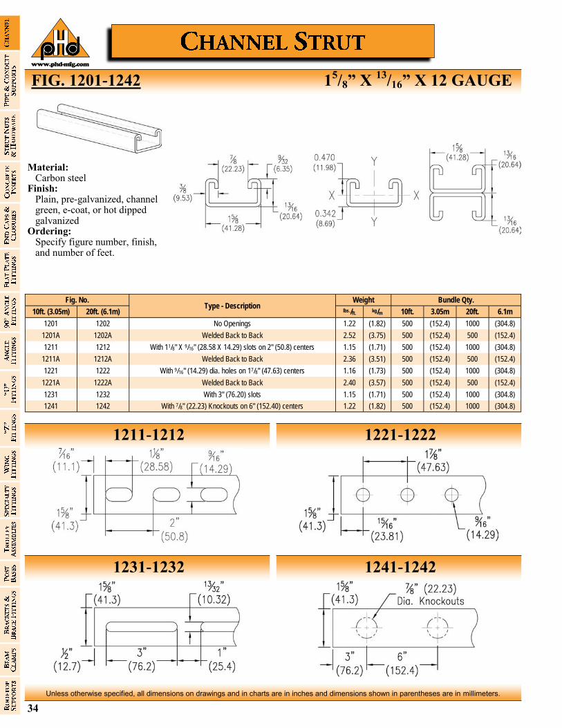
34
Unless otherwise specified, all dimensions on drawings and in charts are in inches and dimensions shown in parentheses are in millimeters.
www.phd-mfg.com
FIG. 1201-1242 15/8” X
13/16” X 12 GAUGE
1211-1212 1221-1222
1231-1232 1241-1242
Fig. No. Type - Description
Bundle Qty. Weight
10ft. (3.05m) 20ft. (6.1m) lbs./ft. kg/m 10ft. 6.1m 3.05m 20ft.
1201 1202 No Openings 1.22 (1.82) 500 (304.8) (152.4) 1000
1201A 1202A Welded Back to Back 2.52 (3.75) 500 (152.4) (152.4) 500
1211 1212 With 11/8" X 9/16" (28.58 X 14.29) slots on 2" (50.8) centers 1.15 (1.71) 500 (304.8) (152.4) 1000
1211A 1212A Welded Back to Back 2.36 (3.51) 500 (152.4) (152.4) 500
1221 1222 With 9/16" (14.29) dia. holes on 17/8" (47.63) centers 1.16 (1.73) 500 (304.8) (152.4) 1000
1221A 1222A Welded Back to Back 2.40 (3.57) 500 (152.4) (152.4) 500
1231 1232 With 3" (76.20) slots 1.15 (1.71) 500 (304.8) (152.4) 1000
1241 1242 With 7/8" (22.23) Knockouts on 6" (152.40) centers 1.22 (1.82) 500 (304.8) (152.4) 1000
Material: Carbon steel Finish: Plain, pre-galvanized, channel
green, e-coat, or hot dipped galvanized
Ordering: Specify figure number, finish,
and number of feet.
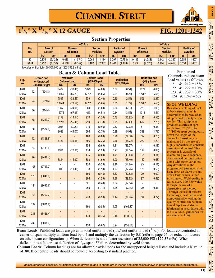
35
Unless otherwise specified, all dimensions on drawings and in charts are in inches and dimensions shown in parentheses are in millimeters.
www.phd-mfg.com
15/8” X
13/16” X 12 GAUGE FIG. 1201-1242
For pierced Channels, reduce beam load values as follows: 1211 & 1212 = 15% 1221 & 1222 = 10% 1231 & 1232 = 30% 1241 & 1242 = 5%
Fig. No.
X-X Axis Y-Y Axis
Area of Section
Moment Of Inertia
Section Modulus
Radius of Gyration
Moment Of Inertia
Section Modulus
Radius of Gyration
in.2 cm2 in.4 cm4 in.3 cm3 in. cm in.4 cm4 in.3 cm3 in. cm
1201 0.376 (2.426) 0.033 (1.374) 0.068 (1.114) 0.297 (0.754) 0.115 (4.788) 0.142 (2.327) 0.554 (1.407)
1201A 0.752 (4.852) 0.148 (6.162) 0.182 (2.982) 0.444 (1.128) 0.23 (9.576) 0.284 (4.654) 0.554 (1.407)
Modules of Elasticity: 29,500,000 psi (203,395.3 mPa)
Section Properties
Beam & Column Load Table
Fig. No.
Beam Span or Unbraced
Column Height
Maximum Column Load
Uniform Load @25,000 psi
Deflection @25,000 psi
Uniform Load @1/240 Span
lbs. kN lbs. kN lbs. kN
1201 12 (304.8)
8407 (37.40) 1079 (4.80) 0.02 (0.51) 1079 (4.80)
1201A 19160 (85.23) 1270* (5.65) 0.01 (0.25) 1270* (5.65)
1201 24 (609.6)
7519 (33.45) 539 (2.40) 0.10 (2.54) 506 (2.25)
1201A 17444 (77.59) 1270* (5.65) 0.05 (1.27) 1270* (5.65)
1201 36 (914.4)
5397 (24.01) 360 (1.60) 0.24 (6.10) 225 (1.00)
1201A 15275 (67.95) 1013 (4.51) 0.14 (3.56) 1013 (4.51)
1201 48 (1219.2)
3178 (14.14) 270 (1.20) 0.43 (10.92) 126 (0.56)
1201A 12692 (56.46) 759 (3.38) 0.25 (6.35) 607 (2.70)
1201 60 (1524.0)
2034 (9.05) 216 (0.96) 0.67 (17.02) 81 (0.36)
1201A 9683 (43.07) 608 (2.70) 0.39 (9.91) 388 (1.73)
1201 72 (1828.8)
- - 180 (0.80) 0.96 (24.38) 56 (0.25)
1201A 6780 (30.16) 506 (2.25) 0.56 (14.22) 270 (1.20)
1201 84 (2133.6)
- - 154 (0.69) 1.31 (33.27) 41 (0.18)
1201A 4981 (22.16) 434 (1.93) 0.77 (19.56) 198 (0.88)
1201 96 (2438.4)
- - 135 (0.60) 1.71 (43.43) 32 (0.14)
1201A 3814 (16.97) 380 (1.69) 1.00 (25.40) 152 (0.68)
1201 108 (2743.2)
- - 120 (0.53) 2.16 (54.86) 25 (0.11)
1201A 3013 (13.40) 338 (1.50) 1.27 (32.26) 120 (0.53)
1201 120 (3048.0)
- - 108 (0.48) 2.67 (67.82) 20 (0.09)
1201A - - 304 (1.35) 1.56 (39.62) 97 (0.43)
1201 144 (3657.6)
- - 90 (0.40) 3.84 (97.54) - -
1201A - - 250 (1.11) 2.25 (57.15) 70 (0.31)
1201 168 (4267.2)
- - - - - - - -
1201A - - 220 (0.98) 3.14 (79.76) 50 (0.22)
1201 192 (4876.8)
- - - - - - - -
1201A - - 190 (0.85) 4.05 (102.87) - -
1201 216 (5486.4)
- - - - - - - -
1201A - - 170 (0.76) 5.16 (131.06) - -
1201 240 (6096.0)
- - - - - - - -
1201A - - 150 (0.67) 6.24 (158.50) - -
Beam Loads: Published loads are given in total uniform load (lbs.) not uniform load (lbs./ft.). For loads concentrated at center of span multiply uniform load by 0.5 and multiply the deflection by 0.8 (refer to page 26 for reduction factors on other beam configurations.). When deflection is not a factor use stress of 25,000 PSI (172.37 mPa). When deflection is a factor use deflection of 1/240 span. *Failure determined by weld shear.
Column Loads: Column loadings are for allowable axial loads for the unsupported heights listed and include a K value of .80. If eccentric, loads should be reduced according to standard practice.
SPOT WELDING Resistance welding of back to back strut channel is accomplished by way of an AC powered press type spot welder. This equipment produces a series of spot welds from 2" (50.8) to 4" (101.6) apart continuously down the length of the channel. Consistency is maintained by the use of a highly sophisticated constant current weld control. This processor is capable of maintaining weld sequence, duration and current control along with other variables. Any deviations in the programmed parameters will issue forth an alarm or shut down fault, which is then investigated. Weld quality is tested every 300-350 welds through the use of a destructive test method. Through the use of modern technology, destructive and non-destructive testing, the quality of strut can be maintained. Spot weld strut is fabricated in accordance with the R.W.M.A. guidelines for resistance welding.
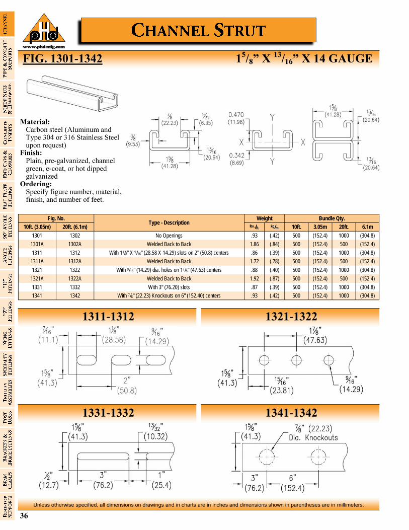
36
Unless otherwise specified, all dimensions on drawings and in charts are in inches and dimensions shown in parentheses are in millimeters.
www.phd-mfg.com
FIG. 1301-1342 15/8” X
13/16” X 14 GAUGE
1311-1312 1321-1322
1331-1332 1341-1342
Fig. No. Type - Description
Bundle Qty. Weight
10ft. (3.05m) 20ft. (6.1m) lbs./ft. kg/m 10ft. 6.1m 3.05m 20ft.
1301 1302 No Openings .93 (.42) 500 (304.8) (152.4) 1000
1301A 1302A Welded Back to Back 1.86 (.84) 500 (152.4) (152.4) 500
1311 1312 With 11/8" X 9/16" (28.58 X 14.29) slots on 2" (50.8) centers .86 (.39) 500 (304.8) (152.4) 1000
1311A 1312A Welded Back to Back 1.72 (.78) 500 (152.4) (152.4) 500
1321 1322 With 9/16" (14.29) dia. holes on 17/8" (47.63) centers .88 (.40) 500 (304.8) (152.4) 1000
1321A 1322A Welded Back to Back 1.92 (.87) 500 (152.4) (152.4) 500
1331 1332 With 3" (76.20) slots .87 (.39) 500 (304.8) (152.4) 1000
1341 1342 With 7/8" (22.23) Knockouts on 6" (152.40) centers .93 (.42) 500 (304.8) (152.4) 1000
Material: Carbon steel (Aluminum and
Type 304 or 316 Stainless Steel upon request)
Finish: Plain, pre-galvanized, channel
green, e-coat, or hot dipped galvanized
Ordering: Specify figure number, material,
finish, and number of feet.
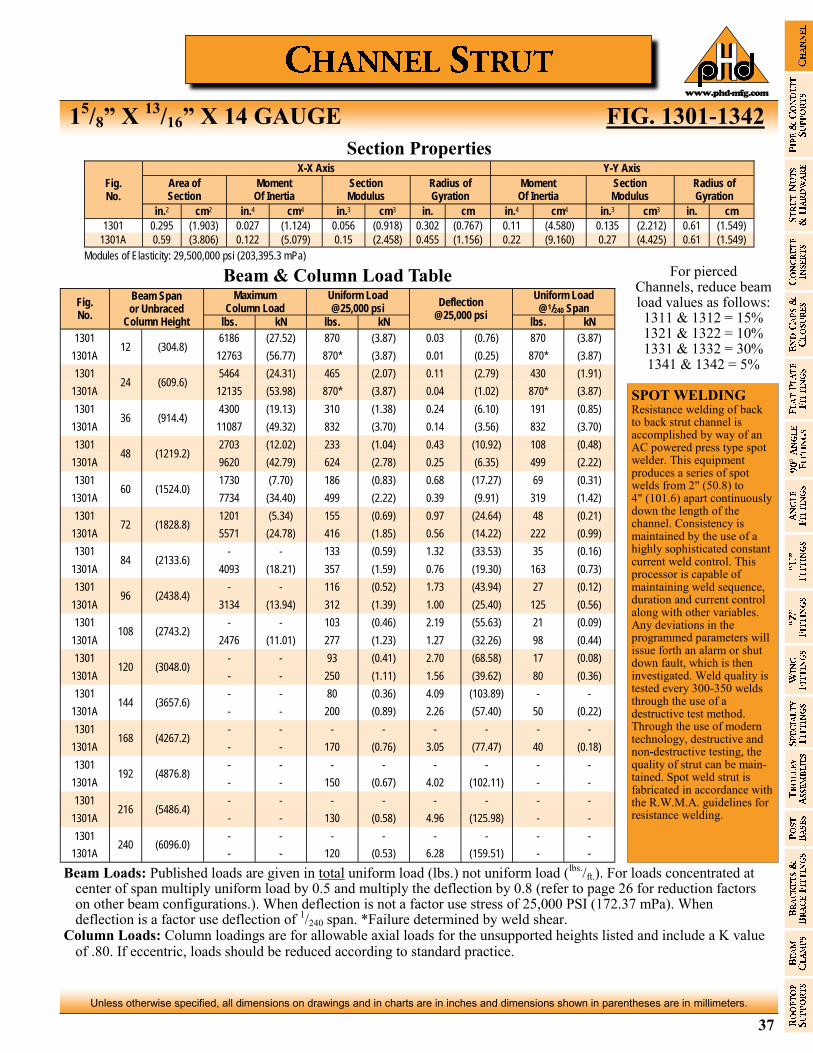
37
Unless otherwise specified, all dimensions on drawings and in charts are in inches and dimensions shown in parentheses are in millimeters.
www.phd-mfg.com
15/8” X
13/16” X 14 GAUGE FIG. 1301-1342
For pierced Channels, reduce beam load values as follows: 1311 & 1312 = 15% 1321 & 1322 = 10% 1331 & 1332 = 30% 1341 & 1342 = 5%
Fig. No.
X-X Axis Y-Y Axis
Area of Section
Moment Of Inertia
Section Modulus
Radius of Gyration
Moment Of Inertia
Section Modulus
Radius of Gyration
in.2 cm2 in.4 cm4 in.3 cm3 in. cm in.4 cm4 in.3 cm3 in. cm
1301 0.295 (1.903) 0.027 (1.124) 0.056 (0.918) 0.302 (0.767) 0.11 (4.580) 0.135 (2.212) 0.61 (1.549)
1301A 0.59 (3.806) 0.122 (5.079) 0.15 (2.458) 0.455 (1.156) 0.22 (9.160) 0.27 (4.425) 0.61 (1.549)
Modules of Elasticity: 29,500,000 psi (203,395.3 mPa)
Section Properties
Beam & Column Load Table
Fig. No.
Beam Span or Unbraced
Column Height
Maximum Column Load
Uniform Load @25,000 psi
Deflection @25,000 psi
Uniform Load @1/240 Span
lbs. kN lbs. kN lbs. kN
1301 12 (304.8)
6186 (27.52) 870 (3.87) 0.03 (0.76) 870 (3.87)
1301A 12763 (56.77) 870* (3.87) 0.01 (0.25) 870* (3.87)
1301 24 (609.6)
5464 (24.31) 465 (2.07) 0.11 (2.79) 430 (1.91)
1301A 12135 (53.98) 870* (3.87) 0.04 (1.02) 870* (3.87)
1301 36 (914.4)
4300 (19.13) 310 (1.38) 0.24 (6.10) 191 (0.85)
1301A 11087 (49.32) 832 (3.70) 0.14 (3.56) 832 (3.70)
1301 48 (1219.2)
2703 (12.02) 233 (1.04) 0.43 (10.92) 108 (0.48)
1301A 9620 (42.79) 624 (2.78) 0.25 (6.35) 499 (2.22)
1301 60 (1524.0)
1730 (7.70) 186 (0.83) 0.68 (17.27) 69 (0.31)
1301A 7734 (34.40) 499 (2.22) 0.39 (9.91) 319 (1.42)
1301 72 (1828.8)
1201 (5.34) 155 (0.69) 0.97 (24.64) 48 (0.21)
1301A 5571 (24.78) 416 (1.85) 0.56 (14.22) 222 (0.99)
1301 84 (2133.6)
- - 133 (0.59) 1.32 (33.53) 35 (0.16)
1301A 4093 (18.21) 357 (1.59) 0.76 (19.30) 163 (0.73)
1301 96 (2438.4)
- - 116 (0.52) 1.73 (43.94) 27 (0.12)
1301A 3134 (13.94) 312 (1.39) 1.00 (25.40) 125 (0.56)
1301 108 (2743.2)
- - 103 (0.46) 2.19 (55.63) 21 (0.09)
1301A 2476 (11.01) 277 (1.23) 1.27 (32.26) 98 (0.44)
1301 120 (3048.0)
- - 93 (0.41) 2.70 (68.58) 17 (0.08)
1301A - - 250 (1.11) 1.56 (39.62) 80 (0.36)
1301 144 (3657.6)
- - 80 (0.36) 4.09 (103.89) - -
1301A - - 200 (0.89) 2.26 (57.40) 50 (0.22)
1301 168 (4267.2)
- - - - - - - -
1301A - - 170 (0.76) 3.05 (77.47) 40 (0.18)
1301 192 (4876.8)
- - - - - - - -
1301A - - 150 (0.67) 4.02 (102.11) - -
1301 216 (5486.4)
- - - - - - - -
1301A - - 130 (0.58) 4.96 (125.98) - -
1301 240 (6096.0)
- - - - - - - -
1301A - - 120 (0.53) 6.28 (159.51) - -
Beam Loads: Published loads are given in total uniform load (lbs.) not uniform load (lbs./ft.). For loads concentrated at center of span multiply uniform load by 0.5 and multiply the deflection by 0.8 (refer to page 26 for reduction factors on other beam configurations.). When deflection is not a factor use stress of 25,000 PSI (172.37 mPa). When deflection is a factor use deflection of 1/240 span. *Failure determined by weld shear.
Column Loads: Column loadings are for allowable axial loads for the unsupported heights listed and include a K value of .80. If eccentric, loads should be reduced according to standard practice.
SPOT WELDING Resistance welding of back to back strut channel is accomplished by way of an AC powered press type spot welder. This equipment produces a series of spot welds from 2" (50.8) to 4" (101.6) apart continuously down the length of the channel. Consistency is maintained by the use of a highly sophisticated constant current weld control. This processor is capable of maintaining weld sequence, duration and current control along with other variables. Any deviations in the programmed parameters will issue forth an alarm or shut down fault, which is then investigated. Weld quality is tested every 300-350 welds through the use of a destructive test method. Through the use of modern technology, destructive and non-destructive testing, the quality of strut can be maintained. Spot weld strut is fabricated in accordance with the R.W.M.A. guidelines for resistance welding.

38
Unless otherwise specified, all dimensions on drawings and in charts are in inches and dimensions shown in parentheses are in millimeters.
www.phd-mfg.com
FIG. 1401-1442 15/8” X 1” X 12 GAUGE
1411-1412 1421-1422
1431-1432 1441-1442
Fig. No. Type - Description
Bundle Qty. Weight
10ft. (3.05m) 20ft. (6.1m) lbs./ft. kg/m 10ft. 6.1m 3.05m 20ft.
1401 1402 No Openings 1.38 (2.05) 500 (304.8) (152.4) 1000
1401A 1402A Welded Back to Back 2.88 (4.29) 500 (121.92) (152.4) 400
1411 1412 With 11/8" X 9/16" (28.58 X 14.29) slots on 2" (50.8) centers 1.34 (1.99) 500 (304.8) (152.4) 1000
1411A 1412A Welded Back to Back 2.72 (4.05) 500 (121.92) (152.4) 400
1421 1422 With 9/16" (14.29) dia. holes on 17/8" (47.63) centers 1.39 (2.07) 500 (304.8) (152.4) 1000
1421A 1422A Welded Back to Back 2.78 (4.14) 500 (121.92) (152.4) 400
1431 1432 With 3" (76.20) slots 1.31 (1.95) 500 (304.8) (152.4) 1000
1441 1442 With 7/8" (22.23) Knockouts on 6" (152.40) centers 1.38 (2.05) 500 (304.8) (152.4) 1000
Material: Carbon steel Finish: Plain, pre-galvanized, channel
green, e-coat, or hot dipped galvanized
Ordering: Specify figure number, finish,
and number of feet.

39
Unless otherwise specified, all dimensions on drawings and in charts are in inches and dimensions shown in parentheses are in millimeters.
www.phd-mfg.com
15/8” X 1” X 12 GAUGE FIG. 1401-1442
For pierced Channels, reduce beam load values as follows: 1411 & 1412 = 15% 1421 & 1422 = 10% 1431 & 1432 = 30% 1441 & 1442 = 5%
Fig. No.
X-X Axis Y-Y Axis
Area of Section
Moment Of Inertia
Section Modulus
Radius of Gyration
Moment Of Inertia
Section Modulus
Radius of Gyration
in.2 cm2 in.4 cm4 in.3 cm3 in. cm in.4 cm4 in.3 cm3 in. cm
1401 0.43 (2.774) 0.055 (2.290) 0.095 (1.557) 0.357 (0.907) 0.163 (6.787) 0.201 (3.294) 0.616 (1.565)
1401A 0.86 (5.548) 0.263 (10.950) 0.263 (4.310) 0.553 (1.405) 0.327 (13.615) 0.402 (6.588) 0.616 (1.565)
Modules of Elasticity: 29,500,000 psi (203,395.3 mPa)
Section Properties
Beam & Column Load Table
Fig. No.
Beam Span or Unbraced
Column Height
Maximum Column Load
Uniform Load @25,000 psi
Deflection @25,000 psi
Uniform Load @1/240 Span
lbs. kN lbs. kN lbs. kN
1401 12 (304.8)
9138 (40.65) 1538 (6.84) 0.02 (0.51) 1538 (6.84)
1401A 21094 (93.83) 1590* (7.07) 0.01 (0.25) 1590* (7.07)
1401 24 (609.6)
8137 (36.20) 769 (3.42) 0.09 (2.29) 769 (3.42)
1401A 19757 (87.88) 1590* (7.07) 0.04 (1.02) 1590* (7.07)
1401 36 (914.4)
7050 (31.36) 513 (2.28) 0.20 (5.08) 388 (1.73)
1401A 18094 (80.49) 1428 (6.35) 0.11 (2.79) 1428 (6.35)
1401 48 (1219.2)
5405 (24.04) 384 (1.71) 0.35 (8.89) 218 (0.97)
1401A 16139 (71.79) 1071 (4.76) 0.20 (5.08) 1053 (4.68)
1401 60 (1524.0)
3512 (15.62) 308 (1.37) 0.55 (13.97) 140 (0.62)
1401A 13906 (61.86) 857 (3.81) 0.32 (8.13) 674 (3.00)
1401 72 (1828.8)
2439 (10.85) 256 (1.14) 0.79 (20.07) 97 (0.43)
1401A 11387 (50.65) 714 (3.18) 0.46 (11.68) 468 (2.08)
1401 84 (2133.6)
1792 (7.97) 220 (0.98) 1.07 (27.18) 71 (0.32)
1401A 8645 (38.45) 612 (2.72) 0.62 (15.75) 344 (1.53)
1401 96 (2438.4)
- - 192 (0.85) 1.41 (35.81) 55 (0.24)
1401A 6619 (29.44) 535 (2.38) 0.81 (20.57) 263 (1.17)
1401 108 (2743.2)
- - 171 (0.76) 1.78 (45.21) 43 (0.19)
1401A 5230 (23.26) 476 (2.12) 1.03 (26.16) 208 (0.93)
1401 120 (3048.0)
- - 154 (0.69) 2.20 (55.88) 35 (0.16)
1401A 4236 (18.84) 428 (1.90) 1.27 (32.26) 168 (0.75)
1401 144 (3657.6)
- - 130 (0.58) 3.22 (81.79) 20 (0.09)
1401A - - 360 (1.60) 1.86 (47.24) 120 (0.53)
1401 168 (4267.2)
- - - - - - - -
1401A - - 310 (1.38) 2.54 (64.52) 90 (0.40)
1401 192 (4876.8)
- - - - - - - -
1401A - - 270 (1.20) 3.31 (84.07) 70 (0.31)
1401 216 (5486.4)
- - - - - - - -
1401A - - 240 (1.07) 4.19 (106.43) - -
1401 240 (6096.0)
- - - - - - - -
1401A - - 210 (0.93) 5.03 (127.76) - -
Beam Loads: Published loads are given in total uniform load (lbs.) not uniform load (lbs./ft.). For loads concentrated at center of span multiply uniform load by 0.5 and multiply the deflection by 0.8 (refer to page 26 for reduction factors on other beam configurations.). When deflection is not a factor use stress of 25,000 PSI (172.37 mPa). When deflection is a factor use deflection of 1/240 span. *Failure determined by weld shear.
Column Loads: Column loadings are for allowable axial loads for the unsupported heights listed and include a K value of .80. If eccentric, loads should be reduced according to standard practice.
SPOT WELDING Resistance welding of back to back strut channel is accomplished by way of an AC powered press type spot welder. This equipment produces a series of spot welds from 2" (50.8) to 4" (101.6) apart continuously down the length of the channel. Consistency is maintained by the use of a highly sophisticated constant current weld control. This processor is capable of maintaining weld sequence, duration and current control along with other variables. Any deviations in the programmed parameters will issue forth an alarm or shut down fault, which is then investigated. Weld quality is tested every 300-350 welds through the use of a destructive test method. Through the use of modern technology, destructive and non-destructive testing, the quality of strut can be maintained. Spot weld strut is fabricated in accordance with the R.W.M.A. guidelines for resistance welding.
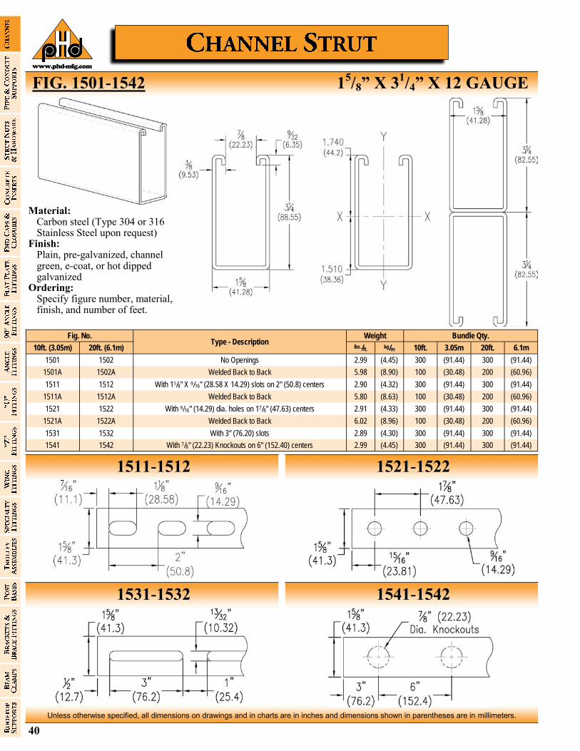
40
Unless otherwise specified, all dimensions on drawings and in charts are in inches and dimensions shown in parentheses are in millimeters.
www.phd-mfg.com
FIG. 1501-1542 15/8” X 3
1/4” X 12 GAUGE
1511-1512 1521-1522
1531-1532 1541-1542
Fig. No. Type - Description
Bundle Qty. Weight
10ft. (3.05m) 20ft. (6.1m) lbs./ft. kg/m 10ft. 6.1m 3.05m 20ft.
1501 1502 No Openings 2.99 (4.45) 300 (91.44) (91.44) 300
1501A 1502A Welded Back to Back 5.98 (8.90) 100 (60.96) (30.48) 200
1511 1512 With 11/8" X 9/16" (28.58 X 14.29) slots on 2" (50.8) centers 2.90 (4.32) 300 (91.44) (91.44) 300
1511A 1512A Welded Back to Back 5.80 (8.63) 100 (60.96) (30.48) 200
1521 1522 With 9/16" (14.29) dia. holes on 17/8" (47.63) centers 2.91 (4.33) 300 (91.44) (91.44) 300
1521A 1522A Welded Back to Back 6.02 (8.96) 100 (60.96) (30.48) 200
1531 1532 With 3" (76.20) slots 2.89 (4.30) 300 (91.44) (91.44) 300
1541 1542 With 7/8" (22.23) Knockouts on 6" (152.40) centers 2.99 (4.45) 300 (91.44) (91.44) 300
Material: Carbon steel (Type 304 or 316
Stainless Steel upon request) Finish: Plain, pre-galvanized, channel
green, e-coat, or hot dipped galvanized
Ordering: Specify figure number, material,
finish, and number of feet.
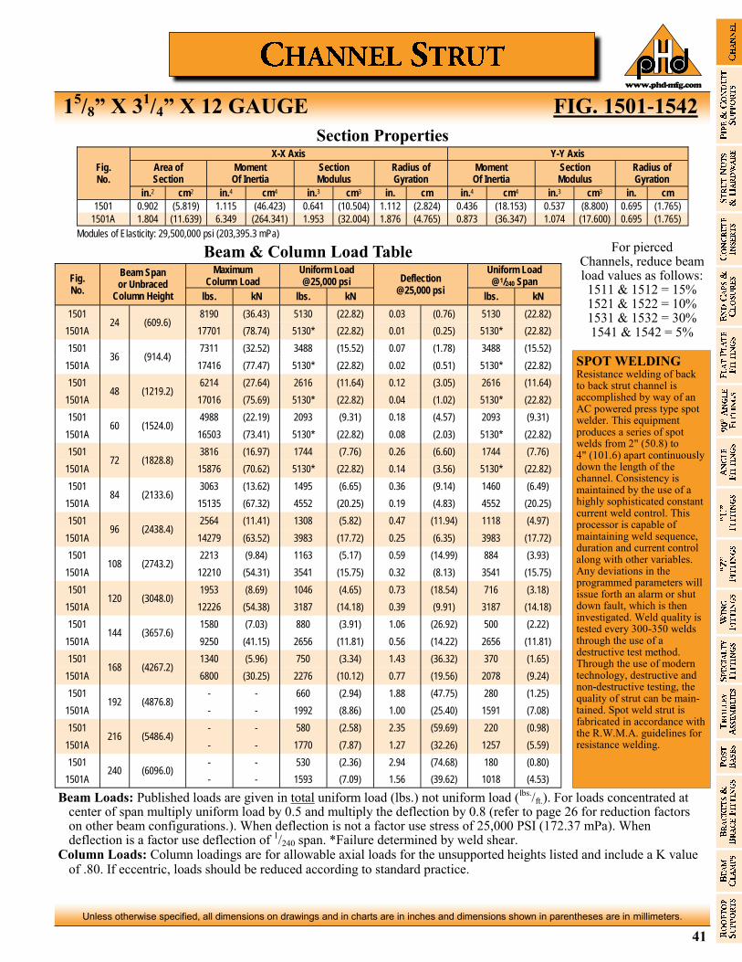
41
Unless otherwise specified, all dimensions on drawings and in charts are in inches and dimensions shown in parentheses are in millimeters.
www.phd-mfg.com
15/8” X 3
1/4” X 12 GAUGE FIG. 1501-1542
Fig. No.
X-X Axis Y-Y Axis
Area of Section
Moment Of Inertia
Section Modulus
Radius of Gyration
Moment Of Inertia
Section Modulus
Radius of Gyration
in.2 cm2 in.4 cm4 in.3 cm3 in. cm in.4 cm4 in.3 cm3 in. cm
1501 0.902 (5.819) 1.115 (46.423) 0.641 (10.504) 1.112 (2.824) 0.436 (18.153) 0.537 (8.800) 0.695 (1.765)
1501A 1.804 (11.639) 6.349 (264.341) 1.953 (32.004) 1.876 (4.765) 0.873 (36.347) 1.074 (17.600) 0.695 (1.765)
Modules of Elasticity: 29,500,000 psi (203,395.3 mPa)
For pierced Channels, reduce beam load values as follows: 1511 & 1512 = 15% 1521 & 1522 = 10% 1531 & 1532 = 30% 1541 & 1542 = 5%
Section Properties
Beam & Column Load Table
Fig. No.
Beam Span or Unbraced
Column Height
Maximum Column Load
Uniform Load @25,000 psi Deflection
@25,000 psi
Uniform Load @1/240 Span
lbs. kN lbs. kN lbs. kN
1501 24 (609.6)
8190 (36.43) 5130 (22.82) 0.03 (0.76) 5130 (22.82)
1501A 17701 (78.74) 5130* (22.82) 0.01 (0.25) 5130* (22.82)
1501 36 (914.4)
7311 (32.52) 3488 (15.52) 0.07 (1.78) 3488 (15.52)
1501A 17416 (77.47) 5130* (22.82) 0.02 (0.51) 5130* (22.82)
1501 48 (1219.2)
6214 (27.64) 2616 (11.64) 0.12 (3.05) 2616 (11.64)
1501A 17016 (75.69) 5130* (22.82) 0.04 (1.02) 5130* (22.82)
1501 60 (1524.0)
4988 (22.19) 2093 (9.31) 0.18 (4.57) 2093 (9.31)
1501A 16503 (73.41) 5130* (22.82) 0.08 (2.03) 5130* (22.82)
1501 72 (1828.8)
3816 (16.97) 1744 (7.76) 0.26 (6.60) 1744 (7.76)
1501A 15876 (70.62) 5130* (22.82) 0.14 (3.56) 5130* (22.82)
1501 84 (2133.6)
3063 (13.62) 1495 (6.65) 0.36 (9.14) 1460 (6.49)
1501A 15135 (67.32) 4552 (20.25) 0.19 (4.83) 4552 (20.25)
1501 96 (2438.4)
2564 (11.41) 1308 (5.82) 0.47 (11.94) 1118 (4.97)
1501A 14279 (63.52) 3983 (17.72) 0.25 (6.35) 3983 (17.72)
1501 108 (2743.2)
2213 (9.84) 1163 (5.17) 0.59 (14.99) 884 (3.93)
1501A 12210 (54.31) 3541 (15.75) 0.32 (8.13) 3541 (15.75)
1501 120 (3048.0)
1953 (8.69) 1046 (4.65) 0.73 (18.54) 716 (3.18)
1501A 12226 (54.38) 3187 (14.18) 0.39 (9.91) 3187 (14.18)
1501 144 (3657.6)
1580 (7.03) 880 (3.91) 1.06 (26.92) 500 (2.22)
1501A 9250 (41.15) 2656 (11.81) 0.56 (14.22) 2656 (11.81)
1501 168 (4267.2)
1340 (5.96) 750 (3.34) 1.43 (36.32) 370 (1.65)
1501A 6800 (30.25) 2276 (10.12) 0.77 (19.56) 2078 (9.24)
1501 192 (4876.8)
- - 660 (2.94) 1.88 (47.75) 280 (1.25)
1501A - - 1992 (8.86) 1.00 (25.40) 1591 (7.08)
1501 216 (5486.4)
- - 580 (2.58) 2.35 (59.69) 220 (0.98)
1501A - - 1770 (7.87) 1.27 (32.26) 1257 (5.59)
1501 240 (6096.0)
- - 530 (2.36) 2.94 (74.68) 180 (0.80)
1501A - - 1593 (7.09) 1.56 (39.62) 1018 (4.53)
Beam Loads: Published loads are given in total uniform load (lbs.) not uniform load (lbs./ft.). For loads concentrated at center of span multiply uniform load by 0.5 and multiply the deflection by 0.8 (refer to page 26 for reduction factors on other beam configurations.). When deflection is not a factor use stress of 25,000 PSI (172.37 mPa). When deflection is a factor use deflection of 1/240 span. *Failure determined by weld shear.
Column Loads: Column loadings are for allowable axial loads for the unsupported heights listed and include a K value of .80. If eccentric, loads should be reduced according to standard practice.
SPOT WELDING Resistance welding of back to back strut channel is accomplished by way of an AC powered press type spot welder. This equipment produces a series of spot welds from 2" (50.8) to 4" (101.6) apart continuously down the length of the channel. Consistency is maintained by the use of a highly sophisticated constant current weld control. This processor is capable of maintaining weld sequence, duration and current control along with other variables. Any deviations in the programmed parameters will issue forth an alarm or shut down fault, which is then investigated. Weld quality is tested every 300-350 welds through the use of a destructive test method. Through the use of modern technology, destructive and non-destructive testing, the quality of strut can be maintained. Spot weld strut is fabricated in accordance with the R.W.M.A. guidelines for resistance welding.
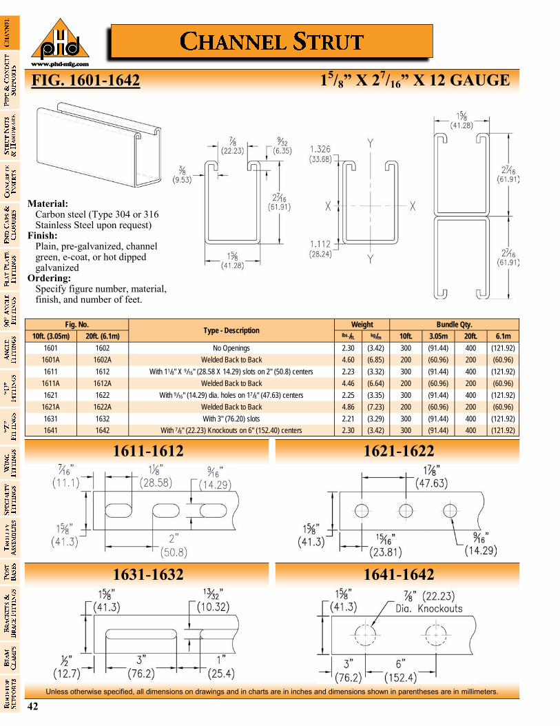
42
Unless otherwise specified, all dimensions on drawings and in charts are in inches and dimensions shown in parentheses are in millimeters.
www.phd-mfg.com
FIG. 1601-1642 15/8” X 2
7/16” X 12 GAUGE
1611-1612 1621-1622
1631-1632 1641-1642
Fig. No. Type - Description
Bundle Qty. Weight
10ft. (3.05m) 20ft. (6.1m) lbs./ft. kg/m 10ft. 6.1m 3.05m 20ft.
1601 1602 No Openings 2.30 (3.42) 300 (121.92) (91.44) 400
1601A 1602A Welded Back to Back 4.60 (6.85) 200 (60.96) (60.96) 200
1611 1612 With 11/8" X 9/16" (28.58 X 14.29) slots on 2" (50.8) centers 2.23 (3.32) 300 (121.92) (91.44) 400
1611A 1612A Welded Back to Back 4.46 (6.64) 200 (60.96) (60.96) 200
1621 1622 With 9/16" (14.29) dia. holes on 17/8" (47.63) centers 2.25 (3.35) 300 (121.92) (91.44) 400
1621A 1622A Welded Back to Back 4.86 (7.23) 200 (60.96) (60.96) 200
1631 1632 With 3" (76.20) slots 2.21 (3.29) 300 (121.92) (91.44) 400
1641 1642 With 7/8" (22.23) Knockouts on 6" (152.40) centers 2.30 (3.42) 300 (121.92) (91.44) 400
Material: Carbon steel (Type 304 or 316
Stainless Steel upon request) Finish: Plain, pre-galvanized, channel
green, e-coat, or hot dipped galvanized
Ordering: Specify figure number, material,
finish, and number of feet.

43
Unless otherwise specified, all dimensions on drawings and in charts are in inches and dimensions shown in parentheses are in millimeters.
www.phd-mfg.com
15/8” X 2
7/16” X 12 GAUGE FIG. 1601-1642
For pierced Channels, reduce beam load values as follows: 1611 & 1612 = 15% 1621 & 1622 = 10% 1631 & 1632 = 30% 1641 & 1642 = 5%
Fig. No.
X-X Axis Y-Y Axis
Area of Section
Moment Of Inertia
Section Modulus
Radius of Gyration
Moment Of Inertia
Section Modulus
Radius of Gyration
in.2 cm2 in.4 cm4 in.3 cm3 in. cm in.4 cm4 in.3 cm3 in. cm
1601 0.732 (4.723) 0.531 (22.108) 0.401 (6.571) 0.852 (2.164) 0.338 (14.073) 0.416 (6.817) 0.68 (1.727)
1601A 1.464 (9.445) 2.874 (119.659) 1.179 (19.320) 1.401 (3.559) 0.676 (28.145) 0.832 (13.634) 0.68 (1.727)
Modules of Elasticity: 29,500,000 psi (203,395.3 mPa)
Section Properties
Beam & Column Load Table
Fig. No.
Beam Span or Unbraced
Column Height
Maximum Column Load
Uniform Load @25,000 psi
Deflection @25,000 psi
Uniform Load @1/240 Span
lbs. kN lbs. kN lbs. kN
1601 12 (304.8)
10140 (45.10) 3880 (17.26) 0.01 (0.25) 3880 (17.26)
1601A 20820 (92.61) 3880* (17.26) 0.01 (0.25) 3880* (17.26)
1601 24 (609.6)
9244 (41.12) 3273 (14.56) 0.04 (1.02) 3273 (14.56)
1601A 20519 (91.27) 3880* (17.26) 0.01 (0.25) 3880* (17.26)
1601 36 (914.4)
7933 (35.29) 2182 (9.71) 0.09 (2.29) 2182 (9.71)
1601A 20017 (89.04) 3880* (17.26) 0.03 (0.76) 3880* (17.26)
1601 48 (1219.2)
6386 (28.41) 1636 (7.28) 0.15 (3.81) 1636 (7.28)
1601A 19315 (85.92) 3880* (17.26) 0.07 (1.78) 3880* (17.26)
1601 60 (1524.0)
4785 (21.28) 1309 (5.82) 0.24 (6.10) 1309 (5.82)
1601A 18412 (81.90) 3847 (17.11) 0.13 (3.30) 3847 (17.11)
1601 72 (1828.8)
3717 (16.53) 1091 (4.85) 0.35 (8.89) 947 (4.21)
1601A 17309 (76.99) 3206 (14.26) 0.19 (4.83) 3206 (14.26)
1601 84 (2133.6)
3052 (13.58) 935 (4.16) 0.47 (11.94) 696 (3.10)
1601A 16005 (71.19) 2748 (12.22) 0.26 (6.60) 2748 (12.22)
1601 96 (2438.4)
2600 (11.57) 818 (3.64) 0.62 (15.75) 533 (2.37)
1601A 14500 (64.50) 2404 (10.69) 0.33 (8.38) 2404 (10.69)
1601 108 (2743.2)
2271 (10.10) 727 (3.23) 0.77 (19.56) 421 (1.87)
1601A 12795 (56.92) 2137 (9.51) 0.42 (10.67) 2137 (9.51)
1601 120 (3048.0)
2019 (8.98) 655 (2.91) 0.96 (24.38) 341 (1.52)
1601A 10889 (48.44) 1924 (8.56) 0.52 (13.21) 1844 (8.20)
1601 144 (3657.6)
1650 (7.34) 550 (2.45) 1.39 (35.31) 240 (1.07)
1601A 7150 (31.80) 1610 (7.16) 0.75 (19.05) 1280 (5.69)
1601 168 (4267.2)
1380 (6.14) 470 (2.09) 1.88 (47.75) 170 (0.76)
1601A 5250 (23.35) 1380 (6.14) 1.03 (26.16) 940 (4.18)
1601 192 (4876.8)
- - 410 (1.82) 2.45 (62.23) 130 (0.58)
1601A - - 1210 (5.38) 1.34 (34.04) 720 (3.20)
1601 216 (5486.4)
- - 360 (1.60) 3.06 (77.72) 110 (0.49)
1601A - - 1070 (4.76) 1.69 (42.93) 570 (2.54)
1601 240 (6096.0)
- - 330 (1.47) 3.85 (97.79) 90 (0.40)
1601A - - 970 (4.31) 2.11 (53.59) 460 (2.05)
Beam Loads: Published loads are given in total uniform load (lbs.) not uniform load (lbs./ft.). For loads concentrated at center of span multiply uniform load by 0.5 and multiply the deflection by 0.8 (refer to page 26 for reduction factors on other beam configurations.). When deflection is not a factor use stress of 25,000 PSI (172.37 mPa). When deflection is a factor use deflection of 1/240 span. *Failure determined by weld shear.
Column Loads: Column loadings are for allowable axial loads for the unsupported heights listed and include a K value of .80. If eccentric, loads should be reduced according to standard practice.
SPOT WELDING Resistance welding of back to back strut channel is accomplished by way of an AC powered press type spot welder. This equipment produces a series of spot welds from 2" (50.8) to 4" (101.6) apart continuously down the length of the channel. Consistency is maintained by the use of a highly sophisticated constant current weld control. This processor is capable of maintaining weld sequence, duration and current control along with other variables. Any deviations in the programmed parameters will issue forth an alarm or shut down fault, which is then investigated. Weld quality is tested every 300-350 welds through the use of a destructive test method. Through the use of modern technology, destructive and non-destructive testing, the quality of strut can be maintained. Spot weld strut is fabricated in accordance with the R.W.M.A. guidelines for resistance welding.

44
Unless otherwise specified, all dimensions on drawings and in charts are in inches and dimensions shown in parentheses are in millimeters.
www.phd-mfg.com
FIG. 1701-1742 15/8” X 1
3/8” X 12 GAUGE
1711-1712 1721-1722
1731-1732 1741-1742
Fig. No. Type - Description
Bundle Qty. Weight
10ft. (3.05m) 20ft. (6.1m) lbs./ft. kg/m 10ft. 6.1m 3.05m 20ft.
1701 1702 No Openings 1.59 (2.37) 500 (152.4) (152.4) 500
1701A 1702A Welded Back to Back 3.40 (5.06) 200 (91.4) (61.0) 300
1711 1712 With 11/8" X 9/16" (28.58 X 14.29) slots on 2" (50.8) centers 1.54 (2.29) 500 (152.4) (152.4) 500
1711A 1712A Welded Back to Back 3.24 (4.82) 200 (91.4) (61.0) 300
1721 1722 With 9/16" (14.29) dia. holes on 17/8" (47.63) centers 1.65 (2.46) 500 (152.4) (152.4) 500
1721A 1722A Welded Back to Back 3.30 (4.91) 200 (91.4) (61.0) 300
1731 1732 With 3" (76.20) slots 1.59 (2.37) 500 (152.4) (152.4) 500
1741 1742 With 7/8" (22.23) Knockouts on 6" (152.40) centers 1.59 (2.37) 500 (152.4) (152.4) 500
Material: Carbon steel Finish: Plain, pre-galvanized, channel
green, e-coat, or hot dipped galvanized
Ordering: Specify figure number, material,
finish, and number of feet.
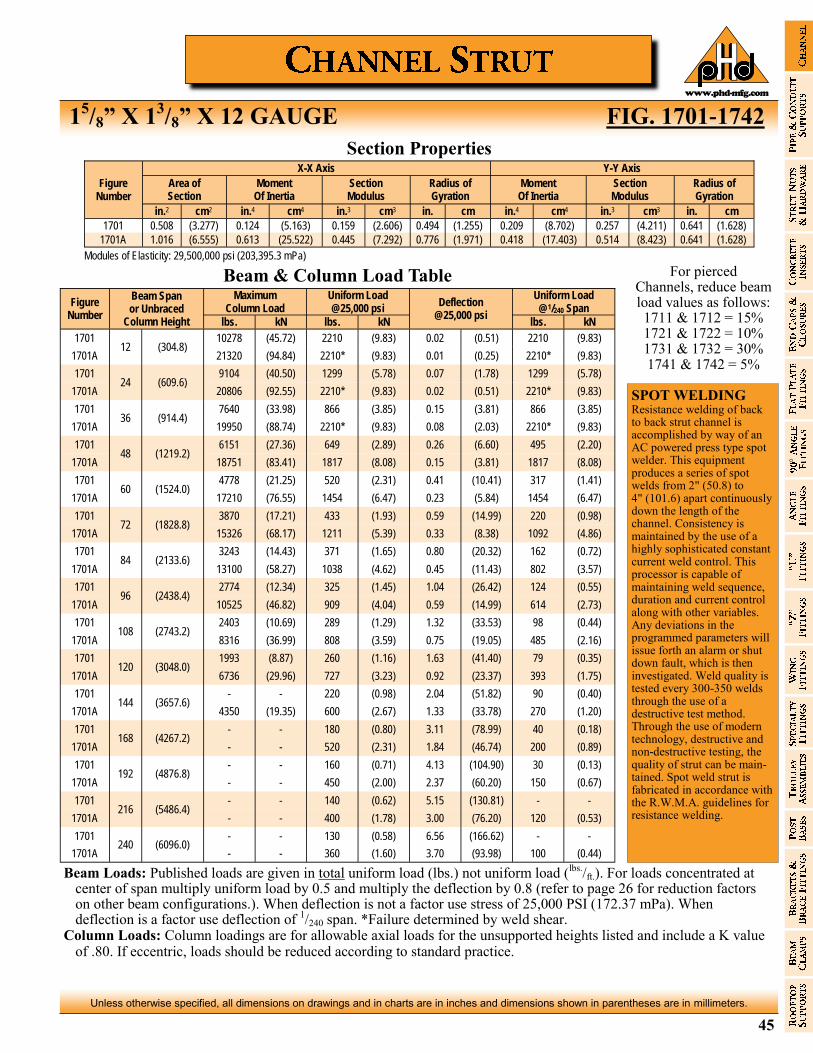
45
Unless otherwise specified, all dimensions on drawings and in charts are in inches and dimensions shown in parentheses are in millimeters.
www.phd-mfg.com
15/8” X 1
3/8” X 12 GAUGE FIG. 1701-1742
For pierced Channels, reduce beam load values as follows: 1711 & 1712 = 15% 1721 & 1722 = 10% 1731 & 1732 = 30% 1741 & 1742 = 5%
Figure Number
X-X Axis Y-Y Axis
Area of Section
Moment Of Inertia
Section Modulus
Radius of Gyration
Moment Of Inertia
Section Modulus
Radius of Gyration
in.2 cm2 in.4 cm4 in.3 cm3 in. cm in.4 cm4 in.3 cm3 in. cm
1701 0.508 (3.277) 0.124 (5.163) 0.159 (2.606) 0.494 (1.255) 0.209 (8.702) 0.257 (4.211) 0.641 (1.628)
1701A 1.016 (6.555) 0.613 (25.522) 0.445 (7.292) 0.776 (1.971) 0.418 (17.403) 0.514 (8.423) 0.641 (1.628)
Modules of Elasticity: 29,500,000 psi (203,395.3 mPa)
Section Properties
Beam & Column Load Table
Figure Number
Beam Span or Unbraced
Column Height
Maximum Column Load
Uniform Load @25,000 psi
Deflection @25,000 psi
Uniform Load @1/240 Span
lbs. kN lbs. kN lbs. kN
1701 12 (304.8)
10278 (45.72) 2210 (9.83) 0.02 (0.51) 2210 (9.83)
1701A 21320 (94.84) 2210* (9.83) 0.01 (0.25) 2210* (9.83)
1701 24 (609.6)
9104 (40.50) 1299 (5.78) 0.07 (1.78) 1299 (5.78)
1701A 20806 (92.55) 2210* (9.83) 0.02 (0.51) 2210* (9.83)
1701 36 (914.4)
7640 (33.98) 866 (3.85) 0.15 (3.81) 866 (3.85)
1701A 19950 (88.74) 2210* (9.83) 0.08 (2.03) 2210* (9.83)
1701 48 (1219.2)
6151 (27.36) 649 (2.89) 0.26 (6.60) 495 (2.20)
1701A 18751 (83.41) 1817 (8.08) 0.15 (3.81) 1817 (8.08)
1701 60 (1524.0)
4778 (21.25) 520 (2.31) 0.41 (10.41) 317 (1.41)
1701A 17210 (76.55) 1454 (6.47) 0.23 (5.84) 1454 (6.47)
1701 72 (1828.8)
3870 (17.21) 433 (1.93) 0.59 (14.99) 220 (0.98)
1701A 15326 (68.17) 1211 (5.39) 0.33 (8.38) 1092 (4.86)
1701 84 (2133.6)
3243 (14.43) 371 (1.65) 0.80 (20.32) 162 (0.72)
1701A 13100 (58.27) 1038 (4.62) 0.45 (11.43) 802 (3.57)
1701 96 (2438.4)
2774 (12.34) 325 (1.45) 1.04 (26.42) 124 (0.55)
1701A 10525 (46.82) 909 (4.04) 0.59 (14.99) 614 (2.73)
1701 108 (2743.2)
2403 (10.69) 289 (1.29) 1.32 (33.53) 98 (0.44)
1701A 8316 (36.99) 808 (3.59) 0.75 (19.05) 485 (2.16)
1701 120 (3048.0)
1993 (8.87) 260 (1.16) 1.63 (41.40) 79 (0.35)
1701A 6736 (29.96) 727 (3.23) 0.92 (23.37) 393 (1.75)
1701 144 (3657.6)
- - 220 (0.98) 2.04 (51.82) 90 (0.40)
1701A 4350 (19.35) 600 (2.67) 1.33 (33.78) 270 (1.20)
1701 168 (4267.2)
- - 180 (0.80) 3.11 (78.99) 40 (0.18)
1701A - - 520 (2.31) 1.84 (46.74) 200 (0.89)
1701 192 (4876.8)
- - 160 (0.71) 4.13 (104.90) 30 (0.13)
1701A - - 450 (2.00) 2.37 (60.20) 150 (0.67)
1701 216 (5486.4)
- - 140 (0.62) 5.15 (130.81) - -
1701A - - 400 (1.78) 3.00 (76.20) 120 (0.53)
1701 240 (6096.0)
- - 130 (0.58) 6.56 (166.62) - -
1701A - - 360 (1.60) 3.70 (93.98) 100 (0.44)
Beam Loads: Published loads are given in total uniform load (lbs.) not uniform load (lbs./ft.). For loads concentrated at center of span multiply uniform load by 0.5 and multiply the deflection by 0.8 (refer to page 26 for reduction factors on other beam configurations.). When deflection is not a factor use stress of 25,000 PSI (172.37 mPa). When deflection is a factor use deflection of 1/240 span. *Failure determined by weld shear.
Column Loads: Column loadings are for allowable axial loads for the unsupported heights listed and include a K value of .80. If eccentric, loads should be reduced according to standard practice.
SPOT WELDING Resistance welding of back to back strut channel is accomplished by way of an AC powered press type spot welder. This equipment produces a series of spot welds from 2" (50.8) to 4" (101.6) apart continuously down the length of the channel. Consistency is maintained by the use of a highly sophisticated constant current weld control. This processor is capable of maintaining weld sequence, duration and current control along with other variables. Any deviations in the programmed parameters will issue forth an alarm or shut down fault, which is then investigated. Weld quality is tested every 300-350 welds through the use of a destructive test method. Through the use of modern technology, destructive and non-destructive testing, the quality of strut can be maintained. Spot weld strut is fabricated in accordance with the R.W.M.A. guidelines for resistance welding.

46
Unless otherwise specified, all dimensions on drawings and in charts are in inches and dimensions shown in parentheses are in millimeters.
www.phd-mfg.com
FIG. 1801-1842 15/8” X
13/16” X 16 GAUGE
1811-1812 1821-1822
1831-1832 1841-1842
Fig. No. Type - Description
Bundle Qty. Weight
10ft. (3.05m) 20ft. (6.1m) lbs./ft. kg/m 10ft. 6.1m 3.05m 20ft.
1801 1802 No Openings 0.86 (1.28) 500 (304.8) (152.4) 1000
1801A 1802A Welded Back to Back 1.72 (2.56) 500 (152.4) (152.4) 500
1811 1812 With 11/8" X 9/16" (28.58 X 14.29) slots on 2" (50.8) centers 0.75 (1.12) 500 (304.8) (152.4) 1000
1811A 1812A Welded Back to Back 1.52 (2.26) 500 (152.4) (152.4) 500
1821 1822 With 9/16" (14.29) dia. holes on 17/8" (47.63) centers 0.77 (1.15) 500 (304.8) (152.4) 1000
1821A 1822A Welded Back to Back 1.56 (2.32) 500 (152.4) (152.4) 500
1831 1832 With 3" (76.20) slots 0.75 (1.12) 500 (304.8) (152.4) 1000
1841 1842 With 7/8" (22.23) Knockouts on 6" (152.40) centers 0.86 (1.28) 500 (304.8) (152.4) 1000
Material: Carbon steel Finish: Plain, pre-galvanized, channel
green, e-coat, or hot dipped galvanized
Ordering: Specify figure number, material,
finish, and number of feet.
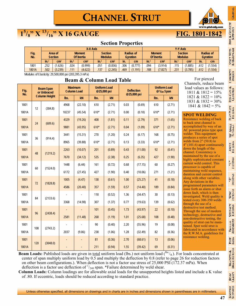
47
Unless otherwise specified, all dimensions on drawings and in charts are in inches and dimensions shown in parentheses are in millimeters.
www.phd-mfg.com
15/8” X
13/16” X 16 GAUGE FIG. 1801-1842
For pierced Channels, reduce beam load values as follows: 1811 & 1812 = 15% 1821 & 1822 = 10% 1831 & 1832 = 30% 1841 & 1842 = 5%
Fig. No.
X-X Axis Y-Y Axis
Area of Section
Moment Of Inertia
Section Modulus
Radius of Gyration
Moment Of Inertia
Section Modulus
Radius of Gyration
in.2 cm2 in.4 cm4 in.3 cm3 in. cm in.4 cm4 in.3 cm3 in. cm
1801 .252 (1.626) .024 (0.999) .051 (0.836) .306 (0.777) .094 (3.914) .115 (1.885) .612 (1.554)
1801A .502 (3.239) .111 (4.622) .137 (2.245) .469 (1.191) .188 (7.827) .231 (3.785) .612 (1.554)
Modules of Elasticity: 29,500,000 psi (203,395.3 mPa)
Section Properties
Beam & Column Load Table
Fig. No.
Beam Span or Unbraced
Column Height
Maximum Column Load
Uniform Load @25,000 psi Deflection
@25,000 psi
Uniform Load @1/240 Span
lbs. kN lbs. kN lbs. kN
1801 12 (304.8)
4968 (22.10) 610 (2.71) 0.03 (0.69) 610 (2.71)
1801A 10237 (45.54) 610* (2.71) 0.00 (0.10) 610* (2.71)
1801 24 (609.6)
4329 (19.26) 408 (1.81) 0.11 (2.79) 371 (1.65)
1801A 9881 (43.95) 610* (2.71) 0.04 (1.09) 610* (2.71)
1801 36 (914.4)
3441 (15.31) 270 (1.20) 0.24 (6.17) 168 (0.75)
1801A 8965 (39.88) 610* (2.71) 0.13 (3.33) 610* (2.71)
1801 48 (1219.2)
2263 (10.07) 201 (0.89) 0.43 (11.00) 92 (0.41)
1801A 7670 (34.12) 535 (2.38) 0.25 (6.35) 427 (1.90)
1801 60 (1524.0)
1448 (6.44) 161 (0.72) 0.68 (17.15) 60 (0.27)
1801A 6172 (27.45) 427 (1.90) 0.40 (10.06) 271 (1.21)
1801 72 (1828.8)
1005 (4.47) 138 (0.61) 1.00 (25.27) 41 (0.18)
1801A 4586 (20.40) 357 (1.59) 0.57 (14.40) 189 (0.84)
1801 84 (2133.6)
- - 118 (0.52) 1.36 (34.47) 30 (0.13)
1801A 3368 (14.98) 307 (1.37) 0.77 (19.63) 139 (0.62)
1801 96 (2438.4)
- - 101 (0.45) 1.73 (43.97) 22 (0.10)
1801A 2581 (11.48) 268 (1.19) 1.01 (25.68) 108 (0.48)
1801 108 (2743.2)
- - 90 (0.40) 2.20 (55.96) 19 (0.08)
1801A 2037 (9.06) 238 (1.06) 1.28 (32.49) 82 (0.36)
1801 120 (3048.0)
- - 81 (0.36) 2.70 (68.61) 13 (0.06)
1801A - - 211 (0.94) 1.55 (39.42) 69 (0.31)
Beam Loads: Published loads are given in total uniform load (lbs.) not uniform load (lbs./ft.). For loads concentrated at center of span multiply uniform load by 0.5 and multiply the deflection by 0.8 (refer to page 26 for reduction factors on other beam configurations.). When deflection is not a factor use stress of 25,000 PSI (172.37 mPa). When deflection is a factor use deflection of 1/240 span. *Failure determined by weld shear.
Column Loads: Column loadings are for allowable axial loads for the unsupported heights listed and include a K value of .80. If eccentric, loads should be reduced according to standard practice.
SPOT WELDING Resistance welding of back to back strut channel is accomplished by way of an AC powered press type spot welder. This equipment produces a series of spot welds from 2" (50.8) to 4" (101.6) apart continuously down the length of the channel. Consistency is maintained by the use of a highly sophisticated constant current weld control. This processor is capable of maintaining weld sequence, duration and current control along with other variables. Any deviations in the programmed parameters will issue forth an alarm or shut down fault, which is then investigated. Weld quality is tested every 300-350 welds through the use of a destructive test method. Through the use of modern technology, destructive and non-destructive testing, the quality of strut can be maintained. Spot weld strut is fabricated in accordance with the R.W.M.A. guidelines for resistance welding.
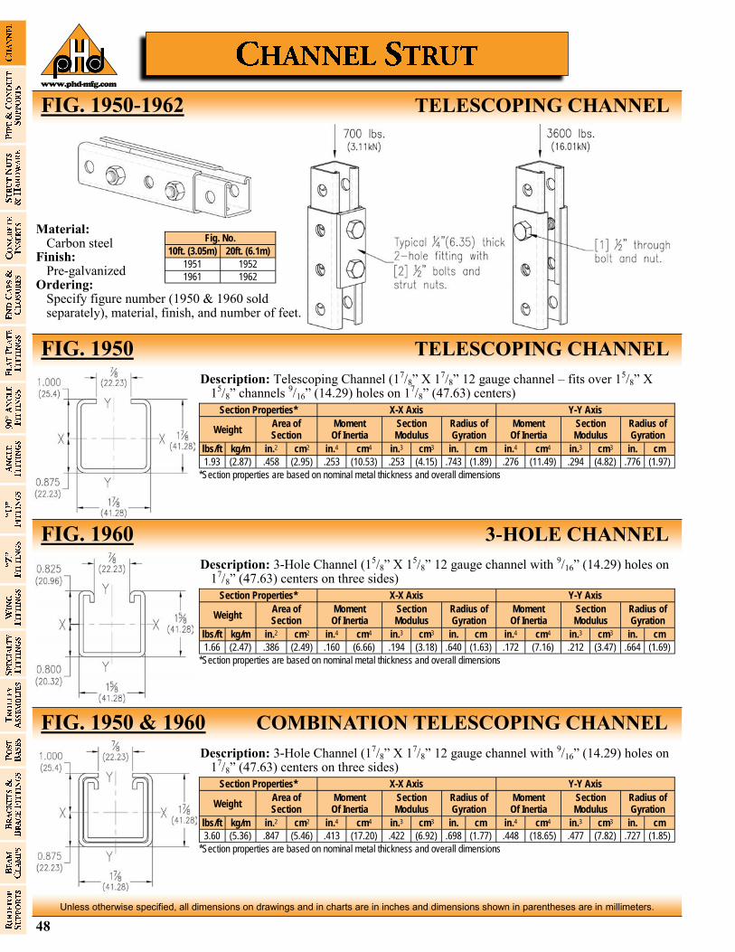
48
Unless otherwise specified, all dimensions on drawings and in charts are in inches and dimensions shown in parentheses are in millimeters.
www.phd-mfg.com
FIG. 1950-1962 TELESCOPING CHANNEL
Section Properties* X-X Axis Y-Y Axis
Weight Area of Section
Moment Of Inertia
Section Modulus
Radius of Gyration
Moment Of Inertia
Section Modulus
Radius of Gyration
lbs/ft kg/m in.2 cm2 in.4 cm4 in.3 cm3 in. cm in.4 cm4 in.3 cm3 in. cm
1.93 (2.87) .458 (2.95) .253 (10.53) .253 (4.15) .743 (1.89) .276 (11.49) .294 (4.82) .776 (1.97)
*Section properties are based on nominal metal thickness and overall dimensions
Description: Telescoping Channel (17/8” X 17/8” 12 gauge channel – fits over 15/8” X 15/8” channels 9/16” (14.29) holes on 17/8” (47.63) centers)
FIG. 1950 TELESCOPING CHANNEL
Section Properties* X-X Axis Y-Y Axis
Weight Area of Section
Moment Of Inertia
Section Modulus
Radius of Gyration
Moment Of Inertia
Section Modulus
Radius of Gyration
lbs/ft kg/m in.2 cm2 in.4 cm4 in.3 cm3 in. cm in.4 cm4 in.3 cm3 in. cm
1.66 (2.47) .386 (2.49) .160 (6.66) .194 (3.18) .640 (1.63) .172 (7.16) .212 (3.47) .664 (1.69)
*Section properties are based on nominal metal thickness and overall dimensions
Description: 3-Hole Channel (15/8” X 15/8” 12 gauge channel with 9/16” (14.29) holes on 17/8” (47.63) centers on three sides)
FIG. 1960 3-HOLE CHANNEL
Section Properties* X-X Axis Y-Y Axis
Weight Area of Section
Moment Of Inertia
Section Modulus
Radius of Gyration
Moment Of Inertia
Section Modulus
Radius of Gyration
lbs/ft kg/m in.2 cm2 in.4 cm4 in.3 cm3 in. cm in.4 cm4 in.3 cm3 in. cm
3.60 (5.36) .847 (5.46) .413 (17.20) .422 (6.92) .698 (1.77) .448 (18.65) .477 (7.82) .727 (1.85)
*Section properties are based on nominal metal thickness and overall dimensions
Description: 3-Hole Channel (17/8” X 17/8” 12 gauge channel with 9/16” (14.29) holes on 17/8” (47.63) centers on three sides)
FIG. 1950 & 1960 COMBINATION TELESCOPING CHANNEL
Material: Carbon steel Finish: Pre-galvanized Ordering: Specify figure number (1950 & 1960 sold
separately), material, finish, and number of feet.
Fig. No.
10ft. (3.05m) 20ft. (6.1m)
1951 1952
1961 1962

49
Unless otherwise specified, all dimensions on drawings and in charts are in inches and dimensions shown in parentheses are in millimeters.
www.phd-mfg.com
TELESCOPING CHANNEL FIG. 1950
3-HOLE CHANNEL FIG. 1960
COMBINATION TELESCOPING CHANNEL FIG. 1950 & 1960
Beam Span
Allowable load
Resulting Deflection
Allowable load @1/240 Span
lbs. kN lbs. kN
12 (304.8) 4203 (18.70) 0.012 (0.305) 4703 (20.92)
24 (609.6) 2099 (9.34) 0.050 (1.270) 2099 (9.34)
36 (914.4) 1396 (6.21) 0.112 (2.845) 1396 (6.21)
48 (1219.2) 1044 (4.64) 0.200 (5.080) 1044 (4.64)
60 (1524.0) 831 (3.70) 0.312 (7.925) 664 (2.95)
72 (1828.8) 689 (3.06) 0.450 (11.430) 456 (2.03)
84 (2133.6) 587 (2.61) 0.612 (15.545) 330 (1.47)
96 (2438.4) 510 (2.27) 0.799 (20.295) 248 (1.10)
108 (2743.2) 450 (2.00) 1.012 (25.705) 190 (0.85)
120 (3048.0) 401 (1.78) 1.249 (31.725) 149 (0.66)
Beam Span
Allowable load
Resulting Deflection
Allowable load @1/240 Span
lbs. kN lbs. kN
12 (304.8) 2225 (9.90) 0.015 (0.381) 2225 (9.90)
24 (609.6) 1610 (7.16) 0.061 (1.549) 1610 (7.16)
36 (914.4) 1071 (4.76) 0.136 (3.454) 1071 (4.76)
48 (1219.2) 800 (3.56) 0.243 (6.172) 658 (2.93)
60 (1524.0) 637 (2.83) 0.379 (9.627) 417 (1.85)
72 (1828.8) 528 (2.35) 0.546 (13.868) 286 (1.27)
84 (2133.6) 449 (2.00) 0.743 (18.872) 206 (0.92)
96 (2438.4) 390 (1.73) 0.970 (24.638) 153 (0.68)
108 (2743.2) 344 (1.53) 1.228 (31.191) 116 (0.52)
120 (3048.0) 306 (1.36) 1.516 (38.506) 90 (0.40)
Beam Span
Allowable load
Resulting Deflection
Allowable load @1/240 Span
lbs. kN lbs. kN
12 (304.8) 7033 (31.28) 0.013 (0.330) 7033 (31.28)
24 (609.6) 3511 (15.62) 0.051 (1.295) 3511 (15.62)
36 (914.4) 2335 (10.39) 0.115 (2.921) 2335 (10.39)
48 (1219.2) 1745 (7.76) 0.205 (5.207) 1705 (7.58)
60 (1524.0) 1389 (6.18) 0.320 (8.128) 1082 (4.81)
72 (1828.8) 1151 (5.12) 0.460 (11.684) 742 (3.30)
84 (2133.6) 980 (4.36) 0.627 (15.926) 536 (2.38)
96 (2438.4) 851 (3.79) 0.819 (20.803) 401 (1.78)
108 (2743.2) 749 (3.33) 1.036 (26.314) 307 (1.37)
120 (3048.0) 668 (2.97) 1.279 (32.487) 239 (1.06)
Loads based on telescoping members of equal length.
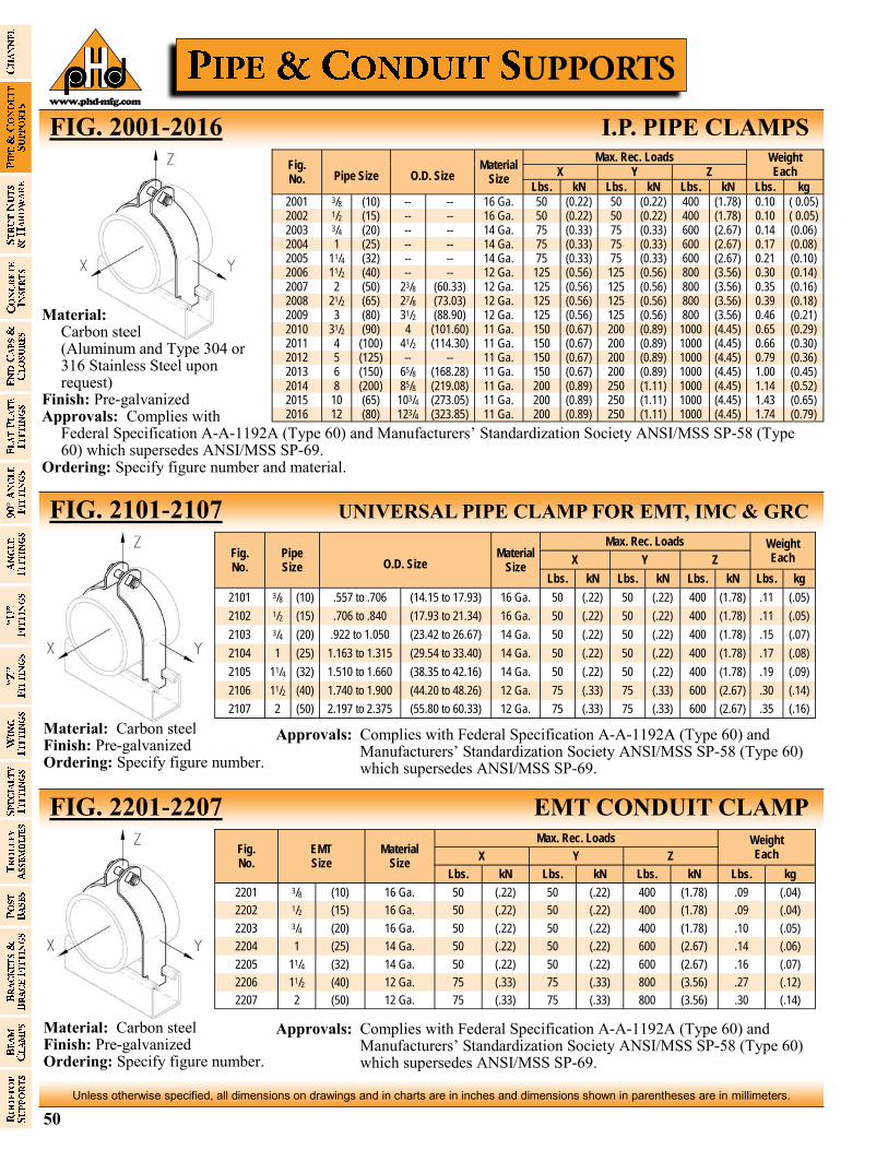
50
Unless otherwise specified, all dimensions on drawings and in charts are in inches and dimensions shown in parentheses are in millimeters.
www.phd-mfg.com
FIG. 2001-2016 I.P. PIPE CLAMPS
FIG. 2101-2107 UNIVERSAL PIPE CLAMP FOR EMT, IMC & GRC
Fig. No.
Pipe Size O.D. Size
Material Size
Max. Rec. Loads Weight Each X Y Z
Lbs. kN Lbs. kN Lbs. kN Lbs. kg
2101 3/8 (10) .557 to .706 (14.15 to 17.93) 16 Ga. 50 (.22) 50 (.22) 400 (1.78) .11 (.05)
2102 1/2 (15) .706 to .840 (17.93 to 21.34) 16 Ga. 50 (.22) 50 (.22) 400 (1.78) .11 (.05)
2103 3/4 (20) .922 to 1.050 (23.42 to 26.67) 14 Ga. 50 (.22) 50 (.22) 400 (1.78) .15 (.07)
2104 1 (25) 1.163 to 1.315 (29.54 to 33.40) 14 Ga. 50 (.22) 50 (.22) 400 (1.78) .17 (.08)
2105 11/4 (32) 1.510 to 1.660 (38.35 to 42.16) 14 Ga. 50 (.22) 50 (.22) 400 (1.78) .19 (.09)
2106 11/2 (40) 1.740 to 1.900 (44.20 to 48.26) 12 Ga. 75 (.33) 75 (.33) 600 (2.67) .30 (.14)
2107 2 (50) 2.197 to 2.375 (55.80 to 60.33) 12 Ga. 75 (.33) 75 (.33) 600 (2.67) .35 (.16)
FIG. 2201-2207 EMT CONDUIT CLAMP
Material: Carbon steel (Aluminum and Type 304 or
316 Stainless Steel upon request)
Finish: Pre-galvanized Approvals: Complies with
Federal Specification A-A-1192A (Type 60) and Manufacturers’ Standardization Society ANSI/MSS SP-58 (Type 60) which supersedes ANSI/MSS SP-69.
Ordering: Specify figure number and material.
Fig. No. Pipe Size O.D. Size
Material Size
Max. Rec. Loads Weight Each X Y Z
Lbs. kN Lbs. kN Lbs. kN Lbs. kg
2001 3/8 (10) -- -- 16 Ga. 50 (0.22) 50 (0.22) 400 (1.78) 0.10 ( 0.05) 2002 1/2 (15) -- -- 16 Ga. 50 (0.22) 50 (0.22) 400 (1.78) 0.10 ( 0.05) 2003 3/4 (20) -- -- 14 Ga. 75 (0.33) 75 (0.33) 600 (2.67) 0.14 (0.06) 2004 1 (25) -- -- 14 Ga. 75 (0.33) 75 (0.33) 600 (2.67) 0.17 (0.08) 2005 11/4 (32) -- -- 14 Ga. 75 (0.33) 75 (0.33) 600 (2.67) 0.21 (0.10) 2006 11/2 (40) -- -- 12 Ga. 125 (0.56) 125 (0.56) 800 (3.56) 0.30 (0.14) 2007 2 (50) 23/8 (60.33) 12 Ga. 125 (0.56) 125 (0.56) 800 (3.56) 0.35 (0.16) 2008 21/2 (65) 27/8 (73.03) 12 Ga. 125 (0.56) 125 (0.56) 800 (3.56) 0.39 (0.18) 2009 3 (80) 31/2 (88.90) 12 Ga. 125 (0.56) 125 (0.56) 800 (3.56) 0.46 (0.21) 2010 31/2 (90) 4 (101.60) 11 Ga. 150 (0.67) 200 (0.89) 1000 (4.45) 0.65 (0.29) 2011 4 (100) 41/2 (114.30) 11 Ga. 150 (0.67) 200 (0.89) 1000 (4.45) 0.66 (0.30) 2012 5 (125) -- -- 11 Ga. 150 (0.67) 200 (0.89) 1000 (4.45) 0.79 (0.36) 2013 6 (150) 65/8 (168.28) 11 Ga. 150 (0.67) 200 (0.89) 1000 (4.45) 1.00 (0.45) 2014 8 (200) 85/8 (219.08) 11 Ga. 200 (0.89) 250 (1.11) 1000 (4.45) 1.14 (0.52) 2015 10 (65) 103/4 (273.05) 11 Ga. 200 (0.89) 250 (1.11) 1000 (4.45) 1.43 (0.65) 2016 12 (80) 123/4 (323.85) 11 Ga. 200 (0.89) 250 (1.11) 1000 (4.45) 1.74 (0.79)
Fig. No.
EMT Size
Material Size
Max. Rec. Loads Weight Each X Y Z
Lbs. kN Lbs. kN Lbs. kN Lbs. kg
2201 3/8 (10) 16 Ga. 50 (.22) 50 (.22) 400 (1.78) .09 (.04)
2202 1/2 (15) 16 Ga. 50 (.22) 50 (.22) 400 (1.78) .09 (.04)
2203 3/4 (20) 16 Ga. 50 (.22) 50 (.22) 400 (1.78) .10 (.05)
2204 1 (25) 14 Ga. 50 (.22) 50 (.22) 600 (2.67) .14 (.06)
2205 11/4 (32) 14 Ga. 50 (.22) 50 (.22) 600 (2.67) .16 (.07)
2206 11/2 (40) 12 Ga. 75 (.33) 75 (.33) 800 (3.56) .27 (.12)
2207 2 (50) 12 Ga. 75 (.33) 75 (.33) 800 (3.56) .30 (.14)
Material: Carbon steel Finish: Pre-galvanized Ordering: Specify figure number.
Material: Carbon steel Finish: Pre-galvanized Ordering: Specify figure number.
Approvals: Complies with Federal Specification A-A-1192A (Type 60) and Manufacturers’ Standardization Society ANSI/MSS SP-58 (Type 60) which supersedes ANSI/MSS SP-69.
Approvals: Complies with Federal Specification A-A-1192A (Type 60) and Manufacturers’ Standardization Society ANSI/MSS SP-58 (Type 60) which supersedes ANSI/MSS SP-69.
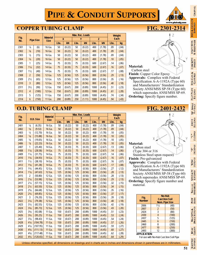
51
Unless otherwise specified, all dimensions on drawings and in charts are in inches and dimensions shown in parentheses are in millimeters.
www.phd-mfg.com
COPPER TUBING CLAMP FIG. 2301-2314
O.D. TUBING CLAMP FIG. 2401-2432
Material: Carbon steel Finish: Copper Color Epoxy Approvals: Complies with Federal
Specification A-A-1192A (Type 60) and Manufacturers’ Standardization Society ANSI/MSS SP-58 (Type 60) which supersedes ANSI/MSS SP-69.
Ordering: Specify figure number.
Fig. No. Pipe Size
Material Size
Max. Rec. Loads Weight Each X Y Z
Lbs. kN Lbs. kN Lbs. kN Lbs. kg
2301 1/4 (6) 16 Ga. 50 (0.22) 50 (0.22) 400 (1.78) .09 (.04)
2302 3/8 (10) 16 Ga. 50 (0.22) 50 (0.22) 400 (1.78) .09 (.04)
2303 1/2 (15) 16 Ga. 50 (0.22) 50 (0.22) 400 (1.78) .09 (.04)
2304 3/4 (20) 16 Ga. 50 (0.22) 50 (0.22) 400 (1.78) .10 (.05)
2305 1 (25) 14 Ga. 75 (0.33) 75 (0.33) 600 (2.67) .14 (.06)
2306 11/4 (32) 14 Ga. 75 (0.33) 75 (0.33) 600 (2.67) .16 (.07)
2307 11/2 (40) 14 Ga. 75 (0.33) 75 (0.33) 600 (2.67) .17 (.08)
2308 2 (50) 12 Ga. 125 (0.56) 125 (0.56) 800 (3.56) .29 (.13)
2309 21/2 (65) 12 Ga. 125 (0.56) 125 (0.56) 800 (3.56) .35 (.16)
2310 3 (80) 12 Ga. 125 (0.56) 125 (0.56) 800 (3.56) .40 (.18)
2311 31/2 (90) 12 Ga. 150 (0.67) 200 (0.89) 1000 (4.45) .51 (.23)
2312 4 (100) 12 Ga. 150 (0.67) 200 (0.89) 1000 (4.45) .61 (.28)
2313 5 (125) 11 Ga. 150 (0.67) 200 (0.89) 1000 (4.45) .74 (.34)
2314 6 (150) 11 Ga. 200 (0.89) 250 (1.11) 1000 (4.45) .94 (.43)
Fig. No. O.D. Size
Material Size
Max. Rec. Loads Weight Each X Y Z
Lbs. kN Lbs. kN Lbs. kN Lbs. kg
2401 1/4 (6.35) 16 Ga. 50 (0.22) 50 (0.22) 400 (1.78) .09 (.04)
2402 3/8 (9.53) 16 Ga. 50 (0.22) 50 (0.22) 400 (1.78) .09 (.04)
2403 1/2 (12.70) 16 Ga. 50 (0.22) 50 (0.22) 400 (1.78) .10 (.05)
2404 5/8 (15.88) 16 Ga. 50 (0.22) 50 (0.22) 400 (1.78) .10 (.05)
2405 3/4 (19.05) 16 Ga. 50 (0.22) 50 (0.22) 400 (1.78) .10 (.05)
2406 7/8 (22.23) 16 Ga. 50 (0.22) 50 (0.22) 400 (1.78) .10 (.05)
2407 1 (25.40) 14 Ga. 75 (0.33) 75 (0.33) 600 (2.67) .13 (.06)
2408 11/8 (28.58) 14 Ga. 75 (0.33) 75 (0.33) 600 (2.67) .14 (.06)
2409 11/4 (31.75) 14 Ga. 75 (0.33) 75 (0.33) 600 (2.67) .14 (.06)
2410 13/8 (34.93) 14 Ga. 75 (0.33) 75 (0.33) 600 (2.67) .16 (.07)
2411 11/2 (38.10) 14 Ga. 75 (0.33) 75 (0.33) 600 (2.67) .16 (.07)
2412 15/8 (41.28) 14 Ga. 75 (0.33) 75 (0.33) 600 (2.67) .17 (.08)
2413 13/4 (44.45) 12 Ga. 125 (0.56) 125 (0.56) 800 (3.56) .27 (.12)
2414 17/8 (47.63) 12 Ga. 125 (0.56) 125 (0.56) 800 (3.56) .28 (.13)
2415 2 (50.80) 12 Ga. 125 (0.56) 125 (0.56) 800 (3.56) .28 (.13)
2416 21/8 (53.98) 12 Ga. 125 (0.56) 125 (0.56) 800 (3.56) .29 (.13)
2417 21/4 (57.15) 12 Ga. 125 (0.56) 125 (0.56) 800 (3.56) .32 (.15)
2418 21/2 (63.50) 12 Ga. 125 (0.56) 125 (0.56) 800 (3.56) .34 (.15)
2419 25/8 (66.68) 12 Ga. 125 (0.56) 125 (0.56) 800 (3.56) .35 (.16)
2420 23/4 (69.85) 12 Ga. 125 (0.56) 125 (0.56) 800 (3.56) .37 (.17)
2421 3 (76.20) 12 Ga. 125 (0.56) 125 (0.56) 800 (3.56) .39 (.18)
2422 31/8 (79.38) 12 Ga. 125 (0.56) 125 (0.56) 800 (3.56) .40 (.18)
2423 31/4 (82.55) 12 Ga. 125 (0.56) 125 (0.56) 800 (3.56) .42 (.19)
2424 33/8 (85.73) 12 Ga. 125 (0.56) 125 (0.56) 800 (3.56) .43 (.20)
2425 35/8 (92.08) 11 Ga. 150 (0.67) 200 (0.89) 1000 (4.45) .51 (.23)
2426 33/4 (95.25) 11 Ga. 150 (0.67) 200 (0.89) 1000 (4.45) .53 (.24)
2427 37/8 (98.43) 11 Ga. 150 (0.67) 200 (0.89) 1000 (4.45) .54 (.24)
2428 41/8 (104.78) 11 Ga. 150 (0.67) 200 (0.89) 1000 (4.45) .57 (.26)
2429 41/4 (107.95) 11 Ga. 150 (0.67) 200 (0.89) 1000 (4.45) .59 (.27)
2430 43/8 (111.13) 11 Ga. 150 (0.67) 200 (0.89) 1000 (4.45) .60 (.27)
2431 45/8 (117.48) 11 Ga. 150 (0.67) 200 (0.89) 1000 (4.45) .62 (.28)
2432 43/4 (120.65) 11 Ga. 150 (0.67) 200 (0.89) 1000 (4.45) .64 (.29)
Material: Carbon steel (Type 304 or 316 Stainless Steel upon request) Finish: Pre-galvanized Approvals: Complies with Federal
Specification A-A-1192A (Type 60) and Manufacturers’ Standardization Society ANSI/MSS SP-58 (Type 60) which supersedes ANSI/MSS SP-69.
Ordering: Specify figure number and material.
Fig. Number
No-Hub Cast Iron Soil
Nom. Pipe Size
2006 11/2 (40) 2007 2 (50) 2424 3 (80) 2430 4 (100) 2437 5 (125) 2445 6 (150) 2460 8 (200) 2477 10 (250) 2493 12 (300)
APPLICATION: For use with No-Hub Cast Iron Soil Pipe
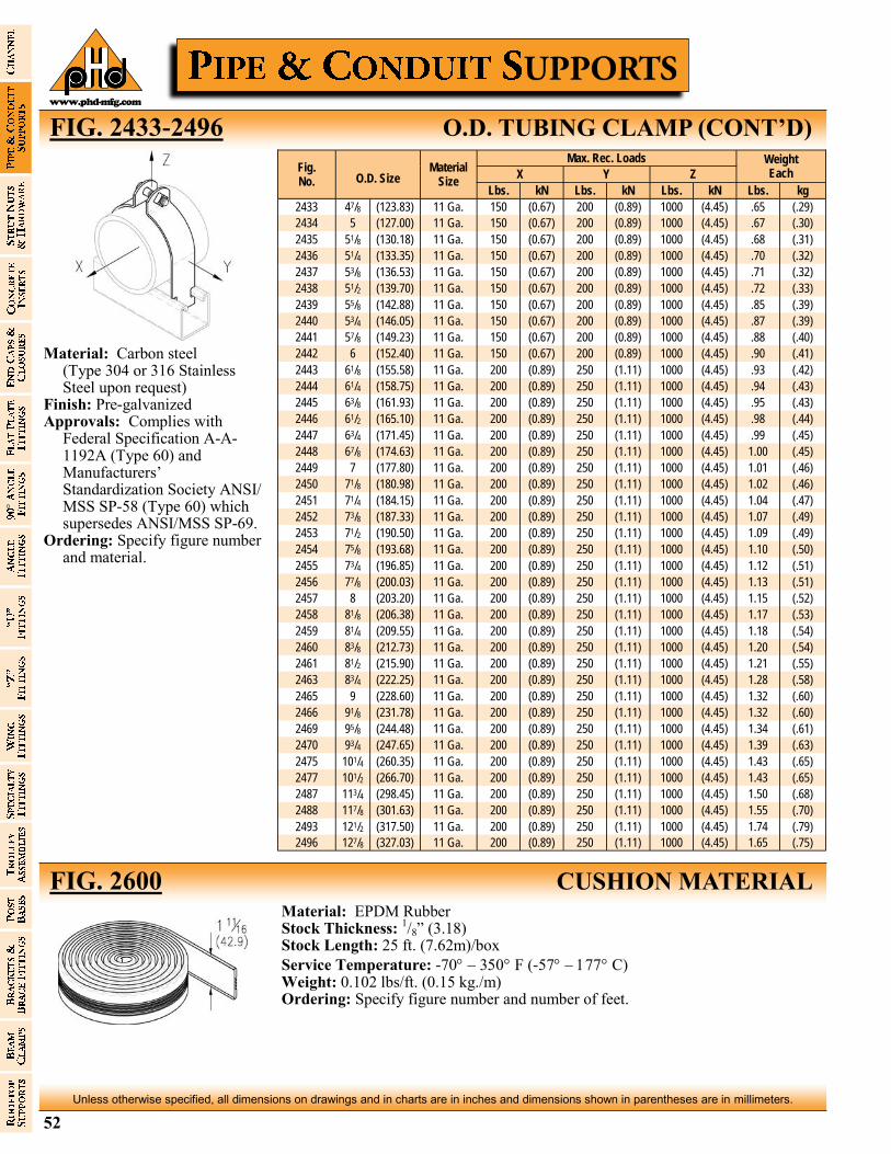
52
Unless otherwise specified, all dimensions on drawings and in charts are in inches and dimensions shown in parentheses are in millimeters.
www.phd-mfg.com
FIG. 2433-2496 O.D. TUBING CLAMP (CONT’D)
FIG. 2600 CUSHION MATERIAL
Fig. No. O.D. Size
Material Size
Max. Rec. Loads Weight Each X Y Z
Lbs. kN Lbs. kN Lbs. kN Lbs. kg
2433 47/8 (123.83) 11 Ga. 150 (0.67) 200 (0.89) 1000 (4.45) .65 (.29)
2434 5 (127.00) 11 Ga. 150 (0.67) 200 (0.89) 1000 (4.45) .67 (.30)
2435 51/8 (130.18) 11 Ga. 150 (0.67) 200 (0.89) 1000 (4.45) .68 (.31)
2436 51/4 (133.35) 11 Ga. 150 (0.67) 200 (0.89) 1000 (4.45) .70 (.32)
2437 53/8 (136.53) 11 Ga. 150 (0.67) 200 (0.89) 1000 (4.45) .71 (.32)
2438 51/2 (139.70) 11 Ga. 150 (0.67) 200 (0.89) 1000 (4.45) .72 (.33)
2439 55/8 (142.88) 11 Ga. 150 (0.67) 200 (0.89) 1000 (4.45) .85 (.39)
2440 53/4 (146.05) 11 Ga. 150 (0.67) 200 (0.89) 1000 (4.45) .87 (.39)
2441 57/8 (149.23) 11 Ga. 150 (0.67) 200 (0.89) 1000 (4.45) .88 (.40)
2442 6 (152.40) 11 Ga. 150 (0.67) 200 (0.89) 1000 (4.45) .90 (.41)
2443 61/8 (155.58) 11 Ga. 200 (0.89) 250 (1.11) 1000 (4.45) .93 (.42)
2444 61/4 (158.75) 11 Ga. 200 (0.89) 250 (1.11) 1000 (4.45) .94 (.43)
2445 63/8 (161.93) 11 Ga. 200 (0.89) 250 (1.11) 1000 (4.45) .95 (.43)
2446 61/2 (165.10) 11 Ga. 200 (0.89) 250 (1.11) 1000 (4.45) .98 (.44)
2447 63/4 (171.45) 11 Ga. 200 (0.89) 250 (1.11) 1000 (4.45) .99 (.45)
2448 67/8 (174.63) 11 Ga. 200 (0.89) 250 (1.11) 1000 (4.45) 1.00 (.45)
2449 7 (177.80) 11 Ga. 200 (0.89) 250 (1.11) 1000 (4.45) 1.01 (.46)
2450 71/8 (180.98) 11 Ga. 200 (0.89) 250 (1.11) 1000 (4.45) 1.02 (.46)
2451 71/4 (184.15) 11 Ga. 200 (0.89) 250 (1.11) 1000 (4.45) 1.04 (.47)
2452 73/8 (187.33) 11 Ga. 200 (0.89) 250 (1.11) 1000 (4.45) 1.07 (.49)
2453 71/2 (190.50) 11 Ga. 200 (0.89) 250 (1.11) 1000 (4.45) 1.09 (.49)
2454 75/8 (193.68) 11 Ga. 200 (0.89) 250 (1.11) 1000 (4.45) 1.10 (.50)
2455 73/4 (196.85) 11 Ga. 200 (0.89) 250 (1.11) 1000 (4.45) 1.12 (.51)
2456 77/8 (200.03) 11 Ga. 200 (0.89) 250 (1.11) 1000 (4.45) 1.13 (.51)
2457 8 (203.20) 11 Ga. 200 (0.89) 250 (1.11) 1000 (4.45) 1.15 (.52)
2458 81/8 (206.38) 11 Ga. 200 (0.89) 250 (1.11) 1000 (4.45) 1.17 (.53)
2459 81/4 (209.55) 11 Ga. 200 (0.89) 250 (1.11) 1000 (4.45) 1.18 (.54)
2460 83/8 (212.73) 11 Ga. 200 (0.89) 250 (1.11) 1000 (4.45) 1.20 (.54)
2461 81/2 (215.90) 11 Ga. 200 (0.89) 250 (1.11) 1000 (4.45) 1.21 (.55)
2463 83/4 (222.25) 11 Ga. 200 (0.89) 250 (1.11) 1000 (4.45) 1.28 (.58)
2465 9 (228.60) 11 Ga. 200 (0.89) 250 (1.11) 1000 (4.45) 1.32 (.60)
2466 91/8 (231.78) 11 Ga. 200 (0.89) 250 (1.11) 1000 (4.45) 1.32 (.60)
2469 95/8 (244.48) 11 Ga. 200 (0.89) 250 (1.11) 1000 (4.45) 1.34 (.61)
2470 93/4 (247.65) 11 Ga. 200 (0.89) 250 (1.11) 1000 (4.45) 1.39 (.63)
2475 101/4 (260.35) 11 Ga. 200 (0.89) 250 (1.11) 1000 (4.45) 1.43 (.65)
2477 101/2 (266.70) 11 Ga. 200 (0.89) 250 (1.11) 1000 (4.45) 1.43 (.65)
2487 113/4 (298.45) 11 Ga. 200 (0.89) 250 (1.11) 1000 (4.45) 1.50 (.68)
2488 117/8 (301.63) 11 Ga. 200 (0.89) 250 (1.11) 1000 (4.45) 1.55 (.70)
2493 121/2 (317.50) 11 Ga. 200 (0.89) 250 (1.11) 1000 (4.45) 1.74 (.79)
2496 127/8 (327.03) 11 Ga. 200 (0.89) 250 (1.11) 1000 (4.45) 1.65 (.75)
Material: Carbon steel (Type 304 or 316 Stainless
Steel upon request) Finish: Pre-galvanized Approvals: Complies with
Federal Specification A-A-1192A (Type 60) and Manufacturers’ Standardization Society ANSI/MSS SP-58 (Type 60) which supersedes ANSI/MSS SP-69.
Ordering: Specify figure number and material.
Material: EPDM Rubber Stock Thickness: 1/8” (3.18) Stock Length: 25 ft. (7.62m)/box
Service Temperature: -70 − F (-57 − C) Weight: 0.102 lbs/ft. (0.15 kg./m) Ordering: Specify figure number and number of feet.

53
Unless otherwise specified, all dimensions on drawings and in charts are in inches and dimensions shown in parentheses are in millimeters.
www.phd-mfg.com
CLAMP WITH CUSHION FIG. 2501-2588 Clamp Material: Carbon steel (Type 304 or 316 Stainless Steel upon request) Cushion Material: Multi-Flex TES A9110 EV1 Black, in accordance with ASTM D4474 TES
0130 A90000. Classified 2043 ( 25/50 ) for use in plenums and air handling systems. Temperature Range: -65°F to 275°F (-54°C to 135°C) Finish: Western gold Approvals: Complies with Federal Specification A-A-1192A (Type 61) and Manufacturers’
Standardization Society ANSI/MSS SP-58 (Type 61) which supersedes ANSI/MSS SP-69. Ordering: Specify figure number.
Fig. No.
O.D. Size A
Nom. Tube Size
Nom. Pipe Size
B C D
Max. Rec. Load Wt. Each
X Y Z
Lbs. kN Lbs. kN Lbs. kN Lbs. kg
2501 .25 (6.35) 1/8 (3) - - 1.11 (28.19) .075 (1.91) .62 (15.75) 50 (.22) 50 (.22) 400 (1.78) .13 (.06) 2502 .375 (9.53) 1/4 (6) - - 1.24 (31.50) .075 (1.91) .75 (19.05) 50 (.22) 50 (.22) 400 (1.78) .14 (.06) 2503 .5 (12.70) 3/8 (10) - - 1.36 (34.54) .075 (1.91) .87 (22.10) 50 (.22) 50 (.22) 400 (1.78) .15 (.07) 2504 .625 (15.88) 1/2 (15) - - 1.5 (38.10) .075 (1.91) 1 (25.40) 50 (.22) 50 (.22) 400 (1.78) .16 (.07) 2505 .75 (19.05) 5/8 (17) - - 1.78 (45.21) .075 (1.91) 1.33 (33.78) 75 (.33) 75 (.33) 600 (2.67) .19 (.09) 2506 .875 (22.23) 3/4 (20) - - 1.91 (48.51) .075 (1.91) 1.45 (36.83) 75 (.33) 75 (.33) 600 (2.67) .21 (.09) 2515 1 (25.40) - - - - 2.03 (51.56) .075 (1.91) 1.66 (42.16) 75 (.33) 75 (.33) 600 (2.67) .29 (.13) 2507 1.125 (28.58) 1 (25) - - 2.16 (54.86) .075 (1.91) 1.79 (45.47) 75 (.33) 75 (.33) 600 (2.67) .31 (.14) 2516 1.25 (31.75) - - - - 2.3 (58.42) .105 (2.67) 1.92 (48.77) 75 (.33) 75 (.33) 600 (2.67) .33 (.15) 2508 1.375 (34.93) 11/4 (32) - - 2.75 (69.85) .119 (3.02) 2.22 (56.39) 75 (.33) 75 (.33) 600 (2.67) .42 (.19) 2517 1.5 (38.10) - - - - 2.75 (69.85) .119 (3.02) 2.22 (56.39) 75 (.33) 75 (.33) 600 (2.67) .38 (.17) 2509 1.625 (41.28) 11/2 (40) - - 3.03 (76.96) .119 (3.02) 2.47 (62.74) 75 (.33) 75 (.33) 600 (2.67) .48 (.22) 2518 1.75 (44.45) - - - - 3.03 (76.96) .119 (3.02) 2.47 (62.74) 125 (.56) 125 (.56) 800 (3.56) .46 (.21) 2519 1.875 (47.63) - - - - 3.28 (83.31) .119 (3.02) 2.47 (62.74) 125 (.56) 125 (.56) 800 (3.56) .52 (.24) 2520 2 (50.80) - - - - 3.28 (83.31) .119 (3.02) 2.72 (69.09) 125 (.56) 125 (.56) 800 (3.56) .50 (.23) 2510 2.125 (53.98) 2 (50) - - 3.53 (89.66) .119 (3.02) 2.97 (75.44) 125 (.56) 125 (.56) 800 (3.56) .57 (.26) 2521 2.25 (57.15) - - - - 3.78 (96.01) .119 (3.02) 3.22 (81.79) 125 (.56) 125 (.56) 800 (3.56) .62 (.28) 2523 2.5 (63.50) - - - - 4.03 (102.36) .119 (3.02) 3.47 (88.14) 125 (.56) 125 (.56) 800 (3.56) .60 (.27) 2511 2.625 (66.68) 21/2 (65) - - 4.03 (102.36) .119 (3.02) 3.47 (88.14) 125 (.56) 125 (.56) 800 (3.56) .58 (.26) 2524 3 (76.20) - - - - 4.52 (114.81) .119 (3.02) 3.97 (100.84) 125 (.56) 125 (.56) 800 (3.56) .69 (.31) 2512 3.125 (79.38) 3 (80) - - 4.52 (114.81) .119 (3.02) 3.97 (100.84) 125 (.56) 125 (.56) 800 (3.56) .68 (.31) 2513 3.625 (92.08) 31/2 (90) - - 5.03 (127.76) .119 (3.02) 4.47 (113.54) 150 (.67) 200 (.89) 1000 (4.45) .76 (.34) 2514 4.125 (104.78) 4 (100) - - 5.66 (143.76) .119 (3.02) 5.09 (129.29) 150 (.67) 200 (.89) 1000 (4.45) .88 (.40) 2525 5.125 (130.18) 5 (125) - - 6.75 (171.45) .119 (3.02) 6.25 (158.75) 150 (.67) 200 (.89) 1000 (4.45) 1.17 (.53)
2527 6 (152.4) - - - - 7.75 (196.85) .119 (3.02) 7.5 (190.50) 150 (.67) 200 (.89) 1000 (4.45) 1.28 (.58)
2526 6.125 (155.58) 6 (150) - - 7.75 (196.85) .119 (3.02) 7.5 (190.50) 150 (.67) 200 (.89) 1000 (4.45) 1.28 (.58)
2530 .79 (20) Metric Pipe 1.78 (45.21) .07 (1.78) 1.33 (33.78) 75 (.33) 75 (.33) 600 (2.67) .19 (.09) 2531 .98 (25) Metric Pipe 2.03 (51.56) .07 (1.78) 1.66 (42.16) 75 (.33) 75 (.33) 600 (2.67) .29 (.13) 2532 1.26 (32) Metric Pipe 2.30 (58.42) .07 (1.78) 1.92 (48.77) 75 (.33) 75 (.33) 600 (2.67) .33 (.15) 2533 1.57 (40) Metric Pipe 2.75 (69.85) .11 (2.79) 2.22 (56.39) 75 (.33) 75 (.33) 600 (2.67) .48 (.22) 2534 1.97 (50) Metric Pipe 3.28 (83.31) .11 (2.79) 2.72 (69.09) 125 (.56) 125 (.56) 800 (3.56) .50 (.23) 2535 2.48 (63) Metric Pipe 4.03 (102.36) .11 (2.79) 3.47 (88.14) 125 (.56) 125 (.56) 800 (3.56) .60 (.27) 2536 2.95 (75) Metric Pipe 4.52 (114.81) .11 (2.79) 3.97 (100.84) 125 (.56) 125 (.56) 800 (3.56) .62 (.28) 2537 3.54 (90) Metric Pipe 4.91 (124.71) .11 (2.79) 4.36 (110.74) 150 (.67) 200 (.89) 1000 (4.45) .72 (.33) 2538 4.33 (110) Metric Pipe 5.76 (146.30) .11 (2.79) 5.30 (134.62) 150 (.67) 200 (.89) 1000 (4.45) .94 (.43) 2539 4.92 (125) Metric Pipe 6.55 (166.37) .11 (2.79) 6.15 (156.21) 150 (.67) 200 (.89) 1000 (4.45) 1.06 (.48) 2540 6.30 (160) Metric Pipe 7.95 (201.93) .11 (2.79) 7.70 (195.58) 150 (.67) 200 (.89) 1000 (4.45) 1.43 (.65)
2574 .540 (13.72) - - 1/4 (5) 1.41 (35.81) .075 (1.91) .91 (23.11) 50 (.22) 50 (.22) 400 (1.78) .16 (.07) 2575 .675 (17.15) - - 3/8 (10) 1.59 (40.39) .075 (1.91) 1.07 (27.18) 75 (.33) 75 (.33) 600 (2.67) .17 (.08) 2576 .840 (21.34) - - 1/2 (15) 1.91 (48.51) .075 (1.91) 1.45 (36.83) 75 (.33) 75 (.33) 600 (2.67) .21 (.10) 2577 1.050 (26.67) - - 3/4 (20) 2.16 (54.86) .075 (1.91) 1.79 (45.47) 75 (.33) 75 (.33) 600 (2.67) .31 (.14) 2578 1.315 (33.40) - - 1 (25) 2.75 (69.85) .119 (3.02) 2.22 (56.39) 75 (.33) 75 (.33) 600 (2.67) .43 (.20) 2579 1.660 (42.16) - - 11/4 (32) 3.03 (76.96) .119 (3.02) 2.47 (62.74) 125 (.56) 125 (.56) 800 (3.56) .48 (.22) 2580 1.900 (48.26) - - 11/2 (40) 3.28 (83.31) .119 (3.02) 2.47 (62.74) 125 (.56) 125 (.56) 800 (3.56) .52 (.24) 2581 2.375 (60.33) - - 2 (50) 3.78 (96.01) .119 (3.02) 3.22 (81.79) 125 (.56) 125 (.56) 800 (3.56) .61 (.28) 2582 2.875 (73.03) - - 21/2 (65) 4.27 (108.46) .119 (3.02) 3.72 (94.49) 125 (.56) 125 (.56) 800 (3.56) .62 (.28) 2583 3.500 (88.90) - - 3 (80) 4.91 (124.71) .119 (3.02) 4.36 (110.74) 150 (.67) 200 (.89) 1000 (4.45) .72 (.33) 2584 4.000 (101.60) - - 31/2 (90) 5.53 (140.46) .119 (3.02) 4.97 (126.24) 150 (.67) 200 (.89) 1000 (4.45) .88 (.40) 2585 4.500 (114.30) - - 4 (100) 6.03 (153.16) .119 (3.02) 5.47 (138.94) 150 (.67) 200 (.89) 1000 (4.45) .95 (.43) 2586 5.563 (141.30) - - 5 (125) 7.03 (178.56) .135 (3.43) 6.47 (164.34) 150 (.67) 200 (.89) 1000 (4.45) 1.22 (.55) 2587 6.625 (168.28) - - 6 (150) 8.03 (203.96) .135 (3.43) 7.47 (189.74) 150 (.67) 200 (.89) 1000 (4.45) 1.44 (.65) 2588 8.625 (219.08) - - 8 (200) 10.3 (261.62) .135 (3.43) 9.38 (238.25) 150 (.67) 200 (.89) 1000 (4.45) 2.00 (.90)
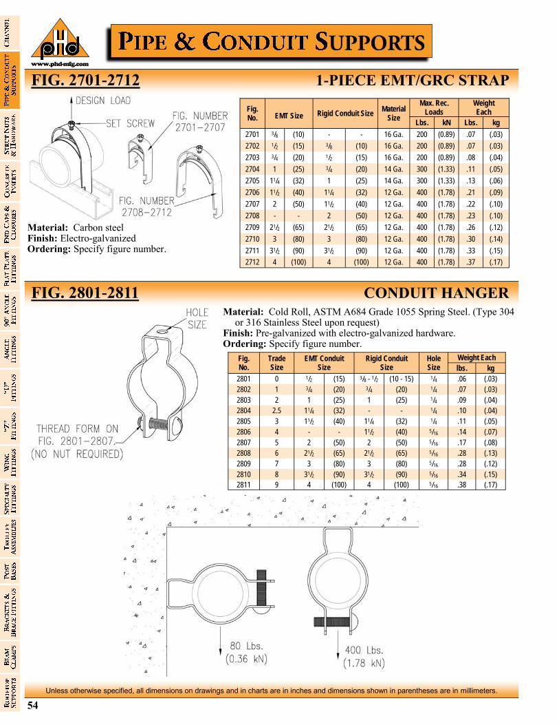
54
Unless otherwise specified, all dimensions on drawings and in charts are in inches and dimensions shown in parentheses are in millimeters.
www.phd-mfg.com
FIG. 2701-2712 1-PIECE EMT/GRC STRAP
FIG. 2801-2811 CONDUIT HANGER
Fig. No. EMT Size Rigid Conduit Size
Material Size
Max. Rec. Loads
Weight Each
Lbs. kN Lbs. kg
2701 3/8 (10) - - 16 Ga. 200 (0.89) .07 (.03)
2702 1/2 (15) 3/8 (10) 16 Ga. 200 (0.89) .07 (.03)
2703 3/4 (20) 1/2 (15) 16 Ga. 200 (0.89) .08 (.04)
2704 1 (25) 3/4 (20) 14 Ga. 300 (1.33) .11 (.05)
2705 11/4 (32) 1 (25) 14 Ga. 300 (1.33) .13 (.06)
2706 11/2 (40) 11/4 (32) 12 Ga. 400 (1.78) .21 (.09)
2707 2 (50) 11/2 (40) 12 Ga. 400 (1.78) .22 (.10)
2708 - - 2 (50) 12 Ga. 400 (1.78) .23 (.10)
2709 21/2 (65) 21/2 (65) 12 Ga. 400 (1.78) .26 (.12)
2710 3 (80) 3 (80) 12 Ga. 400 (1.78) .30 (.14)
2711 31/2 (90) 31/2 (90) 12 Ga. 400 (1.78) .33 (.15)
2712 4 (100) 4 (100) 12 Ga. 400 (1.78) .37 (.17)
Material: Carbon steel Finish: Electro-galvanized Ordering: Specify figure number.
Fig. No.
Trade Size
EMT Conduit Size
Rigid Conduit Size
Weight Each Hole Size lbs. kg
2801 0 1/2 (15) 3/8 - 1/2 (10 - 15) 1/4 .06 (.03)
2802 1 3/4 (20) 3/4 (20) 1/4 .07 (.03)
2803 2 1 (25) 1 (25) 1/4 .09 (.04)
2804 2.5 11/4 (32) - - 1/4 .10 (.04)
2805 3 11/2 (40) 11/4 (32) 1/4 .11 (.05)
2806 4 - - 11/2 (40) 5/16 .14 (.07)
2807 5 2 (50) 2 (50) 5/16 .17 (.08)
2808 6 21/2 (65) 21/2 (65) 5/16 .28 (.13)
2809 7 3 (80) 3 (80) 5/16 .28 (.12)
2810 8 31/2 (90) 31/2 (90) 5/16 .34 (.15)
2811 9 4 (100) 4 (100) 5/16 .38 (.17)
Material: Cold Roll, ASTM A684 Grade 1055 Spring Steel. (Type 304 or 316 Stainless Steel upon request)
Finish: Pre-galvanized with electro-galvanized hardware. Ordering: Specify figure number.
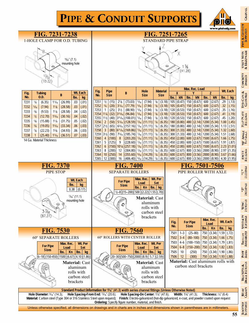
55
Unless otherwise specified, all dimensions on drawings and in charts are in inches and dimensions shown in parentheses are in millimeters.
www.phd-mfg.com
Fig. No.
Tubing O.D.
B Wt. Each
lbs. kg
7231 1/4 (6.35) 11/16 (26.99) .03 (.01)
7232 5/16 (7.94) 11/8 (28.58) .03 (.01)
7233 3/8 (9.53) 11/8 (28.58) .04 (.02)
7234 1/2 (12.70) 13/16 (30.16) .04 (.02)
7235 5/8 (15.88) 11/4 (31.75) .05 (.02)
7236 3/4 (19.05) 15/16 (33.34) .06 (.03)
7237 7/8 (22.23) 13/8 (34.93) .06 (.03)
7238 1 (25.40) 17/16 (36.51) .07 (.03)
14 Ga. Material Thickness
FIG. 7231-7238 1-HOLE CLAMP FOR O.D. TUBING
Standard Product Information for 15⁄8” (41.3) width series channel fittings (Unless Otherwise Noted)
Hole Diameter: 9⁄16” (14.3); Hole Spacing-From End: 13⁄16” (20.6); Hole Spacing-On Center: 17⁄8” (47.6); Width: 15⁄8” (41.3); Thickness: 1⁄4” (6.4) Material: Carbon steel (Type 304 or 316 Stainless Steel upon request); Finish: Electro-galvanized (hot-dip galvanized, e-coat, and powder coated upon request
Ordering: Specify figure number, material, and finish.
FIG. 7251-7265 STANDARD PIPE STRAP
Fig. No.
Pipe Size
B Hole Size
Material Size
Max. Rec. Load Wt. Each
X Y Z
lbs. kN lbs. kN lbs. kN lbs. kg
7251 1/2 (15) 27/8 (73.03) 5/16 (7.94) 1/8 (3.18) 105 (0.47) 150 (0.67) 600 (2.67) .29 (.13) 7252 3/4 (20) 31/16 (77.79) 5/16 (7.94) 1/8 (3.18) 105 (0.47) 150 (0.67) 600 (2.67) .32 (.15) 7253 1 (25) 31/2 (88.90) 5/16 (7.94) 1/8 (3.18) 120 (0.53) 150 (0.67) 600 (2.67) .35 (.16) 7254 11/4 (32) 313/16 (96.84) 5/16 (7.94) 1/8 (3.18) 120 (0.53) 150 (0.67) 600 (2.67) .41 (.19) 7255 11/2 (40) 315/16 (100.01) 5/16 (7.94) 1/8 (3.18) 120 (0.53) 150 (0.67) 600 (2.67) .45 (.20) 7256 2 (50) 51/16 (128.59) 7/16 (11.11) 1/4 (6.35) 180 (0.80) 480 (2.14) 1200 (5.34) 1.00 (.45) 7257 21/2 (65) 63/16 (157.16) 7/16 (11.11) 1/4 (6.35) 180 (0.80) 480 (2.14) 1200 (5.34) 1.13 (.51) 7258 3 (80) 611/16 (169.86) 7/16 (11.11) 1/4 (6.35) 300 (1.33) 480 (2.14) 1200 (5.34) 1.32 (.60) 7259 31/2 (90) 75/16 (185.74) 7/16 (11.11) 1/4 (6.35) 300 (1.33) 480 (2.14) 1200 (5.34) 1.51 (.68) 7260 4 (100) 8 (203.20) 7/16 (11.11) 1/4 (6.35) 450 (2.00) 600 (2.67) 1500 (6.67) 1.66 (.75) 7261 5 (125) 9 (228.60) 7/16 (11.11) 1/4 (6.35) 450 (2.00) 600 (2.67) 1500 (6.67) 1.91 (.87) 7262 6 (150) 101/8 (257.18) 7/16 (11.11) 1/4 (6.35) 450 (2.00) 600 (2.67) 1500 (6.67) 2.23 (1.01) 7263 8 (200) 12 (304.80) 7/16 (11.11) 1/4 (6.35) 600 (2.67) 800 (3.56) 2000 (8.90) 2.97 (1.35) 7264 10 (250) 14 (355.60) 9/16 (14.29) 1/4 (6.35) 600 (2.67) 800 (3.56) 2000 (8.90) 3.67 (1.66) 7265 12 (300) 16 (406.40) 9/16 (14.29) 1/4 (6.35) 600 (2.67) 800 (3.56) 2000 (8.90) 4.30 (1.95)
FIG. 7370 PIPE STOP
FIG. 7400 SEPARATE ROLLERS
FIG. 7501-7506 PIPE ROLLER WITH AXLE
FIG. 7530 60 SEPARATE ROLLERS
FIG. 7560 60 ROLLERS WITH CENTER ROLLER
Fig. No.
For Pipe Sizes
Wt. Each Max. Rec.
Load
lbs. Kn lbs. kg
7501 1–3 (25–80) 750 (3.34) 1.59 (.72)
7502 3–4 (80–100) 750 (3.34) 1.66 (.75)
7503 4–6 (100–150) 750 (3.34) 1.79 (.81)
7504 6–8 (150–200) 750 (3.34) 1.82 (.83)
7505 10 (250) 750 (3.34) 1.90 (.86)
7506 12 (300) 750 (3.34) 1.93 (.88)
Wt. Each
lbs. kg
0.38 (0.17)
Max. Rec. Load
Wt. Per Set For Pipe
Sizes lbs. Kn lbs. kg
1/2–8 (15–200) 500 (2.22) 1.55 (.70)
Material: Cast aluminum rolls with carbon steel brackets
Max. Rec. Load
Wt. Per Set For Pipe
Sizes lbs. Kn lbs. kg
6–18 (150-450) 1500 (6.67) 4.10 (1.86)
Material: Cast aluminum rolls with carbon steel brackets
Max. Rec. Load
Wt. Per Set For Pipe
Sizes lbs. Kn lbs. kg
20–30 (500–750) 2000 (8.9) 5.7 (2.59)
Material: Cast aluminum rolls with carbon steel brackets
Material: Cast aluminum rolls with carbon steel brackets
9/32” (7.1) mounting hole
7/16” (11.1)mounting hole
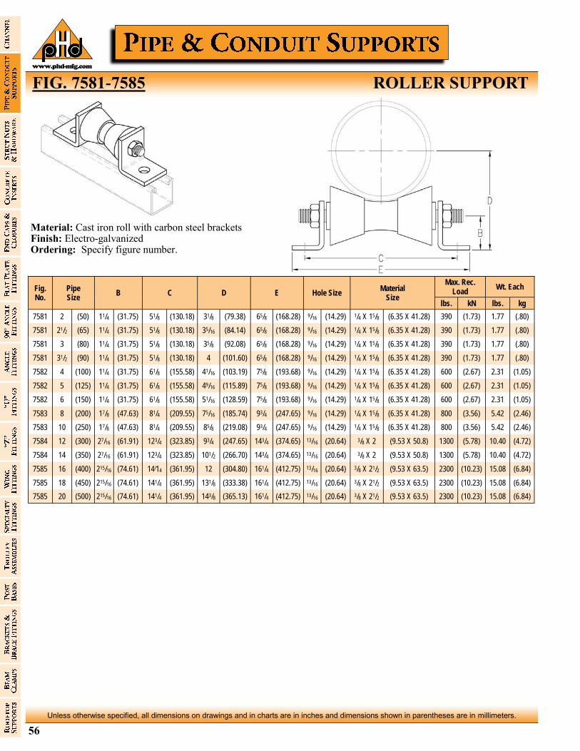
56
Unless otherwise specified, all dimensions on drawings and in charts are in inches and dimensions shown in parentheses are in millimeters.
www.phd-mfg.com
Fig. No.
Pipe Size
B C D E Hole Size Material
Size
Max. Rec. Load
Wt. Each
lbs. kN lbs. kg
7581 2 (50) 11/4 (31.75) 51/8 (130.18) 31/8 (79.38) 65/8 (168.28) 9/16 (14.29) 1/4 X 15/8 (6.35 X 41.28) 390 (1.73) 1.77 (.80)
7581 21/2 (65) 11/4 (31.75) 51/8 (130.18) 35/16 (84.14) 65/8 (168.28) 9/16 (14.29) 1/4 X 15/8 (6.35 X 41.28) 390 (1.73) 1.77 (.80)
7581 3 (80) 11/4 (31.75) 51/8 (130.18) 35/8 (92.08) 65/8 (168.28) 9/16 (14.29) 1/4 X 15/8 (6.35 X 41.28) 390 (1.73) 1.77 (.80)
7581 31/2 (90) 11/4 (31.75) 51/8 (130.18) 4 (101.60) 65/8 (168.28) 9/16 (14.29) 1/4 X 15/8 (6.35 X 41.28) 390 (1.73) 1.77 (.80)
7582 4 (100) 11/4 (31.75) 61/8 (155.58) 41/16 (103.19) 75/8 (193.68) 9/16 (14.29) 1/4 X 15/8 (6.35 X 41.28) 600 (2.67) 2.31 (1.05)
7582 5 (125) 11/4 (31.75) 61/8 (155.58) 49/16 (115.89) 75/8 (193.68) 9/16 (14.29) 1/4 X 15/8 (6.35 X 41.28) 600 (2.67) 2.31 (1.05)
7582 6 (150) 11/4 (31.75) 61/8 (155.58) 51/16 (128.59) 75/8 (193.68) 9/16 (14.29) 1/4 X 15/8 (6.35 X 41.28) 600 (2.67) 2.31 (1.05)
7583 8 (200) 17/8 (47.63) 81/4 (209.55) 75/16 (185.74) 93/4 (247.65) 9/16 (14.29) 1/4 X 15/8 (6.35 X 41.28) 800 (3.56) 5.42 (2.46)
7583 10 (250) 17/8 (47.63) 81/4 (209.55) 85/8 (219.08) 93/4 (247.65) 9/16 (14.29) 1/4 X 15/8 (6.35 X 41.28) 800 (3.56) 5.42 (2.46)
7584 12 (300) 27/16 (61.91) 123/4 (323.85) 93/4 (247.65) 143/4 (374.65) 13/16 (20.64) 3/8 X 2 (9.53 X 50.8) 1300 (5.78) 10.40 (4.72)
7584 14 (350) 27/16 (61.91) 123/4 (323.85) 101/2 (266.70) 143/4 (374.65) 13/16 (20.64) 3/8 X 2 (9.53 X 50.8) 1300 (5.78) 10.40 (4.72)
7585 16 (400) 215/16 (74.61) 14/14 (361.95) 12 (304.80) 161/4 (412.75) 13/16 (20.64) 3/8 X 21/2 (9.53 X 63.5) 2300 (10.23) 15.08 (6.84)
7585 18 (450) 215/16 (74.61) 141/4 (361.95) 131/8 (333.38) 161/4 (412.75) 13/16 (20.64) 3/8 X 21/2 (9.53 X 63.5) 2300 (10.23) 15.08 (6.84)
7585 20 (500) 215/16 (74.61) 141/4 (361.95) 143/8 (365.13) 161/4 (412.75) 13/16 (20.64) 3/8 X 21/2 (9.53 X 63.5) 2300 (10.23) 15.08 (6.84)
Material: Cast iron roll with carbon steel brackets Finish: Electro-galvanized Ordering: Specify figure number.
FIG. 7581-7585 ROLLER SUPPORT
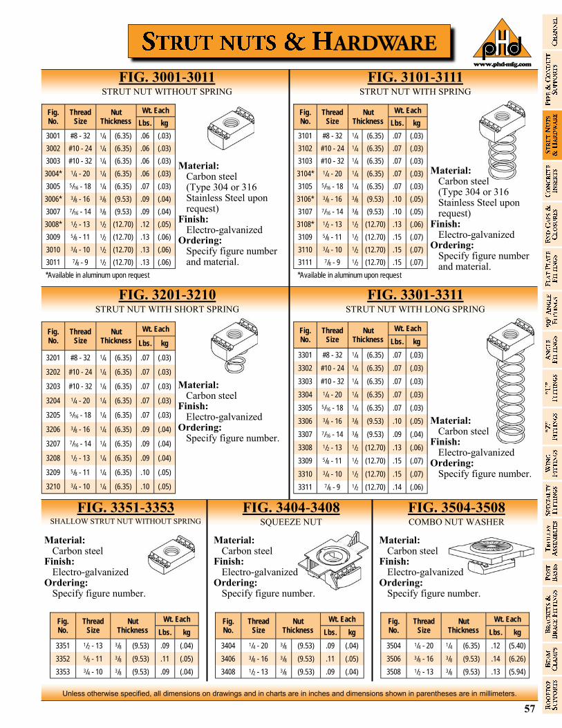
57
Unless otherwise specified, all dimensions on drawings and in charts are in inches and dimensions shown in parentheses are in millimeters.
www.phd-mfg.com
FIG. 3001-3011 STRUT NUT WITHOUT SPRING
FIG. 3101-3111 STRUT NUT WITH SPRING
Fig. No.
Thread Size
Nut Thickness
Wt. Each
Lbs. kg
3001 #8 - 32 1/4 (6.35) .06 (.03)
3002 #10 - 24 1/4 (6.35) .06 (.03)
3003 #10 - 32 1/4 (6.35) .06 (.03)
3004* 1/4 - 20 1/4 (6.35) .06 (.03)
3005 5/16 - 18 1/4 (6.35) .07 (.03)
3006* 3/8 - 16 3/8 (9.53) .09 (.04)
3007 7/16 - 14 3/8 (9.53) .09 (.04)
3008* 1/2 - 13 1/2 (12.70) .12 (.05)
3009 5/8 - 11 1/2 (12.70) .13 (.06)
3010 3/4 - 10 1/2 (12.70) .13 (.06)
3011 7/8 - 9 1/2 (12.70) .13 (.06)
*Available in aluminum upon request
Material: Carbon steel (Type 304 or 316
Stainless Steel upon request)
Finish: Electro-galvanized Ordering: Specify figure number
and material.
FIG. 3201-3210 STRUT NUT WITH SHORT SPRING
FIG. 3301-3311 STRUT NUT WITH LONG SPRING
Fig. No.
Thread Size
Nut Thickness
Wt. Each
Lbs. kg
3101 #8 - 32 1/4 (6.35) .07 (.03)
3102 #10 - 24 1/4 (6.35) .07 (.03)
3103 #10 - 32 1/4 (6.35) .07 (.03)
3104* 1/4 - 20 1/4 (6.35) .07 (.03)
3105 5/16 - 18 1/4 (6.35) .07 (.03)
3106* 3/8 - 16 3/8 (9.53) .10 (.05)
3107 7/16 - 14 3/8 (9.53) .10 (.05)
3108* 1/2 - 13 1/2 (12.70) .13 (.06)
3109 5/8 - 11 1/2 (12.70) .15 (.07)
3110 3/4 - 10 1/2 (12.70) .15 (.07)
3111 7/8 - 9 1/2 (12.70) .15 (.07)
*Available in aluminum upon request
Material: Carbon steel (Type 304 or 316
Stainless Steel upon request) Finish: Electro-galvanized Ordering: Specify figure number
and material.
Fig. No.
Thread Size
Nut Thickness
Wt. Each
Lbs. kg
3201 #8 - 32 1/4 (6.35) .07 (.03)
3202 #10 - 24 1/4 (6.35) .07 (.03)
3203 #10 - 32 1/4 (6.35) .07 (.03)
3204 1/4 - 20 1/4 (6.35) .07 (.03)
3205 5/16 - 18 1/4 (6.35) .07 (.03)
3206 3/8 - 16 1/4 (6.35) .09 (.04)
3207 7/16 - 14 1/4 (6.35) .09 (.04)
3208 1/2 - 13 1/4 (6.35) .09 (.04)
3209 5/8 - 11 1/4 (6.35) .10 (.05)
3210 3/4 - 10 1/4 (6.35) .10 (.05)
Material: Carbon steel Finish: Electro-galvanized Ordering: Specify figure number.
Fig. No.
Thread Size
Nut Thickness
Wt. Each
Lbs. kg
3301 #8 - 32 1/4 (6.35) .07 (.03)
3302 #10 - 24 1/4 (6.35) .07 (.03)
3303 #10 - 32 1/4 (6.35) .07 (.03)
3304 1/4 - 20 1/4 (6.35) .07 (.03)
3305 5/16 - 18 1/4 (6.35) .07 (.03)
3306 3/8 - 16 3/8 (9.53) .10 (.05)
3307 7/16 - 14 3/8 (9.53) .09 (.04)
3308 1/2 - 13 1/2 (12.70) .13 (.06)
3309 5/8 - 11 1/2 (12.70) .15 (.07)
3310 3/4 - 10 1/2 (12.70) .15 (.07)
3311 7/8 - 9 1/2 (12.70) .14 (.06)
Material: Carbon steel Finish: Electro-galvanized Ordering: Specify figure number.
FIG. 3351-3353 SHALLOW STRUT NUT WITHOUT SPRING
FIG. 3404-3408 SQUEEZE NUT
FIG. 3504-3508 COMBO NUT WASHER
Fig. No.
Thread Size
Nut Thickness
Wt. Each
Lbs. kg
3351 1/2 - 13 3/8 (9.53) .09 (.04)
3352 5/8 - 11 3/8 (9.53) .11 (.05)
3353 3/4 - 10 3/8 (9.53) .09 (.04)
Fig. No.
Thread Size
Nut Thickness
Wt. Each
Lbs. kg
3404 1/4 - 20 3/8 (9.53) .09 (.04)
3406 3/8 - 16 3/8 (9.53) .11 (.05)
3408 1/2 - 13 3/8 (9.53) .09 (.04)
Fig. No.
Thread Size
Nut Thickness
Wt. Each
Lbs. kg
3504 1/4 - 20 1/4 (6.35) .12 (5.40)
3506 3/8 - 16 3/8 (9.53) .14 (6.26)
3508 1/2 - 13 3/8 (9.53) .13 (5.94)
Material: Carbon steel Finish: Electro-galvanized Ordering: Specify figure number.
Material: Carbon steel Finish: Electro-galvanized Ordering: Specify figure number.
Material: Carbon steel Finish: Electro-galvanized Ordering: Specify figure number.
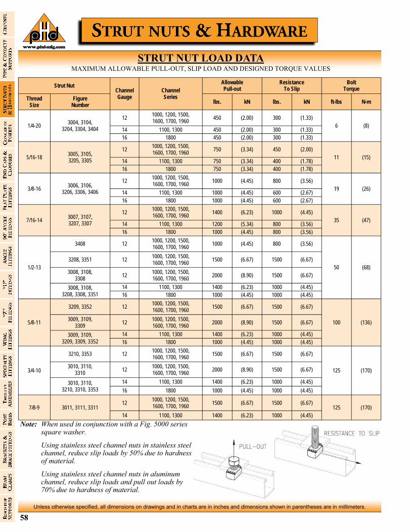
58
Unless otherwise specified, all dimensions on drawings and in charts are in inches and dimensions shown in parentheses are in millimeters.
www.phd-mfg.com
Strut Nut Channel Gauge
Channel Series
Allowable Pull-out
Resistance To Slip
Bolt Torque
Thread Size
Figure Number
lbs. kN lbs. kN ft-lbs N-m
1/4-20 3004, 3104,
3204, 3304, 3404
12 1000, 1200, 1500, 1600, 1700, 1960
450 (2.00) 300 (1.33)
6 (8) 14 1100, 1300 450 (2.00) 300 (1.33)
16 1800 450 (2.00) 300 (1.33)
5/16-18 3005, 3105, 3205, 3305
12 1000, 1200, 1500, 1600, 1700, 1960
750 (3.34) 450 (2.00)
11 (15) 14 1100, 1300 750 (3.34) 400 (1.78)
16 1800 750 (3.34) 400 (1.78)
3/8-16 3006, 3106,
3206, 3306, 3406
12 1000, 1200, 1500, 1600, 1700, 1960
1000 (4.45) 800 (3.56)
19 (26) 14 1100, 1300 1000 (4.45) 600 (2.67)
16 1800 1000 (4.45) 600 (2.67)
7/16-14 3007, 3107, 3207, 3307
12 1000, 1200, 1500, 1600, 1700, 1960
1400 (6.23) 1000 (4.45)
35 (47) 14 1100, 1300 1200 (5.34) 800 (3.56)
16 1800 1000 (4.45) 800 (3.56)
1/2-13
3408 12 1000, 1200, 1500, 1600, 1700, 1960
1000 (4.45) 800 (3.56)
50 (68)
3208, 3351 12 1000, 1200, 1500, 1600, 1700, 1960
1500 (6.67) 1500 (6.67)
3008, 3108, 3308
12 1000, 1200, 1500, 1600, 1700, 1960
2000 (8.90) 1500 (6.67)
3008, 3108, 3208, 3308, 3351
14 1100, 1300 1400 (6.23) 1000 (4.45)
16 1800 1000 (4.45) 1000 (4.45)
5/8-11
3209, 3352 12 1000, 1200, 1500, 1600, 1700, 1960
1500 (6.67) 1500 (6.67)
100 (136) 3009, 3109,
3309 12
1000, 1200, 1500, 1600, 1700, 1960
2000 (8.90) 1500 (6.67)
3009, 3109, 3209, 3309, 3352
14 1100, 1300 1400 (6.23) 1000 (4.45)
16 1800 1000 (4.45) 1000 (4.45)
3/4-10
3210, 3353 12 1000, 1200, 1500, 1600, 1700, 1960
1500 (6.67) 1500 (6.67)
125 (170) 3010, 3110,
3310 12
1000, 1200, 1500, 1600, 1700, 1960
2000 (8.90) 1500 (6.67)
3010, 3110, 3210, 3310, 3353
14 1100, 1300 1400 (6.23) 1000 (4.45)
16 1800 1000 (4.45) 1000 (4.45)
7/8-9 12
1000, 1200, 1500, 1600, 1700, 1960
1500 (6.67) 1500 (6.67) 125 (170) 3011, 3111, 3311
14 1100, 1300 1400 (6.23) 1000 (4.45)
STRUT NUT LOAD DATA MAXIMUM ALLOWABLE PULL-OUT, SLIP LOAD AND DESIGNED TORQUE VALUES
Note: When used in conjunction with a Fig. 5000 series square washer.
Using stainless steel channel nuts in stainless steel channel, reduce slip loads by 50% due to hardness of material.
Using stainless steel channel nuts in aluminum channel, reduce slip loads and pull out loads by 70% due to hardness of material.

59
Unless otherwise specified, all dimensions on drawings and in charts are in inches and dimensions shown in parentheses are in millimeters.
www.phd-mfg.com
Function: Designed to stiffen 3/8” to 5/8” rod. Material: Carbon steel Finish: Electro-galvanized Ordering: Specify figure number.
Rod Size
Wt. Each
Lbs. kg 3/8 (10) .03 (.01) 1/2 (12) .03 (.01) 5/8 (16) .03 (.01)
FIG. 7600 CRADLE CLIP
FIG. 7605 ROD STIFFENER
Function: Designed to stiffen 3/8” to 5/8” rod. Material: Carbon steel Finish: Electro-galvanized Ordering: Specify figure
number.
Rod Size
Wt. Each
Lbs. kg 3/8 (10) .14 (.06) 1/2 (12) .14 (.06) 5/8 (16) .14 (.06)
Rod Size
Root Area
Radius of Gyration
Design Load Rod Stiffener Clip Spacing (L)
in2 mm2 Lbs. Kn Rod Stress
@ 100% 10,700 psi
Rod Stress @ 75%
8,025 psi
Rod Stress @ 50%
5,350 psi
Rod Stress @ 35%
3,745 psi 3/8 (10) 0.068 (49.5) 0.074 (1.99) 730 (3.6) 9 (229) 11 (279) 13 (330) 15 (381) 1/2 (12) 0.126 (72.4) 0.10 (2.40) 1350 (5.3) 12 (305) 14 (356) 17 (432) 21 (533) 5/8 (16) 0.202 (138.3) 0.127 (3.32) 2160 (10.2) 15 (381) 18 (457) 22 (559) 26 (660)
FIG. 7610 & 7611 FEMALE SWIVEL
FIG. 7615 & 7616 MALE SWIVEL
FIG. 7620 & 7621 FEMALE/FEMALE SWIVEL
FIG. 7625 & 7626 FEMALE/MALE SWIVEL
Fig. No.
A D Max. Rec. Load Wt. Each
B lbs. kN lbs. kg
7610 3/8-16 9/32 (7.14) 610 (2.71) .13 (.06) -
7611 1/2-13 3/8 (9.53) 1130 (5.03) .15 (.07) -
7615 - 9/32 (7.14) 610 (2.71) .16 (.07) 3/8-16 X 1
7616 - 3/8 (9.53) 1130 (5.03) .20 (.09) 1/2-13 X 1
7620 3/8-16 - - 610 (2.71) .26 (.12) -
7621 1/2-13 - - 1130 (5.03) .28 (.13) -
7625 3/8-16 - - 610 (2.71) .26 (.12) 3/8-16 X 1 7626 1/2-13 - - 1130 (5.03) .28 (.13) 1/2-13 X 1
Material: Carbon steel Finish: Electro-galvanized Ordering: Specify figure number.
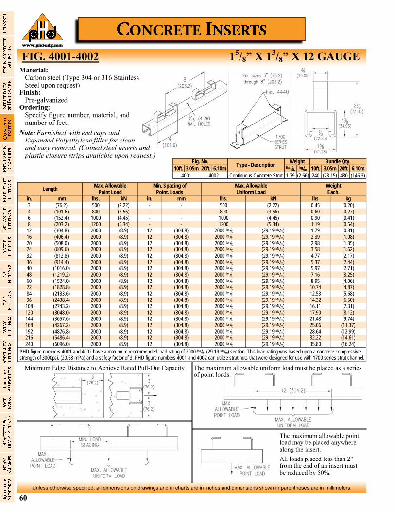
60
Unless otherwise specified, all dimensions on drawings and in charts are in inches and dimensions shown in parentheses are in millimeters.
www.phd-mfg.com
FIG. 4001-4002 15/8” X 1
3/8” X 12 GAUGE
Length Max. Allowable
Point Load Min. Spacing of
Point. Loads Max. Allowable Uniform Load
Weight Each.
in. mm lbs. kN in. mm lbs. kN lbs kg
3 (76.2) 500 (2.22) - - 500 (2.22) 0.45 (0.20) 4 (101.6) 800 (3.56) - - 800 (3.56) 0.60 (0.27) 6 (152.4) 1000 (4.45) - - 1000 (4.45) 0.90 (0.41) 8 (203.2) 1200 (5.34) - - 1200 (5.34) 1.19 (0.54)
12 (304.8) 2000 (8.9) 12 (304.8) 2000 lbs/ft (29.19 kN/m) 1.79 (0.81) 16 (406.4) 2000 (8.9) 12 (304.8) 2000 lbs/ft (29.19 kN/m) 2.39 (1.08) 20 (508.0) 2000 (8.9) 12 (304.8) 2000 lbs/ft (29.19 kN/m) 2.98 (1.35) 24 (609.6) 2000 (8.9) 12 (304.8) 2000 lbs/ft (29.19 kN/m) 3.58 (1.62) 32 (812.8) 2000 (8.9) 12 (304.8) 2000 lbs/ft (29.19 kN/m) 4.77 (2.17) 36 (914.4) 2000 (8.9) 12 (304.8) 2000 lbs/ft (29.19 kN/m) 5.37 (2.44) 40 (1016.0) 2000 (8.9) 12 (304.8) 2000 lbs/ft (29.19 kN/m) 5.97 (2.71) 48 (1219.2) 2000 (8.9) 12 (304.8) 2000 lbs/ft (29.19 kN/m) 7.16 (3.25) 60 (1524.0) 2000 (8.9) 12 (304.8) 2000 lbs/ft (29.19 kN/m) 8.95 (4.06) 72 (1828.8) 2000 (8.9) 12 (304.8) 2000 lbs/ft (29.19 kN/m) 10.74 (4.87) 84 (2133.6) 2000 (8.9) 12 (304.8) 2000 lbs/ft (29.19 kN/m) 12.53 (5.68) 96 (2438.4) 2000 (8.9) 12 (304.8) 2000 lbs/ft (29.19 kN/m) 14.32 (6.50) 108 (2743.2) 2000 (8.9) 12 (304.8) 2000 lbs/ft (29.19 kN/m) 16.11 (7.31) 120 (3048.0) 2000 (8.9) 12 (304.8) 2000 lbs/ft (29.19 kN/m) 17.90 (8.12) 144 (3657.6) 2000 (8.9) 12 (304.8) 2000 lbs/ft (29.19 kN/m) 21.48 (9.74) 168 (4267.2) 2000 (8.9) 12 (304.8) 2000 lbs/ft (29.19 kN/m) 25.06 (11.37) 192 (4876.8) 2000 (8.9) 12 (304.8) 2000 lbs/ft (29.19 kN/m) 28.64 (12.99) 216 (5486.4) 2000 (8.9) 12 (304.8) 2000 lbs/ft (29.19 kN/m) 32.22 (14.61) 240 (6096.0) 2000 (8.9) 12 (304.8) 2000 lbs/ft (29.19 kN/m) 35.80 (16.24)
PHD figure numbers 4001 and 4002 have a maximum recommended load rating of 2000 lbs/ft (29.19 kN/m) section. This load rating was based upon a concrete compressive strength of 3000psi. (20.68 mPa) and a safety factor of 3. PHD figure numbers 4001 and 4002 can utilize strut nuts that were designed for use with 1700 series strut channel.
Material: Carbon steel (Type 304 or 316 Stainless
Steel upon request) Finish: Pre-galvanized Ordering: Specify figure number, material, and
number of feet.
Note: Furnished with end caps and Expanded Polyethylene filler for clean and easy removal. (Coined steel inserts and plastic closure strips available upon request.)
Fig. No. Type - Description
Weight Bundle Qty.
10ft. 3.05m 20ft. 6.10m lbs./ft. kg/m 10ft. 3.05m 20ft. 6.10m
4001 4002 Continuous Concrete Strut 1.79 (2.66) 240 (73.15) 480 (146.3)
Minimum Edge Distance to Achieve Rated Pull-Out Capacity The maximum allowable uniform load must be placed as a series of point loads.
The maximum allowable point load may be placed anywhere along the insert.
All loads placed less than 2" from the end of an insert must be reduced by 50%.
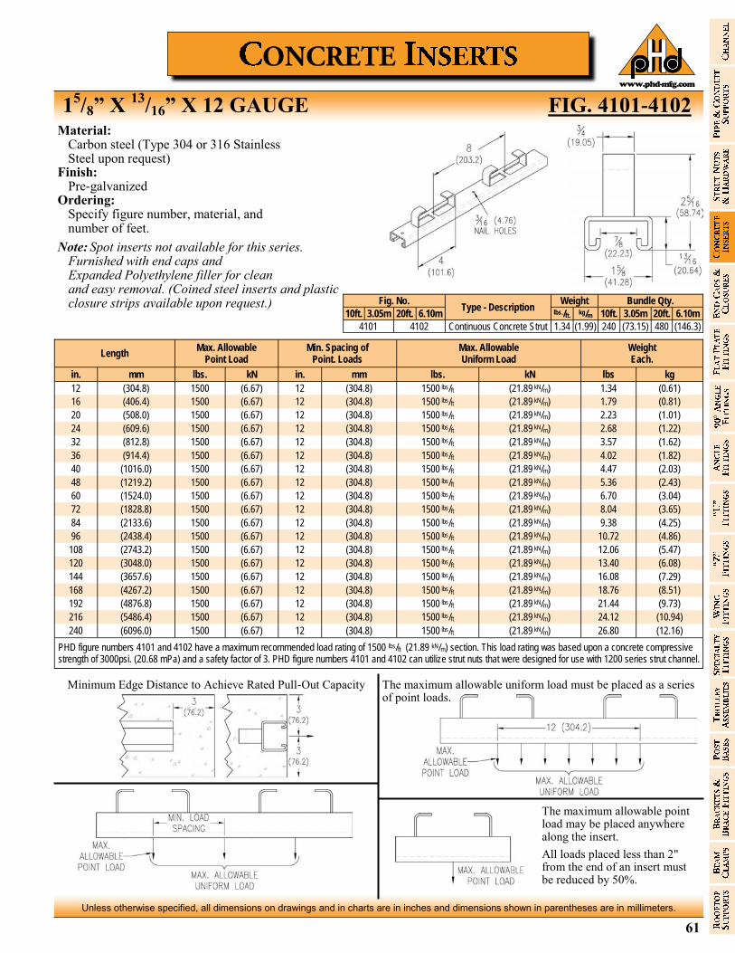
61
Unless otherwise specified, all dimensions on drawings and in charts are in inches and dimensions shown in parentheses are in millimeters.
www.phd-mfg.com
15/8” X
13/16” X 12 GAUGE FIG. 4101-4102
Length Max. Allowable
Point Load Min. Spacing of
Point. Loads Max. Allowable Uniform Load
Weight Each.
in. mm lbs. kN in. mm lbs. kN lbs kg
12 (304.8) 1500 (6.67) 12 (304.8) 1500 lbs/ft (21.89 kN/m) 1.34 (0.61)
16 (406.4) 1500 (6.67) 12 (304.8) 1500 lbs/ft (21.89 kN/m) 1.79 (0.81)
20 (508.0) 1500 (6.67) 12 (304.8) 1500 lbs/ft (21.89 kN/m) 2.23 (1.01)
24 (609.6) 1500 (6.67) 12 (304.8) 1500 lbs/ft (21.89 kN/m) 2.68 (1.22)
32 (812.8) 1500 (6.67) 12 (304.8) 1500 lbs/ft (21.89 kN/m) 3.57 (1.62)
36 (914.4) 1500 (6.67) 12 (304.8) 1500 lbs/ft (21.89 kN/m) 4.02 (1.82)
40 (1016.0) 1500 (6.67) 12 (304.8) 1500 lbs/ft (21.89 kN/m) 4.47 (2.03)
48 (1219.2) 1500 (6.67) 12 (304.8) 1500 lbs/ft (21.89 kN/m) 5.36 (2.43)
60 (1524.0) 1500 (6.67) 12 (304.8) 1500 lbs/ft (21.89 kN/m) 6.70 (3.04)
72 (1828.8) 1500 (6.67) 12 (304.8) 1500 lbs/ft (21.89 kN/m) 8.04 (3.65)
84 (2133.6) 1500 (6.67) 12 (304.8) 1500 lbs/ft (21.89 kN/m) 9.38 (4.25)
96 (2438.4) 1500 (6.67) 12 (304.8) 1500 lbs/ft (21.89 kN/m) 10.72 (4.86)
108 (2743.2) 1500 (6.67) 12 (304.8) 1500 lbs/ft (21.89 kN/m) 12.06 (5.47)
120 (3048.0) 1500 (6.67) 12 (304.8) 1500 lbs/ft (21.89 kN/m) 13.40 (6.08)
144 (3657.6) 1500 (6.67) 12 (304.8) 1500 lbs/ft (21.89 kN/m) 16.08 (7.29)
168 (4267.2) 1500 (6.67) 12 (304.8) 1500 lbs/ft (21.89 kN/m) 18.76 (8.51)
192 (4876.8) 1500 (6.67) 12 (304.8) 1500 lbs/ft (21.89 kN/m) 21.44 (9.73)
216 (5486.4) 1500 (6.67) 12 (304.8) 1500 lbs/ft (21.89 kN/m) 24.12 (10.94)
240 (6096.0) 1500 (6.67) 12 (304.8) 1500 lbs/ft (21.89 kN/m) 26.80 (12.16)
PHD figure numbers 4101 and 4102 have a maximum recommended load rating of 1500 lbs/ft (21.89 kN/m) section. This load rating was based upon a concrete compressive strength of 3000psi. (20.68 mPa) and a safety factor of 3. PHD figure numbers 4101 and 4102 can utilize strut nuts that were designed for use with 1200 series strut channel.
Fig. No. Type - Description
Weight Bundle Qty.
10ft. 3.05m 20ft. 6.10m lbs./ft. kg/m 10ft. 3.05m 20ft. 6.10m
4101 4102 Continuous Concrete Strut 1.34 (1.99) 240 (73.15) 480 (146.3)
Minimum Edge Distance to Achieve Rated Pull-Out Capacity The maximum allowable uniform load must be placed as a series of point loads.
The maximum allowable point load may be placed anywhere along the insert.
All loads placed less than 2" from the end of an insert must be reduced by 50%.
Material: Carbon steel (Type 304 or 316 Stainless
Steel upon request) Finish: Pre-galvanized Ordering: Specify figure number, material, and
number of feet.
Note: Spot inserts not available for this series. Furnished with end caps and
Expanded Polyethylene filler for clean and easy removal. (Coined steel inserts and plastic
closure strips available upon request.)
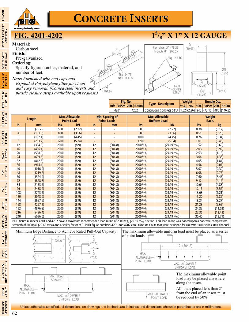
62
Unless otherwise specified, all dimensions on drawings and in charts are in inches and dimensions shown in parentheses are in millimeters.
www.phd-mfg.com
FIG. 4201-4202 15/8” X 1” X 12 GAUGE
Length Max. Allowable
Point Load Min. Spacing of
Point. Loads Max. Allowable Uniform Load
Weight Each.
in. mm lbs. kN in. mm lbs. kN lbs kg
3 (76.2) 500 (2.22) - - 500 (2.22) 0.38 (0.17) 4 (101.6) 800 (3.56) - - 800 (3.56) 0.51 (0.23) 6 (152.4) 1000 (4.45) - - 1000 (4.45) 0.76 (0.34) 8 (203.2) 1200 (5.34) - - 1200 (5.34) 1.01 (0.46)
12 (304.8) 2000 (8.9) 12 (304.8) 2000 lbs/ft (29.19 kN/m) 1.52 (0.69) 16 (406.4) 2000 (8.9) 12 (304.8) 2000 lbs/ft (29.19 kN/m) 2.03 (0.92) 20 (508.0) 2000 (8.9) 12 (304.8) 2000 lbs/ft (29.19 kN/m) 2.53 (1.15) 24 (609.6) 2000 (8.9) 12 (304.8) 2000 lbs/ft (29.19 kN/m) 3.04 (1.38) 32 (812.8) 2000 (8.9) 12 (304.8) 2000 lbs/ft (29.19 kN/m) 4.05 (1.84) 36 (914.4) 2000 (8.9) 12 (304.8) 2000 lbs/ft (29.19 kN/m) 4.56 (2.07) 40 (1016.0) 2000 (8.9) 12 (304.8) 2000 lbs/ft (29.19 kN/m) 5.07 (2.30) 48 (1219.2) 2000 (8.9) 12 (304.8) 2000 lbs/ft (29.19 kN/m) 6.08 (2.76) 60 (1524.0) 2000 (8.9) 12 (304.8) 2000 lbs/ft (29.19 kN/m) 7.60 (3.45) 72 (1828.8) 2000 (8.9) 12 (304.8) 2000 lbs/ft (29.19 kN/m) 9.12 (4.14) 84 (2133.6) 2000 (8.9) 12 (304.8) 2000 lbs/ft (29.19 kN/m) 10.64 (4.83) 96 (2438.4) 2000 (8.9) 12 (304.8) 2000 lbs/ft (29.19 kN/m) 12.16 (5.52) 108 (2743.2) 2000 (8.9) 12 (304.8) 2000 lbs/ft (29.19 kN/m) 13.68 (6.21) 120 (3048.0) 2000 (8.9) 12 (304.8) 2000 lbs/ft (29.19 kN/m) 15.20 (6.89) 144 (3657.6) 2000 (8.9) 12 (304.8) 2000 lbs/ft (29.19 kN/m) 18.24 (8.27) 168 (4267.2) 2000 (8.9) 12 (304.8) 2000 lbs/ft (29.19 kN/m) 21.28 (9.65) 192 (4876.8) 2000 (8.9) 12 (304.8) 2000 lbs/ft (29.19 kN/m) 24.32 (11.03) 216 (5486.4) 2000 (8.9) 12 (304.8) 2000 lbs/ft (29.19 kN/m) 27.36 (12.41) 240 (6096.0) 2000 (8.9) 12 (304.8) 2000 lbs/ft (29.19 kN/m) 30.40 (13.79)
PHD figure numbers 4201 and 4202 have a maximum recommended load rating of 2000 lbs/ft (29.19 kN/m) section. This load rating was based upon a concrete compressive strength of 3000psi. (20.68 mPa) and a safety factor of 3. PHD figure numbers 4201 and 4202 can utilize strut nuts that were designed for use with 1400 series strut channel.
Material: Carbon steel Finish: Pre-galvanized Ordering: Specify figure number, material, and
number of feet.
Note: Furnished with end caps and Expanded Polyethylene filler for clean and easy removal. (Coined steel inserts and plastic closure strips available upon request.)
Fig. No. Type - Description
Weight Bundle Qty.
10ft. 3.05m 20ft. 6.10m lbs./ft. kg/m 10ft. 3.05m 20ft. 6.10m
4201 4202 Continuous Concrete Strut 1.52 (2.26) 240 (73.15) 480 (146.3)
Minimum Edge Distance to Achieve Rated Pull-Out Capacity The maximum allowable uniform load must be placed as a series of point loads.
The maximum allowable point load may be placed anywhere along the insert.
All loads placed less than 2" from the end of an insert must be reduced by 50%.
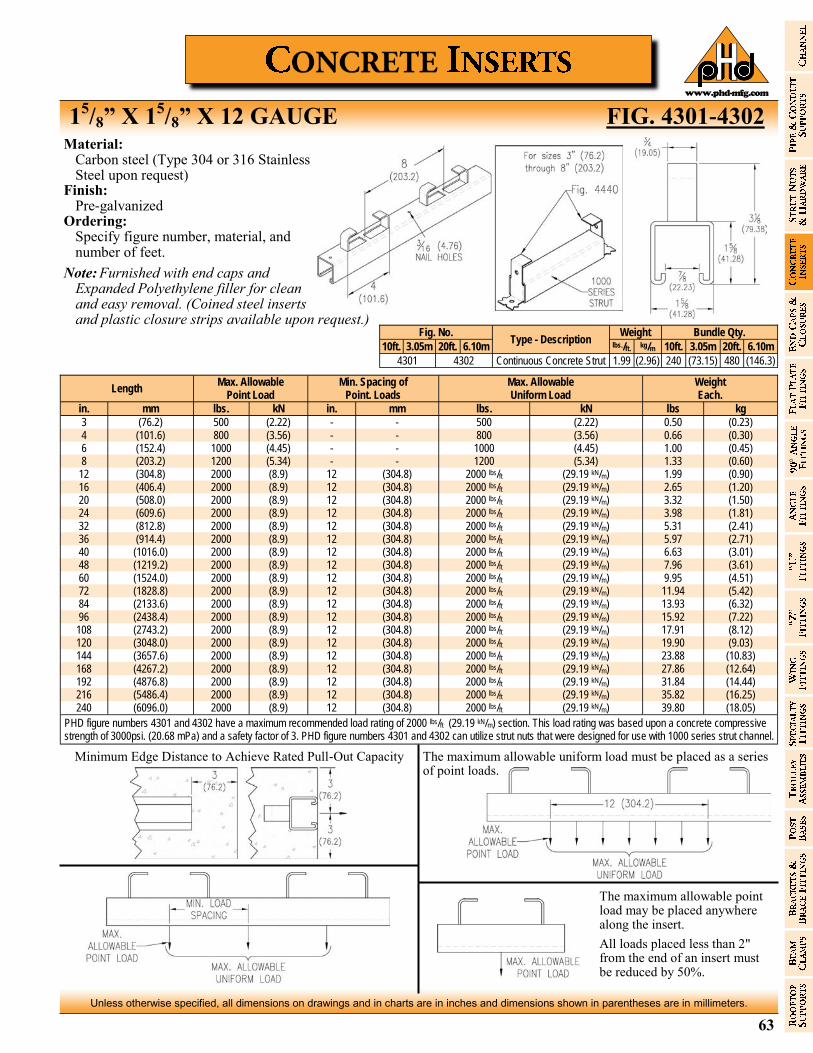
63
Unless otherwise specified, all dimensions on drawings and in charts are in inches and dimensions shown in parentheses are in millimeters.
www.phd-mfg.com
15/8” X 1
5/8” X 12 GAUGE FIG. 4301-4302
Length Max. Allowable
Point Load Min. Spacing of
Point. Loads Max. Allowable Uniform Load
Weight Each.
in. mm lbs. kN in. mm lbs. kN lbs kg
3 (76.2) 500 (2.22) - - 500 (2.22) 0.50 (0.23) 4 (101.6) 800 (3.56) - - 800 (3.56) 0.66 (0.30) 6 (152.4) 1000 (4.45) - - 1000 (4.45) 1.00 (0.45) 8 (203.2) 1200 (5.34) - - 1200 (5.34) 1.33 (0.60)
12 (304.8) 2000 (8.9) 12 (304.8) 2000 lbs/ft (29.19 kN/m) 1.99 (0.90) 16 (406.4) 2000 (8.9) 12 (304.8) 2000 lbs/ft (29.19 kN/m) 2.65 (1.20) 20 (508.0) 2000 (8.9) 12 (304.8) 2000 lbs/ft (29.19 kN/m) 3.32 (1.50) 24 (609.6) 2000 (8.9) 12 (304.8) 2000 lbs/ft (29.19 kN/m) 3.98 (1.81) 32 (812.8) 2000 (8.9) 12 (304.8) 2000 lbs/ft (29.19 kN/m) 5.31 (2.41) 36 (914.4) 2000 (8.9) 12 (304.8) 2000 lbs/ft (29.19 kN/m) 5.97 (2.71) 40 (1016.0) 2000 (8.9) 12 (304.8) 2000 lbs/ft (29.19 kN/m) 6.63 (3.01) 48 (1219.2) 2000 (8.9) 12 (304.8) 2000 lbs/ft (29.19 kN/m) 7.96 (3.61) 60 (1524.0) 2000 (8.9) 12 (304.8) 2000 lbs/ft (29.19 kN/m) 9.95 (4.51) 72 (1828.8) 2000 (8.9) 12 (304.8) 2000 lbs/ft (29.19 kN/m) 11.94 (5.42) 84 (2133.6) 2000 (8.9) 12 (304.8) 2000 lbs/ft (29.19 kN/m) 13.93 (6.32) 96 (2438.4) 2000 (8.9) 12 (304.8) 2000 lbs/ft (29.19 kN/m) 15.92 (7.22) 108 (2743.2) 2000 (8.9) 12 (304.8) 2000 lbs/ft (29.19 kN/m) 17.91 (8.12) 120 (3048.0) 2000 (8.9) 12 (304.8) 2000 lbs/ft (29.19 kN/m) 19.90 (9.03) 144 (3657.6) 2000 (8.9) 12 (304.8) 2000 lbs/ft (29.19 kN/m) 23.88 (10.83) 168 (4267.2) 2000 (8.9) 12 (304.8) 2000 lbs/ft (29.19 kN/m) 27.86 (12.64) 192 (4876.8) 2000 (8.9) 12 (304.8) 2000 lbs/ft (29.19 kN/m) 31.84 (14.44) 216 (5486.4) 2000 (8.9) 12 (304.8) 2000 lbs/ft (29.19 kN/m) 35.82 (16.25) 240 (6096.0) 2000 (8.9) 12 (304.8) 2000 lbs/ft (29.19 kN/m) 39.80 (18.05)
PHD figure numbers 4301 and 4302 have a maximum recommended load rating of 2000 lbs/ft (29.19 kN/m) section. This load rating was based upon a concrete compressive strength of 3000psi. (20.68 mPa) and a safety factor of 3. PHD figure numbers 4301 and 4302 can utilize strut nuts that were designed for use with 1000 series strut channel.
Fig. No. Type - Description
Weight Bundle Qty.
10ft. 3.05m 20ft. 6.10m lbs./ft. kg/m 10ft. 3.05m 20ft. 6.10m
4301 4302 Continuous Concrete Strut 1.99 (2.96) 240 (73.15) 480 (146.3)
Minimum Edge Distance to Achieve Rated Pull-Out Capacity The maximum allowable uniform load must be placed as a series of point loads.
The maximum allowable point load may be placed anywhere along the insert.
All loads placed less than 2" from the end of an insert must be reduced by 50%.
Material: Carbon steel (Type 304 or 316 Stainless
Steel upon request) Finish: Pre-galvanized Ordering: Specify figure number, material, and
number of feet.
Note: Furnished with end caps and Expanded Polyethylene filler for clean and easy removal. (Coined steel inserts
and plastic closure strips available upon request.)
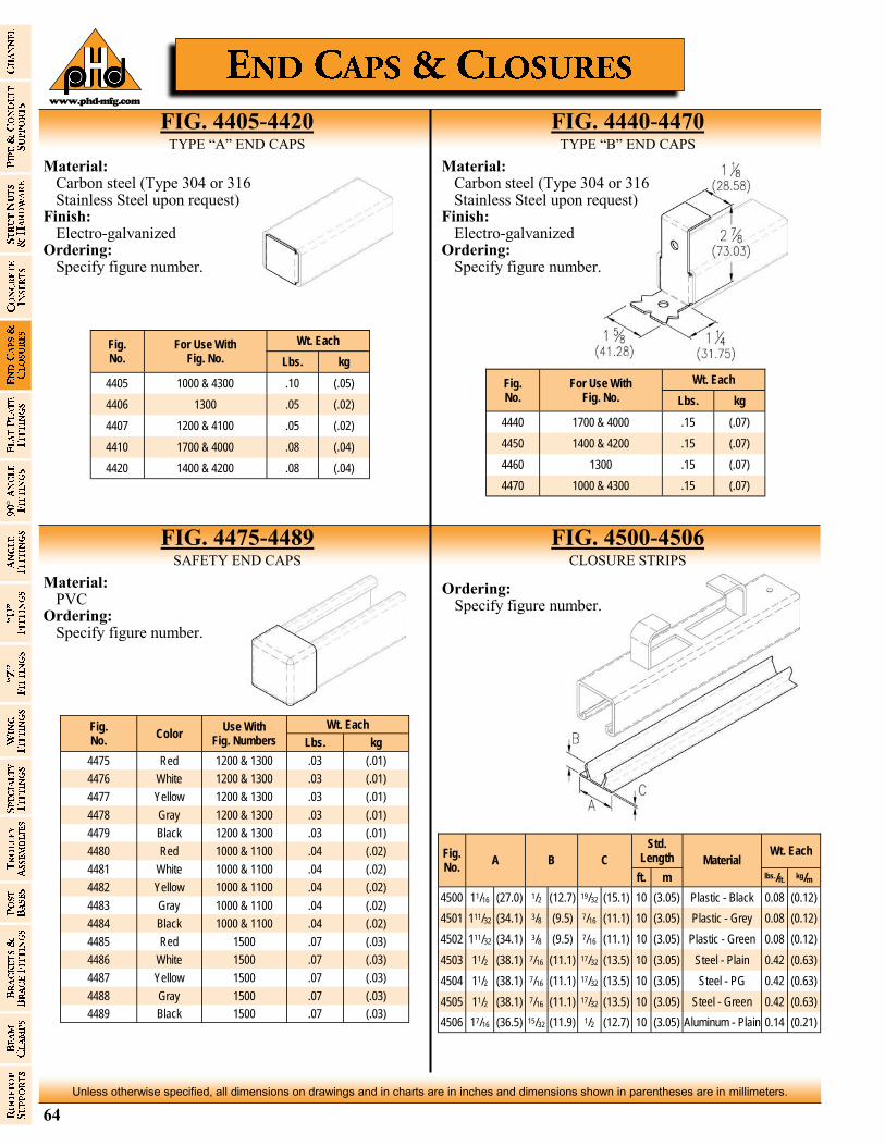
64
Unless otherwise specified, all dimensions on drawings and in charts are in inches and dimensions shown in parentheses are in millimeters.
www.phd-mfg.com
Material: Carbon steel (Type 304 or 316
Stainless Steel upon request) Finish: Electro-galvanized Ordering: Specify figure number.
FIG. 4405-4420 TYPE “A” END CAPS
FIG. 4440-4470 TYPE “B” END CAPS
Fig. No.
For Use With Fig. No.
Wt. Each
Lbs. kg
4405 1000 & 4300 .10 (.05)
4406 1300 .05 (.02)
4407 1200 & 4100 .05 (.02)
4410 1700 & 4000 .08 (.04)
4420 1400 & 4200 .08 (.04)
Fig. No.
For Use With Fig. No.
Wt. Each
Lbs. kg
4440 1700 & 4000 .15 (.07)
4450 1400 & 4200 .15 (.07)
4460 1300 .15 (.07)
4470 1000 & 4300 .15 (.07)
Material: Carbon steel (Type 304 or 316
Stainless Steel upon request) Finish: Electro-galvanized Ordering: Specify figure number.
Fig. No.
Color Use With
Fig. Numbers
Wt. Each
Lbs. kg
4475 Red 1200 & 1300 .03 (.01)
4476 White 1200 & 1300 .03 (.01)
4477 Yellow 1200 & 1300 .03 (.01)
4478 Gray 1200 & 1300 .03 (.01)
4479 Black 1200 & 1300 .03 (.01)
4480 Red 1000 & 1100 .04 (.02)
4481 White 1000 & 1100 .04 (.02)
4482 Yellow 1000 & 1100 .04 (.02)
4483 Gray 1000 & 1100 .04 (.02)
4484 Black 1000 & 1100 .04 (.02)
4485 Red 1500 .07 (.03)
4486 White 1500 .07 (.03)
4487 Yellow 1500 .07 (.03)
4488 Gray 1500 .07 (.03)
4489 Black 1500 .07 (.03)
Material: PVC Ordering: Specify figure number.
Fig. No.
A B C
Std. Length Material
Wt. Each
ft. m lbs./ft. kg/m
4500 11/16 (27.0) 1/2 (12.7) 19/32 (15.1) 10 (3.05) Plastic - Black 0.08 (0.12)
4501 111/32 (34.1) 3/8 (9.5) 7/16 (11.1) 10 (3.05) Plastic - Grey 0.08 (0.12)
4502 111/32 (34.1) 3/8 (9.5) 7/16 (11.1) 10 (3.05) Plastic - Green 0.08 (0.12)
4503 11/2 (38.1) 7/16 (11.1) 17/32 (13.5) 10 (3.05) Steel - Plain 0.42 (0.63)
4504 11/2 (38.1) 7/16 (11.1) 17/32 (13.5) 10 (3.05) Steel - PG 0.42 (0.63)
4505 11/2 (38.1) 7/16 (11.1) 17/32 (13.5) 10 (3.05) Steel - Green 0.42 (0.63)
4506 17/16 (36.5) 15/32 (11.9) 1/2 (12.7) 10 (3.05) Aluminum - Plain 0.14 (0.21)
Ordering: Specify figure number.
FIG. 4475-4489 SAFETY END CAPS
FIG. 4500-4506 CLOSURE STRIPS
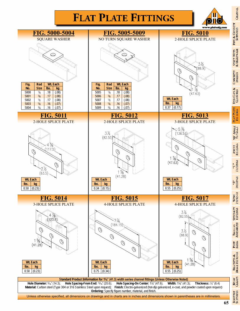
65
Unless otherwise specified, all dimensions on drawings and in charts are in inches and dimensions shown in parentheses are in millimeters.
www.phd-mfg.com
Fig. No.
Rod Size
Wt. Each
lbs. kg
5000 1/4 .18 (.08) 5001 3/8 .17 (.08) 5002 1/2 .17 (.08) 5003 5/8 .16 (.07) 5004 3/4 .16 (.07)
Fig. No.
Rod Size
Wt. Each
lbs. kg
5005 1/4 .18 (.08) 5006 3/8 .17 (.08) 5007 1/2 .17 (.08) 5008 5/8 .16 (.07) 5009 3/4 .16 (.07)
Wt. Each
lbs. kg
0.75 (0.34)
Wt. Each
lbs. kg
0.50 (0.23)
Wt. Each
lbs. kg
0.55 (0.25)
Wt. Each
lbs. kg
0.34 (0.15)
Wt. Each
lbs. kg
0.50 (0.23)
Wt. Each
lbs. kg
0.37 (0.17)
Standard Product Information for 15⁄8” (41.3) width series channel fittings (Unless Otherwise Noted)
Hole Diameter: 9⁄16” (14.3); Hole Spacing-From End: 13⁄16” (20.6); Hole Spacing-On Center: 17⁄8” (47.6); Width: 15⁄8” (41.3); Thickness: 1⁄4” (6.4) Material: Carbon steel (Type 304 or 316 Stainless Steel upon request); Finish: Electro-galvanized (hot-dip galvanized, e-coat, and powder coated upon request)
Ordering: Specify figure number, material, and finish.
FIG. 5000-5004 SQUARE WASHER
FIG. 5005-5009 NO TURN SQUARE WASHER
FIG. 5011 2-HOLE SPLICE PLATE
FIG. 5012 2-HOLE SPLICE PLATE
FIG. 5013 3-HOLE SPLICE PLATE
FIG. 5015 4-HOLE SPLICE PLATE
FIG. 5017 4-HOLE SPLICE PLATE
FIG. 5014 3-HOLE SPLICE PLATE
FIG. 5010 2-HOLE SPLICE PLATE
Wt. Each
lbs. kg
0.55 (0.25)
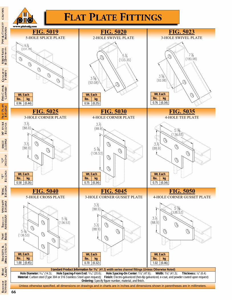
66
Unless otherwise specified, all dimensions on drawings and in charts are in inches and dimensions shown in parentheses are in millimeters.
www.phd-mfg.com
Wt. Each
lbs. kg
0.96 (0.44)
Wt. Each
lbs. kg
0.70 (0.32)
Wt. Each
lbs. kg
1.00 (0.45)
Wt. Each
lbs. kg
0.75 (0.34)
Wt. Each
lbs. kg
0.75 (0.34)
Wt. Each
lbs. kg
0.58 (0.26)
Wt. Each
lbs. kg
0.76 (0.34)
Wt. Each
lbs. kg
0.56 (0.25)
Standard Product Information for 15⁄8” (41.3) width series channel fittings (Unless Otherwise Noted)
Hole Diameter: 9⁄16” (14.3); Hole Spacing-From End: 13⁄16” (20.6); Hole Spacing-On Center: 17⁄8” (47.6); Width: 15⁄8” (41.3); Thickness: 1⁄4” (6.4) Material: Carbon steel (Type 304 or 316 Stainless Steel upon request); Finish: Electro-galvanized (hot-dip galvanized, e-coat, and powder coated upon request)
Ordering: Specify figure number, material, and finish.
FIG. 5023 3-HOLE SWIVEL PLATE
FIG. 5019 5-HOLE SPLICE PLATE
FIG. 5025 3-HOLE CORNER PLATE
FIG. 5030 4-HOLE CORNER PLATE
FIG. 5035 4-HOLE TEE PLATE
FIG. 5045 3-HOLE CORNER GUSSET PLATE
FIG. 5050 4-HOLE CORNER GUSSET PLATE
FIG. 5040 5-HOLE CROSS PLATE
FIG. 5020 2-HOLE SWIVEL PLATE
Wt. Each
lbs. kg
1.02 (0.46)
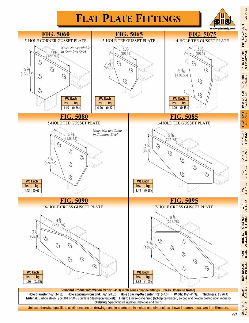
67
Unless otherwise specified, all dimensions on drawings and in charts are in inches and dimensions shown in parentheses are in millimeters.
www.phd-mfg.com
Wt. Each
lbs. kg
1.43 (0.65)
Wt. Each
lbs. kg
1.66 (0..75)
Wt. Each
lbs. kg
1.00 (0.45)
Wt. Each
lbs. kg
0.70 (0.32)
Wt. Each
lbs. kg
1.45 (0.66)
Standard Product Information for 15⁄8” (41.3) width series channel fittings (Unless Otherwise Noted)
Hole Diameter: 9⁄16” (14.3); Hole Spacing-From End: 13⁄16” (20.6); Hole Spacing-On Center: 17⁄8” (47.6); Width: 15⁄8” (41.3); Thickness: 1⁄4” (6.4) Material: Carbon steel (Type 304 or 316 Stainless Steel upon request); Finish: Electro-galvanized (hot-dip galvanized, e-coat, and powder coated upon request)
Ordering: Specify figure number, material, and finish.
FIG. 5060 5-HOLE CORNER GUSSET PLATE
FIG. 5065 3-HOLE TEE GUSSET PLATE
FIG. 5080 5-HOLE TEE GUSSET PLATE
FIG. 5085 6-HOLE TEE GUSSET PLATE
FIG. 5095 7-HOLE CROSS GUSSET PLATE
FIG. 5090 6-HOLE CROSS GUSSET PLATE
FIG. 5075 4-HOLE TEE GUSSET PLATE
Wt. Each
lbs. kg
2.32 (1.05)
Wt. Each
lbs. kg
1.49 (0.68)
Note: Not available in Stainless Steel.
Note: Not available in Stainless Steel.
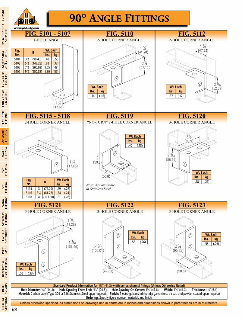
68
Unless otherwise specified, all dimensions on drawings and in charts are in inches and dimensions shown in parentheses are in millimeters.
www.phd-mfg.com
Wt. Each
lbs. kg
.37 (.17)
Wt. Each
lbs. kg
.36 (.16)
Standard Product Information for 15⁄8” (41.3) width series channel fittings (Unless Otherwise Noted)
Hole Diameter: 9⁄16” (14.3); Hole Spacing-From End: 13⁄16” (20.6); Hole Spacing-On Center: 17⁄8” (47.6); Width: 15⁄8” (41.3); Thickness: 1⁄4” (6.4) Material: Carbon steel (Type 304 or 316 Stainless Steel upon request); Finish: Electro-galvanized (hot-dip galvanized, e-coat, and powder coated upon request)
Ordering: Specify figure number, material, and finish.
FIG. 5101 - 5107 1-HOLE ANGLE
FIG. 5110 2-HOLE CORNER ANGLE
FIG. 5112 2-HOLE CORNER ANGLE
°
Fig. No.
Wt. Each B
lbs. kg
5101 37/8 (98.43) .48 (.22)
5103 57/8 (149.23) .83 (.38)
5105 77/8 (200.03) 1.05 (.48)
5107 97/8 (250.83) 1.30 (.59)
FIG. 5123 3-HOLE CORNER ANGLE
FIG. 5121 3-HOLE CORNER ANGLE
Fig. No.
B Wt. Each
lbs. kg
5115 3 (76.20) .49 (.22)
5116 31/2 (81.28) .54 (.24)
5118 4 (101.60) .61 (.28)
FIG. 5115 - 5118 2-HOLE CORNER ANGLE
FIG. 5119 “NO-TURN” 2-HOLE CORNER ANGLE
FIG. 5122 3-HOLE CORNER ANGLE
Wt. Each
lbs. kg
.40 (.18)
Wt. Each
lbs. kg
.58 (.26)
Wt. Each
lbs. kg
.50 (.23)
Wt. Each
lbs. kg
.58 (.26)
FIG. 5120 3-HOLE CORNER ANGLE
Wt. Each
lbs. kg
.58 (.26)
Note: Not available in Stainless Steel.
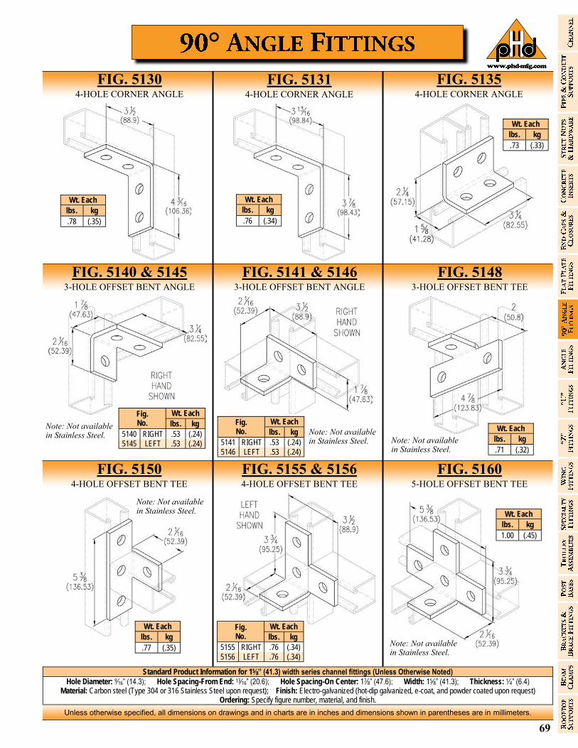
69
Unless otherwise specified, all dimensions on drawings and in charts are in inches and dimensions shown in parentheses are in millimeters.
www.phd-mfg.com
°
Standard Product Information for 15⁄8” (41.3) width series channel fittings (Unless Otherwise Noted)
Hole Diameter: 9⁄16” (14.3); Hole Spacing-From End: 13⁄16” (20.6); Hole Spacing-On Center: 17⁄8” (47.6); Width: 15⁄8” (41.3); Thickness: 1⁄4” (6.4) Material: Carbon steel (Type 304 or 316 Stainless Steel upon request); Finish: Electro-galvanized (hot-dip galvanized, e-coat, and powder coated upon request)
Ordering: Specify figure number, material, and finish.
Wt. Each
lbs. kg
.78 (.35)
Wt. Each
lbs. kg
.73 (.33)
Wt. Each
lbs. kg
.76 (.34)
FIG. 5135 4-HOLE CORNER ANGLE
FIG. 5130 4-HOLE CORNER ANGLE
FIG. 5140 & 5145 3-HOLE OFFSET BENT ANGLE
FIG. 5141 & 5146 3-HOLE OFFSET BENT ANGLE
FIG. 5148 3-HOLE OFFSET BENT TEE
FIG. 5131 4-HOLE CORNER ANGLE
Wt. Each Fig. No. lbs. kg
5140 RIGHT .53 (.24)
5145 LEFT .53 (.24)
Wt. Each Fig. No. lbs. kg
5141 RIGHT .53 (.24)
5146 LEFT .53 (.24)
Wt. Each
lbs. kg
.71 (.32)
FIG. 5150 4-HOLE OFFSET BENT TEE
FIG. 5155 & 5156 4-HOLE OFFSET BENT TEE
FIG. 5160 5-HOLE OFFSET BENT TEE
Wt. Each Fig. No. lbs. kg
5155 RIGHT .76 (.34)
5156 LEFT .76 (.34)
Wt. Each
lbs. kg
.77 (.35)
Wt. Each
lbs. kg
1.00 (.45)
Note: Not available in Stainless Steel. Note: Not available
in Stainless Steel. Note: Not available in Stainless Steel.
Note: Not available in Stainless Steel.
Note: Not available in Stainless Steel.
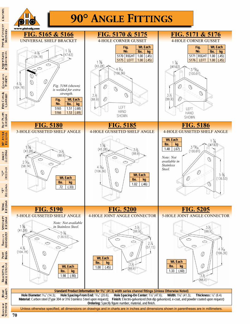
70
Unless otherwise specified, all dimensions on drawings and in charts are in inches and dimensions shown in parentheses are in millimeters.
www.phd-mfg.com
Standard Product Information for 15⁄8” (41.3) width series channel fittings (Unless Otherwise Noted)
Hole Diameter: 9⁄16” (14.3); Hole Spacing-From End: 13⁄16” (20.6); Hole Spacing-On Center: 17⁄8” (47.6); Width: 15⁄8” (41.3); Thickness: 1⁄4” (6.4) Material: Carbon steel (Type 304 or 316 Stainless Steel upon request); Finish: Electro-galvanized (hot-dip galvanized, e-coat, and powder coated upon request)
Ordering: Specify figure number, material, and finish.
°
FIG. 5165 & 5166 UNIVERSAL SHELF BRACKET
FIG. 5170 & 5175 4-HOLE CORNER GUSSET
FIG. 5171 & 5176 4-HOLE CORNER GUSSET
FIG. 5205 5-HOLE JOINT ANGLE CONNECTOR
FIG. 5190 5-HOLE GUSSETED SHELF ANGLE
FIG. 5180 3-HOLE GUSSETED SHELF ANGLE
FIG. 5185 4-HOLE GUSSETED SHELF ANGLE
FIG. 5200 4-HOLE JOINT ANGLE CONNECTOR
Wt. Each
lbs. kg
1.02 (.46)
Wt. Each
lbs. kg
1.48 (.67)
Wt. Each
lbs. kg
1.98 (.90)
Wt. Each
lbs. kg
1.00 (.45)
FIG. 5186 4-HOLE GUSSETED SHELF ANGLE
Wt. Each
lbs. kg
1.33 (.60)
Fig. No.
Wt. Each
lbs. kg
5165 1.51 (.68)
5166 1.53 (.69)
Wt. Each
lbs. kg
.72 (.33)
Fig. 5166 (shown) is welded for extra
strength.
Wt. Each Fig. No. lbs. kg
5170 RIGHT 1.00 (.45)
5175 LEFT 1.00 (.45)
Wt. Each Fig. No. lbs. kg
5171 RIGHT 1.00 (.45)
5176 LEFT 1.00 (.45)
Note: Not available in Stainless Steel.
Note: Not available in Stainless Steel.
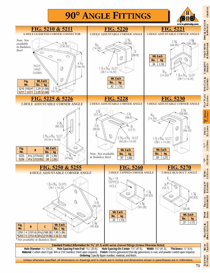
71
Unless otherwise specified, all dimensions on drawings and in charts are in inches and dimensions shown in parentheses are in millimeters.
www.phd-mfg.com
°
Standard Product Information for 15⁄8” (41.3) width series channel fittings (Unless Otherwise Noted)
Hole Diameter: 9⁄16” (14.3); Hole Spacing-From End: 13⁄16” (20.6); Hole Spacing-On Center: 17⁄8” (47.6); Width: 15⁄8” (41.3); Thickness: 1⁄4” (6.4) Material: Carbon steel (Type 304 or 316 Stainless Steel upon request); Finish: Electro-galvanized (hot-dip galvanized, e-coat, and powder coated upon request)
Ordering: Specify figure number, material, and finish.
Wt. Each
lbs. kg
.97 (.44)
Wt. Each
lbs. kg
.36 (.16)
Wt. Each
lbs. kg
.42 (.19)
FIG. 5221 2-HOLE ADJUSTABLE CORNER ANGLE
FIG. 5210 & 5211 6-HOLE GUSSETED CORNER CONNECTOR
FIG. 5225 & 5226 2-HOLE ADJUSTABLE CORNER ANGLE
FIG. 5228 2-HOLE ADJUSTABLE CORNER ANGLE
FIG. 5230 3-HOLE ADJUSTABLE CORNER ANGLE
FIG. 5220 2-HOLE ADJUSTABLE CORNER ANGLE
Wt. Each Fig. No. lbs. kg
5210 RIGHT 2.29 (1.04)
5211 LEFT 2.29 (1.04)
Wt. Each
lbs. kg
.59 (.27)
FIG. 5250 & 5255 4-HOLE ADJUSTABLE CORNER ANGLE
FIG. 5260 2-HOLE TAPPED CORNER ANGLE
FIG. 5270 2-HOLE BUS DUCT ANGLE
Wt. Each
lbs. kg
.33 (.15)
Wt. Each
lbs. kg
.37 (.17)
Fig. No.
B Wt. Each
lbs. kg
5225 67/8 (174.63) .85 (.39)
5226 47/8 (123.83) .58 (.26)
Fig. No.
B C Wt. Each
lbs. kg
5250 4 (101.6) 65/8 (168.28) 1.90 (.86)
*5255 6 (152.4) 85/8 (219.08) 2.56 (1.16)
* Not available in Stainless Steel.
Note: Not available in Stainless Steel.
Note: Not available in Stainless Steel.

72
Unless otherwise specified, all dimensions on drawings and in charts are in inches and dimensions shown in parentheses are in millimeters.
www.phd-mfg.com
Standard Product Information for 15⁄8” (41.3) width series channel fittings (Unless Otherwise Noted)
Hole Diameter: 9⁄16” (14.3); Hole Spacing-From End: 13⁄16” (20.6); Hole Spacing-On Center: 17⁄8” (47.6); Width: 15⁄8” (41.3); Thickness: 1⁄4” (6.4) Material: Carbon steel (Type 304 or 316 Stainless Steel upon request); Finish: Electro-galvanized (hot-dip galvanized, e-coat, and powder coated upon request)
Ordering: Specify figure number, material, and finish.
FIG. 5301 - 5315 2-HOLE OPEN ANGLE CONNECTOR
FIG. 5340 - 5350 4-HOLE OPEN ANGLE CONNECTOR
FIG. 5360 - 5366 2-HOLE CLOSED ANGLE CONNECTOR
FIG. 5370 - 5376 4-HOLE CLOSED ANGLE CONNECTOR
Fig. No.
Angle B°
Wt. Each
lbs. kg
5301 71/2 .58 (.26)
5302 15 .58 (.26)
5303 221/2 .58 (.26)
5304 30 .58 (.26)
5306 371/2 .58 (.26)
5307 521/2 .58 (.26)
5308 60 .58 (.26)
5309 671/2 .58 (.26)
5310 75 .58 (.26)
5311 821/2 .58 (.26)
5315 45 .58 (.26)
Fig. No.
Angle B°
Wt. Each
lbs. kg
5340 71/2 .78 (.35)
5341 15 .78 (.35)
5342 221/2 .78 (.35)
5343 30 .78 (.35)
5344 371/2 .78 (.35)
5345 45 .78 (.35)
5346 521/2 .78 (.35)
5347 60 .78 (.35)
5348 671/2 .78 (.35)
5349 75 .78 (.35)
5350 821/2 .78 (.35)
Fig. No.
Angle B°
Wt. Each
lbs. kg
5360 371/2 .58 (.26)
5361 45 .58 (.26)
5362 521/2 .58 (.26)
5363 60 .58 (.26)
5364 671/2 .58 (.26)
5365 75 .58 (.26)
5366 821/2 .58 (.26)
Fig. No.
Angle B°
Wt. Each
lbs. kg
5370 371/2 .95 (.43)
5371 45 .95 (.43)
5372 521/2 .95 (.43)
5373 60 .95 (.43)
5374 671/2 .95 (.43)
5375 75 .95 (.43)
5376 821/2 .95 (.43)
FIG. 5380 2-HOLE ADJUSTABLE HINGE
FIG. 5381 & 5382 3-HOLE ADJUSTABLE HINGE
Wt. Each
lbs. kg
.78 (.35)
Fig. No.
D Wt. Each
lbs. kg
5381 7/16 (11.1) .96 (.44)
5382 9/16 (14.3) .94 (.43)
Note: Not available in Stainless Steel.
Note: Not available in Stainless Steel.
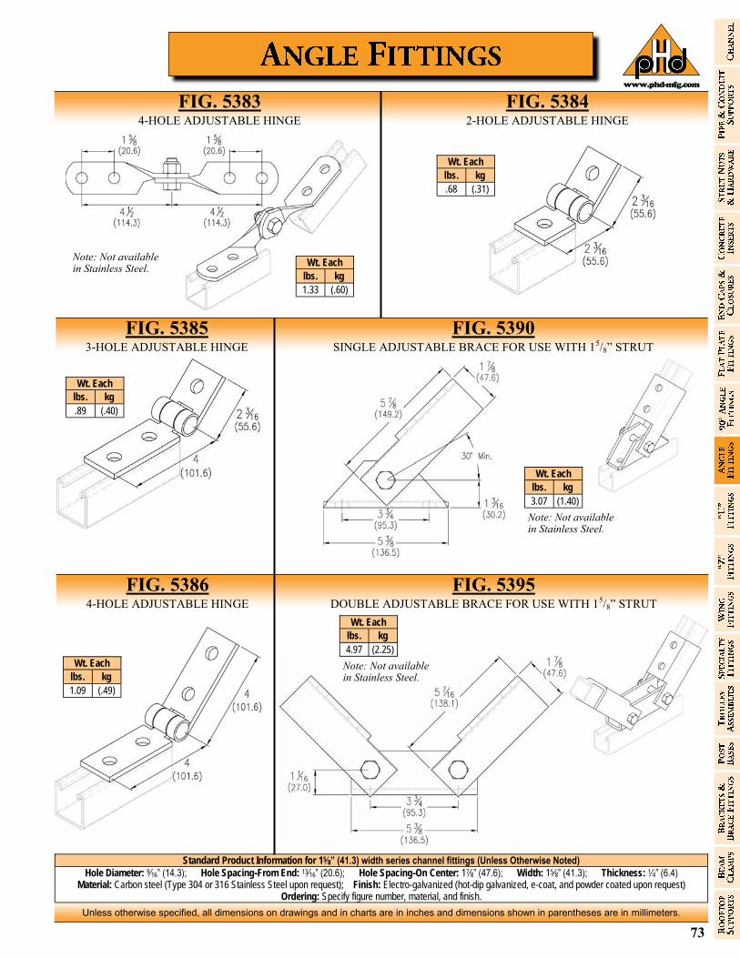
73
Unless otherwise specified, all dimensions on drawings and in charts are in inches and dimensions shown in parentheses are in millimeters.
www.phd-mfg.com
Standard Product Information for 15⁄8” (41.3) width series channel fittings (Unless Otherwise Noted)
Hole Diameter: 9⁄16” (14.3); Hole Spacing-From End: 13⁄16” (20.6); Hole Spacing-On Center: 17⁄8” (47.6); Width: 15⁄8” (41.3); Thickness: 1⁄4” (6.4) Material: Carbon steel (Type 304 or 316 Stainless Steel upon request); Finish: Electro-galvanized (hot-dip galvanized, e-coat, and powder coated upon request)
Ordering: Specify figure number, material, and finish.
FIG. 5383 4-HOLE ADJUSTABLE HINGE
FIG. 5384 2-HOLE ADJUSTABLE HINGE
Wt. Each
lbs. kg
1.33 (.60)
Wt. Each
lbs. kg
.68 (.31)
FIG. 5385 3-HOLE ADJUSTABLE HINGE
FIG. 5386 4-HOLE ADJUSTABLE HINGE
Note: Not available in Stainless Steel.
Wt. Each
lbs. kg
.89 (.40)
Wt. Each
lbs. kg
1.09 (.49)
FIG. 5395 DOUBLE ADJUSTABLE BRACE FOR USE WITH 15/8” STRUT
FIG. 5390 SINGLE ADJUSTABLE BRACE FOR USE WITH 15/8” STRUT
Wt. Each
lbs. kg
3.07 (1.40)
Note: Not available in Stainless Steel.
Wt. Each
lbs. kg
4.97 (2.25)
Note: Not available in Stainless Steel.

74
Unless otherwise specified, all dimensions on drawings and in charts are in inches and dimensions shown in parentheses are in millimeters.
www.phd-mfg.com
Standard Product Information for 15⁄8” (41.3) width series channel fittings (Unless Otherwise Noted)
Hole Diameter: 9⁄16” (14.3); Hole Spacing-From End: 13⁄16” (20.6); Hole Spacing-On Center: 17⁄8” (47.6); Width: 15⁄8” (41.3); Thickness: 1⁄4” (6.4) Material: Carbon steel (Type 304 or 316 Stainless Steel upon request); Finish: Electro-galvanized (hot-dip galvanized, e-coat, and powder coated upon request)
Ordering: Specify figure number, material, and finish.
FIG. 5503 5-HOLE “U” SUPPORT
FIG. 5501 - 5511 3-HOLE “U” SUPPORT
FIG. 5513 3-HOLE “U” SUPPORT
FIG. 5521 6-HOLE “U” SUPPORT
FIG. 5530 - 5532 SLOTTED 3-HOLE “U” SUPPORT
FIG. 5541 1-STUD RING CONNECTOR
FIG. 5542 2-STUD RING CONNECTOR
FIG. 5543 2-STUD RING CONNECTOR
Wt. Each
lbs. kg
.95 (.43)
Wt. Each
lbs. kg
.53 (.24)
Wt. Each
lbs. kg
.85 (.39)
Wt. Each
lbs. kg
1.04 (.47)
Wt. Each
lbs. kg
.59 (.27)
Wt. Each
lbs. kg
.59 (.27)
Fig. No.
B Wt. Each
lbs. kg
*5501 13/16 (20.64) .66 (.30)
5505 27/16 (61.91) 1.08 (.49)
5507 31/4 (82.55) 1.25 (.57)
* 5509 47/8 (123.83) 1.57 (.71)
5511 61/2 (165.10) 2.25 (1.02)
* Not available in Stainless Steel.
Fig. No.
B Wt. Each
lbs. kg
5530 71/4 (184.15) .96 (.44)
5531 81/2 (215.90) 1.11 (.50)
5532 103/8 (263.53) 1.29 (.59)
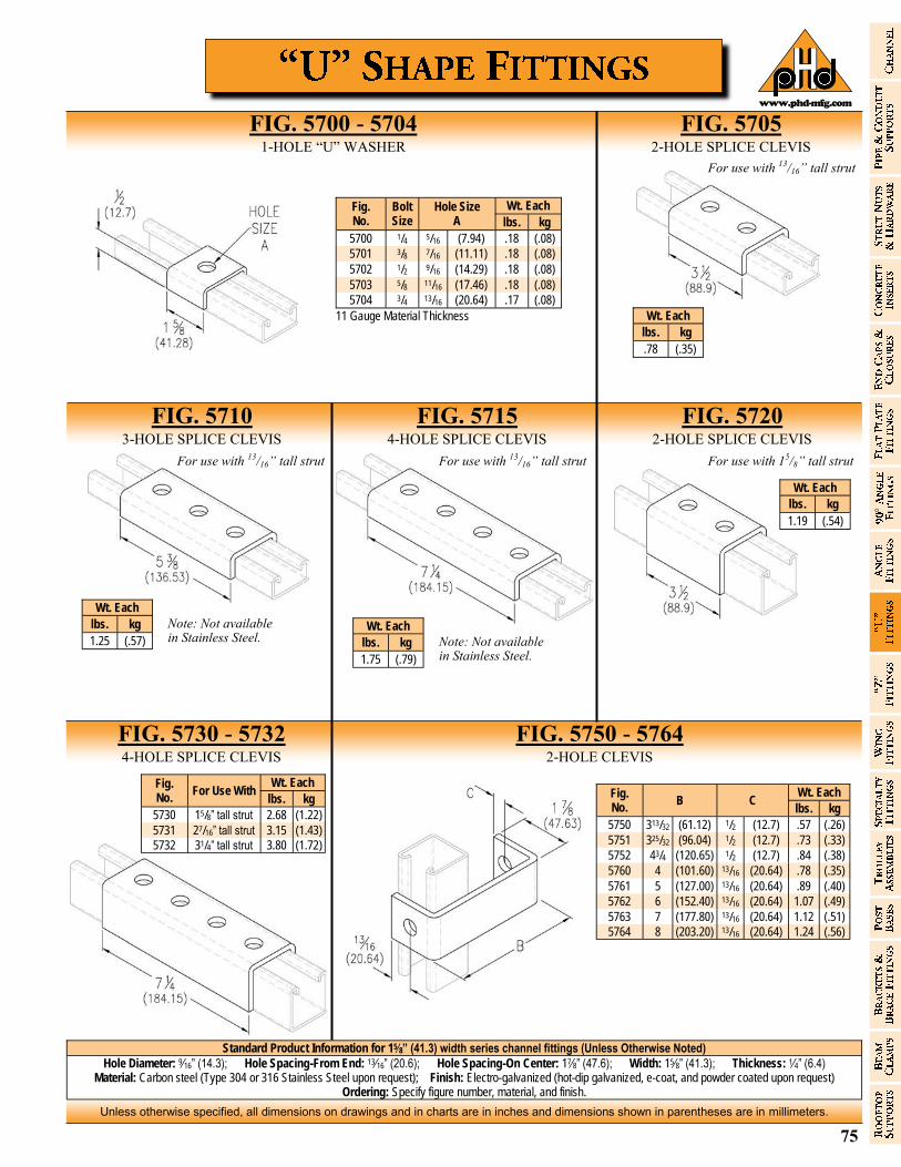
75
Unless otherwise specified, all dimensions on drawings and in charts are in inches and dimensions shown in parentheses are in millimeters.
www.phd-mfg.com
Standard Product Information for 15⁄8” (41.3) width series channel fittings (Unless Otherwise Noted)
Hole Diameter: 9⁄16” (14.3); Hole Spacing-From End: 13⁄16” (20.6); Hole Spacing-On Center: 17⁄8” (47.6); Width: 15⁄8” (41.3); Thickness: 1⁄4” (6.4) Material: Carbon steel (Type 304 or 316 Stainless Steel upon request); Finish: Electro-galvanized (hot-dip galvanized, e-coat, and powder coated upon request)
Ordering: Specify figure number, material, and finish.
FIG. 5705 2-HOLE SPLICE CLEVIS
FIG. 5700 - 5704 1-HOLE “U” WASHER
FIG. 5710 3-HOLE SPLICE CLEVIS
FIG. 5715 4-HOLE SPLICE CLEVIS
FIG. 5720 2-HOLE SPLICE CLEVIS
FIG. 5730 - 5732 4-HOLE SPLICE CLEVIS
FIG. 5750 - 5764 2-HOLE CLEVIS
Fig. No.
Bolt Size
Hole Size A
Wt. Each
lbs. kg
5700 1/4 5/16 (7.94) .18 (.08)
5701 3/8 7/16 (11.11) .18 (.08)
5702 1/2 9/16 (14.29) .18 (.08)
5703 5/8 11/16 (17.46) .18 (.08)
5704 3/4 13/16 (20.64) .17 (.08)
11 Gauge Material Thickness Wt. Each
lbs. kg
.78 (.35)
For use with 13/16” tall strut
Note: Not available in Stainless Steel. Note: Not available
in Stainless Steel.
For use with 13/16” tall strut For use with 13/16” tall strut For use with 15/8” tall strut
Wt. Each
lbs. kg
1.25 (.57)
Wt. Each
lbs. kg
1.75 (.79)
Wt. Each
lbs. kg
1.19 (.54)
Fig. No.
B Wt. Each
C lbs. kg
5750 313/32 (61.12) 1/2 (12.7) .57 (.26)
5751 325/32 (96.04) 1/2 (12.7) .73 (.33)
5752 43/4 (120.65) 1/2 (12.7) .84 (.38)
5760 4 (101.60) 13/16 (20.64) .78 (.35)
5761 5 (127.00) 13/16 (20.64) .89 (.40)
5762 6 (152.40) 13/16 (20.64) 1.07 (.49)
5763 7 (177.80) 13/16 (20.64) 1.12 (.51)
5764 8 (203.20) 13/16 (20.64) 1.24 (.56)
Fig. No.
For Use With Wt. Each
lbs. kg
5730 15/8” tall strut 2.68 (1.22)
5731 27/16” tall strut 3.15 (1.43)
5732 31/4” tall strut 3.80 (1.72)

76
Unless otherwise specified, all dimensions on drawings and in charts are in inches and dimensions shown in parentheses are in millimeters.
www.phd-mfg.com
Standard Product Information for 15⁄8” (41.3) width series channel fittings (Unless Otherwise Noted)
Hole Diameter: 9⁄16” (14.3); Hole Spacing-From End: 13⁄16” (20.6); Hole Spacing-On Center: 17⁄8” (47.6); Width: 15⁄8” (41.3); Thickness: 1⁄4” (6.4) Material: Carbon steel (Type 304 or 316 Stainless Steel upon request); Finish: Electro-galvanized (hot-dip galvanized, e-coat, and powder coated upon request)
Ordering: Specify figure number, material, and finish.
FIG. 5770 3-HOLE CLEVIS
FIG. 5775 3-HOLE SUSPENSION CLEVIS
FIG. 5780 4-HOLE SUSPENSION CLEVIS
FIG. 8000 - 8001 INSIDE STRUT JOINER
FIG. 8005 90° ELBOW STRUT JOINER
FIG. 8010 TEE STRUT JOINER
FIG. 8015 CROSS STRUT JOINER
Wt. Each
lbs. kg
.75 (.34)
Note: Not available in Stainless Steel.
Note: Not available in Stainless Steel.
Wt. Each
lbs. kg
.75 (.34)
Wt. Each
lbs. kg
.71 (.32)
Material: Aluminum Finish: Plain
Material: Aluminum Finish: Plain
Material: Carbon steel Finish: Electro-galvanized
Material: Aluminum Finish: Plain
Cam screws lock joiner in place
Cam screws lock joiner in place Cam screws lock
joiner in place
Fig. No.
For Use With
Wt. Each
lbs. kg
8000 15/8” Strut .55 (.25) 8001 13/16” Strut .31 (.14)
For Use With
Wt. Each
lbs. kg
15/8” Strut .39 (.18)
For Use With
Wt. Each
lbs. kg
15/8” Strut .79 (.36)
Cam screws lock joiner in place
For Use With
Wt. Each
lbs. kg
15/8” Strut .87 (.39)
Note: Not available in Stainless Steel.
Note: Not available in Stainless Steel.
Note: Not available in Stainless Steel.
Note: Not available in Stainless Steel.
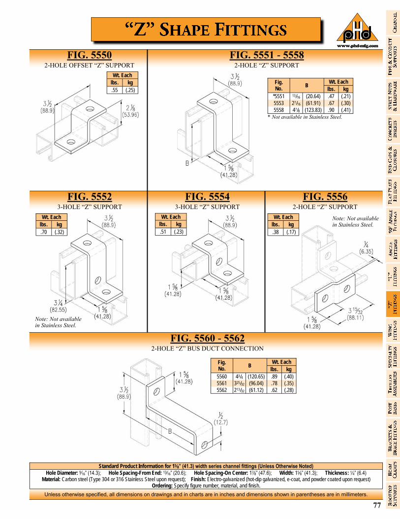
77
Unless otherwise specified, all dimensions on drawings and in charts are in inches and dimensions shown in parentheses are in millimeters.
www.phd-mfg.com
Standard Product Information for 15⁄8” (41.3) width series channel fittings (Unless Otherwise Noted)
Hole Diameter: 9⁄16” (14.3); Hole Spacing-From End: 13⁄16” (20.6); Hole Spacing-On Center: 17⁄8” (47.6); Width: 15⁄8” (41.3); Thickness: 1⁄4” (6.4) Material: Carbon steel (Type 304 or 316 Stainless Steel upon request); Finish: Electro-galvanized (hot-dip galvanized, e-coat, and powder coated upon request)
Ordering: Specify figure number, material, and finish.
FIG. 5560 - 5562 2-HOLE “Z” BUS DUCT CONNECTION
FIG. 5550 2-HOLE OFFSET “Z” SUPPORT
FIG. 5551 - 5558 2-HOLE “Z” SUPPORT
FIG. 5552 3-HOLE “Z” SUPPORT
FIG. 5554 3-HOLE “Z” SUPPORT
FIG. 5556 2-HOLE “Z” SUPPORT
Wt. Each
lbs. kg
.55 (.25)
Wt. Each
lbs. kg
.70 (.32)
Note: Not available in Stainless Steel.
Wt. Each
lbs. kg
.51 (.23)
Wt. Each
lbs. kg
.38 (.17)
Note: Not available in Stainless Steel.
Fig. No.
B Wt. Each
lbs. kg
*5551 13/16 (20.64) .47 (.21)
5553 27/16 (61.91) .67 (.30)
5558 47/8 (123.83) .90 (.41)
* Not available in Stainless Steel.
Fig. No.
B Wt. Each
lbs. kg
5560 43/4 (120.65) .89 (.40)
5561 325/32 (96.04) .78 (.35)
5562 213/32 (61.12) .62 (.28)
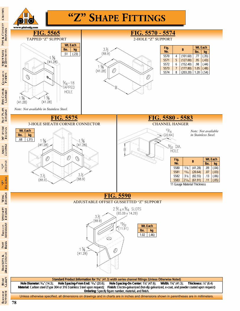
78
Unless otherwise specified, all dimensions on drawings and in charts are in inches and dimensions shown in parentheses are in millimeters.
www.phd-mfg.com
Standard Product Information for 15⁄8” (41.3) width series channel fittings (Unless Otherwise Noted)
Hole Diameter: 9⁄16” (14.3); Hole Spacing-From End: 13⁄16” (20.6); Hole Spacing-On Center: 17⁄8” (47.6); Width: 15⁄8” (41.3); Thickness: 1⁄4” (6.4) Material: Carbon steel (Type 304 or 316 Stainless Steel upon request); Finish: Electro-galvanized (hot-dip galvanized, e-coat, and powder coated upon request)
Ordering: Specify figure number, material, and finish.
FIG. 5590 ADJUSTABLE OFFSET GUSSETTED “Z” SUPPORT
FIG. 5565 TAPPED “Z” SUPPORT
FIG. 5570 - 5574 2-HOLE “Z” SUPPORT
FIG. 5580 - 5583 CHANNEL HANGER
FIG. 5575 3-HOLE SHEATH CORNER CONNECTOR
Wt. Each
lbs. kg
.51 (.23)
Note: Not available in Stainless Steel.
Fig. No.
Wt. Each B
lbs. kg
5570 4 (101.60) .77 (.35)
5571 5 (127.00) .95 (.43)
5572 6 (152.40) .98 (.44)
5573 7 (177.80) 1.05 (.48)
5574 8 (203.20) 1.20 (.54)
Wt. Each
lbs. kg
.68 (.31)
Fig. No.
B Wt. Each
lbs. kg
5580 15/8 (41.28) .09 (.04)
5581 13/16 (20.64) .07 (.03)
5582 31/4 (82.55) .13 (.06)
5583 27/16 (61.91) .11 (.05)
11 Gauge Material Thickness
Note: Not available in Stainless Steel.
Wt. Each
lbs. kg
1.02 (.46)

79
Unless otherwise specified, all dimensions on drawings and in charts are in inches and dimensions shown in parentheses are in millimeters.
www.phd-mfg.com
Standard Product Information for 15⁄8” (41.3) width series channel fittings (Unless Otherwise Noted)
Hole Diameter: 9⁄16” (14.3); Hole Spacing-From End: 13⁄16” (20.6); Hole Spacing-On Center: 17⁄8” (47.6); Width: 15⁄8” (41.3); Thickness: 1⁄4” (6.4) Material: Carbon steel (Type 304 or 316 Stainless Steel upon request); Finish: Electro-galvanized (hot-dip galvanized, e-coat, and powder coated upon request)
Ordering: Specify figure number, material, and finish.
FIG. 5600 & 5601 3-HOLE CORNER CONNECTOR
FIG. 5605 & 5606 4-HOLE CORNER CONNECTOR
FIG. 5620 4-HOLE DOUBLE CORNER CONNECTOR
FIG. 5625 6-HOLE DOUBLE CORNER CONNECTOR
FIG. 5630 8-HOLE DOUBLE CORNER CONNECTOR
FIG. 5615 & 5616 6-HOLE CORNER CONNECTOR
FIG. 5610 & 5611 5-HOLE CORNER CONNECTOR
Wt. Each Fig. No. lbs. kg
5600 RIGHT .60 (.27)
5601 LEFT .60 (.27)
Wt. Each Fig. No. lbs. kg
5605 RIGHT .70 (.32)
5606 LEFT .70 (.32)
Wt. Each Fig. No. lbs. kg
5610 RIGHT 1.00 (.45)
5611 LEFT 1.00 (.45)
Wt. Each Fig. No. lbs. kg
5615 RIGHT 1.20 (.54)
5616 LEFT 1.20 (.54)
Wt. Each
lbs. kg
.76 (.34)
Wt. Each
lbs. kg
1.15 (.52)
Wt. Each
lbs. kg
1.55 (.70)
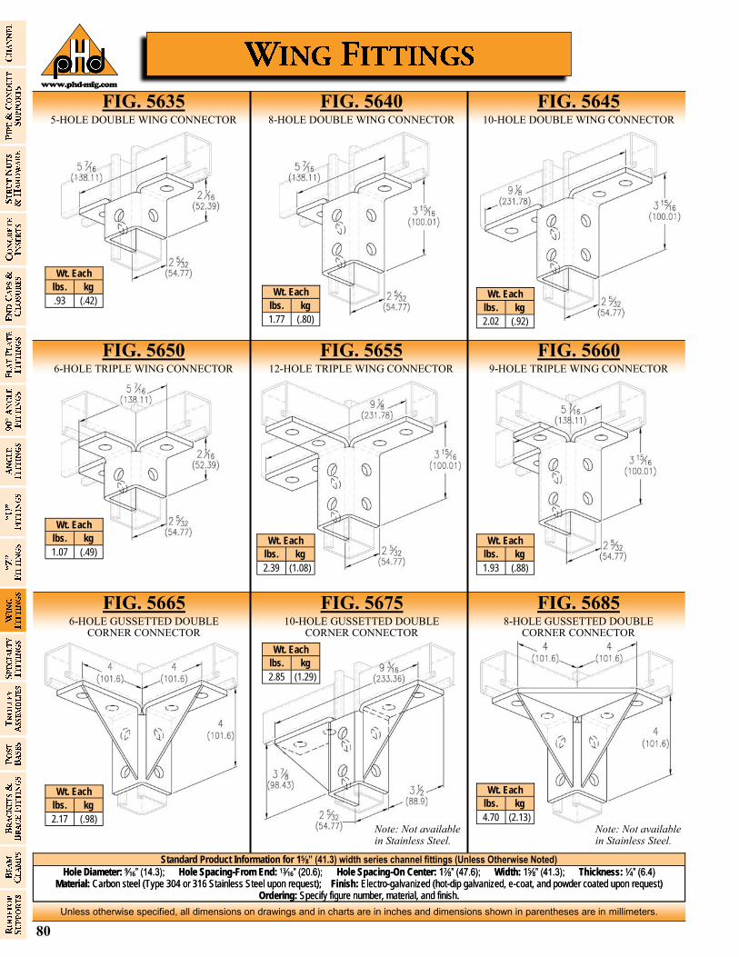
80
Unless otherwise specified, all dimensions on drawings and in charts are in inches and dimensions shown in parentheses are in millimeters.
www.phd-mfg.com
Standard Product Information for 15⁄8” (41.3) width series channel fittings (Unless Otherwise Noted)
Hole Diameter: 9⁄16” (14.3); Hole Spacing-From End: 13⁄16” (20.6); Hole Spacing-On Center: 17⁄8” (47.6); Width: 15⁄8” (41.3); Thickness: 1⁄4” (6.4) Material: Carbon steel (Type 304 or 316 Stainless Steel upon request); Finish: Electro-galvanized (hot-dip galvanized, e-coat, and powder coated upon request)
Ordering: Specify figure number, material, and finish.
FIG. 5635 5-HOLE DOUBLE WING CONNECTOR
FIG. 5640 8-HOLE DOUBLE WING CONNECTOR
FIG. 5645 10-HOLE DOUBLE WING CONNECTOR
FIG. 5685 8-HOLE GUSSETTED DOUBLE
CORNER CONNECTOR
FIG. 5665 6-HOLE GUSSETTED DOUBLE
CORNER CONNECTOR
FIG. 5650 6-HOLE TRIPLE WING CONNECTOR
FIG. 5655 12-HOLE TRIPLE WING CONNECTOR
FIG. 5675 10-HOLE GUSSETTED DOUBLE
CORNER CONNECTOR
FIG. 5660 9-HOLE TRIPLE WING CONNECTOR
Wt. Each
lbs. kg
.93 (.42) Wt. Each
lbs. kg
1.77 (.80)
Wt. Each
lbs. kg
2.02 (.92)
Wt. Each
lbs. kg
1.07 (.49) Wt. Each
lbs. kg
2.39 (1.08)
Wt. Each
lbs. kg
1.93 (.88)
Wt. Each
lbs. kg
2.17 (.98)
Wt. Each
lbs. kg
2.85 (1.29)
Wt. Each
lbs. kg
4.70 (2.13) Note: Not available in Stainless Steel.
Note: Not available in Stainless Steel.
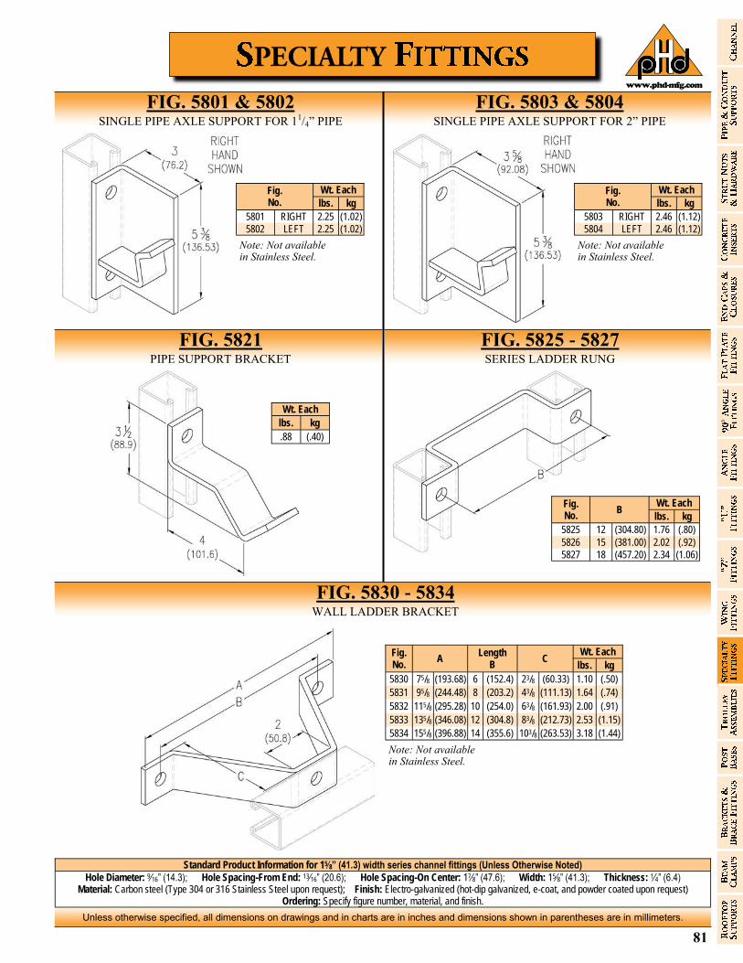
81
Unless otherwise specified, all dimensions on drawings and in charts are in inches and dimensions shown in parentheses are in millimeters.
www.phd-mfg.com
Standard Product Information for 15⁄8” (41.3) width series channel fittings (Unless Otherwise Noted)
Hole Diameter: 9⁄16” (14.3); Hole Spacing-From End: 13⁄16” (20.6); Hole Spacing-On Center: 17⁄8” (47.6); Width: 15⁄8” (41.3); Thickness: 1⁄4” (6.4) Material: Carbon steel (Type 304 or 316 Stainless Steel upon request); Finish: Electro-galvanized (hot-dip galvanized, e-coat, and powder coated upon request)
Ordering: Specify figure number, material, and finish.
Fig. No.
Wt. Each
lbs. kg
5801 RIGHT 2.25 (1.02)
5802 LEFT 2.25 (1.02)
Note: Not available in Stainless Steel.
FIG. 5801 & 5802 SINGLE PIPE AXLE SUPPORT FOR 11/4” PIPE
FIG. 5803 & 5804 SINGLE PIPE AXLE SUPPORT FOR 2” PIPE
FIG. 5825 - 5827 SERIES LADDER RUNG
FIG. 5821 PIPE SUPPORT BRACKET
Fig. No.
Wt. Each
lbs. kg
5803 RIGHT 2.46 (1.12)
5804 LEFT 2.46 (1.12)
Note: Not available in Stainless Steel.
FIG. 5830 - 5834 WALL LADDER BRACKET
Wt. Each
lbs. kg
.88 (.40)
Fig. No.
B Wt. Each
lbs. kg
5825 12 (304.80) 1.76 (.80)
5826 15 (381.00) 2.02 (.92)
5827 18 (457.20) 2.34 (1.06)
Fig. No.
A Length
B C
Wt. Each
lbs. kg
5830 75/8 (193.68) 6 (152.4) 23/8 (60.33) 1.10 (.50)
5831 95/8 (244.48) 8 (203.2) 43/8 (111.13) 1.64 (.74)
5832 115/8 (295.28) 10 (254.0) 63/8 (161.93) 2.00 (.91)
5833 135/8 (346.08) 12 (304.8) 83/8 (212.73) 2.53 (1.15)
5834 155/8 (396.88) 14 (355.6) 103/8 (263.53) 3.18 (1.44)
Note: Not available in Stainless Steel.
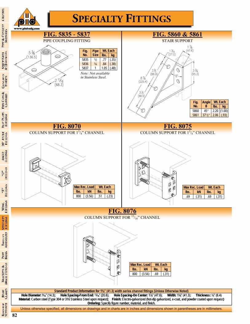
82
Unless otherwise specified, all dimensions on drawings and in charts are in inches and dimensions shown in parentheses are in millimeters.
www.phd-mfg.com
Standard Product Information for 15⁄8” (41.3) width series channel fittings (Unless Otherwise Noted)
Hole Diameter: 9⁄16” (14.3); Hole Spacing-From End: 13⁄16” (20.6); Hole Spacing-On Center: 17⁄8” (47.6); Width: 15⁄8” (41.3); Thickness: 1⁄4” (6.4) Material: Carbon steel (Type 304 or 316 Stainless Steel upon request); Finish: Electro-galvanized (hot-dip galvanized, e-coat, and powder coated upon request)
Ordering: Specify figure number, material, and finish.
FIG. 5835 - 5837 PIPE COUPLING FITTING
FIG. 5860 & 5861 STAIR SUPPORT
FIG. 8075 COLUMN SUPPORT FOR 15/8” CHANNEL
FIG. 8070 COLUMN SUPPORT FOR 15/8” CHANNEL
Fig. No.
Pipe Size
Wt. Each
lbs. kg
5835 1/2 .77 (.35)
5836 3/4 .84 (.38)
5837 1 1.05 (.48)
Note: Not available in Stainless Steel.
Fig. No.
Angle B
Wt. Each
lbs. kg
5860 45° 2.20 (1.00)
5861 371/2° 2.06 (.93)
FIG. 8076 COLUMN SUPPORT FOR 13/16” CHANNEL
Max Rec. Load Wt. Each lbs. kN lbs. kg
800 (3.56) .51 (.23)
Max Rec. Load Wt. Each lbs. kN lbs. kg
.69 (.31) .69 (.31)
Max Rec. Load Wt. Each lbs. kN lbs. kg
800 (3.56) .69 (.31)

83
Unless otherwise specified, all dimensions on drawings and in charts are in inches and dimensions shown in parentheses are in millimeters.
www.phd-mfg.com
Standard Product Information for 15⁄8” (41.3) width series channel fittings (Unless Otherwise Noted)
Hole Diameter: 9⁄16” (14.3); Hole Spacing-From End: 13⁄16” (20.6); Hole Spacing-On Center: 17⁄8” (47.6); Width: 15⁄8” (41.3); Thickness: 1⁄4” (6.4) Material: Carbon steel (Type 304 or 316 Stainless Steel upon request); Finish: Electro-galvanized (hot-dip galvanized, e-coat, and powder coated upon request)
Ordering: Specify figure number, material, and finish.
FIG. 5840 TROLLEY BEAM SUPPORT
FIG. 5845 TROLLEY BEAM JOINT SUPPORT
FIG. 5875 2-BEARING TROLLEY ASSEMBLY
FIG. 5870 4-BEARING TROLLEY ASSEMBLY
Wt. Each
lbs. kg
1.10 (.50)
FPM RPM Design Load
lbs. kN
180 600 300 (1.33)
90 300 450 (2.00)
30 100 600 (2.67)
Design Load based on use with PHD 1000 Series Strut Channel.
Wt. Each
lbs. kg
.48 (.22)
FPM RPM Design Load
lbs. kN
180 600 150 (0.67)
90 300 225 (1.00)
30 100 437 (1.94)
Design Load based on use with PHD 1000 Series Strut Channel.
Note: Not available in Stainless Steel. Note: Not available
in Stainless Steel.
Note: Not available in Stainless Steel.
Note: Not available in Stainless Steel.
Design Load Wt. Each lbs. kN lbs. kg
1200 (5.34) 1.02 (.46)
Design Load Wt. Each lbs. kN lbs. kg
2500 (11.12) 2.20 (1.00)
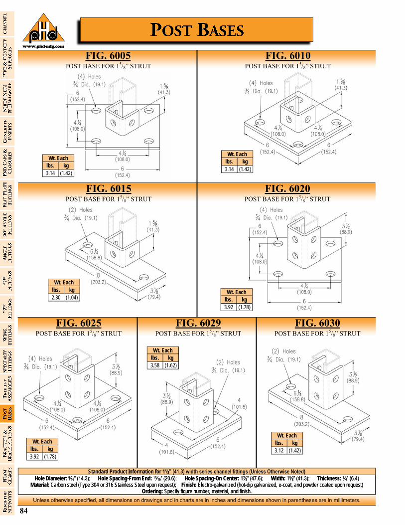
84
Unless otherwise specified, all dimensions on drawings and in charts are in inches and dimensions shown in parentheses are in millimeters.
www.phd-mfg.com
Standard Product Information for 15⁄8” (41.3) width series channel fittings (Unless Otherwise Noted)
Hole Diameter: 9⁄16” (14.3); Hole Spacing-From End: 13⁄16” (20.6); Hole Spacing-On Center: 17⁄8” (47.6); Width: 15⁄8” (41.3); Thickness: 1⁄4” (6.4) Material: Carbon steel (Type 304 or 316 Stainless Steel upon request); Finish: Electro-galvanized (hot-dip galvanized, e-coat, and powder coated upon request)
Ordering: Specify figure number, material, and finish.
Wt. Each
lbs. kg
3.14 (1.42)
Wt. Each
lbs. kg
3.14 (1.42)
Wt. Each
lbs. kg
2.30 (1.04) Wt. Each
lbs. kg
3.92 (1.78)
Wt. Each
lbs. kg
3.92 (1.78)
Wt. Each
lbs. kg
3.58 (1.62)
FIG. 6020 POST BASE FOR 15/8” STRUT
FIG. 6005 POST BASE FOR 15/8” STRUT
FIG. 6010 POST BASE FOR 15/8” STRUT
FIG. 6025 POST BASE FOR 15/8” STRUT
Wt. Each
lbs. kg
3.12 (1.42)
FIG. 6029 POST BASE FOR 15/8” STRUT
FIG. 6030 POST BASE FOR 15/8” STRUT
FIG. 6015 POST BASE FOR 15/8” STRUT
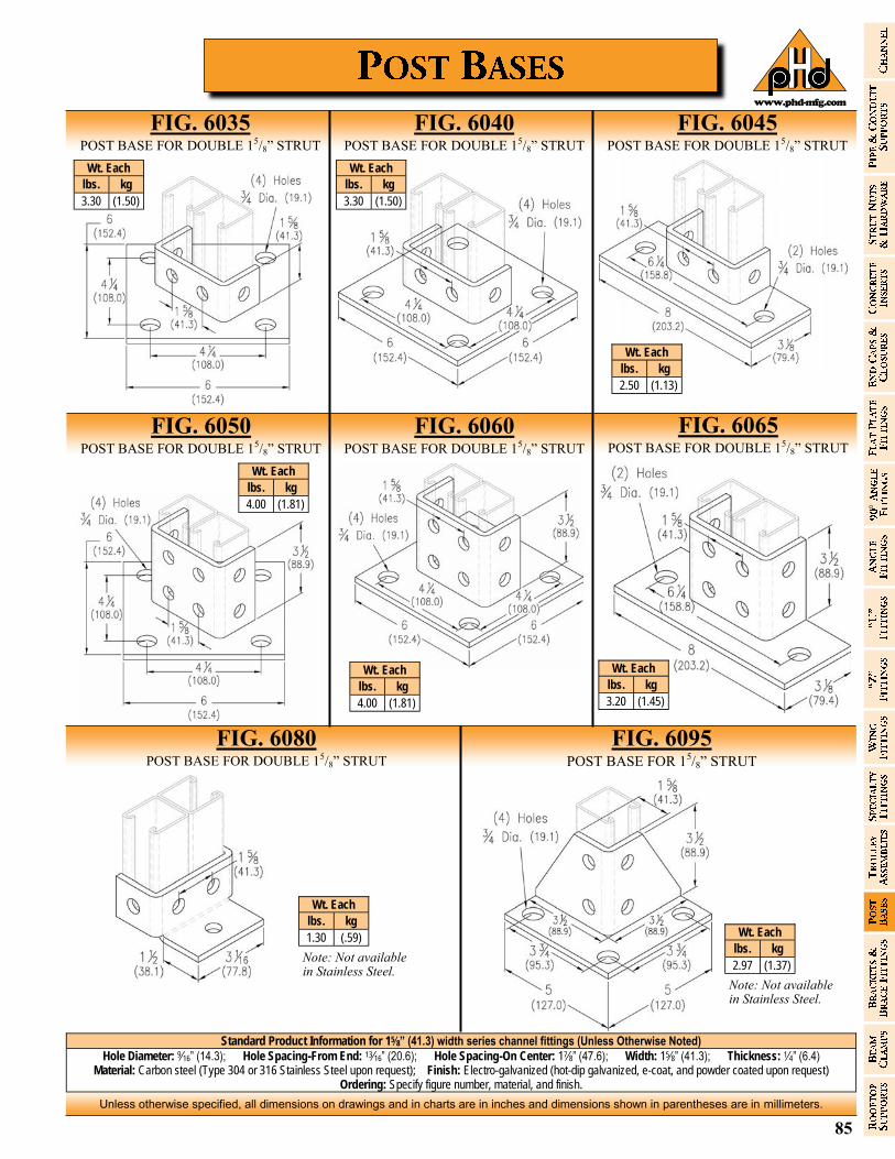
85
Unless otherwise specified, all dimensions on drawings and in charts are in inches and dimensions shown in parentheses are in millimeters.
www.phd-mfg.com
Standard Product Information for 15⁄8” (41.3) width series channel fittings (Unless Otherwise Noted)
Hole Diameter: 9⁄16” (14.3); Hole Spacing-From End: 13⁄16” (20.6); Hole Spacing-On Center: 17⁄8” (47.6); Width: 15⁄8” (41.3); Thickness: 1⁄4” (6.4) Material: Carbon steel (Type 304 or 316 Stainless Steel upon request); Finish: Electro-galvanized (hot-dip galvanized, e-coat, and powder coated upon request)
Ordering: Specify figure number, material, and finish.
Wt. Each
lbs. kg
3.30 (1.50)
Wt. Each
lbs. kg
3.30 (1.50)
FIG. 6065 POST BASE FOR DOUBLE 15/8” STRUT
FIG. 6080 POST BASE FOR DOUBLE 15/8” STRUT
FIG. 6095 POST BASE FOR 15/8” STRUT
FIG. 6035 POST BASE FOR DOUBLE 15/8” STRUT
FIG. 6040 POST BASE FOR DOUBLE 15/8” STRUT
FIG. 6045 POST BASE FOR DOUBLE 15/8” STRUT
Note: Not available in Stainless Steel.
Note: Not available in Stainless Steel.
Wt. Each
lbs. kg
2.50 (1.13)
Wt. Each
lbs. kg
4.00 (1.81)
Wt. Each
lbs. kg
4.00 (1.81)
Wt. Each
lbs. kg
3.20 (1.45)
Wt. Each
lbs. kg
1.30 (.59) Wt. Each
lbs. kg
2.97 (1.37)
FIG. 6050 POST BASE FOR DOUBLE 15/8” STRUT
FIG. 6060 POST BASE FOR DOUBLE 15/8” STRUT
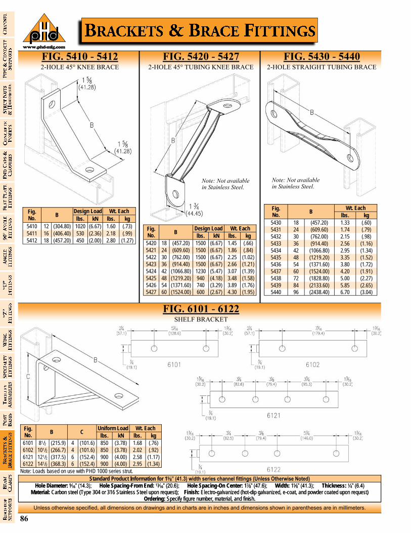
86
Unless otherwise specified, all dimensions on drawings and in charts are in inches and dimensions shown in parentheses are in millimeters.
www.phd-mfg.com
Standard Product Information for 15⁄8” (41.3) width series channel fittings (Unless Otherwise Noted)
Hole Diameter: 9⁄16” (14.3); Hole Spacing-From End: 13⁄16” (20.6); Hole Spacing-On Center: 17⁄8” (47.6); Width: 15⁄8” (41.3); Thickness: 1⁄4” (6.4) Material: Carbon steel (Type 304 or 316 Stainless Steel upon request); Finish: Electro-galvanized (hot-dip galvanized, e-coat, and powder coated upon request)
Ordering: Specify figure number, material, and finish.
Fig. No.
B Design Load Wt. Each lbs. kN lbs. kg
5410 12 (304.80) 1020 (6.67) 1.60 (.73)
5411 16 (406.40) 530 (2.36) 2.18 (.99)
5412 18 (457.20) 450 (2.00) 2.80 (1.27)
Fig. No.
B Design Load Wt. Each lbs. kN lbs. kg
5420 18 (457.20) 1500 (6.67) 1.45 (.66)
5421 24 (609.60) 1500 (6.67) 1.86 (.84)
5422 30 (762.00) 1500 (6.67) 2.25 (1.02)
5423 36 (914.40) 1500 (6.67) 2.66 (1.21)
5424 42 (1066.80) 1230 (5.47) 3.07 (1.39)
5425 48 (1219.20) 940 (4.18) 3.48 (1.58)
5426 54 (1371.60) 740 (3.29) 3.89 (1.76)
5427 60 (1524.00) 600 (2.67) 4.30 (1.95)
FIG. 5410 - 5412 2-HOLE 45° KNEE BRACE
FIG. 5420 - 5427 2-HOLE 45° TUBING KNEE BRACE
FIG. 5430 - 5440 2-HOLE STRAIGHT TUBING BRACE
Note: Not available in Stainless Steel.
Note: Not available in Stainless Steel.
Fig. No.
B Wt. Each
lbs. kg
5430 18 (457.20) 1.33 (.60)
5431 24 (609.60) 1.74 (.79)
5432 30 (762.00) 2.15 (.98)
5433 36 (914.40) 2.56 (1.16)
5434 42 (1066.80) 2.95 (1.34)
5435 48 (1219.20) 3.35 (1.52)
5436 54 (1371.60) 3.80 (1.72)
5437 60 (1524.00) 4.20 (1.91)
5438 72 (1828.80) 5.00 (2.27)
5439 84 (2133.60) 5.85 (2.65)
5440 96 (2438.40) 6.70 (3.04)
FIG. 6101 - 6122 SHELF BRACKET
Fig. No.
B Uniform Load Wt. Each
C lbs. kN lbs. kg
6101 81/2 (215.9) 4 (101.6) 850 (3.78) 1.68 (.76)
6102 101/2 (266.7) 4 (101.6) 850 (3.78) 2.02 (.92)
6121 121/2 (317.5) 6 (152.4) 900 (4.00) 2.58 (1.17)
6122 141/2 (368.3) 6 (152.4) 900 (4.00) 2.95 (1.34)
Note: Loads based on use with PHD 1000 series strut.
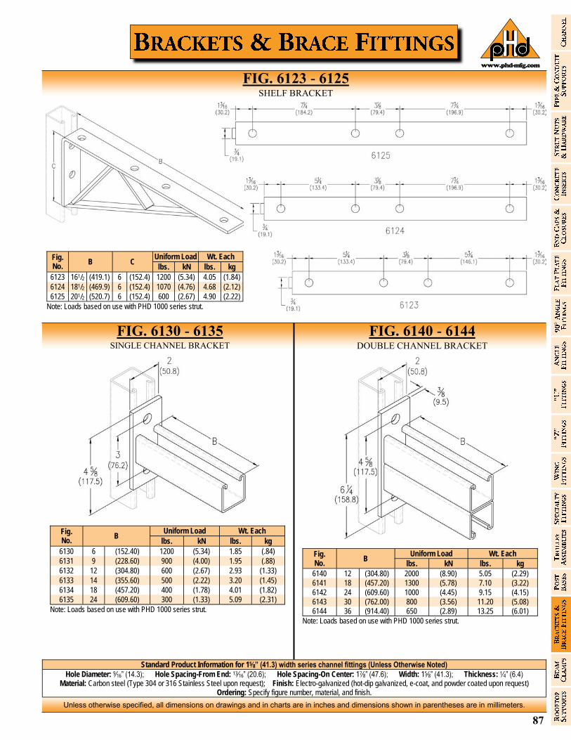
87
Unless otherwise specified, all dimensions on drawings and in charts are in inches and dimensions shown in parentheses are in millimeters.
www.phd-mfg.com
Standard Product Information for 15⁄8” (41.3) width series channel fittings (Unless Otherwise Noted)
Hole Diameter: 9⁄16” (14.3); Hole Spacing-From End: 13⁄16” (20.6); Hole Spacing-On Center: 17⁄8” (47.6); Width: 15⁄8” (41.3); Thickness: 1⁄4” (6.4) Material: Carbon steel (Type 304 or 316 Stainless Steel upon request); Finish: Electro-galvanized (hot-dip galvanized, e-coat, and powder coated upon request)
Ordering: Specify figure number, material, and finish.
FIG. 6123 - 6125 SHELF BRACKET
Fig. No.
B C Uniform Load Wt. Each
lbs. kN lbs. kg
6123 161/2 (419.1) 6 (152.4) 1200 (5.34) 4.05 (1.84)
6124 181/2 (469.9) 6 (152.4) 1070 (4.76) 4.68 (2.12)
6125 201/2 (520.7) 6 (152.4) 600 (2.67) 4.90 (2.22)
Note: Loads based on use with PHD 1000 series strut.
Fig. No.
B Uniform Load Wt. Each
lbs. kN lbs. kg
6130 6 (152.40) 1200 (5.34) 1.85 (.84)
6131 9 (228.60) 900 (4.00) 1.95 (.88)
6132 12 (304.80) 600 (2.67) 2.93 (1.33)
6133 14 (355.60) 500 (2.22) 3.20 (1.45)
6134 18 (457.20) 400 (1.78) 4.01 (1.82)
6135 24 (609.60) 300 (1.33) 5.09 (2.31)
Note: Loads based on use with PHD 1000 series strut.
Fig. No.
B Uniform Load Wt. Each
lbs. kN lbs. kg
6140 12 (304.80) 2000 (8.90) 5.05 (2.29)
6141 18 (457.20) 1300 (5.78) 7.10 (3.22)
6142 24 (609.60) 1000 (4.45) 9.15 (4.15)
6143 30 (762.00) 800 (3.56) 11.20 (5.08) 6144 36 (914.40) 650 (2.89) 13.25 (6.01)
Note: Loads based on use with PHD 1000 series strut.
FIG. 6130 - 6135 SINGLE CHANNEL BRACKET
FIG. 6140 - 6144 DOUBLE CHANNEL BRACKET
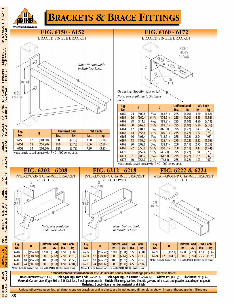
88
Unless otherwise specified, all dimensions on drawings and in charts are in inches and dimensions shown in parentheses are in millimeters.
www.phd-mfg.com
Standard Product Information for 15⁄8” (41.3) width series channel fittings (Unless Otherwise Noted)
Hole Diameter: 9⁄16” (14.3); Hole Spacing-From End: 13⁄16” (20.6); Hole Spacing-On Center: 17⁄8” (47.6); Width: 15⁄8” (41.3); Thickness: 1⁄4” (6.4) Material: Carbon steel (Type 304 or 316 Stainless Steel upon request); Finish: Electro-galvanized (hot-dip galvanized, e-coat, and powder coated upon request)
Ordering: Specify figure number, material, and finish.
Fig. No.
B Uniform Load Wt. Each
lbs. kN lbs. kg
6150 12 (304.80) 1600 (7.12) 3.88 (1.76)
6151 18 (457.20) 850 (3.78) 5.06 (2.30)
6152 24 (609.60) 850 (3.78) 7.20 (3.27)
Note: Loads based on use with PHD 1400 series strut.
FIG. 6150 - 6152 BRACED SINGLE BRACKET
FIG. 6160 - 6172 BRACED SINGLE BRACKET
Note: Not available in Stainless Steel.
Fig. No.
B Uniform Load Wt. Each
C lbs. kN lbs. kg
6160 24 (609.6) 67/16 (163.51) 225 (1.00) 3.70 (1.68) 6161 26 (660.4) 615/16 (176.21) 225 (1.00) 4.25 (1.93) 6162 28 (711.2) 77/16 (188.91) 225 (1.00) 4.80 (2.18) 6163 30 (762.0) 715/16 (201.61) 225 (1.00) 5.20 (2.36) 6164 12 (304.8) 37/16 (87.31) 275 (1.22) 1.43 (.65) 6165 14 (355.6) 315/16 (100.01) 275 (1.22) 1.62 (.73) 6166 16 (406.4) 47/16 (112.71) 275 (1.22) 2.04 (.93)
6167 18 (457.2) 415/16 (125.41) 275 (1.22) 2.32 (1.05) 6168 20 (508.0) 57/16 (138.11) 250 (1.11) 2.75 (1.25)
6169 22 (558.8) 515/16 (150.81) 250 (1.11) 3.17 (1.44)
6170 6 (152.4) 115/16 (49.21) 275 (1.22) .58 (.26) 6171 8 (203.2) 27/16 (61.91) 275 (1.22) .82 (.37) 6172 10 (254.0) 215/16 (74.61) 275 (1.22) 1.03 (.47)
Note: Loads based on use with PHD 1000 series strut.
Ordering: Specify right or left.
Note: Not available in Stainless Steel.
FIG. 6202 - 6208 INTERLOCKING CHANNEL BRACKET
(SLOT UP)
FIG. 6212 - 6218 INTERLOCKING CHANNEL BRACKET
(SLOT DOWN)
FIG. 6222 & 6224 WRAP-AROUND CHANNEL BRACKET
(SLOT UP)
Fig. No.
B Uniform Load Wt. Each
lbs. kN lbs. kg
6202 6 (152.40) 1200 (5.34) 1.50 (.68)
6204 12 (304.80) 600 (2.67) 2.50 (1.13)
6206 18 (457.20) 400 (1.78) 3.50 (1.59)
6208 24 (609.60) 300 (1.33) 4.50 (2.04)
Note: Loads based on use with PHD 1000 series strut.
Note: Not available in Stainless Steel.
Fig. No.
B Uniform Load Wt. Each
lbs. kN lbs. kg
6212 6 (152.40) 1200 (5.34) 1.50 (.68)
6214 12 (304.80) 600 (2.67) 2.50 (1.13)
6216 18 (457.20) 400 (1.78) 3.50 (1.59)
6218 24 (609.60) 300 (1.33) 4.50 (2.04)
Note: Loads based on use with PHD 1000 series strut.
Note: Not available in Stainless Steel.
Fig. No.
B Uniform Load Wt. Each
lbs. kN lbs. kg
6222 6 (152.4) 1600 (7.12) 1.90 (.86)
6224 12 (304.8) 800 (3.56) 2.75 (1.25)
Note: Loads based on use with PHD 1000 series strut.
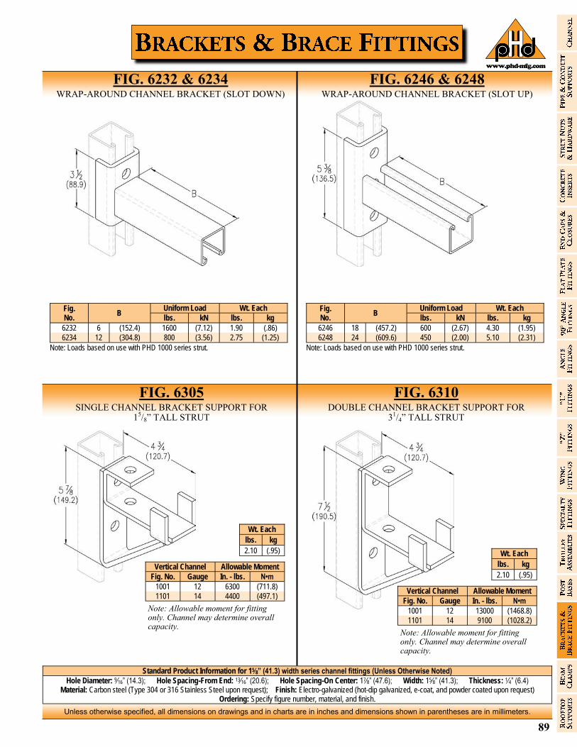
89
Unless otherwise specified, all dimensions on drawings and in charts are in inches and dimensions shown in parentheses are in millimeters.
www.phd-mfg.com
Standard Product Information for 15⁄8” (41.3) width series channel fittings (Unless Otherwise Noted)
Hole Diameter: 9⁄16” (14.3); Hole Spacing-From End: 13⁄16” (20.6); Hole Spacing-On Center: 17⁄8” (47.6); Width: 15⁄8” (41.3); Thickness: 1⁄4” (6.4) Material: Carbon steel (Type 304 or 316 Stainless Steel upon request); Finish: Electro-galvanized (hot-dip galvanized, e-coat, and powder coated upon request)
Ordering: Specify figure number, material, and finish.
Fig. No.
B Uniform Load Wt. Each lbs. kN lbs. kg
6246 18 (457.2) 600 (2.67) 4.30 (1.95)
6248 24 (609.6) 450 (2.00) 5.10 (2.31)
Note: Loads based on use with PHD 1000 series strut.
FIG. 6310 DOUBLE CHANNEL BRACKET SUPPORT FOR
31/4” TALL STRUT
FIG. 6232 & 6234 WRAP-AROUND CHANNEL BRACKET (SLOT DOWN)
FIG. 6246 & 6248 WRAP-AROUND CHANNEL BRACKET (SLOT UP)
FIG. 6305 SINGLE CHANNEL BRACKET SUPPORT FOR
15/8” TALL STRUT
Fig. No.
B Uniform Load Wt. Each lbs. kN lbs. kg
6232 6 (152.4) 1600 (7.12) 1.90 (.86)
6234 12 (304.8) 800 (3.56) 2.75 (1.25)
Note: Loads based on use with PHD 1000 series strut.
Allowable Moment Vertical Channel
Fig. No. Gauge In. - lbs. N•m
1001 12 6300 (711.8)
1101 14 4400 (497.1)
Wt. Each
lbs. kg
2.10 (.95)
Note: Allowable moment for fitting only. Channel may determine overall capacity.
Allowable Moment Vertical Channel
Fig. No. Gauge In. - lbs. N•m
1001 12 13000 (1468.8)
1101 14 9100 (1028.2)
Wt. Each
lbs. kg
2.10 (.95)
Note: Allowable moment for fitting only. Channel may determine overall capacity.
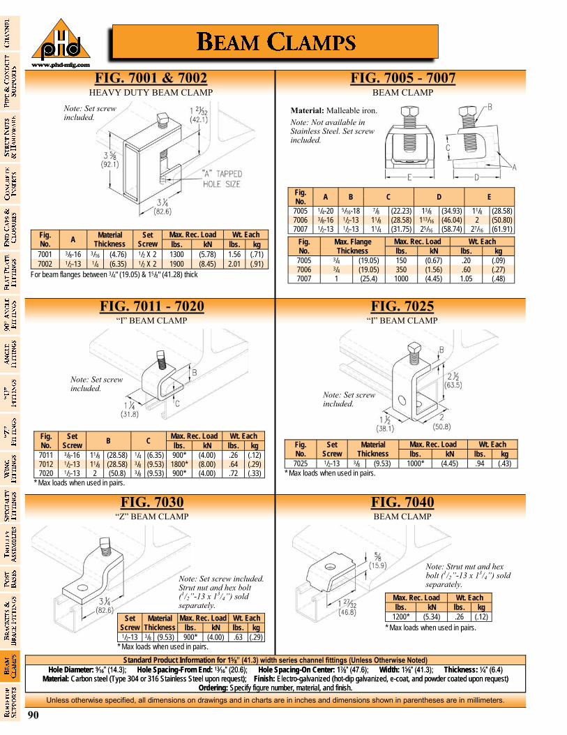
90
Unless otherwise specified, all dimensions on drawings and in charts are in inches and dimensions shown in parentheses are in millimeters.
www.phd-mfg.com
Standard Product Information for 15⁄8” (41.3) width series channel fittings (Unless Otherwise Noted)
Hole Diameter: 9⁄16” (14.3); Hole Spacing-From End: 13⁄16” (20.6); Hole Spacing-On Center: 17⁄8” (47.6); Width: 15⁄8” (41.3); Thickness: 1⁄4” (6.4) Material: Carbon steel (Type 304 or 316 Stainless Steel upon request); Finish: Electro-galvanized (hot-dip galvanized, e-coat, and powder coated upon request)
Ordering: Specify figure number, material, and finish.
Fig. No.
A Material
Thickness
Max. Rec. Load Wt. Each Set Screw lbs. kN lbs. kg
7001 3/8-16 3/16 (4.76) 1/2 X 2 1300 (5.78) 1.56 (.71)
7002 1/2-13 1/4 (6.35) 1/2 X 2 1900 (8.45) 2.01 (.91)
For beam flanges between 3/4" (19.05) & 15/8" (41.28) thick
FIG. 7001 & 7002 HEAVY DUTY BEAM CLAMP
FIG. 7005 - 7007 BEAM CLAMP
FIG. 7011 - 7020 “I” BEAM CLAMP
FIG. 7025 “I” BEAM CLAMP
Note: Set screw included.
Fig. No.
A B C D E
7005 1/4-20 5/16-18 7/8 (22.23) 13/8 (34.93) 11/8 (28.58) 7006 3/8-16 1/2-13 11/8 (28.58) 113/16 (46.04) 2 (50.80) 7007 1/2-13 1/2-13 11/4 (31.75) 25/16 (58.74) 27/16 (61.91)
Fig. No.
Max. Flange Thickness
Max. Rec. Load Wt. Each
lbs. kN lbs. kg
7005 3/4 (19.05) 150 (0.67) .20 (.09) 7006 3/4 (19.05) 350 (1.56) .60 (.27) 7007 1 (25.4) 1000 (4.45) 1.05 (.48)
Material: Malleable iron.
Note: Not available in Stainless Steel. Set screw included.
Fig. No.
Set Screw
C Max. Rec. Load Wt. Each
B lbs. kN lbs. kg
7011 3/8-16 11/8 (28.58) 1/4 (6.35) 900* (4.00) .26 (.12) 7012 1/2-13 11/8 (28.58) 3/8 (9.53) 1800* (8.00) .64 (.29) 7020 1/2-13 2 (50.8) 3/8 (9.53) 900* (4.00) .72 (.33)
* Max loads when used in pairs.
Note: Set screw included.
Note: Set screw included.
Fig. No.
Set Screw
Material Thickness
Max. Rec. Load Wt. Each
lbs. kN lbs. kg
7025 1/2-13 3/8 (9.53) 1000* (4.45) .94 (.43)
* Max loads when used in pairs.
FIG. 7030 “Z” BEAM CLAMP
FIG. 7040 BEAM CLAMP
Set Screw
Material Thickness
Max. Rec. Load Wt. Each
lbs. kN lbs. kg 1/2-13 3/8 (9.53) 900* (4.00) .63 (.29)
* Max loads when used in pairs.
Note: Set screw included. Strut nut and hex bolt (1/2”-13 x 13/4”) sold separately.
Max. Rec. Load Wt. Each
lbs. kN lbs. kg
1200* (5.34) .26 (.12)
* Max loads when used in pairs.
Note: Strut nut and hex bolt (1/2”-13 x 13/4”) sold separately.
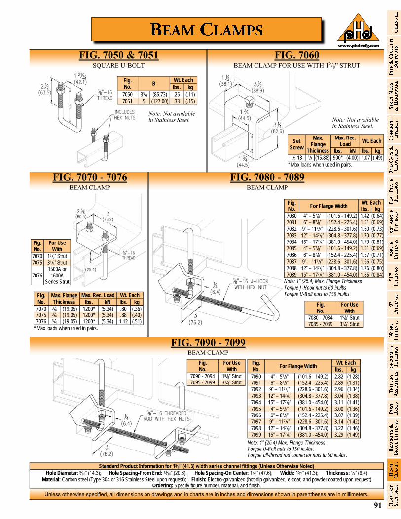
91
Unless otherwise specified, all dimensions on drawings and in charts are in inches and dimensions shown in parentheses are in millimeters.
www.phd-mfg.com
Standard Product Information for 15⁄8” (41.3) width series channel fittings (Unless Otherwise Noted)
Hole Diameter: 9⁄16” (14.3); Hole Spacing-From End: 13⁄16” (20.6); Hole Spacing-On Center: 17⁄8” (47.6); Width: 15⁄8” (41.3); Thickness: 1⁄4” (6.4) Material: Carbon steel (Type 304 or 316 Stainless Steel upon request); Finish: Electro-galvanized (hot-dip galvanized, e-coat, and powder coated upon request)
Ordering: Specify figure number, material, and finish.
FIG. 7050 & 7051 SQUARE U-BOLT
FIG. 7060 BEAM CLAMP FOR USE WITH 15/8” STRUT
FIG. 7070 - 7076 BEAM CLAMP
FIG. 7080 - 7089 BEAM CLAMP
FIG. 7090 - 7099 BEAM CLAMP
Fig. No.
B Wt. Each
lbs. kg
7050 33/8 (85.73) .25 (.11)
7051 5 (127.00) .33 (.15)
Note: Not available in Stainless Steel.
Set Screw
Max. Rec. Load
Wt. Each Max.
Flange Thickness lbs. kN lbs. kg
1/2-13 5/8 (15.88) 900* (4.00) 1.07 (.49)
* Max loads when used in pairs.
Note: Not available in Stainless Steel.
Fig. No.
Max. Flange Thickness
Max. Rec. Load Wt. Each
lbs. kN lbs. kg
7070 3/4 (19.05) 1200* (5.34) .80 (.36) 7075 3/4 (19.05) 1200* (5.34) .88 (.40) 7076 3/4 (19.05) 1200* (5.34) 1.12 (.51)
* Max loads when used in pairs.
Fig. No.
For Use With
7070 15/8” Strut 7075 31/4” Strut
7076 1500A or
1600A Series Strut
Fig. No.
For Flange Width Wt. Each
lbs. kg
7080 4” – 57/8” (101.6 - 149.2) 1.42 (0.64) 7081 6” – 87/8” (152.4 - 225.4) 1.51 (0.69) 7082 9” – 117/8” (228.6 - 301.6) 1.60 (0.73) 7083 12” – 147/8” (304.8 - 377.8) 1.70 (0.77)
7084 15” – 177/8” (381.0 - 454.0) 1.79 (0.81) 7085 4” – 57/8” (101.6 - 149.2) 1.51 (0.69) 7086 6” – 87/8” (152.4 - 225.4) 1.57 (0.71)
7087 9” – 117/8” (228.6 - 301.6) 1.66 (0.75) 7088 12” – 147/8” (304.8 - 377.8) 1.76 (0.80) 7089 15” – 177/8” (381.0 - 454.0) 1.85 (0.84)
Note: 1” (25.4) Max. Flange Thickness Torque J-Hook nut to 60 in./lbs Torque U-Bolt nuts to 150 in./lbs.
Fig. No.
For Flange Width Wt. Each
lbs. kg
7090 4” – 57/8” (101.6 - 149.2) 2.82 (1.28) 7091 6” – 87/8” (152.4 - 225.4) 2.89 (1.31) 7092 9” – 117/8” (228.6 - 301.6) 2.96 (1.34) 7093 12” – 147/8” (304.8 - 377.8) 3.04 (1.38) 7094 15” – 177/8” (381.0 - 454.0) 3.11 (1.41) 7095 4” – 57/8” (101.6 - 149.2) 3.00 (1.36) 7096 6” – 87/8” (152.4 - 225.4) 3.07 (1.39) 7097 9” – 117/8” (228.6 - 301.6) 3.14 (1.42) 7098 12” – 147/8” (304.8 - 377.8) 3.22 (1.46) 7099 15” – 177/8” (381.0 - 454.0) 3.29 (1.49)
Note: 1” (25.4) Max. Flange Thickness Torque U-Bolt nuts to 150 in./lbs. Torque all-thread rod connector nuts to 60 in./lbs.
Fig. No.
For Use With
7080 - 7084 15/8” Strut 7085 - 7089 31/4” Strut
Fig. No.
For Use With
7090 - 7094 15/8” Strut 7095 - 7099 31/4” Strut
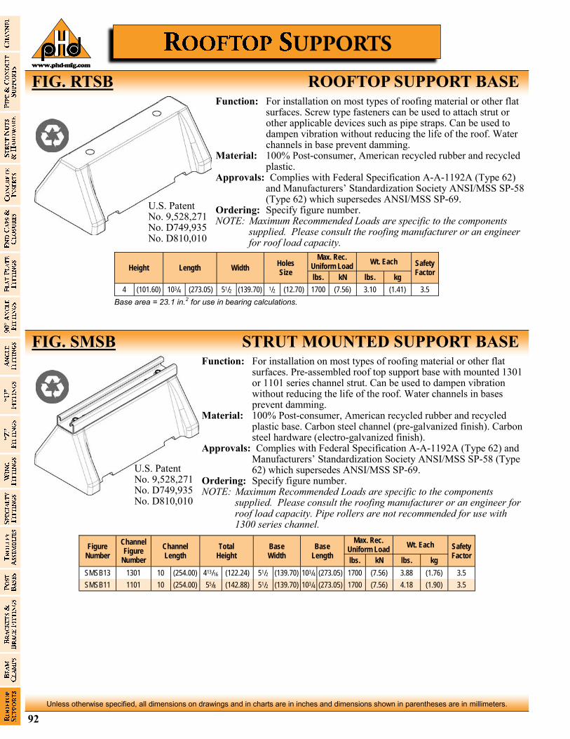
92
Unless otherwise specified, all dimensions on drawings and in charts are in inches and dimensions shown in parentheses are in millimeters.
www.phd-mfg.com
Function: For installation on most types of roofing material or other flat surfaces. Screw type fasteners can be used to attach strut or other applicable devices such as pipe straps. Can be used to dampen vibration without reducing the life of the roof. Water channels in base prevent damming.
Material: 100% Post-consumer, American recycled rubber and recycled plastic.
Approvals: Complies with Federal Specification A-A-1192A (Type 62) and Manufacturers’ Standardization Society ANSI/MSS SP-58 (Type 62) which supersedes ANSI/MSS SP-69.
Ordering: Specify figure number. NOTE: Maximum Recommended Loads are specific to the components
supplied. Please consult the roofing manufacturer or an engineer for roof load capacity.
Height Length Width Holes Size
Max. Rec. Uniform Load
Wt. Each Safety Factor
lbs. kN lbs. kg
4 (101.60) 103/4 (273.05) 51/2 (139.70) 1/2 (12.70) 1700 (7.56) 3.10 (1.41) 3.5
Base area = 23.1 in.2 for use in bearing calculations.
Function: For installation on most types of roofing material or other flat surfaces. Pre-assembled roof top support base with mounted 1301 or 1101 series channel strut. Can be used to dampen vibration without reducing the life of the roof. Water channels in bases prevent damming.
Material: 100% Post-consumer, American recycled rubber and recycled plastic base. Carbon steel channel (pre-galvanized finish). Carbon steel hardware (electro-galvanized finish).
Approvals: Complies with Federal Specification A-A-1192A (Type 62) and Manufacturers’ Standardization Society ANSI/MSS SP-58 (Type 62) which supersedes ANSI/MSS SP-69.
Ordering: Specify figure number. NOTE: Maximum Recommended Loads are specific to the components
supplied. Please consult the roofing manufacturer or an engineer for roof load capacity. Pipe rollers are not recommended for use with 1300 series channel.
FIG. SMSB STRUT MOUNTED SUPPORT BASE
FIG. RTSB ROOFTOP SUPPORT BASE
U.S. Patent No. 9,528,271 No. D749,935 No. D810,010
Figure Number
Channel Figure
Number
Channel Length
Total Height
Base Width
Base Length
Max. Rec. Uniform Load
Wt. Each Safety Factor
lbs. kN lbs. kg
SMSB13 1301 10 (254.00) 413/16 (122.24) 51/2 (139.70) 103/4 (273.05) 1700 (7.56) 3.88 (1.76) 3.5
SMSB11 1101 10 (254.00) 55/8 (142.88) 51/2 (139.70) 103/4 (273.05) 1700 (7.56) 4.18 (1.90) 3.5
U.S. Patent No. 9,528,271 No. D749,935 No. D810,010
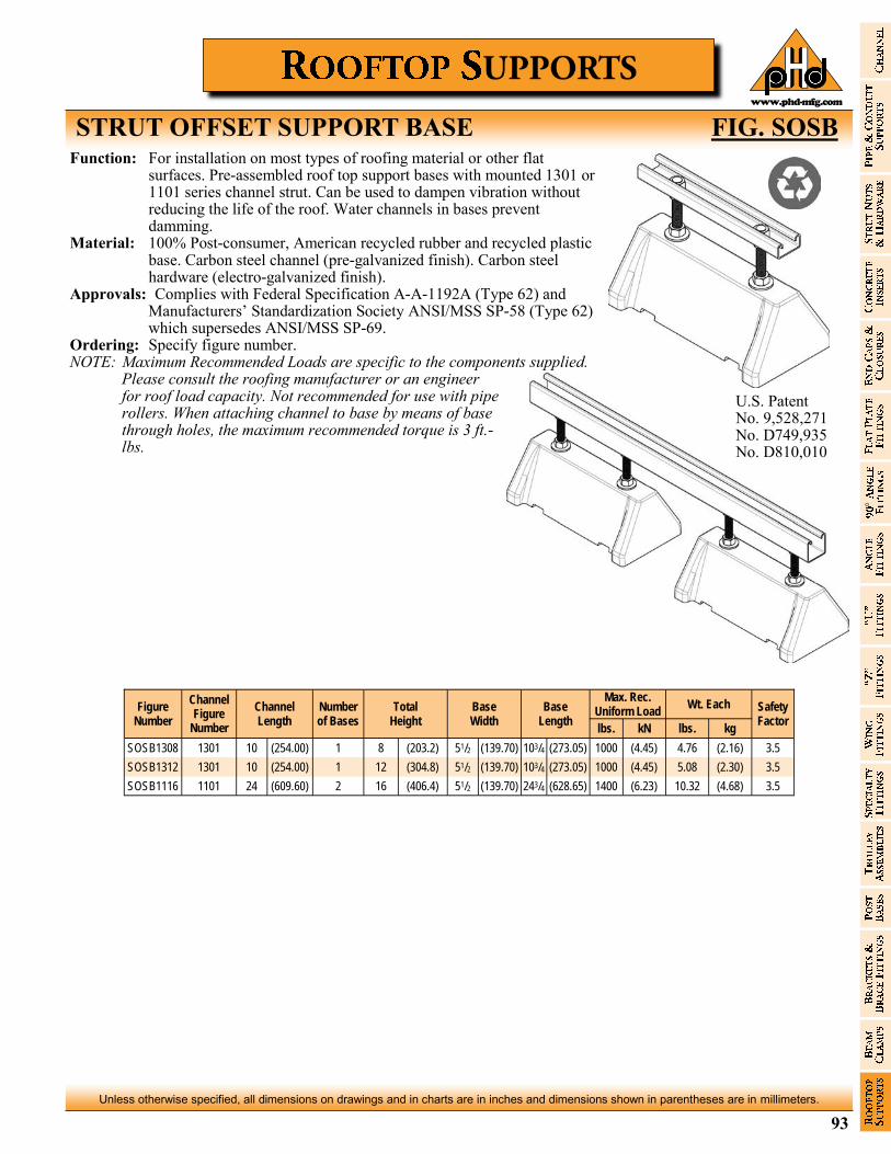
93
Unless otherwise specified, all dimensions on drawings and in charts are in inches and dimensions shown in parentheses are in millimeters.
www.phd-mfg.com
STRUT OFFSET SUPPORT BASE FIG. SOSB Function: For installation on most types of roofing material or other flat
surfaces. Pre-assembled roof top support bases with mounted 1301 or 1101 series channel strut. Can be used to dampen vibration without reducing the life of the roof. Water channels in bases prevent damming.
Material: 100% Post-consumer, American recycled rubber and recycled plastic base. Carbon steel channel (pre-galvanized finish). Carbon steel hardware (electro-galvanized finish).
Approvals: Complies with Federal Specification A-A-1192A (Type 62) and Manufacturers’ Standardization Society ANSI/MSS SP-58 (Type 62) which supersedes ANSI/MSS SP-69.
Ordering: Specify figure number. NOTE: Maximum Recommended Loads are specific to the components supplied.
Please consult the roofing manufacturer or an engineer for roof load capacity. Not recommended for use with pipe rollers. When attaching channel to base by means of base through holes, the maximum recommended torque is 3 ft.-lbs.
Figure Number
Channel Figure
Number
Channel Length
Total Height
Base Width
Base Length
Max. Rec. Uniform Load
Wt. Each Safety Factor
Number of Bases
lbs. kN lbs. kg
SOSB1308 1301 10 (254.00) 1 8 (203.2) 51/2 (139.70) 103/4 (273.05) 1000 (4.45) 4.76 (2.16) 3.5
SOSB1312 1301 10 (254.00) 1 12 (304.8) 51/2 (139.70) 103/4 (273.05) 1000 (4.45) 5.08 (2.30) 3.5
SOSB1116 1101 24 (609.60) 2 16 (406.4) 51/2 (139.70) 243/4 (628.65) 1400 (6.23) 10.32 (4.68) 3.5
U.S. Patent No. 9,528,271 No. D749,935 No. D810,010
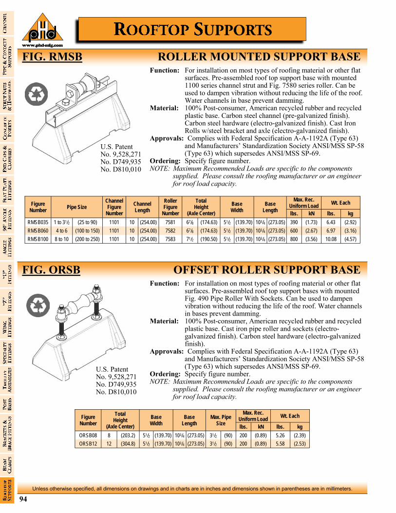
94
Unless otherwise specified, all dimensions on drawings and in charts are in inches and dimensions shown in parentheses are in millimeters.
www.phd-mfg.com
Function: For installation on most types of roofing material or other flat surfaces. Pre-assembled roof top support base with mounted 1100 series channel strut and Fig. 7580 series roller. Can be used to dampen vibration without reducing the life of the roof. Water channels in base prevent damming.
Material: 100% Post-consumer, American recycled rubber and recycled plastic base. Carbon steel channel (pre-galvanized finish). Carbon steel hardware (electro-galvanized finish). Cast Iron Rolls w/steel bracket and axle (electro-galvanized finish).
Approvals: Complies with Federal Specification A-A-1192A (Type 63) and Manufacturers’ Standardization Society ANSI/MSS SP-58 (Type 63) which supersedes ANSI/MSS SP-69.
Ordering: Specify figure number. NOTE: Maximum Recommended Loads are specific to the components
supplied. Please consult the roofing manufacturer or an engineer for roof load capacity.
FIG. ORSB OFFSET ROLLER SUPPORT BASE
FIG. RMSB ROLLER MOUNTED SUPPORT BASE
U.S. Patent No. 9,528,271 No. D749,935 No. D810,010
Figure Number
Pipe Size Channel Figure
Number
Channel Length
Roller Figure
Number
Total Height
(Axle Center)
Base Width
Base Length
Max. Rec. Uniform Load
Wt. Each
lbs. kN lbs. kg
RMSB035 1 to 31/2 (25 to 90) 1101 10 (254.00) 7581 67/8 (174.63) 51/2 (139.70) 103/4 (273.05) 390 (1.73) 6.43 (2.92)
RMSB060 4 to 6 (100 to 150) 1101 10 (254.00) 7582 67/8 (174.63) 51/2 (139.70) 103/4 (273.05) 600 (2.67) 6.97 (3.16)
RMSB100 8 to 10 (200 to 250) 1101 10 (254.00) 7583 71/2 (190.50) 51/2 (139.70) 103/4 (273.05) 800 (3.56) 10.08 (4.57)
Function: For installation on most types of roofing material or other flat surfaces. Pre-assembled roof top support bases with mounted Fig. 490 Pipe Roller With Sockets. Can be used to dampen vibration without reducing the life of the roof. Water channels in bases prevent damming.
Material: 100% Post-consumer, American recycled rubber and recycled plastic base. Cast iron pipe roller and sockets (electro-galvanized finish). Carbon steel hardware (electro-galvanized finish).
Approvals: Complies with Federal Specification A-A-1192A (Type 63) and Manufacturers’ Standardization Society ANSI/MSS SP-58 (Type 63) which supersedes ANSI/MSS SP-69.
Ordering: Specify figure number. NOTE: Maximum Recommended Loads are specific to the components
supplied. Please consult the roofing manufacturer or an engineer for roof load capacity.
U.S. Patent No. 9,528,271 No. D749,935 No. D810,010
Figure Number
Total Height
(Axle Center)
Base Width
Base Length
Max. Pipe Size
Max. Rec. Uniform Load
Wt. Each
lbs. kN lbs. kg
ORSB08 8 (203.2) 51/2 (139.70) 103/4 (273.05) 31/2 (90) 200 (0.89) 5.26 (2.39)
ORSB12 12 (304.8) 51/2 (139.70) 103/4 (273.05) 31/2 (90) 200 (0.89) 5.58 (2.53)
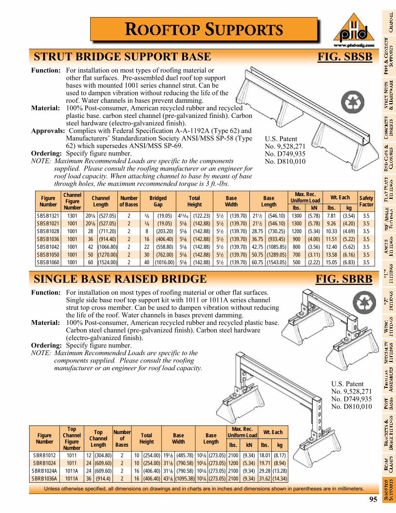
95
Unless otherwise specified, all dimensions on drawings and in charts are in inches and dimensions shown in parentheses are in millimeters.
www.phd-mfg.com
STRUT BRIDGE SUPPORT BASE FIG. SBSB Function: For installation on most types of roofing material or
other flat surfaces. Pre-assembled duel roof top support bases with mounted 1001 series channel strut. Can be used to dampen vibration without reducing the life of the roof. Water channels in bases prevent damming.
Material: 100% Post-consumer, American recycled rubber and recycled plastic base. carbon steel channel (pre-galvanized finish). Carbon steel hardware (electro-galvanized finish).
Approvals: Complies with Federal Specification A-A-1192A (Type 62) and Manufacturers’ Standardization Society ANSI/MSS SP-58 (Type 62) which supersedes ANSI/MSS SP-69.
Ordering: Specify figure number. NOTE: Maximum Recommended Loads are specific to the components
supplied. Please consult the roofing manufacturer or an engineer for roof load capacity. When attaching channel to base by means of base through holes, the maximum recommended torque is 3 ft.-lbs.
Figure Number
Channel Figure
Number
Channel Length
Number of Bases
Total Height
Base Width
Base Length
Max. Rec. Uniform Load
Wt. Each Safety Factor
Bridged Gap
lbs. kN lbs. kg
SBSB1321 1301 203/4 (527.05) 2 3/4 (19.05) 413/16 (122.23) 51/2 (139.70) 211/2 (546.10) 1300 (5.78) 7.81 (3.54) 3.5
SBSB1021 1001 203/4 (527.05) 2 3/4 (19.05) 55/8 (142.88) 51/2 (139.70) 211/2 (546.10) 1300 (5.78) 9.26 (4.20) 3.5
SBSB1028 1001 28 (711.20) 2 8 (203.20) 55/8 (142.88) 51/2 (139.70) 28.75 (730.25) 1200 (5.34) 10.33 (4.69) 3.5
SBSB1036 1001 36 (914.40) 2 16 (406.40) 55/8 (142.88) 51/2 (139.70) 36.75 (933.45) 900 (4.00) 11.51 (5.22) 3.5
SBSB1042 1001 42 (1066.80) 2 22 (558.80) 55/8 (142.88) 51/2 (139.70) 42.75 (1085.85) 800 (3.56) 12.40 (5.62) 3.5
SBSB1050 1001 50 (1270.00) 2 30 (762.00) 55/8 (142.88) 51/2 (139.70) 50.75 (1289.05) 700 (3.11) 13.58 (6.16) 3.5
SBSB1060 1001 60 (1524.00) 2 40 (1016.00) 55/8 (142.88) 51/2 (139.70) 60.75 (1543.05) 500 (2.22) 15.05 (6.83) 3.5
U.S. Patent No. 9,528,271 No. D749,935 No. D810,010
SINGLE BASE RAISED BRIDGE FIG. SBRB Function: For installation on most types of roofing material or other flat surfaces.
Single side base roof top support kit with 1011 or 1011A series channel strut top cross member. Can be used to dampen vibration without reducing the life of the roof. Water channels in bases prevent damming.
Material: 100% Post-consumer, American recycled rubber and recycled plastic base. Carbon steel channel (pre-galvanized finish). Carbon steel hardware (electro-galvanized finish).
Ordering: Specify figure number. NOTE: Maximum Recommended Loads are specific to the
components supplied. Please consult the roofing manufacturer or an engineer for roof load capacity.
Figure Number
Top Channel Figure
Number
Top Channel Length
Number of
Bases
Total Height
Base Width
Base Length
Max. Rec. Uniform Load
Wt. Each
lbs. kN lbs. kg
SBRB1012 1011 12 (304.80) 2 10 (254.00) 191/8 (485.78) 103/4 (273.05) 2100 (9.34) 18.01 (8.17)
SBRB1024 1011 24 (609.60) 2 10 (254.00) 311/8 (790.58) 103/4 (273.05) 1200 (5.34) 19.71 (8.94)
SBRB1024A 1011A 24 (609.60) 2 16 (406.40) 311/8 (790.58) 103/4 (273.05) 2100 (9.34) 29.28 (13.28)
SBRB1036A 1011A 36 (914.4) 2 16 (406.40) 431/8 (1095.38) 103/4 (273.05) 2100 (9.34) 31.62 (14.34)
U.S. Patent No. 9,528,271 No. D749,935 No. D810,010
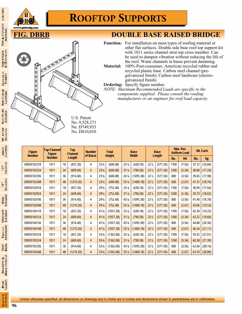
96
Unless otherwise specified, all dimensions on drawings and in charts are in inches and dimensions shown in parentheses are in millimeters.
www.phd-mfg.com
Function: For installation on most types of roofing material or other flat surfaces. Double side base roof top support kit with 1011 series channel strut top cross member. Can be used to dampen vibration without reducing the life of the roof. Water channels in bases prevent damming.
Material: 100% Post-consumer, American recycled rubber and recycled plastic base. Carbon steel channel (pre-galvanized finish). Carbon steel hardware (electro-galvanized finish).
Ordering: Specify figure number. NOTE: Maximum Recommended Loads are specific to the
components supplied. Please consult the roofing manufacturer or an engineer for roof load capacity.
FIG. DBRB DOUBLE BASE RAISED BRIDGE
U.S. Patent No. 9,528,271 No. D749,935 No. D810,010
Figure Number
Top Channel Figure
Number
Top Channel Length
Number of Bases
Total Height
Base Width
Base Length
Max. Rec. Uniform Load
Wt. Each
lbs. kN lbs. kg
DBRB102318 1011 18 (457.20) 4 235/8 (600.08) 251/8 (638.18) 221/2 (571.50) 1700 (7.56) 37.12 (16.84)
DBRB102324 1011 24 (609.60) 4 235/8 (600.08) 311/8 (790.58) 221/2 (571.50) 1200 (5.34) 38.00 (17.24)
DBRB102336 1011 36 (914.40) 4 235/8 (600.08) 431/8 (1095.38) 221/2 (571.50) 800 (3.56) 39.65 (17.98)
DBRB102348 1011 48 (1219.20) 4 235/8 (600.08) 551/8 (1400.18) 221/2 (571.50) 600 (2.67) 41.31 (18.74)
DBRB102918 1011 18 (457.20) 4 295/8 (752.48) 251/8 (638.18) 221/2 (571.50) 1700 (7.56) 38.90 (17.64)
DBRB102924 1011 24 (609.60) 4 295/8 (752.48) 311/8 (790.58) 221/2 (571.50) 1200 (5.34) 39.73 (18.02)
DBRB102936 1011 36 (914.40) 4 295/8 (752.48) 431/8 (1095.38) 221/2 (571.50) 800 (3.56) 41.40 (18.78)
DBRB102948 1011 48 (1219.20) 4 295/8 (752.48) 551/8 (1400.18) 221/2 (571.50) 600 (2.67) 43.06 (19.53)
DBRB104118 1011 18 (457.20) 4 415/8 (1057.28) 251/8 (638.18) 221/2 (571.50) 1700 (7.56) 42.39 (19.23)
DBRB104124 1011 24 (609.60) 4 415/8 (1057.28) 311/8 (790.58) 221/2 (571.50) 1200 (5.34) 43.22 (19.60)
DBRB104136 1011 36 (914.40) 4 415/8 (1057.28) 431/8 (1095.38) 221/2 (571.50) 800 (3.56) 44.88 (20.36)
DBRB104148 1011 48 (1219.20) 4 415/8 (1057.28) 551/8 (1400.18) 221/2 (571.50) 600 (2.67) 46.54 (21.11)
DBRB105318 1011 18 (457.20) 4 535/8 (1362.08) 251/8 (638.18) 221/2 (571.50) 1700 (7.56) 59.55 (27.01)
DBRB105324 1011 24 (609.60) 4 535/8 (1362.08) 311/8 (790.58) 221/2 (571.50) 1200 (5.34) 60.38 (27.39)
DBRB105336 1011 36 (914.40) 4 535/8 (1362.08) 431/8 (1095.38) 221/2 (571.50) 800 (3.56) 62.04 (28.14)
DBRB105348 1011 48 (1219.20) 4 535/8 (1362.08) 551/8 (1400.18) 221/2 (571.50) 600 (2.67) 63.70 (28.89)
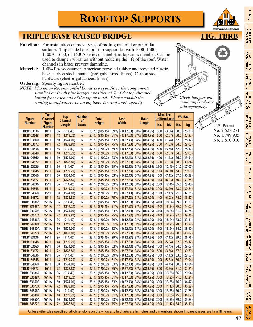
97
Unless otherwise specified, all dimensions on drawings and in charts are in inches and dimensions shown in parentheses are in millimeters.
www.phd-mfg.com
TRIPLE BASE RAISED BRIDGE FIG. TBRB Function: For installation on most types of roofing material or other flat
surfaces. Triple side base roof top support kit with 1000, 1500, 1500A, 1600, or 1600A series channel strut top cross member. Can be used to dampen vibration without reducing the life of the roof. Water channels in bases prevent damming.
Material: 100% Post-consumer, American recycled rubber and recycled plastic base. carbon steel channel (pre-galvanized finish). Carbon steel hardware (electro-galvanized finish).
Ordering: Specify figure number. NOTE: Maximum Recommended Loads are specific to the components
supplied and with pipe hangers positioned ¼ of the top channel length from each end of the top channel. Please consult the roofing manufacturer or an engineer for roof load capacity.
U.S. Patent No. 9,528,271 No. D749,935 No. D810,010
Figure Number
Top Channel Figure
Number
Top Channel Length
Number of
Bases
Total Height
Base Width
Base Length
Max. Rec. Uniform Load
Wt. Each
lbs. kN lbs. kg
TBRB103636 1011 36 (914.40) 6 351/4 (895.35) 397/8 (1012.83) 341/4 (869.95) 800 (3.56) 58.0 (26.31)
TBRB103648 1011 48 (1219.20) 6 351/4 (895.35) 517/8 (1317.63) 341/4 (869.95) 600 (2.67) 60.0 (27.22)
TBRB103660 1011 60 (1524.00) 6 351/4 (895.35) 637/8 (1622.43) 341/4 (869.95) 400 (1.78) 62.0 (28.12)
TBRB103672 1011 72 (1828.80) 6 351/4 (895.35) 757/8 (1927.23) 341/4 (869.95) 300 (1.33) 64.0 (29.03)
TBRB104836 1011 36 (914.40) 6 471/4 (1200.2) 397/8 (1012.83) 341/4 (869.95) 800 (3.56) 62.0 (28.12)
TBRB104848 1011 48 (1219.20) 6 471/4 (1200.2) 517/8 (1317.63) 341/4 (869.95) 600 (2.67) 64.0 (29.03)
TBRB104860 1011 60 (1524.00) 6 471/4 (1200.2) 637/8 (1622.43) 341/4 (869.95) 400 (1.78) 66.0 (29.94)
TBRB104872 1011 72 (1828.80) 6 471/4 (1200.2) 757/8 (1927.23) 341/4 (869.95) 300 (1.33) 68.0 (30.84)
TBRB153636 1511 36 (914.40) 6 351/4 (895.35) 397/8 (1012.83) 341/4 (869.95) 2800 (12.46) 61.0 (27.67)
TBRB153648 1511 48 (1219.20) 6 351/4 (895.35) 517/8 (1317.63) 341/4 (869.95) 2000 (8.90) 64.0 (29.03)
TBRB153660 1511 60 (1524.00) 6 351/4 (895.35) 637/8 (1622.43) 341/4 (869.95) 1600 (7.12) 67.0 (30.39)
TBRB153672 1511 72 (1828.80) 6 351/4 (895.35) 757/8 (1927.23) 341/4 (869.95) 1400 (6.23) 70.0 (31.75)
TBRB154836 1511 36 (914.40) 6 471/4 (1200.2) 397/8 (1012.83) 341/4 (869.95) 2800 (12.46) 65.0 (29.48)
TBRB154848 1511 48 (1219.20) 6 471/4 (1200.2) 517/8 (1317.63) 341/4 (869.95) 2000 (8.90) 68.0 (30.84)
TBRB154860 1511 60 (1524.00) 6 471/4 (1200.2) 637/8 (1622.43) 341/4 (869.95) 1600 (7.12) 71.0 (32.21)
TBRB154872 1511 72 (1828.80) 6 471/4 (1200.2) 757/8 (1927.23) 341/4 (869.95) 1400 (6.23) 74.0 (33.57)
TBRB153636A 1511A 36 (914.40) 6 351/4 (895.35) 397/8 (1012.83) 341/4 (869.95) 4100 (18.24) 69.0 (31.30)
TBRB153648A 1511A 48 (1219.20) 6 351/4 (895.35) 517/8 (1317.63) 341/4 (869.95) 4100 (18.24) 75.0 (34.02)
TBRB153660A 1511A 60 (1524.00) 6 351/4 (895.35) 637/8 (1622.43) 341/4 (869.95) 4100 (18.24) 81.0 (36.74)
TBRB153672A 1511A 72 (1828.80) 6 351/4 (895.35) 757/8 (1927.23) 341/4 (869.95) 4100 (18.24) 87.0 (39.46)
TBRB154836A 1511A 36 (914.40) 6 471/4 (1200.2) 397/8 (1012.83) 341/4 (869.95) 4100 (18.24) 73.0 (33.11)
TBRB154848A 1511A 48 (1219.20) 6 471/4 (1200.2) 517/8 (1317.63) 341/4 (869.95) 4100 (18.24) 78.0 (35.38)
TBRB154860A 1511A 60 (1524.00) 6 471/4 (1200.2) 637/8 (1622.43) 341/4 (869.95) 4100 (18.24) 84.0 (38.10)
TBRB154872A 1511A 72 (1828.80) 6 471/4 (1200.2) 757/8 (1927.23) 341/4 (869.95) 4100 (18.24) 90.0 (40.82)
TBRB163636 1611 36 (914.40) 6 351/4 (895.35) 397/8 (1012.83) 341/4 (869.95) 1600 (7.12) 59.0 (26.76)
TBRB163648 1611 48 (1219.20) 6 351/4 (895.35) 517/8 (1317.63) 341/4 (869.95) 1200 (5.34) 62.0 (28.12)
TBRB163660 1611 60 (1524.00) 6 351/4 (895.35) 637/8 (1622.43) 341/4 (869.95) 1000 (4.45) 64.0 (29.03)
TBRB163672 1611 72 (1828.80) 6 351/4 (895.35) 757/8 (1927.23) 341/4 (869.95) 800 (3.56) 67.0 (30.39)
TBRB164836 1611 36 (914.40) 6 471/4 (1200.2) 397/8 (1012.83) 341/4 (869.95) 1600 (7.12) 63.0 (28.58)
TBRB164848 1611 48 (1219.20) 6 471/4 (1200.2) 517/8 (1317.63) 341/4 (869.95) 1200 (5.34) 66.0 (29.94)
TBRB164860 1611 60 (1524.00) 6 471/4 (1200.2) 637/8 (1622.43) 341/4 (869.95) 1000 (4.45) 68.0 (30.84)
TBRB164872 1611 72 (1828.80) 6 471/4 (1200.2) 757/8 (1927.23) 341/4 (869.95) 800 (3.56) 71.0 (32.21)
TBRB163636A 1611A 36 (914.40) 6 351/4 (895.35) 397/8 (1012.83) 341/4 (869.95) 3000 (13.35) 66.0 (29.94)
TBRB163648A 1611A 48 (1219.20) 6 351/4 (895.35) 517/8 (1317.63) 341/4 (869.95) 3000 (13.35) 71.0 (32.21)
TBRB163660A 1611A 60 (1524.00) 6 351/4 (895.35) 637/8 (1622.43) 341/4 (869.95) 3000 (13.35) 76.0 (34.47)
TBRB163672A 1611A 72 (1828.80) 6 351/4 (895.35) 757/8 (1927.23) 341/4 (869.95) 2500 (11.12) 80.0 (36.29)
TBRB164836A 1611A 36 (914.40) 6 471/4 (1200.2) 397/8 (1012.83) 341/4 (869.95) 3000 (13.35) 70.0 (31.75)
TBRB164848A 1611A 48 (1219.20) 6 471/4 (1200.2) 517/8 (1317.63) 341/4 (869.95) 3000 (13.35) 75.0 (34.02)
TBRB164860A 1611A 60 (1524.00) 6 471/4 (1200.2) 637/8 (1622.43) 341/4 (869.95) 3000 (13.35) 79.0 (35.83)
TBRB164872A 1611A 72 (1828.80) 6 471/4 (1200.2) 757/8 (1927.23) 341/4 (869.95) 2500 (11.12) 84.0 (38.10)
Clevis hangers and mounting hardware sold separately.
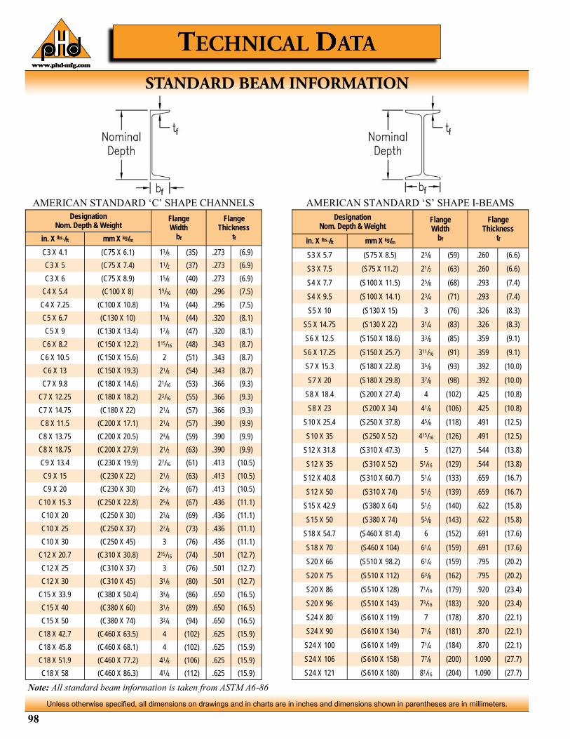
98
Unless otherwise specified, all dimensions on drawings and in charts are in inches and dimensions shown in parentheses are in millimeters.
www.phd-mfg.com
Designation Nom. Depth & Weight
Flange Width
bf
Flange Thickness
tf in. X lbs./ft mm X kg/m
C3 X 4.1 (C75 X 6.1) 13/8 (35) .273 (6.9)
C3 X 5 (C75 X 7.4) 11/2 (37) .273 (6.9)
C3 X 6 (C75 X 8.9) 15/8 (40) .273 (6.9)
C4 X 5.4 (C100 X 8) 19/16 (40) .296 (7.5)
C4 X 7.25 (C100 X 10.8) 13/4 (44) .296 (7.5)
C5 X 6.7 (C130 X 10) 13/4 (44) .320 (8.1)
C5 X 9 (C130 X 13.4) 17/8 (47) .320 (8.1)
C6 X 8.2 (C150 X 12.2) 115/16 (48) .343 (8.7)
C6 X 10.5 (C150 X 15.6) 2 (51) .343 (8.7)
C6 X 13 (C150 X 19.3) 21/8 (54) .343 (8.7)
C7 X 9.8 (C180 X 14.6) 21/16 (53) .366 (9.3)
C7 X 12.25 (C180 X 18.2) 23/16 (55) .366 (9.3)
C7 X 14.75 (C180 X 22) 21/4 (57) .366 (9.3)
C8 X 11.5 (C200 X 17.1) 21/4 (57) .390 (9.9)
C8 X 13.75 (C200 X 20.5) 23/8 (59) .390 (9.9)
C8 X 18.75 (C200 X 27.9) 21/2 (63) .390 (9.9)
C9 X 13.4 (C230 X 19.9) 27/16 (61) .413 (10.5)
C9 X 15 (C230 X 22) 21/2 (63) .413 (10.5)
C9 X 20 (C230 X 30) 25/8 (67) .413 (10.5)
C10 X 15.3 (C250 X 22.8) 25/8 (67) .436 (11.1)
C10 X 20 (C250 X 30) 23/4 (69) .436 (11.1)
C10 X 25 (C250 X 37) 27/8 (73) .436 (11.1)
C10 X 30 (C250 X 45) 3 (76) .436 (11.1)
C12 X 20.7 (C310 X 30.8) 215/16 (74) .501 (12.7)
C12 X 25 (C310 X 37) 3 (76) .501 (12.7)
C12 X 30 (C310 X 45) 31/8 (80) .501 (12.7)
C15 X 33.9 (C380 X 50.4) 33/8 (86) .650 (16.5)
C15 X 40 (C380 X 60) 31/2 (89) .650 (16.5)
C15 X 50 (C380 X 74) 33/4 (94) .650 (16.5)
C18 X 42.7 (C460 X 63.5) 4 (102) .625 (15.9)
C18 X 45.8 (C460 X 68.1) 4 (102) .625 (15.9)
C18 X 51.9 (C460 X 77.2) 41/8 (106) .625 (15.9)
C18 X 58 (C460 X 86.3) 41/4 (112) .625 (15.9)
Designation Nom. Depth & Weight
Flange Width
bf
Flange Thickness
tf in. X lbs./ft mm X kg/m
S3 X 5.7 (S75 X 8.5) 23/8 (59) .260 (6.6)
S3 X 7.5 (S75 X 11.2) 21/2 (63) .260 (6.6)
S4 X 7.7 (S100 X 11.5) 25/8 (68) .293 (7.4)
S4 X 9.5 (S100 X 14.1) 23/4 (71) .293 (7.4)
S5 X 10 (S130 X 15) 3 (76) .326 (8.3)
S5 X 14.75 (S130 X 22) 31/4 (83) .326 (8.3)
S6 X 12.5 (S150 X 18.6) 33/8 (85) .359 (9.1)
S6 X 17.25 (S150 X 25.7) 311/16 (91) .359 (9.1)
S7 X 15.3 (S180 X 22.8) 35/8 (93) .392 (10.0)
S7 X 20 (S180 X 29.8) 37/8 (98) .392 (10.0)
S8 X 18.4 (S200 X 27.4) 4 (102) .425 (10.8)
S8 X 23 (S200 X 34) 41/8 (106) .425 (10.8)
S10 X 25.4 (S250 X 37.8) 45/8 (118) .491 (12.5)
S10 X 35 (S250 X 52) 415/16 (126) .491 (12.5)
S12 X 31.8 (S310 X 47.3) 5 (127) .544 (13.8)
S12 X 35 (S310 X 52) 51/16 (129) .544 (13.8)
S12 X 40.8 (S310 X 60.7) 51/4 (133) .659 (16.7)
S12 X 50 (S310 X 74) 51/2 (139) .659 (16.7)
S15 X 42.9 (S380 X 64) 51/2 (140) .622 (15.8)
S15 X 50 (S380 X 74) 55/8 (143) .622 (15.8)
S18 X 54.7 (S460 X 81.4) 6 (152) .691 (17.6)
S18 X 70 (S460 X 104) 61/4 (159) .691 (17.6)
S20 X 66 (S510 X 98.2) 61/4 (159) .795 (20.2)
S20 X 75 (S510 X 112) 63/8 (162) .795 (20.2)
S20 X 86 (S510 X 128) 71/16 (179) .920 (23.4)
S20 X 96 (S510 X 143) 73/16 (183) .920 (23.4)
S24 X 80 (S610 X 119) 7 (178) .870 (22.1)
S24 X 90 (S610 X 134) 71/8 (181) .870 (22.1)
S24 X 100 (S610 X 149) 71/4 (184) .870 (22.1)
S24 X 106 (S610 X 158) 77/8 (200) 1.090 (27.7)
S24 X 121 (S610 X 180) 81/16 (204) 1.090 (27.7)
AMERICAN STANDARD ‘S’ SHAPE I-BEAMS AMERICAN STANDARD ‘C’ SHAPE CHANNELS
Note: All standard beam information is taken from ASTM A6-86
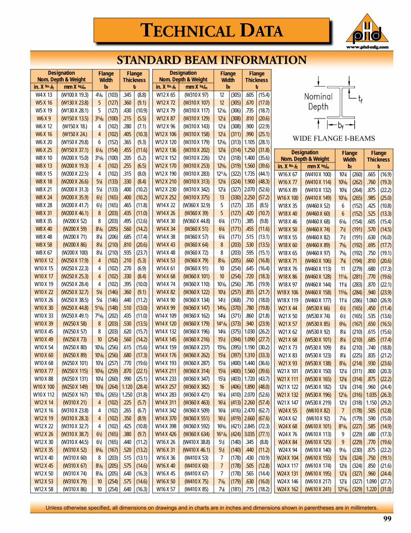
99
Unless otherwise specified, all dimensions on drawings and in charts are in inches and dimensions shown in parentheses are in millimeters.
www.phd-mfg.com
Designation Nom. Depth & Weight
Flange Width
bf
Flange Thickness
tf in. X lbs./ft mm X kg/m
W4 X 13 (W100 X 19.3) 41/16 (103) .345 (8.8)
W5 X 16 (W130 X 23.8) 5 (127) .360 (9.1)
W5 X 19 (W130 X 28.1) 5 (127) .430 (10.9)
W6 X 9 (W150 X 13.5) 315/16 (100) .215 (5.5)
W6 X 12 (W150 X 18.) 4 (102) .280 (7.1)
W6 X 16 (W150 X 24.) 4 (102) .405 (10.3)
W6 X 20 (W150 X 29.8) 6 (152) .365 (9.3)
W6 X 25 (W150 X 37.1) 61/16 (154) .455 (11.6)
W8 X 10 (W200 X 15.0) 315/16 (100) .205 (5.2)
W8 X 13 (W200 X 19.3) 4 (102) .255 (6.5)
W8 X 15 (W200 X 22.5) 4 (102) .315 (8.0)
W8 X 18 (W200 X 26.6) 51/4 (133) .330 (8.4)
W8 X 21 (W200 X 31.3) 51/4 (133) .400 (10.2)
W8 X 24 (W200 X 35.9) 61/2 (165) .400 (10.2)
W8 X 28 (W200 X 41.7) 61/2 (165) .465 (11.8)
W8 X 31 (W200 X 46.1) 8 (203) .435 (11.0)
W8 X 35 (W200 X 52) 8 (203) .495 (12.6)
W8 X 40 (W200 X 59) 81/16 (205) .560 (14.2)
W8 X 48 (W200 X 71) 81/8 (206) .685 (17.4)
W8 X 58 (W200 X 86) 81/4 (210) .810 (20.6)
W8 X 67 (W200 X 100) 81/4 (210) .935 (23.7)
W10 X 12 (W250 X 17.9) 4 (102) .210 (5.3)
W10 X 15 (W250 X 22.3) 4 (102) .270 (6.9)
W10 X 17 (W250 X 25.3) 4 (102) .330 (8.4)
W10 X 19 (W250 X 28.4) 4 (102) .395 (10.0)
W10 X 22 (W250 X 32.7) 53/4 (146) .360 (9.1)
W10 X 26 (W250 X 38.5) 53/4 (146) .440 (11.2)
W10 X 30 (W250 X 44.8) 513/16 (148) .510 (13.0)
W10 X 33 (W250 X 49.1) 715/16 (202) .435 (11.0)
W10 X 39 (W250 X 58) 8 (203) .530 (13.5)
W10 X 45 (W250 X 57) 8 (203) .620 (15.7)
W10 X 49 (W250 X 73) 10 (254) .560 (14.2)
W10 X 54 (W250 X 80) 101/16 (256) .615 (15.6)
W10 X 60 (W250 X 89) 101/16 (256) .680 (17.3)
W10 X 68 (W250 X 101) 101/8 (257) .770 (19.6)
W10 X 77 (W250 X 115) 103/16 (259) .870 (22.1)
W10 X 88 (W250 X 131) 101/4 (260) .990 (25.1)
W10 X 100 (W250 X 149) 103/8 (264) 1.120 (28.4)
W10 X 112 (W250 X 167) 107/16 (265) 1.250 (31.8)
W12 X 14 (W310 X 21) 4 (102) .225 (5.7)
W12 X 16 (W310 X 23.8) 4 (102) .265 (6.7)
W12 X 19 (W310 X 28.3) 4 (102) .350 (8.9)
W12 X 22 (W310 X 32.7) 4 (102) .425 (10.8)
W12 X 26 (W310 X 38.7) 61/2 (165) .380 (9.7)
W12 X 30 (W310 X 44.5) 61/2 (165) .440 (11.2)
W12 X 35 (W310 X 52) 69/16 (167) .520 (13.2)
W12 X 40 (W310 X 60) 8 (203) .515 (13.1)
W12 X 45 (W310 X 67) 81/16 (205) .575 (14.6)
W12 X 50 (W310 X 74) 81/16 (205) .640 (16.3)
W12 X 53 (W310 X 79) 10 (254) .575 (14.6)
W12 X 58 (W310 X 86) 10 (254) .640 (16.3)
Designation Nom. Depth & Weight
Flange Width
bf
Flange Thickness
tf in. X lbs./ft mm X kg/m
W12 X 65 (W310 X 97) 12 (305) .605 (15.4)
W12 X 72 (W310 X 107) 12 (305) .670 (17.0)
W12 X 79 (W310 X 117) 121/16 (306) .735 (18.7)
W12 X 87 (W310 X 129) 121/8 (308) .810 (20.6)
W12 X 96 (W310 X 143) 121/8 (308) .900 (22.9)
W12 X 106 (W310 X 158) 121/4 (311) .990 (25.1)
W12 X 120 (W310 X 179) 125/16 (313) 1.105 (28.1)
W12 X 136 (W310 X 202) 123/8 (314) 1.250 (31.8)
W12 X 152 (W310 X 226) 121/2 (318) 1.400 (35.6)
W12 X 170 (W310 X 253) 129/16 (319) 1.560 (39.6)
W12 X 190 (W310 X 283) 1211/16 (322) 1.735 (44.1)
W12 X 210 (W310 X 313) 123/4 (324) 1.900 (48.3)
W12 X 230 (W310 X 342) 127/8 (327) 2.070 (52.6)
W12 X 252 (W310 X 375) 13 (330) 2.250 (57.2)
W14 X 22 (W360 X 32.9) 5 (127) .335 (8.5)
W14 X 26 (W360 X 39) 5 (127) .420 (10.7)
W14 X 30 (W360 X 44.8) 63/4 (171) .385 (9.8)
W14 X 34 (W360 X 51) 63/4 (171) .455 (11.6)
W14 X 38 (W360 X 57) 63/4 (171) .515 (13.1)
W14 X 43 (W360 X 64) 8 (203) .530 (13.5)
W14 X 48 (W360 X 72) 8 (203) .595 (15.1)
W14 X 53 (W360 X 79) 81/16 (205) .660 (16.8)
W14 X 61 (W360 X 91) 10 (254) .645 (16.4)
W14 X 68 (W360 X 101) 10 (254) .720 (18.3)
W14 X 74 (W360 X 110) 101/16 (256) .785 (19.9)
W14 X 82 (W360 X 122) 101/8 (257) .855 (21.7)
W14 X 90 (W360 X 134) 141/2 (368) .710 (18.0)
W14 X 99 (W360 X 147) 149/16 (370) .780 (19.8)
W14 X 109 (W360 X 162) 145/8 (371) .860 (21.8)
W14 X 120 (W360 X 179) 1411/16 (373) .940 (23.9)
W14 X 132 (W360 X 196) 143/4 (375) 1.030 (26.2)
W14 X 145 (W360 X 216) 151/2 (394) 1.090 (27.7)
W14 X 159 (W360 X 237) 159/16 (395) 1.190 (30.2)
W14 X 176 (W360 X 262) 155/8 (397) 1.310 (33.3)
W14 X 193 (W360 X 287) 153/4 (400) 1.440 (36.6)
W14 X 211 (W360 X 314) 153/4 (400) 1.560 (39.6)
W14 X 233 (W360 X 347) 157/8 (403) 1.720 (43.7)
W14 X 257 (W360 X 382) 16 (406) 1.890 (48.0)
W14 X 283 (W360 X 421) 161/8 (410) 2.070 (52.6)
W14 X 311 (W360 X 463) 161/4 (413) 2.260 (57.4)
W14 X 342 (W360 X 509) 163/8 (416) 2.470 (62.7)
W14 X 370 (W360 X 551) 161/2 (419) 2.660 (67.6)
W14 X 398 (W360 X 592) 169/16 (421) 2.845 (72.3)
W14 X 426 (W360 X 634) 1611/16 (424) 3.035 (77.1)
W16 X 26 (W410 X 38.8) 51/2 (140) .345 (8.8)
W16 X 31 (W410 X 46.1) 51/2 (140) .440 (11.2)
W16 X 36 (W410 X 53) 7 (178) .430 (10.9)
W16 X 40 (W410 X 60) 7 (178) .505 (12.8)
W16 X 45 (W410 X 67) 7 (178) .565 (14.4)
W16 X 50 (W410 X 75) 71/16 (179) .630 (16.0)
W16 X 57 (W410 X 85) 71/8 (181) .715 (18.2)
Designation Nom. Depth & Weight
Flange Width
bf
Flange Thickness
tf in. X lbs./ft mm X kg/m
W16 X 67 (W410 X 100) 101/4 (260) .665 (16.9)
W16 X 77 (W410 X 114) 105/16 (262) .760 (19.3)
W16 X 89 (W410 X 132) 103/8 (264) .875 (22.2)
W16 X 100 (W410 X 149) 107/16 (265) .985 (25.0)
W18 X 35 (W460 X 52) 6 (152) .425 (10.8)
W18 X 40 (W460 X 60) 6 (152) .525 (13.3)
W18 X 46 (W460 X 68) 61/16 (154) .605 (15.4)
W18 X 50 (W460 X 74) 71/2 (191) .570 (14.5)
W18 X 55 (W460 X 82) 71/2 (191) .630 (16.0)
W18 X 60 (W460 X 89) 79/16 (192) .695 (17.7)
W18 X 65 (W460 X 97) 79/16 (192) .750 (19.1)
W18 X 71 (W460 X 106) 75/8 (194) .810 (20.6)
W18 X 76 (W460 X 113) 11 (279) .680 (17.3)
W18 X 86 (W460 X 128) 111/16 (281) .770 (19.6)
W18 X 97 (W460 X 144) 111/8 (283) .870 (22.1)
W18 X 106 (W460 X 158) 113/16 (284) .940 (23.9)
W18 X 119 (W460 X 177) 111/4 (286) 1.060 (26.9)
W21 X 44 (W530 X 66) 61/2 (165) .450 (11.4)
W21 X 50 (W530 X 74) 61/2 (165) .535 (13.6)
W21 X 57 (W530 X 85) 69/16 (167) .650 (16.5)
W21 X 62 (W530 X 92) 81/4 (210) .615 (15.6)
W21 X 68 (W530 X 101) 81/4 (210) .685 (17.4)
W21 X 73 (W530 X 109) 81/4 (210) .740 (18.8)
W21 X 83 (W530 X 123) 87/8 (225) .835 (21.2)
W21 X 93 (W530 X 138) 87/16 (214) .930 (23.6)
W21 X 101 (W530 X 150) 121/4 (311) .800 (20.3)
W21 X 111 (W530 X 165) 123/8 (314) .875 (22.2)
W21 X 122 (W530 X 182) 123/8 (314) .960 (24.4)
W21 X 132 (W530 X 196) 127/16 (316) 1.035 (26.3)
W21 X 147 (W530 X 219) 121/2 (318) 1.150 (29.2)
W24 X 55 (W610 X 82) 7 (178) .505 (12.8)
W24 X 62 (W610 X 92) 71/16 (179) .590 (15.0)
W24 X 68 (W610 X 101) 815/16 (227) .585 (14.9)
W24 X 76 (W610 X 113) 9 (229) .680 (17.3)
W24 X 84 (W610 X 125) 9 (229) .770 (19.6)
W24 X 94 (W610 X 140) 91/16 (230) .875 (22.2)
W24 X 104 (W610 X 155) 123/4 (324) .750 (19.1)
W24 X 117 (W610 X 174) 123/4 (324) .850 (21.6)
W24 X 131 (W610 X 195) 127/8 (327) .960 (24.4)
W24 X 146 (W610 X 217) 127/8 (327) 1.090 (27.7)
W24 X 162 (W610 X 241) 1215/16 (329) 1.220 (31.0)
WIDE FLANGE I-BEAMS

100
Unless otherwise specified, all dimensions on drawings and in charts are in inches and dimensions shown in parentheses are in millimeters.
www.phd-mfg.com
Note: Spacing and capacities are based on pipe filled with water. Additional valves and fittings increase the load and therefore closer hanger spacing is required. Taken from ANSI/MSS SP-58. *Many Codes and specifications require pipe hangers to be spaced every 10 ft (3.05m) regardless of size. Check local codes.
Nominal Pipe Size
1/2 3/4 1 11/4 11/2 2 21/2 3 31/2 4 5 6 8 10 12 14 16 18 20 24
(15) (20) (25) (32) (40) (50) (65) (80) (90) (100) (125) (150) (200) (250) (300) (350) (400) (450) (500) (600)
Max. Span 7 7 7 7 9 10 11 12 13 14 16 17 19 22 23 25 27 28 30 32
(2.13) (2.13) (2.13) (2.13) (2.74) (3.05) (3.35) (3.66) (3.96) (4.27) (4.88) (5.18) (5.79) (6.71) (7.01) (7.62) (8.23) (8.53) (9.14) (9.75)
Recommended Hanger Rod
Size
3/8 3/8 3/8 3/8 3/8 3/8 1/2 1/2 1/2 5/8 5/8 3/4 3/4 7/8 7/8 1 1 1 11/4 11/4
OR TRAPEZE
Pipe Size
Schedule No.
O.D. Wall
Thickness
Weight
Water Pipe lbs./ft kg/m lbs./ft kg/m
3/8 (10)
10
0.675 (17.15)
.066 (1.68) 0.100 (0.15) 0.4325 (0.64)
40 .091 (2.31) 0.083 (0.12) 0.567 (0.84)
80 .126 (3.20) 0.061 (0.09) 0.738 (1.10)
1/2 (15)
10
0.84 (21.34)
.083 (2.11) 0.155 (0.23) 0.671 (1.00)
40 .109 (2.77) 0.132 (0.20) 0.85 (1.26)
80 .147 (3.73) 0.102 (0.15) 1.087 (1.62)
3/4 (20)
10
1.05 (26.67)
.083 (2.11) 0.266 (0.40) 0.8572 (1.28)
40 .113 (2.87) 0.231 (0.34) 1.13 (1.68)
80 .154 (3.91) 0.187 (0.28) 1.473 (2.19)
1 (25)
10
1.315 (33.40)
.109 (2.77) 0.410 (0.61) 1.404 (2.09)
40 .133 (3.38) 0.375 (0.56) 1.678 (2.50)
80 .179 (4.55) 0.312 (0.46) 2.171 (3.23)
11/4 (32)
10
1.66 (42.16)
.109 (2.77) 0.708 (1.05) 1.806 (2.69)
40 .14 (3.56) 0.648 (0.96) 2.272 (3.38)
80 .191 (4.85) 0.556 (0.83) 2.996 (4.46)
11/2 (40)
10
1.9 (48.26)
.109 (2.77) 0.963 (1.43) 2.085 (3.10)
40 .145 (3.68) 0.883 (1.31) 2.717 (4.04)
80 .2 (5.08) 0.766 (1.14) 3.631 (5.40)
2 (50)
10
2.375 (60.33)
.109 (2.77) 1.584 (2.36) 2.638 (3.93)
40 .154 (3.91) 1.455 (2.16) 3.652 (5.43)
80 .218 (5.54) 1.280 (1.91) 5.022 (7.47)
21/2 (65)
10
2.875 (73.03)
.12 (3.05) 2.364 (3.52) 3.531 (5.25)
40 .203 (5.16) 2.076 (3.09) 5.79 (8.62)
80 .276 (7.01) 1.837 (2.73) 7.66 (11.40)
3 (80)
10
3.5 (88.90)
.12 (3.05) 3.619 (5.39) 4.332 (6.45)
40 .216 (5.49) 3.205 (4.77) 7.57 (11.27)
80 .3 (7.62) 2.864 (4.26) 10.25 (15.25)
31/2 (90)
10
4 (101.60)
.12 (3.05) 4.814 (7.16) 4.973 (7.40)
40 .226 (5.74) 4.286 (6.38) 9.11 (13.56)
80 .318 (8.08) 3.853 (5.73) 12.51 (18.62)
4 (100)
10
4.5 (114.30)
.12 (3.05) 6.179 (9.20) 5.613 (8.35)
40 .237 (6.02) 5.519 (8.21) 10.79 (16.06)
80 .337 (8.56) 4.984 (7.42) 14.98 (22.29)
Pipe Size
Schedule No.
O.D. Wall
Thickness
Weight
Water Pipe lbs./ft kg/m lbs./ft kg/m
5 (125)
10
5.563 (141.30)
0.134 (3.40) 9.55 (14.21) 7.77 (11.56)
40 0.258 (6.55) 8.67 (12.91) 14.62 (21.76)
80 0.375 (9.53) 7.89 (11.74) 20.78 (30.92)
6 (150)
10
6.625 (168.28)
0.134 (3.40) 13.76 (20.48) 9.289 (13.82)
40 0.28 (7.11) 12.52 (18.64) 18.97 (28.23)
80 0.432 (10.97) 11.30 (16.82) 28.57 (42.52)
8 (200)
10
8.625 (219.08)
0.148 (3.76) 23.62 (35.15) 13.4 (19.94)
40 0.322 (8.18) 21.69 (32.28) 28.55 (42.49)
80 0.5 (12.70) 19.80 (29.46) 43.39 (64.57)
10 (250)
10
10.75 (273.05)
0.165 (4.19) 36.97 (55.02) 18.7 (27.83)
40 0.365 (9.27) 34.19 (50.87) 40.48 (60.24)
80 0.593 (15.06) 31.14 (46.35) 64.4 (95.84)
12 (300)
10
12.75 (323.85)
0.18 (4.57) 52.27 (77.79) 24.2 (36.01)
40 0.406 (10.31) 48.53 (72.21) 53.6 (79.77)
80 0.687 (17.45) 44.06 (65.57) 88.6 (131.85)
14 (350)
10
14 (355.60)
0.25 (6.35) 62.05 (92.35) 36.71 (54.63)
40 0.437 (11.10) 58.66 (87.30) 63 (93.75)
80 0.75 (19.05) 53.20 (79.17) 107 (159.23)
16 (400)
10
16 (406.40)
0.25 (6.35) 81.80 (121.74) 42.05 (62.58)
40 0.5 (12.70) 76.61 (114.01) 83 (123.52)
80 0.843 (21.41) 69.76 (103.82) 137 (203.88)
18 (450)
10
18 (457.20)
0.25 (6.35) 104.27 (155.18) 47.39 (70.52)
40 0.563 (14.30) 96.95 (144.27) 105 (156.26)
80 0.937 (23.80) 88.54 (131.77) 171 (254.48)
20 (500)
10
20 (508.00)
0.25 (6.35) 129.47 (192.67) 62.73 (93.35)
40 0.593 (15.06) 120.52 (179.36) 123 (183.04)
80 1.031 (26.19) 109.56 (163.04) 209 (311.03)
24 (600)
10
24 (609.60)
0.25 (6.35) 188.04 (279.83) 63.41 (94.36)
40 0.687 (17.45) 174.31 (259.40) 171 (254.48)
80 1.218 (30.94) 158.33 (235.62) 297 (441.98)
30 (750) 20 30 (762.00) .5 (12.70) 286.00 (425.61) 158 (235.13)
36 (900) API 36 (914.40) .5 (12.70) 417.00 (620.56) 190 (282.75)
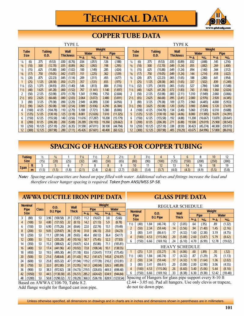
101
Unless otherwise specified, all dimensions on drawings and in charts are in inches and dimensions shown in parentheses are in millimeters.
www.phd-mfg.com
Tube Size
Tubing O.D.
Wall Thickness
Weight
Water Pipe lbs./ft kg/m lbs./ft kg/m
1/4 (6) .375 (9.53) .030 (0.76) .034 (.051) .126 (.188) 3/8 (10) .500 (12.70) .035 (0.89) .062 (.092) .198 (.295) 1/2 (15) .625 (15.88) .040 (1.02) .100 (.149) .285 (.424) 5/8 (17) .750 (19.05) .042 (1.07) .151 (.225) .362 (.539) 3/4 (20) .875 (22.23) .045 (1.14) .209 (.311) .455 (.677)
1 (25) 1.125 (28.58) .050 (1.27) .357 (.531) .655 (.975)
11/4 (32) 1.375 (34.93) .055 (1.40) .546 (.813) .884 (1.316)
11/2 (40) 1.625 (41.28) .060 (1.52) .767 (1.141) 1.140 (1.697)
2 (50) 2.125 (53.98) .070 (1.78) 1.341 (1.996) 1.750 (2.604)
21/2 (65) 2.625 (66.68) .080 (2.03) 2.064 (3.072) 2.480 (3.691)
3 (80) 3.125 (79.38) .090 (2.29) 2.949 (4.389) 3.330 (4.956)
31/2 (90) 3.625 (92.08) .100 (2.54) 3.989 (5.936) 4.290 (6.384)
4 (100) 4.125 (104.78) .110 (2.79) 5.188 (7.721) 5.380 (8.006)
5 (125) 5.125 (130.18) .125 (3.18) 8.081 (12.026) 7.610 (11.325)
6 (150) 6.125 (155.58) .140 (3.56) 11.616 (17.287) 10.200 (15.179)
8 (200) 8.125 (206.38) .200 (5.08) 20.289 (30.193) 19.260 (28.662)
10 (250) 10.125 (257.18) .250 (6.35) 31.590 (47.011) 30.100 (44.794) 12 (300) 12.125 (307.98) .280 (7.11) 45.426 (67.601) 40.400 (60.122)
Tube Size
Tubing O.D.
Wall Thickness
Weight
Water Pipe lbs./ft kg/m lbs./ft kg/m
1/4 (6) .375 (9.53) .035 (0.89) .032 (.048) .145 (.216) 3/8 (10) .500 (12.70) .049 (1.24) .055 (.082) .269 (.400) 1/2 (15) .625 (15.88) .049 (1.24) .094 (.140) .344 (.512) 5/8 (17) .750 (19.05) .049 (1.24) .144 (.214) .418 (.622) 3/4 (20) .875 (22.23) .065 (1.65) .188 (.280) .641 (.954)
1 (25) 1.125 (28.58) .065 (1.65) .337 (.502) .839 (1.249)
11/4 (32) 1.375 (34.93) .065 (1.65) .527 (.784) 1.040 (1.548)
11/2 (40) 1.625 (41.28) .072 (1.83) .743 (1.106) 1.360 (2.024)
2 (50) 2.125 (53.98) .083 (2.11) 1.310 (1.949) 2.060 (3.066)
21/2 (65) 2.625 (66.68) .095 (2.41) 2.000 (2.976) 2.920 (4.345)
3 (80) 3.125 (79.38) .109 (2.77) 2.960 (4.405) 4.000 (5.953)
31/2 (90) 3.625 (92.08) .120 (3.05) 3.900 (5.804) 5.120 (7.619)
4 (100) 4.125 (104.78) .134 (3.40) 5.060 (7.530) 6.510 (9.688)
5 (125) 5.125 (130.18) .160 (4.06) 8.000 (11.905) 9.670 (14.391)
6 (150) 6.125 (155.58) .192 (4.88) 11.200 (16.667) 13.870 (20.641)
8 (200) 8.125 (206.38) .271 (6.88) 19.500 (29.019) 25.900 (38.543)
10 (250) 10.125 (257.18) .338 (8.59) 30.423 (45.274) 40.300 (59.973) 12 (300) 12.125 (307.98) .405 (10.29) 43.675 (64.996) 57.800 (86.016)
TYPE L TYPE K
Note: Spacing and capacities are based on pipe filled with water. Additional valves and fittings increase the load and
therefore closer hanger spacing is required. Taken from ANSI/MSS SP-58.
Tubing Size
1/2 3/4 1 11/4 11/2 2 21/2 3 31/2 4 5 6 8 10 12
(15) (20) (25) (32) (40) (50) (65) (80) (90) (100) (125) (150) (200) (250) (300)
Span ft 5 5 6 7 8 8 9 10 11 12 13 14 16 18 19
m (1.5) (1.5) (1.8) (2.1) (2.4) (2.4) (2.7) (3.0) (3.4) (3.7) (4.0) (4.3) (4.9) (5.5) (5.8)
Based on AWWA C108-70, Table 8.2. Add flange weight for flanged cast iron pipe.
Spacing of Hangers for glass pipe support every 8-10 ft (2.44 - 3.05 m). Pad all hangers. Use only clevis or trapeze, do not tie down pipe.
Nominal Pipe Size
O.D. D.I. Pipe
Wall Thick
Weight
Pipe Water lbs./ft kg/m lbs./ft kg/m
11/2 (40) 1.84 (46.74) .12 (3.05) .64 (.95) .89 (1.32)
2 (50) 2.34 (59.44) .14 (3.56) .94 (1.40) 1.45 (2.16)
3 (80) 3.41 (86.61) .17 (4.32) 1.60 (2.38) 3.19 (4.75)
4 (100) 4.53 (115.06) .20 (5.08) 2.60 (3.87) 5.79 (8.62)
6 (150) 6.66 (169.16) .24 (6.10) 4.70 (6.99) 12.78 (19.02)
1 (25) 1.31 (33.27) .16 (4.06) .60 (.89) .35 (.52)
11/2 (40) 1.84 (46.74) .17 (4.32) .87 (1.29) .76 (1.13)
2 (50) 2.34 (59.44) .17 (4.32) 1.10 (1.64) 1.36 (2.02)
3 (80) 3.41 (86.61) .20 (5.08) 2.00 (2.98) 3.06 (4.55)
4 (100) 4.53 (115.06) .26 (6.60) 3.40 (5.06) 5.44 (8.10)
6 (150) 6.66 (169.16) .33 (8.38) 6.30 (9.38) 12.42 (18.48)
Nominal Pipe Size
Class O.D.
D.I. Pipe Wall Thick
Weight
Pipe Water lbs./ft kg/m lbs./ft kg/m
3 (80) 53 3.96 (100.58) .31 (7.87) 11.2 (16.67) 3.8 (5.66)
4 (100) 53 4.80 (121.92) .32 (8.13) 14.2 (21.13) 5.9 (8.78)
6 (150) 53 6.90 (175.26) .34 (8.64) 22.0 (32.74) 13.1 (19.49)
8 (200) 53 9.05 (229.87) .36 (9.14) 31.0 (46.13) 23.0 (34.23)
10 (250) 53 11.1 (281.94) .38 (9.65) 40.4 (60.12) 36.4 (54.17)
12 (300) 53 13.2 (335.28) .40 (10.16) 50.7 (75.45) 52.3 (77.83)
14 (350) 53 15.3 (388.62) .42 (10.67) 62.4 (92.86) 71.1 (105.81)
16 (400) 53 17.4 (441.96) .43 (10.92) 72.8 (108.34) 93.1 (138.55)
18 (450) 53 19.5 (495.30) .44 (11.18) 83.6 (124.41) 117.9 (175.45)
20 (500) 53 21.6 (548.64) .45 (11.43) 95.2 (141.67) 145.8 (216.97)
24 (600) 53 25.8 (655.32) .47 (11.94) 119.2 (177.39) 210.2 (312.81)
30 (750) 53 32.0 (812.80) .51 (12.95) 161.3 (240.04) 326.5 (485.89)
36 (900) 53 38.3 (972.82) .58 (14.73) 219.5 (326.65) 469.3 (698.40)
42 (1050) 53 44.5 (1130.30) .65 (16.51) 285.2 (424.42) 634.9 (944.84)
48 (1200) 53 50.8 (1290.32) .72 (18.29) 360.3 (536.19) 828.9 (1233.54)
REGULAR SCHEDULE
HEAVY SCHEDULE

102
Unless otherwise specified, all dimensions on drawings and in charts are in inches and dimensions shown in parentheses are in millimeters.
www.phd-mfg.com
Pipe Size
Sch. No.
O.D. Wall
Thickness
Weight
Water Pipe lbs./ft kg/m lbs./ft kg/m
1/8 (3) 40
.405 (10.3) .068 (1.73) .025 (.037) .043 (.064)
80 .095 (2.41) .016 (.024) .055 (.082)
1/4 (6) 40
.540 (13.7) .088 (2.24) .045 (.067) .074 (.110)
80 .119 (3.02) .031 (.046) .094 (.140)
3/8 (10) 40
.675 (17.15) .091 (2.31) .083 (.124) .100 (.149)
80 .126 (3.20) .061 (.091) .129 (.192)
1/2 (15) 40
.840 (21.34) .109 (2.77) .132 (.196) .150 (.223)
80 .147 (3.73) .101 (.150) .200 (.298)
3/4 (20) 40
1.050 (26.67) .113 (2.87) .230 (.342) .199 (.296)
80 .154 (3.91) .186 (.277) .259 (.385)
1 (25) 40
1.315 (33.40) .133 (3.38) .374 (.557) .295 (.439)
80 .179 (4.55) .311 (.463) .382 (.568)
11/4 (32) 40
1.660 (42.16) .140 (3.56) .647 (.963) .400 (.595)
80 .191 (4.85) .555 (.826) .527 (.784)
11/2 (40) 40
1.900 (48.26) .145 (3.68) .882 (1.313) .479 (.713)
80 .200 (5.08) .765 (1.138) .639 (.951)
2 (50) 40
2.375 (60.33) .154 (3.91) 1.452 (2.161) .643 (.957)
80 .218 (5.54) 1.279 (1.903) .884 (1.316)
Pipe Size
Sch. No.
O.D. Wall
Thickness
Weight
Water Pipe lbs./ft kg/m lbs./ft kg/m
21/2 (65) 40
2.875 (73.03) .203 (5.16) 2.072 (3.08) 1.020 (1.518)
80 .276 (7.01) 1.834 (2.73) 1.350 (2.009)
3 (80) 40
3.500 (88.9) .216 (5.49) 3.20 (4.76) 1.333 (1.984)
80 .300 (7.62) 2.86 (4.26) 1.804 (2.685)
31/2 (90) 40
4.000 (101.6) .226 (5.74) 4.28 (6.37) 1.598 (2.378)
80 .318 (8.08) 3.85 (5.73) 2.195 (3.267)
4 (100) 40
4.500 (114.3) .237 (6.02) 5.51 (8.20) 1.899 (2.826)
80 .337 (8.56) 4.98 (7.41) 2.636 (3.923)
5 (125) 40
5.563 (141.30) .258 (6.55) 8.66 (12.89) 2.770 (4.122)
80 .375 (9.53) 7.87 (11.71) 4.126 (6.140)
6 (150) 40
6.625 (168.28) .280 (7.11) 12.51 (18.62) 3.339 (4.969)
80 .432 (10.97) 11.92 (17.74) 5.028 (7.482)
8 (200) 40
8.625 (219.08) .322 (8.18) 21.60 (32.14) 5.280 (7.858)
80 .500 (12.70) 19.80 (29.47) 8.023 (11.940)
10 (250) 40
10.75 (273.05) .365 (9.27) 34.10 (50.75) 7.505 (11.169)
80 .593 (15.06) 31.10 (46.28) 11.894 (17.700)
12 (300) 40
12.75 (323.85) .406 (10.31) 48.50 (72.18) 10.023 (14.916)
80 .687 (17.45) 44.00 (65.48) 16.365 (24.354)
Schedule 40
Pipe Size
Support Spacing
Temperature
20°F (-6.6°C) 40°F (4.4°C) 60°F (15.6°C) 80°F (26.7°C) 100°F (37.8°C) 110°F (43.3°C) 120°F (48.9°C) 130°F (54.4°C) 140°F (60°C) 150°F (65.6°C)
ft m ft m ft m ft m ft m ft m ft m ft m ft m ft m 1/2 - 3/4 (15-20) 5.00 (1.52) 4.75 (1.45) 4.50 (1.37) 4.25 (1.30) 4.00 (1.22) 3.75 (1.14) 3.33 (1.01) 3.00 (.91) 2.66 (.81) 2.00 (.61)
1 - 11/4 (25-32) 5.50 (1.68) 5.25 (1.60) 5.00 (1.52) 4.66 (1.42) 4.33 (1.32) 4.00 (1.22) 3.75 (1.14) 3.33 (1.01) 2.80 (.85) 2.25 (.69)
11/2 - 2 (40-50) 5.80 (1.77) 5.50 (1.68) 5.25 (1.60) 5.00 (1.52) 4.66 (1.42) 4.33 (1.32) 3.80 (1.16) 3.50 (1.07) 3.00 (.91) 2.50 (.76)
21/2 (65) 6.66 (2.03) 6.33 (1.93) 6.00 (1.83) 5.50 (1.68) 5.25 (1.60) 4.80 (1.46) 4.50 (1.37) 4.00 (1.22) 3.50 (1.07) 2.80 (.85)
3 (80) 6.80 (2.07) 6.50 (1.98) 6.25 (1.91) 5.80 (1.77) 5.50 (1.68) 5.25 (1.60) 4.75 (1.45) 4.25 (1.30) 3.66 (1.12) 3.00 (.91)
4 (100) 7.33 (2.23) 7.00 (2.13) 6.50 (1.98) 6.25 (1.91) 5.80 (1.77) 5.50 (1.68) 5.00 (1.52) 4.50 (1.37) 3.80 (1.16) 3.25 (.99)
6 (150) 7.80 (2.38) 7.50 (2.29) 7.00 (2.13) 6.80 (2.07) 6.33 (1.93) 5.80 (1.77) 5.33 (1.62) 4.80 (1.46) 4.25 (1.30) 3.50 (1.07)
Schedule 80
Pipe Size
Support Spacing
Temperature
20°F (-6.6°C) 40°F (4.4°C) 60°F (15.6°C) 80°F (26.7°C) 100°F (37.8°C) 110°F (43.3°C) 120°F (48.9°C) 130°F (54.4°C) 140°F (60°C) 150°F (65.6°C)
ft m ft m ft m ft m ft m ft m ft m ft m ft m ft m 1/2 - 3/4 (15-20) 5.75 (1.75) 5.50 (1.68) 5.25 (1.60) 4.80 (1.46) 4.50 (1.37) 4.33 (1.32) 3.80 (1.16) 3.50 (1.07) 3.00 (.91) 2.50 (.76)
1 (25) 6.33 (1.93) 6.00 (1.83) 5.75 (1.75) 5.33 (1.62) 5.00 (1.52) 4.60 (1.40) 4.33 (1.32) 3.80 (1.16) 3.33 (1.01) 2.75 (.84)
11/4 -11/2 (32-40) 6.66 (2.03) 6.33 (1.93) 6.00 (1.83) 5.66 (1.73) 5.25 (1.60) 4.80 (1.46) 4.50 (1.37) 4.00 (1.22) 3.50 (1.07) 3.00 (.91)
2 (50) 7.00 (2.13) 6.50 (1.98) 6.25 (1.91) 6.00 (1.83) 5.50 (1.68) 5.12 (1.56) 4.75 (1.45) 4.33 (1.32) 3.66 (1.12) 3.12 (.95)
21/2 (65) 7.80 (2.38) 7.50 (2.29) 7.00 (2.13) 6.66 (2.03) 6.33 (1.93) 5.80 (1.77) 5.33 (1.62) 4.75 (1.45) 4.25 (1.30) 3.33 (1.01)
3 (80) 8.20 (2.50) 7.75 (2.36) 7.33 (2.23) 7.00 (2.13) 6.50 (1.98) 6.00 (1.83) 5.50 (1.68) 5.00 (1.52) 4.33 (1.32) 3.50 (1.07)
4 (100) 8.66 (2.64) 8.25 (2.51) 7.80 (2.38) 7.33 (2.23) 6.80 (2.07) 6.33 (1.93) 5.80 (1.77) 5.25 (1.60) 4.66 (1.42) 3.75 (1.14)
6 (150) 9.80 (2.99) 9.33 (2.84) 8.80 (2.68) 8.33 (2.54) 7.80 (2.38) 7.33 (2.23) 6.50 (1.98) 6.00 (1.83) 5.12 (1.56) 4.25 (1.30)
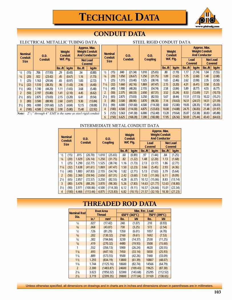
103
Unless otherwise specified, all dimensions on drawings and in charts are in inches and dimensions shown in parentheses are in millimeters.
www.phd-mfg.com
ELECTRICAL METALLIC TUBING DATA STEEL RIGID CONDUIT DATA
INTERMEDIATE METAL CONDUIT DATA
Nominal Conduit
Size
O.D. Conduit
O.D. Coupling
Weight Conduit W/C Plg.
Approx. Max. Weight Conduit And Conductor
Lead Covered
Not Lead Covered
lbs./ft kg/m lbs./ft kg/m lbs./ft kg/m 1/2 (15) .840 (21.34) 1.010 (25.65) .80 (1.19) 1.17 (1.74) 1.04 (1.55) 3/4 (20) 1.050 (26.67) 1.250 (31.75) 1.09 (1.62) 1.75 (2.60) 1.40 (2.08)
1 (25) 1.315 (33.40) 1.525 (38.74) 1.65 (2.46) 2.62 (3.90) 2.35 (3.50)
11/4 (32) 1.660 (42.16) 1.869 (47.47) 2.15 (3.20) 4.31 (6.41) 3.58 (5.33)
11/2 (40) 1.900 (48.26) 2.155 (54.74) 2.58 (3.84) 5.89 (8.77) 4.55 (6.77)
2 (50) 2.375 (60.33) 2.650 (67.31) 3.52 (5.24) 8.53 (12.69) 7.21 (10.73)
21/2 (65) 2.875 (73.03) 3.250 (82.55) 5.67 (8.44) 11.51 (17.13) 10.22 (15.21)
3 (80) 3.500 (88.90) 3.870 (98.30) 7.14 (10.63) 16.51 (24.57) 14.51 (21.59)
31/2 (90) 4.000 (101.60) 4.500 (114.30) 8.60 (12.80) 19.05 (28.35) 17.49 (26.03)
4 (100) 4.500 (114.30) 4.875 (123.83) 10.00 (14.88) 24.75 (36.83) 21.48 (31.97)
5 (125) 5.563 (141.30) 6.000 (152.40) 13.20 (19.64) 35.87 (53.38) 30.83 (45.88)
6 (150) 6.625 (168.28) 7.200 (182.88) 17.85 (26.56) 50.69 (75.44) 43.43 (64.63)
Nominal Conduit
Size
O.D. Conduit
Weight Conduit W/C Plg.
Approx. Max. Weight Conduit And Conductor
Not Lead Covered
lbs./ft kg/m lbs./ft kg/m 1/2 (15) .706 (17.93) .29 (0.43) .54 (0.80) 3/4 (20) .922 (23.42) .45 (0.67) 1.16 (1.73)
1 (25) 1.163 (29.54) .65 (0.97) 1.83 (2.72)
11/4 (32) 1.510 (38.35) .96 (1.43) 2.96 (4.40)
11/2 (40) 1.740 (44.20) 1.11 (1.65) 3.68 (5.48)
2 (50) 2.197 (55.80) 1.41 (2.10) 4.45 (6.62)
21/2 (65) 2.875 (73.03) 2.15 (3.20) 6.41 (9.54)
3 (80) 3.500 (88.90) 2.60 (3.87) 9.30 (13.84)
31/2 (90) 4.000 (101.60) 3.25 (4.84) 12.15 (18.08)
4 (100) 4.500 (114.30) 3.90 (5.80) 15.40 (22.92)
Note: 21/2” through 4” EMT is the same as steel rigid conduit
Nominal Conduit
Size
O.D. Conduit
O.D. Coupling
Weight Conduit W/C Plg.
Approx. Max. Weight Conduit And Conductor
Lead Covered
Not Lead Covered
lbs./ft kg/m lbs./ft kg/m lbs./ft kg/m 1/2 (15) .815 (20.70) 1.010 (25.65) .60 (0.89) .97 (1.44) .84 (1.25) 3/4 (20) 1.029 (26.14) 1.250 (31.75) .82 (1.22) 1.48 (2.20) 1.13 (1.68)
1 (25) 1.290 (32.77) 1.525 (38.74) 1.16 (1.73) 2.13 (3.17) 1.86 (2.77)
11/4 (32) 1.638 (41.61) 1.869 (47.47) 1.50 (2.23) 3.66 (5.45) 2.93 (4.36)
11/2 (40) 1.883 (47.83) 2.155 (54.74) 1.82 (2.71) 5.13 (7.63) 3.79 (5.64)
2 (50) 2.360 (59.94) 2.650 (67.31) 2.42 (3.60) 7.43 (11.06) 6.11 (9.09)
21/2 (65) 2.857 (72.57) 3.250 (82.55) 4.28 (6.37) 10.12 (15.06) 8.83 (13.14)
3 (80) 3.476 (88.29) 3.870 (98.30) 5.26 (7.83) 14.63 (21.77) 12.63 (18.80)
31/2 (90) 3.971 (100.86) 4.500 (114.30) 6.12 (9.11) 16.57 (24.66) 15.01 (22.34)
4 (100) 4.466 (113.44) 4.875 (123.83) 6.82 (10.15) 21.57 (32.10) 18.30 (27.23)
Nominal Rod Dia.
Root Area Thread
Max. Rec. Load
650°F (343°C) 750°F (399°C)
in.2 mm2 lbs. kN lbs. kN 1/4 .027 (17.42) 240 (1.07) 210 (0.93) 3/8 .068 (43.87) 730 (3.25) 572 (2.54) 1/2 .126 (81.29) 1350 (6.01) 1057 (4.70) 5/8 .202 (130.32) 2160 (9.61) 1692 (7.53) 3/4 .302 (194.84) 3230 (14.37) 2530 (11.25) 7/8 .419 (270.32) 4480 (19.93) 3508 (15.60)
1 .552 (356.13) 5900 (26.24) 4620 (20.55)
11/8 .693 (447.10) 7450 (33.14) 5830 (25.93)
11/4 .889 (573.55) 9500 (42.26) 7440 (33.09)
11/2 1.293 (834.19) 13800 (61.39) 10807 (48.07)
13/4 1.744 (1125.16) 18600 (82.74) 14566 (64.79)
2 2.300 (1483.87) 24600 (109.43) 19625 (87.30)
21/4 3.023 (1950.32) 32300 (143.68) 25295 (112.52)
21/2 3.719 (2399.35) 39800 (177.04) 31169 (138.65)
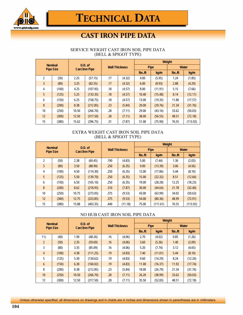
104
Unless otherwise specified, all dimensions on drawings and in charts are in inches and dimensions shown in parentheses are in millimeters.
www.phd-mfg.com
SERVICE WEIGHT CAST IRON SOIL PIPE DATA (BELL & SPIGOT TYPE)
Nominal Pipe Size
O.D. of Cast Iron Pipe
Wall Thickness
Weight
Pipe Water
lbs./ft kg/m lbs./ft kg/m
2 (50) 2.25 (57.15) .17 (4.32) 4.00 (5.95) 1.24 (1.85)
3 (80) 3.25 (82.55) .17 (4.32) 6.00 (8.93) 2.88 (4.29)
4 (100) 4.25 (107.95) .18 (4.57) 8.00 (11.91) 5.15 (7.66)
5 (125) 5.25 (133.35) .18 (4.57) 10.40 (15.48) 8.14 (12.11)
6 (150) 6.25 (158.75) .18 (4.57) 13.00 (19.35) 11.80 (17.57)
8 (200) 8.38 (212.85) .23 (5.84) 20.00 (29.76) 21.34 (31.76)
10 (250) 10.50 (266.70) .28 (7.11) 29.00 (43.16) 33.62 (50.03)
12 (300) 12.50 (317.50) .28 (7.11) 38.00 (56.55) 48.51 (72.18)
15 (380) 15.62 (396.75) .31 (7.87) 51.00 (75.90) 76.55 (113.92)
Nominal Pipe Size
O.D. of Cast Iron Pipe
Wall Thickness
Weight
Pipe Water
lbs./ft kg/m lbs./ft kg/m
2 (50) 2.38 (60.45) .190 (4.83) 5.00 (7.44) 1.36 (2.03)
3 (80) 3.50 (88.90) .250 (6.35) 9.00 (13.39) 3.06 (4.56)
4 (100) 4.50 (114.30) .250 (6.35) 12.00 (17.86) 5.44 (8.10)
5 (125) 5.50 (139.70) .250 (6.35) 15.00 (22.32) 8.51 (12.66)
6 (150) 6.50 (165.10) .250 (6.35) 19.00 (28.28) 12.25 (18.23)
8 (200) 8.62 (218.95) .310 (7.87) 30.00 (44.64) 21.78 (32.40)
10 (250) 10.75 (273.05) .375 (9.53) 43.00 (63.99) 34.02 (50.63)
12 (300) 12.75 (323.85) .375 (9.53) 54.00 (80.36) 48.99 (72.91)
15 (380) 15.88 (403.35) .440 (11.18) 75.00 (111.61) 76.55 (113.92)
Nominal Pipe Size
O.D. of Cast Iron Pipe
Wall Thickness
Weight
Pipe Water
lbs./ft kg/m lbs./ft kg/m
11/2 (40) 1.90 (48.26) .16 (4.06) 2.70 (4.02) 0.85 (1.26)
2 (50) 2.35 (59.69) .16 (4.06) 3.60 (5.36) 1.40 (2.09)
3 (80) 3.35 (85.09) .16 (4.06) 5.20 (7.74) 3.12 (4.65)
4 (100) 4.38 (111.25) .19 (4.83) 7.40 (11.01) 5.44 (8.10)
5 (125) 5.30 (134.62) .19 (4.83) 9.60 (14.29) 8.24 (12.26)
6 (150) 6.30 (160.02) .19 (4.83) 11.00 (16.37) 11.92 (17.74)
8 (200) 8.38 (212.85) .23 (5.84) 18.00 (26.79) 21.34 (31.76)
10 (250) 10.50 (266.70) .28 (7.11) 26.20 (38.99) 33.62 (50.03)
12 (300) 12.50 (317.50) .28 (7.11) 35.50 (52.83) 48.51 (72.18)
EXTRA WEIGHT CAST IRON SOIL PIPE DATA (BELL & SPIGOT TYPE)
NO HUB CAST IRON SOIL PIPE DATA
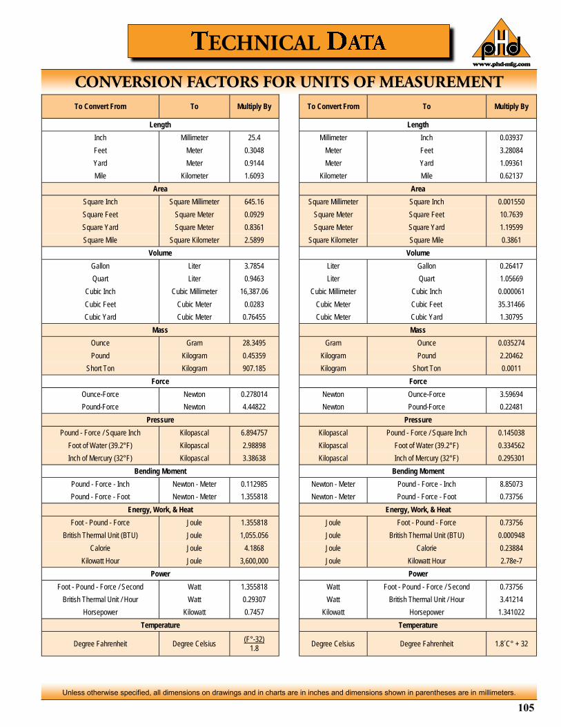
105
Unless otherwise specified, all dimensions on drawings and in charts are in inches and dimensions shown in parentheses are in millimeters.
www.phd-mfg.com
To Convert From To Multiply By
Length
Inch Millimeter 25.4
Feet Meter 0.3048
Yard Meter 0.9144
Mile Kilometer 1.6093
Area
Square Inch Square Millimeter 645.16
Square Feet Square Meter 0.0929
Square Yard Square Meter 0.8361
Square Mile Square Kilometer 2.5899
Volume
Gallon Liter 3.7854
Quart Liter 0.9463
Cubic Inch Cubic Millimeter 16,387.06
Cubic Feet Cubic Meter 0.0283
Cubic Yard Cubic Meter 0.76455
Mass
Ounce Gram 28.3495
Pound Kilogram 0.45359
Short Ton Kilogram 907.185
Force
Ounce-Force Newton 0.278014
Pound-Force Newton 4.44822
Pressure
Pound - Force / Square Inch Kilopascal 6.894757
Foot of Water (39.2°F) Kilopascal 2.98898
Inch of Mercury (32°F) Kilopascal 3.38638
Bending Moment
Pound - Force - Inch Newton - Meter 0.112985
Pound - Force - Foot Newton - Meter 1.355818
Energy, Work, & Heat
Foot - Pound - Force Joule 1.355818
British Thermal Unit (BTU) Joule 1,055.056
Calorie Joule 4.1868
Kilowatt Hour Joule 3,600,000
Power
Foot - Pound - Force / Second Watt 1.355818
British Thermal Unit / Hour Watt 0.29307
Horsepower Kilowatt 0.7457
Temperature
Degree Fahrenheit Degree Celsius (F°-32)
1.8
To Convert From To Multiply By
Length
Millimeter Inch 0.03937
Meter Feet 3.28084
Meter Yard 1.09361
Kilometer Mile 0.62137
Area
Square Millimeter Square Inch 0.001550
Square Meter Square Feet 10.7639
Square Meter Square Yard 1.19599
Square Kilometer Square Mile 0.3861
Volume
Liter Gallon 0.26417
Liter Quart 1.05669
Cubic Millimeter Cubic Inch 0.000061
Cubic Meter Cubic Feet 35.31466
Cubic Meter Cubic Yard 1.30795
Mass
Gram Ounce 0.035274
Kilogram Pound 2.20462
Kilogram Short Ton 0.0011
Force
Newton Ounce-Force 3.59694
Newton Pound-Force 0.22481
Pressure
Kilopascal Pound - Force / Square Inch 0.145038
Kilopascal Foot of Water (39.2°F) 0.334562
Kilopascal Inch of Mercury (32°F) 0.295301
Bending Moment
Newton - Meter Pound - Force - Inch 8.85073
Newton - Meter Pound - Force - Foot 0.73756
Energy, Work, & Heat
Joule Foot - Pound - Force 0.73756
Joule British Thermal Unit (BTU) 0.000948
Joule Calorie 0.23884
Joule Kilowatt Hour 2.78e-7
Power
Watt Foot - Pound - Force / Second 0.73756
Watt British Thermal Unit / Hour 3.41214
Kilowatt Horsepower 1.341022
Temperature
Degree Celsius Degree Fahrenheit 1.8´C° + 32

www.phd-mfg.com
106
PHD Manufacturing Inc. reserves the right to make changes to the specifications, materials, equipment, prices, or the availability of products at any time without prior notice. While every effort has been made to assure the accuracy of information contained in this catalog at the time of publication, we cannot accept responsibility for inaccuracies resulting from undetected errors or omissions.
Figure Number
Page Number
1001 - 1042 30-31
1101 - 1142 32-33
1201 - 1242 34-35
1301 - 1342 36-37
1401 - 1442 38-39
1501 - 1542 40-41
1601 - 1642 42-43
1701 - 1742 44-45
1801 - 1842 46-47
1950 - 1960 48-49
2001 - 2016 50
2101 - 2107 50
2201 - 2207 50
2301 - 2314 51
2401 - 2496 51-52
2501 - 2588 53
2600 52
2701 - 2712 54
2801 - 2808 54
3001 - 3011 57
3101 - 3111 57
3201 - 3210 57
3301 - 3311 57
3351 - 3353 57
3404 - 3408 57
3504 - 3508 57
4001 - 4002 60
4101 - 4102 61
4201 - 4202 62
4301 - 4302 63
4405 - 4420 64
4440 - 4470 64
4475 - 4489 64
4500 - 4506 64
5000 - 5004 65
5005 - 5009 65
5010 65
5011 65
5012 65
5013 65
5014 65
5015 65
5017 65
5019 66
5020 66
5023 66
5025 66
5030 66
5035 66
Figure Number
Page Number
5040 66
5045 66
5050 66
5060 67
5065 67
5075 67
5080 67
5085 67
5090 67
5095 67
5101 - 5107 68
5110 68
5112 68
5115 - 5118 68
5119 68
5120 68
5121 68
5122 68
5123 68
5130 69
5131 69
5135 69
5140 & 5145 69
5141 & 5146 69
5148 69
5150 69
5155 & 5156 69
5160 69
5165 70
5166 70
5170 & 5175 70
5171 & 5176 70
5180 70
5185 70
5186 70
5190 70
5200 70
5205 70
5210 & 5211 71
5220 71
5221 71
5225 & 5226 71
5228 71
5230 71
5250 71
5255 71
5260 71
5270 71
5301 - 5315 72
Figure Number
Page Number
5340 - 5350 72
5360 - 5366 72
5370 - 5376 72
5380 72
5381 & 5382 72
5383 73
5384 73
5385 73
5386 73
5390 73
5395 73
5410 - 5412 86
5420 - 5427 86
5430 - 5440 86
5501 74
5503 74
5505 74
5507 74
5509 74
5511 74
5513 74
5521 74
5530 - 5532 74
5541 74
5542 74
5543 74
5550 77
5551 77
5552 77
5553 77
5554 77
5556 77
5558 77
5560 - 5562 77
5565 78
5570 - 5574 78
5575 78
5580 - 5583 78
5590 78
5600 & 5601 79
5605 & 5606 79
5610 & 5611 79
5615 & 5616 79
5620 79
5625 79
5630 79
5635 80
5640 80
5645 80
Figure Number
Page Number
5650 80
5655 80
5660 80
5665 80
5675 80
5685 80
5700 - 5704 75
5705 75
5710 75
5715 75
5720 75
5730 - 5732 75
5750 - 5764 75
5770 76
5775 76
5780 76
5801 - 5804 81
5821 81
5825 - 5827 81
5830 - 5834 81
5835 - 5837 82
5840 83
5845 83
5860 & 5861 82
5870 83
5875 83
6005 84
6010 84
6015 84
6020 84
6025 84
6029 84
6030 84
6035 85
6040 85
6045 85
6050 85
6060 85
6065 85
6080 85
6095 85
6101 - 6122 86
6123 - 6125 87
6130 - 6135 87
6140 - 6144 87
6150 - 6152 88
6160 - 6172 88
6202 - 6208 88
6212 - 6218 88
Figure Number
Page Number
6222 & 6224 88
6232 & 6234 89
6246 & 6248 89
6305 89
6310 89
7001 & 7002 90
7005 - 7007 90
7011 - 7020 90
7025 90
7030 90
7040 90
7050 & 7051 91
7060 91
7070 - 7076 91
7080 - 7089 91
7090 - 7099 91
7231 - 7238 55
7251 - 7265 55
7370 55
7400 55
7501 - 7506 55
7530 55
7560 55
7581 - 7585 56
7600 59
7605 59
7610 & 7611 59
7615 & 7616 59
7620 & 7621 59
7625 & 7626 59
8000 - 8001 76
8005 76
8010 76
8015 76
8070 82
8075 82
8076 82
DBRB 96
ORSB 94
RMSB 94
RTSB 92
SBRB 95
SBSB 95
SMSB 92
SOSB 93
TBRB 97


![Specialized strut-and-tie method for rapid strength ......program named STM-CAP (Strut-and-Tie Method for pier CAPs) [25,26].Theprogramisdividedintoseveralsectionscoveringvarious aspectsoftheinputparameters](https://img.pdfslide.net/doc/110x75/5f0349757e708231d408776e/specialized-strut-and-tie-method-for-rapid-strength-program-named-stm-cap.jpg)