Embed Size (px)
Citation preview
AVANT-GARDE
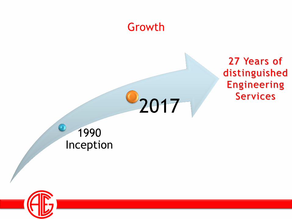
Growth
1990 Inception
2017
27 Years of
distinguished
Engineering
Services
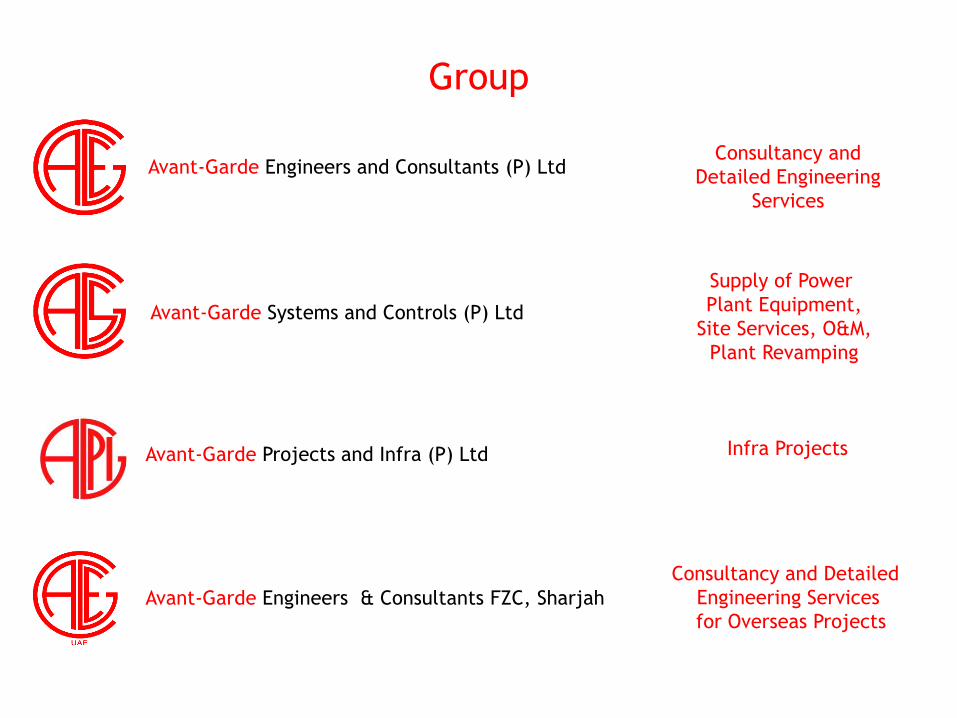
Group
Avant-Garde Systems and Controls (P) Ltd
Avant-Garde Projects and Infra (P) Ltd
Avant-Garde Engineers & Consultants FZC, Sharjah
Avant-Garde Engineers and Consultants (P) Ltd Consultancy and
Detailed Engineering
Services
Supply of Power
Plant Equipment,
Site Services, O&M,
Plant Revamping
Infra Projects
Consultancy and Detailed
Engineering Services
for Overseas Projects
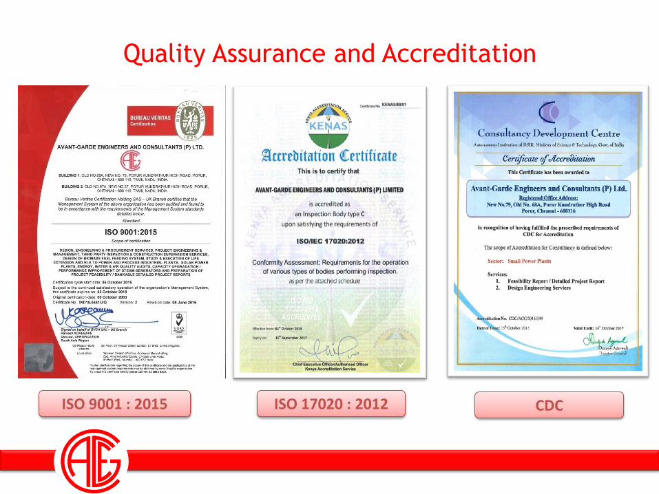
Quality Assurance and Accreditation
ISO 9001 : 2015 ISO 17020 : 2012 CDC
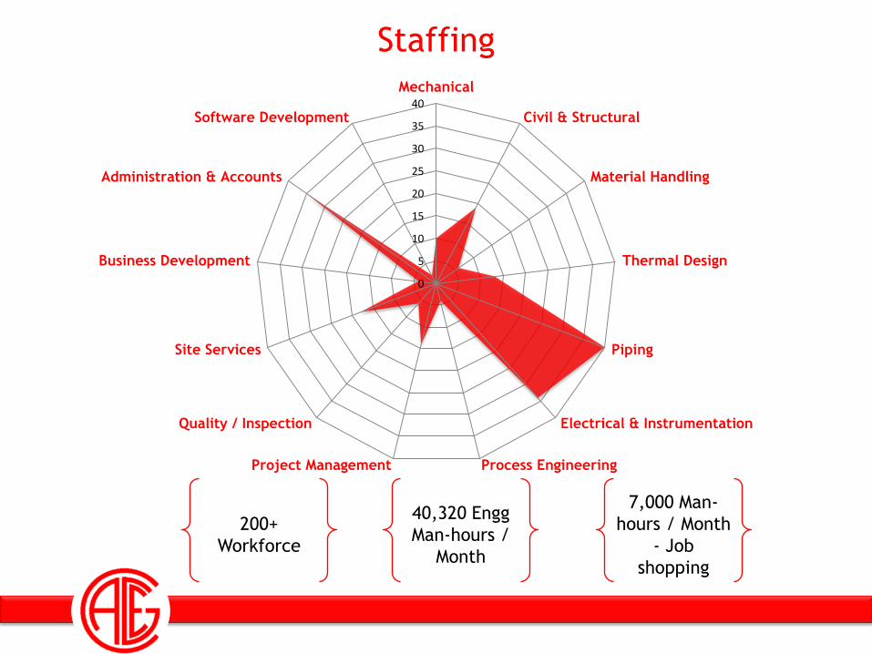
Staffing
0
5
10
15
20
25
30
35
40
Mechanical
Civil & Structural
Material Handling
Thermal Design
Piping
Electrical & Instrumentation
Process EngineeringProject Management
Quality / Inspection
Site Services
Business Development
Administration & Accounts
Software Development
200+
Workforce
40,320 Engg
Man-hours /
Month
7,000 Man-
hours / Month
- Job
shopping

Memberships & Associations
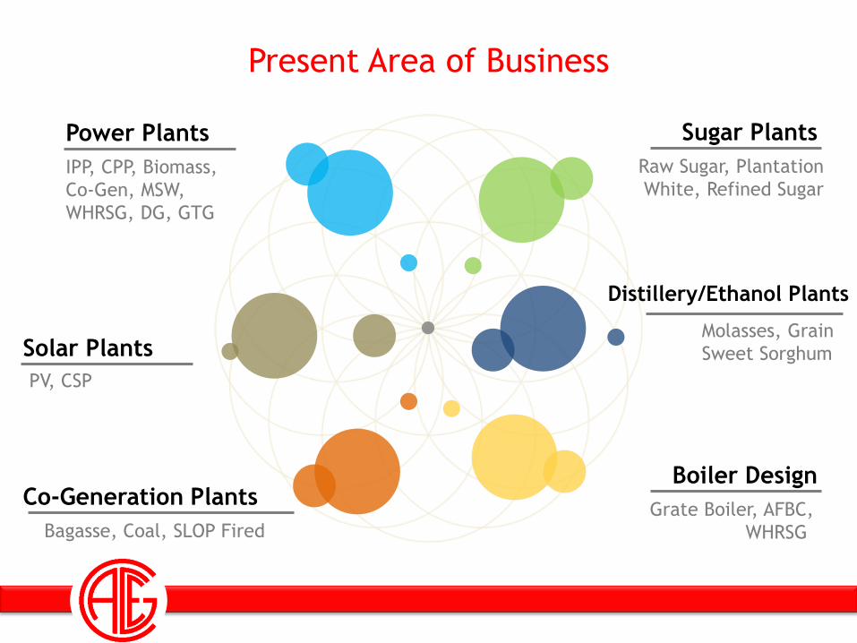
Present Area of Business
Solar Plants
Co-Generation Plants
Sugar Plants
Distillery/Ethanol Plants
Power Plants
IPP, CPP, Biomass,
Co-Gen, MSW,
WHRSG, DG, GTG
PV, CSP
Bagasse, Coal, SLOP Fired
Molasses, Grain
Sweet Sorghum
Boiler Design
Grate Boiler, AFBC,
WHRSG
Raw Sugar, Plantation
White, Refined Sugar
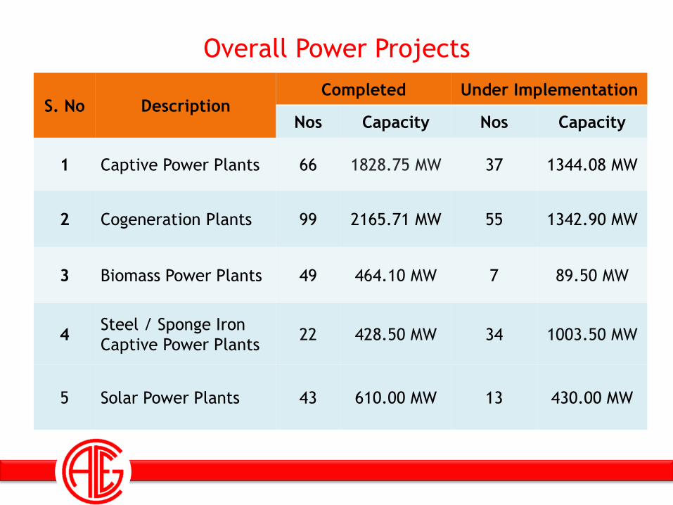
Overall Power Projects
S. No Description Completed Under Implementation
Nos Capacity Nos Capacity
1 Captive Power Plants 66 1828.75 MW 37 1344.08 MW
2 Cogeneration Plants 99 2165.71 MW 55 1342.90 MW
3 Biomass Power Plants 49 464.10 MW 7 89.50 MW
4 Steel / Sponge Iron
Captive Power Plants 22 428.50 MW 34 1003.50 MW
5 Solar Power Plants 43 610.00 MW 13 430.00 MW
WtE Projects
• Two (2) projects have been commissioned to a cumulative capacity of 30 MW
• Detailed Project Report (DPR) has been completed for eleven (11) projects
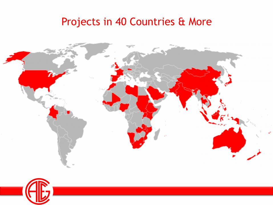
Projects in 40 Countries & More

AVANT-GARDE
ENGINEERS AND CONSULTANTS (P) LTD
STEAM AND WATER
CYCLE IN WTE PLANT
Presented By:
J. Gladstone Evans
(HOD – Thermal Department)
AGENDA
• Introduction on Water and steam Cycle
• Rankine Cycle and Efficiency Improvement
• Selection Of Water and Steam Cycle Parameter in WTE Plants
• Typical Heat and Mass Balance Diagram for a WTE Plant.
• Water and Steam Cycle Heat rate and Plant Efficiency Calculation
• Questions & Discussions
Introduction on Water and
steam Cycle
INTRODUCTION
• WATER & STEAM is viewed as a Thermodynamic fluid,
which is well favoured for Power Generation and Heat
Transfer. It captures the energy released from the fuel and
convert it to another form of energy. (Chemical to Thermal,
Thermal to Mechanical and Mechanical to Electrical)
• The way in which the energy conversion occurs from one
form to another is referred to as process.
• A cycle is a sequence of processes that is capable of
producing net heat flow or work when placed between an
energy source and energy sink
ENERGY CONVERSION
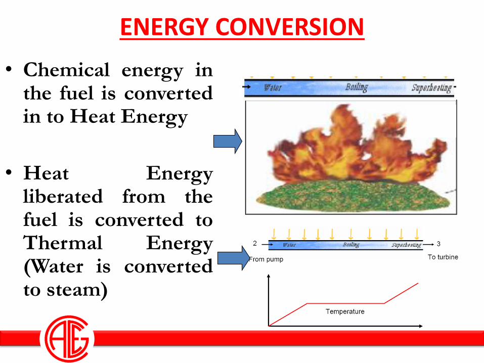
• Chemical energy in the fuel is converted in to Heat Energy
• Heat Energy liberated from the fuel is converted to Thermal Energy (Water is converted to steam)
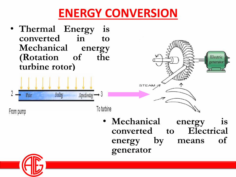
• Thermal Energy is converted in to Mechanical energy (Rotation of the turbine rotor)
ENERGY CONVERSION
• Mechanical energy is converted to Electrical energy by means of generator
PROCESS & EQUIPMENTS INVOLVED IN THE POWER CYCLE
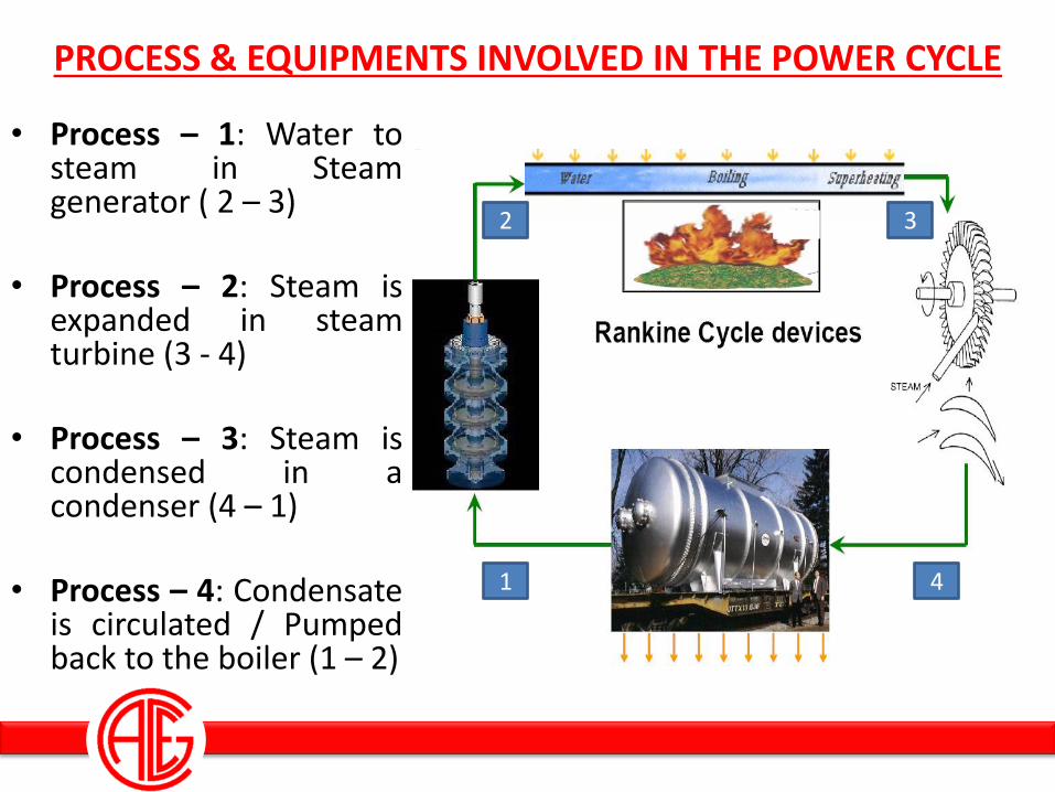
• Process – 1: Water to steam in Steam generator ( 2 – 3)
• Process – 2: Steam is expanded in steam turbine (3 - 4)
• Process – 3: Steam is condensed in a condenser (4 – 1)
• Process – 4: Condensate
is circulated / Pumped back to the boiler (1 – 2)
2 3
4 1
WATER AND STEAM AS A WORKING MEDIUM
• Water & Steam is an Excellent resource for Mankind and the preference of water & steam as the working medium for power plants is due to – Wide Availability and Non Toxic nature. – Non Corrosive nature. – Inert System – High Heat Capacity (Specific heat). – High Critical Temperature. – High latent heat. – Excellent heat transfer characteristics – Has a well known property
Rankine Cycle and Efficiency
Improvement
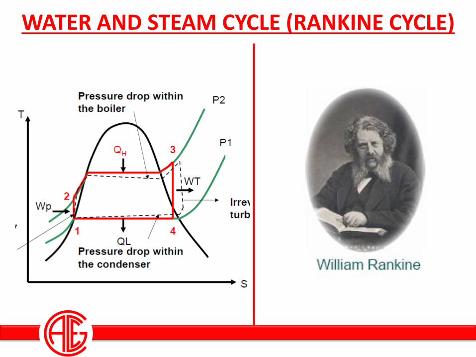
WATER AND STEAM CYCLE (RANKINE CYCLE)
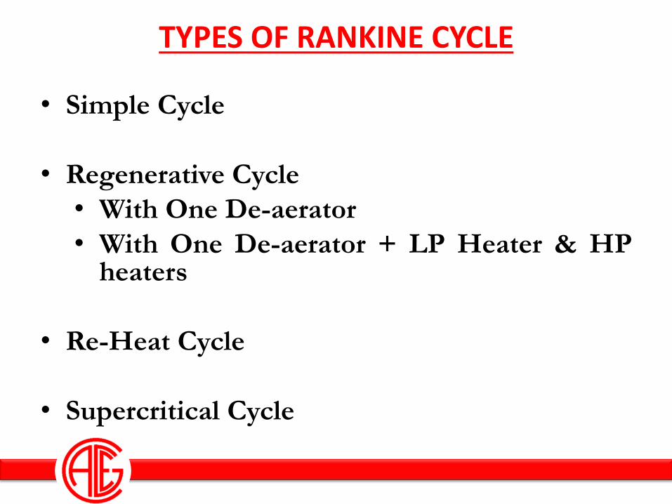
TYPES OF RANKINE CYCLE
• Simple Cycle
• Regenerative Cycle
• With One De-aerator
• With One De-aerator + LP Heater & HP heaters
• Re-Heat Cycle
• Supercritical Cycle
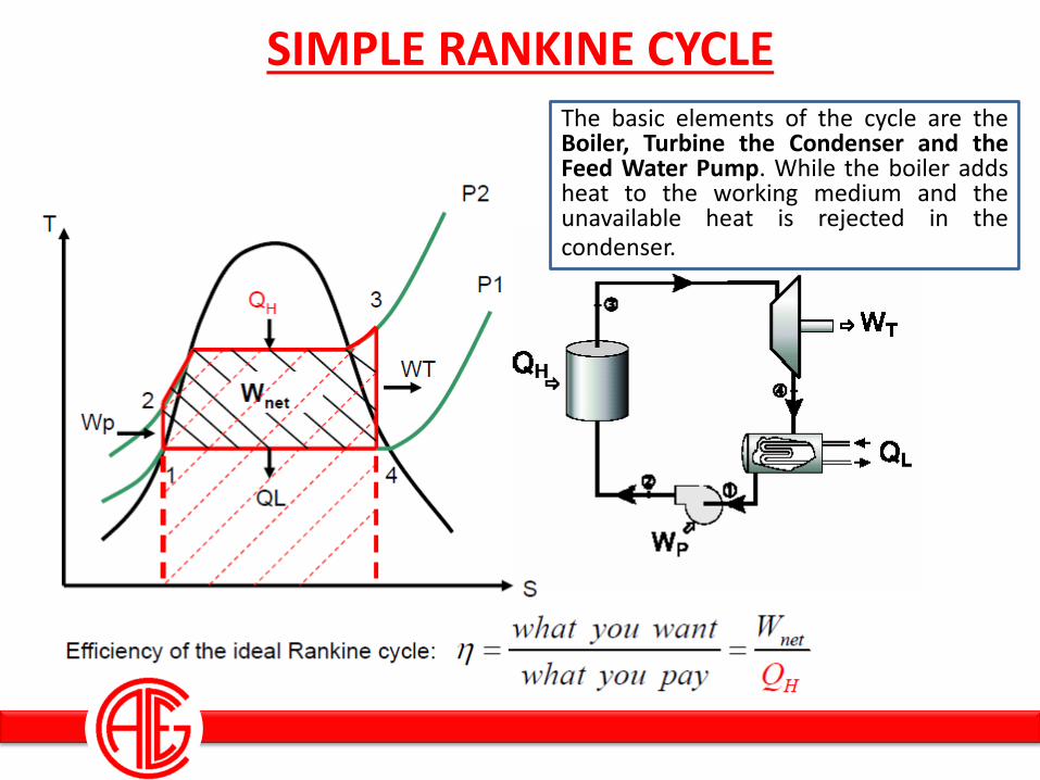
SIMPLE RANKINE CYCLE The basic elements of the cycle are the Boiler, Turbine the Condenser and the Feed Water Pump. While the boiler adds heat to the working medium and the unavailable heat is rejected in the condenser.
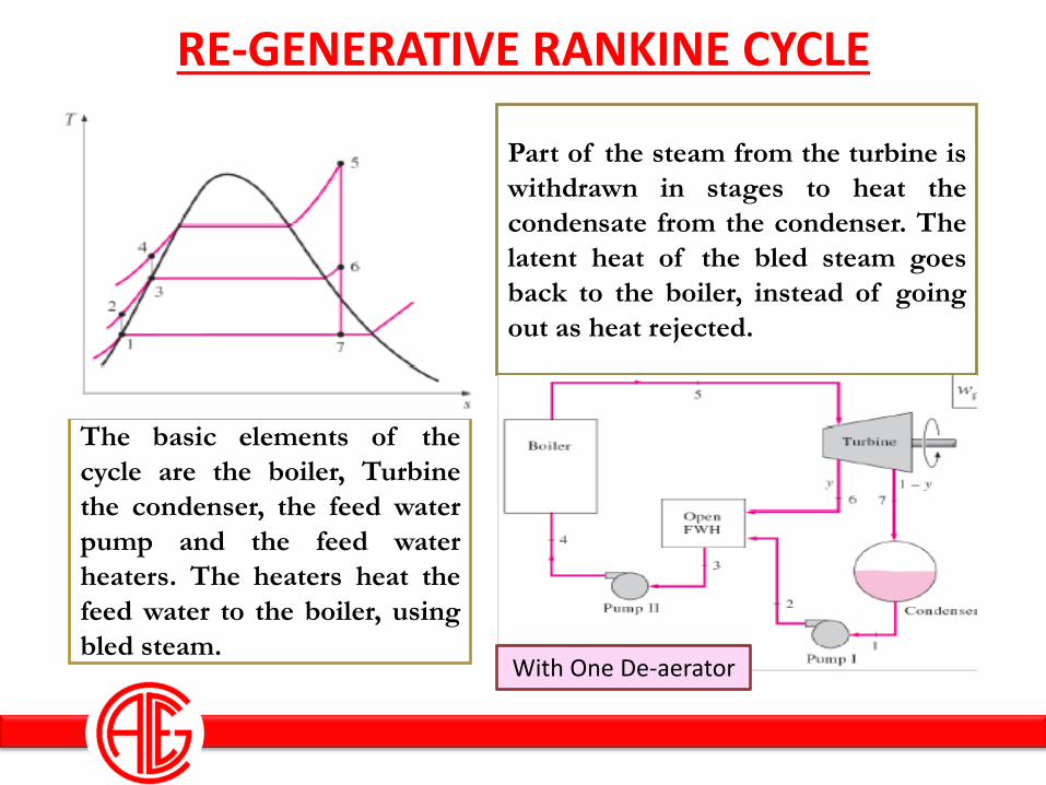
RE-GENERATIVE RANKINE CYCLE
Part of the steam from the turbine is
withdrawn in stages to heat the
condensate from the condenser. The
latent heat of the bled steam goes
back to the boiler, instead of going
out as heat rejected.
The basic elements of the
cycle are the boiler, Turbine
the condenser, the feed water
pump and the feed water
heaters. The heaters heat the
feed water to the boiler, using
bled steam. With One De-aerator
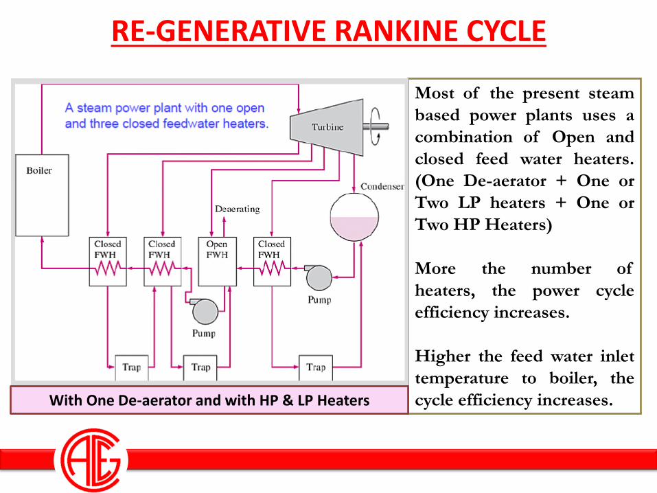
RE-GENERATIVE RANKINE CYCLE
Most of the present steam
based power plants uses a
combination of Open and
closed feed water heaters.
(One De-aerator + One or
Two LP heaters + One or
Two HP Heaters)
More the number of
heaters, the power cycle
efficiency increases.
Higher the feed water inlet
temperature to boiler, the
cycle efficiency increases. With One De-aerator and with HP & LP Heaters
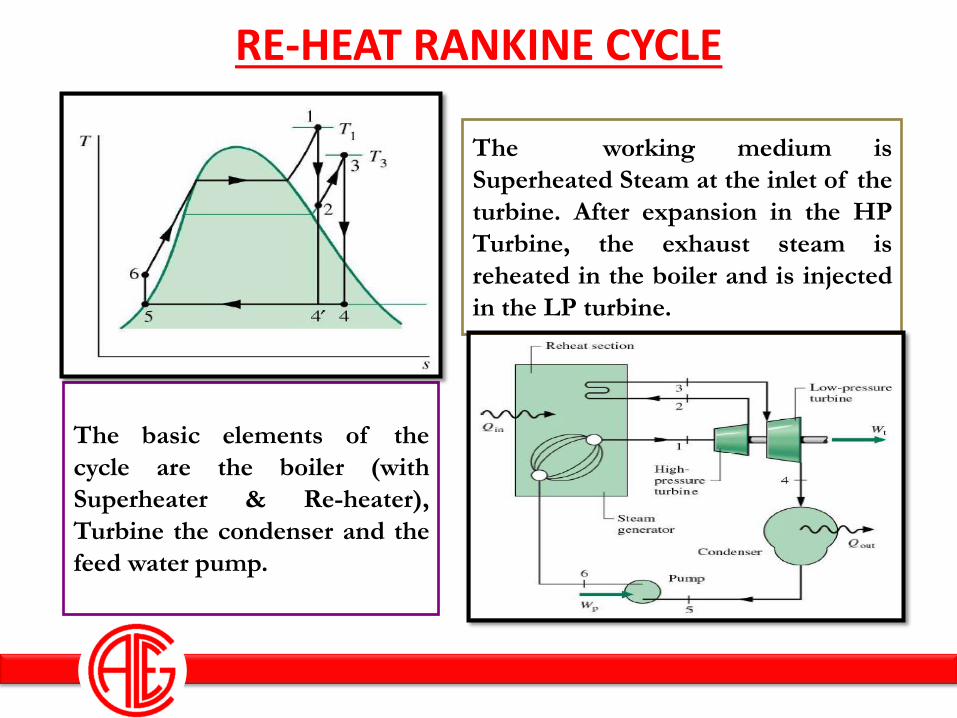
RE-HEAT RANKINE CYCLE
The working medium is
Superheated Steam at the inlet of the
turbine. After expansion in the HP
Turbine, the exhaust steam is
reheated in the boiler and is injected
in the LP turbine.
The basic elements of the
cycle are the boiler (with
Superheater & Re-heater),
Turbine the condenser and the
feed water pump.
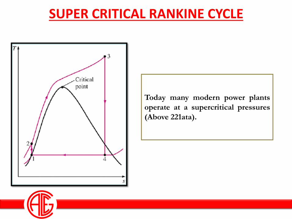
SUPER CRITICAL RANKINE CYCLE
Today many modern power plants
operate at a supercritical pressures
(Above 221ata).
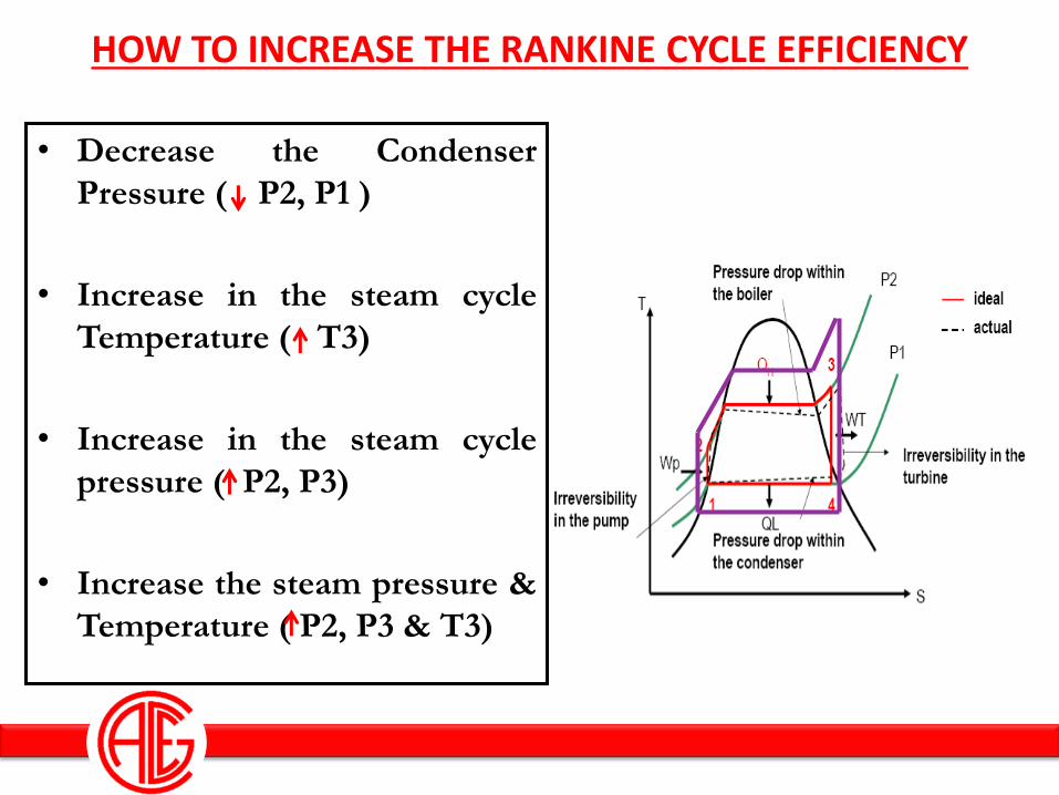
HOW TO INCREASE THE RANKINE CYCLE EFFICIENCY
• Decrease the Condenser
Pressure ( P2, P1 )
• Increase in the steam cycle
Temperature ( T3)
• Increase in the steam cycle
pressure ( P2, P3)
• Increase the steam pressure &
Temperature ( P2, P3 & T3)
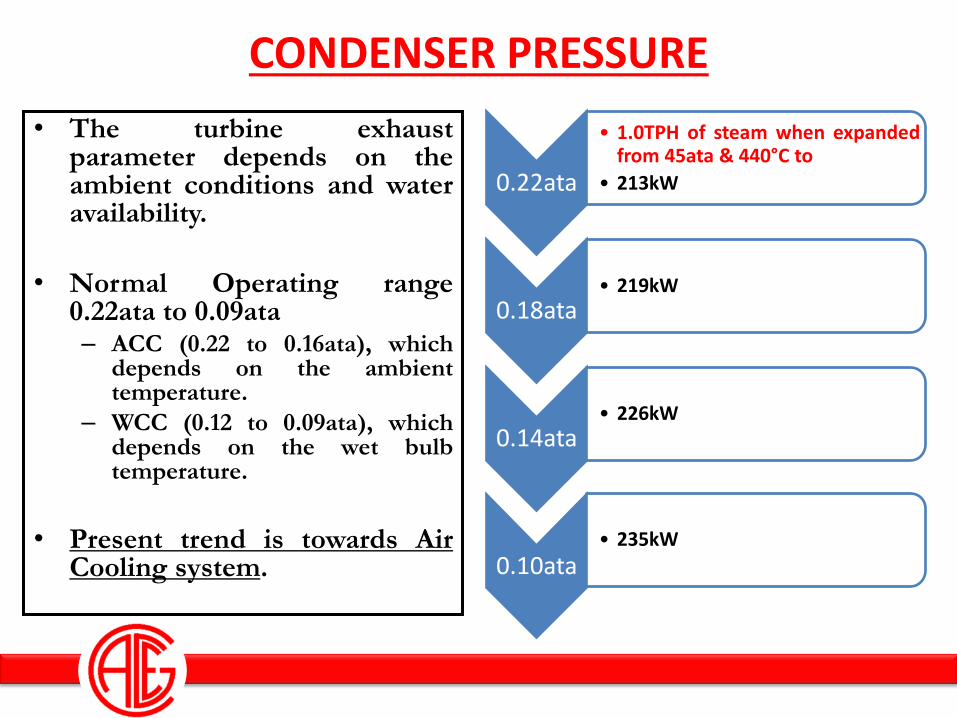
CONDENSER PRESSURE
• The turbine exhaust parameter depends on the ambient conditions and water availability.
• Normal Operating range 0.22ata to 0.09ata – ACC (0.22 to 0.16ata), which
depends on the ambient temperature.
– WCC (0.12 to 0.09ata), which depends on the wet bulb temperature.
• Present trend is towards Air Cooling system.
0.22ata
• 1.0TPH of steam when expanded from 45ata & 440°C to
• 213kW
0.18ata • 219kW
0.14ata • 226kW
0.10ata • 235kW
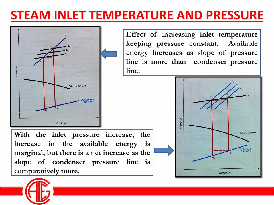
STEAM INLET TEMPERATURE AND PRESSURE
With the inlet pressure increase, the
increase in the available energy is
marginal, but there is a net increase as the
slope of condenser pressure line is
comparatively more.
Effect of increasing inlet temperature
keeping pressure constant. Available
energy increases as slope of pressure
line is more than condenser pressure
line.
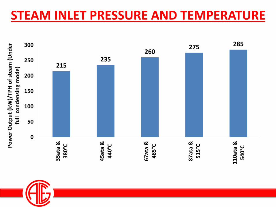
STEAM INLET PRESSURE AND TEMPERATURE
215 235
260 275 285
0
50
100
150
200
250
300
35
ata
&3
80
°C
45
ata
&4
40
°C
67
ata
&4
85
°C
87
ata
&5
15
°C
11
0at
a &
54
0°CP
ow
er
Ou
tpu
t (k
W)/
TPH
of
ste
am (
Un
de
r fu
ll c
on
de
nsi
ng
mo
de
)
Selection Of Water and Steam
Cycle Parameter in WTE Plants
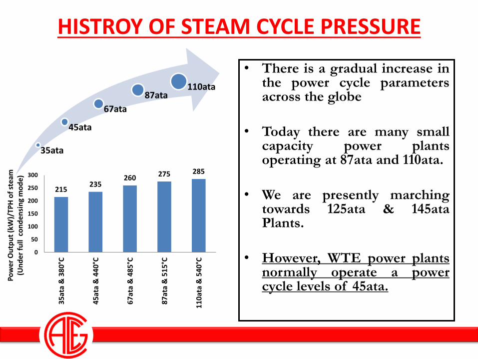
HISTROY OF STEAM CYCLE PRESSURE
• There is a gradual increase in the power cycle parameters across the globe
• Today there are many small capacity power plants operating at 87ata and 110ata.
• We are presently marching towards 125ata & 145ata Plants.
• However, WTE power plants normally operate a power cycle levels of 45ata.
35ata
45ata
67ata
87ata 110ata
215 235
260 275 285
0
50
100
150
200
250
300
35
ata
& 3
80°
C
45
ata
& 4
40°
C
67
ata
& 4
85°
C
87
ata
& 5
15°
C
11
0at
a &
54
0°C
Po
wer
Ou
tpu
t (k
W)/
TPH
of
stea
m
(Un
der
fu
ll c
on
den
sin
g m
od
e)
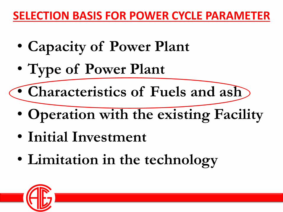
SELECTION BASIS FOR POWER CYCLE PARAMETER
• Capacity of Power Plant
• Type of Power Plant
• Characteristics of Fuels and ash
• Operation with the existing Facility
• Initial Investment
• Limitation in the technology

FUEL & ASH CHARECTERISTICS - MSW Indian Coal Bagasse Rice Husk MSW
SiO2 55-65 40-55 80 -92 45-60
Fe2O3 03-06 03-08 01 - 03 03-12
Al2O3 08-20 05 - 10 00-05 06-12
CaO 01-03 05 - 08 02-04 07-16
MgO 01-02 01 - 04 Traces 01-02
Na2O 00-01 00-02 00-01 02-15
K2O 00-01 00-08 00-03 05-20
SO3 00-03 Traces Traces 00-05
P2O5 00-02 01 - 04 Traces 10 -25
Cl 00-0.1 Nil Nil 00-02
IDT 1400 1100 1400 700 - 800
High Percentage of Fe2O3, Na2O, K2O & Cl makes the fuel, a very high fouling, slagging and corrosive nature
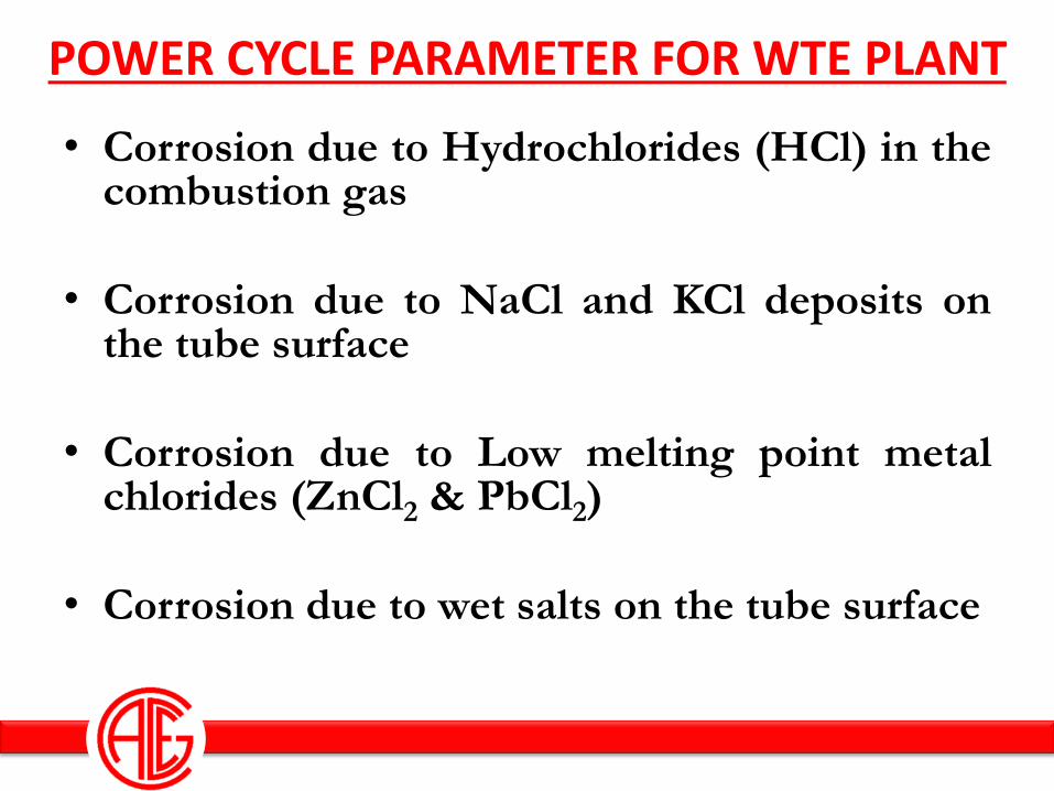
POWER CYCLE PARAMETER FOR WTE PLANT
• Corrosion due to Hydrochlorides (HCl) in the combustion gas
• Corrosion due to NaCl and KCl deposits on the tube surface
• Corrosion due to Low melting point metal chlorides (ZnCl2 & PbCl2)
• Corrosion due to wet salts on the tube surface
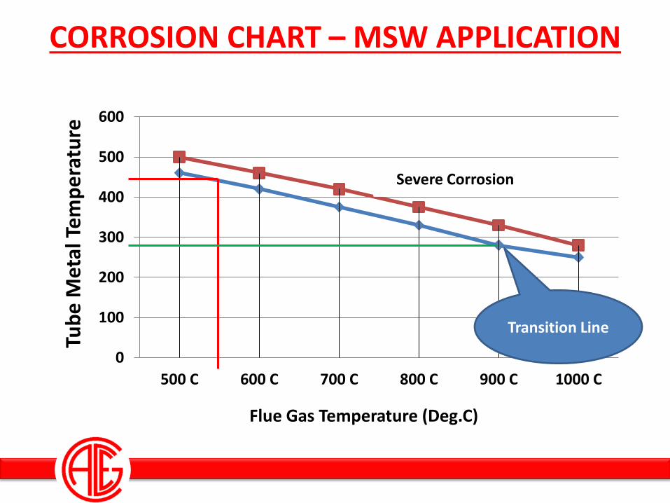
CORROSION CHART – MSW APPLICATION
0
100
200
300
400
500
600
500 C 600 C 700 C 800 C 900 C 1000 C
Tub
e M
eta
l Te
mp
era
ture
Flue Gas Temperature (Deg.C)
Severe Corrosion
Transition Line
POWER CYCLE PARAMETER FOR WTE PLANT
Considering the characteristics of the Fuel, the power cycle parameter selected for WTE plant will be 45ata
& 400 to 410°C, with a feed water temperature in the order of 130 to
150°C
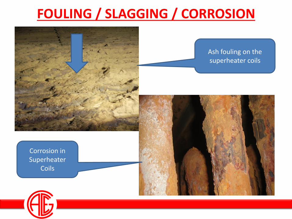
FOULING / SLAGGING / CORROSION
Ash fouling on the superheater coils
Corrosion in Superheater
Coils
Typical Heat and Mass Balance Diagram for a WTE Plant.
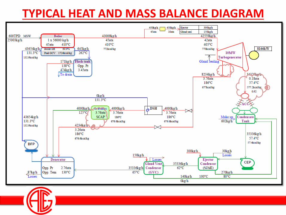
TYPICAL HEAT AND MASS BALANCE DIAGRAM
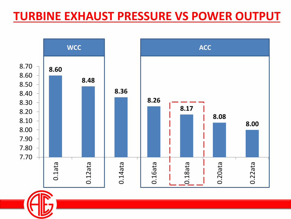
TURBINE EXHAUST PRESSURE VS POWER OUTPUT
8.60
8.48
8.36 8.26
8.17 8.08
8.00
7.707.807.908.008.108.208.308.408.508.608.70
0.1
ata
0.1
2at
a
0.1
4at
a
0.1
6at
a
0.1
8at
a
0.2
0at
a
0.2
2at
a
WCC ACC
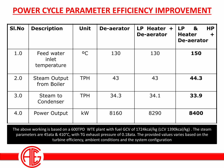
POWER CYCLE PARAMETER EFFICIENCY IMPROVEMENT
Sl.No Description Unit De-aerator LP Heater + De-aerator
LP & HP Heater + De-aerator
1.0 Feed water inlet
temperature
ºC 130 130 150
2.0 Steam Output from Boiler
TPH 43 43 44.3
3.0 Steam to Condenser
TPH 34.3 34.1 33.9
4.0 Power Output kW 8160 8290 8400
The above working is based on a 600TPD WTE plant with fuel GCV of 1724kcal/kg (LCV 1390kcal/kg) . The steam parameters are 45ata & 410°C, with TG exhaust pressure of 0.18ata. The provided values varies based on the
turbine efficiency, ambient conditions and the system configuration
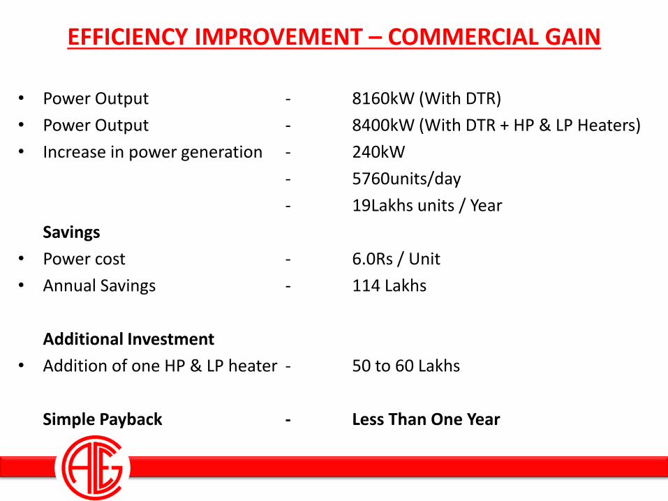
EFFICIENCY IMPROVEMENT – COMMERCIAL GAIN
• Power Output - 8160kW (With DTR)
• Power Output - 8400kW (With DTR + HP & LP Heaters)
• Increase in power generation - 240kW
- 5760units/day
- 19Lakhs units / Year
Savings
• Power cost - 6.0Rs / Unit
• Annual Savings - 114 Lakhs
Additional Investment
• Addition of one HP & LP heater - 50 to 60 Lakhs
Simple Payback - Less Than One Year
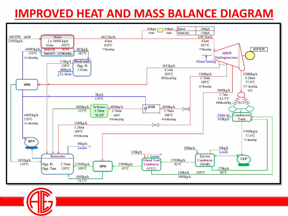
IMPROVED HEAT AND MASS BALANCE DIAGRAM
Cycle Heat rate and Plant
Efficiency Calculation
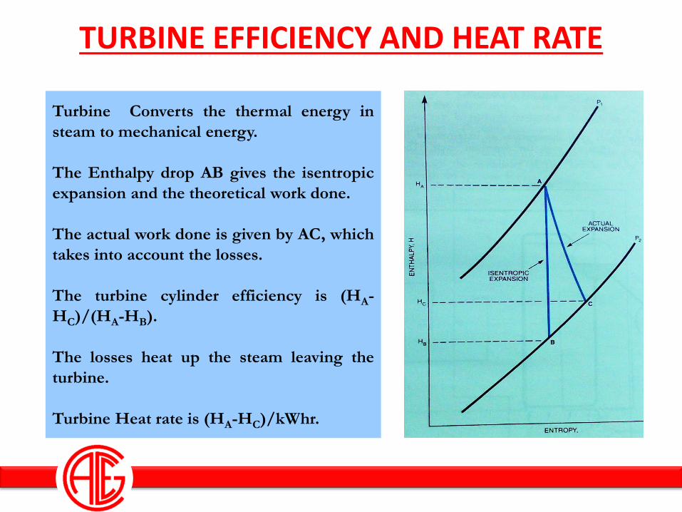
TURBINE EFFICIENCY AND HEAT RATE
Turbine Converts the thermal energy in
steam to mechanical energy.
The Enthalpy drop AB gives the isentropic
expansion and the theoretical work done.
The actual work done is given by AC, which
takes into account the losses.
The turbine cylinder efficiency is (HA-
HC)/(HA-HB).
The losses heat up the steam leaving the
turbine.
Turbine Heat rate is (HA-HC)/kWhr.
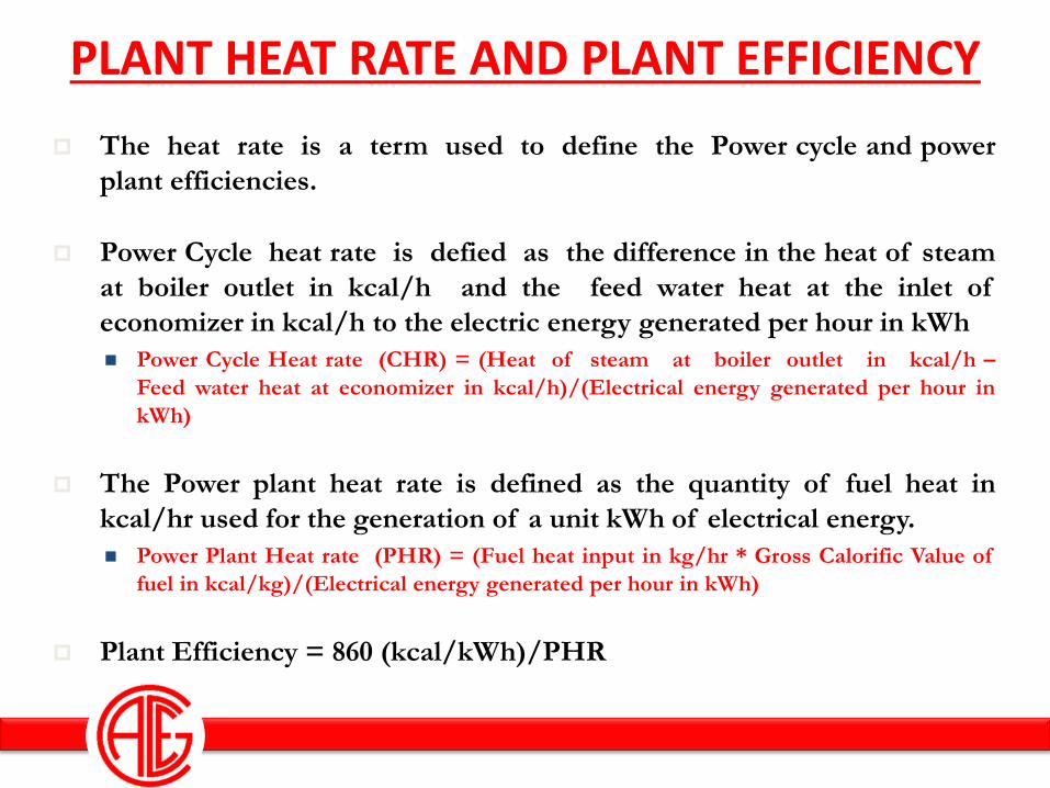
PLANT HEAT RATE AND PLANT EFFICIENCY
The heat rate is a term used to define the Power cycle and power
plant efficiencies.
Power Cycle heat rate is defied as the difference in the heat of steam
at boiler outlet in kcal/h and the feed water heat at the inlet of
economizer in kcal/h to the electric energy generated per hour in kWh
Power Cycle Heat rate (CHR) = (Heat of steam at boiler outlet in kcal/h –
Feed water heat at economizer in kcal/h)/(Electrical energy generated per hour in
kWh)
The Power plant heat rate is defined as the quantity of fuel heat in
kcal/hr used for the generation of a unit kWh of electrical energy.
Power Plant Heat rate (PHR) = (Fuel heat input in kg/hr * Gross Calorific Value of
fuel in kcal/kg)/(Electrical energy generated per hour in kWh)
Plant Efficiency = 860 (kcal/kWh)/PHR
SUMMARY
• Water and steam Cycle works under the principle of Rankine cycle
• Higher the steam cycle pressure and temperature and lower the condenser pressure, the cycle efficiency increases. Also higher the feed water temperature at the inlet of the boiler, and more number of heaters, improve the power cycle efficiency.
• However, due the characteristics of the fuel (MSW) and its ash, it is forced to select a power cycle parameter of 45ata & 400 to 410˚C, with a feed water temperature of 130 to 150˚C.
• The condenser pressure is selected based on water availability at site, Ambient conditions, etc. In the case of WCC, the condenser pressure will be 0.12 to 0.1ata. In case of ACC, the condenser pressure will be 0.2 to 0.16ata.
• Based on the Comparison of two HMBD’s (HMBD for a WTE Plant with one De-aeartor and another HMBD with One De-aerator, One HP Heater and One LP heater.) shows that, there is an increase in the power output to an extent of 3.0% while considering HP & LP heaters in the circuit.