Embed Size (px)
Citation preview

CIVIL AVIATION AUTHORITY OF MALAYSIA
ELECTRONIC
CIVIL AVIATION GUIDANCE MATERIAL – 6008(V)
ISSUE 01 REVISION 00 – 1ST APRIL 2021
FLIGHT BAGEFB

INTENTIONALLY LEFT BLANK

Introduction
Issue 01/Rev 00 CAGM 6008 (V) EFB i
Introduction
This Civil Aviation Guidance Material 6008 Part III (CAGM – 6008 (III)) is issued by the Civil Aviation Authority of Malaysia (CAAM) to provide guidance for the application for, and approval for operations with Electronic Flight Bags (EFBs), pursuant to Civil Aviation Directives 6 Part 1 – Commercial Air Transport (CAD 6 Part 1 – CAT), Civil Aviation Directives 6 Part 2 – GeneralAviation (CAD 6 Part 2 – GA) Civil Aviation Directives 6 Part 3 - Helicopters (collectivelyreferred to as “CAD”).
Organisations may use these guidelines to ensure compliance with the respective provisions of the relevant CAD’s issued. Notwithstanding the Regulation 204 and Regulation 205 of the Malaysian Civil Aviation Regulations 2016 (MCAR 2016), when the CAGMs issued by the CAAM are complied with, the related requirements of the CAD’s may be deemed as being satisfied and further demonstration of compliance may not be required.
(Captain Chester Voo Chee Soon) Chief Executive Officer
Civil Aviation Authority of Malaysia

Introduction
Issue 01/Rev 00 CAGM 6008 (V) EFB
ii
Civil Aviation Guidance Material components and Editorial practices
This Civil Aviation Directive is made up of the following components and are defined as
follows:
Standards: Usually preceded by words such as “shall” or “must”, are any specification for
physical characteristics, configuration, performance, personnel or procedure, where uniform
application is necessary for the safety or regularity of air navigation and to which Operators
must conform. In the event of impossibility of compliance, notification to the CAAM is
compulsory.
Recommended Practices: Usually preceded by the words such as “should” or “may”, are any
specification for physical characteristics, configuration, performance, personnel or procedure,
where the uniform application is desirable in the interest of safety, regularity or efficiency of
air navigation, and to which Operators will endeavour to conform.
Appendices: Material grouped separately for convenience, but forms part of the Standards
and Recommended Practices stipulated by the CAAM.
Definitions: Terms used in the Standards and Recommended Practices which are not self-
explanatory in that they do not have accepted dictionary meanings. A definition does not have
an independent status but is an essential part of each Standard and Recommended Practice
in which the term is used, since a change in the meaning of the term would affect the
specification.
Tables and Figures: These add to or illustrate a Standard or Recommended Practice, and
which are referred to therein, form part of the associated Standard or Recommended Practice
and have the same status.
Notes: Included in the text, where appropriate, Notes give factual information or references
bearing on the Standards or Recommended Practices in question but not constituting part of
the Standards or Recommended Practices;
Attachments: Material supplementary to the Standards and Recommended Practices or
included as a guide to their application.
It is to be noted that some Standards in this Civil Aviation Directive incorporates, by reference,
other specifications having the status of Recommended Practices. In such cases, the text of
the Recommended Practice becomes part of the Standard.
The units of measurement used in this document are in accordance with the International
System of Units (SI) as specified in CAD 5. Where CAD 5 permits the use of non-SI alternative
units, these are shown in parentheses following the basic units. Where two sets of units are
quoted it must not be assumed that the pairs of values are equal and interchangeable. It may,
however, be inferred that an equivalent level of safety is achieved when either set of units is
used exclusively.
Any reference to a portion of this document, which is identified by a number and/or title,
includes all subdivisions of that portion.
Throughout this Civil Aviation Directive, the use of the male gender should be understood to
include male and female persons

Records of revisions
Issue 01/Rev 00 CAGM 6008 (V) EFB
iii
Record of revisions
Revisions to this CAGM shall be made by authorised personnel only. After inserting the
revision, enter the required data in the revision sheet below. The ‘Initials’ has to be signed off
by the personnel responsible for the change.
Rev No. Revision Date Revision Details Initials

Records of revisions
Issue 01/Rev 00 CAGM 6008 (V) EFB
iv
INTENTIONALLY LEFT BLANK

Table of contents
Issue 01/Rev 00 CAGM 6008 (V) EFB
v
Table of contents
1 General .......................................................................................................................................... 1-1
1.1 Background ......................................................................................................................................... 1-1 1.2 Definitions........................................................................................................................................... 1-1 1.3 Abbreviations...................................................................................................................................... 1-3
2 Equipment/Hardware Considerations ........................................................................................... 2-1
2.1 Types of EFB ........................................................................................................................................ 2-1 2.2 EFB Hardware (Portable EFB) ............................................................................................................. 2-1 2.3 Evaluation of portable EFBs ............................................................................................................. 2-2 2.4 Installed EFB ..................................................................................................................................... 2-11 2.5 Airworthiness Approval for Installed Resources, Data Connectivity and Power to the EFBs .......... 2-12
3 Human Factors ................................................................................................................................ 3-1
3.1 General ............................................................................................................................................... 3-1
4 Crew Operating Procedures ............................................................................................................. 4-1
4.1 General ............................................................................................................................................... 4-1 4.2 Revisions and Updates ...................................................................................................................... 4-1 4.3 Workload and Crew Coordination ................................................................................................... 4-1
5 Flight Crew Training ........................................................................................................................ 5-1
5.1 Requirements ..................................................................................................................................... 5-1 5.2 Additional requirements for the usage of AMMD ............................................................................. 5-1 5.3 Additional requirements for the usage of ECL ................................................................................... 5-1
6 EFB Risk Assessment ....................................................................................................................... 6-1
6.1 General ............................................................................................................................................... 6-1 6.2 EFB failures and mitigation means ..................................................................................................... 6-1 6.3 Continued surveillance / Monitoring programme ......................................................................... 6-1
7 EFB Functions ................................................................................................................................. 7-1
7.1 General ............................................................................................................................................... 7-1 7.2 Guidance/criteria for operational use of EFB functions ................................................................. 7-1 7.3 EFB functions essential to safe operation of flight ......................................................................... 7-1 7.4 Considerations for all EFB functions - software HMI ...................................................................... 7-3 7.5 EFB management ................................................................................................................................ 7-4
8 Operational Evaluation Process ....................................................................................................... 8-1
8.1 Definition of the scope ....................................................................................................................... 8-1 8.2 Application for EFB approval .............................................................................................................. 8-1
9 EFB use in General Aviation Operations with Helicopters or other than Large or Turbojet Aeroplanes 9-1
9.1 Equipment/Hardware considerations ................................................................................................ 9-1 9.2 Pilot operating procedures ................................................................................................................. 9-1 9.3 Pilot training ....................................................................................................................................... 9-1 9.4 EFB Risk Assessment ........................................................................................................................... 9-1 9.5 EFB Functions...................................................................................................................................... 9-1 9.6 Evaluation process .............................................................................................................................. 9-2
10 Appendices ............................................................................................................................... 10-1
10.1 Appendix 1 – Performance and Mass and Balance (M&B) Applications ......................................... 10-1

Table of contents
Issue 01/Rev 00 CAGM 6008 (V) EFB
vi
10.2 Appendix 2 – Electronic Charting ..................................................................................................... 10-9 10.3 Appendix 3 – Taxi Aid Camera System (TACS) ................................................................................ 10-11 10.4 Appendix 4 – Airport Moving Map Display (AMMD) ..................................................................... 10-12 10.5 Appendix 5 – Electronic checklist application ................................................................................ 10-13 10.6 Appendix 6 – In-flight weather (IFW) application .......................................................................... 10-15 10.7 Appendix 7 – EFB Policy and Procedures Manual .......................................................................... 10-17
11 Attachments ............................................................................................................................. 11-1
11.1 Attachment A – Evaluation Checklist ............................................................................................... 11-1 11.2 Attachment B - Sample of EFB feedback form ................................................................................. 11-5 11.3 Attachment C – EFB application form .............................................................................................. 11-7

Chapter 1 – General
Issue 01/Rev 00 CAGM 6008 (V) EFB
1-1
1 General
1.1 Background
1.1.1 An Electronic Flight Bag or EFB is defined by ICAO as “An electronic
information system, comprised of equipment and applications for flight crew,
which allows for storing, updating, displaying and processing of EFB functions
to support flight operations or duties.”
1.1.2 This CAGM provides the guidance to understand the intent and objectives of
the requirements for the performance of operational evaluation of the EFB
system and its commonly used functions; and, where appropriate, enables the
operator to seek the grant operational approval from CAAM.
1.2 Definitions
AID (Aircraft Interface Device) means a device or function that provides
an interface between the EFBs and other aircraft systems which protects the
aircraft systems and related functions from the undesired effects from non-
certified equipment and related functions.
Airworthiness inspector (AWI) is a representative of the Civil Aviation Authority
of Malaysia in charge of initial authorisation and/or continued oversight of the
operator’s maintenance and engineering organisation and processes. The
assessment performed by the AWI may include (but not be limited to):
a) the adequacy of maintenance facilities, equipment and procedures;
b) the adequacy of the training programmes and competence of employees;
c) the adequacy of the programme or schedule for periodic maintenance and
overhauls; and
d) the airworthiness of the aircraft.
AMMD (Airport Moving Map Display) means a software application
displaying airport maps and using a navigation source to depict the aircraft
current position on this map while on ground.
Controlled Portable Electronic Device (C-PED) is a PED subject to
administrative control by the operator using it. This will include tracking the
allocation of the devices to specific aircraft or persons and ensuring that no
unauthorised changes are made to the hardware, software or database, among
other things.
Critical phases of flight mean the periods of high workload on the flight deck,
which includes all ground operations involving taxi, takeoff and landing; all
other flight operations conducted below 10,000 feet, and when handling
abnormal situations.
Data connectivity for EFB systems mean data connectivity for EFB
system supports either uni- or bi-directional data communication between
the EFB and other aircraft systems (e.g. avionics). Direct interconnectivity
between EFBs or direct connectivity between EFBs and ground systems are
not covered by this definition.

Chapter 1 – General
Issue 01/Rev 00 CAGM 6008 (V) EFB
1-2
EFB administrator is a person appointed by the operator, held responsible
for the administration of the EFB system within the company. The EFB
administrator is the primary link between the operator and the EFB system
and software suppliers.
EFB host platform is the equipment (i.e. hardware) in which the computing
capabilities and basic software (e.g. operating system, input/output
software) reside.
EFB management contains all procedures related to the operator’s EFB
management system as listed in the section “EFB management”.
EFB risk assessment and mitigation is a process that considers an EFB
system, its software applications, and its integration inside a specific aircraft,
to identify the potential malfunctions and failure scenarios, analyse their
operational repercussions, and, if necessary, propose mitigation means.
EFB software application is a software installed on an EFB system that
allows specific operational functionality.
EFB system comprises the hardware (including any battery, connectivity
provision, input/output (I/O) devices) and software (including databases)
needed to support the intended EFB function(s).
EFB system supplier is the company responsible for developing, or for
having developed, the EFB system or part of it. The EFB system supplier is
not necessarily a host platform or aircraft manufacturer.
Flight operations inspector (FOI) Is a representative of the Civil Aviation
Authority of Malaysia in charge of initial authorisation and/or continued oversight
of the operator’s flight operations organisation and processes. The assessment
performed by the FOI may include (but not be limited to):
a) the adequacy of flight operations facilities, equipment and procedures;
b) the adequacy of the training programmes and competence of employees; and
c) the adequacy of the programme to ensure safe operations of the aircraft.
Minor failure conditions are failure conditions which would not significantly
reduce aircraft safety, and which involve crew actions that are well within
their capabilities. Minor failure conditions may include, for example, a slight
reduction in safety margins or functional capabilities, a slight increase in crew
workload, such as routine flight plan changes, or some physical discomfort
to passengers or cabin crew.
Mounting device is an aircraft certified part which secures portable or
installed EFB, and/or its system components.
Installed resources are hardware/software installed in accordance with
airworthiness requirements.
Independent EFB platforms mean multiple EFBs that are designed in such a
way that no single failure makes all of them unavailable.

Chapter 1 – General
Issue 01/Rev 00 CAGM 6008 (V) EFB
1-3
Portable Electronic Devices (PEDs) mean any lightweight, electrically
powered equipment, that are typically consumer electronic devices, which
have functional capability for communications, entertainment, data
processing, and/or utility. There are two basic categories of PEDs – those
with and those without intentional transmitting capability.
Transmitting PED (T-PED) is a PED that has intended radio frequency
transmission capabilities.
Viewable Stowage is a device that is secured either on the flight crew (e.g.
kneeboard) or in/to an existing aircraft part (e.g. mounted using suction cups)
with the intent of holding a portable EFB (e.g. a tablet) viewable to the pilot at
his duty station. The device is not necessarily part of the certified aircraft
configuration.
1.3 Abbreviations
AID = Aircraft Interface Device
AMMD = Aircraft Moving Map Display
AODB = Airport, runway, Obstacle Database
AWI = Airworthiness Inspector
CAAM = Civil Aviation Authority of Malaysia
CAD = Civil Aviation Directive
ECL = Electronic check list
EFB = Electronic Flight Bag
EMC = electromagnetic compatibility
EMI = electromagnetic interference
FOI = Flight Operations Inspector
GUI = Graphics User Interface
HMI = Human Machine Interface
IFW = in-flight weather
M&B = Mass & Balance
PED = Portable Electronic Device
RWY = runway
SCAP = standard computerised aircraft performance
SOP = standard operating procedure
STC = supplemental type certificate
TACS = taxi aid camera system
TALP = take-off and landing performance
TC = type certificate
T-PED = transmitting portable electronic device
TOM = takeoff mass
ZFM = zero fuel mass

Chapter 1 – General
Issue 01/Rev 00 CAGM 6008 (V) EFB
1-4
INTENTIONALLY LEFT BLANK

Chapter 2 – Equipment/Hardware considerations
Issue 01/Rev 00 CAGM 6008 (V) EFB
2-1
2 Equipment/Hardware Considerations
2.1 Types of EFB
2.1.1 EFBs can be either portable EFBs or installed EFBs.
2.1.2 Portable EFBs are not part of the aircraft configuration and are considered as
PEDs. They generally have self-contained power and may rely on data
connectivity to achieve full functionality. Modifications to the aircraft to use
portable EFBs require the appropriate airworthiness approvals.
2.1.3 Installed EFBs are integrated into the aircraft and are subject to airworthiness
requirements. The approval of these EFBs is included in the aircraft type
certificate (TC) or the supplemental type certificate (STC).
2.2 EFB Hardware (Portable EFB)
2.2.1 A portable EFB provides a portable host platform, although when used on the
flight deck, it is not part of the certified aircraft configuration. Portable EFBs
can be used either as hand-held equipment or secured in a mounting device /
viewable stowage solution.
2.2.2 The following are characteristics of a Portable EFB:
It can be operated inside and outside the aircraft.
A portable EFB hosts type A and/or type B EFB software applications. In
addition, it may host miscellaneous (non-EFB) software applications.
The mass, dimensions, shape, and position of the portable EFB should
not compromise flight safety.
A portable EFB may connect to aircraft power, data ports (wired or
wireless) and installed antennas provided those connections have been
installed in a certified and approved manner. (see 2.5.4)
If secured with viewable stowage, the portable EFB should be easily
removable without the use of tools by the flight crew and the attachment or
removal does not constitute a maintenance action.
A portable EFB may be part of a system containing EFB installed
resources which are part of the certified aircraft configuration.
When a portable EFB is a T-PED, the conditions for use of its transmitting
capability are established in the approved Aircraft Operating Manual
(AOM). In absence of information in the AOM, the EFB transmitting
capability may be allowed during non-critical phases of the flight (subject
to requirements as specified in 2.3.5 of this CAGM.
Portable EFBs may be used in all phases of the flight if secured to a
certified mount or securely attached to a viewable stowage device in a
Chapter 2 – Equipment/Hardware considerations
Issue 01/Rev 00 CAGM 6008 (V) EFB
2-2
manner which allows its normal use. EFBs not meeting this requirement,
should be stowed during critical phases of flight.
The portable EFB and its operating components should be easily
accessible by the flight crew members in the flight compartment.
Portable EFBs are controlled PEDs.
Any EFB component that is either not accessible in the flight crew
compartment by the flight crew members or not removable by the flight
crew, should be installed as ‘certificated equipment’ and be approved by
the CAAM.
2.3 Evaluation of portable EFBs
2.3.1 Physical Characteristics
2.3.1.1 The size and practicality of the EFB should be evaluated as some devices may
prove to be cumbersome for normal use on a flight deck.
2.3.2 Readability
2.3.2.1 The EFB data should be legible under the full range of lighting conditions
expected on the flight deck, including direct sunlight.
2.3.2.2 Placement of the display
a) The EFB display and any other element of the EFB system should be
placed in such a way that they do not unduly impair the pilot’s external view
during all phases of the flight. Equally, they should not impair the view and
access to any cockpit control or instrument
b) The location of the display unit and the other EFB system elements should
be assessed for impact on egress requirements.
c) When the EFB is in use (intended to be viewed or controlled), its display
should be within 90 degrees on either side of each pilot’s line of sight.
d) Glare and reflection on the EFB display should not interfere with the normal
duties of the flight crew or unduly impair the legibility of the EFB data.
i. The EFB data should be legible under the full range of lighting
conditions expected on a flight crew compartment, including use in
direct sunlight.
e) In addition, consideration should be given to the potential for confusion that
could result from presentation of relative directions when the EFB is
positioned in an orientation inconsistent with that information. For example,
it may be misleading if the aircraft heading is pointed to the top of the
display and the display is not aligned with the aircraft longitudinal axis. This
does not apply to charts that are presented in a static way (e.g. with no

Chapter 2 – Equipment/Hardware considerations
Issue 01/Rev 00 CAGM 6008 (V) EFB
2-3
HMI mechanisation such like automatic repositioning), and that can be
considered as similar to paper charts.
2.3.2.3 Display characteristics.
a) Consideration should be given to the long-term display degradation as a
result of abrasion and ageing.
b) Users should be able to adjust the screen brightness of an EFB
independently of the brightness of other displays on the flight crew
compartment. In addition, when incorporating an automatic brightness
adjustment, it should operate independently for each EFB in the flight crew
compartment. Brightness adjustment using software means may be
acceptable providing that this operation does not affect adversely the crew
workload.
c) Buttons and labels should have adequate illumination for night use.
‘Buttons and labels’ refer to hardware controls located on the display itself.
d) The 90-degree viewing angle on either side of each pilot’s line of sight, may
be unacceptable for certain EFB applications if aspects of the display
quality are degraded at large viewing angles (e.g. the display colours wash
out or the displayed colour contrast is not discernible at the installation
viewing angle).
2.3.3 Environmental
2.3.3.1 The EFB has to be operable within the foreseeable cockpit operating conditions
including probable high/low temperatures, and after rapid depressurisation if
the EFB is intended for use in such an event.
2.3.3.2 Environmental testing
2.3.3.2.1 Environmental testing, in particular testing for rapid depressurisation, may
need to be performed when the EFB host applications that are required to
be used during flight following a rapid depressurisation, and/or when the
EFB environmental operational range is potentially insufficient with respect
to the foreseeable cockpit operating conditions. However, since many
portable EFB devices were originally consumer electronic systems accepted
for aviation use, testing done on a specific EFB model configuration may be
applied to other aircraft installations and these generic environmental tests
may not need to be duplicated. The operator should collect and retain:
a) evidence of these tests that have already been accomplished; or
b) suitable alternate procedures to deal with the total loss of the EFB
system.
2.3.3.2.2 Testing for rapid depressurisation may need to be repeated when the EFB
model identification changes, or the battery type is changed.

Chapter 2 – Equipment/Hardware considerations
Issue 01/Rev 00 CAGM 6008 (V) EFB
2-4
2.3.3.2.3 This testing is not equivalent to a full environmental qualification. Operators
should account for the possible loss or erroneous functioning of the EFB in
abnormal environmental conditions.
2.3.3.2.4 The safe stowage and the use of the EFB under any foreseeable cockpit
environmental conditions, including turbulences, should be evaluated.
2.3.4 Basic non-interference testing
2.3.4.1 As previously noted, portable EFBs are considered to be PEDs. As such, any
reference to PEDs in this section also applies to portable EFBs.
2.3.4.2 EFB devices intended to be used in all phases of flight should demonstrate
that they meet environmental standards for radiated emissions for
equipment operating in an airborne environment. Installed EFBs will be
required to demonstrate non-interference with other aircraft systems as part
of their certification process.
2.3.4.3 To operate a portable EFB during flight, the user/operator is responsible for
ensuring that the EFB will not interfere in any way with the operation of
aircraft equipment. The following methods are means to test portable EFBs
that are to remain powered (including being in standby mode) throughout
the flight, to ensure that they will not electromagnetically interfere with the
operation of aircraft equipment:
a) Method 1:
1) Step 1 is to conduct an EMI test in accordance with ED-14()/DO-
160(), section 21, category M. An EFB vendor or other source can
conduct this Step 1 test for an EFB user/operator. An evaluation of
the results of the ED-14()/DO-160() EMI test can be used to
determine if an adequate margin exists between the EMI emitted
by the PED and the interference susceptibility threshold of aircraft
equipment. If Step 1 testing determines that adequate margins
exist for all interference (both front door and back door
susceptibility), then Method 1 is complete. It is necessary to
complete Step 2 testing if Step 1 testing identifies inadequate
margins for interference, or either front door or back door
susceptibility. (Front door emissions couple to aircraft system
antennas by means of propagation through aircraft apertures such
as doors and windows. Back door emissions couple to aircraft
equipment, wires, and cables).
2) Step 2 testing is specific to each aircraft model in which the PED
will be operated. Test the specific PED equipment in operation on
the aircraft to show that no interference of aircraft equipment
occurs from the operation of the PED. Step 2 testing is conducted

Chapter 2 – Equipment/Hardware considerations
Issue 01/Rev 00 CAGM 6008 (V) EFB
2-5
in an actual aircraft, and credit may be given to other similarly
equipped aircraft of the same make and model as the one tested.
b) Method 2:
1) As an alternative, Step 2 of Method 1 can be used directly in order
to determine non-interference of the EFB.
2.3.5 Additional Testing for Transmitting Portable EFBs and Other Transmitting PEDs
2.3.5.1 To activate the transmitting function of a portable EFB or other PED during
flight in conditions other than those that may be already certified at aircraft
level (e.g. tolerance to specific transmitting PED models) and hence
documented in the aircraft flight manual or equivalent, the user/operator is
responsible to ensure that the device will not interfere with the operation of
the aircraft equipment in any way. The following is an accepted method to
test portable EFBs and PEDs that are to remain powered (including being
in standby mode) during flight. This test consists of two separate test
requirements:
a) Test Requirement 1:
1) Each T-PED model should have an assessment of potential electro-
magnetic interferences (EMI) based on a representative sample of the
frequency and power output of the T-PED. This EMI assessment
should be in accordance with applicable processes set forth in ED-
130()/DO-294(). The applicable DO-160() section 21 Category to be
considered in the ED-130() process for an EFB used as a T-PED, is
Cat M. This EMI assessment should confirm that no interference with
aircraft equipment will occur as a result of intentional transmissions
from these devices.
b) Test Requirement 2:
1) Once an EMI assessment determines there will be no interference
from the T-PED’s intentional transmissions, each T-PED model should
be tested while powered but not deliberately transmitting using either
Method 1 or Method 2 for basic non-interference testing requirements.
This basic non-interference testing is applicable to both an EFB-
integrated T-PED and a T-PED that is remote to an EFB. When an
EFB has an integrated T-PED, the basic non-interference testing is to
be conducted both with and without the T-PED transmit function being
operative. If a T-PED is located remotely from the EFB, the T-PED
basic non-interference testing is independent from the EFB non-
interference testing. The positioning of the T-PED is very critical to
non-interference testing, hence the operating/testing locations of a T-
PED in T-PED operating procedures should be clearly defined and
adhered to.
2.3.6 Power Supply
Chapter 2 – Equipment/Hardware considerations
Issue 01/Rev 00 CAGM 6008 (V) EFB
2-6
2.3.6.1 The operator should ensure that power to the EFB, either by battery and/or
supplied power, is available to the extent required for the intended
operation.
2.3.6.2 If an operator intends to solely use battery power for the EFB or in the
instance of a power source failure; the EFB discharge rates, battery
conservation techniques and minimum EFB charge rates for dispatch
should be documented.
2.3.6.3 If the EFB hosts functions essential to safe operation of flight, one of the
following must be available before a flight departs:
a) an established procedure to recharge the battery from aircraft power
during flight operations.
b) a battery or batteries with a combined useful battery life to ensure
operational availability during taxi and flight operations to include
diversions and reasonable delays considering duration of flight.
c) an acceptable mitigation strategy providing availability of aeronautical
information for the entire duration of flight authorised by the CAAM.
2.3.6.4 The power source needs to be suitable for the device. The power source
may be a dedicated power source, or a general-purpose source already
fitted.
2.3.6.5 Means to turn off the power source, other than a circuit breaker, should be
reachable by the pilot when strapped in the normal seated position (e g.
access to unplug the EFB or a separate hardware or software switch clearly
labelled for the power source, etc.).
2.3.6.6 Connection of EFB power provisions to a non-essential, or to the least
critical power bus, is recommended, so failure or malfunction of the EFB, or
power supply, will not affect safe operation of aircraft critical or essential
systems.
2.3.6.7 Portable EFB system design must consider the source of electrical power, the
independence of the power sources for multiple EFBs, and the potential need
for an independent battery source. A non-exhaustive list of factors to be
considered includes:
a) The possibility to adopt operational procedures to assure an adequate level
of safety (for example minimum level of charge at pre-flight);
b) The possible redundancy of portable EFBs to reduce the risk of exhausted
batteries;
c) The availability of back up battery packs to assure an alternative source of
power.

Chapter 2 – Equipment/Hardware considerations
Issue 01/Rev 00 CAGM 6008 (V) EFB
2-7
2.3.6.8 Battery-powered EFBs that have aircraft power available for recharging the
internal EFB battery are considered to have a suitable backup power source.
2.3.6.9 For EFBs having an internal battery power source and that are used in place of
paper products required by the operating rules, the operator should either have
at least one EFB connected to an aircraft power bus or established and
documented mitigation means and procedures to ensure that sufficient power
will be available during the whole flight with acceptable margins.
2.3.6.10 If the aircraft is equipped with electrical power outlet(s) in the cockpit, the
operator should ensure that their certified characteristics are compatible with
the intended use for the EFB system. The powering or charging of the EFB
system should be compatible with the electrical characteristics of the power
supplied by the outlets in terms of power consumption, voltage, frequency, etc.
in order not to impair the EFB system or other aircraft systems.
2.3.7 Batteries
2.3.7.1 The operator should ensure that the batteries in a portable EFB are
compliant with the applicable standards for use in an aircraft.
2.3.7.2 Due to their proximity to the flight crew and potential hazard to safe operation
of the aircraft, the use of rechargeable lithium-type batteries in portable EFBs
located in the aircraft cockpit call for the following standards. Operators should
collect and retain evidence of the following testing standards to determine
whether rechargeable lithium type batteries used to power EFBs are acceptable
for use and for recharging. Operators should collect and retain evidence of the
standards in subparagraphs (a) and either (b) or (c) or (d). Refer to the following
current editions:
a) United Nations (UN) Transportation Regulations. UN
ST/SG/AC.10/11/Rev.5 2009, Recommendations on the Transport of
Dangerous Goods-Manual of Tests and Criteria.
b) Underwriters Laboratory (UL). UL 1642, Lithium Batteries; UL 2054,
Household and Commercial Batteries; and UL 60950-1, Information
Technology Equipment Safety.
c) NOTE: Compliance with UL 2054 indicates compliance with UL 1642.
d) International Electrotechnical Commission (IEC). International Standard
IEC 62133, Secondary cells and batteries containing alkaline or other non-
acid electrolytes - Safety requirements for portable sealed secondary cells,
and for batteries made from them, for use in portable applications.
e) RTCA/DO-311, Minimum Operational Performance Standards for
Rechargeable Lithium Battery Systems. An appropriate airworthiness
testing standard such as RTCA/DO-311 can be used to address concerns
regarding overcharging, over-discharging, and the flammability of cell

Chapter 2 – Equipment/Hardware considerations
Issue 01/Rev 00 CAGM 6008 (V) EFB
2-8
components. RTCA/DO-311 is intended to test permanently installed
equipment; however, these tests are applicable and sufficient to test EFB
rechargeable lithium-type batteries.
2.3.7.3 An appropriate airworthiness testing standard such as RTCA/DO-311 can
be used to address concerns regarding overcharging, over-discharging,
and the flammability of cell components. RTCA/DO-311 is intended to test
permanently installed equipment, however, these tests are applicable and
sufficient to test EFB rechargeable lithium- type batteries.
2.3.7.4 The operator should consider introducing procedures to handle thermal
runaways or similar battery malfunctions potentially caused by EFB
batteries (e.g. lithium-based batteries). At least the following issues should
be addressed:
f) risk of leakage;
g) safe storage of spares including the potential for short circuit; and
h) hazards due to on-board continuous charging of the device, including
battery overheat.
2.3.8 Cabling
2.3.8.1 The operator needs to ensure that any cabling attached to the EFB, whether
in the dedicated mounting or when handheld, does not present an operational
or safety hazard. This may be achieved using cable tether straps / clips.
2.3.8.2 If cabling is installed to mate aircraft systems with an EFB,
a) if the cable is not run inside the mount, the cable should not hang loosely
in a way that compromises task performance and safety. Flight crew should
be able to easily secure the cables out of the way during operations (e.g.,
cable tether straps);
b) cables that are external to the mounting device should be of sufficient
length in order not to obstruct the use of any movable device on the flight
crew compartment; and
c) for large airplanes, installed cables are considered electrical wiring
interconnection systems and, therefore, need to comply with applicable
certification requirements.
2.3.9 Temperature rise
2.3.9.1 Operating the proposed EFB device may generate heat. The placement of
the EFB should allow sufficient airflow around the unit, if required.
2.3.10 Data connectivity between EFBs
Chapter 2 – Equipment/Hardware considerations
Issue 01/Rev 00 CAGM 6008 (V) EFB
2-9
2.3.10.1 If two or more EFBs on the flight deck are connected to each other, then
the operator should demonstrate that this connection does not negatively
influence otherwise independent EFB platforms.
2.3.11 Data connectivity to aircraft systems
2.3.11.1 EFB data connectivity should be validated and verified to ensure non-
interference and isolation from certified aircraft systems during data
transmission and reception.
2.3.11.2 Certified aircraft systems should be protected from adverse effects of EFB
system failures by using a certified AID. An AID may be implemented as a
dedicated device, e.g. as defined in ARINC 759, or it may be implemented
in non-dedicated devices such as an EFB docking station, a Network File
Server or other avionics equipment.
2.3.11.3 Data connectivity to aircraft systems are further explained in 2.5.6 of this CAGM
2.3.12 External Connectivity
2.3.12.1 Some EFB may have the provision for external ports other than power or
data connectivity with aircraft systems (e.g. an antenna or a data connection
to a ground network). External connectivity leading to a change to the
aircraft type design should require an airworthiness approval. The extent of
this information is dependent on the complexity of the interface to the aircraft
systems.
2.3.13 Stowage
2.3.13.1 All hand-held EFBs need to be stowed during critical phases of flight to
ensure the safety of the occupants of the flight deck. Stowage needs to be
configured such that the EFB can be easily stowed securely but remain
readily accessible in flight. The method of stowage should not cause any
hazard during aircraft operations.
2.3.13.2 Viewable stowage.
2.3.13.2.1 A portable EFB not mounted in a mounting device may be used during
all phases of flight provided that it is secured on the flight crew or into an
existing aircraft part with the intended function to hold acceptable light
mass portable devices viewable to the pilot at his required duty station.
This viewable stowage device is not necessarily part of the certified
aircraft configuration. Its location should be documented in the EFB
policy and procedures manual.
2.3.13.2.2 Some types of viewable stowage may have characteristics that degrade
appreciably with aging or due to various environmental factors. In that
case, it should be ensured that the stowage characteristics remain within

Chapter 2 – Equipment/Hardware considerations
Issue 01/Rev 00 CAGM 6008 (V) EFB
2-10
acceptable limits for the proposed operations. Securing means based on
vacuum (e.g. suction cups) have a holding capacity that decreases with
pressure. It should be demonstrated that they will still perform their
intended function at operating cabin altitudes or in case of a rapid
depressurisation.
2.3.13.2.3 It should be demonstrated that if the EFB moves or is separated from its
stowage, or if the viewable stowage is unsecured from the aircraft (as a
result of turbulence, manoeuvring, or other action), it will not interfere with
flight controls, damage flight deck equipment, or injure flight crew members.
2.3.13.2.4 Training and procedures must address specific and acceptable
placement of viewable stowage devices.
2.3.13.2.5 The evaluation of the viewable stowage should be performed for a given
location in the flight deck. This location should be documented and this
information should be part of the EFB policy.
2.3.13.2.6 Regardless of whether an EFB is secured using either a certified
mounting device or viewable stowage, the following guidance should be
considered:
a) There must be no interference with flight control movement,
obstruction to visual or physical access to controls and/or displays
or obstruct flight crew member ingress or egress.
b) The pilot should have easy access to the EFB controls and a clear
unobstructed view of the EFB when strapped in the normal seated
position. The effects of glare and/or reflections should be minimised.
This may be accomplished by providing some adjustment to the pilot
to compensate for glare and reflections.
c) Blockage of windshields should be minimised to allow the pilots to
maintain a clear view of critical outside references (e.g. During
ground operations, taxiing, take-off, approach and landing)
d) The mounting device and associated mechanisms should not impede
the flight crew in the performance of any task (normal, abnormal, or
emergency) associated with operating any aircraft system.
e) When the mounting device is used to secure an EFB display (e.g.
portable EFB, installed EFB side display), the mount should be able to
be locked in position easily. If necessary, selection of positions should
be adjustable enough to accommodate a range of flight crew member
preferences. In addition, the range of available movement should
accommodate the expected range of users’ physical abilities (i.e.
anthropometrics constraints). Locking mechanisms should be of the
low-wear types that will minimise slippage after extended periods of
normal use.

Chapter 2 – Equipment/Hardware considerations
Issue 01/Rev 00 CAGM 6008 (V) EFB
2-11
f) Crashworthiness considerations should be taken into account in the
design of this device. This includes the appropriate restraint of any
device when in use.
g) When the mounting device is used to secure an EFB display (e.g.
portable EFB, installed EFB side display), a provision should be
provided to secure or lock the mounting device in a position out of the
way of flight crew operations when not in use. When stowed, the device
and its securing mechanism should not intrude into the flight crew
compartment space to the extent that they cause either visual or
physical obstruction of flight controls/displays and/or egress routes.
h) Mechanical interference issues of the mounting device, either on the
side panel (side stick controller) or on the control yoke in terms of full
and free movement under all operating conditions and non-interference
with buckles, etc. For yoke mounted devices, (Supplemental) Type
Certificate holder data should be obtained to show that the mass inertia
effect on column force has no adverse effect on the aircraft handling
qualities.
i) Adequate means should be provided (e.g. hardware or software) to shut
down the portable EFB when its controls are not accessible by the pilot
strapped in the normal seated position. This objective can be achieved
through a dedicated installed resource certified according to 2.5.3 (e.g.
button accessible from pilot seated position).
2.4 Installed EFB
2.4.1 Installed EFBs are integrated into the aircraft and are subject to normal
airworthiness requirements. An installed EFB is considered as part of the aircraft
and, therefore, requires a full airworthiness approval. An installed EFB is usually
managed under the aircraft type design configuration.
2.4.2 The assessment of compliance with the airworthiness requirements would
typically include two specific areas:
a) the safety assessment addressing failure conditions of the EFB system
hardware, of any certified application (or applications ineligible as Type A
and/or Type B) installed on the EFB and the partition provided for uncertified
applications and miscellaneous non-EFB applications; and
b) hardware and operating system software qualification conducted in
accordance with the necessary Development Assurance Level (DAL) for the
system and its interfaces.

Chapter 2 – Equipment/Hardware considerations
Issue 01/Rev 00 CAGM 6008 (V) EFB
2-12
2.4.3 The complementary characteristics below pertain to Installed EFBs:
In addition to the EFB functions to support flight operations, an installed
EFB may host other applications provided they meet CAAM certification
requirements.
In addition to hosting type A and B applications, an installed EFB may host
certified applications, provided the EFB meets the certification requirements
for hosting such applications, including assurance that the non-certified
software applications do not adversely affect the certified application(s). For
example, a robust partitioning mechanism is one possible means to ensure
the independence between certified applications and the other types of
applications.
2.5 Airworthiness Approval for Installed Resources, Data Connectivity and Power
to the EFBs
2.5.1 Installation of installed resources, mounting devices, data connectivity and power
provision to the EFB constitutes a modification to the aircraft type design.
Therefore, such modification requires a separate airworthiness approval.
2.5.2 The modification specified shall be certified either: -
a) During the certification of aircraft; or
b) Through service bulletins by the type certificate holder; or
c) By CAAM; or
d) By design organisations approved by CAAM.
2.5.3 Installed resources
2.5.3.1 Installed resources are the input/output components external to the EFB host
platform itself, such as an installed remote display, a control device (e.g. a
keyboard, pointing device, switches, etc.) or a docking station.
2.5.3.2 The installed resources should be dedicated to EFB functions only, or in the
case of use of resources shared with avionics, this possibility shall be part of
the approved type design. It should be demonstrated, using the appropriate
level of assessment, that the integration in the aircraft of the EFB and the EFB
software applications does not jeopardise the compliance of the aircraft
installed systems and equipment (including the shared resources) to
airworthiness requirements.
2.5.4 Power to the EFB
2.5.4.1 This section applies to design considerations for installing dedicated power port
and cabling provisions for EFBs. EFB power provisions should comply with the
applicable airworthiness specifications.

Chapter 2 – Equipment/Hardware considerations
Issue 01/Rev 00 CAGM 6008 (V) EFB
2-13
2.5.4.2 Connection of EFB power provisions to a non-essential, or to the least critical
power bus, is recommended, so failure or malfunction of the EFB, or power
supply, will not affect safe operation of aircraft critical or essential systems.
2.5.4.3 Connection to more critical aircraft power buses is, however, permitted if
appropriate, taking into account the intended function of the EFB.
2.5.4.4 In all cases, an electrical load analysis should be conducted to replicate a
typical EFB system to ensure that powering or charging the EFB will not
adversely affect other aircraft systems and that power requirements remain
within power-load budgets.
2.5.4.5 The aircraft power source delivering power supply to the EFB system should
be demonstrated to protect the aircraft electrical network from EFB system
failures or malfunctions (e.g. short-circuit, over-voltages, over-load, electrical
transients or harmonics, etc.).
a) A placard should be mounted beside the power outlet, containing the
information needed by the flight or maintenance crews (e.g. 28 VDC, 115
VAC, 60 or 400 Hz, etc.).
b) The EFB power source should be designed so that it may be deactivated
at any time. If the flight crew cannot quickly remove the plug, which is used
to connect the EFB to the aircraft electrical network, an alternate means
should be provided to quickly stop powering and charging the EFB. Circuit
breakers are not to be used as switches; their use for this purpose is
prohibited.
c) if a manual means (e.g. on/off switch) is used, this means should be clearly
labelled and be readily accessible.
d) If an automatic means is used, the applicant should describe the intended
function and the design of the automatic feature and should substantiate
that the objective of deactivating the EFB power source, when required to
maintain safety, is fulfilled.
2.5.5 EFB data connectivity
2.5.5.1 Portable EFB having data connectivity to aircraft systems, either wired or
wireless, may receive or transmit data to and from aircraft systems, provided
the connection (hardware and software for data connection provisions) and
adequate interface protection devices are incorporated into the aircraft type
design.
2.5.5.2 A portable EFB can receive any data from aircraft systems, but data
transmission from EFB is limited to:
a) systems whose failures have no safety effect or minor safety effect at
aircraft level (e.g. printer or ACARS);

Chapter 2 – Equipment/Hardware considerations
Issue 01/Rev 00 CAGM 6008 (V) EFB
2-14
b) aircraft systems which have been certified with the purpose of providing
connectivity to PEDs (e.g. SATCOM with a router) in accordance with the
limitations established in the AOM;
c) systems which are completely isolated (in both directions) from the certified
aircraft systems (e.g. a transmission media that receives and transmits
data for Aircraft Administrative Communications (AAC) purposes on the
ground only); and
d) EFB system installed resources according to section 2.5.3 of this CAGM.
2.5.5.3 EFB data connectivity should be validated and verified to ensure non-
interference and isolation from certified aircraft systems during data
transmission and reception.
2.5.5.4 The safety assessment of the EFB data connectivity installation should include
an analysis of vulnerabilities to new threats that may be introduced by the
connection of the EFB to the aircraft systems (malware and unauthorised
access) and their effect on safety. This assessment is independent and does
not take any credit from the operational assessment of EFB System Security,
which is intended to protect EFB systems themselves.
2.5.5.5 Certified aircraft systems should not be adversely affected by EFB system
failures.
2.5.5.6 Any consequent airworthiness limitations should be included in the AOM. EFB
data connectivity should be validated and verified to ensure non-interference
and isolation from certified aircraft systems during data transmission and
reception.

Chapter 3 – Human Factors
Issue 01/Rev 00 CAGM 6008 (V) EFB
3-1
3 Human Factors
3.1 General
3.1.1 The operator should carry out an assessment of the human-machine interface
and aspects governing crew coordination when using the EFB. Whenever
possible, the EFB user interface philosophy should be consistent (but not
necessarily identical) with the flight deck design philosophy.
3.1.2 The review of the complete system should include, but is not limited to:
general considerations including workload, usability, integration of the EFB
into the flight deck, display and lighting issues, system shutdown, and
system failures;
physical placement issues, including stowage area, use of unsecured
EFBs, design and placement of mounting devices;
considerations for interference with anthropometric constraints, cockpit
ventilation, and speaker sound;
training and procedures considerations, including training on using EFB
applications, the EFB policy and procedures manual, fidelity of the EFB
training devices, and mechanisms for gathering user feedback on EFB
use;
hardware considerations – refer to Chapter 2.
software considerations – refer to Chapter 7.

Chapter 3 – Human Factors
Issue 01/Rev 00 CAGM 6008 (V) EFB
3-2
INTENTIONALLY LEFT BLANK

Chapter 4 – Crew Operating Procedures
Issue 01/Rev 00 CAGM 6008 (V) EFB
4-1
4 Crew Operating Procedures
4.1 General
4.1.1 The operator should have procedures for using the EFB in conjunction with the
other flight-deck equipment.
4.1.2 If an EFB generates information similar to that generated by existing flight-deck
systems, procedures should clearly identify the following:
which information source will be primary;
which source will be used as secondary information;
under what conditions to use the secondary source; and
what actions to take when information provided by an EFB does not agree
with that from other flight deck sources, or, if more than one EFB is used,
when one EFB disagrees with another.
4.1.3 If normal operational procedures require an EFB for each flight-deck crew
member, the setup should comply with the definition of independent EFB
platforms.
4.1.4 Operators should include the requirements for EFB availability in the operations
manual, as part of the minimum equipment list, or both.
4.2 Revisions and Updates
4.2.1 The operator should have a procedure in place to allow the flight crew to
confirm the revision number and/or date of EFB application software including,
where applicable, database versions (e.g. update to the latest aeronautical
charts).
4.2.2 Flight crew should not, however, have to confirm the revision dates for
databases that would not, in the case of outdated data, adversely affect flight
operations. There should be procedures to specify what actions to take if the
software applications or databases loaded on the EFB are out of date.
4.3 Workload and Crew Coordination
4.3.1 In general, using an EFB should not increase the workload of the flight crew
during critical phases of flight. For other flight phases, crew operating
procedures should be designed to mitigate and/or control additional workload
created by using an EFB.
4.3.2 Workload should be distributed between flight crew members to ensure ease
of use and continued monitoring of other flight crew functions and aircraft
equipment. The procedures should include specification of the phases of flight
at which the flight crew may not use the EFB, if applicable.

Chapter 4 – Crew Operating Procedures
Issue 01/Rev 00 CAGM 6008 (V) EFB
4-2
INTENTIONALLY LEFT BLANK
Chapter 5 – Flight Crew Training
Issue 01/Rev 00 CAGM 6008 (V) EFB
5-1
5 Flight Crew Training
5.1 Requirements
5.1.1 The use of the EFB should be conditional upon appropriate training. Training
should be in accordance with the operator’s SOP (including abnormal
procedures) and should include:
an overview of the system architecture;
pre-flight checks of the system;
limitations of the system;
the use of each operational software application
restrictions on the use of the system, including when some or all of the
EFB functions are not available;
the conditions (including phases of flight) under which the EFB may not
be used;
procedures for cross-checking data entry and computed information;
human performance considerations on the use of the EFB;
additional training for new applications, new features of current
applications, or changes to the hardware configuration;
recurrent training and proficiency checks; and
any area of special emphasis raised during the EFB evaluation with the
CAAM.
5.2 Additional requirements for the usage of AMMD
5.2.1 The operator should define specific training in support of an AMMD’s
implementation. It should be included in the operator’s overall EFB training.
5.2.2 The operations manual or user guide shall provide sufficient information to the
flight crew, including limitations and accuracy of the system and all related
procedures.
5.3 Additional requirements for the usage of ECL
5.3.1 The operator should define specific flight crew training in support of an ECL
implementation. It should be included in the operator’s overall EFB training. The
operating manual or user guide should provide sufficient information to the flight
crew including limitations of the system and all related procedures.

Chapter 5 – Flight Crew Training
Issue 01/Rev 00 CAGM 6008 (V) EFB
5-2
INTENTIONALLY LEFT BLANK

Chapter 6 – EFB Risk Assessment
Issue 01/Rev 00 CAGM 6008 (V) EFB
6-1
6 EFB Risk Assessment
6.1 General
6.1.1 The EFB risk assessment is a process that should be performed to assess the
risks associated with the use of each EFB function and should allow the
operator to keep the risks to an acceptable level by defining the appropriate
mitigation means.
6.1.2 This risk assessment should be performed before the beginning of the
approval process (if applicable) and its results should be reviewed on a periodic
basis.
6.1.3 The guidance on safety risk assessment is contained in the Safety
Management Manual (SMM) (ICAO Doc 9859).
6.2 EFB failures and mitigation means
6.2.1 Based on the outcome of the EFB risk assessment, the operator should
determine the need for software architectural features, personnel, procedures,
and/or equipment that will eliminate, reduce, or control risks associated with an
identified failure in a system.
6.2.2 If normal operational procedures require an EFB for each flight crew member,
the installation should comply with the definition of independent EFB platforms.
6.2.3 Apart from procedures to inform maintenance and flight crew about a fault or
failure of the EFB and the actions taken to isolate it until corrective action is
taken, back-up procedures should also be in place to prevent the use of
erroneous information by the flight crew.
6.2.4 Mitigation against EFB failure or impairment may be accomplished by one or
a combination of:
system design;
separate and backup power sources for the EFB;
electronic fallback solutions to the last known, stable configuration (e.g.
before an update);
redundant EFB applications hosted on independent EFB platforms;
paper products carried by selected crew members;
complete set of sealed paper backups in the flight deck; and/or
procedural means.
6.3 Continued surveillance / Monitoring programme
Chapter 6 – EFB Risk Assessment
Issue 01/Rev 00 CAGM 6008 (V) EFB
6-2
This process provides guidance to operators in establishing a continuous surveillance / monitoring programme for Electronic Flight Bags to ensure compliance with the requirements of the CAAM.
6.3.1 A reporting system for EFB failures should be established which includes
procedures to inform maintenance and flight crew about a fault or failure of the
EFB and the actions taken to isolate it until corrective action is taken.
6.3.2 Flight crew are encouraged to submit reports in the case of EFB errors
encountered by the flight crew. A sample of the error reporting can be obtained
from Attachment 2 of this CAGM.
6.3.3 The monitoring of software and hardware of the EFB should include the below
items, as applicable:
Document viewer or equivalent;
Electronic charting or equivalent;
In-flight weather application;
Airport Moving Map Display;
Taxi-aid Camera System
Flight Performance Applications;
EFB damages / dents / cracks;
Battery level and life;
Cabling.
Any other error affecting the EFB.
6.3.4 Monitoring should include random EFB audits either using an automatic
monitoring system or performing physical audits.
6.3.5 Details of self audits should be recorded.

Chapter 7 – EFB Functions
Issue 01/Rev 00 CAGM 6008 (V) EFB
7-1
7 EFB Functions
7.1 General
7.1.1 Use of multiple software applications in an EFB is allowable.
7.1.2 Operational use of EFB functions requires the approval from the CAAM.
7.2 Guidance/criteria for operational use of EFB functions
7.2.1 The following are the guidance/criteria established by CAAM for the
operational use of EFBs that:
the EFB equipment and its associated installation hardware, including
interaction with aircraft systems as applicable, meet the CAAM
Airworthiness Certification requirements;
the operator/owner has assessed the safety risks associated with the
operations with support by the EFB function(s);
the operator/owner has established requirements for redundancy of the
information, as appropriate, contained in and displayed by the EFB
functions;
the operator/owner has established and documented procedures for the
management of the EFB function(s) including any database it may use;
the operator/owner has established and documented the procedures for
the use of, and training requirements for, the EFB and the EFB function(s).
7.3 EFB functions essential to safe operation of flight
7.3.1 EFB functions whose failure, malfunction or misuse would have an adverse
effect on the safety of flight operations (e.g. increase in flight crew workload
during critical phases of flight, reduction in functional capabilities or safety
margins, etc.) are essential to the safe operation of the flight should be
recorded in the operations manual and linked to the operations specifications.
7.3.2 The applications below may be considered examples of such functions,
depending on their use, associated procedures, and failure mitigation means:
Document browser displaying information required to be carried by
regulations (subject to State authority approval, where required);
Electronic aeronautical charting applications;
Airport moving map display (AMMD) applications, not used as a primary
means of navigation on the ground and used in conjunction with other
materials and procedures;

Chapter 7 – EFB Functions
Issue 01/Rev 00 CAGM 6008 (V) EFB
7-2
Aircraft performance calculation application to provide take-off, en-route,
approach, landing and missed approach performance calculations; and
Mass and balance (M&B) calculation application.
Electronic checklist application.
7.3.3 The following features are not EFB functions and, unless certified as avionics
functions, should not be hosted on an EFB:
Displaying information which may be directly used by the flight crew to assess
the real0time status of aircraft critical and essential systems, as a replacement
for existing installed avionics, and/or to manage aircraft critical and essential
systems following failure;
Communicating with air traffic control;
Sending data to the certified aircraft system other than the EFB
installed/shared resources; and
EFB Functions that require certification, as determined by the CAAM.
7.3.4 Display of Own-Ship Position
7.3.4.1 An operator may overlay the EFB own-ship position on an EFB only when
the installed primary flight display, weather display, or map display also
depicts own-ship position.
7.3.4.2 Proper Use of EFB Own-Ship: An operator must ensure flight crew
members understand the proper use of EFB own-ship position, including the
need for concurrent use and differentiation. The flight crew’s reference for
maneuvering the aircraft in the air is the installed primary flight and
navigational displays; therefore, they must be able to resolve conflicts
between the EFB information depicted on the “secondary” display and the
installed avionics system identified for each EFB application as its reference
for in-flight use. For EFB own-ship position use in ground operations, use of
external visual references shall be sufficient for maneuvering.
7.3.4.3 EFB Own-Ship Display Supporting Requirements:
a) Position Source Selection: Using position data from an installed GNSS
source is recommended. Portable equipment is more likely to
experience signal blockage, signal degradation, and performance
degradation. Position data from a portable GNSS source may be
acceptable, but for consistency of availability, the operator is
recommended to select an external GNSS source rather than the GNSS
internal to the portable EFB.
b) EFB Own-Ship Directionality: Change own-ship to a non-directional
(circular) depiction when track or heading is not available.
Chapter 7 – EFB Functions
Issue 01/Rev 00 CAGM 6008 (V) EFB
7-3
c) EFB Own-Ship GNSS Data Stream: Remove EFB own-ship if the
position becomes unavailable or is insufficient for the application. This
will guard against a “frozen” own-ship condition caused by position
source signal or power loss and removal should take no more than 3
seconds.
d) EFB Own-Ship Surface Use Accuracy: For airport map applications, a
database with an accuracy of 5 meters or less should be used. For
airports where such data is not currently available, a database accuracy
of up to 30 meters can still be operationally useful. If the database
accuracy exceeds 30 meters, do not display EFB own-ship position. An
operator should contact its EFB airport map application provider to
obtain the accuracy of their database. This information is usually found
in documentation supporting the EFB airport map application.
7.4 Considerations for all EFB functions - software HMI
7.4.1 The EFB system should provide an intuitive, and in general, consistent user
interface within and across the various hosted EFB applications. This should
include, but not be limited to, data entry methods, color-coding philosophies,
and symbology.
7.4.2 Software considerations, including ease of access to common functions,
consistency of symbols, terms and abbreviations, legibility of text, system
responsiveness, methods of interaction, use of colour, display of system
status, error messages, management of multiple applications, off-screen
text/content and use of active regions should be addressed.
7.4.3 Use of colours and messages.
The colour “red” should be used only to indicate a warning level condition.
“Amber” should be used to indicate a caution level condition.
Any other colour may be used for items other than warnings or cautions,
providing that the colours used differ sufficiently from the colours
prescribed to avoid possible confusion.
EFB messages and reminders should be integrated with (or compatible
with) presentation of other flight deck system alerts.
EFB aural messages should be inhibited during critical phases of flight. If,
however, there are regulatory requirements that conflict with the
recommendation above, those shall have precedence.
7.4.4 System error messages: If an application is fully or partially disabled, or is not
visible or accessible to the user, it may be desirable to have an indication of its
status available to the user upon request. It may be desirable to prioritise these
EFB status and fault messages.
Chapter 7 – EFB Functions
Issue 01/Rev 00 CAGM 6008 (V) EFB
7-4
7.4.5 Data entry and error messages: If user-entered data are not of the correct
format or type needed by the application, the EFB should not accept the data.
An error message should be provided that communicates which entry is
suspect and specifies what type of data are expected.
7.4.6 Responsiveness of application: The system should provide feedback to the
user when user input is accepted. If the system is busy with internal tasks that
preclude immediate processing of user input (e.g. calculations, self-test, or
data refresh), the EFB should display a “system busy” indicator (e.g. clock
icon) to inform the user that the system is occupied and cannot process inputs
immediately. The timeliness of system response to user input should be
consistent with an application’s intended function.
7.4.7 Off-screen text and content: If the document segment is not visible in its
entirety in the available display area, such as during “zoom” or “pan” operations,
the existence of off-screen content should be clearly indicated in a consistent
way. For some intended functions, it may be unacceptable if off-screen content
is not indicated. This should be evaluated based on the application and
intended operational function.
7.4.8 Electronic Signatures: To be accepted as an equivalent to a handwritten
signature, electronic signatures used in EFB applications needs, as a minimum,
to fulfil the same objectives and should, as a minimum, assure the same degree
of security as the handwritten or any other form of signature it intends to replace.
Authenticated certificates and secure signature creation devices are normally
not required for EFB operations.
Note. - For further guidance on electronic signatures refer to ICAO Safety
Management Manual Doc 9859.
7.5 EFB management
7.5.1 The operator should have an EFB management system in place. The role of an
EFB administrator is a key factor in the management of the EFB system. Complex
EFB systems may require more than one individual to support the EFB
management system. However, at least one person (e.g. the EFB administrator or
dedicated EFB manager, OPS director, etc.) should possess an overview of the
complete EFB system, including the distribution of responsibilities within the
operator’s management structure. This role and accountability can be by
delegations and by establishing procedures to ensure compliance.
7.5.2 The EFB administrator is the key link between the operator, the EFB system, and
the software suppliers.
7.5.3 The following are responsibilities of the EFB administrator:
Hardware and software configuration management and for ensuring, in
particular, that no unauthorised software is installed.

Chapter 7 – EFB Functions
Issue 01/Rev 00 CAGM 6008 (V) EFB
7-5
Ensuring that only a valid version of the application software and current
data packages are installed on the EFB system.
Ensure the operator establishes the means to carry out their own check of
data contents prior to load and/or release for operational use.
Conducting internal quality control measures to ensure that all EFB
management personnel comply with the defined procedures.
Ensure that software applications supporting function(s) not directly
related to operations conducted by the flight crew on the aircraft (e.g. web
browser, email client, picture management, etc.) do not adversely impact
the operation of the EFB.
Ensure each person involved in EFB management receive appropriate
training in their role and have a good working knowledge of the proposed
system hardware, operating system and relevant software applications as
well as knowledge about flight operations.
Should establish procedures, documented in an EFB Policy and
Procedures Manual, to ensure that no unauthorised changes take place.
The EFB Policy and Procedures Manual may be part of the Operator’s
Operations Manual
Ensure procedures are established for the maintenance of the EFB.
7.5.4 The EFB administrator should be responsible for the overall procedures and
systems, documented in the EFB Policy and Procedures Manual that maintain
EFB security and integrity to the level of EFB security as required by the
criticality of the used functions.

Chapter 7 – EFB Functions
Issue 01/Rev 00 CAGM 6008 (V) EFB
7-6
INTENTIONALLY LEFT BLANK

Chapter 8 – Operational evaluation process
Issue 01/Rev 00 CAGM 6008 (V) EFB
8-1
8 Operational Evaluation Process
8.1 Definition of the scope
8.1.1 Subject to the operational evaluation and approval of the CAAM, an operator
implementing EFB functions:
may choose to start a paperless flight deck operation without paper backup
or a combination of solutions with limited on-board paper backup.
may also choose to keep the paper backup as a cross-check against the
EFB information and as a means of mitigation against failure, when
transitioning from paper to electronic format.
8.1.2 The operational evaluation process below is designed to lead to specific
operational approval and consists of the following phases of actions.
Attachment A provides a sample checklist of evaluation items.
8.1.3 If the operational evaluation during the initial approval as stated in CAD 6 is
unsuccessful, the operator may be required to conduct further evaluation prior
to being granted the final approval.
8.2 Application for EFB approval
8.2.1 General
8.2.1.1 CAAM certification procedures are outlined in this CAGM.
8.2.1.2 The required information shall be provided to the CAAM by an air operator
applying for EFB operations at least 60 working days prior to the intended start
of EFB operations.
8.2.1.3 Any questions not covered herein, or any point of apparent conflict requiring
resolution, should be referred to the CAAM.
8.2.2 The approval process should consist of the following phases:
8.2.2.1 Step 1 — Pre-application phase: Prior to initiating the approval process, the
operator will review the requirements and guidelines outlined in the relevant
regulations, CADs, and CAGMs which are published by the CAAM.
A pre-application usually commences when a prospective applicant makes his
initial inquiries regarding application for an approval in the form of a letter or a
personal visit to the CAAM. If the proposed application is complex, the operator
may need to obtain advice and assistance from OEMs or other design
organisations, training establishments, data providers, etc.
This Phase will include both flight operations and Airworthiness division to
assist the applicant in queries and highlighting the requirements.

Chapter 8 – Operational evaluation process
Issue 01/Rev 00 CAGM 6008 (V) EFB
8-2
8.2.2.2 Step 2 — Formal application phase: The operator submits to the CAAM a
formal, written application for approval, the CAAM will then appoint a Specific
Approvals Manger (SAM) to oversee the application
Note. – An example application form is contained in Attachment C.
8.2.2.3 Step 3 — Document evaluation phase: The CAAM FOI and AWI evaluate the
formal written application for approval to determine if all the requirements are
being met. The FOI and AWI, may need to obtain advice and assistance from
other departments within CAAM or organisations such as regional agencies or
experts in other States.
8.2.2.4 Step 4 – Demonstration and inspection phase: During a formal inspection
by the FOI and AWI (assisted as necessary by a team from the CAAM), the
operator demonstrates how the requirements are being met.
8.2.2.5 Step 5 – Approval phase: Following a successful formal inspection by the
CAAM, approval is given via:
e) an amendment to the OM; and
f) an Ops Spec associated with the AOC; or
g) a LOA
Note 1. – The demonstration and inspection phase may not be required
depending upon the type of operation used, subject to the consideration of the
CAAM.

Chapter 9 – EFB use in General Aviation operations with helicopters or other than large or turbojet aeroplanes
Issue 01/Rev 00 CAGM 6008 (V) EFB
9-1
9 EFB use in General Aviation Operations with Helicopters or
other than Large or Turbojet Aeroplanes
9.1 Equipment/Hardware considerations
9.1.1 Operators involved in general aviation with helicopters or other than large or
turbojet aeroplanes, should consider the following provisions before using an EFB.
9.1.2 The operator should follow the provisions of Chapter 2 of this CAGM when using
a portable EFB.
9.2 Pilot operating procedures
9.2.1 To ensure that adequate guidance is available for use of the EFB applications, the
user guide established by the software developer should be available to the pilot.
9.3 Pilot training
9.3.1 The pilot should be familiar with EFB use before using it in flight. Changes to EFB
hardware or software may warrant additional familiarisation.
9.4 EFB Risk Assessment
9.4.1 For general aviation operations, hazard assessment in the traditional sense is not
practical. Therefore, the following mitigations are presented to address risks
associated with EFB use. Before each flight, the pilot should conduct the following
checks to ensure the continued safe operation of the EFB during the flight.
general check of the EFB operation by switching it ON and checking that the
applications intended to be used in-flight are operative;
check battery or other power sources to ensure the availability of the EFB
during taxi and flight operations, including diversions and reasonable delays;
check for currency of EFB databases (effective dates), (e.g. aeronautical
charts, performance calculation, and weight and balance applications); and
check that an appropriate backup is available when using an application
displaying information or data required to be on board.
9.5 EFB Functions
9.5.1 If EFB applications provide functions that display information related to the aircraft
position in-flight, navigation, terrain or traffic surroundings or altitude, the pilot
should be aware of the potential misleading or erroneous information displayed
and should only use these functions as an advisory means.
9.5.2 When using an aeronautical chart, performance calculation, mass and balance,
in-flight weather (IFW) application, electronic checklist application (ECL) or an

Chapter 9 – EFB use in General Aviation operations with helicopters or other than large or turbojet aeroplanes
Issue 01/Rev 00 CAGM 6008 (V) EFB
9-2
airport moving map display (AMMD), the following considerations should be taken
into account by the pilot:
Aeronautical chart application: The aeronautical charts that are depicted
should contain the information necessary, in appropriate form, to conduct the
flight safely. Consideration should be given to the size and resolution of the
display to ensure legibility.
Performance calculation and mass and balance (M&B) application: Prior to
the first use of a performance or M&B application and following any update of
the database supporting the application, the operator should obtain assurance
that the output of the application corresponds with the data derived from the
AOM (or other appropriate sources).
Airport moving map display (AMMD) application: An AMMD application should
not be used as a primary means of navigation for taxi; outside references
remain primary.
In-flight weather application: The displayed meteorological information may
be forecast, observed, or both and may be updated on the ground or in-flight.
It should be based on data from providers approved by the meteorological
authority concerned or other sources approved by the operator. Consideration
should be given to the latency of meteorological information and the hazards
associated with utilisation of latent information. Pilots should only use in-flight
weather applications for broad strategic avoidance of adverse meteorological
conditions.
Electronic checklist (ECL): An EFB application that displays checklists to the
flight crew by means of an EFB.
9.6 Evaluation process
9.6.1 As stated in chapter 8, an evaluation process is not required, but nevertheless
recommended that pilots and/or the operator/owner undergo an evaluation period
to ensure that mitigations to risk, including EFB failures, EFB misuse and other
EFB malfunctions, are addressed. During this period, the pilot or owner/operator
should validate that the EFB is as available and reliable as the paper-based
system being replaced, if applicable.

Chapter 10 – Appendices
Issue 01/Rev 00 CAGM 6008 (V) EFB
10-1
10 Appendices
10.1 Appendix 1 – Performance and Mass and Balance (M&B) Applications
1 Introduction
1.1 The use of EFB to compute aircraft performance as well as mass and balance (M&B)
data has become commonplace in recent years. The computing power and versatility
offered particularly by the portable devices such as laptops and tablets in relation to
their flexibility for development and use have also allowed the creation of numerous
applications for most types of aircraft.
1.2 In any event, for the safe operations of flight, the validity and integrity of the aircraft
performance and M&B data are crucial and the applications and the procedures for
their use have to be properly evaluated before being used in service.
1.3 In that regard, the verification of the aircraft performance data and calculation
algorithm correctness becomes an essential step of the evaluation. The other part
of the evaluation is to deal with the user interface and crew procedures. A proper
human- machine interface (HMI) on one side, with adequate administration and
crew procedures and training on the other, are necessary to mitigate those errors.
2 Performance applications architecture
2.1 Performance applications are usually separated into different layers:
a) HMI (human-machine interface);
b) calculation module;
c) aircraft-specific information; and
d) airport, runway, obstacle database (AODB).
2.2 The figure below shows a typical architecture of a performance application. Individual
solutions that are in use by operators might not need to be as modular as shown, but
rather, have the different parts integrated into one software. Alternatively, there
might be solutions where modularity is taken to a point where some or all parts are
supplied by different providers.
Input HMI
Airport Runway Obstacle
Air manufacturer (e.g. SCAP) software with aircraft-specific
or Calculation Module (Calling Module)
or Pre-calculated
tables
aircraft-specific
or
Output HMI
Aircraft-specific digitised AOM or
FCOM data

Chapter 10 – Appendices
Issue 01/Rev 00 CAGM 6008 (V) EFB
10-2
2.3 Input and output HMI: The input HMI takes the pilot’s inputs (or data read from the
avionics if applicable) and requests the calculation from the calculation module. The
results are transferred to the output HMI.
2.4 Calculation module: The calculation module will process the request data from the
input HMI and determine the results, which are then sent back to the output HMI.
2.4.1 Calculation modules are commonly setup using manufacturer SCAP software
together with the respective aircraft-specific database. To obtain the results, the
calculation module might call the SCAP software several times. Thus, the
expression “calling module” has become widespread in the industry.
2.4.2 Another way for the calculation module to obtain results is to interpolate between
pre- calculated tables (e.g. runway weight limitation charts). Those tables are
typically calculated using SCAP software. The SCAP software itself, however, is not
specifically part of the performance application.
2.4.3 Where manufacturer software is not available, paper AOM or FCOM charts may
have to be digitised.
2.5 Performance data sources: Different sources of performance data can be used by
performance applications. Performance data can be delivered in a digitised format:
a) SCAP modules or the equivalent delivered by the manufacturer. The
SCAP module is either based on equations of motion or digitised AOM
material. Modules may or may not come from an airworthiness approved
electronic flight manual;
b) the operator can build its own digitised performance data, based on the
data published in the flight manual; and
c) data based on pre-calculated take-off or landing performance tables.
2.6 Airport, runway, obstacle database (AODB): Take-off and landing performance
applications require information about airport, runway and obstacles.
a) The AODB should provide this information in a suitable way. Usually, it
is the part of the EFB performance applications that will be updated
most often.
b) The management of this data is critical.
c) The operator is ultimately responsible for the data quality, accuracy and
integrity of the runway and obstacle data, and should ensure this
together with the data provider.
2.7 Performance and M&B applications and applications and graphical user interface (GUI)
2.7.1 Pilot data-entry errors have been identified to have contributed to incidents and
accidents. A well-designed GUI can significantly reduce the risk of errors. Below
are examples of design guidelines which are part of software HMI considerations
in Chapter 7:

Chapter 10 – Appendices
Issue 01/Rev 00 CAGM 6008 (V) EFB
10-3
a) input data and output data (results) should be clearly distinctive. All the
information necessary for a given task should be presented together or
easily accessible;
b) all data required for the performance and M&B applications should be
prompted-for or displayed, including correct and unambiguous terms
(names), units of measurement (e.g. kg or lbs). The units should match
those from other cockpit sources for the same type of data;
c) field names and abbreviations used in the GUI should correspond to
those used in the manuals and should match the labels in the cockpit;
d) if the application computes both dispatch (regulatory, factored) and
other results (e.g. in-flight or not factored), the flight crew should be
made aware of the nature of the results;
e) the application should clearly distinguish user entries from default
values or entries imported from other aircraft systems;
f) the aircraft tail sign used for calculation must be clearly displayed to the
flight crew, if relevant differences between tail signs exist. If tail signs are
associated with different sub-fleets, the selected sub-fleet should be
clearly displayed to the flight crew;
g) the GUI should be designed so that input data are difficult to enter into
the wrong fields of the GUI, by defining data entry rules;
h) the GUI should only accept input parameters within the aircraft’s
operational envelope approved for the operator. Consideration should
be given to the plausibility of outputs within the AOM envelope but
outside normal operating conditions;
i) all critical performance calculation assumptions (e.g. use of thrust
reversers, full or reduced thrust/power rating) should clearly be
displayed. The assumptions made about any calculation should be at
least as clear to pilots as similar information would be on a tabular chart;
j) the GUI should indicate to the pilot if a set of entries results in an
unachievable operation (for instance, a negative stopping margin), in
accordance with general HMI considerations;
k) the user should be able to modify its input data easily, especially to
account for last-minute changes;
l) when calculation results are displayed, the most critical input
parameters should be visible at the same time;
m) any active MEL/CDL/special restriction should be clearly visible and
identifiable;
n) in case of multiple runway selection, the output data should be clearly
associated with the selected runway; and

Chapter 10 – Appendices
Issue 01/Rev 00 CAGM 6008 (V) EFB
10-4
o) changes of runway data by the pilot should be clearly displayed and the
changes should be easy to identify.
2.8 The development, testing and approval of a GUI are considerable investments and
system integrators and operators are encouraged to evaluate the usability of an
existing GUI before developing a new GUI themselves. It is also recommended to
review the GUI after some time of operation in the everyday environment for
unforeseeable common human errors with special regard to the specific-use case
of the operator, which require changes or enhancement of the given design.
2.9 Any new or modified GUI requires exhaustive testing of this component.
2.10 Any major GUI modification requires a new risk assessment by the operator.
3 Performance application testing
3.1 The criticality of performance calculations and the importance of the correctness of
the calculation results delivered by performance algorithms or calculation modules
cannot be over-emphasised and hence the justification for the considerable
investment in the development, testing and approval or certification of a
performance algorithm or calculation module.
3.2 Depending on the EFB set-up three different test phases may apply:
a) the correctness test checks whether the performance results are
consistent with the approved data;
b) a robustness and constraint test checks for sensible system
behaviour in case incorrect values have been entered; and
c) finally, the integration test shall make sure that the application runs in
the EFB environment without any issue.
3.3 Correctness test
a) When developing a performance calculation module which processes
entry variables (e.g. take-off or landing performance calculations), the
calculation outputs must be verified. Due to the large number of
parameters influencing the results of performance applications, testing
all possible combinations of parameter values is not feasible.
b) Test cases should, therefore, be defined to sufficiently cover the
operations of the aircraft under a representative cross section of
conditions (e.g. for performance applications: runway state and slope,
different wind conditions and pressure altitudes, various aircraft
configuration including failures with a performance impact, etc.), and
take into account the data sources and their individual characteristics
(e.g. corner points, break points, etc.). The evaluation effort should be
adapted to the type of data source used.
c) For selected calculations, a detailed check against approved data, or
where data are not approved in the AOM, the best available data has
to be documented. Those calculations must prove that the module’s

Chapter 10 – Appendices
Issue 01/Rev 00 CAGM 6008 (V) EFB
10-5
results will match the data source or are consistently conservative
throughout the entire operating envelope of the aircraft.
d) The operator should provide an explanation of the methods used to
evaluate enough testing points with respect to the design of their
software application and databases.
e) Tests, documented graphically or in tabular form, are subject to the
acceptance of the CAAM.
3.4 Robustness and constraint test
a) Sufficient test cases shall make sure that the performance application
provides understandable answers or instructions if incorrect input
values (outside envelope, wrong combination of inputs) are entered.
b) Even if using incorrect input values, the application shall not fail or get
into a state that would require special skills or procedures to bring it back
to an operational state.
c) The testing should show that the application, in its operating
environment (operating software (OS) and hardware included), is
stable and deterministic, i.e. identical answers are generated each time
the process is entered with identical parameters.
3.5 Integration testing
a) Typically, the design and test of performance applications are done on
a different hardware and software environment than the EFB. Thus,
integration testing shall make sure that the application runs properly on
the EFB environment. These tests should be performed using the final
system (e.g. a connected EFB, hosting the performance HMI, while
accessing a ground-based performance engine and database via a
mobile phone link.)
b) Integration testing shall ensure the performance application(s)
produces the same results on the EFB as on the computer it was
designed and tested on. In addition, the performance application shall
not interfere adversely with other EFB applications or vice versa.
c) Where data from other applications are processed (e.g. T/O performance
using results from the M&B application), the correct interfacing of those
data shall be tested.
d) Finally, the overall acceptability of the performance calculation should
be assessed; e.g. the data modification and calculation times should
be within acceptable limits to allow quick recalculations in case of
dynamic operational conditions like meteorological or last minute
runway changes.
4 M&B application testing

Chapter 10 – Appendices
Issue 01/Rev 00 CAGM 6008 (V) EFB
10-6
4.1 Accurate M&B calculations are essential to safe aircraft operations, and EFB
applications can be an effective tool to make these calculations. CAAM shall thoroughly
test the EFB application used before approval for operational use.
4.2 Applications designed to perform M&B calculations must use data derived from the
AOM.
4.3 A proper evaluation of a M&B application includes documented testing that verifies the
calculation accuracy, user interface and integration. The extent of testing and supporting
documentation should reflect the complexity and functionality of the application being
tested.
4.4 Calculation Accuracy Tests: Tests designed to verify an application calculates M&B
results that are consistent with the AOM data or advisory data provided by the aircraft
manufacturer.
a) Results of M&B tests are influenced by a large number of input parameters,
and thus it is not feasible to verify all possible outputs for accuracy. Test
cases should be defined to sufficiently cover the entire operating envelop[e
of the aircraft under a representative cross section of conditions for M&B
applications (e.g. fuel load schedules including varying fuel densities or
actual fuel density if known, passenger load schedules, cargo load
schedules and unique or special cargo loads)
b) Test cases should also be defined to sufficiently cover a representative
cross section of an operator’s aircraft (e.g. different aircraft types, models,
configurations and modifications).
c) Tests cases should contain a detailed check showing that the application
produces results that match or are consistently conservative to results
derived from previously approved methods accepted by the CAAM.
4.5 User-interface tests: Tests designed to verify that an application’s user interface is
acceptable. Tests cases should be defined to demonstrate that:
a) the GUI requirements are complied with;
b) the application has reasonable system response when incorrect values are
inadvertently entered;
c) the application provides easily comprehended results or error messages
and instructions if incorrect input values (e.g. outside envelope, wrong
combination inputs) are entered; and
d) the application does not fail or get into a state that would require special
skills or procedures to bring it back to an operational state if incorrect input
values are entered.
4.6 Operational integration tests: Tests that demonstrate that the application runs
properly in the complete operational environment for which the EFB application is to be
used. Tests cases should be defined to demonstrate that:
a) the application functions correctly on the EFB platform;

Chapter 10 – Appendices
Issue 01/Rev 00 CAGM 6008 (V) EFB
10-7
b) the application does not adversely impact other EFB applications or aircraft
systems or vice versa; and
c) the application correctly interfaces with other applications, when applicable
(e.g. take-off performance using results from M&B application).
5 Procedures, management and training
5.1 When approving the operational use of a performance or M&B application(s), due
consideration shall also be given to all other processes that contribute to the use of
the application.
5.2 Crew operating procedures:
a) Procedures should be developed that define any new roles that the flight
crew and the flight dispatcher may have in creating, reviewing, and
using performance or M&B calculations supported by EFBs.
b) Performance and M&B calculations should be performed by both the
pilots independently on independent EFBs, if available.
c) The results should be cross-checked and differences discussed before
the results are used operationally.
d) Crew procedures should ensure that, in the event of loss of functionality
by an EFB through either the loss of a single application or the failure
of the device hosting the application, a high level of safety can be
maintained. Consistency with the EFB risk assessment assumptions
should be confirmed.
5.3 Procedures for EFB security and quality assurance
a) Application and data should be checked for integrity and protected
against unauthorised manipulation, e.g. by checking file checksum
values at EFB start-up or prior to each calculation.
b) A quality assurance process should apply for all performance-related
software application modifications.
5.4 Procedures for addressing EFB failure
a) Procedures should be developed and introduced to assure that EFB
failure events, especially those where the EFB failure leads to the
calculation of misleading information (such as an error in the AODB), is
immediately brought to the attention of other pilots who may be affected.
b) A reporting system shall be in place allowing the operator to detect the
nature of problems and to decide on mitigations.
5.5 Flight crew training
a) Training should emphasise the importance of executing all
performance calculations in accordance with SOP to assure fully
independent calculations. As an example, one pilot should not
announce the values to be entered into the HMI of the performance
Chapter 10 – Appendices
Issue 01/Rev 00 CAGM 6008 (V) EFB
10-8
applications, because a wrong announcement could lead to both
calculations showing the same misleading results.
b) Training should include cross-checks (e.g. with avionics or flight plan
data) and gross error check methods (e.g. “rule-of-thumb”) that may be
used by pilots to identify order- of-magnitude errors like entering the
ZFM as TOM or transposed digits.
c) It should be understood, that the use of EFBs makes performance
calculations simple and does not eliminate the necessity of good pilot
performance knowledge.
d) Using EFBs, new procedures may be introduced (e.g. the use of multiple
flaps settings for take-off) and pilots should be trained accordingly.
5.6 Management of performance (Performance and M&B applications)
a) Within the operator’s organisation, the responsibilities between the
performance management, other departments involved and the EFB
management should be if separate, clear and well-documented.
Furthermore, an operator needs to utilise a designated person/group
who is sufficiently trained to provide support for the performance tools.
This person/group must have comprehensive knowledge of current
regulations, aircraft performance and performance software (e.g. SCAP
modules) used on the EFB.

Chapter 10 – Appendices
Issue 01/Rev 00 CAGM 6008 (V) EFB
10-9
10.2 Appendix 2 – Electronic Charting
1 Description
1.1 An EFB software application that supports route planning, route monitoring and
navigation by displaying required information and includes visual, instrument and
aerodrome charts.
1.2 Considerations:
a) electronic aeronautical charts should provide, at least to a minimum, a level of
information and usability comparable to paper charts;
b) for approach charts, the EFB software application should be able to show the
entire instrument approach procedure all at once on the intended EFB
hardware, with a degree of legibility and clarity equivalent to that of a paper
chart;
c) an EFB display may not be capable of presenting an entire chart (e.g. airport
diagram, departure/arrival procedures, etc.) if the chart is the expanded detail
(fold-over) type;
d) panning, scrolling, zooming, rotating, or other active manipulation is
permissible; and
e) for data driven charts, it should be assured that shown symbols and labels
remain clearly readable, (e.g. not overlapping each other). Layers of data may
be used for de-cluttering.

Chapter 10 – Appendices
Issue 01/Rev 00 CAGM 6008 (V) EFB
10-10
INTENTIONALLY LEFT BLANK

Chapter 10 – Appendices
Issue 01/Rev 00 CAGM 6008 (V) EFB
10-11
10.3 Appendix 3 – Taxi Aid Camera System (TACS)
1 Description
1.1 Taxi Aid Camera System (TACS) is an EFB software application to increase
situational awareness during taxi by displaying real-time video of the actual external
scene.
1.2 Considerations:
a) ensure real-time, live display of received imagery without noticeable time-
lapse;
b) adequate image quality during foreseeable environmental lighting conditions;
c) display of turning or aircraft dimension aids may be provided, (e.g. turning
radius, undercarriage track width, etc.). In such cases, the information provided
to the pilot should be verified to be accurate;
d) connection to one or more installed vision systems. Vision systems include, but
are not limited to, visible light cameras, forward-looking infrared sensors and
intensifying low-light level images;
e) operators should establish SOPs for use of the application. Training should
emphasise use of as an additional resource and not as a primary means for
ground navigation or avoiding obstacles; and
f) pilot use should not induce disorientation.
Chapter 10 – Appendices
Issue 01/Rev 00 CAGM 6008 (V) EFB
10-12
10.4 Appendix 4 – Airport Moving Map Display (AMMD)
1 Introduction
1.1 This section provides some consideration on how to demonstrate the safe
operational use for AMMD applications to be hosted on EFBs.
1.2 An EFB AMMD with own-ship position symbol is designed to assist the flight crew
in orienting themselves on the airport surface to improve pilot positional awareness
during taxi operations. The AMMD function is not to be used as the primary means
of taxiing navigation. This application is limited to ground operations only.
1.3 The AMMD application is designed to indicate the aircraft position and heading (in
case the own-ship position symbol is directional) on dynamic maps. The maps
graphically portray runways, taxiways and other airport features to support taxi and
taxi-related operations. Additionally, warning functions can be provided which notify
crews about potentially dangerous conditions, i.e. inadvertently entering a RWY.
1.4 Considerations for AMMD:
a) an AMMD application should not be used as the primary means of taxiing
navigation; primary means of taxiing navigation remains the use of normal
procedures and direct visual observation out of the cockpit window;
b) the display of own-ship information in the AMMD application should comply
with the requirements detailed in para 7.3.4 of this CAGM.

Chapter 10 – Appendices
Issue 01/Rev 00 CAGM 6008 (V) EFB
10-13
10.5 Appendix 5 – Electronic checklist application
1 Scope
1.1 An electronic checklist (ECL) is an EFB application that displays checklists to the flight
crew by means of an EFB.
1.2 This guidance applies to the following:
a) an ECL displaying pre-composed information or featuring a specific HMI to display the information in an optimised way to the flight crew;
b) an ECL with or without capability to interact with the pilot to record the completion of the actions and checklists;
c) an ECL without capability to process information from the aircraft (e.g. a stand-alone ECL); and
Note.— The capability to process information from the aircraft is more critical and not addressed by this manual.
d) an ECL displaying only normal checklists (Non-normal/abnormal/emergency checklists and procedures are more critical and are not addressed in this manual).
1.3 Other ECL functionalities, such as those identified in the list below, may be present, in
which case the operator’s CAA is responsible for the establishment of the applicable
basis for compliance:
a) The ECL receives information from the aircraft (e.g. senses items such as aircraft system state, switch positions). The status of the sensed items may be reflected on the checklist. For example, if an action line of a checklist indicates that a button should be pressed and the aircraft sensors sense that the button has been pressed, then the checklist display will indicate that the item has been accomplished.
b) The ECL content includes non-normal (abnormal or emergency) checklists/procedures.
2 HMI design and Human Factors considerations
2.1 The ECL system (hardware, software) should provide at least the same level of
accessibility, usability and reliability as a paper checklist.
2.2 HMI and Human Factor considerations:
a) Accessibility time for any checklist should not be longer than an equivalent paper
checklist.
b) All checklists should be easily accessible for reference or review.
c) The resulting pilot actions called from an ECL should be identical to a paper checklist.
d) The pilot should be able to clearly recognisable which items or checklists are safety
relevant for the operation of the aircraft and which are of an additional nature.
e) Checklists should be presented in accordance with the normal sequence of flight.
f) The title of the checklist should be displayed and distinguished at all times when in
use.
g) An indication of the existence of off-screen checklist content should be provided.
h) The end of each checklist should be clearly indicated.

Chapter 10 – Appendices
Issue 01/Rev 00 CAGM 6008 (V) EFB
10-14
i) The effect of switching between ECL and other EFB applications on the same
hardware should be evaluated.
2.3 Additional HMI and Human Factor considerations for ECL with capability to interact with
the pilot to record the completion of the actions and checklists:
a) ECL should provide a checklist overview displaying which checklists are completed
and which are not.
b) ECL should display the completion status of action items within a checklist.
c) It should be possible to restart a checklist, if needed. The crew should be able to rest
the checklist with a varication steo to confirm the restart.
d) It should be possible to uncheck an action item in a checklist, if needed.
3 Flight crew procedures
3.1 The operator should consider the impact on the pilot’s workload in determining the
method of use of ECL.
3.2 The flight crew procedure should be established to:
a) ensure that the flight crew verifies the validity of the ECL database before use; and
b) define backup procedure in case loss of ECL during flight to enable access to
checklists at any time (e.g. to include scenarios regarding power loss, software
malfunction).
4 Administration
4.1 The operator should also establish a consistent and methodical process for modifying
the ECL data and updated data transmission and implementation on the EFBs. Such
processes should include a method for database applicability verification to individual
aircraft in the operator’s fleet.
4.2 ECL populated data content should:
a) be concise, simple, clear and unambiguous; and
b) ensure consistency between aircraft manufacturer provided data and operator
customised data (e.g. language, terminology, acronyms)

Chapter 10 – Appendices
Issue 01/Rev 00 CAGM 6008 (V) EFB
10-15
10.6 Appendix 6 – In-flight weather (IFW) application
1 Definition
In the context of this manual, in-flight weather (IFW) is an electronic flight bag (EFB) function
enabling the crew to access meteorological information.
2 Intended Use and Limitations
2.1 The introduction of IFW is supplemental to the information required by Annex 3 —
Meteorological Service for International Air Navigation. It would contribute to increased
situational awareness and support the flight crew when making strategic decisions.
2.2 The IFW application could be used to access both information required to be on board
(e.g. world area forecast system (WAFS) data) and supplemental weather information.
2.3 Use of IFW should be non-safety-critical and not necessary for the performance of the
flight.
2.4 In order to be non-safety-critical, IFW should not be used to support tactical decisions
and/or substitute certified aircraft systems (e.g. weather radar).
2.5 Information from the official flight documentation or aircraft primary systems should
always prevail in case there is a contradiction with IFW information.
2.6 Meteorological information in IFW applications may be displayed, for example, as an
overlay on aeronautical charts and geographical maps or may be a stand-alone weather
depiction (e.g. radar images, satellite images).
Note.— This manual will not supersede the regulatory material contained in CAD 3.
3 Meteorological Information Considerations
3.1 Meteorological information can be forecast and/or observed, and can be updated on the
ground and/or in- flight. It should be based on data from providers approved by the
meteorological authority concerned or other sources approved by the operator.
3.2 The meteorological information provided to the flight crew should, as far as possible, be
consistent with the information available to ground-based users (e.g. airline operations
centre (AOC), dispatcher) in order to establish common situation awareness and to
facilitate collaborative decision-making.
4 Display Considerations
4.1 Meteorological information should be presented to the flight crew in a format that is
appropriate to the content of the information; graphical depiction is encouraged
whenever practicable.
4.2 Presentation should include:
a) type of information contained in the meteorological information (e.g. forecast or
observed);
b) currency or age and validity time of the meteorological information;
c) information necessary for interpreting the meteorological information (e.g. legend); and
d) a clear indication of any missing information or data in order for the flight crew to
determine areas of uncertainty when making hazardous weather avoidance decisions.

Chapter 10 – Appendices
Issue 01/Rev 00 CAGM 6008 (V) EFB
10-16
4.3 If meteorological information is overlaid on aeronautical charts, special considerations
should be given to human-machine interface (HMI) issues in order to avoid adverse
effects on the basic chart functions.
4.4 Meteorological information may require reformatting for cockpit use, for example, to
accommodate display size or depiction technology. However, any reformatting of
meteorological information should preserve both the geo-location and intensity of
meteorological conditions regardless of projection, scaling or any other types of
processing.
4.5 IFW display should, as far as possible, be consistent with the flight-deck design
philosophy in terms of location of titles, location and visual representation of legends,
element size, labelling and text styles, etc.
4.6 It is recommended that the IFW is able to display the meteorological information in
relation to the route or operational flight plan, in order to ease interpretation of forecast
information.
5 Training and Procedures
5.1 The operator is required to specify standard operating procedures (SOPs) specifying
the use of IFW information.
5.2 Adequate training should be provided for the use of IFW. Training should address the
following:
a) limitations of the IFW, in particular those presented in section 6.2;
b) latency of observed meteorological information and the hazards associated with
utilisation of old information;
c) that IFW information beyond Annex 3 specifications is supplementary to the required
information;
d) use of the application;
e) different types of displayed information (e.g. forecast or observed);
f) symbology (e.g. symbols, colours);
g) interpretation of meteorological information;
h) identifying failures (e.g. incomplete uplinks, datalink failures, missing information);
i) avoiding fixation; and
j) managing workload.
6 Note
6.1 Consideration should be given to the speed of technological development. The authority
providing or arranging for the provision of meteorological service for international air
navigation on behalf of a Contracting State (meteorological authority) should
collaboratively work with the stakeholders to assess and, if requirements are met (e.g.
actuality, latency, accuracy), enable new service implementation.
6.2 Whenever possible, future comparable information display functions, e.g. volcanic ash,
solar radiation, should consider this guidance unless specific guidance is available.

Chapter 10 – Appendices
Issue 01/Rev 00 CAGM 6008 (V) EFB
10-17
10.7 Appendix 7 – EFB Policy and Procedures Manual
1 The following are typical contents of an EFB policy and procedures manual that can
be fully or partly integrated in the Operations Manual, as applicable.
2 The structure and content of the EFB policy and procedures manual should correspond
to the size of the operator, the complexity of its activities and the complexity of the EFB
used.
a) Introduction
1) EFB general philosophy
2) EFB limitations
3) EFB approved hardware and software applications
b) EFB management
1) Responsibilities
2) Data management
3) Updates and changes management
c) Hardware description
1) EFB system architecture
2) Hardware configuration control
d) Software description
1) Operating system description
2) List and description of applications hosted
e) Flight crew training
f) Operating procedures
g) Maintenance considerations
h) Security considerations
Chapter 10 – Appendices
Issue 01/Rev 00 CAGM 6008 (V) EFB
10-18
INTENTIONALLY LEFT BLANK

Chapter 11 – Attachments
Issue 01/Rev 00 CAGM 6008 (V) EFB
11-1
11 Attachments
11.1 Attachment A – Evaluation Checklist
11.1.1 Checklist items are designed so that some questions may not be applicable (check
“N/A”). Questions answered as “NO” are meant to allow identifying deficiencies
that should be corrected and revalidated prior to approval being issued.
11.1.2 The corresponding documents should be listed under “REMARKS”. Part 1
HARDWARE REMARKS
1
Have the installed EFB resources been certified by a CAA to accepted aviation standards either during the certification of the aircraft, service bulletin by the original equipment manufacturer, or by a third-party STC?
Yes
No
N/A
2
Has the operator assessed the physical use of the device on the flight deck to include safe stowage, crashworthiness (mounting devices and EFBs, if installed), safety and use under normal environmental conditions including turbulence?
Yes
No
N/A
3
Will the display be readable in all the ambient lighting conditions, both day and night, encountered on the flight deck?
Yes
No
N/A
4
Has the operator demonstrated that the EFB will not electromagnetically interfere with the operation of aircraft equipment?
Yes
No
N/A
5
Has the EFB been tested to confirm operation in the anticipated environmental conditions (e.g. temperature range, low humidity, altitude, etc.)?
Yes
No
N/A
6
Have procedures been developed to establish the level of battery capacity degradation during the life of the EFB?
Yes
No
N/A
7 Is the capability of connecting the EFB to certified aircraft systems covered by an airworthiness approval?
Yes
No
N/A
8 When using the transmitting functions of a portable EFB during flight, has the operator ensured that the device does not electromagnetically interfere with the operation of the aircraft equipment in any way?
Yes
No
N/A
9 If two or more EFBs on the flight deck are connected to each other, has the operator demonstrated that this connection does not negatively affect otherwise independent EFB platforms?
Yes
No
N/A
10 Can the brightness or contrast of the EFB display be easily adjusted by the flight crew for various lighting conditions?
Yes
No
N/A
Part 2
INSTALLATION
Mounting REMARKS
1
Has the installation of the mounting device been approved in accordance with the appropriate airworthiness regulations?
Yes
No
N/A
2
Is it evident that there are no mechanical interference issues between the EFB in its mounting device and any of the flight controls in terms of full and free movement, under all operating conditions and no interference with other equipment such as buckles, oxygen hoses, etc.?
Yes
No
N/A
3
Has it been confirmed that the mounted EFB location does not impede crew ingress, egress and emergency egress path?
Yes
No
N/A
4
Is it evident that the mounted EFB does not obstruct visual or physical access to aircraft displays or controls?
Yes
No
N/A
5
Does the mounted EFB location minimise the effects of glare and/or reflections?
Yes
No
N/A
6
Does the mounting method for the EFB allow easy access to the EFB controls and a clear unobstructed view of the EFB display?
Yes
No
N/A
7
Is the EFB mounting easily adjustable by flight crew to compensate for glare and reflections?
Yes
No
N/A
Yes

Chapter 11 – Attachments
Issue 01/Rev 00 CAGM 6008 (V) EFB
11-2
8 Does the placement of the EFB allow sufficient airflow around the unit, if required? No
N/A
Part 3 Note.- This part should be completed multiple times to account for the different software applications being considered
SOFTWARE REMARKS
Software application:_______________________________________________ (fill in the name of the software application)
1
Is the application considered an EFB function? (see Chapter 7 of this CAGM)
Yes
No
N/A
2
Has the software application been evaluated to confirm that the information being provided to the pilot is a true and accurate representation of the documents or charts being replaced?
Yes
No
N/A
3
Has the software application been evaluated to confirm that the computational solution(s) being provided to the pilot is a true and accurate solution (e.g. performance, and mass and balance (M&B), etc.)?
Yes
No
N/A
4
Does the software application have adequate security measures to ensure data integrity (e.g. preventing unauthorised manipulation)?
Yes
No
N/A
5
Does the EFB system provide, in general, a consistent and intuitive user interface, within and across the various hosted applications?
Yes
No
N/A
6
Has the EFB software been evaluated to consider HMI and workload aspects?
Yes
No
N/A
7
Does the software application follow Human Factors guidance?
Yes
No
N/A
8
Can the flight crew easily determine the validity and currency of the software application and databases installed on the EFB, if required?
Yes
No
N/A
Power/batteries REMARKS
1
Is there a means other than a circuit-breaker to turn off the power source (e.g. can the pilot easily remove the plug from the installed outlet)?
Yes
No
N/A
2
Is the power source suitable for the device?
Yes
No
N/A
3
Have guidance/procedures been provided for battery failure or malfunction?
Yes
No
N/A
4
Is power to the EFB, either by battery and/or supplied power, available to the extent required for the intended operation?
Yes
No
N/A
5
Has the operator ensured that the batteries are compliant to acceptable standards?
Yes
No
N/A
Cabling REMARKS
1
Has the operator ensured that any cabling attached to the EFB, whilst mounted or hand-held does not present an operational or safety hazard (e.g. it does not interfere with flight controls movement, egress, oxygen mask deployment, etc.)?
Yes
No
N/A
Stowage REMARKS
1
If there is no mounting device available, can the EFB be easily stowed securely and readily accessible in flight?
Yes
No
N/A
2
Is it evident that stowage does not cause any hazard during aircraft operations?
Yes
No
N/A
Viewable stowage REMARKS
1
Has the operator documented the location of its viewable stowage?
Yes
No
N/A
2
Has the operator assessed that the stowage characteristics remain within acceptable limits for the proposed operations?
Yes
No
N/A
3
Has the operator assessed that if the EFB moves or is separated from its stowage, or if the viewable stowage is unsecured from the aircraft (because of turbulence, manoeuvring, or other action), it will not interfere with flight controls, damage flight deck equipment, or injure flight crew members? (A full motion flight simulator may be used for this assessment)
Yes
No
N/A

Chapter 11 – Attachments
Issue 01/Rev 00 CAGM 6008 (V) EFB
11-3
Part 4
MANAGEMENT
EFB Management REMARKS
1
Is there an EFB management system in place?
Yes
No
N/A
2
Does one person possess an overview of the complete EFB system and responsibilities within the operator’s management structure?
Yes
No
N/A
3
Are the authorities and responsibilities clearly defined within the EFB management system?
Yes
No
N/A
4
Are there adequate resources assigned for managing the EFB?
Yes
No
N/A
5
Are third parties (e.g. software vendor) responsibilities clearly defined?
Yes
No
N/A
Crew procedures REMARKS
1
Is there a clear description of the system, its operational philosophy and operational limitations?
Yes
No
N/A
2
Are the requirements for EFB availability in the operations manual and / or as part of the minimum equipment list (MEL)?
Yes
No
N/A
3
Have crew procedures for EFB operation been integrated within the existing operations manual?
Yes
No
N/A
4
Are there suitable crew cross-checks for verifying safety-critical data (e.g. performance, mass & balance (M&B) calculations)?
Yes
No
N/A
5
If an EFB generates information similar to that generated by existing flight deck systems, do procedures identify which information will be primary?
Yes
No
N/A
6
Are there procedures when information provided by an EFB does not agree with that from other flight deck sources, or, if more than one EFB is used, when one EFB disagrees with another?
Yes
No
N/A
7
Are there procedures that specify what actions to take if the software applications or databases loaded on the EFB are out of date?
Yes
No
N/A
8
Are there procedures in place to prevent the use of erroneous information by the flight crew?
Yes
No
N/A
9
Is there a reporting system for system failures?
Yes
No
N/A
10
Have crew operating procedures been designed to mitigate and/or control additional workload created by using an EFB?
Yes
No
N/A
11
Are there procedures in place to inform maintenance and flight crew about a fault or failure of the EFB, including actions to isolate it until corrective action is taken?
Yes
No
N/A
EFB risk assessment REMARKS
1
Has an EFB risk assessment been performed?
Yes
No
N/A
2
Are there procedures/guidance for loss of data and identification of corrupt/erroneous outputs?
Yes
No
N/A
3
Are there contingency procedures for total or partial EFB failure?
Yes
No
N/A
4
Is there a procedure in the event of EFB failure? The operator may employ mitigation strategies to reduce the probability of EFB failures prior to becoming airborne. Adequate mitigations must be employed to ensure pertinent critical information resident on the EFB is available to the flight crew during the flight. In such cases the operator will have to demonstrate to CAAM a full Operational Risk Assessment with suitable means of mitigation against failure or malfunction of all EFBs.
Yes
No
N/A
5
Have the EFB dispatch requirements (e.g. minimum number of EFBs on board) been incorporated into the operations manual?
Yes
No
N/A
6
Have MEL or procedures in case of EFB failure been considered and published?
Yes
No

Chapter 11 – Attachments
Issue 01/Rev 00 CAGM 6008 (V) EFB
11-4
N/A
Training REMARKS
1
Is the training material appropriate with respect to the EFB equipment and published procedures?
Yes
No
N/A
2 Does the training cover the list of items in Chapter 5 – Flight crew training of this CAGM
Yes
No
N/A
Hardware management procedures REMARKS
1
Are there documented procedures for the control of EFB hardware configuration?
Yes
No
N/A
2
Do the procedures include maintenance of EFB equipment? Yes
No
N/A
Software management procedures REMARKS
1
Are there documented procedures for the configuration control of loaded software and software access rights to the EFB?
Yes
No
N/A
2
Are there adequate controls to prevent corruption of operating systems, software, and databases?
Yes
No
N/A
3
Are there adequate security measures to prevent system degradation, malware and unauthorised access?
Yes
No
N/A
4
Are procedures defined to track database expiration/updates?
Yes
No
N/A
5
Are there documented procedures for the management of data integrity?
Yes
No
N/A
6
If the hardware is assigned to the flight crew, does a policy on private use exist?
Yes
No
N/A

Chapter 11 – Attachments
Issue 01/Rev 00 CAGM 6008 (V) EFB
11-5
11.2 Attachment B - Sample of EFB feedback form

Chapter 11 – Attachments
Issue 01/Rev 00 CAGM 6008 (V) EFB
11-6

Chapter 11 – Attachments
Issue 01/Rev 00 CAGM 6008 (V) EFB
11-7
11.3 Attachment C – EFB application form
About this Application Form:
This form is approved by the Civil Aviation Authority Of Malaysia (CAAM) for the issuance of
specific approvals. The application form is made up of five sections as follows:
1) Section A- Details of the Applicant
2) Section B- Details of Proposed/ Approved Type of Operations
3) Section C- Applicant(s) Declaration
4) Section D- Flight Operations Section
5) Section E- Airworthiness Section
Abbreviations
AFM = Aircraft Flight Manual
AMMD = aircraft moving map display
AMO = Approved Maintenance Organisation
AOC = Air operator certificate
AWI = Airworthiness Inspector
CAAM = The Civil Aviation Authority of Malaysia
CAD = Civil Aviation Directives
CAGM = Civil Aviation guidance manual
CAMO = Continuing Airworthiness Management Organisation
DG = Dangerous goods
EDTO = Extended diversion time operations
EFB = Electronic. Flight bag
FOI = Flight Operations
HEMS (H) = Helicopter Emergency Medical Service
HHO (H) = Helicopter Hoist Operations
HOFO (H) = Helicopter Offshore Operations
IMC = Instrument meteorological conditions
LVO = Low Visibility Operations
MCAR = Malaysian Civil Aviation Regulations
MOE = Maintenance Organisation Exposition
NAT-HLA = North Atlantic High-Level Airspace
NVIS (H) = Night Vision Imaging Systems

Chapter 11 – Attachments
Issue 01/Rev 00 CAGM 6008 (V) EFB
11-8
PMI = Principal Maintenance Inspector
POI = Principal Operations Inspector
PBN = Performance based navigation
RVSM = Reduced Vertical Separation Minimum
SET-IMC = Single - Engined Turbine Aeroplane Operations at night or in IMC
SPA = Specific approval
SAM = Specific Approvals Manger
SME = Subject Matter Expert
TSO = Technical Standard Order
AFM = Aircraft Flight Manual
AMMD = aircraft moving map display
AMO = Approved Maintenance Organisation
AOC = Air operator certificate
AWI = Airworthiness Inspector
CAAM = The Civil Aviation Authority of Malaysia
CAD = Civil Aviation Directives
CAGM = Civil Aviation guidance manual
CAMO = Continuing Airwothiness Management Organisation
DG = Dangerous goods
EDTO = Extended diversion time operations
EFB = Electronic. Flight bag
FOI = Flight Operations Inspector
HEMS (H) = Helicopter Emergency Medical Service
HHO (H) = Helicopter Hoist Operations
HOFO (H) = Helicopter Offshore Operations
IMC = Instrument meteorological conditions
LVO = Low Visibility Operations
MCAR = Malaysian Civil Aviation Regulations
MOE = Maintenance Organisation Exposition
NAT-HLA = North Atlantic High-Level Airspace
NVIS (H) = Night Vision Imaging Systems
PMI = Principal Maintenance Inspector
POI = Principal Operations Inspector
PBN = Performance based navigation
RVSM = Reduced Vertical Separation Minimum
SET-IMC = Single - Engined Turbine Aeroplane Operations at night or in IMC
SPA = Specific approval
TSO = Technical Standard Order

Chapter 11 – Attachments
Issue 01/Rev 00 CAGM 6008 (V) EFB
11-9
GUIDELINES FOR COMPLETING THIS APPLICATION FORM All applicants shall fill all sections of this application form. If applying for multiple specific
approvals, only ONE section A to section C is required, followed with all the relevant section
D and section E as applicable to the SPA being applied for.
All information will be used to assess if the applicant is entitled to a Specific Approval. An
incomplete, poorly prepared or inaccurate application may:
• Result in rejection of the application
• Result in delays
• Result in a refusal to issue the SPA.
Please remember it is an offence to make a false declaration in this form in accordance
with Regulation 164 of the Civil Aviation Regulations 2016 (MCAR 2016)
If the form is filled by hand, use block letters and either a black or blue ballpoint pen. Some
questions contain check boxes. Annotate with a where appropriate. This information is used
by the FOI/AWI when going through the application package.

Chapter 11 – Attachments
Issue 01/Rev 00 CAGM 6008 (V) EFB
11-10
Section A – Details of the applicant
Applicant type:
AOC Number:
Proposed Start Date:
Details of the operator of the aircraft:
Name of Operator
Trading name if different
Phone Fax
Registered Address
City
State Postcode
Details of the person that you wish CAAM to contact in relation to this application
Full Name
Phone Mobile
Section B – Details of proposed type of operations
RVSM PBN LVO EDTO EFB
MNPS PBCS CPDLC ADS-C ADS-B OUT
ADS-B IN NVIS(H) HHO(H) HEMS(H) HOFO(H)
SET-IMC DG Others Specify:
Proposed/Approved Type of Operations
Schedule Non-Schedule Passenger Cargo
Initial issue of Specific Approval
Variation to existing Specific Approval

Chapter 11 – Attachments
Issue 01/Rev 00 CAGM 6008 (V) EFB
11-11
(Use additional sheets if necessary)
Authorisation and Aircraft Details – Provide details of the aircraft.
*Note: the column “SPA being applied for” is only applicable when applying for different SPA’s on different aircraft. If applying for similar SPA’s on all aircraft listed below as ticked in section B, the column need not be filled.
# Aircraft
Manufacturer Aircraft Model
MSN Registration Mark Is it a new Aircraft?
(Y/N)
Est. date of entry into service dd/mmm/yy. (applicable to new
aircraft only)
SPA being applied for.*

Chapter 11 – Attachments
Issue 01/Rev 00 CAGM 6008 (V) EFB
11-12
Section C- Applicants Declaration
DECLARATION
1. I declare and undersign below that the statements, answers and attachments provided in this application form is true and correct to the best of my knowledge in accordance with Civil Aviation Regulations 2016 (MCAR) and Civil Aviation Directives (CAD).
Giving false or misleading information is an offence under Regulation 164 of the Civil Aviation Regulations 2016 (MCAR)
2. I understand that processing the application may be delayed if:
• The application does not accurately and completely identify my/our requirements; or
• The details in this application are subsequently changed; or
• Adequate supporting documentation has not been provided.
3. I understand and agree that for CAAM to proceed with this application, I must:
• Accept the cost as per civil aviation (fees and charges) regulation; and
• Forward the prescribed payment; and
• Forward all supporting documentation as required by the specific approval being applied for.
Note. – CAAM may send materials/responses relating to this application by email or by mail.
Name of DFO
Signature
Date
FOR CAAM USE ONLY
Date of Initial application Received by administrator
Fee payable
……………………………………………………… Name & Signature of CAAM Personnel
Cash / Credit Card
Receipt No.:
Subject Responsible division Date Name & Signature
Application Form and application package checked for completeness.
SAM & Airworthiness SME
Airworthiness Recommendation granted
Airworthiness SME/PMI
Operational Approval granted (AOC, AOC Extract, or letter of Authorisation).
POI/SAM
Approval process administratively completed (OPS Spec Update, Billing, and Exchange of Certificates).
Administrator
Approved (if no, state reasons below))
YES NO
Withdrawal of Approval reason.
Remarks:
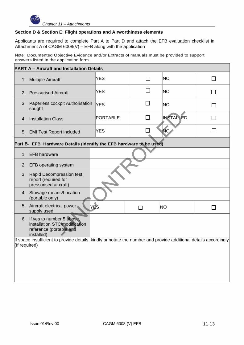
Chapter 11 – Attachments
Issue 01/Rev 00 CAGM 6008 (V) EFB
11-13
Section D & Section E: Flight operations and Airworthiness elements
Applicants are required to complete Part A to Part D and attach the EFB evaluation checklist in
Attachment A of CAGM 6008(V) – EFB along with the application
Note: Documented Objective Evidence and/or Extracts of manuals must be provided to support answers listed in the application form.
PART A – Aircraft and Installation Details
1. Multiple Aircraft YES NO
2. Pressurised Aircraft YES NO
3. Paperless cockpit Authorisation sought
YES NO
4. Installation Class PORTABLE INSTALLED
5. EMI Test Report included YES NO
Part B- EFB Hardware Details (identify the EFB hardware to be used)
1. EFB hardware
2. EFB operating system
3. Rapid Decompression test report (required for pressurised aircraft)
4. Stowage means/Location (portable only)
5. Aircraft electrical power supply used
YES NO
6. If yes to number 5 above, installation STC/modification reference (portable and installed)
If space insufficient to provide details, kindly annotate the number and provide additional details accordingly (If required)

Chapter 11 – Attachments
Issue 01/Rev 00 CAGM 6008 (V) EFB
11-14
Part C – EFB Software application details (identify EFB software application to be used)
Application Software type* Provider of application
*Software type – TALP, M&B, TACS, AMMD, ECL, IFW
Part D – Operator Documentation (to submit a copy of the procedures developed to address the following)
Operators documents (tick)
1. Operating procedures
a. Normal procedures
b. One EFB inoperative (when applicable);
c. All EFB inoperative
2. Paperless cockpit procedures (if applicable)
3. EFB software configuration management
4. EFB navigation data configuration management
5. EFB reliability monitoring procedures