Embed Size (px)
Citation preview
1
Abstract The paper discusses the static behaviour and the seismic vulnerability of Vasari's House Museum in Arezzo (Italy), a three-storey masonry construction composed of disordered stone and brick masonry walls. Floors were realized with different typologies: masonry vaults at the lower levels, wooden, steel and reinforced concrete floors at the upper ones. The seismic vulnerability of the Museum was evaluated according to the provision of the Italian “Guidelines for the assessment and mitigation of the seismic risk of the cultural heritage” (DPCM2011) that identify a methodology of analysis based on three different levels of evaluation (LV1, analysis at territorial level; LV2, local analysis and LV3, global analysis), according to an increasing level of knowledge. A detailed and careful knowledge process, which included an experimental in-situ investigation, allowed to characterize the geometric and mechanical parameters required to perform a reliable structural assessment. The seismic assessment of Vasari’s House, in particular, was performed analysing both local mechanisms and global behaviour assuming different structural configurations (based on the degree of connection between the structural elements as observed during the knowledge process). This paper, through the discussion of an emblematic case study, highlights the importance of the level of knowledge for the vulnerability assessment of an historic building. Keywords: seismic vulnerability, local and global analysis, museum, masonry building, historic structure, masonry, pushover.
1 Introduction The research project "ARCUS" among the MIBACT - Ministry for the Heritage, Cultural Activities and Tourism (MInistero dei Beni e delle Attività Culturali e del Turismo) and the Universities of the Italian territory, has been conceived for the seismic safety analysis of the Italian Museums, in accordance with the requirements
Paper 64 Numerical Modelling and Seismic Assessment of the Vasari's House Museum in Arezzo A. Ciavattone, M. Betti, A. Borghini, S. Boschi, E. Del Monte S. Giordano, B. Ortolani and A. Vignoli Department of Civil and Environmental Engineering University of Florence, Italy
Civil-Comp Press, 2015 Proceedings of the Fifteenth International Conference on Civil, Structural and Environmental Engineering Computing, J. Kruis, Y. Tsompanakis and B.H.V. Topping, (Editors), Civil-Comp Press, Stirlingshire, Scotland
2
of the O.P.C.M. 3274/2003, law which has required the seismic verifications of all the strategic and relevant buildings of Italy.
In this framework, the Department of Civil and Environmental Engineering of the University of Florence (DICEA) has been involved in the project for the seismic verification of two constructions: the Museum of the Vasari’s House and the Basilica of San Francesco, both located in the city of Arezzo.
This paper shows the procedure of investigation used for the knowledge process and seismic verification of the Museum of Vasari’s House, highlighting the peculiarities of the performed studies: the object, a three levels masonry building, is characterized by many particular aspects, which play a relevant role in the seismic verification.
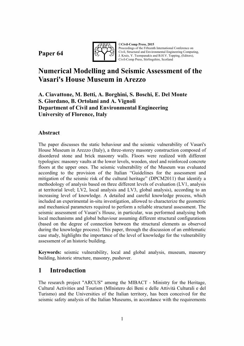
(Imagery © Google, Map data ©2015 Google)
Figure 1: Location of the Vasari's House.
2 The case study: Museum of Vasari's House 2.1 Building description Arezzo is a city located in the central part of the Tuscany Region, on a hill rising from the floodplain of the River Arno. The average elevation of its territory is approximately 300m above the sea level.
Giorgio Vasari, born in Arezzo on the 30th July 1511, was one of the most famous Italian artists of the XVI century: mainly known as a painter (he realized some of the decorations of the Brunelleschi's Dome in the Cathedral of Florence and the ones in the “Salone dei Cinquecento” inside Palazzo Vecchio, town hall of Florence), he worked also as architect for the realization of very important buildings such as the Uffizi Museum in Florence and the Vasari Corridor, private connection for the Medici family among Palazzo Vecchio and Palazzo Pitti in Florence.
The Vasari's House is a palace located in the northern part of Arezzo; it was the residence of the artist who bought the building around 1540. He participated to the works of completion of the building as well as the decoration of the rooms.
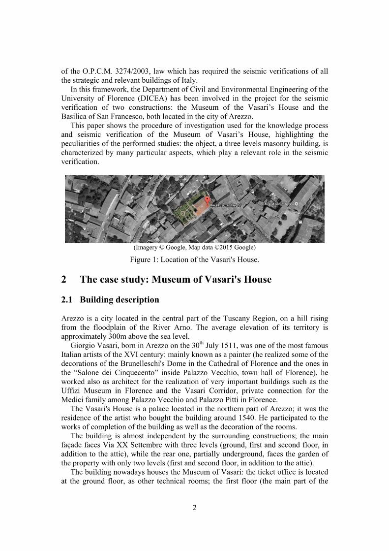
The building is almost independent by the surrounding constructions; the main façade faces Via XX Settembre with three levels (ground, first and second floor, in addition to the attic), while the rear one, partially underground, faces the garden of the property with only two levels (first and second floor, in addition to the attic).
The building nowadays houses the Museum of Vasari: the ticket office is located at the ground floor, as other technical rooms; the first floor (the main part of the
3
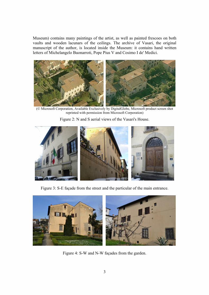
Museum) contains many paintings of the artist, as well as painted frescoes on both vaults and wooden lacunars of the ceilings. The archive of Vasari, the original manuscript of the author, is located inside the Museum: it contains hand written letters of Michelangelo Buonarroti, Pope Pius V and Cosimo I de' Medici.
(© Microsoft Corporation, Available Exclusively by DigitalGlobe, Microsoft product screen shot
reprinted with permission from Microsoft Corporation)
Figure 2: N and S aerial views of the Vasari's House.
Figure 3: S-E façade from the street and the particular of the main entrance.
Figure 4: S-W and N-W façades from the garden.
4
The second floor hosts the residence of the building’s caretaker, as well as another apartment owned by the Superintendence for the Cultural Heritage. On the top level, there is the attic: one half of it, characterized by a medium-high degree of finish, is used as deposit, while the other one, accessible only for maintenance purposes, is in a rough finishing state.
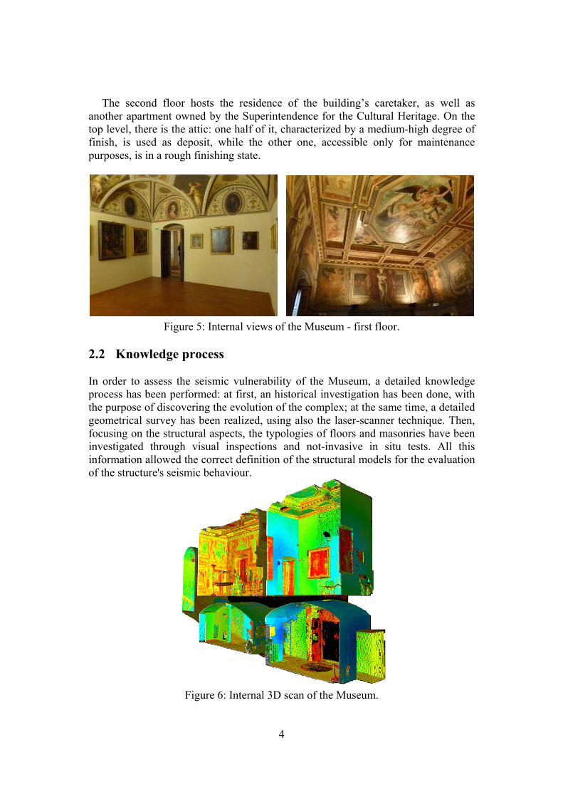
Figure 5: Internal views of the Museum - first floor. 2.2 Knowledge process In order to assess the seismic vulnerability of the Museum, a detailed knowledge process has been performed: at first, an historical investigation has been done, with the purpose of discovering the evolution of the complex; at the same time, a detailed geometrical survey has been realized, using also the laser-scanner technique. Then, focusing on the structural aspects, the typologies of floors and masonries have been investigated through visual inspections and not-invasive in situ tests. All this information allowed the correct definition of the structural models for the evaluation of the structure's seismic behaviour.
Figure 6: Internal 3D scan of the Museum.
5
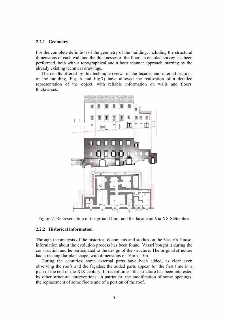
2.2.1 Geometry For the complete definition of the geometry of the building, including the structural dimensions of each wall and the thicknesses of the floors, a detailed survey has been performed, both with a topographical and a laser scanner approach, starting by the already existing technical drawings.
The results offered by this technique (views of the façades and internal sections of the building, Fig. 6 and Fig.7) have allowed the realization of a detailed representation of the object, with reliable information on walls and floors' thicknesses.
Figure 7: Representation of the ground floor and the façade on Via XX Settembre.
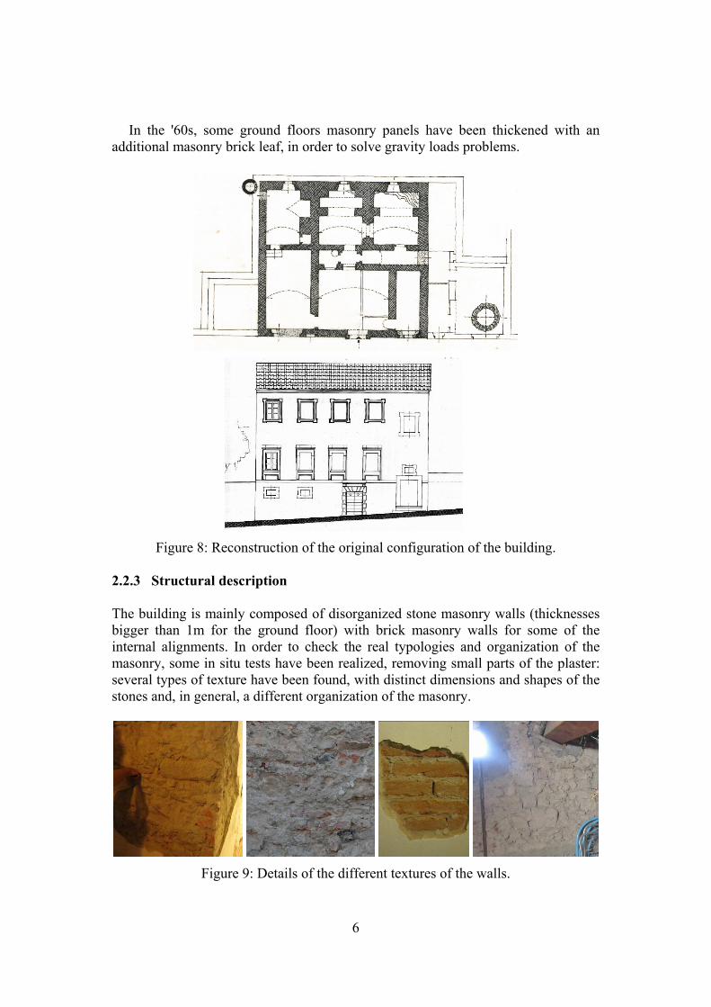
2.2.2 Historical information Through the analysis of the historical documents and studies on the Vasari's House, information about the evolution process has been found. Vasari bought it during the construction and he participated to the design of the structure. The original structure had a rectangular plan shape, with dimensions of 16m x 15m.
During the centuries, some external parts have been added, as clear even observing the roofs and the façades; the added parts appear for the first time in a plan of the end of the XIX century. In recent times, the structure has been interested by other structural interventions: in particular, the modification of some openings, the replacement of some floors and of a portion of the roof.
6
In the '60s, some ground floors masonry panels have been thickened with an additional masonry brick leaf, in order to solve gravity loads problems.
Figure 8: Reconstruction of the original configuration of the building.
2.2.3 Structural description The building is mainly composed of disorganized stone masonry walls (thicknesses bigger than 1m for the ground floor) with brick masonry walls for some of the internal alignments. In order to check the real typologies and organization of the masonry, some in situ tests have been realized, removing small parts of the plaster: several types of texture have been found, with distinct dimensions and shapes of the stones and, in general, a different organization of the masonry.
Figure 9: Details of the different textures of the walls.
7
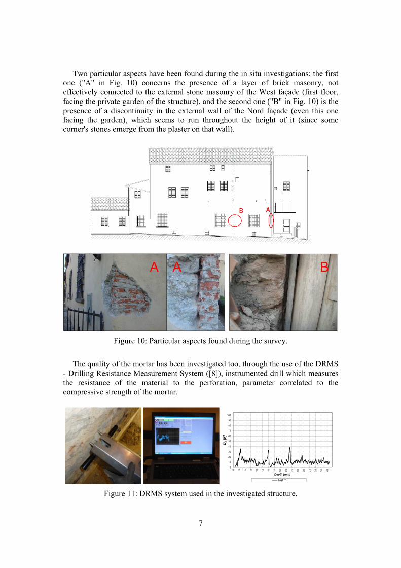
Two particular aspects have been found during the in situ investigations: the first one ("A" in Fig. 10) concerns the presence of a layer of brick masonry, not effectively connected to the external stone masonry of the West façade (first floor, facing the private garden of the structure), and the second one ("B" in Fig. 10) is the presence of a discontinuity in the external wall of the Nord façade (even this one facing the garden), which seems to run throughout the height of it (since some corner's stones emerge from the plaster on that wall).
Figure 10: Particular aspects found during the survey.
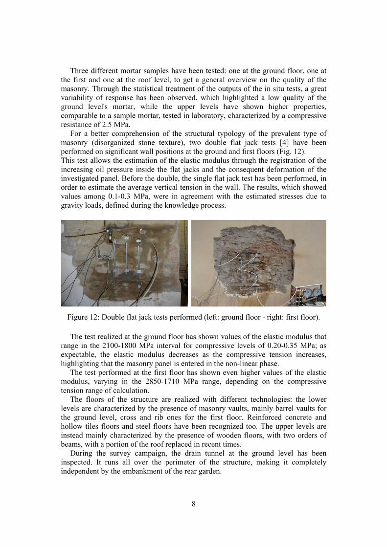
The quality of the mortar has been investigated too, through the use of the DRMS
- Drilling Resistance Measurement System ([8]), instrumented drill which measures the resistance of the material to the perforation, parameter correlated to the compressive strength of the mortar.
0
10
20
30
40
50
60
70
80
90
100
0 3 5 8 10 13 15 18 20 23 25 28 30 33 35 38 40
DR
[N]
Depth [mm]
Test n1
Figure 11: DRMS system used in the investigated structure.
8
Three different mortar samples have been tested: one at the ground floor, one at the first and one at the roof level, to get a general overview on the quality of the masonry. Through the statistical treatment of the outputs of the in situ tests, a great variability of response has been observed, which highlighted a low quality of the ground level's mortar, while the upper levels have shown higher properties, comparable to a sample mortar, tested in laboratory, characterized by a compressive resistance of 2.5 MPa.
For a better comprehension of the structural typology of the prevalent type of masonry (disorganized stone texture), two double flat jack tests [4] have been performed on significant wall positions at the ground and first floors (Fig. 12). This test allows the estimation of the elastic modulus through the registration of the increasing oil pressure inside the flat jacks and the consequent deformation of the investigated panel. Before the double, the single flat jack test has been performed, in order to estimate the average vertical tension in the wall. The results, which showed values among 0.1-0.3 MPa, were in agreement with the estimated stresses due to gravity loads, defined during the knowledge process.
Figure 12: Double flat jack tests performed (left: ground floor - right: first floor).
The test realized at the ground floor has shown values of the elastic modulus that range in the 2100-1800 MPa interval for compressive levels of 0.20-0.35 MPa; as expectable, the elastic modulus decreases as the compressive tension increases, highlighting that the masonry panel is entered in the non-linear phase.
The test performed at the first floor has shown even higher values of the elastic modulus, varying in the 2850-1710 MPa range, depending on the compressive tension range of calculation.
The floors of the structure are realized with different technologies: the lower levels are characterized by the presence of masonry vaults, mainly barrel vaults for the ground level, cross and rib ones for the first floor. Reinforced concrete and hollow tiles floors and steel floors have been recognized too. The upper levels are instead mainly characterized by the presence of wooden floors, with two orders of beams, with a portion of the roof replaced in recent times.
During the survey campaign, the drain tunnel at the ground level has been inspected. It runs all over the perimeter of the structure, making it completely independent by the embankment of the rear garden.
9
2.3 Knowledge process and Confidence Factor During the surveys on the Vasari's House, it has been possible to observe most of the typologies of masonry and some not destructive tests have been performed, in order to get reliable information about the mechanical properties of them. Considering the observed texture's variability of the different types of masonry, the results of the DRMS and of the flat jack tests, "disorganized stone masonry" and "brick masonry" from the Table C8A.2.1 of the Italian Standard (NTC 2008 [2]) have been chosen for the estimation of the mechanical properties.
In order to take into account the uncertainty in the knowledge of the structural properties of the existing buildings, the Standard defines an adjustment factor, called Confidence Factor (CF), whose value depends on the level of knowledge (KL) of properties such as geometry, reinforcement details and mechanical characteristics of the materials.
In the specific case of monumental buildings, the confidence factor is determined by defining different partial confidence factors fck (k=1÷4) whose values are associated to four categories of investigations and the reached levels of knowledge (DPCM 2011 [1]).
In the Vasari’s House case study, partial factors of confidence are defined considering the collected results of the diagnostic tests performed on the structure. The value of FC1 factor has been assumed equal to 0.00 due to the exhaustive geometric survey, which included the surveys of the crack patterns. FC2 factor has been assumed equal to 0.06 because, thanks to the historic information, the recognition of the principal historic phases of construction was known. For the values of the mechanical characteristics of the masonries, FC3 factor has been assumed equal to 0.06 due to the collected information on the quality and resistance of the masonry. FC4 factor has been assumed equal to 0.03 because geological and geotechnical data were available, as well as the foundation's typology. The execution of the surface seismic test MASW (Multichannel Analysis of Surface Waves) provided additional data, concerning the definition of the category of the soil for the definition of the seismic action.
The global confidence factor adopted for the structural analysis is then equal to 1.15, since it is the sum of the partial factors defined above, added to the unit. For the local analyses, since the resistance is considered infinite (punctual definition of the hinge configuration in the cross section), the FC3 is conventionally defined equal to 0.12 and the global confidence factor for this analysis becomes 1.21. A comparison with the results taking as reference the factor 1.35 has also been performed. 2.4 The seismic hazard The reference seismic action has been evaluated according to the Italian Standard (NTC, 2008) which provides the seismic action starting by the basic seismic hazard of the site in terms of: ag (maximum expected peak ground horizontal acceleration), F0 (maximum spectral amplification factor) and TC* (cut-off period for beginning of the constant velocity part of the spectrum). The spectral shape (elastic response
10
spectrum on rigid ground, Soil Type A, with horizontal topographic surface) is hence defined through the triplet {ag, F0, TC*} and it is provided for 9 return periods TR,SL (between 30 and 2475 years), each one characterized by a probability PVR of exceedance in the reference period VR.
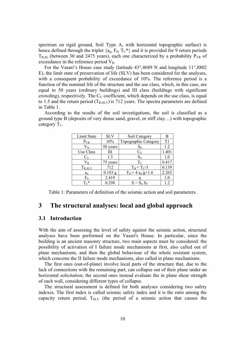
For the Vasari’s House case study (latitude 43°,4689 N and longitude 11°,8802 E), the limit state of preservation of life (SLV) has been considered for the analyses, with a consequent probability of exceedance of 10%. The reference period is a function of the nominal life of the structure and the use class, which, in this case, are equal to 50 years (ordinary buildings) and III class (buildings with significant crowding), respectively. The CU coefficient, which depends on the use class, is equal to 1.5 and the return period (TR,SLV) is 712 years. The spectra parameters are defined in Table 1.
According to the results of the soil investigations, the soil is classified as a ground type B (deposits of very dense sand, gravel, or stiff clay…) with topographic category T1.
Limit State SLV Soil Category B PVR 10% Topographic Category T1 VN 50 years SS 1.2
Use Class III CC 1.401CU 1.5 ST 1.0 VR 75 years TC 0.417
TR,SLV 712 TB = TC/3 0.139ag 0.183 g TD = 4 ag/g+1.6 2.265F0 2.419 η 1.0
TC* 0.298 S = SS ST 1.2
Table 1: Parameters of definition of the seismic action and soil parameters. 3 The structural analyses: local and global approach 3.1 Introduction With the aim of assessing the level of safety against the seismic action, structural analyses have been performed on the Vasari's House. In particular, since the building is an ancient masonry structure, two main aspects must be considered: the possibility of activation of I failure mode mechanisms at first, also called out of plane mechanisms, and then the global behaviour of the whole resistant system, which concerns the II failure mode mechanisms, also called in plane mechanisms.
The first ones (out-of-plane) involve local parts of the structure that, due to the lack of connections with the remaining part, can collapse out of their plane under an horizontal solicitation; the second ones instead evaluate the in plane shear strength of each wall, considering different types of collapse.
The structural assessment is defined for both analyses considering two safety indexes. The first index is called seismic safety index and it is the ratio among the capacity return period, TSLV (the period of a seismic action that causes the
11
achievement of the Life Safety limit state, SLV), and the demand return period, TR,SLV:
SLVR
SLVSLVS T
TI
,, (1)
The second index is defined as the ratio between the peak ground acceleration of
capacity of the structure, aSLV (acceleration that causes the achievement of the SLV), and the demand ag, which is the reference peak ground acceleration for the site in which the structure is located, evaluated for the return period of the SLV.
Both accelerations are considered as independent from the soil, using as reference the best category of it (A soil type - NTC, 2008).
SLVg
SLVSLVa a
af
,, (2)
3.2 Local mechanisms analysis LV2 The application of the method of analysis LV2 requires a critical evaluation of the potential collapses through local mechanisms of the structure. The macro-blocks’ types and shapes depend on the constraints of the panels, such as the orthogonal connections of the masonries, the typologies of floors which insist on the walls, the presence of adjacent buildings, the presence of metal tie-rods and eventual existing crack patterns.
The mechanisms considered for the Vasari's House are able to reconstruct a complete picture of the plausible collapses that could be activated, according to the panels' geometries and the constraints configuration.
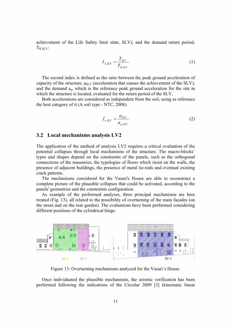
As example of the performed analyses, three principal mechanisms are here treated (Fig. 13), all related to the possibility of overturning of the main façades (on the street and on the rear garden). The evaluations have been performed considering different positions of the cylindrical hinge.
Figure 13: Overturning mechanisms analyzed for the Vasari’s House.
Once individuated the plausible mechanisms, the seismic verification has been performed following the indications of the Circular 2009 [3] (kinematic linear
12
analysis), with the calculation of the multiplier of horizontal actions α0 and the spectral acceleration a0*, converted then in peak ground acceleration of capacity.
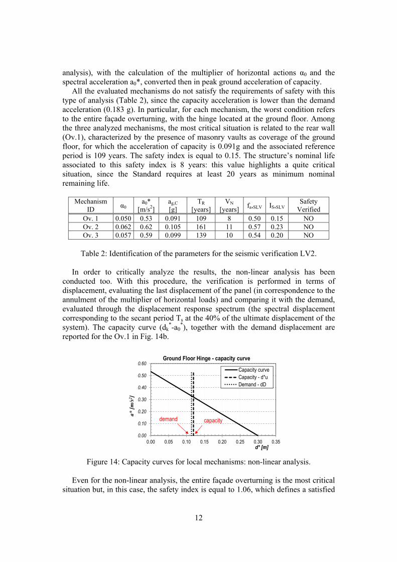
All the evaluated mechanisms do not satisfy the requirements of safety with this type of analysis (Table 2), since the capacity acceleration is lower than the demand acceleration (0.183 g). In particular, for each mechanism, the worst condition refers to the entire façade overturning, with the hinge located at the ground floor. Among the three analyzed mechanisms, the most critical situation is related to the rear wall (Ov.1), characterized by the presence of masonry vaults as coverage of the ground floor, for which the acceleration of capacity is 0.091g and the associated reference period is 109 years. The safety index is equal to 0.15. The structure’s nominal life associated to this safety index is 8 years: this value highlights a quite critical situation, since the Standard requires at least 20 years as minimum nominal remaining life.
Mechanism
ID α0
a0* [m/s2]
ag,C
[g] TR
[years] VN
[years] fa,SLV IS,SLV
Safety Verified
Ov. 1 0.050 0.53 0.091 109 8 0.50 0.15 NO Ov. 2 0.062 0.62 0.105 161 11 0.57 0.23 NO Ov. 3 0.057 0.59 0.099 139 10 0.54 0.20 NO
Table 2: Identification of the parameters for the seismic verification LV2.
In order to critically analyze the results, the non-linear analysis has been
conducted too. With this procedure, the verification is performed in terms of displacement, evaluating the last displacement of the panel (in correspondence to the annulment of the multiplier of horizontal loads) and comparing it with the demand, evaluated through the displacement response spectrum (the spectral displacement corresponding to the secant period Ts at the 40% of the ultimate displacement of the system). The capacity curve (dk
*-a0*), together with the demand displacement are
reported for the Ov.1 in Fig. 14b.
0.00
0.10
0.20
0.30
0.40
0.50
0.60
0.00 0.05 0.10 0.15 0.20 0.25 0.30 0.35
a* [
m/s
2 ]
d* [m]
Ground Floor Hinge - capacity curve
Capacity curveCapacity - d*uDemand - dD
capacitydemand
Figure 14: Capacity curves for local mechanisms: non-linear analysis. Even for the non-linear analysis, the entire façade overturning is the most critical
situation but, in this case, the safety index is equal to 1.06, which defines a satisfied
13
verification. Despite that, from the capacity curves in Fig. 6, it is possible to notice that the last displacement is quite high, arriving to about 30 cm (which corresponds to about 50 centimetres in the curve of real displacement (dk-α0)). This fact could be in contrast with the presence of the top floor, which can collapse even for a smaller displacement or for crumbling phenomenon of the masonry panel.
For this reason, the verification has been carried out again by assuming as ultimate displacements an indicative value of 15 centimetres, which could be associated to the limit displacement for the collapse of the slabs of the top floor. Under this hypothesis, the safety index, ratio between the last capacity displacement (0.09 m) and the request one (0.12 m), is 0.77 and it is worth to notice that the verification shows a lower index of safety, more in line with the results of the linear analysis. 3.3 Global analysis 3.3.1 Typology of analysis Once that the local behaviour of the walls of the structure has been investigated, a global analysis has been performed, in order to evaluate the level of safety related to the in plane behaviour of the masonry panels.
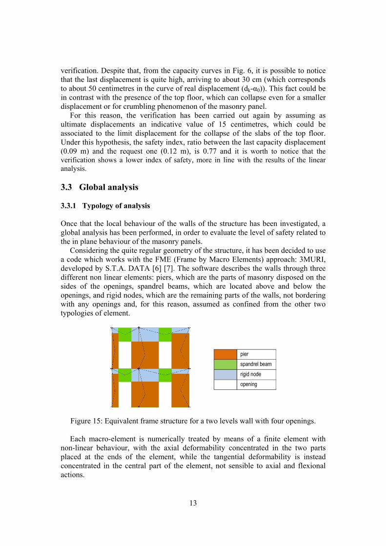
Considering the quite regular geometry of the structure, it has been decided to use a code which works with the FME (Frame by Macro Elements) approach: 3MURI, developed by S.T.A. DATA [6] [7]. The software describes the walls through three different non linear elements: piers, which are the parts of masonry disposed on the sides of the openings, spandrel beams, which are located above and below the openings, and rigid nodes, which are the remaining parts of the walls, not bordering with any openings and, for this reason, assumed as confined from the other two typologies of element.
Figure 15: Equivalent frame structure for a two levels wall with four openings.
Each macro-element is numerically treated by means of a finite element with non-linear behaviour, with the axial deformability concentrated in the two parts placed at the ends of the element, while the tangential deformability is instead concentrated in the central part of the element, not sensible to axial and flexional actions.
14
The elastic - perfectly plastic behaviour is associated to each macro-element, defined by the shear strength of the element, its elastic deformation and the maximum drift, which is a function of the typology of failure (shear collapse due to diagonal cracking, bending moment or sliding).
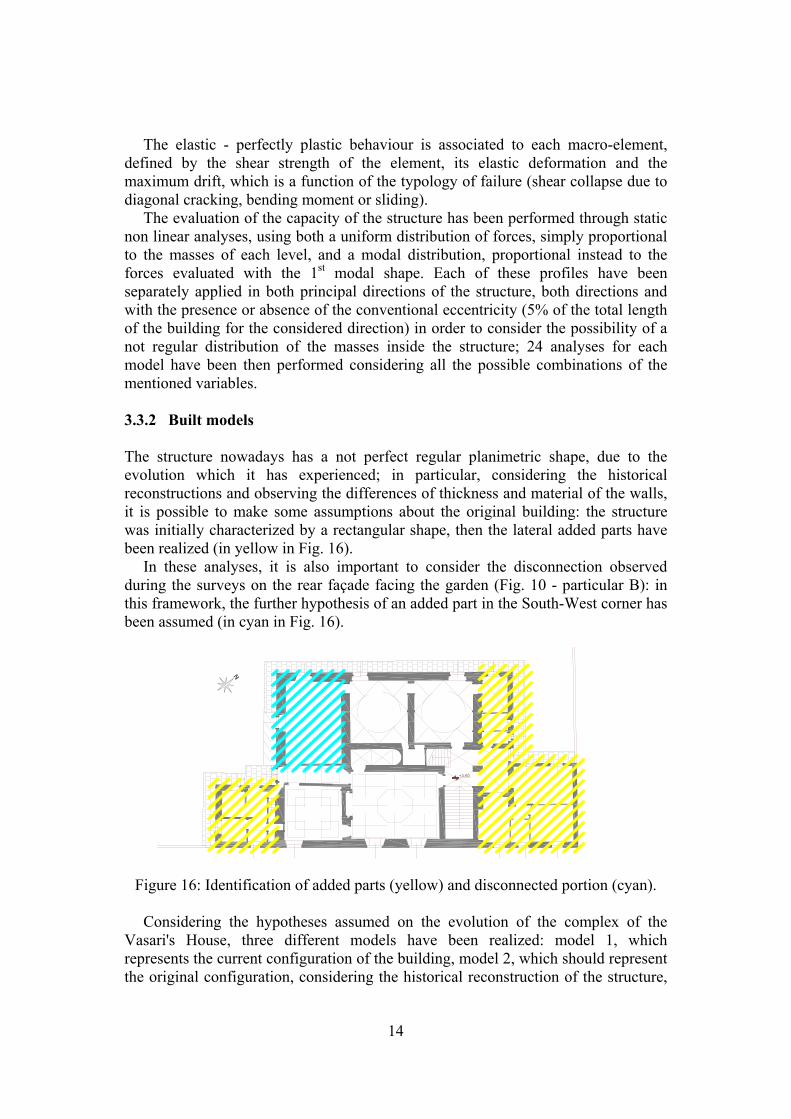
The evaluation of the capacity of the structure has been performed through static non linear analyses, using both a uniform distribution of forces, simply proportional to the masses of each level, and a modal distribution, proportional instead to the forces evaluated with the 1st modal shape. Each of these profiles have been separately applied in both principal directions of the structure, both directions and with the presence or absence of the conventional eccentricity (5% of the total length of the building for the considered direction) in order to consider the possibility of a not regular distribution of the masses inside the structure; 24 analyses for each model have been then performed considering all the possible combinations of the mentioned variables. 3.3.2 Built models The structure nowadays has a not perfect regular planimetric shape, due to the evolution which it has experienced; in particular, considering the historical reconstructions and observing the differences of thickness and material of the walls, it is possible to make some assumptions about the original building: the structure was initially characterized by a rectangular shape, then the lateral added parts have been realized (in yellow in Fig. 16).
In these analyses, it is also important to consider the disconnection observed during the surveys on the rear façade facing the garden (Fig. 10 - particular B): in this framework, the further hypothesis of an added part in the South-West corner has been assumed (in cyan in Fig. 16).
+3,50
Figure 16: Identification of added parts (yellow) and disconnected portion (cyan).
Considering the hypotheses assumed on the evolution of the complex of the Vasari's House, three different models have been realized: model 1, which represents the current configuration of the building, model 2, which should represent the original configuration, considering the historical reconstruction of the structure,
15
and model 3, which takes into account the discontinuity observed on the rear wall, starting from the original configuration.
Figure 17: Schemes of the realized models.
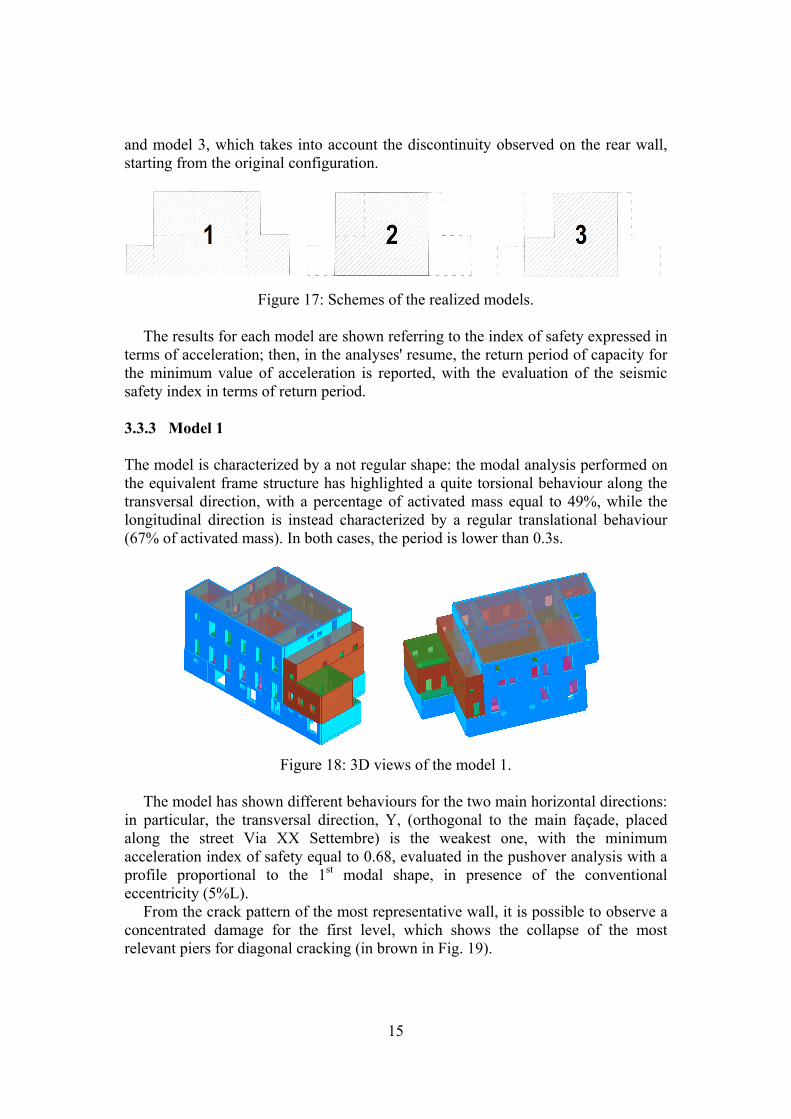
The results for each model are shown referring to the index of safety expressed in terms of acceleration; then, in the analyses' resume, the return period of capacity for the minimum value of acceleration is reported, with the evaluation of the seismic safety index in terms of return period. 3.3.3 Model 1 The model is characterized by a not regular shape: the modal analysis performed on the equivalent frame structure has highlighted a quite torsional behaviour along the transversal direction, with a percentage of activated mass equal to 49%, while the longitudinal direction is instead characterized by a regular translational behaviour (67% of activated mass). In both cases, the period is lower than 0.3s.
Figure 18: 3D views of the model 1.
The model has shown different behaviours for the two main horizontal directions: in particular, the transversal direction, Y, (orthogonal to the main façade, placed along the street Via XX Settembre) is the weakest one, with the minimum acceleration index of safety equal to 0.68, evaluated in the pushover analysis with a profile proportional to the 1st modal shape, in presence of the conventional eccentricity (5%L).
From the crack pattern of the most representative wall, it is possible to observe a concentrated damage for the first level, which shows the collapse of the most relevant piers for diagonal cracking (in brown in Fig. 19).
16
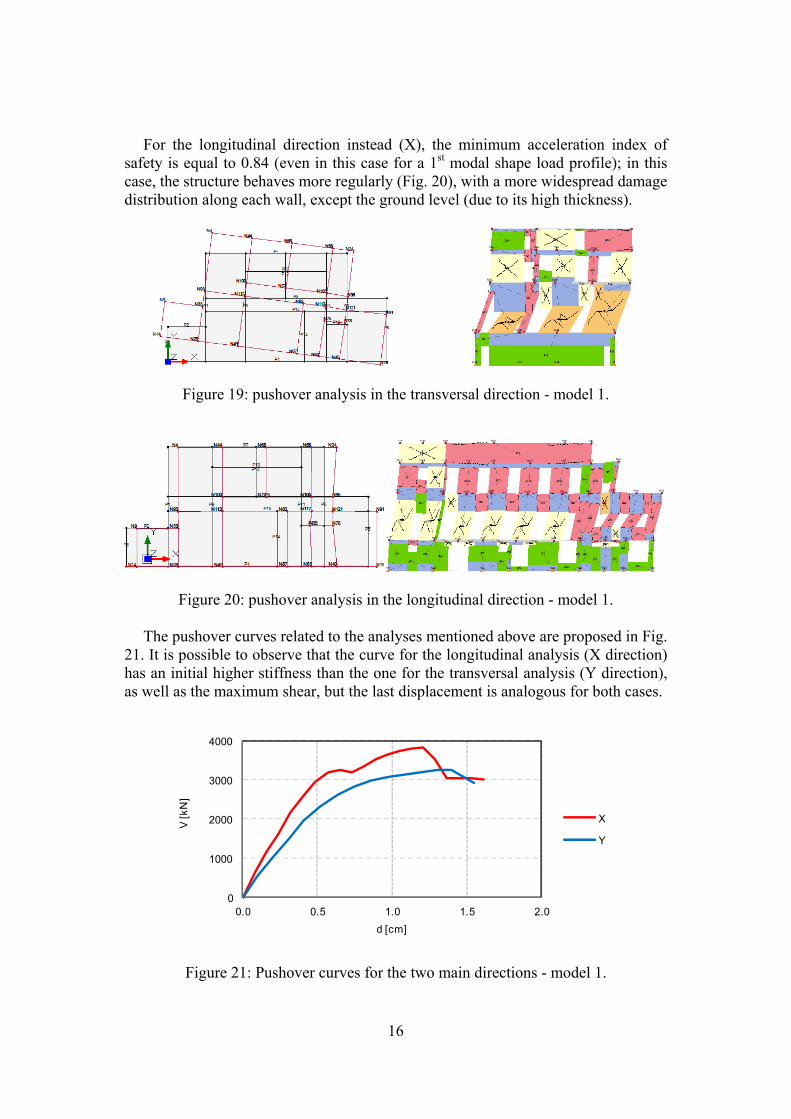
For the longitudinal direction instead (X), the minimum acceleration index of safety is equal to 0.84 (even in this case for a 1st modal shape load profile); in this case, the structure behaves more regularly (Fig. 20), with a more widespread damage distribution along each wall, except the ground level (due to its high thickness).
Figure 19: pushover analysis in the transversal direction - model 1.
Figure 20: pushover analysis in the longitudinal direction - model 1.
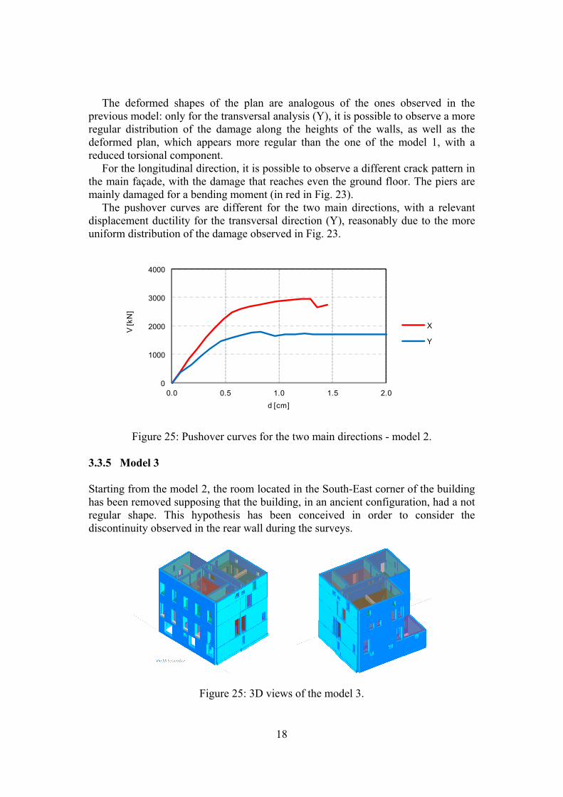
The pushover curves related to the analyses mentioned above are proposed in Fig. 21. It is possible to observe that the curve for the longitudinal analysis (X direction) has an initial higher stiffness than the one for the transversal analysis (Y direction), as well as the maximum shear, but the last displacement is analogous for both cases.
0
1000
2000
3000
4000
0.0 0.5 1.0 1.5 2.0
V [k
N]
d [cm]
X
Y
Figure 21: Pushover curves for the two main directions - model 1.
17
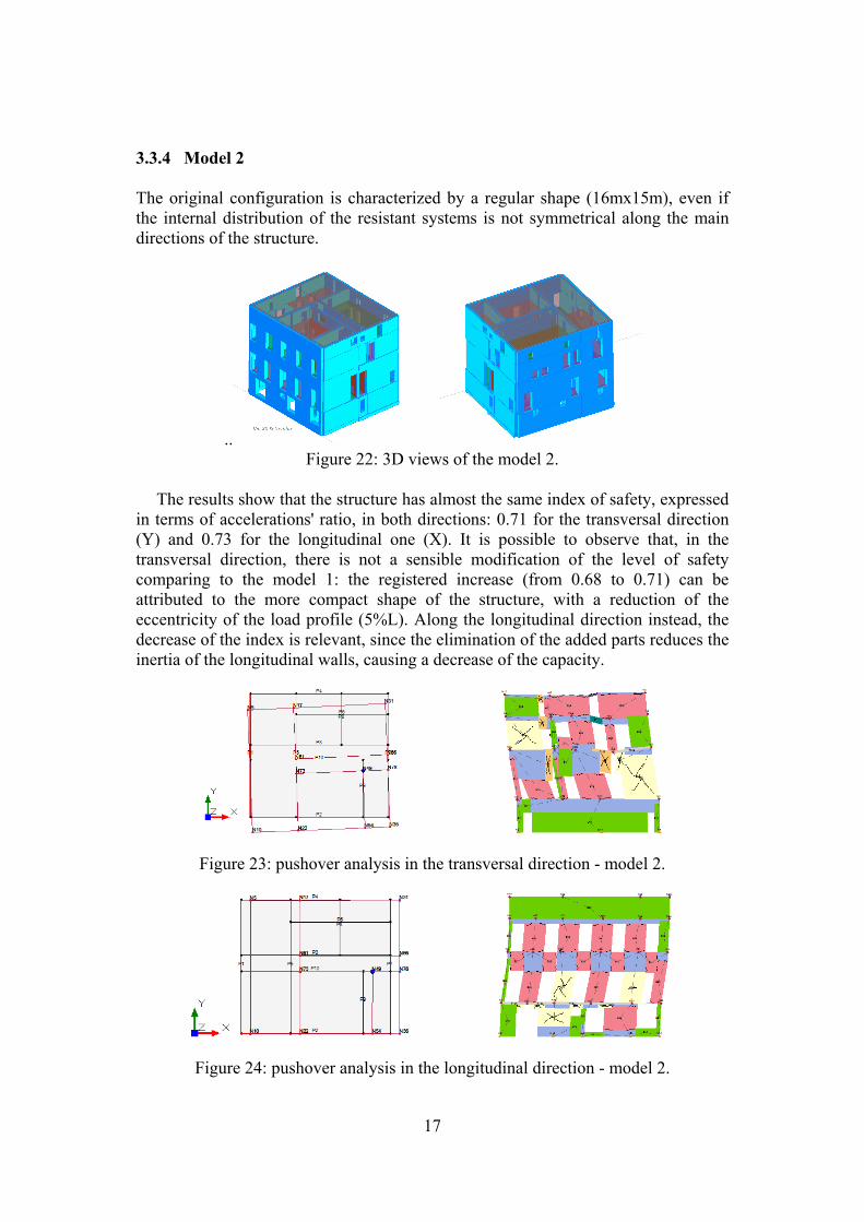
3.3.4 Model 2 The original configuration is characterized by a regular shape (16mx15m), even if the internal distribution of the resistant systems is not symmetrical along the main directions of the structure.
.. Figure 22: 3D views of the model 2.
The results show that the structure has almost the same index of safety, expressed
in terms of accelerations' ratio, in both directions: 0.71 for the transversal direction (Y) and 0.73 for the longitudinal one (X). It is possible to observe that, in the transversal direction, there is not a sensible modification of the level of safety comparing to the model 1: the registered increase (from 0.68 to 0.71) can be attributed to the more compact shape of the structure, with a reduction of the eccentricity of the load profile (5%L). Along the longitudinal direction instead, the decrease of the index is relevant, since the elimination of the added parts reduces the inertia of the longitudinal walls, causing a decrease of the capacity.
Figure 23: pushover analysis in the transversal direction - model 2.
Figure 24: pushover analysis in the longitudinal direction - model 2.
18
The deformed shapes of the plan are analogous of the ones observed in the previous model: only for the transversal analysis (Y), it is possible to observe a more regular distribution of the damage along the heights of the walls, as well as the deformed plan, which appears more regular than the one of the model 1, with a reduced torsional component.
For the longitudinal direction, it is possible to observe a different crack pattern in the main façade, with the damage that reaches even the ground floor. The piers are mainly damaged for a bending moment (in red in Fig. 23).
The pushover curves are different for the two main directions, with a relevant displacement ductility for the transversal direction (Y), reasonably due to the more uniform distribution of the damage observed in Fig. 23.
0
1000
2000
3000
4000
0.0 0.5 1.0 1.5 2.0
V [k
N]
d [cm]
X
Y
Figure 25: Pushover curves for the two main directions - model 2.
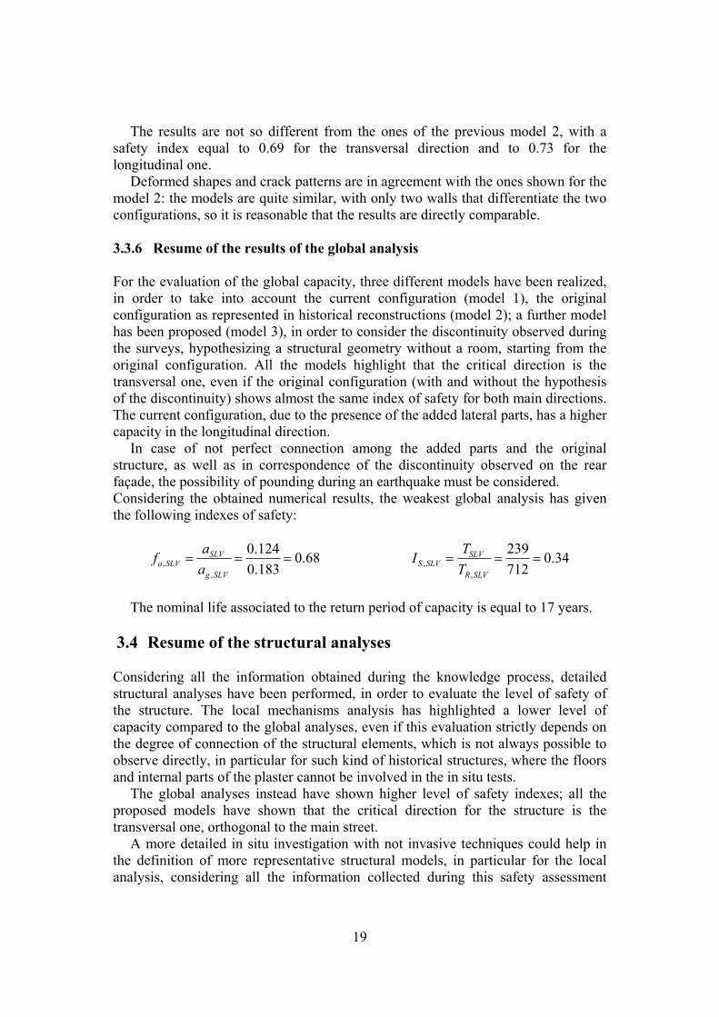
3.3.5 Model 3 Starting from the model 2, the room located in the South-East corner of the building has been removed supposing that the building, in an ancient configuration, had a not regular shape. This hypothesis has been conceived in order to consider the discontinuity observed in the rear wall during the surveys.
Figure 25: 3D views of the model 3.
19
The results are not so different from the ones of the previous model 2, with a safety index equal to 0.69 for the transversal direction and to 0.73 for the longitudinal one.
Deformed shapes and crack patterns are in agreement with the ones shown for the model 2: the models are quite similar, with only two walls that differentiate the two configurations, so it is reasonable that the results are directly comparable. 3.3.6 Resume of the results of the global analysis For the evaluation of the global capacity, three different models have been realized, in order to take into account the current configuration (model 1), the original configuration as represented in historical reconstructions (model 2); a further model has been proposed (model 3), in order to consider the discontinuity observed during the surveys, hypothesizing a structural geometry without a room, starting from the original configuration. All the models highlight that the critical direction is the transversal one, even if the original configuration (with and without the hypothesis of the discontinuity) shows almost the same index of safety for both main directions. The current configuration, due to the presence of the added lateral parts, has a higher capacity in the longitudinal direction.
In case of not perfect connection among the added parts and the original structure, as well as in correspondence of the discontinuity observed on the rear façade, the possibility of pounding during an earthquake must be considered. Considering the obtained numerical results, the weakest global analysis has given the following indexes of safety:
68.0183.0
124.0
,,
SLVg
SLVSLVa a
af 34.0
712
239
,,
SLVR
SLVSLVS T
TI
The nominal life associated to the return period of capacity is equal to 17 years.
3.4 Resume of the structural analyses Considering all the information obtained during the knowledge process, detailed structural analyses have been performed, in order to evaluate the level of safety of the structure. The local mechanisms analysis has highlighted a lower level of capacity compared to the global analyses, even if this evaluation strictly depends on the degree of connection of the structural elements, which is not always possible to observe directly, in particular for such kind of historical structures, where the floors and internal parts of the plaster cannot be involved in the in situ tests.
The global analyses instead have shown higher level of safety indexes; all the proposed models have shown that the critical direction for the structure is the transversal one, orthogonal to the main street.
A more detailed in situ investigation with not invasive techniques could help in the definition of more representative structural models, in particular for the local analysis, considering all the information collected during this safety assessment
20
procedure carried out by the Department of Civil and Environmental Engineering of the University of Florence.
4 Conclusions In case of monumental historical buildings, the knowledge process represents a very important phase for the definition of reliable structural models: the case study of the Vasary's House has shown that, even in a quite simple construction, many peculiar aspects can be found with a detailed and careful in situ investigation, through focused not destructive tests.
For the computational aspects, it is important to highlight that the safety assessment of an historical building, due to the structural uncertainties (related to the evolution of the considered complex), must consider different configuration and, as consequence, different models, in order to get reliable information on the level of safety. The proposed analyses show a possible approach for the investigation of the structural capacity of an ancient masonry building, considering both local and global analyses, focusing on the types of approach (linear and non linear) in order to compare in a critical way the obtained results.
References [1] DPCM 2011. Direttiva del Presidente del Consiglio dei Ministri per la
valutazione e riduzione del rischio sismico del patrimonio culturale con riferimento alle NTC 2008. G. U. n. 47 del 26.02.2011..
[2] NTC 2008. D.M. del Ministero delle Infrastrutture e dei Trasporti del 14/01/2008. Nuove Norme Tecniche per le Costruzioni. G.U. n. 29 del 04.02.2008, S.O. n. 30.
[3] Circular 2009. Circolare n. 617 del 2 febbraio 2009. Istruzioni per l’Applicazione Nuove Norme Tecniche Costruzioni di cui al Decreto Ministeriale 14 gennaio 2008.
[4] ASTM C 1197, 2014. ‘Standard test method for in-situ measurement of masonry deformability properties using the flat jack method’.
[5] Borghini A., Ciavattone A., Boschi S., Vignoli A. (2014). Metodi di stima della vulnerabilità sismica: il caso di Villa Fabbricotti in Firenze. Workshop "SAFE MONUMENTS": Conservation vs Safety of Monuments and Historical Constructions - 28/03/2014 - Florence - Italy.
[6] Galasco A., Frumento S. (2011). Analisi sismica delle strutture murarie - Calcoli strutturali. Sistemi editoriali - Gruppo Editoriale Simone.
[7] Cattari S., Galasco A., Lagomarsino S., Penna A. (2004). Analisi non lineare di edifici in muratura con il programma TREMURI”. Atti del XI Congresso Nazionale “L’ingegneria Sismica in Italia”, Genova January 2004.
[8] Del Monte E., Vignoli A. (2008). In situ mechanical characterization of the mortar in masonry buildings with DRMS. Proceedings of the Sacomatis conference, Varenna (Co), Italy, 1–2 September 2008, Rilem PRO 59, - Vol. 1 - pp. 421-430.
![Civil-Comp Press, Stirlingshire, Scotland Floor Acceleration … · 2015. 8. 6. · in [11]. The structural response quantities are interstory drifts and floor acceleration spectral](https://img.pdfslide.net/doc/110x75/5fea5732b62efc21dd519f05/civil-comp-press-stirlingshire-scotland-floor-acceleration-2015-8-6-in-11.jpg)