Embed Size (px)
Citation preview

A I R M O B I L I T Y C O M M A N D
CIVIL ENGINEER SQUADRONDESIGN GUIDE
ARCHIVED

i
Air Mobility Command’s civil engineer squadrons providevital support to the Air Mobility Team. They construct,operate, and maintain AMC’s facilities; provide emergencyservices; and orchestrate our efforts to preserve and enhancethe environment.
As these civil engineering troops are leading the charge toupgrade facilities in our command, AMC needs to give theman environment in which they can be fully productive andproud to serve. This guide sets new standards—they will bethe keys to success in planning, programming, design, andconstruction of excellent facilities.
“The Air Mobility Team...Responsive Global Reach for America...Every Day!”ARCHIVED

ii
Chapter 1Introduction 1
A. Purpose . . . . . . . . . . . . . . . . . . . . . . . . . . . . . . . . . . . . . . . . . . . . . . . . . . . . . . . . . . . . . . 1B. Project Development . . . . . . . . . . . . . . . . . . . . . . . . . . . . . . . . . . . . . . . . . . . . . . . . . . . . 2
1. Planning2. Programming3. Design4. Construction
Chapter 2Site Considerations 3
A. General . . . . . . . . . . . . . . . . . . . . . . . . . . . . . . . . . . . . . . . . . . . . . . . . . . . . . . . . . . . . . . 3B. Functional Area Relationships . . . . . . . . . . . . . . . . . . . . . . . . . . . . . . . . . . . . . . . . . . . . . 3C. Exterior Elements . . . . . . . . . . . . . . . . . . . . . . . . . . . . . . . . . . . . . . . . . . . . . . . . . . . . . . . 4
1. General2. Entries3. Exterior Signs4. Parking Areas5. Exterior Storage Areas6. Screen Walls7. Landscaping8. Exterior Break Area
Table of Contents
ARCHIVED

iii
TABLE OF CONTENTS
Chapter 3Functional Areas 7
A. General . . . . . . . . . . . . . . . . . . . . . . . . . . . . . . . . . . . . . . . . . . . . . . . . . . . . . . . . . . . . . . 7B. Administration Area . . . . . . . . . . . . . . . . . . . . . . . . . . . . . . . . . . . . . . . . . . . . . . . . . . . . 7
1. Command Section2. Engineer Flight3. Environmental Flight4. Operations Center5. Resources Flight
C. Shop/Warehouse Areas . . . . . . . . . . . . . . . . . . . . . . . . . . . . . . . . . . . . . . . . . . . . . . . . . . 151. Operations Flight2. Readiness Flight
D. Remote Facilities . . . . . . . . . . . . . . . . . . . . . . . . . . . . . . . . . . . . . . . . . . . . . . . . . . . . . . 231. Explosive Ordnance Disposal Flight2. Entomology Facility
Chapter 4Interior Standards 29
A. General . . . . . . . . . . . . . . . . . . . . . . . . . . . . . . . . . . . . . . . . . . . . . . . . . . . . . . . . . . . . . 29B. Color Concepts. . . . . . . . . . . . . . . . . . . . . . . . . . . . . . . . . . . . . . . . . . . . . . . . . . . . . . . . 29C. Floor Coverings . . . . . . . . . . . . . . . . . . . . . . . . . . . . . . . . . . . . . . . . . . . . . . . . . . . . . . . 29D. Wallcoverings . . . . . . . . . . . . . . . . . . . . . . . . . . . . . . . . . . . . . . . . . . . . . . . . . . . . . . . . . 29E. Ceilings . . . . . . . . . . . . . . . . . . . . . . . . . . . . . . . . . . . . . . . . . . . . . . . . . . . . . . . . . . . . . 29F. Window Coverings . . . . . . . . . . . . . . . . . . . . . . . . . . . . . . . . . . . . . . . . . . . . . . . . . . . . . 29G. Accessories. . . . . . . . . . . . . . . . . . . . . . . . . . . . . . . . . . . . . . . . . . . . . . . . . . . . . . . . . . . 29H. Signs . . . . . . . . . . . . . . . . . . . . . . . . . . . . . . . . . . . . . . . . . . . . . . . . . . . . . . . . . . . . . . . 29I. Systems Furniture . . . . . . . . . . . . . . . . . . . . . . . . . . . . . . . . . . . . . . . . . . . . . . . . . . . . . 30J. Lighting . . . . . . . . . . . . . . . . . . . . . . . . . . . . . . . . . . . . . . . . . . . . . . . . . . . . . . . . . . . . . 30K. Communications. . . . . . . . . . . . . . . . . . . . . . . . . . . . . . . . . . . . . . . . . . . . . . . . . . . . . . . 30
References 40ARCHIV
ED

iv
TABLE OF CONTENTS
List of Figures
Number Description PageFigure 1-A Functional Area Relationships 1Figure 2-A Concept Site Plan for the CE Complex 3Figure 2-B Concept Plan for Optional Two-Story Administration Area 4Figure 3-A Location of the Administration Area in the CE Complex 7Figure 3-B Command Section Concept Floor Plan 8Figure 3-C Engineer Flight Concept Floor Plan 11Figure 3-D Environmental Flight Concept Floor Plan 12Figure 3-E Operations Center Concept Floor Plan 13Figure 3-F Resources Flight Concept Floor Plan 14Figure 3-G Location of the Shop/Warehouse Areas in the CE Complex 15Figure 3-H Heavy Repair Element Concept Floor Plan 16Figure 3-I Zonal Maintenance Shop Concept Floor Plan 18Figure 3-J Typical Zonal Maintenance Shop
Concept Floor Plan (Outside the CE Complex) 18Figure 3-K Infrastructure Element Concept Floor Plan 19Figure 3-L Logistics Management Element Concept Floor Plan 20Figure 3-M Main CE Building Concept Floor Plan 21Figure 3-N Readiness Flight Concept Floor Plan 22Figure 3-O EOD Flight Concept Floor Plan 24Figure 3-P Entomology Facility Concept Floor Plan 25
List of Tables
Number Description PageTable 3-A Functional Space Requirements for the Main CE Building 26-27Table 3-B Functional Space Requirements for the Readiness Flight,
EOD Flight, and Entomology Facility 28Table 4-A Finish Schedule 31-33Table 4-B Furnishings Schedule 34-36Table 4-C Equipment Schedule 37-39
ARCHIVED

1
A. PurposeThis guide provides the basic criteria to organize, evaluate,plan, program, and design Air Mobility Command (AMC)civil engineer (CE) facilities. The information presentedis intended to make commanders and their staffs aware ofimportant design considerations and to aid them in pro-ject development. These facilities should provide anatmosphere in which customers feel comfortable whilereceiving quality assistance. This guide is for use by com-manders, Headquarters AMC staff, design architects andengineers, and others involved in CE facilities design andconstruction. Use this guide to supplement other AirForce (AF) and Department of Defense (DoD) policiesand instructions.
Chapters 2 and 3 address most of the flights of a CEsquadron. Family housing, fire station, and self-help storefacility design guidelines have already been published in
the AMC Commander’s Guide to Family Housing Excel-lence, the Air Force Housing Support Facilities Guide, theAMC and Air Combat Command Fire Station FacilitiesDesign Guide, and the Commander’s Guide to Self-HelpSuccess.
A typical CE squadron operates from multiple facilities. TheCE complex contains the main CE building, the readinessfacility, covered storage facilities, the vehicle wash rack, andthe gas mask confidence facility. Some members of thesquadron work outside the complex in “remote” facilities,which include the entomology and explosive ordnance dis-posal facilities.
This guide organizes the various functions of the CEsquadron into administration and shop/warehouse areas,then discusses the squadron’s remote facilities (Figure 1-A).Chapter 2 addresses the functional area relationshipsbetween these areas in more detail.
Chapter 1
Introduction
Figure 1-A: Functional Area Relationships.
EXPLOSIVEORDNANCEDISPOSAL(EOD)
ADMINISTRATIONAREA
SHOP AREAS
REMOTE FACILITIES
EXTERIOR STORAGE EXTERIOR STORAGE
STAFF ENTRANCE
STAFF PARKING
MAIN ENTRANCE
VISITORAND STAFFPARKING
VISITOR AND STAFF ENTRANCE
ENTOMOLOGYFACILITY
READI-NESSFACILITY(SHOP/WARE-HOUSEAREAS)
WARE-HOUSEAREAS
ARCHIVED

2
INTRODUCTION
B. Project Development
1. PlanningGood planning establishes the objectives for an effectiveprogram and provides the means to help meet them. Itshould also lead to a timetable for project completion.Planning must be long-term. When planning a newfacility, complete the site selection prior to preparing a DD Form 1391, Military Construction Project Data.
2. ProgrammingProgramming includes determining user requirements,developing solutions, identifying funding sources, andforwarding programming documents to the appropriatereview and approval authorities. Each project should beconsistent with the base comprehensive plan for new andexisting facilities. Work is classified as maintenance,repair, or minor construction. Information required dur-ing preparation of the DD Form 1391, which initiatesproject development, is found throughout this guide.Included are considerations of space criteria, overall facil-ity size, and special factors for use in estimating costs.
3. DesignDesign includes concept development, design reviews, andfinal design drawings and specifications. It is important forall participants to actively communicate throughout thedesign process to bring about a successful project.
Life safety code requirements take precedence over otherfacility improvement requirements. All areas should bebarrier free and accessible to the disabled in accordancewith the Americans with Disabilities Act (ADA) andUniform Federal Accessibility Standards (UFAS).
The designer should complete an overall comprehensiveinterior design (CID) standard for your facilities in con-junction with any major design project. The CID standardaddresses interior finishes, artwork, signs, and furnishings.It ensures even small upgrade projects meet the designobjectives for all CE facilities. Refer to the AMC InteriorDesign Guide for an expanded discussion of interior design.
Integration of engineering, architectural, and interiordesign considerations during project development creates a well coordinated interior design. Analyze an existingfacility’s structural, electrical, communications, andmechanical systems before planning interior designupgrades. The designer should include infrastructureimprovements concurrently with interior finish work when appropriate.
4. ConstructionQuality reviews of the contractors’ submittals by projectengineers and frequent on-site inspections by civil engi-neering construction management personnel and the user will help to ensure design goals are met. ■
ARCHIVED

3
A. GeneralThis chapter includes functional area relationships withinthe CE complex, as well as exterior elements. Use theguidance that suits the needs of your squadron, increasesyour operations’ efficiency, and enhances the visual qualityof your squadron’s facilities.
B. Functional AreaRelationships
The CE squadron is a team of engineers, architects,craftsmen, logisticians, and administrators. The squad-ron operates most efficiently when the following are neareach other:
◆ Command Section
◆ Engineer Flight
◆ Environmental Flight
◆ Resources Flight
◆ Operations Center
EXTERIOR STORAGEAREA FOR BUILDINGMATERIALS
Chapter 2
Site Considerations
Figure 2-A: Concept Site Plan for the CE Complex.
READINESS FACILITY
SECONDARY ENTRIES
EXTERIOR BREAK AREA
VISITOR DROP-OFF
SECONDARY ENTRIES
MAIN ENTRANCE
VEHICLEWASHRACK
COVERED STORAGE FOREQUIPMENT AND SUPPLIES
GAS MASK CONFIDENCE FACILITY
COVERED STORAGE FOREQUIPMENT AND SUPPLIES
SECURED GATEREADINESSVEHICLEPARKING
OUTSIDEDEMON-STRATIONAREA
STAFFPARKING
VISITORPARKING
STAFF PARKING
VISITOR PARKING STAFF PARKING
SECUREDGATESECURED GATE
STOCK STORAGE AREARECEIVING
SECURED GATE
MAIN CEBUILDINGARCHIVED

4
Locate these flights in the administration area of themain CE building. This administration area should benear the main entrance to the CE complex so visitors caneasily identify it.
A one-story facility is the AMC standard, though siteconcerns such as availability of land may dictate a two-story administration area design. In that case, locate theCommand Section with the Operations Center andResources Flight on the lower level, and the Engineer andEnvironmental Flights on the upper level (see Figure 2-B).
Provide a “zonal maintenance” shop in each majorgeographic area or “zone” of the base. The squadroncommander determines the number of zones dependingon the mission and size of the base. For small bases withonly one or two zones, it is feasible to locate all zonalmaintenance shops in the CE complex as long as eachzone’s shops are separate.
Locate the readiness facility in the CE complex because squadron personnel frequently need to use thereadiness classrooms for training. Because the ExplosiveOrdnance Disposal (EOD) Flight stores and uses smallexplosives, locate it in a facility which meets applicablesafety standards.
Utility plants, entomology facilities, snow removalequipment storage facilities, and outdoor readiness trainingareas are other examples of squadron facilities which areseparate from the complex. This guide does not addressutility plants or snow removal equipment storage facilitiesin detail.
C. Exterior Elements
1. GeneralExterior elements provide the first impression visitorshave of the squadron’s facilities and quality of service.This section addresses entries, exterior signs, parkingareas, exterior storage areas, screen walls, landscaping, and an exterior break area. The Architectural Compat-ibility Plan for each base will help in the design of these elements.
SITE CONSIDERATIONS
Figure 2-B: Concept Plan for Optional Two-Story AdministrationArea.
Entomology facilities should be separate from the main CE building.
ENGINEER ANDENVIRONMENTALFLIGHTS
COMMAND SECTION,RESOURCES FLIGHT,AND OPERATIONSCENTER
ADMINISTRATION AREA
ARCHIVED

5
SITE CONSIDERATIONS
Use screen walls around unattractive storage areas, and provide ample off-street parking for visitors.
2. EntriesThe entry to the CE complex and its administration areashould be easily identifiable to first time visitors. Provide a visitor drop-off area at the main entrance to the adminis-tration area. Consider secondary entries near parkingareas for squadron personnel.
3. Exterior SignsExterior signs include facility, directional, and parkingsigns. Follow the AMC sign standards. Locate facilitysigns at the primary entrance to the CE complex andremote facilities. Directional signs should guide vehicleand pedestrian traffic to each facility. Use parking signs to designate visitor, staff, and handicapped parking areas.
4. Parking AreasInclude designated spaces for visitors and squadron staff. Locate handicapped parking near building entries.Parking requirements will depend on the size of thesquadron. Parking for all privately owned vehicles shouldbe separate from equipment storage areas and other gov-ernment vehicle parking areas.
◆ Parking for government vehicles should be within asecure, screened compound, adjacent to the shops andlogistics management areas.
◆ Provide additional parking at the readiness facility for base personnel who attend training classes.
◆ Secure EOD Flight parking areas with a fence anddouble gate. Include security lighting in these areas(see Figure 3-O, page 24).
ARCHIVED

6
5. Exterior Storage AreasThe CE complex and EOD facility require exterior storage areas with power outlets and lighting. Locate acovered storage area in the complex for building materialsand miscellaneous small equipment.
6. Screen WallsScreen walls can hide exterior shop and storage areas. Thedesign of screen walls is part of each base’s ArchitecturalCompatibility Plan.
7. Landscaping Landscaping elements help create a quality appearance around all CE facilities. These elements screen parkingareas and define building entries. Landscaping elementsinclude earth berms, shrubs, trees, and flowers. Refer to the AMC Landscape Design Guide for specific information.
8. Exterior Break AreaProvide a covered patio to serve as a break area and a per-sonnel gathering place for squadron activities. Locate thisarea away from the complex entrance, and provide privacythrough the use of screen walls and landscaping. ■
SITE CONSIDERATIONS
Exterior covered storage facilities should include overhead doors tosecure equipment and supplies, and provide ease of access.
Provide an exterior break area for squadron activities.
ARCHIVED

7
Chapter 3
Functional Areas
A. GeneralThis chapter addresses the functional areas of each flight within the administration area, shop/warehouseareas, and remote facilities. The discussion includes thesupport each flight provides to the squadron’s mission,interaction between the squadron’s flights, and specialrequirements for the flights to function efficiently.
B. Administration Area The Command Section, Engineer Flight, EnvironmentalFlight, Operations Center, and Resources Flight require anoffice environment. A large portion of the office spaceshould be open areas with systems furniture. CommandSection, flight, and element supervisors require privateoffices near their respective open office areas so they canmanage their personnel and provide private counseling.Administration support areas are for common use andinclude a main conference room, a copy machine room, a central break area, and rest rooms.
◆ Corridors should provide clear paths from administra-tion area lobbies to the various flights.
◆ Conference and administration support areas are infre-quent-use areas not requiring natural light. Locatethese areas at the interior portions of open office areas.
◆ Centrally locate a main conference room for 30-35people between the administration and shop areas ofthe main CE building. Include space for communica-tions and audio-visual equipment.
Figure 3-A: Location of the Administration Area in the CE Complex.
ARCHIVED
FUNCTIONAL AREAS
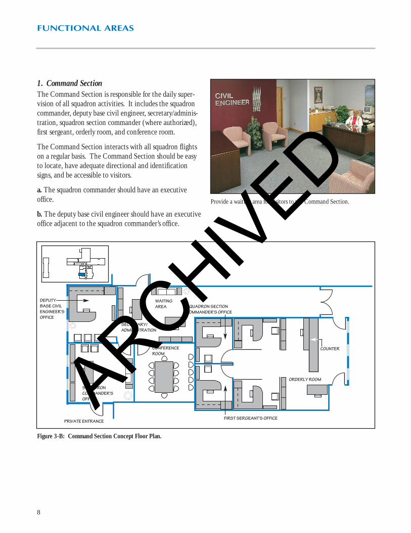
1. Command SectionThe Command Section is responsible for the daily super-vision of all squadron activities. It includes the squadroncommander, deputy base civil engineer, secretary/adminis-tration, squadron section commander (where authorized),first sergeant, orderly room, and conference room.
The Command Section interacts with all squadron flightson a regular basis. The Command Section should be easyto locate, have adequate directional and identificationsigns, and be accessible to visitors.
a. The squadron commander should have an executiveoffice.
b. The deputy base civil engineer should have an executiveoffice adjacent to the squadron commander’s office.
8
Provide a waiting area for visitors to the Command Section.
Figure 3-B: Command Section Concept Floor Plan.
DEPUTYBASE CIVILENGINEER’SOFFICE
SQUADRONCOMMANDER’SOFFICE
CONFERENCE ROOM
ORDERLY ROOM
COUNTER
SQUADRON SECTIONCOMMANDER’S OFFICE
SECRETARY/ ADMINISTRATION
PRIVATE ENTRANCE
WAITING AREA
FIRST SERGEANT’S OFFICE
ARCHIVED

FUNCTIONAL AREAS
c. Provide a small conference room for 12 -15 people forsmall group meetings chaired by the squadron commanderor the deputy base civil engineer.
d. Squadron members visit the orderly room for weightchecks, physician and dental appointment coordination,training appointments, status changes, and paperworkdistribution. Locate this room centrally within theadministration area so all members have easy access.
e. The squadron section commander supervises the orderlyroom staff and acts as the squadron commander’s executiveofficer. Locate a private office for the squadron sectioncommander adjacent to the orderly room.
f. Include a private office for the first sergeant adjacent tothe orderly room.
9
The orderly room should have a reception counter.
The main conference room should accommodate 30-35 people.
Provide a central break area which includes counters, sinks, and appli-ances for food preparation.
ARCHIVED

FUNCTIONAL AREAS
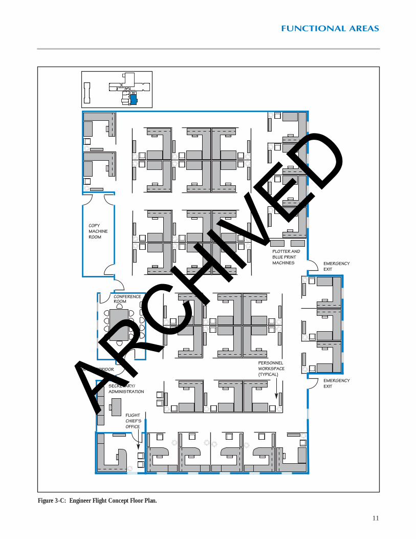
2. Engineer FlightThis flight is responsible for programming, design, andconstruction management of large scale facility projects.Locate this flight within the administration area near theEnvironmental Flight and Operations Center.
◆ Include a private office for the flight chief.
◆ Locate a small conference room for 12-15 people in this flight for project review meetings.
◆ Provide an uninterruptible power source for drawingreproduction equipment and at least one computeraided drafting and design (CADD) workstation for base exercises and other contingency operations.
a. Programming personnel receive work requests and createproject justification documents. They work closely withcustomers, design engineers, Simplified Acquisition forBase Engineer Requirements (SABER) project managers,and financial managers.
b. Design engineers and engineer assistants design in-house and contract work. This work includes periodicdesign reviews with multiple base agencies (safety office,bio-environmental engineers, communications squadron,security police squadron, users, and base operations) andoutside agencies such as design agents, major commandrepresentatives, and architect – engineer firms.
c. Construction managers oversee the construction phaseof projects. Though they are often monitoring projects on-site, they require workspaces to prepare inspection reportsand review construction drawings and specifications.
d. The Engineer Flight also manages the SABER con-tract with a civilian contractor. SABER enables thesquadron to quickly complete construction projects that do not require complicated design efforts.
10
Separate the sections of the Engineer Flight with well-definedcorridors.
The Engineer Flight should have a conference room for project reviewmeetings.
ARCHIVED
FUNCTIONAL AREAS
11
Figure 3-C: Engineer Flight Concept Floor Plan.
FLIGHT CHIEF’S OFFICE
SECRETARY/ADMINISTRATION
MAIN CORRIDOR
CONFERENCEROOM
COPYMACHINEROOM
PLOTTER ANDBLUE PRINTMACHINES EMERGENCY
EXIT
EMERGENCYEXIT
PERSONNELWORKSPACE(TYPICAL)ARCHIVED

FUNCTIONAL AREAS
12
3. Environmental FlightThis flight manages the environmental restoration andenvironmental compliance programs for the wing. Theflight frequently interacts with numerous outside agencies,public and private. Flight personnel work efficiently in anopen office area. There should be a distinct separationbetween the various functions within the flight. Provide aprivate office for the flight chief. File storage areas and anaccessible conference room are also required.
The Environmental Flight frequently interacts with theCommand Section, as well as the Engineer, Operations,and Resources Flights.
a. Environmental restoration personnel manage all envi-ronmental remediation efforts on the base, including thedesign and construction phases. They work closely withthe Engineer Flight to manage these projects.
b. Environmental compliance personnel ensure that the wing complies with applicable laws and regulatoryrequirements, and educates and trains the base populaceon environmental issues and programs. They manage thewing’s pollution prevention program; environmental com-pliance, assessment, and management program (ECAMP);environmental funding programs; and natural and culturalresources management programs.
Figure 3-D: Environmental Flight Concept Floor Plan.
SECRETARY/ADMINISTRATION
FLIGHT CHIEF’S OFFICE
MAIN CORRIDOR
EMERGENCY EXIT FILE STORAGE AREA
ARCHIVED

FUNCTIONAL AREAS
13
4. Operations CenterLocate flight and element supervisors in the administrationarea.
a. The following personnel require private offices:
◆ Flight chief
◆ Deputy flight chief
◆ Heavy Repair superintendent
◆ Facility Maintenance superintendent (supervises allzonal maintenance shops)
◆ Infrastructure superintendent
The flight chief and secretary interact daily with most ofthe other flights in the squadron. Other members of theOperations Center staff primarily interact with the shops,the orderly room, and the Resources Flight.
This flight should also house the damage control center,which should include sufficient space for 10-12 personnel,a radio base station, and wall space for charts, maps, andtracking boards for contingency operations. Include com-puter and communications equipment with anuninterruptible power source.
b. Maintenance Engineering incorporates an engineeringcapability in the Operations Flight to provide an effectiveliaison between the Engineer and Operations Flights.Locate the element near the Engineer Flight since theyfrequently interact on project work.
Include a fire-resistant vault/storage room to store facilitydrawings and an adjacent fume-vented drawing reproduc-tion room.
Figure 3-E: Operations Center Concept Floor Plan.
FLIGHTCHIEF’SOFFICE
SECRETARY/ADMINISTRATION
STAFFENTRANCE
DEPUTYFLIGHTCHIEF’SOFFICE
MAIN CORRIDOR
DAMAGECONTROLCENTER ANDRADIO BASESTATION
VAULT/STORAGEROOM
DRAWINGREPRODUCTION
HEAVY REPAIRSUPERINTENDENT’SOFFICE
FACILITY MAINTENANCESUPERINTENDENT’SOFFICE
INFRASTRUCTURESUPERINTENDENT’SOFFICE
MAINTENANCE ENGINEERINGWORKSPACESARCHIV
ED

FUNCTIONAL AREAS
14
5. Resources FlightThis flight manages real estate files, squadron informationsystems, and financial resources. They require ample stor-age for files and records. Locate an environmentally cleanroom for the main-frame computer and server in this area.Include dedicated utilities for the computer room.
This flight interacts with all other flights in the squadronon a daily basis. Locate this flight in a central locationwithin the administration area to provide the easiest accessfor all squadron personnel.
a. Real estate managers maintain records on all basefacilities. They require workspaces at the interior of the flight area.
b. Information systems administrators should have work-spaces adjacent to the main-frame computer room.
c. Financial managers process funding requests daily for CE personnel. Locate this area at the front of theResources Flight for ease of access and to minimize inter-ruptions to other flight activities. Provide a working areafor analysis work.
Figure 3-F: Resources Flight Concept Floor Plan.
SECRETARY/ADMINISTRATION
WORKING AREA
FLIGHTCHIEF’SOFFICE
REAL ESTATEMANAGEMENT’SWORKSPACES
FILE STORAGE
INFORMATION SYSTEMSMANAGEMENT’S WORKSPACES
MAIN-FRAMECOMPUTER ROOM
FINANCIALMANAGEMENT’SWORKSPACES
MAIN CORRIDOR
ARCHIVED

FUNCTIONAL AREAS
15
C. Shop/Warehouse Areas These areas support the Operations Flight and its manyelements. Most personnel begin work days at theirrespective shops, storing personal items in the lockerareas, receiving work assignments, and leaving to servicevarious base facilities. Sometimes they bring serviceitems, such as electrical or mechanical components, back to their shops for repair.
The logistics management area provides storage space forbuilding supplies and equipment. Shop personnel visit thisarea to obtain bench stock for their shops and parts/sup-plies for work orders.
◆ Provide a covered work area outside the shops wherecraftsmen handle oversized parts. Incorporate overheadcranes into the roof structures of shops that supportheavy equipment repair.
◆ Include an indoor corridor between the shops for weather protected access to the warehouse andadministration area.
◆ Integrate a central dust collection system for shops with woodworking tools. Include air exhaust systemsfor the paint area and vehicle maintenance bays, whichproduce hazardous fumes.
◆ Include a private office in each shop area for the shopsupervisor, a technical library area for repair manuals,adequate work space for tools and equipment, and abreak area with lockers for the shop personnel. Locateshower facilities near the shops.
◆ Provide a mechanical room and rest rooms (with show-ers for shop personnel) in the support areas.
Figure 3-G: Location of the Shop/Warehouse Areas in the CE complex.
A covered work area outside the shops provides additional space forcraftsmen to service equipment.
ARCHIVED

FUNCTIONAL AREAS
16
1. Operations FlightThis flight’s responsibilities include managing and conduct-ing all facility and infrastructure maintenance, small repairand construction projects, and most service contracts.
a. The Heavy Repair element includes the vertical andhorizontal shops. These shops perform the more compli-cated in-house facility repair and construction projects.
Include an open office area for work planners. The verti-cal shop should have structural, sheet metal, plumbing,electrical, and paint areas.
The horizontal shop maintains base pavements, isresponsible for landscaping, and performs entomologyservices. This shop also manages snow removal opera-tions. The entomology facility is a remote facilityoutside the complex.
Include storage and maintenance space for governmentvehicles, equipment, and indoor storage for perishablesupplies.
Some vehicles require servicing within shop facilities.
Figure 3-H: Heavy Repair Element Concept Floor Plan.
LOCKERS/BREAK AREA
TECH.LIBRARY
OFFICE
VERTICALSHOP(PLUMB-ING)
VERTICAL SHOP(ELECTRICAL)
VERTICAL SHOP(SHEET METAL)
MAIN CORRIDOR
LOCKERS/BREAK AREA VERTICAL SHOP(STRUCTURAL)
LOCKERS/BREAK
AREA
HORIZONTAL SHOP
COVERED WORK AREA
VERTICALSHOP(WORKPLAN-NERS)
VERTICALSHOP(PAINT)
OFFICE
OFFICE TECH.LIBRARY
TECH.LIBRARY
OFFICE
TECH.LIBRARY
OFFICE
TECH.LIBRARY
OFFICE
ARCHIVED

FUNCTIONAL AREAS
17
b. Facility maintenance includes the zonal maintenanceshops. Shop personnel perform routine facility mainte-nance and repair. The shops have the following areas:
◆ Shop supervisor’s office
◆ Customer service area
◆ Work controller’s office
◆ Work assignment and break area
◆ Tool and equipment storage
◆ Areas for structural and locksmith, plumbing, interiorelectric, and sheet metal
◆ Interior and exterior storage
Provide a customer service area which has direct access tothe shop supervisor’s office and the shop.
Zonal maintenance shops outside the complex requireadditional shop space and support areas (see Figures 3-I and 3-J, page 18).
The shop supervisor’s office should have a window to the shop forsupervision.
Shops should have adequate clearances around equipment.
Provide a professional, interactive environment in the customer ser-vice area.
ARCHIVED

FUNCTIONAL AREAS
18
Figure 3-J: Typical Zonal Maintenance Shop Concept Floor Plan (Outside the CE Complex).
WORK ASSIGNMENT AND BREAK AREA
MECHAN-ICAL
MEN WOMEN
SHOP SUPERVISOR
CUSTOMERSERVICEAREA
TOOL ROOM
SHOP AREA
MAINENTRANCE
PERSONNELENTRANCE
LOCKERS
CABINETS/COUNTER
Figure 3-I: Zonal Maintenance Shop Concept Floor Plan.
SHOP SUPERVI-SOR CUSTOMER SERVICE
AREA/WORKCONTROLLER’SOFFICE
SHOP AREA
WORK ASSIGNMENTAND BREAK AREA
TO0L ROOM
ARCHIVED

19
FUNCTIONAL AREAS
Figure 3-K: Infrastructure Element Concept Floor Plan.
EMCS SHOP
LOCKERS/BREAK AREA
TECH.LIBRARY
OFFICEOFFICE OFFICE
LIQUIDFUELSSHOP
TECH.LIBRARY
LOCKERS/BREAK AREA
POWER PRODUCTIONSHOP
ELECTRICDISTRIBUTIONSHOP
COVERED WORK AREA
OFFICE
c. The Infrastructure Element monitors and maintains thebase’s utility distribution systems from the following shops,some of which may not be in the CE complex:
◆ Electric distribution
◆ Power production
◆ Energy management and control systems (EMCS), ifapplicable
◆ Utility plants (heat, water and waste water treatment,and power), if applicable
◆ Liquid fuels
These shops require indoor and outdoor storage areas forspecialized vehicles, large equipment, and materials (trans-formers, piping, etc.). Consider environmental hazardprevention, such as oil/water separators and fume ventila-tors, at all working and storage areas. Include additionalindoor work space for bases which experience frequentperiods of inclement weather.
EMCS monitors energy consumption in critical base facili-ties. After-hours monitoring is done from the squadron’s24-hour emergency service center. Provide an environ-mentally clean room with raised flooring and dedicatedpower for the EMCS computer equipment.
ARCHIVED
20
FUNCTIONAL AREAS
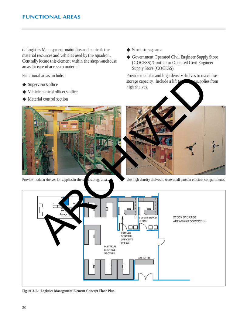
Provide modular shelves for supplies in the stock storage area.
Figure 3-L: Logistics Management Element Concept Floor Plan.
Use high density shelves to store small parts in efficient compartments.
SUPERVISOR’SOFFICE
VEHICLECONTROLOFFICER’SOFFICE
COUNTER
MATERIALCONTROLSECTION
STOCK STORAGEAREA/GOCESS/COCESS
d. Logistics Management maintains and controls thematerial resources and vehicles used by the squadron.Centrally locate this element within the shop/warehouseareas for ease of access to materiel.
Functional areas include:
◆ Supervisor’s office
◆ Vehicle control officer’s office
◆ Material control section
◆ Stock storage area
◆ Government Operated Civil Engineer Supply Store(GOCESS)/Contractor Operated Civil EngineerSupply Store (COCESS)
Provide modular and high density shelves to maximizestorage capacity. Include a lift to retrieve supplies fromhigh shelves.
ARCHIVED

21
FUNCTIONAL AREAS
Figure 3-M: Main CE Building Concept Floor Plan.
MAIN CE BUILDING
ENGINEER FLIGHT
ENVIRONMENTAL FLIGHT
COMMAND SECTION
OPERATIONS CENTER
RESOURCES FLIGHT
LOGISTICS MANAGEMENT
HEAVY REPAIR
FACILITY MAINTENANCE
INFRASTRUCTURE
MAIN ENTRANCE
ADMINISTRATIONSUPPORT AREAS
MECHANICAL ROOM
REST ROOMS/SHOWERS
ARCHIVED

22
FUNCTIONAL AREAS
Figure 3-N: Readiness Flight Concept Floor Plan.
MAINENTRANCE
STAFFPARKING
FLIGHTCHIEF’SOFFICE
READINESSTRAININGWORKSPACES
SECRETARYADMIN.
MECH. NBCCONTROLCENTER
TRAININGNCO’SOFFICE
STUDENTBREAK ROOM
HAZMAT CERTIFICATIONTESTING ROOM
TRAININGCLASSROOM
TRAININGCLASSROOM
INSIDE DEMON-STRATION ROOM
LOGISTICSOFFICE
PROJECTIONROOM
SECURESTORAGEAREA
VEHICLESTORAGE
WAREHOUSE STORAGE ANDMOBILITY PROCESSING
VISITORPARKING
OUTSIDEDEMON-STRATIONAREA
READINESSOPERATIONSWORKSPACES
GAS MASKCONFIDENCE FACILITY
MEN
WOMEN
FENCE
2. Readiness FlightThe Readiness Flight ensures the squadron is prepared to meet any peacetime or wartime contingency. Thisincludes the following training:
◆ Disaster preparedness
◆ Prime Base Engineer Emergency Force (BEEF)
◆ Air base operability
◆ Hazardous material
Readiness personnel interact daily with squadron and basepersonnel. They operate and maintain the squadron dam-age control center in the main CE building and a nuclear,biological, and chemical (NBC) control center in thereadiness facility. They also operate the gas mask confi-dence facility.
The readiness facility should have adequate space foradministration offices, training classrooms, and storage.The training NCO’s office may also be in this facility.This manager is responsible for all skill level upgrade and professional development training.
Provide offices for the following:
◆ Flight Chief
◆ Training NCO
◆ Readiness operations
◆ Readiness training
◆ Logistics
Provide storage space for the following:
◆ Chemical warfare training equipment
◆ Mobile command post
◆ Disaster preparedness equipment
◆ Prime BEEF equipment sets, tool boxes, and mobilitybags
The training classrooms should have space for seating andseveral computer work stations for skill level upgrade training.
Equip rest rooms with showers and provide access from theoutside demonstration area and gas mask confidence facility.
ARCHIVED

23
FUNCTIONAL AREAS
Provide an outdoor area for on-site ordnance recognition training.
D. Remote Facilities
1. Explosive Ordnance Disposal FlightThis flight is responsible for protecting people and resources from the effects of weapons, weaponcomponents, and other hazardous components anddevices. This includes storing hazardous materials.
The Explosive Ordnance Disposal (EOD) Flight primarilyinteracts with others within the squadron for ordnancerecognition training. This training is most effective on an outdoor training site. They also provide classroom andpractical training to numerous federal and state agencies inbomb search and neutralization procedures. Some basemissions do not require an EOD flight. Other bases maybe augmented by Air Force Reserve or Air National GuardEOD units. In these cases, every effort should be made tocollocate these units with the active duty forces.
Locate this flight away from the CE complex, but near theoutdoor training area. The EOD facility should includethe following areas:
◆ Flight chief’s office
◆ EOD staff’s workspaces
◆ Reception/dispatch desk with radio base station
◆ Training room
◆ Physical fitness room
◆ Maintenance and secure storage area
◆ Vehicle storage bays
◆ Primary weapons vault
The open office area includes technical orders, operations,supply, and training offices. Training includes hands-onaccess to models of explosive ordnance. Store these mod-els in display cabinets.
◆ Equip rest rooms with showers.
◆ Isolate the outdoor training area from populated areasand weapons storage areas of the base.
ARCHIVED

24
FUNCTIONAL AREAS
Figure 3-O: EOD Flight Concept Floor Plan.
MAINTENANCE AND SECURESTORAGE AREA
PRIMARYWEAPONSVAULT
TRAINING ROOM
RECEPTION/DISPATCH DESK
EOD STAFF’SWORKSPACES
FLIGHT CHIEF’S OFFICE
DISPLAY CASE
EXTERIOR SECURESTORAGE SPACE ANDPARKING
FENCE
FENCE
DOUBLE GATE
VEHICLE STORAGEBAYS
MAINTENANCEAND SECURESTORAGE AREA
LAUNDRY
MECHANICAL
PHYSICALFITNESSROOM
JANITOR’SCLOSET
ARCHIVED

FUNCTIONAL AREAS
25
The training room should include a television, table space, and adisplay area for explosive ordnance models.
The reception/dispatch desk is the central point of contact for visitors.
Entomology facilities require vented exhaust hoods in the mixing room.Figure 3-P Entomology Facility Concept Floor Plan.
WASHDOWN AREA
EQUIPMENTREPAIR
BREAKROOM
OFFICE
HERBICIDESTORAGE
INSECTICIDESTORAGE
MIXINGROOM
LAUNDRY
MECH.
STORAGE
RESTROOM
MAINENTRANCE
◆ Provide exterior covered storage areas.
◆ Include outdoor and indoor parking for special EODvehicles.
◆ Incorporate a weapons vault with an integral securitysystem that can contract base security in case of unau-thorized intrusion.
◆ Provide a communications system for paging.
◆ Include an electric door lock at the main entrance tocontrol visitor access to the facility and its explosivesupplies.
◆ Provide a temperature and humidity controlled spacefor vehicle and equipment maintenance areas.
2. Entomology FacilityIsolate this facility from congested areas of the base anddesign it to protect human health as well as the air, water,and soil.
Provide an eye wash station in the mixing room, showersin the rest rooms, and laundry facilities. Include amplestorage for personal protective equipment, emergencysupplies, and spill clean-up equipment. Insecticide andherbicide storage areas should have containment curbs so chemicals don’t spill into other rooms. The facilityshould include provisions to collect, store, and recyclerinsewater. ■
ARCHIVED

Functional Space Requirements for the Main CE Building(Typical AF Objective CE Squadron of 350 People)
Functions Square Footage Square Meters(1)
Administration AreaCommand SectionSquadron Commander’s Office 200 19Deputy Base Civil Engineer’s Office 150 14Squadron Section Commander’s Office 120 11First Sergeant’s Office 120 11Secretary/Administration(2) 240 22Orderly Room(3) 360 33Conference Room (12 - 15 people) 225 21
Engineer FlightFlight Chief’s Office 150 14Secretary/Administration 120 11Programmers’ Workspaces(4) 480 45Design Engineers’/Engineer Assistants’ Workspaces(5) 1,800 167Construction Management’s Workspaces(6) 1,560 145SABER Workspaces(3) 360 33Conference Room (12 - 15 people) 225 21
Environmental FlightFlight Chief’s Office 150 14Secretary/Administration 120 11Environmental Program Managers’ Workspaces(7) 960 89
Operations CenterFlight Chief’s Office 150 14Deputy Flight Chief’s Office 120 11Secretary/Administration 120 11Facility Maintenance Superintendent’s Office 120 11Infrastructure Superintendent’s Office 120 11Heavy Repair Superintendent’s Office 120 11Maintenance Engineering’s Workspaces(7) 960 89Vault/Storage Room 300 28Damage Control Center 300 28
Resources FlightFlight Chief’s Office 150 14Secretary/Administration 120 11Real Estate Management’s Workspaces(2) 240 22Information Systems Management’s Workspaces(2) 240 22Financial Management’s Workspaces(2) 240 22
26
FUNCTIONAL AREAS
Table 3-A: Functional Space Requirements for the Main CE Building.
ARCHIVED

FUNCTIONAL AREAS
Functional Space Requirements for the Main CE Building (Continued)
Functions Square Footage Square Meters(1)
Resources Flight (Continued)Working Area 120 11File Storage Room 100 9Computer Room 250 23
Administration Support AreasBreak Areas 200 19Copy Machine Rooms 100 9Rest Rooms 500 47Janitor’s Closet 50 5Main Conference Room (30-35 people) 525 49
Shop/Warehouse AreasOperations FlightHeavy Repair ShopVertical Shop(8) 9,500 883Horizontal Shop(8) 4,000 372Facility MaintenanceFacility Maintenance Shop(8) 3,000 279Customer Service/Work Controller’s Office 150 14Infrastructure ElementElectric Distribution Shop(8) 1,200 112EMCS Shop(8) 300 28Power Production Shop(8) 1,500 139Liquid Fuels Shop(8) 400 37Logistics ManagementMaterial Control Section 1,180 110Stock Storage Area/GOCESS/COCESS 16,000 1,487Vehicle Control Officer’s Office 120 11
Support AreasMechanical Rooms 2,500 232Rest Rooms (with showers) 750 70
Subtotal 53,085 4,932Circulation and Walls (15%) 7,963 740
Gross Total 61,048 5,672
27
Table 3-A Continued: Functional Space Requirements for the Main CE Building.
Legend for Table 3-A. (1) Square Meters = .0929 x Square Footage ( All measurements are rounded.)
(2) Two people at 120 square feet each. (3) Three people at 120 square feet each. (4) Four people at 120 square feet each. (5) Fifteen people at 120 square feet each.
(6) Thirteen people at 120 square feet each. (7) Eight people at 120 square feet each. (8) These are average shop sizes. Each squadron should adjust these sizes based on local requirements.
ARCHIVED

28
FUNCTIONAL AREAS
Functional Space Requirements for the Readiness Flight, EOD Flight, and Entomology Facility
Functions Square Footage Square Meters(1)
Readiness FlightFlight Chief’s Office 150 14Secretary/Administration 120 11Readiness Staff’s Workspaces(2) 1,200 111Training NCO’s Office 120 11Logistics Office 120 11HAZMAT Certification Testing Room (12-15 people) 400 37Training Classrooms(3) 1,400 130Projection Room 120 11Inside Demonstration Room 500 47Student Break Room 400 37Secure Storage Area 500 47NBC Control Center 300 28Vehicle Storage 300 28Warehouse Storage and Mobility Processing(4) 5,000 464Rest Rooms 300 28Mechanical Room 400 37
Subtotal 11,330 1,052Circulation and Walls (15%) 1,700 158
Gross Total for Readiness Flight 13,030 1,210EOD FlightFlight Chief’s Office 150 14EOD Staff’s Workspaces(2) 1,200 111Training Room 450 42Physical Fitness Room 250 23Maintenance and Secure Storage Area 1,900 176Vehicle Storage Bays 2,460 229Primary Weapons Vault 150 14Laundry 75 7Rest Rooms 300 28Janitor's Closet 25 2Mechanical Room 300 28
Subtotal 7,260 674Circulation and Walls (15%) 1,089 101
Gross Total for EOD Flight 8,349 775
Gross Total for Entomology Facility(5) 1,800 167
Table 3-B: Functional Space Requirements for the Readiness Flight, EOD Flight, and Entomology Facility.
Legend for Table 3-B. (1) Square Meters = .0929 x Square Footage ( All measurements are rounded.) (2) Ten people at 120 square feet each.
(3) Two classrooms at 700 square feet each. (4) Sizing may vary depending on local storage or mobility processing requirements.
(5) This is an average facility size. Each squadron should adjust the size based on local requirements.
ARCHIVED

29
Chapter 4
Interior StandardsA. GeneralCE squadron facilities reflect the AMC standard of“understated excellence” and create an environmentwhere people can provide quality services. Select interiorfinishes for cost-effectiveness and life cycle maintenance,as well as appearance. Interior finishes that are durableand easy to maintain are essential. Quality interiors pro-vide an environment which improves job performanceand customer satisfaction. In this chapter, Tables 4-Athrough 4-C offer guidance for finishing, furnishing, andequipping each functional area.
B. Color ConceptsDesigners should give special attention to color selectionand provide a timeless color scheme. Use accent colorssparingly to complement a neutral color scheme.
Select a neutral color for carpets, wallcoverings, and sys-tems furniture wall panels. Incorporate accent colors inupholstery, graphics, borders, accessories, and artwork fordesign scheme consistency.
C. Floor CoveringsConsider patterned carpet tile for high-use areas such ashallways, waiting areas, and training rooms in administra-tion areas. Avoid stripes and linear designs that are hard toline up with walls in corridors, vestibules, or irregularlyshaped areas.
◆ Select neutral colored carpet for offices.
◆ Use vinyl composition tile in the corridors and breakrooms, where cleanup of food and dirt is a daily task.
◆ Provide ceramic tile in rest rooms.
◆ Select a sealed concrete finish in warehouse, shop, andstorage areas for durability.
D. WallcoveringsUse vinyl and acoustic wallcovering in all administrationareas. Select painted finishes in shop/warehouse areas inthe main CE building for ease of maintenance.
E. CeilingsUse suspended acoustical ceiling tile with a revealed edgefinish in all administration areas. A standardized 2’ x 2’tile is recommended as the consistent module throughoutCE facilities. Shop areas should have an open paintedceiling. A gypsum board ceiling with water-resistant paintworks well in rest rooms.
F. Window CoveringsVertical blinds and miniblinds filter daylight and allowoutdoor views. Use lined draperies to block daylight forvisual presentations in conference and training rooms.
G. AccessoriesFramed artwork, wall murals, and plants complementinterior finishes and the design scheme. Choose onlyprofessionally framed pictures and paintings with colorschemes and images that contribute to the facility’s decor.Live plants or professional quality silk plants are optional.
H. SignsDevelop an interior sign plan as part of the comprehensiveinterior design. Use professionally made signs appropriate-ly sized for the viewing distance and compatible with thedesign scheme. The main CE building entrance shouldhave signs that clearly direct visitors to specific flights.
ARCHIVED

30
INTERIOR STANDARDS
Incorporate glass panels into systems furniture wall panels so light can filter throughout open office areas.
I. Systems FurnitureThis furniture includes interchangeable wall panels, deskcomponents, and storage modules which combine to formoffice workspaces. These stations allow for a reconfigura-tion of office areas when requirements change.
Select systems furniture that easily integrates computerhardware. Systems furniture panels should incorporateintegrated conduits for electrical and communicationsservice. Sound absorbent fabric panels will reduce back-ground noise and provide a quiet work area.
Finish work surfaces in plastic laminate or wood. Plasticlaminate with a wrapped edge is an easily maintainablefinish.
◆ Use systems furniture in all offices except the squadroncommander’s, deputy base civil engineer’s, andsquadron commander’s secretary’s offices.
J. LightingNatural and artificial lighting are important factors increating a quality interior appearance. Lighting affects theperception of space, as well as the color of interior finishes.Design lighting to enhance the design scheme.
The designer should provide natural and accent lighting in all administration areas. Include task lighting at officedesks. Use high-efficiency fluorescent lighting in theshops in lieu of incandescent lighting.
K. CommunicationsProvide telephone and computer wiring to support fire alarm systems and other equipment listed in the EquipmentSchedules (Table 4-C). Equip facilities with the capabilityfor intercom, cable television, Defense Systems Network(DSN), Defense Information Systems Network (DISN), faxlines, on- and off-base lines, and Local Area Network (LAN)connections. The Operations, Readiness, and EOD Flightsmay require dispatch, STU III secure, and other communica-tions equipment. Locate large antennae away from the mainentrances of buildings. The designer should contact the basecommunications squadron for specific communicationsrequirements before planning major building upgrades ormodifications. Incorporate these requirements in buildingdesign and modification specifications. ■
ARCHIVED

31
♦ ♦ ♦ ♦
♦ ♦ ♦ ♦
♦ ♦ ♦ ♦
♦ ♦ ♦ ♦
♦ ♦ ♦ ♦
♦ ♦ ♦ ♦
♦ ♦ ♦ ♦
♦ ♦ ♦ ♦
♦ ♦ ♦ ♦
♦ ♦ ♦ ♦
♦ ♦ ♦ ♦
♦ ♦ ♦ ♦ ♦
♦ ♦ ♦ ♦
♦ ♦ ♦ ♦
♦ ♦ ♦ ♦
♦ ♦ ♦ ♦
♦ ♦ ♦ ♦
♦ ♦ ♦ ♦
♦ ♦ ♦ ♦
♦ ♦ ♦ ♦
♦ ♦ ♦ ♦
♦ ♦ ♦ ♦
♦ ♦ ♦ ♦
♦ ♦ ♦ ♦
♦ ♦ ♦ ♦
♦ ♦ ♦ ♦
FLOORS BASE WALLS CEILING
Car
pet
Vin
yl C
ompo
sitio
n Ti
le
Cer
amic
Tile
Seal
ed C
oncr
ete
Vin
ylC
eram
ic T
ilePa
int
Vin
yl W
allc
over
ing
Aco
ustic
Wal
lcov
erin
g
Cer
amic
Tile
Aco
ustic
al C
eilin
g Ti
le
Pain
ted
Gyp
sum
Boa
rd
Pain
ted
Expo
sed
Com
pute
r Flo
or
Administration Area
Command SectionSquadron Commander’s OfficeDeputy Base Civil Engineer’s Office
Squadron Section Commander’s Office
First Sergeant’s Office
Secretary/Administration
Orderly Room
Conference Room
Engineer Flight
Flight Chief’s Office
Secretary/Administration
Programmers’ WorkspacesDesign Engineers’/Engineer Assistants’ WorkspacesConstruction Management’s Workspaces
SABER Workspaces
Conference Room
Environmental Flight
Flight Chief’s OfficeSecretary/Administration
Environmental Program Managers’ Workspaces
Operations Center
Flight Chief’s OfficeDeputy Flight Chief’s OfficeSecretary/AdministrationFacility Maintenance Superintendent’s Office
Infrastructure Superintendent’s OfficeHeavy Repair Superintendent’s OfficeMaintenance Engineering’s Workspaces
Vault/Storage Room
Damage Control Center
Woo
d
INTERIOR STANDARDS
Table 4-A: Finish Schedule.
ARCHIVED

32
♦ ♦ ♦ ♦
♦ ♦ ♦ ♦
♦ ♦ ♦ ♦
♦ ♦ ♦ ♦ ♦
♦ ♦ ♦ ♦
♦ ♦ ♦ ♦
♦ ♦ ♦ ♦
♦ ♦ ♦ ♦
♦ ♦ ♦ ♦
♦ ♦ ♦ ♦
♦ ♦ ♦ ♦
♦ ♦ ♦ ♦
♦ ♦ ♦
♦ ♦ ♦ ♦
♦ ♦ ♦
♦ ♦ ♦ ♦
♦ ♦ ♦
♦ ♦ ♦
♦ ♦ ♦ ♦
♦ ♦ ♦
♦ ♦ ♦ ♦
♦ ♦ ♦
♦ ♦ ♦ ♦
♦ ♦ ♦
♦ ♦ ♦
♦ ♦ ♦
FLOORS BASE WALLS CEILING
Car
pet
Vin
yl C
ompo
sitio
n Ti
le
Cer
amic
Tile
Seal
ed C
oncr
ete
Vin
ylC
eram
ic T
ilePa
int
Vin
yl W
allc
over
ing
Aco
ustic
Wal
lcov
erin
g
Cer
amic
Tile
Aco
ustic
al C
eilin
g Ti
le
Pain
ted
Gyp
sum
Boa
rd
Pain
ted
Expo
sed
Com
pute
r Flo
or
Resources Flight
Flight Chief’s Office
Secretary/AdministrationReal Estate Management’s WorkspacesInformation Systems Management’s WorkspacesFinancial Management’s WorkspacesWorking Area
File Storage RoomComputer Room
Administration Support Areas
Break AreasCopy Machine Rooms
Rest Rooms
Janitor’s ClosetMain Conference Room
Shop/Warehouse AreasOperations FlightHeavy Repair ShopVertical ShopHorizontal ShopFacility MaintenanceFacility Maintenance Shop
Customer Service/Work Controller’s OfficeInfrastructure SupportElectric Distribution Shop
EMCS ShopPower Production ShopLiquid Fuels ShopLogistics Management
Material Control SectionStock Storage Area/GOCESS/COCESSVehicle Control Officer’s OfficeSupport Areas
Rest RoomsMechanical Rooms
Woo
d
INTERIOR STANDARDS
Table 4-A Continued: Finish Schedule.
ARCHIVED

33
♦ ♦ ♦ ♦
♦ ♦ ♦ ♦
♦ ♦ ♦ ♦
♦ ♦ ♦ ♦
♦ ♦ ♦ ♦
♦ ♦ ♦ ♦
♦ ♦ ♦ ♦
♦ ♦ ♦ ♦
♦ ♦ ♦ ♦
♦ ♦ ♦ ♦
♦ ♦ ♦ ♦
♦ ♦ ♦ ♦
♦ ♦ ♦
♦ ♦ ♦ ♦
♦ ♦ ♦ ♦
♦ ♦ ♦ ♦
♦ ♦ ♦ ♦
♦ ♦ ♦ ♦
♦ ♦ ♦ ♦
♦ ♦ ♦ ♦
♦ ♦ ♦ ♦
♦ ♦ ♦ ♦
♦ ♦ ♦ ♦
♦ ♦ ♦ ♦
♦ ♦ ♦ ♦
♦ ♦ ♦ ♦
♦ ♦ ♦ ♦
FLOORS BASE WALLS CEILING
Car
pet
Vin
yl C
ompo
sitio
n Ti
le
Cer
amic
Tile
Seal
ed C
oncr
ete
Vin
ylC
eram
ic T
ilePa
int
Vin
yl W
allc
over
ing
Aco
ustic
Wal
lcov
erin
g
Cer
amic
Tile
Aco
ustic
al C
eilin
g Ti
le
Pain
ted
Gyp
sum
Boa
rd
Pain
ted
Expo
sed
Com
pute
r Flo
orW
ood
Readiness FlightFlight Chief’s OfficeSecretary/Administration
Readiness Staff’s WorkspacesTraining NCO’s OfficeLogistics OfficeHAZMAT Certification Testing RoomTraining Classrooms
Projection Room
Inside Demonstration RoomStudent Break RoomSecure Storage Area
NBC Control CenterVehicle StorageWarehouse Storage and Mobility Processing
Rest RoomsMechanical Room
Remote Facilities
EOD FlightFlight Chief’s Office
EOD Staff’s WorkspacesTraining RoomPhysical Fitness RoomMaintenance and Secure Storage Area
Vehicle Storage BaysPrimary Weapons VaultLaundry
Rest Rooms
Janitor’s Closet
Mechanical Room
INTERIOR STANDARDS
Table 4-A Continued: Finish Schedule.
ARCHIVED

34
♦ ♦ ♦ ♦ ♦ ♦ ♦ ♦ ♦ ♦ ♦
♦ ♦ ♦ ♦ ♦ ♦ ♦
♦ ♦ ♦ ♦ ♦ ♦ ♦
♦ ♦ ♦ ♦ ♦ ♦ ♦
♦ ♦ ♦ ♦ ♦ ♦ ♦ ♦ ♦ ♦
♦ ♦ ♦ ♦ ♦ ♦ ♦ ♦ ♦ ♦
♦ ♦ ♦ ♦ ♦ ♦
♦ ♦ ♦ ♦ ♦ ♦ ♦ ♦
♦ ♦ ♦ ♦ ♦ ♦ ♦ ♦ ♦
♦ ♦ ♦ ♦ ♦ ♦
♦ ♦ ♦ ♦ ♦ ♦ ♦ ♦
♦ ♦ ♦ ♦ ♦ ♦ ♦ ♦
♦ ♦ ♦ ♦ ♦
♦ ♦ ♦ ♦ ♦ ♦
♦ ♦ ♦ ♦ ♦ ♦ ♦ ♦
♦ ♦ ♦ ♦ ♦ ♦ ♦ ♦
♦ ♦ ♦ ♦ ♦ ♦ ♦ ♦
♦ ♦ ♦ ♦ ♦ ♦ ♦ ♦
♦ ♦ ♦ ♦ ♦ ♦ ♦ ♦
♦ ♦ ♦ ♦ ♦ ♦ ♦ ♦
♦ ♦ ♦ ♦ ♦ ♦ ♦ ♦
♦ ♦ ♦ ♦ ♦ ♦ ♦ ♦
♦ ♦ ♦ ♦ ♦ ♦ ♦ ♦
♦ ♦ ♦ ♦ ♦ ♦ ♦ ♦
♦ ♦ ♦ ♦ ♦ ♦ ♦ ♦ ♦
♦ ♦ ♦ ♦ ♦ ♦ ♦ ♦ ♦
Administration Area
Command SectionSquadron Commander’s OfficeDeputy Base Civil Engineer’s OfficeSquadron Section Commander’s Office
First Sergeant’s Office
Secretary/Administration
Orderly Room
Conference Room
Engineer Flight
Flight Chief’s OfficeSecretary/Administration
Programmers’ WorkspacesDesign Engineers’/Engineer Assistants’ WorkspacesConstruction Management’s Workspaces
SABER Workspaces
Conference Room
Environmental Flight
Flight Chief’s OfficeSecretary/AdministrationEnvironmental Program Managers’ Workspaces
Operations Center
Flight Chief’s OfficeDeputy Flight Chief’s OfficeSecretary/AdministrationFacility Maintenance Superintendent’s OfficeInfrastructure Superintendent’s OfficeHeavy Repair Superintendent’s OfficeMaintenance Engineering’s Workspaces
Vault/Storage Room
Damage Control Center
Bul
letin
Boa
rd
Dis
play
Cas
e, G
lass
Boo
kcas
e(s)
Cha
ir(s)
Coa
t Rac
kC
ount
er, R
ecep
tion
Cou
nter
, Ref
resh
men
t
Cre
denz
aD
esk(
s) (W
orks
tatio
ns)
File
Cab
inet
(s),
2, o
r 5 d
raw
er
Podi
umSh
elf,
Stor
age
Sofa
(s)
Stor
age
Cab
inet
Tabl
e, C
onfe
renc
eW
hite
boar
d
Tabl
e(s)
, Fol
ding
Tabl
e(s)
, End
Mirr
or, F
ull S
ize
Dra
fting
Tab
le
Wor
k B
ench
INTERIOR STANDARDS
Table 4-B: Furnishings Schedule.
ARCHIVED

35
♦ ♦ ♦ ♦ ♦ ♦ ♦ ♦
♦ ♦ ♦ ♦ ♦ ♦ ♦ ♦
♦ ♦ ♦ ♦ ♦ ♦ ♦ ♦
♦ ♦ ♦ ♦ ♦ ♦ ♦ ♦
♦ ♦ ♦ ♦ ♦ ♦ ♦ ♦
♦ ♦ ♦ ♦
♦
♦ ♦ ♦♦ ♦ ♦
♦ ♦ ♦ ♦ ♦ ♦ ♦ ♦ ♦
♦ ♦ ♦
♦
♦ ♦
♦ ♦ ♦ ♦ ♦ ♦
♦ ♦ ♦ ♦ ♦ ♦ ♦ ♦ ♦ ♦ ♦ ♦ ♦ ♦
♦ ♦ ♦ ♦ ♦ ♦ ♦ ♦ ♦ ♦ ♦ ♦ ♦ ♦
♦ ♦ ♦ ♦ ♦ ♦ ♦ ♦ ♦ ♦ ♦ ♦ ♦ ♦
♦ ♦ ♦ ♦ ♦ ♦ ♦ ♦ ♦ ♦ ♦
♦ ♦ ♦ ♦ ♦ ♦ ♦ ♦ ♦ ♦ ♦ ♦ ♦ ♦
♦ ♦ ♦ ♦ ♦ ♦ ♦ ♦ ♦ ♦ ♦ ♦ ♦ ♦
♦ ♦ ♦ ♦ ♦ ♦ ♦ ♦ ♦ ♦ ♦ ♦ ♦ ♦
♦ ♦ ♦ ♦ ♦ ♦ ♦ ♦ ♦ ♦ ♦ ♦ ♦ ♦
♦ ♦ ♦ ♦ ♦ ♦ ♦ ♦ ♦ ♦
♦ ♦
♦ ♦ ♦ ♦ ♦ ♦ ♦ ♦
Resources Flight
Flight Chief’s OfficeSecretary/AdministrationReal Estate Management’s WorkspacesInformation Systems Management’s Workspaces
Financial Management’s WorkspacesWorking Area
File Storage RoomComputer Room
Administration Support Areas
Break AreasCopy Machine Rooms
Rest RoomsJanitor’s Closet
Main Conference Room
Shop/Warehouse AreasOperations FlightHeavy Repair ShopVertical ShopHorizontal Shop
Facility MaintenanceFacility Maintenance Shop
Customer Service/Work Controller’s OfficeInfrastructure Support
Electric Distribution ShopEMCS ShopPower Production ShopLiquid Fuels ShopLogistics Management
Material Control SectionStock Storage Area/GOCESS/COCESSVehicle Control Officer’s OfficeSupport Areas
Rest Rooms(1)
Mechanical Rooms(1)
Coa
t Rac
kC
ount
er, R
ecep
tion
Cou
nter
, Ref
resh
men
t
Cre
denz
aD
esk(
s) (W
orks
tatio
ns)
Dis
play
Cas
e, G
lass
Dra
fting
Tab
leFi
le C
abin
et(s
), 2,
or 5
dra
wer
Mirr
or, F
ull S
ize
Podi
umSh
elf,
Stor
age
Stor
age
Cab
inet
Sofa
(s)
Tabl
e, C
onfe
renc
e
Tabl
e(s)
, End
Tabl
e(s)
, Fol
ding
Whi
tebo
ard
Wor
k B
ench
Boo
kcas
e(s)
Cha
ir(s)
Bul
letin
Boa
rd
INTERIOR STANDARDS
Table 4-B Continued: Furnishings Schedule.
Legend for Table 4-B Continued. (1) This room does not require furnishings.
ARCHIVED

36
♦ ♦ ♦ ♦ ♦ ♦ ♦ ♦ ♦
♦ ♦ ♦ ♦ ♦ ♦ ♦ ♦
♦ ♦ ♦ ♦ ♦ ♦ ♦ ♦
♦ ♦ ♦ ♦ ♦ ♦ ♦ ♦
♦ ♦ ♦ ♦ ♦ ♦ ♦ ♦
♦ ♦ ♦ ♦ ♦ ♦ ♦ ♦ ♦
♦ ♦ ♦
♦ ♦ ♦ ♦
♦ ♦ ♦ ♦ ♦ ♦
♦
♦ ♦ ♦ ♦ ♦ ♦ ♦ ♦
♦ ♦
♦ ♦ ♦ ♦ ♦ ♦ ♦ ♦ ♦
♦ ♦ ♦ ♦ ♦ ♦ ♦ ♦
♦ ♦ ♦ ♦ ♦ ♦ ♦ ♦ ♦ ♦ ♦
♦ ♦ ♦
♦
♦
♦
♦ ♦
♦ ♦ ♦ ♦ ♦ ♦ ♦ ♦
Readiness FlightFlight Chief’s OfficeSecretary/AdministrationReadiness Staff's WorkspacesTraining NCO’s OfficeLogistics Office
HAZMAT Certification Testing RoomTraining Classrooms
Projection RoomInside Demonstration Room
Student Break RoomSecure Storage Area
NBC Control CenterVehicle Storage(1)
Warehouse Storage and Mobility Processing
Rest Rooms(1)
Mechanical Room(1)
Remote Facilities
EOD FlightFlight Chief’s Office
EOD Staff’s WorkspacesTraining Room
Physical Fitness Room(1)
Maintenance and Secure Storage Area
Vehicle Storage BaysPrimary Weapons VaultLaundry
Rest Rooms(1)
Janitor’s Closet
Mechanical Room(1)
Coa
t Rac
kC
ount
er, R
ecep
tion
Cou
nter
, Ref
resh
men
t
Cre
denz
aD
esk(
s) (W
orks
tatio
ns)
Dis
play
Cas
e, G
lass
Dra
fting
Tab
leFi
le C
abin
et(s
), 2,
or 5
dra
wer
Mirr
or, F
ull S
ize
Podi
umSh
elf,
Stor
age
Stor
age
Cab
inet
Sofa
(s)
Tabl
e, C
onfe
renc
e
Tabl
e(s)
, End
Tabl
e(s)
, Fol
ding
Whi
tebo
ard
Wor
k B
ench
Boo
kcas
e(s)
Cha
ir(s)
Bul
letin
Boa
rd
INTERIOR STANDARDS
Table 4-B Continued: Furnishings Schedule.
Legend for Table 4-B Continued. (1) This room does not require furnishings.
ARCHIVED

INTERIOR STANDARDS
37
♦ ♦ ♦ ♦
♦ ♦ ♦ ♦ ♦
♦ ♦
♦ ♦ ♦ ♦ ♦
♦ ♦ ♦ ♦
♦ ♦ ♦ ♦
♦ ♦ ♦
♦ ♦
♦ ♦ ♦ ♦ ♦
♦ ♦
♦ ♦
♦ ♦
♦ ♦ ♦ ♦ ♦
♦ ♦
♦ ♦
♦ ♦
♦ ♦
♦ ♦
♦ ♦
♦ ♦ ♦ ♦ ♦
♦ ♦ ♦ ♦ ♦ ♦ ♦ ♦ ♦
♦ ♦ ♦ ♦
♦ ♦
♦ ♦
♦ ♦ ♦ ♦ ♦
♦ ♦ ♦ ♦
Administration AreaCommand Section
Squadron Commander’s OfficeDeputy Base Civil Engineer’s Office
Squadron Section Commander’s Office
First Sergeant’s Office
Secretary/Administration
Orderly Room
Conference Room
Engineer Flight
Flight Chief's Office
Secretary/Administration
Programmers’ Workspaces
Design Engineers’/Engineer Assistants’ Workspaces
Construction Management’s Workspaces
SABER Workspaces
Conference Room
Environmental Flight
Flight Chief’s Office
Secretary/AdministrationEnvironmental Program Managers’ Workspaces
Operations Center
Flight Chief’s Office
Deputy Flight Chief’s OfficeSecretary/Administration
Facility Maintenance Superintendent’s OfficeInfrastructure Superintendent’s Office
Heavy Repair Superintendent’s OfficeMaintenance Engineering’s WorkspacesVault/Storage Room
Damage Control Center
Blu
eprin
t Mac
hine
Arm
s Vau
lt C
abin
et
Com
pute
r(s)
with
Mod
em(s
)
Com
pute
r File
Ser
ver
Cop
ier
Fax
Scre
en P
roje
ctor
Tele
phon
e(s)
Tele
visi
onVe
ndin
g M
achi
nes
Prin
ter
Scre
en, R
ear P
roje
ctio
n
Plot
ters
CA
DD
/CA
M
Aud
io S
yste
m
Dis
patc
h Sy
stem
Hig
h D
ensi
ty S
helv
ing
Lock
ers
Ove
rhea
d C
rane
Secu
rity
Syst
em
Table 4-C: Equipment Schedule.
ARCHIVED

38
INTERIOR STANDARDS
♦ ♦
♦ ♦ ♦ ♦ ♦
♦ ♦ ♦
♦ ♦ ♦
♦ ♦ ♦ ♦ ♦
♦ ♦
♦ ♦ ♦ ♦
♦ ♦
♦
♦ ♦ ♦ ♦
♦ ♦ ♦ ♦ ♦ ♦ ♦ ♦ ♦
♦ ♦ ♦ ♦ ♦ ♦ ♦ ♦ ♦
♦ ♦ ♦ ♦ ♦ ♦ ♦ ♦ ♦
♦ ♦ ♦ ♦ ♦ ♦ ♦ ♦
♦ ♦ ♦ ♦ ♦ ♦
♦ ♦ ♦ ♦ ♦ ♦
♦ ♦ ♦ ♦ ♦ ♦
♦ ♦ ♦ ♦ ♦ ♦
♦ ♦ ♦ ♦ ♦ ♦
♦ ♦ ♦
♦ ♦ ♦
Resources FlightFlight Chief’s OfficeSecretary/AdministrationReal Estate Management’s WorkspacesInformation Systems Management’s Workspaces
Financial Management’s WorkspacesWorking Area
File Storage Room(1)
Computer Room
Administration Support AreasBreak AreasCopy Machine Rooms
Rest Rooms(1)
Janitor's Closet(1)
Main Conference Room
Shop/Warehouse AreasOperations Flight
Heavy Repair Shop
Vertical ShopHorizontal ShopFacility Maintenance
Facility Maintenance Shop
Customer Service/Work Controller’s OfficeInfrastructure SupportElectric Distribution Shop
EMCS ShopPower Production ShopLiquid Fuels ShopLogistics Management
Material Control SectionStock Storage Area/GOCESS/COCESS
Vehicle Control Officer’s OfficeSupport Areas
Rest Rooms(1)
Mechanical Rooms(1)
Blu
eprin
t Mac
hine
Arm
s Vau
lt C
abin
et
Com
pute
r(s)
with
Mod
em(s
)
Com
pute
r File
Ser
ver
Cop
ier
Fax
Scre
en P
roje
ctor
Tele
phon
e(s)
Tele
visi
onVe
ndin
g M
achi
nes
Prin
ter
Scre
en, R
ear P
roje
ctio
n
Plot
ters
CA
DD
/CA
M
Aud
io S
yste
m
Dis
patc
h Sy
stem
Hig
h D
ensi
ty S
helv
ing
Lock
ers
Ove
rhea
d C
rane
Secu
rity
Syst
em
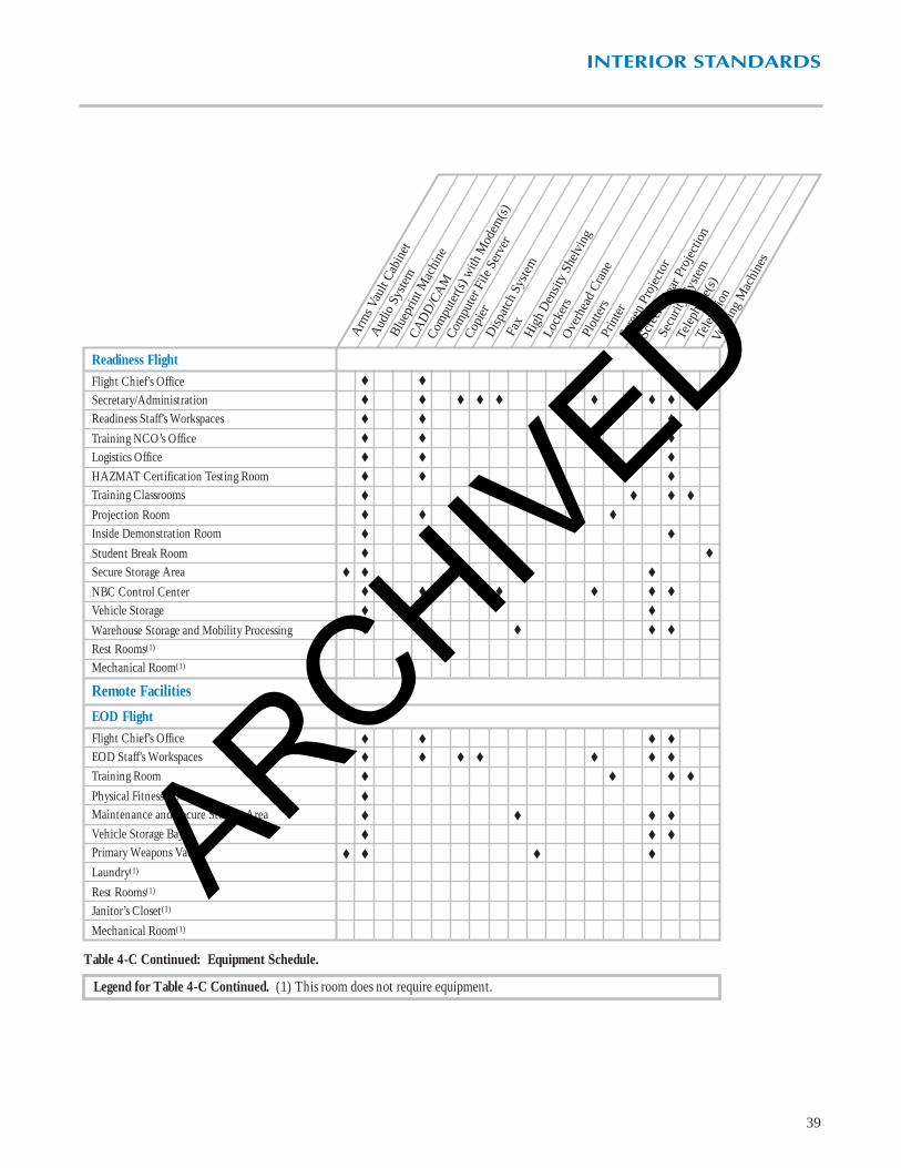
Table 4-C Continued: Equipment Schedule.
Legend for Table 4-C Continued. (1) This room does not require equipment.
ARCHIVED
39
INTERIOR STANDARDS
♦ ♦ ♦
♦ ♦ ♦ ♦ ♦ ♦ ♦ ♦
♦ ♦ ♦
♦ ♦ ♦
♦ ♦ ♦
♦ ♦ ♦ ♦
♦ ♦ ♦
♦ ♦
♦ ♦
♦ ♦ ♦ ♦
♦ ♦ ♦ ♦ ♦ ♦ ♦
♦ ♦
♦ ♦ ♦ ♦
♦ ♦ ♦ ♦
♦ ♦ ♦ ♦ ♦ ♦ ♦
♦ ♦ ♦ ♦
♦
♦ ♦ ♦ ♦
♦ ♦ ♦
♦ ♦ ♦ ♦
♦ ♦ ♦
Readiness FlightFlight Chief’s OfficeSecretary/AdministrationReadiness Staff’s Workspaces
Training NCO’s OfficeLogistics OfficeHAZMAT Certification Testing RoomTraining Classrooms
Projection RoomInside Demonstration Room
Student Break RoomSecure Storage Area
NBC Control CenterVehicle Storage
Warehouse Storage and Mobility ProcessingRest Rooms(1)
Mechanical Room(1)
Remote Facilities
EOD FlightFlight Chief’s OfficeEOD Staff’s WorkspacesTraining Room
Physical Fitness RoomMaintenance and Secure Storage AreaVehicle Storage BaysPrimary Weapons Vault
Laundry(1)
Rest Rooms(1)
Janitor’s Closet(1)
Mechanical Room(1)
Blu
eprin
t Mac
hine
Arm
s Vau
lt C
abin
et
Com
pute
r(s)
with
Mod
em(s
)
Com
pute
r File
Ser
ver
Cop
ier
Fax
Scre
en P
roje
ctor
Tele
phon
e(s)
Tele
visi
onVe
ndin
g M
achi
nes
Prin
ter
Scre
en, R
ear P
roje
ctio
n
Plot
ters
CA
DD
/CA
M
Aud
io S
yste
m
Dis
patc
h Sy
stem
Hig
h D
ensi
ty S
helv
ing
Lock
ers
Ove
rhea
d C
rane
Secu
rity
Syst
em
Table 4-C Continued: Equipment Schedule.
Legend for Table 4-C Continued. (1) This room does not require equipment.
ARCHIVED

AFI 31-209 Air Force Resources Protection Program
AFI 32-1023 Design and Construction Standards and Execution of Facility Construction
AFI 32-1024 Standard Facility Requirements
AFI 32-1032 Planning and Programming Real Property Maintenance Projects Using Appropriated Funds
AFM 88-3 Structural Design Criteria Loads
AFP 88-40 Sign Standards
ADA Americans with Disabilities Act
DoD 4270.1-M Construction Criteria Manual
FED STD. 795 Uniform Federal Accessibility Standards
MIL-HDBK 1008B Fire Protection for Facilities Engineering, Design, and Construction
MIL-HDBK 1190 Military Building Code
NFPA 70 National Electric Code
NFPA 101 Life Safety Code
NFPA 220 Types of Construction
10 CFR Chapter 11 Energy Conservation Voluntary Performance Standards for New Buildings
UFAS Uniform Federal Accessibility Standards
AMC Air Force Housing Support Facilities Guide
AMC Commander’s Guide to Facility Excellence
AMC Commander’s Guide to Self-Help Success
AMC Architectural Compatibility Plans
AMC Commander’s Guide to Family Housing Excellence
ACC & AMC Fire Station Facilities Design Guide
AMC Interior Design Guide
AMC Landscape Design Guide
AMC Sign Standards, “Engineering Technical Letter” (ETL 93-02)
References
40
ARCHIVED

AIR MOBILITY COMMAND…
…GLOBAL REACH FOR AMERICA
Prepared by Directorate of Civil EngineeringJune 1999
ARCHIVED