Embed Size (px)
Citation preview
8/3/2019 Cl Lmt Manual
http://slidepdf.com/reader/full/cl-lmt-manual 1/296
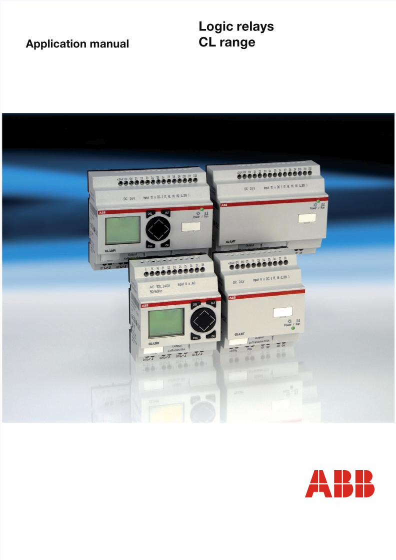
Application manual
Logic relays
CL range

8/3/2019 Cl Lmt Manual
http://slidepdf.com/reader/full/cl-lmt-manual 2/296
I
Before commencing the installation
Disconnect the power supply of the device.
• Ensure that devices cannot be accidentallyrestarted.
• Verify isolation from the supply.
• Earth and short circuit.
• Cover or enclose neighbouring units that
are live.• Follow the operating and installation
instructions of the device concerned.
• Only suitably qualified personnel inaccordance with EN 50110-1/-2(VDE 0105 Part 100) may work on thisdevice/system.
• Before installation and before touching
the device ensure that you are free ofelectrostatic charge.
• The functional earth (FE) must beconnected to the protective earth (PE) orto the potential equalisation. The systeminstaller is responsible for implementingthis connection.
• Connecting cables and signal lines should
be installed in such a way that inductive orcapacitive interference does not impair theautomation functions.
• Install automation devices and relatedoperating elements in such a way that theyare well protected against unintentionaloperation.
• Suitable safety hardware and softwaremeasures should be implemented for theI/O interface so that a line or wire breakageon the signal side does not result inundefined states in the automationdevices.
• Ensure a reliable electrical isolation of the
low voltage for the 24 volt supply. Onlyuse power supply units complying withIEC 60364-4-41 (VDE 0100 Part 410) orHD 384.4.41 S2.
• Deviations of the mains voltage from therated value must not exceed the tolerancelimits given in the specifications, otherwisethis may cause malfunction and dangerousoperation.
• Emergency stop devices complying withIEC/EN 60204-1 must be effective in alloperating modes of the automationdevices. Unlatching the emergency-stopdevices must not cause restart.
• Devices that are designed for mounting inhousings or control cabinets must only beoperated and controlled after they have
been installed with the housing closed.Desktop or portable units must only beoperated and controlled in enclosedhousings.
S a f e t y
i n s t r u c t i o n s
Warning!Dangerous electrical voltage!

8/3/2019 Cl Lmt Manual
http://slidepdf.com/reader/full/cl-lmt-manual 3/296
II
• Measures should be taken to ensure theproper restart of programs interrupted
after a voltage dip or failure. This shouldnot cause dangerous operating states evenfor a short time. If necessary, emergency-stop devices should be implemented.
• Wherever faults in the automation systemmay cause damage to persons or property,
external measures must be implemented toensure a safe operating state in the eventof a fault or malfunction (for example, bymeans of separate limit switches,mechanical interlocks etc.).

8/3/2019 Cl Lmt Manual
http://slidepdf.com/reader/full/cl-lmt-manual 4/296
1
1SVC 440 795 M0100
About this manual 9Device designation 9Reading conventions 10
1 Logic relay 11Intended users 11Proper use 11
– Improper use 11Overview 12Device overview 14CL operating principles 16– Keypad 16– Selecting menus and entering values 16– Selecting main and system menu 17– Status display logic relay 18– Status display for local expansion 18
– Advanced status display 19– CL-LED display 19– Menu structure 20– Selecting or toggling between menu items 25– Cursor display 25– Set value 25
2 Installation 27
Mounting 27Connecting the expansion device 30Terminals 31– Tools 31– Cable cross-sections 31Connecting the power supply 31– Cable protection 31– Supplying AC units 32– Supplying DC units 33
Table of Contents

8/3/2019 Cl Lmt Manual
http://slidepdf.com/reader/full/cl-lmt-manual 5/296
Table of Contents
2
1SVC 440 795 M0100
Connecting the inputs 35– Connect digital AC inputs 35
– Connect digital DC inputs 40– Connect analog DC inputs 41– Connecting high-speed counters and frequency
generators 46Connecting outputs 48– Connect relay outputs 49– Connecting transistor outputs 51Expanding inputs/outputs 54– Local expansion 54– Remote expansion 55
3 Commissioning 57Switching on 57Setting the menu language 58CL operating modes 59Creating your first circuit diagram 60– Circuit diagram display 62– From the first contact to the output coil 63– Wiring 64– Testing the circuit diagram 65– Deleting the circuit diagram 67– Fast circuit diagram entry 67
4 Wiring with the logic relay 69CL operation 69– Buttons for editing circuit diagrams and
function relays 69– Operating principles 70– Relays, function relays 74– Saving and loading circuit diagrams 76Working with contacts and relays 77– Input and output contacts 77– Creating and modifying connections 80
– Inserting and deleting a rung 82– Switching with the cursor buttons 82– Checking the circuit diagram 84– Coil functions 85
8/3/2019 Cl Lmt Manual
http://slidepdf.com/reader/full/cl-lmt-manual 6/296
Table of Contents
3
1SVC 440 795 M0100
Function relays 91– Example function relay with timer and counter
relay 93Analog value comparator/threshold value switch 98– Circuit diagram display with analog value
comparator 99– Compatibility of AC010 devices with logic
relays 101– Parameter display in RUN mode 102– Resolution of the analog inputs 102– Function of the analog value comparator
function relay 103Counters 111– Function of the counter function relay 115High-speed counters, CL-DC1, CL-DC2 119– Frequency counter 119– High-speed counters 125Text display 131– Wiring a text display 132
– Retention 132– Scaling 133– Function 133– Text entry 134– Character set 134– Entering a setpoint in a display 1357-day time switch 137– Parameter display and parameter set for 7-day
time switch 138
– Changing time switch channel 139– Function of the 7-day time switch 139Operating hours counter 143– Value range of the operating hours counter 144– Accuracy of the operating hours counter 144– Function of the operating hours counter
function block 144
8/3/2019 Cl Lmt Manual
http://slidepdf.com/reader/full/cl-lmt-manual 7/296
Table of Contents
4
1SVC 440 795 M0100
Timing relays 148– Parameter display and parameter set for a
timing relay 149– Retention 150– Timing relay modes 151– Time range 151– Function of the timing relay function block 154– Examples timing relay 161Jumps 164– Function 164– Power flow display 165Year time switch 167– Wiring of a year time switch 167– Parameter display and parameter set for year
time switch 168– Changing time switch channel 169– Entry rules 169– Function of the year time switch 171Master reset 174
– Operating modes 175– Function of the master reset function relay 175Basic circuits 176– Negation (contact) 176– Negation (coil) 177– Maintained contact 177– Series circuit 177– Parallel circuit 178– Parallel circuit operating like a series
connection of n/o contacts 179– Parallel circuit operating like a series
connection of n/c contacts 180– Two-way circuit 180– Self-latching 181– Impulse relay 182– Cycle pulse on rising edge 182– Cycle pulse on falling edge 183

8/3/2019 Cl Lmt Manual
http://slidepdf.com/reader/full/cl-lmt-manual 8/296
Table of Contents
5
1SVC 440 795 M0100
Circuit examples 184– Star-delta starting 184
– 4x shift register 186– Running light 190– Stairwell lighting 191
5 CL settings 195Password protection 195– Password setup 196– Selecting the scope of the password 197
– Activating the password 198– Unlock logic relay 199Changing the menu language 201Changing parameters 202– Adjustable parameters for function relays 203Setting date and time 205– Setting the time 205– Setting summer time start and end 206– Selection of summer time start and end 207– Summer time start and end, setting the rule 207Activating input delay (debounce) 214– Activating debounce (input delay) 215– Deactivating debounce (input delay) 215Activating and deactivating the P buttons 215– Activating the P buttons 216– Function of the P buttons 216– Deactivating the P buttons 216
Startup behaviour 217– Setting the startup behaviour 217– Behaviour when the circuit diagram is deleted 218– Behaviour during upload/download to
memory module or PC 218– Possible faults 218– Startup behaviour for memory module 219Setting the cycle time 220Retention (non-volatile data storage) 221
– Permissible markers and function relays 221– Setting retentive behaviour 222
8/3/2019 Cl Lmt Manual
http://slidepdf.com/reader/full/cl-lmt-manual 9/296
Table of Contents
6
1SVC 440 795 M0100
– Deleting retentive actual values 223– Transferring retentive behaviour 223
– Changing the operating mode or the circuitdiagram 224
– Changing the startup behaviour in theSYSTEM menu 224
Displaying device information 225
6 Inside the logic relay 227Logic relay circuit diagram cycle 227
– CL operation and implications for circuitdiagram creation 228
Delay times for inputs and outputs 230– Delay times with CL-DC1 and CL-DC2
basic units 230– Delay time with CL-AC1 and CL-AC2
basic units 232– Delay times for the analog inputs
CL-AC1, CL-DC1 and CL-DC2 233Monitoring of short-circuit/overload with CL-LST, CL-LMT and CL-LET 234Expanding CL-LMR/CL-LMT 235– How is an expansion unit recognised? 235– Transfer behaviour 235– Function monitoring of expansion units 236Saving and loading circuit diagrams 237– CL-LSR..X.../CL-LST..X...,
CL-LMR..X.../CL-LMT..X... 237– Interface 238Memory module 239– Compatibility of memory modules MD001
and MD002 239– Loading or saving circuit diagrams 240CL-SOFT 243Logic relay with separate display module 244Device version 245

8/3/2019 Cl Lmt Manual
http://slidepdf.com/reader/full/cl-lmt-manual 10/296
Table of Contents
7
1SVC 440 795 M0100
7 What happens if …? 247Messages from the CL system 247Possible situations when creating circuit diagrams 248Event 250
Appendix 251Dimensions 251Technical data 254– General 254– Special approvals 256– Power supply 257– Inputs 258– Relay outputs 265– Transistor outputs 267List of the function relays 270– Usable contacts 270– Available function relays 271– Names of relays 271
– Names of function relay 272– Name of function block inputs(constants, operands) 272
Compatibility of the function relay parameters 273– Parameter display of analog value comparator 273– Parameter display of counters 273– Parameter display 7-day time switch 274– Parameter display of timing relay 274– Compatibility of the memory module 274
Glossary 275
Index 279

8/3/2019 Cl Lmt Manual
http://slidepdf.com/reader/full/cl-lmt-manual 11/296
8
1SVC 440 795 M0100

8/3/2019 Cl Lmt Manual
http://slidepdf.com/reader/full/cl-lmt-manual 12/296
9
1SVC 440 795 M0100
About this manual
This manual describes the installation, commissioning andprogramming (circuit diagram generation) of the logic relaysCL-LSR/CL-LST and CL-LMR/CL-LMT.
Specialist electrical training is needed for commissioning andcreating circuit diagrams. When controlling activecomponents such as motors or pressure cylinders, parts ofthe system can be damaged and persons put at risk if the
logic relay is connected or programmed incorrectly.
Device designation This manual uses the following abbreviated designations fordifferent device models:
CL-LSR/CL-LST forCL-LSR...12AC1, CL-LSR...12AC2, CL-LSR...12DC1,CL-LSR...12DC2 and CL-LST...12DC2
CL-LMR/CL-LMT forCL-LMR...18AC1, CL-LMR...18AC2, CL-LMR...18DC1,CL-LMR...18DC2 and CL-LST...20DC2
CL-AC1 forCL-LSR...12AC1CL-LMR...18AC1
CL-AC2 forCL-LSR...12AC2
CL-LER.18AC2 and CL-LMR...18AC2
CL-DC1 forCL-LSR...12DC1CL-LMR...18DC1
CL-DC2 forCL-LSR...12DC2, CL-LST...12DC2CL-LMR...18DC2, CL-LMT...20DC2,CL-LER.18DC2 and CL-LET.20DC2
CL-LE... forCL-LER.2O, CL-LEC.CI000, CL-LER.18AC2, CL-LER.18DC2and CL-LER.20DC2

8/3/2019 Cl Lmt Manual
http://slidepdf.com/reader/full/cl-lmt-manual 13/296
About this manual
10
1SVC 440 795 M0100
Reading conventions Symbols used in this manual have the following meanings:
X indicates actions to be taken.
For greater clarity, the name of the current chapter is shown
in the header of the left-hand page and the name of thecurrent section in the header of the right-hand page. Thisdoes not apply to pages at the start of a chapter and emptypages at the end of a chapter.
hAttention! Warns of the risk of material damage.
iCaution!Warns of the possibility of serious damage and slightinjury.
jWarning!Indicates the risk of major damage to property, or seriousor fatal injury.
h Draws your attention to interesting tips andsupplementary information.

8/3/2019 Cl Lmt Manual
http://slidepdf.com/reader/full/cl-lmt-manual 14/296
11
1SVC 440 795 M0100
1 Logic relay
Intended users The logic relay must only be installed and wired up by trainedelectricians or other persons familiar with the installation ofelectrical equipment.
Specialist electrical training is needed for commissioning andcreating circuit diagrams. When controlling activecomponents such as motors or pressure cylinders, parts ofthe system can be damaged and persons put at risk if the
logic relay is connected or programmed incorrectly.
Proper use The logic relay is a programmable switching and controldevice and is used as a replacement for relay and contactorcontrol circuits. The logic relay must be properly installedbefore use.
• The logic relay is designed to be installed in an enclosure,
switch cabinet or distribution board. Both the power feedand the signal terminals must be laid and covered so as toprevent accidental contact.
• The installation must comply with regulations forelectromagnetic compatibility (EMC).
• The power up of the logic relay must not cause anyhazards arising from activated devices, such asunexpected motor startups or power ups.
Improper use
The logic relay should not be used as a substitute forsafety-related controls such as burner or crane controls,emergency-stop or two-hand safety controls.

8/3/2019 Cl Lmt Manual
http://slidepdf.com/reader/full/cl-lmt-manual 15/296
Logic relay
12
1SVC 440 795 M0100
Overview
Figure 1: CL basic units and expansions
Legend for figure 1:
a CL-LSR/CL-LST logic relays
b CL-LER, CL-LET input/output expansion
c CL-LER.2O output expansion
d Coupler unit for CL-LEC.CI000 remote expansion
e CL-LINK CL-LAS.TK011 data plugf CL-LMR/CL-LMT logic relays
The logic relay is an electronic control relay with logicfunctions, timer, counter and time switch functions. It is alsoa control and input device rolled into one. With the logicrelay you can create solutions for domestic applications aswell as for tasks in machine and plant construction.
Circuit diagrams are connected up using ladder diagrams,and each element is entered directly via the CL display.
a b
b
c
def

8/3/2019 Cl Lmt Manual
http://slidepdf.com/reader/full/cl-lmt-manual 16/296
Overview
13
1SVC 440 795 M0100
For example, you can:
• Connect n/o and n/c contacts in series and in parallel• Connect output relays and markers,
• Use outputs as relays, impulse relays or latching relays
• Use multi-function timing relays with different functions
• Use up and down counters
• Count high-speed counter pulses
• Measure frequencies
• Process analog inputs, CL-AC1, CL-DC1, CL-DC2,
(CL-LSR/CL-LST: two analog inputs, CL-LMR/CL-LMT:four analog inputs)
• Display any texts with variables, enter setpoints
• Use year time switches, 7-day time switches CL-...C(X)...
• Count operating hours (four retentive operating hourscounters integrated)
• Track the flow of current in the circuit diagram
• Load, save and password-protect circuit diagrams
To wire the logic relay via your PC use the CL-SOFTprogramming software. This software is used to create andtest your circuit diagram on the PC. CL-SOFT enables you toprint out your circuit diagram in DIN, ANSI or CL format.

8/3/2019 Cl Lmt Manual
http://slidepdf.com/reader/full/cl-lmt-manual 17/296
Logic relay
14
1SVC 440 795 M0100
Device overview CL basic units at a glance
Figure 2: Device overview
a Supply voltage
b Inputs
c Operating status LED
d Keypad
e Interface for memory module or PC connection
f Outputs
g Display
DEL A LT
ESCOK
ESCOK
DEL A LT

8/3/2019 Cl Lmt Manual
http://slidepdf.com/reader/full/cl-lmt-manual 18/296
Overview
15
1SVC 440 795 M0100
Logic relay with remote display CL-LDD..., CL-LDC.S...
Figure 3: Device overview with remote display
a CL-LSR/CL-LST logic relays
b CL-LMR/CL-LMT logic relays
c Display module CL-LDD...d Remote display connection module CL-LDC.S... with connection
cable
a b
cd

8/3/2019 Cl Lmt Manual
http://slidepdf.com/reader/full/cl-lmt-manual 19/296
Logic relay
16
1SVC 440 795 M0100
CL operating principles Keypad
Selecting menus and entering values
DEL: Delete object in circuit diagram
ALT: Special functions in circuit diagram, status display
Cursor buttons ú í ÍÚ:Move cursorSelect menu itemsSet contact numbers, contacts and values
OK: Next menu level, save your entry
ESC: Previous menu level, cancel
ALTDELDELDELDELDELDELDELDELDELDEL
ESC OK
andShow system menu
Move to next menu level
Call menu itemActivate, change, store entries
Move to previous menu levelCancel entries since last OK
ÍÚ
ú í
Change menu itemChange valueChange place
P buttons function:
úí
Input P1Input P3
ÍÚ
Input P2Input P4

8/3/2019 Cl Lmt Manual
http://slidepdf.com/reader/full/cl-lmt-manual 20/296
Overview
17
1SVC 440 795 M0100
Selecting main and system menu
Status display
1.2RSMO0.2 6..
I .2..5.....P-
MO 02:00..34 . RUN
and
Nopassword
PROGRAM...STOPå RUNPARAMETERINFO...SET CLOCK
SECURITYSYSTEM...LANGUAGE...
CL-LSR/CL-LST: 8 inputs, 4 outputs
Current selectionflashes inCL menu
Clock menu ondevices with clock
1st menu levelMain menu 1st menu levelSystem menuCL-LSR/CL-LST orCL-LMR/CL-LMT
SECURITYSYSTEM...LANGUAGE...CONFIGURATOR

8/3/2019 Cl Lmt Manual
http://slidepdf.com/reader/full/cl-lmt-manual 21/296
Logic relay
18
1SVC 440 795 M0100
Toggling between weekday, time display and datedisplay
(only on devices with clock)
Status display logic relay
Status display for local expansion
0.2..5.......
P-MO 11:50 0.2..5......
.P-
4/1/2004
0.2..5.......
P-MO 11:50 0.2..5......
P-4/1/2002Q ..34..STOP
CL-LSR/CL-LST: input 1 to 8,CL-LMR/CL-LMT: input 1 to 12
Inputs
Weekday/Time or Weekday/Date
Outputs RUN/STOP mode
CL-LSR/CL-LST: output 1 to 4,CL-LMR/CL-LMT: output 1 to 6
or 8On: 1, 2, 3, 4/Off:…
1.......9...RS AC P-MO 10:421.....7. RUN
Inputs
Expansion device
Weekday/Time or Weekday/Date
OutputsOn: 1, 2, 3, 4/Off:…
RS = Expansion functioning correctly
1.......9...RS AC P-MO 10:421.....7. RUN

8/3/2019 Cl Lmt Manual
http://slidepdf.com/reader/full/cl-lmt-manual 22/296
Overview
19
1SVC 440 795 M0100
Advanced status display
CL-LED display
CL-LSR.CX..., CL-LST.CX..., CL-LMR/CL-LMT, CL-LER andCL-LET feature an LED on the front which indicates the statusof the power supply as well as the RUN or STOP mode(a figure 2, Page 14).
Retention/debounce AC expansion ok/P buttons
Startup behaviour
RE : Retention switched on
I : Debounce switched on
AC : AC expansion functioning correctly
DC : DC expansion functioning correctlyGW : Bus coupling module detected
GW flashing: Only CL-LEC.CI000 detected. I/O expansion not detected.17.03.04 Display of actual device date
ST : When the power supply is switched on, the logic relay switches to STOP mode
12...6.89...RE I AC P-17.03.04 ST123.5.78 RUN
LED OFF No power supply
LED continuouslylit
Power supply present, STOP mode
LED flashing Power supply present, RUN mode

8/3/2019 Cl Lmt Manual
http://slidepdf.com/reader/full/cl-lmt-manual 23/296
Logic relay
20
1SVC 440 795 M0100
Menu structure
Main menu without password protectionX You access the main menu by pressing OK.
PROGRAM...ÆSTOP å RUNPARAMETERINFO... æSET CLOCK..
PROGRAM...DELETE PROGMODE
SAVECANCEL
Main menu
STOP: Circuit diagram displayRUN: Power flow display
Parameters
Circuit diagram
Parameterdisplay
DELETE ?
PROGRAM...
DELETE PROGCARD
DEVICE-CARDCARD-DEVICE
DELETE CARD
REPLACE ?
PROGRAM...DELETE PROGCARD
DEVICE-CARDCARD-DEVICEDELETE CARD
DELETE ?
DEVICE-CARDCARD-DEVICEDELETE CARD
REPLACE ?
Thearrowsindicatethat thereare morethan fourmenus.

8/3/2019 Cl Lmt Manual
http://slidepdf.com/reader/full/cl-lmt-manual 24/296
Overview
21
1SVC 440 795 M0100
PROGRAM...ÆSTOP RUN åPARAMETERINFO... æSET CLOCK..
Main menu
Parameter display
SET CLOCK..SUMMER TIME
PROGRAM...ÆSTOP RUN åPARAMETER...INFO... æSET CLOCK..
PROGRAM...STOP RUN Æ
PARAMETERINFO...SET CLOCK.æ
Display for date and
time settingHH:MM --:--DD.MM --.--YEAR ____
HH:MM 14:23DD.MM 17.03YEAR 2004
T1 X S +T2 Ü M:S +C1 N +O1 +
T1 X S +S1 10.000S2 +0T:
Information display of the devicePROGRAM...ÆSTOP RUN åPARAMETER...INFO... æSET CLOCK..
DC TC LCDOS: 1.00.027CRC: 21779

8/3/2019 Cl Lmt Manual
http://slidepdf.com/reader/full/cl-lmt-manual 25/296
Logic relay
22
1SVC 440 795 M0100
AM --ÆWD: --
--DD.MM:00.00æHH:MM:00:00DIFF: 0:00
NONE ÆRULE åEUGB æUS
NONE ÆRULEEUGB æUS
DAY --
ÆWD: --
--DD.MM:00.00æHH:MM:00:00
Ma n menu
PROGRAM...STOP RUN ÆPARAMETER..INFO...SET CLOCK.æ
SET CLOCK...SUMMER TIME
Only one selection is possible.
NONE åÆRULEEUGB æUS
SUMMER STARTSUMMER END
SUMMER STARTSUMMER END
SET CLOCK...SUMMER TIME
NONE ÆRULE åEUGB æUS
SUMMER STARTSUMMER END
SET CLOCK...SUMMER TIME
SET CLOCK...SUMMER TIME

8/3/2019 Cl Lmt Manual
http://slidepdf.com/reader/full/cl-lmt-manual 26/296
Overview
23
1SVC 440 795 M0100
Main menu with password protection
System menu CLThe system menu is accessed by simultaneously pressingDEL and ALT.
PASSWORD.. ÆSTOP RUN åPARAMETER...INFO... æSET CLOCK..
Password
Password entryUnlock logicrelay
Main menu
PASSWORD...STOP RUN å
DELETE ?
Correct entryStatus display
Four wrong entries(if enabled)
Example:Password onlyon program
PROGRAM å ÆPARAMETER åTIME åOPRTNG MODEæINTERFACE åDEL PROG å
PROGRAM å ÆPARAMETERCLOCKOPRTNG MODEæINTERFACEDEL PROG
ENTERPASSW..
XXXX
System menu
ACTIVATE PWCHANGE PW
Password entry
Change/deletepassword
SECURITYSYSTEM...LANGUAGE...CONFIGURATOR
Password setup
PASSWORD...RANGE ENTERPASSW..XXXX
CHANGE PWACTIVATE PW
CHANGE PWACTIVATE PW
PASSWORD...RANGE
8/3/2019 Cl Lmt Manual
http://slidepdf.com/reader/full/cl-lmt-manual 27/296
Logic relay
24
1SVC 440 795 M0100
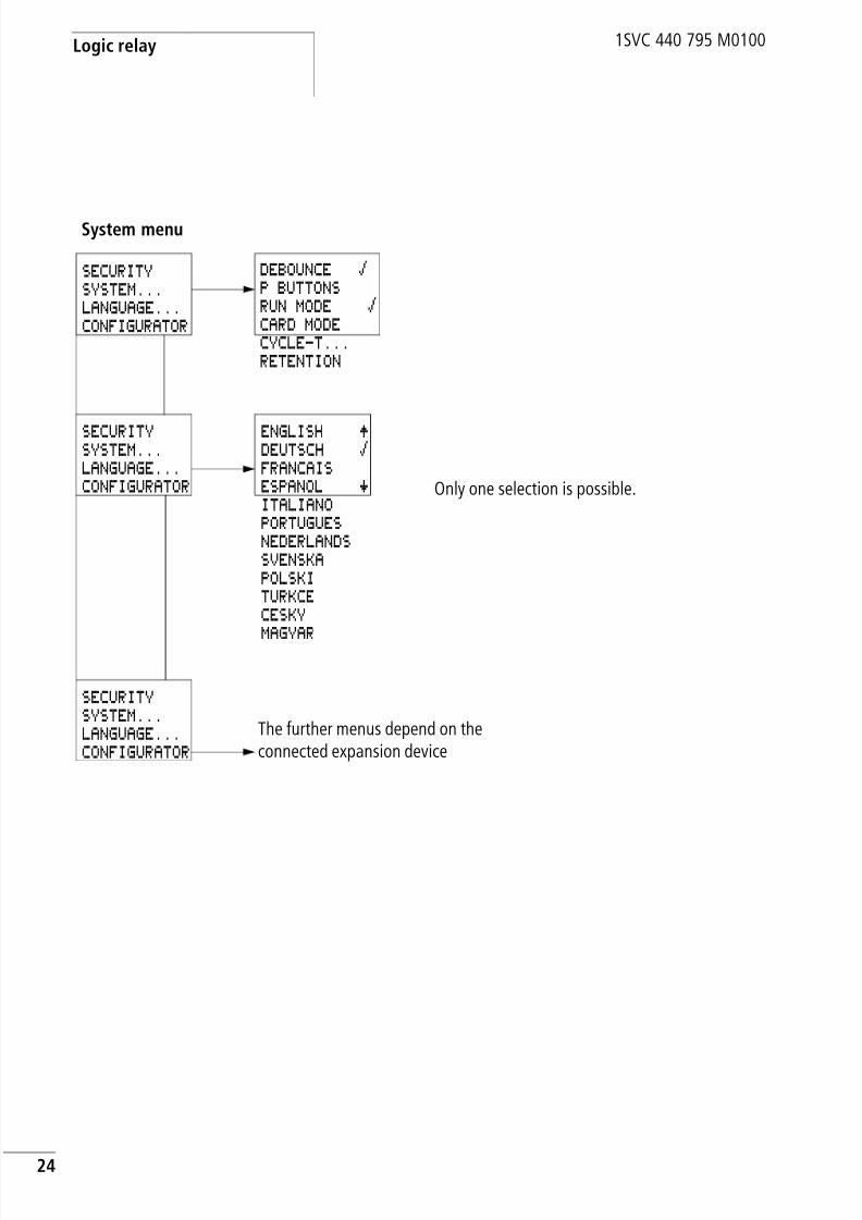
ENGLISH ÆDEUTSCH åFRANCAISESPANOL æITALIANOPORTUGUESNEDERLANDSSVENSKAPOLSKITURKCECESKYMAGYAR
System menu
SECURITYSYSTEM...LANGUAGE...CONFIGURATOR
SECURITYSYSTEM...LANGUAGE...CONFIGURATOR
The further menus depend on theconnected expansion device
Only one selection is possible.
SECURITYSYSTEM...LANGUAGE...CONFIGURATOR
DEBOUNCE åP BUTTONSRUN MODE åCARD MODECYCLE-T...RETENTION

8/3/2019 Cl Lmt Manual
http://slidepdf.com/reader/full/cl-lmt-manual 28/296
Overview
25
1SVC 440 795 M0100
Selecting or toggling between menu items
Cursor display
Set value
Cursor Í Ú
Select or toggle
PROGRAM...STOPPARAMETERINFO
The cursor flashes.
Full cursor Ê/:
• Move cursor with ú í,• in circuit diagram also with Í Ú
Value M/M• Change position with ú í• Change values with Í ÚFlashing values/menus are shown in grey in this manual.
HH:MM '4:23DD.MM 17.03YEAR 2004
HH:MM 14:23DD.MM 17.03YEAR 2004
Select value Í ÚSelect digit ú íChange value at digit Í Ú
Store entry
Retain previous valueCurrent value at the
position (can bechanged, Cursor = 3)
HH:MM 14:23DD.MM 17.03YEAR 2004
ValuesDigits

8/3/2019 Cl Lmt Manual
http://slidepdf.com/reader/full/cl-lmt-manual 29/296
26
1SVC 440 795 M0100
8/3/2019 Cl Lmt Manual
http://slidepdf.com/reader/full/cl-lmt-manual 30/296
27
1SVC 440 795 M0100
2 Installation
The logic relay must only be installed and wired up by trainedelectricians or other persons familiar with the mounting ofelectrical equipment.
The logic relay is installed in the following order:
• Assemble devices if necessary• Mounting
• Wiring up the inputs
• Wiring up the outputs
• Connecting the power supply
Mounting Install the logic relay in a control cabinet, service distribution
board or in an enclosure so that the power feed and terminalconnections cannot be touched accidentally duringoperation.
Fit the logic relay on a top-hat rail in accordance withDIN EN 50022 or fasten the logic relay with fixing brackets.The logic relay can be mounted either vertically orhorizontally.
jDanger of electric shock
Never carry out electrical work on the device while thepower supply is switched on.
Always follow the safety rules:
• Switch off and isolate
• Secure against reclosing
• Ensure that the device is no longer live
• Cover adjacent live parts
h When using the logic relay with expansion units, connectthe expansion concerned before mounting (a page 30).
8/3/2019 Cl Lmt Manual
http://slidepdf.com/reader/full/cl-lmt-manual 31/296
Installation
28
1SVC 440 795 M0100
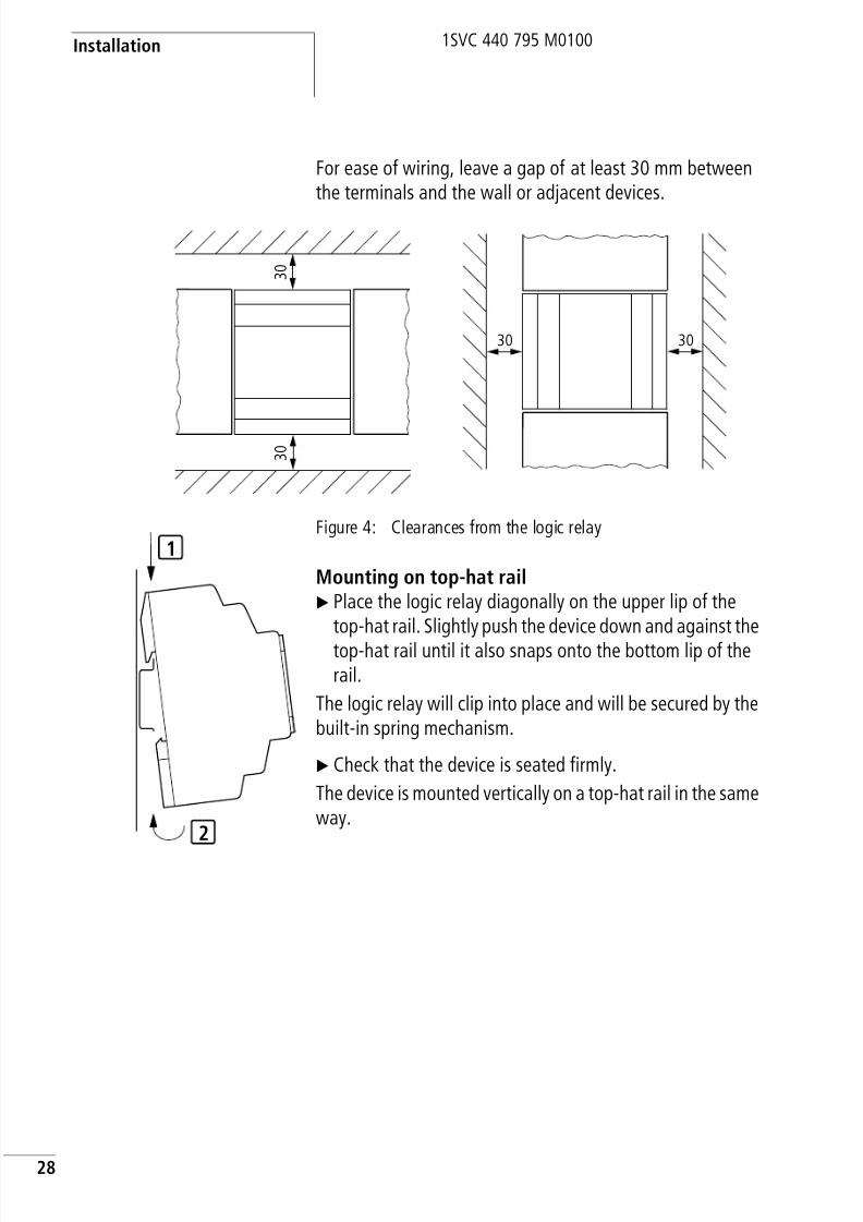
For ease of wiring, leave a gap of at least 30 mm betweenthe terminals and the wall or adjacent devices.
Figure 4: Clearances from the logic relay
Mounting on top-hat railX Place the logic relay diagonally on the upper lip of the
top-hat rail. Slightly push the device down and against thetop-hat rail until it also snaps onto the bottom lip of therail.
The logic relay will clip into place and will be secured by thebuilt-in spring mechanism.
X Check that the device is seated firmly.
The device is mounted vertically on a top-hat rail in the sameway.
3 0
3 0
3030
1
2

8/3/2019 Cl Lmt Manual
http://slidepdf.com/reader/full/cl-lmt-manual 32/296
Mounting
29
1SVC 440 795 M0100
Screw mountingFixing brackets that can be inserted on the rear of the logic
relay are required for screw mounting. The fixing bracketsare available as an accessory.
CL-LMR/CL-LMT: Fasten each device with at least threefixing brackets.
Figure 5: Screw mounting
CL-LEC.CI000: CL-LSR/CL-LST: CL-LMR/CL-LMT:

8/3/2019 Cl Lmt Manual
http://slidepdf.com/reader/full/cl-lmt-manual 33/296
Installation
30
1SVC 440 795 M0100
Connecting the expansiondevice
Figure 6: Connecting expansion units
1
3
4
2

8/3/2019 Cl Lmt Manual
http://slidepdf.com/reader/full/cl-lmt-manual 34/296
Terminals
31
1SVC 440 795 M0100
X Open the CL-LINK connections on the side of both CLdevices.
X Fit the CL-LINK data plug CL-LAS.TK011 in the openingprovided on the expansion device.
X Plug the devices together.
X Proceed in the reverse order to dismantle the device.
Terminals Tools
Slot-head screwdriver, width 3.5 mm, tightening torque0.6 Nm.
Cable cross-sections
• Solid: 0.2 to 4 mm2
• Flexible with ferrule: 0.2 to 2.5 mm2
Connecting the powersupply
Cable protection
The logic relay requires cable protection (F1) rated for atleast 1 A (slow).
h The required connection data for device types CL-AC1with the voltage 24 V AC, CL-AC2 with the standardvoltage of 100 V to 240 V AC, CL-DC1 with the voltage12 V DC and CL-DC2 with 24 V DC is provided in section“Technical data”, Page 254.
The CL-LSR/CL-LST and CL-LMR/CL-LMT logic relaysperform a two-second system test after the power supplyvoltage is applied. Either RUN or STOP mode will beactivated after these two seconds, depending on thedefault setting.

8/3/2019 Cl Lmt Manual
http://slidepdf.com/reader/full/cl-lmt-manual 35/296
Installation
32
1SVC 440 795 M0100
Supplying AC units
Supplying AC basic unitsCL-LSR...12AC1,CL-LMR...18AC1,CL-LSR...12AC2,CL-LMR...18AC2
Figure 7: Supply voltage to AC basic unit
Supplying AC basic units
CL-LER.18AC2
Figure 8: Supply voltage to AC basic unit
NNL
N
F1
L
NNL
N
F1
L
E+ E- R1 ... R12

8/3/2019 Cl Lmt Manual
http://slidepdf.com/reader/full/cl-lmt-manual 36/296
Connecting the power supply
33
1SVC 440 795 M0100
Supplying DC units
Supplying DC basic unitsCL-LSR...12DC1, CL-LMR...18DC1, CL-LSR...12DC2,CL-LMR...18DC2
Figure 9: Supply voltage to DC basic unit
j
Applies to CL-AC devices with a power supply greater than
24 V AC:• The voltage terminals for phase L and neutral conductor
N have been reversed.
• This enables the CL interface (for memory module orPC connection) to have the full connection voltage ofthe phase conductor L (100 to 240 V AC).
• There is a danger of electric shock if the CL interfaceis not properly connected or if conductive objects are
inserted into the socket.
hAttention!A short current surge will be produced when switching onfor the first time. Do not switch on the logic relay with reedcontacts because these could possibly burn or stick.
+...V 0 V0 V
L01
F1
L01
DC : +24 V
DA : +12 V

8/3/2019 Cl Lmt Manual
http://slidepdf.com/reader/full/cl-lmt-manual 37/296
Installation
34
1SVC 440 795 M0100
Supplying DC expansion devicesCL-LER.18DC2, CL-LER.20DC2
Figure 10: Supply voltage to DC expansion unit
Cable protectionThe logic relay requires cable protection (F1) rated for atleast 1 A (slow).
0V0V24V
L01-
F1
L01+
24 V
E+ E- R1 ... R12
h CL-DC1 and CL-DC2 are protected against reversepolarity. Ensure the correct polarity of the terminals toensure that the logic relay functions correctly.
h When the CL device is switched on for the first time, its
power supply circuit behaves like a capacitor. Ensure thatreed relay contacts or proximity switches are not used asthe switching device for switching on the power supply.
8/3/2019 Cl Lmt Manual
http://slidepdf.com/reader/full/cl-lmt-manual 38/296
Connecting the inputs
35
1SVC 440 795 M0100
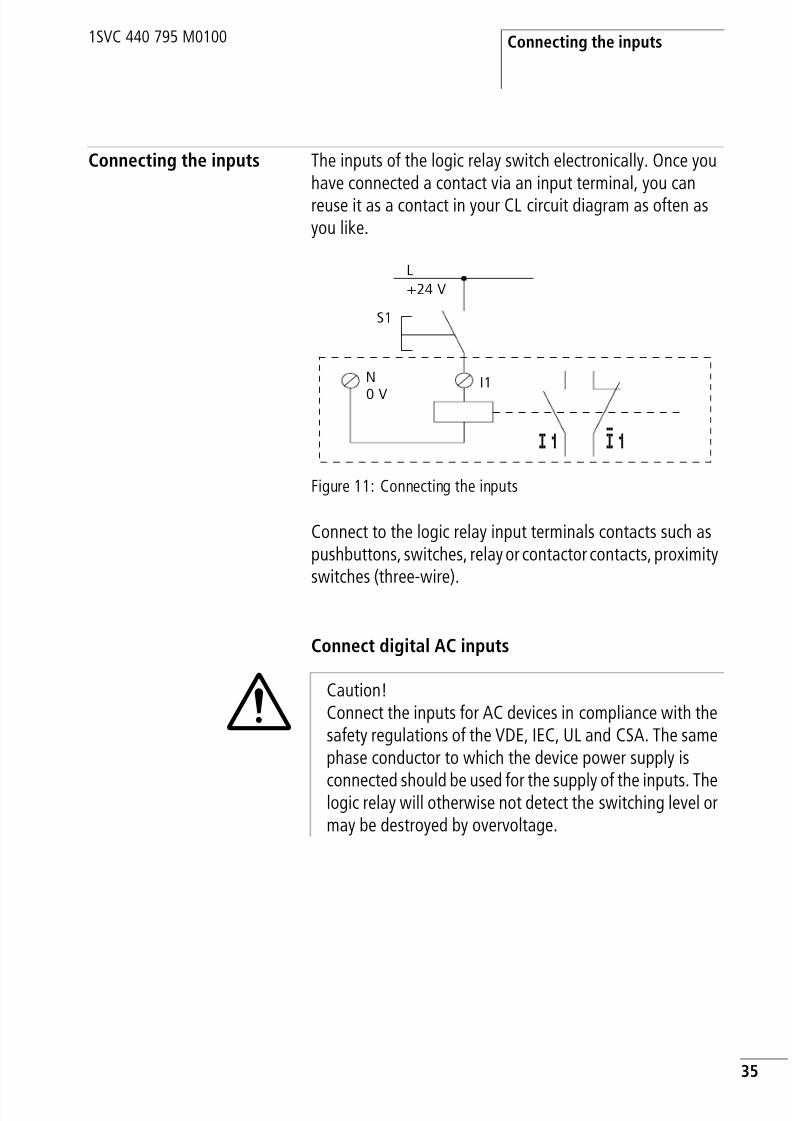
Connecting the inputs The inputs of the logic relay switch electronically. Once youhave connected a contact via an input terminal, you canreuse it as a contact in your CL circuit diagram as often asyou like.
Figure 11: Connecting the inputs
Connect to the logic relay input terminals contacts such aspushbuttons, switches, relay or contactor contacts, proximityswitches (three-wire).
Connect digital AC inputs
+24 V
S1
0 V
I1
I1 i1
L
N
iCaution!Connect the inputs for AC devices in compliance with thesafety regulations of the VDE, IEC, UL and CSA. The samephase conductor to which the device power supply is
connected should be used for the supply of the inputs. Thelogic relay will otherwise not detect the switching level ormay be destroyed by overvoltage.

8/3/2019 Cl Lmt Manual
http://slidepdf.com/reader/full/cl-lmt-manual 39/296
Installation
36
1SVC 440 795 M0100
Connect digital AC inputs to the basic unit
Figure 12: Connect digital inputs CL-AC1 and CL-AC2
Connect digital AC inputs to the expansion unit
Figure 13: Connect digital inputs CL-LER.18AC2
l1 I2 I7
L
N
L N N
F1
L
N
R10R9R8R7R6R5R4R3R2R1E+ E- R11 R12 NNL
F1

8/3/2019 Cl Lmt Manual
http://slidepdf.com/reader/full/cl-lmt-manual 40/296
Connecting the inputs
37
1SVC 440 795 M0100
Table 1: Input signal values CL-AC1
Table 2: Input signal values CL-AC2
Cable lengthsSevere interference can cause a “1” signal on the inputswithout a proper signal being applied. Observe therefore thefollowing maximum cable lengths:
Voltage range of the input signals Input current
OFF signal ON signal
CL-LSR/CL-LMR
I1 to I6 0 to 6 V AC 14 to 26.4 V AC 4 mA at 24 V AC
I7, I8 greater than 7 V ACor greater than9.5 V DC
2 mA with 24 V AC and24 V DC
CL-LMR I9, I10 14 to 26.4 V AC 4 mA at 24 V AC
I7, I8 greater than 7 V ACor greater than9.5 V DC
2 mA with 24 V AC and24 V DC
Voltage range of the input signals Input current
OFF signal ON signal
CL-LSR/CL-LMR
I1 to I6 0 to 40 V 79 to 264 V 0.5 mA at 230 V AC/0.25 mA at 115 V AC
I7, I8 6 mA at 230 V AC/4 mAat 115 V
CL-LMR I1 to I6 0.5 mA at 230 V AC/0.25 mA at 115 V AC
CL-LER/CL-LET
R1 toR12
I1 to I6 40 m without additional circuit
I7, I8 100 m without additional circuit
I1 to I6 40 m without additional circuit
R1 to R12
8/3/2019 Cl Lmt Manual
http://slidepdf.com/reader/full/cl-lmt-manual 41/296
Installation
38
1SVC 440 795 M0100
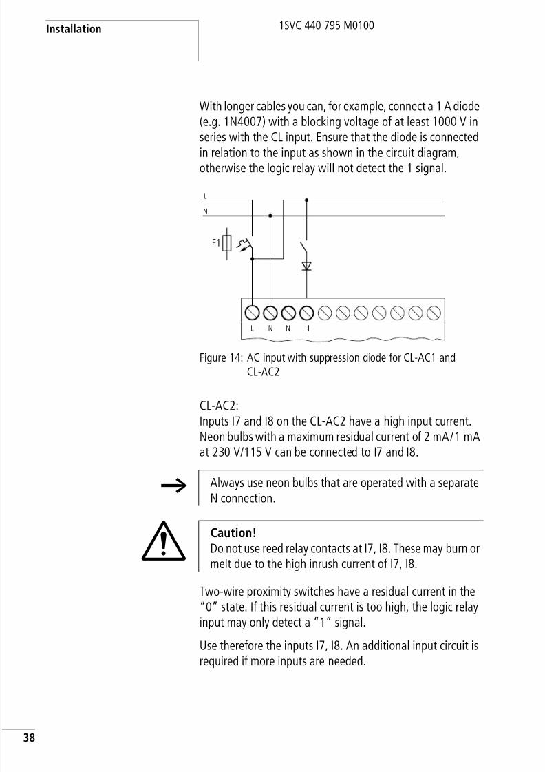
With longer cables you can, for example, connect a 1 A diode(e.g. 1N4007) with a blocking voltage of at least 1000 V in
series with the CL input. Ensure that the diode is connectedin relation to the input as shown in the circuit diagram,otherwise the logic relay will not detect the 1 signal.
Figure 14: AC input with suppression diode for CL-AC1 andCL-AC2
CL-AC2:Inputs I7 and I8 on the CL-AC2 have a high input current.Neon bulbs with a maximum residual current of 2 mA/1 mAat 230 V/115 V can be connected to I7 and I8.
Two-wire proximity switches have a residual current in the“0” state. If this residual current is too high, the logic relayinput may only detect a “1” signal.
Use therefore the inputs I7, I8. An additional input circuit isrequired if more inputs are needed.
L
N
L N N I1
F1
h Always use neon bulbs that are operated with a separateN connection.
iCaution!Do not use reed relay contacts at I7, I8. These may burn ormelt due to the high inrush current of I7, I8.
8/3/2019 Cl Lmt Manual
http://slidepdf.com/reader/full/cl-lmt-manual 42/296
Connecting the inputs
39
1SVC 440 795 M0100
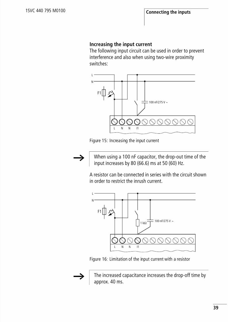
Increasing the input currentThe following input circuit can be used in order to prevent
interference and also when using two-wire proximityswitches:
Figure 15: Increasing the input current
A resistor can be connected in series with the circuit shownin order to restrict the inrush current.
Figure 16: Limitation of the input current with a resistor
L
N
L N N I1
100 nF/275 V h
F1
h When using a 100 nF capacitor, the drop-out time of theinput increases by 80 (66.6) ms at 50 (60) Hz.
L
N
L N N I1
100 nF/275 V h1 kO
F1
h The increased capacitance increases the drop-off time by
approx. 40 ms.

8/3/2019 Cl Lmt Manual
http://slidepdf.com/reader/full/cl-lmt-manual 43/296
Installation
40
1SVC 440 795 M0100
Connect digital DC inputs
Use input terminals I1 to I12 , R1 to R12 to connectpushbutton actuators, switches or 3 or 4-wire proximityswitches. Given the high residual current, do not use 2-wireproximity switches.
Connect digital DC inputs to the basic unit
Figure 17: Connect digital inputs CL-DC1 and CL-DC2
Connect digital DC inputs to the expansion unit
CL-LE...DC2
Figure 18: Connect digital inputs CL-LER.18DC2, CL-LET.20DC
L01
L01
0 V l1 I2 I7+...V
DC : +24 V
DA : +12 V
F1
+24V
0 V
R10R9R8R7R6R5R4R3R2R1E+ E- R11 R12 0V0V+24V
Input 24 V 24 V
F1
8/3/2019 Cl Lmt Manual
http://slidepdf.com/reader/full/cl-lmt-manual 44/296
Connecting the inputs
41
1SVC 440 795 M0100
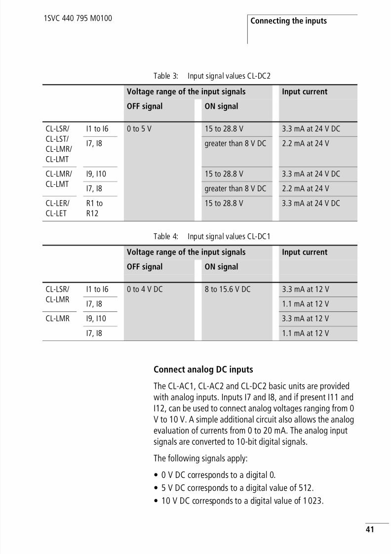
Table 3: Input signal values CL-DC2
Table 4: Input signal values CL-DC1
Connect analog DC inputs
The CL-AC1, CL-AC2 and CL-DC2 basic units are providedwith analog inputs. Inputs I7 and I8, and if present I11 andI12, can be used to connect analog voltages ranging from 0V to 10 V. A simple additional circuit also allows the analogevaluation of currents from 0 to 20 mA. The analog inputsignals are converted to 10-bit digital signals.
The following signals apply:
• 0 V DC corresponds to a digital 0.
• 5 V DC corresponds to a digital value of 512.
• 10 V DC corresponds to a digital value of 1023.
Voltage range of the input signals Input current
OFF signal ON signal
CL-LSR/CL-LST/CL-LMR/CL-LMT
I1 to I6 0 to 5 V 15 to 28.8 V 3.3 mA at 24 V DC
I7, I8 greater than 8 V DC 2.2 mA at 24 V
CL-LMR/CL-LMT
I9, I10 15 to 28.8 V 3.3 mA at 24 V DC
I7, I8 greater than 8 V DC 2.2 mA at 24 V
CL-LER/CL-LET
R1 toR12
15 to 28.8 V 3.3 mA at 24 V DC
Voltage range of the input signals Input current
OFF signal ON signal
CL-LSR/CL-LMR
I1 to I6 0 to 4 V DC 8 to 15.6 V DC 3.3 mA at 12 VI7, I8 1.1 mA at 12 V
CL-LMR I9, I10 3.3 mA at 12 V
I7, I8 1.1 mA at 12 V

8/3/2019 Cl Lmt Manual
http://slidepdf.com/reader/full/cl-lmt-manual 45/296
Installation
42
1SVC 440 795 M0100
Safety measures with analog signalsX Use shielded twisted pair cables to prevent interference
with the analog signals.
X With short cable lengths, ground the shield at both endsusing a large contact area. If the cable length is more thanaround 30 m, grounding at both ends can result inequalisation currents between the two grounding pointsand thus in the interference of analog signals. In this case,only ground the cable at one end.
X Do not lay signal cables parallel to power cables.
X Connect inductive loads to be switched via the logic relay
outputs to a separate power feed, or use a suppressorcircuit for motors and valves. If loads such as motors,solenoid valves or contactors are operated via the samepower feed, switching may give rise to interference on theanalog input signals.
The following four circuits contain examples of applicationsfor analog value processing.
i
Caution!
Analog signals are more sensitive to interference thandigital signals. Consequently, greater care must be takenwhen laying and connecting the signal lines.
Incorrect switching states may occur if they are notconnected correctly.
iCaution!Ensure that the reference potential is connected. Connectthe 0 V of the power supply unit for the different setpointpotentiometers and sensors shown in the examples to the0 V and neutral conductor terminal (CL-AC1) of the logicrelay power feed. Otherwise incorrect switching statesmay occur if they are not connected correctly.

8/3/2019 Cl Lmt Manual
http://slidepdf.com/reader/full/cl-lmt-manual 46/296
Connecting the inputs
43
1SVC 440 795 M0100
Power supply of CL-AC1 devices and analog inputsWith CL-AC1 devices that process analog signals, the device
must be fed via a transformer so that the device is isolatedfrom the mains supply. The neutral conductor and thereference potential of the DC power feed of analog sensorsmust be electrically connected.
Figure 19: CL-AC1 analog input, connection of reference potentials
h Ensure that the common reference potential is groundedor monitored by a ground fault monitoring device. Observethe requirements of the relevant regulations.
I7L N I1N
L
N
~
0 V+12 V
L01h
N01h
I8
F1
EASY200-POWCL-LAS.SD001

8/3/2019 Cl Lmt Manual
http://slidepdf.com/reader/full/cl-lmt-manual 47/296
Installation
44
1SVC 440 795 M0100
Analog setpoint potentiometer,CL-AC1,CL-DC1,CL-DC2
Figure 20: Analog setpoint potentiometer with own power feed
Use a potentiometer with a resistance of 1 k, e. g. 1 k,0.25 W.
Analog setpoint potentiometer CL-DC2
Figure 21: Analog setpoint potentiometer with 24 V DC power feed
~
0 V +12 V
I7+...V
L
0 V
N
0 V
N
F1
L01
L01
1.3 kO/0.25 W
1 kO/0.25 W
0 V 0 V I7+...V
DC : +24 V
DA : +12 V
F1

8/3/2019 Cl Lmt Manual
http://slidepdf.com/reader/full/cl-lmt-manual 48/296
Connecting the inputs
45
1SVC 440 795 M0100
Brightness sensor CL-AC1, CL-DC1, CL-DC2
Figure 22: Connection of a brightness sensor, analog input
Temperature sensor, CL-DC1, CL-DC2
Figure 23: Connection of the temperature sensor, analog input
0 V
0...10 V
12 V ~
0 V +12 V
I7+...V
L
0 V
N
0 V
N
F1
+24 V
–0 V
Out
0...10 V –35...55 ˚C
I7+...V
L
0 V
N
0 V
N
F1

8/3/2019 Cl Lmt Manual
http://slidepdf.com/reader/full/cl-lmt-manual 49/296
Installation
46
1SVC 440 795 M0100
20 mA sensor4 to 20 mA (0 to 20 mA) sensors can be connected easily
without any problem using an external 500 V resistor.
Figure 24: Connection 0 (4) to 20 mA sensor output, analog input
Analog sensor
The following values apply:
• 4 mA = 1.9 V
• 4 mA = 1.9 V
• 20 mA = 9.5 V
(Based on U = R I = 478 10 mA 4.8 V).
Connecting high-speed counters and frequencygenerators
High-speed counter signals and frequencies on the CL-DC1and CL-DC2 can be counted accurately on inputs I1 to I4independently of the cycle time. These inputs arepermanently assigned to counters.
The coils and contacts have the following meanings:
• I1 = C13 high-speed up/down counter
• I2 = C14 high-speed up/down counter
• I3 = C15 frequency counter
• I3 = C15 frequency counter
L01
F1
L01
500
4...20 mA
I7+...V 0 V0 V
DC1 : +24 V
DC2 : +12 V

8/3/2019 Cl Lmt Manual
http://slidepdf.com/reader/full/cl-lmt-manual 50/296
Connecting the inputs
47
1SVC 440 795 M0100
Pulse shape of count signals:the logic relay processes square wave signals.
Mark-to-space ratio of count signals:We recommend a mark-to-space ratio of 1:1.
If this is not the case:The minimum pulse or pause duration is 0.5 ms.
t min = 0.5 x (1/f max)
t min = minimum time of the pulse or pause duration
f max = maximum count frequency (1 kHz)
Figure 25: Connecting high-speed counters and frequencygenerators
0 V0 V...V
L01 –
F1
L01 +
I1 I2 I3 I4 I5 I6
L02 +
24 VH

8/3/2019 Cl Lmt Manual
http://slidepdf.com/reader/full/cl-lmt-manual 51/296
Installation
48
1SVC 440 795 M0100
Connecting outputs The Q outputs operate inside the CL as isolated contacts.
Figure 26: Output Q
The associated relay coils are controlled in the CL circuitdiagram via the following outputs.
• Q1 to Q4 and Q1 to Q8 (Q6), basic units
• S1 to S8 (S6), expansion devices
The signal states of the outputs can be used in the CL circuitdiagram as n/o or n/c contacts for other switchingconditions.
The relay or transistor outputs are used to switch loads suchas fluorescent tubes, filament bulbs, contactors, relays ormotors. Prior to installation observe the technical limitvalues and data for the outputs (a section “Technicaldata”, Page 254).
h Inputs that are used as high-speed counter inputs should
not be used in the circuit diagram as contacts. If thecounter frequency is high:
Not all the high-speed counter signals will be measuredfor processing in the circuit diagram. The logic relay willonly process randomly detected signals in the circuitdiagram.
Q11 2

8/3/2019 Cl Lmt Manual
http://slidepdf.com/reader/full/cl-lmt-manual 52/296
Connecting outputs
49
1SVC 440 795 M0100
Connect relay outputs
CL-LSR
Figure 27: Relay outputs CL-LSR
Figure 28: Relay outputs CL-LMR and CL-LER.2O
0 V H, N
F 8 A/B 16
L1, L2, L3 (115/230 V h)
+ 24 V H
25 000
R L
24 V H 8 A
115 V h 8 A
230 V h 8 A
3 A
3 A
3 A
1000 W
10 x 58 W
1 2 1 2 1 2 1 2
10 000 000
Q1 Q2 Q3 Q4
CL-LMR and CL-LER.2O
+ 24 V H
0 VH, N
F 8 A/B 16
L1, L2, L3 (115/230 V h)
1 2 2 2 2 2 21 1 1 1 1
10 000 000
Q6Q5Q4Q3Q2Q1
F 8 A/B 16
+ 24 V H
0 VH, N
L1, L2, L3 (115/230 V h)
1 2 21
10 000 000
S2S1

8/3/2019 Cl Lmt Manual
http://slidepdf.com/reader/full/cl-lmt-manual 53/296
Installation
50
1SVC 440 795 M0100
CL-LER.18AC2, CL-LER.18DC2
Figure 29: Relay outputs CL-LER.18AC2, CL-LER.18DC2
Unlike the inputs, the outputs can be connected to differentphases.
0 VH, N
F 8 A/B 16
L1, L2, L3 (115/230 V h)+ 24 V H
25 000
R
24 V H 8 A
115 V h 8 A
230 V h 8 A
2 A
2 A
2 A
1000 W
10 x 58 W
1 2 2 2 2 2 21 1 1 1 1
10 000 000
S6S5S4S3S2S1
j
Caution!Do not exceed the maximum voltage of 250 V AC on a
relay contact.
If the voltage exceeds this threshold, flashover may occurat the contact, resulting in damage to the device or aconnected load.

8/3/2019 Cl Lmt Manual
http://slidepdf.com/reader/full/cl-lmt-manual 54/296
Connecting outputs
51
1SVC 440 795 M0100
Connecting transistor outputs
CL-LST
Figure 30: Transistor outputs CL-LST
CL-LMT
Figure 31: Transistor outputs CL-LMT
0 VH
R L
24 V 0.5 A
+24 V 0 V Q1 Q2 Q3 Q4
F10 A
0.5 A
5 W/24 V
f 2.5 A
+ 24 V H
20.4 – 28.8 V H
Q Q
(20.4 – 28.8 V H)
+ 24 V H
R
5 W/24 V
0.5 A
0 VH
+24 V 0 V Q1 Q2 Q3 Q4 Q5 Q6 Q7
f 2.5 A
F10 A
24 VH 0.5 A
Q8Q Q

8/3/2019 Cl Lmt Manual
http://slidepdf.com/reader/full/cl-lmt-manual 55/296
Installation
52
1SVC 440 795 M0100
CL-LET.20DC2
Figure 32: Transistor outputs CL-LET.20DC2
Parallel connection:
Up to four outputs can be connected in parallel in order toincrease the output power. This enables a maximum outputcurrent of 2 A.
0 VH
S1 S2 S3 S4 S5 S6 S7 S8 +24 V
f 2.5 A
F10 A
0V
+ 24 V H
R
5 W/24 V
0.5 A
(20.4 – 28.8 V H)
24 VH 0.5 A
Q Q
iCaution! Outputs within a group (Q1 to Q4 or Q5 to Q8, S1 to S4 orS5 to S8) can be switched in parallel; e.g. Q1 and Q3 orQ5, Q7 and Q8. Outputs switched in parallel must beactivated at the same time.
iCaution!Please note the following when switching off inductiveloads.
Suppressed inductive loads cause less interference in theentire electrical system. For optimum suppression thesuppressor circuits are best connected directly to theinductive load.

8/3/2019 Cl Lmt Manual
http://slidepdf.com/reader/full/cl-lmt-manual 56/296
Connecting outputs
53
1SVC 440 795 M0100
If inductive loads are not suppressed, the following applies:Several inductive loads should not be switched off
simultaneously to avoid overheating the driver blocks in theworst possible case. If in the event of an emergency stop the+24 V DC power supply is to be switched off by means of acontact, and if this would mean switching off more than onecontrolled output with an inductive load, then you mustprovide suppressor circuits for these loads (see the followingdiagrams).
Figure 33: Inductive load with suppressor circuit
Behaviour with short-circuit/overloadA transistor output will switch off in the event of a short-circuit or overload. The output will switch back on up to themaximum temperature after a cooling time that depends onthe ambient temperature and the current level. If the faultcondition persists, the output will keep switching off and onuntil the fault is corrected or until the power supply is
switched off (a section “Monitoring of short-circuit/overload with CL-LST, CL-LMT and CL-LET”, Page 234).
Uemax < Uz < 33 V
0 VH
Q..
+ 24 V H
0 VH
Q..
8/3/2019 Cl Lmt Manual
http://slidepdf.com/reader/full/cl-lmt-manual 57/296
Installation
54
1SVC 440 795 M0100
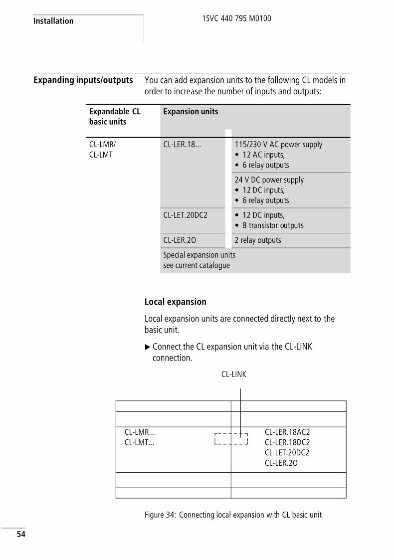
Expanding inputs/outputs You can add expansion units to the following CL models inorder to increase the number of inputs and outputs:
Local expansion
Local expansion units are connected directly next to thebasic unit.
X Connect the CL expansion unit via the CL-LINKconnection.
Figure 34: Connecting local expansion with CL basic unit
Expandable CLbasic units
Expansion units
CL-LMR/CL-LMT
CL-LER.18... 115/230 V AC power supply• 12 AC inputs,• 6 relay outputs
24 V DC power supply• 12 DC inputs,• 6 relay outputs
CL-LET.20DC2 • 12 DC inputs,• 8 transistor outputs
CL-LER.2O 2 relay outputs
Special expansion unitssee current catalogue
CL-LMR...CL-LMT...
CL-LER.18AC2CL-LER.18DC2CL-LET.20DC2CL-LER.2O
CL-LINK

8/3/2019 Cl Lmt Manual
http://slidepdf.com/reader/full/cl-lmt-manual 58/296
Expanding inputs/outputs
55
1SVC 440 795 M0100
Remote expansion
Remote expansion units can be installed and run up to 30 maway from the basic unit.
j
Warning!
The following electrical separation is implementedbetween the CL-LMR.C.../CL-LMT.C... basic unit and theexpansion device (separation always in local connection ofexpansion unit)
• Basic isolation 400 V AC (+10 %)
• Safe isolation 240 V AC (+10 %)
Units may be destroyed if the value 400 V AC +10 % isexceeded, and may cause the malfunction of the entiresystem or machine!
h The basic unit and expansion unit can be provided withdifferent DC power supplies.
jWarning!The two-wire or multi-core cable between units must havethe necessary insulation voltage required for theinstallation environment concerned. In the event of a fault(ground leakage, short-circuit) serious damage or injury topersons may otherwise occur.
A cable such as NYM-0 with a rated operating voltage ofUe = 300/500 V AC is normally sufficient.

8/3/2019 Cl Lmt Manual
http://slidepdf.com/reader/full/cl-lmt-manual 59/296
Installation
56
1SVC 440 795 M0100
Figure 35: Connecting remote expansion units to CL basic unit
E+ E–
E+ E–
CL-LMR...CL-LMT... CL-LEC.CI0
00
CL-LER18...CL-LET20...
Ue = 300/500 VCL-LER.18AC2
h The terminals “E+” and “E-” of the CL-LEC.CI000 are
protected against short-circuits and polarity reversal.Functionality is only ensured if “E+” is connected with“E+” and “E-” with “E-”.

8/3/2019 Cl Lmt Manual
http://slidepdf.com/reader/full/cl-lmt-manual 60/296
57
1SVC 440 795 M0100
3 Commissioning
Switching on Before switching on, check that you have connected thepower supply terminals and inputs correctly:
• 24 V AC version CL-AC1
– Terminal L: Phase conductor L
– Terminal N: Neutral conductor N
– Terminals I1 to I12:
Actuation via same phase conductor L• 230 V AC version CL-AC2
– Terminal L: Phase conductor L
– Terminal N: Neutral conductor N
– Terminals I1 to I12, R1 to R12:Actuation via phase conductor L
• 12 V DC version:
– Terminal +12 V: voltage +12 V
– Terminal 0 V: voltage 0 V– Terminals I1 to I12:
Actuation via same +12V
• 24 V DC version:
– Terminal +24 V: voltage +24 V
– Terminal 0 V: voltage 0 V
– Terminals I1 to I12, R1 to R12:Actuation via the same +24 V
If you have already integrated the logic relay into a system,secure any parts of the system connected to the workingarea to prevent access and ensure that no-one can be injuredif, for example, motors start up unexpectedly.

8/3/2019 Cl Lmt Manual
http://slidepdf.com/reader/full/cl-lmt-manual 61/296
Commissioning
58
1SVC 440 795 M0100
Setting the menulanguage
When you switch on the logic relay for the first time, you willbe asked to select the menu language.
X Use the cursor buttons Í or Ú to select the languagerequired.
– English
– German
– French
– Spanish
– Italian
– Portuguese
– Dutch
– Swedish
– Polish
– Turkish
– Czech
– Hungarian
X Press OK to confirm your choice and press ESC to exit themenu.
The logic relay will then switch to the status display.
ENGLISH åDEUTSCHFRANCAISESPANOL
h You can change the language setting at a later date,(a section “Changing the menu language”, Page 201).
If you do not set the language, the logic relay will displaythis menu every time you switch on and wait for you toselect a language.

8/3/2019 Cl Lmt Manual
http://slidepdf.com/reader/full/cl-lmt-manual 62/296
Setting the menu language
59
1SVC 440 795 M0100
CL operating modes The logic relay has two operating modes – RUN and STOP.
In RUN mode the logic relay continuously processes a storedcircuit diagram until you select STOP or disconnect thepower. The circuit diagram, parameters and the CL settingsare retained in the event of a power failure. All you will haveto do is reset the real-time clock after the back-up time haselapsed. Circuit diagram entry is only possible in STOP mode.
When a memory module with a circuit diagram is fitted in aCL model with an LCD display, this circuit diagram will notstart automatically if there is circuit diagram in the logicrelay. You therefore have to transfer the circuit diagram from
the memory module to the logic relay.
In RUN mode CL models without an LCD display load thecircuit diagram on the memory module automatically andrun it immediately.
iCaution!In RUN mode the logic relay will immediately run the
saved circuit diagram in the unit when the power supply isswitched on. This will happen unless STOP mode was setas startup mode. In RUN mode outputs are activatedaccording to the switch logic of the circuit diagram.

8/3/2019 Cl Lmt Manual
http://slidepdf.com/reader/full/cl-lmt-manual 63/296
Commissioning
60
1SVC 440 795 M0100
Creating your first circuitdiagram
The following single line diagram takes you step by stepthrough wiring up your first CL circuit diagram. In this wayyou will learn all the rules, quickly enabling you to use thelogic relay for your own projects.
As with conventional wiring, you use contacts and relays inthe CL circuit diagram. With the logic relay, however, you nolonger have to connect up components individually. At thepush of a few buttons, the CL circuit diagram produces allthe wiring required. All you have to do is then connect anyswitches, sensors, lamps or contactors you wish to use.
Figure 36: Lamp controller with relays
In the following example, the logic relay carries out all thewiring and performs the tasks of the circuit diagram shownbelow.
H1
L01-
S1
S2
L01+
F1
K1
K1
8/3/2019 Cl Lmt Manual
http://slidepdf.com/reader/full/cl-lmt-manual 64/296
Setting the menu language
61
1SVC 440 795 M0100
Figure 37: Lamp controller with logic relay
Starting point: the status display
The logic relay activates the status display after it is poweredup. This shows the switching state of the inputs and outputs,and indicates whether the logic relay is already running acircuit diagram.
1 2
Q1
H1
L01-
S1 S2
L01+
L01-
F1
+24V 0V I1 I2
...........IMO 02:00.......STOP
h The examples were written without the use of expansionunits. If an expansion unit is connected, the status displaywill first show the status of the basic unit and then thestatus of the expansion unit before showing the firstselection menu.

8/3/2019 Cl Lmt Manual
http://slidepdf.com/reader/full/cl-lmt-manual 65/296
Commissioning
62
1SVC 440 795 M0100
X Press OK to switch to the main menu.
Press OK to switch to the next menu level, and press ESC tomove one level back.
The logic relay is in STOP mode.
X Press OK 2 to enter the circuit diagram display viamenu items PROGRAM… r PROGRAM. This is where youwill create the circuit diagram.
Circuit diagram display
The circuit diagram display is currently empty. The cursorflashes at the top left, which is where you will start to createyour diagram. The logic relay automatically proposes the firstcontact input I1.
Use theÍÚ ú í cursor buttons to move the cursor over theinvisible circuit diagram grid.
The first three double columns are the contact fields and the
right-hand columns form the coil field. Each line is a circuitconnection. The logic relay automatically connects thecontact to the power supply.
X Now try to wire up the following CL circuit diagram.
The switches S1 and S2 are at the input whilst I1 and I2 arethe contacts for the input terminals. Relay K1 is representedby the relay coil ÄQ1. The symbol Ä identifies the coil’sfunction, in this case a relay coil acting as a contactor. Q1 is
one of up to eight CL output relays in the basic unit.
PROGRAM...
STOP å RUNPARAMETERINFO
h OK has two other functions:
• Press OK to save modified settings.
• In the circuit diagram, you can also press OK to insertand modify contacts and relay coils.
Â
êê êê êê êêêêê êê êê êêê
êê êê êê êêêêê êê êê êêê
Ml
L
m
I1-I2----ÄQ1

8/3/2019 Cl Lmt Manual
http://slidepdf.com/reader/full/cl-lmt-manual 66/296
Setting the menu language
63
1SVC 440 795 M0100
From the first contact to the output coil
With the logic relay you work from the input to the output.The first input contact is I1.
X Press OK.
The logic relay proposes the first contact I1 at the cursorposition.
XI flashes and can be changed, for example, to a P for apushbutton input using the cursor buttons Í or Ú.However, nothing needs to be changed at this point.
X Press OK 2 x, to move the cursor across the 1 to thesecond contact field.
You could also move the cursor to the next contact fieldusing the cursor button í.X Press OK.
Again, the CL inserts a contact I1 at the cursor position.
Change the contact number toI2
so that n/c contact S2 canbe connected to input terminal I2.
X Press OK so that the cursor jumps to the next position anduse cursor buttons Í orÚ to change the number 2.
X Press OK to move the cursor to the third contact field.
You do not need a third relay contact, so you can now wire
the contacts directly up to the coil field.
I1 êê êê êêê
I1 I1 êê êêê
h Press DEL to delete a contact at the cursor position.
I1-I2 Â

8/3/2019 Cl Lmt Manual
http://slidepdf.com/reader/full/cl-lmt-manual 67/296
Commissioning
64
1SVC 440 795 M0100
Wiring
The logic relay displays a small arrow in the circuit diagramwhen creating the wiring.
Press ALT to activate the arrow and press the cursor buttonsÍÚ ú í to move it.
The wiring arrow works between contacts and relays. Whenyou move the arrow onto a contact or relay coil, it changesback to the cursor and can be reactivated if required.
X Press ALT to wire the cursor from I2 through to the coilfield.
The cursor changes into a flashing wiring arrow andautomatically jumps to the next logical wiring position.
X Press the cursor button í. ContactI2will be connected upto the coil field.
X Press the cursor button í once more.
The cursor will move to the coil field.
h ALT also has two other functions depending on the cursorposition:
• From the left contact field, press ALT to insert a new,
empty rung.• The contact under the cursor can be changed between
a n/o and n/c contact by pressing the ALT button.
êê êê êêêêê êêê
Ml
L
m l
h The logic relay automatically wires adjacent contacts in acircuit connection up to the coil.
I1-I2l
êê êê êê êêêêê êê êê êêêêê êê êê êêê
h You can use DEL to erase a connection at the cursor orarrow position. Where connections intersect, the verticalconnections are deleted first, then, if you press DEL again,the horizontal connections are deleted.

8/3/2019 Cl Lmt Manual
http://slidepdf.com/reader/full/cl-lmt-manual 68/296
Setting the menu language
65
1SVC 440 795 M0100
X Press OK.
The logic relay proposes the relay coilQ1
. The specified coilfunction Ä and the output relay Q1 are correct and do nothave to be changed.
Your first working CL circuit diagram now looks like this:
Press ESC to leave the circuit diagram display.
The adjacent menu will appear.
X Press OK.
The circuit diagram is now automatically saved. CANCELexits the circuit diagram. Changes that have been made tothe circuit diagram are not saved.
Once you have connected pushbutton actuators S1 and S2,you can test your circuit diagram straight away.
Testing the circuit diagram
X Switch with ESC to the main menu and select the STOPå RUN menu option.
With STOP RUN å and STOP å RUN you switchto the RUN or STOP operating modes.
The CL is in RUN mode if the tick is present at thecorresponding menu item, i.e. STOP RUN å.
I1-I2----ÄQ1
I1-I2----ÄQ1
SAVECANCEL
h The logic relay saves all the necessary circuit diagram and
program data retentively in the internal data memory.
PROGRAM...Æ
STOP å RUNPARAMETER..INFO... æ
h The tick next to a menu item indicates which operatingmode or function is currently active.

8/3/2019 Cl Lmt Manual
http://slidepdf.com/reader/full/cl-lmt-manual 69/296
Commissioning
66
1SVC 440 795 M0100
X Press OK.
The tick changes to “STOP RUNå
”The status display shows the current mode and the switchingstates of the inputs and outputs.
X Change to the status display by pressing ESC and presspushbutton actuator S1.
The contacts for inputs I1 and I2 are activated and relay Q1picks up.
Power flow displayThe logic relay allows you to check rungs in RUN mode.This means that you can check your circuit diagram via thebuilt-in power flow display while it is being processed by thelogic relay.
X Switch to the circuit diagram display (confirm PROGRAM menu with OK) and actuate pushbutton S1.
The relay picks up. The logic relay indicates the current flow.
X Press pushbutton actuator S2, that has been connected asa n/c contact.
The rung is interrupted and relay Q1 drops out.
Press ESC to return to the status display.
PROGRAM...Æ
STOP RUNåPARAMETER..
12..........I
MO 02:001....... RUN
I1-I2----ÄQ1
I1-I2----ÄQ1
h With the logic relay you can test parts of a circuit diagrambefore it is entirely completed.
The logic relay simply ignores any incomplete wiring thatis not yet working and only runs the finished wiring.

8/3/2019 Cl Lmt Manual
http://slidepdf.com/reader/full/cl-lmt-manual 70/296
67
1SVC 440 795 M0100
Deleting the circuit diagram
X
Switch the logic relay to the STOP mode.
The display shows STOP å RUN.
X Use PROGRAM... to switch from the main menu to thenext menu level.
X Select DELETE PROGRAM
The logic relay shows the query DELETE?.
X Press OK to delete the program or ESC to cancel.
Press ESC to return to the status display.
Fast circuit diagram entry
You can create a circuit diagram in several ways: The firstoption is to enter the elements in the circuit and then to wireall the elements together. The other option is to use theenhanced operator guidance of the CL and create the circuitdiagram in one go, from the first contact through to the lastcoil.
If you use the first option, you will have to select some of theelements in order to create and connect up your circuit
diagram.
The second, faster option is what you learned in theexample. In this case you create the entire rung from left toright.
h The logic relay must be in STOP mode in order to extend,delete or modify the circuit diagram.
PROGRAMDELETE PROG

8/3/2019 Cl Lmt Manual
http://slidepdf.com/reader/full/cl-lmt-manual 71/296
68
1SVC 440 795 M0100
8/3/2019 Cl Lmt Manual
http://slidepdf.com/reader/full/cl-lmt-manual 72/296
69
1SVC 440 795 M0100
4 Wiring with the logic relay
By working through the example in chapter 3 you shouldnow have gained an initial impression of just how simple itis to create a circuit diagram in the logic relay. This chapterdescribes the full range of logic relay functions and providesfurther examples of how to use the logic relay.
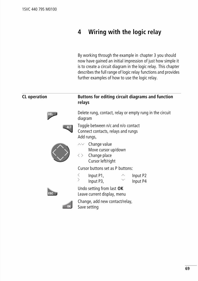
CL operation Buttons for editing circuit diagrams and functionrelays
Delete rung, contact, relay or empty rung in the circuitdiagram
Toggle between n/c and n/o contactConnect contacts, relays and rungsAdd rungs,
ÍÚ
ú í
Change valueMove cursor up/downChange placeCursor left/right
Cursor buttons set as P buttons:
úí
Input P1,Input P3,
ÍÚ
Input P2Input P4
Undo setting from last OK Leave current display, menu
Change, add new contact/relay,Save setting

8/3/2019 Cl Lmt Manual
http://slidepdf.com/reader/full/cl-lmt-manual 73/296
Wiring with the logic relay
70
1SVC 440 795 M0100
Operating principles
The cursor buttons in the circuit diagram perform threefunctions. The appearance of the flashing cursor indicatesthe current mode.
• Move
• Enter
• Connect
In Move mode you can use ÍÚ ú í to move the cursoraround the circuit diagram in order to select a circuit
connection, contact or relay coil.Use OK to switch to Entry mode so that you can enter orchange a value at the current cursor position. If you pressESC in Entry mode, the logic relay will undo the most recentchanges.
Press ALT to switch to Connect mode for wiring contacts andrelays. Press ALT again to return to Move.
Press ESC to exit the circuit diagram and parameter display.
Opening the parameter display for function relayswith contacts or coilsIf you specify the contact or coil of a function relay in Entry
mode, the logic relay automatically switches from thecontact number to the function relay parameter displaywhen you press OK.
Press í to switch to the next contact or coil field withoutentering any parameters.
ProgramA program is a sequence of commands which the logic relayexecutes cyclically in RUN mode. A CL program consists ofthe necessary settings for the device, password, systemsettings, a circuit diagram and/or function relays.
â
I 1
l
h The logic relay performs many of these cursor movementsautomatically. For example, the logic relay switches thecursor to Move mode if no further entries or connectionsare possible at the selected cursor position.

8/3/2019 Cl Lmt Manual
http://slidepdf.com/reader/full/cl-lmt-manual 74/296
CL operation
71
1SVC 440 795 M0100
Circuit diagramThe circuit diagram is that part of the program where the
contacts are connected together. In RUN mode a coil isswitched on and off in accordance with the current flow andthe coil function specified.
Function relayFunction relays are program elements with special functions.Example: timing relays, time switches, counters. Functionrelays are elements provided with or without contacts andcoils as required. In RUN mode the function relays are
processed according to the circuit diagram and the resultsare updated accordingly.
Examples:Timing relay = function relay with contacts and coilsTime switch = function relay with contacts
RelaysRelays are switching devices which are electronicallysimulated in the logic relay. They actuate their contacts
according to their designated function. A relay consists of atleast a coil and a contact.
ContactsYou modify the current flow with the contacts in the CLcircuit diagram. Contacts such as n/o contacts are set to 1when they are closed and 0 when they are opened.Every n/o or n/c contact in the CL circuit diagram can bedefined as either a n/o contact or a n/c contact.

8/3/2019 Cl Lmt Manual
http://slidepdf.com/reader/full/cl-lmt-manual 75/296
Wiring with the logic relay
72
1SVC 440 795 M0100
CoilsCoils are the actuating mechanisms of relays. In RUN mode,
the results of the wiring are sent to the coils, which switchon or off accordingly. Coils can have seven different coilfunctions.
Table 5: Usable contacts
The logic relay works with different contacts, which can beused in any order in the contact fields of the circuit diagram.
Contact CL display
n/o contact,
Open in the rest state
I, Q, M, N, A, Ö, Y, C, T, O, P, :,D
,S
,R
,Z
n/c contact,Closed in the rest state
i, q, m, , a, ö, , c, t, , p, ,, ,
N Y O DS R Z
h In order to ensure compatibility with the AC010 devices,each CL-LSR/CL-LST and CL-LMR/CL-LMT logically
supports all possible contacts. The switching state isalways zero if contacts are not supported by the device,i.e. devices without a clock. The switching states ofcontacts (n/o) and time switches are always logically zero.
This feature enables the same circuit diagram to be usedon all CL-AC1, CL-AC2, CL-DC1 and CL-DC2 devices.

8/3/2019 Cl Lmt Manual
http://slidepdf.com/reader/full/cl-lmt-manual 76/296
CL operation
73
1SVC 440 795 M0100
Table 6: Contacts
Contact type n/o n/c CL-LSRCL-LST
CL-LMRCL-LMT
Page
Analog value comparator functionrelay
A a A1…A16 A1…A16 98
Counter function relay C c C1…C16 C1…C16 111
Text marker function relay D D1…D16 D1…D16 131
7-day time switch function relay Ö ö Ö1…Ö8 Ö1…Ö8 137
CL input terminal I i I1…I8 I1…I12 770 signal I13 I13
Expansion status – I14 236
Short-circuit/overload I16 I15…I16 236
Markers, (auxiliary relay) M m M1…M16 M1…M16 85
Markers (auxiliary relay) N N1…N16 N1…N16 85
Operating hours counter O O1…O4 O1…O4 143
Cursor button P p P1…P4 P1…P4 82
CL output Q q Q1…Q4 Q1…Q8 77
Input terminal for expansion unit R – R1…R12 77
Short-circuit/overload withexpansion
R – R15…R16 236
CL output(expansion or auxiliary marker S)
S S1…S8 (as marker)
S1…S8 85
Timer function relay T t T1…T16 T1…T16 148
Jump label : – :1…:8 :1…:8 164
Year time switch Y Y1…Y8 Y1…Y8 167
Master reset, (central reset) Z Z1…Z3 Z1…Z3 174
D
N
O
R
R
S
Y
Z

8/3/2019 Cl Lmt Manual
http://slidepdf.com/reader/full/cl-lmt-manual 77/296
Wiring with the logic relay
74
1SVC 440 795 M0100
Relays, function relays
The logic relay has different types of relay for wiring in acircuit diagram.
You can set the switching behaviour of these relays bymeans of the coil functions and parameters selected.
h In order to ensure compatibility with the AC010 devices,each CL-LSR/CL-LST and CL-LMR/CL-LMT logicallysupports all relay types internally. If a relay type is notsupported by the device, the switching state of thecontacts is always set to zero. The switching states ofcontacts (n/o) and time switches are always logically zero.
This feature enables the same circuit diagram to be usedon all CL-AC1, CL-AC2, CL-DC1 and CL-DC2 devices.Furthermore, you can use outputs that are not physicallypresent as markers.
Relay CLdisplay
CL-LSRCL-LST
CL-LMRCL-LMT
Coilfunction
Parameters
Analog value comparatorfunction relayA A1
…A16
A1
…A16
–j
Counter function relay C C1…C16 C1…C16 j j
Text marker function relay D D1…D16 D1…D16 j j
7-day time switch function relay Ö Ö1…Ö4 Ö1…Ö4 – j
Markers (auxiliary relay) M M1…M16 M1…M16 j –
Markers (auxiliary relay) N N1…N16 N1…N16 j –
Operating hours counterO O1
…O4
O1
…O4
j j CL output relay Q Q1…Q8 Q1…Q8 j –
CL output relay expansion,marker
S S1…S8 (as marker)
S1…S8 j –
Timer function relay T T1…T16 T1…T16 j j
Conditional jump : :1…:8 :1…:8 j –
Year time switch Y Y1…Y8 Y1…Y8 – j
Master reset, (central reset) Z Z1…Z3 Z1…Z3 j –

8/3/2019 Cl Lmt Manual
http://slidepdf.com/reader/full/cl-lmt-manual 78/296
CL operation
75
1SVC 440 795 M0100
The options for setting output and marker relays are listedwith the description of each coil function.
The coil functions and parameters are listed with thedescription of each function relay.
Circuit diagram displayIn the logic relay circuit diagram, contacts and coils areconnected up from left to right – from the contact to the coil.The circuit diagram is created on a hidden wiring gridcontaining contact fields, coil fields and rungs. It is thenwired up with connections.
• You can add switching contacts in the three contactfields. The first contact field is automatically connected tothe voltage.
• You add the relay coil to be controlled together with itsfunction and designation in the coil field.
• Every line in the circuit diagram forms a circuitconnection or rung. Up to 128 rungs can be wired in acircuit diagram.
• Connections are used to produce the electrical contactbetween switching contacts and the coils. They can becreated across several rungs. Each point of intersection isa connection.
Contact fields Coil field
Rungs/Current paths
I1-I2uT1-ÄQ1Q1-Ö1kêê êêêêê êê êê êêêêê êê êê êêê
Connecting lines

8/3/2019 Cl Lmt Manual
http://slidepdf.com/reader/full/cl-lmt-manual 79/296
Wiring with the logic relay
76
1SVC 440 795 M0100
Saving and loading circuit diagrams
The logic relay provides you with two ways of saving circuitdiagrams externally:
• Saving with the memory module
• Saving to a PC running CL-SOFT.
Once they have been saved, programs can be reloaded intothe logic relay, edited and run.
All circuit diagram data is saved in the logic relay. In theevent of a power failure the data will be retained until thenext time it is overwritten or deleted.
Memory moduleEach CL-LAS.MD003 memory module contains one circuitdiagram and is inserted in the interface of the logic relay. Theprogram is stored retentively on the memory module.
The way the memory module works and a description of howto transfer a program to the module is given in on section“Memory module”, Page 239.
CL SOFT
CL-SOFT is a PC program with which you can create, store,test and manage CL circuit diagrams.
h The circuit diagram display performs two functions:
• In STOP mode it is used to edit the circuit diagram.• In RUN mode it is used to check the circuit diagram
using the power flow display.
h MD001 memory modules of the AC010 devices can beread in CL-LSR/CL-LST. Memory modules MD001 andMD002 of AC010 devices can be read in the CL-LMR/CL-LMT.
Only the CL-LAS.MD003 memory module can be writeaccessed by CL-LSR/CL-LST and CL-LMR/CL-LMT.
8/3/2019 Cl Lmt Manual
http://slidepdf.com/reader/full/cl-lmt-manual 80/296
Working with contacts andrelays
77
1SVC 440 795 M0100
Completed circuit diagrams are transferred between your PCand the logic relay via the connecting cable. Once you have
transferred a circuit diagram, simply run the logic relaystraight from your PC.
Details on the program and transferring circuit diagrams aregiven in section “CL-SOFT”, Page 243.
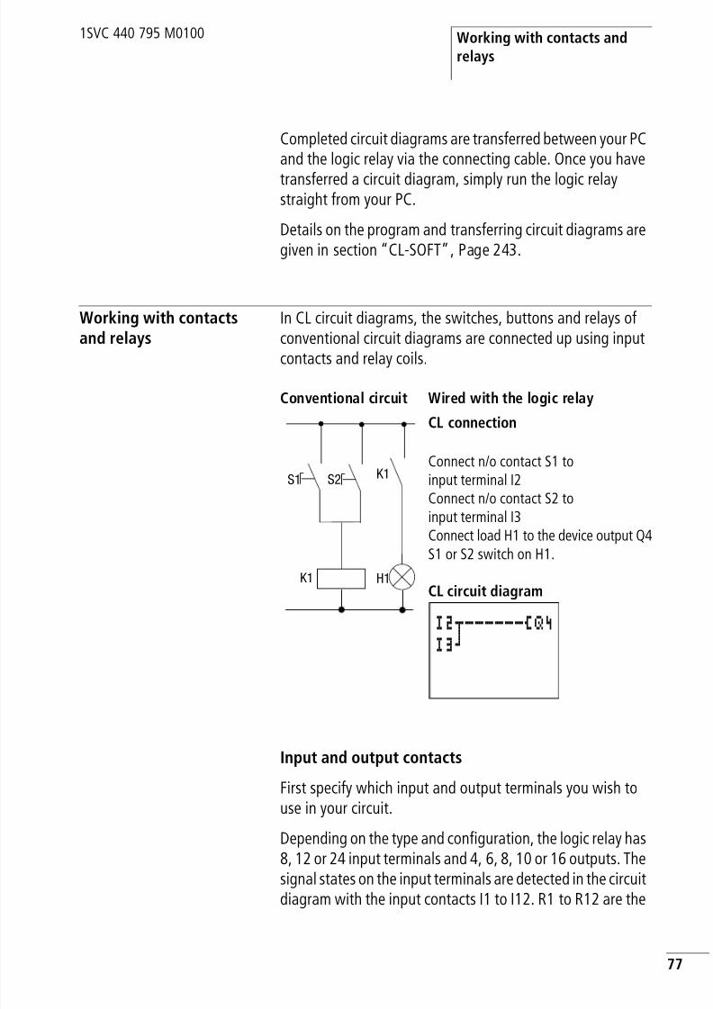
Working with contactsand relays
In CL circuit diagrams, the switches, buttons and relays ofconventional circuit diagrams are connected up using input
contacts and relay coils.
Input and output contacts
First specify which input and output terminals you wish touse in your circuit.
Depending on the type and configuration, the logic relay has8, 12 or 24 input terminals and 4, 6, 8, 10 or 16 outputs. The
signal states on the input terminals are detected in the circuitdiagram with the input contacts I1 to I12. R1 to R12 are the
Conventional circuit Wired with the logic relay
CL connection
Connect n/o contact S1 toinput terminal I2Connect n/o contact S2 toinput terminal I3
Connect load H1 to the device output Q4S1 or S2 switch on H1.
CL circuit diagramH1
S1
K1
K1S2
I2u------ÄQ4I3k

8/3/2019 Cl Lmt Manual
http://slidepdf.com/reader/full/cl-lmt-manual 81/296
Wiring with the logic relay
78
1SVC 440 795 M0100
input contacts of the expansion device. The outputs areswitched in the circuit diagram with the output relays Q1 to
Q8 or S1 to S8 (expansion).
Entering and changing contacts and relay coils
A switching contact is selected in the logic relay via thecontact name and contact number.
A relay coil is defined by its coil function, name and number.
Values for contacts and coil fields are changed in Entrymode. The value to be changed flashes.
X Move the cursor using the buttons ú í ÍÚ to a contactor coil field.
X Press OK to switch to Entry mode.X Use ú í to select the position you wish to change,
or press OK to jump to the next position.
X UseÍÚ to modify the value of the position.
I2Contact name
Contact number
ÄQ4Coil function
Relay name
Relay number
h A full list of all the contacts and relays is given in theoverview starting on Page 72.
I1
h If the field is empty, the logic relay will enter contact I1 or the coil ÄQ 1.
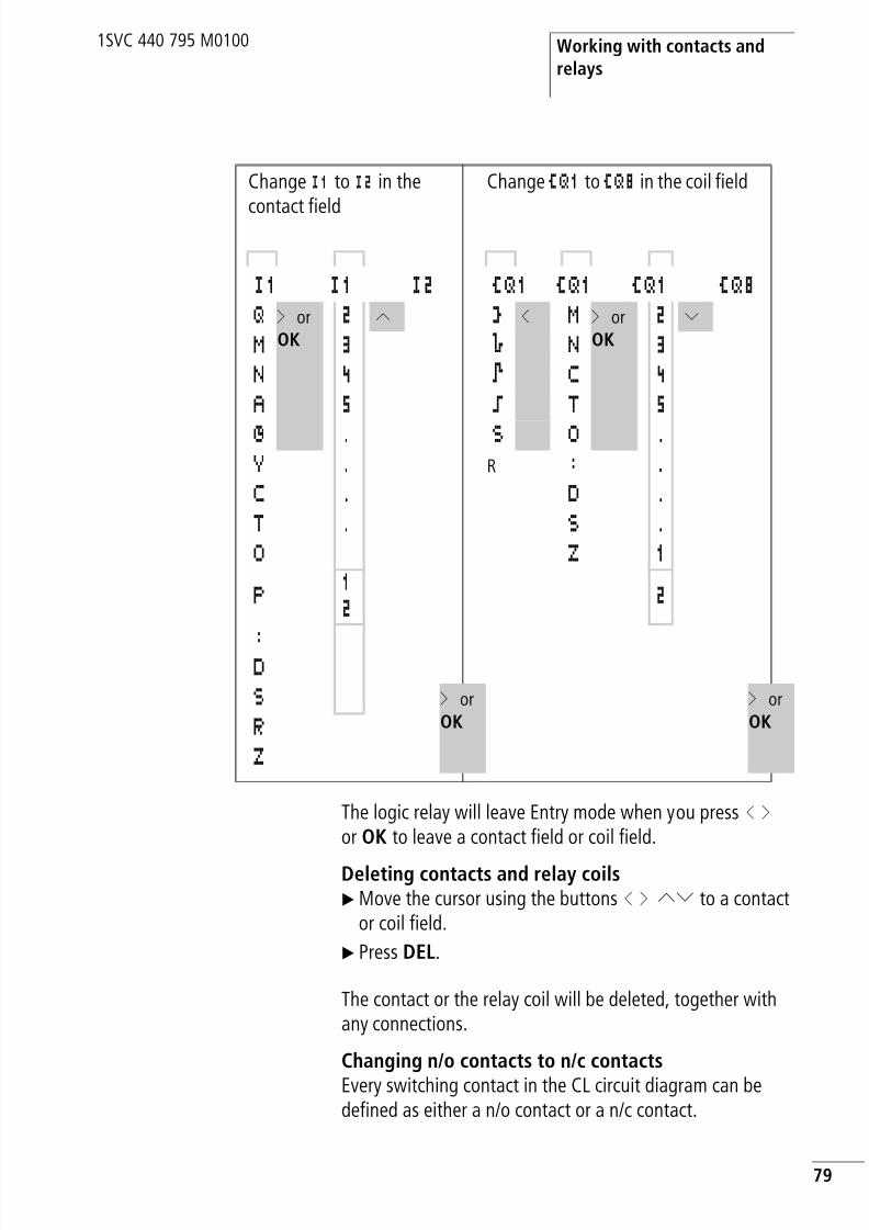
8/3/2019 Cl Lmt Manual
http://slidepdf.com/reader/full/cl-lmt-manual 82/296
Working with contacts andrelays
79
1SVC 440 795 M0100
The logic relay will leave Entry mode when you press ú í or OK to leave a contact field or coil field.
Deleting contacts and relay coilsX Move the cursor using the buttons ú í ÍÚ to a contact
or coil field.
X Press DEL.
The contact or the relay coil will be deleted, together withany connections.
Changing n/o contacts to n/c contactsEvery switching contact in the CL circuit diagram can bedefined as either a n/o contact or a n/c contact.
Change I1 to I2 in the
contact field
Change ÄQ1 to ÄQ8 in the coil field
I1 I1 I2 ÄQ1 ÄQ1 ÄQ1 ÄQ8Q í or
OK2 Í Å ú M í or
OK2 Ú
M 3 è N 3N 4 È C 4A 5 ä T 5
Ö . S O .Y . R : .C . D .T . S .O Z 1
P12 2
:DS í or
OKí or OKR
Z

8/3/2019 Cl Lmt Manual
http://slidepdf.com/reader/full/cl-lmt-manual 83/296

8/3/2019 Cl Lmt Manual
http://slidepdf.com/reader/full/cl-lmt-manual 84/296

8/3/2019 Cl Lmt Manual
http://slidepdf.com/reader/full/cl-lmt-manual 85/296
Wiring with the logic relay
82
1SVC 440 795 M0100
Inserting and deleting a rung
The CL circuit diagram shows four of the 128 rungs in thedisplay at the same time. The logic relay automatically scrollsup or down the display to show hidden rungs – even emptyones – if you move the cursor past the top or bottom of thedisplay.
A new rung is added below the last connection or insertedabove the cursor position:
X Position the cursor on the first contact field of a circuitconnection.
X Press ALT.
The existing rung with all its additional connections is“shifted” downwards. The cursor is then positioned directlyin the new rung.
Deleting a rung
The logic relay only removes empty rungs (without contactsor coils).
X Delete all the contacts and relay coils from the rung.
X Position the cursor on the first contact field of the emptyrung.
X Press DEL.
The subsequent rung(s) will be “pulled up” and any existing
links between rungs will be retained.
Switching with the cursor buttons
The logic relay also allows you to use the four cursor buttonsas hardwired inputs in the circuit diagram.
The buttons are wired in the circuit diagram as contacts P1to P4. The P buttons can be activated and deactivated in the
system menu.
I2u------ÄQ4I3k
I2u------ÄQ4Â nI3k
P1
P2
P3
P4

8/3/2019 Cl Lmt Manual
http://slidepdf.com/reader/full/cl-lmt-manual 86/296
Working with contacts andrelays
83
1SVC 440 795 M0100
The P buttons can also be used for testing circuits or manualoperation. These button functions are also useful for
servicing and commissioning purposes.Example 1:A lamp at output relay Q1 is switched on and off via inputsI1 and I2 or using cursor buttons Í Ú.
Example 2Terminal I1 is used to control output relay Q1. Terminal I5
switches to Cursor button mode and deactivates rung I1 viaM1.
The status menu display shows whether the P buttons are
used in the circuit diagram.
• P: button function wired and active.
• P2: button function wired, active and P2 buttonÍ pressed
• P-: button function wired and not active.
• Empty field: P buttons not used.
I1u------SQ1P2kI2u------RQ1P2k
I5-------ÄM1
I1-m1u---ÄQ1P1-M1k
h The P buttons are only detected as switches in the statusmenu. The cursor buttons are used for other functions inthe menus, the power flow display and in the text display.
............
I P2FR 15:59........STOP

8/3/2019 Cl Lmt Manual
http://slidepdf.com/reader/full/cl-lmt-manual 87/296
Wiring with the logic relay
84
1SVC 440 795 M0100
Checking the circuit diagram
The logic relay contains a built-in measuring device enablingyou to monitor the switching states of contacts and relaycoils during operation.
X Complete the small parallel connection and switch thelogic relay to RUN mode via the main menu.
X Return to the circuit diagram display.
You are now unable to edit the circuit diagram.
The circuit diagram display performs two functionsdepending on the mode:
• STOP: Creation of the circuit diagram
• RUN: Power flow display
X Switch on I3.
In the power flow display, energized connections are thickerthan non-energized connections.
You can follow energized connections across all rungs byscrolling the display up and down.
I2---u---ÄQ4I3---k
h If you switch to the circuit diagram display and are unableto modify a circuit diagram, first check whether the logicrelay is in STOP mode.
I2---U---ÄQ4I3---k
h The power flow display will not show signal fluctuations in
the millisecond range.This is due to the inherent delayfactor of LCD displays.

8/3/2019 Cl Lmt Manual
http://slidepdf.com/reader/full/cl-lmt-manual 88/296
Working with contacts andrelays
85
1SVC 440 795 M0100
Coil functions
You can set the coil function to determine the switchingbehaviour of relay coils. The following coil functions areavailable for relays Q, M, S, D, “:”:
Table 7: Coil function
Marker relays M and N are used as a flag. The S relay can beused as the output of an expansion unit or as a marker if noexpansion unit is connected. The only difference betweenthem and the output relay Q is that they have no outputterminals.
Circuit diagramdisplay
CLdisplay
Coil function Example
Ä Contactor
function
ÄQ1, ÄD2, ÄS4,
Ä:1, ÄM7
Å Contactorfunction withnegated result
ÅQ1, ÅD2, ÅS4
è Cycle pulse onfalling edge
èQ3, èM4, èD8,èS7
È Cycle pulse onrising edge ÈQ4, ÈM5, ÈD7,
ÈS3
ä Impulse relayfunction
äQ3, äM4, äD8,äS7
S Set (latching) SQ8, SM2, SD3,SS4
R Reset(unlatching)
RQ4, RM5, RD7,RS3
h The coil functions of the function relays are described inthe descriptions for the appropriate relays.

8/3/2019 Cl Lmt Manual
http://slidepdf.com/reader/full/cl-lmt-manual 89/296
Wiring with the logic relay
86
1SVC 440 795 M0100
Rules for wiring relay coilsTo ensure a clear overview of all relay states only assign the
same coil function once to a relay (ä, S, R). However,retentive coil functions such as ä, S, R can be used severaltimes if required by the circuit diagram logic.
Exception: When using jumps to structure a circuit diagram,this coil function can also be used effectively several times.
Relay with contactor function ÄThe output signal follows immediately after the input signaland the relay acts as a contactor.
Figure 39: Signal diagram of contactor function
Display in the logic relay:
• Output relays Q: ÄQ1 to ÄQ8 (depending on type)
• Markers M, N: ÄM1 to ÄM16, ÄN1 to ÄN16• Function relays (Text) D: ÄD1 to ÄD16• Output relays S: ÄS1 to ÄS8• Jumps: Ä:1 to Ä:8
h The coil functions Ä, Å, è, È, (contactor, contactor
negated, cycle pulse falling, rising edge) must only be usedonce for each relay coil. The last coil in the circuit diagramdetermines the status of the relay.
When controlling a contactor or relay, the control coilis only present once. Create parallel circuits or use Set,Reset as a coil function.
on
on
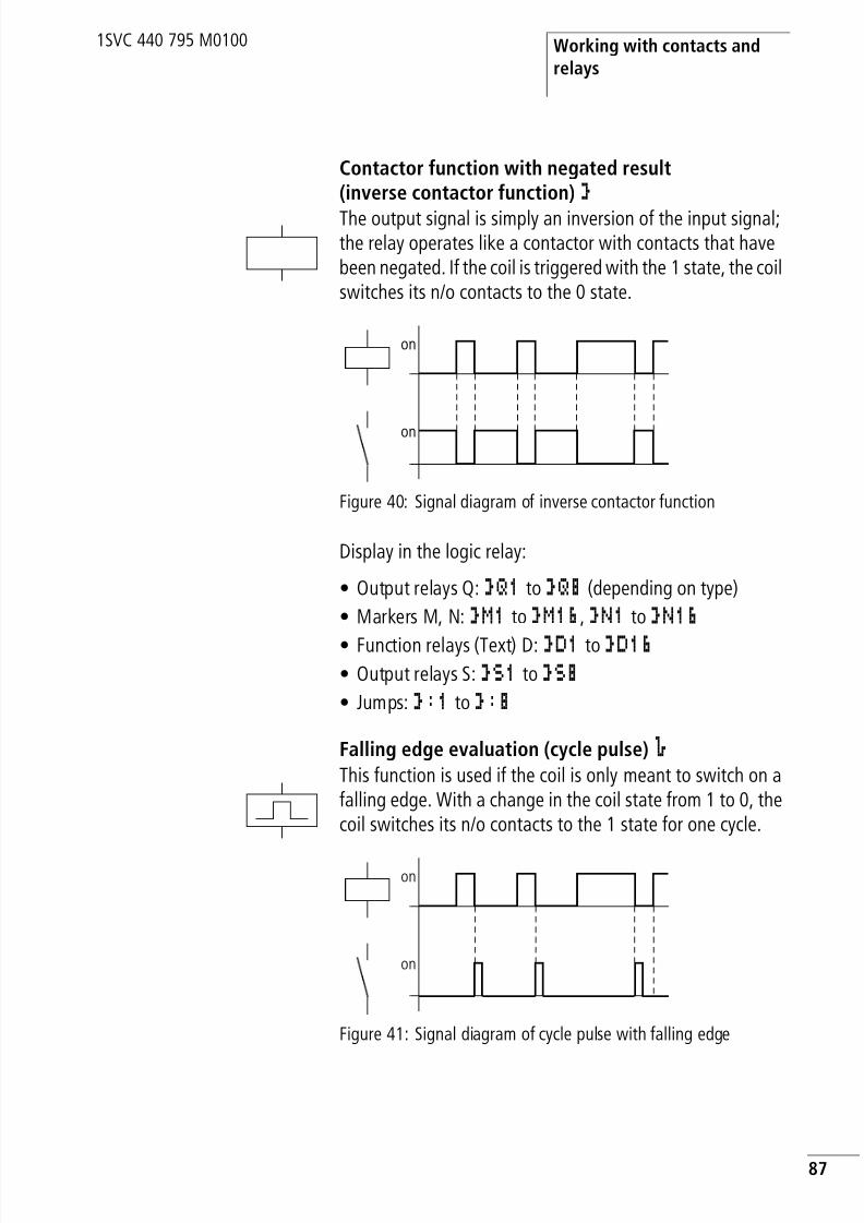
8/3/2019 Cl Lmt Manual
http://slidepdf.com/reader/full/cl-lmt-manual 90/296
Working with contacts andrelays
87
1SVC 440 795 M0100
Contactor function with negated result(inverse contactor function) ÅThe output signal is simply an inversion of the input signal;the relay operates like a contactor with contacts that havebeen negated. If the coil is triggered with the 1 state, the coilswitches its n/o contacts to the 0 state.
Figure 40: Signal diagram of inverse contactor function
Display in the logic relay:
• Output relays Q: ÅQ1 to ÅQ8 (depending on type)
• Markers M, N: ÅM1 to ÅM16, ÅN1 to ÅN16
• Function relays (Text) D: ÅD1 to ÅD16 • Output relays S: ÅS1 to ÅS8
• Jumps: Å:1 to Å:8
Falling edge evaluation (cycle pulse) èThis function is used if the coil is only meant to switch on afalling edge. With a change in the coil state from 1 to 0, thecoil switches its n/o contacts to the 1 state for one cycle.
Figure 41: Signal diagram of cycle pulse with falling edge
on
on
on
on

8/3/2019 Cl Lmt Manual
http://slidepdf.com/reader/full/cl-lmt-manual 91/296
Wiring with the logic relay
88
1SVC 440 795 M0100
Display in the logic relay:
• Markers M, N:èM1
toèM16
,èN1
toèN16
• Jumps: è:1 to è:8
Rising edge evaluation (cycle pulse) ÈThis function is used if the coil is only meant to switch on arising edge. With a change in the coil state from 0 to 1, the
coil switches its n/o contacts to the 1 state for one cycle.
Figure 42: Signal diagram of cycle pulse with rising edge
Display in the logic relay:
• Markers M, N: ÈM1to ÈM16, ÈN1to ÈN16• Jumps: È:1to È:8
h Physical outputs should not be used as a cycle pulse isgenerated.
on
on
h Physical outputs should not be used as a cycle pulse isgenerated.

8/3/2019 Cl Lmt Manual
http://slidepdf.com/reader/full/cl-lmt-manual 92/296
Working with contacts andrelays
89
1SVC 440 795 M0100
Impulse relay ä
The relay coil switches whenever the input signal changesfrom 0 to 1. The relay behaves like an impulse relay.
Figure 43: Signal diagram of impulse relay
Display in the logic relay:
• Output relay Q: äQ1to äQ8 (depending on type)
• Markers M: äM1to äM16• Function relays (Text) D: äD1to äD8• Relays S: äS1 to äS8
on
on
h A coil is automatically switched off if the power fails andif STOP mode is active. Exception: Retentive coils retainsignal 1 (a section “Retention (non-volatiledata storage)”, Page 221).

8/3/2019 Cl Lmt Manual
http://slidepdf.com/reader/full/cl-lmt-manual 93/296
Wiring with the logic relay
90
1SVC 440 795 M0100
Latching relay
The “latch” and “unlatch” relay functions are used in pairs.
The relay picks up when latched and remains in this stateuntil it is reset by the “unlatch” function.
:
Figure 44: Latching relay signal diagram
• Range A: The set coil and the reset coil are triggered at differenttimes
• Range B: Reset coil is triggered at the same time as the set coil• Range C: Power supply switched off
Display in the logic relay:
• Q output relays: SQ1to SQ8, RQ1to RQ8 (depending on type)
• M markers: SM1to SM16, RM1to RM16• (Text) D function relays: SD1 to SD8, RD1 to RD8
• S relays: SS1to SS8, RS1to RS8Use each of the two relay functions S andR once only per relay.
If both coils are triggered at the same time, priority is givento the coil further down in the circuit diagram.This is shownin the above signal diagram in section B.
on
on
S
R
on
A B C
I1-I2----SQ1
I2-------RQ1
h A latched relay is automatically switched off if the powerfails or if the device is in STOP mode. Exception: Retentivecoils retain signal 1 (a section “Retention (non-volatiledata storage)”, Page 221).

8/3/2019 Cl Lmt Manual
http://slidepdf.com/reader/full/cl-lmt-manual 94/296
Function relays
91
1SVC 440 795 M0100
Function relays Function relays allow you to simulate the functions ofdifferent conventional control engineering devices in yourcircuit diagram. The CL logic relay provides the followingfunction relays:
Table 8: Function relays
CL circuit diagramdisplay
Function relays
A1, A2 Analog value comparator, threshold
value switch (only useful for deviceswith an analog input)
C1, CC1, DC1, RC1 Counter relay, up/down counter,high-speed counter, frequencycounter
D2, ÄD2 Text, output user-defined texts, entervalues
Ö1, Ö2 Time switch, weekday/time
O1, ÄO2 Operating hours counter with limitvalue entry
T1,TT1, RT1, HT1X, ?X
Timing relay, on-delayedTiming relay, on-delayed with randomswitching
T1,TT1, RT1, HT1â, ?â
Timing relay, off-delayedTiming relay, off-delayed withrandom switching
T6,TT6, RT6, HT6Xâ, ?Xâ
Timing relay, on- and off-delayedTiming relay, on- and off-delayed withrandom switching
T2,TT2, RT2, HT2ü
Timing relay, single pulse
T3,TT3, RT3, HT3Ü
Timing relay, flashing

8/3/2019 Cl Lmt Manual
http://slidepdf.com/reader/full/cl-lmt-manual 95/296
Wiring with the logic relay
92
1SVC 440 795 M0100
A function relay is started via its relay coil or by evaluating a
parameter. It switches the contact of the function relayaccording to its function and the set parameters.
:2,Ä:2
Jump
Y3 Year time switch, date
Z1, Z3 Master reset, central reset of outputs,markers
CL circuit diagramdisplay
Function relays
h Current actual values are cleared if the power supply isswitched off or if the logic relay is switched to STOP mode.
Exception: Retentive coils keep their logic state(a section “Retention (non-volatile data storage)”,Page 221).
hAttention!The following applies to RUN mode: The logic relayprocesses the function relays after a pass through thecircuit diagram.The last state of the coils is used for this.
Only use the coil of a function relay once. Exception: Whenworking with jumps, the same coil can be used severaltimes.

8/3/2019 Cl Lmt Manual
http://slidepdf.com/reader/full/cl-lmt-manual 96/296
Function relays
93
1SVC 440 795 M0100
Example function relay with timer and counter relay
A warning light flashes when the counter reaches 10. Theexample shows function relays C1 and T1. The S1pushbutton actuator is used for the count signal. The S2pushbutton actuator resets counter P1.
Figure 45: Hardwiring with relays
The wiring of the logic relay is as follows.
Figure 46: CL wiring and circuit diagram
The counter P1 is called C1 in the logic relay.
The timing relay K1T is called T1 in the logic relay.
L01–
P1
P1
K1T
K1T
C R
H1
S1 S2
L01+
2sCounter
Value 10
I5-------CC1I6-------RC1C1-------TT1T1-------ÄQ1
1 2
H1
L01–
S2
L01+
L01–
+24 V 0 V I5 I6
S1
Q 1
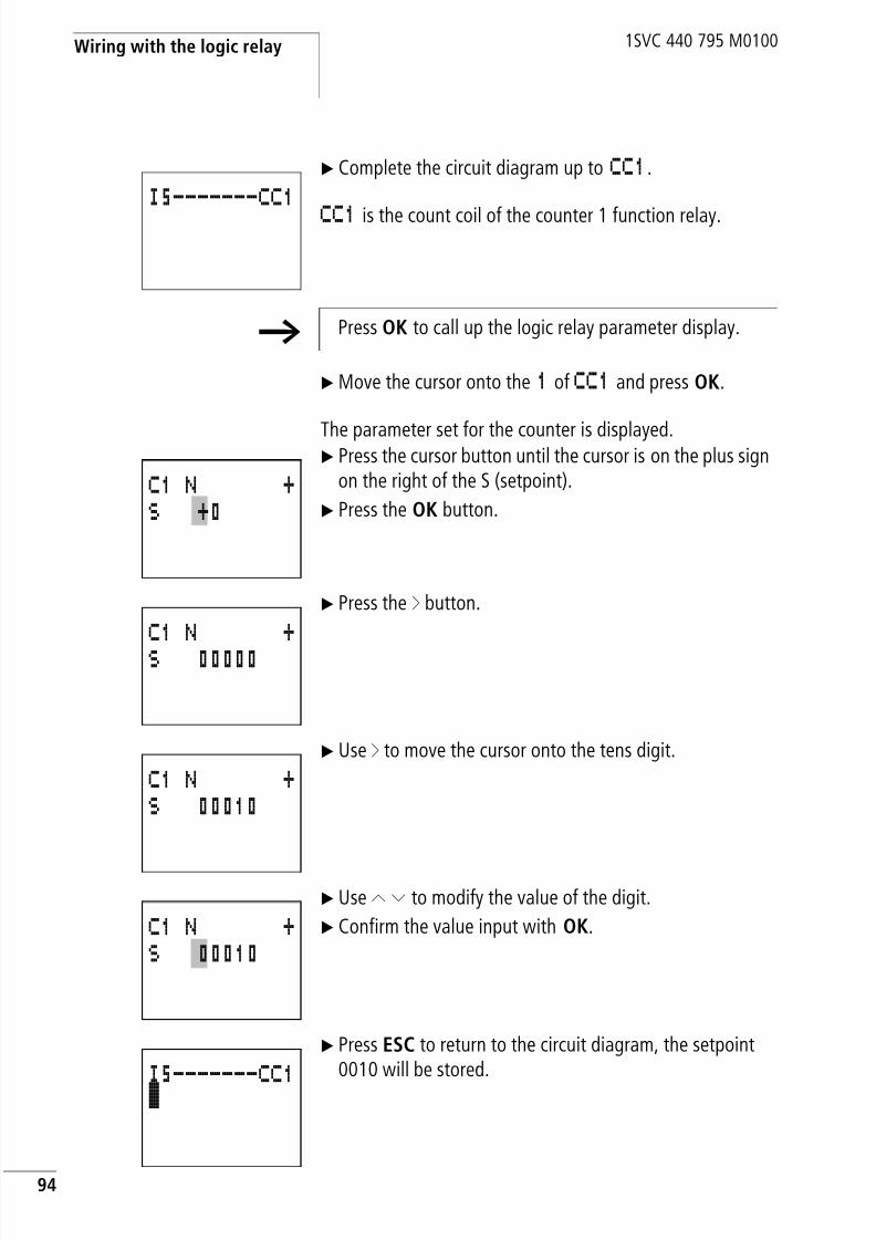
8/3/2019 Cl Lmt Manual
http://slidepdf.com/reader/full/cl-lmt-manual 97/296
Wiring with the logic relay
94
1SVC 440 795 M0100
X Complete the circuit diagram up to CC1.
CC1 is the count coil of the counter 1 function relay.
X Move the cursor onto the 1 of CC1 and press OK.
The parameter set for the counter is displayed.X Press the cursor button until the cursor is on the plus sign
on the right of the S (setpoint).
X Press the OK button.
X Press the í button.
X Use í to move the cursor onto the tens digit.
X Use Í Ú to modify the value of the digit.
X Confirm the value input with OK.
X Press ESC to return to the circuit diagram, the setpoint0010 will be stored.
I5-------CC1
h Press OK to call up the logic relay parameter display.
C1 N +S +0
C1 N +
S 00000
C1 N +S 00010
C1 N +S 00010
I5-------CC1ê

8/3/2019 Cl Lmt Manual
http://slidepdf.com/reader/full/cl-lmt-manual 98/296
Function relays
95
1SVC 440 795 M0100
X Enter the circuit diagram up to coil TT1 of the timingrelay. Set the parameter for T1.
The timing relay operates as a flash relay. The CL symbol for
the flasher/blink relay is Ü and is set at the top left of theparameter display. S means here the time base second.
X Select the Ü symbol by pressing the Ú button.
X Use the í to move to the first time setpoint I1.
X Press the OK button.
X Press the í button.
X Use the Í Ú ú í buttons to enter the value 01.000.
X Confirm with OK.
The time setpointI1
for the pause time is 1 s
h The logic relay has specific parameter displays for function
relays. The meaning of these parameters is explainedunder each relay type.
I5-------CC1I6-------RC1C1-------TT1
T1 X S +I1 +0I2 +0
T:
T1 Ü S +I1 +0I2 +0
T:
T1 Ü S +I1 +0I2 +0
T:
T1 Ü S +I1 00.000I2 +0
T:
T1 Ü S +I1 01.000
I2 +0T:

8/3/2019 Cl Lmt Manual
http://slidepdf.com/reader/full/cl-lmt-manual 99/296
Wiring with the logic relay
96
1SVC 440 795 M0100
X Use theÚ button to enter the value of the second setpointI2.
X Set this value to 0.5 s.
This is the time value for the pulse time.
X Press ESC to leave the parameter entry.
The values are now stored.
X Complete the circuit diagram.
X Press the ESC button.
X Press OK to store the circuit diagram.
X Test the circuit diagram with the power flow display.
X Switch the logic relay to RUN mode and return to thecircuit diagram.
Each parameter set can be displayed using the power flowdisplay for the circuit diagram.
X Move the cursor onto C1 and press OK.
The parameter set for the counter is displayed with actualand setpoint values.
X Switch I5. The actual value changes.
This is represented in the logic replay parameter display. Inthe last line C: 0007 the counter actual value is = 7.
T1 Ü S +
I1 01.000I2 00.500T:
I5-------CC1
I6-------RC1C1-------TT1T1-------ÄQ1
SAVECANCEL
C1 N +S 0010
# C:0000
C1 N +S 0010
# C:0007

8/3/2019 Cl Lmt Manual
http://slidepdf.com/reader/full/cl-lmt-manual 100/296
Function relays
97
1SVC 440 795 M0100
If the actual value is greater than or equal to the setpoint(10), the left character on the bottom row will change to â.
The contact of counterC1
switches.The counter contact triggers the timing relay. This causes thewarning light to flash at output Q1.
Power flow of the circuit diagram
Doubling the flashing frequency:
X In the power flow display select T1.
X Press OK.
X Change the set timeI1 to00.500 andI2 to00.250(0.5 and 0.25 s).
X The set time will be accepted as soon as you press OK.
The character on the left of the bottom row will indicate
whether the contact has switched or not.
• # Contact has not switched (n/o contact open).
• â Contact has switched (n/o contact closed).
You can also modify parameter settings via the PARAMETERmenu option.
C1 N +
S 0010
â C:0010
I5-------CC1I6-------RC1C1=======TT1T1=======ÄQ1
T1 Ü S +S1 00.500S2 00.250â T:00.200
h If you want to prevent other people from modifying the
parameters, change the access enable symbol from + to –when creating the circuit diagram and setting parameters.You can then protect the circuit diagram with a password.

8/3/2019 Cl Lmt Manual
http://slidepdf.com/reader/full/cl-lmt-manual 101/296
Wiring with the logic relay
98
1SVC 440 795 M0100
Analog value comparator/threshold value switch
The logic relay provides 16 analog comparators A1 to A16for use as required. These can also be used as thresholdvalue switches or comparators.
An analog value comparator or threshold value switchenables you to compare analog input values with a setpoint,the actual value of another function relay or another analoginput. This enables you to implement small controller taskssuch as two-point controllers very easily.
All CL-AC1, CL-AC2 and CL-DC2 devices are provided with
analog inputs.• The analog inputs of the CL-LSR/CL-LST are I7 and I8.
• The analog inputs of the CL-LMR/CL-LMT are I7, I8, I11and I12
The following comparisons are possible:
h Compatibility with AC010 devices
If you have loaded an existing AC010 circuit diagram, theprevious comparator functions and values are retained.The analog comparator function relay operates in CL-LSR/CL-LST and CL-LMR/CL-LMT as well as in AC010 devices.The setpoints are converted to the new resolution of theanalog inputs. The setpoint 5.0 (AC010) produces thesetpoint 512 (CL-LSR/CL-LST, CL-LMR/CL-LMT).
Value at function
relay input I1
Comparator functions Value at function
relay value inputI2
Mode selection atthe function relay
Analog input I7, I8,I11, I12
Analog input I7, I8,I11, I12
Setpoint 0000 to9999
Setpoint 0000 to9999
Actual value of
counter relay C1 toC16
Actual value of
counter relay C1 toC16

8/3/2019 Cl Lmt Manual
http://slidepdf.com/reader/full/cl-lmt-manual 102/296
Analog value comparator/threshold value switch
99
1SVC 440 795 M0100
Table 9: Comparison examples:
Circuit diagram display with analog valuecomparator
Analog value comparators are integrated as contacts in thecircuit diagram.
Actual value oftiming relay T1 toT16
Actual value oftiming relay T1 toT16
Less than LT
Less than/equal to LE
Equal to EQGreater than/equal to GE
Greater than GT
Value at functionrelay input I1
Comparator functions Value at functionrelay value input
I2Mode selection atthe function relay
A1 function relayValue input I1
A1 function relayValue input I1
I7 GE
(greater than/equalto)
I8
I7 LE(less than/equal to)
I8
I7 GE(greater than/equalto)
Setpoint
I7 LE
(less than/equal to)
Setpoint
I8 GE(greater than/equalto)
Setpoint
I8 LE(less than/equal to)
Setpoint
I1uA1----SQ1
hA2----RQ1A3-------ÄM1
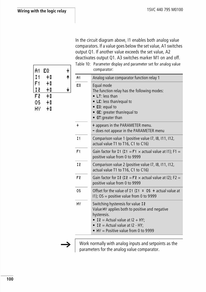
8/3/2019 Cl Lmt Manual
http://slidepdf.com/reader/full/cl-lmt-manual 103/296
Wiring with the logic relay
100
1SVC 440 795 M0100
In the circuit diagram above, I1 enables both analog valuecomparators. If a value goes below the set value, A1 switches
output Q1. If another value exceeds the set value, A2deactivates output Q1. A3 switches marker M1 on and off.
Table 10: Parameter display and parameter set for analog valuecomparator:A1 EQ +
I1 +0 ÆF1 +0I2 +0 æF2 +0
OS +0HY +0
A1 Analog value comparator function relay 1
EQ Equal modeThe function relay has the following modes:• LT: less than
• LE: less than/equal to• EQ: equal to• GE: greater than/equal to• GT:greater than
+ + appears in the PARAMETER menu.- does not appear in the PARAMETER menu
I1 Comparison value 1 (positive value I7, I8, I11, I12,actual value T1 to T16, C1 to C16)
F1Gain factor for
I1(I1
=F1
× actual value at I1); F1 =positive value from 0 to 9999
I2 Comparison value 2 (positive value I7, I8, I11, I12,actual value T1 to T16, C1 to C16)
F2 Gain factor for I2 (I2 = F2 × actual value at I2); F2 =positive value from 0 to 9999
OS Offset for the value of I1 (I1 = OS + actual value atI1); OS = positive value from 0 to 9999
HY Switching hysteresis for value I2Value HY applies both to positive and negativehysteresis.• I2 = Actual value at I2 + HY;• I2 = Actual value at I2 - HY;• HY = Positive value from 0 to 9999
h Work normally with analog inputs and setpoints as theparameters for the analog value comparator.

8/3/2019 Cl Lmt Manual
http://slidepdf.com/reader/full/cl-lmt-manual 104/296
Analog value comparator/threshold value switch
101
1SVC 440 795 M0100
Compatibility of AC010 devices with logic relays
New functions were added to the parameter display of theCL-LSR/CL-LST and CL-LMR/CL-LMT. The AC010 parameterscan be found at the following points.
AC010 parameter Logic relayparameter
AA = I1 AABB = I2 BBA1 = A1
+ = +
$ = GE
h The analog comparator of the CL-LSR/CL-LST and CL-LMR/CL-LMT operates internally in the value range:
–2147483648 to +2147483647
This ensures that the correct value is always calculated.This is important for multiplying values (I1 × F1 orI2 × F2).
Example:
I1 = 9999, F1 = 9999
I1 x F1 = 99980001
The result is within the value range.
h If no value is entered at F1 or F2, only the value at I1 andI2 is used (no multiplication).
h If the value of a counter relay exceeds the value 9999, thevalue of the counter is shown in the display of the analogvalue comparator minus 10000.
Example: Counter actual value =10233Display of the analog value comparator: 233 (10000 isdisplayed as 0).
ANALOGAAw g
n $ dA1BBy b +
A1 GE +I1 AA ÆF1 +0I2 BB æF2 +0OS +0HY +0

8/3/2019 Cl Lmt Manual
http://slidepdf.com/reader/full/cl-lmt-manual 105/296
Wiring with the logic relay
102
1SVC 440 795 M0100
Parameter display in RUN mode
Parameter display and parameter set for analog valuecomparator in RUN mode with the display of the actualvalues:
Resolution of the analog inputs
The analog inputs I7, I8, and on the CL-LMR/CL-LMT I11, I12have the following resolution.
The analog signal from 0 to 10 V DC is converted to a 10-bitdigital value from 0 to 1023. A digital value of 100represents an analog value of 1.0 V (exactly 0.98 V).
Figure 47: Resolution of the analog inputs
Actual value, e.g.: analog input
Factor is not used
Actual comparison value, e.g.: constant
Factor is not used
Offset is not usedThe switching hysteresis is +/– 25
A1 EQ +I1 0249 ÆF1 0000I2 0350 æF2 0000
OS 0000HY 0025
U [V]
5.0
512 1023
10.0
0

8/3/2019 Cl Lmt Manual
http://slidepdf.com/reader/full/cl-lmt-manual 106/296
Analog value comparator/threshold value switch
103
1SVC 440 795 M0100
Function of the analog value comparator functionrelay
Function of the Less than comparisonParameter display and parameter set for Less than analogvalue comparator.
Circuit diagram with analog value comparator.
h The GT, GE, LT, and LE comparison functions only differ inthe fact that GE and LE also switch when the value is equalto the setpoint. To ensure that all analog valuecomparators of AC010 devices are compatible with thelogic relays, the CL-LSR/CL-LST and the CL-LMR/CL-LMThave five comparison modes.
iCaution!Analog signals are more sensitive to interference thandigital signals.Consequently, greater care must be takenwhen laying and connecting the signal lines.
Set the switching hysteresis to a value so that interferencesignals will not cause accidental switching. A value of 0.2V (value 20 without gain) must be observed as a safetyvalue.
A1 LT +I1 I7 ÆF1 +0I2 0100 æF2 +0OS +0
HY 0025
A1-------ÄQ1
h The valuesF1 +0,F2 +0 andOS +0were not defined.
A gain is not used with any values. No offset is used.

8/3/2019 Cl Lmt Manual
http://slidepdf.com/reader/full/cl-lmt-manual 107/296
Wiring with the logic relay
104
1SVC 440 795 M0100
Figure 48: Signal diagram of analog value comparator in Less than
mode1: actual value at I7
2: setpoint plus hysteresis value
3: setpoint
4: setpoint minus hysteresis
The n/o contact switches off when the actual value at I7exceeds the setpoint plus hysteresis. If the actual value at I7falls below the setpoint, the n/o contact switches on.
Function of the Less than/equal to comparison
Parameter display and parameter set for Less than/equal toanalog value comparator.
Circuit diagram with analog value comparator.
on
off
1
234
A2 LE +I1 I7 ÆF1 +0I2 0100 æF2 +0
OS +0HY 0025
A2-------ÄQ1
h The valuesF1 +0,F2 +0 andOS +0were not defined.No values are used with a gain factor, and no offset isused.

8/3/2019 Cl Lmt Manual
http://slidepdf.com/reader/full/cl-lmt-manual 108/296
Analog value comparator/threshold value switch
105
1SVC 440 795 M0100
Figure 49: Signal diagram of analog value comparator in Less than/
equal to mode
1: actual value at I7
2: setpoint plus hysteresis value
3: setpoint
4: setpoint minus hysteresis
The n/o contact switches off when the actual value at I7exceeds the setpoint plus hysteresis. If the actual value at I7
equals or falls below the setpoint, the n/o contact switches on.Function of the Equal to comparison
Parameter display and parameter set for Equal to analogvalue comparator.
Circuit diagram with analog value comparator.
on
off
1
234
A8 EQ +I1 I8 ÆF1 0010I2 3000 æF2 +0
OS +0HY 0250
A8-------ÄQ3
h The values F2 +0 and OS +0 were not defined. Novalues are used with a gain factor, and no offset is used.A gain factor of 10 is used with the analog value at I8. Thehysteresis is adjusted accordingly.

8/3/2019 Cl Lmt Manual
http://slidepdf.com/reader/full/cl-lmt-manual 109/296
Wiring with the logic relay
106
1SVC 440 795 M0100
Figure 50: Signal diagram of analog value comparator in Equal to
mode
1: actual value at I8, multiplied with gain factor F2
2: setpoint plus hysteresis value
3: setpoint
4: setpoint minus hysteresis
The n/o contact switches on if the actual value at I8(multiplied by F1) reaches the configured setpoint. If the
actual value exceeds the setpoint, the n/o contact switchesoff. The n/o contact switches on if the actual value at I8(multiplied by F1) reaches the configured setpoint. If theactual value falls below the setpoint minus hysteresis, then/o contact switches off.
Example: Function of the Greater than/equal tocomparison
Parameter display and parameter set for Greater than/equalanalog value comparator.
Circuit diagram with analog value comparator.
on
off
1
234
A5 GE +I1 I7 ÆF1 +0I2 0100 æF2 +0OS +0HY 0025
A5-------ÄQ1

8/3/2019 Cl Lmt Manual
http://slidepdf.com/reader/full/cl-lmt-manual 110/296
Analog value comparator/threshold value switch
107
1SVC 440 795 M0100
Figure 51: Signal diagram of analog value comparator in Greaterthan/equal to mode
1: actual value at I7
2: setpoint plus hysteresis value
3: setpoint
4: setpoint minus hysteresis
The n/o contact switches if the actual value at I7 is equal tothe setpoint. The n/o contact switches off when the actualvalue at I7 falls below the setpoint minus hysteresis.
Example: Function of the Greater than comparison
Parameter display and parameter set for Greater than analogvalue comparator.
Circuit diagram with analog value comparator.
h The valuesF1 +0,F2 +0 andOS +0were not defined.
No values are used with a gain factor, and no offset isused.
on
off
1234
A4 GT +
I1 I7 ÆF1 +0I2 0100 æF2 +0OS +0HY 0025
A4-------ÄQ1

8/3/2019 Cl Lmt Manual
http://slidepdf.com/reader/full/cl-lmt-manual 111/296
Wiring with the logic relay
108
1SVC 440 795 M0100
Figure 52: Signal diagram of analog value comparator in Greaterthan mode
1: actual value at I7
2: setpoint plus hysteresis value
3: setpoint
4: setpoint minus hysteresis
The n/o contact switches if the actual value at I7 reaches thesetpoint. The n/o contact switches off when the actual valueat I7 falls below the setpoint minus hysteresis.
Example: Analog value comparator as two-stepcontroller
If, for example, the temperature goes below a value, A1
switches on the output Q1 with the enable input I5. If thetemperature exceeds the set value, A2 will switch off. Ifthere is no enable signal, output Q1 will always be switchedoff by I5.
h The valuesF1 +0,F2 +0 andOS +0were not defined.
No values are used with a gain factor, and no offset isused.
on
off
1234
I5uA1----SQ1hA2u---RQ1
i5---k

8/3/2019 Cl Lmt Manual
http://slidepdf.com/reader/full/cl-lmt-manual 112/296
Analog value comparator/threshold value switch
109
1SVC 440 795 M0100
Parameter settings of both analog value comparators:
A simple circuit can be implemented if a switching point ofthe controller is assigned to the digital switching point of theanalog input. This switching point is 8 V DC (CL-DC1,CL-DC2) and 9.5 V (CL-AC1).
Parameter settings:
Example: Analog value comparator, detection of
operating statesSeveral analog value comparators can be used to evaluatedifferent operating states. In this case 3 different operatingstates are evaluated.
Parameter settings of three analog value comparators:
Switching on Switch offA1 LT +I1 I7 ÆF1 +0I2 0500 æF2 +0OS +0HY +0
A2 GT +I1 I7 ÆF1 +0I2 0550 æF2 +0OS +0HY 0015
I5uA1----SQ1hI7u---RQ1
i5---k
Switching on Switch off
The switch point isimplemented via I7(digital switching signal).
A1 LT +I1 I7 ÆF1 +0I2 0500 æF2 +0OS +0HY +0
A6-------ÄN1A7-------ÄN2A8-------ÄN3

8/3/2019 Cl Lmt Manual
http://slidepdf.com/reader/full/cl-lmt-manual 113/296
Wiring with the logic relay
110
1SVC 440 795 M0100
Example: Analog value comparator, comparison oftwo analog values
To compare two analog values, you can use the followingcircuit. In this case, the comparison determines whether I7 isless than I8.
Parameter settings of the analog value comparator.
First operating state
Second operating state Third operating state
A6 EQ +I1 I7 ÆF1 +0I2 0500 æF2 +0OS +0HY 0025
A7 EQ +I1 I7 ÆF1 +0I2 0700 æF2 +0OS +0
HY 0025
A8 EQ +I1 I7 ÆF1 +0I2 0850 æF2 +0OS +0
HY 0025
A1-------ÄM9
A1 LT +I1 I7 ÆF1 +0I2 I8 æF2 +0OS +0HY 0025

8/3/2019 Cl Lmt Manual
http://slidepdf.com/reader/full/cl-lmt-manual 114/296
Counters
111
1SVC 440 795 M0100
Counters The logic relay provides 16 up/down counters C1 to C16 foruse as required. The counter relays allow you to countevents. You can define an upper threshold value as acomparison value. The contact will switch according to theactual value.
High-speed counters, frequency counters up to 1 kHzcounter frequency.CL-DC1 and CL-DC2 feature four high-speed counters C13 toC16. The function is defined by the mode selected. Thecounter input is connected directly to a digital input. The
high-speed digital inputs are I1 to I4.
Possible applications include the counting of components,lengths, events and frequency measurement.
Table 11: Counter modes
h The counters of CL-LSR/CL-LST and CL-LMR/CL-LMTfunction in the same way as the counters of the AC010devices. If required, the same counters can also be usedfor retentive data.
Counters Operatingmode
C1 to C12 N Up/down counter
C13, C14 N or H Up/down counters orhigh-speed up counters(CL-DC1, CL-DC2)
C15, C16 N or F Up/down counters orfrequency counters(CL-DC1, CL-DC2)

8/3/2019 Cl Lmt Manual
http://slidepdf.com/reader/full/cl-lmt-manual 115/296
Wiring with the logic relay
112
1SVC 440 795 M0100
Wiring of a counterYou integrate a counter into your circuit in the form of a
contact and coil. The counter relay has different coils.
CL circuit diagram with counter relayThe coils and contacts have the following meanings:
Parameter display and parameter set for counter relays:
In the parameter display of a counter relay you change themode, the setpoint and the enable of the parameter display.
h To prevent unpredictable switching states, use each coil ofa relay once only in the circuit diagram.
Do not use the input of a high-speed counter as a contactin the circuit diagram. If the counter frequency is too highonly a random input value will be used in the circuitdiagram.
I5-------CC2I6-------DC2I7-------RC2C2-------SM9
Contact Coil
C1 to C12 The contact switches if theactual value is greater than orequal to the setpoint.
CC1 to CC16 Counter input, rising edgecounts
DC1 to DC16 Counting direction• Coil not triggered: up
counting.• Coil triggered: down
counting.
RC1 to RC16 Reset, coil triggered: actualvalue reset to 00000
C2 N +S 00000
C2 Counter function relay number 2
N • Mode N: up/down counter• Mode H: high-speed up/down counter• Mode F: frequency counter
+ • + appears in the PARAMETER menu.• - does not appear in the PARAMETER menu
S Setpoint, constant from 00000 to 32000

8/3/2019 Cl Lmt Manual
http://slidepdf.com/reader/full/cl-lmt-manual 116/296

8/3/2019 Cl Lmt Manual
http://slidepdf.com/reader/full/cl-lmt-manual 117/296
Wiring with the logic relay
114
1SVC 440 795 M0100
Determining counter frequencyThe maximum counter frequency depends on the length of
the circuit diagram in the logic relay. The number ofcontacts, coils and rungs used determines the run time (cycletime) required to process the CL circuit diagram.
Example: When using CL-LST.C12DC2 with only three rungsfor counting, resetting and outputting the result via theoutput, the counter frequency may be 100 Hz.
The maximum counter frequency depends on the maximumcycle time.
The following formula is used to determine the maximumcounter frequency:
f c = maximum counter frequency
t c = maximum cycle time
0.8 = correction factor
ExampleThe maximum cycle time is t c = 4000 ms (4 ms).
f c =1
x 0.82 x t c
f c =1
x 0.8 = 100 Hz2 x 4 ms

8/3/2019 Cl Lmt Manual
http://slidepdf.com/reader/full/cl-lmt-manual 118/296
Counters
115
1SVC 440 795 M0100
Function of the counter function relay
:
Figure 53: Signal diagram
1: Count pulses at the count coil CC…
2: Count direction, direction coil DC…
3: Reset signal at the reset coil RC…
4: Counter setpoint (the setpoint in the figure = 6)
5: actual value of the counter
6: contact of the counter, C
• Range A: The relay contact of counter C with setpoint value 6switches when the actual value is 6.
• Range B: If the counting direction is reversed, the contact is resetwhen the actual value is 5.
• Range C: Without count pulses the current actual value isretained.
• Range D: The reset coil resets the counter to 0.
Example: Counters, counting unit quantities, manualcounter value resetThe input I6 contains the necessary counter information and
controls the count coil CC1 of counter 1. Q4 is activated ifthe setpoint is reached. Q4 remains switched on until I7resets counter C1 to zero with the RC1 coil.
on
on
1
2
on
3
on6
BA C D
4
01
234
56 7
8
5

8/3/2019 Cl Lmt Manual
http://slidepdf.com/reader/full/cl-lmt-manual 119/296
Wiring with the logic relay
116
1SVC 440 795 M0100
Example: Counting unit quantities, automatic countervalue resetThe input I6 contains the necessary counter information and
controls the count coil CC2 of counter 2. M8 will be switchedon for one program cycle if the setpoint is reached. Thecounter C2 is automatically set to zero by the reset coil RC2.
Circuit diagram display Parameter settings of thecounter C1
Circuit diagram display Parameter settings of thecounter C2
I6-------CC1C1-------ÄQ4I7-Q4----RC1
C1 N +S 00100
I6-------CC2C2------uÄM8
hRC2
C2 N +S 01000

8/3/2019 Cl Lmt Manual
http://slidepdf.com/reader/full/cl-lmt-manual 120/296
Counters
117
1SVC 440 795 M0100
Example of a two counter cascadeAnother counter is added to the previous example. As the
contact of counter C2 is only set to 1 for one program cycle,the carry of counter C2 is transferred to counter C3. Thecounter C3 prevents further counting when its setpoint isreached.
Example: Up/down counting with a scan for actualvalue = zeroThe input I6 contains the necessary counter information andcontrols the count coil CC6 of counter 6. Marker N2 is set ifthe setpoint is reached. Marker N2 controls the direction coilDC6 of counter C6. If N2 is 1 (activated), counter C6 counts
down. If the actual value of the counter is 00000, the analog
Circuit diagram display Parameter settings of thecounter C2
Parameter settings of thecounter C3
25000 pulses arecounted. 25x1000 =25000
I6-c3----CC2C2------uÄM8
dRC2hCC3
C3-------ÄQ2I8-Q2----RC3
C2 N +S 01000
C3 N +S 00025

8/3/2019 Cl Lmt Manual
http://slidepdf.com/reader/full/cl-lmt-manual 121/296
Wiring with the logic relay
118
1SVC 440 795 M0100
value comparator A6 resets mark N2. The direction coil DC6of counter C is switched off. Counter C6 only operates as an
up counter.
Example: Counter with retentive actual valueSelect a retentive counter if you wish to retain the actualvalue of a counter, even after a power failure or a changefrom RUN to STOP.
X Select the required counter in the SYSTEM… r
RETENTION… menu.
Circuit diagram display Parameter settings of thecounter C6
Parameter settings of the analog value comparator A6
I6-------CC6C6-------SN2N2-------DC6A6-N2----RN2
C6 N +S 01000
A6 EQ +I1 C6 ÆF1 +0I2 0000 æF2 +0OS +0
HY +0
h The above example scans the value zero. However, anypermissible value within the range of the analog valuecomparator function block can be entered.

8/3/2019 Cl Lmt Manual
http://slidepdf.com/reader/full/cl-lmt-manual 122/296
High-speed counters,CL-DC1, CL-DC2
119
1SVC 440 795 M0100
The example shows the counters C5 to C7 as retentivecounters.
The counter has the value 450 before the power supply isswitched off.
Figure 54: Retentive counter
a The numerical value 450 is retained even after a power outage.
U = Supply voltage of the device
High-speed counters,CL-DC1, CL-DC2
The logic relay provides various high-speed counterfunctions. These counter function blocks are coupled directlyto digital inputs. The following functions are possible:
• Frequency counters: C15 and C16
• High-speed counters: C13 and C14.
Frequency counter
The logic relay provides two frequency counters C15 andC16 for use as required. The frequency counters can be usedfor measuring frequencies. The high-speed frequencycounters are permanently connected to the digital inputs I3and I4.
Applications such as speed monitoring, volume
measurement using a volume counter, the monitoring ofmachine running can be implemented with the frequencycounter.
M 9 - M12 Æ
M13 - M16N 9 - N16C 5 - C 7 åæC 20C13 - C16T 02T 8T13 - T16
D 1 - D 8
Circuit diagram display Parameter settings of the counter C5
I6-------CC5C5-------ÄQ3I8-Q3----RC5
C5 N +S 00565
U

8/3/2019 Cl Lmt Manual
http://slidepdf.com/reader/full/cl-lmt-manual 123/296
Wiring with the logic relay
120
1SVC 440 795 M0100
The frequency counter allows you to enter an upperthreshold value as a comparison value. The C15 and C16
frequency counters are not dependent on the cycle time.
Counter frequency and pulse shapeThe maximum counter frequency is 1 kHz.
The minimum counter frequency is 4 Hz.
The signals must be square waves. We recommend a mark-to-space ratio of 1:1.
If this is not the case:
The minimum mark-to-space ratio is 0.5 ms.
t min = minimum time of the pulse or pause duration
f max = maximum count frequency (1 kHz)
Measurement method
The pulses on the input are counted for one secondirrespective of the cycle time, and the frequency isdetermined. The measurement result is provided as an actualvalue.
Wiring of a frequency counterThe digital inputs have the following assignment:
• I3 counter input for frequency counter C15.
• I4 counter input for frequency counter C16.
t min = 0.5 x1
f max
h Frequency counters operate independently of the programcycle time. The result of the actual value setpointcomparison is only transferred once every program cyclefor processing in the circuit diagram.
The reaction time in relation to the setpoint/actual valuecomparison can therefore be up to one cycle in length.

8/3/2019 Cl Lmt Manual
http://slidepdf.com/reader/full/cl-lmt-manual 124/296
High-speed counters,CL-DC1, CL-DC2
121
1SVC 440 795 M0100
You only integrate a frequency counter into your circuit inthe form of a contact and enable coil. The coils and contactshave the following meanings:
Parameter display and parameter set for frequencycounter:
In the parameter display of a counter relay you change themode, the setpoint and the enable of the parameter display.
h If you use C15 or C16 as frequency counters, coils DC15 or
DC16 will have no function. The counter signals aretransferred directly from the digital inputs I3 and I4 to thecounters. A frequency counter measures the actual valueand does not measure a direction.
---------CC15C15-------SQ3I8--------RC15
Contact Coil
C15 toC16 The contact switches if theactual value is greater than orequal to the setpoint.
CC15, CC16 Enable of the frequency counteron “1” state, coil activated
RC15, RC16 Reset, coil triggered: actualvalue reset to 00000
h The frequency counter can also be enabled specifically fora special operating state. This has the advantage that thecycle time of the device is only burdened with thefrequency measurement when it is taking place. If thefrequency counter is not enabled, the cycle time of thedevice is shorter.
C15 F +S 00200 C15 Counter function relay number 15
F Mode F: frequency counter
+ • + appears in the PARAMETER menu.• - does not appear in the PARAMETER menu
S Setpoint, constant from 00000 to 01000(32000 is a possible setting, the maximum frequency is1 kHz)

8/3/2019 Cl Lmt Manual
http://slidepdf.com/reader/full/cl-lmt-manual 125/296
Wiring with the logic relay
122
1SVC 440 795 M0100
Value rangeThe counter relay counts between 4 and 1000 [Hz].
Parameter display in RUN mode:
RetentionSetting retention on the frequency counter serves no purposesince the frequency is continuously remeasured.
Current setpoint, constant (0309)
# Contact has not switched.
â Contact has switched.
Actual value (0153)
C15F +S 00200

8/3/2019 Cl Lmt Manual
http://slidepdf.com/reader/full/cl-lmt-manual 126/296
High-speed counters,CL-DC1, CL-DC2
123
1SVC 440 795 M0100
Function of the frequency counter
Figure 55: Signal diagram of frequency counter
1: counter input I3 or I4
2: upper setpoint
3: enable coil CC…
4: reset coil RC…5: contact (n/o contact) C… upper setpoint value reached.
t g: gate time for the frequency measurement
• Range A: The counter is enabled. After a frequency above thesetpoint was measured for the first time, contact C15 (C16)switches.
• Range B: If the actual value falls below the setpoint, the contactis reset. The removal of the enable signal resets the actual valueto zero.
• Range C: The counter is enabled. After a frequency above thesetpoint was measured for the first time, contact C15 (C16)switches.
• Range D: The reset coil resets the actual value to zero.
1
2
3
t g t g t g t g t g t g t g t g
4
5
t g
A B C D

8/3/2019 Cl Lmt Manual
http://slidepdf.com/reader/full/cl-lmt-manual 127/296
Wiring with the logic relay
124
1SVC 440 795 M0100
Example: Frequency counterFrequency counters with different switch points
The frequency measured at input I3 is to be classified indifferent value ranges. The analog value comparator is usedas an additional comparison option.
The counter is enabled via the marker N3. The value 900 orhigher is detected by frequency counter C15 as the upperlimit value. This triggers the coil of marker N4.
If the frequency is higher than 600 Hz, analog value
comparator A1 indicates this and triggers marker N5.If the frequency is higher than 400 Hz, analog valuecomparator A2 indicates this and triggers marker N6.
Circuit diagram display Parameter settings of thecounter C15
Parameter settings of theanalog value comparator A1
Parameter settings of theanalog value comparator A2
N3-------CC15C15-------ÄN4
A1-------ÄN5A2-------ÄN6
C15 F +S 00900
A1 GE +I1 C15 ÆF1 +0I2 0600 æ
F2 +0OS +0HY +0
A2 GE +I1 C15 ÆF1 +0I2 0400 æ
F2 +0OS +0HY +0

8/3/2019 Cl Lmt Manual
http://slidepdf.com/reader/full/cl-lmt-manual 128/296
High-speed counters,CL-DC1, CL-DC2
125
1SVC 440 795 M0100
High-speed counters
You can use the high-speed counters to count highfrequency signals reliably.
The logic relay provides two high-speed up/down countersC13 and C14 for use as required. The high-speed counterinputs are permanently connected to the digital inputs I1 andI2. This counter relay allows you to count eventsindependently of the cycle time.
The high-speed counters allow you to enter an upper
threshold value as a comparison value. The C13 and C14high-speed counters are not dependent on the cycle time.
Counter frequency and pulse shapeThe maximum counter frequency is 1 kHz.
The signals must be square waves. We recommend a mark-to-space ratio of 1:1.
If this is not the case:
The minimum mark-to-space ratio is 0.5 ms.
t min = minimum time of the pulse or pause duration
f max = maximum count frequency (1 kHz)
Wiring of a high-speed counterThe digital inputs have the following assignment:
• I1: high-speed counter input for counter C13.
• I2: high-speed counter input for counter C14.
t min = 0.5 x1
f max
h High-speed counters operate independently of theprogram cycle time. The result of the actual value setpointcomparison is only transferred once every program cyclefor processing in the circuit diagram.
The reaction time in relation to the setpoint/actual valuecomparison can therefore be up to one cycle in length.

8/3/2019 Cl Lmt Manual
http://slidepdf.com/reader/full/cl-lmt-manual 129/296
Wiring with the logic relay
126
1SVC 440 795 M0100
You integrate a high-speed counter into your circuit in theform of a contact and coil.
.The coils and contacts have the following meanings:
Parameter display and parameter set for thehigh-speed counter:
In the parameter display of a counter relay you change themode, the setpoint and the enable of the parameter display.
h If you use C13 or C14 as high-speed counters you must
enable them with the coil CC13 or CC14 accordingly.
---------CC13C13-------SN3I6-------DC13I8-C13----RC13 Contact Coil
C13 toC14
The contact switches if theactual value is greater than or
equal to the setpoint.
CC13, CC14 Enable of the high-speedcounter on 1 signal coil activated
DC13, DC14 Counting direction• Status 0, not activated, up
counting.• Status 1, activated, down
counting.
RC13, RC14 Reset, coil triggered: actualvalue reset to 00000
h The high-speed counter can also be enabled specificallyfor a special operating state. This has the advantage thatthe cycle time of the device is only burdened with thecounting when it is taking place. If the high-speed counteris not enabled, the cycle time of the device is shorter.
C13 H +S 00950 C13 Counter function relay number 13
H High-speed counter mode (H = high speed)
+ • + appears in the PARAMETER menu.• - does not appear in the PARAMETER menu
S Setpoint, constant from 00000 to 32000

8/3/2019 Cl Lmt Manual
http://slidepdf.com/reader/full/cl-lmt-manual 130/296
High-speed counters,CL-DC1, CL-DC2
127
1SVC 440 795 M0100
Value rangeThe counter relay counts between 0 and 32000.
Behaviour when value range is reachedThe logic relay is in RUN mode.
The value is retained if the counter reaches 32000. If thecounter counts down and reaches 0, this value is retained.
Parameter display in RUN mode:
RetentionThe high-speed counter can be run with the retentive actualvalue. You can select the retentive counter relays in the
SYSTEM… r RETENTION… menu. C5 to C7, C8 and C13 toC16 can be selected.
If a counter relay is retentive, the actual value is retainedwhen the operating mode changes from RUN to STOP aswell as when the power supply is switched off.
If the logic relay is started in RUN mode, the counter relayoperates with the retentively saved actual value.
Current setpoint, constant (1 250)
# Contact has not switched.
â Contact has switched.
Actual value (877)
C13
H +S 00950
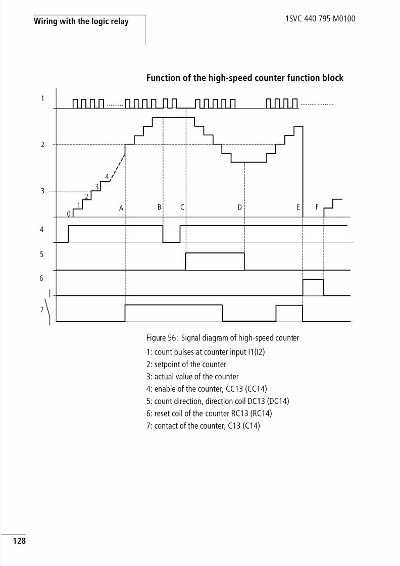
8/3/2019 Cl Lmt Manual
http://slidepdf.com/reader/full/cl-lmt-manual 131/296
Wiring with the logic relay
128
1SVC 440 795 M0100
Function of the high-speed counter function block
Figure 56: Signal diagram of high-speed counter
1: count pulses at counter input I1(I2)
2: setpoint of the counter
3: actual value of the counter
4: enable of the counter, CC13 (CC14)
5: count direction, direction coil DC13 (DC14)
6: reset coil of the counter RC13 (RC14)
7: contact of the counter, C13 (C14)
1
2
......... .........
3
4
5
A B C D E
.........
01
2
3
4
F
6
7

8/3/2019 Cl Lmt Manual
http://slidepdf.com/reader/full/cl-lmt-manual 132/296
High-speed counters,CL-DC1, CL-DC2
129
1SVC 440 795 M0100
• Range A: The relay contact C13 (C14) of the counter withsetpoint value 512 switches as soon as the actual value is 512.
• Range B: When new count pulses or the counter enable are notpresent, the actual value is retained.
• Range C: If the count direction is reversed DC13 (DC14), thecontact is reset when the actual value is 511.
• Range D: The count direction is set to up counting• Range E: The reset coil RC13 (RC14) resets the counter to 0. No
pulses are counted.• Range F: The reset coil is not active, pulses are counted.
Example: Counting measuring pulses and setting anoutput
Measuring pulses can represent lengths, rotations, angles orother values. These program sections are required for
applications involving the filling of sacks, bags or the cuttingof foil.
The count signals are continuously present at I1. Thehigh-speed counter C13 counts these pulses. The counter isautomatically set to zero if the actual value equals thesetpoint. Contact C13 is then set for one program cycle.The output Q3 is set at the same time. This is then reset byinput I8.
Example: Running motors or spindles in parallel
Applications may involve motion control with the parallelcontrol of two drives. Only certain deviations are permissibleso that the mechanical system does not jam.
h In the examples it must be remembered that there may bea time difference of up to one program cycle between thesetpoint/actual value comparison and the processing ofthe result. This may cause deviations in values.
Circuit diagram display Parameter settings of thecounter C13
N1-------CC13C13-------SQ13C13-------RC13I8-------RQ13
C13 H +S 1000

8/3/2019 Cl Lmt Manual
http://slidepdf.com/reader/full/cl-lmt-manual 133/296
Wiring with the logic relay
130
1SVC 440 795 M0100
These tasks can be implemented with the following solution.
I8 starts the drives. I7 and I6 carry the feedback signals of themotor-protective circuit-breakers. The drives are stopped if amotor-protective circuit-breaker trips. The analog valuecomparators control the difference of the path distance. Theappropriate drive is stopped temporarily if one path distanceis outside of the set tolerance. The coils and contacts havethe following meanings:
• M8 = enable for all drives
• Q1 = drive 1, counter drive 1 is connected with input I1and this with high-speed counter C13.
• Q2 = drive 2, counter drive 2 is connected with input I2and this with high-speed counter C14.
• A1 = comparison, if C13 is less than C14, drive 2 is toofast.
• A2 = comparison, if C14 is less than C13, drive 1 is toofast.
• A3 = comparison, if C13 and C14 are equal, both drivescan be activated.
• The hysteresis value of A1, A2 and A3 depends on theresolution of the transducer and the mechanical system.
Circuit diagram display Parameter settings of the counter C13
I8-I7-I6-ÄM8M8ua2u---ÄQ1
dA3kda1u---ÄQ2hA3k
--------uCC13hCC14
C13 H +S +0

8/3/2019 Cl Lmt Manual
http://slidepdf.com/reader/full/cl-lmt-manual 134/296
Text display
131
1SVC 440 795 M0100
Text display CL-LSR/CL-LST and CL-LMR/CL-LMT are able to display 16freely editable texts. These texts can be triggered by theactual values of function relays such as timing relays,counters, operating hours counters, analog valuecomparators, date, time or scaled analog values. Thesetpoints of timing relays, counters, operating hourscounters, analog value comparators can be modified whenthe text is displayed. The text display can only be edited withCL-SOFT (from Version 6.xx). The texts are stored in the
CL-SOFT file or on the CL-LAS.MD003 memory module forCL-LSR/CL-LST and CL-LMR/CL-LMT.
Parameter settings of the counter C14
Parameter setting of analog value comparators A1 and A2
Parameter settings A3
C14 H +S +0
A1 LT +I1 C13 ÆF1 +0
I2 C14 æF2 +0OS +0HY 0015
A2 LT +I1 C14 ÆF1 +0
I2 C13 æF2 +0OS +0HY 0015
A1 EQ +I1 C13 Æ
F1 +0I2 C14 æF2 +0OS +0HY 0020

8/3/2019 Cl Lmt Manual
http://slidepdf.com/reader/full/cl-lmt-manual 135/296
Wiring with the logic relay
132
1SVC 440 795 M0100
Wiring a text display
You integrate a text display into your circuit in the form of acontact and coil.
The coils and contacts have the following meanings:
The text display does not have a parameter display in thePARAMETER menu.
Retention
The texts D1 to D8 can be operated with retentive actual
values (contacts).If the text displays are retentive, the actual value is retainedwhen the operating mode changes from RUN to STOP aswell as when the power supply is switched off.
When the logic relay is restarted in RUN mode, the textdisplays D1 to D8 continue with the retentively stored actualvalue.
h Compatibility with AC010
If you wish to load an existing AC010 circuit diagram, theavailable text display functions are retained. The textdisplay operates in CL-LSR/CL-LST and CL-LMR/CL-LMT inthe same way as in AC010.
i5-------ÄD2i6-------ÄD3D2u------ÄT5D3k Contact Coil
D1 to D16 Coil of the corresponding textdisplay is triggered
Ä, Å, è, ^, ä,S, R
D1 to D16
If a coil is triggered, the text isshown in the display.

8/3/2019 Cl Lmt Manual
http://slidepdf.com/reader/full/cl-lmt-manual 136/296
Text display
133
1SVC 440 795 M0100
Example of a text display:
The text display can display the following:
Scaling
The values of the analog inputs can be scaled.
Function
The D text output function block (D = Display, tex t display)
operates in the circuit diagram like a normal M marker. If atext is assigned to a marker, this is displayed in the CLdisplay when the coil is set to 1. For this to take place, thelogic relay must be in RUN mode and the status display mustbe activated before the text is displayed.
D2 to D16:If several texts are present and are triggered, each text isautomatically displayed in turn every 4 s. This process will be
repeated until• No other text display function block is set to 1.
• STOP mode is selected.
SWITCH;
CONTROL;DISPLAYS;MADE EASY!
Line 1, 12 characters
Line 2, 12 characters, a setpoint or actual value
Line 3, 12 characters, a setpoint or actual value
Line 4, 12 characters
RUNTIME M:ST1 :012:46C1 :0355 STPRODUCED
Range Selectable displayrange
Example
10 to +10 V 0 to 9999 0000 to 0100
10 to +10 V g 999 –025 to 050
10 to +10 V g 9.9 –5.0 to 5.0

8/3/2019 Cl Lmt Manual
http://slidepdf.com/reader/full/cl-lmt-manual 137/296
Wiring with the logic relay
134
1SVC 440 795 M0100
• The power supply of the logic relay is no longer present.
• The OK or DEL + ALT buttons are used to switch to a
menu.
• A setpoint is entered.
• The text for D1 is displayed.
D1:D1 is designed as an alarm text. If D1 is activated, the textassigned to it will be displayed until
• The coil D1 is reset to 0.
• STOP mode is selected.
• The power supply of the logic relay is no longer present.
• The OK or DEL + ALT buttons are used to switch to amenu.
Text entry
Text entry is only possible using CL–SOFT.
Character set
All ASCII characters in upper and lower case are permissible.
• A B C D E F G H I J K L M N O P Q R S T U V W X Y Z
• a b c d e f g h i j k l m n o p q r s t u v w x y z
The following special characters are permissible:! „“ # $ % & ’ () * + , – ./0 1 2 3 4 5 6 7 8 9
Figure 57: Text output examples
Counter with actual value Analog input scaled astemperature value
D1 as error message onfuse failure
QUANTITYPCE:0042!COUNTING!
TEMPERATUREOUT -010 DEGIN +018 DEG
HEAT
FUSE FAULTHOUSE 1FAILED!

8/3/2019 Cl Lmt Manual
http://slidepdf.com/reader/full/cl-lmt-manual 138/296
Text display
135
1SVC 440 795 M0100
Entering a setpoint in a display
A text can contain two values such as actual values andsetpoints of function relays, analog input values and timeand date. The position of setpoints and actual values is fixedto the centre of lines 2 and 3. The length depends on thevalue to be displayed. Setpoint entries in the text display areuseful if the PARAMETER menu is not available for display orentry. Also when the operator is to be shown which setpointis being modified.
The example shows the following.
The setpoint of timing relay T1 is to be changed from 12minutes to 15 minutes.
• Line 2: setpoint of timing relay T1, can be edited.
• Line 3: actual value of timing relay T1.
The text is displayed.
Line 1Line 2, setpoint can be edited
Line 3, setpoint can be edited
Line 4
h The appropriate text function block must be available inorder to modify a setpoint. The setpoint must be aconstant.
h When values are being entered, the text is retainedstatically on the display. The actual values are updated.
RUNTIME M:ST1 :012:46C1 :0355 STPRODUCED
STIR M:SS : 012:00ACT: 008:33BREAD ROLLS

8/3/2019 Cl Lmt Manual
http://slidepdf.com/reader/full/cl-lmt-manual 139/296
Wiring with the logic relay
136
1SVC 440 795 M0100
X Pressing the ALT button will cause the cursor to jump tothe first editable value.
In this operating mode, you can use the cursor buttons ÍÚ to move between different editable constants.
X Press the OK button, the cursor will jump to the highestdigit of the constant to be modified.
In this operating mode use the cursor buttonsÍÚ to modifythe value. Use the cursor buttons ú í to move betweendigits.
Use the OK button to accept the modified value. Use theESC button to abort the entry and leave the previous value.
X Press the OK button, the cursor will move from constantto constant.
The modified value is accepted.
Press the ESC button to leave Entry mode.
STIR M:S
S : 012:00ACT: 008:33
STIR M:SS : 012:00ACT: 008:33BREAD ROLLS
STIR M:SS : 015:00ACT:008:34BREAD ROLLS
STIR M:SS : 015:00ACT:008:34BREAD ROLLS
STIR M:SS : 015:00ACT:008:34BREAD ROLLS

8/3/2019 Cl Lmt Manual
http://slidepdf.com/reader/full/cl-lmt-manual 140/296
7-day time switch
137
1SVC 440 795 M0100
7-day time switch Types CL-LSR.C... /CL-LST.C... and CL-LMR.C.../CL-LMT.C...are provided with a real-time clock. The time switches canonly be used properly in these devices.
The logic relay offers eight 7-day time switches Ö1 to Ö8 forup to 32 switch times.
Each time switch has four channels which you can use to setfour on and off times. The channels are set via the parameterdisplay.
The timer has a back-up battery. This means that it willcontinue to run in the event of a power failure, although thetime switch relays will not switch. When the logic relay is ina de-energized state, the timer contacts remain open.Information on the battery back-up time are provided onPage 256.
A 7-day time switch can be integrated into your circuit in theform of a contact.
h The procedure for setting the time is described undersection “Setting date and time” on Page 205.
h Compatibility with AC010
If you wish to load an existing AC010 circuit diagram, theexisting 7-day time switch functions are retained. The 7-day time switches in the CL-LSR/CL-LST and CL-LMR/CL-LMT operate in the same way as in the AC010.
Ö1u------ÄQ1Ö2k
Contact Coil
Ö1 to Ö8 Contact of the 7-day time switch
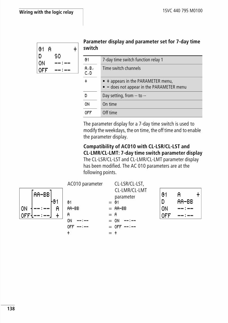
8/3/2019 Cl Lmt Manual
http://slidepdf.com/reader/full/cl-lmt-manual 141/296
Wiring with the logic relay
138
1SVC 440 795 M0100
Parameter display and parameter set for 7-day timeswitch
The parameter display for a 7-day time switch is used tomodify the weekdays, the on time, the off time and to enablethe parameter display.
Compatibility of AC010 with CL-LSR/CL-LST andCL-LMR/CL-LMT: 7-day time switch parameter displayThe CL-LSR/CL-LST and CL-LMR/CL-LMT parameter displayhas been modified. The AC 010 parameters are at thefollowing points.
Ö1 A +
D SOON --:--OFF --:--
Ö1 7-day time switch function relay 1
A,B,C,D
Time switch channels
+ • + appears in the PARAMETER menu,• - does not appear in the PARAMETER menu
D Day setting, from -- to --
ON On time
OFF Off time
AC010 parameter CL-LSR/CL-LST,CL-LMR/CL-LMTparameter
Ö1 = Ö1 AA-BB = AA-BB A = A ON --:-- = ON --:--
OFF --:-- = OFF --:-- + = +
fAA-BBgn dÖ1
ON s--:--n AOFFy--:--b +
Ö1 A +D AA-BBON --:--OFF --:--

8/3/2019 Cl Lmt Manual
http://slidepdf.com/reader/full/cl-lmt-manual 142/296
7-day time switch
139
1SVC 440 795 M0100
Table 12: On and off times
Parameter display in RUN mode:
Changing time switch channel
You can change time switch channel in either RUN or STOPmode by selecting the channel required with the cursorbuttons ÍÚ.
Example:
The parameter display of the 7-day time switch is active. Thecursor is flashing on channel A.
X Press the Í button to move the cursor to channel B.
Press the í button to reach any value that can be edited.
Function of the 7-day time switch
The following examples illustrate the function of the 7-daytime switch.
Parameters Meaning Meaningful values
Day of theweek
Monday to Sunday MO, TU, WE, TH, FR,SA, SU, --
On time Hours: MinutesNo time set at “--:--”
00:00 to 23:59, --:--
Off time Hours: MinutesNo time set at “--:--”
00:00 to 23:59, --:--
Selected channel, current time (only in RUN)
Weekday(s) from – to
On time
Off time
# Contact has not switched.
â Contact has switched.
Ö1 A 11:30 +D MO-FRON 06:45OFF 19:30 â
Ö1 A 11:30 +D MO-FRON 06:45OFF 19:30 â
Ö1 B 11:30 +D SAON 06:45
OFF 15:00 â

8/3/2019 Cl Lmt Manual
http://slidepdf.com/reader/full/cl-lmt-manual 143/296
Wiring with the logic relay
140
1SVC 440 795 M0100
Work days exampleThe time switch Ö1 switches on Monday to Friday between
06:30 and 09:00 and between 17:00 and 22:30.
Figure 58: Work days signal diagram
Weekends exampleTime switch Ö2 switches on at 16:00 on Friday and switchesoff at 06:00 on Monday.
Figure 59: Signal diagram of “weekend”
Ö1 A +D MO-FRON 06:30OFF 09:00
Ö1 B +D MO-FRON 17:00OFF 22:30
Ö2 A +D FRON 16:00OFF --:--
Ö2 B +D MOON --:--OFF 06:00

8/3/2019 Cl Lmt Manual
http://slidepdf.com/reader/full/cl-lmt-manual 144/296
7-day time switch
141
1SVC 440 795 M0100
Night switching exampleTime switch Ö3 switches on at 22:00 on Monday and
switches off at 06:00 on Tuesday.
Figure 60: Night switching signal diagram
Time overlaps exampleThe time settings of a time switch overlap. The clockswitches on at 16:00 on Monday, whereas on Tuesday andWednesday it switches on at 10:00. On Monday toWednesday the switching-off time is 22:00.
Figure 61: Time overlaps signal diagram
Ö3 D +D MOON 22:00OFF 06:00
h If the Off time is before the On time, the logic relay willswitch off on the following day.
Ö4 A +D MO-MION 16:00OFF 22:00
Ö4 B +D TU-WEON 10:00OFF 00:00

8/3/2019 Cl Lmt Manual
http://slidepdf.com/reader/full/cl-lmt-manual 145/296
Wiring with the logic relay
142
1SVC 440 795 M0100
Power failure exampleThe power is removed between 15:00 and 17:00. The relaydrops out and remains off, even after the power returns,since the first off time was at 16:00.
24 hour switching example
The time switch is to switch for 24 hours. Switch-on time at00:00 on Monday and switch-off time at 00:00 on Tuesday.
h On and off times always follow the channel which
switches first.
Ö4 A +D MO-SU
ON 12:00OFF 16:00
Ö4 B +D MO-SU
ON 12:00OFF 18:00
h When switched on, the logic relay always updates theswitching state on the basis of all the available switchingtime settings.
Ö1 A +D MOON 00:00OFF --:--
Ö1 B +D TUON --:--OFF 00:00

8/3/2019 Cl Lmt Manual
http://slidepdf.com/reader/full/cl-lmt-manual 146/296
Operating hours counter
143
1SVC 440 795 M0100
Operating hours counter The logic relay provides 4 independent operating hourscounters. These operating hours counters enables you torecord the operating hours of systems, machines andmachine parts. An adjustable setpoint can be selected withinthe value range. In this way, maintenance times can belogged and reported. The counter states are retained evenwhen the device is switched off. As long as the count coil ofthe operating hours counter is active, the logic relay countsthe hours in one second cycles.
You integrate an operating hours counter into your circuit in
the form of a contact and coil.
Parameter display and parameter set for the operating hourscounter function block:
In the parameter display of an operating hours counter youchange the setpoint in hours and the enable of theparameter display.
I2-------ÄO1O1uI8----RO1h------TT1
T1-------ÄQ3
Contact Coil
O1 to O4
ÄO1 to ÄO4 Count coil of the operating hourscounter
RO1 to RO4 reset coil of the operating hourscounter
O4 +S 000000
O:
O4 Operating hours counter number 04
+ • + appears in the parameter display• - appears in the parameter display
SSetpoint in hours
O: Actual value of the operating hours counter [h]

8/3/2019 Cl Lmt Manual
http://slidepdf.com/reader/full/cl-lmt-manual 147/296
Wiring with the logic relay
144
1SVC 440 795 M0100
Parameter display in RUN mode:
Value range of the operating hours counter
The operating hours counter counts in the range from0 hours up to more than 100 years.
Accuracy of the operating hours counter
The operating hours counter counts in seconds. When thedevice is switched off, up to 999 ms can be lost.
Function of the operating hours counter functionblock
When the coil of the O operating hours counter is set to 1,the counter increments its actual value by 1 (basic pulse: 1second).
If the actual value of the operating hours counter reaches thesetpoint of S, the contact O… switches for as long as theactual value is greater than or equal to the setpoint.
The actual value is kept stored in the device until the resetcoil RO… is triggered. The actual value is then set to zero.
Set time in hours
Actual time in hours
# Contact has not switched.
â Contact has switched.
O1 +S 001000
# O:000309
h Operating mode change RUN, STOP, power On, Off,delete program, change program, load new program. Allthese functions do not clear the actual value of theoperating hours counter.

8/3/2019 Cl Lmt Manual
http://slidepdf.com/reader/full/cl-lmt-manual 148/296
Operating hours counter
145
1SVC 440 795 M0100
Example: Operating hours counterOperating hours counter for the operating time of a
machine. The time in which a machine (logic relay) isenergized is to be measured.
Example: Maintenance meter for different machinesectionsMachine sections have to be maintained after different timeshave elapsed. Markers N1 and N2 are the On markers of twodifferent machine sections. These markers control theassociated operating hours counters. Output Q4 switches ona warning light if the setpoint of an operating hours counterhas been reached. A keyswitch at input I8 resets theassociated operating hours counter after maintenance hasbeen completed.
Circuit diagram display Parameter settings ofoperating hours counter O1
Circuit diagram display Parameter settings ofoperating hours counter O2
Parameter settings ofoperating hours counter O3
---------ÄO1 O1 +S 000000
N1-------ÄO2N2-------ÄO3O2u------ÄQ4
O3kI8uO2----RO2hO3----RO3
O2 +S 000500
O3 +S 000800

8/3/2019 Cl Lmt Manual
http://slidepdf.com/reader/full/cl-lmt-manual 149/296
Wiring with the logic relay
146
1SVC 440 795 M0100
Example: Maintenance meter for different machinesections, with text output
The entire machine operating time is to be counted. Machinesections have to be maintained after different times haveelapsed. Markers N1 and N2 are the On markers of twodifferent machine areas. These markers control theassociated operating hours counters. Output Q4 switches ona warning light if the setpoint of an operating hours counterhas been reached. This should flash. A keyswitch at input I8resets the associated operating hours counter aftermaintenance has been completed.
The entire machine operation time is to be displayedcontinuously. The run time of the machine sections shouldonly be displayed once the maintenance interval haselapsed.
Circuit diagram display Parameter settings ofoperating hours counter O1
Parameter settings ofoperating hours counter O2
Parameter settings ofoperating hours counter O3
---------ÄO1
O1-------ÄD4N1-------ÄO2N2-------ÄO3O2u------TT4O3kT4-------ÄQ4O2uI8----RO2
h------ÄD2
O3uI8----RO3h------ÄD3
O1 +
S 000000
O2 +S 000500
O3 +S 000800

8/3/2019 Cl Lmt Manual
http://slidepdf.com/reader/full/cl-lmt-manual 150/296
Operating hours counter
147
1SVC 440 795 M0100
Parameter setting of timingrelay T1
Text of text display D2
Text of text display D3 Text of text display D4
T1 Ü S +I1 02.000I2 01.500
T:
MAINTENANCEREQUIREDHRS:000501MACHINE 01
MAINTENANCEREQUIRED
HRS:000800MACHINE 02
RUNTIMEMACHINE
HRS:001955

8/3/2019 Cl Lmt Manual
http://slidepdf.com/reader/full/cl-lmt-manual 151/296
Wiring with the logic relay
148
1SVC 440 795 M0100
Timing relays The logic relay provides 16 timing relays from T 1 to T 16.
A timing relay is used to change the switching duration andthe make and break times of a switching contact. The delaytimes can be configured between 2 ms and 99 h 59 min. Youcan use positive values, values of analog inputs, actualvalues of counter relays and timing relays.
You can also use the logic relay as a multi-function relay inthe application. The logic relay is more flexible than anyhardwired timing relay since you can wire all the functions at
the push of a button as well as program additional functions.
You integrate a timing relay into your circuit in the form of acontact and coil.
h The timing relays of CL-LSR/CL-LST and CL-LMR/CL-LMTfunction in the same way as the timing relays of theAC010 devices.
Exception: The “flasher” function starts on the CL-LSR/CL-LST and CL-LMR/CL-LMT with the pulse. With theAC010, the “flasher” function starts with the pause. Ifrequired, the same timing relays can also be used forretentive data.
I1-I4----TT1T1-------ÄQ3
Contact Coil
T1 to T16 Contact of a timing relay
TT1 to TT16 Enable, timing relay trigger
RT1 to RT16 reset coil of the timing relay
HT1 to HT16 stop coil of the timing relay(H = Stop , S means the set coilfunction)
h To prevent unpredictable switching states, use each coil ofa relay once only in the circuit diagram.

8/3/2019 Cl Lmt Manual
http://slidepdf.com/reader/full/cl-lmt-manual 152/296
Timing relays
149
1SVC 440 795 M0100
Parameter display and parameter set for a timingrelay
In the parameter display of a timing relay you can change themode, the time base, the time setpoint 1, time setpoint 2(if necessary) and the enable of the parameter display.
Compatibility of AC010 with CL-LSR/CL-LST andCL-LMR/CL-LMT: Timing relay parameter displayThe CL-LSR/CL-LST and CL-LMR/CL-LMT parameter displayhas been provided with new functions. The AC010parameters are at the following points.
T1 X S +
I1 00.000I2 00.000T:
T1 Timing relay number 1
X On-delayed mode
S Time range in seconds
+ • + appears in the PARAMETER menu.• - does not appear in the PARAMETER menu
I1 Time setpoint 1:• Positive value, I7, I8, I11, I12
• Actual value T1 to T16, C1 to C16I2 Time setpoint 2 (with timing relay with 2 setpoints):
• Positive value, I7, I8, I11, I12• Actual value T1 to T16, C1 to C16
T: Display of actual value in RUN mode
AC010 parameter CL-LSR/CL-LST-,CL-LMR/CL-LMT
parameterT1 = T1 X = X S = S AA.BB = AA.BB + = +
X w g
S nAA.BBnÄ sTRG dT1
yRES b+
T1 X S +I1 AA.BBI2

8/3/2019 Cl Lmt Manual
http://slidepdf.com/reader/full/cl-lmt-manual 153/296
Wiring with the logic relay
150
1SVC 440 795 M0100
Parameter display in RUN mode:
Retention
Timing relays can be run with retentive actual values. Selectthe number of retentive timing relays in the SYSTEM… r
RETENTION… menu.T7, T8, T13 to T16 can be used asretentive timing relays.
If a timing relay is retentive, the actual value is retained
when the operating mode is changed from RUN to STOP andwhen the power supply is switched off.
If the logic relay is started in RUN mode, the timing relayoperates with the retentively saved actual value.
Mode, time base
Time setpoint 1
Time setpoint 2
Actual value of elapsed time
# Contact has not switched.
â Contact has switched.
T1 X S +I1 10.000I2 00.000# T:03.305
h When the device is restarted, the status of the triggerpulse must be the same as on disconnection.
Status 1 with all operating modes:
• on-delayed,
• single pulse,
• flashing.
Status 0 with all operating modes: off-delayed.
Status 1 or 0 (as with disconnection): on-delayed: on/off-delayed

8/3/2019 Cl Lmt Manual
http://slidepdf.com/reader/full/cl-lmt-manual 154/296
Timing relays
151
1SVC 440 795 M0100
Timing relay modes
Time range
Variable values as time setpoint (I7, I8, I11, I12, actual valueT1 to T16, C1 to C16)
Parameters Switch function
X Switch with on-delay
?X Switch with on-delay and random time range
â Switch with off-delay
?â Switch with off-delay and random time range
Xâ On- and off-delayed, two time setpoints
?Xâ On- and off-delayed switching with random time, 2 time setpointsü Single-pulse switching
Ü Flash switching, mark-to-space ratio = 1:1, 2 time setpoints
Ü Flash switching, mark-to-space ratio k 1:1, 2 time setpoints
Parameters Time range and setpoint time Resolution
S 00.000 Seconds: 0.00 to 99.99 s 10 ms
M:S 00:00 Minutes: Seconds 00:00 to 99:59 1 s
H:M 00:00 Hours: Minutes, 00:00 to 99:59 1 min.
h Minimum time setting:
If a time value is less than the logic relay’s cycle time, theelapsed time will not be recognised until the next cycle.This may cause unforeseeable switching states.
h If the value of the variable is greater than the maximumpermissible value of the configured time range, the
maximum value of the time range will be used as thesetpoint.

8/3/2019 Cl Lmt Manual
http://slidepdf.com/reader/full/cl-lmt-manual 155/296
Wiring with the logic relay
152
1SVC 440 795 M0100
The following conversion rules apply if you are using variablevalues such as an analog input:
s time base
Equation: Time setpoint = ( Valuex10) in [ms]
M:S time base
Rule:Time setpoint = Value divided by 60,integer result = Number of minutes, remainder is the numberof seconds
h You can only use analog values as setpoints if the value of
the analog input is stable. Fluctuating analog valuesreduce the reproducibility of the time value.
Value, e.g. Analoginput
Time setpoint in [s]
0 00.00
100 01.00
300 03.00
500 05.00
1023 10.23
Value, e.g. Analoginput Time setpoint in[M:S]
0 00:00
100 01:40
300 05:00
500 08:20
1023 17:03
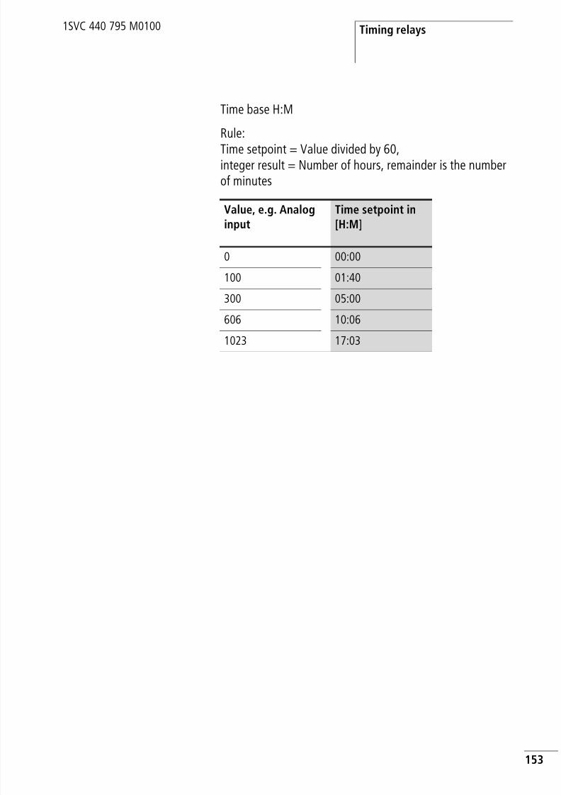
8/3/2019 Cl Lmt Manual
http://slidepdf.com/reader/full/cl-lmt-manual 156/296
Timing relays
153
1SVC 440 795 M0100
Time base H:M
Rule:Time setpoint = Value divided by 60,integer result = Number of hours, remainder is the numberof minutes
Value, e.g. Analoginput
Time setpoint in[H:M]
0 00:00
100 01:40300 05:00
606 10:06
1023 17:03

8/3/2019 Cl Lmt Manual
http://slidepdf.com/reader/full/cl-lmt-manual 157/296
Wiring with the logic relay
154
1SVC 440 795 M0100
Function of the timing relay function block
Timing relay, on-delayed with and without randomswitchingRandom switching: The contact of the timing relay switchesrandomly within the setpoint value range.
Figure 62: Signal diagram of timing relay, on-delayed(with and without random switching)
1: Trigger coil TTx
2: Stop coil HTx
3: Reset coil RTx
4: Switching contact (n/o contact) Tx
t s: Setpoint time
• Range A: The set time elapses normally.• Range B: The entered setpoint does not elapse normally because
the trigger coil drops out prematurely.
• Range C: The stop coil stops the time from elapsing.
t 1
+ t 2
= t s
t
A B
t s
1
2
4
3
C

8/3/2019 Cl Lmt Manual
http://slidepdf.com/reader/full/cl-lmt-manual 158/296
Timing relays
155
1SVC 440 795 M0100
Figure 63: Signal diagram of timing relay, on-delayed(with and without random switching)
• Range D: The stop coil is inoperative after the time has elapsed.• Range E: The reset coil resets the relay and the contact.• Range F: The reset coil resets the time during the timeout
sequence. After the reset coil drops out, the time elapsesnormally.
Timing relay, off-delayed with and without randomswitchingRandom switching: The contact of the timing relay switchesrandomly within the setpoint value range.
Figure 64: Signal diagram of timing relay, off-delayed
(with and without random switching)
t FD E
t s
1
2
4
3
t sF
t s
A Bt 1+ t
2= t
st s
C
1
2
4
3
t s
Dt

8/3/2019 Cl Lmt Manual
http://slidepdf.com/reader/full/cl-lmt-manual 159/296
Wiring with the logic relay
156
1SVC 440 795 M0100
1: Trigger coil TTx
2: Stop coil HTx
3: Reset coil RTx
4: Switching contact (n/o contact) Tx
t s: Setpoint time
• Range A: The time elapses after the trigger coil is deactivated.• Range B: The stop coil stops the time from elapsing.• Range C: The reset coil resets the relay and the contact. After the
reset coil drops out, the relay continues to work normally.• Range D: The reset coil resets the relay and the contact when the
function block is timing out.
Figure 65: Signal diagram of timing relay, off-delayed(with/without random switching with retriggering)
Range E: The trigger coil drops out twice. The actual time t 1 iscleared and the set time ts elapses completely (retriggerable switchfunction).
1
2
4
3
t sE
t 1

8/3/2019 Cl Lmt Manual
http://slidepdf.com/reader/full/cl-lmt-manual 160/296
Timing relays
157
1SVC 440 795 M0100
Timing relay, on- and off-delayed with and withoutrandom switching
Time value I1: on-delay timeTime value I2: off-delay time
Random switching: The contact of the timing relay switchesrandomly within the setpoint value ranges.
Figure 66: Signal diagram timing relay, on and off-delayed 1
1: Trigger coil TTx
2: Stop coil HTx
3: Reset coil RTx
4: Switching contact (n/o contact) Tx
t s1: Pick-up time
t s2: Drop-out time
• Range A: The relay processes the two times without anyinterruption.
• Range B: The trigger coil drops out before the on-delay isreached.
• Range C: The stop coil stops the timeout of the on-delay.• Range D: The stop coil has no effect in this range.
A B C
1
2
4
3
Dt t
s1t s2
t s2
t s1
t s2
t 1+ t
2= t
s1

8/3/2019 Cl Lmt Manual
http://slidepdf.com/reader/full/cl-lmt-manual 161/296
Wiring with the logic relay
158
1SVC 440 795 M0100
Figure 67: Signal diagram timing relay, on and off-delayed 2
• Range E: The stop coil stops the timeout of the off-delay.• Range F: The reset coil resets the relay after the on-delay has
elapsed• Range G: The reset coil resets the relay and the contact whilst the
on-delay is timing out. After the reset coil drops out, the timeelapses normally.
Figure 68: Signal diagram timing relay, on- and off-delayed 3
• Range H: The Reset signal interrupts the timing out of the settime.
E F
t 1+ t
2= t
s2
G
1
2
4
3
t t s1
t s1
t s1
t s2
H
t
1
2
4
3
t s1

8/3/2019 Cl Lmt Manual
http://slidepdf.com/reader/full/cl-lmt-manual 162/296
Timing relays
159
1SVC 440 795 M0100
Timing relay, single pulse
Figure 69: Signal diagram of timing relay, single pulse 1
1: Trigger coil TTx
2: Stop coil HTx
3: Reset coil RTx
4: Switching contact (n/o contact) Tx
• Range A: The trigger signal is short and is lengthened
• Range B: The trigger signal is longer than the set time.• Range C: The stop coil interrupts the timing out of the set time.
Figure 70: Signal diagram timing relay, pulse shaping 2
• Range D: The reset coil resets the timing relay.• Range E: The reset coil resets the timing relay. The trigger coil is
still activated after the reset coil has been deactivated and thetime is still running.
A Bt 1 + t 2 = t st s t s
C
1
2
4
3
t
D Et t
s
1
2
4
3
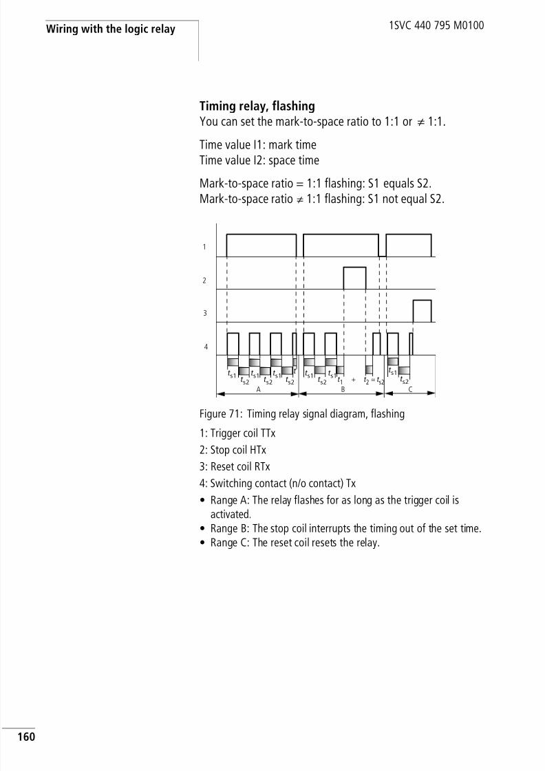
8/3/2019 Cl Lmt Manual
http://slidepdf.com/reader/full/cl-lmt-manual 163/296
Wiring with the logic relay
160
1SVC 440 795 M0100
Timing relay, flashingYou can set the mark-to-space ratio to 1:1 or k 1:1.
Time value I1: mark timeTime value I2: space time
Mark-to-space ratio = 1:1 flashing: S1 equals S2.Mark-to-space ratio k 1:1 flashing: S1 not equal S2.
Figure 71: Timing relay signal diagram, flashing
1: Trigger coil TTx
2: Stop coil HTx
3: Reset coil RTx
4: Switching contact (n/o contact) Tx
• Range A: The relay flashes for as long as the trigger coil isactivated.
• Range B: The stop coil interrupts the timing out of the set time.
• Range C: The reset coil resets the relay.
t 1+ t 2
= t s2
t s1
t s1
t s1
t s2
t s2
t s1
t s1
t s2
t s2
A B
1
2
4
3
t t s1
t s2
C

8/3/2019 Cl Lmt Manual
http://slidepdf.com/reader/full/cl-lmt-manual 164/296
Timing relays
161
1SVC 440 795 M0100
Examples timing relay
Example: Timing relay, on-delayedIn this example a conveyor starts 10 s after the system ispowered up.
Example: Timing relay, off-delayedThe off-delayed function is used to implement a rundowntime on the conveyor if required.
Example: Timing relay, on- and off-delayedThe on/off-delayed function is used to implement the delayof both the startup and the disconnection if required.
Circuit diagram display Parameter settings oftiming relay T1
Circuit diagram display Parameter settings oftiming relay T2
Circuit diagram display Parameter settings of
timing relay T3
I5-------TT1T1-------ÄQ1
T1 X S +I1 10.000I2
I6-------TT2
T2-------ÄQ2
T2 â S +
I1 30.000I2
I6-------TT3T3-------ÄQ3
T3 Xâ S +I1 10.000I2 30.000

8/3/2019 Cl Lmt Manual
http://slidepdf.com/reader/full/cl-lmt-manual 165/296
Wiring with the logic relay
162
1SVC 440 795 M0100
Example: Timing relay, single pulseThe input pulses present may vary in length. These pulses
must be normalised to the same length. The single pulsefunction can be used very simply to implement this.
Example: Timing relay, flashingThis example shows a continuous flash pulse function.Outputs Q3 or Q4 flash according to the marker states of M8or M9.
Example: On-delayed timing relay with retentiveactual valueSelect a retentive timing relay if you wish to retain the actual
value of a timing relay, even after a power failure or achange from RUN to STOP.
Circuit diagram display Parameter settings oftiming relay T4
Circuit diagram display Parameter settings oftiming relay T5
I7-------TT4T4-------ÄQ4
T4 ü S +I1 10.000I2
---------TT5T5uM8----ÄQ3hM9----ÄQ4
T5 Ü S +I1 02.000I2 01.000

8/3/2019 Cl Lmt Manual
http://slidepdf.com/reader/full/cl-lmt-manual 166/296
Timing relays
163
1SVC 440 795 M0100
X Select the required timing relay in the SYSTEM… r RETENTION… menu.
The example shows the timing relays T7, T8 as retentivetiming relays. Markers M9 to M12 were also selected asretentive.
Figure 72: Function of the circuit
1: Power supply
2: Status of marker M9 and thus trigger signal T8
3: Status of n/o contact T8
M 9 - M12 åÆ
M13 - M16N 9 - N16C 5 - C 7 æC 20C13 - C16T 7 åT 8 åT13 - T16
D 1 - D 8
Circuit diagram display Parameter settings oftiming relay T8
M9-------TT8T8-------ÄQ1
T8 X M:S +I1 15:00
I2
t 1 + t 2 = t s
1
2
3

8/3/2019 Cl Lmt Manual
http://slidepdf.com/reader/full/cl-lmt-manual 167/296
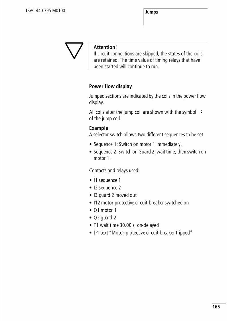
8/3/2019 Cl Lmt Manual
http://slidepdf.com/reader/full/cl-lmt-manual 168/296
Jumps
165
1SVC 440 795 M0100
Power flow display
Jumped sections are indicated by the coils in the power flowdisplay.
All coils after the jump coil are shown with the symbol :of the jump coil.
ExampleA selector switch allows two different sequences to be set.
• Sequence 1: Switch on motor 1 immediately.
• Sequence 2: Switch on Guard 2, wait time, then switch onmotor 1.
Contacts and relays used:
• I1 sequence 1
• I2 sequence 2
• I3 guard 2 moved out
• I12 motor-protective circuit-breaker switched on
• Q1 motor 1
• Q2 guard 2
• T1 wait time 30.00 s, on-delayed• D1 text “Motor-protective circuit-breaker tripped”
h
Attention!
If circuit connections are skipped, the states of the coilsare retained. The time value of timing relays that havebeen started will continue to run.

8/3/2019 Cl Lmt Manual
http://slidepdf.com/reader/full/cl-lmt-manual 169/296
Wiring with the logic relay
166
1SVC 440 795 M0100
Circuit diagram: Power flow display: I1 selected:
Section from jump label 1 processed.
Jump to label 8.Section to jump label 8 skipped.
Jump label 8, circuit diagram processedfrom this point on.
I1-------Ä:1I2-------Ä:2:1--------uÄQ1
hRQ2---------Ä:8:2-------ÄQ2Q2-I3----TT2T2-------ÄQ1:8i12-------ÄD1
I1-------Ä:1I2------- ::1--------uÄQ1
hRQ2---------Ä:8:2------- :Q2-I3---- :T2------- ::8i12-------

8/3/2019 Cl Lmt Manual
http://slidepdf.com/reader/full/cl-lmt-manual 170/296
Year time switch
167
1SVC 440 795 M0100
Year time switch Types CL-LSR.C.../CL-LST.C... and CL-LMR.C.../CL-LMT.C...are provided with a real-time clock that can be used as a7-day time switch and year time switch in the circuitdiagram. If you have to implement special on and offswitching functions on public holidays, vacations, companyholidays, school holidays and special events, these can beimplemented easily with the year time switch.
The logic relay offers eight year time switches Y1 to Y8 forup to 32 switch times.
Each time switch has four channels which you can use to setfour different on and off times. The channels are set via theparameter display.
The time and date are backed up in the event of a powersupply failure and continue to run. This means that it will
continue to run in the event of a power failure, although thetime switch relays will not switch. When the device is in ade-energized state, the timer contacts remain open. Refer tosection “Technical data”, Page 256, for information on thebuffer time.
Wiring of a year time switch
A year time switch can be integrated into your circuit in theform of a contact.
The coils and contacts have the following meanings:
h The procedure for setting the time is described undersection “Setting date and time” on Page 205.
h The clock module integrated in the logic relay workswithin the date range 01.01.2000 to 31.12.2099.
Y1u------ÄQ1Y2kÖ1-Y3----ÄQ2
Contact Coil
Y1to
Y8Contact of the year timeswitch

8/3/2019 Cl Lmt Manual
http://slidepdf.com/reader/full/cl-lmt-manual 171/296
Wiring with the logic relay
168
1SVC 440 795 M0100
Parameter display and parameter set for year timeswitch
The parameter display for a year time switch is used tomodify the on time, the off time and to enable the parameterdisplay.
Table 13: On and off times
Parameter display in RUN mode:
Y1 A +
ON --.--.--OFF --.--.--Y3 Year time switch function relay 1
A,B,C,D
Time switch channels
+ • + appears in the PARAMETER menu.• - does not appear in the PARAMETER menu
ON On date: day, month, year (two-digit 2004 = 04)
OFF Off date: day, month, year (two-digit 2004 = 04)
Parameters Meaning Meaningful values
xx.--.00 Date, day 01 to 31
--.xx.00 Month 01 to 12
--.-0.00 Year, two-digit 00 to 99
Selected channel
On time
Off time
# Contact has not switched.
â Contact has switched.
Y1 A +ON 01.01.04OFF 31.12.04
â

8/3/2019 Cl Lmt Manual
http://slidepdf.com/reader/full/cl-lmt-manual 172/296
Year time switch
169
1SVC 440 795 M0100
Changing time switch channel
You can the change time switch channel in either RUN orSTOP mode by selecting the channel required with the cursorbuttons ÍÚ.
Example:
The display on the left shows the parameter display of a yeartime switch.
X Press the Í button to move the cursor to channel B.
Press the í button to reach any value that can be edited.
Entry rules
The following nine entry rules are possible.
Display format: XX = digit used
Rule 1ON: Day
OFF: Day
Y4 A +ON 01.01.04OFF 31.03.04â
Y4 B +ON 01.10.04OFF 31.12.04#
h Important input rules.
The year time switch only operates properly by observing
the following rules.The on year must not be later than the off year.
ON and OFF times must have the same parameters.Example: ON = Year, OFF = Year; ON = Year/Month,OFF = Year/Month
Y1 A +ON XX.--.--OFF XX.--.--

8/3/2019 Cl Lmt Manual
http://slidepdf.com/reader/full/cl-lmt-manual 173/296
Wiring with the logic relay
170
1SVC 440 795 M0100
Rule 2
ON: MonthOFF: Month
Rule 3ON: Year
OFF: Year
Rule 4ON: Day/month
OFF: Day/month
Rule 5ON: Month/year
OFF: Month/year
Rule 6ON: Day/month/year
OFF: Day/month/year
Rule 7Two-channel
Channel A ON: Day/month
Channel B OFF: Day/month
Y1 A +
ON --.XX.--OFF --.XX.--
Y1 A +ON --.--.XXOFF --.--.XX
Y1 A +ON XX.XX.--OFF XX.XX.--
Y1 A +ON --.XX.XX
OFF --.XX.XX
Y1 A +ON XX.XX.XXOFF XX.XX.XX
Y1 A +ON XX.XX.--OFF --.--.--
Y1 B +ON --.--.--OFF XX.XX.--

8/3/2019 Cl Lmt Manual
http://slidepdf.com/reader/full/cl-lmt-manual 174/296
Year time switch
171
1SVC 440 795 M0100
Rule 8
Two-channelChannel ON: Day/month/year
Channel D OFF: Day/month/year
With this rule, the same year number must be entered ineach channel in the ON and OFF entry area.
Rule 9Overlapping channels:
The first ON date switches on and the first OFF date switchesoff.
Function of the year time switch
The year time switch can switch ranges, individual days,months, years or combinations of all three.
YearsON: 2002 to OFF: 2010 means: Switch on at 00:00 on01.01.2002 and switch off at 00:00 on 01.01.2011.
MonthsON: 04 to OFF: 10 means:
Switch on at 00:00 on 1 April and switch off at 00:00 on 1November
DaysON: 02 to OFF: 25 means:Switch on at 00:00 on day 2 and switch off at 00:00 day 26
Example: Selecting year rangeThe year time switch Y1 is required to switch on at 00:00 onJanuary 1 2004 and stay on until 23:59 December 31 2005.
Y1 B +
ON XX.XX.XXOFF --.--.XX
Y1 D +ON --.--.XXOFF XX.XX.XX
h Avoid incomplete entries. It hinders transparency andleads to unwanted functions.

8/3/2019 Cl Lmt Manual
http://slidepdf.com/reader/full/cl-lmt-manual 175/296
Wiring with the logic relay
172
1SVC 440 795 M0100
Example: Selecting month rangesThe year time switch Y2 is required to switch on at 00:00 onMarch 1 and stay on until 23:59 September 30.
Example: Selecting day rangesThe year time switch Y3 is required to switch on at 00:00 onday 1 of each month and switch off at 23:59 on day 28 ofeach month.
Example: Selecting public holidaysThe year time switch Y4 is required to switch on at 00:00 onday 25.12 of each year and switch off at 23:59 on day 26.12of each year. “Christmas program”
Circuit diagram display Parameter settings of theyear time switch Y1
Circuit diagram display Parameter settings of theyear time switch Y2
Circuit diagram display Parameter settings of theyear time switch Y3
Y1-------ÄQ1 Y1 A +ON --.--.04OFF --.--.05
Y2-------ÄQ1 Y2 A +ON __.03.--OFF --.09.--
Y3-------ÄQ1 Y3 A +ON 01.--.--OFF 28.--.--

8/3/2019 Cl Lmt Manual
http://slidepdf.com/reader/full/cl-lmt-manual 176/296
Year time switch
173
1SVC 440 795 M0100
Example: Selecting a time rangeThe year time switch Y1 is required to switch on at 00:00 onday 02.05 of each year and switch off at 23:59 on day 31.10of each year. “Open air season”
Example: Overlapping rangesThe year time switch Y1 channel C switches on at 00:00 on
day 3 of months 5, 6, 7, 8, 9, 10 and remains on until 23:59on day 25 of these months.
The year time switch Y1 channel D switches on at 00:00 onday 2 of months 6, 7, 8, 9, 10, 11, 12 and remains on until23:59 on day 17 of these months.
Circuit diagram display Parameter settings of theyear time switch Y4
Circuit diagram display Parameter settings of theyear time switch Y1
Y4-------ÄQ1 Y4 A +ON 25.12.--OFF 26.12.--
Y1-------ÄQ1 Y1 A +ON 02.05.--OFF --.--.--
Y1 B +ON --.--.--OFF 31.10.--

8/3/2019 Cl Lmt Manual
http://slidepdf.com/reader/full/cl-lmt-manual 177/296
Wiring with the logic relay
174
1SVC 440 795 M0100
Total number of channels and behaviour of the contact Y1:The time switch will switch on at 00:00 from 3 May and offat 23:59 on 25 May.In June, July, August, September, October, the time switchwill switch on at 00:00 on day 2 of the month and switch offat 23:59 on day 17 .In November and December, the time switch will switch onat 00:00 on day 2 of the month and switch off at 23:59 onday 17.
Master reset The master reset function relay enables you to set with onecommand the status of the markers and all outputs to “0”.Depending on the operating mode of this function relay, it ispossible to reset the outputs only, or the markers only, or
both. Three function blocks are available.
Wiring of the master reset function relayYou integrate a master reset function relay into your circuitin the form of a contact and coil.
The coils and contacts have the following meanings:
Circuit diagram display Parameter settings of theyear time switch Y1
Y1-------ÄQ1 Y1 C +ON 03.05.--OFF 25.10.--
Y1 D +ON 02.06.--OFF 17.12.--
N8-------ÄZ1Q3-------ÄZ2I8-------ÄZ3Z1-Z2-Z3-ÅQ2
Contact Coil
Z1 to Z3 Contact of the masterreset
ÄZ1 to ÄZ3 Coil of the master reset

8/3/2019 Cl Lmt Manual
http://slidepdf.com/reader/full/cl-lmt-manual 178/296
Master reset
175
1SVC 440 795 M0100
Operating modes
The different coils of the master reset have differentoperating modes
• Z1: For Q outputs: controls outputs Q1 to Q8 and S1 to S8.
• Z2: For markers M, N: controls the marker range M1 toM16 and N1 to N16.
• Z3: for outputs and markers: controls Q1 to Q8, S1 to S8,M1 to M16 and N1 to N16.
Function of the master reset function relay
A rising edge or the 1 signal on the coil will reset the outputsor markers to 0, depending on the operating mode set. Thelocation of the coil in the circuit diagram is of no importance.The master reset always has the highest priority.
The contacts Z1 to Z3 follow the status of their own coil.
Example: Resetting outputsAll outputs that you have used can be reset to 0 with onecommand.
A rising edge at the coil of Z1 will cause all Q and S outputsto be reset.
Example: Resetting markers
All markers that you have used can be reset to 0 with onecommand.
A rising edge at the coil of Z2 will cause all markers M andN to be reset.
I8-------ÈZ1I5-------ÄQ1I2-M1-T1-SS3M3uC1----SQ3M4b
I8-------ÈZ2I5-------ÄM1I2-M1-T1-SN3M3uC1----SM8M4b

8/3/2019 Cl Lmt Manual
http://slidepdf.com/reader/full/cl-lmt-manual 179/296
Wiring with the logic relay
176
1SVC 440 795 M0100
Example: Resetting outputs and markersAll outputs and markers that you have used can be reset to
0 with one command.A rising edge at the coil of Z3 will cause all Q and S outputsand all M and N markers to be reset.
Basic circuits The values in the logic table have the following meanings
For switching contacts:
• 0 = n/o contact open, n/c contact closed
• 1 = n/o contact closed, n/c contact open
For Q…: relay coils• 0 = coil not energized
• 1 = coil energized
Negation (contact)
Negation means that the contact opens rather than closeswhen it is actuated (NOT circuit).
In the CL circuit diagram, press the ALT button to togglecontact I1 between n/c and n/o contact.
Table 14: Negation
I8-------ÈZ3
I5-------ÄQ1I2-M1-T1-SS3M3uC1----SQ3M4bI1-------ÄM1I7-C2-T1-SN3T3-A1----SM8M4-A5----SN8
i1-------ÄQ1
I1 Q1
1 0
0 1

8/3/2019 Cl Lmt Manual
http://slidepdf.com/reader/full/cl-lmt-manual 180/296
Basic circuits
177
1SVC 440 795 M0100
Negation (coil)
Negation means in this case that the coil opens when then/o contact is actuated (NOT circuit).
In the CL circuit diagram example, you only change the coilfunction
Table 15: Negation
Maintained contact
To energize a relay coil continuously, make a connection ofall contact fields from the coil to the leftmost position.
Table 16: Maintained contact
Series circuit
Q1 is controlled by a series circuit consisting of threen/o contacts (AND circuit).
Q2 is controlled by a series circuit consisting of threen/c contacts (NOR circuit).
In the CL circuit diagram, you can connect up to three n/o orn/c contacts in series within a rung. Use M marker relays ifyou need to connect more than three n/o contacts in series.
I1-------ÅQ1
I1 Q1
1 0
0 1
---------ÄQ1
--- Q1
… 1
I1-I2-I3-ÄQ1
i1-i2-i3-ÄQ2

8/3/2019 Cl Lmt Manual
http://slidepdf.com/reader/full/cl-lmt-manual 181/296
Wiring with the logic relay
178
1SVC 440 795 M0100
Table 17: Series circuit
Parallel circuit
Q1 is controlled by a parallel circuit consisting of severaln/o contacts (OR circuit).
A parallel circuit of n/c contacts controls Q2 (NAND circuit).
Table 18: Parallel circuit
I1 I2 I3 Q1 Q2
0 0 0 0 1
0 0 1 0 0
0 1 0 0 0
0 1 1 0 0
1 0 0 0 0
1 0 1 0 0
1 1 0 0 0
1 1 1 1 0
I1u------ÄQ1
I2sI3k
i1u------ÄQ2i2si3k
I1 I2 I3 Q1 Q2
0 0 0 0 1
0 0 1 1 1
0 1 0 1 1
0 1 1 1 1
1 0 0 1 1
1 0 1 1 1
1 1 0 1 1
1 1 1 1 0

8/3/2019 Cl Lmt Manual
http://slidepdf.com/reader/full/cl-lmt-manual 182/296
Basic circuits
179
1SVC 440 795 M0100
Parallel circuit operating like a series connection ofn/o contacts
A series circuit with more than three contacts (n/o contacts)can be implemented with a parallel circuit of n/c contacts ona negated coil.
In the CL circuit diagram you can switch as many rungs inparallel as you have rungs available.
Table 19: Parallel connection of n/c contacts on a negated coil
i1u------ÅQ1i2si3sI2sI3k
I1 I2 I3 I4 I5 Q1
0 0 0 0 0 0
0 0 0 0 1 0
0 0 0 1 0 0
0 0 0 1 1 0
0 0 1 0 0 0
0 0 1 0 1 0
0 0 1 1 0 0
0 0 1 1 1 0
0 1 0 0 0 0
0 1 0 0 1 0
0 1 0 1 0 0
0 1 0 1 1 0
0 1 1 0 0 0… … … … … 0
… … … … … 0
1 1 1 1 1 1

8/3/2019 Cl Lmt Manual
http://slidepdf.com/reader/full/cl-lmt-manual 183/296
Wiring with the logic relay
180
1SVC 440 795 M0100
Parallel circuit operating like a series connection ofn/c contacts
A series circuit with more than three contacts (n/c contacts)can be implemented with a parallel connection ofn/o contacts on a negated coil.
In the CL circuit diagram you can switch as many rungs inparallel as you have rungs available.
Table 20: Parallel connection of n/o contacts on a negated coil
Two-way circuit
A two-way circuit is made in the logic relay using two seriesconnections that are combined to form a parallel circuit(XOR).
An XOR circuit stands for an “Exclusive Or” circuit. The coil
is only energized if one contact is activated.
I1u------ÅQ1I2sI3sI4sI5k
I1 I2 I3 I4 I5 Q1
0 0 0 0 0 1
0 0 0 0 1 0
0 0 0 1 0 0
0 0 0 1 1 0
0 0 1 0 0 0
0 0 1 0 1 0
0 0 1 1 0 0
0 0 1 1 1 0
0 1 0 0 0 0
0 1 0 0 1 0
… … … … … 0
… … … … … 0
1 1 1 1 1 0
I1-i2u---ÄQ1i1-I2k
8/3/2019 Cl Lmt Manual
http://slidepdf.com/reader/full/cl-lmt-manual 184/296
Basic circuits
181
1SVC 440 795 M0100
Table 21: Two-way circuit (XOR)
Self-latchingA combination of a series and parallel connection is used towire a latching circuit.
Latching is established by contact Q1 which is connected inparallel to I1. If I1 is actuated and reopened, the currentflows via contact Q1 until I2 is actuated.
Table 22: Self-latching
Latching circuits are used to switch machines on and off. Themachine is switched on at the input terminals via n/o contactS1 and is switched off via n/c contact S2.
S2 breaks the connection to the control voltage in order to
switch off the machine. This ensures that the machine can beswitched off, even in the event of a wire break. I2 is alwaysclosed when not actuated.
I1 I2 Q1
0 0 0
0 1 1
1 0 1
1 1 0
I1uI2----ÄQ1Q1k
S1 n/o contact at I1S2 n/c contact at I2
I1 I2 Contact Q1 Coil Q1
0 0 0 0
0 1 0 0
1 0 0 0
1 1 0 1
0 0 1 0
0 1 1 11 0 1 0
1 1 1 1

8/3/2019 Cl Lmt Manual
http://slidepdf.com/reader/full/cl-lmt-manual 185/296
Wiring with the logic relay
182
1SVC 440 795 M0100
Alternatively the latching circuit can also be set up with thewire break function using the “Set” and “Reset” coil
functions.Coil Q1 latches if I1 is activated. I2 inverts the n/c contactsignal of S2 and only switches if S2 is activated in order todisconnect the machine or in the event of a wire break.
Make sure that both coils are wired up in the correct order inthe CL circuit diagram: first wire the S coil and then the Rcoil. This will ensure that the machine will be switched offwhen I2 is actuated, even if I1 is switched on.
Impulse relay
An impulse relay is often used for controlling lighting, suchas stairwell lighting.
Table 23: Impulse relay
Cycle pulse on rising edgeYou can create a cycle pulse on a rising edge if you use theappropriate coil function.
This is very useful for count pulses, jump pulses.
I1-------SQ1
i2-------RQ1
S1 n/o contact at I1S2 n/c contact at I2
I1-------äQ1
S1 n/o contact at I1
I1 Status ofQ1
Q1
0 0 0
0 1 1
1 0 1
1 1 0
I1-------ÈQ1
S1 n/o contact at I1

8/3/2019 Cl Lmt Manual
http://slidepdf.com/reader/full/cl-lmt-manual 186/296
Basic circuits
183
1SVC 440 795 M0100
Table 24: Cycle pulse on rising edge
Cycle pulse on falling edge
You can create a cycle pulse on a falling edge if you use theappropriate coil function.
This is very useful for count pulses, jump pulses.
Table 25: Cycle pulse on falling edge
I1 Status ofQ1 cycle n
Status of Q1cycle n + 1
0 0 0
1 1 0
0 0 0
I1-------èQ1
S1 n/o contact at I1 I1 Status ofQ1 cycle n
Status of Q1cycle n + 1
1 0 0
0 1 0
1 0 0

8/3/2019 Cl Lmt Manual
http://slidepdf.com/reader/full/cl-lmt-manual 187/296
Wiring with the logic relay
184
1SVC 440 795 M0100
Circuit examples Star-delta starting
Two star-delta circuits can be obtained with the logic relay.The advantage of the logic relay is that you can select anychangeover time between star and delta contactors and anywait time between switching off the star contactor andswitching on the delta contactor.
Figure 73: Star-delta circuit with conventional contactors
NQ11
Q11
Q11
K1
K1
Q12
Q12
Q13
Q13
L
S1
S2
Q12

8/3/2019 Cl Lmt Manual
http://slidepdf.com/reader/full/cl-lmt-manual 188/296
Circuit examples
185
1SVC 440 795 M0100
Figure 74: Star-delta circuit with the logic relay
1 12 2
Q1
I1L N
Q2
Q12 Q12Q11
N
Q11
L
N
S1
S2

8/3/2019 Cl Lmt Manual
http://slidepdf.com/reader/full/cl-lmt-manual 189/296
Wiring with the logic relay
186
1SVC 440 795 M0100
Function of the CL circuit diagram:
Start/Stop of circuit with the external actuators S1 and S2.
The mains contactor starts the timing relay in the logic relay.
• I1: Mains contactor switched on
• Q1: Star contactor ON
• Q2: Delta contactor ON
• T1: Star-delta changeover time (10 to 30 s, X)
• T2: Wait time between star off, delta on(30, 40, 50, 60 ms, X)
If your logic relay has an integral time switch, you can combinestar-delta starting with the time switch function. In this case,use the logic relay to switch the mains contactor as well.
4x shift register
You can use a shift register for storing an item ofinformation, such as for the sorting of parts into good andbad, for two, three or four transport steps further on.
A shift pulse and the value (0 or 1) to be shifted are neededfor the shift register.
The shift register’s reset input is used to clear any values thatare no longer needed. The values in the shift register gothrough the register in the order: 1st, 2nd, 3rd, 4th storagelocation.
Figure 75: Block diagram of the 4x shift register
I1u------DD1dt1----ÄQ1dT1----DD2hT2----ÄQ2
1 2 3 4
Storage positions
PULSE VALUE RESET

8/3/2019 Cl Lmt Manual
http://slidepdf.com/reader/full/cl-lmt-manual 190/296
Circuit examples
187
1SVC 440 795 M0100
Table 26: Shift register
Assign the information “bad” to value 0. If the shift registeris cleared accidentally, no bad parts are used further.
• I1: Shift pulse (PULSE)
• I2: Information (good/bad) to be shifted (VALUE)
• I3: Clear content of the shift register (RESET)
• M1: 1st storage location• M2: 2nd storage location
• M3: 3rd storage location
• M4: 4th storage location
• M7: Marker relay for cycle pulse
• M8: Cyclical pulse for shift pulse
Pulse Value Storage position
1 2 3 4
1 1 1 0 0 0
2 0 0 1 0 0
3 0 0 0 1 0
4 1 1 0 0 1
5 0 0 1 0 0
Reset = 1 0 0 0 0

8/3/2019 Cl Lmt Manual
http://slidepdf.com/reader/full/cl-lmt-manual 191/296
Wiring with the logic relay
188
1SVC 440 795 M0100
Figure 76: CL circuit diagram shift register
How does the shift register work?The shift pulse is activated for exactly one cycle. To do this,the shift pulse is generated by evaluating the change from I1OFF to I1 ON – the rising edge.
The cyclical processing of the logic relay is used to trigger theshift pulse.
When I1 is activated for the first time, the marker relayn/c contact M7 is closed during the first pass through the
cycle. Thus, the series circuit consisting of I1, n/c contact M7(closed) and M8 is activated. Although M7 is now alsoactivated, this does not yet have any effect on contact M7.
The contact of M8 (n/o contact) was still open during the firstcycle so a shift pulse cannot yet be generated. When therelay coil M8 is activated, the logic relay transfers the resultto the contacts.
In the second cycle n/c contact M7 is open. The series circuitis opened. The contact M8 is activated from the result of thefirst cycle. Now, all the storage locations are either set orreset in accordance with the series circuit.
Generate shift pulse
Set 4th storage location
Clear 4th storage location
Set 3rd storage location
Clear 3rd storage location
Set 2nd storage location
Clear 2nd storage location
Set 1st storage location
Clear 1st storage location
Clear all storage locations
I1um7----ÄM8h------ÄM7
M8uM3----SM4dm3----RM4dM2----SM3dm2----RM3dM1----SM2dm1----RM2dI2----SM1
hi2----RM1I3------uRM1
dRM2dRM3hRM4
8/3/2019 Cl Lmt Manual
http://slidepdf.com/reader/full/cl-lmt-manual 192/296
Circuit examples
189
1SVC 440 795 M0100
If the relay coils were activated, the logic relay transfers theresult to the contacts. M8 is now open again. No new pulse
can be formed until I1 has opened, since M7 is open for aslong as I1 is closed.
How does the value reach the shift register?When shift pulse M8 = ON, the state of I2 (VALUE) istransferred to storage location M1.
If I2 is activated, M1 is set. If I2 is deactivated, M1 isdeactivated via n/c contact I2.
How is the result shifted?The logic relay activates the coils in accordance with therung and its result, from top to bottom. M4 assumes thevalue of M3 (value 0 or 1) before M3 assumes the value ofM2. M3 assumes the value of M2, M2 the value of M1 andM1 the value of I2.
Why are the values not constantly overwritten?In this example, the coils are controlled only by the S and R
functions, i.e. the values are retained in on or off states eventhough the coil is not constantly activated. The state of thecoil changes only if the rung up to the coil is activated. In thiscircuit, the marker relay is therefore either set or reset. Therungs of the coils (storage locations) are only activated viaM8 for one cycle. The result of activating the coils is storedin the logic relay until a new pulse changes the state of thecoils.
How are all the storage locations cleared?When I3 is activated, all the R coils of storage locations M1to M4 are reset, i.e. the coils are deactivated. Since the resetwas entered at the end of the circuit diagram, the resetfunction has priority over the set function.
How can the value of a storage location betransferred?Use the n/o or n/c contact of storage locations M1 to M4 andwire them to an output relay or in the circuit diagram
according to the task required.

8/3/2019 Cl Lmt Manual
http://slidepdf.com/reader/full/cl-lmt-manual 193/296
Wiring with the logic relay
190
1SVC 440 795 M0100
Running light
An automatic running light can be created by slightlymodifying the shift register circuit.
One relay is always switched on. It starts at Q1, runs throughto Q4 and then starts again at Q1.
The marker relays for storage locations M1 to M4 arereplaced by relays Q1 to Q4.
The shift pulse I1 has been automated by the flasher relayT1. The cycle pulse M8 remains as it is.
On the first pass, the value is switched on once byn/c contact M9. If Q1 is set, M9 is switched on. Once Q4(the last storage location) has been switched on, the value ispassed back to Q1.
Change the times.
Figure 77: CL running light circuit diagram
T1 Ü S +
I1 00.500I2 00.500
Flasher relay
Generate shift pulse
Clear first value
Set 4th storage location
Clear 4th storage location
Set 3rd storage location
Clear 3rd storage location
Set 2nd storage location
Clear 2nd storage locationSet 1st storage location
Enter first value (=1)
Clear 1st storage location
---------DD1
T1um7----ÄM8h------ÄM7Q1-------SM9M8uQ3----SQ4
dQ4----RQ4dQ2----SQ3dQ3----RQ3dQ1----SQ2
dQ2----RQ2dQ4u---SQ1dm9khQ1----RQ1

8/3/2019 Cl Lmt Manual
http://slidepdf.com/reader/full/cl-lmt-manual 194/296
Circuit examples
191
1SVC 440 795 M0100
Stairwell lighting
For a conventional circuit you would need at least five spaceunits in the distribution board, i.e. one impulse relay, twotiming relays and two auxiliary relays.
The logic relay requires only four space units. A fullyfunctioning stairwell lighting system can be set up with fiveterminals and the CL circuit diagram.
Figure 78: Conventional stairwell lighting
N
L
S1
S2
S3
K3TK1 K2T
K4
K4
K5
K5
K3T K1
K2T
K5
K5
5 s 6 min
H1
H2
H3
h Up to twelve such stairwell circuits can be implementedwith one CL device.

8/3/2019 Cl Lmt Manual
http://slidepdf.com/reader/full/cl-lmt-manual 195/296
Wiring with the logic relay
192
1SVC 440 795 M0100
Figure 79: Stairwell lighting with the logic relay
Button pressedbriefly Light ON or OFF. The impulse relayfunction will even switch off continuouslighting.
Light switches off automatically after6 min.; with continuous lighting thisfunction is not active.
Button pressed formore than 5 s
Continuous lighting
NL
S1
S2
S3
H1
H2
H3
1 2
Q1
I1L N

8/3/2019 Cl Lmt Manual
http://slidepdf.com/reader/full/cl-lmt-manual 196/296
Circuit examples
193
1SVC 440 795 M0100
Figure 80: CL circuit diagram for stairwell lighting
Meaning of the contacts and relays used:
• I1: ON/OFF pushbutton• Q1: Output relay for light ON/OFF
• M1: Marker relay. This is used to block the “switch offautomatically after 6 minutes” function for continuouslighting.
• T1: Cycle pulse for switching Q1 on and off,(ü, single-pulse with value 00.00 s)
• T2: Scan to determine how long the button was pressed.
If pressed longer than 5 s, continuous lighting is switchedon (X, on-delayed, value 5 s).
• T3: Switch off after a lighting time of 6 min.(X, on-delayed, value 06:00 min).
• T4: Switch off after 4 hours continuous lighting(X, on-delayed, value 04:00 h).
If you are using the logic relay with a time switch, you candefine both the stairwell lighting and the continuous lighting
periods via the time switch.
The CL circuit diagram for theabove functions is as follows:
The enhanced CL circuit diagram:after four hours, the continuouslighting is also switched off.
I1-------TT2T2-------SM1I1u------äQ1T3kQ1-m1----TT3q1-------RM1
I1------uTT1hTT2
T2-------SM1T1u------äQ1T3sT3k
Q1um1----TT3h------TT4
q1-------RM1

8/3/2019 Cl Lmt Manual
http://slidepdf.com/reader/full/cl-lmt-manual 197/296
Wiring with the logic relay
194
1SVC 440 795 M0100
If you use the logic relay with analog inputs, you canoptimise the stairwell lighting with a brightness sensor to
suit the lighting conditions.

8/3/2019 Cl Lmt Manual
http://slidepdf.com/reader/full/cl-lmt-manual 198/296
195
1SVC 440 795 M0100
5 CL settings
All CL settings can only be carried out on models providedwith keypad and LCD display.
CL-SOFT can be used to set all models via the software.
Password protection The logic relay can be protected by a password againstunauthorised access.
In this case the password consists of a value between000001 and 999999. The number combination 000000 isused to delete a password.
Password protection inhibits access to selected areas. Thesystem menu is always protected when a password isactivated.
The password can protect the following entries and areas:
• Start or modification of the program
• Transfer of a circuit diagram to the memory module
• Change of the RUN or STOP mode.
• Calling and modification of function block parameters• All settings of the real-time clock.
• Modifications of all system parameters.
• Communication with the individual device
• Disabling of the password delete function.
h Factory setting:
0000, no password present and none active, circuitdiagram area selected.

8/3/2019 Cl Lmt Manual
http://slidepdf.com/reader/full/cl-lmt-manual 199/296
CL settings
196
1SVC 440 795 M0100
Password setup
A password can be set up via the system menu in either RUNor STOP mode. You cannot change to the system menu if apassword is already activated.
X Press DEL and ALT to call up the system menu.
X Select the menu option SECURITY… to enter thepassword.
X Press the OK button and move to the PASSWORD…
menu.X Press OK again to enter the Password entry mode.
If no password has been entered, the logic relay changesdirectly to the password display and displays four XXXXcharacters: No password present.
X Press OK, four zeros will appear
X Set the password using the cursor buttons:
– ú í select position in the password,– ÍÚ set a value between 0 to 9.
X Save the new password by pressing OK.
Use OK to exit the password display and proceed with ESC and Ú to the RANGE… menu.
The scope of the password has not yet been defined. Thepassword is now valid but not yet activated.
h A password that has been entered in the logic relay is
transferred to the memory module together with thecircuit diagram, irrespective of whether it was activated ornot.
If this CL circuit diagram is loaded back from the memorymodule, the password will also be transferred to the logicrelay and is activated immediately.
ENTER PASSWâXXX
ENTER PASSW0042

8/3/2019 Cl Lmt Manual
http://slidepdf.com/reader/full/cl-lmt-manual 200/296
Password protection
197
1SVC 440 795 M0100
Selecting the scope of the password
X Press the OK button.
X Select the function or the menu to be protected.
X Press the OK button in order to protect the function ormenu (tick = protected).
• CIRCUIT DIAG: The password is effective on the programwith circuit diagram and non-enabled function relays.
• PARAMETER: The PARAMETER menu is protected.
• CLOCK: Date and time are protected with the password.
• OPERATING MODE: The toggling of the RUN or STOP
operating mode is protected.• INTERFACE: The interface is disabled for access with
CL-SOFT.
• DELETE FUNCT: The question DELETE PROG? will appearon the device after four incorrect password entries havebeen made. This prompt is not displayed if selected.However, it is no longer possible to make changes inprotected areas if you forget the password.
CIRCUIT DIAG.å ÆPARAMETERCLOCKOPRTNG MODEæINTERFACEDELETE FUNCT
h Standard protection encompasses the programs and
circuit diagram.
At least one function or menu must be protected.

8/3/2019 Cl Lmt Manual
http://slidepdf.com/reader/full/cl-lmt-manual 201/296
CL settings
198
1SVC 440 795 M0100
Activating the password
You can activate a valid password in three different ways:• automatically when the logic relay is switched on again
• automatically after a protected circuit diagram is loaded
• via the password menu.
X Press DEL and ALT to call up the system menu.
X Open the password menu via the SECURITY… menu
The logic relay will only show this password menu if a
password is present.
X Select ACTIVATE PW and press OK.
The password is now active. The logic relay willautomatically return to the status display.
You must unlock the logic relay with the password beforeyou implement a protected function, enter a protected menuor the system menu.
CHANGE PWACTIVATE
h Make a note of your password before activating it. If thepassword is no longer known, the logic relay can beunlocked (DELETE FUNCT is not active), but the circuit
diagram and data settings are lost. The interface must notbe disabled.
Attention!The following applies if the password is not known or islost and the delete password function is disabled: Thedevice can only be reset to the factory setting at themanufacturers. The program and all data will be lost.

8/3/2019 Cl Lmt Manual
http://slidepdf.com/reader/full/cl-lmt-manual 202/296
Password protection
199
1SVC 440 795 M0100
Unlock logic relay
Unlocking the logic relay will deactivate the password. Youcan reactivate password protection later via the passwordmenu or by switching the power supply off and on again.
X Press OK to switch to the main menu.
The PASSWORD… entry will flash.
X Press OK to enter the password entry menu.
The logic relay will display the password entry field.
X Set the password using the cursor buttons:
X Confirm with OK.
If the password is correct, the logic relay will returnautomatically to the status display.
The PROGRAM… menu option is now accessible so that youcan edit your circuit diagram.
The system menu is also accessible.
Changing or deleting the password range
X Unlock the logic relayX Press DEL and ALT to call up the system menu.
X Open the password menu via the menu option SECURITYr PASSWORD…
The CHANGE PW entry will flash.
The logic relay will only show this menu if a password ispresent.
PASSWORD...STOP RUN åPASSWORD...
INFO
h If the logic relay shows PROGRAM… in the main menuinstead of PASSWORD…, this means that there is nopassword protection active.
ENTER PASSWXXXX
PROGRAM...STOPPARAMETERINFO
CHANGE PWACTIVATE PW

8/3/2019 Cl Lmt Manual
http://slidepdf.com/reader/full/cl-lmt-manual 203/296
CL settings
200
1SVC 440 795 M0100
X Press OK to enter the password entry menu.
X Press OK to move to the 4-digit entry field.
X Four zeros will be displayed
X Modify the four password digits using the cursor buttons.
X Confirm with OK.
Press ESC to exit the security area.
DeleteUse number combination 000000 to delete a password.
If a password has not been entered already, the logic relaywill show four XXXX.
Password incorrect or no longer knownIf you no longer know the exact password, you can try to re-enter the password several times.
Have you entered an incorrect password?
X Re-enter the password.
After the fourth entry attempt the logic relay will ask
whether you wish to delete the circuit diagram and data.X Press
– ESC: Circuit diagram, data or password are not deleted.
– OK: Circuit diagram, data and password are deleted.
The logic relay will return to the status display.
ENTER PASSW
XXXX
ENTER PASSW1789
ENTER PASSW0000
h The DELETE FUNCT function has not been deactivated.
ENTER PASSWXXXX
DELETE ?
h If you no longer know the exact password, you can press
OK to unlock the protected logic relay. The saved circuitdiagram and all function relay parameters will be lost.
8/3/2019 Cl Lmt Manual
http://slidepdf.com/reader/full/cl-lmt-manual 204/296
Changing the menu language
201
1SVC 440 795 M0100
Pressing ESC will retain the circuit diagram and data. Youcan then make another four attempts to enter the password.
Changing the menulanguage
CL-LSR/CL-LST and CL-LMR/CL-LMT provide twelve menulanguages which are set as required via the system menu.
X Press DEL and ALT to call up the system menu.
X Select LANGUAGE… to change the menu language.
Language Display
English ENGLISH
German DEUTSCHFrench FRANCAIS
Spanish ESPANOL
Italian ITALIANO
Portuguese PORTUGUES
Dutch NEDERLANDS
Swedish SVENSKA
Polish POLSKI
Turkish TURKCE
Czech CESKY
Hungarian MAGYAR
h Language selection is only possible if the logic relay is notpassword-protected.

8/3/2019 Cl Lmt Manual
http://slidepdf.com/reader/full/cl-lmt-manual 205/296
CL settings
202
1SVC 440 795 M0100
The language selection for the first entry ENGLISH isdisplayed.
X Use Í or Ú to select the new menu language, e.g. Italian(ITALIANO).
X Confirm with OK. ITALIANO is assigned a tick.
X Exit the menu with ESC.
The logic relay will now show the new menu language.
Press ESC to return to the status display.
Changing parameters The logic relay allows you to change function relayparameters such as timing relay setpoint values and countersetpoints without having to call up the circuit diagram. Thisis possible regardless of whether the logic relay is running aprogram or is in STOP mode.
XPress OK to switch to the main menu.
X Start the parameter display by selecting PARAMETER.
All function relays are displayed as a list.
The following preconditions must be fulfilled in order for aparameter set to be displayed:
• A function relay must have been included in the circuitdiagram.
• The PARAMETER menu must be available.• The parameter set must have been enabled for access,
indicated by the + character at the bottom right of thedisplay.
ENGLISH Æ
DEUTSCH åFRANCAISESPANOL æITALIANOPORTUGUESNEDERLANDSSVENSKAPOLSKI
TURKCECESKYMAGYAR
SICUREZZASISTEMA...LINGUA MENUCONFIGURA
T3 Ü S +T8 X M:S +C4 N +O3 +Ö2 +
A1 EQ +A3 LT +
8/3/2019 Cl Lmt Manual
http://slidepdf.com/reader/full/cl-lmt-manual 206/296
Changing parameters
203
1SVC 440 795 M0100
X Select the required function block with Í or Ú .
X Press the OK button.
X Use the cursor buttons Í or Ú to scroll through theparameters.
X Change the values for a parameter set:
– Press OK to enter the Entry mode,
– Press ú í to change decimal place
– Press ÍÚ to change the value of a decimal place,– Press OK to save constants or
– ESC Retain previous setting.
Press ESC to leave the parameter display.
Adjustable parameters for function relays
You can also modify the function relay parameters used inthe circuit diagram in the PARAMETER menu.
Adjustable setpoint values are:
• With all function relays the setpoints
• On and off times with time switches.
In RUN mode the logic relay operates with a new setpoint assoon as it has been modified in the parameter display and
saved with OK.Example: Changing switch times for outdoor lightingThe outdoor lighting of a building is automatically switchedon from 19:00 to 23:30 Mondays to Fridays in the CL circuitdiagram.
h You can enable or disable parameter access using the “+”
or “–” parameter set characters in the circuit diagram.
T3 Ü S +I1 02.030I2 05.000
T:

8/3/2019 Cl Lmt Manual
http://slidepdf.com/reader/full/cl-lmt-manual 207/296
CL settings
204
1SVC 440 795 M0100
The parameter set for the time switch function relay 1 issaved in channel A and looks like this.
From the following weekend, the outdoor lighting is nowalso required to switch on between 19:00 and 22:00 onSaturdays.
X Select PARAMETER from the main menu.
The first parameter set is displayed.
X UseÍ orÚ to scroll through the parameter sets untilchannel A of time switch 1 is displayed.
X PressÍ to select the next empty parameter set, in thiscase channel B of time switch 1.
The current time is 11:30.
X Change the value for the day interval from MO to SA:
– ú í Move between the parameters
– ÍÚ Change value.
X Press OK to acknowledge the value SA.
X Change the ON value to 19:00.
X Move to the value of ON
X Press OK.
– ú í Move between the parameters
–ÍÚ
Change value.X Press OK to acknowledge the value 19:00.
X Set the switching off time to 22:00.
X Press OK.
The logic relay will save the new parameters. The cursor willremain in the contact field on channel identifier B.
Press ESC to leave the parameter display.
The time switch will now also switch on at 19:00 onSaturdays and switch off at 22:00.
Ö1 A 11:30 +
D MO-FRON 19:00OFF 23:30
Ö1 B 11:30 +D --ON 00:00OFF 00:00
Ö1 B 11:30 +
D SAON 00:00OFF 00:00
Ö1 B 11:30 +D SAON 19:00OFF 00:00
Ö1 B 11:30 +D SAON 19:00OFF 22:00

8/3/2019 Cl Lmt Manual
http://slidepdf.com/reader/full/cl-lmt-manual 208/296
Setting date and time
205
1SVC 440 795 M0100
Setting date and time Some CL-LSR/CL-LST and CL-LMR/CL-LMT devices areprovided with a real-time clock with date and time functions.Type designation CL-LSR.C.../CL-LST.C... and CL-LMR.C.../CL-LMT.C... The time switch function relays can thus be usedto implement time switch applications.
Setting the time
If the clock is not yet set or if the the logic relay is restartedafter the backup time has elapsed, the clock will start withthe setting “SA 0:01 01.05.2004”. The CL clock operateswith date and time so that hour, minute, day, month andyear have to be set.
X Select SET CLOCK… from the main menu.
This will open the menu for setting the time.
X Select SET CLOCK and confirm with OK.
X Set the values for time, day, month and year.
X Press the OK button to access the Entry mode.
– ú í Move between the parameters
– ÍÚ Change the value of a parameter– OK Save day and time
– ESC Retain previous setting.
Press ESC to leave the time setting display.
h Factory setting:
„SA 0:01 01.05.2004“
SET CLOCKSUMMER TIME
HH:MM: 18:24DD.MM 05.05
YEAR : 2002

8/3/2019 Cl Lmt Manual
http://slidepdf.com/reader/full/cl-lmt-manual 209/296
CL settings
206
1SVC 440 795 M0100
Setting summer time start and end
Most CL models are fitted with a real-time clock. The clockhas various possibilities for starting and ending the summertime (DST) setting. These are subject to different legalrequirements in the EU, GB and USA.
You can make the following settings:
• NONE: no DST setting rule.
• RULE: a user-defined date for the DST change.
• EU: date defined by the European Union; Start: lastSunday in March; End: last Sunday in October:
• GB: date defined in Great Britain; Start: last Sunday inMarch; End: fourth Sunday in October.
• US: date defined in the United States of America: Start:
first Sunday in April; End: last Sunday in October.
The following applies to all legally stipulated DST settings:
Summer time start: On the day of time change, the clockmoves forward one hour at 02:00 to 03:00.
Summer time end: On the day of time change, the clockmoves back one hour at 03:00 to 02:00.
Select SET CLOCK… from the main menu.
This will open the menu for setting the time.
X Select the SUMMER TIME menu option.
h Factory setting:
No automatic DST setting present
SET CLOCKSUMMER TIME

8/3/2019 Cl Lmt Manual
http://slidepdf.com/reader/full/cl-lmt-manual 210/296
Setting date and time
207
1SVC 440 795 M0100
Selection of summer time start and end
The logic relay shows you the options for the DST change.The standard setting is NONE for automatic DST changeover(Tick at NONE).
X Select the required variant and press the OK button.
The rule for the European Union (EU) has been selected.
Summer time start and end, setting the rule
If you wish to enter your own date, it is important to knowwhat settings are possible.
The start and end of summer time is a complex calculationprocedure throughout the world. For this reason, thestandard rules for the EU, US, GB are provided in the logicrelay.
h The start and end of summer time can only be set in STOPmode.
NONE åÆ
RULE...EUGB æUS
NONE ÆRULE...EU å
GB æUS

8/3/2019 Cl Lmt Manual
http://slidepdf.com/reader/full/cl-lmt-manual 211/296
CL settings
208
1SVC 440 795 M0100
The following rules normally apply:
Table 27: DST setting ruleWhen Weekday How Date
DAY WD
Rule 1: change on a special date
-- -- -- a Table 28
Rule 2: change on a defined day in the month
• 1st (first)• 2nd (second)• 3rd (third)• 4th (fourth)• L. (last)
• SU (Sunday)• MO (Monday)• TU (Tuesday)• WE (Wednesday)• TH (Thursday)• FR (Friday)• SA (Saturday)
MONTHa
Table 281)
Rule 3: change on a defined day after or before a date
1st (first) • SU (Sunday)
• MO (Monday)• TU (Tuesday)• WE (Wednesday)• TH (Thursday)• FR (Friday)• SA (Saturday)
• AFTER THE
• BEFORE THE
a Table 28
1) Apart from day definitions

8/3/2019 Cl Lmt Manual
http://slidepdf.com/reader/full/cl-lmt-manual 212/296
Setting date and time
209
1SVC 440 795 M0100
Table 28: Date parameters
Example with EU (European Union)End of summer time
Menu in SUMMER END:The following rule applies:
The clock goes back one hour (-1:00) to 2:00 at 3:00 on thelast Sunday in October.
Table 29: EU Summer time end
Start of summer time
Menu in logic relay SUMMER START:
The following rule applies:
The clock goes forward one hour (+1:00) to 3:00 at 2:00 onthe last Sunday in March.
Day Month Hour Minute Time difference
DD. MM HH: MM H:M
• 1.• 2.• …• 31.
• 1 (January)• 2 (February)• …• 12 (December)
• 00• 01• 02• 03• …• 23
• 00• 01• 02• 03• 04• …
• 59
• + 03:00• + 02:30• + 02:00• + 01:30• + 01:00• + 00:30
• – 00:30• – 01:00• – 01:30• – 02:00• – 02:30• – 03:00
When Weekday How Day Month Hour Minute Timedifference
WD DD. MM HH: MM H:M
DAYL. (last)
SU (Sunday) MONTH -- 10(October)
03 00 - 01:00

8/3/2019 Cl Lmt Manual
http://slidepdf.com/reader/full/cl-lmt-manual 213/296
CL settings
210
1SVC 440 795 M0100
Table 30: EU Start of summer time
The following start and times for summer time normallyapply throughout the world (as at beginning of 2004):
Table 31: Summer time rules
When Weekday How Day Month Hour Minute Timedifference
WD DD. MM HH: MM H:M
DAYL. (last)
SU (Sunday) MONTH -- 03(March)
02 00 + 01:00
Country/Region
Summer time start Summer time end Starttime1)
Endtime2)
Brazil, Rio deJaneiro
1st Sunday in November 1st Sunday after the15th February
00:00 00:00
Chile, Santiago 1st Sunday after 8thOctober
1st Sunday after 8thMarch
00:00 00:00
USA/Antarctic,McMurdo
1st Sunday in October 1st Sunday after 15thMarch
02:00 02:00
ChathamIslands
1st Sunday in October 1st Sunday after 15thMarch
02:45 03:45
New Zealand 1st Sunday in October 1st Sunday after 15thMarch
02:00 03:00
Chile, Easterislands
1st Saturday after 8thOctober
1st Saturday after 8thMarch
22:00 22:00
USA/Antarctic,Palmer
1st Sunday after 9thOctober
1st Sunday after 9thMarch
00:00 00:00
Iran3) 1st day of Favardin 30th day of Shahrivar 00:00 00:00
Jordan Last Thursday in March Last Thursday inSeptember
00:00 01:00
Israel Special rules according to the Hebrew calendar 01:00 01:00
Australia,
Howe Islands
Last Sunday in October Last Sunday in March 02:04) 02:00
Australia Last Sunday in October Last Sunday in March 02:00 03:00

8/3/2019 Cl Lmt Manual
http://slidepdf.com/reader/full/cl-lmt-manual 214/296
Setting date and time
211
1SVC 440 795 M0100
1) Relevant local time to which the clock should be set forward.
2) Relevant local time to which the clock should be set back.
3) Persian calendar4) Summer time = standard time + 0.5 hours
X Select the RULE menu.
X Press the OK button.
The two SUMMER START (start of summer time) andSUMMER END (end of summer time) menus are shown.
SUMMER START: set the DST time for the start of summer.
SUMMER END: set the DST time for the end of summer.
Georgia Last Sunday in March Last Sunday in October 00:00 00:00
Azerbaijan Last Sunday in March Last Sunday in October 01:00 01:00
Kirgistan Last Sunday in March Last Sunday in October 02:30 02:30
Syria 1st April 1st October 00:00 00:00
Iraq 1st April 1st October 03:00 04:00
Pakistan 1st Sunday after the 2nd
April
1st Saturday in October 00:00 00:00
Namibia 1st Sunday in September 1st Sunday in April 02:00 02:00
Paraguay 1st Sunday in September 1st Sunday in April 02:00 00:00
Canada,Newfoundland
1st Sunday in April Last Sunday in October 00:01 00:01
Country/Region
Summer time start Summer time end Starttime1)
Endtime2)
NONE ÆRULE...EUGB æ
US
SUMMER STARTSUMMER END
h If a standard rule has been selected, this will be acceptedas the rule.
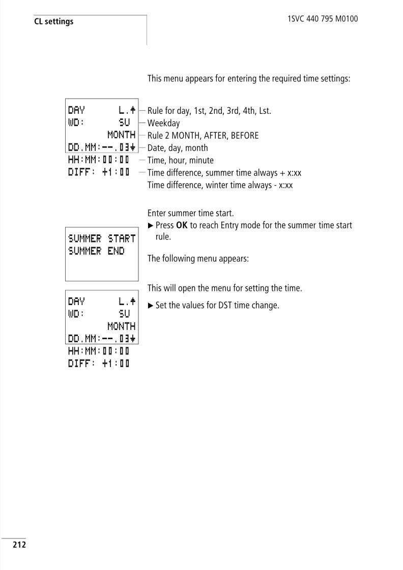
8/3/2019 Cl Lmt Manual
http://slidepdf.com/reader/full/cl-lmt-manual 215/296
CL settings
212
1SVC 440 795 M0100
This menu appears for entering the required time settings:
Enter summer time start.
X Press OK to reach Entry mode for the summer time startrule.
The following menu appears:
This will open the menu for setting the time.
X Set the values for DST time change.
Rule for day, 1st, 2nd, 3rd, 4th, Lst.
Weekday
Rule 2 MONTH, AFTER, BEFORE
Date, day, month
Time, hour, minute
Time difference, summer time always + x:xx
Time difference, winter time always - x:xx
DAY L.ÆWD: SU
MONTHDD.MM:--.03æHH:MM:00:00DIFF: +1:00
SUMMER STARTSUMMER END
DAY L.ÆWD: SUMONTH
DD.MM:--.03æHH:MM:00:00DIFF: +1:00

8/3/2019 Cl Lmt Manual
http://slidepdf.com/reader/full/cl-lmt-manual 216/296
Setting date and time
213
1SVC 440 795 M0100
X Press the OK button to access the Entry mode.
– ÍÚ Select required value.
– ú í Move between the parameters
– ÍÚ Change the value of a parameter
– OK Save value.
– ESC Retain previous setting.
Press ESC to leave the DST setting display.
The above rule is the EU rule for the start of summer time.
h The menu for the end of summer time has the samestructure. The values are now entered accordingly.
h The DIFF time difference value can be modified both forthe summer time setting and the winter time setting. Thevalue is always the same.
Summer time means a positive value + X:XX.
Winter time means a negative value – X:XX.
h Behaviour on 29 February
If the time change is set for 29.02. at HH.MM, the switchtime for years that are not leap years will occur on 01.03at HH.MM.
The DST time minus the time difference should not go into
28.02. The following applies:00:15 is put back by –30 min. New time: 28.02. 23:45
h Behaviour for summer time end on 01.01.
If 01.01. is selected for the end of summer time, ensure thefollowing:
The DST time minus the time difference should not go into
31.12. Otherwise the time will continue to run until the settime minus the time difference 0:00 on the 01.01. Thetime will then continue to run with 00:00.

8/3/2019 Cl Lmt Manual
http://slidepdf.com/reader/full/cl-lmt-manual 217/296
CL settings
214
1SVC 440 795 M0100
Activating input delay(debounce)
Input signals are evaluated by the logic relay with an inputdelay. This enables, for example, the trouble-free evaluationof switches and pushbutton actuators subject to contactbounce.
High-speed counter functions are evaluated independentlyof the debounce function.
In many applications, however, very short input signals haveto be monitored. In this case, the debounce function can beswitched off.
X Press DEL and ALT to call up the system menu.
X Select the SYSTEM menu.
The input delay (debounce) is set with the DEBOUNCE menuitem.
h Setting the time manually within the summer time end
setting:At 3:00 on summer time end the time is to be put back byone hour to 2:00.
The time is set to 3:05 at 1:30. The logic relay interpretsthis as 3:05 “Winter time”. A time change will not becarried out.
h Factory setting:
Debounce is activated.
h If the logic relay is password-protected you cannot openthe system menu until you have “unlocked” it.
DEBOUNCE ÆP BUTTONSRUN MODECARD MODE æ

8/3/2019 Cl Lmt Manual
http://slidepdf.com/reader/full/cl-lmt-manual 218/296
Activating and deactivatingthe P buttons
215
1SVC 440 795 M0100
Activating debounce (input delay)
A tick å next to DEBOUNCE indicates that this function
is activated.
If this is not so, proceed as follows:
X Select DEBOUNCE and press OK.
Debounce mode will be activated and the display will showDEBOUNCE å.
Press ESC to return to the status display.
Deactivating debounce (input delay)
If the logic relay is showing DEBOUNCE in the display, thismeans that Debounce mode has already been deactivated.
X Otherwise select DEBOUNCE å and press OK.
If Debounce mode is deactivated the display will showDEBOUNCE.
Activating anddeactivating the P buttons
Even though the cursor buttons (P buttons) have been set aspushbutton actuator inputs in the circuit diagram, thisfunction is not activated automatically. This prevents any
unauthorised use of the cursor buttons. The P buttons can beactivated in the system menu.
DEBOUNCE åÆ
P BUTTONSRUN MODECARD MODE æ
h How the logic relay input and output signals are processedinternally is explained in section “Delay times for inputsand outputs”, from Page 230.
h If the logic relay is password-protected you cannot openthe system menu until you have “unlocked” it.
h Factory setting:
The P buttons are not activated.

8/3/2019 Cl Lmt Manual
http://slidepdf.com/reader/full/cl-lmt-manual 219/296
CL settings
216
1SVC 440 795 M0100
The P buttons are activated and deactivated via theP BUTTONS menu.
X Press DEL and ALT to call up the system menu.X Select the SYSTEM menu.
X Move the cursor to the P BUTTONS menu.
Activating the P buttons
If the logic relay shows P BUTTONS å in the display, the
P buttons are active.X Otherwise select P BUTTONS and press OK.
The logic relay will then show P BUTTONS å and theP buttons will be activated.
X Press ESC to return to the status display.
Function of the P buttons
The P buttons are only active in the status display. In thisdisplay you can use the P buttons to activate inputs in yourcircuit diagram.
Deactivating the P buttons
X Select P BUTTONS å and press OK.
The logic relay will then show P BUTTONS and theP buttons will be deactivated.
DEBOUNCE åÆP BUTTONSRUN MODECARD MODE æ
DEBOUNCE åÆP BUTTONS åRUN MODECARD MODE æ
h If a text is displayed, the P buttons only function if a valueentry is not carried out.
h Deleting a circuit diagram in the logic relay will cause theP buttons to be deactivated automatically. If a circuitdiagram is loaded from the memory module or from
CL-SOFT, the status set there is also transferred.

8/3/2019 Cl Lmt Manual
http://slidepdf.com/reader/full/cl-lmt-manual 220/296
Startup behaviour
217
1SVC 440 795 M0100
Startup behaviour The startup behaviour is an important aid during thecommissioning phase. The circuit diagram which the logicrelay contains is not yet fully wired up, or the system ormachine is in a state which the logic relay is not permitted tocontrol. It must not be possible to activate the outputs whenthe logic relay is connected to the power supply.
Setting the startup behaviour
Requirement: the logic relay must contain a valid circuitdiagram.
Switch to the system menu.
Specify the operating mode which the logic relay must usewhen the supply voltage is applied.
Activating RUN modeIf the logic relay displays RUN MODE å, this means thatthe logic relay will start in RUN mode when the supplyvoltage is applied.
X Otherwise select RUN MODE and press OK.
RUN mode is activated.
X Press ESC to return to the status display.
h The CL models without a display can only be started inRUN mode.
h Factory setting:
RUN mode is activated.
h If the logic relay is protected by a password, the systemmenu will not be available until is the logic relay“unlocked” (a section “Unlock logic relay”, fromPage 199).
DEBOUNCE åÆP BUTTONSRUN MODE å
CARD MODE æ

8/3/2019 Cl Lmt Manual
http://slidepdf.com/reader/full/cl-lmt-manual 221/296
CL settings
218
1SVC 440 795 M0100
Deactivating RUN modeX Select RUN MODE å and press OK.
The RUN mode function is deactivated.The default setting for the logic relay is for RUN MODE åto be displayed. In other words, starts in RUN mode whenthe power is switched on.
Table 32: Startup behaviour
Behaviour when the circuit diagram is deleted
The startup mode setting is a CL device function. When thecircuit diagram is deleted this does not result in the loss ofthe setting selected.
Behaviour during upload/download to memorymodule or PC
When a valid circuit diagram is transferred from the logic
relay to a memory module or the PC or vice versa, the settingis still retained.
Possible faults
The logic relay does not start in RUN mode:• The logic relay does not have a program in it.
• You have selected STOP mode (RUN MODE menu).
DEBOUNCE åÆ
P BUTTONSRUN MODE åCARD MODE æ
Startup behaviour Menu displayed Status of the logicrelay after startup
The logic relay starts inSTOP mode
RUN MODE STOP mode
The logic relay starts inRUN mode
RUN MODE å RUN mode
h The CL models without a display can only be started inRUN mode.

8/3/2019 Cl Lmt Manual
http://slidepdf.com/reader/full/cl-lmt-manual 222/296
Startup behaviour
219
1SVC 440 795 M0100
Startup behaviour for memory module
The startup behaviour using a memory module is forapplications where unskilled personnel have to change thememory module with the logic relay de-energized.
The logic relay will then only start in RUN mode if a memorymodule with a valid program is fitted.
If the program on the memory module is different to theprogram in the logic relay, the program on the module isloaded first and the logic relay starts in RUN mode.
X Switch to the system menu.
Activate memory module startupIf the logic relay shows RUN MODE å in the display, itwill only start up in RUN mode at power on if the memorymodule fitted contains a valid program.
X Otherwise select CARD MODE and press OK.
The logic relay will start up with the program on the module.X Press ESC to return to the status display.
h Factory setting:
Card mode is not activated.
h If the logic relay is protected by a password, thesystem menu will not be available until the logic relay
is “unlocked” (a section “Unlock logic relay”,from Page 199).
DEBOUNCE åÆ
P BUTTONSRUN MODE åCARD MODEåæ
h Card mode is only possible with the CL-LAS.MD003memory module. Old MD001 or MD002 memory modulesdo not support this function.

8/3/2019 Cl Lmt Manual
http://slidepdf.com/reader/full/cl-lmt-manual 223/296
CL settings
220
1SVC 440 795 M0100
Deactivating card modeX Select CARD MODE å and press OK.
The Card mode function is deactivated.
The default setting for the logic relay is for CARD MODE tobe displayed. In other words, the logic relay starts in RUNmode when the power is switched on.
Setting the cycle time The logic relay allows you to fix the cycle time. To do this,
move to the SYSTEM menu and from there to the CYCLETIME… menu.
The cycle time can only be set in STOP mode.
The logic relay is in STOP mode.
X Select CYCLE-T and press OK.
The following menu appears:X Press OK.
You can now enter the set cycle time.
• ú í Move between the parameters
• ÍÚ Change value.
X Press OK to acknowledge the value: e.g. 35 ms.
The set cycle time is at least 35 ms. The cycle time can belonger if the logic relay requires more time for processing theprogram.
Set cycle time value range:between 00 and 60 ms.
DEBOUNCE åÆ
P BUTTONSRUN MODE åCARD MODE æ
h Factory setting:The cycle time is set to 00 ms.
P BUTTONS ÆRUN MODE åCARD MODE å
CYCLE-T.. .æ
CYCLE TIME00 MS
CYCLE TIME35 MS
h The entry of a set cycle time is only useful in applicationsinvolving two-step controllers or similar functions.With a cycle time setting of 00 ms, the logic relay willprocess the circuit diagram and the program at the fastest
possible speed (see also Inside CL, cycle time).

8/3/2019 Cl Lmt Manual
http://slidepdf.com/reader/full/cl-lmt-manual 224/296
Retention (non-volatiledata storage)
221
1SVC 440 795 M0100
Retention (non-volatiledata storage)
It is a requirement of system and machine controllers foroperating states or actual values to have retentive settings.What this means is that the values will be retained safelyeven after the supply voltage to a machine or system hasbeen switched off and are also retained until the next timethe actual value is overwritten.
Permissible markers and function relays
It is possible to retentively store (non-volatile memory) theactual values (status) of markers, timing relays and up/downcounters.
The following markers and function relays can be set to haveretentive actual values:
• Markers: M9 to M12, M13 to M16, N9 to N16• Up/down counters: C5 to C7, C8, C13 to C16
• Text function relays: D1 to D8
• Timing relays: T7, T8, T13 to T16
h Factory setting:
The retention function is not activated.
h In order to ensure the full compatibility of CL-LSR/CL-LSTand CL-LMR/CL-LMT devices with the AC010 devices, thesettings for the retentive data were divided into the above
areas.
hAttention! The retentive data is kept every time the power supply isswitched off. Data security is assured for 1000000 writecycles.

8/3/2019 Cl Lmt Manual
http://slidepdf.com/reader/full/cl-lmt-manual 225/296
CL settings
222
1SVC 440 795 M0100
Setting retentive behaviour
Requirement: the logic relay must be in STOP mode.X Switch to the system menu.
X Switch to STOP mode.
X Switch to the system menu.
X Move to the SYSTEM menu and continue to theRETENTION… menu.
X Press the OK button.
The first screen display is the selection of the marker range.
XÍÚ Select a range.
X Press OK to select the marker, the function relay or the
range that is to be retentive (tick on the line).
Press ESC to exit the input for the retentive ranges.
Example:M9 to M12, counters C5 to C7, C8 as well as timing relaysT7 and T8 are retentive. Indicated by the tick on the line.
The default setting of the logic relay is selected so that noretentive data is selected. In this setting, the logic relayworks without retentive actual values if a valid circuitdiagram is present. When the logic relay is in STOP mode orhas been switched to a de-energized state, all actual valuesare cleared.
h If the logic relay is protected by a password, the systemmenu will not be available until the logic relay is“unlocked” (a section “Unlock logic relay”, fromPage 199).
RUN MODE åÆCARD MODECYCLE-T...RETENTION æ
M 9 - M12 åÆM13 - M16
N 9 - N16C 5 - C 7 åæC 8 åC13 - C16D 1 - D 8T7T8T13 - T16
M 9 - M12 åÆM13 - M16N 9 - N16C 5 - C 7 åæC 8 åC13 - C16D 1 - D 8
T 7 åT 8 åT13 - T16

8/3/2019 Cl Lmt Manual
http://slidepdf.com/reader/full/cl-lmt-manual 226/296
Retention (non-volatiledata storage)
223
1SVC 440 795 M0100
Deleting retentive actual values
The retentive actual values are cleared if the following isfulfilled (applies only in STOP mode):
• The program’s retentive actual values are reset to 0 whenit is transferred to the logic relay from CL-SOFT or from thememory module. This also applies when there is noprogram on the memory module, in which case the oldcircuit diagram is retained in the logic relay.
• When the selected retentive markers, function relays or
text display are deactivated.• When the circuit diagram is deleted via the DELETE FUNCTmenu.
The operating hours counters are always retentive. Theactual values can only be reset by means of a special resetoperation from the circuit diagram.
Transferring retentive behaviour
The setting for retentive behaviour is a circuit diagramsetting; in other words, the retention setting is on thememory module and is transferred with the circuit diagramwhen uploading or downloading from the PC.
8/3/2019 Cl Lmt Manual
http://slidepdf.com/reader/full/cl-lmt-manual 227/296
CL settings
224
1SVC 440 795 M0100
Changing the operating mode or the circuit diagram
When the operating mode is changed or the CL circuitdiagram is modified, the retentive data is normally savedtogether with their actual values. The actual values of relaysno longer being used are also retained.
Changing the operating modeIf you change from RUN to STOP and then back to RUN, theactual values of the retentive data will be retained.
Changing the CL circuit diagram
The actual values are retained if the CL circuit diagram ismodified.
Changing the startup behaviour in the SYSTEM menu
The retentive actual values in the logic relay are retained,irrespective of the RUN MODE or STOP MODE setting.
hAttention!Even if the markers and function relays that were selectedas retentive are deleted from the circuit diagram, theretentive actual values are retained when switching fromSTOP to RUN or when switching the power supply off andon again. If these relays are used in the circuit diagram
again, they will be assigned with the previous actualvalues.

8/3/2019 Cl Lmt Manual
http://slidepdf.com/reader/full/cl-lmt-manual 228/296
Displaying device information
225
1SVC 440 795 M0100
Displaying deviceinformation
The device information is provided for service tasks or inorder to determine the performance level of the device.
This function is only available with devices featuring adisplay.
Exception: Terminal mode with the display system.
The logic relay allows you to show the following deviceinformation:
• Power supply AC1, AC2 or DC1, DC2,
• T (transistor output) or R (relay output)• C (clock provided)
• LCD (display provided)
• OS: 1.10.204 (operating system version)
• CRC: 25825 (Checksum of the operating system is onlydisplayed in STOP mode).
• Program name if this was assigned with CL- SOFT.
X Switch to the main menu.
X Select the main menu.
X Select the INFO.. menu with the cursor button Ú.
X Press the OK button.
This will display all device information.
Press ESC to exit the display.
h The device information is always available. The passworddoes not prevent access.
PROGRAM... ÆSTOP å RUNPARAMETER...
INFO... æSET CLOCK..
DC TC LCDOS: 1.00.027CRC: 21779PROGRAM_0815

8/3/2019 Cl Lmt Manual
http://slidepdf.com/reader/full/cl-lmt-manual 229/296
226
1SVC 440 795 M0100
8/3/2019 Cl Lmt Manual
http://slidepdf.com/reader/full/cl-lmt-manual 230/296

8/3/2019 Cl Lmt Manual
http://slidepdf.com/reader/full/cl-lmt-manual 231/296
Inside the logic relay
228
1SVC 440 795 M0100
The fifth segment is outside of the circuit diagram. The logicrelay uses this to contact the “outside world”: output relays
Q1 to Q… are switched and inputs I1 to “I…” are re-read.The logic relay also copies all new switch states to the statusimage.
The logic relay only uses this status image for one cycle. Thisensures that each rung is evaluated with the same switchingstates for one cycle, even if the input signals at I1 to I12, forexample, change their status several times within a cycle.
Evaluation in the circuit diagram and high-speedcounter functionsWhen using high-speed counter functions, the signal state iscontinuously counted or measured irrespective of theprocessing of the circuit diagram. (C13, C14 high-speedup/down counters, C15, C16 frequency counters)
CL operation and implications for circuit diagram
creationThe logic relay evaluates the circuit diagram in these fivesegments in succession. You should therefore remember twopoints when you create your circuit diagrams:
• The changeover of a relay coil does not change theswitching state of an associated contact until the nextcycle starts.
• Always wire forwards, upwards or downwards. Never wire
backwards.

8/3/2019 Cl Lmt Manual
http://slidepdf.com/reader/full/cl-lmt-manual 232/296
Logic relaycircuit diagram cycle
229
1SVC 440 795 M0100
Example: switching in the next cycle
Start condition:
• I1, I2 switched on
• Q1 switched off.
This is the circuit diagram of a self-latching circuit. If I1 andI2 are closed, the switching state of relay coilÄQ1 is latchedvia contact Q1.
• 1st cycle: Inputs I1 and I2 are switched on. Coil ÄQ1
picks up.• Contact Q1 remains switched off since the logic relay
evaluates from left to right.
• 2nd cycle: The self-latching now becomes active. Thelogic relay has transferred the coil states at the end of thefirst cycle to contact Q1.
Example: Do not wire backwards
This example is shown in section “Creating and modifying
connections”. It was used there to illustrate how NOT to do it.
In the third circuit connection, the logic relay finds aconnection to the second circuit connection in which the firstcontact field is empty. The output relay is not switched.
When wiring more than three contacts in series, use one ofthe marker relays.
I1uI2----ÄQ1Q1k
I1-Q4-i3oz-----khI2-I4-ÄQ2
I1-Q4-i3-ÄM1I2-I4-M1-ÄQ2

8/3/2019 Cl Lmt Manual
http://slidepdf.com/reader/full/cl-lmt-manual 233/296
Inside the logic relay
230
1SVC 440 795 M0100
Delay times for inputsand outputs
The time from reading the inputs and outputs to switchingcontacts in the circuit diagram can be set in the logic relayvia the delay time.
This function is useful, for example, in order to ensure aclean switching signal despite contact bounce.
Figure 81: CL input assigned with a switch
CL-DC1, CL-DC2, CL-AC1 and CL-AC2 function withdifferent input voltages and therefore also have different
evaluation methods and delay times.
Delay times with CL-DC1 and CL-DC2 basic units
The delay time for DC signals is 20 ms.
Figure 82: Delay times of CL-DC1 and CL-DC2 basic units
S1
0V I1
1
0
1
0
S1
B
A
B
C

8/3/2019 Cl Lmt Manual
http://slidepdf.com/reader/full/cl-lmt-manual 234/296
Delay times for inputsand outputs
231
1SVC 440 795 M0100
An input signal S1 must therefore be 15 V or 8 V (CL-DC1)for at least 20 ms on the input terminal before the switching
contact will change from 0 to 1 (range A). If applicable, thistime must also include the cycle time (range B) since thelogic relay does not detect the signal until the start of a cycle.
The same time delay (range C) applies when the signal dropsout from 1 to 0.
If the debounce is switched off, the logic relay responds toan input signal after just 0.25 ms.
Figure 83: Switching behaviour with input debounce disabled
Typical delay times with the debounce delay switched off are:
• On-delay for I1 to I12:
– 0.25 ms (CL-DC2),
– 0.3 ms (CL-DC1)
• Off-delay for
– I1 to I6 and I9 to I12: 0.4 ms (CL-DC2), 0.3 ms (CL-DC1)
– I7 and I8: 0.2 ms (CL-DC2), 0.35 ms (CL-DC1)
1
0
1
0
S1
B
A C
B
h Ensure that input signals are noise-free if the inputdebounce is disabled. The logic relay will even react tovery short signals.

8/3/2019 Cl Lmt Manual
http://slidepdf.com/reader/full/cl-lmt-manual 235/296
Inside the logic relay
232
1SVC 440 795 M0100
Delay time with CL-AC1 and CL-AC2 basic units
The input delay with AC voltage signals depends on thefrequency. The appropriate values for 60 Hz are given inbrackets.
• On-delay
– 80 ms at 50 Hz,
– 66 ms at 60 Hz
• Off-delay for
– I1 to I6 and I9 to I12: 80 ms (66 ms)
– I7 and I8: 160 ms (150 ms) with CL-AC1– I7 and I8: 80 ms (66 ms) with CL-AC2
Figure 84: On-delay, CL-AC1 and CL-AC2
If the debounce delay is switched on, the logic relay checksat 40 ms (33 ms) intervals whether there is a half-wavepresent at an input terminal (1st and 2nd pulses in A). If thelogic relay detects two pulses in succession, the deviceswitches on the corresponding input internally.
If this is not the case, the input is switched off again as soonas the logic relay does not detect two successive half-waves(1st and 2nd pulses in B).
Figure 85: Pushbutton with bounce
A
21 21
B
S1
1 1 21
S1
A B

8/3/2019 Cl Lmt Manual
http://slidepdf.com/reader/full/cl-lmt-manual 236/296
Delay times for inputsand outputs
233
1SVC 440 795 M0100
If a button or switch bounces (A), the delay time may beextended by 40 ms (33 ms) (A).
If the debounce delay is switched off, the delay time isreduced.
• On-delay20 ms (16.6 ms)
• Off-delay forI1 to I6 and I9 to I12: 20 ms (16.6 ms)
• Off-delay for
I7 and I8: 100 ms (100 ms) with CL-AC1, CL-AC2
Figure 86: On- and Off-delays
The logic relay switches the contact as soon as it detects apulse (A). If no pulse is detected, the logic relay switches offthe contact (B).
Delay times for the analog inputs CL-AC1, CL-DC1 andCL-DC2
The analog input values are read at 1 ms intervals. Thevalues are continuously smoothed so that the analog valuesdo not fluctuate excessively and remain clean. At the start ofthe circuit diagram cycle, the currently available analogvalues that have been smoothed are provided for processingin the circuit diagram.
A
1 1
B
S1
h The procedure for changing the delay times is described insection “Activating input delay (debounce)” on Page 214.

8/3/2019 Cl Lmt Manual
http://slidepdf.com/reader/full/cl-lmt-manual 237/296
Inside the logic relay
234
1SVC 440 795 M0100
Monitoring ofshort-circuit/overload with CL-LST,CL-LMT and CL-LET
Depending on the CL type in use, it is possible to use theinternal inputs I15 and I16, R15, R16 to monitor forshort-circuits or overloads on an output.
• CL-LST:I16 = Group fault alarm for outputs Q1 to Q4.
• CL-LMT:
– I16 = Group fault alarm for outputs Q1 to Q4.
– I15 = Group fault alarm for outputs Q5 to Q8.
• CL-LET:
– R16 = Group fault alarm for outputs S1 to S4.– R15 = Group fault alarm for outputs S5 to S8.
Table 33: Status of error outputs
The following examples are for I16 = Q1 to Q4. I15 indicatesin the same way short-circuits and overloads on Q5 to Q8.
Example 1: Output with fault indication
The circuit diagram functions as follows:If a transistor output reports a fault, M16 is set by I16. Then/c contact of M16 switches off output Q1. M16 can becleared by resetting the CL power supply.
Example 2: Output of operating stateThe circuit functions as described in example 1. An additionalfeature is that when an overload is detected, the indicatorlight at Q4 is actuated. If Q4 has an overload, it would ’pulse’.
Example 3: Automatic reset of error signal
The circuit diagram functions in the same way as example 2.In addition the marker M16 is reset every 60 seconds bytiming relay T8 (on-delayed, 60 s). Should I16 remain at 1,M16 will continue to be set. Q1 is set briefly to 1 until I16switches off again.
State of outputs Status I15 or I16, R15 or R16
No fault found 0 = switched off (n/o contact)
At least one output has a fault 1 = switched on (n/o contact)
I1-m16----ÄQ1I16-------SM16
I1-m16---ÄQ1I16-----SM16M16-------ÄQ4
I1-m16---ÄQ1I16-----SM16
M16-------TT8T8-------RM16M16------ÄQ4

8/3/2019 Cl Lmt Manual
http://slidepdf.com/reader/full/cl-lmt-manual 238/296
Expanding CL-LMR/CL-LMT
235
1SVC 440 795 M0100
Expanding CL-LMR/CL-LMT CL-LMR/CL-LMT can be expanded locally using theCL-LER.18AC2, CL-LER.18DC2, CL-LER.2O or CL-LET.20DC2expansion modules, or remotely via the CL-LEC.CI000coupler unit.
Install the units and connect the inputs and outputs asdescribed (a chapter “Installation”, Page 27).
You process the inputs of the expansion devices as contactsin the CL circuit diagram in the same way as you process theinputs of the basic unit. The input contacts are assigned the
operand identifiers R1 to R12.R15 and R16 are the group fault alarms of the transistorexpansion unit (a section “Monitoring of short-circuit/overload with CL-LST, CL-LMT and CL-LET”, Page 234).
The outputs are processed as relay coils or contacts like theoutputs in the basic unit. The output relays are S1 to S8.
How is an expansion unit recognised?
The logic relay checks cyclically whether a device is sendingdata on CL-LINK.
Transfer behaviour
The input and output data of the expansion units istransferred serially in both directions. Take into account themodified reaction times of the inputs and outputs of theexpansion units:
Input and output reaction times of expansion unitsThe debounce setting has no effect on the expansion unit.
h CL-LER.18AC2 and CL-LER.18DC2 are provided with the
outputs S1 to S6. The other outputs S7, S8 can be used asmarkers.
8/3/2019 Cl Lmt Manual
http://slidepdf.com/reader/full/cl-lmt-manual 239/296
Inside the logic relay
236
1SVC 440 795 M0100
Transfer times for input and output signals:
• Central expansionTime for inputs R1 to R12:30 ms + 1 cycle time
• Time for outputs S1 to S6 (S8):15 ms + 1 cycle
• Remote expansionTime for inputs R1 to R12:80 ms + 1 cycle time
• Time for outputs S1 to S6 (S8):40 ms + 1 cycle
Function monitoring of expansion units
If the power supply of the expansion unit is not present, noconnection can be established between it and basic unit. Theexpansion inputs R1 to R12, R15, R16 are incorrectlyprocessed in the basic unit and show status 0. It cannot be
assured that the outputs S1 to S8 are transferred to theexpansion unit.
The status of the internal input I14 of the basic unit indicates
the status of the expansion unit:
• I14 = “0”: expansion unit is functional
• I14 = “1”: expansion unit is not functional
jWarning!Ensure the continuous monitoring of CL expansion devicesin order to prevent switching faults in machines orsystems.
h When the power supply is switched on, basic units andexpansion devices may require different power up times toreach full functionality. If the basic unit is powered up
faster, the internal monitoring input I14 will have status 1,indicating that an expansion device is not functional.

8/3/2019 Cl Lmt Manual
http://slidepdf.com/reader/full/cl-lmt-manual 240/296
Saving and loadingcircuit diagrams
237
1SVC 440 795 M0100
Example
The expansion unit may be powered up later than the basic
unit. This means that the basic unit is switched to RUN whenan expansion unit is missing. The following CL circuitdiagram detects if the expansion unit is functional or notfunctional.
As long as I14 is 1, the remaining circuit diagram is skipped.If I14 is 0, the circuit diagram is processed. If the expansionunit drops out for any reason, the circuit diagram is skipped.M1 detects whether the circuit diagram was processed for at
least one cycle after the power supply is switched on. If thecircuit diagram is skipped, all the outputs retain theirprevious state. The next example should be used if this is notdesired.
Example with LCD output and reset of the outputs
Saving and loadingcircuit diagrams
You can either use the logic relay interface to save circuitdiagrams to a memory module or use CL-SOFT and atransmission cable to transfer them to a PC.
CL-LSR..X.../CL-LST..X..., CL-LMR..X.../CL-LMT..X...
CL models without a keypad can be loaded with a CL circuitdiagram via CL-SOFT or automatically from the fitted
memory module every time the power supply is switched on.
I14-m1----Ä:8---------SM1I14--------Ä:8I1uI2----ÄQ1Q1k:8
I14-m1----Ä:1---------SM1I14--------Ä:1
I2uI3----ÄQ1Q1k-----------Ä:8:1------uÄD1
hRQ1:8

8/3/2019 Cl Lmt Manual
http://slidepdf.com/reader/full/cl-lmt-manual 241/296
Inside the logic relay
238
1SVC 440 795 M0100
Interface
The logic relay interface is covered.
Figure 87: Do not touch the interface
X Carefully remove the cover with a screwdriver.
Figure 88: Remove the cover
To close the slot again, push the cover back onto the slot.
jDANGER of electric shock with CL-AC units!If the voltage terminals for phase (L) and neutralconductor (N) are reversed, the connected 230 V/115 Vvoltage will be present at the CL interface. There is adanger of electric shock if the plug is not properlyconnected or if conductive objects are inserted into thesocket.

8/3/2019 Cl Lmt Manual
http://slidepdf.com/reader/full/cl-lmt-manual 242/296
Memory module
239
1SVC 440 795 M0100
Memory module The module is available as an accessory CL-LAS.MD003 forCL-LSR/CL-LST and CL-LMR/CL-LMT.
Compatibility of memory modules MD001 andMD002
Circuit diagrams with all the data can transferred to theCL-LSR/CL-LST and CL-LMR/CL-LMT from the MD001 andMD002 memory module. A transfer, however, in the otherdirection is not possible.
Each memory module saves one CL circuit diagram.
Information stored on the memory module is “non-volatile”and thus you can use the module to archive, transfer andcopy circuit diagrams.
The memory module can be used for saving
• the circuit diagram
• all parameter sets of the function relays• all display texts with functions
• the system settings,
– Input delay
– P buttons
– Password
– Retention on/off,
• card start
• summer time start/end time settings
X The memory module is fitted in the opened interfaceprovided for it.

8/3/2019 Cl Lmt Manual
http://slidepdf.com/reader/full/cl-lmt-manual 243/296
Inside the logic relay
240
1SVC 440 795 M0100
Figure 89: Insert memory module
Loading or saving circuit diagrams
You can only transfer circuit diagrams in STOP mode.
Behaviour of CL device without integrated keypad,display when loading the memory moduleThe CL modules without a keypad and LCD display transferthe circuit diagram from the inserted memory module toCL-LSR..X.../CL-LST..X... or CL-LMR..X.../CL-LMT..X.. whenthe power supply is switched on. The circuit diagram in the
logic relay is retained if the circuit diagram on the memorymodule is invalid.
Behaviour of CL device with integrated keypad,display when memory module is insertedIf the logic relay does not contain a circuit diagram, thecircuit diagram is loaded from the memory moduleautomatically when the logic relay is switched on.
CL-LSR/CL-LST (CL-LAS.MD003): CL-LMR/CL-LMT (CL-LAS.MD003):
2
11
2
h With the logic relay you can insert and remove the memorymodule even if the power feed is switched on, without therisk of losing data.

8/3/2019 Cl Lmt Manual
http://slidepdf.com/reader/full/cl-lmt-manual 244/296
Memory module
241
1SVC 440 795 M0100
X Switch to STOP mode.X Select PROGRAM… from the main menu.
X Select the CARD… menu option.
The CARD… menu option will only appear if you haveinserted a functional memory module.
You can transfer a circuit diagram from the logic relay to themodule and from the module to the CL memory or delete the
content of the module.
After transmission, remove the memory module and close
the cover.
Saving a circuit diagram to the memory moduleX Select CARD-DEVICE.
X Confirm the prompt with OK to delete the contents of thememory module and replace it with the CL circuit diagram.
Press ESC to cancel.
h The memory module is detected when the module is
inserted and you move from the main menu to theprogram menu.
As read access to MD001, MD002 and CL-LAS.MD003modules are possible, the module can only be removed inthe status display. This ensures that the correct module isalways detected.
Only the CL-LAS.MD003 memory module can be writtento.
PROGRAMDELETE PROGCARD
DEVICE-CARD
CARD-DEVICEDELETE CARD
h If the operating voltage fails during communication withthe module, repeat the last step since the logic relay maynot have transferred or deleted all the data.
REPLACE ?

8/3/2019 Cl Lmt Manual
http://slidepdf.com/reader/full/cl-lmt-manual 245/296
Inside the logic relay
242
1SVC 440 795 M0100
Loading a circuit diagram from the memory module
X Select the CARD r DEVICE menu option.
X Press OK to confirm the prompt if you want to delete theCL memory and replace it with the module content.
Press ESC to go back one menu.
Deleting a circuit diagram on the memory moduleX Select the DELETE CARD menu option.
X Press OK to confirm the prompt and to delete the modulecontent.
Press ESC to cancel.
DEVICE-CARDCARD-DEVICEDELETE CARD
hAttention!Once you have started the CARD r DEVICE transfer, thefollowing operation is initiated:
• The RAM of the device is loaded from the module.
• The internal program memory is cleared.
• The data is written from the module to the internalretentive program memory.
This is carried out in blocks. A complete program is nottransferred to the RAM for space reasons.
If an invalid program or an interruption occurs during theread or write operation, CL-LSR/CL-LST or CL-LMR/CL-LMTloses the program in the internal memory.
DELETE ?

8/3/2019 Cl Lmt Manual
http://slidepdf.com/reader/full/cl-lmt-manual 246/296
CL-SOFT
243
1SVC 440 795 M0100
CL-SOFT CL-SOFT is a PC program with which you can create, store,test and manage CL circuit diagrams.
Figure 90: Inserting CL-LAS.TK001a
X Connect the PC cable to the serial PC interface.
X Insert the CL plug in the opened interface.
X Activate the status display on the logic relay.
Use CL-SOFT to transfer circuit diagrams from your PC to thelogic relay and vice versa. Switch the logic relay to RUNmode from the PC to test the program using the currentwiring.
CL-SOFT provides extensive help on how to use the software.
X Start CL-SOFT and click on Help.
The help provides all the additional information aboutCL-SOFT that you will need.
h You should only transfer data between the PC and thelogic relay using the special CL-PC connecting cable,which is available as an optional accessory CL-LAS.TK001.
jDANGER of electric shock with CL-AC units!Safe isolation of the interface voltage is only ensured byusing the cable CL-LAS.TK001.
h The logic relay cannot exchange data with the PC while
the circuit diagram display is on screen.

8/3/2019 Cl Lmt Manual
http://slidepdf.com/reader/full/cl-lmt-manual 247/296
Inside the logic relay
244
1SVC 440 795 M0100
If there are transmission problems, the logic relay will displaythe INVALID PROG message.
X Check whether the circuit diagram is suitable for thedestination device.
Figure 91: Pull CL-LAS.TK001a
X After transmission, remove the cable and close the cover.
Logic relay with separatedisplay module
CL-LSR/CL-LST and CL-LMR/CL-LMT can be operated with aseparate display module. In this configuration, all the displayinformation is transferred via the CL interface.
This has the advantage that the logic relay can be operatedremotely. The texts in the logic relay are backlit anddisplayed on the front of the operator or control panel intwice the size. The display module has the high degree ofprotection IP65.
When using a display module with a keypad, the logic relaycan be programmed and assigned parameters “fromoutside”.
INVALID PROG
h If the operating voltage fails during communication withthe PC, repeat the last step. It is possible that not all thedata was transferred between the PC and the logic relay.
h Card mode operation is not possible when using a stand-alone display module. The interface can only be used once.
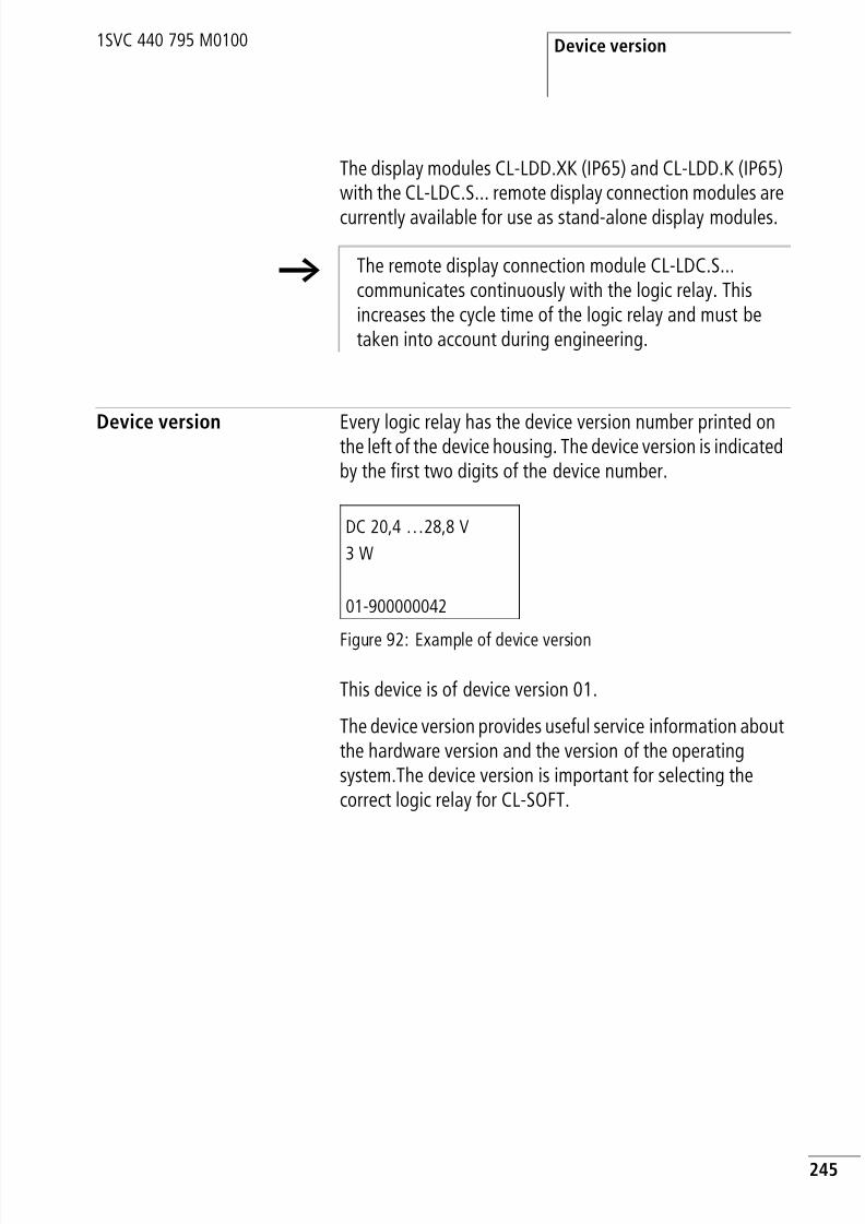
8/3/2019 Cl Lmt Manual
http://slidepdf.com/reader/full/cl-lmt-manual 248/296
Device version
245
1SVC 440 795 M0100
The display modules CL-LDD.XK (IP65) and CL-LDD.K (IP65)with the CL-LDC.S... remote display connection modules are
currently available for use as stand-alone display modules.
Device version Every logic relay has the device version number printed onthe left of the device housing. The device version is indicatedby the first two digits of the device number.
Figure 92: Example of device version
This device is of device version 01.
The device version provides useful service information aboutthe hardware version and the version of the operatingsystem.The device version is important for selecting thecorrect logic relay for CL-SOFT.
h The remote display connection module CL-LDC.S...communicates continuously with the logic relay. Thisincreases the cycle time of the logic relay and must betaken into account during engineering.
DC 20,4 …28,8 V
3 W
01-900000042

8/3/2019 Cl Lmt Manual
http://slidepdf.com/reader/full/cl-lmt-manual 249/296
246
1SVC 440 795 M0100

8/3/2019 Cl Lmt Manual
http://slidepdf.com/reader/full/cl-lmt-manual 250/296
247
1SVC 440 795 M0100
7 What happens if …?
You may sometimes find that the logic relay does not doexactly what you expect. If this happens, read through thefollowing notes which are intended to help you solve someof the problems you may encounter.
You can use the power flow display in the logic relay tocheck the logic operations in the CL circuit diagram withreference to the switching states of contacts and relays.
Only qualified persons should test the logic relay voltageswhile the device is in operation.
Messages from theCL system
Messages fromthe CL system on
the LCD display
Explanation Remedy
No display Power supply interrupted Switch on the power supply
LCD is faulty Replace logic relay
Continuous display
TEST: AC Self-test aborted Replace logic relay
TEST: EEPROM
TEST: DISPLAY
TEST: CLOCK
ERROR: I2C Memory module removed or not insertedcorrectly before saving
Insert memory module
Memory module is faulty Change memory module
Logic relay is faulty Replace logic relay
ERROR: EEPROM The memory for storing the retentive values
or the CL circuit diagram memory is faulty.
Replace logic relay
ERROR: CLOCK Clock error Replace logic relay

8/3/2019 Cl Lmt Manual
http://slidepdf.com/reader/full/cl-lmt-manual 251/296
What happens if …?
248
1SVC 440 795 M0100
Possible situations whencreating circuit diagrams
ERROR: LCD LCD is faulty Replace logic relay
ERROR: ACLOW Incorrect AC voltage Test the voltage
Logic relay is faulty Replace logic relay
Messages fromthe CL system on
the LCD display
Explanation Remedy
Possible situations whencreating circuit diagrams
Explanation Remedy
Cannot enter contact or relay incircuit diagram
Logic relay is in RUN mode Select STOP mode
Time switch switches at wrongtimes
Time or time switch parameters notcorrect
Check time andparameters
Message when using a memorymodule PROG INVALID
CL memory module without circuitdiagram
Change CL type orchange the circuitdiagram in thememory module
Circuit diagram on the memory moduleuses contacts/relays that the logic relaydoes not recognise
Power flow display does notshow changes to the rungs
Logic relay is in STOP mode Select RUN mode
Association/connection not fulfilled Check and modify
circuit diagram andparameter setsRelay does not activate coil
Incorrect parameter values/time
• Analog value comparison is incorrect• Time value of timing relay is incorrect• Function of timing relay is incorrect
Relay Q or M does not energize Relay coil has been wired up severaltimes
Check coil field entries

8/3/2019 Cl Lmt Manual
http://slidepdf.com/reader/full/cl-lmt-manual 252/296
Possible situations whencreating circuit diagrams
249
1SVC 440 795 M0100
Input not detected Loose terminal contact Check installationinstructions, checkexternal wiring
No voltage to switch/button
Wire breakage
CL input is faulty Replace logic relay
Relay output Q does not switchand activate the load
Logic relay in STOP mode Select RUN mode
No voltage at relay contact Check installation
instructions, checkexternal wiring
Logic relay power supply interrupted
CL circuit diagram does not activaterelay output
Wire breakage
CL relay is faulty Replace logic relay
Possible situations whencreating circuit diagrams
Explanation Remedy

8/3/2019 Cl Lmt Manual
http://slidepdf.com/reader/full/cl-lmt-manual 253/296
What happens if …?
250
1SVC 440 795 M0100
Event
Event Explanation Remedy
The actual values are not beingstored retentively.
Retention has not beenswitched on.
Switch on retention in theSYSTEM menu.
The RETENTION… menu is notdisplayed in the SYSTEM menu.
Logic relay is in RUN mode Select STOP mode
The SYSTEM menu is notdisplayed.
This CL model does not havethis menu.
Exchange logic relay if youneed retention
Logic relay starts in STOP modeonly No circuit diagram in logic relay Load, input circuit diagramStartup behaviour is set to thefunction “Startup in operatingmode STOP”.
Set the startup behaviour in theSYSTEM menu.
LCD display showing nothing. No power supply Switch on the power supply
Logic relay is faulty Press the OK button. If nomenu appears, replace thelogic relay.
Text displayed with too manyspaces
Enter text or do not select
GW flashes on the statusdisplay
CL-LEC.CI000 coupler unitdetected without I/O expansion.
Connect I/O expansion toexternal CL-LINK

8/3/2019 Cl Lmt Manual
http://slidepdf.com/reader/full/cl-lmt-manual 254/296
251
1SVC 440 795 M0100
Appendix
Dimensions
Figure 93: Dimensions CL-LEC.CI000 and CL-LER.2O in mm(specifications in inches see table 34, page 253)
M4
7.5
35.5
7.5
9 0
1 0 2
1 1 0
47.5
56.5
58
4 5
4.5
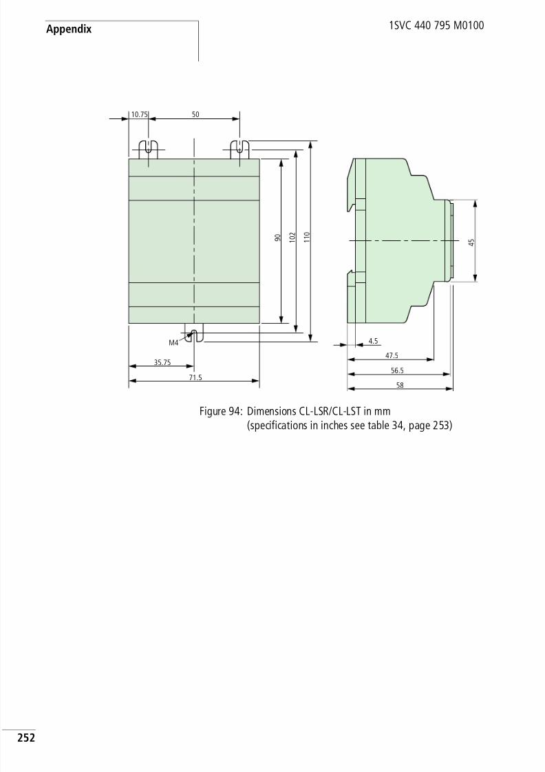
8/3/2019 Cl Lmt Manual
http://slidepdf.com/reader/full/cl-lmt-manual 255/296
Appendix
252
1SVC 440 795 M0100
Figure 94: Dimensions CL-LSR/CL-LST in mm(specifications in inches see table 34, page 253)
10.75 50
M4
35.75
71.5
9 0
1 0 2
1 1 0
47.5
56.5
58
4 5
4.5

8/3/2019 Cl Lmt Manual
http://slidepdf.com/reader/full/cl-lmt-manual 256/296
Dimensions
253
1SVC 440 795 M0100
Figure 95: Dimensions CL-LMR/CL-LMT in mm(specifications in inches see table 34)
Table 34: Dimensions in inches
9 0
1 0 2
1 1 0
M4
107.5
75 16.2516.25
47.5
56.5
58
4 5
4.5
mm inches mm inches
4.5 0.177 56.5 2.22
7.5 0.295 58 2.28
10.75 4.23 71.5 2.81
16.25 0.64 75 2.95
35.5 1.4 90 3.54
35.75 1.41 102 4.01
45 1.77 107.5 4.23
47.5 1.87 110 4.33
50 1.97

8/3/2019 Cl Lmt Manual
http://slidepdf.com/reader/full/cl-lmt-manual 257/296
Appendix
254
1SVC 440 795 M0100
Technical data General
CL…CL-LEC.CI000CL-LER.2O
CL-LSR,CL-LST
CL-LMR,CL-LMT
Dimensions W × H × D
[mm] 35.5 × 90 × 56.5 71.5 × 90 × 56.5 107.5 x 90 x 56.5
[inches] 1.4 × 3.54 × 2.08 2.81 × 3.54 × 2.08 4.23 × 3.54 × 2.08
Space units (SU) width 2 SU (space units)
wide
4 SU (space units)
wide
6 SU (space units)
wide
Weight
[g] 70 200 300
[lb] 0.154 0.441 0.661
Mounting Top-hat rail DIN 50022, 35 mm or screw mounting with 3 CL-LAS.FD001fixing brackets (accessories); only 2 fixing brackets required forCL-LEC.CI000 and CL-LER.2O.
Climatic environmental conditions(Cold to IEC 60068-2-1, Heat to IEC 60068-2-2)
Ambient temperature during operationInstalled horizontally/vertically
–25 to 55 °C, –13 to 131 °F
Condensation Prevent condensation with suitable measures
LCD display (reliably legible) 0 to 55 °C, 32 to 131 °F
Storage/transport temperature –40 to +70 °C, –40 to 158 °F
Relative humidity (IEC 60068-2-30) 5 to 95 %, non-condensing
Air pressure (operation) 795 to 1080 hPa
Corrosion resistance
IEC 60068-2-42 SO2 10 cm3/m3, 4 days
IEC 60068-2-43 H2S 1 cm3/m3, 4 days
Inflammability class to UL 94 V 0
Ambient mechanical conditions
Pollution degree 2
Degree of protection (EN 50178, IEC 60529, VBG4) IP 20

8/3/2019 Cl Lmt Manual
http://slidepdf.com/reader/full/cl-lmt-manual 258/296
Technical data
255
1SVC 440 795 M0100
Oscillations (IEC 60068-2-6) 10 to 57 Hz (constant amplitude 0.15 mm)
57 to 150 Hz (constant acceleration 2 g)Shock (IEC 60068-2-27) 18 shocks (semi-sinusoidal 15 g/11 ms)
Drop (IEC 60068-2-31) Drop height 50 mm
Free fall, when packed (IEC 60068-2-32) 1 m
Electromagnetic compatibility (EMC)
Electrostatic discharge (ESD), (IEC/EN 61 000-4-2,severity level 3)
8 kV air discharge,6 kV contact discharge
Electromagnetic fields (RFI), (IEC/EN 61000-4-3) Field strength 10 V/mEmitted interference Interference immunity(EN 55011, EN 55022) IEC 61000-6-1,2,3,4
Class B
Fast transient burst (IEC/EN 61000-4-4,severity level 3)
2 kV power cables,2 kV signal cables
High-energy pulses (surge) CL-AC(IEC/EN 61000-4-5)
2 kV power cable symmetrical
High-energy pulses (surge) CL-DC1, CL-DC2,
CL-AC1 (IEC/EN 61000-4-5, severity level 2)
0.5 kV power cable symmetrical
Immunity to line-conducted interference to(IEC/EN 61000-4-6)
10 V
Insulation resistance
Clearance and creepage distances EN 50178, UL 508, CSA C22.2, No 142
Insulation resistance EN 50178
Overvoltage category/degree of pollution II/2
Tools and cable cross-sections
solid core min. 0.2 mm2, max. 4 mm2/AWG:22 – 12
Flexible with ferrule min. 0.2 mm2, max. 2.5 mm2/AWG: 22 – 12Factory wiring: to AWG 30
Slot-head screwdriver, width 3.5 x 0.8 mm
Tightening torque 0.6 Nm

8/3/2019 Cl Lmt Manual
http://slidepdf.com/reader/full/cl-lmt-manual 259/296
Appendix
256
1SVC 440 795 M0100
Special approvals
Backup/accuracy of real-time clock(only with CL-LSR..X.../CL-LST..X..., CL-LMR..X.../CL-LMT..X...)
Clock battery back-up
a = backup time in hoursb = service life in years
Accuracy of the real-time clock Normally 5 s/day, ~0,5 h/year
Repetition accuracy of timing relays
Accuracy of timing relays 1 % of value
Resolution
Range “s” 10 msRange “M:S” 1 s
Range “H:M” 1 min.
Retentive memory
Write cycles of the retentive memory (at least) 1000000
Rungs (logic relay)
CL-LSR/CL-LST, CL-LMR/CL-LMT 128
a
b
180
200
160
140
120
100
80
60
40
20
00 2 4 6 8 10 2012 141 3 5 7 9 11 13
55˚C
25˚C
15 17 1916 18
CSA Hazardous Locations CLASS I Division 2 Groups A, B, C and DTemperature Code T3C –160 °C in 55 °C ambient.

8/3/2019 Cl Lmt Manual
http://slidepdf.com/reader/full/cl-lmt-manual 260/296
Technical data
257
1SVC 440 795 M0100
Power supply
CL-LSR...AC1, CL-LMR...AC1, CL-LSR...AC2,CL-LMR...AC2
CL-LSR...AC1,CL-LMR...AC1
CL-LSR...AC2,CL-LMR...AC2
Rated value (sinusoidal) 24 V AC 100/110/115/120/230/240 V AC
Operating range +10/–15 %20.4 to 26.4 V AC
+10/–15 %85 to 264 V AC
Frequency, rated value,tolerance 50/60 Hz,
5 % 50/60 Hz,
5 %
Input current consumption CL-LSR...AC1 CL-LMR...AC1 CL-LSR...AC2 CL-LMR...AC2
at 115/120 V AC 60 Hz Normally 40 mA Normally 70 mA
at 230/240 V AC 50 Hz Normally 20 mA Normally 35 mA
at 24 V AC 50/60 Hz Normally 200 mA Normally 300 mA
Voltage dips 20 ms, IEC/EN 61131-2 20 ms, IEC/EN 61131-2
Power loss CL-LSR...AC1 CL-LMR...AC1 CL-LSR...AC2 CL-LMR...AC2at 115/120 V AC Normally 5 VA Normally 10 VA
at 230/240 V AC Normally 5 VA Normally 10 VA
at 24 V AC Normally 5 VA Normally 7 VA

8/3/2019 Cl Lmt Manual
http://slidepdf.com/reader/full/cl-lmt-manual 261/296
Appendix
258
1SVC 440 795 M0100
CL-LSR...DC1, CL-LMR...DC1, CL-LS...DC2, CL-LM...DC2
Inputs
CL- LSR...AC1, CL-LMR...AC1
CL-LSR...DC1,CL-LMR...DC1
CL-LSR...DC2,CL-ST...DC2,CL-LMR...DC2,CL-LMT...-DC2
Rated voltage
Nominal value 12 V DC,+30 %, –15 %
24 V DC, +20 %, –15 %
Permissible range 10.2 to 15.6 V DC 20.4 to 28.8 V DC
Residual ripple 5 % 5 %
Input currentat rated voltage
CL-LSR...DC1 CL-LMR...DC1 CL-LS...DC2 CL-LM...DC2
Normally 140 mA Normally 200 mA Normally 80 mA Normally 140 mA
Voltage dips 10 ms, IEC/EN 61 131-2 10 ms, IEC/EN 61 131-2
Power loss CL-LS...DC1 CL-LM...DC1 CL-LS...DC2 CL-LM...DC2
Normally 2 W Normally 3.5 W Normally 2 W Normally 3.5 W
CL- LSR...AC1 CL-LMR...AC1
Digital inputs 24 V AC
Quantity 8 12
Status display LCD (if provided) LCD (if provided)
2 inputs (I7, I8) usable asanalog inputs
4 inputs (I7, I8, I11, I12) usableas analog inputs
Potential isolation
To power supply No No
Between each other No No
To the outputs Yes Yes

8/3/2019 Cl Lmt Manual
http://slidepdf.com/reader/full/cl-lmt-manual 262/296
Technical data
259
1SVC 440 795 M0100
CL-LSR...AC2, CL-LER.18AC2, CL-LMR...AC2
Rated voltage L (sinusoidal) 24 V AC 24 V AC
At state ”0” 0 to 6 V AC 0 to 6 V AC
At state ”1” (I7, I8)> 8 V AC, > 11 V DC(I1 to I6, I9 to I12)14 to26.4 V AC
(I7, I8, I11, I12)> 8 V AC, > 11 V DC(I1 to I6, I9, I10) 14 to26.4 V AC
Rated frequency 50/60 Hz 50/60 Hz
Input current for state “1”I1 to I6 (CL-LMR also I9 to I10)
4 mA at 24 V AC 50 Hz 4 mA at 24 V AC 50 Hz
Input current for state “1”I7, I8 (CL-LMR also I11, I12)
2 mA at 24 V AC 50 Hz,2 mA at 24 V DC
2 mA at 24 V AC 50 Hz,2 mA at 24 V DC
Delay time for 0 to 1 and 1 to 0 for I1 to I8, CL-LMR also I9 to I12
Debounce ON 80 ms (50 Hz), 66B/c ms (60 Hz) 80 ms (50 Hz), 66B/c ms (60 Hz)
Debounce OFF 20 ms (50 Hz), 16B/c ms (60 Hz) 20 ms (50 Hz), 16B/c ms (60 Hz)
Max. permissible cable length (per input)
I1 to I8 (CL-LMR also I9 to I10) Normally 40 m Normally 40 m
CL- LSR...AC1 CL-LMR...AC1
CL-LSR...AC2 CL-LER.18AC2,CL-LMR...AC2
Digital inputs 115/230 V AC
Quantity 8 12
Status display LCD (if provided) LCD (if provided)
Potential isolation
To power supply No No
Between each other No No
To the outputs Yes Yes
Rated voltage L (sinusoidal)
At signal ”0” 0 to 40 V AC 0 to 40 V ACAt signal ”1” 79 to 264 V AC 79 to 264 V AC
Rated frequency 50/60 Hz 50/60 Hz

8/3/2019 Cl Lmt Manual
http://slidepdf.com/reader/full/cl-lmt-manual 263/296
Appendix
260
1SVC 440 795 M0100
Input current for state „1“R1 to R12, I1 to I6(CL-LMR also I9 to I12)
6x 0.5 mA at 230 V AC 50 Hz6x 0.25 mA at 115 V AC 60 Hz
10 (12) x 0.5 mA at230 V AC 50 Hz10 (12) x 0.25 mA at115 V AC 60 Hz
Input current for state “1”I7, I8
2 x 6 mA at 230 V AC 50 Hz,2 x 4 mA at 115 V AC 60 Hz
2 x 6 mA at 230 V AC 50 Hz,2 x 4 mA at 115 V AC 60 Hz
Delay time for 0 to 1 and 1 to 0 for I1 to I6, I9 to I12
Debounce ON 80 ms (50 Hz), 66B/c ms (60 Hz) 80 ms (50 Hz), 66B/c ms (60 Hz)
Debounce OFF(also R1 to R12)
20 ms (50 Hz), 16B/c ms (60 Hz) 20 ms (50 Hz), 16B/c ms (60 Hz)
Delay time I7, I8 for 1 to 0
Debounce ON 160 ms (50 Hz), 150 ms (60 Hz) 80 ms (50 Hz),66B/c ms (60 Hz)
Debounce OFF 100 ms (50 Hz/60 Hz) 20 ms (50 Hz), 16B/c ms (60 Hz)
Delay time I7, I8 for 0 to 1
Debounce ON 80 ms (50 Hz), 66B/c ms (60 Hz) 80 ms (50 Hz), 66B/c ms (60 Hz)
Debounce OFF 20 ms (50 Hz), 16B/c ms (60 Hz) 20 ms (50 Hz), 16B/c ms (60 Hz)
Max. permissible cable length (per input)
I1 to I6, R1 to R12(CL-LMR also I9 to I12)
Normally 40 m Normally 40 m
I7, I8 Normally 100 m Normally 100 m
CL-LSR...AC2 CL-LER.18AC2,CL-LMR...AC2
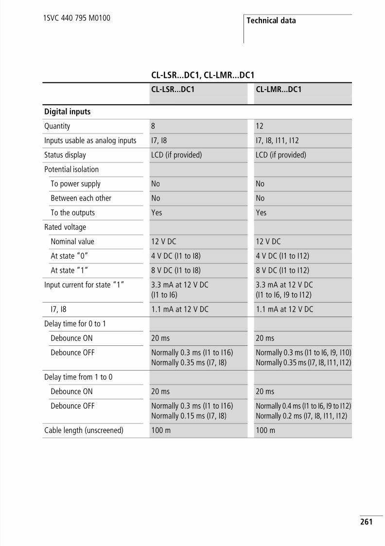
8/3/2019 Cl Lmt Manual
http://slidepdf.com/reader/full/cl-lmt-manual 264/296
Technical data
261
1SVC 440 795 M0100
CL-LSR...DC1, CL-LMR...DC1
CL-LSR...DC1 CL-LMR...DC1
Digital inputs
Quantity 8 12
Inputs usable as analog inputs I7, I8 I7, I8, I11, I12
Status display LCD (if provided) LCD (if provided)
Potential isolation
To power supply No No
Between each other No No
To the outputs Yes Yes
Rated voltage
Nominal value 12 V DC 12 V DC
At state ”0” 4 V DC (I1 to I8) 4 V DC (I1 to I12)
At state ”1” 8 V DC (I1 to I8) 8 V DC (I1 to I12)
Input current for state “1” 3.3 mA at 12 V DC(I1 to I6)
3.3 mA at 12 V DC(I1 to I6, I9 to I12)
I7, I8 1.1 mA at 12 V DC 1.1 mA at 12 V DC
Delay time for 0 to 1
Debounce ON 20 ms 20 ms
Debounce OFF Normally 0.3 ms (I1 to I16)Normally 0.35 ms (I7, I8)
Normally 0.3 ms (I1 to I6, I9, I10)Normally 0.35 ms (I7, I8, I11, I12)
Delay time from 1 to 0
Debounce ON 20 ms 20 ms
Debounce OFF Normally 0.3 ms (I1 to I16)Normally 0.15 ms (I7, I8)
Normally 0.4 ms (I1 to I6, I9 to I12)Normally 0.2 ms (I7, I8, I11, I12)
Cable length (unscreened) 100 m 100 m
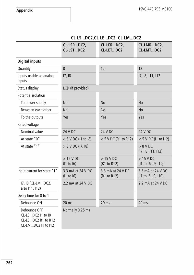
8/3/2019 Cl Lmt Manual
http://slidepdf.com/reader/full/cl-lmt-manual 265/296
Appendix
262
1SVC 440 795 M0100
CL-LS...DC2,CL-LE...DC2, CL-LM...DC2
CL-LSR...DC2,CL-LST...DC2
CL-LER...DC2,CL-LET...DC2
CL-LMR...DC2,CL-LMT...DC2
Digital inputs
Quantity 8 12 12
Inputs usable as analoginputs
I7, I8 I7, I8, I11, I12
Status display LCD (if provided)
Potential isolationTo power supply No No No
Between each other No No No
To the outputs Yes Yes Yes
Rated voltage
Nominal value 24 V DC 24 V DC 24 V DC
At state ”0” < 5 V DC (I1 to I8) < 5 V DC (R1 to R12) < 5 V DC (I1 to I12)
At state ”1” > 8 V DC (I7, I8) > 8 V DC(I7, I8, I11, I12)
> 15 V DC(I1 to I6)
> 15 V DC(R1 to R12)
> 15 V DC(I1 to I6, I9, I10)
Input current for state “1” 3.3 mA at 24 V DC(I1 to I6)
3.3 mA at 24 V DC(R1 to R12)
3.3 mA at 24 V DC(I1 to I6, I9, I10)
I7, I8 (CL-LM...DC2.also I11, I12)
2.2 mA at 24 V DC 2.2 mA at 24 V DC
Delay time for 0 to 1
Debounce ON 20 ms 20 ms 20 ms
Debounce OFFCL-LS...DC2 I1 to I8CL-LE...DC2 R1 to R12CL-LM...DC2 I1 to I12
Normally 0.25 ms

8/3/2019 Cl Lmt Manual
http://slidepdf.com/reader/full/cl-lmt-manual 266/296
Technical data
263
1SVC 440 795 M0100
Delay time from 1 to 0
Debounce ON 20 ms 20 ms 20 ms
Debounce OFF • Normally 0.4 ms(I1 to I6)
• Normally 0.2 ms(I7, I8)
Normally 0.4 ms(R1 to R12)
• Normally 0.4 ms(I1 to I6, I9, I10)
• Normally 0.2 ms(I7, I8, I11, I12)
Cable length (unshielded) 100 m 100 m 100 m
CL-LSR...DC2,CL-LST...DC2
CL-LER...DC2,CL-LET...DC2
CL-LMR...DC2,CL-LMT...DC2
High-speed counter inputs, I1 to I4 CL-LSR...DC1,CL-LSR...DC2,CL-LST...DC2,CL-LMR...DC1,CL-LMR...DC2,CL-LMT...DC2
Number 4
Cable length (shielded) m 20
High-speed up and down counter
Counting frequency kHz < 1
Pulse shape Square
Pulse pause ratio 1:1
Frequency counter
Counting frequency kHz < 1
Pulse shape Square
Pulse pause ratio 1:1

8/3/2019 Cl Lmt Manual
http://slidepdf.com/reader/full/cl-lmt-manual 267/296
Appendix
264
1SVC 440 795 M0100
CL-LSR...AC1,CL-LSR...DC1,
CL-LSR...DC2,CL-LST...DC2
CL-LMR...AC1,CL-LMR...DC1,
CL-LMR...DC2,CL-LMT...DC2
Analog inputs I7, I8, I11, I12
Quantity 2 4
Potential isolation
To power supply No No
From the digital inputs No NoTo the outputs Yes Yes
Input type DC voltage DC voltage
Signal range 0 to 10 V DC 0 to 10 V DC
Resolution analog 10 mV 10 mV
Resolution digital 0.01 (10-bit, 1 to 1023) 0.01 (10-bit, 0 to 1023)
Input impedance 11.2 kO 11.2 kO
Accuracy
Two CL devices g 3 % of actual value g 3 % of actual value
Within a single device g 2 % of actual value (I7, I8), g 0,12 V
Conversion time, analog/digital Debounce ON: 20 msDebounce OFF: every cycle
Input current at 10 V DC 1 mA 1 mA
Cable length (shielded) 30 m 30 m

8/3/2019 Cl Lmt Manual
http://slidepdf.com/reader/full/cl-lmt-manual 268/296
Technical data
265
1SVC 440 795 M0100
Relay outputs
CL-LSR, CL-LMR, CL-LER.18AC2, CL-LER.18DC2,CL-LER.2O
CL-LSR CL-LMR,CL-LER.18AC2,CL-LER.18DC2
CL-LER.2O
Quantity 4 6 2
Type of outputs Relay
In groups of 1 1 2
Parallel switching of outputs toincrease performance
Not permissible
Protection of an output relay Miniature circuit-breaker B16 or 8 A fuse (slow)
Potential isolation for mains currentsupply, inputs
Yes300 V AC (safe isolation)600 V AC (basic isolation)
Mechanical lifespan(switching operations)
10 x 106
Mains relays
Conventional therm. current 8 A (10 A UL)
Recommended for load > 500 mA, 12 V AC/DC
Short-circuit resistance y = 1 16 A characteristic B (B16) at 600 A
Short-circuit resistancey = 0.5 to 0.7
16 A characteristic B (B16) at 900 A
Rated impulse withstand voltageUimp contact coil
4 kV
Rated insulation voltage Ui
Rated operational voltage Ue 250 V AC
Safe isolation to EN 50178 betweencoil and contact
300 V AC
Safe isolation to EN 50178 betweentwo contacts
300 V AC
Making capacity
AC-15 250 V AC, 3 A (600 Ops/h) 300000 operationsDC-13 L/R F 150 ms 24 V DC,1 A (500 Ops/h)
200000 operations

8/3/2019 Cl Lmt Manual
http://slidepdf.com/reader/full/cl-lmt-manual 269/296
Appendix
266
1SVC 440 795 M0100
UL/CSA
Breaking capacity
AC-15 250 V AC, 3 A (600 Ops/h) 300 000 operations
DC-13 L/R F 150 ms 24 V DC,1 A (500 Ops/h)
200 000 operations
Filament bulb load 1000 W at 230/240 V AC/25000 operations500 W at 115/120 V AC/25000 operations
Fluorescent tube with ballast 10 x 58 W at 230/240 V AC/25000 operationsConventional fluorescent tube,compensated
1 x 58 W at 230/240 V AC/25000 operations
Fluorescent tube, uncompensated 10 x 58 W at 230/240 V AC/25000 operations
Operating frequency, relays
Mechanical switching operations 10 million (1 x 10⁷)
Mechanical switching frequency 10 Hz
Resistive lamp load 2 Hz
Inductive load 0.5 Hz
CL-LSR CL-LMR,CL-LER.18AC2,
CL-LER.18DC2
CL-LER.2O
Uninterrupted current at 240 V AC/24 V DC 10/8 A
AC Control Circuit Rating Codes(Utilization category)
B300 Light Pilot Duty
Max. rated operational voltage 300 V AC
Max. uninterrupted thermal current y = 1 at B 300 5 A
Maximum make/break capacity y k 1 (Make/break)with B300
3600/360 VA
DC Control Circuit Rating Codes(Utilization category)
R300 Light Pilot Duty
Max. rated operational voltage 300 V DC
Max. thermal uninterrupted current with R300 1 AMaximum apparent on/off power with R300 28/28 VA

8/3/2019 Cl Lmt Manual
http://slidepdf.com/reader/full/cl-lmt-manual 270/296
Technical data
267
1SVC 440 795 M0100
Transistor outputs
CL-LST, CL-LMT, CL-LET.20DC2CL-LST CL-LMT,
CL-LET.20DC2
Number of outputs 4 8
Contacts Semiconductors Semiconductors
Rated voltage Ue 24 V DC 24 V DC
Permissible range 20.4 to 28.8 V DC 20.4 to 28.8 V DC
Residual ripple F 5 % F 5 %
Supply current
At state ”0” Normally 9 mA, max. 16 mA Normally 18 mA, max. 32 mA
At state ”1” Normally 12 mA, max. 22 mA Normally 24 mA, max. 44 mA
Reverse polarity protection Yes, Attention! If voltage is applied to the outputs when the polarityof the power supply is reversed, this will result in a short circuit.
Potential isolation to mains
supply, inputs
Yes Yes
Rated current I e on 1 signal max. 0.5 A DC max. 0.5 A DC
Lamp load 5 Watts without RV 5 Watts without RV
Residual current on 0 stateper channel
< 0,1 mA < 0,1 mA
Max. output voltage
On 0 state
with ext. load 10 M
2.5 V 2.5 V
On 1 state, Ie = 0.5 A U = Ue – 1 V U = Ue – 1 V
Short-circuit protection Yes, thermal (analysis via diagnostics input I16, I15; R16, R15)
Short-circuit tripping currentfor Ra F 10 mO
0,7 A F I e F 2 A per output
Max. total short-circuitcurrent
8 A 16 A
Peak short-circuit current 16 A 32 A
Thermal cutout Yes Yes

8/3/2019 Cl Lmt Manual
http://slidepdf.com/reader/full/cl-lmt-manual 271/296
Appendix
268
1SVC 440 795 M0100
Inductive load (without external suppressor circuit)
General explanations:
T0.95 = time in milliseconds until 95 % of the stationarycurrent is reached.
Utilisation category in groups for:
• Q1 to Q4
• Q5 to Q8
• S1 to S4
• S5 to S8
Max. switching frequency withconstant resistive loadRL 100 kO: operations/hour
40000 (depends on program and load)
Parallel connection of outputswith resistive load; inductiveload with external suppressioncircuit (see page 53)Combination within a group
Group 1: Q1 to Q4 • Group 1:Q1 to Q4, S1 to S4
• Group 2:Q5 to Q8, S5 to S8
Number of outputs max. 4 max. 4
Total maximum current 2.0 A, Attention! Outputs must be actuated simultaneously andfor the same time duration.
Status display of the outputs LCD display (if provided)
CL-LST CL-LMT,CL-LET.20DC2
T 0,95 Q 3 x T 0,65 = 3xL
R

8/3/2019 Cl Lmt Manual
http://slidepdf.com/reader/full/cl-lmt-manual 272/296
Technical data
269
1SVC 440 795 M0100
T 0.95 = 1 msR = 48 O
L = 16 mH
Utilization factor g = 0.25
Relative duty factor % 100Maximum switching frequency f = 0.5 HzMaximum duty factor DF = 50 %
Operations/h 1500
DC13T 0.95 = 72 msR = 48 O
L = 1.15 H
Utilization factor g = 0.25
Relative duty factor % 100
Maximum switching frequency f = 0.5 HzMaximum duty factor DF = 50 %
Operations/h 1500
Other inductive loads:T 0.95 = 15 msR = 48 O
L = 0.24 H
Utilization factor g = 0.25
Relative duty factor % 100
Maximum switching frequency f = 0.5 HzMaximum duty factor DF = 50 %
Operations/h 1500
Inductive loading with external suppressor circuit for each load(a section “Connecting transistor outputs”, Page 51)
Utilization factor g = 1
Relative duty factor % 100
max. operating frequencyMax. duty factor
Operations/h Depending onthe suppressorcircuit

8/3/2019 Cl Lmt Manual
http://slidepdf.com/reader/full/cl-lmt-manual 273/296
Appendix
270
1SVC 440 795 M0100
List of the function relays Usable contacts
Contact type n/o n/c CL-LSR/CL-LST
CL-LMR/CL-LMT
Page
Analog value comparatorfunction relay
A a A1…A16 A1…A16 98
Counter function relays C c C1…C16 C1…C16 111
Text display function relay D D1…D16 D1…D16 131
Week time switch function relay Ö ö Ö1…Ö8 Ö1…Ö8 137
CL input terminal I i I1…I8 I1…I12 77
0 signal I13 I13
Expansion status – I14 236
Short-circuit/overload I16 I15…I16 234
Markers, (auxiliary relay) M m M1…M16 M1…M16 85
Markers (auxiliary relay) N N1…N16 N1…N16
Operating hours counter O O1…O4 O1…O4 143Cursor button P p P1…P4 P1…P4 82
CL output Q q Q1…Q4 Q1…Q8 77
Input terminal for expansion unit R – R1…R12 77
Short-circuit/overload withexpansion
R – R15…R16 234
CL output (expansion orauxiliary marker S)
S S1…S8(as marker)
S1…S8 85
Timer function relays T t T1…T16 T1…T16 148
Jump label : – :1…:8 :1…:8 164
Year time switch Y Y1…Y8 Y1…Y8 167
Master reset, (central reset) Z Z1…Z3 Z1…Z3 174
D
N
O
R
R
S
Y
Z

8/3/2019 Cl Lmt Manual
http://slidepdf.com/reader/full/cl-lmt-manual 274/296
List of the function relays
271
1SVC 440 795 M0100
Available function relays
Names of relays
Relay CLdisplay
CL-LSR/CL-LST
CL-LMR/CL-LMT
Coilfunction
Parameters
Analog value comparatorfunction relay
A A1…A16 A1…A16 – j
Counter function relays C C1…C16 C1…C16 j j
Text marker function relay D D1…D16 D1…D16 j j
Week time switch function relay Ö Ö1…Ö8 Ö1…Ö8 – j
Markers (auxiliary relay) M M1…M16 M1…M16 j –
Markers (auxiliary relay) N N1…N16 N1…N16 j –
Operating hours counter O O1…O4 O1…O4 j j
CL output relay Q Q1…Q4 Q1…Q8 j –
CL output relay expansion,markers
S S1…S8(as marker)
S1…S8 j –
Timer function relays T T1…T16 T1…T16 j j
Conditional jump : :1…:8 :1…:8 j –
Year time switch Y Y1…Y4 Y1…Y4 – j
Master reset (central reset) Z Z1…Z8 Z1…Z8 j –
Relay Meaning of
abbreviation
Function relay designation Page
A Analog value comparator Analog value comparator 98
C counter Counter 111
D display Text display 131
Ö (week, Software) Week time switch 137
O operating time Operating hours counter 143
T timing relays Timing relay 148Y year Year time switch 167
Z zero reset, Master reset 174

8/3/2019 Cl Lmt Manual
http://slidepdf.com/reader/full/cl-lmt-manual 275/296
Appendix
272
1SVC 440 795 M0100
Names of function relay
Name of function block inputs(constants, operands)
Function relaycoil
Meaning ofabbreviation
Description
C count input Counter input, counter
D direction input Counter direction, counter
H hold, stop Stopping of timing relay, stop, timing relay
R reset Reset of actual value to zero, operating hourscounters, counters, text displays, timing relays
T trigger Timing coil, timing relay
Input Meaning of abbreviation Description
F1 Factor 1 Gain factor for I1 (I1 = F1 × Value)F2 Factor 2 Gain factor for I2 (I2 = F2 × Value)
HY Hysteresis Switching hysteresis for value I2 (Value HY appliesto positive and negative hysteresis.)
D Day Day
I1 Input 1 1st setpoint, comparison value
I2 Input 2 2nd setpoint, comparison value
S Setpoint Setpoint, limit value

8/3/2019 Cl Lmt Manual
http://slidepdf.com/reader/full/cl-lmt-manual 276/296
Compatibility of the functionrelay parameters
273
1SVC 440 795 M0100
Compatibility of thefunction relay parameters
The functions of the CL-LSR/CL-LST and CL-LMR/CL-LMTunits were extended to integrate the function relays of theAC010 units. The parameter displays were adapted for theadditional functions.
Parameter display of analog value comparator
Parameter display of counters
AC010 parameter CL-LSR/CL-LST-,CL-LMR/CL-LMTparameter
AA = I1 AABB = I2 BBA1 = A1+ = +
$ = GE
ANALOG
AAw gn $ dA1
BBy b +
A1 GE +
I1 AA ÆF1 +0I2 BB æF2 +0OS +0HY +0
AC010 parameter CL-LSR/CL-LST,CL-LMR/CL-LMTparameter
AAAA = S AAAAA=
C1 = C1+ = +
fAAAAgÄ sDIR nÄ sCNT d C1Ä yRES b +
C1 N +S AAAAA

8/3/2019 Cl Lmt Manual
http://slidepdf.com/reader/full/cl-lmt-manual 277/296
Appendix
274
1SVC 440 795 M0100
Parameter display 7-day time switch
Parameter display of timing relay
Compatibility of the memory module
AC010 parameter CL-LSR/CL-LST,CL-LMR/CL-LMTparameter
B1 = B1 AA-BB = AA-BB A = A ON --:-- = ON --:-- OFF --:-- = OFF --:-- + = +
fAA-BBgn dÖ1
ON s--:--n AOFFy--:--b +
Ö1 A +D AA-BBON --:--OFF --:--
AC010 parameter CL-LSR/CL-LST,CL-LMR/CL-LMTparameter
T1 = T1 X = X
S = S AA.BB = AA.BB + = +
X w gS nAA.BBnÄ sTRG dT1
yRES b+
T1 X S +I1 AA.BBI2
Type ofmemorymodule
CL-LSR, CL-LST CL-LMR, CL-LMT
Reading Writing Reading Writing
MD001 j – j –
MD002 – – j –
CL-LAS.MD003 j j j j

8/3/2019 Cl Lmt Manual
http://slidepdf.com/reader/full/cl-lmt-manual 278/296
275
1SVC 440 795 M0100
Glossary
Analog input The CL-AC1, CL-DC1 and CL-DC2 devices are provided withthe two (CL-LSR/CL-LST) or four (CL-LMR/CL-LMT) analoginputs I7, I8 and I11, I12. The input voltages are between0 V and 10 V. The measuring data is evaluated with theintegrated function relays.
Circuit diagram
elements
As in conventional wiring, the circuit diagram is made up of
circuit elements. These include input, output and markerrelays, plus function relays and P buttons.
Connect mode Connect mode is used to wire up the circuit elements in yourCL circuit diagram.
Contact behaviour The contact behaviour of any circuit element can be defined
as either a n/c contact or a n/o contact. n/c contact elementsare identified by a line above the identifier (Exception: jump).
Decentralized
expansion
I/O expansion with the expansion device (e.g. CL-LET.20DC2)is installed up to 30 m away from the basic unit. TheCL-LEC.CI000 coupler is fitted centrally on the basic unit. Atwo-wire cable is used to exchange the input and output databetween the expansion device and the basic unit.
Entry mode Entry mode is used to input or modify values when creatingcircuit diagrams or setting parameters, for example.

8/3/2019 Cl Lmt Manual
http://slidepdf.com/reader/full/cl-lmt-manual 279/296
Glossary
276
1SVC 440 795 M0100
Function relay Function relays can be used for complex control tasks.The logic relay features the following function relays:
• Timing relay
• 7-day time switch
• Year time switch
• Counter, up/down, high-speed, frequency
• Analog value comparator/threshold value switch
• Operating hours counter
• Master reset
• Text marker relay
Impulse relay An impulse relay is a relay which changes its switching stateand retains its new state (latched) when a voltage is appliedto the relay coil for a short time.
Input The inputs are used to connect up external contacts. In the
circuit diagram, inputs are evaluated via contacts I1 to I12and R1 to R12.
CL-AC1, CL-DC1 and CL-DC2 can receive additional analogdata via the inputs I7, I8 and I11, I 12.
Interface The CL interface is used to exchange and save circuitdiagrams to a memory module or PC.
A memory module stores a circuit diagram and the CLsettings.
The CL-SOFT PC software allows you to control the logicrelay from the PC. For this the PC and the logic relay areconnected via the CL-LAS.TD001 cable.
Local expansion I/O expansion with the expansion device (e.g.
CL-LET.20DC2) is installed directly on the basic unit. Theconnector is always supplied with the expansion unit.

8/3/2019 Cl Lmt Manual
http://slidepdf.com/reader/full/cl-lmt-manual 280/296
Glossary
277
1SVC 440 795 M0100
Memory module The memory module is used to store your CL circuit diagram,together with its parameter and CL settings. The data on the
memory module will be retained without an external powersupply.
The memory module is fitted in the interface provided for it.
Non-volatile data See Retention.
Operating buttons The logic relay has eight operating buttons. These are usedto select menu functions and create circuit diagrams. Thelarge round button in the middle is used to move the cursor.
DEL, ALT, ESC and OK all perform additional functions.
Operating mode The logic relay has two operating modes: RUN and STOP.RUN mode is used to process your CL circuit diagram (withthe controller running continuously). In STOP mode you can
create your circuit diagrams.
Output You can connect various loads to the logic relay outputs,such as contactors, lamps or and motors. In the circuitdiagram the outputs are controlled via the correspondingoutput relay coils Q1 to Q8 or S1 to S8.
Parameter Parameters enable the user to set the behaviour of functionrelays. The relevant parameters apply for switch times orcounter setpoints. They are set in the parameter display.
P buttons The P buttons can be used to simulate four additional inputswhich are controlled directly by the four cursor buttons,rather than via external contacts. The switching contacts ofP buttons are connected up in the circuit diagram.

8/3/2019 Cl Lmt Manual
http://slidepdf.com/reader/full/cl-lmt-manual 281/296
Glossary
278
1SVC 440 795 M0100
Power supply CL-AC1 is powered by AC voltage at 24 V AC. The terminaldesignations are “L” and “N”.
CL-AC2 is powered by AC voltage at 85 to 264 V AC, 50/60Hz. The terminals are labelled with “L” and “N”.
CL-DC1 is powered by DC voltage at 12 V DC. The terminalsare labelled “+12 V” and “0 V”.
CL-DC2 is powered by DC voltage at 24 V DC. The terminalsare labelled “+24 V” and “0 V”.
The terminals for the power feed are the first three terminalson the input side.
Retention Data is retained even after the logic relay power supply isswitched off. (retentive data)
The following data is retentive:
• CL circuit diagram
• Parameters, setpoint values• Texts
• System settings
• Password
• Actual values of marker relays, timing relays, counters(selectable)
Rung Each line in the circuit diagram is a rung. CL-LSR/CL-LST andCL-LMR/CL-LMT can take 128 rungs.

8/3/2019 Cl Lmt Manual
http://slidepdf.com/reader/full/cl-lmt-manual 282/296
1SVC 440 795 M0100
279
Index
A Accuracy of real-time clock ................................256Actual values, deleting retentive ........................223Add rung .............................................................64Ambient conditions ...........................................254Analog
Comparing two values ................................110Input ....................................................41, 275
Input power supply .......................................43Input, resolution .........................................102Setpoint potentiometer .................................44Signals .........................................................42Value comparator .........................................98Value comparator parameter compatibility .273Value comparator, two-step controller .......108Value scaling ..............................................133
AND circuit ........................................................177
Annual timer .....................................................167Approvals ..........................................................256Auxiliary relay ......................................................85
B Basic circuit .......................................................176Changeover circuit .....................................180Latching .....................................................181Negation ............................................176, 177
Parallel circuit .............................................178Permanent contact .....................................177Series circuit ...............................................177
ButtonALT ..............................................................64DEL ..............................................................64OK ..........................................................62, 70
Buttons for circuit diagram processing .................69
8/3/2019 Cl Lmt Manual
http://slidepdf.com/reader/full/cl-lmt-manual 283/296
Index 1SVC 440 795 M0100
280
C Cable cross-sections ............................................31Cable lengths ......................................................37Cables .................................................................31Change channel
7-day time switch .......................................139Annual timer ..............................................169
Change language ..............................................201Circuit diagram ...................................................71
CL function ................................................228Coil field ......................................................75
Contact fields ...............................................75Controlling ...................................................84Creation, troubleshooting ..........................248Cycle ..........................................................227Delete ..........................................................67Detection ...................................................228Display ...................................................62, 75Elements ....................................................275Enter ............................................................60
Fast entry .....................................................67Grid .......................................................62, 75Internal processing .....................................227Load ....................................76, 237, 242, 243Operating buttons ........................................69Overview ......................................................75Rung ............................................................75Save .............................76, 237, 240, 241, 243Testing ...................................................65, 84
Wiring ....................................................64, 80Circuit examples ................................................184CL basic units at a glance ....................................14Clock backup time .............................................256Coil .....................................................................72Coil field .............................................................75Coil function
Contactor .....................................................86Impulse relay ................................................89Latching relay ..............................................90Negate .........................................................87Overview ......................................................85

8/3/2019 Cl Lmt Manual
http://slidepdf.com/reader/full/cl-lmt-manual 284/296
Index
281
1SVC 440 795 M0100
Commissioning ....................................................57Comparator functions ..........................................98
Comparison“Equal to” .................................................105“Greater than/equal to” .............................106“Greater than” ...........................................107“Less than/equal to” ..................................104“Less than” ................................................103Two analog values .....................................110
Compatibility of parameters ..............................273Connect mode ...................................................275Connecting
20 mA sensor ...............................................46Alternating voltage .......................................32Analog inputs ...............................................41Analog setpoint potentiometer .....................44Brightness sensor ...................................44, 45Contactors and relays ...................................48Cross-sections ..............................................31
DC voltage ...................................................33Digital input .................................................40Expansion .....................................................30Frequency encoder .......................................46High-speed counters .....................................46Input ............................................................35Neon bulbs ...................................................38Output .........................................................48Power supply ................................................31
Proximity switches ........................................40Pushbuttons and switches ............................40Relay outputs ...............................................49Setpoint potentiometer .................................44Temperature sensor ......................................45Transistor outputs ........................................51
ConnectionsChanging .....................................................80Creating .......................................................80
Delete ..........................................................81Position in the circuit diagram ......................75

8/3/2019 Cl Lmt Manual
http://slidepdf.com/reader/full/cl-lmt-manual 285/296
Index 1SVC 440 795 M0100
282
Contact ...............................................................71Behaviour ..................................................275
Field .............................................................75First .............................................................63List all ........................................................270
Contactor function, invert ...................................87Counter .....................................111, 115, 116, 119
Cascading ..................................................117Component quantities ................................115Counter frequency ......................................114Fast, circuit diagram evaluation ..................228High-speed ...........................................46, 125Maintenance ..............................................145Operating time/hours .................................143Parameter compatibility .............................273Retentive actual value ................................118Scan for actual value = zero .......................117
Counter relay ....................................................111Parameter set .....................................122, 127
Counter value automatic reset ...........................116Counting unit quantities ....................................115Current
Increasing input ...........................................39Input ......................................................37, 41
Cursor buttons ..............................................16, 82Activating ..................................................216Deactivating ...............................................216See „P buttons“ .........................................277
Cursor display ...............................................25, 70Cycle .................................................................227Cycle pulse ....................................87, 88, 182, 183

8/3/2019 Cl Lmt Manual
http://slidepdf.com/reader/full/cl-lmt-manual 286/296
Index
283
1SVC 440 795 M0100
D Date setting .......................................................205Delay times
for CL-AC1 and CL-AC2 ..............................232for CL-AC1, CL-DC1 and CL-DC2 ................233for CL-DC1 and CL-DC2 ..............................230Inputs and outputs .....................................230
Deleting retentive actual values .........................223Detecting operating states .................................109Device information ............................................225Device overview ..................................................14
Device version ...................................................245Dimensions ........................................................251Display module ..................................................244DST setting ........................................................206
E EdgeEvaluate falling ............................................87Evaluate rising ..............................................88
Falling ........................................................183Rising .........................................................182Electromagnetic compatibility (EMC) .................255Entry mode ........................................................275Error handling
See „What happens if“ ..............................247Expanding CL-LMR/CL-LMT ...............................235Expansion ..........................................................235
Connecting ...................................................30
Detecting ...................................................235Local ..........................................................276Monitoring .................................................236Remote ......................................................275Transfer behaviour .....................................235
Expansion units ...................................................54

8/3/2019 Cl Lmt Manual
http://slidepdf.com/reader/full/cl-lmt-manual 287/296
Index 1SVC 440 795 M0100
284
F Fixing brackets ....................................................29Flashing ............................................................160Frequency .........................................................119Frequency counter .............................................119Function block inputs, list of names ..................272Function relays ....................71, 119, 131, 143, 276
Counter ......................................................111Example .......................................................93High-speed counter ....................................125Master reset ...............................................174
Overview ......................................................91Overview lists .............................270, 271, 272Parameter ..................................................203Retention ...................................................221Time switch ........................................137, 167Timing relays ..............................................148
H Hours-run meter ................................................143
I Improper use .......................................................11Impulse relay .......................................89, 182, 276Input .................................................................276
Analog connecting .......................................41Analog resolution .......................................102Analog, power supply ..................................43Connecting ..................................................35
Contacts ......................................................77Current ............................................37, 39, 41Debounce setting .......................................214Delay time ..................................................230Digital connecting ........................................40Expanding ....................................................54Response time ............................................235Technical data ............................................258Terminals .....................................................77
Voltage range ........................................37, 41Inrush current limitation ......................................39Inside ................................................................227
8/3/2019 Cl Lmt Manual
http://slidepdf.com/reader/full/cl-lmt-manual 288/296
Index
285
1SVC 440 795 M0100
Installation ..........................................................27Insulation resistance ..........................................255
Intended users .....................................................11Interface ....................................................238, 276Interference .........................................................37Invert ...................................................................79
J Jumps ................................................................164
K Keypad ................................................................16
L Latching ............................................................181Latching relay ......................................................90LED display ..........................................................19Line protection ..............................................31, 34List
Contacts .....................................................270
Function relays ...........................................271Relays ........................................................271
Logic relays at a glance .......................................15
M Main menuOverview ......................................................20Selecting ......................................................17
Maintenance meter ...........................................145
Marker ................................................................85Marker relay ......................................................229Marker reset ......................................................175Master reset ......................................................174Memory module ..................................76, 239, 277
delete .........................................................242insert ..........................................................239read ...........................................................242write ..........................................................241

8/3/2019 Cl Lmt Manual
http://slidepdf.com/reader/full/cl-lmt-manual 289/296
Index 1SVC 440 795 M0100
286
MenuChange language .......................................201
Changing level .............................................62Guidance .....................................................16Language setting .........................................58Selecting main menu ....................................17Selecting system menu .................................17
MessageINVALID PROG ...................................244, 248System .......................................................247
Mode ................................................................277Change ........................................................65
Monitoring expansion .......................................236Mounting ............................................................27
Screwing ......................................................29Top-hat rail ..................................................28
N n/c contact ............................................72, 73, 270Invert ...........................................................79
n/o contact ............................................72, 73, 270Invert ...........................................................79
NAND circuit .....................................................178Neon bulbs ..........................................................38Non-volatile data (retention) .............................221NOT circuit ................................................176, 177
O Operating buttons .......................................69, 277Operating modes .................................................59Operation ................................................16, 69, 70OR circuit ..........................................................178

8/3/2019 Cl Lmt Manual
http://slidepdf.com/reader/full/cl-lmt-manual 290/296
Index
287
1SVC 440 795 M0100
Output ...............................................................277Connecting ...................................................48
Connecting relay ..........................................49Connecting transistor ...................................51Contacts .......................................................77Delay time ..................................................230Expanding ....................................................54Relay ............................................................77Reset ..........................................................175Response time ............................................235
Overload .............................................................53monitoring with CL-LST, CL-LMT, CL-LET ....234
Overview .............................................................12
P P buttons ...........................................................277Activating ...................................................216Activating and deactivating ........................215Deactivating ...............................................216See “Cursor buttons” ...................................82
ParameterBlock access ...............................................203Change ......................................................202Change switch time ....................................203Display .......................................................202Function relay .............................................203Power flow display .......................................96
Parameter display ................................................70
Timing relay .......................................122, 127Parameters ........................................................277Compatibility ..............................................273
PasswordActivate ......................................................198Changing ...................................................199Deactivating, see “Unlock logic relay” .......199Deleting .....................................................200Range ........................................................197
Remove protection .....................................200Set up ........................................................196
Password protection ..........................................195
8/3/2019 Cl Lmt Manual
http://slidepdf.com/reader/full/cl-lmt-manual 291/296
Index 1SVC 440 795 M0100
288
Permissible markers and function relays ............221Power flow display ..................................66, 84, 96
Power supply ..............................................31, 278Analog input ................................................43Technical data ............................................257
Program ..............................................................70Proper use ...........................................................11Pulse shaping ....................................................159
R Real-time clock, accuracy ..................................256
Real-time clock, backup time .............................256Reed relay contacts .............................................38Relay coil
Changing .....................................................78Coil function ..........................................78, 85Delete ..........................................................79Enter ............................................................65Entering .......................................................78
Relays ...........................................................71, 77Connecting output .......................................49Contactor function .......................................86Impulse ........................................................89List all ........................................................271Name ...........................................................78Negate .........................................................87Number ........................................................78Output, technical data ...............................265
Overview ......................................................74Reset ............................................................90Set ...............................................................90Timing ........................................................148
Reset ...................................................................90Markers .....................................................175Master .......................................................174
Reset counter value manually ............................115Response time input/output ..............................235
Retention ..................................................221, 278Memory .....................................................256

8/3/2019 Cl Lmt Manual
http://slidepdf.com/reader/full/cl-lmt-manual 292/296
Index
289
1SVC 440 795 M0100
Retentive behaviourSetting .......................................................222
Transferring ................................................223Transferring the circuit diagram ..................224
RUN, start behaviour ...........................................59RUN/STOP switching ...........................................65Rung .................................................................278
Add new ......................................................64Delete ..........................................................82Insert ............................................................82
Running light .....................................................190
S Scaling ..............................................................133Screw mounting ..................................................29Sensor (20 mA)
Connecting ...................................................46Set .......................................................................90Setpoints ...........................................................203Setting summer time rule ...................................207Setting the cycle time ........................................220Settings .............................................................195Shift register ......................................................186Short-circuit .........................................................53
monitoring with CL-LST, CL-LMT, CL-LET ....234Signals, analog ....................................................42Stairwell lighting ...............................................191Star-delta starting ..............................................184
Startup behaviour ......................................217, 219After deleting circuit diagram .....................218Basic setting .......................................218, 220Memory module .........................................219Possible faults ............................................218Setting .......................................................217Upload/download to memory module or PC 218
Status display ................................................17, 18Status image register .........................................228
Statusanzeige ......................................................18

8/3/2019 Cl Lmt Manual
http://slidepdf.com/reader/full/cl-lmt-manual 293/296
Index 1SVC 440 795 M0100
290
Supply voltageAlternating voltage ......................................32
Analog input ................................................43DC voltage ...................................................33
Switching contact ................................................79Changing .....................................................78Contact number ...........................................78Contacting ...................................................78Cursor buttons .............................................82Delete ..........................................................79Entering .......................................................78Invert ...........................................................64Overview ......................................................72
Switching on .......................................................57System menu selection ........................................17
T Technical data ...................................................254General ......................................................254Inputs ........................................................258Power supply .............................................257Relay output ..............................................265Transistor output ........................................267
Terminals ............................................................31Text display .......................................................131Threshold switch .................................................98Tightening torque ................................................31Time setting ......................................................205
Time switch .......................................................1377-day .........................................................137Annual .......................................................167Change channel .................................139, 169Examples ...................................................140

8/3/2019 Cl Lmt Manual
http://slidepdf.com/reader/full/cl-lmt-manual 294/296
Index
291
1SVC 440 795 M0100
Timing relays .....................................................148Flashing .....................................................160
Off-delayed ................................................155On- and off-delayed ...................................157On-delayed .................................................154Operating modes ........................................151Parameter compatibility ..............................274Pulse shaping .............................................159Time range .................................................151
Top-hat rail .........................................................28Transfer behaviour expansion ............................235Transfer cable ....................................................243Transistor output, technical data .......................267Troubleshooting
During circuit diagram creation ..................248With result .................................................250
Two-step controller ...........................................108Two-wire proximity switches ...............................39
U Unlocking ..........................................................199
V Value entry ..........................................................16Voltage range, Input ............................................41Voltage range, input ......................................37, 41
W Week time switch
Parameter compatibility ..............................274Weekday setting ................................................205What happens if ................................................247Wiring .................................................................69
Backwards ..................................................229Delete ..........................................................64Enter ............................................................64
Wiring rules .........................................................86
X XOR circuit ........................................................180

8/3/2019 Cl Lmt Manual
http://slidepdf.com/reader/full/cl-lmt-manual 295/296
1SVC 440 795 M0100
292
8/3/2019 Cl Lmt Manual
http://slidepdf.com/reader/full/cl-lmt-manual 296/296