Embed Size (px)
Citation preview
CLA-VAL CV-Log & CV-Log+ Communicating Data Logger
with Latching Solenoid Control Option
CLA-VAL Europe www.cla-val.ch [email protected] 1 - CLOG01UE D 07/18
© Copyright CLA-VAL Europe - Specifications subject to change without notice - no contractual illustrations.
User Manual
CLA-VAL CV-Log & CV-Log+ Communicating Data Logger
with Latching Solenoid Control Option
CLA-VAL Europe www.cla-val.ch [email protected] 2 - CLOG01UE D 07/18
© Copyright CLA-VAL Europe - Specifications subject to change without notice - no contractual illustrations.
Table of Contents
1 Introduction ...................................................................................................................... 4
1.1 Precautions Before Starting ...................................................................................................... 4
1.2 Battery....................................................................................................................................... 4
1.3 Troubleshooting ........................................................................................................................ 4
1.4 General Disclaimer ................................................................................................................... 4
1.5 Environmental Protection .......................................................................................................... 4
1.6 Typography ............................................................................................................................... 4
1.7 Acronyms .................................................................................................................................. 5
2 CV-Log / CV-Log+ Characteristics ................................................................................. 5
3 CV-Log & CV-Log+ Wiring ............................................................................................... 6
4 Introduction ...................................................................................................................... 7
4.1 Product Family .......................................................................................................................... 7
4.2 Specification .............................................................................................................................. 7
5 Sensor Mounting .............................................................................................................. 8
5.1 Pressure Sensors ..................................................................................................................... 8
5.2 Meter with Pulse Emitter ........................................................................................................... 8
6 CV-Log & CV-Log+ Mounting .......................................................................................... 8
6.1 Cellular Network Quality ........................................................................................................... 8
6.2 Orientation in Space ................................................................................................................. 9
6.3 Wall Mounted Installation .......................................................................................................... 9
6.4 Pipe Mounted Installation .......................................................................................................... 9
6.4.1 Horizontal Pipes ................................................................................................................................. 9
6.4.2 Vertical Pipes ..................................................................................................................................... 9
6.5 Recommended Installation ....................................................................................................... 9
6.5.1 Strandard Installation ......................................................................................................................... 9
6.5.2 Network Quality between -85 dBm and -95 dBm ............................................................................ 10
6.5.3 Network Quality less than -95 dBm ................................................................................................. 10
7 Connection ..................................................................................................................... 10
7.1 Pulse Counting........................................................................................................................ 10
8 SIM Card ......................................................................................................................... 11
8.1 Preparing the SIM Card .......................................................................................................... 11
8.2 Inserting the SIM Card ............................................................................................................ 11
9 Starting Service .............................................................................................................. 11
9.1 Installation Validation .............................................................................................................. 11
9.2 CV-Log & CV-Log+ Assembly ................................................................................................ 11
CLA-VAL CV-Log & CV-Log+ Communicating Data Logger
with Latching Solenoid Control Option
CLA-VAL Europe www.cla-val.ch [email protected] 3 - CLOG01UE D 07/18
© Copyright CLA-VAL Europe - Specifications subject to change without notice - no contractual illustrations.
9.3 Activating CV-Log & CV-Log+ ................................................................................................ 12
9.4 Activation Feedback ................................................................................................................ 12
10 Tools ............................................................................................................................... 12
10.1 CV-Log-LED-Dongle ............................................................................................................... 12
10.2 CV-Log-Tool............................................................................................................................ 13
10.2.1 Installation Checkup ......................................................................................................................... 13
10.2.2 Firmware Update ............................................................................................................................. 14
11 Sensor Calibration ......................................................................................................... 16
12 Programing Commutation Rules (CV-Log+ only) ....................................................... 17
12.1 Rules Combinations ................................................................................................................ 18
13 Support ........................................................................................................................... 19
13.1 Maintenance and Retrofit ........................................................................................................ 19
13.2 Non-Conformity Return (NCR) ................................................................................................ 19
13.3 CV-Log / CV-Log+ Labelling ................................................................................................... 19
14 Accessories .................................................................................................................... 20
CLA-VAL CV-Log & CV-Log+ Communicating Data Logger
with Latching Solenoid Control Option
CLA-VAL Europe www.cla-val.ch [email protected] 4 - CLOG01UE D 07/18
© Copyright CLA-VAL Europe - Specifications subject to change without notice - no contractual illustrations.
1 INTRODUCTION
1.1 PRECAUTIONS BEFORE STARTING
Installation and electrical connection should be carried out in accordance with local regulations and only by qualified technicians!
The protection level is guaranteed only if CV-Log has been installed by technicians instructed by CLA-VAL personnel and thereafter correctly maintained. During installation and maintenance, the inside of CV-Log must remain completely dry. Humidity may drastically shorten the life of the battery and electronics.
1.2 BATTERY
Do not connect or disconnect the CV-Log battery connector in hazardous locations. Always manipulate the battery connector in a safe location.
Using batteries other than those provided by CLA-VAL Europe risk danger of explosion, as well as implies the warranty on CV-Log becoming void.
The battery provided with CV-Log is not rechargeable and must be disposed properly at end of life.
1.3 TROUBLESHOOTING
Reset
- Place the magnet over the base of the upper housing and scroll the magnet over the "ACTIVATE / RESET" arrow printed on the product label. This will reset measurement and transmission cycle.
Diagnostic with dongle blinking blue
- Follow the reset procedure with dongle connected and make note of the LED status (Refer to corresponding chapter 13 « Support » in this document).
1.4 GENERAL DISCLAIMER
In accordance with our policy of continuous development and improvement, CLA-VAL Europe reserves the right to modify or improve these products at any time without prior notice. CLA-VAL Europe assumes no liability or responsibility for any errors or omissions in the content of this document.
1.5 ENVIRONMENTAL PROTECTION
The CV-Log / CV-Log+ is delivered with batteries marked with the symbol shown here.
Help to preserve and protect the environment. Recycle used batteries and accessories; this means that according to local laws and regulations, they should be disposed of separately from household waste.
1.6 TYPOGRAPHY
Throughout this manual, the following typographical conventions and symbols have been adopted to help readability:
a. "Bold": Menu, command, tab and button
b. BOLD ITALIC: Important information
c. (1) or (A): Circled numbers and letters in the text refer to the parts described in Figure 1 and 2 respectively (see page 5 and 6)
d. www.cla-val.ch: Internet address
e. Note: Indicates useful information and advice
f. : Indicates safety advice that must be strictly followed
CLA-VAL CV-Log & CV-Log+ Communicating Data Logger
with Latching Solenoid Control Option
CLA-VAL Europe www.cla-val.ch [email protected] 5 - CLOG01UE D 07/18
© Copyright CLA-VAL Europe - Specifications subject to change without notice - no contractual illustrations.
1.7 ACRONYMS
CSQ: Cell Signal Quality
LED: Light Emitting Diode
PIN: Personal Identification Number
NCR: Notification Claim Return
SMS: Short Messages Service
GPRS: General Packet Radio Service
USB OTG: USB On-The-Go
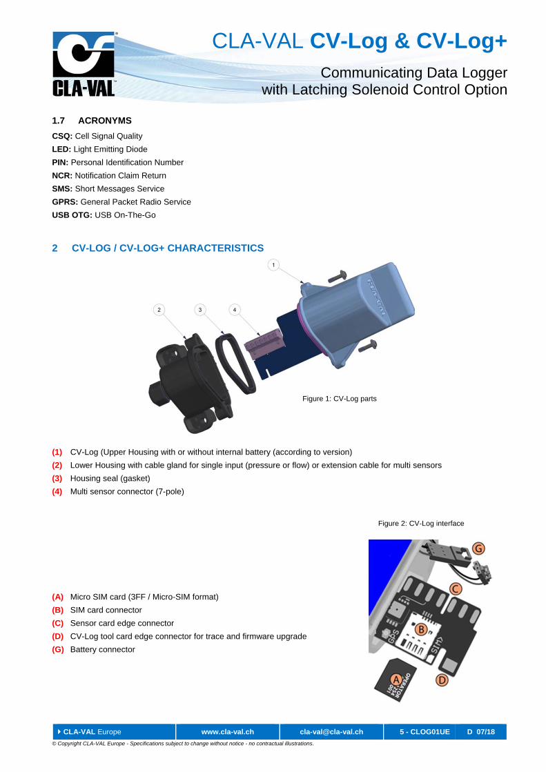
2 CV-LOG / CV-LOG+ CHARACTERISTICS
(1) CV-Log (Upper Housing with or without internal battery (according to version)
(2) Lower Housing with cable gland for single input (pressure or flow) or extension cable for multi sensors
(3) Housing seal (gasket)
(4) Multi sensor connector (7-pole)
(A) Micro SIM card (3FF / Micro-SIM format)
(B) SIM card connector
(C) Sensor card edge connector
(D) CV-Log tool card edge connector for trace and firmware upgrade
(G) Battery connector
Figure 1: CV-Log parts
Figure 2: CV-Log interface
CLA-VAL CV-Log & CV-Log+ Communicating Data Logger
with Latching Solenoid Control Option
CLA-VAL Europe www.cla-val.ch [email protected] 6 - CLOG01UE D 07/18
© Copyright CLA-VAL Europe - Specifications subject to change without notice - no contractual illustrations.
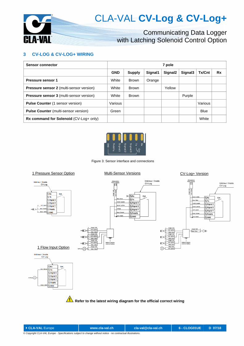
3 CV-LOG & CV-LOG+ WIRING
Sensor connector 7 pole
GND Supply Signal1 Signal2 Signal3 Tx/Cnt Rx
Pressure sensor 1 White Brown Orange
Pressure sensor 2 (multi-sensor version) White Brown Yellow
Pressure sensor 3 (multi-sensor version) White Brown Purple
Pulse Counter (1 sensor version) Various Various
Pulse Counter (multi-sensor version) Green Blue
Rx command for Solenoid (CV-Log+ only) White
Refer to the latest wiring diagram for the official correct wiring
1 Pressure Sensor Option
1 Flow Input Option
CV-Log+ Version Multi-Sensor Versions
Figure 3: Sensor interface and connections
CLA-VAL CV-Log & CV-Log+ Communicating Data Logger
with Latching Solenoid Control Option
CLA-VAL Europe www.cla-val.ch [email protected] 7 - CLOG01UE D 07/18
© Copyright CLA-VAL Europe - Specifications subject to change without notice - no contractual illustrations.
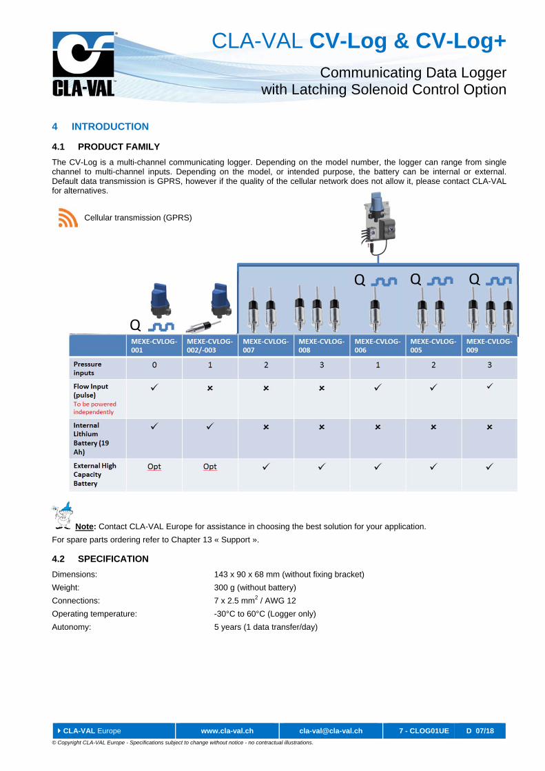
4 INTRODUCTION
4.1 PRODUCT FAMILY
The CV-Log is a multi-channel communicating logger. Depending on the model number, the logger can range from single channel to multi-channel inputs. Depending on the model, or intended purpose, the battery can be internal or external. Default data transmission is GPRS, however if the quality of the cellular network does not allow it, please contact CLA-VAL for alternatives.
Note: Contact CLA-VAL Europe for assistance in choosing the best solution for your application.
For spare parts ordering refer to Chapter 13 « Support ».
4.2 SPECIFICATION
Dimensions: 143 x 90 x 68 mm (without fixing bracket)
Weight: 300 g (without battery)
Connections: 7 x 2.5 mm2 / AWG 12
Operating temperature: -30°C to 60°C (Logger only)
Autonomy: 5 years (1 data transfer/day)
Cellular transmission (GPRS)
Q
Q Q Q
CLA-VAL CV-Log & CV-Log+ Communicating Data Logger
with Latching Solenoid Control Option
CLA-VAL Europe www.cla-val.ch [email protected] 8 - CLOG01UE D 07/18
© Copyright CLA-VAL Europe - Specifications subject to change without notice - no contractual illustrations.
5 SENSOR MOUNTING
5.1 PRESSURE SENSORS
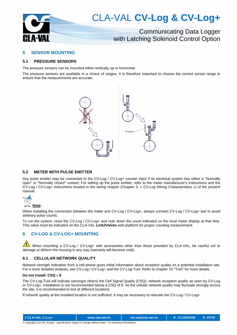
The pressure sensors can be mounted either vertically up or horizontal.
The pressure sensors are available in a choice of ranges. It is therefore important to choose the correct sensor range to ensure that the measurements are accurate.
5.2 METER WITH PULSE EMITTER
Any pulse emitter may be connected to the CV-Log / CV-Log+ counter input if its electrical system has either a "Normally open" or "Normally closed" contact. For setting up the pulse emitter, refer to the meter manufacturer’s instructions and the CV-Log / CV-Log+ instructions located in the wiring chapter (Chapter 3: « CV-Log Wiring Characteristics ») of the present manual.
Note:
When installing the connection between the meter and CV-Log / CV-Log+, always connect CV-Log / CV-Log+ last to avoid arbitrary pulse counts.
To run the system, reset the CV-Log / CV-Log+ and note down the count indicated on the local meter display at that time. This value must be indicated on the CLA-VAL Link2Valves web platform for proper counting measurement.
6 CV-LOG & CV-LOG+ MOUNTING
When mounting a CV-Log / CV-Log+ with accessories other than those provided by CLA-VAL, be careful not to damage or deform the housing in any way (warranty will become void).
6.1 CELLULAR NETWORK QUALITY
Network strength indication from a cell phone gives initial information about reception quality on a potential installation site. For a more detailed analysis, use CV-Log / CV-Log+ and the CV-Log-Tool. Refer to chapter 10 "Tool" for more details.
Do not install: CSQ 8
The CV-Log-Tool will indicate (amongst others) the Cell Signal Quality (CSQ), network reception quality as seen by CV-Log or CV-Log+. Installation is not recommended below a CSQ of 8. As the cellular network quality may fluctuate strongly across the site, it is recommended to test at different locations.
If network quality at the installed location is not sufficient, it may be necessary to relocate the CV-Log / CV-Log+.
CLA-VAL CV-Log & CV-Log+ Communicating Data Logger
with Latching Solenoid Control Option
CLA-VAL Europe www.cla-val.ch [email protected] 9 - CLOG01UE D 07/18
© Copyright CLA-VAL Europe - Specifications subject to change without notice - no contractual illustrations.
6.2 ORIENTATION IN SPACE
CV-Log / CV-Log+ should be mounted in an upright position (antenna side up, cable gland down) to guarantee longest battery lifetime and good cellular connectivity.
CV-Log / CV-Log+ may have difficulties transmitting when submerged (e.g. in a manhole after rainfall). To guarantee reliable transmission install it as high as possible.
6.3 WALL MOUNTED INSTALLATION
CV-Log is designed for direct fixing on walls using the two ears on the lower housing, one on each side and two screws (max 6 mm diameter). The shape of the ears allows fixing on straight and curved surfaces, e.g. the inside wall of a manhole.
Drill the holes at the correct distance (72 mm) or use the lower housing as a drilling gauge. The drilled holes must be perpendicular to the housing and not to the wall.
6.4 PIPE MOUNTED INSTALLATION
The T-shaped construction on the front side of the lower housing facilitates mounting on any horizontal or vertical pipe. Appropriate cable ties must be used to mount CV-Log on pipes.
6.4.1 HORIZONTAL PIPES
Two cable ties are required for optimal orientation of the CV-Log mounted on horizontal pipes. Tighten the first tie around the pipe while fastening the second one against the pipe with it. Then fasten CV-Log against the pipe using the second tie.
6.4.2 VERTICAL PIPES
CV-Log is directly fixed to vertical pipes using a single cable tie.
6.5 RECOMMENDED INSTALLATION
Depending on the GPRS network signal strength, the CV-Log/CV-Log+ installation might need to be changed. The network signal quality values mentioned below are indicative and correspond to a signal acquired with a High Performance Cellular Signal and Network Analyzer, reference: Siretta «SNYPER-LTE».
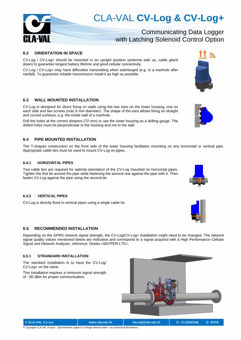
6.5.1 STRANDARD INSTALLATION
The standard installation is to have the CV-Log/ CV-Log+ on the valve.
This installation requires a minimum signal strength of - 80 dBm for proper communication.
CLA-VAL CV-Log & CV-Log+ Communicating Data Logger
with Latching Solenoid Control Option
CLA-VAL Europe www.cla-val.ch [email protected] 10 - CLOG01UE D 07/18
© Copyright CLA-VAL Europe - Specifications subject to change without notice - no contractual illustrations.
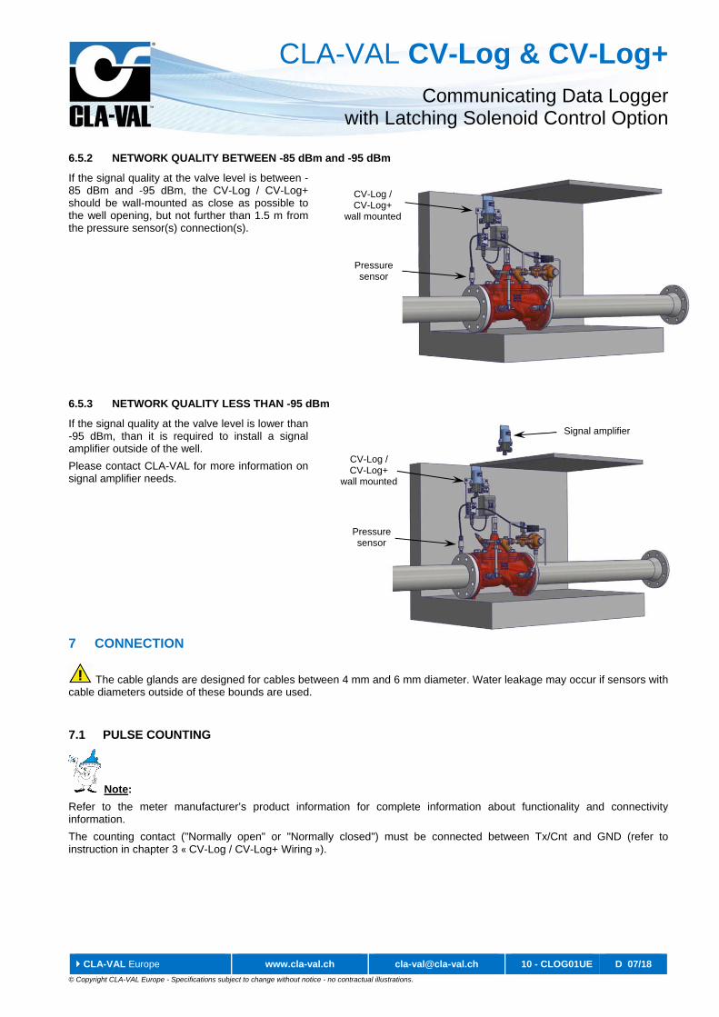
6.5.2 NETWORK QUALITY BETWEEN -85 dBm and -95 dBm
If the signal quality at the valve level is between -85 dBm and -95 dBm, the CV-Log / CV-Log+ should be wall-mounted as close as possible to the well opening, but not further than 1.5 m from the pressure sensor(s) connection(s).
6.5.3 NETWORK QUALITY LESS THAN -95 dBm
If the signal quality at the valve level is lower than -95 dBm, than it is required to install a signal amplifier outside of the well.
Please contact CLA-VAL for more information on signal amplifier needs.
7 CONNECTION
The cable glands are designed for cables between 4 mm and 6 mm diameter. Water leakage may occur if sensors with cable diameters outside of these bounds are used.
7.1 PULSE COUNTING
Note:
Refer to the meter manufacturer’s product information for complete information about functionality and connectivity information.
The counting contact ("Normally open" or "Normally closed") must be connected between Tx/Cnt and GND (refer to instruction in chapter 3 « CV-Log / CV-Log+ Wiring »).
CV-Log / CV-Log+
wall mounted
Pressure sensor
CV-Log / CV-Log+
wall mounted
Pressure sensor
Signal amplifier
CLA-VAL CV-Log & CV-Log+ Communicating Data Logger
with Latching Solenoid Control Option
CLA-VAL Europe www.cla-val.ch [email protected] 11 - CLOG01UE D 07/18
© Copyright CLA-VAL Europe - Specifications subject to change without notice - no contractual illustrations.
8 SIM CARD
8.1 PREPARING THE SIM CARD
CV-Log / CV-Log+ sends the collected data to a number read from the SIM card (A) (3FF / Micro-SIM format) provided by CLA-VAL. As such, the SIM card needs to be programmed with this number before being inserted in CV-Log or CV-Log+.
Contact CLA-VAL Europe if you need to use your SIM card.
8.2 INSERTING THE SIM CARD
Insert the SIM card with the golden contacts downwards into the card holder. Refer to Figure 2 - Chapter 2 « CV-Log Characteristics » and the symbol printed on CV-Log for correct SIM card orientation. The card must be completely inserted into the card holder. If the card is still overlapping the electronics card edge after insertion, remove it and check the card’s orientation.
9 STARTING SERVICE
If the CV-Log model used implements an internal battery, ensure it is connected to the battery connector inside the housing (Figure 2 - Chapter 2 « CV-Log Characteristics »).
If the external battery is used, the internal battery connector is already connected, and the product does not need to be opened.
9.1 INSTALLATION VALIDATION
The simplest and fastest way to verify the successful start of the product is to use the CV-Log-LED-Dongle tool.
For immediate in-depth control of all relevant parameters or when the web application platform is not available (e.g. mobile data communication not available at installation site), use the CV-Log-Tool (see Chapter 10 « Tools »).
9.2 CV-LOG & CV-LOG+ ASSEMBLY
Before re-assembly, ensure the inside of the housings and seal are clean and dry. Presence of dust or humidity when installing may shorten the lifetime of CV-Log / CV-Log+.
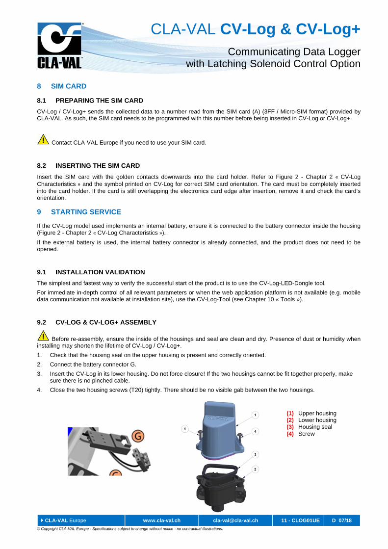
1. Check that the housing seal on the upper housing is present and correctly oriented.
2. Connect the battery connector G.
3. Insert the CV-Log in its lower housing. Do not force closure! If the two housings cannot be fit together properly, make sure there is no pinched cable.
4. Close the two housing screws (T20) tightly. There should be no visible gab between the two housings.
(1) Upper housing (2) Lower housing (3) Housing seal (4) Screw
CLA-VAL CV-Log & CV-Log+ Communicating Data Logger
with Latching Solenoid Control Option
CLA-VAL Europe www.cla-val.ch [email protected] 12 - CLOG01UE D 07/18
© Copyright CLA-VAL Europe - Specifications subject to change without notice - no contractual illustrations.
9.3 ACTIVATING CV-LOG & CV-LOG+
Once the following actions are performed
- Connected the battery & installed the sensor
- Inserted the SIM card (if not using the default CLA-VAL SIM card)
- Closed the housing
Place the magnet over the base of the upper housing and scroll the magnet on the edge beside the Activate / Reset arrow printed on the product label. This will start the first measurement and transmission cycle.
Video demo: https://youtu.be/FKXwdKIbraM
9.4 ACTIVATION FEEDBACK
Once CV-Log / CV-Log+ has sent its first data after activation, information about sensor readings and cellular network quality can be requested from the CLA-VAL Link2Valves web platform. For more information please refer to the Quick Start document.
10 TOOLS
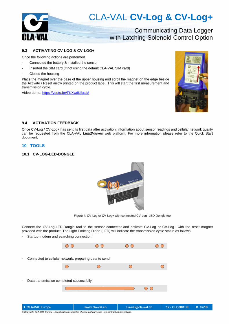
10.1 CV-LOG-LED-DONGLE
Connect the CV-Log-LED-Dongle tool to the sensor connector and activate CV-Log or CV-Log+ with the reset magnet provided with the product. The Light Emitting Diode (LED) will indicate the transmission cycle status as follows:
- Startup modem and searching connection:
- Connected to cellular network, preparing data to send:
- Data transmission completed successfully:
Figure 4: CV-Log or CV-Log+ with connected CV-Log -LED-Dongle tool
CLA-VAL CV-Log & CV-Log+ Communicating Data Logger
with Latching Solenoid Control Option
CLA-VAL Europe www.cla-val.ch [email protected] 13 - CLOG01UE D 07/18
© Copyright CLA-VAL Europe - Specifications subject to change without notice - no contractual illustrations.
- Data transmission trial failed:
In addition to visual feedback the CV-Log-LED-Dongle tool sets the sensor entries to a specific value for measurement validation.
The use of CV-Log-LED-Dongle tool in hazardous locations is strictly prohibited! Remove CV-Log / CV-Log+ from the installation site and test in a safe place, protected from environmental conditions.
10.2 CV-LOG-TOOL
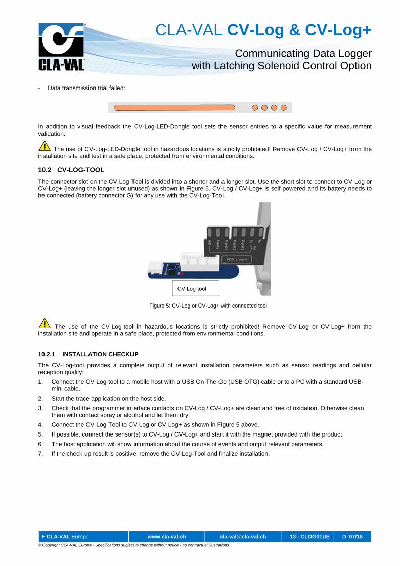
The connector slot on the CV-Log-Tool is divided into a shorter and a longer slot. Use the short slot to connect to CV-Log or CV-Log+ (leaving the longer slot unused) as shown in Figure 5. CV-Log / CV-Log+ is self-powered and its battery needs to be connected (battery connector G) for any use with the CV-Log-Tool.
The use of the CV-Log-tool in hazardous locations is strictly prohibited! Remove CV-Log or CV-Log+ from the installation site and operate in a safe place, protected from environmental conditions.
10.2.1 INSTALLATION CHECKUP
The CV-Log-tool provides a complete output of relevant installation parameters such as sensor readings and cellular reception quality:
1. Connect the CV-Log-tool to a mobile host with a USB On-The-Go (USB OTG) cable or to a PC with a standard USB-mini cable.
2. Start the trace application on the host side.
3. Check that the programmer interface contacts on CV-Log / CV-Log+ are clean and free of oxidation. Otherwise clean them with contact spray or alcohol and let them dry.
4. Connect the CV-Log-Tool to CV-Log or CV-Log+ as shown in Figure 5 above.
5. If possible, connect the sensor(s) to CV-Log / CV-Log+ and start it with the magnet provided with the product.
6. The host application will show information about the course of events and output relevant parameters.
7. If the check-up result is positive, remove the CV-Log-Tool and finalize installation.
CV-Log-tool
Figure 5: CV-Log or CV-Log+ with connected tool
CLA-VAL CV-Log & CV-Log+ Communicating Data Logger
with Latching Solenoid Control Option
CLA-VAL Europe www.cla-val.ch [email protected] 14 - CLOG01UE D 07/18
© Copyright CLA-VAL Europe - Specifications subject to change without notice - no contractual illustrations.
10.2.2 FIRMWARE UPDATE
1. Connect the CV-Log-Tool to a computer via a standard USB-mini cable. If this is a first-time-use, Microsoft® Windows® will install Silabs drivers. In this case, allow Windows® to install it automatically.
2. Check that the programmer interface contacts on CV-Log / CV-Log+ are clean and free of oxidation. Otherwise clean them with contact spray or alcohol and let them dry.
3. Connect the CV-Log-Tool to CV-Log or CV-Log+ as shown in Figure 5 / page 13.
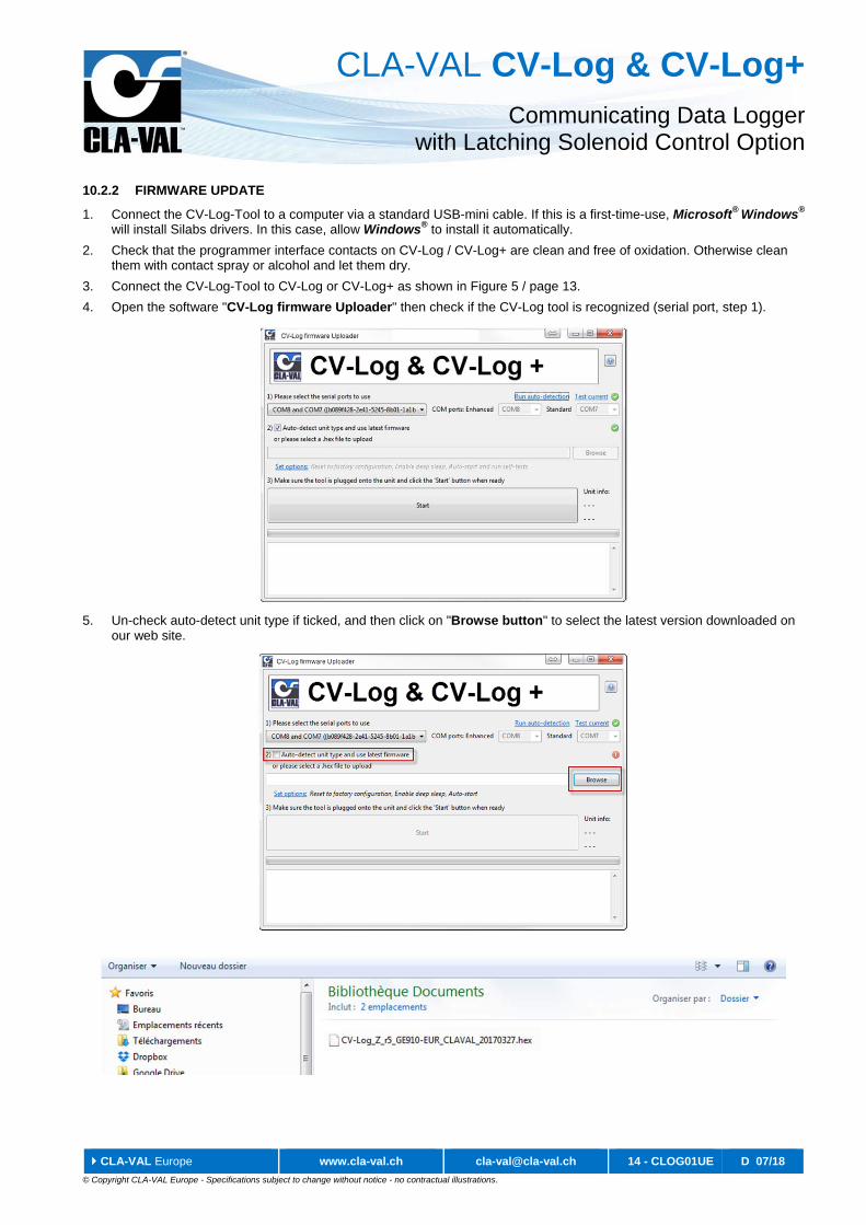
4. Open the software "CV-Log firmware Uploader" then check if the CV-Log tool is recognized (serial port, step 1).
5. Un-check auto-detect unit type if ticked, and then click on "Browse button" to select the latest version downloaded on our web site.
CLA-VAL CV-Log & CV-Log+ Communicating Data Logger
with Latching Solenoid Control Option
CLA-VAL Europe www.cla-val.ch [email protected] 15 - CLOG01UE D 07/18
© Copyright CLA-VAL Europe - Specifications subject to change without notice - no contractual illustrations.
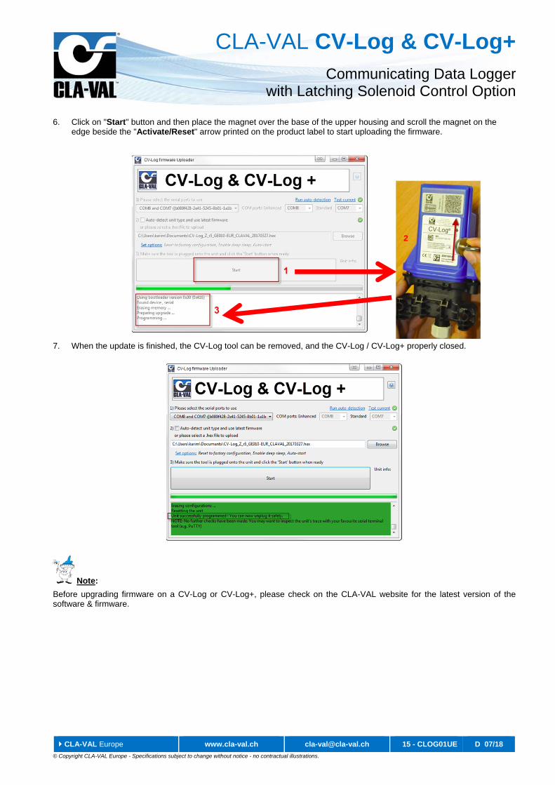
6. Click on "Start" button and then place the magnet over the base of the upper housing and scroll the magnet on the edge beside the "Activate/Reset" arrow printed on the product label to start uploading the firmware.
7. When the update is finished, the CV-Log tool can be removed, and the CV-Log / CV-Log+ properly closed.
Note:
Before upgrading firmware on a CV-Log or CV-Log+, please check on the CLA-VAL website for the latest version of the software & firmware.
2
CLA-VAL CV-Log & CV-Log+ Communicating Data Logger
with Latching Solenoid Control Option
CLA-VAL Europe www.cla-val.ch [email protected] 16 - CLOG01UE D 07/18
© Copyright CLA-VAL Europe - Specifications subject to change without notice - no contractual illustrations.
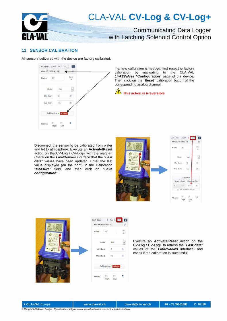
11 SENSOR CALIBRATION
All sensors delivered with the device are factory calibrated.
If a new calibration is needed, first reset the factory calibration by navigating to the CLA-VAL Link2Valves "Configuration" page of the device. Then click on the "Reset" calibration button of the corresponding analog channel.
This action is irreversible.
Disconnect the sensor to be calibrated from water and let to atmosphere. Execute an Activate/Reset action on the CV-Log / CV-Log+ with the magnet. Check on the Link2Valves interface that the "Last data" values have been updated. Enter the last value displayed (on the right) in the Calibration "Measure" field, and then click on "Save configuration".
Execute an Activate/Reset action on the CV-Log / CV-Log+ to refresh the "Last data" values of the Link2Valves interface, and check if the calibration is successful.
CLA-VAL CV-Log & CV-Log+ Communicating Data Logger
with Latching Solenoid Control Option
CLA-VAL Europe www.cla-val.ch [email protected] 17 - CLOG01UE D 07/18
© Copyright CLA-VAL Europe - Specifications subject to change without notice - no contractual illustrations.
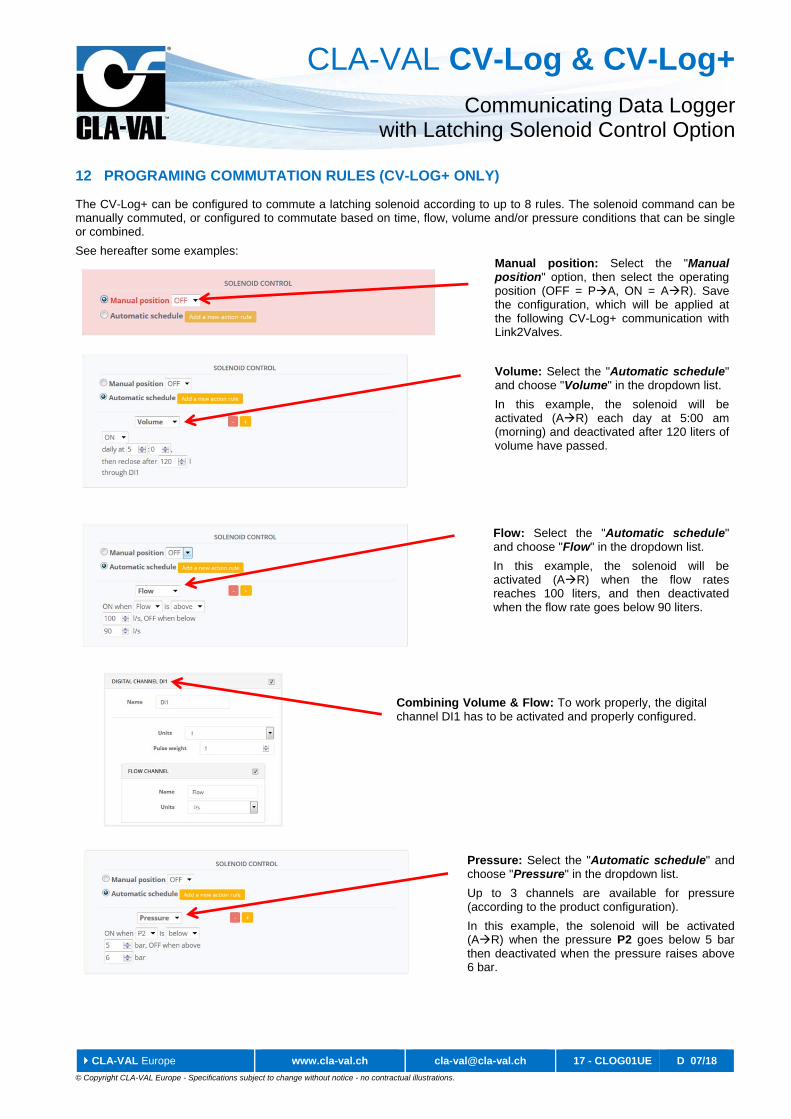
12 PROGRAMING COMMUTATION RULES (CV-LOG+ ONLY)
The CV-Log+ can be configured to commute a latching solenoid according to up to 8 rules. The solenoid command can be manually commuted, or configured to commutate based on time, flow, volume and/or pressure conditions that can be single or combined.
See hereafter some examples:
Combining Volume & Flow: To work properly, the digital channel DI1 has to be activated and properly configured.
Manual position: Select the "Manual position" option, then select the operating position (OFF = PA, ON = AR). Save the configuration, which will be applied at the following CV-Log+ communication with Link2Valves.
Volume: Select the "Automatic schedule" and choose "Volume" in the dropdown list.
In this example, the solenoid will be activated (AR) each day at 5:00 am (morning) and deactivated after 120 liters of volume have passed.
Flow: Select the "Automatic schedule" and choose "Flow" in the dropdown list.
In this example, the solenoid will be activated (AR) when the flow rates reaches 100 liters, and then deactivated when the flow rate goes below 90 liters.
Pressure: Select the "Automatic schedule" and choose "Pressure" in the dropdown list.
Up to 3 channels are available for pressure (according to the product configuration).
In this example, the solenoid will be activated (AR) when the pressure P2 goes below 5 bar then deactivated when the pressure raises above 6 bar.
CLA-VAL CV-Log & CV-Log+ Communicating Data Logger
with Latching Solenoid Control Option
CLA-VAL Europe www.cla-val.ch [email protected] 18 - CLOG01UE D 07/18
© Copyright CLA-VAL Europe - Specifications subject to change without notice - no contractual illustrations.
Note: Pay attention to the dead band. The following table summarizes the state of the solenoid, according to the condition:
Condition True Dead band False
Solenoid Activation ON (AR) Keep Value OFF (PA)
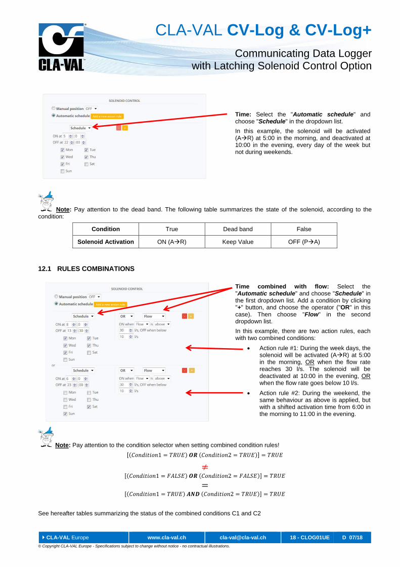
12.1 RULES COMBINATIONS
Note: Pay attention to the condition selector when setting combined condition rules!
1 2
1 2
1 2
See hereafter tables summarizing the status of the combined conditions C1 and C2
Time: Select the "Automatic schedule" and choose "Schedule" in the dropdown list.
In this example, the solenoid will be activated (AR) at 5:00 in the morning, and deactivated at 10:00 in the evening, every day of the week but not during weekends.
Time combined with flow: Select the "Automatic schedule" and choose "Schedule" in the first dropdown list. Add a condition by clicking "+" button, and choose the operator ("OR" in this case). Then choose "Flow" in the second dropdown list.
In this example, there are two action rules, each with two combined conditions:
Action rule #1: During the week days, the solenoid will be activated (AR) at 5:00 in the morning, OR when the flow rate reaches 30 l/s. The solenoid will be deactivated at 10:00 in the evening, OR when the flow rate goes below 10 l/s.
Action rule #2: During the weekend, the same behaviour as above is applied, but with a shifted activation time from 6:00 in the morning to 11:00 in the evening.
CLA-VAL CV-Log & CV-Log+ Communicating Data Logger
with Latching Solenoid Control Option
CLA-VAL Europe www.cla-val.ch [email protected] 19 - CLOG01UE D 07/18
© Copyright CLA-VAL Europe - Specifications subject to change without notice - no contractual illustrations.
OR condition (Condition1 OR Condition2)
Condition1 Condition2 Solenoid Activation
(C1 OR C2)
FALSE FALSE OFF (PA)
TRUE FALSE ON (AR)
FALSE TRUE ON (AR)
TRUE TRUE ON (AR)
AND condition (Condition1 AND Condition2)
Condition1 Condition2 Solenoid Activation
(C1 & C2)
FALSE FALSE OFF (PA)
TRUE FALSE OFF (PA)
FALSE TRUE OFF (PA)
TRUE TRUE ON (AR)
13 SUPPORT
13.1 MAINTENANCE AND RETROFIT
CV-Log / CV-Log+ is maintenance-free over the entire battery lifetime, which depends on the measurement and transmission frequencies settings (which are remotely configurable). However, environmental conditions may shorten battery lifetime and the presence of humidity inside the housing lead to corrosion. Prevent these situations with clean and robust installations.
When the battery reaches its end-of-life, ask CLA-VAL, or an authorized reseller for maintenance assistance to change the battery, update the device to the most current Firmware, and test the system.
13.2 NON-CONFORMITY RETURN (NCR)
Only return CV-Log / CV-Log+ under warranty after attribution of an Equipment Return Authorization provided by CLA-VAL Europe. The returned CV-Log or CV-Log+ must be clearly marked with the Non-Conformity (NCR) number.
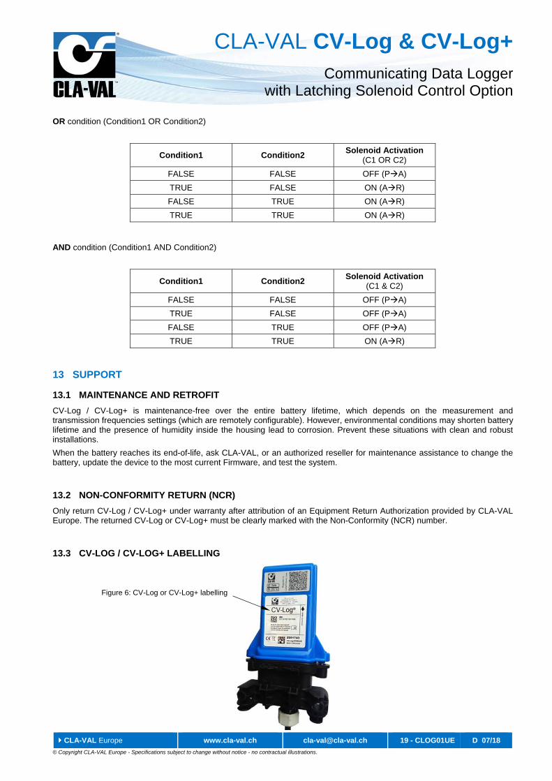
13.3 CV-LOG / CV-LOG+ LABELLING
Figure 6: CV-Log or CV-Log+ labelling
CLA-VAL CV-Log & CV-Log+ Communicating Data Logger
with Latching Solenoid Control Option
CLA-VAL Europe www.cla-val.ch [email protected] 20 - CLOG01UE D 07/18
© Copyright CLA-VAL Europe - Specifications subject to change without notice - no contractual illustrations.
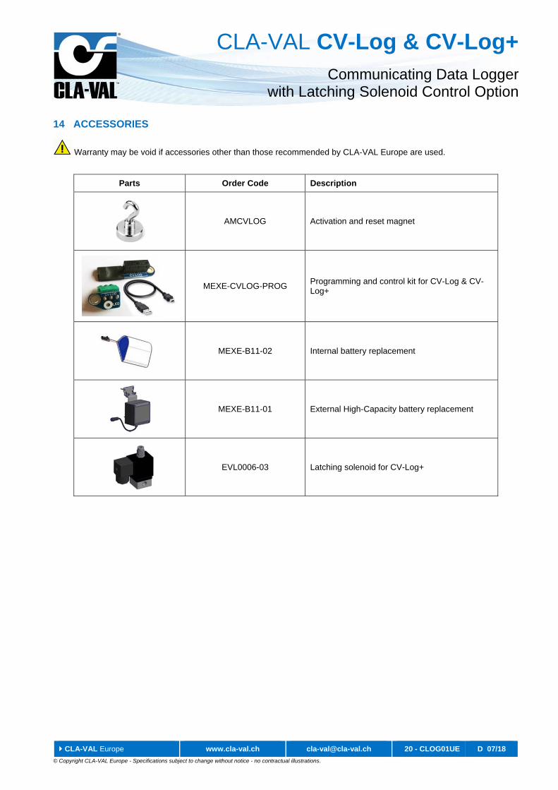
14 ACCESSORIES
Warranty may be void if accessories other than those recommended by CLA-VAL Europe are used.
Parts Order Code Description
AMCVLOG Activation and reset magnet
MEXE-CVLOG-PROG Programming and control kit for CV-Log & CV-Log+
MEXE-B11-02 Internal battery replacement
MEXE-B11-01 External High-Capacity battery replacement
EVL0006-03 Latching solenoid for CV-Log+


![Axa Magnet - Presentasi AXA Magnet [ Maestro Global Network ] Terbaru](https://img.pdfslide.net/doc/110x75/55d2ed27bb61ebdd398b462f/axa-magnet-presentasi-axa-magnet-maestro-global-network-terbaru.jpg)