Embed Size (px)
Citation preview
Clara Gaspar, September 2010
Data Acquisition, Trigger and
Control
22Clara Gaspar, September 2010
Definitions
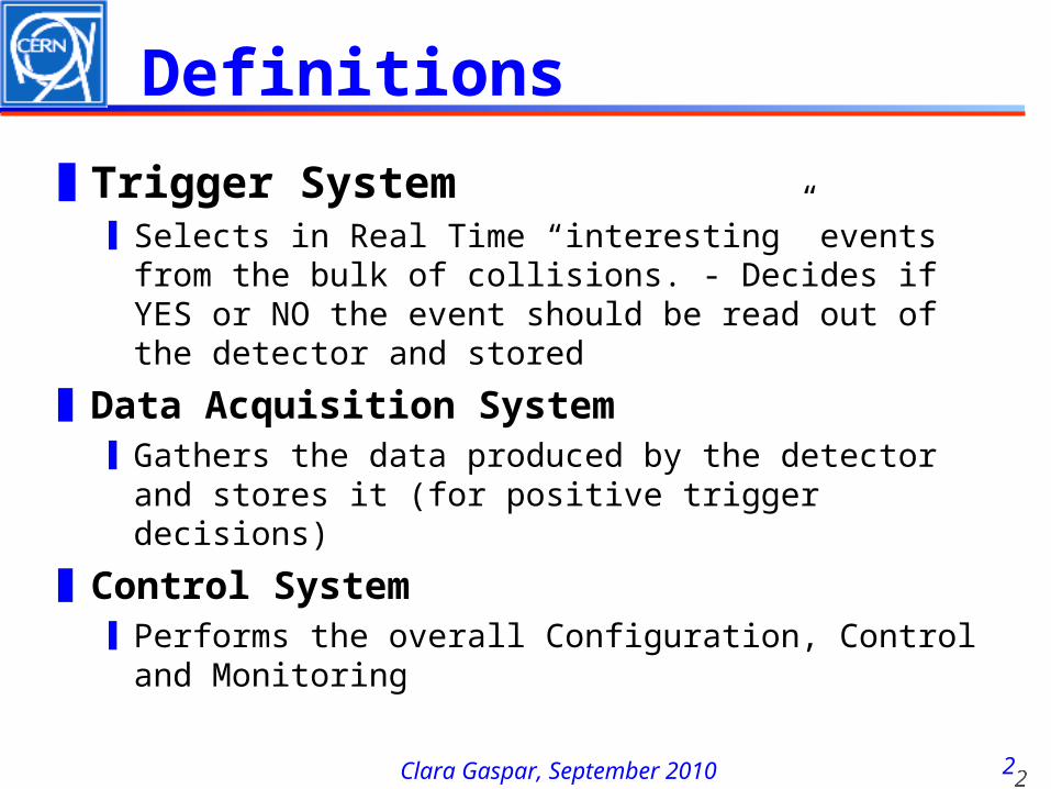
❚Trigger System❙Selects in Real Time “interesting” events from
the bulk of collisions. - Decides if YES or NO the event should be read out of the detector and stored
❚Data Acquisition System❙Gathers the data produced by the detector and
stores it (for positive trigger decisions)
❚Control System❙Performs the overall Configuration, Control and
Monitoring
33Clara Gaspar, September 2010
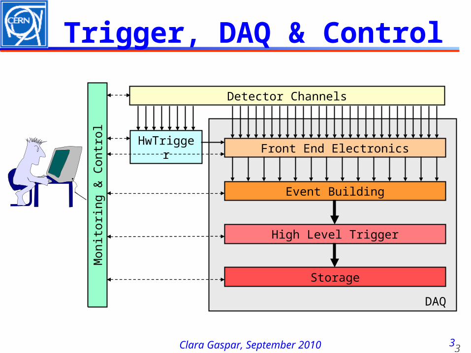
Trigger, DAQ & Control
Detector Channels
Front End Electronics
Event Building
High Level Trigger
Storage
HwTrigger
Monit
ori
ng &
Contr
ol
DAQ
44Clara Gaspar, September 2010
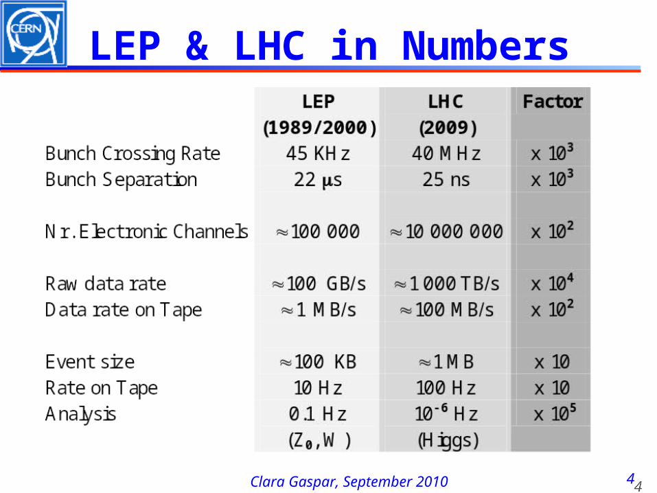
LEP & LHC in Numbers
Clara Gaspar, September 2010
Basic Concepts
66Clara Gaspar, September 2010
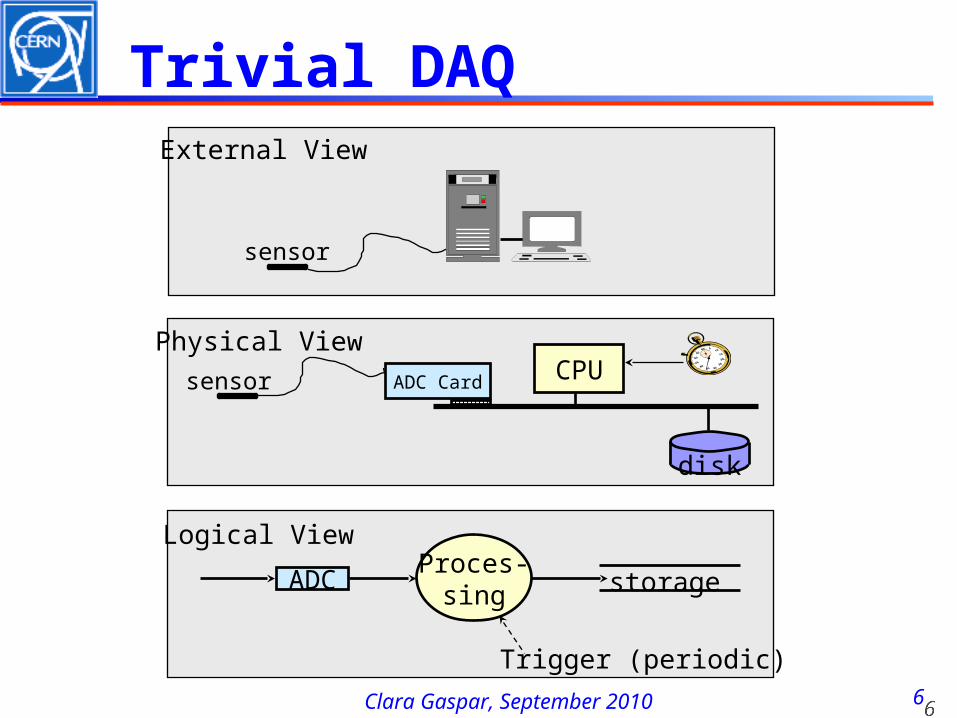
Trivial DAQExternal View
sensor
ADC Cardsensor CPU
disk
Physical View
ADC storage
Trigger (periodic)
Logical ViewProces-
sing
77Clara Gaspar, September 2010
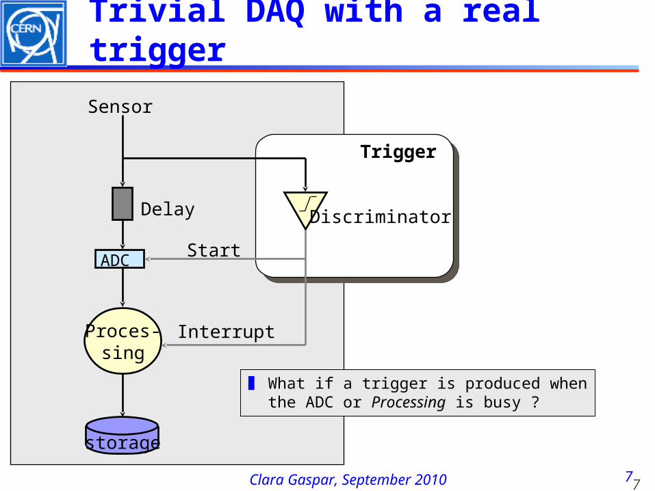
Trivial DAQ with a real trigger
ADC
Sensor
Delay
Proces-sing
Interrupt
Discriminator
Trigger
Start
storage
❚ What if a trigger is produced when the ADC or Processing is busy ?
88Clara Gaspar, September 2010
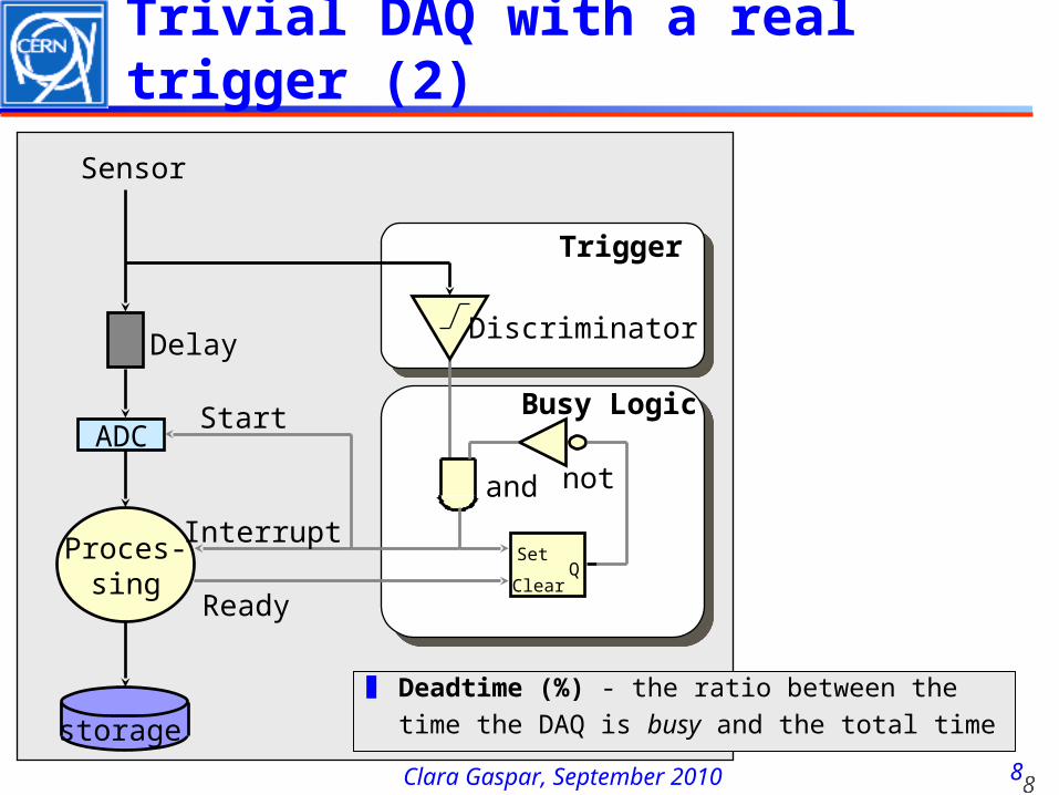
Trivial DAQ with a real trigger (2)
ADC
Sensor
Delay
Proces-sing
Interrupt
Discriminator
Trigger
Start
SetQ
Clear
and not
Busy Logic
Ready
storage
❚ Deadtime (%) - the ratio between the time the DAQ is busy and the total time
99Clara Gaspar, September 2010
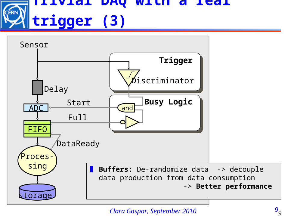
Trivial DAQ with a real trigger (3)
ADC
Sensor
Delay
Proces-sing
Discriminator
Trigger
Start Busy Logic
FIFO
Full
DataReady
and
storage
❚ Buffers: De-randomize data -> decouple data production from data consumption -> Better performance
1010Clara Gaspar, September 2010
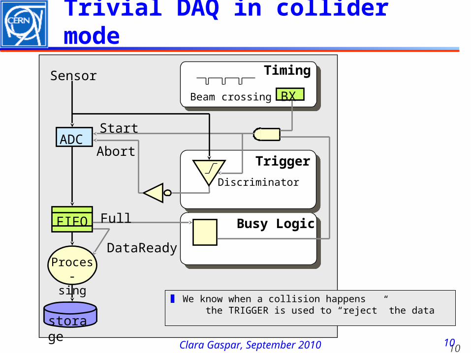
Trivial DAQ in collider mode
ADC
Sensor
Proces-sing
Discriminator
Trigger
Start
storage
Busy LogicFIFO
DataReady
Timing
BX
Abort
Beam crossing
Full
❚ We know when a collision happens the TRIGGER is used to “reject” the data
1111Clara Gaspar, September 2010
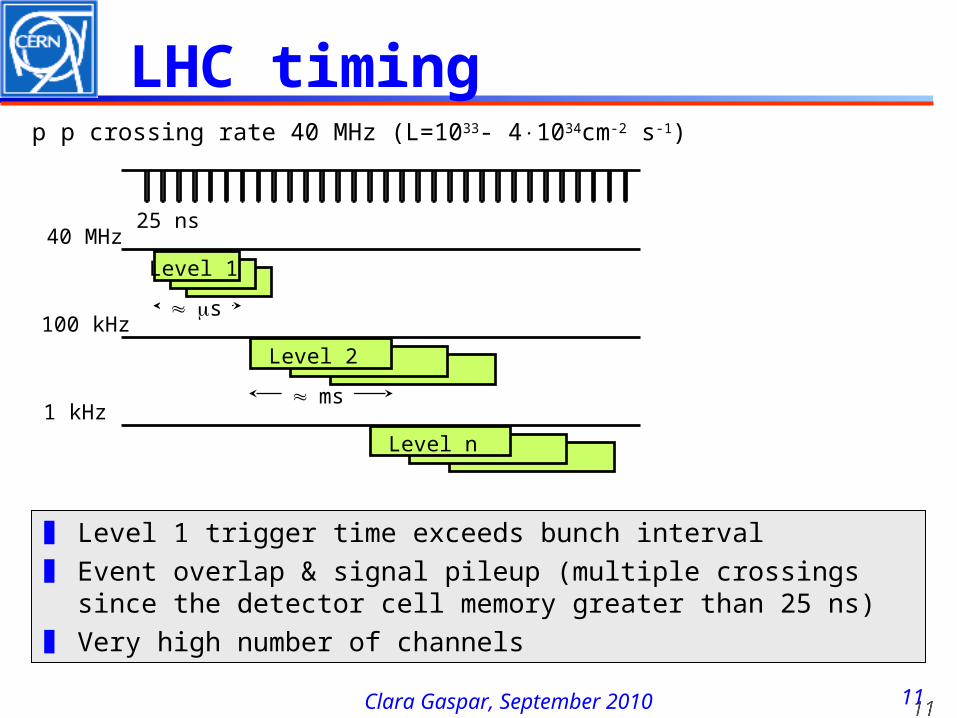
LHC timing
s
p p crossing rate 40 MHz (L=1033- 41034cm-2 s-1)
25 ns
Level 1
40 MHz
ms
Level 2
100 kHz
Level n
1 kHz
❚ Level 1 trigger time exceeds bunch interval❚ Event overlap & signal pileup (multiple crossings since the
detector cell memory greater than 25 ns)❚ Very high number of channels
1212Clara Gaspar, September 2010
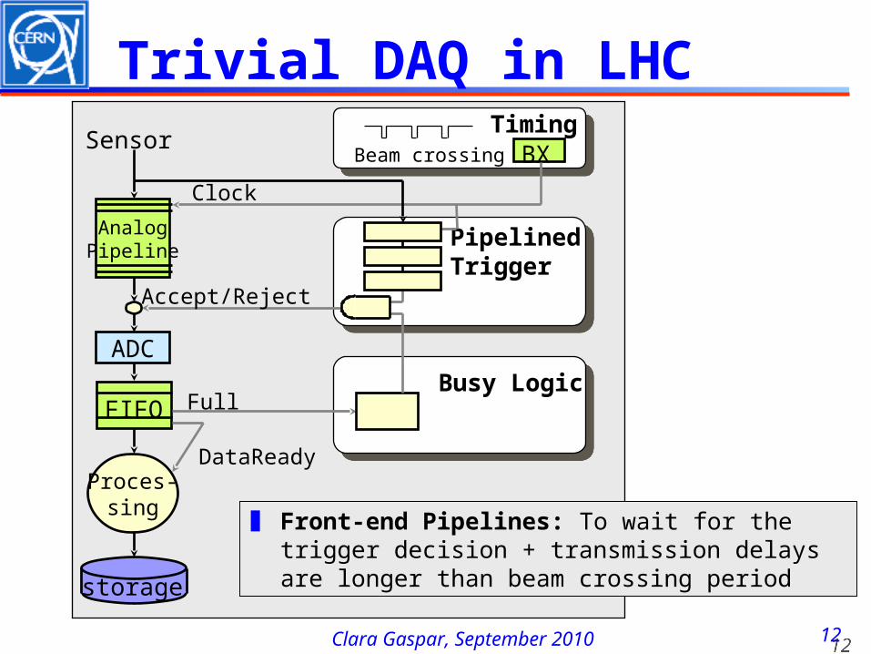
Trivial DAQ in LHC
ADC
Sensor
Proces-sing
PipelinedTrigger
Clock
storage
Busy LogicFIFO
DataReady
TimingBX
Accept/Reject
Beam crossing
Full
AnalogPipeline
❚ Front-end Pipelines: To wait for the trigger decision + transmission delays are longer than beam crossing period
1313Clara Gaspar, September 2010
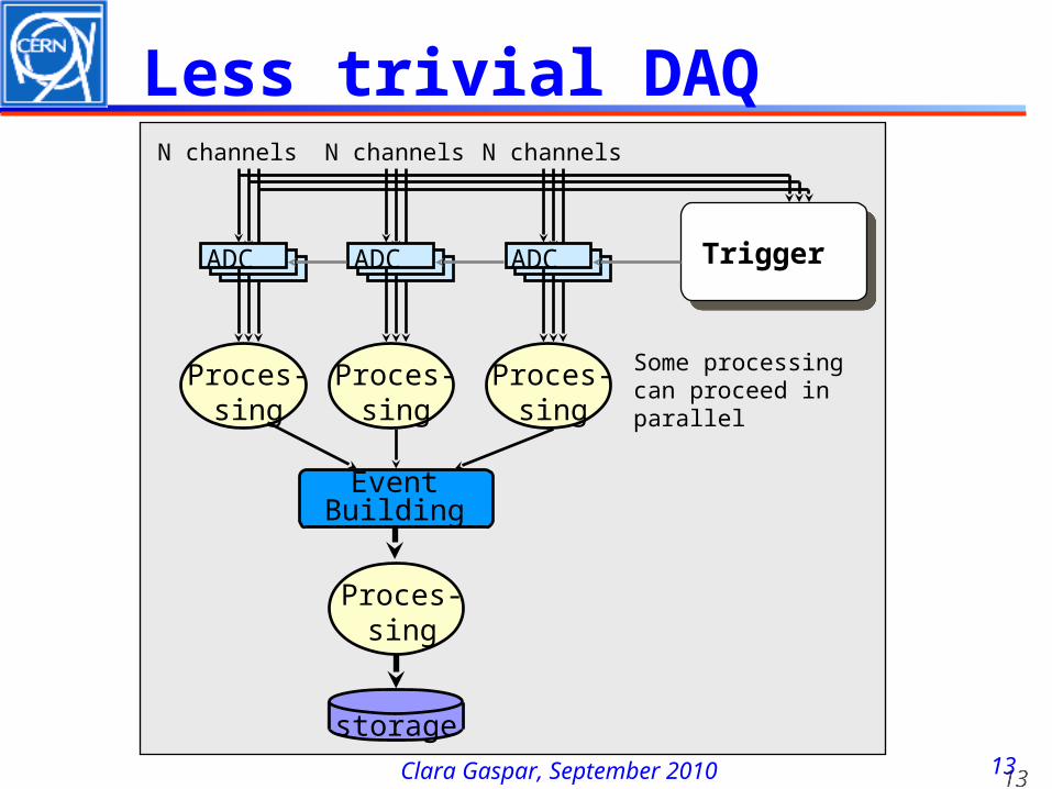
Less trivial DAQ
ADC
N channels
Proces-sing
storage
ADC
Proces-sing
N channels
ADC
Proces-sing
N channels
Trigger
Some processingcan proceed in parallel
Proces-sing
EventBuilding
1414Clara Gaspar, September 2010
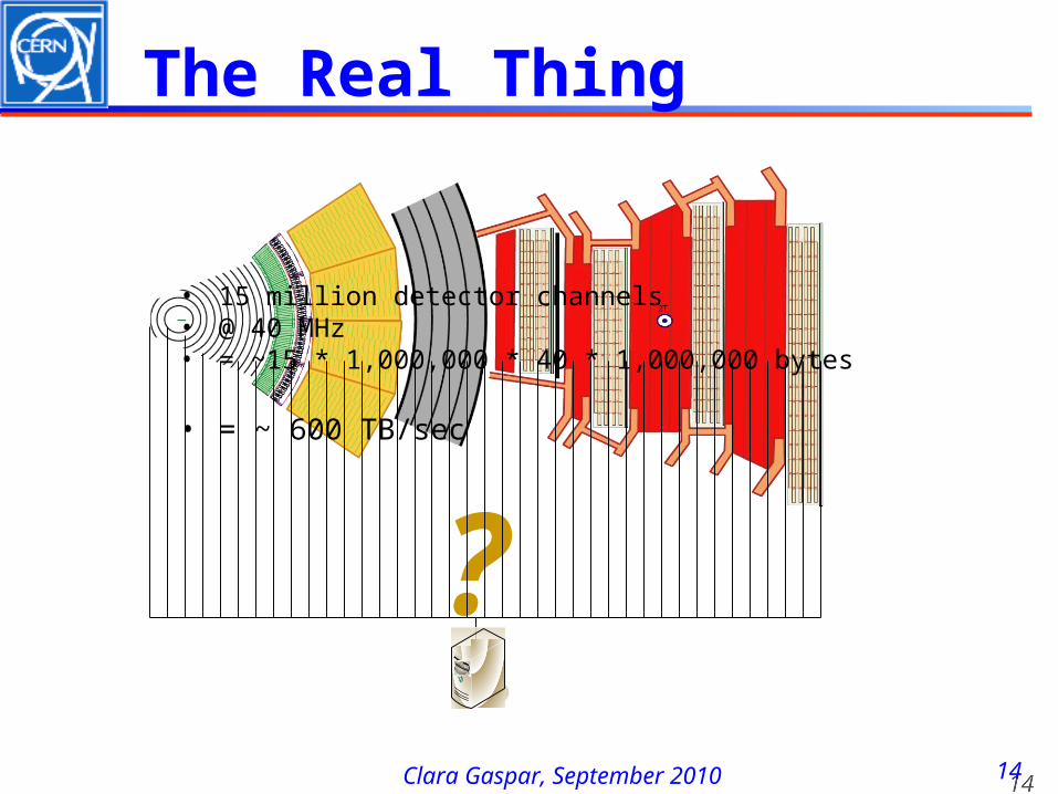
The Real Thing
?
• 15 million detector channels• @ 40 MHz• = ~15 * 1,000,000 * 40 * 1,000,000 bytes
• = ~ 600 TB/sec
Clara Gaspar, September 2010
Trigger
1616Clara Gaspar, September 2010
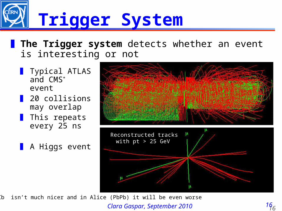
Trigger System
Reconstructed tracks with pt > 25 GeV
❚ Typical ATLAS and CMS* event
❚ 20 collisions may overlap
❚ This repeats every 25 ns
❚ A Higgs event
❚ The Trigger system detects whether an event is interesting or not
*)LHCb isn’t much nicer and in Alice (PbPb) it will be even worse
1717Clara Gaspar, September 2010
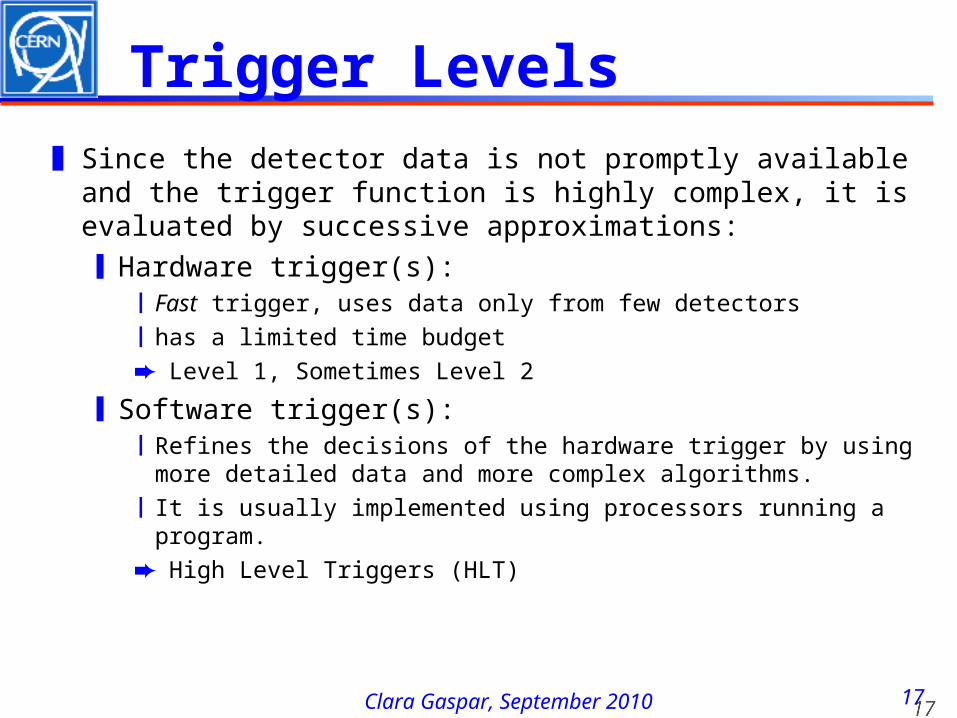
Trigger Levels❚ Since the detector data is not promptly available
and the trigger function is highly complex, it is evaluated by successive approximations:❙Hardware trigger(s):
❘Fast trigger, uses data only from few detectors❘has a limited time budget ➨ Level 1, Sometimes Level 2
❙Software trigger(s): ❘Refines the decisions of the hardware trigger by using
more detailed data and more complex algorithms. ❘It is usually implemented using processors running a
program.➨ High Level Triggers (HLT)
1818Clara Gaspar, September 2010
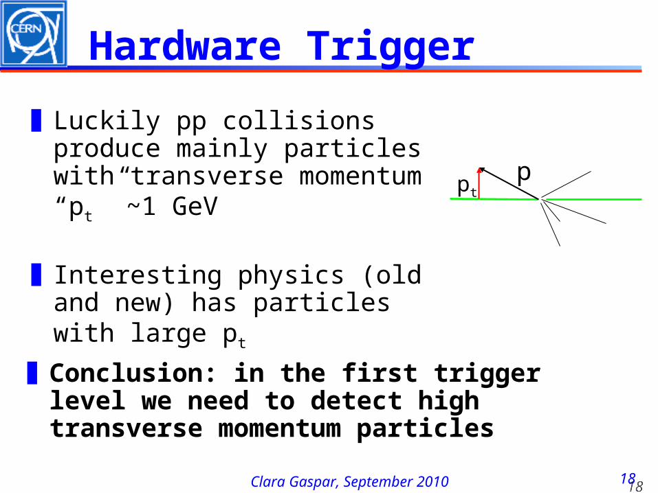
❚Luckily pp collisions produce mainly particles with transverse momentum “pt ”
~1 GeV
❚Interesting physics (old and new) has particles with large pt
ptp
Hardware Trigger
❚Conclusion: in the first trigger level we need to detect high transverse momentum particles
1919Clara Gaspar, September 2010
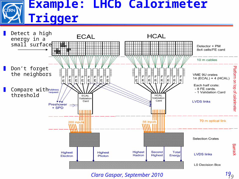
Example: LHCb Calorimeter Trigger
❚ Detect a high energy in a small surface
❚ Don’t forget the neighbors
❚ Compare with threshold
2020Clara Gaspar, September 2010
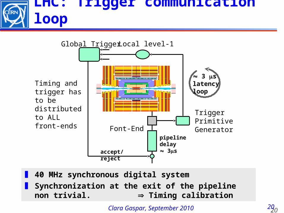
LHC: Trigger communication loop
TriggerPrimitiveGeneratorFont-End
Local level-1Global Trigger
accept/reject
pipeline delay 3s
3 slatencyloop
Timing and trigger has to be distributed to ALL front-ends
❚ 40 MHz synchronous digital system❚ Synchronization at the exit of the pipeline non
trivial. Timing calibration
2121Clara Gaspar, September 2010
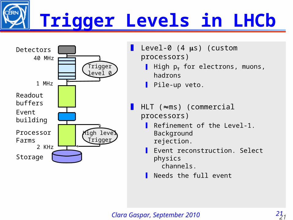
Trigger Levels in LHCb
Triggerlevel 0
Event building
High levelTrigger
ProcessorFarms
Storage
Detectors
Readoutbuffers
40 MHz
1 MHz
❚ Level-0 (4 s) (custom processors)❙ High pT for electrons, muons, hadrons
❙ Pile-up veto.
❚ HLT (ms) (commercial processors)❙ Refinement of the Level-1. Background
rejection.❙ Event reconstruction. Select physics
channels.❙ Needs the full event
2 KHz
2222Clara Gaspar, September 2010
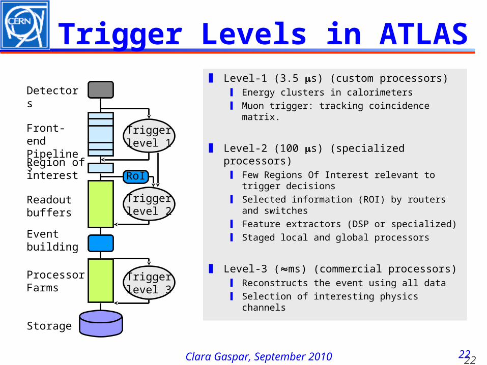
Trigger Levels in ATLAS
Triggerlevel 1
Triggerlevel 2
Front-endPipelines
Event building
Triggerlevel 3
ProcessorFarms
Storage
Detectors
RoI
Readoutbuffers
Region ofinterest
❚ Level-1 (3.5 s) (custom processors)❙ Energy clusters in calorimeters❙ Muon trigger: tracking coincidence matrix.
❚ Level-2 (100 s) (specialized processors)❙ Few Regions Of Interest relevant to trigger
decisions❙ Selected information (ROI) by routers and
switches❙ Feature extractors (DSP or specialized)❙ Staged local and global processors
❚ Level-3 (ms) (commercial processors)❙ Reconstructs the event using all data❙ Selection of interesting physics channels
Clara Gaspar, September 2010
Data Acquisition
2424Clara Gaspar, September 2010
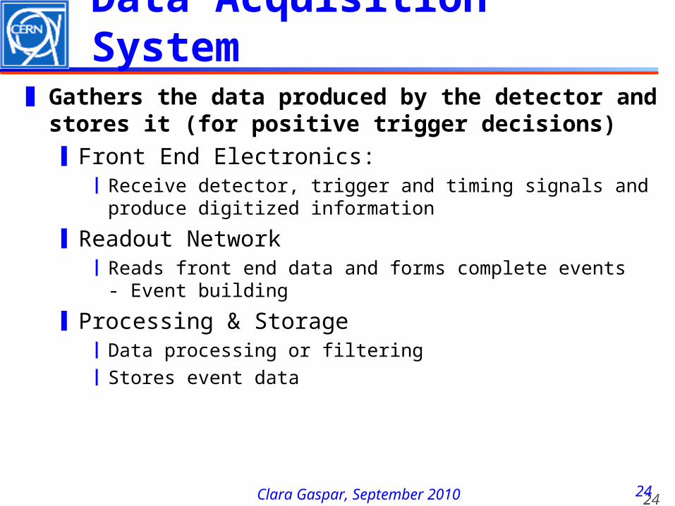
Data Acquisition System
❚ Gathers the data produced by the detector and stores it (for positive trigger decisions)❙Front End Electronics:
❘Receive detector, trigger and timing signals and produce digitized information
❙Readout Network❘Reads front end data and forms complete events
- Event building
❙Processing & Storage❘Data processing or filtering❘Stores event data
2525Clara Gaspar, September 2010
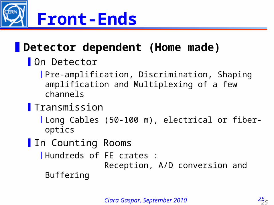
Front-Ends
❚Detector dependent (Home made)❙On Detector
❘Pre-amplification, Discrimination, Shaping amplification and Multiplexing of a few channels
❙Transmission❘Long Cables (50-100 m), electrical or fiber-
optics
❙In Counting Rooms❘Hundreds of FE crates :
Reception, A/D conversion and Buffering
2626Clara Gaspar, September 2010
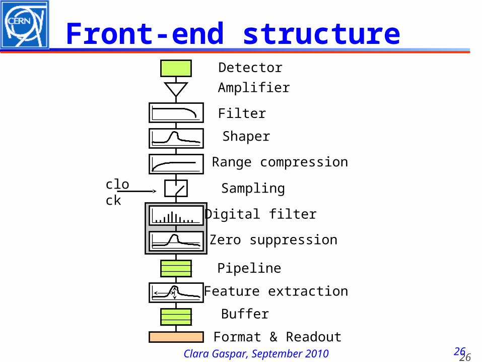
Front-end structure
Amplifier
Filter
Shaper
Range compression
clock
Sampling
Digital filter
Zero suppression
Pipeline
Format & Readout
Buffer
Feature extraction
Detector
2727Clara Gaspar, September 2010
DAQ Readout
❚Event-data are now digitized, pre-processed and tagged with a unique, monotonically increasing number
❚But distributed over many read-out boards (“sources”)
❚For the next stage of selection, or even simply to write it to tape we have to get the pieces together: Event Building
2828Clara Gaspar, September 2010
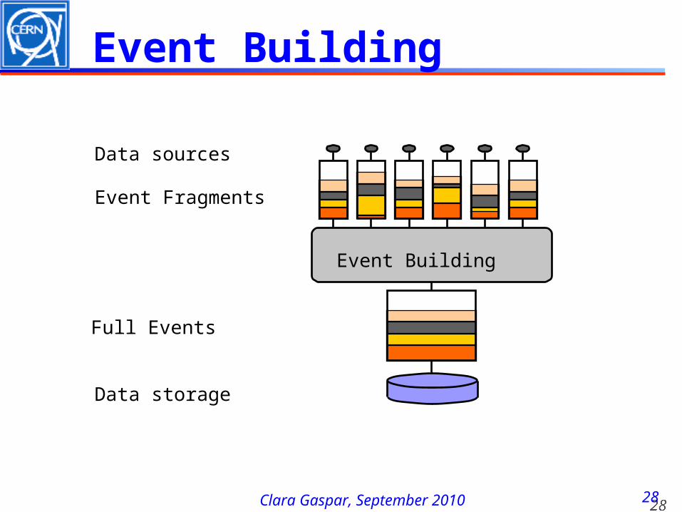
Event Building
Data sources
Event Fragments
Event Building
Data storage
Full Events
2929Clara Gaspar, September 2010
Event Filters
Event building
Triggerlevel 3,4
Event filter
Storage
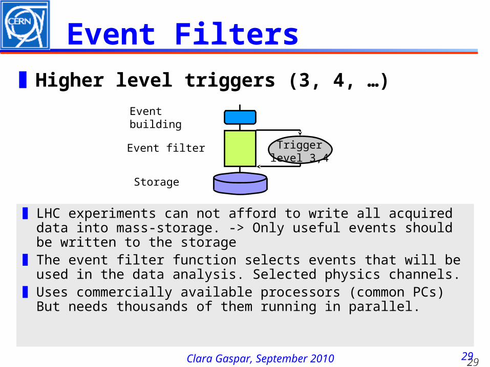
❚ LHC experiments can not afford to write all acquired data into mass-storage. -> Only useful events should be written to the storage
❚ The event filter function selects events that will beused in the data analysis. Selected physics channels.
❚ Uses commercially available processors (common PCs)But needs thousands of them running in parallel.
❚Higher level triggers (3, 4, …)
3030Clara Gaspar, September 2010
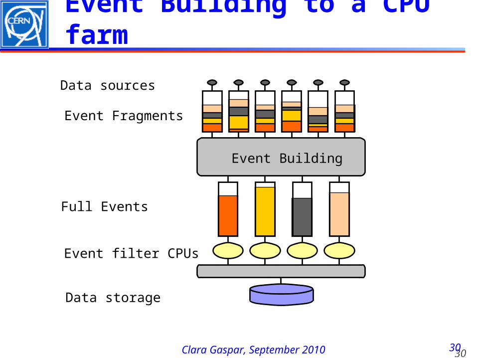
Event Building to a CPU farm
Data sources
Event Fragments
Event Building
Data storage
Full Events
Event filter CPUs
3131Clara Gaspar, September 2010
datasources
dataprocessors
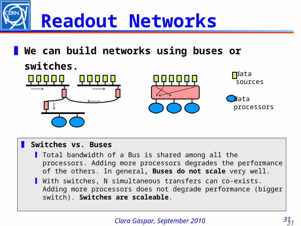
Readout Networks❚ We can build networks using buses or
switches.
❚ Switches vs. Buses❙ Total bandwidth of a Bus is shared among all the processors.
Adding more processors degrades the performance of the others. In general, Buses do not scale very well.
❙ With switches, N simultaneous transfers can co-exists. Adding more processors does not degrade performance (bigger switch). Switches are scaleable.
3232Clara Gaspar, September 2010
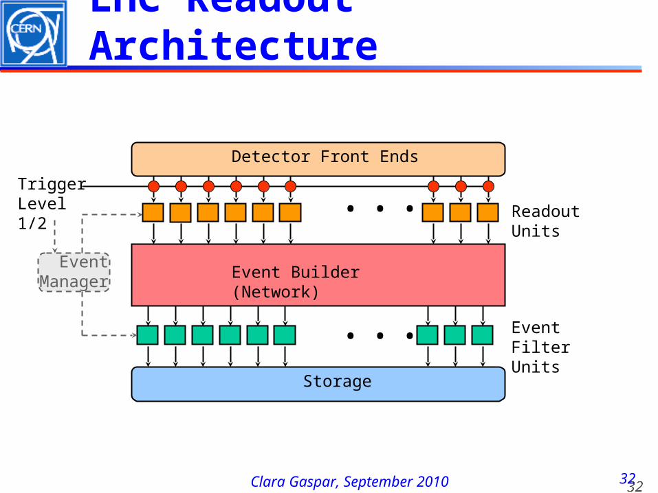
LHC Readout Architecture
Detector Front Ends
Event Builder (Network)
Storage
Readout Units
Event Filter Units
Event Manager
Trigger Level 1/2
...
...
3333Clara Gaspar, September 2010
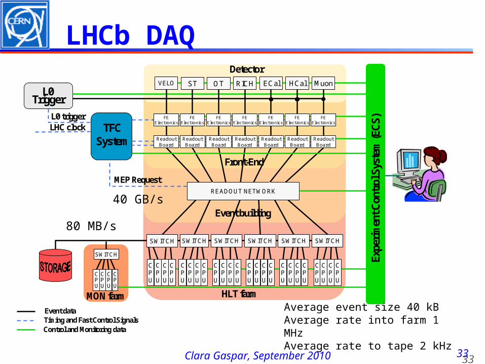
SWITCH
HLT farm
Detector
TFC System
SWITCHSWITCH SWITCH SWITCH SWITCH SWITCH
READOUT NETWORK
L0 triggerLHC clock
MEP Request
Event building
Front-End
CPU
CPU
CPU
CPU
CPU
CPU
CPU
CPU
CPU
CPU
CPU
CPU
CPU
CPU
CPU
CPU
CPU
CPU
CPU
CPU
CPU
CPU
CPU
CPU
Readout Board
Expe
rimen
t Con
trol
Sys
tem
(EC
S)
VELO ST OT RICH ECal HCal MuonL0
Trigger
Event dataTiming and Fast Control SignalsControl and Monitoring data
SWITCH
MON farm
CPU
CPU
CPU
CPU
Readout Board
Readout Board
Readout Board
Readout Board
Readout Board
Readout Board
FEElectronics
FEElectronics
FEElectronics
FEElectronics
FEElectronics
FEElectronics
FEElectronics
40 GB/s
80 MB/s
Average event size 40 kBAverage rate into farm 1 MHzAverage rate to tape 2 kHz
LHCb DAQ
3434Clara Gaspar, September 2010
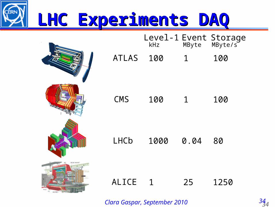
LHC Experiments DAQLHC Experiments DAQ Level-1 Event Storage kHz MByte MByte/s ATLAS 100 1 100 CMS 100 1 100 LHCb 1000 0.04 80 ALICE 1 25 1250
Clara Gaspar, September 2010
Configuration, Control and Monitoring
3636Clara Gaspar, September 2010
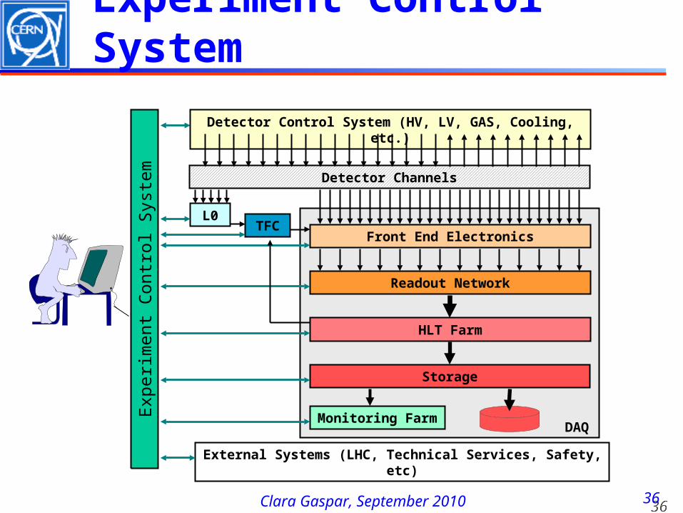
Experiment Control System
Detector Channels
Front End Electronics
Readout Network
HLT Farm
Storage
L0
Experi
men
t C
on
trol S
yst
em
DAQ
Detector Control System (HV, LV, GAS, Cooling, etc.)
External Systems (LHC, Technical Services, Safety, etc)
TFC
Monitoring Farm
3737Clara Gaspar, September 2010
Control System
❚Control System Tasks❙Configuration
❘Loading of parameters (according to RUN type)❘Enabling/disabling parts of the experiment
❙Partitioning❘Ability to run parts of the experiment in stand-
alone mode simultaneously
❙Monitoring, Error Reporting & Recovery❘Detect and recover problems as fast as possible
❙User Interfacing
3838Clara Gaspar, September 2010
LHC Control Systems
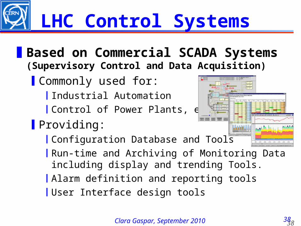
❚Based on Commercial SCADA Systems (Supervisory Control and Data Acquisition)
❙Commonly used for:❘Industrial Automation❘Control of Power Plants, etc.
❙Providing:❘Configuration Database and Tools❘Run-time and Archiving of Monitoring Data including
display and trending Tools.❘Alarm definition and reporting tools❘User Interface design tools
3939Clara Gaspar, September 2010
Control Automation
❚Experiment runs 24/24 7/7❚Only 2 (non-expert) operators❚Automation
❙Avoids human mistakes and speeds up standard procedures
❙What can be automated❘Standard Procedures (Start of fill, End of fill)❘Detection and Recovery from (known) error
situations
❙How❘Finite State Machine tools❘Expert System Type Tools (automated rules)
4040Clara Gaspar, September 2010
Monitoring
❚Two types of Monitoring❙Monitor Experiment’s Behaviour
❘Automation tools whenever possible❘Good (homogeneous) User Interface
❙Monitor the quality of the data❘Automatic histogram production and analysis❘User Interfaced histogram analysis❘Event displays (raw data)
4141Clara Gaspar, September 2010
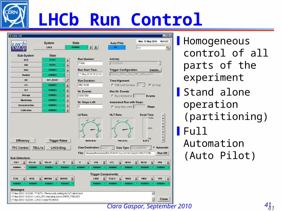
LHCb Run Control❙Homogeneous
control of all parts of the experiment
❙Stand alone operation (partitioning)
❙Full Automation (Auto Pilot)
4242Clara Gaspar, September 2010
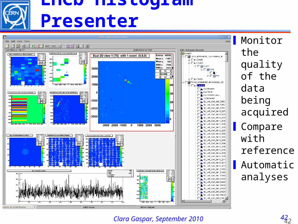
LHCb Histogram Presenter
❙Monitor the quality of the data being acquired
❙Compare with reference
❙Automatic analyses
4343Clara Gaspar, September 2010
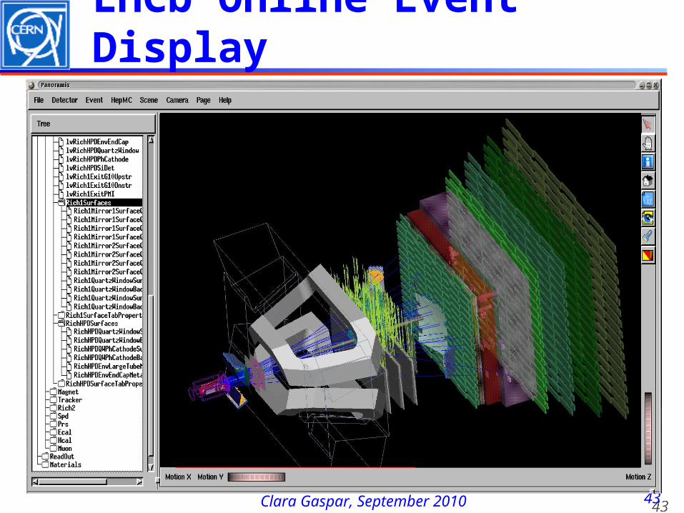
LHCb Online Event Display
4444Clara Gaspar, September 2010
Concluding Remarks❚ Trigger and Data Acquisition systems are becoming
increasingly complex. ❚ Luckily the requirements of telecommunications and
computing in general have strongly contributed to the development of standard technologies:❙ Hardware: Flash ADCs, Analog memories, PCs, Networks,
Helical scan recording, Data compression, Image processing, ...
❙ Software: Distributed computing, Software development environments, Supervisory systems, ...
❚ We can now build a large fraction of our systems using commercial components (customization will still be needed in the front-end).
❚ It is essential that we keep up-to-date with the progress being made by industry.