Embed Size (px)
Citation preview

CLARREO on JEM-ISS: Accommodation Feasibility
CLARREO Science Definition Team Meeting Laboratory for Atmospheric and Space Physics (LASP)
Boulder, CO October 16-18, 2012
Barry Dunn, Paul Speth, Carlos Roithmayr NASA Langley Research Center
Hampton, VA

Overview!• This study was initiated to determine the engineering feasibility of hosting
the combined CLARREO MCR reflected solar and infrared instruments on the ISS.
• The “Kibo” - Japanese Experiment Module Exposed Facility (JEM-EF) site was specifically chosen due to field-of-regard (FOR), mass, power, and thermal management capabilities.
• This effort was a design study and not an “MCR-like” mission study with detailed ground operations, cost estimates, schedule, risk, or safety.
2
Questions to Answer!1. Could the instruments be packaged in an “ISS friendly” manner?
2. Could the ISS host the instruments in a “CLARREO friendly” manner? NASA Langley Research Center

Scope of Accommodation Study!• Conceptually the instruments were “in storage” and would need only
minimal modifications and the required ISS packaging and interfaces.
• No GNSS-RO (ruled out in earlier study)
• No thermal management design
• No optimization of mass or power
• No vibration or jitter analyses
• No ISS roll-pitch-yaw off-nominal considerations
• No contamination analysis
3 NASA Langley Research Center
This effort represents our first design assessment of placing both CLARREO science instruments on the ISS

JEM-EF OVERVIEW!
4 NASA Langley Research Center
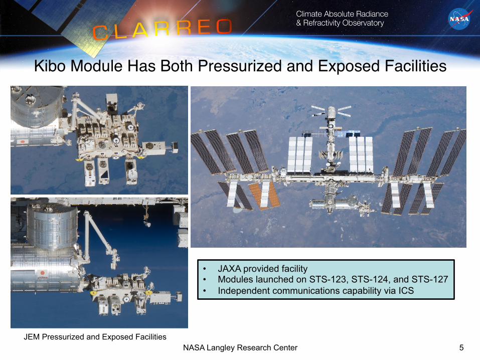
Kibo Module Has Both Pressurized and Exposed Facilities!
5 NASA Langley Research Center JEM Pressurized and Exposed Facilities
• JAXA provided facility • Modules launched on STS-123, STS-124, and STS-127 • Independent communications capability via ICS
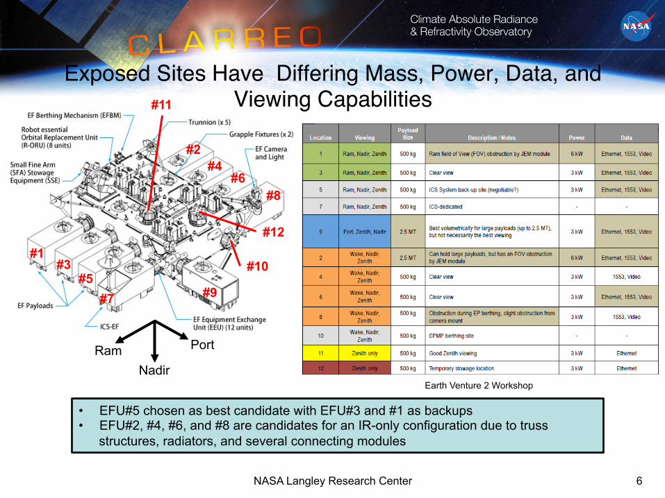
Exposed Sites Have Differing Mass, Power, Data, and Viewing Capabilities!
6
#1 #3
#5 #7
#12
#11
#9
#10
NASA Langley Research Center
#2 #4
#6 #8
Ram Nadir
Port
• EFU#5 chosen as best candidate with EFU#3 and #1 as backups • EFU#2, #4, #6, and #8 are candidates for an IR-only configuration due to truss
structures, radiators, and several connecting modules
Earth Venture 2 Workshop

CLARREO-ISS Accommodation Compliance Matrix!
7
JEM-EF CLARREO-ISS
Mass 550 kg (standard site) ~453 kg with GFE (~20% margin)
Power 3 kW (standard site) ~250 W (~92% margin)
Thermal 3 kW (fluid cooling loop) ~250 W
Data Rate 1 Mbps (MIL-STD-1553) 10 Mbps (10 Base-T Ethernet) 43 Mbps (Shared-Negotiated) NTSC Video
~640 kbps to ~72 Mbps (Highest rate due to RS during solar calibration requires data buffering at the payload)
Data Volume
Negotiable – Up to 1.5 TB ~90 Gb/day
Volume 0.8 x 1.0 x 1.85 m Complies (stowed)
NASA Langley Research Center

Field-of-Regard Varies Due to Solar Array, ISS Attitude, and ICS Motion!
8
ICS
Solar Array
TV Camera
Viewing Point: Center of zenith face of EFU#5 Viewing Direction: Zenith
Viewing Point: Center of nadir face of EFU#5 Viewing Direction: Nadir
Viewing Point: Center of ram face of EFU#5 Viewing Direction: Ram (Velocity)
Kibo EF
EFU#11
Solar Array
Kibo PM
SSE
90°
60°
30° 30° 30°
60° 60°
90° 90°
Earth
Earth
Solar Array
Solar Array Solar
Array
Solar Array
Kibo Exposed Facility User Handbook, September 2010
NASA Langley Research Center
Starboard
Ram
Port
Starboard
Ram
Port
Starboard
Nadir
Port
• Pitch offset from nadir predicted to be -10 to +2 degrees after ISS completion

Dual Manifest Payload on JEM-EF Demonstrated by HREP!
HICO
RAIDS
• Led by NRL, HREP deployed on JEM-EF October 2009. • HREP was the first US science payload utilizing JEM-EF. • Partnerships between NASA, NRL, DOD Space Test Program, and ONR.
9

CLARREO-ISS OVERVIEW!
10 NASA Langley Research Center

Lessons Learned from Combined Observatory Free-Flyer Spacecraft Studies!
• The Reflected Solar wanted to be on the ram/wake end to have the best views for solar calibration-lunar verification.
• The Reflected Solar also wanted nadir views with large off-nadir view angles for reference intercalibration.
• The Reflected Solar needed a two-axis gimbal for pointing agility and to avoid loss of IR data.
• The IR could be closer to the bus and still have unobstructed nadir, zenith, and off-zenith views for benchmarking, a cold reference, and periodic polarization checks.
• The overall configuration worked best when radiators were placed on the spacecraft “cold” side for thermal maintenance.
11 NASA Langley Research Center

CLARREO-ISS Payload Concept Compatible with JEM-EF!*FRGF (Grapple Fixture)
*HCAM-P
RS Deployment Mechanism
IR Suite
*PIU
RS Gimbal
* = Required GFE
Payload Carrier
Fluid Cooled IR Electronics Bench
Fluid Cooled RS Electronics Bench
RS Spectrometers
12 NASA Langley Research Center
1.85 m
1 m
0.85 m

JEM-EF Allows for Deployable Payloads in the Nadir Direction!
Due to constraints on maintaining the field-of-view of neighboring ICS payload’s Earth and Sun sensors, the RS cannot deploy through the end (ram deck) but can deploy through the bottom (nadir deck).
13 NASA Langley Research Center

CLARREO-ISS on JEM-EF Configuration!
NASA Langley Research Center 14
MAXI
SEDA
ICS-EF
SMILES
HREP
CLARREO-ISS
Ram Nadir
Port

IR SUITE!
15 NASA Langley Research Center

Modified IR Suite Overview!
Interferometer Enclosure
JEM-EF IR Instrument Concept Design
Calibration- Verification
Blackbodies Integrating
Sphere Nadir Sun Shield
FTS Scan Mechanism
Scene Select Mechanism
Baseline Instrument Package: Ø FTS, calibration-verification system, thermal
management hardware, support structure, and electronics Ø Mass: ~74.8 kg (59.8 kg + 15 kg electronics) Ø Power: ~124 W
Ø Instrument Dimension: ~0.8m x 0.76m x 0.58m
Ø Data Rate: ~228 kb/sec Ø Data Volume: ~20 Gb/day
Instrument Description: Ø A Fourier Transform Spectrometer (FTS) for SI
traceable measurements of the Mid and Far-IR spectrum of the Earth and atmosphere
Ø Utilizes one ambient black body, one phase-change black body, and deep space as on-orbit calibration sources
Ø Scene select mechanism utilized for ISS motion compensation and calibration source selection
Ø Uncooled pyroelectric detector for the Far-IR Ø Two-actively cryocooled HgCdTe (MCT) detectors for
the Mid-IR Characteristics:
Ø Radiance Scale Accuracy: 0.1 K 3σ Ø Spectral Range:
Ø ~ 5-50 µm (200-2000 cm-1) Ø Unapodized Resolution: 0.5 cm-1 Ø Detectors:
Ø MCT #1: ~3 to 9 µm (1111-3333 cm-1) Ø MCT #2: ~8 to 16.5 µm (606-1250 cm-1) Ø Pyroelectric: ~15 to 50 µm (200-667 cm-1)
Ø Footprint: ~17 km from 400 km Ø Integration Period: ~ 8 seconds
Payload Carrier Interface Hardware Zenith and
Off-Zenith Sun Shields
16 NASA Langley Research Center
(Rotated 45°from MCR Concept)

IR Operational Concept Very Similar to Free-Flyer!
NASA Langley Research Center 17
• JEM-EF provides unobstructed views for nadir, zenith, and off-zenith collections. • ISS pitch offset (port rotation) from nadir implies an offset of ~4°in the IR mounting
interface or in the scene-select mirror zero position. • ISS roll-yaw offsets need error contribution evaluation for CLARREO. • An IR-only payload could also function on the opposite (wake) side of JEM-EF.
Nadir (Point-Ahead and Look-Behind for Motion Compensation) Ram
Nadir
Port
Zenith (“Cold” Source for Calibration)
Off-Zenith (Polarization Check) **Payload Carrier side removed for clarity

REFLECTED SOLAR SUITE!
18 NASA Langley Research Center

Modified Reflected Solar Suite Overview!Spectrometer Assemblies
Sun-Shields
Aperture/Filter Assemblies and Baffles
JEM-EF Reflected Solar Suite Design Concept
Baseline Instrument Package: Ø Two spectrometers and aperture-filter wheel
assemblies Ø Mass: ~53.2 kg (33.7 kg + 19.5 kg electronics) Ø Average Power: ~96 W
Ø Dimension: ~0.58m x 0.56m x 0.32m
Ø Data Rate: (with 2x compression) Ø Solar Calibration: ~72 Mb/sec Ø Nadir Collection: <0.5 Mb/sec
Ø Data Volume: (with 2x compression) Ø Typical: ~66 Gb/day Ø Peak: ~69 Gb/day
Instrument Description: Ø A pair of pushbroom hyperspectral imagers with high
spatial and spectral resolution Ø Measures solar spectral reflectance of the Earth and
its atmosphere relative to the solar irradiance spectrum
Ø On-orbit calibration using the sun and moon as sources obtained through precision apertures, neutral density filters, and perforated plates rotated via filter wheels
Ø Field of regard (FOR) for reference intercalibration, solar calibration, and lunar calibration verification achieved with two-axis gimbal and deployment mechanism
Characteristics: Ø Absolute reflectance measurement uncertainty of
0.3% at 2σ confidence for the total integrated broadband reflected solar spectrum
Ø Polarization sensitivity <0.25% below 1000 nm and <0.75% at other wavelengths
Ø Spectral Range: 320 – 2300 nm Ø ~320 to ~640 nm (“Blue”) Ø ~600 to ~2300 nm (“Red-NIR”)
Ø Spectral Sampling: ~2 – 4 nm Ø Swath Width: > 67 km cross-track from 400 km Ø Spatial Sampling : ~0.34 km at Nadir
19 NASA Langley Research Center
(One spectrometer rotated about boresight from MCR Concept)

RS Operational Concept Very Similar to Free-Flyer!
NASA Langley Research Center 20
Nadir Benchmarking Reference Intercalibration Solar Calibration – Lunar Verification
• JEM-EF provides predominantly unobstructed views for benchmarking and reference intercalibration with a deployable gimbal-instrument.
• Views are more constrictive for solar calibration and lunar verification due to neighboring payloads. (Results in later slide)
• Calibration-verification could be more complex than free-flyer due to timing with solar array positions and ISS roll-pitch-yaw offsets.
• IR+RS or RS-only payload probably not viable on the opposite (wake) side of JEM-EF due to additional ISS structure interfering with calibration-verification.
Ram
Nadir
Port
NOTE: The deployed position also offers solar calibration capability.

RS Benchmarking-Intercalibration Ops Concept!
21 NASA Langley Research Center

1st Annual International Space Station Research and Development Conference, June 26 – 28, 2012, Denver, Colorado
RS Reference Intercalibration Opportunities Study Overview!
Monthly and Seasonal Sampling Estimates, ISS vs: JPSS-VIIRS, JPSS-CERES, and MetOp-AVHRR
22 NASA Langley Research Center
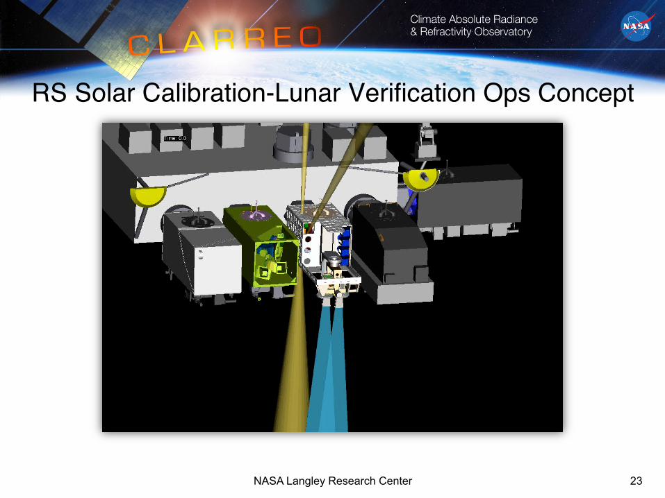
RS Solar Calibration-Lunar Verification Ops Concept!
23 NASA Langley Research Center

• From the undeployed configuration, solar calibration opportunities span 21-52 days which are followed by 3-20 day gaps.
• From the deployed configuration, solar calibration opportunities span 7-32 days followed by 7-11 day gaps.
• The undeployed configuration would enable greater scheduling flexibility for calibration while remaining in the desired configuration for benchmark and reference intercalibration measurements.
Solar Calibration Overview!Solar Calibration opportunities are regularly available in both the
undeployed and deployed configurations.
NASA Langley Research Center 24
Solar Calibra*on Cycle Summary
Gap Dura*on (days)
Prior Access Dura*on (days)
Ind. Accesses
Cumula*ve Solar Access Time per
Cycle (m) Deployed Averages 21.8 8.2 135.0 599.3
Undeployed Averages 11.4 37.1 610.0 3775.7
Lunar Verification – Operational Constraints Same as Free-Flyer!
• Lunar Verification Operations – Limited to occur while ISS is in umbra.
• Earth Grazing Angle, i.e. Earth limb to Moon angle as viewed by RS – Greater than 2.5 degrees
• Lunation, i.e. Sun-Moon-RS phase angle – Constrained from 5 to 9 degrees
NASA Langley Research Center 25
• Lunar verification operations are only achievable while the RS instrument is in the undeployed configuration, i.e. the deployed field-of-regard prohibits lunar verification. • The lunation constraint is not always met, i.e. some months do not meet viewing constraints. (See next page)

• 2 year simulation was performed (Jan 2012 – April 2014).
• Ephemeris estimates beyond 2014 quickly become inaccurate.
• The “Opportunities” column contains the number of times when the Moon can be viewed in the undeployed configuration. • The “Mean Duration” column contains the average duration of all the viewing opportunities over each lunation. • The “Cumulative” column contains the sum of all opportunities over each lunation.
• There are instances in a given orbit when the Moon exits one viewing opportunity and enters the next after several seconds have elapsed.
Lunar Verification – Study Results!Lunation Start Date
Opportunities (#)
Mean Duration (minutes)
Cumulative (minutes)
1 7-Feb-12 28 6.4 178.6 2 8-Mar-12 0 0.0 0.0 3 5-Apr-12 0 0.0 0.0 4 5-May-12 19 2.0 38.8 5 3-Jun-12 0 0.0 0.0 6 3-Jul-12 22 1.7 36.7 7 1-Aug-12 2 0.3 0.7 8 30-Aug-12 28 3.4 94.4 9 29-Sep-12 42 4.2 178.1
10 29-Oct-12 11 2.5 27.4 11 27-Nov-12 24 4.5 107.9 12 27-Dec-12 10 4.8 47.5 13 26-Jan-13 39 3.5 136.9 14 25-Feb-13 27 3.0 79.9 15 26-Mar-13 29 4.7 136.9 16 25-Apr-13 18 4.5 80.3 17 24-May-13 20 5.9 118.4 18 22-Jun-13 20 3.9 77.3 19 22-Jul-13 40 4.7 187.4 20 20-Aug-13 25 3.6 89.2 21 18-Sep-13 24 4.6 109.5 22 18-Oct-13 20 3.6 71.2 23 16-Nov-13 22 4.1 89.6 24 16-Dec-13 36 2.9 105.9 25 15-Jan-14 32 3.9 123.5 26 14-Feb-14 43 3.5 149.7 27 15-Mar-14 25 4.3 106.8 28 14-Apr-14 24 4.1 98.2
AVERAGES 22.5 3.4 88.2
NASA Langley Research Center 26

Solar Calibration-Lunar Verification Cumulative Data Functions!
NASA Langley Research Center 27
0 2 4 6 8 10 12 140
10
20
30
40
50
60
70
80
90
100
Duration (Minutes)
% o
f All
Opp
ortu
nitie
s
CDF of Lunar Verification Durations
0 2 4 6 8 10 12 14 16 180
10
20
30
40
50
60
70
80
90
100
Duration (Minutes)
% o
f All
Opp
ortu
nitie
s
CDF of Solar Calibration Durations
DeployedUndeployed

Conclusions!• At a high-level the concept of utilizing the JEM-EF for CLARREO-ISS
appears feasible.
• The CLARREO-ISS concept is “ISS friendly”.
– Design drivers of mass, power, volume, and thermal all seen as a reasonable design space.
– HREP dual-payload success adds credibility to the concept.
• The JEM-EF is “CLARREO friendly” but perhaps not ideal for a combined IR+RS payload.
– The IR configuration appears closer to a dedicated free-flyer than the Reflected Solar.
– Reflected solar calibration and lunar verification opportunities should be assessed by the Science Team.
28 NASA Langley Research Center

Questions?!
NASA Langley Research Center 29

BACKUPS!
30 NASA Langley Research Center
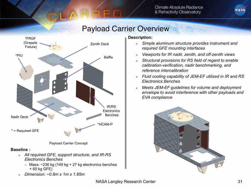
Payload Carrier Overview!*FRGF
(Grapple Fixture)
Payload Carrier Concept
Nadir Deck
Baffle
IR/RS Electronics
Benches
Description: Ø Simple aluminum structure provides instrument and
required GFE mounting interfaces Ø Viewports for IR nadir, zenith, and off-zenith views Ø Structural provisions for RS field of regard to enable
calibration-verification, nadir benchmarking, and reference intercalibration
Ø Fluid cooling capability of JEM-EF utilized in IR and RS Electronics Benches
Ø Meets JEM-EF guidelines for volume and deployment envelope to avoid interference with other payloads and EVA compliance
*PIU
Zenith Deck
*HCAM-P
Baseline : Ø All required GFE, support structure, and IR-RS
Electronics Benches Ø Mass: ~236 kg (149 kg + 27 kg electronics benches
+ 60 kg GFE) Ø Dimension: ~0.8m x 1m x 1.85m
* = Required GFE
31 NASA Langley Research Center

Two-Axis Gimbal Overview!AZ Drive Motor-Twist Capsule
Assembly Outer Yoke
Two-Axis Gimbal Concept Design (Electronics and Cabling not Shown)
Baseline Concept: Ø Gimbal , electronics, and cabling
Ø Mass: ~25 kg Ø Average Power: ~21 W Ø Peak Power: ~92 W
Ø Dimension: ~0.5m x 0.6m x 0.37m
Ø Data Rate: ~10 kb/sec Ø Data Volume: ~300 Mb/day
Description: Ø Two-Axis gimbal supports benchmarking, reference
intercalibration, solar calibration, and lunar calibration verification modes of operation
Ø Allows independent pointing and tracking with respect to the ISS
Ø High-TRL components and similar gimbals have flight heritage
Ø DC brushless motors using resolvers or encoders for closed-loop control and motor commutation
Ø Twist capsules or cable wrap used to carry gimbal and reflected solar signals and power across rotating interfaces
Characteristics:
Ø AZ Range: +/- 180 degrees Ø EL Range: +/-140 degrees (with spectrometers) Ø Slew Rates: < 5 deg/sec (both axes) Ø Tracking Rates: <1.5 deg/sec Ø Acceleration: < 1 deg/sec2 (both axes)
EL Drive Motor-Twist Capsule
Assembly Instrument
Carrier
32 NASA Langley Research Center

Deployment Mechanism Overview!
Deployment Mechanism Design Concept
Baseline Concept: Ø Mechanism, drive, electronics, and cabling
Ø Mass: ~64 kg (TBR) Ø Peak Power: ~10 W (TBR)
Ø Dimension: Ø Stowed: ~0.25m x 0.58m x 0.75m Ø Deployed: ~0.25m x 0.58m x 1.23m
Description: Ø Simple linear translation stage provides stowage/
deployment capability for the RS gimbal and spectrometer assemblies
Ø Supports RS gimbal and spectrometer assemblies within the payload carrier for launch, docking, and JEM-EF installation
Ø Deploys RS gimbal and spectrometer assembly through the payload carrier nadir deck to allow off-nadir pointing required for the RS operational modes
Ø High-TRL components and similar mechanisms have flight heritage – bearings, motor, ball screw
Ø Limit switches provide verification of home-deployment positions
Ø Mechanism with no precision position or rate and low life-cycle requirements
Characteristics:
Ø Range of Motion: 0 to 0.5 m Ø Position Knowledge: < 1 mm (TBR) Ø Position Control: < 0.5 mm (TBR)
Gimbal Carrier
Gimbal Interface
Motor Drive-Bearing Assembly
Deployed Stowed
33 NASA Langley Research Center

JEM-EF Provides Accommodation Approaching a Free-Flyer for the IR!
NASA Langley Research Center 34