Embed Size (px)
Citation preview
Page 1
Class 455
Enhancement Pack
Volume 2
Contents
How to Install ............................................................................................................................................ 2
Liveries ........................................................................................................................................................ 3
Keyboard Controls .................................................................................................................................. 4
Features ...................................................................................................................................................... 5
Variations ............................................................................................................................................... 5
DC & AC Traction Physics ................................................................................................................ 7
Adhesion .............................................................................................................................................. 10
Driver Only Operation (DOO) ....................................................................................................... 12
Global System for Mobile Communication-Railway (GSM-R) .......................................... 13
Player Changeable Destination Display .................................................................................... 15
Variable Power & Brake Performance ....................................................................................... 16
Variable Traction Motor Volume ................................................................................................. 17
Automatic Unit Numbering ........................................................................................................... 17
Bits and Bobs ...................................................................................................................................... 18
How to Use in the Scenario Editor .................................................................................................. 19
Setting up the Driver’s Cab................................................................................................................ 20
Driving Guide .......................................................................................................................................... 21
Scenarios .................................................................................................................................................. 21
Credits ....................................................................................................................................................... 22
Page 2
How to Install
1) Locate where you have downloaded this pack and unzip it. Information on
how to do this can be found here.
2) Go to the location where you have extracted the files from the .zip file.
3) Now find the .exe file called ‘Class 455 Enhancement Pack Vol 2’. Double-click
this file.
4) Follow the steps and by the end of the process, the main part of this pack will
have installed.
5) If you intend to use any of the included scenarios, make sure you have the
requirements installed, as listed on the product page.
6) To ensure the cab environment sounds as intended in this pack, please make
sure that ‘EFX’ is ticked within your in-game Audio settings.
Page 3
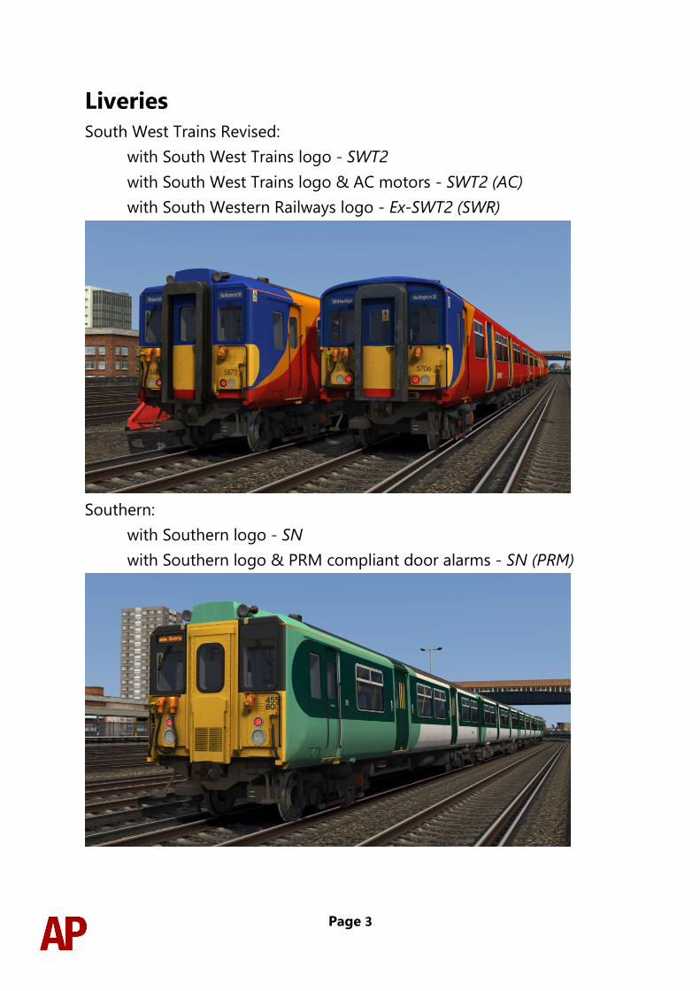
Liveries
South West Trains Revised:
with South West Trains logo - SWT2
with South West Trains logo & AC motors - SWT2 (AC)
with South Western Railways logo - Ex-SWT2 (SWR)
Southern:
with Southern logo - SN
with Southern logo & PRM compliant door alarms - SN (PRM)
Page 4
Keyboard Controls Non-standard keyboard controls are listed below:
L - Cab light ON/OFF
F7 - Destination blind (secondman’s side) DOWN
F8 - Destination blind (secondman’s side) UP
Shift+F7 - Destination blind (driver’s side) DOWN
Shift+F8 - Destination blind (driver’s side) UP
N - Destination blind light switch ON/OFF
R - Door close button
U - Door release buttons (left)
O - Door release buttons (right)
Y - Driver reminder appliance (DRA) ON/OFF
C - Driver to guard call button
H - Headlight switch CLOCKWISE
Shift+H - Headlight switch ANTI-CLOCKWISE
Ctrl+R - Passenger door operation toggle DOO/GO
Ctrl+Numpad Enter - Visual aids ON/OFF
V - Wiper switch CLOCKWISE
Shift+V - Wiper switch ANTI-CLOCKWISE
Page 5
Features
Variations
Many of the detail differences between the three subclasses (455/7, 455/8 & 455/9)
have been simulated in this pack.
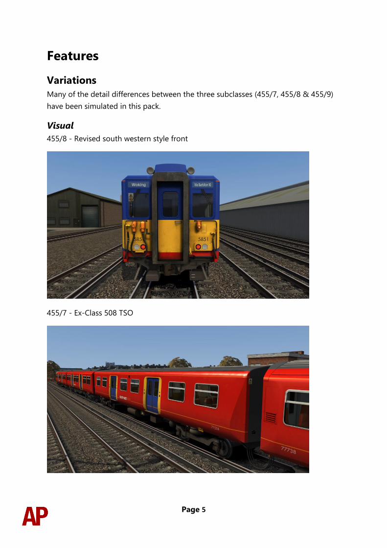
Visual
455/8 - Revised south western style front
455/7 - Ex-Class 508 TSO
Page 6
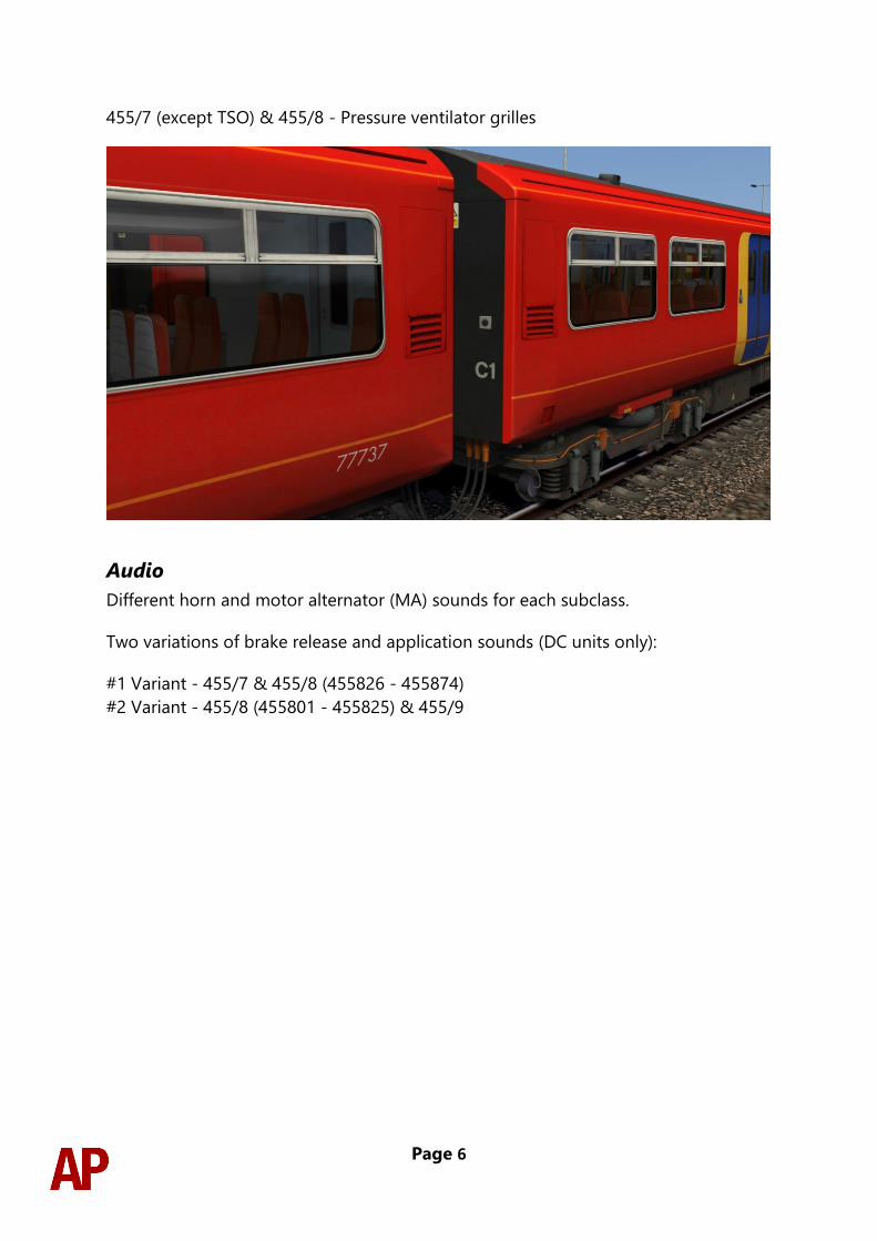
455/7 (except TSO) & 455/8 - Pressure ventilator grilles
Audio
Different horn and motor alternator (MA) sounds for each subclass.
Two variations of brake release and application sounds (DC units only):
#1 Variant - 455/7 & 455/8 (455826 - 455874)
#2 Variant - 455/8 (455801 - 455825) & 455/9
Page 7
DC & AC Traction Physics
DC (Camshaft) Traction System
This pack implements the camshaft system of regulating power, the class 455 being
the final class of unit to utilise it. This works by progressively cutting out resistances
when powering up so as to control the current going to the motors. As well as the
resistances, the traction motors can be set up in two modes so as to control current:
Series & Parallel.
The resistances and traction motor modes are controlled depending on which of the
four power handle notches the driver selects:
0 - Traction power is OFF
1 (Shunt) - All resistances are in circuit. This provides minimal acceleration which
soon decays. The traction motors are in ‘Series’ mode.
2 (Series) - As the unit gains speed, resistances are progressively removed from the
circuit until they are all removed. As each resistance is removed, acceleration
increases.
3 (Parallel) - Once the unit has gone through the steps described above, the traction
motors switch to ‘Parallel’ mode and all resistances are placed back into the circuit.
This provides a significant increase in acceleration. As speed increases, pairs of
resistances are then progressively removed from the circuit for further acceleration.
4 (Weakfield) - Once the unit has gone through both the ‘Series’ and ‘Parallel’ steps,
it will start to weaken the field of the traction motors, which once again, provides a
further boost in acceleration. If this notch is selected before all resistances have been
removed from the circuit, the resistances will be removed quicker than in the lower
notches so as to aid acceleration.
At any time, it is possible to halt the progression listed above by selecting a lower
power handle position (except 0). For example, if you wish not to take all of the
resistances out in the ‘Series’ notch, you can hold your current level of acceleration
by placing the power handle back into the ‘Shunt’ notch. This is known as ‘hand-
notching’.
You can only decrease power by returning the power handle to 0, or OFF, and then
re-applying the power to your desired notch.
Page 8
If you find you are unable to obtain power at any point, the traction motors may
have overloaded. This is especially likely during wheelslip. To obtain power again,
return the power handle to ‘OFF’ and press the ‘Overload Reset’ button.
AC Traction System
During 2016 & 2017, South West Trains re-tractioned their 455s with AC motors to
reduce maintenance requirements. From a driver’s perspective, this is a much-
simplified system compared to the old camshaft and most significantly, does not
require you to shut off power to reduce power. Please see below for a description of
what occurs in each power notch:
0 - Traction power is OFF
1 - This is considered a shunt notch and on level track, your train will not accelerate
above 10 mph.
2 - Around 25% power
3 - Around 40% power
4 - 100% power
Whilst official documentation suggests notches 1, 2 & 3 should offer 25%, 50% &
75% power respectively, the reality is as described above. This proves troublesome in
poor adhesion conditions with notch 4 often resulting in wheelslip and notch 3 not
supplying enough power to make good progress. This is something you will need to
battle with, just like a real driver.
The AC traction system also features dynamic braking which means the traction
motors will assist in braking until around 7 mph. When dynamic braking is active, you
will see a reduced reading on the brake pressure gauge compared to a conventional
DC unit. Finally, dynamic braking will not occur when the emergency brake is applied.
Other smaller changes were also made during this re-tractioning and these are listed
below:
- If you have power applied whilst in step 1 brake for more than 10 seconds,
power will be automatically cut.
- Brake pressure reverts to emergency when the doors are released. Once the
doors are closed and you have interlock, you will need to wait 3 seconds and
ensure you have the reverser in either forward or reverse for the brakes to
release.
- Different air brake equipment installed with much quieter release sounds.

Page 9
- Cooling fans fitted to aid the cooling of the traction motors. These will run at
low speed 11 minutes after power was last applied and at high speed for 1
minute after the dynamic brake was last active.
The AC traction system is present on the SWT (AC) & Ex-SWT (SWR) variants.
Page 10
Adhesion
Adhesion between a train’s wheels and the rails plays a big part in allowing a train to
accelerate or brake. Too little of it and the train will slip or slide. There are a myriad of
factors that control the level of adhesion and we have attempted to simulate the
most important of these to give a varied and realistic driving experience:
Season
Adhesion is generally good in dry conditions during summer and spring. Slightly
decreased adhesion during winter to take account of the increased amount of
moisture and possible ice on the rails due to cooler temperatures. Much decreased
adhesion during autumn due to leaf mulch.
Weather
Adhesion decreases in wet weather, especially so when rain first starts falling before
it has had a chance to clean the railhead. If rain is light, it will take longer for the
railhead to be cleaned whereas heavy rain will clean it quicker, resulting in adhesion
recovering sooner.
When using the drizzle weather pattern in our Sky & Weather Enhancement Pack,
adhesion is particularly poor as the rain hasn’t enough force to clean the railhead but
still makes it sufficiently wet to worsen adhesion.
Time of Day
Adhesion will decrease somewhat after dusk as the air cools and dew is more likely
to form on the railhead. This persists throughout the night until around an hour after
sunrise when higher temperatures or the sun dry it out. In our simulation, this factor
is reduced during summer to account for warmer temperatures, which on average
result in less dew.
Tunnels
When adhesion is poor due to external factors such as weather or season, adhesion
will generally improve upon entering a tunnel, which is not as susceptible to these
factors. When adhesion is good during dry weather and outside of autumn, adhesion
may decrease a little upon entering a tunnel due to their damp nature.
Page 11
Wheelslip
Wheelslip protection aids the driver when powering or braking during times of poor
adhesion.
When wheelslip is encountered during acceleration, a three-stage process takes
place:
1) The motors can be heard rising rapidly in pitch and on DC units, the camshaft
ceases to progress.
2) On DC units, if the slip does not stop after a second or three, power is cut. On
AC units, power is immediately reduced.
3) Once grip is regained, power is reapplied at the notch selected on the power
handle.
As a driver, you must assess which power notch is most suitable for the conditions
and balance the occurrence of wheelslip with the maximum possible rate of
acceleration.
Wheelslide
When wheelslide is encountered during braking, a three-stage process takes place:
1) Brake pressure is automatically reduced to try and control the slide. On AC
units, the dynamic brake will stop and the air brake will fully take over.
2) Sand is automatically applied if in step 2, step 3 or emergency brake.
3) Once the slide stops, brake pressure is returned to the notch selected on the
brake handle. Additionally, on AC units, the dynamic brake will remain
disabled until you release and apply the brakes again.
As a driver, you must resist the temptation to reduce the brake yourself as the
wheelslip protection will offer the best braking performance.
Page 12
Driver Only Operation (DOO)
Full door control is featured in this pack to simulate ‘DOO’. Please see below for what
the relevant procedure is and how to change the type of operation whilst in-game:
Driver Only Operation (DOO)
1) Open the doors by pressing T+U (left-hand side) or T+O (right-hand side).
Alternatively, you can click the corresponding red buttons in the cab.
2) If at a platform, wait for the ‘Platform Duties Complete’ message to appear in
the top-right corner and press R to close the doors. If not at a platform, press
R whenever you wish.
3) Once the door interlock light illuminates, you may depart.
Guard Operation (GO)
1) Open the doors by pressing T.
2) Doors will be closed by the guard once passengers have finished
boarding/alighting.
3) Once the door interlock light illuminates, the guard will give you two bells.
Unlike many other units, a driver to guard bell is not fitted and you are not
required to return the signal. Many drivers still do though out of habit and do
so via the ‘Cab-to-Cab’ call button which can be pressed by pressing C.
How to Change Operation
This can be changed in-game by pressing Ctrl+R which will produce a visual
message in the top-right hand corner of the screen to let you know which option you
have selected.
Page 13
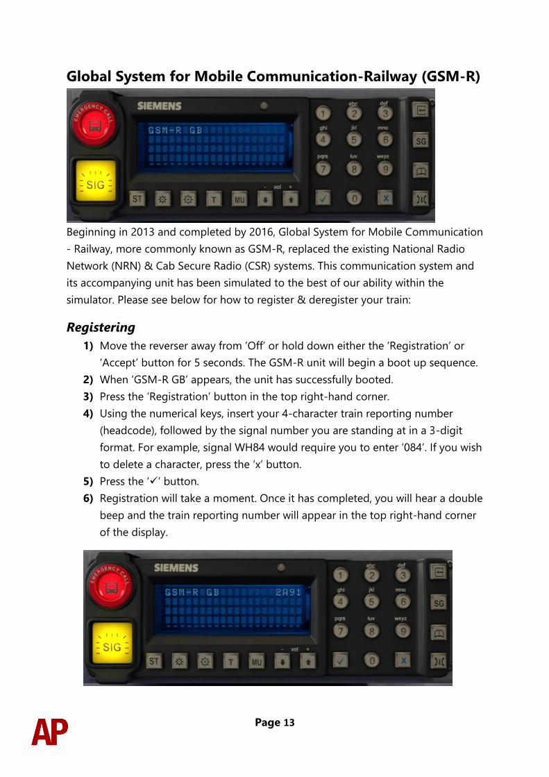
Global System for Mobile Communication-Railway (GSM-R)
Beginning in 2013 and completed by 2016, Global System for Mobile Communication
- Railway, more commonly known as GSM-R, replaced the existing National Radio
Network (NRN) & Cab Secure Radio (CSR) systems. This communication system and
its accompanying unit has been simulated to the best of our ability within the
simulator. Please see below for how to register & deregister your train:
Registering
1) Move the reverser away from ‘Off’ or hold down either the ‘Registration’ or
‘Accept’ button for 5 seconds. The GSM-R unit will begin a boot up sequence.
2) When ‘GSM-R GB’ appears, the unit has successfully booted.
3) Press the ‘Registration’ button in the top right-hand corner.
4) Using the numerical keys, insert your 4-character train reporting number
(headcode), followed by the signal number you are standing at in a 3-digit
format. For example, signal WH84 would require you to enter ‘084’. If you wish
to delete a character, press the ‘x’ button.
5) Press the ‘✓’ button.
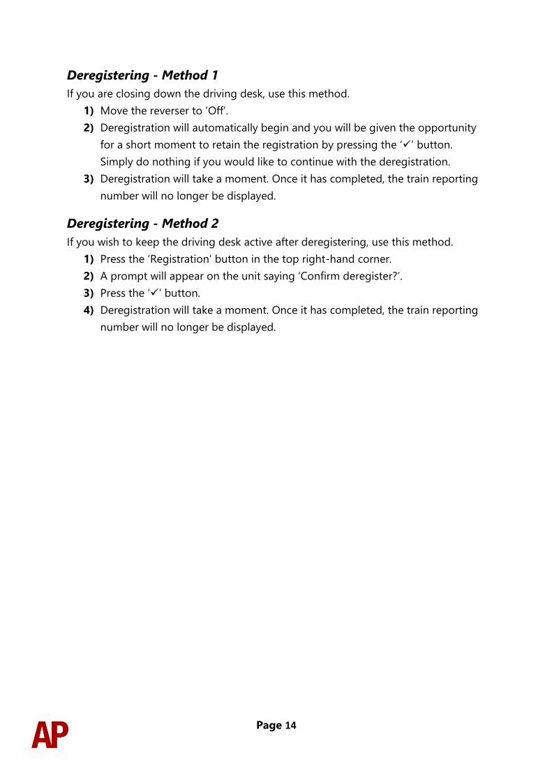
6) Registration will take a moment. Once it has completed, you will hear a double
beep and the train reporting number will appear in the top right-hand corner
of the display.
Page 14
Deregistering - Method 1
If you are closing down the driving desk, use this method.
1) Move the reverser to ‘Off’.
2) Deregistration will automatically begin and you will be given the opportunity
for a short moment to retain the registration by pressing the ‘✓’ button.
Simply do nothing if you would like to continue with the deregistration.
3) Deregistration will take a moment. Once it has completed, the train reporting
number will no longer be displayed.
Deregistering - Method 2
If you wish to keep the driving desk active after deregistering, use this method.
1) Press the ‘Registration’ button in the top right-hand corner.
2) A prompt will appear on the unit saying ‘Confirm deregister?’.
3) Press the ‘✓’ button.
4) Deregistration will take a moment. Once it has completed, the train reporting
number will no longer be displayed.
Page 15
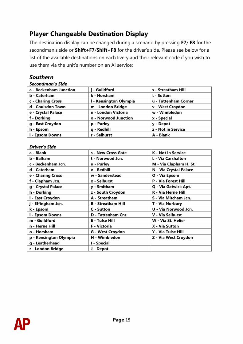
Player Changeable Destination Display
The destination display can be changed during a scenario by pressing F7/ F8 for the
secondman’s side or Shift+F7/Shift+F8 for the driver’s side. Please see below for a
list of the available destinations on each livery and their relevant code if you wish to
use them via the unit’s number on an AI service:
Southern Secondman’s Side
a - Beckenham Junction j - Guildford s - Streatham Hill
b - Caterham k - Horsham t - Sutton
c - Charing Cross l - Kensington Olympia u - Tattenham Corner
d - Coulsdon Town m - London Bridge v - West Croydon
e - Crystal Palace n - London Victoria w - Wimbledon
f - Dorking o - Norwood Junction x - Special
g - East Croydon p - Purley y - Depot
h - Epsom q - Redhill z - Not in Service
i - Epsom Downs r - Selhurst A - Blank
Driver’s Side
a - Blank s - New Cross Gate K - Not in Service
b - Balham t - Norwood Jcn. L - Via Carshalton
c - Beckenham Jcn. u - Purley M - Via Clapham H. St.
d - Caterham v - Redhill N - Via Crystal Palace
e - Charing Cross w - Sanderstead O - Via Epsom
f - Clapham Jcn. x - Selhurst P - Via Forest Hill
g - Crystal Palace y - Smitham Q - Via Gatwick Apt.
h - Dorking z - South Croydon R - Via Herne Hill
i - East Croydon A - Streatham S - Via Mitcham Jcn.
j - Effingham Jcn. B - Streatham Hill T - Via Norbury
k - Epsom C - Sutton U - Via Norwood Jcn.
l - Epsom Downs D - Tattenham Cnr. V - Via Selhurst
m - Guildford E - Tulse Hill W - Via St. Helier
n - Herne Hill F - Victoria X - Via Sutton
o - Horsham G - West Croydon Y - Via Tulse Hill
p - Kensington Olympia H - Wimbledon Z - Via West Croydon
q - Leatherhead I - Special
r - London Bridge J - Depot
Page 16
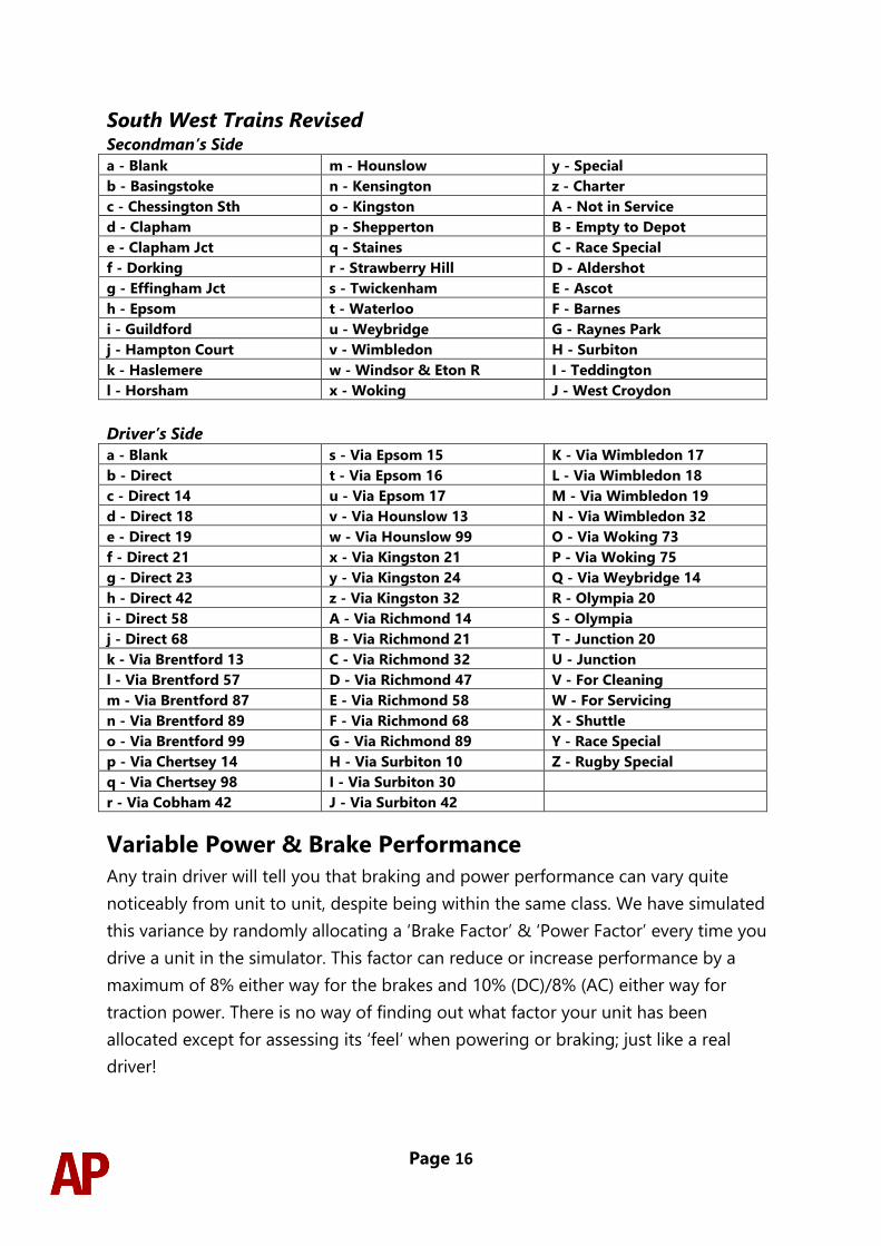
South West Trains Revised Secondman’s Side
a - Blank m - Hounslow y - Special
b - Basingstoke n - Kensington z - Charter
c - Chessington Sth o - Kingston A - Not in Service
d - Clapham p - Shepperton B - Empty to Depot
e - Clapham Jct q - Staines C - Race Special
f - Dorking r - Strawberry Hill D - Aldershot
g - Effingham Jct s - Twickenham E - Ascot
h - Epsom t - Waterloo F - Barnes
i - Guildford u - Weybridge G - Raynes Park
j - Hampton Court v - Wimbledon H - Surbiton
k - Haslemere w - Windsor & Eton R I - Teddington
l - Horsham x - Woking J - West Croydon
Driver’s Side
a - Blank s - Via Epsom 15 K - Via Wimbledon 17
b - Direct t - Via Epsom 16 L - Via Wimbledon 18
c - Direct 14 u - Via Epsom 17 M - Via Wimbledon 19
d - Direct 18 v - Via Hounslow 13 N - Via Wimbledon 32
e - Direct 19 w - Via Hounslow 99 O - Via Woking 73
f - Direct 21 x - Via Kingston 21 P - Via Woking 75
g - Direct 23 y - Via Kingston 24 Q - Via Weybridge 14
h - Direct 42 z - Via Kingston 32 R - Olympia 20
i - Direct 58 A - Via Richmond 14 S - Olympia
j - Direct 68 B - Via Richmond 21 T - Junction 20
k - Via Brentford 13 C - Via Richmond 32 U - Junction
l - Via Brentford 57 D - Via Richmond 47 V - For Cleaning
m - Via Brentford 87 E - Via Richmond 58 W - For Servicing
n - Via Brentford 89 F - Via Richmond 68 X - Shuttle
o - Via Brentford 99 G - Via Richmond 89 Y - Race Special
p - Via Chertsey 14 H - Via Surbiton 10 Z - Rugby Special
q - Via Chertsey 98 I - Via Surbiton 30
r - Via Cobham 42 J - Via Surbiton 42
Variable Power & Brake Performance
Any train driver will tell you that braking and power performance can vary quite
noticeably from unit to unit, despite being within the same class. We have simulated
this variance by randomly allocating a ‘Brake Factor’ & ‘Power Factor’ every time you
drive a unit in the simulator. This factor can reduce or increase performance by a
maximum of 8% either way for the brakes and 10% (DC)/8% (AC) either way for
traction power. There is no way of finding out what factor your unit has been
allocated except for assessing its ‘feel’ when powering or braking; just like a real
driver!
Page 17
Variable Traction Motor Volume
As per reality, through wear and tear, some tractions are louder than others. To
simulate this, we have implemented a random ‘Motor Factor’ to each motor bogie
which ranges from 1 to 6; 1 being the quietest and 6 being the loudest. This can not
be changed by the player.
Automatic Unit Numbering
When placing a unit in the scenario editor or using one in Quick Drive, all vehicles
will automatically be given correct unit and coach numbers, instead of you having to
select each vehicle and changing their number manually so they match. The unit
number is controlled via the MSO vehicle if you wish to change it.
Page 18
Bits and Bobs
This section is dedicated to aspects of this pack that don’t warrant a dedicated
section but are still of note:
• Higher resolution cab visuals
• 4-step reverser (off/forward/neutral/reverse).
• TPWS lights illuminate during AWS self-test.
• Power cannot be applied if the brake handle is in ‘Step 2’, ‘Step 3’ or ‘Emergency’.
• If the brake handle is placed in ‘Step 2’, ‘Step 3’ or ‘Emergency’ whilst powering, power
will be lost and you must return the power handle to ‘Off’ before being able to regain
power.
• Visual alarms outside of cab when AWS is active.
• The visible driver automatically moves to whichever cab you are in.
• Emergency brake pressure applied when reverser is in ‘Off’.
• When moving the reverser away from ‘Off’, brake pressure will release once the AWS self-
test has been reset and the reverser is placed into ‘Forward’ or ‘Reverse’.
• When the sander button is pressed, you must be in a power notch and it will only apply
for 10 seconds maximum at a time. If you wish to continue to apply sand after 10
seconds, you must re-press the sander button.
• 1 second delay between train passing over AWS magnet and AWS warning sound
occurring. The F3/F4 HUD will show the warning immediately so you must wait 1 second
before trying to cancel it.
• Wobbly speedometer needle. Especially at low speed.
• Flash from the line breaker on the MSO visible when cutting power (DC only).
• The headlights only provide illumination before sunrise and after sunset. This is to avoid
the unrealistic appearance of projected light in broad daylight.
• High quality headlight/marker light & tail light visuals.
• Correct looking tightlock coupler applied.
• A special ‘bogie cam’ is available if you switch to the right-hand ‘head-out’ view (Shift+2
THEN Right Arrow)
• Wipers operate on AI services if it’s raining
• Revised LED destination display visuals on Southern livery
• Selected destination stated on the TrainFX screen to the left of the driver’s cab window
on Southern livery
Page 19
How to Use in the Scenario Editor
How to place
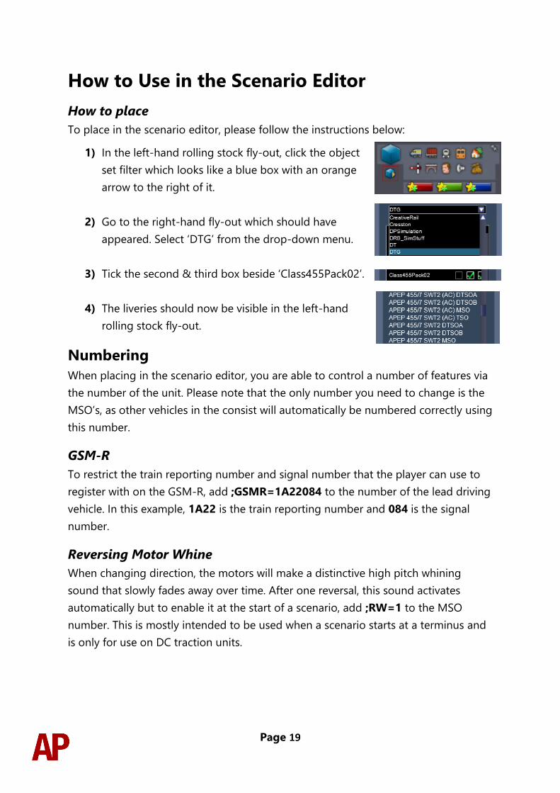
To place in the scenario editor, please follow the instructions below:
1) In the left-hand rolling stock fly-out, click the object
set filter which looks like a blue box with an orange
arrow to the right of it.
2) Go to the right-hand fly-out which should have
appeared. Select ‘DTG’ from the drop-down menu.
3) Tick the second & third box beside ‘Class455Pack02’.
4) The liveries should now be visible in the left-hand
rolling stock fly-out.
Numbering
When placing in the scenario editor, you are able to control a number of features via
the number of the unit. Please note that the only number you need to change is the
MSO’s, as other vehicles in the consist will automatically be numbered correctly using
this number.
GSM-R
To restrict the train reporting number and signal number that the player can use to
register with on the GSM-R, add ;GSMR=1A22084 to the number of the lead driving
vehicle. In this example, 1A22 is the train reporting number and 084 is the signal
number.
Reversing Motor Whine
When changing direction, the motors will make a distinctive high pitch whining
sound that slowly fades away over time. After one reversal, this sound activates
automatically but to enable it at the start of a scenario, add ;RW=1 to the MSO
number. This is mostly intended to be used when a scenario starts at a terminus and
is only for use on DC traction units.
Page 20
Example number:
455863Hj;RW=1
Key:
455863 - Unit number
H - Destination (secondman’s side)
j - Destination (driver’s side)
;RW=1 - Reversing motor whine activated
Setting up the Driver’s Cab
Please follow these steps to set up the cab so you are ready to move:
1) Move the reverser to the ‘Neutral’ position by pressing S.
2) Cancel the AWS self-test alarm by pressing Q.
3) Turn the tail lights off and headlights on by pressing H. Please that only the
‘Day’ headlight option is available as per pre-refurbishment units.
4) Register the GSM-R if applicable.
5) Set your destination by pressing F7/F8 (secondman’s side) or
Shift+F7/Shift+F8 (driver’s side).
6) Turn the Driver Reminder Appliance (DRA) off by pressing Y.
You should now be ready to move off.
Page 21
Driving Guide The following steps should allow you to drive in a realistic and safe manner:
1) Move the reverser to your desired direction of travel by pressing either W for
‘Forward’ or S for ‘Reverse’.
2) Move the brake handle to ‘Step 1’ by pressing ;.
3) Move the power handle to ‘Notch 2’ by pressing A. At the same time, move
the brake handle to ‘Release’, to ensure you depart without rolling back.
4) From then on, increase power as you see fit. In dry conditions outside of
autumn, you should be safe to use ‘Notch 4’ for the maximum rate of
acceleration.
5) To brake the train, you may make applications and releases by moving the
handle between ‘Step 1 and ‘Full Service’. It is recommended you only use ‘Full
Service’ as a last resort so as to ensure you always have more brake force
available if required.
6) Just before coming to a stop, aim to have the brake handle in ‘Step 1’ so as to
provide a smooth stop.
Scenarios
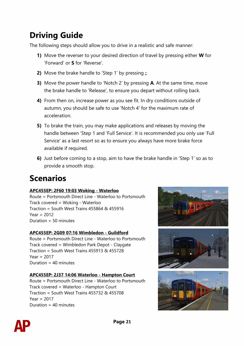
APC455EP: 2F60 19:03 Woking - Waterloo
Route = Portsmouth Direct Line - Waterloo to Portsmouth
Track covered = Woking - Waterloo
Traction = South West Trains 455864 & 455916
Year = 2012
Duration = 50 minutes
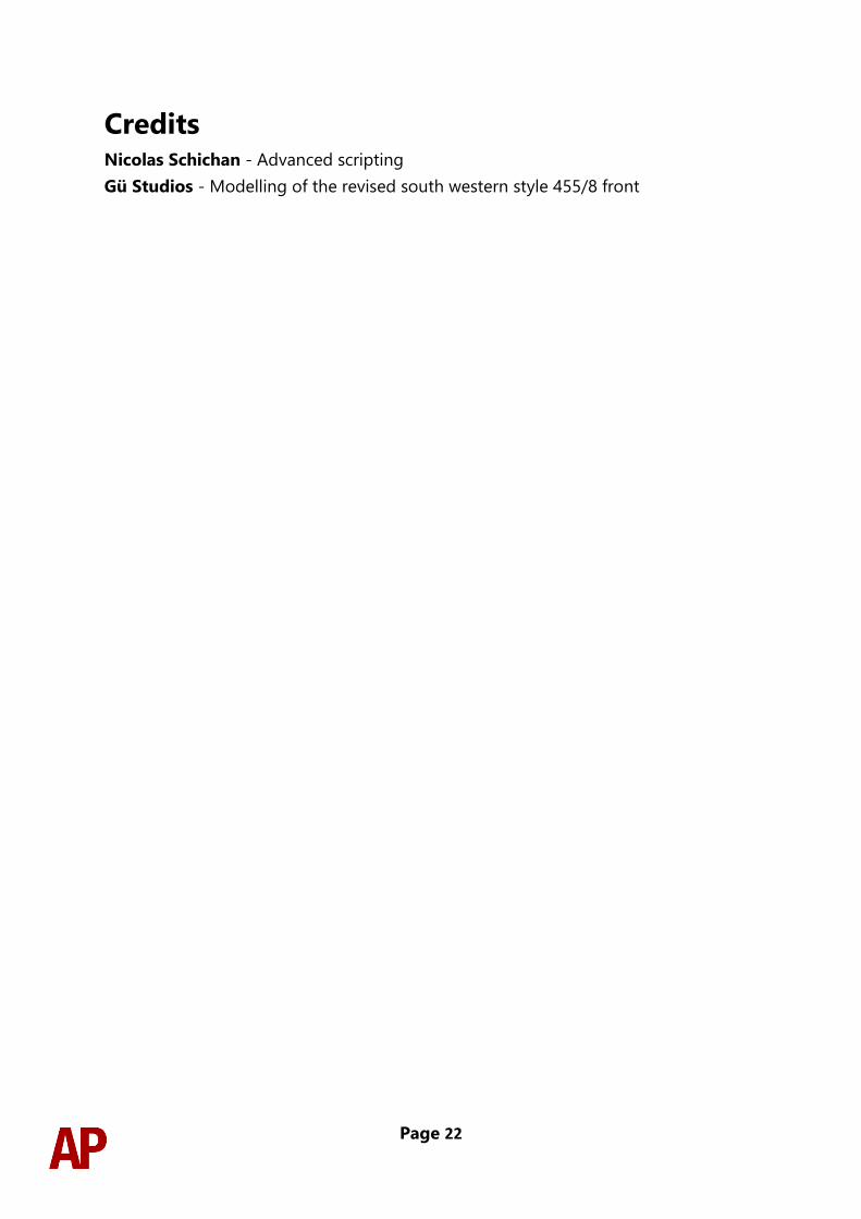
APC455EP: 2G09 07:16 Wimbledon - Guildford
Route = Portsmouth Direct Line - Waterloo to Portsmouth
Track covered = Wimbledon Park Depot - Claygate
Traction = South West Trains 455913 & 455728
Year = 2017
Duration = 40 minutes
APC455EP: 2J37 14:06 Waterloo - Hampton Court
Route = Portsmouth Direct Line - Waterloo to Portsmouth
Track covered = Waterloo - Hampton Court
Traction = South West Trains 455732 & 455708
Year = 2017
Duration = 40 minutes
Page 22
Credits Nicolas Schichan - Advanced scripting
Gü Studios - Modelling of the revised south western style 455/8 front