Embed Size (px)
Citation preview
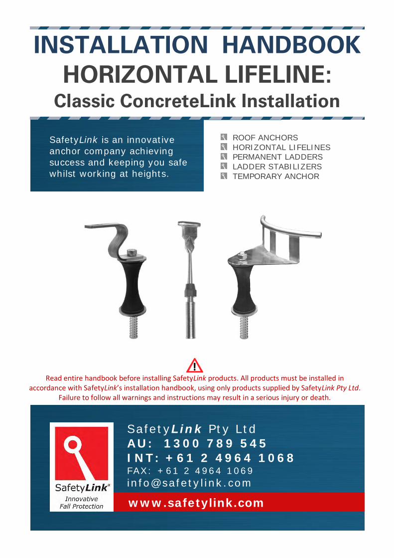
SafetyLink is an innovative
anchor company achieving
success and keeping you safe
whilst working at heights.
INSTALLATION HANDBOOK
HORIZONTAL LIFELINE: Classic ConcreteLink Installation
Read entire handbook before installing SafetyLink products. All products must be installed in
accordance with SafetyLink’s installation handbook, using only products supplied by SafetyLink Pty Ltd. Failure to follow all warnings and instructions may result in a serious injury or death.
ROOF ANCHORS
HORIZONTAL LIFELINES PERMANENT LADDERS
LADDER STABILIZERS
TEMPORARY ANCHOR
SafetyLink Pty Ltd AU: 1300 789 545 INT: +61 2 4964 1068 FAX: +61 2 4964 1069
www.safetylink.com

Table of Contents SafetyLink Classic ConcreteLink Lifeline Handbook - Version 08.17 Page 2 of 20
TABLE OF CONTENTS
INSTALLATION OF A SAFETYLINK HORIZONTAL LIFELINE
SYSTEM USING CONCRETELINK UNITS
WARNINGS .......................................................................................................................... 3
MAINTENANCE – PERIODIC INSPECTIONS ........................................................................... 4
WARRANTIES....................................................................................................................... 5
CLASSIC CONCRETELINK – SINGLE END UNIT ....................................................................... 6
COMPONENTS ......................................................................................................... 6 INSTALLATION & ASSEMBLY ..................................................................................... 7 FITTING THE END ANCHOR ASSEMBLY ...................................................................... 8
CLASSIC CONCRETELINK – SINGLE INTERMEDIATE UNIT ...................................................... 9
COMPONENTS ......................................................................................................... 9 INSTALLATION & ASSEMBLY ................................................................................... 10 FITTING THE INTERMEDIATE ANCHOR ASSEMBLY ................................................... 11
CLASSIC CONCRETELINK – SINGLE CORNER UNIT ............................................................... 12
COMPONENTS ....................................................................................................... 12 INSTALLATION & ASSEMBLY ................................................................................... 13 FITTING THE CORNER ANCHOR ASSEMBLY ............................................................. 14
LIFELINE SYSTEM ............................................................................................................... 15
INSTALLATION: HORIZONTALLY ON ROOF PITCHES BELOW 25 DEGREES ................. 15 TIGHTENING TORQUE FOR SWAGELESS TERMINALS ............................................... 15
APPENDIX A – SWAGELESS/SWAGED FITTINGS INSTALLATION ......................................... 16
APPENDIX A – CRIMPED FITTINGS INSTALLATION ............................................................. 17
EXAMPLE: LAYOUT OF LIFELINE SYSTEM ........................................................................... 18
EXPERT FALL PROTECTION PLANNING ............................................................................... 19
IN CASE OF ACCIDENT........................................................................................................ 20

Table of Contents SafetyLink Classic ConcreteLink Lifeline Handbook - Version 08.17 Page 3 of 20
WARNINGS
READ CAREFULLY SOMEONE’S LIFE DEPENDS ON IT
The building or structure for the anchorages should be assessed by an engineer, unless it is clear to a competent person that the structure is adequate.
SafetyLink Height Safety Systems must only be installed as per our installation guides, to structures as specified in the installation manual for each product.
All safety procedures must be complied with in accordance with the current safety code(s) of practice(s) for working at heights. Ensure safety at all times by being attached to suitable anchor points and approved safety equipment or approved scaffolding.
Installation is to be carried out by, or under the supervision of a competent person.
To prevent galling of non-permanent or adjustable stainless steel components use nickel anti-seize or similar boundary layer lubricant.
Recommended waterproofing for roof tiles: Sika Flex Co-Polymer Sealant.
Recommended waterproofing for metal roof: Silicone Sealant Neutral Cure.
Recommended chemical anchor: Hilti RE500 or Hilti HY200 as per Hilti Product Supplement Data sheets.
All bolt threads must be applied with Loctite 243 thread-locker prior to assembly. (IMPORTANT NOTE: Before applying Loctite 243 use Loctite 7471 primer to activate the surface according to manufacturer’s instructions).
A personal energy absorber or a fall-arrest device with a personal energy absorber must be used in conjunction with all SafetyLink Anchorages and Lifeline systems.
SafetyLink Horizontal Lifelines must be installed to roofs pitches no greater than 25 degrees. WARNING: Surface Mounted Anchors should be positioned no less than 2 metres from the edge on KlipLok roofs.
Maximum number of users per system is Four (4). Maximum number of persons per span is Two (2). See system information for site specific use.
Intermediate T Bolt Locking Hex Nut
WARNING
Locking Hex Nut must be fully screwed up the thread of the eyebolt to expose 30mm of thread. This thread must be fully screwed into the bracket. (Loctite must be used on all threads) Locking Hex Nut must be firmly tightened onto the bracket to stop the Intermediate T Bolt from unscrewing and to gain maximum strength.
30mm
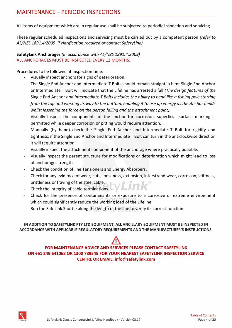
Table of Contents SafetyLink Classic ConcreteLink Lifeline Handbook - Version 08.17 Page 4 of 20
MAINTENANCE – PERIODIC INSPECTIONS All items of equipment which are in regular use shall be subjected to periodic inspection and servicing. These regular scheduled inspections and servicing must be carried out by a competent person (refer to AS/NZS 1891.4:2009 if clarification required or contact SafetyLink). SafetyLink Anchorages (In accordance with AS/NZS 1891.4:2009) ALL ANCHORAGES MUST BE INSPECTED EVERY 12 MONTHS. Procedures to be followed at inspection time:
- Visually inspect anchors for signs of deterioration.
- The Single End Anchor and Intermediate T Bolts should remain straight, a bent Single End Anchor
or Intermediate T Bolt will indicate that the Lifeline has arrested a fall (The design features of the
Single End Anchor and Intermediate T Bolts includes the ability to bend like a fishing pole starting
from the top and working its way to the bottom, enabling it to use up energy as the Anchor bends
whilst lessening the force on the person falling and the attachment point).
- Visually inspect the components of the anchor for corrosion, superficial surface marking is
permitted while deeper corrosion or pitting would require attention.
- Manually (by hand) check the Single End Anchor and Intermediate T Bolt for rigidity and
tightness, if the Single End Anchor and Intermediate T Bolt can turn in the anticlockwise direction
it will require attention.
- Visually inspect the attachment component of the anchorage where practically possible.
- Visually inspect the parent structure for modifications or deterioration which might lead to loss
of anchorage strength.
- Check the condition of line Tensioners and Energy Absorbers.
- Check for any evidence of wear, cuts, looseness, extension, interstrand wear, corrosion, stiffness,
brittleness or fraying of the steel cable.
- Check the integrity of cable terminations.
- Check for the presence of contaminants or exposure to a corrosive or extreme environment
which could significantly reduce the working load of the Lifeline.
- Run the SafeLink Shuttle along the length of the line to verify its correct function.
IN ADDITION TO SAFETYLINK PTY LTD EQUIPMENT, ALL ANCILLARY EQUIPMENT MUST BE INSPECTED IN ACCORDANCE WITH APPLICABLE REGULATORY REQUIREMENTS AND THE MANUFACTURER’S INSTRUCTIONS.
FOR MAINTENANCE ADVICE AND SERVICES PLEASE CONTACT SAFETYLINK
ON +61 249 641068 OR 1300 789545 FOR YOUR NEAREST SAFETYLINK INSPECTION SERVICE CENTRE OR EMAIL: [email protected]
Table of Contents SafetyLink Classic ConcreteLink Lifeline Handbook - Version 08.17 Page 5 of 20
WARRANTIES
EXTRACT: SafetyLink Pty Ltd STANDARD TERMS AND CONDITIONS
11.1 To the extent permitted by law all implied conditions, warranties and undertakings are expressly excluded.
11.2 Except as provided in this clause the Company shall not be liable for any loss or damage, whether direct or indirect (including consequential losses or damage) arising out of any breach of contract by the Company or any negligence of the Company, its employees or agents.
11.3 Should the Company be liable for a breach of a guarantee, condition or warranty implied by the Australian Consumer Law (not being a guarantee, condition or warranty implied by sections 51, 52 and 53 of that Law) then its liability for a breach of any such condition or warranty express or implied shall be limited, at its option, to any one or more of the following.
A) in case of Goods (I) the replacement of the Goods or the supply of equivalent Goods. (II) the repair of the goods, (III) the payment of the cost of replacing the Goods or acquiring equivalent Goods. (IV) The payment of the cost of having the Goods repaired. Provided that any such Goods are returned to the Company by the Purchaser at the Purchaser’s expense.
B) in the case of services (i) the supply of the services again, (ii) the payment of the cost of having the services supplies again.
11.4 The Company will not liable for the costs of recovery of the Goods from the field, loss of use of the Goods, loss of time, inconvenience, incidental or consequential loss or damage, nor for any other loss or damage of her than as stated above, whether ordinary or exemplary, caused either directly or indirectly by use of the Goods.
11.5 The Company warrants that at the time of shipment, Products manufactured by it will be free from defects in material and workmanship. In the absence of a modified written warranty, the Company agrees to making good any such defects by repairing the same or at the Company ’s option by replacement, for a period of (1) one year from the date of shipment. This limited warranty applies provided that:
(a) defects have arising solely from faulty materials or workmanship; (b) the Products have not received maltreatment, inattention or interference; (c) the Products have been installed in accordance with the Company’s Installation Handbooks using
only products supplied by the Company; (d) accessories used with the Products are manufactured by or approved by the Company ; (e) the Products are maintained in accordance with Australian Standard 1891.4 (section 9). (f) you notify any claim under this warranty to SafetyLink in writing to the address below no later than 14
days after the event or occurrence concerning the produce giving rise to the claim and you pay all costs related to your claim.
This warranty does not apply to any defects or other malfunctions caused to the Goods by accident, neglect, vandalism, misuse, alteration, modification or unusual physical, environment or electrical stress.
Please note that the benefits to the purchaser (as a consumer) given by this warranty are in addition to your other rights and remedies under the Australian Consumer Law. Our goods come with guarantees that cannot be excluded under the Australian Consumer Law. You are entitled to a replacement or refund for a major failure and compensation for any other reasonably foreseeable loss or damage. You are also entitled to have the goods repaired or replaced if the goods fail to be of acceptable quality and the failure does not amount to a major failure.
11.6 If any goods are not manufactured by the Company, the guarantee of the manufacturer thereof shall be accepted by the Purchaser as the only express warranty given in respect of the goods.
11.7 Except as provided in this clause 11, all express and implied warranties, guarantees and conditions under statute or general law as the merchantability, description, quality, suitability or fitness of the Products for any purpose or as to design, assembly, installation, materials or workmanship or otherwise are hereby expressly excluded (to the extent to which they may be excluded by law).
PLEASE SEE SAFETYLINK PTY LTD FULL STANDARD TERMS OF CONDITIONS OF SALE FOR FURTHER REFERENCE.
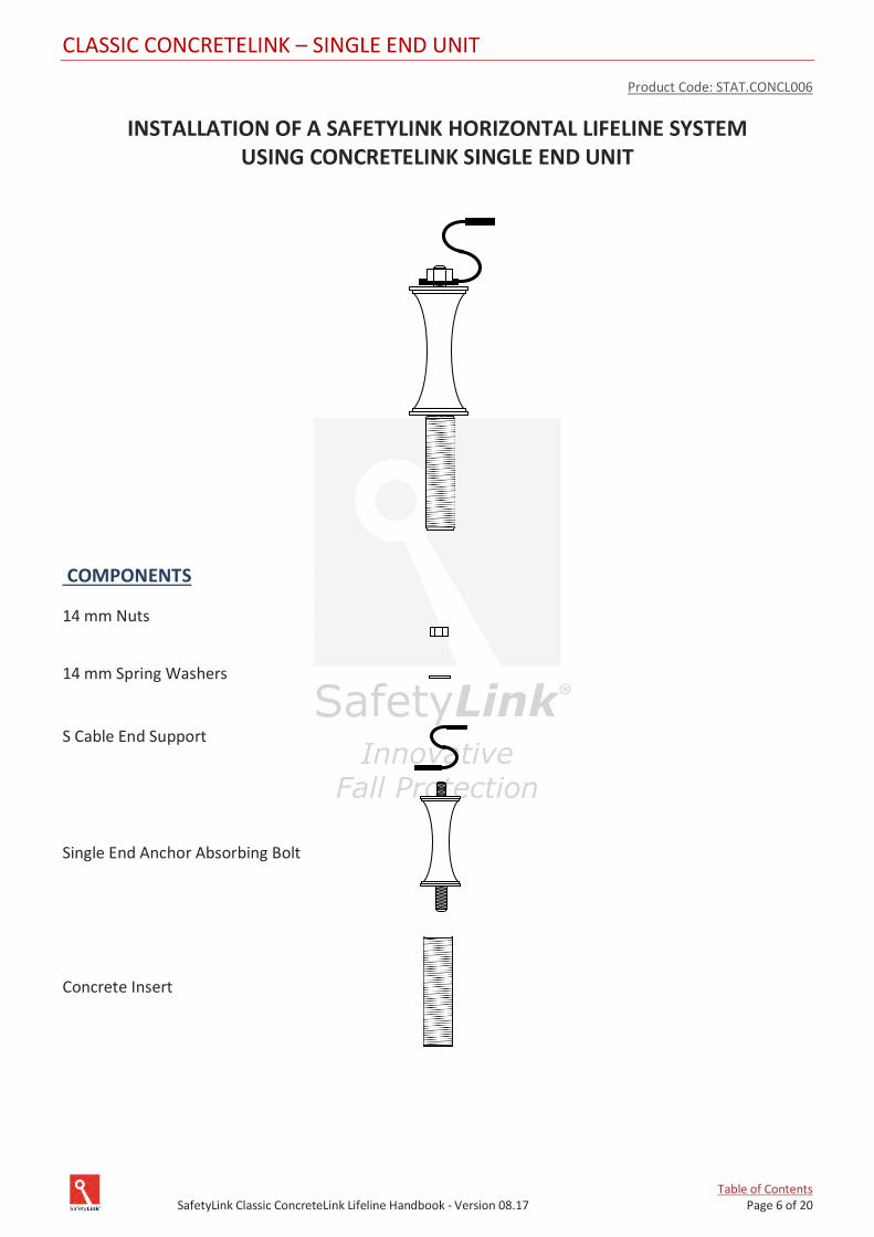
Table of Contents SafetyLink Classic ConcreteLink Lifeline Handbook - Version 08.17 Page 6 of 20
CLASSIC CONCRETELINK – SINGLE END UNIT
Product Code: STAT.CONCL006
INSTALLATION OF A SAFETYLINK HORIZONTAL LIFELINE SYSTEM USING CONCRETELINK SINGLE END UNIT
COMPONENTS
14 mm Nuts
14 mm Spring Washers
S Cable End Support
Single End Anchor Absorbing Bolt
Concrete Insert
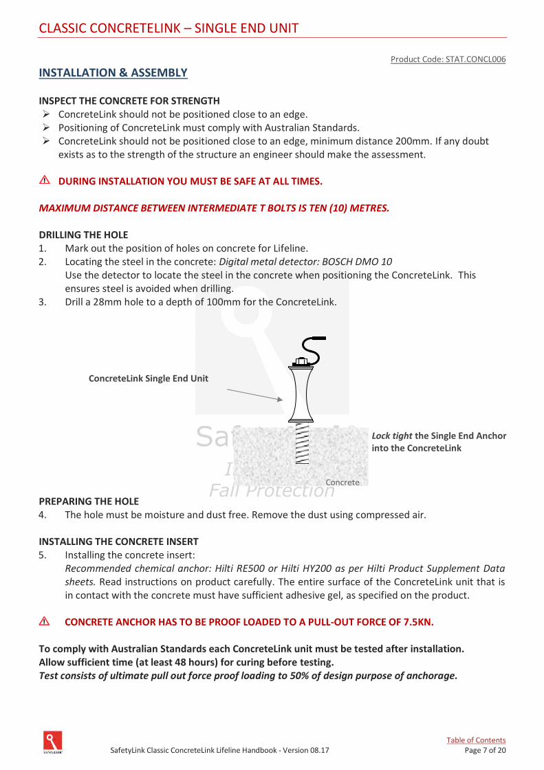
Table of Contents SafetyLink Classic ConcreteLink Lifeline Handbook - Version 08.17 Page 7 of 20
CLASSIC CONCRETELINK – SINGLE END UNIT
Product Code: STAT.CONCL006
INSTALLATION & ASSEMBLY
INSPECT THE CONCRETE FOR STRENGTH ➢ ConcreteLink should not be positioned close to an edge. ➢ Positioning of ConcreteLink must comply with Australian Standards. ➢ ConcreteLink should not be positioned close to an edge, minimum distance 200mm. If any doubt
exists as to the strength of the structure an engineer should make the assessment.
DURING INSTALLATION YOU MUST BE SAFE AT ALL TIMES. MAXIMUM DISTANCE BETWEEN INTERMEDIATE T BOLTS IS TEN (10) METRES. DRILLING THE HOLE 1. Mark out the position of holes on concrete for Lifeline. 2. Locating the steel in the concrete: Digital metal detector: BOSCH DMO 10 Use the detector to locate the steel in the concrete when positioning the ConcreteLink. This
ensures steel is avoided when drilling. 3. Drill a 28mm hole to a depth of 100mm for the ConcreteLink.
PREPARING THE HOLE 4. The hole must be moisture and dust free. Remove the dust using compressed air.
INSTALLING THE CONCRETE INSERT 5. Installing the concrete insert:
Recommended chemical anchor: Hilti RE500 or Hilti HY200 as per Hilti Product Supplement Data sheets. Read instructions on product carefully. The entire surface of the ConcreteLink unit that is in contact with the concrete must have sufficient adhesive gel, as specified on the product.
CONCRETE ANCHOR HAS TO BE PROOF LOADED TO A PULL-OUT FORCE OF 7.5KN.
To comply with Australian Standards each ConcreteLink unit must be tested after installation. Allow sufficient time (at least 48 hours) for curing before testing. Test consists of ultimate pull out force proof loading to 50% of design purpose of anchorage.
ConcreteLink Single End Unit
Concrete
Lock tight the Single End Anchor into the ConcreteLink
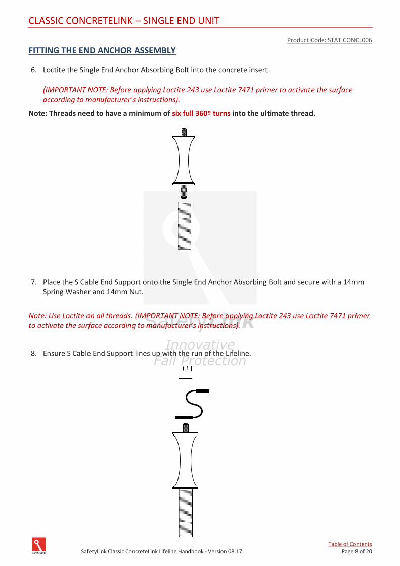
Table of Contents SafetyLink Classic ConcreteLink Lifeline Handbook - Version 08.17 Page 8 of 20
CLASSIC CONCRETELINK – SINGLE END UNIT
Product Code: STAT.CONCL006
FITTING THE END ANCHOR ASSEMBLY
6. Loctite the Single End Anchor Absorbing Bolt into the concrete insert. (IMPORTANT NOTE: Before applying Loctite 243 use Loctite 7471 primer to activate the surface according to manufacturer’s instructions).
Note: Threads need to have a minimum of six full 360º turns into the ultimate thread.
7. Place the S Cable End Support onto the Single End Anchor Absorbing Bolt and secure with a 14mm Spring Washer and 14mm Nut.
Note: Use Loctite on all threads. (IMPORTANT NOTE: Before applying Loctite 243 use Loctite 7471 primer to activate the surface according to manufacturer’s instructions).
8. Ensure S Cable End Support lines up with the run of the Lifeline.
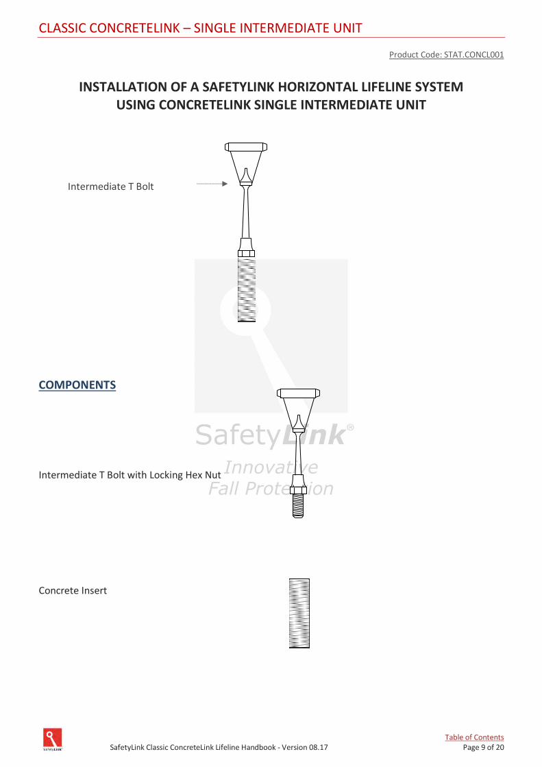
Table of Contents SafetyLink Classic ConcreteLink Lifeline Handbook - Version 08.17 Page 9 of 20
CLASSIC CONCRETELINK – SINGLE INTERMEDIATE UNIT
Product Code: STAT.CONCL001
INSTALLATION OF A SAFETYLINK HORIZONTAL LIFELINE SYSTEM
USING CONCRETELINK SINGLE INTERMEDIATE UNIT
COMPONENTS
Intermediate T Bolt with Locking Hex Nut
Concrete Insert
Intermediate T Bolt
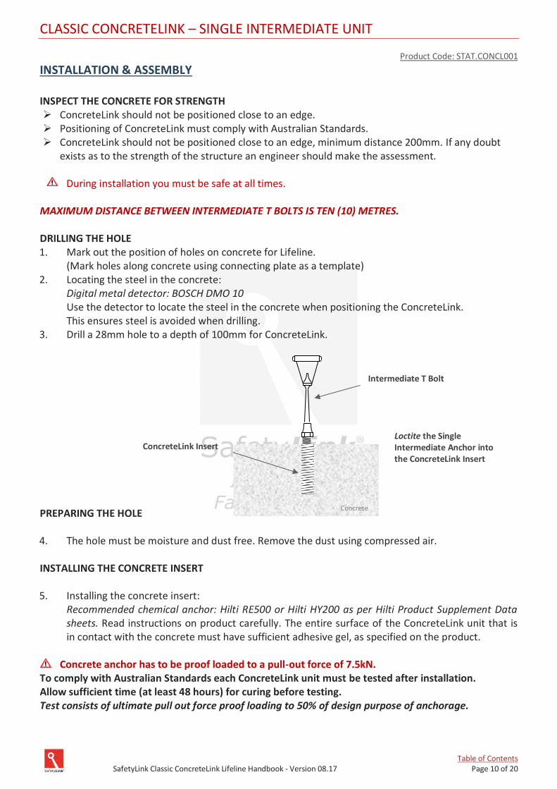
Table of Contents SafetyLink Classic ConcreteLink Lifeline Handbook - Version 08.17 Page 10 of 20
CLASSIC CONCRETELINK – SINGLE INTERMEDIATE UNIT
Product Code: STAT.CONCL001
INSTALLATION & ASSEMBLY
INSPECT THE CONCRETE FOR STRENGTH ➢ ConcreteLink should not be positioned close to an edge. ➢ Positioning of ConcreteLink must comply with Australian Standards. ➢ ConcreteLink should not be positioned close to an edge, minimum distance 200mm. If any doubt
exists as to the strength of the structure an engineer should make the assessment.
During installation you must be safe at all times. MAXIMUM DISTANCE BETWEEN INTERMEDIATE T BOLTS IS TEN (10) METRES. DRILLING THE HOLE 1. Mark out the position of holes on concrete for Lifeline. (Mark holes along concrete using connecting plate as a template) 2. Locating the steel in the concrete:
Digital metal detector: BOSCH DMO 10 Use the detector to locate the steel in the concrete when positioning the ConcreteLink. This ensures steel is avoided when drilling. 3. Drill a 28mm hole to a depth of 100mm for ConcreteLink. PREPARING THE HOLE 4. The hole must be moisture and dust free. Remove the dust using compressed air. INSTALLING THE CONCRETE INSERT 5. Installing the concrete insert:
Recommended chemical anchor: Hilti RE500 or Hilti HY200 as per Hilti Product Supplement Data sheets. Read instructions on product carefully. The entire surface of the ConcreteLink unit that is in contact with the concrete must have sufficient adhesive gel, as specified on the product.
Concrete anchor has to be proof loaded to a pull-out force of 7.5kN.
To comply with Australian Standards each ConcreteLink unit must be tested after installation. Allow sufficient time (at least 48 hours) for curing before testing. Test consists of ultimate pull out force proof loading to 50% of design purpose of anchorage.
Intermediate T Bolt
ConcreteLink Insert
Loctite the Single Intermediate Anchor into the ConcreteLink Insert
Concrete
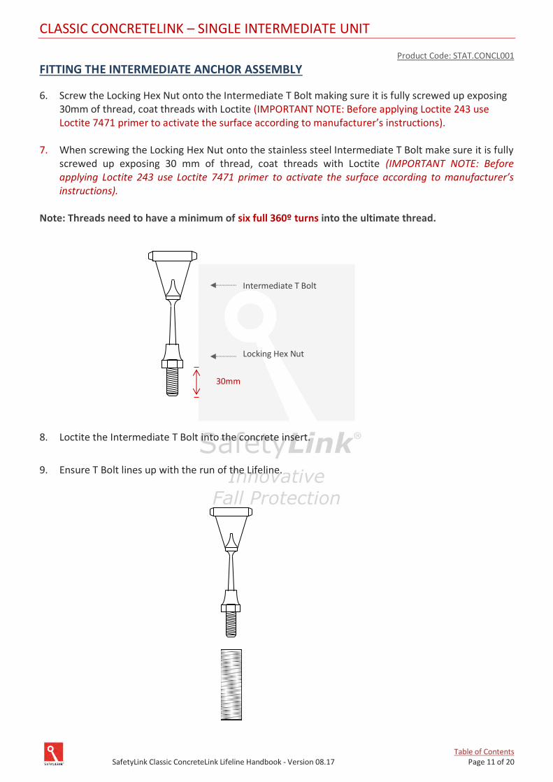
Table of Contents SafetyLink Classic ConcreteLink Lifeline Handbook - Version 08.17 Page 11 of 20
CLASSIC CONCRETELINK – SINGLE INTERMEDIATE UNIT
Product Code: STAT.CONCL001
FITTING THE INTERMEDIATE ANCHOR ASSEMBLY
6. Screw the Locking Hex Nut onto the Intermediate T Bolt making sure it is fully screwed up exposing 30mm of thread, coat threads with Loctite (IMPORTANT NOTE: Before applying Loctite 243 use Loctite 7471 primer to activate the surface according to manufacturer’s instructions).
7. When screwing the Locking Hex Nut onto the stainless steel Intermediate T Bolt make sure it is fully
screwed up exposing 30 mm of thread, coat threads with Loctite (IMPORTANT NOTE: Before applying Loctite 243 use Loctite 7471 primer to activate the surface according to manufacturer’s instructions).
Note: Threads need to have a minimum of six full 360º turns into the ultimate thread.
8. Loctite the Intermediate T Bolt into the concrete insert.
9. Ensure T Bolt lines up with the run of the Lifeline.
Intermediate T Bolt Locking Hex Nut
30mm
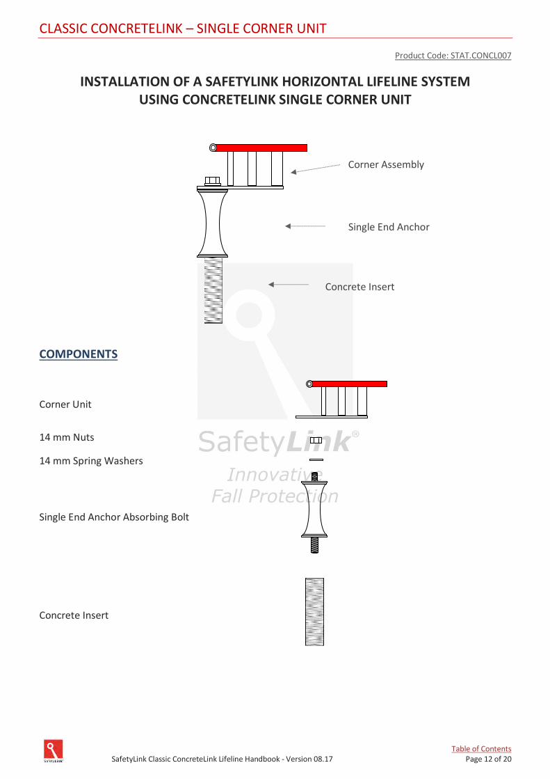
Table of Contents SafetyLink Classic ConcreteLink Lifeline Handbook - Version 08.17 Page 12 of 20
CLASSIC CONCRETELINK – SINGLE CORNER UNIT
Product Code: STAT.CONCL007
INSTALLATION OF A SAFETYLINK HORIZONTAL LIFELINE SYSTEM USING CONCRETELINK SINGLE CORNER UNIT
COMPONENTS
Corner Unit
14 mm Nuts
14 mm Spring Washers
Single End Anchor Absorbing Bolt
Concrete Insert
Single End Anchor
Corner Assembly
Concrete Insert
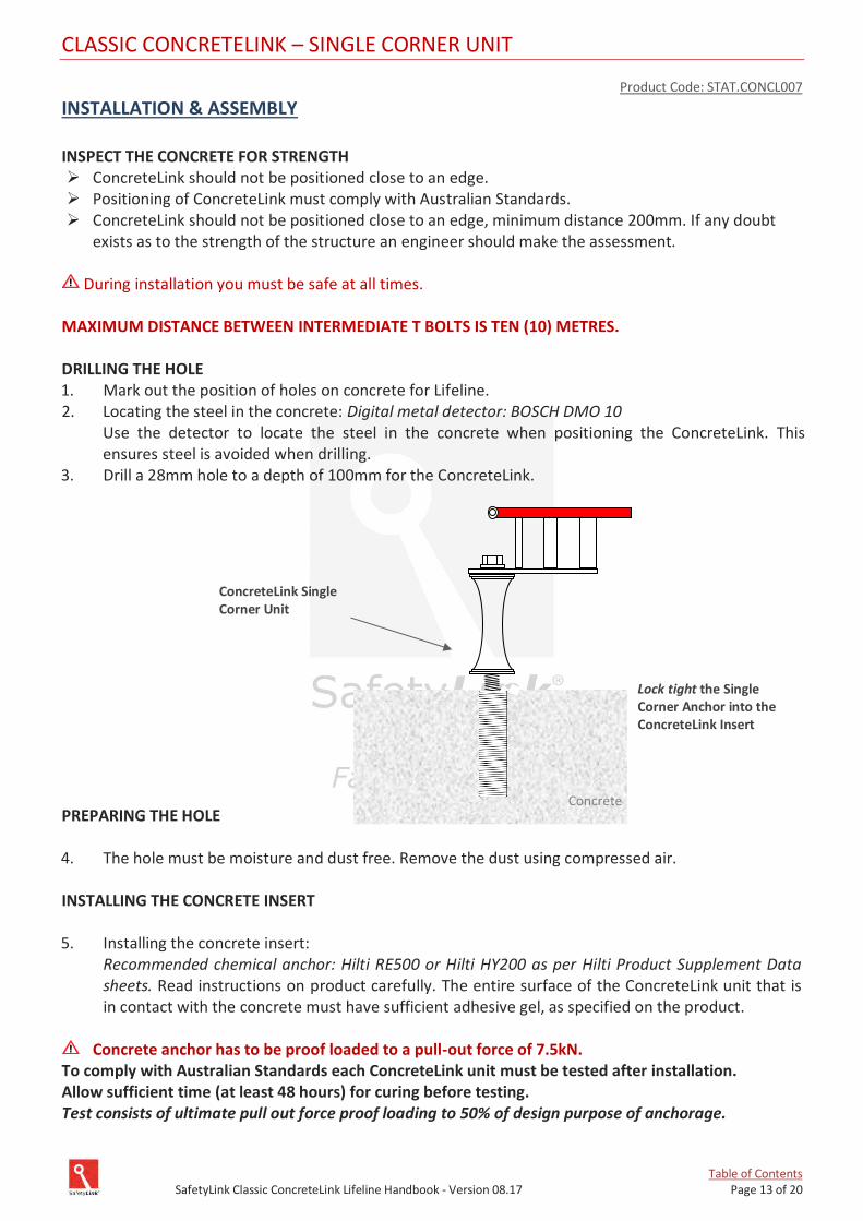
Table of Contents SafetyLink Classic ConcreteLink Lifeline Handbook - Version 08.17 Page 13 of 20
CLASSIC CONCRETELINK – SINGLE CORNER UNIT
Product Code: STAT.CONCL007
INSTALLATION & ASSEMBLY
INSPECT THE CONCRETE FOR STRENGTH ➢ ConcreteLink should not be positioned close to an edge. ➢ Positioning of ConcreteLink must comply with Australian Standards. ➢ ConcreteLink should not be positioned close to an edge, minimum distance 200mm. If any doubt
exists as to the strength of the structure an engineer should make the assessment.
During installation you must be safe at all times. MAXIMUM DISTANCE BETWEEN INTERMEDIATE T BOLTS IS TEN (10) METRES. DRILLING THE HOLE 1. Mark out the position of holes on concrete for Lifeline. 2. Locating the steel in the concrete: Digital metal detector: BOSCH DMO 10 Use the detector to locate the steel in the concrete when positioning the ConcreteLink. This
ensures steel is avoided when drilling. 3. Drill a 28mm hole to a depth of 100mm for the ConcreteLink. PREPARING THE HOLE 4. The hole must be moisture and dust free. Remove the dust using compressed air.
INSTALLING THE CONCRETE INSERT
5. Installing the concrete insert:
Recommended chemical anchor: Hilti RE500 or Hilti HY200 as per Hilti Product Supplement Data sheets. Read instructions on product carefully. The entire surface of the ConcreteLink unit that is in contact with the concrete must have sufficient adhesive gel, as specified on the product.
Concrete anchor has to be proof loaded to a pull-out force of 7.5kN.
To comply with Australian Standards each ConcreteLink unit must be tested after installation. Allow sufficient time (at least 48 hours) for curing before testing. Test consists of ultimate pull out force proof loading to 50% of design purpose of anchorage.
Lock tight the Single Corner Anchor into the ConcreteLink Insert
ConcreteLink Single Corner Unit
Concrete
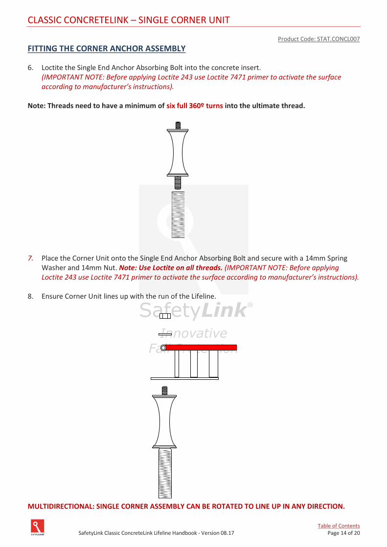
Table of Contents SafetyLink Classic ConcreteLink Lifeline Handbook - Version 08.17 Page 14 of 20
CLASSIC CONCRETELINK – SINGLE CORNER UNIT
Product Code: STAT.CONCL007
FITTING THE CORNER ANCHOR ASSEMBLY
6. Loctite the Single End Anchor Absorbing Bolt into the concrete insert. (IMPORTANT NOTE: Before applying Loctite 243 use Loctite 7471 primer to activate the surface according to manufacturer’s instructions).
Note: Threads need to have a minimum of six full 360º turns into the ultimate thread. 7. Place the Corner Unit onto the Single End Anchor Absorbing Bolt and secure with a 14mm Spring
Washer and 14mm Nut. Note: Use Loctite on all threads. (IMPORTANT NOTE: Before applying Loctite 243 use Loctite 7471 primer to activate the surface according to manufacturer’s instructions).
8. Ensure Corner Unit lines up with the run of the Lifeline.
MULTIDIRECTIONAL: SINGLE CORNER ASSEMBLY CAN BE ROTATED TO LINE UP IN ANY DIRECTION.

Table of Contents SafetyLink Classic ConcreteLink Lifeline Handbook - Version 08.17 Page 15 of 20
LIFELINE SYSTEM
INSTALLATION: HORIZONTALLY ON ROOF PITCHES BELOW 25 DEGREES
1. Install Swaged/Swageless Termination to the cable in accordance with product guidelines. See
Appendix A.
2. Determine which end is most suitable to have the cable Tensioner with Tension Indicator. (Some
lifelines may require a Tensioner with Tension Indicator on both ends). Connect the cable with
Termination end to the FrogLine End Anchor top connection point. This will be at the opposite end to
where the Tensioner end will be. (Ensure securing pin has been installed correctly).
3. Run the cable through Intermediates and Corners to the opposite end of the Lifeline system
(Intermediates must be installed as per installation manual, maximum distance between
Intermediates is 10 metres).
4. Connect Swaged/Swageless Tensioner with Tension Indicator to FrogLine End Anchor top connection
point. (Do not attach Tensioner to cable at this stage).
5. Adjust the Tensioner out to the maximum safe length.
6. Match the cable along the side of the Tensioner and mark where to cut cable so that it will reach
safely in to the Tensioner unit in accordance with product guidelines. Appendix A.
7. Cut cable to length.
8. Install Swage/Swageless Tensioner fitting to cable as per Appendix A. Connect Tensioner to FrogLine
End Anchor top connection point (Ensure securing pin has been installed correctly).
9. Tension cable until the disc on the Tension Indicator can spin and indicates 80kg/8kn/800n.
COMPLETE LAYOUT DIAGRAM
TIGHTENING TORQUE FOR SWAGELESS TERMINALS
Wire size: Nm Lbf ft
Ø 3 - 11 8.25
- 1/8” 11 8.25
Ø 4 5/32” 17 12.75
- 3/16” 22 16.5
Ø 5 - 22 16.5
- 7/32 38 28.5
Ø 6 - 38 28.5
- 1/4” 38 28.5
Ø 7 9/32” 48 35.5
Ø 8 5/16” 58 43.0
- 3/8” 75 55.5
Ø 10 - 75 55.5
Ø 12 -
- 1/2”
Ø 14 -
Ø 16 -

Table of Contents SafetyLink Classic ConcreteLink Lifeline Handbook - Version 08.17 Page 16 of 20
APPENDIX A – SWAGELESS/SWAGED FITTINGS INSTALLATION
INSTALLATION
Make sure that the cable matches the terminal. The SS terminal use only for 8mm 7x7 and 7 x 19 Stainless Wire. Do no reuse jaws or house.
1 Slide the jaw housing in place on the cable. 2 Slide the jaws onto the cable, ensuring there is equal space between the jaws. 3 Place the brass pressure ring on the end of the cable. Make sure that the distance from the
pressure ring to the end of the cable is 5-8mm. 4 Slide the jaw housing over the jaws. 5 The terminal can now be assembled. Screw the head on the jaw housing with a torque wrench –
min. 58 Nm (43Lbf ft), Tighten the lock nut with min. 50 Nm (36 Lbf ft).
Note: after the first dynamic load the terminal MUST be tightened again. When assembling Swageless Terminals the breaking strength of the cable will be reduced by 0-15%. The user is responsible for choosing the proper cable, and for correct assembly.
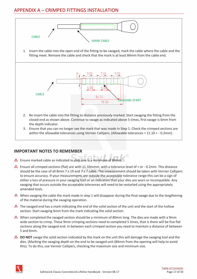
Table of Contents SafetyLink Classic ConcreteLink Lifeline Handbook - Version 08.17 Page 17 of 20
APPENDIX A – CRIMPED FITTINGS INSTALLATION
1. Insert the cable into the open end of the fitting to be swaged, mark the cable where the cable and the fitting meet. Remove the cable and check that the mark is at least 84mm from the cable end.
2. Re-insert the cable into the fitting to distance previously marked. Start swaging the fitting from the
closed end as shown above. Continue to swage as indicated above 5 times, first swage is 6mm from the depth indicator.
3. Ensure that you can no longer see the mark that was made in Step 1. Check the crimped sections are within the allowable tolerances using Vernier Callipers. (Allowable tolerances = 11.10 + - 0.2mm).
IMPORTANT NOTES TO REMEMBER
Ensure marked cable as indicated in step one is a minimum of 84mm.
Ensure all crimped sections (flat) are with 11.10mmm, with a tolerance level of + or - 0.2mm. This distance should be the case of all 8mm 7 x 19 and 7 x 7 cable. The measurement should be taken with Vernier Callipers to ensure accuracy. If your measurements are outside the acceptable tolerance range this can be a sign of either a loss of pressure in your swaging tool or an indication that your dies are worn or incompatible. Any swaging that occurs outside the acceptable tolerances will need to be restarted using the appropriately amended tools.
When swaging the cable the mark made in step 1 will disappear during the final swage due to the lengthening of the material during the swaging operation.
The swaged end has a mark indicating the end of the solid section of the unit and the start of the hollow section. Start swaging 6mm from the mark indicating the solid section.
When completed the swaged section should be a minimum of 80mm long. The dies are made with a 9mm wide section to crimp. These 9mm crimping sections need to completed 5 times, that is there will be five flat sections along the swaged end. In between each crimped section you need to maintain a distance of between 5 and 6mm.
DO NOT swage the solid section indicated by the mark on the unit this will damage the swaging tool and the dies. (Marking the swaging depth on the end to be swaged unit (84mm from the opening will help to avoid this). To do this, use Vernier Callipers, checking the maximum size and minimum size.
SWAGING START
MARK CABLE CABLE
CABLE
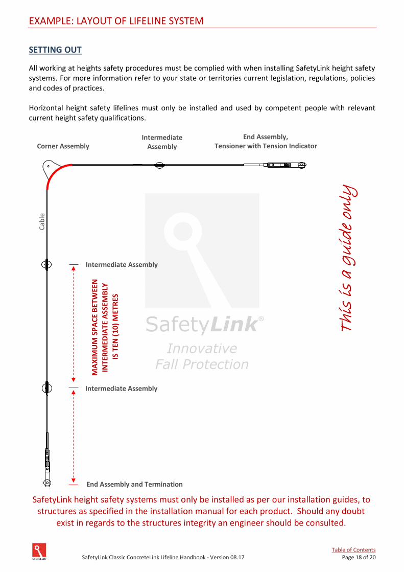
Table of Contents SafetyLink Classic ConcreteLink Lifeline Handbook - Version 08.17 Page 18 of 20
EXAMPLE: LAYOUT OF LIFELINE SYSTEM
SETTING OUT
All working at heights safety procedures must be complied with when installing SafetyLink height safety systems. For more information refer to your state or territories current legislation, regulations, policies and codes of practices. Horizontal height safety lifelines must only be installed and used by competent people with relevant current height safety qualifications.
SafetyLink height safety systems must only be installed as per our installation guides, to structures as specified in the installation manual for each product. Should any doubt
exist in regards to the structures integrity an engineer should be consulted.
HO
RIZ
ON
TA
L T
his
is
a g
uid
e on
ly
MA
XIM
UM
SP
AC
E B
ETW
EEN
INTE
RM
EDIA
TE A
SSEM
BLY
IS T
EN (
10)
MET
RES
Cab
le
End Assembly and Termination
Intermediate Assembly
Intermediate Assembly
End Assembly, Tensioner with Tension Indicator Corner Assembly
Intermediate Assembly
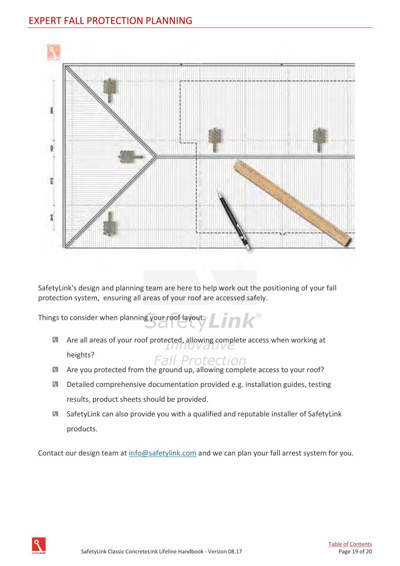
Table of Contents SafetyLink Classic ConcreteLink Lifeline Handbook - Version 08.17 Page 19 of 20
EXPERT FALL PROTECTION PLANNING
SafetyLink's design and planning team are here to help work out the positioning of your fall protection system, ensuring all areas of your roof are accessed safely. Things to consider when planning your roof layout:
Are all areas of your roof protected, allowing complete access when working at
heights?
Are you protected from the ground up, allowing complete access to your roof?
Detailed comprehensive documentation provided e.g. installation guides, testing
results, product sheets should be provided.
SafetyLink can also provide you with a qualified and reputable installer of SafetyLink
products.
Contact our design team at [email protected] and we can plan your fall arrest system for you.
IN CASE OF ACCIDENT
A FALL RESCUE PLAN SHOULD BE DEVELOPED PRIOR TO USING SAFETYLINK EQUIPMENT.
PERSONS WORKING AT HEIGHTS SHOULD NOT WORK ALONE. It is critical that before using any SafetyLink Systems a fall rescue plan is in place for any persons suspended mid-air following a fall. Serious injury or death can occur in a matter of minutes, particularly if a person’s movement or breathing is restricted or loss of consciousness has occurred. In accordance with your fall rescue plan and appropriate first aid procedures it is essential to remove the person from the suspended position as quickly as possible. IN ACCORDANCE WITH AS/NZS 1891.4:2009 CLAUSE 9.5 EQUIPMENT WHICH HAS ARRESTED A FALL OR SHOWS A DEFECT Any piece of equipment including both personal and permanently installed items, which has been used to arrest a fall or which shows any defect during operator or periodic inspection shall be withdrawn from service immediately and a replacement obtained if necessary. A label indicating the condition or defect should be attached to the equipment, and it should be examined by a competent person who will decide whether the equipment is to be destroyed or repaired if necessary and returned to service. In the latter case, details of any repair shall be documented and a copy given to the operator.
Terms/Conditions/Warranties
DISTRIBUTOR:
SafetyLink Pty Ltd | ABN 83 081 777 371 Phone: 1300 789 545 or +61 2 4964 1068| Fax: 1300 738 071 or +61 2 49641069
[email protected] | www.safetylink.com


![PERIODIC CLASSIFICATION & PERIODIC PROPERTIES [ 1 ...youvaacademy.com/youvaadmin/image/PERIODIC TABLE BY RS.pdf · [ 2 ] PERIODIC CLASSIFICATION & PERIODIC PROPERTIES BY RAJESH SHAH](https://img.pdfslide.net/doc/110x75/604570870a43592d4f6b3e29/periodic-classification-periodic-properties-1-table-by-rspdf-2.jpg)