Embed Size (px)
Citation preview
Classic Products, Inc.
ClickLock Standing Seam
Installation Manual
Classic Products, Inc.
8510 Industry Park Drive
Piqua, OH 45356
800.543.8938

Table of Contents page
Introduction………………………………………………………………………………………………… 1. 1
Starter………………………………………………………………………………………………………. 2. 1
Panels………………………………………………………………………………………………………. 3. 1
Z Cleats…………………………………………………………………………………………………….. 4. 1
Gable Edge Trim……………………………………………………………………………………..…….. 5. 1
Sidewall…………………………………………………………………………………………….…...…. 6. 1
Protrusions………………………………………………………………………………………….……… 7. 1
Pitch Change…………………………………………………………………….……………………….… 8. 1
Hip and Ridge………...……………………………………………………………….…………………… 9. 1
Valley………………………………………………………………………………………………………10.1
Panels into a Valley…………………………………………………………………………….…………..11.1
Introduction
1. 1
DESCRIPTION
ClickLock Standing Seam roof panels are 12" wide and
.032" thick (nominal).
GENERAL INSTALLATION INSTRUCTIONS
Fastener Specifications Only use stainless steel screws and only use stainless
steel or aluminum pop rivets.
Screws should be long enough so the tip of the screw
and at least 1/8" of the full shank penetrates through solid
decking.
Install 1 clip per foot of panel and at least 2 clips per
panel. Attach each clip with at least 2 screws. When
attaching the clips, the head of the screw must set tight
against the top of the clip.
Use only the accessories designed for use with
ClickLock. Do not install accessories of dissimilar
metals with this system. To protect against moisture
problems and/or electrolytic corrosion, insulate the
product from contact with existing masonry or metal by
coating with bituminous paint or mastic and separating
with a layer of underlayment.
Do not walk on the panels’ locks. When work must be
done from installed panels, protect the panels with
carpet, foam or other nonabrasive material. Take care
not to scratch the panels’ surfaces. Minimize the use of
touch-up paint.
Always keep the uphill portions of flashings on top of
the downhill portions to prevent water from running
under the flashings.
SUGGESTED TOOLS
Some of the tools that may be needed for the proper
installation include:
Hammer Power saw & mitre Tin snips Utility knife Pop rivet gun Hand drill 9/64”�drill bits Hand flangers Pliers Scaffolding Ladders Tape measure
Chalk line Portable brake Caulking gun Compass Soap pencil Extension cords Safety Glasses Zip Tool
Remember to follow each tool manufacturer’s
instructions on safety and maintenance.
SAFETY CONSIDERATIONS
Caution must be exercised when positioning a ladder.
Set the ladder to extend at least 36" above the point of
support. Set the ladder at an angle so that the horizontal
distance from the foot of the ladder to the building is
about one fourth of the working length of the ladder. The
ladder should be secured to a permanent part of the roof
to ensure safety. Inspect for damaged rungs and examine
the locking system.
Upon reaching the roof, inspect it for working hazards.
Note the presence of loose roofing or weakened
substrate, protrusions such as pipe flashings, electrical
wiring, nails, stabilizing wires, moss growth or
dampness that might make the roof slippery, material
and equipment that could slip, and extension cords.
Power saws, especially on cutbacks, must be handled
with extreme caution, and should be used by only
professional, experienced installers. The use of safety
glasses is essential not only during cutback procedures
but also when cutting panels. Pay attention to the
presence of other individuals on the roof.
SLOPE REQUIREMENTS
The minimum roof pitch is 1 1/2:12 (one and one half:
twelve).
ROOF TEAR OFF
Assure the homeowner that property will not be
damaged during tear off. Workers should employ
caution at all times during this procedure.
Dust control is critical when removing old roofing. Old
roofing should be placed in barrels, which are then
unloaded off the roof into a container located close to the
work area.
Before starting a project, check for any obvious interior
and exterior damage.
Introduction
1. 2
Replace damaged or rotted areas with new lumber before
roofing.
After the old roof has been removed and any deteriorated
lumber has been replaced, install ½" minimum decking.
Fasten per local code requirements.
The building inspector may wish to inspect the deck
before installation begins. Be sure to comply with local
building codes.
ROOF PREPARATION
Existing Asphalt Composition Shingles, Clay Tile,
Cement Tile, Wood Shingles, Wood Shakes and metal
roofing must be removed before installing decking (if
required), underlayment and roofing.
If damage has occurred, remove and replace the
damaged material. Remove all roof debris.
SHEATHING & UNDERLAYMENT
The minimum sheathing thickness for new construction
application is ½” plywood type sheathing or equivalent.
Follow local codes to anchor the plywood sheathing
securely to the roof framing. Inspect the plywood for
gaps and weak spots.
The minimum requirement for underlayment is one layer SP-6000 Roof Guard or other approved underlayment.
If asphalt-saturated felt is used as underlayment, it
should not come in contact with the backs of the panels.
As the felt gets hot it will stick to the backs of the
panels. As the panels expand and contract, the panels
will tear the felt. If felt is used, a slip-sheet must be
installed between the felt and the panels. Resin paper is a
suitable slip-sheet.
A minimum 18” vertical and 6” horizontal lap is
required. Underlayment should overhang all roof edges
and extend up all penetrations at least 1½”
Underlayment should be securely fastened every square
foot and the horizontal laps should be fastened every 6
inches using N-501 Plastic Top Nails. The underlayment
is fastened as needed to resist tearing or wind blow off.
Check the local building code for the underlayment
installation requirements.
Around a large protrusion, such as a chimney, skylight
or dormer, cut the underlayment to extend at least 1½"
up the protrusion. Where underlayment is cut around any
protrusion, apply roofing cement or VP-275 sealant to
ensure a watertight seal. It is important to try to do this
neatly and not puncture or tear the underlayment.
At a valley, run the underlayment completely across so
that the courses of underlayment are interwoven and lap
at least 6” at the top of the preceding ply, providing
double coverage at the valley. The underlayment should
conform to the valley to avoid any tears or punctures.
Apply a third layer of underlayment with a full width
extending the entire length of the valley.
If the underlayment tears or fractures, install patches
made of underlayment and roofing cement to seal these
areas thoroughly.
It is critical that the underlayment be installed properly
to avoid problems in the future. Metal roofing can
develop condensation beneath it during certain weather
conditions. The underlayment prevents such moisture
from causing a problem.
Starter
2. 1
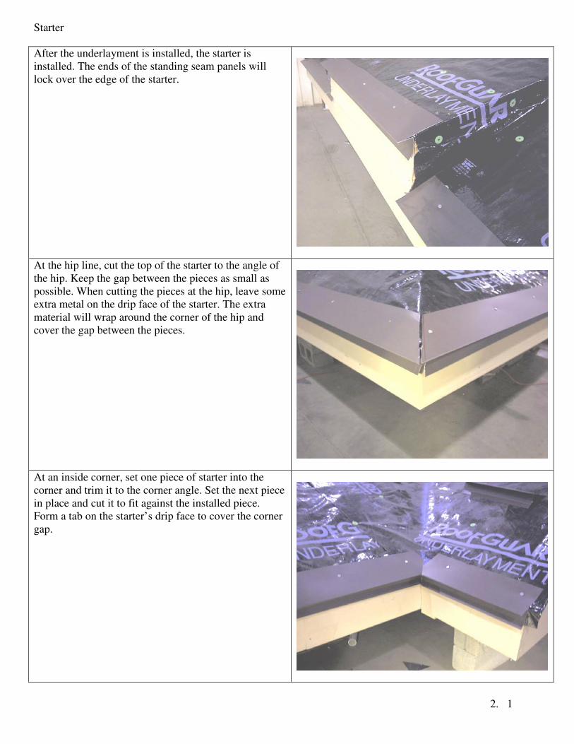
After the underlayment is installed, the starter is
installed. The ends of the standing seam panels will
lock over the edge of the starter.
At the hip line, cut the top of the starter to the angle of
the hip. Keep the gap between the pieces as small as
possible. When cutting the pieces at the hip, leave some
extra metal on the drip face of the starter. The extra
material will wrap around the corner of the hip and
cover the gap between the pieces.
At an inside corner, set one piece of starter into the
corner and trim it to the corner angle. Set the next piece
in place and cut it to fit against the installed piece.
Form a tab on the starter’s drip face to cover the corner
gap.
Starter
2. 2
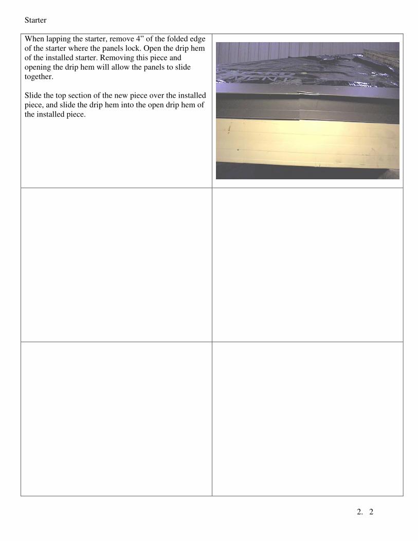
When lapping the starter, remove 4” of the folded edge
of the starter where the panels lock. Open the drip hem
of the installed starter. Removing this piece and
opening the drip hem will allow the panels to slide
together.
Slide the top section of the new piece over the installed
piece, and slide the drip hem into the open drip hem of
the installed piece.
Panels
3. 1
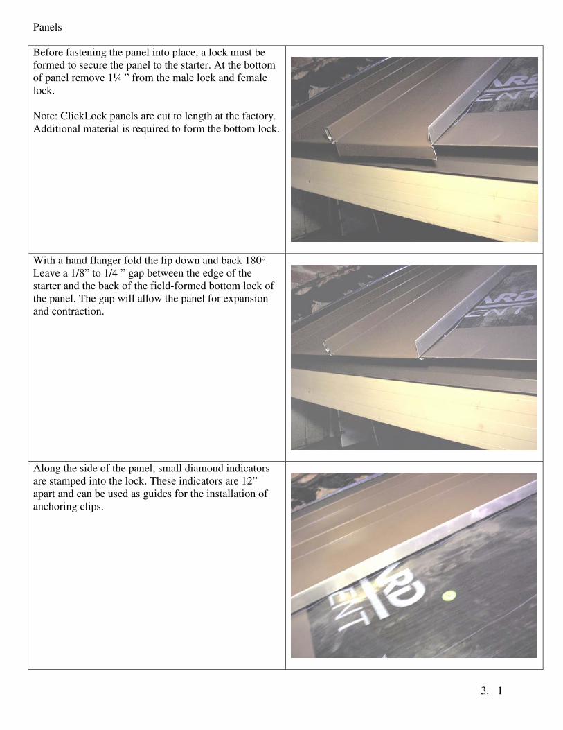
Before fastening the panel into place, a lock must be
formed to secure the panel to the starter. At the bottom
of panel remove 1¼ ” from the male lock and female
lock.
Note: ClickLock panels are cut to length at the factory.
Additional material is required to form the bottom lock.
With a hand flanger fold the lip down and back 180O.
Leave a 1/8” to 1/4 ” gap between the edge of the
starter and the back of the field-formed bottom lock of
the panel. The gap will allow the panel for expansion
and contraction.
Along the side of the panel, small diamond indicators
are stamped into the lock. These indicators are 12”
apart and can be used as guides for the installation of
anchoring clips.
Panels
3. 2
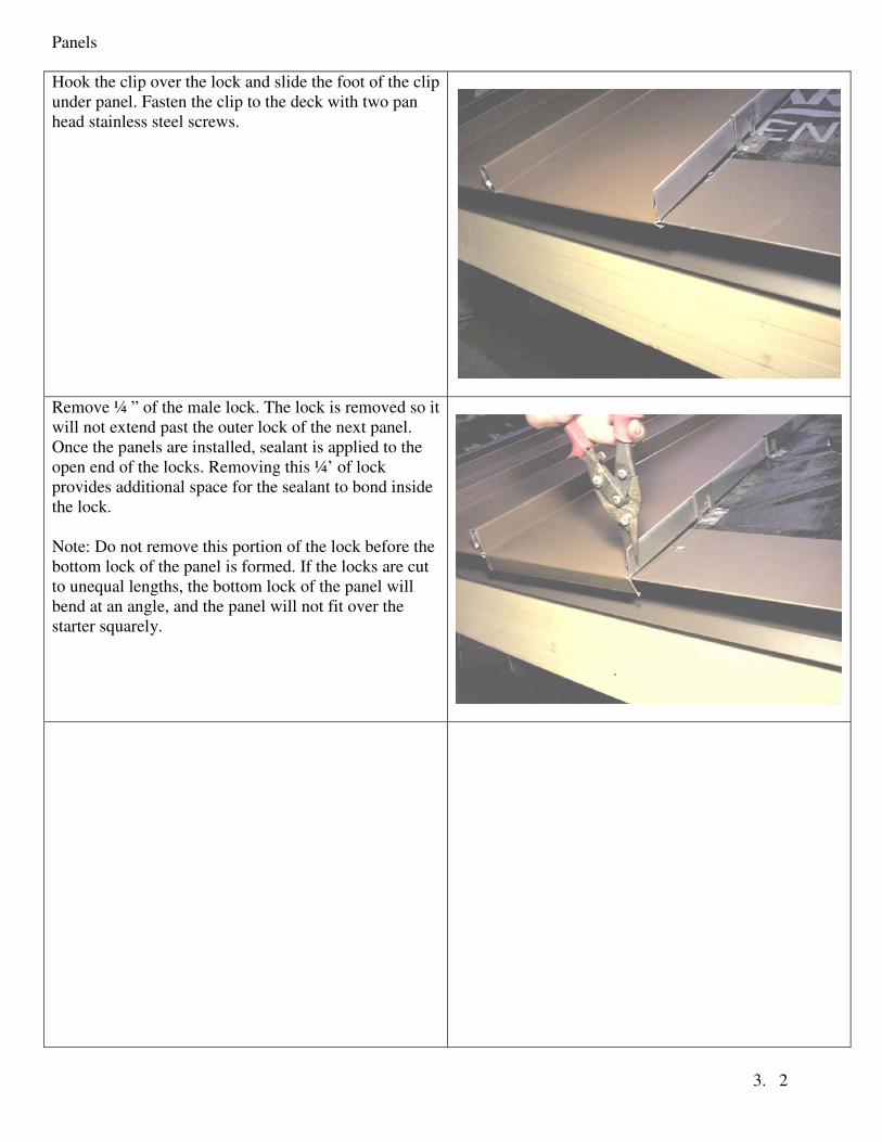
Hook the clip over the lock and slide the foot of the clip
under panel. Fasten the clip to the deck with two pan
head stainless steel screws.
Remove ¼ ” of the male lock. The lock is removed so it
will not extend past the outer lock of the next panel.
Once the panels are installed, sealant is applied to the
open end of the locks. Removing this ¼’ of lock
provides additional space for the sealant to bond inside
the lock.
Note: Do not remove this portion of the lock before the
bottom lock of the panel is formed. If the locks are cut
to unequal lengths, the bottom lock of the panel will
bend at an angle, and the panel will not fit over the
starter squarely.
Z -Cleats
4. 1
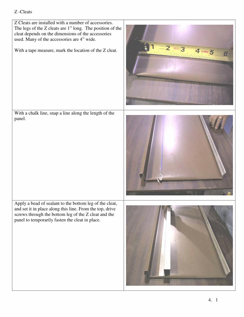
Z Cleats are installed with a number of accessories.
The legs of the Z cleats are 1” long. The position of the
cleat depends on the dimensions of the accessories
used. Many of the accessories are 4” wide.
With a tape measure, mark the location of the Z cleat.
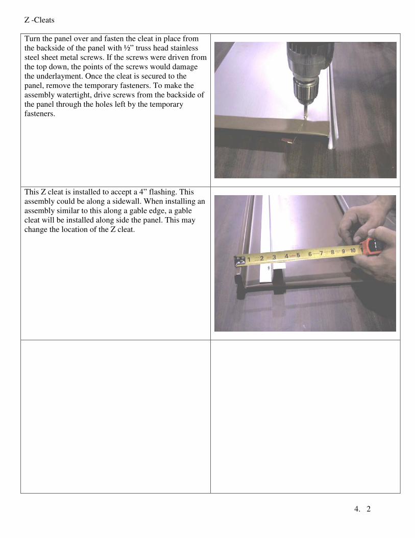
With a chalk line, snap a line along the length of the
panel.
Apply a bead of sealant to the bottom leg of the cleat,
and set it in place along this line. From the top, drive
screws through the bottom leg of the Z cleat and the
panel to temporarily fasten the cleat in place.
Z -Cleats
4. 2
Turn the panel over and fasten the cleat in place from
the backside of the panel with ½” truss head stainless
steel sheet metal screws. If the screws were driven from
the top down, the points of the screws would damage
the underlayment. Once the cleat is secured to the
panel, remove the temporary fasteners. To make the
assembly watertight, drive screws from the backside of
the panel through the holes left by the temporary
fasteners.
This Z cleat is installed to accept a 4” flashing. This
assembly could be along a sidewall. When installing an
assembly similar to this along a gable edge, a gable
cleat will be installed along side the panel. This may
change the location of the Z cleat.
Gable Edge Trim
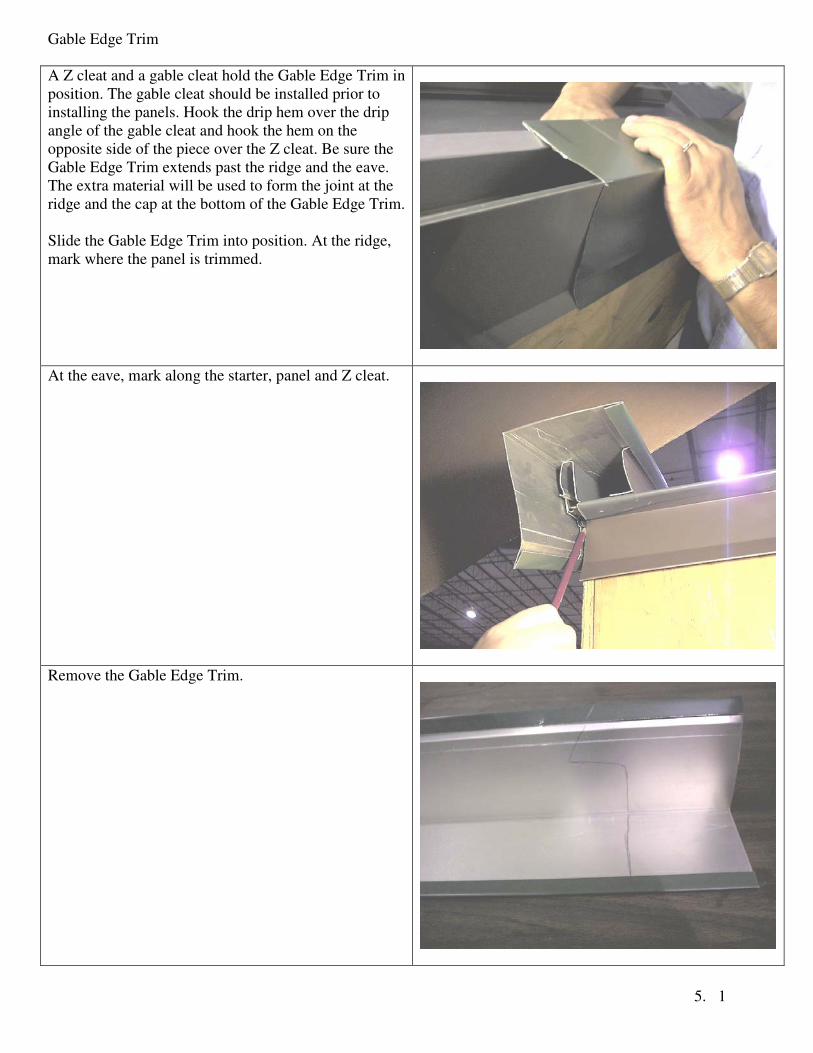
5. 1
A Z cleat and a gable cleat hold the Gable Edge Trim in
position. The gable cleat should be installed prior to
installing the panels. Hook the drip hem over the drip
angle of the gable cleat and hook the hem on the
opposite side of the piece over the Z cleat. Be sure the
Gable Edge Trim extends past the ridge and the eave.
The extra material will be used to form the joint at the
ridge and the cap at the bottom of the Gable Edge Trim.
Slide the Gable Edge Trim into position. At the ridge,
mark where the panel is trimmed.
At the eave, mark along the starter, panel and Z cleat.
Remove the Gable Edge Trim.
Gable Edge Trim
5. 2
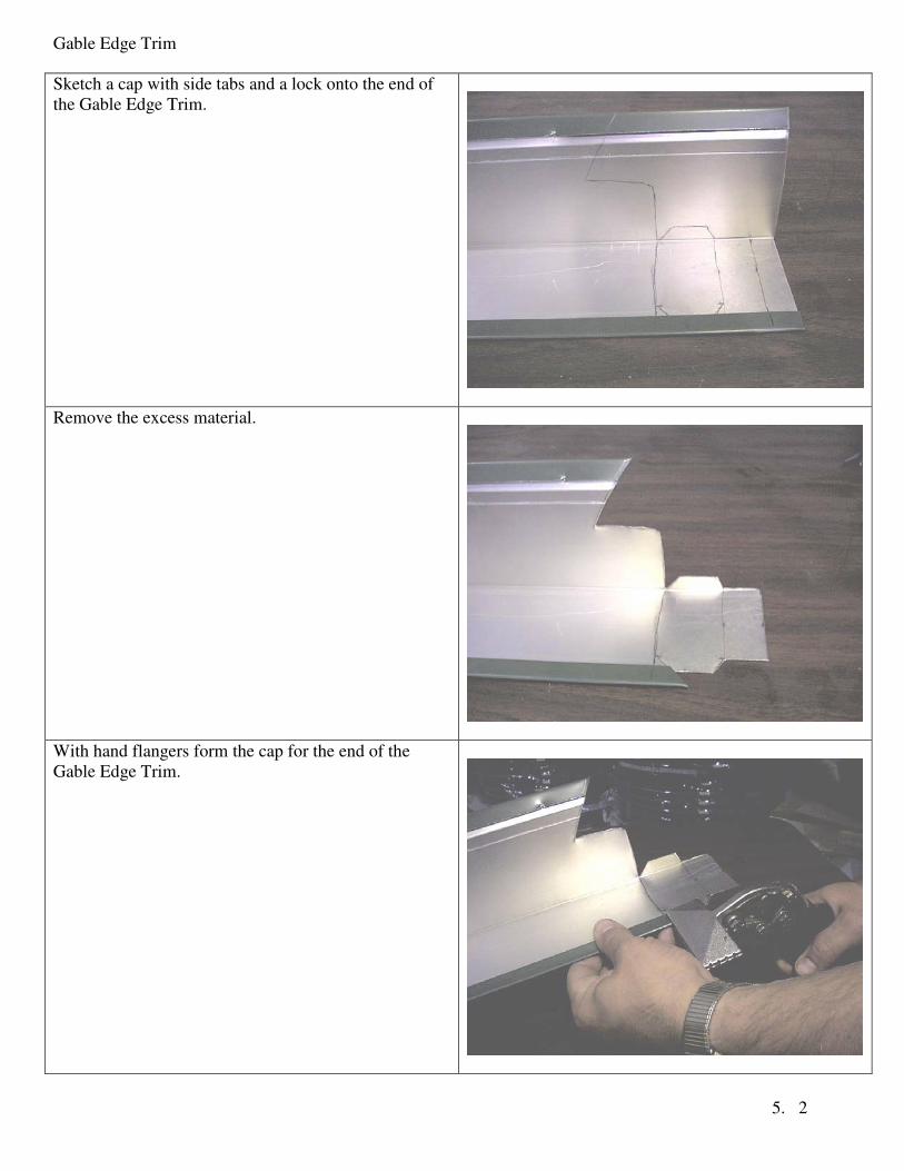
Sketch a cap with side tabs and a lock onto the end of
the Gable Edge Trim.
Remove the excess material.
With hand flangers form the cap for the end of the
Gable Edge Trim.

Gable Edge Trim
5. 3
Be sure the cap will cover the end of the flashing and
the lock will fit under the starter.
Top view of a field formed Gable Edge Trim Cap.
Once the ends are formed, slide the Gable Edge Trim
back into position.

Gable Edge Trim
5. 4
Side view of the Gable Edge Trim locked in place.
The cap of the Gable Edge Trim completely covers the
hole behind the Gable Edge Trim and the lock fits
under the starter.
Sidewall
6. 1
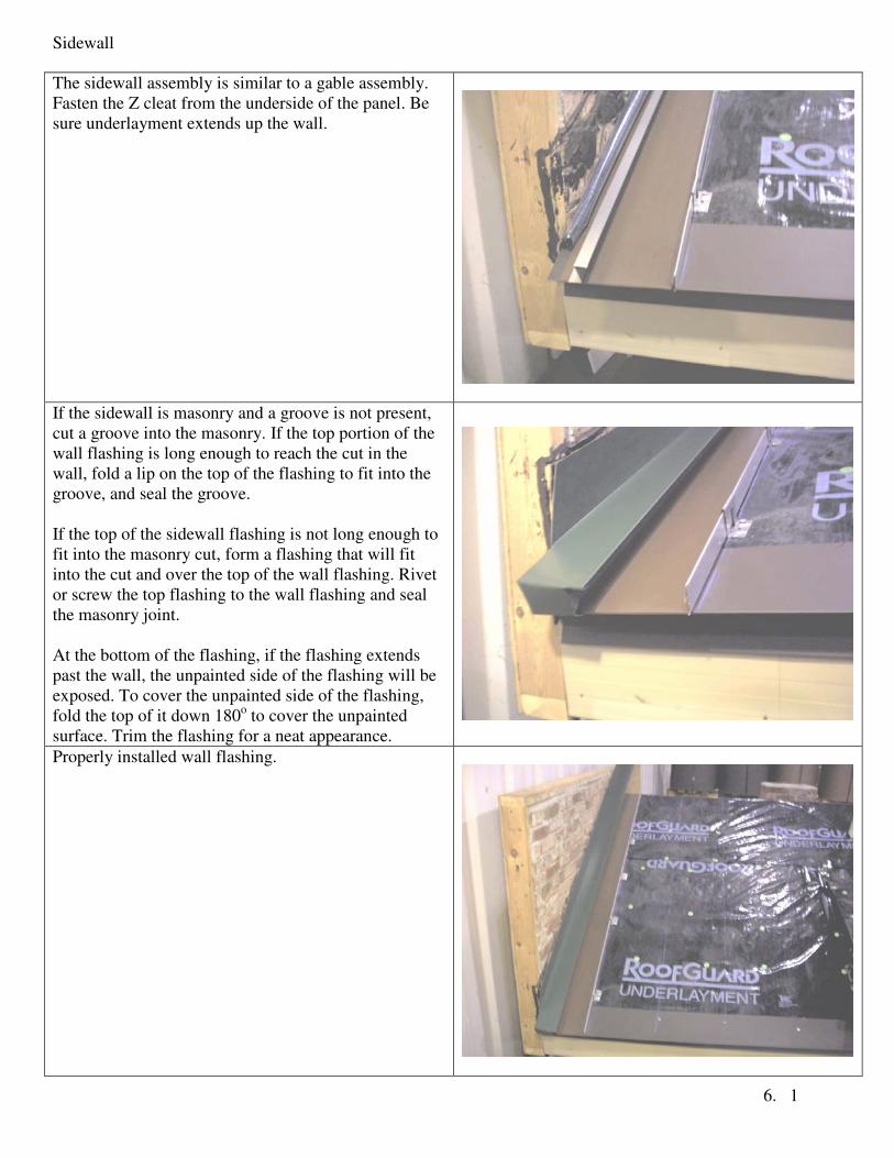
The sidewall assembly is similar to a gable assembly.
Fasten the Z cleat from the underside of the panel. Be
sure underlayment extends up the wall.
If the sidewall is masonry and a groove is not present,
cut a groove into the masonry. If the top portion of the
wall flashing is long enough to reach the cut in the
wall, fold a lip on the top of the flashing to fit into the
groove, and seal the groove.
If the top of the sidewall flashing is not long enough to
fit into the masonry cut, form a flashing that will fit
into the cut and over the top of the wall flashing. Rivet
or screw the top flashing to the wall flashing and seal
the masonry joint.
At the bottom of the flashing, if the flashing extends
past the wall, the unpainted side of the flashing will be
exposed. To cover the unpainted side of the flashing,
fold the top of it down 180o to cover the unpainted
surface. Trim the flashing for a neat appearance.
Properly installed wall flashing.
Protrusions
7. 1
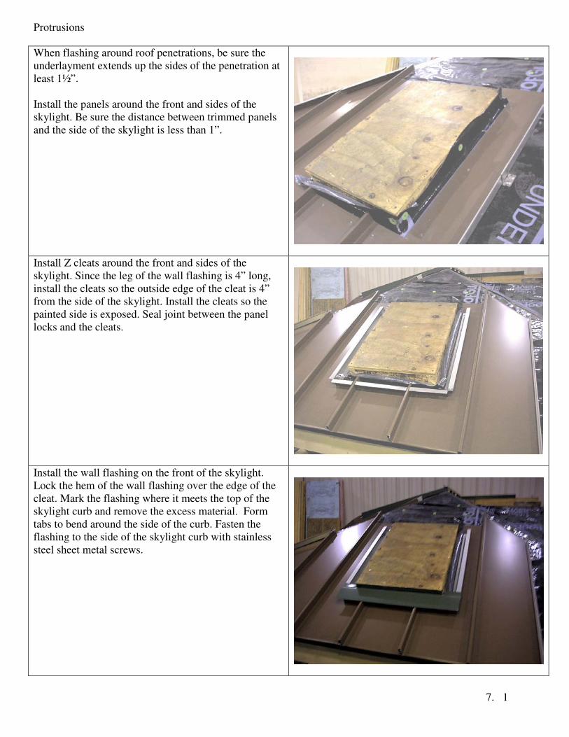
When flashing around roof penetrations, be sure the
underlayment extends up the sides of the penetration at
least 1½”.
Install the panels around the front and sides of the
skylight. Be sure the distance between trimmed panels
and the side of the skylight is less than 1”.
Install Z cleats around the front and sides of the
skylight. Since the leg of the wall flashing is 4” long,
install the cleats so the outside edge of the cleat is 4”
from the side of the skylight. Install the cleats so the
painted side is exposed. Seal joint between the panel
locks and the cleats.
Install the wall flashing on the front of the skylight.
Lock the hem of the wall flashing over the edge of the
cleat. Mark the flashing where it meets the top of the
skylight curb and remove the excess material. Form
tabs to bend around the side of the curb. Fasten the
flashing to the side of the skylight curb with stainless
steel sheet metal screws.
Protrusions
7. 2
Install the wall flashing along the sides of the skylight.
The top of the flashing is trimmed flush with the top of
the curb while the bottom of the flashing is trimmed to
a 45o
angle. Fasten the bottom corners through the wall
flashing and Z cleat. Seal the fastener heads.
When the panels are installed along the sides of the
skylight, the panels should extend approximately, 12”
past the top of the sky light. A field-formed flashing
will cover the back of the skylight, so the panel locks
behind the skylight should be removed.
Note: In this photo, the underlayment has fallen down.
It will be put back in place prior to installing the back
flashing.
The field-formed back flashing does a number of
things: It covers the back of the skylight curb and the
open ends of the Z cleat/wall flashing assembly. It will
be the lock for the panels above the skylight and it
extends between the locks of the panels. The flashing in
this picture was made from 24” coil stock.
With a hand brake, make a fold in the flashing. The
fold should be about 6” from the back of the curb and
about 1½ ” deep. The fold will be the lock for the
panels installed above it.

Protrusions
7. 3
Form 1” tabs that bend around the sides of the curb,
and form dog ears that cover the open end of the Z
cleat/wall flashing assembly. The dog ears will divert
water away from the skylight. Seal the joints along the
back flashing and side flashing.
When installing panels above the skylight, the female
lock of the first panel is lapped over the female lock of
the previously installed panel at left.
A lock is formed on the bottom of the panel that
engages into back flashing.
Install the remaining panels above the skylight. The
male lock of the last panel installed above the skylight
will align with the male lock of the panel below.
Protrusions
7. 4
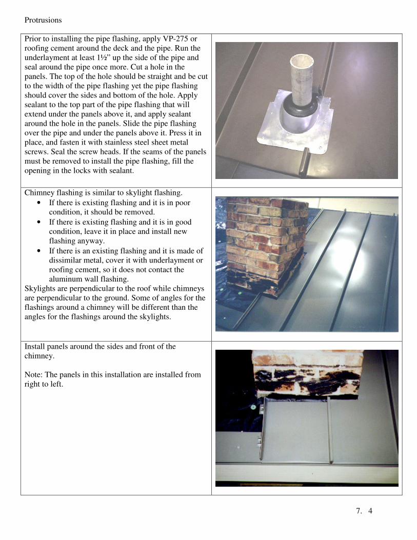
Prior to installing the pipe flashing, apply VP-275 or
roofing cement around the deck and the pipe. Run the
underlayment at least 1½” up the side of the pipe and
seal around the pipe once more. Cut a hole in the
panels. The top of the hole should be straight and be cut
to the width of the pipe flashing yet the pipe flashing
should cover the sides and bottom of the hole. Apply
sealant to the top part of the pipe flashing that will
extend under the panels above it, and apply sealant
around the hole in the panels. Slide the pipe flashing
over the pipe and under the panels above it. Press it in
place, and fasten it with stainless steel sheet metal
screws. Seal the screw heads. If the seams of the panels
must be removed to install the pipe flashing, fill the
opening in the locks with sealant.
Chimney flashing is similar to skylight flashing.
• If there is existing flashing and it is in poor
condition, it should be removed.
• If there is existing flashing and it is in good
condition, leave it in place and install new
flashing anyway.
• If there is an existing flashing and it is made of
dissimilar metal, cover it with underlayment or
roofing cement, so it does not contact the
aluminum wall flashing.
Skylights are perpendicular to the roof while chimneys
are perpendicular to the ground. Some of angles for the
flashings around a chimney will be different than the
angles for the flashings around the skylights.
Install panels around the sides and front of the
chimney.
Note: The panels in this installation are installed from
right to left.
Protrusions
7. 5
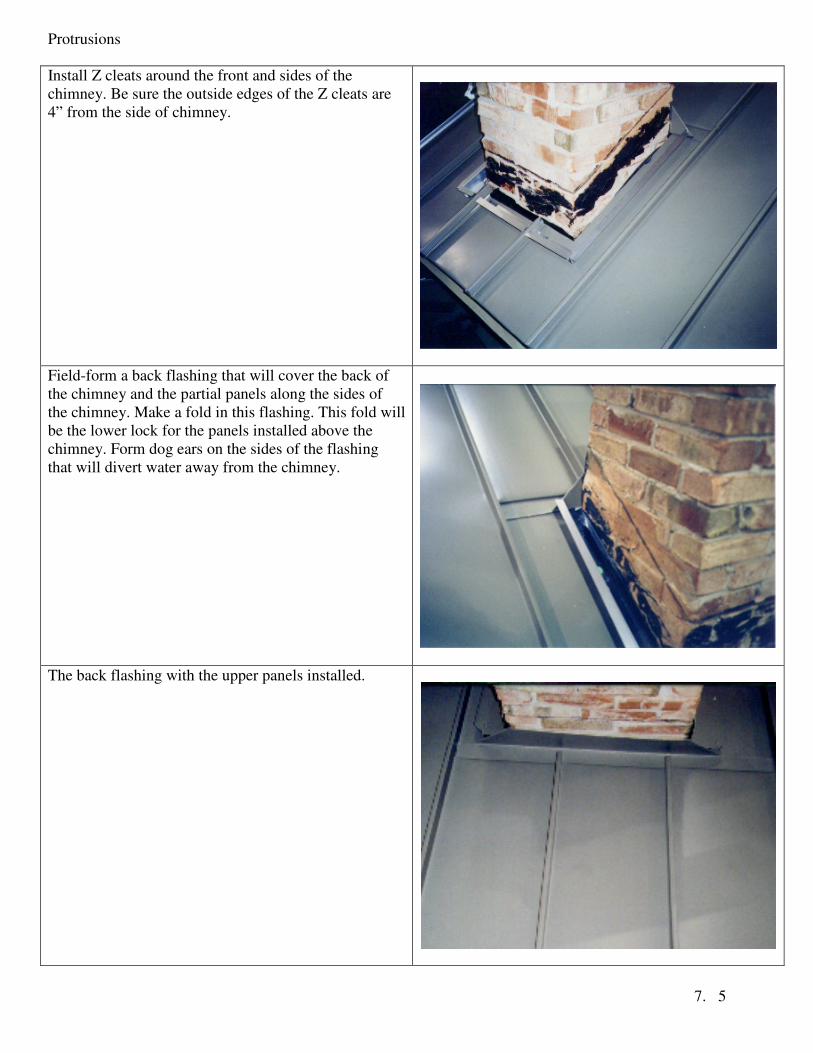
Install Z cleats around the front and sides of the
chimney. Be sure the outside edges of the Z cleats are
4” from the side of chimney.
Field-form a back flashing that will cover the back of
the chimney and the partial panels along the sides of
the chimney. Make a fold in this flashing. This fold will
be the lower lock for the panels installed above the
chimney. Form dog ears on the sides of the flashing
that will divert water away from the chimney.
The back flashing with the upper panels installed.
Protrusions
7. 6
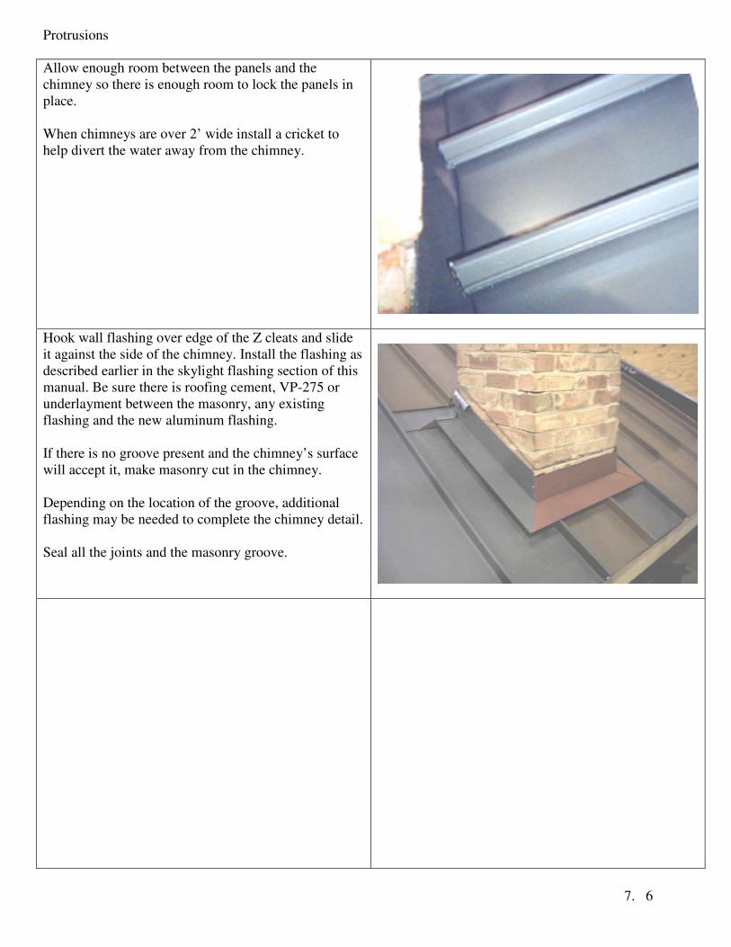
Allow enough room between the panels and the
chimney so there is enough room to lock the panels in
place.
When chimneys are over 2’ wide install a cricket to
help divert the water away from the chimney.
Hook wall flashing over edge of the Z cleats and slide
it against the side of the chimney. Install the flashing as
described earlier in the skylight flashing section of this
manual. Be sure there is roofing cement, VP-275 or
underlayment between the masonry, any existing
flashing and the new aluminum flashing.
If there is no groove present and the chimney’s surface
will accept it, make masonry cut in the chimney.
Depending on the location of the groove, additional
flashing may be needed to complete the chimney detail.
Seal all the joints and the masonry groove.
Pitch Change
8. 1
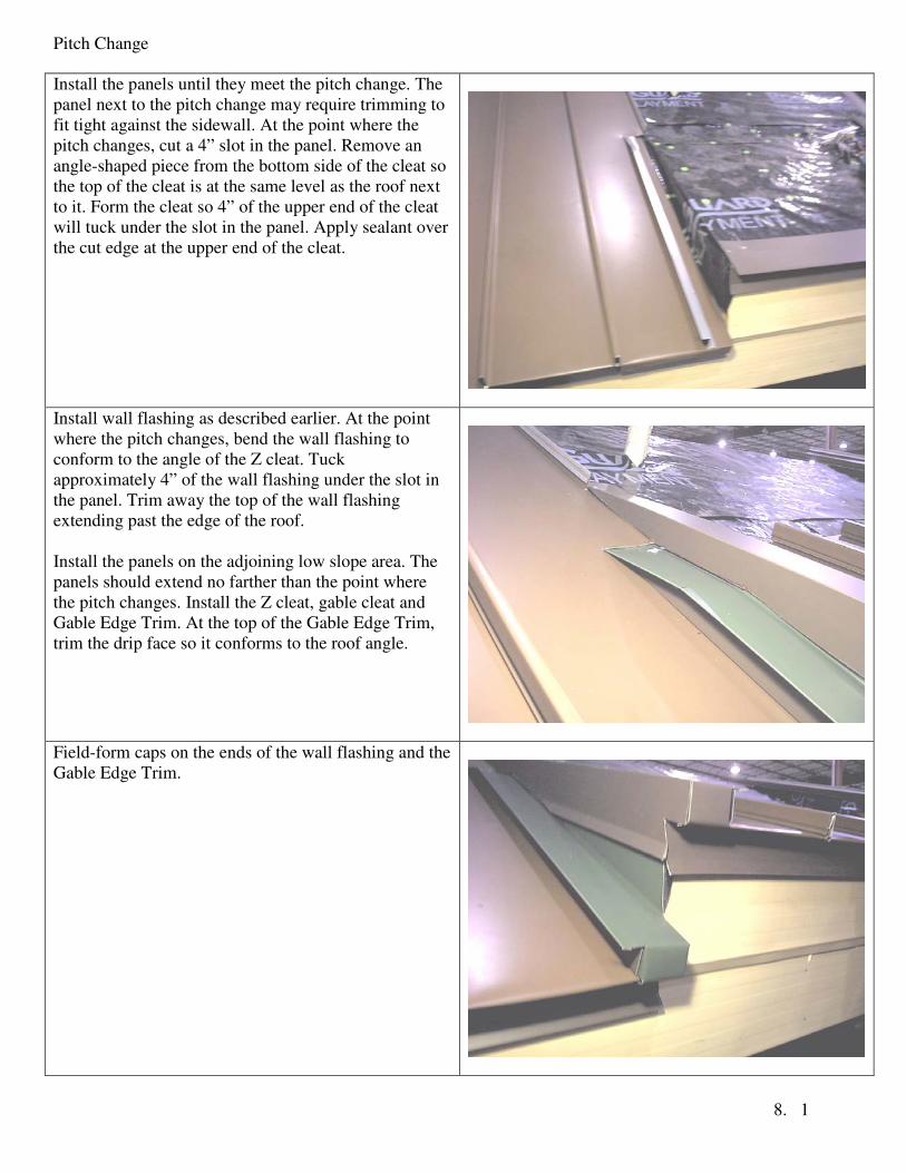
Install the panels until they meet the pitch change. The
panel next to the pitch change may require trimming to
fit tight against the sidewall. At the point where the
pitch changes, cut a 4” slot in the panel. Remove an
angle-shaped piece from the bottom side of the cleat so
the top of the cleat is at the same level as the roof next
to it. Form the cleat so 4” of the upper end of the cleat
will tuck under the slot in the panel. Apply sealant over
the cut edge at the upper end of the cleat.
Install wall flashing as described earlier. At the point
where the pitch changes, bend the wall flashing to
conform to the angle of the Z cleat. Tuck
approximately 4” of the wall flashing under the slot in
the panel. Trim away the top of the wall flashing
extending past the edge of the roof.
Install the panels on the adjoining low slope area. The
panels should extend no farther than the point where
the pitch changes. Install the Z cleat, gable cleat and
Gable Edge Trim. At the top of the Gable Edge Trim,
trim the drip face so it conforms to the roof angle.
Field-form caps on the ends of the wall flashing and the
Gable Edge Trim.
Pitch Change
8. 2
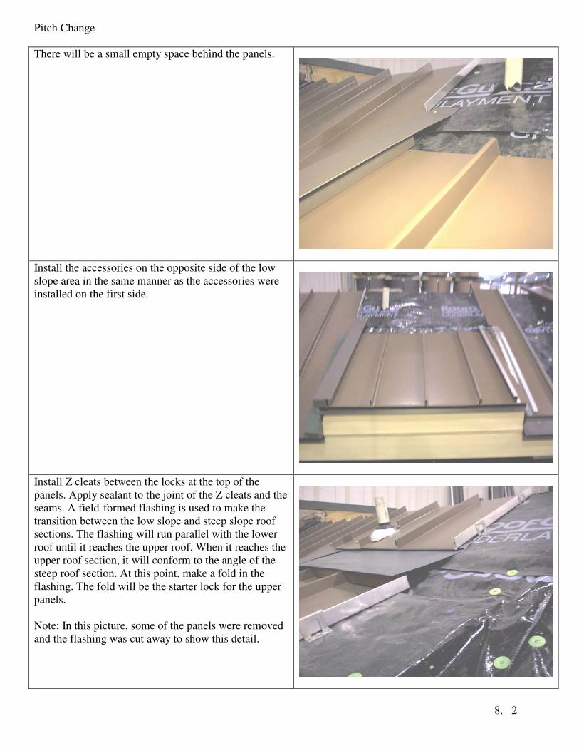
There will be a small empty space behind the panels.
Install the accessories on the opposite side of the low
slope area in the same manner as the accessories were
installed on the first side.
Install Z cleats between the locks at the top of the
panels. Apply sealant to the joint of the Z cleats and the
seams. A field-formed flashing is used to make the
transition between the low slope and steep slope roof
sections. The flashing will run parallel with the lower
roof until it reaches the upper roof. When it reaches the
upper roof section, it will conform to the angle of the
steep roof section. At this point, make a fold in the
flashing. The fold will be the starter lock for the upper
panels.
Note: In this picture, some of the panels were removed
and the flashing was cut away to show this detail.
Pitch Change
8. 3
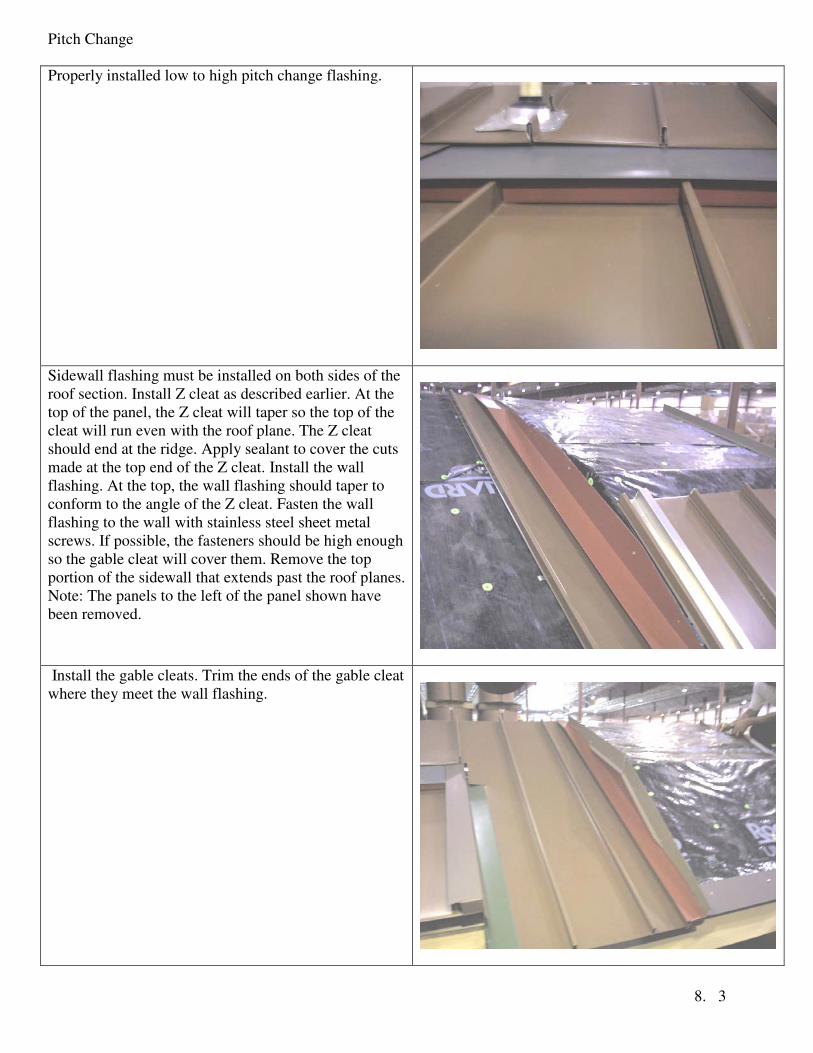
Properly installed low to high pitch change flashing.
Sidewall flashing must be installed on both sides of the
roof section. Install Z cleat as described earlier. At the
top of the panel, the Z cleat will taper so the top of the
cleat will run even with the roof plane. The Z cleat
should end at the ridge. Apply sealant to cover the cuts
made at the top end of the Z cleat. Install the wall
flashing. At the top, the wall flashing should taper to
conform to the angle of the Z cleat. Fasten the wall
flashing to the wall with stainless steel sheet metal
screws. If possible, the fasteners should be high enough
so the gable cleat will cover them. Remove the top
portion of the sidewall that extends past the roof planes.
Note: The panels to the left of the panel shown have
been removed.
Install the gable cleats. Trim the ends of the gable cleat
where they meet the wall flashing.
Pitch Change
8. 4
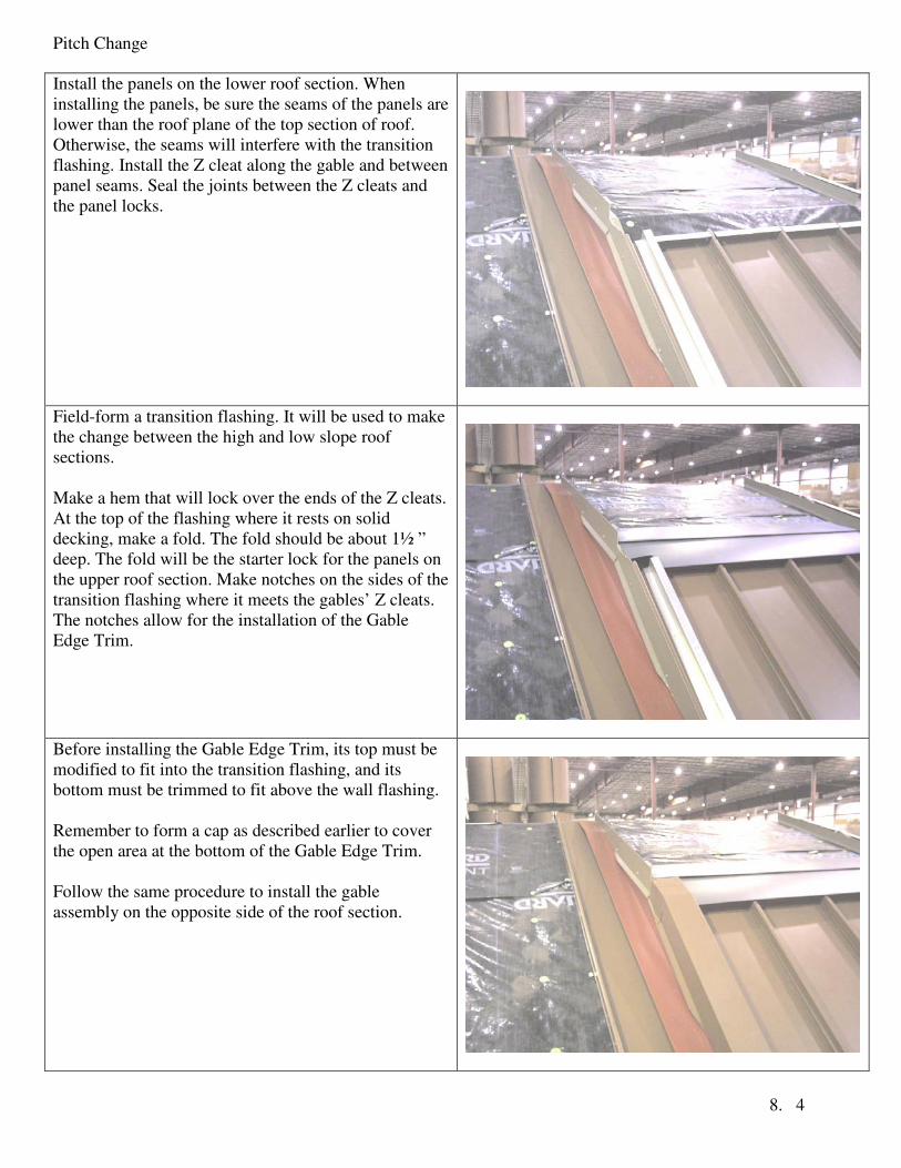
Install the panels on the lower roof section. When
installing the panels, be sure the seams of the panels are
lower than the roof plane of the top section of roof.
Otherwise, the seams will interfere with the transition
flashing. Install the Z cleat along the gable and between
panel seams. Seal the joints between the Z cleats and
the panel locks.
Field-form a transition flashing. It will be used to make
the change between the high and low slope roof
sections.
Make a hem that will lock over the ends of the Z cleats.
At the top of the flashing where it rests on solid
decking, make a fold. The fold should be about 1½ ”
deep. The fold will be the starter lock for the panels on
the upper roof section. Make notches on the sides of the
transition flashing where it meets the gables’ Z cleats.
The notches allow for the installation of the Gable
Edge Trim.
Before installing the Gable Edge Trim, its top must be
modified to fit into the transition flashing, and its
bottom must be trimmed to fit above the wall flashing.
Remember to form a cap as described earlier to cover
the open area at the bottom of the Gable Edge Trim.
Follow the same procedure to install the gable
assembly on the opposite side of the roof section.

Pitch Change
8. 5
Install the first panel and the Z cleat for the gable trim.
The field-formed bottom lock of the panel will fit into
the fold in the transition flashing and cover the end of
the Gable Edge Trim on the lower roof section.
Form the Gable Edge Trim for the upper roof section.
Remove some of the drip hem and drip face from the
top end of the part and form a cap at the bottom of the
part. The Gable Edge Trim should terminate at the
ridge.
Transition detail.

Pitch Change
8. 6
Install the remaining panels across the upper roof
section, and install the gable assembly on the opposite
side of the roof section.
Hip and Ridge
9. 1
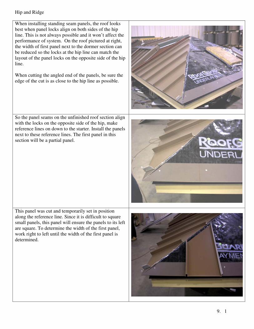
When installing standing seam panels, the roof looks
best when panel locks align on both sides of the hip
line. This is not always possible and it won’t affect the
performance of system. On the roof pictured at right,
the width of first panel next to the dormer section can
be reduced so the locks at the hip line can match the
layout of the panel locks on the opposite side of the hip
line.
When cutting the angled end of the panels, be sure the
edge of the cut is as close to the hip line as possible.
So the panel seams on the unfinished roof section align
with the locks on the opposite side of the hip, make
reference lines on down to the starter. Install the panels
next to these reference lines. The first panel in this
section will be a partial panel.
This panel was cut and temporarily set in position
along the reference line. Since it is difficult to square
small panels, this panel will ensure the panels to its left
are square. To determine the width of the first panel,
work right to left until the width of the first panel is
determined.

Hip and Ridge
9. 2
Once the panels on both sides of the hip are installed,
the Z cleats can then be installed. On both sides of the
hip, measure approximately 2” from the center of the
hip line. With a chalk line, mark all the panel locks.
This will mark the outside edge of the Z cleats.
Cut Z cleats so they fit tightly between the panel locks.
Fasten them in place with stainless steel screws. Seal
the joints between the panel lock and the cleats.
Note: The fasteners in the Z cleats will prevent the
panels from sliding off of the roof.
Set the Hip Cleat in position. Trim the bottom of the
cleat so it conforms to the corner of the roof.
Hip and Ridge
9. 3
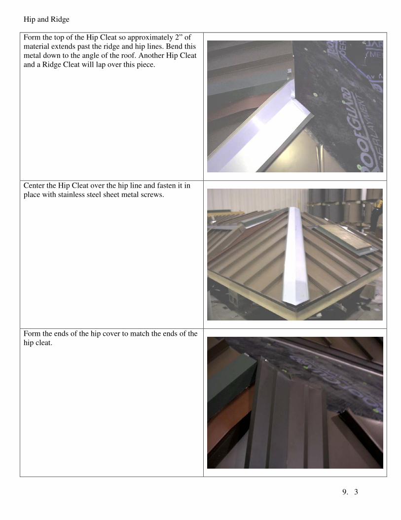
Form the top of the Hip Cleat so approximately 2” of
material extends past the ridge and hip lines. Bend this
metal down to the angle of the roof. Another Hip Cleat
and a Ridge Cleat will lap over this piece.
Center the Hip Cleat over the hip line and fasten it in
place with stainless steel sheet metal screws.
Form the ends of the hip cover to match the ends of the
hip cleat.
Hip and Ridge
9. 4
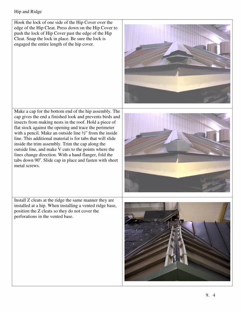
Hook the lock of one side of the Hip Cover over the
edge of the Hip Cleat. Press down on the Hip Cover to
push the lock of Hip Cover past the edge of the Hip
Cleat. Snap the lock in place. Be sure the lock is
engaged the entire length of the hip cover.
Make a cap for the bottom end of the hip assembly. The
cap gives the end a finished look and prevents birds and
insects from making nests in the roof. Hold a piece of
flat stock against the opening and trace the perimeter
with a pencil. Make an outside line ½” from the inside
line. This additional material is for tabs that will slide
inside the trim assembly. Trim the cap along the
outside line, and make V cuts to the points where the
lines change direction. With a hand flanger, fold the
tabs down 90o. Slide cap in place and fasten with sheet
metal screws.
Install Z cleats at the ridge the same manner they are
installed at a hip. When installing a vented ridge base,
position the Z cleats so they do not cover the
perforations in the vented base.
Hip and Ridge
9. 5
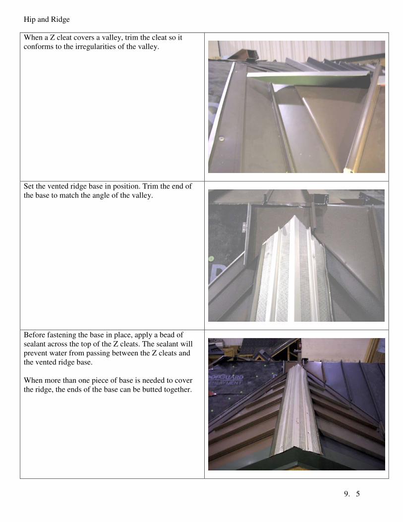
When a Z cleat covers a valley, trim the cleat so it
conforms to the irregularities of the valley.
Set the vented ridge base in position. Trim the end of
the base to match the angle of the valley.
Before fastening the base in place, apply a bead of
sealant across the top of the Z cleats. The sealant will
prevent water from passing between the Z cleats and
the vented ridge base.
When more than one piece of base is needed to cover
the ridge, the ends of the base can be butted together.

Hip and Ridge
9. 6
Set the ridge cover over the base and trim its end to
match the angle of the valley. In the picture to the right,
the ridge cover had to be notched to fit around a seam
lock.
Hook one side of the ridge cover over the lock of the
ridge base, and push the opposite side of the cover
down over the base until it locks in place.
When lapping the ridge cap, remove 4” from the locks
of the cap where it locks around the base. Apply sealant
to this 4” area, and set the next piece of ridge cover in
place.
When a vented base is used, be sure the cover does not
rest on the baffles and restrict the air flow.
The ridge cover and ridge base are custom made to the
pitch of the roof. Provide the factory with the roof pitch
when ordering these parts
Form an end cap to cover the open end of the ridge
assembly. This detail is described earlier in this section.

Valley
10. 1
Snap a chalk line down the center of the valley. Set the
valley flashing in position. Be sure the valley’s return
flanges extend at least 1¼” past the edge of the starter.
Mark the underside of the valley where it meets the
starter. Trim the valley 1¼” past the mark. At the mark,
use hand flangers and bend this extra material back
180o
to form locks for the bottom of the valley. Set the
valley back in position and push it in place so the locks
wrap the end of the starter.
Lap valley flashing at least 4”. Open the water return
flanges of the installed valley. Apply sealant to the
lapped area. Press the upper section of the valley into
the installed valley, and bend the water return flanges
back in position.
When installing the panels over valley, do not block the
end of the valley’s water return channels. Remove the
field-formed locks of the panels that would otherwise
restrict the flow of water from draining out of the
valley’s water return channel.
When installing the valley flashing over the ridge,
allow for extra material to extend past the ridge. Fold
the extra metal flat against roof deck.

Valley
10. 2
Install the valley on the opposite side of the ridge.
Allow 2” to 3” of material to extend past the ridge line.
Trim and fold the valley so it fits neatly into the
installed valley. Before fastening the valley in place,
apply a bead of sealant where the valleys overlap.
Seal the lap joints
Panels into a Valley
11. 1
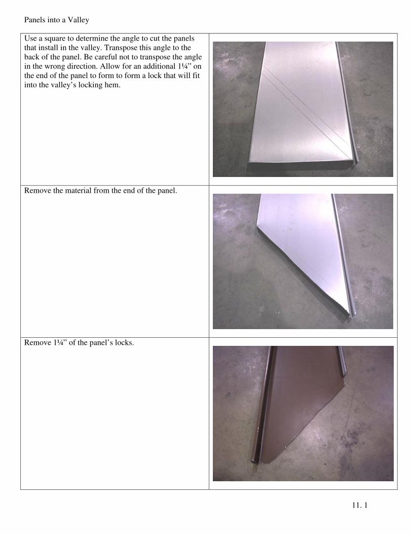
Use a square to determine the angle to cut the panels
that install in the valley. Transpose this angle to the
back of the panel. Be careful not to transpose the angle
in the wrong direction. Allow for an additional 1¼” on
the end of the panel to form to form a lock that will fit
into the valley’s locking hem.
Remove the material from the end of the panel.
Remove 1¼” of the panel’s locks.

Panels into a Valley
11. 2
Insert the angled end of the panel into a hand flanger.
Fold the metal back 180o
to form the bottom lock.
The lock on the bottom of the panel may need to be
trimmed so it doesn’t interfere with the panel’s side
locks.

Panels into a Valley
11. 3
Lock the panel into the lock of the previously installed
panel.
Slide the panel in place until it engages into the valley’s
locking hem. Remove some of the panel’s male lock so
the male lock does not extend past the next panel’s
female lock.

Panels into a Valley
11. 4
The last page is intentionally left blank.