Embed Size (px)
Citation preview
WJC129
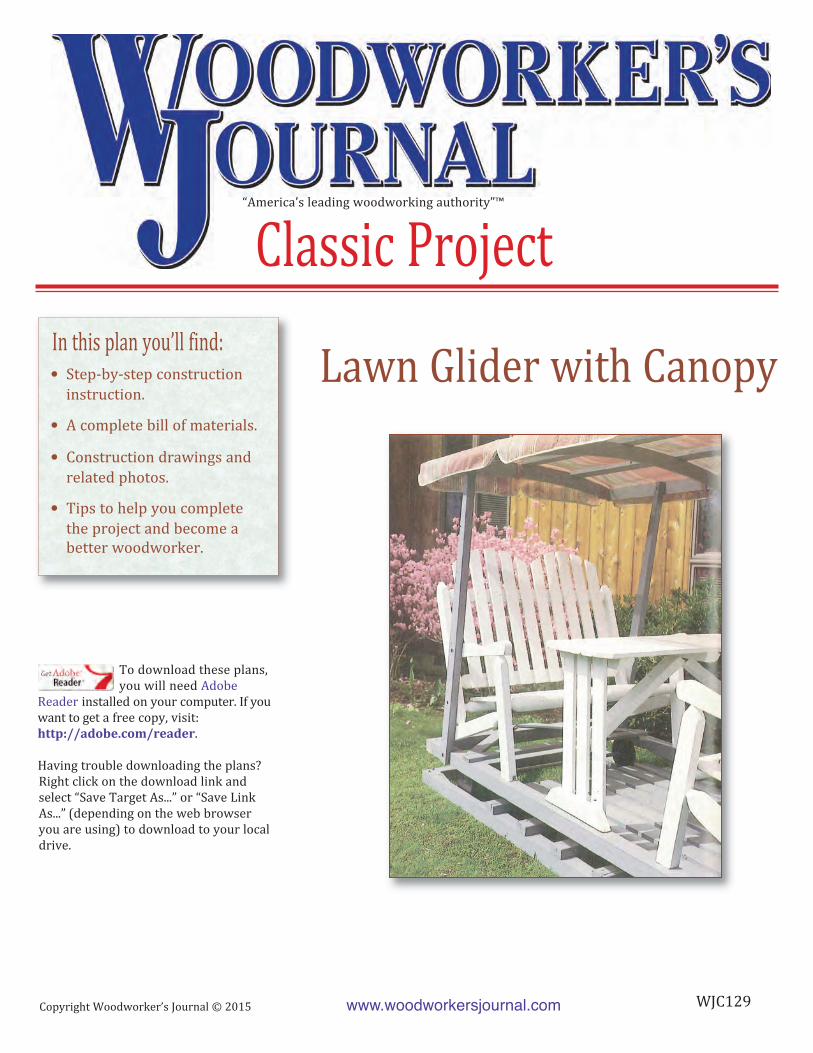
Lawn Glider with Canopy
“America’s leading woodworking authority”™
Classic Project
• Step-by-step construction
instruction.
• A complete bill of materials.
• Construction drawings and
related photos.
• Tips to help you complete
the project and become a
better woodworker.
To download these plans,
you will need Adobe
Reader installed on your computer. If you
want to get a free copy, visit:
http://adobe.com/reader.
Having trouble downloading the plans?
Right click on the download link and
select “Save Target As...” or “Save Link
As...” (depending on the web browser
you are using) to download to your local
drive.
Copyright Woodworker’s Journal © 2015
In this plan you’ll find:
www.woodworkersjournal.com
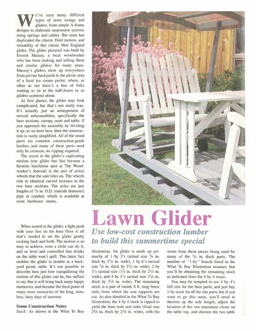
We've seen many different types of lawn swings and gliders, from simple A-frame
designs to e laborate suspension systems using springs and cables. But none has duplicated the charm, fluid motion, and versatility of this classic New England glider. The glider pictured was built by Everett Massey, a local woodworker who has been making and selling these and similar gliders for many years. Massey's gliders show up everywhere from private backyards to the picnic area of a local ice cream parlor, where, as often as not there's a line of folks waiting to sit in the half-dozen or so gliders scattered about.
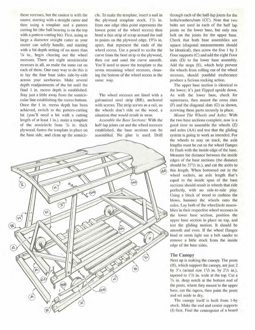
At first glance, the glider may look complicated, but that 's not really true. It's actually just an arrangement of several subassemblies, specifically the base sections, canopy, seats and table. If you approach the assembly by dividing it up, as we have here, then the construction is vastly simplified. All of the wood parts are common construction-grade lumber, and many of these parts need only be crosscut, no ripping required.
The secret to the glider's captivating motion (our glider has fast become a favorite lunchtime spot at The Woodworker's Journal) is the pair of axles/ wheels that the unit rides on. The wheels ride in identical curved recesses in the two base sections. The ax les a re just lengths of 3/4 in. O.D. (outside diameter) pipe or conduit, which is available at most hardware stores,
When seated in the glider, a light push with your feet on the base floor is all that 's needed to set the glider gently rocking back and forth. The motion is so easy to achieve, even a child can do it, and so level and controlled that drinks on the table won ' t spill. This latter fact enables the glider to double as a backyard picnic table. It's not possible to describe here just how tranquilizing the motion of this glider can be, but suffice to say that it will bring back many happy memories, and become the focal point of many more memories of the long, slow, lazy, hazy days of summer.
Some Construction Notes Stock: As shown in the What To Buy
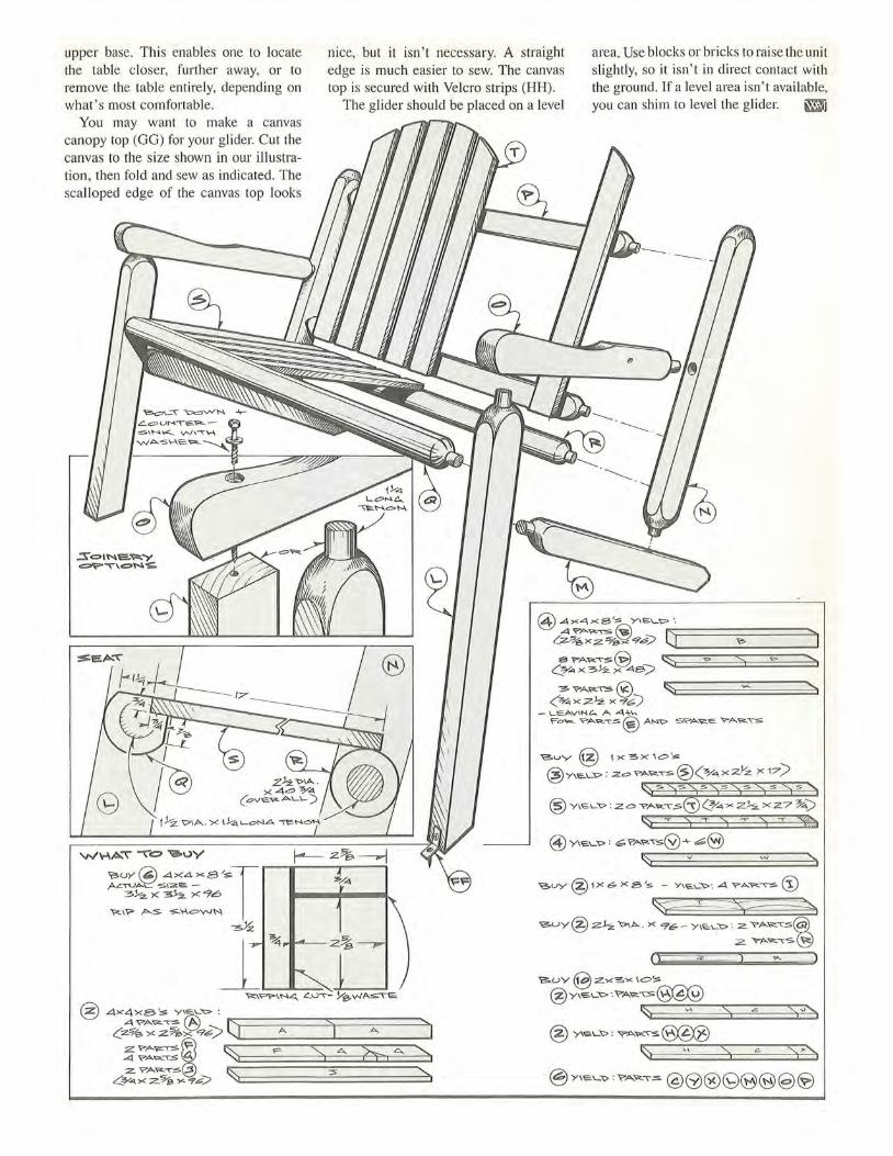
Lawn Gli er Use low-cost construction lumber to build this summertime special illustration, the glider is made up primarily of l by 3 's (actual size 3/4 in. thick by 2 1/ 2 in. wide), l by 6's (actual size 3/4 in. thick by 5 1 / 2 in. wide), 2 by 3's (actual size 11/ 2 in. thick by 2 1/2 in. wide), and 4 by 4's (actual size 31/ 2 in. thick by 3 1/ 2 in. wide). The remaining stock is a pair of round, 8 ft. long fence rails, from which the seat supports are cut. As also detailed in the What To Buy illustration, the 4 by 4 stock is ripped to yield the base ends and sides (final size 25/s in. thick by 25/s in. wide), with the
waste from these pieces being used for many of the 3/ 4 in. thick parts. The number of " I -by " boards listed in the What To Buy Illustration assumes that you'll be obtaining the remaining stock as indicated from the 4 by 4 waste.
You may be tempted to use 4 by 4's full s ize for the base parts, and just buy 1-by stock for a ll the slat parts, but if you want to go this route, you'll need to shorten up the axle length, adjust the location of the two outermost cleats on the table top, and shorten the two table
.
1e z~.
.-----zo%---,..,
ltl I lltfl 111~
56
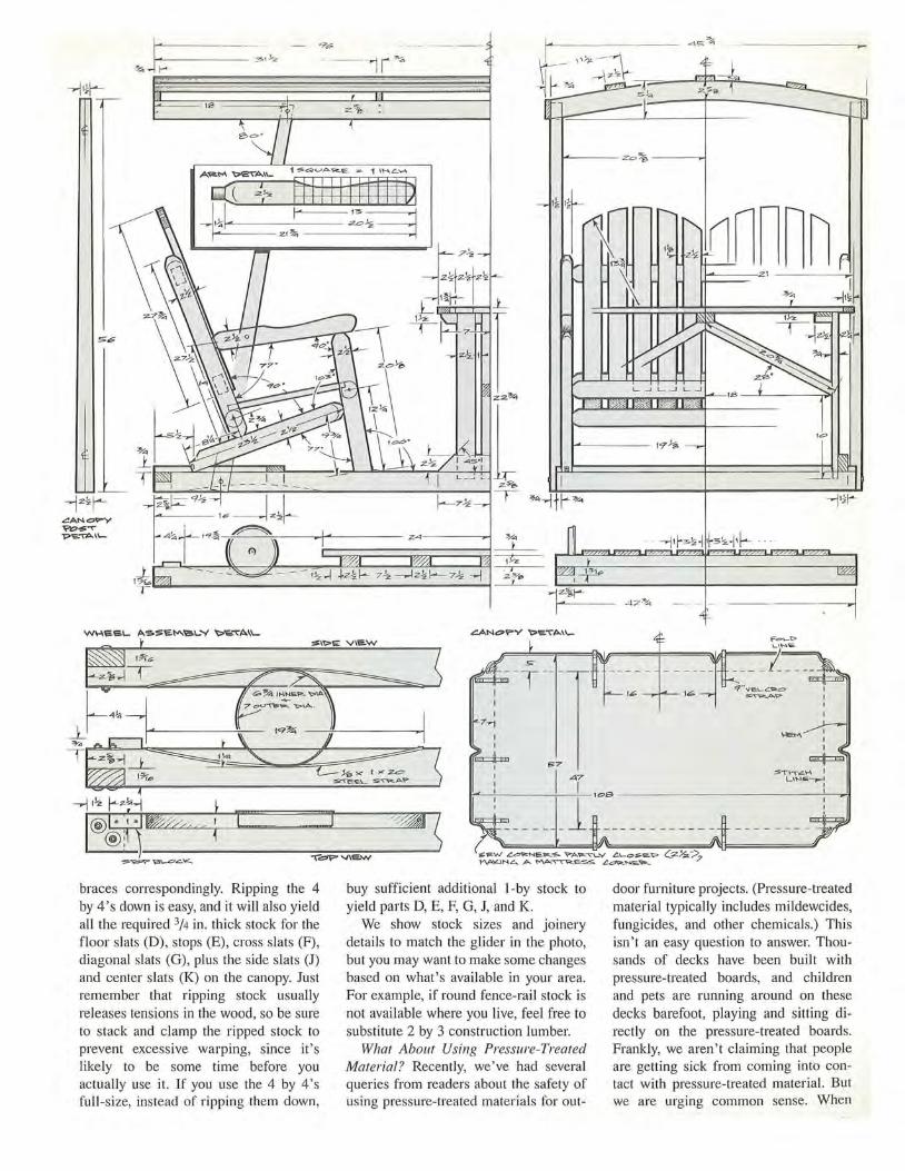
braces correspondingly. Ripping the 4 by 4's down is easy, and it will also yield all the required 3/4 in. thick stock for the floor slats (D), stops (E), cross slats (F), diagonal slats (G), plus the side slats (J) and center slats (K) on the canopy. Just remember that ripping stock usually releases tensions in the wood, so be sure to stack and clamp the ripped stock to prevent excessive warping, since it 's likely to be some time before you actually use it. If you use the 4 by 4's full -size, instead of ripping them down,
t-<---- --w.!s
I ''1
42~ --~
I \JEM : I I
~ 57 ~ I I :ST\\~~ I : ..qi L\~,e~
...-~'---~--100 ~------------~'----,..;t
: ______ _ l --- --- ------ : io:.e.w ~~~e...~s Y"'A'<pl:.""t"":__Y ~\.-c>$.E't> (_:z~:/,? ~\NL.... A ~~SS ~'N.e..~
buy sufficient additional 1-by stock to yield parts D, E, F, G, J, and K.
We show stock sizes and joinery details to match the glider in the photo, but you may want to make some changes based on what's available in your area. For example, if round fence-rail stock is not available where you live, feel free to substitute 2 by 3 construction lumber.
What About Using Pressure-Treated Material? Recently, we've had several queries from readers about the safety of using pressure-treated materials for out-
door furniture projects. (Pressure-treated material typically includes mildewcides, fungicides, and other chemicals.) This isn't an easy question to answer. Thousands of decks have been built with pressure-treated boards, and children and pets are running around on these decks barefoot, playing and sitting directly on the pressure-treated boards. Frankly, we aren't claiming that people are getting sick from coming into contact with pressure-treated material. But we are urging common sense. When
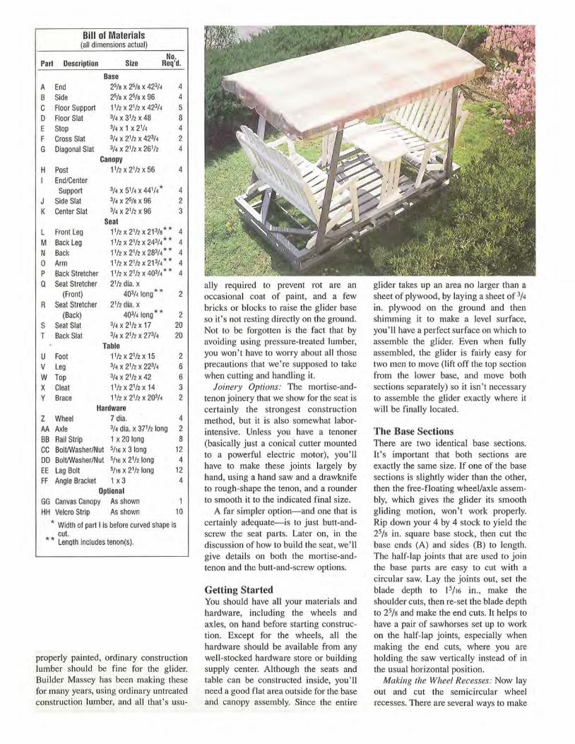
Bill of Materials (all dimensions actual)
No. Part Description Size Req'd.
Base A End 25/a x 25/a x 423/4 4 B Side 25/a x 25/a x 96 4 c Floor Support 11/2 x 21/2 x 423/4 5 D Floor Slat 3/4 x 3112 x 48 8 E Stop 3/4 x 1 x 21/4 4 F Cross Slat 3/4 x 21/2 x 423/4 2 G Diagonal Slat 3/4 x 2112 x 26112 4
Canopy H Post 1112 x 2112 x 56 4
End/Center Support 3/4 x 51/4 x 441/4 * 4
J Side Slat 3/4 x 25/a x 96 2 K Center Slat 3/4 x 2112 x 96 3
Seat L Front Leg 1112 x 21/2 x 213/a** 4 M Back Leg 1112 x 2112 x 243/4 * * 4 N Back 11/2 x 2112 x 283/4 * * 4 0 Arm 11/2 x 2112 x 213/4** 4 p Back Stretcher 11/2 x 2112 x 403/4 * * 4 a Seat Stretcher 2112 dia. x
(Front) 403/4 long ** 2 R Seat Stretcher 21/2 dia. x
(Back) 403/4 long ** 2 s Seat Slat 3/4 x 2112 x 17 20 T Back Slat 3/4 x 2112 x 273/4 20
Table u Foot 1112x2112x15 2 v Leg 3/4 x 2112 x 223/4 6 w Top 3/4 x 21/2 x 42 6 x Cleat 1112x2112x14 3 y Brace 11/2 x 2112 x 203/4 2
Hardware z Wheel 7 dia. 4 AA Axle 3/4 dia. x 37112 long 2 BB Rail Strip 1 x 20 long 8 cc Boll/Washer/Nut 5/16 x 3 long 12 DD Boll/Washer/Nut 5/16 x 21/2 long 4 EE Lag Bolt 5/15 x 21/2 long 12 FF Angle Bracket 1 x 3 4
Optional GG Canvas Canopy As shown HH Velcro Strip As shown 10
* Width of part I is before curved shape is cut.
* * Length includes tenon(s).
properly painted, ordinary construction lumber should be fine for the glider. Builder Massey has been making these for many years, using ordinary untreated construction lumber, and all that's usu-
ally required to prevent rot are an occasional coat of paint, and a few bricks or blocks to raise the glider base so it's not resting directly on the ground. Not to be forgotten is the fact that by avoiding using pressure-treated lumber, you won't have to worry about all those precautions that we're supposed to take when cutting and handling it.
Joinery Options: The mortise-andtenon joinery that we show for the seat is certainly the strongest construction method, but it is also somewhat laborintensive. Unless you have a tenoner (basically just a conical cutter mounted to a powerful electric motor), you'll have to make these joints largely by hand, using a hand saw and a drawknife to rough-shape the tenon, and a rounder to smooth it to the indicated final size.
A far simpler option-and one that is certainly adequate- is to just butt-andscrew the seat parts. Later on, in the discussion of how to build the seat, we'll give details on both the mortise-andtenon and the butt-and-screw options.
Getting Started You should have all your materials and hardware, including the wheels and axles, on hand before starting construction. Except for the wheels, all the hardware should be available from any well-stocked hardware store or building supply center. Although the seats and table can be constructed inside, you'll need a good flat area outside for the base and canopy assembly. Since the entire
glider takes up an area no larger than a sheet of plywood, by laying a sheet of 3/4
in. plywood on the ground and then shimming it to make a level surface, you' II have a perfect surface on which to assemble the glider. Even when fully assembled, the glider is fairly easy for two men to move (lift off the top section from the lower base, and move both sections separately) so it isn't necessary to assemble the glider exactly where it will be finally located.
The Base Sections There are two identical base sections. It's important that both sections are exactly the same size. If one of the base sections is slightly wider than the other, then the free-floating wheel/axle assembly, which gives the glider its smooth gliding motion, won't work properly. Rip down your 4 by 4 stock to yield the 25/s in. square base stock, then cut the base ends (A) and sides (B) to length. The half-lap joints that are used to join the base parts are easy to cut with a circular saw. Lay the joints out, set the blade depth to l5/l6 in., make the shoulder cuts, then re-set the blade depth to 25/s and make the end cuts. It helps to have a pair of sawhorses set up to work on the half-lap joints, especially when making the end cuts, where you are holding the saw vertically instead of in the usual horizontal position.
Making the Wheel Recesses: Now lay out and cut the semicircular wheel recesses. There are several ways to make
these recesses, but the easiest is with the router, starting with a straight cutter and then using a template and a pattern cutting bit (the ball bearing is on the top with a pattern-cutting bit). First, using as large a diameter straight cutter as your router can safely handle, and starting with a bit depth setting of no more than 1/4 in., begin clearing out the wheel recesses. There are eight semicircular recesses in all , so make the same cut on each of them. One easy way to do this is to lay the four base sides side-by-side across your sawhorses. Make several depth readjustments of the bit until the final I in. recess depth is established. Stay just a little away from the semicircular line establishing the recess bottom. Once the I in. recess depth has been achieved, switch to the pattern-cutting bit (you'll need a bit with a cutting length of at least I in.), make a template of the semicircle from 1/ 4 in . thick plywood, fasten the template in place on the base side, and clean up the semicir-
cle. To make the template, insert a nail in the plywood template stock, 11/4 in. from one edge (this point represents the lowest point of the wheel recess) then bend a thin strip of scrap around the nail to points on the plywood edge, 193/4 in. apart, that represent the ends of the wheel recess. Use a pencil to scribe the curve from the bent strip to the plywood, then cut and sand the curve smooth. You ' ll need to move the template to the seven remaining wheel recesses, cleaning the bottom of the wheel recess in the same way.
The wheel recesses are lined with a galvanized steel strip (BB), anchored with screws. The strip serves as a rail , so the wheels don't ride on the wood, a situation that would result in wear.
Assemble the Base Sections: With the half-lap joints cut and the wheel recesses established, the base sections can be assembled. No glue is used. Drill
through each of the half-lap joints for the bolts/washers/nuts (CC). Note that two bolts are used in each of the half lap joints on the lower base, but only one bolt on the joints for the upper base. Check that both base assemblies are square (diagonal measurements should be identical), then screw the five 1 by 3 floor supports (C) and add the eight floor slats (D) to the lower base assembly. Add the stops (E), which help prevent the wheels from rolling out of the wheel recesses, should youthful exuberance produce a furious rocking action.
The upper base section is identical to the lower; it 's just flipped upside down. As with the lower base, check for squareness, then mount the cross slats (F) and the diagonal slats (G) as shown, screwing these parts securely in place.
Mount The Wheels and Axles: With the two base sections complete, now is a good time to assemble the wheels (Z) and ax les (AA) and test that the gliding system is going to work as intended. For the wheels to stay on track, the axle lengths must be cut so the wheel flanges fit flush with the inside edge of the base. Measure the distance between the inside edges of the base sections (the distance should be 37 1 / 2 in.), and cut the axles to this length. When bottomed out in the wheel sockets, an axle length that's equal to the inside span of the base sections should result in wheels that ride perfectly, with no side-to-side play. Using a block of wood to cushion the blows, hammer the wheels onto the axles. Lay both of the wheel/axle assemblies in their respective wheel recesses in the lower base section, position the upper base section in place on top, and test the gliding motion. It should be smooth and even. If the wheel flanges bind or seem tight use a belt sander to remove a little stock from the inside edge of the base sides.
The Canopy Next up is making the canopy. The posts (H), which support the canopy, are just 2 by 3's (actual size 11/2 in. by 2 1/ 2 in.), tapered to 11/ 2 in. wide at the top. Cut a 3/ 4 in . deep notch at the bottom end of the posts, where they mount to the upper base, cut the tapers, then paint the posts and set aside to dry.
The canopy itself is built from 1-by stock. Make the end and center supports (I) first. Find the centerpoint of a board
at least 5 1/4 in. wide by 44 1/4 in. long, measure 25/s in. from the bottom edge, insert a nail at this point, and then bend a thin ripping around this nail to points at the board ends. Scribe the curve with a pencil, repeat the process for the top curve, then cut the shape with a jigsaw or band saw. Sand smooth, then use this part as a template to trace the same shape onto the 5 1 /4 in . wide boards for the three remaining end/cen ter supports. Screw the side and center slats (J, K) to the end and center supports, then paint the canopy and set aside to dry. Don't mount either the canopy or the posts yet.
The Seats The two seats are identical. As mentioned earlier, although most of the seat frame parts are 2 by 3 stock, as shown, the seat stretchers (Q, R) are fence rail stock. Use 2 by 3 stock for these parts as well, if you wish.
If You Use B11tt-a11d-Screw Joinery: If you opt for butt joints and lag bolts to hold the seat frame together, then use the angles showri in the elevation views to cut the ends of the front and back legs (L, M), back (N), and arm (0) parts. Refer to the grid pattern for the arm profile, then cut with a band saw and gently round the top edges. Countersink for the bolt heads. Auto body filler called Bondo is perfect for filling these countersunk bolt holes before painting. Since butted and screwed joints won't have the strength of mortise-and-tenon joints, we do recommend that you add support cleats behind the two back stretchers (P) and under the front and back seat stretchers.
If You Use the Mortise-and-Tenon: Making the mortise-and-tenon joint shown is a 5-step process. Lay out the tenon, use a handsaw to establish the shoulders, then cut down from the ends to remove the bulk of the waste. Next, use a drawknife or a spokeshave to roughly shape the shoulders and tenon . To final round the tenon, you could use files or sandpaper, but an easier method is to use an old fashioned hand tool called a ''rounder.'' Clamp the rounder in the bench vise, then turn the workpiece to shave the tenon to round.
Once the tenon has been cut, use a drill or drill press to
bore the tenon holes. The drill press has a tilting table that will enable you to accurately get the hole angles right.
The assembly procedure for the seat frames is to first bore the hole in the front leg (located 93/4 in. up from the bottom end) for the back leg, then bore the hole in the back leg (8 1 /4 in. from the encl) for the back. Next bore the hole in the back for the arm, and in the arm for the front leg, and finally bore the various back and seat stretcher holes. Join each of the leg/arm/back subassembl ies, using glue and reinforcing the mortiseand-tenon joints with a nail or screw into each of the tenons.
Cut the 3/4 in. by 3/4 in. rabbet in the front seat stretcher for the seat slats (S), join the leg/arm/back subassemblies
with the back and seat stretchers, and finally screw the seat and back slats (T) in place. To cut the curve on the top end of the seat back slats, tie a nail and a pencil to a str ing, so they are 133/4 in. apart. Tack the nail to the center point of the third slat in from each seat end, 133/4
in. down from the top, then use the pencil to scr ibe the radius. Cut the radius with a jigsaw and sand the ends smooth. Paint the seats, then set them aside to dry while you go to work on the table.
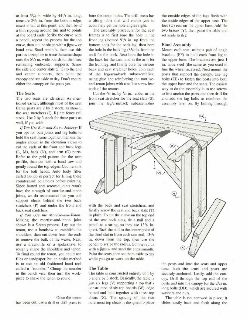
The Table The table is constructed entirely of l by 3 and 2 by 3 stock. Basically, the table is just six legs (V) supporting a top that ' s constructed of six top boards (W), edge butted and held together with three top cleats (X). The spacing of the two outermost top cleats is designed to place
the outside edges of the legs flush with the inside edges of the upper base. The feet (U) rest on the upper base. Add the two braces (Y), then paint the table and set aside to dry.
Final Assembly Mount each seat, using a pair of angle brackets (FF) to hold each front leg to the upper base. The brackets are just 1 in. wide steel (the same as you used to line the wheel recesses). Next mount the posts that support the canopy. Use lag bolts (EE) to fasten the posts into both the upper base and the seats. The easiest way to do the assembly is to use screws to first anchor the parts, and then drill for and add the lag bolts to reinforce the assembly later on. By bolting through
the posts and into the seats and upper base, both the seats and posts are securely anchored. Lastly, add the canopy. Drill through the top end of the posts and into the canopy for the 2 1 /2 in. long bolts (DD), which are secured with washers and nuts.
The table is not screwed in place. It slides easily back and forth along the
upper base. This enables one to locate the table closer, further away, or to remove the table entirely, depending on what's most comfortable.
nice, but it isn't necessary. A straight edge is much easier to sew. The canvas top is secured with Velcro strips (HH).
area. Use blocks or bricks to raise the unit slightly, so it isn ' t in direct contact with the ground. If a level area isn't available, you can shim to level the glider. mi The glider should be placed on a level
You may want to make a canvas canopy top (GG) for your glider. Cut the canvas to the size shown in our illustration, then fold and sew as indicated. The scalloped edge of the canvas top looks
®
-e.uy@ .L\X4 ><8 ',;T ALTLJA\- $ \"2.E. -
3 v::z_ x 3Vz >< 9 6
'i>:.\'? P....S -S:.T\e>V'1N
°3~ l ~----z~
'i>:.\'?'1>.___\N_.4__ <'..!_u-r_ '-_' '"y,'""s-v./_A_:s:-\_ E.
4><4 XB ':s Y IE \..."'I> :
4 '?A "'-TS ® l"''l----:----~<:,,___----:------..."-(zo/'e. >< Z%>< <96/ "-.. ... 1 ___ A ___ _...I ___ A ____ _.I
~ ~::~; ~ ~~·===""'===""~·:;;""'=~&::!:::·::c...=="'2· :z. ? ,A.¥<--r:S@ .... ::s 0'4 >< :z.3B )<. -r.:;;/
I
\ \
'Ov Y @ I x 3X ' o ',_ @ Y\E.-\....\> : Ze> ? A"''''$ ® ('7'4 x z Yz x 17)
s.ss.:s s :s s
® Y \E-\-"t> '.ZC> VA'i<.T.$ \ (74xz~xz7~') ~ ,- 51 ·'1 s j'$
~uy ® IX 6 x 8's - Y \E-\-\>: .L\ '<"A .... "5 ® ~T~
'OUy@ :z.l-z '\:>\)>.. · X '76 - Y lc\-\> : .Z. Y'A ..... ,:s@ 2- , • ..,,,,,,,~®
( I ) )
"2>U Y 0 Z ><3'>< l e>'.s
® y ,e.._"'I> ·. ?A'"'-'-""~ -~-.-----s-.----.. s-, " ..... '-i
® Y\E \-\> : Y'°A""-TS~ K....--------.s----.....,...s-~~" "1 I I I