Embed Size (px)
Citation preview
Abstract—The simulation techniques development for multi-
axis machining is key to the evolution of productivity and
quality in the manufacture of mechanical parts with complex
shapes (aerodynamic shapes, molds, etc.). The machining
simulation representing accurately the cutting phenomenon is
indispensable. However, this technique is penalized by the lack
of knowledge of the cut. This field is wide and deals with
various aspects. In this paper, the main machining simulation
techniques are classified by category (geometrical and
physical), by scale (multi-scale approach) and Part-Tool-
Machine (dynamic and geometric) system. In the end,
particular attention is given to geometric simulation techniques
at macroscale.
Key Words—Machining simulation, Multi-axis machining,
NC verification, Virtual workpiece, Geometric modeling.
I. INTRODUCTION
echanical parts with free form surfaces used in various
industries (molds, automotive, aerospace, etc...) are
machined on multi-axis CNC milling machines because of
their highly complex geometric shapes. Toolpaths for
obtaining these parts are generated by taking into account
several parameters (cutting conditions, tools shapes, surfaces
models, etc...). The final shape of the part is obtained in
three operations: roughing, semi-finishing and finishing.
Before real machining, it is essential to simulate virtually the
machining to verify the geometry of the finished part and to
predict physical factors that are necessary to optimize the
cutting parameters. Several researches have been conducted
to deal with various problems related to the machining
simulation of freeform surfaces on multi-axis machines. The
objective of this work is to propose criteria for classification
of these studies. The different proposed classifications are
by category (geometrical and physical), by scale (human,
macroscopic and microscopic) and by model of the Part-
Tool-Machine system (dynamic model and geometric
model). In the end, special attention is given to the
geometric simulation at the macroscale.
II. CLASSIFICATION BY CATEGORIES
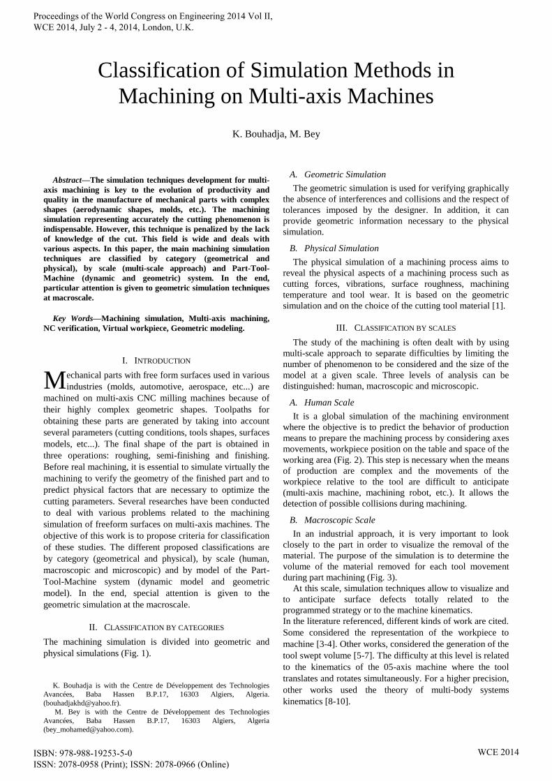
The machining simulation is divided into geometric and
physical simulations (Fig. 1).
K. Bouhadja is with the Centre de Développement des Technologies
Avancées, Baba Hassen B.P.17, 16303 Algiers, Algeria.
M. Bey is with the Centre de Développement des Technologies
Avancées, Baba Hassen B.P.17, 16303 Algiers, Algeria
A. Geometric Simulation
The geometric simulation is used for verifying graphically
the absence of interferences and collisions and the respect of
tolerances imposed by the designer. In addition, it can
provide geometric information necessary to the physical
simulation.
B. Physical Simulation
The physical simulation of a machining process aims to
reveal the physical aspects of a machining process such as
cutting forces, vibrations, surface roughness, machining
temperature and tool wear. It is based on the geometric
simulation and on the choice of the cutting tool material [1].
III. CLASSIFICATION BY SCALES
The study of the machining is often dealt with by using
multi-scale approach to separate difficulties by limiting the
number of phenomenon to be considered and the size of the
model at a given scale. Three levels of analysis can be
distinguished: human, macroscopic and microscopic.
A. Human Scale
It is a global simulation of the machining environment
where the objective is to predict the behavior of production
means to prepare the machining process by considering axes
movements, workpiece position on the table and space of the
working area (Fig. 2). This step is necessary when the means
of production are complex and the movements of the
workpiece relative to the tool are difficult to anticipate
(multi-axis machine, machining robot, etc.). It allows the
detection of possible collisions during machining.
B. Macroscopic Scale
In an industrial approach, it is very important to look
closely to the part in order to visualize the removal of the
material. The purpose of the simulation is to determine the
volume of the material removed for each tool movement
during part machining (Fig. 3).
At this scale, simulation techniques allow to visualize and
to anticipate surface defects totally related to the
programmed strategy or to the machine kinematics.
In the literature referenced, different kinds of work are cited.
Some considered the representation of the workpiece to
machine [3-4]. Other works, considered the generation of the
tool swept volume [5-7]. The difficulty at this level is related
to the kinematics of the 05-axis machine where the tool
translates and rotates simultaneously. For a higher precision,
other works used the theory of multi-body systems
kinematics [8-10].
Classification of Simulation Methods in
Machining on Multi-axis Machines
K. Bouhadja, M. Bey
M
Proceedings of the World Congress on Engineering 2014 Vol II, WCE 2014, July 2 - 4, 2014, London, U.K.
ISBN: 978-988-19253-5-0 ISSN: 2078-0958 (Print); ISSN: 2078-0966 (Online)
WCE 2014
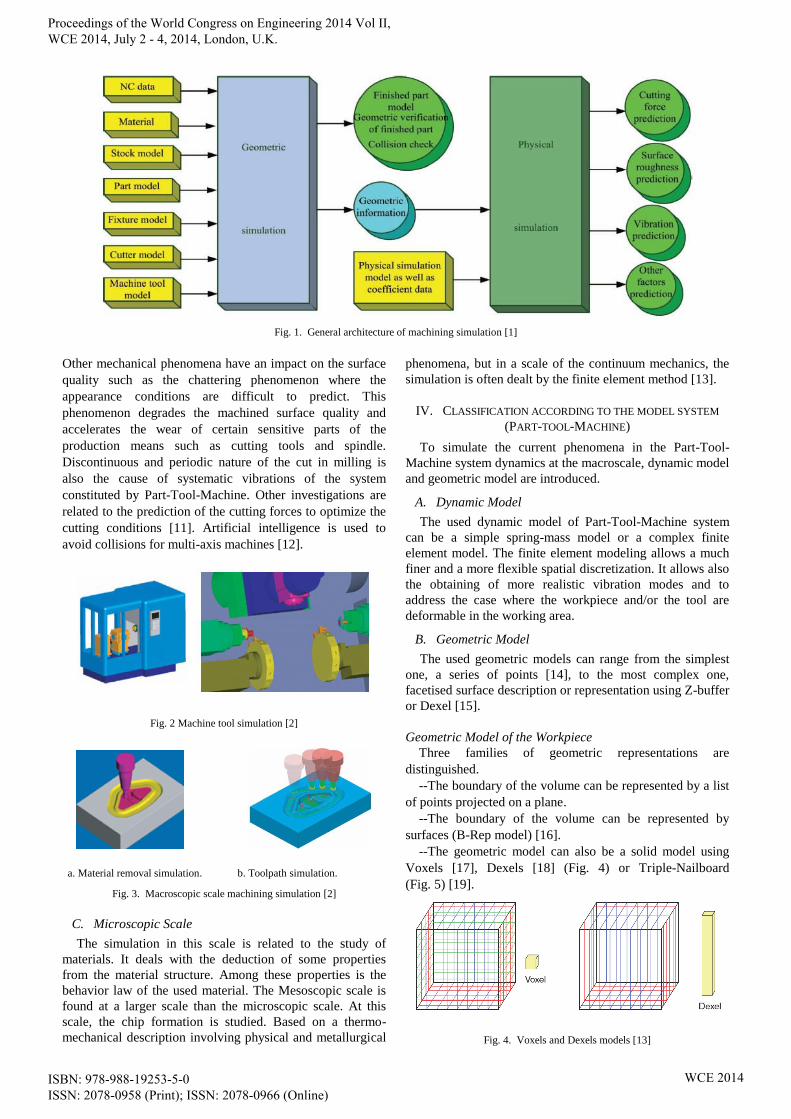
Fig. 1. General architecture of machining simulation [1]
Other mechanical phenomena have an impact on the surface
quality such as the chattering phenomenon where the
appearance conditions are difficult to predict. This
phenomenon degrades the machined surface quality and
accelerates the wear of certain sensitive parts of the
production means such as cutting tools and spindle.
Discontinuous and periodic nature of the cut in milling is
also the cause of systematic vibrations of the system
constituted by Part-Tool-Machine. Other investigations are
related to the prediction of the cutting forces to optimize the
cutting conditions [11]. Artificial intelligence is used to
avoid collisions for multi-axis machines [12].
Fig. 2 Machine tool simulation [2]
a. Material removal simulation. b. Toolpath simulation.
Fig. 3. Macroscopic scale machining simulation [2]
C. Microscopic Scale
The simulation in this scale is related to the study of
materials. It deals with the deduction of some properties
from the material structure. Among these properties is the
behavior law of the used material. The Mesoscopic scale is
found at a larger scale than the microscopic scale. At this
scale, the chip formation is studied. Based on a thermo-
mechanical description involving physical and metallurgical
phenomena, but in a scale of the continuum mechanics, the
simulation is often dealt by the finite element method [13].
IV. CLASSIFICATION ACCORDING TO THE MODEL SYSTEM
(PART-TOOL-MACHINE)
To simulate the current phenomena in the Part-Tool-
Machine system dynamics at the macroscale, dynamic model
and geometric model are introduced.
A. Dynamic Model
The used dynamic model of Part-Tool-Machine system
can be a simple spring-mass model or a complex finite
element model. The finite element modeling allows a much
finer and a more flexible spatial discretization. It allows also
the obtaining of more realistic vibration modes and to
address the case where the workpiece and/or the tool are
deformable in the working area.
B. Geometric Model
The used geometric models can range from the simplest
one, a series of points [14], to the most complex one,
facetised surface description or representation using Z-buffer
or Dexel [15].
Geometric Model of the Workpiece
Three families of geometric representations are
distinguished.
--The boundary of the volume can be represented by a list
of points projected on a plane.
--The boundary of the volume can be represented by
surfaces (B-Rep model) [16].
--The geometric model can also be a solid model using
Voxels [17], Dexels [18] (Fig. 4) or Triple-Nailboard
(Fig. 5) [19].
Fig. 4. Voxels and Dexels models [13]
Proceedings of the World Congress on Engineering 2014 Vol II, WCE 2014, July 2 - 4, 2014, London, U.K.
ISBN: 978-988-19253-5-0 ISSN: 2078-0958 (Print); ISSN: 2078-0966 (Online)
WCE 2014
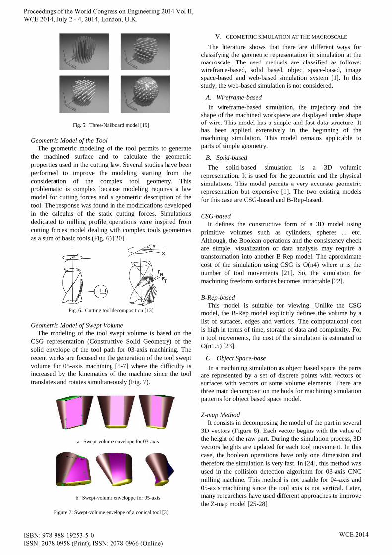
Fig. 5. Three-Nailboard model [19]
Geometric Model of the Tool
The geometric modeling of the tool permits to generate
the machined surface and to calculate the geometric
properties used in the cutting law. Several studies have been
performed to improve the modeling starting from the
consideration of the complex tool geometry. This
problematic is complex because modeling requires a law
model for cutting forces and a geometric description of the
tool. The response was found in the modifications developed
in the calculus of the static cutting forces. Simulations
dedicated to milling profile operations were inspired from
cutting forces model dealing with complex tools geometries
as a sum of basic tools (Fig. 6) [20].
Fig. 6. Cutting tool decomposition [13]
Geometric Model of Swept Volume
The modeling of the tool swept volume is based on the
CSG representation (Constructive Solid Geometry) of the
solid envelope of the tool path for 03-axis machining. The
recent works are focused on the generation of the tool swept
volume for 05-axis machining [5-7] where the difficulty is
increased by the kinematics of the machine since the tool
translates and rotates simultaneously (Fig. 7).
a. Swept-volume envelope for 03-axis
b. Swept-volume enveloppe for 05-axis
Figure 7: Swept-volume envelope of a conical tool [3]
V. GEOMETRIC SIMULATION AT THE MACROSCALE
The literature shows that there are different ways for
classifying the geometric representation in simulation at the
macroscale. The used methods are classified as follows:
wireframe-based, solid based, object space-based, image
space-based and web-based simulation system [1]. In this
study, the web-based simulation is not considered.
A. Wireframe-based
In wireframe-based simulation, the trajectory and the
shape of the machined workpiece are displayed under shape
of wire. This model has a simple and fast data structure. It
has been applied extensively in the beginning of the
machining simulation. This model remains applicable to
parts of simple geometry.
B. Solid-based
The solid-based simulation is a 3D volumic
representation. It is used for the geometric and the physical
simulations. This model permits a very accurate geometric
representation but expensive [1]. The two existing models
for this case are CSG-based and B-Rep-based.
CSG-based
It defines the constructive form of a 3D model using
primitive volumes such as cylinders, spheres ... etc.
Although, the Boolean operations and the consistency check
are simple, visualization or data analysis may require a
transformation into another B-Rep model. The approximate
cost of the simulation using CSG is O(n4) where n is the
number of tool movements [21]. So, the simulation for
machining freeform surfaces becomes intractable [22].
B-Rep-based
This model is suitable for viewing. Unlike the CSG
model, the B-Rep model explicitly defines the volume by a
list of surfaces, edges and vertices. The computational cost
is high in terms of time, storage of data and complexity. For
n tool movements, the cost of the simulation is estimated to
O(n1.5) [23].
C. Object Space-base
In a machining simulation as object based space, the parts
are represented by a set of discrete points with vectors or
surfaces with vectors or some volume elements. There are
three main decomposition methods for machining simulation
patterns for object based space model.
Z-map Method
It consists in decomposing the model of the part in several
3D vectors (Figure 8). Each vector begins with the value of
the height of the raw part. During the simulation process, 3D
vectors heights are updated for each tool movement. In this
case, the boolean operations have only one dimension and
therefore the simulation is very fast. In [24], this method was
used in the collision detection algorithm for 03-axis CNC
milling machine. This method is not usable for 04-axis and
05-axis machining since the tool axis is not vertical. Later,
many researchers have used different approaches to improve
the Z-map model [25-28]
Proceedings of the World Congress on Engineering 2014 Vol II, WCE 2014, July 2 - 4, 2014, London, U.K.
ISBN: 978-988-19253-5-0 ISSN: 2078-0958 (Print); ISSN: 2078-0966 (Online)
WCE 2014
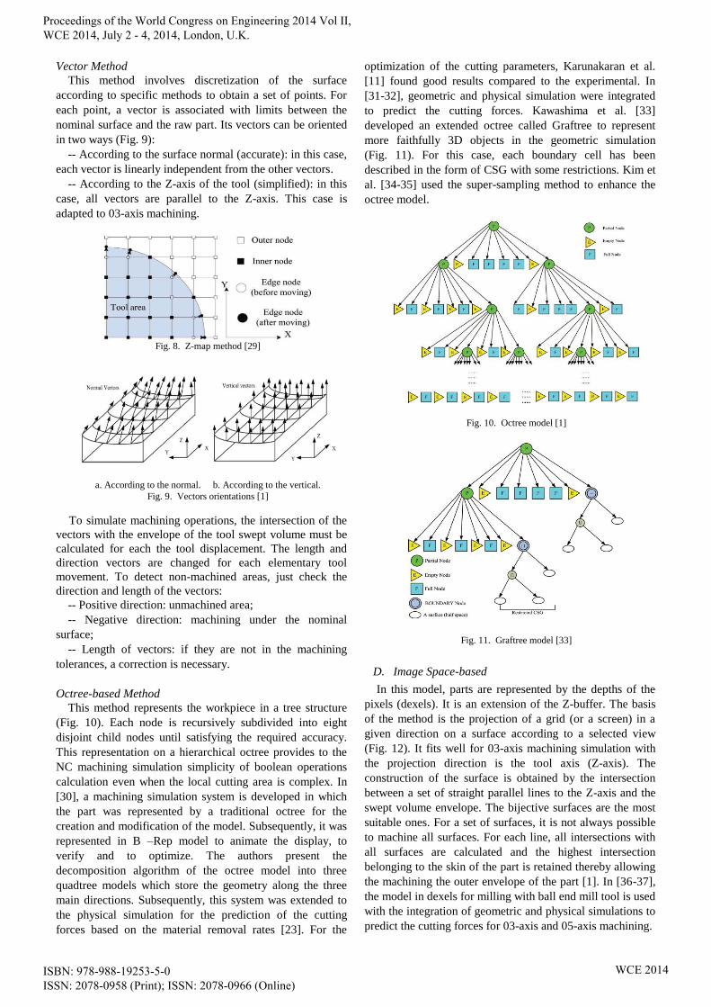
Vector Method
This method involves discretization of the surface
according to specific methods to obtain a set of points. For
each point, a vector is associated with limits between the
nominal surface and the raw part. Its vectors can be oriented
in two ways (Fig. 9):
-- According to the surface normal (accurate): in this case,
each vector is linearly independent from the other vectors.
-- According to the Z-axis of the tool (simplified): in this
case, all vectors are parallel to the Z-axis. This case is
adapted to 03-axis machining.
Fig. 8. Z-map method [29]
a. According to the normal. b. According to the vertical.
Fig. 9. Vectors orientations [1]
To simulate machining operations, the intersection of the
vectors with the envelope of the tool swept volume must be
calculated for each the tool displacement. The length and
direction vectors are changed for each elementary tool
movement. To detect non-machined areas, just check the
direction and length of the vectors:
-- Positive direction: unmachined area;
-- Negative direction: machining under the nominal
surface;
-- Length of vectors: if they are not in the machining
tolerances, a correction is necessary.
Octree-based Method
This method represents the workpiece in a tree structure
(Fig. 10). Each node is recursively subdivided into eight
disjoint child nodes until satisfying the required accuracy.
This representation on a hierarchical octree provides to the
NC machining simulation simplicity of boolean operations
calculation even when the local cutting area is complex. In
[30], a machining simulation system is developed in which
the part was represented by a traditional octree for the
creation and modification of the model. Subsequently, it was
represented in B –Rep model to animate the display, to
verify and to optimize. The authors present the
decomposition algorithm of the octree model into three
quadtree models which store the geometry along the three
main directions. Subsequently, this system was extended to
the physical simulation for the prediction of the cutting
forces based on the material removal rates [23]. For the
optimization of the cutting parameters, Karunakaran et al.
[11] found good results compared to the experimental. In
[31-32], geometric and physical simulation were integrated
to predict the cutting forces. Kawashima et al. [33]
developed an extended octree called Graftree to represent
more faithfully 3D objects in the geometric simulation
(Fig. 11). For this case, each boundary cell has been
described in the form of CSG with some restrictions. Kim et
al. [34-35] used the super-sampling method to enhance the
octree model.
Fig. 10. Octree model [1]
Fig. 11. Graftree model [33]
D. Image Space-based
In this model, parts are represented by the depths of the
pixels (dexels). It is an extension of the Z-buffer. The basis
of the method is the projection of a grid (or a screen) in a
given direction on a surface according to a selected view
(Fig. 12). It fits well for 03-axis machining simulation with
the projection direction is the tool axis (Z-axis). The
construction of the surface is obtained by the intersection
between a set of straight parallel lines to the Z-axis and the
swept volume envelope. The bijective surfaces are the most
suitable ones. For a set of surfaces, it is not always possible
to machine all surfaces. For each line, all intersections with
all surfaces are calculated and the highest intersection
belonging to the skin of the part is retained thereby allowing
the machining the outer envelope of the part [1]. In [36-37],
the model in dexels for milling with ball end mill tool is used
with the integration of geometric and physical simulations to
predict the cutting forces for 03-axis and 05-axis machining.
Proceedings of the World Congress on Engineering 2014 Vol II, WCE 2014, July 2 - 4, 2014, London, U.K.
ISBN: 978-988-19253-5-0 ISSN: 2078-0958 (Print); ISSN: 2078-0966 (Online)
WCE 2014
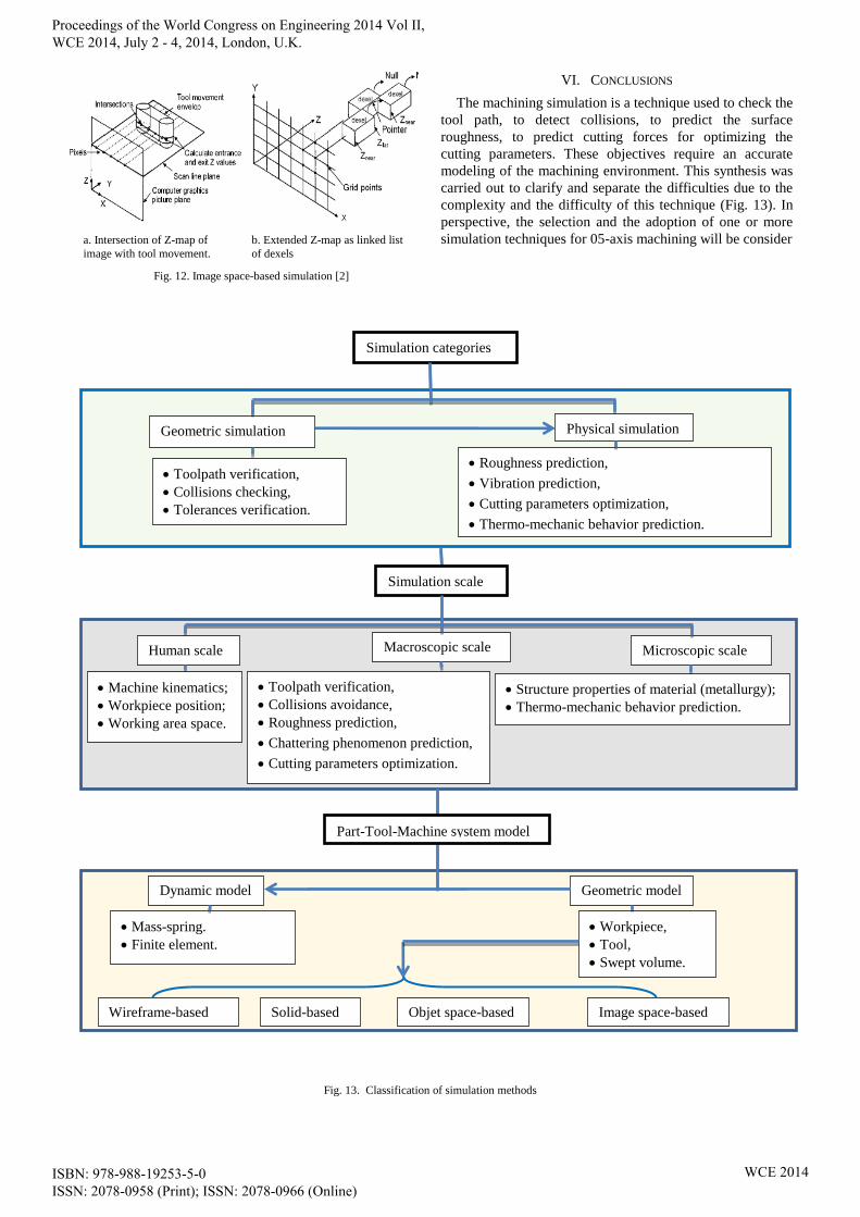
a. Intersection of Z-map of
image with tool movement.
b. Extended Z-map as linked list
of dexels
Fig. 12. Image space-based simulation [2]
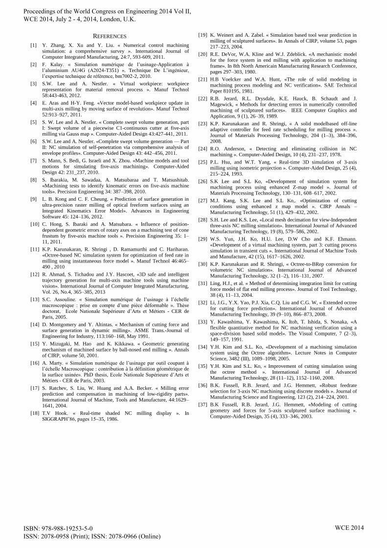
VI. CONCLUSIONS
The machining simulation is a technique used to check the
tool path, to detect collisions, to predict the surface
roughness, to predict cutting forces for optimizing the
cutting parameters. These objectives require an accurate
modeling of the machining environment. This synthesis was
carried out to clarify and separate the difficulties due to the
complexity and the difficulty of this technique (Fig. 13). In
perspective, the selection and the adoption of one or more
simulation techniques for 05-axis machining will be consider
Fig. 13. Classification of simulation methods
Simulation categories
Geometric simulation Physical simulation
Toolpath verification,
Collisions checking,
Tolerances verification.
Roughness prediction,
Vibration prediction,
Cutting parameters optimization,
Thermo-mechanic behavior prediction.
Simulation scale
Machine kinematics;
Workpiece position;
Working area space.
Toolpath verification,
Collisions avoidance,
Roughness prediction,
Chattering phenomenon prediction,
Cutting parameters optimization.
Human scale Macroscopic scale Microscopic scale
Structure properties of material (metallurgy);
Thermo-mechanic behavior prediction.
Dynamic model Geometric model
Workpiece,
Tool,
Swept volume.
Mass-spring.
Finite element.
Solid-based Objet space-based Image space-based
Wireframe-based
Part-Tool-Machine system model
Proceedings of the World Congress on Engineering 2014 Vol II, WCE 2014, July 2 - 4, 2014, London, U.K.
ISBN: 978-988-19253-5-0 ISSN: 2078-0958 (Print); ISSN: 2078-0966 (Online)
WCE 2014
REFERENCES
[1] Y. Zhang, X. Xu and Y. Liu. « Numerical control machining simulation: a comprehensive survey ». International Journal of Computer Integrated Manufacturing, 24:7, 593-609, 2011.
[2] F. Kalay. « Simulation numérique de l’usinage-Application à l’aluminium AU4G (A2024-T351) ». Technique De L’ingénieur, l’expertise technique de référence, bm7002-2, 2010.
[3] S.W. Lee and A. Nestler. « Virtual workpiece: workpiece representation for material removal process ». Manuf Technol 58:443-463, 2012.
[4] E. Aras and H-Y. Feng. «Vector model-based workpiece update in multi-axis milling by moving surface of revolution». Manuf Technol 52:913–927, 2011.
[5] S. W. Lee and A. Nestler. « Complete swept volume generation, part I: Swept volume of a piecewise C1-continuous cutter at five-axis milling via Gauss map ». Computer-Aided Design 43:427-441, 2011.
[6] S.W. Lee and A. Nestler. «Complete swept volume generation — Part II: NC simulation of self-penetration via comprehensive analysis of envelope profiles». Computer-Aided Design 43: 442–456, 2011.
[7] S. Mann, S. Bedi, G. Israeli and X. Zhou. «Machine models and tool motions for simulating five-axis machining». Computer-Aided Design 42: 231_237, 2010.
[8] S. Ibarakia, M. Sawadaa, A. Matsubaraa and T. Matsushitab. «Machining tests to identify kinematic errors on five-axis machine tools». Precision Engineering 34: 387–398, 2010.
[9] L. B. Kong and C. F. Cheung. « Prediction of surface generation in ultra-precision raster milling of optical freeform surfaces using an Integrated Kinematics Error Model». Advances in Engineering Software 45: 124–136, 2012.
[10] C. Hong, S. Ibaraki and A. Matsubara. « Influence of position-dependent geometric errors of rotary axes on a machining test of cone frustum by five-axis machine tools ». Precision Engineering 35: 1–11, 2011.
[11] K.P. Karunakaran, R. Shringi , D. Ramamurthi and C. Hariharan. «Octree-based NC simulation system for optimization of feed rate in milling using instantaneous force model ». Manuf Technol 46:465–490 , 2010
[12] R. Ahmad, S. Tichadou and J.Y. Hascoet, «3D safe and intelligent trajectory generation for multi-axis machine tools using machine vision». International Journal of Computer Integrated Manufacturing, Vol. 26, No.4, 365–385, 2013
[13] S.C. Assouline. « Simulation numérique de l’usinage à l’échelle macroscopique : prise en compte d’une pièce déformable ». Thèse doctorat, Ecole Nationale Supérieure d’Arts et Métiers - CER de Paris, 2005.
[14] D. Montgomery and Y. Altintas. « Mechanism of cutting force and surface generation in dynamic milling». ASME Trans.-Journal of Engineering for Industry, 113:160–168, May 1991.
[15] Y. Mizugaki, M. Hao and K. Kikkawa. « Geometric generating mechanism of machined surface by ball-nosed end milling ». Annals of CIRP, volume 50, 2001.
[16] A. Marty. « Simulation numérique de l’usinage par outil coupant à l’échelle Macroscopique : contribution à la définition géométrique de la surface usinée». PhD thesis, Ecole Nationale Supérieure d’Arts et Métiers - CER de Paris, 2003.
[17] S. Ratchev, S. Liu, W. Huang and A.A. Becker. « Milling error prediction and compensation in machining of low-rigidity parts». International Journal of Machine, Tools and Manufacture, 44:1629–1641, 2004.
[18] T.V Hook. « Real-time shaded NC milling display ». In SIGGRAPH’86, pages 15–35, 1986.
[19] K. Weinert and A. Zabel. « Simulation based tool wear prediction in milling of sculptured surfaces». In Annals of CIRP, volume 53, pages 217–223, 2004.
[20] R.E. DeVor, W.A. Kline and W.J. Zdeblick. «A mechanistic model for the force system in end milling with application to machining frame». In 8th North Americain Manufacturing Research Conference, pages 297–303, 1980.
[21] H.B Voelcker and W.A. Hunt, «The role of solid modeling in machining process modeling and NC verification». SAE Technical Paper 810195, 1981.
[22] R.B. Jerard, R.L. Drysdale, K.E. Hauck, B. Schaudt and J. Magewick, « Methods for detecting errors in numerically controlled machining of sculptured surfaces». IEEE Computer Graphics and Application, 9 (1), 26–39, 1989.
[23] K.P. Karunakaran and R. Shringi, « A solid modelbased off-line adaptive controller for feed rate scheduling for milling process ». Journal of Materials Processing Technology, 204 (1–3), 384–396, 2008.
[24] R.O. Anderson, « Detecting and eliminating collision in NC machining ». Computer-Aided Design, 10 (4), 231–237, 1978.
[25] P.L. Hsu, and W.T. Yang, « Real-time 3D simulation of 3-axis milling using isometric projection ». Computer-Aided Design, 25 (4), 215–224, 1993.
[26] S.K Lee and S.L Ko, «Development of simulation system for machining process using enhanced Z-map model ». Journal of Materials Processing Technology, 130–131, 608–617, 2002.
[27] M.J. Kang, S.K. Lee and S.L Ko,. «Optimization of cutting conditions using enhanced z map model ». CIRP Annals – Manufacturing Technology, 51 (1), 429–432, 2002.
[28] S.H. Lee and K.S. Lee, «Local mesh decimation for view-Independent three-axis NC milling simulation». International Journal of Advanced Manufacturing Technology, 19 (8), 579–586, 2002.
[29] W.S. Yun, J.H. Ko, H.U. Lee, D.W Cho and K.F. Ehmann. «Development of a virtual machining system, part 3: cutting process simulation in transient cuts ». International Journal of Machine Tools and Manufacture, 42 (15), 1617–1626, 2002.
[30] K.P. Karunakaran and R. Shringi, « Octree-to-BRep conversion for volumetric NC simulation». International Journal of Advanced Manufacturing Technology, 32 (1–2), 116–131, 2007.
[31] Ling, H.J., et al. « Method of determining integration limit for cutting force model of flat end milling process». Journal of Tool Technology, 38 (4), 11–13, 2004.
[32] Li, J.G., Y.X. Yao, P.J. Xia, C.Q. Liu and C.G. W, « Extended octree for cutting force prediction». International Journal of Advanced Manufacturing Technology, 39 (9–10), 866–873, 2008.
[33] Y. Kawashima, Y. Kawashima, K. Itoh, T. Ishida, S. Nonaka, «A flexible quantitative method for NC machining verification using a space-division based solid model». The Visual Computer, 7 (2–3), 149–157, 1991.
[34] Y.H. Kim and S.L. Ko, «Development of a machining simulation system using the Octree algorithm». Lecture Notes in Computer Science, 3482 (III), 1089–1098, 2005.
[35] Y.H. Kim and S.L. Ko, « Improvement of cutting simulation using the octree method ». International Journal of Advanced Manufacturing Technology, 28 (11–12), 1152–1160, 2008.
[36] B.K. Fussell, R.B. Jerard, and J.G. Hemmett, «Robust feedrate selection for 3-axis NC machining using discrete models ». Journal of Manufacturing Science and Engineering, 123 (2), 214–224, 2001.
[37] B.K Fussell, R.B. Jerard, J.G. Hemmett, «Modeling of cutting geometry and forces for 5-axis sculptured surface machining ». Computer-Aided Design, 35 (4), 333–346, 2003.
Proceedings of the World Congress on Engineering 2014 Vol II, WCE 2014, July 2 - 4, 2014, London, U.K.
ISBN: 978-988-19253-5-0 ISSN: 2078-0958 (Print); ISSN: 2078-0966 (Online)
WCE 2014