Embed Size (px)
Citation preview

1033
SDSS’Rio 2010 STABILITY AND DUCTILITY OF STEEL STRUCTURES E. Batista, P. Vellasco, L. de Lima (Eds.)
Rio de Janeiro, Brazil, September 8 - 10, 2010
CLASSIFICATION OF STABILITY FAILURE MODES OF SANDWICH PANELS UNDER COMPRESSION LOADING:
GLOBAL AND LOCAL BUCKLING, CRIPPLING AT SUPPORT LINE
Saskia Käpplein and Thomas Ummenhofer
Versuchsanstalt für Stahl, Holz und Steine; Karlsruhe Institut of Technology (KIT) e-mails: [email protected], thomas.ummenhofer@kit edu
Keywords: sandwich panels, axial force, buckling, wrinkling.
Abstract. Traditionally, sandwich panels are designed as unidirectional spanning flexural members, transferring the load to a skeletal substructure. As a recent development, sandwich panels are used without substructure. In this application the panels have to transfer normal forces in addition to transverse loads. The paper introduces a design model for axial loaded sandwich panels. Additionally, the basic failure modes at the area of load application were illustrated and a mechanical model is presented.
1 INTRODUCTION
Sandwich panels used in industrial buildings consist of two metallic faces and a core layer made of thermal insulating materials (hard foam PUR, PS or mineral wool). The application being common practice up to now, is restricted to the brick partition; i.e. the panels only transfer transverse loads (wind, snow) acting on them to the substructure by bending. In the panel only the stress resultants of the bending moment M and transverse force V are effective.
A recent tendency, especially in the area of smaller buildings (Fig. 1) – such as cooling chambers, climatic chambers and clean rooms – is to apply the panels without substructure.
D
Figure 1: Cross-section of a sandwich panel; Building without substructure
In this application the wall panels have to transfer normal forces in addition to the stress resultants arising from transverse loads. This results in the question for the load-bearing capacity of the panels in the areas of load application, i.e. on the lower ends of the panel and on the connection between wall and ceiling, where the superimposed loads from the ceiling are applied as normal force into the wall panels (Fig. 2).
First published in:
EVA-STAR (Elektronisches Volltextarchiv – Scientific Articles Repository) http://digbib.ubka.uni-karlsruhe.de/volltexte/1000020018
CORE Metadata, citation and similar papers at core.ac.uk
Provided by KITopen

1034
Saskia Käpplein and Thomas Ummenhofer
Figure 2: Connection between wall and ceiling and lower ends
In addition to the load application areas, also the load-bearing capacity of the panels subjected to normal force load or rather a combination from normal force and bending moment is to be verified. Since the loads at the connection between wall and ceiling are usually transferred into the inner face, a fixed-end moment always exists, and therefore a pure axial load of the wall panel is also rather unusual for lacking transverse load.
2 FAILURE MODES
In flat and lightly profiled sandwich panels, bending moments are transferred in both faces by a force couple. The bending load capacity of a sandwich panel is mostly restricted by the wrinkling stress of the face subjected to compression (Fig. 3a). Wrinkling concerns a stability failure of the compressed face, which is elastically supported by the core material. In rare cases, failure can also occur by reaching the yield strength in the face subjected to tension.
A further possible failure mode is the shear failure of the core, e.g. in the considered wall panel itself or in the ceiling panel which applies the load (Fig. 3b).
In the end region of the panels, normal forces have to be applied on the free cut edge of the face. Failure may occur by “crippling” of the edge or by “long-wave buckling” (Fig. 3c). This problem is naturally similar to wrinkling, the edge, however, is not supported and imperfections of the contact area may reduce the load-bearing capacity for uneven edges.
The ceiling panel is only supported by the inner face of the wall panel, corresponding to a knife-edge support. This may result in incising of the inner face of the ceiling panel above the support line (Fig. 3d).
Figure 3: Wrinkling, shear failure, failure at load application, incising of the ceiling panel
3 GLOBAL FAILURES: BUCKLING AND WRINKLING OF THE WALL PANELS
3.1 Basic principles
Considering the elastic buckling load of the faces Nki and the elastic buckling load of the core GA, the elastic buckling load Ncr of a sandwich panel subjected to centric axial load can be calculated to
GAN
1
NN
ki
kicr (1)
a d cb

1035
Saskia Käpplein and Thomas Ummenhofer
The load at which wrinkling of both facings occur under centric axial load, can be calculated to
Fww A2N (2)
Thus, the slenderness of a sandwich panel can be calculated to
2GA
2ki
cr
wN
N (3)
With
ki
wki N
N ; GANw
GA (4)
For axially loaded sandwich panels, a buckling failure occurs for > 1. This is only the case for panels with higher slenderness. Therefore, the panels must be thin and the faces must have a large stiffness, so that a buckling failure occurs.
Calculating the global load-bearing capacity of the panels subjected to axial loads, there is basically the possibility of determining the stress resultants according to the theory of second order and furnishing proof of the stress level using the wrinkling stress as limit stress. In addition, design according to the equivalent member method by buckling curves is possible.
3.2 Design according to the theory of second order
The stress resultants according to the theory of second order can be calculated approximately with the amplification factor .
III MM (5) III VV (6)
III NN (7) With
crN
N1
1 (8)
)we(NMM T00I (9)
M0 = bending moment from transverse load (for ex. wind loading) N = normal force e0 = pre-deformation from geometric initial imperfection wT = deflection due to temperature differences between inside and outside
Then, the structural analysis is done on the stress level.
wFF
II
A2
N
DA
M (10)
With transverse load, the shear load capacity of the core material can become decisive.

1036
Saskia Käpplein and Thomas Ummenhofer
CvC
II
fA
V (11)
This procedure facilitates the consideration of transverse loads and fixed-end moments acting on the panels as well as the deflection due to temperature difference.
For checking the applicability of the procedure described above, tests and numerical calculations were performed. The tests showed the problem of load application. In order to avoid a failure at the load application position, thus at the cut edges of the panels, panels with very high, practically rather unusual slendernesses have to be used. This results in a global failure of the panel by global buckling or wrinkling of the compressed face in mid-span, Therefore, the performed tests served as a source for checking the FE-model. In addition, the FE-Model was calibrated by a comparison of the wrinkling stress and the elastic buckling load using the corresponding theoretical characteristic value.
In the FE analyses, a short-wave imperfection (Fig. 4a) corresponding to the natural buckling mode when reaching the wrinkling stress was applied as local geometrical imperfection on the face subjected to pressure. As a global imperfection, a deflection e0 corresponding to the first natural buckling mode of the axial loaded panels was applied (Fig. 4b). The initial deformation e0 was assumed to be
l500
1eo (12)
according to the maximum allowable imperfection value in compliance with EN 14509.
Figure 4: Local and global imperfections in the FE analyses
In the FE analyses, the failure stresses of axial loaded sandwich panels were determined using the above described local and global geometrical imperfections. Furthermore, the failure stress for transverese load was determined as a comparative value. Fig. 5 shows for example wrinkling stresses of two different panels with different local imperfections.
Figure 5: Wrinkling stresses
a b
1037
Saskia Käpplein and Thomas Ummenhofer
Obviously, the failure stress for axial load or rather for interaction of axial and transverse load corresponds approximately to that for pure bending. Thus, the wrinkling stress usually determined in simple bending tests can be used as limit stress for the design of panels subjected to axial or combined load.
3.3 Design via buckling curves
Alternative to a calculation according to the theory of second order, a design by means of the equivalent member method would also be possible. But a buckling curve is necessary. The reduction factor would in turn use the wrinkling stress as reference stress.
wRk NN (13)
The reduction factor can be calculated according to the following formulae:
22
1 (14)
]1[5,0 22GA
2 (15)
The imperfection coefficient depends on the cross-section geometry and the material parameters of the considered sandwich panel as well as on the length-dependent imperfection e0, and can be calculated to
w
S0
N
B
D
e2 (16)
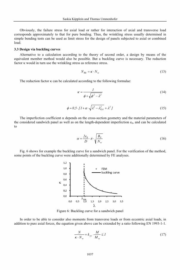
Fig. 6 shows for example the buckling curve for a sandwich panel. For the verification of the method, some points of the buckling curve were additionally determined by FE analyses.
Figure 6: Buckling curve for a sandwich panel
In order to be able to consider also moments from transverse loads or from eccentric axial loads, in addition to pure axial forces, the equation given above can be extended by a ratio following EN 1993-1-1.
1M
Mk
N
N
wyy
w
(17)

1038
Saskia Käpplein and Thomas Ummenhofer
With
wFw ADM (18)
)N
N8,01(Ck
wmyyy (19)
Cmy = Equivalent uniform moment factor according to EN 1993-1-1, Table B.3
In Table 1, some calculations performed by means of the above described equivalent member method are compared with the results of a FE analysis and a calculation according to the theory of second order.
Table 1: Nmax/Nw calculated by equivalent member method, theory of second order and FE
M/Mw
N/Nw calculated byEquivalent
member methodTheory of
second orderFE
0,20 0,46 0,46 0,45 0,39 0,31 0,32 0,31 0,79 0,10 0,10 0,10 0,19 0,47 0,46 0,46 0,39 0,33 0,32 0,33 0,78 0,12 0,10 0,11
4 LOCAL FAILURES: DELAMINATION AND CRIPPLING AT LOAD APPLICATION AREA
4.1 Tests on load application
For investigating the load-bearing capacity of sandwich panels at the area of load application, tests on connection details were performed. Failure mostly occurred by crippling of the loaded face, directly below the cut edge. Especially tests on panels with faces made of GFRP resulted in a long-wave buckling in combination with delamination of the face (Fig. 7).
Figure 7: Failure modes at load application
Since the loads are directly applied on the free cut edge, this edge is especially sensitive to imperfections. At the cut edge, imperfections mainly develop through sawing of the cut in the wall panel. During sawing cracks often occur between core and face, which disturb the composite between core and face. Uneven cut edges result in contact imperfections and thus in peak stresses at the load application.

1039
Saskia Käpplein and Thomas Ummenhofer
The sensitivity of the cut edge against these imperfections can be reduced by an angle, which is stuck on the face and on the core of the wall panel (Fig. 8a). Then, failure does no longer occur by crippling of the edge, but by a long-wave buckling (Fig. 8b), which rises the load-bearing capacity of the edge. In addition to an increase of the load-bearing capacity of the cut edge, the reinforcement by an angle is also advantageous for the supported ceiling panel. Then, the panel is no longer lying on a cutting edge, but on the arm of the angle, by means of which a failure of the ceiling panel by impressing the face can be prevented.
Figure 8: Corner detail with stuck angle
4.2 Mechanical model
The failure mode in the load application area is related to wrinkling of a face in mid-span. Wrinkling in mid-span concerns an elastically supported plate, the two ends of which are supported. The face of the wall panel, to which the load is applied from the ceiling, also concerns an elastically supported plate, in which the cut edge represents an unsupported end (Fig. 9). Based on the deflection of the ceiling panel under superimposed load, the load application area of the ceiling panel is not exactly at right angles to the inner face of the wall panel. This results in an additional horizontal load F2. Further equivalent loads due to imperfections could be considered in F2 as well. Effects from the theory of second order result in an increase of the equivalent load F2. Possibly existing stiffeners at the load application area, such as stuck angles or C-sections, can be considered by an additional horizontal spring.
Figure 9: Mechanical model of load application
Based on the free end, the stress level that can be carried by the edge is below the wrinkling stress. Since there is a relation to the wrinkling stress, it is appropriate to perform the calculation of the load application through the relation to the known flexural wrinkling stress. In Fig. 10, the stresses in the inner face determined by the tests are compared to the flexural wrinkling stress.
a b

1040
Saskia Käpplein and Thomas Ummenhofer
Figure 10: Comparison of wrinkling stress and stress at load application
4.3 Glued connections
Especially in cold storage house construction it is common to glue together the core material of the panels at the connections between wall and ceiling. Especially for faces made of GFRP, also the faces are sometimes glued together with each other. Tests on connection details with glued core material show that despite bonding at the connection no moment is transferred, thus, the connection can be furthermore regarded as hinged. The ceiling load is applied as normal force into the inner face.
Bonding can cause or change stiffness and restraints in the core material. Bonding of the core often even leads to the disadvantage of an early failure of the core due to tension and shear stresses resulting from additional stiffness due to bonding (Fig. 11).
Figure 11: Failure of glued corner details
4.4 Lower ends
The problem of load application into the faces does not only exist at the connection between wall and ceiling, but also at the lower ends of the wall panels. It could be shown that both faces do not interact. Therefore, the load-bearing capacity of both faces can be added for determining the load-bearing capacity of a lower end.
5 SUMMARY
In addition to the usual application of sandwich panels for enclosures, sandwich panels in small buildings are also partly applied without supporting substructure. This results in question on the load-bearing capacity of the wall panels being now also stressed by axial loads as well as on the load-bearing capacity of panels in the area of load application, such as at the connection between wall and ceiling or at the lower ends. It could be shown by FE analyses that the wall panels stressed by normal forces can be calculated with the wrinkling stress as limit stress according to the theory of second order. The basic failure modes at the load application area were illustrated and a mechanical model was developed.
The presented research has been done within the framework of the EASIE project. Further research is going on. The EASIE project has received financial support from the European Community’s Seventh Framework Programme FP7/NMP2-SE-2008 under grant agreement No 213302.


![Optimization of Sandwich Composites Fuselages Under ......NASA[5] issued a manual on the structural stability analysis of sandwich structures under axial compression, pure bending,](https://img.pdfslide.net/doc/110x75/61148003c730c10bd54dc76b/optimization-of-sandwich-composites-fuselages-under-nasa5-issued-a-manual.jpg)