Embed Size (px)
Citation preview

Glauconite case study
CMCC21 14/01/2009 03:44PM Page 471
Clay Mineral Cements in Sandstones. Edited by Richard H. Worden and Morad © 2003 International Association of Sedimentologists. ISBN: 978-1-405-10587-3
Application of glauconite morphology ingeosteering and for on-site reservoir qualityassessment in very fine-grained sandstones:
Carnarvon Basin, Australia
J .P. SCHULZ-ROJAHN*, D.A. SEEBURGER† and G.J . BEACHER‡
West Australian Petroleum Pty Ltd. (WAPET), Box S1580 GPO, Perth, Western Australia 6001, Australia
ABSTRACT
This paper describes the innovative application of drill cuttings during thedrilling of a horizontal development well in the Mardie Greensand of EarlyCretaceous age, Saladin Field, Australian North West Shelf (CarnarvonBasin). Well results show that the morphology of glauconite pellets, asobserved in drill cuttings under the binocular microscope, can be useful formaking a first-pass assessment of reservoir quality when drilling with oil-based mud (OBM) in this very fine to fine-grained sandstone. The shape of the glauconite pellets is controlled by the degree of rock compaction,which, in turn, is controlled by the degree of framework grain support thatdrives reservoir quality. At Saladin, good-quality Mardie reservoir rock (upto 100 mD at least) capable of producing initial oil rates of up to 4000 BOPD(barrels of oil per day) from individual horizontal wells is dominated bymore or less well-rounded (‘marshmallow-shaped’) glauconite pellets withgently curved flat tops and bottoms, consistent with very minor compactionowing to abundant framework grain support. In contrast, relatively poor-quality Mardie Greensand reservoir (≤ 10 mD) is dominated by thin glau-conite pellets with long flat tops and bottoms, and non-reservoir MardieGreensand lithologies contain disk- or plate-shaped glauconite pellets thatare estimated to have compacted by as much as 80% or more. The descrip-tion of the clay pellet style rather than just a conventional description ofcuttings is the key to a reliable lithology indicator because the bulk of thevery fine to fine sand grains tends to be lost at the shakers, whereas thelarger glauconite pellets are retained preferentially. This simple recogni-tion could have important implications for pay detection in low-resistivity(greensand) exploration settings, although unproven for non-OBM bore-hole conditions. Further, despite lag time, the simple but effective methodcan complement measurement-while-drilling (MWD) controlled geosteer-ing, as exemplified by the Saladin Field, where along-hole variations in theshape of glauconite pellets provided key stratigraphical clues. In the event
Int. Assoc. Sedimentol. Spec. Publ. (2003) 34, 473–488
* Present address: Shell International Exploration and Production B.V. (SIEP), c/o Brunei Shell Petroleum, EPE/21, KB3534, Seria, Brunei Darussalam, e-mail: [email protected]† Present address: Chevron Petroleum Technology Company (CPTC), 6001 Bollinger Canyon Road, San Ramon, CA94583, USA, e-mail: [email protected]‡ Present address: Kalaro Pty Ltd., 40 Campbell Drive, Hillarys, Western Australia 6025, Australia, e-mail: [email protected]
CMCC21 14/01/2009 03:44PM Page 473
Clay Mineral Cements in Sandstones. Edited by Richard H. Worden and Morad © 2003 International Association of Sedimentologists. ISBN: 978-1-405-10587-3
474 J.P. Schulz-Rojahn et al.
INTRODUCTION
Knowledge about clay minerals and diageneticprocesses in sandstone reservoirs is to a verylarge extent based on core and outcrop data,however, valuable insights also can be gainedfrom drill cuttings. Researchers in their reser-voir studies, for a number of good reasons, tra-ditionally have ignored drill cuttings: sampledisintegration, sample contamination, ambigu-ity in depth derivation, and lack of accom-panying sedimentological data. However, withrecent advances in drilling technology, the timemay have come to re-evaluate the usefulness ofdrill cuttings in reservoir studies because it isclear that cuttings can have certain advantagesover core data, supplementing petrophysicalevaluation. In horizontal or high-angle deviatedwells where individual reservoir sections canbe followed for a kilometre or more, drill cut-tings can provide a more comprehensive two-dimensional appreciation of lateral reservoirvariation than normally would be possible fromcore material, typically cut over relatively shortdepth intervals for cost efficiency reasons. Withincreases in the number of horizontal or devi-ated wells in a hydrocarbon asset, the potentialis given for a three-dimensional approximationof lateral lithology, textural and diagenetic vari-ations, improving static reservoir visualization.
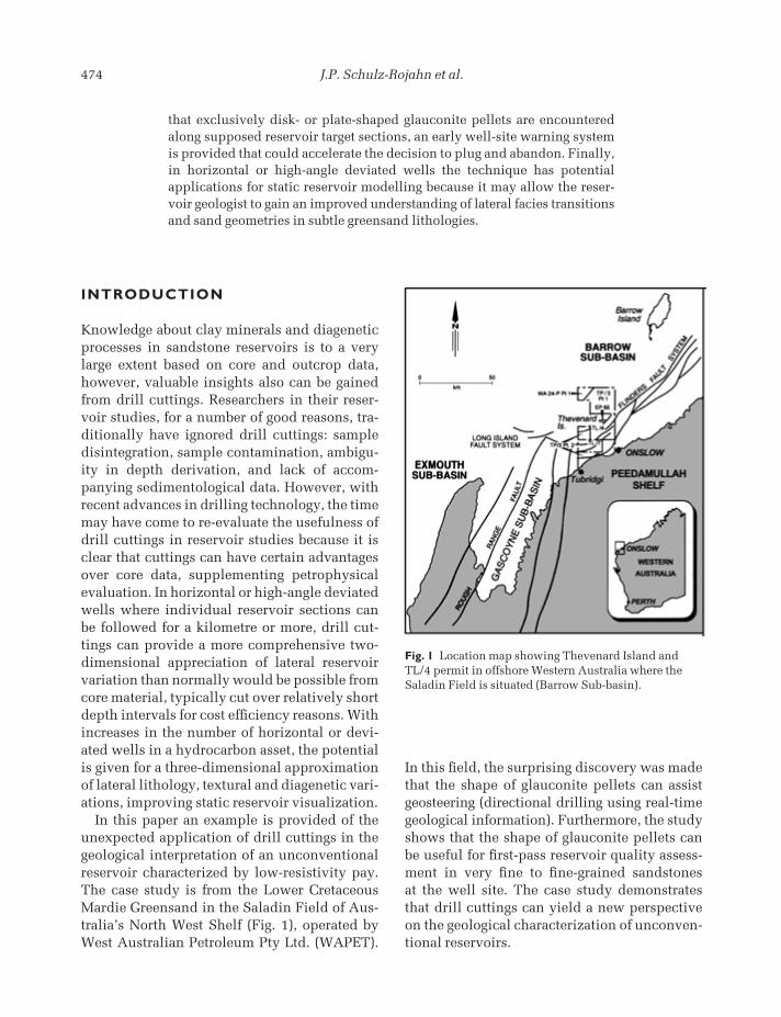
In this paper an example is provided of theunexpected application of drill cuttings in thegeological interpretation of an unconventionalreservoir characterized by low-resistivity pay.The case study is from the Lower CretaceousMardie Greensand in the Saladin Field of Aus-tralia’s North West Shelf (Fig. 1), operated byWest Australian Petroleum Pty Ltd. (WAPET).
In this field, the surprising discovery was madethat the shape of glauconite pellets can assistgeosteering (directional drilling using real-timegeological information). Furthermore, the studyshows that the shape of glauconite pellets canbe useful for first-pass reservoir quality assess-ment in very fine to fine-grained sandstones at the well site. The case study demonstratesthat drill cuttings can yield a new perspectiveon the geological characterization of unconven-tional reservoirs.
that exclusively disk- or plate-shaped glauconite pellets are encounteredalong supposed reservoir target sections, an early well-site warning systemis provided that could accelerate the decision to plug and abandon. Finally,in horizontal or high-angle deviated wells the technique has potentialapplications for static reservoir modelling because it may allow the reser-voir geologist to gain an improved understanding of lateral facies transitionsand sand geometries in subtle greensand lithologies.
Fig. 1 Location map showing Thevenard Island andTL/4 permit in offshore Western Australia where theSaladin Field is situated (Barrow Sub-basin).
CMCC21 14/01/2009 03:44PM Page 474
Application of glauconite morphology in geosteering, Carnarvon Basin 475
REGIONAL FRAMEWORK
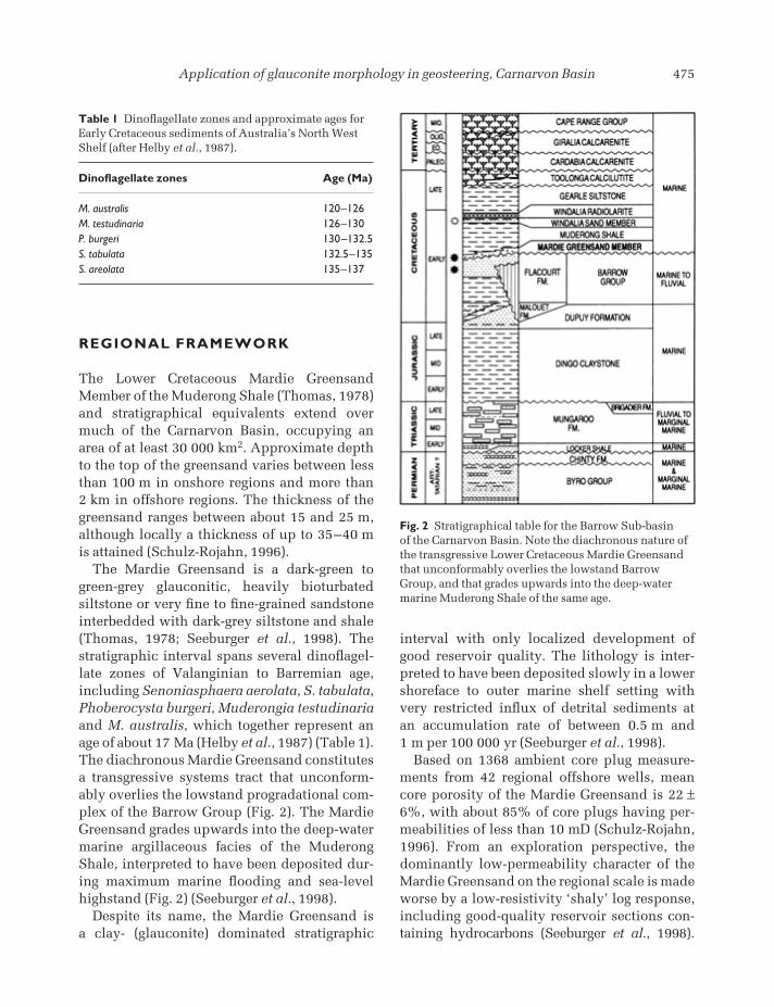
The Lower Cretaceous Mardie GreensandMember of the Muderong Shale (Thomas, 1978)and stratigraphical equivalents extend overmuch of the Carnarvon Basin, occupying anarea of at least 30 000 km2. Approximate depthto the top of the greensand varies between lessthan 100 m in onshore regions and more than 2 km in offshore regions. The thickness of thegreensand ranges between about 15 and 25 m,although locally a thickness of up to 35–40 m is attained (Schulz-Rojahn, 1996).
The Mardie Greensand is a dark-green togreen-grey glauconitic, heavily bioturbated siltstone or very fine to fine-grained sandstoneinterbedded with dark-grey siltstone and shale(Thomas, 1978; Seeburger et al., 1998). Thestratigraphic interval spans several dinoflagel-late zones of Valanginian to Barremian age,including Senoniasphaera aerolata, S. tabulata,Phoberocysta burgeri, Muderongia testudinariaand M. australis, which together represent anage of about 17 Ma (Helby et al., 1987) (Table 1).The diachronous Mardie Greensand constitutesa transgressive systems tract that unconform-ably overlies the lowstand progradational com-plex of the Barrow Group (Fig. 2). The MardieGreensand grades upwards into the deep-watermarine argillaceous facies of the MuderongShale, interpreted to have been deposited dur-ing maximum marine flooding and sea-levelhighstand (Fig. 2) (Seeburger et al., 1998).
Despite its name, the Mardie Greensand is a clay- (glauconite) dominated stratigraphic
interval with only localized development ofgood reservoir quality. The lithology is inter-preted to have been deposited slowly in a lowershoreface to outer marine shelf setting withvery restricted influx of detrital sediments at an accumulation rate of between 0.5 m and 1 m per 100 000 yr (Seeburger et al., 1998).
Based on 1368 ambient core plug measure-ments from 42 regional offshore wells, meancore porosity of the Mardie Greensand is 22 ±6%, with about 85% of core plugs having per-meabilities of less than 10 mD (Schulz-Rojahn,1996). From an exploration perspective, thedominantly low-permeability character of theMardie Greensand on the regional scale is madeworse by a low-resistivity ‘shaly’ log response,including good-quality reservoir sections con-taining hydrocarbons (Seeburger et al., 1998).
Fig. 2 Stratigraphical table for the Barrow Sub-basin of the Carnarvon Basin. Note the diachronous nature ofthe transgressive Lower Cretaceous Mardie Greensandthat unconformably overlies the lowstand BarrowGroup, and that grades upwards into the deep-watermarine Muderong Shale of the same age.
Table 1 Dinoflagellate zones and approximate ages forEarly Cretaceous sediments of Australia’s North WestShelf (after Helby et al., 1987).
Dinoflagellate zones Age (Ma)
M. australis 120–126M. testudinaria 126–130P. burgeri 130–132.5S. tabulata 132.5–135S. areolata 135–137
CMCC21 14/01/2009 03:44PM Page 475
476 J.P. Schulz-Rojahn et al.
In many wells, this petrophysical challenge(Zhang et al., 1996, 1997, 2000) is amplified bypoor hole conditions owing to extensive wash-outs over reservoir and non-reservoir sectionsalike (Seeburger et al., 1998). In cores, the reser-voir zones are also very subtle and easily can be missed by the inexperienced geologist ornewcomer to the Mardie Greensand, especiallyif initial core descriptions are carried out with-out availability of measured core plug or profilepermeametry data (Schulz-Rojahn, 1996). Thus,log-derived pay recognition and prediction ofreservoir quality trends represent two key chal-lenges for the successful opening of the MardieGreensand as a frontier exploration play.
The Mardie Greensand also lacks any form ofseismic expression, rendering trap delineationdifficult using conventional methods. Further,all hitherto known reservoir zones are rela-tively thin (maximum 11 m) as based onregional core and log data (Schulz-Rojahn,1996), which makes it uncertain if a sufficientlylarge hydrocarbon accumulation can ever befound to justify a stand-alone offshore fielddevelopment in the Mardie Greensand. Thus,despite hundreds of regional well-penetrationpoints, only about two dozen drill-stem testswere attempted over the Mardie Greensandinterval by different operators, with a disap-pointing outcome in almost every case, for avariety of reasons (Schulz-Rojahn, 1996). Thesefacts have frustrated sporadic explorationefforts in the Mardie Greensand by a variety ofdifferent oil companies over the years. At best,the Mardie Greensand has been viewed as a secondary objective in the quest for richer pick-ings in the underlying prolific, high-qualityBarrow Group sandstones. At worst, drilling pro-grammes were designed without any MardieGreensand evaluations in mind (Seeburger et al., 1998).
Despite these frustrations and key chal-lenges, three fields presently produce from theMardie Greensand in the general study area(Fig. 1). The Barrow Island field produces froma relatively low-quality P. burgeri/M. testudi-naria zone, whereas both the onshore Tubridgigas field and the offshore Saladin oil field
produce from high-quality lower M. australisreservoir intervals (Schulz-Rojahn, 1996). AtTubridgi, the producing lower (to middle?) M.australis zone consists of an unusually quartz-rich unit of medium-grey to light-green colour,with exceptionally low glauconite content. Theoccurrence of this unit at this biostratigraphicallevel is consistent with regional reservoir trends,which show that relatively high-permeability(quartz-rich) Mardie Greensand intervals occurchiefly in the Lower M. australis zone, or at theuppermost M. testudinaria/lower M. australisboundary (Schulz-Rojahn, 1996; Seeburger et al., 1998).
These regional observations point towards aprimary eustatic control on reservoir develop-ment in the Mardie Greensand (Schulz-Rojahn,1996; Seeburger et al., 1998). The occurrence of the relatively poor-quality P. burgeri/M. testudinaria reservoir at Barrow Island could be the result of additional eustatic events, however, no associated reservoir trends havebeen identified to date (Schulz-Rojahn, 1996;Seeburger et al., 1998). Importantly, significantregional variations in reservoir quality at theuppermost M. testudinaria/lower M. australisboundary, over relatively short distances (1–2 km), show that important secondary controlsare at work. These secondary controls arethought to be related to winnowing and sortingwithin the wavebase, along subtle syndeposi-tional highs (Schulz-Rojahn, 1996; Seeburger et al., 1998).
SALADIN FIELD
Saladin Field is located about 500–1000 m off-shore from the eastern end of Thevenard Islandin TL/4, Western Australia (Fig. 1). The field isa fault-bounded structure in which oil pro-duction initially was established only from thehigh-quality Barrow Group sandstones (coreporosity 25–35%, permeability 1–20 darcy)(Tippet & Beacher, 2000).
In 1993, Saladin-1 tested the overlyingMardie Greensand, demonstrating the produc-tive nature of this interval, despite a typical
CMCC21 14/01/2009 03:44PM Page 476
Application of glauconite morphology in geosteering, Carnarvon Basin 477
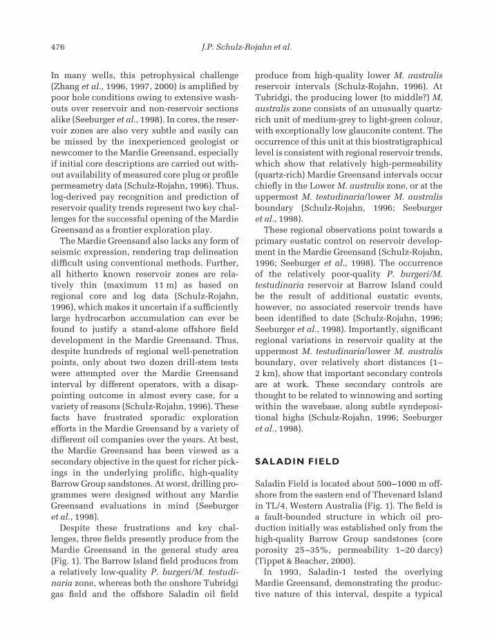
‘shaly’ log response over the pay zone (Fig. 3).Conventional log interpretation indicates watersaturations of 60–70% or greater, with resistiv-ity logs showing only about 0.5 ohm-m dif-ference between porous water-bearing sandsand hydrocarbon-bearing intervals (Seeburgeret al., 1988). Despite the high apparent Sw, allearly Mardie Greensand tests produced cleanoil with no water at Saladin. Initial oil rates of up to 4000 BOPD have been achieved fromindividual horizontal wells in the Mardie Green-sand. As of December 1997, Mardie Greensandproduction was about 12 000 BOPD, with lessthan 100 BWPD (barrels of water per day) from
seven producers in Saladin Field (Seeburger et al., 1998). With nearing depletion of BarrowGroup reservoirs, the Mardie Greensand nowsupplies more than half of total Saladin oil production.
Along the Saladin structure, top Mardiereservoir depth varies between about 1050 and1120 m subsea. Total thickness of the MardieGreensand is a relatively constant 18 m butreservoir sands are found only in the lowermiddle 10 m of section (Fig. 3) (Seeburger et al.,1998). This productive interval corresponds tothe lower M. australis zone and is underlain by a 3–5 m thick, variably siderite and pyritecemented member that is of dominantly M. testudinaria age, with a possible local influenceof P. burgeri (Schulz-Rojahn, 1996). This basalcemented member, which includes a 15–60 cmthick pyrite-cemented conglomeratic unit dir-ectly overlying the Barrow Group sandstones,has been demonstrated to be a seal, at least onthe production time-scale (Beacher, 1998). Thesealing capacity stems from the intense sideriteand/or pyrite cementation, and especially thepoor to very poor sorting with resultant lack ofresidual interstitial porosity between isolatedquartz grains that occur sprinkled betweenstrongly compacted glauconite pellets (Fig. 4).
The lower M. australis reservoir interval con-sists of a succession of glauconitic sandstones,each between 2 and 3 m thick, which are separated by siderite-cemented zones or ‘tightstreaks’ that in turn vary in thickness between30 cm and less than 2 m (Schulz-Rojahn, 1996;Seeburger et al., 1998) (Fig. 3). These siderite-cemented zones are interpreted to be of a rela-tively early diagenetic (methanogenic) originon the basis of their cyclic stratigraphy, theircorrelatable nature across the field, isotope and petrographic evidence (Stuart et al., 1995;Schulz-Rojahn, 1996). Siderite cementation isthought to have commenced at relatively shal-low depth within the seafloor sediment, belowthe influence of erosive processes (Stuart et al.,1995; Seeburger et al., 1996). Although thesesiderite-cemented layers typically have lowpermeability (< 2 mD) they are not perceived tobe seals on the geological time-scale, and a
Fig. 3 Saladin-1 composite log signature over the Mardie Greensand, including approximatebiostratigraphical zonation. Note the ‘shaly’ gamma-raylog response, the low-resistivity invasion profile and thedensity-neutron separation, rendering conventional loginterpretation difficult over this oil-bearing reservoir.The high-density M. testudinaria zone is a proven sealon the production time-scale whereas the lower M.australis zone represents the actual producing reservoir.
CMCC21 14/01/2009 03:44PM Page 477
478 J.P. Schulz-Rojahn et al.
common oil–water contact is assumed for thevarious lower M. australis reservoir sands atSaladin.
In hand specimens, the oil-producing lowerM. australis reservoir sands are characterizedby a dark-green greyish colour, very fine to finegrain size, intense bioturbation and a subtlewispy texture (Fig. 5a). In thin-section thesesame reservoir sands are distinguished on the basis of their generally well-sorted natureand high textural maturity, an abundance ofdark-green pelloidal glauconite (19–57%) andvarying amounts of finely dispersed sideritemicrospar cement (0–10%). The glauconitepellets display no evidence of the primary sub-strate of glauconitization. Significantly, theseglauconite pellets (average 200–286 µm) arelarger than the associated detrital quartz grains(average 100–138 µm) (Fig. 5b).
Virtually all the visible thin-section porosityis of primary intergranular nature (Fig. 5b),with some minor contributions from feldspardissolution. Abundant microporosity is associ-ated with the glauconite pellets, as evidentfrom a poor correlation between measured coreporosity and visible thin-section porosity (Stuartet al., 1995; Schulz-Rojahn, 1996) and also the
lack of a good porosity–permeability correla-tion (Seeburger et al., 1998). Although mea-sured core porosity falls within the 21–29%range, core permeability varies between 6.5 and106 mD at least over the lower M. australisreservoir zone (excluding hard streaks). Mar-ginal reservoir facies are characterized by core
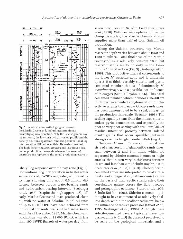
Fig. 4 Thin-section micrograph (plain polarized light)of the M. testudinaria greensand, about 1 m above thebasal conglomerate. Individual quartz grains do nottouch each other but occur interspersed betweenstrongly compacted, dark-green glauconite pellets. The lack of a rigid grain framework accounts for thegeneral lack of interstitial macroporosity in thisbiostratigraphical zone. Scale bar ≈ 2 mm.
Fig. 5 (a) Hand specimen view of the very fine-grainedproductive lower M. australis greensand characterizedby a subtle wispy texture and intense bioturbation. The dots with regular spacing represent areas whereprofile permeametry measurements were undertaken.Saladin-2, depth 1099 mKB (metres below KellyBushing, a standard reference point for drilled depth).(b) Thin-section micrograph (plain polarized light) of the lower M. australis reservoir. Note the relativeabundance of detrital quartz (white) producing a good-quality reservoir dominated by primary intergranularporosity. Further note that the glauconite pelletsgenerally are larger than the detrital quartz grains. The sample contains minor siderite microspar that has helped to resist the effects of compaction in thissample. Ambient core porosity is around 27%,permeability 30–35 mD. Scale bar = 2 mm.
(a)
(b)
CMCC21 14/01/2009 03:44PM Page 478
Application of glauconite morphology in geosteering, Carnarvon Basin 479
permeabilities in the order of a few millidarciesto 10 mD. Typically, more than half of the measured core porosity is intrapelletal porosity(microporosity) associated with the glauconite.On the basis of high-pressure mercury poros-imetry data and using a cutoff of 0.5 µm for distinguishing between productive and non-productive porosity, Seeburger et al. (1998)estimate that the Saladin productive porosity is in the 8–13% range.
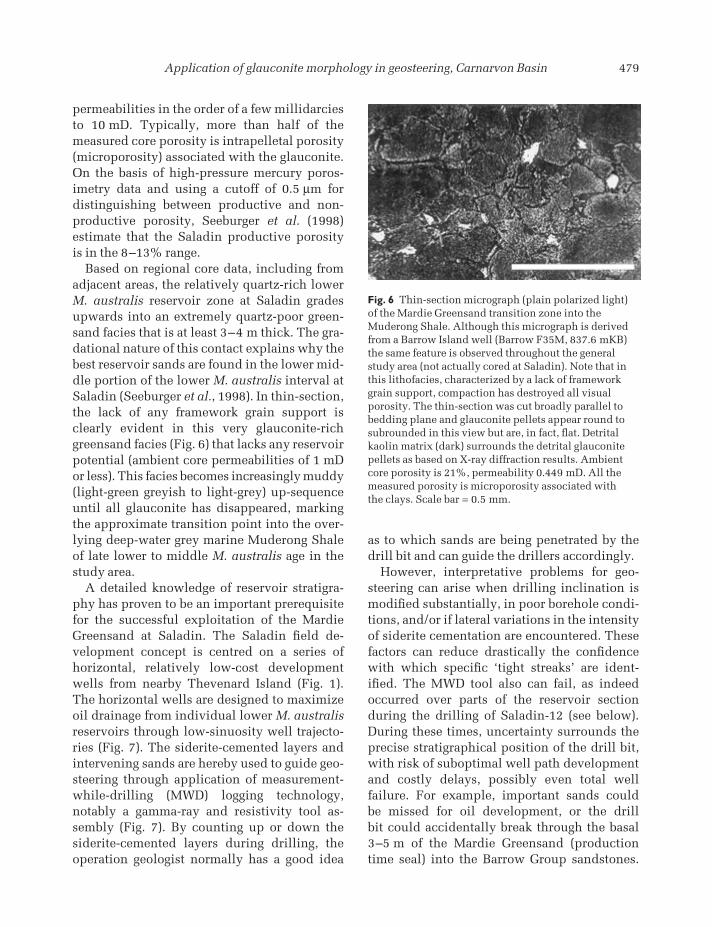
Based on regional core data, including fromadjacent areas, the relatively quartz-rich lowerM. australis reservoir zone at Saladin gradesupwards into an extremely quartz-poor green-sand facies that is at least 3–4 m thick. The gra-dational nature of this contact explains why thebest reservoir sands are found in the lower mid-dle portion of the lower M. australis interval atSaladin (Seeburger et al., 1998). In thin-section,the lack of any framework grain support isclearly evident in this very glauconite-richgreensand facies (Fig. 6) that lacks any reservoirpotential (ambient core permeabilities of 1 mDor less). This facies becomes increasingly muddy(light-green greyish to light-grey) up-sequenceuntil all glauconite has disappeared, markingthe approximate transition point into the over-lying deep-water grey marine Muderong Shaleof late lower to middle M. australis age in thestudy area.
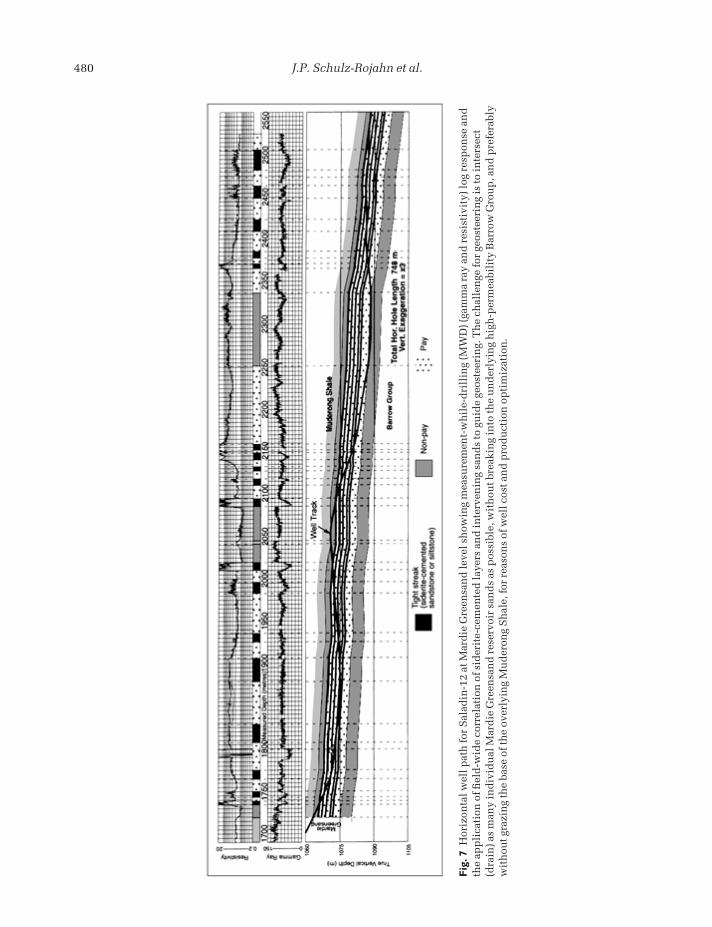
A detailed knowledge of reservoir stratigra-phy has proven to be an important prerequisitefor the successful exploitation of the MardieGreensand at Saladin. The Saladin field de-velopment concept is centred on a series of horizontal, relatively low-cost developmentwells from nearby Thevenard Island (Fig. 1).The horizontal wells are designed to maximizeoil drainage from individual lower M. australisreservoirs through low-sinuosity well trajecto-ries (Fig. 7). The siderite-cemented layers andintervening sands are hereby used to guide geo-steering through application of measurement-while-drilling (MWD) logging technology,notably a gamma-ray and resistivity tool as-sembly (Fig. 7). By counting up or down thesiderite-cemented layers during drilling, theoperation geologist normally has a good idea
as to which sands are being penetrated by thedrill bit and can guide the drillers accordingly.
However, interpretative problems for geo-steering can arise when drilling inclination ismodified substantially, in poor borehole condi-tions, and/or if lateral variations in the intensityof siderite cementation are encountered. Thesefactors can reduce drastically the confidencewith which specific ‘tight streaks’ are ident-ified. The MWD tool also can fail, as indeedoccurred over parts of the reservoir section during the drilling of Saladin-12 (see below).During these times, uncertainty surrounds theprecise stratigraphical position of the drill bit,with risk of suboptimal well path developmentand costly delays, possibly even total well failure. For example, important sands could be missed for oil development, or the drill bit could accidentally break through the basal3–5 m of the Mardie Greensand (productiontime seal) into the Barrow Group sandstones.
Fig. 6 Thin-section micrograph (plain polarized light)of the Mardie Greensand transition zone into theMuderong Shale. Although this micrograph is derivedfrom a Barrow Island well (Barrow F35M, 837.6 mKB)the same feature is observed throughout the generalstudy area (not actually cored at Saladin). Note that inthis lithofacies, characterized by a lack of frameworkgrain support, compaction has destroyed all visualporosity. The thin-section was cut broadly parallel tobedding plane and glauconite pellets appear round tosubrounded in this view but are, in fact, flat. Detritalkaolin matrix (dark) surrounds the detrital glauconitepellets as based on X-ray diffraction results. Ambientcore porosity is 21%, permeability 0.449 mD. All themeasured porosity is microporosity associated with the clays. Scale bar = 0.5 mm.
CMCC21 14/01/2009 03:44PM Page 479
480 J.P. Schulz-Rojahn et al.
Fig
. 7H
oriz
onta
l wel
l pat
h fo
r S
alad
in-1
2 at
Mar
die
Gre
ensa
nd
leve
l sh
owin
g m
easu
rem
ent-
wh
ile-
dri
llin
g (M
WD
) (ga
mm
a ra
y an
d r
esis
tivi
ty) l
og r
esp
onse
an
dth
e ap
pli
cati
on o
f fiel
d-w
ide
corr
elat
ion
of s
ider
ite-
cem
ente
d la
yers
an
d in
terv
enin
g sa
nd
s to
gu
ide
geos
teer
ing.
Th
e ch
alle
nge
for
geos
teer
ing
is to
inte
rsec
t(d
rain
) as
man
y in
div
idu
al M
ard
ie G
reen
san
d r
eser
voir
san
ds
as p
ossi
ble,
wit
hou
t bre
akin
g in
to th
e u
nd
erly
ing
hig
h-p
erm
eabi
lity
Bar
row
Gro
up
, an
d p
refe
rabl
yw
ith
out g
razi
ng
the
base
of t
he
over
lyin
g M
ud
eron
g S
hal
e, fo
r re
ason
s of
wel
l cos
t an
d p
rod
uct
ion
op
tim
izat
ion
.
CMCC21 14/01/2009 03:44PM Page 480
Application of glauconite morphology in geosteering, Carnarvon Basin 481
The latter would have disastrous consequencesfor Mardie Greensand production in view of thesuperior reservoir performance of the BarrowGroup sandstones. These considerations arehighlighted as they place the ensuing observa-tions into their operational context.
WELL-SITE OBSERVATIONS
Saladin-12 was spudded from Thevenard Islandin July 1996, with the sole objective of increas-ing oil production from the lower M. australisinterval in the Mardie Greensand. The hor-izontal well was drilled using oil-based mud(OBM). Figure 7 illustrates the well path throughthe Mardie Greensand.
Drill cuttings were collected from the shakersby the mudlogger about every 10 m of along-hole section drilled using a 250-µm mesh (i.e. borderline fine to medium grain size). The samples were then gently washed in fresh water containing small amounts of detergent toremove as much as possible of the oil-basedmud from the drill cuttings before inspectionand description of the samples under the binoc-ular microscope. Usually by the time this pro-cess was completed (against the backdrop ofadditional tasks) the next batch of drill cuttingswas due for collection. Calculated travel time ofthe cuttings from reservoir depth to surface was no more than about 20 min on average.
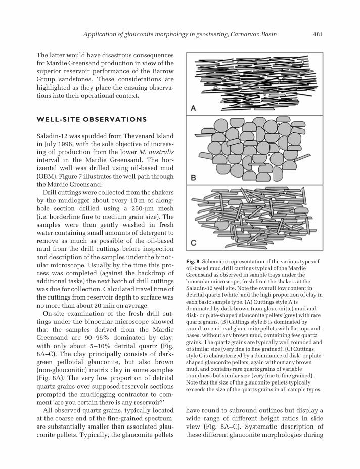
On-site examination of the fresh drill cut-tings under the binocular microscope showedthat the samples derived from the MardieGreensand are 90–95% dominated by clay,with only about 5–10% detrital quartz (Fig.8A–C). The clay principally consists of dark-green pelloidal glauconite, but also brown(non-glauconitic) matrix clay in some samples(Fig. 8A). The very low proportion of detritalquartz grains over supposed reservoir sectionsprompted the mudlogging contractor to com-ment ‘are you certain there is any reservoir?’
All observed quartz grains, typically locatedat the coarse end of the fine-grained spectrum,are substantially smaller than associated glau-conite pellets. Typically, the glauconite pellets
have round to subround outlines but display awide range of different height ratios in sideview (Fig. 8A–C). Systematic description ofthese different glauconite morphologies during
Fig. 8 Schematic representation of the various types ofoil-based mud drill cuttings typical of the MardieGreensand as observed in sample trays under thebinocular microscope, fresh from the shakers at theSaladin-12 well site. Note the overall low content indetrital quartz (white) and the high proportion of clay ineach basic sample type. (A) Cuttings style A isdominated by dark-brown (non-glauconitic) mud anddisk- or plate-shaped glauconite pellets (grey) with rarequartz grains. (B) Cuttings style B is dominated byround to semi-oval glauconite pellets with flat tops andbases, without any brown mud, containing few quartzgrains. The quartz grains are typically well rounded andof similar size (very fine to fine grained). (C) Cuttingsstyle C is characterized by a dominance of disk- or plate-shaped glauconite pellets, again without any brownmud, and contains rare quartz grains of variableroundness but similar size (very fine to fine grained).Note that the size of the glauconite pellets typicallyexceeds the size of the quartz grains in all sample types.
CMCC21 14/01/2009 03:44PM Page 481
482 J.P. Schulz-Rojahn et al.
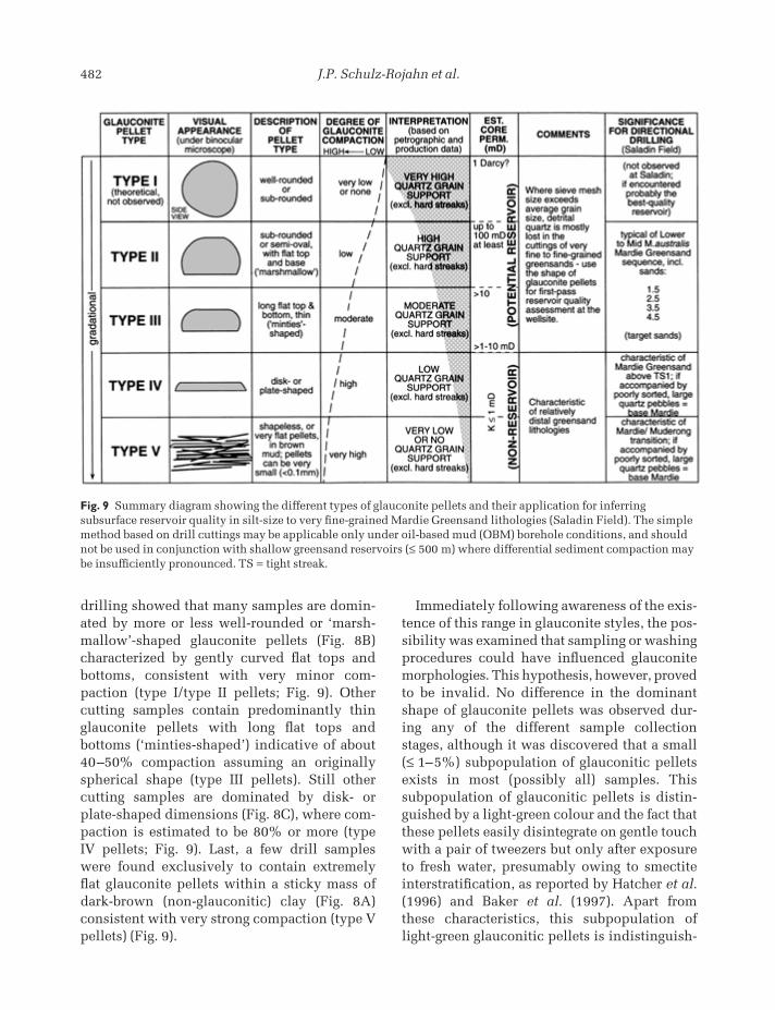
drilling showed that many samples are domin-ated by more or less well-rounded or ‘marsh-mallow’-shaped glauconite pellets (Fig. 8B)characterized by gently curved flat tops andbottoms, consistent with very minor com-paction (type I/type II pellets; Fig. 9). Other cutting samples contain predominantly thinglauconite pellets with long flat tops and bottoms (‘minties-shaped’) indicative of about40–50% compaction assuming an originallyspherical shape (type III pellets). Still other cutting samples are dominated by disk- orplate-shaped dimensions (Fig. 8C), where com-paction is estimated to be 80% or more (type IV pellets; Fig. 9). Last, a few drill samples were found exclusively to contain extremelyflat glauconite pellets within a sticky mass ofdark-brown (non-glauconitic) clay (Fig. 8A)consistent with very strong compaction (type Vpellets) (Fig. 9).
Immediately following awareness of the exis-tence of this range in glauconite styles, the pos-sibility was examined that sampling or washingprocedures could have influenced glauconitemorphologies. This hypothesis, however, provedto be invalid. No difference in the dominantshape of glauconite pellets was observed dur-ing any of the different sample collectionstages, although it was discovered that a small(≤ 1–5%) subpopulation of glauconitic pelletsexists in most (possibly all) samples. This subpopulation of glauconitic pellets is distin-guished by a light-green colour and the fact thatthese pellets easily disintegrate on gentle touchwith a pair of tweezers but only after exposureto fresh water, presumably owing to smectiteinterstratification, as reported by Hatcher et al.(1996) and Baker et al. (1997). Apart from these characteristics, this subpopulation oflight-green glauconitic pellets is indistinguish-
Fig. 9 Summary diagram showing the different types of glauconite pellets and their application for inferringsubsurface reservoir quality in silt-size to very fine-grained Mardie Greensand lithologies (Saladin Field). The simplemethod based on drill cuttings may be applicable only under oil-based mud (OBM) borehole conditions, and shouldnot be used in conjunction with shallow greensand reservoirs (≤ 500 m) where differential sediment compaction maybe insufficiently pronounced. TS = tight streak.
CMCC21 14/01/2009 03:44PM Page 482
Application of glauconite morphology in geosteering, Carnarvon Basin 483
able from the dominant (dark-green) glauconitevariety under the binocular microscope: bothglauconite types display the same range of morphologies.
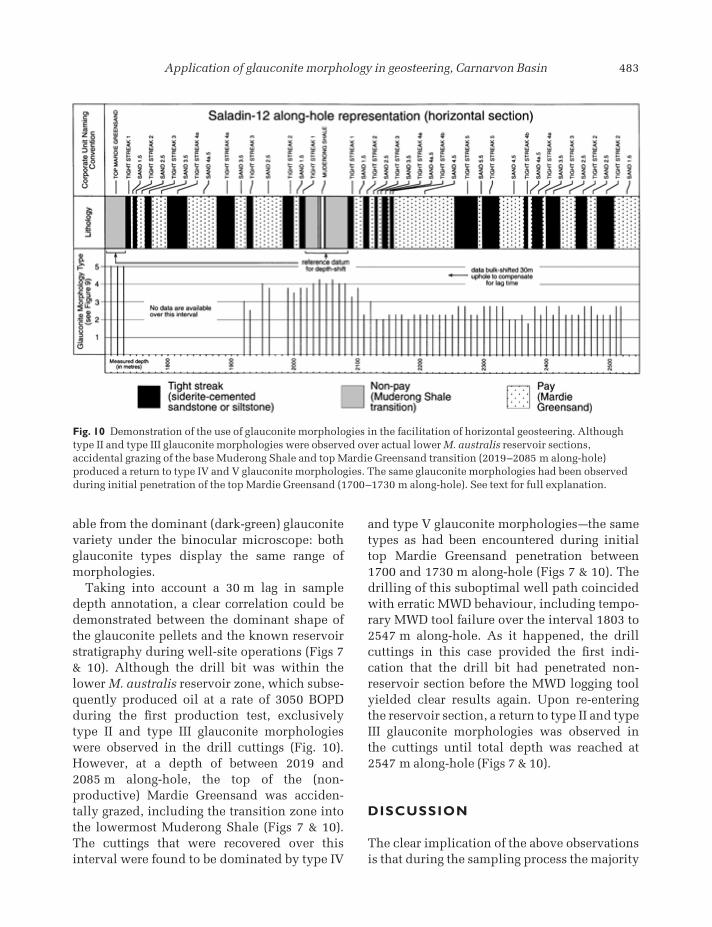
Taking into account a 30 m lag in sampledepth annotation, a clear correlation could bedemonstrated between the dominant shape ofthe glauconite pellets and the known reservoirstratigraphy during well-site operations (Figs 7& 10). Although the drill bit was within thelower M. australis reservoir zone, which subse-quently produced oil at a rate of 3050 BOPDduring the first production test, exclusivelytype II and type III glauconite morphologieswere observed in the drill cuttings (Fig. 10).However, at a depth of between 2019 and 2085 m along-hole, the top of the (non-productive) Mardie Greensand was acciden-tally grazed, including the transition zone intothe lowermost Muderong Shale (Figs 7 & 10).The cuttings that were recovered over thisinterval were found to be dominated by type IV
and type V glauconite morphologiesathe sametypes as had been encountered during initialtop Mardie Greensand penetration between1700 and 1730 m along-hole (Figs 7 & 10). Thedrilling of this suboptimal well path coincidedwith erratic MWD behaviour, including tempo-rary MWD tool failure over the interval 1803 to2547 m along-hole. As it happened, the drillcuttings in this case provided the first indi-cation that the drill bit had penetrated non-reservoir section before the MWD logging toolyielded clear results again. Upon re-enteringthe reservoir section, a return to type II and typeIII glauconite morphologies was observed inthe cuttings until total depth was reached at2547 m along-hole (Figs 7 & 10).
DISCUSSION
The clear implication of the above observationsis that during the sampling process the majority
Fig. 10 Demonstration of the use of glauconite morphologies in the facilitation of horizontal geosteering. Althoughtype II and type III glauconite morphologies were observed over actual lower M. australis reservoir sections,accidental grazing of the base Muderong Shale and top Mardie Greensand transition (2019–2085 m along-hole)produced a return to type IV and V glauconite morphologies. The same glauconite morphologies had been observedduring initial penetration of the top Mardie Greensand (1700–1730 m along-hole). See text for full explanation.
CMCC21 14/01/2009 03:44PM Page 483
484 J.P. Schulz-Rojahn et al.
of the quartz grains that constitute the reservoirzones were being lost at the shakers. Monitor-ing of the quartz content in the drill cuttingsprovided no reliable indication as to whether a reservoir or non-reservoir zone was beingpenetrated by the drill bit. The mesh size used(250 µm) was simply too coarse for the gener-ally very fine to fine-grained Mardie Greensandlithologies (62–170 µm). Although this samplebias can be easily remedied by selection of afiner mesh size, such simple modificationwould require more time by the mudlogger towash, describe and bag samples at the rig site.The consequence of this action would be eithera wider sample spacing (at least every 20 to 30 m) or the requirement for additional man-power to keep pace with a relatively fast rate of penetration. Although the former is clearlynot desirable from a data acquisition perspect-ive, the latter is equally not desirable from acost leadership perspective. Thus, descriptionof glauconite morphology has a small but viablerole in downhole reservoir characterizationbased on drill cuttings in the Mardie Green-sand, and possibly other greensands around the world.
At Saladin, the observed variety in glauconitemorphologies is attributed to differential com-paction of the pellets, which must be related to varying rock compositions at different strati-graphic levels within the Mardie Greensand.Principally the varying proportions of detritalquartz and to a lesser extent feldspars and other compaction-resistant framework grains(including minor cements) are thought to con-trol glauconite morphology in the subsurface.In a quartz-rich greensand lithology, each indi-vidual glauconite pellet only has to support theweight of the detrital grains in its immediatevicinity because the bulk of the overburdenweight is absorbed by a plethora of frameworkgrains (types I–III glauconite morphologies). Incontrast, glauconite pellets in lithologies thatlack framework grain support can provide littlemechanical resistance to the increasing over-burden weight and, consequently, are squashedduring sediment burial (types IV and V glau-conite morphologies, Fig. 9). Thus, the domin-
ant shape of glauconite pellets as observed indrill cuttings can be used to broadly estimatethe level of framework grain support, andthereby indirectly reservoir quality in theMardie Greensand, at least under oil-basedmud conditions (Fig. 9).
This conclusion is based on the assumptionthat the glauconite pellets were more or lessspherical before major sediment compactionwas initiated. Various workers have shown thatthe shape of glauconite grains can depend uponthe shape of the primary substrate of glauconit-ization, including quartz grains, mica flakes,microfossil tests, faecal pellets, shell fragments,etc. (Odin & Matter, 1981; Van Houten &Purucker, 1984; Odin & Fullagar, 1988). In thepresent study, no primary substrate is evidentin any of the glauconite pellets as seen in thin-section, which would appear to be a wide-spread feature based on a regional petrographicdata base for the Mardie Greensand (see Stuart et al., 1995; Rezaee & Tingate, 1996;Schulz-Rojahn, 1996). Hatcher et al. (1996)demonstrate both highly evolved, dark-greenglauconite and a small population of expand-able pale-green nascent glaucony (glauconiticsmectite) in the Mardie Greensand of the SaladinField. Baker et al. (1997) also report abundantdark-green, low-expandability glauconite pel-lets characterized by an average K2O content of8.5% in broadly time-equivalent glauconiticsandstones of the northern Carnarvon Basin.Baker et al. (1997) again show that these dark-green pellets coexist with very low amounts oflight-green, pelloidal glauconitic smectite thatis prone to swelling and disintegration whenexposed to fresh water.
These data, coupled with the chiefly dark-green colour of the glauconitic pellets and the complete dissolution of the substrate (seeAmorosi, 1995, 1997) underline the dominanceof an evolved or even highly evolved form ofglaucony (glauconite) in the Mardie Greensand,including at Saladin. Thus, it is exceedinglyunlikely that the shape of the glauconite pelletswas inherited from the primary substrates of glauconitization, in particular because thepellets tend to have round to subround out-
CMCC21 14/01/2009 03:44PM Page 484
Application of glauconite morphology in geosteering, Carnarvon Basin 485
lines and differ only in height ratios, which isexplained most readily by differential com-paction. Baker et al. (1997) also noted the roleof compaction in influencing peloid shape. Itseems reasonable to assume that the glaucon-ite pellets that experienced the least degree ofcompaction (types I–III) provide a good approx-imation of how type IV and V glauconite pelletsalso must have looked like in Early Cretaceoustimes, on the seafloor, prior to the onset ofmajor subsidence.
Petrographic evidence for this hypothesisstems from the abundant occurrence of micro-crystalline quartz cement envelopes aroundspherical dissolution pores that locally stillcontain residual glauconite pellets in distalgreensand facies of the Mardie Greensand,within a few kilometres of the Saladin Field(Rezaee & Tingate, 1996; Schulz-Rojahn, 1996).The shape of the dissolution pores vividlydemonstrates that the network of microcrys-talline quartz cement envelopes must haveformed around virtually uncompacted (near-spherical) glauconitic pellets in the shallowsubsurface prior to dissolution of the pellets(Rezaee & Tingate, 1996; Schulz-Rojahn, 1996).This zone of diagenetic alteration, character-ized by an almost complete lack of frameworkgrains, grades laterally and vertically into anunaltered greensand facies of the same type (seeFig. 6) dominated by dark-green type IV and Vglauconite pellets (Schulz-Rojahn, 1996). Thus,the evidence available strongly suggests thatcompaction principally is responsible for thepresent-day shape of the peloidal grains ratherthan changes in spatial distribution of the substrates of glauconitization in the MardieGreensand. Certainly the observation that type I–III glauconite morphologies dominate inreservoir sections (as proven by actual produc-tion data) whereas type IV and V glauconitemorphologies occur in non-reservoir sections isconsistent with this interpretation.
This simple recognition leads to a variety of possible industry or research applications.The Saladin-12 case study demonstrates thatclassification of glauconite morphology ratherthan just a conventional description of cuttings
is the key to a reliable lithology indicator in theMardie Greensand, unless a dedicated effort ismade to capture the very fine grain fraction atthe shakers, desander and desilter. Certainlyunder OBM conditions, descriptive focus onglauconite morphologies is required in order toidentify reservoir zones that otherwise could bemistaken for clay-dominated lithologies in drillcuttings. Especially in low-resistivity (green-sand) exploration settings where pay recogni-tion can be a key subsurface challenge, thedescription of glauconite morphologies couldprovide an imperfect but low-cost insuranceagainst the risk of pay zones being bypassed.However, it remains to be seen if the techniquealso can be used under non-OBM conditions,which tend to be preferred by explorationistsbecause reservoir oil/condensates and oil-baseddrilling mud generally cannot be differentiatedunder the UV fluoroscope at the well site.
Further, the present case study indicates thatglauconite morphologies can provide a broadqualitative indication of reservoir quality, wellahead of routine petrophysical evaluation, flowtests and/or core analysis. Subject to the rate ofpenetration, circulation, hole length and vari-ous other variables, cuttings from the MardieGreensand are received on surface within a fewtens of minutes at most. At Saladin, type II andIII glauconite morphologies were observed to have been derived from reservoir zones cap-able of producing initial oil rates of up to 4000 BOPD, consistent with permeability up toabout 100 mD at least (Seeburger et al., 1998).In contrast, type IV and V glauconite morpho-logies encountered over non-reservoir Mardiesections are thought to be representative ofglauconite-rich, quartz-poor greensand facies(Fig. 6) characterized by core permeability of 1 mD or less (Schulz-Rojahn, 1996). Thus, abroad framework is established that assigns a range of different permeability values to dif-ferent glauconite morphologies (Fig. 9), whichperhaps could be refined with growing experi-ence in the future. This recognition is usefulbecause in the event that exclusively type IVand/or type V glauconite morphologies areencountered along supposed reservoir target
CMCC21 14/01/2009 03:44PM Page 485
486 J.P. Schulz-Rojahn et al.
sections, an early well-site warning system isprovided that could signal the selection of apoor drilling target owing to inadequacies inthe geological model (or lack thereof ). In such acase, the decision could be accelerated to plugand abandon, thereby reducing rig-based costexposure. By the same token, systematic mon-itoring of glauconite morphologies along thewell path could act as a basic cross-check onpetrophysical evaluations in low-confidenceinterpretation situations (e.g. hole rugosity). Inthe same context, a hypothetical situation isconceivable whereby this type of independentcross-check has an impact on the selection of completion intervals in multilayered green-sand reservoirs of variable reservoir quality andwith known hydrocarbon fill(s).
Glauconite morphology as seen in drill cut-tings also can provide a good indication of the stratigraphical level that is being penetratedby the drill bit, provided the stratigraphy andpetrological characteristics of the target forma-tion are well understood. This type of data can be helpful for geosteering, especially incases where drilling rates are relatively slow, orMWD data are temporarily not available, asindeed was the case at Saladin-12. The presentcase study provides convincing evidence thatmonitoring of glauconite morphology can behelpful to the well-site geologist, who mustdecide whether the drill bit is too high or toolow in the stratigraphical sequence, or indeedon track, during critical well-site operationstages.
Intriguingly, with a growing field data base,the potential is even there for indirect incor-poration of differential glauconite compactionin the static reservoir model to reduce uncer-tainties in the three-dimensional porosity andpermeability realization. In a formation thatlacks seismic expression and where predic-tion of reservoir quality trends remains a keychallenge, certainly on the regional scale, mon-itoring of drill cuttings could provide crucialclues in subtle reservoir lithologies such as the Mardie Greensand. On the field-scale, sys-tematic description of glauconite style, both in
the lateral and vertical sense, could provide theframework for a refined reservoir model (reser-voir geometries, facies transitions) facilitatinglong-term production and facility optimization.
CONCLUSIONS
1 Study results show that, seemingly againstall odds, glauconite pellets can survive in anear-perfect state a journey of several kilome-tres along borehole to surface, under oil-basedmud conditions. This fact vividly demonstratesthe high level of geological detail that can beobtained from drill cuttings, providing a freshnew perspective on the characterization of theunconventional Mardie Greensand reservoir.Drill cuttings represent a primary informationsource about the subsurface that always shouldbe considered by the reservoir geologist.2 The dominant shape of glauconite pellets, asobserved under the binocular microscope at thewell site, can be a first-pass indicator of sub-surface reservoir quality ahead of petrophysicalevaluation, flow tests and/or core analysis. Inthe Mardie Greensand, the shape of individualglauconite pellets is controlled by differentialcompaction, which, in turn, is controlled by thedegree of framework grain support that drivesreservoir quality. Glauconite pellets withround, oval or semi-oval shapes (types I–III)reflect quartz-rich greensand reservoirs withpermeabilities of up to 100 mD at least, capableof producing initial oil rates of up to 4000BOPD from individual horizontal wells. In con-trast, disk- or plate-shaped glauconite pellets(types IV and V) dominate in very quartz-poor,strongly compacted greensand facies withoutany reservoir potential.3 This simple reservoir characterization tech-nique based on glauconite morphology finds itsexclusive application in silt-size to fine-grainedgreensand lithologies, where it can be pro-blematic to obtain representative drill cuttings, especially at high rates of penetration. Underthese circumstances, the bulk of the silt-size tofine sand grains tend to be lost at the shakers,
CMCC21 14/01/2009 03:44PM Page 486
Application of glauconite morphology in geosteering, Carnarvon Basin 487
which can lead to prolific reservoir zones beingmistaken for clay-dominated lithologies in drillcuttings, especially in cases where the glauconitepellets are larger than the framework grains.4 Monitoring of glauconite morphology in drill cuttings has several potential, or proven,industry applications.
(i) Potential pay recognition in low-resistivity(greensand) exploration or appraisal settings,although as yet unproven for non-OBM bore-hole conditions.(ii) The technique can be used as an inde-pendent, rather crude and basic cross-checkon reservoir quality in low-confidence petro-physical interpretation situations. In thesame context, the technique possibly couldbe used to cross-check selection of com-pletion intervals in multilayered greensandreservoirs of variable reservoir quality andwith known hydrocarbon fill(s).(iii) Despite lag time of cuttings to surface,the technique can facilitate MWD-controlledgeosteering, as exemplified by the horizontalSaladin-12 well, where along-hole variationsin the shape of glauconite pellets providedhelpful stratigraphical clues.(iv) In the event that exclusively disk- orplate-shaped glauconite pellets are encoun-tered along supposed reservoir target sec-tions, an early well-site warning system isprovided that could accelerate the decisionto plug and abandon.(v) In horizontal or high-angle deviatedwells, the technique has potential applica-tions for static reservoir modelling because it may allow the reservoir geologist to gain an improved understanding of lateral faciestransitions and sand geometries in subtlegreensand lithologies.
5 The case study demonstrates that oil com-pany staff (well owners) have an active role in the geological description of drill cuttings,including for self-awareness reasons, especiallyduring the early phases of a drilling campaign(exploration, appraisal and/or early field devel-opment phases). Failure to do so may lead toerroneous or ambiguous perceptions of reser-
voir quality and continuity because the mud-logging contractors more often than not will notbe familiar with the key reservoir uncertaintiesand the potential subtleties of the target litholo-gies, usually through no fault of their own. AtSaladin, description of glauconite pellet stylesrather than just a conventional description of cuttings proved to be the key to a reliablelithology indicator.6 A data acquisition strategy based on cuttingsideally should be tailored to the target litho-logy, which can be particularly important inunconventional and/or fine-grained reservoirlithologies. Sieve size, sampling rate and man-power (mud-logging) resource requirementsshould be considered carefully in advance,especially in formations where prediction ofregional reservoir quality trends constitutes akey subsurface challenge.
ACKNOWLEDGEMENTS
We are indebted to West Australian PetroleumPty Ltd. (WAPET), the operator on behalf ofChevron Asiatic Ltd., Texaco Inc., MobilExploration and Producing Australia (MEPA)and Shell (Development) Australia Pty Ltd., forpermission to publish this work. We furtherwould like to thank IAS reviewers E. McBride(University of Texas at Austin) and A. Amorosi(University of Bologna) for their constructivecriticisms of the draft manuscript. We also express our warm appreciation to our colleaguesS. Morad (University of Uppsala), J. Meath, J. Popek (Chevron Overseas Petroleum), M.Rezaee (University of Tehran) and R. Helby fortheir support. All opinions expressed reflectthose of the authors. This paper evolved out of acollaborative project between WAPET and theAustralian Petroleum Cooperative ResearchCentre (APCRC) as represented by the NationalCentre for Petroleum Geology and Geophysics(NCPGG) and the Centre for PetroleumEngineering (CPE) following recruitment of the geological team leader (senior author) byWAPET in 1996.
CMCC21 14/01/2009 03:44PM Page 487
488 J.P. Schulz-Rojahn et al.
REFERENCES
Amorosi, A. (1995) Glaucony and sequence stratigraphy:a conceptual framework of distribution in siliciclasticsequences. J. Sed. Res., B65 (4), 419–425.
Amorosi, A. (1997) Detecting compositional, spatial,and temporal attributes of glaucony: a tool for proven-ance research. Sed. Geol., 109, 135–153.
Baker, J.C., Uwins, P.J.R. & Hamilton, P.J. (1997)Freshwater sensitivity of glauconitic hydrocarbonreservoirs. J. Petrol. Sci. Eng., 18, 83–91.
Beacher, G.J. (1998) Pressure study of the FlacourtFormation aquifer in the Thevenard Island area of the Barrow Sub-basin. J. Aust. Petrol. Prod. Explor.Assoc., 38 (1), 438–452.
Hatcher, G.B., Chen, H., Rahman, S.S. & Hogg, P.F.(1996) Evaluating formation damage risks in a glau-conitic sandstone reservoir: a case history from theOffshore North West Shelf of Australia. Soc. Petrol.Eng. Pap., 37014, 1–15.
Helby, R., Morgan, R. & Partridge, A.D. (1987) A palyno-logical zonation of the Australian Mesozoic. Mem.Assoc. Aust. Paleontol., 4, 1–94.
Odin, G.S. & Fullagar, P.D. (1988) Geological sign-ificance of the glaucony facies. In: Green Marine Clays, Developments in Sedimentology 45 (Ed. by G.S. Odin), Elsevier, Amsterdam, pp. 295–332.
Odin, G.S. & Matter, A. (1981) De glauconiarum origine.Sedimentology, 28, 611–641.
Rezaee, M. & Tingate, P.R. (1996) Regional ReservoirProspectivity of the Mardie Greensand, Part II:Petrology and Quantitative Lithofacies Identification.Unpublished report on behalf of the AustralianPetroleum Cooperative Research Center (APCRC) forWest Australian Petroleum Pty Ltd, Perth, 35 pp.
Schulz-Rojahn, J.P. (1996) Regional Reservoir Prospect-ivity of the Mardie Greensand, Carnarvon BasinaPart1: Stratigraphic Controls on Reservoir Developmentand Implications for Forward Modeling. Unpublishedreport on behalf of the Australian Petroleum Cooperat-ive Research Center (APCRC) for West AustralianPetroleum Pty Ltd, Perth, 48 pp.
Seeburger, D.A., Miller, N.W.D., Beacher, G.J., Schulz-Rojahn, J.P. & Popek, J.P. (1998) An evaluation of theMardie Greensand reservoir, Thevenard Island area,Carnarvon Basin. In: The Sedimentary Basins ofWestern Australia 2: Proceedings of the PetroleumExploration Society of Australia Symposium (Ed. byP.G. and R.R. Purcall), Perth, pp. 491–502.
Stuart, W.J., Schulz-Rojahn, J.P. & Hayball, A. (1995)Lithofacies Identification, Correlation and ReservoirCharacterization of the Mardie Greensand, BarrowField Area. Unpublished report by the AustralianPetroleum Cooperative Research Center (APCRC) forWest Australian Petroleum Pty Ltd, Perth.
Thomas, B.M. (1978) Robe Riveraan onshore shallow oilaccumulation. J. Aust. Petrol. Explor. Assoc., 18 (1),3–12.
Tippet, P.J. & Beacher, G.J. (2000) Integration of sub-surface disciplines to optimize the development of the Mardie Greensand at Thevenard Island, WesternAustralia. SPE paper 59410. 2000 SPE Asia PacificConference on Integrated Modeling for Asset Manage-ment, Yokohoma, 25–26 April 2000.
Van Houten, F.B. & Purucker, M.E. (1984) Glauconiticpeloids and chamositic ooidsafavourable factors, con-straints, and problems. Earth Sci. Rev., 20, 211–243.
Zhang, Y.J., Lollback, P.A., Schulz-Rojahn, J.P., Salisch,H.A. & Stuart, W.J. (1996) A methodology for estim-ating permeability from well logs in a formation of complex lithology. SPE paper 37025. In: 1996 SPEAsia Pacific Oil and Gas Conference, 28–31 October,Adelaide, pp. 561–566.
Zhang, Y.J., Lollback, P.A., Salisch, H.A. & Schulz-Rojahn, J.P. (1997) Determination of permeabilitytransforms from geophysical logs using statistical pattern recognition: the Mardie Greensand. Explor.Geophys., 28, 181–184.
Zhang, Y.J., Salisch, H.A. & Arns, C. (2000) Permeabil-ity evaluation in a glauconite-rich formation in theCarnarvon Basin, Western Australia. Geophysics, 65(1), 46–53.
CMCC21 14/01/2009 03:44PM Page 488