Embed Size (px)
Citation preview

CLCP-PRC010B-ENJune 2019
Product Catalog
CLCP SeriesFlexible Air Handling Unit CLCP 003~1202000~120000CMH
2 CLCP-PRC010B-EN
IntroductionTrane has been manufacturing air handling units throughout the world for the past 40 years. This proven worldwide experience enables us to develop a world class air handling unit, the new Quantum Clmate Changer. Quantum Climate Changer is a combination of 4 key elements:
1. Globally Integrated Research and Development
A global marketing team comprising air handling specialist from Europe, Asia Pacific and China, Middle East, Africa and South America was formed to provide critical customer and market needs. Aglobal design team comprising design specialist from the Trane Technology Center, USA, Trane Europe and the Trane Air Handling International Development Center in Asia was formed to developed new world class air handling technology.
2. World Class Manufacturing Facility
The Quantum Climate Changer manufacturing facility is certified to MS ISO 9001 and is one of the earliest American facilities certified to Demand Flow Technologies (DFT). DFT is a technology that takes quality to the people and the machines that produce the product. In addtion, Total Quality Control methodology within DFT brings quality into the manufacturing process at the point where work is being performed, resulting in consisitent product quality.
3. Performance Assurance and Commitment to Quality
Trane combines comprehensive performance certifications with thorough laboratory testing and manufacturing methods. Together, these elements assure that each Quantum Climate Changer operates predictably and reliably throughout the life of the unit.
4. Matching Technologies to Systems
The building industry is continuously evolving and the rate of change is accelerating. Technologies, economic, regulatory and environmental factors are very different now than there were just a few years ago, which will affect the application and installation of the HVAC systems. Recognizing this and utilizing the Trane worldwode air conditioning system experience, the Quantum Climate Changer was developed and packaged to suit most current air conditioning system application needs.
Purpose
The purpose of this catalogue is to help consulting engineers in the preliminary selection of the Quantum Climate Changer air handling units. Your regional Trane office will assist to provide a computerized selection to confirm or complete your preliminary selection. Where something more special is required, we have full technical support in our regional sales offices and at our factory where non-standard layouts and configurations can be designed to individual requirements.
3 CLCP-PRC010B-EN
Features and Benefits
Ultra Low Leak Construction
Unique casing design with panel attached to the frame through a selflocking mechanism represented by a wedge and frame, exerting pressure evenly onto the panel and the seal attached to the frame, and hence a better air tight cabinet construction. The casing is designed to meet Eurovent Casing Air Leakage Standard.
Excellent Condensate Management
Dual pitched sloping drain pan allows for total condensate removal. A unique feature developed to prevent stagnant water in air handling units.
Enironmental Friendly Materials
High-grade aluminium frame is non-corrosive and is easily clean-able. All these features will further enhance indoor air quality.
Design for Routine Cleaning
Double wall panel construction allows for easy cleaning and disinfecting of the interior surfaces. Panel and frame design allows for easy removal of side panels for maximum access to internal areas.
High Grade Aluminum Frame
Frame is constructed of extruded aluminum channels for structural rigidity and lightness.
Injected Polyurethane Foam Panels
All panels are injected with high efficiency podyurethane foam insulation. Foamed panels provide superior thermal resistance properties, and have excellent acoustic and vibration absorption characteristics. In addition, polyurethane foam does not absorb moisture and will not promote fungus growth.
High Efficiency Performance
Patented heat transfer technology gives maximum cooling and dehumidification. Trane engineered fan systems provide maximum airflow while minimizing vibration, acoustic levels and power consumption.
Suitable for Retrofit, Renovation and Replacement
Change is inevitable. As time passes, building loads alter, new technologies emerge and codes and standards are revised. The Quantum Climate Changer design lends itself to the needs of the renovation, retrofit and replacement market.
Sturdy Unit Construction
The Quantum Climate Changer's flexibility is contributed by the structural integrity pentapost and panel construction. That not only means you can stack modules in a space-saving vertical air-handler configuration, but also allows removal of panels for unlimited access. The casing strength is designed to meet Eurpean Standard EN 1886:2007.
4 CLCP-PRC010B-EN
Features and Benefits
Optimized Coils
Flexibility characterizes the Quantum Climate Changer's broad coil offering. The variety of types, sizes, arrangements and materials enables you to select a coil optimized for the application pressure drop and capacity requirements. Options include:● 2 to 12 rows, 1/2 inch OD chilled water coils and two separate cooling coil in series to meet
high capacity requirement.● One and two rows, 1/2 inch OD hot water coils.● Four and six rows, 1/2 inch OD refrigerant coils.● One row 1/2 inch OD, distributing type steam coils.● Infinitely variable fin spacing (IVS).● Stainless steel coil casing (option). Copper fins.● Coated aluminum fin for corrosion resistance.● Header drain and vent connections.● Fully drain able coils at header.
All standard heating and cooling coils are engineered and manufactured at Trane air handiling systems manufacturing facility.
Performance Assurance and Commitment to Quality
Trane combines comprehensive performance certifications with thorough laboratory testing and manufacturing methods. Together these elements help to ensure that each Quantum Climate Changer operates predictably and reliably throughout the life of the unit. All fans are tested as per ANSI/AMCA 210, ANSI/ASHRAE Standard 51 - Laboratory Method of Testing Fans for Rating and AMCA 300 "Reverberant Room Method for Sound Testing of Fans."
All coil capacifies, pressure drops and selection procedures are rated in accordance to ARI Standard 410. All coils are leak and proof tested to min 375 psig.
Quantum Climate Changer is manufactured in a facility that is certified to MS ISO9001.
5 CLCP-PRC010B-EN
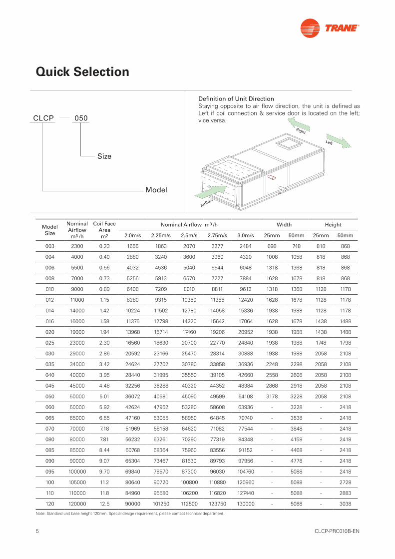
Model
Size
CLCP 050Right
Left
Airflow
Model Size
Nominal Airflowm3 /h
Coil Face Aream2
Nominal Airflow m3 /h Width Height
2.0m/s 2.25m/s 2.5m/s 2.75m/s 3.0m/s 25mm 50mm 25mm 50mm
003 2300 0.23 1656 1863 2070 2277 2484 698 748 818 868
004 4000 0.40 2880 3240 3600 3960 4320 1008 1058 818 868
006 5500 0.56 4032 4536 5040 5544 6048 1318 1368 818 868
008 7000 0.73 5256 5913 6570 7227 7884 1628 1678 818 868
010 9000 0.89 6408 7209 8010 8811 9612 1318 1368 1128 1178
012 11000 1.15 8280 9315 10350 11385 12420 1628 1678 1128 1178
014 14000 1.42 10224 11502 12780 14058 15336 1938 1988 1128 1178
016 16000 1.58 11376 12798 14220 15642 17064 1628 1678 1438 1488
020 19000 1.94 13968 15714 17460 19206 20952 1938 1988 1438 1488
025 23000 2.30 16560 18630 20700 22770 24840 1938 1988 1748 1798
030 29000 2.86 20592 23166 25470 28314 30888 1938 1988 2058 2108
035 34000 3.42 24624 27702 30780 33858 36936 2248 2298 2058 2108
040 40000 3.95 28440 31995 35550 39105 42660 2558 2608 2058 2108
045 45000 4.48 32256 36288 40320 44352 48384 2868 2918 2058 2108
050 50000 5.01 36072 40581 45090 49599 54108 3178 3228 2058 2108
060 60000 5.92 42624 47952 53280 58608 63936 - 3228 - 2418
065 65000 6.55 47160 53055 58950 64845 70740 - 3538 - 2418
070 70000 7.18 51969 58158 64620 71082 77544 - 3848 - 2418
080 80000 7.81 56232 63261 70290 77319 84348 - 4158 - 2418
085 85000 8.44 60768 68364 75960 83556 91152 - 4468 - 2418
090 90000 9.07 65304 73467 81630 89793 97956 - 4778 - 2418
095 100000 9.70 69840 78570 87300 96030 104760 - 5088 - 2418
100 105000 11.2 80640 90720 100800 110880 120960 - 5088 - 2728
110 110000 11.8 84960 95580 106200 116820 127440 - 5088 - 2883
120 120000 12.5 90000 101250 112500 123750 130000 - 5088 - 3038
Note: Standard unit base height 120mm. Special design requirement, please contact technical department.
Definition of Unit DirectionStaying opposite to air flow direction, the unit is defined as Left if coil connection & service door is located on the left; vice versa.
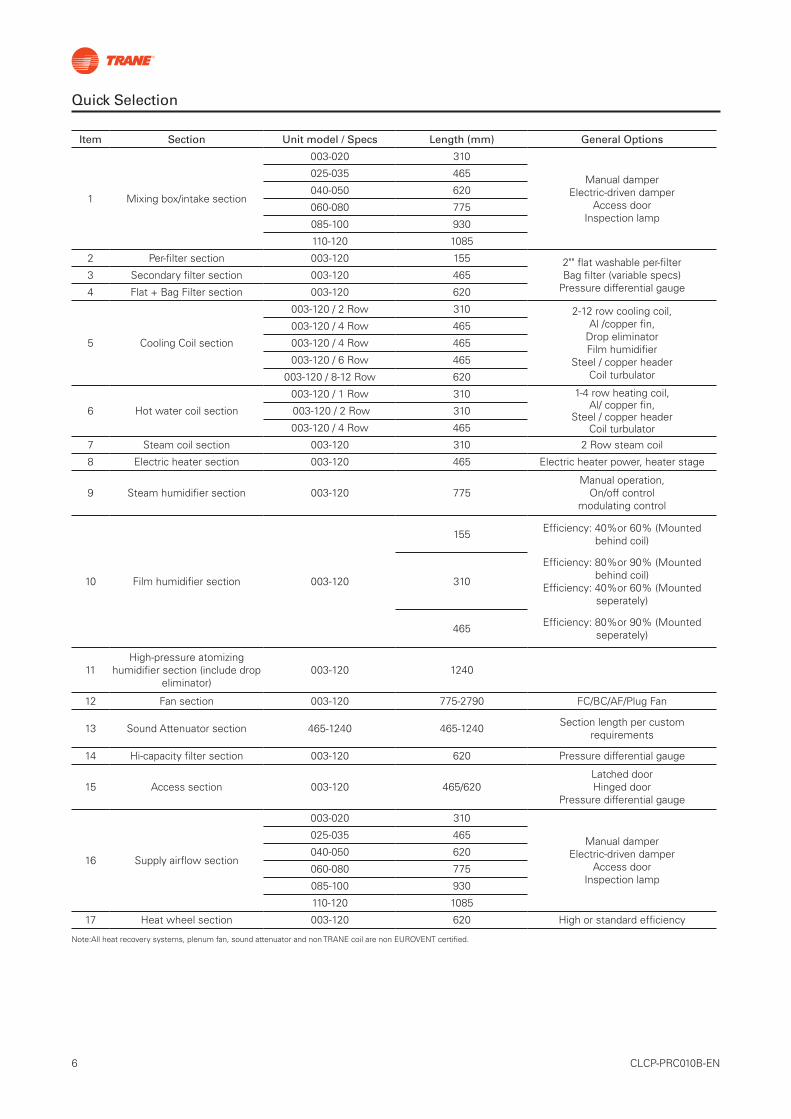
Quick Selection
6 CLCP-PRC010B-EN
Item Section Unit model / Specs Length (mm) General Options
1 Mixing box/intake section
003-020 310
Manual damper Electric-driven damper
Access door Inspection lamp
025-035 465
040-050 620
060-080 775
085-100 930
110-120 1085
2 Per-filter section 003-120 155 2"" flat washable per-filter Bag filter (variable specs)
Pressure differential gauge3 Secondary filter section 003-120 465
4 Flat + Bag Filter section 003-120 620
5 Cooling Coil section
003-120 / 2 Row 310 2-12 row cooling coil, Al /copper fin,
Drop eliminator Film humidifier
Steel / copper header Coil turbulator
003-120 / 4 Row 465
003-120 / 4 Row 465
003-120 / 6 Row 465
003-120 / 8-12 Row 620
6 Hot water coil section
003-120 / 1 Row 310 1-4 row heating coil, Al/ copper fin,
Steel / copper header Coil turbulator
003-120 / 2 Row 310
003-120 / 4 Row 465
7 Steam coil section 003-120 310 2 Row steam coil
8 Electric heater section 003-120 465 Electric heater power, heater stage
9 Steam humidifier section 003-120 775Manual operation,
On/off control modulating control
10 Film humidifier section 003-120
155 Efficiency: 40%or 60% (Mounted behind coil)
310
Efficiency: 80%or 90% (Mounted behind coil)
Efficiency: 40%or 60% (Mounted seperately)
465 Efficiency: 80%or 90% (Mounted seperately)
11High-pressure atomizing
humidifier section (include drop eliminator)
003-120 1240
12 Fan section 003-120 775-2790 FC/BC/AF/Plug Fan
13 Sound Attenuator section 465-1240 465-1240 Section length per custom requirements
14 Hi-capacity filter section 003-120 620 Pressure differential gauge
15 Access section 003-120 465/620Latched door Hinged door
Pressure differential gauge
16 Supply airflow section
003-020 310
Manual damper Electric-driven damper
Access door Inspection lamp
025-035 465
040-050 620
060-080 775
085-100 930
110-120 1085
17 Heat wheel section 003-120 620 High or standard efficiency
Note:All heat recovery systems, plenum fan, sound attenuator and non TRANE coil are non EUROVENT certified.
Quick Selection
7 CLCP-PRC010B-EN
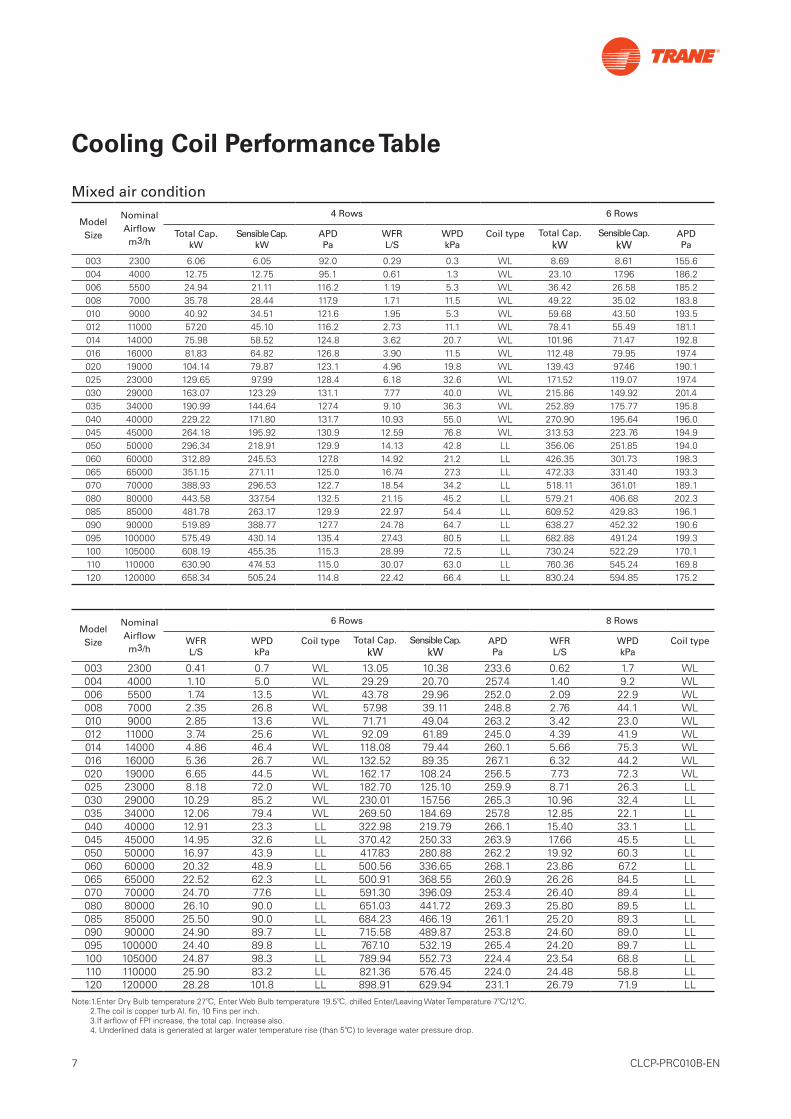
Cooling Coil Performance Table
Mixed air condition
Note:1.Enter Dry Bulb temperature 27℃, Enter Web Bulb temperature 19.5℃, chilled Enter/Leaving Water Temperature 7℃/12℃. 2.The coil is copper turb Al. fin, 10 Fins per inch. 3.If airflow of FPI increase, the total cap. Increase also. 4.Underlineddataisgeneratedatlargerwatertemperaturerise(than5℃)toleveragewaterpressuredrop.
Model Size
Nominal Airflowm3/h
4 Rows 6 Rows
Total Cap.kW
Sensible Cap.kW
APDPa
WFRL/S
WPDkPa
Coil type Total Cap.kW
Sensible Cap.kW
APDPa
003 2300 6.06 6.05 92.0 0.29 0.3 WL 8.69 8.61 155.6004 4000 12.75 12.75 95.1 0.61 1.3 WL 23.10 17.96 186.2006 5500 24.94 21.11 116.2 1.19 5.3 WL 36.42 26.58 185.2008 7000 35.78 28.44 117.9 1.71 11.5 WL 49.22 35.02 183.8010 9000 40.92 34.51 121.6 1.95 5.3 WL 59.68 43.50 193.5012 11000 57.20 45.10 116.2 2.73 11.1 WL 78.41 55.49 181.1014 14000 75.98 58.52 124.8 3.62 20.7 WL 101.96 71.47 192.8016 16000 81.83 64.82 126.8 3.90 11.5 WL 112.48 79.95 197.4020 19000 104.14 79.87 123.1 4.96 19.8 WL 139.43 97.46 190.1025 23000 129.65 97.99 128.4 6.18 32.6 WL 171.52 119.07 197.4030 29000 163.07 123.29 131.1 7.77 40.0 WL 215.86 149.92 201.4035 34000 190.99 144.64 127.4 9.10 36.3 WL 252.89 175.77 195.8040 40000 229.22 171.80 131.7 10.93 55.0 WL 270.90 195.64 196.0045 45000 264.18 195.92 130.9 12.59 76.8 WL 313.53 223.76 194.9050 50000 296.34 218.91 129.9 14.13 42.8 LL 356.06 251.85 194.0060 60000 312.89 245.53 127.8 14.92 21.2 LL 426.35 301.73 198.3065 65000 351.15 271.11 125.0 16.74 27.3 LL 472.33 331.40 193.3070 70000 388.93 296.53 122.7 18.54 34.2 LL 518.11 361.01 189.1080 80000 443.58 337.54 132.5 21.15 45.2 LL 579.21 406.68 202.3085 85000 481.78 263.17 129.9 22.97 54.4 LL 609.52 429.83 196.1090 90000 519.89 388.77 127.7 24.78 64.7 LL 638.27 452.32 190.6095 100000 575.49 430.14 135.4 27.43 80.5 LL 682.88 491.24 199.3100 105000 608.19 455.35 115.3 28.99 72.5 LL 730.24 522.29 170.1110 110000 630.90 474.53 115.0 30.07 63.0 LL 760.36 545.24 169.8120 120000 658.34 505.24 114.8 22.42 66.4 LL 830.24 594.85 175.2
Model Size
Nominal Airflowm3/h
6 Rows 8 Rows
WFRL/S
WPDkPa
Coil type Total Cap.kW
Sensible Cap.kW
APDPa
WFRL/S
WPDkPa
Coil type
003 2300 0.41 0.7 WL 13.05 10.38 233.6 0.62 1.7 WL004 4000 1.10 5.0 WL 29.29 20.70 257.4 1.40 9.2 WL006 5500 1.74 13.5 WL 43.78 29.96 252.0 2.09 22.9 WL008 7000 2.35 26.8 WL 57.98 39.11 248.8 2.76 44.1 WL010 9000 2.85 13.6 WL 71.71 49.04 263.2 3.42 23.0 WL012 11000 3.74 25.6 WL 92.09 61.89 245.0 4.39 41.9 WL014 14000 4.86 46.4 WL 118.08 79.44 260.1 5.66 75.3 WL016 16000 5.36 26.7 WL 132.52 89.35 267.1 6.32 44.2 WL020 19000 6.65 44.5 WL 162.17 108.24 256.5 7.73 72.3 WL025 23000 8.18 72.0 WL 182.70 125.10 259.9 8.71 26.3 LL030 29000 10.29 85.2 WL 230.01 157.56 265.3 10.96 32.4 LL035 34000 12.06 79.4 WL 269.50 184.69 257.8 12.85 22.1 LL040 40000 12.91 23.3 LL 322.98 219.79 266.1 15.40 33.1 LL045 45000 14.95 32.6 LL 370.42 250.33 263.9 17.66 45.5 LL050 50000 16.97 43.9 LL 417.83 280.88 262.2 19.92 60.3 LL060 60000 20.32 48.9 LL 500.56 336.65 268.1 23.86 67.2 LL065 65000 22.52 62.3 LL 500.91 368.55 260.9 26.26 84.5 LL070 70000 24.70 77.6 LL 591.30 396.09 253.4 26.40 89.4 LL080 80000 26.10 90.0 LL 651.03 441.72 269.3 25.80 89.5 LL085 85000 25.50 90.0 LL 684.23 466.19 261.1 25.20 89.3 LL090 90000 24.90 89.7 LL 715.58 489.87 253.8 24.60 89.0 LL095 100000 24.40 89.8 LL 767.10 532.19 265.4 24.20 89.7 LL100 105000 24.87 98.3 LL 789.94 552.73 224.4 23.54 68.8 LL110 110000 25.90 83.2 LL 821.36 576.45 224.0 24.48 58.8 LL120 120000 28.28 101.8 LL 898.91 629.94 231.1 26.79 71.9 LL
8 CLCP-PRC010B-EN
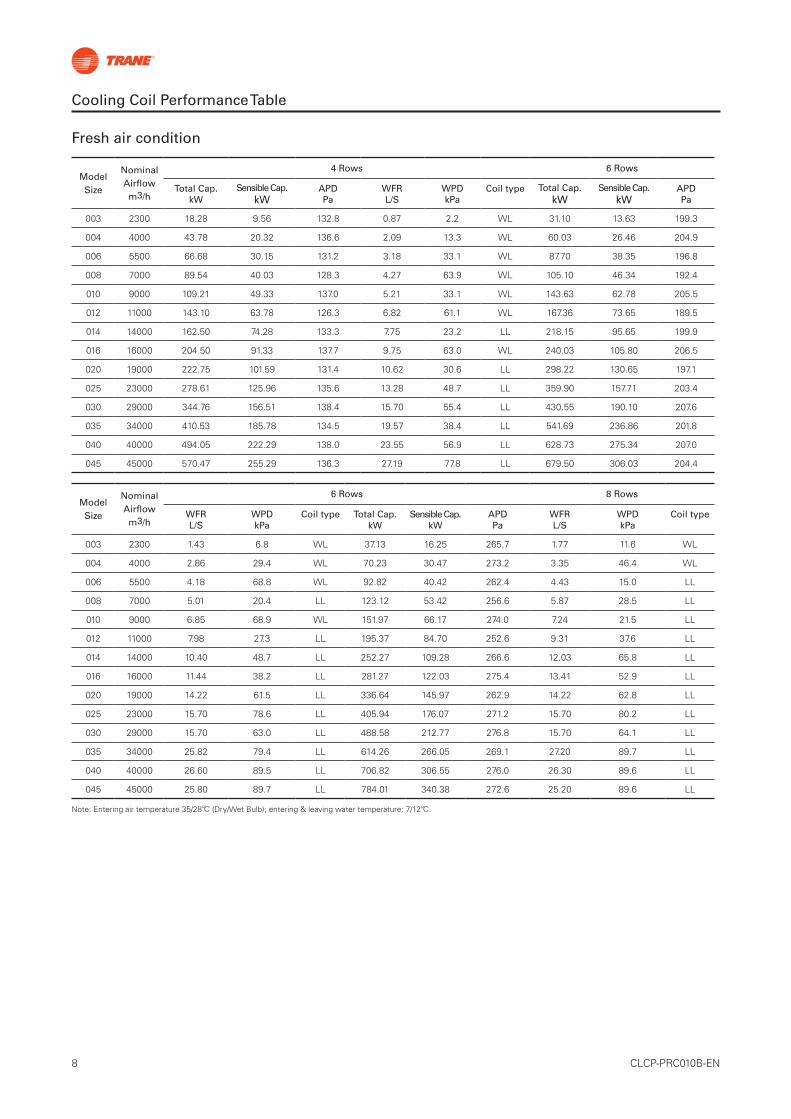
Cooling Coil Performance Table
Fresh air condition
Note: Entering air temperature 35/28℃ (Dry/Wet Bulb); entering & leaving water temperature: 7/12℃.
Model Size
Nominal Airflowm3/h
4 Rows 6 Rows
Total Cap.kW
Sensible Cap.kW
APDPa
WFRL/S
WPDkPa
Coil type Total Cap.kW
Sensible Cap.kW
APDPa
003 2300 18.28 9.56 132.8 0.87 2.2 WL 31.10 13.63 199.3
004 4000 43.78 20.32 136.6 2.09 13.3 WL 60.03 26.46 204.9
006 5500 66.68 30.15 131.2 3.18 33.1 WL 87.70 38.35 196.8
008 7000 89.54 40.03 128.3 4.27 63.9 WL 105.10 46.34 192.4
010 9000 109.21 49.33 137.0 5.21 33.1 WL 143.63 62.78 205.5
012 11000 143.10 63.78 126.3 6.82 61.1 WL 167.36 73.65 189.5
014 14000 162.50 74.28 133.3 7.75 23.2 LL 218.15 95.65 199.9
016 16000 204.50 91.33 137.7 9.75 63.0 WL 240.03 105.80 206.5
020 19000 222.75 101.59 131.4 10.62 30.6 LL 298.22 130.65 197.1
025 23000 278.61 125.96 135.6 13.28 48.7 LL 359.90 157.71 203.4
030 29000 344.76 156.51 138.4 15.70 55.4 LL 430.55 190.10 207.6
035 34000 410.53 185.78 134.5 19.57 38.4 LL 541.69 236.86 201.8
040 40000 494.05 222.29 138.0 23.55 56.9 LL 628.73 275.34 207.0
045 45000 570.47 255.29 136.3 27.19 77.8 LL 679.50 306.03 204.4
Model Size
Nominal Airflowm3/h
6 Rows 8 Rows
WFRL/S
WPDkPa
Coil type Total Cap.kW
Sensible Cap.kW
APDPa
WFRL/S
WPDkPa
Coil type
003 2300 1.43 6.8 WL 37.13 16.25 265.7 1.77 11.6 WL
004 4000 2.86 29.4 WL 70.23 30.47 273.2 3.35 46.4 WL
006 5500 4.18 68.8 WL 92.82 40.42 262.4 4.43 15.0 LL
008 7000 5.01 20.4 LL 123.12 53.42 256.6 5.87 28.5 LL
010 9000 6.85 68.9 WL 151.97 66.17 274.0 7.24 21.5 LL
012 11000 7.98 27.3 LL 195.37 84.70 252.6 9.31 37.6 LL
014 14000 10.40 48.7 LL 252.27 109.28 266.6 12.03 65.8 LL
016 16000 11.44 38.2 LL 281.27 122.03 275.4 13.41 52.9 LL
020 19000 14.22 61.5 LL 336.64 145.97 262.9 14.22 62.8 LL
025 23000 15.70 78.6 LL 405.94 176.07 271.2 15.70 80.2 LL
030 29000 15.70 63.0 LL 488.58 212.77 276.8 15.70 64.1 LL
035 34000 25.82 79.4 LL 614.26 266.05 269.1 27.20 89.7 LL
040 40000 26.60 89.5 LL 706.82 306.55 276.0 26.30 89.6 LL
045 45000 25.80 89.7 LL 784.01 340.38 272.6 25.20 89.6 LL
9 CLCP-PRC010B-EN
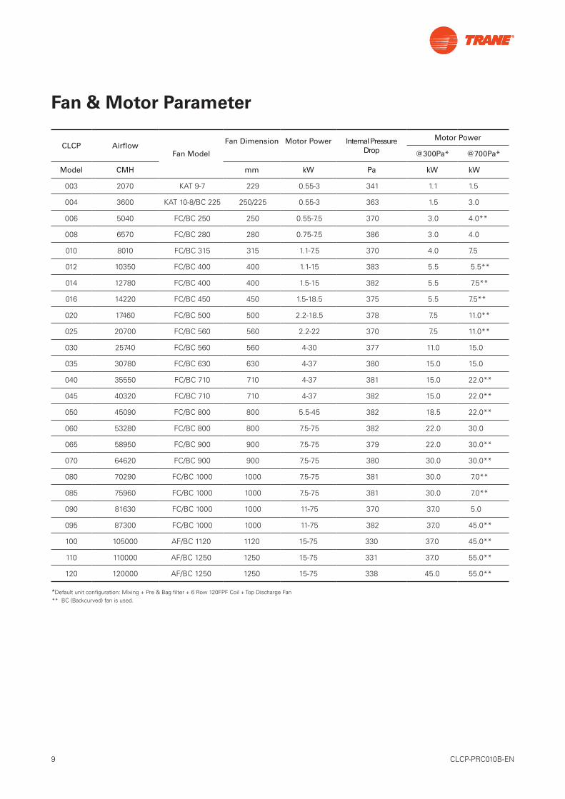
Fan & Motor Parameter
CLCP AirflowFan Model
Fan Dimension Motor Power Internal Pressure Drop
Motor Power
@300Pa* @700Pa*
Model CMH mm kW Pa kW kW
003 2070 KAT 9-7 229 0.55-3 341 1.1 1.5
004 3600 KAT 10-8/BC 225 250/225 0.55-3 363 1.5 3.0
006 5040 FC/BC 250 250 0.55-7.5 370 3.0 4.0**
008 6570 FC/BC 280 280 0.75-7.5 386 3.0 4.0
010 8010 FC/BC 315 315 1.1-7.5 370 4.0 7.5
012 10350 FC/BC 400 400 1.1-15 383 5.5 5.5**
014 12780 FC/BC 400 400 1.5-15 382 5.5 7.5**
016 14220 FC/BC 450 450 1.5-18.5 375 5.5 7.5**
020 17460 FC/BC 500 500 2.2-18.5 378 7.5 11.0**
025 20700 FC/BC 560 560 2.2-22 370 7.5 11.0**
030 25740 FC/BC 560 560 4-30 377 11.0 15.0
035 30780 FC/BC 630 630 4-37 380 15.0 15.0
040 35550 FC/BC 710 710 4-37 381 15.0 22.0**
045 40320 FC/BC 710 710 4-37 382 15.0 22.0**
050 45090 FC/BC 800 800 5.5-45 382 18.5 22.0**
060 53280 FC/BC 800 800 7.5-75 382 22.0 30.0
065 58950 FC/BC 900 900 7.5-75 379 22.0 30.0**
070 64620 FC/BC 900 900 7.5-75 380 30.0 30.0**
080 70290 FC/BC 1000 1000 7.5-75 381 30.0 7.0**
085 75960 FC/BC 1000 1000 7.5-75 381 30.0 7.0**
090 81630 FC/BC 1000 1000 11-75 370 37.0 5.0
095 87300 FC/BC 1000 1000 11-75 382 37.0 45.0**
100 105000 AF/BC 1120 1120 15-75 330 37.0 45.0**
110 110000 AF/BC 1250 1250 15-75 331 37.0 55.0**
120 120000 AF/BC 1250 1250 15-75 338 45.0 55.0**
*Default unit configuration: Mixing + Pre & Bag filter + 6 Row 120FPF Coil + Top Discharge Fan** BC (Backcurved) fan is used.
10 CLCP-PRC010B-EN
Bag Filter
Plate Filter
CEN ENMPPS
Chinese ClassificationSdoium Flame
EU14UH20UH19UH18UH17
H16
H15
H14
H13M12M11M10M9L8L7L6L5C2~C4
C1
EU13EU12EU11
EU10
EU9
EU8
EU7
EU6
EU5
EU4
EU3
EU2
ASH
RA
E 52
.2-1
999
EU1
Old Eurovent
US Proposal
HEPA
Sub-HEPA
High-medium
Dust-spot
Arrestance
U17
U16
U15
H14
H13
H12
H11
H10
F9
F8
F7
F6
F5
G4
G3
G2
G1
99.999995%
99.99995%
99.9995%
99.995%
99.95%
99.5%
95%
85%
99.9%
95%(0.5 µm)
99.999%
99.99%99.97%
99.9%
95%
70%(1 µm)
20%(1 µm)80%(5 µm)
40%(5 µm)
99.9%(1 µm)
90%
95%
90%
80%
65%
80%
60%
40%
EN 1
882-
1:19
98
AN
SI/A
SHR
AE
52.1
-199
2
AN
SI/A
SHR
AE
52.1
-199
2
GB
1221
8-89
GB
/T14
259-
93
BS3
928,
GB
6165
-85
(0.5 µm)
V
IV
III
II
I
Medium
Coarse
GB
1355
4-92
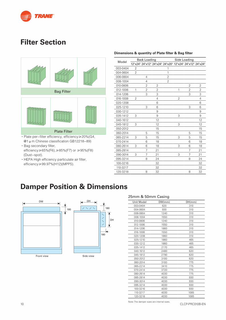
·Plateper-filterefficiency,efficiency≥20%(G4,@1μmChineseclassificationGB12218-89)
·Bagsecondaryfilter,efficiency≥65%(F6),≥85%(F7)or≥95%(F8)(Dust-spot).
·HEPAHighefficiencyparticulateairfilter,efficiency≥99.97%(H12)(MPPS).
Dimensions & quantity of Plate filter & Bag filter
ModelBack Loading Side Loading
12"x24" 24"x12" 24"x24" 24"x20" 12"x24" 24"x12" 24"x24"003-0404 2 1004-0604 2 1006-0804 4 2008-1004 4 2010-0806 2 2 2 2012-1006 1 2 2 1 2 2014-1206 3 3 3 3016-1008 2 4 2 4020-1208 6 6025-1210 3 6 3 6030-1212 9 9035-1412 3 9 3 9040-1612 12 12045-1812 3 12 3 12050-2012 15 15060-2014 5 15 5 15065-2214 3 5 15 3 5 15070-2414 6 18 6 18080-2614 3 6 18 3 6 18085-2814 7 21 7 21090-3014 3 7 21 3 7 21095-3214 8 24 8 24100-3216 32 32110-3217 32 32120-3218 8 32 8 32
Filter Section
Damper Position & Dimensions
180
180
DH
DH
Front view Side view
Drain pan
H = The maximum negative pressure valueJ=0.5HL = H + J + Pipe diameter + Insulation thickness
Nomal operate water level
Duct bend direction & the Fan rotate direction are the same.
Fan diameter
Transition duct
Supply fan duct
Flexible connection
No less than Fan diameter
Picture 1
Picture 2
180
DW
图3
LH
J
25mm & 50mm CasingUnit Model DW(mm) DH(mm)003-0404 620 310004-0604 930 310006-0804 1240 310008-1004 1550 310010-0806 1240 310012-1006 1550 310014-1206 1860 310016-1008 1550 310020-1208 1860 310025-1210 1860 465030-1212 1860 465035-1412 2170 465040-1612 2480 620045-1812 2790 620050-2012 3100 620060-2014 3100 775065-2214 3410 775070-2414 3720 775080-2614 4030 775085-2814 4030 930090-3014 4030 930095-3214 4030 930100-3216 4030 930110-3217 4030 1085120-3218 4030 1085
Note: The damper sizes are internal sizes.
11 CLCP-PRC010B-EN
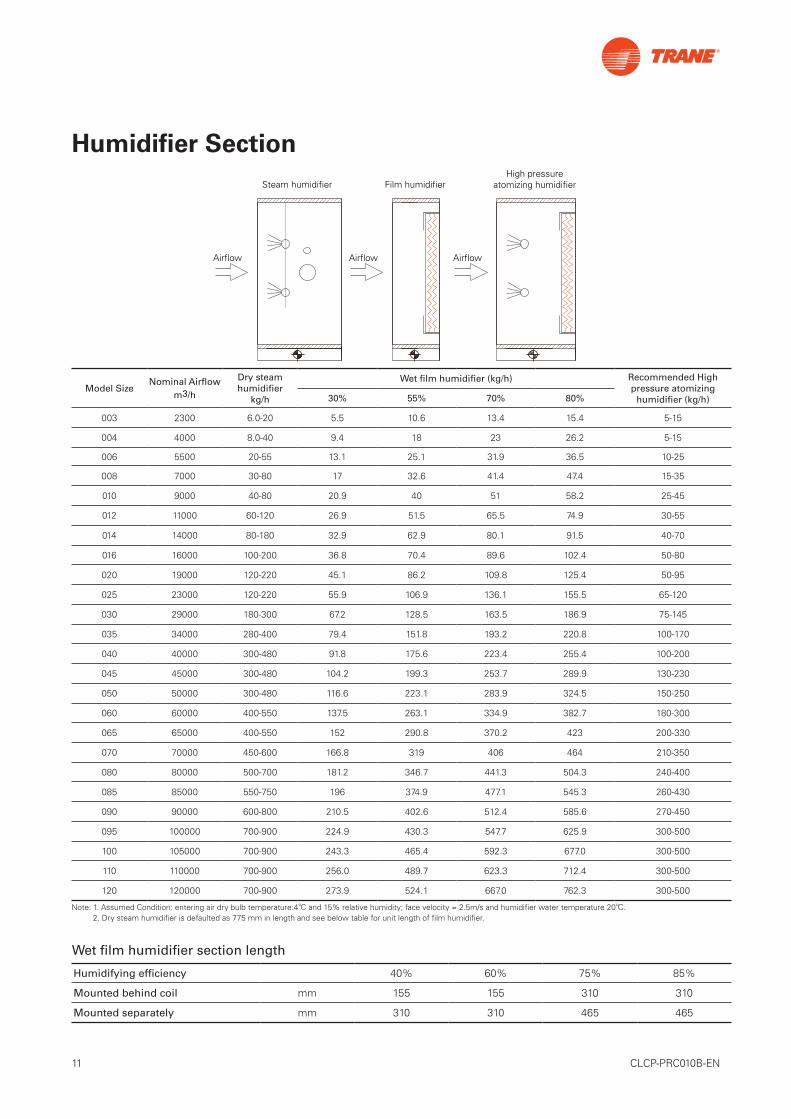
Humidifier Section
Note: 1. Assumed Condition: entering air dry bulb temperature:4℃ and 15% relative humidity; face velocity = 2.5m/s and humidifier water temperature 20℃. 2. Dry steam humidifier is defaulted as 775 mm in length and see below table for unit length of film humidifier.
Model SizeNominal Airflow
m3/h
Dry steam humidifier
kg/h
Wet film humidifier (kg/h) Recommended High pressure atomizing
humidifier (kg/h)30% 55% 70% 80%
003 2300 6.0-20 5.5 10.6 13.4 15.4 5-15
004 4000 8.0-40 9.4 18 23 26.2 5-15
006 5500 20-55 13.1 25.1 31.9 36.5 10-25
008 7000 30-80 17 32.6 41.4 47.4 15-35
010 9000 40-80 20.9 40 51 58.2 25-45
012 11000 60-120 26.9 51.5 65.5 74.9 30-55
014 14000 80-180 32.9 62.9 80.1 91.5 40-70
016 16000 100-200 36.8 70.4 89.6 102.4 50-80
020 19000 120-220 45.1 86.2 109.8 125.4 50-95
025 23000 120-220 55.9 106.9 136.1 155.5 65-120
030 29000 180-300 67.2 128.5 163.5 186.9 75-145
035 34000 280-400 79.4 151.8 193.2 220.8 100-170
040 40000 300-480 91.8 175.6 223.4 255.4 100-200
045 45000 300-480 104.2 199.3 253.7 289.9 130-230
050 50000 300-480 116.6 223.1 283.9 324.5 150-250
060 60000 400-550 137.5 263.1 334.9 382.7 180-300
065 65000 400-550 152 290.8 370.2 423 200-330
070 70000 450-600 166.8 319 406 464 210-350
080 80000 500-700 181.2 346.7 441.3 504.3 240-400
085 85000 550-750 196 374.9 477.1 545.3 260-430
090 90000 600-800 210.5 402.6 512.4 585.6 270-450
095 100000 700-900 224.9 430.3 547.7 625.9 300-500
100 105000 700-900 243.3 465.4 592.3 677.0 300-500
110 110000 700-900 256.0 489.7 623.3 712.4 300-500
120 120000 700-900 273.9 524.1 667.0 762.3 300-500
Humidifying efficiency 40% 60% 75% 85%
Mounted behind coil mm 155 155 310 310
Mounted separately mm 310 310 465 465
Film humidifierSteam humidifierHigh pressure
atomizing humidifier
Airflow Airflow Airflow
Wet film humidifier section length
12 CLCP-PRC010B-EN
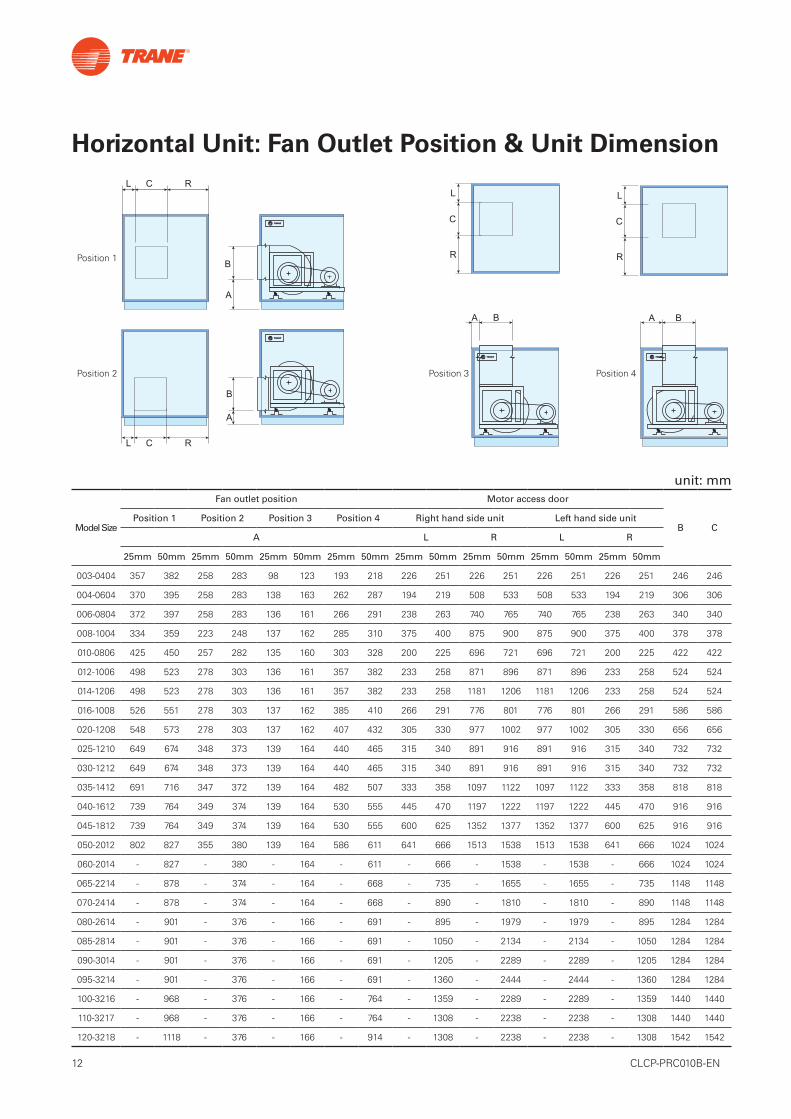
Horizontal Unit: Fan Outlet Position & Unit Dimension
Model Size
Fan outlet position Motor access door
B CPosition 1 Position 2 Position 3 Position 4 Right hand side unit Left hand side unit
A L R L R
25mm 50mm 25mm 50mm 25mm 50mm 25mm 50mm 25mm 50mm 25mm 50mm 25mm 50mm 25mm 50mm
003-0404 357 382 258 283 98 123 193 218 226 251 226 251 226 251 226 251 246 246
004-0604 370 395 258 283 138 163 262 287 194 219 508 533 508 533 194 219 306 306
006-0804 372 397 258 283 136 161 266 291 238 263 740 765 740 765 238 263 340 340
008-1004 334 359 223 248 137 162 285 310 375 400 875 900 875 900 375 400 378 378
010-0806 425 450 257 282 135 160 303 328 200 225 696 721 696 721 200 225 422 422
012-1006 498 523 278 303 136 161 357 382 233 258 871 896 871 896 233 258 524 524
014-1206 498 523 278 303 136 161 357 382 233 258 1181 1206 1181 1206 233 258 524 524
016-1008 526 551 278 303 137 162 385 410 266 291 776 801 776 801 266 291 586 586
020-1208 548 573 278 303 137 162 407 432 305 330 977 1002 977 1002 305 330 656 656
025-1210 649 674 348 373 139 164 440 465 315 340 891 916 891 916 315 340 732 732
030-1212 649 674 348 373 139 164 440 465 315 340 891 916 891 916 315 340 732 732
035-1412 691 716 347 372 139 164 482 507 333 358 1097 1122 1097 1122 333 358 818 818
040-1612 739 764 349 374 139 164 530 555 445 470 1197 1222 1197 1222 445 470 916 916
045-1812 739 764 349 374 139 164 530 555 600 625 1352 1377 1352 1377 600 625 916 916
050-2012 802 827 355 380 139 164 586 611 641 666 1513 1538 1513 1538 641 666 1024 1024
060-2014 - 827 - 380 - 164 - 611 - 666 - 1538 - 1538 - 666 1024 1024
065-2214 - 878 - 374 - 164 - 668 - 735 - 1655 - 1655 - 735 1148 1148
070-2414 - 878 - 374 - 164 - 668 - 890 - 1810 - 1810 - 890 1148 1148
080-2614 - 901 - 376 - 166 - 691 - 895 - 1979 - 1979 - 895 1284 1284
085-2814 - 901 - 376 - 166 - 691 - 1050 - 2134 - 2134 - 1050 1284 1284
090-3014 - 901 - 376 - 166 - 691 - 1205 - 2289 - 2289 - 1205 1284 1284
095-3214 - 901 - 376 - 166 - 691 - 1360 - 2444 - 2444 - 1360 1284 1284
100-3216 - 968 - 376 - 166 - 764 - 1359 - 2289 - 2289 - 1359 1440 1440
110-3217 - 968 - 376 - 166 - 764 - 1308 - 2238 - 2238 - 1308 1440 1440
120-3218 - 1118 - 376 - 166 - 914 - 1308 - 2238 - 2238 - 1308 1542 1542
B
A
A
Position 1
Position 3Position 2 Position 4
L C R
A B
L
C
R
L
C
R
A B
L C R
B
unit: mm
13 CLCP-PRC010B-EN
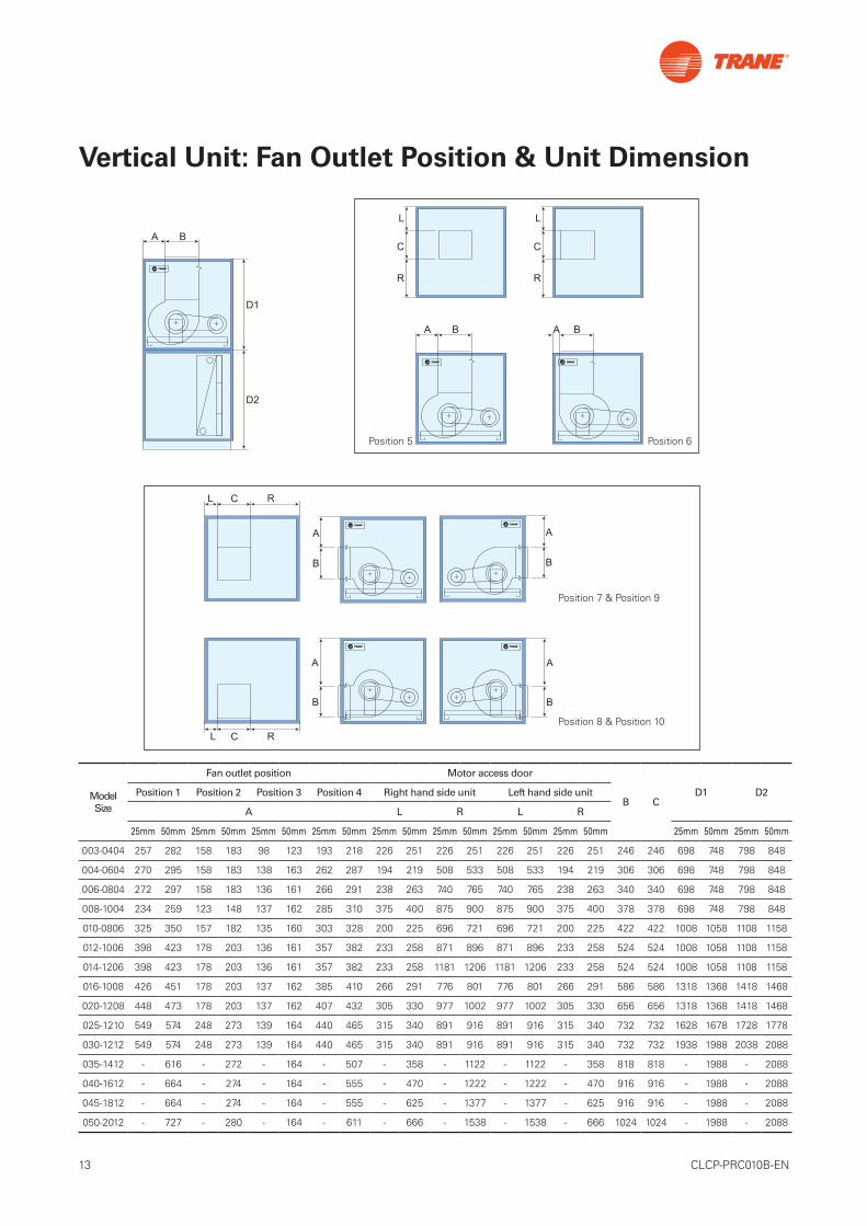
Vertical Unit: Fan Outlet Position & Unit Dimension
Model Size
Fan outlet position Motor access door
B CD1 D2Position 1 Position 2 Position 3 Position 4 Right hand side unit Left hand side unit
A L R L R
25mm 50mm 25mm 50mm 25mm 50mm 25mm 50mm 25mm 50mm 25mm 50mm 25mm 50mm 25mm 50mm 25mm 50mm 25mm 50mm
003-0404 257 282 158 183 98 123 193 218 226 251 226 251 226 251 226 251 246 246 698 748 798 848
004-0604 270 295 158 183 138 163 262 287 194 219 508 533 508 533 194 219 306 306 698 748 798 848
006-0804 272 297 158 183 136 161 266 291 238 263 740 765 740 765 238 263 340 340 698 748 798 848
008-1004 234 259 123 148 137 162 285 310 375 400 875 900 875 900 375 400 378 378 698 748 798 848
010-0806 325 350 157 182 135 160 303 328 200 225 696 721 696 721 200 225 422 422 1008 1058 1108 1158
012-1006 398 423 178 203 136 161 357 382 233 258 871 896 871 896 233 258 524 524 1008 1058 1108 1158
014-1206 398 423 178 203 136 161 357 382 233 258 1181 1206 1181 1206 233 258 524 524 1008 1058 1108 1158
016-1008 426 451 178 203 137 162 385 410 266 291 776 801 776 801 266 291 586 586 1318 1368 1418 1468
020-1208 448 473 178 203 137 162 407 432 305 330 977 1002 977 1002 305 330 656 656 1318 1368 1418 1468
025-1210 549 574 248 273 139 164 440 465 315 340 891 916 891 916 315 340 732 732 1628 1678 1728 1778
030-1212 549 574 248 273 139 164 440 465 315 340 891 916 891 916 315 340 732 732 1938 1988 2038 2088
035-1412 - 616 - 272 - 164 - 507 - 358 - 1122 - 1122 - 358 818 818 - 1988 - 2088
040-1612 - 664 - 274 - 164 - 555 - 470 - 1222 - 1222 - 470 916 916 - 1988 - 2088
045-1812 - 664 - 274 - 164 - 555 - 625 - 1377 - 1377 - 625 916 916 - 1988 - 2088
050-2012 - 727 - 280 - 164 - 611 - 666 - 1538 - 1538 - 666 1024 1024 - 1988 - 2088
D2
A B
D1
Position 5 Position 6
Position 7 & Position 9
Position 8 & Position 10
14 CLCP-PRC010B-EN
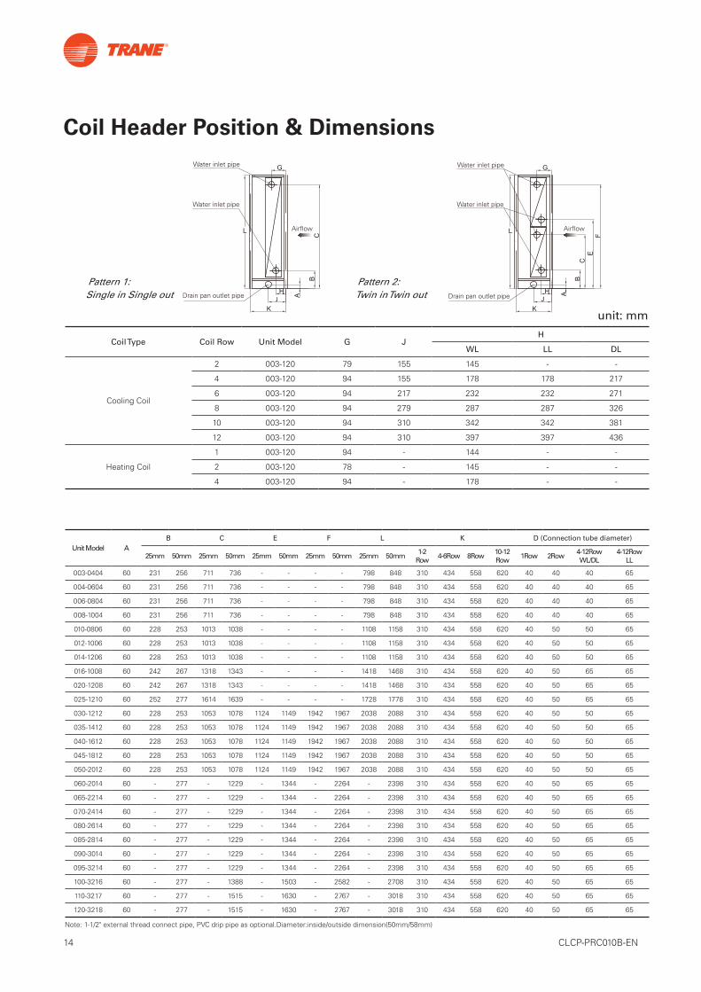
G
BC
H
KJ A
L
G
BC
H
KJ
A
L
EF
Water inlet pipe
Water inlet pipe
Airflow
Drain pan outlet pipe
Water inlet pipe
Water inlet pipe
Airflow
Drain pan outlet pipe
Coil Type Coil Row Unit Model G JH
WL LL DL
Cooling Coil
2 003-120 79 155 145 - -
4 003-120 94 155 178 178 217
6 003-120 94 217 232 232 271
8 003-120 94 279 287 287 326
10 003-120 94 310 342 342 381
12 003-120 94 310 397 397 436
Heating Coil
1 003-120 94 - 144 - -
2 003-120 78 - 145 - -
4 003-120 94 - 178 - -
Unit Model AB C E F L K D (Connection tube diameter)
25mm 50mm 25mm 50mm 25mm 50mm 25mm 50mm 25mm 50mm1-2
Row4-6Row 8Row
10-12Row
1Row 2Row4-12RowWL/DL
4-12RowLL
003-0404 60 231 256 711 736 - - - - 798 848 310 434 558 620 40 40 40 65
004-0604 60 231 256 711 736 - - - - 798 848 310 434 558 620 40 40 40 65
006-0804 60 231 256 711 736 - - - - 798 848 310 434 558 620 40 40 40 65
008-1004 60 231 256 711 736 - - - - 798 848 310 434 558 620 40 40 40 65
010-0806 60 228 253 1013 1038 - - - - 1108 1158 310 434 558 620 40 50 50 65
012-1006 60 228 253 1013 1038 - - - - 1108 1158 310 434 558 620 40 50 50 65
014-1206 60 228 253 1013 1038 - - - - 1108 1158 310 434 558 620 40 50 50 65
016-1008 60 242 267 1318 1343 - - - - 1418 1468 310 434 558 620 40 50 65 65
020-1208 60 242 267 1318 1343 - - - - 1418 1468 310 434 558 620 40 50 65 65
025-1210 60 252 277 1614 1639 - - - - 1728 1778 310 434 558 620 40 50 65 65
030-1212 60 228 253 1053 1078 1124 1149 1942 1967 2038 2088 310 434 558 620 40 50 50 65
035-1412 60 228 253 1053 1078 1124 1149 1942 1967 2038 2088 310 434 558 620 40 50 50 65
040-1612 60 228 253 1053 1078 1124 1149 1942 1967 2038 2088 310 434 558 620 40 50 50 65
045-1812 60 228 253 1053 1078 1124 1149 1942 1967 2038 2088 310 434 558 620 40 50 50 65
050-2012 60 228 253 1053 1078 1124 1149 1942 1967 2038 2088 310 434 558 620 40 50 50 65
060-2014 60 - 277 - 1229 - 1344 - 2264 - 2398 310 434 558 620 40 50 65 65
065-2214 60 - 277 - 1229 - 1344 - 2264 - 2398 310 434 558 620 40 50 65 65
070-2414 60 - 277 - 1229 - 1344 - 2264 - 2398 310 434 558 620 40 50 65 65
080-2614 60 - 277 - 1229 - 1344 - 2264 - 2398 310 434 558 620 40 50 65 65
085-2814 60 - 277 - 1229 - 1344 - 2264 - 2398 310 434 558 620 40 50 65 65
090-3014 60 - 277 - 1229 - 1344 - 2264 - 2398 310 434 558 620 40 50 65 65
095-3214 60 - 277 - 1229 - 1344 - 2264 - 2398 310 434 558 620 40 50 65 65
100-3216 60 - 277 - 1388 - 1503 - 2582 - 2708 310 434 558 620 40 50 65 65
110-3217 60 - 277 - 1515 - 1630 - 2767 - 3018 310 434 558 620 40 50 65 65
120-3218 60 - 277 - 1515 - 1630 - 2767 - 3018 310 434 558 620 40 50 65 65
Pattern 1: Single in Single out
Pattern 2: Twin in Twin out
Note: 1-1/2" external thread connect pipe, PVC drip pipe as optional.Diameter:inside/outside dimension(50mm/58mm)
Coil Header Position & Dimensions
unit: mm

15 CLCP-PRC010B-EN

©2020 Trane
Trane - by Trane Technologies (NYSE: TT), a global climate innovator - creates comfortable, energyefficient indoor environments for commercial and residential applications. For more information,please visit trane.com or tranetechnologies.com.
Trane has a policy of continuous product and product data improvement and reserves the right to change design and specifications without
notice. We are committed to using environmentally conscious print practices.
CLCP-PRC010B-EN 10 Jun 2019