Embed Size (px)
Citation preview
Clean Sky - Systems for Green Operation &
links with SESAR
Vienna, 3rd of February, 2011
Helmut Schwarze (CleanSky JU)
Ruud den Boer (CleanSky JU)

Contents
1. Context & planning
2. Examples of progress
- Management of Aircraft Energy (MAE)
- Mission and Trajectory Management (MTM)
3. Relation with SESAR
4. CfP - examples
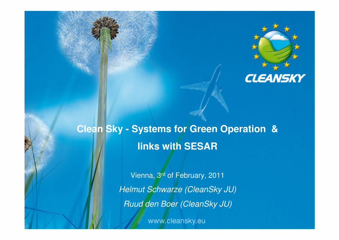
• Pillar 2: Management of Trajectory and Mission (MTM)
– The silent and agile aircraft will generate a reduced noise footprint
during approach and departure by flying optimised trajectories.
– Aircraft will be able to fly a green mission from start to finish, thanks
to technologies which allow to avoid fuel consuming meteorological
hazards
– Smart Operations on Ground
• Pillar 1: Management of Aircraft Energy (MAE)
– The use of all (more) -electric equipment system architectures
from electrical generation and distribution to electrical aircraft
systems.
– Thermal management will address many levels, particularly
relating to electric aircraft, from hot spots in large power
electronics to motor drive system cooling, to overall aircraft
solutions.
Systems for Green Operation: the concepts
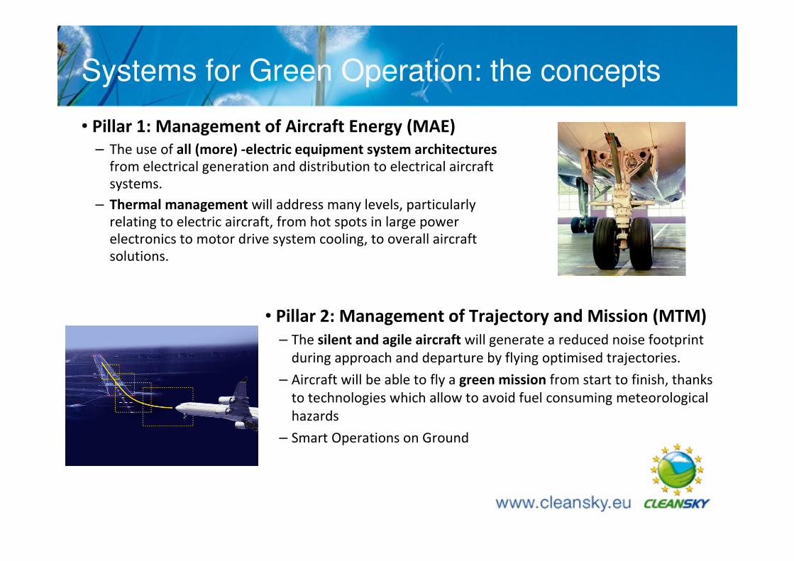
MTM planning
Q3 Q4 Q1 Q2 Q3 Q4 Q1 Q2 Q3 Q4 Q1 Q2 Q3 Q4 Q1 Q2 Q3 Q4 Q1 Q2 Q3 Q4 Q1 Q2 Q3 Q4 Q1 Q2 Q3 Q4 Q1 Q2 Q3 Q4
Flight Management functions
Green take-off and climb function
Green cruise function
Green approach
Green FMS
Weather avoidance and
mission optimization
Water Vapour Sensor (WVS) and
Airborne Data Transmission
System (ADTS)
Advanced weather radar
algorithms
On board optimisation
Smart Operation on ground
Gear integrated motion system
Disptach towing vehicle
2011 20162012 2013 2014 2015
Trajectory Optimization tool
(GATAC)
2008 2009 2010
Development
Ground Tests Detailed design
Pre-feasibility phase Preliminary design Detailed design
Pre-feasibility phase Preliminary design
Ground test (Mosart / Airlab)
Ground TestPre-feasibility phase Preliminary design
development (
Tests
Architecture / pre design Ground Test
3 4
5 6
Ground test (Avionics demonstrator)
3 4
avionics demonstrator design
5 6
3 4 5
Tests
Integration
3 4
Ground Tests
3 4 5
Detailed design
GRA
Ground Tests
validation
integration
Inputs for cycle 2
3 4 5 6
GO/NO GO
5 6
Flight Test
Ground test (Mosart / Airlab)
4
Contents
1. Context & planning
2. Examples of progress
- Management of Aircraft Energy (MAE)
- Mission and Trajectory Management (MTM)
3. Relation with SESAR
4. CfP - examples
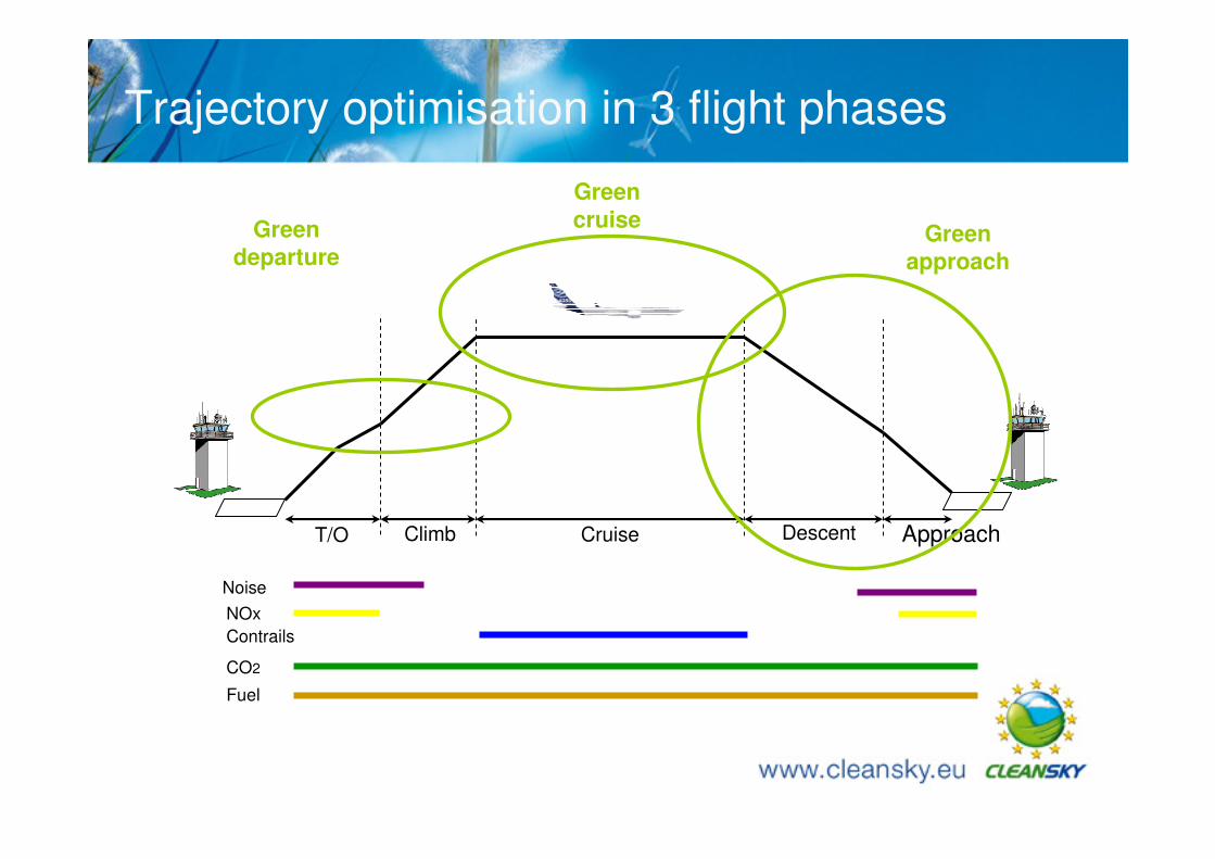
Trajectory optimisation in 3 flight phases
Fuel
Noise
NOx
Contrails
CO2
CruiseT/O Climb Descent Approach
Green
departure
Green
cruiseGreen
approach
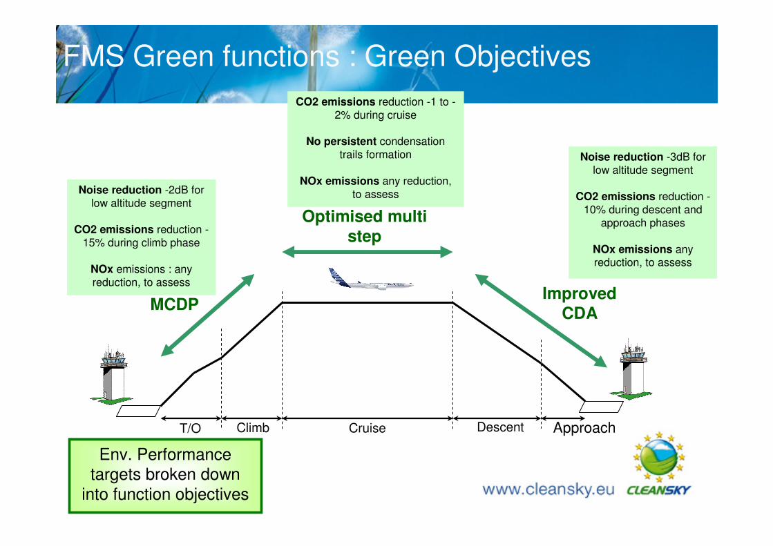
FMS Green functions : Green Objectives
CruiseT/O Climb Descent Approach
Noise reduction -2dB for
low altitude segment
CO2 emissions reduction -
15% during climb phase
NOx emissions : any
reduction, to assess
CO2 emissions reduction -1 to -
2% during cruise
No persistent condensation
trails formation
NOx emissions any reduction,
to assess
Noise reduction -3dB for
low altitude segment
CO2 emissions reduction -
10% during descent and
approach phases
NOx emissions anyreduction, to assess
MCDP
Optimised multi
step
ImprovedCDA
Env. Performance
targets broken down
into function objectives
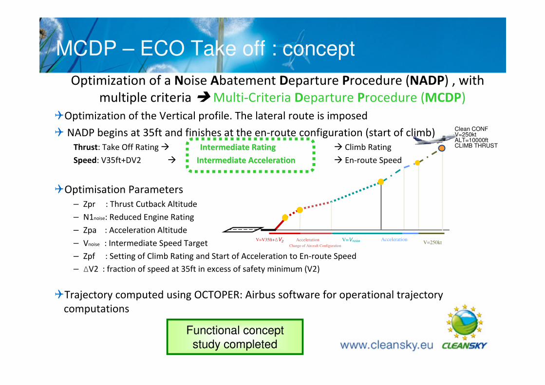
MCDP – ECO Take off : concept
Optimization of a Noise Abatement Departure Procedure (NADP) , with
multiple criteria � Multi-Criteria Departure Procedure (MCDP)
�Optimization of the Vertical profile. The lateral route is imposed
� NADP begins at 35ft and finishes at the en-route configuration (start of climb)
Thrust: Take Off Rating � Intermediate RatingIntermediate Rating � Climb Rating
Speed: V35ft+DV2 � Intermediate AccelerationIntermediate Acceleration � En-route Speed
�Optimisation Parameters
– Zpr : Thrust Cutback Altitude
– N1noise: Reduced Engine Rating
– Zpa : Acceleration Altitude
– Vnoise : Intermediate Speed Target
– Zpf : Setting of Climb Rating and Start of Acceleration to En-route Speed
– ∆V2 : fraction of speed at 35ft in excess of safety minimum (V2)
�Trajectory computed using OCTOPER: Airbus software for operational trajectory
computations
Clean CONFV=250ktALT=10000ftCLIMB THRUST
Change of Aircraft Configuration
V=VnoiseV=V35ft+∆V2 Acceleration Acceleration V=250kt
Functional concept
study completed

Contents
1. Context & planning
2. Examples of progress
- Management of Aircraft Energy (MAE)
- Mission and Trajectory Management (MTM)
3. Relation with SESAR
4. CfP - examples
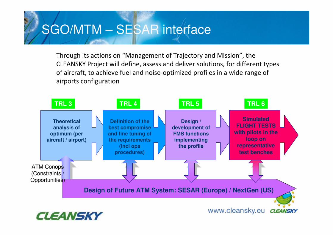
SGO/MTM – SESAR interface
Through its actions on “Management of Trajectory and Mission”, the
CLEANSKY Project will define, assess and deliver solutions, for different types
of aircraft, to achieve fuel and noise-optimized profiles in a wide range of
airports configuration
Design of Future ATM System: SESAR (Europe) / NextGen (US)
Theoretical
analysis of
optimum (per
aircraft / airport)
TRL 3 TRL 4 TRL 5 TRL 6
Definition of the
best compromise
and fine tuning of
the requirements
(incl ops
procedures)
Design /
development of
FMS functions
implementing
the profile
Simulated FLIGHT TESTS
with pilots in the loop on
representative test benches
ATM Conops(Constraints / Opportunities)
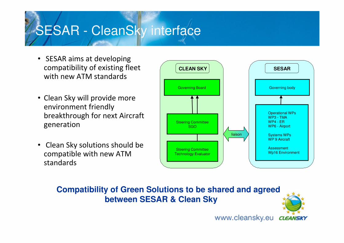
SESAR - CleanSky interface
• SESAR aims at developing compatibility of existing fleet with new ATM standards
• Clean Sky will provide more environment friendly breakthrough for next Aircraft generation
• Clean Sky solutions should be compatible with new ATM standards
Compatibility of Green Solutions to be shared and agreed between SESAR & Clean Sky
CLEAN SKY
Steering Committee
SGO
Governing Board
Steering Committee
Technology Evaluator
SESAR
Governing body
Operational WPsWP3 - TMA
WP4 - ERWP6 - Airport
Systems WPsWP 9 Aircraft
Assessment
Wp16 Environment
Liaisonliaison
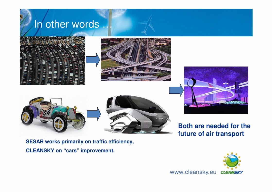
In other words …
SESAR works primarily on traffic efficiency,
CLEANSKY on “cars” improvement.
Both are needed for the future of air transport
Contents
1. Context & planning
2. Examples of progress
- Management of Aircraft Energy (MAE)
- Mission and Trajectory Management (MTM)
3. Relation with SESAR
4. CfP - examples
Examples of CfP – work (MTM & SOG)
1. Management of Missions and trajectory
a) SIMET - METEO – modelling (1st call)
b) COMET – Downlink A/C – derived data (1st call)
c) Turbofan emissions-modelling (1st call)
d) Turbofan noise-modelling (1st call)
e) Parametric optimisation of trajectories (3rd call)
f) Weather radar modelling (5th call)
g) Modelling -start- propfan noise (6th call)
h) Rapid trajectory integration (6th call)
2. Smart Operations on Ground
a) Wheel actuator (7th call)
b) Aircraft tractor (7th call)

The end . …. . . …Q & A