Embed Size (px)
Citation preview
201801001
CLG835H WHEEL LOADERPERKINS POWER T4f / LIUGONG WET AXLE / ZF158A GEARBOX /
ZF160 GEARBOX( 英语 )
OPERATION AND MAINTENANCE MANUAL

Important Safety Information
Most accidents involving product operation, maintenance and repair are caused by failure to observe safety rules or precautions. An accident can often be avoided by recognizing potentially hazardous situations before an accident occurs. A person must be alert to potential hazards. This person should also have the necessary training, skills and tools to perform these functions properly.
Improper operation, lubrication, maintenance or repair on this product can be dangerous and could result in injury or death.
Do not operate or perform any lubrication, maintenance or repair on this product, until you have read and understood the operation, lubrication, maintain and repair information.
Safety precautions and warnings are provided in this manual and on the product. If these hazard warnings are not heeded, bodily injury or death could occur to you or other persons.
The hazards are identified by the "Safety Alert Symbol" and followed by a "Signal Word" such as "WARNING" as shown following.
The meaning of this safety alert symbol is as follows:
Attention. Be alert. Your safety is involved.
The message that appears under the warning, explaining the hazard, can be either written or pictorially presented.
Operations that may cause product damage are identified by NOTICE labels on the product and in this publication.
LiuGong cannot anticipate every possible circumstance that might involve a potential hazard. The warnings in this publication and on the product are therefore not all inclusive. If a tool, procedure, work method or operating technique not specifically recommended by LiuGong is used, you must satisfy yourself that it is safe for you and others. You should also ensure that the product will not be damaged or made unsafe by the operation, lubrication, maintenance or require procedures you choose.
The information, specification, and illustrations in this publication are on the basis of information available at the time when it was written. The specification, torques, pressures, measurements, adjustments, illustrations, and other items can change at any time. These changes can affect the service given to the product. Obtain the complete and most current information before starting any job. LiuGong has the most current information available.
CALIFORNIA PROPOSITION 65
Diesel engine exhaust and some of its constituents are known to the state of California to cause cancer, birth defects and other reproductive harm.
Battery post, terminal and related accessories contain lead and lead compounds, Always wash hands after handling.

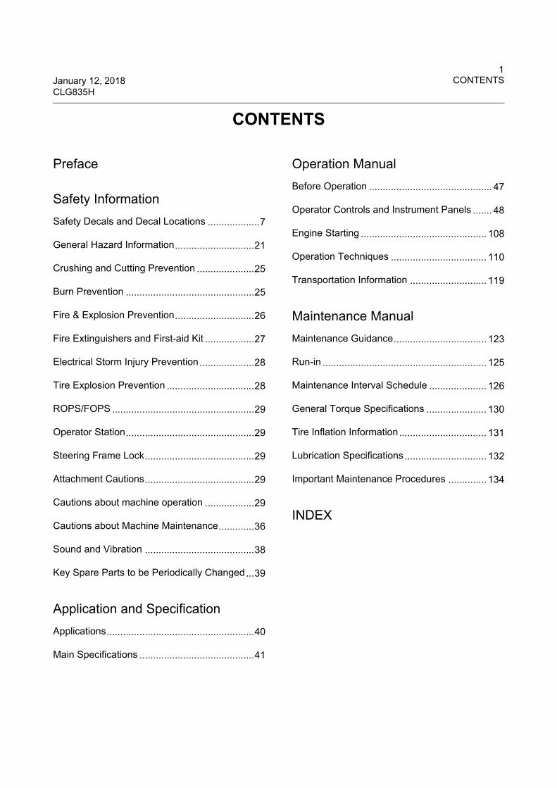
1January 12, 2018 CONTENTSCLG835H
CONTENTS
Preface
Safety Information
Safety Decals and Decal Locations ...................7
General Hazard Information.............................21
Crushing and Cutting Prevention .....................25
Burn Prevention ...............................................25
Fire & Explosion Prevention.............................26
Fire Extinguishers and First-aid Kit ..................27
Electrical Storm Injury Prevention....................28
Tire Explosion Prevention ................................28
ROPS/FOPS ....................................................29
Operator Station...............................................29
Steering Frame Lock........................................29
Attachment Cautions........................................29
Cautions about machine operation ..................29
Cautions about Machine Maintenance.............36
Sound and Vibration ........................................38
Key Spare Parts to be Periodically Changed...39
Application and Specification
Applications......................................................40
Main Specifications ..........................................41
Operation Manual
Before Operation ............................................. 47
Operator Controls and Instrument Panels ....... 48
Engine Starting .............................................. 108
Operation Techniques ................................... 110
Transportation Information ............................ 119
Maintenance Manual
Maintenance Guidance.................................. 123
Run-in ............................................................ 125
Maintenance Interval Schedule ..................... 126
General Torque Specifications ...................... 130
Tire Inflation Information................................ 131
Lubrication Specifications.............................. 132
Important Maintenance Procedures .............. 134
INDEX

2CONTENTS January 12, 2018
CLG835H
1January 12, 2018 PrefaceCLG835H
Preface
This manual includes important instructions concerning operation, lubrication, checking testing, adjusting the machine and permanent key components.
This manual should always be kept safe, clean and with the machine where it is convenient to find for operators to use. This manual should not be separated from the machine even when reselling or leasing.
Some photographs and illustrations in this manual show details of attachments that may be different from your machine. Guards and covers may have been removed for the purpose of illustration.
Read this manual carefully and follow all instructions for proper operation and maintenance of this machine. Instructions in this manual should help the reader avoid possible personal injury or damage to the machine. The operator should proficiently and correctly operate the machine to ensure safety.
Use this machine only for the purpose described in this manual. Contact your Liugong dealer for approval before making any modifications or adding attachments to the machine. The addition of any unauthorized attachment may cause operation of the machine to become unsafe and reduce the service life of the machine. Guangxi Liugong accepts no liability for any damage resulting from the use of unapproved attachments or working practices.
Guangxi Liugong ensured that the engine system and aftertreatment device of the machine leaving the factory are in full compliance with the authentication configuration. Do not allow any unit or individual to modify the engine aftertreatment device or change parts suppliers freely, otherwise, LiuGong will bear no responsibility.
Only trained or experienced personnel should be allowed to operate or maintain this machine. Correctly record the machine type, serial number, engine serial number and all major component serial numbers for your reference when ordering parts or in the event of theft. Record the correct numbers to both the operator’s manual and a secure place outside the machine.
Safety
The safety section lists basic safety precautions. In addition this section identifies the text and locations of warning signs and labels used on the machine.
Read and understand the basic precautions listed in the safety section before operating or performing lubrication, maintenance or repairs on this machine.
Operation
The operation section is a reference for the new operator and a refresher for the experienced operator. Read, understand and reference it whenever necessary. This section includes a description of gauges, machine controls, switches and other controls at the operators’ station. It also provides transportation and towing information.
Photographs and illustrations guide the operator through correct procedures of checking, starting, operating and stopping the machine.
Operating techniques outlined in this publication are basic. Skill and techniques develop as the operator gains knowledge of the machine and its capabilities.
Maintenance
The maintenance section is a guide for equipment care. The illustrated, step-by-step instructions are grouped by servicing intervals. Items without specific intervals are listed under the "When Required" service interval. Items in the "Maintenance Intervals" are referenced to detailed instructions that follow.

2Preface January 12, 2018
CLG835H
For the replacement of environment-friendly key parts and components when maintaining an engine, please use the OEM parts and components of the same type and the same specifications. Otherwise, LiuGong accepts no legal liability for any consequence resulting from the use of unapproved parts.
Maintenance Intervals
Use the service hour meter to determine servicing intervals. Calendar intervals shown (daily, weekly, monthly, etc) can be used instead of service hour meter intervals if they provide more convenient servicing schedules and approximate the indicated service hour meter reading. Recommended service should always be performed at the interval that occurs first.
Under extremely severe, dusty or wet operating conditions, more frequent lubrication than is specified in the "Maintenance Intervals" may be necessary.
Perform service on items at multiples of the original requirement. For example, at every 500 service hours, also service those items listed under every 250 service hours, 50 service hours and every 10 service hours or daily.
All the information, figures, tables and specifications are the latest product information obtainable at the time of publication. Guangxi Liugong Company will reserve the right to make change without notice.
3January 12, 2018 PrefaceCLG835H
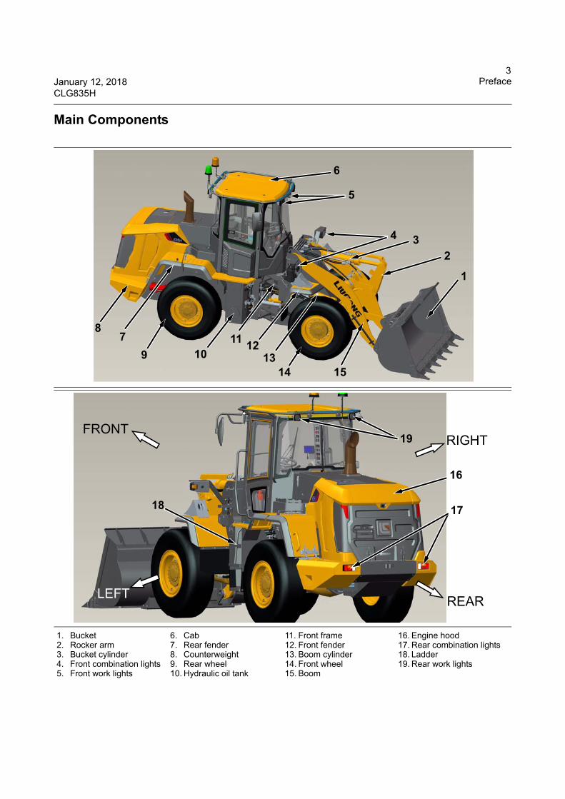
Main Components
1. Bucket2. Rocker arm3. Bucket cylinder4. Front combination lights5. Front work lights
6. Cab7. Rear fender8. Counterweight9. Rear wheel10. Hydraulic oil tank
11. Front frame12. Front fender13. Boom cylinder14. Front wheel15. Boom
16. Engine hood17. Rear combination lights18. Ladder19. Rear work lights
5
6
4 32
1
87
9 1011
1312
1514
19
17
16
FRONT
LEFT
RIGHT
REAR
18
4Preface January 12, 2018
CLG835H
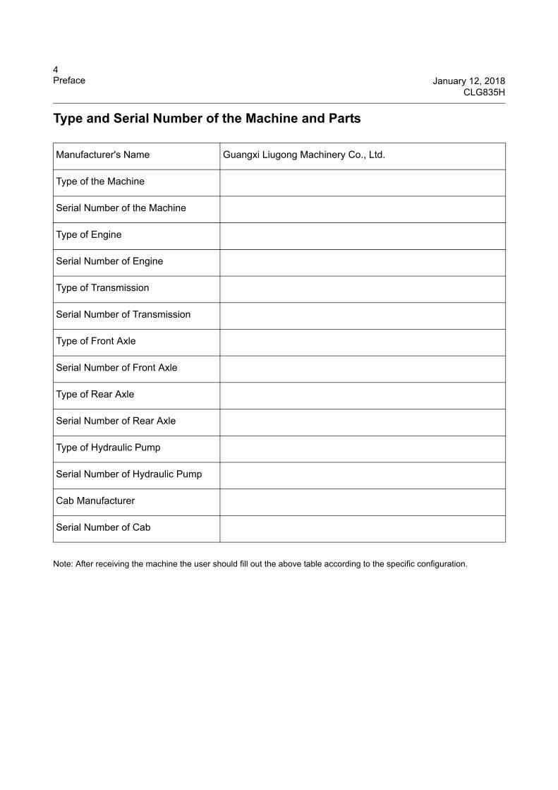
Type and Serial Number of the Machine and Parts
Note: After receiving the machine the user should fill out the above table according to the specific configuration.
Manufacturer's Name Guangxi Liugong Machinery Co., Ltd.
Type of the Machine
Serial Number of the Machine
Type of Engine
Serial Number of Engine
Type of Transmission
Serial Number of Transmission
Type of Front Axle
Serial Number of Front Axle
Type of Rear Axle
Serial Number of Rear Axle
Type of Hydraulic Pump
Serial Number of Hydraulic Pump
Cab Manufacturer
Serial Number of Cab
5January 12, 2018 PrefaceCLG835H
CE Marking, EMC Directive
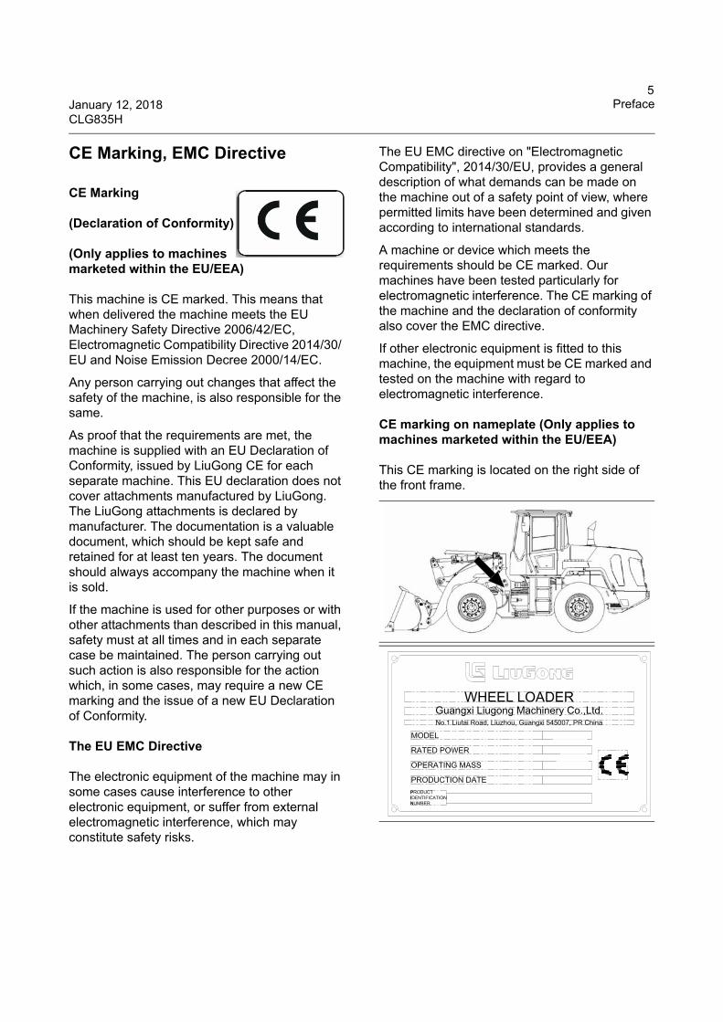
CE Marking
(Declaration of Conformity)
(Only applies to machines marketed within the EU/EEA)
This machine is CE marked. This means that when delivered the machine meets the EU Machinery Safety Directive 2006/42/EC, Electromagnetic Compatibility Directive 2014/30/ EU and Noise Emission Decree 2000/14/EC.
Any person carrying out changes that affect the safety of the machine, is also responsible for the same.
As proof that the requirements are met, the machine is supplied with an EU Declaration of Conformity, issued by LiuGong CE for each separate machine. This EU declaration does not cover attachments manufactured by LiuGong. The LiuGong attachments is declared by manufacturer. The documentation is a valuable document, which should be kept safe and retained for at least ten years. The document should always accompany the machine when it is sold.
If the machine is used for other purposes or with other attachments than described in this manual, safety must at all times and in each separate case be maintained. The person carrying out such action is also responsible for the action which, in some cases, may require a new CE marking and the issue of a new EU Declaration of Conformity.
The EU EMC Directive
The electronic equipment of the machine may in some cases cause interference to other electronic equipment, or suffer from external electromagnetic interference, which may constitute safety risks.
The EU EMC directive on "Electromagnetic Compatibility", 2014/30/EU, provides a general description of what demands can be made on the machine out of a safety point of view, where permitted limits have been determined and given according to international standards.
A machine or device which meets the requirements should be CE marked. Our machines have been tested particularly for electromagnetic interference. The CE marking of the machine and the declaration of conformity also cover the EMC directive.
If other electronic equipment is fitted to this machine, the equipment must be CE marked and tested on the machine with regard to electromagnetic interference.
CE marking on nameplate (Only applies to machines marketed within the EU/EEA)
This CE marking is located on the right side of the front frame.
WHEEL LOADERGuangxi Liugong Machinery Co.,Ltd.No.1 Liutai Road, Liuzhou, Guangxi 545007, PR China
PRODUCTIDENTIFICATIONNUMBER
6Preface January 12, 2018
CLG835H
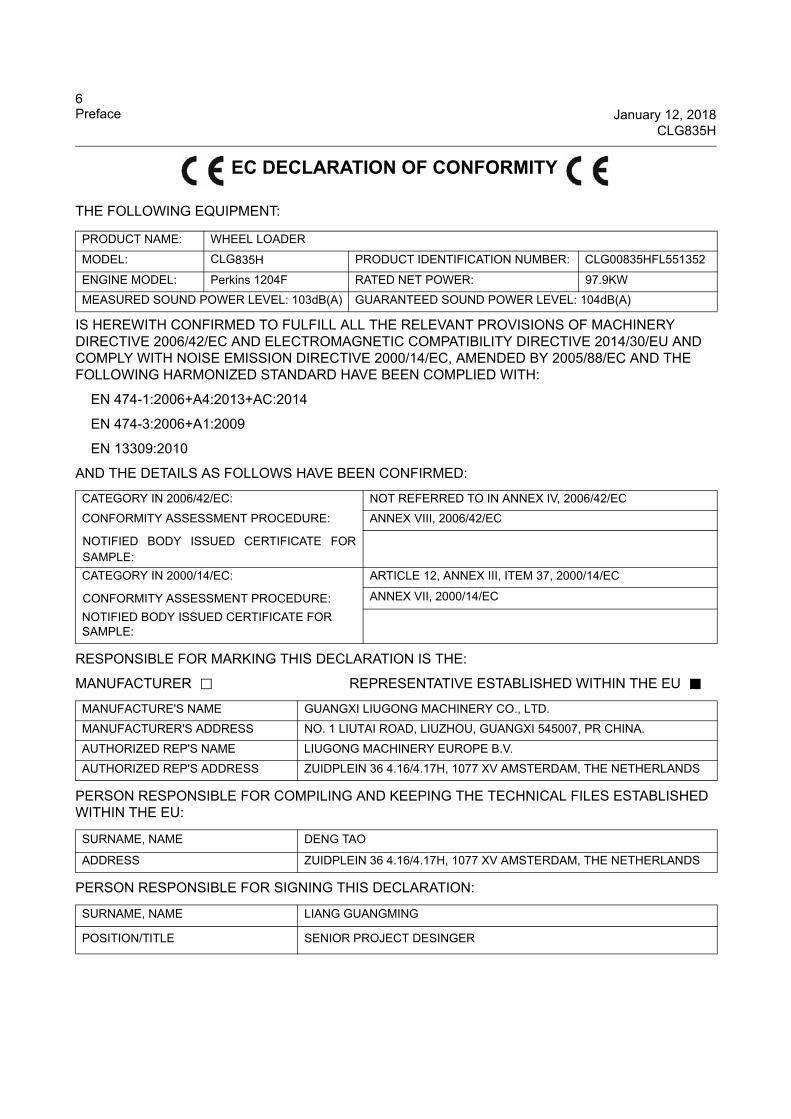
EC DECLARATION OF CONFORMITY
THE FOLLOWING EQUIPMENT:
IS HEREWITH CONFIRMED TO FULFILL ALL THE RELEVANT PROVISIONS OF MACHINERY DIRECTIVE 2006/42/EC AND ELECTROMAGNETIC COMPATIBILITY DIRECTIVE 2014/30/EU AND COMPLY WITH NOISE EMISSION DIRECTIVE 2000/14/EC, AMENDED BY 2005/88/EC AND THE FOLLOWING HARMONIZED STANDARD HAVE BEEN COMPLIED WITH:
EN 474-1:2006+A4:2013+AC:2014
EN 474-3:2006+A1:2009
EN 13309:2010
AND THE DETAILS AS FOLLOWS HAVE BEEN CONFIRMED:
RESPONSIBLE FOR MARKING THIS DECLARATION IS THE:
MANUFACTURER □ REPRESENTATIVE ESTABLISHED WITHIN THE EU ■
PERSON RESPONSIBLE FOR COMPILING AND KEEPING THE TECHNICAL FILES ESTABLISHED WITHIN THE EU:
PERSON RESPONSIBLE FOR SIGNING THIS DECLARATION:
PRODUCT NAME: WHEEL LOADER
MODEL: CLG835H PRODUCT IDENTIFICATION NUMBER: CLG00835HFL551352
ENGINE MODEL: Perkins 1204F RATED NET POWER: 97.9KW
MEASURED SOUND POWER LEVEL: 103dB(A) GUARANTEED SOUND POWER LEVEL: 104dB(A)
CATEGORY IN 2006/42/EC: NOT REFERRED TO IN ANNEX IV, 2006/42/EC
CONFORMITY ASSESSMENT PROCEDURE: ANNEX VIII, 2006/42/EC
NOTIFIED BODY ISSUED CERTIFICATE FOR SAMPLE:
CATEGORY IN 2000/14/EC: ARTICLE 12, ANNEX III, ITEM 37, 2000/14/EC
CONFORMITY ASSESSMENT PROCEDURE: ANNEX VII, 2000/14/EC
NOTIFIED BODY ISSUED CERTIFICATE FOR SAMPLE:
MANUFACTURE'S NAME GUANGXI LIUGONG MACHINERY CO., LTD.
MANUFACTURER'S ADDRESS NO. 1 LIUTAI ROAD, LIUZHOU, GUANGXI 545007, PR CHINA.
AUTHORIZED REP'S NAME LIUGONG MACHINERY EUROPE B.V.
AUTHORIZED REP'S ADDRESS ZUIDPLEIN 36 4.16/4.17H, 1077 XV AMSTERDAM, THE NETHERLANDS
SURNAME, NAME DENG TAO
ADDRESS ZUIDPLEIN 36 4.16/4.17H, 1077 XV AMSTERDAM, THE NETHERLANDS
SURNAME, NAME LIANG GUANGMING
POSITION/TITLE SENIOR PROJECT DESINGER
7January 12, 2018 Safety InformationCLG835H Safety Decals and Decal Locations
Safety Information
Safety Symbol
The symbol for safety alerting appears on machines, safety signs, manuals or for important safety information at other places. When you see this
symbol, you should follow the instructions in the safety information, guarding against any possibility of personal injuries or death.
Safety Signs
Definitions of the safety signs with the words "Danger", "Warning" and "Caution" which appear in this manual and on the machine are as follows:
● Danger: this word denotes an impending danger, failure to observe instructions could result in death or serious injuries.
● Warning: this word denotes potential danger, failure to observe instructions could result in death or serious injuries.
● Caution: this word denotes potential danger, failure to observe instructions could result in minor to medium degree of injury.
"Caution" is also used to indicate safety information relating to unsafe operations which may cause personal injuries. "Danger" represents the most dangerous conditions. The safety signs "Danger" or "Warning" are placed near particular dangerous places. General notice information is placed on the safety sign "Caution."
Safety Decals and Decal Locations
There are several specific safety decals on your machine. The exact location of and description of the hazards are reviewed in this section. Take time to read, understand and familiarize yourself with each and every one of these safety decals.
Make sure that you can read all safety decals. Clean or replace if you cannot read the words or see the pictures. When cleaning the decals use a cloth, water and soap. Do not use solvent, gasoline, or other harsh chemicals to clean the safety decals. Solvents, gasoline or harsh chemicals could loosen the adhesive backing of decals causing them to fall off the machine.
You must replace a decal if it is damaged, missing or cannot be read. If a decal is on a part that is replaced, make sure a new decal is installed on the replacement part. Pay attention to the instructional and safety decals located in the cab before starting.
8Safety Information January 12, 2018Safety Decals and Decal Locations CLG835H
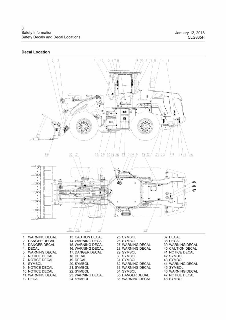
Decal Location
1. WARNING DECAL2. DANGER DECAL3. DANGER DECAL4. DECAL5. WARNING DECAL6. NOTICE DECAL7. NOTICE DECAL8. SYMBOL9. NOTICE DECAL10. NOTICE DECAL11. WARNING DECAL12. DECAL
13. CAUTION DECAL14. WARNING DECAL15. WARNING DECAL16. WARNING DECAL17. DANGER DECAL18. DECAL19. DECAL20. SYMBOL21. SYMBOL22. SYMBOL23. WARNING DECAL24. SYMBOL
25. SYMBOL26. SYMBOL27. WARNING DECAL28. WARNING DECAL29. SYMBOL30. SYMBOL31. SYMBOL32. WARNING DECAL33. WARNING DECAL34. SYMBOL35. DANGER DECAL36. WARNING DECAL
37. DECAL38. DECAL39. WARNING DECAL40. CAUTION DECAL41. NOTICE DECAL42. SYMBOL43. SYMBOL44. WARNING DECAL45. SYMBOL46. WARNING DECAL47. NOTICE DECAL48. SYMBOL
454647
9January 12, 2018 Safety InformationCLG835H Safety Decals and Decal Locations
Decal Location
1. WARNING DECAL2. DANGER DECAL3. DANGER DECAL4. DECAL5. WARNING DECAL6. NOTICE DECAL7. NOTICE DECAL8. SYMBOL9. NOTICE DECAL10. NOTICE DECAL11. WARNING DECAL12. DECAL
13. CAUTION DECAL14. WARNING DECAL15. WARNING DECAL16. WARNING DECAL17. DANGER DECAL18. DECAL19. DECAL20. SYMBOL21. SYMBOL22. SYMBOL23. WARNING DECAL24. SYMBOL
25. SYMBOL26. SYMBOL27. WARNING DECAL28. WARNING DECAL29. SYMBOL30. SYMBOL31. SYMBOL32. WARNING DECAL33. WARNING DECAL34. SYMBOL35. DANGER DECAL36. WARNING DECAL
37. DECAL38. DECAL39. WARNING DECAL40. CAUTION DECAL41. NOTICE DECAL42. SYMBOL43. SYMBOL44. WARNING DECAL45. SYMBOL46. WARNING DECAL47. NOTICE DECAL48. SYMBOL
10Safety Information January 12, 2018Safety Decals and Decal Locations CLG835H
Decal Information
Fig.1 WARNING DECAL
(Located near the crush area)
CRUSH HAZARD. Keep clear.
74A3167
Fig. 2 DANGER DECAL
(Located on the arm)
CRUSH HAZARD. Keep away from raised loader arm or bucket.
74A3153
Fig. 3 DANGER DECAL
(Located on the arm or arm cylinder)
CRUSH HAZARD. Install arm support before maintenance or repair with loader arm raised.
74A3165
11January 12, 2018 Safety InformationCLG835H Safety Decals and Decal Locations
Fig. 5 WARNING DECAL
(Located in the cab)
Read and understand Operation and Maintenance Manual before operating or performing maintenance on this machine, death or serious injury could result. It is your responsibility to be aware of and follow all local laws and regulations. Operate only from operator’s seat. Do not carry riders on machine. Before starting machine, make sure hydraulic control lever is in lockout position and all control levers are in neutral. Sound horn to alert people. Ensure bystanders and obstacles are clear of machine before moving machine or its attachment. Before leaving operator’s compartment, park on level ground, lower attachmentsto ground, make sure hydraulic control lever is in lockout position. All control levers are in neutral. Engage parking brake. Never operate machine downhill with stalled engine and gear in neutral. Avoid contacting overhead obstacles when operating or hauling machine. 74A4777
Decal Information
12Safety Information January 12, 2018Safety Decals and Decal Locations CLG835H
Fig. 6 NOTICE DECAL
(Located in the cab)
DW-3 shifting lever plus FNR switch operating instruction:
To Start Machine:
1. Apply parking brake
2. Move DWG-3 shifting lever on steering column to “N”position
3. Press the “N” button on the FNR switch
4. Turn key to “on” position
5. Turn key switch to “start” position
To move machine with DW-3:
1. Keep FNR switch in “N” position
2. Apply service brake and hold
3. Release parking brake(P)
4. Move the DW-3 shifting lever to “↑”or” ↓ ” position as desired
5. Release service brake and press accelerator
To move machine with FNR switch:
1. Keep DW-3 shifting lever in “N2” position
2. Keep FNR switch in “N” position
3. Apply service brake and hold
4. Release parking brake(P)
5. Move the FNR switch to “F” or “R” position as desired
6. Release service brake and press accelerator
Notice:
1. Only the DWG-3 shifting lever is in “N2” position, the FNR switch can be used normally
2. DW-3 shifting lever has absolute priority. 74A6093
Decal Information
13January 12, 2018 Safety InformationCLG835H Safety Decals and Decal Locations
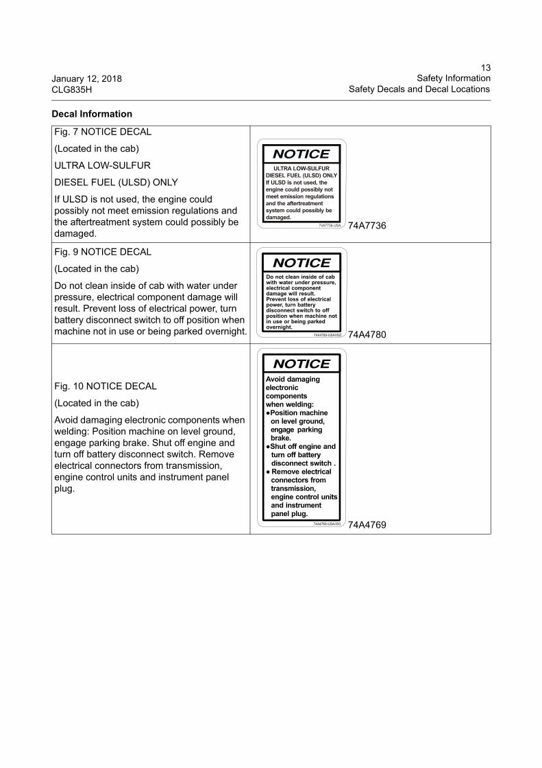
Fig. 7 NOTICE DECAL
(Located in the cab)
ULTRA LOW-SULFUR
DIESEL FUEL (ULSD) ONLY
If ULSD is not used, the engine could possibly not meet emission regulations and the aftertreatment system could possibly be damaged.
74A7736
Fig. 9 NOTICE DECAL
(Located in the cab)
Do not clean inside of cab with water under pressure, electrical component damage will result. Prevent loss of electrical power, turn battery disconnect switch to off position when machine not in use or being parked overnight. 74A4780
Fig. 10 NOTICE DECAL
(Located in the cab)
Avoid damaging electronic components when welding: Position machine on level ground, engage parking brake. Shut off engine and turn off battery disconnect switch. Remove electrical connectors from transmission, engine control units and instrument panel plug.
74A4769
Decal Information
14Safety Information January 12, 2018Safety Decals and Decal Locations CLG835H
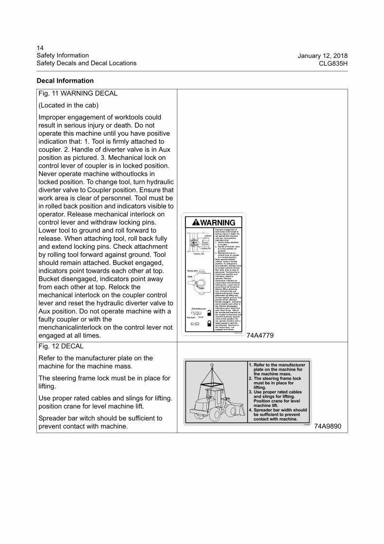
Fig. 11 WARNING DECAL
(Located in the cab)
Improper engagement of worktools could result in serious injury or death. Do not operate this machine until you have positive indication that: 1. Tool is firmly attached to coupler. 2. Handle of diverter valve is in Aux position as pictured. 3. Mechanical lock on control lever of coupler is in locked position. Never operate machine withoutlocks in locked position. To change tool, turn hydraulic diverter valve to Coupler position. Ensure that work area is clear of personnel. Tool must be in rolled back position and indicators visible to operator. Release mechanical interlock on control lever and withdraw locking pins. Lower tool to ground and roll forward to release. When attaching tool, roll back fully and extend locking pins. Check attachment by rolling tool forward against ground. Tool should remain attached. Bucket engaged, indicators point towards each other at top. Bucket disengaged, indicators point away from each other at top. Relock the mechanical interlock on the coupler control lever and reset the hydraulic diverter valve to Aux position. Do not operate machine with a faulty coupler or with the menchanicalinterlock on the control lever not engaged at all times. 74A4779
Fig. 12 DECAL
Refer to the manufacturer plate on the machine for the machine mass.
The steering frame lock must be in place for lifting.
Use proper rated cables and slings for lifting. position crane for level machine lift.
Spreader bar witch should be sufficient to prevent contact with machine. 74A9890
Decal Information
15January 12, 2018 Safety InformationCLG835H Safety Decals and Decal Locations
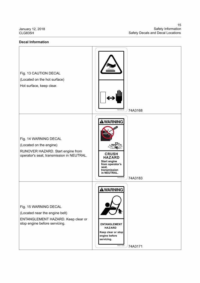
Fig. 13 CAUTION DECAL
(Located on the hot surface)
Hot surface, keep clear.
74A3168
Fig. 14 WARNING DECAL
(Located on the engine)
RUNOVER HAZARD. Start engine from operator's seat, transmission in NEUTRAL.
74A3183
Fig. 15 WARNING DECAL
(Located near the engine belt)
ENTANGLEMENT HAZARD. Keep clear or stop engine before servicing.
74A3171
Decal Information
16Safety Information January 12, 2018Safety Decals and Decal Locations CLG835H
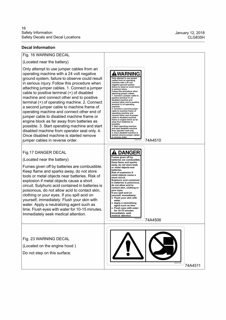
Fig. 16 WARNING DECAL
(Located near the battery)
Only attempt to use jumper cables from an operating machine with a 24 volt negative ground system, failure to observe could result in serious injury. Follow this procedure when attaching jumper cables. 1. Connect a jumper cable to positive terminal (+) of disabled machine and connect other end to positive terminal (+) of operating machine. 2. Connect a second jumper cable to machine frame of operating machine and connect other end of jumper cable to disabled machine frame or engine block as far away from batteries as possible. 3. Start operating machine and start disabled machine from operator seat only. 4. Once disabled machine is started remove jumper cables in reverse order. 74A4510
Fig.17 DANGER DECAL
(Located near the battery)
Fumes given off by batteries are combustible. Keep flame and sparks away, do not store tools or metal objects near batteries. Risk of explosion if metal objects cause a short circuit. Sulphuric acid contained in batteries is poisonous, do not allow acid to contact skin, clothing or your eyes. If you spill acid on yourself, immediately: Flush your skin with water. Apply a neutralizing agent such as lime. Flush eyes with water for 10-15 minutes. Immediately seek medical attention.
74A4506
Fig. 23 WARNING DECAL
(Located on the engine hood )
Do not step on this surface.
74A4511
Decal Information
17January 12, 2018 Safety InformationCLG835H Safety Decals and Decal Locations
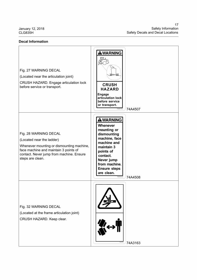
Fig. 27 WARNING DECAL
(Located near the articulation joint)
CRUSH HAZARD. Engage articulation lock before service or transport.
74A4507
Fig. 28 WARNING DECAL
(Located near the ladder)
Whenever mounting or dismounting machine, face machine and maintain 3 points of contact. Never jump from machine. Ensure steps are clean.
74A4508
Fig. 32 WARNING DECAL
(Located at the frame articulation joint)
CRUSH HAZARD. Keep clear.
74A3163
Decal Information
18Safety Information January 12, 2018Safety Decals and Decal Locations CLG835H
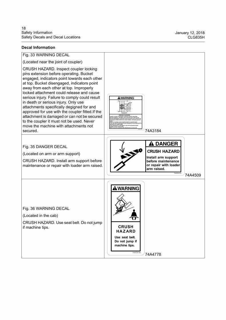
Fig. 33 WARNING DECAL
(Located near the joint of coupler)
CRUSH HAZARD. Inspect coupler locking pins extension before operating. Bucket engaged, indicators point towards each other at top. Bucket disengaged, indicators point away from each other at top. Improperly locked attachment could release and cause serious injury. Failure to comply could result in death or serious injury. Only use attachments specifically degigned for and approved for use with the coupler fitted.If the attachment is damaged or can not be secured to the coupler it must not be used. Never move the machine with attachments not secured. 74A3184
Fig. 35 DANGER DECAL
(Located on arm or arm support)
CRUSH HAZARD. Install arm support before maintenance or repair with loader arm raised.
74A4509
Fig. 36 WARNING DECAL
(Located in the cab)
CRUSH HAZARD. Use seat belt. Do not jump if machine tips.
74A4778
Decal Information
19January 12, 2018 Safety InformationCLG835H Safety Decals and Decal Locations
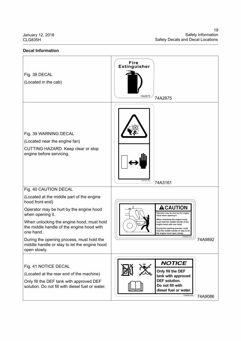
Fig. 38 DECAL
(Located in the cab)
74A2875
Fig. 39 WARNING DECAL
(Located near the engine fan)
CUTTING HAZARD. Keep clear or stop engine before servicing.
74A3161
Fig. 40 CAUTION DECAL
(Located at the middle part of the engine hood front end)
Operator may be hurt by the engine hood when opening it.
When unlocking the engine hood, must hold the middle handle of the engine hood with one hand.
During the opening process, must hold the middle handle or stay to let the engine hood open slowly.
74A9892
Fig. 41 NOTICE DECAL
(Located at the rear end of the machine)
Only fill the DEF tank with approved DEF solution. Do not fill with diesel fuel or water.
74A9086
Decal Information
20Safety Information January 12, 2018Safety Decals and Decal Locations CLG835H
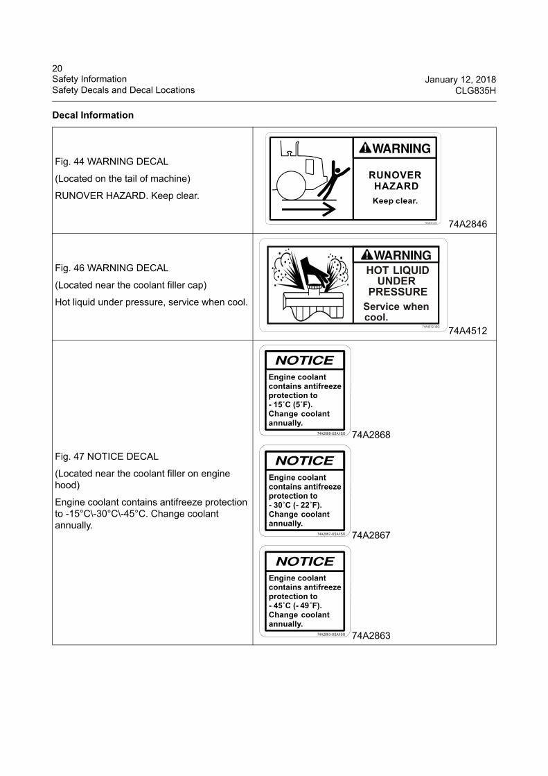
Fig. 44 WARNING DECAL
(Located on the tail of machine)
RUNOVER HAZARD. Keep clear.
74A2846
Fig. 46 WARNING DECAL
(Located near the coolant filler cap)
Hot liquid under pressure, service when cool.
74A4512
Fig. 47 NOTICE DECAL
(Located near the coolant filler on engine hood)
Engine coolant contains antifreeze protection to -15°C\-30°C\-45°C. Change coolant annually.
74A2868
74A2867
74A2863
Decal Information
21January 12, 2018 Safety InformationCLG835H General Hazard Information
General Hazard Information
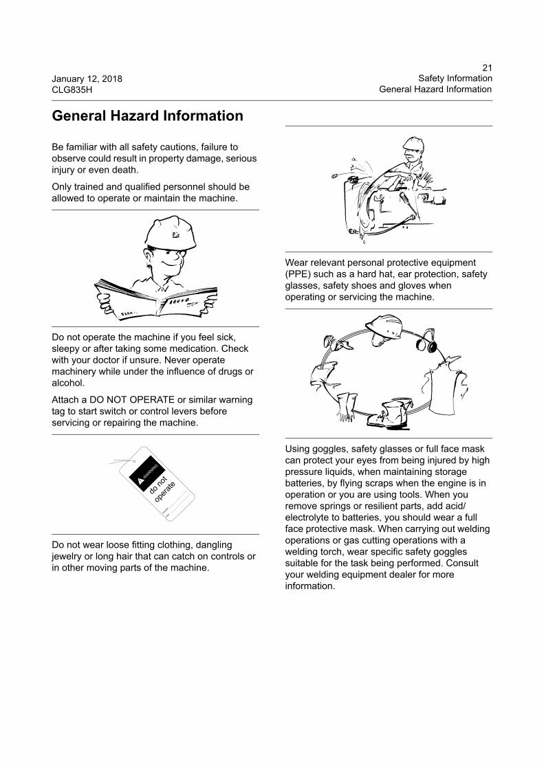
Be familiar with all safety cautions, failure to observe could result in property damage, serious injury or even death.
Only trained and qualified personnel should be allowed to operate or maintain the machine.
Do not operate the machine if you feel sick, sleepy or after taking some medication. Check with your doctor if unsure. Never operate machinery while under the influence of drugs or alcohol.
Attach a DO NOT OPERATE or similar warning tag to start switch or control levers before servicing or repairing the machine.
Do not wear loose fitting clothing, dangling jewelry or long hair that can catch on controls or in other moving parts of the machine.
Wear relevant personal protective equipment (PPE) such as a hard hat, ear protection, safety glasses, safety shoes and gloves when operating or servicing the machine.
Using goggles, safety glasses or full face mask can protect your eyes from being injured by high pressure liquids, when maintaining storage batteries, by flying scraps when the engine is in operation or you are using tools. When you remove springs or resilient parts, add acid/electrolyte to batteries, you should wear a full face protective mask. When carrying out welding operations or gas cutting operations with a welding torch, wear specific safety goggles suitable for the task being performed. Consult your welding equipment dealer for more information.
do
not
oper
ate
Opera
ter:
Date:
WARNIN
G
!
22Safety Information January 12, 2018General Hazard Information CLG835H
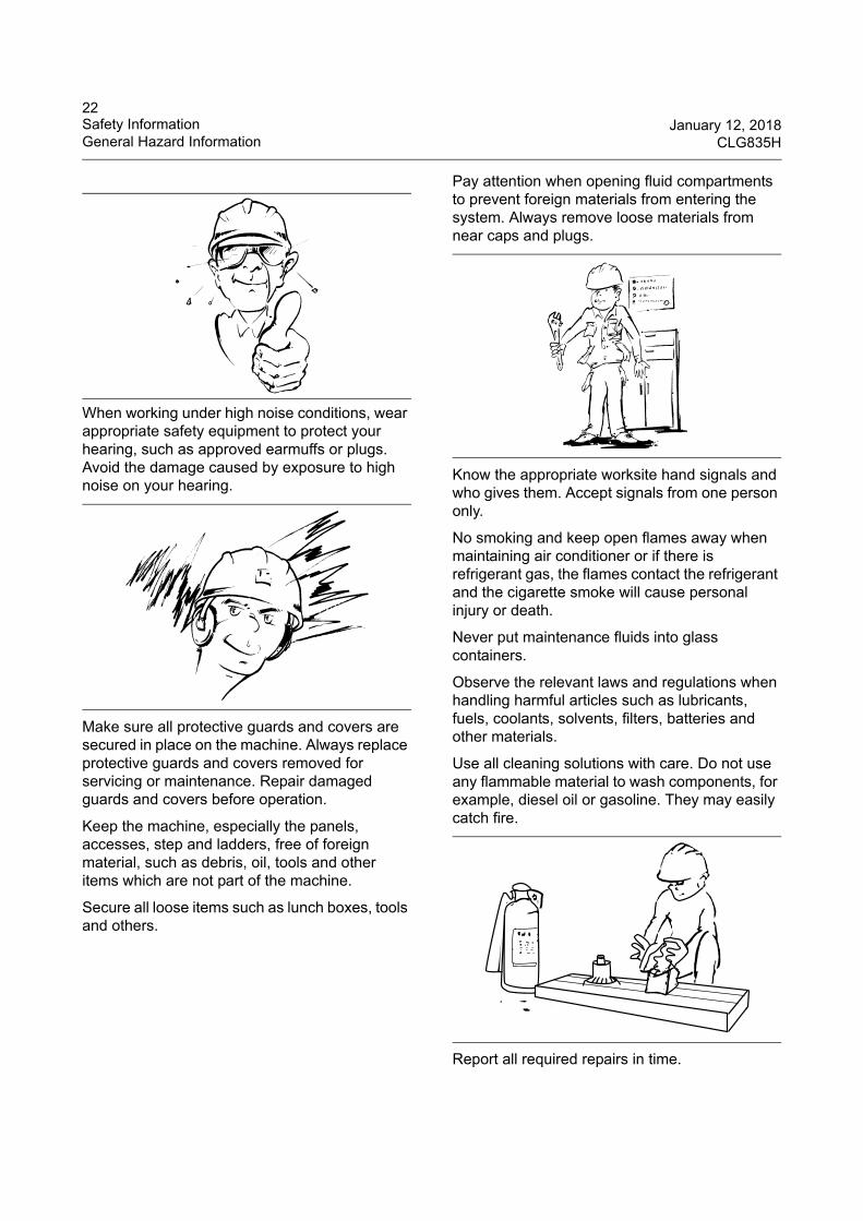
When working under high noise conditions, wear appropriate safety equipment to protect your hearing, such as approved earmuffs or plugs. Avoid the damage caused by exposure to high noise on your hearing.
Make sure all protective guards and covers are secured in place on the machine. Always replace protective guards and covers removed for servicing or maintenance. Repair damaged guards and covers before operation.
Keep the machine, especially the panels, accesses, step and ladders, free of foreign material, such as debris, oil, tools and other items which are not part of the machine.
Secure all loose items such as lunch boxes, tools and others.
Pay attention when opening fluid compartments to prevent foreign materials from entering the system. Always remove loose materials from near caps and plugs.
Know the appropriate worksite hand signals and who gives them. Accept signals from one person only.
No smoking and keep open flames away when maintaining air conditioner or if there is refrigerant gas, the flames contact the refrigerant and the cigarette smoke will cause personal injury or death.
Never put maintenance fluids into glass containers.
Observe the relevant laws and regulations when handling harmful articles such as lubricants, fuels, coolants, solvents, filters, batteries and other materials.
Use all cleaning solutions with care. Do not use any flammable material to wash components, for example, diesel oil or gasoline. They may easily catch fire.
Report all required repairs in time.
23January 12, 2018 Safety InformationCLG835H General Hazard Information
Do not allow unauthorized personnel on or around the machine.
Guangxi Liugong bears no responsibility for failures caused by modifications to machine structure without Liugong’s permission.
Compressed Air
Compressed air can cause personal injury. When using compressed air for cleaning, wear a protective face shield, protective clothing, hearing protection and protective shoes. Never aim compressed air at yourself or others. Compressed air could penetrate your skin and cause serious injury or death. The maximum air pressure used should not exceed 25psi (0.2Mpa).
High-pressure Fluid
Use caution before disconnecting hydraulic lines or connectors. High pressure oil that is released can cause a hose to whip.
Always support attachments and release residual pressure before attempting to disconnect hydraulic lines. Pressure applied by loads on attachments could cause hydraulic oil to spray when lines are removed.
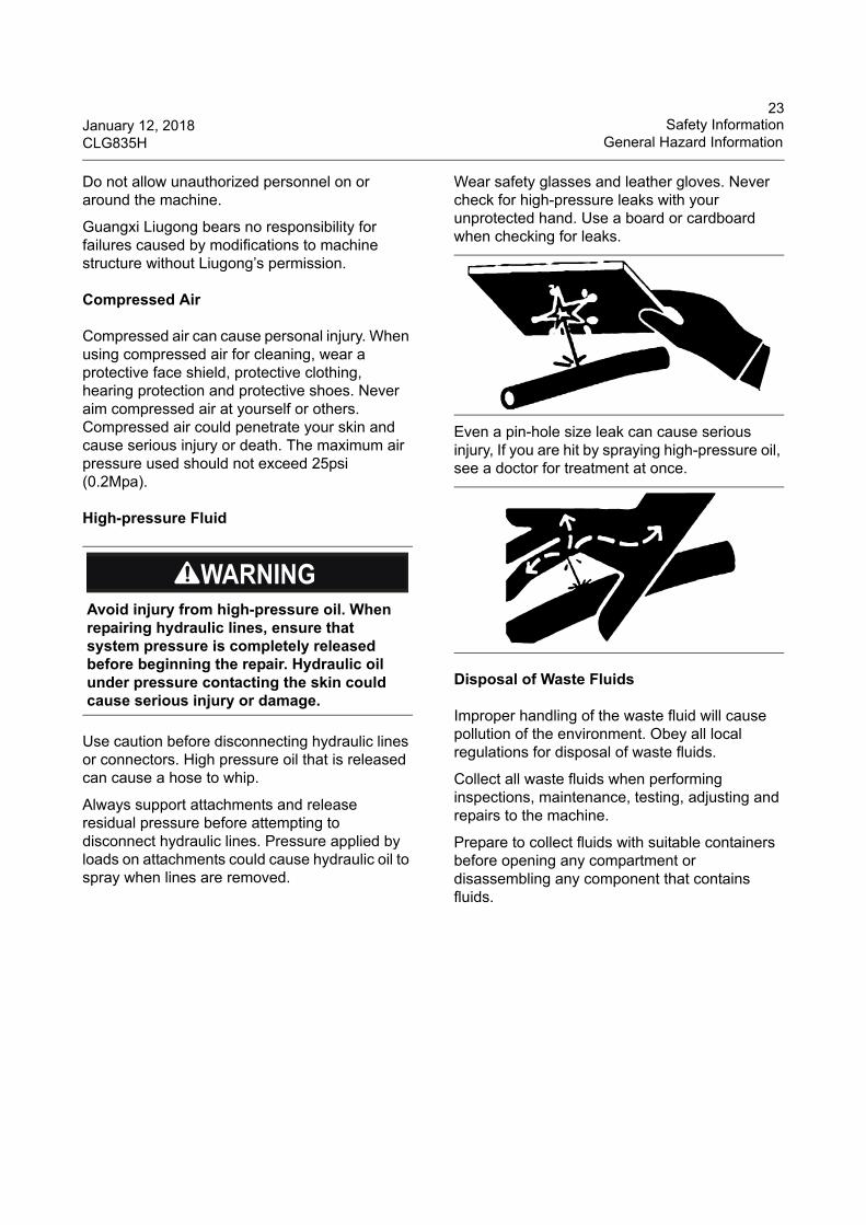
Wear safety glasses and leather gloves. Never check for high-pressure leaks with your unprotected hand. Use a board or cardboard when checking for leaks.
Even a pin-hole size leak can cause serious injury, If you are hit by spraying high-pressure oil, see a doctor for treatment at once.
Disposal of Waste Fluids
Improper handling of the waste fluid will cause pollution of the environment. Obey all local regulations for disposal of waste fluids.
Collect all waste fluids when performing inspections, maintenance, testing, adjusting and repairs to the machine.
Prepare to collect fluids with suitable containers before opening any compartment or disassembling any component that contains fluids.
Avoid injury from high-pressure oil. When repairing hydraulic lines, ensure that system pressure is completely released before beginning the repair. Hydraulic oil under pressure contacting the skin could cause serious injury or damage.
24Safety Information January 12, 2018General Hazard Information CLG835H
Use suitable containers to collect waste fluids. Do not use food containers or beverage bottles as they could mislead people to drink the contents.
Cautions about Accumulators
High-pressure nitrogen is contained in the accumulators making them dangerous articles. Read the following requirements and pay attention to the proper use of accumulators.
Check accumulators before charging with nitrogen. Safe use cannot be guaranteed if there is not a nameplate attached to the accumulator. Never charge accumulators that have an incomplete nameplate or that are of an unidentified type.
Accumulators are charged with nitrogen. The use of oxygen, compressed air or other flammable air in the accumulator could cause an explosion and possible injury, death and damage to the machine.
When charging accumulators with nitrogen, care should be taken not to damage the diaphragm.
The accumulator's valve should be installed facing vertically upward. Do not attempt to fix accumulators by welding them.
Do not drill any hole in the accumulator or close a hole by welding.
Do not weld a boss on the accumulator.
Accumulators are high-pressure vessels and should be repaired only by trained specialized personnel.
Always release pressure in the accumulator before disposing of it.
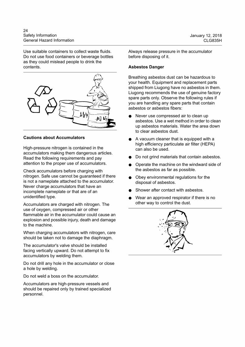
Asbestos Danger
Breathing asbestos dust can be hazardous to your health. Equipment and replacement parts shipped from Liugong have no asbestos in them. Liugong recommends the use of genuine factory spare parts only. Observe the following rules if you are handling any spare parts that contain asbestos or asbestos fibers:
● Never use compressed air to clean up asbestos. Use a wet method in order to clean up asbestos materials. Water the area down to clear asbestos dust.
● A vacuum cleaner that is equipped with a high efficiency particulate air filter (HEPA) can also be used.
● Do not grind materials that contain asbestos.
● Operate the machine on the windward side of the asbestos as far as possible.
● Obey environmental regulations for the disposal of asbestos.
● Shower after contact with asbestos.
● Wear an approved respirator if there is no other way to control the dust.
25January 12, 2018 Safety InformationCLG835H Crushing and Cutting Prevention
Crushing and Cutting Prevention
Don't put hands, arms, or any other parts of the body in the way of removable parts.
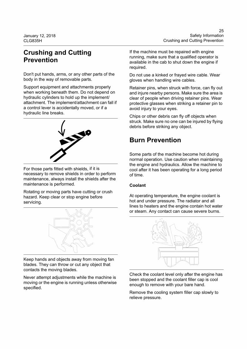
Support equipment and attachments properly when working beneath them. Do not depend on hydraulic cylinders to hold up the implement/attachment. The implement/attachment can fall if a control lever is accidentally moved, or if a hydraulic line breaks.
For those parts fitted with shields, if it is necessary to remove shields in order to perform maintenance, always install the shields after the maintenance is performed.
Rotating or moving parts have cutting or crush hazard. Keep clear or stop engine before servicing.
Keep hands and objects away from moving fan blades. They can throw or cut any object that contacts the moving blades.
Never attempt adjustments while the machine is moving or the engine is running unless otherwise specified.
If the machine must be repaired with engine running, make sure that a qualified operator is available in the cab to shut down the engine if required.
Do not use a kinked or frayed wire cable. Wear gloves when handling wire cables.
Retainer pins, when struck with force, can fly out and injure nearby persons. Make sure the area is clear of people when driving retainer pins. Wear protective glasses when striking a retainer pin to avoid injury to your eyes.
Chips or other debris can fly off objects when struck. Make sure no one can be injured by flying debris before striking any object.
Burn Prevention
Some parts of the machine become hot during normal operation. Use caution when maintaining the engine and hydraulics. Allow the machine to cool after it has been operating for a long period of time.
Coolant
At operating temperature, the engine coolant is hot and under pressure. The radiator and all lines to heaters and the engine contain hot water or steam. Any contact can cause severe burns.
Check the coolant level only after the engine has been stopped and the coolant filler cap is cool enough to remove with your bare hand.
Remove the cooling system filler cap slowly to relieve pressure.
26Safety Information January 12, 2018Fire & Explosion Prevention CLG835H
Coolant contains alkali that can cause personal injury. Avoid contact with the skin, eyes and mouth.
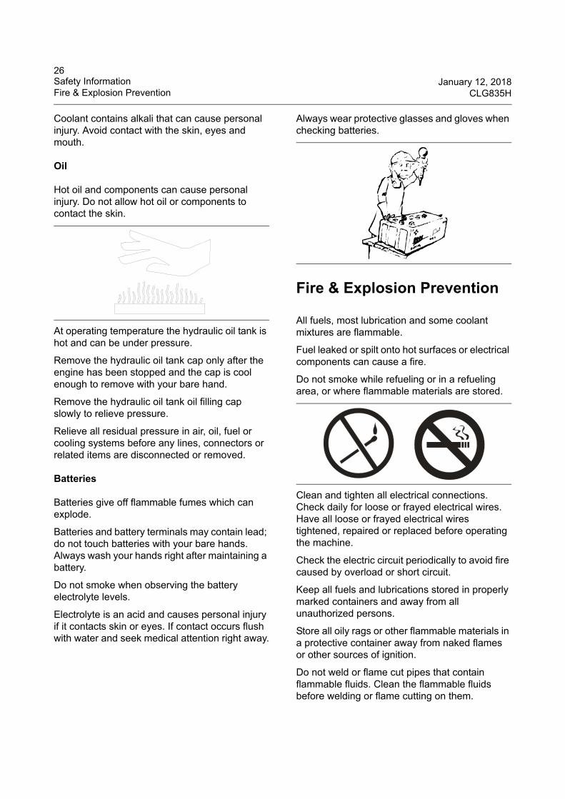
Oil
Hot oil and components can cause personal injury. Do not allow hot oil or components to contact the skin.
At operating temperature the hydraulic oil tank is hot and can be under pressure.
Remove the hydraulic oil tank cap only after the engine has been stopped and the cap is cool enough to remove with your bare hand.
Remove the hydraulic oil tank oil filling cap slowly to relieve pressure.
Relieve all residual pressure in air, oil, fuel or cooling systems before any lines, connectors or related items are disconnected or removed.
Batteries
Batteries give off flammable fumes which can explode.
Batteries and battery terminals may contain lead; do not touch batteries with your bare hands. Always wash your hands right after maintaining a battery.
Do not smoke when observing the battery electrolyte levels.
Electrolyte is an acid and causes personal injury if it contacts skin or eyes. If contact occurs flush with water and seek medical attention right away.
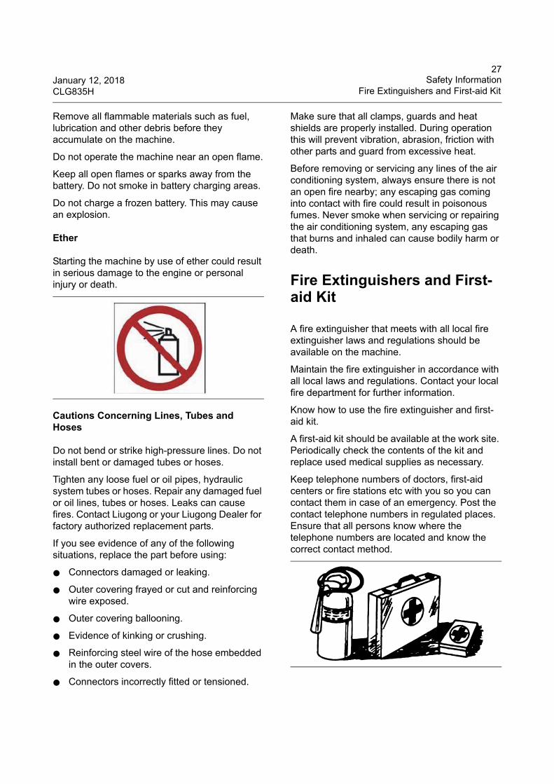
Always wear protective glasses and gloves when checking batteries.
Fire & Explosion Prevention
All fuels, most lubrication and some coolant mixtures are flammable.
Fuel leaked or spilt onto hot surfaces or electrical components can cause a fire.
Do not smoke while refueling or in a refueling area, or where flammable materials are stored.
Clean and tighten all electrical connections. Check daily for loose or frayed electrical wires. Have all loose or frayed electrical wires tightened, repaired or replaced before operating the machine.
Check the electric circuit periodically to avoid fire caused by overload or short circuit.
Keep all fuels and lubrications stored in properly marked containers and away from all unauthorized persons.
Store all oily rags or other flammable materials in a protective container away from naked flames or other sources of ignition.
Do not weld or flame cut pipes that contain flammable fluids. Clean the flammable fluids before welding or flame cutting on them.
27January 12, 2018 Safety InformationCLG835H Fire Extinguishers and First-aid Kit
Remove all flammable materials such as fuel, lubrication and other debris before they accumulate on the machine.
Do not operate the machine near an open flame.
Keep all open flames or sparks away from the battery. Do not smoke in battery charging areas.
Do not charge a frozen battery. This may cause an explosion.
Ether
Starting the machine by use of ether could result in serious damage to the engine or personal injury or death.
Cautions Concerning Lines, Tubes and Hoses
Do not bend or strike high-pressure lines. Do not install bent or damaged tubes or hoses.
Tighten any loose fuel or oil pipes, hydraulic system tubes or hoses. Repair any damaged fuel or oil lines, tubes or hoses. Leaks can cause fires. Contact Liugong or your Liugong Dealer for factory authorized replacement parts.
If you see evidence of any of the following situations, replace the part before using:
● Connectors damaged or leaking.
● Outer covering frayed or cut and reinforcing wire exposed.
● Outer covering ballooning.
● Evidence of kinking or crushing.
● Reinforcing steel wire of the hose embedded in the outer covers.
● Connectors incorrectly fitted or tensioned.
Make sure that all clamps, guards and heat shields are properly installed. During operation this will prevent vibration, abrasion, friction with other parts and guard from excessive heat.
Before removing or servicing any lines of the air conditioning system, always ensure there is not an open fire nearby; any escaping gas coming into contact with fire could result in poisonous fumes. Never smoke when servicing or repairing the air conditioning system, any escaping gas that burns and inhaled can cause bodily harm or death.
Fire Extinguishers and First-aid Kit
A fire extinguisher that meets with all local fire extinguisher laws and regulations should be available on the machine.
Maintain the fire extinguisher in accordance with all local laws and regulations. Contact your local fire department for further information.
Know how to use the fire extinguisher and first-aid kit.
A first-aid kit should be available at the work site. Periodically check the contents of the kit and replace used medical supplies as necessary.
Keep telephone numbers of doctors, first-aid centers or fire stations etc with you so you can contact them in case of an emergency. Post the contact telephone numbers in regulated places. Ensure that all persons know where the telephone numbers are located and know the correct contact method.
28Safety Information January 12, 2018Electrical Storm Injury Prevention CLG835H
Inspect and service the fire extinguisher regularly. Obey the recommendations on the instruction plate and all local laws and regulations relating to fire extinguishers.
Electrical Storm Injury Prevention
When lightning is striking in the vicinity of the machine, the operator should never attempt to mount and dismount the machine.
If you are in the cab during an electrical storm, stay in the cab. If you are on the ground during an electrical storm, stay away from the machine.
Tire Explosion Prevention
Maintenance, removal, repair and installation of the tires and wheel rims must be performed with special equipment and a trained repairer. Therefore, it is better to repair and maintain the tires in a tire service shop.
Explosions of tires have resulted from gas heat-induced and combustion inside the tires. Explosions can be caused by heat that is generated by welding, by heating rim components, by external fire, or by excessive use of brakes.
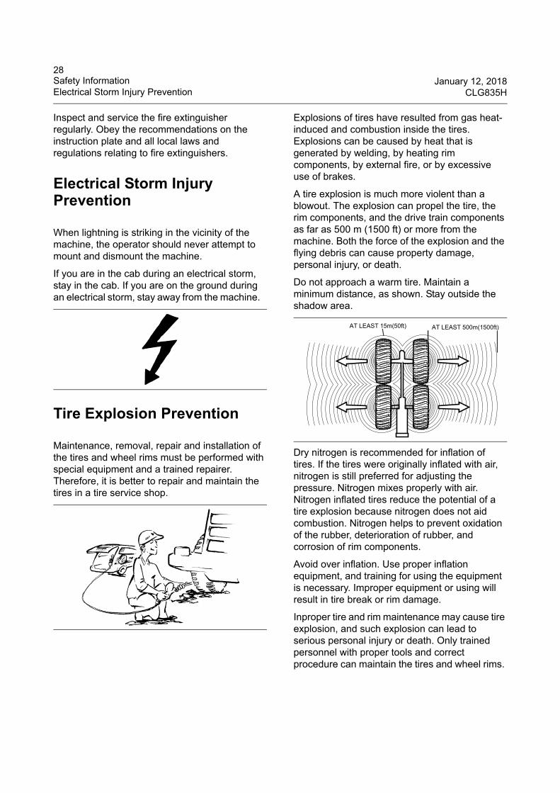
A tire explosion is much more violent than a blowout. The explosion can propel the tire, the rim components, and the drive train components as far as 500 m (1500 ft) or more from the machine. Both the force of the explosion and the flying debris can cause property damage, personal injury, or death.
Do not approach a warm tire. Maintain a minimum distance, as shown. Stay outside the shadow area.
Dry nitrogen is recommended for inflation of tires. If the tires were originally inflated with air, nitrogen is still preferred for adjusting the pressure. Nitrogen mixes properly with air. Nitrogen inflated tires reduce the potential of a tire explosion because nitrogen does not aid combustion. Nitrogen helps to prevent oxidation of the rubber, deterioration of rubber, and corrosion of rim components.
Avoid over inflation. Use proper inflation equipment, and training for using the equipment is necessary. Improper equipment or using will result in tire break or rim damage.
Inproper tire and rim maintenance may cause tire explosion, and such explosion can lead to serious personal injury or death. Only trained personnel with proper tools and correct procedure can maintain the tires and wheel rims.
AT LEAST 500m(1500ft)AT LEAST 15m(50ft)
29January 12, 2018 Safety InformationCLG835H ROPS/FOPS
ROPS/FOPS
ROPS/FOPS of Guangxi LiuGong Machinery Co., Ltd are located above the operator's compartment and secured to the machine.
The strength of the structure will be reduced if it is damaged due to a rollover. ROPS are certified structures and cannot be repaired. Any damage to the ROPS structure will require replacement of the structure to retain the certification.
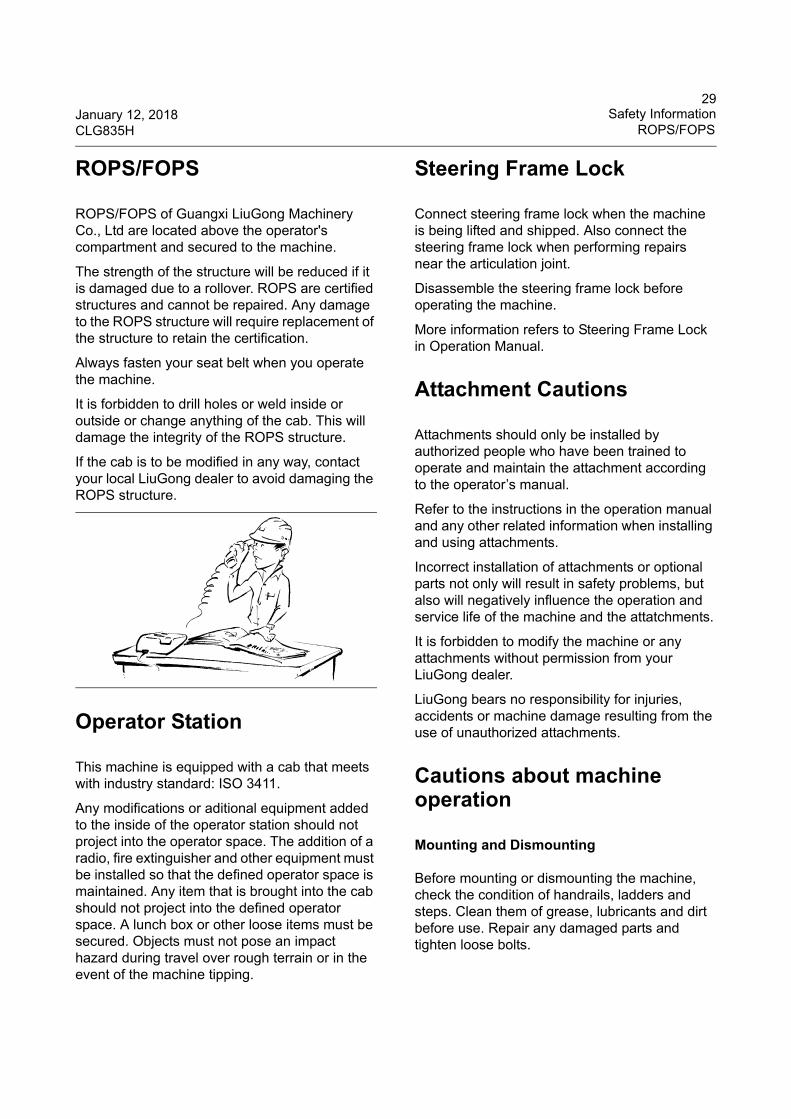
Always fasten your seat belt when you operate the machine.
It is forbidden to drill holes or weld inside or outside or change anything of the cab. This will damage the integrity of the ROPS structure.
If the cab is to be modified in any way, contact your local LiuGong dealer to avoid damaging the ROPS structure.
Operator Station
This machine is equipped with a cab that meets with industry standard: ISO 3411.
Any modifications or aditional equipment added to the inside of the operator station should not project into the operator space. The addition of a radio, fire extinguisher and other equipment must be installed so that the defined operator space is maintained. Any item that is brought into the cab should not project into the defined operator space. A lunch box or other loose items must be secured. Objects must not pose an impact hazard during travel over rough terrain or in the event of the machine tipping.
Steering Frame Lock
Connect steering frame lock when the machine is being lifted and shipped. Also connect the steering frame lock when performing repairs near the articulation joint.
Disassemble the steering frame lock before operating the machine.
More information refers to Steering Frame Lock in Operation Manual.
Attachment Cautions
Attachments should only be installed by authorized people who have been trained to operate and maintain the attachment according to the operator’s manual.
Refer to the instructions in the operation manual and any other related information when installing and using attachments.
Incorrect installation of attachments or optional parts not only will result in safety problems, but also will negatively influence the operation and service life of the machine and the attatchments.
It is forbidden to modify the machine or any attachments without permission from your LiuGong dealer.
LiuGong bears no responsibility for injuries, accidents or machine damage resulting from the use of unauthorized attachments.
Cautions about machine operation
Mounting and Dismounting
Before mounting or dismounting the machine, check the condition of handrails, ladders and steps. Clean them of grease, lubricants and dirt before use. Repair any damaged parts and tighten loose bolts.
30Safety Information January 12, 2018Cautions about machine operation CLG835H
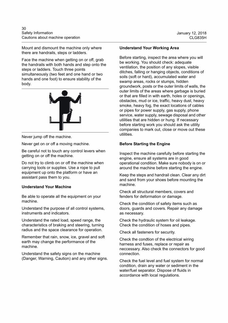
Mount and dismount the machine only where there are handrails, steps or ladders.
Face the machine when getting on or off, grab the handrails with both hands and step onto the steps or ladders. Touch three points simultaneously (two feet and one hand or two hands and one foot) to ensure stability of the body.
Never jump off the machine.
Never get on or off a moving machine.
Be careful not to touch any control levers when getting on or off the machine.
Do not try to climb on or off the machine when carrying tools or supplies. Use a rope to pull equipment up onto the platform or have an assistant pass them to you.
Understand Your Machine
Be able to operate all the equipment on your machine.
Understand the purpose of all control systems, instruments and indicators.
Understand the rated load, speed range, the characteristics of braking and steering, turning radius and the space clearance for operation.
Remember that rain, snow, ice, gravel and soft earth may change the performance of the machine.
Understand the safety signs on the machine (Danger, Warning, Caution) and any other signs.
Understand Your Working Area
Before starting, inspect the area where you will be working. You should check: adequate ventilation, the position of any slopes, visible ditches, falling or hanging objects, conditions of soils (soft or hard), accumulated water and swamp areas, rocks or stumps, hidden groundwork, posts or the outer limits of walls, the outer limits of the areas where garbage is buried or that are filled in with earth, holes or openings, obstacles, mud or ice, traffic, heavy dust, heavy smoke, heavy fog, the exact locations of cables or pipes for power supply, gas supply, phone service, water supply, sewage disposal and other utilities that are hidden or hung. If necessary before starting work you should ask the utility companies to mark out, close or move out these utilities.
Before Starting the Engine
Inspect the machine carefully before starting the engine, ensure all systems are in good operational condition. Make sure nobody is on or around the machine before starting the engine.
Keep the steps and handrail clean. Clear any dirt and sand from your shoes before mounting the machine.
Check all structural members, covers and fenders for deformation or damage.
Check the condition of safety items such as doors, guards and covers. Repair any damage as necessary.
Check the hydraulic system for oil leakage. Check the condition of hoses and pipes.
Check all fasteners for security.
Check the condtion of the electrical wiring harness and fuses, replace or repair as neccessary. Also check the connectors for good connection.
Check the fuel level and fuel system for normal condition, drain any water or sediment in the water/fuel separator. Dispose of fluids in accordance with local regulations.
31January 12, 2018 Safety InformationCLG835H Cautions about machine operation
Replace all damaged or lost parts and carry out lubrication according to the maintenance interval schedule.
Remove all loose objects from the cab. Loose objects may affect the operation and cause accidents.
Make sure that all the windows, if fitted, are clean and the screenwiper works normally.
Adjust the operators seat to a position that is most comfortable and provides for easiest operation of the machine. Check the seat belt and the condition of mounting hardware. Repair or replace any items that are damaged. Replace the seat belt after three years of use or any time the belt shows signs of wear or damage.
Adjust the seat to ensure that you can depress the pedals fully when your back is against the seat.
Check all the illumination equipment before operation in low light, and ensure that the illumination system is in good condition.
Check to make sure the steering frame lock is in the RELEASED position.
Engine Starting
Do not start the engine if there is a DO NOT OPERATE or similar tag attached to the start switch or control levers.
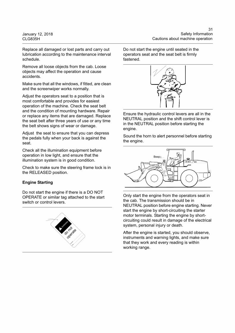
Do not start the engine until seated in the operators seat and the seat belt is firmly fastened.
Ensure the hydraulic control levers are all in the NEUTRAL position and the shift control lever is in the NEUTRAL position before starting the engine.
Sound the horn to alert personnel before starting the engine.
Only start the engine from the operators seat in the cab. The transmission should be in NEUTRAL position before engine starting. Never start the engine by short-circuiting the starter motor terminals. Starting the engine by short-circuiting could result in damage of the electrical system, personal injury or death.
After the engine is started, you should observe, instruments and warning lights, and make sure that they work and every reading is within working range.
do
not
oper
ate
Opera
ter:
Date:
WARNIN
G
!
Beep
32Safety Information January 12, 2018Cautions about machine operation CLG835H
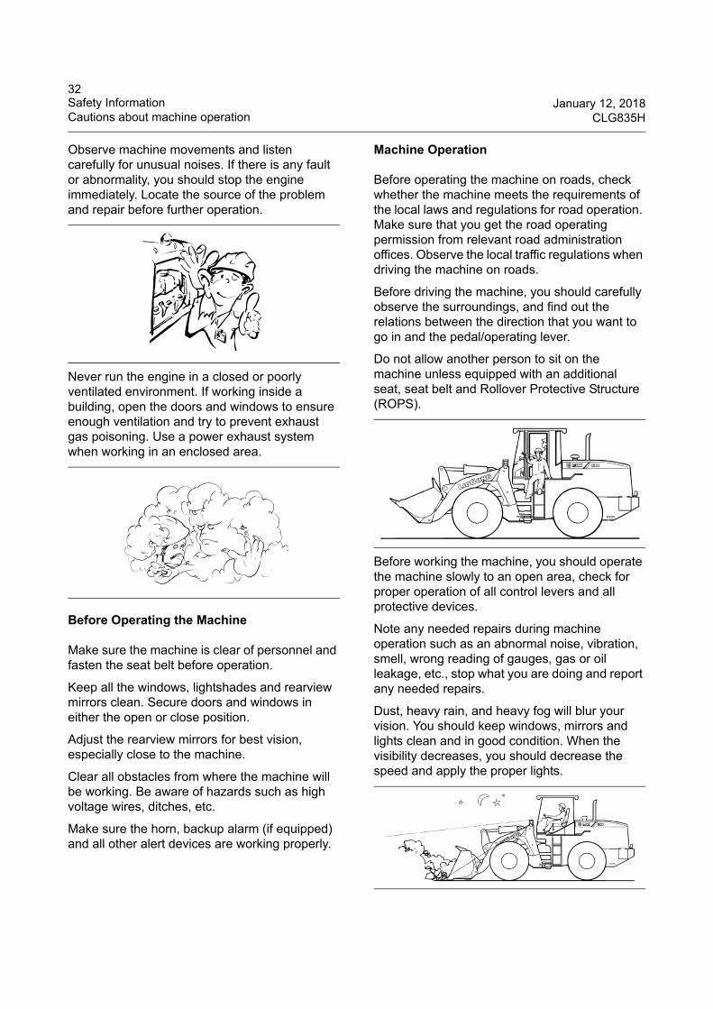
Observe machine movements and listen carefully for unusual noises. If there is any fault or abnormality, you should stop the engine immediately. Locate the source of the problem and repair before further operation.
Never run the engine in a closed or poorly ventilated environment. If working inside a building, open the doors and windows to ensure enough ventilation and try to prevent exhaust gas poisoning. Use a power exhaust system when working in an enclosed area.
Before Operating the Machine
Make sure the machine is clear of personnel and fasten the seat belt before operation.
Keep all the windows, lightshades and rearview mirrors clean. Secure doors and windows in either the open or close position.
Adjust the rearview mirrors for best vision, especially close to the machine.
Clear all obstacles from where the machine will be working. Be aware of hazards such as high voltage wires, ditches, etc.
Make sure the horn, backup alarm (if equipped) and all other alert devices are working properly.
Machine Operation
Before operating the machine on roads, check whether the machine meets the requirements of the local laws and regulations for road operation. Make sure that you get the road operating permission from relevant road administration offices. Observe the local traffic regulations when driving the machine on roads.
Before driving the machine, you should carefully observe the surroundings, and find out the relations between the direction that you want to go in and the pedal/operating lever.
Do not allow another person to sit on the machine unless equipped with an additional seat, seat belt and Rollover Protective Structure (ROPS).
Before working the machine, you should operate the machine slowly to an open area, check for proper operation of all control levers and all protective devices.
Note any needed repairs during machine operation such as an abnormal noise, vibration, smell, wrong reading of gauges, gas or oil leakage, etc., stop what you are doing and report any needed repairs.
Dust, heavy rain, and heavy fog will blur your vision. You should keep windows, mirrors and lights clean and in good condition. When the visibility decreases, you should decrease the speed and apply the proper lights.
33January 12, 2018 Safety InformationCLG835H Cautions about machine operation
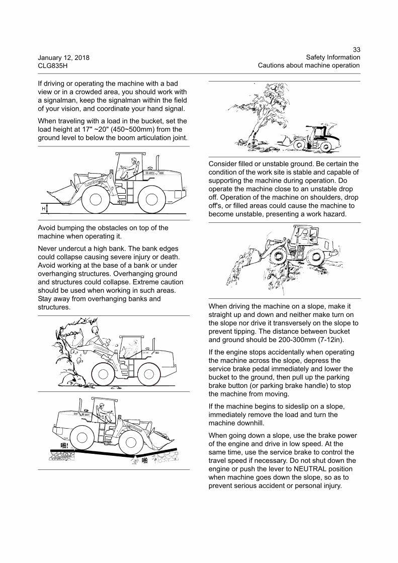
If driving or operating the machine with a bad view or in a crowded area, you should work with a signalman, keep the signalman within the field of your vision, and coordinate your hand signal.
When traveling with a load in the bucket, set the load height at 17" ~20" (450~500mm) from the ground level to below the boom articulation joint.
Avoid bumping the obstacles on top of the machine when operating it.
Never undercut a high bank. The bank edges could collapse causing severe injury or death. Avoid working at the base of a bank or under overhanging structures. Overhanging ground and structures could collapse. Extreme caution should be used when working in such areas. Stay away from overhanging banks and structures.
Consider filled or unstable ground. Be certain the condition of the work site is stable and capable of supporting the machine during operation. Do operate the machine close to an unstable drop off. Operation of the machine on shoulders, drop off's, or filled areas could cause the machine to become unstable, presenting a work hazard.
When driving the machine on a slope, make it straight up and down and neither make turn on the slope nor drive it transversely on the slope to prevent tipping. The distance between bucket and ground should be 200-300mm (7-12in).
If the engine stops accidentally when operating the machine across the slope, depress the service brake pedal immediately and lower the bucket to the ground, then pull up the parking brake button (or parking brake handle) to stop the machine from moving.
If the machine begins to sideslip on a slope, immediately remove the load and turn the machine downhill.
When going down a slope, use the brake power of the engine and drive in low speed. At the same time, use the service brake to control the travel speed if necessary. Do not shut down the engine or push the lever to NEUTRAL position when machine goes down the slope, so as to prevent serious accident or personal injury.
H
34Safety Information January 12, 2018Cautions about machine operation CLG835H
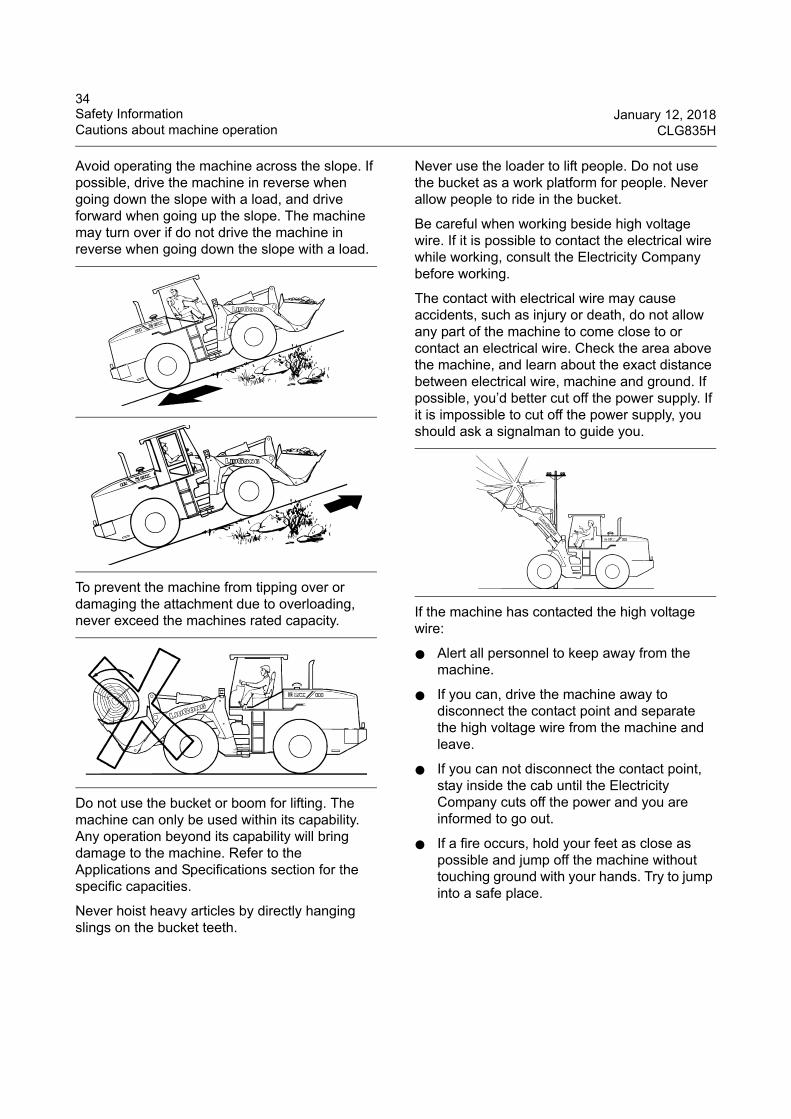
Avoid operating the machine across the slope. If possible, drive the machine in reverse when going down the slope with a load, and drive forward when going up the slope. The machine may turn over if do not drive the machine in reverse when going down the slope with a load.
To prevent the machine from tipping over or damaging the attachment due to overloading, never exceed the machines rated capacity.
Do not use the bucket or boom for lifting. The machine can only be used within its capability. Any operation beyond its capability will bring damage to the machine. Refer to the Applications and Specifications section for the specific capacities.
Never hoist heavy articles by directly hanging slings on the bucket teeth.
Never use the loader to lift people. Do not use the bucket as a work platform for people. Never allow people to ride in the bucket.
Be careful when working beside high voltage wire. If it is possible to contact the electrical wire while working, consult the Electricity Company before working.
The contact with electrical wire may cause accidents, such as injury or death, do not allow any part of the machine to come close to or contact an electrical wire. Check the area above the machine, and learn about the exact distance between electrical wire, machine and ground. If possible, you’d better cut off the power supply. If it is impossible to cut off the power supply, you should ask a signalman to guide you.
If the machine has contacted the high voltage wire:
● Alert all personnel to keep away from the machine.
● If you can, drive the machine away to disconnect the contact point and separate the high voltage wire from the machine and leave.
● If you can not disconnect the contact point, stay inside the cab until the Electricity Company cuts off the power and you are informed to go out.
● If a fire occurs, hold your feet as close as possible and jump off the machine without touching ground with your hands. Try to jump into a safe place.
35January 12, 2018 Safety InformationCLG835H Cautions about machine operation
Transportation
When transporting, make sure that the hooks and the towing devices are adequate. Connect tie down equipment to a drawbar or hook only. Never straddle a wire rope cable or similar device, nor allow others to do so.
Before transporting, ensure that no personnel stays between the machine and tie down equipment. The towing bracket or drawbar pin of the tie down equipment should be centering connected with the drawbar or hook of the machine.
Parking the Machine
When possible choose flat level ground to park the machine, apply the parking brake, always lower any attachment to the ground and ensure the machine will not move, possibly causing damage or injury.
Consider any overhead hazards such as the posibility of falling rocks, any powerlines or any other overhead hazards that may exist.
Consider the ground conditions. Do not park the machine near the edge of a cliff, close to an open excavation or pit.
Consider environmental conditions such as the posibility of flooding, heavy snow fall, electrical storms and exposure to wind and cold. Any of these conditions may cause damage to the machine.
Do not cause an obstruction, consider the site access and other emergency conditions the machine may obstruct.
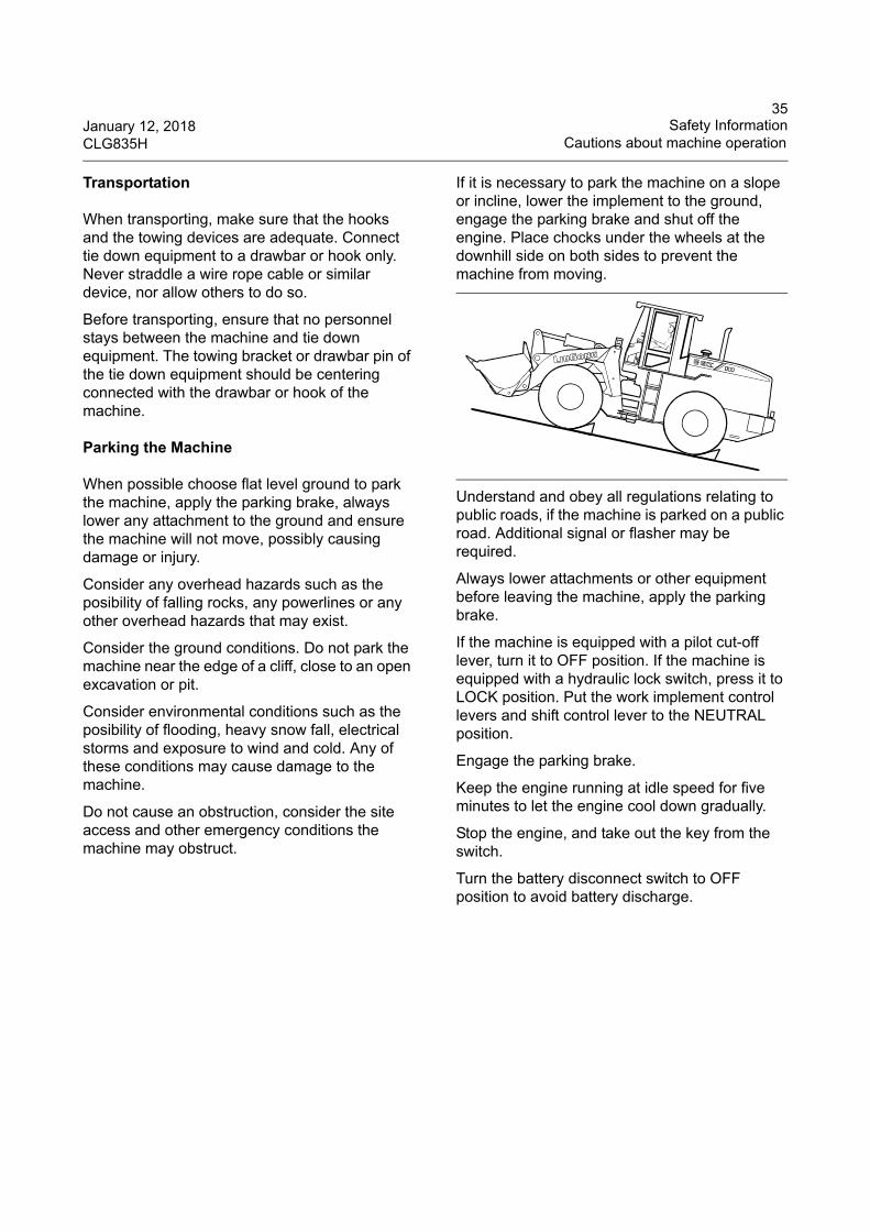
If it is necessary to park the machine on a slope or incline, lower the implement to the ground, engage the parking brake and shut off the engine. Place chocks under the wheels at the downhill side on both sides to prevent the machine from moving.
Understand and obey all regulations relating to public roads, if the machine is parked on a public road. Additional signal or flasher may be required.
Always lower attachments or other equipment before leaving the machine, apply the parking brake.
If the machine is equipped with a pilot cut-off lever, turn it to OFF position. If the machine is equipped with a hydraulic lock switch, press it to LOCK position. Put the work implement control levers and shift control lever to the NEUTRAL position.
Engage the parking brake.
Keep the engine running at idle speed for five minutes to let the engine cool down gradually.
Stop the engine, and take out the key from the switch.
Turn the battery disconnect switch to OFF position to avoid battery discharge.
36Safety Information January 12, 2018Cautions about Machine Maintenance CLG835H
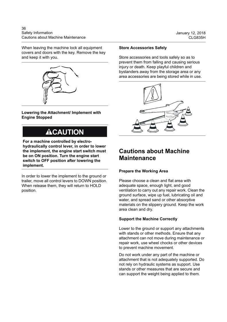
When leaving the machine lock all equipment covers and doors with the key. Remove the key and keep it with you.
Lowering the Attachment/ Implement with Engine Stopped
In order to lower the implement to the ground or trailer, move all control levers to DOWN position. When release them, they will return to HOLD position.
Store Accessories Safely
Store accessories and tools safely so as to prevent them from falling and causing serious injury or death. Keep playful children and bystanders away from the storage area or any area accessories are being stored while in use.
Cautions about Machine Maintenance
Prepare the Working Area
Please choose a clean and flat area with adequate space, enough light, and good ventilation to carry out any repair work. Clean the ground surface, wipe up fuel, lubricating oil and water, and spread sand or other absorptive materials on the slippery ground. Keep the work area clean and dry.
Support the Machine Correctly
Lower to the ground or support any attachments with stands or other methods. Ensure that any attachment can not move during maintenance or repair work, use wheel chocks or other devices to prevent machine movement.
Do not work under any part of the machine or attachment that is not adequately supported. Do not rely on hydraulic systems as support. Use stands or other measures that are secure and can support the weight being applied to them.
For a machine controlled by electro-hydraulically control lever, in order to lower the implement, the engine start switch must be on ON position. Turn the engine start switch to OFF position after lowering the implement.
37January 12, 2018 Safety InformationCLG835H Cautions about Machine Maintenance
Transportation Information
Obey the appropriate laws that govern the parameters of the load (weight, length, width, and height).
Understand the correct procedures for loading and unloading.
Carry out the loading and unloading operations on flat ground.
Chock the wheel of the trailer to make it unable to move.
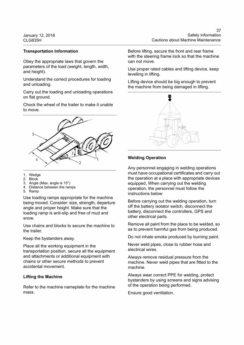
1. Wedge2. Block3. Angle (Max. angle is 15°)4. Distance between the ramps5. Ramp
Use loading ramps appropriate for the machine being moved. Consider: size, strength, departure angle and proper height. Make sure that the loading ramp is anti-slip and free of mud and snow.
Use chains and blocks to secure the machine to the trailer.
Keep the bystanders away.
Place all the working equipment in the transportation position, secure all the equipment and attachments or additional equipment with chains or other secure methods to prevent accidental movement.
Lifting the Machine
Refer to the machine nameplate for the machine mass.
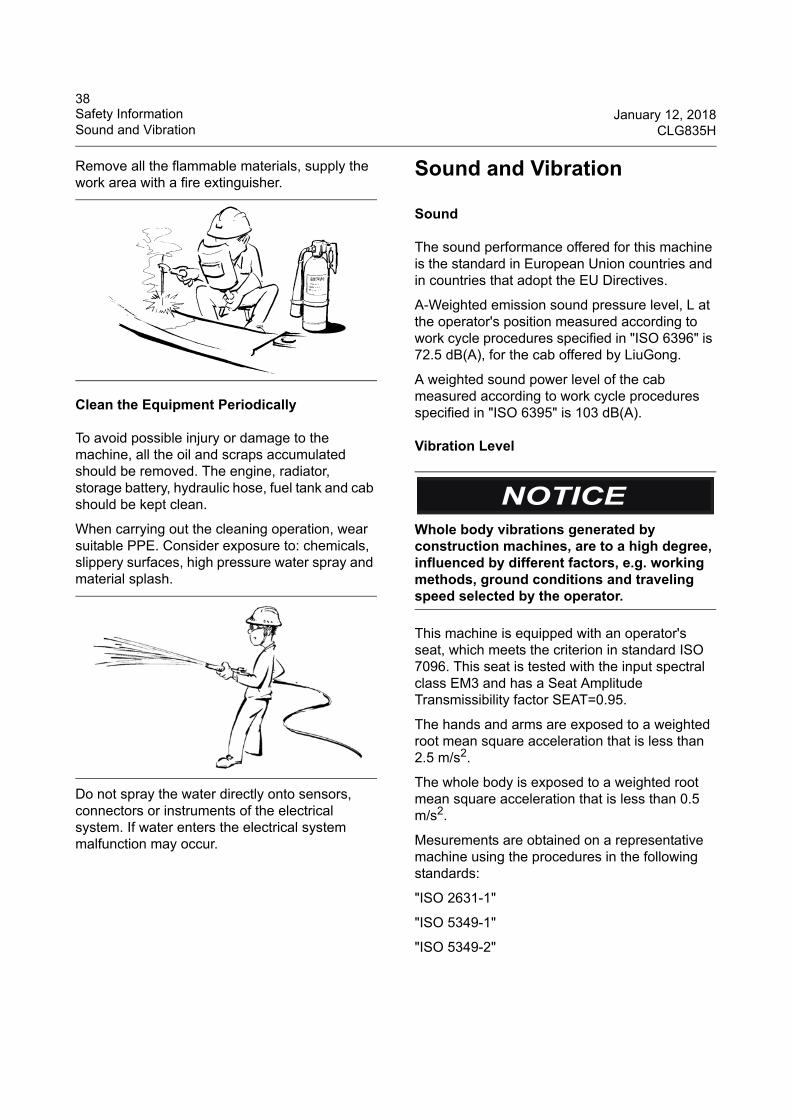
Before lifting, secure the front and rear frame with the steering frame lock so that the machine can not move.
Use proper rated cables and lifting device, keep levelling in lifting.
Lifting device should be big enough to prevent the machine from being damaged in lifting.
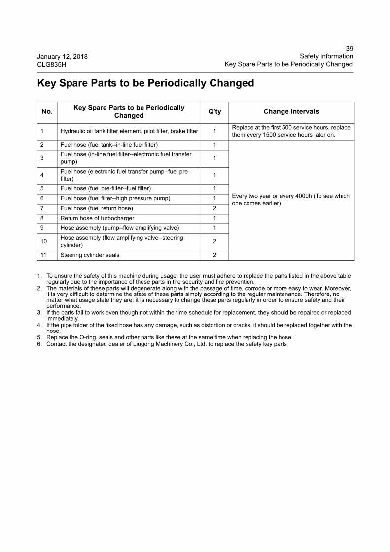
Welding Operation
Any personnel engaging in welding operations must have occupational certificates and carry out the operation at a place with appropriate devices equipped, When carrying out the welding operation, the personnel must follow the instructions below:
Before carrying out the welding operation, turn off the battery isolator switch, disconnect the battery, disconnect the controllers, GPS and other electrical parts.
Remove all paint from the place to be welded, so as to prevent harmful gas from being produced.
Do not inhale smoke produced by burning paint.
Never weld pipes, close to rubber hose and electrical wires.
Always remove residual pressure from the machine. Never weld pipes that are fitted to the machine.
Always wear correct PPE for welding, protect bystanders by using screens and signs advising of the operation being performed.
Ensure good ventilation.
38Safety Information January 12, 2018Sound and Vibration CLG835H
Remove all the flammable materials, supply the work area with a fire extinguisher.
Clean the Equipment Periodically
To avoid possible injury or damage to the machine, all the oil and scraps accumulated should be removed. The engine, radiator, storage battery, hydraulic hose, fuel tank and cab should be kept clean.
When carrying out the cleaning operation, wear suitable PPE. Consider exposure to: chemicals, slippery surfaces, high pressure water spray and material splash.
Do not spray the water directly onto sensors, connectors or instruments of the electrical system. If water enters the electrical system malfunction may occur.
Sound and Vibration
Sound
The sound performance offered for this machine is the standard in European Union countries and in countries that adopt the EU Directives.
A-Weighted emission sound pressure level, L at the operator's position measured according to work cycle procedures specified in "ISO 6396" is 72.5 dB(A), for the cab offered by LiuGong.
A weighted sound power level of the cab measured according to work cycle procedures specified in "ISO 6395" is 103 dB(A).
Vibration Level
This machine is equipped with an operator's seat, which meets the criterion in standard ISO 7096. This seat is tested with the input spectral class EM3 and has a Seat Amplitude Transmissibility factor SEAT=0.95.
The hands and arms are exposed to a weighted root mean square acceleration that is less than 2.5 m/s2.
The whole body is exposed to a weighted root mean square acceleration that is less than 0.5 m/s2.
Mesurements are obtained on a representative machine using the procedures in the following standards:
"ISO 2631-1"
"ISO 5349-1"
"ISO 5349-2"
Whole body vibrations generated by construction machines, are to a high degree, influenced by different factors, e.g. working methods, ground conditions and traveling speed selected by the operator.
39January 12, 2018 Safety InformationCLG835H Key Spare Parts to be Periodically Changed
Key Spare Parts to be Periodically Changed
1. To ensure the safety of this machine during usage, the user must adhere to replace the parts listed in the above table regularly due to the importance of these parts in the security and fire prevention.
2. The materials of these parts will degenerate along with the passage of time, corrode,or more easy to wear. Moreover, it is very difficult to determine the state of these parts simply according to the regular maintenance. Therefore, no matter what usage state they are, it is necessary to change these parts regularly in order to ensure safety and their performance.
3. If the parts fail to work even though not within the time schedule for replacement, they should be repaired or replaced immediately.
4. If the pipe folder of the fixed hose has any damage, such as distortion or cracks, it should be replaced together with the hose.
5. Replace the O-ring, seals and other parts like these at the same time when replacing the hose. 6. Contact the designated dealer of Liugong Machinery Co., Ltd. to replace the safety key parts
No.Key Spare Parts to be Periodically
ChangedQ'ty Change Intervals
1 Hydraulic oil tank filter element, pilot filter, brake filter 1Replace at the first 500 service hours, replace them every 1500 service hours later on.
2 Fuel hose (fuel tank--in-line fuel filter) 1
Every two year or every 4000h (To see which one comes earlier)
3Fuel hose (in-line fuel filter--electronic fuel transfer pump)
1
4Fuel hose (electronic fuel transfer pump--fuel pre-filter)
1
5 Fuel hose (fuel pre-filter--fuel filter) 1
6 Fuel hose (fuel filter--high pressure pump) 1
7 Fuel hose (fuel return hose) 2
8 Return hose of turbocharger 1
9 Hose assembly (pump--flow amplifying valve) 1
10Hose assembly (flow amplifying valve--steering cylinder)
2
11 Steering cylinder seals 2
40Application and Specification January 12, 2018Applications CLG835H
Application and Specification
Applications
Wheel loader is a kind of engineering machinery mainly used for loading & unloading loose materials. It is mainly used for loading, unloading,bulldozing and traction operation etc. at mine areas, ports and docks, capital construction, road repair and steel & iron enterprises etc. It is a kind of multi-purpose and high efficiency engineering machinery.
This loader is a kind of general-purpose engineering machinery and is not suitable for the flammable, explosive, dusty and air poisonous environments.
Requirements of Work Environments
1. Altitude: ≤3000m
2. Environmental temperature: -15°C~40°C (The cold starting aid device is not available)
3. Water depth: ≤630mm
Preventive measures for operation, maintenance and safety rules outlined on this manual are only suitable for the stipulated applications of the machine. Do not use the machine beyond the stipulated application scope, Guangxi Liugong Machinery Co., Ltd will not bear any safety liabilities, and these safety liabilities will be born by users. Under any cases, do not use the forbidden operation outlined in this manual.
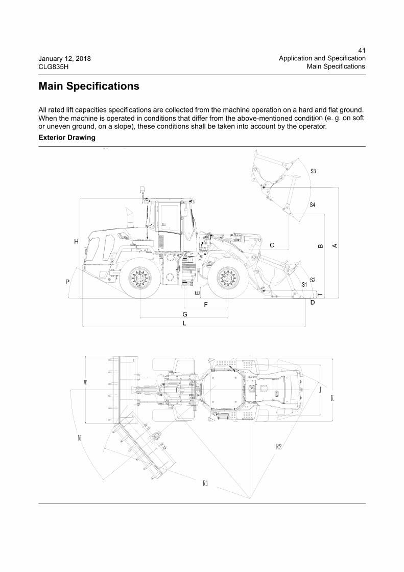
41January 12, 2018 Application and SpecificationCLG835H Main Specifications
Main Specifications
All rated lift capacities specifications are collected from the machine operation on a hard and flat ground. When the machine is operated in conditions that differ from the above-mentioned condition (e. g. on soft or uneven ground, on a slope), these conditions shall be taken into account by the operator.
Exterior Drawing
BC
D
TE
F
G
L
H
P
A
42Application and Specification January 12, 2018Main Specifications CLG835H
Machine Specifications
NO. Item Unit
CLG835H T4f(with ZF158 gearbox)
CLG835H T4f(with ZF160 gearbox)
Quick coupler
Pin OnQuick
couplerPin On
1 Rated load weight kg (lb) 3000 (6615) 3000 (6615) 3000 (6615) 3000 (6615)
2 Rated power kW 97.9 97.9 97.9 97.9
3 Operating mass kg (lb)11200
(24696)10860
(23946)11200
(24696)10860
(23946)
4 Rated bucket capacity m3 1.9 1.9 1.9 1.9
5 Dumping height mm (In) 2700 (106) 2800 (110) 2700 (106) 2800 (110)
6 Max. breakout force (bucket tilting) kN (lbf) 85 (19108) 100 (22480) 85 (19108) 100 (22480)
7 Tipping load (aligning) kg (lb) 7700 (16979) 9452 (20842) 7700 (16979) 9452 (20842)
8 Tipping load (full steering) kg (lb) 6600 (14553) 7369 (16249) 6600 (14553) 7369 (16249)
9 Boom lifting time (full load) s 5.5 5.5 5.5 5.5
10 Total time s 9.6 9.6 9.6 9.6
11 Max. traveling speed km/h(mph) 38.6 (23.9) 38.6 (23.9) 38.6 (23.9) 38.6 (23.9)
12 Max. gradeability ° 28 28 28 28
13Min. turning radius (outside of front wheel)
mm (In) 5410 (213) 5410 (213) 5410 (213) 5410 (213)
Overall Dimensions
Parameters below are for Z-bar or 8-bar machine Z-bar Z-bar Z-bar Z-bar
1 A: Height to hinge pin, fully raised mm (In) 3720 (146) 3720 (146) 3720 (146) 3720 (146)
2 B: Dumping height, fully raised mm (In) 2700 (106) 2800 (110) 2700 (106) 2800 (110)
3 C: Dumping reach, fully raised mm (In) 1150 (45) 1076 (42) 1150 (45) 1076 (42)
4 D: Max. digging depth mm (In) 100 (4) 80(3) 100 (4) 80(3)
5E: Min. ground clearance (at articulation joint)
mm (In) 325 (13) 325 (13) 325 (13) 325 (13)
6F: Distance from centre of rotation to the centre of the front wheels
mm (In) 1435 (56) 1435 (56) 1435 (56) 1435 (56)
7 G: Wheel base mm (In) 2870 (113) 2870 (113) 2870 (113) 2870 (113)
8 H: Overall height (top of cab) mm (In) 3200 (126) 3200 (126) 3200 (126) 3200 (126)
9 J: Tread width mm (In) 1855 (73) 1855 (73) 1855 (73) 1855 (73)
10 K: Overall width (outside of wheel) mm (In) 2300 (90.55) 2300 (90.55) 2300 (90.55) 2300 (90.55)
11 L: Over length (bucket on ground) mm (In) 7265 (286) 7115 (280) 7265 (286) 7115 (280)
12 M: Max. steering angle ° 40 40 40 40
13 W: Overall width (outside of bucket) mm (In) 2530 (100) 2530 (100) 2530 (100) 2530 (100)
14 R1: Turning radius (outside of bucket) mm (In) 6520 (256.7) 5920 (233) 6520 (256.7) 5920 (233)
15R2: Turning radius (center of rear wheel)
mm (In) 5188 (204.3) 5188 (204.3) 5188 (204.3) 5188 (204.3)
16 P: Departure angle ° 28 28 28 28
43January 12, 2018 Application and SpecificationCLG835H Main Specifications
17 S1: Bucket tilt back angle (on ground) ° 45 45 45 45
18S2: Bucket tilt back angle (in transport position)
° 48 48 48 48
19S3: Bucket tilt back angle (in highest position)
° 60 60 60 60
20S4: Dumping angle (in highest position)
° 45 45 45 45
21T: Bucket articulation height (in transport position)
mm (In) 450 (18) 450 (18) 450 (18) 450 (18)
Machine Specifications
NO. Item Unit
CLG835H T4f(with ZF158 gearbox)
CLG835H T4f(with ZF160 gearbox)
Quick coupler
Pin OnQuick
couplerPin On
Main Components Specifications
NO. ItemCLG835H T4f
(with ZF158 gearbox)CLG835H T4f
(with ZF160 gearbox)
Engine1 Manufacturer / Perkins Perkins
2 Model / 1204F E44TAN 1204F E44TAN
3 Type / Electronic fuel injection Electronic fuel injection
4 Displacement L (US gal) 4.4 (1.16) 4.4 (1.16)
5 Rated power KW (hp) 97.9 (131.3) 97.9 (131.3)
6 Emission level / Tier 4f Tier 4f
7Number of cylinders and arrangement
/ Straight-four cylinders Straight-four cylinders
8 Intake type /Turbocharged & inter-
coolingTurbocharged & inter-
cooling
9 Rated speed r/min 2200 2200
10 Max. rotating speed (no-load) r/min 2300 2300
11 Min. rotating speed (no-load) r/min 800 800
12Rotating speed at max. torque
r/min 1400 1400
13 Max. torque N.m (lbf·ft) 530 (391) 530 (391)
14 Start motor V-Kw 24V-5.5 KW 24V-5.5 KW
15 Alternator V-A 24V- 70A 24V- 70A
44Application and Specification January 12, 2018Main Specifications CLG835H
Power train system
1 Torque converter TypeSingle turbine, three
membersSingle turbine, three
members
2
Transmission
Manufacturer ZF ZF
3 Model 4WG158 4WG160
4 TypeFixed shaft type, power
shiftFixed shaft type, power
shift
5 Number of gearsFour forward gears and
three reverse gearsFour forward gears and
three reverse gears
6Operating pressure of shift oil pump (gear pump)
1.6~1.8MPa (232~261psi) 1.6~1.8MPa (232~261psi)
7
Drive axle
Manufacturer LiuGong LiuGong
8 Model LiuGong 3T wet-type axle LiuGong 3T wet-type axle
9 Type Wet-type alxe Wet-type alxe
10 Max. traction force 100kN (22480lbf) 104kN (23379lbf)
11Front & rear axle reduction ratio
20.267 20.267
12 Rear axle swing angle 12° 12°
13 Wheels Tire model 17.5-25 PR16/TL L-3 17.5-25 PR16/TL L-3
14
Traveling speed
F1/ R17.1/ 7.1km/h (4.4/ 4.4mph)
7.0/ 7.0km/h (4.35/ 4.35mph)
15 F2/ R212.3/ 12.3km/h (7.6/ 7.6mph)
13.7/ 13.7km/h (8.5/ 8.5mph)
16 F3/ R325.1/ 25.1km/h (15.6/ 15.6mph)
24.4/ 24.4km/h (15.16/ 15.16mph)
17 F4 38.6km/h (23.99mph) 38.6km/h (23.99mph)
Work hydraulic system
1 Work pump Type Piston pump Piston pump
2 Work pump displacement ml/r (cc/rev) 100 (100) 100 (100)
3 System pressure Mpa (psi) 19 (2755) 19 (2755)
4 Control valve / Three spools Three spools
5 System flow L/min (US gpm) 210 (55.48) 210 (55.48)
6 Lifting time (full load) s 5.5 5.5
7 Dumping time s 1.1 1.1
8 Float lowering time s 3 3
9 Total time s 9.6 9.6
Main Components Specifications
NO. ItemCLG835H T4f
(with ZF158 gearbox)CLG835H T4f
(with ZF160 gearbox)
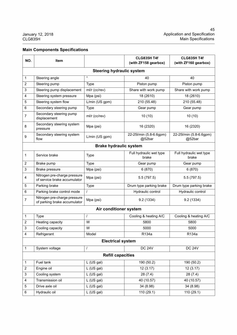
45January 12, 2018 Application and SpecificationCLG835H Main Specifications
Steering hydraulic system
1 Steering angle ° 40 40
2 Steering pump Type Piston pump Piston pump
3 Steering pump displacement ml/r (cc/rev) Share with work pump Share with work pump
4 Steering system pressure Mpa (psi) 18 (2610) 18 (2610)
5 Steering system flow L/min (US gpm) 210 (55.48) 210 (55.48)
6 Secondary steering pump Type Gear pump Gear pump
7Secondary steering pump displacement
ml/r (cc/rev) 10 (10) 10 (10)
8Secondary steering system pressure
Mpa (psi) 16 (2320) 16 (2320)
9Secondary steering system flow
L/min (US gpm)22-25l/min (5.8-6.6gpm)
@52bar 22-25l/min (5.8-6.6gpm)
@52bar
Brake hydraulic system
1 Service brake TypeFull hydraulic wet type
brakeFull hydraulic wet type
brake
2 Brake pump Type Gear pump Gear pump
3 Brake pressure Mpa (psi) 6 (870) 6 (870)
4Nitrogen pre-charge pressure of service brake accumulator
Mpa (psi) 5.5 (797.5) 5.5 (797.5)
5 Parking brake Type Drum type parking brake Drum type parking brake
6 Parking brake control mode / Hydraulic control Hydraulic control
7Nitrogen pre-charge pressure of parking brake accumulator
Mpa (psi) 9.2 (1334) 9.2 (1334)
Air conditioner system
1 Type / Cooling & heating A/C Cooling & heating A/C
2 Heating capacity W 5800 5800
3 Cooling capacity W 5000 5000
4 Refrigerant Model R134a R134a
Electrical system
1 System voltage / DC 24V DC 24V
Refill capacities
1 Fuel tank L (US gal) 190 (50.2) 190 (50.2)
2 Engine oil L (US gal) 12 (3.17) 12 (3.17)
3 Cooling system L (US gal) 28 (7.4) 28 (7.4)
4 Transmission oil L (US gal) 40 (10.57) 40 (10.57)
5 Drive axle oil L (US gal) 34 (8.98) 34 (8.98)
6 Hydraulic oil L (US gal) 110 (29.1) 110 (29.1)
Main Components Specifications
NO. ItemCLG835H T4f
(with ZF158 gearbox)CLG835H T4f
(with ZF160 gearbox)
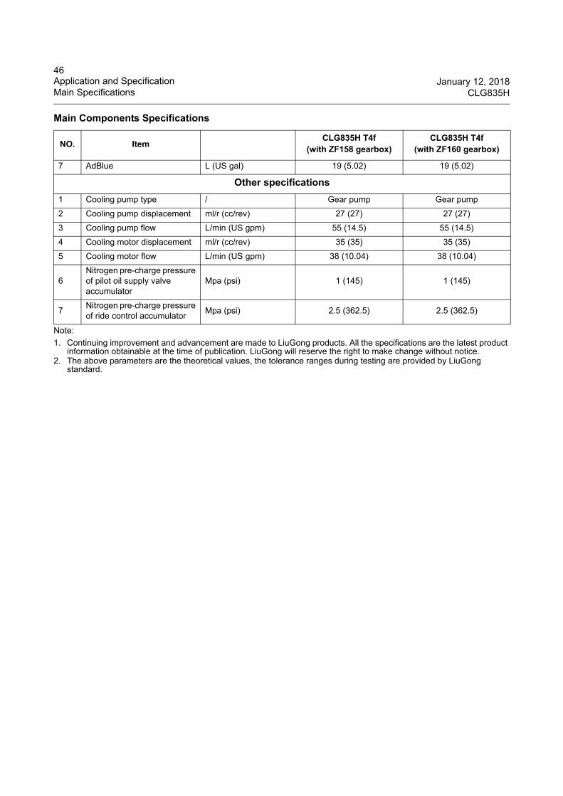
46Application and Specification January 12, 2018Main Specifications CLG835H
Note:
1. Continuing improvement and advancement are made to LiuGong products. All the specifications are the latest product information obtainable at the time of publication. LiuGong will reserve the right to make change without notice.
2. The above parameters are the theoretical values, the tolerance ranges during testing are provided by LiuGong standard.
7 AdBlue L (US gal) 19 (5.02) 19 (5.02)
Other specifications
1 Cooling pump type / Gear pump Gear pump
2 Cooling pump displacement ml/r (cc/rev) 27 (27) 27 (27)
3 Cooling pump flow L/min (US gpm) 55 (14.5) 55 (14.5)
4 Cooling motor displacement ml/r (cc/rev) 35 (35) 35 (35)
5 Cooling motor flow L/min (US gpm) 38 (10.04) 38 (10.04)
6Nitrogen pre-charge pressure of pilot oil supply valve accumulator
Mpa (psi) 1 (145) 1 (145)
7Nitrogen pre-charge pressure of ride control accumulator
Mpa (psi) 2.5 (362.5) 2.5 (362.5)
Main Components Specifications
NO. ItemCLG835H T4f
(with ZF158 gearbox)CLG835H T4f
(with ZF160 gearbox)
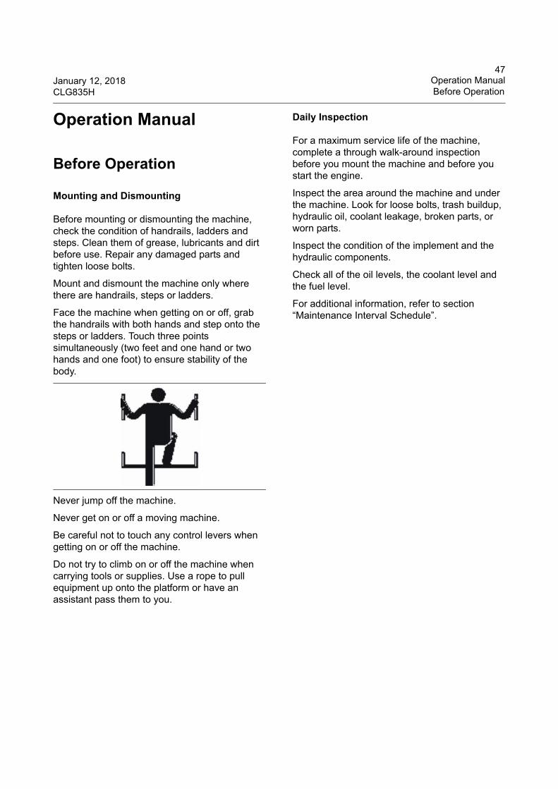
47January 12, 2018 Operation ManualCLG835H Before Operation
Operation Manual
Before Operation
Mounting and Dismounting
Before mounting or dismounting the machine, check the condition of handrails, ladders and steps. Clean them of grease, lubricants and dirt before use. Repair any damaged parts and tighten loose bolts.
Mount and dismount the machine only where there are handrails, steps or ladders.
Face the machine when getting on or off, grab the handrails with both hands and step onto the steps or ladders. Touch three points simultaneously (two feet and one hand or two hands and one foot) to ensure stability of the body.
Never jump off the machine.
Never get on or off a moving machine.
Be careful not to touch any control levers when getting on or off the machine.
Do not try to climb on or off the machine when carrying tools or supplies. Use a rope to pull equipment up onto the platform or have an assistant pass them to you.
Daily Inspection
For a maximum service life of the machine, complete a through walk-around inspection before you mount the machine and before you start the engine.
Inspect the area around the machine and under the machine. Look for loose bolts, trash buildup, hydraulic oil, coolant leakage, broken parts, or worn parts.
Inspect the condition of the implement and the hydraulic components.
Check all of the oil levels, the coolant level and the fuel level.
For additional information, refer to section “Maintenance Interval Schedule”.
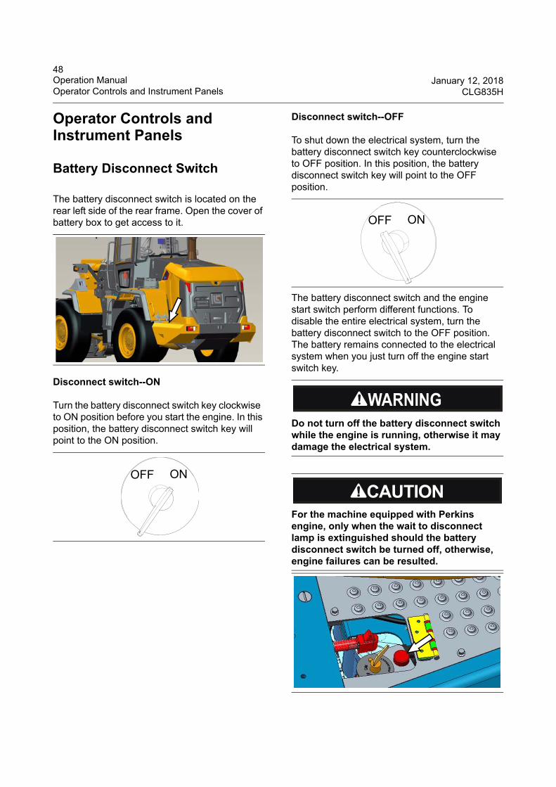
48Operation Manual January 12, 2018Operator Controls and Instrument Panels CLG835H
Operator Controls and Instrument Panels
Battery Disconnect Switch
The battery disconnect switch is located on the rear left side of the rear frame. Open the cover of battery box to get access to it.
Disconnect switch--ON
Turn the battery disconnect switch key clockwise to ON position before you start the engine. In this position, the battery disconnect switch key will point to the ON position.
Disconnect switch--OFF
To shut down the electrical system, turn the battery disconnect switch key counterclockwise to OFF position. In this position, the battery disconnect switch key will point to the OFF position.
The battery disconnect switch and the engine start switch perform different functions. To disable the entire electrical system, turn the battery disconnect switch to the OFF position. The battery remains connected to the electrical system when you just turn off the engine start switch key.
OFF ON
Do not turn off the battery disconnect switch while the engine is running, otherwise it may damage the electrical system.
For the machine equipped with Perkins engine, only when the wait to disconnect lamp is extinguished should the battery disconnect switch be turned off, otherwise, engine failures can be resulted.
OFF ON
49January 12, 2018 Operation ManualCLG835H Operator Controls and Instrument Panels
Engine Start Switch
The start switch (also called ignition switch) is located on the right side of the steering column in the cab and it has three positions in clockwise direction.
OFF——The oil passage of the engine is cut off at this position. The power of the machine is turned off. All of the other electrical appliances can not be turned on except the turn signal lights, rotating beacon and dome light.
ON——The first position when insert the start switch key and turn it clockwise. The electrical system of the machine can turn on and work normally.
START——The second position when insert the start switch key and turn it clockwise. The engine will be turned on and work. Release the start switch key after starting the engine. This position can not hold on automatically and the key will reset to the ON position automatically after being released.
The start switch key can only be inserted or taken out in OFF position.
The battery disconnect switch must be at ON position and the shift control lever must be in NEUTRAL before starting the engine.
If the engine fails to start, turn the start switch to the OFF position before restart or the start switch could be damaged.
Do not engage the start switch for more than 15 seconds at one time. Wait at least 30 seconds before restarting. Do not exceed three consecutive attempts before allowing the starter motor and choke solenoid to cool down. Failure to comply could result in a reduction of the service life of the battery as well as damage to the starter motor and choke solenoid.
50Operation Manual January 12, 2018Operator Controls and Instrument Panels CLG835H
Instrument Panels
Most of the monitoring gauges, alert and turn indicators of the machine are integrated in the instrument assembly under the steering wheel and on the right front upright column.
A. Central instrument panel B. Front switch panel C. Auxiliary instrument panelD. Backup monitor system
E. Front upright column instrument panel-RHF. Top switch panelG. Sound systemH. A/C panel
51January 12, 2018 Operation ManualCLG835H Operator Controls and Instrument Panels
Central Instrument Panel
Central instrument panel consists of five pointer gauges, one LCD, status indicators and warning indicators, etc..
1. Turn indicators2. Speedometer3. AdBlue gauge4. Fuel level gauge5. Engine coolant temperature gauge6. Torque converter oil temperature gauge7. Service hour meter8. LCD screen
Turn indicators
The left indicator flashes when the machine turns left, the front & rear left turn signal light will also flash simultaneously.
The right indicator flashes when the machine turns right, the front & rear right turn signal light will also flash simultaneously.
Speedometer
This meter shows the actual speed of the machine. The external scale
indicates the value in metric system; The interior scale indicates the value in British system. It is a meter which has backlight function. Turn on the meter light switch to open backlight function if it can not be seen under strong light.
AdBlue gauge
This gauge indicates the level of AdBlue. Green zone indicates the
normal volume range, red zone indicates that the AdBlue level is very low. Add AdBlue in time when the gauge pointer points to red zone.
Fuel level gauge
This gauge indicates the fuel level of the machine fuel tank. Green zone
indicates the normal fuel level of the fuel tank. Red zone indicates the low fuel level. Add fuel in time when the pointer points at the red zone.
Engine coolant temperature gauge
This gauge shows the coolant temperature of the engine. The green
zone shows normal work temperature; the yellow zone shows low temperature and the red zone shows high temperature.
12 1 53 64
8 7
Stop the engine and park the machine on a convenient place to check when the gauge points to red zone. Check the engine fan, belts and the radiator coolant level. Never go on working until the trouble is eliminated.
When checking the engine fan, belt and water tank level, be extremely careful to avoid injury. Keep away from the moving parts to avoid being injured and keep away from hot parts to avoid being burnt.
52Operation Manual January 12, 2018Operator Controls and Instrument Panels CLG835H
Torque converter oil temperature gauge
This gauge is used to indicate the oil temperature of the torque converter. The green zone shows normal work temperature; the yellow zone shows low temperature and the red zone shows high temperature.
Service hour meter
Service hour meter indicates the total work hours of the machine, unit in
hour. The time range of the hour meter is 0 to 9999.99 hours. When starting engine, the service hour meter starts to time. The display shows the accumulated work hours of the engine. The recording value by the service hour meter can be used to determine the machine maintenance intervals.
LCD screen
This LCD screen is divided into left and right display areas. Left area can display the transmission gear and transmission fault code; right area can display the engine rotating speed, system voltage, engine fault code, LiuGong controller fault code and so on, which can show in turn by using the screen selector switch.
1. Left area2. Right area
1. Transmission gear display: F2
2. Transmission fault code display: 10
3. Engine rotating speed display: 1325
4. System voltage display: 24.8
When the pointer of the torque converter oil temperature gauge points to the red zone, park the machine on a safe and convenient place for repair. Check the transmission and transmission oil level. Never go on working or operate the machine before eliminating the problem.
1 2
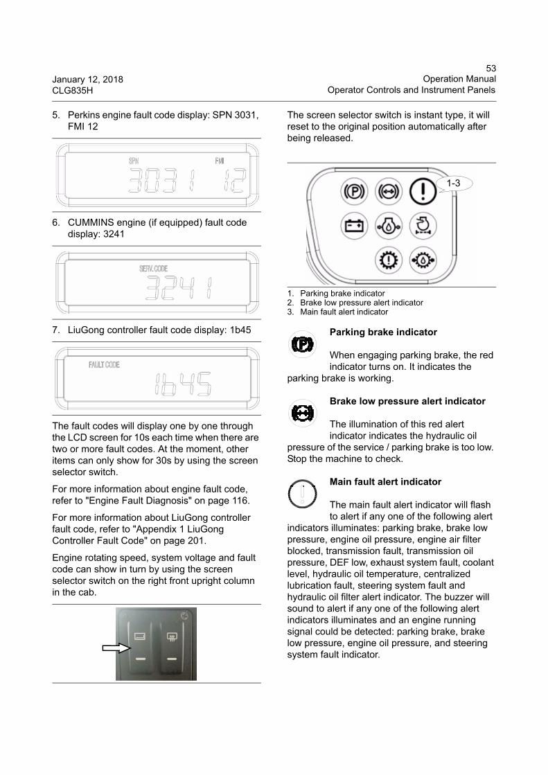
53January 12, 2018 Operation ManualCLG835H Operator Controls and Instrument Panels
5. Perkins engine fault code display: SPN 3031, FMI 12
6. CUMMINS engine (if equipped) fault code display: 3241
7. LiuGong controller fault code display: 1b45
The fault codes will display one by one through the LCD screen for 10s each time when there are two or more fault codes. At the moment, other items can only show for 30s by using the screen selector switch.
For more information about engine fault code, refer to "Engine Fault Diagnosis" on page 116.
For more information about LiuGong controller fault code, refer to "Appendix 1 LiuGong Controller Fault Code" on page 201.
Engine rotating speed, system voltage and fault code can show in turn by using the screen selector switch on the right front upright column in the cab.
The screen selector switch is instant type, it will reset to the original position automatically after being released.
1. Parking brake indicator2. Brake low pressure alert indicator3. Main fault alert indicator
Parking brake indicator
When engaging parking brake, the red indicator turns on. It indicates the
parking brake is working.
Brake low pressure alert indicator
The illumination of this red alert indicator indicates the hydraulic oil
pressure of the service / parking brake is too low. Stop the machine to check.
Main fault alert indicator
The main fault alert indicator will flash to alert if any one of the following alert
indicators illuminates: parking brake, brake low pressure, engine oil pressure, engine air filter blocked, transmission fault, transmission oil pressure, DEF low, exhaust system fault, coolant level, hydraulic oil temperature, centralized lubrication fault, steering system fault and hydraulic oil filter alert indicator. The buzzer will sound to alert if any one of the following alert indicators illuminates and an engine running signal could be detected: parking brake, brake low pressure, engine oil pressure, and steering system fault indicator.
1-3
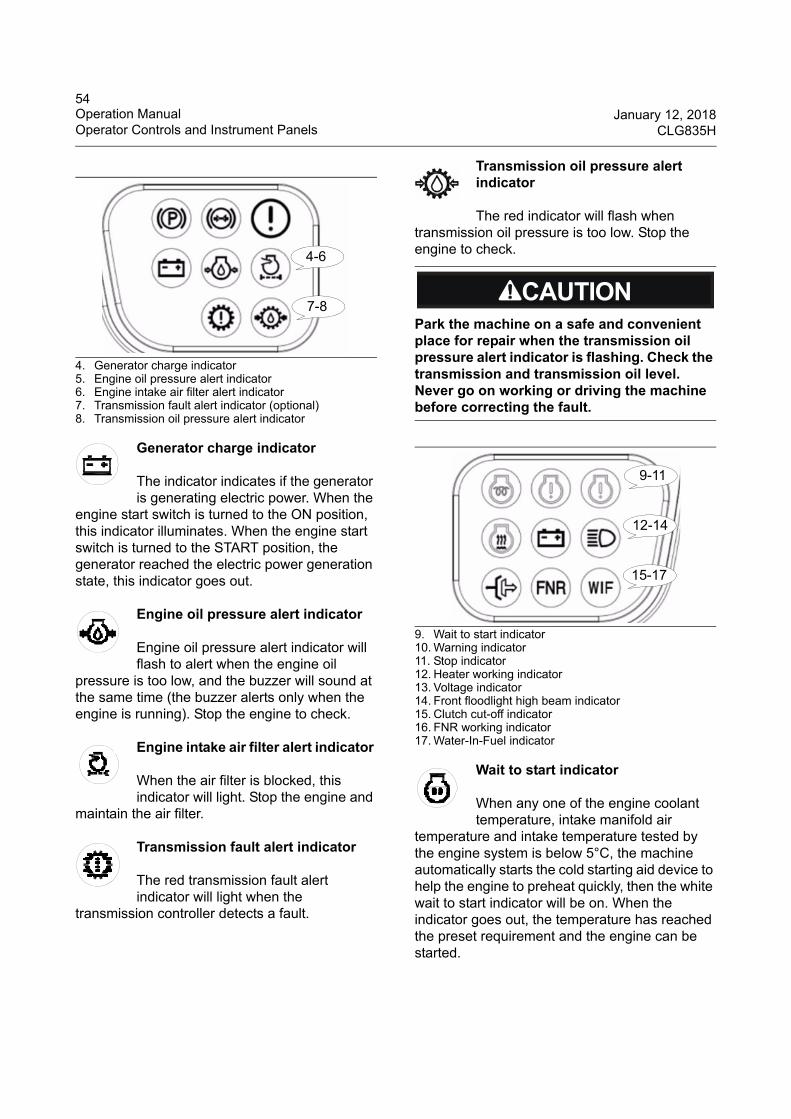
54Operation Manual January 12, 2018Operator Controls and Instrument Panels CLG835H
4. Generator charge indicator5. Engine oil pressure alert indicator6. Engine intake air filter alert indicator7. Transmission fault alert indicator (optional)8. Transmission oil pressure alert indicator
Generator charge indicator
The indicator indicates if the generator is generating electric power. When the
engine start switch is turned to the ON position, this indicator illuminates. When the engine start switch is turned to the START position, the generator reached the electric power generation state, this indicator goes out.
Engine oil pressure alert indicator
Engine oil pressure alert indicator will flash to alert when the engine oil
pressure is too low, and the buzzer will sound at the same time (the buzzer alerts only when the engine is running). Stop the engine to check.
Engine intake air filter alert indicator
When the air filter is blocked, this indicator will light. Stop the engine and
maintain the air filter.
Transmission fault alert indicator
The red transmission fault alert indicator will light when the
transmission controller detects a fault.
Transmission oil pressure alert indicator
The red indicator will flash when transmission oil pressure is too low. Stop the engine to check.
9. Wait to start indicator 10. Warning indicator11. Stop indicator12. Heater working indicator13. Voltage indicator14. Front floodlight high beam indicator15. Clutch cut-off indicator16. FNR working indicator17. Water-In-Fuel indicator
Wait to start indicator
When any one of the engine coolant temperature, intake manifold air
temperature and intake temperature tested by the engine system is below 5°C, the machine automatically starts the cold starting aid device to help the engine to preheat quickly, then the white wait to start indicator will be on. When the indicator goes out, the temperature has reached the preset requirement and the engine can be started.
4-6
7-8Park the machine on a safe and convenient place for repair when the transmission oil pressure alert indicator is flashing. Check the transmission and transmission oil level. Never go on working or driving the machine before correcting the fault.
9-11
12-14
15-17
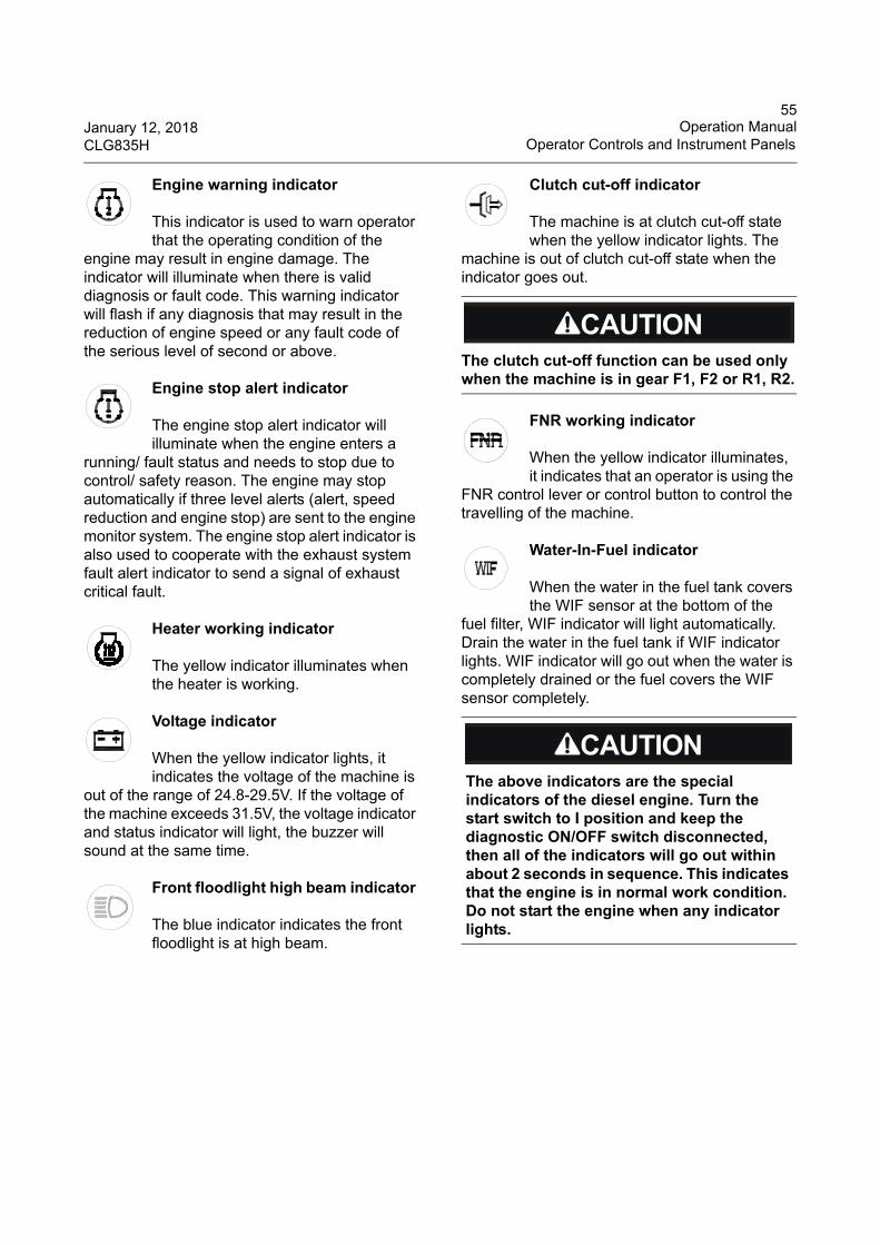
55January 12, 2018 Operation ManualCLG835H Operator Controls and Instrument Panels
Engine warning indicator
This indicator is used to warn operator that the operating condition of the
engine may result in engine damage. The indicator will illuminate when there is valid diagnosis or fault code. This warning indicator will flash if any diagnosis that may result in the reduction of engine speed or any fault code of the serious level of second or above.
Engine stop alert indicator
The engine stop alert indicator will illuminate when the engine enters a
running/ fault status and needs to stop due to control/ safety reason. The engine may stop automatically if three level alerts (alert, speed reduction and engine stop) are sent to the engine monitor system. The engine stop alert indicator is also used to cooperate with the exhaust system fault alert indicator to send a signal of exhaust critical fault.
Heater working indicator
The yellow indicator illuminates when the heater is working.
Voltage indicator
When the yellow indicator lights, it indicates the voltage of the machine is
out of the range of 24.8-29.5V. If the voltage of the machine exceeds 31.5V, the voltage indicator and status indicator will light, the buzzer will sound at the same time.
Front floodlight high beam indicator
The blue indicator indicates the front floodlight is at high beam.
Clutch cut-off indicator
The machine is at clutch cut-off state when the yellow indicator lights. The
machine is out of clutch cut-off state when the indicator goes out.
FNR working indicator
When the yellow indicator illuminates, it indicates that an operator is using the
FNR control lever or control button to control the travelling of the machine.
Water-In-Fuel indicator
When the water in the fuel tank covers the WIF sensor at the bottom of the
fuel filter, WIF indicator will light automatically. Drain the water in the fuel tank if WIF indicator lights. WIF indicator will go out when the water is completely drained or the fuel covers the WIF sensor completely.
The clutch cut-off function can be used only when the machine is in gear F1, F2 or R1, R2.
The above indicators are the special indicators of the diesel engine. Turn the start switch to I position and keep the diagnostic ON/OFF switch disconnected, then all of the indicators will go out within about 2 seconds in sequence. This indicates that the engine is in normal work condition. Do not start the engine when any indicator lights.
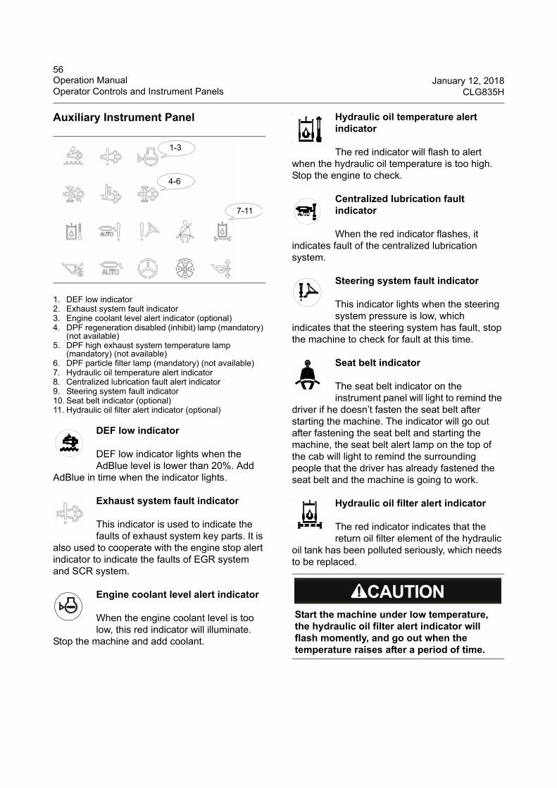
56Operation Manual January 12, 2018Operator Controls and Instrument Panels CLG835H
Auxiliary Instrument Panel
1. DEF low indicator2. Exhaust system fault indicator3. Engine coolant level alert indicator (optional)4. DPF regeneration disabled (inhibit) lamp (mandatory)
(not available)5. DPF high exhaust system temperature lamp
(mandatory) (not available)6. DPF particle filter lamp (mandatory) (not available)7. Hydraulic oil temperature alert indicator8. Centralized lubrication fault alert indicator9. Steering system fault indicator10. Seat belt indicator (optional)11. Hydraulic oil filter alert indicator (optional)
DEF low indicator
DEF low indicator lights when the AdBlue level is lower than 20%. Add
AdBlue in time when the indicator lights.
Exhaust system fault indicator
This indicator is used to indicate the faults of exhaust system key parts. It is
also used to cooperate with the engine stop alert indicator to indicate the faults of EGR system and SCR system.
Engine coolant level alert indicator
When the engine coolant level is too low, this red indicator will illuminate.
Stop the machine and add coolant.
Hydraulic oil temperature alert indicator
The red indicator will flash to alert when the hydraulic oil temperature is too high. Stop the engine to check.
Centralized lubrication fault indicator
When the red indicator flashes, it indicates fault of the centralized lubrication system.
Steering system fault indicator
This indicator lights when the steering system pressure is low, which
indicates that the steering system has fault, stop the machine to check for fault at this time.
Seat belt indicator
The seat belt indicator on the instrument panel will light to remind the
driver if he doesn’t fasten the seat belt after starting the machine. The indicator will go out after fastening the seat belt and starting the machine, the seat belt alert lamp on the top of the cab will light to remind the surrounding people that the driver has already fastened the seat belt and the machine is going to work.
Hydraulic oil filter alert indicator
The red indicator indicates that the return oil filter element of the hydraulic
oil tank has been polluted seriously, which needs to be replaced.
1-3
4-6
7-11
Start the machine under low temperature, the hydraulic oil filter alert indicator will flash momently, and go out when the temperature raises after a period of time.
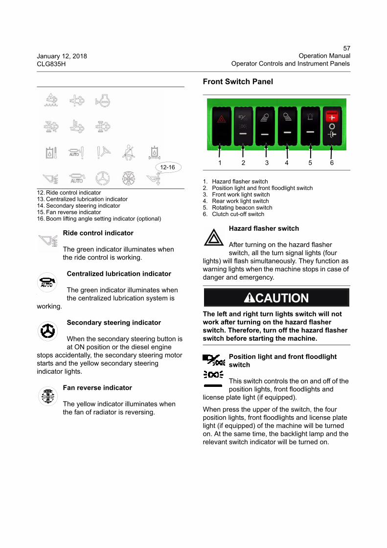
57January 12, 2018 Operation ManualCLG835H Operator Controls and Instrument Panels
12. Ride control indicator13. Centralized lubrication indicator 14. Secondary steering indicator15. Fan reverse indicator16. Boom lifting angle setting indicator (optional)
Ride control indicator
The green indicator illuminates when the ride control is working.
Centralized lubrication indicator
The green indicator illuminates when the centralized lubrication system is
working.
Secondary steering indicator
When the secondary steering button is at ON position or the diesel engine
stops accidentally, the secondary steering motor starts and the yellow secondary steering indicator lights.
Fan reverse indicator
The yellow indicator illuminates when the fan of radiator is reversing.
Front Switch Panel
1. Hazard flasher switch2. Position light and front floodlight switch3. Front work light switch4. Rear work light switch5. Rotating beacon switch6. Clutch cut-off switch
Hazard flasher switch
After turning on the hazard flasher switch, all the turn signal lights (four
lights) will flash simultaneously. They function as warning lights when the machine stops in case of danger and emergency.
Position light and front floodlight switch
This switch controls the on and off of the position lights, front floodlights and
license plate light (if equipped).
When press the upper of the switch, the four position lights, front floodlights and license plate light (if equipped) of the machine will be turned on. At the same time, the backlight lamp and the relevant switch indicator will be turned on.
12-16
The left and right turn lights switch will not work after turning on the hazard flasher switch. Therefore, turn off the hazard flasher switch before starting the machine.
1 2 3 4 5 6
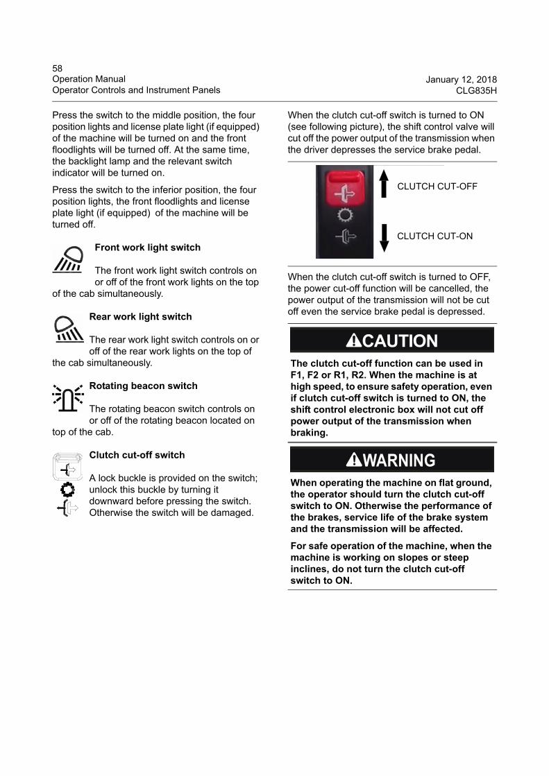
58Operation Manual January 12, 2018Operator Controls and Instrument Panels CLG835H
Press the switch to the middle position, the four position lights and license plate light (if equipped) of the machine will be turned on and the front floodlights will be turned off. At the same time, the backlight lamp and the relevant switch indicator will be turned on.
Press the switch to the inferior position, the four position lights, the front floodlights and license plate light (if equipped) of the machine will be turned off.
Front work light switch
The front work light switch controls on or off of the front work lights on the top
of the cab simultaneously.
Rear work light switch
The rear work light switch controls on or off of the rear work lights on the top of
the cab simultaneously.
Rotating beacon switch
The rotating beacon switch controls on or off of the rotating beacon located on
top of the cab.
Clutch cut-off switch
A lock buckle is provided on the switch; unlock this buckle by turning it downward before pressing the switch. Otherwise the switch will be damaged.
When the clutch cut-off switch is turned to ON (see following picture), the shift control valve will cut off the power output of the transmission when the driver depresses the service brake pedal.
When the clutch cut-off switch is turned to OFF, the power cut-off function will be cancelled, the power output of the transmission will not be cut off even the service brake pedal is depressed.
The clutch cut-off function can be used in F1, F2 or R1, R2. When the machine is at high speed, to ensure safety operation, even if clutch cut-off switch is turned to ON, the shift control electronic box will not cut off power output of the transmission when braking.
When operating the machine on flat ground, the operator should turn the clutch cut-off switch to ON. Otherwise the performance of the brakes, service life of the brake system and the transmission will be affected.
For safe operation of the machine, when the machine is working on slopes or steep inclines, do not turn the clutch cut-off switch to ON.
CLUTCH CUT-OFF
CLUTCH CUT-ON
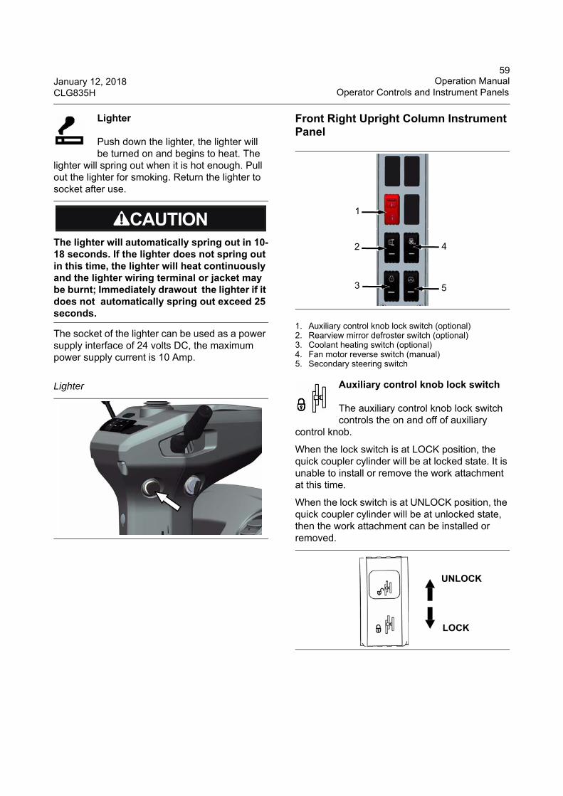
59January 12, 2018 Operation ManualCLG835H Operator Controls and Instrument Panels
Lighter
Push down the lighter, the lighter will be turned on and begins to heat. The
lighter will spring out when it is hot enough. Pull out the lighter for smoking. Return the lighter to socket after use.
The socket of the lighter can be used as a power supply interface of 24 volts DC, the maximum power supply current is 10 Amp.
Front Right Upright Column Instrument Panel
1. Auxiliary control knob lock switch (optional)2. Rearview mirror defroster switch (optional)3. Coolant heating switch (optional)4. Fan motor reverse switch (manual)5. Secondary steering switch
Auxiliary control knob lock switch
The auxiliary control knob lock switch controls the on and off of auxiliary
control knob.
When the lock switch is at LOCK position, the quick coupler cylinder will be at locked state. It is unable to install or remove the work attachment at this time.
When the lock switch is at UNLOCK position, the quick coupler cylinder will be at unlocked state, then the work attachment can be installed or removed.
The lighter will automatically spring out in 10-18 seconds. If the lighter does not spring out in this time, the lighter will heat continuously and the lighter wiring terminal or jacket may be burnt; Immediately drawout the lighter if it does not automatically spring out exceed 25 seconds.
Lighter
1
2
3
4
5
UNLOCK
LOCK
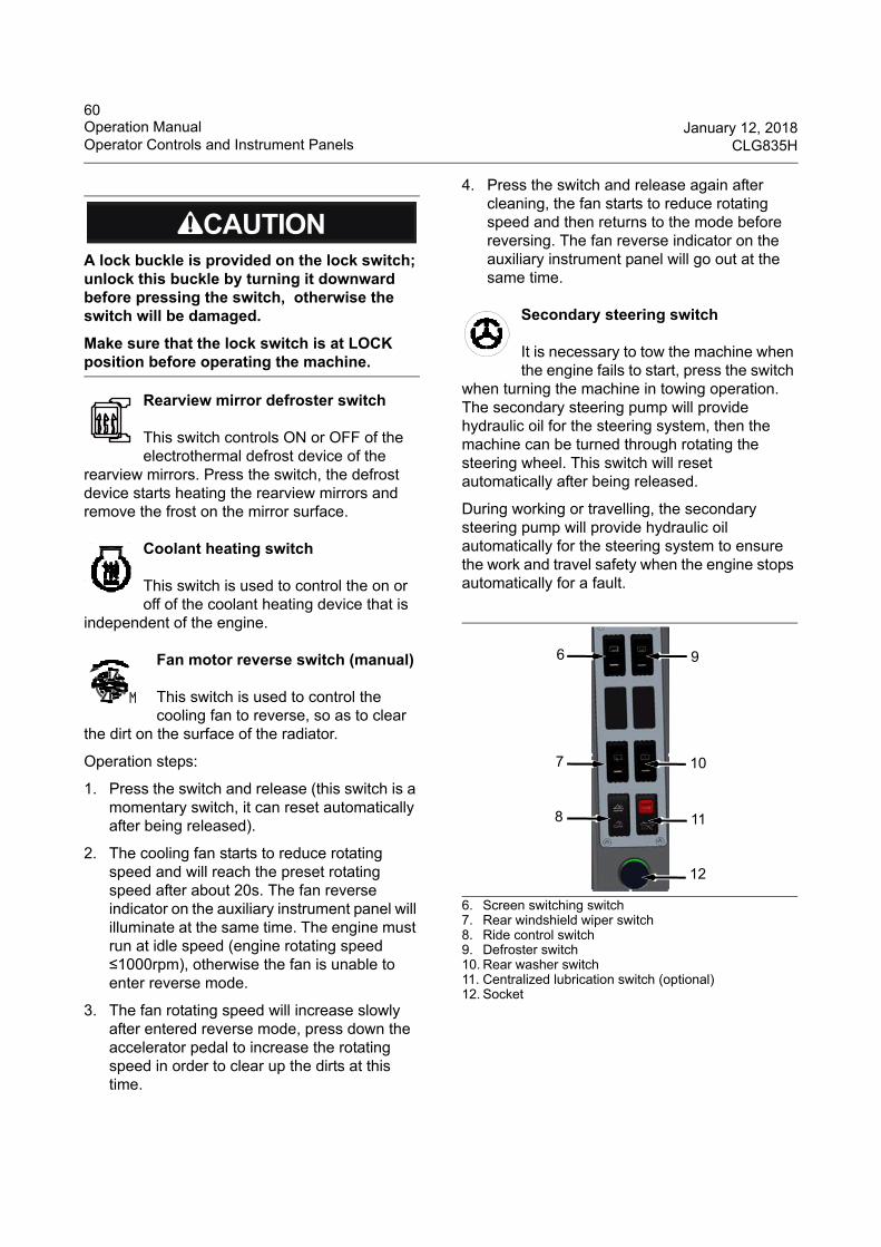
60Operation Manual January 12, 2018Operator Controls and Instrument Panels CLG835H
Rearview mirror defroster switch
This switch controls ON or OFF of the electrothermal defrost device of the
rearview mirrors. Press the switch, the defrost device starts heating the rearview mirrors and remove the frost on the mirror surface.
Coolant heating switch
This switch is used to control the on or off of the coolant heating device that is
independent of the engine.
Fan motor reverse switch (manual)
This switch is used to control the cooling fan to reverse, so as to clear
the dirt on the surface of the radiator.
Operation steps:
1. Press the switch and release (this switch is a momentary switch, it can reset automatically after being released).
2. The cooling fan starts to reduce rotating speed and will reach the preset rotating speed after about 20s. The fan reverse indicator on the auxiliary instrument panel will illuminate at the same time. The engine must run at idle speed (engine rotating speed ≤1000rpm), otherwise the fan is unable to enter reverse mode.
3. The fan rotating speed will increase slowly after entered reverse mode, press down the accelerator pedal to increase the rotating speed in order to clear up the dirts at this time.
4. Press the switch and release again after cleaning, the fan starts to reduce rotating speed and then returns to the mode before reversing. The fan reverse indicator on the auxiliary instrument panel will go out at the same time.
Secondary steering switch
It is necessary to tow the machine when the engine fails to start, press the switch
when turning the machine in towing operation. The secondary steering pump will provide hydraulic oil for the steering system, then the machine can be turned through rotating the steering wheel. This switch will reset automatically after being released.
During working or travelling, the secondary steering pump will provide hydraulic oil automatically for the steering system to ensure the work and travel safety when the engine stops automatically for a fault.
6. Screen switching switch7. Rear windshield wiper switch8. Ride control switch9. Defroster switch10. Rear washer switch11. Centralized lubrication switch (optional)12. Socket
A lock buckle is provided on the lock switch; unlock this buckle by turning it downward before pressing the switch, otherwise the switch will be damaged.
Make sure that the lock switch is at LOCK position before operating the machine.
9
7
8
10
11
6
12
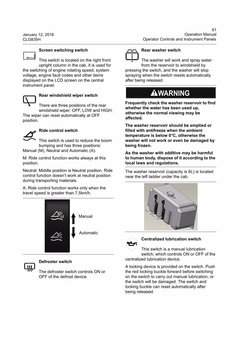
61January 12, 2018 Operation ManualCLG835H Operator Controls and Instrument Panels
Screen switching switch
This switch is located on the right front upright column in the cab, it is used for
the switching of engine rotating speed, system voltage, engine fault codes and other items displayed on the LCD screen on the central instrument panel.
Rear windshield wiper switch
There are three positions of the rear windshield wiper: OFF, LOW and HIGH.
The wiper can reset automatically at OFF position.
Ride control switch
This switch is used to reduce the boom bumping and has three positions:
Manual (M), Neutral and Automatic (A).
M: Ride control function works always at this position.
Neutral: Middle position is Neutral position. Ride control function doesn’t work at neutral position during transporting materials.
A: Ride control function works only when the travel speed is greater than 7.5km/h.
Defroster switch
The defroster switch controls ON or OFF of the defrost device.
Rear washer switch
The washer will work and spray water from the reservoir to windshield by
pressing the switch, and the washer will stop spraying when the switch resets automatically after being released.
The washer reservoir (capacity is 6L) is located near the left ladder under the cab.
Centralized lubrication switch
This switch is a manual lubrication switch, which controls ON or OFF of the
centralized lubrication device.
A locking device is provided on the switch. Push the red locking buckle forward before switching on the switch to carry out manual lubrication, or the switch will be damaged. The switch and locking buckle can reset automatically after being released.
Manual
Automatic
Frequently check the washer reservoir to find whether the water has been used up, otherwise the normal viewing may be affected.
The washer reservoir should be emptied or filled with antifreeze when the ambient temperature is below 0°C, otherwise the washer will not work or even be damaged by being frozen.
As the washer with additive may be harmful to human body, dispose of it according to the local laws and regulations.
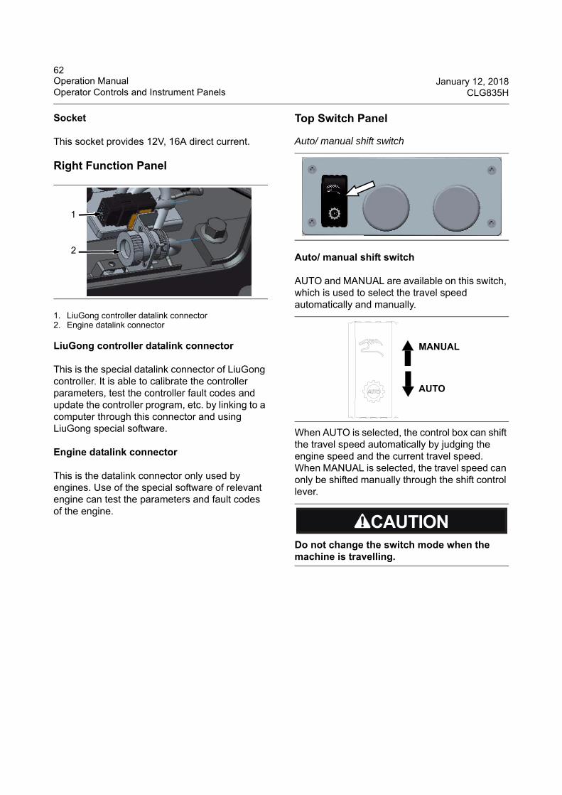
62Operation Manual January 12, 2018Operator Controls and Instrument Panels CLG835H
Socket
This socket provides 12V, 16A direct current.
Right Function Panel
1. LiuGong controller datalink connector2. Engine datalink connector
LiuGong controller datalink connector
This is the special datalink connector of LiuGong controller. It is able to calibrate the controller parameters, test the controller fault codes and update the controller program, etc. by linking to a computer through this connector and using LiuGong special software.
Engine datalink connector
This is the datalink connector only used by engines. Use of the special software of relevant engine can test the parameters and fault codes of the engine.
Top Switch Panel
Auto/ manual shift switch
AUTO and MANUAL are available on this switch, which is used to select the travel speed automatically and manually.
When AUTO is selected, the control box can shift the travel speed automatically by judging the engine speed and the current travel speed. When MANUAL is selected, the travel speed can only be shifted manually through the shift control lever.
1
2
Auto/ manual shift switch
Do not change the switch mode when the machine is travelling.
AUTO
MANUAL
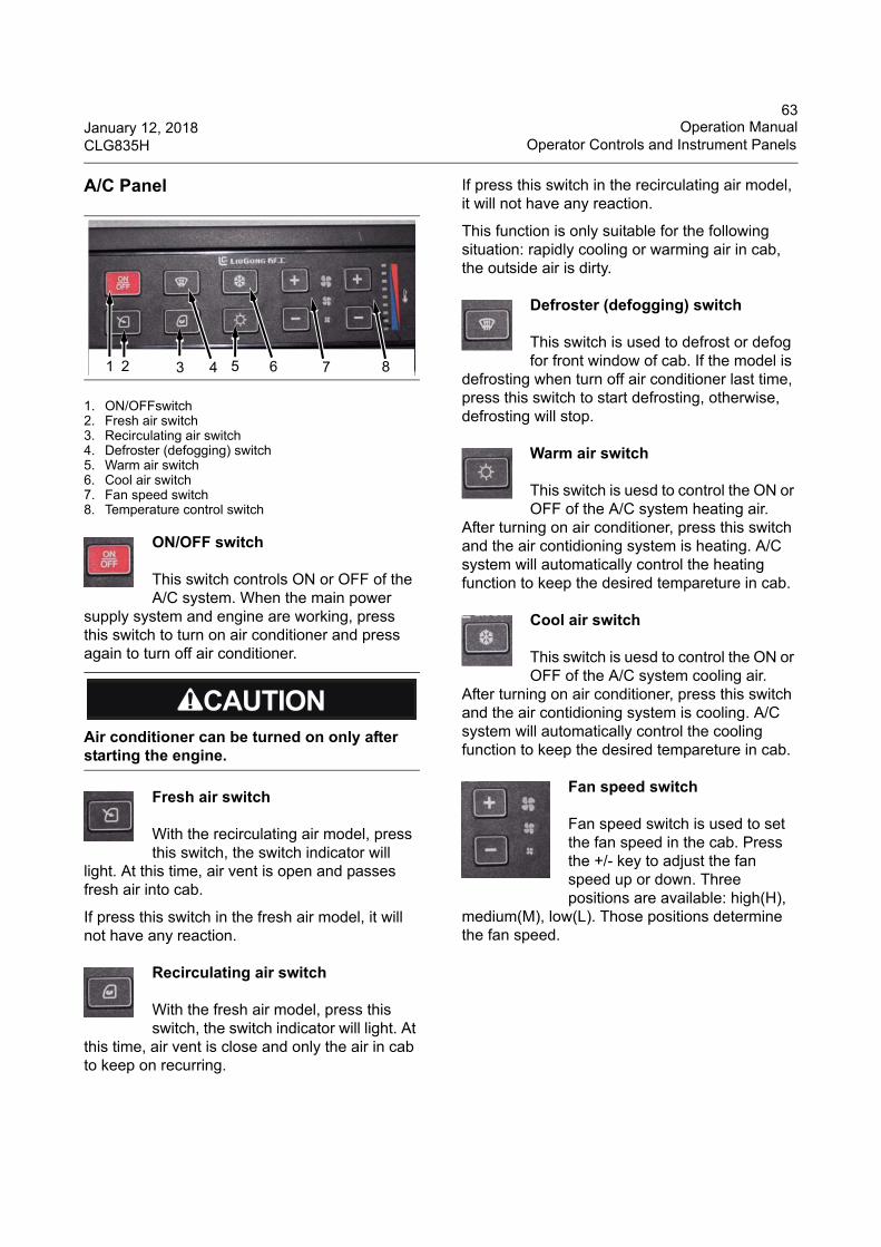
63January 12, 2018 Operation ManualCLG835H Operator Controls and Instrument Panels
A/C Panel
1. ON/OFFswitch2. Fresh air switch3. Recirculating air switch4. Defroster (defogging) switch5. Warm air switch6. Cool air switch7. Fan speed switch8. Temperature control switch
ON/OFF switch
This switch controls ON or OFF of the A/C system. When the main power
supply system and engine are working, press this switch to turn on air conditioner and press again to turn off air conditioner.
Fresh air switch
With the recirculating air model, press this switch, the switch indicator will
light. At this time, air vent is open and passes fresh air into cab.
If press this switch in the fresh air model, it will not have any reaction.
Recirculating air switch
With the fresh air model, press this switch, the switch indicator will light. At
this time, air vent is close and only the air in cab to keep on recurring.
If press this switch in the recirculating air model, it will not have any reaction.
This function is only suitable for the following situation: rapidly cooling or warming air in cab, the outside air is dirty.
Defroster (defogging) switch
This switch is used to defrost or defog for front window of cab. If the model is
defrosting when turn off air conditioner last time, press this switch to start defrosting, otherwise, defrosting will stop.
Warm air switch
This switch is uesd to control the ON or OFF of the A/C system heating air.
After turning on air conditioner, press this switch and the air contidioning system is heating. A/C system will automatically control the heating function to keep the desired tempareture in cab.
Cool air switch
This switch is uesd to control the ON or OFF of the A/C system cooling air.
After turning on air conditioner, press this switch and the air contidioning system is cooling. A/C system will automatically control the cooling function to keep the desired tempareture in cab.
Fan speed switch
Fan speed switch is used to set the fan speed in the cab. Press the +/- key to adjust the fan speed up or down. Three positions are available: high(H),
medium(M), low(L). Those positions determine the fan speed.
Air conditioner can be turned on only after starting the engine.
1 2 3 4 5 6 7 8
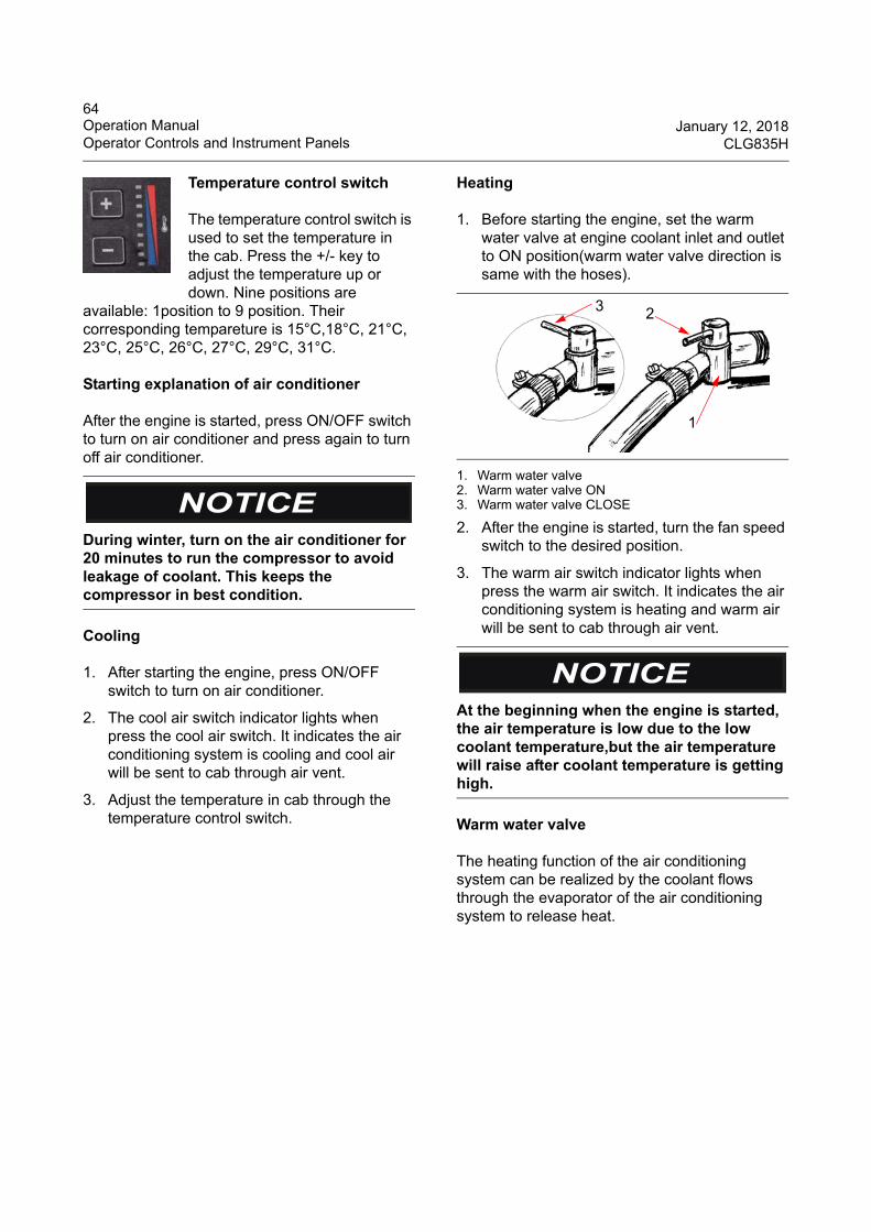
64Operation Manual January 12, 2018Operator Controls and Instrument Panels CLG835H
Temperature control switch
The temperature control switch is used to set the temperature in the cab. Press the +/- key to adjust the temperature up or down. Nine positions are
available: 1position to 9 position. Their corresponding tempareture is 15°C,18°C, 21°C, 23°C, 25°C, 26°C, 27°C, 29°C, 31°C.
Starting explanation of air conditioner
After the engine is started, press ON/OFF switch to turn on air conditioner and press again to turn off air conditioner.
Cooling
1. After starting the engine, press ON/OFF switch to turn on air conditioner.
2. The cool air switch indicator lights when press the cool air switch. It indicates the air conditioning system is cooling and cool air will be sent to cab through air vent.
3. Adjust the temperature in cab through the temperature control switch.
Heating
1. Before starting the engine, set the warm water valve at engine coolant inlet and outlet to ON position(warm water valve direction is same with the hoses).
1. Warm water valve2. Warm water valve ON3. Warm water valve CLOSE
2. After the engine is started, turn the fan speed switch to the desired position.
3. The warm air switch indicator lights when press the warm air switch. It indicates the air conditioning system is heating and warm air will be sent to cab through air vent.
Warm water valve
The heating function of the air conditioning system can be realized by the coolant flows through the evaporator of the air conditioning system to release heat.
During winter, turn on the air conditioner for 20 minutes to run the compressor to avoid leakage of coolant. This keeps the compressor in best condition.
At the beginning when the engine is started, the air temperature is low due to the low coolant temperature,but the air temperature will raise after coolant temperature is getting high.
2
1
3
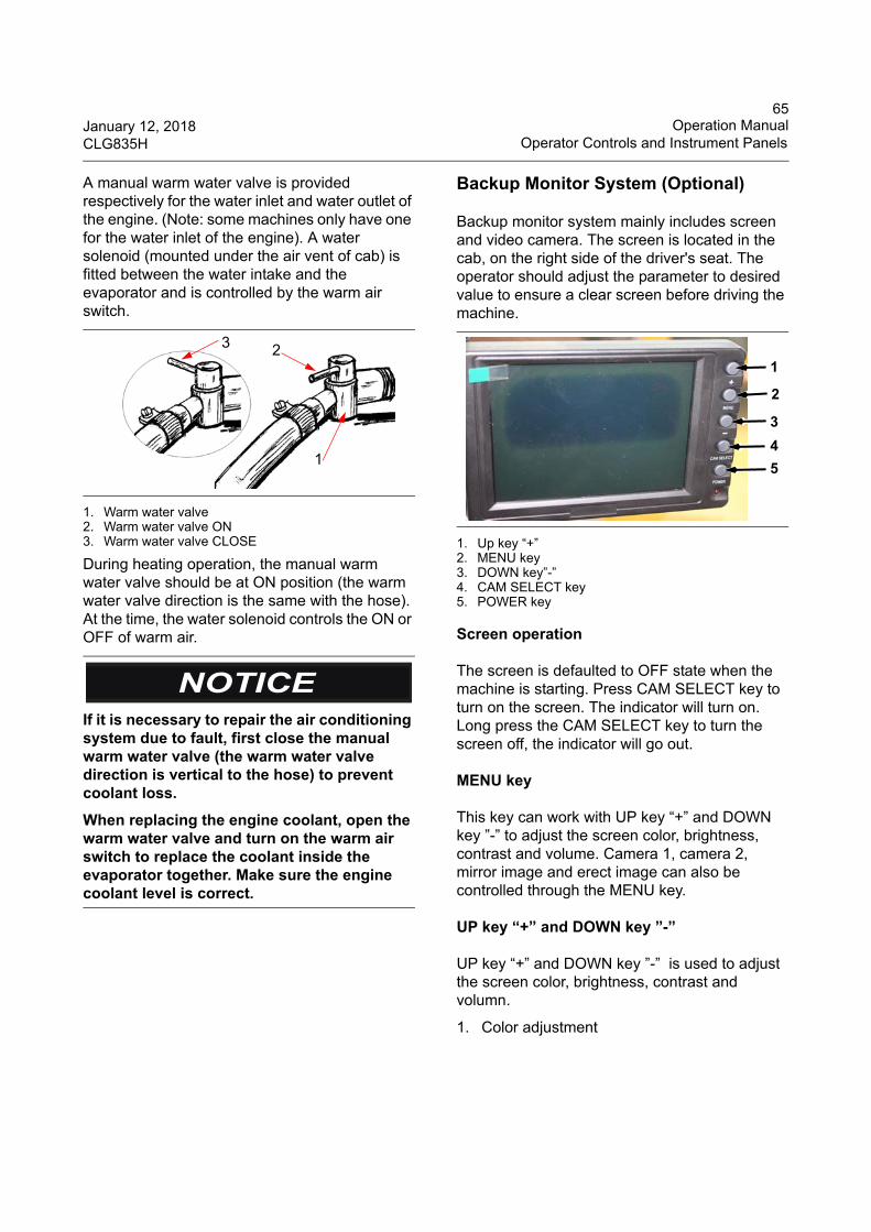
65January 12, 2018 Operation ManualCLG835H Operator Controls and Instrument Panels
A manual warm water valve is provided respectively for the water inlet and water outlet of the engine. (Note: some machines only have one for the water inlet of the engine). A water solenoid (mounted under the air vent of cab) is fitted between the water intake and the evaporator and is controlled by the warm air switch.
1. Warm water valve2. Warm water valve ON3. Warm water valve CLOSE
During heating operation, the manual warm water valve should be at ON position (the warm water valve direction is the same with the hose). At the time, the water solenoid controls the ON or OFF of warm air.
Backup Monitor System (Optional)
Backup monitor system mainly includes screen and video camera. The screen is located in the cab, on the right side of the driver's seat. The operator should adjust the parameter to desired value to ensure a clear screen before driving the machine.
1. Up key “+”2. MENU key3. DOWN key”-”4. CAM SELECT key5. POWER key
Screen operation
The screen is defaulted to OFF state when the machine is starting. Press CAM SELECT key to turn on the screen. The indicator will turn on. Long press the CAM SELECT key to turn the screen off, the indicator will go out.
MENU key
This key can work with UP key “+” and DOWN key ”-” to adjust the screen color, brightness, contrast and volume. Camera 1, camera 2, mirror image and erect image can also be controlled through the MENU key.
UP key “+” and DOWN key ”-”
UP key “+” and DOWN key ”-” is used to adjust the screen color, brightness, contrast and volumn.
1. Color adjustment
If it is necessary to repair the air conditioning system due to fault, first close the manual warm water valve (the warm water valve direction is vertical to the hose) to prevent coolant loss.
When replacing the engine coolant, open the warm water valve and turn on the warm air switch to replace the coolant inside the evaporator together. Make sure the engine coolant level is correct.
2
1
3
1
2
3
4
5
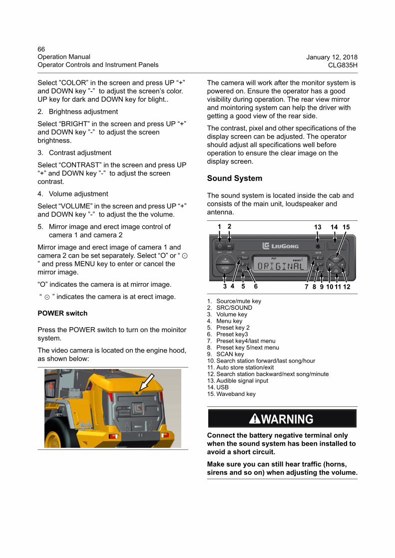
66Operation Manual January 12, 2018Operator Controls and Instrument Panels CLG835H
Select ”COLOR” in the screen and press UP “+” and DOWN key ”-” to adjust the screen’s color. UP key for dark and DOWN key for blight..
2. Brightness adjustment
Select “BRIGHT” in the screen and press UP “+” and DOWN key ”-” to adjust the screen brightness.
3. Contrast adjustment
Select “CONTRAST” in the screen and press UP “+” and DOWN key ”-” to adjust the screen contrast.
4. Volume adjustment
Select “VOLUME” in the screen and press UP “+” and DOWN key ”-” to adjust the the volume.
5. Mirror image and erect image control of camera 1 and camera 2
Mirror image and erect image of camera 1 and camera 2 can be set separately. Select “O” or “⊙” and press MENU key to enter or cancel the mirror image.
“O” indicates the camera is at mirror image.
“ ⊙ ” indicates the camera is at erect image.
POWER switch
Press the POWER switch to turn on the moinitor system.
The video camera is located on the engine hood, as shown below:
The camera will work after the monitor system is powered on. Ensure the operator has a good visibility during operation. The rear view mirror and mointoring system can help the driver with getting a good view of the rear side.
The contrast, pixel and other specifications of the display screen can be adjusted. The operator should adjust all specifications well before operation to ensure the clear image on the display screen.
Sound System
The sound system is located inside the cab and consists of the main unit, loudspeaker and antenna.
1. Source/mute key2. SRC/SOUND3. Volume key4. Menu key5. Preset key 26. Preset key37. Preset key4/last menu8. Preset key 5/next menu9. SCAN key10. Search station forward/last song/hour11. Auto store station/exit12. Search station backward/next song/minute13. Audible signal input14. USB15. Waveband key
Connect the battery negative terminal only when the sound system has been installed to avoid a short circuit.
Make sure you can still hear traffic (horns, sirens and so on) when adjusting the volume.
3 4 5 6 7 8 9 10 11 12
21 13 14 15
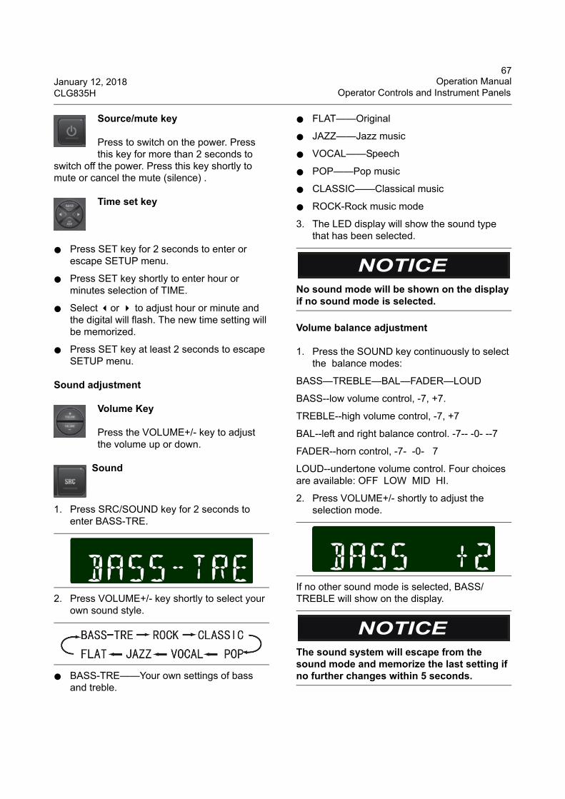
67January 12, 2018 Operation ManualCLG835H Operator Controls and Instrument Panels
Source/mute key
Press to switch on the power. Press this key for more than 2 seconds to
switch off the power. Press this key shortly to mute or cancel the mute (silence) .
Time set key
● Press SET key for 2 seconds to enter or escape SETUP menu.
● Press SET key shortly to enter hour or minutes selection of TIME.
● Select or to adjust hour or minute and the digital will flash. The new time setting will be memorized.
● Press SET key at least 2 seconds to escape SETUP menu.
Sound adjustment
Volume Key
Press the VOLUME+/- key to adjust the volume up or down.
Sound
1. Press SRC/SOUND key for 2 seconds to enter BASS-TRE.
2. Press VOLUME+/- key shortly to select your own sound style.
● BASS-TRE——Your own settings of bass and treble.
● FLAT——Original
● JAZZ——Jazz music
● VOCAL——Speech
● POP——Pop music
● CLASSIC——Classical music
● ROCK-Rock music mode
3. The LED display will show the sound type that has been selected.
Volume balance adjustment
1. Press the SOUND key continuously to select the balance modes:
BASS—TREBLE—BAL—FADER—LOUD
BASS--low volume control, -7, +7.
TREBLE--high volume control, -7, +7
BAL--left and right balance control. -7-- -0- --7
FADER--horn control, -7- -0- 7
LOUD--undertone volume control. Four choices are available: OFF LOW MID HI.
2. Press VOLUME+/- shortly to adjust the selection mode.
If no other sound mode is selected, BASS/TREBLE will show on the display.
No sound mode will be shown on the display if no sound mode is selected.
The sound system will escape from the sound mode and memorize the last setting if no further changes within 5 seconds.
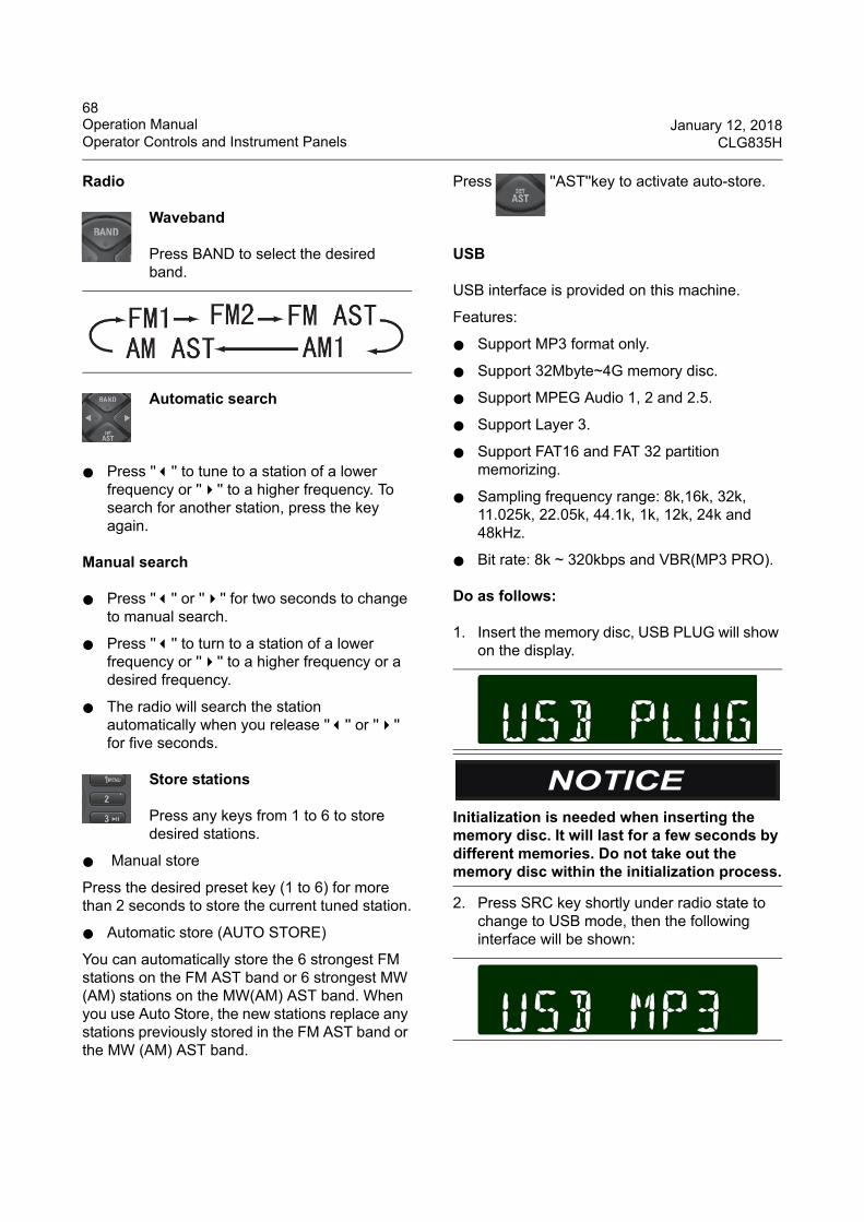
68Operation Manual January 12, 2018Operator Controls and Instrument Panels CLG835H
Radio
Waveband
Press BAND to select the desired band.
Automatic search
● Press '''' to tune to a station of a lower frequency or '''' to a higher frequency. To search for another station, press the key again.
Manual search
● Press '''' or '''' for two seconds to change to manual search.
● Press '''' to turn to a station of a lower frequency or '''' to a higher frequency or a desired frequency.
● The radio will search the station automatically when you release '''' or '''' for five seconds.
Store stations
Press any keys from 1 to 6 to store desired stations.
● Manual store
Press the desired preset key (1 to 6) for more than 2 seconds to store the current tuned station.
● Automatic store (AUTO STORE)
You can automatically store the 6 strongest FM stations on the FM AST band or 6 strongest MW (AM) stations on the MW(AM) AST band. When you use Auto Store, the new stations replace any stations previously stored in the FM AST band or the MW (AM) AST band.
Press ''AST''key to activate auto-store.
USB
USB interface is provided on this machine.
Features:
● Support MP3 format only.
● Support 32Mbyte~4G memory disc.
● Support MPEG Audio 1, 2 and 2.5.
● Support Layer 3.
● Support FAT16 and FAT 32 partition memorizing.
● Sampling frequency range: 8k,16k, 32k, 11.025k, 22.05k, 44.1k, 1k, 12k, 24k and 48kHz.
● Bit rate: 8k ~ 320kbps and VBR(MP3 PRO).
Do as follows:
1. Insert the memory disc, USB PLUG will show on the display.
2. Press SRC key shortly under radio state to change to USB mode, then the following interface will be shown:
Initialization is needed when inserting the memory disc. It will last for a few seconds by different memories. Do not take out the memory disc within the initialization process.
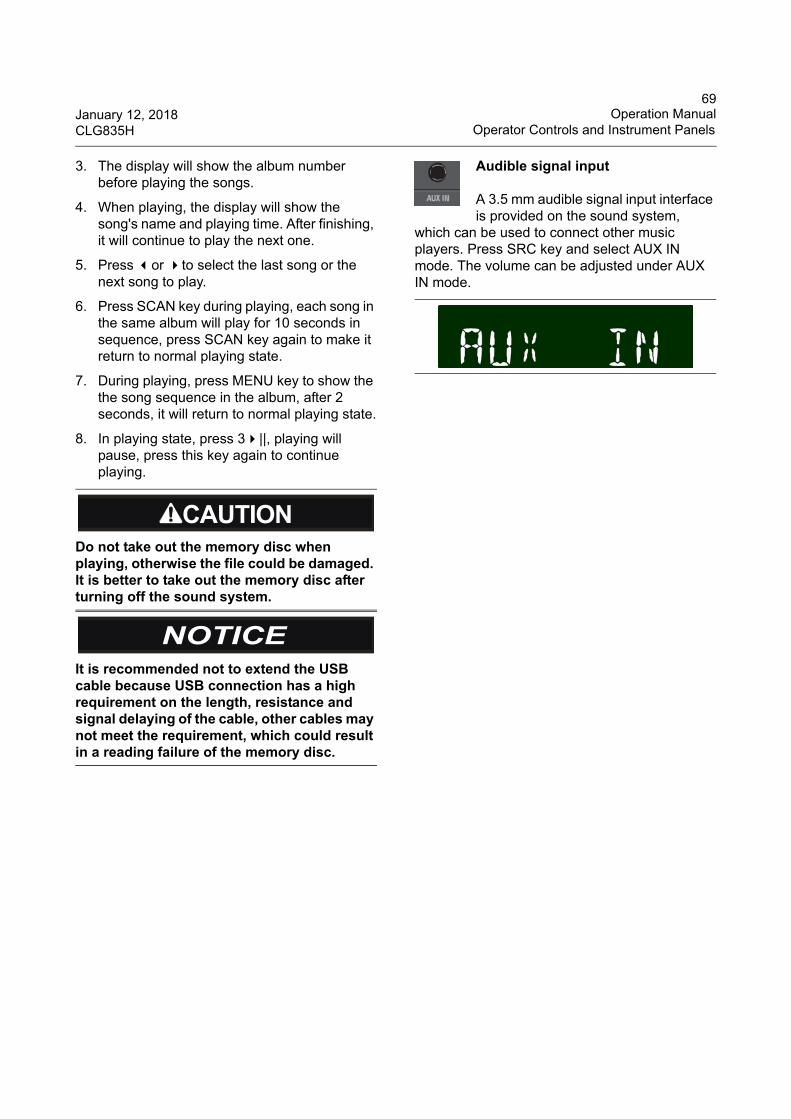
69January 12, 2018 Operation ManualCLG835H Operator Controls and Instrument Panels
3. The display will show the album number before playing the songs.
4. When playing, the display will show the song's name and playing time. After finishing, it will continue to play the next one.
5. Press or to select the last song or the next song to play.
6. Press SCAN key during playing, each song in the same album will play for 10 seconds in sequence, press SCAN key again to make it return to normal playing state.
7. During playing, press MENU key to show the the song sequence in the album, after 2 seconds, it will return to normal playing state.
8. In playing state, press 3||, playing will pause, press this key again to continue playing.
Audible signal input
A 3.5 mm audible signal input interface is provided on the sound system,
which can be used to connect other music players. Press SRC key and select AUX IN mode. The volume can be adjusted under AUX IN mode.
Do not take out the memory disc when playing, otherwise the file could be damaged. It is better to take out the memory disc after turning off the sound system.
It is recommended not to extend the USB cable because USB connection has a high requirement on the length, resistance and signal delaying of the cable, other cables may not meet the requirement, which could result in a reading failure of the memory disc.
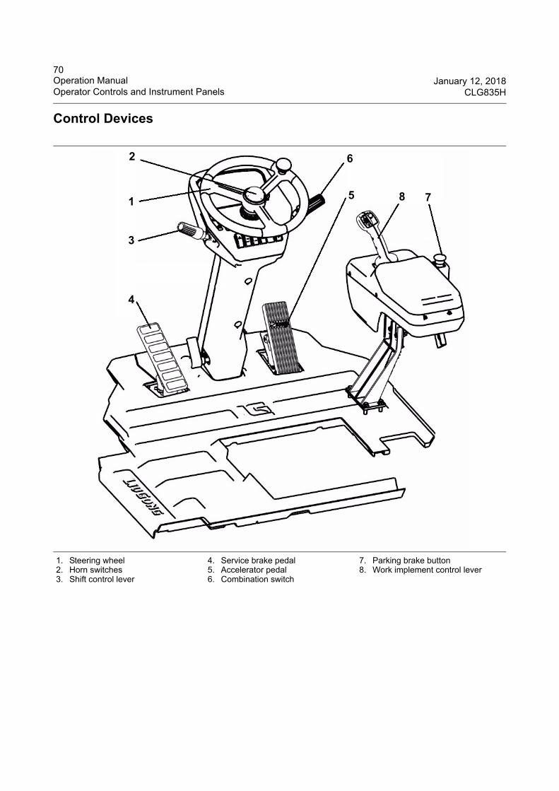
70Operation Manual January 12, 2018Operator Controls and Instrument Panels CLG835H
Control Devices
1. Steering wheel2. Horn switches3. Shift control lever
4. Service brake pedal5. Accelerator pedal 6. Combination switch
7. Parking brake button8. Work implement control lever
1
2
3
4
5 78
6
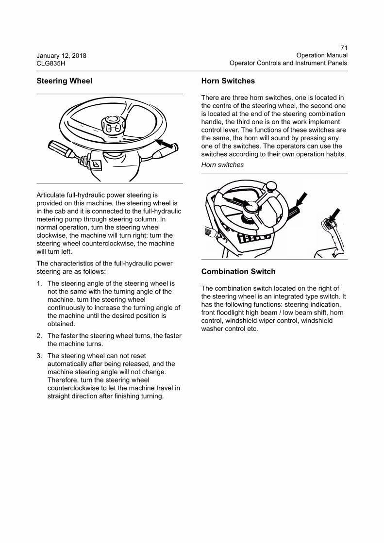
71January 12, 2018 Operation ManualCLG835H Operator Controls and Instrument Panels
Steering Wheel
Articulate full-hydraulic power steering is provided on this machine, the steering wheel is in the cab and it is connected to the full-hydraulic metering pump through steering column. In normal operation, turn the steering wheel clockwise, the machine will turn right; turn the steering wheel counterclockwise, the machine will turn left.
The characteristics of the full-hydraulic power steering are as follows:
1. The steering angle of the steering wheel is not the same with the turning angle of the machine, turn the steering wheel continuously to increase the turning angle of the machine until the desired position is obtained.
2. The faster the steering wheel turns, the faster the machine turns.
3. The steering wheel can not reset automatically after being released, and the machine steering angle will not change. Therefore, turn the steering wheel counterclockwise to let the machine travel in straight direction after finishing turning.
Horn Switches
There are three horn switches, one is located in the centre of the steering wheel, the second one is located at the end of the steering combination handle, the third one is on the work implement control lever. The functions of these switches are the same, the horn will sound by pressing any one of the switches. The operators can use the switches according to their own operation habits.
Combination Switch
The combination switch located on the right of the steering wheel is an integrated type switch. It has the following functions: steering indication, front floodlight high beam / low beam shift, horn control, windshield wiper control, windshield washer control etc.
Horn switches
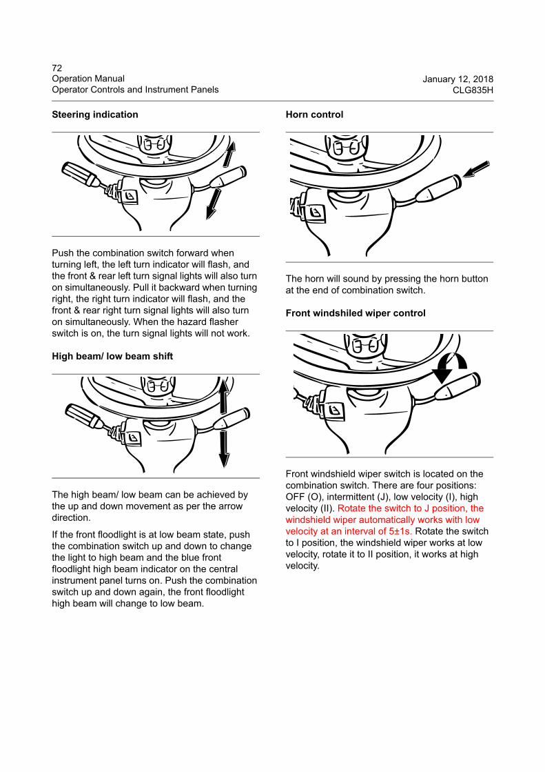
72Operation Manual January 12, 2018Operator Controls and Instrument Panels CLG835H
Steering indication
Push the combination switch forward when turning left, the left turn indicator will flash, and the front & rear left turn signal lights will also turn on simultaneously. Pull it backward when turning right, the right turn indicator will flash, and the front & rear right turn signal lights will also turn on simultaneously. When the hazard flasher switch is on, the turn signal lights will not work.
High beam/ low beam shift
The high beam/ low beam can be achieved by the up and down movement as per the arrow direction.
If the front floodlight is at low beam state, push the combination switch up and down to change the light to high beam and the blue front floodlight high beam indicator on the central instrument panel turns on. Push the combination switch up and down again, the front floodlight high beam will change to low beam.
Horn control
The horn will sound by pressing the horn button at the end of combination switch.
Front windshiled wiper control
Front windshield wiper switch is located on the combination switch. There are four positions: OFF (O), intermittent (J), low velocity (I), high velocity (II). Rotate the switch to J position, the windshield wiper automatically works with low velocity at an interval of 5±1s. Rotate the switch to I position, the windshield wiper works at low velocity, rotate it to II position, it works at high velocity.
73January 12, 2018 Operation ManualCLG835H Operator Controls and Instrument Panels
Front washer control
The washer will work by pressing the washer control switch inwards. The water from reservoir will be sprayed to windshield window glass.
The washer will reset to natural position and stop spraying after being released.
Refer to section “Window Washer Reservoir--Fill” for the location and maintenance of the washer reservoir.
Shift Control Lever
The shift control lever is automatic type. It is located on the left side of the steering column, which is used to choose travel direction and travel speed.
Direction selection
F: ForwardR: ReverseN: Neutral
1. Shift control lever
Forward: push the shift control lever to FORWARD position, the machine will move forward.
Neutral: push the shift control lever to NEUTRAL position, the machine should not move. Only when the shift control lever is in NEUTRAL position can the engine starts.
Reverse: push the shift control lever to REVERSE position, the machine will move backward.
Speed selection
Rotate the shift control lever. The number in the arrow direction as illustrated in the picture is the speed position. This machine has four forward speeds and three reverse speeds. When the shift control lever is in the R4, actually it is in R3.
1. ''1'' for first speed2. ''2'' for second speed3. ''3'' for third speed4. ''4'' for fourth speed
When the shift control system has a fault, never remove the transmission system without authorization. Consult LiuGong dealer or Service Company if the fault can not be eliminated.
1
F
N
R
74Operation Manual January 12, 2018Operator Controls and Instrument Panels CLG835H
1. Gear2. Gear indication
When the shift control lever is at 4th speed, increasing or decreasing the accelerator can change the travel speed automatically. A LCD display is provided on the central instrument panel to show the gear and fault code of the transmission. The specific travel speed of the machine will display on the speedometer on the central instrument panel.
Except for the direction and speed change function, the shift control system also has other special functions.
Special functions of the shift control system:
1. Neutral locking protection function
Push the shift control lever to NEUTRAL, and push the lock switch to position (N), the shift control lever will be locked at NEUTRAL position.
Push the lock switch to position (D), the shift control lever will be unlocked, and the machine can be operated normally.
Generally, when the machine is in maintenance or in parking condition, in order to prevent the misoperation, push the lock switch to position (N) to lock the shift control lever at NEUTRAL position.
Use this switch to prevent misoperation.
2. Neutral/start interlock protection functions
The electrical system of the machine has neutral/ start interlock protection function, start the engine only after the shift control lever is at NEUTRAL position so as to prevent unexpected accidents due to sudden actions.
3. Direct forward/reverse change function
The shift control lever of the machine has no turning interlock function, the driver can directly change directions according to the driving speed:
At F1or F2gear, directly engage the corresponding reverse (F1 <=> R1 and F2 <=> R2) any time.
At F3 and F4, The driver should operate the shift control lever according to the driving speed as the following rules:
Gear display
Neutral lock switch
2
1
When the shift control lever is locked at NEUTRAL position, it is forbidden to shift forward or reverse without releasing the neutral lock switch, otherwise the shift control lever will be damaged.
75January 12, 2018 Operation ManualCLG835H Operator Controls and Instrument Panels
When the machine exceeds the preset speed (normally 2nd gear is set as the maximum driving speed), the system first automatically reduces to 2nd position at the present driving direction and engages the 2nd position after a while, and finally changes speed to the preset position.
4. Forced down shift function (Kick down key)
Two kick down keys (KD keys) are available. One is located at the end of the shift control lever, it is sliding type; the other one is located behind the work implement control lever.
See above picture shows, the arrow direction is the operation direction of the KD key.
When the F2 or R2 is selected, press KD key on the shift control lever, the transmission can automatically shift to F1 or R1.
The KD key function and the direct forward/ reverse change function have supplied a convenience for gear shifting when loading materials. For example, when the machine moves close to the material stack at F2, push down the KD key, the gear can shift into F1 automatically; after loading, press down the key ↓, the gear will shift to R2 automatically. The machine will leave the material stack at R2 speed, so a high working efficiency can be achieved.
The KD key function will stop automatically when other position is selected, cancel the KD key function through the following ways:
● Pressing KD key again.
● Reversing.
● Operate the shift control lever to change the driving speed.
● The lever is at NEUTRAL position.
5. Start speed limit function
To ensure the driving safety, the position is limited at F1, F2 or R1, R2 by the electronic control box when the machine starts. Only after the speed exceeds the setting value can F3, F4 be shifted. If the speed doesn’ t reach this value, the machine only can move in F2 (the road condition determines the running speed) even shift the gear to F3, F4. Therefore, after the machine starts, it can move at high speed only after the driving speed exceeds the setting value.
KD keys
76Operation Manual January 12, 2018Operator Controls and Instrument Panels CLG835H
6. System self-protection function
When abnormal information occurs (such as disconnected wiring, ground short-circuit of the electronic control box and odd signal) or power supply exceeds the specified limit or there is an open circuit, the electronic control box changes to NEUTRAL to lock all output signals so that misoperation can be greatly prevented to ensure the driving safety.
7. Clutch cut off function
Depress the brake pedal after the clutch cut off switch is turned to ON (see the follwing picture), then the shift control valve will cut off the transmission power output.
When the clutch cut off switch is turned to OFF, the power cut off function will be cancelled. That is, the transmission power output will not be cut off when the brake is engaged.
Service Brake Pedal
The service brake pedal is located at the front left side of the driver’s seat. The service brake system has single brake pedal and double circuits. Depress the service brake pedal, the front and rear axle brakes will engage and the brake lights will light simultaneously. The other circuit will not be affected if one of the circuits has fault so as to let the machine keep enough brake capability to ensure the operation security. Repair the brake system in time if it has fault to ensure the machine has enough brake power.
The clutch cut off function only can be used in F 1, F 2 or R 1, R 2. To ensure safe operation, when the machine is at high speed, even if the clutch cut off switch is turned to ON, the electronic control box will not shut off power output of the transmission.
CLUTCH CUT -OFF
CLUTCH CUT-ON
A lock buckle is provided on the clutch cut off switch. Unlock the buckle before turning off the switch, otherwise the switch could be damaged.
When operating the machine on flat ground, the operator should turn the clutch cut off switch to ON. Otherwise the performance of the brakes, service life of the brake system and the transmission will be affected.
For safe operation of the machine, when the machine is working on a slope, do not turn the clutch cut off switch to ON.
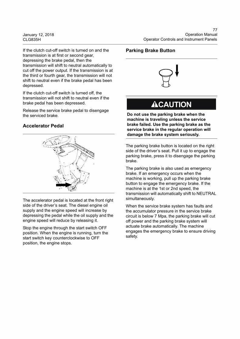
77January 12, 2018 Operation ManualCLG835H Operator Controls and Instrument Panels
If the clutch cut-off switch is turned on and the transmission is at first or second gear, depressing the brake pedal, then the transmission will shift to neutral automatically to cut off the power output. If the transmission is at the third or fourth gear, the transmission will not shift to neutral even if the brake pedal has been depressed.
If the clutch cut-off switch is turned off, the transmission will not shift to neutral even if the brake pedal has been depressed.
Release the service brake pedal to disengage the serviced brake.
Accelerator Pedal
The accelerator pedal is located at the front right side of the driver’s seat. The diesel engine oil supply and the engine speed will increase by depressing the pedal while the oil supply and the engine speed will reduce by releasing it.
Stop the engine through the start switch OFF position. When the engine is running, turn the start switch key counterclockwise to OFF position, the engine stops.
Parking Brake Button
The parking brake button is located on the right side of the driver’s seat. Pull it up to engage the parking brake, press it to disengage the parking brake.
The parking brake is also used as emergency brake. If an emergency occurs when the machine is working, pull up the parking brake button to engage the emergency brake. If the machine is at the 1st or 2nd speed, the transmission will automatically shift to NEUTRAL simultaneously.
When the service brake system has faults and the accumulator pressure in the service brake circuit is below 7 Mpa, the parking brake will cut off power and the parking brake system will actuate brake automatically. The machine engages the emergency brake to ensure driving safety.
Do not use the parking brake when the machine is traveling unless the service brake failed. Use the parking brake as the service brake in the regular operation will damage the brake system seriously.
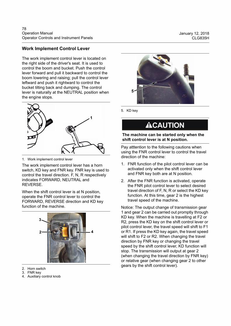
78Operation Manual January 12, 2018Operator Controls and Instrument Panels CLG835H
Work Implement Control Lever
The work implement control lever is located on the right side of the driver's seat. It is used to control the boom and bucket. Push the control lever forward and pull it backward to control the boom lowering and raising; pull the control lever leftward and push it rightward to control the bucket tilting back and dumping. The control lever is naturally at the NEUTRAL position when the engine stops.
1. Work implement control lever
The work implement control lever has a horn switch, KD key and FNR key. FNR key is used to control the travel direction. F, N, R respectively indicates FORWARD, NEUTRAL and REVERSE.
When the shift control lever is at N position, operate the FNR control lever to control the FORWARD, REVERSE direction and KD key function of the machine.
2. Horn switch3. FNR key4. Auxiliary control knob
5. KD key
Pay atttention to the following cautions when using the FNR control lever to control the travel direction of the machine:
1. FNR function of the pilot control lever can be activated only when the shift control lever and FNR key both are at N position.
2. After the FNR function is activated, operate the FNR pilot control lever to select desired travel direction of F, N, R or select the KD key function. At this time, gear 2 is the highest travel speed of the machine.
Notice: The output change of transmission gear 1 and gear 2 can be carried out promptly through KD key. When the machine is travelling at F2 or R2, press the KD key on the shift control lever or pilot control lever, the travel speed will shift to F1 or R1. If press the KD key again, the travel speed will shift to F2 or R2. When changing the travel direction by FNR key or changing the travel speed by the shift control lever, KD function will stop. The transmission will output at gear 2 (when changing the travel direction by FNR key) or relative gear (when changing gear 2 to other gears by the shift control lever).
1
4
3
2
The machine can be started only when the shift control lever is at N position.
5
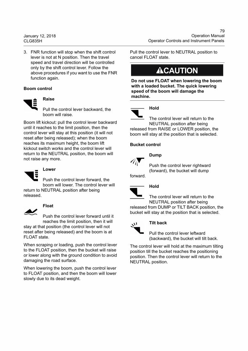
79January 12, 2018 Operation ManualCLG835H Operator Controls and Instrument Panels
3. FNR function will stop when the shift control lever is not at N position. Then the travel speed and travel direction will be controlled only by the shift control lever. Follow the above procedures if you want to use the FNR function again.
Boom control
Raise
Pull the control lever backward, the boom will raise.
Boom lift kickout: pull the control lever backward until it reaches to the limit position, then the control lever will stay at this position (it will not reset after being released); when the boom reaches its maximum height, the boom lift kickout switch works and the control lever will return to the NEUTRAL position, the boom will not raise any more.
Lower
Push the control lever forward, the boom will lower. The control lever will
return to NEUTRAL position after being released.
Float
Push the control lever forward until it reaches the limit position, then it will
stay at that position (the control lever will not reset after being released) and the boom is at FLOAT state.
When scraping or loading, push the control lever to the FLOAT position, then the bucket will raise or lower along with the ground condition to avoid damaging the road surface.
When lowering the boom, push the control lever to FLOAT position, and then the boom will lower slowly due to its dead weight.
Pull the control lever to NEUTRAL position to cancel FLOAT state.
Hold
The control lever will return to the NEUTRAL position after being
released from RAISE or LOWER position, the boom will stay at the position that is selected.
Bucket control
Dump
Push the control lever rightward (forward), the bucket will dump
forward.
Hold
The control lever will return to the NEUTRAL position after being
released from DUMP or TILT BACK position, the bucket will stay at the position that is selected.
Tilt back
Pull the control lever leftward (backward), the bucket will tilt back.
The control lever will hold at the maximum tilting position till the bucket reaches the positioning position. Then the control lever will return to the NEUTRAL position.
Do not use FLOAT when lowering the boom with a loaded bucket. The quick lowering speed of the boom will damage the machine.
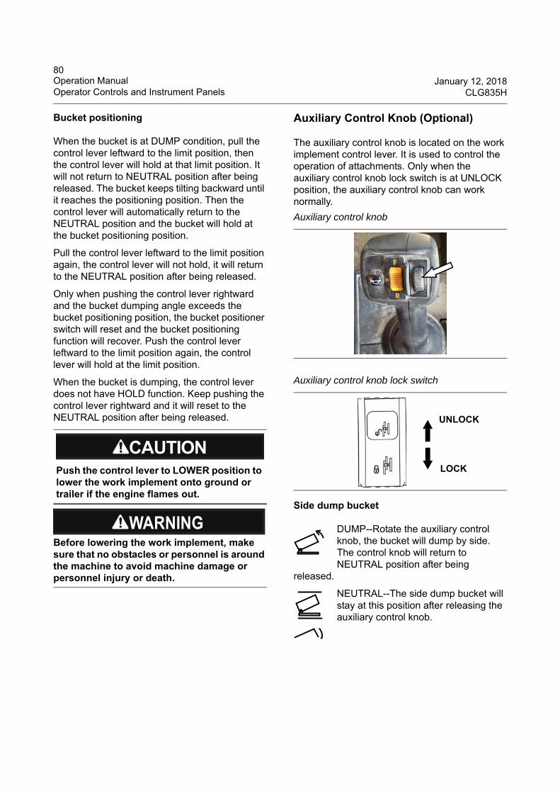
80Operation Manual January 12, 2018Operator Controls and Instrument Panels CLG835H
Bucket positioning
When the bucket is at DUMP condition, pull the control lever leftward to the limit position, then the control lever will hold at that limit position. It will not return to NEUTRAL position after being released. The bucket keeps tilting backward until it reaches the positioning position. Then the control lever will automatically return to the NEUTRAL position and the bucket will hold at the bucket positioning position.
Pull the control lever leftward to the limit position again, the control lever will not hold, it will return to the NEUTRAL position after being released.
Only when pushing the control lever rightward and the bucket dumping angle exceeds the bucket positioning position, the bucket positioner switch will reset and the bucket positioning function will recover. Push the control lever leftward to the limit position again, the control lever will hold at the limit position.
When the bucket is dumping, the control lever does not have HOLD function. Keep pushing the control lever rightward and it will reset to the NEUTRAL position after being released.
Auxiliary Control Knob (Optional)
The auxiliary control knob is located on the work implement control lever. It is used to control the operation of attachments. Only when the auxiliary control knob lock switch is at UNLOCK position, the auxiliary control knob can work normally.
Side dump bucket
DUMP--Rotate the auxiliary control knob, the bucket will dump by side. The control knob will return to NEUTRAL position after being
released.
NEUTRAL--The side dump bucket will stay at this position after releasing the auxiliary control knob.
Push the control lever to LOWER position to lower the work implement onto ground or trailer if the engine flames out.
Before lowering the work implement, make sure that no obstacles or personnel is around the machine to avoid machine damage or personnel injury or death.
Auxiliary control knob
Auxiliary control knob lock switch
UNLOCK
LOCK
81January 12, 2018 Operation ManualCLG835H Operator Controls and Instrument Panels
TILT BACK--Rotate the auxiliary control knob again, the bucket will tilt back. The control knob will return to NEUTRAL position after being
released.
Logging fork
CLOSE--Rotate the auxiliary control knob, the logging fork will close. The control knob will return to NEUTRAL position after being released.
NEUTRAL--The logging fork will stay at this position after releasing the auxiliary control knob.
OPEN--Rotate the auxiliary control knob again, the logging fork will open. The control knob will return to NEUTRAL position after being released.
Snow plow moldboard
SWING RIGHT--Rotate the auxiliary control knob, the moldboard will swing right. The control knob will return to NEUTRAL position after being
released.
NEUTRAL--The moldboard will stay at this position after releasing the auxiliary control knob.
SWING LEFT--Rotate the auxiliary control knob again, the moldboard will swing left. The control knob will return to NEUTRAL position after being
released.
After finish dumping, do not operate other control levers until the side dump bucket is lowered to ground.
Do not operate the auxiliary control knob during loading, otherwise the side dump cylinder will be damaged, the bucket will loose and dump accidently, serious accident will be caused.
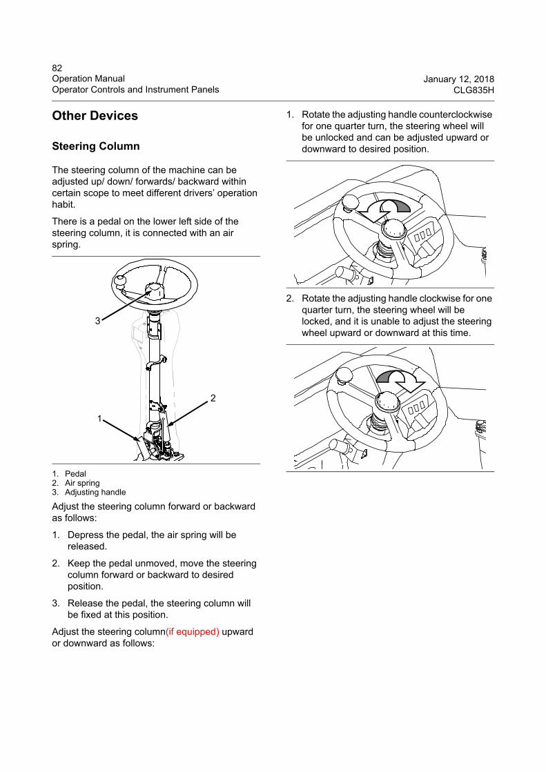
82Operation Manual January 12, 2018Operator Controls and Instrument Panels CLG835H
Other Devices
Steering Column
The steering column of the machine can be adjusted up/ down/ forwards/ backward within certain scope to meet different drivers’ operation habit.
There is a pedal on the lower left side of the steering column, it is connected with an air spring.
1. Pedal2. Air spring3. Adjusting handle
Adjust the steering column forward or backward as follows:
1. Depress the pedal, the air spring will be released.
2. Keep the pedal unmoved, move the steering column forward or backward to desired position.
3. Release the pedal, the steering column will be fixed at this position.
Adjust the steering column(if equipped) upward or downward as follows:
1. Rotate the adjusting handle counterclockwise for one quarter turn, the steering wheel will be unlocked and can be adjusted upward or downward to desired position.
2. Rotate the adjusting handle clockwise for one quarter turn, the steering wheel will be locked, and it is unable to adjust the steering wheel upward or downward at this time.
1
2
3
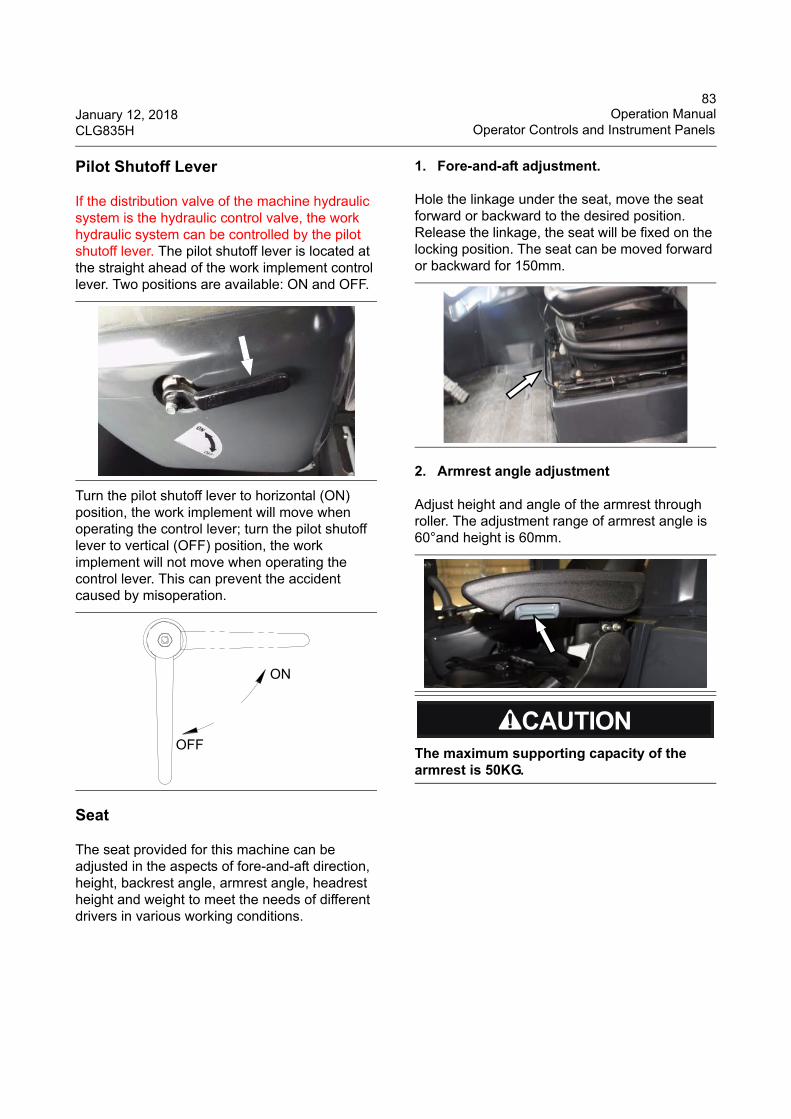
83January 12, 2018 Operation ManualCLG835H Operator Controls and Instrument Panels
Pilot Shutoff Lever
If the distribution valve of the machine hydraulic system is the hydraulic control valve, the work hydraulic system can be controlled by the pilot shutoff lever. The pilot shutoff lever is located at the straight ahead of the work implement control lever. Two positions are available: ON and OFF.
Turn the pilot shutoff lever to horizontal (ON) position, the work implement will move when operating the control lever; turn the pilot shutoff lever to vertical (OFF) position, the work implement will not move when operating the control lever. This can prevent the accident caused by misoperation.
Seat
The seat provided for this machine can be adjusted in the aspects of fore-and-aft direction, height, backrest angle, armrest angle, headrest height and weight to meet the needs of different drivers in various working conditions.
1. Fore-and-aft adjustment.
Hole the linkage under the seat, move the seat forward or backward to the desired position. Release the linkage, the seat will be fixed on the locking position. The seat can be moved forward or backward for 150mm.
2. Armrest angle adjustment
Adjust height and angle of the armrest through roller. The adjustment range of armrest angle is 60°and height is 60mm.
ON
OFFThe maximum supporting capacity of the armrest is 50KG.
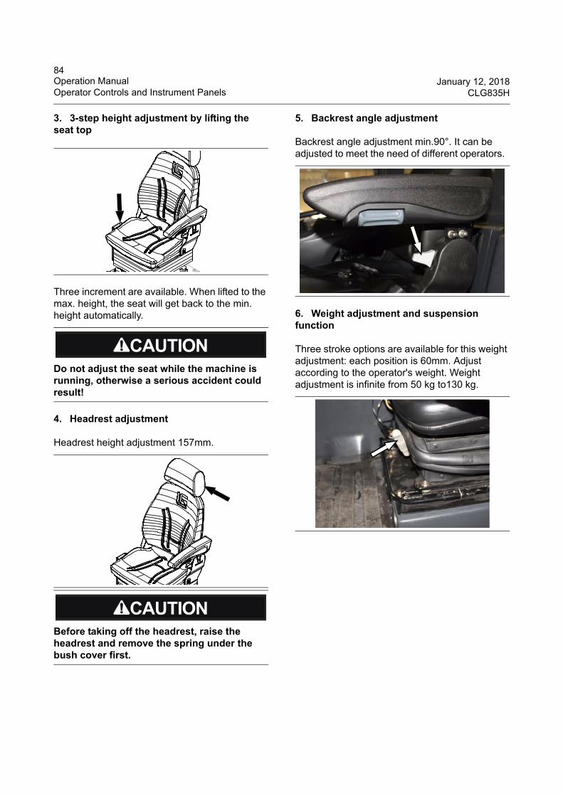
84Operation Manual January 12, 2018Operator Controls and Instrument Panels CLG835H
3. 3-step height adjustment by lifting the seat top
Three increment are available. When lifted to the max. height, the seat will get back to the min. height automatically.
4. Headrest adjustment
Headrest height adjustment 157mm.
5. Backrest angle adjustment
Backrest angle adjustment min.90°. It can be adjusted to meet the need of different operators.
6. Weight adjustment and suspension function
Three stroke options are available for this weight adjustment: each position is 60mm. Adjust according to the operator's weight. Weight adjustment is infinite from 50 kg to130 kg.
Do not adjust the seat while the machine is running, otherwise a serious accident could result!
Before taking off the headrest, raise the headrest and remove the spring under the bush cover first.
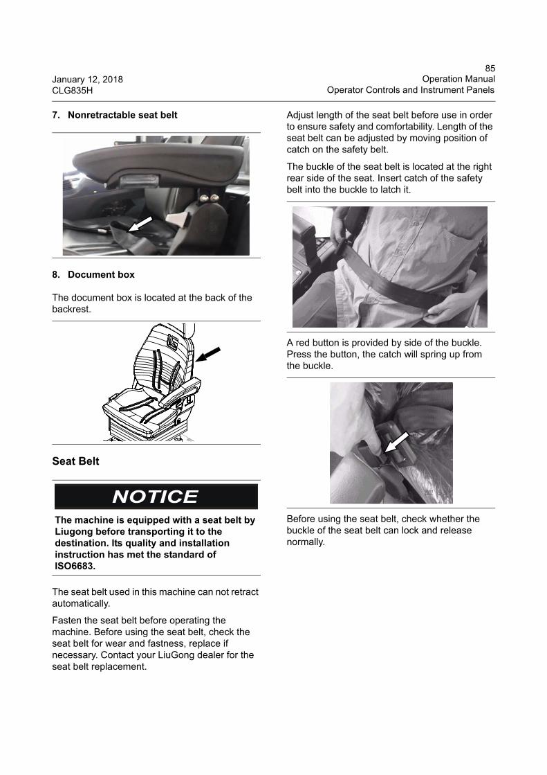
85January 12, 2018 Operation ManualCLG835H Operator Controls and Instrument Panels
7. Nonretractable seat belt
8. Document box
The document box is located at the back of the backrest.
Seat Belt
The seat belt used in this machine can not retract automatically.
Fasten the seat belt before operating the machine. Before using the seat belt, check the seat belt for wear and fastness, replace if necessary. Contact your LiuGong dealer for the seat belt replacement.
Adjust length of the seat belt before use in order to ensure safety and comfortability. Length of the seat belt can be adjusted by moving position of catch on the safety belt.
The buckle of the seat belt is located at the right rear side of the seat. Insert catch of the safety belt into the buckle to latch it.
A red button is provided by side of the buckle. Press the button, the catch will spring up from the buckle.
Before using the seat belt, check whether the buckle of the seat belt can lock and release normally.
The machine is equipped with a seat belt by Liugong before transporting it to the destination. Its quality and installation instruction has met the standard of ISO6683.
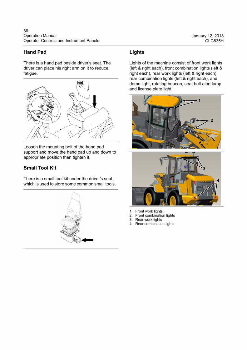
86Operation Manual January 12, 2018Operator Controls and Instrument Panels CLG835H
Hand Pad
There is a hand pad beside driver's seat. The driver can place his right arm on it to reduce fatigue.
Loosen the mounting bolt of the hand pad support and move the hand pad up and down to appropriate position then tighten it.
Small Tool Kit
There is a small tool kit under the driver's seat, which is used to store some common small tools.
Lights
Lights of the machine consist of front work lights (left & right each), front combination lights (left & right each), rear work lights (left & right each), rear combination lights (left & right each), and dome light, rotating beacon, seat belt alert lamp and license plate light.
1. Front work lights2. Front combination lights3. Rear work lights4. Rear combination lights
1
2
1
3
4
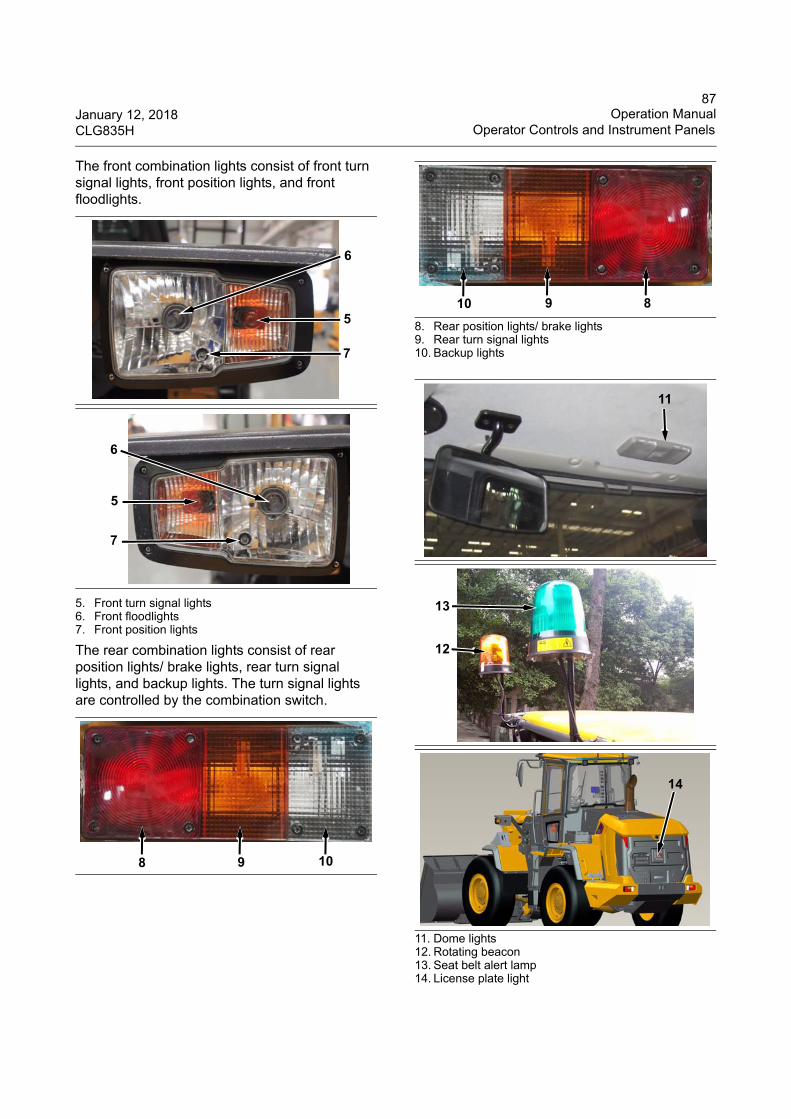
87January 12, 2018 Operation ManualCLG835H Operator Controls and Instrument Panels
The front combination lights consist of front turn signal lights, front position lights, and front floodlights.
5. Front turn signal lights6. Front floodlights7. Front position lights
The rear combination lights consist of rear position lights/ brake lights, rear turn signal lights, and backup lights. The turn signal lights are controlled by the combination switch.
8. Rear position lights/ brake lights9. Rear turn signal lights10. Backup lights
11. Dome lights12. Rotating beacon13. Seat belt alert lamp14. License plate light
5
7
6
5
6
7
8 9 10
10 9 8
11
12
13
14
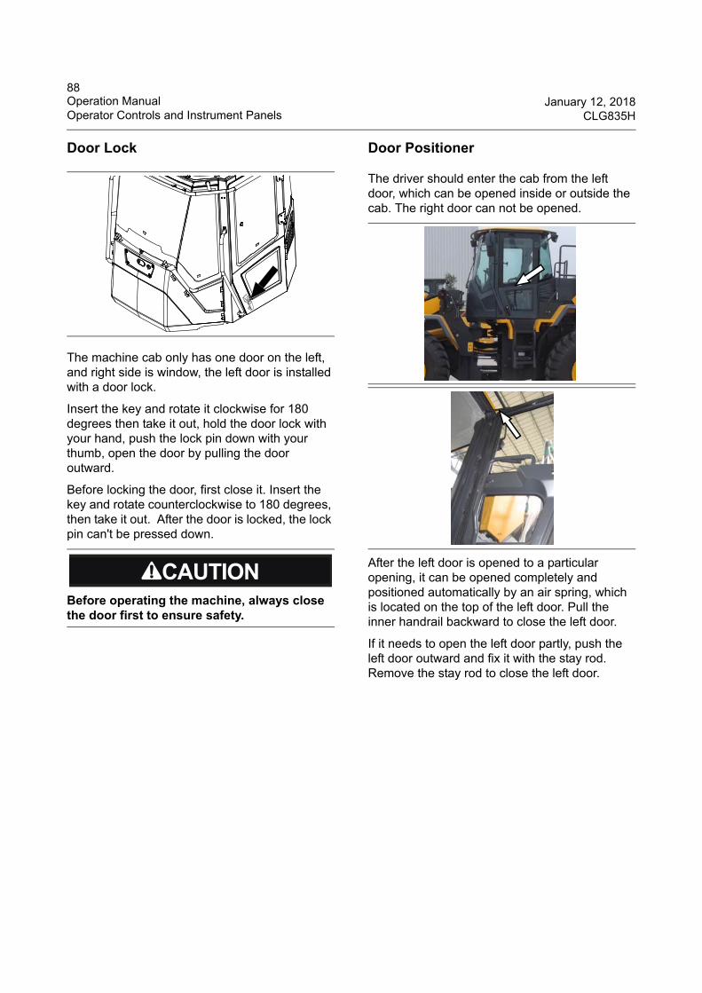
88Operation Manual January 12, 2018Operator Controls and Instrument Panels CLG835H
Door Lock
The machine cab only has one door on the left, and right side is window, the left door is installed with a door lock.
Insert the key and rotate it clockwise for 180 degrees then take it out, hold the door lock with your hand, push the lock pin down with your thumb, open the door by pulling the door outward.
Before locking the door, first close it. Insert the key and rotate counterclockwise to 180 degrees, then take it out. After the door is locked, the lock pin can't be pressed down.
Door Positioner
The driver should enter the cab from the left door, which can be opened inside or outside the cab. The right door can not be opened.
After the left door is opened to a particular opening, it can be opened completely and positioned automatically by an air spring, which is located on the top of the left door. Pull the inner handrail backward to close the left door.
If it needs to open the left door partly, push the left door outward and fix it with the stay rod. Remove the stay rod to close the left door.
Before operating the machine, always close the door first to ensure safety.
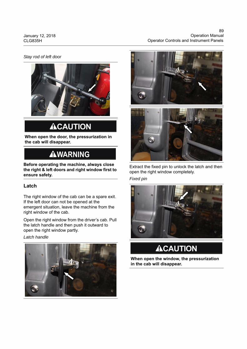
89January 12, 2018 Operation ManualCLG835H Operator Controls and Instrument Panels
Latch
The right window of the cab can be a spare exit. If the left door can not be opened at the emergent situation, leave the machine from the right window of the cab.
Open the right window from the driver’s cab. Pull the latch handle and then push it outward to open the right window partly.
Extract the fixed pin to unlock the latch and then open the right window completely.
Stay rod of left door
When open the door, the pressurization in the cab will disappear.
Before operating the machine, always close the right & left doors and right window first to ensure safety.
Latch handle
Fixed pin
When open the window, the pressurization in the cab will disappear.
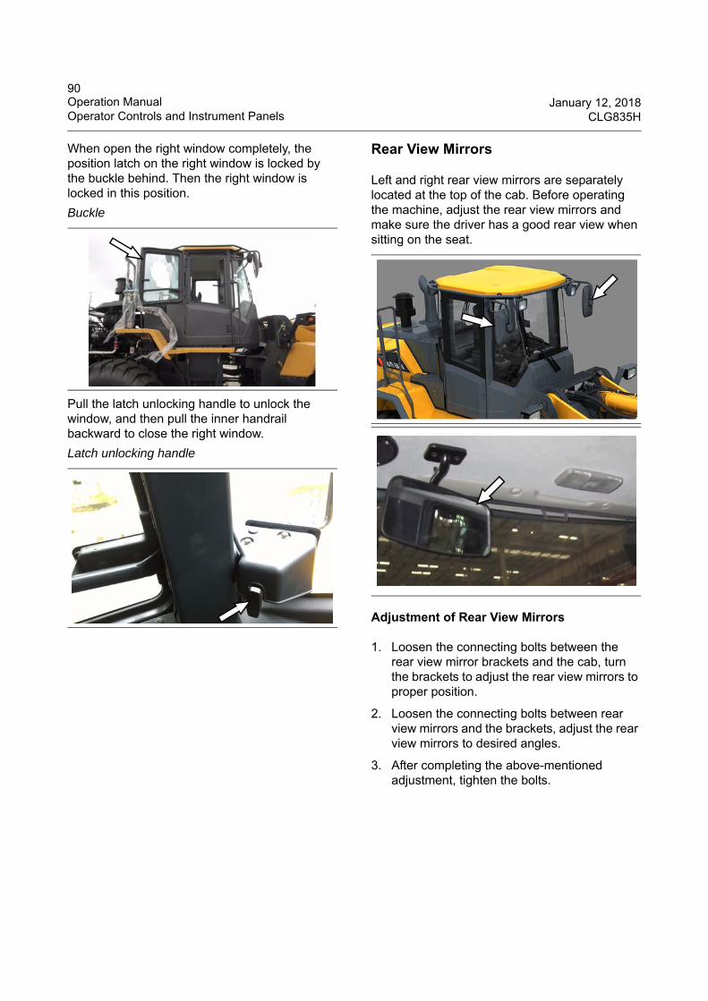
90Operation Manual January 12, 2018Operator Controls and Instrument Panels CLG835H
When open the right window completely, the position latch on the right window is locked by the buckle behind. Then the right window is locked in this position.
Pull the latch unlocking handle to unlock the window, and then pull the inner handrail backward to close the right window.
Rear View Mirrors
Left and right rear view mirrors are separately located at the top of the cab. Before operating the machine, adjust the rear view mirrors and make sure the driver has a good rear view when sitting on the seat.
Adjustment of Rear View Mirrors
1. Loosen the connecting bolts between the rear view mirror brackets and the cab, turn the brackets to adjust the rear view mirrors to proper position.
2. Loosen the connecting bolts between rear view mirrors and the brackets, adjust the rear view mirrors to desired angles.
3. After completing the above-mentioned adjustment, tighten the bolts.
Buckle
Latch unlocking handle
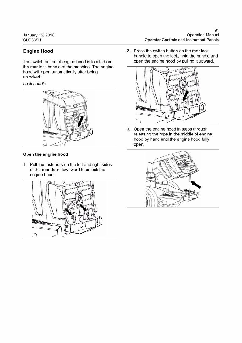
91January 12, 2018 Operation ManualCLG835H Operator Controls and Instrument Panels
Engine Hood
The switch button of engine hood is located on the rear lock handle of the machine. The engine hood will open automatically after being unlocked.
Open the engine hood
1. Pull the fasteners on the left and right sides of the rear door downward to unlock the engine hood.
2. Press the switch button on the rear lock handle to open the lock, hold the handle and open the engine hood by pulling it upward.
3. Open the engine hood in steps through releasing the rope in the middle of engine hood by hand until the engine hood fully open.
Lock handle
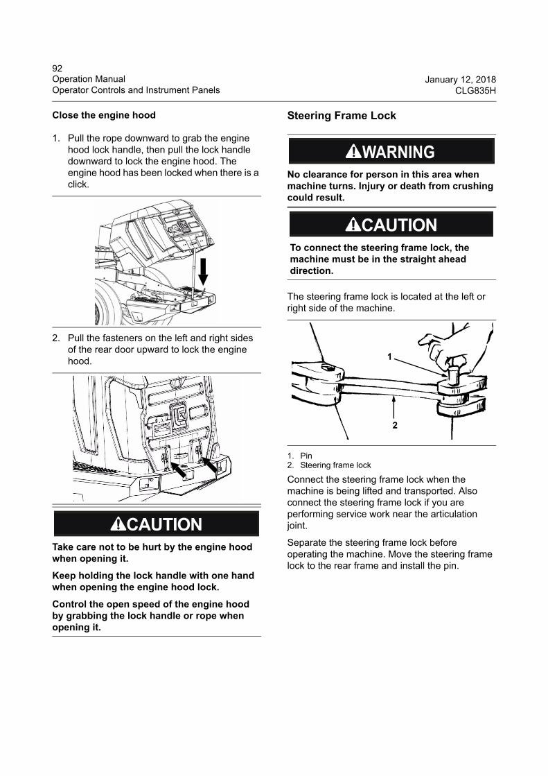
92Operation Manual January 12, 2018Operator Controls and Instrument Panels CLG835H
Close the engine hood
1. Pull the rope downward to grab the engine hood lock handle, then pull the lock handle downward to lock the engine hood. The engine hood has been locked when there is a click.
2. Pull the fasteners on the left and right sides of the rear door upward to lock the engine hood.
Steering Frame Lock
The steering frame lock is located at the left or right side of the machine.
1. Pin2. Steering frame lock
Connect the steering frame lock when the machine is being lifted and transported. Also connect the steering frame lock if you are performing service work near the articulation joint.
Separate the steering frame lock before operating the machine. Move the steering frame lock to the rear frame and install the pin.
Take care not to be hurt by the engine hood when opening it.
Keep holding the lock handle with one hand when opening the engine hood lock.
Control the open speed of the engine hood by grabbing the lock handle or rope when opening it.
No clearance for person in this area when machine turns. Injury or death from crushing could result.
To connect the steering frame lock, the machine must be in the straight ahead direction.
1
2

93January 12, 2018 Operation ManualCLG835H Operator Controls and Instrument Panels
Backup Alarm System
The backup alarm is located at the back of the machine. When the machine is reversing with shift control lever turned to REVERSE position, the backup alarm will sound automatically.
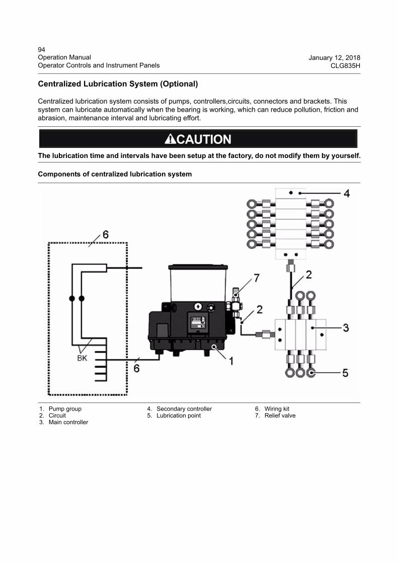
94Operation Manual January 12, 2018Operator Controls and Instrument Panels CLG835H
Centralized Lubrication System (Optional)
Centralized lubrication system consists of pumps, controllers,circuits, connectors and brackets. This system can lubricate automatically when the bearing is working, which can reduce pollution, friction and abrasion, maintenance interval and lubricating effort.
The lubrication time and intervals have been setup at the factory, do not modify them by yourself.
Components of centralized lubrication system
1. Pump group2. Circuit3. Main controller
4. Secondary controller5. Lubrication point
6. Wiring kit7. Relief valve
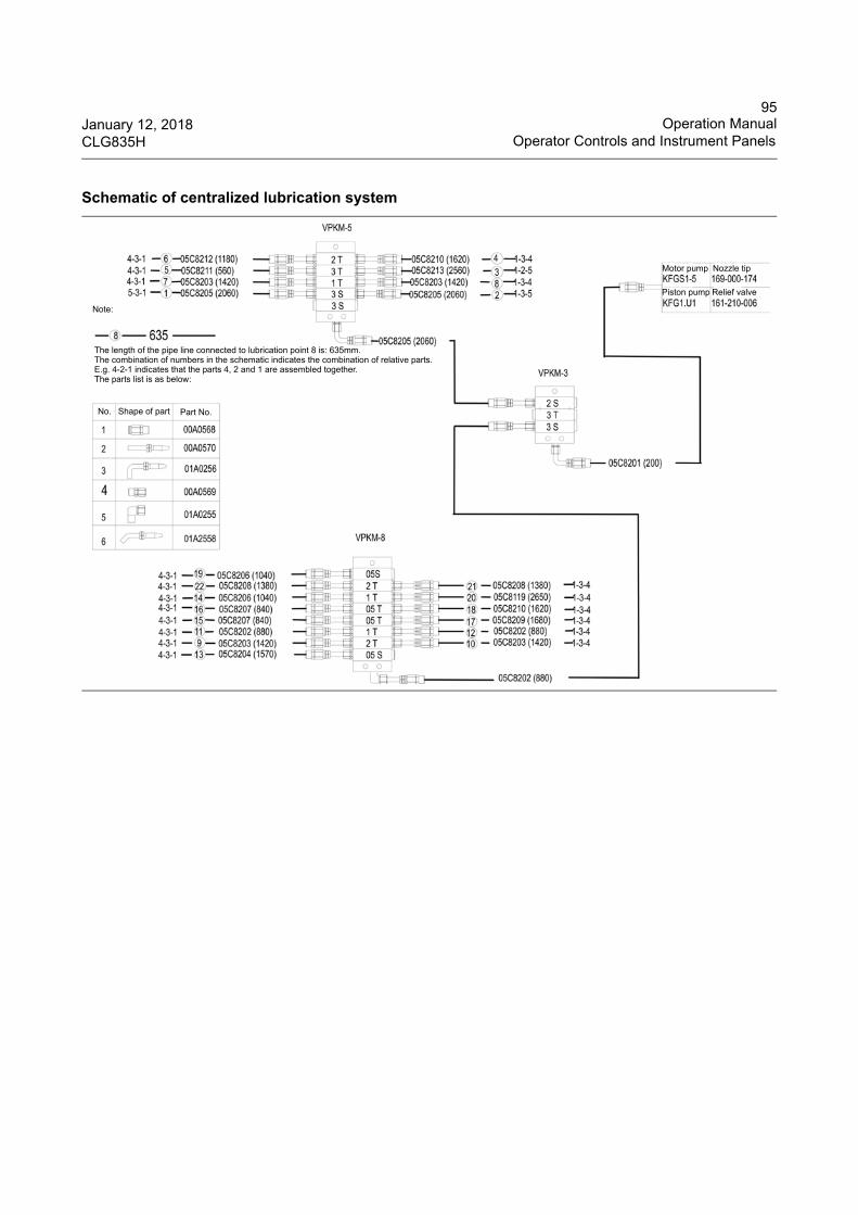
95January 12, 2018 Operation ManualCLG835H Operator Controls and Instrument Panels
Schematic of centralized lubrication system
Motor pump Nozzle tip
Piston pump Relief valve
Note:
The length of the pipe line connected to lubrication point 8 is: 635mm.The combination of numbers in the schematic indicates the combination of relative parts.E.g. 4-2-1 indicates that the parts 4, 2 and 1 are assembled together. The parts list is as below:
No. Shape of part Part No.
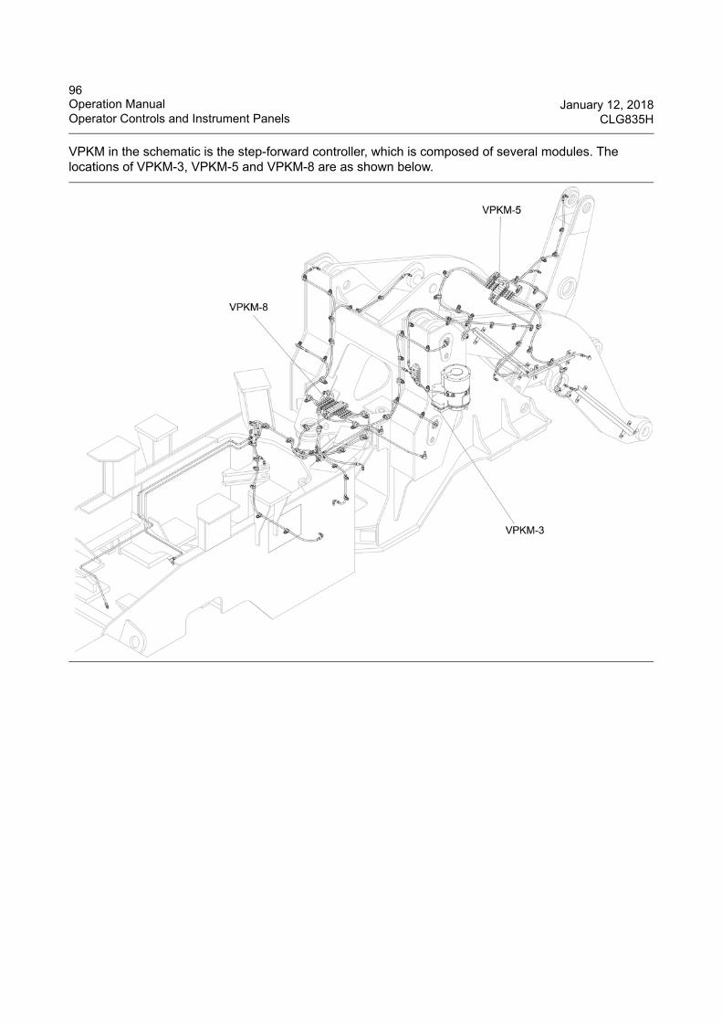
96Operation Manual January 12, 2018Operator Controls and Instrument Panels CLG835H
VPKM in the schematic is the step-forward controller, which is composed of several modules. The locations of VPKM-3, VPKM-5 and VPKM-8 are as shown below.
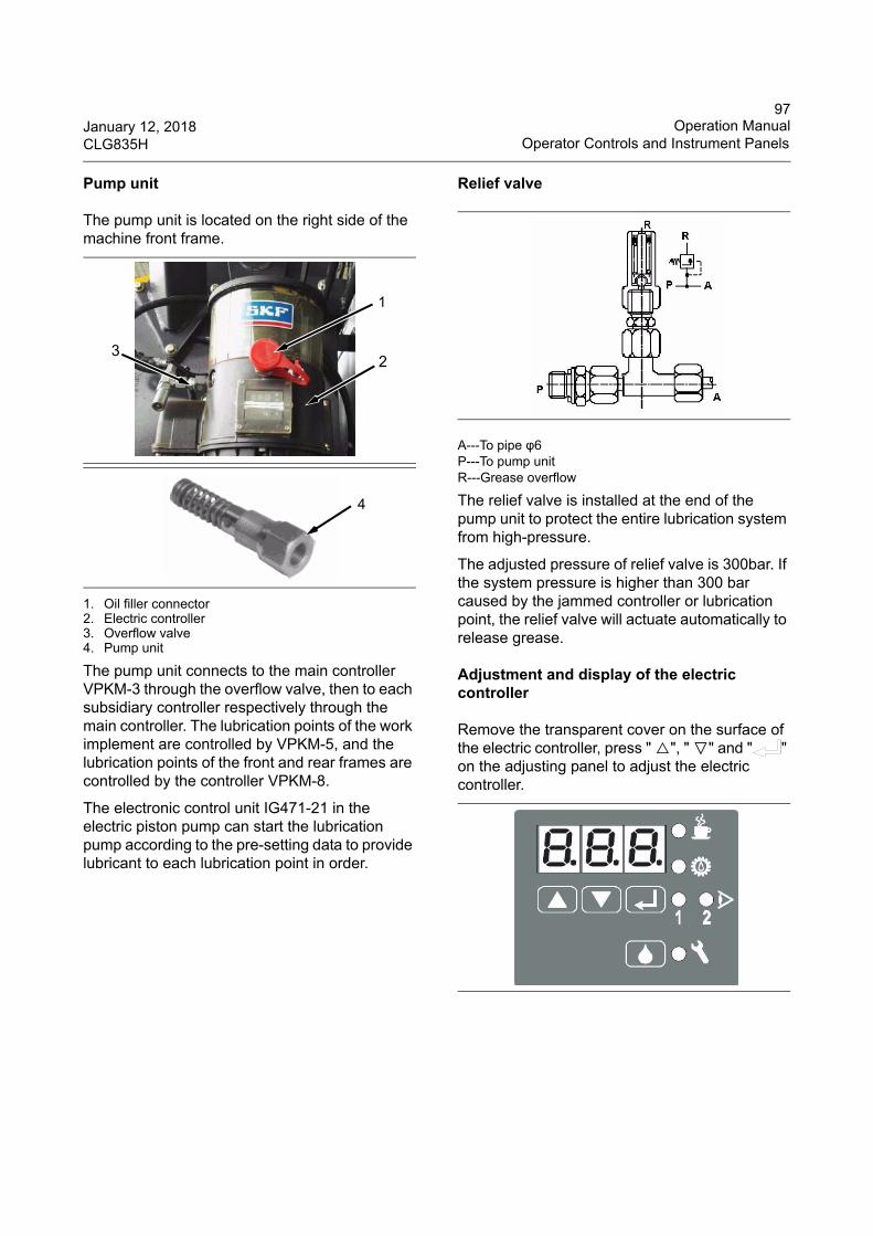
97January 12, 2018 Operation ManualCLG835H Operator Controls and Instrument Panels
Pump unit
The pump unit is located on the right side of the machine front frame.
1. Oil filler connector 2. Electric controller3. Overflow valve4. Pump unit
The pump unit connects to the main controller VPKM-3 through the overflow valve, then to each subsidiary controller respectively through the main controller. The lubrication points of the work implement are controlled by VPKM-5, and the lubrication points of the front and rear frames are controlled by the controller VPKM-8.
The electronic control unit IG471-21 in the electric piston pump can start the lubrication pump according to the pre-setting data to provide lubricant to each lubrication point in order.
Relief valve
A---To pipe φ6P---To pump unitR---Grease overflow
The relief valve is installed at the end of the pump unit to protect the entire lubrication system from high-pressure.
The adjusted pressure of relief valve is 300bar. If the system pressure is higher than 300 bar caused by the jammed controller or lubrication point, the relief valve will actuate automatically to release grease.
Adjustment and display of the electric controller
Remove the transparent cover on the surface of the electric controller, press " △", " ▽" and " " on the adjusting panel to adjust the electric controller.
1
23
4
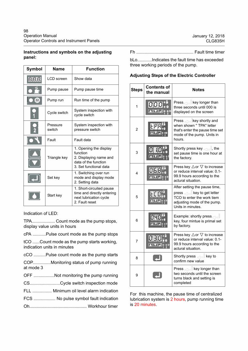
98Operation Manual January 12, 2018Operator Controls and Instrument Panels CLG835H
Instructions and symbols on the adjusting panel:
Indication of LED:
TPA................... Count mode as the pump stops, display value units in hours
cPA ...........Pulse count mode as the pump stops
tCO ......Count mode as the pump starts working, indication units in minutes
cCO ..........Pulse count mode as the pump starts
COP...............Monitoring status of pump running at mode 3
OFF .................Not monitoring the pump running
CS.........................Cycle switch inspection mode
FLL ................ Minimum oil level alarm indication
FCS .................. No pulse symbol fault indication
Oh............................................... Workhour timer
Fh ............................................... Fault time timer
bLo............Indicates the fault time has exceeded three working periods of the pump.
Adjusting Steps of the Electric Controller
For this machine, the pause time of centralized lubrication system is 2 hours, pump running time is 20 minutes.
Symbol Name Function
LCD screen Show data
Pump pause Pump pause time
Pump run Run time of the pump
Cycle switch System inspection with cycle switch
Pressure switch
System inspection with pressure switch
Fault Fault data
Triangle key
1. Opening the display function2. Displaying name and data of the function3. Set functional data
Set key1. Switching over run mode and display mode2. Setting data
Start key
1. Short-circuited pause time and directly entering next lubrication cycle2. Fault reset
StepsContents of the manual
Notes
1Press key longer than three seconds until 000 is displayed on the screen
2
Press key shortly and when shown '' TPA'' letter that's enter the pause time set mode of the pump. Units in hours.
3Shortly press key , the set pause time is one hour at the factory.
4
Press key △or ▽ to increase or reduce interval value: 0.1-99.9 hours according to the actural situation.
5
After setting the pause time,
press key to get letter TCO to enter the work tiem adjusting mode of the pump. Units in minutes.
6Example: shortly press key, four mintue is primal set by factory.
7
Press key △or ▽ to increase or reduce interval value: 0.1-99.9 hours according to the actural situation.
8 Shortly press key to confirm new value
9
Press key longer than two seconds until the screen turns black and setting is completed
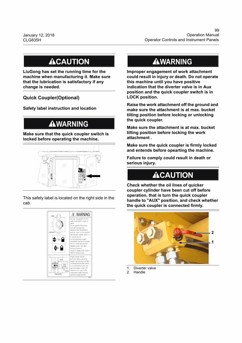
99January 12, 2018 Operation ManualCLG835H Operator Controls and Instrument Panels
Quick Coupler(Optional)
Safety label instruction and location
This safety label is located on the right side in the cab.
1. Diverter valve2. Handle
LiuGong has set the running time for the machine when manufacturing it. Make sure that the lubrication is satisfactory if any change is needed.
Make sure that the quick coupler switch is locked before operating the machine.
Improper engagement of work attachment could result in injury or death. Do not operate this machine until you have positive indication that the diverter valve is in Aux position and the quick coupler switch is in LOCK position.
Raise the work attachment off the ground and make sure the attachment is at max. bucket tilting position before locking or unlocking the quick coupler.
Make sure the attachment is at max. bucket tilting position before locking the work attachment .
Make sure the quick coupler is firmly locked and entends before opearting the machine.
Failure to comply could result in death or serious injury.
Check whether the oil lines of quicker coupler cylinder have been cut off before operation, that is turn the quick coupler handle to "AUX" position, and check whether the quick coupler is connected firmly.
1
2
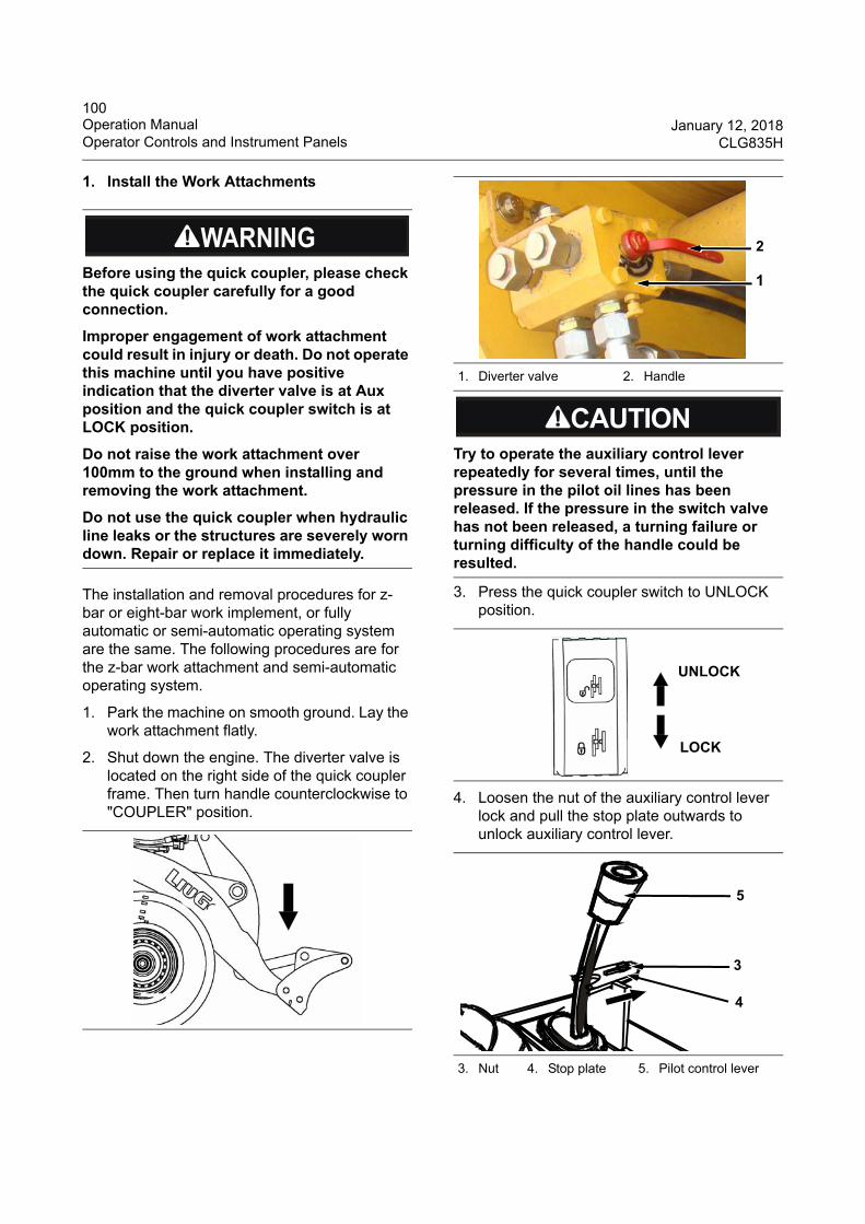
100Operation Manual January 12, 2018Operator Controls and Instrument Panels CLG835H
1. Install the Work Attachments
The installation and removal procedures for z-bar or eight-bar work implement, or fully automatic or semi-automatic operating system are the same. The following procedures are for the z-bar work attachment and semi-automatic operating system.
1. Park the machine on smooth ground. Lay the work attachment flatly.
2. Shut down the engine. The diverter valve is located on the right side of the quick coupler frame. Then turn handle counterclockwise to "COUPLER" position.
3. Press the quick coupler switch to UNLOCK position.
4. Loosen the nut of the auxiliary control lever lock and pull the stop plate outwards to unlock auxiliary control lever.
Before using the quick coupler, please check the quick coupler carefully for a good connection.
Improper engagement of work attachment could result in injury or death. Do not operate this machine until you have positive indication that the diverter valve is at Aux position and the quick coupler switch is at LOCK position.
Do not raise the work attachment over 100mm to the ground when installing and removing the work attachment.
Do not use the quick coupler when hydraulic line leaks or the structures are severely worn down. Repair or replace it immediately.
1. Diverter valve 2. Handle
Try to operate the auxiliary control lever repeatedly for several times, until the pressure in the pilot oil lines has been released. If the pressure in the switch valve has not been released, a turning failure or turning difficulty of the handle could be resulted.
3. Nut 4. Stop plate 5. Pilot control lever
1
2
UNLOCK
LOCK
3
4
5
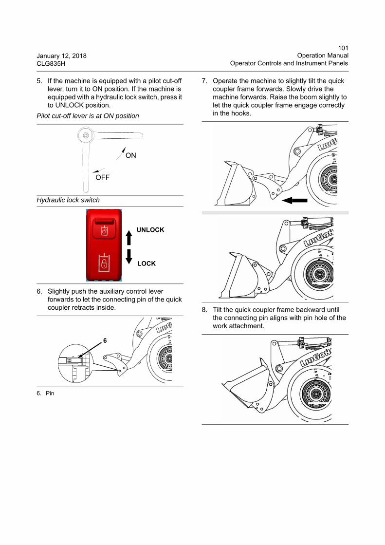
101January 12, 2018 Operation ManualCLG835H Operator Controls and Instrument Panels
5. If the machine is equipped with a pilot cut-off lever, turn it to ON position. If the machine is equipped with a hydraulic lock switch, press it to UNLOCK position.
6. Slightly push the auxiliary control lever forwards to let the connecting pin of the quick coupler retracts inside.
6. Pin
7. Operate the machine to slightly tilt the quick coupler frame forwards. Slowly drive the machine forwards. Raise the boom slightly to let the quick coupler frame engage correctly in the hooks.
8. Tilt the quick coupler frame backward until the connecting pin aligns with pin hole of the work attachment.
Pilot cut-off lever is at ON position
Hydraulic lock switch
ON
OFF
UNLOCK
LOCK
6
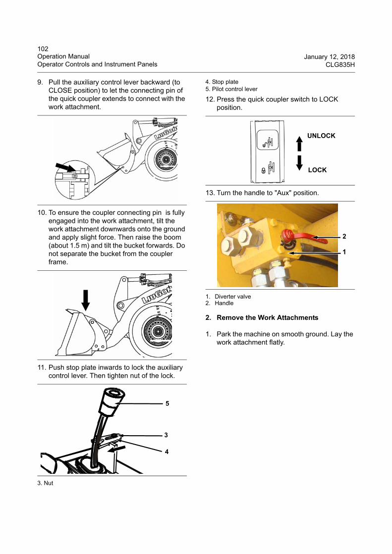
102Operation Manual January 12, 2018Operator Controls and Instrument Panels CLG835H
9. Pull the auxiliary control lever backward (to CLOSE position) to let the connecting pin of the quick coupler extends to connect with the work attachment.
10. To ensure the coupler connecting pin is fully engaged into the work attachment, tilt the work attachment downwards onto the ground and apply slight force. Then raise the boom (about 1.5 m) and tilt the bucket forwards. Do not separate the bucket from the coupler frame.
11. Push stop plate inwards to lock the auxiliary control lever. Then tighten nut of the lock.
3. Nut
4. Stop plate 5. Pilot control lever
12. Press the quick coupler switch to LOCK position.
13. Turn the handle to "Aux" position.
1. Diverter valve2. Handle
2. Remove the Work Attachments
1. Park the machine on smooth ground. Lay the work attachment flatly.
3
4
5
UNLOCK
LOCK
1
2
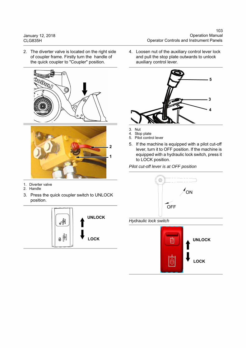
103January 12, 2018 Operation ManualCLG835H Operator Controls and Instrument Panels
2. The diverter valve is located on the right side of coupler frame. Firstly turn the handle of the quick coupler to "Coupler" position.
1. Diverter valve2. Handle
3. Press the quick coupler switch to UNLOCK position.
4. Loosen nut of the auxiliary control lever lock and pull the stop plate outwards to unlock auxiliary control lever.
3. Nut4. Stop plate 5. Pilot control lever
5. If the machine is equipped with a pilot cut-off lever, turn it to OFF position. If the machine is equipped with a hydraulic lock switch, press it to LOCK position.
1
2
UNLOCK
LOCK
Pilot cut-off lever is at OFF position
Hydraulic lock switch
3
4
5
ON
OFF
UNLOCK
LOCK
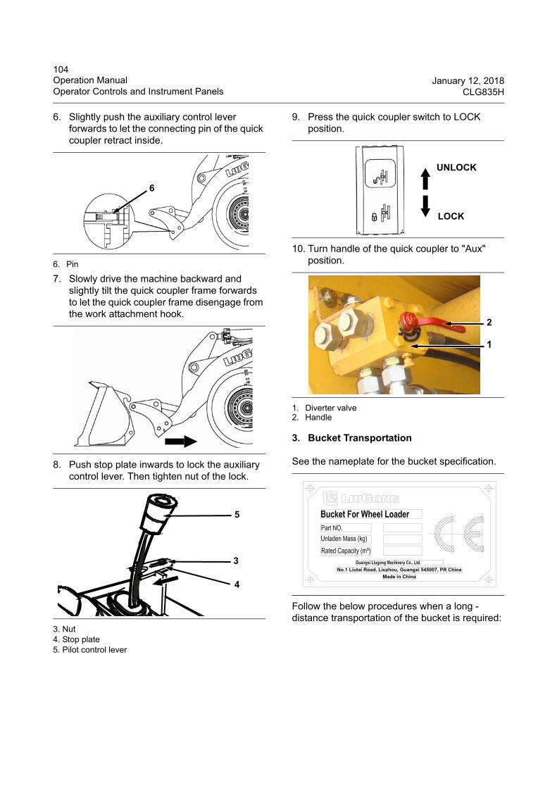
104Operation Manual January 12, 2018Operator Controls and Instrument Panels CLG835H
6. Slightly push the auxiliary control lever forwards to let the connecting pin of the quick coupler retract inside.
6. Pin
7. Slowly drive the machine backward and slightly tilt the quick coupler frame forwards to let the quick coupler frame disengage from the work attachment hook.
8. Push stop plate inwards to lock the auxiliary control lever. Then tighten nut of the lock.
3. Nut4. Stop plate 5. Pilot control lever
9. Press the quick coupler switch to LOCK position.
10. Turn handle of the quick coupler to "Aux" position.
1. Diverter valve2. Handle
3. Bucket Transportation
See the nameplate for the bucket specification.
Follow the below procedures when a long -distance transportation of the bucket is required:
6
3
4
5
UNLOCK
LOCK
1
2
No.1 Liutai Road, Liuzhou, Guangxi 545007, PR China
Made in China
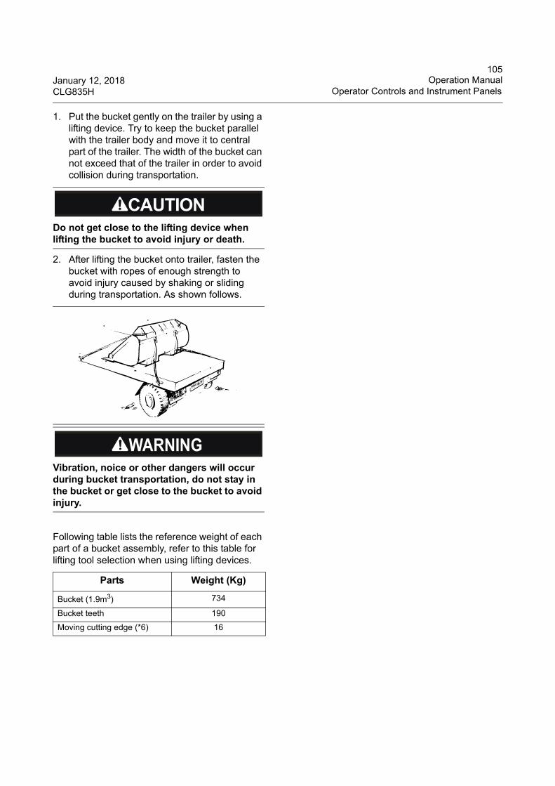
105January 12, 2018 Operation ManualCLG835H Operator Controls and Instrument Panels
1. Put the bucket gently on the trailer by using a lifting device. Try to keep the bucket parallel with the trailer body and move it to central part of the trailer. The width of the bucket can not exceed that of the trailer in order to avoid collision during transportation.
2. After lifting the bucket onto trailer, fasten the bucket with ropes of enough strength to avoid injury caused by shaking or sliding during transportation. As shown follows.
Following table lists the reference weight of each part of a bucket assembly, refer to this table for lifting tool selection when using lifting devices.
Do not get close to the lifting device when lifting the bucket to avoid injury or death.
Vibration, noice or other dangers will occur during bucket transportation, do not stay in the bucket or get close to the bucket to avoid injury.
Parts Weight (Kg)
Bucket (1.9m3) 734
Bucket teeth 190
Moving cutting edge (*6) 16
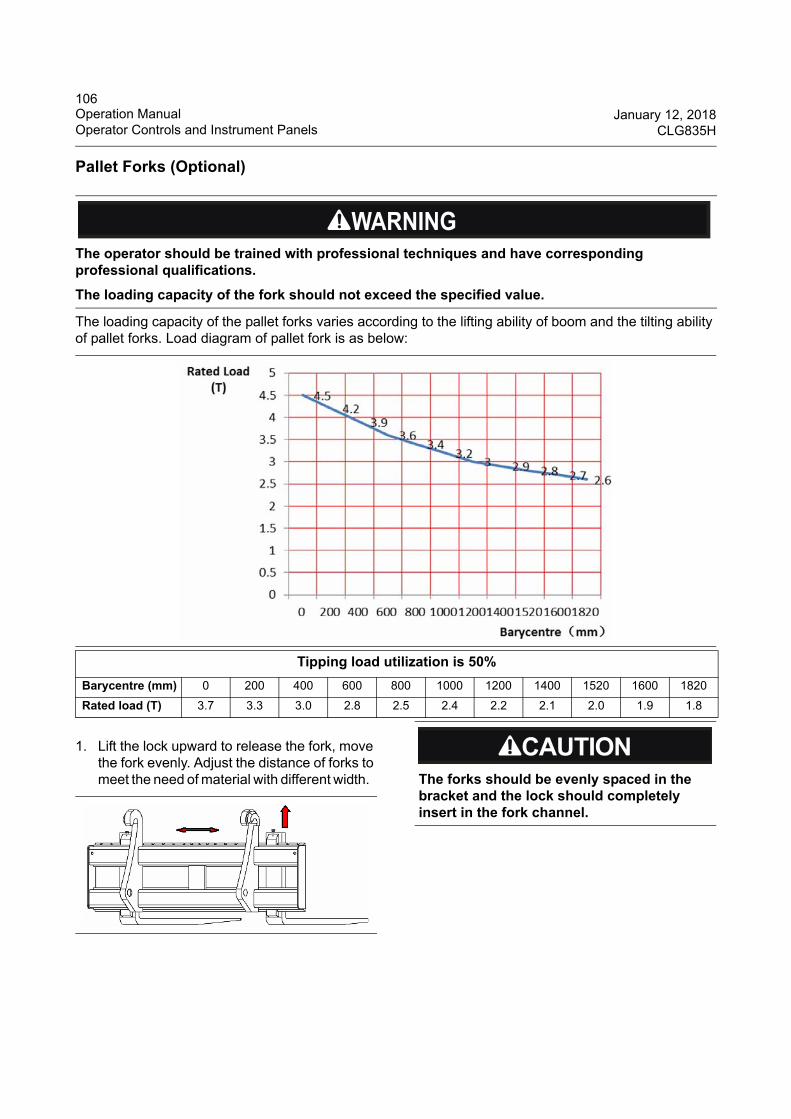
106Operation Manual January 12, 2018Operator Controls and Instrument Panels CLG835H
Pallet Forks (Optional)
The loading capacity of the pallet forks varies according to the lifting ability of boom and the tilting ability of pallet forks. Load diagram of pallet fork is as below:
1. Lift the lock upward to release the fork, move the fork evenly. Adjust the distance of forks to meet the need of material with different width.
The operator should be trained with professional techniques and have corresponding professional qualifications.
The loading capacity of the fork should not exceed the specified value.
Tipping load utilization is 50%
Barycentre (mm) 0 200 400 600 800 1000 1200 1400 1520 1600 1820
Rated load (T) 3.7 3.3 3.0 2.8 2.5 2.4 2.2 2.1 2.0 1.9 1.8
The forks should be evenly spaced in the bracket and the lock should completely insert in the fork channel.
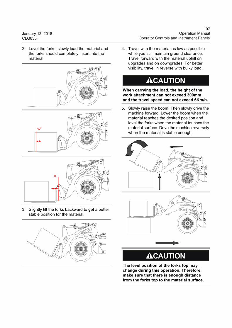
107January 12, 2018 Operation ManualCLG835H Operator Controls and Instrument Panels
2. Level the forks, slowly load the material and the forks should completely insert into the material.
3. Slightly tilt the forks backward to get a better stable position for the material.
4. Travel with the material as low as possible while you still maintain ground clearance. Travel forward with the material uphill on upgrades and on downgrades. For better visibility, travel in reverse with bulky load.
5. Slowly raise the boom. Then slowly drive the machine forward. Lower the boom when the material reaches the desired position and level the forks when the material touches the material surface. Drive the machine reversely when the material is stable enough.
√
×
When carrying the load, the height of the work attachment can not exceed 300mm and the travel speed can not exceed 6Km/h.
The level position of the forks top may change during this operation. Therefore, make sure that there is enough distance from the forks top to the material surface.
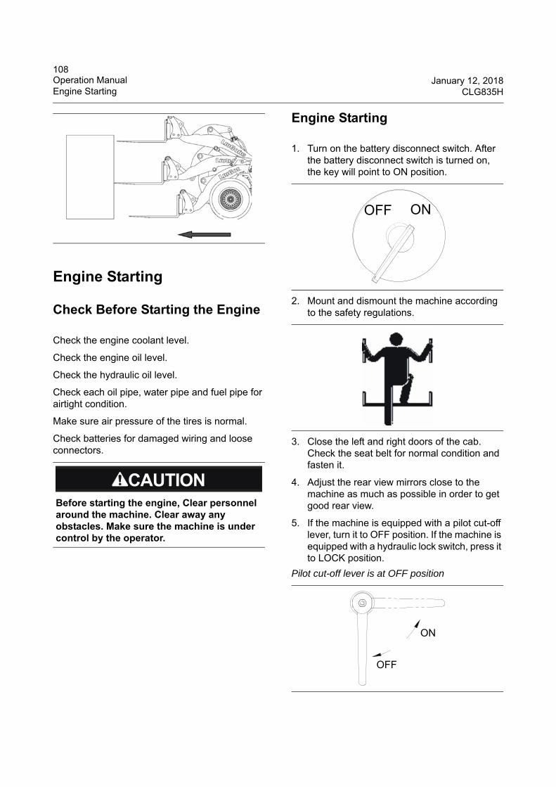
108Operation Manual January 12, 2018Engine Starting CLG835H
Engine Starting
Check Before Starting the Engine
Check the engine coolant level.
Check the engine oil level.
Check the hydraulic oil level.
Check each oil pipe, water pipe and fuel pipe for airtight condition.
Make sure air pressure of the tires is normal.
Check batteries for damaged wiring and loose connectors.
Engine Starting
1. Turn on the battery disconnect switch. After the battery disconnect switch is turned on, the key will point to ON position.
2. Mount and dismount the machine according to the safety regulations.
3. Close the left and right doors of the cab. Check the seat belt for normal condition and fasten it.
4. Adjust the rear view mirrors close to the machine as much as possible in order to get good rear view.
5. If the machine is equipped with a pilot cut-off lever, turn it to OFF position. If the machine is equipped with a hydraulic lock switch, press it to LOCK position.
Before starting the engine, Clear personnel around the machine. Clear away any obstacles. Make sure the machine is under control by the operator.
Pilot cut-off lever is at OFF position
OFF ON
ON
OFF
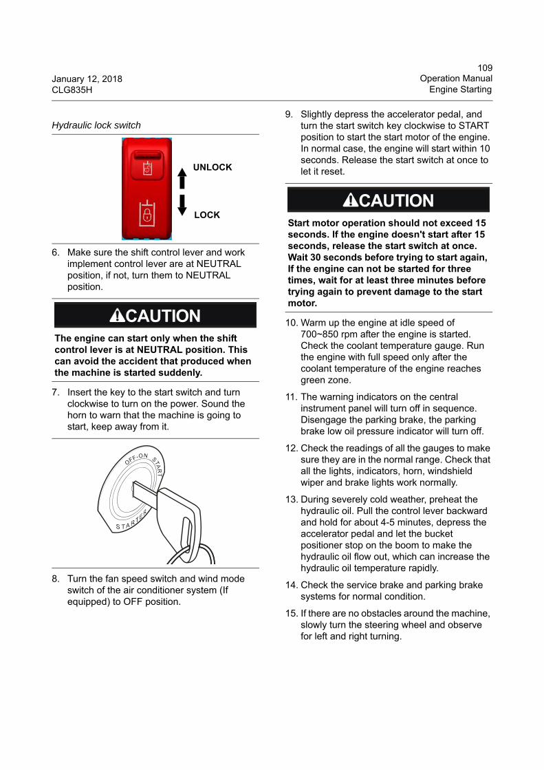
109January 12, 2018 Operation ManualCLG835H Engine Starting
6. Make sure the shift control lever and work implement control lever are at NEUTRAL position, if not, turn them to NEUTRAL position.
7. Insert the key to the start switch and turn clockwise to turn on the power. Sound the horn to warn that the machine is going to start, keep away from it.
8. Turn the fan speed switch and wind mode switch of the air conditioner system (If equipped) to OFF position.
9. Slightly depress the accelerator pedal, and turn the start switch key clockwise to START position to start the start motor of the engine. In normal case, the engine will start within 10 seconds. Release the start switch at once to let it reset.
10. Warm up the engine at idle speed of 700~850 rpm after the engine is started. Check the coolant temperature gauge. Run the engine with full speed only after the coolant temperature of the engine reaches green zone.
11. The warning indicators on the central instrument panel will turn off in sequence. Disengage the parking brake, the parking brake low oil pressure indicator will turn off.
12. Check the readings of all the gauges to make sure they are in the normal range. Check that all the lights, indicators, horn, windshield wiper and brake lights work normally.
13. During severely cold weather, preheat the hydraulic oil. Pull the control lever backward and hold for about 4-5 minutes, depress the accelerator pedal and let the bucket positioner stop on the boom to make the hydraulic oil flow out, which can increase the hydraulic oil temperature rapidly.
14. Check the service brake and parking brake systems for normal condition.
15. If there are no obstacles around the machine, slowly turn the steering wheel and observe for left and right turning.
Hydraulic lock switch
The engine can start only when the shift control lever is at NEUTRAL position. This can avoid the accident that produced when the machine is started suddenly.
UNLOCK
LOCKStart motor operation should not exceed 15 seconds. If the engine doesn't start after 15 seconds, release the start switch at once. Wait 30 seconds before trying to start again, If the engine can not be started for three times, wait for at least three minutes before trying again to prevent damage to the start motor.
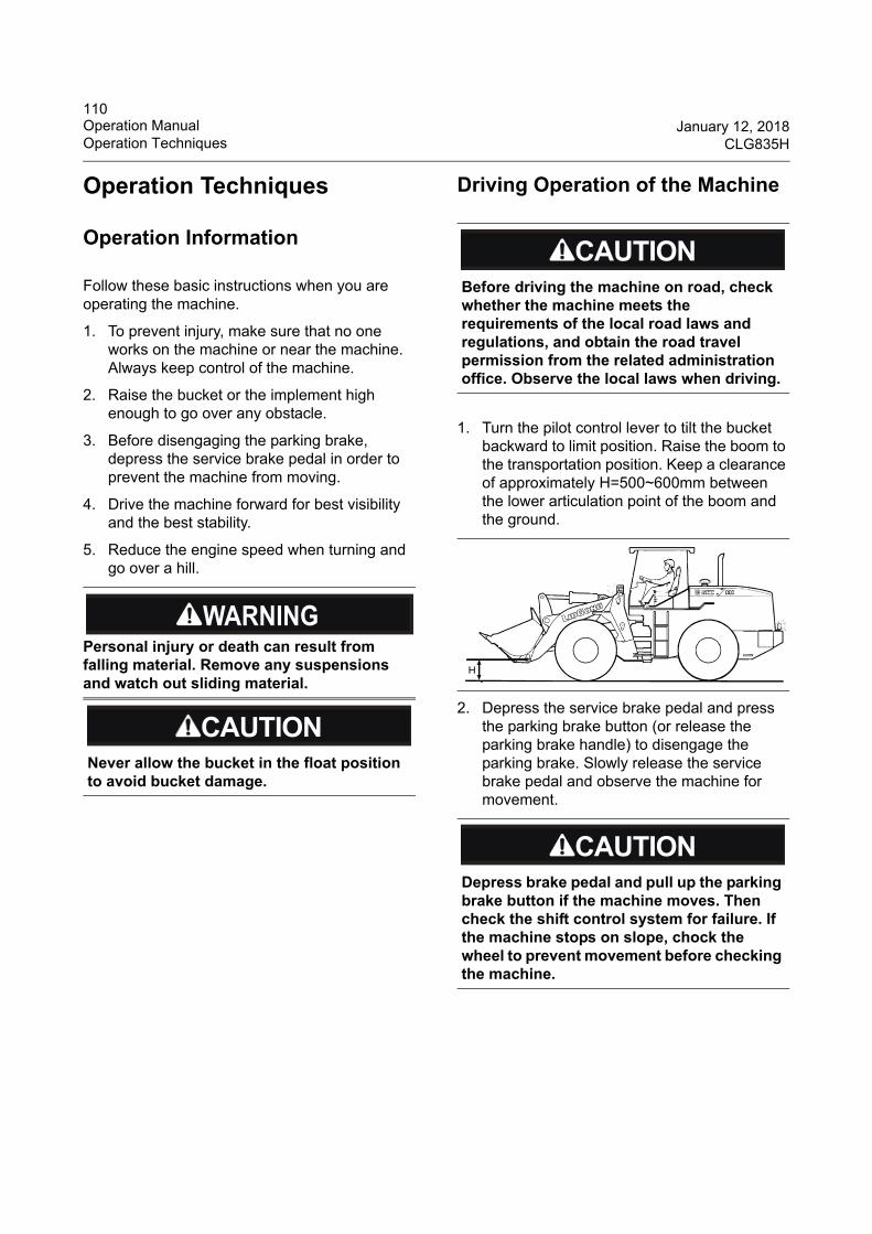
110Operation Manual January 12, 2018Operation Techniques CLG835H
Operation Techniques
Operation Information
Follow these basic instructions when you are operating the machine.
1. To prevent injury, make sure that no one works on the machine or near the machine. Always keep control of the machine.
2. Raise the bucket or the implement high enough to go over any obstacle.
3. Before disengaging the parking brake, depress the service brake pedal in order to prevent the machine from moving.
4. Drive the machine forward for best visibility and the best stability.
5. Reduce the engine speed when turning and go over a hill.
Driving Operation of the Machine
1. Turn the pilot control lever to tilt the bucket backward to limit position. Raise the boom to the transportation position. Keep a clearance of approximately H=500~600mm between the lower articulation point of the boom and the ground.
2. Depress the service brake pedal and press the parking brake button (or release the parking brake handle) to disengage the parking brake. Slowly release the service brake pedal and observe the machine for movement.
Personal injury or death can result from falling material. Remove any suspensions and watch out sliding material.
Never allow the bucket in the float position to avoid bucket damage.
Before driving the machine on road, check whether the machine meets the requirements of the local road laws and regulations, and obtain the road travel permission from the related administration office. Observe the local laws when driving.
Depress brake pedal and pull up the parking brake button if the machine moves. Then check the shift control system for failure. If the machine stops on slope, chock the wheel to prevent movement before checking the machine.
H
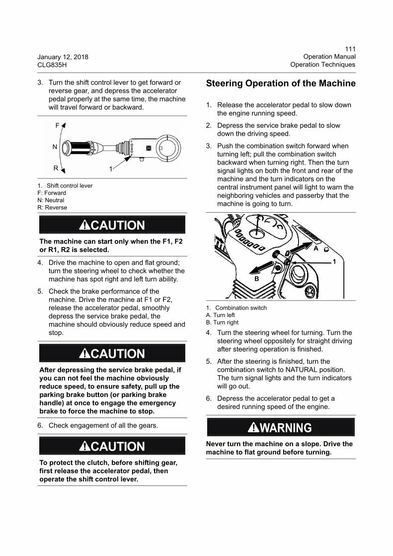
111January 12, 2018 Operation ManualCLG835H Operation Techniques
3. Turn the shift control lever to get forward or reverse gear, and depress the accelerator pedal properly at the same time, the machine will travel forward or backward.
1. Shift control leverF: ForwardN: Neutral R: Reverse
4. Drive the machine to open and flat ground; turn the steering wheel to check whether the machine has spot right and left turn ability.
5. Check the brake performance of the machine. Drive the machine at F1 or F2, release the accelerator pedal, smoothly depress the service brake pedal, the machine should obviously reduce speed and stop.
6. Check engagement of all the gears.
Steering Operation of the Machine
1. Release the accelerator pedal to slow down the engine running speed.
2. Depress the service brake pedal to slow down the driving speed.
3. Push the combination switch forward when turning left; pull the combination switch backward when turning right. Then the turn signal lights on both the front and rear of the machine and the turn indicators on the central instrument panel will light to warn the neighboring vehicles and passerby that the machine is going to turn.
1. Combination switchA. Turn left B. Turn right
4. Turn the steering wheel for turning. Turn the steering wheel oppositely for straight driving after steering operation is finished.
5. After the steering is finished, turn the combination switch to NATURAL position. The turn signal lights and the turn indicators will go out.
6. Depress the accelerator pedal to get a desired running speed of the engine.
The machine can start only when the F1, F2 or R1, R2 is selected.
After depressing the service brake pedal, if you can not feel the machine obviously reduce speed, to ensure safety, pull up the parking brake button (or parking brake handle) at once to engage the emergency brake to force the machine to stop.
To protect the clutch, before shifting gear, first release the accelerator pedal, then operate the shift control lever.
1
F
N
R
Never turn the machine on a slope. Drive the machine to flat ground before turning.
B
A
1
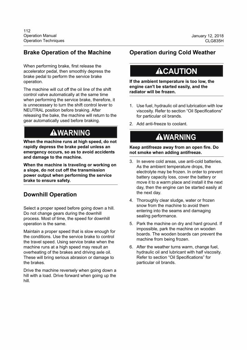
112Operation Manual January 12, 2018Operation Techniques CLG835H
Brake Operation of the Machine
When performing brake, first release the accelerator pedal, then smoothly depress the brake pedal to perform the service brake operation.
The machine will cut off the oil line of the shift control valve automatically at the same time when performing the service brake, therefore, it is unnecessary to turn the shift control lever to NEUTRAL position before braking. After releasing the bake, the machine will return to the gear automatically used before braking.
Downhill Operation
Select a proper speed before going down a hill. Do not change gears during the downhill process. Most of time, the speed for downhill operation is the same.
Maintain a proper speed that is slow enough for the conditions. Use the service brake to control the travel speed. Using service brake when the machine runs at a high speed may result an overheating of the brakes and driving axle oil. These will bring serious abrasion or damage to the brakes.
Drive the machine reversely when going down a hill with a load. Drive forward when going up the hill.
Operation during Cold Weather
1. Use fuel, hydraulic oil and lubrication with low viscosity. Refer to section “Oil Specifications” for particular oil brands.
2. Add anti-freeze to coolant.
3. In severe cold areas, use anti-cold batteries. As the ambient temperature drops, the electrolyte may be frozen. In order to prevent battery capacity loss, cover the battery or move it to a warm place and install it the next day, then the engine can be started easily at the next day.
4. Thoroughly clear sludge, water or frozen snow from the machine to avoid them entering into the seams and damaging sealing performance.
5. Park the machine on dry and hard ground. If impossible, park the machine on wooden boards. The wooden boards can prevent the machine from being frozen.
6. After the weather turns warm, change fuel, hydraulic oil and lubricant with half viscosity. Refer to section “Oil Specifications” for particular oil brands.
When the machine runs at high speed, do not rapidly depress the brake pedal unless an emergency occurs, so as to avoid accidents and damage to the machine.
When the machine is traveling or working on a slope, do not cut off the transmission power output when performing the service brake to ensure safety.
If the ambient temperature is too low, the engine can't be started easily, and the radiator will be frozen.
Keep antifreeze away from an open fire. Do not smoke when adding antifreeze.
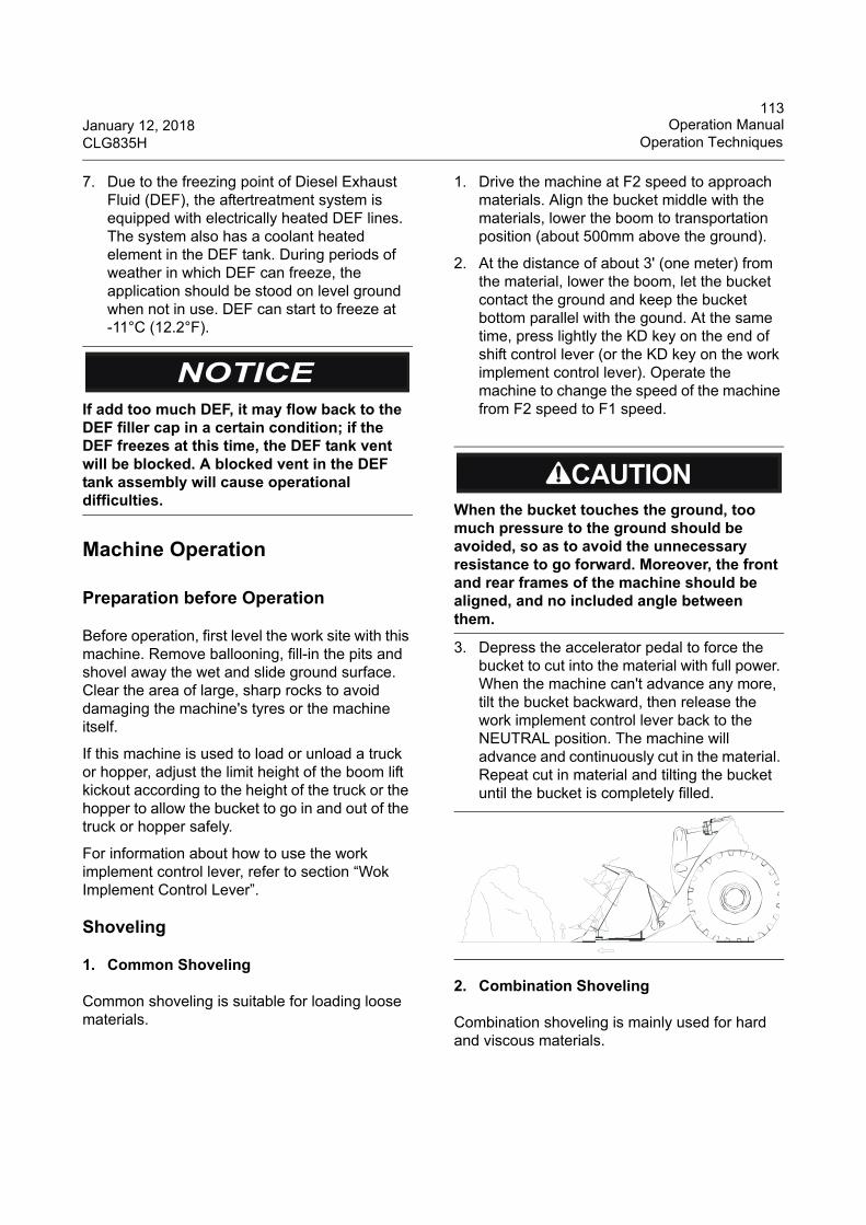
113January 12, 2018 Operation ManualCLG835H Operation Techniques
7. Due to the freezing point of Diesel Exhaust Fluid (DEF), the aftertreatment system is equipped with electrically heated DEF lines. The system also has a coolant heated element in the DEF tank. During periods of weather in which DEF can freeze, the application should be stood on level ground when not in use. DEF can start to freeze at -11°C (12.2°F).
Machine Operation
Preparation before Operation
Before operation, first level the work site with this machine. Remove ballooning, fill-in the pits and shovel away the wet and slide ground surface. Clear the area of large, sharp rocks to avoid damaging the machine's tyres or the machine itself.
If this machine is used to load or unload a truck or hopper, adjust the limit height of the boom lift kickout according to the height of the truck or the hopper to allow the bucket to go in and out of the truck or hopper safely.
For information about how to use the work implement control lever, refer to section “Wok Implement Control Lever”.
Shoveling
1. Common Shoveling
Common shoveling is suitable for loading loose materials.
1. Drive the machine at F2 speed to approach materials. Align the bucket middle with the materials, lower the boom to transportation position (about 500mm above the ground).
2. At the distance of about 3' (one meter) from the material, lower the boom, let the bucket contact the ground and keep the bucket bottom parallel with the gound. At the same time, press lightly the KD key on the end of shift control lever (or the KD key on the work implement control lever). Operate the machine to change the speed of the machine from F2 speed to F1 speed.
3. Depress the accelerator pedal to force the bucket to cut into the material with full power. When the machine can't advance any more, tilt the bucket backward, then release the work implement control lever back to the NEUTRAL position. The machine will advance and continuously cut in the material. Repeat cut in material and tilting the bucket until the bucket is completely filled.
2. Combination Shoveling
Combination shoveling is mainly used for hard and viscous materials.
If add too much DEF, it may flow back to the DEF filler cap in a certain condition; if the DEF freezes at this time, the DEF tank vent will be blocked. A blocked vent in the DEF tank assembly will cause operational difficulties.
When the bucket touches the ground, too much pressure to the ground should be avoided, so as to avoid the unnecessary resistance to go forward. Moreover, the front and rear frames of the machine should be aligned, and no included angle between them.
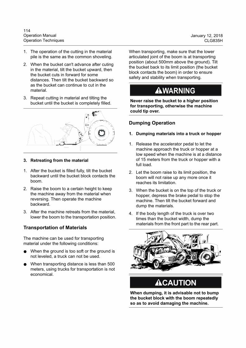
114Operation Manual January 12, 2018Operation Techniques CLG835H
1. The operation of the cutting in the material pile is the same as the common shoveling.
2. When the bucket can't advance after cuting in the material, tilt the bucket upward, then the bucket cuts in forward for some distances. Then tilt the bucket backward so as the bucket can continue to cut in the material.
3. Repeat cutting in material and tilting the bucket until the bucket is completely filled.
3. Retreating from the material
1. After the bucket is filled fully, tilt the bucket backward until the bucket block contacts the boom.
2. Raise the boom to a certain height to keep the machine away from the material when reversing. Then operate the machine backward.
3. After the machine retreats from the material, lower the boom to the transportation position.
Transportation of Materials
The machine can be used for transporting material under the following conditions:
● When the ground is too soft or the ground is not leveled, a truck can not be used.
● When transporting distance is less than 500 meters, using trucks for transportation is not economical.
When transporting, make sure that the lower articulated joint of the boom is at transporting position (about 500mm above the ground). Tilt the bucket back to its limit position (the bucket block contacts the boom) in order to ensure safety and stability when transporting.
Dumping Operation
1. Dumping materials into a truck or hopper
1. Release the accelerator pedal to let the machine approach the truck or hopper at a low speed when the machine is at a distance of 15 meters from the truck or hopper with a full load.
2. Let the boom raise to its limit position, the boom will not raise up any more once it reaches its limitation.
3. When the bucket is on the top of the truck or hopper, depress the brake pedal to stop the machine. Then tilt the bucket forward and dump the materials.
4. If the body length of the truck is over two times than the bucket width, dump the materials from the front part to the rear part.
Never raise the bucket to a higher position for transporting, otherwise the machine could tip over.
When dumping, it is advisable not to bump the bucket block with the boom repeatedly so as to avoid damaging the machine.
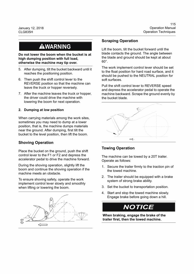
115January 12, 2018 Operation ManualCLG835H Operation Techniques
5. After dumping, tilt the bucket backward until it reaches the positioning position.
6. Then push the shift control lever to the REVERSE position so that the machine can leave the truck or hopper reversely.
7. After the machine leaves the truck or hopper, the driver could drive the machine with lowering the boom for next operation.
2. Dumping at low position
When carrying materials among the work sites, sometimes you may need to dump at a lower position, that is, the machine dumps materials near the ground. After dumping, first tilt the bucket to the level position, then lift the boom.
Shoving Operation
Place the bucket on the ground, push the shift control lever to the F1 or F2 and depress the accelerator pedal to drive the machine forward.
During the shoving operation, slightly lift the boom and continue the shoving operation if the machine meets an obstacle.
To ensure shoving safety, operate the work implement control lever slowly and smoothly when lifting or lowering the boom.
Scraping Operation
Lift the boom, tilt the bucket forward until the blade contacts the ground. The angle between the blade and ground should be kept at about 60°.
The work implement control lever should be set to the float position for hard road surface, and it should be pushed to the NEUTRAL position for soft surfaces.
Pull the shift control lever to REVERSE speed and depress the accelerator pedal to operate the machine backward. Scrape the ground evenly by the bucket blade.
Towing Operation
The machine can be towed by a 20T trailer. Operate as follows:
1. Secure the trailer firmly to the traction pin of the towed machine.
2. The trailer should be equipped with a brake system of strong brake ability.
3. Set the bucket to transportation position.
4. Start and stop the towed machine slowly. Engage brake before going down a hill.
Do not lower the boom when the bucket is at high dumping position with full load, otherwise the machine may tip over.
When braking, engage the brake of the trailer first, then the towed machine.
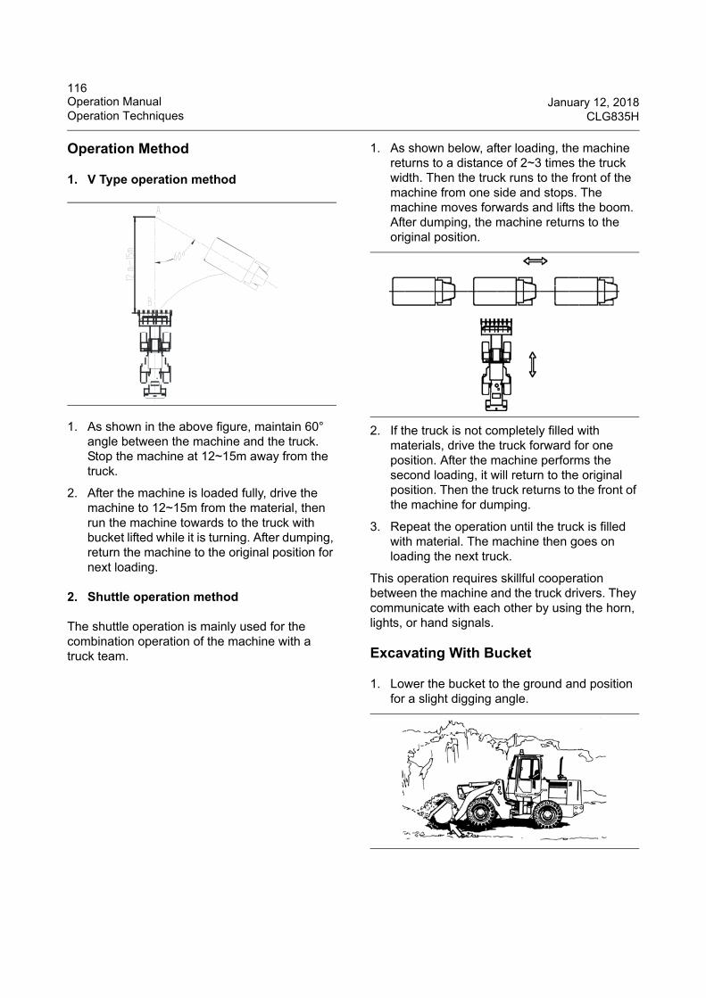
116Operation Manual January 12, 2018Operation Techniques CLG835H
Operation Method
1. V Type operation method
1. As shown in the above figure, maintain 60° angle between the machine and the truck. Stop the machine at 12~15m away from the truck.
2. After the machine is loaded fully, drive the machine to 12~15m from the material, then run the machine towards to the truck with bucket lifted while it is turning. After dumping, return the machine to the original position for next loading.
2. Shuttle operation method
The shuttle operation is mainly used for the combination operation of the machine with a truck team.
1. As shown below, after loading, the machine returns to a distance of 2~3 times the truck width. Then the truck runs to the front of the machine from one side and stops. The machine moves forwards and lifts the boom. After dumping, the machine returns to the original position.
2. If the truck is not completely filled with materials, drive the truck forward for one position. After the machine performs the second loading, it will return to the original position. Then the truck returns to the front of the machine for dumping.
3. Repeat the operation until the truck is filled with material. The machine then goes on loading the next truck.
This operation requires skillful cooperation between the machine and the truck drivers. They communicate with each other by using the horn, lights, or hand signals.
Excavating With Bucket
1. Lower the bucket to the ground and position for a slight digging angle.
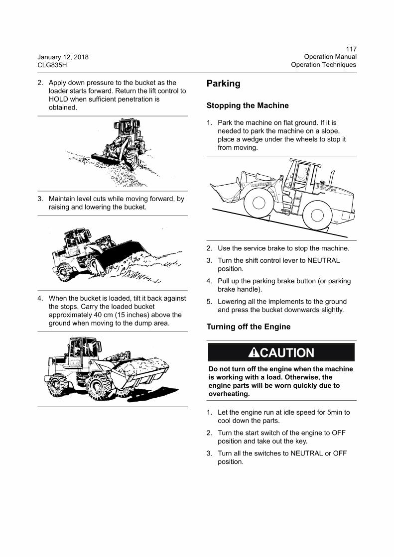
117January 12, 2018 Operation ManualCLG835H Operation Techniques
2. Apply down pressure to the bucket as the loader starts forward. Return the lift control to HOLD when sufficient penetration is obtained.
3. Maintain level cuts while moving forward, by raising and lowering the bucket.
4. When the bucket is loaded, tilt it back against the stops. Carry the loaded bucket approximately 40 cm (15 inches) above the ground when moving to the dump area.
Parking
Stopping the Machine
1. Park the machine on flat ground. If it is needed to park the machine on a slope, place a wedge under the wheels to stop it from moving.
2. Use the service brake to stop the machine.
3. Turn the shift control lever to NEUTRAL position.
4. Pull up the parking brake button (or parking brake handle).
5. Lowering all the implements to the ground and press the bucket downwards slightly.
Turning off the Engine
1. Let the engine run at idle speed for 5min to cool down the parts.
2. Turn the start switch of the engine to OFF position and take out the key.
3. Turn all the switches to NEUTRAL or OFF position.
Do not turn off the engine when the machine is working with a load. Otherwise, the engine parts will be worn quickly due to overheating.
118Operation Manual January 12, 2018Operation Techniques CLG835H
Lowering the Work Implement with Engine Stopped
Make sure that no pesonnel is around the machine before lowering the implement.
1. Turn the engine start switch to ON position.
2. If the machine is equipped with a pilot cut-off lever, turn it to ON position. If the machine is equipped with a hydraulic lock switch, press it to UNLOCK position.
3. Push the work implement control lever to LOWER position to lower the implement. This lever can return to HOLD position automatically after being released.
4. Push the pilot cut-off lever to OFF position (If equipped).
5. Turn the engine start switch to OFF position.
Leaving the Machine
1. Close the left and right doors and lock them.
2. Use the ladder and the handrail when you get off the machine. Face the machine and use both hands. Make sure that the steps are clear of debris before you dismounting.
3. Inspect the engine compartment for debris. Clean out any debris and paper in order to avoid a fire.
4. Remove all flammable debris in order to reduce a fire hazard. Dispose all debris properly.
5. Turn the battery disconnect switch to the “OFF” position.
6. If the machine is not filled with anti-freeze, after the machine parks in winter, open all water drain valves of the engine in time to discharge coolant in the cooling system and air conditioner system so as to prevent the machine from being cracked by frost. If the machine has been filled with anti-freeze at ex-factory, refer to the instructions of the anti-freeze labels.
7. Fix all covers, lock all equipment and remove the key.
Storage
Before Storage
1. Clean and dry every part of the machine and store it in a dry warehouse. If the machine has to be stored in the open air, park the machine on concrete ground and cover with canvas.
2. Before storage, refill the oil tank, lubricate every moving pin & shaft and change hydraulic oil.
3. Paint a thin layer of grease on the exposed parts of the hydraulic oil cylinder piston rod.
4. Remove batteries from the machine and store in a separate place.
5. If the air temperature is below 0°C, add anti-freeze in cooling water of the engine until it reaches the engine body and evaporator of the air conditioner. Drain out water in the cooling system, also drain out water in the evaporator of the air conditioner.
Pilot cut-off lever is at ON position
Hydraulic lock switch
ON
OFF
UNLOCK
LOCK
119January 12, 2018 Operation ManualCLG835H Transportation Information
During Storage
1. Start the machine once every month and run every system, and lubricate every parts of the moving pins and shafts. Meanwhile, charge the batteries.
2. Before starting the machine, wipe off grease from the hydraulic oil cylinder piston rod. After operation, paint a layer of grease on it.
3. Paint antirust additive on rusted parts.
Before Reuse
1. Change lubricant of the engine, transmission, axles lubrication and hydraulic oil, brake oil and anti-freeze of the engine.
2. Lubricate all moving pins and shafts.
3. Before starting the machine, wipe off grease from the hydraulic oil cylinder piston rod.
Transportation Information
Transportation of the Machine
Investigate the travel route for overpass clearances, Make sure that there will be adequate clearance for the machine.
Clean ice, snow, or other slippery material from the loading dock and from the truck bed before you load the machine onto the transport machine. This will prevent the machine from slipping in transit. This will also prevent the machine from moving during transportation.
Perform loading according to the following steps:
1. Chock the trailer wheels or the truck wheels before you load the machine.
2. When the machine is loading on the trailer or truck, it is forbidden to turn.
To avoid personal injury or death, when working with anti-freeze inside the room, open the windows for ventilation.
If the machine is not coated with antirust additive per month during storage, consult your LiuGong dealer.
Obey the correlative laws govern characteristics of the load (weight, width, and length).
120Operation Manual January 12, 2018Transportation Information CLG835H
3. After the machine being parked, use the steering frame lock to lock the front frame and the rear frame.
4. Lower the bucket to the floor of the trailer. Turn the shift control lever to the NEUTRAL position.
5. Push the pilot cut-off lever to the OFF position (If equipped).
6. Engage the parking brake.
7. Stop the engine, turn every switch to NEUTRAL or OFF position and remove the key.
8. Lock the door and remove the key.
9. Turn the battery disconnect switch to the OFF position.
10. Chock the wheels of the machine and fasten them with steel wires or chains to avoid movement during transportation.
11. Cover the exhaust outlet to prevent the turbocharger from rotating during transportation. Damage to the turbocharger can result.
Driving the Machine
1. Before operating the machine, consult your tire dealer for recommended tire pressure and speed limitations.
2. Stop for 30 minutes after every 40km or after every hour when driving the machine for a long distance in order to cool down the tires.
3. Inflate the tires to the correct pressure. Refer to the maintenance section for tire inflation information.
4. Travel at a moderate speed. Observe all speed limitations when you drive the machine.
Lifting the Machine
1. Lift the machine by professional personnel.
2. Calculate the maximum lift weight of the crane and loading capacity of the lifting device to ensure the lift safety.
Use suitable lifting device and shackles when lifting a machine to avoid damage or falling of the machine. Improper lifting or securing could cause the machine to move accidentally and cause machine damage, personnel injury or death. Install the steering frame lock before lifting.
121January 12, 2018 Operation ManualCLG835H Transportation Information
3. The length of the four ropes on the lifting device must be the same to ensure the four lifting eyes share the same pressure.
4. Turn the battery disconnect switch to OFF position.
5. The lifting decal can be seen on the front and rear frame of the machine.
6. Before lifting, secure the front and rear frame with the steering frame lock so that the machine can not move.
7. The lifting device should be fixed on the lift eyes with lift decals on the machine.
Towing Information
Towing the Machine
Do not tow the machine unless the loader has a severe trouble. The machine can only be towed for a short distance for repair. Never tow the machine for a long distance. The towing distance should not exceed 10Km(328083'4") and towing speed should not exceed 10km/h(6.2mph); otherwise, the gear box will be damaged due to insufficient lubrication. If the machine needs to be transported for a long distance, a truck and trailer should be used.
Do the following steps:
1. If the machine doesn’t move due to machine brakes caused by an engine fault or a brake system fault. Remove the connecting shaft between the parking brake cylinder and the parking brake rod to disengage the parking brake by force.
Personal injury or death could result when towing a disabled machine incorrectly. Chock the wheels before disengage the brake to prevent the machine from moving.
122Operation Manual January 12, 2018Transportation Information CLG835H
2. The towing machine should be equipped with protective guard to protect the towing operator once the towing ropes or towing bar cracks accidentally.
3. Do not allow riders on the machine that is being towed unless the operator can control the steering wheel or the brake.
4. Before you towing the machine, make sure that the towing ropes or the towing bar are strong enough for towing the machine. The towing ropes or towing bar must have a strength that is 1.5 times of the gross weight of the machine that is being towed.
5. Do not use a chain for pulling. A chain link may break. This can cause personal injury. Use a wire rope that has cable loops or end rings. Position an observer at a safe location. The observer should stop the pulling procedure if the cable starts to break or the cable starts to loose. If the towing machine moves without the pulled machine, stop the pulling procedure.
6. The minimum angle between the towing ropes and straight direction should not exceed 30°.
7. Quick machine movement could cause the towing ropes or the towing bar overload. This could cause the towing ropes or the towing bar to break. A smooth machine movement helps towing operation easier.
8. Normally, the towing machine should be as large as the disabled machine. The towing machine must have enough brake capacity, weight, and power for the grade and distance that is involved.
9. During towing, all personnel should keep away from the both sides of the towing ropes so as to avoid injury caused by break.
10. It may be necessary to connect a large machine or additional machine to the disabled machine in order to provide sufficient control and brake ability. This will prevent the disabled machine from rolling away on a downgrade.
11. When towing the disabled machine downhill, to get enough control and brake ability, it is necessary to connect a larger truck or additional machine on the back to avoid a rolling accident.
It is impossible to list all the requirements for all different situations. Refer to liugong dealer for more information of towing the disabled machine.
Towing with a Running Engine
If the engine is running, the machine can be towed for a short distance under certain conditions. The power train and the steering system must be operable. Tow the machine for a short distance only. For example, pull the machine out of mud or to the side of the road.
The operator on the towed machine must turn the machine in the direction of the towing ropes.
Turn the shift control lever to NEUTRAL position, lift all implements and strictly observe all the instructions that are outlined in this topic.
Before releasing the parking brake, chock the wheel to prevent movement. Remove the wedge before starting the machine.
123January 12, 2018 Maintenance ManualCLG835H Maintenance Guidance
Maintenance Manual
Maintenance Guidance
Correct Maintenance Procedures
Learn how to maintain your machine correctly. Follow the instructions of this manual, if your machine has troubles, you must maintain or contact your dealer before operating.
Daily Checks
1. Check the gauges.
2. Check the coolant, fuel and oil level.
3. Check hoses and tubes for leakage, wear conditions and damage.
4. Perform a walk-around inspection of the machine.
5. Check for loose or missing parts.
Check Service Hour Meter
1. The service hour meter determines when your machine needs to be maintained. The time in the maintenance table is basically given for normal operation. If the machine is operated in severe conditions, you must maintain the machine more frequently.
Maintain Machine on Schedule
Follow the maintenance methods listed in this maintenance manual.
Maintenance Suggestions
1. Use only recommended fuels and lubricants.
2. Don't adjust the engine speed setting and/or the hydraulic safety valve.
3. Protect electronic units from water and vapor.
4. Do not disassemble electronic units such as sensors etc.
5. Use only recommended Liugong parts.
Cleanser of Windshield
Clean the windshield with special windshield cleanser and ensure no foreign matter mixes with cleanser.
Clean Engine Oil
Use clean engine oil and keep the engine oil clean. Ensure no foreign matter mixes with the engine oil.
Check Discharged Oil or Used Filter Element
After replacing the oil or filter element, check the discharged oil or filter element for iron particles and foreign matter. If any iron particles or foreign matter is found, report this immediately and take preventive measures.
Welding Cautions
1. Turn off the engine.
2. Do not keep using voltage above 200V.
3. Keep the welding area and earth cables within 1m. If the earth cable is close to gauges or connectors, failure could result.
4. Protect the seals and bearings located between the welding area and earth cables.
5. Never use the surrounding area of the work implement pin or cylinder as an earthing point.
Perform the maintenance procedures at the intervals according to this manual. Proper maintenance will extend the service life of the machine and provide safer operation.
124Maintenance Manual January 12, 2018Maintenance Guidance CLG835H
Prevent Dropping Things into Machine Interior
1. When checking through an open window or tank filler, be careful not to drop nuts, bolts or tools into the machine interior. If anything is dropped carelessly, take them out at once.
2. It is suggested not to take unnecessary items with you in your pockets, take necessary tools only.
Dusty Environment
Pay attention to the following instructions when working in dusty environments:
1. Check the air filter indicator regularly to see whether it is blocked. Service the air filter prior to the normal schedule.
2. Wash the radiator core frequently. Clean and replace the fuel filter periodically.
3. Clean the electrical units, especially the starter motor and alternator, to remove accumulated dust.
Avoid Mixing Oil
Do not use oils of different brands. If it is really needed, change the old oil prior to using the new oil of another brand.
Lock the covers
If it is needed to service the machine with the covers opened, lock the covers with the lock lever.
Purge Hydraulic System
Purge the air from the hydraulic lines if the hydraulic lines or components have been repaired, replaced or removed.
Install Hydraulic Hoses
1. If components equipped with O-rings or gaskests need to be removed, clean the mounting surfaces. Do not forget to install new O-rings and gaskets.
2. When installing hoses, do not twist or bend them. This will damage and shorten the service life of the hoses.
Proper Fuel and Lurbicant
Use proper fuel and lubricant that adapts to the ambient temperature.
Check Electrical Wiring
1. Check the fuse for damage. Check the circuit for broken or shorted wires. Check the terminals for loose connections and tighten any loose parts.
2. Check the circuits of the battery, starter motor and alternator.
3. Contact your Liugong dealer for more information about the solutions.
Check Air Conditioner
Check the fan speed switch of the air conditioning system to see if it is at NEUTRAL position and the work mode switch is at the OFF position. If not, turn them to the correct position.
Check Gauges
Check the gauges, lighting, indicators, horn and wipers for good condition. Contact your Liugong dealer if any problem is found.
If a fuse is burnt out frequently or short-circuited, find out the reason and repair or contact your Liugong dealer for assistance.
Keep the battery surface clean.
Before starting the engine, make sure nobody is on or near the machine. Keep the machine controlled by the operator.
125January 12, 2018 Maintenance ManualCLG835H Run-in
Preparation before Maintenance
Park the machine as follows before maintenance:
1. Park the machine on flat ground.
2. Lower the bucket to the ground.
3. Set the engine speed to idling speed and run it for 5 minutes.
4. Turn the start switch to OFF position and take out the key (If the machine needs to be maintained with the engine running, make sure the machine is under control of the operator).
5. Push the pilot control lever to LOCK position.
6. Attach a ''DO NOT OPERATE'' tag to right hand control lever if the machine is not operated.
Run-in
The run-in of new machine is an important procedure for prolonging the service life of the machine, eliminating fault and avoiding accidents. The user must read these guidelines for run-in of a new machine and how to operate and maintain the machine after purchase.
Run-in-Requirements for a New Machine
1. Run-in of a new machine is 100 hours.
2. Run the engine at idle speed for five minutes after starting the engine. Start the machine at low speed. Slowly increase speed.
3. Run-in should be done averagely in each forward or reverse gear.
4. Start the machine at low speed. Slowly increase speed. Always avoid starting, speeding up, turning and braking suddenly except for emergency cases.
5. It is better to load with loose material during run-in period. Do not operate rushly and exceed its rating load capacity and travel speed by 70%.
6. Check the lubricant periodically. Replace or add lubricant according to the recommended period.
7. Always pay attention to the temperature of the transmission, torque converter, front and rear axles, wheel hub, parking brake, middle shafts, hydraulic oil, engine coolant and engine oil, if there is overheating, find out the reason and eliminate it.
8. Check the tightness of all the bolts and nuts.
The following must be done after the first 8 hours of operation during the run-in period.
1. Check the tightness of all the bolts and nuts especially the bolts of the engine cylinder cover, exhaust pipe, front and rear axles, drive shaft, diesel engine, transmission, front and rear frames joint, and wheel rim nuts etc.
2. Check the tightness of the fan belt, engine belt and air conditioner compressor belt.
3. Check the oil level of the transmission, drive axle and diesel engine.
4. Check the hydraulic system and brake system for oil leakage.
5. Check the connections of all control levers, throttle linkage (if equipped) and flexible shaft.
6. Check temperatures and connections of the electrical system, power supply of the alternator, lights and the turn signal lights.
do
not
oper
ate
Opera
ter:
Date:
WARNIN
G
!
Check oil level according to the relevant operation regulations.
126Maintenance Manual January 12, 2018Maintenance Interval Schedule CLG835H
Work should be done after the finish of run-in
1. Check the tightness of all the bolts and nuts especially the bolts of the cylinder head, exhaust pipe, front and rear axles, drive shaft, diesel engine, transmission, front and rear frames joint, and wheel rim nuts etc..
2. Check the tightness of the fan belt, engine belt and air conditioner compressor belt.
3. Check the hydraulic system and brake system for oil leakage.
4. Replace the transmission oil and axle lubricant.
5. Replace the secondary filter and clean the primary filter of the transmission.
6. Clean the return oil filter element of the hydraulic oil tank.
Maintenance Interval Schedule
The maintenance intervals stated in this manual are determined according to the service hour meter or calendar intervals shown (daily, weekly, monthly, etc). Liugong recommends that maintenance should be performed according to whichever of the above-mentioned intervals occurs first.
Under extremely severe, dusty or wet operating conditions, more frequent lubrication than is specified in the "Maintenance Intervals" chart may be necessary.
Perform service on items at multiples of the original requirement. For example, at every 500 service hours or 3 months, also service those items listed under every 250 service hours or monthly, every 50 service hours or weekly and every 10 service hours or daily.
Every 10 Service Hours or Every Day
1. Check engine oil level.
2. Check coolant level.
3. Check hydraulic oil level.
4. Check fuel level.
5. Drain any water and impurity from the fuel pre-filter and filter of the engine.
6. Daily inspection.
7. Check the engine fan and belt.
8. Check working condition of lights and gauges.
9. Check tire inflation pressure and look for tire damage.
10. Check the working condition of the backup alarm.
Every 50 Service Hours or Every Week
In addition to all previous service checks:
1. Check the transmission oil level.
2. At the first 50 service hours, check the clearance between the parking brake shoe and brake drum, adjust it if necessary; check the wear condition of the friction disc, replace it if it has been worn away, and exhaust air in the clamp. Check once every 250 service hours later on.
Replace transmission oil, axle lubricant and secondary filter of the transmission according to operation instructions.
Read and understand all the safety instructions, warnings and indications before any operations or maintenance.
127January 12, 2018 Maintenance ManualCLG835H Maintenance Interval Schedule
3. For the machine equipped with air conditioner, clean the dust and sundries from the cab recirculating air strainer and fresh air strainer. Wash them if it is necessary. Check the compressor belt for tightness and check the condenser for grease, dirt and sundries.
4. Check the lubrication condition of the lubricating points and lubricate every lubricating point according to lubrication diagram on the machine. If the machine is equipped with central lubrication system, for those manual lubricating points, pump grease by hand according to the lubrication diagram on the machine.
5. Check the oil level of the booster cup .
6. Check nitrogen precharge pressure of the accumulators at the first 50 service hours (suitable for the machine with accumulators).
Every 100 Service Hours or Two Weeks
In addition to all previous service checks:
1. Lubricate every drive shaft according to lubrication diagram on the machine.
2. Tighten all connecting bolts on drive shafts at the first 100 service hours, tighten them every 2000 service hours later on.
3. Replace transmission oil, the filter element and seal ring of transmission oil filter, and clean the primary filter in the transmission oil sump at the first 100 service hours, and doing once every 1000 service hours later on. If the operating hours are less than 1000 hours a year, replace the transmission oil at least once every year.
4. For the machine with LiuGong wet axle, replace gear oil of the axles after the first 100 service hours, replace once every 1000 service hours later on. If the operating hours are less than 1000 hours a year, replace the gear oil of the axles at least once every year.
5. Clean the engine cylinder head.
6. Clean the radiator groups.
7. Clean the filter strainer of the fuel tank.
8. Check nitrogen precharge pressure of the accumulators at the first 100 service hours (suitable for the machine with accumulators).
Every 250 Service Hours or Every Month
In addition to all previous service checks:
1. Check battery voltage.
2. Check the tightening torque of the rim set bolts.
3. Check the tightening torque of the transmission and engine mounting bolts.
4. Check the work implement, and each stress weld and mounting bolt of the front & rear frames for cracks and looseness.
5. Check the engine air intake system, air filter service indicator or air filter alert indicator (if equipped). If the yellow piston of the service indicator rises to red area or the alert indicator blinks, clean or replace the air filter element.
6. Replace the fuel pre-filter (the fuel /water separator) and fuel filter on the engine.
7. Replace the engine oil and engine oil filter. Use higher grade engine oil can prolong the service hour of engine oil, contact LiuGong or engine manufacturer for details.
8. Replace the coolant filter.
9. Check tension and wear conditions of the engine belt and air conditioner compressor belts.
10. Check the service brake ability and parking brake ability.
11. Check the clearance between the parking brake shoe and brake drum, adjust it if necessary; check the wear condition of the friction disc, replace it if it has been worn away, and exhaust air in the clamp.
12. Check nitrogen precharge pressure of the accumulators at the first 250 service hours (suitable for the machine with accumulators).
13. Check the oil level of the front and rear axles.
128Maintenance Manual January 12, 2018Maintenance Interval Schedule CLG835H
Every 500 Service Hours or Three Months
In addition to all previous service checks:
1. Check the density of anti-freeze and coolant additives.
2. Tighten connecting bolts of the front & rear axles and front & rear frames.
3. Check bolts on the articulation joint of the frame for loose condition.
4. Check nitrogen precharge pressure of the accumulators at the first 500 service hours (suitable for the machine with accumulators).
5. Replce the breather filter element of hydraulic oil tank.
6. Replace the return oil filter element of the hydraulic system at the first 500 service hours. Replace the return oil filter element of the hydraulic system once every 1500 service hours later on.
7. Replace the pilot oil filter element of the hydraulic system at the first 500 service hours. Replace the pilot oil filter element of the hydraulic system once every 1500 service hours later on (suitable for the machine with pilot oil filter element).
8. For the machine with LiuGong axle, ZF axle or ZFAP axle, replace gear oil of the axles after the first 500 service hours, replace once every 1000 service hours later on. If the operating hours are less than 1000 hours a year, replace the gear oil of the axles at least once every year.
Every 1000 Service Hours or Six Months
In addition to all previous service checks:
1. Adjust the engine valve lash.
2. Check the engine tensioner bearing and fan shaft housing.
3. Replace transmission oil, the filter element and seal ring of transmission oil filter, and clean the primary filter in the transmission oil sump.
4. Change gear oil of the drive axles.
5. Clean the fuel tank.
6. Tighten all mounting bolts of the battery and clean the battery surface.
7. Check nitrogen precharge pressure of the accumulators at the first 1000 service hours (suitable for the machine with accumulators).
8. For the machine equipped with air conditioner, replace the fresh air strainer of the cab.
9. Clean the AdBlue tank.
Every 1500 Service Hours or Nine Months
In addition to all previous service checks:
1. Replace the return oil filter element of the hydraulic system.
2. Replace the pilot oil filter element of the hydraulic system (suitable for the machine with pilot oil filter element).
Every 2000 Service Hours or Every Year
In addition to all previous service checks:
1. Replace coolant, coolant filter and clean the cooling system. If the operating hours are less than specified, replace the coolant at least every two years.
2. Replace hydraulic oil, clean the hydraulic oil tank and check the oil suction hose.
3. Check the service brake system and parking brake system. Remove and check the friction disc for wear condition and replace if necessary.
4. Check airtight condition of the control valve and work cylinder by measuring natural sediment of the cylinder.
5. For the machine equipped with air conditioner, check the refrigerant pipe and water hose of the air conditioner for cracks, wear or foaming by oil. Check the connectors and clamps for loose condition.
6. For the machine equipped with air conditioner, replace the recirculating air strainer of the cab.
129January 12, 2018 Maintenance ManualCLG835H Maintenance Interval Schedule
7. For the machine equipped with air conditioner, check the refrigerant level in the refrigerant receiver.
8. Check flexibility of the steering system.
9. Tighten all connecting bolts on drive shafts.
10. Check the tightening torque of the transmission mounting bolts.
11. Check nitrogen precharge pressure of the accumulators at the first 2000 service hours, check the pressure every 2000 hours later on (suitable for the machine with accumulators).
Every 4000 Service Hours
In addition to all previous service checks:
1. Clean the AdBlue pump.
Every 4500 Service Hours or Every Three Years
In addition to all previous service checks:
1. Replace the filter element of the AdBlue pump.
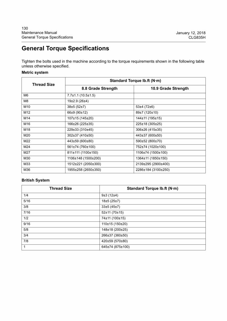
130Maintenance Manual January 12, 2018General Torque Specifications CLG835H
General Torque Specifications
Tighten the bolts used in the machine according to the torque requirements shown in the following table unless otherwise specified.
Metric system
Thread SizeStandard Torque lb.ft (N·m)
8.8 Grade Strength 10.9 Grade Strength
M6 7.7±1.1 (10.5±1.5)
M8 19±2.9 (26±4)
M10 38±5 (52±7) 53±4 (72±6)
M12 66±9 (90±12) 89±7 (120±10)
M14 107±15 (145±20) 144±11 (195±15)
M16 166±26 (225±35) 225±18 (305±25)
M18 229±33 (310±45) 306±26 (415±35)
M20 302±37 (410±50) 443±37 (600±50)
M22 443±59 (600±80) 590±52 (800±70)
M24 561±74 (760±100) 752±74 (1020±100)
M27 811±111 (1100±150) 1106±74 (1500±100)
M30 1106±148 (1500±200) 1364±11 (1850±150)
M33 1512±221 (2050±300) 2139±295 (2900±400)
M36 1955±258 (2650±350) 2286±184 (3100±250)
British System
Thread Size Standard Torque lb.ft (N·m)
1/4 9±3 (12±4)
5/16 18±5 (25±7)
3/8 33±5 (45±7)
7/16 52±11 (70±15)
1/2 74±11 (100±15)
9/16 110±15 (150±20)
5/8 148±18 (200±25)
3/4 266±37 (360±50)
7/8 420±59 (570±80)
1 645±74 (875±100)
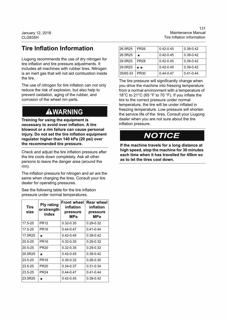
131January 12, 2018 Maintenance ManualCLG835H Tire Inflation Information
Tire Inflation Information
Liugong recommends the use of dry nitrogen for tire inflation and tire pressure adjustments. It includes all machines with rubber tires. Nitrogen is an inert gas that will not aid combustion inside the tire.
The use of nitrogen for tire inflation can not only reduce the risk of explosion, but also help to prevent oxidation, aging of the rubber, and corrosion of the wheel rim parts.
Check and adjust the tire inflation pressure after the tire cools down completely. Ask all other persons to leave the danger area (around the rim).
The inflation pressure for nitrogen and air are the same when charging the tires. Consult your tire dealer for operating pressures.
See the following table for the tire inflation pressure under normal temperatures.
The tire pressure will significantly change when you drive the machine into freezing temperature from a normal environment with a temperature of 18°C to 21°C (65 °F to 70 °F). If you inflate the tire to the correct pressure under normal temperature, the tire will be under inflated in freezing temperature. Low pressure will shorten the service life of the tires. Consult your Liugong dealer when you are not sure about the tire inflation pressure.
Training for using the equipment is necessary to avoid over inflation. A tire blowout or a rim failure can cause personal injury. Do not set the tire inflation equipment regulator higher than 140 kPa (20 psi) over the recommended tire pressure.
Tire size
Ply rating or strength
index
Front wheel inflation pressure
MPa
Rear wheelinflation pressure
MPa
17.5-25 PR12 0.32-0.35 0.29-0.32
17.5-25 PR16 0.44-0.47 0.41-0.44
17.5R25 ★ 0.42-0.45 0.39-0.42
20.5-25 PR16 0.32-0.35 0.29-0.32
20.5-25 PR20 0.32-0.35 0.29-0.32
20.5R25 ★ 0.42-0.45 0.39-0.42
23.5-25 PR16 0.30-0.32 0.28-0.30
23.5-25 PR20 0.34-0.37 0.31-0.34
23.5-25 PR24 0.44-0.47 0.41-0.44
23.5R25 ★ 0.42-0.45 0.39-0.42
26.5R25 PR26 0.42-0.45 0.39-0.42
26.5R25 ★ 0.42-0.45 0.39-0.42
29.5R25 PR28 0.42-0.45 0.39-0.42
29.5R25 ★★ 0.42-0.45 0.39-0.42
35/65-33 PR30 0.44-0.47 0.41-0.44
If the machine travels for a long distance at high speed, stop the machine for 30 minutes each time when it has travelled for 45km so as to let the tires cool down.
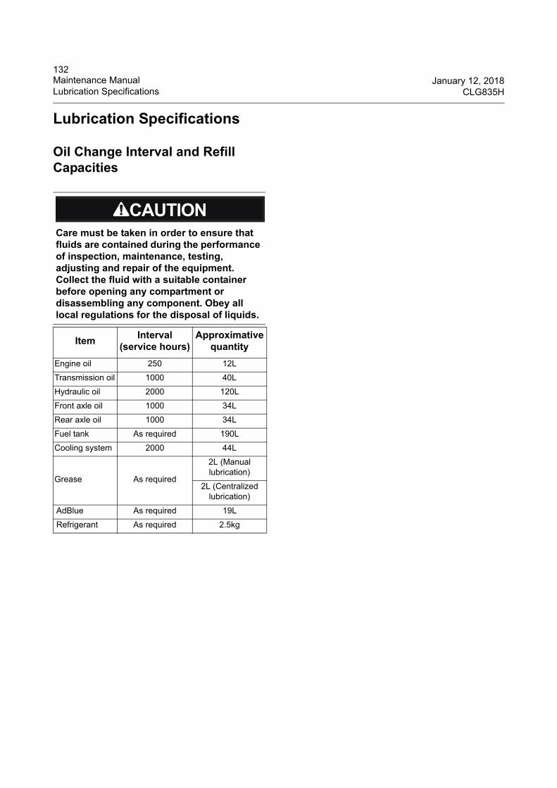
132Maintenance Manual January 12, 2018Lubrication Specifications CLG835H
Lubrication Specifications
Oil Change Interval and Refill Capacities
Care must be taken in order to ensure that fluids are contained during the performance of inspection, maintenance, testing, adjusting and repair of the equipment. Collect the fluid with a suitable container before opening any compartment or disassembling any component. Obey all local regulations for the disposal of liquids.
ItemInterval
(service hours)Approximative
quantity
Engine oil 250 12L
Transmission oil 1000 40L
Hydraulic oil 2000 120L
Front axle oil 1000 34L
Rear axle oil 1000 34L
Fuel tank As required 190L
Cooling system 2000 44L
Grease As required
2L (Manual lubrication)
2L (Centralized lubrication)
AdBlue As required 19L
Refrigerant As required 2.5kg
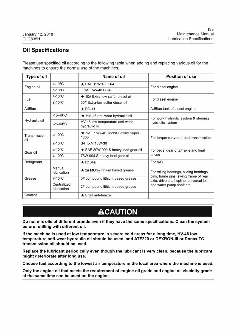
133January 12, 2018 Maintenance ManualCLG835H Lubrication Specifications
Oil Specifications
Please use specified oil according to the following table when adding and replacing various oil for the machines to ensure the normal use of the machines.
Type of oil Name of oil Position of use
Engine oil≥-10°C ★ SAE 15W/40 CJ-4
For diesel engine≤-10°C SAE 5W/40 CJ-4
Fuel≥-10°C ★ 10# Extra-low sulfur diesel oil
For diesel engine≤-10°C 35# Extra-low sulfur diesel oil
AdBlue ★ RD-11 AdBlue tank of diesel engine
Hydraulic oil
-15-40°C ★ HM-46 anti-wear hydraulic oilFor work hydraulic system & steering hydraulic system-25-40°C
HV-46 low temperature anti-wear hydraulic oil
Transmission oil
≥-10°C ★ SAE 15W-40 Mobil Delvac Super 1300 For torque converter and transmission
≤-10°C S4 TXM 10W-30
Gear oil≥-10°C ★ SAE 80W-90/LS heavy load gear oil For bevel gear of ZF axle and final
drives≤-10°C 75W-90/LS heavy load gear oil
Refrigerant ★ R134a For A/C
Grease
Manual lubrication
★ 2# MOS2 lithium based grease For rolling bearings, sliding bearings, pins, frame pins, swing frame of rear axle, drive shaft spline, universal joint and water pump shaft etc.
≤-10°C 0# compound lithium based grease
Centralized lubrication
2# compound lithium based grease
Coolant ★ Shell anti-freeze
Do not mix oils of different brands even if they have the same specifications. Clean the system before refilling with different oil.
If the machine is used at low temperature in severe cold areas for a long time, HV-46 low temperature anti-wear hydraulic oil should be used, and ATF220 or DEXRON-III or Donax TC transmission oil should be used.
Replace the lubricant periodically even though the lubricant is very clean, because the lubricant might deteriorate after long use.
Choose fuel according to the lowest air temperature in the local area where the machine is used.
Only the engine oil that meets the requirement of engine oil grade and engine oil viscidity grade at the same time can be used on the engine.
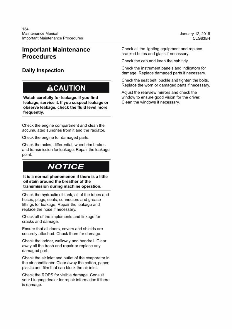
134Maintenance Manual January 12, 2018Important Maintenance Procedures CLG835H
Important Maintenance Procedures
Daily Inspection
Check the engine compartment and clean the accumulated sundries from it and the radiator.
Check the engine for damaged parts.
Check the axles, differential, wheel rim brakes and transmission for leakage. Repair the leakage point.
Check the hydraulic oil tank, all of the tubes and hoses, plugs, seals, connectors and grease fittings for leakage. Repair the leakage and replace the hose if necessary.
Check all of the implements and linkage for cracks and damage.
Ensure that all doors, covers and shields are securely attached. Check them for damage.
Check the ladder, walkway and handrail. Clear away all the trash and repair or replace any damaged part.
Check the air inlet and outlet of the evaporator in the air conditioner. Clear away the cotton, paper, plastic and film that can block the air inlet.
Check the ROPS for visible damage. Consult your Liugong dealer for repair information if there is damage.
Check all the lighting equipment and replace cracked bulbs and glass if necessary.
Check the cab and keep the cab tidy.
Check the instrument panels and indicators for damage. Replace damaged parts if necessary.
Check the seat belt, buckle and tighten the bolts. Replace the worn or damaged parts if necessary.
Adjust the rearview mirrors and check the window to ensure good vision for the driver. Clean the windows if necessary.
Watch carefully for leakage. If you find leakage, service it. If you suspect leakage or observe leakage, check the fluid level more frequently.
It is a normal phenomenon if there is a little oil stain around the breather of the transmission during machine operation.
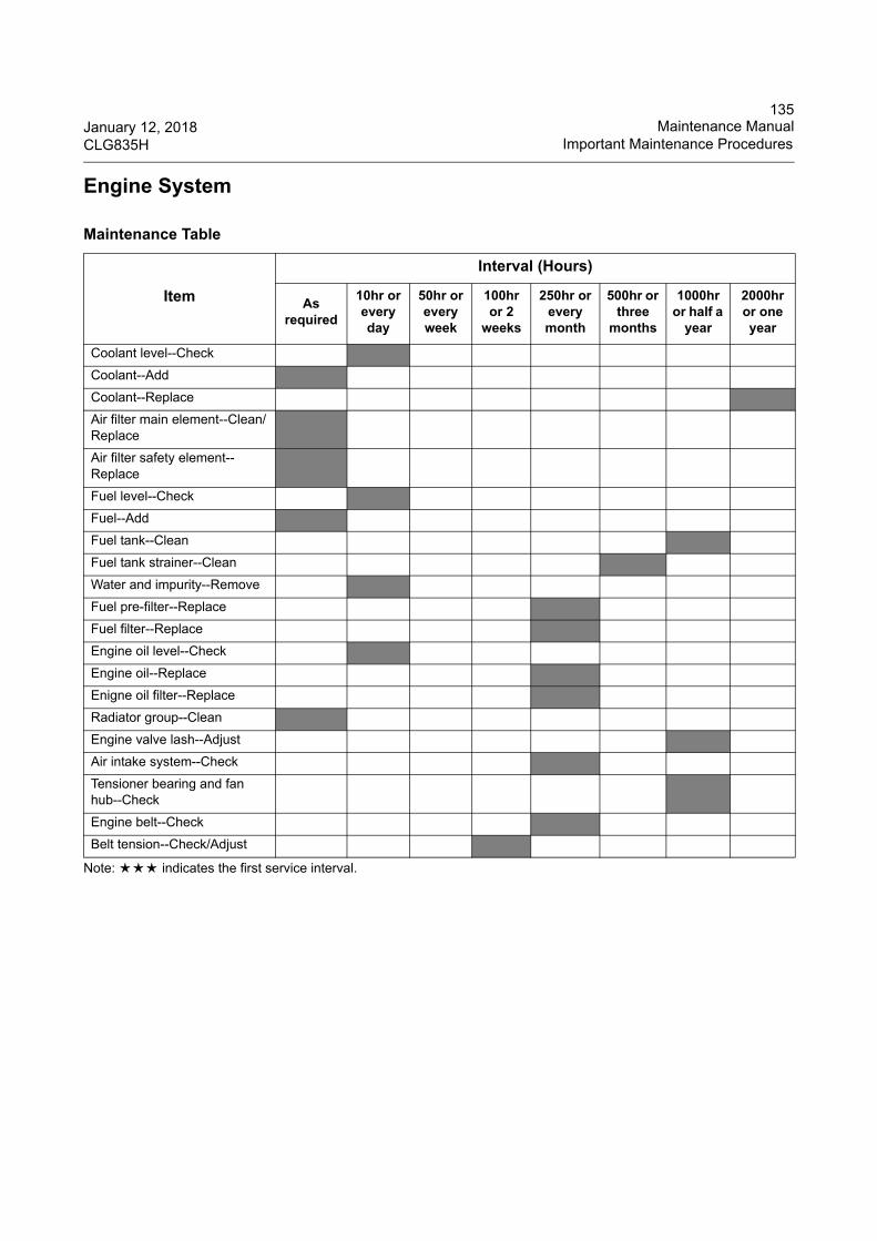
135January 12, 2018 Maintenance ManualCLG835H Important Maintenance Procedures
Engine System
Note: ★★★ indicates the first service interval.
Maintenance Table
Item
Interval (Hours)
As required
10hr or every day
50hr or every week
100hr or 2
weeks
250hr or every month
500hr or three
months
1000hr or half a
year
2000hr or one year
Coolant level--Check
Coolant--Add
Coolant--Replace
Air filter main element--Clean/Replace
Air filter safety element--Replace
Fuel level--Check
Fuel--Add
Fuel tank--Clean
Fuel tank strainer--Clean
Water and impurity--Remove
Fuel pre-filter--Replace
Fuel filter--Replace
Engine oil level--Check
Engine oil--Replace
Enigne oil filter--Replace
Radiator group--Clean
Engine valve lash--Adjust
Air intake system--Check
Tensioner bearing and fan hub--Check
Engine belt--Check
Belt tension--Check/Adjust
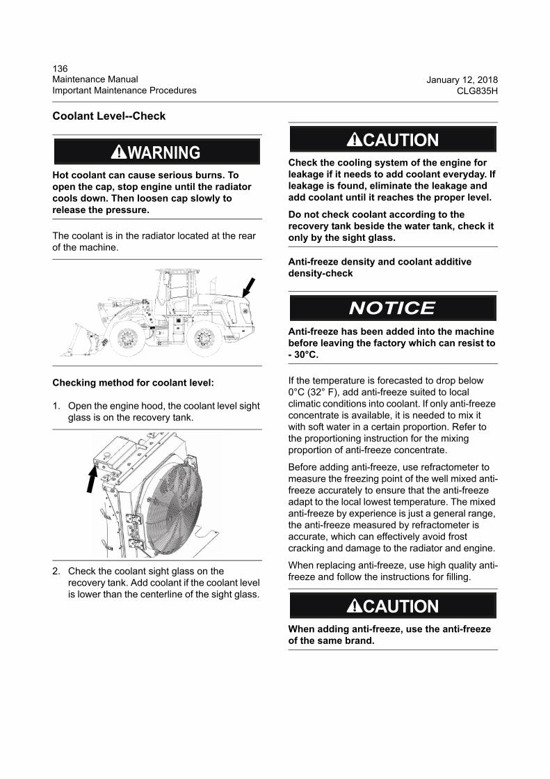
136Maintenance Manual January 12, 2018Important Maintenance Procedures CLG835H
Coolant Level--Check
The coolant is in the radiator located at the rear of the machine.
Checking method for coolant level:
1. Open the engine hood, the coolant level sight glass is on the recovery tank.
2. Check the coolant sight glass on the recovery tank. Add coolant if the coolant level is lower than the centerline of the sight glass.
Anti-freeze density and coolant additive density-check
If the temperature is forecasted to drop below 0°C (32° F), add anti-freeze suited to local climatic conditions into coolant. If only anti-freeze concentrate is available, it is needed to mix it with soft water in a certain proportion. Refer to the proportioning instruction for the mixing proportion of anti-freeze concentrate.
Before adding anti-freeze, use refractometer to measure the freezing point of the well mixed anti-freeze accurately to ensure that the anti-freeze adapt to the local lowest temperature. The mixed anti-freeze by experience is just a general range, the anti-freeze measured by refractometer is accurate, which can effectively avoid frost cracking and damage to the radiator and engine.
When replacing anti-freeze, use high quality anti-freeze and follow the instructions for filling.
Hot coolant can cause serious burns. To open the cap, stop engine until the radiator cools down. Then loosen cap slowly to release the pressure.
WHEEL L OADERG ua ng x i L iu go n g Ma ch ine ry Co .,L td .N o.1 Li utai R oad, Li uzhou, G uangxi 54 5007, PR Ch ina
PRODUCTIDENT IF ICAT ION
NUMBER
Check the cooling system of the engine for leakage if it needs to add coolant everyday. If leakage is found, eliminate the leakage and add coolant until it reaches the proper level.
Do not check coolant according to the recovery tank beside the water tank, check it only by the sight glass.
Anti-freeze has been added into the machine before leaving the factory which can resist to - 30°C.
When adding anti-freeze, use the anti-freeze of the same brand.
137January 12, 2018 Maintenance ManualCLG835H Important Maintenance Procedures
Coolant must contain additive (SCA) to prevent the engine parts which contact with coolant from rusting, scaling, pitting, and corrosion. Additive (SCA) of low density doesn’t have effect, additive (SCA) of high density will have a negative impact on engine, it may result in water pump leakage and corrosion of cooling system solder and aluminum parts.
The density of coolant additive should be maintained at about 3%. Anti-freeze already contains additive, but the additive will be consumed up during running the engine. Therefore, check the coolant density every 500 work hours or six months. Add additive by changing the coolant filter periodically.
Refer to the Operation and Maintenance Manual of Diesel Engine provided with the machine for the additive density inspection method and detailed instructions.
Coolant--Add
Water used in coolant must be soft water or distilled water, because ordinary fresh water and tap water contains a lot of calcium and magnesium materials, which will cause scaling of the cooling system radiator, engine and piping, while excessive chlorine compounds and sulfate will corrode the cooling system and engine waterways. If there isn’t soft water or distilled water, the quality of water used in coolant must meet all of the requirements listed in the following table, and the density level of each element shall not exceed the permitted maximum value in the following table.
If the temperature is forecasted to drop below 0°C (32° F), add anti-freeze suited to local climatic conditions into coolant. If only anti-freeze concentrate is available, it is needed to mix it with soft water in a certain proportion. Refer to the proportioning instruction for the mixing proportion of anti-freeze concentrate.
Since the heat absorption capacity of anti-freeze to the engine isn’t as good as water, add anti-freeze into the engine before thoroughly mixed with water will cause overheat of the engine.
Before adding anti-freeze, use refractometer to measure the freezing point of the well mixed anti-freeze accurately to ensure that the anti-freeze adapt to the local lowest temperature. The anti-freeze concentration mixed by experience is just a general range, the anti-freeze value measured by refractometer is accurate, which can effectively avoid damage to the radiator and engine caused by frost cracking.
Hot coolant can cause serious burn. To open cap, stop engine until radiator cools down. Then loosen cap slowly to release the pressure.
Anti-freeze is flammable. Never expose anti-freeze to an open fire. Never use water as the coolant otherwise it will cause corrosion damage to the cooling system.
Min. water quality requirement
ItemPermitted max. content
value
Calcium and magnesium content (hardness)
Max. content in (CaCO3 + MgCO3) is 170ppm
Chlorine Max. content in (Cl) is 40ppm
Sulfur Max. content in (SO4) is 100ppm
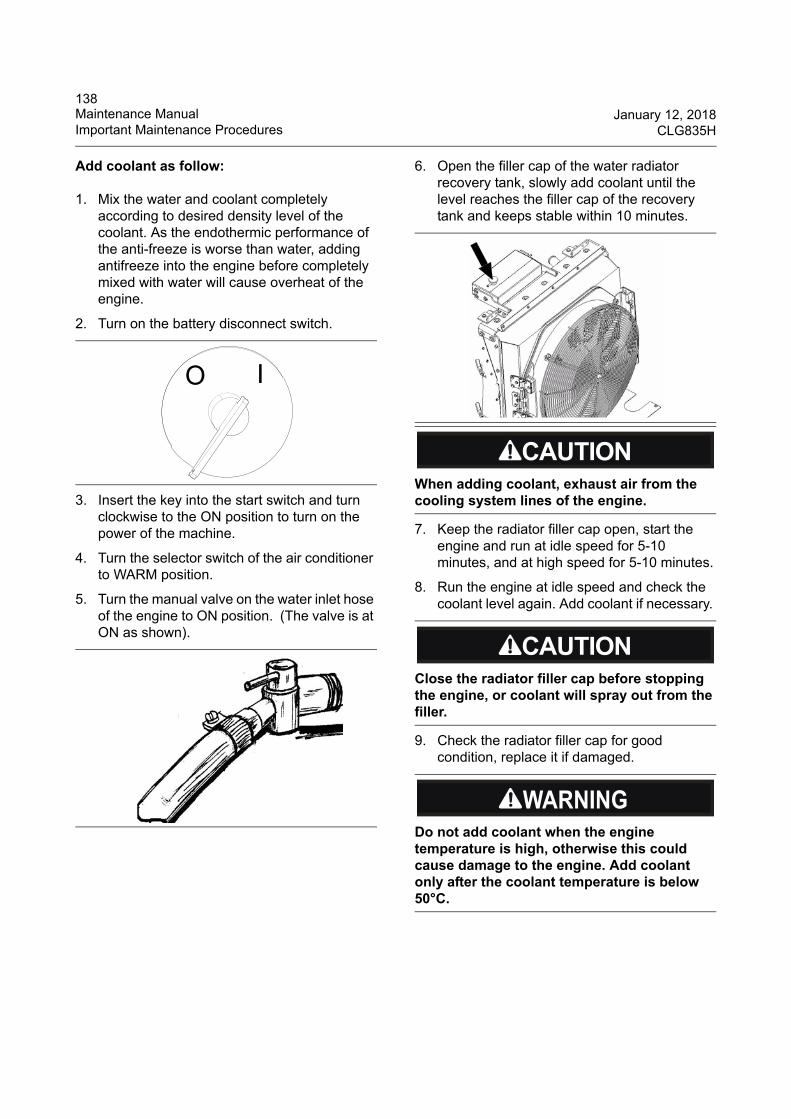
138Maintenance Manual January 12, 2018Important Maintenance Procedures CLG835H
Add coolant as follow:
1. Mix the water and coolant completely according to desired density level of the coolant. As the endothermic performance of the anti-freeze is worse than water, adding antifreeze into the engine before completely mixed with water will cause overheat of the engine.
2. Turn on the battery disconnect switch.
3. Insert the key into the start switch and turn clockwise to the ON position to turn on the power of the machine.
4. Turn the selector switch of the air conditioner to WARM position.
5. Turn the manual valve on the water inlet hose of the engine to ON position. (The valve is at ON as shown).
6. Open the filler cap of the water radiator recovery tank, slowly add coolant until the level reaches the filler cap of the recovery tank and keeps stable within 10 minutes.
7. Keep the radiator filler cap open, start the engine and run at idle speed for 5-10 minutes, and at high speed for 5-10 minutes.
8. Run the engine at idle speed and check the coolant level again. Add coolant if necessary.
9. Check the radiator filler cap for good condition, replace it if damaged.
O I
When adding coolant, exhaust air from the cooling system lines of the engine.
Close the radiator filler cap before stopping the engine, or coolant will spray out from the filler.
Do not add coolant when the engine temperature is high, otherwise this could cause damage to the engine. Add coolant only after the coolant temperature is below 50°C.
139January 12, 2018 Maintenance ManualCLG835H Important Maintenance Procedures
Coolant--Replace
Completely replace the coolant every 2000 service hours or one year (which ever comes first) and clean the cooling system. Clean the cooling system before that interval if the coolant is polluted, the engine is running excessively hot or bubbles appear in the radiator.
When coolant is polluted, engine overheated or bubbles appeared in radiator, test the freezing point of the additive and anti-freeze in the cooling system to determine whether the coolant must be replaced, replace the coolant if it exceeds any permitted limit value in the coolant replacement limit table.
Note ★ : The replacement limit of the min. pH value may change with the product changes. Consult the product manufacturer for the pH value limit. The pH value less than 6.5 is unacceptable generally.
Steps for cleaning the cooling system
1. Turn on the disconnect switch.
2. Insert the start switch key and turn clockwise to the ON position to turn on the power of the machine.
3. Turn the selector switch of the air conditioner to WARM AIR position.
Hot coolant can cause serious burn. To open cap, stop engine until radiator cools down. Then loosen cap slowly to release the pressure.
Anti-freeze might hurt the skin, when replacing it, wear goggles and protective clothing to avoid personal injury.
Care must be taken in order to ensure that fluids are contained during performance of inspection, maintenance, testing, adjusting and repair of the equipment. Prepare to collect the fluid with suitable containers before disassembling any hydraulic oil lines. Obey all local regulation for the disposal of liquids.
If the cooling system failed to be cleaned thoroughly, the new coolant may be polluted during adding, and result in the cooling system and engine failure.
Do not mixed use multiple brands of coolant, otherwise the consequent cooling system and engine failures are not covered by warranty.
Coolant replacement limit table
Pollutants Permitted limit value
Sulfate (SO4) Max. 1500ppm
Chloride (Cl) fluoride, bromide
Max. 200ppm
Engine oil or fuel pollution
Coolant shall not contain engine oil or fuel
pH value Min. 6.5 (see Note ★ )
Grease, solder , silicone, corrosion or scaling
Coolant shall not contain these pollutants.
OFF ON
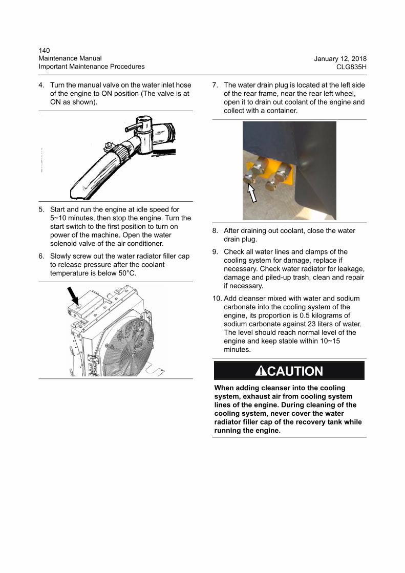
140Maintenance Manual January 12, 2018Important Maintenance Procedures CLG835H
4. Turn the manual valve on the water inlet hose of the engine to ON position (The valve is at ON as shown).
5. Start and run the engine at idle speed for 5~10 minutes, then stop the engine. Turn the start switch to the first position to turn on power of the machine. Open the water solenoid valve of the air conditioner.
6. Slowly screw out the water radiator filler cap to release pressure after the coolant temperature is below 50°C.
7. The water drain plug is located at the left side of the rear frame, near the rear left wheel, open it to drain out coolant of the engine and collect with a container.
8. After draining out coolant, close the water drain plug.
9. Check all water lines and clamps of the cooling system for damage, replace if necessary. Check water radiator for leakage, damage and piled-up trash, clean and repair if necessary.
10. Add cleanser mixed with water and sodium carbonate into the cooling system of the engine, its proportion is 0.5 kilograms of sodium carbonate against 23 liters of water. The level should reach normal level of the engine and keep stable within 10~15 minutes.
When adding cleanser into the cooling system, exhaust air from cooling system lines of the engine. During cleaning of the cooling system, never cover the water radiator filler cap of the recovery tank while running the engine.
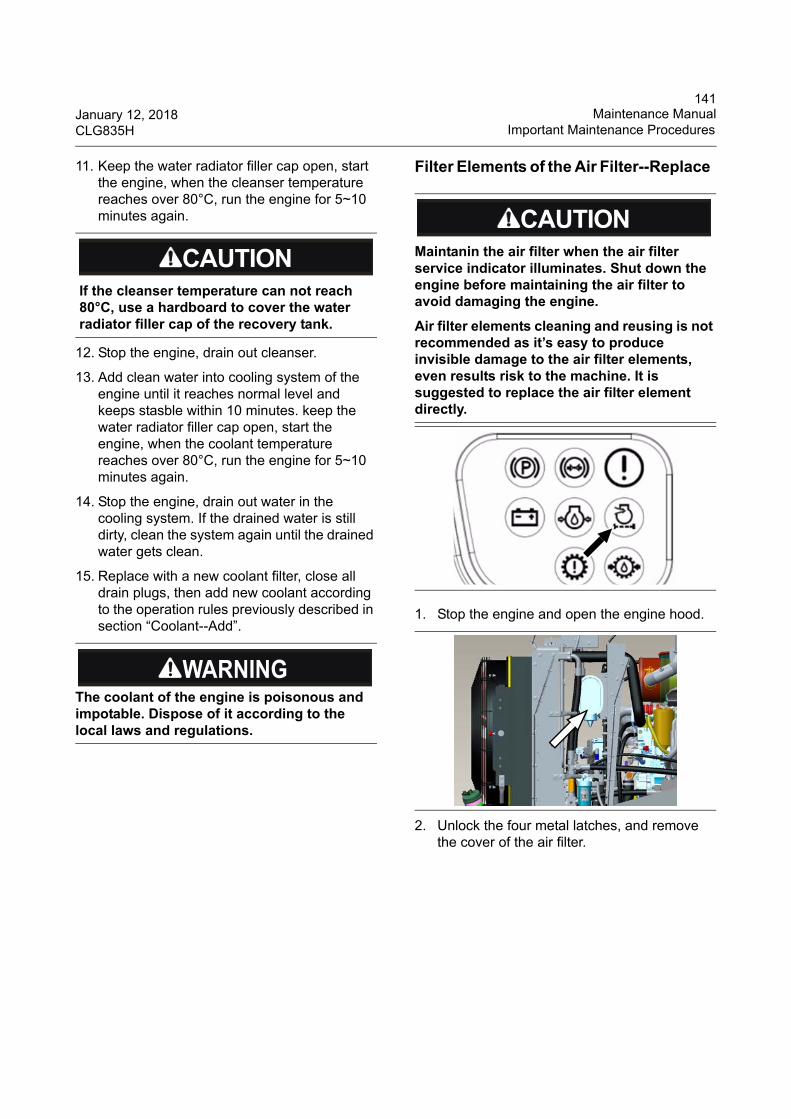
141January 12, 2018 Maintenance ManualCLG835H Important Maintenance Procedures
11. Keep the water radiator filler cap open, start the engine, when the cleanser temperature reaches over 80°C, run the engine for 5~10 minutes again.
12. Stop the engine, drain out cleanser.
13. Add clean water into cooling system of the engine until it reaches normal level and keeps stasble within 10 minutes. keep the water radiator filler cap open, start the engine, when the coolant temperature reaches over 80°C, run the engine for 5~10 minutes again.
14. Stop the engine, drain out water in the cooling system. If the drained water is still dirty, clean the system again until the drained water gets clean.
15. Replace with a new coolant filter, close all drain plugs, then add new coolant according to the operation rules previously described in section “Coolant--Add”.
Filter Elements of the Air Filter--Replace
1. Stop the engine and open the engine hood.
2. Unlock the four metal latches, and remove the cover of the air filter.
If the cleanser temperature can not reach 80°C, use a hardboard to cover the water radiator filler cap of the recovery tank.
The coolant of the engine is poisonous and impotable. Dispose of it according to the local laws and regulations.
Maintanin the air filter when the air filter service indicator illuminates. Shut down the engine before maintaining the air filter to avoid damaging the engine.
Air filter elements cleaning and reusing is not recommended as it’s easy to produce invisible damage to the air filter elements, even results risk to the machine. It is suggested to replace the air filter element directly.
142Maintenance Manual January 12, 2018Important Maintenance Procedures CLG835H
A: Main filter element B: Safety filter element
3. Take out the main filter element along with the housing direction. Push the main filter element downward by handles to loosen the gasket from it and tilt it for about 5°, and then pull the main filter element out.
4. Take out the safety filter element. Use the handles on the safety filter element to pull it towards the filter housing center, and then take it out.
5. Check the new filter elements before installation to see if there is any cutting, tearing or indentation on the seal surface. Do not install it if damaged.
6. If replace with a new safety filter element, use the handles on the safety filter element to tilt it a little bit and slide it into the filter housing, and then push the safety filter element into the limit position until it is installed firmly and smoothly in the filter housing.
7. Insert the main filter element. Tilt the main filter element for about 5° and slide it into the end of the filter housing.
8. Install the cover of the air filter, lock the metal latches.
A
B
The safety air filter element should be changed every third time the main air filter element is changed.
Before pushing the safety filter element to proper position, insert the fins of it into the locating slot.
143January 12, 2018 Maintenance ManualCLG835H Important Maintenance Procedures
9. Check the connection of the air inlet and air outlet. If the air filter is equipped with a dust valve, check the dust exhaust valve, replace it if damaged.
10. Close the engine hood.
Fuel Level--Check
The fuel level gauge is on the cab instrument panel. It has two zones. “1” indicates the high fuel level. “0” indicates the low fuel level. Add fuel in time when the fuel level is lower than “0.2”.
If the fuel level is lower than 0.2, ensure enough time for the operator to add fuel.
Fuel--Add
The fuel tank of the machine is located below the rear of the engine.
1. Stop the engine.
2. Open the rear door of the engine hood to access the fuel filler of the fuel tank.
3. Pull up the lock plate of the fuel filler cap, turn the cap counterclockwise to the next position and move it outwards, and then remove the cap.
If the air filter cover can’t be installed, remove it and check the locations of the filter elements again. It is difficult to install the air filter cover if the filter elements are not installed properly.
Fuel level gauge
No smoking and keep away from the flames or spark area when adding fuel.
WHEEL LOADERGu an g xi L iug o ng M ac hin ery C o.,Ltd.No . 1 L iu t a i Ro a d , L iu z h o u , Gu a n g x i 5 4 5 0 0 7 , PR Ch in a
PRODUCTI DENTI F ICAT ION
NUMBER
144Maintenance Manual January 12, 2018Important Maintenance Procedures CLG835H
4. Add fuel.
Fuel Tank--Clean
1. Stop the engine.
2. Remove the flange cover in front of the fuel tank. Wash the inner surface of the tank with clean fuel.
1. Flange cover2. Drain plug
3. Remove the drain plug to drain out the residual fuel.
4. Repeat washing until the drained fuel is clean.
Fuel Strainer--Clean
1. Stop the engine.
2. Remove the fuel filler cap of the fuel tank. Check the gaskets for damage. Replace the gaskets if damaged.
3. Take out and check the fuel strainer. Replace if damaged.
4. Wash the fuel filler and fuel strainer with clean and nonflammable detergent. Dry them in the air or by compressed air.
5. Install the fuel filler cap and strainer.
Water and Impurity--Remove
The fuel pump and fuel injection nozzle are precision devices, if fuel is mixed with water or impurity, the fuel pump and fuel injection nozzle can't work properly and quickly worn. Measures should be taken to remove water and impurity in fuel.
1. If the condition is permitted, fuel should be deposited for 24 hours before it is filled to the tank.
Don't take out the strainer of the fuel filler when adding fuel.
Care must be taken to ensure that fluids are contained during performance of inspection, maintenance, testing, adjusting and repair of the product. Be prepared to collect the fluid with suitable containers before disassembling any component containing fluids. Dispose of all fluids according to local regulations.
No smoking and keep away from the flames or spark area when cleaning the fuel tank.
12
145January 12, 2018 Maintenance ManualCLG835H Important Maintenance Procedures
2. Before filling, screw out the drain plug at the bottom of the fuel tank to drain out water and impurity deposited in the tank once every week.
3. After completing daily work, add fuel and remove the humid air in the fuel tank.
4. After replenishing the fuel tank every time, wait for 5 ~ 10 minutes before starting the engine so that water and impurity have sunk to the bottom of the tank.
5. After completing daily work, loosen the water drain plugs of fuel pre-filter (fuel water separator) to drain out water and impurity.
Filter Element of Fuel Water Separator--Replace
The fuel water separator is located on the rear right side of the machine.
1. First clean the fuel water separator surroundings and the support.
2. Remove the fuel water separator from the support with a wrench.
1. Breather plug2. Drain valve3. Water outlet4. Adapter
Fuel pre-filter (fuel water separator)
Add the fuel in time. Any residual fuel at the bottom of the fuel tank that contains water and impurity will affect the normal running of the engine. Drain and clean fuel tank before adding.
1
2
34
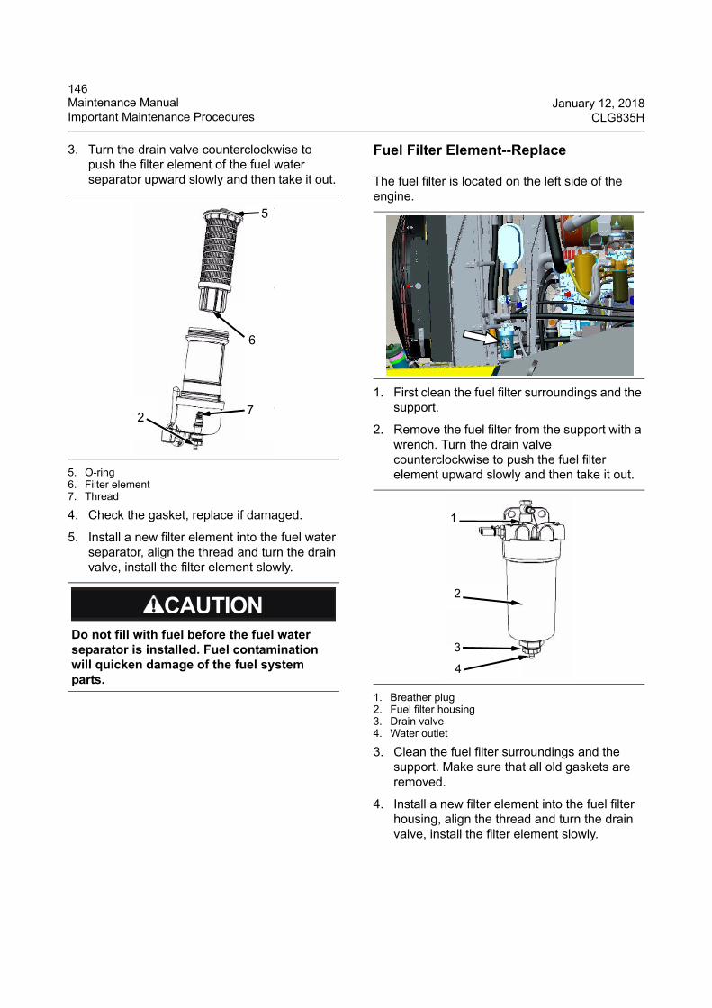
146Maintenance Manual January 12, 2018Important Maintenance Procedures CLG835H
3. Turn the drain valve counterclockwise to push the filter element of the fuel water separator upward slowly and then take it out.
5. O-ring6. Filter element7. Thread
4. Check the gasket, replace if damaged.
5. Install a new filter element into the fuel water separator, align the thread and turn the drain valve, install the filter element slowly.
Fuel Filter Element--Replace
The fuel filter is located on the left side of the engine.
1. First clean the fuel filter surroundings and the support.
2. Remove the fuel filter from the support with a wrench. Turn the drain valve counterclockwise to push the fuel filter element upward slowly and then take it out.
1. Breather plug2. Fuel filter housing3. Drain valve4. Water outlet
3. Clean the fuel filter surroundings and the support. Make sure that all old gaskets are removed.
4. Install a new filter element into the fuel filter housing, align the thread and turn the drain valve, install the filter element slowly.
Do not fill with fuel before the fuel water separator is installed. Fuel contamination will quicken damage of the fuel system parts.
2
5
6
7
1
2
3
4
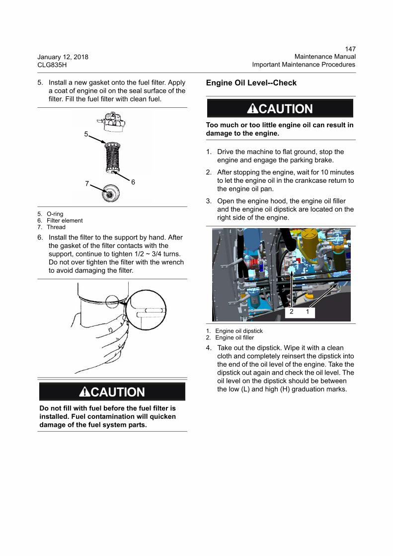
147January 12, 2018 Maintenance ManualCLG835H Important Maintenance Procedures
5. Install a new gasket onto the fuel filter. Apply a coat of engine oil on the seal surface of the filter. Fill the fuel filter with clean fuel.
5. O-ring6. Filter element7. Thread
6. Install the filter to the support by hand. After the gasket of the filter contacts with the support, continue to tighten 1/2 ~ 3/4 turns. Do not over tighten the filter with the wrench to avoid damaging the filter.
Engine Oil Level--Check
1. Drive the machine to flat ground, stop the engine and engage the parking brake.
2. After stopping the engine, wait for 10 minutes to let the engine oil in the crankcase return to the engine oil pan.
3. Open the engine hood, the engine oil filler and the engine oil dipstick are located on the right side of the engine.
1. Engine oil dipstick2. Engine oil filler
4. Take out the dipstick. Wipe it with a clean cloth and completely reinsert the dipstick into the end of the oil level of the engine. Take the dipstick out again and check the oil level. The oil level on the dipstick should be between the low (L) and high (H) graduation marks.
Do not fill with fuel before the fuel filter is installed. Fuel contamination will quicken damage of the fuel system parts.
5
67
Too much or too little engine oil can result in damage to the engine.
2 1
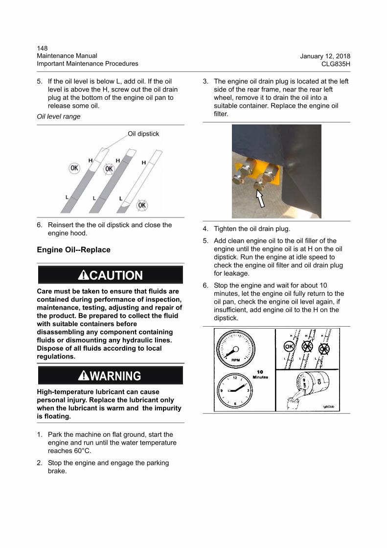
148Maintenance Manual January 12, 2018Important Maintenance Procedures CLG835H
5. If the oil level is below L, add oil. If the oil level is above the H, screw out the oil drain plug at the bottom of the engine oil pan to release some oil.
6. Reinsert the the oil dipstick and close the engine hood.
Engine Oil--Replace
1. Park the machine on flat ground, start the engine and run until the water temperature reaches 60°C.
2. Stop the engine and engage the parking brake.
3. The engine oil drain plug is located at the left side of the rear frame, near the rear left wheel, remove it to drain the oil into a suitable container. Replace the engine oil filter.
4. Tighten the oil drain plug.
5. Add clean engine oil to the oil filler of the engine until the engine oil is at H on the oil dipstick. Run the engine at idle speed to check the engine oil filter and oil drain plug for leakage.
6. Stop the engine and wait for about 10 minutes, let the engine oil fully return to the oil pan, check the engine oil level again, if insufficient, add engine oil to the H on the dipstick.
Oil level range
Care must be taken to ensure that fluids are contained during performance of inspection, maintenance, testing, adjusting and repair of the product. Be prepared to collect the fluid with suitable containers before disassembling any component containing fluids or dismounting any hydraulic lines. Dispose of all fluids according to local regulations.
High-temperature lubricant can cause personal injury. Replace the lubricant only when the lubricant is warm and the impurity is floating.
Oil dipstick
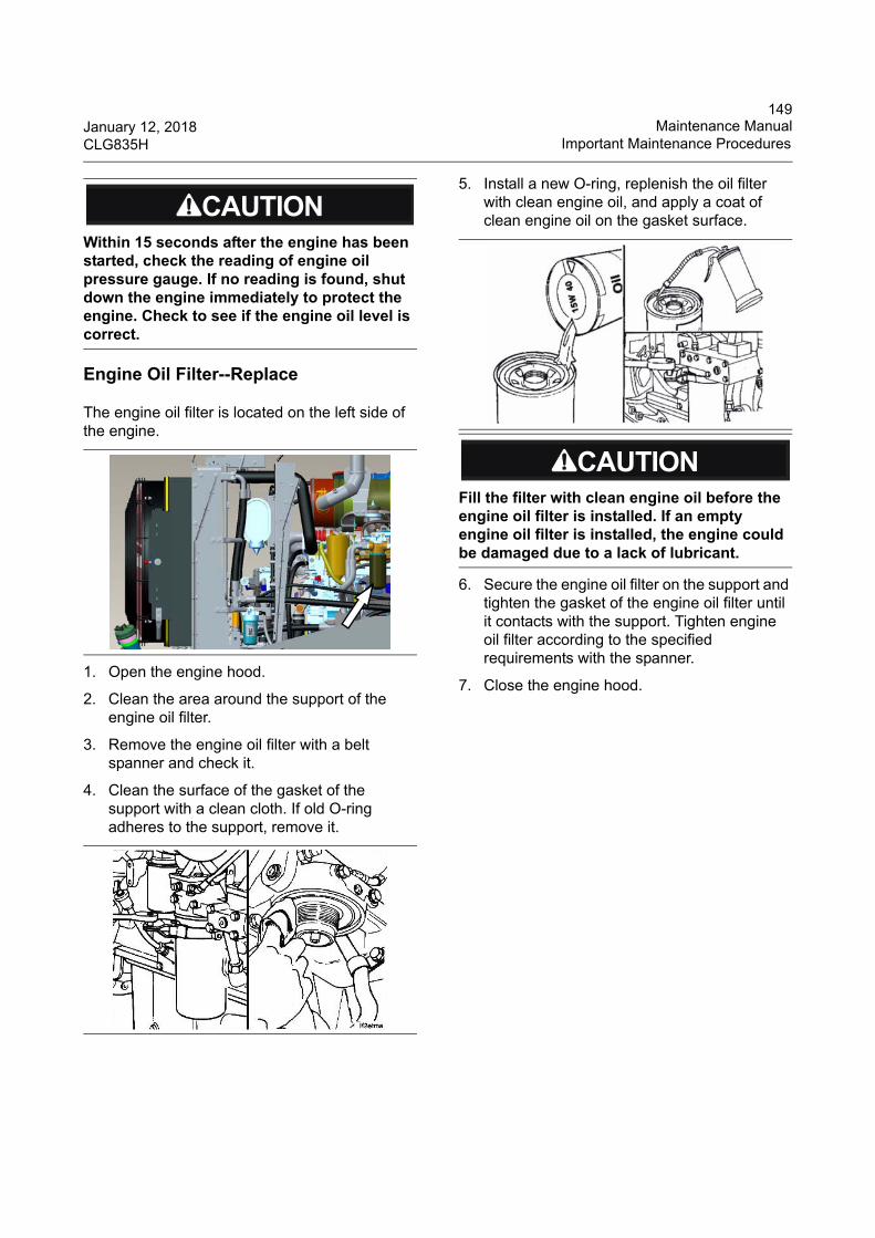
149January 12, 2018 Maintenance ManualCLG835H Important Maintenance Procedures
Engine Oil Filter--Replace
The engine oil filter is located on the left side of the engine.
1. Open the engine hood.
2. Clean the area around the support of the engine oil filter.
3. Remove the engine oil filter with a belt spanner and check it.
4. Clean the surface of the gasket of the support with a clean cloth. If old O-ring adheres to the support, remove it.
5. Install a new O-ring, replenish the oil filter with clean engine oil, and apply a coat of clean engine oil on the gasket surface.
6. Secure the engine oil filter on the support and tighten the gasket of the engine oil filter until it contacts with the support. Tighten engine oil filter according to the specified requirements with the spanner.
7. Close the engine hood.
Within 15 seconds after the engine has been started, check the reading of engine oil pressure gauge. If no reading is found, shut down the engine immediately to protect the engine. Check to see if the engine oil level is correct.
Fill the filter with clean engine oil before the engine oil filter is installed. If an empty engine oil filter is installed, the engine could be damaged due to a lack of lubricant.
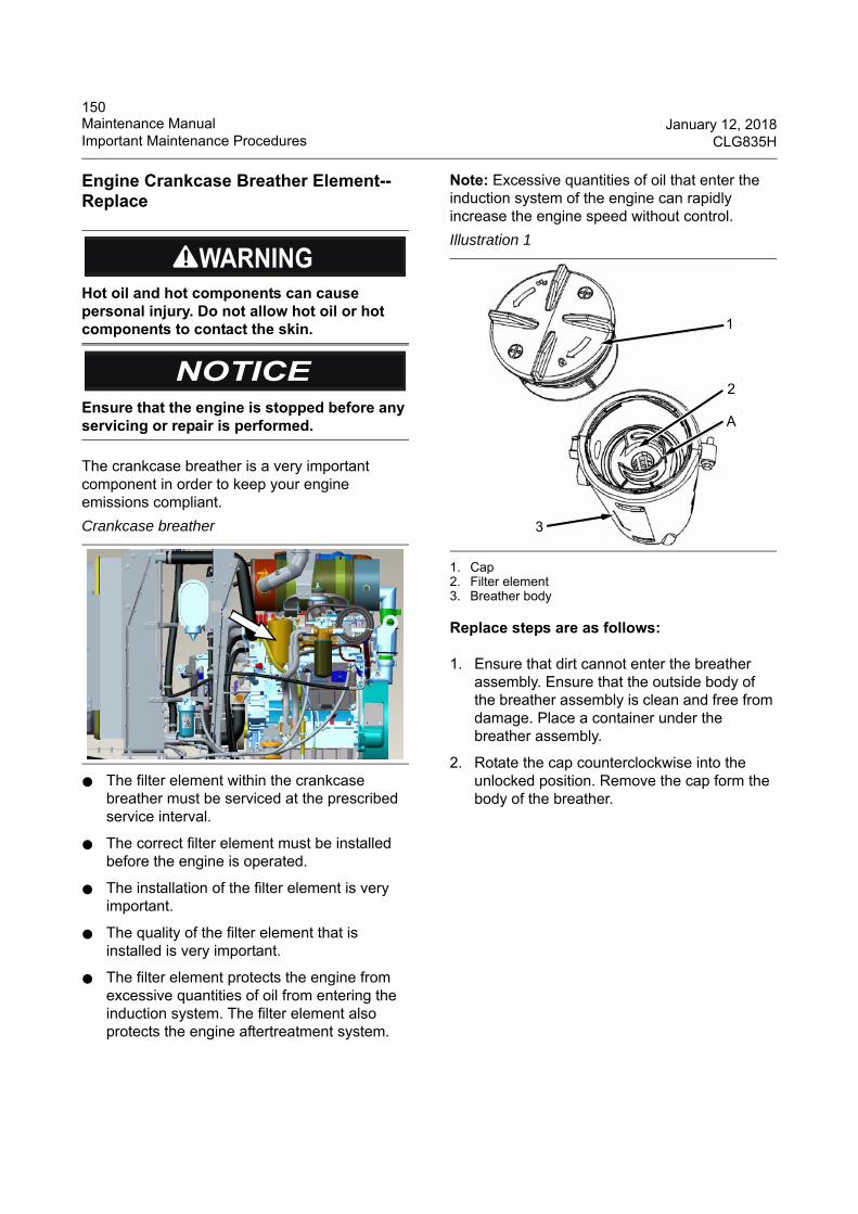
150Maintenance Manual January 12, 2018Important Maintenance Procedures CLG835H
Engine Crankcase Breather Element--Replace
The crankcase breather is a very important component in order to keep your engine emissions compliant.
● The filter element within the crankcase breather must be serviced at the prescribed service interval.
● The correct filter element must be installed before the engine is operated.
● The installation of the filter element is very important.
● The quality of the filter element that is installed is very important.
● The filter element protects the engine from excessive quantities of oil from entering the induction system. The filter element also protects the engine aftertreatment system.
Note: Excessive quantities of oil that enter the induction system of the engine can rapidly increase the engine speed without control.
1. Cap2. Filter element3. Breather body
Replace steps are as follows:
1. Ensure that dirt cannot enter the breather assembly. Ensure that the outside body of the breather assembly is clean and free from damage. Place a container under the breather assembly.
2. Rotate the cap counterclockwise into the unlocked position. Remove the cap form the body of the breather.
Hot oil and hot components can cause personal injury. Do not allow hot oil or hot components to contact the skin.
Ensure that the engine is stopped before any servicing or repair is performed.
Crankcase breather
Illustration 1
3
1
2
A
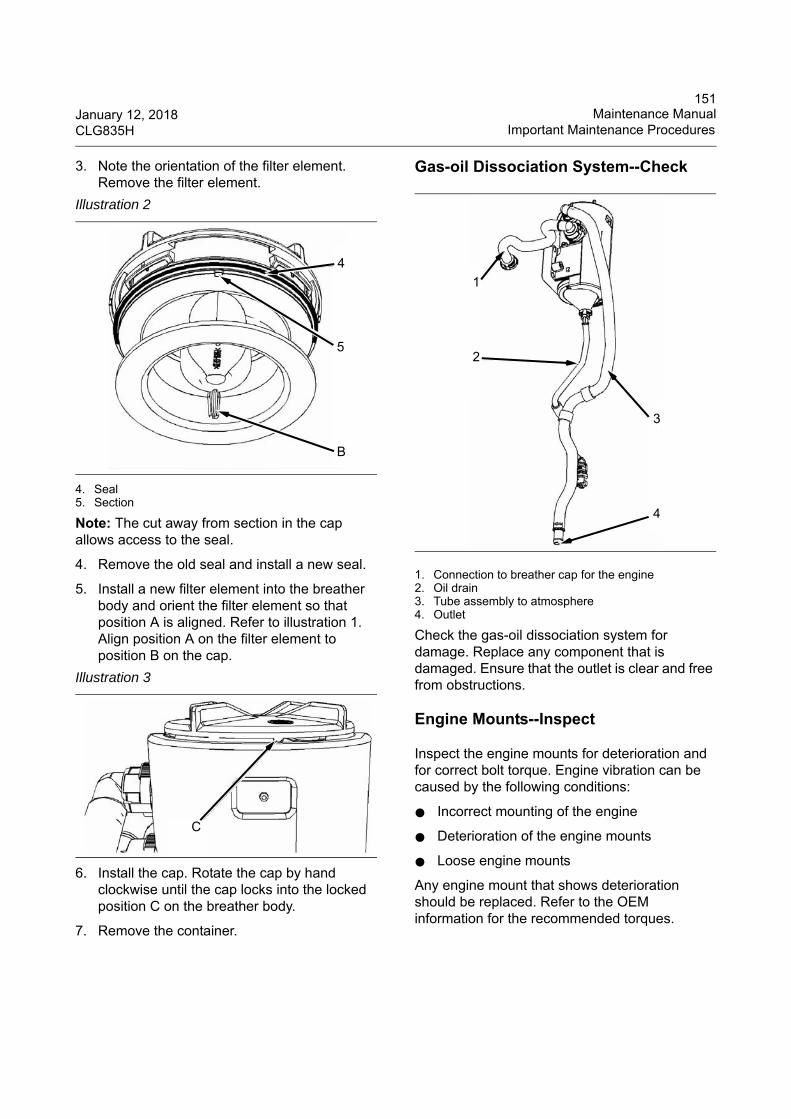
151January 12, 2018 Maintenance ManualCLG835H Important Maintenance Procedures
3. Note the orientation of the filter element. Remove the filter element.
4. Seal5. Section
Note: The cut away from section in the cap allows access to the seal.
4. Remove the old seal and install a new seal.
5. Install a new filter element into the breather body and orient the filter element so that position A is aligned. Refer to illustration 1. Align position A on the filter element to position B on the cap.
6. Install the cap. Rotate the cap by hand clockwise until the cap locks into the locked position C on the breather body.
7. Remove the container.
Gas-oil Dissociation System--Check
1. Connection to breather cap for the engine2. Oil drain3. Tube assembly to atmosphere4. Outlet
Check the gas-oil dissociation system for damage. Replace any component that is damaged. Ensure that the outlet is clear and free from obstructions.
Engine Mounts--Inspect
Inspect the engine mounts for deterioration and for correct bolt torque. Engine vibration can be caused by the following conditions:
● Incorrect mounting of the engine
● Deterioration of the engine mounts
● Loose engine mounts
Any engine mount that shows deterioration should be replaced. Refer to the OEM information for the recommended torques.
Illustration 2
Illustration 3
4
5
B
C
1
2
3
4
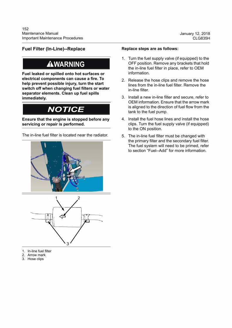
152Maintenance Manual January 12, 2018Important Maintenance Procedures CLG835H
Fuel Filter (In-Line)--Replace
The in-line fuel filter is located near the radiator.
1. In-line fuel filter2. Arrow mark3. Hose clips
Replace steps are as follows:
1. Turn the fuel supply valve (if equipped) to the OFF position. Remove any brackets that hold the in-line fuel filter in place, refer to OEM information.
2. Release the hose clips and remove the hose lines from the in-line fuel filter. Remove the in-line filter.
3. Install a new in-line filter and secure, refer to OEM information. Ensure that the arrow mark is aligned to the direction of fuel flow from the tank to the fuel pump.
4. Install the fuel hose lines and install the hose clips. Turn the fuel supply valve (if equipped) to the ON position.
5. The in-line fuel filter must be changed with the primary filter and the secondary fuel filter. The fuel system will need to be primed, refer to section “Fuel--Add” for more information.
Fuel leaked or spilled onto hot surfaces or electrical components can cause a fire. To help prevent possible injury, turn the start switch off when changing fuel filters or water separator elements. Clean up fuel spills immediately.
Ensure that the engine is stopped before any servicing or repair is performed.
3
1 2
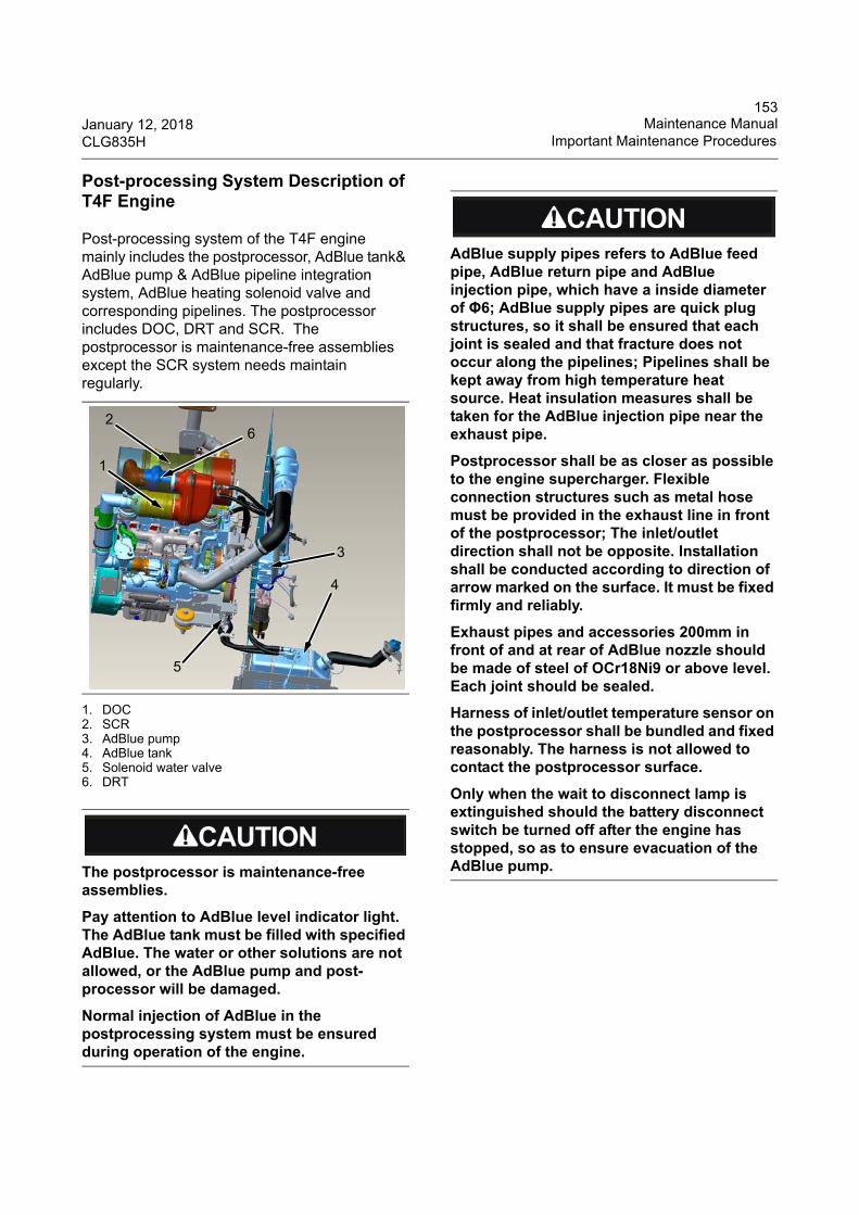
153January 12, 2018 Maintenance ManualCLG835H Important Maintenance Procedures
Post-processing System Description of T4F Engine
Post-processing system of the T4F engine mainly includes the postprocessor, AdBlue tank& AdBlue pump & AdBlue pipeline integration system, AdBlue heating solenoid valve and corresponding pipelines. The postprocessor includes DOC, DRT and SCR. The postprocessor is maintenance-free assemblies except the SCR system needs maintain regularly.
1. DOC2. SCR3. AdBlue pump4. AdBlue tank5. Solenoid water valve6. DRT
The postprocessor is maintenance-free assemblies.
Pay attention to AdBlue level indicator light. The AdBlue tank must be filled with specified AdBlue. The water or other solutions are not allowed, or the AdBlue pump and post-processor will be damaged.
Normal injection of AdBlue in the postprocessing system must be ensured during operation of the engine.
5
2
1
3
4
6
AdBlue supply pipes refers to AdBlue feed pipe, AdBlue return pipe and AdBlue injection pipe, which have a inside diameter of Φ6; AdBlue supply pipes are quick plug structures, so it shall be ensured that each joint is sealed and that fracture does not occur along the pipelines; Pipelines shall be kept away from high temperature heat source. Heat insulation measures shall be taken for the AdBlue injection pipe near the exhaust pipe.
Postprocessor shall be as closer as possible to the engine supercharger. Flexible connection structures such as metal hose must be provided in the exhaust line in front of the postprocessor; The inlet/outlet direction shall not be opposite. Installation shall be conducted according to direction of arrow marked on the surface. It must be fixed firmly and reliably.
Exhaust pipes and accessories 200mm in front of and at rear of AdBlue nozzle should be made of steel of OCr18Ni9 or above level. Each joint should be sealed.
Harness of inlet/outlet temperature sensor on the postprocessor shall be bundled and fixed reasonably. The harness is not allowed to contact the postprocessor surface.
Only when the wait to disconnect lamp is extinguished should the battery disconnect switch be turned off after the engine has stopped, so as to ensure evacuation of the AdBlue pump.
154Maintenance Manual January 12, 2018Important Maintenance Procedures CLG835H
SCR System--Maintain
1. Diesel Exhaust Fluid--Fill
1. DEF cap2. DEF tank opening
Ensure that the correct specification Diesel Exhaust Fluid (DEF) is used. Ensure the cleanliness of the DEF, the quality of DEF can be measured by using a refractometer. The DEF must comply with ISO standard 22241-1 with the urea solution of 32.5 percent.
Care should be taken when dispensing DEF. Spills should be cleaned immediately. All surfaces should be wiped clean and rinsed with water.
DEF that has been split will crystallize when the water within the liquid evaporates. Split DEF will attack paint and metal. If DEF is split, wash the area with water.
Ensure that the DEF tank is full before starting work.
Before filling the DEF tank, ensure that the DEF lines have been purged. The wait to disconnect lamp will illuminate for 15 minutes after the engine has stopped.
Cooling and purging of the DEF system will take place at the same time. Disconnecting the battery power too soon may prevent cooling of the DEF system and purging of the DEF lines after the engine is shut down, which can damage the DEF system. Only when the wait to disconnect lamp is extinguished should the battery disconnect switch be turned off.
1. Ensure that the DEF cap and the surrounding area is clean and free from dirt. Ensure that all equipment use in filling the tank is clean and free from dirt.
2. Remove the DEF cap from the tank.
AdBlue and pipeline should be isolated from outside pollution sources.
Do not disconnect each connecting joint at random, otherwise foreign matter will bypass the filter device and directly damage the system. If it is necessary to disconnect the joint, clean the interface and its adjacent parts before disconnecting, and protect the joint, such as installing a dust cover to prevent foreign matter from entering the pipeline or metering pump.
1
2
Caution should be used when dispensing DEF near an engine that has recently been running. Spilling DEF onto hot components may cause the release of ammonia vapors. Do not breathe ammonia vapors. Do not clean up any spills with bleach.
155January 12, 2018 Maintenance ManualCLG835H Important Maintenance Procedures
3. Fill the tank with the required amount of DEF. Ensure that dirt is not introduced into the tank during filling. Do not over fill the tank. The DEF will require room for expansion.
Note: Always fill the DEF tank on level ground. Cold weather can affect DEF, refer to this Operation and Maintenance Manual, “Operation during Cold Weather” for more information.
4. The opening on the DEF tank is a special diameter. Ensure that the correct nozzle is used when filling the DEF tank.
5. Install the DEF cap. Check visually the DEF tank for leakage.
2. DEF Filler Screen--Clean
1. Cap2. Tabs3. Filter screen4. DEF tank neck adapter
1. Ensure that the area around cap on the Diesel Exhaust Fluid (DEF) tank is clean. Remove cap.
2. Using a suitable tool, press the tabs in order to release the tabs. With the tabs released remove the filter screen from DEF tank neck adapter.
3. The filter screen can be cleaned in clean water and dried using compressed air. Refer to this Operation and Maintenance Manual, “General Hazard Information” for information on using compressed air.
4. If the filter screen cannot be cleaned or the filter screen is damaged, then the filter screen must be replaced.
5. Install filter screen into DEF tank neck adapter. Press filter screen into neck adapter and ensure that tabs are located correctly. Install cap.
3. DEF Manifold Filters--Replace
1. Manifold filter
Replace the manifold filter. Refer to Disassembly and Assembly, “Manifold (DEF Heater)--Remove and Install” for more information.
Ensure that the engine is stopped before any servicing or repair is performed.
1
2
3
4
1
156Maintenance Manual January 12, 2018Important Maintenance Procedures CLG835H
4. Diesel Exhaust Fluid Filter--Clean/Replace
1. Ensure that the area around the Diesel Exhaust Fluid (DEF) filter is clean and free from dirt. The DEF filter threaded cap and the filter element are a combined assembly.
1. Protective cover2. DEF filter assembly3. DEF pump housing
2. Remove the protective cover. Remove the DEF filter assembly and discard the filter assembly.
3. Install a new DEF filter assembly into DEF pump housing.
4. Tighten filter assembly to a torque of 14 Nm (124 lb in). Install the protective cover.
5. Turning on the power will automatically prime the DEF system.
5. Diesel Exhaust Fluid Tank--Flush
Clean the diesel exhaust fluid tank once every 4000 service hours.
1. Park the machine on flat ground, turn off the engine, and turn the battery disconnect switch to OFF position after the AdBlue pump stops working.
2. Open the engine hood, remove the mounting clamp from the AdBlue tank, and remove the pipelines connected with AdBlue tank. Take the AdBlue tank out of the mounting frame.
1. Mounting clamp2. Connecting pipelines
1
2
3
Care must be taken to ensure that fluids are contained during performance of inspection, maintenance, testing, adjusting the product. Be prepared to collect the fluid with suitable containers before disassembling any hydraulic lines or component containing fluids. And dispose of all fluids according to local regulations.
2
1
157January 12, 2018 Maintenance ManualCLG835H Important Maintenance Procedures
1. Filler cap2. Manifold (DEF Heater)3. DEF tank4. Drain plug
If contamination of the Diesel Exhaust Fluid (DEF) is suspected, the DEF tank will need to be drained and the DEF tank flushed.
1. Ensure that the purging of the DEF system has been completed.
Note: Ensure that the vessel that will be used is large enough to collect the fluid to be drained.
2. Position the vessel below the drain plug. Remove the filler cap. Remove the drain plug and allow the fluid to drain.
3. Remove the Manifold (DEF Heater). Refer to Disassembly and Assembly, “Manifold (DEF Heater)--Remove and Install” after draining the fluid.
4. If necessary, remove the DEF filler screen. For more information, refer to this Operation and Maintenance Manual, “DEF Filler Screen--Clean”.
The DEF tank must be flushed after draining. Flush the tank with deionized water. Ensure that all the flushing agents have been drained.
1. Install the Manifold (DEF Heater). Refer to Disassembly and ASsembly, “Manifold (DEF Heater)--Remove and Install”.
2. If necessary, install the DEF filler screen. For more information, refer to this Operation and Maintenance Manual, “DEF Filler Screen--Clean”.
3. Install the drain plug. Tighten the drain plug to a torque of 66 Nm (53 lb in). Remove the vessel used for draining. Dispose of the drain fluid in accordance with local regulation.
4. Refill the DEF tank. Refer to this Operation and Maintenance Manual, “Diesel Exhaust Fluid--Fill” for more information.
If the DEF tank has been fill with another fluid other than DEF, then contact your Perkins dealer or distributor.
Radiator Group--Clean
1. Open the engine hood to get access to the radiator group.
2. Remove the dust and debris on the radiator group by compressed air.
12
3
4
Reduce the compressed air pressure when cleaning. Keep any bystander away and use protective devices to avoid being hurt.
WHEEL L OADERG ua ng x i L iu go n g Ma ch ine ry Co .,L td .N o .1 L i u ta i R o a d , L i u z h o u , G u a n g x i 5 4 5 0 0 7 , PR Ch in a
PRODUCT
IDENT IF ICAT ION
NUMBER
158Maintenance Manual January 12, 2018Important Maintenance Procedures CLG835H
Engine Valve Lash--Adjust
For more information about the adjusting procedure of the engine valve lash, refer to the Operation and Maintenance Manual of the Engine.
Engine Air Intake System--Check
Check the air intake system for cracked hoses, loose clamps or holes. Tighten or replace the parts to ensure the sealability of the air intake system.
Engine Tensioner Bearing and Fan Hub --Check
Check the tensioner to ensure it can turn freely.
Check the fan hub, it should rotate without any wobble or excessive clearance.
Engine Belt--Check
Check the belt of the engine by sight for cracked surfaces.
If the belt cracks lengthways or if flaking material falls off, replace it with a new belt. For more information about the replacing procedure, refer to the Operation and Maintenance Manual of the Engine.
Fan Belt Tension--Check/Adjust
For more information on fan belt adjustment procedures, refer to the Operator and Maintenance Manual of the Engine.
Adjustment of the engine valve lash must be performed by trained personnel with special tools.
Loose fan belt could cause improper battery charging, engine heating and rapid abnormal belt wear problems. But an over tightened fan belt will cause damage to both bearings and the belt .
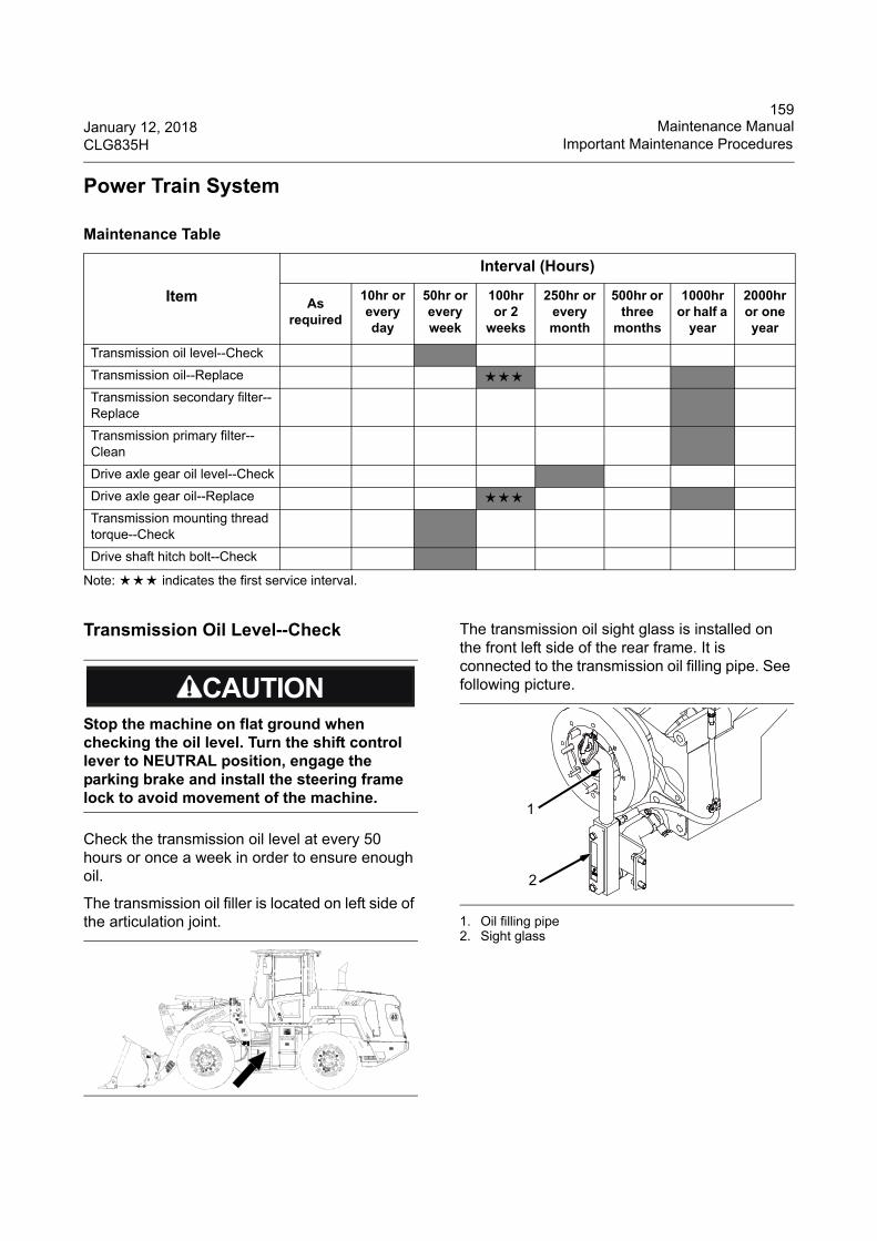
159January 12, 2018 Maintenance ManualCLG835H Important Maintenance Procedures
Power Train System
Note: ★★★ indicates the first service interval.
Transmission Oil Level--Check
Check the transmission oil level at every 50 hours or once a week in order to ensure enough oil.
The transmission oil filler is located on left side of the articulation joint.
The transmission oil sight glass is installed on the front left side of the rear frame. It is connected to the transmission oil filling pipe. See following picture.
1. Oil filling pipe2. Sight glass
Maintenance Table
Item
Interval (Hours)
As required
10hr or every day
50hr or every week
100hr or 2
weeks
250hr or every month
500hr or three
months
1000hr or half a
year
2000hr or one year
Transmission oil level--Check
Transmission oil--Replace ★★★Transmission secondary filter-- Replace
Transmission primary filter--Clean
Drive axle gear oil level--Check
Drive axle gear oil--Replace ★★★Transmission mounting thread torque--Check
Drive shaft hitch bolt--Check
Stop the machine on flat ground when checking the oil level. Turn the shift control lever to NEUTRAL position, engage the parking brake and install the steering frame lock to avoid movement of the machine.
WHEEL L OADERG ua ng x i L iu go n g Ma ch ine ry Co .,L td .N o .1 L i u ta i R o a d , L i u z h o u , G u a n g x i 5 4 5 0 0 7 , PR Ch in a
PRODUCTIDENT IF ICAT ION
NUMBER
1
2
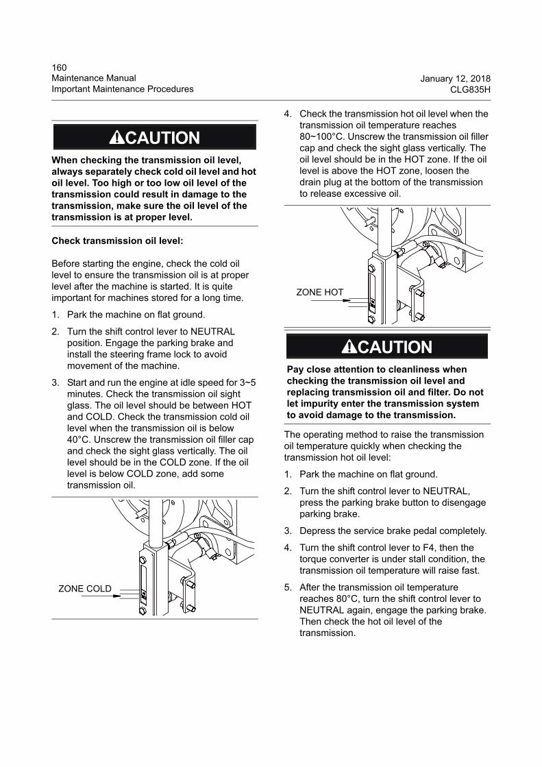
160Maintenance Manual January 12, 2018Important Maintenance Procedures CLG835H
Check transmission oil level:
Before starting the engine, check the cold oil level to ensure the transmission oil is at proper level after the machine is started. It is quite important for machines stored for a long time.
1. Park the machine on flat ground.
2. Turn the shift control lever to NEUTRAL position. Engage the parking brake and install the steering frame lock to avoid movement of the machine.
3. Start and run the engine at idle speed for 3~5 minutes. Check the transmission oil sight glass. The oil level should be between HOT and COLD. Check the transmission cold oil level when the transmission oil is below 40°C. Unscrew the transmission oil filler cap and check the sight glass vertically. The oil level should be in the COLD zone. If the oil level is below COLD zone, add some transmission oil.
4. Check the transmission hot oil level when the transmission oil temperature reaches 80~100°C. Unscrew the transmission oil filler cap and check the sight glass vertically. The oil level should be in the HOT zone. If the oil level is above the HOT zone, loosen the drain plug at the bottom of the transmission to release excessive oil.
The operating method to raise the transmission oil temperature quickly when checking the transmission hot oil level:
1. Park the machine on flat ground.
2. Turn the shift control lever to NEUTRAL, press the parking brake button to disengage parking brake.
3. Depress the service brake pedal completely.
4. Turn the shift control lever to F4, then the torque converter is under stall condition, the transmission oil temperature will raise fast.
5. After the transmission oil temperature reaches 80°C, turn the shift control lever to NEUTRAL again, engage the parking brake. Then check the hot oil level of the transmission.
When checking the transmission oil level, always separately check cold oil level and hot oil level. Too high or too low oil level of the transmission could result in damage to the transmission, make sure the oil level of the transmission is at proper level.
ZONE COLD
Pay close attention to cleanliness when checking the transmission oil level and replacing transmission oil and filter. Do not let impurity enter the transmission system to avoid damage to the transmission.
ZONE HOT
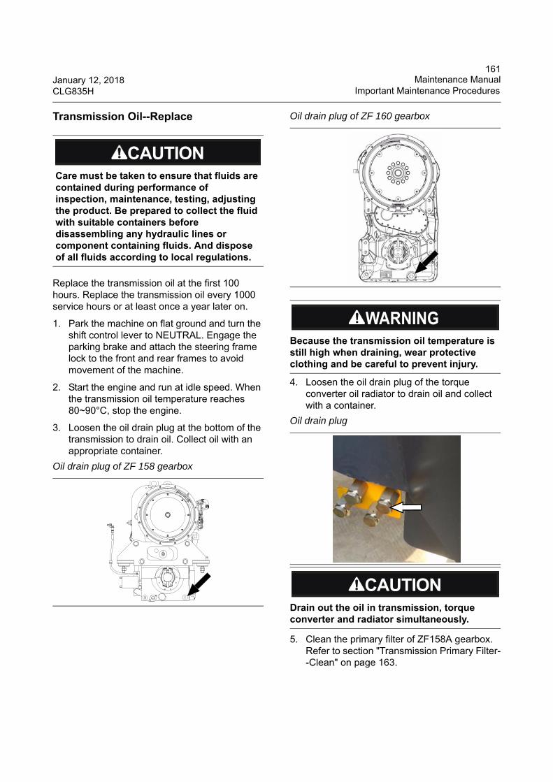
161January 12, 2018 Maintenance ManualCLG835H Important Maintenance Procedures
Transmission Oil--Replace
Replace the transmission oil at the first 100 hours. Replace the transmission oil every 1000 service hours or at least once a year later on.
1. Park the machine on flat ground and turn the shift control lever to NEUTRAL. Engage the parking brake and attach the steering frame lock to the front and rear frames to avoid movement of the machine.
2. Start the engine and run at idle speed. When the transmission oil temperature reaches 80~90°C, stop the engine.
3. Loosen the oil drain plug at the bottom of the transmission to drain oil. Collect oil with an appropriate container.
4. Loosen the oil drain plug of the torque converter oil radiator to drain oil and collect with a container.
5. Clean the primary filter of ZF158A gearbox. Refer to section "Transmission Primary Filter--Clean" on page 163.
Care must be taken to ensure that fluids are contained during performance of inspection, maintenance, testing, adjusting the product. Be prepared to collect the fluid with suitable containers before disassembling any hydraulic lines or component containing fluids. And dispose of all fluids according to local regulations.
Oil drain plug of ZF 158 gearbox
Oil drain plug of ZF 160 gearbox
Because the transmission oil temperature is still high when draining, wear protective clothing and be careful to prevent injury.
Oil drain plug
Drain out the oil in transmission, torque converter and radiator simultaneously.
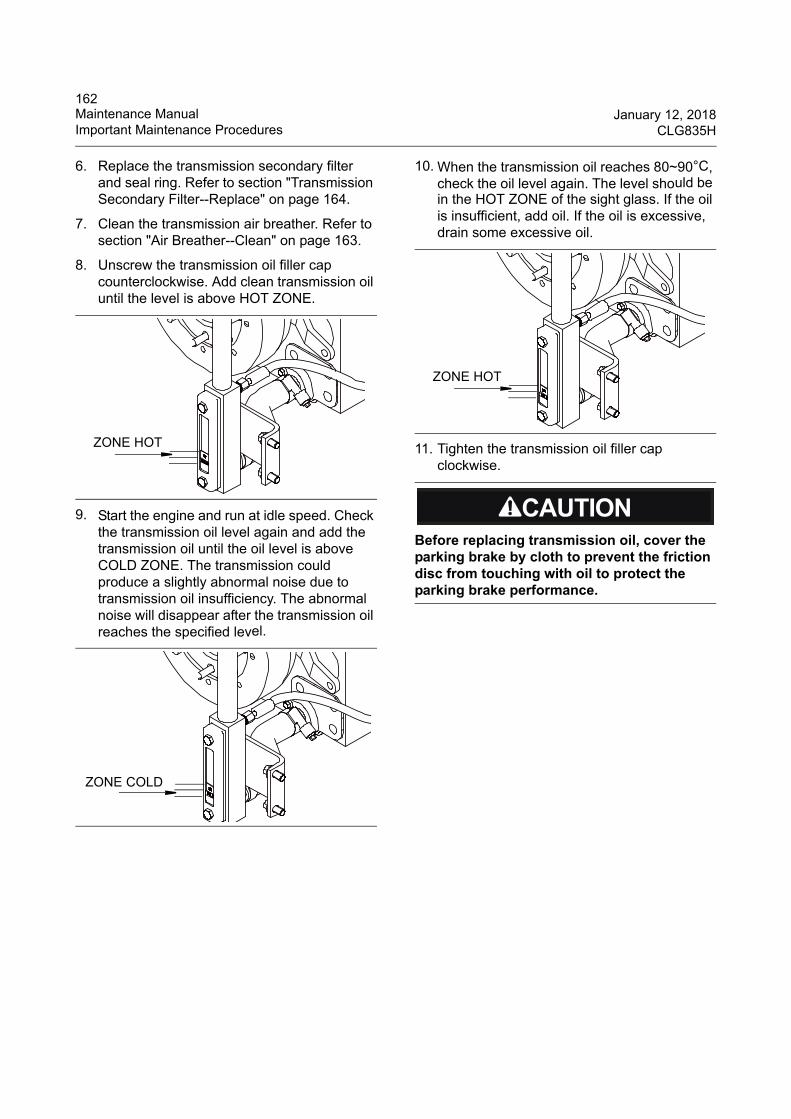
162Maintenance Manual January 12, 2018Important Maintenance Procedures CLG835H
6. Replace the transmission secondary filter and seal ring. Refer to section "Transmission Secondary Filter--Replace" on page 164.
7. Clean the transmission air breather. Refer to section "Air Breather--Clean" on page 163.
8. Unscrew the transmission oil filler cap counterclockwise. Add clean transmission oil until the level is above HOT ZONE.
9. Start the engine and run at idle speed. Check the transmission oil level again and add the transmission oil until the oil level is above COLD ZONE. The transmission could produce a slightly abnormal noise due to transmission oil insufficiency. The abnormal noise will disappear after the transmission oil reaches the specified level.
10. When the transmission oil reaches 80~90°C, check the oil level again. The level should be in the HOT ZONE of the sight glass. If the oil is insufficient, add oil. If the oil is excessive, drain some excessive oil.
11. Tighten the transmission oil filler cap clockwise.
ZONE HOT
ZONE COLD
Before replacing transmission oil, cover the parking brake by cloth to prevent the friction disc from touching with oil to protect the parking brake performance.
ZONE HOT
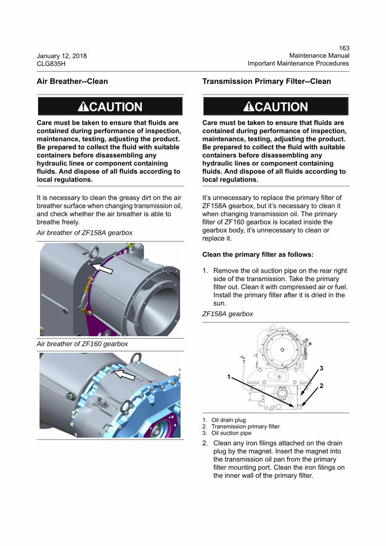
163January 12, 2018 Maintenance ManualCLG835H Important Maintenance Procedures
Air Breather--Clean
It is necessary to clean the greasy dirt on the air breather surface when changing transmission oil, and check whether the air breather is able to breathe freely.
Transmission Primary Filter--Clean
It’s unnecessary to replace the primary filter of ZF158A gearbox, but it’s necessary to clean it when changing transmission oil. The primary filter of ZF160 gearbox is located inside the gearbox body, it’s unnecessary to clean or replace it.
Clean the primary filter as follows:
1. Remove the oil suction pipe on the rear right side of the transmission. Take the primary filter out. Clean it with compressed air or fuel. Install the primary filter after it is dried in the sun.
1. Oil drain plug2. Transmission primary filter3. Oil suction pipe
2. Clean any iron filings attached on the drain plug by the magnet. Insert the magnet into the transmission oil pan from the primary filter mounting port. Clean the iron filings on the inner wall of the primary filter.
Care must be taken to ensure that fluids are contained during performance of inspection, maintenance, testing, adjusting the product. Be prepared to collect the fluid with suitable containers before disassembling any hydraulic lines or component containing fluids. And dispose of all fluids according to local regulations.
Air breather of ZF158A gearbox
Air breather of ZF160 gearbox
Care must be taken to ensure that fluids are contained during performance of inspection, maintenance, testing, adjusting the product. Be prepared to collect the fluid with suitable containers before disassembling any hydraulic lines or component containing fluids. And dispose of all fluids according to local regulations.
ZF158A gearbox
12
3
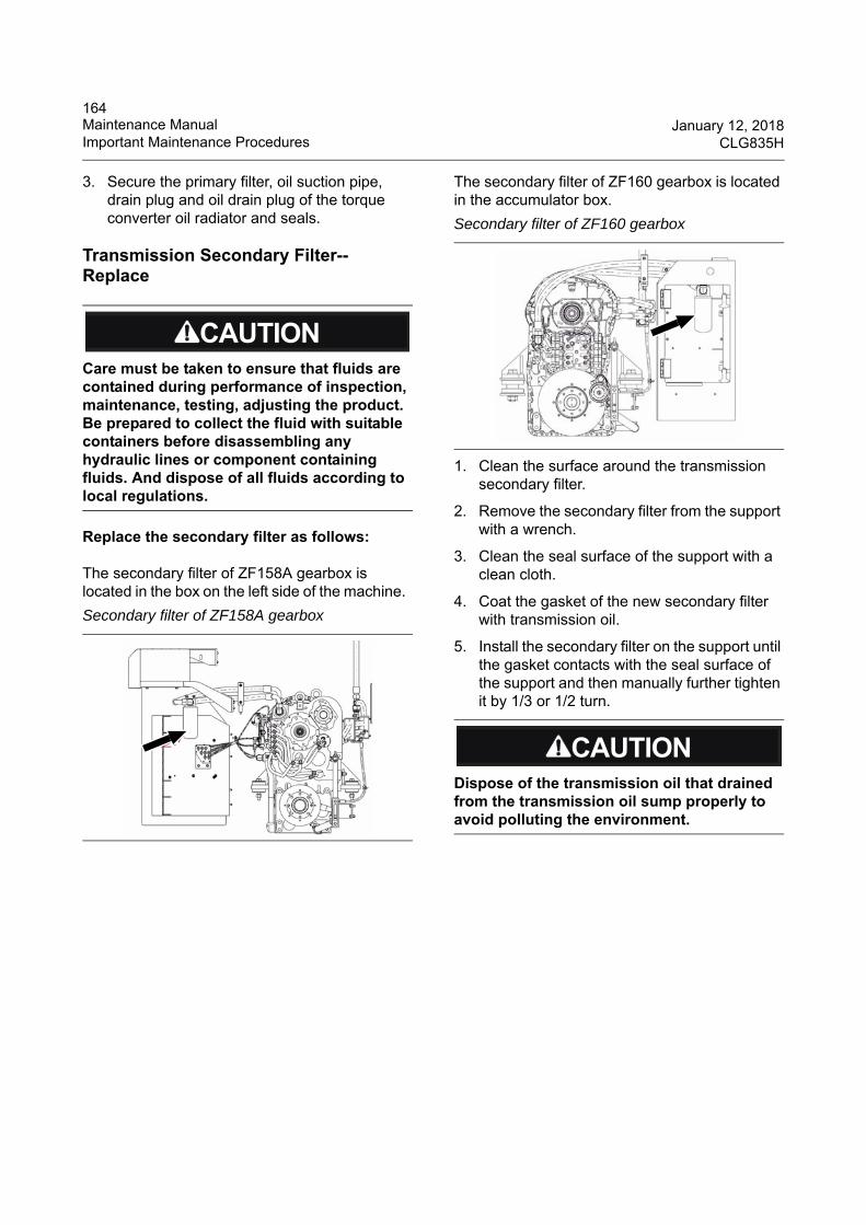
164Maintenance Manual January 12, 2018Important Maintenance Procedures CLG835H
3. Secure the primary filter, oil suction pipe, drain plug and oil drain plug of the torque converter oil radiator and seals.
Transmission Secondary Filter--Replace
Replace the secondary filter as follows:
The secondary filter of ZF158A gearbox is located in the box on the left side of the machine.
The secondary filter of ZF160 gearbox is located in the accumulator box.
1. Clean the surface around the transmission secondary filter.
2. Remove the secondary filter from the support with a wrench.
3. Clean the seal surface of the support with a clean cloth.
4. Coat the gasket of the new secondary filter with transmission oil.
5. Install the secondary filter on the support until the gasket contacts with the seal surface of the support and then manually further tighten it by 1/3 or 1/2 turn.
Care must be taken to ensure that fluids are contained during performance of inspection, maintenance, testing, adjusting the product. Be prepared to collect the fluid with suitable containers before disassembling any hydraulic lines or component containing fluids. And dispose of all fluids according to local regulations.
Secondary filter of ZF158A gearbox
Secondary filter of ZF160 gearbox
Dispose of the transmission oil that drained from the transmission oil sump properly to avoid polluting the environment.
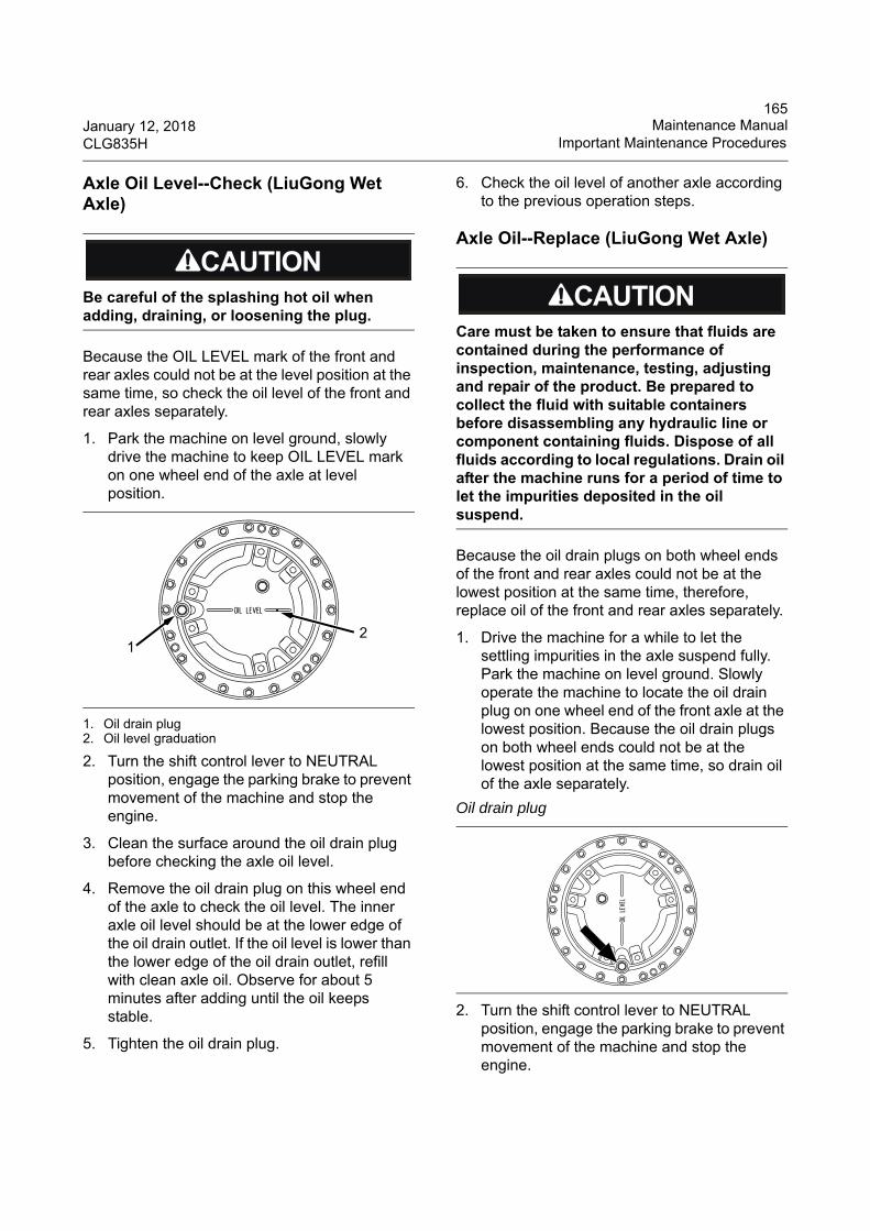
165January 12, 2018 Maintenance ManualCLG835H Important Maintenance Procedures
Axle Oil Level--Check (LiuGong Wet Axle)
Because the OIL LEVEL mark of the front and rear axles could not be at the level position at the same time, so check the oil level of the front and rear axles separately.
1. Park the machine on level ground, slowly drive the machine to keep OIL LEVEL mark on one wheel end of the axle at level position.
1. Oil drain plug2. Oil level graduation
2. Turn the shift control lever to NEUTRAL position, engage the parking brake to prevent movement of the machine and stop the engine.
3. Clean the surface around the oil drain plug before checking the axle oil level.
4. Remove the oil drain plug on this wheel end of the axle to check the oil level. The inner axle oil level should be at the lower edge of the oil drain outlet. If the oil level is lower than the lower edge of the oil drain outlet, refill with clean axle oil. Observe for about 5 minutes after adding until the oil keeps stable.
5. Tighten the oil drain plug.
6. Check the oil level of another axle according to the previous operation steps.
Axle Oil--Replace (LiuGong Wet Axle)
Because the oil drain plugs on both wheel ends of the front and rear axles could not be at the lowest position at the same time, therefore, replace oil of the front and rear axles separately.
1. Drive the machine for a while to let the settling impurities in the axle suspend fully. Park the machine on level ground. Slowly operate the machine to locate the oil drain plug on one wheel end of the front axle at the lowest position. Because the oil drain plugs on both wheel ends could not be at the lowest position at the same time, so drain oil of the axle separately.
2. Turn the shift control lever to NEUTRAL position, engage the parking brake to prevent movement of the machine and stop the engine.
Be careful of the splashing hot oil when adding, draining, or loosening the plug.
12
Care must be taken to ensure that fluids are contained during the performance of inspection, maintenance, testing, adjusting and repair of the product. Be prepared to collect the fluid with suitable containers before disassembling any hydraulic line or component containing fluids. Dispose of all fluids according to local regulations. Drain oil after the machine runs for a period of time to let the impurities deposited in the oil suspend.
Oil drain plug
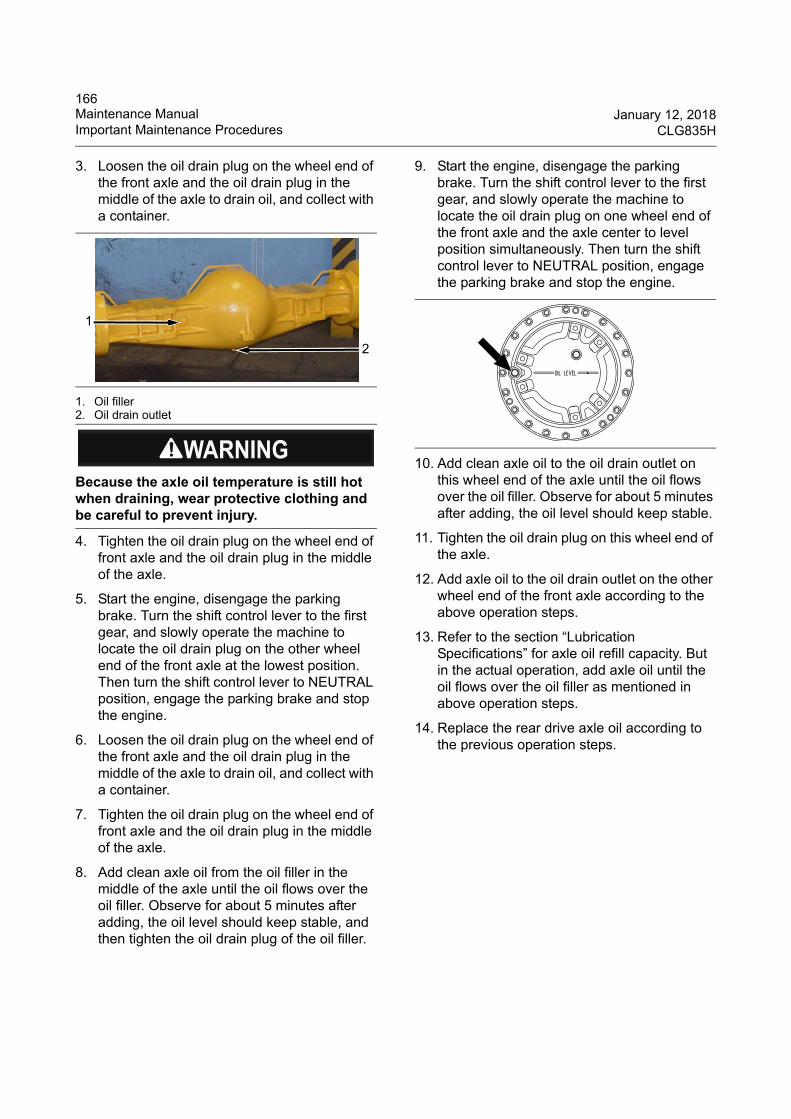
166Maintenance Manual January 12, 2018Important Maintenance Procedures CLG835H
3. Loosen the oil drain plug on the wheel end of the front axle and the oil drain plug in the middle of the axle to drain oil, and collect with a container.
1. Oil filler2. Oil drain outlet
4. Tighten the oil drain plug on the wheel end of front axle and the oil drain plug in the middle of the axle.
5. Start the engine, disengage the parking brake. Turn the shift control lever to the first gear, and slowly operate the machine to locate the oil drain plug on the other wheel end of the front axle at the lowest position. Then turn the shift control lever to NEUTRAL position, engage the parking brake and stop the engine.
6. Loosen the oil drain plug on the wheel end of the front axle and the oil drain plug in the middle of the axle to drain oil, and collect with a container.
7. Tighten the oil drain plug on the wheel end of front axle and the oil drain plug in the middle of the axle.
8. Add clean axle oil from the oil filler in the middle of the axle until the oil flows over the oil filler. Observe for about 5 minutes after adding, the oil level should keep stable, and then tighten the oil drain plug of the oil filler.
9. Start the engine, disengage the parking brake. Turn the shift control lever to the first gear, and slowly operate the machine to locate the oil drain plug on one wheel end of the front axle and the axle center to level position simultaneously. Then turn the shift control lever to NEUTRAL position, engage the parking brake and stop the engine.
10. Add clean axle oil to the oil drain outlet on this wheel end of the axle until the oil flows over the oil filler. Observe for about 5 minutes after adding, the oil level should keep stable.
11. Tighten the oil drain plug on this wheel end of the axle.
12. Add axle oil to the oil drain outlet on the other wheel end of the front axle according to the above operation steps.
13. Refer to the section “Lubrication Specifications” for axle oil refill capacity. But in the actual operation, add axle oil until the oil flows over the oil filler as mentioned in above operation steps.
14. Replace the rear drive axle oil according to the previous operation steps.
Because the axle oil temperature is still hot when draining, wear protective clothing and be careful to prevent injury.
2
1
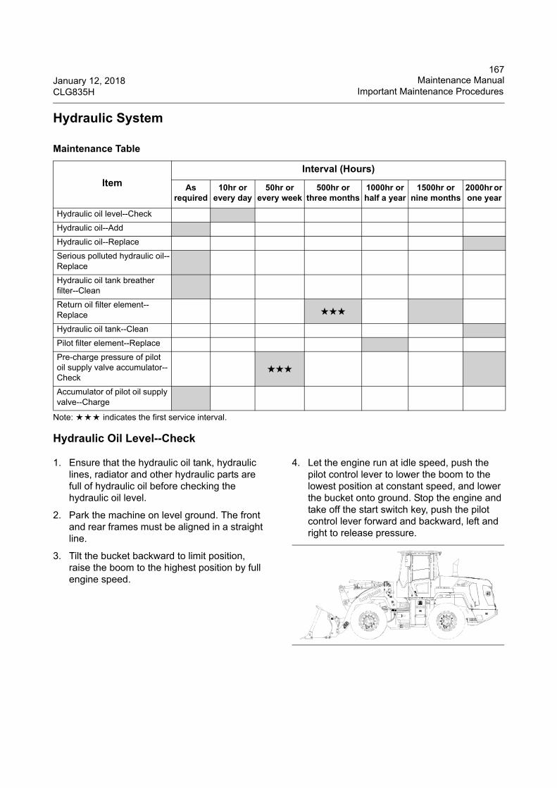
167January 12, 2018 Maintenance ManualCLG835H Important Maintenance Procedures
Hydraulic System
Note: ★★★ indicates the first service interval.
Hydraulic Oil Level--Check
1. Ensure that the hydraulic oil tank, hydraulic lines, radiator and other hydraulic parts are full of hydraulic oil before checking the hydraulic oil level.
2. Park the machine on level ground. The front and rear frames must be aligned in a straight line.
3. Tilt the bucket backward to limit position, raise the boom to the highest position by full engine speed.
4. Let the engine run at idle speed, push the pilot control lever to lower the boom to the lowest position at constant speed, and lower the bucket onto ground. Stop the engine and take off the start switch key, push the pilot control lever forward and backward, left and right to release pressure.
Maintenance Table
Item
Interval (Hours)
As required
10hr or every day
50hr or every week
500hr or three months
1000hr or half a year
1500hr or nine months
2000hr or one year
Hydraulic oil level--Check
Hydraulic oil--Add
Hydraulic oil--Replace
Serious polluted hydraulic oil--Replace
Hydraulic oil tank breather filter--Clean
Return oil filter element--Replace ★★★
Hydraulic oil tank--Clean
Pilot filter element--Replace
Pre-charge pressure of pilot oil supply valve accumulator--Check
★★★
Accumulator of pilot oil supply valve--Charge
WHEEL L OADERG ua ng x i L iu go n g Ma ch ine ry Co .,L td .N o .1 L i u ta i R o a d , L i u z h o u , G u a n g x i 5 4 5 0 0 7 , PR Ch in a
PRODUCTIDENT IF ICAT ION
NUMBER
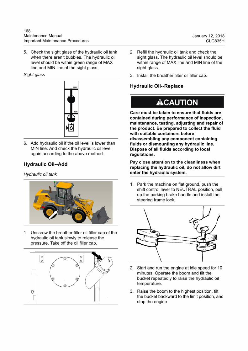
168Maintenance Manual January 12, 2018Important Maintenance Procedures CLG835H
5. Check the sight glass of the hydraulic oil tank when there aren’t bubbles. The hydraulic oil level should be within green range of MAX line and MIN line of the sight glass.
6. Add hydraulic oil if the oil level is lower than MIN line. And check the hydraulic oil level again according to the above method.
Hydraulic Oil--Add
1. Unscrew the breather filter oil filler cap of the hydraulic oil tank slowly to release the pressure. Take off the oil filler cap.
2. Refill the hydraulic oil tank and check the sight glass. The hydraulic oil level should be within range of MAX line and MIN line of the sight glass.
3. Install the breather filter oil filler cap.
Hydraulic Oil--Replace
1. Park the machine on flat ground, push the shift control lever to NEUTRAL position, pull up the parking brake handle and install the steering frame lock.
2. Start and run the engine at idle speed for 10 minutes. Operate the boom and tilt the bucket repeatedly to raise the hydraulic oil temperature.
3. Raise the boom to the highest position, tilt the bucket backward to the limit position, and stop the engine.
Sight glass
Hydraulic oil tank
Care must be taken to ensure that fluids are contained during performance of inspection, maintenance, testing, adjusting and repair of the product. Be prepared to collect the fluid with suitable containers before disassembling any component containing fluids or dismounting any hydraulic line. Dispose of all fluids according to local regulations.
Pay close attention to the cleanliness when replacing the hydraulic oil, do not allow dirt enter the hydraulic system.
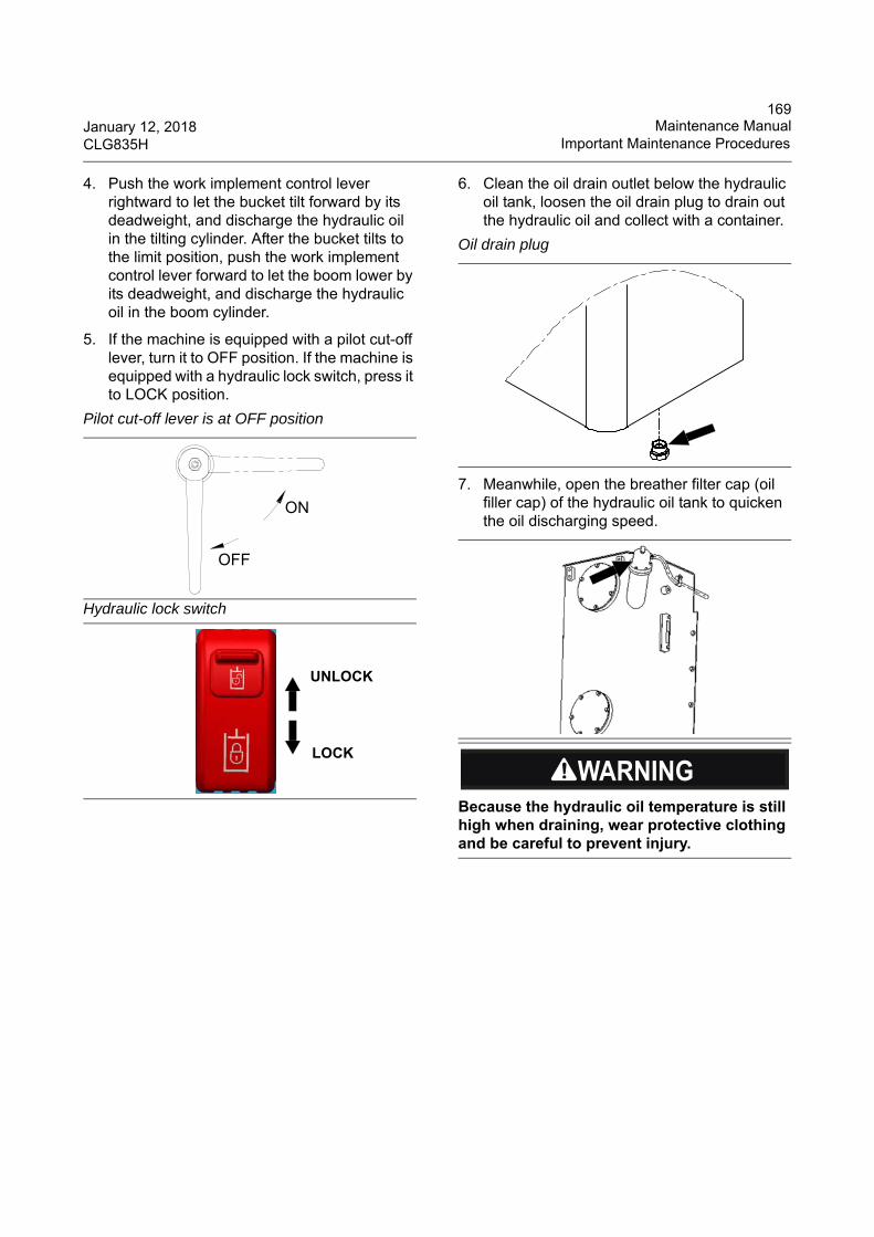
169January 12, 2018 Maintenance ManualCLG835H Important Maintenance Procedures
4. Push the work implement control lever rightward to let the bucket tilt forward by its deadweight, and discharge the hydraulic oil in the tilting cylinder. After the bucket tilts to the limit position, push the work implement control lever forward to let the boom lower by its deadweight, and discharge the hydraulic oil in the boom cylinder.
5. If the machine is equipped with a pilot cut-off lever, turn it to OFF position. If the machine is equipped with a hydraulic lock switch, press it to LOCK position.
6. Clean the oil drain outlet below the hydraulic oil tank, loosen the oil drain plug to drain out the hydraulic oil and collect with a container.
7. Meanwhile, open the breather filter cap (oil filler cap) of the hydraulic oil tank to quicken the oil discharging speed.
Pilot cut-off lever is at OFF position
Hydraulic lock switch
ON
OFF
UNLOCK
LOCK
Oil drain plug
Because the hydraulic oil temperature is still high when draining, wear protective clothing and be careful to prevent injury.
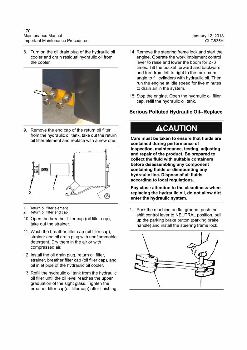
170Maintenance Manual January 12, 2018Important Maintenance Procedures CLG835H
8. Turn on the oil drain plug of the hydraulic oil cooler and drain residual hydraulic oil from the cooler.
9. Remove the end cap of the return oil filter from the hydraulic oil tank, take out the return oil filter element and replace with a new one.
1. Return oil filter element 2. Return oil filter end cap
10. Open the breather filter cap (oil filler cap), take out the strainer.
11. Wash the breather filter cap (oil filler cap), strainer and oil drain plug with nonflammable detergent. Dry them in the air or with compressed air.
12. Install the oil drain plug, return oil filter, strainer, breather filter cap (oil filler cap), and oil inlet pipe of the hydraulic oil cooler.
13. Refill the hydraulic oil tank from the hydraulic oil filler until the oil level reaches the upper graduation of the sight glass. Tighten the breather filter cap(oil filler cap) after finishing.
14. Remove the steering frame lock and start the engine. Operate the work implement control lever to raise and lower the boom for 2~3 times. Tilt the bucket forward and backward and turn from left to right to the maximum angle to fill cylinders with hydraulic oil. Then run the engine at idle speed for five minutes to drain air in the system.
15. Stop the engine. Open the hydraulic oil filler cap, refill the hydraulic oil tank.
Serious Polluted Hydraulic Oil--Replace
1. Park the machine on flat ground, push the shift control lever to NEUTRAL position, pull up the parking brake button (parking brake handle) and install the steering frame lock.
12
Care must be taken to ensure that fluids are contained during performance of inspection, maintenance, testing, adjusting and repair of the product. Be prepared to collect the fluid with suitable containers before disassembling any component containing fluids or dismounting any hydraulic line. Dispose of all fluids according to local regulations.
Pay close attention to the cleanliness when replacing the hydraulic oil, do not allow dirt enter the hydraulic system.
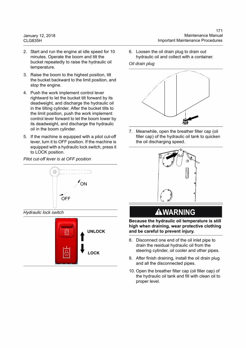
171January 12, 2018 Maintenance ManualCLG835H Important Maintenance Procedures
2. Start and run the engine at idle speed for 10 minutes. Operate the boom and tilt the bucket repeatedly to raise the hydraulic oil temperature.
3. Raise the boom to the highest position, tilt the bucket backward to the limit position, and stop the engine.
4. Push the work implement control lever rightward to let the bucket tilt forward by its deadweight, and discharge the hydraulic oil in the tilting cylinder. After the bucket tilts to the limit position, push the work implement control lever forward to let the boom lower by its deadweight, and discharge the hydraulic oil in the boom cylinder.
5. If the machine is equipped with a pilot cut-off lever, turn it to OFF position. If the machine is equipped with a hydraulic lock switch, press it to LOCK position.
6. Loosen the oil drain plug to drain out hydraulic oil and collect with a container.
7. Meanwhile, open the breather filter cap (oil filler cap) of the hydraulic oil tank to quicken the oil discharging speed.
8. Disconnect one end of the oil inlet pipe to drain the residual hydraulic oil from the steering cylinder, oil cooler and other pipes.
9. After finish draining, install the oil drain plug and all the disconnected pipes.
10. Open the breather filter cap (oil filler cap) of the hydraulic oil tank and fill with clean oil to proper level.
Pilot cut-off lever is at OFF position
Hydraulic lock switch
ON
OFF
UNLOCK
LOCK
Oil drain plug
Because the hydraulic oil temperature is still high when draining, wear protective clothing and be careful to prevent injury.
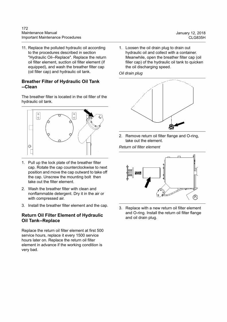
172Maintenance Manual January 12, 2018Important Maintenance Procedures CLG835H
11. Replace the polluted hydraulic oil according to the procedures described in section "Hydraulic Oil--Replace". Replace the return oil filter element, suction oil filter element (if equipped), and wash the breather filter cap (oil filler cap) and hydraulic oil tank.
Breather Filter of Hydraulic Oil Tank --Clean
The breather filter is located in the oil filler of the hydraulic oil tank.
1. Pull up the lock plate of the breather filter cap. Rotate the cap counterclockwise to next position and move the cap outward to take off the cap. Unscrew the mounting bolt then take out the filter element.
2. Wash the breather filter with clean and nonflammable detergent. Dry it in the air or with compressed air.
3. Install the breather filter element and the cap.
Return Oil Filter Element of Hydraulic Oil Tank--Replace
Replace the return oil filter element at first 500 service hours, replace it every 1500 service hours later on. Replace the return oil filter element in advance if the working condition is very bad.
1. Loosen the oil drain plug to drain out hydraulic oil and collect with a container. Meanwhile, open the breather filter cap (oil filler cap) of the hydraulic oil tank to quicken the oil discharging speed.
2. Remove return oil filter flange and O-ring, take out the element.
3. Replace with a new return oil filter element and O-ring. Install the return oil filter flange and oil drain plug.
Oil drain plug
Return oil filter element
173January 12, 2018 Maintenance ManualCLG835H Important Maintenance Procedures
Hydraulic Oil Tank--Clean
1. Stop the engine.
2. Unscrew the oil drain plug at the bottom of the hydraulic oil tank to drain hydraulic oil. Collect with a container.
3. Remove the return oil filter end cap, take out the return oil filter element and O ring. Deal with them properly.
1. Return oil filter end cap2. Cleaning flange cover
4. Remove the cleaning flange cover and gasket.
5. Wash the bottom and four walls of the hydraulic oil tank with fuel through the return oil filter opening and cleaning flange, and then dry with a clean cloth.
6. Wash the bottom and four walls of the hydraulic oil tank with hydraulic oil again.
7. Install the gasket and cleaning flange cover.
8. Install the oil drain plug, a new return oil filter element, a new O-ring and return oil filter cap.
Care must be taken to ensure that fluids are contained during performance of inspection, maintenance, testing, adjusting and repair of the product. Be prepared to collect the fluid with suitable containers before disassembling any component containing fluids or dismounting any hydraulic line. Dispose of all fluids according to local regulations.
Oil drain plug
1
2
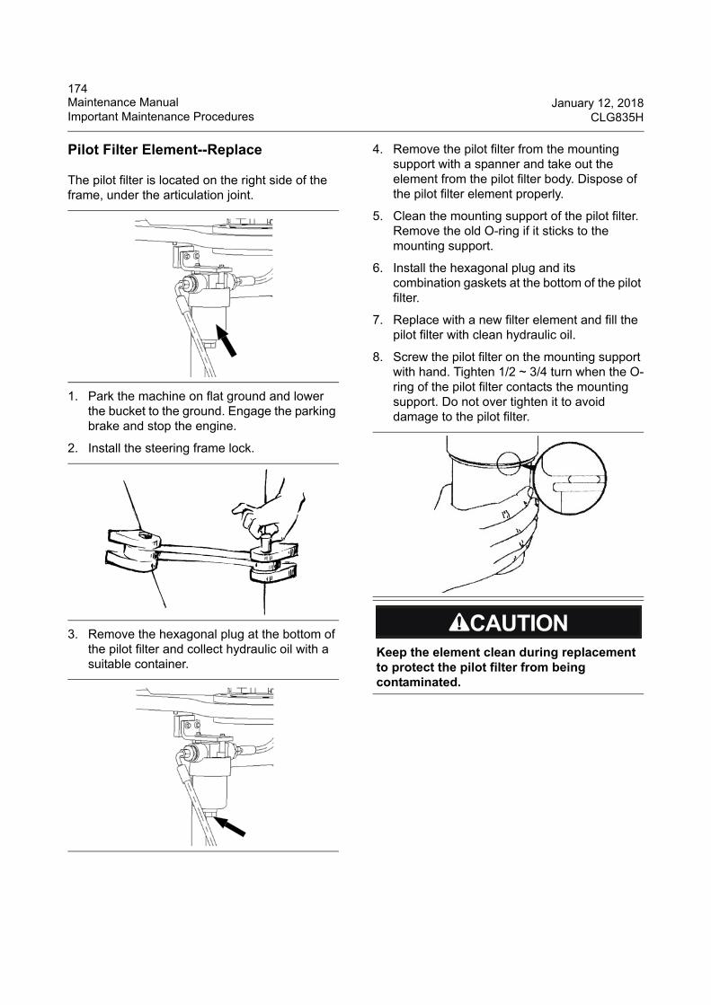
174Maintenance Manual January 12, 2018Important Maintenance Procedures CLG835H
Pilot Filter Element--Replace
The pilot filter is located on the right side of the frame, under the articulation joint.
1. Park the machine on flat ground and lower the bucket to the ground. Engage the parking brake and stop the engine.
2. Install the steering frame lock.
3. Remove the hexagonal plug at the bottom of the pilot filter and collect hydraulic oil with a suitable container.
4. Remove the pilot filter from the mounting support with a spanner and take out the element from the pilot filter body. Dispose of the pilot filter element properly.
5. Clean the mounting support of the pilot filter. Remove the old O-ring if it sticks to the mounting support.
6. Install the hexagonal plug and its combination gaskets at the bottom of the pilot filter.
7. Replace with a new filter element and fill the pilot filter with clean hydraulic oil.
8. Screw the pilot filter on the mounting support with hand. Tighten 1/2 ~ 3/4 turn when the O-ring of the pilot filter contacts the mounting support. Do not over tighten it to avoid damage to the pilot filter.
Keep the element clean during replacement to protect the pilot filter from being contaminated.
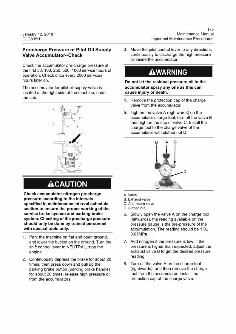
175January 12, 2018 Maintenance ManualCLG835H Important Maintenance Procedures
Pre-charge Pressure of Pilot Oil Supply Valve Accumulator--Check
Check the accumulator pre-charge pressure at the first 50, 100, 250, 500, 1000 service hours of operation. Check once every 2000 services hours later on.
The accumulator for pilot oil supply valve is located at the right side of the machine, under the cab.
1. Park the machine on flat and open ground, and lower the bucket on the ground. Turn the shift control lever to NEUTRAL, stop the engine.
2. Continuously depress the brake for about 20 times, then press down and pull up the parking brake button (parking brake handle) for about 20 times, release high pressure oil from the accumulators.
3. Move the pilot control lever to any directions continuously to discharge the high pressure oil inside the accumulator.
4. Remove the protection cap of the charge valve from the accumulator.
5. Tighten the valve A (rightwards) on the accumulator charge tool, turn off the valve B then tighten the cap of valve C. Install the charge tool to the charge valve of the accumulator with slotted nut D.
A. Valve B. Exhaust valve C. Anti-return valve D. Slotted nut
6. Slowly open the valve A on the charge tool (leftwards), the reading available on the pressure gauge is the pre-pressure of the accumulation. The reading should be 1.0± 0.05MPa.
7. Add nitrogen if the pressure is low; if the pressure is higher than expected, adjust the exhaust valve B to get the desired pressure reading.
8. Turn off the valve A on the charge tool (rightwards), and then remove the charge tool from the accumulator. Install the protection cap of the charge valve.
Check accumulator nitrogen precharge pressure according to the intervals specified in maintenance interval schedule section to ensure the proper working of the service brake system and parking brake system. Checking of the precharge pressure should only be done by trained personnel with special tools only.
Do not let the residual pressure oil in the accumulator spray any one as this can cause injury or death.
B A C
D
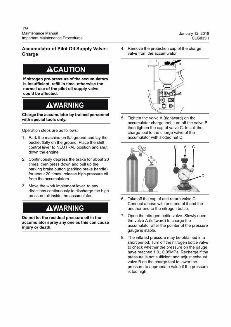
176Maintenance Manual January 12, 2018Important Maintenance Procedures CLG835H
Accumulator of Pilot Oil Supply Valve--Charge
Operation steps are as follows:
1. Park the machine on flat ground and lay the bucket flatly on the ground. Place the shift control lever to NEUTRAL position and shut down the engine.
2. Continuously depress the brake for about 20 times, then press down and pull up the parking brake button (parking brake handle) for about 20 times, release high pressure oil from the accumulators.
3. Move the work implement lever to any directions continuously to discharge the high pressure oil inside the accumulator.
4. Remove the protection cap of the charge valve from the accumulator.
5. Tighten the valve A (rightward) on the accumulator charge tool, turn off the valve B then tighten the cap of valve C. Install the charge tool to the charge valve of the accumulator with slotted nut D.
6. Take off the cap of anti-return valve C. Connect a hose with one end of it and the another end to the nitrogen bottle.
7. Open the nitrogen bottle valve. Slowly open the valve A (leftward) to charge the accumulator after the pointer of the pressure gauge is stable.
8. The inflated pressure may be obtained in a short period. Turn off the nitrogen bottle valve to check whether the pressure on the gauge have reached 1.0± 0.05MPa. Recharge if the pressure is not sufficient and adjust exhaust valve B on the charge tool to lower the pressure to appropriate value if the pressure is too high.
If nitrogen pre-pressure of the accumulators is insufficient, refill in time, otherwise the normal use of the pilot oil supply valve could be affected.
Charge the accumulator by trained personnel with special tools only.
Do not let the residual pressure oil in the accumulator spray any one as this can cause injury or death.
B A C
D
177January 12, 2018 Maintenance ManualCLG835H Important Maintenance Procedures
9. If the desired pressure is available, turn off the nitrogen bottle valve then take off the valve A on the charge tool. Remove the charge tool.
10. Apply a coat of engine oil to the top of the charge valve to check if any leakage occurs. There is a leak if air bubbles are found. Consult your LiuGong dealer to eliminate the fault.
11. Install the protection cap of the charge valve on the accumulator.
When removing the protection cap of the charging valve, do not rotate the steering wheel and ensure the engine has been stopped to avoid personnel injury.
Charge the accumulator with nitrogen only. Do not charge it with oxygen, compressed air or other flammable gas to avoid explosion.
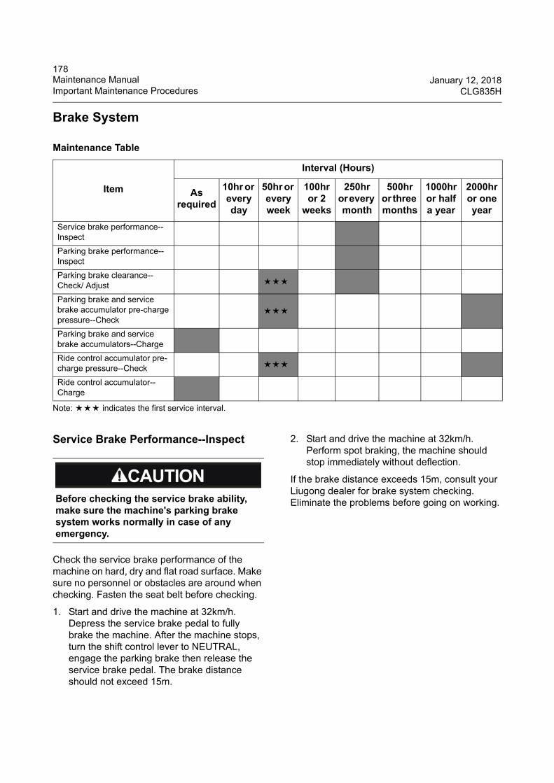
178Maintenance Manual January 12, 2018Important Maintenance Procedures CLG835H
Brake System
Note: ★★★ indicates the first service interval.
Service Brake Performance--Inspect
Check the service brake performance of the machine on hard, dry and flat road surface. Make sure no personnel or obstacles are around when checking. Fasten the seat belt before checking.
1. Start and drive the machine at 32km/h. Depress the service brake pedal to fully brake the machine. After the machine stops, turn the shift control lever to NEUTRAL, engage the parking brake then release the service brake pedal. The brake distance should not exceed 15m.
2. Start and drive the machine at 32km/h. Perform spot braking, the machine should stop immediately without deflection.
If the brake distance exceeds 15m, consult your Liugong dealer for brake system checking. Eliminate the problems before going on working.
Maintenance Table
Item
Interval (Hours)
As required
10hr or every day
50hr or every week
100hr or 2
weeks
250hr or every month
500hr or three months
1000hr or half a year
2000hr or one year
Service brake performance--Inspect
Parking brake performance--Inspect
Parking brake clearance--Check/ Adjust ★★★
Parking brake and service brake accumulator pre-charge pressure--Check
★★★
Parking brake and service brake accumulators--Charge
Ride control accumulator pre-charge pressure--Check ★★★
Ride control accumulator--Charge
Before checking the service brake ability, make sure the machine's parking brake system works normally in case of any emergency.
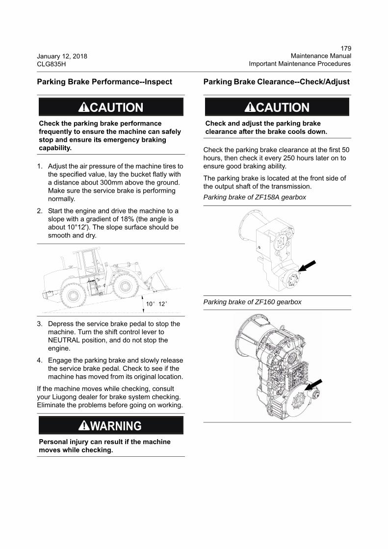
179January 12, 2018 Maintenance ManualCLG835H Important Maintenance Procedures
Parking Brake Performance--Inspect
1. Adjust the air pressure of the machine tires to the specified value, lay the bucket flatly with a distance about 300mm above the ground. Make sure the service brake is performing normally.
2. Start the engine and drive the machine to a slope with a gradient of 18% (the angle is about 10°12'). The slope surface should be smooth and dry.
3. Depress the service brake pedal to stop the machine. Turn the shift control lever to NEUTRAL position, and do not stop the engine.
4. Engage the parking brake and slowly release the service brake pedal. Check to see if the machine has moved from its original location.
If the machine moves while checking, consult your Liugong dealer for brake system checking. Eliminate the problems before going on working.
Parking Brake Clearance--Check/Adjust
Check the parking brake clearance at the first 50 hours, then check it every 250 hours later on to ensure good braking ability.
The parking brake is located at the front side of the output shaft of the transmission.
Check the parking brake performance frequently to ensure the machine can safely stop and ensure its emergency braking capability.
Personal injury can result if the machine moves while checking.
10°12’
Check and adjust the parking brake clearance after the brake cools down.
Parking brake of ZF158A gearbox
Parking brake of ZF160 gearbox
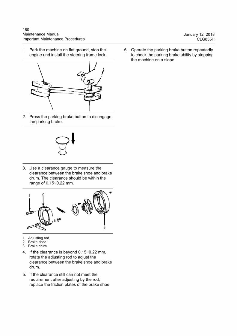
180Maintenance Manual January 12, 2018Important Maintenance Procedures CLG835H
1. Park the machine on flat ground, stop the engine and install the steering frame lock.
2. Press the parking brake button to disengage the parking brake.
3. Use a clearance gauge to measure the clearance between the brake shoe and brake drum. The clearance should be within the range of 0.15~0.22 mm.
1. Adjusting rod2. Brake shoe3. Brake drum
4. If the clearance is beyond 0.15~0.22 mm, rotate the adjusting rod to adjust the clearance between the brake shoe and brake drum.
5. If the clearance still can not meet the requirement after adjusting by the rod, replace the friction plates of the brake shoe.
6. Operate the parking brake button repeatedly to check the parking brake ability by stopping the machine on a slope.
1 2
3
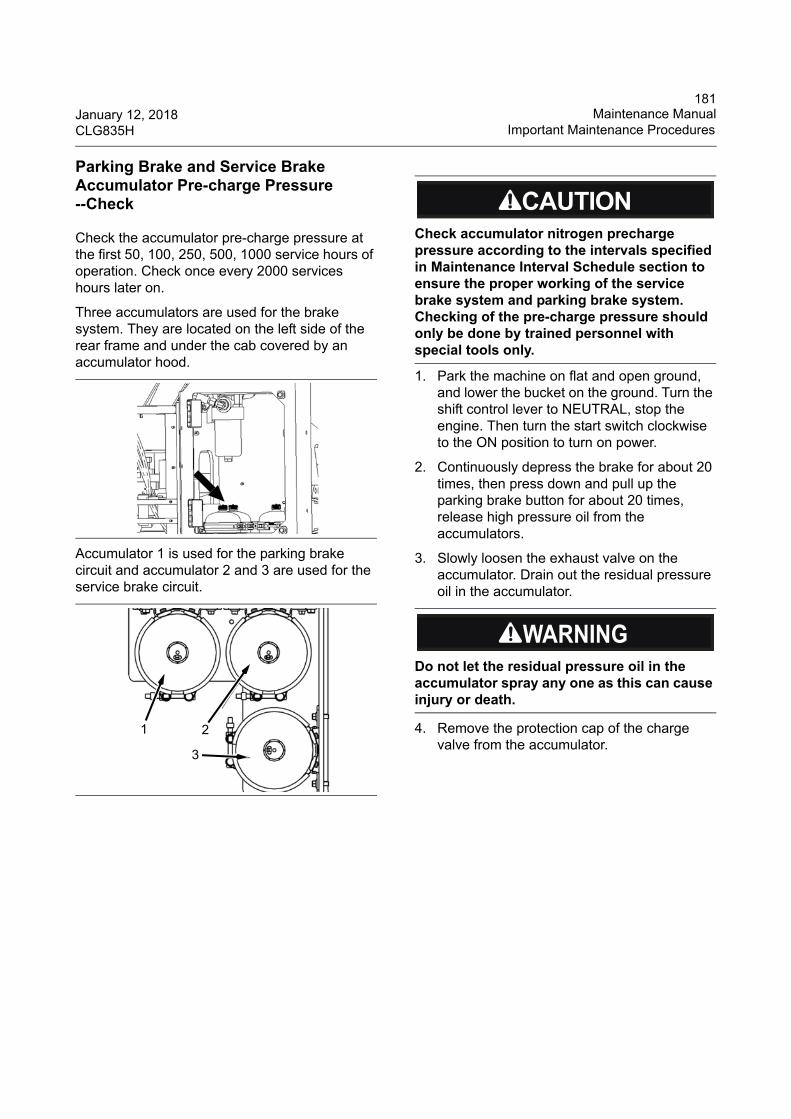
181January 12, 2018 Maintenance ManualCLG835H Important Maintenance Procedures
Parking Brake and Service Brake Accumulator Pre-charge Pressure --Check
Check the accumulator pre-charge pressure at the first 50, 100, 250, 500, 1000 service hours of operation. Check once every 2000 services hours later on.
Three accumulators are used for the brake system. They are located on the left side of the rear frame and under the cab covered by an accumulator hood.
Accumulator 1 is used for the parking brake circuit and accumulator 2 and 3 are used for the service brake circuit.
1. Park the machine on flat and open ground, and lower the bucket on the ground. Turn the shift control lever to NEUTRAL, stop the engine. Then turn the start switch clockwise to the ON position to turn on power.
2. Continuously depress the brake for about 20 times, then press down and pull up the parking brake button for about 20 times, release high pressure oil from the accumulators.
3. Slowly loosen the exhaust valve on the accumulator. Drain out the residual pressure oil in the accumulator.
4. Remove the protection cap of the charge valve from the accumulator.
1 2
3
Check accumulator nitrogen precharge pressure according to the intervals specified in Maintenance Interval Schedule section to ensure the proper working of the service brake system and parking brake system. Checking of the pre-charge pressure should only be done by trained personnel with special tools only.
Do not let the residual pressure oil in the accumulator spray any one as this can cause injury or death.
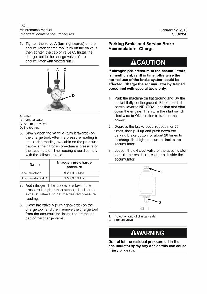
182Maintenance Manual January 12, 2018Important Maintenance Procedures CLG835H
5. Tighten the valve A (turn rightwards) on the accumulator charge tool, turn off the valve B then tighten the cap of valve C. Install the charge tool to the charge valve of the accumulator with slotted nut D.
A. Valve B. Exhaust valve C. Anti-return valve D. Slotted nut
6. Slowly open the valve A (turn leftwards) on the charge tool. After the pressure reading is stable, the reading available on the pressure gauge is the nitrogen pre-charge pressure of the accumulator. The reading should comply with the following table.
7. Add nitrogen if the pressure is low; if the pressure is higher than expected, adjust the exhaust valve B to get the desired pressure reading.
8. Close the valve A (turn rightwards) on the charge tool, and then remove the charge tool from the accumulator. Install the protection cap of the charge valve.
Parking Brake and Service Brake Accumulators--Charge
1. Park the machine on flat ground and lay the bucket flatly on the ground. Place the shift control lever to NEUTRAL position and shut down the engine. Then turn the start switch clockwise to ON position to turn on the power.
2. Depress the brake pedal repeatly for 20 times, then pull up and push down the parking brake button for about 20 times to discharge the high pressure oil inside the accumulator.
3. Loosen the exhaust valve of the accumulator to drain the residual pressure oil inside the accumulator.
1. Protection cap of charge vavle2. Exhaust valve
NameNitrogen pre-charge
pressure
Accumulator 1 9.2 ± 0.05Mpa
Accumulator 2 & 3 5.5 ± 0.05Mpa
B A C
D
If nitrogen pre-pressure of the accumulators is insufficient, refill in time, otherwise the normal use of the brake system could be affected. Charge the accumulator by trained personnel with special tools only.
Do not let the residual pressure oil in the accumulator spray any one as this can cause injury or death.
1
2
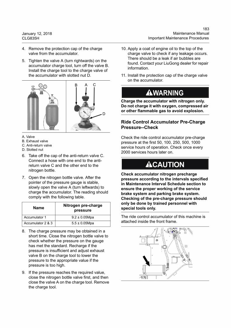
183January 12, 2018 Maintenance ManualCLG835H Important Maintenance Procedures
4. Remove the protection cap of the charge valve from the accumulator.
5. Tighten the valve A (turn rightwards) on the accumulator charge tool, turn off the valve B. Install the charge tool to the charge valve of the accumulator with slotted nut D.
A. Valve B. Exhaust valve C. Anti-return valve D. Slotted nut
6. Take off the cap of the anti-return valve C. Connect a hose with one end to the anti-return valve C and the other end to the nitrogen bottle.
7. Open the nitrogen bottle valve. After the pointer of the pressure gauge is stable, slowly open the valve A (turn leftwards) to charge the accumulator. The reading should comply with the following table.
8. The charge pressure may be obtained in a short time. Close the nitrogen bottle valve to check whether the pressure on the gauge has met the standard. Recharge if the pressure is insufficient and adjust exhaust valve B on the charge tool to lower the pressure to the appropriate value if the pressure is too high.
9. If the pressure reaches the required value, close the nitrogen bottle valve first, and then close the valve A on the charge tool. Remove the charge tool.
10. Apply a coat of engine oil to the top of the charge valve to check if any leakage occurs. There should be a leak if air bubbles are found. Contact your LiuGong dealer for repair information.
11. Install the protection cap of the charge valve on the accumulator.
Ride Control Accumulator Pre-Charge Pressure--Check
Check the ride control accumulator pre-charge pressure at the first 50, 100, 250, 500, 1000 service hours of operation. Check once every 2000 services hours later on.
The ride control accumulator of this machine is attached inside the front frame.
NameNitrogen pre-charge
pressure
Accumulator 1 9.2 ± 0.05Mpa
Accumulator 2 & 3 5.5 ± 0.05Mpa
B A C
D
Charge the accumulator with nitrogen only. Do not charge it with oxygen, compressed air or other flammable gas to avoid explosion.
Check accumulator nitrogen precharge pressure according to the intervals specified in Maintenance Interval Schedule section to ensure the proper working of the service brake system and parking brake system. Checking of the pre-charge pressure should only be done by trained personnel with special tools only.
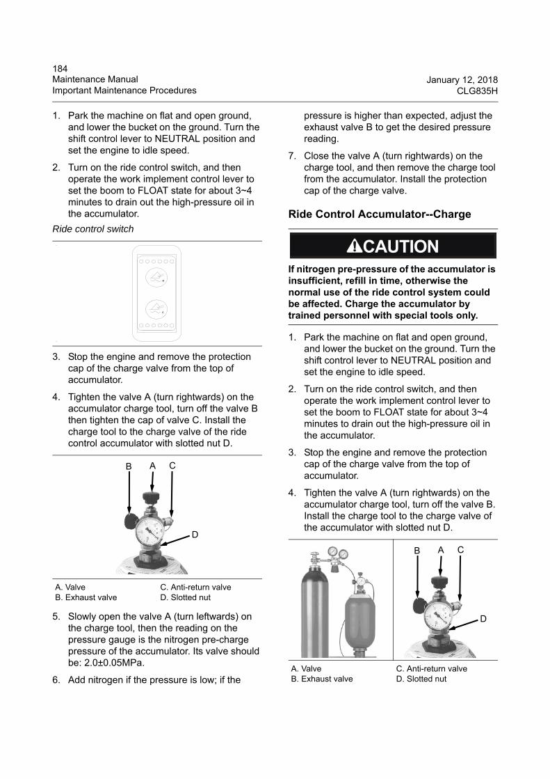
184Maintenance Manual January 12, 2018Important Maintenance Procedures CLG835H
1. Park the machine on flat and open ground, and lower the bucket on the ground. Turn the shift control lever to NEUTRAL position and set the engine to idle speed.
2. Turn on the ride control switch, and then operate the work implement control lever to set the boom to FLOAT state for about 3~4 minutes to drain out the high-pressure oil in the accumulator.
3. Stop the engine and remove the protection cap of the charge valve from the top of accumulator.
4. Tighten the valve A (turn rightwards) on the accumulator charge tool, turn off the valve B then tighten the cap of valve C. Install the charge tool to the charge valve of the ride control accumulator with slotted nut D.
5. Slowly open the valve A (turn leftwards) on the charge tool, then the reading on the pressure gauge is the nitrogen pre-charge pressure of the accumulator. Its valve should be: 2.0±0.05MPa.
6. Add nitrogen if the pressure is low; if the
pressure is higher than expected, adjust the exhaust valve B to get the desired pressure reading.
7. Close the valve A (turn rightwards) on the charge tool, and then remove the charge tool from the accumulator. Install the protection cap of the charge valve.
Ride Control Accumulator--Charge
1. Park the machine on flat and open ground, and lower the bucket on the ground. Turn the shift control lever to NEUTRAL position and set the engine to idle speed.
2. Turn on the ride control switch, and then operate the work implement control lever to set the boom to FLOAT state for about 3~4 minutes to drain out the high-pressure oil in the accumulator.
3. Stop the engine and remove the protection cap of the charge valve from the top of accumulator.
4. Tighten the valve A (turn rightwards) on the accumulator charge tool, turn off the valve B. Install the charge tool to the charge valve of the accumulator with slotted nut D.
Ride control switch
A. Valve B. Exhaust valve
C. Anti-return valve D. Slotted nut
B A C
D
If nitrogen pre-pressure of the accumulator is insufficient, refill in time, otherwise the normal use of the ride control system could be affected. Charge the accumulator by trained personnel with special tools only.
A. Valve B. Exhaust valve
C. Anti-return valve D. Slotted nut
B A C
D
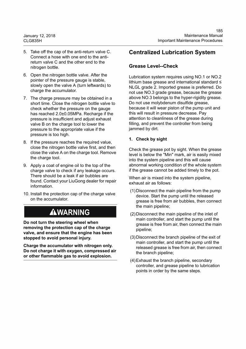
185January 12, 2018 Maintenance ManualCLG835H Important Maintenance Procedures
5. Take off the cap of the anti-return valve C. Connect a hose with one end to the anti-return valve C and the other end to the nitrogen bottle.
6. Open the nitrogen bottle valve. After the pointer of the pressure gauge is stable, slowly open the valve A (turn leftwards) to charge the accumulator.
7. The charge pressure may be obtained in a short time. Close the nitrogen bottle valve to check whether the pressure on the gauge has reached 2.0±0.05MPa. Recharge if the pressure is insufficient and adjust exhaust valve B on the charge tool to lower the pressure to the appropriate value if the pressure is too high.
8. If the pressure reaches the required value, close the nitrogen bottle valve first, and then close the valve A on the charge tool. Remove the charge tool.
9. Apply a coat of engine oil to the top of the charge valve to check if any leakage occurs. There should be a leak if air bubbles are found. Contact your LiuGong dealer for repair information.
10. Install the protection cap of the charge valve on the accumulator.
Centralized Lubrication System
Grease Level--Check
Lubrication system requires using NO.1 or NO.2 lithium base grease and international standard ≤ NLGL grade 2. Imported grease is preferred. Do not use NO.3 grade grease, because the grease above NO.3 belongs to the hyper-rigidity grease. Do not use molybdenum disulfide grease, because it will wear piston of the pump unit and this will result in pressure decrease. Pay attention to cleanliness of the grease during filling, and prevent the controller from being jammed by dirt.
1. Check by sight
Check the grease pot by sight. When the grease level is below the "Min" mark, air is easily mixed into the system pipeline and this will cause abnormal working condition of the whole system if the grease cannot be added timely to the pot.
When air is mixed into the system pipeline, exhaust air as follows:
(1)Disconnect the main pipeline from the pump device. Start the pump until the released grease is free from air bubbles, then connect the main pipeline;
(2)Disconnect the main pipeline of the inlet of main controller, and start the pump until the grease is free from air, then connect the main pipeline;
(3)Disconnect the branch pipeline of the exit of main controller, and start the pump until the released grease is free from air, then connect the branch pipeline;
(4)Exhaust the branch pipeline, secondary controller, and grease pipeline to lubrication points in order by the same steps.
Do not turn the steering wheel when removing the protection cap of the charge valve, and ensure that the engine has been stopped to avoid personal injury.
Charge the accumulator with nitrogen only. Do not charge it with oxygen, compressed air or other flammable gas to avoid explosion.
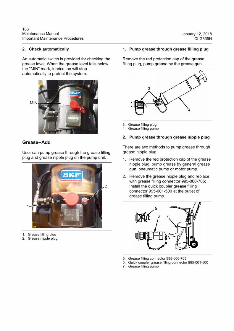
186Maintenance Manual January 12, 2018Important Maintenance Procedures CLG835H
2. Check automatically
An automatic switch is provided for checking the grease level. When the grease level falls below the "MIN" mark, lubrication will stop automatically to protect the system.
Grease--Add
User can pump grease through the grease filling plug and grease nipple plug on the pump unit.
1. Grease filling plug2. Grease nipple plug
1. Pump grease through grease filling plug
Remove the red protection cap of the grease filling plug, pump grease by the grease gun.
3. Grease filling plug4. Grease filling pump
2. Pump grease through grease nipple plug
There are two methods to pump grease through grease nipple plug:
1. Remove the red protection cap of the grease nipple plug, pump grease by general grease gun, pneumatic pump or motor pump.
2. Remove the grease nipple plug and replace with grease filling connector 995-000-705; Install the quick coupler grease filling connector 995-001-500 at the outlet of grease filling pump.
5. Grease filling connector 995-000-7056. Quick coupler grease filling connector 995-001-5007. Grease filling pump
MIN
2
1
6
3
4
5
6 7
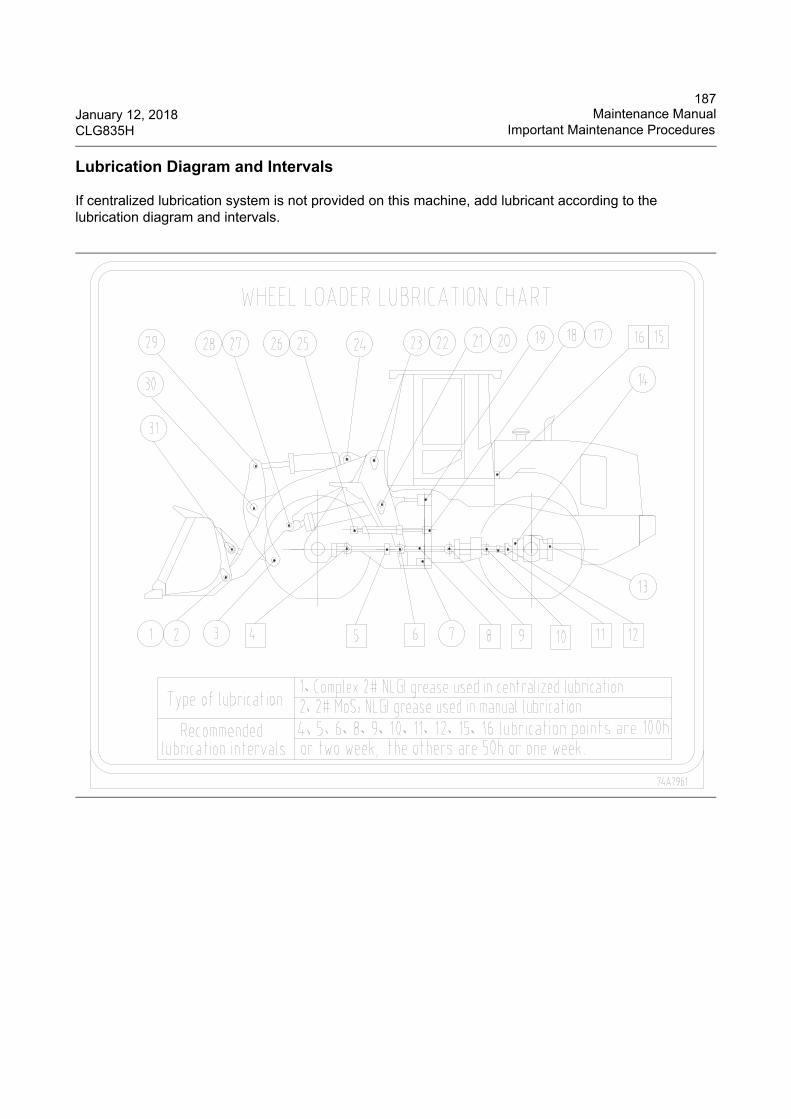
187January 12, 2018 Maintenance ManualCLG835H Important Maintenance Procedures
Lubrication Diagram and Intervals
If centralized lubrication system is not provided on this machine, add lubricant according to the lubrication diagram and intervals.
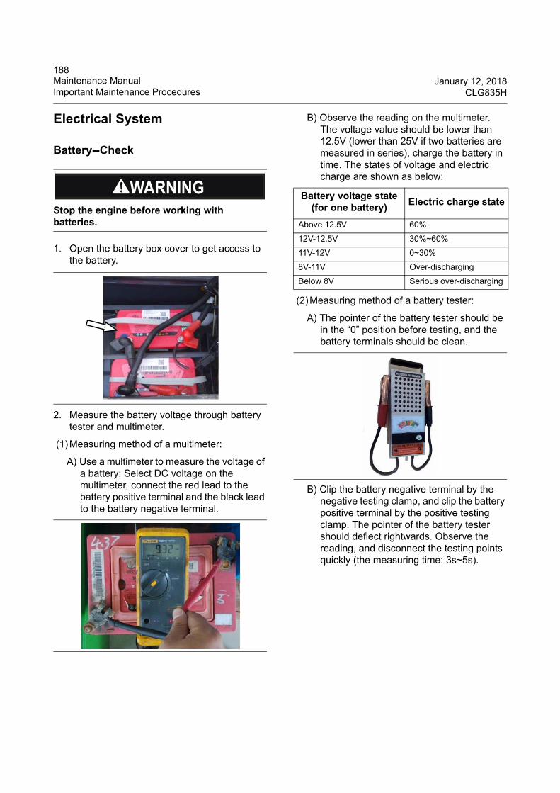
188Maintenance Manual January 12, 2018Important Maintenance Procedures CLG835H
Electrical System
Battery--Check
1. Open the battery box cover to get access to the battery.
2. Measure the battery voltage through battery tester and multimeter.
(1)Measuring method of a multimeter:
A) Use a multimeter to measure the voltage of a battery: Select DC voltage on the multimeter, connect the red lead to the battery positive terminal and the black lead to the battery negative terminal.
B) Observe the reading on the multimeter. The voltage value should be lower than 12.5V (lower than 25V if two batteries are measured in series), charge the battery in time. The states of voltage and electric charge are shown as below:
(2)Measuring method of a battery tester:
A) The pointer of the battery tester should be in the “0” position before testing, and the battery terminals should be clean.
B) Clip the battery negative terminal by the negative testing clamp, and clip the battery positive terminal by the positive testing clamp. The pointer of the battery tester should deflect rightwards. Observe the reading, and disconnect the testing points quickly (the measuring time: 3s~5s).
Stop the engine before working with batteries.
Battery voltage state(for one battery)
Electric charge state
Above 12.5V 60%
12V-12.5V 30%~60%
11V-12V 0~30%
8V-11V Over-discharging
Below 8V Serious over-discharging
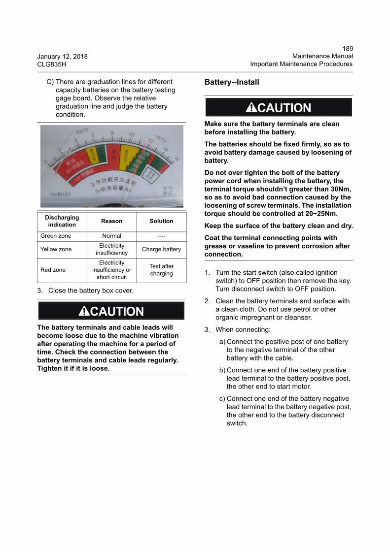
189January 12, 2018 Maintenance ManualCLG835H Important Maintenance Procedures
C) There are graduation lines for different capacity batteries on the battery testing gage board. Observe the relative graduation line and judge the battery condition.
3. Close the battery box cover.
Battery--Install
1. Turn the start switch (also called ignition switch) to OFF position then remove the key. Turn disconnect switch to OFF position.
2. Clean the battery terminals and surface with a clean cloth. Do not use petrol or other organic impregnant or cleanser.
3. When connecting:
a) Connect the positive post of one battery to the negative terminal of the other battery with the cable.
b) Connect one end of the battery positive lead terminal to the battery positive post, the other end to start motor.
c) Connect one end of the battery negative lead terminal to the battery negative post, the other end to the battery disconnect switch.
Discharging indication
Reason Solution
Green zone Normal ----
Yellow zoneElectricity
insufficiencyCharge battery
Red zoneElectricity
insufficiency or short circuit
Test after charging
The battery terminals and cable leads will become loose due to the machine vibration after operating the machine for a period of time. Check the connection between the battery terminals and cable leads regularly. Tighten it if it is loose.
Make sure the battery terminals are clean before installing the battery.
The batteries should be fixed firmly, so as to avoid battery damage caused by loosening of battery.
Do not over tighten the bolt of the battery power cord when installing the battery, the terminal torque shouldn’t greater than 30Nm, so as to avoid bad connection caused by the loosening of screw terminals. The installation torque should be controlled at 20~25Nm.
Keep the surface of the battery clean and dry.
Coat the terminal connecting points with grease or vaseline to prevent corrosion after connection.
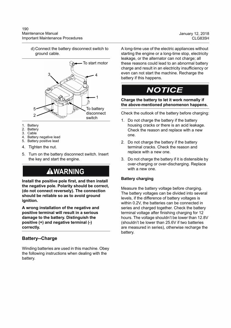
190Maintenance Manual January 12, 2018Important Maintenance Procedures CLG835H
d) Connect the battery disconnect switch to ground cable.
1. Battery2. Battery3. Cable4. Battery negative lead5. Battery positive lead
4. Tighten the nut.
5. Turn on the battery disconnect switch. Insert the key and start the engine.
Battery--Charge
Winding batteries are used in this machine. Obey the following instructions when dealing with the battery.
A long-time use of the electric appliances without starting the engine or a long-time stop, electricity leakage, or the alternator can not charge; all these reasons could lead to an abnormal battery charge and result in an electricity insufficiency or even can not start the machine. Recharge the battery if this happens.
Check the outlook of the battery before charging:
1. Do not charge the battery if the battery housing cracks or there is an acid leakage. Check the reason and replace with a new one.
2. Do not charge the battery if the battery terminal cracks. Check the reason and replace with a new one.
3. Do not charge the battery if it is distensible by over-charging or over-discharging. Replace with a new one.
Battery charging
Measure the battery voltage before charging. The battery voltages can be divided into several levels, if the difference of battery voltages is within 0.2V, the batteries can be connected in series and charged together. Check the battery terminal voltage after finishing charging for 12 hours. The voltage shouldn’t be lower than 12.8V (shouldn’t be lower than 25.6V if two batteries are measured in series), otherwise recharge the battery.
Install the positive pole first, and then install the negative pole. Polarity should be correct, (do not connect reversely). The connection should be reliable so as to avoid ground ignition.
A wrong installation of the negative and positive terminal will result in a serious damage to the battery. Distinguish the positive (+) and negative terminal (-) correctly.
1
2
3 4
5
To start motor
To batterydisconnectswitch
Charge the battery to let it work normally if the above-mentioned phenomenon happens.
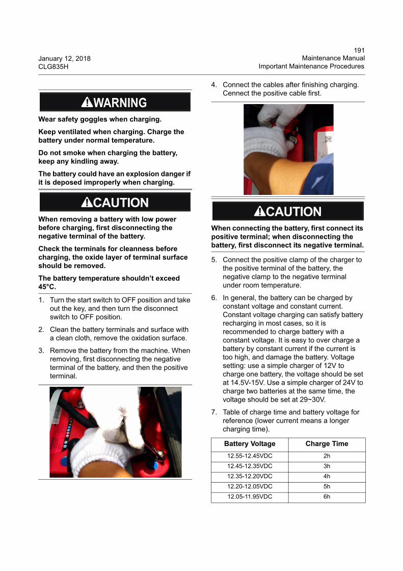
191January 12, 2018 Maintenance ManualCLG835H Important Maintenance Procedures
1. Turn the start switch to OFF position and take out the key, and then turn the disconnect switch to OFF position.
2. Clean the battery terminals and surface with a clean cloth, remove the oxidation surface.
3. Remove the battery from the machine. When removing, first disconnecting the negative terminal of the battery, and then the positive terminal.
4. Connect the cables after finishing charging. Cennect the positive cable first.
5. Connect the positive clamp of the charger to the positive terminal of the battery, the negative clamp to the negative terminal under room temperature.
6. In general, the battery can be charged by constant voltage and constant current. Constant voltage charging can satisfy battery recharging in most cases, so it is recommended to charge battery with a constant voltage. It is easy to over charge a battery by constant current if the current is too high, and damage the battery. Voltage setting: use a simple charger of 12V to charge one battery, the voltage should be set at 14.5V-15V. Use a simple charger of 24V to charge two batteries at the same time, the voltage should be set at 29~30V.
7. Table of charge time and battery voltage for reference (lower current means a longer charging time).
Wear safety goggles when charging.
Keep ventilated when charging. Charge the battery under normal temperature.
Do not smoke when charging the battery, keep any kindling away.
The battery could have an explosion danger if it is deposed improperly when charging.
When removing a battery with low power before charging, first disconnecting the negative terminal of the battery.
Check the terminals for cleanness before charging, the oxide layer of terminal surface should be removed.
The battery temperature shouldn’t exceed 45°C.
When connecting the battery, first connect its positive terminal; when disconnecting the battery, first disconnect its negative terminal.
Battery Voltage Charge Time
12.55-12.45VDC 2h
12.45-12.35VDC 3h
12.35-12.20VDC 4h
12.20-12.05VDC 5h
12.05-11.95VDC 6h
192Maintenance Manual January 12, 2018Important Maintenance Procedures CLG835H
8. As for a battery with a voltage under 11.0VDC, it may not be able to be charged at the beginning. Due to the serious insufficiency of electricity, the proportion of vitriol is close to water, therefore, the battery resistance is higher. The vitriol proportion increases during recharge and the circuit can get right gradually.
9. Stop charging if the battery temperature exceeds 45°C during the charging process. Halve the circuit before recharging after the battery temperature drops to the ambient temperature.
10. Check the battery voltage 12 hours after finished charging or carried out discharging operation once. If the battery voltage dropped over 0.5V within 12-24 hours, replace the battery directly to avoid empty voltage of the battery.
11. It is recommended applying vaseline on the battery terminals to avoid electric corrosion after charge is completed.
Charge the battery according to the following method when the battery voltage is low, but the machine still can be started and alternator works normally.
1. Start the engine, and ensure that the battery charging system is in normal (observe the battery voltage through gauge), keep the engine speed at second gear to charge the battery until it is fully charged.
2. Turn off the A/C, radio, lights (except night) and other high-power electric equipment during battery charging.
3. Avoid starting the machine frequently as far as possible during battery charging. If restart is necessary, it is recommended to restart the machine after finishing charging the battery.
11.95-11.80VDC 7h
11.80-11.65VDC 8h
11.65-11.50VDC 9h
11.50-11.30VDC 10h
11.30-11.00VDC 12h
Below 11.00VDC 14h
Fix the two terminals tightly. Do not charge the battery of 24VDC voltage in serial connection.
Stop charging immediately to check the reason if the battery discharge hole spurts acid during the charging process.
Battery Voltage Charge Time
193January 12, 2018 Maintenance ManualCLG835H Important Maintenance Procedures
Battery--Store/ Service
1. Turn off the battery disconnect switch when storing the batteries being installed on a machine, and check the battery voltage state at least every other month.
2. For the machine needs to be stored over 30 days, the batteries should be removed and managed together. Check the battery voltage once every 30 days. Recharge the battery in time if its voltage is lower than 12.5V (lower than 25V if two batteries are measured in series).
3. For the machine needs to be stored less than 30 days, disconnect the battery disconnect switch. Check the battery voltage once over 15 days to ensure that the battery voltage is above 12.5V.
4. As for the machine which has not disconnected the battery terminals, check the battery voltage state every month. Recharge if the battery lacks for electricity. Recharge according to special procedures.
5. As for the machine which is stored over one year, replace with a new battery and dispose the old one if the above- mentioned requirements can not be followed.
Battery--Recycle
When discarding a battery, its inner material such as lead, acid and plastic shell can pollute the environment due to its outer frayed structure or other reasons. Therefore, do not throw away the old battery randomly, deal with it by collecting for a battery disposal station or put it into a recycle can set by the manufacturer (if there is any) in a local place.
Battery, Cable, Battery Disconnect Switch--Replace
1. Turm the engine start switch key to OFF position. Turn all of the switches to OFF position. Take out the switch key.
2. Turn the battery disconnect switch to OFF position.
3. Disconnect the negative battery cable from the battery disconnect switch.
4. Sequences for disconnecting the battery cables:
● Disconnect the negative battery cable from the battery.
● Disconnect the positive battery cable from the battery.
5. Inspect the battery terminals for corrosion. Inspect the battery cables for wear or damage.
6. Make any necessary repairs. If necessary, replace the battery cables or the battery.
7. Sequences for connecting the battery cables:
● Connect the positive battery cable to the battery.
● Connect the negative battery cable to the battery.
8. Connect the battery cable with the battery disconnect switch.
9. Install the switch key and turn the battery disconnect switch to ON position.
Do not let the disconnected negative battery cable contact with the battery disconnect switch.
194Maintenance Manual January 12, 2018Important Maintenance Procedures CLG835H
Alternator--Maintain
The alternator is a supporting component of the diesel engine, refer to specification section or the alternator’s nameplate for the working voltage and current value of the alternator. It has a built-in electronic voltage regulator. Check the connections of the alternator terminals frequently. Connection looseness at either positive terminal or negative terminal will result in trouble of the electrical system, even cause serious failure.
Turn off the start switch before checking the two terminals for good connection.
Method of judging whether the alternator works normally and the handling measures:
1. Turn on the start switch and observe the reading of the voltmeter, and then start the diesel engine and observe reading of the voltmeter again. The latter reading should be higher than the former one.
2. You can also use the 200V DC voltage position of a multimeter to check. Turn on the start switch, measure terminal voltage of the alternator (red meter pen connects positive terminal of the alternator while black meter pen connects the ground), and then write down the reading of the multimeter.
3. Start the engine and increase the engine speed to rated speed. Check the voltage of the alternator again and write down the reading of the multimeter. The latter reading should be higher than the former one.
4. In case the alternator does not work:
a) Check the drive belt of the alternator for looseness.
b) Turn off the start switch, and then use a wrench to check the connections of the alternator terminals.
c) Check to see whether the alternator connects correctly to the ground.
Starter Motor--Maintain
The starter motor is a supporting component of the diesel engine. It mainly consists of a solenoid, DC motor, shifting fork and driving gear. The starter motor converts electrical energy of the battery into mechanical energy through the DC motor. Then the driving gear will drive the flywheel of the engine to start the engine.
After the engine starts, the starter motor should immediately stop. Otherwise, the driving gear may be damaged, the DC motor may be burnt, the chock electromagnet may be damaged, and capacity and service life of the battery may also be greatly affected.
It is prohibited to allow any metallic conductor to approach any naked terminal freely. Especially ensure that the other metallic articles around the starter motor will not contact or rub the naked terminal after a long and severe shock or operation of the machine. Otherwise, fire may occur to the machine.
It is forbidden to check the alternator by short-circuiting the negative and positive terminals of the alternator, otherwise the diode will be burnt and the voltage regulator could be affected.
Keep any metallic conductor away from positive terminals of the alternator.
The cable of the terminals can not be incorrectly connected, otherwise the diode could be burnt and result in serious failure.
195January 12, 2018 Maintenance ManualCLG835H Important Maintenance Procedures
Fuse--Check/ Replace
The fuses protect the electrical system from being damaged due to circuit overload. If the fuse is broken, replace with a new one. Check the circuit if the new fuse is broken again. Repair the circuit, if necessary.
The machine has two fuse boxes, the box with fuses below 30A is located in the cab, another box with fuses of 30A or above is located near the battery box.
Check and replace the fuse as follows:
1. Turn the start switch to OFF position.
2. Open the fuse box cover. Take off the broken fuse with a clamp.
3. Replace the broken fuse with a new one with same specification.
4. Install the fuse box cover.
The slice type fuse and flat type fuse that used in this machine should meet the regulation in standard of QC/T420 Fuse-Links for Motor Vehicles. See the following table for the fuse model:
The color of the fuses near the battery box is as follows:
Replacing fuses with the same type and size from different brands is allowed. Do not use copper wire, otherwise the circuit could be damaged.
It is recommeded to use fuse supplied by LiuGong if it needs to replace the fuse when repairing. Do not buy the fuse randomly in the market as fuse of poor quality will bring bad effect to the machine, even could cause a fire.
If it is necessary to replace fuses frequently, an electrical problem may occur. Contact your LiuGong dealer.
Model LiuGong PDM Number
CLA-5 37B2023
CLA-7.5 37B2024
CLA-10 37B2025
CLA-15 37B2026
CLA-20 37B2027
Model Color
BK/AMI-030-30A Orange
BK/AMI-050-50A Red
BK/AMI-060-60A Yellow
BK/AMI-080-80A White
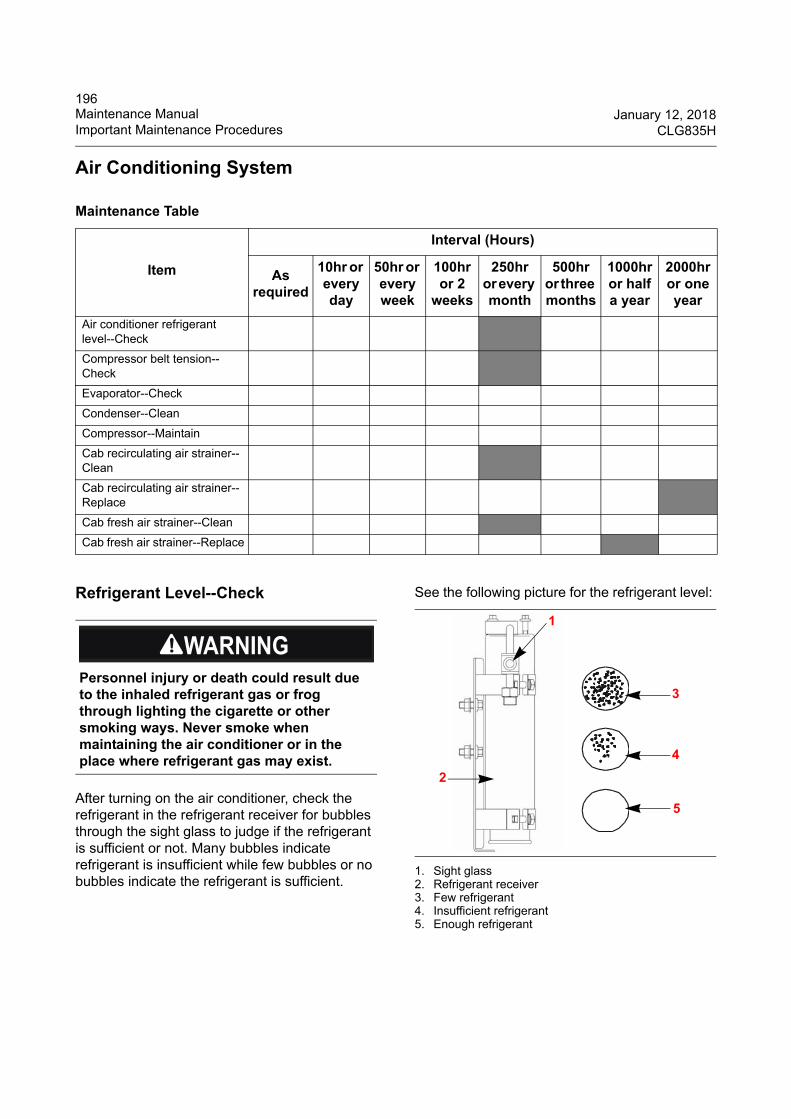
196Maintenance Manual January 12, 2018Important Maintenance Procedures CLG835H
Air Conditioning System
Refrigerant Level--Check
After turning on the air conditioner, check the refrigerant in the refrigerant receiver for bubbles through the sight glass to judge if the refrigerant is sufficient or not. Many bubbles indicate refrigerant is insufficient while few bubbles or no bubbles indicate the refrigerant is sufficient.
See the following picture for the refrigerant level:
1. Sight glass2. Refrigerant receiver3. Few refrigerant4. Insufficient refrigerant5. Enough refrigerant
Maintenance Table
Item
Interval (Hours)
As required
10hr or every day
50hr or every week
100hr or 2
weeks
250hr or every month
500hr or three months
1000hr or half a year
2000hr or one year
Air conditioner refrigerant level--Check
Compressor belt tension--Check
Evaporator--Check
Condenser--Clean
Compressor--Maintain
Cab recirculating air strainer--Clean
Cab recirculating air strainer--Replace
Cab fresh air strainer--Clean
Cab fresh air strainer--Replace
Personnel injury or death could result due to the inhaled refrigerant gas or frog through lighting the cigarette or other smoking ways. Never smoke when maintaining the air conditioner or in the place where refrigerant gas may exist.
1
2
5
4
3

197January 12, 2018 Maintenance ManualCLG835H Important Maintenance Procedures
Refrigerant receiver is located on the rear left side of the machine, behind the heat insulation supporter.
Compressor Belt Tension--Check/Adjust/ Replace
The compressor belt tension: apply(W=15N) force in the center span of the pulleys (compressor pulley and engine pulley). The deflection of the belt center distance should be 5 ± 1mm. See the following picture:
1. Engine pulley2. Compressor pulley
1. Shut down the engine, open the engine hood to access the air conditioner compressor.
2. Check the air conditoner belt. Replace with a new belt if the belt is not tense. That is, the deflection of the belt center distance is more than 5±1mm when applying (W=15N) force in the center span of the pulleys (compressor pulley and engine pulley).
3. Replace the belt if the belt has cracks or splits.
4. Check the air conditioner belt tension with a gauge.
a) The used air conditioner belt tension should be 400 ± 44N when it has run for more than 30 minutes at the rated speed.
b) The new air conditioner belt tension should be 534 ± 22N when it has run in 30 minutes at the rated speed.
R134a refrigerant is used in this air conditioning system. Do not use other refrigerant or refrigerant with low quality to avoid damaging the compressor.
Do not add excess refrigerant when adding refrigerant to avoid compressor liquid impact damage caused by insufficient space for refrigerant vaporization in the air conditioning system.
If refrigerant leakage is found, check all the joints that connect to the hoses for loose conditions. 1
2W
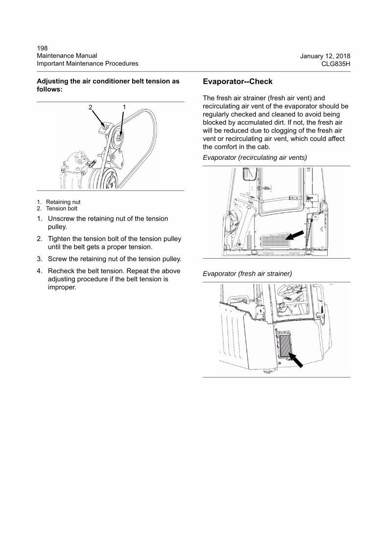
198Maintenance Manual January 12, 2018Important Maintenance Procedures CLG835H
Adjusting the air conditioner belt tension as follows:
1. Retaining nut2. Tension bolt
1. Unscrew the retaining nut of the tension pulley.
2. Tighten the tension bolt of the tension pulley until the belt gets a proper tension.
3. Screw the retaining nut of the tension pulley.
4. Recheck the belt tension. Repeat the above adjusting procedure if the belt tension is improper.
Evaporator--Check
The fresh air strainer (fresh air vent) and recirculating air vent of the evaporator should be regularly checked and cleaned to avoid being blocked by accmulated dirt. If not, the fresh air will be reduced due to clogging of the fresh air vent or recirculating air vent, which could affect the comfort in the cab.
12
Evaporator (recirculating air vents)
Evaporator (fresh air strainer)
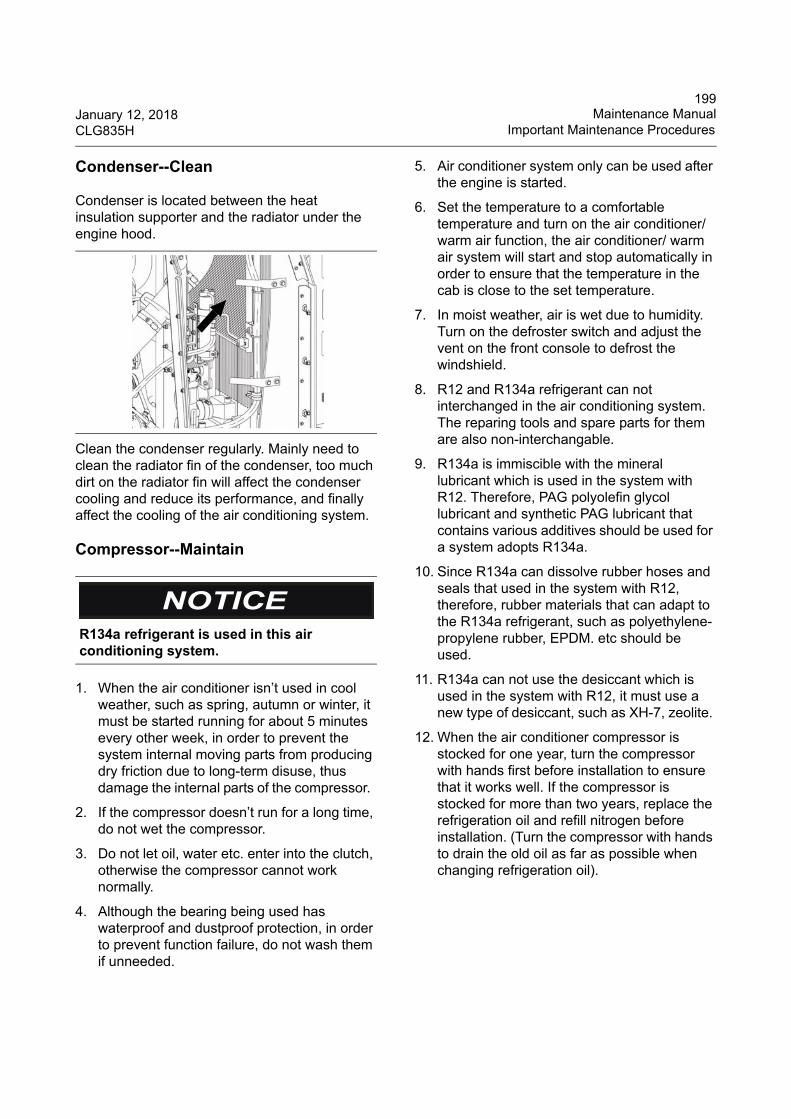
199January 12, 2018 Maintenance ManualCLG835H Important Maintenance Procedures
Condenser--Clean
Condenser is located between the heat insulation supporter and the radiator under the engine hood.
Clean the condenser regularly. Mainly need to clean the radiator fin of the condenser, too much dirt on the radiator fin will affect the condenser cooling and reduce its performance, and finally affect the cooling of the air conditioning system.
Compressor--Maintain
1. When the air conditioner isn’t used in cool weather, such as spring, autumn or winter, it must be started running for about 5 minutes every other week, in order to prevent the system internal moving parts from producing dry friction due to long-term disuse, thus damage the internal parts of the compressor.
2. If the compressor doesn’t run for a long time, do not wet the compressor.
3. Do not let oil, water etc. enter into the clutch, otherwise the compressor cannot work normally.
4. Although the bearing being used has waterproof and dustproof protection, in order to prevent function failure, do not wash them if unneeded.
5. Air conditioner system only can be used after the engine is started.
6. Set the temperature to a comfortable temperature and turn on the air conditioner/ warm air function, the air conditioner/ warm air system will start and stop automatically in order to ensure that the temperature in the cab is close to the set temperature.
7. In moist weather, air is wet due to humidity. Turn on the defroster switch and adjust the vent on the front console to defrost the windshield.
8. R12 and R134a refrigerant can not interchanged in the air conditioning system. The reparing tools and spare parts for them are also non-interchangable.
9. R134a is immiscible with the mineral lubricant which is used in the system with R12. Therefore, PAG polyolefin glycol lubricant and synthetic PAG lubricant that contains various additives should be used for a system adopts R134a.
10. Since R134a can dissolve rubber hoses and seals that used in the system with R12, therefore, rubber materials that can adapt to the R134a refrigerant, such as polyethylene-propylene rubber, EPDM. etc should be used.
11. R134a can not use the desiccant which is used in the system with R12, it must use a new type of desiccant, such as XH-7, zeolite.
12. When the air conditioner compressor is stocked for one year, turn the compressor with hands first before installation to ensure that it works well. If the compressor is stocked for more than two years, replace the refrigeration oil and refill nitrogen before installation. (Turn the compressor with hands to drain the old oil as far as possible when changing refrigeration oil).
R134a refrigerant is used in this air conditioning system.
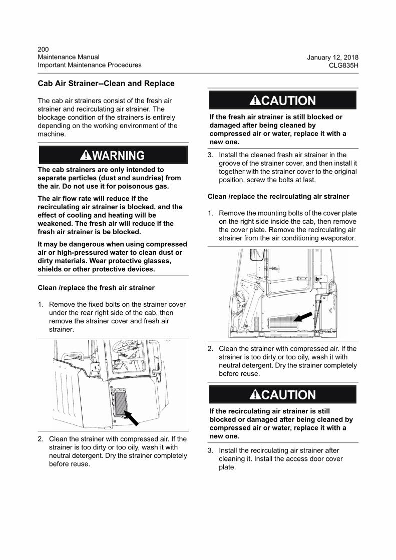
200Maintenance Manual January 12, 2018Important Maintenance Procedures CLG835H
Cab Air Strainer--Clean and Replace
The cab air strainers consist of the fresh air strainer and recirculating air strainer. The blockage condition of the strainers is entirely depending on the working environment of the machine.
Clean /replace the fresh air strainer
1. Remove the fixed bolts on the strainer cover under the rear right side of the cab, then remove the strainer cover and fresh air strainer.
2. Clean the strainer with compressed air. If the strainer is too dirty or too oily, wash it with neutral detergent. Dry the strainer completely before reuse.
3. Install the cleaned fresh air strainer in the groove of the strainer cover, and then install it together with the strainer cover to the original position, screw the bolts at last.
Clean /replace the recirculating air strainer
1. Remove the mounting bolts of the cover plate on the right side inside the cab, then remove the cover plate. Remove the recirculating air strainer from the air conditioning evaporator.
2. Clean the strainer with compressed air. If the strainer is too dirty or too oily, wash it with neutral detergent. Dry the strainer completely before reuse.
3. Install the recirculating air strainer after cleaning it. Install the access door cover plate.
The cab strainers are only intended to separate particles (dust and sundries) from the air. Do not use it for poisonous gas.
The air flow rate will reduce if the recirculating air strainer is blocked, and the effect of cooling and heating will be weakened. The fresh air will reduce if the fresh air strainer is be blocked.
It may be dangerous when using compressed air or high-pressured water to clean dust or dirty materials. Wear protective glasses, shields or other protective devices.
If the fresh air strainer is still blocked or damaged after being cleaned by compressed air or water, replace it with a new one.
If the recirculating air strainer is still blocked or damaged after being cleaned by compressed air or water, replace it with a new one.
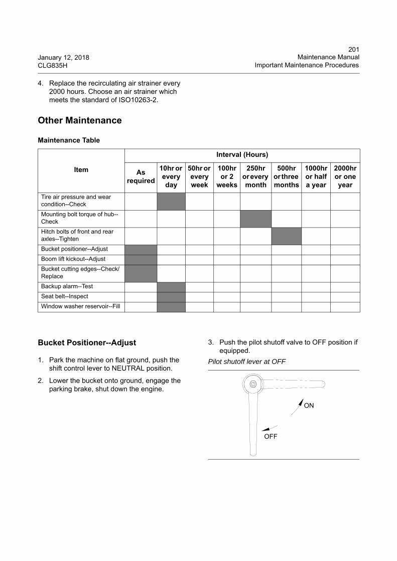
201January 12, 2018 Maintenance ManualCLG835H Important Maintenance Procedures
4. Replace the recirculating air strainer every 2000 hours. Choose an air strainer which meets the standard of ISO10263-2.
Other Maintenance
Bucket Positioner--Adjust
1. Park the machine on flat ground, push the shift control lever to NEUTRAL position.
2. Lower the bucket onto ground, engage the parking brake, shut down the engine.
3. Push the pilot shutoff valve to OFF position if equipped.
Maintenance Table
Item
Interval (Hours)
As required
10hr or every day
50hr or every week
100hr or 2
weeks
250hr or every month
500hr or three months
1000hr or half a year
2000hr or one year
Tire air pressure and wear condition--Check
Mounting bolt torque of hub--Check
Hitch bolts of front and rear axles--Tighten
Bucket positioner--Adjust
Boom lift kickout--Adjust
Bucket cutting edges--Check/Replace
Backup alarm--Test
Seat belt--Inspect
Window washer reservoir--Fill
Pilot shutoff lever at OFF
ON
OFF
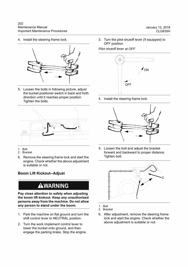
202Maintenance Manual January 12, 2018Important Maintenance Procedures CLG835H
4. Install the steering frame lock.
5. Loosen the bolts in following picture, adjust the bucket positioner switch in back and forth direction until it reaches proper position. Tighten the bolts.
1. Bolt2. Bracket
6. Remove the steering frame lock and start the engine. Check whether the above adjustment is suitable or not.
Boom Lift Kickout--Adjust
1. Park the machine on flat ground and turn the shift control lever to NEUTRAL position.
2. Turn the work implement control lever to lower the bucket onto ground, and then engage the parking brake. Stop the engine.
3. Turn the pilot shutoff lever (If equipped) to OFF position.
4. Install the steering frame lock.
5. Loosen the bolt and adjust the bracket forward and backward to proper distance. Tighten bolt.
1. Bolt2. Bracket
6. After adjustment, remove the steering frame lock and start the engine. Check whether the above adjustment is suitable or not.
Pay close attention to safety when adjusting the boom lift kickout. Keep any unauthorized persons away from the machine. Do not allow any person to stand under the boom.
Pilot shutoff lever at OFF
ON
OFF
1
2
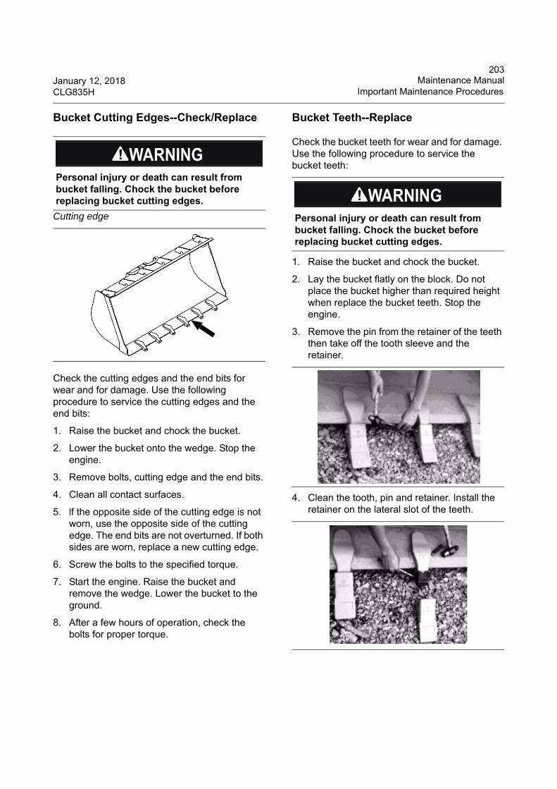
203January 12, 2018 Maintenance ManualCLG835H Important Maintenance Procedures
Bucket Cutting Edges--Check/Replace
Check the cutting edges and the end bits for wear and for damage. Use the following procedure to service the cutting edges and the end bits:
1. Raise the bucket and chock the bucket.
2. Lower the bucket onto the wedge. Stop the engine.
3. Remove bolts, cutting edge and the end bits.
4. Clean all contact surfaces.
5. lf the opposite side of the cutting edge is not worn, use the opposite side of the cutting edge. The end bits are not overturned. If both sides are worn, replace a new cutting edge.
6. Screw the bolts to the specified torque.
7. Start the engine. Raise the bucket and remove the wedge. Lower the bucket to the ground.
8. After a few hours of operation, check the bolts for proper torque.
Bucket Teeth--Replace
Check the bucket teeth for wear and for damage. Use the following procedure to service the bucket teeth:
1. Raise the bucket and chock the bucket.
2. Lay the bucket flatly on the block. Do not place the bucket higher than required height when replace the bucket teeth. Stop the engine.
3. Remove the pin from the retainer of the teeth then take off the tooth sleeve and the retainer.
4. Clean the tooth, pin and retainer. Install the retainer on the lateral slot of the teeth.
Personal injury or death can result from bucket falling. Chock the bucket before replacing bucket cutting edges.
Cutting edge Personal injury or death can result from bucket falling. Chock the bucket before replacing bucket cutting edges.
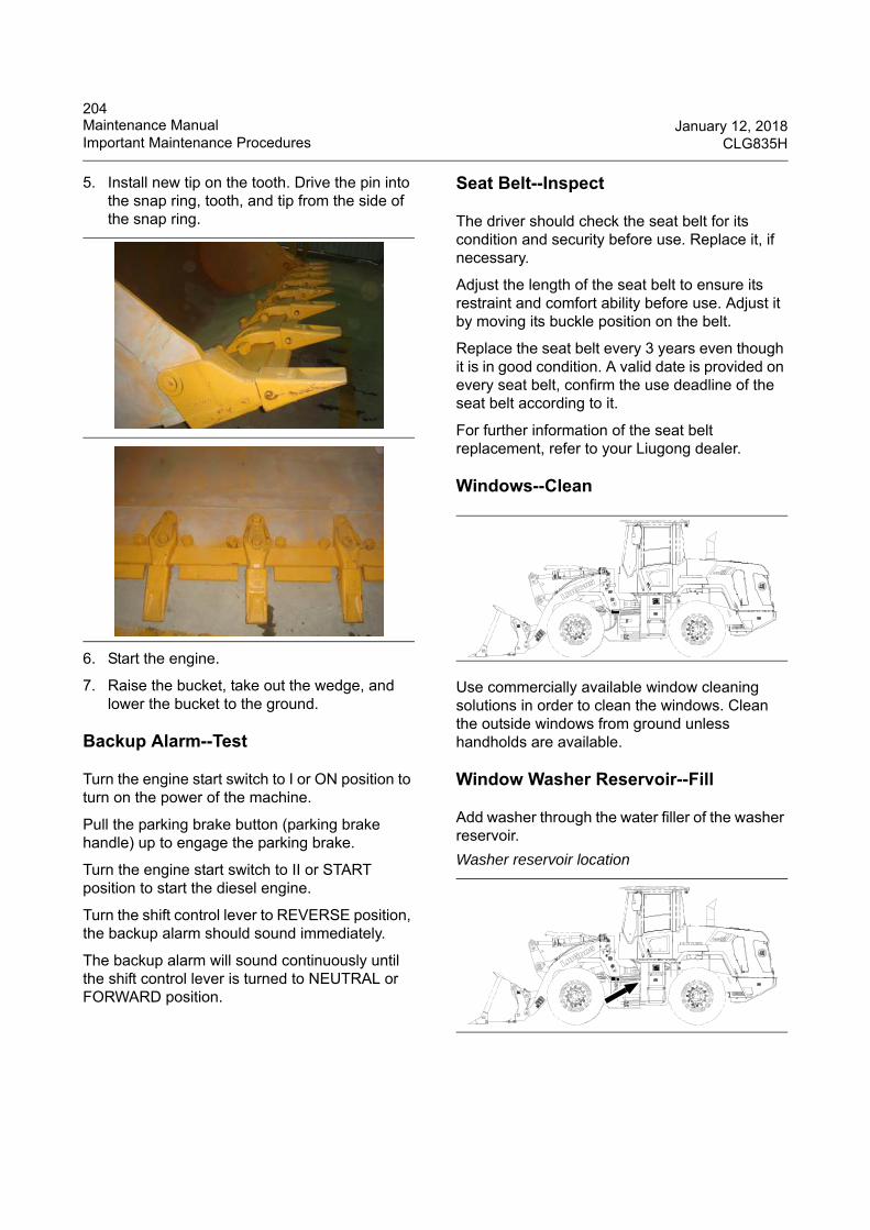
204Maintenance Manual January 12, 2018Important Maintenance Procedures CLG835H
5. Install new tip on the tooth. Drive the pin into the snap ring, tooth, and tip from the side of the snap ring.
6. Start the engine.
7. Raise the bucket, take out the wedge, and lower the bucket to the ground.
Backup Alarm--Test
Turn the engine start switch to I or ON position to turn on the power of the machine.
Pull the parking brake button (parking brake handle) up to engage the parking brake.
Turn the engine start switch to II or START position to start the diesel engine.
Turn the shift control lever to REVERSE position, the backup alarm should sound immediately.
The backup alarm will sound continuously until the shift control lever is turned to NEUTRAL or FORWARD position.
Seat Belt--Inspect
The driver should check the seat belt for its condition and security before use. Replace it, if necessary.
Adjust the length of the seat belt to ensure its restraint and comfort ability before use. Adjust it by moving its buckle position on the belt.
Replace the seat belt every 3 years even though it is in good condition. A valid date is provided on every seat belt, confirm the use deadline of the seat belt according to it.
For further information of the seat belt replacement, refer to your Liugong dealer.
Windows--Clean
Use commercially available window cleaning solutions in order to clean the windows. Clean the outside windows from ground unless handholds are available.
Window Washer Reservoir--Fill
Add washer through the water filler of the washer reservoir.
Washer reservoir location
WHEEL L OADERG ua ng x i L iu go n g Ma ch ine ry Co .,L td .N o .1 L i u ta i R o a d , L i u z h o u , G u a n g x i 5 4 5 0 0 7 , PR Ch in a
PRODUCTIDENT IF ICAT ION
NUMBER
WHEEL L OADERG ua ng x i L iu go n g Ma ch ine ry Co .,L td .N o .1 L i u ta i R o a d , L i u z h o u , G u a n g x i 5 4 5 0 0 7 , PR Ch in a
PRODUCTIDENT IF ICAT ION
NUMBER
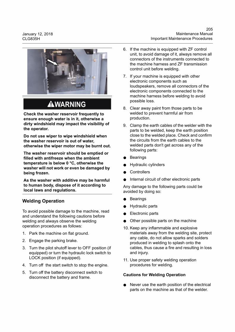
205January 12, 2018 Maintenance ManualCLG835H Important Maintenance Procedures
Welding Operation
To avoid possible damage to the machine, read and understand the following cautions before welding and always observe the welding operation procedures as follows:
1. Park the machine on flat ground.
2. Engage the parking brake.
3. Turn the pilot shutoff lever to OFF position (if equipped) or turn the hydraulic lock switch to LOCK position (if equipped).
4. Turn off the start switch to stop the engine.
5. Turn off the battery disconnect switch to disconnect the battery and frame.
6. If the machine is equipped with ZF control unit, to avoid damage of it, always remove all connectors of the instruments connected to the machine harness and ZF transmission control unit before welding.
7. If your machine is equipped with other electronic components such as loudspeakers, remove all connectors of the electronic components connected to the machine harness before welding to avoid possible loss.
8. Clear away paint from those parts to be welded to prevent harmful air from production.
9. Clamp the earth cables of the welder with the parts to be welded, keep the earth position close to the welded place. Check and confirm the circuits from the earth cables to the welded parts don't get across any of the following parts:
● Bearings
● Hydraulic cylinders
● Controllers
● Internal circuit of other electronic parts
Any damage to the following parts could be avoided by doing so:
● Bearings
● Hydraulic parts
● Electronic parts
● Other possible parts on the machine
10. Keep any inflammable and explosive materials away from the welding site, protect any cable, do not allow sparks and solders produced in welding to splash onto the cables, thus cause a fire and resulting in loss and injury.
11. Use proper safety welding operation procedures for welding.
Cautions for Welding Operation
● Never use the earth position of the electrical parts on the machine as that of the welder.
Check the washer reservoir frequently to ensure enough water is in it, otherwise a dirty windshield may impact the visibility of the operator.
Do not use wiper to wipe windshield when the washer reservoir is out of water, otherwise the wiper motor may be burnt out.
The washer reservoir should be emptied or filled with antifreeze when the ambient temperature is below 0 °C, otherwise the washer will not work or even be damaged by being frozen.
As the washer with additive may be harmful to human body, dispose of it according to local laws and regulations.
206Maintenance Manual January 12, 2018Important Maintenance Procedures CLG835H
●When performing welding near the earth position of an electrical part, always disconnect the earth position of this electrical part, and perform welding operation after ensuring that the welding circuit of the welder doesn't get across this electrical part. Otherwise it will result in damage to this electrical part or even result in a fire.
● Do not keep using voltage above 200V. Keep the welding area and earth cables within 1m.
● Avoid seals and bearings located between the welding area and earth cables.
● Never weld any pipe or container with fuel, engine oil or hydraulic oil.
● Never weld any sealed container or container which is poorly ventilated.
● Do not allow sparks and solders produced in welding to splash onto the cables, rubber hoses and other inflammable materials, thus cause a fire and resulting in loss and injury.
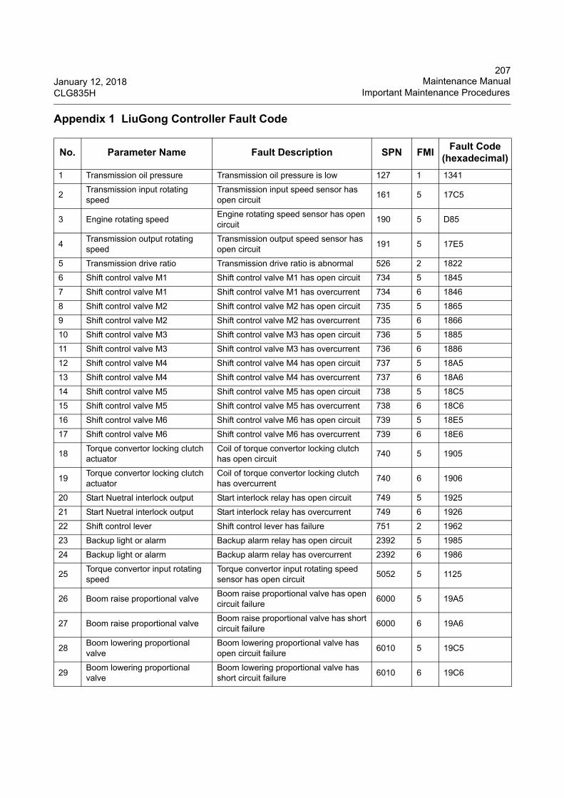
207January 12, 2018 Maintenance ManualCLG835H Important Maintenance Procedures
Appendix 1 LiuGong Controller Fault Code
No. Parameter Name Fault Description SPN FMIFault Code
(hexadecimal)
1 Transmission oil pressure Transmission oil pressure is low 127 1 1341
2Transmission input rotating speed
Transmission input speed sensor has open circuit
161 5 17C5
3 Engine rotating speedEngine rotating speed sensor has open circuit
190 5 D85
4Transmission output rotating speed
Transmission output speed sensor has open circuit
191 5 17E5
5 Transmission drive ratio Transmission drive ratio is abnormal 526 2 1822
6 Shift control valve M1 Shift control valve M1 has open circuit 734 5 1845
7 Shift control valve M1 Shift control valve M1 has overcurrent 734 6 1846
8 Shift control valve M2 Shift control valve M2 has open circuit 735 5 1865
9 Shift control valve M2 Shift control valve M2 has overcurrent 735 6 1866
10 Shift control valve M3 Shift control valve M3 has open circuit 736 5 1885
11 Shift control valve M3 Shift control valve M3 has overcurrent 736 6 1886
12 Shift control valve M4 Shift control valve M4 has open circuit 737 5 18A5
13 Shift control valve M4 Shift control valve M4 has overcurrent 737 6 18A6
14 Shift control valve M5 Shift control valve M5 has open circuit 738 5 18C5
15 Shift control valve M5 Shift control valve M5 has overcurrent 738 6 18C6
16 Shift control valve M6 Shift control valve M6 has open circuit 739 5 18E5
17 Shift control valve M6 Shift control valve M6 has overcurrent 739 6 18E6
18Torque convertor locking clutch actuator
Coil of torque convertor locking clutch has open circuit
740 5 1905
19Torque convertor locking clutch actuator
Coil of torque convertor locking clutch has overcurrent
740 6 1906
20 Start Nuetral interlock output Start interlock relay has open circuit 749 5 1925
21 Start Nuetral interlock output Start interlock relay has overcurrent 749 6 1926
22 Shift control lever Shift control lever has failure 751 2 1962
23 Backup light or alarm Backup alarm relay has open circuit 2392 5 1985
24 Backup light or alarm Backup alarm relay has overcurrent 2392 6 1986
25Torque convertor input rotating speed
Torque convertor input rotating speed sensor has open circuit
5052 5 1125
26 Boom raise proportional valveBoom raise proportional valve has open circuit failure
6000 5 19A5
27 Boom raise proportional valveBoom raise proportional valve has short circuit failure
6000 6 19A6
28Boom lowering proportional valve
Boom lowering proportional valve has open circuit failure
6010 5 19C5
29Boom lowering proportional valve
Boom lowering proportional valve has short circuit failure
6010 6 19C6
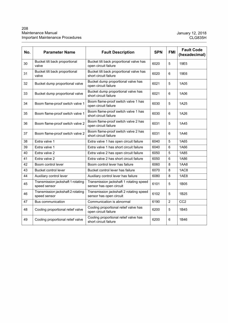
208Maintenance Manual January 12, 2018Important Maintenance Procedures CLG835H
30Bucket tilt back proportional valve
Bucket tilt back proportional valve has open circuit failure
6020 5 19E5
31Bucket tilt back proportional valve
Bucket tilt back proportional valve has short circuit failure
6020 6 19E6
32 Bucket dump proportional valveBucket dump proportional valve has open circuit failure
6021 5 1A05
33 Bucket dump proportional valveBucket dump proportional valve has short circuit failure
6021 6 1A06
34 Boom flame-proof switch valve 1Boom flame-proof switch valve 1 has open circuit failure
6030 5 1A25
35 Boom flame-proof switch valve 1Boom flame-proof switch valve 1 has short circuit failure
6030 6 1A26
36 Boom flame-proof switch valve 2Boom flame-proof switch valve 2 has open circuit failure
6031 5 1A45
37 Boom flame-proof switch valve 2Boom flame-proof switch valve 2 has short circuit failure
6031 6 1A46
38 Extra valve 1 Extra valve 1 has open circuit failure 6040 5 1A65
39 Extra valve 1 Extra valve 1 has short circuit failure 6040 6 1A66
40 Extra valve 2 Extra valve 2 has open circuit failure 6050 5 1A85
41 Extra valve 2 Extra valve 2 has short circuit failure 6050 6 1A86
42 Boom control lever Boom control lever has failure 6060 8 1AA8
43 Bucket control lever Bucket control lever has failure 6070 8 1AC8
44 Auxiliary control lever Auxiliary control lever has failure 6080 8 1AE8
45Transmission jackshaft 1 rotating speed sensor
Transmission jackshaft 1 rotating speed sensor has open circuit
6101 5 1B05
46Transmission jackshaft 2 rotating speed sensor
Transmission jackshaft 2 rotating speed sensor has open circuit
6102 5 1B25
47 Bus communication Communication is abnormal 6190 2 CC2
48 Cooling proportional relief valveCooling proportional relief valve has open circuit failure
6200 5 1B45
49 Cooling proportional relief valveCooling proportional relief valve has short circuit failure
6200 6 1B46
No. Parameter Name Fault Description SPN FMIFault Code
(hexadecimal)
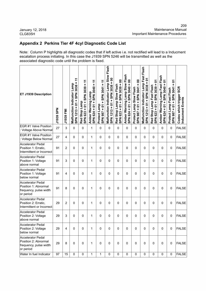
209January 12, 2018 Maintenance ManualCLG835H Important Maintenance Procedures
Appendix 2 Perkins Tier 4F 4cyl Diagnostic Code List
Note: Column P highlights all diagnostic codes that if left active i.e. not rectified will lead to a Inducment escalation process initiating. In this case the J1939 SPN 5246 will be transmitted as well as the associated diagnostic code until the problem is fixed.
ET J1939 Description
J19
39
SP
N
J19
39
FM
I
Mal
fun
ctio
n In
dic
ato
r L
am
pS
PN
12
13 =
01
+ S
PN
30
38 =
11
Red
Sto
p L
amp
SP
N 6
23
= 0
1 +
SP
N 3
039
= 1
1
Am
be
r W
arn
ing
La
mp
SP
N 6
24
= 0
1 +
SP
N 3
040
= 1
1
Pro
tect
Lam
pS
PN
98
7 =
01
+ S
PN
304
1 =
11
Ma
lfu
nct
ion
Ind
ica
tor
La
mp
Slo
w F
lash
SP
N 1
213
= 0
1 +
SP
N 3
038
= 0
0
Red
Sto
p L
amp
Slo
w F
lash
SP
N 6
23
= 0
1 +
SP
N 3
039
= 0
0
Am
be
r W
arn
ing
La
mp
Slo
w F
lash
SP
N 6
24
= 0
1 +
SP
N 3
040
= 0
0
Pro
tec
t L
amp
Slo
w F
lash
SP
N 9
87
= 0
1 +
SP
N 3
041
= 0
0
Ma
lfu
nct
ion
Ind
ica
tor
La
mp
Fas
t F
lash
SP
N 1
213
= 0
1 +
SP
N 3
038
= 0
1
Red
Sto
p L
amp
Fas
t F
las
hS
PN
62
3 =
01
+ S
PN
303
9 =
01
Am
be
r W
arn
ing
La
mp
Fa
st F
lash
SP
N 6
24
= 0
1 +
SP
N 3
040
= 0
1
Pro
tec
t L
amp
Fas
t F
las
hS
PN
98
7 =
01
+ S
PN
304
1 =
01
Co
des
wh
ich
tri
gg
er S
CR
In
du
cmen
t E
ven
ts
EGR #1 Valve Position : Voltage Above Normal
27 3 0 0 1 0 0 0 0 0 0 0 0 0 FALSE
EGR #1 Valve Position : Voltage Below Normal
27 4 0 0 1 0 0 0 0 0 0 0 0 0 FALSE
Accelerator Pedal Position 1: Erratic, Intermittent or Incorrect
91 2 0 0 1 0 0 0 0 0 0 0 0 0 FALSE
Accelerator Pedal Position 1: Voltage above normal
91 3 0 0 1 0 0 0 0 0 0 0 0 0 FALSE
Accelerator Pedal Position 1: Voltage below normal
91 4 0 0 1 0 0 0 0 0 0 0 0 0 FALSE
Accelerator Pedal Position 1: Abnormal frequency, pulse width or period
91 8 0 0 1 0 0 0 0 0 0 0 0 0 FALSE
Accelerator Pedal Position 2: Erratic, Intermittent or Incorrect
29 2 0 0 1 0 0 0 0 0 0 0 0 0 FALSE
Accelerator Pedal Position 2: Voltage above normal
29 3 0 0 1 0 0 0 0 0 0 0 0 0 FALSE
Accelerator Pedal Position 2: Voltage below normal
29 4 0 0 1 0 0 0 0 0 0 0 0 0 FALSE
Accelerator Pedal Position 2: Abnormal frequency, pulse width or period
29 8 0 0 1 0 0 0 0 0 0 0 0 0 FALSE
Water In fuel Indicator 97 15 0 0 1 1 0 0 0 0 0 0 0 0 FALSE
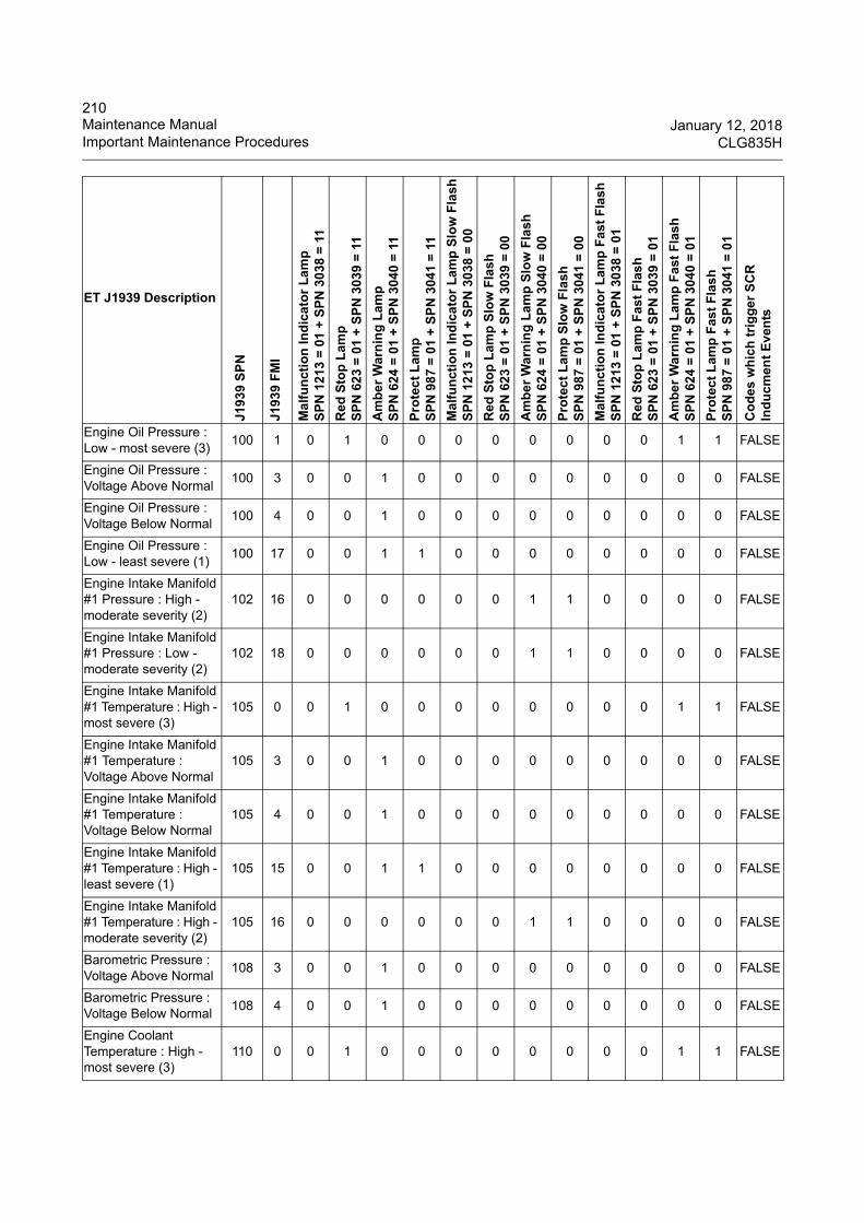
210Maintenance Manual January 12, 2018Important Maintenance Procedures CLG835H
Engine Oil Pressure : Low - most severe (3)
100 1 0 1 0 0 0 0 0 0 0 0 1 1 FALSE
Engine Oil Pressure : Voltage Above Normal
100 3 0 0 1 0 0 0 0 0 0 0 0 0 FALSE
Engine Oil Pressure : Voltage Below Normal
100 4 0 0 1 0 0 0 0 0 0 0 0 0 FALSE
Engine Oil Pressure : Low - least severe (1)
100 17 0 0 1 1 0 0 0 0 0 0 0 0 FALSE
Engine Intake Manifold #1 Pressure : High - moderate severity (2)
102 16 0 0 0 0 0 0 1 1 0 0 0 0 FALSE
Engine Intake Manifold #1 Pressure : Low - moderate severity (2)
102 18 0 0 0 0 0 0 1 1 0 0 0 0 FALSE
Engine Intake Manifold #1 Temperature : High - most severe (3)
105 0 0 1 0 0 0 0 0 0 0 0 1 1 FALSE
Engine Intake Manifold #1 Temperature : Voltage Above Normal
105 3 0 0 1 0 0 0 0 0 0 0 0 0 FALSE
Engine Intake Manifold #1 Temperature : Voltage Below Normal
105 4 0 0 1 0 0 0 0 0 0 0 0 0 FALSE
Engine Intake Manifold #1 Temperature : High - least severe (1)
105 15 0 0 1 1 0 0 0 0 0 0 0 0 FALSE
Engine Intake Manifold #1 Temperature : High - moderate severity (2)
105 16 0 0 0 0 0 0 1 1 0 0 0 0 FALSE
Barometric Pressure : Voltage Above Normal
108 3 0 0 1 0 0 0 0 0 0 0 0 0 FALSE
Barometric Pressure : Voltage Below Normal
108 4 0 0 1 0 0 0 0 0 0 0 0 0 FALSE
Engine Coolant Temperature : High - most severe (3)
110 0 0 1 0 0 0 0 0 0 0 0 1 1 FALSE
ET J1939 Description
J193
9 S
PN
J193
9 F
MI
Ma
lfu
nct
ion
Ind
ica
tor
La
mp
SP
N 1
213
= 0
1 +
SP
N 3
038
= 1
1
Red
Sto
p L
amp
SP
N 6
23
= 0
1 +
SP
N 3
039
= 1
1
Am
be
r W
arn
ing
La
mp
SP
N 6
24
= 0
1 +
SP
N 3
040
= 1
1
Pro
tec
t L
amp
SP
N 9
87
= 0
1 +
SP
N 3
041
= 1
1
Ma
lfu
nct
ion
Ind
ica
tor
La
mp
Slo
w F
lash
SP
N 1
213
= 0
1 +
SP
N 3
038
= 0
0
Red
Sto
p L
amp
Slo
w F
lash
SP
N 6
23
= 0
1 +
SP
N 3
039
= 0
0
Am
be
r W
arn
ing
La
mp
Slo
w F
lash
SP
N 6
24
= 0
1 +
SP
N 3
040
= 0
0
Pro
tec
t L
amp
Slo
w F
lash
SP
N 9
87
= 0
1 +
SP
N 3
041
= 0
0
Ma
lfu
nct
ion
Ind
ica
tor
La
mp
Fas
t F
lash
SP
N 1
213
= 0
1 +
SP
N 3
038
= 0
1
Red
Sto
p L
amp
Fas
t F
las
hS
PN
62
3 =
01
+ S
PN
303
9 =
01
Am
be
r W
arn
ing
La
mp
Fas
t F
lash
SP
N 6
24
= 0
1 +
SP
N 3
040
= 0
1
Pro
tec
t L
amp
Fas
t F
las
hS
PN
98
7 =
01
+ S
PN
304
1 =
01
Co
des
wh
ich
tri
gg
er S
CR
In
du
cmen
t E
ven
ts

211January 12, 2018 Maintenance ManualCLG835H Important Maintenance Procedures
Engine Coolant Temperature : Voltage Above Normal
110 3 0 0 1 0 0 0 0 0 0 0 0 0 FALSE
Engine Coolant Temperature : Voltage Below Normal
110 4 0 0 1 0 0 0 0 0 0 0 0 0 FALSE
Engine Coolant Temperature : High - least severe (1)
110 15 0 0 1 1 0 0 0 0 0 0 0 0 FALSE
Engine Coolant Temperature : High - moderate severity (2)
110 16 0 0 0 0 0 0 1 1 0 0 0 0 FALSE
Number Of ECU Resets : High - most severe (3)
152 0 0 0 0 0 0 0 0 0 0 0 0 0 FALSE
Number Of ECU Resets : Low - most severe (3)
152 1 0 0 0 0 0 0 0 0 0 0 0 0 FALSE
Number Of ECU Resets : Erratic, Intermittent, or Incorrect
152 2 0 0 0 0 0 0 0 0 0 0 0 0 FALSE
Number Of ECU Resets : Voltage Above Normal
152 3 0 0 0 0 0 0 0 0 0 0 0 0 FALSE
Number Of ECU Resets : Voltage Below Normal
152 4 0 0 0 0 0 0 0 0 0 0 0 0 FALSE
Number Of ECU Resets : Current Below Normal
152 5 0 0 0 0 0 0 0 0 0 0 0 0 FALSE
Number Of ECU Resets : Current Above Normal
152 6 0 0 0 0 0 0 0 0 0 0 0 0 FALSE
ET J1939 Description
J193
9 S
PN
J193
9 F
MI
Ma
lfu
nct
ion
Ind
ica
tor
La
mp
SP
N 1
213
= 0
1 +
SP
N 3
038
= 1
1
Red
Sto
p L
amp
SP
N 6
23
= 0
1 +
SP
N 3
039
= 1
1
Am
be
r W
arn
ing
La
mp
SP
N 6
24
= 0
1 +
SP
N 3
040
= 1
1
Pro
tec
t L
amp
SP
N 9
87
= 0
1 +
SP
N 3
041
= 1
1
Ma
lfu
nct
ion
Ind
ica
tor
La
mp
Slo
w F
lash
SP
N 1
213
= 0
1 +
SP
N 3
038
= 0
0
Red
Sto
p L
amp
Slo
w F
lash
SP
N 6
23
= 0
1 +
SP
N 3
039
= 0
0
Am
be
r W
arn
ing
La
mp
Slo
w F
lash
SP
N 6
24
= 0
1 +
SP
N 3
040
= 0
0
Pro
tec
t L
amp
Slo
w F
lash
SP
N 9
87
= 0
1 +
SP
N 3
041
= 0
0
Ma
lfu
nct
ion
Ind
ica
tor
La
mp
Fas
t F
lash
SP
N 1
213
= 0
1 +
SP
N 3
038
= 0
1
Red
Sto
p L
amp
Fas
t F
las
hS
PN
62
3 =
01
+ S
PN
303
9 =
01
Am
be
r W
arn
ing
La
mp
Fas
t F
lash
SP
N 6
24
= 0
1 +
SP
N 3
040
= 0
1
Pro
tec
t L
amp
Fas
t F
las
hS
PN
98
7 =
01
+ S
PN
304
1 =
01
Co
des
wh
ich
tri
gg
er S
CR
In
du
cmen
t E
ven
ts
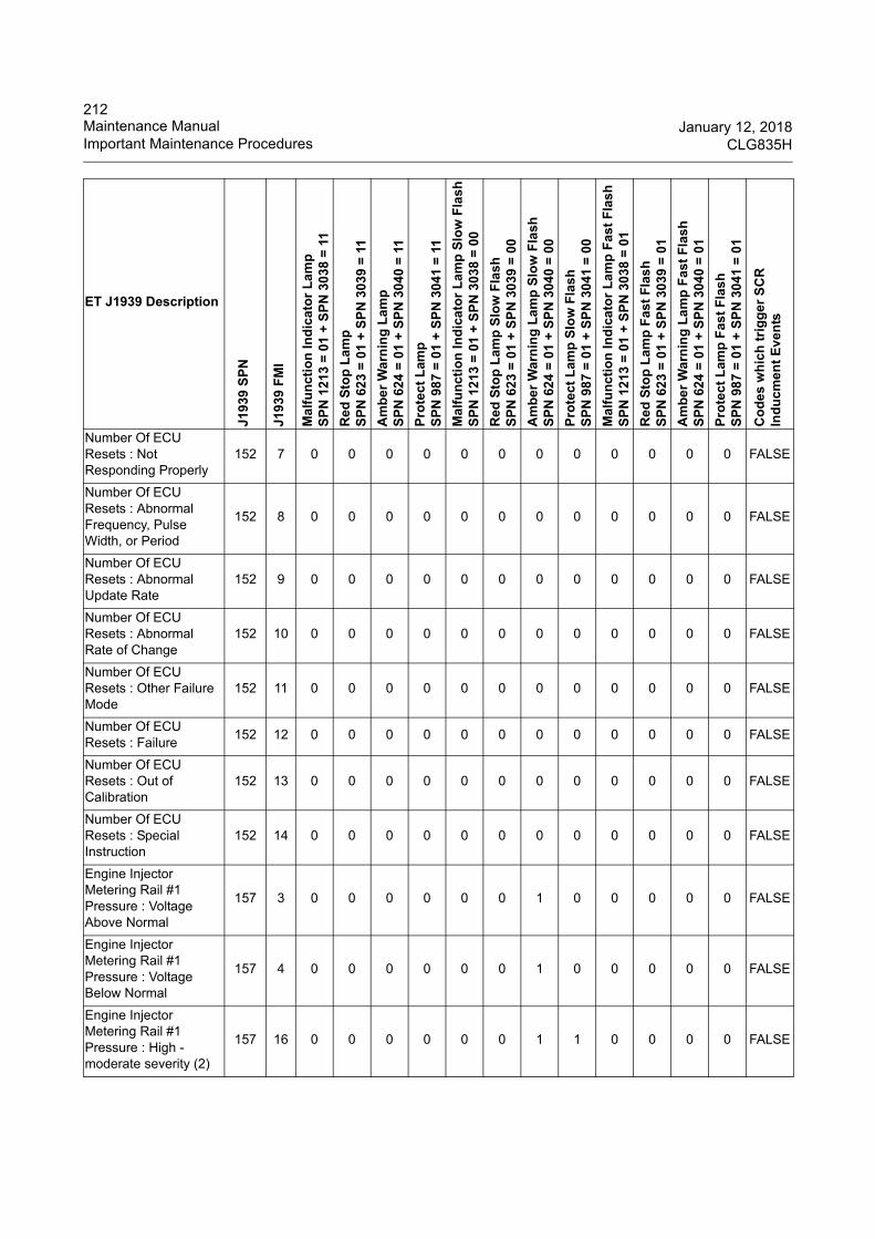
212Maintenance Manual January 12, 2018Important Maintenance Procedures CLG835H
Number Of ECU Resets : Not Responding Properly
152 7 0 0 0 0 0 0 0 0 0 0 0 0 FALSE
Number Of ECU Resets : Abnormal Frequency, Pulse Width, or Period
152 8 0 0 0 0 0 0 0 0 0 0 0 0 FALSE
Number Of ECU Resets : Abnormal Update Rate
152 9 0 0 0 0 0 0 0 0 0 0 0 0 FALSE
Number Of ECU Resets : Abnormal Rate of Change
152 10 0 0 0 0 0 0 0 0 0 0 0 0 FALSE
Number Of ECU Resets : Other Failure Mode
152 11 0 0 0 0 0 0 0 0 0 0 0 0 FALSE
Number Of ECU Resets : Failure
152 12 0 0 0 0 0 0 0 0 0 0 0 0 FALSE
Number Of ECU Resets : Out of Calibration
152 13 0 0 0 0 0 0 0 0 0 0 0 0 FALSE
Number Of ECU Resets : Special Instruction
152 14 0 0 0 0 0 0 0 0 0 0 0 0 FALSE
Engine Injector Metering Rail #1 Pressure : Voltage Above Normal
157 3 0 0 0 0 0 0 1 0 0 0 0 0 FALSE
Engine Injector Metering Rail #1 Pressure : Voltage Below Normal
157 4 0 0 0 0 0 0 1 0 0 0 0 0 FALSE
Engine Injector Metering Rail #1 Pressure : High - moderate severity (2)
157 16 0 0 0 0 0 0 1 1 0 0 0 0 FALSE
ET J1939 Description
J193
9 S
PN
J193
9 F
MI
Ma
lfu
nct
ion
Ind
ica
tor
La
mp
SP
N 1
213
= 0
1 +
SP
N 3
038
= 1
1
Red
Sto
p L
amp
SP
N 6
23
= 0
1 +
SP
N 3
039
= 1
1
Am
be
r W
arn
ing
La
mp
SP
N 6
24
= 0
1 +
SP
N 3
040
= 1
1
Pro
tec
t L
amp
SP
N 9
87
= 0
1 +
SP
N 3
041
= 1
1
Ma
lfu
nct
ion
Ind
ica
tor
La
mp
Slo
w F
lash
SP
N 1
213
= 0
1 +
SP
N 3
038
= 0
0
Red
Sto
p L
amp
Slo
w F
lash
SP
N 6
23
= 0
1 +
SP
N 3
039
= 0
0
Am
be
r W
arn
ing
La
mp
Slo
w F
lash
SP
N 6
24
= 0
1 +
SP
N 3
040
= 0
0
Pro
tec
t L
amp
Slo
w F
lash
SP
N 9
87
= 0
1 +
SP
N 3
041
= 0
0
Ma
lfu
nct
ion
Ind
ica
tor
La
mp
Fas
t F
lash
SP
N 1
213
= 0
1 +
SP
N 3
038
= 0
1
Red
Sto
p L
amp
Fas
t F
las
hS
PN
62
3 =
01
+ S
PN
303
9 =
01
Am
be
r W
arn
ing
La
mp
Fas
t F
lash
SP
N 6
24
= 0
1 +
SP
N 3
040
= 0
1
Pro
tec
t L
amp
Fas
t F
las
hS
PN
98
7 =
01
+ S
PN
304
1 =
01
Co
des
wh
ich
tri
gg
er S
CR
In
du
cmen
t E
ven
ts

213January 12, 2018 Maintenance ManualCLG835H Important Maintenance Procedures
Engine Injector Metering Rail #1 Pressure : Low - moderate severity (2)
157 18 0 0 0 0 0 0 1 1 0 0 0 0 FALSE
Battery Potential / Power Input #1 : Voltage Above Normal
168 3 0 0 1 0 0 0 0 0 0 0 0 0 FALSE
Battery Potential / Power Input #1 : Voltage Below Normal
168 4 0 0 1 0 0 0 0 0 0 0 0 0 FALSE
Engine Air Inlet Temperature : Voltage Above Normal
172 3 0 0 1 0 0 0 0 0 0 0 0 0 FALSE
Engine Air Inlet Temperature : Voltage Below Normal
172 4 0 0 1 0 0 0 0 0 0 0 0 0 FALSE
Engine Fuel Temperature 1 : Voltage Above Normal
174 3 0 0 1 0 0 0 0 0 0 0 0 0 FALSE
Engine Fuel Temperature 1 : Voltage Below Normal
174 4 0 0 1 0 0 0 0 0 0 0 0 0 FALSE
Engine Fuel Temperature 1 : High - least severe (1)
174 15 0 0 1 1 0 0 0 0 0 0 0 0 FALSE
Engine Fuel Temperature 1 : High - moderate severity (2)
174 16 0 0 0 0 0 0 1 1 0 0 0 0 FALSE
Engine Speed : High - most severe (3)
190 0 0 1 0 0 0 0 0 0 0 0 1 1 FALSE
Engine Speed : Abnormal Frequency, Pulse Width, or Period
190 8 0 0 1 0 0 0 0 0 0 0 0 0 FALSE
Engine Speed : High - least severe (1)
190 15 0 0 1 1 0 0 0 0 0 0 0 0 FALSE
ET J1939 Description
J193
9 S
PN
J193
9 F
MI
Ma
lfu
nct
ion
Ind
ica
tor
La
mp
SP
N 1
213
= 0
1 +
SP
N 3
038
= 1
1
Red
Sto
p L
amp
SP
N 6
23
= 0
1 +
SP
N 3
039
= 1
1
Am
be
r W
arn
ing
La
mp
SP
N 6
24
= 0
1 +
SP
N 3
040
= 1
1
Pro
tec
t L
amp
SP
N 9
87
= 0
1 +
SP
N 3
041
= 1
1
Ma
lfu
nct
ion
Ind
ica
tor
La
mp
Slo
w F
lash
SP
N 1
213
= 0
1 +
SP
N 3
038
= 0
0
Red
Sto
p L
amp
Slo
w F
lash
SP
N 6
23
= 0
1 +
SP
N 3
039
= 0
0
Am
be
r W
arn
ing
La
mp
Slo
w F
lash
SP
N 6
24
= 0
1 +
SP
N 3
040
= 0
0
Pro
tec
t L
amp
Slo
w F
lash
SP
N 9
87
= 0
1 +
SP
N 3
041
= 0
0
Ma
lfu
nct
ion
Ind
ica
tor
La
mp
Fas
t F
lash
SP
N 1
213
= 0
1 +
SP
N 3
038
= 0
1
Red
Sto
p L
amp
Fas
t F
las
hS
PN
62
3 =
01
+ S
PN
303
9 =
01
Am
be
r W
arn
ing
La
mp
Fas
t F
lash
SP
N 6
24
= 0
1 +
SP
N 3
040
= 0
1
Pro
tec
t L
amp
Fas
t F
las
hS
PN
98
7 =
01
+ S
PN
304
1 =
01
Co
des
wh
ich
tri
gg
er S
CR
In
du
cmen
t E
ven
ts

214Maintenance Manual January 12, 2018Important Maintenance Procedures CLG835H
Engine Exhaust Gas Recirculation Differential Pressure : Voltage Above Normal
411 3 0 0 1 0 0 0 0 0 0 0 0 0 FALSE
Engine Exhaust Gas Recirculation Differential Pressure : Voltage Below Normal
411 4 0 0 1 0 0 0 0 0 0 0 0 0 FALSE
Engine Exhaust Gas Recirculation Differential Pressure : Out of Calibration
411 13 0 0 1 0 0 0 0 0 0 0 0 0 FALSE
Engine Exhaust Gas Recirculation Temperature : Voltage Above Normal
412 3 0 0 1 0 0 0 0 0 0 0 0 0 FALSE
Engine Exhaust Gas Recirculation Temperature : Voltage Below Normal
412 4 0 0 1 0 0 0 0 0 0 0 0 0 FALSE
Engine Exhaust Gas Recirculation Temperature : High - least severe (1)
412 15 0 0 1 1 0 0 0 0 0 0 0 0 FALSE
Engine Exhaust Gas Recirculation Temperature : High - moderate severity (2)
412 16 0 0 0 0 0 0 1 1 0 0 0 0 FALSE
Accelerator pedal 1 low idle switch erratic intermittent or incorrect
558 2 0 0 1 0 0 0 0 0 0 0 0 0 FALSE
Engine Start Enable Device 1 : Current Below Normal
626 5 0 0 0 0 0 0 0 0 0 0 0 0 FALSE
Engine Start Enable Device 1 : Current Above Normal
626 6 0 0 0 0 0 0 0 0 0 0 0 0 FALSE
ET J1939 Description
J193
9 S
PN
J193
9 F
MI
Ma
lfu
nct
ion
Ind
ica
tor
La
mp
SP
N 1
213
= 0
1 +
SP
N 3
038
= 1
1
Red
Sto
p L
amp
SP
N 6
23
= 0
1 +
SP
N 3
039
= 1
1
Am
be
r W
arn
ing
La
mp
SP
N 6
24
= 0
1 +
SP
N 3
040
= 1
1
Pro
tec
t L
amp
SP
N 9
87
= 0
1 +
SP
N 3
041
= 1
1
Ma
lfu
nct
ion
Ind
ica
tor
La
mp
Slo
w F
lash
SP
N 1
213
= 0
1 +
SP
N 3
038
= 0
0
Red
Sto
p L
amp
Slo
w F
lash
SP
N 6
23
= 0
1 +
SP
N 3
039
= 0
0
Am
be
r W
arn
ing
La
mp
Slo
w F
lash
SP
N 6
24
= 0
1 +
SP
N 3
040
= 0
0
Pro
tec
t L
amp
Slo
w F
lash
SP
N 9
87
= 0
1 +
SP
N 3
041
= 0
0
Ma
lfu
nct
ion
Ind
ica
tor
La
mp
Fas
t F
lash
SP
N 1
213
= 0
1 +
SP
N 3
038
= 0
1
Red
Sto
p L
amp
Fas
t F
las
hS
PN
62
3 =
01
+ S
PN
303
9 =
01
Am
be
r W
arn
ing
La
mp
Fas
t F
lash
SP
N 6
24
= 0
1 +
SP
N 3
040
= 0
1
Pro
tec
t L
amp
Fas
t F
las
hS
PN
98
7 =
01
+ S
PN
304
1 =
01
Co
des
wh
ich
tri
gg
er S
CR
In
du
cmen
t E
ven
ts

215January 12, 2018 Maintenance ManualCLG835H Important Maintenance Procedures
Calibration Memory : Erratic, Intermittent, or Incorrect
630 2 0 0 1 0 0 0 0 0 0 0 0 0 FALSE
Engine Timing Sensor : Other Failure Mode
637 11 0 0 1 0 0 0 0 0 0 0 0 0 FALSE
J1939 Network #1 : Abnormal Update Rate
639 9 0 0 0 0 0 0 1 0 0 0 0 0 FALSE
J1939 Network #1 : Special Instruction
639 14 0 0 0 0 0 0 1 0 0 0 0 0 FALSE
Engine Exhaust Back Pressure Regulator Control Command : Current Below Normal
649 5 0 0 1 0 0 0 0 0 0 0 0 0 FALSE
Engine Exhaust Back Pressure Regulator Control Command : Current Above Normal
649 6 0 0 1 0 0 0 0 0 0 0 0 0 FALSE
Engine Exhaust Back Pressure Regulator Control Command : Not Responding Properly
649 7 0 0 0 0 0 0 1 1 0 0 0 0 FALSE
Engine Injector Cylinder #01 : Erratic, Intermittent, or Incorrect
651 2 0 0 0 0 0 0 0 0 0 0 0 0 FALSE
Engine Injector Cylinder #01 : Current Below Normal
651 5 0 0 1 0 0 0 0 0 0 0 0 0 FALSE
Engine Injector Cylinder #01 : Current Above Normal
651 6 0 0 1 0 0 0 0 0 0 0 0 0 FALSE
Engine Injector Cylinder #02 : Erratic, Intermittent, or Incorrect
652 2 0 0 0 0 0 0 0 0 0 0 0 0 FALSE
ET J1939 Description
J193
9 S
PN
J193
9 F
MI
Ma
lfu
nct
ion
Ind
ica
tor
La
mp
SP
N 1
213
= 0
1 +
SP
N 3
038
= 1
1
Red
Sto
p L
amp
SP
N 6
23
= 0
1 +
SP
N 3
039
= 1
1
Am
be
r W
arn
ing
La
mp
SP
N 6
24
= 0
1 +
SP
N 3
040
= 1
1
Pro
tec
t L
amp
SP
N 9
87
= 0
1 +
SP
N 3
041
= 1
1
Ma
lfu
nct
ion
Ind
ica
tor
La
mp
Slo
w F
lash
SP
N 1
213
= 0
1 +
SP
N 3
038
= 0
0
Red
Sto
p L
amp
Slo
w F
lash
SP
N 6
23
= 0
1 +
SP
N 3
039
= 0
0
Am
be
r W
arn
ing
La
mp
Slo
w F
lash
SP
N 6
24
= 0
1 +
SP
N 3
040
= 0
0
Pro
tec
t L
amp
Slo
w F
lash
SP
N 9
87
= 0
1 +
SP
N 3
041
= 0
0
Ma
lfu
nct
ion
Ind
ica
tor
La
mp
Fas
t F
lash
SP
N 1
213
= 0
1 +
SP
N 3
038
= 0
1
Red
Sto
p L
amp
Fas
t F
las
hS
PN
62
3 =
01
+ S
PN
303
9 =
01
Am
be
r W
arn
ing
La
mp
Fas
t F
lash
SP
N 6
24
= 0
1 +
SP
N 3
040
= 0
1
Pro
tec
t L
amp
Fas
t F
las
hS
PN
98
7 =
01
+ S
PN
304
1 =
01
Co
des
wh
ich
tri
gg
er S
CR
In
du
cmen
t E
ven
ts
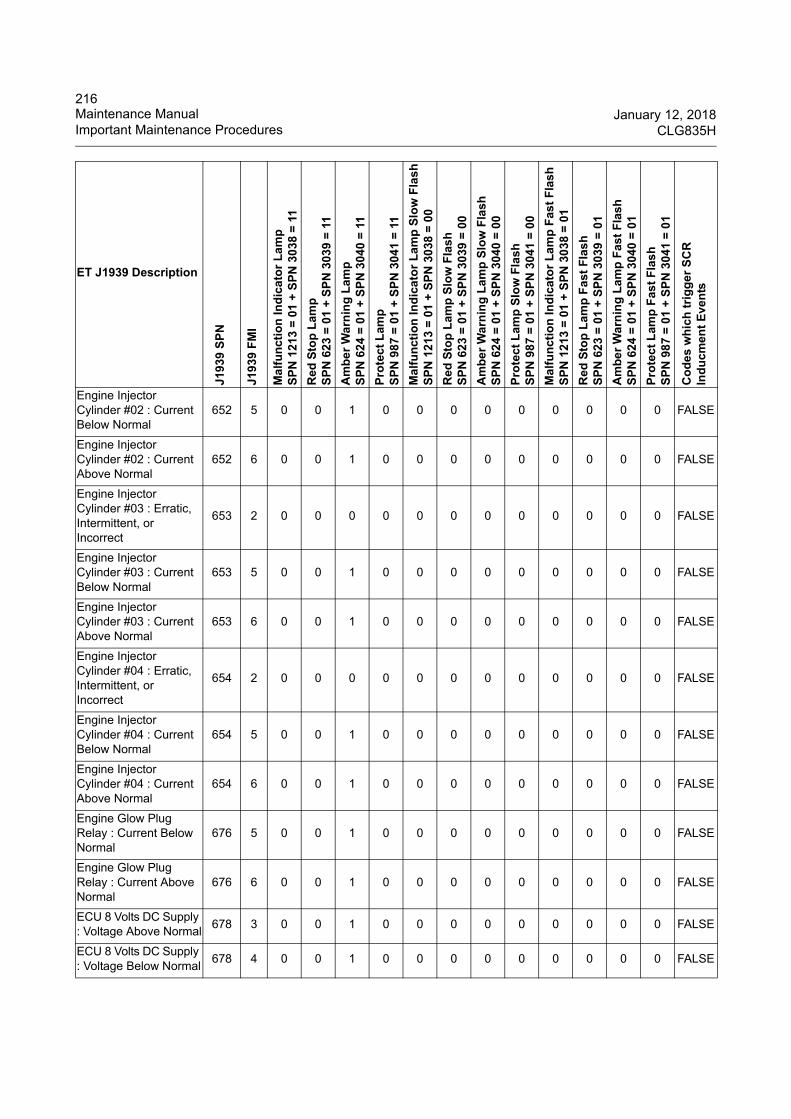
216Maintenance Manual January 12, 2018Important Maintenance Procedures CLG835H
Engine Injector Cylinder #02 : Current Below Normal
652 5 0 0 1 0 0 0 0 0 0 0 0 0 FALSE
Engine Injector Cylinder #02 : Current Above Normal
652 6 0 0 1 0 0 0 0 0 0 0 0 0 FALSE
Engine Injector Cylinder #03 : Erratic, Intermittent, or Incorrect
653 2 0 0 0 0 0 0 0 0 0 0 0 0 FALSE
Engine Injector Cylinder #03 : Current Below Normal
653 5 0 0 1 0 0 0 0 0 0 0 0 0 FALSE
Engine Injector Cylinder #03 : Current Above Normal
653 6 0 0 1 0 0 0 0 0 0 0 0 0 FALSE
Engine Injector Cylinder #04 : Erratic, Intermittent, or Incorrect
654 2 0 0 0 0 0 0 0 0 0 0 0 0 FALSE
Engine Injector Cylinder #04 : Current Below Normal
654 5 0 0 1 0 0 0 0 0 0 0 0 0 FALSE
Engine Injector Cylinder #04 : Current Above Normal
654 6 0 0 1 0 0 0 0 0 0 0 0 0 FALSE
Engine Glow Plug Relay : Current Below Normal
676 5 0 0 1 0 0 0 0 0 0 0 0 0 FALSE
Engine Glow Plug Relay : Current Above Normal
676 6 0 0 1 0 0 0 0 0 0 0 0 0 FALSE
ECU 8 Volts DC Supply : Voltage Above Normal
678 3 0 0 1 0 0 0 0 0 0 0 0 0 FALSE
ECU 8 Volts DC Supply : Voltage Below Normal
678 4 0 0 1 0 0 0 0 0 0 0 0 0 FALSE
ET J1939 Description
J193
9 S
PN
J193
9 F
MI
Ma
lfu
nct
ion
Ind
ica
tor
La
mp
SP
N 1
213
= 0
1 +
SP
N 3
038
= 1
1
Red
Sto
p L
amp
SP
N 6
23
= 0
1 +
SP
N 3
039
= 1
1
Am
be
r W
arn
ing
La
mp
SP
N 6
24
= 0
1 +
SP
N 3
040
= 1
1
Pro
tec
t L
amp
SP
N 9
87
= 0
1 +
SP
N 3
041
= 1
1
Ma
lfu
nct
ion
Ind
ica
tor
La
mp
Slo
w F
lash
SP
N 1
213
= 0
1 +
SP
N 3
038
= 0
0
Red
Sto
p L
amp
Slo
w F
lash
SP
N 6
23
= 0
1 +
SP
N 3
039
= 0
0
Am
be
r W
arn
ing
La
mp
Slo
w F
lash
SP
N 6
24
= 0
1 +
SP
N 3
040
= 0
0
Pro
tec
t L
amp
Slo
w F
lash
SP
N 9
87
= 0
1 +
SP
N 3
041
= 0
0
Ma
lfu
nct
ion
Ind
ica
tor
La
mp
Fas
t F
lash
SP
N 1
213
= 0
1 +
SP
N 3
038
= 0
1
Red
Sto
p L
amp
Fas
t F
las
hS
PN
62
3 =
01
+ S
PN
303
9 =
01
Am
be
r W
arn
ing
La
mp
Fas
t F
lash
SP
N 6
24
= 0
1 +
SP
N 3
040
= 0
1
Pro
tec
t L
amp
Fas
t F
las
hS
PN
98
7 =
01
+ S
PN
304
1 =
01
Co
des
wh
ich
tri
gg
er S
CR
In
du
cmen
t E
ven
ts

217January 12, 2018 Maintenance ManualCLG835H Important Maintenance Procedures
Engine Speed Sensor #2 : Abnormal Frequency, Pulse Width, or Period
723 8 0 0 0 0 0 0 0 0 0 0 0 0 FALSE
Engine Electric Lift Pump for Engine Fuel Supply : Current Below Normal
1075 5 0 0 1 0 0 0 0 0 0 0 0 0 FALSE
Engine Electric Lift Pump for Engine Fuel Supply : Current Above Normal
1075 6 0 0 1 0 0 0 0 0 0 0 0 0 FALSE
Engine Fuel Injection Pump Fuel Control Valve : Current Below Normal
1076 5 0 0 1 0 0 0 0 0 0 0 0 0 FALSE
Engine Fuel Injection Pump Fuel Control Valve : Current Above Normal
1076 6 0 0 1 0 0 0 0 0 0 0 0 0 FALSE
Engine Turbocharger 1 turbine output temperature voltage above normal
1184 3 0 0 1 0 0 0 0 0 0 0 0 0 FALSE
Engine Turbocharger 1 turbine output temperature voltage below normal
1184 4 0 0 1 0 0 0 0 0 0 0 0 0 FALSE
Engine Turbocharger 1 turbine outlet temperature abnormal frequency, pulse width or period
1184 8 0 0 1 0 0 0 0 0 0 0 0 0 FALSE
Engine Turbocharger 1 Wastegate Drive : Current Below Normal
1188 5 0 0 0 0 0 0 1 0 0 0 0 0 FALSE
ET J1939 Description
J193
9 S
PN
J193
9 F
MI
Ma
lfu
nct
ion
Ind
ica
tor
La
mp
SP
N 1
213
= 0
1 +
SP
N 3
038
= 1
1
Red
Sto
p L
amp
SP
N 6
23
= 0
1 +
SP
N 3
039
= 1
1
Am
be
r W
arn
ing
La
mp
SP
N 6
24
= 0
1 +
SP
N 3
040
= 1
1
Pro
tec
t L
amp
SP
N 9
87
= 0
1 +
SP
N 3
041
= 1
1
Ma
lfu
nct
ion
Ind
ica
tor
La
mp
Slo
w F
lash
SP
N 1
213
= 0
1 +
SP
N 3
038
= 0
0
Red
Sto
p L
amp
Slo
w F
lash
SP
N 6
23
= 0
1 +
SP
N 3
039
= 0
0
Am
be
r W
arn
ing
La
mp
Slo
w F
lash
SP
N 6
24
= 0
1 +
SP
N 3
040
= 0
0
Pro
tec
t L
amp
Slo
w F
lash
SP
N 9
87
= 0
1 +
SP
N 3
041
= 0
0
Ma
lfu
nct
ion
Ind
ica
tor
La
mp
Fas
t F
lash
SP
N 1
213
= 0
1 +
SP
N 3
038
= 0
1
Red
Sto
p L
amp
Fas
t F
las
hS
PN
62
3 =
01
+ S
PN
303
9 =
01
Am
be
r W
arn
ing
La
mp
Fas
t F
lash
SP
N 6
24
= 0
1 +
SP
N 3
040
= 0
1
Pro
tec
t L
amp
Fas
t F
las
hS
PN
98
7 =
01
+ S
PN
304
1 =
01
Co
des
wh
ich
tri
gg
er S
CR
In
du
cmen
t E
ven
ts

218Maintenance Manual January 12, 2018Important Maintenance Procedures CLG835H
Engine Turbocharger 1 Wastegate Drive : Current Above Normal
1188 6 0 0 0 0 0 0 1 0 0 0 0 0 FALSE
J1939 Network #2 : Abnormal Update Rate
1231 9 0 0 0 0 0 0 1 0 0 0 0 0 TRUE
J1939 Network #2 : Special Instruction
1231 14 0 0 0 0 0 0 1 0 0 0 0 0 TRUE
J1939 Network #3 : Abnormal Update Rate
1235 9 0 0 0 0 0 0 1 0 0 0 0 0 TRUE
J1939 Network #3 : Special Instruction
1235 14 0 0 0 0 0 0 1 0 0 0 0 0 TRUE
Engine Fuel Leakage 1 : High - most severe (3)
1239 0 0 1 0 0 0 0 0 0 0 0 1 1 FALSE
Catalyst Tank Level : Low - most severe (3)
1761 1 0 1 0 0 0 0 0 0 1 0 1 1 TRUE
Catalyst Tank Level : Failure
1761 12 0 0 0 0 0 0 1 0 0 0 0 0 TRUE
Catalyst Tank Level : Low - least severe (1)
1761 17 1 0 1 1 0 0 0 0 0 0 0 0 TRUE
Catalyst Tank Level : Low - moderate severity (2)
1761 18 0 0 0 0 1 0 1 1 0 0 0 0 TRUE
Engine Exhaust Gas Recirculation (EGR) Mass Flow Rate : Not Responding Properly
2659 7 0 0 0 0 0 0 1 1 0 0 0 0 TRUE
Engine Exhaust Gas Recirculation (EGR) Valve Control : Current Below Normal
2791 5 0 0 1 0 0 0 0 0 0 0 0 0 TRUE
Engine Exhaust Gas Recirculation (EGR) Valve Control : Current Above Normal
2791 6 0 0 1 0 0 0 0 0 0 0 0 0 FALSE
ET J1939 Description
J193
9 S
PN
J193
9 F
MI
Ma
lfu
nct
ion
Ind
ica
tor
La
mp
SP
N 1
213
= 0
1 +
SP
N 3
038
= 1
1
Red
Sto
p L
amp
SP
N 6
23
= 0
1 +
SP
N 3
039
= 1
1
Am
be
r W
arn
ing
La
mp
SP
N 6
24
= 0
1 +
SP
N 3
040
= 1
1
Pro
tec
t L
amp
SP
N 9
87
= 0
1 +
SP
N 3
041
= 1
1
Ma
lfu
nct
ion
Ind
ica
tor
La
mp
Slo
w F
lash
SP
N 1
213
= 0
1 +
SP
N 3
038
= 0
0
Red
Sto
p L
amp
Slo
w F
lash
SP
N 6
23
= 0
1 +
SP
N 3
039
= 0
0
Am
be
r W
arn
ing
La
mp
Slo
w F
lash
SP
N 6
24
= 0
1 +
SP
N 3
040
= 0
0
Pro
tec
t L
amp
Slo
w F
lash
SP
N 9
87
= 0
1 +
SP
N 3
041
= 0
0
Ma
lfu
nct
ion
Ind
ica
tor
La
mp
Fas
t F
lash
SP
N 1
213
= 0
1 +
SP
N 3
038
= 0
1
Red
Sto
p L
amp
Fas
t F
las
hS
PN
62
3 =
01
+ S
PN
303
9 =
01
Am
be
r W
arn
ing
La
mp
Fas
t F
lash
SP
N 6
24
= 0
1 +
SP
N 3
040
= 0
1
Pro
tec
t L
amp
Fas
t F
las
hS
PN
98
7 =
01
+ S
PN
304
1 =
01
Co
des
wh
ich
tri
gg
er S
CR
In
du
cmen
t E
ven
ts

219January 12, 2018 Maintenance ManualCLG835H Important Maintenance Procedures
Engine Exhaust Gas Recirculation (EGR) Valve Control : Not Responding Properly
2791 7 0 0 0 0 0 0 1 1 0 0 0 0 FALSE
Catalyst Tank Temperature : Failure
3031 12 0 0 0 0 0 0 1 0 0 0 0 0 TRUE
Catalyst Tank Temperature : High - moderate severity (2)
3031 16 0 0 0 0 0 0 1 1 0 0 0 0 TRUE
Catalyst Tank Temperature : Low - moderate severity (2)
3031 18 0 0 0 0 0 0 1 1 0 0 0 0 TRUE
Aftertreatment #1 Intake NOx : Current Below Normal
3216 5 0 0 1 0 0 0 0 0 0 0 0 0 TRUE
Aftertreatment #1 Intake NOx : Current Above Normal
3216 6 0 0 1 0 0 0 0 0 0 0 0 0 TRUE
Aftertreatment #1 Intake NOx : Not Responding Properly
3216 7 0 0 0 0 0 0 1 1 0 0 0 0 TRUE
Aftertreatment #1 Intake NOx : Other Failure Mode
3216 11 0 0 1 0 0 0 0 0 0 0 0 0 TRUE
Aftertreatment #1 Intake NOx : Failure
3216 12 0 0 1 0 0 0 0 0 0 0 0 0 TRUE
Aftertreatment #1 Intake O2 : High - moderate severity (2)
3217 16 0 0 0 0 0 0 1 1 0 0 0 0 TRUE
Aftertreatment #1 Outlet NOx : Current Below Normal
3226 5 0 0 1 0 0 0 0 0 0 0 0 0 TRUE
Aftertreatment #1 Outlet NOx : Current Above Normal
3226 6 0 0 1 0 0 0 0 0 0 0 0 0 TRUE
ET J1939 Description
J193
9 S
PN
J193
9 F
MI
Ma
lfu
nct
ion
Ind
ica
tor
La
mp
SP
N 1
213
= 0
1 +
SP
N 3
038
= 1
1
Red
Sto
p L
amp
SP
N 6
23
= 0
1 +
SP
N 3
039
= 1
1
Am
be
r W
arn
ing
La
mp
SP
N 6
24
= 0
1 +
SP
N 3
040
= 1
1
Pro
tec
t L
amp
SP
N 9
87
= 0
1 +
SP
N 3
041
= 1
1
Ma
lfu
nct
ion
Ind
ica
tor
La
mp
Slo
w F
lash
SP
N 1
213
= 0
1 +
SP
N 3
038
= 0
0
Red
Sto
p L
amp
Slo
w F
lash
SP
N 6
23
= 0
1 +
SP
N 3
039
= 0
0
Am
be
r W
arn
ing
La
mp
Slo
w F
lash
SP
N 6
24
= 0
1 +
SP
N 3
040
= 0
0
Pro
tec
t L
amp
Slo
w F
lash
SP
N 9
87
= 0
1 +
SP
N 3
041
= 0
0
Ma
lfu
nct
ion
Ind
ica
tor
La
mp
Fas
t F
lash
SP
N 1
213
= 0
1 +
SP
N 3
038
= 0
1
Red
Sto
p L
amp
Fas
t F
las
hS
PN
62
3 =
01
+ S
PN
303
9 =
01
Am
be
r W
arn
ing
La
mp
Fas
t F
lash
SP
N 6
24
= 0
1 +
SP
N 3
040
= 0
1
Pro
tec
t L
amp
Fas
t F
las
hS
PN
98
7 =
01
+ S
PN
304
1 =
01
Co
des
wh
ich
tri
gg
er S
CR
In
du
cmen
t E
ven
ts
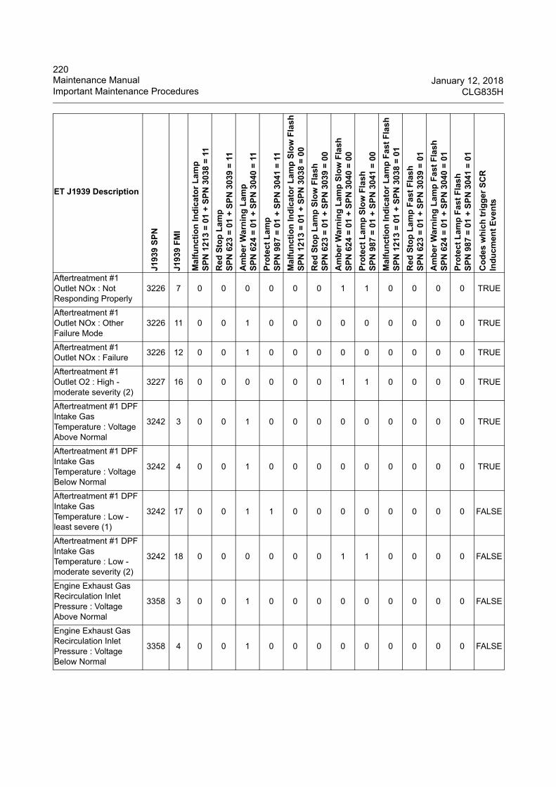
220Maintenance Manual January 12, 2018Important Maintenance Procedures CLG835H
Aftertreatment #1 Outlet NOx : Not Responding Properly
3226 7 0 0 0 0 0 0 1 1 0 0 0 0 TRUE
Aftertreatment #1 Outlet NOx : Other Failure Mode
3226 11 0 0 1 0 0 0 0 0 0 0 0 0 TRUE
Aftertreatment #1 Outlet NOx : Failure
3226 12 0 0 1 0 0 0 0 0 0 0 0 0 TRUE
Aftertreatment #1 Outlet O2 : High - moderate severity (2)
3227 16 0 0 0 0 0 0 1 1 0 0 0 0 TRUE
Aftertreatment #1 DPF Intake Gas Temperature : Voltage Above Normal
3242 3 0 0 1 0 0 0 0 0 0 0 0 0 TRUE
Aftertreatment #1 DPF Intake Gas Temperature : Voltage Below Normal
3242 4 0 0 1 0 0 0 0 0 0 0 0 0 TRUE
Aftertreatment #1 DPF Intake Gas Temperature : Low - least severe (1)
3242 17 0 0 1 1 0 0 0 0 0 0 0 0 FALSE
Aftertreatment #1 DPF Intake Gas Temperature : Low - moderate severity (2)
3242 18 0 0 0 0 0 0 1 1 0 0 0 0 FALSE
Engine Exhaust Gas Recirculation Inlet Pressure : Voltage Above Normal
3358 3 0 0 1 0 0 0 0 0 0 0 0 0 FALSE
Engine Exhaust Gas Recirculation Inlet Pressure : Voltage Below Normal
3358 4 0 0 1 0 0 0 0 0 0 0 0 0 FALSE
ET J1939 Description
J193
9 S
PN
J193
9 F
MI
Ma
lfu
nct
ion
Ind
ica
tor
La
mp
SP
N 1
213
= 0
1 +
SP
N 3
038
= 1
1
Red
Sto
p L
amp
SP
N 6
23
= 0
1 +
SP
N 3
039
= 1
1
Am
be
r W
arn
ing
La
mp
SP
N 6
24
= 0
1 +
SP
N 3
040
= 1
1
Pro
tec
t L
amp
SP
N 9
87
= 0
1 +
SP
N 3
041
= 1
1
Ma
lfu
nct
ion
Ind
ica
tor
La
mp
Slo
w F
lash
SP
N 1
213
= 0
1 +
SP
N 3
038
= 0
0
Red
Sto
p L
amp
Slo
w F
lash
SP
N 6
23
= 0
1 +
SP
N 3
039
= 0
0
Am
be
r W
arn
ing
La
mp
Slo
w F
lash
SP
N 6
24
= 0
1 +
SP
N 3
040
= 0
0
Pro
tec
t L
amp
Slo
w F
lash
SP
N 9
87
= 0
1 +
SP
N 3
041
= 0
0
Ma
lfu
nct
ion
Ind
ica
tor
La
mp
Fas
t F
lash
SP
N 1
213
= 0
1 +
SP
N 3
038
= 0
1
Red
Sto
p L
amp
Fas
t F
las
hS
PN
62
3 =
01
+ S
PN
303
9 =
01
Am
be
r W
arn
ing
La
mp
Fas
t F
lash
SP
N 6
24
= 0
1 +
SP
N 3
040
= 0
1
Pro
tec
t L
amp
Fas
t F
las
hS
PN
98
7 =
01
+ S
PN
304
1 =
01
Co
des
wh
ich
tri
gg
er S
CR
In
du
cmen
t E
ven
ts

221January 12, 2018 Maintenance ManualCLG835H Important Maintenance Procedures
Engine Exhaust Gas Recirculation Inlet Pressure : Out of Calibration
3358 13 0 0 1 0 0 0 0 0 0 0 0 0 FALSE
Aftertreatment #1 DEF Controller : Voltage Above Normal
3360 3 0 0 1 0 0 0 0 0 0 0 0 0 TRUE
Aftertreatment #1 DEF Controller : Voltage Below Normal
3360 4 0 0 1 0 0 0 0 0 0 0 0 0 TRUE
Catalyst Dosing Unit : Voltage Above Normal
3361 3 0 0 0 0 1 0 1 0 0 0 0 0 TRUE
Catalyst Dosing Unit : Current Below Normal
3361 5 0 0 1 0 0 0 0 0 0 0 0 0 TRUE
Catalyst Dosing Unit : Current Above Normal
3361 6 0 0 1 0 0 0 0 0 0 0 0 0 TRUE
Catalyst Dosing Unit : Not responding properly
3361 7 0 0 1 0 0 0 0 0 0 0 0 0 TRUE
Catalyst Tank Heater : Current Below Normal
3363 5 0 0 1 0 0 0 0 0 0 0 0 0 TRUE
Catalyst Tank Heater : Current Above Normal
3363 6 0 0 1 0 0 0 0 0 0 0 0 0 TRUE
Sensor Supply Voltage 1 : Voltage Above Normal
3509 3 0 0 0 0 0 0 1 0 0 0 0 0 FALSE
Sensor Supply Voltage 1 : Voltage Below Normal
3509 4 0 0 0 0 0 0 1 0 0 0 0 0 FALSE
Sensor Supply Voltage 2 : Voltage Above Normal
3510 3 0 0 0 0 0 0 0 0 0 0 0 0 FALSE
Sensor Supply Voltage 2 : Voltage Below Normal
3510 4 0 0 0 0 0 0 0 0 0 0 0 0 FALSE
ET J1939 Description
J193
9 S
PN
J193
9 F
MI
Ma
lfu
nct
ion
Ind
ica
tor
La
mp
SP
N 1
213
= 0
1 +
SP
N 3
038
= 1
1
Red
Sto
p L
amp
SP
N 6
23
= 0
1 +
SP
N 3
039
= 1
1
Am
be
r W
arn
ing
La
mp
SP
N 6
24
= 0
1 +
SP
N 3
040
= 1
1
Pro
tec
t L
amp
SP
N 9
87
= 0
1 +
SP
N 3
041
= 1
1
Ma
lfu
nct
ion
Ind
ica
tor
La
mp
Slo
w F
lash
SP
N 1
213
= 0
1 +
SP
N 3
038
= 0
0
Red
Sto
p L
amp
Slo
w F
lash
SP
N 6
23
= 0
1 +
SP
N 3
039
= 0
0
Am
be
r W
arn
ing
La
mp
Slo
w F
lash
SP
N 6
24
= 0
1 +
SP
N 3
040
= 0
0
Pro
tec
t L
amp
Slo
w F
lash
SP
N 9
87
= 0
1 +
SP
N 3
041
= 0
0
Ma
lfu
nct
ion
Ind
ica
tor
La
mp
Fas
t F
lash
SP
N 1
213
= 0
1 +
SP
N 3
038
= 0
1
Red
Sto
p L
amp
Fas
t F
las
hS
PN
62
3 =
01
+ S
PN
303
9 =
01
Am
be
r W
arn
ing
La
mp
Fas
t F
lash
SP
N 6
24
= 0
1 +
SP
N 3
040
= 0
1
Pro
tec
t L
amp
Fas
t F
las
hS
PN
98
7 =
01
+ S
PN
304
1 =
01
Co
des
wh
ich
tri
gg
er S
CR
In
du
cmen
t E
ven
ts
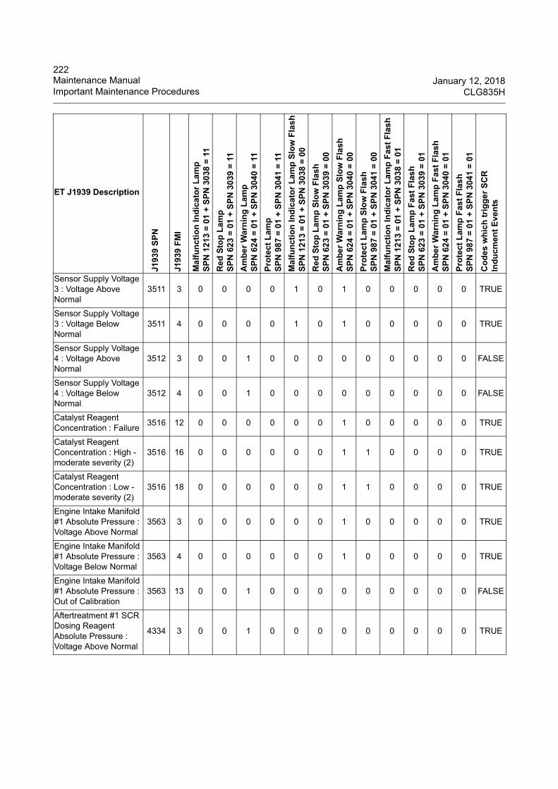
222Maintenance Manual January 12, 2018Important Maintenance Procedures CLG835H
Sensor Supply Voltage 3 : Voltage Above Normal
3511 3 0 0 0 0 1 0 1 0 0 0 0 0 TRUE
Sensor Supply Voltage 3 : Voltage Below Normal
3511 4 0 0 0 0 1 0 1 0 0 0 0 0 TRUE
Sensor Supply Voltage 4 : Voltage Above Normal
3512 3 0 0 1 0 0 0 0 0 0 0 0 0 FALSE
Sensor Supply Voltage 4 : Voltage Below Normal
3512 4 0 0 1 0 0 0 0 0 0 0 0 0 FALSE
Catalyst Reagent Concentration : Failure
3516 12 0 0 0 0 0 0 1 0 0 0 0 0 TRUE
Catalyst Reagent Concentration : High - moderate severity (2)
3516 16 0 0 0 0 0 0 1 1 0 0 0 0 TRUE
Catalyst Reagent Concentration : Low - moderate severity (2)
3516 18 0 0 0 0 0 0 1 1 0 0 0 0 TRUE
Engine Intake Manifold #1 Absolute Pressure : Voltage Above Normal
3563 3 0 0 0 0 0 0 1 0 0 0 0 0 TRUE
Engine Intake Manifold #1 Absolute Pressure : Voltage Below Normal
3563 4 0 0 0 0 0 0 1 0 0 0 0 0 TRUE
Engine Intake Manifold #1 Absolute Pressure : Out of Calibration
3563 13 0 0 1 0 0 0 0 0 0 0 0 0 FALSE
Aftertreatment #1 SCR Dosing Reagent Absolute Pressure : Voltage Above Normal
4334 3 0 0 1 0 0 0 0 0 0 0 0 0 TRUE
ET J1939 Description
J193
9 S
PN
J193
9 F
MI
Ma
lfu
nct
ion
Ind
ica
tor
La
mp
SP
N 1
213
= 0
1 +
SP
N 3
038
= 1
1
Red
Sto
p L
amp
SP
N 6
23
= 0
1 +
SP
N 3
039
= 1
1
Am
be
r W
arn
ing
La
mp
SP
N 6
24
= 0
1 +
SP
N 3
040
= 1
1
Pro
tec
t L
amp
SP
N 9
87
= 0
1 +
SP
N 3
041
= 1
1
Ma
lfu
nct
ion
Ind
ica
tor
La
mp
Slo
w F
lash
SP
N 1
213
= 0
1 +
SP
N 3
038
= 0
0
Red
Sto
p L
amp
Slo
w F
lash
SP
N 6
23
= 0
1 +
SP
N 3
039
= 0
0
Am
be
r W
arn
ing
La
mp
Slo
w F
lash
SP
N 6
24
= 0
1 +
SP
N 3
040
= 0
0
Pro
tec
t L
amp
Slo
w F
lash
SP
N 9
87
= 0
1 +
SP
N 3
041
= 0
0
Ma
lfu
nct
ion
Ind
ica
tor
La
mp
Fas
t F
lash
SP
N 1
213
= 0
1 +
SP
N 3
038
= 0
1
Red
Sto
p L
amp
Fas
t F
las
hS
PN
62
3 =
01
+ S
PN
303
9 =
01
Am
be
r W
arn
ing
La
mp
Fas
t F
lash
SP
N 6
24
= 0
1 +
SP
N 3
040
= 0
1
Pro
tec
t L
amp
Fas
t F
las
hS
PN
98
7 =
01
+ S
PN
304
1 =
01
Co
des
wh
ich
tri
gg
er S
CR
In
du
cmen
t E
ven
ts
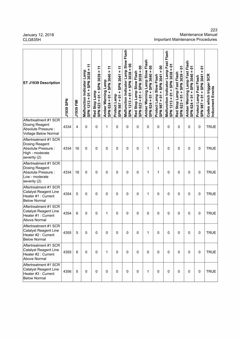
223January 12, 2018 Maintenance ManualCLG835H Important Maintenance Procedures
Aftertreatment #1 SCR Dosing Reagent Absolute Pressure : Voltage Below Normal
4334 4 0 0 1 0 0 0 0 0 0 0 0 0 TRUE
Aftertreatment #1 SCR Dosing Reagent Absolute Pressure : High - moderate severity (2)
4334 16 0 0 0 0 0 0 1 1 0 0 0 0 TRUE
Aftertreatment #1 SCR Dosing Reagent Absolute Pressure : Low - moderate severity (2)
4334 18 0 0 0 0 0 0 1 1 0 0 0 0 TRUE
Aftertreatment #1 SCR Catalyst Reagent Line Heater #1 : Current Below Normal
4354 5 0 0 0 0 0 0 1 0 0 0 0 0 TRUE
Aftertreatment #1 SCR Catalyst Reagent Line Heater #1 : Current Above Normal
4354 6 0 0 1 0 0 0 0 0 0 0 0 0 TRUE
Aftertreatment #1 SCR Catalyst Reagent Line Heater #2 : Current Below Normal
4355 5 0 0 0 0 0 0 1 0 0 0 0 0 TRUE
Aftertreatment #1 SCR Catalyst Reagent Line Heater #2 : Current Above Normal
4355 6 0 0 1 0 0 0 0 0 0 0 0 0 TRUE
Aftertreatment #1 SCR Catalyst Reagent Line Heater #3 : Current Below Normal
4356 5 0 0 0 0 0 0 1 0 0 0 0 0 TRUE
ET J1939 Description
J193
9 S
PN
J193
9 F
MI
Ma
lfu
nct
ion
Ind
ica
tor
La
mp
SP
N 1
213
= 0
1 +
SP
N 3
038
= 1
1
Red
Sto
p L
amp
SP
N 6
23
= 0
1 +
SP
N 3
039
= 1
1
Am
be
r W
arn
ing
La
mp
SP
N 6
24
= 0
1 +
SP
N 3
040
= 1
1
Pro
tec
t L
amp
SP
N 9
87
= 0
1 +
SP
N 3
041
= 1
1
Ma
lfu
nct
ion
Ind
ica
tor
La
mp
Slo
w F
lash
SP
N 1
213
= 0
1 +
SP
N 3
038
= 0
0
Red
Sto
p L
amp
Slo
w F
lash
SP
N 6
23
= 0
1 +
SP
N 3
039
= 0
0
Am
be
r W
arn
ing
La
mp
Slo
w F
lash
SP
N 6
24
= 0
1 +
SP
N 3
040
= 0
0
Pro
tec
t L
amp
Slo
w F
lash
SP
N 9
87
= 0
1 +
SP
N 3
041
= 0
0
Ma
lfu
nct
ion
Ind
ica
tor
La
mp
Fas
t F
lash
SP
N 1
213
= 0
1 +
SP
N 3
038
= 0
1
Red
Sto
p L
amp
Fas
t F
las
hS
PN
62
3 =
01
+ S
PN
303
9 =
01
Am
be
r W
arn
ing
La
mp
Fas
t F
lash
SP
N 6
24
= 0
1 +
SP
N 3
040
= 0
1
Pro
tec
t L
amp
Fas
t F
las
hS
PN
98
7 =
01
+ S
PN
304
1 =
01
Co
des
wh
ich
tri
gg
er S
CR
In
du
cmen
t E
ven
ts
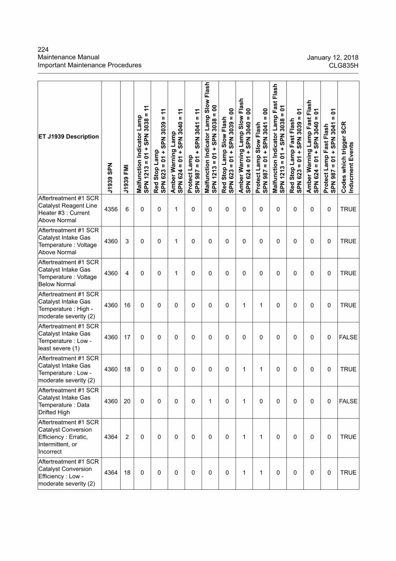
224Maintenance Manual January 12, 2018Important Maintenance Procedures CLG835H
Aftertreatment #1 SCR Catalyst Reagent Line Heater #3 : Current Above Normal
4356 6 0 0 1 0 0 0 0 0 0 0 0 0 TRUE
Aftertreatment #1 SCR Catalyst Intake Gas Temperature : Voltage Above Normal
4360 3 0 0 1 0 0 0 0 0 0 0 0 0 TRUE
Aftertreatment #1 SCR Catalyst Intake Gas Temperature : Voltage Below Normal
4360 4 0 0 1 0 0 0 0 0 0 0 0 0 TRUE
Aftertreatment #1 SCR Catalyst Intake Gas Temperature : High - moderate severity (2)
4360 16 0 0 0 0 0 0 1 1 0 0 0 0 TRUE
Aftertreatment #1 SCR Catalyst Intake Gas Temperature : Low - least severe (1)
4360 17 0 0 0 0 0 0 0 0 0 0 0 0 FALSE
Aftertreatment #1 SCR Catalyst Intake Gas Temperature : Low - moderate severity (2)
4360 18 0 0 0 0 0 0 1 1 0 0 0 0 TRUE
Aftertreatment #1 SCR Catalyst Intake Gas Temperature : Data Drifted High
4360 20 0 0 0 0 1 0 1 0 0 0 0 0 FALSE
Aftertreatment #1 SCR Catalyst Conversion Efficiency : Erratic, Intermittent, or Incorrect
4364 2 0 0 0 0 0 0 1 1 0 0 0 0 TRUE
Aftertreatment #1 SCR Catalyst Conversion Efficiency : Low - moderate severity (2)
4364 18 0 0 0 0 0 0 1 1 0 0 0 0 TRUE
ET J1939 Description
J193
9 S
PN
J193
9 F
MI
Ma
lfu
nct
ion
Ind
ica
tor
La
mp
SP
N 1
213
= 0
1 +
SP
N 3
038
= 1
1
Red
Sto
p L
amp
SP
N 6
23
= 0
1 +
SP
N 3
039
= 1
1
Am
be
r W
arn
ing
La
mp
SP
N 6
24
= 0
1 +
SP
N 3
040
= 1
1
Pro
tec
t L
amp
SP
N 9
87
= 0
1 +
SP
N 3
041
= 1
1
Ma
lfu
nct
ion
Ind
ica
tor
La
mp
Slo
w F
lash
SP
N 1
213
= 0
1 +
SP
N 3
038
= 0
0
Red
Sto
p L
amp
Slo
w F
lash
SP
N 6
23
= 0
1 +
SP
N 3
039
= 0
0
Am
be
r W
arn
ing
La
mp
Slo
w F
lash
SP
N 6
24
= 0
1 +
SP
N 3
040
= 0
0
Pro
tec
t L
amp
Slo
w F
lash
SP
N 9
87
= 0
1 +
SP
N 3
041
= 0
0
Ma
lfu
nct
ion
Ind
ica
tor
La
mp
Fas
t F
lash
SP
N 1
213
= 0
1 +
SP
N 3
038
= 0
1
Red
Sto
p L
amp
Fas
t F
las
hS
PN
62
3 =
01
+ S
PN
303
9 =
01
Am
be
r W
arn
ing
La
mp
Fas
t F
lash
SP
N 6
24
= 0
1 +
SP
N 3
040
= 0
1
Pro
tec
t L
amp
Fas
t F
las
hS
PN
98
7 =
01
+ S
PN
304
1 =
01
Co
des
wh
ich
tri
gg
er S
CR
In
du
cmen
t E
ven
ts
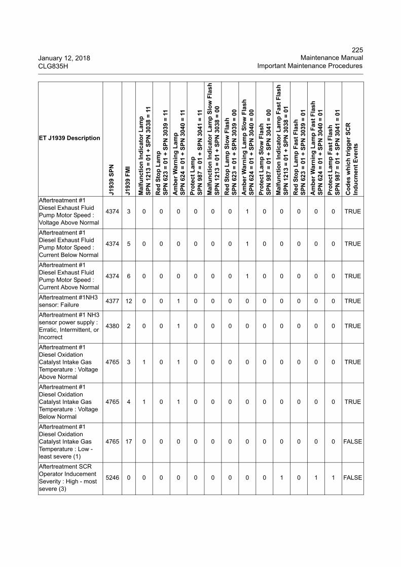
225January 12, 2018 Maintenance ManualCLG835H Important Maintenance Procedures
Aftertreatment #1 Diesel Exhaust Fluid Pump Motor Speed : Voltage Above Normal
4374 3 0 0 0 0 0 0 1 0 0 0 0 0 TRUE
Aftertreatment #1 Diesel Exhaust Fluid Pump Motor Speed : Current Below Normal
4374 5 0 0 0 0 0 0 1 0 0 0 0 0 TRUE
Aftertreatment #1 Diesel Exhaust Fluid Pump Motor Speed : Current Above Normal
4374 6 0 0 0 0 0 0 1 0 0 0 0 0 TRUE
Aftertreatment #1NH3 sensor: Failure
4377 12 0 0 1 0 0 0 0 0 0 0 0 0 TRUE
Aftertreatment #1 NH3 sensor power supply : Erratic, Intermittent, or Incorrect
4380 2 0 0 1 0 0 0 0 0 0 0 0 0 TRUE
Aftertreatment #1 Diesel Oxidation Catalyst Intake Gas Temperature : Voltage Above Normal
4765 3 1 0 1 0 0 0 0 0 0 0 0 0 TRUE
Aftertreatment #1 Diesel Oxidation Catalyst Intake Gas Temperature : Voltage Below Normal
4765 4 1 0 1 0 0 0 0 0 0 0 0 0 TRUE
Aftertreatment #1 Diesel Oxidation Catalyst Intake Gas Temperature : Low - least severe (1)
4765 17 0 0 0 0 0 0 0 0 0 0 0 0 FALSE
Aftertreatment SCR Operator Inducement Severity : High - most severe (3)
5246 0 0 0 0 0 0 0 0 0 1 0 1 1 FALSE
ET J1939 Description
J193
9 S
PN
J193
9 F
MI
Ma
lfu
nct
ion
Ind
ica
tor
La
mp
SP
N 1
213
= 0
1 +
SP
N 3
038
= 1
1
Red
Sto
p L
amp
SP
N 6
23
= 0
1 +
SP
N 3
039
= 1
1
Am
be
r W
arn
ing
La
mp
SP
N 6
24
= 0
1 +
SP
N 3
040
= 1
1
Pro
tec
t L
amp
SP
N 9
87
= 0
1 +
SP
N 3
041
= 1
1
Ma
lfu
nct
ion
Ind
ica
tor
La
mp
Slo
w F
lash
SP
N 1
213
= 0
1 +
SP
N 3
038
= 0
0
Red
Sto
p L
amp
Slo
w F
lash
SP
N 6
23
= 0
1 +
SP
N 3
039
= 0
0
Am
be
r W
arn
ing
La
mp
Slo
w F
lash
SP
N 6
24
= 0
1 +
SP
N 3
040
= 0
0
Pro
tec
t L
amp
Slo
w F
lash
SP
N 9
87
= 0
1 +
SP
N 3
041
= 0
0
Ma
lfu
nct
ion
Ind
ica
tor
La
mp
Fas
t F
lash
SP
N 1
213
= 0
1 +
SP
N 3
038
= 0
1
Red
Sto
p L
amp
Fas
t F
las
hS
PN
62
3 =
01
+ S
PN
303
9 =
01
Am
be
r W
arn
ing
La
mp
Fas
t F
lash
SP
N 6
24
= 0
1 +
SP
N 3
040
= 0
1
Pro
tec
t L
amp
Fas
t F
las
hS
PN
98
7 =
01
+ S
PN
304
1 =
01
Co
des
wh
ich
tri
gg
er S
CR
In
du
cmen
t E
ven
ts

226Maintenance Manual January 12, 2018Important Maintenance Procedures CLG835H
Aftertreatment SCR Operator Inducement Severity : High - least severe (1)
5246 15 1 0 1 1 0 0 0 0 0 0 0 0 FALSE
Aftertreatment SCR Operator Inducement Severity : High - moderate severity (2)
5246 16 0 0 0 0 1 0 1 1 0 0 0 0 FALSE
Low Aftertreatment 1 DOC conversion Efficiency (1)
5298 17 0 0 1 1 0 0 0 0 0 0 0 0 TRUE
Aftertreatment Diesel Exhaust Fluid Dosing Unit Loss of Prime
5392 31 0 0 0 0 0 0 1 1 0 0 0 0 TRUE
High Pressure Common Rail Fuel Pressure Relief Valve : High - most severe (3)
5571 0 0 0 0 0 0 0 1 1 0 0 0 0 FALSE
Aftertreatment #1 Identification : Erratic, Intermittent, or Incorrect
5576 2 0 0 0 0 0 0 1 0 0 0 0 0 FALSE
Aftertreatment #1 Identification : Abnormal Frequency, Pulse Width, or Period
5576 8 0 0 0 0 0 0 1 0 0 0 0 0 FALSE
Aftertreatment #1 Identification : Special Instruction
5576 14 0 0 0 0 0 0 1 0 0 0 0 0 FALSE
Engine Exhaust Back Pressure Regulator Position : Voltage Above Normal
5625 3 0 0 1 0 0 0 0 0 0 0 0 0 FALSE
Engine Exhaust Back Pressure Regulator Position : Voltage Below Normal
5625 4 0 0 1 0 0 0 0 0 0 0 0 0 FALSE
ET J1939 Description
J193
9 S
PN
J193
9 F
MI
Ma
lfu
nct
ion
Ind
ica
tor
La
mp
SP
N 1
213
= 0
1 +
SP
N 3
038
= 1
1
Red
Sto
p L
amp
SP
N 6
23
= 0
1 +
SP
N 3
039
= 1
1
Am
be
r W
arn
ing
La
mp
SP
N 6
24
= 0
1 +
SP
N 3
040
= 1
1
Pro
tec
t L
amp
SP
N 9
87
= 0
1 +
SP
N 3
041
= 1
1
Ma
lfu
nct
ion
Ind
ica
tor
La
mp
Slo
w F
lash
SP
N 1
213
= 0
1 +
SP
N 3
038
= 0
0
Red
Sto
p L
amp
Slo
w F
lash
SP
N 6
23
= 0
1 +
SP
N 3
039
= 0
0
Am
be
r W
arn
ing
La
mp
Slo
w F
lash
SP
N 6
24
= 0
1 +
SP
N 3
040
= 0
0
Pro
tec
t L
amp
Slo
w F
lash
SP
N 9
87
= 0
1 +
SP
N 3
041
= 0
0
Ma
lfu
nct
ion
Ind
ica
tor
La
mp
Fas
t F
lash
SP
N 1
213
= 0
1 +
SP
N 3
038
= 0
1
Red
Sto
p L
amp
Fas
t F
las
hS
PN
62
3 =
01
+ S
PN
303
9 =
01
Am
be
r W
arn
ing
La
mp
Fas
t F
lash
SP
N 6
24
= 0
1 +
SP
N 3
040
= 0
1
Pro
tec
t L
amp
Fas
t F
las
hS
PN
98
7 =
01
+ S
PN
304
1 =
01
Co
des
wh
ich
tri
gg
er S
CR
In
du
cmen
t E
ven
ts

227January 12, 2018 Maintenance ManualCLG835H Important Maintenance Procedures
DPF Active Regeneration Inhibited Due to Low Exhaust Gas Pressure
5629 31 0 0 1 1 0 0 0 0 0 0 0 0 FALSE
Aftertreatment #1 Diesel Exhaust Fluid Dosing Valve Actuator:Current Below Normal
5706 5 0 0 1 0 0 0 0 0 0 0 0 0 TRUE
Aftertreatment #1 SCR Catalyst Reagent Pump Heater : Current Above Normal
5706 6 0 0 1 0 0 0 0 0 0 0 0 0 TRUE
Engine Exhaust Nox Level Sensor Power Supply : Other Failure Mode
5758 11 0 0 1 0 0 0 0 0 0 0 0 0 TRUE
Aftertreatment #1 Outlet #1 Nox level Sensor Power Supply : Other Failure Mode
5759 11 0 0 1 0 0 0 0 0 0 0 0 0 TRUE
Aftertreatment #1 DEF Control Module Relay Control : Current Below Normal
5965 5 0 0 0 0 0 0 1 0 0 0 0 0 TRUE
Aftertreatment #1 DEF Control Module Relay Control : Current Above Normal
5965 6 0 0 0 0 0 0 1 0 0 0 0 0 TRUE
Aftertreatment #1 DEF Control Module Power Supply : Current Below Normal
5966 5 0 0 0 0 0 0 1 0 0 0 0 0 FALSE
Aftertreatment #1 DEF Control Module Power Supply : Current Above Normal
5966 6 0 0 0 0 0 0 1 0 0 0 0 0 FALSE
ET J1939 Description
J193
9 S
PN
J193
9 F
MI
Ma
lfu
nct
ion
Ind
ica
tor
La
mp
SP
N 1
213
= 0
1 +
SP
N 3
038
= 1
1
Red
Sto
p L
amp
SP
N 6
23
= 0
1 +
SP
N 3
039
= 1
1
Am
be
r W
arn
ing
La
mp
SP
N 6
24
= 0
1 +
SP
N 3
040
= 1
1
Pro
tec
t L
amp
SP
N 9
87
= 0
1 +
SP
N 3
041
= 1
1
Ma
lfu
nct
ion
Ind
ica
tor
La
mp
Slo
w F
lash
SP
N 1
213
= 0
1 +
SP
N 3
038
= 0
0
Red
Sto
p L
amp
Slo
w F
lash
SP
N 6
23
= 0
1 +
SP
N 3
039
= 0
0
Am
be
r W
arn
ing
La
mp
Slo
w F
lash
SP
N 6
24
= 0
1 +
SP
N 3
040
= 0
0
Pro
tec
t L
amp
Slo
w F
lash
SP
N 9
87
= 0
1 +
SP
N 3
041
= 0
0
Ma
lfu
nct
ion
Ind
ica
tor
La
mp
Fas
t F
lash
SP
N 1
213
= 0
1 +
SP
N 3
038
= 0
1
Red
Sto
p L
amp
Fas
t F
las
hS
PN
62
3 =
01
+ S
PN
303
9 =
01
Am
be
r W
arn
ing
La
mp
Fas
t F
lash
SP
N 6
24
= 0
1 +
SP
N 3
040
= 0
1
Pro
tec
t L
amp
Fas
t F
las
hS
PN
98
7 =
01
+ S
PN
304
1 =
01
Co
des
wh
ich
tri
gg
er S
CR
In
du
cmen
t E
ven
ts
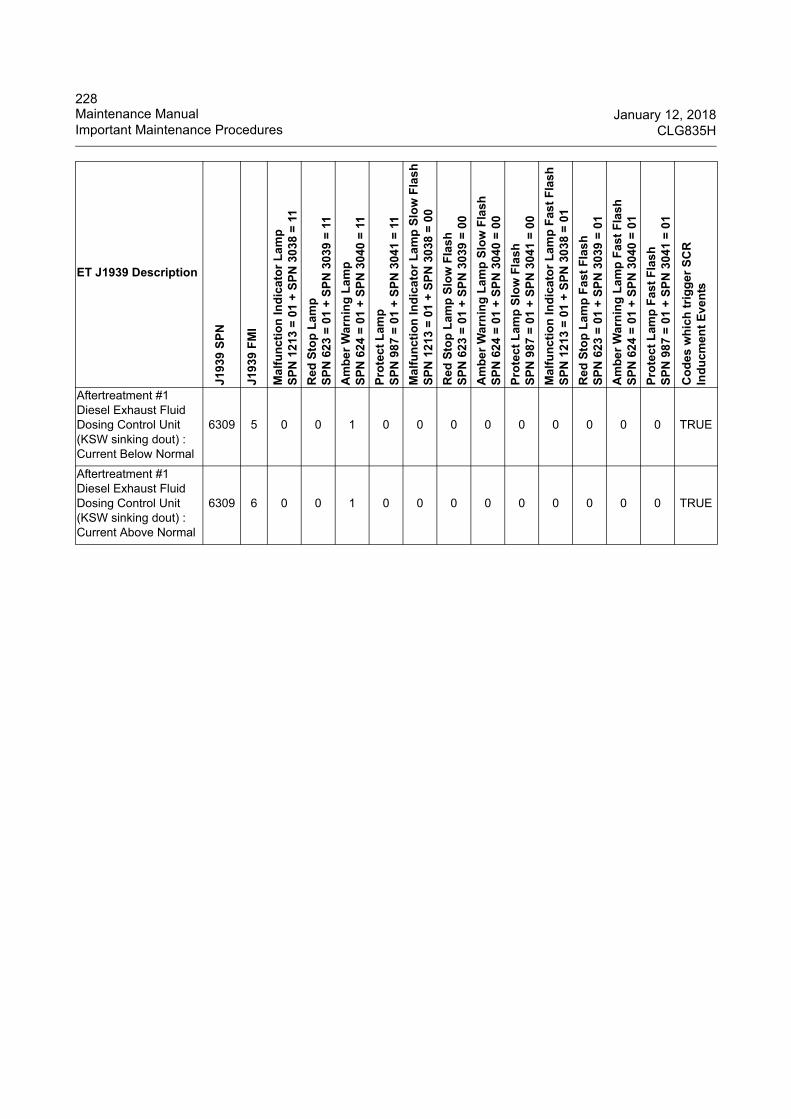
228Maintenance Manual January 12, 2018Important Maintenance Procedures CLG835H
Aftertreatment #1 Diesel Exhaust Fluid Dosing Control Unit (KSW sinking dout) : Current Below Normal
6309 5 0 0 1 0 0 0 0 0 0 0 0 0 TRUE
Aftertreatment #1 Diesel Exhaust Fluid Dosing Control Unit (KSW sinking dout) : Current Above Normal
6309 6 0 0 1 0 0 0 0 0 0 0 0 0 TRUE
ET J1939 Description
J193
9 S
PN
J193
9 F
MI
Ma
lfu
nct
ion
Ind
ica
tor
La
mp
SP
N 1
213
= 0
1 +
SP
N 3
038
= 1
1
Red
Sto
p L
amp
SP
N 6
23
= 0
1 +
SP
N 3
039
= 1
1
Am
be
r W
arn
ing
La
mp
SP
N 6
24
= 0
1 +
SP
N 3
040
= 1
1
Pro
tec
t L
amp
SP
N 9
87
= 0
1 +
SP
N 3
041
= 1
1
Ma
lfu
nct
ion
Ind
ica
tor
La
mp
Slo
w F
lash
SP
N 1
213
= 0
1 +
SP
N 3
038
= 0
0
Red
Sto
p L
amp
Slo
w F
lash
SP
N 6
23
= 0
1 +
SP
N 3
039
= 0
0
Am
be
r W
arn
ing
La
mp
Slo
w F
lash
SP
N 6
24
= 0
1 +
SP
N 3
040
= 0
0
Pro
tec
t L
amp
Slo
w F
lash
SP
N 9
87
= 0
1 +
SP
N 3
041
= 0
0
Ma
lfu
nct
ion
Ind
ica
tor
La
mp
Fas
t F
lash
SP
N 1
213
= 0
1 +
SP
N 3
038
= 0
1
Red
Sto
p L
amp
Fas
t F
las
hS
PN
62
3 =
01
+ S
PN
303
9 =
01
Am
be
r W
arn
ing
La
mp
Fas
t F
lash
SP
N 6
24
= 0
1 +
SP
N 3
040
= 0
1
Pro
tec
t L
amp
Fas
t F
las
hS
PN
98
7 =
01
+ S
PN
304
1 =
01
Co
des
wh
ich
tri
gg
er S
CR
In
du
cmen
t E
ven
ts
229January 12, 2018 INDEXCLG835H
INDEX
A
A/C Panel ........................................................63Accelerator Pedal ............................................77Accumulator of Pilot Oil Supply Valve -- Charge .......................................................................176Air Breather--Clean .......................................163Air Conditioning System ................................196Alternator--maintain ......................................194Application and Specification ..........................40Applications .....................................................40Attachment Cautions .......................................29Auxiliary Control Knob ....................................80Auxiliary Instrument Panel ..............................56Axle Oil Level--Check ...................................165Axle Oil--Replace ..........................................165
B
Backup Alarm System (Optional) ....................93Backup Alarm--Test ......................................204Backup Monitor System (Optional) .................65Battery Disconnect Switch ..............................48Battery, Cable, Battery Disconnect Switch--Replace .........................................................193Battery--Charge ............................................190Battery--Check ..............................................188Battery--Install ...............................................189Battery--Recycle ...........................................193Battery--Store/ Service ..................................193Before Operation .............................................47Before Reuse ................................................119Before Storage ..............................................118Boom Lift Kickout--Adjust ..............................202Brake Operation of the Machine ...................112Brake System ................................................178Breather Filter of Hydraulic Oil Tank--Clean .172Bucket Cutting Edges--Check/Replace .........203Bucket Positioner--Adjust ..............................201Bucket Teeth--Replace .................................203Burn Prevention ..............................................25
C
Cab Air Strainer--Clean and Replace ........... 200Cautions about Machine Maintenance ........... 36Cautions about machine operation ................. 29CE Marking, EMC Directive .............................. 5Central Instrument Panel ................................ 51Centralized Lubrication System ..............94, 185Check Before Starting the Engine ................ 108Combination Switch ........................................ 71Compressor Belt Tension--Check/Adjust/Replace ........................................................ 197Compressor--Maintain .................................. 199Condenser--Clean ........................................ 199Control Device ................................................ 70Coolant Level--Check ................................... 136Coolant--Add ................................................ 137Coolant--Replace .......................................... 139Crushing and Cutting Prevention .................... 25
D
Daily Inspection ............................................ 134Door Lock ....................................................... 88Door Positioner ............................................... 88Downhill Operation ....................................... 112Driving Operation of the Machine ................. 110Driving the Machine ...................................... 120Dumping Operation ...................................... 114During Storage ............................................. 119
E
EC DECLARATION OF CONFORMITY ........... 6Electrical Storm Injury Prevention .................. 28Electrical System .......................................... 188Engine Air Intake System--Check ................. 158Engine Belt--Check ....................................... 158Engine Crankcase Breather Element--Replace ....................................................................... 150Engine Hood ................................................... 91Engine Mounts--Inspect ................................ 151Engine Oil Filter--Replace ............................ 149
230INDEX January 12, 2018
CLG835H
Engine Oil Level--Check ...............................147Engine Oil--Replace ......................................148Engine Start Switch .........................................49Engine Starting .............................................108Engine System ..............................................135Engine Tensioner Bearing and Fan Hub--Check .......................................................................158Engine Valve Lash--Adjust ............................158Evaporator--Check ........................................198Excavating With Bucket ................................116
F
Fan Belt Tension--Check/Adjust ...................158Filter Element of Fuel Water Separator--Replace .......................................................................145Filter Elements of the Air Filter--Replace ......141Fire &Explosion Prevention .............................26Fire Extinguishers and First-aid Kit .................27Front Right Upright Column Instrument Panel 59Front Switch Panel ..........................................57Fuel Filter (In-Line)--Replace ........................152Fuel Filter Element--Replace ........................146Fuel Level--Check .........................................143Fuel Strainer--Clean ......................................144Fuel Tank--Clean ..........................................144Fuel--Add ......................................................143Fuse--Check/ Replace ..................................195
G
Gas-oil Dissociation System--Check .............151General Hazard Information ............................21General Torque Specifications ......................130Grease Level--Check ....................................185Grease--Add .................................................186
H
Hand Pad ........................................................86Horn Switches .................................................71Hydraulic Oil Level--Check ...........................167Hydraulic Oil Tank--Clean .............................173Hydraulic Oil--Add .........................................168Hydraulic Oil--Replace ..................................168Hydraulic System ..........................................167
I
Important Maintenance Procedures ............. 134Important Safety Information ............................ 1Instrument Panels ........................................... 50
K
Key Spare Parts to be Periodically Changed . 39
L
Latch ............................................................... 89Leaving the Machine .................................... 118Lifting the Machine ....................................... 120Lights .............................................................. 86LiuGong Controller Fault Code ..................... 207Lowering the Work Implement with Engine Stopped ........................................................ 118Lubrication Diagram and Intervals ................ 187Lubrication Specifications ............................. 132
M
Machine Operation ....................................... 113Main Components ............................................ 3Main Specifications ......................................... 41Maintenance Guidance ................................. 123Maintenance Interval Schedule .................... 126Maintenance Manual .................................... 123
O
Oil Change Interval and Refill Capacities ..... 132Oil Specifications .......................................... 133Operation during Cold Weather .................... 112Operation Information ................................... 110Operation Manual ........................................... 47Operation Method ......................................... 116Operation Techniques .................................. 110Operator Controls and Instrument Panels ...... 48Operator Station ............................................. 29Other Devices ................................................. 82Other Maintenance ....................................... 201
231January 12, 2018 INDEXCLG835H
P
Pallet Forks ...................................................106Parking ..........................................................117Parking Brake and Service Brake Accumulator Pre-charge Pressure--Check ........................181Parking Brake and Service Brake Accumulators--Charge ..........................................................182Parking Brake Button ......................................77Parking Brake Clearance--Check/Adjust ......179Parking Brake Performance--Inspect ............179Perkins Tier 4F 4cyl Diagnostic Code List ....209Pilot Filter Element--Replace ........................174Pilot Shutoff Lever ...........................................83Post-processing System Description of T4F Engine ...........................................................153Power Train System ......................................159Pre-charge Pressure of Pilot Oil Supply Valve Accumulator-Check .......................................175Preface ..............................................................1Preparation before Operation .......................113
Q
Quick Coupler(Optional) .................................99
R
Radiator Group--Clean ..................................157Rear View Mirrors ...........................................90Refrigerant Level--Check ..............................196Return Oil Filter Element of Hydraulic Oil Tank--Replace .........................................................172Ride Control Accumulator Pre-Charge Pressure--Check ...........................................................183Ride Control Accumulator--Charge ...............184Right Function Panel .......................................62ROPS/FOPS ...................................................29Run-in ...........................................................125
S
Safety Decals and Decal Locations ..................7Safety Information .............................................7Safety Signs ......................................................7Safety Symbol ...................................................7
SCR System--Maintain ................................. 154Scraping Operation ....................................... 115Seat ................................................................ 83Seat Belt ......................................................... 85Seat Belt--Inspect ......................................... 204Serious Polluted Hydraulic Oil--Replace ...... 170Service Brake Pedal ....................................... 76Service Brake Performance--Inspect ............ 178Shift Control Lever .......................................... 73Shoveling ...................................................... 113Shoving Operation ........................................ 115Small Tool Kit ................................................. 86Sound and Vibration ....................................... 38Sound System ................................................ 66Starter Motor--Maintain ................................. 194Steering Column ............................................. 82Steering Frame Lock ................................29, 92Steering Operation of the Machine ............... 111Steering Wheel ............................................... 71Stopping the Machine ................................... 117Storage ......................................................... 118
T
Tire Explosion Prevention ............................... 28Tire Inflation Information ............................... 131Top Switch Panel ............................................ 62Towing Information ....................................... 121Towing Operation ......................................... 115Towing the Machine ..................................... 121Towing with a Running Engine ..................... 122Transmission Oil Filter--Replace .................. 164Transmission Oil Level--Check ..................... 159Transmission Oil--Replace ........................... 161Transmission Primary Filter--Clean .............. 163Transportation Information ........................... 119Transportation of Materials ........................... 114Transportation of the Machine ...................... 119Turning off the Engine .................................. 117Type and Serial Number of the Machine and Parts ................................................................. 4
W
Water and Impurity--Remove ....................... 144Welding Operation ........................................ 205Window Washer Reservoir--Fill .................... 204

232INDEX January 12, 2018
CLG835H
Windows--Clean ............................................204Work Implement Control Lever .......................78