Embed Size (px)
Citation preview

P/N 37390
May 2019
Revision 4
BB3000 OPERATING MANUAL


P/N 37390, Rev. 4 Page A
©2019 CLIMAX or its subsidiaries.
All rights reserved.
Except as expressly provided herein, no part of this manual may be reproduced, copied, transmitted, disseminated, downloaded, or stored in any storage medium, without the express prior written consent of CLIMAX. CLIMAX hereby grants permission to download a single copy of this manual and of any revision hereto onto an electronic storage medium to be viewed and to print one copy of this manual or any revision hereto, pro- vided that such electronic or printed copy of this manual or revision must contain the complete text of this copyright notice and provided further that any unauthorized commercial distribution of this manual or any revision hereto is prohibited.
At CLIMAX, we value your opinion.
For comments or questions about this manual or other CLIMAX documentation, please e-mail [email protected].
For comments or questions about CLIMAX products or services, please call CLIMAX or e-mail [email protected]. For quick and accurate service, please provide your representative with the following:
• Your name • Shipping address • Telephone number • Machine model • Serial number (if applicable) • Date of purchase
CLIMAX World Headquarters
2712 East 2nd Street Newberg, Oregon 97132 USA
Telephone (worldwide): +1-503-538-2815 Toll-free (North America): 1-800-333-8311 Fax: 503-538-7600
H&S Tool World Headquarters
715 Weber Dr. Wadsworth, OH 44281 USA
Telephone: +1-330-336-4550 Fax: 1-330-336-9159 hstool.com
CLIMAX | H&S Tool (UK Headquarters)
Unit 7 Castlehill Industrial Estate Bredbury Industrial Park Horsfield Way
Stockport SK6 2SU, UK Telephone: +44 (0) 161-406-1720
CLIMAX | H&S Tool (European Headquarters)
Am Langen Graben 8 52353 Düren, Germany
Telephone: +49 24-219-1770 E-mail: [email protected]
CLIMAX | H&S Tool (Asia Pacific Head-
quarters)
316 Tanglin Road #02-01 Singapore 247978
Telephone: +65 9647-2289 Fax: +65 6801-0699
CLIMAX | H&S Tool (Middle East Headquarters)
Warehouse #5, Plot: 369 272 Um Sequim Road Al Quoz 4 PO Box 414 084 Dubai, UAE
Telephone: +971 04-321-0328

Page B BB3000 Operating Manual
CLIMAX WORLDWIDE LOCATIONS
P/N 37390, Rev. 4 Page C
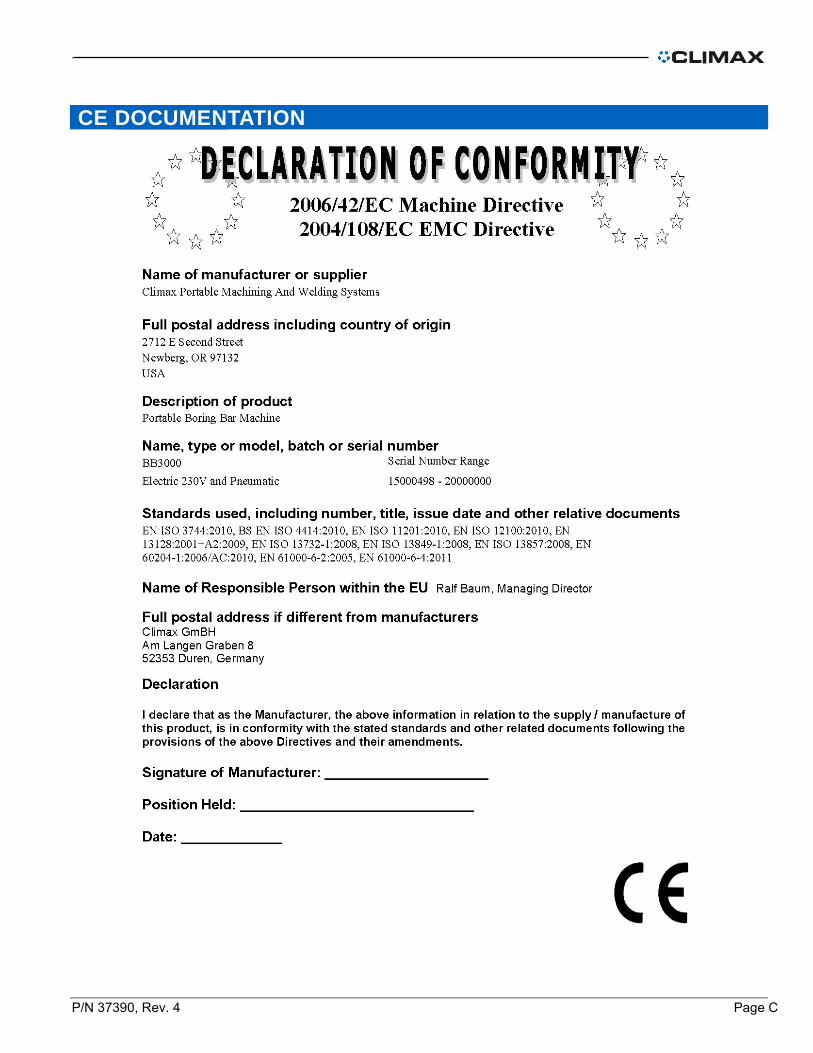
CE DOCUMENTATION

Page D BB3000 Operating Manual
This page is intentionally left blank
P/N 37390, Rev. 4 Page i
TABLE OF CONTENTS
1 OVERVIEW .............................................................................................................................. 1
1.1 LIMITED WARRANTY ..................................................................................................................... 1 1.2 HOW TO USE THIS MANUAL .......................................................................................................... 2 1.3 SAFETY PRECAUTIONS................................................................................................................. 3 1.4 RISK ASSESSMENT AND HAZARD MITIGATION ................................................................................. 4 1.5 RISK ASSESSMENT CHECKLIST ...................................................................................................... 5 1.6 WARNING LABELS ........................................................................................................................ 6
1.6.1 POSITION OF WARNING LABELS ................................................................................................ 7
2 INTRODUCTION ...................................................................................................................... 9
2.1.1 WEIGHTS OF SUB-ASSEMBLIES ............................................................................................... 10 2.2 ABOUT THIS MANUAL .................................................................................................................. 10 2.3 RECEIPT AND INSPECTION .......................................................................................................... 10 2.4 AUDIBLE NOISE LEVELS ............................................................................................................. 10 2.5 INTEGRATED RDU ..................................................................................................................... 11
2.5.1 ELECTRIC MOTORS ............................................................................................................... 11 2.5.2 ELECTRIC CONTROL CIRCUIT .................................................................................................. 11 2.5.3 PNEUMATIC MOTOR ............................................................................................................... 12 2.5.4 BORING BAR ......................................................................................................................... 13
3 SETUP ................................................................................................................................... 14
3.1 RECOMMENDED TOOLS .............................................................................................................. 14 3.2 COMMON SETUPS ...................................................................................................................... 14 3.3 SETUP OVER LONG DISTANCES ................................................................................................... 16 3.4 SETUP CONES ........................................................................................................................... 16
3.4.1 SETUP GUIDELINES ............................................................................................................... 17 3.4.2 CENTERING THE BEARINGS .................................................................................................... 17 3.4.3 SPACERS AND TACK PLATES .................................................................................................. 18 3.4.4 CENTERING THE BAR ............................................................................................................. 19
3.5 ROTATIONAL DRIVE UNIT ............................................................................................................ 19 3.6 SETTING THE FEED RATE ............................................................................................................ 21 3.7 SETTING AUTO FEED .................................................................................................................. 21 3.8 TOOL BITS ................................................................................................................................. 22
4 OPERATION .......................................................................................................................... 23
4.1 HORIZONTAL OR VERTICAL BORING ............................................................................................ 23
5 MAINTENANCE ..................................................................................................................... 25
5.1 APPROVED LUBRICANTS ............................................................................................................. 25 5.2 ROTATIONAL DRIVE UNIT ............................................................................................................ 25 5.3 BORING BAR ASSEMBLY ............................................................................................................. 25 5.4 ELECTRIC MOTOR ...................................................................................................................... 25 5.5 AIR MOTOR ............................................................................................................................... 26
6 STORAGE .............................................................................................................................. 27
APPENDIX A TOOLS AND RECCOMENDED SPARE PARTS ............................................ 29
APPENDIX B EXPLODED VIEWS AND PARTS ................................................................... 31
APPENDIX C MSDS ............................................................................................................... 52
Page ii BB3000 Operating Manual
LIST OF FIGURES
FIGURE 1 P/N 37460 DRIVE ASSY 230 V 2-SPD 780/1500 RPM LABEL PLACEMENT ....................................................................7 FIGURE 2 P/N 72918 WELDON SPINDLE 230V CONTROLLER SIDE LABEL LOCATIONS .......................................................................8 FIGURE 3 P/N 79218 WELDON SPINDLE 230V CONTROLLER TOP LABEL LOCATIONS ........................................................................8 FIGURE 4 - MODEL BB3000 WITH ELECTRIC MOTOR ...................................................................................................................9 FIGURE 5 P/N 79218 CONROLLER BB3000 .......................................................................................................................... 11 FIGURE 6 PNEUMATIC CONDITIONING UNIT P/N 78264 .......................................................................................................... 13 FIGURE 7 – BORING BAR WITH SQUARE HOLES FOR STANDARD TOOL BITS .................................................................................... 13 FIGURE 8 – TYPICAL SETUP WITH AND WITHOUT SPACERS .......................................................................................................... 14 FIGURE 9 - SPACERS ON OPPOSING ENDS ................................................................................................................................ 15 FIGURE 10 - SETUP FOR MACHINING BLIND HOLES .................................................................................................................... 15 FIGURE 11 – AN INTERMEDIATE BEARING SUPPORT GIVES RIGIDITY ............................................................................................. 16 FIGURE 12 - CENTERING THE BEARINGS .................................................................................................................................. 18 FIGURE 13 - SPACERS AND TACK PLATES MOUNTED TO BEARING SUPPORTS .................................................................................. 18 FIGURE 14 - SECURING TACK PLATES TO THE WORK PIECE .......................................................................................................... 19 FIGURE 15 - RDU ASSEMBLY WITH TORQUE SCISSORS AND CLAMP COLLAR................................................................................... 20 FIGURE 16 - SETTING FEED RATE AND DIRECTION ..................................................................................................................... 21 FIGURE 17 – HSS TOOL BITS WITH RECOMMENDED RAKE AND CLEARANCE ANGLES ....................................................................... 22 FIGURE 18 - SQUARE HOLES IN THE BORING BAR ACCEPT TOOL BITS ............................................................................................ 23 FIGURE 19 - A TOOL HEAD ACCEPTS TOOL BITS FOR LARGER IDS ................................................................................................. 23 FIGURE 20 P/N 33544 DRIVE ROTATIONAL ASSY ................................................................................................................... 32 FIGURE 21 P/N 33544 DRIVE ROTATIONAL ASSY ................................................................................................................... 33 FIGURE 22 P/N 33544 DRIVE ROTATIONAL ASSY PARTS LIST .................................................................................................... 34 FIGURE 23 P/N 82117 SET CONE SET UP ............................................................................................................................... 35 FIGURE 24 P/N 33712 PARTS LIST ....................................................................................................................................... 36 FIGURE 25 P/N 36961 MOUNT UNIVERSAL........................................................................................................................... 38 FIGURE 26 P/N DRIVE ASSY 120 V ....................................................................................................................................... 39 FIGURE 27 P/N 37460 DRIVE ASSEMBLY 230V ...................................................................................................................... 40 FIGURE 28 P/N 45494 YOKE ASSEMBLY FOR FACING HEAD FEED TRIP ......................................................................................... 41 FIGURE 29 P/N 31412 FACING HEAD ASSY ............................................................................................................................ 42 FIGURE 30 P/N 31412 FACING HEAD ASSY PARTS LIST ............................................................................................................. 43 FIGURE 31 P/N 37085 PNEUMATIC POWER ASSY ................................................................................................................... 45 FIGURE 32 P/N 78264 PNEUMATIC CONDITIONING UNIT ......................................................................................................... 46 FIGURE 33 P/N 78264 PNEUMATIC CONDITIONING UNIT PARTS LIST .......................................................................................... 47 FIGURE 34 P/N 79218 WELDON CONTROLLER 230V .............................................................................................................. 48 FIGURE 35 P/N 79218 WELDON CONTROLLER 230V .............................................................................................................. 49 FIGURE 36 P/N 79218 WELDON CONTROLLER 230V PARTS LIST ............................................................................................... 50

P/N 37390, Rev. 4 Page iii
LIST OF TABLES
TABLE 1. RISK ASSESSMENT CHECKLIST BEFORE SET-UP ................................................................................................................ 5 TABLE 2. RISK ASSESSMENT CHECKLIST AFTER SET-UP .................................................................................................................. 5 TABLE 3 WARNING LABELS ..................................................................................................................................................... 6 TABLE 4 SUB-ASSEMBLY WEIGHTS .......................................................................................................................................... 10 TABLE 5 BORING BAR BENDING MEASUREMENTS ...................................................................................................................... 16 TABLE 6 RECCOMENDED LUBRICANTS ..................................................................................................................................... 25

Page iv BB3000 Operating Manual
This page intentionally left blank.
P/N 37390, Rev. 4 Page 1
1 OVERVIEW
1.1 Limited Warranty
Climax Portable Machine Tools, Inc. (hereafter referred to as “Climax”) warrants that all new machines are free from defects in materials and workmanship. This warranty is available to the original purchaser for a period of one year after delivery. If the original purchaser finds any defect in materials or workmanship within the warranty period, the original purchaser should contact its factory representative and return the entire machine, shipping prepaid, to the factory. Climax will, at its option, either repair or replace the defective machine at no charge and will return the machine with shipping prepaid.
Climax warrants that all parts are free from defects in materials and workmanship, and that all labor has been performed properly. This warranty is available to the customer purchasing parts or labor for a period of 90 days after delivery of the part or repaired machine or 180 days on used machines and components. If the customer purchasing parts or labor finds any defect in materials or workmanship within the warranty period, the purchaser should contact its factory representative and return the part or repaired machine, shipping prepaid, to the factory. Climax will, at its option, either repair or replace the defective part and/ or correct any defect in the labor performed, both at no charge, and return the part or repaired machine shipping prepaid.
These warranties do not apply to the following:
• Damage after the date of shipment not caused by defects in materials or workmanship
• Damage caused by improper or inadequate machine maintenance • Damage caused by unauthorized machine modification or repair • Damage caused by machine abuse • Damage caused by using the machine beyond its rated capacity
All other warranties, express or implied, including without limitation the warranties of merchantability and fitness for a particular purpose are disclaimed and excluded.
Terms of Sale Be sure to review the terms of sale which appear on the reverse side of your invoice. These terms control and limit your rights with respect to the goods purchased from Climax.
About This Manual Climax provides the contents of this manual in good faith as a guideline to the operator. Climax cannot guarantee that the information contained in this manual is correct for applications other than the application described in this manual. Product specifications are subject to change without notice.
Page 2 BB3000 Operating Manual
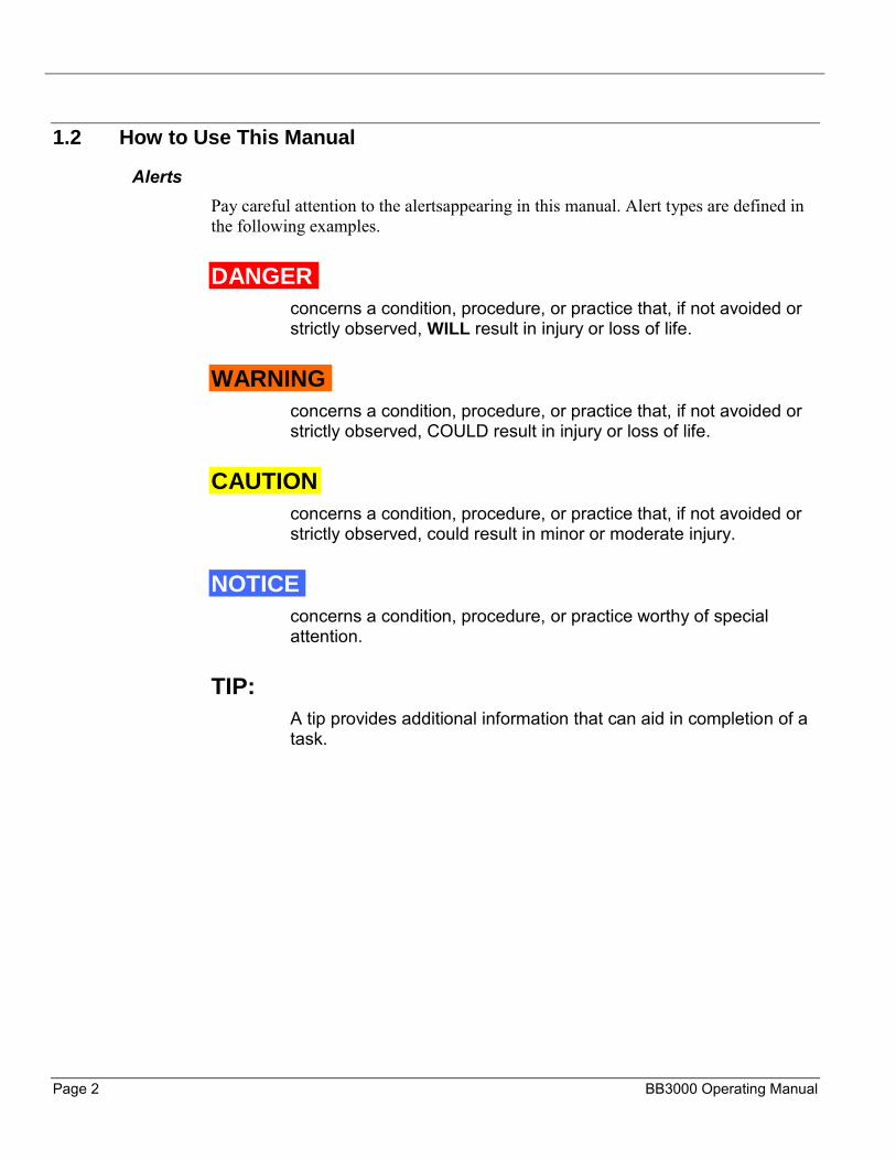
1.2 How to Use This Manual
Alerts Pay careful attention to the alertsappearing in this manual. Alert types are defined in the following examples.
DANGER
concerns a condition, procedure, or practice that, if not avoided or strictly observed, WILL result in injury or loss of life.
WARNING
concerns a condition, procedure, or practice that, if not avoided or strictly observed, COULD result in injury or loss of life.
CAUTION
concerns a condition, procedure, or practice that, if not avoided or strictly observed, could result in minor or moderate injury.
NOTICE
concerns a condition, procedure, or practice worthy of special attention.
TIP:
A tip provides additional information that can aid in completion of a task.
P/N 37390, Rev. 4 Page 3
1.3 Safety Precautions
Climax Portable Machining and Welding Systems leads the way in promoting the safe use of portable machine tools. Safety is a joint effort. You, the machine operator, must do your part by being aware of your work environment and closely following the operating procedures and safety precautions contained in this manual, as well as your employer’s safety guidelines.
Observe the following safety precautions when operating or working around the machine.
Training – Before operating this or any machine tool, you should receive instruction from a qualified trainer. Contact Climax for machine-specific training information.
Intended Use – Use this machine in accordance with the instructions and precautions in this manual. Do not use this machine for any purpose other than its intended use as described in this manual.
Personal Protective Equipment – Always wear the appropriate personal protective gear when operating this or any other machine tool. Eye and ear protection are required when operating or working around the machine. Flame-resistant clothing with long sleeves and legs is recommended when operating the machine, as hot flying chips from the workpiece may burn or cut bare skin.
Work Area – Keep the work area around the machine clear of clutter. Keep all cords and hoses away from the work area when operating the machine. Cords and hoses pose a tripping hazard.
Moving Parts – Except for operating controls, avoid contact with moving parts by hands or tools during machine operation. Secure, hair, clothing, jewelry, and pocket items to prevent them from becoming entangled in moving parts.

Page 4 BB3000 Operating Manual
1.4 Risk assessment and hazard mitigation
Machine Tools are specifically designed to perform precise material-removal operations.
Stationary Machine Tools include lathes and milling machines and are typically found in a machine shop. They are mounted in a fixed location during operation and are considered to be a complete, self-contained machine. Stationary Machine Tools achieve the rigidity needed to accomplish material-removal operations from the structure that is an integral part of the machine tool.
In contrast, Portable Machine Tools are designed for on-site machining applications. They typically attach directly to the workpiece itself, or to an adjacent structure, and achieve their rigidity from the structure to which it is attached. The design intent is that the Portable Machine Tool and the structure attached to it become one complete machine during the material-removal process.
To achieve the intended results and to promote safety, the operator must understand and follow the design intent, set-up, and operation practices that are unique to Portable Machine Tools. The operator must perform an overall review and on-site risk assessment of the intended application. Due to the unique nature of portable machining applications, identifying one or more hazards that must be addressed is typical.
When performing the on-site risk assessment, it is important to consider the Portable Machine Tool and the workpiece as a whole.
P/N 37390, Rev. 4 Page 5
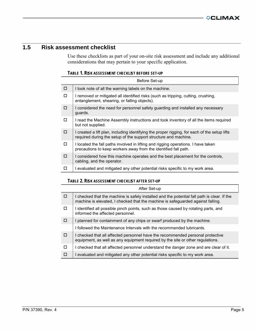
1.5 Risk assessment checklist
Use these checklists as part of your on-site risk assessment and include any additional considerations that may pertain to your specific application.
TABLE 1. RISK ASSESSMENT CHECKLIST BEFORE SET-UP
Before Set-up
I took note of all the warning labels on the machine.
I removed or mitigated all identified risks (such as tripping, cutting, crushing, entanglement, shearing, or falling objects).
I considered the need for personnel safety guarding and installed any necessary guards.
I read the Machine Assembly instructions and took inventory of all the items required but not supplied.
I created a lift plan, including identifying the proper rigging, for each of the setup lifts required during the setup of the support structure and machine.
I located the fall paths involved in lifting and rigging operations. I have taken precautions to keep workers away from the identified fall path.
I considered how this machine operates and the best placement for the controls, cabling, and the operator.
I evaluated and mitigated any other potential risks specific to my work area.
TABLE 2. RISK ASSESSMENT CHECKLIST AFTER SET-UP
After Set-up
I checked that the machine is safely installed and the potential fall path is clear. If the machine is elevated, I checked that the machine is safeguarded against falling.
I identified all possible pinch points, such as those caused by rotating parts, and informed the affected personnel.
I planned for containment of any chips or swarf produced by the machine.
I followed the Maintenance Intervals with the recommended lubricants.
I checked that all affected personnel have the recommended personal protective equipment, as well as any equipment required by the site or other regulations.
I checked that all affected personnel understand the danger zone and are clear of it.
I evaluated and mitigated any other potential risks specific to my work area.

Page 6 BB3000 Operating Manual
1.6 Warning labels
The following warning labels should be on your machine. If any are defaced or missing, contact Climax immediately for replacements.
TABLE 3 WARNING LABELS
P/N 29154 Climax serial number, year and model number plate.
P/N 59044 Label safety warning cirlce read the manual
P/N78741 Label safety warning hand crush
P/N 78742 Label safety warning entanglement of hand, or rotating shaft warning
P/N 78748 Label safety warning eye protection
P/N 78824 Label saftey warning do not expose to water
P/N 80510 label safety warning cutting of fingers, or rotating blade
P/N 78593 Label safety warning electrical shock or electrocution

P/N 37390, Rev. 4 Page 7
1.6.1 Position of warning labels
FIGURE 1 P/N 37460 DRIVE ASSY 230 V 2-SPD 780/1500 RPM LABEL PLACEMENT

Page 8 BB3000 Operating Manual
FIGURE 2 P/N 72918 WELDON SPINDLE 230V CONTROLLER SIDE LABEL LOCATIONS
FIGURE 3 P/N 79218 WELDON SPINDLE 230V CONTROLLER TOP LABEL LOCATIONS
P/N 37390, Rev. 4 Page 9
2 INTRODUCTION
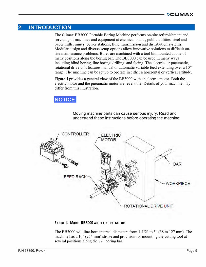
The Climax BB3000 Portable Boring Machine performs on-site refurbishment and servicing of machines and equipment at chemical plants, public utilities, steel and paper mills, mines, power stations, fluid transmission and distribution systems. Modular design and diverse setup options allow innovative solutions to difficult on-site maintenance problems. Bores are machined with a tool bit mounted at one of many positions along the boring bar. The BB3000 can be used in many ways including blind boring, line boring, drilling, and facing. The electric, or pneumatic, rotational drive unit features manual or automatic variable feed extending over a 10” range. The machine can be set up to operate in either a horizontal or vertical attitude.
Figure 4 provides a general view of the BB3000 with an electric motor. Both the electric motor and the pneumatic motor are reversible. Details of your machine may differ from this illustration.
NOTICE
Moving machine parts can cause serious injury. Read and understand these instructions before operating the machine.
FIGURE 4 - MODEL BB3000 WITH ELECTRIC MOTOR
The BB3000 will line-bore internal diameters from 1-1/2" to 5" (38 to 127 mm). The machine has a 10" (254 mm) stroke and provision for mounting the cutting tool at several positions along the 72” boring bar.

Page 10 BB3000 Operating Manual
2.1.1 Weights of sub-assemblies
TABLE 4 SUB-ASSEMBLY WEIGHTS
Sub-assembly Weight
Motor and RDU assembly 59 lbs (27 kg)
Controller 7 lbs (3 kg)
Double Arm Bearing Mount 14 lbs (6 kg)
Universal Bearing Mount 36 lbs (16 kg)
2.2 About this manual
This manual describes the use and maintenance of your Model BB3000 Portable Boring Machine. For maximum safety and performance, read the entire manual before operating this machine. Exploded-view drawings and parts lists are provided toward the back of this manual.
2.3 Receipt and Inspection
Your Climax product was inspected and tested prior to shipment, and packaged for normal shipment conditions. Climax does not guarantee the condition of your machine upon delivery. When you receive your Climax product, perform the following receipt checks.
Inspect the shipping container(s) for damage. Check the contents of the shipping container(s) against the included invoice to make
sure that all components have been shipped. Inspect all components for damage. Contact Climax immediately to report damaged or missing components.
2.4 Audible Noise Levels
Electric Drive Option:
• Declared Sound Power Level is 80 dBA • Declared Operator Sound Pressure Level is 79 dBA • Declared Bystander Sound Pressure Level is 74 dBA
P/N 37390, Rev. 4 Page 11
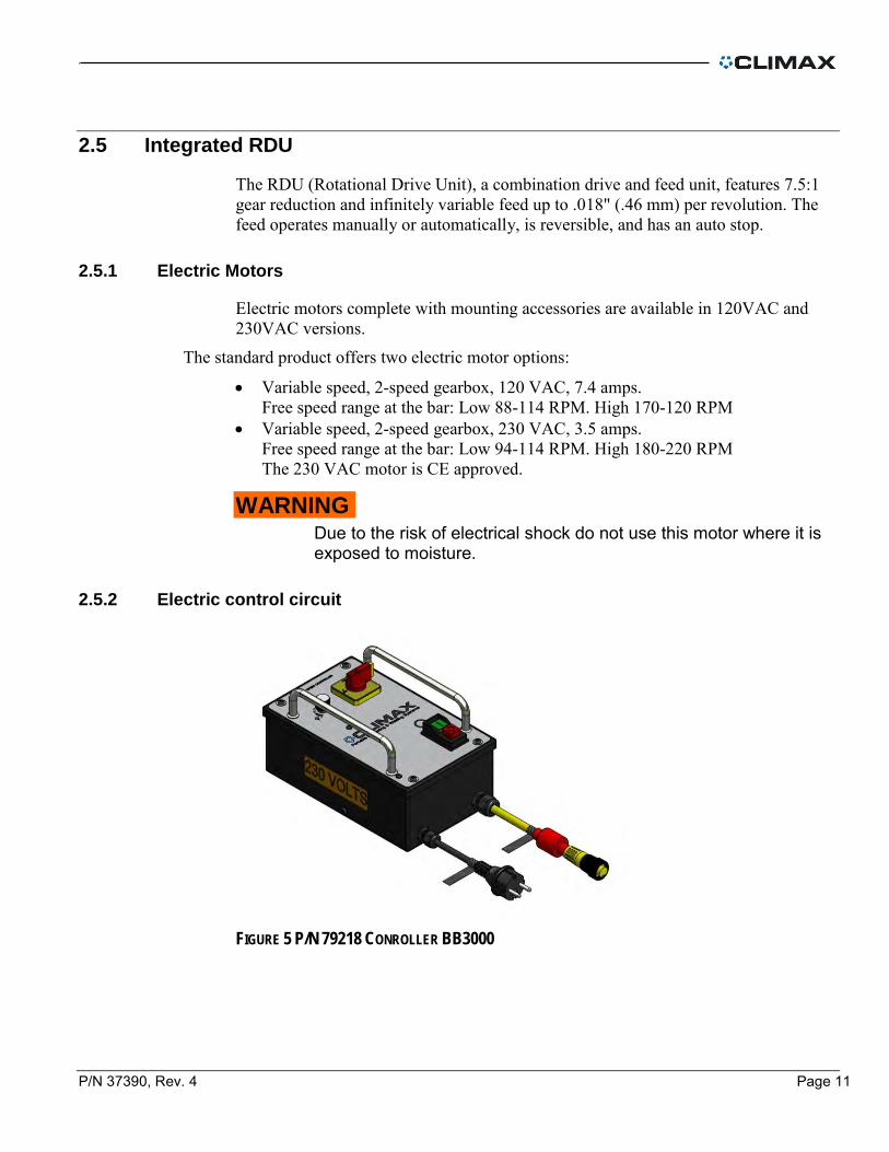
2.5 Integrated RDU
The RDU (Rotational Drive Unit), a combination drive and feed unit, features 7.5:1 gear reduction and infinitely variable feed up to .018" (.46 mm) per revolution. The feed operates manually or automatically, is reversible, and has an auto stop.
2.5.1 Electric Motors
Electric motors complete with mounting accessories are available in 120VAC and 230VAC versions.
The standard product offers two electric motor options:
• Variable speed, 2-speed gearbox, 120 VAC, 7.4 amps. Free speed range at the bar: Low 88-114 RPM. High 170-120 RPM
• Variable speed, 2-speed gearbox, 230 VAC, 3.5 amps. Free speed range at the bar: Low 94-114 RPM. High 180-220 RPM The 230 VAC motor is CE approved.
WARNING Due to the risk of electrical shock do not use this motor where it is exposed to moisture.
2.5.2 Electric control circuit
FIGURE 5 P/N 79218 CONROLLER BB3000
Page 12 BB3000 Operating Manual
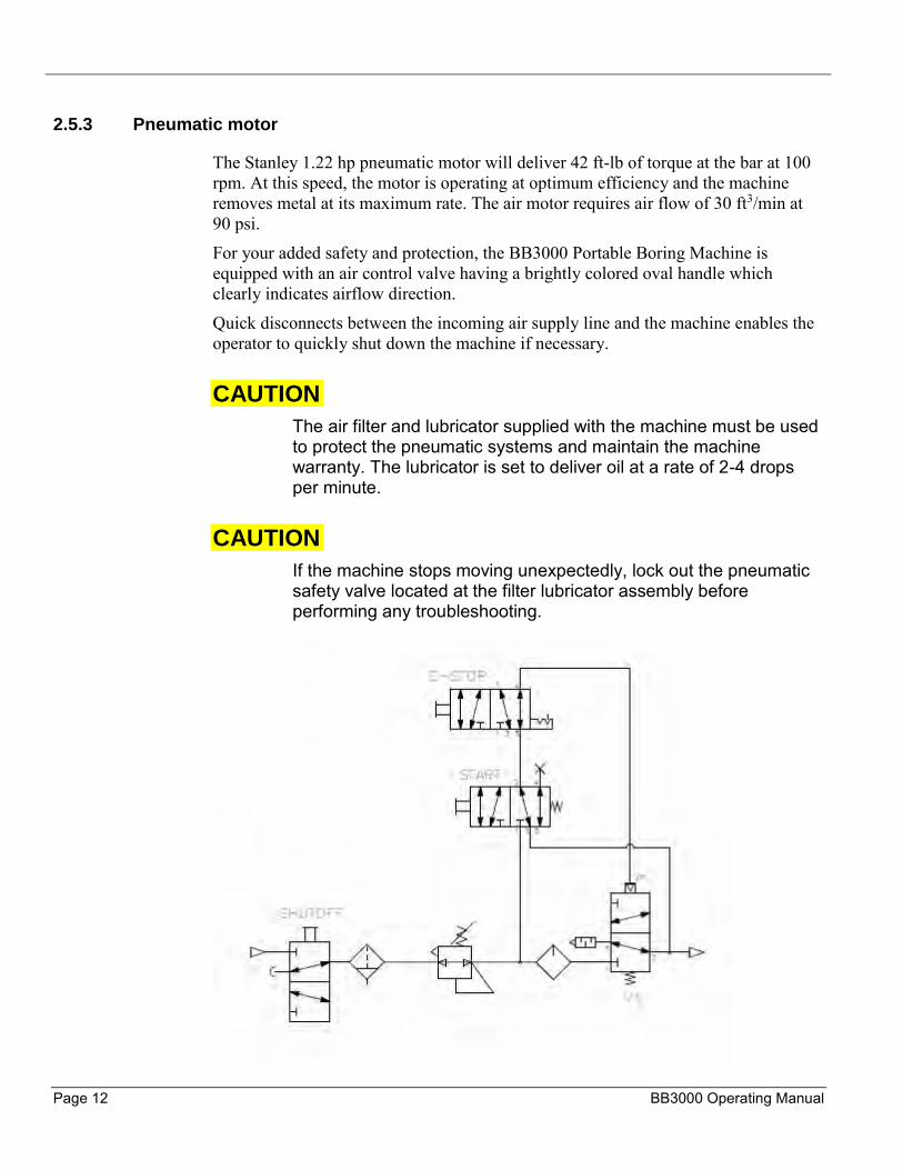
2.5.3 Pneumatic motor
The Stanley 1.22 hp pneumatic motor will deliver 42 ft-lb of torque at the bar at 100 rpm. At this speed, the motor is operating at optimum efficiency and the machine removes metal at its maximum rate. The air motor requires air flow of 30 ft3/min at 90 psi.
For your added safety and protection, the BB3000 Portable Boring Machine is equipped with an air control valve having a brightly colored oval handle which clearly indicates airflow direction.
Quick disconnects between the incoming air supply line and the machine enables the operator to quickly shut down the machine if necessary.
CAUTION
The air filter and lubricator supplied with the machine must be used to protect the pneumatic systems and maintain the machine warranty. The lubricator is set to deliver oil at a rate of 2-4 drops per minute.
CAUTION
If the machine stops moving unexpectedly, lock out the pneumatic safety valve located at the filter lubricator assembly before performing any troubleshooting.

P/N 37390, Rev. 4 Page 13
FIGURE 6 PNEUMATIC CONDITIONING UNIT P/N 78264
2.5.4 Boring bar
The 1-1/4" (31.8 mm) diameter, 72" (1829 mm) long boring bar is chrome plated 1045.
CAUTION
A nicked or gouged boring bar can damage mating parts. Protect the bar and exercise caution when handling or sliding it through the work piece.
Standard bars come in 48, 72, 96 lengths with either 10" or 6" hole spacing. Custom lengths and holes spacing can be ordered on request.
On standard machines, these tool-bit holes are 3/8” square. For the metric version, tool-bit holes are 10mm square.
FIGURE 7 – BORING BAR WITH SQUARE HOLES FOR STANDARD TOOL BITS
TIP
Other bar lengths to suit your special requirements are available by calling Climax toll free at 1-800-333-8311
Self-aligning spherical bearings allow for as much as five degrees out of alignment. They attach to brackets for securing the boring bar to the work during operation. In most applications, spacers and tack plates are welded or clamped in place to facilitate mounting.

Page 14 BB3000 Operating Manual
3 SETUP
3.1 Recommended tools
When setting up the BB3000 Portable Boring Machine, you may want to have the following tools and equipment on hand.
• Dial indicator with magnetic base • Large C-clamps • Portable welder • Rubber mallet • Pedestal or bench grinder
3.2 Common setups
TIP
Before proceeding, make it a habit to check the bar for nicks, cuts, or abrasions. Dress the bar smooth if necessary and Wipe it clean with solvent to remove dirt and chips.
Figure 8 is a typical setup arrangement using spacers at both the left and mid spherical mounts and no spacer at the right mount. This setup provides rigidity for many job configurations. Spherical bearing mounts allow for some self-alignment of the boring bar.
FIGURE 8 – TYPICAL SETUP WITH AND WITHOUT SPACERS

P/N 37390, Rev. 4 Page 15
Jobs where the in-line holes are less than 12” apart overall are set as shown in Figure 9. Spacers clear the work at each end to allow boring all the way through.
FIGURE 9 - SPACERS ON OPPOSING ENDS
A typical setup for machining a blind hole is shown in Figure 10. You will require longer screws for this special setup using 3” spacers.
FIGURE 10 - SETUP FOR MACHINING BLIND HOLES
TIP
You may require longer screws for special setups such as shown in Figure 10 using 3” spacers
Page 16 BB3000 Operating Manual
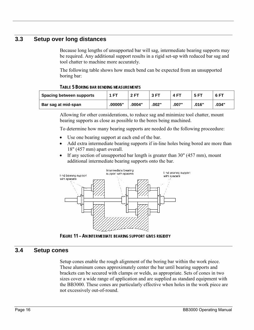
3.3 Setup over long distances
Because long lengths of unsupported bar will sag, intermediate bearing supports may be required. Any additional support results in a rigid set-up with reduced bar sag and tool chatter to machine more accurately.
The following table shows how much bend can be expected from an unsupported boring bar:
TABLE 5 BORING BAR BENDING MEASUREMENTS
Spacing between supports 1 FT 2 FT 3 FT 4 FT 5 FT 6 FT
Bar sag at mid-span .00005" .0004" .002" .007" .016" .034"
Allowing for other considerations, to reduce sag and minimize tool chatter, mount bearing supports as close as possible to the bores being machined.
To determine how many bearing supports are needed do the following proceedure:
• Use one bearing support at each end of the bar. • Add extra intermediate bearing supports if in-line holes being bored are more than
18" (457 mm) apart overall. • If any section of unsupported bar length is greater than 30" (457 mm), mount
additional intermediate bearing supports onto the bar.
FIGURE 11 – AN INTERMEDIATE BEARING SUPPORT GIVES RIGIDITY
3.4 Setup cones
Setup cones enable the rough alignment of the boring bar within the work piece. These aluminum cones approximately center the bar until bearing supports and brackets can be secured with clamps or welds, as appropriate. Sets of cones in two sizes cover a wide range of application and are supplied as standard equipment with the BB3000. These cones are particularly effective when holes in the work piece are not excessively out-of-round.

P/N 37390, Rev. 4 Page 17
Setup cones support the boring bar in place until clamping or welds on tack plates can be completed. Cones are then removed and precise adjustments are made to accurately center the supported bar.
CAUTION
Wooden devices are at risk when placed next to a hot work piece. Allow welded work to cool before setting up the machine.
3.4.1 Setup guidelines
TIP
These guidelines specifically discuss the use of Climax’s standard setup cones. Of course, the same setup principles can be adapted to work just as well with your own improvised rough-aligning methods
1. Clean the work piece with solvent to remove grease, oil, and dirt. 2. Carefully slide the bar through the holes to be bored. 3. Slide a setup cone onto each end of the bar. 4. Slide the standard clamp collar on one end of the bar and lock it in place behind
the setup cone 5. Retract the set screws in the other clamp collar until the tips are below flush. Slide
it on the bar with the setscrew tips facing the back of the cone. 6. Pull on the bar from the other end while guiding both cones snuggly into the bore. 7. Using the 2 setscrews in the clamp collar, push the cone into the bore until there is
no movement in the bar or the cones. 8. Holding both cones close to the bore, lock the second clamp collar on the bar. 9. As shown in Figure 12, center the bearings in the bearing supports:
a. Loosen the hex bolts holding the bearing to the bracket. b. Adjust the four setscrews to center the bearing. c. Tighten the hex bolts.
3.4.2 Centering the bearings

Page 18 BB3000 Operating Manual
FIGURE 12 - CENTERING THE BEARINGS
1. Slide outer bearings onto the bar, one from each end. 2. Mount spacers and tack plates to the bearing supports.
3.4.3 Spacers and tack plates
FIGURE 13 - SPACERS AND TACK PLATES MOUNTED TO BEARING SUPPORTS
1. Secure the bearing supports and tack plates to the work piece with clamps or by tack welding as indicated in Figure 14.
WARNING
The tack plate welds must be strong enough to support 1200 lbs. Failure to secrure tack weld plates with recommended load could result in serious injury.

P/N 37390, Rev. 4 Page 19
FIGURE 14 - SECURING TACK PLATES TO THE WORK PIECE
2. If welding is your preferred method, for each bearing support, mark the location where tack plates contact the work surface.
3. Slide the bearing supports clear of the work piece and grind away any rust or paint to prepare a clean surface for welding.
4. Protect the bar and supports from any weld splatter. 5. Weld tack plates to the work piece, ½” x ½” in two or more places. 6. With bearing supports securely attached by clamps or by welding, loosen the
screws holding the setup cones in place. 7. Make sure that the bar slides freely through all bearing supports before removing
the setup cones. 8. Remove the temporary clamps, if used. 9. Loosen clamp collars holding the setup cones. 10. Remove the bar from the brackets and remove the setup cones and clamp collars. 11. Carefully reinstall the bar through the brackets.
3.4.4 Centering the bar
1. To precisely center the bar in the bore do the following proceedure: 2. Loosen the hex bolts holding the bearing to the bracket. 3. With a dial indicator mounted on the bar, touch the stylus to the wall of the bore.
Rotating the bar, adjust the setscrews to center the bar. 4. Tighten the hex bolts to hold the bearing and bar in place. 5. Again, make sure that the boring bar slides freely through all bearing supports.
3.5 Rotational drive unit
The RDU (Rotational Drive Unit), with either an air or electric motor features manual or automatic variable feed extending over a 10” range.
Page 20 BB3000 Operating Manual
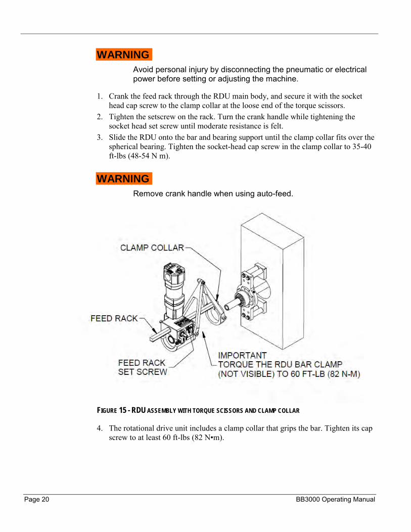
WARNING
Avoid personal injury by disconnecting the pneumatic or electrical power before setting or adjusting the machine.
1. Crank the feed rack through the RDU main body, and secure it with the socket head cap screw to the clamp collar at the loose end of the torque scissors.
2. Tighten the setscrew on the rack. Turn the crank handle while tightening the socket head set screw until moderate resistance is felt.
3. Slide the RDU onto the bar and bearing support until the clamp collar fits over the spherical bearing. Tighten the socket-head cap screw in the clamp collar to 35-40 ft-lbs (48-54 N m).
WARNING
Remove crank handle when using auto-feed.
FIGURE 15 - RDU ASSEMBLY WITH TORQUE SCISSORS AND CLAMP COLLAR
4. The rotational drive unit includes a clamp collar that grips the bar. Tighten its cap screw to at least 60 ft-lbs (82 N•m).
P/N 37390, Rev. 4 Page 21
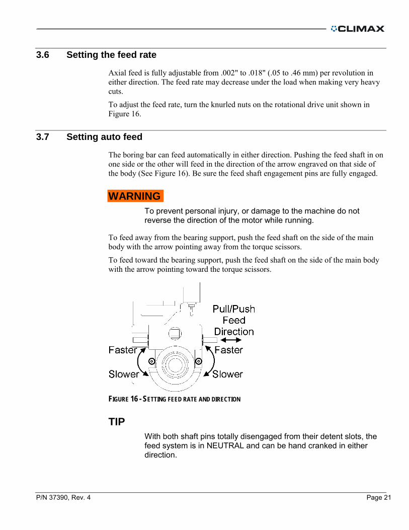
3.6 Setting the feed rate
Axial feed is fully adjustable from .002" to .018" (.05 to .46 mm) per revolution in either direction. The feed rate may decrease under the load when making very heavy cuts.
To adjust the feed rate, turn the knurled nuts on the rotational drive unit shown in Figure 16.
3.7 Setting auto feed
The boring bar can feed automatically in either direction. Pushing the feed shaft in on one side or the other will feed in the direction of the arrow engraved on that side of the body (See Figure 16). Be sure the feed shaft engagement pins are fully engaged.
WARNING
To prevent personal injury, or damage to the machine do not reverse the direction of the motor while running.
To feed away from the bearing support, push the feed shaft on the side of the main body with the arrow pointing away from the torque scissors.
To feed toward the bearing support, push the feed shaft on the side of the main body with the arrow pointing toward the torque scissors.
FIGURE 16 - SETTING FEED RATE AND DIRECTION
TIP
With both shaft pins totally disengaged from their detent slots, the feed system is in NEUTRAL and can be hand cranked in either direction.
Page 22 BB3000 Operating Manual
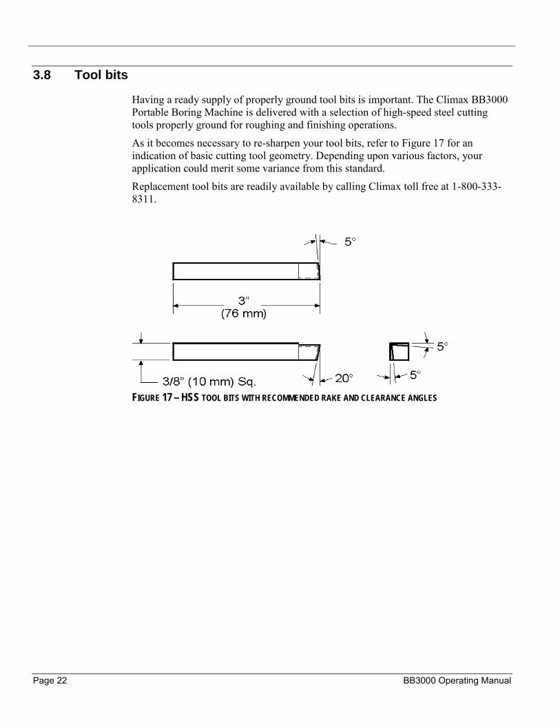
3.8 Tool bits
Having a ready supply of properly ground tool bits is important. The Climax BB3000 Portable Boring Machine is delivered with a selection of high-speed steel cutting tools properly ground for roughing and finishing operations.
As it becomes necessary to re-sharpen your tool bits, refer to Figure 17 for an indication of basic cutting tool geometry. Depending upon various factors, your application could merit some variance from this standard.
Replacement tool bits are readily available by calling Climax toll free at 1-800-333-8311.
FIGURE 17 – HSS TOOL BITS WITH RECOMMENDED RAKE AND CLEARANCE ANGLES
P/N 37390, Rev. 4 Page 23
4 OPERATION
4.1 Horizontal or Vertical Boring
The BB3000 portable boring bar can be set to operate in either a horizontal or a vertical position. Setups are essentially the same except, with vertical operation, tighten the setscrew in the side of the rotational drive unit sufficient to keep the rack from sliding downward. Do not over tighten or the feed system will be locked.
In addition, it is generally better to feed in an upward direction to prevent problems concerning normal backlash with the rack and pinion.
WARNING
When setting up, or servicing the machine disconnect the power source.
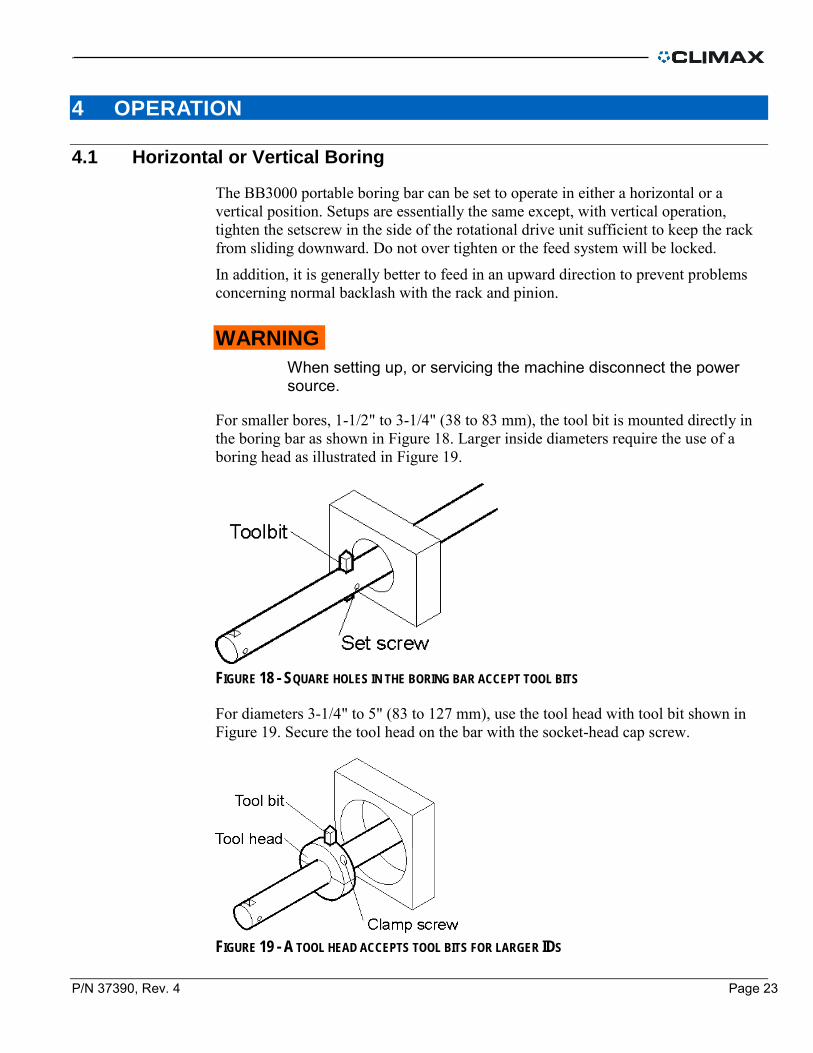
For smaller bores, 1-1/2" to 3-1/4" (38 to 83 mm), the tool bit is mounted directly in the boring bar as shown in Figure 18. Larger inside diameters require the use of a boring head as illustrated in Figure 19.
FIGURE 18 - SQUARE HOLES IN THE BORING BAR ACCEPT TOOL BITS
For diameters 3-1/4" to 5" (83 to 127 mm), use the tool head with tool bit shown in Figure 19. Secure the tool head on the bar with the socket-head cap screw.
FIGURE 19 - A TOOL HEAD ACCEPTS TOOL BITS FOR LARGER IDS

Page 24 BB3000 Operating Manual
1. Insert a tool bit into the bar or tool head. Be sure the cutting edge is facing the direction of bar rotation.
2. With the RDU feed shaft in NEUTRAL, position the bar so the tool bit is near the work to be bored.
3. Adjust the setting of the tool bit to obtain the bore diameter required.
TIP
Climax offers a bore-measuring device especially for setting the tool bit height and checking the actual bore diameter.
Call Climax toll free at 1-800-333-8311 for more information on this very useful tool.
4. Tighten the setscrew to secure the tool bit then make sure accuracy of the setting. 5. Select the auto feed direction. See “Setting auto feed” for detailed information.
WARNING
Electrical equipment can shock or cause an explosion if used near wet or flammable materials. Do not operate the motor if it is damp or exposed to combustible materials.
6. Reconnect the pneumatic or electric power and start the motor.
CAUTION
For machines with air motors, if the machine stops moving unexpectedly, lock out the pneumatic safety valve located at the filter lubricator assembly before performing any troubleshooting
7. Set the feed rate. See “Setting the feed rate” for information. 8. After machining the bore, turn off the motor. 9. If necessary, adjust the tool bit cutting depth and repeat the preceding steps as
required.
P/N 37390, Rev. 4 Page 25
5 MAINTENANCE
5.1 Approved lubricants
TABLE 6 RECCOMENDED LUBRICANTS
Lubricant Brand Where used
Gear grease Polytac EP #2 Gear box, thrust bearings
Light oil LPS 2 Unpainted surfaces
Cutting fluid UNOCAL KOOLKUT Tool bits, work piece
Lubricating oil Almo 525 Air lubricator
Rust inhibitor LPS 3 Long term storage
5.2 Rotational drive unit
Under normal use, the RDU is maintenance-free. To prevent corrosion, apply a thin layer of oil to the rack before and after using the machine.
5.3 Boring bar assembly
Lightly lubricate the bar before and after using the machine.
5.4 Electric motor
• Always unplug the motor before carrying out any maintenance. • Inspect the power cord at frequent intervals. • Clean the motor with dry compressed air to keep the cooling passages operational. • Replace the gear lubricating grease every 300 hours. • Replace brushes when they have worn down to 1/4". Always replace brushes in
sets.
Page 26 BB3000 Operating Manual
5.5 Air motor
To maintain the air motor do the following:
• Route the air supply through the specified lubricator and air filter. • Drain the air filter before and after using the machine. • Fill the lubricator oil cup before using the machine. Lubricate at a rate of 2-4
drops of oil per minute. • Use nonrestrictive air lines and fittings. Check the air system periodically to be
sure the air pressure is 90 psi (620 kPa). • Adjust air motor speed only by turning the air control valve.
TIP
DO NOT attempt to control motor speed by adjusting air line pressure.

P/N 37390, Rev. 4 Page 27
6 STORAGE
Proper storage of the BB3000 will prolong its usefulness and prevent undue damage. Before storing, clean the machine with solvent to remove grease, metal chips, and moisture. Spray the machine with WD-40 for short-term storage and LPS 3 for long-term storage.
• Place the boring bar with tools and accessories in the case provided. • Make sure there are no parts missing. • Include desiccant or vapor wrap to absorb moisture.

Page 28 BB3000 Operating Manual
This page left intentionally blank.
P/N 37390, Rev. 4 Page 29
APPENDIX A TOOLS AND RECCOMENDED SPARE PARTS
The following table lists items most frequently replaced due to wear, loss, or damage. You can avoid unscheduled downtime by maintaining an inventory of these critical parts
Part No. Description Qty Where used
19472 Screw 1/4-28 x 1-1/4 HHCS 8 Boring bar assembly
18231 Screw 1/4-20 x 3/8 SSSCPNI 4
11756 Screw 3/8-16 x 7/8 SHCS 1
Rotational drive unit 12213 Screw 1/2-13 x 5/8 SSSHD 2
16502 Ball nylon 7/16 dia. 2
78976 Motor brushes 2 Electric motor
32461 Tool bit 3/8 x 1.8 LH finish 3
Tool bits
32456 Tool bit 3/8 x 1.8 LH rough 3
32460 Tool bit 3/8 x .98 LH finish 3
32454 Tool bit 3/8 x .98 LH rough 3
31854 Tool bit 3/8 x 1.3 LH finish 3
31863 Tool bit 3/8 x 1.3 LH rough 3

Page 30 BB3000 Operating Manual
This page left intentionally blank.

P/N 37390, Rev. 4 Page 31
APPENDIX B EXPLODED VIEWS AND PARTS
The following diagrams and parts lists are for your reference purposes only. The machine Limited Warranty is void if the machine has been tampered with by anyone who has not been authorized in writing by Climax Portable Machining & Welding Systems to perform service on the machine.
Page 32 BB3000 Operating Manual
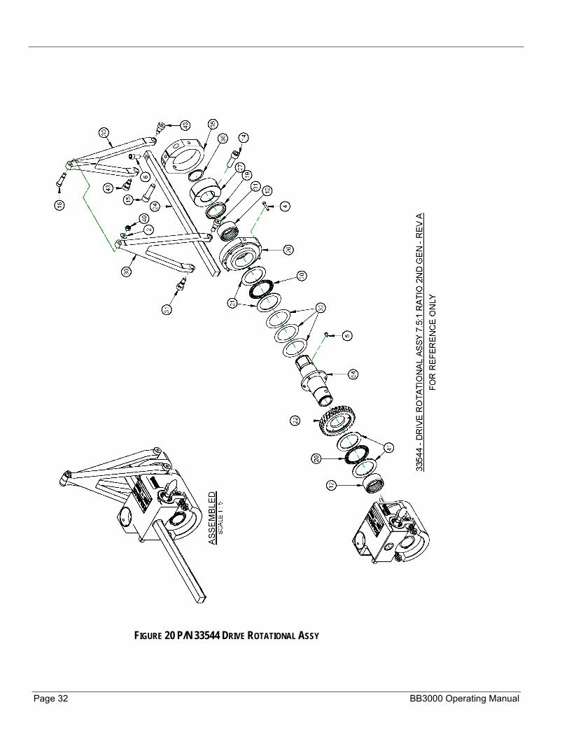
FIGURE 20 P/N 33544 DRIVE ROTATIONAL ASSY
P/N 37390, Rev. 4 Page 33
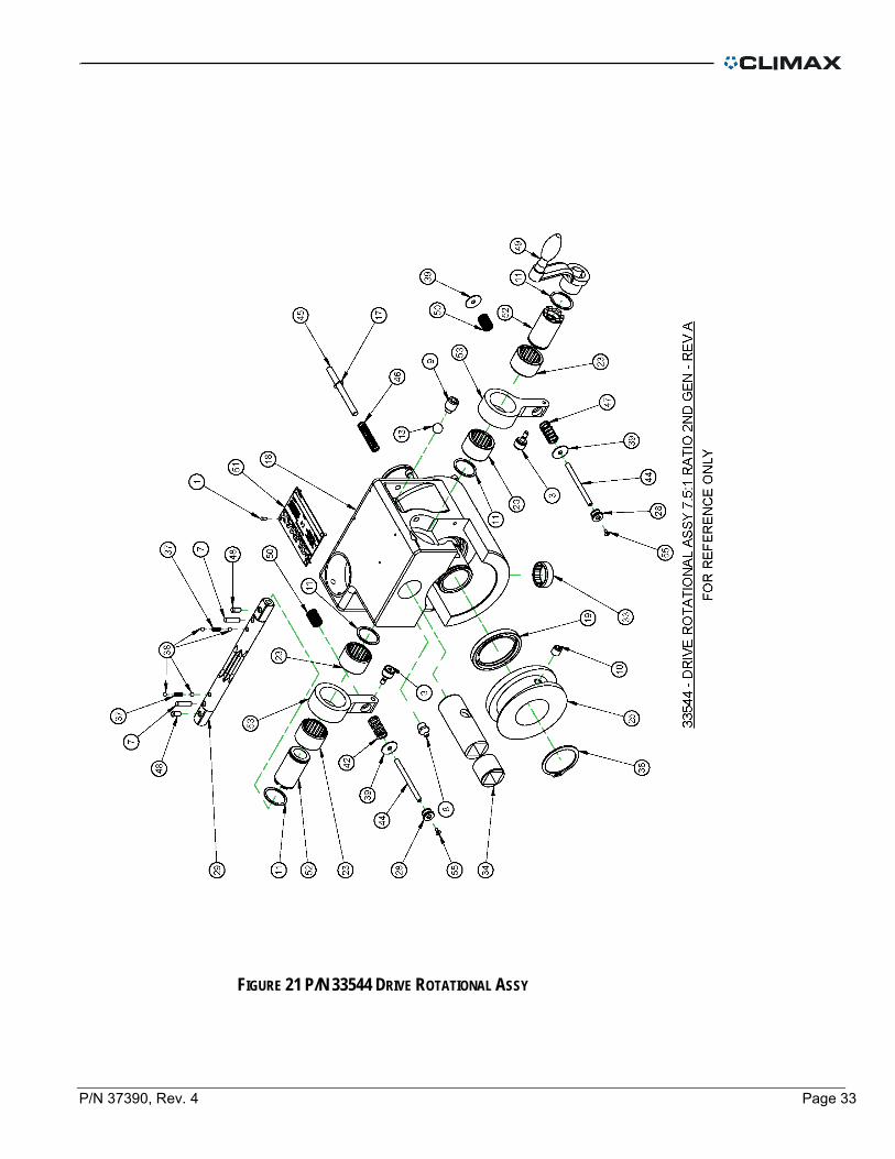
FIGURE 21 P/N 33544 DRIVE ROTATIONAL ASSY

Page 34 BB3000 Operating Manual
FIGURE 22 P/N 33544 DRIVE ROTATIONAL ASSY PARTS LIST

P/N 37390, Rev. 4 Page 35
FIGURE 23 P/N 82117 SET CONE SET UP

Page 36 BB3000 Operating Manual
FIGURE 24 P/N 33712 PARTS LIST
P/N 37390, Rev. 4 Page 37
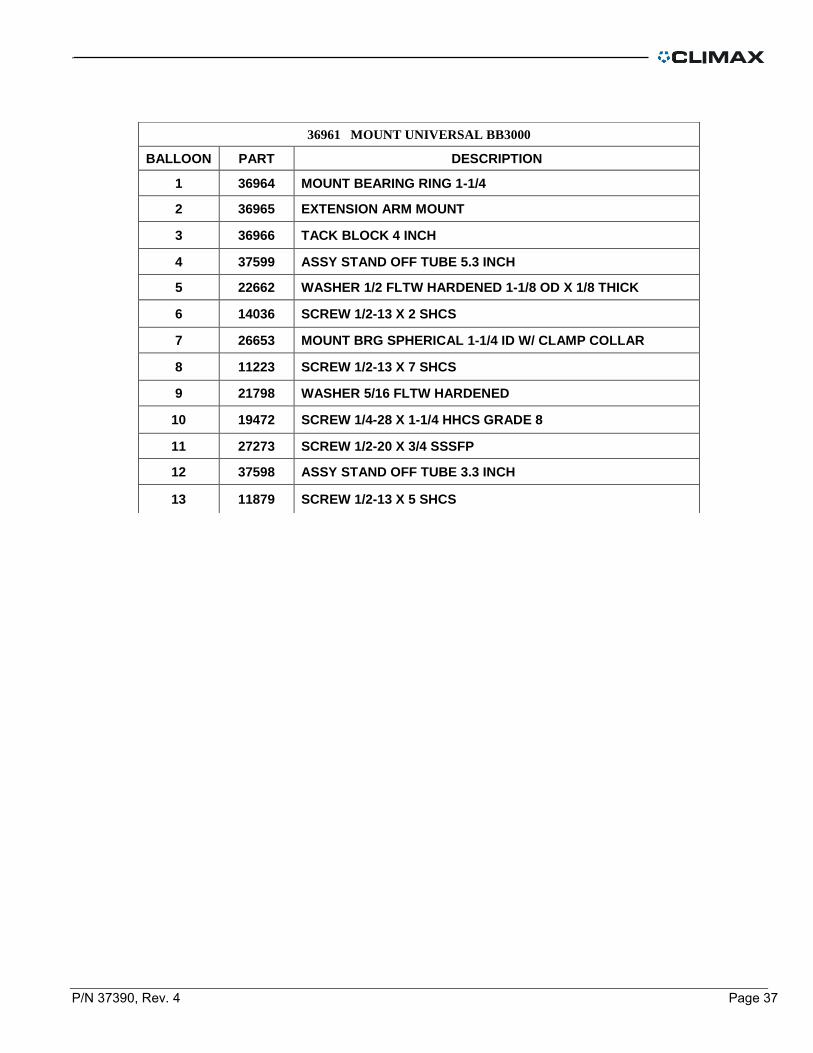
36961 MOUNT UNIVERSAL BB3000
BALLOON PART DESCRIPTION
1 36964 MOUNT BEARING RING 1-1/4
2 36965 EXTENSION ARM MOUNT
3 36966 TACK BLOCK 4 INCH
4 37599 ASSY STAND OFF TUBE 5.3 INCH
5 22662 WASHER 1/2 FLTW HARDENED 1-1/8 OD X 1/8 THICK
6 14036 SCREW 1/2-13 X 2 SHCS
7 26653 MOUNT BRG SPHERICAL 1-1/4 ID W/ CLAMP COLLAR
8 11223 SCREW 1/2-13 X 7 SHCS
9 21798 WASHER 5/16 FLTW HARDENED
10 19472 SCREW 1/4-28 X 1-1/4 HHCS GRADE 8
11 27273 SCREW 1/2-20 X 3/4 SSSFP
12 37598 ASSY STAND OFF TUBE 3.3 INCH
13 11879 SCREW 1/2-13 X 5 SHCS

Page 38 BB3000 Operating Manual
FIGURE 25 P/N 36961 MOUNT UNIVERSAL
P/N 37390, Rev. 4 Page 39
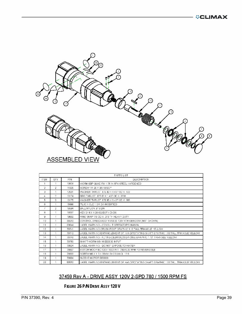
FIGURE 26 P/N DRIVE ASSY 120 V
Page 40 BB3000 Operating Manual
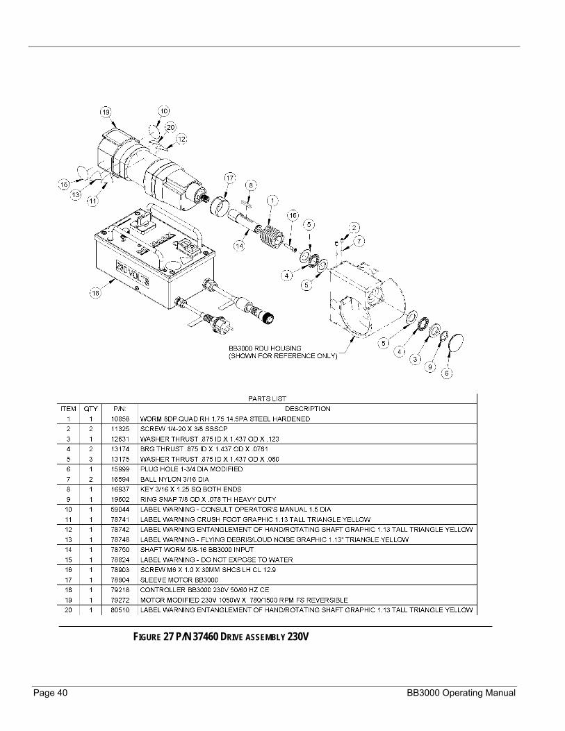
FIGURE 27 P/N 37460 DRIVE ASSEMBLY 230V
P/N 37390, Rev. 4 Page 41
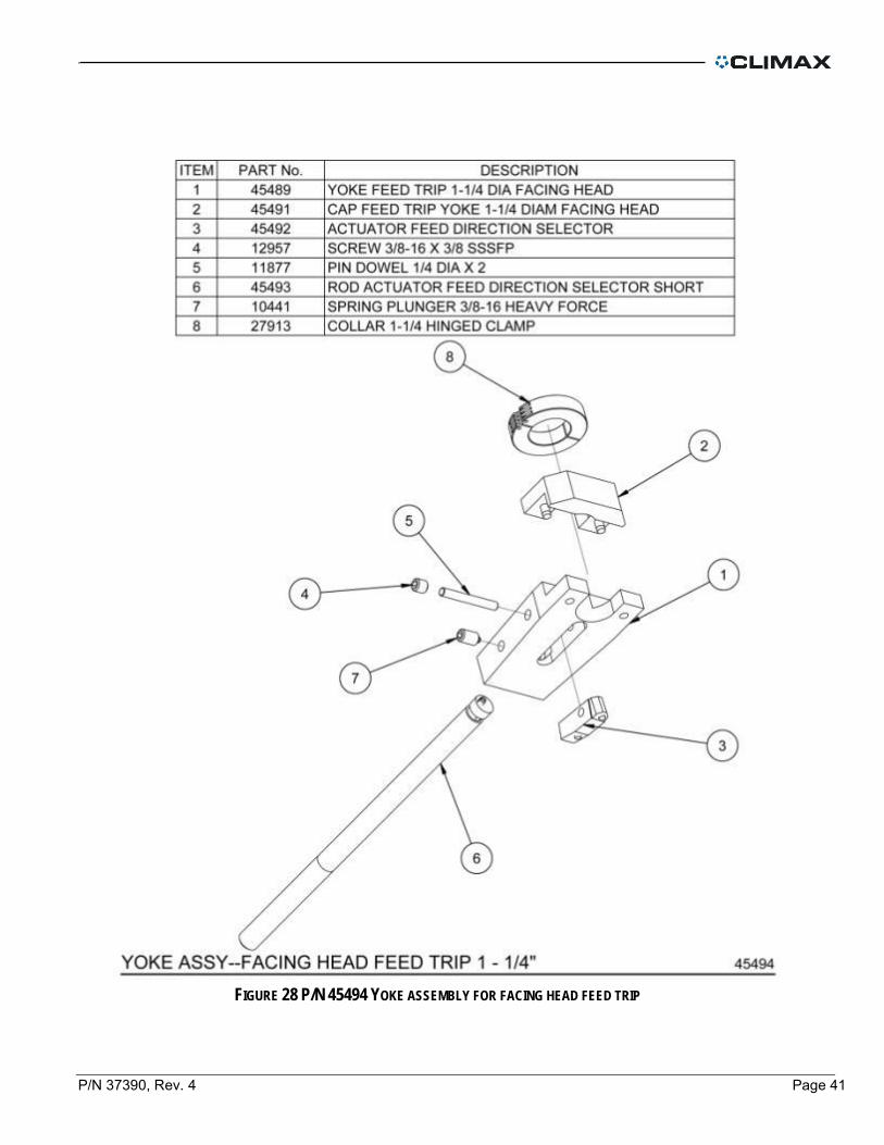
FIGURE 28 P/N 45494 YOKE ASSEMBLY FOR FACING HEAD FEED TRIP
Page 42 BB3000 Operating Manual
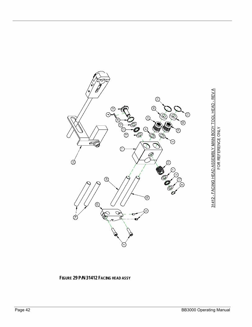
FIGURE 29 P/N 31412 FACING HEAD ASSY

P/N 37390, Rev. 4 Page 43
FIGURE 30 P/N 31412 FACING HEAD ASSY PARTS LIST
Page 44 BB3000 Operating Manual
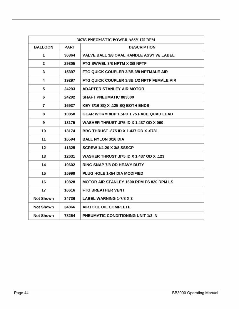
30785 PNEUMATIC POWER ASSY 175 RPM
BALLOON PART DESCRIPTION
1 36864 VALVE BALL 3/8 OVAL HANDLE ASSY W/ LABEL
2 29305 FTG SWIVEL 3/8 NPTM X 3/8 NPTF
3 15397 FTG QUICK COUPLER 3/8B 3/8 NPTMALE AIR
4 19297 FTG QUICK COUPLER 3/8B 1/2 NPTF FEMALE AIR
5 24293 ADAPTER STANLEY AIR MOTOR
6 24292 SHAFT PNEUMATIC 883000
7 16937 KEY 3/16 SQ X .125 SQ BOTH ENDS
8 10858 GEAR WORM 8DP 1.5PD 1.75 FACE QUAD LEAD
9 13175 WASHER THRUST .875 ID X 1.437 OD X 060
10 13174 BRG THRUST .875 ID X 1.437 OD X .0781
11 16594 BALL NYLON 3/16 DIA
12 11325 SCREW 1/4-20 X 3/8 SSSCP
13 12631 WASHER THRUST .875 ID X 1.437 OD X .123
14 19602 RING SNAP 7/8 OD HEAVY DUTY
15 15999 PLUG HOLE 1-3/4 DIA MODIFIED
16 10828 MOTOR AIR STANLEY 1600 RPM FS 820 RPM LS
17 16616 FTG BREATHER VENT
Not Shown 34736 LABEL WARNING 1-7/8 X 3
Not Shown 34866 AIRTOOL OIL COMPLETE
Not Shown 78264 PNEUMATIC CONDITIONING UNIT 1/2 IN

P/N 37390, Rev. 4 Page 45
FIGURE 31 P/N 37085 PNEUMATIC POWER ASSY
Page 46 BB3000 Operating Manual
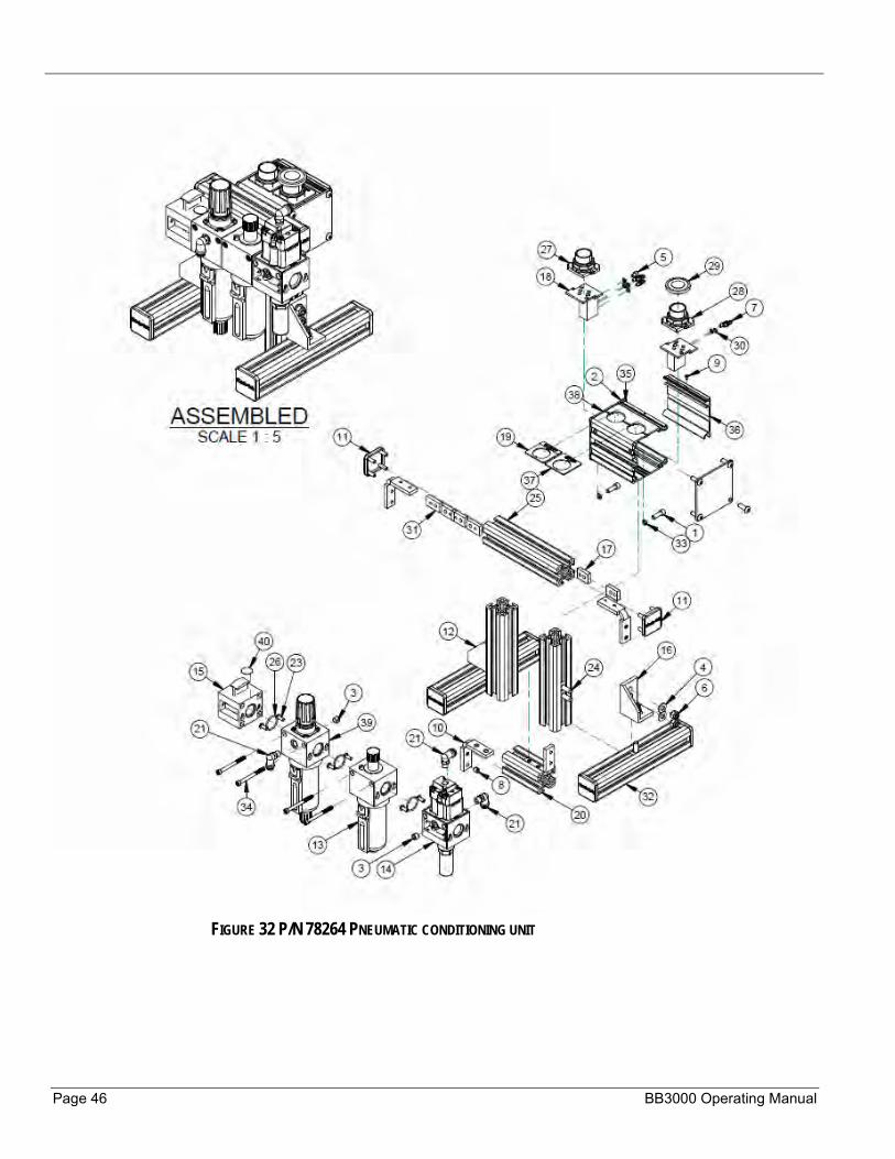
FIGURE 32 P/N 78264 PNEUMATIC CONDITIONING UNIT
P/N 37390, Rev. 4 Page 47
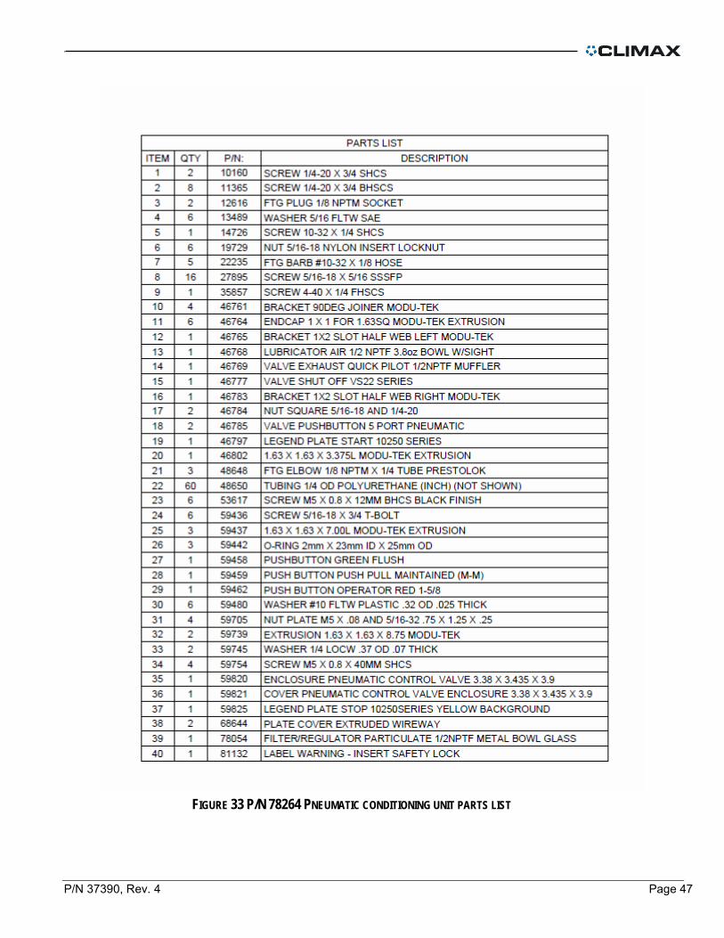
FIGURE 33 P/N 78264 PNEUMATIC CONDITIONING UNIT PARTS LIST

Page 48 BB3000 Operating Manual
FIGURE 34 P/N 79218 WELDON CONTROLLER 230V
P/N 37390, Rev. 4 Page 49
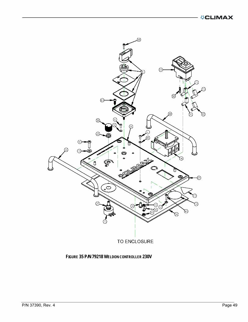
FIGURE 35 P/N 79218 WELDON CONTROLLER 230V

Page 50 BB3000 Operating Manual
FIGURE 36 P/N 79218 WELDON CONTROLLER 230V PARTS LIST
P/N 37390, Rev. 4 Page 51
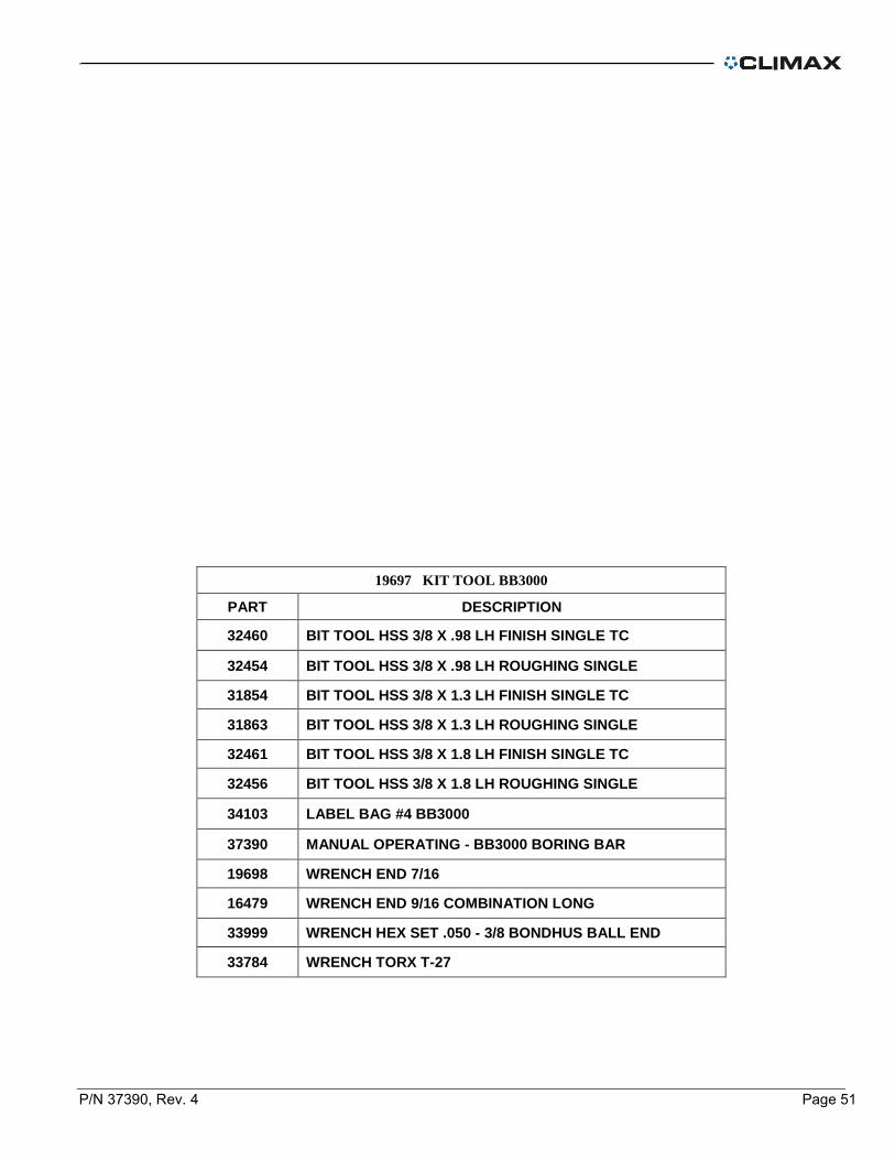
19697 KIT TOOL BB3000
PART DESCRIPTION
32460 BIT TOOL HSS 3/8 X .98 LH FINISH SINGLE TC
32454 BIT TOOL HSS 3/8 X .98 LH ROUGHING SINGLE
31854 BIT TOOL HSS 3/8 X 1.3 LH FINISH SINGLE TC
31863 BIT TOOL HSS 3/8 X 1.3 LH ROUGHING SINGLE
32461 BIT TOOL HSS 3/8 X 1.8 LH FINISH SINGLE TC
32456 BIT TOOL HSS 3/8 X 1.8 LH ROUGHING SINGLE
34103 LABEL BAG #4 BB3000
37390 MANUAL OPERATING - BB3000 BORING BAR
19698 WRENCH END 7/16
16479 WRENCH END 9/16 COMBINATION LONG
33999 WRENCH HEX SET .050 - 3/8 BONDHUS BALL END
33784 WRENCH TORX T-27

Page 52 BB3000 Operating Manual
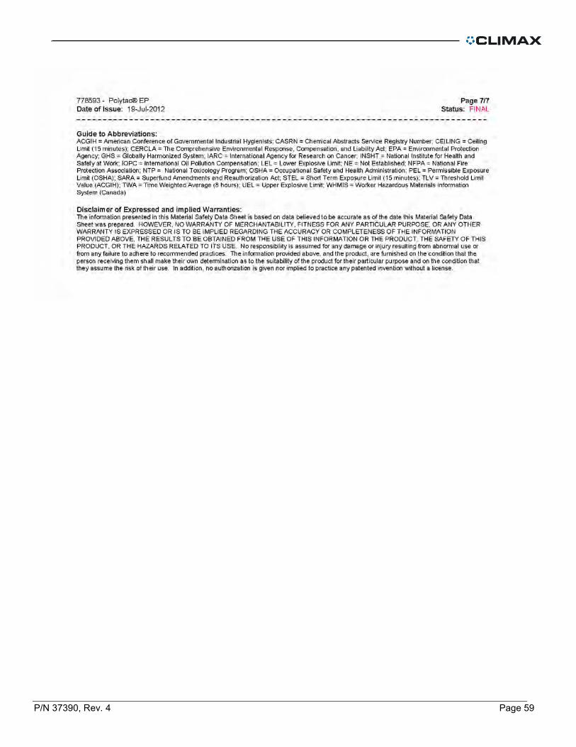
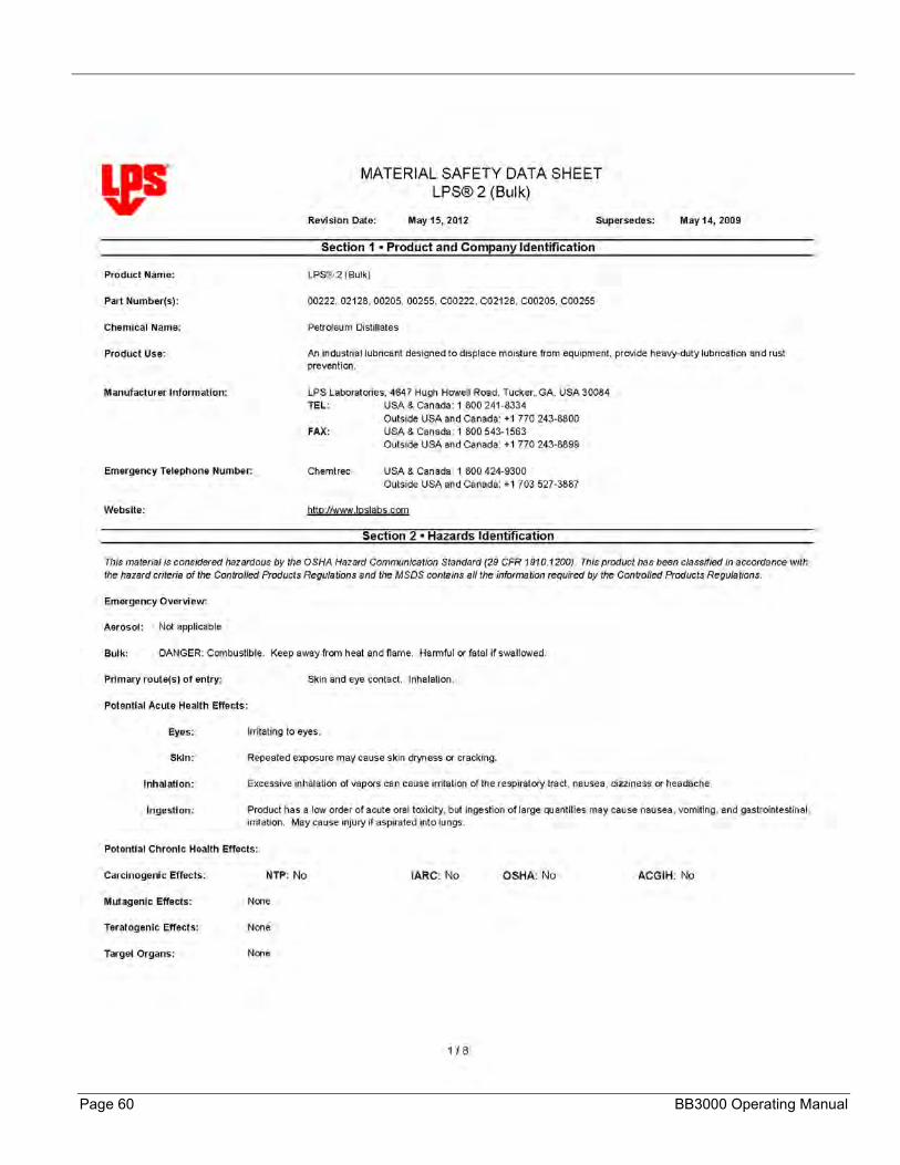
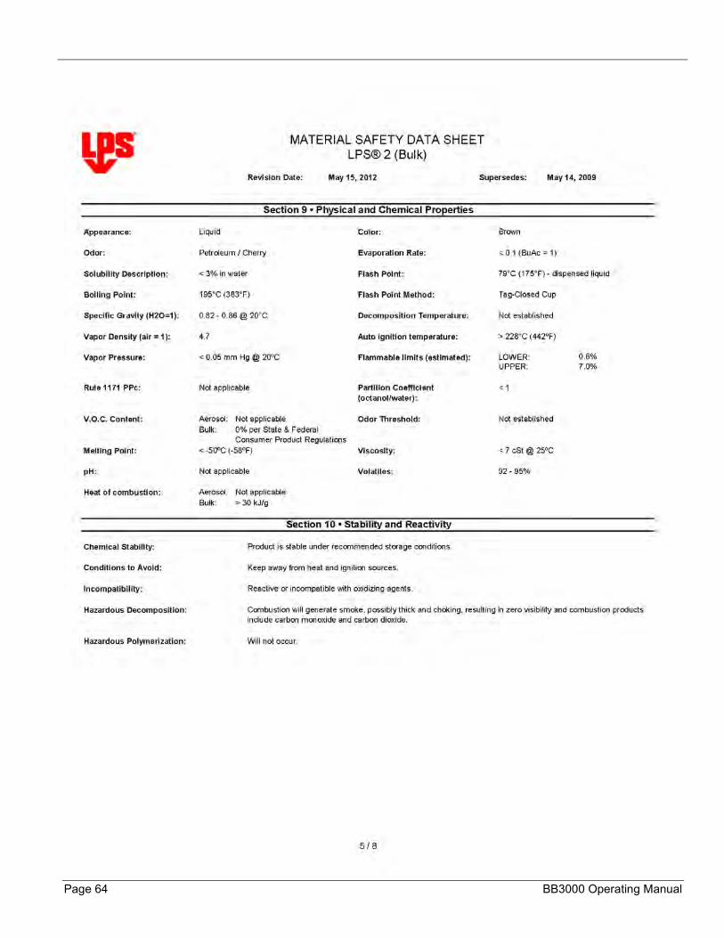
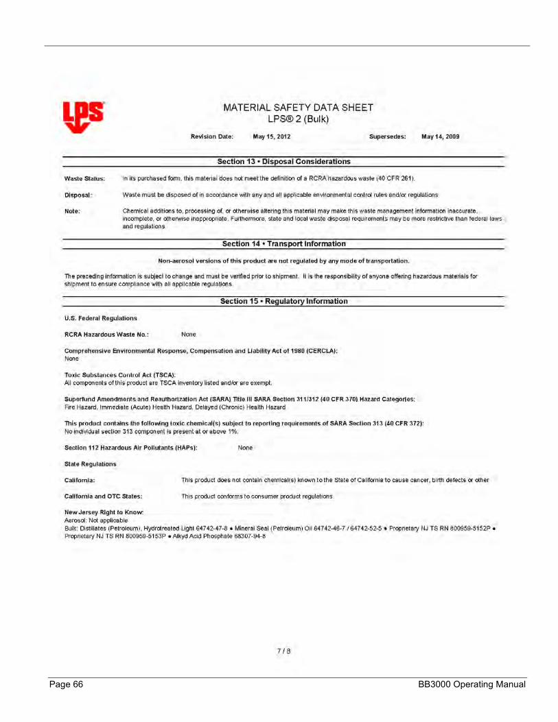
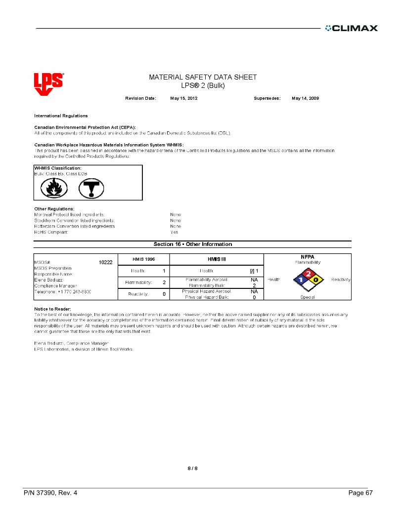
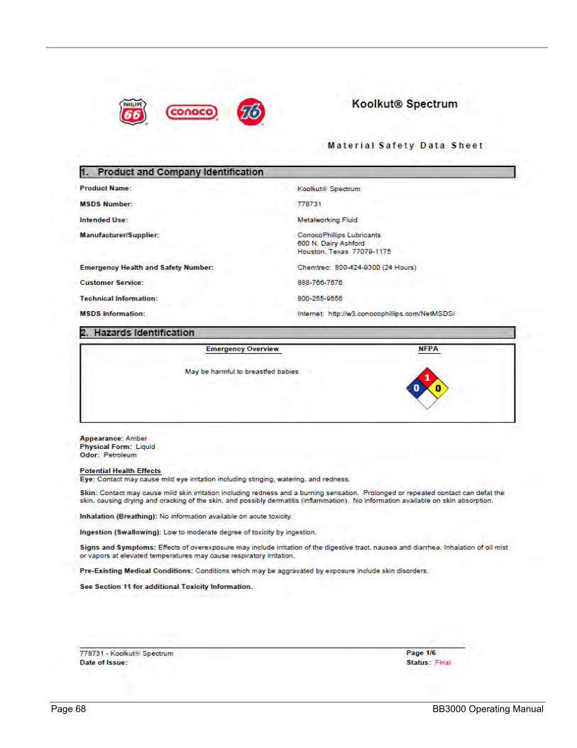
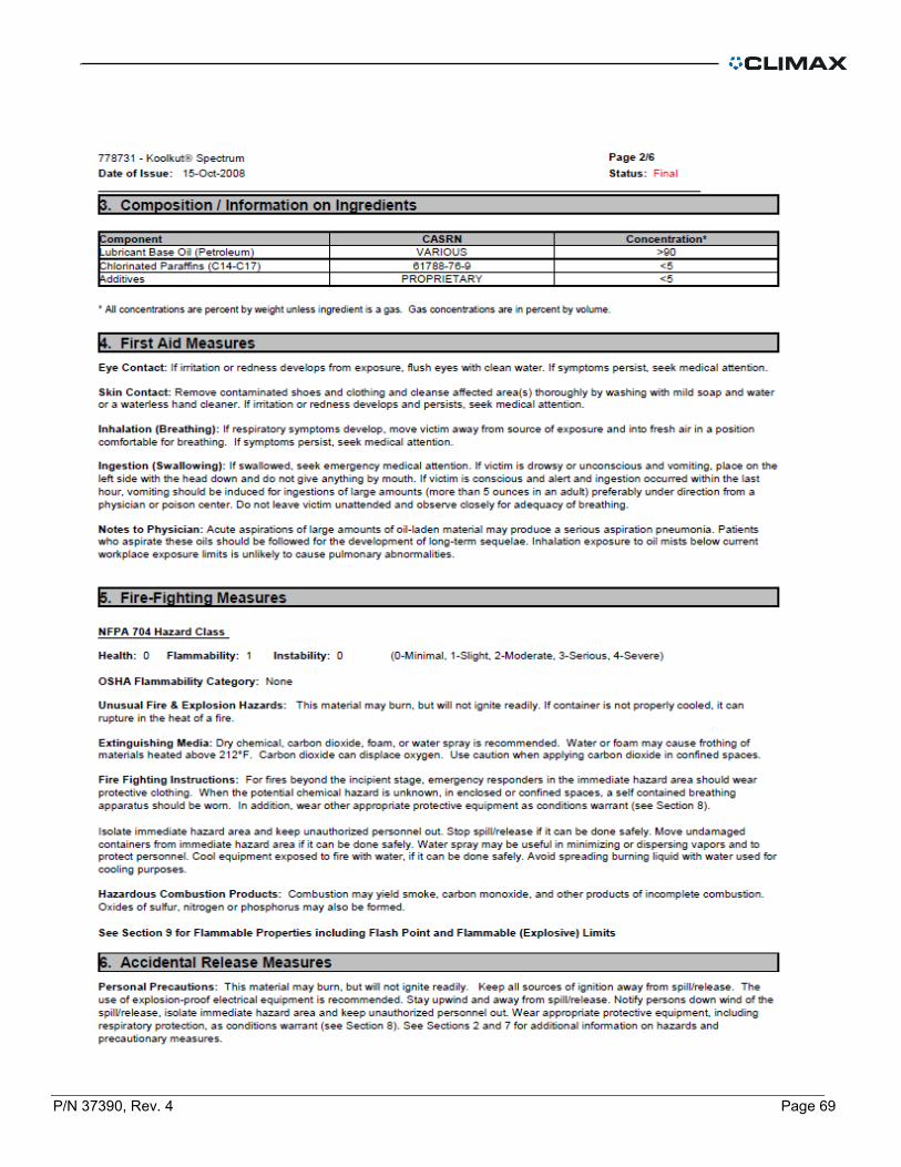
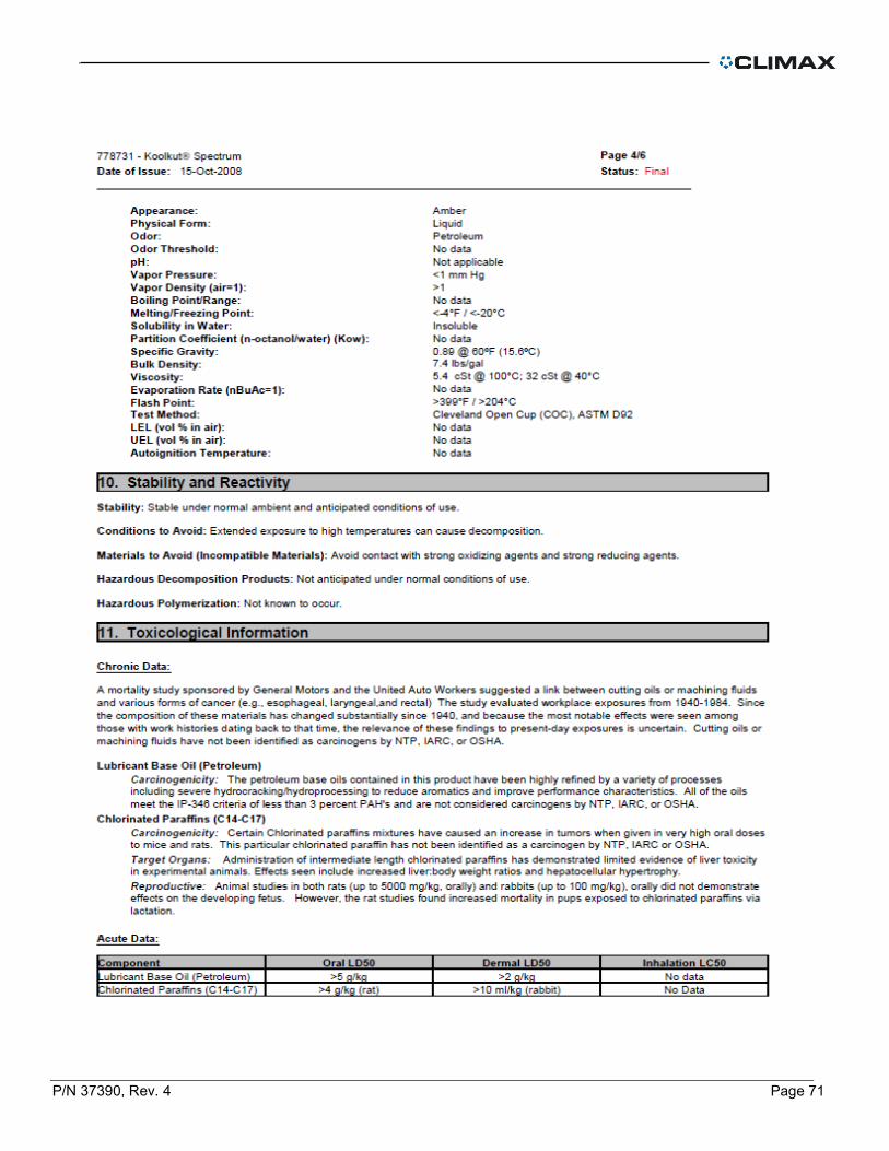
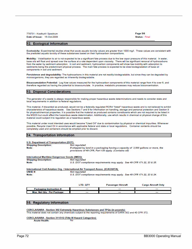
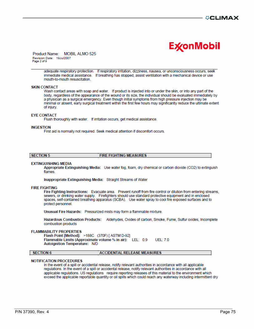
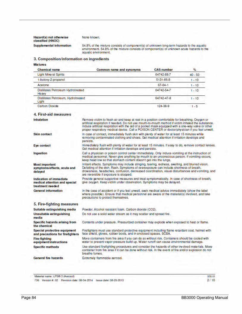
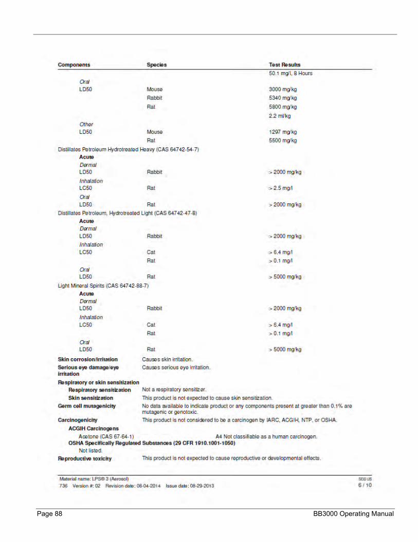
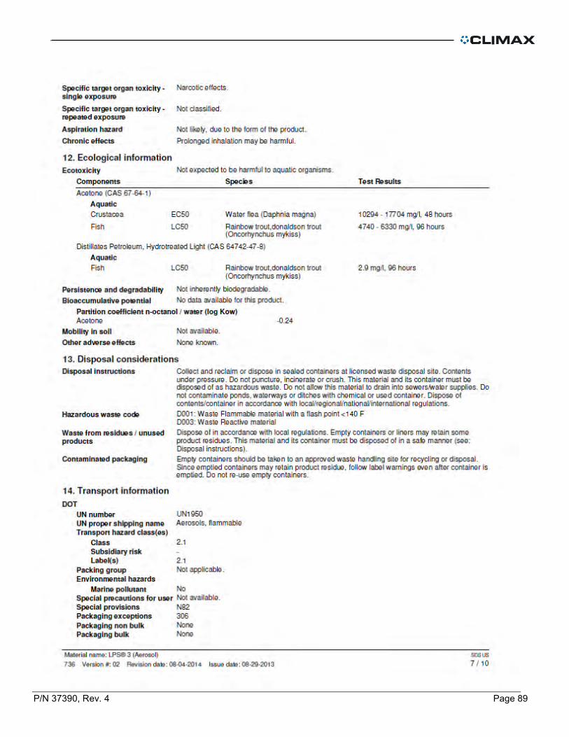
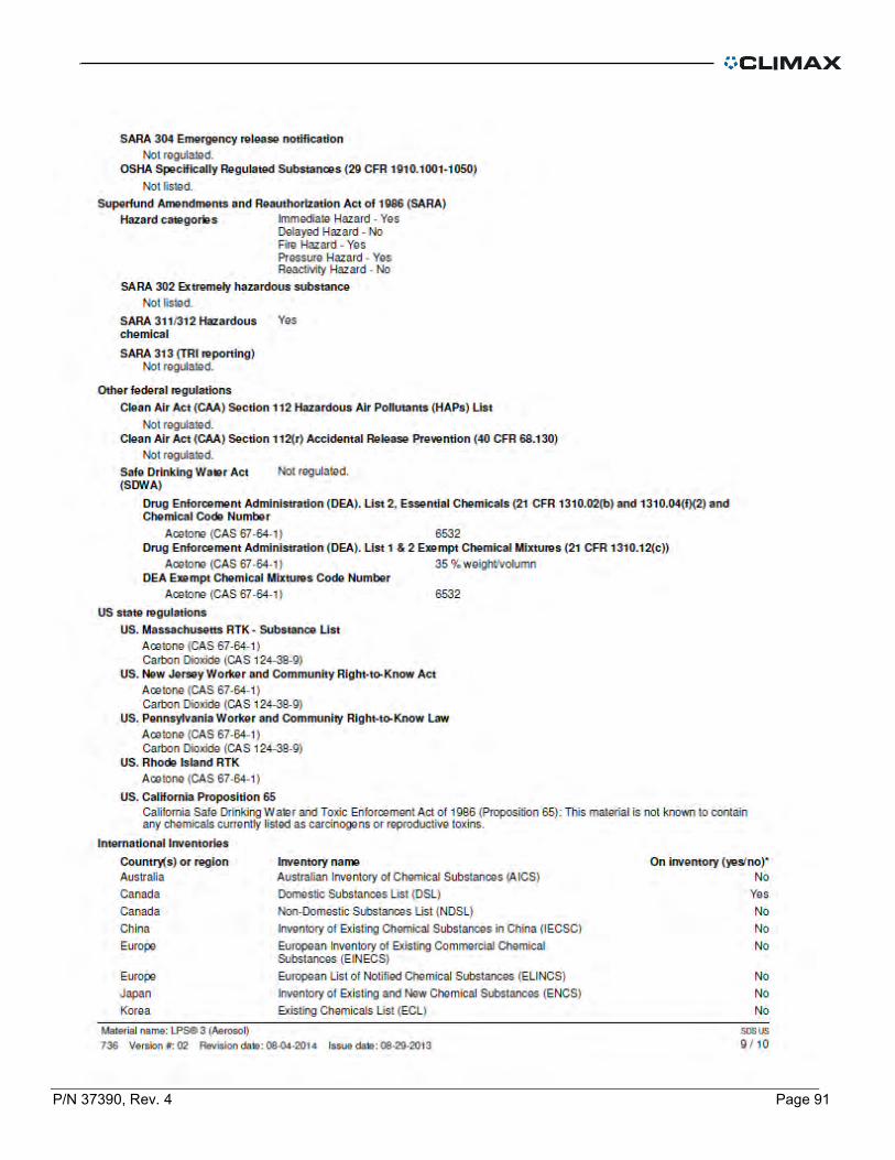
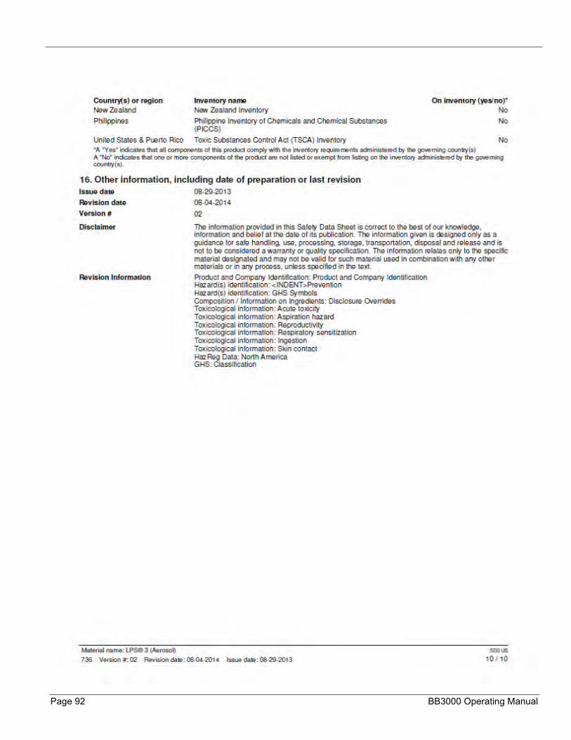
APPENDIX C MSDS

P/N 37390, Rev. 4 Page 53
Page 54 BB3000 Operating Manual
P/N 37390, Rev. 4 Page 55

Page 56 BB3000 Operating Manual

P/N 37390, Rev. 4 Page 57

Page 58 BB3000 Operating Manual
P/N 37390, Rev. 4 Page 59
Page 60 BB3000 Operating Manual

P/N 37390, Rev. 4 Page 61

Page 62 BB3000 Operating Manual

P/N 37390, Rev. 4 Page 63
Page 64 BB3000 Operating Manual

P/N 37390, Rev. 4 Page 65
Page 66 BB3000 Operating Manual
P/N 37390, Rev. 4 Page 67
Page 68 BB3000 Operating Manual
P/N 37390, Rev. 4 Page 69

Page 70 BB3000 Operating Manual
P/N 37390, Rev. 4 Page 71
Page 72 BB3000 Operating Manual

P/N 37390, Rev. 4 Page 73

Page 74 BB3000 Operating Manual
P/N 37390, Rev. 4 Page 75

Page 76 BB3000 Operating Manual

P/N 37390, Rev. 4 Page 77

Page 78 BB3000 Operating Manual

P/N 37390, Rev. 4 Page 79

Page 80 BB3000 Operating Manual

P/N 37390, Rev. 4 Page 81
Page 82 BB3000 Operating Manual

P/N 37390, Rev. 4 Page 83
Page 84 BB3000 Operating Manual

P/N 37390, Rev. 4 Page 85

Page 86 BB3000 Operating Manual

P/N 37390, Rev. 4 Page 87
Page 88 BB3000 Operating Manual
P/N 37390, Rev. 4 Page 89

Page 90 BB3000 Operating Manual
P/N 37390, Rev. 4 Page 91
Page 92 BB3000 Operating Manual