Embed Size (px)
Citation preview
CLIMB: a new Los Alamos Scientific Laboratorylens design code
Morris Klein and Berlyn Brixner
The new LASL lens design code uses a Monte Carlo random selection of object points in the object field, eachwith a ray of specified color traced through a randomly selected point in the entrance pupil. The figure ofmerit is measured by the failure of the designer's mapping function, including constraints, to predict the ac-tual ray trace position at the focal surface or elsewhere in the optical system. Optical system layout flexibili-ty has been increased by allowing (1) the coordinate system to move with the central ray during designing,(2) the introduction of an accessory reference surface anywhere in the system, and (3) the specification ofan optical surface by a table of surface coordinates.
Introduction
CLIMB-Continuing Lens Investigation Morris(Klein) and Berlyn (Brixner)-reflects a continuingeffort at the Los Alamos Scientific Laboratory (LASL)to develop computer aids that will enable the designerto meet the optical specifications required for use inLASL research. Over the last two decades two majorlens design codes have been developed at Los Alamos-The Holliday-Lehman (later written in Fortran by theJet Propulsion Laboratory) and the Doyle codes.1-3 Inboth of these codes a merit function, summing thegeometrical image errors at the focal plane, is minimizedby varying selected parameters of the lens. An imagespot is produced by tracing a bundle of rays from a givenobject point to the focal plane. Image deviations of theimage spot from a target position, such as the dis-placement of the spot centroid from a given imageheight or the rms radius of image points about the spotcentroid, are combined to form the merit function. InCLIMB, a random collection of rays, chosen by a MonteCarlo technique, is traced. As rays do not emanate froma given point in the object plane in general, they do notproduce a spot in the focal plane. The ray as it is de-fined in the object (or other) plane is mapped onto thefocal plane by a mathematical transformation. Thedesigner defines the form of the transformation. Thedefect of the defined transformation in predicting raybehavior defines the merit function.
The techniques employed by CLIMB have been em-ployed successfully in the design of magnet spectrom-eters. Several magnetic beam channels for the Los
The authors are with University of California, Los Alamos ScientificLaboratory, Los Alamos, New Mexico 87545.
Received 25 August 1975.
Alamos Meson Facility have been designed or improvedwith the aid of a code known as MOTER. The highresolution pion spectrometer EPICS is our best exam-ple. 4
This code, as its predecessors, was built for a fastturnaround, large machine (CDC-7600) batch envi-ronment. The input format has been built with theuser in mind. Moreover, the code itself is written inmodular form to allow fast implementation of unusualoptical elements.
In the paper we describe the main features of thecode. These include (1) Monte Carlo selection of inputrays, () layout mobility for tracing off-axis lens sys-tems, and (3) generalized constraint definition. We willthen discuss an application of the code to the sensitivityanalysis of a paraboloidal reflector.
Monte Carlo Selection
The selection of rays to be traced through the lenssystem is made by a Monte Carlo sampling technique.A first point is selected in the object space and assigneda color. A second point is then chosen in the entrancepupil. A straight line is then drawn connecting the twopoints. The ray, which is defined by this line, is thentraced through the lens. If the ray intercepts a physicalstop or encounters a violation (internal reflection) it isrejected. The second and succeeding rays are similarlyselected. When the requested number of rays has beenaccepted, the selection process is completed. The ratioproduced by dividing the number of rays accepted bythe total number of rays sampled provides a measureof the initial ray acceptance of the lens. This particularcollection of rays may be frozen or a new set may bechosen at a later stage of the optimization procedure.
The object and entrance pupil may have arbitrarygeometrical shapes. Upon option the following shapes
October 1976 / Vol. 15, No. 10 / APPLIED OPTICS 2583
may be selected automatically: a point; a line; a disk;a rectangle; an annulus; or a rectangular doughnut. Tosample a point source one obviously chooses the pointitself. To sample a line, for example, the line 0 < y <A with uniform intensity, one sets y = A-,random., Hererandom represents a random number lying between 0and 1 chosen from a uniform distribution. Similarconsiderations are used to sample a distribution ofuniform energy intensity for a rectangle or a rectangulardoughnut. To sample an energy distribution for a diskor annulus source we employ a slightly different pro-cedure. The point is selected in polar coordinates (pk).To pick the angle we use the following rejection formuladerived by von Neuman.5
R3: Criterion for selecting an angle ke (0,27r):(1) pick random numbers r and r2 from a uniform 0-1distribution;(2)ifS=x2 +y2 1,wherex =2r- 1,y =r2,
set cos0 = (X2 + y2 )/Ssing = 2xy/S.
Otherwise reject r and r2 and repeat 1.To pick the radius we set
random = rdr / f rdr(A).
Random is a random number chosen from a uniform 0-1distribution, where R R represent the inside andoutside radii of the annulus, and where p is the desiredradius. If we reduce the above expression, we obtainthe equation.
p = [Ri2 + (RO2- Ri 2)- random]l/ 2 .
This formula is easily modified to sample nonuniformintensity source distributions. For example if f(r)represents an axially symmetric intensity source func-tion, p obtained from the following expression willrepresent a radius sampling the energy profile.
random = f(r)rdr /SRo f(r)rdr.
We may also choose up to six colors for design. Theselection of color may be uniform or may be biased ac-cording to some known response of the detector oroutput distribution of the source. To accomplish thiswe assign each color a fraction of the unit interval. Forexample, the eye's response may be modeled by lettingthe C,e,F lines be weighted 8%, 80%, and 12%, respec-tively. The assignment would then be
select: C-if random lies between 0. and 0.08,e-if random lies between 0.08 and 0.88,F-if random lies between 0.88 and 1.
The addition of the random sampling technique intoa lens design code removes some of the objections nor-mally attributed to standard rms spot size minimiza-tion. In using a preset pattern of rays the designer mustoften skillfully assign weights to the various ray bundles.At times he may wish to emphasize rim rays. At othertimes he may wish to consider only central rays. Oftenrays are lost in the image due to boundary violations.These violations may completely overwhelm the code.The best way to handle the lost rays is to try to avoidtheir presence. For a fixed ray pattern this would imply
either a reduced aperture or a modification of thebundle. In CLIMB only rays that are able to passthrough the initial design are employed for optimiza-tion. There is no intervention by the designer to ex-clude rays. Experimentally we have observed that theinitial acceptance ratio often improves during the op-timization procedure. A second optimization passreinitializing the sample ray collection often indicatesa larger acceptance.
A standard rms spot size optimization code requiresthat a large number of rays be traced. A typical raytrace pattern consists of three bundles in three colorswith twenty-eight rays per bundle. This requires 252rays. Using CLIMB we have observed that a good designcan be obtained with only sixty-four rays. Finalizingtrim runs employing 200 rays for a three-color problemdo not significantly alter the previously determineddesign parameters.
The ability to sample an arbitrary source facilitatesdesign on unusual optical systems. For example, we arecurrently developing a spectrometer whose light sourceis a cerenkov radiator. Light from this radiator origi-nates from any point in a thick transparent sheet, thepoint being the vertex of a fixed-angle hollow cone oflight. Computer design of such a system without ver-satile sampling can be performed only with a lot of de-signer ingenuity.
Layout and Surface ElementsCLIMB can trace rays through a variety of common
optical surfaces. These surfaces include on- and off-axis conic sections, generalized aspherics, a drift ele-ment, and a tabular surface element. These surfacesmay be oriented either in a position defined by a fixedcoordinate system or a coordinate system tied to thecurrent path of the central ray. The mathematicaldescription of the elements, the determination of theray intersections with the optical surface, and the cal-culation of the resultant ray refraction closely parallelsthat described in the report of the Jet Propulsion Lab-oratory's version of the Holliday-Lehman code3 and thepaper of Spencer and Murty.6
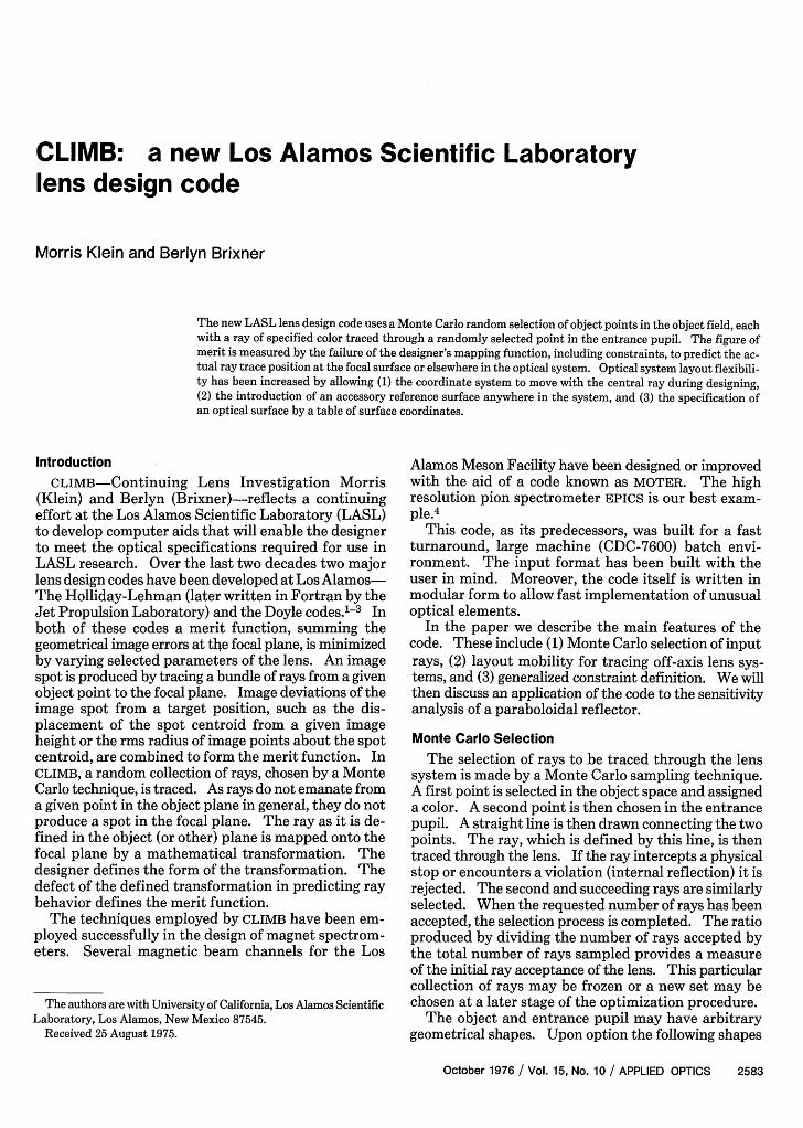
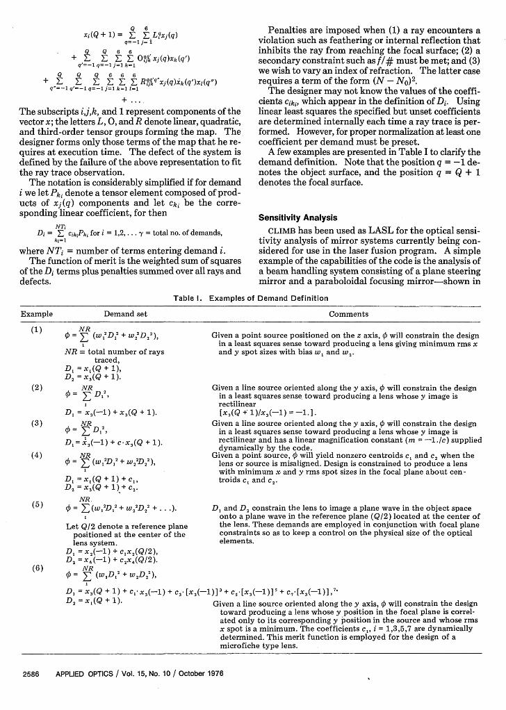
The layout flexibility may be illustrated with the aidof Fig. 1. In this figure a beam of light is reflected offthe flat mirror 21 into the optical system denoted by 12.The central ray C, which initially travels in the positiveZ1 direction, is reflected into the positive Z2 direction.The designer has the option to define the surface X2 ineither the coordinate system (X1, Y1,Zl) or the coordi-nate system (X2, Y2,Z2). In the latter choice the posi-tion of 12 will automatically adjust to any change in theorientation of Z1 during design.
CLIMB contains two elements not common to ourprevious codes. These elements are Drift and Toric.Drift is a reference plane that permits one to analyze thebeam at a particular place without adding anothersurface to the lens system. This element provides anadditional reference surface at which the designer mayinvestigate beam properties. In misalignment studiesthis surface has been used to define the optimal focalsurface. Thus the designer has simultaneously a
2584 APPLIED OPTICS / Vol. 15, No. 10 / October 1976
I
xi I; -
ZI
/
Fig. 1. Reflection from flat mirror, optic reference (x1 , yl, zl) rede-fined (x2, Y2, Z2)-
measure of performance on both the nominal and op-timal focal planes. Toric is a surface of revolution thatis defined by function and derivative data. For exam-ple, we have reconstructed a Schwarzschild two-mirroraplanat and similar surfaces generated by a differentialequation. The data for the element are stored on tapeand read into computer memory at execution time.The surface is reconstructed internally through Hermitecubic interpolation.7
Figure of Merit
The design produced by an automatic procedure isstrongly influenced by the designer's choice of the figureof merit. Therefore, the figure of merit is the heart ofthe optimization procedure. It is here that the designerspecifies and balances his design objectives. To insureflexibility while designing many diverse systems mostcodes ask the designer to choose the components of thefigure of merit. These components in lens system de-sign may be measures of aberration defects, measuresof spot quality in the image plane, or, as in CLIMB,
measures of defects of a mapping function that describethe ray trajectories through the system. In all cases thedesigner chooses and weighs component parts to meethis over-all design expectation.
The Holliday-Lehmann3 and Doyle2 codes, majordesign tools at LASL, define the merit function prin-
cipally as the least squares sum of focal plane spot sizesand deviations of the centroids of these spots fromspecified target positions. The spot pattern that isscrutinized is produced by tracing a bundle of raysemanating from one of a select group of object points.In CLIMB it is seldom that more than one ray is tracedfrom the same point in object space. The notable ex-ception of course is the instance of a point source. Thefigure of merit, therefore, can reflect only the quality ofhow the ray was transferred from the object plane to thefocal plane. This quality is described by a mappingfunction constructed by the designer to relate positionsand angles of a ray as it traverses the object, the en-trance pupil, the vertex reference planes for each sur-face, the actual surfaces, and the focal surface. Thedefect of the design is the failure of the mapping func-tion to predict the actual ray trace observation.
The mapping function is chosen by the designerthrough input cards at execution time. Values ofcoefficients for terms appearing in the map functionmay be specified. If they are not specified, they aredetermined by CLIMB through a linear least squares fit.The optical system parameters are then modified so asto minimize the least squares defect of the map to pre-dict the ray data. The figure of merit also containsadditional terms that impose penalties to a design thattends to lose rays in its effort to achieve the design cri-terion.
One may view the mapping function as a demand thatray positions be correlated in a manner that has beendefined by the designer. Correlations between raypositions are determined by geometrical optics and theactual parameter prescription. A poor choice of themapping function will lead to a figure of merit that isinsensitive to the design parameters. Fortunately, thefinished design reflects the designer's judgement.
The constraints added to the system by the mappingfunction are common to design programs. One mayrequest a perfectly rectilinear image or he may requestan image with allowance for distortion. Secondaryconsiderations may be limits on the size of optical piecesor of the total system. To illustrate the concept of amapping function, let us define the ray vector:
X - (x1,x2,x3 ,x4 ,X5,x6) = (XxY,0Y1A)
where the x and y's are the x and y coordinate inter-section positions on a reference surface; Ix and Qy arethe corresponding direction tangents before refractionwith respect to the z layout axis; 1 is a constant whosevalue has unity; and 6 = [(1)/(X) - (1)/(Xc)] representsreciprocal deviation of the wavelength X from the re-ciprocal of the central wavelength Xc In CLIMB onemay choose any combination of various reference sur-faces (object, entrance pupil, surface vertex plane, ac-tual surface intersection, or focal surface) in his for-mulation of the mapping function. Surfaces are labeledby the numerical order by which they occur in the code.The index q, q = -1,0,1,2, .. Q,Q + 1 represents theobject surface, the entrance pupil, the optical surface(one of Q surfaces), and the focal surface. The generalform of the mapping function may be written
October 1976 / Vol. 15, No. 10 / APPLIED OPTICS 2585
Q 6xi(Q + 1) = F Lqxj(q)
q=-1 j= iQ Q 6 6
+ _ O?•x j(q)Xk(q')q'=-1 q=-1 j=l k=1
Q Q Q 6 6 6+ E E Z E E E R qJq'xj(q)xk(q')xl(q")ql=-1 q'=-1 q=-1 =l k=l 1=1
The subscripts ij,k, and 1 represent components of thevector x; the letters L, 0, and R denote linear, quadratic,and third-order tensor groups forming the map. Thedesigner forms only those terms of the map that he re-quires at execution time. The defect of the system isdefined by the failure of the above representation to fitthe ray trace observation.
The notation is considerably simplified if for demandi we let Pki denote a tensor element composed of prod-ucts of x(q) components and let Cki be the corre-sponding linear coefficient, for then
NTiDi = CikiPki for i = 1,2,. . = total no. of demands,
ki= 1
where NTi = number of terms entering demand i.The function of merit is the weighted sum of squares
of the Di terms plus penalties summed over all rays anddefects.
Penalties are imposed when (1) a ray encounters aviolation such as feathering or internal reflection thatinhibits the ray from reaching the focal surface; (2) asecondary constraint such as f/# must be met; and (3)we wish to vary an index of refraction. The latter caserequires a term of the form (N - NO)2.
The designer may not know the values of the coeffi-cients Ciki, which appear in the definition of Di. Usinglinear least squares the specified but unset coefficientsare determined internally each time a ray trace is per-formed. However, for proper normalization at least onecoefficient per demand must be preset.
A few examples are presented in Table I to clarify thedemand definition. Note that the position q = -1 de-notes the object surface, and the position q = Q + 1denotes the focal surface.
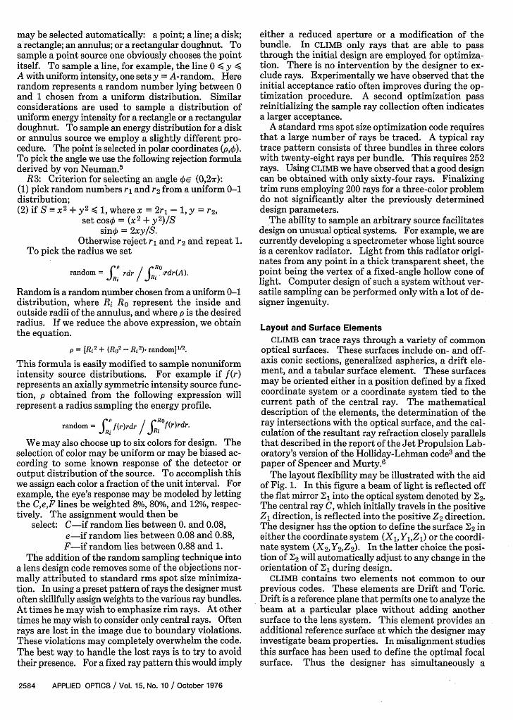
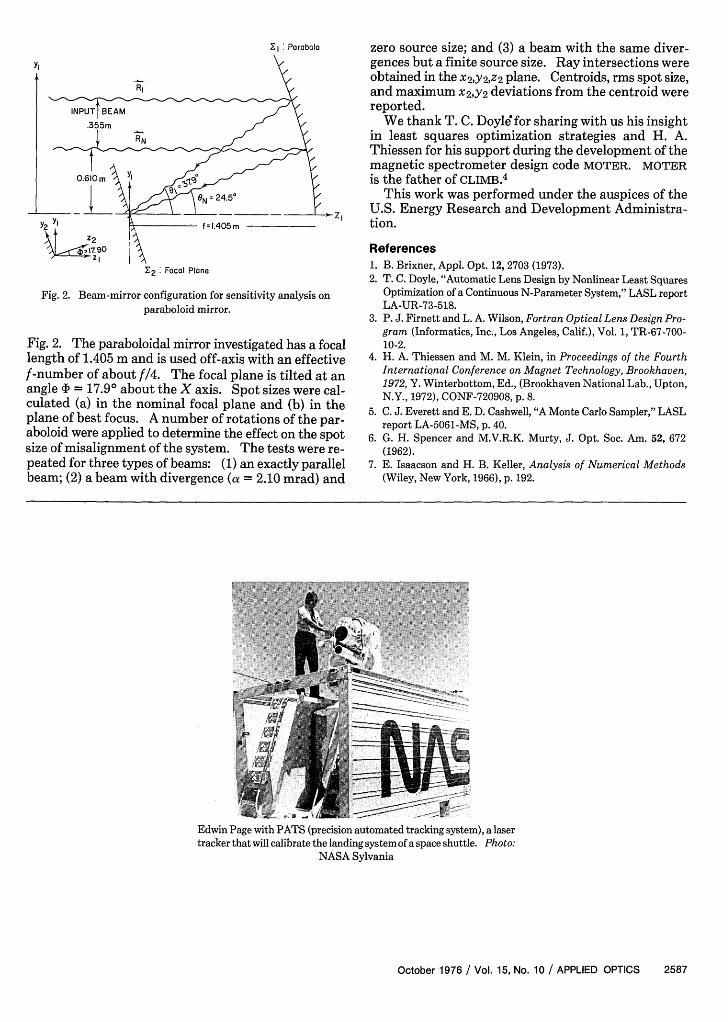
Sensitivity AnalysisCLIMB has been used as LASL for the optical sensi-
tivity analysis of mirror systems currently being con-sidered for use in the laser fusion program. A simpleexample of the capabilities of the code is the analysis ofa beam handling system consisting of a plane steeringmirror and a paraboloidal focusing mirror-shown in
Table I. Examples of Demand Definition
Example Demand set Comments
(1) NR= N (wl2D, + w22D2
2), Given a point source positioned on the z axis, 0 will constrain the designin a least squares sense toward producing a lens giving minimum rms x
NR total number of rays and y spot sizes with bias w, and w2.traced,
D, = x(Q + 1),D2 = x 3(Q + 1).
(2) NR 2 Given a line source oriented along the y axis, will constrain the design0 = ED,, in a least squares sense toward producing a lens whose y image is
rectilinearD, = X3(-1) + x3(Q + 1). [X3(Q + 1 )/X3(-1) =-1.]
(3) NR 2 Given a line source oriented along the y axis, will constrain the design= D,, in a least squares sense toward producing a lens whose y image is
D,= 3 (-1) + C.X3(Q + 1). rectilinear and has a linear magnification constant (m = -1./c) supplieddynamically by the code.
(4) NR 2 + 2 2 Given a point source, 0 will yield nonzero centroids c and 2 when the¢ - (wD,`D 2 D2
2 ), lens or source is misaligned. Design is constrained to produce a lens1 with minimum x and y rms spot sizes in the focal plane about cen-
D, = x,(Q + 1) + c,, troids c, and c2.D = x 3(Q + 1) + C2.
NR(5) ¢ = EZ(w,2D2 + w2
2D22 + * *)- D, and D2 constrain the lens to image a plane wave in the object space
onto a plane wave in the reference plane (Q/2) located at the center ofLet Q/2 denote a reference plane the lens. These demands are employed in conjunction with focal plane
positioned at the center of the constraints so as to keep a control on the physical size of the opticallens system. elements.
D, = X2(-1) + cx 2(Q/2),D2 = x4 (-1 ) + c2x(Q/2 ).
(6) NR(6) 5= (wD, 2 + 2D 2
2 ),
D, =X3(Q + 1) + CX3 (-1) + C 3 X 3(-)] 3 + 5 .[X3(-1)F + C7X3(-1)],7D2 = X(Q + 1). Given a line source oriented along the y axis, 0 will constrain the design
toward producing a lens whose y position in the focal plane is correl-ated only to its corresponding y position in the source and whose rmsx spot is a minimum. The coefficients c,, i = 1,3,5,7 are dynamicallydetermined. This merit function is employed for the design of amicrofiche type lens.
2586 APPLIED OPTICS / Vol. 15, No. 10 / October 1976
E1 : Parabola
yI
.355mRN
L Y2 yj
atZ21 -7 o
2 : Focal Plane
Fig. 2. Beam-mirror configuration for sensitivity analysis onparaboloid mirror.
Fig. 2. The paraboloidal mirror investigated has a focallength of 1.405 m and is used off-axis with an effectivef-number of about f/4. The focal plane is tilted at anangle cI) = 17.90 about the X axis. Spot sizes were cal-culated (a) in the nominal focal plane and (b) in theplane of best focus. A number of rotations of the par-aboloid were applied to determine the effect on the spotsize of misalignment of the system. The tests were re-peated for three types of beams: (1) an exactly parallelbeam; (2) a beam with divergence (a = 2.10 mrad) and
zero source size; and (3) a beam with the same diver-gences but a finite source size. Ray intersections wereobtained in the x2,y2 ,z2 plane. Centroids, rms spot size,and maximum x2,y2 deviations from the centroid werereported.
We thank T. C. Doyle' for sharing with us his insightin least squares optimization strategies and H. A.Thiessen for his support during the development of themagnetic spectrometer design code MOTER. MOTERis the father of CLIMB.4
This work was performed under the auspices of theU.S. Energy Research and Development Administra-tion.
References1. B. Brixner, Appl. Opt. 12, 2703 (1973).2. T. C. Doyle, "Automatic Lens Design by Nonlinear Least Squares
Optimization of a Continuous N-Parameter System," LASL reportLA-UR-73-518.
3. P. J. Firnett and L. A. Wilson, Fortran Optical Lens Design Pro-gram (Informatics, Inc., Los Angeles, Calif.), Vol. 1, TR-67-700-10-2.
4. H. A. Thiessen and M. M. Klein, in Proceedings of the FourthInternational Conference on Magnet Technology, Brookhaven,1972, Y. Winterbottom, Ed., (Brookhaven National Lab., Upton,N.Y., 1972), CONF-720908, p. 8.
5. C. J. Everett and E. D. Cashwell, "A Monte Carlo Sampler," LASLreport LA-5061-MS, p. 40.
6. G. H. Spencer and M.V.R.K. Murty, J. Opt. Soc. Am. 52, 672(1962).
7. E. Isaacson and H. B. Keller, Analysis of Numerical Methods(Wiley, New York, 1966), p. 192.
Edwin Page with PATS (precision automated tracking system), a lasertracker that will calibrate the landing systemof a space shuttle. Photo:
NASA Sylvania
October 1976 / Vol. 15, No. 10 / APPLIED OPTICS 2587
f =1.405 r