Embed Size (px)
Citation preview
1
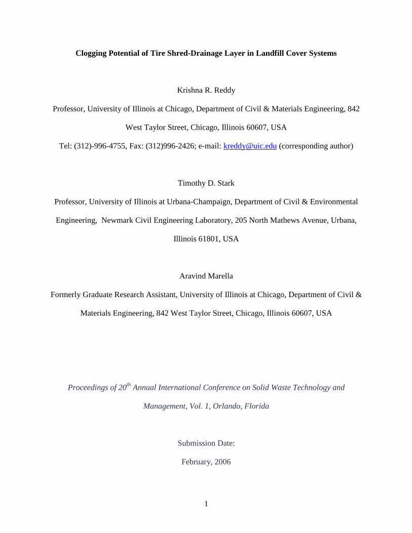
Clogging Potential of Tire Shred-Drainage Layer in Landfill Cover Systems
Krishna R. Reddy
Professor, University of Illinois at Chicago, Department of Civil & Materials Engineering, 842
West Taylor Street, Chicago, Illinois 60607, USA
Tel: (312)-996-4755, Fax: (312)996-2426; e-mail: [email protected] (corresponding author)
Timothy D. Stark
Professor, University of Illinois at Urbana-Champaign, Department of Civil & Environmental
Engineering, Newmark Civil Engineering Laboratory, 205 North Mathews Avenue, Urbana,
Illinois 61801, USA
Aravind Marella
Formerly Graduate Research Assistant, University of Illinois at Chicago, Department of Civil &
Materials Engineering, 842 West Taylor Street, Chicago, Illinois 60607, USA
Proceedings of 20th Annual International Conference on Solid Waste Technology and
Management, Vol. 1, Orlando, Florida
Submission Date:
February, 2006
2
Abstract: This paper investigates the clogging potential of shredded scrap tire drainage layers in
landfill covers. Laboratory clogging tests were conducted using soil and shredded tire profiles in
a large-scale permeameter. In each test, a layer of shredded tire overlain by a soil layer was
subjected to flow under a constant hydraulic gradient condition. Two types of shredded tires
were used for this study and they contained individual tire chips with sizes ranging from 2.5 cm
to 50 cm. The soil layer consisted of silty clay that is commonly used as cover soil in landfill
cover systems. Tests were also conducted by placing a geotextile filter between the soil and the
shredded tire layers. During the testing, the outflow from the bottom of the shredded tire layer
was measured. After a specified number of days, the inflow was stopped and the soil layer was
removed. The soil was dried and weighed. If a geotextile was used, it was also removed, dried
and weighed. The mass of the soil that remained after completion of testing was compared with
the initial mass of the soil used to determine the extent of soil infiltration into the underlying
shredded tire layer. The hydraulic conductivity of the shredded tires was measured before and
after soil infiltration. Overall, the test results showed that flow through the cover soil was very
low, and the extent of soil infiltration into the shredded tires ranged from 4 to 15%, depending on
the presence of a geotextile and the thickness of the soil layer. Despite partial clogging of tire
shred voids with the infiltrated soil, the hydraulic conductivity of the shredded tires still
remained the same as the initial value of 3.5 to 6.5 cm/s demonstrating that shredded tires can be
used as an effective drainage media in landfill cover systems.
Keywords: clogging, cover system, drainage, hydraulic conductivity, landfill, recycling, tires

3
Introduction
Over 280 million used automobile, truck and specialty tires are discarded each year
nationwide. The State of Illinois alone contributes approximately 12 million scrap tires each year
to this figure. Disposal of whole tires in landfills was the common practice for many years.
However, whole tires disposed in landfills tend to “float” to the surface, breaking the landfill
cover and causing increased leachate production, which can contaminate groundwater. Because
of this, many states have banned the disposal of whole tires in landfills. The State of Illinois
requires tires to be shredded before being placed in landfills. This requirement has caused an
increase in scrap tire stockpiling. Currently, 2 to 4 billion tires are stockpiled nationwide and
approximately 40 to 50 million scrap tires are stockpiled at numerous locations in Illinois
(IDENR, 1994). These stockpiled tires represent an aesthetic nuisance, a public health hazard,
and waste of a valuable resource. A scrap tire stockpile or dump provides an ideal breeding
ground for mosquitoes, rats and other disease carrying vermin. Mosquito-born diseases
associated with the stockpiling of scrap tires costs approximately $5.5 million per year. Scrap tire
stockpiles can self-ignite, which has detrimental effects on air quality, groundwater quality, and
public health due to liquid and gaseous emissions from the burning tires. The annual cost of
extinguishing used tire fires exceeds $2 million.
The best way to reduce the environmental and health hazards associated with used and
waste tires is to minimize, and ultimately eliminate, stockpiling. Numerous studies have been
conducted to investigate and develop alternative methods to landfilling and stockpiling such as
using shredded tires for tire-derived fuel (TDF), the creation of barrier reefs, and crumb rubber
asphalt surfaces. TDF appears to consume the largest quantity of tires in Illinois as well as
nationwide. However, such usage has a number of limitations including: (1) the need to shred
4
tires into small, uniform chips (usually less than 5 x 5 cm), which results in high processing
costs; (2) a marginal cost advantage as compared to other competing fuels such as coal; (3) the
need for major environmental permit modifications to burn tires; (4) high costs of conducting
permit required tests for compliance; (5) reliability of supply in remote locations; (6)
transportation cost for remote locations; and (7) local community opposition to tire burning.
Other uses include retreading, pyrolysis, rubber-modified asphalt, and molded rubber products;
however, these applications currently consume a very small amount of the stockpile. In addition,
or as an alternative to TDF, the State of Illinois is searching for other beneficial uses for waste
tires. The State is seeking to develop additional statewide, large-scale, and cost-effective uses for
large size (greater than 10 cm ) tires shreds. The larger the shredded tire, the lower the
processing cost and the more viable the recycling option. Large-scale uses of shredded tires have
been identified by several researchers for civil engineering applications such as highway
embankments, pavements, retaining structures, and lightweight fill material (e.g., Ahmed and
Lovell, 1993; ASTM, 1998; Bernal et al., 1996; Bressette, 1984; Cecich et al., 1996; Edil and
Bosscher, 1992; Edil and Bosscher, 1994; Foose et al., 1996; Humphery and Manion, 1992;
Humphery and Sandford, 1993; Humphery et al., 1993; Masad et al., 1996; Newcomb and
Drescher, 1994).
We propose to use shredded tires as drainage material in cover systems for waste
containment facilities. The cover system of a landfill is designed to prevent infiltration of
precipitation into the waste; promote good surface drainage; resist erosion; restrict landfill gas
migration or enhance recovery; prevent animals, insects and rodents from contact with the waste;
minimize long-term maintenance; and protect human health and the environment (Daniel and
Koerner, 1992; USEPA, 1994; Sharma and Reddy, 2004). Typical cover systems consist of a low
5
permeability barrier layer underlying a vegetative cover soil layer. A drainage layer may be
placed between the barrier and cover soil layers. The drainage layer causes lateral drainage of the
infiltrated rainwater. If a drainage layer is not provided, the rainwater eventually infiltrates the
waste causing excessive leachate production inside the landfill. In addition, the drainage layer
prevents build-up of pore water pressures in the final cover system, leading to increased stability
of slopes. The drainage layer in cover systems is typically constructed from granular soil such as
sand. However, shredded tires have great potential because they possess a hydraulic
conductivity that is higher than sand. This application has significant potential for utilizing large
quantities of shredded tires (160,493 to 395,061 tires per hectare) and providing economic
advantages over conventionally used materials without compromising engineering performance
(Reddy and Saichek, 1998a, b). This application also has the potential for immediate field
implementation as compared to other civil engineering applications, thus alleviating the growing
problem of management and disposal of scrap tires in a timely fashion.
Along with the infiltrating rainwater, soil particles from the clay soil cover layer may
migrate into the tire-shred drainage layer. Such migration of soil particles can clog the drainage
layer, leading to inefficient drainage performance. In conventional drainage layers, where sand
and/or gravel are used as drainage material, the initial porosity of these drainage materials is too
small to allow significant migration of soil particles from the overlying cover soil layer.
However, when tire shreds are used as drainage material, the porosity of the tire shreds is very
high (approx. 60%) which has the potential for a greater amount of soil migration from the
overlying cover soil layer. As a result, the tire-shred drainage layer may become significantly
clogged and its drainage performance may be compromised.
6
This paper presents a laboratory research program undertaken to assess the clogging
potential of tire-shred drainage layer in a landfill cover system. Controlled laboratory simulation
experiments were conducted in a large-scale permeameter with various cover soil and tire-shred
drainage layer conditions. Three different series of experiments, each consisting of four
experiments, were conducted to evaluate the extent of the clogging potential of tire-shred layers
as well as to assess the benefits of using a geotextile filter at the interface between the cover soil
layer and the tire-shred drainage layer to reduce soil infiltration and the clogging of the tire-shred
drainage layer. Based on the experimental results, the usefulness of employing tire-shred
drainage layers in cover systems was assessed.
Experimental Methodology
Experimental Setup
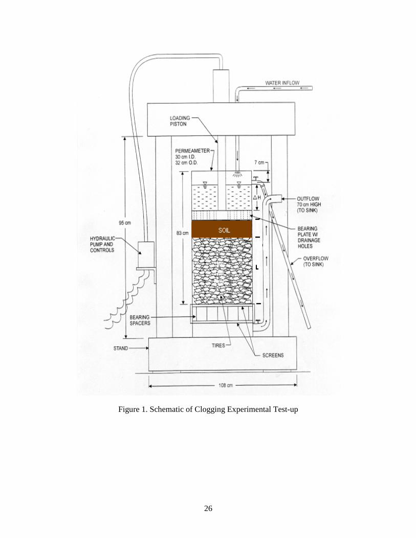
A large-scale permeameter setup was used to simulate the tire-shred drainage layer and
cover soil layer system and to study the clogging potential of tire shreds. Figure 1 shows a
schematic of this setup. The same permeameter setup was used in a previous study to determine
hydraulic conductivity of tire shreds under different normal stresses (Reddy and Saichek, 1998a).
The permeameter was made of a rigid PVC cylindrical pipe 30 cm in diameter and 83 cm in
height. An inlet was constructed at the top of the permeameter to allow water inflow. Outlets
with control valves were constructed at the top and bottom of the permeameter. The top outlet
maintained a constant hydraulic head and it was located at a height of 76 cm from the base of the
permeameter. The bottom outlet consisted of two openings of diameter 3.8 cm and 1.9 cm which
were located at a height of 8.1 cm from the base of the permeameter. The purpose of the smaller
7
opening was to measure low outflow volumes. A flow meter was connected to the bottom outlets
to record outflow volume. A metal screen was placed at the bottom of the permeameter at a
height of 11.4 cm from the base. The screen was supported on a set of bearing spacers that
transfer the load uniformly onto the base. The screen was rigid enough to support the tire shreds,
soil, and any additional applied normal stress. Adhesive plastic measuring tape was fixed to the
inner wall of the permeameter to measure the depth of tire shreds, thickness of the soil layer, and
the hydraulic head over the soil layer.
Materials Used
Tire Shreds
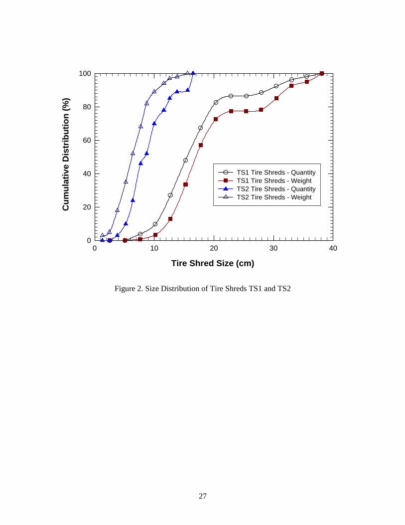
Two different sizes of tire shreds, obtained from two different sources, were used in this
study. These tire shreds were designated as TS-1 and TS-2 and were tested for their size
distribution, unit weight, and hydraulic conductivity. A standard sieve analysis could not be
performed to determine the size distribution of the tire chips present in the tire shreds. Instead,
the tire shreds were characterized by randomly selecting samples from a tire shred pile.
Approximately 10 kg of tire shreds were chosen per sample. The weight and the maximum and
minimum size of each individual tire chip in the tire shred sample were measured and recorded.
The size distribution of TS-1 and TS-2 are shown in Figure 2.
The unit weight of tire shreds was determined by filling the tire shreds in a large
cylindrical container and measuring their weight and volume. Using the specific gravity (1.02 to
1.27) for tire shreds, the void ratio (e) and porosity (n) were calculated. The average density,
8
void ratio and porosity were varied from 416 to 502 kg/m3, 1.28 to 1.5, and 50% to 58%,
respectively.
The hydraulic conductivity (K) of the tire shreds was determined by using the same
permeameter shown in Figure 1. The tire shreds were placed in the permeameter without any
compaction. The initial thickness of the tire shred layer in the permeameter was 30 cm.
Hydraulic conductivity was measured consecutively under three different stress conditions: (a)
under zero normal stress, (b) 5.7 kPa normal stress, and (c) 11.5 kPa normal stress. The normal
stress of 5.7 kPa simulated one-foot soil layer overlying the tire-shred drainage layer, while the
normal stress of 11.5 kPa simulated a 61 cm soil layer overlying tire-shred layer. During each
testing stage, the amount of water discharged from the bottom outlet for a specified time period
(t) was measured. Initial head (H1) and the final head (H2) in the permeameter were recorded.
The hydraulic conductivity (K) was calculated using:
=
2
1lnHH
tLK
where L is the thickness of the tire-shred layer in the permeameter. Based on these experiments,
the hydraulic conductivity of the TS-1 tire shreds with no normal stress was found to be 2.65
cm/s. The hydraulic conductivity of tire shreds was slightly decreased to 2.27 cm/s and 1.83 cm/s
and compression increased to 23% and 37% under normal stresses of 5.7 kPa and 11.5 kPa
respectively. The compressibility and hydraulic conductivity of TS-2 tire shreds are reported by
Reddy and Saichek (1998a). These results show that both TS-1 and TS-2 tire shreds possessed
higher hydraulic conductivity than the standard drainage materials such as sand and gravel;
therefore, they are as the most suitable drainage material in a landfill final cover system.
Cover Soil
9
A silty clay soil obtained from the Carlinville Landfill in Carlinville, Illinois, USA, was
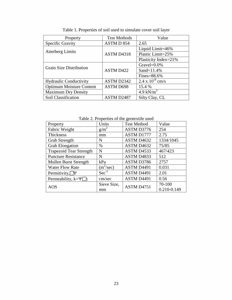
used as cover soil in this study. The soil was tested for specific gravity, Atterberg limits, grain
size distribution, hydraulic conductivity, and moisture-density relationship. Table 1 summarizes
the testing procedures and the property values for the soil.
Geotextile
A geotextile was used at the interface between the tire shreds and the cover soil in select
experiments to assess the possibility of minimizing soil infiltration and clogging of the tire-shred
layer. A non-woven geotextile (270 g/m2) was chosen in this study and its properties are
summarized in Table 2.
Testing Program
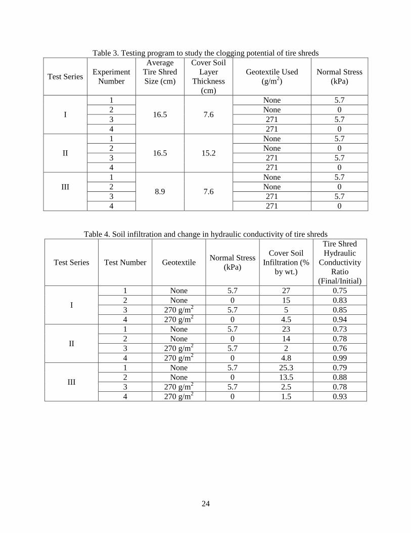
Table 3 shows the testing variables selected and the number of tests conducted in this
study. Three different series of simulation experiments, designated as Series I, II and III, were
conducted to assess the clogging potential of tire shreds when using them as drainage layer in a
landfill cover. In each series, the initial thickness of the tire shreds was maintained constant at
30.5 cm simulating the minimum drainage layer thickness in a landfill cover.
In the Series I experiments, tire shreds TS-1 were used, which correspond to tire chips
ranging in size from 1.3 cm to 22.9 cm with an average tire chip size of approximately 16.5 cm.
The thickness of the soil layer over the shredded tire layer was 7.6 cm, which created a hydraulic
head of 16.5 cm over the soil layer. In this series, four experiments were conducted starting with
the most critical condition. The experiments in Series I were labeled as 1, 2, 3, and 4 as shown in
Table 3. In experiment 1, a normal stress of 5.7 kPa, which is equivalent to a 30.5 cm thick soil
10
layer in the landfill cover, was applied. A geotextile was not used at the interface of the drainage
layer, meaning the shredded tire layer and the overlying cover soil layer were in direct contact. In
Experiment 2, a geotextile was not used at the interface of the soil and tire-shred layers and zero
normal stress was applied. Experiments 3 and 4 were identical to experiments 1 and 2 except that
a geotextile was used at the interface between the tire shreds and the cover soil layer. Each
experiment was conducted for 150 to 200 hours. At the end of the experiment, the cover soil was
removed and the hydraulic conductivity of the tire shreds was measured and compared with their
initial hydraulic conductivity to assess the influence of clogging. The flow rate versus elapsed
time was plotted and the flow pattern was observed. The amount of soil infiltration due to inflow
through the cover soil layer was calculated in each experiment.
The tire shreds TS-1 were also used in the Series II experiments as shown in Table 3. The
testing program adopted and the methodologies followed were the same as in Series I. The only
difference between the Series I and Series II testing was the thickness of the soil layer. In this
series, a 15.2 cm thick soil layer was placed over the tire shred layer instead of a 7.6 cm thick
soil layer. The increased soil thickness of 7.6 cm reduced the hydraulic head over the soil layer
to 8.9 cm. The 15.2 cm soil layer was used to study the effect of the hydraulic head on the flow
rate and the amount of soil infiltration into the voids of the tire shreds.
In Series III, tire shreds TS-2, with the size of the tire chips ranging from 1.3 cm to 14.0
cm, with an average size of 7.6 cm, were used. The size of these tire shreds were almost half the
size of tire shreds TS-1 used in Series I and II. A soil layer thickness of 7.6 cm was used and the
testing program and methodology was the same as Series I and II. The amount of soil infiltrated
and thus clogging of tire shreds, the magnitude of the flow rate and its pattern, and the hydraulic
conductivity of tire shreds after clogging were evaluated and then compared with data obtained
11
in the first two series of experiments conducted with tire shreds TS-1. This comparison was
performed to examine the effects of tire shred size on soil infiltration and the clogging of the tire
shreds.
Testing Procedure
Approximately 8.0 kg of tire chips were weighed and placed in the permeameter. This
amount was required to create an approximately 30.5 cm thick tire-shred layer in the
permeameter. The tire shreds were placed carefully to ensure that no large void(s) existed in the
layer. No compaction effort was applied while placing the tire shreds. The exact thickness of the
shredded tire layer was measured. Then, the required amount of dry silty clay soil to yield a 7.6
or 15.2 cm soil layer in the permeameter was weighed. Water was added to the soil so that the
placement water content was equal to the optimum moisture content. The soil was mixed
thoroughly until it became uniform in color and consistency. The soil was placed over the tire-
shreds in layers and was slightly tamped after each layer was applied. In select tests, a non-
woven geotextile was placed on the top of the shredded tire layer before placing the cover soil
layer. The geotextile was cut into a circular shape with a diameter slightly greater than that of the
permeameter cell to avoid direct soil migration from the edges of the permeameter. The dry
weight of the geotextile was measured prior to placement in the test setup. Where required, a
normal stress of 5.7 kPa was applied to simulate a one foot thick soil layer in a landfill cover
system.
Tap water was allowed to enter over the soil layer through the inlet. The inflow rate was
adjusted in such a way that it did not exceed flow in the outlet, thus a constant head was
maintained in the setup during the experiment. The starting time of the experiment was noted.
12
The outflow was collected for a specified time interval and the total outflow volume was
recorded. Experiments were conducted for a total duration of 150 – 200 hours.
At the end of experiments, the inflow was stopped and the applied normal stress was
removed. The soil layer was taken out of the permeameter and was allowed to dry. Its dry
weight was then measured. If present, the geotextile used at the soil and tire shred interface was
also taken out and dried and its dry weight was also measured. The hydraulic conductivity of the
tire shreds was measured as explained previously. This was done to assess potential reduction in
hydraulic conductivity due to the compression of tire shreds and clogging of tire shreds with soil.
Finally, the tire shreds were removed from the permeameter and dried.
Results and Discussion
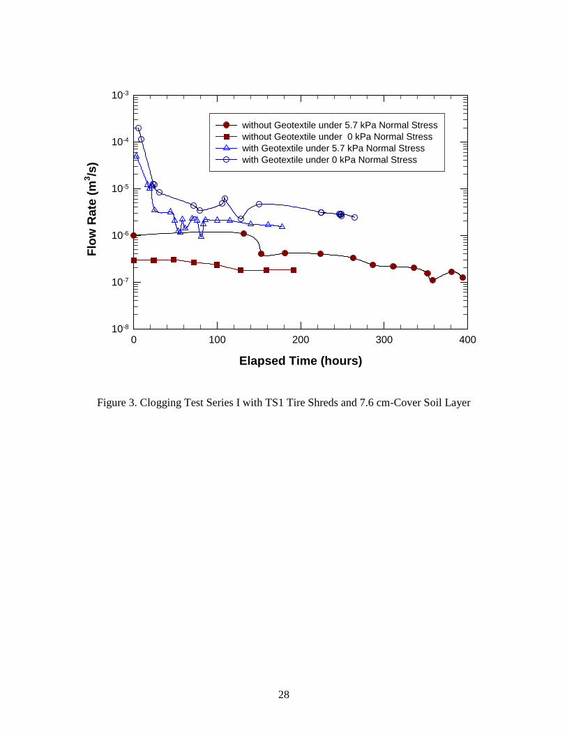
Figure 3 shows the results of the four experiments conducted in Series I using the TS-1
tire shreds with 7.6 cm of soil cover. As shown in Figure 3, the flow rate is low in all tests and it
ranges from 2.8 x 10⁻⁴ m3/s to 2.8 x 10⁻⁷ m3/s. In experiment 1, a geotextile was not used under
the soil layer and a normal stress of 5.7 kPa was applied. This experiment was conducted for a
longer duration, being the first and most critical of the experiments. Initially, the outflow was in
the range of 2.8 x 10⁻⁶ m3/s to 2.8 x10⁻⁷ m3/s. As time progressed, the outflow rate reduced to a
value in the range of 2.8 x 10⁻⁷ m3/s to 2.8 x 10⁻⁸ m3/s. In experiment 2, a geotextile was not used
underneath the soil layer, and no normal stress was applied. The self-weight of the 7.6 cm soil
was the only stress applied. There was only a slight difference in the flow rate between the
beginning and the end of the experiment. The flow rate was 2.8 x 10⁻⁷ m3/s at the beginning of
the test and was approximately the same at the end of the test. The initial flow rate in experiment
2 was expected to be higher than that of the initial flow rate in experiment 1 because the
13
permittivity of the tire shreds should be more under zero normal stress than the permittivity
under a normal stress condition of 5.7 kPa. However, the flow rate was observed to be higher in
experiment 1 in which normal stress was applied when compared to the flow rate in experiment 2
in which there was no application of normal stress. The possible reason for the low flow rate
with zero normal stress may be due to the presence of larger voids in the top portion of the tire
shred layer, which may have held a larger amount of migrated soil. This increased soil may have
created a barrier that acted as a less porous layer. During experiment 3, initially there was a
relatively high outflow as shown by the high flow rate. The high outflow may have resulted from
the flow of water from the space between the geotextile and the sides of the permeameter. The
flow rate decreased as the soil layer settled at the interface area within a very short period of
time. As the test progressed, the flow rate remained almost constant with minor fluctuations
around 2.8 x 10⁻⁶ m3/s. Experiment 4 was conducted in a manner similar to experiment 3, except
that there was no applied normal stress. The results obtained were also similar to those obtained
in experiment 3. In this experiment, the flow rate was slightly higher throughout the duration of
the experiment than in experiment 3, and it remained almost constant after 35 – 40 hours. In the
later part of the experiment, as seen from Figure 3, minor fluctuations in the flow rate were
observed. However, the flow rate is almost constant and is in the range of 2.8 x 10⁻⁵ m3/s to 2.8
x10-6 m3/s. The hydraulic conductivity of the tire shreds was less under higher normal stresses,
which means water can permeate more freely under lower normal stress conditions. This may
explain the higher flow rate in this experiment when compared to experiment 3.
The percentage of soil infiltration, in the form of soil clogged in the voids of the tire
shreds during each experiment, is presented in Table 4. Due to soil migration, there was about
27% soil infiltration by weight from the cover soil layer into the tire shreds in experiment 1. In
14
experiment 2, the amount of soil infiltration or the amount of soil that migrated into the tire shred
voids is about 15%. In experiments 3 and 4, the amount of soil infiltration was less than 5%
because of the presence of a geotextile, which acted as a filter layer. Table 4 also shows the
hydraulic conductivity of tire shreds after the completion of clogging experiments and reflects
the effects of soil clogging on reduction in hydraulic conductivity. In experiment 1, 25%
reduction in hydraulic conductivity value was observed as a result of a significant soil clogging
(27%); however, the hydraulic conductivity value was still higher than the minimum requirement
for the drainage material in a landfill cover. There was a potential for washing of soil out of the
tire shreds resulting partial clogging of the tire shreds. The hydraulic conductivity decreased by
17% in experiment 2, by 15% in experiment 3, and by 6% in experiment 4. The presence of the
geotextile at the interface in experiments 3 and 4 minimized any soil from clogging the voids of
the tire shreds. Thus, the amount of soil infiltration (less than 5%) was probably in the form of
fine soil particles that passed through the fine interstices of the geotextile. These fine soil
particles were then washed through the large voids of the tire shreds. A small amount of soil
migration may have also occurred along the sides of the permeameter wall and the geotextile into
the tire shred layer because it was difficult to create water tight edges in the permeameter. It was
also found that there was an increase of about 167% to 190% in the weight of the geotextile at
the end of the experiment because of clogging of the geotextile by fine soil particles.
The Series I experimental results show that although the tire shreds are highly permeable,
the overlying soil layer possesses low hydraulic conductivity that results in low flow rates. In all
tests, the flow rate was generally high initially and it gradually reduced with time. The reduction
in the flow rate may be due to gradual migration of soil particles into the tire shred layer that lead
to the clogging of the tire shreds. In the experiments in which the geotextile was not used, the
15
soil infiltration is 27% and 15% under the application of 5.7 kPa and 0 kPa, respectively. This
indicates that the applied stress increased soil migration and caused greater clogging of the tire
shreds. The flow was higher in the tests with the use of a geotextile, indicating that the geotextile
was effective in minimizing the migration of soil particles into the tire-shred layer. Moreover, the
soil infiltration significantly reduced and it varied from 4.5% to 5% for tests with and without the
application of normal stress of 5.7 kPa. The geotextile served as a filter and effectively contained
the migration of soil particles and minimized the clogging of tire shreds. The hydraulic
conductivity of tire shreds decreased due to clogging of tire shreds. The reduction in hydraulic
conductivity of tire shreds ranged from 25% for experiment 1 (test with no geotextile and with
applied 5.7 kPa normal stress) to 6% for the experiment 4 (test with geotextile and no normal
stress). In spite of this reduction in hydraulic conductivity, the tire shreds still possessed
hydraulic conductivity that is higher than the conventional drainage materials (granular soils).
Thus, the influence of clogging on the hydraulic performance of the tire shreds was not
compromised. The voids in the tire shreds were large and were only partially reduced by
clogging. This allowed enough void space for flow to occur easily.
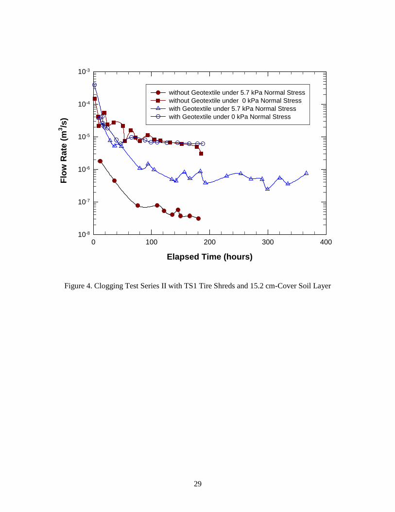
Figure 4 shows the results of the four experiments conducted in Series II. In this series,
four experiments are conducted with the same variables as in the Series I experiments except that
a 15.2 cm instead of a 7.6 cm soil layer was placed over the tire-shred layer. The results of these
experiments helped assess the effects of variable hydraulic gradient across the soil cover layer on
the drainage performance of the underlying tire-shred layer. Table 4 shows the percentage of soil
infiltration and the change in hydraulic conductivity of the tire shreds after the completion of the
clogging experiments. These results showed that flow under applied normal stress and the
absence of the geotextile (experiment 1) was the most critical condition. A significant amount of
16
soil infiltration (23%) was observed in this experiment. The lower flow rate and the higher soil
infiltration (i.e. high soil clogging) in this test were responsible for approximately 27% reduction
in hydraulic conductivity of the tire shreds. However, the hydraulic conductivity of partially
clogged tire shreds was still adequate to meet the hydraulic conductivity required for a landfill
cover system drainage layer. Experiment 2 also represents a critical condition; however, since
no vertical stress was applied in this test, the voids in the tire shreds remained large and the
migration of soil did not significantly clog the tire shreds. This produced higher flow rates and
soil infiltration (14%) and lower reduction in hydraulic conductivity of tire shreds (22%) when
compared with the results from experiment 1. Using the geotextile filter at the soil and tire shred
interface yielded higher flow rates, lower soil infiltration, and lower reduction in hydraulic
conductivity of tire shreds (see Figure 4 and Table 4). Overall, the Series II experiment results
show that a minor change in hydraulic gradient across the soil cover does not significantly affect
the hydraulic performance of tire shred drainage layers in a landfill cover system. Despite partial
clogging, the tire shred layer possesses a very high porosity to allow efficient drainage.
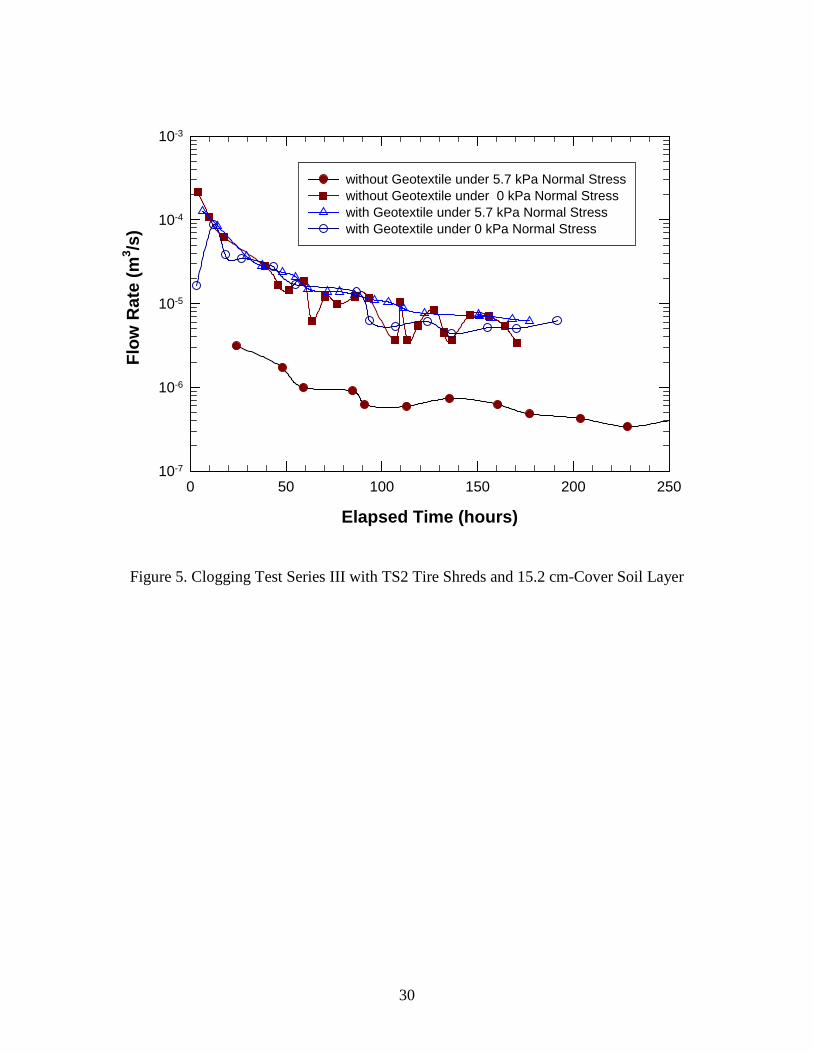
In Series III experiments, TS-2 tire shreds were used which consisted of tire shreds
ranging from 1.3 cm to 14.0 cm with an average size of 8.9 cm. All other experimental variables
were the same as those used for Series I experiments. The flow rates, percent of soil infiltration,
and reduction in hydraulic conductivity of tire shreds obtained in this experiment series were
shown in Figure 5 and Table 4. The results obtained in this series are helpful to assess the effect
of tire shred size on clogging and drainage in the tire-shred layer. The results of all four
experiments conducted in Series-III are compared to those obtained in Series I and it was
observed that the results were similar in both series. These results clearly show that the
experimental conditions used in experiment 1 were the critical condition because experiment 1
17
yielded the lowest flow rate, the highest soil infiltration, and the highest reduction in hydraulic
conductivity of tire shreds. As previously stated, in Series I and II, tire shreds TS-1 were used,
which consisted of tire shreds ranging in size from 1.3 cm to 22.9 cm with an average tire chip
size of approximately 16.5 cm. Thus, the smaller size of TS-2 tire shreds may have created
relatively lower initial porosity. Thus, for a given situation (no geotextile and a normal stress of
5.7 kPa), the smaller tire shreds are likely to yield a lower flow rate. In this series, the flow rates
of experiments 2, 3, and 4 were similar. Even though the flow rates were similar, the percentage
of soil infiltration and the tire shred hydraulic conductivity reduction (which was partially
dependant on the soil infiltration) was different in each experiment. These parameters were
largely controlled by the presence of a geotextile at the interface of the drainage layer and the
soil cover layer. Overall, the use of different tire shred sizes in this series did not show a
significant difference in the flow rates or percentages of soil infiltration. The results obtained
were similar to those obtained in Series I and II and indicate that tire shreds with the size ranges
considered in this study can serve as effective drainage material. However, it is important to use
a non-woven geotextile at the soil and tire-shred layer interface to minimize soil infiltration and
maintain high hydraulic conductivity of tire shreds.
Summary and Conclusions
Three series of experiments were conducted to determine the degree and importance of
soil clogging in tire shreds due to migration of soil from the soil cover layer overlying the tire-
shred drainage layer in a simulated landfill final cover system. Clogging of the tire shreds is
important because it will be used to determine whether or not tire shreds are a suitable drainage
material for landfill cover systems. Four different experiments were performed in each of the
18
three series of experiments. In Series I, a 7.6 cm soil layer was used over 30.5 cm of tire shreds
with an average tire shred size of 16.5 cm. In Series II, a similar size of average tire shred was
used, but the thickness of the soil layer was increased from 7.6 cm to 15.2 cm. In Series III, an
average tire shred size of 7.6 cm was used to observe the effects of a smaller tire shred size on
the measured outcomes.
The presence of 7.6 cm of soil above the tire shreds results in a hydraulic head of 16.5
cm, which is an important variable because the hydraulic head governs the hydraulic gradient
and flow rate and thus to some extent clogging potential. The flow rate under the critical test
condition, i.e., experiment 1 in all three Series, is similar. Thus, the difference in the hydraulic
head applied in Series I (16.5 cm) and II (7.6 cm) did not significantly affect the flow rate. The
flow rate of the critical experiment in each series remained in the range of 2.8 x 10⁻⁶ m3/s to 2.8 x
10-8 m3/s. The amount of soil infiltration, expressed by percentage of weight, is also almost the
same, but is large for the smaller area tested. The greater the soil infiltration in the cover soil
layer, the greater the potential for slope stability problems and the greater the reduction in the
flow rate values. A reduction in flow rate affects the drainage potential of the tire shreds. To
enhance the flow potential of a shredded tire layer, it is recommended that a non-woven
geotextile be installed above the tire-shred layer to reduce the migration of the soil into the tire
shreds. A geotextile was not used in the critical test condition, i.e., experiment 1 in each Series,
and thus soil migration into the shredded tire layer occurred.
The Series I and III experiments were similar in all aspects except for the size of tire
shreds used, which were an average of 16.5 cm and 7.6 cm, respectively. However, the test
results obtained for the two series of tests were similar and thus tire shred size did not have a
large impact on the drainage potential of the tire shreds. Both the Series I and III flow rate and
19
percent loss of soil results are comparable with the Series II results even though the soil cover
layer in Series II had a greater thickness (15.2 cm versus 7.6 cm). The presence of a 15.2 cm soil
layer provided less hydraulic head but more opportunity for permeation of soil into the tire-shred
layer.
The high hydraulic conductivity of the tire shreds even without a non-woven geotextile is
sufficient to accommodate the flow rate that is likely to be encountered in a landfill final cover
system. However, soil migration from the cover soil into the tire shreds can cause clogging in the
drainage layer, increased pore water pressures, and reduced slope stability of the cover systems.
The test results show that inclusion of a non-woven geotextile at the cover soil and tire shred
interface will reduce the soil migration and possible slope stability problems. The geotextile acts
as a separator between the cover soil layer and the drainage layer and prevents soil particles from
migrating into the tire shreds.
Acknowledgements
This project was funded by the Illinois Department of Commerce and Economic
Opportunity and the Illinois Environmental Protection Agency. The support of these agencies is
gratefully acknowledged.
20
References
Ahmed, I., and Lovell, C. W. (1993), “Rubber Soils as Lightweight Geomaterial”, Transportation
Research Record 1422, pp. 61-70.
ASTM (1998), “Standard Practice for Use of Scrap Tires in Civil Engineering Applications-
ASTM D 6270-98”, American Society for Testing and Materials, W. Conshohocken, PA,
19p.
Bernal, A., Lovell, C.W., and Salgado, R. (1996), “Laboratory Study on the use of Tire Shreds
and Rubber-Sand in Backfills and Reinforced Soil Applications”, FHWA/IN/JHRP-
96/12, Purdue University, West Lafayette, Indiana.
Bressette (1984), “Used Tire Material as an Alternative Permeable Aggregate”, Report No.
FHWA/CA/TL-84/07, Office of Transportation Laboratory, California Department of
Transportation, Sacramento, California.
Cecich, V., Gonzales, L., Hoisaeter, A., Williams, J., and Reddy, K., (1996), “Use of Shredded
Tires as Lightweight Backfill Material for Retaining Structures”, Waste Management &
Research, Vol.14, pp.433-451.
Daniel, D. E. and Koerner, R. M., Final Cover System, Chapter 18 in Geotechnical Practice for
Waste Disposal, D. E. Daniel, Editor, Chapter-Hall, London, 1992, pp. 455-496.
Edil, T. B., and Bosscher, P.J., (1992), “Development of Engineering Criteria for Shredded or
Whole Tires in Highway Applications”, Report No.WI 14-92, Department of Civil and
Environmental Engineering, University of Wisconsin, Madison, Wisconsin.
Edil, T. B., and Bosscher, P.J. (1994), “Engineering Properties of Tire Chips and Soil Mixtures”,
Geotechnical Testing Journal, Vol. 17, No. 4, pp. 453-464.
21
Foose, G.J., Benson, C.H., and Bosscher, P.J., (1996), “Sand with Shredded Waste Tires”,
Geotechnical Testing Journal, GTJODJ, Vol. 122, No. 9, pp 760-767.
Humphery, D. N., and Manion, W. P., (1992), “Properties of Tire Chips for Lightweight Fill”,
Proceedings of the Conference on Grouting, Soil Improvement, and Geosynthetics,
ASCE, New Orleans, Louisiana, Vol-2, pp. 1344-1355.
Humphery, D. N., and Sandford, T.C., (1993), “Tire Chips as Lightweight Sub grade Fill and
Retaining Wall Backfill”, Proceedings of the Symposium on Recovery and Effective
reuse of Discarded Materials and By-Products for Construction of Highway Facilities,
Federal Highway Administration, Washington, D.C.
Humphery, D. N., and Sandford, T.C., Cribbs, M.M., and Manion, W. P. (1993), “Shear Strength
and Compressibility of Tire Chips for Use as Retaining Wall Backfill”, Transportation
Research Record 1422, Transportation Research Board, Washington, D.C.
Masad, E., Taha, R., Ho, C., and Papagiannakis, T., (1996), “Engineering Properties of Tire/Soil
Mixtures as a Lightweight Fill Material”, Geotechnical Testing Journal, Vol.19, No.3,
pp.297-304.
Newcomb, D.E., and Drescher, A., (1994), “Engineering Properties of Shredded Tires in
Lightweight Fill Applications”, Preprint, Transportation Research Board, Washington,
D.C.
Reddy, K.R. and Saichek, R.E., (1998a), “Characterization and Performance Assessment of
Shredded Scrap Tires as Leachate Drainage Material in Landfills”, Proceedings of the
Fourteenth International Conference on Solid Waste Technology and Management,
Philadelphia, PA.
22
Reddy, K.R., and Saichek, R.E., (1998b), “Assessment of Damage to Geomembrane Liners by
Shredded Scrap Tires”, Geotechnical Testing Journal, Vol.21, No.4, pp. 307-316.
Reddy, K.R., Kosgi, S., and Motan, E.S. (1996). “Interface Shear Behavior of Landfill
Composite Liner Systems: A Finite Element Analysis”, Geosynthetics International, Vol.
3, No. 2, pp. 247-275.
Sharma, H.D., and Reddy, K.R., “Geoenvironmental Engineering: Site Remediation, Waste
Containment, and Emerging Waste management Technologies,” John Wiley & Sons,
Inc., New Jersey, 2004.
Upton, R.J., and Machan, G., (1993), “Use of Shredded Tires for Lightweight Fill”,
Transportation Research Record 1422, Washington, D.C.
U.S Environmental Protection Agency, ‘Design and Construction of RCRA / CERCLA Final
Covers’, Office of Research and Development, Washington D.C., EPA 822-R-94-001,
May 1994.
23
Table 1. Properties of soil used to simulate cover soil layer
Property Test Methods Value Specific Gravity ASTM D 854 2.65
Atterberg Limits ASTM D4318
Liquid Limit=46% Plastic Limit=25% Plasticity Index=21%
Grain Size Distribution ASTM D422
Gravel=0.0% Sand=11.4% Fines=88.6%
Hydraulic Conductivity ASTM D2342 2.4 x 10⁻⁸ cm/s Optimum Moisture Content ASTM D698
15.4 %
Maximum Dry Density 4.9 kN/m3 Soil Classification ASTM D2487 Silty Clay, CL
Table 2. Properties of the geotextile used Property Units Test Method Value Fabric Weight g/m2 ASTM D3776 254 Thickness mm ASTM D1777 2.75 Grab Strength N ASTM D4632 1334/1045 Grab Elongation % ASTM D4632 75/85 Trapezoid Tear Strength N ASTM D4533 467/423 Puncture Resistance N ASTM D4833 512 Mullen Burst Strength kPa ASTM D3786 2757 Water Flow Rate (m2/sec) ASTM D4491 0.031 Permitivity,Ψ Sec-1 ASTM D4491 2.01 Permeability, k=Ψt cm/sec ASTM D4491 0.56
AOS Sieve Size, mm ASTM D4751 70-100
0.210-0.149
24
Table 3. Testing program to study the clogging potential of tire shreds
Test Series Experiment Number
Average Tire Shred Size (cm)
Cover Soil Layer
Thickness (cm)
Geotextile Used (g/m2)
Normal Stress (kPa)
I
1
16.5 7.6
None 5.7 2 None 0 3 271 5.7 4 271 0
II
1
16.5 15.2
None 5.7 2 None 0 3 271 5.7 4 271 0
III
1
8.9 7.6
None 5.7 2 None 0 3 271 5.7 4 271 0
Table 4. Soil infiltration and change in hydraulic conductivity of tire shreds
Test Series Test Number Geotextile Normal Stress (kPa)
Cover Soil Infiltration (%
by wt.)
Tire Shred Hydraulic
Conductivity Ratio
(Final/Initial)
I
1 None 5.7 27 0.75 2 None 0 15 0.83 3 270 g/m2 5.7 5 0.85 4 270 g/m2 0 4.5 0.94
II
1 None 5.7 23 0.73 2 None 0 14 0.78 3 270 g/m2 5.7 2 0.76 4 270 g/m2 0 4.8 0.99
III
1 None 5.7 25.3 0.79 2 None 0 13.5 0.88 3 270 g/m2 5.7 2.5 0.78 4 270 g/m2 0 1.5 0.93
25
Figure Captions Figure 1. Schematic of Clogging Experimental Test-up Figure 2. Size Distribution of Tire Shreds TS1 and TS2
Figure 3. Clogging Test Series I with TS1 Tire Shreds and 7.6 cm-Cover Soil Layer
Figure 4. Clogging Test Series II with TS1 Tire Shreds and 15.2 cm -Cover Soil Layer
Figure 5. Clogging Test Series III with TS2 Tire Shreds and 15.2 cm-Cover Soil Layer
26
Figure 1. Schematic of Clogging Experimental Test-up
27
Tire Shred Size (cm)
0 10 20 30 40
Cum
ulat
ive
Dis
trib
utio
n (%
)
0
20
40
60
80
100
TS1 Tire Shreds - QuantityTS1 Tire Shreds - WeightTS2 Tire Shreds - QuantityTS2 Tire Shreds - Weight
Figure 2. Size Distribution of Tire Shreds TS1 and TS2
28
Elapsed Time (hours)
0 100 200 300 400
Flow
Rat
e (m
3 /s)
10-8
10-7
10-6
10-5
10-4
10-3
without Geotextile under 5.7 kPa Normal Stresswithout Geotextile under 0 kPa Normal Stresswith Geotextile under 5.7 kPa Normal Stresswith Geotextile under 0 kPa Normal Stress
Figure 3. Clogging Test Series I with TS1 Tire Shreds and 7.6 cm-Cover Soil Layer
29
Elapsed Time (hours)
0 100 200 300 400
Flow
Rat
e (m
3 /s)
10-8
10-7
10-6
10-5
10-4
10-3
without Geotextile under 5.7 kPa Normal Stresswithout Geotextile under 0 kPa Normal Stresswith Geotextile under 5.7 kPa Normal Stresswith Geotextile under 0 kPa Normal Stress
Figure 4. Clogging Test Series II with TS1 Tire Shreds and 15.2 cm-Cover Soil Layer
30
Elapsed Time (hours)
0 50 100 150 200 250
Flow
Rat
e (m
3 /s)
10-7
10-6
10-5
10-4
10-3
without Geotextile under 5.7 kPa Normal Stresswithout Geotextile under 0 kPa Normal Stresswith Geotextile under 5.7 kPa Normal Stresswith Geotextile under 0 kPa Normal Stress
Figure 5. Clogging Test Series III with TS2 Tire Shreds and 15.2 cm-Cover Soil Layer