Embed Size (px)
Citation preview
1398SCP016EN00 - 19-06-2019
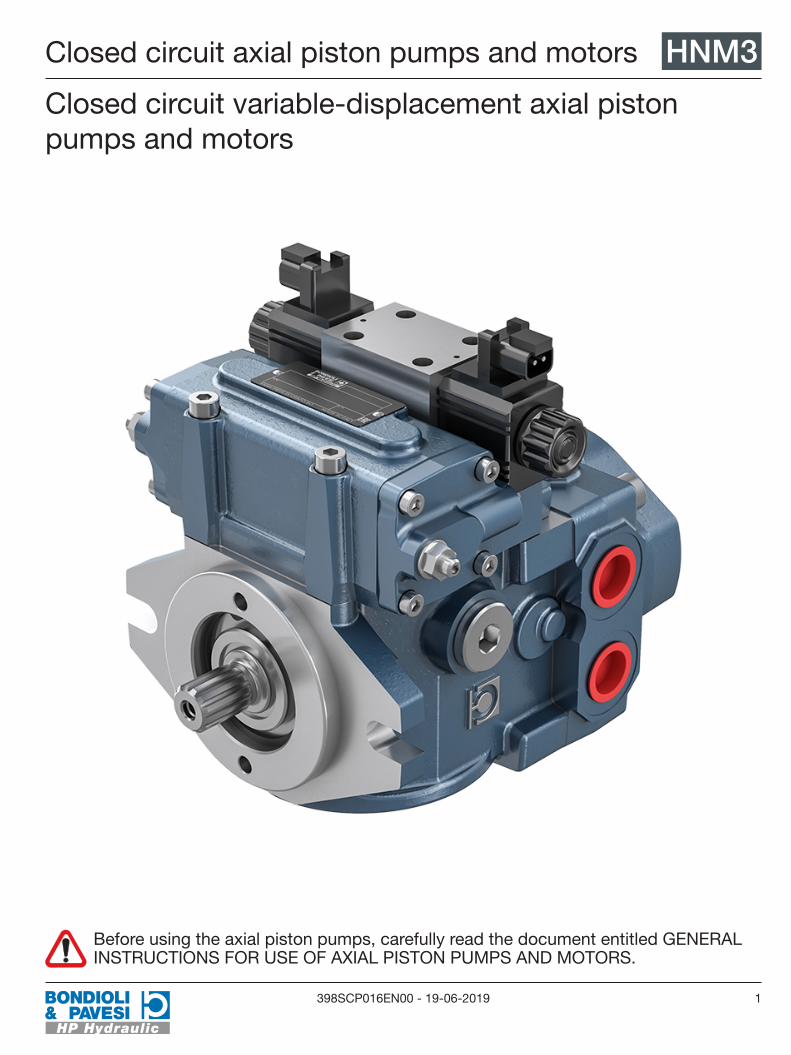
Closed circuit axial piston pumps and motors HNM3
Closed circuit variable-displacement axial piston pumps and motors
Before using the axial piston pumps, carefully read the document entitled GENERAL INSTRUCTIONS FOR USE OF AXIAL PISTON PUMPS AND MOTORS. Closed circuit axial piston pumps and motorsHNM3 398SCP016EN00 -

2 398SCP016EN00 - 19-06-2019
HNM3 Dimensions
3,
8998
,8
3,
829
97,2
5
by-pass
8,283210,4
4,
7211
9,9
3,26
883
HNM3 Nominal displacement
Swash plate
Continuous pressure Intermittent pressure Peak pressure Rotational speed Weight
cm3 in3 ° bar psi bar psi bar psi min-1 min-1 kg lbs
021 21 1.28 14.6 210 3046 230 3336 250 3626 3200 500 25 55
028 28 1.71 16.3 210 3046 230 3336 250 3626 3200 500 25 55
032 32 1.95 18 210 3046 230 3336 250 3626 3200 500 25 55
B21 21 1.28 14.6 250 3626 300 4351 350 5076 3600 500 25 55
B28 28 1.71 16.3 250 3626 300 4351 350 5076 3600 500 25 55
B37 37 2.26 18 250 3626 300 4351 350 5076 3400 500 25 55
Dimensions

3398SCP016EN00 - 19-06-2019
Dimensions HNM3Feed pump
Type Feed pump displacement Pressure
cm3 in3 bar psi
HNM3 021 9 0.55 22 319
HNM3 028 9 0.55 22 319
HNM3 032 9 0.55 22 319
HNM3 B21 9 0.55 22 319
HNM3 B28 9 0.55 22 319
HNM3 B37 12 0.72 22 319

4 398SCP016EN00 - 19-06-2019
HNM3 Flanges
B SAE B
0,374
9,5
4 -0,
000
0,00
2
101,
6 -0 0,
05
5,748146
6,77172
0,
591
15
Flanges

5398SCP016EN00 - 19-06-2019
Shaft profile HNM33 SAE 15T 16/32 DP
0,311
7,9
0,98
225
1,22431,1
1,811
46 Coppia Max 460 Nm
6 SAE 13T 16/32 DP
1,02826,1
0,85
821
,8
1,614
41
0,311
7,9
Coppia Max 310 Nm
Shaft profile

6 398SCP016EN00 - 19-06-2019
HNM3 Position of ports
A,B - UseL1, L2 - Drain portS - InletP - Pressure intakeM1, M2 - Manometer intake
Position of ports
7398SCP016EN00 - 19-06-2019
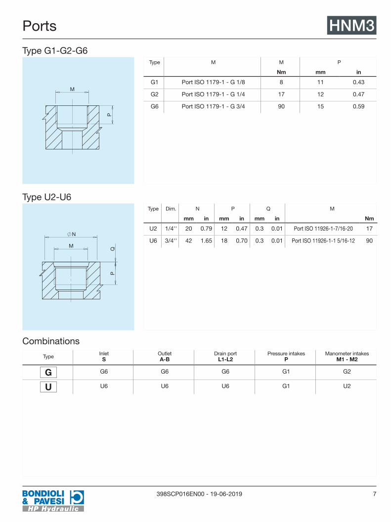
Ports HNM3Type G1-G2-G6
P
M
Type M M P
Nm mm in
G1 Port ISO 1179-1 - G 1/8 8 11 0.43
G2 Port ISO 1179-1 - G 1/4 17 12 0.47
G6 Port ISO 1179-1 - G 3/4 90 15 0.59
Type U2-U6
P
N
Q M
Type Dim. N P Q M
mm in mm in mm in Nm
U2 1/4'' 20 0.79 12 0.47 0.3 0.01 Port ISO 11926-1-7/16-20 17
U6 3/4'' 42 1.65 18 0.70 0.3 0.01 Port ISO 11926-1-1 5/16-12 90
Combinations
Type Inlet S
Outlet A-B
Drain port L1-L2
Pressure intakes P
Manometer intakes M1 - M2
G G6 G6 G6 G1 G2
U U6 U6 U6 G1 U2
Ports
8 398SCP016EN00 - 19-06-2019
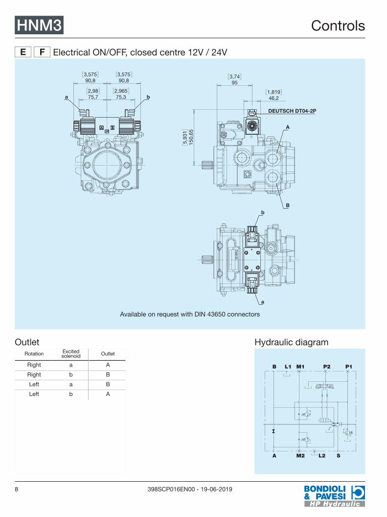
HNM3 Controls
E F Electrical ON/OFF, closed centre 12V / 24V
1,81946,2
3,7495
5,
931
150,
65
B
A
DEUTSCH DT04-2P
b
a
2,9875,7
2,96575,3
3,57590,8
3,57590,8
b a
Available on request with DIN 43650 connectors
OutletRotation Excited
solenoid Outlet
Right a A
Right b B
Left a B
Left b A
Hydraulic diagram
L1 M1
A SM2 L2
B P1P2
Controls

9398SCP016EN00 - 19-06-2019
Controls HNM3
N Q Electrical ON/OFF, open centre 12V / 24V
1,81946,2
3,7495
5,
929
150,
6
B
A
DEUTSCH DT04-2P
b
a
2,96975,4
2,96975,4
3,57590,8
3,57590,8
b a
Available on request with DIN 43650 connectors
OutletRotation Excited
solenoid Outlet
Right a A
Right b B
Left a B
Left b A
Hydraulic diagram
L1 M1
A SM2 L2
B P2 P1

10 398SCP016EN00 - 19-06-2019
HNM3 Controls
I Lever-operated hydraulic
0,
315
8
0,2366
5,
102
129,
6
2,362
60
B
A
3,7495
30°
30°
Y
X
F
OutletRotation Control lever Outlet
Right Y B
Right X A
Left Y B
Left X A
Pilot pressure
0% 100% (cm3)
26
F (N)
DISPLACEMENT
2119
Hydraulic diagram
B L2M2 S
A M1L1 P1M4 M3P2
Controls

11398SCP016EN00 - 19-06-2019
Controls HNM3
K Remote hydraulic
1,772
45
4,
031
102,
4
B
A
3,7495
0,
965
24,5
2,
343
59,5
a
b
OutletRotation Pilot pressure Outlet
Right a A
Right b B
Left a A
Left b B
Pilot pressure
0% 100% (cm3)
14
(bar)
3,5
DISPLACEMENT
PIL
OT
PR
ES
SU
RE
@p A-B = 0 bar
Hydraulic diagram
B L2M2 S
A M1L1 a b P2 P1
Controls
12 398SCP016EN00 - 19-06-2019
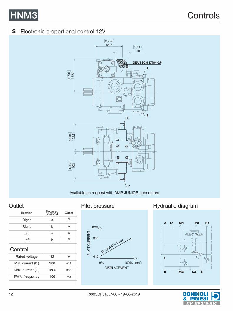
HNM3 Controls
S Electronic proportional control 12V
3,72894,7
1,811
46
4,
701
119,
4
B
A
DEUTSCH DT04-2P
4,
035
102,
5
4,
055
103
b
a
Available on request with AMP JUNIOR connectors
OutletRotation Powered
solenoid Outlet
Right a B
Right b A
Left a A
Left b B
ControlRated voltage 12 V
Min. current (I1) 300 mA
Max. current (I2) 1500 mA
PWM frequency 100 Hz
Pilot pressure
0% 100% (cm3)
800
(mA)
440
DISPLACEMENT
PIL
OT
CU
RR
EN
T
@p A-B = 0 bar
Hydraulic diagram
B L2M2 S
A M1L1 P1P2
Controls
13398SCP016EN00 - 19-06-2019
Controls HNM3
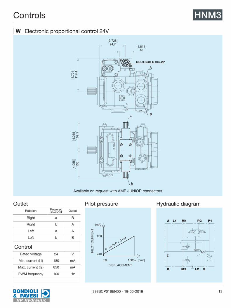
W Electronic proportional control 24V
3,72894,7
1,811
46
4,
701
119,
4
B
A
DEUTSCH DT04-2P
4,
035
102,
5
4,
055
103
b
a
Available on request with AMP JUNIOR connectors
OutletRotation Powered
solenoid Outlet
Right a B
Right b A
Left a A
Left b B
ControlRated voltage 24 V
Min. current (I1) 180 mA
Max. current (I2) 850 mA
PWM frequency 100 Hz
Pilot pressure
0% 100% (cm3)
420
(mA)
240
DISPLACEMENT
PIL
OT
CU
RR
EN
T
@p A-B = 0 bar
Hydraulic diagram
B L2M2 S
A M1L1 P1P2

14 398SCP016EN00 - 19-06-2019
HNM3 Through Drive
2 SAE A with boost pump
SA
E 9
T 16
/32
DP
3,25
2 + 0,
002
0,00
0
82,6
+ 0,04
0
8,264209,9
0,276
7
0,55614,11
1,6541,9
120
Nm
M10
4,189106,4
47 N
m
5 SAE A without boost pump
SA
E 9
T 16
/32
DP
3,25
2 + 0,
002
0,00
0
82,6
+ 0,04
0
8,264209,9
0,276
7
0,55614,11
1,6541,9
120
Nm
M10
4,189106,4
47 N
m
Through Drive

15398SCP016EN00 - 19-06-2019
Accessories HNM3
V Flushing valve (5-7 l/min)
3,
78 96
5,
197
132
Hydraulic diagram
B L2 M2 S
A M1L1 a b P
Accessories

16 398SCP016EN00 - 19-06-2019
HNM3 Instructions for ordering
HNM3
1 2 3
4
5
4
7
8
9
10
11
12 13 14
1 2 3
Displacement 021B21
028B28
032B37
4
Direction of rotation RightR LeftL
5
Flanges SAE BB
4
Shaft profile SAE 15T 16/32 DP3 SAE 13T 16/32 DP6
7
Type of ports GasG UnfU
8
Controls Electrical ON/OFF, closed centre 12VE
Electrical ON/OFF, closed centre 24VF
Electrical ON/OFF, open centre 12VN
Electrical ON/OFF, open centre 24VQ
Lever-operated hydraulicI Remote hydraulicK
Electronic proportional control 12VS
Electronic proportional control 24VW
9
Valve calibration 150 barB 180 barD
210 barE 250 barG
280 barI 300 barL
350 barO 400 barP
10
Through Drive No special fittings, without boost pump0 No special fittings, with boost
pump1 SAE A with boost pump2 SAE A without boost pump5
11
Accessories No option0 Flushing valveV
12 13 14
Special versions...
Instructions for ordering