Embed Size (px)
DESCRIPTION
In this project, we design an efficient audit service for verifying the integrity of untrusted and outsourced storage. Our audit service, constructed based on the technique of fragment structure can support timely abnormal detection. This system has a lower computation overhead, as well as a shorter extra storage for audit metadata.
Citation preview

CHAPTER – 1
INTRODUCTION
1.1 OVERVIEW
Cloud computing has been envisioned as the next generation information
technology (IT) architecture for enterprises, due to its long list of unprecedented
advantages in the IT history: on-demand self-service, ubiquitous network access,
location independent resource pooling, rapid resource elasticity, usage-based pricing
and transference of risk. As a disruptive technology with profound implications,
Cloud Computing is transforming the very nature of how businesses use information
technology. One fundamental aspect of this paradigm shifting is that data is being
centralized or outsourced to the Cloud. From users’ perspective, including both
individuals and IT enterprises, storing data remotely to the cloud in a flexible on-
demand manner brings appealing benefits: relief of the burden for storage
management, universal data access with location independence, and avoidance of
capital expenditure on hardware, software, and personnel maintenances, etc. While
Cloud Computing makes these advantages more appealing than ever, it also brings
new and challenging security threats towards users’ outsourced data.
Since cloud service providers (CSP) are separate administrative entities, data
outsourcing is actually relinquishing user’s ultimate control over the fate of their data.
As a result, the correctness of the data in the cloud is being put at risk due to the
following reasons. First of all, although the infrastructures under the cloud are much
more powerful and reliable than personal computing devices, they are still facing the
broad range of both internal and external threats for data integrity . Examples of
outages and security breaches of noteworthy cloud services appear from time to
time. Secondly, there do exist various motivations for CSP to behave unfaithfully
towards the cloud users regarding their outsourced data status. For examples, CSP
might reclaim storage for monetary reasons by discarding data that has not been or
is rarely accessed, or even hide data loss incidents to maintain a reputation. In short,
although outsourcing data to the cloud is economically attractive for long-term large-
scale storage, it does not immediately offer any guarantee on data integrity and
availability. This problem, if not properly addressed, may impede the success of
1
cloud architecture. Security audit is an important solution enabling tracking and
analysis of any activities including data accesses, security breaches, application
activities, and so on. Data security tracking is crucial for all organizations that must
be able to comply with a range of federal laws including the Sarbanes-Oxley Act,
Basel II, HIPAA and other regulations.
1.2 OBJECTIVE
The main objective of our project is to create an efficient audit system profiting
from the interactive zero-knowledge proof system. We address the construction of an
interactive PDP protocol to prevent the fraudulence of prover (soundness property)
and the leakage of verified data (zero-knowledge property). Another major concern
addressed by our project is how to improve the performance of audit services. The
audit performance concerns not only the costs of computation, communication,
storage for audit activities but also the scheduling of audit activities. No doubt
improper scheduling, more or less frequent, causes poor audit performance, but an
efficient scheduling can help provide a better quality of and a more cost-effective
service. Hence, it is critical to investigate an efficient schedule for cloud audit
services.
1.3 AIM
Through our project, we aim to:
To design an efficient architecture of audit system to reduce the storage and
network overheads and enhance the security of audit activities;
To provide an efficient audit scheduling to help provide a more cost-effective
audit service
To optimize parameters of audit systems to minimize the computation
overheads of audit services.
2

CHAPTER – 2
BACKGROUND WORK
2.1 EXISTING SYSTEM
2.1.1 PROBLEM DEFINITION
We consider a cloud data storage service involving three different entities, as
illustrated in Fig. 1: the cloud user (U), who has large amount of data files to be
stored in the cloud; the cloud server (CS), which is managed by cloud service
provider (CSP) to provide data storage service and has significant storage space
and computation resources (we will not differentiate CS and CSP hereafter );the third
party auditor (TPA), who has expertise and capabilities that cloud users do not have
and is trusted to assess the cloud storage service security on behalf of the user upon
request. Users rely on the CS for cloud data storage and maintenance. They may
also dynamically interact with the CS to access and update their stored data for
various application purposes. The users may resort to TPA for ensuring the storage
security of their outsourced data, while
hoping to keep their data private from TPA.
We consider the existence of a semi-trusted CS in the sense that in most of
time it behaves properly and does not deviate from the prescribed protocol
execution. While providing the cloud data storage based services, for their own
benefits the CS might neglect to keep or deliberately delete rarely accessed data
files which belong to ordinary cloud users. Moreover, the CS may decide to hide the
data corruptions caused by server hacks or Byzantine failures to maintain reputation.
We assume the TPA, who is in the business of auditing, is reliable and independent,
and thus has no incentive to collude with either the CS or the users during the
auditing process. TPA should be able to efficiently audit the cloud data storage
without local copy of data and without bringing in additional on-line burden to cloud
users. However, any possible leakage of user’s outsourced data towards TPA
through the auditing protocol should be prohibited.
3

FIG 1 ARCHITECTURE OF CLOUD DATA STORAGE SERVICE
2.2 RELATED WORK
The traditional cryptographic technologies for data integrity and availability,
based on Hash functions and signature schemes, cannot work on the outsourced
data without a local copy of data. In addition, it is not a practical solution for data
validation by downloading them due to the expensive communications, especially for
large size files. Moreover, the ability to audit the correctness of the data in a cloud
environment can be formidable and expensive for the cloud users. Therefore, it is
crucial to realize public auditability for CSS, so that data owners may resort to a third
party auditor (TPA), who has expertise and capabilities that a common user does not
have, for periodically auditing the outsourced data. This audit service is significantly
important for digital forensics and credibility in clouds.
To implement public auditability, the notions of proof of retrievability (POR)
and provable data possession (PDP) have been proposed by some researchers.
Their approach was based on a probabilistic proof technique for a storage provider
to prove that clients’ data remain intact. For ease of use, some POR/PDP schemes
work on a publicly verifiable way, so that anyone can use the verification protocol to
prove the availability of the stored data. Hence, this provides us an effective
approach to accommodate the requirements from public auditability. POR/PDP
schemes evolved around an untrusted storage offer a publicly accessible remote
interface to check the tremendous amount of data.
4

There exist some solutions for audit services on outsourced data. For
example, Xie et al. proposed an efficient method on content comparability for
outsourced database, but it wasn’t suited for irregular data. Wang et al. also provided
a similar architecture for public audit services. To support their architecture, a public
audit scheme was proposed with privacy-preserving property. However, lack of
rigorous performance analysis for constructed audit system greatly affects the
practical application of this scheme. For instance, in this scheme an outsourced file
is directly split into n blocks, and then each block generates a verification tag.
In order to maintain security, the length of block must be equal to the size of
cryptosystem, that is, 160-bit=20- Bytes. This means that 1M-Bytes file is split into
50,000 blocks and generates 50,000 tags, and the storage of tags is at least 1M-
Bytes. It is clearly inefficient to build an audit system based on this scheme. To
address such a problem, a fragment technique is introduced in this paper to improve
performance and reduce extra storage. Another major concern is the security issue
of dynamic data operations for public audit services.
In clouds, one of the core design principles is to provide dynamic scalability
for various applications. This means that remotely stored data might be not only
accessed but also dynamically updated by the clients, for instance, through block
operations such as modification, deletion and insertion. However, these operations
may raise security issues in most of existing schemes, e.g., the forgery of the
verification metadata (called as tags) generated by data owners and the leakage of
the user’s secret key. Hence, it is crucial to develop a more efficient and secure
mechanism for dynamic audit services, in which possible adversary’s advantage
through dynamic data operations should be prohibited.
5

CHAPTER – 3
PROPOSED SYSTEM
3.1 PROPOSED SYSTEM
In this method we provide an efficient and secure cryptographic interactive
audit scheme for public auditability. This scheme retains the soundness property and
zero knowledge property of proof systems. These two properties ensure that our
scheme can not only prevent the deception and forgery of cloud storage providers,
but also prevent the leakage of outsourced data in the process of verification.
3.2 SYSTEM DESCRIPTION
Audit system architecture for outsourced data in clouds is shown in figure 1. In
this architecture, we consider a data storage service containing four entities:
Data owner (DO): who has a large amount of data to be stored in the cloud;
Cloud service provider (CSP): who provides data storage service and has enough
storage spaces and computation resources;
Third party auditor (TPA): who has capabilities to manage or monitor outsourced
data under the delegation of data owner;
Granted applications (GA): who have the right to access and manipulate stored
data. These applications can be either inside clouds or outside clouds according to
the specific requirements.
Next, we describe a flowchart for audit service based on TPA. This also
provides a background for the description of our audit service outsourcing as follows:
• First, the client (data owner) uses the secret key sk to preprocesses the file, which
consists of a collection of n blocks, generates a set of public verification information
that is stored in TPA, transmits the file and some verification tags to CSP, and
may delete its local copy;
6

• At a later time, using a protocol of proof of retrievability, TPA (as an audit agent of
clients) issues a challenge to audit (or check) the integrity and availability of the
outsourced data in terms of the public verification information. It is necessary to give
an alarm for abnormal events.
This architecture is known as the audit service outsourcing due to data
integrity verification can be implemented by TPA without help of data owner. In this
architecture, the data owner and granted clients need to dynamically interact with
CSP to access or update their data for various application purposes. However, we
neither assume that CSP is trust to guarantee the security of stored data, nor
assume that the data owner has the ability to collect the evidences of CSP’s fault
after errors occur. Hence, TPA, as a trust third party (TTP), is used to ensure the
storage security of their outsourced data. We assume the TPA is reliable and
independent, and thus has no incentive to collude with either the CSP or the clients
during the auditing process:
FIG 2 PROPOSED SYSTEM ARCHITECTURE
• TPA should be able to make regular checks on the integrity and availability of these
delegated data at appropriate intervals;
7
• TPA should be able to take the evidences for the disputes about the inconsistency
of data in terms of authentic records for all data operations.
In this audit architecture, our core idea is to maintain the security of TPA to
guarantee the credibility of cloud storages. This is because it is more easy and
feasible to ensure the security of one TTP than to maintain the credibility of the
whole cloud. Hence, the TPA could be considered as the root of trust in clouds. To
enable privacy-preserving public auditing for cloud data storage under this
architecture, our protocol design should achieve following security and performance
guarantees:
Audit-without-downloading: to allow TPA (or other clients with the help of TPA) to
verify the correctness of cloud data on demand without retrieving a copy of whole
data or introducing additional on-line burden to the cloud users;
Verification-correctness: to ensure there exists no cheating CSP that can pass the
audit from TPA without indeed storing users’ data intact;
Privacy-preserving: to ensure that there exists no way for TPA to derive users’ data
from the information collected during the auditing process; and
High-performance: to allow TPA to perform auditing with minimum overheads in
storage, communication and computation, and to support statistical audit sampling
and optimized audit schedule with a long enough period of time.
8

CHAPTER – 4
SYSTEM ANALYSIS
4.1 INTRODUCTION
After analyzing the requirements of the task to be performed, the next step is
to analyze the problem and understand its context. The first activity in this phase is
studying the existing system and other is to understand the requirements and the
domain of the new system. Both the activities are equally important, but the first
activity serves as a basis of giving the functional specifications and then successful
design of the proposed system. Understanding the requirements of the new system
is more difficult and requires creative thinking and understanding of existing running
system is also difficult, improper understanding of present system can lead diversion
from solution.
4.2 ANALYSIS MODEL
This document plays a vital role in development life cycle( SDLC) as it
describes the complete requirement of the system. It means for use by developers
and will be the basic during testing phase. Any changes made to requirements in
future will have to go through formal change approval process.
WATERFALL MODEL
The waterfall model is a sequential development process, in which
development is seen as flowing steadily downwards (like a waterfall) through the
phases of requirement analysis, design, implementation, testing (validation),
integration, and maintenance. The first formal description of waterfall model is often
cited to be an article published by Winston W. Royce in 1970 although Royce did not
use the term “waterfall” in this article.
9

Basic principles of waterfall model are:
Project is divided into sequential phases, with some overlap and splash back
acceptable between phases.
Emphasis is on planning, time schedules, target dates, budgets and
implementation of entire system at one time.
Tight control is maintained over the life of the project through the use of
extensive written documentation, as well as through formal reviews and
approval/signoff by the user and information technology mangament occurring
at the end of most phases before beginning the next phase.
Fig 3 ANALYSIS MODEL
To follow the water fall model one has to proceed from one phase to the next in a
sequential manner. For example, one first completes requirements specifications,
which after sign-off are considered to be “set in stone”. When the requirements are
fully completed, one proceeds to design. The software in question is designed and a
blueprint is drawn for the implementers to follow – this design should be plan for
implementing the requirements given. When the design is fully completed, an
implementation of that design is made by the coders. Towards later stages of this
implementation phase, separate software components produced are combined to
10

introduce new functionality and reduce the risk of errors through removal of errors.
Thus waterfall model maintains that one should move to a phase only if its preceding
phase is completed and perfected.
11

CHAPTER – 5
SYSTEM DESIGN
5.1 SYSTEM REQUIREMENTS
HARDWARE REQUIREMENTS:
Pentium 4 processor
1 GB RAM
80 GB Hard disk space
SOFTWARE REQUIREMENTS:
Operating system Windows XP
Coding Language ASP.Net with C#
Data Base SQL Server 2005
5.2 FLOW CHART
A flowchart is a type of diagram that represents an algorithm or process,
showing the steps as boxes of various kinds, and their order by connecting them with
arrows. This diagrammatic representation can give a step-by-step solution to a
given problem. Process operations are represented in these boxes, and arrows
connecting them represent flow of control. Data flows are not typically represented in
a flowchart, in contrast with data flow diagrams; rather, they are implied by the
sequencing of operations. Flowcharts are used in analyzing, designing, documenting
or managing a process or program in various fields.
12

FIG 4 FLOWCHART OF THE AUDIT SYSTEM
13

5.3 UNIFIED MODELING LANGUAGE
The Unified Modeling Language (UML) is a standard language for
specifying, visualizing, constructing, and documenting the artifacts of software
systems, as well as for business modeling and other non-software systems. The
UML represents a collection of best engineering practices that have proven
successful in the modeling of large and complex systems. The UML is a very
important part of developing object oriented software and the software development
process. The UML uses mostly graphical notations to express the design of software
projects. Using the UML helps project teams communicate, explore potential
designs, and validate the architectural design of the software.
Each UML diagram is designed to let developers and customers view a
software system from a different perspective and in varying degrees of abstraction.
UML diagrams commonly created in visual modeling tools include:
5.3.1 Use Case Diagram: This displays the relationship among actors and use
cases. A use case is a description of a system's behavior from a user's standpoint.
For system developers, this is a valuable tool: it's a tried-and-true technique for
gathering system requirements from a user's point of view. That's important if the
goal is to build a system that real people can use. In graphical representations of use
cases a symbol for the actor is used. Use cases are a relatively easy UML diagram
to draw. Start by listing the sequence of steps the user might take to complete an
action. For example in our audit system a user will
Create his/her account. And generate a secret key.
Login using their user – id and a secret key
Upload a file
The third party auditor and server will:
Validate the user
Verify the uploaded file details
Maintain the client details
14

Usecase are collection of scenarios about system use. Each scenario describes a
sequence of events. Each sequence is initiated by a person, another system, a piece
of hardware, or by the passage of time. Entities that initiate sequences are called
actors. The result of the sequence has to be something of use either to the actor who
initiated it or to another actor. It's possible to reuse use cases. One way - inclusion,
is to use the steps from one use case as part of the sequence of steps in another
use case. Another way - extension, is to create a new use case by adding steps to
an existing use case.
15

FIG 5 USECASE DIAGRAM FOR AUDIT SYSTEM
16

5.3.2 Class Diagrams
In software engineering, a class diagram in the Unified Modeling Language (UML) is
a type of static structure diagram that describes the structure of a system by showing
the system's classes, their attributes, operations (or methods), and the relationships
among the classes.
The class diagram is the main building block of object oriented modelling. It is used
both for general conceptual modelling of the systematics of the application, and for
detailed modelling translating the models into programming code. Class diagrams
can also be used for data modeling. The classes in a class diagram represent both
the main objects, interactions in the application and the classes to be programmed.
In the diagram, classes are represented with boxes which contain three parts:
The upper part holds the name of the class
The middle part contains the attributes of the class
The bottom part gives the methods or operations the class can take or undertake
In the design of a system, a number of classes are identified and grouped together in
a class diagram which helps to determine the static relations between those objects.
With detailed modeling, the classes of the conceptual design are often split into a
number of subclasses.
17

FIG 6 CLASS DIAGRAM FOR AUDIT SYSTEM
18

5.3.3 Sequence Diagram
A sequence diagram is a kind of interaction diagram that shows how
processes operate with one another and in what order. It is a construct of a Message
Sequence Chart. A sequence diagram shows object interactions arranged in time
sequence. It depicts the objects and classes involved in the scenario and the
sequence of messages exchanged between the objects needed to carry out the
functionality of the scenario. Sequence diagrams are typically associated with use
case realizations in the Logical View of the system under development. Sequence
diagrams are sometimes called event diagrams, event scenarios, and timing
diagrams.
A sequence diagram shows, as parallel vertical lines (lifelines), different
processes or objects that live simultaneously, and, as horizontal arrows, the
messages exchanged between them, in the order in which they occur. This allows
the specification of simple runtime scenarios in a graphical manner.
19
FIG 7 SEQUENCE DIAGRAM FOR AUDIT SYSTEM
20

5.3.4 Activity Diagram
Activity diagrams are graphical representations of workflows of stepwise activities
and actions with support for choice, iteration and concurrency. In the Unified
Modeling Language, activity diagrams can be used to describe the business and
operational step-by-step workflows of components in a system. An activity diagram
shows the overall flow of control.
Activity diagrams are constructed from a limited number of shapes, connected with
arrows. The most important shape types:
rounded rectangles represent actions;
diamonds represent decisions;
bars represent the start (split) or end (join) of concurrent activities;
a black circle represents the start (initial state) of the workflow;
an encircled black circle represents the end (final state).
Arrows run from the start towards the end and represent the order in which activities
happen. Hence they can be regarded as a form of flowchart. Typical flowchart
techniques lack constructs for expressing concurrency. However, the join and split
symbols in activity diagrams only resolve this for simple cases; the meaning of the
model is not clear when they are arbitrarily combined with decisions or loops.
21

Login
Exists
Create Account
VerificationStatus
Check
DownloadRequestStatus
Client
View ClientDetails
Warning MailTo Client
File NotModify
user blocked
File Downloadwith crypto
keyblocked
File Upload
Cryptographic keySent to Mail
File Verification
DownloadVerification
key requestto Client
ProcessPending
File Download
Verify & UploadDownlod File
A
TPV
yes
No
Warning fromTPV
Untrust Server
FIG 8 ACTIVITY DIAGRAM FOR AUDIT SYSTEM
22

CHAPTER – 6
RESULTS AND PERFORMANCE ANALYSIS
6.1 INPUT DESIGN
The input design is the link between the information system and the user. It
comprises the developing specification and procedures for data preparation and
those steps are necessary to put transaction data in to a usable form for processing
can be achieved by inspecting the computer to read data from a written or printed
document or it can occur by having people keying the data directly into the system.
The design of input focuses on controlling the amount of input required, controlling
the errors, avoiding delay, avoiding extra steps and keeping the process simple. The
input is designed in such a way so that it provides security and ease of use with
retaining the privacy. Input Design considered the following things:
What data should be given as input?
How the data should be arranged or coded?
The dialog to guide the operating personnel in providing input.
Methods for preparing input validations and steps to follow when error occur.
OBJECTIVES
Input Design is the process of converting a user-oriented description of
the input into a computer-based system. This design is important to avoid errors in
the data input process and show the correct direction to the management for getting
correct information from the computerized system.
It is achieved by creating user-friendly screens for the data entry to handle
large volume of data. The goal of designing input is to make data entry easier
and to be free from errors. The data entry screen is designed in such a way
that all the data manipulates can be performed. It also provides record
viewing facilities.
23

When the data is entered it will check for its validity. Data can be entered with
the help of screens. Appropriate messages are provided as when needed so
that the user will not be in maize of instant. Thus the objective of input design
is to create an input layout that is easy to follow
6.2 OUTPUT DESIGN
A quality output is one, which meets the requirements of the end user and
presents the information clearly. In any system results of processing are
communicated to the users and to other system through outputs. In output design it
is determined how the information is to be displaced for immediate need and also the
hard copy output. It is the most important and direct source information to the user.
Efficient and intelligent output design improves the system’s relationship to help user
decision-making.
Designing computer output should proceed in an organized, well thought out
manner; the right output must be developed while ensuring that each output
element is designed so that people will find the system can use easily and
effectively. When analysis design computer output, they should Identify the
specific output that is needed to meet the requirements.
Select methods for presenting information.
Create document, report, or other formats that contain information produced
by the system.
The output form of an information system should accomplish one or more of the
following objectives.
Convey information about past activities, current status or projections of the
Future.
Signal important events, opportunities, problems, or warnings.
Trigger an action.
Confirm an action.
24

CHAPTER – 7
SOFTWARE TESTING
7.1 INTRODUCTION TO SOFTWARE TESTING
The purpose of testing is to discover errors. Testing is the process of trying to
discover every conceivable fault or weakness in a work product. It provides a way to
check the functionality of components, sub assemblies, assemblies and/or a finished
product It is the process of exercising software with the intent of ensuring that the
Software system meets its requirements and user expectations and does not fail in
an unacceptable manner. There are various types of test. Each test type addresses
a specific testing requirement.
7.2 TYPES OF TESTING
In order to make sure that the system does not have any errors, the different
levels of testing strategies applied at different phases of software development are:
7.2.1 Unit testing
Unit testing involves the design of test cases that validate that the internal
program logic is functioning properly, and that program inputs produce valid outputs.
All decision branches and internal code flow should be validated. It is the testing of
individual software units of the application .it is done after the completion of an
individual unit before integration. This is a structural testing, that relies on knowledge
of its construction and is invasive. Unit tests perform basic tests at component level
and test a specific business process, application, and/or system configuration. Unit
tests ensure that each unique path of a business process performs accurately to the
documented specifications and contains clearly defined inputs and expected results.
Test objectives:
All field entries must work properly.
Pages must be activated from the identified link.
The entry screen, messages and responses must not be delayed.
Features to be tested:
Verify that the entries are of the correct format
No duplicate entries should be allowed
25

All links should take the user to the correct page.
7.2.2 Black box testing
In this strategy some test cases are generated as input conditions that fully
execute all functional requirements for the program. This testing is used to find errors
in following categories:
Incorrect or missing functions
Interface errors
Errors in data structure or external database access
Performance errors
Initialization and termination errors
In this testing only the output is checked for correctness. The logical flow of data is
not checked.
7.2.3 White box testing
In this the test cases are generated on the logic of each module by drawing
flow graphs of that module and logical decisions are tested on all the cases. It has
been used to generate the test cases in the following cases:
Guarantee that all independent paths have been executed
Execute all logical decisions on their true and false sides
Execute all the loops at their boundaries and within their operational bounds
Execute internal data structures to ensure their validity
7.2.4 Integration testing
Integration tests are designed to test integrated software components to
determine if they actually run as one program. Testing is event driven and is more
concerned with the basic outcome of screens or fields. Integration tests demonstrate
that although the components were individually satisfaction, as shown by
successfully unit testing, the combination of components is correct and consistent.
Integration testing is specifically aimed at exposing the problems that arise from the
combination of components.
26
7.2.5 System Testing
Involves in house testing of the entire system before delivery to the user. Its aim is to
satisfy the user that the system meets all the requirements of clients specifications.
Test Approach:
Testing can be done in two ways:
Bottom up approach
Top down approach
Bottom up approach:
Testing can be performed starting from smallest and lowest level modules and
proceeding one at a time. All the bottom or low-level modules, procedures or
functions are tested and then integrated. After the integration testing of lower level
integrated modules, the next level of modules will be formed and can be used for
integration testing. This approach is helpful only when all or most of the modules of
the same development level are ready. This method also helps to determine the
levels of software developed and makes it easier to report testing progress in the
form of a percentage.
Top down approach
It is an approach to integrated testing where the top integrated modules are tested
and the branch of the module is tested step by step until the end of the related
module.
27

7.2.6 Test Cases
Testcase no Description Expected Result Input Actual Result
1 User name is valid only if it is present in database
User name is valid or invalid
shravya Invalid message appears
2 Invalid passwords are not accepted
Invalid message should appear
User name=”hhhhh” && secret key=”1111”
Invalid message appears
3 User cannot register without entering proper field values
User registration should fail
Do not enter email – id field
Error message appears
4 User cannot download the file without the secret key
Encrypted text appears
Enter a file name Encrypted text appears
5 Secret key should be sent to mail if the user searches for a file and submits email –id to TPA
Secret key is sent to mail id
Enter mail id Secret key is sent to mail
6 User should not be able to upload the file without selecting a file to upload
Error message appears
Enter only the file name but do not select the file to upload
Error message –Error unable to upload file appears
28

CHAPTER – 8
OUTPUT SCREENS
SCREEN 1: HOME PAGE – In this page the cloud user is expected to login using a
user name and a secret key. If the user is new, he/she has to register and login
using the user name and secret key sent to their mail. Users can also search for files
by clicking on “Search files click here” label.
29

SCREEN 2: REGISTRATION PAGE –User has to register himself to login and
Upload his files. Registration can be done by entering the valid field values.
30

SCREEN 3: SUCCESSFUL REGISTRATION – On successful registration a secret
key is sent to the registered mail.
31

SCREEN 4: DATA OWNER LOGIN – Data owner can login using his user name
and secret key after registration
32
SCREEN 5: DATA OWNER PAGE – Data owner can view his profile, save his files
to cloud and upload file details
33

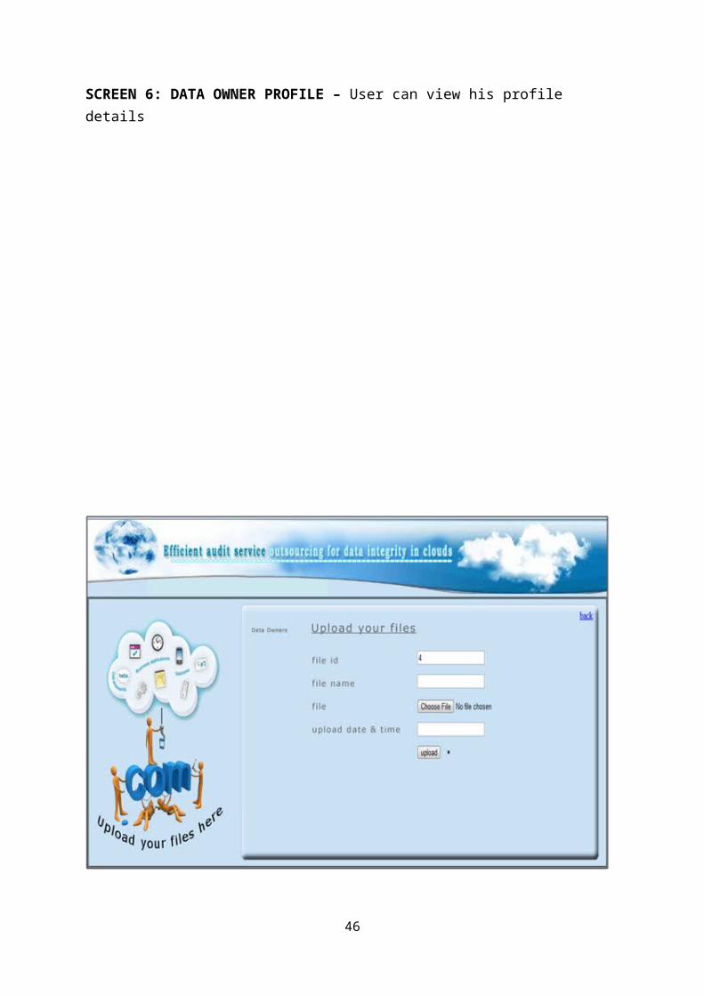
SCREEN 6: DATA OWNER PROFILE – User can view his profile details
34

SCREEN 7: FILE UPLOAD PAGE – User can upload his files by entering valid field
values.
35

SCREEN 8: FILE UPLOAD PAGE – After selecting the file, and entering the file
details click on upload button to upload.
36

SCREEN 9: UPLOADED FILE DETAILS – Data owner can views the details of the
files uploaded by him in this page.
37

SCREEN 10: FILE DOWNLOAD AND VERIFICATION – Data owner can verify the
files by downloading them.
38

SCREEN 11: TPA LOGIN – TPA can login by using his user name and secret key
39

SCREEN 12: TPA PAGE – TPA can view data owner details and the uploaded file
details.
40

SCREEN 13: OWNER DETAIL PAGE – Data owner details can be viewed in this
page.
41

SCREEN 14: UPLOADED FILE DETAILS – Uploaded file details can be viewed in
this page
42

SCREEN 15: SEARCH PAGE – File can be searched by clicking on search button in
home page
43

SCREEN 16: SEARCH RESULT PAGE – User cannot view the contents of a file
without email – id and secret key
44

SCREEN 17: SECRET KEY REQUEST PAGE – To view a file user should request
for a secret key from TPA
45
SCREEN 18: SECRET SENT TO GIVEN MAIL – TPA sends the secret key to the registered mail id
46

SCREEN 19: FILE DOWNLOAD USING SECRET KEY – By entering the mail – id
and secret key user can download the file
CHAPTER – 9
CONCLUSION
In this project, we addressed the construction of an efficient audit service for
data integrity in clouds. In this audit service, the third party auditor, known as an
agent of data owners, can issue a periodic verification to monitor the change of
outsourced data by providing an optimized schedule. To realize the audit model, we
only need to maintain the security of the third party auditor and execute the
verification protocol. Hence, our technology can be easily adopted in a cloud
computing environment to replace the traditional Hash-based solution. More
importantly, we proposed and quantified a new audit approach based on probabilistic
queries and periodic verification, as well as an optimization method of parameters of
cloud audit services. This approach greatly reduces the workload on the storage
47

servers, while still achieves the detection of servers’ misbehavior with a high
probability.
BIBILIOGRAPHY
Armbrust, M., Fox, A., Griffith, R., Joseph, A.D., Katz, R.H., Konwinski, A.,
Lee, G., Patterson, D.A., Rabkin, A., Stoica, I., Zaharia, M., 2010. A view of
cloud computing. Commun. ACM 53 (4), 50–58.
Ateniese, G., Burns, R.C., Curtmola, R., Herring, J., Kissner, L., Peterson,
Z.N.J., Song,D.X., 2007. Provable data possession at untrusted stores. In:
Proceedings of the 2007 ACM Conference on Computer and Communications
Security, CCS 2007, pp. 598–609.
48

Ateniese, G., Pietro, R.D., Mancini, L.V., Tsudik, G., 2008. Scalable and
efficient provable data possession. In: Proceedings of the 4th International
Conference on
Security and Privacy in Communication Networks, SecureComm, pp. 1–10.
Barreto, P.S.L.M., Galbraith, S.D., O’Eigeartaigh, C., Scott, M., 2007. Efficient
pairing computation on supersingular abelian varieties. Des. Codes Cryptogr.
42 (3), 239–271.
Beuchat, J.-L., Brisebarre, N., Detrey, J., Okamoto, E., 2007. Arithmetic
operators for pairing-based cryptography. In: Cryptographic Hardware and
Embedded Systems, CHES 2007, 9th International Workshop, pp. 239–255.
Boneh, D., Boyen, X., Shacham, H.,2004. Short group signatures. In: In
Proceedings of CRYPTO 04, LNCS Series. Springer-Verlag, pp. 41–55.
Boneh, D., Franklin, M., 2001. Identity-based encryption from the weil pairing.
In:
Advances in Cryptology (CRYPTO’2001). Vol. 2139 of LNCS, pp. 213–229.
Bowers, K.D., Juels, A., Oprea, A., 2009. Hail: a high-availability and integrity
layer for cloud storage. In: ACM Conference on Computer and
Communications Security, pp. 187–198.
Cramer, R., Damgård, I., MacKenzie, P.D., 2000. Efficient zero-knowledge
proofs of knowledge without intractability assumptions. In: Public Key
Cryptography, pp.
354–373.
Erway, C.C., Küpc¸ ü, A., Papamanthou, C., Tamassia, R., 2009. Dynamic
provable data possession. In: Proceedings of the 2009 ACM Conference on
Computer and Communications Security, CCS 2009, pp. 213–222.
49

Hsiao, H.-C., Lin, Y.-H., Studer, A., Studer, C., Wang, K.-H., Kikuchi, H.,
Perrig, A., Sun, H.-M., Yang, B.-Y., 2009. A study of user-friendly hash
comparison schemes. In: ACSAC, pp. 105–114.
Hu, H., Hu, L., Feng, D., 2007. On a class of pseudorandom sequences from
elliptic curves over finite fields. IEEE Trans. Inform. Theory 53 (7), 2598–
2605.
Juels Jr., A., Kaliski, B.S., 2007. Pors: proofs of retrievability for large files. In:
Proceedings of the 2007 ACM Conference on Computer and Communications
Security, CCS 2007, pp. 584–597.
50


![Federated Cloud Security Architecture for Secure and … · Federated Cloud Security Architecture 171 2 Cloud Security We briefly review cloud security [40] and related prior work](https://img.pdfslide.net/doc/110x75/5b19fbfc7f8b9a32258cef49/federated-cloud-security-architecture-for-secure-and-federated-cloud-security.jpg)