Embed Size (px)
Citation preview
CLPCCD Network Infrastructure Upgrade
Last modified 3/10/2009
CLPCCD
NETWORK INFRASTRUCTURE
UPGRADE

CLPCCD Network Infrastructure Upgrade
Page 1 of 20 Last modified 3/10/2009
Prepared for CLPCCD District ITS
TABLE OF CONTENTS 1.0 BACKGROUND: NETWORK HISTORY AND STANDARDS ..........................................................................
1.1 Routing Installed Base ......................................................................................................................
1.2 Switch/Hub Installed Base - Chabot .................................................................................................
1.3 Switch/Hub Installed Base - LPC .....................................................................................................
1.4 Switch/Hub Installed Base – District Office ....................................................................................
1.5 Additional Growth ............................................................................................................................ 2.0 NETWORK DESIGN RECOMMENDATIONS...............................................................................................
2.1 Security .............................................................................................................................................
2.2 High Availability ..............................................................................................................................
2.3 Upgraded Fiber Backbone ................................................................................................................
2.4 Redundant Server Connections.........................................................................................................
2.5 Transparent Internet Rerouting .........................................................................................................
2.6 Advanced Switching Features...........................................................................................................
2.7 Manageability ...................................................................................................................................
2.8 Step-wise Migration.......................................................................................................................... 3.0 PRODUCT SELECTION
3.1 Core Switching..................................................................................................................................
3.2 High Density Switching....................................................................................................................
3.3 Stackable Switching..........................................................................................................................
CLPCCD Network Infrastructure Upgrade
Page 2 of 20 Last modified 3/10/2009
Prepared for CLPCCD District ITS
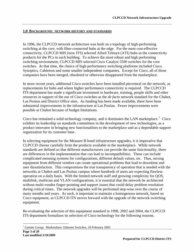
APPENDICES
A.1 Wiring Closet/IDF Inventory Details............................................................................................... A.2 Bill of Materials ...............................................................................................................................
A.3 Cisco Trade-in Equipment Inventory...............................................................................................
CLPCCD Network Infrastructure Upgrade
Page 3 of 20 Last modified 3/10/2009
Prepared for CLPCCD District ITS
1.0 BACKGROUND: NETWORK HISTORY AND STANDARDS In 1996, the CLPCCD network architecture was built on a topology of high-performing switching at the core, with fiber-connected hubs at the edge. For the most cost-effective connectivity, CLPCCD MIS (now ITS) selected Allied Telesyn (ATI) hubs as the connectivity products for the PCs in each building. To achieve the most robust and high performing switching environment, CLPCCD MIS selected Cisco Catalyst 5500 switches for the core switches. At that time, the choice of high performance switching platforms included Cisco, Synoptics, Cabletron and some smaller independent companies. Except for Cisco, all of those companies have been merged, obsoleted or otherwise disappeared from the marketplace. In more recent years, additional Cisco switches have been installed piecemeal on the network, as replacements for hubs and where higher performance connectivity is required. The CLPCCD ITS department has made a significant investment in hardware, training, people skills and other resources in support of the use of Cisco switches as the de facto network standard for the Chabot, Las Positas and District Office sites. As funding has been made available, there have been substantial improvements in the infrastructure at Las Positas. Fewer improvements were possible at Chabot because of budget limitations. Cisco has remained a solid technology company, and it dominates the LAN marketplace.1 Cisco exhibits its leadership on standards committees in the development of new technologies, as a product innovator in bringing new functionalities to the marketplace and as a dependable support organization for its customer base. In selecting equipment for the Measure B bond infrastructure upgrades, it is imperative that CLPCCD choose carefully from the products available in the marketplace. While network standards are defined so that different manufacturers can provide the same functionality, there are differences in the implementation that can lead to incompatibilities. These can include complicated menuing systems for configurations, different default values, etc. Thus, mixing equipment from different vendors can create operational problems that lead to downtime and user dissatisfaction. This compromises the true transparency of operation that is needed with the networks at Chabot and Las Positas campus where hundreds of users are expecting flawless operation on a daily basis. With the limited network staff and growing complexity for QOS, multilink, multicast and VLAN configurations, it is essential that the network be architected without multi-vendor finger-pointing and support issues that could delay problem resolution during critical times. The network upgrades will be performed step-wise over the course of many months and years. As such, it important to maintain a homogenous network, based on Cisco equipment, as CLPCCD ITS moves forward with the upgrade of the network switching equipment. Re-evaluating the selection of this equipment standard in 1998, 2002 and 2004, the CLPCCD ITS department formalizes its selection of Cisco technology for the following reasons.
1 Gartner Group: Marketshare: Ethernet Switches, 18 February 2005
CLPCCD Network Infrastructure Upgrade
Page 4 of 20 Last modified 3/10/2009
Prepared for CLPCCD District ITS
Robust Hardware and Software: Cisco products are well-respected as high
performance switching and routing products. Cisco develops and embraces new technology, thereby providing support for a broad range of technologies that can meet CLPCCD’s increasing technology needs.
Standardization of Commands: The Cisco IOS command set has been enhanced and
ported across the entire product line. This provides for quick-startup on new devices and a consistency of operations support. Many other manufacturers have ported a subset of the Cisco IOS to their systems to augment their custom commands.
Installed Base of Knowledge: For many years, CLPCCD staff has been able to build
their skills and knowledge to be very proficient in the operation and troubleshooting of Cisco hardware. Many of the technicians are Cisco certified. Given the limited staffing at CLPCCD, moving away from the Cisco IOS interface to another product line would present a substantial setback in the efficacy of the operations team.
Best in Class Support: Cisco SmartNET support provides CLPCCD with 24x7 access
to knowledgeable and responsive engineers. The breadth of information that is available free on the Cisco website is unsurpassed by other network equipment providers.
Consultant Availability: When staffing limitations require CLPCCD ITS to augment its
workforce, there is always a breadth of consulting expertise available in the industry. The Cisco Academy program has developed many knowledgeable technicians who can help with routine network tasks. Cisco’s CCIE (Cisco Certified Internetwork Expert) certification is regarded as the “doctorate of networking professionals”. No other manufacturer provides such in depth training and certification for networking expertise and their products. CLPCCD ITS benefits by being able to draw from these expert resources as needed.
Academic Resources: As a Cisco Academy in both the Chabot and LPC locations,
technical resources are available to help in the training of CLPCCD ITS staff. Cisco Academies in Californian Community Colleges and High Schools produce knowledgeable technicians on an annual basis. No other network equipment manufacturer has invested in an educational program that generates trained network resources, prepared for work in the network operations field.
The following sections detail the equipment summary at the Chabot, Las Positas and District Office locations. This describes the current investment in Cisco technology solutions. 1.1 Routing Installed Base At the core of the network, located at the Chabot campus, is the 7507 router. This router controllers 1) routing between the instructional and administrative VLANs, 2) access to the PIX firewall from instructional and admin networks and 3) WAN connectivity to LPC and the District Office. At LPC, the 7206 controls the WAN connectivity to the District Office and
CLPCCD Network Infrastructure Upgrade
Page 5 of 20 Last modified 3/10/2009
Prepared for CLPCCD District ITS
Chabot campuses. A 3550-48 Layer 3 switch is used to provide VLAN routing between discrete VLAN networks. At the District Office site, a 3620 router provides routing and WAN connectivity. Upgrades planned for the routing technology will be based on the design and selection of site-to-site high speed connectivity. This will be developed in the coming year. 1.2 Switch/Hub Installed Base - Chabot The Chabot network was originally built using two Cisco 5500 switches in the core. An additional Cisco 5500 switch was added in the Science building when it was built. These devices will be no longer supported after May 31, 2005, thereby creating the urgency for the upgrade of these devices. The core switches connected to buildings using ATI hubs with 10BaseF fiber links. In recent years, a few of buildings have been upgraded to Cisco 2950C 10/100 switches. These switches are limited in their functionality, but do provide a speed and operation enhancement over the 10 Mbps hub environment. Limits in Chabot College funding sources have prevented much-needed upgrades at most of the buildings across the campus. Currently, the number of Cisco switch ports on Chabot is in the range of 720 ports. The number of active hub ports is in the range of 900 ports. Because of the limitations in the 2950C switches, virtually all the switch and hub devices at the Chabot campus need upgrading. Total switch ports: 720 Minimum number of ports to be replaced: 1620
1.3 Switch/Hub Installed Base - LPC Like Chabot, the LPC network was originally built using a Cisco 5500 switch at the core with Allied Telesyn 10Mbps hubs as edge devices. Over the years, this architecture has been gradually enhanced to a fully-switched topology based on Cisco equipment. The Cisco equipment consists of 2924M-XL switches, Linksys 24-port and 5-port switches, 3548-XL switches, 2950-24/48 switches, 3524-XL switches and 3550-48 switches. Many of these switches are “Gigabit-ready”. Of the installed base, the more recent deployments of 3550 and 2950 class switches are viable switches to maintain in the infrastructure. Older and more basic functionality in switches such as the 2924 and Linksys products are posing multicast and other technical issues. These switches must be upgraded. Total switch ports: 1440 Minimum number of ports to be replaced: 312

CLPCCD Network Infrastructure Upgrade
Page 6 of 20 Last modified 3/10/2009
Prepared for CLPCCD District ITS
1.4 Switch/Hub Installed Base – District Office The District Office network is based on Cisco 2950 switches. These switches offer solid performance and reliability for the 100+ users who depend on the network for access to Banner and Internet job functions. Total switch ports: 144 Minimum number of ports to be replaced: 0 1.5 Additional Growth These estimates for switch ports discussed above do not include the new buildings and growth planned in the next several years. In particular, the Las Positas campus will double in size and add new buildings such as the Multi-Disciplinary Building, Teaching Buildings and the new District Data Center. These additional buildings will require new high-performance switches and hundreds of additional network ports. Chabot College will also receive new buildings and modernize current buildings to accommodate state-of-the-art network connectivity to classrooms and computer labs. As at LPC, increases in network connectivity and switch ports will be implemented as the construction and modernizations complete. The Measure B Bond will allow CLPCCD ITS to move forward with some much-needed upgrades to the network infrastructure at Chabot and Las Positas campuses. The selection of network equipment from one manufacturer will eliminate incompatibilities and problem solving issues as the upgrades are gradually installed over the coming months and years. The continued selection of the Cisco equipment standards will allow CLPCCD to maximize its current investment in product and people, to be able to offer a robust and reliable state-of-the-art network infrastructure that will benefit every user at Chabot and Las Positas campuses.
CLPCCD Network Infrastructure Upgrade
Page 7 of 20 Last modified 3/10/2009
Prepared for CLPCCD District ITS
2.0 NETWORK DESIGN RECOMMENDATIONS The new enterprise network design for CLPCCD incorporates key design principles organized in the following areas:
Security: A primary design goal of the upgraded CLPCCD Enterprise Network is to ensure that the network is segmented into multiple security zones to isolate user communities from each other and to protect key areas of the network from worms and viruses.
High Availability: A second high-priority goal of the upgraded CLPCCD Enterprise
Network is to incorporate as much redundancy and diversity into the design that is cost effective in order to ensure maximum uptime and permit software and hardware maintenance to be performed without downtime.
Upgraded Fiber Backbone Building Connectivity: An upgrade of the fiber backbones
to allow for high bandwidth, diverse connectivity is a basis for the building connectivity design.
Redundant Server Connectivity: Wherever possible, redundant, high-performance
connections to mission-critical servers are recommended to limit downtime caused by NIC card failures.
Transparent Internet Rerouting: The success of the instructional environment is
dependent on access to Internet resources. In the event of failures, fast and transparent traffic rerouting is required.
Extensive support of advanced switching features: Advanced features such as Quality
of Service (QoS) and security parameters are important design requirements of the upgraded network at Chabot and Las Positas Colleges in order to support high-quality video conferencing, responsive administrative and educational application access, and reduce the impact of worms and viruses.
Manageability: The new architecture is built upon consistent hardware platforms and
software configurations. Migration of IPX/AppleTalk network protocols used by older desktop equipment to native IP is planned. This enables CLPCCD technical staff to leverage their IP and switching knowledge across the entire network environment.
Phased implementation: A multi-phased implementation plan for installing the new
network equipment is planned so as to allow the existing staff to implement the new equipment at a confident pace.
Each of these design principles is described in greater detail in the following pages.
CLPCCD Network Infrastructure Upgrade
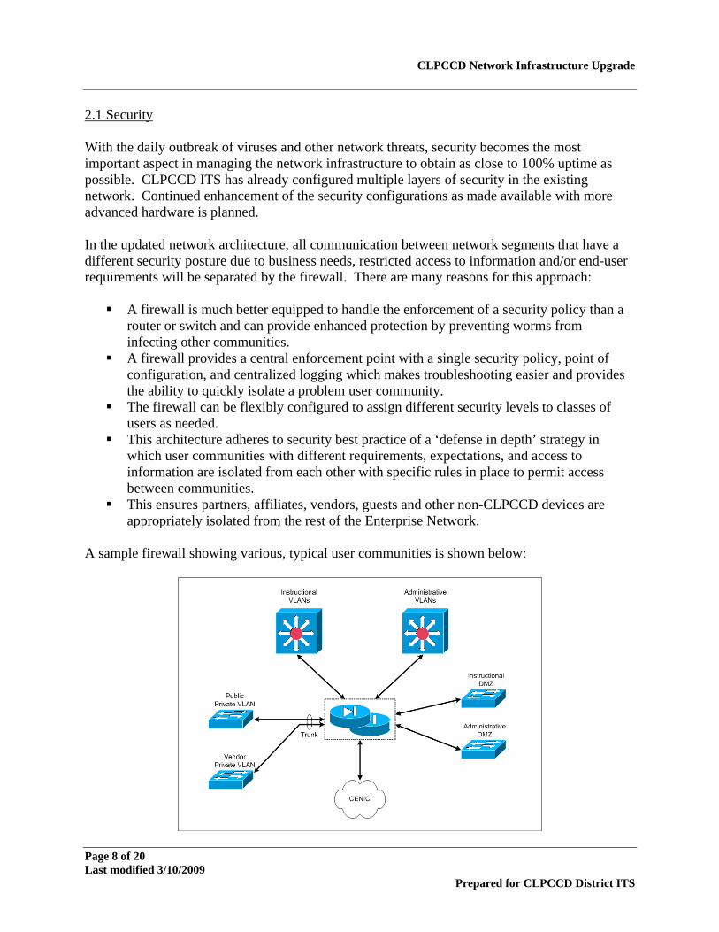
2.1 Security With the daily outbreak of viruses and other network threats, security becomes the most important aspect in managing the network infrastructure to obtain as close to 100% uptime as possible. CLPCCD ITS has already configured multiple layers of security in the existing network. Continued enhancement of the security configurations as made available with more advanced hardware is planned. In the updated network architecture, all communication between network segments that have a different security posture due to business needs, restricted access to information and/or end-user requirements will be separated by the firewall. There are many reasons for this approach:
A firewall is much better equipped to handle the enforcement of a security policy than a router or switch and can provide enhanced protection by preventing worms from infecting other communities.
A firewall provides a central enforcement point with a single security policy, point of configuration, and centralized logging which makes troubleshooting easier and provides the ability to quickly isolate a problem user community.
The firewall can be flexibly configured to assign different security levels to classes of users as needed.
This architecture adheres to security best practice of a ‘defense in depth’ strategy in which user communities with different requirements, expectations, and access to information are isolated from each other with specific rules in place to permit access between communities.
This ensures partners, affiliates, vendors, guests and other non-CLPCCD devices are appropriately isolated from the rest of the Enterprise Network.
A sample firewall showing various, typical user communities is shown below:
Page 8 of 20 Last modified 3/10/2009
Prepared for CLPCCD District ITS
CLPCCD Network Infrastructure Upgrade
Page 9 of 20 Last modified 3/10/2009
Prepared for CLPCCD District ITS
In order to implement this architecture, the following elements are required:
A document that specifically lists end-user requirements and business rules
Analysis to determine network connectivity and firewall rules required to adhere to the above policy
A high performance firewall with multiple interfaces to support connectivity between
user communities without impacting application performance The CLPCCD network had been architected with Firewall protection since early Internet connectivity in 1998. As enhanced services were required, the old Firewall system became limited in its capacity and functionality. Through the PIX firewall upgrades purchased as a Measure B Quickstart and implemented in March of 2005, CLPCCD has improved its security posture and is well positioned with the high-performance firewall needed for this architecture. The remaining work to establish user communities, policies and configurations will be accomplished during the infrastructure upgrade. 2.2 High Availability The existing network equipment has been deployed with little redundancy of equipment or connectivity. The result is end-user downtime when failures occur. The new architecture is based on a high availability LAN design with a redundant and diverse infrastructure at both large campuses. This means:
A firewall cluster or failover pair is installed at each core location to prevent downtime associated with the failure of a single firewall.
End-user connectivity does not rely on a single core switch or two core switches located
in the same location.
Hardware and software upgrades can be performed on a single core switch at a time to verify success and stability before repeating process on second core switch.
Configuration changes can be made to only a single core switch and, in the event of a
problem or mis-configuration, the network is still available.
Can be combined with diverse fiber to prevent a single fiber failure or fiber cut (backhoe) from impacting a large portion (if not all) of the Enterprise Network.
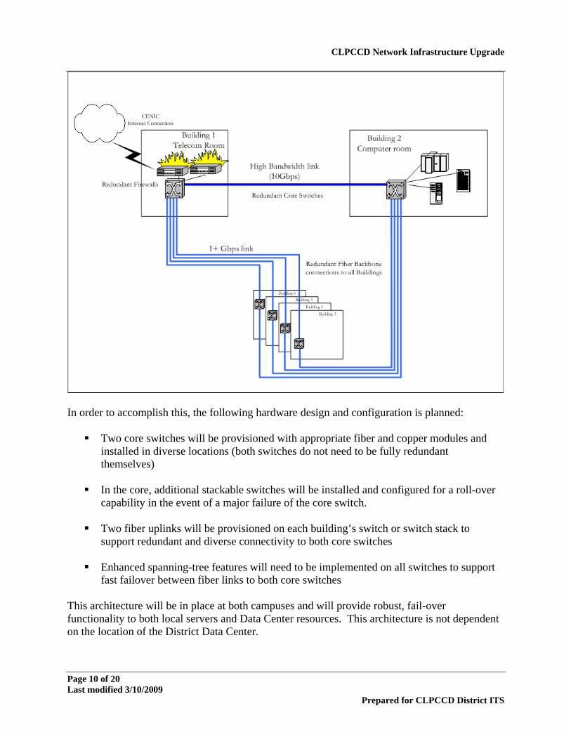
The proposed topology is shown schematically in the following diagram:
CLPCCD Network Infrastructure Upgrade
In order to accomplish this, the following hardware design and configuration is planned:
Two core switches will be provisioned with appropriate fiber and copper modules and installed in diverse locations (both switches do not need to be fully redundant themselves)
In the core, additional stackable switches will be installed and configured for a roll-over
capability in the event of a major failure of the core switch.
Two fiber uplinks will be provisioned on each building’s switch or switch stack to support redundant and diverse connectivity to both core switches
Enhanced spanning-tree features will need to be implemented on all switches to support
fast failover between fiber links to both core switches This architecture will be in place at both campuses and will provide robust, fail-over functionality to both local servers and Data Center resources. This architecture is not dependent on the location of the District Data Center.
Page 10 of 20 Last modified 3/10/2009
Prepared for CLPCCD District ITS
CLPCCD Network Infrastructure Upgrade
Page 11 of 20 Last modified 3/10/2009
Prepared for CLPCCD District ITS
2.3 Upgraded Fiber Backbones As a corollary requirement to the redundant topology discussed above, the installation of new diverse fiber backbones between wiring closets in each building and the two separate and diverse core switch locations is required. The redundant fiber backbone design is required because:
With the amount of future construction planned for both Chabot College and LPC there is a high degree of risk that data fiber will be disrupted.
A fiber disruption caused by a fiber cut, conduit crush, or fiber stretch/stress situation
would cause an extended data network downtime, possibly across a large portion of the data network.
It is possible to design diverse, redundant fiber pathways/conduits at both CC and LPC
that could be used to run fiber in opposite directions to diverse core switch locations. The following steps are required:
Complete analysis of conduit proofing results to determine usable conduit paths. Work with Architect and Engineering teams to augment current conduit system to allow for installation of new fiber.
Install and terminate appropriate fiber between each building wiring closet and a diverse
core switch location using different paths. At Chabot, the existing 62.5/125 multimode fiber will be used for limited initial deployment until the new fiber backbones are provisioned. For longevity, the installation of single mode fiber is recommended, and connectivity using Gigabit LX transmission is designed. Initial deployment will use LX connectivity with mode conditioning cables over multimode cables wherever the fiber transmission characteristics can support it. If transmission issues arise, Gigabit SX or 100FX connectivity will be enabled. At LPC, the single mode fiber that was installed in 1998 has laid dormant. Gigabit LX connectivity over this existing single mode will be used. 2.4 Redundant Server Connections All servers that are critical to the operation of CLPCCD applications should be connected redundantly to the new high availability core network in order to ensure the highest reachability of critical business applications in the event of a network component failure or scheduled maintenance. In order to accomplish this connectivity, the following equipment and configuration needs to be factored into the enterprise network design:
1. Redundant and diverse switching infrastructure located within cabling distance of the data center and servers.
CLPCCD Network Infrastructure Upgrade
Page 12 of 20 Last modified 3/10/2009
Prepared for CLPCCD District ITS
a. At the Chabot campus, an additional stackable 48-port switch will be located in the
data center to provide network connectivity to critical servers in the event of the data center core switch failure or scheduled maintenance.
b. At the LPC campus, the Information Technology Building that will house the District
Data Center will be built within copper cabling distance of the campus MDF and the main core switch in Building 1900. Approximately 50 to 100 copper cables will be run in underground conduit from the new Information Technology Building Telecom room to the existing campus MDF. Therefore, the main core switch, located in the MDF, will provide network connectivity to critical servers in the event of the Data Center core switch failure or scheduled maintenance.
2. Server diversity, NIC teaming, or clustering, depending on the server’s criticality to the
operation of the business application will provide increased uptime.
a. Server diversity. Several background servers that provide essential services for PC access to the data network can be deployed on multiple servers in diverse locations and do not individually require redundant connections to the data network because there are additional servers providing those services elsewhere on the network. These services include, but are not limited to, DNS, DDNS, DHCP, WINS, and Active Directory DCs.
b. Server NIC teaming. Many applications do not support server diversity (or clustering)
and must be deployed on a single server. Even with ECC/RAID memory, RAID or mirrored hard drives, and redundant power supplies, a single application server can lose connectivity to the network under many circumstances: A cable pulled or cut, network equipment or blade failure, user error or misconfiguration, or even a local NIC failure within the server. For a relatively low cost, multiple NICs can be installed in a server, connected to diverse network equipment, and configured to act as a single NIC (teamed). It is important that multiple physical NICs be used and to not rely on multiple interface or built-in NICs for both members of the team.
c. Server clustering. The highest available applications are deployed on multiple servers
configured as a cluster. This essentially combines the characteristics of server diversity and NIC teaming to ensure the highest uptime as no hardware point of failure exists. It is important to configure the cluster so that each server in the cluster has diverse connectivity to the network and that the heartbeat and replication NICs do not rely on the enterprise network.
The new network architecture will be able to support any and all of the server redundancy choices described above.
CLPCCD Network Infrastructure Upgrade
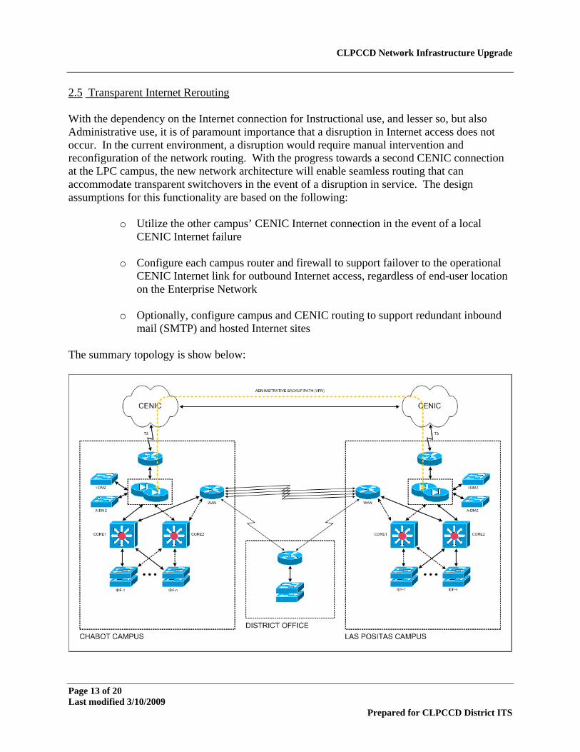
2.5 Transparent Internet Rerouting With the dependency on the Internet connection for Instructional use, and lesser so, but also Administrative use, it is of paramount importance that a disruption in Internet access does not occur. In the current environment, a disruption would require manual intervention and reconfiguration of the network routing. With the progress towards a second CENIC connection at the LPC campus, the new network architecture will enable seamless routing that can accommodate transparent switchovers in the event of a disruption in service. The design assumptions for this functionality are based on the following:
o Utilize the other campus’ CENIC Internet connection in the event of a local CENIC Internet failure
o Configure each campus router and firewall to support failover to the operational
CENIC Internet link for outbound Internet access, regardless of end-user location on the Enterprise Network
o Optionally, configure campus and CENIC routing to support redundant inbound
mail (SMTP) and hosted Internet sites The summary topology is show below:
Page 13 of 20 Last modified 3/10/2009
Prepared for CLPCCD District ITS
CLPCCD Network Infrastructure Upgrade
Page 14 of 20 Last modified 3/10/2009
Prepared for CLPCCD District ITS
This topology would still make use of the T1 connection between the College campuses and District Office. While lower in net bandwidth, it would be key to allowing the rerouting if one Internet connection was disabled. For periods of normal traffic, a VPN would be enable through the CENIC connections that allowed high-speed access between the Administrative networks. 2.6 Advanced Switching Features In moving to new equipment, CLPCCD can take advantage of advanced switch features that were not available in the existing equipment. Of greatest importance are the capabilities that will optimize traffic flows, management and security. Quality of Service (QoS) will be implemented as a part of any current network implementation for the following reasons:
1. Video conferencing is becoming increasingly important in educational institutions to improve collaboration and to provide access to content that is not readily available locally. Specific network requirements need to be met in order for video conferencing equipment to work correctly over the enterprise network.
LAN: All switches will be configured for multiple queues per port, including both and inbound and outbound priority queue. WAN: Outbound priority class on all WAN ports will be configured to ensure high quality video and audio over slow WAN links. Internet: Priority bandwidth guarantee will be configured for outgoing video conferencing traffic during active call. This will require firewall and Internet border router configuration.
2. QOS will ensure predictability of application response times so that end-users are presented with consistent and reliable access to their business critical applications, regardless of what is occurring on the network. This is particularly important as high-bandwidth access is provided to the Internet which competes with available bandwidth on the LAN for business critical applications
LAN: All switches will be configured for multiple queues per port. Specific switch ports configured to mark application server traffic with appropriate class of service (CoS) as traffic enters the network. Additionally, all end-user switch port, particularly on the educational side, should be configured with a scavenger policy that marks down excessive traffic as discard eligible WAN: Multiple class policy will be configured on each outbound interface to give minimum bandwidth guarantee to 5 to 11 different traffic types.
CLPCCD Network Infrastructure Upgrade
Page 15 of 20 Last modified 3/10/2009
Prepared for CLPCCD District ITS
Internet: Minimum bandwidth guarantees will be configured for several traffic types to ensure a single user, application, or protocol cannot consume more than its fair share of bandwidth.
The following security features are being evaluated for implementation on all client switch ports in order to ensure high availability of the network even during attack and/or worm events. This is especially important in an educational environment in which a large number of PCs are accessed by a constantly changing body of students. Since the users of many of the systems are not college employees, it is that much more important to automatically protect the network and administrative functionality from rogue and uncontrolled student access.
1. Port Security: Prevent MAC flooding attacks by limiting the number of MAC addresses that are allowed on a physical port.. This may need to be modified to 3 endpoints if an IP phone and PC share the same port.
2. DHCP Snooping: DHCP snooping combats against rogue DHCP servers while
protecting the network from denial of service (DoS) attacks. This is accomplished by rate-limiting the incoming DHCP packets and limiting client-facing ports to sending DHCP request-and-renew traffic. It also forms the basis for other security features such as IP Source Guard and dynamic ARP inspection (DAI).
3. Dynamic ARP Inspection: Dynamic ARP inspection (DAI) prevents ARP spoofing and
man-in-the-middle attacks for both static and dynamic IP addresses, without requiring any changes on the end hosts. Violating hosts may be logged, and the ports may be error-disabled until an administrative action is taken. IP Source Guard mitigates IP address-spoofing by dynamically maintaining per-port VLAN ACLs.
4. IP Source Guard: IP source guard adds security to an IP source address using DHCP
snooping table. DAI is not required for IP source guard. However, it is recommended to mitigate ARP spoofing attacks on a given VLAN and also turn IP Source Guard on each interface of the VLAN.
5. Private VLAN: Another VLAN feature used for privacy is private VLANs, essentially
smaller, sub-VLANs within a larger VLAN that each requires privacy. This requirement was first seen in hosted data centers, but also is often seen in networks that have many disparate groups connecting into a common infrastructure. Private VLANs allow multiple users to co-exist on a single VLAN, but are unable to communicate with each other without going through a layer-3 router (or firewall) which enables policy enforcement between the two endpoints. Previously, without this feature, any number of endpoints that are connected in the same VLAN, anywhere on the campus network, are able to communicate directly to each other without going through central policy enforcement. In today’s networks, unrestricted and direct connectivity between any two end-user devices is neither required nor desirable as all required resources are located in the data center or on the Internet and worms/viruses are much more prevalent. The only application that requires direct peer-to-peer connectivity is voice and video conferencing.
CLPCCD Network Infrastructure Upgrade
Page 16 of 20 Last modified 3/10/2009
Prepared for CLPCCD District ITS
Under investigation for later deployment are the following capabilities:
6. MAC-Based VLAN Assignment – near term: Dynamic virtual LAN (VLAN) membership is a convenient way to dynamically assign end stations to VLANs. Dynamic VLAN assignment is especially useful in administering large networks because you can move a connection from a port on one switch to a port on another switch in the network without reconfiguring the port. Dynamic-access ports work with a Cisco VLAN Management Policy Server (VMPS) appliance, which holds a database of Media Access Control (MAC)-address-to-VLAN mappings. Other Cisco switches act as clients to the VMPS and communicate with it via the VLAN Query Protocol (VQP). Cisco Secure User Registration Tool (URT) is a VLAN assignment service that functions as a VMPS, providing traditional host-based (MAC address) VLAN assignments, as well as user identity-based VLAN assignments. URT also provides monitoring of user access and management of the database.
7. Network Admission Control (NAC) – future: NAC is an important part of the Cisco
Self-Defending Network initiative and will become an important and useful feature in the coming months. Whereas MAC-based VLAN assignment verifies that the user is eligible for connectivity to the network, NAC identifies the "posture" of the device. NAC on the switching platforms works as a system in conjunction with the Cisco Trust Agent. The Cisco Trust Agent collects security state information from multiple security software clients, such as antivirus clients, and communicates this information to the connected Cisco network where access control decisions are enforced. Application and operating system status, such as antivirus and operating system patch levels or credentials, can be used to determine the appropriate network admission decision.
2.7 Manageability Leveraging the CLPCCD staff’s experience with Cisco products, the new architecture will also allow for better management of the environment. As part of the migration, the network protocols will be standardized on IP and IP multicast, thereby eliminating Novell IPX and AppleTalk protocols from the Enterprise Network backbone. There reasons for this are:
o Campus LAN design best practices dictate the use of only IP and IP multicast routing
o Enhanced security and Quality of Service (QoS) technologies available in newer
switches require the use of IP and IP multicast protocols exclusively
o Quality of Service (QoS) prioritization effectiveness is substantially reduced if configured in the presence of non-IP protocols
To smoothly manage the transition, the following steps are required.
o Identify systems and end-users still using other protocols such as Novell IPX, AppleTalk, and NetBEUI/bridging
CLPCCD Network Infrastructure Upgrade
Page 17 of 20 Last modified 3/10/2009
Prepared for CLPCCD District ITS
o Migrate AppleTalk users to Apple Native IP
o Migrate Novell IPX users to Novell Native IP
o Remove NetBEUI and bridging configuration from existing devices (servers and
end-user workstations) These transitions can be coordinated with College CS staff in the rollout of the new desktop systems. 2.8 Stepwise Migration One of the significant advantages in selecting network switches from one manufacturer is the consistency and interoperability with older equipment. The migration to the new topology will be performed in a stepwise fashion to enable the following:
CLPCCD staff can gradually come up to speed on the expanded switching/routing features of the new equipment and IOS.
Smaller, more frequent installations can be planned and implemented successfully.
CLPCCD staff can schedule and manage the implementation according to their
availability.
If an implementation needs to be reworked, there is limited impact on the user community. Contingency plans can be developed for rapid service restoration.
The implementation is planned as three phases:
1) Phase 1 – Replacement of the core switches at Chabot Campus. The 5500 core switches used at Chabot will be considered end-of-support for the Supervisor engine as of May 31st, 2005. This presents a critical need for early implementation of new redundant core switches. It is expected that this implementation will occur towards the end of July. In the interim, CLPCCD has spare parts on the shelf, if a failure were to occur.
2) Phase 2 – Replacement of LPC equipment. Implementation of the core switches, high
density switches and edge switch replacement/upgrades is planned for August. This will position the campus in a fully upgraded status for soon after the fall session begins.
3) Phase 3 – Replacement of remaining Chabot switches. In a step-wise fashion, new
switches will be installed in suitable communications closets across campus. It is expected that this will allow Gigabit connectivity from most buildings. In limited locations, 100FX connectivity will be provisioned.

CLPCCD Network Infrastructure Upgrade
Page 18 of 20 Last modified 3/10/2009
Prepared for CLPCCD District ITS
It is expected that most of the network implementations for Phase 1 and 2 can be performed during the Friday closures as many departments move to the 4x10 work days in the summertime. Preparation time for switch burn-in and configuration can be performed during the week. In Phase 3, the installations will be coordinated with Chabot College for minimal service disruption.
CLPCCD Network Infrastructure Upgrade
Page 19 of 20 Last modified 3/10/2009
Prepared for CLPCCD District ITS
3.0 PRODUCT SELECTION The CLPCCD Enterprise Network Upgrade bill of materials identifies specific equipment part numbers that were determined to best fit the needs of CLPCCD. A detailed justification for each product selection is described below. 3.1 Core Switching In the switching core, there is a need for a high performance, highly redundant switching platform that can manage the concentrated routing and switching of the cumulative network traffic. The successor product for the Cisco Catalyst 5500 switches is the 65xx line of switches. The Catalyst 6500 Series optimizes IT infrastructure utilization and uses an architecture that supports a wide range of services including data and voice integration and LAN, WAN, and MAN convergence, with:
• Maximum network uptime for higher user productivity and business resiliency • Comprehensive network security • Investment Protection and long product lifecycle supporting multiple generations of
interfaces and packet forwarding engines • Operational consistency allowing customers to standardize on a single platform that
addresses all network deployment requirements • Superior services integration supporting the application-aware convergence of data,
voice, and video, on a single highly manageable platform
The architecture selected for the core switching at each campus is a pair of Cisco 6509 switches, equipped with: 48-port 10/100/1000 network cards 48-port SFP Gigabit network cards Redundant 3000W power supplies 802.3af POE support These switches will be located at Chabot campus in buildings 200 and 300, and at LPC campus in Building 1900 and the new Data Center. For the initial configuration, these switches will connect to buildings using Gigabit LX fiber connections. Future configurations may include upgrades to 10 Gigabit fiber links. Each pair of core switches will be configured for routing redundancy and failover, so that if one chassis were to suffer a hardware failure, transparent routing through the other chassis would take over. This requires two pairs of fiber between the switches and each building. While initial deployment will use fiber in the same bundle, the redundant fiber topology discussed earlier will achieve the connectivity diversity that is required in the final architecture.
CLPCCD Network Infrastructure Upgrade
Page 20 of 20 Last modified 3/10/2009
Prepared for CLPCCD District ITS
3.2 High Density Switches In buildings and floors that concentrate a large number (100+) of users into a single switch, the equipment configuration will be a chassis-based 45xx switch. Cisco Catalyst 4500 Series switches are designed for enterprise LAN access and Layer 3 distribution points. For consistency across the network, the 4506 switch has been selected. This switching platform will include: 48-port 10/100/1000 network cards 6-port SFP Gigabit network card Redundant 1000/1300W power supplies 802.3af POE support In buildings that have multiple closets, the 4506 switch will be used as a concentrator for building connectivity to the site fiber backbone. 3.3 Stackable Switches In evaluating the type of switch required for smaller buildings, a more cost effective alternative are stackable switches. Two product lines are available from Cisco: the 2950 and the 3560. The 3560 line was chosen because of the following reasons.
• Much more advanced feature set, even at the SMI level. • Layer 3 routing capability, i.e. wire-speed layer-2 AND layer-3 packet forwarding. • Much more granular QoS and security functionality. • Faster CPU, lower average CPU utilization; i.e. supports more concurrent features. • IOS Software based on Native IOS release for the Catalyst 6500 Series (both run IOS
12.2S). • 64MB DRAM and 16MB Flash (vs. 16MB DRAM and 8MB Flash on c2950 series
switches). • Many new features have been made available for the 3500 series and NOT the 2950G
series. • Small retail price difference: $4,995 (WS-C3550-48-SMI) vs $4,495 (WS-C2950G-
48-EI) with even price differential after discounts. The 3560 switches will be deployed in locations where less than 96 ports are required. A maximum of two cascaded 48-port switches will be deployed in a single location. These switches will be connected with Gigabit interconnect cables.