Embed Size (px)
Citation preview

Product Specifications
METALLIZED POLYPROPYLENE CAPACITOR TYPE ECWF(L)
Clsf. 28-37 No. 1-18 Revision Code R1
1/ 22 P.
Toyama・Matsue Plant Device Solutions Business Division Panasonic Corporation
1. SCOPE This specification covers the requirement for metallized polypropylene
dielectric fixed capacitor for use in high frequency and high current circuits. 2. PRODUCT NAME Metallized polypropylene film capacitor, Type ECWF(L).
3. PRODUCT RANGE Category temperature range
-40to +105 (Including temperature-rise and heat souce side on unit surface.)
Rated voltage 400VDC, 630VDC Capacitance range Refer to the individual drawing. Capacitance tolerance Refer to the individual drawing.
4.PERMISSIBLE CURRENT
(1) Pulse current is based on the permissible pulse current value calculated by Table.1.
(2) Continuation current is based on the permissible current value classified by frequency of Fig. 5.
5. APPEARANCE (1) Marking shall be legible in the right place. (2) Plating of lead wire shall be perfect without rust. (3) Coating shall be perfect without any crack, rent, pinhole etc., that matters
practical use.
6. CONSTRUCTION The capacitor has a non-inductive construction, would with metallized polypropylene film dielectric. The capacitor is enclosed in noncombustible epoxy resin and has two leads.
Noncombustible epoxy resin(UL94V-0) Epoxy resin
Element (Metallized polypropylene)
Lead wire(Tin-plated wire)
7.DIMENSIONS As specified in the individual drawing.
8.CONDITIONAL STANDARD TEST
The test shall be conducted at a temperature of from 15 to 35,a humidity of from 45% to 75%. However the test shall be conducted at a temperature of (20±1),a humidity of 60% to 67%,when doubt is entertained about judgement.
9.MARKING
Marking shall not be erased easily and describes the following items as a rule. 1.Capacitance 2.Capacitance tolerance code 3.Rated voltage 4.Date code 5.Manufacturer's trade mark 6.Type name (WFL)

Product Specifications
METALLIZED POLYPROPYLENE CAPACITOR TYPE ECWF(L)
Clsf. 28-37 No. 1-18 Revision Code R1
2/ 22 P.
Toyama・Matsue Plant Device Solutions Business Division Panasonic Corporation
10.CHARACTER
No Item Performance
Testing methodRefer to JIS C 5101-16-1999 [IEC 60384-16]
1. Voltage proof [Between terminals]: Nothing abnormal shall be found, when applied a voltage of 150% of the DC rated voltage for 60s. (The capacitor shall be applied the voltage through a resistor of 2kΩ or more when charge and discharge.)
According to 4.2.1
[[Between terminals and enclosure]: Nothing abnormal shall be found, when applied a voltage of 1500VAC for 60s.
Outside of JIS C 5101-16-1999
2. Insulation resistance
[between terminals]: 3000MΩ・μF or more (C > 0.33μF) 9000MΩ or more (C ≦ 0.33μF) When the reading of measuring instrument becomes steady at a value after applying a voltage of (100±15)V [400VDC], (500±50)V [630VDC] for (60±5)s.
According to 4.2.4
3. Capacitance Within a range of specified value. (Measurement shall be conducted at a frequency of (1±0.2)kHz)
According to 4.2.2
4. Tangent of loss angle
0.05% or less at (1±0.2)kHz 0.20% or less at (10±2)kHz (Measurement shall be conducted at a frequency of above value.)
According to 4.2.3
5. Terminal strength
[Tensile strength] The load specified below shall be applied to the terminal in its draw-out direction gradually up to the specified value and held thus for (10±1)s. After the test, breaking or loosening of the terminal shall be not found.
According to 4.3
Lead wire diameter [mm] Tensile force [N] over 0.5 to 0.8 10±1
[Bending strength] With the termination in its normal position,the component is held by its body in such a manner that the axis of the termination is vertical;a mass applying a force of the regulation value is then suspended from the end of the termination.The body of the component is then inclined, over a period 2s to 3s,through an angle of approximately 90° in the vertical plane and then returned to its initial position over the same period of time. This operation constitutes one bent. Two bends in the same direction,without interruption,two bends in the opposite direction.
According to 4.3
Lead wire diameter [mm] Bending force [N] over 0.5 to 0.8 5±0.5

Product Specifications
METALLIZED POLYPROPYLENE CAPACITOR TYPE ECWF(L)
Clsf. 28-37 No. 1-18 Revision Code R1
3/ 22 P.
Toyama・Matsue Plant Device Solutions Business Division Panasonic Corporation
10.CHARACTER
No Item Performance
Testing methodRefer to JIS C 5101-16-1999 [IEC 60384-16]
6. Vibration Vibration test shall be conducted for 2.0h each (total 6.0h) in 3 mutually perpendicular directions. The connection shall not get short-circuit or open. During the last 30 min of vibration in each direction, checks shall be made for open or short-circuiting and interruption. Attachment method is refer to JIS C 0047 appendix A fig.2-f.Total amplitude:1.5mm
According to 4.7
7. Solderability The lead wire shall be immersed in methanol solution of resin (about 10%) and its depth of dipping shall be up to (1.5+0.5/-0)mm from the root of the terminal in the solder bath at a temperature of (245±5) for (2±0.5)s, by using a heat shield plate of (1.5±0.5)mm. After test immersion, the solder shall be sticked to more than 90% in the circumferential direction of the lead wire.
According to 4.5
8. Resistance to soldering heat
[1]The lead wire shall be immersed in methanol solution of resin (about 25%) and its depth of dipping shall be up to (1.5+0.5/-0)mm from the root of the terminal in the solder bath at a temperature of (350±10) for (5±1)s by using a heat shield plate of (1.5±0.5)mm. After the immersion is finished, the capacitor shall be let alone at ordinary temperature and humidity for 1h to 2h. After this,the capacitor shall be satisfied with the following performance.
According to 4.4
[2]The lead wire shall be immersed in methanol solution of resin (about 25%) and its depth of dipping shall be up to (1.5+0.5/-0)mm from the root of the terminal in the solder bath at a temperature of (260±5) for (10±1)s by using a heat shield plate of (1.5±0.5)mm. After the immersion is finished, the capacitor shall be let alone at ordinary temperature and humidity for 1h to 2 h. After this,the capacitor shall be satisfied with the following performance.
Appearance : No remarkable change Voltage proof : [between terminals]
Satisfy the value which provides to item 1. Insulation resistance :[between terminals]
Satisfy the value which provides to item 2. Change rate of capacitance :
Within ±3% of the value before the test. Tangent of loss angle Satisfy the value which provides to item 4.

Product Specifications
METALLIZED POLYPROPYLENE CAPACITOR TYPE ECWF(L)
Clsf. 28-37 No. 1-18 Revision Code R1
4/ 22 P.
Toyama・Matsue Plant Device Solutions Business Division Panasonic Corporation
10.CHARACTER
No Item Performance
Testing methodRefer to JIS C 5101-16-1999 [IEC 60384-16]
9. Component solvent resistance
The capacitor shall be completely immersed into the reagent of Isopropyl alcohol at a temperature of (23±5) for (5±0.5)min. After this, the capacitor shall be satisfied with the following performance.
Appearance : No remarkable change. Marking : To be legible
According to 4.14
10. Characteristics depending on temperature [Lower category temperrature]
Measurements shall be conducted at each of the temperatures specified as following after the capacitor has reached thermal stability. (a)(-40±3)
(b) (20±2) Change rate of capacitance Within (+3/-0)% of the rate of change of (a) points to (b) points before the test.
According to 4.2.6
Characteristics depending on temperature [Upper category temperrature]
Measurements shall be conducted at each of the temperatures specified as following after the capacitor has reached thermal stability.
(b) (20±2) (c) (105±2)
Insulation resistance [between terminals] (The value of (c) points) 100MΩ・μF or more(C > 0.33μF) 300MΩ or more (C ≦ 0.33μF) Change rate of capacitance Within (+0/-5)% of the rate of change of (c) points to (b) points before the test.
According to 4.2.6

Product Specifications
METALLIZED POLYPROPYLENE CAPACITOR TYPE ECWF(L)
Clsf. 28-37 No. 1-18 Revision Code R1
5/ 22 P.
Toyama・Matsue Plant Device Solutions Business Division Panasonic Corporation
10.CHARACTER
No Item Performance
Testing methodRefer to JIS C 5101-16-1999 [IEC 60384-16]
11. Rapid change of temperature
The capacitor under the test shall be kept in the testing oven and kept at condition of the temperature of (-40±3) for (30±3) minutes. After this, the capacitor shall be let alone at the ordinary temperature for 3 minutes or less. After this, the capacitor under the test shall be kept in the testing oven and kept at condition of the temperature of (105±3) for (30±3) minutes. Then the capacitor shall be let alone at the ordinary temperature for 3 minutes or less. This operation shall be counted as 1 cycle, and it shall be repeated for 100 cycles successively. After the test, the capacitor shall be let alone at the ordinary condition for (1.5±0.5) hours, and shall be satisfied with the following performance.
Appearance : No remarkable change. Insulation resistance :
[between terminals] 1000MΩ・μF or more(C > 0.33μF) 3000MΩ or more (C ≦ 0.33μF)
Change rate of capacitance : Within ±5% of the value before the test.
Tangent of loss angle : 0.055% or less (at 1kHz) 0.22% or less (at 10kHz)
According to 4.6
12. Moisture resistance
[1]The capacitor under the test shall be put in the testing oven and kept at condition of the temperature (60±2) and the humidity at 90% to 95% for (500+24/-0)hours and then shall be let alone at ordinary condition for (1.5±0.5)hours. After the test, the capacitor shall be satisfied with the following performance.
According to 4.11
[2]The capacitor under the test shall be put in the testing oven and kept at condition of the temperature (85±2) and the humidity at (85±5)% for (500+24/-0)hours and then shall be let alone at ordinary condition for (1.5±0.5)hours. After the test, the capacitor shall be satisfied with the following performance.
Appearance : No remarkable change. Withstand voltage : [between terminals]
Nothing abnormal shall be found, when applied a voltage of 130% of the DC rated voltage for 60 seconds.
Insulation resistance : [between terminals] 1000MΩ・μF or more(C > 0.33μF) 3000MΩ or more (C ≦ 0.33μF)
Change rate of capacitance : Within ±5% of the value before the test.
Tangent of loss angle : 0.055% or less (at 1kHz) 0.22% or less (at 10kHz)

Product Specifications
METALLIZED POLYPROPYLENE CAPACITOR TYPE ECWF(L)
Clsf. 28-37 No. 1-18 Revision Code R1
6/ 22 P.
Toyama・Matsue Plant Device Solutions Business Division Panasonic Corporation
10.CHARACTER
No Item Performance
Testing methodRefer to JIS C 5101-16-1999 [IEC 60384-16]
13. Moisture resistant loading
[1]The capacitor under the test shall be applied the DC rated voltage continuously for (500+24/-0)hours in the testing oven and kept at condition of the temperature (60±2) and the humidity at 90% to 95% and then shall be let alone at ordinary condition for (1.5±0.5)hours. After the test, the capacitor shall be satisfied with the following performance.
According to 4.11
[2]The capacitor under the test shall be applied the DC rated voltage continuously for (500+24/-0)hours in the testing oven and kept at condition of the temperature (85±2) and the humidity at (85±5)% and then shall be let alone at ordinary condition for (1.5±0.5)hours. After the test, the capacitor shall be satisfied with the following performance.
Appearance : No remarkable change. Withstand voltage : [between terminals]
Nothing abnormal shall be found, when applied a voltage of 130% of the DC rated voltage for 60 seconds.
Insulation resistance : [between terminals] 1000MΩ・μF or more(C > 0.33μF) 3000MΩ or more (C ≦ 0.33μF)
Change rate of capacitance : Within ±5% of the value before the test.
Tangent of loss angle: 0.055% or less (at 1kHz) 0.22% or less (at 10kHz)
14. Endurance The capacitor under the test shall be applied the voltage of 125% of the DC rated voltage continuously through a resistance of 0.022Ω devidede by capacitance of the test capacitor for (1000+48/-0) hours in the testing oven and kept at condition of the temperature at (105±2) and then shall be let alone at ordinary condition for (1.5±0.5) hours. After the test, the capacitor shall be satisfied with the following performance.
Appearance : No remarkable change. Insulation resistance :
[between terminals] 1000MΩ・μF or more(C > 0.33μF)
3000MΩ or more (C ≦ 0.33μF) Change rate of capacitance :
Within ±7% of the value before the test. Tangent of loss angle: 0.055% or less (at 1kHz) 0.22% or less (at 10kHz)
According to 4.12

Product Specifications
METALLIZED POLYPROPYLENE CAPACITOR TYPE ECWF(L)
Clsf. 28-37 No. 1-18 Revision Code R1
7/ 22 P.
Toyama・Matsue Plant Device Solutions Business Division Panasonic Corporation
10.CHARACTER No Item Performance Testing method
Refer to JIS C 5101-16-1999 [IEC 60384-16]
15. High frequency loading
The capacitor under the test shall be applied the current of 120% of allowable current specified in Fig.5 showed as below, for (1000 +48/-0) hours in the testing oven kept at (105±2). After this, the capacitor shall be let alone at ordinary temperature for (1.5±0.5) hours. After the test, the capacitor shall be satisfied with the following performance.
[wave form: sine curve] frequency : 15.75~100kHz
Appearance : No remarkable change. Insulation resistance :
[between terminals] 1000MΩ・μF or more(C > 0.33μF)
3000MΩ or more (C ≦ 0.33μF) Change rate of capacitance :
Within ±5% of the value before the test. Tangent of loss angle: 0.055% or less (at 1kHz) 0.22% or less (at 10kHz)
Outside of JIS C 5101-16-1999
16. Charge and Discharge
The capacitor shall be applied with the permissible pulse current for 10,000 times at room temperature. However, charge voltage must be kept under the rated voltage.
Appearance : No remarkable change. Change rate of capacitance :
Within ±1% of the value before the test. Tangent of loss angle: 0.055% or less (at 1kHz)
0.22% or less (at 10kHz)
According to 4.13

Product Specifications
METALLIZED POLYPROPYLENE CAPACITOR TYPE ECWF(L)
Clsf. 28-37 No. 1-18 Revision Code R1
8/ 22 P.
Toyama・Matsue Plant Device Solutions Business Division Panasonic Corporation
11.CAUTION OF USING ! (1) Permissible Conditions
Please use component within the conditions specified under the clause 1-1,1-2,1-3 and 1-4. If it is used exceeding the condition range, there is danger of degradation, damage, or combustion. Please do not use it on the conditions beyond rating. 1-1.Permissible voltage
Applicable peak voltage (Vo-p) between the capacitor terminals must be within the rated voltage (including pulse voltage). Under AC voltage, such as the secondary circuit of power supply, please use the following voltage. 400VDC: Below 141VAC (400 Vp-p), 630VDC: Below 223VAC (630 Vp-p) In addition, please do not use in the AC primary side.
1-2. Permissible pulse current (Ao-p) Please use components within the set pulse current value calculated from Table 1. However, there may be a case of thermal destruction caused by excessive self-heating, if continuous pulse current is generated. If the pulse is applied for more than 1 second and the interval is less than 10 seconds, please check that the value of a self-temperature rise is lower than the value of Fig. 4.
1-3. Permissible continuous current (Arms) Please use it within the range shown on figure 5. In addition, please ask when there is no indication of the capacity. Under the operating condition where the capacitor surface temperature rises over 85 (including temperature rise through self heat generation) please use it within the range shown on figure 3. Temperature rise through self heat generation, under room temperature and no air circulation, must be within the range shown on figure 4. (Surface temperature shown on figure 4 is the maximum capacitor surface temperature under the operating conditions.) Temperature rise through self heat generation is affected by the environmental temperature and by the measuring method. (See page 11)
1-4.Operating temperature range Maximum capacitor surface temperature (environmental + self temperature rise) must be within the category temperature range shown on page 1. Capacitors may be affected by the heat radiated from heat-sinks and resistors. Please check the capacitor surface temperature on the affected side.
Please install safety device in the cases where abnormal operations by failure of other components, or when applying high voltage to the capacitors caused by kick voltage at switching.
(2) Handling
Sudden charge/discharge may cause characteristic degradation of capacitor. When charging or discharging, pass through a resistance of 2kΩ or more. Please be careful not to apply excessive force to the lead wire root area, which may cause crack or gap in the coating resin near the root area.
(3) Storing and operating conditions
3-1.Storage product Please keep the capacitor within temperature of 35 or less and humidity of 85%RH or less. If capacitor was kept for long period, soldering property is fall by oxidation of lead wire surface. Therefore we recommend the keeping period within 6month.
3-2. Humid environment When used in high humidity for a long period, please check a performance and reliability beforehand, because degradation of insulation resistance or oxidization of electrodes may occur due to the humidity absorbed through the enclosure of the components.
3-3. Atmospheric gas Hydrogen chloride, hydrogen sulfide, sulfurous acid etc., may lead to oxidization of electrodes and may induce smoke emission and ignition.
3-4. Resin coat application When using resin coating or resin embedding, please check a performance and reliability beforehand because of following reason. ・The solvent contained in resin may attack the capacitors and characteristic degradation may be caused. ・Heat generated by the hardening resin may damage the capacitors. ・By expansive and contractile stress of resin to a capacitor, a lead-wire may be cut or a crack of solder
may occur.

Product Specifications
METALLIZED POLYPROPYLENE CAPACITOR TYPE ECWF(L)
Clsf. 28-37 No. 1-18 Revision Code R1
9/ 22 P.
Toyama・Matsue Plant Device Solutions Business Division Panasonic Corporation
(4)Soldering A film capacitor tends to be influenced of heat. Therefore, sufficient cautions are required for the determination of soldering conditions. When soldering, the internal temperature of a capacitor must keep below the value of the table mentioned below.
(maximum value of the internal temperature of a Capacitor)
*Both metallic contact part temperature and internal center temperature should be checked so that they are below the above-mentioned value.
*When two or more capacitors are used, please check in each capacitance range using the minimum capacitor.
Fig.1 is recommended as a condition range which fills the above-mentioned internal temperature. However, this condition range cannot apply to all solder bath. Therefore, when lead wire root of capacitor directly attached to P.W.Board, please check the internal temperature of a capacitor. (In the case of the capacity of less than 400V/0.2μF and less than 630V/0.09μF, cautions are especially required.)
Soldering time is the total of first and second bath in the case of double solder bath.
Rated voltage
Capacitance range (μF)
Metallic contact part temperature
(thermocouple A)
Internal center temperature
(thermocouple B)
400VDC 0.022~0.11 135 125 0.12~2.4 145 125
630VDC 0.01~0.043 135 125 0.047~1.3 145 125
Thermocouple A(φ0.1)
Metallic contact part
Capacitor
Thermocouple B (φ0.1)

Product Specifications
METALLIZED POLYPROPYLENE CAPACITOR TYPE ECWF(L)
Clsf. 28-37 No. 1-18 Revision Code R1
10/ 22 P.
Toyama・Matsue Plant Device Solutions Business Division Panasonic Corporation
Pre-heat temperature means the maximum temperature of the circumference of a capacitor containing the Copper plating portion on the reverse side of the P.W.Board when carrying out pre-heat. (Please check a temperature profile by thermocouple) These soldering conditions are only for the prevention of the capacitor degradation, and do not show the stable soldering range. For stable soldering conditions, please confirm individually. Soldering amendments or secondary solder must be performed after capacitors cool down to room temperature. However, please do not solder 3 times or more.
Fig. 1 Permission soldering condition range
Avoid using adhesive hardening furnace. (The heat more than mounting heat resistance temperature is added, and breakage of coating resin or characteristic degradation of a capacitor will occur) Please solder after adhesives hardening. Do not use re-flow soldering. (The heat more than mounting heat resistance temperature is added, and breakage of coating resin or characteristic degradation of a capacitor will occur)
(5)Washing Some detergents and washing conditions may attack the capacitors. Alcoholic detergents are recommended. For environmental protection, please avoid the use of agents that may cause ozone layer destruction. Long washing time may cause damage to the capacitor. After washing, please fully dry so that detergent does not remain.
(6) Applicable laws and regulations
6-1. Foreign exchange and foreign trade law When the capacitor shipped to foreign country, please make application to follow the Foreign exchange and
foreign trade law. 6-2. Chemical substance, Environmental load substance The ozone layer destructive substance that provided by the Montreal agreement is not used in the
manufacturing process of material of the capacitor. The particular bromine flame resistance substance (including PBB and PBDE) is not intentionally used to the
material of Product. All of the materials of Product are recognized the existence chemical substances based on the law for
examination and production control about chemical substance.
380 Soldering with iron Dip soldering
Conditions P.W.Board: t=1.6mm Pre-heating:120 or less 90sec or less
Soldering time(sec)
0 2 4 6 8 10
360
260
Solder temperature()
400
240
300
280
220
Product Specifications
METALLIZED POLYPROPYLENE CAPACITOR TYPE ECWF(L)
Clsf. 28-37 No. 1-18 Revision Code R1
11/ 22 P.
Toyama・Matsue Plant Device Solutions Business Division Panasonic Corporation
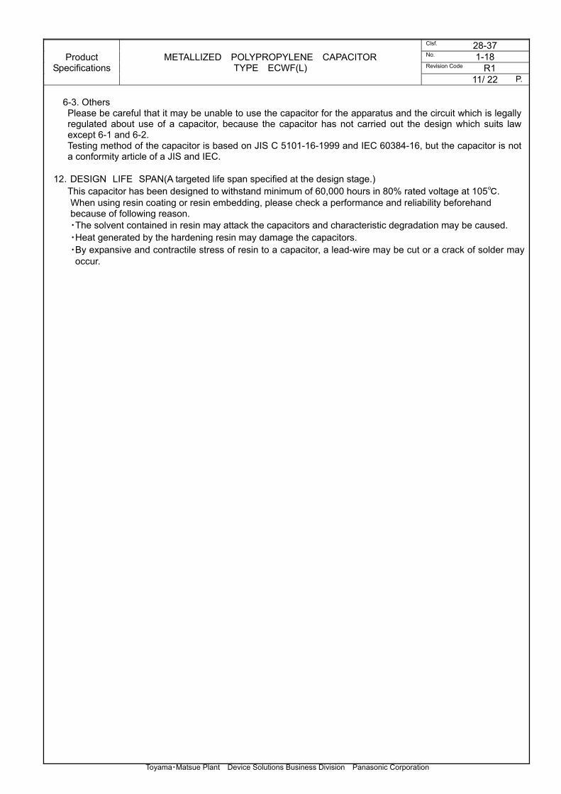
6-3. Others Please be careful that it may be unable to use the capacitor for the apparatus and the circuit which is legally
regulated about use of a capacitor, because the capacitor has not carried out the design which suits law except 6-1 and 6-2. Testing method of the capacitor is based on JIS C 5101-16-1999 and IEC 60384-16, but the capacitor is not a conformity article of a JIS and IEC.
12.DESIGN LIFE SPAN(A targeted life span specified at the design stage.) This capacitor has been designed to withstand minimum of 60,000 hours in 80% rated voltage at 105.
When using resin coating or resin embedding, please check a performance and reliability beforehand because of following reason. ・The solvent contained in resin may attack the capacitors and characteristic degradation may be caused. ・Heat generated by the hardening resin may damage the capacitors. ・By expansive and contractile stress of resin to a capacitor, a lead-wire may be cut or a crack of solder may occur.

Product Specifications
METALLIZED POLYPROPYLENE CAPACITOR TYPE ECWF(L)
Clsf. 28-37 No. 1-18 Revision Code R1
12/ 22 P.
Toyama・Matsue Plant Device Solutions Business Division Panasonic Corporation
Permissible Pulse Current Permissible pulse current is determined as the product of the capacitance value C(μF) and voltage change dV/dt per μs. (Example) In the case of ECWF4104JL Capacitance : 0.1(μF) Permissible dV/dt value : 200
Permissible Pulse Current : 0.1×200=20(Ao-p) When pulses are applied more than 10,000 times, please check that pulse current is less than the value calculated from formula (1). 10,000/L1=(I1/I2)13 ・・・・・・(1) L1: the total number of times applied pulse current I1: permissible pulse current at L1 I2: permissible pulse current when the number of times applied pulse current is less
than 10,000 times
Tabl.1 Permissible dV/dt value Within 10,000 pulses Capacitance
Value(μF) Rated voltage Capacitance
Value(μF) Rated voltage
400VDC 630VDC 400VDC 630VDC 103 (0.010) 164 (0.16) 113 (0.011) 184 (0.18) 200 249 123 (0.012) 204 (0.20) 133 (0.013) ― 561 224 (0.22) 153 (0.015) 244 (0.24) 163 (0.016) 274 (0.27) 183 (0.018) 304 (0.30) 203 (0.020) 334 (0.33) 154 223 (0.022) 364 (0.36) 216 243 (0.024) 394 (0.39) 273 (0.027) 412 434 (0.43) 303 (0.030) 451 474 (0.47) 333 (0.033) 514 (0.51) 363 (0.036) 564 (0.56)
393 (0.039) 624 (0.62) 136 433 (0.043) 684 (0.68) 473 (0.047) 754 (0.75) 513 (0.051) 824 (0.82) 131 563 (0.056) 283 914 (0.91) 113 623 (0.062) 332 105 (1.0) 683 (0.068) 115 (1.1) 753 (0.075) 125 (1.2) 823 (0.082) 135 (1.3) 913 (0.091) 155 (1.5) 104 (0.10) 165 (1.6) 85 114 (0.11) 185 (1.8) ― 124 (0.12) 200 249 205 (2.0) 134 (0.13) 225 (2.2) 154 (0.15) 245 (2.4)

Product Specifications
METALLIZED POLYPROPYLENE CAPACITOR TYPE ECWF(L)
Clsf. 28-37 No. 1-18 Revision Code R1
13/ 22 P.
Toyama・Matsue Plant Device Solutions Business Division Panasonic Corporation
Measuring method of a self-temperature rise
As shown in the following Fig.2, thermocouple is attached to the capacitor surface with adhesives, andcapacitor surface temperature is measured under conditions not influenced by other components. (Measurement is carried out at room temperature.) If there are influences from other components, please measure with one of the following procedures.
a) Attach the capacitor on the other of PC board. b) Mount the capacitor on the same PC board as the actual model and place them inside a box. Connect to the main set and measure under no circulating air (refer to the following figure). Same PC board as the actual model must be used to prevent the self-temperature rise variation caused by the types of PC board, wiring pattern, etc. Fig.2 T1 : Capacitor surface temperature – Must be measured at the capacitor center. T2 : Atmosphere temperature (Please use thermocouple φ0.1 typeT) Self-temperature rise T=T1-T2 Calm box T1 T2 The same substrate as real use Drawer line
Temperature measuring instrument
Set

Product Specifications
METALLIZED POLYPROPYLENE CAPACITOR TYPE ECWF(L)
Clsf. 28-37 No. 1-18 Revision Code R1
14/ 22 P.
Toyama・Matsue Plant Device Solutions Business Division Panasonic Corporation
Fig.3 The rate of permission current mitigation
Fig.4 The permissible value of self-temperature rise
0
1
2
3
4
5
6
7
8
9
60 70 80 90 100 110
Capacitor surface temperature()
Se
lf-
tem
pe
ratu
re r
ise
(
0
10
20
30
40
50
60
70
80
90
100
60 70 80 90 100 110
Capacitor surface temperature()
Pe
rce
nt
rate
d p
erm
issib
le c
urr
e
Per
cent
rat
ed p
erm
issi
ble
curr
ent (
%)
Sel
f-te
mpe
ratu
re r
ise
(deg
)

Product Specifications
METALLIZED POLYPROPYLENE CAPACITOR TYPE ECWF(L)
Clsf. 28-37 No. 1-18 Revision Code R1
15/ 22 P.
Toyama・Matsue Plant Device Solutions Business Division Panasonic Corporation
Fig.5-1 Permissible current vs. frequency(sine wave) Permissible voltage: 400Vp-p Temperature range : -40 to 85 (Capacitor surface temperature include the self-temperature rise)
(Refer to Fig.3 when the temperature exceed 85) Self-temperature rise: Refer to Fig.4 It cannot be used when it dissociates from the value which can permit voltage and a self-temperature rise even when current is in agreement in the value of graph.
ECWF4223~4823
0.0
0.5
1.0
1.5
2.0
2.5
3.0
10 100 1000
FREQUENCY (kHz)
PER
MIS
SIB
LE C
UR
REN
T (A
rms)
0.082uF
0.068uF 0.056uF
0.047uF 0.039uF
0.033uF 0.027uF
0.022uF

Product Specifications
METALLIZED POLYPROPYLENE CAPACITOR TYPE ECWF(L)
Clsf. 28-37 No. 1-18 Revision Code R1
16/ 22 P.
Toyama・Matsue Plant Device Solutions Business Division Panasonic Corporation
Fig.5-2 Permissible current vs. frequency(sine wave) Permissible voltage: 400Vp-p Temperature range : -40 to 85 (Capacitor surface temperature include the self-temperature rise)
(Refer to Fig.3 when the temperature exceed 85) Self-temperature rise: Refer to Fig.4
It cannot be used when it dissociates from the value which can permit voltage and a self-temperature rise even when current is in agreement in the value of graph.
ECWF4104~4474
0
1
2
3
4
5
6
7
10 100 1000
FREQUENCY (kHz)
PER
MIS
SIB
LE C
UR
REN
T (
Arm
s)
0.47uF 0.39uF 0.33uF 0.27uF 0.22uF 0.18uF 0.15uF
0.12uF
0.10uF

Product Specifications
METALLIZED POLYPROPYLENE CAPACITOR TYPE ECWF(L)
Clsf. 28-37 No. 1-18 Revision Code R1
17/ 22 P.
Toyama・Matsue Plant Device Solutions Business Division Panasonic Corporation
Fig.5-3 Permissible current vs. frequency(sine wave) Permissible voltage: 400Vp-p Temperature range : -40 to 85 (Capacitor surface temperature include the self-temperature rise)
(Refer to Fig.3 when the temperature exceed 85) Self-temperature rise: Refer to Fig.4
It cannot be used when it dissociates from the value which can permit voltage and a self-temperature rise even when current is in agreement in the value of graph.
ECWF4564~4105
0
1
2
3
4
5
6
7
10 100 1000
FREQUENCY (kHz)
PERMISSIBLE CURRENT (Arms)
1.0uF 0.82uF 0.68uF 0.56uF

Product Specifications
METALLIZED POLYPROPYLENE CAPACITOR TYPE ECWF(L)
Clsf. 28-37 No. 1-18 Revision Code R1
18/ 22 P.
Toyama・Matsue Plant Device Solutions Business Division Panasonic Corporation
Fig.5-4 Permissible current vs. frequency(sine wave) Permissible voltage: 400Vp-p Temperature range : -40 to 85 (Capacitor surface temperature include the self-temperature rise)
(Refer to Fig.3 when the temperature exceed 85) Self-temperature rise: Refer to Fig.4
It cannot be used when it dissociates from the value which can permit voltage and a self-temperature rise even when current is in agreement in the value of graph.
ECWF4125~4245
0
1
2
3
4
5
6
7
8
10 100 1000
FREQUENCY (kHz)
PERMISSIBLE CURRENT (Arms)
2.2uF 1.8uF 1.5uF 1.2uF
Product Specifications
METALLIZED POLYPROPYLENE CAPACITOR TYPE ECWF(L)
Clsf. 28-37 No. 1-18 Revision Code R1
19/ 22 P.
Toyama・Matsue Plant Device Solutions Business Division Panasonic Corporation
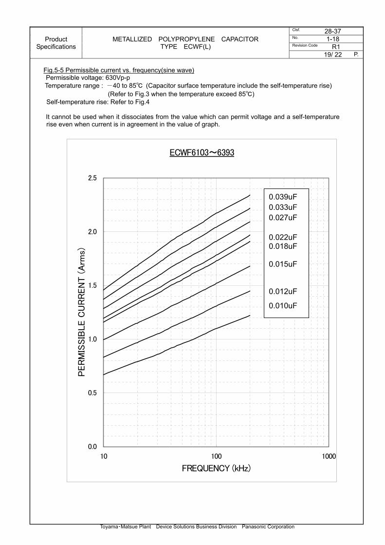
Fig.5-5 Permissible current vs. frequency(sine wave) Permissible voltage: 630Vp-p Temperature range : -40 to 85 (Capacitor surface temperature include the self-temperature rise)
(Refer to Fig.3 when the temperature exceed 85) Self-temperature rise: Refer to Fig.4
It cannot be used when it dissociates from the value which can permit voltage and a self-temperature rise even when current is in agreement in the value of graph.
ECWF6103~6393
0.0
0.5
1.0
1.5
2.0
2.5
10 100 1000
FREQUENCY (kHz)
PER
MIS
SIB
LE C
UR
REN
T (
Arm
s)
0.039uF 0.033uF 0.027uF 0.022uF 0.018uF 0.015uF
0.012uF
0.010uF

Product Specifications
METALLIZED POLYPROPYLENE CAPACITOR TYPE ECWF(L)
Clsf. 28-37 No. 1-18 Revision Code R1
20/ 22 P.
Toyama・Matsue Plant Device Solutions Business Division Panasonic Corporation
Fig.5-6 Permissible current vs. frequency(sine wave) Permissible voltage: 630Vp-p Temperature range : -40 to 85 (Capacitor surface temperature include the self-temperature rise)
(Refer to Fig.3 when the temperature exceed 85) Self-temperature rise: Refer to Fig.4
It cannot be used when it dissociates from the value which can permit voltage and a self-temperature rise even when current is in agreement in the value of graph.
ECWF6473~6224
0.0
0.5
1.0
1.5
2.0
2.5
3.0
3.5
4.0
4.5
5.0
10 100 1000
FREQUENCY (kHz)
PER
MIS
SIB
LE C
UR
REN
T (A
rms)
0.22uF
0.18uF
0.15uF
0.12uF 0.10uF 0.082uF 0.068uF
0.056uF
0.047uF
Product Specifications
METALLIZED POLYPROPYLENE CAPACITOR TYPE ECWF(L)
Clsf. 28-37 No. 1-18 Revision Code R1
21/ 22 P.
Toyama・Matsue Plant Device Solutions Business Division Panasonic Corporation
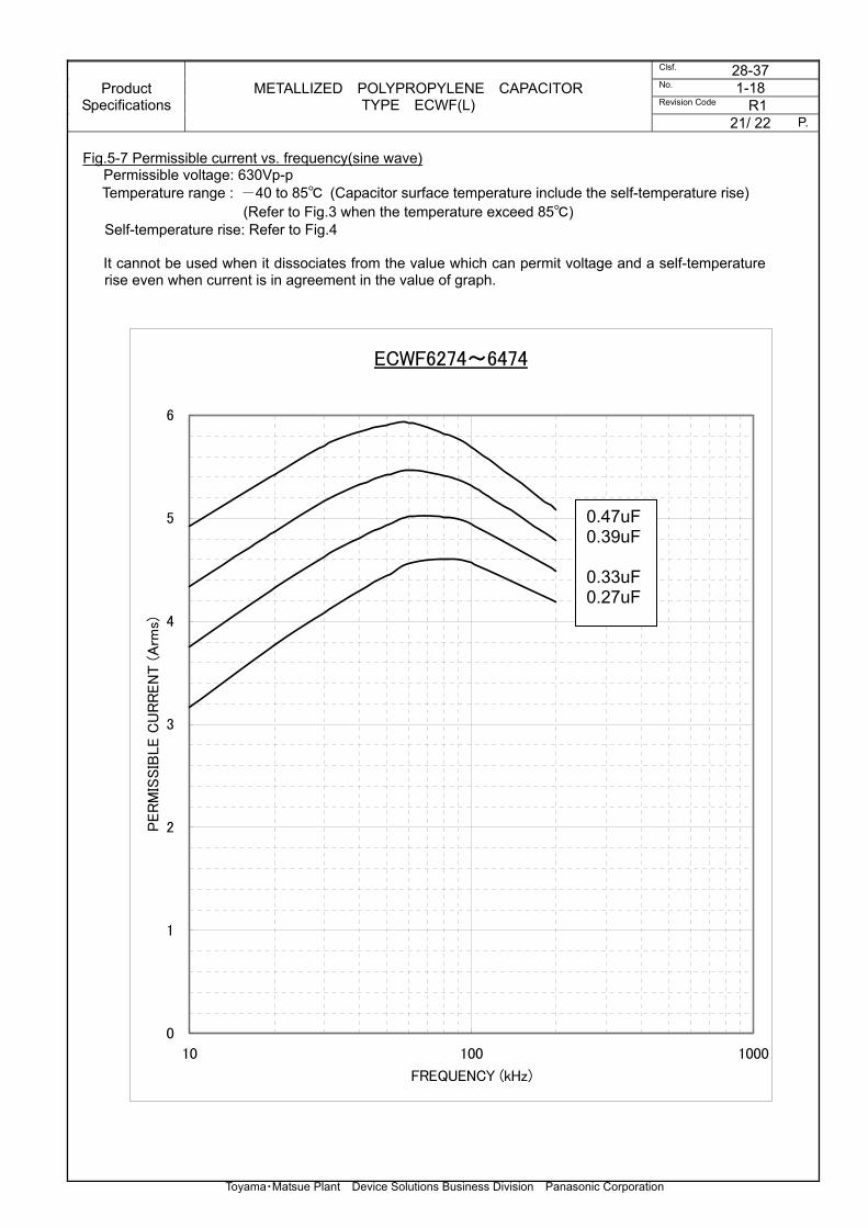
Fig.5-7 Permissible current vs. frequency(sine wave) Permissible voltage: 630Vp-p Temperature range : -40 to 85 (Capacitor surface temperature include the self-temperature rise)
(Refer to Fig.3 when the temperature exceed 85) Self-temperature rise: Refer to Fig.4
It cannot be used when it dissociates from the value which can permit voltage and a self-temperature rise even when current is in agreement in the value of graph.
ECWF6274~6474
0
1
2
3
4
5
6
10 100 1000
FREQUENCY (kHz)
PER
MIS
SIB
LE C
UR
REN
T (A
rms)
0.47uF 0.39uF 0.33uF 0.27uF

Product Specifications
METALLIZED POLYPROPYLENE CAPACITOR TYPE ECWF(L)
Clsf. 28-37 No. 1-18 Revision Code R1
22/ 22 P.
Toyama・Matsue Plant Device Solutions Business Division Panasonic Corporation
Fig.5-8 Permissible current vs. frequency(sine wave) Permissible voltage: 630Vp-p Temperature range : -40 to 85 (Capacitor surface temperature include the self-temperature rise)
(Refer to Fig.3 when the temperature exceed 85) Self-temperature rise: Refer to Fig.4
It cannot be used when it dissociates from the value which can permit voltage and a self-temperature rise even when current is in agreement in the value of graph.
ECWF6564~6125
0
1
2
3
4
5
6
7
8
10 100 1000
FREQUENCY (kHz)
PER
MIS
SIB
LE C
UR
REN
T (A
rms)
1.2uF 1.0uF 0.82uF 0.68uF 0.56uF