Embed Size (px)
Citation preview
BONETTIQuality Valves & Level Gauges
Il futuro come tradizione
Our
trad
ition
is th
e fu
ture
CMI Globe Valves
This catalogue describes our line of globe valves only. Other
Bonetti’s “CMI” products, such as gate and globe valves, are
described in other bulletins available on request.
DESIGN
All valves described herein are either:
- straight-through, with a vertical stem (T pattern), or
- angle type, or
- Y pattern with an inclined stem.
This last body pattern allows a streamlined smooth flow, less
turbulence and as consequence less internal erosion, less
pressure losses, etc.
OPERATIONS
Bonetti’s “CMI” valves described in this catalogue perform the
following functions:
- Stop on-off shut off to fluid flow;
- Stop and throttle - when a parabolic shaped disk is used in
lieu of a standard stop disk. A linear flow control
characteristic is achieved as a direct function of the stem
turns;
- Stop check - both a stop and a non-return valve;
- Piston lift check - for automatic prevention of undesired
reverse flow.
CONNECTIONS
Bonetti’s “CMI” valves illustrated in this catalogue have the
following pipe connections:
- Flanged ends according to ASME B16.5 (usually for Class
600 only, not for higher pressure Classes) or to different
Standards;
- Butt weld ends in accordance to ASME B16.25. (See pages
30 and 31 for different standards.).
We can supply valves with connections as needed.
SIZES
Bonetti’s “CMI” valves are currently manufactured in sizes from
2" (DN 50) up to 24" (DN 600).
RATINGS
Bonetti’s “CMI” valves are currently manufactured as per the
following Ratings:
ASME Class 600, 900, 1500 and 2500;
(PN 100, 150, 250 and 420).
As indicated in the foreword, Bonetti’s experience is not limited
to the above pressure classes. Tables showing max operating
conditions (pressure and temperature) for pressure ratings and
material codes are given on pgs. 28 – 29. We wish to point out
that Bonetti’s “CMI” valves are over dimension with respect to
most international standards. Actual max. operating conditions
can be supplied on request.
The Material Codes with tag followed by a -” Z “ are special
constructions, slightly different from the standard one.
STANDARDS
Bonetti’s “CMI” valves have been designed, rated, manufactured
and inspected, where applicable, in accordance with most widely
used international Standards, namely:
- ASME B16.34 "Steel valves, Flanged and Butt welding Ends"
- ASME B16.10 "Face-to-Face and End-to-End Dimensions"
- Applicable Sections of ASME Boiler and Pressure Vessel
Code, including Nuclear Section III
- MSS SP 44 "Steel pipe line flanges”
- MSS SP 61 "Hydrostatic testing of steel valves”
- API Standard 598 "Valve inspection and test”
- ASME B16.25 "Butt welding ends"
SHIPPING PREPARATION
Bonetti’s “CMI” valves are only shipped after undergoing the
prescribed dimensional and operating inspections.
Valves are adequately protected for storage and shipment.
To guarantee perfect valve sizing and selection please state:
- Size of the valve (DN)
- Fluid
- Design conditions (pressureand temperature) or Rating
- Operating conditions (pressure and temperature)
- Operating �p
- Connections type
- Operating means (by handwheel, actuator, etc.)
- installation type, that is the orientation of the valve within the
space
- Desired materials
- Options
- Possible environmental and operating peculiarities.
We reserve the right to carry out any product changes without
prior notice
MATERIAL CODE
Bonetti’s “CMI” valves are manufactured in different material
codes. For "Material code" we mean the material composition of
the valve parts.
The descriptive pages relevant to each valve clearly indicate the
materials used for the more important components and the
corresponding “Material code”.
Below we list the main characteristic elements of the different
Material Codes:
Material Material for Trim and
Code Body and Bonnet Hardfaced Surfaces
CB ASTM A216 WCB Stellite Gr. 6
C6 ASTM A217 WC6 Stellite Gr. 6
C9 ASTM A217 WC9 Stellite Gr. 6
C12A ASTM A217 C12A Stellite Gr. 6
GLOBE VALVES
01
BONETTIQuality Valves & Level Gauges CMI SERIES

23
7
6
4
9
2
1
3
21
18
19
20
15.1
15
Fig. 201
02
23
7
21
15.1
15
2
6
28
4
3
18
16
9
19
20
1
27
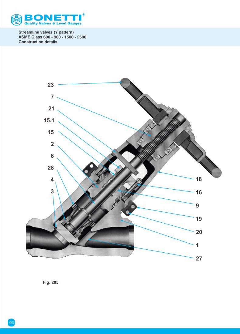
Fig. 205
Quality Valves & Level Gauges
Streamline valves (Y pattern)ASME Class 600 - 900 - 1500 - 2500Construction details
03
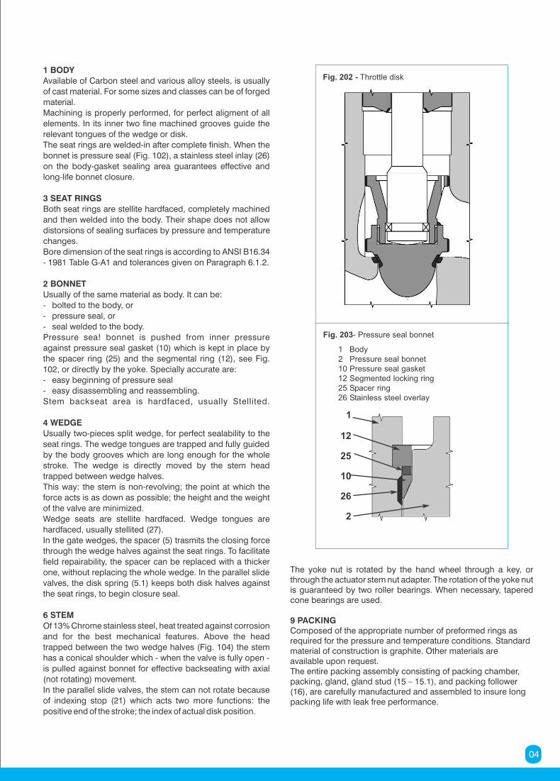
1 BODY
Available of Carbon steel and various alloy steels, is usually
of cast material. For some sizes and classes can be of forged
material.
Machining is properly performed, for perfect aligment of all
elements. In its inner two fine machined grooves guide the
relevant tongues of the wedge or disk.
The seat rings are welded-in after complete finish. When the
bonnet is pressure seal (Fig. 102), a stainless steel inlay (26)
on the body-gasket sealing area guarantees effective and
long-life bonnet closure.
3 SEAT RINGS
Both seat rings are stellite hardfaced, completely machined
and then welded into the body. Their shape does not allow
distorsions of sealing surfaces by pressure and temperature
changes.
Bore dimension of the seat rings is according to ANSI B16.34
- 1981 Table G-A1 and tolerances given on Paragraph 6.1.2.
2 BONNET
Usually of the same material as body. It can be:
- bolted to the body, or
- pressure seal, or
- seal welded to the body.
Pressure sea! bonnet is pushed from inner pressure
against pressure seal gasket (10) which is kept in place by
the spacer ring (25) and the segmental ring (12), see Fig.
102, or directly by the yoke. Specially accurate are:
- easy beginning of pressure seal
- easy disassembling and reassembling.
Stem backseat area is hardfaced, usually Stellited.
4 WEDGE
Usually two-pieces split wedge, for perfect sealability to the
seat rings. The wedge tongues are trapped and fully guided
by the body grooves which are long enough for the whole
stroke. The wedge is directly moved by the stem head
trapped between wedge halves.
This way: the stem is non-revolving; the point at which the
force acts is as down as possible; the height and the weight
of the valve are minimized.
Wedge seats are stellite hardfaced. Wedge tongues are
hardfaced, usually stellited (27).
In the gate wedges, the spacer (5) trasmits the closing force
through the wedge halves against the seat rings. To facilitate
field repairability, the spacer can be replaced with a thicker
one, without replacing the whole wedge. In the parallel slide
valves, the disk spring (5.1) keeps both disk halves against
the seat rings, to begin closure seal.
6 STEM
Of 13% Chrome stainless steel, heat treated against corrosion
and for the best mechanical features. Above the head
trapped between the two wedge halves (Fig. 104) the stem
has a conical shoulder which - when the valve is fully open -
is pulled against bonnet for effective backseating with axial
(not rotating) movement.
In the parallel slide valves, the stem can not rotate because
of indexing stop (21) which acts two more functions: the
positive end of the stroke; the index of actual disk position.
The yoke nut is rotated by the hand wheel through a key, orthrough the actuator stem nut adapter. The rotation of the yoke nut is guaranteed by two roller bearings. When necessary, tapered cone bearings are used.
9 PACKINGComposed of the appropriate number of preformed rings asrequired for the pressure and temperature conditions. Standardmaterial of construction is graphite. Other materials are available upon request.The entire packing assembly consisting of packing chamber,packing, gland, gland stud (15 – 15.1), and packing follower (16), are carefully manufactured and assembled to insure long packing life with leak free performance.
Fig. 202 - Throttle disk
Fig. 203- Pressure seal bonnet
1
12
25
10
26
2
1 Body2 Pressure seal bonnet10 Pressure seal gasket12 Segmented locking ring25 Spacer ring26 Stainless steel overlay
04
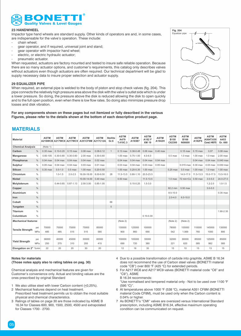
23 HANDWHEELImpactor type hand wheels are standard supply. Other kinds of operators are and, in some cases, are indispensable for the valve’s operation. These include:- chain wheel;- gear operator, and if required, universal joint and stand;- gear operator with impactor hand wheel;- electric, or electric hydraulic actuator;- pneumatic actuator.When requested, actuators are factory mounted and tested to insure safe reliable operation. Because there are so many actuator options, and customer’s requirements, this catalog only describes valves without actuators even though actuators are often required. Our technical department will be glad to supply necessary data to insure proper selection and actuator supply.
29 EQUALIZER PIPEWhen required, an external pipe is welded to the body of piston and stop check valves (fig. 204). This pipe connects the relatively high pressure area above the disk with the valve’s outlet side which is under a lower pressure. So doing, the pressure above the disk is reduced allowing the disk to open quickly and to the full open position, even when there is low flow rates. So doing also minimizes pressure drop losses and disk vibration.
For any components shown on these pages but not itemized or fully described in the various Figures, please refer to the details shown at the bottom of each descriptive product page.
Notes for materials(Those notes apply also to rating tables on pag. 30)
Chemical analysis and mechanical features are given for Customer’s convenience only. Actual and binding values are the ones prescribed by original Standard
1 We also utilise steel with lower Carbon content (<0,25%).2 Mechanical features depend on heat treatment. Prescribed heat treatment permits us to obtain the most suitable physical and chemical characteristics.3 Ratings of tables on page 30 are those indicated by ASME B 16.34 for Classes 600, 900, 1500, 2500, 4500 and extrapolated for Classes 1700 - 2700.
4 Due to a possible transformation of carbide into graphite, ASME B 16.34 does not recommend the use of Carbon steel valves (BONETTI material code “CB”) over 800 °F (425 °C) for extended periods.5 For A217 WC6 and A217 WC9 valves (BONETTI material code “C6” and “C9”), ASME B 16.34 recommends: “Use normalised and tempered material only - Not to be used over 1100 °F (595 °C)”.6 At temperatures above 1000 °F (538 °C), material A351 CF8M (BONETTI material Code CF8M), must be used only when the Carbon content is 0.04% or higher.7 As BONETTI’s “CMI” valves are oversized versus International Standard prescription, including ASME B16.34, effective maximum operating condition can be communicated on request.
Fig. 204Equalizer pipe
MATERIALS
MaterialASTM
A216WCBASTM
A217WC6ASTM
A217WC9ASTM
A351CF8MASTM
A217C12AStellite
Gr.6
ASTMA479
T.410C.3
ASTMA193B7
ASTMA182 FXM 19
ASTMA1942H
ASTMB150
C62300
ASTMB166
N06600
ASTMA182F6
ASTMA564T.630Cond. H1075
ASTMA453
Gr. 660
Chemical Analysis (Note 1)
Carbon % 0.35 max 0.10-0.20 0.15 max 0.08 max 0.08-0.12 1 0.13 max 0.38-0.48 0.06 max 0.40 max 0.15 max 0.15 max 0,07 0.08 max
Manganese % 0.60-105 0.30-0.80 0.30-0.60 2.00 max 0.30-0.60 1.00 max 0.75-1.00 4.0-6.0 0.5 max 1.0 max 1.00 max 1.0 max 2.00 max
Phosphorus % 0.04 max 0.04 max 0.04 max 0.04 max 0.02 max 0.04 max 0.04 max 0.04 max 0.04 max 0.04 max 0.04 max 0.040 max
Sulphur % 0.05 max 0.04 max 0.04 max 0.03 max 0.01 max 0.03 max 0.04 max 0.03 max 0.05 max 0.015 max 0.30 max 0.03 max 0.030 max
Silicon % 0.35 max 0.5-1.0 0.5 max 1.00 max 0.20-0.50 1.00 max 0.20-0.35 1.00 max 0.25 max 0.5 max 1.00 max 1.0 max 1.00 max
Chromium % 1.0-1.5 2.0-2.5 16.00-18.00 8.00-9.50 28 11.5-13.5 0.80-1.10 20.5-23.5 14.0-17.0 11.5-13.5 15.0-17.5 13.5-16.0
Nickel % 10.00-14.00 0.40 max 0.50 max 11.5-13.5 1.0 max 72 min+Co 0.50 max 3.0-5.0 24.0-27.0
Molybdenum % 0.44-0.65 0.87-1.13 2.00-3.00 0.85-1.05 0.15-0.25 1.5-3.0 1.2-2.0 1.0-1.5
Copper % 82.2 min 0.50 max 3.0-5.0
Aluminium % 8.5-10.0 0.35 max
Iron % 2.0-4.0 6.0-10.0
Cobalt % 66
Tungsten % 5
Titanium % 1.90-2.35
Columbium % 0.10-0.30
Mechanical features (Note 2) (Note 2) (Note 2)
Tensile Strengthpsi 70000 70000 75000 75000 85000 130000 125000 100000 78000 155000 110000 145000 130000
MPa 485 485 515 515 585 900 860 690 542 1.069 760 1000 895
Yield Strengthpsi 36000 40000 45000 30000 60000 100000 105000 55000 32000 90000 85000 125000 85000
MPa 250 275 310 205 415 690 720 380 221 620 585 862 585
Elongation on 2" %min 22 20 20 30 20 12 16 35 15 10 15 13 15
Quality Valves & Level Gauges
05
V
L1Class 600
L3Class 900
L4Class 1500
L6Class 2500
B C
23
22
24
15.1
16
15
9
20
19
8
28
7
18
21
14
13
12
25
10
2
6
1
4
27
3
V
L1Class 600
L3Class 900
L4Class 1500
L6Class 2500
B C
23
22
24
15.1
16
15
9
20
19
8
28
29
7
18
21
14
13
12
25
10
2
6
1
4
27
3
L1Class 600
L3Class 900
L4Class 1500
L6Class 2500
12
E
25
10
1
27
3
24
13
14
2
28
4
29
Fig. 231
Fig. 232
Fig. 233
Fig. 221.1
Fig. 222.1
Fig. 223.1
V
LClass 600Flanged
L1Class 600
Butt Welding
B C
23
D
22
241615.11592
10.18128
76
2411
427
3
V
LClass 600Flanged
L1Class 600
Butt Welding
B C
23
D
22
241615.11592
810.1
12829
76
2411
431
LClass 600Flanged
L1Class 600
Butt Welding
E
24
D
11
427
3
210.11
2829
06
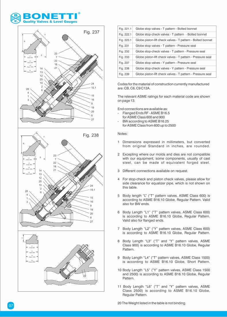
Codes for the material of construction currently manufacturedare: CB, C6, C9 C12A.
The relevant ASME ratings for each material code are shown on page 13.
End connections are available as:- Flanged Ends RF - ASME B16.5 for ASME Class 600 and 900- BW according to ASME B16.25 for ASME Class from 600 up to 2500
Notes:
1 Dimensions expressed in millimeters, but converted from original Standard in inches, are rounded.
2 Excepting where our molds and dies are not compatible with our equipment, some components, usually of cast steel, can be made of equivalent forged steel.
3 Different connections available on request.
4 For stop-check and piston check valves, please allow for side clearance for equalizer pipe, which is not shown on this table.
5 Body length “L” (“T” pattern valves, ASME Class 600) is according to ASME B16.10 Globe, Regular Pattern. Valid also for BW ends.
6 Body Length “L1” (“T” pattern valves, ASME Class 600) is according to ASME B16.10 Globe, Regular Pattern. Valid also for flanged ends.
7 Body Length “L2” (“Y” pattern valves, ASME Class 600) is according to ASME B16.10 Globe, Regular Pattern.
8 Body Length “L3” (“T” and “Y” pattern valves, ASME Class 900) is according to ASME B16.10 Globe, Regular Pattern.
9 Body Length “L4” (“T” pattern valves, ASME Class 1500) is according to ASME B16.10 Globe, Short Pattern.
10 Body Length “L5” (“Y” pattern valves, ASME Class 1500 and 2500) is according to ASME B16.10 Globe, Regular Pattern.
11 Body Length “L6” (“T” and “Y” pattern valves, ASME Class 2500) is according to ASME B16.10 Globe, Regular Pattern.
20 The Weight listed in the table is not binding.
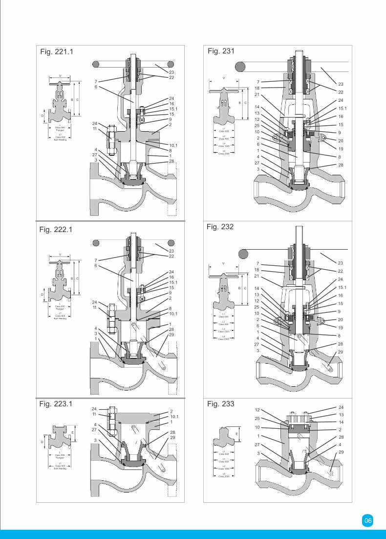
Fig. 221.1 Globe stop valves - T pattern - Bolted bonnet
Fig. 222.1 Globe stop-check valves - T pattern - Bolted bonnet
Fig. 223.1 Globe piston-lift check valves - T pattern - Bolted bonnet
Fig. 231 Globe stop valves - T pattern - Pressure seal
Fig. 232 Globe stop-check valves - T pattern - Pressure seal
Fig. 233 Globe piston-lift check valves - T pattern - Pressure seal
Fig. 237 Globe stop valves - Y pattern - Pressure seal
Fig. 238 Globe stop-check valves - Y pattern - Pressure seal
Fig. 239 Globe piston-lift check valves - T pattern - Pressure seal
V
L1Class 600
L3Class 900
L4Class 1500
L6Class 2500
R
S
24
15.1
15
16
9
19
20
8
27
23
7
22
18
2114
13
12
25
10
2
628
4
1
3
Fig. 237
Fig. 238V
L1Class 600
L3Class 900
L4Class 1500
L6Class 2500
R
S
24
15.1
15
16
9
19
20
8
27
23
7
22
18
2114
13
12
25
10
2
628
4
1
3
L1Class 600
L3Class 900
L4Class 1500
L6Class 2500
T
Quality Valves & Level Gauges
07
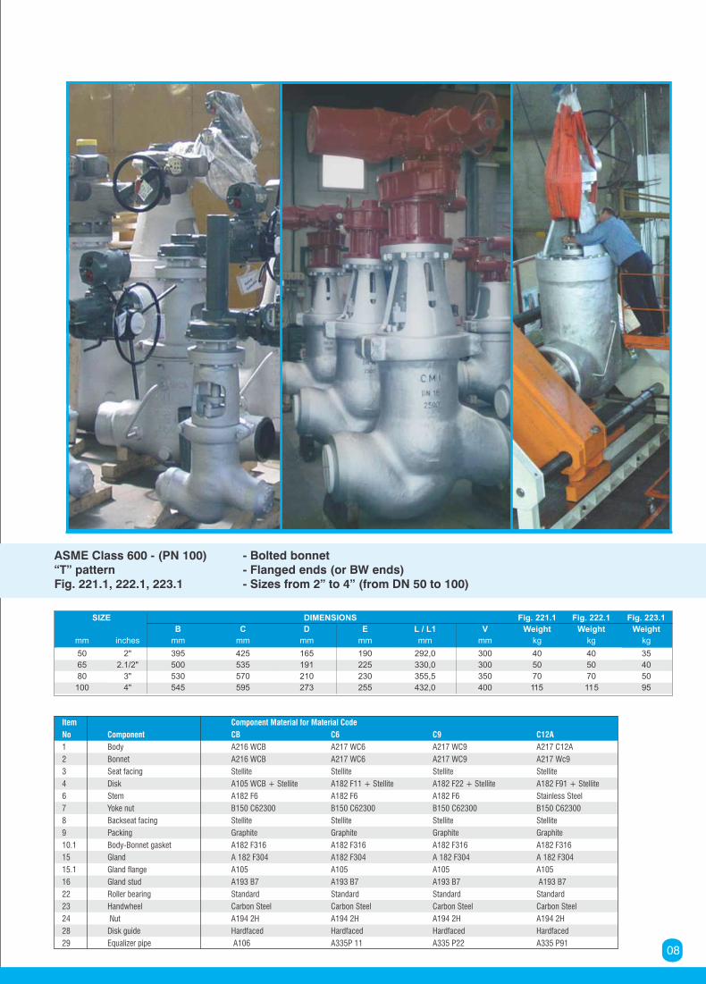
SIZE DIMENSIONS Fig. 221.1 Fig. 222.1 Fig. 223.1
B C D E L / L1 V Weight Weight Weight
mm inches mm mm mm mm mm mm kg kg kg
50 2" 395 425 165 190 292,0 300 40 40 35
65 2.1/2" 500 535 191 225 330,0 300 50 50 40
80 3" 530 570 210 230 355,5 350 70 70 50
100 4" 545 595 273 255 432,0 400 115 115 95
ASME Class 600 - (PN 100) - Bolted bonnet“T” pattern - Flanged ends (or BW ends)Fig. 221.1, 222.1, 223.1 - Sizes from 2” to 4” (from DN 50 to 100)
Item Component Material for Material Code
No Component CB C6 C9 C12A
1 Body A216 WCB A217 WC6 A217 WC9 A217 C12A
2 Bonnet A216 WCB A217 WC6 A217 WC9 A217 Wc9
3 Seat facing Stellite Stellite Stellite Stellite
4 Disk A105 WCB + Stellite A182 F11 + Stellite A182 F22 + Stellite A182 F91 + Stellite
6 Stem A182 F6 A182 F6 A182 F6 Stainless Steel
7 Yoke nut B150 C62300 B150 C62300 B150 C62300 B150 C62300
8 Backseat facing Stellite Stellite Stellite Stellite
9 Packing Graphite Graphite Graphite Graphite
10.1 Body-Bonnet gasket A182 F316 A182 F316 A182 F316 A182 F316
15 Gland A 182 F304 A182 F304 A 182 F304 A 182 F304
15.1 Gland flange A105 A105 A105 A105
16 Gland stud A193 B7 A193 B7 A193 B7 A193 B7
22 Roller bearing Standard Standard Standard Standard
23 Handwheel Carbon Steel Carbon Steel Carbon Steel Carbon Steel
24 Nut A194 2H A194 2H A194 2H A194 2H
28 Disk guide Hardfaced Hardfaced Hardfaced Hardfaced
29 Equalizer pipe A106 A335P 11 A335 P22 A335 P9108
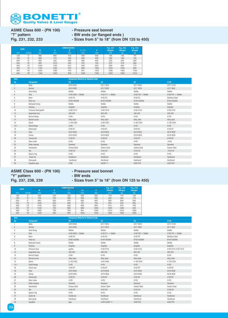
ASME Class 600 - (PN 100) - Pressure seal bonnet“T” pattern - BW ends (or flanged ends )Fig. 231, 232, 233 - Sizes from 5” to 18” (from DN 125 to 450)
Item Component Material for Material Code
No Component CB C8 C9 C12A
1 Body A216 WCB A217 WC6 A217 WC9 A217 C12A
2 Bonnet A216 WCB A217 WC6 A217 WC9 A217 Wc9
3 Seat facing Stellite Stellite Stellite Stellite
4 Disk A105 WCB + Stellite A182 F11 + Stellite A182 F22 + Stellite A182 F91 + Stellite
6 Stem A182 F6 A182 F6 A182 F6 Stainless Steel
7 Yoke nut B150 C62300 B150 C62300 B150 C62300 B150 C62300
8 Backseat facing Stellite Stellite Stellite Stellite
9 Packing Graphite Graphite Graphite Graphite
10 Pressure-Seal gasket A182 F316 A182 F316 A182 F316 A182 F316
12 Segmental ring AISI 420 AISI 420 AISI 420 AISI 420
13 Bonnet flange A105 A105 A105 A105
14 Bonnet screw Alloy steel Alloy steel Alloy steel Alloy steel
15 Gland A 182 F304 A182 F304 A 182 F304 A 182 F304
15.1 Gland flange A105 A105 A105 A105
16 Gland stud A193 B7 A193 B7 A193 B7 A193 B7
18 Yoke A216 WCB A216 WCB A216 WCB A216 WCB
19 Clamp A216 WCB A216 WCB A216 WCB A216 WCB
20 Clamp bolt A193 B7 A193 B7 A193 B7 A193 B7
21 Stem index A105 A105 A105 A105
22 Roller bearing Standard Standard Standard Standard
23 Handwheel Carbon Steel Carbon Steel Carbon Steel Carbon Steel
24 Nut A194 2H A194 2H A194 2H A194 2H
25 Spacer ring A105 A105 A105 A105
27 Guide rib Hardfaced Hardfaced Hardfaced Hardfaced
28 Disk guide Hardfaced Hardfaced Hardfaced Hardfaced
29 Equalizer pipe A106 A335P 11 A335 P22 A335 P91
ASME Class 600 - (PN 100) - Pressure seal bonnet“Y” pattern - BW endsFig. 237, 238, 239 - Sizes from 5” to 18” (from DN 125 to 450)
SIZEDIMENSIONS Fig. 231 Fig. 232 Fig. 233
B C E L / L1 V Weight Weight Weight
mm inches mm mm mm mm mm mm kg kg
125 5" 585 660 310 508 500 145 145 115
150 6" 680 770 350 559 500 180 180 150
200 8" 820 925 460 660 600 325 325 265
250 10" 950 1070 540 787 700 575 575 465
300 12" 1040 1180 610 838 800 845 845 710
350 14" 1100 1250 670 889 1000 1035 1035 885
400 16" 1200 1360 740 991 1000 1380 1380 1190
450 18" 1340 1500 830 1092 1000 1820 1820 1610
SIZEDIMENSIONS Fig. 237 Fig. 238 Fig. 239
R S T L2 V Weight Weight Weight
mm inches mm mm mm mm mm mm kg kg
125 5" 640 330 330 508 500 175 175 140
150 6" 700 370 380 559 500 225 225 175
200 8" 880 500 475 660 600 280 280 290
250 10" 1020 550 560 787 700 620 620 485
300 12" 1100 630 625 838 800 910 910 740
350 14" 1230 700 690 889 1000 1090 1090 940
400 16" 1300 790 750 991 1000 1510 1510 1260
450 18" 1420 820 850 1092 1000 1950 1950 1620
Quality Valves & Level Gauges
09
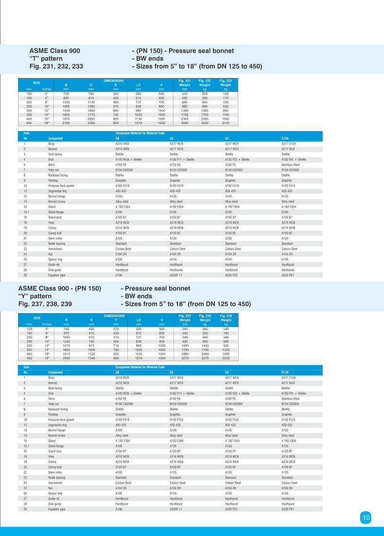
ASME Class 900 - (PN 150) - Pressure seal bonnet“T” pattern - BW endsFig. 231, 232, 233 - Sizes from 5” to 18” (from DN 125 to 450)
Item Component Material for Material Code
No Component CB C8 C9 C12A
1 Body A216 WCB A217 WC6 A217 WC9 A217 C12A
2 Bonnet A216 WCB A217 WC6 A217 WC9 A217 Wc9
3 Seat facing Stellite Stellite Stellite Stellite
4 Disk A105 WCB + Stellite A182 F11 + Stellite A182 F22 + Stellite A182 F91 + Stellite
6 Stem A182 F6 A182 F6 A182 F6 Stainless Steel
7 Yoke nut B150 C62300 B150 C62300 B150 C62300 B150 C62300
8 Backseat facing Stellite Stellite Stellite Stellite
9 Packing Graphite Graphite Graphite Graphite
10 Pressure-Seal gasket A182 F316 A182 F316 A182 F316 A182 F316
12 Segmental ring AISI 420 AISI 420 AISI 420 AISI 420
13 Bonnet flange A105 A105 A105 A105
14 Bonnet screw Alloy steel Alloy steel Alloy steel Alloy steel
15 Gland A 182 F304 A182 F304 A 182 F304 A 182 F304
15.1 Gland flange A105 A105 A105 A105
16 Gland stud A193 B7 A193 B7 A193 B7 A193 B7
18 Yoke A216 WCB A216 WCB A216 WCB A216 WCB
19 Clamp A216 WCB A216 WCB A216 WCB A216 WCB
20 Clamp bolt A193 B7 A193 B7 A193 B7 A193 B7
21 Stem index A105 A105 A105 A105
22 Roller bearing Standard Standard Standard Standard
23 Handwheel Carbon Steel Carbon Steel Carbon Steel Carbon Steel
24 Nut A194 2H A194 2H A194 2H A194 2H
25 Spacer ring A105 A105 A105 A105
27 Guide rib Hardfaced Hardfaced Hardfaced Hardfaced
28 Disk guide Hardfaced Hardfaced Hardfaced Hardfaced
29 Equalizer pipe A106 A335P 11 A335 P22 A335 P91
ASME Class 900 - (PN 150) - Pressure seal bonnet“Y” pattern - BW endsFig. 237, 238, 239 - Sizes from 5” to 18” (from DN 125 to 450)
SIZEDIMENSIONS Fig. 237 Fig. 238 Fig. 239
R S T L3 V Weight Weight Weight
mm inches mm mm mm mm mm mm kg kg
125 5" 740 420 370 559 500 240 240 145
150 6" 870 510 420 610 600 320 320 195
200 8" 1050 610 510 737 700 545 545 345
250 10" 1240 790 605 838 800 930 930 590
300 12" 1470 915 715 965 1000 1430 1430 935
350 14" 1600 1000 780 1029 1000 1790 1790 1220
400 16" 1810 1120 850 1130 1000 2480 2480 1680
450 18" 2050 1340 960 1219 1000 3275 3275 2235
SIZEDIMENSIONS Fig. 231 Fig. 232 Fig. 233
B C E L3 V Weight Weight Weight
mm inches mm mm mm mm mm mm kg kg
125 5" 725 790 360 559 500 225 225 125
150 6" 830 910 400 610 600 295 295 170
200 8" 1030 1130 485 737 700 540 540 335
250 10" 1265 1380 575 838 800 880 880 535
300 12" 1430 1580 680 965 1000 1380 1380 860
350 14" 1605 1770 740 1029 1000 1755 1755 1140
400 16" 1870 2050 800 1130 1000 2360 2360 1590
450 18" 2150 2350 900 1219 1000 3050 3050 2110
10
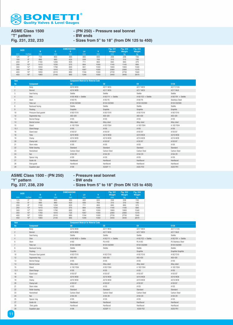
ASME Class 1500 - (PN 250) - Pressure seal bonnet“T” pattern - BW endsFig. 231, 232, 233 - Sizes from 5” to 18” (from DN 125 to 450)
Item Component Material for Material Code
No Component CB C8 C9 C12A
1 Body A216 WCB A217 WC6 A217 WC9 A217 C12A
2 Bonnet A216 WCB A217 WC6 A217 WC9 A217 Wc9
3 Seat facing Stellite Stellite Stellite Stellite
4 Disk A105 WCB + Stellite A182 F11 + Stellite A182 F22 + Stellite A182 F91 + Stellite
6 Stem A182 F6 A182 F6 A182 F6 Stainless Steel
7 Yoke nut B150 C62300 B150 C62300 B150 C62300 B150 C62300
8 Backseat facing Stellite Stellite Stellite Stellite
9 Packing Graphite Graphite Graphite Graphite
10 Pressure-Seal gasket A182 F316 A182 F316 A182 F316 A182 F316
12 Segmental ring AISI 420 AISI 420 AISI 420 AISI 420
13 Bonnet flange A105 A105 A105 A105
14 Bonnet screw Alloy steel Alloy steel Alloy steel Alloy steel
15 Gland A 182 F304 A182 F304 A 182 F304 A 182 F304
15.1 Gland flange A105 A105 A105 A105
16 Gland stud A193 B7 A193 B7 A193 B7 A193 B7
18 Yoke A216 WCB A216 WCB A216 WCB A216 WCB
19 Clamp A216 WCB A216 WCB A216 WCB A216 WCB
20 Clamp bolt A193 B7 A193 B7 A193 B7 A193 B7
21 Stem index A105 A105 A105 A105
22 Roller bearing Standard Standard Standard Standard
23 Handwheel Carbon Steel Carbon Steel Carbon Steel Carbon Steel
24 Nut A194 2H A194 2H A194 2H A194 2H
25 Spacer ring A105 A105 A105 A105
27 Guide rib Hardfaced Hardfaced Hardfaced Hardfaced
28 Disk guide Hardfaced Hardfaced Hardfaced Hardfaced
29 Equalizer pipe A106 A335P 11 A335 P22 A335 P91
ASME Class 1500 - (PN 250) - Pressure seal bonnet“Y” pattern - BW endsFig. 237, 238, 239 - Sizes from 5” to 18” (from DN 125 to 450)
SIZEDIMENSIONS Fig. 231 Fig. 232 Fig. 233
B C E L4 V Weight Weight Weight
mm inches mm mm mm mm mm mm kg kg
125 5" 735 800 365 483 600 258 258 150
150 6" 890 960 420 559 700 310 310 195
200 8" 1160 1250 505 711 800 660 660 375
250 10" 1410 1530 570 864 1000 1145 1145 695
300 12" 1650 1790 665 991 1000 1660 1660 1040
350 14" 1760 1910 720 1067 1000 2080 2080 1370
400 16" 1850 2010 880 1194 1000 2730 2730 1940
450 18" 1960 2140 965 1346 1000 3440 3440 2670
Quality Valves & Level Gauges
11
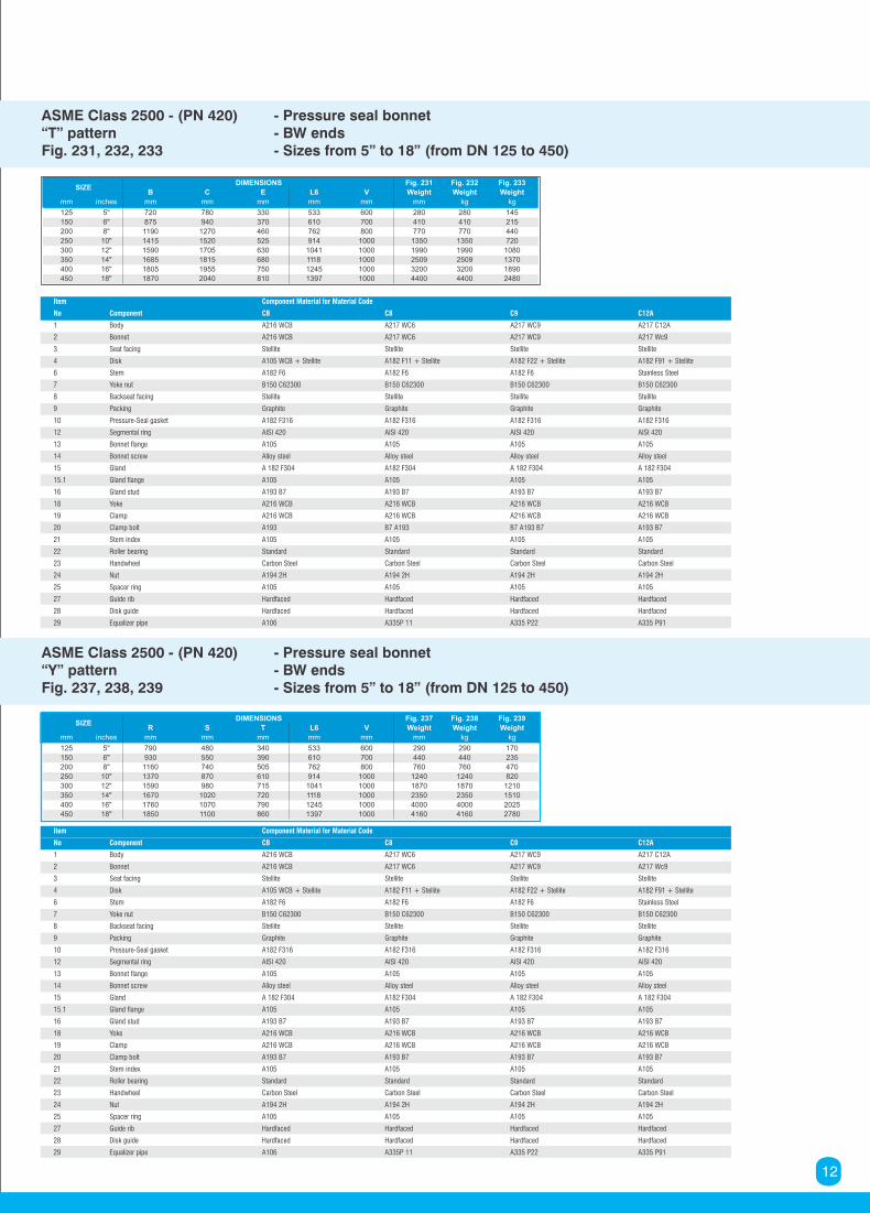
ASME Class 2500 - (PN 420) - Pressure seal bonnet“T” pattern - BW endsFig. 231, 232, 233 - Sizes from 5” to 18” (from DN 125 to 450)
Item Component Material for Material Code
No Component CB C8 C9 C12A
1 Body A216 WCB A217 WC6 A217 WC9 A217 C12A
2 Bonnet A216 WCB A217 WC6 A217 WC9 A217 Wc9
3 Seat facing Stellite Stellite Stellite Stellite
4 Disk A105 WCB + Stellite A182 F11 + Stellite A182 F22 + Stellite A182 F91 + Stellite
6 Stem A182 F6 A182 F6 A182 F6 Stainless Steel
7 Yoke nut B150 C62300 B150 C62300 B150 C62300 B150 C62300
8 Backseat facing Stellite Stellite Stellite Stellite
9 Packing Graphite Graphite Graphite Graphite
10 Pressure-Seal gasket A182 F316 A182 F316 A182 F316 A182 F316
12 Segmental ring AISI 420 AISI 420 AISI 420 AISI 420
13 Bonnet flange A105 A105 A105 A105
14 Bonnet screw Alloy steel Alloy steel Alloy steel Alloy steel
15 Gland A 182 F304 A182 F304 A 182 F304 A 182 F304
15.1 Gland flange A105 A105 A105 A105
16 Gland stud A193 B7 A193 B7 A193 B7 A193 B7
18 Yoke A216 WCB A216 WCB A216 WCB A216 WCB
19 Clamp A216 WCB A216 WCB A216 WCB A216 WCB
20 Clamp bolt A193 B7 A193 B7 A193 B7 A193 B7
21 Stem index A105 A105 A105 A105
22 Roller bearing Standard Standard Standard Standard
23 Handwheel Carbon Steel Carbon Steel Carbon Steel Carbon Steel
24 Nut A194 2H A194 2H A194 2H A194 2H
25 Spacer ring A105 A105 A105 A105
27 Guide rib Hardfaced Hardfaced Hardfaced Hardfaced
28 Disk guide Hardfaced Hardfaced Hardfaced Hardfaced
29 Equalizer pipe A106 A335P 11 A335 P22 A335 P91
ASME Class 2500 - (PN 420) - Pressure seal bonnet“Y” pattern - BW endsFig. 237, 238, 239 - Sizes from 5” to 18” (from DN 125 to 450)
SIZEDIMENSIONS Fig. 237 Fig. 238 Fig. 239
R S T L6 V Weight Weight Weight
mm inches mm mm mm mm mm mm kg kg
125 5" 790 480 340 533 600 290 290 170
150 6" 930 550 390 610 700 440 440 235
200 8" 1160 740 505 762 800 760 760 470
250 10" 1370 870 610 914 1000 1240 1240 820
300 12" 1590 980 715 1041 1000 1870 1870 1210
350 14" 1670 1020 720 1118 1000 2350 2350 1510
400 16" 1760 1070 790 1245 1000 4000 4000 2025
450 18" 1850 1100 860 1397 1000 4160 4160 2780
SIZEDIMENSIONS Fig. 231 Fig. 232 Fig. 233
B C E L6 V Weight Weight Weight
mm inches mm mm mm mm mm mm kg kg
125 5" 720 780 330 533 600 280 280 145
150 6" 875 940 370 610 700 410 410 215
200 8" 1190 1270 460 762 800 770 770 440
250 10" 1415 1520 525 914 1000 1350 1350 720
300 12" 1590 1705 630 1041 1000 1990 1990 1080
350 14" 1685 1815 680 1118 1000 2509 2509 1370
400 16" 1805 1955 750 1245 1000 3200 3200 1890
450 18" 1870 2040 810 1397 1000 4400 4400 2480
12
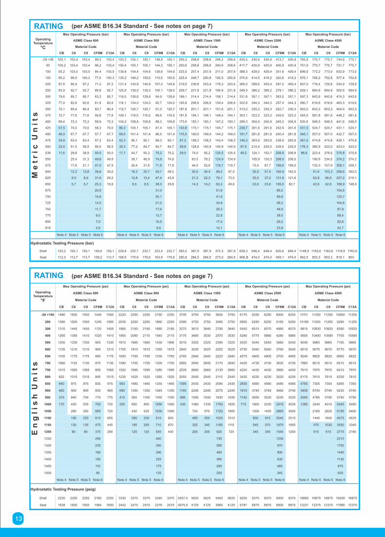
RATING (per ASME B16.34 Standard - See notes on page 7)
OperatingTemperature
°C
Max Operating Pressure (bar) Max Operating Pressure (bar) Max Operating Pressure (bar) Max Operating Pressure (bar) Max Operating Pressure (bar)
ASME Class 600 ASME Class 900 ASME Class 1500 ASME Class 2500 ASME Class 4500
Material Code Material Code Material Code Material Code Material Code
CB C6 C9 CF8M C12A CB C6 C9 CF8M C12A CB C6 C9 CF8M C12A CB C6 C9 CF8M C12A CB C6 C9 CF8M C12A
Me
tr
ic
Un
it
s
-29 +38 102,1 103,4 103,4 99,3 103,4 153,2 155,1 155,1 148,9 155,1 255,3 258,6 258,6 248,2 258,6 425,5 430,9 430,9 413,7 430,9 765,9 775,7 775,7 744,6 775,7
50 100,2 103,4 103,4 96,2 103,4 150,4 155,1 155,1 144,3 155,1 250,6 258,6 258,6 240,6 258,6 417,7 430,9 430,9 400,9 430,9 751,9 775,7 775,7 721,7 775,7
100 93,2 103,0 103,0 84,4 103,0 139,8 154,4 154,6 126,6 154,6 233,0 257,4 257,6 211,0 257,6 388,3 429,0 429,4 351,6 429,4 699,0 772,2 773,0 632,9 773,0
150 90,2 99,5 100,3 77,0 100,3 135,2 149,2 150,6 115,5 150,6 225,4 248,7 250,8 192,5 250,8 375,6 414,5 418,2 320,8 418,2 676,1 746,2 752,8 577,4 752,8
200 87,6 95,9 97,2 71,3 97,2 131,4 143,9 145,8 107,0 145,8 219,0 239,8 243,4 178,3 243,4 365,0 399,6 405,4 297,2 405,4 657,0 719,4 729,8 534,9 729,8
250 83,9 92,7 92,7 66,8 92,7 125,8 139,0 139,0 100,1 139,0 209,7 231,8 231,8 166,9 231,8 349,5 386,2 386,2 278,1 386,2 629,1 694,8 694,8 500,6 694,8
300 79,6 85,7 85,7 63,2 85,7 119,5 128,6 128,6 94,9 128,6 199,1 214,4 214,4 158,1 214,4 331,8 357,1 357,1 263,5 357,1 597,3 642,6 642,6 474,3 642,6
325 77,4 82,6 82,6 61,8 82,6 116,1 124,0 124,0 92,7 124,0 193,6 206,6 206,6 154,4 206,6 322,6 344,3 344,3 257,4 344,3 580,7 619,6 619,6 463,3 619,6
350 75,1 80,4 80,4 60,7 80,4 112,7 120,7 120,7 91,0 120,7 187,8 201,1 201,1 151,6 201,1 313,0 335,3 335,3 252,7 335,3 563,5 603,3 603,3 454,9 603,3
375 72,7 77,6 77,6 59,8 77,6 109,1 116,5 116,5 89,6 116,5 181,8 194,1 194,1 149,4 194,1 303,1 323,2 323,2 249,0 323,2 545,5 581,8 581,8 448,2 581,8
400 69,4 73,3 73,3 58,9 73,3 104,2 109,8 109,8 88,3 109,8 173,6 183,1 183,1 147,2 183,1 289,3 304,9 304,9 245,3 304,9 520,8 548,5 548,5 441,6 548,5
425 57,5 70,0 70,0 58,3 70,0 86,3 105,1 105,1 87,4 105,1 143,8 175,1 175,1 145,7 175,1 239,7 291,6 291,6 242,9 291,6 431,5 524,7 524,7 437,1 524,7
450 46,0 67,7 67,7 57,7 67,7 69,0 101,4 101,4 86,5 101,4 115,0 169,0 169,0 144,2 169,0 191,7 281,8 281,8 240,4 281,8 345,1 507,0 507,0 432,7 507,0
475 34,9 63,4 63,4 57,3 63,4 52,3 95,1 95,1 86,0 95,1 87,2 158,2 158,2 143,4 158,2 145,3 263,9 263,9 238,9 263,9 261,5 474,8 474,8 430,1 474,8
500 23,5 51,5 56,5 56,5 56,5 35,3 77,2 84,7 84,7 84,7 58,8 128,6 140,9 140,9 140,9 97,9 214,4 235,0 235,0 235,0 176,3 385,9 423,0 423,0 423,0
538 11,8 29,8 36,9 50,0 50,0 17,7 44,7 55,3 75,2 75,2 29,5 74,5 92,2 125,5 125,5 49,2 124,1 153,7 208,9 208,9 88,6 223,4 276,6 375,8 375,8
550 25,4 31,3 49,8 49,8 38,1 46,9 74,8 74,8 63,5 78,2 124,9 124,9 105,9 130,3 208,0 208,0 190,6 234,5 374,2 374,2
575 17,6 21,1 47,9 47,9 26,4 31,6 71,8 71,8 44,0 52,6 119,7 119,7 73,4 87,7 199,5 199,5 132,0 157,9 359,1 359,1
600 12,2 13,8 39,8 39,0 18,3 20,7 59,7 58,5 30,5 34,4 99,5 97,5 50,9 57,4 165,9 162,5 91,6 103,3 298,6 292,5
625 8,5 8,9 31,6 29,2 12,8 13,4 47,4 43,8 21,3 22,3 79,1 73,0 35,5 37,2 131,8 121,6 63,9 66,9 237,2 219,1
650 5,7 5,7 25,3 19,9 8,5 8,5 38,0 29,8 14,2 14,2 63,3 49,6 23,6 23,6 105,5 82,7 42,6 42,6 189,9 148,9
675 20,6 31,0 51,6 86,0 154,8
700 16,8 25,1 41,9 69,8 125,7
725 14,0 21,0 34,9 58,2 104,8
750 11,7 17,6 29,3 48,9 87,9
775 9,0 13,7 22,8 38,0 68,4
800 7,0 10,5 17,4 29,2 52,6
816 5,9 8,6 14,1 23,8 42,7
Note 4 Note 5 Note 5 Note 6 Note 4 Note 5 Note 5 Note 6 Note 4 Note 5 Note 5 Note 6 Note 4 Note 5 Note 5 Note 6 Note 4 Note 5 Note 5 Note 6
Hydrostatic Testing Pressure (bar)
Shell 153,2 155,1 155,1 149,0 155,1 229,8 232,7 232,7 223,4 232,7 383,0 387,9 387,9 372,3 387,9 638,3 646,4 646,4 620,6 646,4 1148,9 1163,6 1163,6 1116,9 1163,6
Seat 112,3 113,7 113,7 109,2 113,7 168,5 170,6 170,6 163,8 170,6 280,8 284,5 284,5 273,0 284,5 468,,13 474,0 474,0 455,1 474,0 842,5 853,3 853,3 819,1 853
RATING (per ASME B16.34 Standard - See notes on page 7)
OperatingTemperature
°F
Max Operating Pressure (psi) Max Operating Pressure (psi) Max Operating Pressure (psi) Max Operating Pressure (psi) Max Operating Pressure (psi)
ASME Class 600 ASME Class 900 ASME Class 1500 ASME Class 2500 ASME Class 4500
Material Code Material Code Material Code Material Code Material Code
CB C6 C9 CF8M C12A CB C6 C9 CF8M C12A CB C6 C9 CF8M C12A CB C6 C9 CF8M C12A CB C6 C9 CF8M C12A
En
glis
h
Un
it
s
-20 +100 1480 1500 1500 1440 1500 2220 2250 2250 2160 2250 3705 3750 3750 3600 3750 6170 6250 6250 6000 6250 11110 11250 11250 10800 11250
200 1360 1500 1500 1240 1500 2035 2250 2250 1860 2250 3395 3750 3750 3095 3750 5655 6250 6250 5160 6250 10185 11250 11250 9290 11250
300 1310 1445 1455 1120 1455 1965 2165 2185 1680 2185 3270 3610 3640 2795 3640 5450 6015 6070 4660 6070 9815 10830 10925 8390 10925
400 1265 1385 1410 1025 1410 1900 2080 2115 1540 2115 3170 3465 3530 2570 3530 5280 5775 5880 4280 5880 9505 10400 10585 7705 10585
500 1205 1330 1330 955 1330 1810 1995 1995 1435 1995 3015 3325 3325 2390 3325 5025 5540 5540 3980 5540 9040 9965 9965 7165 9965
600 1135 1210 1210 900 1210 1705 1815 1815 1355 1815 2840 3025 3025 2255 3025 4730 5040 5040 3760 5040 8515 9070 9070 6770 9070
650 1100 1175 1175 890 1175 1650 1765 1765 1330 1765 2745 2940 2940 2220 2940 4575 4905 4905 3700 4905 8240 8825 8825 6660 8825
700 1060 1135 1135 870 1135 1590 1705 1705 1305 1705 2665 2840 2840 2170 2840 4425 4730 4730 3620 4730 7960 8515 8515 6515 8515
750 1015 1065 1065 855 1065 1520 1595 1595 1280 1595 2535 2660 2660 2135 2660 4230 4430 4430 3560 4430 7610 7970 7970 6410 7970
800 825 1015 1015 845 1015 1235 1525 1525 1265 1525 2055 2540 2540 2110 2540 3430 4230 4230 3520 4230 6170 7610 7610 6335 7610
850 640 975 975 835 975 955 1460 1460 1255 1460 1595 2435 2435 2090 2435 2655 4060 4060 3480 4060 4785 7305 7305 6265 7305
900 460 900 900 830 900 690 1350 1350 1245 1350 1150 2245 2245 2075 2245 1915 3745 3745 3460 3745 3455 6740 6740 6230 6740
950 275 640 755 775 775 410 955 1160 1160 1160 685 1595 1930 1930 1930 1145 2655 3220 3220 3220 2055 4785 5795 5795 5795
1000 170 430 535 700 725 255 650 800 1050 1090 430 1080 1335 1750 1820 715 1800 2230 2915 3030 1285 3240 4010 5245 5450
1050 290 350 685 720 430 525 1030 1080 720 875 1720 1800 1200 1455 2865 3000 2160 2625 5155 5400
1100 190 220 610 605 290 330 915 905 480 550 1525 1510 800 915 2545 2515 1440 1645 4575 4525
1150 130 135 475 445 195 205 710 670 325 345 1185 1115 545 570 1970 1855 975 1030 3550 3345
1200 80 80 370 290 125 125 555 430 205 205 925 720 345 345 1545 1200 615 615 2775 2160
1250 295 440 735 1230 2210
1300 235 350 585 970 1750
1350 190 290 480 800 1440
1400 150 225 380 630 1130
1450 115 175 290 485 875
1500 85 125 205 345 620
Note 4 Note 5 Note 5 Note 6 Note 4 Note 5 Note 5 Note 6 Note 4 Note 5 Note 5 Note 6 Note 4 Note 5 Note 5 Note 6 Note 4 Note 5 Note 5 Note 6
Hydrostatic Testing Pressure (psig)
Shell 2220 2250 2250 2160 2250 3330 3375 3375 3240 3375 5557,5 5625 5625 5400 5625 9255 9375 9375 9000 9375 16665 16875 16875 16200 16875
Seat 1628 1650 1650 1584 1650 2442 2475 2475 2376 2475 4075,5 4125 4125 3960 4125 6787 6875 6875 6600 6875 12221 12375 12375 11880 12375
13

AV2 valve AV3 valve
Quick acting automatic 2 and 3 way valvesfor H.P. Pre-heaters bypass systems.
Valves are hydraulic self-actuated by means of an integral piston whose speed is controlled byan external regulating valve.Meeting ASME Class 900 thru 2500, and special classes. Available in sizes up to 18”
OPERATION
These fully automatic valves are operated by a piston which is
integral to the stem. The piston slides within a cylinder which
is itself integral to the pressure seal bonnet.
The stem-piston-disk assembly derives its motive force from
the pressure of the fluid being handled, without the need of an
external power source. The piston is sealed within the
cylinder by means of piston rings.
In the 2-way valves, AV-2, the disk opens or closes the
passage of fluid between the inlet and outlet ports.
In the 3-way valves, AV-3, the disk intercepts the passage of
the main fluid flow and diverts this flow to a secondary by-
pass, or an emergency line.
The stem-piston-disk assembly is connected to the threaded
stem, or hand wheel, by means of a yoke. It may also be
operated manually and locked in place.
The valve’s operating speed (and the length of its cycle) may be
controlled by means of separate auxiliary control valve (CV1 and
CV2 in figure at page 17).
These automatic by-pass valves are typically installed on the
condensate or feedwater lines of thermal power stations. They are
designed to automatically intercept fluid flow to the HP feed water
preheater, in case of a
high water level condition in the preheater shell. This design
includes:
- One 3-way automatic valve, AV-3, whose function is to switch
over the water flow from the preheater to the by-pass line.
- One 2-way automatic valve, AV-2, designed to function as a
stop-check valve, isolating the preheater’s outlet from the feed
water line.
- One set of auxiliary control valves (CV1, CV2, MGV and RV1 in
figure at page 17).
14
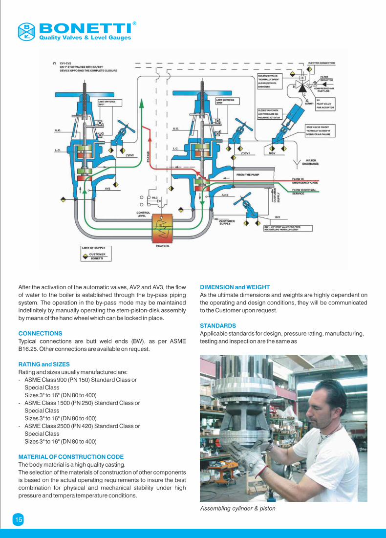
Assembling cylinder & piston
Quality Valves & Level Gauges
After the activation of the automatic valves, AV2 and AV3, the flow
of water to the boiler is established through the by-pass piping
system. The operation in the by-pass mode may be maintained
indefinitely by manually operating the stem-piston-disk assembly
by means of the hand wheel which can be locked in place.
CONNECTIONS
Typical connections are butt weld ends (BW), as per ASME
B16.25. Other connections are available on request.
RATING and SIZES
Rating and sizes usually manufactured are:
- ASME Class 900 (PN 150) Standard Class or
Special Class
Sizes 3" to 16" (DN 80 to 400)
- ASME Class 1500 (PN 250) Standard Class or
Special Class
Sizes 3" to 16" (DN 80 to 400)
- ASME Class 2500 (PN 420) Standard Class or
Special Class
Sizes 3" to 16" (DN 80 to 400)
MATERIAL OF CONSTRUCTION CODE
The body material is a high quality casting.
The selection of the materials of construction of other components
is based on the actual operating requirements to insure the best
combination for physical and mechanical stability under high
pressure and tempera temperature conditions.
DIMENSION and WEIGHT
As the ultimate dimensions and weights are highly dependent on
the operating and design conditions, they will be communicated
to the Customer upon request.
STANDARDS
Applicable standards for design, pressure rating, manufacturing,
testing and inspection are the same as
15
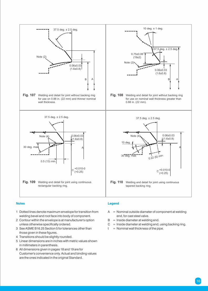
Fig. 107 Welding end detail for joint without backing ring
for use on 0.88 in. (22 mm) and thinner nominalwall thickness.
Fig. 108 Welding end detail for joint without backing ring
for use on nominal wall thickness greater than0.88 in. (22 mm).
Fig. 109 Welding end detail for joint using continuous
rectangular backing ring.
Fig. 110 Welding end detail for joint using continuous
tapered backing ring.
37.5 deg. ± 2.5 deg.
Note (2)
0.06±0.03(1.6±0.8)
B A
10 deg. ± 1 deg.
Note (2)
0.06±0.03(1.6±0.8)
B A
37.5 deg. ± 2.5 deg.
0.75±0.06(19±2)
37.5 deg. ± 2.5 deg.
Note (4) 0.06±0.03(1.6±0.8)
A
C
30 deg. max
+0.010-0(+0.25)
0.5 (13) min.
37.5 deg. ± 2.5 deg.
Note (4) 0.06±0.03(1.6±0.8)
A
C
10 deg.
+0.010-0(+0.25)
0.22 (6) min.30 deg. max
Notes
1 Dotted lines denote maximum envelope for transition from
welding bevel and root face into body of component.
2 Contour within the envelope is at manufacturer's option
unless otherwise specifically ordered.
3 See ASME B16.25 Section 5 for tolerances other than
those given in these figures.
4 Transitions should be slightly rounded.
5 Linear dimensions are in inches with metric values shown
in millimeters in parenthesis.
6 All dimensions given in pages 18 and 19 are for
Customer's convenience only. Actual and binding values
are the ones indicated in the original Standard.
Legend
A = Nominal outside diameter of component at welding
end, for cast steel valve.
B = Inside diameter at welding end.
C = Inside diameter at welding end, using backing ring.
t = Nominal wall thickness of the pipe.
16
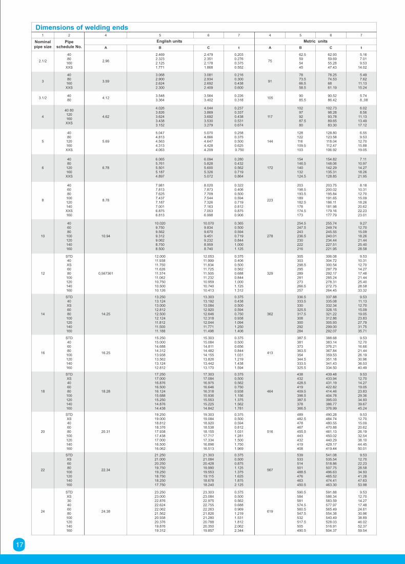
Dimensions of welding ends1 2 4 5 6 7 4 5 6 7
Nominalpipe size
Pipeschedule No.
English units Metric units
A B C t A B C t
2.1/2
4080
160XXS
2.96
2.4692.3232.1251.771
2.4792.3512.1781.868
0.2030.2760.3750.552
75
62.5595445
62.9359.6955.2847.43
5.167.019.53
14.02
3
4080
160XXS
3.59
3.0682.9002.6242.300
3.0812.9342.6922.409
0.2160.3000.4380.600
91
7873.566.558.5
78.2574.536861.19
5.497.62
11.1315.24
3.1/24080
4.123.5483.364
3.5643.402
0.2260.318
1059085.5
90.5286.42
5.748.,08
4
40 80120160XXS
4.62
4.0263.8263.6243.4383.152
4.0443.8693.6923.5303.279
0.2370.3370.4380.5310.674
117
102979287.580
102.7398.2893.7889.6583.30
6.028.56
11.1313.4917.12
5
4080
120160XXS
5.69
5.0474.8134.5634.3134.063
5.0704.8664.6474.4284.209
0.2580.3750.5000.6250.750
144
128122116109.5103
128.80123.58118.04112.47106.92
6.559.53
12.7015.8819.05
6
4080
120160XXS
6.78
6.0655.7615.5015.1874.897
6.0945.8285.6005.3265.072
0.2800.4320.5620.7190.864
172
154146.5140132124.5
154.82148.06142.29135.31128.85
7.1110.9714.2718.2621.95
8
406080
100120140XXS160
8.78
7.9817.8137.6257.4377.1877.0016.8756.813
8.0207.8737.7097.5447.3267.1637.0536.998
0.3220.4060.5000.5940.7190.8120.8750.906
223
203198.5193.5189182.5178174.5173
203.75200.02195.84191.65186.11181.98179.16177.79
8.1810.3112.7015.0918.2620.6222.2323.01
10
406080
100120140160
10.94
10.0209.7509.5629.3129.0628.7508.500
10.0709.8349.6709.4519.2328.9598.740
0.3650.5000.5940.7190.8441.0001.125
278
254.5247.5243236.5230222216
255.74249.74245.55240.01234.44227.51221.95
9.2712.7015.0918.2621.4425.4028.58
12
STD40XS6080
100120140160
0,567361
12.00011.93811.75011.62611.37411.06210.75010.50010.126
12.05311.99911.83411.72511.50511.23210.95910.74010.413
0.3750.4060.5000.5620.6880.8441.0001.1251.312
329
305303298.5295289281273266.5257
306.08304.72300.54297.79292.17285.24278.31272.75264.45
9.5310.3112.7014.2717.4821.4425.4028.5833.32
14
STD40XS6080
100120140160
14.25
13.25013.12413.00012.81212.50012.12411.81211.50011.188
13.30313.19213.08412.92012.64612.31812.04411.77111.498
0.3750.4380.5000.5940.7500.9381.0941.2501.406
362
336.5333.5330325.5317.5308300292284
337.88335.08332.34328.15321.22312.86305.93299.00292.07
9.5311.1312.7015.0919.0523.8327.7931.7535.71
16
STD406080
100120140160
16.25
15.25015.00014.68814.31213.93813.56213.12412.812
15.30315.08414.81114.48214.15513.82613.44213.170
0.3750.5000.6560.8441.0311.2191.4381.594
413
387.5381373363.5354344.5333.5325.5
388.68383.14376.21367.84359.53351.18341.43334.50
9.5312.7016.6621.4426.1930.9636.5340.49
18
STDXS406080
100120140160
18.28
17.25017.00016.87616.50016.12415.68815.25014.87614.438
17.30317.08416.97516.64616.31815.93615.55315.22514.842
0.3750.5000.5620.7500.9381.1561.3751.5621.781
464
438432428.5419409.5398.5387.5378366.5
439.48433.94431.19422.82414.46404.78395.03386.77376.99
9.5312.7014.2719.0523.8329.3634.9339.6745.24
20
STDXS406080
100120140160
20.31
19.25019.00018.81218.37617.93817.43817.00016.50016.062
19.30319.08418.92018.53818.15517.71717.33416.89616.513
0.3750.5000.5940.8121.0311.2811.5001.7501.969
516
489482.5478467455.5443432419408
490.28484.74480.55470.88461.13450.02440.29429.17419.44
9.5312.7015.0920.6226.1932.5438.1044.4550.01
22
STDXS6080
100120140160
22.34
21.25021.00020.25019.75019.25018.75018.25017.750
21.30321.08420.42819.99019.55319.11518.67818.240
0.3750.5000.8751.1251.3751.6251.8752.125
567
539533514501488.5476463450.5
541.08535.54518.86507.75496.63485.52474.41463.30
9.5312.7022.2328.5834.9341.2847.6353.98
24
STDXS30406080
100120140160
24.38
23.25023.00022.87622.62422.06221.56220.93820.37619.87619.312
23.30323.08422.97522.75522.26321.82621.28020.78820.35019.857
0.3750.5000.5620.6880.9691.2191.5311.8122.0622.344
619
590.5584581574.5560.5547.5532517.5505490.5
591.88586.34583.59577.97565.49554.38540.49528.03516.91504.37
9.5312.7014.2717.4824.6130.9638.8946.0252.3759.54
17
18
Copyright © Cesare Bonetti. All rights reserved.
Unless otherwise indicated, all materials on these pages are copyrighted by Cesare Bonetti S.p.A. All rights reserved. Any reproduction, modification, storage in a retrieval system or retransmission, in any
form or by any means, electronic, mechanical or otherwise is strictly prohibited.
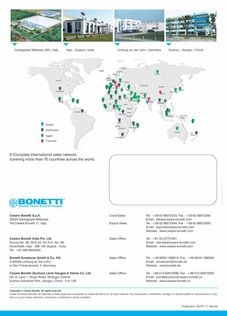
Suzhou - Jiangsu | ChinaLimburg an der Lahn | Germany Garbagnate Milanese (MI) | Italy Vapi - Gujarat | India
Publication CB-PC-11- Rev.00
BONETTIQuality Valves & Level Gauges
Cesare Bonetti S.p.A.
20024 Garbagnate Milanese,
Via Cesare Bonetti 17, Italy.
Cesare Bonetti India Pvt. Ltd.
Survey No. 36, 39 & 42, On N.H. No. 08,
Karambele, Vapi - 396 105 Gujarat - India.
Tel : +91-260-6634000
Bonetti Armaturen GmbH & Co. KG.
D-65549 Limburg an der Lahn,
In Den Fritzenstucker, 4. Germany.
Cesare Bonetti (Suzhou) Level Gauges & Valves Co. Ltd.
No. 8, Lane 1, Wupu Road, Shengpu District,
Suzhou Industrial Park, Jiangsu, China - 215 126.
Local Sales: Tel.: +39-02 99072333, Fax : +39-02 99072300
Email : [email protected]
Export Sales: Tel.: +39-02 99072444, Fax : +39-02 99072400
Email : [email protected]
Website : www.cesare-bonetti.com
Sales Office: Tel.: +91-22-27751851
Email : [email protected]
Website : www.cesare-bonetti.com
Sales Office: Tel.: +49-06431 598310, Fax : +49-06431 598329
Email : [email protected]
Website : www.bonetti.de
Sales Office: Tel.: +86-512-62816396, Fax : +86-512-62816393
Email : [email protected]
Website : www.cesare-bonetti.cn
Dealer
Distributors
Agent
Factories
Iceland
Canada
United States
Mexica
Venezuela
UnitedKingdom
Norway
Sweden
Finland
Russia
Indonesia Papua NewGuinea
Australia NewZealand
Thailand
Mongolia
ChinaSouth Korea
Japan
India
Afghanistan
Pakistan
Kazakhstan
Madagascar
South Africa
Botswana
Namibia
Angola
Tanzania
KenyaDR Congo
Ethiopia
SudanChad
Nigeria
NigerMali
AgeriaLibya
Egypt
South Araiba
Iraq
Spain Turkey
UkrainePoland
Germany
FranceItaly
A Complete International sales network, covering more than 70 countries across the world.
uandvc
reativ
ess
.com