Embed Size (px)
Citation preview

Production Processes and Systems, vol. 6. (2013) No. 1. pp. 47-56.
CMT PIN – DEFINE THE SHAPE OF THE WELDED PIN
THROUGH WELDING PARAMETERS
Gábor Somoskői, Imre Török University of Miskolc, Department of Mechanical Technology
Abstract
The article in the first part covers the demand for the new welding technologies, and mate-rial, mainly in the automotive industry. The industrial demand drives to develop the differ-ent high-performance welding process, the tandem and the T.I.M.E. and the CMT process. The requirement for safe joining processes, mainly in the light-gauge area, requires weld-ing processes with maximum process stability and adjustable, reduced heat input. The spat-ter and the heat impact of the ground material should be decreased; the economical figures of the whole process have to be increased. The CMT, this new welding approach which incorporates the wire feeding into process control satisfies these different demands. In the second part contains the responsible parameters to define the geometry of the welded CMT pin. At the end the future outlook and further investigation is covered.
Keywords: CMT welding, tandem welding, T.I.M.E. welding, high-performance welding, PIN welding
1. Demand for modified material transfer in the welding technology
Recently in the automotive industry thinner and thinner steel sheet metals have been using for reducing the weight of product. The sheets are mainly galvanized, and heavily cold formed. These properties cause several problems to make welded joint. Traditional puls welding is not inapplicable because the vapor of zinc disturbs the arc and the continuously changing in the arc length makes the process unstable. We need also methods to decrease the welding spatter for reducing the costs associated with post weld spatter removal. The aluminium sheet are also have been used increasing way. Aluminium usage in automotive applications has grown more than double in the past 7 years. This material has high strength to weight ratio, good formability, outstanding corrosion resistance and ideal to replace traditional heavier material for the increasing demand of weight reduction. From the weld-ing engineer aspect revolutionary new technologies need to handle this type of materials.[1]
On the other side of the coin to reduce the cost better efficiency is needed. It means to increase the deposit rate. Currently different methods and systems with high deposit rate have developed. This process is not exclusive for thick sheet, but for welding thin sheets with extreme high welding speed. In the automotive industry and his supplier it is not ex-traordinary the welding speed of 1.5 m/min. Even more problem occurs when we have to weld in position, the prevail over the welding pool could be challenging.
The next necessity is the good, deep penetration. Since the tendency is to work with lesser material – because the cost reducing – we don’t have a lot of room for making mis-takes. The task to be done is even more difficult if we have to deal with different thickness-

Somoskői G., Török I.
48
es. Until the expected penetration on the thicker sheet is reached, the thinner sheet has been already molted.[2]
In the next section I try to list different processes and compare them on the ground the above mentioned requirements.
1.1. Tandem welding
The submerged arc welding was the first process where the welding with two wires was applied. Seeing the advantages, the method was successfully transferred to gas metal arc welding. There are two power sources and wire feeders, the arc burns in one welding pool.
Fig. 1. Tandem welding torch
The electrical characteristics of the two machines could be separated adjustable, the shielding gas is common. With this setup there is wide possibility to control the result of welding, the form and shape of welded butt.
The two wires are adjusted one after one. The first is called master; its role is to provide deep penetration. The second one is the slave, its task is to shape the welded joint, to ensure the proper time to outgas, to set free from porosity and undercutting. The wires could be with different diameters, but usually there are the same for the sake of simplicity.
The arc type could be also different. We can use pulse, dip transfer, or spray arc on both wire, controlling the result in the different ways.
Machines for Tandem welding are made up of two, usually inverter, welding power sources, which allow optional adjustment of work characteristics of individual machines and two wire feeding systems supplying electrode wires and welding torch, equipped with two contact tubes oriented in the required directions to be applied. Figure 1. A torch should be water cooled and the geometry is suitable for the desired task to be done.[3]

CMT pin – Define the shape of the welded pin
49
Fig. 2. Welding joint with tandem process
With this type of robust torch the application is mainly designed for robotic and auto-matic usage. It is possible to reach several meters welding speed so the manual applications is neither suitable on ergonomic ground. Typical welded joint is shown on Figure 2.
1.2. T.I.M.E. welding
Different approach to solve high deposit rate welding is to use more component gas mixtures. That’s the way T.I.M.E. (Transfer Ionized Molten Energy) process is born. Figure 3.
The four-component gas mixture varies on the ground of welded material (typical com-position 65% Ar + 26,6% He + 8% CO2 + 0,5% O2). The result of this gas mixture is the high current density. Beyond the traditional dip transfer, spray arc this process is suitable for the rotational arc.
Short arc: up to 8 m/min wire feed speed Spray arc: up to 23 m/min Rotational arc: from 25 m/min up to 40 m/min
All of the above mentioned arc type works with less then 2% spatter. The deposit rate could reach the 27 kg/hour.
In contrast to conventional MIG/MAG welding, the TIME process has a longer, free wire stick-out in the welding torch. The most powerful TIME variant has two wires that burn together in one weld bath. In this “TimeTwin” process, the contact tubes in the special welding torch are insulated from each other, so that the material transfer for each wire is separately controlled. The result is doubled or tripled welding speed compared to MIG/MAG welding, with the best possible quality and virtually no welding spatter.[4]

Somoskői G., Török I.
50
Fig. 3. T.I.M.E. welding machine
1.3. The CMT arc process
There are other developments to solve the above mentioned questions: control the current in the droplet phases. This process’s name is the STT (Surface Tension Transfer), dedicated mainly to weld the root passes of energetic pipe-line welding seams. STT welding power source provide stabile main welding parameters during welding process which enable weld-ing by “short circuit arc”. The material transfer in electric arc is founded on surface tension force between weld pool and melted bead in electric arc. STT unit frequently and precisely controls welding current during welding. It sets an optimal welding parameters (which are stabile) by significant changing of arc length and “stick out”. Other processes try to modify the inductivity and the electrical behavior of the welding circuit, with more or less outcome.
The most significant difference between traditional short, or spray arc and the CMT ma-terial transfer is the involving the wire motion in transfer process. The system has two fire feeding machine: the first is in the welding source and his main task is the continuously feed the wire with stable speed. The second is in the torch integrated, and this one is able to push and also to pull back the wire, couple dozens times per seconds. This creates a move-ment reminiscent of the well-known saying "two steps forward, one step back". To supply the feeding, a special buffer is installed between the two wire feeding machines.
When the welding wire touches work piece, a short circuit is created. The digital control recognizes the start of the short-circuit phase and reduces the welding current accordingly. The control interrupts the arc for fractions of a second, thus preventing the usual spattering associated with short-circuit arcs. Another advantage is the reduced heat input into the weld pool, as heat input only occurs during droplet detachment in the non-arc phase. This ex-plains just why this reversing movement has been designed: the torch drive pulls the wire electrode out of the weld pool for a fraction of a second during the non-arc phase. This slight reverse movement assists the transfer of the droplet from the electrode into the weld pool with the help of the surface tension [4]. Immediately after the droplet detaches, the

CMT pin – Define the shape of the welded pin
51
torch drive releases the wire so that it can move again towards the weld pool. In parallel, the control increases the current again and recreates the arc - a new cycle begins.
Fig. 4. Droplet functions in the CMT process To make a long story short following the main characteristic of the new process:
Incorporated wire motions No spatter Extremely low thermal input Extremely stable arc
Advantages are the increased speed, deeper penetration using CO2 shield gas and the practically no spatter. Figure 5 shows a typical seam, where we were able to increase the welding speed from 70 cm/min to 150 cm/min. The application is made at a Hungarian automotive supplier.
Fig. 5. Dip-transfer seam and CMT seam on steel
2. Thought parameter defined PIN geometry
2.1. Pin process
Pins on a metal sheet provide very effective method to join non-metallic material to the metallic, for instance rubber or plastic. The joint is bonded and the pins geometry makes it more reliable and gives higher strength. The pins are placed on the sheet by special modi-fied arc process, called CMT Pin. The mentioned back and forth motion of welding wire allows welding the pins.

Somoskői G., Török I.
52
The parts of the process are threefold. At the first, the so called warm up phase the wire is welded to the base material. Second the cooling phase, where the temperature of wire and base sheet decreases. At the last, the shaping phases the additional current and the back-ward motion of wire forms the pin with the help of Joule heat.
The base material and the wire could be aluminium, bronze or stainless steel. Diameter of wire varies from 0.8 mm up to 1.2 mm. The shielding gas is according the base material could be Ar, or standard mixtures of shielding gases.
The shape of the recent pin can be spike, cylindrical and ball. These forms determine the yield strength of bonded joint between metal sheet and non-metallic material. We run test to determine the influence of welding parameter to the pin shape.
2.2. Phases
Preheating. During the preheating phase the wire touches the base plate and 60 A current lasts 3 ms long
Heating. During this phase the 58 A arc is burning 40 ms long. The wire approaches until it reaches the plate, the arc is breaking down.
Backwards movement. The wire is pulled back for 6 ms. Cooling phase. Shaping. In the phase 78 A current arc applied on the wire. Depending on
the ball correction, the wire is pulled back for about 30 ms. In the test applied material and equipments:
Welding wire: G3Si1, diameter 1.2 mm Base material: S355J2 Shielding gas: M21 Robot: ABB IRB 1200 Welding equipment: Fronius TPS 3200 CMT 2 channel digital oscilloscope: Metrix OX 6062-C Contact tube: Fronius Contec
We varied the stick-out of the electrode and the shaping process. The stick-out was var-
ied in three steps, 7.85 mm, 9.55 mm and 12.60 mm. The shaping correction is a process parameter, and it could be set in digits: -1, 0, 1, 2, 3.
To get exact stick-out length we used special contact tube by Fronius. Figure 6. The ad-vantage is, that place of the current transfer is always the same. The stick-out is precise settable. The contact is made by two elements in the form of conical half shells. The weld-ing current flows through them in two paths into the wire electrode. The adjustable force of a spring pushes the two shells together and onto the wire passing between them. During welding, the tube system material is only subjected to wear in the ring-shaped contact areas at the front of the half shells. This results in a number of benefits for the user, in particular greater process reliability and extended availability in comparison with conventional con-tact tubes. This means consistently lower reject rates and helps save resources. Contec contact tubes have a service life up to seven times as long as their conventional rivals, while using only a fifth of the material used by conventional nozzles.

CMT pin – Define the shape of the welded pin
53
Fig. 6. Contec contact tube by Fronius
With the help of the digital oscilloscope we measured the current and voltage in every 0.008 s. Typical datas are show on spreadsheet 1.
Spreadsheet 1. Typical data of experiment
Waveform 1 Waveform 2
t (s) Ampers t (s) Volts
0.000 2.285 0.000 11.541
0.008 2.285 0.008 11.541
0.016 2.773 0.016 11.053
0.024 2.285 0.024 11.053
0.032 3.261 0.032 11.541
0.040 2.285 0.040 11.053
0.048 2.285 0.048 10.564
0.056 1.797 0.056 12.029
0.064 2.773 0.064 11.541
0.072 2.285 0.072 11.541
0.080 3.261 0.080 11.541
0.088 2.285 0.088 10.564
0.096 2.773 0.096 11.541
0.104 2.773 0.104 11.541
0.112 2.285 0.112 10.564
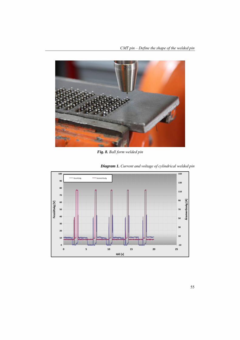
Shapes of welded pins are show on the figures 7. and the 8. On the figure 7. cylindrical
pins are shown. The geometry was not influenced by the stick-out, just the length of the pin. The only parameter handling the shape of the pin is the relation of backward movement and the current in the shaping phase. On the figure 8. ball formed pins are showed.
The diagram 1. and 2. show the current and voltage curve by the welding time. There were altogether 30 parameters setting, varied by stick-out and shaping correction.

Somoskői G., Török I.
54
Fig. 7. Cylindrical welded pin
Diagram 1. Current and voltage of cylindrical welded pin
0
10
20
30
40
50
60
70
80
90
100
0 2 4 6 8 10 12
Idő [s]
Feszültsé
g [V
]
‐10
10
30
50
70
90
110
130
150
Áramerő
sség [A
]
feszültség áramerősség
CMT pin – Define the shape of the welded pin
55
Fig. 8. Ball form welded pin
Diagram 1. Current and voltage of cylindrical welded pin
0
10
20
30
40
50
60
70
80
90
100
0 5 10 15 20 25
Idő [s]
Feszültség [V]
‐10
10
30
50
70
90
110
130
150
Áramerősség [A]
feszültség áramerősség

Somoskői G., Török I.
56
3. Summary
We were able to influence the welded pin geometry with the ball correction parameter. It is proven that the current and the voltage don’t influence the pin geometry. Neither does the stick-out. With the stick-out we can define the length of the pins.
The responsible is the relation of wire backward movement and the current in the shap-ing phase. Future outlook would be worth while to analyze the different phases of pin weld-ing by FE method. Software Sysweld or Calculix could perform this task.[5]
4. Acknowledgement
The described work was carried out as part of the TÁMOP-4.2.1.B-10/2/KONV-2010-0001 project in the framework of the New Hungarian Development Plan. The realization of this project is supported by the European Union, co-financed by the European Social Fund.
5. References
[1] W.S. Miller, L. Zhuang, J. Bottema, A.J. Wittebrood, P. De Smet, A. Haszler, A. Vieregge: Recent development in aluminium alloys for the automotive industry, Materials Science and Engineering A280 (2000) p. 37–49
[2] Somoskői G.: A CMT eljárás elméleti alapjai és gyakorlati alkalmazási lehetőségei, 25. Jubileumi Hegesztési Konferencia, p. 271-281., 2010
[3] Tobias Rosado, Pedro Almeida, Inês Pires, Rosa Miranda and Luísa Quintino: In-novations in Arc Welding, 5º Congresso Luso-Moçambicano de Engenharia, Mapu-to, 2-4 Setembro 2008, p. 1.-18.
[4] Tetsuo Era, Tomoyuki Ueyama, Matthew Brooks: Welding Steel Sheet with a Mod-ified Short Circuiting Process, AWS Detroit Section’s Sheet Metal Welding Con-ference XIII, Livonia, Mich., May 14–16, 2008. p. 28.-33.
[5] Lukas Wittwer and Norbert Enzinger: Simulating the welding process of pin struc-tures, Sysweld Forum 2011, 25.-26. October 2011, p. 45-54


![cMT-G01 Startup Guide - · PDF file[cMT Series] » [Maintenance] » [cMT-G01 OS Upgrade]. ... cMT Gateway Viewer can read from or write to PLC. ... cMT-G01 Startup Guide](https://img.pdfslide.net/doc/110x75/5ab85bac7f8b9ad13d8c70d9/cmt-g01-startup-guide-cmt-series-maintenance-cmt-g01-os-upgrade-cmt.jpg)