Embed Size (px)
Citation preview
CNC 8037 ·M·
Programming manual
Ref. 1310Soft: V01.4x
This product uses the following source code, subject to the terms of the GPL license. The applications busybox V0.60.2;dosfstools V2.9; linux-ftpd V0.17; ppp V2.4.0; utelnet V0.1.1. The librarygrx V2.4.4. The linux kernel V2.4.4. The linux bootppcboot V1.1.3. If you would like to have a CD copy of this source code sent to you, send 10 Euros to Fagor Automationfor shipping and handling.
All rights reserved. No part of this documentation may be transmitted,transcribed, stored in a backup device or translated into another languagewithout Fagor Automation’s consent. Unauthorized copying or distributing of thissoftware is prohibited.
The information described in this manual may be subject to changes due totechnical modifications. Fagor Automation reserves the right to change thecontents of this manual without prior notice.
All the trade marks appearing in the manual belong to the corresponding owners.The use of these marks by third parties for their own purpose could violate therights of the owners.
It is possible that CNC can execute more functions than those described in itsassociated documentation; however, Fagor Automation does not guarantee thevalidity of those applications. Therefore, except under the express permissionfrom Fagor Automation, any CNC application that is not described in thedocumentation must be considered as "impossible". In any case, FagorAutomation shall not be held responsible for any personal injuries or physicaldamage caused or suffered by the CNC if it is used in any way other than asexplained in the related documentation.
The content of this manual and its validity for the product described here has beenverified. Even so, involuntary errors are possible, hence no absolute match isguaranteed. However, the contents of this document are regularly checked andupdated implementing the necessary corrections in a later edition. We appreciateyour suggestions for improvement.
The examples described in this manual are for learning purposes. Before usingthem in industrial applications, they must be properly adapted making sure thatthe safety regulations are fully met.
Programming manual
CNC 8037
SOFT: V01.4X
·3·
I N D E X
About the product ......................................................................................................................... 7Declaration of conformity .............................................................................................................. 9Version history ............................................................................................................................ 11Safety conditions ........................................................................................................................ 13Warranty terms ........................................................................................................................... 17Material returning terms.............................................................................................................. 19Additional remarks ...................................................................................................................... 21Fagor documentation.................................................................................................................. 23
CHAPTER 1 GENERAL CONCEPTS
1.1 Part programs ................................................................................................................ 261.1.1 Considerations regarding the Ethernet connection .................................................... 281.2 DNC connection............................................................................................................. 291.3 Communication protocol via DNC or peripheral device ................................................. 30
CHAPTER 2 CREATING A PROGRAM
2.1 Program structure at the CNC ....................................................................................... 322.1.1 Block header .............................................................................................................. 322.1.2 Program block ............................................................................................................ 332.1.3 End of block ............................................................................................................... 34
CHAPTER 3 AXES AND COORDINATE SYSTEMS
3.1 Axis nomenclature ......................................................................................................... 363.2 Plane selection (G16, G17, G18, G19) .......................................................................... 373.3 Part dimensioning. Millimeters (G71) or inches (G70) ................................................... 393.4 Absolute/incremental programming (G90, G91) ............................................................ 403.5 Coordinate programming ............................................................................................... 413.5.1 Cartesian coordinates ................................................................................................ 423.5.2 Polar coordinates ....................................................................................................... 433.5.3 Cylindrical coordinates ............................................................................................... 453.5.4 Angle and Cartesian coordinate................................................................................. 463.6 Rotary axes.................................................................................................................... 473.7 Work zones .................................................................................................................... 483.7.1 Definition of the work zones ....................................................................................... 483.7.2 Using the work zones................................................................................................. 49
CHAPTER 4 REFERENCE SYSTEMS
4.1 Reference points............................................................................................................ 514.2 Machine reference (Home) search (G74) ...................................................................... 524.3 Programming with respect to machine zero (G53) ........................................................ 534.4 Coordinate preset and zero offsets................................................................................ 544.4.1 Coordinate preset and S value limitation (G92) ......................................................... 554.4.2 Zero offsets (G54..G59 and G159) ............................................................................ 564.5 Polar origin preset (G93)................................................................................................ 58
CHAPTER 5 ISO CODE PROGRAMMING
5.1 Preparatory functions..................................................................................................... 605.2 Feedrate F ..................................................................................................................... 625.2.1 Feedrate in mm/min or inches/min (G94)................................................................... 635.2.2 Feedrate in mm/rev.or inches/rev (G95) .................................................................... 645.2.3 Constant surface speed (G96) ................................................................................... 655.2.4 Constant tool center speed (G97) .............................................................................. 665.3 Spindle speed (S) .......................................................................................................... 675.4 Tool number (T) and tool offset (D)................................................................................ 68
·4·
Programming manual
CNC 8037
SOFT: V01.4X
5.5 Auxiliary function (M) ..................................................................................................... 695.5.1 M00. Program stop .................................................................................................... 705.5.2 M01. Conditional program stop.................................................................................. 705.5.3 M02. End of program ................................................................................................. 715.5.4 M30. End of program with return to the first block ..................................................... 715.5.5 M03 Clockwise spindle rotation ................................................................................. 725.5.6 M04. Counterclockwise spindle rotation .................................................................... 725.5.7 M05. Spindle stop ...................................................................................................... 735.5.8 M06. Tool change code ............................................................................................. 735.5.9 M19. Spindle orientation ............................................................................................ 745.5.10 M41, M42, M43, M44. Spindle gear change .............................................................. 75
CHAPTER 6 PATH CONTROL
6.1 Rapid traverse (G00) ..................................................................................................... 786.2 Linear interpolation (G01) .............................................................................................. 796.3 Circular interpolation (G02, G03)................................................................................... 806.4 Circular interpolation with absolute arc center coordinates (G06) ................................. 856.5 Arc tangent to previous path (G08)................................................................................ 866.6 Arc defined by three points (G09).................................................................................. 876.7 Helical interpolation ....................................................................................................... 886.8 Tangential entry at the beginning of a machining operation (G37)................................ 896.9 Tangential exit at the end of a machining operator (G38) ............................................. 906.10 Automatic radius blend (G36) ........................................................................................ 916.11 Chamfer (G39)............................................................................................................... 926.12 Threading (G33) ............................................................................................................ 936.13 Variable pitch threads (G34).......................................................................................... 956.14 Move to hardstop (G52)................................................................................................. 966.15 Feedrate "F" as an inverted function of time (G32)........................................................ 97
CHAPTER 7 ADDITIONAL PREPARATORY FUNCTIONS
7.1 Interruption of block preparation (G04).......................................................................... 997.1.1 G04 K0: Block preparation interruption and coordinate update ............................... 1017.2 Dwell (G04 K) .............................................................................................................. 1027.3 Working with square (G07) and round (G05,G50) corners.......................................... 1037.3.1 G07 (square corner)................................................................................................. 1037.3.2 G05 (round corner) .................................................................................................. 1047.3.3 Controlled round corner (G50) ................................................................................. 1057.4 Look-ahead (G51)........................................................................................................ 1067.4.1 Advanced look-ahead algorithm (integrating Fagor filters) ...................................... 1087.4.2 Look-ahead operation with Fagor filters active ........................................................ 1097.5 Mirror image (G10, G11. G12, G13, G14) ................................................................... 1107.6 Scaling factor (G72)..................................................................................................... 1117.6.1 Scaling factor applied to all axes. ............................................................................ 1127.6.2 Scaling factor applied to one or more axes.............................................................. 1137.7 Pattern rotation (G73) .................................................................................................. 115
CHAPTER 8 TOOL COMPENSATION
8.1 Tool radius compensation (G40, G41, G42)................................................................ 1188.1.1 Beginning of tool radius compensation .................................................................... 1198.1.2 Sections of tool radius compensation ...................................................................... 1228.1.3 Cancellation of tool radius compensation ................................................................ 1238.1.4 Change of type of tool radius compensation while machining ................................. 1298.2 Tool length compensation (G43, G44, G15)................................................................ 1308.3 Collision detection (G41 N, G42 N) ............................................................................. 132
CHAPTER 9 CANNED CYCLES
9.1 Canned cycle definition................................................................................................ 1349.2 Influence zone of a canned cycle ................................................................................ 1359.2.1 G79. Modification of the canned cycle parameters.................................................. 1369.3 Canned cycle cancellation ........................................................................................... 1389.4 Some general points to consider ................................................................................. 1399.5 Machining canned cycles............................................................................................. 1409.6 G69. Drilling canned cycle with variable peck ............................................................. 1439.6.1 Basic operation ........................................................................................................ 1459.7 G81. Drilling canned cycle ........................................................................................... 1489.7.1 Basic operation ........................................................................................................ 1499.8 G82. Drilling canned cycle with dwell .......................................................................... 1519.8.1 Basic operation ........................................................................................................ 1529.9 G83. Deep-hole drilling canned cycle with constant peck ........................................... 1549.9.1 Basic operation ........................................................................................................ 156
Programming manual
CNC 8037
SOFT: V01.4X
·5·
9.10 G84. Tapping canned cycle ......................................................................................... 1589.10.1 Basic operation ........................................................................................................ 1609.11 G85. Reaming canned cycle........................................................................................ 1639.11.1 Basic operation ........................................................................................................ 1649.12 G86. Boring cycle with withdrawal in G00.................................................................... 1659.12.1 Basic operation ........................................................................................................ 1679.13 G87. Rectangular pocket canned cycle. ...................................................................... 1689.13.1 Basic operation ........................................................................................................ 1719.14 G88. Circular pocket canned cycle .............................................................................. 1749.14.1 Basic operation ........................................................................................................ 1789.15 G89. Boring cycle with withdrawal at work feedrate (G01) .......................................... 1809.15.1 Basic operation ........................................................................................................ 1819.16 G210. Bore milling canned cycle ................................................................................. 1829.16.1 Basic operation ........................................................................................................ 1849.17 G211. Inside thread milling cycle ................................................................................. 1859.17.1 Basic operation ........................................................................................................ 1879.18 G212. Outside thread milling cycle .............................................................................. 1889.18.1 Basic operation ........................................................................................................ 190
CHAPTER 10 MULTIPLE MACHINING
10.1 G60: Multiple machining in a straight line .................................................................... 19210.1.1 Basic operation ........................................................................................................ 19310.2 G61: Multiple machining in a rectangular pattern ........................................................ 19410.2.1 Basic operation ........................................................................................................ 19610.3 G62: Multiple machining in a grid pattern. ................................................................... 19710.3.1 Basic operation ........................................................................................................ 19910.4 G63: Multiple machining in a circular pattern............................................................... 20010.4.1 Basic operation ........................................................................................................ 20210.5 G64: Multiple machining in an arc................................................................................ 20310.5.1 Basic operation ........................................................................................................ 20510.6 G65: Machining programmed with an arc-chord.......................................................... 20610.6.1 Basic operation ........................................................................................................ 207
CHAPTER 11 PROBING
11.1 Probing (G75, G76)...................................................................................................... 210
CHAPTER 12 HIGH-LEVEL LANGUAGE PROGRAMMING
12.1 Lexical description ....................................................................................................... 21112.2 Variables ...................................................................................................................... 21312.2.1 General purpose parameters or variables................................................................ 21412.2.2 Variables associated with tools. ............................................................................... 21612.2.3 Variables associated with zero offsets. .................................................................... 21912.2.4 Variables associated with machine parameters....................................................... 22012.2.5 Variables associated with work zones ..................................................................... 22112.2.6 Variables associated with feedrates......................................................................... 22212.2.7 Variables associated with coordinates ..................................................................... 22412.2.8 Variables associated with electronic handwheels .................................................... 22712.2.9 Variables associated with feedback ......................................................................... 22912.2.10 Variables associated with the main spindle ............................................................. 23012.2.11 PLC related variables............................................................................................... 23312.2.12 Variables associated with local parameters ............................................................. 23512.2.13 Operating-mode related variables............................................................................ 23612.2.14 Other variables......................................................................................................... 23812.3 Constants..................................................................................................................... 24312.4 Operators ..................................................................................................................... 24412.5 Expressions ................................................................................................................. 24612.5.1 Arithmetic expressions ............................................................................................. 24612.5.2 Relational expressions ............................................................................................. 247
CHAPTER 13 PROGRAM CONTROL INSTRUCTIONS
13.1 Assignment instructions ............................................................................................... 25013.2 Display instructions ...................................................................................................... 25113.3 Enable-disable instructions .......................................................................................... 25213.4 Flow control instructions .............................................................................................. 25313.5 Subroutine instructions ................................................................................................ 25513.6 Interruption-subroutine instructions.............................................................................. 25913.7 Program instructions .................................................................................................... 26013.8 Screen customizing instructions .................................................................................. 263
·6·
Programming manual
CNC 8037
SOFT: V01.4X
CHAPTER 14 ANGULAR TRANSFORMATION OF AN INCLINE AXIS
14.1 Turning angular transformation on and off................................................................... 27114.2 Freezing the angular transformation............................................................................ 272
APPENDIX
A ISO code programming................................................................................................ 275B Program control instructions ........................................................................................ 277C Summary of internal CNC variables. ........................................................................... 279D Key code...................................................................................................................... 285E Maintenance ................................................................................................................ 287
CNC 8037
·7·
ABOUT THE PRODUCT
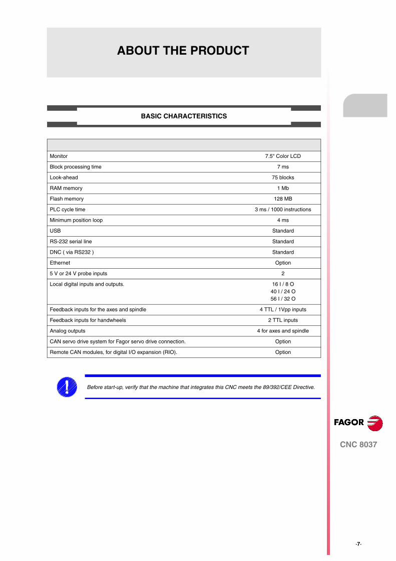
BASIC CHARACTERISTICS
Monitor 7.5" Color LCD
Block processing time 7 ms
Look-ahead 75 blocks
RAM memory 1 Mb
Flash memory 128 MB
PLC cycle time 3 ms / 1000 instructions
Minimum position loop 4 ms
USB Standard
RS-232 serial line Standard
DNC ( via RS232 ) Standard
Ethernet Option
5 V or 24 V probe inputs 2
Local digital inputs and outputs. 16 I / 8 O40 I / 24 O56 I / 32 O
Feedback inputs for the axes and spindle 4 TTL / 1Vpp inputs
Feedback inputs for handwheels 2 TTL inputs
Analog outputs 4 for axes and spindle
CAN servo drive system for Fagor servo drive connection. Option
Remote CAN modules, for digital I/O expansion (RIO). Option
Before start-up, verify that the machine that integrates this CNC meets the 89/392/CEE Directive.
·8·
CNC 8037
Abo
ut th
e pr
oduc
t
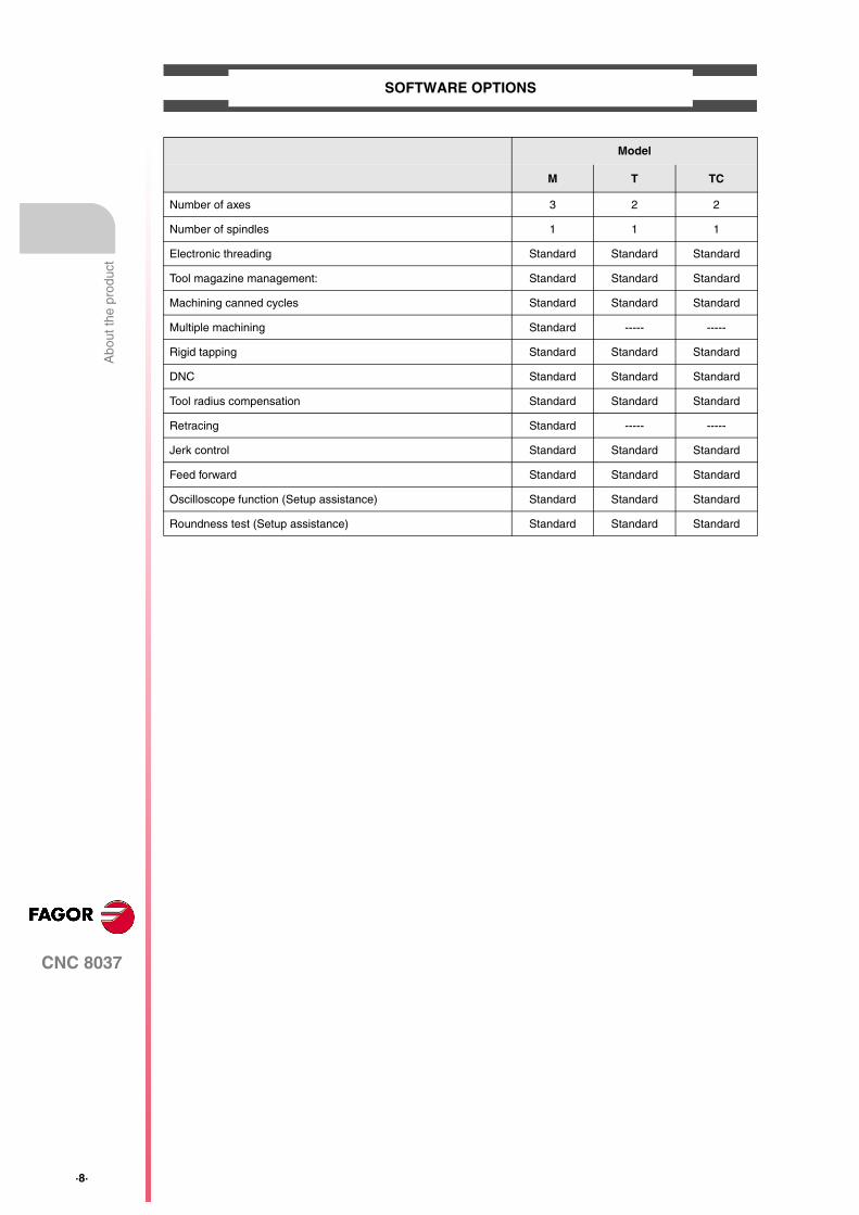
SOFTWARE OPTIONS
Model
M T TC
Number of axes 3 2 2
Number of spindles 1 1 1
Electronic threading Standard Standard Standard
Tool magazine management: Standard Standard Standard
Machining canned cycles Standard Standard Standard
Multiple machining Standard ----- -----
Rigid tapping Standard Standard Standard
DNC Standard Standard Standard
Tool radius compensation Standard Standard Standard
Retracing Standard ----- -----
Jerk control Standard Standard Standard
Feed forward Standard Standard Standard
Oscilloscope function (Setup assistance) Standard Standard Standard
Roundness test (Setup assistance) Standard Standard Standard
CNC 8037
·9·
DECLARATION OF CONFORMITY
The manufacturer:
Fagor Automation S. Coop.
Barrio de San Andrés Nº 19, C.P. 20500, Mondragón -Guipúzcoa- (SPAIN).
Declares:
Under their responsibility that the product:
8037 CNC
Consisting of the following modules and accessories:
8037-M, 8037-T, 8037-TCRemote modules RIOETHERNET, ETHERNET-CAN-CAN AXES, ETHERNET-CAN AXES
Note. Some additional characters may follow the references mentioned above. They all comply with the directiveslisted. However, check that that's the case by checking the label of the unit itself.
Referred to by this declaration with following directives:
As instructed by the European Community Directives 2006/95/EEC on Low Voltage and2004/108/EC on Electromagnetic Compatibility and its updates.
In Mondragón, March 14th, 2012
Low voltage regulations.
EN 60204-1: 2006 Electrical equipment on machines — Part 1. General requirements.
Regulation on electromagnetic compatibility.
EN 61131-2: 2007 PLC — Part 2. Requirements and equipment tests.

CNC 8037
·11·
VERSION HISTORY
Here is a list of the features added in each software version and the manuals that describe them.
The version history uses the following abbreviations:
INST Installation manual
PRG Programming manual
OPT Operating manual
OPT-TC Operating manual for the TC option.
Software V01.42 March 2012
First version.

·12·
CNC 8037
Ver
sion
his
tory
CNC 8037
·13·
SAFETY CONDITIONS
Read the following safety measures in order to prevent harming people or damage to this product and thoseproducts connected to it.
This unit may only be repaired by authorized personnel at Fagor Automation.
Fagor Automation shall not be held responsible of any physical damage or defective unit resulting from notcomplying with these basic safety regulations.
PRECAUTIONS AGAINST PERSONAL DAMAGE
• Interconnection of modules.
Use the connection cables provided with the unit.
• Use proper Mains AC power cables
To avoid risks, use only the Mains AC cables recommended for this unit.
• Avoid electrical overloads.
In order to avoid electrical discharges and fire hazards, do not apply electrical voltage outside the rangeselected on the rear panel of the central unit.
• Ground connection.
In order to avoid electrical discharges, connect the ground terminals of all the modules to the mainground terminal. Before connecting the inputs and outputs of this unit, make sure that all the groundingconnections are properly made.
• Before powering the unit up, make sure that it is connected to ground.
In order to avoid electrical discharges, make sure that all the grounding connections are properly made.
• Do not work in humid environments.
In order to avoid electrical discharges, always work under 90% of relative humidity (non-condensing)and 45 ºC (113º F).
• Do not work in explosive environments.
In order to avoid risks or damages, do no work in explosive environments.
·14·
CNC 8037
Saf
ety
cond
ition
s
PRECAUTIONS AGAINST PRODUCT DAMAGE
• Working environment.
This unit is ready to be used in industrial environments complying with the directives and regulationseffective in the European Community.
Fagor Automation shall not be held responsible for any damage suffered or caused when installed inother environments (residential or homes).
• Install this unit in the proper place.
It is recommended, whenever possible, to install the CNC away from coolants, chemical product, blows,etc. that could damage it.
This unit complies with the European directives on electromagnetic compatibility. Nevertheless, it isrecommended to keep it away from sources of electromagnetic disturbance such as:
Powerful loads connected to the same AC power line as this equipment.
Nearby portable transmitters (Radio-telephones, Ham radio transmitters).
Nearby radio/TV transmitters.
Nearby arc welding machines.
Nearby High Voltage power lines.
Etc.
• Enclosures.
The manufacturer is responsible of assuring that the enclosure involving the equipment meets all thecurrently effective directives of the European Community.
• Avoid disturbances coming from the machine tool.
The machine-tool must have all the interference generating elements (relay coils, contactors, motors,etc.) uncoupled.
DC relay coils. Diode type 1N4000.
AC relay coils. RC connected as close to the coils as possible with approximate values of R=220 1 W y C=0,2 µF / 600 V.
AC motors. RC connected between phases, with values of R=300 / 6 W y C=0,47 µF / 600 V.
• Use the proper power supply.
Use an external regulated 24 Vdc power supply for the inputs and outputs.
• Grounding of the power supply.
The zero volt point of the external power supply must be connected to the main ground point of themachine.
• Analog inputs and outputs connection.
It is recommended to connect them using shielded cables and connecting their shields (mesh) to thecorresponding pin.
• Ambient conditions.
The working temperature must be between +5 ºC and +40 ºC (41ºF and 104º F)
The storage temperature must be between -25 ºC and +70 ºC. (-13 ºF and 158 ºF)
• Central unit enclosure (8037 CNC).
Make sure that the needed gap is kept between the central unit and each wall of the enclosure. Usea DC fan to improve enclosure ventilation.
• Power switch.
This power switch must be mounted in such a way that it is easily accessed and at a distance between0.7 meters (27.5 inches) and 1.7 meters (5.5ft) off the floor.
CNC 8037
·15·
Saf
ety
cond
ition
s
PROTECTIONS OF THE UNIT ITSELF (8037)
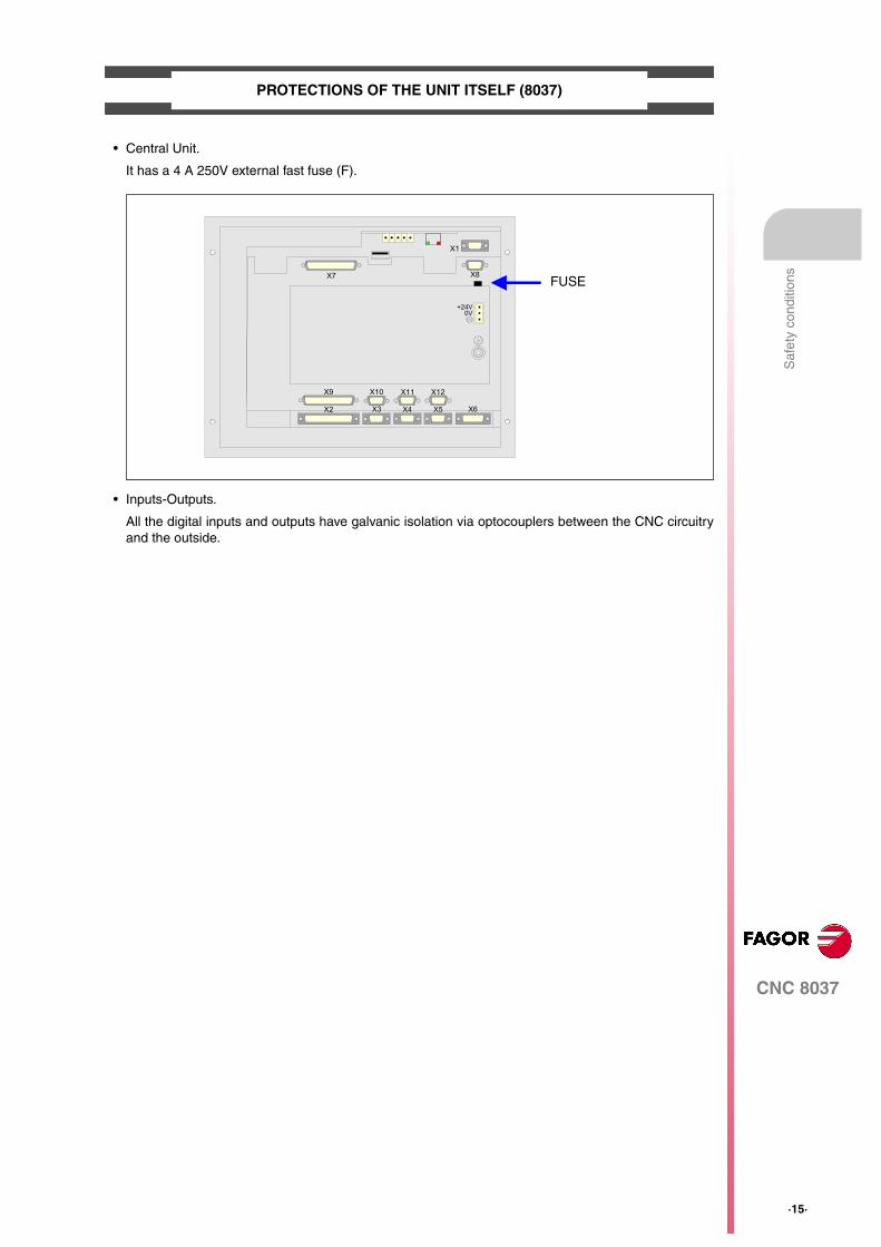
• Central Unit.
It has a 4 A 250V external fast fuse (F).
• Inputs-Outputs.
All the digital inputs and outputs have galvanic isolation via optocouplers between the CNC circuitryand the outside.
FUSEX7
X1
X8
X9
X2
X10
X3
X11
X4
X12
X5 X6
+24V0V
·16·
CNC 8037
Saf
ety
cond
ition
s
PRECAUTIONS DURING REPAIR
SAFETY SYMBOLS
• Symbols which may appear on the manual.
Do not get into the inside of the unit. Only personnel authorized by Fagor Automation may manipulatethe inside of this unit.Do not handle the connectors with the unit connected to main AC power. Before manipulating theconnectors (inputs/outputs, feedback, etc.) make sure that the unit is not connected to AC power.
Symbol for danger or prohibition.It indicates actions or operations that may cause damage to people or to units.
Warning symbol.It indicates situations that may be caused by certain operations and the actions to be taken to preventthem.
Obligation symbol.It indicates actions and operations that must be carried out.
Information symbol.It indicates notes, warnings and advises.i
CNC 8037
·17·
WARRANTY TERMS
INITIAL WARRANTY
All products manufactured or marketed by FAGOR carry a 12-month warranty for the end user which couldbe controlled by the our service network by means of the warranty control system established by FAGORfor this purpose.
In order to prevent the possibility of having the time period from the time a product leaves our warehouseuntil the end user actually receives it run against this 12-month warranty, FAGOR has set up a warrantycontrol system based on having the manufacturer or agent inform FAGOR of the destination, identificationand on-machine installation date, by filling out the document accompanying each FAGOR product in thewarranty envelope. This system, besides assuring a full year of warranty to the end user, enables our servicenetwork to know about FAGOR equipment coming from other countries into their area of responsibility.
The warranty starting date will be the one appearing as the installation date on the above mentioneddocument. FAGOR offers the manufacturer or agent 12 months to sell and install the product. This meansthat the warranty starting date may be up to one year after the product has left our warehouse so long asthe warranty control sheet has been sent back to us. This translates into the extension of warranty periodto two years since the product left our warehouse. If this sheet has not been sent to us, the warranty periodends 15 months from when the product left our warehouse.
This warranty covers all costs of material and labour involved in repairs at FAGOR carried out to correctmalfunctions in the equipment. FAGOR undertakes to repair or replace their products within the period fromthe moment manufacture begins until 8 years after the date on which it disappears from the catalog.
FAGOR has exclusive competence in deciding whether the repair enters within the term defined as thewarranty period.
EXCLUDING CLAUSES
Repairs will be carried out on our premises. Therefore, all expenses incurred as a result of trips made bytechnical personnel to carry out equipment repairs, despite these being within the above-mentioned periodof warranty, are not covered by the warranty.
Said warranty will be applied whenever the equipment has been installed in accordance with instructions,has not be mistreated, has not been damaged by accident or by negligence and has not been tamperedwith by personnel not authorized by FAGOR. If, once servicing or repairs have been made, the cause ofthe malfunction cannot be attributed to said elements, the customer is obliged to cover the expensesincurred, in accordance with the tariffs in force.
Other warranties, implicit or explicit, are not covered and FAGOR AUTOMATION cannot be held responsiblefor other damages which may occur.
·18·
CNC 8037
War
rant
y te
rms
WARRANTY ON REPAIRS
In a similar way to the initial warranty, FAGOR offers a warranty on standard repairs according to thefollowing conditions:
When the customer does not choose the standard repair and just the faulty material has been replaced,the warranty will cover just the replaced parts or components within 12 months.
For sold parts the warranty is 12 moths length.
MAINTENANCE CONTRACTS
The SERVICE CONTRACT is available for the distributor or manufacturer who buys and installs our CNCsystems.
PERIOD 12 months.
CONCEPT Covers parts and labor for repairs (or replacements) at the network's ownfacilities.
EXCLUDING CLAUSES The same as those applied regarding the chapter on initial warranty.If the repair is carried out within the warranty period, the warranty extensionhas no effect.
CNC 8037
·19·
MATERIAL RETURNING TERMS
When sending the central nit or the remote modules, pack them in its original package and packagingmaterial. If the original packaging material is not available, pack it as follows:
1. Get a cardboard box whose three inside dimensions are at least 15 cm (6 inches) larger than thoseof the unit. The cardboard being used to make the box must have a resistance of 170 kg. (375 pounds).
2. Attach a label indicating the owner of the unit, person to contact, type of unit and serial number.
3. In case of failure, also indicate the symptom and a short description.
4. Wrap the unit in a polyethylene roll or similar material to protect it.
5. When sending the central unit, protect especially the screen.
6. Pad the unit inside the cardboard box with polyurethane foam on all sides.
7. Seal the cardboard box with packing tape or industrial staples.
·20·
CNC 8037
Mat
eria
l ret
urni
ng te
rms

CNC 8037
·21·
ADDITIONAL REMARKS
Mount the CNC away from coolants, chemical products, blows, etc. which could damage it. Before turningthe unit on, verify that the ground connections have been properly made.
In case of a malfunction or failure, disconnect it and call the technical service. Do not get into the insideof the unit.

·22·
CNC 8037
Add
ition
al r
emar
ks
CNC 8037
·23·
FAGOR DOCUMENTATION
OEM manual
It is directed to the machine builder or person in charge of installing and starting-up the CNC.
USER-M manual
Directed to the end user.
It describes how to operate and program in M mode.
USER-T manual
Directed to the end user.
It describes how to operate and program in T mode.
TC Manual
Directed to the end user.
It describes how to operate and program in TC mode.
It contains a self-teaching manual.

·24·
CNC 8037
Fag
or d
ocum
enta
tion
CNC 8037
·M· MODELSOFT: V01.4X
1
·25·
GENERAL CONCEPTS
The CNC may be programmed at the machine (from the front panel) and from a peripheral(computer). Memory available to the user for carrying out the part programs is 1 Mbyte.
The part programs and the values in the tables which the CNC has can be entered from the frontpanel, from a pc (DNC) or from a peripheral.
Entering programs and tables from the front panel.
Once the editing mode or desired table has been selected, the CNC allows you to enter data fromthe keyboard.
Entering programs and tables from a Computer (DNC) or peripheral device.
The CNC allows data to be exchanged with a computer or peripheral device, using the RS232C serialline.
If this is controlled from the CNC, it is necessary to preset the corresponding table or part programdirectory (utilities) you want to communicate with.
Depending on the type of communication required, the serial port machine parameter "PROTOCOL"should be set.
"PROTOCOL" = 0 If the communication is with a peripheral device.
"PROTOCOL" = 1 If the communication is via DNC.
·26·
Programming manual
CNC 8037
1.
GE
NE
RA
L C
ON
CE
PT
S
·M· MODELSOFT: V01.4X
Par
t pro
gram
s
1.1 Part programs
The operating manual describes the different operating modes. Refer to that manual for furtherinformation.
Editing a part-program
To create a part-program, access the –Edit– mode.
The new part-program edited is stored in the CNC's RAM memory. A copy of the part-programs maybe stored in the hard disk (KeyCF) at a PC connected through the serial line or in the USB disk.
To transmit a program to a PC through the serial, proceed as follows:
1. Execute the "WinDNC.exe" application program at the PC.
2. Activate DNC communications at the CNC.
3. Select the work directory at the CNC. It is selected from the –Utilities– mode, option Directory\Serial L \Change directory
In –Edit– mode, it is possible to modify part-programs residing in the CNC's RAM memory. To modifya program stored in the hard disk (KeyCF), in a PC or in the USB disk, it must be previously copiedinto RAM memory.
Executing and editing a part-program
Part-programs stored anywhere may be executed or simulated. Simulation is carried out in the–Simulation– mode, whereas the execution is done in the –Automatic– mode
When executing or simulating a part-program, bear in mind the following points:
• Only subroutines stored in the CNC's RAM memory can be executed. Therefore, to execute asubroutine stored in the hard disk (KeyCF), in a PC or in the USB disk, it must be first copiedinto the CNC's RAM memory.
• The GOTO and RPT instructions cannot be used in programs that are executed from a PCconnected through the serial line.
• From a program in execution, it is possible to execute another program located in RAM memory,in the hard disk (KeyCF) or in a PC using the EXEC instruction.
The user customizing programs must be in RAM memory so the CNC can execute them.
–Utilities– operating mode.
The –Utilities– mode, lets display the part-program directory of all the devices, make copies, delete,rename and even set the protections for any of them.
Programming manual
CNC 8037
GE
NE
RA
L C
ON
CE
PT
S
1.
·M· MODELSOFT: V01.4X
·27·
Par
t pro
gram
s
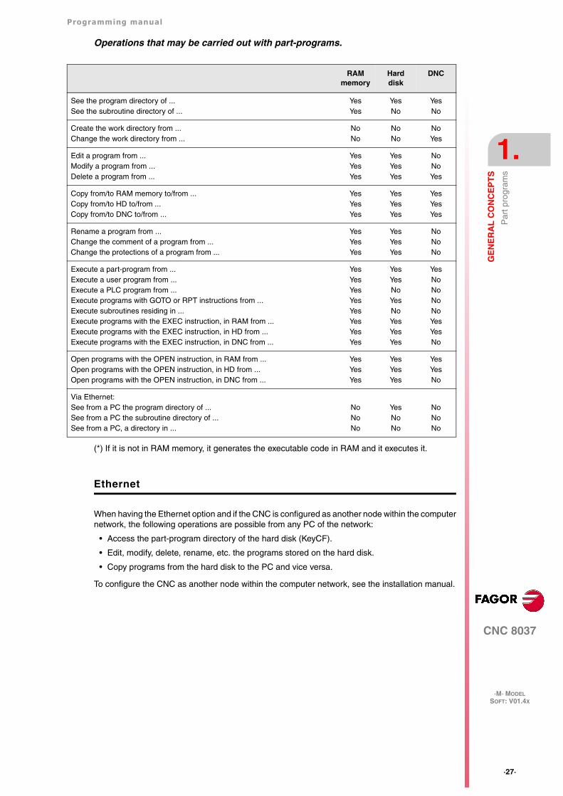
Operations that may be carried out with part-programs.
(*) If it is not in RAM memory, it generates the executable code in RAM and it executes it.
Ethernet
When having the Ethernet option and if the CNC is configured as another node within the computernetwork, the following operations are possible from any PC of the network:
• Access the part-program directory of the hard disk (KeyCF).
• Edit, modify, delete, rename, etc. the programs stored on the hard disk.
• Copy programs from the hard disk to the PC and vice versa.
To configure the CNC as another node within the computer network, see the installation manual.
RAM memory
Hard disk
DNC
See the program directory of ...See the subroutine directory of ...
YesYes
YesNo
YesNo
Create the work directory from ...Change the work directory from ...
NoNo
NoNo
NoYes
Edit a program from ...Modify a program from ...Delete a program from ...
YesYesYes
YesYesYes
NoNoYes
Copy from/to RAM memory to/from ...Copy from/to HD to/from ...Copy from/to DNC to/from ...
YesYesYes
YesYesYes
YesYesYes
Rename a program from ...Change the comment of a program from ...Change the protections of a program from ...
YesYesYes
YesYesYes
NoNoNo
Execute a part-program from ...Execute a user program from ...Execute a PLC program from ...Execute programs with GOTO or RPT instructions from ...Execute subroutines residing in ...Execute programs with the EXEC instruction, in RAM from ...Execute programs with the EXEC instruction, in HD from ...Execute programs with the EXEC instruction, in DNC from ...
YesYesYesYesYesYesYesYes
YesYesNoYesNoYesYesYes
YesNoNoNoNoYesYesNo
Open programs with the OPEN instruction, in RAM from ...Open programs with the OPEN instruction, in HD from ...Open programs with the OPEN instruction, in DNC from ...
YesYesYes
YesYesYes
YesYesNo
Via Ethernet:See from a PC the program directory of ...See from a PC the subroutine directory of ...See from a PC, a directory in ...
NoNoNo
YesNoNo
NoNoNo
·28·
Programming manual
CNC 8037
1.
GE
NE
RA
L C
ON
CE
PT
S
·M· MODELSOFT: V01.4X
Par
t pro
gram
s
1.1.1 Considerations regarding the Ethernet connection
When configuring the CNC as another node in the computer network, the programs stored in thehard disk (KeyCF) may be edited and modified from any PC.
Instructions for setting up a PC to access CNC directories
To set up the PC to access the CNC directories, we recommend to proceed as follows.
1. Open the "Windows Explorer"
2. On the "Tools" menu, select the "Connect to Network Drives" option.
3. Select the drive, for example "D".
4. Indicate the path. The path will be the CNC name followed by the name of the shared directory.
For example: \\FAGORCNC\CNCHD
5. When selecting the option: "Connect again when initiating the session", the selected CNC willappear on each power-up as another path of the "Windows Explorer" without having to defineit again.
Data format
This connection is established through Ethernet and, therefore, the CNC does not control the syntaxof the programs while they are received or modified. However, whenever accessing the programdirectory of the Hard Disk (HD), the following verification takes place:
File name.
The file number must always have 6 digits and the extension PIM (for milling) or PIT (for lathe).
Examples: 001204.PIM 000100.PIM 123456.PIT 020150.PIT
If the file has been given the wrong name, for example: 1204.PIM or 100.PIT, the CNC will not changeit, but it will display it with the comment "****************". The file name cannot be modifiedat the CNC; it must be edited from the PC to correct the error.
File size.
If the file is empty (size = 0) the CNC will display it with the comment "********************".
The file can be edited or deleted either from the CNC or from the PC.
First line of the program.
The first line of the program must have the % character, the comment associated with the file (upto 20 characters) and between the two commas (,) the program attributes O (OEM), H (hidden), M(modifiable), X (executable).
Examples: %Comment ,MX,
% ,OMX,
If the first line does not exist, the CNC will display the program with an empty comment and withthe modifiable (M) and executable (X) attributes.
When the format of the first line is wrong, the CNC does not modify it, but it displays it with thecomment "****************". The file can be edited or deleted either from the CNC or from thePC.
The format is incorrect when the comment has more than 20 characters, a comma (,) is missingto group the attributes or there is a strange character in the attributes.
Programming manual
CNC 8037
GE
NE
RA
L C
ON
CE
PT
S
1.
·M· MODELSOFT: V01.4X
·29·
DN
C c
onne
ctio
n
1.2 DNC connection
The CNC offers as optional feature the possibility of working in DNC (Distributed Numerical Control),enabling communication between the CNC and a computer to carry out the following functions:
• Directory and delete commands.
• Transfer of programs and tables between the CNC and a computer.
• Remote control of the machine.
• The ability to supervise the status of advanced DNC systems.
·30·
Programming manual
CNC 8037
1.
GE
NE
RA
L C
ON
CE
PT
S
·M· MODELSOFT: V01.4X
Com
mun
icat
ion
prot
ocol
via
DN
C o
r pe
riphe
ral d
evic
e
1.3 Communication protocol via DNC or peripheral device
This type of communication enables program-and-table transfer commands, plus the organizationof CNC directories such as the computer directory, for copying/deleting programs, etc. to be doneeither from the CNC or the computer.
When you want to transfer files, it is necessary to follow this protocol:
• The "%" symbol will be used to start the file, followed by the program comment (optional), of upto 20 characters.
Then, and separated by a comma ",", comes the protection of each file, read, write, etc. Theseprotections are optional and need not be programmed.
To end the file header, RT (RETURN ) or LF (LINE FEED) characters should be sent separatedby a comma (",").
Example: %Fagor Automation, MX, RT
• Following the header, the file blocks should be programmed. These will all be programmedaccording to the programming rules indicated in this manual. After each block, to separate it fromthe others, the RT (RETURN ) or LF (LINE FEED) characters should be used.
Example: N20 G90 G01 X100 Y200 F2000 LF
(RPT N10, N20) N3 LF
If communication is made with a peripheral device, you will need to send the ‘end of file’ command.This command is selected via the machine parameter for the serial port: "EOFCHR", and can beone of the following characters :
ESC ESCAPE
EOT END OF TRANSMISSION
SUB SUBSTITUTE
EXT END OF TRANSMISSION
CNC 8037
·M· MODELSOFT: V01.4X
2
·31·
CREATING A PROGRAM
A CNC program consists of a series of blocks or instructions. These blocks or instructions are madeof words composed of capital letters and numerical format.
The CNC’s numerical format consists of :
• The signs . (decimal points, + (plus), - (minus).
• Digits 0 1 2 3 4 5 6 7 8 9.
Programming allows spaces between letters, numbers and symbols, in addition to ignoring thenumerical format if it has zero value, or a symbol if it is positive.
The numeric format of a word may be replaced by an arithmetic parameter when programming. Lateron, during execution, the CNC will replace the arithmetic parameter by its value. For example, if XP3has been programmed, during execution the CNC will replace P3 by its numerical value, obtainingresults such as X20, X20.567, X-0.003, etc.
·32·
Programming manual
CNC 8037
2.
CR
EA
TIN
G A
PR
OG
RA
M
·M· MODELSOFT: V01.4X
Pro
gram
str
uctu
re a
t the
CN
C
2.1 Program structure at the CNC
All the blocks which make up the program have the following structure:
Block header + program block + end of block
2.1.1 Block header
The block header is optional, and may consist of one or more block skip conditions and by the blocknumber or label. Both must be programmed in this order.
Block skip condition. "/", "/1", "/2", "/3".
These three block skip conditions, given that "/" and "/1" are the same, they are governed by themarks BLKSKIP1, BLKSKIP2 and BLKSKIP3 of the PLC. If any of these marks is active, the CNCwill not execute the block or blocks in which it has been programmed; the execution takes place inthe following block.
Up to 3 skip conditions can be programmed in one block; they will be evaluated one by one,respecting the order in which they have been programmed.
The control reads 200 blocks ahead of the one being executed in order to calculate in advance thepath to be run. The condition for block skip will be analyzed at the time when the block is read i.e.200 blocks before execution.
If the block skip needs to be analyzed at the time of execution, it is necessary to interrupt the blockpreparation, by programming G4 in the previous block.
Label or block number. N(0-99999999).
This is used to identify the block, and is only used when block references or jumps are made. Theyare represented by the letter N followed by up to 8 digits (0-99999999).
No particular order is required and the numbers need not be sequential. If two or more blocks withthe same label number are present in the same program, the CNC will always give priority to thefirst number.
Although it is not necessary to program it, by using a softkey the CNC allows the automaticprogramming of labels. The programmer can select the initial number and the step between labels.
Restrictions:
• Displaying the number of the active block in the top window of the screen:
When executing a program in ISO mode, when the label number is higher than 9999, itdisplays N**** .
On the "DISPLAY / SUBROUTINES" window, when displaying an RPT that has a label higherthan 9999, it displays it with ****.
• Canned cycles G66, G67 and G68 (irregular pockets with islands) can only be edited using 4-digit labels.
Programming manual
CNC 8037
CR
EA
TIN
G A
PR
OG
RA
M
2.
·M· MODELSOFT: V01.4X
·33·
Pro
gram
str
uctu
re a
t the
CN
C
2.1.2 Program block
This is written with commands in ISO and high level languages. To prepare a program, blocks writtenin both languages will be used, although each one should be edited with commands in just onelanguage.
ISO language.
This language is specially designed to control axis movement, as it gives information and movementconditions, in addition to data on feedrate. It offers the following types of functions.
• Preparatory functions for movement, used to determine geometry and working conditions, suchas linear and circular interpolations, threading, etc.
• Control functions for axis feedrate and spindle speeds.
• Tool control functions.
• Complementary functions, with technological instructions.
High level language.
This enables access to general purpose variables and to system tables and variables.
It gives the user a number of control sentences which are similar to the terminology used in otherlanguages, such as IF, GOTO, CALL, etc. It also allows the use of any type of expression (arithmetic,referential, or logical).
It also has instructions for the construction of loops, plus subroutines with local variables. A localvariable is one that is only recognized by the subroutine in which it has been defined.
It is also possible to create libraries, grouping subroutines with useful and tested functions, whichcan be accessed from any program.
·34·
Programming manual
CNC 8037
2.
CR
EA
TIN
G A
PR
OG
RA
M
·M· MODELSOFT: V01.4X
Pro
gram
str
uctu
re a
t the
CN
C
2.1.3 End of block
The end of block is optional and may consist of the indication of number of repetitions of the blockand of the block comment. Both must be programmed in this order.
Number of block repetitions. N(0-9999)
This indicates the number of times the block will be executed. The number of repetitions isrepresented by the letter N followed by up to 4 digits (0-9999). The active machining operation doesnot take place if N0 is programmed; only the movement programmed within the block takes place.
Movement blocks can only be repeated which, at the time of their execution, are under the influenceof a modal subroutine. In these cases, the CNC executes the programmed move and the activemachining operation (canned cycle or modal subroutine) the indicated number of times.
Block comment
The CNC allows you to incorporate any kind of information into all blocks in the form of a comment.The comment is programmed at the end of the block, and should begin with the character ";"(semicolon).
If a block begins with ";" all its contents will be considered as a comment, and it will not be executed.
Empty blocks are not permitted. They should contain at least one comment.
CNC 8037
·M· MODELSOFT: V01.4X
3
·35·
AXES AND COORDINATE SYSTEMS
Given that the purpose of the CNC is to control the movement and positioning of axes, it is necessaryto determine the position of the point to be reached through its coordinates.
The CNC allows you to use absolute, relative or incremental coordinates throughout the sameprogram.
·36·
Programming manual
CNC 8037
3.
AX
ES
AN
D C
OO
RD
INA
TE
SY
ST
EM
S
·M· MODELSOFT: V01.4X
Axi
s no
men
clat
ure
3.1 Axis nomenclature
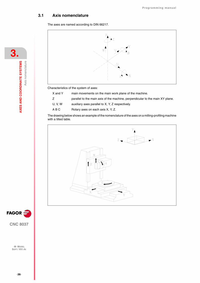
The axes are named according to DIN 66217.
Characteristics of the system of axes:
X and Y main movements on the main work plane of the machine.
Z parallel to the main axis of the machine, perpendicular to the main XY plane.
U, V, W auxiliary axes parallel to X, Y, Z respectively.
A B C Rotary axes on each axis X, Y, Z.
The drawing below shows an example of the nomenclature of the axes on a milling-profiling machinewith a tilted table.
Programming manual
CNC 8037
AX
ES
AN
D C
OO
RD
INA
TE
SY
ST
EM
S
3.
·M· MODELSOFT: V01.4X
·37·
Pla
ne s
elec
tion
(G16
, G17
, G18
, G19
)
3.2 Plane selection (G16, G17, G18, G19)
Plane selection should be made when the following are carried out :
• Circular interpolations.
• Controlled corner rounding.
• Tangential entry and exit.
• Chamfer.
• Coordinate programming in Polar coordinates.
• Machining canned cycles.
• Pattern rotation.
• Tool radius Compensation.
• Tool length compensation.
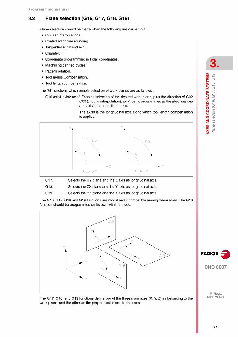
The "G" functions which enable selection of work planes are as follows :
G16 axis1 axis2 axis3.Enables selection of the desired work plane, plus the direction of G02G03 (circular interpolation), axis1 being programmed as the abscissa axisand axis2 as the ordinate axis.
The axis3 is the longitudinal axis along which tool length compensationis applied.
G17. Selects the XY plane and the Z axis as longitudinal axis.
G18. Selects the ZX plane and the Y axis as longitudinal axis.
G19. Selects the YZ plane and the X axis as longitudinal axis.
The G16, G17, G18 and G19 functions are modal and incompatible among themselves. The G16function should be programmed on its own within a block.
The G17, G18, and G19 functions define two of the three main axes (X, Y, Z) as belonging to thework plane, and the other as the perpendicular axis to the same.
·38·
Programming manual
CNC 8037
3.
AX
ES
AN
D C
OO
RD
INA
TE
SY
ST
EM
S
·M· MODELSOFT: V01.4X
Pla
ne s
elec
tion
(G16
, G17
, G18
, G19
)
When radius compensation is done on the work plane, and length compensation on theperpendicular axis, the CNC does not allow functions G17, G18, and G19 if any one of the X, Y,or Z axes is not selected as being controlled by the CNC.
On power-up, after executing M02, M30 or after EMERGENCY or RESET, the CNC will assume thatthe plane defined by the general machine parameter as "IPLANE" is the work plane.
Programming manual
CNC 8037
AX
ES
AN
D C
OO
RD
INA
TE
SY
ST
EM
S
3.
·M· MODELSOFT: V01.4X
·39·
Par
t dim
ensi
onin
g. M
illim
eter
s (G
71)
or in
ches
(G
70)
3.3 Part dimensioning. Millimeters (G71) or inches (G70)
The CNC allows you to enter units of measurement with the programming, either in millimeters orinches.
It has a general machine parameter "INCHES" to define the unit of measurement of the CNC.
However, these units of measurement can be changed at any time in the program. Two functionsare supplied for this purpose :
• G70. Programming in inches.
• G71. Programming in millimeters.
Depending on whether G70 or G71 has been programmed, the CNC assumes the correspondingset of units for all the blocks programmed from that moment on.
The G70 and G71 functions are modal and are incompatible.
The CNC allows you to program figures from 0.00001 to 99999.9999 with or without sign, workingin millimeters (G71), called format +/-5.4, or either from 0.00001 to 3937.00787 with or without signif the programming is done in inches (G70), called format +/-4.5.
However, and to simplify the instructions, we can say that the CNC admits +/- 5.5 format, therebyadmitting +/- 5.4 in millimeters and +/- 4.5 in inches.
On power-up, after executing M02, M30 or after EMERGENCY or RESET, the CNC will assume thatthe system of units of measurement is the one defined by the general machine parameter "INCHES".
·40·
Programming manual
CNC 8037
3.
AX
ES
AN
D C
OO
RD
INA
TE
SY
ST
EM
S
·M· MODELSOFT: V01.4X
Abs
olut
e/in
crem
enta
l pro
gram
min
g (G
90, G
91)
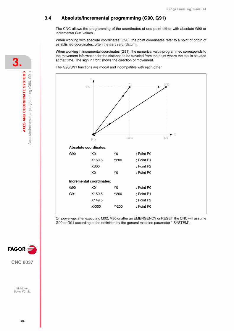
3.4 Absolute/incremental programming (G90, G91)
The CNC allows the programming of the coordinates of one point either with absolute G90 orincremental G91 values.
When working with absolute coordinates (G90), the point coordinates refer to a point of origin ofestablished coordinates, often the part zero (datum).
When working in incremental coordinates (G91), the numerical value programmed corresponds tothe movement information for the distance to be traveled from the point where the tool is situatedat that time. The sign in front shows the direction of movement.
The G90/G91 functions are modal and incompatible with each other.
On power-up, after executing M02, M30 or after an EMERGENCY or RESET, the CNC will assumeG90 or G91 according to the definition by the general machine parameter "ISYSTEM".
Absolute coordinates:
G90 X0 Y0 ; Point P0
X150.5 Y200 ; Point P1
X300 ; Point P2
X0 Y0 ; Point P0
Incremental coordinates:
G90 X0 Y0 ; Point P0
G91 X150.5 Y200 ; Point P1
X149.5 ; Point P2
X-300 Y-200 ; Point P0
Programming manual
CNC 8037
AX
ES
AN
D C
OO
RD
INA
TE
SY
ST
EM
S
3.
·M· MODELSOFT: V01.4X
·41·
Coo
rdin
ate
prog
ram
min
g
3.5 Coordinate programming
The CNC allows the selection of up to 7 of the 9 possible axes X, Y, Z, U, V, W, A, B, C.
Each of these may be linear, linear to position only, normal rotary, rotary to position only or rotarywith hirth toothing (positioning in complete degrees), according to the specification in the machineparameter of each "AXISTYPE" axis.
With the aim of always selecting the most suitable coordinate programming system, the CNC hasthe following types :
• Cartesian coordinates
• Polar coordinates
• Cylindrical coordinates
• Angle and Cartesian coordinate
·42·
Programming manual
CNC 8037
3.
AX
ES
AN
D C
OO
RD
INA
TE
SY
ST
EM
S
·M· MODELSOFT: V01.4X
Coo
rdin
ate
prog
ram
min
g
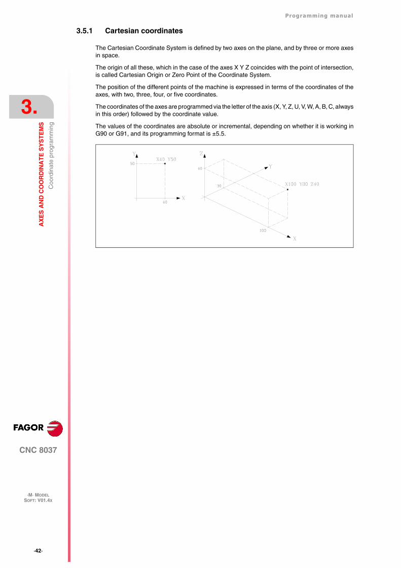
3.5.1 Cartesian coordinates
The Cartesian Coordinate System is defined by two axes on the plane, and by three or more axesin space.
The origin of all these, which in the case of the axes X Y Z coincides with the point of intersection,is called Cartesian Origin or Zero Point of the Coordinate System.
The position of the different points of the machine is expressed in terms of the coordinates of theaxes, with two, three, four, or five coordinates.
The coordinates of the axes are programmed via the letter of the axis (X, Y, Z, U, V, W, A, B, C, alwaysin this order) followed by the coordinate value.
The values of the coordinates are absolute or incremental, depending on whether it is working inG90 or G91, and its programming format is ±5.5.
Programming manual
CNC 8037
AX
ES
AN
D C
OO
RD
INA
TE
SY
ST
EM
S
3.
·M· MODELSOFT: V01.4X
·43·
Coo
rdin
ate
prog
ram
min
g
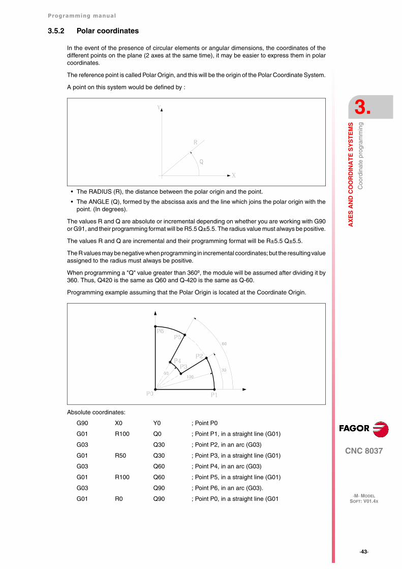
3.5.2 Polar coordinates
In the event of the presence of circular elements or angular dimensions, the coordinates of thedifferent points on the plane (2 axes at the same time), it may be easier to express them in polarcoordinates.
The reference point is called Polar Origin, and this will be the origin of the Polar Coordinate System.
A point on this system would be defined by :
• The RADIUS (R), the distance between the polar origin and the point.
• The ANGLE (Q), formed by the abscissa axis and the line which joins the polar origin with thepoint. (In degrees).
The values R and Q are absolute or incremental depending on whether you are working with G90or G91, and their programming format will be R5.5 Q±5.5. The radius value must always be positive.
The values R and Q are incremental and their programming format will be R±5.5 Q±5.5.
The R values may be negative when programming in incremental coordinates; but the resulting valueassigned to the radius must always be positive.
When programming a "Q" value greater than 360º, the module will be assumed after dividing it by360. Thus, Q420 is the same as Q60 and Q-420 is the same as Q-60.
Programming example assuming that the Polar Origin is located at the Coordinate Origin.
Absolute coordinates:
G90 X0 Y0 ; Point P0
G01 R100 Q0 ; Point P1, in a straight line (G01)
G03 Q30 ; Point P2, in an arc (G03)
G01 R50 Q30 ; Point P3, in a straight line (G01)
G03 Q60 ; Point P4, in an arc (G03)
G01 R100 Q60 ; Point P5, in a straight line (G01)
G03 Q90 ; Point P6, in an arc (G03).
G01 R0 Q90 ; Point P0, in a straight line (G01
·44·
Programming manual
CNC 8037
3.
AX
ES
AN
D C
OO
RD
INA
TE
SY
ST
EM
S
·M· MODELSOFT: V01.4X
Coo
rdin
ate
prog
ram
min
g
Incremental coordinates:
G90 X0 Y0 ; Point P0
G91 G01 R100 Q0 ; Point P1, in a straight line (G01)
G03 Q30 ; Point P2, in an arc (G03)
G01 R-50 Q0 ; Point P3, in a straight line (G01)
G03 Q30 ; Point P4, in an arc (G03)
G01 R50 Q0 ; Point P5, in a straight line (G01)
G03 Q30 ; Point P6, in an arc (G03).
G01 R-100 Q0 ; Point P0, in a straight line (G01
The polar origin, apart from being able to be preset using function G93 (described later) can bemodified in the following cases :
• On power-up, after executing M02, M30 EMERGENCY or RESET, the CNC will assume, as thepolar origin, the coordinate origin of the work plane defined by the general machineparameter"IPLANE".
• Every time the work plane is changed (G16,G17,G18 or G19), the CNC assumes the coordinateorigin of the new work plane selected as the polar origin.
• When executing a circular interpolation (G02 or G03), and if the general machine parameter"PORGMOVE" has a value of 1, the center of the arc will become the new polar origin.
Programming manual
CNC 8037
AX
ES
AN
D C
OO
RD
INA
TE
SY
ST
EM
S
3.
·M· MODELSOFT: V01.4X
·45·
Coo
rdin
ate
prog
ram
min
g
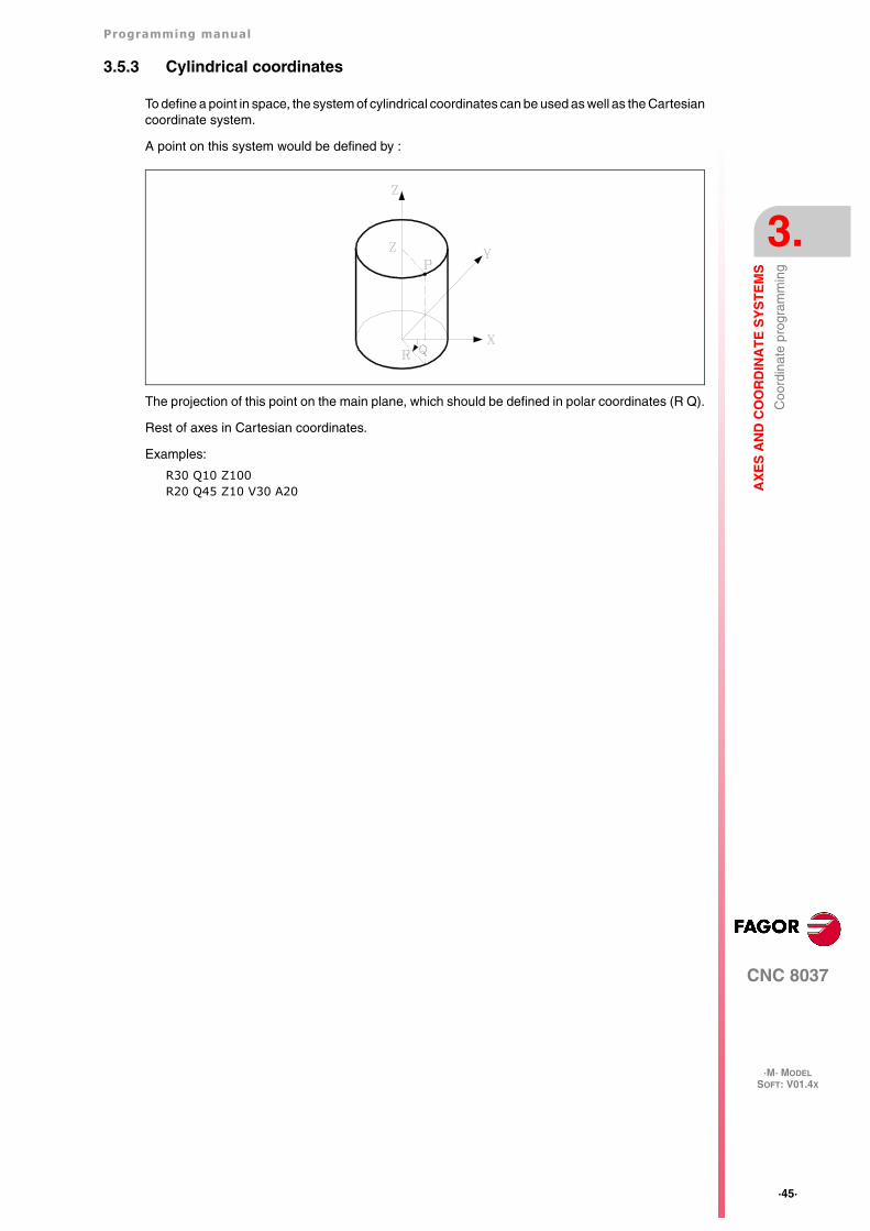
3.5.3 Cylindrical coordinates
To define a point in space, the system of cylindrical coordinates can be used as well as the Cartesiancoordinate system.
A point on this system would be defined by :
The projection of this point on the main plane, which should be defined in polar coordinates (R Q).
Rest of axes in Cartesian coordinates.
Examples:
R30 Q10 Z100R20 Q45 Z10 V30 A20
·46·
Programming manual
CNC 8037
3.
AX
ES
AN
D C
OO
RD
INA
TE
SY
ST
EM
S
·M· MODELSOFT: V01.4X
Coo
rdin
ate
prog
ram
min
g
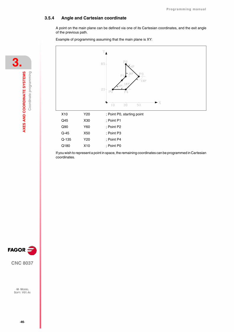
3.5.4 Angle and Cartesian coordinate
A point on the main plane can be defined via one of its Cartesian coordinates, and the exit angleof the previous path.
Example of programming assuming that the main plane is XY:
X10 Y20 ; Point P0, starting point
Q45 X30 ; Point P1
Q90 Y60 ; Point P2
Q-45 X50 ; Point P3
Q-135 Y20 ; Point P4
Q180 X10 ; Point P0
If you wish to represent a point in space, the remaining coordinates can be programmed in Cartesiancoordinates.
Programming manual
CNC 8037
AX
ES
AN
D C
OO
RD
INA
TE
SY
ST
EM
S
3.
·M· MODELSOFT: V01.4X
·47·
Rot
ary
axes
3.6 Rotary axes
The types of rotary axes available are:
Normal rotary axis.
Positioning-only rotary axis.
Rotary HIRTH axis.
Each one of them can be divided into:
Rollover When it is displayed between 0º and 360º.
Non Rollover When it may be displayed between -99999º and 99999º.
They are all programmed in degrees. Therefore, their readings are not affected by the inch/mmconversion.
Normal rotary axes
They can interpolate with linear axes.
Movement: In G00 and G01.
Rollover axis programming:
G90 The sign indicates the turning direction and the target position (between 0 and359.9999).
G91 The sign indicates the turning direction. If the programmed movement exceeds360º, the axis will rotate more than one turn before positioning at the desired point.
Non-rollover axis programming.
In G90 and G91 like a linear axis.
Positioning-only rotary axis
They cannot be interpolated with linear axes.
Movement: Always in G00 and they do not admit tool radius compensation (G41, G42).
Rollover axis programming:
G90 Always positive and in the shortest direction. End coordinate between 0 and359.9999.
G91 The sign indicates the turning direction. If the programmed movement exceeds360º, the axis will rotate more than one turn before positioning at the desired point.
Non-rollover axis programming.
In G90 and G91 like a linear axis.
Rotary Hirth axis
They work like the positioning-only axis except that they do not admit decimal position values(coordinates).
More than one hirth axis can be used, but they can only be moved one at a time.
·48·
Programming manual
CNC 8037
3.
AX
ES
AN
D C
OO
RD
INA
TE
SY
ST
EM
S
·M· MODELSOFT: V01.4X
Wor
k zo
nes
3.7 Work zones
The CNC provides four work zones or areas, and also limits the tool movement in each of these.
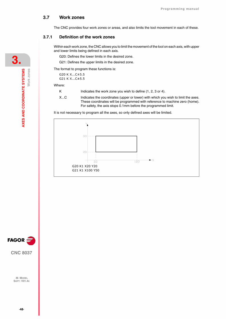
3.7.1 Definition of the work zones
Within each work zone, the CNC allows you to limit the movement of the tool on each axis, with upperand lower limits being defined in each axis.
G20: Defines the lower limits in the desired zone.
G21: Defines the upper limits in the desired zone.
The format to program these functions is:
G20 K X...C±5.5G21 K X...C±5.5
Where:
K Indicates the work zone you wish to define (1, 2, 3 or 4).
X...C Indicates the coordinates (upper or lower) with which you wish to limit the axes.These coordinates will be programmed with reference to machine zero (home).For safety, the axis stops 0.1mm before the programmed limit.
It is not necessary to program all the axes, so only defined axes will be limited.
G20 K1 X20 Y20G21 K1 X100 Y50
Programming manual
CNC 8037
AX
ES
AN
D C
OO
RD
INA
TE
SY
ST
EM
S
3.
·M· MODELSOFT: V01.4X
·49·
Wor
k zo
nes
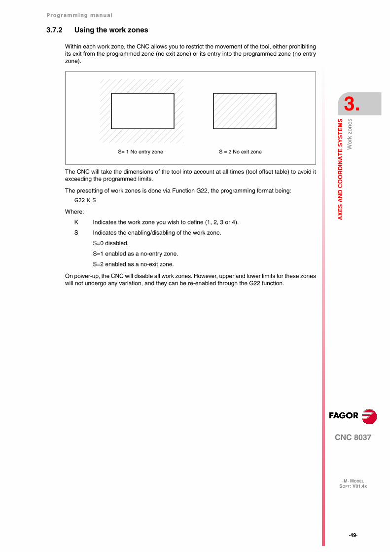
3.7.2 Using the work zones
Within each work zone, the CNC allows you to restrict the movement of the tool, either prohibitingits exit from the programmed zone (no exit zone) or its entry into the programmed zone (no entryzone).
The CNC will take the dimensions of the tool into account at all times (tool offset table) to avoid itexceeding the programmed limits.
The presetting of work zones is done via Function G22, the programming format being:
G22 K S
Where:
K Indicates the work zone you wish to define (1, 2, 3 or 4).
S Indicates the enabling/disabling of the work zone.
S=0 disabled.
S=1 enabled as a no-entry zone.
S=2 enabled as a no-exit zone.
On power-up, the CNC will disable all work zones. However, upper and lower limits for these zoneswill not undergo any variation, and they can be re-enabled through the G22 function.
S= 1 No entry zone S = 2 No exit zone
·50·
Programming manual
CNC 8037
3.
AX
ES
AN
D C
OO
RD
INA
TE
SY
ST
EM
S
·M· MODELSOFT: V01.4X
Wor
k zo
nes
CNC 8037
·M· MODELSOFT: V01.4X
4
·51·
REFERENCE SYSTEMS
4.1 Reference points
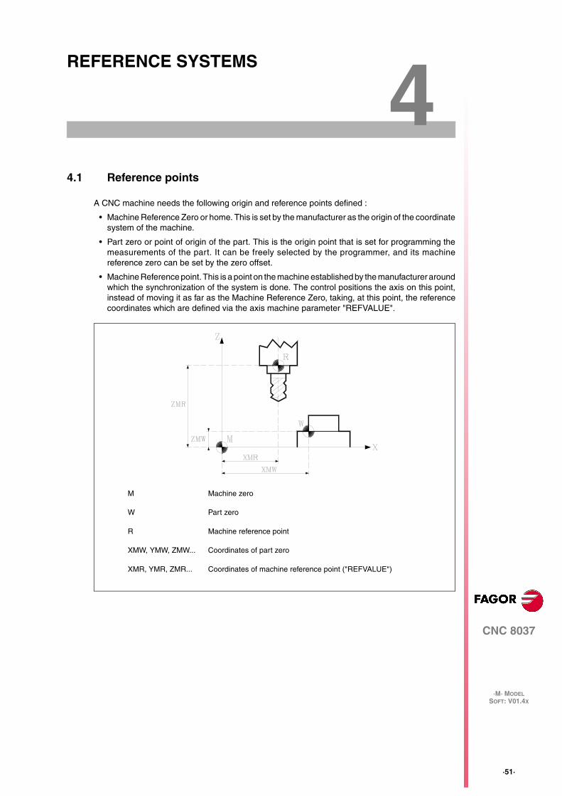
A CNC machine needs the following origin and reference points defined :
• Machine Reference Zero or home. This is set by the manufacturer as the origin of the coordinatesystem of the machine.
• Part zero or point of origin of the part. This is the origin point that is set for programming themeasurements of the part. It can be freely selected by the programmer, and its machinereference zero can be set by the zero offset.
• Machine Reference point. This is a point on the machine established by the manufacturer aroundwhich the synchronization of the system is done. The control positions the axis on this point,instead of moving it as far as the Machine Reference Zero, taking, at this point, the referencecoordinates which are defined via the axis machine parameter "REFVALUE".
M Machine zero
W Part zero
R Machine reference point
XMW, YMW, ZMW... Coordinates of part zero
XMR, YMR, ZMR... Coordinates of machine reference point ("REFVALUE")
·52·
Programming manual
CNC 8037
4.
RE
FE
RE
NC
E S
YS
TE
MS
·M· MODELSOFT: V01.4X
Mac
hine
ref
eren
ce (
Hom
e) s
earc
h (G
74)
4.2 Machine reference (Home) search (G74)
The CNC allows you to program the machine reference search in two ways :
• Machine reference (home) search of one or more axes in a particular order.
G74 is programmed followed by the axes in which you want to carry out the reference search.For example: G74 X Z.
The CNC begins the movement of all the selected axes which have a machine reference switch(machine axis parameter "DECINPUT") and in the direction indicated by the axis machineparameter "REFDIREC".
This movement is carried out at the feedrate indicated by the axis machine parameter"REFEED1" for each axis until the home switch is hit.
Next, the home search (marker pulse or home) will be carried out in the programmed order.
This second movement will be carried out one axis at a time, at the feedrate indicated in the axismachine parameter "REFEED2" until the machine reference point is reached (i.e. the markerpulse is found).
• Home search using the associated subroutine.
The G74 function will be programmed alone in the block, and the CNC will automatically executethe subroutine whose number appears in the general machine parameter "REFPSUB". In thissubroutine it is possible to program the machine reference searches required, and also in therequired order.
In a block in which G74 has been programmed, no other preparatory function may appear.
If the machine reference search is done in JOG mode, the part zero selected is lost. The coordinatesof the reference point indicated in the machine axis parameter "REFVALUE" is displayed. In all othercases, the active part zero will be maintained and the CNC will display the position values withrespect to that part zero.
If the G74 command is executed in MDI, the display of coordinates depends on the mode in whichit is executed : Jog, Execution, or Simulation.
Programming manual
CNC 8037
RE
FE
RE
NC
E S
YS
TE
MS
4.
·M· MODELSOFT: V01.4X
·53·
Pro
gram
min
g w
ith r
espe
ct to
mac
hine
zer
o (G
53)
4.3 Programming with respect to machine zero (G53)
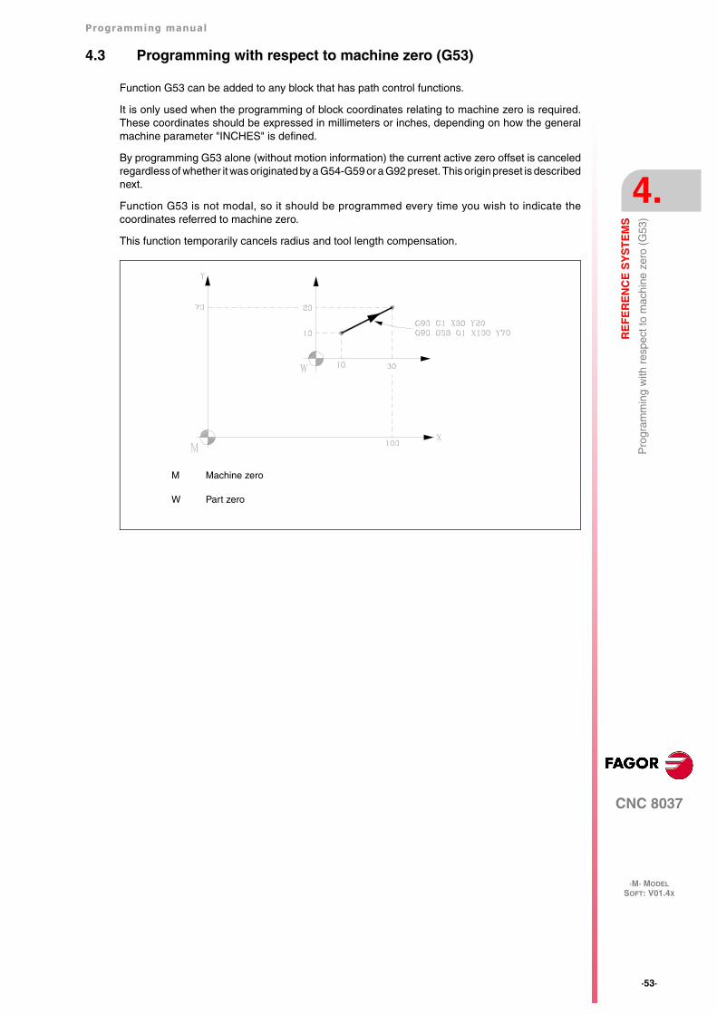
Function G53 can be added to any block that has path control functions.
It is only used when the programming of block coordinates relating to machine zero is required.These coordinates should be expressed in millimeters or inches, depending on how the generalmachine parameter "INCHES" is defined.
By programming G53 alone (without motion information) the current active zero offset is canceledregardless of whether it was originated by a G54-G59 or a G92 preset. This origin preset is describednext.
Function G53 is not modal, so it should be programmed every time you wish to indicate thecoordinates referred to machine zero.
This function temporarily cancels radius and tool length compensation.
M Machine zero
W Part zero
·54·
Programming manual
CNC 8037
4.
RE
FE
RE
NC
E S
YS
TE
MS
·M· MODELSOFT: V01.4X
Coo
rdin
ate
pres
et a
nd z
ero
offs
ets
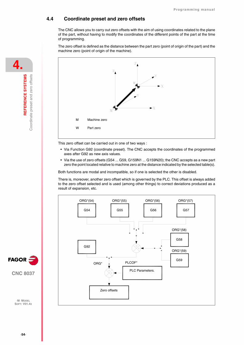
4.4 Coordinate preset and zero offsets
The CNC allows you to carry out zero offsets with the aim of using coordinates related to the planeof the part, without having to modify the coordinates of the different points of the part at the timeof programming.
The zero offset is defined as the distance between the part zero (point of origin of the part) and themachine zero (point of origin of the machine).
This zero offset can be carried out in one of two ways :
• Via Function G92 (coordinate preset). The CNC accepts the coordinates of the programmedaxes after G92 as new axis values.
• Via the use of zero offsets (G54 ... G59, G159N1 ... G159N20); the CNC accepts as a new partzero the point located relative to machine zero at the distance indicated by the selected table(s).
Both functions are modal and incompatible, so if one is selected the other is disabled.
There is, moreover, another zero offset which is governed by the PLC. This offset is always addedto the zero offset selected and is used (among other things) to correct deviations produced as aresult of expansion, etc.
M Machine zero
W Part zero
Zero offsets
PLC Parameters.
G59
G58
G92ORG*(59)
ORG*(58)
ORG* PLCOF*
ORG*(54) ORG*(55) ORG*(56) ORG*(57)
G54 G55 G56 G57
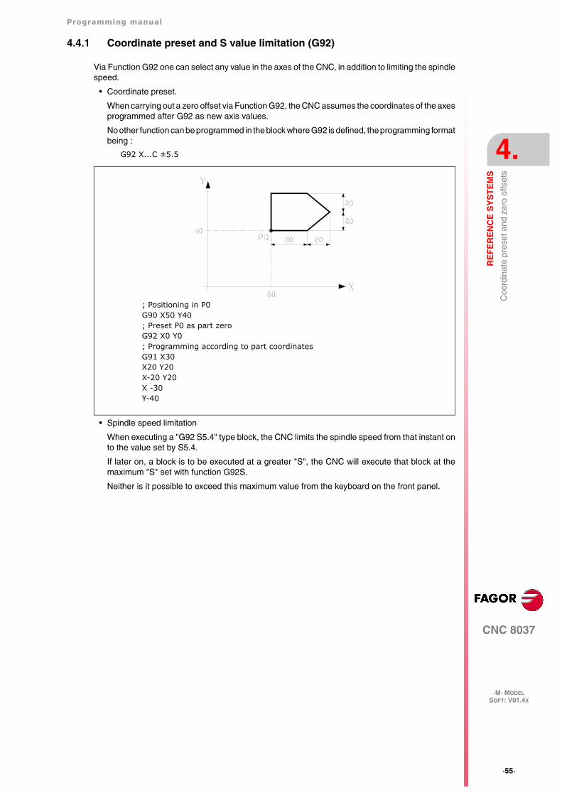
Programming manual
CNC 8037
RE
FE
RE
NC
E S
YS
TE
MS
4.
·M· MODELSOFT: V01.4X
·55·
Coo
rdin
ate
pres
et a
nd z
ero
offs
ets
4.4.1 Coordinate preset and S value limitation (G92)
Via Function G92 one can select any value in the axes of the CNC, in addition to limiting the spindlespeed.
• Coordinate preset.
When carrying out a zero offset via Function G92, the CNC assumes the coordinates of the axesprogrammed after G92 as new axis values.
No other function can be programmed in the block where G92 is defined, the programming formatbeing :
G92 X...C ±5.5
• Spindle speed limitation
When executing a "G92 S5.4" type block, the CNC limits the spindle speed from that instant onto the value set by S5.4.
If later on, a block is to be executed at a greater "S", the CNC will execute that block at themaximum "S" set with function G92S.
Neither is it possible to exceed this maximum value from the keyboard on the front panel.
; Positioning in P0G90 X50 Y40; Preset P0 as part zeroG92 X0 Y0; Programming according to part coordinatesG91 X30X20 Y20X-20 Y20X -30Y-40
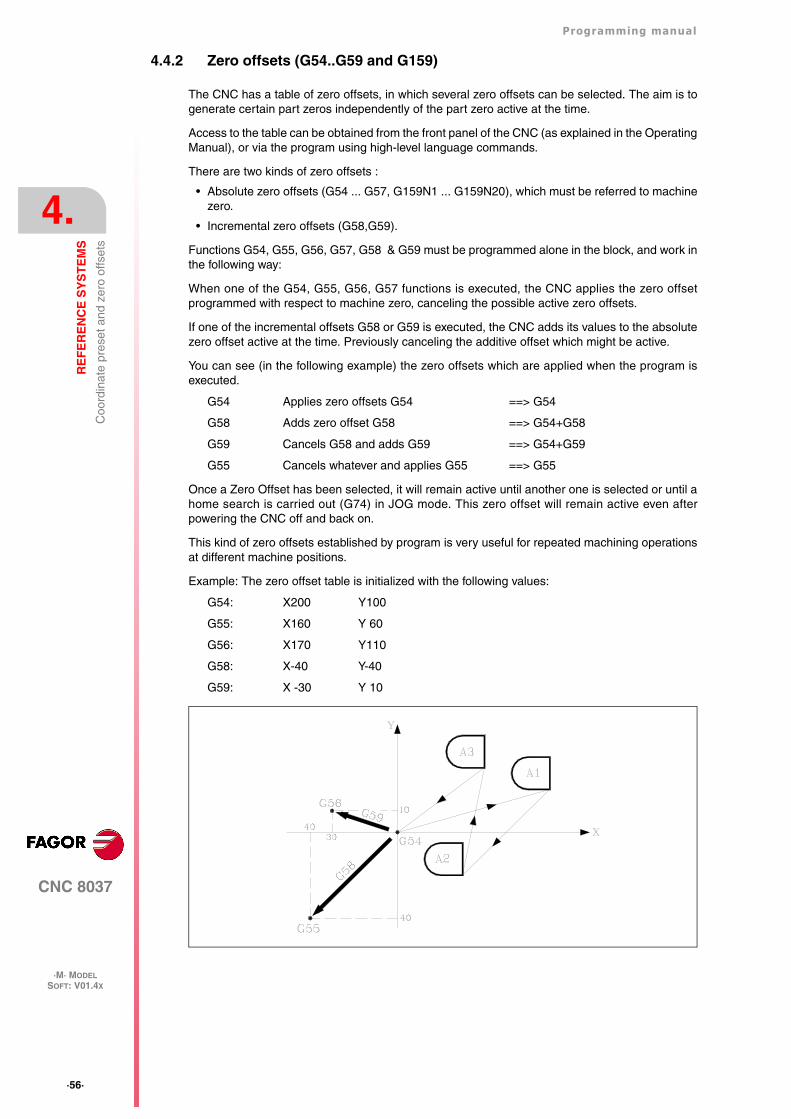
·56·
Programming manual
CNC 8037
4.
RE
FE
RE
NC
E S
YS
TE
MS
·M· MODELSOFT: V01.4X
Coo
rdin
ate
pres
et a
nd z
ero
offs
ets
4.4.2 Zero offsets (G54..G59 and G159)
The CNC has a table of zero offsets, in which several zero offsets can be selected. The aim is togenerate certain part zeros independently of the part zero active at the time.
Access to the table can be obtained from the front panel of the CNC (as explained in the OperatingManual), or via the program using high-level language commands.
There are two kinds of zero offsets :
• Absolute zero offsets (G54 ... G57, G159N1 ... G159N20), which must be referred to machinezero.
• Incremental zero offsets (G58,G59).
Functions G54, G55, G56, G57, G58 & G59 must be programmed alone in the block, and work inthe following way:
When one of the G54, G55, G56, G57 functions is executed, the CNC applies the zero offsetprogrammed with respect to machine zero, canceling the possible active zero offsets.
If one of the incremental offsets G58 or G59 is executed, the CNC adds its values to the absolutezero offset active at the time. Previously canceling the additive offset which might be active.
You can see (in the following example) the zero offsets which are applied when the program isexecuted.
G54 Applies zero offsets G54 ==> G54
G58 Adds zero offset G58 ==> G54+G58
G59 Cancels G58 and adds G59 ==> G54+G59
G55 Cancels whatever and applies G55 ==> G55
Once a Zero Offset has been selected, it will remain active until another one is selected or until ahome search is carried out (G74) in JOG mode. This zero offset will remain active even afterpowering the CNC off and back on.
This kind of zero offsets established by program is very useful for repeated machining operationsat different machine positions.
Example: The zero offset table is initialized with the following values:
G54: X200 Y100
G55: X160 Y 60
G56: X170 Y110
G58: X-40 Y-40
G59: X -30 Y 10
Programming manual
CNC 8037
RE
FE
RE
NC
E S
YS
TE
MS
4.
·M· MODELSOFT: V01.4X
·57·
Coo
rdin
ate
pres
et a
nd z
ero
offs
ets
Using absolute zero offsets:
G54 ; Applies G54 offset
Profile execution ; Executes profile A1
G55 ; Applies G55 offset
Profile execution ; Executes profile A2
G56 ; Applies G56 offset
Profile execution ; Executes profile A3
Using incremental zero offsets:
G54 ; Applies G54 offset
Profile execution ; Executes profile A1
G58 ; Applies offsets G54+G58
Profile execution ; Executes profile A2
G59 ; Applies offsets G54+G59
Profile execution ; Executes profile A3
Function G159
To apply any zero offset defined in the table.
The first six zero offsets are the same as programming G54 through G59, except that the valuesof G58 and G59 are absolute. This is because function G159 cancels functions G54 through G57and, consequently, there is no active zero offset to add the G58 or G59 to.
Function G159 is programmed as follows:
G159 Nn Where n is a number from 1 to 20 that indicates the number of the zero offset beingapplied.
Function G159 is modal, it is programmed alone in the block and is incompatible with functions G53,G54, G55, G56, G57, G58, G59 and G92.
On power-up, the CNC assumes the zero offset that was active when the CNC was turned off. Onthe other hand, the zero offset is neither affected by functions M02 and M30 nor by RESET.
This function is displayed in the history like G159Nn where the n is the active zero offset.
Examples:
G159 N1 It applies the first zero offset. It is the same as programming G54.
G159 N6 It applies the second zero offset. It is the same as programming G59, but it isapplied in absolute.
G159 N20 It applies the 20th zero offset.
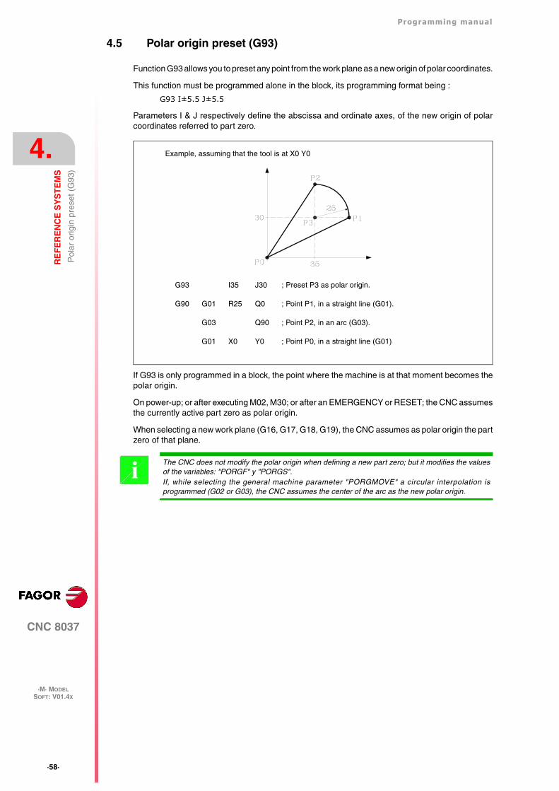
·58·
Programming manual
CNC 8037
4.
RE
FE
RE
NC
E S
YS
TE
MS
·M· MODELSOFT: V01.4X
Pol
ar o
rigin
pre
set (
G93
)
4.5 Polar origin preset (G93)
Function G93 allows you to preset any point from the work plane as a new origin of polar coordinates.
This function must be programmed alone in the block, its programming format being :
G93 I±5.5 J±5.5
Parameters I & J respectively define the abscissa and ordinate axes, of the new origin of polarcoordinates referred to part zero.
If G93 is only programmed in a block, the point where the machine is at that moment becomes thepolar origin.
On power-up; or after executing M02, M30; or after an EMERGENCY or RESET; the CNC assumesthe currently active part zero as polar origin.
When selecting a new work plane (G16, G17, G18, G19), the CNC assumes as polar origin the partzero of that plane.
G93 I35 J30 ; Preset P3 as polar origin.
G90 G01 R25 Q0 ; Point P1, in a straight line (G01).
G03 Q90 ; Point P2, in an arc (G03).
G01 X0 Y0 ; Point P0, in a straight line (G01)
Example, assuming that the tool is at X0 Y0
The CNC does not modify the polar origin when defining a new part zero; but it modifies the valuesof the variables: "PORGF" y "PORGS".If, while selecting the general machine parameter "PORGMOVE" a circular interpolation isprogrammed (G02 or G03), the CNC assumes the center of the arc as the new polar origin.
i
CNC 8037
·M· MODELSOFT: V01.4X
5
·59·
ISO CODE PROGRAMMING
A block programmed in ISO language can consist of:
• Preparatory (G) functions
• Axis coordinates (X...C)
• Feedrate (F)
• Spindle speed (S)
• Tool number (T)
• Tool offset number (D)
• Auxiliary functions (M)
This order should be maintained within each block, although it is not necessary for every block tocontain the information.
The CNC allows you to program figures from 0.00001 to 99999.9999 with or without sign, workingin millimeters (G71), called format +/-5.4, or either from 0.00001 to 3937.00787 with or without signif the programming is done in inches (G70), called format +/-4.5.
However, and to simplify the instructions, we can say that the CNC admits +/- 5.5 format, therebyadmitting +/- 5.4 in millimeters and +/- 4.5 in inches.
Any function with parameters can also be programmed in a block, apart from the number of the labelor block. Thus, when the block is executed the CNC substitutes the arithmetic parameter for its valueat that time.
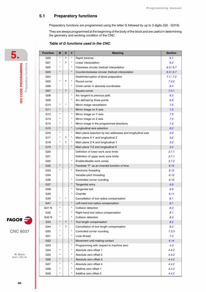
·60·
Programming manual
CNC 8037
5.
ISO
CO
DE
PR
OG
RA
MM
ING
·M· MODELSOFT: V01.4X
Pre
para
tory
func
tions
5.1 Preparatory functions
Preparatory functions are programmed using the letter G followed by up to 3 digits (G0 - G319).
They are always programmed at the beginning of the body of the block and are useful in determiningthe geometry and working condition of the CNC.
Table of G functions used in the CNC.
Function M D V Meaning Section
G00 * ? * Rapid traverse 6.1
G01 * ? * Linear interpolation 6.2
G02 * * Clockwise circular (helical) interpolation 6.3 / 6.7
G03 * * Counterclockwise circular (helical) interpolation 6.3 / 6.7
G04 Dwell/interruption of block preparation 7.1 / 7.2
G05 * ? * Round corner 7.3.2
G06 * Circle center in absolute coordinates 6.4
G07 * ? Square corner 7.3.1
G08 * Arc tangent to previous path. 6.5
G09 * Arc defined by three points 6.6
G10 * * Mirror image cancellation 7.5
G11 * * Mirror image on X axis 7.5
G12 * * Mirror image on Y axis 7.5
G13 * * Mirror image on Z axis 7.5
G14 * * Mirror image in the programmed directions 7.5
G15 * * Longitudinal axis selection 8.2
G16 * * Main plane selection by two addresses and longitudinal axis 3.2
G17 * ? * Main plane X-Y and longitudinal Z 3.2
G18 * ? * Main plane Z-X and longitudinal Y 3.2
G19 * * Main plane Y-Z and longitudinal X 3.2
G20 Definition of lower work zone limits 3.7.1
G21 Definition of upper work zone limits. 3.7.1
G22 * Enable/disable work zones. 3.7.2
G32 * * Feedrate "F" as an inverted function of time. 6.15
G33 * * Electronic threading 6.12
G34 Variable-pitch threading 6.13
G36 * Controlled corner rounding 6.10
G37 * Tangential entry 6.8
G38 * Tangential exit 6.9
G39 * Chamfer 6.11
G40 * * Cancellation of tool radius compensation 8.1
G41 * * Left-hand tool radius compensation 8.1
G41 N * * Collision detection 8.3
G42 * * Right-hand tool radius compensation 8.1
G42 N * * Collision detection 8.3
G43 * ? * Tool length compensation 8.2
G44 * ? Cancellation of tool length compensation 8.2
G50 * * Controlled corner rounding 7.3.3
G51 * * Look-Ahead 7.4
G52 * Movement until making contact 6.14
G53 * Programming with respect to machine zero 4.3
G54 * * Absolute zero offset 1 4.4.2
G55 * * Absolute zero offset 2 4.4.2
G56 * * Absolute zero offset 3 4.4.2
G57 * * Absolute zero offset 4 4.4.2
G58 * * Additive zero offset 1 4.4.2
G59 * * Additive zero offset 2 4.4.2
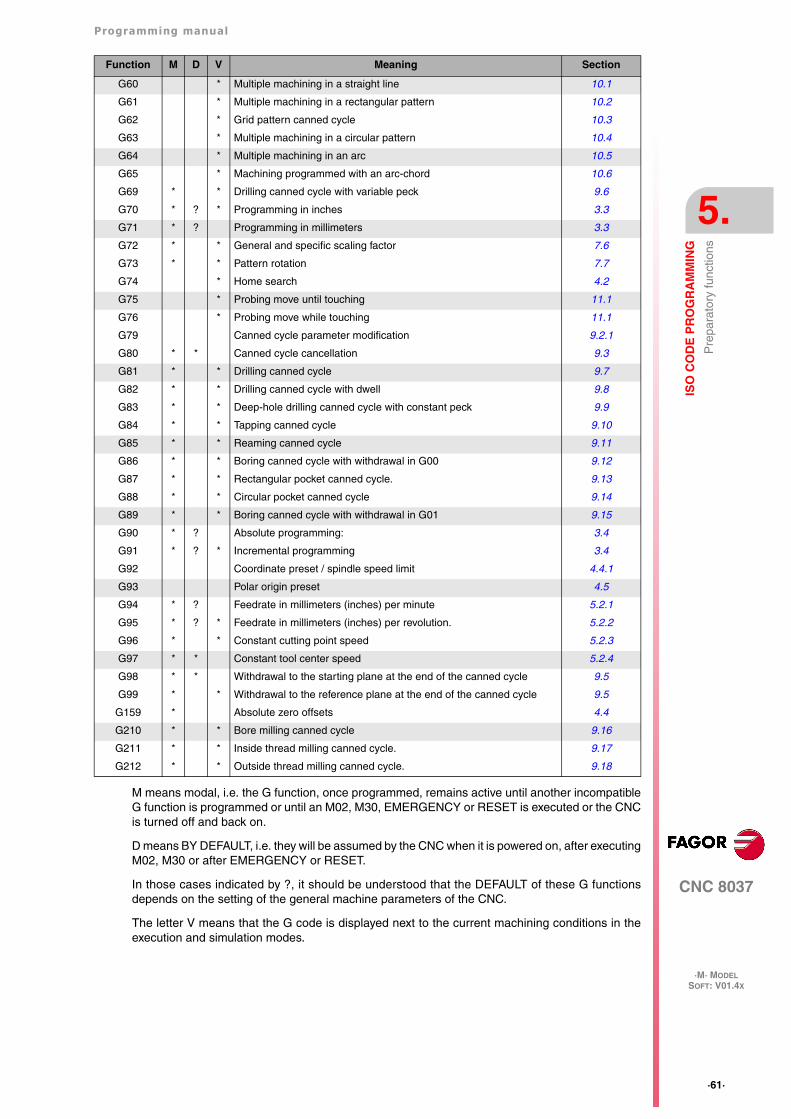
Programming manual
CNC 8037
ISO
CO
DE
PR
OG
RA
MM
ING
5.
·M· MODELSOFT: V01.4X
·61·
Pre
para
tory
func
tions
M means modal, i.e. the G function, once programmed, remains active until another incompatibleG function is programmed or until an M02, M30, EMERGENCY or RESET is executed or the CNCis turned off and back on.
D means BY DEFAULT, i.e. they will be assumed by the CNC when it is powered on, after executingM02, M30 or after EMERGENCY or RESET.
In those cases indicated by ?, it should be understood that the DEFAULT of these G functionsdepends on the setting of the general machine parameters of the CNC.
The letter V means that the G code is displayed next to the current machining conditions in theexecution and simulation modes.
G60 * Multiple machining in a straight line 10.1
G61 * Multiple machining in a rectangular pattern 10.2
G62 * Grid pattern canned cycle 10.3
G63 * Multiple machining in a circular pattern 10.4
G64 * Multiple machining in an arc 10.5
G65 * Machining programmed with an arc-chord 10.6
G69 * * Drilling canned cycle with variable peck 9.6
G70 * ? * Programming in inches 3.3
G71 * ? Programming in millimeters 3.3
G72 * * General and specific scaling factor 7.6
G73 * * Pattern rotation 7.7
G74 * Home search 4.2
G75 * Probing move until touching 11.1
G76 * Probing move while touching 11.1
G79 Canned cycle parameter modification 9.2.1
G80 * * Canned cycle cancellation 9.3
G81 * * Drilling canned cycle 9.7
G82 * * Drilling canned cycle with dwell 9.8
G83 * * Deep-hole drilling canned cycle with constant peck 9.9
G84 * * Tapping canned cycle 9.10
G85 * * Reaming canned cycle 9.11
G86 * * Boring canned cycle with withdrawal in G00 9.12
G87 * * Rectangular pocket canned cycle. 9.13
G88 * * Circular pocket canned cycle 9.14
G89 * * Boring canned cycle with withdrawal in G01 9.15
G90 * ? Absolute programming: 3.4
G91 * ? * Incremental programming 3.4
G92 Coordinate preset / spindle speed limit 4.4.1
G93 Polar origin preset 4.5
G94 * ? Feedrate in millimeters (inches) per minute 5.2.1
G95 * ? * Feedrate in millimeters (inches) per revolution. 5.2.2
G96 * * Constant cutting point speed 5.2.3
G97 * * Constant tool center speed 5.2.4
G98 * * Withdrawal to the starting plane at the end of the canned cycle 9.5
G99 * * Withdrawal to the reference plane at the end of the canned cycle 9.5
G159 * Absolute zero offsets 4.4
G210 * * Bore milling canned cycle 9.16
G211 * * Inside thread milling canned cycle. 9.17
G212 * * Outside thread milling canned cycle. 9.18
Function M D V Meaning Section
·62·
Programming manual
CNC 8037
5.
ISO
CO
DE
PR
OG
RA
MM
ING
·M· MODELSOFT: V01.4X
Fee
drat
e F
5.2 Feedrate F
The machining feedrate can be selected from the program. It remains active until another feedrateis programmed. It is represented by the letter F and Depending on whether it is working in G94 orG95, it is programmed in mm/minute (inches/minute) or in mm/revolution (inches/revolution).
Its programming format is 5.5; in other words, 5.4 when programmed in mm and 4.5 whenprogrammed in inches.
The maximum operating feedrate of the machine, limited on each axis by the axis machineparameter "MAXFEED", may be programmed via code F0, or by giving F the corresponding value.
The programmed feedrate F is effective working in linear (G01) or circular (G02, G03) interpolation.If function F is not programmed, the CNC assumes the feedrate to be F0. When working in rapidtravel (G00), the machine will move at the rapid feedrate indicated by the axis machine parameter"G00FEED", apart from the F programmed.
The programmed feedrate F may be varied between 0% and 255% via the PLC, or by DNC, orbetween 0% and 120% via the switch located on the Operator Panel of the CNC.
The CNC, however, is equipped with the general machine parameter "MAXFOVR" to limit maximumfeedrate variation.
If you are working in rapid travel (G00), rapid feedrate will be fixed at 100%, alternatively it can bevaried between 0% and 100%, depending on how the machine parameter "RAPIDOVR" is set.
When functions G33 (electronic threading), G34 (variable-pitch threading) or G84 (tapping cannedcycle) are executed the feedrate cannot be modified; it works at 100% of programmed F.
Programming manual
CNC 8037
ISO
CO
DE
PR
OG
RA
MM
ING
5.
·M· MODELSOFT: V01.4X
·63·
Fee
drat
e F
5.2.1 Feedrate in mm/min or inches/min (G94)
From the moment the code G94 is programmed, the control takes that the feedrates programmedthrough F5.5 are in mm/min or inches/mm.
If the moving axis is rotary, the CNC interprets that the programmed feedrate is in degrees/minute.
If an interpolation is made between a rotary and a linear axis, the programmed feedrate is takenin mm/min or inches/min, and the movement of the rotary axis (programmed in degrees) will beconsidered programmed in millimeters or inches.
The relationship between the feedrate of the axis component and the programmed feedrate "F" isthe same as that between the movement of the axis and the resulting programmed movement.
Example:
On a machine which has linear X and Y axes and rotary C axis, all located at point X0 Y0 C0, thefollowing movement is programmed :
G1 G90 X100 Y20 C270 F10000
You get:
Function G94 is modal i.e. once programmed it stays active until G95 is programmed.
On power-up, after executing M02, M30 or following EMERGENCY or RESET, the CNC assumesfunction G94 or G95 according to how the general machine parameter "IFEED" is set.
Feedrate component =Feedrate F x Movement of axis
Resulting programmed movement
FxF x
x 2 y 2 c 2+ +----------------------------------------------------------- 10000 100
1002 202 2702+ +------------------------------------------------ 3464 7946= = =
FyF y
x 2 y 2 c 2+ +----------------------------------------------------------- 10000 20
1002 202 2702+ +------------------------------------------------ 692 9589= = =
FcF c
x 2 y 2 c 2+ +----------------------------------------------------------- 10000 270
1002 202 2702+ +------------------------------------------------ 9354 9455= = =
·64·
Programming manual
CNC 8037
5.
ISO
CO
DE
PR
OG
RA
MM
ING
·M· MODELSOFT: V01.4X
Fee
drat
e F
5.2.2 Feedrate in mm/rev.or inches/rev (G95)
From the moment when the code G95 is programmed, the control assumes that the feedratesprogrammed through F5.5 are in mm/rev or inches/mm.
This function does not affect the rapid moves (G00) which will be made in mm/min or inch/min. Bythe same token, it will not be applied to moves made in the JOG mode, during tool inspection, etc.
Function G95 is modal i.e. once programmed it stays active until G94 is programmed.
On power-up, after executing M02, M30 or following EMERGENCY or RESET, the CNC assumesfunction G94 or G95 according to how the general machine parameter "IFEED" is set.
Programming manual
CNC 8037
ISO
CO
DE
PR
OG
RA
MM
ING
5.
·M· MODELSOFT: V01.4X
·65·
Fee
drat
e F
5.2.3 Constant surface speed (G96)
When G96 is programmed the CNC takes the F5.5 feedrate as corresponding to the cutting pointof the tool on the part.
By using this function, the finished surface is uniform in curved sections.
In this manner (working in function G96) the speed of the center of the tool in the inside or outsidecurved sections will change in order to keep the cutting point constant.
Function G96 is modal i.e. once programmed it stays active until G97 is programmed.
On power-up, after executing M02, M30 or following EMERGENCY or RESET, the CNC assumesfunction G97.
·66·
Programming manual
CNC 8037
5.
ISO
CO
DE
PR
OG
RA
MM
ING
·M· MODELSOFT: V01.4X
Fee
drat
e F
5.2.4 Constant tool center speed (G97)
When G97 is programmed the CNC takes the programmed F5.5 feedrate as corresponding to thefeedrate of the center of the tool.
In this manner (working in function G97) the speed of the cutting point on the inside or outside curvedsections is reduced, keeping the speed of the center of the tool constant.
Function G97 is modal i.e. once programmed it stays active until G96 is programmed.
On power-up, after executing M02, M30 or following EMERGENCY or RESET, the CNC assumesfunction G97.

Programming manual
CNC 8037
ISO
CO
DE
PR
OG
RA
MM
ING
5.
·M· MODELSOFT: V01.4X
·67·
Spi
ndle
spe
ed (
S)
5.3 Spindle speed (S)
The turning speed of the spindle is programmed directly in rpm via code S5.4.
The maximum value is limited by spindle machine parameters "MAXGEAR1", MAXGEAR2,MAXGEAR 3 and MAXGEAR4", in each case depending on the spindle range selected.
It is also possible to limit this maximum value from the program by using function G92 S5.4.
The programmed turning speed S may be varied from the PLC, DNC, or by the SPINDLE keys "+"and "-" on the Operator Panel of the CNC.
This speed variation is made between the maximum and minimum values established by spindlemachine parameters "MINSOVR" and "MAXSOVR".
The incremental pitch associated with the SPINDLE keys "+" and "-" on the CNC Operator Panelin order to vary the programmed S value is fixed by the spindle machine parameter "SOVRSTEP".
When functions G33 (electronic threading), G34 (variable-pitch threading) or G84 (tapping cannedcycle) are executed the programmed speed cannot be modified; it works at 100% of programmed S.
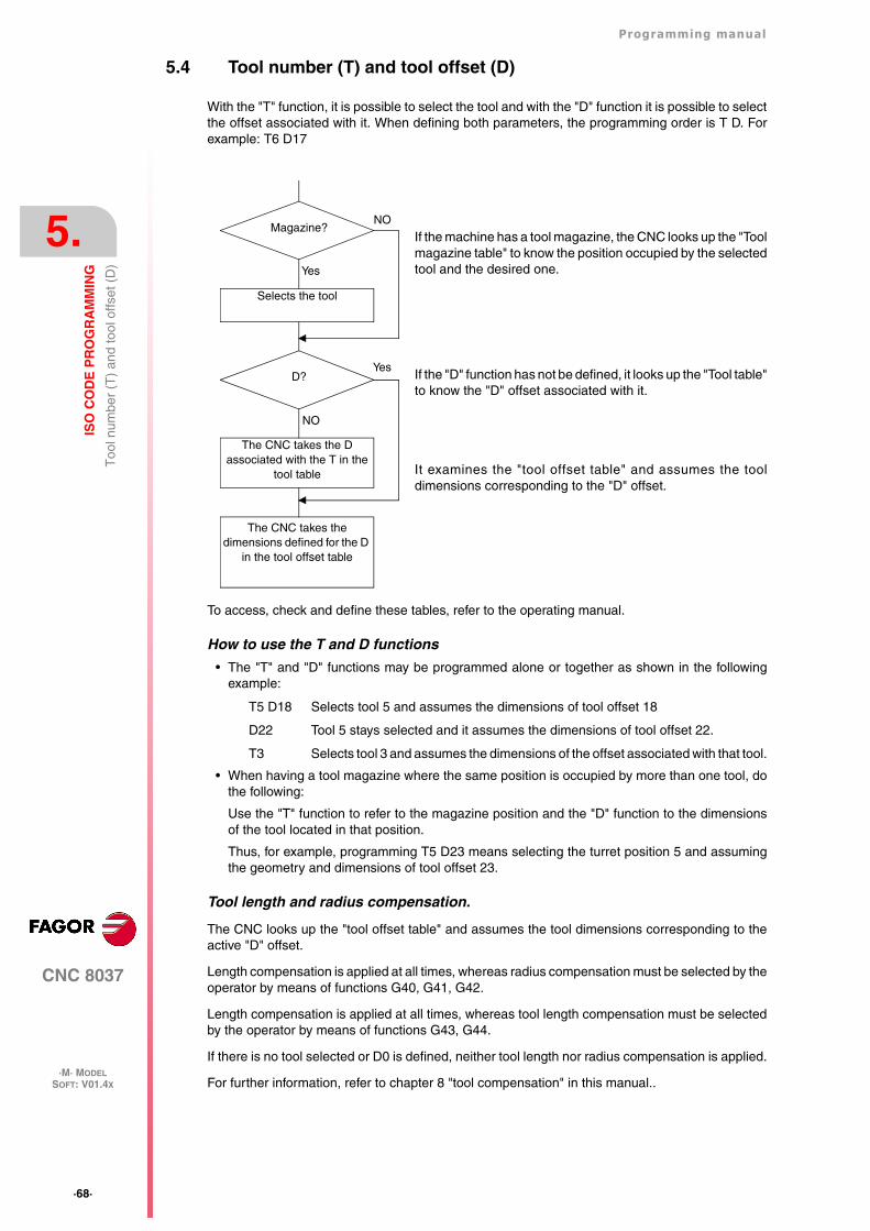
·68·
Programming manual
CNC 8037
5.
ISO
CO
DE
PR
OG
RA
MM
ING
·M· MODELSOFT: V01.4X
Too
l num
ber
(T)
and
tool
offs
et (
D)
5.4 Tool number (T) and tool offset (D)
With the "T" function, it is possible to select the tool and with the "D" function it is possible to selectthe offset associated with it. When defining both parameters, the programming order is T D. Forexample: T6 D17
To access, check and define these tables, refer to the operating manual.
How to use the T and D functions
• The "T" and "D" functions may be programmed alone or together as shown in the followingexample:
T5 D18 Selects tool 5 and assumes the dimensions of tool offset 18
D22 Tool 5 stays selected and it assumes the dimensions of tool offset 22.
T3 Selects tool 3 and assumes the dimensions of the offset associated with that tool.
• When having a tool magazine where the same position is occupied by more than one tool, dothe following:
Use the "T" function to refer to the magazine position and the "D" function to the dimensionsof the tool located in that position.
Thus, for example, programming T5 D23 means selecting the turret position 5 and assumingthe geometry and dimensions of tool offset 23.
Tool length and radius compensation.
The CNC looks up the "tool offset table" and assumes the tool dimensions corresponding to theactive "D" offset.
Length compensation is applied at all times, whereas radius compensation must be selected by theoperator by means of functions G40, G41, G42.
Length compensation is applied at all times, whereas tool length compensation must be selectedby the operator by means of functions G43, G44.
If there is no tool selected or D0 is defined, neither tool length nor radius compensation is applied.
For further information, refer to chapter 8 "tool compensation" in this manual..
If the machine has a tool magazine, the CNC looks up the "Toolmagazine table" to know the position occupied by the selectedtool and the desired one.
If the "D" function has not be defined, it looks up the "Tool table"to know the "D" offset associated with it.
It examines the "tool offset table" and assumes the tooldimensions corresponding to the "D" offset.
Selects the tool
Magazine?NO
Yes
Yes
NO
D?
The CNC takes the D associated with the T in the
tool table
The CNC takes the dimensions defined for the D
in the tool offset table
Programming manual
CNC 8037
ISO
CO
DE
PR
OG
RA
MM
ING
5.
·M· MODELSOFT: V01.4X
·69·
Aux
iliar
y fu
nctio
n (M
)
5.5 Auxiliary function (M)
The miscellaneous functions are programmed by means of the M4 Code, it being possible toprogram up to 7 functions in the same block.
When more than one function has been programmed in one block, the CNC executes thesecorrelatively to the order in which they have been programmed.
The CNC is provided with an M functions table with "NMISCFUN" (general machine parameter)components, specifying for each element:
• The number (0-9999) of the defined miscellaneous M function.
• The number of the subroutine which is required to associate to this miscellaneous function.
• An indicator which determines if the M function is executed before or after the movement blockin which it is programmed.
• An indicator which determines if the execution of the M function interrupts block preparation ornot.
• An indicator which determines if the M function is executed or not, after the execution of theassociated subroutine.
• An indicator which determines if the CNC must wait for the signal AUX END or not (ExecutedM signal, coming from the PLC), to continue the execution of the program.
If, when executing the M miscellaneous function, this is not defined in the M functions table, theprogrammed function will be executed at the beginning of the block and the CNC will wait for theAUX END to continue the execution of the program.
Some of the miscellaneous functions are assigned an internal meaning in the CNC.
If, while executing the associated subroutine of an "M" miscellaneous function, there is a blockcontaining the same "M", this will be executed but not the associated subroutine.
All the miscellaneous "M" functions which have an associated subroutine must be programmed alonein a block.In the case of functions M41 through M44 with associated subroutine, the S that generates the gearchange must be programmed alone in the block. Otherwise, the CNC will display error 1031.
i
·70·
Programming manual
CNC 8037
5.
ISO
CO
DE
PR
OG
RA
MM
ING
·M· MODELSOFT: V01.4X
Aux
iliar
y fu
nctio
n (M
)
5.5.1 M00. Program stop
When the CNC reads code M00 in a block, it interrupts the program. To start up again, press CYCLESTART.
We recommend that you set this function in the table of M functions, in such a way that it is executedat the end of the block in which it is programmed.
5.5.2 M01. Conditional program stop
This is identical to M00, except that the CNC only takes notice of it if the signal M01 STOP fromthe PLC is active (high logic level).
Programming manual
CNC 8037
ISO
CO
DE
PR
OG
RA
MM
ING
5.
·M· MODELSOFT: V01.4X
·71·
Aux
iliar
y fu
nctio
n (M
)
5.5.3 M02. End of program
This code indicates the end of program and carries out a "General Reset" function of the CNC(returning it to original state). It also carries out the M05 function.
We recommend that you set this function in the table of M functions, in such a way that it is executedat the end of the block in which it is programmed.
5.5.4 M30. End of program with return to the first block
Identical to M02 except that the CNC returns to the first block of the program.
·72·
Programming manual
CNC 8037
5.
ISO
CO
DE
PR
OG
RA
MM
ING
·M· MODELSOFT: V01.4X
Aux
iliar
y fu
nctio
n (M
)
5.5.5 M03 Clockwise spindle rotation
This code represents clockwise spindle start. As explained in the corresponding section, the CNCautomatically executes this code in the machining canned cycles.
It is recommended to set this function in the table of M functions, so that it is executed at the beginningof the block in which it is programmed.
5.5.6 M04. Counterclockwise spindle rotation
This code represents counterclockwise spindle start. We recommend that you set this function inthe table of M functions, so that it is executed at the beginning of the block in which it is programmed.
Programming manual
CNC 8037
ISO
CO
DE
PR
OG
RA
MM
ING
5.
·M· MODELSOFT: V01.4X
·73·
Aux
iliar
y fu
nctio
n (M
)
5.5.7 M05. Spindle stop
We recommend that you set this function in the table of M functions, in such a way that it is executedat the end of the block in which it is programmed.
5.5.8 M06. Tool change code
If the general machine parameter "TOFFM06" (indicating that it is a machining center) is active, theCNC sends instructions to the tool changer and updates the table corresponding to the toolmagazine.
It is recommended to set this function in the table of M functions, so that the subroutinecorresponding to the tool changer installed in the machine is executed.
·74·
Programming manual
CNC 8037
5.
ISO
CO
DE
PR
OG
RA
MM
ING
·M· MODELSOFT: V01.4X
Aux
iliar
y fu
nctio
n (M
)
5.5.9 M19. Spindle orientation
With this CNC it is possible to work with the spindle in open loop (M3, M4) and with the spindle inclosed loop (M19).
In order to work in closed loop, it is necessary to have a rotary encoder installed on the spindle ofthe machine.
To switch from open loop to closed loop, execute function M19 or M19 S±5.5. The CNC will act asfollows:
• If the spindle has a home switch, the CNC modifies the spindle speed until it reaches the oneset by spindle machine parameter "REFEED1".
It then searches for actual marker pulse (Io) of the spindle encoder at the turning speed set byspindle machine parameter REFEED2.
And, finally, it positions the spindle at the programmed S±5.5 point.
• If the spindle does not have a home switch, it searches the encoder marker pulse at the turningspeed set by spindle machine parameter REFEED2.
And, then, it positions the spindle at the programmed S±5.5 point.
If only M19 is executed, the spindle is oriented to position "I0".
To, now, orient the spindle to another position, program M19 S±5.5, the CNC will not perform thehome search since it is already in closed loop and it will orient the spindle to the indicated position.(S±5.5).
The S±5.5 code indicates the spindle position, in degrees, from the spindle reference point (markerpulse).
The sign indicates the counting direction and the 5.5 value is always considered to be absolutecoordinates regardless of the type of units currently selected.
Example:
S1000 M3
Spindle in open loop.
M19 S100
The spindle switches to closed loop. Home search and positioning (orientation) at 100º.
M19 S -30
The spindle orients to -30º, passing through 0º.
M19 S400
The spindle turns a whole revolution and positions at 40º.
During the M19 process the screen will display the warning: "M19 in execution"i
Programming manual
CNC 8037
ISO
CO
DE
PR
OG
RA
MM
ING
5.
·M· MODELSOFT: V01.4X
·75·
Aux
iliar
y fu
nctio
n (M
)
5.5.10 M41, M42, M43, M44. Spindle gear change
The CNC offers 4 spindle speed ranges M41, M42, M43 and M44 with maximum speed limits setby the spindle machine parameters "MAXGEAR1", MAXGEAR2", "MAXGEAR3" and"MAXGEAR4".
If machine parameter "AUTOGEAR" is set so the CNC executes the range change automatically,M41 thru M44 will be sent out automatically by the CNC without having to be programmed.
If this machine parameter is set for non-automatic gear change, M41 thru M44 will have to beprogrammed every time a gear change is required. Bear in mind that the maximum velocitycommand value assigned to machine parameter "MAXVOLT" corresponds to the maximum speedindicated for each one of the speed ranges (machine parameters "MAXGEAR1" thru"MAXGEAR4").
Regardless of whether the gear change is automatic or not, functions M41 through M44 may havean associated subroutine. If the function M41 through M44 is programmed and then an Scorresponding to that gear, it does not generate the automatic gear change and it does not executethe associated subroutine.
·76·
Programming manual
CNC 8037
5.
ISO
CO
DE
PR
OG
RA
MM
ING
·M· MODELSOFT: V01.4X
Aux
iliar
y fu
nctio
n (M
)
CNC 8037
·M· MODELSOFT: V01.4X
6
·77·
PATH CONTROL
The CNC allows you to program movements on one axis only or several at the same time.
Only those axes which intervene in the required movement are programmed. The programmingorder of the axes is as follows :
X, Y, Z, U, V, W, A, B, C
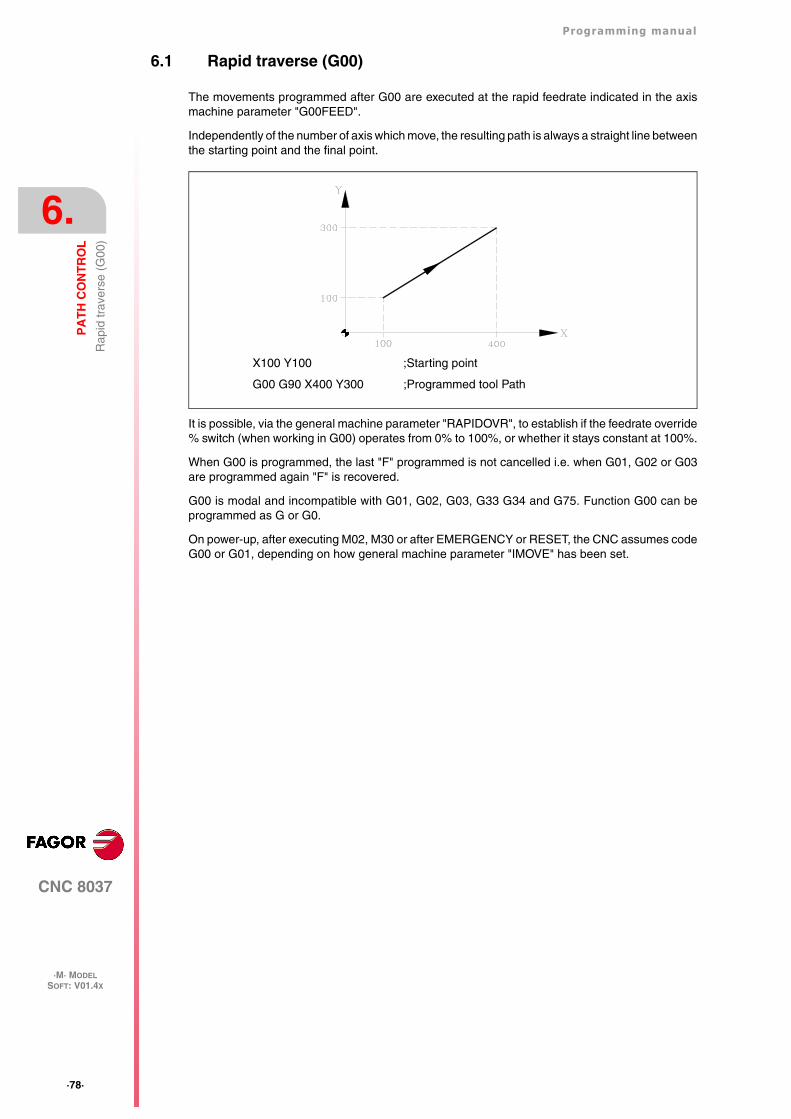
·78·
Programming manual
CNC 8037
6.
PA
TH
CO
NT
RO
L
·M· MODELSOFT: V01.4X
Rap
id tr
aver
se (
G00
)
6.1 Rapid traverse (G00)
The movements programmed after G00 are executed at the rapid feedrate indicated in the axismachine parameter "G00FEED".
Independently of the number of axis which move, the resulting path is always a straight line betweenthe starting point and the final point.
It is possible, via the general machine parameter "RAPIDOVR", to establish if the feedrate override% switch (when working in G00) operates from 0% to 100%, or whether it stays constant at 100%.
When G00 is programmed, the last "F" programmed is not cancelled i.e. when G01, G02 or G03are programmed again "F" is recovered.
G00 is modal and incompatible with G01, G02, G03, G33 G34 and G75. Function G00 can beprogrammed as G or G0.
On power-up, after executing M02, M30 or after EMERGENCY or RESET, the CNC assumes codeG00 or G01, depending on how general machine parameter "IMOVE" has been set.
X100 Y100 ;Starting point
G00 G90 X400 Y300 ;Programmed tool Path
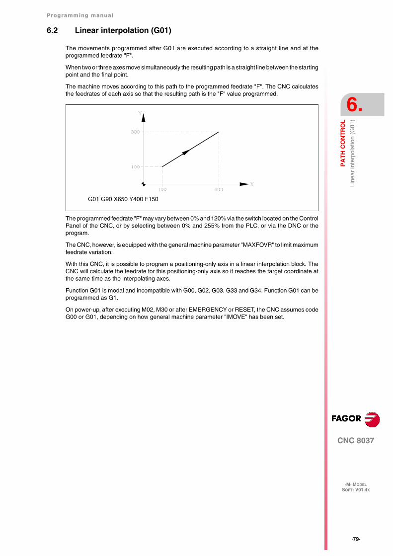
Programming manual
CNC 8037
PA
TH
CO
NT
RO
L
6.
·M· MODELSOFT: V01.4X
·79·
Line
ar in
terp
olat
ion
(G01
)
6.2 Linear interpolation (G01)
The movements programmed after G01 are executed according to a straight line and at theprogrammed feedrate "F".
When two or three axes move simultaneously the resulting path is a straight line between the startingpoint and the final point.
The machine moves according to this path to the programmed feedrate "F". The CNC calculatesthe feedrates of each axis so that the resulting path is the "F" value programmed.
The programmed feedrate "F" may vary between 0% and 120% via the switch located on the ControlPanel of the CNC, or by selecting between 0% and 255% from the PLC, or via the DNC or theprogram.
The CNC, however, is equipped with the general machine parameter "MAXFOVR" to limit maximumfeedrate variation.
With this CNC, it is possible to program a positioning-only axis in a linear interpolation block. TheCNC will calculate the feedrate for this positioning-only axis so it reaches the target coordinate atthe same time as the interpolating axes.
Function G01 is modal and incompatible with G00, G02, G03, G33 and G34. Function G01 can beprogrammed as G1.
On power-up, after executing M02, M30 or after EMERGENCY or RESET, the CNC assumes codeG00 or G01, depending on how general machine parameter "IMOVE" has been set.
G01 G90 X650 Y400 F150
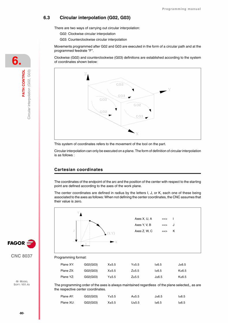
·80·
Programming manual
CNC 8037
6.
PA
TH
CO
NT
RO
L
·M· MODELSOFT: V01.4X
Circ
ular
inte
rpol
atio
n (G
02, G
03)
6.3 Circular interpolation (G02, G03)
There are two ways of carrying out circular interpolation:
G02: Clockwise circular interpolation
G03: Counterclockwise circular interpolation
Movements programmed after G02 and G03 are executed in the form of a circular path and at theprogrammed feedrate "F".
Clockwise (G02) and counterclockwise (G03) definitions are established according to the systemof coordinates shown below:
This system of coordinates refers to the movement of the tool on the part.
Circular interpolation can only be executed on a plane. The form of definition of circular interpolationis as follows :
Cartesian coordinates
The coordinates of the endpoint of the arc and the position of the center with respect to the startingpoint are defined according to the axes of the work plane.
The center coordinates are defined in radius by the letters I, J, or K, each one of these beingassociated to the axes as follows: When not defining the center coordinates, the CNC assumes thattheir value is zero.
Programming format:
The programming order of the axes is always maintained regardless of the plane selected,, as arethe respective center coordinates.
Plane XY: G02(G03) X±5.5 Y±5.5 I±6.5 J±6.5
Plane ZX: G02(G03) X±5.5 Z±5.5 I±6.5 K±6.5
Plane YZ: G02(G03) Y±5.5 Z±5.5 J±6.5 K±6.5
Plane AY: G02(G03) Y±5.5 A±5.5 J±6.5 I±6.5
Plane XU: G02(G03) X±5.5 U±5.5 I±6.5 I±6.5
Axes X, U, A ==> I
Axes Y, V, B ==> J
Axes Z, W, C ==> K
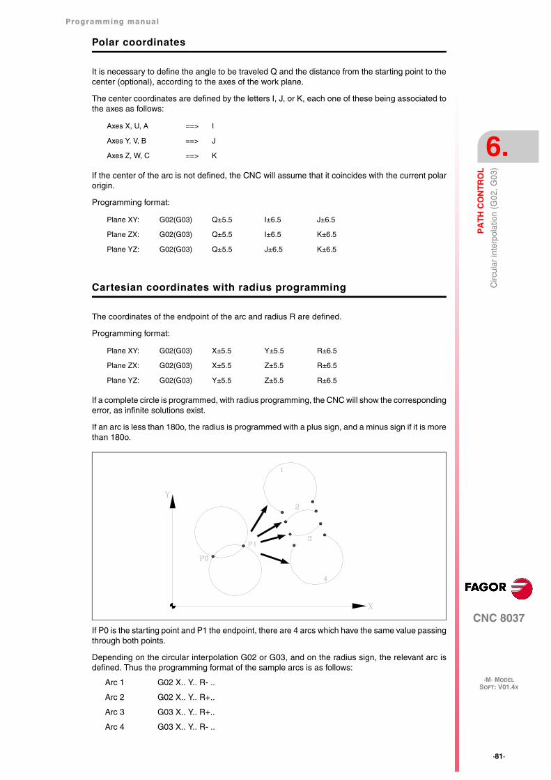
Programming manual
CNC 8037
PA
TH
CO
NT
RO
L
6.
·M· MODELSOFT: V01.4X
·81·
Circ
ular
inte
rpol
atio
n (G
02, G
03)
Polar coordinates
It is necessary to define the angle to be traveled Q and the distance from the starting point to thecenter (optional), according to the axes of the work plane.
The center coordinates are defined by the letters I, J, or K, each one of these being associated tothe axes as follows:
If the center of the arc is not defined, the CNC will assume that it coincides with the current polarorigin.
Programming format:
Cartesian coordinates with radius programming
The coordinates of the endpoint of the arc and radius R are defined.
Programming format:
If a complete circle is programmed, with radius programming, the CNC will show the correspondingerror, as infinite solutions exist.
If an arc is less than 180o, the radius is programmed with a plus sign, and a minus sign if it is morethan 180o.
If P0 is the starting point and P1 the endpoint, there are 4 arcs which have the same value passingthrough both points.
Depending on the circular interpolation G02 or G03, and on the radius sign, the relevant arc isdefined. Thus the programming format of the sample arcs is as follows:
Arc 1 G02 X.. Y.. R- ..
Arc 2 G02 X.. Y.. R+..
Arc 3 G03 X.. Y.. R+..
Arc 4 G03 X.. Y.. R- ..
Axes X, U, A ==> I
Axes Y, V, B ==> J
Axes Z, W, C ==> K
Plane XY: G02(G03) Q±5.5 I±6.5 J±6.5
Plane ZX: G02(G03) Q±5.5 I±6.5 K±6.5
Plane YZ: G02(G03) Q±5.5 J±6.5 K±6.5
Plane XY: G02(G03) X±5.5 Y±5.5 R±6.5
Plane ZX: G02(G03) X±5.5 Z±5.5 R±6.5
Plane YZ: G02(G03) Y±5.5 Z±5.5 R±6.5
·82·
Programming manual
CNC 8037
6.
PA
TH
CO
NT
RO
L
·M· MODELSOFT: V01.4X
Circ
ular
inte
rpol
atio
n (G
02, G
03)
Execution of the circular interpolation
The CNC calculates, depending on the programmed arc, the radii of the starting point and endpoint.Although both of them should be "exactly" the same, general parameter "CIRINERR" allows acertain calculation tolerance by establishing the maximum difference between these two radii. Whenexceeding this value, the CNC will issue the corresponding error message.
In all these programming cases, the CNC checks that the center or radius coordinates do not exceed214748.3647mm. Otherwise, the CNC will display the corresponding error.
The programmed feedrate "F" may vary between 0% and 120% via the switch located on the ControlPanel of the CNC, or by selecting between 0% and 255% from the PLC, or via the DNC or theprogram.
The CNC, however, is equipped with the general machine parameter "MAXFOVR" to limit maximumfeedrate variation.
If the general machine parameter "PORGMOVE" has been selected and a circular interpolation(G02 or G03) is programmed, the CNC assumes the center of the arc to be a new polar origin.
Functions G02 and G03 are modal and incompatible both among themselves and with G00, G01,G33 and G34. Functions G02 and G03 can be programmed as G2 and G3.
Also, function G74 (home search) and G75 (probing) cancel the G02 and G03 functions.
On power-up, after executing M02, M30 or after EMERGENCY or RESET, the CNC assumes codeG00 or G01, depending on how general machine parameter "IMOVE" has been set.
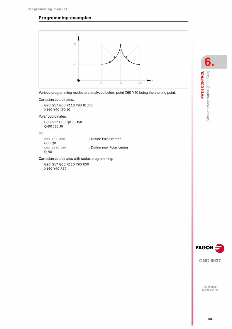
Programming manual
CNC 8037
PA
TH
CO
NT
RO
L
6.
·M· MODELSOFT: V01.4X
·83·
Circ
ular
inte
rpol
atio
n (G
02, G
03)
Programming examples
Various programming modes are analyzed below, point X60 Y40 being the starting point.
Cartesian coordinates:
G90 G17 G03 X110 Y90 I0 J50X160 Y40 I50 J0
Polar coordinates:
G90 G17 G03 Q0 I0 J50Q-90 I50 J0
or:
G93 I60 J90 ; Define Polar centerG03 Q0G93 I160 J90 ; Define new Polar centerQ-90
Cartesian coordinates with radius programming:
G90 G17 G03 X110 Y90 R50X160 Y40 R50
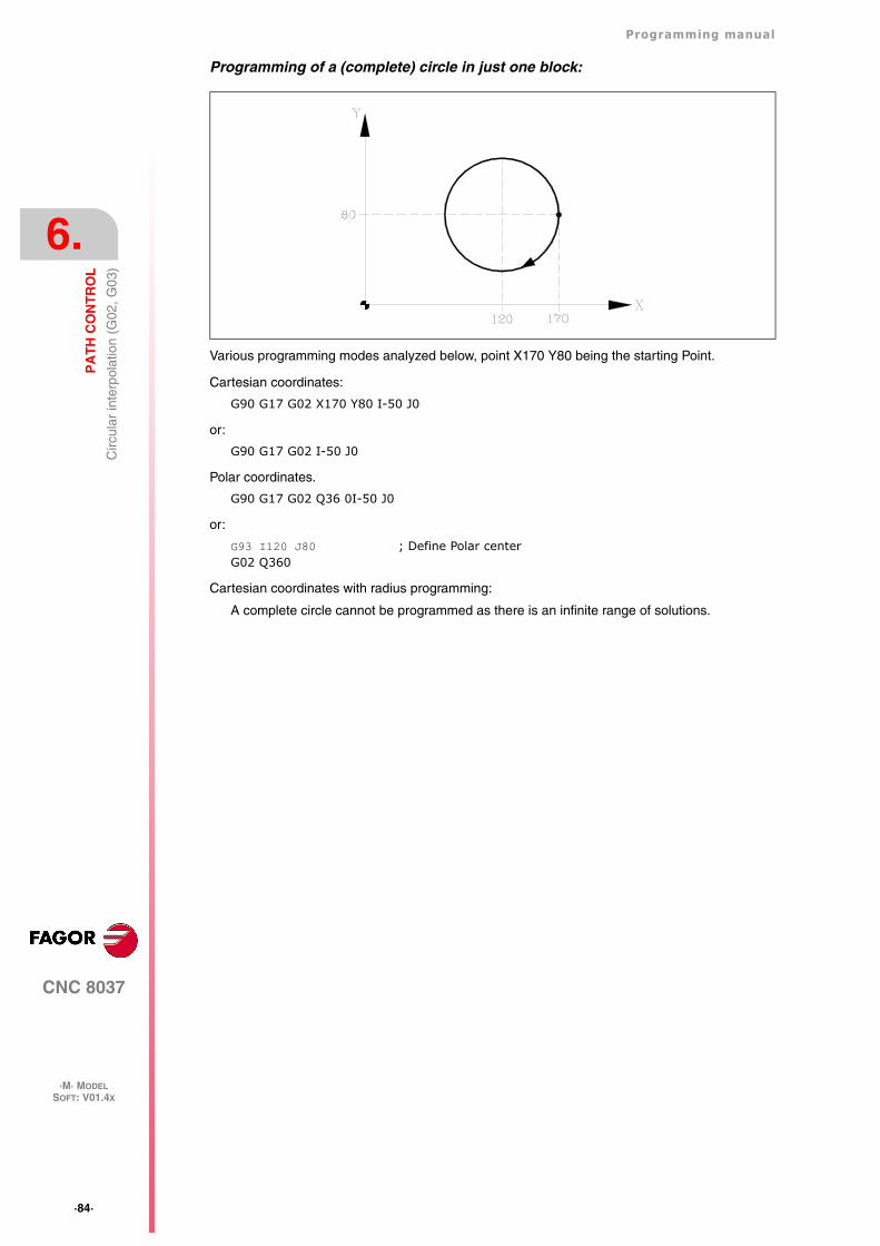
·84·
Programming manual
CNC 8037
6.
PA
TH
CO
NT
RO
L
·M· MODELSOFT: V01.4X
Circ
ular
inte
rpol
atio
n (G
02, G
03)
Programming of a (complete) circle in just one block:
Various programming modes analyzed below, point X170 Y80 being the starting Point.
Cartesian coordinates:
G90 G17 G02 X170 Y80 I-50 J0
or:
G90 G17 G02 I-50 J0
Polar coordinates.
G90 G17 G02 Q36 0I-50 J0
or:
G93 I120 J80 ; Define Polar centerG02 Q360
Cartesian coordinates with radius programming:
A complete circle cannot be programmed as there is an infinite range of solutions.
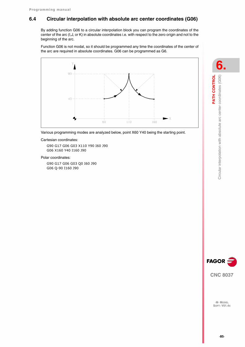
Programming manual
CNC 8037
PA
TH
CO
NT
RO
L
6.
·M· MODELSOFT: V01.4X
·85·
Circ
ular
inte
rpol
atio
n w
ith a
bsol
ute
arc
cent
er c
oord
inat
es (
G06
)
6.4 Circular interpolation with absolute arc center coordinates (G06)
By adding function G06 to a circular interpolation block you can program the coordinates of thecenter of the arc (I,J, or K) in absolute coordinates i.e. with respect to the zero origin and not to thebeginning of the arc.
Function G06 is not modal, so it should be programmed any time the coordinates of the center ofthe arc are required in absolute coordinates. G06 can be programmed as G6.
Various programming modes are analyzed below, point X60 Y40 being the starting point.
Cartesian coordinates:
G90 G17 G06 G03 X110 Y90 I60 J90G06 X160 Y40 I160 J90
Polar coordinates:
G90 G17 G06 G03 Q0 I60 J90G06 Q-90 I160 J90
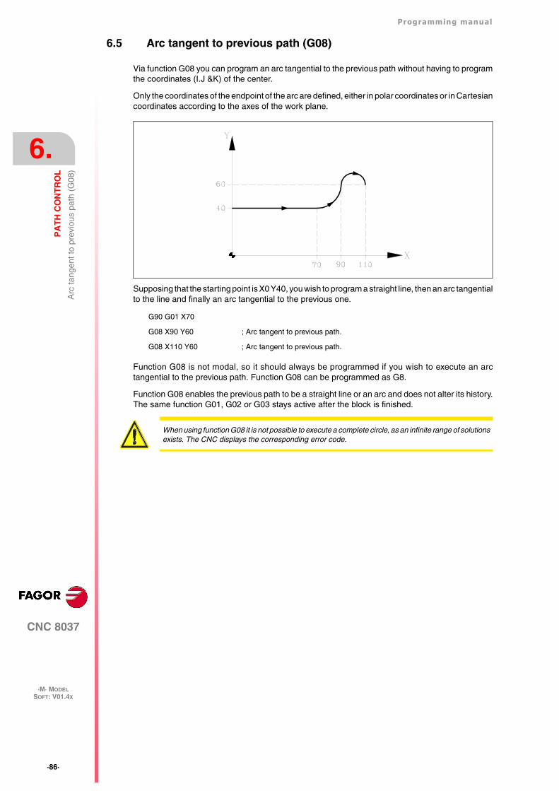
·86·
Programming manual
CNC 8037
6.
PA
TH
CO
NT
RO
L
·M· MODELSOFT: V01.4X
Arc
tang
ent t
o pr
evio
us p
ath
(G08
)
6.5 Arc tangent to previous path (G08)
Via function G08 you can program an arc tangential to the previous path without having to programthe coordinates (I.J &K) of the center.
Only the coordinates of the endpoint of the arc are defined, either in polar coordinates or in Cartesiancoordinates according to the axes of the work plane.
Supposing that the starting point is X0 Y40, you wish to program a straight line, then an arc tangentialto the line and finally an arc tangential to the previous one.
Function G08 is not modal, so it should always be programmed if you wish to execute an arctangential to the previous path. Function G08 can be programmed as G8.
Function G08 enables the previous path to be a straight line or an arc and does not alter its history.The same function G01, G02 or G03 stays active after the block is finished.
G90 G01 X70
G08 X90 Y60 ; Arc tangent to previous path.
G08 X110 Y60 ; Arc tangent to previous path.
When using function G08 it is not possible to execute a complete circle, as an infinite range of solutionsexists. The CNC displays the corresponding error code.
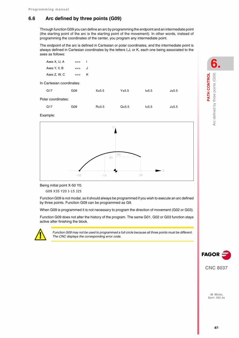
Programming manual
CNC 8037
PA
TH
CO
NT
RO
L
6.
·M· MODELSOFT: V01.4X
·87·
Arc
def
ined
by
thre
e po
ints
(G
09)
6.6 Arc defined by three points (G09)
Through function G09 you can define an arc by programming the endpoint and an intermediate point(the starting point of the arc is the starting point of the movement). In other words, instead ofprogramming the coordinates of the center, you program any intermediate point.
The endpoint of the arc is defined in Cartesian or polar coordinates, and the intermediate point isalways defined in Cartesian coordinates by the letters I,J, or K, each one being associated to theaxes as follows:
In Cartesian coordinates:
Polar coordinates:
Example:
Being initial point X-50 Y0.
G09 X35 Y20 I-15 J25
Function G09 is not modal, so it should always be programmed if you wish to execute an arc definedby three points. Function G09 can be programmed as G9.
When G09 is programmed it is not necessary to program the direction of movement (G02 or G03).
Function G09 does not alter the history of the program. The same G01, G02 or G03 function staysactive after finishing the block.
Axes X, U, A ==> I
Axes Y, V, B ==> J
Axes Z, W, C ==> K
G17 G09 X±5.5 Y±5.5 I±5.5 J±5.5
G17 G09 R±5.5 Q±5.5 I±5.5 J±5.5
Function G09 may not be used to programmed a full circle because all three points must be different.The CNC displays the corresponding error code.
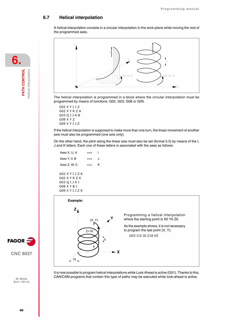
·88·
Programming manual
CNC 8037
6.
PA
TH
CO
NT
RO
L
·M· MODELSOFT: V01.4X
Hel
ical
inte
rpol
atio
n
6.7 Helical interpolation
A helical interpolation consists in a circular interpolation in the work plane while moving the rest ofthe programmed axes.
The helical interpolation is programmed in a block where the circular interpolation must beprogrammed by means of functions: G02, G03, G08 or G09.
G02 X Y I J ZG02 X Y R Z AG03 Q I J A BG08 X Y ZG09 X Y I J Z
If the helical interpolation is supposed to make more than one turn, the linear movement of anotheraxis must also be programmed (one axis only).
On the other hand, the pitch along the linear axis must also be set (format 5.5) by means of the I,J and K letters. Each one of these letters is associated with the axes as follows:
G02 X Y I J Z KG02 X Y R Z KG03 Q I J A IG08 X Y B JG09 X Y I J Z K
It is now possible to program helical interpolations while Look Ahead is active (G51). Thanks to this,CAN/CAM programs that contain this type of paths may be executed while look-ahead is active.
Axes X, U, A ==> I
Axes Y, V, B ==> J
Axes Z, W, C ==> K
Z
Y
X
5
Z=18
15
(X, Y)
Programming a helical interpolationwhere the starting point is X0 Y0 Z0.
As the example shows, it is not necessaryto program the last point (X, Y):
G03 I15 J0 Z18 K5
Example:
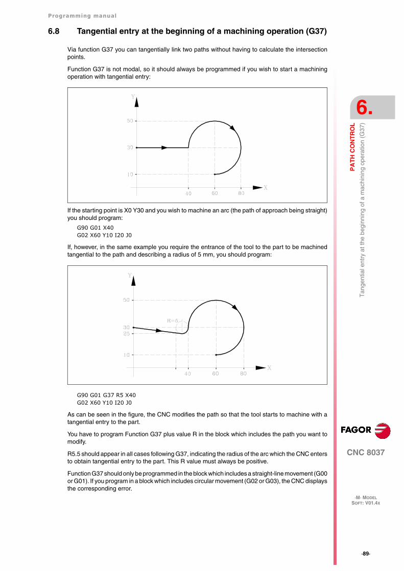
Programming manual
CNC 8037
PA
TH
CO
NT
RO
L
6.
·M· MODELSOFT: V01.4X
·89·
Tan
gent
ial e
ntry
at t
he b
egin
ning
of a
mac
hini
ng o
pera
tion
(G37
)
6.8 Tangential entry at the beginning of a machining operation (G37)
Via function G37 you can tangentially link two paths without having to calculate the intersectionpoints.
Function G37 is not modal, so it should always be programmed if you wish to start a machiningoperation with tangential entry:
If the starting point is X0 Y30 and you wish to machine an arc (the path of approach being straight)you should program:
G90 G01 X40G02 X60 Y10 I20 J0
If, however, in the same example you require the entrance of the tool to the part to be machinedtangential to the path and describing a radius of 5 mm, you should program:
G90 G01 G37 R5 X40G02 X60 Y10 I20 J0
As can be seen in the figure, the CNC modifies the path so that the tool starts to machine with atangential entry to the part.
You have to program Function G37 plus value R in the block which includes the path you want tomodify.
R5.5 should appear in all cases following G37, indicating the radius of the arc which the CNC entersto obtain tangential entry to the part. This R value must always be positive.
Function G37 should only be programmed in the block which includes a straight-line movement (G00or G01). If you program in a block which includes circular movement (G02 or G03), the CNC displaysthe corresponding error.
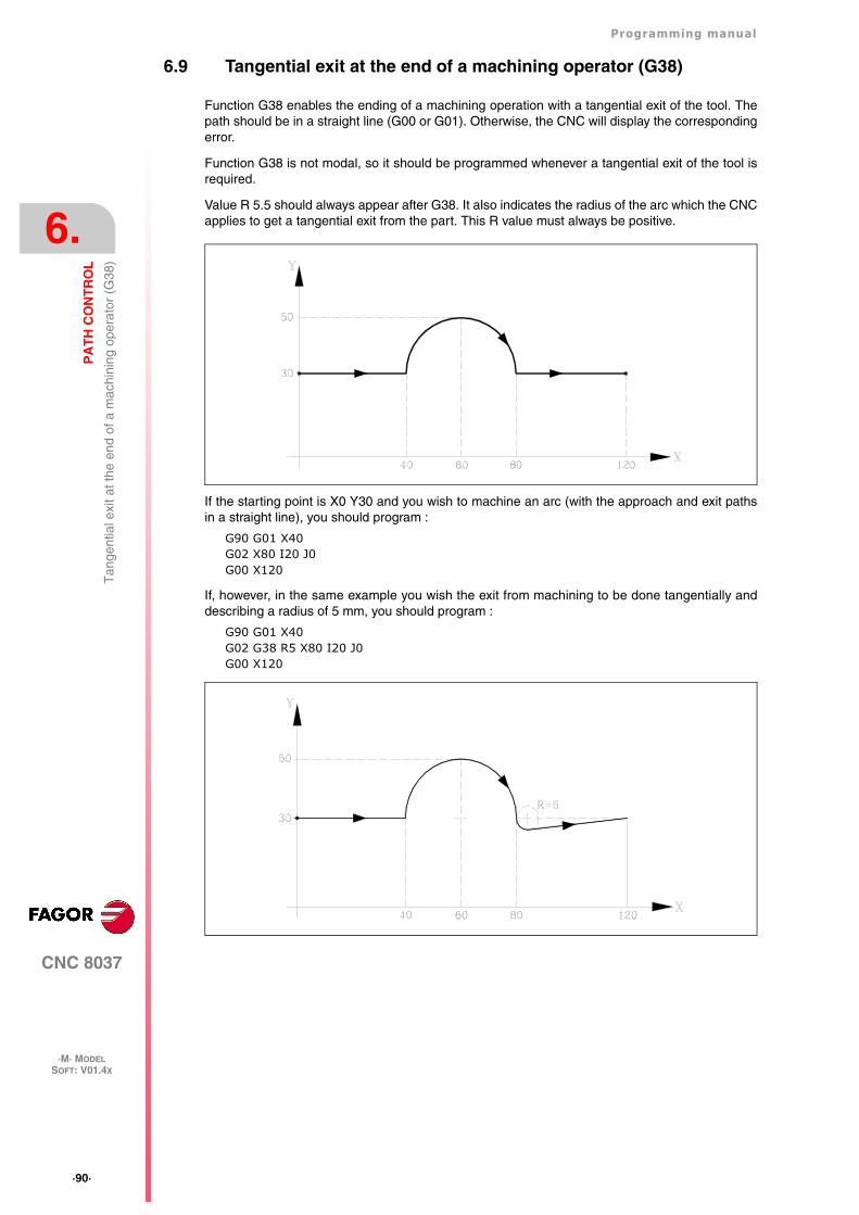
·90·
Programming manual
CNC 8037
6.
PA
TH
CO
NT
RO
L
·M· MODELSOFT: V01.4X
Tan
gent
ial e
xit a
t the
end
of a
mac
hini
ng o
pera
tor
(G38
)
6.9 Tangential exit at the end of a machining operator (G38)
Function G38 enables the ending of a machining operation with a tangential exit of the tool. Thepath should be in a straight line (G00 or G01). Otherwise, the CNC will display the correspondingerror.
Function G38 is not modal, so it should be programmed whenever a tangential exit of the tool isrequired.
Value R 5.5 should always appear after G38. It also indicates the radius of the arc which the CNCapplies to get a tangential exit from the part. This R value must always be positive.
If the starting point is X0 Y30 and you wish to machine an arc (with the approach and exit pathsin a straight line), you should program :
G90 G01 X40G02 X80 I20 J0G00 X120
If, however, in the same example you wish the exit from machining to be done tangentially anddescribing a radius of 5 mm, you should program :
G90 G01 X40G02 G38 R5 X80 I20 J0G00 X120
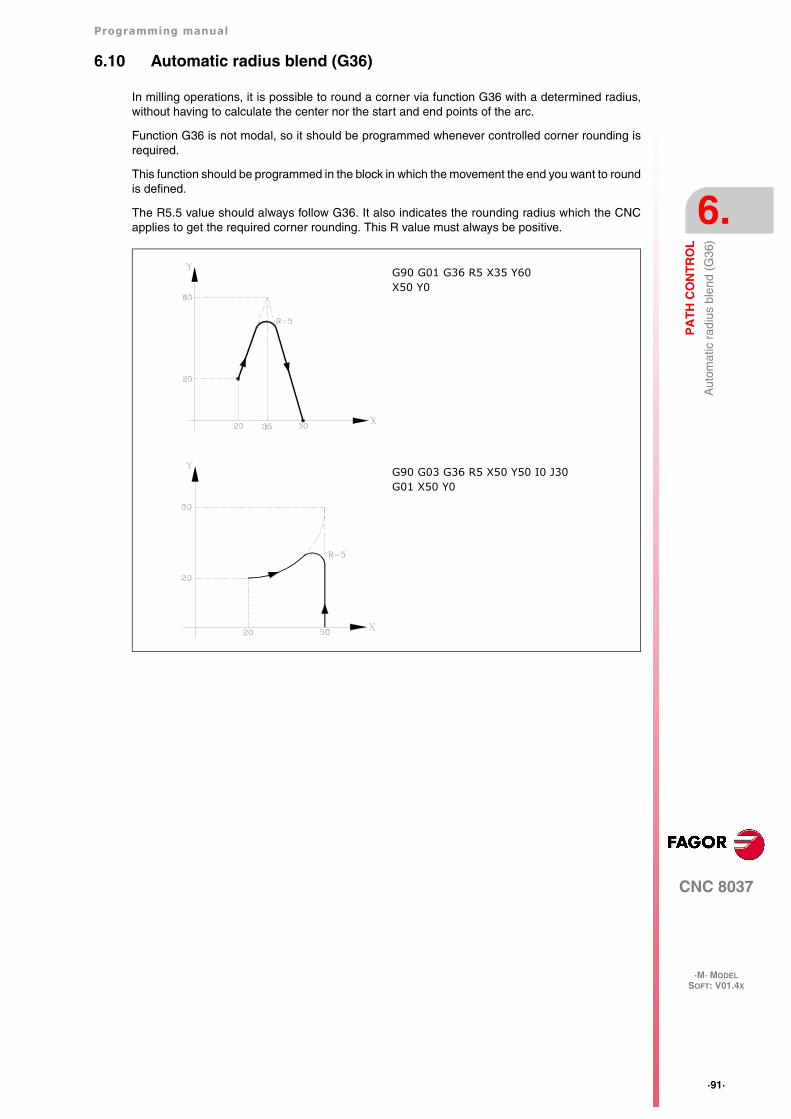
Programming manual
CNC 8037
PA
TH
CO
NT
RO
L
6.
·M· MODELSOFT: V01.4X
·91·
Aut
omat
ic r
adiu
s bl
end
(G36
)
6.10 Automatic radius blend (G36)
In milling operations, it is possible to round a corner via function G36 with a determined radius,without having to calculate the center nor the start and end points of the arc.
Function G36 is not modal, so it should be programmed whenever controlled corner rounding isrequired.
This function should be programmed in the block in which the movement the end you want to roundis defined.
The R5.5 value should always follow G36. It also indicates the rounding radius which the CNCapplies to get the required corner rounding. This R value must always be positive.
G90 G01 G36 R5 X35 Y60X50 Y0
G90 G03 G36 R5 X50 Y50 I0 J30G01 X50 Y0
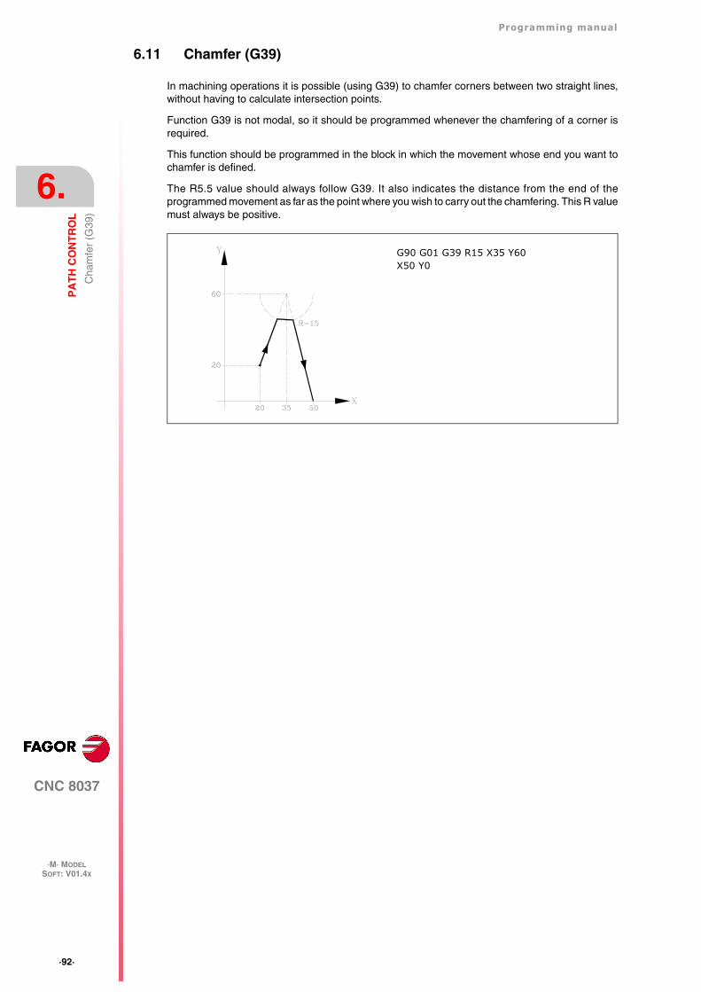
·92·
Programming manual
CNC 8037
6.
PA
TH
CO
NT
RO
L
·M· MODELSOFT: V01.4X
Cha
mfe
r (G
39)
6.11 Chamfer (G39)
In machining operations it is possible (using G39) to chamfer corners between two straight lines,without having to calculate intersection points.
Function G39 is not modal, so it should be programmed whenever the chamfering of a corner isrequired.
This function should be programmed in the block in which the movement whose end you want tochamfer is defined.
The R5.5 value should always follow G39. It also indicates the distance from the end of theprogrammed movement as far as the point where you wish to carry out the chamfering. This R valuemust always be positive.
G90 G01 G39 R15 X35 Y60X50 Y0
Programming manual
CNC 8037
PA
TH
CO
NT
RO
L
6.
·M· MODELSOFT: V01.4X
·93·
Thr
eadi
ng (
G33
)
6.12 Threading (G33)
If the machine spindle is equipped with a rotary encoder, you can thread with a tool tip via functionG33.
Although this threading is often done along the entire length of an axis, the CNC enables threadingto be done interpolating more than one axis at a time.
Programming format:
G33 X.....C L Q
Some points to consider:
Whenever G33 is executed, if s.m.p. M19TYPE (P43) =0, and before making the thread, the CNCreferences the spindle (home search).
Spindle machine parameter M19TYPE (P43) must be set to "1" in order to be able to programparameter Q (angular spindle position).
When executing function G33 Q (s.m.p. M19TYPE (P43) =1), spindle had to be homed after the lastpower-up and before executing the thread.
When executing function G33 Q (s.m.p. M19TYPE (P43) =1) and s.m.p. DECINPUT (P31) =NO,no home search is needed because the spindle will be homed automatically after power-up whenturning the spindle in M3 or in M4 for the first time.
This search will be carried out at the feedrate set by s.m.p. REFEED2 (P35). After finding home,the spindle will speed up or slow down to the programmed speed without stopping.
If the spindle has motor feedback with a SINCOS encoder (without reference mark), the homesearch will be done directly at the programmed S speed without going through the speed set bys.m.p. REFEED2.
If after power-up, an M19 is executed before an M3 or M4, that M19 will be executed without homingthe spindle when executing the first M3 or M4.
If the feedback device does not have the reference mark synchronized, the home search in M3 mightnot coincide with the home search in M4. This does not happen with FAGOR feedback.
If the threads are blended together in round corner, only the first one can have an entry angle (Q).
While function G33 is active, neither the programmed feedrate "F" nor the programmed Spindlespeed "S" can be varied. They will both be set to 100%.
Function G33 is modal and incompatible with G00, G01, G02, G03, G34 and G75.
On power-up, after executing M02, M30 or after EMERGENCY or RESET, the CNC assumes codeG00 or G01, depending on how general machine parameter "IMOVE" has been set.
X...C ±5.5 End point of the thread
L 5.5 Thread pitch
Q ±3.5 Optional. It indicates the spindle angular position (±359.9999) of the thread's startingpoint. If not programmed, a value of 0 is assumed.
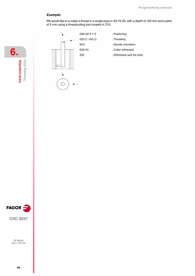
·94·
Programming manual
CNC 8037
6.
PA
TH
CO
NT
RO
L
·M· MODELSOFT: V01.4X
Thr
eadi
ng (
G33
)
Example:
We would like to a make a thread in a single pass in X0 Y0 Z0, with a depth of 100 mm and a pitchof 5 mm using a threadcutting tool located in Z10.
G90 G0 X Y Z ; Positioning
G33 Z -100 L5 ; Threading
M19 ; Spindle orientation
G00 X3 ; Cutter withdrawal
Z30 ; Withdrawal (exit the hole)
Programming manual
CNC 8037
PA
TH
CO
NT
RO
L
6.
·M· MODELSOFT: V01.4X
·95·
Var
iabl
e pi
tch
thre
ads
(G34
)
6.13 Variable pitch threads (G34)
To make variable-pitch threads, the spindle of the machine must have a rotary encoder.
Although this threading is often done along the entire length of an axis, the CNC enables threadingto be done interpolating more than one axis at a time.
Programming format:
G34 X.....C L Q K
Some points to consider:
Whenever G34 is executed and before making the thread, the CNC references the spindle (homesearch) and positions the spindle at the angular position indicated by parameter Q.
Parameter "Q" is available when spindle machine parameter "M19TYPE" has been set to "1".
When working in round corner mode (G05), it is possible to blend different threads in the same part.
While function G34 is active, neither the programmed feedrate "F" nor the programmed Spindlespeed "S" can be varied. They will both be set to 100%.
Function G34 is modal and incompatible with G00, G01, G02, G03, G33 and G75.
On power-up, after executing M02, M30 or after EMERGENCY or RESET, the CNC assumes codeG00 or G01, depending on how general machine parameter "IMOVE" has been set.
Blending a fixed-pitch thread (G33) with a variable-pitch thread (G34).
The starting thread pitch (L) of the G34 must coincide with the thread pitch of the G33.
The pitch increase in the first turn of the spindle in variable pitch will be half and increment (K/2)and in the rest of the turns it will be the full increment K.
Blending a variable-pitch thread (G34) with a fixed-pitch thread.
It is used to finish a variable-pitch thread (G34) with a portion of the thread keeping the final pitchof the previous thread.
Since it is very complicated to calculate the final thread pitch, the fixed-pitch thread is notprogrammed with G33 but with G34 ... L0 K0. The CNC calculates the pitch.
Blending two variable-pitch threads (G34).
Two variable-pitch threads (G34) cannot be blended together.
X...C ±5.5 End point of the thread
L 5.5 Thread pitch
Q ±3.5 Optional. It indicates the spindle angular position (±359.9999) of the thread's startingpoint. If not programmed, a value of "0" is assumed.
K ±5.5 Thread pitch increase or decrease per spindle turn.
·96·
Programming manual
CNC 8037
6.
PA
TH
CO
NT
RO
L
·M· MODELSOFT: V01.4X
Mov
e to
har
dsto
p (G
52)
6.14 Move to hardstop (G52)
By means of function G52 it is possible to program the movement of an axis until running into anobject. This feature may be interesting for forming machines, live tailstocks, bar feeders, etc.
The programming format is:
G52 X..C ±5.5
After G52, program the desired axis as well as the target coordinate of the move.
The axis will move towards the programmed target coordinate until running into something. If theaxis reaches the programmed target coordinate without running into the hardstop it will stop.
Function G52 is not modal; therefore, it must be programmed every time this operation is to becarried out.
Also, it assumes functions G01 and G40 modifying the program history. It is incompatible withfunctions G00, G02, G03, G33, G34, G41, G42, G75 and G76.
Programming manual
CNC 8037
PA
TH
CO
NT
RO
L
6.
·M· MODELSOFT: V01.4X
·97·
Fee
drat
e "F
" as
an
inve
rted
func
tion
of ti
me
(G32
)
6.15 Feedrate "F" as an inverted function of time (G32)
There are instances when it is easier to define the time required by the various axes of the machineto reach the target point instead of defining a common feedrate for all of them.
A typical case may be when a linear axis (X, Y, Z) has to move together (interpolated) with a rotaryaxis programmed in degrees.
Function G32 indicates that the "F" functions programmed next set the time it takes to reach thetarget point.
In order for a greater value of "F" to indicate a greater feedrate, the value assigned to "F" is definedas "Inverted function of time" and it is assumed as the activation of this feature.
"F" units: 1/min
Example: G32 X22 F4
indicates that the movement must be executed in 1/4 minute; i.e. in 0.25 minutes.
Function G32 is modal and incompatible with G94 and G95.
On power-up, after executing M02, M30 or after an Emergency or Reset, the CNC assumes G94or G95 depending on the setting of general machine parameter "IFFED".
Some points to consider:
The CNC variable PROGFIN will show the feedrate programmed as an inverted function of time andvariable FEED will show the resulting feedrate in mm/min or inches/min.
If the resulting feedrate of any axis exceeds the maximum value set by machine parameter"MAXFEED", the CNC will apply this maximum value.
The programmed "F" is ignored on G00 movements. All the movements will be carried out at thefeedrate set by axis machine parameter "G00FEED".
When programming "F0" the movement will be carried out at the feedrate set by axis machineparameter "MAXFEED".
Function G32 may be programmed and executed in the PLC channel.
Function G32 is canceled in JOG mode.
·98·
Programming manual
CNC 8037
6.
PA
TH
CO
NT
RO
L
·M· MODELSOFT: V01.4X
Fee
drat
e "F
" as
an
inve
rted
func
tion
of ti
me
(G32
)
CNC 8037
·M· MODELSOFT: V01.4X
7
·99·
ADDITIONAL PREPARATORY FUNCTIONS
7.1 Interruption of block preparation (G04)
The CNC reads up to 20 blocks ahead of the one it is executing, with the aim of calculatingbeforehand the path to be followed.
Each block is evaluated (in its absence) at the time it is read, but if you wish to evaluate it at thetime of execution of the block you use function G04.
This function holds up the preparation of blocks and waits for the block in question to be executedin order to start the preparation of blocks once more.
A case in point is the evaluation of the "status of block-skip inputs" which is defined in the blockheader.
Example:
.
. G04 ;Interrupts block preparation/1 G01 X10 Y20 ;Jump condition "/1"..
Function G04 is not modal, so it should be programmed whenever you wish to interrupt blockpreparation.
It should be programmed on its own and in the block previous to the one in which the evaluationin execution is required. Function G04 can be programmed as G4.
Every time G04 is programmed, active radius and length compensation are cancelled.
For this reason, care needs to be taken when using this function, because if it is introduced betweenmachining blocks which work with compensation, unwanted profiles may be produced.
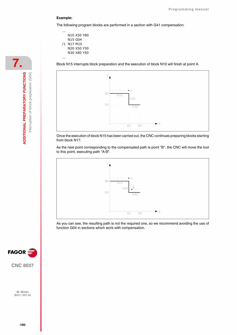
·100·
Programming manual
CNC 8037
7.
AD
DIT
ION
AL
PR
EP
AR
AT
OR
Y F
UN
CT
ION
S
·M· MODELSOFT: V01.4X
Inte
rrup
tion
of b
lock
pre
para
tion
(G04
)
Example:
The following program blocks are performed in a section with G41 compensation.
...N10 X50 Y80N15 G04
/1 N17 M10N20 X50 Y50N30 X80 Y50
...
Block N15 interrupts block preparation and the execution of block N10 will finish at point A.
Once the execution of block N15 has been carried out, the CNC continues preparing blocks startingfrom block N17.
As the next point corresponding to the compensated path is point "B", the CNC will move the toolto this point, executing path "A-B".
As you can see, the resulting path is not the required one, so we recommend avoiding the use offunction G04 in sections which work with compensation.
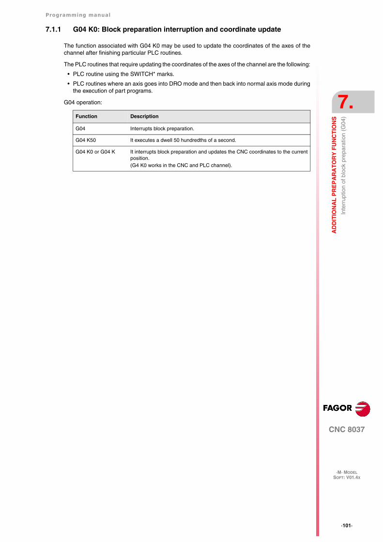
Programming manual
CNC 8037
AD
DIT
ION
AL
PR
EP
AR
AT
OR
Y F
UN
CT
ION
S
7.
·M· MODELSOFT: V01.4X
·101·
Inte
rrup
tion
of b
lock
pre
para
tion
(G04
)
7.1.1 G04 K0: Block preparation interruption and coordinate update
The function associated with G04 K0 may be used to update the coordinates of the axes of thechannel after finishing particular PLC routines.
The PLC routines that require updating the coordinates of the axes of the channel are the following:
• PLC routine using the SWITCH* marks.
• PLC routines where an axis goes into DRO mode and then back into normal axis mode duringthe execution of part programs.
G04 operation:
Function Description
G04 Interrupts block preparation.
G04 K50 It executes a dwell 50 hundredths of a second.
G04 K0 or G04 K It interrupts block preparation and updates the CNC coordinates to the currentposition.(G4 K0 works in the CNC and PLC channel).
·102·
Programming manual
CNC 8037
7.
AD
DIT
ION
AL
PR
EP
AR
AT
OR
Y F
UN
CT
ION
S
·M· MODELSOFT: V01.4X
Dw
ell (
G04
K)
7.2 Dwell (G04 K)
A dwell can be programmed via function G04 K.
The dwell value is programmed in hundredths of a second via format K5 (1..99999).
Example:
G04 K50 ; Dwell of 50 hundredths of a second (0.5 seconds)G04 K200 ; Dwell of 200 hundredths of a second (2 seconds)
Function G04 K is not modal, so it should be programmed whenever a dwell is required. FunctionG04 K can be programmed as G4 K.
The dwell is executed at the beginning of the block in which it is programmed.
Note: When programming G04 K0 or G04 K, instead of applying a delay, it only interrupts blockpreparation and it will refresh the coordinates. See "7.1.1 G04 K0: Block preparationinterruption and coordinate update" on page 101.
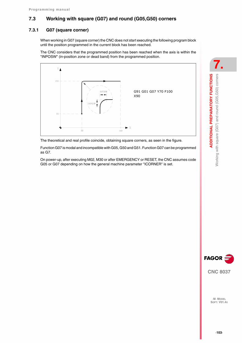
Programming manual
CNC 8037
AD
DIT
ION
AL
PR
EP
AR
AT
OR
Y F
UN
CT
ION
S
7.
·M· MODELSOFT: V01.4X
·103·
Wor
king
with
squ
are
(G07
) an
d ro
und
(G05
,G50
) co
rner
s
7.3 Working with square (G07) and round (G05,G50) corners
7.3.1 G07 (square corner)
When working in G07 (square corner) the CNC does not start executing the following program blockuntil the position programmed in the current block has been reached.
The CNC considers that the programmed position has been reached when the axis is within the"INPOSW" (in-position zone or dead band) from the programmed position.
The theoretical and real profile coincide, obtaining square corners, as seen in the figure.
Function G07 is modal and incompatible with G05, G50 and G51. Function G07 can be programmedas G7.
On power-up, after executing M02, M30 or after EMERGENCY or RESET, the CNC assumes codeG05 or G07 depending on how the general machine parameter "ICORNER" is set.
G91 G01 G07 Y70 F100X90
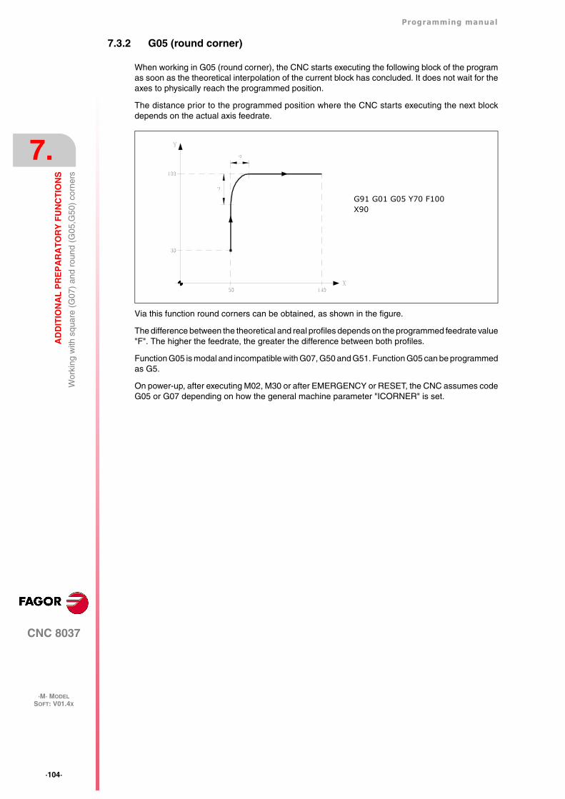
·104·
Programming manual
CNC 8037
7.
AD
DIT
ION
AL
PR
EP
AR
AT
OR
Y F
UN
CT
ION
S
·M· MODELSOFT: V01.4X
Wor
king
with
squ
are
(G07
) an
d ro
und
(G05
,G50
) co
rner
s
7.3.2 G05 (round corner)
When working in G05 (round corner), the CNC starts executing the following block of the programas soon as the theoretical interpolation of the current block has concluded. It does not wait for theaxes to physically reach the programmed position.
The distance prior to the programmed position where the CNC starts executing the next blockdepends on the actual axis feedrate.
Via this function round corners can be obtained, as shown in the figure.
The difference between the theoretical and real profiles depends on the programmed feedrate value"F". The higher the feedrate, the greater the difference between both profiles.
Function G05 is modal and incompatible with G07, G50 and G51. Function G05 can be programmedas G5.
On power-up, after executing M02, M30 or after EMERGENCY or RESET, the CNC assumes codeG05 or G07 depending on how the general machine parameter "ICORNER" is set.
G91 G01 G05 Y70 F100X90
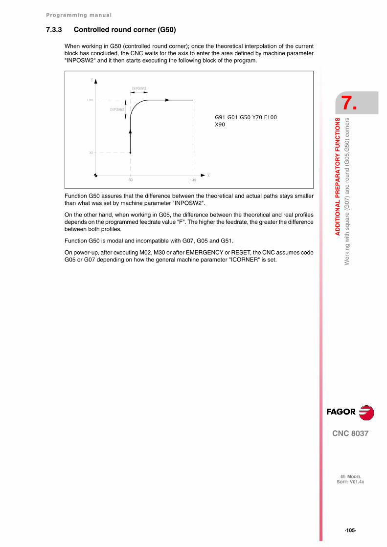
Programming manual
CNC 8037
AD
DIT
ION
AL
PR
EP
AR
AT
OR
Y F
UN
CT
ION
S
7.
·M· MODELSOFT: V01.4X
·105·
Wor
king
with
squ
are
(G07
) an
d ro
und
(G05
,G50
) co
rner
s
7.3.3 Controlled round corner (G50)
When working in G50 (controlled round corner); once the theoretical interpolation of the currentblock has concluded, the CNC waits for the axis to enter the area defined by machine parameter"INPOSW2" and it then starts executing the following block of the program.
Function G50 assures that the difference between the theoretical and actual paths stays smallerthan what was set by machine parameter "INPOSW2".
On the other hand, when working in G05, the difference between the theoretical and real profilesdepends on the programmed feedrate value "F". The higher the feedrate, the greater the differencebetween both profiles.
Function G50 is modal and incompatible with G07, G05 and G51.
On power-up, after executing M02, M30 or after EMERGENCY or RESET, the CNC assumes codeG05 or G07 depending on how the general machine parameter "ICORNER" is set.
G91 G01 G50 Y70 F100X90
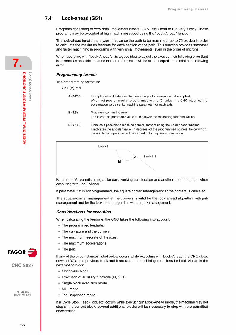
·106·
Programming manual
CNC 8037
7.
AD
DIT
ION
AL
PR
EP
AR
AT
OR
Y F
UN
CT
ION
S
·M· MODELSOFT: V01.4X
Look
-ahe
ad (
G51
)
7.4 Look-ahead (G51)
Programs consisting of very small movement blocks (CAM, etc.) tend to run very slowly. Thoseprograms may be executed at high machining speed using the "Look-Ahead" function.
The look-ahead function analyzes in advance the path to be machined (up to 75 blocks) in orderto calculate the maximum feedrate for each section of the path. This function provides smootherand faster machining in programs with very small movements, even in the order of microns.
When operating with "Look-Ahead", it is a good idea to adjust the axes so their following error (lag)is as small as possible because the contouring error will be at least equal to the minimum followingerror.
Programming format:
The programming format is:
G51 [A] E B
Parameter "A" permits using a standard working acceleration and another one to be used whenexecuting with Look-Ahead.
If parameter "B" is not programmed, the square corner management at the corners is canceled.
The square-corner management at the corners is valid for the look-ahead algorithm with jerkmanagement and for the look-ahead algorithm without jerk management.
Considerations for execution:
When calculating the feedrate, the CNC takes the following into account:
• The programmed feedrate.
• The curvature and the corners.
• The maximum feedrate of the axes.
• The maximum accelerations.
• The jerk.
If any of the circumstances listed below occurs while executing with Look-Ahead, the CNC slowsdown to "0" at the previous block and it recovers the machining conditions for Look-Ahead in thenext motion block.
• Motionless block.
• Execution of auxiliary functions (M, S, T).
• Single block execution mode.
• MDI mode.
• Tool inspection mode.
If a Cycle Stop, Feed-Hold, etc. occurs while executing in Look-Ahead mode, the machine may notstop at the current block, several additional blocks will be necessary to stop with the permitteddeceleration.
A (0-255) It is optional and it defines the percentage of acceleration to be applied.When not programmed or programmed with a "0" value, the CNC assumes theacceleration value set by machine parameter for each axis.
E (5.5) Maximum contouring error.The lower this parameter value is, the lower the machining feedrate will be.
B (0-180) It makes it possible to machine square corners using the Look-ahead function.It indicates the angular value (in degrees) of the programmed corners, below which,the machining operation will be carried out in square corner mode.
BBlock I+1
Block I
Programming manual
CNC 8037
AD
DIT
ION
AL
PR
EP
AR
AT
OR
Y F
UN
CT
ION
S
7.
·M· MODELSOFT: V01.4X
·107·
Look
-ahe
ad (
G51
)
To prevent motionless blocks from causing a square-corner effect, change bit 0 of general machineparameter MANTFCON (P189).
Function properties:
Function G51 is modal and incompatible with G05, G07 and G50. Should any of them beprogrammed, function G51 will be canceled and the new one will be selected.
Function G51 must be programmed alone in a block and there must be no more information in thatblock.
On power-up, after executing an M02, M30, of after an EMERGENCY or RESET, the CNC will cancelG51, if it was active, and it will assume G05 or G07 according to the setting of general machineparameter "ICORNER".
On the other hand, the CNC will issue Error 7 (Incompatible G functions) when programming anyof the following functions while G51 is active:
G33 Electronic threading.
G34 Variable-pitch threading.
G52 Movement until making contact.
G95 Feedrate per revolution.
·108·
Programming manual
CNC 8037
7.
AD
DIT
ION
AL
PR
EP
AR
AT
OR
Y F
UN
CT
ION
S
·M· MODELSOFT: V01.4X
Look
-ahe
ad (
G51
)
7.4.1 Advanced look-ahead algorithm (integrating Fagor filters)
This mode is indicated when machining accuracy is required, especially if Fagor filters have beenset for the axes by machine parameters.
The advanced look-ahead algorithm calculates the feedrates at the corners so as to take the effectof those filters into consideration. When programming G51 E, the contouring errors when machiningcorners will be closer to the value programmed in that G51 function depending on the filters.
To activate the advanced look-ahead algorithm, use bit 15 of g.m.p. LOOKATYP (P160).
Considerations
• If there are no Fagor filters set by machine parameters in the axes of the main channel, activatingthe advanced look-ahead algorithm will internally activate FIR filters of the 5th order and afrequency of 30 Hz in all the axes of the channel.
• If there are Fagor filters set by machine parameters, activating the advanced look-aheadalgorithm will keep the values of those filters as long as their frequency is not higher than 30Hz
If their frequency is higher than 30 Hz, it will assume the values of 5th order and a frequencyof 30 Hz.
If there are several filters defined in the axes of the channel, the one with the lowest frequencywill be assumed as long as it is not higher than 30Hz.
• Even if the advanced look-ahead algorithm (using Fagor filters) is active with bit 15 of g.m.p.LOOKATYP (P160), it will not start working in the following cases:
If g.m.p. IPOTIME (P73) = 1.
If a.m.p. SMOTIME (P58) of any of the axes of the main channel is other than 0.
If any of the axes of the main channel has defined by parameter a non-Fagor type filter, a.m.p.TYPE (P71) is other than 2.
In these cases, when activating G51, the CNC will issue the corresponding error message.
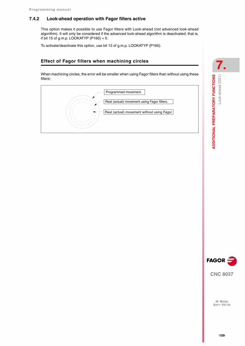
Programming manual
CNC 8037
AD
DIT
ION
AL
PR
EP
AR
AT
OR
Y F
UN
CT
ION
S
7.
·M· MODELSOFT: V01.4X
·109·
Look
-ahe
ad (
G51
)
7.4.2 Look-ahead operation with Fagor filters active
This option makes it possible to use Fagor filters with Look-ahead (not advanced look-aheadalgorithm). It will only be considered if the advanced look-ahead algorithm is deactivated; that is,if bit 15 of g.m.p. LOOKATYP (P160) = 0.
To activate/deactivate this option, use bit 13 of g.m.p. LOOKATYP (P160).
Effect of Fagor filters when machining circles
When machining circles, the error will be smaller when using Fagor filters than without using thesefilters:
Programmed movement.
Real (actual) movement using Fagor filters.
Real (actual) movement without using Fagor
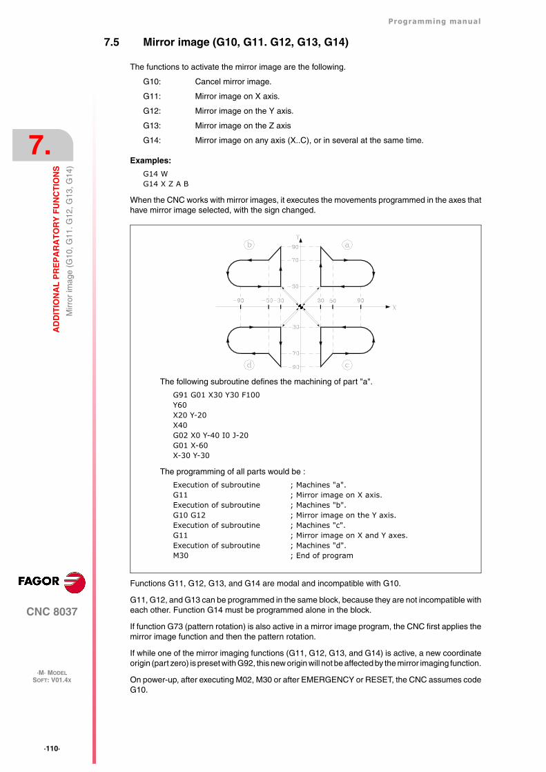
·110·
Programming manual
CNC 8037
7.
AD
DIT
ION
AL
PR
EP
AR
AT
OR
Y F
UN
CT
ION
S
·M· MODELSOFT: V01.4X
Mirr
or im
age
(G10
, G11
. G12
, G13
, G14
)
7.5 Mirror image (G10, G11. G12, G13, G14)
The functions to activate the mirror image are the following.
G10: Cancel mirror image.
G11: Mirror image on X axis.
G12: Mirror image on the Y axis.
G13: Mirror image on the Z axis
G14: Mirror image on any axis (X..C), or in several at the same time.
Examples:
G14 WG14 X Z A B
When the CNC works with mirror images, it executes the movements programmed in the axes thathave mirror image selected, with the sign changed.
Functions G11, G12, G13, and G14 are modal and incompatible with G10.
G11, G12, and G13 can be programmed in the same block, because they are not incompatible witheach other. Function G14 must be programmed alone in the block.
If function G73 (pattern rotation) is also active in a mirror image program, the CNC first applies themirror image function and then the pattern rotation.
If while one of the mirror imaging functions (G11, G12, G13, and G14) is active, a new coordinateorigin (part zero) is preset with G92, this new origin will not be affected by the mirror imaging function.
On power-up, after executing M02, M30 or after EMERGENCY or RESET, the CNC assumes codeG10.
The following subroutine defines the machining of part "a".
G91 G01 X30 Y30 F100Y60X20 Y-20X40G02 X0 Y-40 I0 J-20G01 X-60X-30 Y-30
The programming of all parts would be :
Execution of subroutine ; Machines "a".G11 ; Mirror image on X axis.Execution of subroutine ; Machines "b".G10 G12 ; Mirror image on the Y axis.Execution of subroutine ; Machines "c".G11 ; Mirror image on X and Y axes.Execution of subroutine ; Machines "d".M30 ; End of program
Programming manual
CNC 8037
AD
DIT
ION
AL
PR
EP
AR
AT
OR
Y F
UN
CT
ION
S
7.
·M· MODELSOFT: V01.4X
·111·
Sca
ling
fact
or (
G72
)
7.6 Scaling factor (G72)
By using function G72 you can enlarge or reduce programmed parts.
In this way, you can produce families of parts which are similar in shape but of different sizes witha single program.
Function G72 should be programmed on its own in a block. There are two formats for programmingG72 :
• Scaling factor applied to all axes.
• Scaling factor applied to one or more axes.
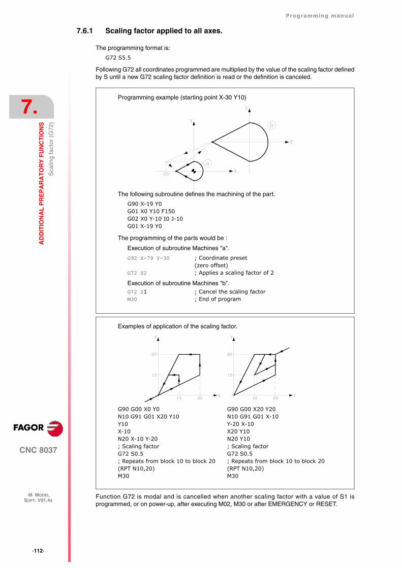
·112·
Programming manual
CNC 8037
7.
AD
DIT
ION
AL
PR
EP
AR
AT
OR
Y F
UN
CT
ION
S
·M· MODELSOFT: V01.4X
Sca
ling
fact
or (
G72
)
7.6.1 Scaling factor applied to all axes.
The programming format is:
G72 S5.5
Following G72 all coordinates programmed are multiplied by the value of the scaling factor definedby S until a new G72 scaling factor definition is read or the definition is canceled.
Function G72 is modal and is cancelled when another scaling factor with a value of S1 isprogrammed, or on power-up, after executing M02, M30 or after EMERGENCY or RESET.
The following subroutine defines the machining of the part.
G90 X-19 Y0G01 X0 Y10 F150G02 X0 Y-10 I0 J-10G01 X-19 Y0
The programming of the parts would be :
Execution of subroutine Machines "a".
G92 X-79 Y-30 ; Coordinate preset(zero offset)
G72 S2 ; Applies a scaling factor of 2
Execution of subroutine Machines "b".G72 S1 ; Cancel the scaling factorM30 ; End of program
Programming example (starting point X-30 Y10)
G90 G00 X0 Y0N10 G91 G01 X20 Y10Y10X-10N20 X-10 Y-20; Scaling factorG72 S0.5; Repeats from block 10 to block 20(RPT N10,20)M30
Examples of application of the scaling factor.
G90 G00 X20 Y20N10 G91 G01 X-10Y-20 X-10X20 Y10N20 Y10; Scaling factorG72 S0.5; Repeats from block 10 to block 20(RPT N10,20)M30
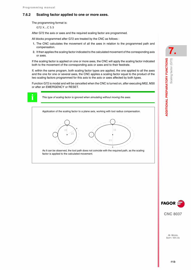
Programming manual
CNC 8037
AD
DIT
ION
AL
PR
EP
AR
AT
OR
Y F
UN
CT
ION
S
7.
·M· MODELSOFT: V01.4X
·113·
Sca
ling
fact
or (
G72
)
7.6.2 Scaling factor applied to one or more axes.
The programming format is:
G72 X...C 5.5
After G72 the axis or axes and the required scaling factor are programmed.
All blocks programmed after G72 are treated by the CNC as follows :
1. The CNC calculates the movement of all the axes in relation to the programmed path andcompensation.
2. It then applies the scaling factor indicated to the calculated movement of the corresponding axisor axes.
If the scaling factor is applied on one or more axes, the CNC will apply the scaling factor indicatedboth to the movement of the corresponding axis or axes and to their feedrate.
If, within the same program, both scaling factor types are applied, the one applied to all the axesand the one for one or several axes, the CNC applies a scaling factor equal to the product of thetwo scaling factors programmed for this axis to the axis or axes affected by both types.
Function G72 is modal and will be cancelled when the CNC is turned on, after executing M02, M30or after an EMERGENCY or RESET.
This type of scaling factor is ignored when simulating without moving the axes.i
As it can be observed, the tool path does not coincide with the required path, as the scalingfactor is applied to the calculated movement.
Application of the scaling factor to a plane axis, working with tool radius compensation.
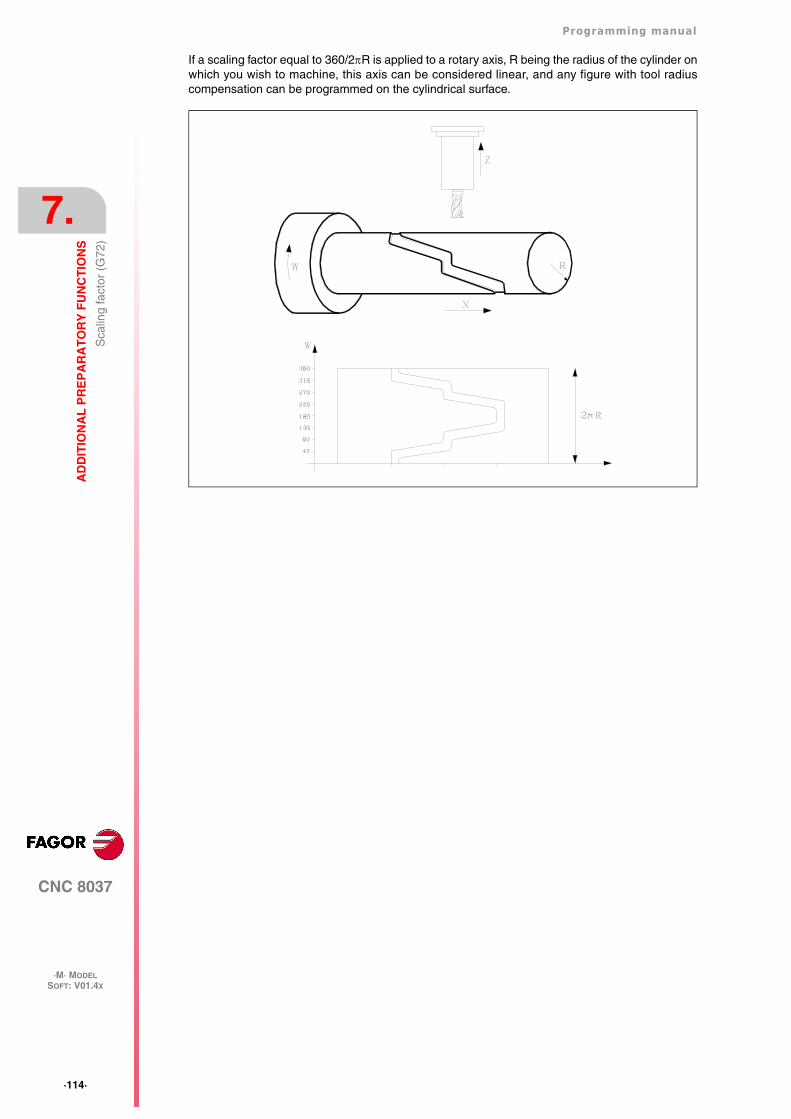
·114·
Programming manual
CNC 8037
7.
AD
DIT
ION
AL
PR
EP
AR
AT
OR
Y F
UN
CT
ION
S
·M· MODELSOFT: V01.4X
Sca
ling
fact
or (
G72
)
If a scaling factor equal to 360/2R is applied to a rotary axis, R being the radius of the cylinder onwhich you wish to machine, this axis can be considered linear, and any figure with tool radiuscompensation can be programmed on the cylindrical surface.
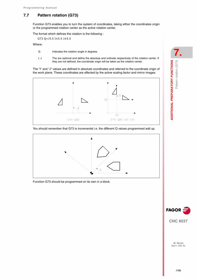
Programming manual
CNC 8037
AD
DIT
ION
AL
PR
EP
AR
AT
OR
Y F
UN
CT
ION
S
7.
·M· MODELSOFT: V01.4X
·115·
Pat
tern
rot
atio
n (G
73)
7.7 Pattern rotation (G73)
Function G73 enables you to turn the system of coordinates, taking either the coordinates originor the programmed rotation center as the active rotation center.
The format which defines the rotation is the following :
G73 Q+/5.5 I±5.5 J±5.5
Where:
The "I" and "J" values are defined in absolute coordinates and referred to the coordinate origin ofthe work plane. These coordinates are affected by the active scaling factor and mirror images.
You should remember that G73 is incremental i.e. the different Q values programmed add up.
Function G73 should be programmed on its own in a block.
Q Indicates the rotation angle in degrees.
I, J The are optional and define the abscissa and ordinate respectively of the rotation center. Ifthey are not defined, the coordinate origin will be taken as the rotation center.
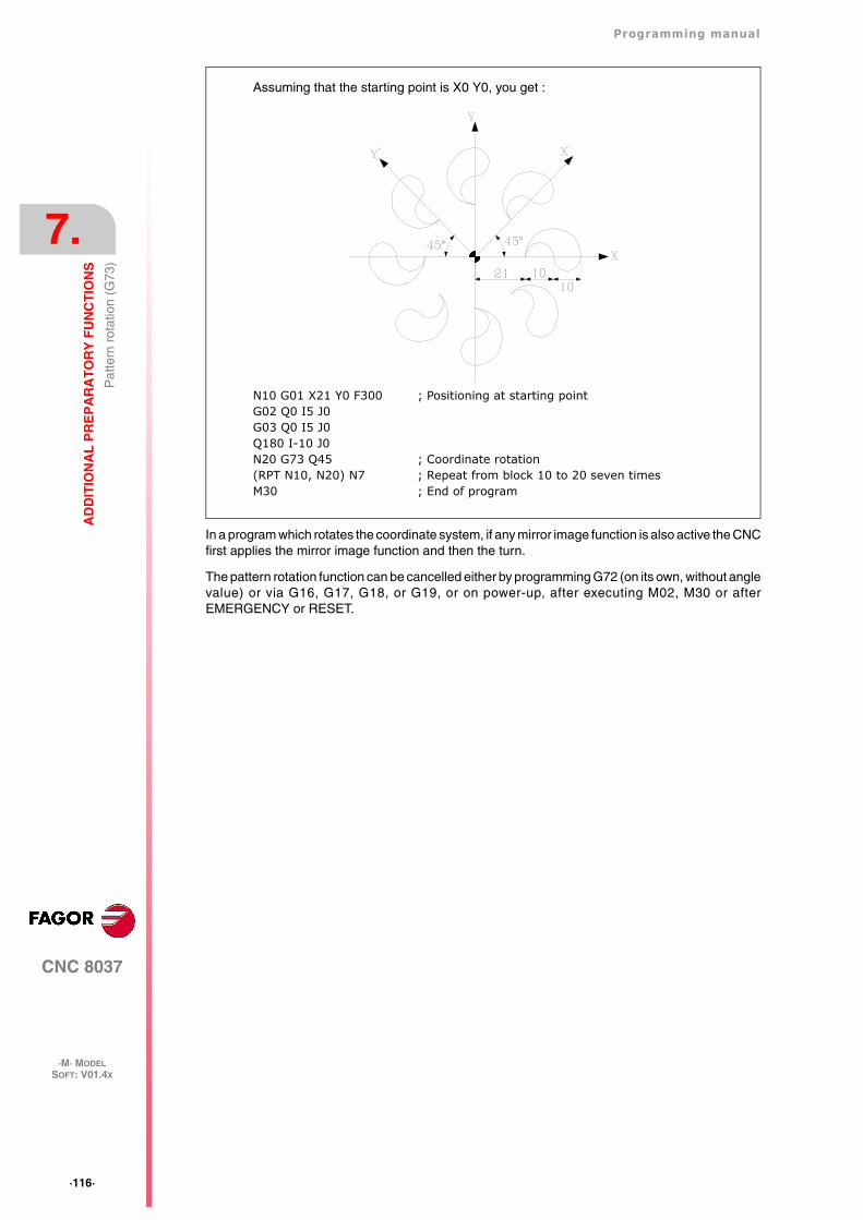
·116·
Programming manual
CNC 8037
7.
AD
DIT
ION
AL
PR
EP
AR
AT
OR
Y F
UN
CT
ION
S
·M· MODELSOFT: V01.4X
Pat
tern
rot
atio
n (G
73)
In a program which rotates the coordinate system, if any mirror image function is also active the CNCfirst applies the mirror image function and then the turn.
The pattern rotation function can be cancelled either by programming G72 (on its own, without anglevalue) or via G16, G17, G18, or G19, or on power-up, after executing M02, M30 or afterEMERGENCY or RESET.
N10 G01 X21 Y0 F300 ; Positioning at starting pointG02 Q0 I5 J0G03 Q0 I5 J0Q180 I-10 J0N20 G73 Q45 ; Coordinate rotation(RPT N10, N20) N7 ; Repeat from block 10 to 20 seven timesM30 ; End of program
Assuming that the starting point is X0 Y0, you get :
CNC 8037
·M· MODELSOFT: V01.4X
8
·117·
TOOL COMPENSATION
The CNC has a tool offset table, its number of components being defined via the general machineparameter "NTOFFSET". The following is specified for each tool offset:
• Tool radius in work units in R±5.5 format.
• Tool length in work units in L±5.5 format.
• Wear of tool radius, in work units, in I±5.5 format. The CNC adds this value to the theoreticalradius (R) to calculate the real radius (R+I).
• Wear of tool length, in work units, in K±5.5 format. The CNC adds this value to the theoreticallength (L) to calculate the real length (L+K).
When tool radius compensation is required (G41 or G42), the CNC applies the sum of R+I valuesof the selected tool offset as the compensation value.
When tool length compensation is required (G43), the CNC applies the sum of L+K values of theselected tool offset as the compensation value.
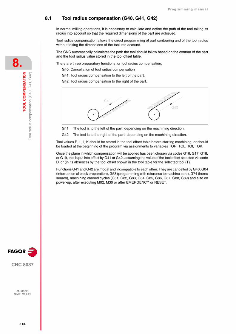
·118·
Programming manual
CNC 8037
8.
TO
OL
CO
MP
EN
SA
TIO
N
·M· MODELSOFT: V01.4X
Too
l rad
ius
com
pens
atio
n (G
40, G
41, G
42)
8.1 Tool radius compensation (G40, G41, G42)
In normal milling operations, it is necessary to calculate and define the path of the tool taking itsradius into account so that the required dimensions of the part are achieved.
Tool radius compensation allows the direct programming of part contouring and of the tool radiuswithout taking the dimensions of the tool into account.
The CNC automatically calculates the path the tool should follow based on the contour of the partand the tool radius value stored in the tool offset table.
There are three preparatory functions for tool radius compensation:
G40: Cancellation of tool radius compensation
G41: Tool radius compensation to the left of the part.
G42: Tool radius compensation to the right of the part.
G41 The tool is to the left of the part, depending on the machining direction.
G42 The tool is to the right of the part, depending on the machining direction.
Tool values R, L, I, K should be stored in the tool offset table before starting machining, or shouldbe loaded at the beginning of the program via assignments to variables TOR, TOL, TOI, TOK.
Once the plane in which compensation will be applied has been chosen via codes G16, G17, G18,or G19, this is put into effect by G41 or G42, assuming the value of the tool offset selected via codeD, or (in its absence) by the tool offset shown in the tool table for the selected tool (T).
Functions G41 and G42 are modal and incompatible to each other. They are cancelled by G40, G04(interruption of block preparation), G53 (programming with reference to machine zero), G74 (homesearch), machining canned cycles (G81, G82, G83, G84, G85, G86, G87, G88, G89) and also onpower-up, after executing M02, M30 or after EMERGENCY or RESET.
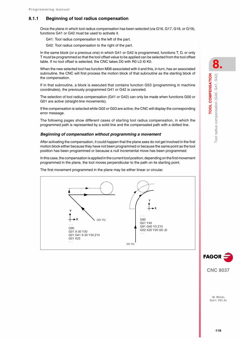
Programming manual
CNC 8037
TO
OL
CO
MP
EN
SA
TIO
N
8.
·M· MODELSOFT: V01.4X
·119·
Too
l rad
ius
com
pens
atio
n (G
40, G
41, G
42)
8.1.1 Beginning of tool radius compensation
Once the plane in which tool radius compensation has been selected (via G16, G17, G18, or G19),functions G41 or G42 must be used to activate it.
G41: Tool radius compensation to the left of the part.
G42: Tool radius compensation to the right of the part.
In the same block (or a previous one) in which G41 or G42 is programmed, functions T, D, or onlyT must be programmed so that the tool offset value to be applied can be selected from the tool offsettable. If no tool offset is selected, the CNC takes D0 with R0 L0 I0 K0.
When the new selected tool has function M06 associated with it and this, in turn, has an associatedsubroutine, the CNC will first process the motion block of that subroutine as the starting block ofthe compensation.
If in that subroutine, a block is executed that contains function G53 (programming in machinecoordinates), the previously programmed G41 or G42 is canceled.
The selection of tool radius compensation (G41 or G42) can only be made when functions G00 orG01 are active (straight-line movements).
If the compensation is selected while G02 or G03 are active, the CNC will display the correspondingerror message.
The following pages show different cases of starting tool radius compensation, in which theprogrammed path is represented by a solid line and the compensated path with a dotted line.
Beginning of compensation without programming a movement
After activating the compensation, it could happen that the plane axes do not get involved in the firstmotion block either because they have not been programmed or because the same point as the toolposition has been programmed or because a null incremental move has been programmed.
In this case, the compensation is applied in the current tool position; depending on the first movementprogrammed in the plane, the tool moves perpendicular to the path on its starting point.
The first movement programmed in the plane may be either linear or circular.
· · ·G90G01 Y40G91 G40 Y0 Z10G02 X20 Y20 I20 J0· · ·
(X0 Y0)
Y
X
· · ·G90G01 X-30 Y30G01 G41 X-30 Y30 Z10G01 X25· · ·
(X0 Y0)
Y
X
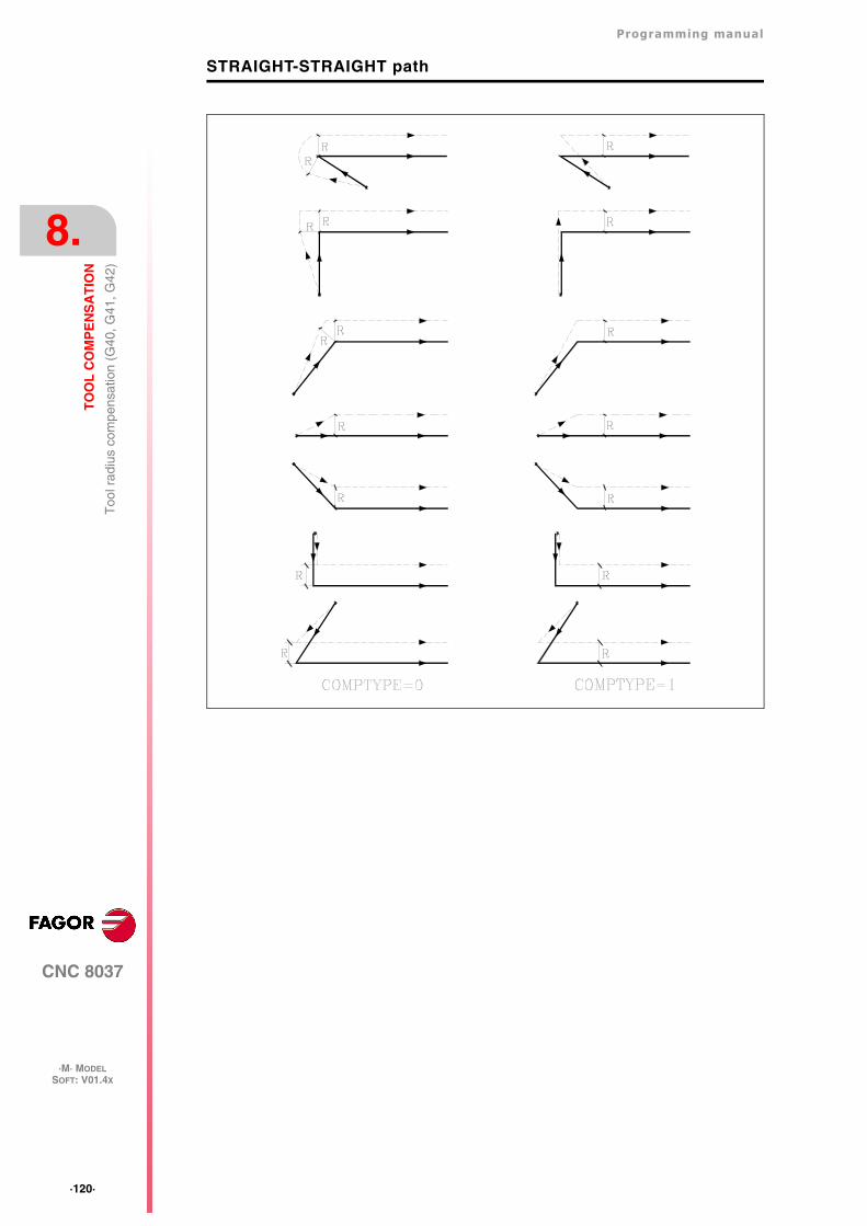
·120·
Programming manual
CNC 8037
8.
TO
OL
CO
MP
EN
SA
TIO
N
·M· MODELSOFT: V01.4X
Too
l rad
ius
com
pens
atio
n (G
40, G
41, G
42)
STRAIGHT-STRAIGHT path
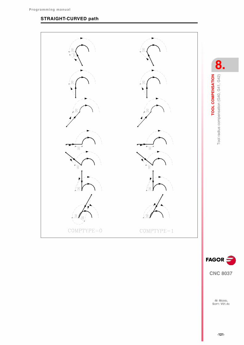
Programming manual
CNC 8037
TO
OL
CO
MP
EN
SA
TIO
N
8.
·M· MODELSOFT: V01.4X
·121·
Too
l rad
ius
com
pens
atio
n (G
40, G
41, G
42)
STRAIGHT-CURVED path
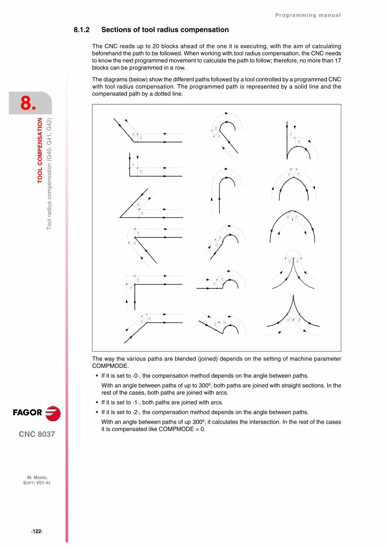
·122·
Programming manual
CNC 8037
8.
TO
OL
CO
MP
EN
SA
TIO
N
·M· MODELSOFT: V01.4X
Too
l rad
ius
com
pens
atio
n (G
40, G
41, G
42)
8.1.2 Sections of tool radius compensation
The CNC reads up to 20 blocks ahead of the one it is executing, with the aim of calculatingbeforehand the path to be followed. When working with tool radius compensation, the CNC needsto know the next programmed movement to calculate the path to follow; therefore, no more than 17blocks can be programmed in a row.
The diagrams (below) show the different paths followed by a tool controlled by a programmed CNCwith tool radius compensation. The programmed path is represented by a solid line and thecompensated path by a dotted line.
The way the various paths are blended (joined) depends on the setting of machine parameterCOMPMODE.
• If it is set to ·0·, the compensation method depends on the angle between paths.
With an angle between paths of up to 300º, both paths are joined with straight sections. In therest of the cases, both paths are joined with arcs.
• If it is set to ·1·, both paths are joined with arcs.
• If it is set to ·2·, the compensation method depends on the angle between paths.
With an angle between paths of up 300º, it calculates the intersection. In the rest of the casesit is compensated like COMPMODE = 0.
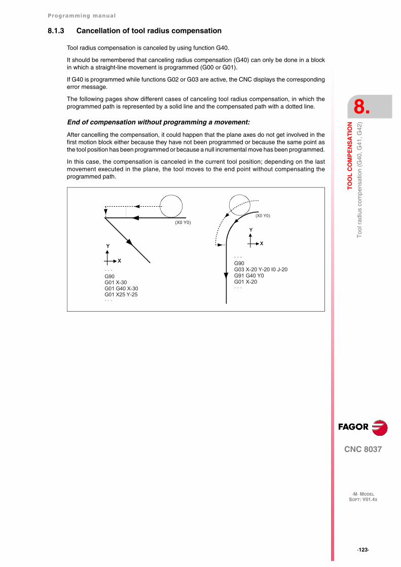
Programming manual
CNC 8037
TO
OL
CO
MP
EN
SA
TIO
N
8.
·M· MODELSOFT: V01.4X
·123·
Too
l rad
ius
com
pens
atio
n (G
40, G
41, G
42)
8.1.3 Cancellation of tool radius compensation
Tool radius compensation is canceled by using function G40.
It should be remembered that canceling radius compensation (G40) can only be done in a blockin which a straight-line movement is programmed (G00 or G01).
If G40 is programmed while functions G02 or G03 are active, the CNC displays the correspondingerror message.
The following pages show different cases of canceling tool radius compensation, in which theprogrammed path is represented by a solid line and the compensated path with a dotted line.
End of compensation without programming a movement:
After cancelling the compensation, it could happen that the plane axes do not get involved in thefirst motion block either because they have not been programmed or because the same point asthe tool position has been programmed or because a null incremental move has been programmed.
In this case, the compensation is canceled in the current tool position; depending on the lastmovement executed in the plane, the tool moves to the end point without compensating theprogrammed path.
· · ·G90G03 X-20 Y-20 I0 J-20G91 G40 Y0G01 X-20· · ·
(X0 Y0)
Y
X
· · ·G90G01 X-30G01 G40 X-30G01 X25 Y-25· · ·
(X0 Y0)
Y
X
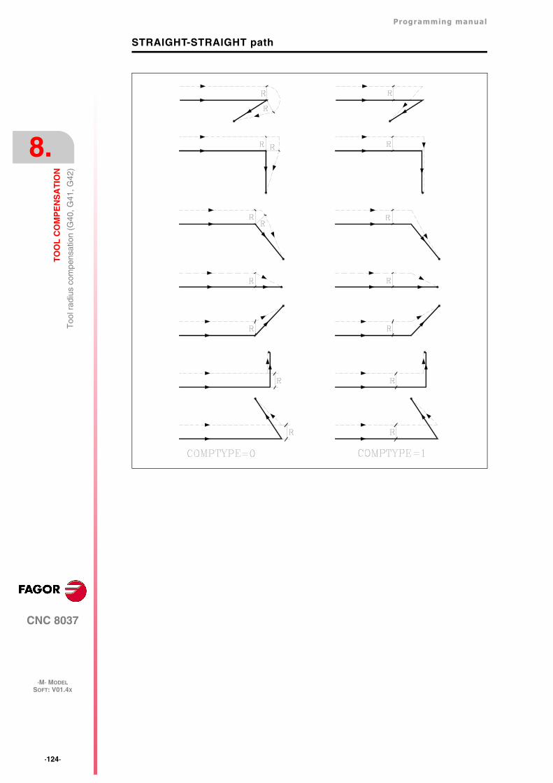
·124·
Programming manual
CNC 8037
8.
TO
OL
CO
MP
EN
SA
TIO
N
·M· MODELSOFT: V01.4X
Too
l rad
ius
com
pens
atio
n (G
40, G
41, G
42)
STRAIGHT-STRAIGHT path
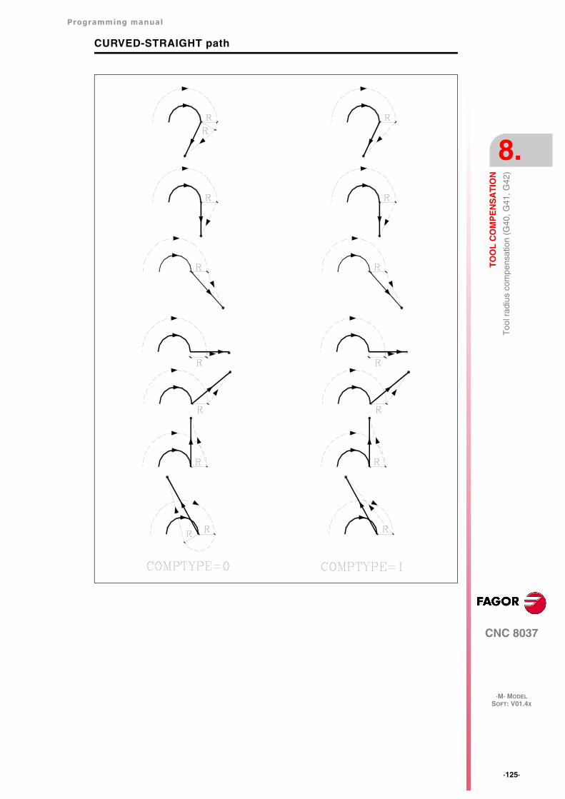
Programming manual
CNC 8037
TO
OL
CO
MP
EN
SA
TIO
N
8.
·M· MODELSOFT: V01.4X
·125·
Too
l rad
ius
com
pens
atio
n (G
40, G
41, G
42)
CURVED-STRAIGHT path
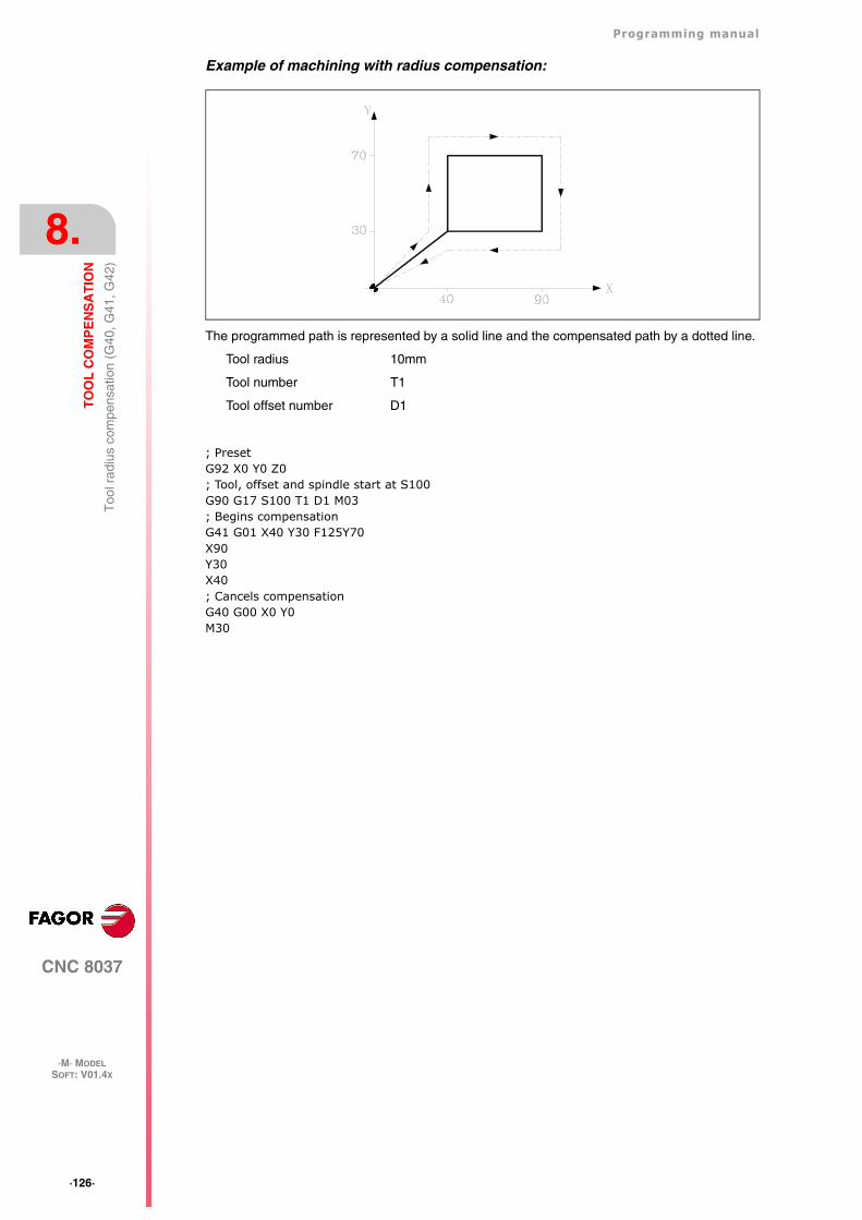
·126·
Programming manual
CNC 8037
8.
TO
OL
CO
MP
EN
SA
TIO
N
·M· MODELSOFT: V01.4X
Too
l rad
ius
com
pens
atio
n (G
40, G
41, G
42)
Example of machining with radius compensation:
The programmed path is represented by a solid line and the compensated path by a dotted line.
Tool radius 10mm
Tool number T1
Tool offset number D1
; PresetG92 X0 Y0 Z0; Tool, offset and spindle start at S100G90 G17 S100 T1 D1 M03; Begins compensationG41 G01 X40 Y30 F125Y70X90Y30X40; Cancels compensationG40 G00 X0 Y0M30
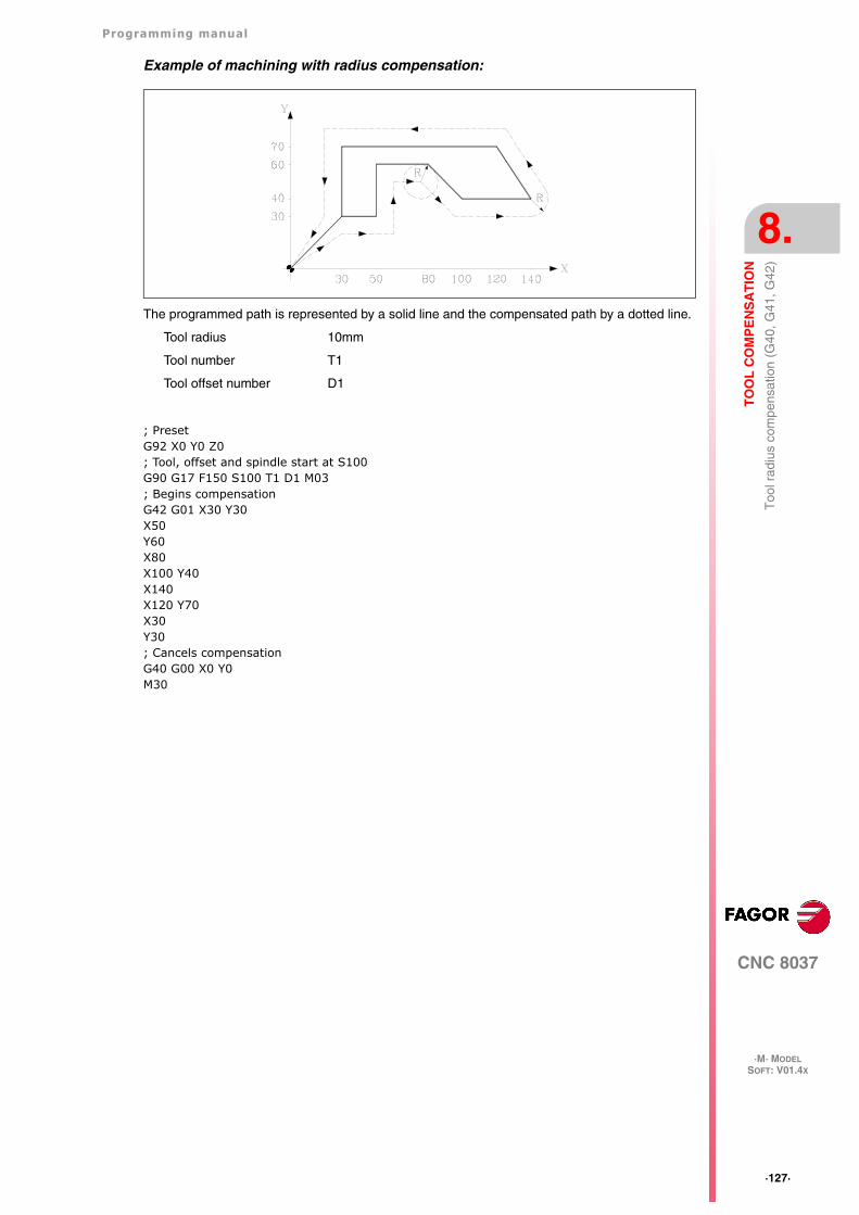
Programming manual
CNC 8037
TO
OL
CO
MP
EN
SA
TIO
N
8.
·M· MODELSOFT: V01.4X
·127·
Too
l rad
ius
com
pens
atio
n (G
40, G
41, G
42)
Example of machining with radius compensation:
The programmed path is represented by a solid line and the compensated path by a dotted line.
Tool radius 10mm
Tool number T1
Tool offset number D1
; PresetG92 X0 Y0 Z0; Tool, offset and spindle start at S100G90 G17 F150 S100 T1 D1 M03; Begins compensationG42 G01 X30 Y30X50Y60X80X100 Y40X140X120 Y70X30Y30; Cancels compensationG40 G00 X0 Y0M30
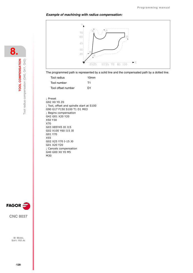
·128·
Programming manual
CNC 8037
8.
TO
OL
CO
MP
EN
SA
TIO
N
·M· MODELSOFT: V01.4X
Too
l rad
ius
com
pens
atio
n (G
40, G
41, G
42)
Example of machining with radius compensation:
The programmed path is represented by a solid line and the compensated path by a dotted line.
Tool radius 10mm
Tool number T1
Tool offset number D1
; PresetG92 X0 Y0 Z0; Tool, offset and spindle start at S100G90 G17 F150 S100 T1 D1 M03; Begins compensationG42 G01 X20 Y20X50 Y30X70G03 X85Y45 I0 J15G02 X100 Y60 I15 J0G01 Y70X55G02 X25 Y70 I-15 J0G01 X20 Y20; Cancels compensationG40 G00 X0 Y0 M5M30
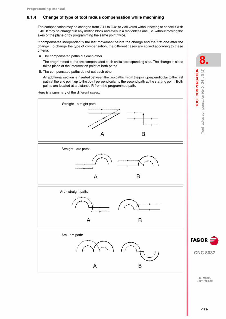
Programming manual
CNC 8037
TO
OL
CO
MP
EN
SA
TIO
N
8.
·M· MODELSOFT: V01.4X
·129·
Too
l rad
ius
com
pens
atio
n (G
40, G
41, G
42)
8.1.4 Change of type of tool radius compensation while machining
The compensation may be changed from G41 to G42 or vice versa without having to cancel it withG40. It may be changed in any motion block and even in a motionless one, i.e. without moving theaxes of the plane or by programming the same point twice.
It compensates independently the last movement before the change and the first one after thechange. To change the type of compensation, the different cases are solved according to thesecriteria:
A. The compensated paths cut each other.
The programmed paths are compensated each on its corresponding side. The change of sidestakes place at the intersection point of both paths.
B. The compensated paths do not cut each other.
An additional section is inserted between the two paths. From the point perpendicular to the firstpath at the end point up to the point perpendicular to the second path at the starting point. Bothpoints are located at a distance R from the programmed path.
Here is a summary of the different cases:
Straight - straight path:
A B
Straight - arc path:
A B
Arc - straight path:
A B
Arc - arc path:
A B
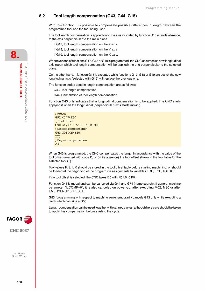
·130·
Programming manual
CNC 8037
8.
TO
OL
CO
MP
EN
SA
TIO
N
·M· MODELSOFT: V01.4X
Too
l len
gth
com
pens
atio
n (G
43, G
44, G
15)
8.2 Tool length compensation (G43, G44, G15)
With this function it is possible to compensate possible differences in length between theprogrammed tool and the tool being used.
The tool length compensation is applied on to the axis indicated by function G15 or, in its absence,to the axis perpendicular to the main plane.
If G17, tool length compensation on the Z axis.
If G18, tool length compensation on the Y axis
If G19, tool length compensation on the X axis.
Whenever one of functions G17, G18 or G19 is programmed, the CNC assumes as new longitudinalaxis (upon which tool length compensation will be applied) the one perpendicular to the selectedplane.
On the other hand, if function G15 is executed while functions G17, G18 or G19 are active, the newlongitudinal axis (selected with G15) will replace the previous one.
The function codes used in length compensation are as follows:
G43: Tool length compensation.
G44: Cancellation of tool length compensation.
Function G43 only indicates that a longitudinal compensation is to be applied. The CNC startsapplying it when the longitudinal (perpendicular) axis starts moving.
When G43 is programmed, the CNC compensates the length in accordance with the value of thetool offset selected with code D, or (in its absence) the tool offset shown in the tool table for theselected tool (T).
Tool values R, L, I, K should be stored in the tool offset table before starting machining, or shouldbe loaded at the beginning of the program via assignments to variables TOR, TOL, TOI, TOK.
If no tool offset is selected, the CNC takes D0 with R0 L0 I0 K0.
Function G43 is modal and can be canceled via G44 and G74 (home search). If general machineparameter "ILCOMP=0", it is also canceled on power-up, after executing M02, M30 or afterEMERGENCY or RESET.
G53 (programming with respect to machine zero) temporarily cancels G43 only while executing ablock which contains a G53.
Length compensation can be used together with canned cycles, although here care should be takento apply this compensation before starting the cycle.
; PresetG92 X0 Y0 Z50 ; Tool, offset ...G90 G17 F150 S100 T1 D1 M03; Selects compensationG43 G01 X20 Y20X70; Begins compensationZ30
Programming manual
CNC 8037
TO
OL
CO
MP
EN
SA
TIO
N
8.
·M· MODELSOFT: V01.4X
·131·
Too
l len
gth
com
pens
atio
n (G
43, G
44, G
15)
Example of machining with tool length compensation:
It is assumed that the tool used is 4 mm shorter than the programmed one.
Tool length -4mm
Tool number T1
Tool offset number D1
; PresetG92 X0 Y0 Z0; Tool, offset ...G91 G00 G05 X50 Y35 S500 M03; Begins compensationG43 Z-25 T1 D1G01 G07 Z-12 F100G00 Z12X40G01 Z-17; Cancels compensationG00 G05 G44 Z42 M5G90 G07 X0 Y0M30
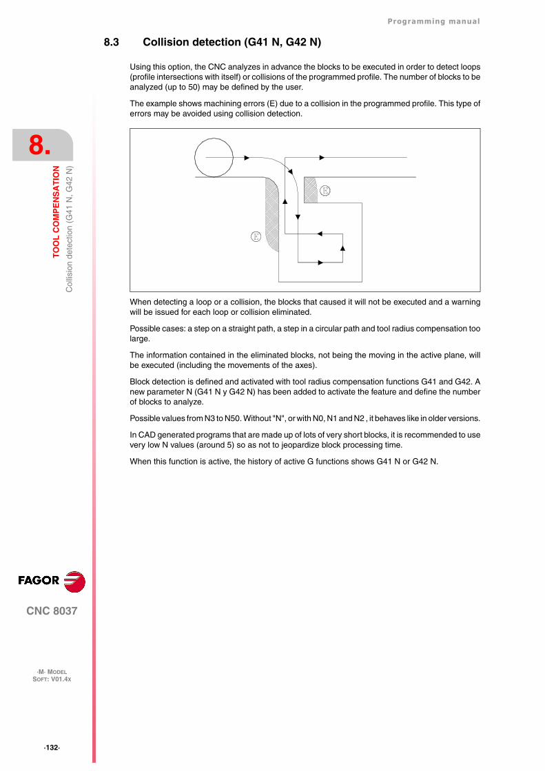
·132·
Programming manual
CNC 8037
8.
TO
OL
CO
MP
EN
SA
TIO
N
·M· MODELSOFT: V01.4X
Col
lisio
n de
tect
ion
(G41
N, G
42 N
)
8.3 Collision detection (G41 N, G42 N)
Using this option, the CNC analyzes in advance the blocks to be executed in order to detect loops(profile intersections with itself) or collisions of the programmed profile. The number of blocks to beanalyzed (up to 50) may be defined by the user.
The example shows machining errors (E) due to a collision in the programmed profile. This type oferrors may be avoided using collision detection.
When detecting a loop or a collision, the blocks that caused it will not be executed and a warningwill be issued for each loop or collision eliminated.
Possible cases: a step on a straight path, a step in a circular path and tool radius compensation toolarge.
The information contained in the eliminated blocks, not being the moving in the active plane, willbe executed (including the movements of the axes).
Block detection is defined and activated with tool radius compensation functions G41 and G42. Anew parameter N (G41 N y G42 N) has been added to activate the feature and define the numberof blocks to analyze.
Possible values from N3 to N50. Without "N", or with N0, N1 and N2 , it behaves like in older versions.
In CAD generated programs that are made up of lots of very short blocks, it is recommended to usevery low N values (around 5) so as not to jeopardize block processing time.
When this function is active, the history of active G functions shows G41 N or G42 N.
CNC 8037
·M· MODELSOFT: V01.4X
9
·133·
CANNED CYCLES
These canned cycles can be performed on any plane, the depth being along the axis selected aslongitudinal via function G15 or, in its absence, along the axis perpendicular to this plane.
The CNC offers the following machining canned cycles :
G69 Deep hole drilling canned cycle with variable peck.
G81 Drilling canned cycle.
G82 Drilling cycle with dwell.
G83 Deep-hole drilling canned cycle with constant peck.
G84 Tapping canned cycle.
G85 Reaming canned cycle.
G86 Boring cycle with rapid withdrawal in G00.
G87 Rectangular pocket canned cycle.
G88 Circular pocket canned cycle.
G89 Boring cycle with withdrawal at work feedrate G01.
G210 Bore milling canned cycle.
G211 Inside thread milling canned cycle.
G212 Outside thread milling canned cycle.
It also offers the following functions that can be used with the machining canned cycles:
G79 Modification of the canned cycle parameters.
G98 Return to the starting plane at the end of the canned cycle.
G99 Return to the reference plane at the end of the canned cycle.
·134·
Programming manual
CNC 8037
9.
CA
NN
ED
CY
CL
ES
·M· MODELSOFT: V01.4X
Can
ned
cycl
e de
finiti
on
9.1 Canned cycle definition
A canned cycle is defined by the G function indicating the canned cycle and its correspondingparameters.
A canned cycle cannot be defined in a block which has nonlinear movements (G02, G03, G08, G09,G33 or G34).
Also, a canned cycle cannot be executed while function G02, G03, G33 or G34 is active. The CNCwill issue the corresponding error message.
However, once a canned cycle has been defined in a block and following blocks, functions G02, G03,G08 or G09 can be programmed.
Programming manual
CNC 8037
CA
NN
ED
CY
CL
ES
9.
·M· MODELSOFT: V01.4X
·135·
Influ
ence
zon
e of
a c
anne
d cy
cle
9.2 Influence zone of a canned cycle
Once a canned cycle has been defined it remains active, and all blocks programmed after this blockare under its influence while it is not cancelled.
In other words, every time a block is executed in which some axis movement has been programmed,the CNC will carry out (following the programmed movement) the machining operation whichcorresponds to the active canned cycle.
If, in a movement block within the area of influence of a canned cycle, the number of times a blockis executed (repetitions) "N" is programmed at the end of the block, the CNC repeats theprogrammed positioning and the machining operation corresponding to the canned cycle theindicated number of times.
If a number of repetitions (times) "N0" is programmed, the machining operation corresponding tothe canned cycle will not be performed. The CNC will only carry out the programmed movement.
If, within the area of influence of a canned cycle, there is a block which does not contain anymovement, the machining operation corresponding to the defined canned cycle will not beperformed, except in the calling block.
G81... Definition and execution of the canned cycle (drilling).
G90 G1 X100 The X axis moves to X100, where the hole is to be drilled.
G91 X10 N3 The CNC runs the following operation 3 times.
• Incremental move to X10.
• Runs the cycle defined above.
G91 X20 N0 Incremental move only to X20 (no drilling).
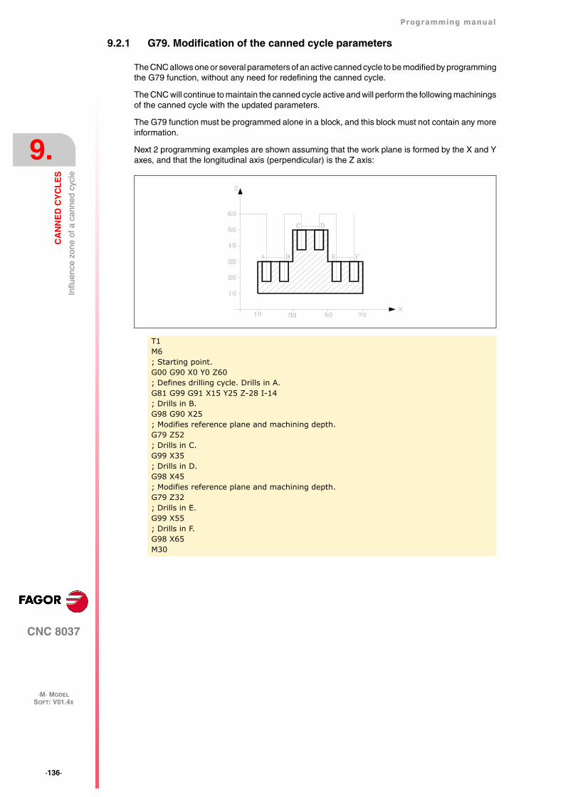
·136·
Programming manual
CNC 8037
9.
CA
NN
ED
CY
CL
ES
·M· MODELSOFT: V01.4X
Influ
ence
zon
e of
a c
anne
d cy
cle
9.2.1 G79. Modification of the canned cycle parameters
The CNC allows one or several parameters of an active canned cycle to be modified by programmingthe G79 function, without any need for redefining the canned cycle.
The CNC will continue to maintain the canned cycle active and will perform the following machiningsof the canned cycle with the updated parameters.
The G79 function must be programmed alone in a block, and this block must not contain any moreinformation.
Next 2 programming examples are shown assuming that the work plane is formed by the X and Yaxes, and that the longitudinal axis (perpendicular) is the Z axis:
T1M6; Starting point.G00 G90 X0 Y0 Z60; Defines drilling cycle. Drills in A.G81 G99 G91 X15 Y25 Z-28 I-14; Drills in B.G98 G90 X25; Modifies reference plane and machining depth.G79 Z52; Drills in C.G99 X35; Drills in D.G98 X45; Modifies reference plane and machining depth.G79 Z32; Drills in E.G99 X55; Drills in F.G98 X65M30
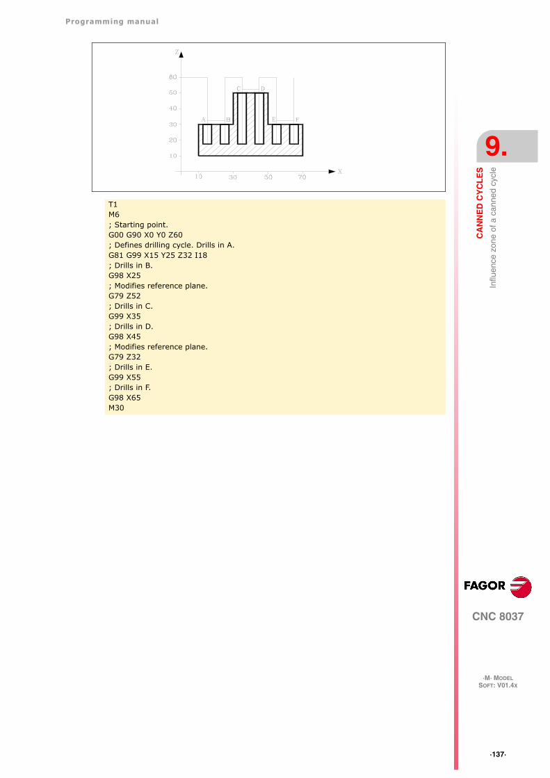
Programming manual
CNC 8037
CA
NN
ED
CY
CL
ES
9.
·M· MODELSOFT: V01.4X
·137·
Influ
ence
zon
e of
a c
anne
d cy
cle
T1M6; Starting point.G00 G90 X0 Y0 Z60; Defines drilling cycle. Drills in A.G81 G99 X15 Y25 Z32 I18; Drills in B.G98 X25; Modifies reference plane.G79 Z52; Drills in C.G99 X35; Drills in D.G98 X45; Modifies reference plane.G79 Z32; Drills in E.G99 X55; Drills in F.G98 X65M30
·138·
Programming manual
CNC 8037
9.
CA
NN
ED
CY
CL
ES
·M· MODELSOFT: V01.4X
Can
ned
cycl
e ca
ncel
latio
n
9.3 Canned cycle cancellation
A canned cycle can be canceled via :
• Function G80, which can be programmed in any block.
• After defining a new canned cycle. This will cancel and replace any other that may be active.
• After executing M02, M30, or after EMERGENCY or RESET.
• When searching home with function G74.
• Selecting a new work plane via functions G16, G17, G18, or G19.
Programming manual
CNC 8037
CA
NN
ED
CY
CL
ES
9.
·M· MODELSOFT: V01.4X
·139·
Som
e ge
nera
l poi
nts
to c
onsi
der
9.4 Some general points to consider
• A canned cycle may be defined anywhere in the program, that is, in the main program as wellas in a subroutine.
• Calls to subroutines can be made from a block within the influence of a canned cycle withoutimplying the cancellation of the canned cycle.
• The execution of a canned cycle will not alter the history of previous "G" functions.
• Nor will the spindle turning direction be altered. A canned cycle can be entered with any turningdirection (M03 or M04), leaving in the same direction in which the cycle was entered.
Should a canned cycle be entered with the spindle stopped, it will start in a clockwise direction(M03), and maintain the same turning direction until the cycle is completed.
• Should it be required to apply a scaling factor when working with canned cycles, it is advisablethat this scale factor be common to all the axes involved.
• The execution of a canned cycle cancels radius compensation (G41 and G42). It is equivalentto G40.
• If tool length compensation (G43) is to be used, this function must be programmed in the sameblock or in the one before the definition of the canned cycle.
The CNC applies the tool length compensation when the longitudinal (perpendicular) axis startsmoving. Therefore, it is recommended to position the tool outside the canned cycle area whendefining function G43 for the canned cycle.
• The execution of any canned cycle will alter the global parameter P299.
·140·
Programming manual
CNC 8037
9.
CA
NN
ED
CY
CL
ES
·M· MODELSOFT: V01.4X
Mac
hini
ng c
anne
d cy
cles
9.5 Machining canned cycles
In all machining cycles there are three coordinates along the longitudinal axis to the work planewhich, due to their importance, are discussed below:
• Initial plane coordinate. This coordinate is given by the position which the tool occupies withrespect to machine zero when the cycle is activated.
• Coordinate of the reference plane. This is programmed in the cycle definition block andrepresents an approach coordinate to the part. It can be programmed in absolute coordinatesor in incremental, in which case it will be referred to the initial plane.
• Machining depth coordinate. This is programmed in the cycle definition block. It can beprogrammed in absolute coordinates or in incremental coordinates, in which case it will bereferred to the reference plane.
There are two functions which allow to select the type of withdrawal of the longitudinal axis aftermachining.
• G98: Selects the withdrawal of the tool as far as the initial plane, once the indicated machininghas been done.
• G99: Selects the withdrawal of the tool as far as the reference plane, once the indicatedmachining has been done.
These functions can be used both in the cycle definition block and the blocks which are under theinfluence of the canned cycle. The initial plane will always be the coordinate which the longitudinalaxis had when the cycle was defined.
The structure of a canned cycle definition block is as follows:
It is possible to program the starting point in the canned cycle definition block (except the longitudinalaxis), both in polar coordinates and in Cartesian coordinates.
After defining the point at which it is required to carry out the canned cycle (optional), the functionsand parameters corresponding to the canned cycle will be defined, and afterwards, if required, thecomplementary functions F S T D M are programmed.
When programming, at the end of the block, the number of times a block is to be executed "N", theCNC performs the programmed move and the machining operation corresponding to the activecanned cycle the indicated number of times.
If "N0" is programmed, it will not execute the machining operation corresponding to the canned cycle.The CNC will only carry out the programmed movement.
The general operation for all the cycles is as follows:
1. If the spindle was previously running, it maintains the turning direction. If it was not in movement,it will start by turning clockwise (M03).
2. Positioning (if programmed) at the starting point for the programmed cycle.
3. Rapid movement of the longitudinal axis from the initial plane to the reference plane.
4. Execution of the programmed machining cycle.
5. Rapid withdrawal of the longitudinal axis to the initial plane or reference plane, depending onwhether G98 or G99 has been programmed.
The explanation of each cycle assumes that the work plane is formed by the X and Y axes, andthat the longitudinal axis (perpendicular) is the Z axis:
G** Machining point Parameters F S T D M N****
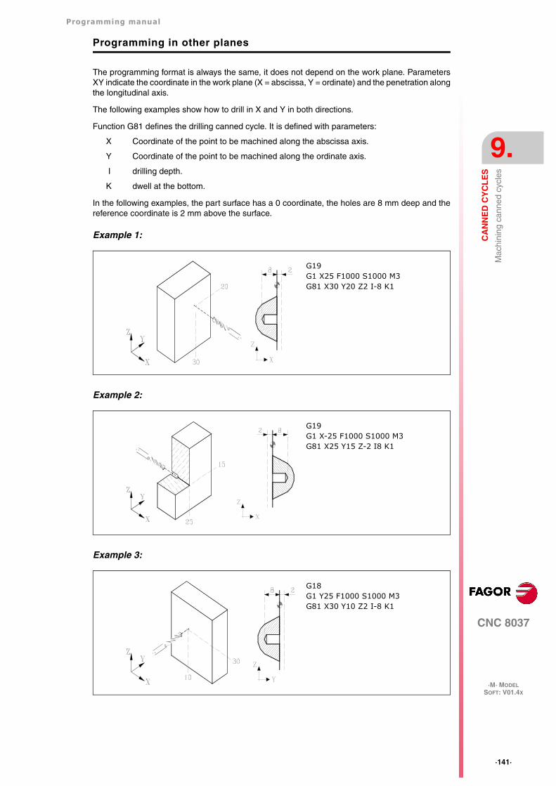
Programming manual
CNC 8037
CA
NN
ED
CY
CL
ES
9.
·M· MODELSOFT: V01.4X
·141·
Mac
hini
ng c
anne
d cy
cles
Programming in other planes
The programming format is always the same, it does not depend on the work plane. ParametersXY indicate the coordinate in the work plane (X = abscissa, Y = ordinate) and the penetration alongthe longitudinal axis.
The following examples show how to drill in X and Y in both directions.
Function G81 defines the drilling canned cycle. It is defined with parameters:
X Coordinate of the point to be machined along the abscissa axis.
Y Coordinate of the point to be machined along the ordinate axis.
I drilling depth.
K dwell at the bottom.
In the following examples, the part surface has a 0 coordinate, the holes are 8 mm deep and thereference coordinate is 2 mm above the surface.
Example 1:
Example 2:
Example 3:
G19G1 X25 F1000 S1000 M3G81 X30 Y20 Z2 I-8 K1
G19G1 X-25 F1000 S1000 M3G81 X25 Y15 Z-2 I8 K1
G18G1 Y25 F1000 S1000 M3G81 X30 Y10 Z2 I-8 K1
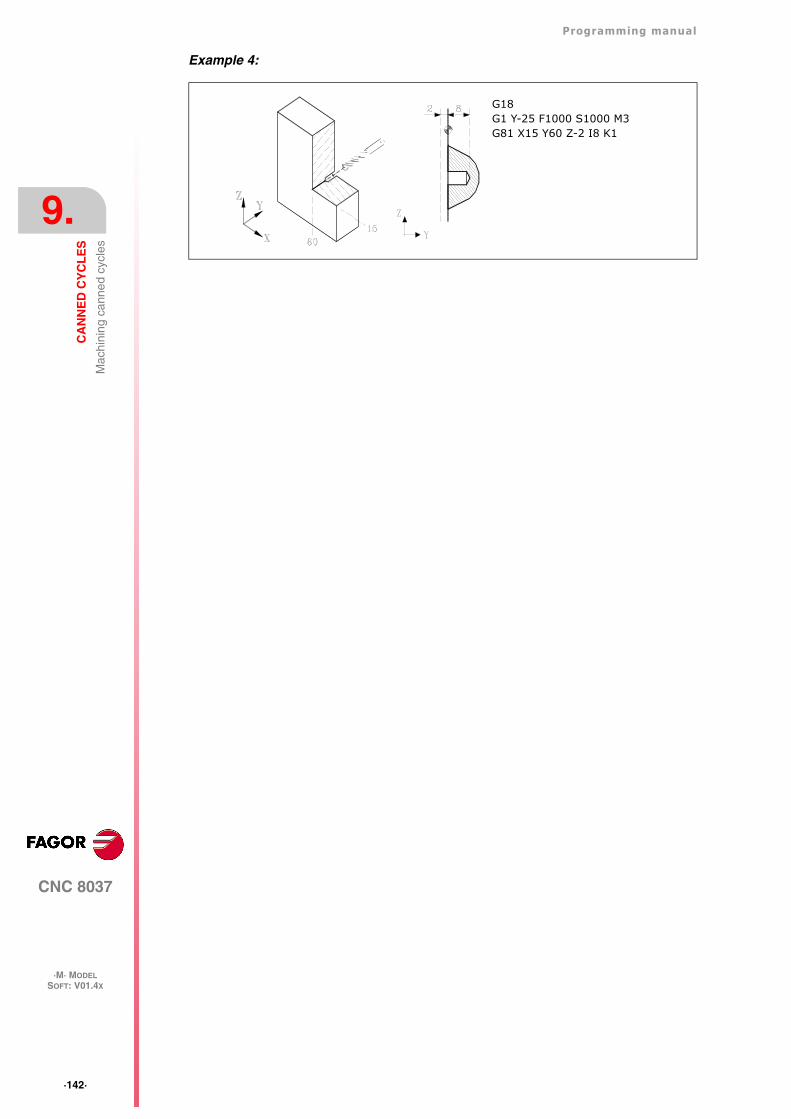
·142·
Programming manual
CNC 8037
9.
CA
NN
ED
CY
CL
ES
·M· MODELSOFT: V01.4X
Mac
hini
ng c
anne
d cy
cles
Example 4:
G18G1 Y-25 F1000 S1000 M3G81 X15 Y60 Z-2 I8 K1
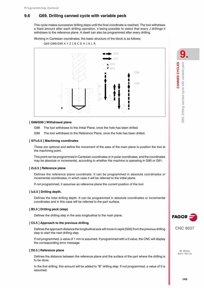
Programming manual
CNC 8037
CA
NN
ED
CY
CL
ES
9.
·M· MODELSOFT: V01.4X
·143·
G69
. Dril
ling
cann
ed c
ycle
with
var
iabl
e pe
ck
9.6 G69. Drilling canned cycle with variable peck
This cycle makes successive drilling steps until the final coordinate is reached. The tool withdrawsa fixed amount after each drilling operation, it being possible to select that every J drillings itwithdraws to the reference plane. A dwell can also be programmed after every drilling.
Working in Cartesian coordinates, the basic structure of the block is as follows:
G69 G98/G99 X Y Z I B C D H J K L R
[ G98/G99 ] Withdrawal plane
G98 The tool withdraws to the Initial Plane, once the hole has been drilled.
G99 The tool withdraws to the Reference Plane, once the hole has been drilled.
[ X/Y±5.5 ] Machining coordinates
These are optional and define the movement of the axes of the main plane to position the tool atthe machining point.
This point can be programmed in Cartesian coordinates or in polar coordinates, and the coordinatesmay be absolute or incremental, according to whether the machine is operating in G90 or G91.
[ Z±5.5 ] Reference plane
Defines the reference plane coordinate. It can be programmed in absolute coordinates orincremental coordinates, in which case it will be referred to the initial plane.
If not programmed, it assumes as reference plane the current position of the tool.
[ I±5.5 ] Drilling depth.
Defines the total drilling depth. It can be programmed in absolute coordinates or incrementalcoordinates and in this case will be referred to the part surface.
[ B5.5 ] Drilling peck (step)
Defines the drilling step in the axis longitudinal to the main plane.
[ C5.5 ] Approach to the previous drilling
Defines the approach distance the longitudinal axis will move in rapid (G00) from the previous drillingstep to start the next drilling step.
If not programmed, a value of 1 mm is assumed. If programmed with a 0 value, the CNC will displaythe corresponding error message.
[ D5.5 ] Reference plane
Defines the distance between the reference plane and the surface of the part where the drilling isto be done.
In the first drilling, this amount will be added to "B" drilling step. If not programmed, a value of 0 isassumed.
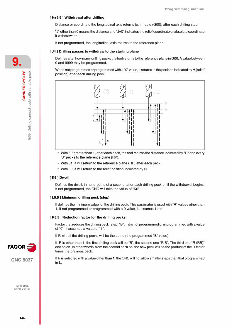
·144·
Programming manual
CNC 8037
9.
CA
NN
ED
CY
CL
ES
·M· MODELSOFT: V01.4X
G69
. Dril
ling
cann
ed c
ycle
with
var
iabl
e pe
ck
[ H±5.5 ] Withdrawal after drilling
Distance or coordinate the longitudinal axis returns to, in rapid (G00), after each drilling step.
"J" other than 0 means the distance and "J=0" indicates the relief coordinate or absolute coordinateit withdraws to.
If not programmed, the longitudinal axis returns to the reference plane.
[ J4 ] Drilling passes to withdraw to the starting plane
Defines after how many drilling pecks the tool returns to the reference plane in G00. A value between0 and 9999 may be programmed.
When not programmed or programmed with a "0" value, it returns to the position indicated by H (reliefposition) after each drilling peck.
• With "J" greater than 1, after each peck, the tool returns the distance indicated by "H" and every"J" pecks to the reference plane (RP).
• With J1, it will return to the reference plane (RP) after each peck .
• With J0, it will return to the relief position indicated by H.
[ K5 ] Dwell
Defines the dwell, in hundredths of a second, after each drilling peck until the withdrawal begins.If not programmed, the CNC will take the value of "K0".
[ L5.5 ] Minimum drilling peck (step)
It defines the minimum value for the drilling peck. This paramater is used with "R" values other than1. If not programmed or programmed with a 0 value, it assumes 1 mm.
[ R5.5 ] Reduction factor for the drilling pecks.
Factor that reduces the drilling peck (step) "B". If it is not programmed or is programmed with a valueof "0", it assumes a value of "1".
If R =1, all the drilling pecks will be the same (the programmed "B" value).
If R is other than 1, the first drilling peck will be "B", the second one "R B", The third one "R (RB)"and so on. In other words, from the second peck on, the new peck will be the product of the R factortimes the previous peck.
If R is selected with a value other than 1, the CNC will not allow smaller steps than that programmedin L.
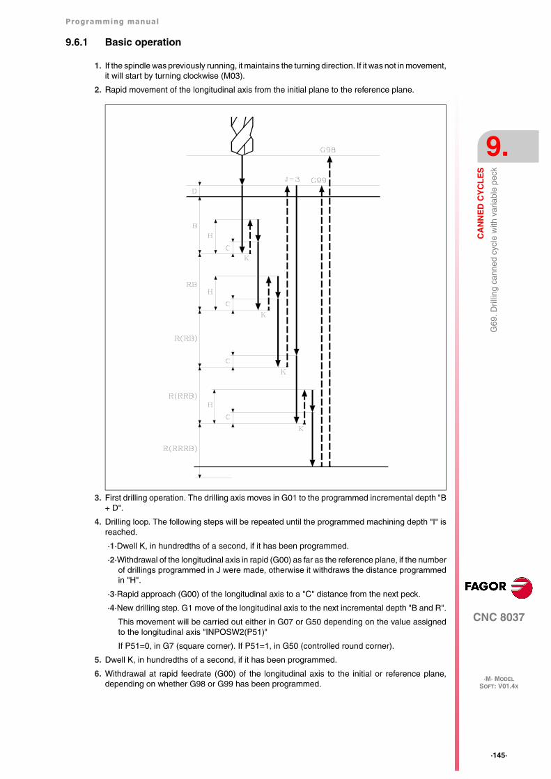
Programming manual
CNC 8037
CA
NN
ED
CY
CL
ES
9.
·M· MODELSOFT: V01.4X
·145·
G69
. Dril
ling
cann
ed c
ycle
with
var
iabl
e pe
ck
9.6.1 Basic operation
1. If the spindle was previously running, it maintains the turning direction. If it was not in movement,it will start by turning clockwise (M03).
2. Rapid movement of the longitudinal axis from the initial plane to the reference plane.
3. First drilling operation. The drilling axis moves in G01 to the programmed incremental depth "B+ D".
4. Drilling loop. The following steps will be repeated until the programmed machining depth "I" isreached.
·1·Dwell K, in hundredths of a second, if it has been programmed.
·2·Withdrawal of the longitudinal axis in rapid (G00) as far as the reference plane, if the numberof drillings programmed in J were made, otherwise it withdraws the distance programmedin "H".
·3·Rapid approach (G00) of the longitudinal axis to a "C" distance from the next peck.
·4·New drilling step. G1 move of the longitudinal axis to the next incremental depth "B and R".
This movement will be carried out either in G07 or G50 depending on the value assignedto the longitudinal axis "INPOSW2(P51)"
If P51=0, in G7 (square corner). If P51=1, in G50 (controlled round corner).
5. Dwell K, in hundredths of a second, if it has been programmed.
6. Withdrawal at rapid feedrate (G00) of the longitudinal axis to the initial or reference plane,depending on whether G98 or G99 has been programmed.
·146·
Programming manual
CNC 8037
9.
CA
NN
ED
CY
CL
ES
·M· MODELSOFT: V01.4X
G69
. Dril
ling
cann
ed c
ycle
with
var
iabl
e pe
ck
The first drilling penetration is done in G07 or G50 depending on the value assigned to the parameterof the longitudinal axis "INPOSW2 (P51)" and to parameter "INPOSW1 (P19)". This is importantto join a drilling operation with another one in multiple drilling so the tool path is faster and smoother.
If INPOSW2 < INPOSW1 in G07 (square corner).
If INPOSW2 >= INPOSW1 in G50 (controlled round corner).
If a scaling factor is applied to this cycle, it should be borne in mind that this scaling factor will onlyaffect the reference plane coordinates and drilling depth.
Therefore, and due to the fact that parameter "D" is not affected by the scaling factor, the surfacecoordinate of the part will not be proportional to the programmed cycle.
Tool withdrawal
While machining, the CNC lets withdraw the tool to the starting plane stopping the spindle whenthe tool reaches the starting plane.
Activating PLC mark RETRACYC (M5065) stops the main axis and the tool is withdrawn withoutstopping the spindle. The spindle stops when the tool is retracted, once it reaches the starting plane.
Options after tool withdrawal
Once the tool has been retracted, the user will have the following options:
• Finish the hole.
• Go to the next hole.
• Go into tool inspection.
After this, the CNC will display the following message:
"To end the cycle, press START to skip to the next SKIPCYCL".
Finish the hole:
To finish the hole, press the [START] key.
It goes down in G0 with spindle running to 1 mm before the coordinate where the hole stopped. Fromthen on, it continues at the F and S programmed in the cycle.
Go to the next hole:
To go to the next hole, activate the PLC mark SKIPCYCL.
The CNC will display the following message:
"Press [START] to continue".
Pressing the [START] key, the CNC considers the cycle to be finished and continues with the nextblock.
Programming example assuming that the work plane is formed by the X and Y axes, that theZ axis is the longitudinal axis and that the starting point is X0 Y0 Z0:
; Tool selection.T1M6; Starting point.G0 G90 X0 Y0 Z0; Canned cycle definition.G69 G98 G91 X100 Y25 Z-98 I-52 B12 C2 D2 H5 J2 K150 L3 R0.8 F100 S500 M8; Cancels the canned cycle.G80; Positioning.G90 X0 Y0; End of program.M30
Programming manual
CNC 8037
CA
NN
ED
CY
CL
ES
9.
·M· MODELSOFT: V01.4X
·147·
G69
. Dril
ling
cann
ed c
ycle
with
var
iabl
e pe
ck
Go into tool inspection:
If you don't wish to finish the hole nor go to the next hole, it is possible to go into a standard toolinspection.
In this case, a block must be selected and a standard repositioning must be done before resumingthe execution of the program.
After inspecting the tool, once repositioning is done, the following choices will be offered:
• Resume the interrupted cycle.
• Skip the interrupted cycle and resume at the next block.
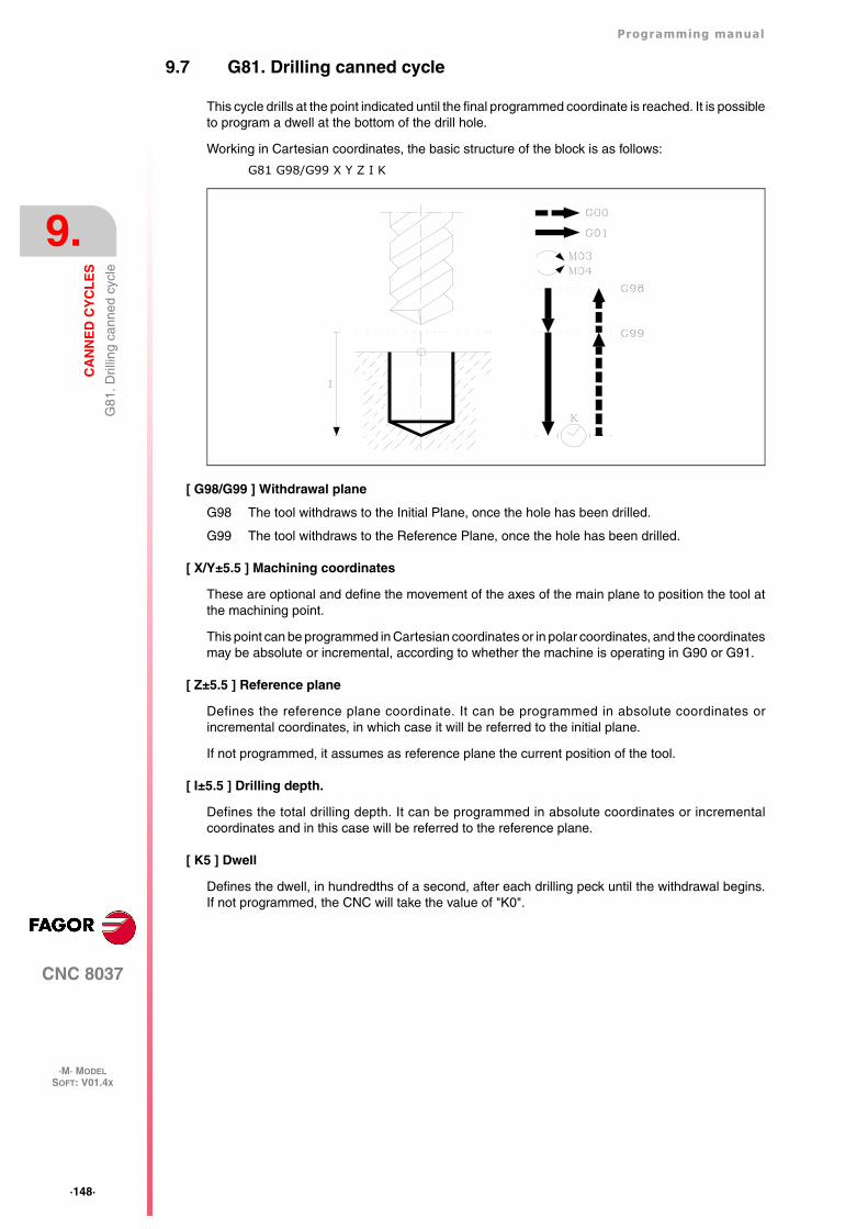
·148·
Programming manual
CNC 8037
9.
CA
NN
ED
CY
CL
ES
·M· MODELSOFT: V01.4X
G81
. Dril
ling
cann
ed c
ycle
9.7 G81. Drilling canned cycle
This cycle drills at the point indicated until the final programmed coordinate is reached. It is possibleto program a dwell at the bottom of the drill hole.
Working in Cartesian coordinates, the basic structure of the block is as follows:
G81 G98/G99 X Y Z I K
[ G98/G99 ] Withdrawal plane
G98 The tool withdraws to the Initial Plane, once the hole has been drilled.
G99 The tool withdraws to the Reference Plane, once the hole has been drilled.
[ X/Y±5.5 ] Machining coordinates
These are optional and define the movement of the axes of the main plane to position the tool atthe machining point.
This point can be programmed in Cartesian coordinates or in polar coordinates, and the coordinatesmay be absolute or incremental, according to whether the machine is operating in G90 or G91.
[ Z±5.5 ] Reference plane
Defines the reference plane coordinate. It can be programmed in absolute coordinates orincremental coordinates, in which case it will be referred to the initial plane.
If not programmed, it assumes as reference plane the current position of the tool.
[ I±5.5 ] Drilling depth.
Defines the total drilling depth. It can be programmed in absolute coordinates or incrementalcoordinates and in this case will be referred to the reference plane.
[ K5 ] Dwell
Defines the dwell, in hundredths of a second, after each drilling peck until the withdrawal begins.If not programmed, the CNC will take the value of "K0".
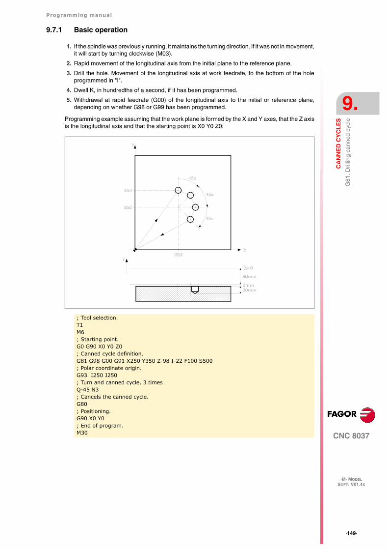
Programming manual
CNC 8037
CA
NN
ED
CY
CL
ES
9.
·M· MODELSOFT: V01.4X
·149·
G81
. Dril
ling
cann
ed c
ycle
9.7.1 Basic operation
1. If the spindle was previously running, it maintains the turning direction. If it was not in movement,it will start by turning clockwise (M03).
2. Rapid movement of the longitudinal axis from the initial plane to the reference plane.
3. Drill the hole. Movement of the longitudinal axis at work feedrate, to the bottom of the holeprogrammed in "I".
4. Dwell K, in hundredths of a second, if it has been programmed.
5. Withdrawal at rapid feedrate (G00) of the longitudinal axis to the initial or reference plane,depending on whether G98 or G99 has been programmed.
Programming example assuming that the work plane is formed by the X and Y axes, that the Z axisis the longitudinal axis and that the starting point is X0 Y0 Z0:
; Tool selection.T1M6; Starting point.G0 G90 X0 Y0 Z0; Canned cycle definition.G81 G98 G00 G91 X250 Y350 Z-98 I-22 F100 S500; Polar coordinate origin.G93 I250 J250; Turn and canned cycle, 3 timesQ-45 N3; Cancels the canned cycle.G80; Positioning.G90 X0 Y0; End of program.M30
·150·
Programming manual
CNC 8037
9.
CA
NN
ED
CY
CL
ES
·M· MODELSOFT: V01.4X
G81
. Dril
ling
cann
ed c
ycle
Tool withdrawal
While machining, the CNC lets withdraw the tool to the starting plane stopping the spindle whenthe tool reaches the starting plane.
Activating PLC mark RETRACYC (M5065) stops the main axis and the tool is withdrawn withoutstopping the spindle. The spindle stops when the tool is retracted, once it reaches the starting plane.
Options after tool withdrawal
Once the tool has been retracted, the user will have the following options:
• Finish the hole.
• Go to the next hole.
• Go into tool inspection.
After this, the CNC will display the following message:
"To end the cycle, press START to skip to the next SKIPCYCL".
Finish the hole:
To finish the hole, press the [START] key.
It goes down in G0 with spindle running to 1 mm before the coordinate where the hole stopped. Fromthen on, it continues at the F and S programmed in the cycle.
Go to the next hole:
To go to the next hole, activate the PLC mark SKIPCYCL.
The CNC will display the following message:
"Press [START] to continue".
Pressing the [START] key, the CNC considers the cycle to be finished and continues with the nextblock.
Go into tool inspection
If you don't wish to finish the hole nor go to the next hole, it is possible to go into a standard toolinspection.
In this case, a block must be selected and a standard repositioning must be done before resumingthe execution of the program.
After inspecting the tool, once repositioning is done, the following choices will be offered:
• Resume the interrupted cycle.
• Skip the interrupted cycle and resume at the next block.
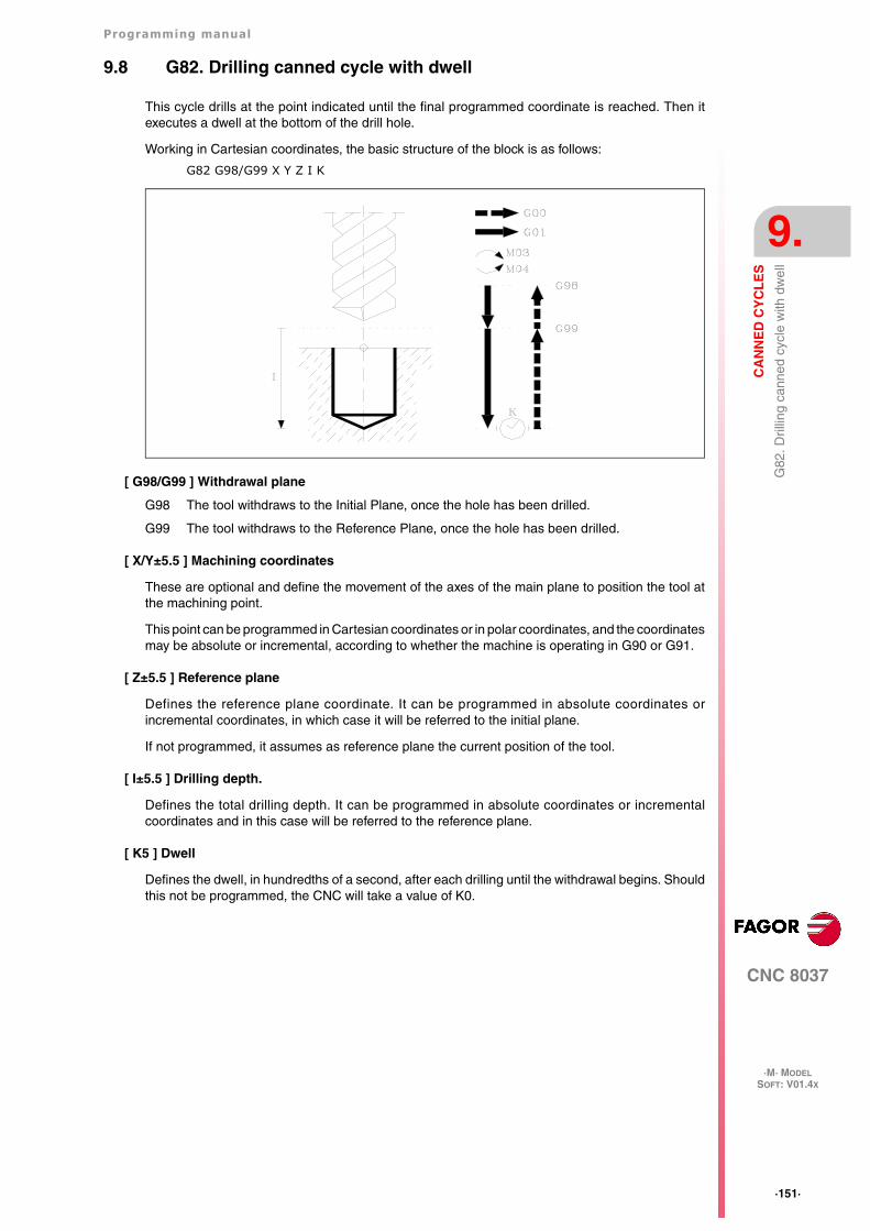
Programming manual
CNC 8037
CA
NN
ED
CY
CL
ES
9.
·M· MODELSOFT: V01.4X
·151·
G82
. Dril
ling
cann
ed c
ycle
with
dw
ell
9.8 G82. Drilling canned cycle with dwell
This cycle drills at the point indicated until the final programmed coordinate is reached. Then itexecutes a dwell at the bottom of the drill hole.
Working in Cartesian coordinates, the basic structure of the block is as follows:
G82 G98/G99 X Y Z I K
[ G98/G99 ] Withdrawal plane
G98 The tool withdraws to the Initial Plane, once the hole has been drilled.
G99 The tool withdraws to the Reference Plane, once the hole has been drilled.
[ X/Y±5.5 ] Machining coordinates
These are optional and define the movement of the axes of the main plane to position the tool atthe machining point.
This point can be programmed in Cartesian coordinates or in polar coordinates, and the coordinatesmay be absolute or incremental, according to whether the machine is operating in G90 or G91.
[ Z±5.5 ] Reference plane
Defines the reference plane coordinate. It can be programmed in absolute coordinates orincremental coordinates, in which case it will be referred to the initial plane.
If not programmed, it assumes as reference plane the current position of the tool.
[ I±5.5 ] Drilling depth.
Defines the total drilling depth. It can be programmed in absolute coordinates or incrementalcoordinates and in this case will be referred to the reference plane.
[ K5 ] Dwell
Defines the dwell, in hundredths of a second, after each drilling until the withdrawal begins. Shouldthis not be programmed, the CNC will take a value of K0.
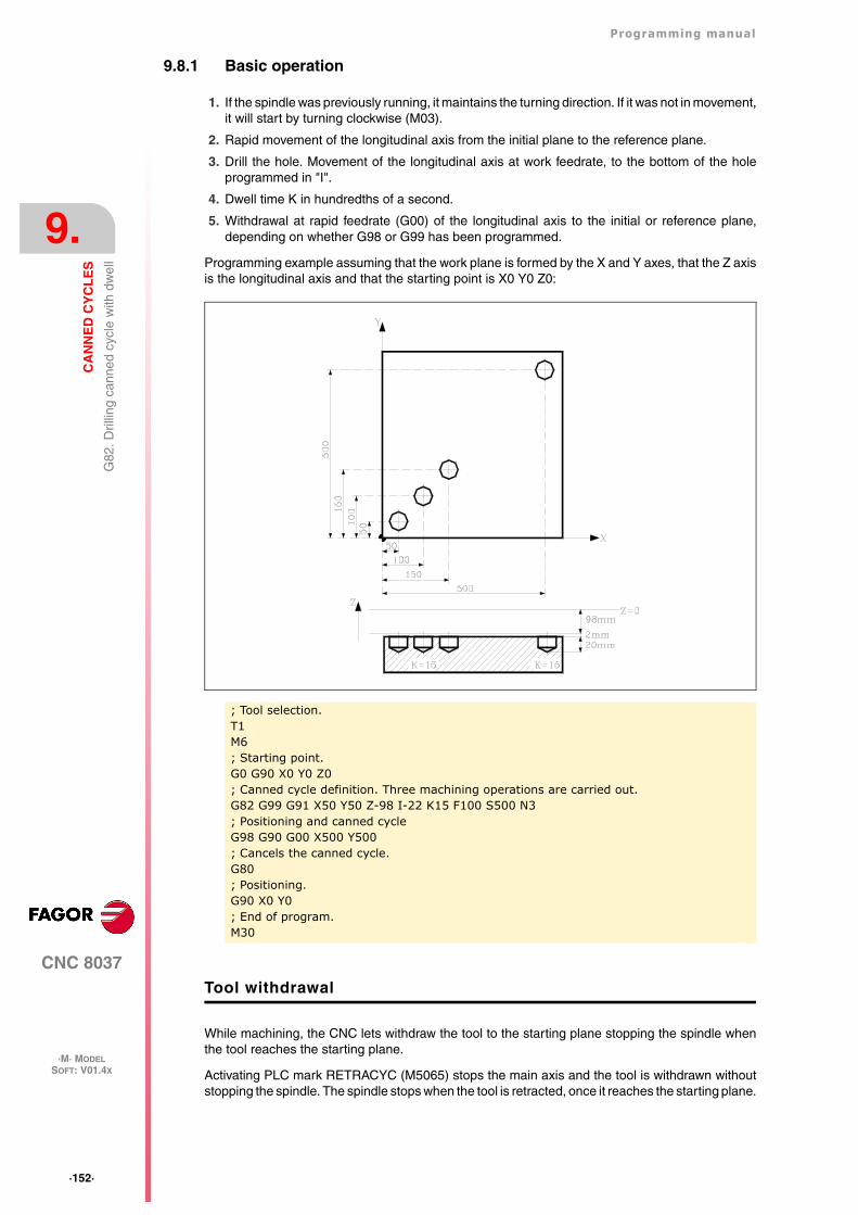
·152·
Programming manual
CNC 8037
9.
CA
NN
ED
CY
CL
ES
·M· MODELSOFT: V01.4X
G82
. Dril
ling
cann
ed c
ycle
with
dw
ell
9.8.1 Basic operation
1. If the spindle was previously running, it maintains the turning direction. If it was not in movement,it will start by turning clockwise (M03).
2. Rapid movement of the longitudinal axis from the initial plane to the reference plane.
3. Drill the hole. Movement of the longitudinal axis at work feedrate, to the bottom of the holeprogrammed in "I".
4. Dwell time K in hundredths of a second.
5. Withdrawal at rapid feedrate (G00) of the longitudinal axis to the initial or reference plane,depending on whether G98 or G99 has been programmed.
Programming example assuming that the work plane is formed by the X and Y axes, that the Z axisis the longitudinal axis and that the starting point is X0 Y0 Z0:
Tool withdrawal
While machining, the CNC lets withdraw the tool to the starting plane stopping the spindle whenthe tool reaches the starting plane.
Activating PLC mark RETRACYC (M5065) stops the main axis and the tool is withdrawn withoutstopping the spindle. The spindle stops when the tool is retracted, once it reaches the starting plane.
; Tool selection.T1M6; Starting point.G0 G90 X0 Y0 Z0; Canned cycle definition. Three machining operations are carried out.G82 G99 G91 X50 Y50 Z-98 I-22 K15 F100 S500 N3; Positioning and canned cycleG98 G90 G00 X500 Y500; Cancels the canned cycle.G80; Positioning.G90 X0 Y0; End of program.M30
Programming manual
CNC 8037
CA
NN
ED
CY
CL
ES
9.
·M· MODELSOFT: V01.4X
·153·
G82
. Dril
ling
cann
ed c
ycle
with
dw
ell
Options after tool withdrawal
Once the tool has been retracted, the user will have the following options:
• Finish the hole.
• Go to the next hole.
• Go into tool inspection.
After this, the CNC will display the following message:
"To end the cycle, press START to skip to the next SKIPCYCL".
Finish the hole:
To finish the hole, press the [START] key.
It goes down in G0 with spindle running to 1 mm before the coordinate where the hole stopped. Fromthen on, it continues at the F and S programmed in the cycle.
Go to the next hole:
To go to the next hole, activate the PLC mark SKIPCYCL.
The CNC will display the following message:
"Press [START] to continue".
Pressing the [START] key, the CNC considers the cycle to be finished and continues with the nextblock.
Go into tool inspection
If you don't wish to finish the hole nor go to the next hole, it is possible to go into a standard toolinspection.
In this case, a block must be selected and a standard repositioning must be done before resumingthe execution of the program.
After inspecting the tool, once repositioning is done, the following choices will be offered:
• Resume the interrupted cycle.
• Skip the interrupted cycle and resume at the next block.
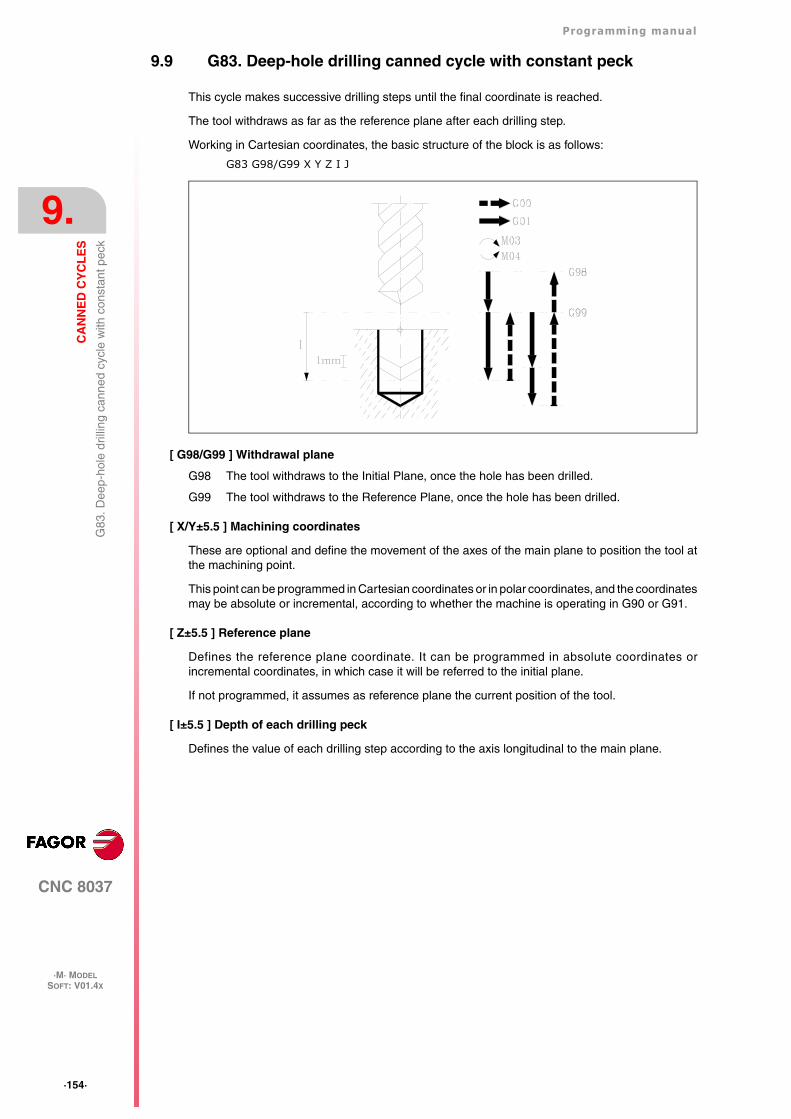
·154·
Programming manual
CNC 8037
9.
CA
NN
ED
CY
CL
ES
·M· MODELSOFT: V01.4X
G83
. Dee
p-ho
le d
rillin
g ca
nned
cyc
le w
ith c
onst
ant p
eck
9.9 G83. Deep-hole drilling canned cycle with constant peck
This cycle makes successive drilling steps until the final coordinate is reached.
The tool withdraws as far as the reference plane after each drilling step.
Working in Cartesian coordinates, the basic structure of the block is as follows:
G83 G98/G99 X Y Z I J
[ G98/G99 ] Withdrawal plane
G98 The tool withdraws to the Initial Plane, once the hole has been drilled.
G99 The tool withdraws to the Reference Plane, once the hole has been drilled.
[ X/Y±5.5 ] Machining coordinates
These are optional and define the movement of the axes of the main plane to position the tool atthe machining point.
This point can be programmed in Cartesian coordinates or in polar coordinates, and the coordinatesmay be absolute or incremental, according to whether the machine is operating in G90 or G91.
[ Z±5.5 ] Reference plane
Defines the reference plane coordinate. It can be programmed in absolute coordinates orincremental coordinates, in which case it will be referred to the initial plane.
If not programmed, it assumes as reference plane the current position of the tool.
[ I±5.5 ] Depth of each drilling peck
Defines the value of each drilling step according to the axis longitudinal to the main plane.
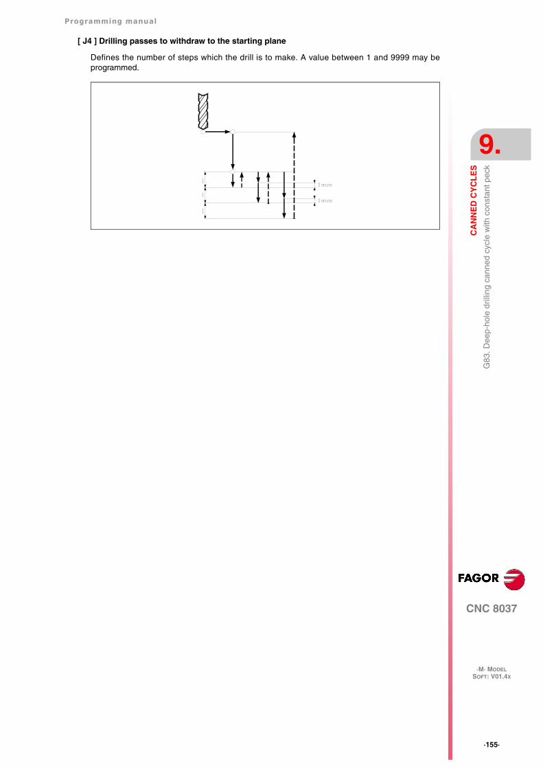
Programming manual
CNC 8037
CA
NN
ED
CY
CL
ES
9.
·M· MODELSOFT: V01.4X
·155·
G83
. Dee
p-ho
le d
rillin
g ca
nned
cyc
le w
ith c
onst
ant p
eck
[ J4 ] Drilling passes to withdraw to the starting plane
Defines the number of steps which the drill is to make. A value between 1 and 9999 may beprogrammed.
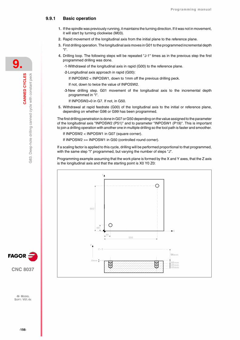
·156·
Programming manual
CNC 8037
9.
CA
NN
ED
CY
CL
ES
·M· MODELSOFT: V01.4X
G83
. Dee
p-ho
le d
rillin
g ca
nned
cyc
le w
ith c
onst
ant p
eck
9.9.1 Basic operation
1. If the spindle was previously running, it maintains the turning direction. If it was not in movement,it will start by turning clockwise (M03).
2. Rapid movement of the longitudinal axis from the initial plane to the reference plane.
3. First drilling operation. The longitudinal axis moves in G01 to the programmed incremental depth"I".
4. Drilling loop. The following steps will be repeated "J-1" times as in the previous step the firstprogrammed drilling was done.
·1·Withdrawal of the longitudinal axis in rapid (G00) to the reference plane.
·2·Longitudinal axis approach in rapid (G00):
If INPOSW2 < INPOSW1, down to 1mm off the previous drilling peck.
If not, down to twice the value of INPOSW2.
·3·New drilling step. G01 movement of the longitudinal axis to the incremental depthprogrammed in "I".
If INPOSW2=0 in G7. If not, in G50.
5. Withdrawal at rapid feedrate (G00) of the longitudinal axis to the initial or reference plane,depending on whether G98 or G99 has been programmed.
The first drilling penetration is done in G07 or G50 depending on the value assigned to the parameterof the longitudinal axis "INPOSW2 (P51)" and to parameter "INPOSW1 (P19)". This is importantto join a drilling operation with another one in multiple drilling so the tool path is faster and smoother.
If INPOSW2 < INPOSW1 in G07 (square corner).
If INPOSW2 >= INPOSW1 in G50 (controlled round corner).
If a scaling factor is applied to this cycle, drilling will be performed proportional to that programmed,with the same step "I" programmed, but varying the number of steps "J".
Programming example assuming that the work plane is formed by the X and Y axes, that the Z axisis the longitudinal axis and that the starting point is X0 Y0 Z0:
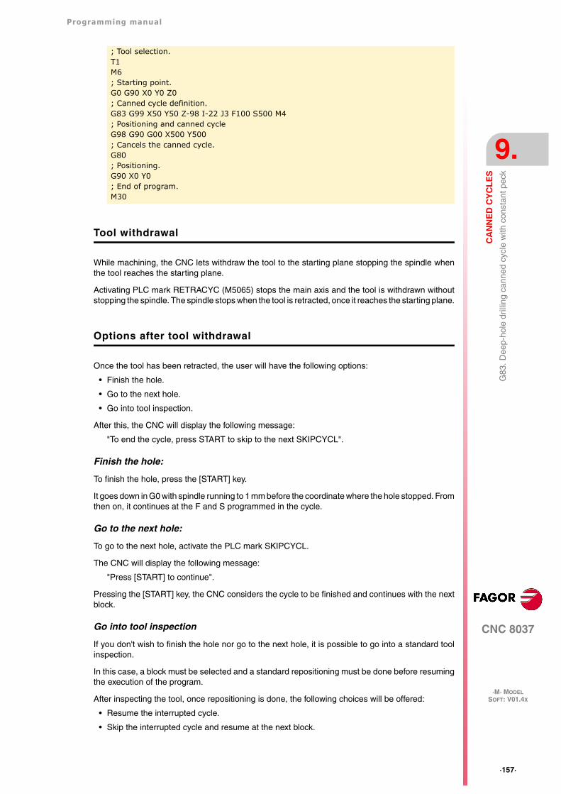
Programming manual
CNC 8037
CA
NN
ED
CY
CL
ES
9.
·M· MODELSOFT: V01.4X
·157·
G83
. Dee
p-ho
le d
rillin
g ca
nned
cyc
le w
ith c
onst
ant p
eck
Tool withdrawal
While machining, the CNC lets withdraw the tool to the starting plane stopping the spindle whenthe tool reaches the starting plane.
Activating PLC mark RETRACYC (M5065) stops the main axis and the tool is withdrawn withoutstopping the spindle. The spindle stops when the tool is retracted, once it reaches the starting plane.
Options after tool withdrawal
Once the tool has been retracted, the user will have the following options:
• Finish the hole.
• Go to the next hole.
• Go into tool inspection.
After this, the CNC will display the following message:
"To end the cycle, press START to skip to the next SKIPCYCL".
Finish the hole:
To finish the hole, press the [START] key.
It goes down in G0 with spindle running to 1 mm before the coordinate where the hole stopped. Fromthen on, it continues at the F and S programmed in the cycle.
Go to the next hole:
To go to the next hole, activate the PLC mark SKIPCYCL.
The CNC will display the following message:
"Press [START] to continue".
Pressing the [START] key, the CNC considers the cycle to be finished and continues with the nextblock.
Go into tool inspection
If you don't wish to finish the hole nor go to the next hole, it is possible to go into a standard toolinspection.
In this case, a block must be selected and a standard repositioning must be done before resumingthe execution of the program.
After inspecting the tool, once repositioning is done, the following choices will be offered:
• Resume the interrupted cycle.
• Skip the interrupted cycle and resume at the next block.
; Tool selection.T1M6; Starting point.G0 G90 X0 Y0 Z0; Canned cycle definition.G83 G99 X50 Y50 Z-98 I-22 J3 F100 S500 M4; Positioning and canned cycleG98 G90 G00 X500 Y500; Cancels the canned cycle.G80; Positioning.G90 X0 Y0; End of program.M30
·158·
Programming manual
CNC 8037
9.
CA
NN
ED
CY
CL
ES
·M· MODELSOFT: V01.4X
G84
. Tap
ping
can
ned
cycl
e
9.10 G84. Tapping canned cycle
This cycle taps at the point indicated until the final programmed coordinate is reached. General logicoutput "TAPPING" (M5517) stays active while executing this cycle.
Due to the fact that the tapping tool turns in two directions (one when tapping and the other whenwithdrawing from the thread), by means of the machine parameter of the spindle "SREVM05" it ispossible to select whether the change in turning direction is made with the intermediate spindle stop,or directly.
General machine parameter "STOPAP(P116)" indicates whether general inputs /STOP, /FEEDHOLand /XFERINH are enabled or not while executing function G84.
It is possible to program a dwell before each reversal of the spindle turning direction, i.e., at thebottom of the thread hole and when returning to the reference plane.
Using parameters B and H, the threading may be done with relief for chip breakage.
The tapping with relief is done in successive approaches until the programmed total depth isreached. After every approach, it withdraws for chip relief. In this case, the dwell (K) is only appliedon the last pass, not on the relief passes.
Working in Cartesian coordinates, the basic structure of the block is as follows:
G84 G98/G99 X Y Z I K R J B H
[ G98/G99 ] Withdrawal plane
G98 The tool withdraws to the Initial Plane, once the hole has tapped.
G99 The tool withdraws to the Reference Plane, once the hole has tapped.
[ X/Y±5.5 ] Machining coordinates
These are optional and define the movement of the axes of the main plane to position the tool atthe machining point.
This point can be programmed in Cartesian coordinates or in polar coordinates, and the coordinatesmay be absolute or incremental, according to whether the machine is operating in G90 or G91.
[ Z±5.5 ] Reference plane
Defines the reference plane coordinate. It can be programmed in absolute coordinates orincremental coordinates, in which case it will be referred to the initial plane.
If not programmed, it assumes as reference plane the current position of the tool.
[ I±5.5 ] Thread depth.
Defines tapping depth. It can be programmed in absolute coordinates or incremental coordinatesand in this case will be referred to the reference plane.
[ K5 ] Dwell
Defines the dwell, in hundredths of a second, after the tapping until the withdrawal begins. If notprogrammed, the CNC will take the value of "K0".
Programming manual
CNC 8037
CA
NN
ED
CY
CL
ES
9.
·M· MODELSOFT: V01.4X
·159·
G84
. Tap
ping
can
ned
cycl
e
[ R ] Type of tapping
Defines the type of tapping to be carried out.
R0 Normal tapping.
R1 Rigid tapping. The CNC stops the spindle with M19 and orients it to begin tapping.
R2 Rigid tapping. If the spindle is turning in M3 or M4, the CNC does not stop it nor orientit to begin tapping. This option does not allow thread repair, even if the part has not beenreleased because the thread start (entry) will coincide with the one machined earlier.
[ J5.5 ] Withdrawal feedrate factor
When rigid tapping, the returning feedrate will be J times the tapping feedrate. When notprogrammed or programmed J1, they will both be the same.
In order to execute a rigid tapping, the spindle must be ready to operate in closed loop; in other words,that it must have a servo drive-motor system with rotary encoder.
When rigid tapping, the CNC interpolates the movement of the longitudinal axis with the spindlerotation.
[ B5.5 ] Penetration step during tapping with relief.
It is optional and sets the penetration step during tapping with relief. This parameter is ignored whenprogramming R=0 or R=2. Tapping with relief is only possible when programming R=1.
When not programmed, tapping will be done in a single pass. When programmed with a 0 value,it issues the corresponding error.
[ H5.5 ] Withdrawal distance after each penetration step.
This withdrawal will be done at a speed that will take into consideration the factor programmed inJ. This parameter is ignored when programming R=0 or R=2, or if parameter B has not beenprogrammed.
If not programmed or programmed with a 0 value, the withdrawal will be done to the Z referenceplane coordinate.
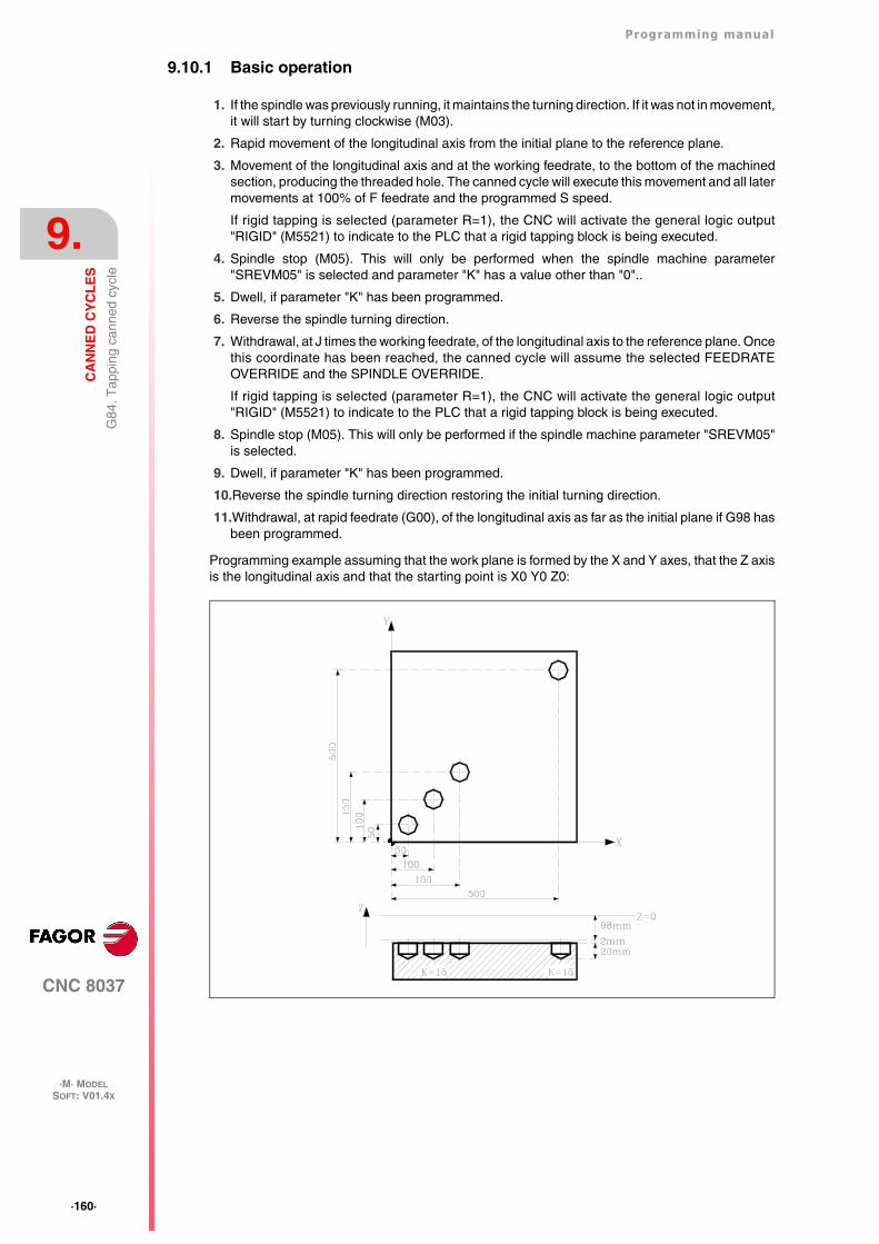
·160·
Programming manual
CNC 8037
9.
CA
NN
ED
CY
CL
ES
·M· MODELSOFT: V01.4X
G84
. Tap
ping
can
ned
cycl
e
9.10.1 Basic operation
1. If the spindle was previously running, it maintains the turning direction. If it was not in movement,it will start by turning clockwise (M03).
2. Rapid movement of the longitudinal axis from the initial plane to the reference plane.
3. Movement of the longitudinal axis and at the working feedrate, to the bottom of the machinedsection, producing the threaded hole. The canned cycle will execute this movement and all latermovements at 100% of F feedrate and the programmed S speed.
If rigid tapping is selected (parameter R=1), the CNC will activate the general logic output"RIGID" (M5521) to indicate to the PLC that a rigid tapping block is being executed.
4. Spindle stop (M05). This will only be performed when the spindle machine parameter"SREVM05" is selected and parameter "K" has a value other than "0"..
5. Dwell, if parameter "K" has been programmed.
6. Reverse the spindle turning direction.
7. Withdrawal, at J times the working feedrate, of the longitudinal axis to the reference plane. Oncethis coordinate has been reached, the canned cycle will assume the selected FEEDRATEOVERRIDE and the SPINDLE OVERRIDE.
If rigid tapping is selected (parameter R=1), the CNC will activate the general logic output"RIGID" (M5521) to indicate to the PLC that a rigid tapping block is being executed.
8. Spindle stop (M05). This will only be performed if the spindle machine parameter "SREVM05"is selected.
9. Dwell, if parameter "K" has been programmed.
10.Reverse the spindle turning direction restoring the initial turning direction.
11.Withdrawal, at rapid feedrate (G00), of the longitudinal axis as far as the initial plane if G98 hasbeen programmed.
Programming example assuming that the work plane is formed by the X and Y axes, that the Z axisis the longitudinal axis and that the starting point is X0 Y0 Z0:
Programming manual
CNC 8037
CA
NN
ED
CY
CL
ES
9.
·M· MODELSOFT: V01.4X
·161·
G84
. Tap
ping
can
ned
cycl
e
Tool withdrawal
While machining, the CNC lets withdraw the tool to the starting plane stopping the spindle whenthe tool reaches the starting plane.
Activating PLC mark RETRACYC (M5065) stops the main axis and the spindle, the tool is withdrawnchanging the direction of the axis and spindle while keeping the machining F and S values. Thiswithdrawal will be to the starting plane.
The stopping and starting sequence of the spindle and the axis when tapping keeps the samesynchronism and dwells as during the execution of the canned cycle.
Options after tool withdrawal
Once the tool has been retracted, the user will have the following options:
• Finish the hole.
• Go to the next hole.
• Go into tool inspection.
After this, the CNC will display the following message:
"To end the cycle, press START to skip to the next SKIPCYCL".
Finish the hole:
To finish the hole, press the [START] key.
The hole is repeated from the starting plane under the same F and S conditions without stoppingat the point where it stopped.
Go to the next hole:
To go to the next hole, activate the PLC mark SKIPCYCL.
The CNC will display the following message:
"Press [START] to continue".
Pressing the [START] key, the CNC considers the cycle to be finished and continues with the nextblock.
; Tool selection.T1M6; Starting point.G0 G90 X0 Y0 Z0; Canned cycle definition. Three machining operations are carried out.G84 G99 G91 X50 Y50 Z-98 I-22 K150 F350 S500 N3; Positioning and canned cycleG98 G90 G00 X500 Y500; Cancels the canned cycle.G80; Positioning.G90 X0 Y0; End of program.M30
·162·
Programming manual
CNC 8037
9.
CA
NN
ED
CY
CL
ES
·M· MODELSOFT: V01.4X
G84
. Tap
ping
can
ned
cycl
e
Go into tool inspection
If you don't wish to finish the hole nor go to the next hole, it is possible to go into a standard toolinspection.
In this case, a block must be selected and a standard repositioning must be done before resumingthe execution of the program.
After inspecting the tool, once repositioning is done, the following choices will be offered:
• Resume the interrupted cycle.
• Skip the interrupted cycle and resume at the next block.
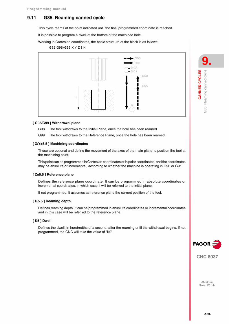
Programming manual
CNC 8037
CA
NN
ED
CY
CL
ES
9.
·M· MODELSOFT: V01.4X
·163·
G85
. Rea
min
g ca
nned
cyc
le
9.11 G85. Reaming canned cycle
This cycle reams at the point indicated until the final programmed coordinate is reached.
It is possible to program a dwell at the bottom of the machined hole.
Working in Cartesian coordinates, the basic structure of the block is as follows:
G85 G98/G99 X Y Z I K
[ G98/G99 ] Withdrawal plane
G98 The tool withdraws to the Initial Plane, once the hole has been reamed.
G99 The tool withdraws to the Reference Plane, once the hole has been reamed.
[ X/Y±5.5 ] Machining coordinates
These are optional and define the movement of the axes of the main plane to position the tool atthe machining point.
This point can be programmed in Cartesian coordinates or in polar coordinates, and the coordinatesmay be absolute or incremental, according to whether the machine is operating in G90 or G91.
[ Z±5.5 ] Reference plane
Defines the reference plane coordinate. It can be programmed in absolute coordinates orincremental coordinates, in which case it will be referred to the initial plane.
If not programmed, it assumes as reference plane the current position of the tool.
[ I±5.5 ] Reaming depth.
Defines reaming depth. It can be programmed in absolute coordinates or incremental coordinatesand in this case will be referred to the reference plane.
[ K5 ] Dwell
Defines the dwell, in hundredths of a second, after the reaming until the withdrawal begins. If notprogrammed, the CNC will take the value of "K0".
·164·
Programming manual
CNC 8037
9.
CA
NN
ED
CY
CL
ES
·M· MODELSOFT: V01.4X
G85
. Rea
min
g ca
nned
cyc
le
9.11.1 Basic operation
1. If the spindle was previously running, it maintains the turning direction. If it was not in movement,it will start by turning clockwise (M03).
2. Rapid movement of the longitudinal axis from the initial plane to the reference plane.
3. Movement at the working feedrate (G01) of the longitudinal axis to the bottom of the machinedhole, and reaming.
4. Dwell, if parameter "K" has been programmed.
5. Withdrawal at working feedrate, of the longitudinal axis as far as the reference plane.
6. Withdrawal, at rapid feedrate (G00), of the longitudinal axis as far as the initial plane if G98 hasbeen programmed.
Programming example assuming that the work plane is formed by the X and Y axes, that the Z axisis the longitudinal axis and that the starting point is X0 Y0 Z0:
; Tool selection.T1M6; Starting point.G0 G90 X0 Y0 Z0; Canned cycle definition.G85 G98 G91 X250 Y350 Z-98 I-22 F100 S500; Cancels the canned cycle.G80; Positioning.G90 X0 Y0; End of program.M30
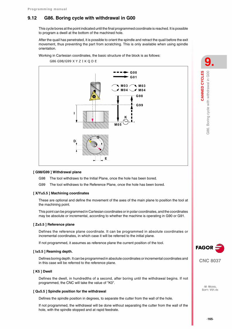
Programming manual
CNC 8037
CA
NN
ED
CY
CL
ES
9.
·M· MODELSOFT: V01.4X
·165·
G86
. Bor
ing
cycl
e w
ith w
ithdr
awal
in G
00
9.12 G86. Boring cycle with withdrawal in G00
This cycle bores at the point indicated until the final programmed coordinate is reached. It is possibleto program a dwell at the bottom of the machined hole.
After the quail has penetrated, it is possible to orient the spindle and retract the quail before the exitmovement, thus preventing the part from scratching. This is only available when using spindleorientation.
Working in Cartesian coordinates, the basic structure of the block is as follows:
G86 G98/G99 X Y Z I K Q D E
[ G98/G99 ] Withdrawal plane
G98 The tool withdraws to the Initial Plane, once the hole has been bored.
G99 The tool withdraws to the Reference Plane, once the hole has been bored.
[ X/Y±5.5 ] Machining coordinates
These are optional and define the movement of the axes of the main plane to position the tool atthe machining point.
This point can be programmed in Cartesian coordinates or in polar coordinates, and the coordinatesmay be absolute or incremental, according to whether the machine is operating in G90 or G91.
[ Z±5.5 ] Reference plane
Defines the reference plane coordinate. It can be programmed in absolute coordinates orincremental coordinates, in which case it will be referred to the initial plane.
If not programmed, it assumes as reference plane the current position of the tool.
[ I±5.5 ] Reaming depth.
Defines boring depth. It can be programmed in absolute coordinates or incremental coordinates andin this case will be referred to the reference plane.
[ K5 ] Dwell
Defines the dwell, in hundredths of a second, after boring until the withdrawal begins. If notprogrammed, the CNC will take the value of "K0".
[ Q±5.5 ] Spindle position for the withdrawal
Defines the spindle position in degrees, to separate the cutter from the wall of the hole.
If not programmed, the withdrawal will be done without separating the cutter from the wall of thehole, with the spindle stopped and at rapid feedrate.
K
G01
G00
I
M03M04
M03M04
G98
G99
M05
D
E
Q
·166·
Programming manual
CNC 8037
9.
CA
NN
ED
CY
CL
ES
·M· MODELSOFT: V01.4X
G86
. Bor
ing
cycl
e w
ith w
ithdr
awal
in G
00
[ D±5.5 ] Gap between the cutter and the wall of the hole on the X axis
Defines the gap between the cutter and the wall of the hole on the X axis for the withdrawal.
If not programmed there will be no gap between the cutter and the wall of the hole on the X axis.
Both Q and D must be programmed for the cutter to separate from the wall of the hole.
[ E±5.5 ] Gap between the cutter and the wall of the hole on the Y axis
Defines the gap between the cutter and the wall of the hole on the Y axis for the withdrawal.
If not programmed there will be no gap between the cutter and the wall of the hole on the Y axis.
Both Q and E must be programmed for the cutter to separate from the wall of the hole.
Programming manual
CNC 8037
CA
NN
ED
CY
CL
ES
9.
·M· MODELSOFT: V01.4X
·167·
G86
. Bor
ing
cycl
e w
ith w
ithdr
awal
in G
00
9.12.1 Basic operation
1. If the spindle was previously running, it maintains the turning direction. If it was not in movement,it will start by turning clockwise (M03).
2. Rapid movement of the longitudinal axis from the initial plane to the reference plane.
3. Movement at the working feedrate (G01) of the longitudinal axis to the bottom of the machinedhole, and boring.
4. Dwell, if parameter "K" has been programmed.
5. Spindle orientation to the position programmed in parameter Q.
6. Tool movement in a slow interpolated movement, the distances programmed in parameters Dand E. If proper values are not programmed, the cutter could run into the wall instead ofseparating from it.
7. Rapid tool withdrawal (G00) to the initial plane or reference plane, depending on whether G98or G99 has been programmed.
8. Rapid interpolated tool movement in the amounts programmed in parameters D and E, but inthe opposite direction (undoing the movement made in step 6).
9. When spindle withdrawal has been completed, it will start in the same direction in which it wasturning before.
Programming example assuming that the work plane is formed by the X and Y axes, that the Z axisis the longitudinal axis and that the starting point is X0 Y0 Z0:
; Tool selection.T1M6; Starting point.G0 G90 X0 Y0 Z0; Canned cycle definition.G86 G98 G91 X250 Y350 Z-98 I-22 K20 F100 S500; Cancels the canned cycle.G80; Positioning.G90 X0 Y0; End of program.M30
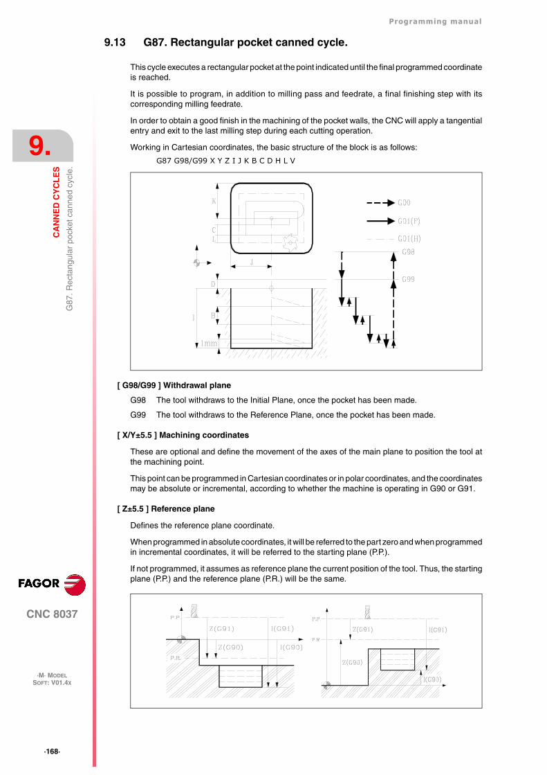
·168·
Programming manual
CNC 8037
9.
CA
NN
ED
CY
CL
ES
·M· MODELSOFT: V01.4X
G87
. Rec
tang
ular
poc
ket c
anne
d cy
cle.
9.13 G87. Rectangular pocket canned cycle.
This cycle executes a rectangular pocket at the point indicated until the final programmed coordinateis reached.
It is possible to program, in addition to milling pass and feedrate, a final finishing step with itscorresponding milling feedrate.
In order to obtain a good finish in the machining of the pocket walls, the CNC will apply a tangentialentry and exit to the last milling step during each cutting operation.
Working in Cartesian coordinates, the basic structure of the block is as follows:
G87 G98/G99 X Y Z I J K B C D H L V
[ G98/G99 ] Withdrawal plane
G98 The tool withdraws to the Initial Plane, once the pocket has been made.
G99 The tool withdraws to the Reference Plane, once the pocket has been made.
[ X/Y±5.5 ] Machining coordinates
These are optional and define the movement of the axes of the main plane to position the tool atthe machining point.
This point can be programmed in Cartesian coordinates or in polar coordinates, and the coordinatesmay be absolute or incremental, according to whether the machine is operating in G90 or G91.
[ Z±5.5 ] Reference plane
Defines the reference plane coordinate.
When programmed in absolute coordinates, it will be referred to the part zero and when programmedin incremental coordinates, it will be referred to the starting plane (P.P.).
If not programmed, it assumes as reference plane the current position of the tool. Thus, the startingplane (P.P.) and the reference plane (P.R.) will be the same.
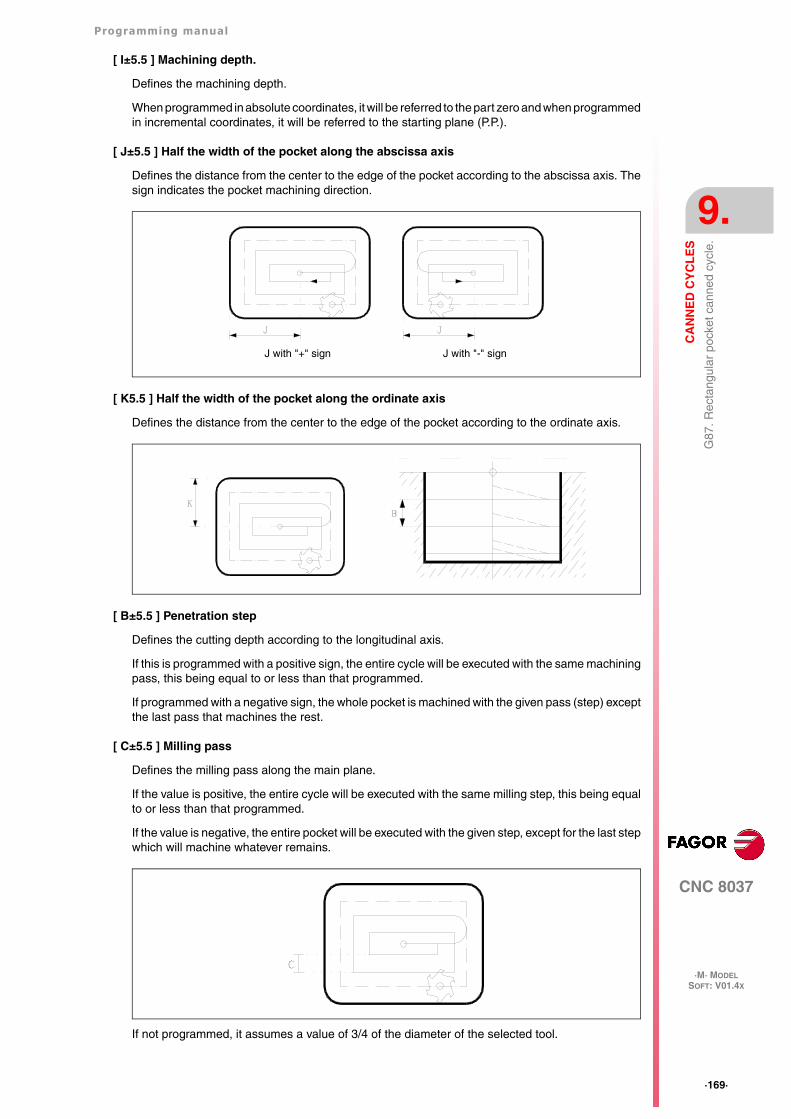
Programming manual
CNC 8037
CA
NN
ED
CY
CL
ES
9.
·M· MODELSOFT: V01.4X
·169·
G87
. Rec
tang
ular
poc
ket c
anne
d cy
cle.
[ I±5.5 ] Machining depth.
Defines the machining depth.
When programmed in absolute coordinates, it will be referred to the part zero and when programmedin incremental coordinates, it will be referred to the starting plane (P.P.).
[ J±5.5 ] Half the width of the pocket along the abscissa axis
Defines the distance from the center to the edge of the pocket according to the abscissa axis. Thesign indicates the pocket machining direction.
[ K5.5 ] Half the width of the pocket along the ordinate axis
Defines the distance from the center to the edge of the pocket according to the ordinate axis.
[ B±5.5 ] Penetration step
Defines the cutting depth according to the longitudinal axis.
If this is programmed with a positive sign, the entire cycle will be executed with the same machiningpass, this being equal to or less than that programmed.
If programmed with a negative sign, the whole pocket is machined with the given pass (step) exceptthe last pass that machines the rest.
[ C±5.5 ] Milling pass
Defines the milling pass along the main plane.
If the value is positive, the entire cycle will be executed with the same milling step, this being equalto or less than that programmed.
If the value is negative, the entire pocket will be executed with the given step, except for the last stepwhich will machine whatever remains.
If not programmed, it assumes a value of 3/4 of the diameter of the selected tool.
J with "+" sign J with "-" sign
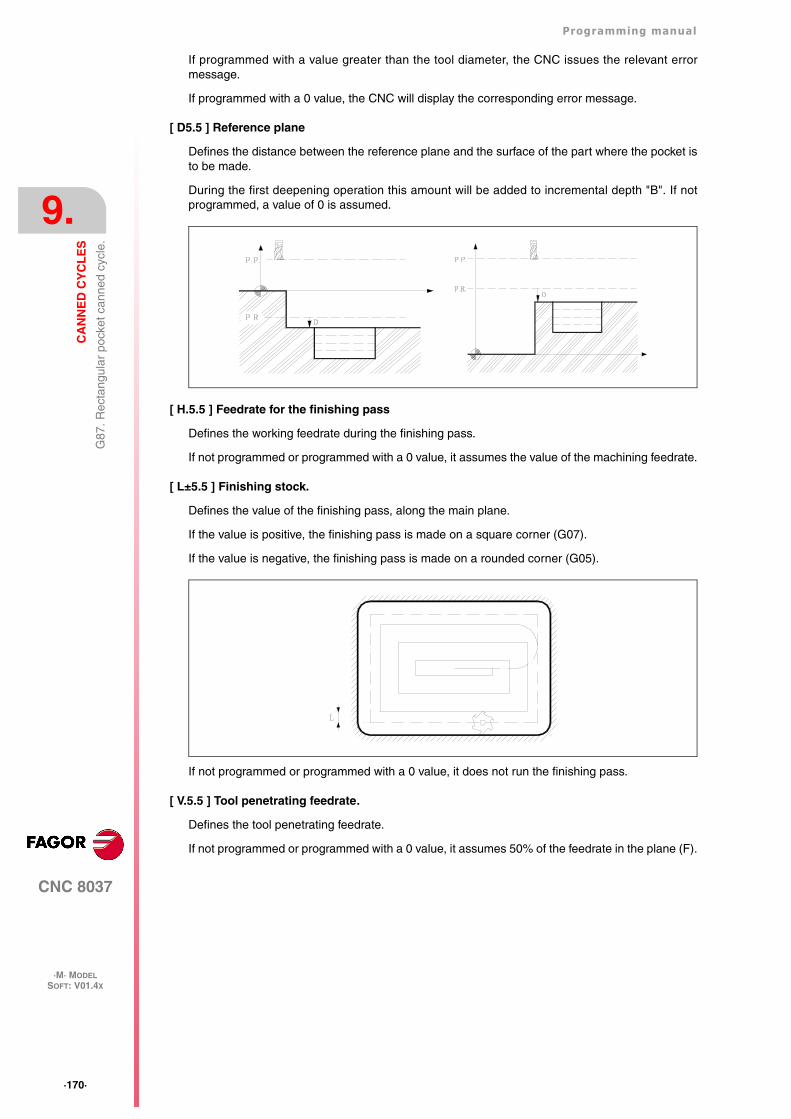
·170·
Programming manual
CNC 8037
9.
CA
NN
ED
CY
CL
ES
·M· MODELSOFT: V01.4X
G87
. Rec
tang
ular
poc
ket c
anne
d cy
cle.
If programmed with a value greater than the tool diameter, the CNC issues the relevant errormessage.
If programmed with a 0 value, the CNC will display the corresponding error message.
[ D5.5 ] Reference plane
Defines the distance between the reference plane and the surface of the part where the pocket isto be made.
During the first deepening operation this amount will be added to incremental depth "B". If notprogrammed, a value of 0 is assumed.
[ H.5.5 ] Feedrate for the finishing pass
Defines the working feedrate during the finishing pass.
If not programmed or programmed with a 0 value, it assumes the value of the machining feedrate.
[ L±5.5 ] Finishing stock.
Defines the value of the finishing pass, along the main plane.
If the value is positive, the finishing pass is made on a square corner (G07).
If the value is negative, the finishing pass is made on a rounded corner (G05).
If not programmed or programmed with a 0 value, it does not run the finishing pass.
[ V.5.5 ] Tool penetrating feedrate.
Defines the tool penetrating feedrate.
If not programmed or programmed with a 0 value, it assumes 50% of the feedrate in the plane (F).
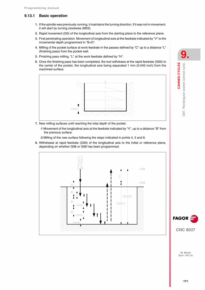
Programming manual
CNC 8037
CA
NN
ED
CY
CL
ES
9.
·M· MODELSOFT: V01.4X
·171·
G87
. Rec
tang
ular
poc
ket c
anne
d cy
cle.
9.13.1 Basic operation
1. If the spindle was previously running, it maintains the turning direction. If it was not in movement,it will start by turning clockwise (M03).
2. Rapid movement (G0) of the longitudinal axis from the starting plane to the reference plane.
3. First penetrating operation. Movement of longitudinal axis at the feedrate indicated by "V" to theincremental depth programmed in "B+D".
4. Milling of the pocket surface at work feedrate in the passes defined by "C" up to a distance "L"(finishing pass) from the pocket wall.
5. Finishing pass milling, "L" at the work feedrate defined by "H".
6. Once the finishing pass has been completed, the tool withdraws at the rapid feedrate (G00) tothe center of the pocket, the longitudinal axis being separated 1 mm (0.040 inch) from themachined surface.
7. New milling surfaces until reaching the total depth of the pocket.
·1·Movement of the longitudinal axis at the feedrate indicated by "V", up to a distance "B" fromthe previous surface.
·2·Milling of the new surface following the steps indicated in points 4, 5 and 6.
8. Withdrawal at rapid feedrate (G00) of the longitudinal axis to the initial or reference plane,depending on whether G98 or G99 has been programmed.
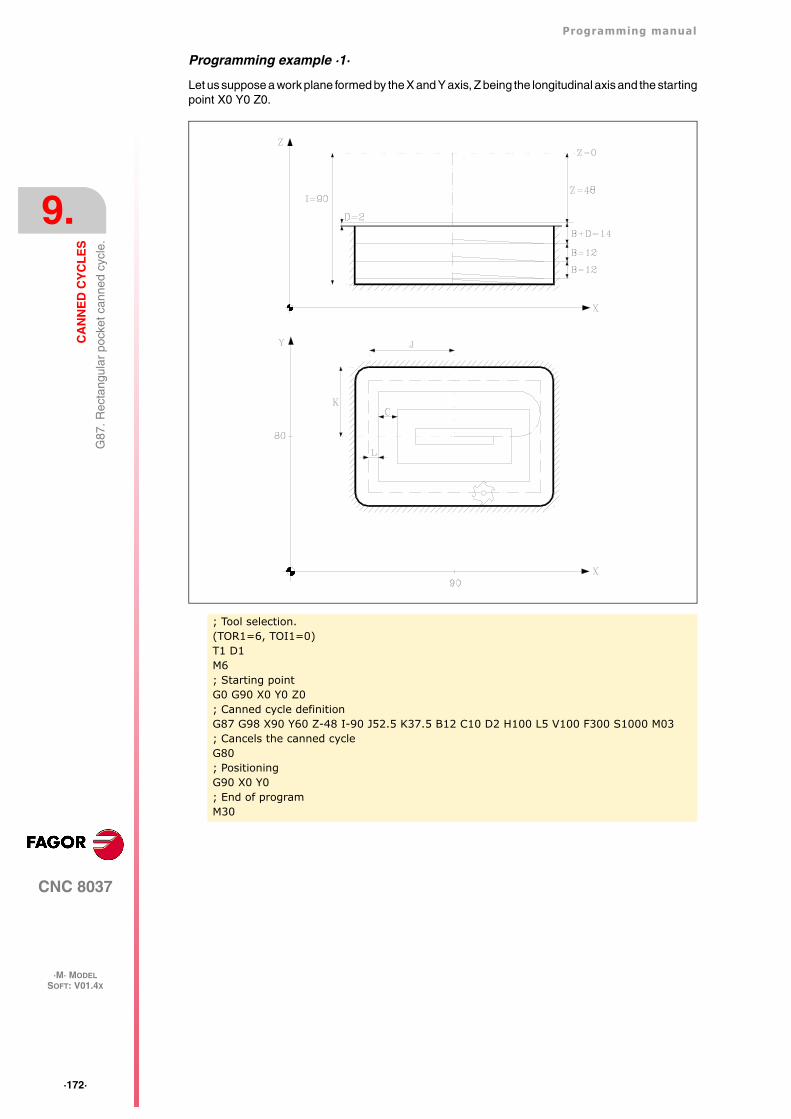
·172·
Programming manual
CNC 8037
9.
CA
NN
ED
CY
CL
ES
·M· MODELSOFT: V01.4X
G87
. Rec
tang
ular
poc
ket c
anne
d cy
cle.
Programming example ·1·
Let us suppose a work plane formed by the X and Y axis, Z being the longitudinal axis and the startingpoint X0 Y0 Z0.
; Tool selection.(TOR1=6, TOI1=0)T1 D1M6; Starting pointG0 G90 X0 Y0 Z0; Canned cycle definitionG87 G98 X90 Y60 Z-48 I-90 J52.5 K37.5 B12 C10 D2 H100 L5 V100 F300 S1000 M03; Cancels the canned cycleG80; PositioningG90 X0 Y0; End of programM30
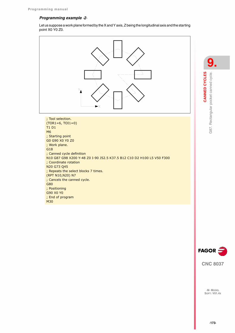
Programming manual
CNC 8037
CA
NN
ED
CY
CL
ES
9.
·M· MODELSOFT: V01.4X
·173·
G87
. Rec
tang
ular
poc
ket c
anne
d cy
cle.
Programming example ·2·
Let us suppose a work plane formed by the X and Y axis, Z being the longitudinal axis and the startingpoint X0 Y0 Z0.
; Tool selection.(TOR1=6, TOI1=0)T1 D1M6; Starting pointG0 G90 X0 Y0 Z0; Work plane.G18; Canned cycle definitionN10 G87 G98 X200 Y-48 Z0 I-90 J52.5 K37.5 B12 C10 D2 H100 L5 V50 F300; Coordinate rotationN20 G73 Q45; Repeats the select blocks 7 times.(RPT N10,N20) N7; Cancels the canned cycle.G80; PositioningG90 X0 Y0; End of programM30
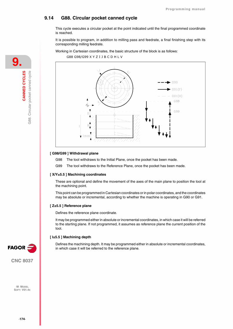
·174·
Programming manual
CNC 8037
9.
CA
NN
ED
CY
CL
ES
·M· MODELSOFT: V01.4X
G88
. Circ
ular
poc
ket c
anne
d cy
cle
9.14 G88. Circular pocket canned cycle
This cycle executes a circular pocket at the point indicated until the final programmed coordinateis reached.
It is possible to program, in addition to milling pass and feedrate, a final finishing step with itscorresponding milling feedrate.
Working in Cartesian coordinates, the basic structure of the block is as follows:
G88 G98/G99 X Y Z I J B C D H L V
[ G98/G99 ] Withdrawal plane
G98 The tool withdraws to the Initial Plane, once the pocket has been made.
G99 The tool withdraws to the Reference Plane, once the pocket has been made.
[ X/Y±5.5 ] Machining coordinates
These are optional and define the movement of the axes of the main plane to position the tool atthe machining point.
This point can be programmed in Cartesian coordinates or in polar coordinates, and the coordinatesmay be absolute or incremental, according to whether the machine is operating in G90 or G91.
[ Z±5.5 ] Reference plane
Defines the reference plane coordinate.
It may be programmed either in absolute or incremental coordinates, in which case it will be referredto the starting plane. If not programmed, it assumes as reference plane the current position of thetool.
[ I±5.5 ] Machining depth
Defines the machining depth. It may be programmed either in absolute or incremental coordinates,in which case it will be referred to the reference plane.
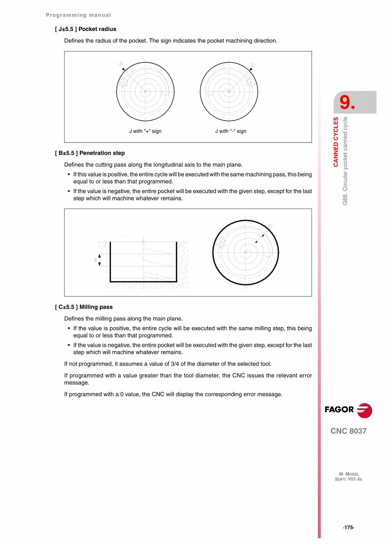
Programming manual
CNC 8037
CA
NN
ED
CY
CL
ES
9.
·M· MODELSOFT: V01.4X
·175·
G88
. Circ
ular
poc
ket c
anne
d cy
cle
[ J±5.5 ] Pocket radius
Defines the radius of the pocket. The sign indicates the pocket machining direction.
[ B±5.5 ] Penetration step
Defines the cutting pass along the longitudinal axis to the main plane.
• If this value is positive, the entire cycle will be executed with the same machining pass, this beingequal to or less than that programmed.
• If the value is negative, the entire pocket will be executed with the given step, except for the laststep which will machine whatever remains.
[ C±5.5 ] Milling pass
Defines the milling pass along the main plane.
• If the value is positive, the entire cycle will be executed with the same milling step, this beingequal to or less than that programmed.
• If the value is negative, the entire pocket will be executed with the given step, except for the laststep which will machine whatever remains.
If not programmed, it assumes a value of 3/4 of the diameter of the selected tool.
If programmed with a value greater than the tool diameter, the CNC issues the relevant errormessage.
If programmed with a 0 value, the CNC will display the corresponding error message.
J with "+" sign J with "-" sign
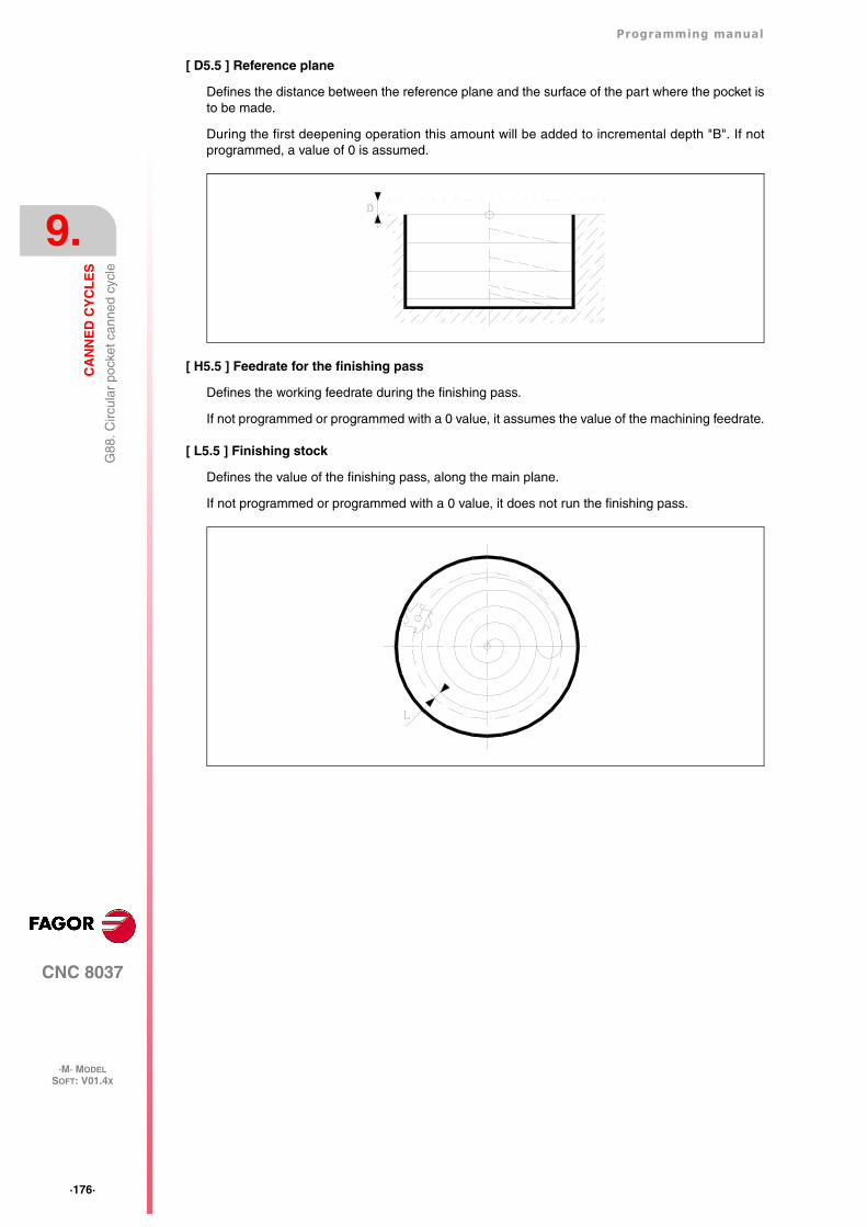
·176·
Programming manual
CNC 8037
9.
CA
NN
ED
CY
CL
ES
·M· MODELSOFT: V01.4X
G88
. Circ
ular
poc
ket c
anne
d cy
cle
[ D5.5 ] Reference plane
Defines the distance between the reference plane and the surface of the part where the pocket isto be made.
During the first deepening operation this amount will be added to incremental depth "B". If notprogrammed, a value of 0 is assumed.
[ H5.5 ] Feedrate for the finishing pass
Defines the working feedrate during the finishing pass.
If not programmed or programmed with a 0 value, it assumes the value of the machining feedrate.
[ L5.5 ] Finishing stock
Defines the value of the finishing pass, along the main plane.
If not programmed or programmed with a 0 value, it does not run the finishing pass.
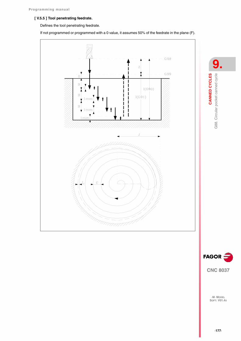
Programming manual
CNC 8037
CA
NN
ED
CY
CL
ES
9.
·M· MODELSOFT: V01.4X
·177·
G88
. Circ
ular
poc
ket c
anne
d cy
cle
[ V.5.5 ] Tool penetrating feedrate.
Defines the tool penetrating feedrate.
If not programmed or programmed with a 0 value, it assumes 50% of the feedrate in the plane (F).
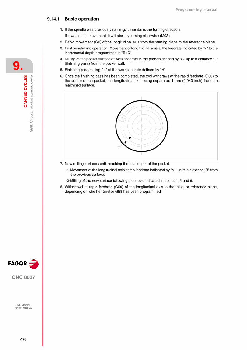
·178·
Programming manual
CNC 8037
9.
CA
NN
ED
CY
CL
ES
·M· MODELSOFT: V01.4X
G88
. Circ
ular
poc
ket c
anne
d cy
cle
9.14.1 Basic operation
1. If the spindle was previously running, it maintains the turning direction.
If it was not in movement, it will start by turning clockwise (M03).
2. Rapid movement (G0) of the longitudinal axis from the starting plane to the reference plane.
3. First penetrating operation. Movement of longitudinal axis at the feedrate indicated by "V" to theincremental depth programmed in "B+D".
4. Milling of the pocket surface at work feedrate in the passes defined by "C" up to a distance "L"(finishing pass) from the pocket wall.
5. Finishing pass milling, "L" at the work feedrate defined by "H".
6. Once the finishing pass has been completed, the tool withdraws at the rapid feedrate (G00) tothe center of the pocket, the longitudinal axis being separated 1 mm (0.040 inch) from themachined surface.
7. New milling surfaces until reaching the total depth of the pocket.
·1·Movement of the longitudinal axis at the feedrate indicated by "V", up to a distance "B" fromthe previous surface.
·2·Milling of the new surface following the steps indicated in points 4, 5 and 6.
8. Withdrawal at rapid feedrate (G00) of the longitudinal axis to the initial or reference plane,depending on whether G98 or G99 has been programmed.
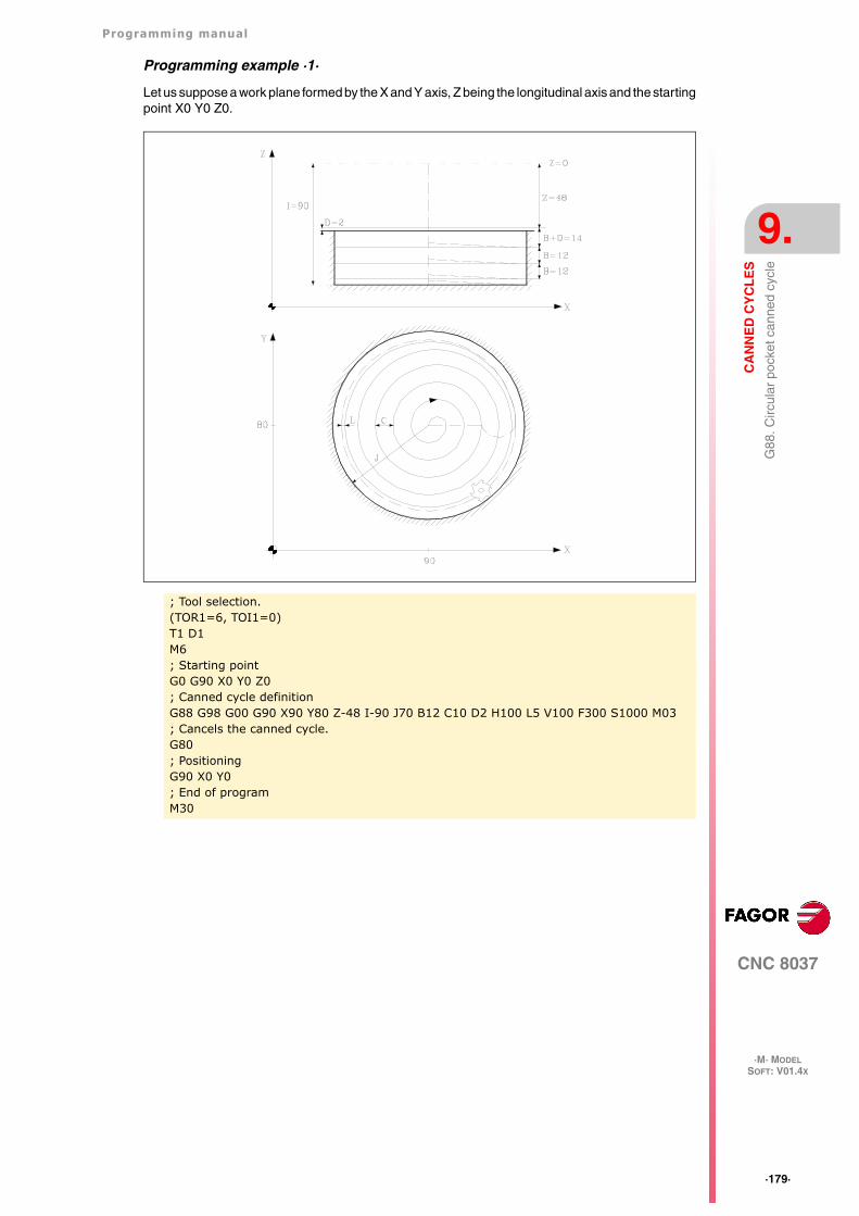
Programming manual
CNC 8037
CA
NN
ED
CY
CL
ES
9.
·M· MODELSOFT: V01.4X
·179·
G88
. Circ
ular
poc
ket c
anne
d cy
cle
Programming example ·1·
Let us suppose a work plane formed by the X and Y axis, Z being the longitudinal axis and the startingpoint X0 Y0 Z0.
; Tool selection.(TOR1=6, TOI1=0)T1 D1M6; Starting pointG0 G90 X0 Y0 Z0; Canned cycle definitionG88 G98 G00 G90 X90 Y80 Z-48 I-90 J70 B12 C10 D2 H100 L5 V100 F300 S1000 M03; Cancels the canned cycle.G80; PositioningG90 X0 Y0; End of programM30
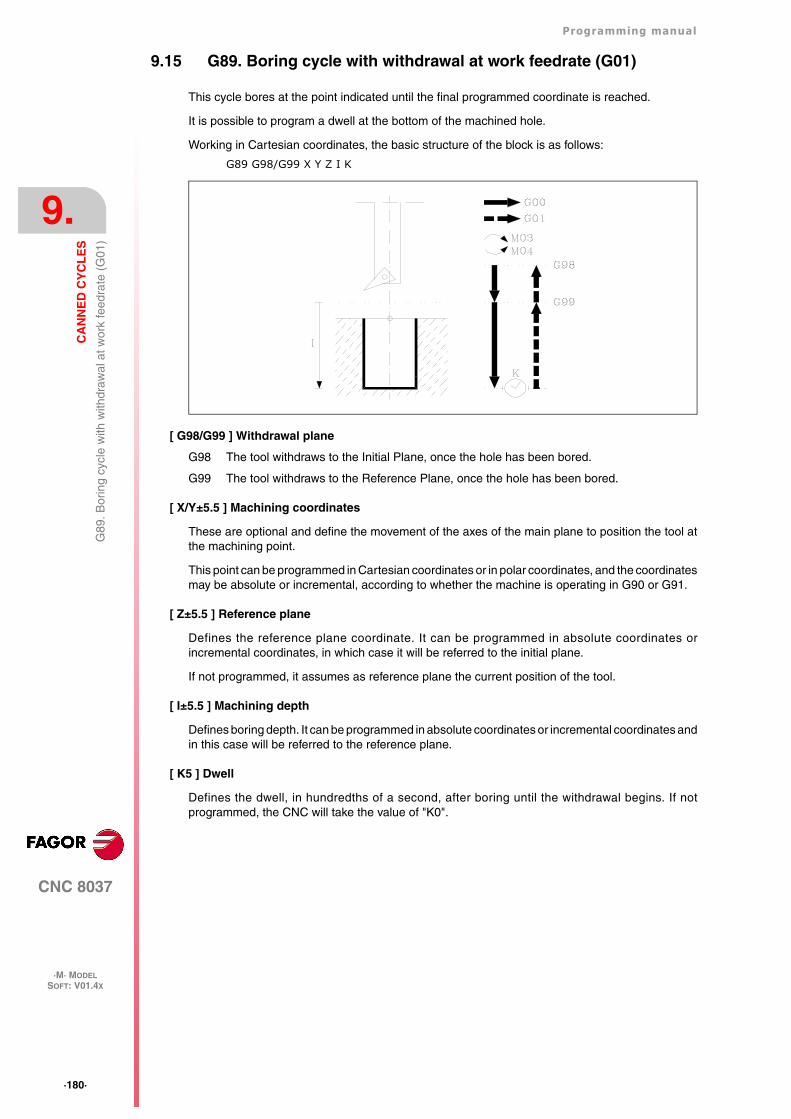
·180·
Programming manual
CNC 8037
9.
CA
NN
ED
CY
CL
ES
·M· MODELSOFT: V01.4X
G89
. Bor
ing
cycl
e w
ith w
ithdr
awal
at w
ork
feed
rate
(G
01)
9.15 G89. Boring cycle with withdrawal at work feedrate (G01)
This cycle bores at the point indicated until the final programmed coordinate is reached.
It is possible to program a dwell at the bottom of the machined hole.
Working in Cartesian coordinates, the basic structure of the block is as follows:
G89 G98/G99 X Y Z I K
[ G98/G99 ] Withdrawal plane
G98 The tool withdraws to the Initial Plane, once the hole has been bored.
G99 The tool withdraws to the Reference Plane, once the hole has been bored.
[ X/Y±5.5 ] Machining coordinates
These are optional and define the movement of the axes of the main plane to position the tool atthe machining point.
This point can be programmed in Cartesian coordinates or in polar coordinates, and the coordinatesmay be absolute or incremental, according to whether the machine is operating in G90 or G91.
[ Z±5.5 ] Reference plane
Defines the reference plane coordinate. It can be programmed in absolute coordinates orincremental coordinates, in which case it will be referred to the initial plane.
If not programmed, it assumes as reference plane the current position of the tool.
[ I±5.5 ] Machining depth
Defines boring depth. It can be programmed in absolute coordinates or incremental coordinates andin this case will be referred to the reference plane.
[ K5 ] Dwell
Defines the dwell, in hundredths of a second, after boring until the withdrawal begins. If notprogrammed, the CNC will take the value of "K0".
Programming manual
CNC 8037
CA
NN
ED
CY
CL
ES
9.
·M· MODELSOFT: V01.4X
·181·
G89
. Bor
ing
cycl
e w
ith w
ithdr
awal
at w
ork
feed
rate
(G
01)
9.15.1 Basic operation
1. If the spindle was previously running, it maintains the turning direction. If it was not in movement,it will start by turning clockwise (M03).
2. Rapid movement of the longitudinal axis from the initial plane to the reference plane.
3. Movement at the working feedrate (G01) of the longitudinal axis to the bottom of the machinedhole, and boring.
4. Dwell, if parameter "K" has been programmed.
5. Withdrawal at working feedrate, of the longitudinal axis as far as the reference plane.
6. Withdrawal, at rapid feedrate (G00), of the longitudinal axis as far as the initial plane if G98 hasbeen programmed.
Programming example ·1·
Let us suppose a work plane formed by the X and Y axis, Z being the longitudinal axis and the startingpoint X0 Y0 Z0.
; Tool selection.T1 D1M6; Starting pointG0 G90 X0 Y0 Z0; Canned cycle definitionG89 G98 G91 X250 Y350 Z-98 I-22 K20 F100 S500; Cancels the canned cycle.G80; PositioningG90 X0 Y0; End of programM30
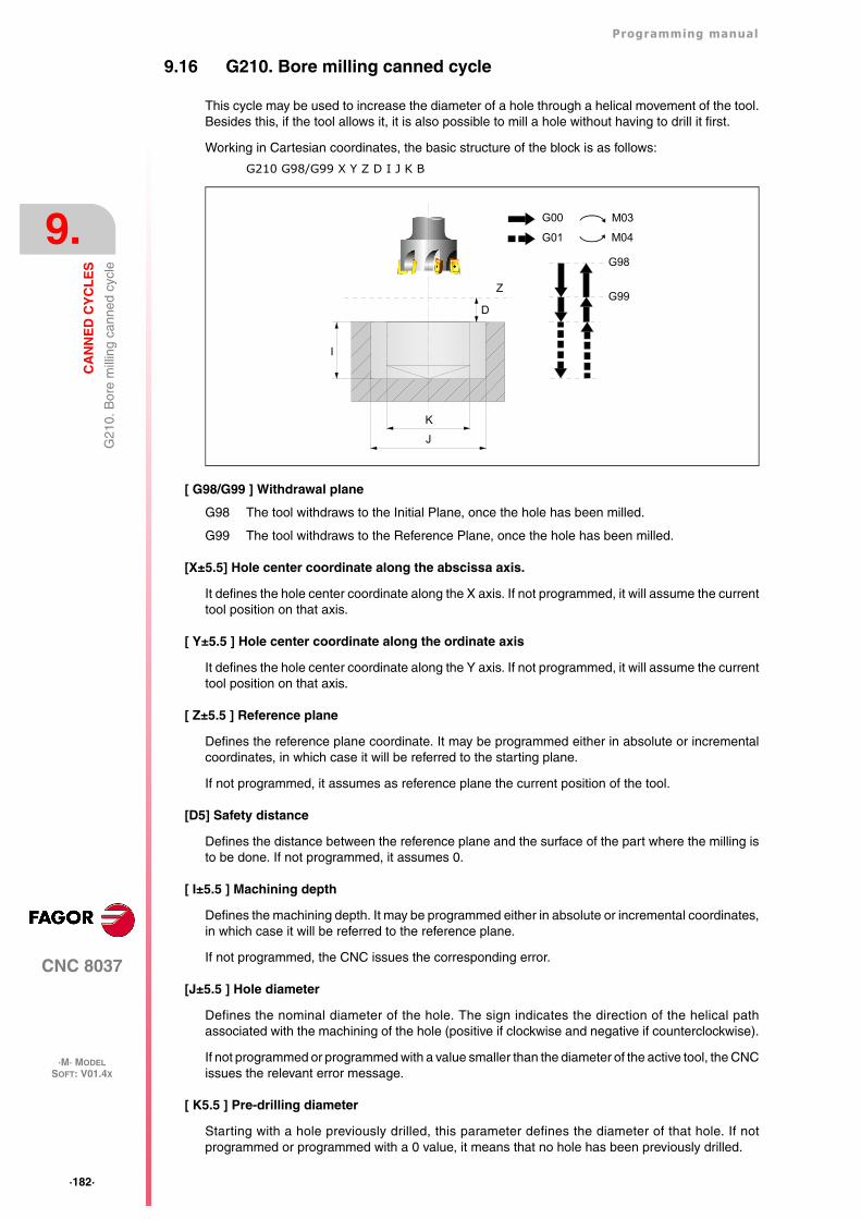
·182·
Programming manual
CNC 8037
9.
CA
NN
ED
CY
CL
ES
·M· MODELSOFT: V01.4X
G21
0. B
ore
mill
ing
cann
ed c
ycle
9.16 G210. Bore milling canned cycle
This cycle may be used to increase the diameter of a hole through a helical movement of the tool.Besides this, if the tool allows it, it is also possible to mill a hole without having to drill it first.
Working in Cartesian coordinates, the basic structure of the block is as follows:
G210 G98/G99 X Y Z D I J K B
[ G98/G99 ] Withdrawal plane
G98 The tool withdraws to the Initial Plane, once the hole has been milled.
G99 The tool withdraws to the Reference Plane, once the hole has been milled.
[X±5.5] Hole center coordinate along the abscissa axis.
It defines the hole center coordinate along the X axis. If not programmed, it will assume the currenttool position on that axis.
[ Y±5.5 ] Hole center coordinate along the ordinate axis
It defines the hole center coordinate along the Y axis. If not programmed, it will assume the currenttool position on that axis.
[ Z±5.5 ] Reference plane
Defines the reference plane coordinate. It may be programmed either in absolute or incrementalcoordinates, in which case it will be referred to the starting plane.
If not programmed, it assumes as reference plane the current position of the tool.
[D5] Safety distance
Defines the distance between the reference plane and the surface of the part where the milling isto be done. If not programmed, it assumes 0.
[ I±5.5 ] Machining depth
Defines the machining depth. It may be programmed either in absolute or incremental coordinates,in which case it will be referred to the reference plane.
If not programmed, the CNC issues the corresponding error.
[J±5.5 ] Hole diameter
Defines the nominal diameter of the hole. The sign indicates the direction of the helical pathassociated with the machining of the hole (positive if clockwise and negative if counterclockwise).
If not programmed or programmed with a value smaller than the diameter of the active tool, the CNCissues the relevant error message.
[ K5.5 ] Pre-drilling diameter
Starting with a hole previously drilled, this parameter defines the diameter of that hole. If notprogrammed or programmed with a 0 value, it means that no hole has been previously drilled.
G98
G99
I
K
Z
D
J
G00
G01
M03
M04
Programming manual
CNC 8037
CA
NN
ED
CY
CL
ES
9.
·M· MODELSOFT: V01.4X
·183·
G21
0. B
ore
mill
ing
cann
ed c
ycle
The tool must meet the following conditions:
• The tool radius must be smaller than J/2.
• The tool radius must be equal to or larger than (J-K)/4.
If these two conditions are not met, the CNC issues the corresponding error.
[ B±5.5 ] Penetration step
It defines the penetration step when machining the hole.
• With a positive sign, it will mill the bottom of the hole.
• With a negative sign, it will not mill the bottom of the hole.
If not programmed or programmed with a 0 value, the CNC will display the corresponding errormessage.
·184·
Programming manual
CNC 8037
9.
CA
NN
ED
CY
CL
ES
·M· MODELSOFT: V01.4X
G21
0. B
ore
mill
ing
cann
ed c
ycle
9.16.1 Basic operation
1. Rapid movement to the center of the hole (X, Y).
2. Rapid movement to the reference plane (Z).
3. Rapid movement to the tangential entry coordinate along the longitudinal axis.
4. Tangential entry to the helical path of the drilling.
5. Helical movement, with the pitch given by parameter B and in the direction given by parameterJ, down to the bottom of the hole.
6. Milling of the bottom of the hole (this step is only carried out if parameter B has a positive sign).
7. Tangential exit movement to the helical path of the drilling to the center of the hole.
8. Rapid movement to the reference plane (G99) or to the starting plane (G98).
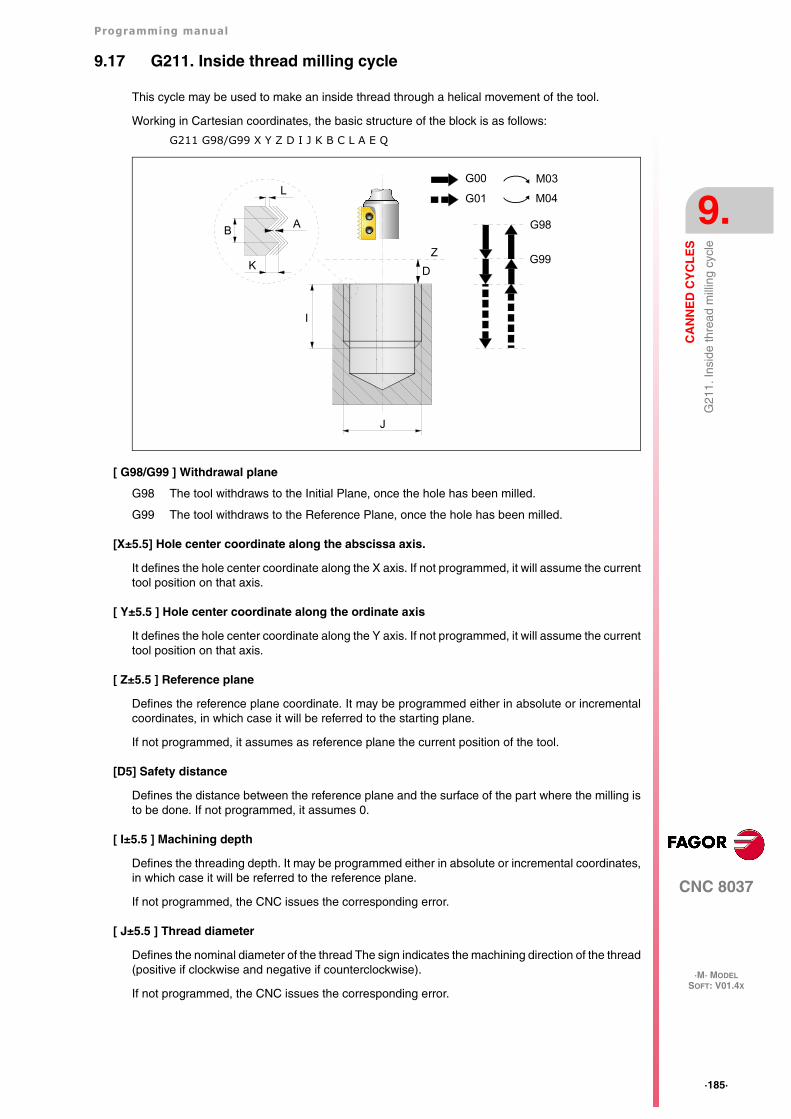
Programming manual
CNC 8037
CA
NN
ED
CY
CL
ES
9.
·M· MODELSOFT: V01.4X
·185·
G21
1. In
side
thre
ad m
illin
g cy
cle
9.17 G211. Inside thread milling cycle
This cycle may be used to make an inside thread through a helical movement of the tool.
Working in Cartesian coordinates, the basic structure of the block is as follows:
G211 G98/G99 X Y Z D I J K B C L A E Q
[ G98/G99 ] Withdrawal plane
G98 The tool withdraws to the Initial Plane, once the hole has been milled.
G99 The tool withdraws to the Reference Plane, once the hole has been milled.
[X±5.5] Hole center coordinate along the abscissa axis.
It defines the hole center coordinate along the X axis. If not programmed, it will assume the currenttool position on that axis.
[ Y±5.5 ] Hole center coordinate along the ordinate axis
It defines the hole center coordinate along the Y axis. If not programmed, it will assume the currenttool position on that axis.
[ Z±5.5 ] Reference plane
Defines the reference plane coordinate. It may be programmed either in absolute or incrementalcoordinates, in which case it will be referred to the starting plane.
If not programmed, it assumes as reference plane the current position of the tool.
[D5] Safety distance
Defines the distance between the reference plane and the surface of the part where the milling isto be done. If not programmed, it assumes 0.
[ I±5.5 ] Machining depth
Defines the threading depth. It may be programmed either in absolute or incremental coordinates,in which case it will be referred to the reference plane.
If not programmed, the CNC issues the corresponding error.
[ J±5.5 ] Thread diameter
Defines the nominal diameter of the thread The sign indicates the machining direction of the thread(positive if clockwise and negative if counterclockwise).
If not programmed, the CNC issues the corresponding error.
J
Z
D
I
B
K
L
A
G00
G01
M03
M04
G98
G99
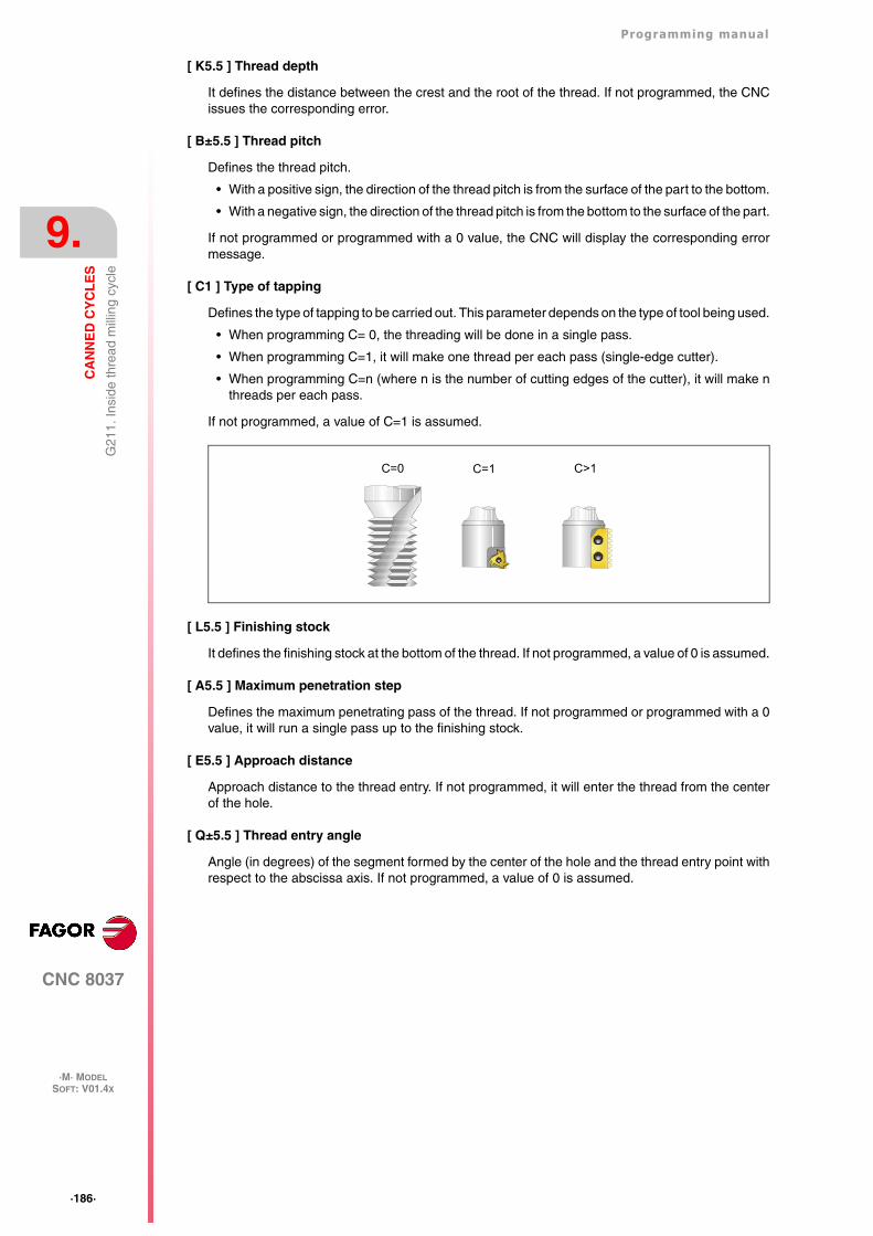
·186·
Programming manual
CNC 8037
9.
CA
NN
ED
CY
CL
ES
·M· MODELSOFT: V01.4X
G21
1. In
side
thre
ad m
illin
g cy
cle
[ K5.5 ] Thread depth
It defines the distance between the crest and the root of the thread. If not programmed, the CNCissues the corresponding error.
[ B±5.5 ] Thread pitch
Defines the thread pitch.
• With a positive sign, the direction of the thread pitch is from the surface of the part to the bottom.
• With a negative sign, the direction of the thread pitch is from the bottom to the surface of the part.
If not programmed or programmed with a 0 value, the CNC will display the corresponding errormessage.
[ C1 ] Type of tapping
Defines the type of tapping to be carried out. This parameter depends on the type of tool being used.
• When programming C= 0, the threading will be done in a single pass.
• When programming C=1, it will make one thread per each pass (single-edge cutter).
• When programming C=n (where n is the number of cutting edges of the cutter), it will make nthreads per each pass.
If not programmed, a value of C=1 is assumed.
[ L5.5 ] Finishing stock
It defines the finishing stock at the bottom of the thread. If not programmed, a value of 0 is assumed.
[ A5.5 ] Maximum penetration step
Defines the maximum penetrating pass of the thread. If not programmed or programmed with a 0value, it will run a single pass up to the finishing stock.
[ E5.5 ] Approach distance
Approach distance to the thread entry. If not programmed, it will enter the thread from the centerof the hole.
[ Q±5.5 ] Thread entry angle
Angle (in degrees) of the segment formed by the center of the hole and the thread entry point withrespect to the abscissa axis. If not programmed, a value of 0 is assumed.
C=0 C=1 C>1
Programming manual
CNC 8037
CA
NN
ED
CY
CL
ES
9.
·M· MODELSOFT: V01.4X
·187·
G21
1. In
side
thre
ad m
illin
g cy
cle
9.17.1 Basic operation
1. Rapid movement to the center of the hole (X, Y).
2. Rapid movement to the reference plane (Z).
3. Rapid movement of the plane axes to the thread entry point (it only makes this movement ifparameter E has been programmed).
4. Rapid movement to the thread entry point coordinate along the longitudinal axis.
5. Thread entry with a helical movement tangent to the first helical threading path.
6. Making the thread according to the value of parameter C.
If C=0:
·1·Helical movement, in the direction indicated in parameter J, to the bottom of the thread(the movement will only be one revolution).
·2·Helical thread exiting movement, tangent to the previous helical path. If parameter E hasnot been programmed, the exit point will correspond with the coordinates of the holecenter.
It must be borne in mind that in the exit tangent to the helical path, the exit point will exceedthe coordinate of the bottom of the thread along the longitudinal axis.
If C=1:
·1·Helical movement, with the pitch and direction given in parameter J, to the bottom of thethread.
·2·Helical thread exiting movement, tangent to the previous helical path. If parameter E hasnot been programmed, the exit point will correspond with the coordinates of the holecenter.
It must be borne in mind that in the exit tangent to the helical path, the exit point will exceedthe coordinate of the bottom of the thread along the longitudinal axis.
If C=n:
·1·Helical movement, with the pitch and direction given in parameter J, (the movement willbe one revolution).
·2·Helical thread exiting movement, tangent to the previous helical path. If parameter E hasnot been programmed, the exit point will correspond with the coordinates of the holecenter.
·3·Rapid movement to the thread entry point of the next threading path.
·4·Rapid movement to the Z coordinate of the thread entry point of the next threading path.
·5·Repetition of the previous 3 steps until reaching the bottom of the thread. It must be bornein mind that in the last helical exit, the exit point will exceed the coordinate of the bottomof the thread along the longitudinal axis.
7. Rapid movement to the center of the hole (X, Y).
8. Rapid movement to the thread entry coordinate along the longitudinal axis.
9. Repetition of steps 3 to 8 until reaching the depth of the finishing stock.
10.Repetition of steps 3 to 8 until reaching the bottom of the thread.
11.Rapid movement to the reference plane (G99) or to the starting plane (G98).
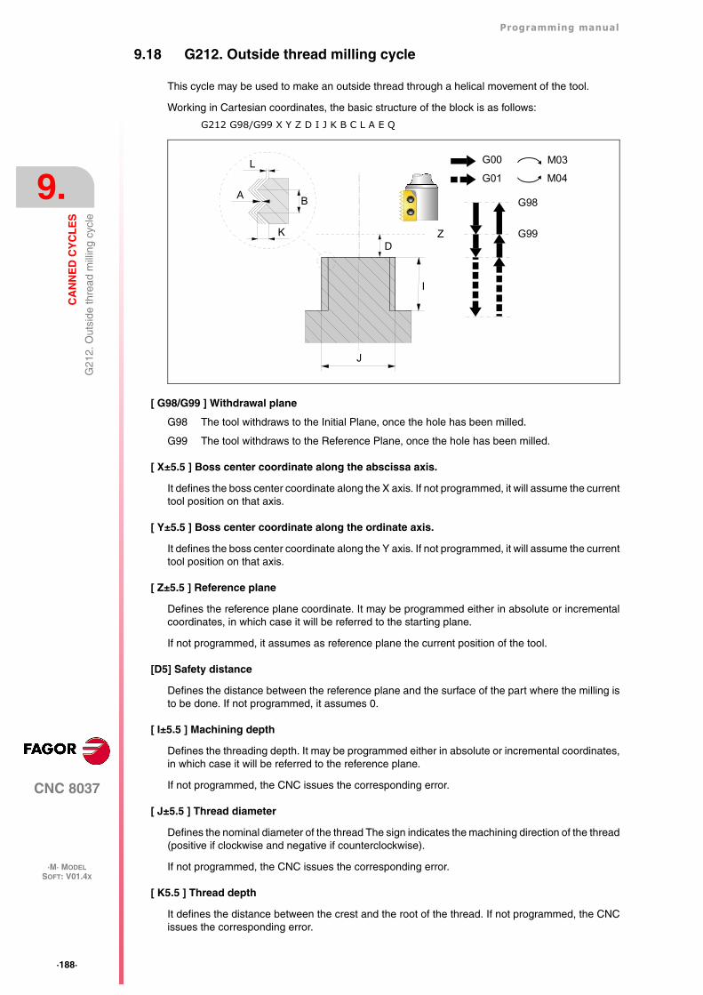
·188·
Programming manual
CNC 8037
9.
CA
NN
ED
CY
CL
ES
·M· MODELSOFT: V01.4X
G21
2. O
utsi
de th
read
mill
ing
cycl
e
9.18 G212. Outside thread milling cycle
This cycle may be used to make an outside thread through a helical movement of the tool.
Working in Cartesian coordinates, the basic structure of the block is as follows:
G212 G98/G99 X Y Z D I J K B C L A E Q
[ G98/G99 ] Withdrawal plane
G98 The tool withdraws to the Initial Plane, once the hole has been milled.
G99 The tool withdraws to the Reference Plane, once the hole has been milled.
[ X±5.5 ] Boss center coordinate along the abscissa axis.
It defines the boss center coordinate along the X axis. If not programmed, it will assume the currenttool position on that axis.
[ Y±5.5 ] Boss center coordinate along the ordinate axis.
It defines the boss center coordinate along the Y axis. If not programmed, it will assume the currenttool position on that axis.
[ Z±5.5 ] Reference plane
Defines the reference plane coordinate. It may be programmed either in absolute or incrementalcoordinates, in which case it will be referred to the starting plane.
If not programmed, it assumes as reference plane the current position of the tool.
[D5] Safety distance
Defines the distance between the reference plane and the surface of the part where the milling isto be done. If not programmed, it assumes 0.
[ I±5.5 ] Machining depth
Defines the threading depth. It may be programmed either in absolute or incremental coordinates,in which case it will be referred to the reference plane.
If not programmed, the CNC issues the corresponding error.
[ J±5.5 ] Thread diameter
Defines the nominal diameter of the thread The sign indicates the machining direction of the thread(positive if clockwise and negative if counterclockwise).
If not programmed, the CNC issues the corresponding error.
[ K5.5 ] Thread depth
It defines the distance between the crest and the root of the thread. If not programmed, the CNCissues the corresponding error.
J
ZD
I
B
K
L G00
G01
M03
M04
G98
G99
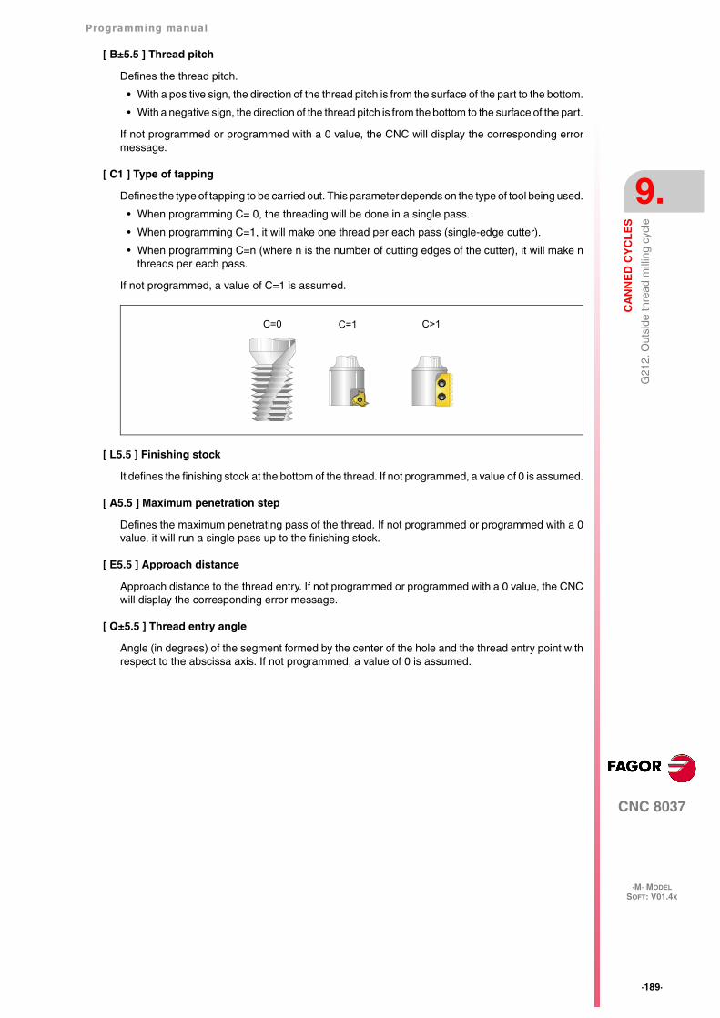
Programming manual
CNC 8037
CA
NN
ED
CY
CL
ES
9.
·M· MODELSOFT: V01.4X
·189·
G21
2. O
utsi
de th
read
mill
ing
cycl
e
[ B±5.5 ] Thread pitch
Defines the thread pitch.
• With a positive sign, the direction of the thread pitch is from the surface of the part to the bottom.
• With a negative sign, the direction of the thread pitch is from the bottom to the surface of the part.
If not programmed or programmed with a 0 value, the CNC will display the corresponding errormessage.
[ C1 ] Type of tapping
Defines the type of tapping to be carried out. This parameter depends on the type of tool being used.
• When programming C= 0, the threading will be done in a single pass.
• When programming C=1, it will make one thread per each pass (single-edge cutter).
• When programming C=n (where n is the number of cutting edges of the cutter), it will make nthreads per each pass.
If not programmed, a value of C=1 is assumed.
[ L5.5 ] Finishing stock
It defines the finishing stock at the bottom of the thread. If not programmed, a value of 0 is assumed.
[ A5.5 ] Maximum penetration step
Defines the maximum penetrating pass of the thread. If not programmed or programmed with a 0value, it will run a single pass up to the finishing stock.
[ E5.5 ] Approach distance
Approach distance to the thread entry. If not programmed or programmed with a 0 value, the CNCwill display the corresponding error message.
[ Q±5.5 ] Thread entry angle
Angle (in degrees) of the segment formed by the center of the hole and the thread entry point withrespect to the abscissa axis. If not programmed, a value of 0 is assumed.
C=0 C=1 C>1
·190·
Programming manual
CNC 8037
9.
CA
NN
ED
CY
CL
ES
·M· MODELSOFT: V01.4X
G21
2. O
utsi
de th
read
mill
ing
cycl
e
9.18.1 Basic operation
1. Rapid movement to the center of the hole (X, Y).
2. Rapid movement to the reference plane (Z).
3. Rapid movement of the plane axes to the thread entry point (it only makes this movement ifparameter E has been programmed).
4. Rapid movement to the thread entry point coordinate along the longitudinal axis.
5. Rapid movement to the thread entry point (movement interpolated in 3 axes).
6. Thread entry with a helical movement tangent to the first helical threading path.
7. Making the thread according to the value of parameter C.
If C=0:
·1·Helical movement, in the direction indicated in parameter J, to the bottom of the thread(the movement will only be one revolution).
·2·Helical thread exiting movement, tangent to the previous helical path.
It must be borne in mind that in the exit tangent to the helical path, the exit point will exceedthe coordinate of the bottom of the thread along the longitudinal axis.
If C=1:
·1·Helical movement, with the pitch and direction given in parameter J, to the bottom of thethread.
·2·Helical thread exiting movement, tangent to the previous helical path.
It must be borne in mind that in the exit tangent to the helical path, the exit point will exceedthe coordinate of the bottom of the thread along the longitudinal axis.
If C=n:
·1·Helical movement, with the pitch and direction given in parameter J, (the movement willbe one revolution).
·2·Helical thread exiting movement, tangent to the previous helical path to the thread entrypoint.
·3·Rapid movement to the Z coordinate of the thread entry point of the next threading path.
·4·Repetition of the previous 3 steps until reaching the bottom of the thread. It must be bornein mind that in the last helical exit, the exit point will exceed the coordinate of the bottomof the thread along the longitudinal axis.
8. Rapid movement to the reference plane (G99).
9. Repetition of steps 3 to 8 until reaching the depth of the finishing stock.
10.Repetition of steps 3 to 8 until reaching the bottom of the thread.
11.Rapid movement to the reference plane (G99) or to the starting plane (G98).
12.Rapid movement to the center of the hole (X, Y).
CNC 8037
·M· MODELSOFT: V01.4X
10
·191·
MULTIPLE MACHINING
Multiple machining is defined as a series of functions which allow a machining operation to berepeated along a given path.
The programmer will select the type of machining, which can be a canned cycle or a subroutine(which must be programmed as a modal subroutine) defined by the user.
Machining paths are defined by the following functions:
G60: Multiple machining in a straight line
G61: Multiple machining in a rectangular pattern.
G62: Multiple machining in a grid pattern.
G63: Multiple machining in a circular pattern.
G64: Multiple machining in an arc
G65: Machining programmed with an arc-chord
These functions can be performed on any work plane and must be defined every time they are used,as they are not modal.
It is absolutely essential for the machining which it is required to repeat to be active. In other words,these functions will only make sense if they are under the influence of a canned cycle or under theinfluence of a modal subroutine.
To perform multiple machining, follow these steps:
1. Move the tool to the first point of the multiple machining operation.
2. Define the canned cycle or modal subroutine to be repeated at all the points.
3. Define the multiple operation to be performed.
All machining operations programmed with these functions will be done under the same workingconditions (T,D,F,S) which were selected when defining the canned cycle or modal subroutine.
Once the multiple machining operation has been performed, the program will recover the historyit had before starting this machining, even when the canned cycle or modal subroutine will remainactive. Now feedrate F corresponds to the feedrate programmed for the canned cycle or modalsubroutine.
Likewise, the tool will be positioned at the last point where the programmed machining operationwas done.
If multiple machining of a modal subroutine is performed in the Single Block mode, this subroutinewill be performed complete (not block by block) after each programmed movement.
A detailed explanation is given on the next page of multiple machining operations, assuming in eachcase, that the work plane is formed by X and Y axes.
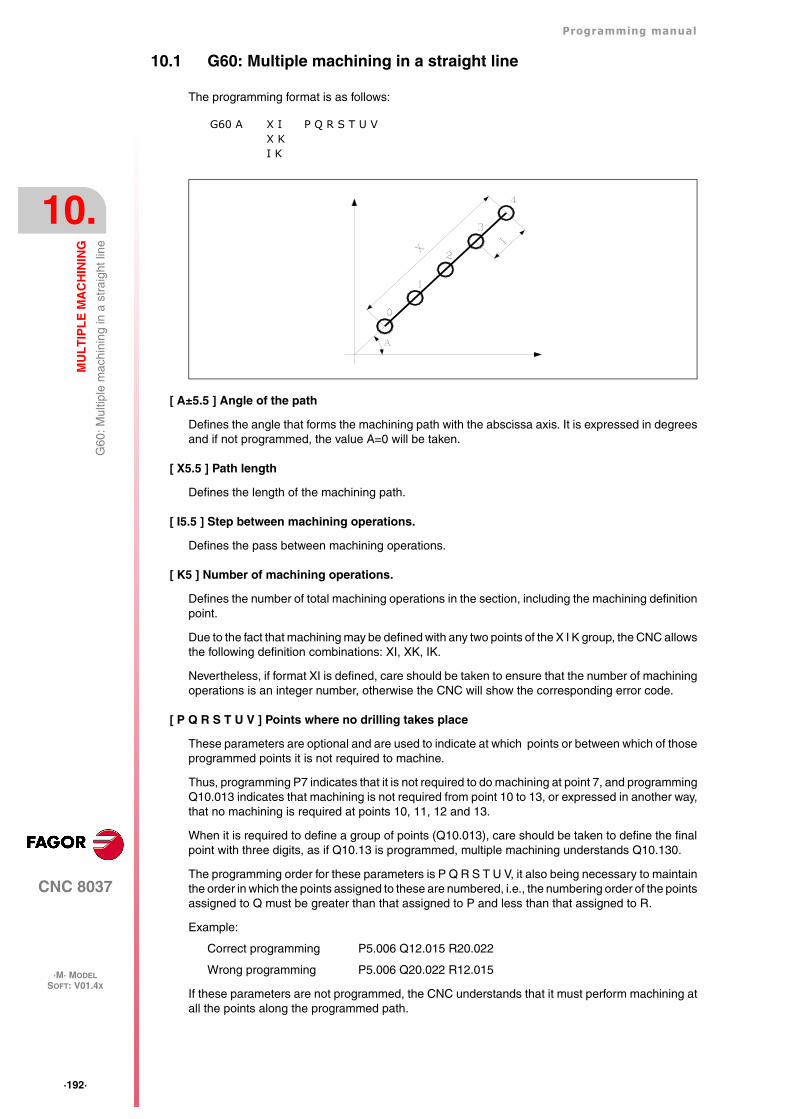
·192·
Programming manual
CNC 8037
10.
MU
LT
IPL
E M
AC
HIN
ING
·M· MODELSOFT: V01.4X
G60
: Mul
tiple
mac
hini
ng in
a s
trai
ght l
ine
10.1 G60: Multiple machining in a straight line
The programming format is as follows:
[ A±5.5 ] Angle of the path
Defines the angle that forms the machining path with the abscissa axis. It is expressed in degreesand if not programmed, the value A=0 will be taken.
[ X5.5 ] Path length
Defines the length of the machining path.
[ I5.5 ] Step between machining operations.
Defines the pass between machining operations.
[ K5 ] Number of machining operations.
Defines the number of total machining operations in the section, including the machining definitionpoint.
Due to the fact that machining may be defined with any two points of the X I K group, the CNC allowsthe following definition combinations: XI, XK, IK.
Nevertheless, if format XI is defined, care should be taken to ensure that the number of machiningoperations is an integer number, otherwise the CNC will show the corresponding error code.
[ P Q R S T U V ] Points where no drilling takes place
These parameters are optional and are used to indicate at which points or between which of thoseprogrammed points it is not required to machine.
Thus, programming P7 indicates that it is not required to do machining at point 7, and programmingQ10.013 indicates that machining is not required from point 10 to 13, or expressed in another way,that no machining is required at points 10, 11, 12 and 13.
When it is required to define a group of points (Q10.013), care should be taken to define the finalpoint with three digits, as if Q10.13 is programmed, multiple machining understands Q10.130.
The programming order for these parameters is P Q R S T U V, it also being necessary to maintainthe order in which the points assigned to these are numbered, i.e., the numbering order of the pointsassigned to Q must be greater than that assigned to P and less than that assigned to R.
Example:
Correct programming P5.006 Q12.015 R20.022
Wrong programming P5.006 Q20.022 R12.015
If these parameters are not programmed, the CNC understands that it must perform machining atall the points along the programmed path.
G60 A X IX K I K
P Q R S T U V
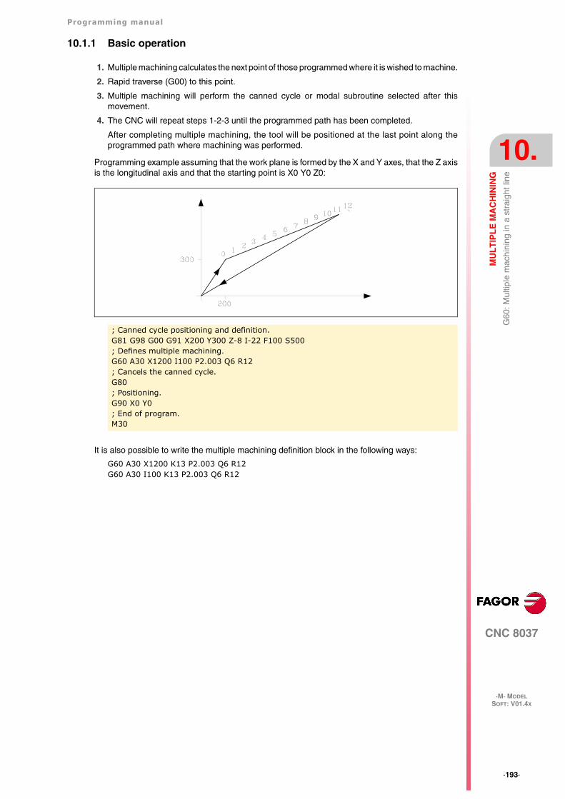
Programming manual
CNC 8037
MU
LT
IPL
E M
AC
HIN
ING
10.
·M· MODELSOFT: V01.4X
·193·
G60
: Mul
tiple
mac
hini
ng in
a s
trai
ght l
ine
10.1.1 Basic operation
1. Multiple machining calculates the next point of those programmed where it is wished to machine.
2. Rapid traverse (G00) to this point.
3. Multiple machining will perform the canned cycle or modal subroutine selected after thismovement.
4. The CNC will repeat steps 1-2-3 until the programmed path has been completed.
After completing multiple machining, the tool will be positioned at the last point along theprogrammed path where machining was performed.
Programming example assuming that the work plane is formed by the X and Y axes, that the Z axisis the longitudinal axis and that the starting point is X0 Y0 Z0:
It is also possible to write the multiple machining definition block in the following ways:
G60 A30 X1200 K13 P2.003 Q6 R12G60 A30 I100 K13 P2.003 Q6 R12
; Canned cycle positioning and definition.G81 G98 G00 G91 X200 Y300 Z-8 I-22 F100 S500; Defines multiple machining.G60 A30 X1200 I100 P2.003 Q6 R12; Cancels the canned cycle.G80; Positioning.G90 X0 Y0; End of program.M30
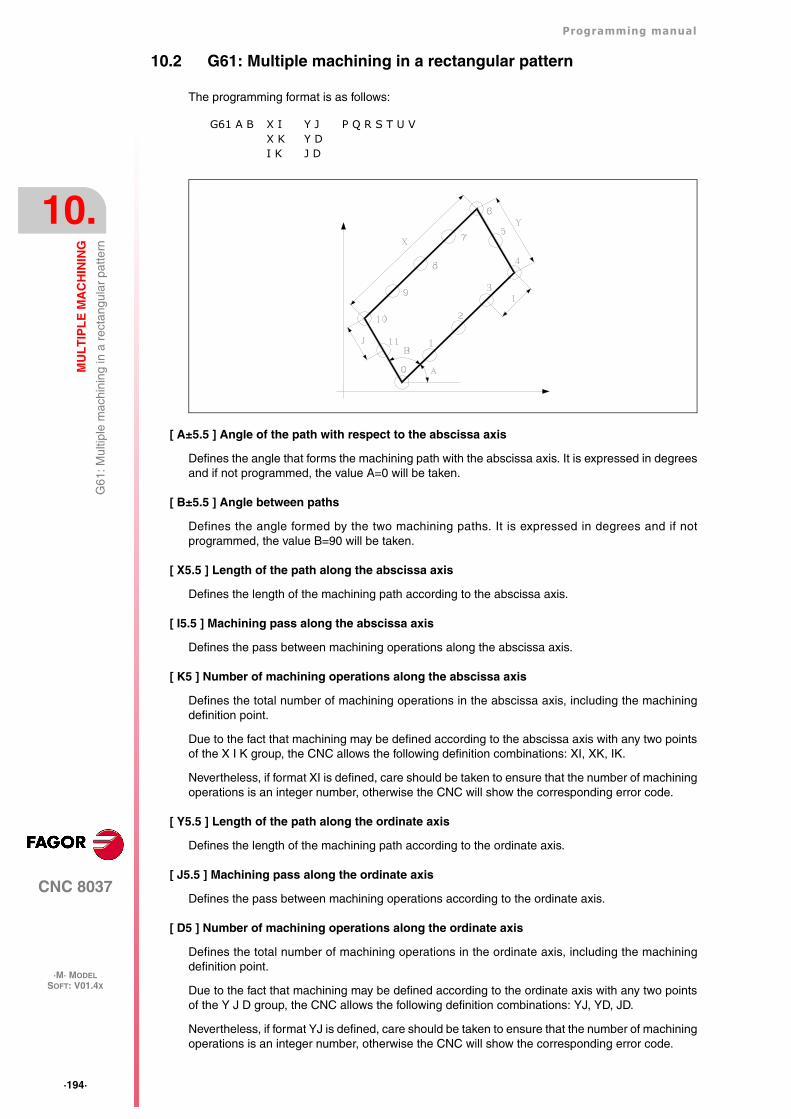
·194·
Programming manual
CNC 8037
10.
MU
LT
IPL
E M
AC
HIN
ING
·M· MODELSOFT: V01.4X
G61
: Mul
tiple
mac
hini
ng in
a r
ecta
ngul
ar p
atte
rn
10.2 G61: Multiple machining in a rectangular pattern
The programming format is as follows:
[ A±5.5 ] Angle of the path with respect to the abscissa axis
Defines the angle that forms the machining path with the abscissa axis. It is expressed in degreesand if not programmed, the value A=0 will be taken.
[ B±5.5 ] Angle between paths
Defines the angle formed by the two machining paths. It is expressed in degrees and if notprogrammed, the value B=90 will be taken.
[ X5.5 ] Length of the path along the abscissa axis
Defines the length of the machining path according to the abscissa axis.
[ I5.5 ] Machining pass along the abscissa axis
Defines the pass between machining operations along the abscissa axis.
[ K5 ] Number of machining operations along the abscissa axis
Defines the total number of machining operations in the abscissa axis, including the machiningdefinition point.
Due to the fact that machining may be defined according to the abscissa axis with any two pointsof the X I K group, the CNC allows the following definition combinations: XI, XK, IK.
Nevertheless, if format XI is defined, care should be taken to ensure that the number of machiningoperations is an integer number, otherwise the CNC will show the corresponding error code.
[ Y5.5 ] Length of the path along the ordinate axis
Defines the length of the machining path according to the ordinate axis.
[ J5.5 ] Machining pass along the ordinate axis
Defines the pass between machining operations according to the ordinate axis.
[ D5 ] Number of machining operations along the ordinate axis
Defines the total number of machining operations in the ordinate axis, including the machiningdefinition point.
Due to the fact that machining may be defined according to the ordinate axis with any two pointsof the Y J D group, the CNC allows the following definition combinations: YJ, YD, JD.
Nevertheless, if format YJ is defined, care should be taken to ensure that the number of machiningoperations is an integer number, otherwise the CNC will show the corresponding error code.
G61 A B X IX KI K
Y JY DJ D
P Q R S T U V
Programming manual
CNC 8037
MU
LT
IPL
E M
AC
HIN
ING
10.
·M· MODELSOFT: V01.4X
·195·
G61
: Mul
tiple
mac
hini
ng in
a r
ecta
ngul
ar p
atte
rn
[ P Q R S T U V ] Points where no drilling takes place
These parameters are optional and are used to indicate at which points or between which of thoseprogrammed points it is not required to machine.
Thus, programming P7 indicates that it is not required to do machining at point 7, and programmingQ10.013 indicates that machining is not required from point 10 to 13, or expressed in another way,that no machining is required at points 10, 11, 12 and 13.
When it is required to define a group of points (Q10.013), care should be taken to define the finalpoint with three digits, as if Q10.13 is programmed, multiple machining understands Q10.130.
The programming order for these parameters is P Q R S T U V, it also being necessary to maintainthe order in which the points assigned to these are numbered, i.e., the numbering order of the pointsassigned to Q must be greater than that assigned to P and less than that assigned to R.
Example:
Correct programming P5.006 Q12.015 R20.022
Wrong programming P5.006 Q20.022 R12.015
If these parameters are not programmed, the CNC understands that it must perform machining atall the points along the programmed path.
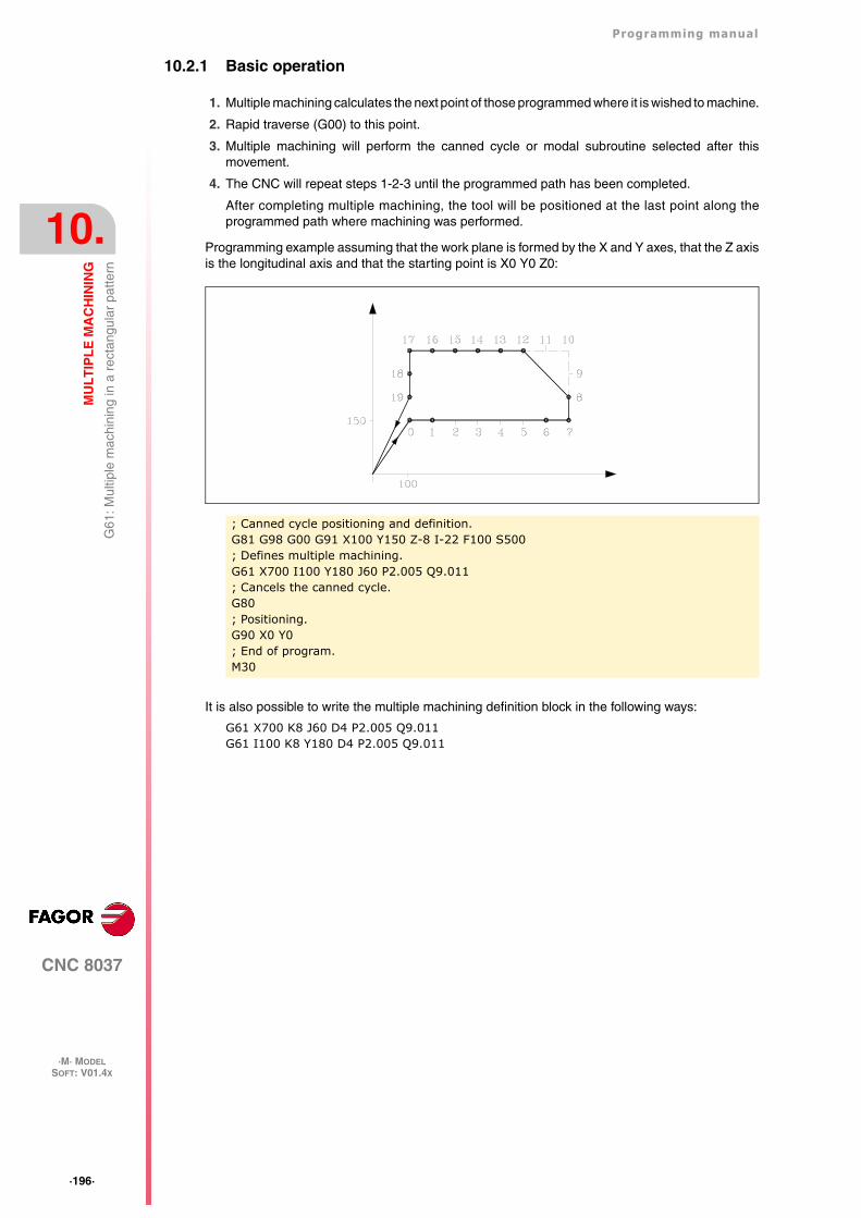
·196·
Programming manual
CNC 8037
10.
MU
LT
IPL
E M
AC
HIN
ING
·M· MODELSOFT: V01.4X
G61
: Mul
tiple
mac
hini
ng in
a r
ecta
ngul
ar p
atte
rn
10.2.1 Basic operation
1. Multiple machining calculates the next point of those programmed where it is wished to machine.
2. Rapid traverse (G00) to this point.
3. Multiple machining will perform the canned cycle or modal subroutine selected after thismovement.
4. The CNC will repeat steps 1-2-3 until the programmed path has been completed.
After completing multiple machining, the tool will be positioned at the last point along theprogrammed path where machining was performed.
Programming example assuming that the work plane is formed by the X and Y axes, that the Z axisis the longitudinal axis and that the starting point is X0 Y0 Z0:
It is also possible to write the multiple machining definition block in the following ways:
G61 X700 K8 J60 D4 P2.005 Q9.011G61 I100 K8 Y180 D4 P2.005 Q9.011
; Canned cycle positioning and definition.G81 G98 G00 G91 X100 Y150 Z-8 I-22 F100 S500; Defines multiple machining.G61 X700 I100 Y180 J60 P2.005 Q9.011; Cancels the canned cycle.G80; Positioning.G90 X0 Y0; End of program.M30
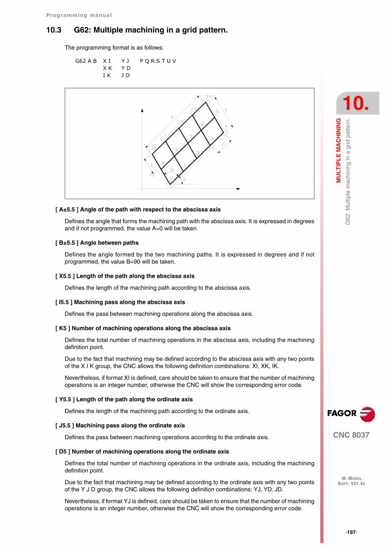
Programming manual
CNC 8037
MU
LT
IPL
E M
AC
HIN
ING
10.
·M· MODELSOFT: V01.4X
·197·
G62
: Mul
tiple
mac
hini
ng in
a g
rid p
atte
rn.
10.3 G62: Multiple machining in a grid pattern.
The programming format is as follows:
[ A±5.5 ] Angle of the path with respect to the abscissa axis
Defines the angle that forms the machining path with the abscissa axis. It is expressed in degreesand if not programmed, the value A=0 will be taken.
[ B±5.5 ] Angle between paths
Defines the angle formed by the two machining paths. It is expressed in degrees and if notprogrammed, the value B=90 will be taken.
[ X5.5 ] Length of the path along the abscissa axis
Defines the length of the machining path according to the abscissa axis.
[ I5.5 ] Machining pass along the abscissa axis
Defines the pass between machining operations along the abscissa axis.
[ K5 ] Number of machining operations along the abscissa axis
Defines the total number of machining operations in the abscissa axis, including the machiningdefinition point.
Due to the fact that machining may be defined according to the abscissa axis with any two pointsof the X I K group, the CNC allows the following definition combinations: XI, XK, IK.
Nevertheless, if format XI is defined, care should be taken to ensure that the number of machiningoperations is an integer number, otherwise the CNC will show the corresponding error code.
[ Y5.5 ] Length of the path along the ordinate axis
Defines the length of the machining path according to the ordinate axis.
[ J5.5 ] Machining pass along the ordinate axis
Defines the pass between machining operations according to the ordinate axis.
[ D5 ] Number of machining operations along the ordinate axis
Defines the total number of machining operations in the ordinate axis, including the machiningdefinition point.
Due to the fact that machining may be defined according to the ordinate axis with any two pointsof the Y J D group, the CNC allows the following definition combinations: YJ, YD, JD.
Nevertheless, if format YJ is defined, care should be taken to ensure that the number of machiningoperations is an integer number, otherwise the CNC will show the corresponding error code.
G62 A B X IX K I K
Y JY DJ D
P Q R S T U V
·198·
Programming manual
CNC 8037
10.
MU
LT
IPL
E M
AC
HIN
ING
·M· MODELSOFT: V01.4X
G62
: Mul
tiple
mac
hini
ng in
a g
rid p
atte
rn.
[ P Q R S T U V ] Points where no drilling takes place
These parameters are optional and are used to indicate at which points or between which of thoseprogrammed points it is not required to machine.
Thus, programming P7 indicates that it is not required to do machining at point 7, and programmingQ10.013 indicates that machining is not required from point 10 to 13, or expressed in another way,that no machining is required at points 10, 11, 12 and 13.
When it is required to define a group of points (Q10.013), care should be taken to define the finalpoint with three digits, as if Q10.13 is programmed, multiple machining understands Q10.130.
The programming order for these parameters is P Q R S T U V, it also being necessary to maintainthe order in which the points assigned to these are numbered, i.e., the numbering order of the pointsassigned to Q must be greater than that assigned to P and less than that assigned to R.
Example:
Correct programming P5.006 Q12.015 R20.022
Wrong programming P5.006 Q20.022 R12.015
If these parameters are not programmed, the CNC understands that it must perform machining atall the points along the programmed path.
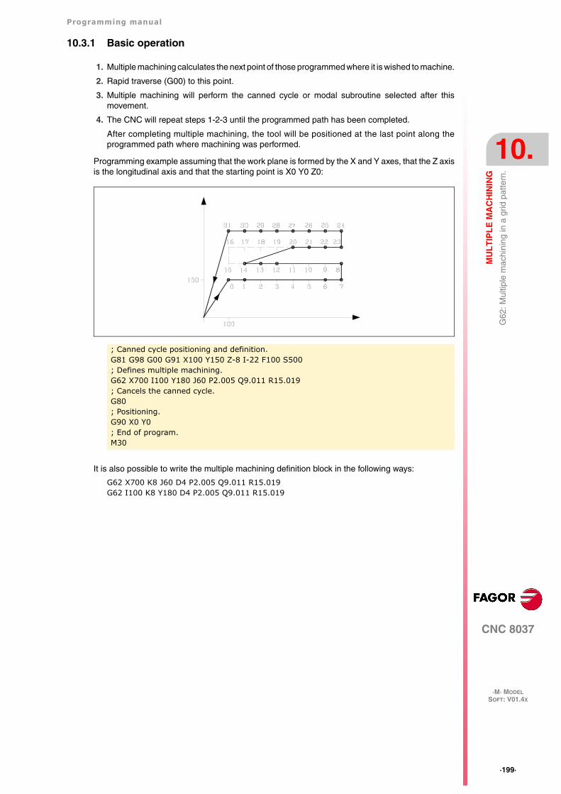
Programming manual
CNC 8037
MU
LT
IPL
E M
AC
HIN
ING
10.
·M· MODELSOFT: V01.4X
·199·
G62
: Mul
tiple
mac
hini
ng in
a g
rid p
atte
rn.
10.3.1 Basic operation
1. Multiple machining calculates the next point of those programmed where it is wished to machine.
2. Rapid traverse (G00) to this point.
3. Multiple machining will perform the canned cycle or modal subroutine selected after thismovement.
4. The CNC will repeat steps 1-2-3 until the programmed path has been completed.
After completing multiple machining, the tool will be positioned at the last point along theprogrammed path where machining was performed.
Programming example assuming that the work plane is formed by the X and Y axes, that the Z axisis the longitudinal axis and that the starting point is X0 Y0 Z0:
It is also possible to write the multiple machining definition block in the following ways:
G62 X700 K8 J60 D4 P2.005 Q9.011 R15.019G62 I100 K8 Y180 D4 P2.005 Q9.011 R15.019
; Canned cycle positioning and definition.G81 G98 G00 G91 X100 Y150 Z-8 I-22 F100 S500; Defines multiple machining.G62 X700 I100 Y180 J60 P2.005 Q9.011 R15.019; Cancels the canned cycle.G80; Positioning.G90 X0 Y0; End of program.M30
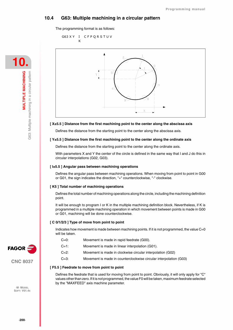
·200·
Programming manual
CNC 8037
10.
MU
LT
IPL
E M
AC
HIN
ING
·M· MODELSOFT: V01.4X
G63
: Mul
tiple
mac
hini
ng in
a c
ircul
ar p
atte
rn
10.4 G63: Multiple machining in a circular pattern
The programming format is as follows:
[ X±5.5 ] Distance from the first machining point to the center along the abscissa axis
Defines the distance from the starting point to the center along the abscissa axis.
[ Y±5.5 ] Distance from the first machining point to the center along the ordinate axis
Defines the distance from the starting point to the center along the ordinate axis.
With parameters X and Y the center of the circle is defined in the same way that I and J do this incircular interpolations (G02, G03).
[ I±5.5 ] Angular pass between machining operations
Defines the angular pass between machining operations. When moving from point to point in G00or G01, the sign indicates the direction, "+" counterclockwise, "-" clockwise.
[ K5 ] Total number of machining operations
Defines the total number of machining operations along the circle, including the machining definitionpoint.
It will be enough to program I or K in the multiple machining definition block. Nevertheless, if K isprogrammed in a multiple machining operation in which movement between points is made in G00or G01, machining will be done counterclockwise.
[ C 0/1/2/3 ] Type of move from point to point
Indicates how movement is made between machining points. If it is not programmed, the value C=0will be taken.
C=0: Movement is made in rapid feedrate (G00).
C=1: Movement is made in linear interpolation (G01).
C=2: Movement is made in clockwise circular interpolation (G02)
C=3: Movement is made in counterclockwise circular interpolation (G03)
[ F5.5 ] Feedrate to move from point to point
Defines the feedrate that is used for moving from point to point. Obviously, it will only apply for "C"values other than zero. If it is not programmed, the value F0 will be taken, maximum feedrate selectedby the "MAXFEED" axis machine parameter.
G63 X Y IK
C F P Q R S T U V
Programming manual
CNC 8037
MU
LT
IPL
E M
AC
HIN
ING
10.
·M· MODELSOFT: V01.4X
·201·
G63
: Mul
tiple
mac
hini
ng in
a c
ircul
ar p
atte
rn
[ P Q R S T U V ] Points where no drilling takes place
These parameters are optional and are used to indicate at which points or between which of thoseprogrammed points it is not required to machine.
Thus, programming P7 indicates that it is not required to do machining at point 7, and programmingQ10.013 indicates that machining is not required from point 10 to 13, or expressed in another way,that no machining is required at points 10, 11, 12 and 13.
When it is required to define a group of points (Q10.013), care should be taken to define the finalpoint with three digits, as if Q10.13 is programmed, multiple machining understands Q10.130.
The programming order for these parameters is P Q R S T U V, it also being necessary to maintainthe order in which the points assigned to these are numbered, i.e., the numbering order of the pointsassigned to Q must be greater than that assigned to P and less than that assigned to R.
Example:
Correct programming P5.006 Q12.015 R20.022
Wrong programming P5.006 Q20.022 R12.015
If these parameters are not programmed, the CNC understands that it must perform machining atall the points along the programmed path.
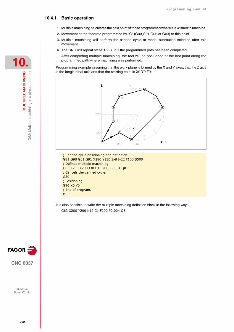
·202·
Programming manual
CNC 8037
10.
MU
LT
IPL
E M
AC
HIN
ING
·M· MODELSOFT: V01.4X
G63
: Mul
tiple
mac
hini
ng in
a c
ircul
ar p
atte
rn
10.4.1 Basic operation
1. Multiple machining calculates the next point of those programmed where it is wished to machine.
2. Movement at the feedrate programmed by "C" (G00,G01,G02 or G03) to this point.
3. Multiple machining will perform the canned cycle or modal subroutine selected after thismovement.
4. The CNC will repeat steps 1-2-3 until the programmed path has been completed.
After completing multiple machining, the tool will be positioned at the last point along theprogrammed path where machining was performed.
Programming example assuming that the work plane is formed by the X and Y axes, that the Z axisis the longitudinal axis and that the starting point is X0 Y0 Z0:
It is also possible to write the multiple machining definition block in the following ways:
G63 X200 Y200 K12 C1 F200 P2.004 Q8
; Canned cycle positioning and definition.G81 G98 G01 G91 X280 Y130 Z-8 I-22 F100 S500; Defines multiple machining.G63 X200 Y200 I30 C1 F200 P2.004 Q8; Cancels the canned cycle.G80; Positioning.G90 X0 Y0; End of program.M30
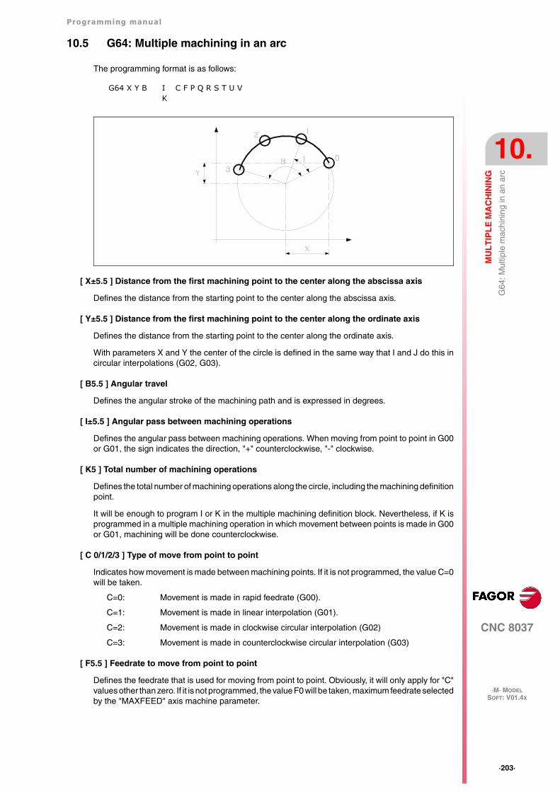
Programming manual
CNC 8037
MU
LT
IPL
E M
AC
HIN
ING
10.
·M· MODELSOFT: V01.4X
·203·
G64
: Mul
tiple
mac
hini
ng in
an
arc
10.5 G64: Multiple machining in an arc
The programming format is as follows:
[ X±5.5 ] Distance from the first machining point to the center along the abscissa axis
Defines the distance from the starting point to the center along the abscissa axis.
[ Y±5.5 ] Distance from the first machining point to the center along the ordinate axis
Defines the distance from the starting point to the center along the ordinate axis.
With parameters X and Y the center of the circle is defined in the same way that I and J do this incircular interpolations (G02, G03).
[ B5.5 ] Angular travel
Defines the angular stroke of the machining path and is expressed in degrees.
[ I±5.5 ] Angular pass between machining operations
Defines the angular pass between machining operations. When moving from point to point in G00or G01, the sign indicates the direction, "+" counterclockwise, "-" clockwise.
[ K5 ] Total number of machining operations
Defines the total number of machining operations along the circle, including the machining definitionpoint.
It will be enough to program I or K in the multiple machining definition block. Nevertheless, if K isprogrammed in a multiple machining operation in which movement between points is made in G00or G01, machining will be done counterclockwise.
[ C 0/1/2/3 ] Type of move from point to point
Indicates how movement is made between machining points. If it is not programmed, the value C=0will be taken.
C=0: Movement is made in rapid feedrate (G00).
C=1: Movement is made in linear interpolation (G01).
C=2: Movement is made in clockwise circular interpolation (G02)
C=3: Movement is made in counterclockwise circular interpolation (G03)
[ F5.5 ] Feedrate to move from point to point
Defines the feedrate that is used for moving from point to point. Obviously, it will only apply for "C"values other than zero. If it is not programmed, the value F0 will be taken, maximum feedrate selectedby the "MAXFEED" axis machine parameter.
G64 X Y B IK
C F P Q R S T U V

·204·
Programming manual
CNC 8037
10.
MU
LT
IPL
E M
AC
HIN
ING
·M· MODELSOFT: V01.4X
G64
: Mul
tiple
mac
hini
ng in
an
arc
[ P Q R S T U V ] Points where no drilling takes place
These parameters are optional and are used to indicate at which points or between which of thoseprogrammed points it is not required to machine.
Thus, programming P7 indicates that it is not required to do machining at point 7, and programmingQ10.013 indicates that machining is not required from point 10 to 13, or expressed in another way,that no machining is required at points 10, 11, 12 and 13.
When it is required to define a group of points (Q10.013), care should be taken to define the finalpoint with three digits, as if Q10.13 is programmed, multiple machining understands Q10.130.
The programming order for these parameters is P Q R S T U V, it also being necessary to maintainthe order in which the points assigned to these are numbered, i.e., the numbering order of the pointsassigned to Q must be greater than that assigned to P and less than that assigned to R.
Example:
Correct programming P5.006 Q12.015 R20.022
Wrong programming P5.006 Q20.022 R12.015
If these parameters are not programmed, the CNC understands that it must perform machining atall the points along the programmed path.
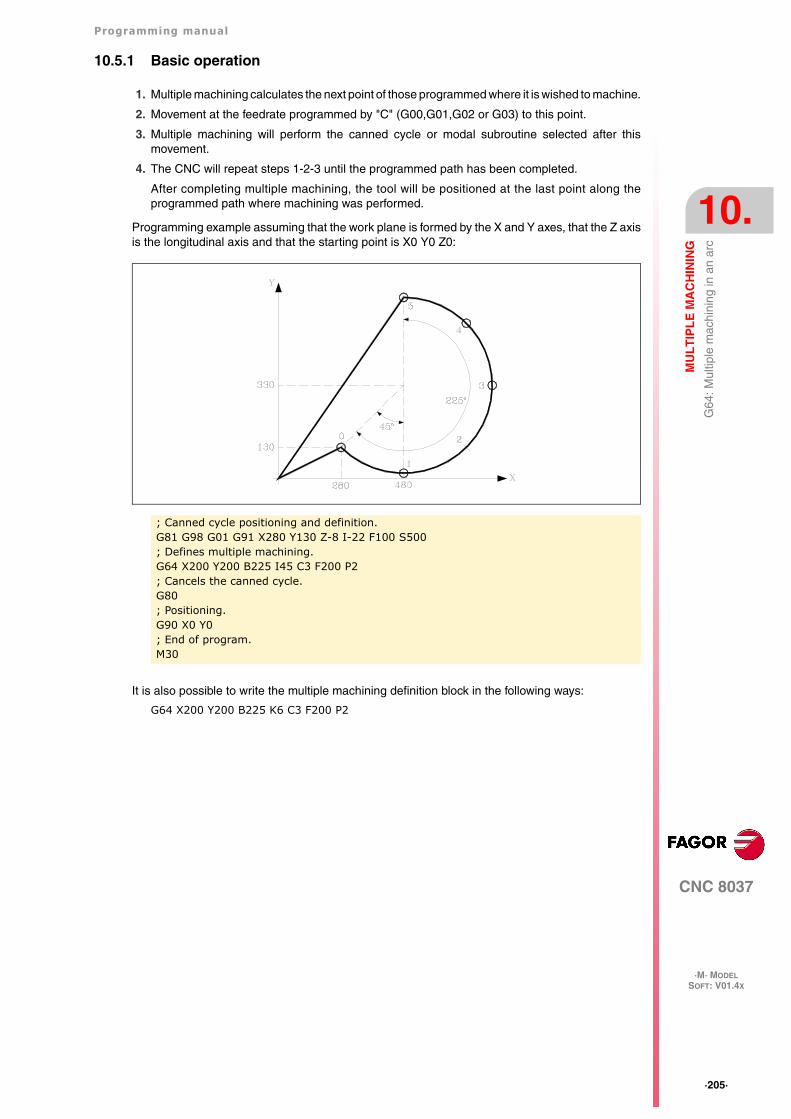
Programming manual
CNC 8037
MU
LT
IPL
E M
AC
HIN
ING
10.
·M· MODELSOFT: V01.4X
·205·
G64
: Mul
tiple
mac
hini
ng in
an
arc
10.5.1 Basic operation
1. Multiple machining calculates the next point of those programmed where it is wished to machine.
2. Movement at the feedrate programmed by "C" (G00,G01,G02 or G03) to this point.
3. Multiple machining will perform the canned cycle or modal subroutine selected after thismovement.
4. The CNC will repeat steps 1-2-3 until the programmed path has been completed.
After completing multiple machining, the tool will be positioned at the last point along theprogrammed path where machining was performed.
Programming example assuming that the work plane is formed by the X and Y axes, that the Z axisis the longitudinal axis and that the starting point is X0 Y0 Z0:
It is also possible to write the multiple machining definition block in the following ways:
G64 X200 Y200 B225 K6 C3 F200 P2
; Canned cycle positioning and definition.G81 G98 G01 G91 X280 Y130 Z-8 I-22 F100 S500; Defines multiple machining.G64 X200 Y200 B225 I45 C3 F200 P2; Cancels the canned cycle.G80; Positioning.G90 X0 Y0; End of program.M30
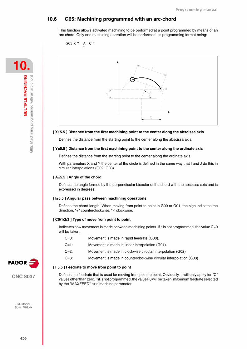
·206·
Programming manual
CNC 8037
10.
MU
LT
IPL
E M
AC
HIN
ING
·M· MODELSOFT: V01.4X
G65
: Mac
hini
ng p
rogr
amm
ed w
ith a
n ar
c-ch
ord
10.6 G65: Machining programmed with an arc-chord
This function allows activated machining to be performed at a point programmed by means of anarc chord. Only one machining operation will be performed, its programming format being:
[ X±5.5 ] Distance from the first machining point to the center along the abscissa axis
Defines the distance from the starting point to the center along the abscissa axis.
[ Y±5.5 ] Distance from the first machining point to the center along the ordinate axis
Defines the distance from the starting point to the center along the ordinate axis.
With parameters X and Y the center of the circle is defined in the same way that I and J do this incircular interpolations (G02, G03).
[ A±5.5 ] Angle of the chord
Defines the angle formed by the perpendicular bisector of the chord with the abscissa axis and isexpressed in degrees.
[ I±5.5 ] Angular pass between machining operations
Defines the chord length. When moving from point to point in G00 or G01, the sign indicates thedirection, "+" counterclockwise, "-" clockwise.
[ C0/1/2/3 ] Type of move from point to point
Indicates how movement is made between machining points. If it is not programmed, the value C=0will be taken.
C=0: Movement is made in rapid feedrate (G00).
C=1: Movement is made in linear interpolation (G01).
C=2: Movement is made in clockwise circular interpolation (G02)
C=3: Movement is made in counterclockwise circular interpolation (G03)
[ F5.5 ] Feedrate to move from point to point
Defines the feedrate that is used for moving from point to point. Obviously, it will only apply for "C"values other than zero. If it is not programmed, the value F0 will be taken, maximum feedrate selectedby the "MAXFEED" axis machine parameter.
G65 X Y AI
C F
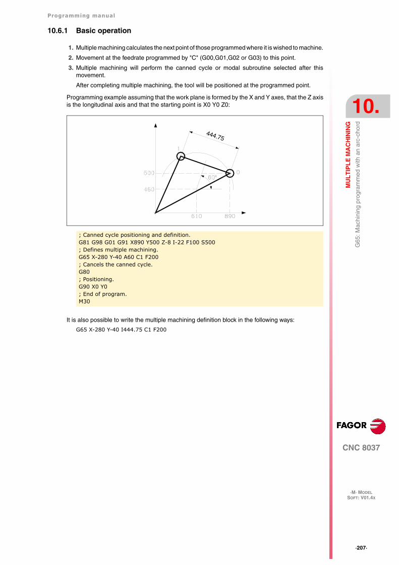
Programming manual
CNC 8037
MU
LT
IPL
E M
AC
HIN
ING
10.
·M· MODELSOFT: V01.4X
·207·
G65
: Mac
hini
ng p
rogr
amm
ed w
ith a
n ar
c-ch
ord
10.6.1 Basic operation
1. Multiple machining calculates the next point of those programmed where it is wished to machine.
2. Movement at the feedrate programmed by "C" (G00,G01,G02 or G03) to this point.
3. Multiple machining will perform the canned cycle or modal subroutine selected after thismovement.
After completing multiple machining, the tool will be positioned at the programmed point.
Programming example assuming that the work plane is formed by the X and Y axes, that the Z axisis the longitudinal axis and that the starting point is X0 Y0 Z0:
It is also possible to write the multiple machining definition block in the following ways:
G65 X-280 Y-40 I444.75 C1 F200
; Canned cycle positioning and definition.G81 G98 G01 G91 X890 Y500 Z-8 I-22 F100 S500; Defines multiple machining.G65 X-280 Y-40 A60 C1 F200; Cancels the canned cycle.G80; Positioning.G90 X0 Y0; End of program.M30
444.75
·208·
Programming manual
CNC 8037
10.
MU
LT
IPL
E M
AC
HIN
ING
·M· MODELSOFT: V01.4X
G65
: Mac
hini
ng p
rogr
amm
ed w
ith a
n ar
c-ch
ord
CNC 8037
·M· MODELSOFT: V01.4X
11
·209·
PROBING
The CNC has two probe inputs, one for TTL-type 5Vdc signals and another for 24 Vdc signals.
The connection of the different types of probes to these inputs are explained in the appendix to theInstallation manual.
·210·
Programming manual
CNC 8037
11.
PR
OB
ING
·M· MODELSOFT: V01.4X
Pro
bing
(G
75, G
76)
11.1 Probing (G75, G76)
The G75 function allows movements to be programmed that will end after the CNC receives thesignal from the measuring probe used.
The G76 function allows movements to be programmed that will end after the CNC no longerreceives the signal from the measuring probe used.
Their definition format is:
G75 X..C ±5.5G76 X..C ±5.5
After G75 or G76, the required axis or axes will be programmed, as well as the coordinates of theseaxes that will define the end point of the programmed movement.
The machine will move according to the programmed path until it receives the signal from the probe(G75) or until it no longer receives the probe signal (G76). At this time, the CNC will consider theblock finished, taking as the theoretical position of the axes the real position they have at that time.
If the axes reach the programmed position before receiving or while receiving the external signalfrom the probe, the CNC will stop the movement of the axes.
This type of movement with probing blocks are very useful when it is required to generatemeasurement or verification programs for tools and parts.
Functions G75 and G76 are not modal and, therefore, must be programmed whenever it is wishedto probe.
Functions G75 and G76 are incompatible with each other and with G00, G02, G03, G33, G34, G41and G42 functions. In addition, once this has been performed, the CNC will assume functions G01and G40.
During G75 or G76 moves, the operation of the feedrate override switch depends on the setting ofOEM machine parameter FOVRG75.
CNC 8037
·M· MODELSOFT: V01.4X
12
·211·
HIGH-LEVEL LANGUAGE PROGRAMMING
12.1 Lexical description
All the words that make up the high-level language of the numerical control must be written in capitalletters except for associated texts which may be written in upper and lower case letters.
The following elements are available for high-level programming:
• Reserved words.
• Numerical constants.
• Symbols.
Reserved words
Reserved words are those that the CNC uses in high-level programming for naming systemvariables, operators, control instructions, etc.
All the letters of the alphabet A-Z are also reserved words, as they can make up a high-level languageword when used alone.
Numerical constants
Blocks programmed in high-level language admit numbers in decimal format and in hexadecimalformat.
• The numbers in decimal format must not exceed the ±6.5 format (6 digits to the left of the decimalpoint and 5 decimals).
• The numbers in hexadecimal format must be preceded by the $ symbol and they must not havemore than 8 digits.
A constant higher than the format ±6,5 must be assigned to a variable by means of arithmeticparameters by means of arithmetic expressions or by means of constants in hexadecimal format.
If the CNC operates in the metric system (millimeters), the resolution is a tenth of a micron and thefigures will be programmed in the ±5.4 format (positive or negative with 5 digits to the left of thedecimal point and 4 decimals).
If the CNC operates in inches, the resolution is a hundred-thousandths of an inch (ten millionthsof an inch) and the figures will be programmed in the ±4.5 format (positive or negative with 4 digitsto the left of the decimal point and 5 decimals).
For the convenience of the programmer, this control always allows the format ±5.5 (positive ornegative, with 5 integers and 5 decimals), adjusting each number appropriately to the working unitsevery time they are used.
To assign the value 100000000 to the variable "TIMER", It can be done in one of the following ways:
(TIMER = $5F5E100)(TIMER = 10000 * 10000)(P100 = 10000 * 10000)(TIMER = P100)
·212·
Programming manual
CNC 8037
12.
HIG
H-L
EV
EL
LA
NG
UA
GE
PR
OG
RA
MM
ING
·M· MODELSOFT: V01.4X
Lexi
cal d
escr
iptio
n
Symbols
The symbols used in high-level language are:
( ) “ = + - * / ,
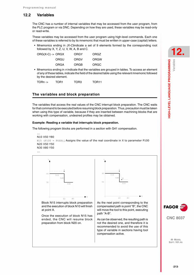
Programming manual
CNC 8037
HIG
H-L
EV
EL
LA
NG
UA
GE
PR
OG
RA
MM
ING
12.
·M· MODELSOFT: V01.4X
·213·
Var
iabl
es
12.2 Variables
The CNC has a number of internal variables that may be accessed from the user program, fromthe PLC program or via DNC. Depending on how they are used, these variables may be read-onlyor read-write.
These variables may be accessed from the user program using high-level commands. Each oneof these variables is referred to by its mnemonic that must be written in upper-case (capital) letters.
• Mnemonics ending in (X-C)indicate a set of 9 elements formed by the corresponding rootfollowed by X, Y, Z, U, V, W, A, B and C.
ORG(X-C) -> ORGX ORGY ORGZ
ORGU ORGV ORGW
ORGA ORGB ORGC
• Mnemonics ending in n indicate that the variables are grouped in tables. To access an elementof any of these tables, indicate the field of the desired table using the relevant mnemonic followedby the desired element.
TORn -> TOR1 TOR3 TOR11
The variables and block preparation
The variables that access the real values of the CNC interrupt block preparation. The CNC waitsfor that command to be executed before resuming block preparation. Thus, precaution must be takenwhen using this type of variable, because if they are inserted between machining blocks that areworking with compensation, undesired profiles may be obtained.
Example: Reading a variable that interrupts block preparation.
The following program blocks are performed in a section with G41 compensation.
...N10 X50 Y80N15 (P100 = POSX); Assigns the value of the real coordinate in X to parameter P100N20 X50 Y50N30 X80 Y50...
Block N15 interrupts block preparationand the execution of block N10 will finishat point A.
Once the execution of block N15 hasended, the CNC will resume blockpreparation from block N20 on.
As the next point corresponding to thecompensated path is point "B", the CNCwill move the tool to this point, executingpath "A-B".
As can be observed, the resulting path isnot the desired one, and therefore it isrecommended to avoid the use of thistype of variable in sections having toolcompensation active.
·214·
Programming manual
CNC 8037
12.
HIG
H-L
EV
EL
LA
NG
UA
GE
PR
OG
RA
MM
ING
·M· MODELSOFT: V01.4X
Var
iabl
es
12.2.1 General purpose parameters or variables
General purpose variables are referred to with the letter "P" followed by an integer number. The CNChas four types of general purpose variables.
Blocks programmed in ISO code allow associating parameters to the G F S T D M fields andcoordinates of the axes. The block label number must be defined with a numeric value. If parametersare used in blocks programmed in high-level language, they can be programmed within anyexpression.
Programmers may use general purpose variables when editing their own programs. Later on, duringexecution, the CNC will replace these variables with the values assigned to them at the time.
Using these general purpose variables will depend on the type of block in which they areprogrammed and the channel of execution. Programs that are executed in the user channel maycontain any global, OEM or user parameter, but may not use local parameters.
Types of arithmetic parameters
Local parameters
Local parameters can only be accessed from the program or subroutine where they have beenprogrammed. There are seven groups of parameters.
Local parameters used in high-level language may be defined either using the above format or byusing the letter A-Z, except for Ñ, so that A is equal to P0 and Z to P25.
The following example shows these two methods of definition:
(IF ((P0+P1)* P2/P3 EQ P4) GOTO N100)(IF ((A+B)* C/D EQ E) GOTO N100)
When using a parameter name (letter) for assigning a value to it (A instead of P0, for example), ifthe arithmetic expression is a constant, the instruction can be abbreviated as follows:
(P0=13.7) ==> (A=13.7) ==> (A13.7)
Be careful when using parenthesis since M30 is not the same as (M30). The CNC interprets (M30)as a high level instruction meaning (P12 = 30) and not the execution of the miscellaneous M30function.
Global parameters
Global parameters can be accessed from any program and subroutine called from a program.
Global parameters may be used by the user, by the OEM or by the CNC cycles.
User parameters
These parameters are an expansion of the global parameters but they are not used by the CNCcycles.
OEM (manufacturer's) parameters
OEM parameters and subroutines with OEM parameters can only be used in OEM programs; thosedefined with the [O] attribute. Modifying one of these parameters in the tables requires an OEMpassword.
Parameter type Range
Local parameters P0-P25
Global parameters P100-P299
User parameters P1000-P1255
OEM (manufacturer's) parameters P2000-P2255
When programming...GP0 XP1 Z100(IF (P100 * P101 EQ P102) GOTO N100)
When executing...G1 X-12.5 Z100(IF (2 * 5 EQ 12) GOTO N100)
Programming manual
CNC 8037
HIG
H-L
EV
EL
LA
NG
UA
GE
PR
OG
RA
MM
ING
12.
·M· MODELSOFT: V01.4X
·215·
Var
iabl
es
Using arithmetic parameters by the cycles
Multiple machining cycles (G60 through G65) and the machining canned cycles (G69, G81 to G89)use the sixth nesting level of local parameters when they are active.
Machining canned cycles use the global parameter P299 for internal calculations and probingcanned cycles use global parameters P294 to P299.
Updating arithmetic parameter tables
The CNC will update the parameter table after processing the operations indicated in the block thatis in preparation. This operation is always done before executing the block and for this reason, thevalues shown in the table do not necessarily have to correspond to the block being executed.
If the execution mode is abandoned after interrupting the execution of the program, the CNC willupdate the parameter tables with values corresponding to the block that was being executed.
When accessing the local parameter and global parameter table, the value assigned to eachparameter may be expressed in decimal notation (4127.423) or in scientific notation (0.23476 E-3).
Arithmetic parameters in the subroutines
The CNC offers high level instructions for defining and using subroutines that may be called uponfrom the main program (or a subroutine) and another subroutine from this one and so on, the CNClimits the number of these calls to a maximum of 15 nesting levels. The CNC limitation is 20 nestinglevels.
Up to 26 (P0-P25) local parameters may be assigned to a subroutine. These parameters, that willbe unknown for blocks outside the subroutine, may be referred to by the blocks that make up thesubroutine.
Local parameters may be assigned to more than one subroutine up to 6 parameter nesting levelswithin the 15 subroutine nesting levels.
·216·
Programming manual
CNC 8037
12.
HIG
H-L
EV
EL
LA
NG
UA
GE
PR
OG
RA
MM
ING
·M· MODELSOFT: V01.4X
Var
iabl
es
12.2.2 Variables associated with tools.
These variables are associated with the tool offset table, tool table and tool magazine table, so thevalues which are assigned to or read from these fields will comply with the formats established forthese tables.
Tool Offset table
The radius (R), length (L) and wear offset (I, K) values of the tool are given in the active units.
If G70, in inches (within ±3937.00787).
If G71, in millimeters (within ±99999.9999).
If rotary axis in degrees (within ±99999.9999).
Tool table
The tool offset number is an integer between 0 and 255. The maximum number of tool offsets islimited by g.m.p. NTOFFSET.
The family code is a number between 0 and 255.
0 to 199 if it is a normal tool.
200 to 255 if it is a special tool.
The nominal life is given either in minutes or in operations (0··65535).
The real (actual) life is given either in hundredths of a minute (0··9999999) or in operations(0··999999).
Tool magazine table
Each magazine position is represented as follows:
1··255 Tool number.
0 The magazine position is empty.
-1 The magazine position has been canceled.
The tool position in the magazine is represented as follows:
1··255 Position number.
0 The tool is in the spindle.
-1 Tool not found.
-2 The tool is in the change position.
Read-only variables
TOOL
Returns the number of the active tool.
TOD
Returns the number of the active tool offset.
NXTOOL
Returns the next tool number, which is selected but is awaiting the execution of M06 to be active.
NXTOD
Returns the number of the tool offset corresponding to the next tool, which is selected but is awaitingthe execution of M06 to be active.
(P100=TOOL)Assigns the number of the active tool to parameter P100.
Programming manual
CNC 8037
HIG
H-L
EV
EL
LA
NG
UA
GE
PR
OG
RA
MM
ING
12.
·M· MODELSOFT: V01.4X
·217·
Var
iabl
es
TMZPn
Returns the position occupied in the tool magazine by the indicated tool (n).
HTOR
The HTOR variable indicates the tool radius being used by the CNC to do the calculations.
Being a variable that can be read and written by the CNC and read-only from the PLC and DNC,its value may be different from the one assigned in the table (TOR).
On power-up, after a T function, after a RESET or after an M30 function, it assumes the value ofthe table (TOR).
Application example
To machine a profile with a residual stock of 0.5 mm running 0.1mm-passes with a tool whose radiusis 10 mm.
Assign to the tool radius the value of:
10.5 mm in the table and execute the profile.
10.4 mm in the table and execute the profile.
10.3 mm in the table and execute the profile.
10.2 mm in the table and execute the profile.
10.1 mm in the table and execute the profile.
10.0 mm in the table and execute the profile.
However, if while machining, the program is interrupted or a reset occurs, the table assumes theradius value assigned in that instant (e.g.: 10.2 mm). Its value has changed.
To avoid this, instead of modifying the tool radius in the (TOR) table, use the variable (HTOR) tochange the tool radius value used by the CNC to calculate.
Now, if the program is interrupted, the tool radius value initially assigned in the (TOR) table will becorrect because it has not changed.
Read-and-write variables
TORn
This variable allows the value assigned to the radius of the indicated tool offset (n) in the tool offsettable to be read or modified.
TOLn
This variable allows the value assigned to the length of the indicated tool offset (n) to be read ormodified in the tool offset table.
TOIn
This variable allows the value assigned to the wear in radius (I) of the indicated tool offset (n) to beread or modified in the tool offset table.
TOKn
This variable allows the value assigned to the wear in length (K) of the indicated tool offset (n) tobe read or modified in the tool offset table.
TLFDn
This variable allows the tool offset number of the indicated tool (n) to be read or modified in the tooltable.
(P110=TOR3)Assigns the radius value of tool offset ·3· to parameter P110.
(TOR3=P111)Assigns the value indicated in parameter P111 to the radius of tool offset 3.
·218·
Programming manual
CNC 8037
12.
HIG
H-L
EV
EL
LA
NG
UA
GE
PR
OG
RA
MM
ING
·M· MODELSOFT: V01.4X
Var
iabl
es
TLFFn
This variable allows the family code of the indicated tool (n) to be read or modified in the tool table.
TLFNn
This variable allows the value assigned as the nominal life of the indicated tool (n) to be read ormodified in the tool table.
TLFRn
This variable allows the value corresponding to the real life of the indicated tool (n) to be read ormodified in the tool table.
TMZTn
This variable allows the contents of the indicated position (n) to be read or modified in the toolmagazine table.
Programming manual
CNC 8037
HIG
H-L
EV
EL
LA
NG
UA
GE
PR
OG
RA
MM
ING
12.
·M· MODELSOFT: V01.4X
·219·
Var
iabl
es
12.2.3 Variables associated with zero offsets.
These variables are associated with the zero offsets and may correspond to the table values or tothose currently preset either by means of function G92 or manually in the JOG mode.
The possible zero offsets in addition to the additive offset indicated by the PLC, are G54, G55, G56,G57, G58 and G59.
The values for each axis are given in the active units:
If G70, in inches (within ±3937.00787).
If G71, in millimeters (within ±99999.9999).
If rotary axis in degrees (within ±99999.9999).
Although there are variables which refer to each axis, the CNC only allows those referring to theaxes selected at the CNC. Thus, if the CNC controls the X and Z axes, it only allows the variablesORGX and ORGZ in the case of ORG(X-C).
Read-only variables
ORG(X-C)
Returns the value of the active zero offset in the selected axis. The value of the additive offsetindicated by the PLC or by the additive handwheel is not included in this value.
PORGF
Returns the abscissa value of the polar coordinate origin with respect to the Cartesian origin.
PORGS
Returns the ordinate value of the polar coordinate origin with respect to the Cartesian origin.
ADIOF(X-C)
It returns the value of the zero offset generated by the additive handwheel in the selected axis.
Read-and-write variables
ORG(X-C)n
This variable allows the value of the selected axis to be read or modified in the table correspondingto the indicated zero offset (n).
PLCOF(X-C)
This variable allows the value of the selected axis to be read or modified in the table of additive offsetsindicated by the PLC.
Accessing any of the PLCOF(X-C) variables interrupts block preparation and the CNC waits for thatcommand to be executed before resuming block preparation.
(P100=ORGX)It assigns to P100 the X value of the part zero active for the X axis. This value could have been set either manually, by means of function G92 or by the variable "ORG(X-C)n".
(P110=ORGX 55)Loads parameter P100 with the X value of G55 in the zero offset table.
(ORGY 54=P111)It assigns parameter P111 to the Y axis in the table for the G54 offset.
·220·
Programming manual
CNC 8037
12.
HIG
H-L
EV
EL
LA
NG
UA
GE
PR
OG
RA
MM
ING
·M· MODELSOFT: V01.4X
Var
iabl
es
12.2.4 Variables associated with machine parameters
These variables associated with machine parameters are read-only variables. These variables maybe read and written when executed inside an OEM program or subroutine.
Refer to the installation and start-up manual to know the format of the values returned. The valuesof 1/0 correspond to the parameters that are set as YES/NO, +/- or ON/OFF.
The coordinate and feedrate values are given in the active units:
If G70, in inches (within ±3937.00787).
If G71, in millimeters (within ±99999.9999).
If rotary axis in degrees (within ±99999.9999).
Modify the machine parameters from an OEM program or subroutine.
These variables may be read and written when executed inside an OEM program or subroutine. Inthis case, these variables can be used to modify the value of certain machine parameters. Referto the installation manual for the list of machine parameters that may be modified.
In order to be able to modify these parameters via PLC, an OEM subroutine containing the relevantvariables must be executed using the CNCEX command.
Read-only variables
MPGn
Returns the value assigned to general machine parameter (n).
MP(X-C)n
Returns the value assigned to the machine parameter (n) of the indicated axis (X-C).
MPSn
Returns the value assigned to the indicated machine parameter (n) of the main spindle.
MPLCn
Returns the value assigned to the indicated machine parameter (n) of the PLC.
(P110=MPG8)It assigns the value of the general machine parameter P8 "INCHES" to parameter P110, if millimeters P110=0 and if inches P110=1.
(P110=MPY 1)Assigns the value of Y axis machine parameter P1 "DFORMAT" to parameter P110.
Programming manual
CNC 8037
HIG
H-L
EV
EL
LA
NG
UA
GE
PR
OG
RA
MM
ING
12.
·M· MODELSOFT: V01.4X
·221·
Var
iabl
es
12.2.5 Variables associated with work zones
Variables associated with work zones are read-only variables.
The values of the limits are given in the active units:
If G70, in inches (within ±3937.00787).
If G71, in millimeters (within ±99999.9999).
If rotary axis in degrees (within ±99999.9999).
The status of the work zones are defined according to the following code:
0 = Disabled.
1 = Enabled as no-entry zone.
2 = Enabled as no-exit zone.
Read-only variables
FZONE
It returns the status of work zone 1.
FZLO(X-C) FZUP(X-C)
Lower limit of zone 1 along the selected axis (X-C).
Upper limit of zone 1 along the selected axis (X-C).
SZONE SZLO(X-C) SZUP(X-C)
Status of work zone 2.
Lower limit of zone 2 along the selected axis (X-C).
Upper limit of zone 2 along the selected axis (X-C).
TZONE TZLO(X-C) TZUP(X-C)
Status of work zone 3.
Lower limit of zone 3 along the selected axis (X-C).
Upper limit of zone 3 along the selected axis (X-C).
FOZONE FOZLO(X-C) FOZUP(X-C)
Status of work zone 4.
Lower limit of zone 4 along the selected axis (X-C).
Upper limit of zone 4 along the selected axis (X-C).
FIZONE FIZLO(X-C) FIZUP(X-C)
Status of work zone 5.
Lower limit of zone 5 along the selected axis (X-C).
Upper limit of zone 5 along the selected axis (X-C).
(P100=FZONE) ; It assigns to parameter P100 the status of work zone 1.(P101=FZOLOX) ; It assigns the lower limit of zone 1 to parameter P101.(P102=FZUPZ) ; It assigns the upper limit of zone 1 to parameter P102.
·222·
Programming manual
CNC 8037
12.
HIG
H-L
EV
EL
LA
NG
UA
GE
PR
OG
RA
MM
ING
·M· MODELSOFT: V01.4X
Var
iabl
es
12.2.6 Variables associated with feedrates
Read-only variables associated with the real (actual) feedrate
FREAL
It returns the CNC's real feedrate. In mm/minute or inches/minute.
FREAL(X-C)
It returns the actual (real) CNC feedrate of the selected axis.
FTEO(X-C)
It returns the theoretical CNC feedrate of the selected axis.
Read-only variables associated with function G94
FEED
It returns the feedrate selected at the CNC by function G94. In mm/minute or inches/minute.
This feedrate may be indicated by program, by PLC or by DNC; the CNC selects one of them, theone indicated by DNC has the highest priority and the one indicated by program has the lowestpriority.
DNCF
It returns the feedrate, in mm/minute or inches/minute selected by DNC. If it has a value of 0 it meansthat it is not selected.
PLCF
It returns the feedrate, in mm/minute or inches/minute selected by PLC. If it has a value of 0 it meansthat it is not selected.
PRGF
It returns the feedrate, in mm/minute or inches/minute selected by program.
Read-only variables associated with function G95
FPREV
It returns the feedrate selected at the CNC by function G95. In mm/turn or inches/turn.
This feedrate may be indicated by program, by PLC or by DNC; the CNC selects one of them, theone indicated by DNC has the highest priority and the one indicated by program has the lowestpriority.
DNCFPR
It returns the feedrate, in mm/turn or inches/turn selected by DNC. If it has a value of 0 it meansthat it is not selected.
PLCFPR
It returns the feedrate, in mm/turn or inches/turn selected by PLC. If it has a value of 0 it means thatit is not selected.
(P100=FREAL)It assigns the real feedrate value of the CNC to parameter P100.
Programming manual
CNC 8037
HIG
H-L
EV
EL
LA
NG
UA
GE
PR
OG
RA
MM
ING
12.
·M· MODELSOFT: V01.4X
·223·
Var
iabl
es
PRGFPR
It returns the feedrate, in mm/turn or inches/turn selected by program.
Read-only variables associated with function G32
PRGFIN
It returns the feedrate selected by program, in 1/min.
Likewise, the CNC variable FEED, associated with G94, indicates the resulting feedrate in mm/minor inches/min.
Read-only variables associated with the override
FRO
It returns the feedrate override (%) currently selected at the CNC. It is given in integer values between0 and "MAXFOVR" (maximum 255).
This feedrate percentage may be indicated by program, by PLC, by DNC or by the front panel; theCNC selects one of them and the priority (from the highest to the lowest) is: by program, by DNC,by PLC and from the front panel switch.
DNCFRO
It returns the feedrate override % currently selected by the DNC. If it has a value of 0 it means thatit is not selected.
PLCFRO
It returns the feedrate override % currently selected by the PLC. If it has a value of 0 it means thatit is not selected.
CNCFRO
It returns the feedrate override % currently selected by the switch.
PLCCFR
It returns the feedrate percentage currently selected by the PLC's execution channel.
Read-write variables associated with the override
PRGFRO
This variable may be used to read or modify the feedrate override percentage currently selectedby program. It is given in integer values between 0 and "MAXFOVR" (maximum 255). If it has a valueof 0 it means that it is not selected.
(P110=PRGFRO)It assigns to P110 the % of feedrate override selected by program.
(PRGFRO=P111)It sets the feedrate override % selected by program to the value of P111.
·224·
Programming manual
CNC 8037
12.
HIG
H-L
EV
EL
LA
NG
UA
GE
PR
OG
RA
MM
ING
·M· MODELSOFT: V01.4X
Var
iabl
es
12.2.7 Variables associated with coordinates
The coordinate values for each axis are given in the active units:
If G70, in inches (within ±3937.00787).
If G71, in millimeters (within ±99999.9999).
If rotary axis in degrees (within ±99999.9999).
Read-only variables
Accessing any of the variables POS(X-C), TPOS(X-C), APOS(X-C), ATPOS(X-C), DPOS(X-C) orFLWE(X-C) interrupts block preparation and the CNC waits for that command to be executed beforeresuming block preparation.
PPOS(X-C)
Returns the programmed theoretical coordinate of the selected axis.
POS(X-C)
It returns the real tool base position value referred to machine reference zero (home).
On limit-less rotary axes, this variable takes into account the value of the active zero offset. Thevalues of the variable are between the active zero offset and ±360º (ORG* ± 360º).
If ORG* = 20º it displays between 20º and 380º / displays between -340º and 20º.
If ORG* = -60º it displays between -60º and 300º / displays between -420 and -60º
TPOS(X-C)
It returns the theoretical position value (real coordinate + following error) of the tool base referredto machine reference zero (home).
On limit-less rotary axes, this variable takes into account the value of the active zero offset. Thevalues of the variable are between the active zero offset and ±360º (ORG* ± 360º).
If ORG* = 20º it displays between 20º and 380º / displays between -340º and 20º.
If ORG* = -60º it displays between -60º and 300º / displays between -420 and -60º
APOS(X-C)
It returns the real tool base position value, referred to part zero, of the selected axis.
ATPOS(X-C)
It returns the theoretical position value (real coordinate + following error) of the tool base referredto part zero.
DPOS(X-C)
The CNC updates this variable when probing, functions G75 and G76.
When the digital probe communicates with the CNC via infrared beams, there could be some delay(milliseconds) from the time the probe touches the part to the instant the CNC receives the probesignal.
(P110=PPOSX)It assigns to P100 the programmed theoretical position of the X axis.
Programming manual
CNC 8037
HIG
H-L
EV
EL
LA
NG
UA
GE
PR
OG
RA
MM
ING
12.
·M· MODELSOFT: V01.4X
·225·
Var
iabl
es
Although the probe keeps moving until the CNC receives the probing signal, the CNC takes intoaccount the value assigned to general machine parameter PRODEL and provides the followinginformation in the variables TPOS(X-C) and DPOS(X-C).
TPOS(X-C) Actual position of the probe when the CNC receives the probe signal.
DPOS(X-C) Theoretical position of the probe when the probe touched the part.
FLWE(X-C)
It returns the following error of the selected axis.
DPLY(X-C)
It returns the position value (coordinate) shown on the screen for the selected axis.
GPOS(X-C)n p
Programmed coordinate for a particular axis in the indicated (n) block of the (p) program.
Only programs located in the CNC's RAM memory may be consulted.
If the defined program or block does not exist, it shows the relevant error message. If the indicatedblock does not contain the requested axis, it returns the value 100000.0000.
(P80=GPOSX N99 P100)It assigns to parameter P88 the value of the coordinate programmed for the X axis in the block having the label N99 and located in program P100.
·226·
Programming manual
CNC 8037
12.
HIG
H-L
EV
EL
LA
NG
UA
GE
PR
OG
RA
MM
ING
·M· MODELSOFT: V01.4X
Var
iabl
es
Read-and-write variables
DIST(X-C)
These variables may be used to read or modify the distance traveled by the selected axis. This valueis accumulative and is very useful when it is required to perform an operation which depends onthe distance traveled by the axes, their lubrication for example.
Accessing any of the DIST(X-C) variables interrupts block preparation and the CNC waits for thatcommand to be executed before resuming block preparation.
LIMPL(X-C) LIMMI(X-C)
With these variables, it is possible to set a second travel limit for each axis: LIMPL for the upper limitand LIMMI for the lower one.
Since the second limits are activated or deactivated from the PLC, through general logic inputACTLIM2 (M5052), besides setting the limits, an auxiliary M code must be executed to let it know.
It is also recommended to execute function G4 after the change so the CNC executes the followingblocks with the new limits.
The second travel limit will be taken into account if the first one has been set using axis machineparameters LIMIT+ (P5) and LIMIT- (P6).
(P110=DISTX)It assigns to P110 the distance traveled by the X axis
(DISTX=P111)It presets the variable indicating the distance traveled by the Z axis with the value of arithmetic parameter P111.
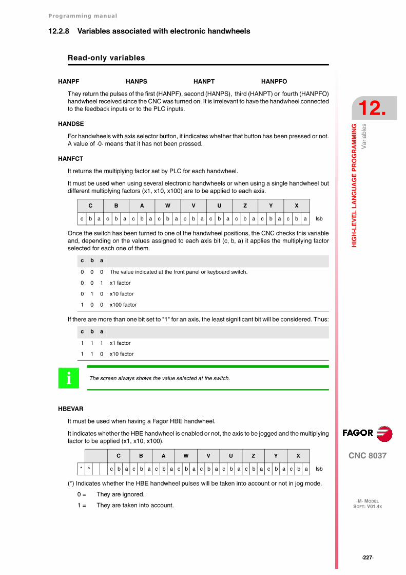
Programming manual
CNC 8037
HIG
H-L
EV
EL
LA
NG
UA
GE
PR
OG
RA
MM
ING
12.
·M· MODELSOFT: V01.4X
·227·
Var
iabl
es
12.2.8 Variables associated with electronic handwheels
Read-only variables
HANPF HANPS HANPT HANPFO
They return the pulses of the first (HANPF), second (HANPS), third (HANPT) or fourth (HANPFO)handwheel received since the CNC was turned on. It is irrelevant to have the handwheel connectedto the feedback inputs or to the PLC inputs.
HANDSE
For handwheels with axis selector button, it indicates whether that button has been pressed or not.A value of ·0· means that it has not been pressed.
HANFCT
It returns the multiplying factor set by PLC for each handwheel.
It must be used when using several electronic handwheels or when using a single handwheel butdifferent multiplying factors (x1, x10, x100) are to be applied to each axis.
Once the switch has been turned to one of the handwheel positions, the CNC checks this variableand, depending on the values assigned to each axis bit (c, b, a) it applies the multiplying factorselected for each one of them.
If there are more than one bit set to "1" for an axis, the least significant bit will be considered. Thus:
HBEVAR
It must be used when having a Fagor HBE handwheel.
It indicates whether the HBE handwheel is enabled or not, the axis to be jogged and the multiplyingfactor to be applied (x1, x10, x100).
(*) Indicates whether the HBE handwheel pulses will be taken into account or not in jog mode.
0 = They are ignored.
1 = They are taken into account.
C B A W V U Z Y X
c b a c b a c b a c b a c b a c b a c b a c b a c b a lsb
c b a
0 0 0 The value indicated at the front panel or keyboard switch.
0 0 1 x1 factor
0 1 0 x10 factor
1 0 0 x100 factor
c b a
1 1 1 x1 factor
1 1 0 x10 factor
The screen always shows the value selected at the switch.i
C B A W V U Z Y X
* ^ c b a c b a c b a c b a c b a c b a c b a c b a c b a lsb
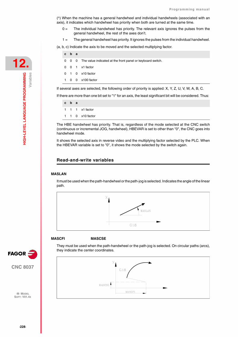
·228·
Programming manual
CNC 8037
12.
HIG
H-L
EV
EL
LA
NG
UA
GE
PR
OG
RA
MM
ING
·M· MODELSOFT: V01.4X
Var
iabl
es
(^) When the machine has a general handwheel and individual handwheels (associated with anaxis), it indicates which handwheel has priority when both are turned at the same time.
0 = The individual handwheel has priority. The relevant axis ignores the pulses from thegeneral handwheel, the rest of the axes don’t.
1 = The general handwheel has priority. It ignores the pulses from the individual handwheel.
(a, b, c) Indicate the axis to be moved and the selected multiplying factor.
If several axes are selected, the following order of priority is applied: X, Y, Z, U, V, W, A, B, C.
If there are more than one bit set to "1" for an axis, the least significant bit will be considered. Thus:
The HBE handwheel has priority. That is, regardless of the mode selected at the CNC switch(continuous or incremental JOG, handwheel), HBEVAR is set to other than "0", the CNC goes intohandwheel mode.
It shows the selected axis in reverse video and the multiplying factor selected by the PLC. Whenthe HBEVAR variable is set to "0", it shows the mode selected by the switch again.
Read-and-write variables
MASLAN
It must be used when the path-handwheel or the path-jog is selected. Indicates the angle of the linearpath.
MASCFI MASCSE
They must be used when the path-handwheel or the path-jog is selected. On circular paths (arcs),they indicate the center coordinates.
c b a
0 0 0 The value indicated at the front panel or keyboard switch.
0 0 1 x1 factor
0 1 0 x10 factor
1 0 0 x100 factor
c b a
1 1 1 x1 factor
1 1 0 x10 factor
Programming manual
CNC 8037
HIG
H-L
EV
EL
LA
NG
UA
GE
PR
OG
RA
MM
ING
12.
·M· MODELSOFT: V01.4X
·229·
Var
iabl
es
12.2.9 Variables associated with feedback
ASIN(X-C)
"A" signal of the CNC's sinusoidal feedback for the X-C axis.
BSIN(X-C)
"B" signal of the CNC's sinusoidal feedback for the X-C axis.
ASINS
"A" signal of the CNC's sinusoidal feedback for the spindle.
BSINS
"B" signal of the CNC's sinusoidal feedback for the spindle.
·230·
Programming manual
CNC 8037
12.
HIG
H-L
EV
EL
LA
NG
UA
GE
PR
OG
RA
MM
ING
·M· MODELSOFT: V01.4X
Var
iabl
es
12.2.10 Variables associated with the main spindle
In these variables associated with the spindle, their values are given in revolutions per minute andthe main spindle override values are given in integers from 0 to 255.
Certain variables interrupt block preparation (it is indicated in each one) and the CNC waits for thatcommand to be executed before resuming block preparation.
Read-only variables
SREAL
Returns the real main spindle turning speed in revolutions per minute. It interrupts block preparation.
FTEOS
It returns the theoretical turning speed of the main spindle.
SPEED
Returns, in revolutions per minute, the main spindle speed selected at the CNC.
This turning speed may be indicated by program, by PLC or by DNC; the CNC selects one of them,the one indicated by DNC has the highest priority and the one indicated by program has the lowestpriority.
DNCS
Returns the turning speed in revolutions per minute, selected by DNC. If it has a value of 0 it meansthat it is not selected.
PLCS
Returns the turning speed in revolutions per minute selected by PLC. If it has a value of 0 it meansthat it is not selected.
PRGS
Returns the turning speed in revolutions per minute, selected by program.
SSO
It returns the turning speed override (%) of the main spindle currently selected at the CNC. It is givenin integer values between 0 and "MAXFOVR" (maximum 255).
This turning speed percentage of the main spindle may be indicated by program, by PLC, by DNCor by the front panel; the CNC selects one of them and the priority (from the highest to the lowest)is: by program, by DNC, by PLC and from the front panel.
DNCSSO
It returns the turning speed override % of the main spindle currently selected via DNC. If it has avalue of 0 it means that it is not selected.
PLCSSO
It returns the turning speed override % of the main spindle currently selected by PLC. If it has a valueof 0 it means that it is not selected.
(P100=SREAL)It assigns to P100 the real turning speed of the main spindle.
Programming manual
CNC 8037
HIG
H-L
EV
EL
LA
NG
UA
GE
PR
OG
RA
MM
ING
12.
·M· MODELSOFT: V01.4X
·231·
Var
iabl
es
CNCSSO
It returns the turning speed override % of the main spindle currently selected from the front panel.
SLIMIT
It returns the value set in rpm at the CNC for the turning speed limit of the main spindle.
This limit may be indicated by program, by PLC or by DNC; the CNC selects one of them, the oneindicated by DNC has the highest priority and the one indicated by program has the lowest priority.
DNCSL
It returns the speed limit of the main spindle in rpm currently selected via DNC. If it has a value of0 it means that it is not selected.
PLCSL
It returns the speed limit of the main spindle in rpm currently selected by PLC. If it has a value of0 it means that it is not selected.
PRGSL
It returns the speed limit of the main spindle in rpm currently selected by program.
MDISL
Maximum machining spindle speed. This variable is also updated (refreshed) when programmingfunction G92 via MDI.
POSS
It returns the real position of the main spindle. Its value may be within ±99999.9999°. It interruptsblock preparation.
RPOSS
It returns the real position of the main spindle. Its value is given in 0.0001 degree units (between-360º and 360º). It interrupts block preparation.
TPOSS
It returns the theoretical position of the main spindle (real position + lag). Its value may be within±99999.9999º. It interrupts block preparation.
RTPOSS
It returns the theoretical position of the main spindle (real position + lag) in 360º module. Its valuemay be between 0 and 360º. It interrupts block preparation.
PRGSP
Position programmed in M19 via program for the main spindle. This variable may be read from theCNC, from the PLC and from DNC.
FLWES
It returns the main spindle's following error in degrees (within ±99999.9999). It interrupts blockpreparation.
·232·
Programming manual
CNC 8037
12.
HIG
H-L
EV
EL
LA
NG
UA
GE
PR
OG
RA
MM
ING
·M· MODELSOFT: V01.4X
Var
iabl
es
Read-and-write variables
PRGSSO
This variable may be used to read or modify the speed override percentage of the main spindlecurrently selected by program. It is given in integer values between 0 and "MAXFOVR" (maximum255). If it has a value of 0 it means that it is not selected.
(P110=PRGSSO)It assigns to P110 the % of the main spindle speed selected by program.
(PRGSSO=P111)It sets the value indicating the main spindle speed % selected by program to the value of arithmetic parameter P111.
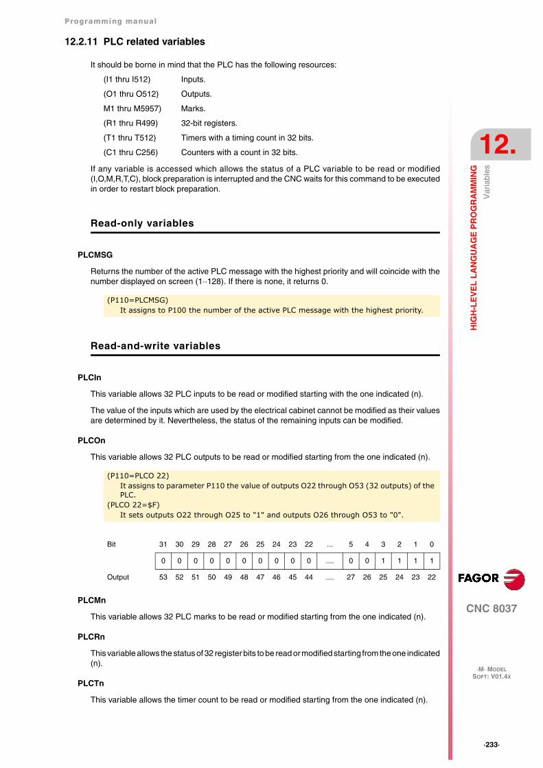
Programming manual
CNC 8037
HIG
H-L
EV
EL
LA
NG
UA
GE
PR
OG
RA
MM
ING
12.
·M· MODELSOFT: V01.4X
·233·
Var
iabl
es
12.2.11 PLC related variables
It should be borne in mind that the PLC has the following resources:
(I1 thru I512) Inputs.
(O1 thru O512) Outputs.
M1 thru M5957) Marks.
(R1 thru R499) 32-bit registers.
(T1 thru T512) Timers with a timing count in 32 bits.
(C1 thru C256) Counters with a count in 32 bits.
If any variable is accessed which allows the status of a PLC variable to be read or modified(I,O,M,R,T,C), block preparation is interrupted and the CNC waits for this command to be executedin order to restart block preparation.
Read-only variables
PLCMSG
Returns the number of the active PLC message with the highest priority and will coincide with thenumber displayed on screen (1··128). If there is none, it returns 0.
Read-and-write variables
PLCIn
This variable allows 32 PLC inputs to be read or modified starting with the one indicated (n).
The value of the inputs which are used by the electrical cabinet cannot be modified as their valuesare determined by it. Nevertheless, the status of the remaining inputs can be modified.
PLCOn
This variable allows 32 PLC outputs to be read or modified starting from the one indicated (n).
PLCMn
This variable allows 32 PLC marks to be read or modified starting from the one indicated (n).
PLCRn
This variable allows the status of 32 register bits to be read or modified starting from the one indicated(n).
PLCTn
This variable allows the timer count to be read or modified starting from the one indicated (n).
(P110=PLCMSG)It assigns to P100 the number of the active PLC message with the highest priority.
(P110=PLCO 22)It assigns to parameter P110 the value of outputs O22 through O53 (32 outputs) of the PLC.
(PLCO 22=$F)It sets outputs O22 through O25 to "1" and outputs O26 through O53 to "0".
Bit 31 30 29 28 27 26 25 24 23 22 ... 5 4 3 2 1 0
0 0 0 0 0 0 0 0 0 0 .... 0 0 1 1 1 1
Output 53 52 51 50 49 48 47 46 45 44 .... 27 26 25 24 23 22
·234·
Programming manual
CNC 8037
12.
HIG
H-L
EV
EL
LA
NG
UA
GE
PR
OG
RA
MM
ING
·M· MODELSOFT: V01.4X
Var
iabl
es
PLCCn
This variable allows the counter count to be read or modified starting from the one indicated (n).
PLCMMn
This variable permits reading or modifying the PLC mark (n).
(PLMM4=1)It sets mark M4 to ·1· and leaves the rest untouched.
(PLCM4=1)It sets mark M4 to ·1· and the following 31 marks (M5, through M35) to ·0·
Programming manual
CNC 8037
HIG
H-L
EV
EL
LA
NG
UA
GE
PR
OG
RA
MM
ING
12.
·M· MODELSOFT: V01.4X
·235·
Var
iabl
es
12.2.12 Variables associated with local parameters
The CNC allows 26 local parameters (P0-P25) to be assigned to a subroutine, by using mnemonicsPCALL and MCALL. In addition to performing the required subroutine these mnemonics allow localparameters to be initialized.
Read-only variables
CALLP
Allows us to know which local parameters have been defined and which have not, in the call to thesubroutine by means of the PCALL or MCALL mnemonic.
The information will be given in the 26 least significant bits (bits 0··25), each of these correspondingto the local parameter of the same number; thus bit 12 corresponds to P12.
Each bit will indicate whether the corresponding local parameter has been defined (=1) or not (0).
Example:
In parameter P100 the following will be obtained:
Bit 31 30 29 28 27 26 25 24 23 22 ... 5 4 3 2 1 0
0 0 0 0 0 0 * * * * ... * * * * * *
;Call to subroutine 20.(PCALL 20, P0=20, P2=3, P3=5)......;Beginning of subroutine 20.( SUB 20)(P100 = CALLP)......
0000 0000 0000 0000 0000 0000 0000 1101 LSB
·236·
Programming manual
CNC 8037
12.
HIG
H-L
EV
EL
LA
NG
UA
GE
PR
OG
RA
MM
ING
·M· MODELSOFT: V01.4X
Var
iabl
es
12.2.13 Operating-mode related variables
Read-only variables related to the standard mode
OPMODE
It returns the code corresponding to the selected operating mode.
0 = Main menu.
10 = Automatic execution.
11 = Single block execution.
12 = MDI in EXECUTION.
13 = Tool inspection.
14 = Repositioning.
15 = Block search executing G.
16 = Block search executing G, M, S, T.
20 = Theoretical path simulation.
21 = G function simulation.
22 = G, M, S and T function simulation.
23 = Simulation with movement in the main plane.
24 = Simulation with rapid movement.
25 = Rapid simulation with S=0.
30 = Normal editing.
31 = User editing.
32 = TEACH-IN editing.
33 = Interactive editor.
40 = Movement in continuous JOG.
41 = Movement in incremental JOG.
42 = Movement with electronic handwheel.
43 = HOME search in JOG.
44 = Position preset in JOG.
45 = Tool calibration.
46 = MDI in JOG.
47 = User JOG operation.
50 = Zero offset table.
51 = Tool offset table.
52 = Tool table.
53 = Tool magazine table.
54 = Global parameter table.
55 = Local parameter table.
56 = User parameter table.
57 = OEM parameter table.
60 = Utilities.
70 = DNC status.
Programming manual
CNC 8037
HIG
H-L
EV
EL
LA
NG
UA
GE
PR
OG
RA
MM
ING
12.
·M· MODELSOFT: V01.4X
·237·
Var
iabl
es
71 = CNC status.
80 = PLC file editing.
81 = PLC program compilation.
82 = PLC monitoring.
83 = Active PLC messages.
84 = Active PLC pages.
85 = Save PLC program.
86 = Restore PLC program.
87 = PLC usage maps.
88 = PLC statistics.
90 = Customizing.
100 = General machine parameter table.
101 = Axis machine parameter tables.
102 = Spindle machine parameter table.
103 = Serial line related machine parameter tables.
104 = PLC machine parameter table.
105 = M function table.
106 = Leadscrew error compensation tables and cross compensation tables.
107 = Machine parameter table for Ethernet.
110 = Diagnosis: configuration.
111 = Diagnosis: hardware test.
112 = Diagnosis: RAM memory test.
113 = Diagnosis: Flash memory test.
114 = User diagnosis.
115 = Hard disk diagnosis (HD).
116 = Circle geometry test.
117 = Oscilloscope.
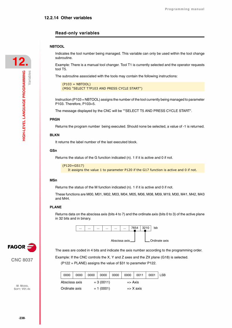
·238·
Programming manual
CNC 8037
12.
HIG
H-L
EV
EL
LA
NG
UA
GE
PR
OG
RA
MM
ING
·M· MODELSOFT: V01.4X
Var
iabl
es
12.2.14 Other variables
Read-only variables
NBTOOL
Indicates the tool number being managed. This variable can only be used within the tool changesubroutine.
Example: There is a manual tool changer. Tool T1 is currently selected and the operator requeststool T5.
The subroutine associated with the tools may contain the following instructions:
Instruction (P103 = NBTOOL) assigns the number of the tool currently being managed to parameterP103. Therefore, P103=5.
The message displayed by the CNC will be ""SELECT T5 AND PRESS CYCLE START".
PRGN
Returns the program number being executed. Should none be selected, a value of -1 is returned.
BLKN
It returns the label number of the last executed block.
GSn
Returns the status of the G function indicated (n). 1 if it is active and 0 if not.
MSn
Returns the status of the M function indicated (n). 1 if it is active and 0 if not.
These functions are M00, M01, M02, M03, M04, M05, M06, M08, M09, M19, M30, M41, M42, M43and M44.
PLANE
Returns data on the abscissa axis (bits 4 to 7) and the ordinate axis (bits 0 to 3) of the active planein 32 bits and in binary.
The axes are coded in 4 bits and indicate the axis number according to the programming order.
Example: If the CNC controls the X, Y and Z axes and the ZX plane (G18) is selected.
(P122 = PLANE) assigns the value of $31 to parameter P122.
Abscissa axis = 3 (0011) => Axis
Ordinate axis = 1 (0001) => X axis
(P103 = NBTOOL)(MSG "SELECT T?P103 AND PRESS CYCLE START")
(P120=GS17)It assigns the value 1 to parameter P120 if the G17 function is active and 0 if not.
0000 0000 0000 0000 0000 0000 0011 0001 LSB
... ... ... ... ... ... 7654 3210 lsb
Ordinate axisAbscissa axis
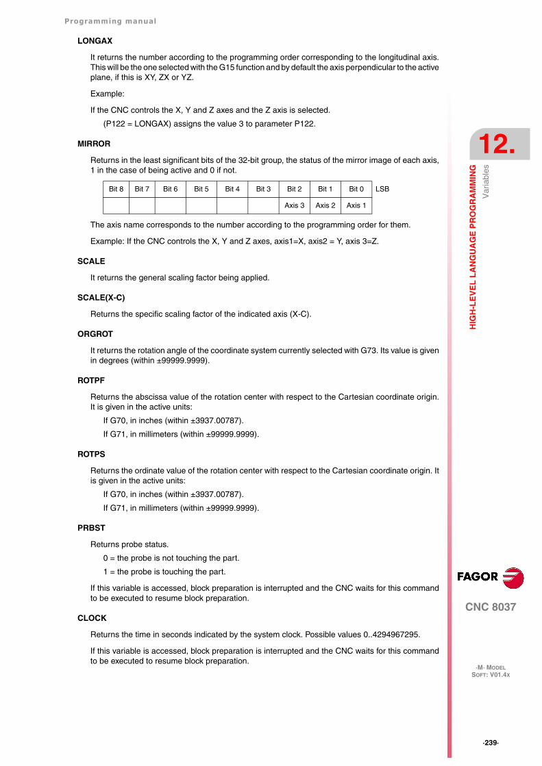
Programming manual
CNC 8037
HIG
H-L
EV
EL
LA
NG
UA
GE
PR
OG
RA
MM
ING
12.
·M· MODELSOFT: V01.4X
·239·
Var
iabl
es
LONGAX
It returns the number according to the programming order corresponding to the longitudinal axis.This will be the one selected with the G15 function and by default the axis perpendicular to the activeplane, if this is XY, ZX or YZ.
Example:
If the CNC controls the X, Y and Z axes and the Z axis is selected.
(P122 = LONGAX) assigns the value 3 to parameter P122.
MIRROR
Returns in the least significant bits of the 32-bit group, the status of the mirror image of each axis,1 in the case of being active and 0 if not.
The axis name corresponds to the number according to the programming order for them.
Example: If the CNC controls the X, Y and Z axes, axis1=X, axis2 = Y, axis 3=Z.
SCALE
It returns the general scaling factor being applied.
SCALE(X-C)
Returns the specific scaling factor of the indicated axis (X-C).
ORGROT
It returns the rotation angle of the coordinate system currently selected with G73. Its value is givenin degrees (within ±99999.9999).
ROTPF
Returns the abscissa value of the rotation center with respect to the Cartesian coordinate origin.It is given in the active units:
If G70, in inches (within ±3937.00787).
If G71, in millimeters (within ±99999.9999).
ROTPS
Returns the ordinate value of the rotation center with respect to the Cartesian coordinate origin. Itis given in the active units:
If G70, in inches (within ±3937.00787).
If G71, in millimeters (within ±99999.9999).
PRBST
Returns probe status.
0 = the probe is not touching the part.
1 = the probe is touching the part.
If this variable is accessed, block preparation is interrupted and the CNC waits for this commandto be executed to resume block preparation.
CLOCK
Returns the time in seconds indicated by the system clock. Possible values 0..4294967295.
If this variable is accessed, block preparation is interrupted and the CNC waits for this commandto be executed to resume block preparation.
Bit 8 Bit 7 Bit 6 Bit 5 Bit 4 Bit 3 Bit 2 Bit 1 Bit 0 LSB
Axis 3 Axis 2 Axis 1
·240·
Programming manual
CNC 8037
12.
HIG
H-L
EV
EL
LA
NG
UA
GE
PR
OG
RA
MM
ING
·M· MODELSOFT: V01.4X
Var
iabl
es
TIME
Returns the time in hours-minutes-seconds format.
If this variable is accessed, block preparation is interrupted and the CNC waits for this commandto be executed to resume block preparation.
DATE
Returns the date in year-month-day format.
If this variable is accessed, block preparation is interrupted and the CNC waits for this commandto be executed to resume block preparation.
CYTIME
It returns the amount of time (in hundredths of a second) elapsed executing the part. It ignores thetime the execution has been interrupted. Possible values 0..4294967295.
If this variable is accessed, block preparation is interrupted and the CNC waits for this commandto be executed to resume block preparation.
FIRST
Indicates whether it is the first time that a program has been run or not. It returns a value of 1 if itis the first time and 0 if not.
A first-time execution is considered as being one which is done:
• After turning on the CNC.
• After pressing [SHIFT]+[RESET].
• Every time a new program is selected.
ANAIn
It returns the status of the indicated analog input (n). The value given in Volts and in ±1.4 format.It is possible to select one of the 8 analog inputs (1··8) available. The values returned will be withinthe ±5 V range.
If this variable is accessed, block preparation is interrupted and the CNC waits for this commandto be executed to resume block preparation.
TIMEG
It shows the timing status of the timer programmed with G4 K in the CNC channel. This variable,returns the time remaining to end the timing block in hundredths of a second.
RIP
Linear theoretical feedrate resulting from the next loop (in mm/min).
The calculation of the resulting feedrate ignores the rotary axes, slave axes (gantry, coupled andsynchronized) as well as DRO axes.
Read-and-write variables
TIMER
This variable allows reading or modifying the time, in seconds, indicated by the clock enabled bythe PLC. Possible values 0..4294967295.
If this variable is accessed, block preparation is interrupted and the CNC waits for this commandto be executed to resume block preparation.
(P150=TIME)Loads P150 with hh-mm-ss. For example if the time is: 34sec. P150 = 182234.
(P151=DATE)It assigns to P151 the year-month-day. For example if the date is April 25th 1992, P151 = 920425.
Programming manual
CNC 8037
HIG
H-L
EV
EL
LA
NG
UA
GE
PR
OG
RA
MM
ING
12.
·M· MODELSOFT: V01.4X
·241·
Var
iabl
es
PARTC
The CNC has a part counter whose count increases, in all modes except simulation, every time M30or M02 is executed and this variable allows its value to be read or modified. This value will be between0 and 4294967295
If this variable is accessed, block preparation is interrupted and the CNC waits for this commandto be executed to resume block preparation.
KEY
Returns the code of the last key accepted.
This variable may be used as a write variable only inside a customizing program (user channel).
If this variable is accessed, block preparation is interrupted and the CNC waits for this commandto be executed to resume block preparation.
KEYSRC
This variable allows reading or modifying the source of keystrokes, possible values being:
0 = Keyboard.
1 = PLC.
2 = DNC.
The CNC only allows modification of this variable if this is at 0.
ANAOn
This variable allows the required analog output (n) to be read or modified. The value assigned willbe expressed in volts and in the ±2.4 format (±10 V).
The analog outputs which are free among the eight (1 through 8) available at the CNC may bemodified, the corresponding error being displayed if an attempt is made to write in one which isoccupied.
If this variable is accessed, block preparation is interrupted and the CNC waits for this commandto be executed to resume block preparation.
SELPRO
When having two probe inputs, it allows selecting the active input.
On power-up, it assumes the value of ·1· thus selecting the first probe input. To select the secondprobe input, set it to a value of ·2·.
Accessing this variable from the CNC interrupts block preparation.
DIAM
It changes the programming mode for X axis coordinates between radius and diameter. Whenchanging the value of this variable, the CNC assumes the new way to program the following blocks.
When the variable is set to ·1·, the programmed coordinates are assumed in diameter; when is setto ·0·, the programmed coordinates are assumed in radius.
This variable affects the display of the real value of the X axis in the coordinate system of the partand the reading of variables PPOSX, TPOSX and POSX.
On power-up, after executing an M02 or M30 and after an emergency or a reset, the variable isinitialized according to the value of the DFORMAT parameter of the X axis. If this parameter hasa value equal to or greater than 4, the variable takes a value of 1; otherwise, it takes the value of ·0·.
PRBMOD
It indicates whether a probing error is to issued or not in the following cases, even if general machineparameter PROBERR (P119) =YES.
• When a G75 probing move finishes before the probe has touched part.
• When a G76 probing move finishes but the probe is still touching the part.
·242·
Programming manual
CNC 8037
12.
HIG
H-L
EV
EL
LA
NG
UA
GE
PR
OG
RA
MM
ING
·M· MODELSOFT: V01.4X
Var
iabl
es
The PRBMOD variable takes the following values.
The PRBMOD variable can be read and written from the CNC and the PLC an read from the DNC.
Value Meaning
0 An error message is issued.
1 No error message is issued.
Default value 0.

Programming manual
CNC 8037
HIG
H-L
EV
EL
LA
NG
UA
GE
PR
OG
RA
MM
ING
12.
·M· MODELSOFT: V01.4X
·243·
Con
stan
ts
12.3 Constants
Constants are defined as being all those fixed values which cannot be altered by a program. Thefollowing are considered as constants:
• Numbers expressed in the decimal system.
• Hexadecimal numbers.
• PI constant.
• Read-only tables and variables as their value cannot be altered with a program.
·244·
Programming manual
CNC 8037
12.
HIG
H-L
EV
EL
LA
NG
UA
GE
PR
OG
RA
MM
ING
·M· MODELSOFT: V01.4X
Ope
rato
rs
12.4 Operators
An operator is a symbol that indicates the mathematical or logic operations to carry out. The CNChas arithmetic, relational, logic, binary, trigonometric operators and special operators.
Arithmetic operators.
Relational operators.
Logic and binary operators.
NOT, OR, AND, XOR: The act as logic operators between conditions and as binary operatorsbetween variables and constants.
IF (FIRST AND GS1 EQ 1) GOTO N100P5 = (P1 AND (NOT P2 OR P3))
Trigonometric functions.
There are two functions for calculating the arc tangent ATAN which returns the result between ±90°and ARG given between 0 and 360°.
+ add. P1=3 + 4 P1=7
- subtraction, also a negative value. P2=5 - 2P3= -(2 * 3)
P2=3P3=-6
* multiplication. P4=2 * 3 P4=6
/ division. P5=9 / 2 P5=4.5
MOD Module or remainder of the division. P6=7 MOD 4 P6=3
EXP exponential. P7=2 EXP 3 P7=8
EQ equal.
NE different.
GT greater than.
GE greater than or equal to.
LT Less than.
LE Less than or equal to.
SIN sine. P1=SIN 30 P1=0.5
COS cosine. P2=COS 30 P2=0.8660
TAN tangent. P3=TAN 30 P3=0.5773
ASIN arc sine. P4=ASIN 1 P4=90
ACOS arc cosine. P5=ACOS 1 P5=0
ATAN arc tangent. P6=ATAN 1 P6=45
ARG ARG(x,y) arctangent y/x. P7=ARG(-1,-2) P7=243.4349
Programming manual
CNC 8037
HIG
H-L
EV
EL
LA
NG
UA
GE
PR
OG
RA
MM
ING
12.
·M· MODELSOFT: V01.4X
·245·
Ope
rato
rs
Other functions.
Conversions to binary and BCD are made in 32 bits, it being possible to represent the number 156in the following formats:
Decimal 156
Hexadecimal 9C
Binary 0000 0000 0000 0000 0000 0000 1001 1100
BCD 0000 0000 0000 0000 0000 0001 0101 0110
ABS absolute value. P1=ABS -8 P1=8
LOG decimal logarithm. P2=LOG 100 P2=2
SQRT square root. P3=SQRT 16 P3=4
ROUND rounding up an integer number. P4=ROUND 5.83 P4=6
FIX Integer. P5=FIX 5.423 P5=5
FUP if integer takes integer.if not, takes entire part + 1.
P6=FUP 7P6=FUP 5,423
P6=7P6=6
BCD converts given number to BCD. P7=BCD 234 P7=564
0010 0011 0100
BIN converts given number to binary. P8=BIN $AB P8=171
1010 1011
·246·
Programming manual
CNC 8037
12.
HIG
H-L
EV
EL
LA
NG
UA
GE
PR
OG
RA
MM
ING
·M· MODELSOFT: V01.4X
Exp
ress
ions
12.5 Expressions
An expression is any valid combination of operators, constants, parameters and variables.
All expressions must be placed between brackets, but if the expression is reduced to an integer,the brackets can be removed.
12.5.1 Arithmetic expressions
These are formed by combining functions and arithmetic, binary and trigonometric operators withthe constants and variables of the language.
The priorities of the operators and the way they can be associated determine how these expressionsare calculated:
Brackets should be used in order to clarify the order in which the expression is to be evaluated.
(P3 = P4/P5 - P6 * P7 - P8/P9 )(P3 = (P4/P5)-(P6 * P7)-(P8/P9))
Using redundant or additional brackets will neither cause errors nor slow down the execution.
In functions, brackets must be used except when these are applied to a numerical constant, in whichcase they are optional.
(SIN 45) (SIN (45)) they're both valid and equivalent.
(SIN 10+5) the same as ((SIN 10)+5).
Expressions can be used also to reference parameters and tables:
(P100 = P9)(P100 = P(P7))(P100 = P(P8 + SIN(P8 * 20)))(P100 = ORGX 55)(P100 = ORGX (12+P9))(PLCM5008 = PLCM5008 OR 1)
; Selects single block execution mode (M5008=1)(PLCM5010 = PLCM5010 AND $FFFFFFFE)
; Frees feedrate override (M5010=0)
Priority from highest to lowest To be associated
NOT, functions, - (negative) from right to left.
EXP, MOD from left to right.
* , / from left to right.
+,- (add, subtract) from left to right.
Relational operators from left to right.
AND, XOR from left to right.
OR from left to right.
Programming manual
CNC 8037
HIG
H-L
EV
EL
LA
NG
UA
GE
PR
OG
RA
MM
ING
12.
·M· MODELSOFT: V01.4X
·247·
Exp
ress
ions
12.5.2 Relational expressions
These are arithmetic expressions joined by relational operators.
(IF (P8 EQ 12.8); It checks if the value of P8 is equal to 12.8.
(IF (ABS(SIN(P24)) GT SPEED);Analyzes if the sine is greater than the spindle speed.
(IF (CLOCK LT (P9 * 10.99)); Analyzes if the clock count is less than (P9 * 10.99)
At the same time these conditions can be joined by means of logic operators.
(IF ((P8 EQ 12.8) OR (ABS(SIN(P24)) GT SPEED)) AND (CLOCK LT (P9 * 10.99)) ...
The result of these expressions is either true or false.

·248·
Programming manual
CNC 8037
12.
HIG
H-L
EV
EL
LA
NG
UA
GE
PR
OG
RA
MM
ING
·M· MODELSOFT: V01.4X
Exp
ress
ions
CNC 8037
·M· MODELSOFT: V01.4X
13
·249·
PROGRAM CONTROL INSTRUCTIONS
The control instructions available to high-level programming can be grouped as follows:
• Assignment instructions.
• Display instructions.
• Enable-disable instructions.
• Flow control instructions.
• Subroutine instructions.
• Interruption-subroutine instructions.
• Program instructions.
• Screen customizing instructions.
Only one instruction can be programmed in each block, and no other additional information maybe programmed in this block.
·250·
Programming manual
CNC 8037
13.
PR
OG
RA
M C
ON
TR
OL
INS
TR
UC
TIO
NS
·M· MODELSOFT: V01.4X
Ass
ignm
ent i
nstr
uctio
ns
13.1 Assignment instructions
This is the simplest type of instruction and can be defined as:
(target = arithmetic expression)
A local or global parameter or a read-write variable may be selected as target. The arithmeticexpression may be as complex as required or a simple numerical constant.
(P102 = FZLOY)(ORGY 55 = (ORGY 54 + P100))
In the specific case of designating a local parameter using its name (A instead of P0, for example)and the arithmetic expression being a numerical constant, the instruction can be abbreviated asfollows:
(P0=13.7) ==> (A=13.7) ==> (A13.7)
Within a single block, up to 26 assignments can be made to different targets, a single assignmentbeing interpreted as the set of assignments made to the same target.
(P1=P1+P2, P1=P1+P3, P1=P1*P4, P1=P1/P5)
It is the same as saying:
(P1=(P1+P2+P3)*P4/P5).
The different assignments which are made in the same block will be separated by commas ",".
Programming manual
CNC 8037
PR
OG
RA
M C
ON
TR
OL
INS
TR
UC
TIO
NS
13.
·M· MODELSOFT: V01.4X
·251·
Dis
play
inst
ruct
ions
13.2 Display instructions
(ERROR integer, "error text")
This instruction stops the execution of the program and displays the indicated error, it being possibleto select this error in the following ways:
(ERROR integer)
This will display the error number indicated and the text associated to this number accordingto the CNC error code (should there be one).
(ERROR integer, "error text")
This will display the number and the error text indicated, it being necessary to write the textbetween quote marks "".
(ERROR "error text").
This will display the error text only.
The error number may be defined by means of a numerical constant or an arithmetic parameter.When using a local parameter, its numeric format must be used (P0 thru P25 instead of A thru Z).
Programming examples:
(ERROR 5)
(ERROR P100)
(ERROR "User error")
(ERROR 3, "User error")
(ERROR P120, "User error)
(MSG "message")
This instruction will display the message indicated between quote marks.
The CNC screen is provided with an area for displaying DNC or user program messages, and alwaysdisplays the last message received irrespective of where it has come from.
Example: (MSG "Check tool")
(DGWZ expression 1, expression 2, expression 3, expression 4, expression 5,expression 6)
The DGWZ instruction (Define Graphic Work Zone) defines the graphics area.
Each expression forming the instruction syntax correspond to one of the limits and they must bedefined in millimeters or inches.
expression 1 Minimum X
expression 2 Maximum X
expression 3 Minimum Y
expression 4 Maximum Y
expression 5 Minimum Z
expression 6 Maximum Z
·252·
Programming manual
CNC 8037
13.
PR
OG
RA
M C
ON
TR
OL
INS
TR
UC
TIO
NS
·M· MODELSOFT: V01.4X
Ena
ble-
disa
ble
inst
ruct
ions
13.3 Enable-disable instructions
(ESBLK and DSBLK)
After executing the mnemonic ESBLK, the CNC executes all the blocks that come after as if it weredealing with a single block.
This single block treatment is kept active until it is cancelled by executing the mnemonic DSBLK.
In this way, should the program be executed in the SINGLE BLOCK operating mode, the group ofblocks which are found between the mnemonics ESBLK and DSBLK will be executed in a continuouscycle, i.e., execution will not be stopped at the end of a block but will continue by executing thefollowing one.
(ESTOP and DSTOP)
After executing the mnemonic DSTOP, the CNC enables the Stop key, as well as the Stop signalfrom the PLC.
It will remain disabled until it is enabled once again by means of the mnemonic ESTOP.
(EFHOLD and DFHOLD)
After executing the mnemonic DFHOLD, the CNC enables the Feed-Hold input from the PLC.
It will remain disabled until it is enabled once again by means of the mnemonic EFHOLD.
G01 X10 Y10 F8000 T1 D1(ESBLK) ; Start of single blockG02 X20 Y20 I20 J-10G01 X40 Y20G01 X40 Y40 F10000G01 X20 Y40 F8000(DSBLK) ; Cancellation of single blockG01 X10 Y10M30
Programming manual
CNC 8037
PR
OG
RA
M C
ON
TR
OL
INS
TR
UC
TIO
NS
13.
·M· MODELSOFT: V01.4X
·253·
Flo
w c
ontr
ol in
stru
ctio
ns
13.4 Flow control instructions
The GOTO and RPT instructions cannot be used in programs that are executed from a PC connectedthrough the serial line.
( GOTO N(expression) )
The mnemonic GOTO causes a jump within the same program, to the block defined by the labelN(expression). The execution of the program will continue after the jump, from the indicated block.
The jump label can be addressed by means of a number or by any expression which results in anumber.
( RPT N(expression), N(expression), P(expression) )
The mnemonic RPT executes the part of the program between the blocks defined by means of thelabels N(expression). The blocks to be executed may be in the execution program or in a RAMmemory program.
The label P(expression) indicates the number of the program containing the blocks to be executed.If not defined, the CNC interprets that the portion to be repeated is located in the same program.
All the labels can be indicated by means of a number or by any expression which results in a number.The part of the program selected by means of the two labels must belong to the same program, byfirst defining the initial block and then the final block.
The execution of the program will continue in the block following the one in which the mnemonicRPT was programmed, once the selected part of the program has been executed.
(IF condition <action1> ELSE <action2>)
This instruction analyzes the given condition that must be a relational expression. If the conditionis true (result equal to 1), <action1> will be executed, otherwise (result equal to 0) <action2> willbe executed.
Example:
(IF (P8 EQ 12.8) CALL 3 ELSE PCALL 5, A2, B5, D8)If P8 = 12.8 executes the mnemonic (CALL3)If P8<>12.8 executes the mnemonic (PCALL 5, A2, B5, D8)
The instruction can lack the ELSE part, i.e., it will be enough to program IF condition <action1>.
Example:
(IF (P8 EQ 12.8) CALL 3)
G00 X0 Y0 Z0 T2 D4X10(GOTO N22) ; Jump instructionX15 Y20 ; It is not executedY22 Z50 ; It is not executed
N22 G01 X30 Y40 Z40 F1000 ; Continues execution in this blockG02 X20 Y40 I-5 J-5...
N10 G00 X10Z20G01 X5G00 Z0
N20 X0N30 (RPT N10, N20) N3N40 G01 X20
M30When reaching block N30, the program will execute section N10-N20 three times. Once this has been completed, the program will continue execution in block N40.
Since the RPT instruction does not interrupt block preparation or tool compensation, it may be usedwhen using the EXEC instruction and while needing to maintain tool compensation active.i
·254·
Programming manual
CNC 8037
13.
PR
OG
RA
M C
ON
TR
OL
INS
TR
UC
TIO
NS
·M· MODELSOFT: V01.4X
Flo
w c
ontr
ol in
stru
ctio
ns
Both <action1> and <action2> can be expressions or instructions, except for mnemonics IF andSUB.
Due to the fact that in a high level block local parameters can be named by means of letters,expressions of this type can be obtained:
(IF (E EQ 10) M10)
If the condition of parameter P5 (E) having a value of 10 is met, the miscellaneous function M10will not be executed, since a high level block cannot have ISO code commands. In this case M10represents the assignment of value 10 to parameter P12, i.e., one can program either:
(IF (E EQ 10) M10) or (IF (P5 EQ 10) P12=10)
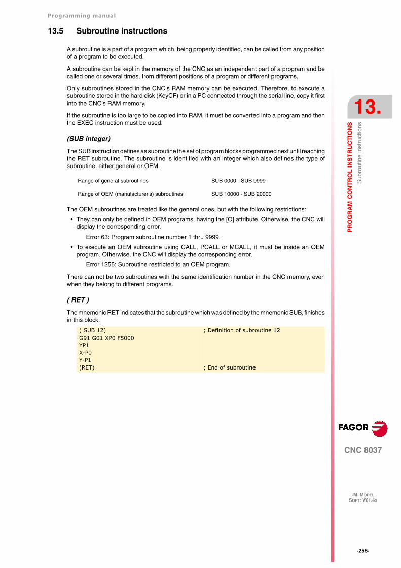
Programming manual
CNC 8037
PR
OG
RA
M C
ON
TR
OL
INS
TR
UC
TIO
NS
13.
·M· MODELSOFT: V01.4X
·255·
Sub
rout
ine
inst
ruct
ions
13.5 Subroutine instructions
A subroutine is a part of a program which, being properly identified, can be called from any positionof a program to be executed.
A subroutine can be kept in the memory of the CNC as an independent part of a program and becalled one or several times, from different positions of a program or different programs.
Only subroutines stored in the CNC's RAM memory can be executed. Therefore, to execute asubroutine stored in the hard disk (KeyCF) or in a PC connected through the serial line, copy it firstinto the CNC's RAM memory.
If the subroutine is too large to be copied into RAM, it must be converted into a program and thenthe EXEC instruction must be used.
(SUB integer)
The SUB instruction defines as subroutine the set of program blocks programmed next until reachingthe RET subroutine. The subroutine is identified with an integer which also defines the type ofsubroutine; either general or OEM.
The OEM subroutines are treated like the general ones, but with the following restrictions:
• They can only be defined in OEM programs, having the [O] attribute. Otherwise, the CNC willdisplay the corresponding error.
Error 63: Program subroutine number 1 thru 9999.
• To execute an OEM subroutine using CALL, PCALL or MCALL, it must be inside an OEMprogram. Otherwise, the CNC will display the corresponding error.
Error 1255: Subroutine restricted to an OEM program.
There can not be two subroutines with the same identification number in the CNC memory, evenwhen they belong to different programs.
( RET )
The mnemonic RET indicates that the subroutine which was defined by the mnemonic SUB, finishesin this block.
Range of general subroutines SUB 0000 - SUB 9999
Range of OEM (manufacturer's) subroutines SUB 10000 - SUB 20000
( SUB 12)G91 G01 XP0 F5000YP1X-P0Y-P1(RET)
; Definition of subroutine 12
; End of subroutine
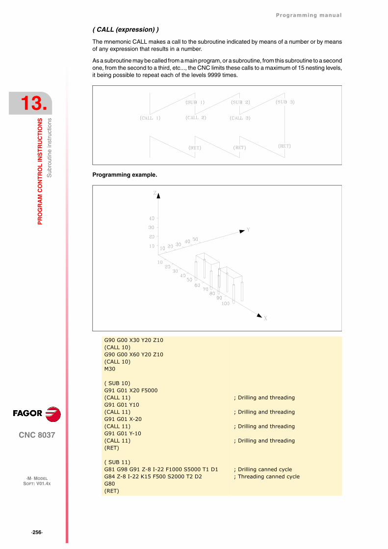
·256·
Programming manual
CNC 8037
13.
PR
OG
RA
M C
ON
TR
OL
INS
TR
UC
TIO
NS
·M· MODELSOFT: V01.4X
Sub
rout
ine
inst
ruct
ions
( CALL (expression) )
The mnemonic CALL makes a call to the subroutine indicated by means of a number or by meansof any expression that results in a number.
As a subroutine may be called from a main program, or a subroutine, from this subroutine to a secondone, from the second to a third, etc..., the CNC limits these calls to a maximum of 15 nesting levels,it being possible to repeat each of the levels 9999 times.
Programming example.
G90 G00 X30 Y20 Z10(CALL 10)G90 G00 X60 Y20 Z10(CALL 10)M30
( SUB 10)G91 G01 X20 F5000(CALL 11)G91 G01 Y10(CALL 11)G91 G01 X-20(CALL 11)G91 G01 Y-10(CALL 11)(RET)
( SUB 11)G81 G98 G91 Z-8 I-22 F1000 S5000 T1 D1G84 Z-8 I-22 K15 F500 S2000 T2 D2G80(RET)
; Drilling and threading
; Drilling and threading
; Drilling and threading
; Drilling and threading
; Drilling canned cycle; Threading canned cycle
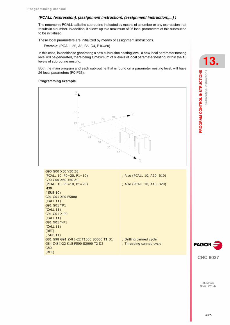
Programming manual
CNC 8037
PR
OG
RA
M C
ON
TR
OL
INS
TR
UC
TIO
NS
13.
·M· MODELSOFT: V01.4X
·257·
Sub
rout
ine
inst
ruct
ions
(PCALL (expression), (assignment instruction), (assignment instruction),...) )
The mnemonic PCALL calls the subroutine indicated by means of a number or any expression thatresults in a number. In addition, it allows up to a maximum of 26 local parameters of this subroutineto be initialized.
These local parameters are initialized by means of assignment instructions.
Example: (PCALL 52, A3, B5, C4, P10=20)
In this case, in addition to generating a new subroutine nesting level, a new local parameter nestinglevel will be generated, there being a maximum of 6 levels of local parameter nesting, within the 15levels of subroutine nesting.
Both the main program and each subroutine that is found on a parameter nesting level, will have26 local parameters (P0-P25).
Programming example.
G90 G00 X30 Y50 Z0(PCALL 10, P0=20, P1=10)G90 G00 X60 Y50 Z0(PCALL 10, P0=10, P1=20)M30( SUB 10)G91 G01 XP0 F5000(CALL 11)G91 G01 YP1(CALL 11)G91 G01 X-P0(CALL 11)G91 G01 Y-P1(CALL 11)(RET)( SUB 11)G81 G98 G91 Z-8 I-22 F1000 S5000 T1 D1G84 Z-8 I-22 K15 F500 S2000 T2 D2G80(RET)
; Also (PCALL 10, A20, B10)
; Also (PCALL 10, A10, B20)
; Drilling canned cycle; Threading canned cycle
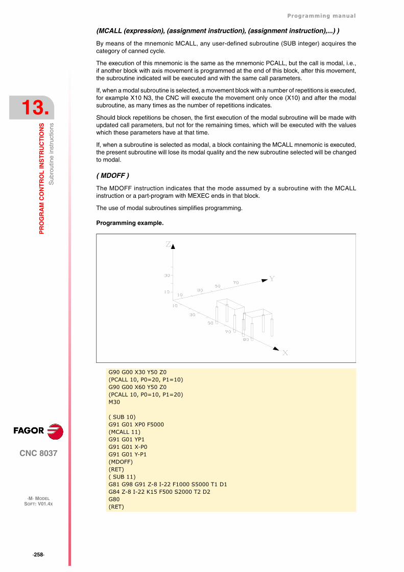
·258·
Programming manual
CNC 8037
13.
PR
OG
RA
M C
ON
TR
OL
INS
TR
UC
TIO
NS
·M· MODELSOFT: V01.4X
Sub
rout
ine
inst
ruct
ions
(MCALL (expression), (assignment instruction), (assignment instruction),...) )
By means of the mnemonic MCALL, any user-defined subroutine (SUB integer) acquires thecategory of canned cycle.
The execution of this mnemonic is the same as the mnemonic PCALL, but the call is modal, i.e.,if another block with axis movement is programmed at the end of this block, after this movement,the subroutine indicated will be executed and with the same call parameters.
If, when a modal subroutine is selected, a movement block with a number of repetitions is executed,for example X10 N3, the CNC will execute the movement only once (X10) and after the modalsubroutine, as many times as the number of repetitions indicates.
Should block repetitions be chosen, the first execution of the modal subroutine will be made withupdated call parameters, but not for the remaining times, which will be executed with the valueswhich these parameters have at that time.
If, when a subroutine is selected as modal, a block containing the MCALL mnemonic is executed,the present subroutine will lose its modal quality and the new subroutine selected will be changedto modal.
( MDOFF )
The MDOFF instruction indicates that the mode assumed by a subroutine with the MCALLinstruction or a part-program with MEXEC ends in that block.
The use of modal subroutines simplifies programming.
Programming example.
G90 G00 X30 Y50 Z0(PCALL 10, P0=20, P1=10)G90 G00 X60 Y50 Z0(PCALL 10, P0=10, P1=20)M30
( SUB 10)G91 G01 XP0 F5000(MCALL 11)G91 G01 YP1G91 G01 X-P0G91 G01 Y-P1(MDOFF)(RET)( SUB 11)G81 G98 G91 Z-8 I-22 F1000 S5000 T1 D1G84 Z-8 I-22 K15 F500 S2000 T2 D2G80(RET)
Programming manual
CNC 8037
PR
OG
RA
M C
ON
TR
OL
INS
TR
UC
TIO
NS
13.
·M· MODELSOFT: V01.4X
·259·
Inte
rrup
tion-
subr
outin
e in
stru
ctio
ns
13.6 Interruption-subroutine instructions
Whenever one of the general interruption logic input is activated, "INT1" (M5024), "INT2" (M5025),"INT3" (M5026) or "INT4 (M5027), the CNC temporarily interrupts the execution of the program inprogress and starts executing the interruption subroutine whose number is indicated by thecorresponding general parameter.
With INT1 (M5024) the one indicated by machine parameter INT1SUB (P35)
With INT2 (M5025) the one indicated by machine parameter INT2SUB (P36)
With INT3 (M5026) the one indicated by machine parameter INT3SUB (P37)
With INT4 (M5027) the one indicated by machine parameter INT4SUB (P38)
The interruption subroutines are defined like any other subroutine by using the instructions: "(SUBinteger)" and "(RET)".
These interruption subroutines do not change the nesting level of local parameters, thus only globalparameters must be used in them.
Within an interruption subroutine, it is possible to use the "(REPOS X, Y, Z, ...)" instruction describednext.
Once the execution of the subroutine is over, the CNC resumes the execution of the program whichwas interrupted.
( REPOS X, Y, Z, ... )
The REPOS instruction must always be used inside an interruption subroutine and facilitates therepositioning of the machine axes to the point of interruption.
When executing this instruction, the CNC moves the axes to the point where the program wasinterrupted.
Inside the REPOS instruction, indicate the order the axes must move to the point where the programwas interrupted.
• The axes move one by one.
• It is not necessary to define all the axes, only those to be repositioned.
• The axes that make up the main plane of the machine move together. Both axes need not bedefined because the CNC moves the first one. The movement is not repeated when definingthe second one, it is ignored.
Example:
The main plane is formed by the XY axes, the Z axis is the longitudinal axis. To reposition firstthe X and Y axes and finally the Z axis.
This repositioning move may be defined in any of the following ways:
(REPOS X, Y, Z)(REPOS X, Z)(REPOS Y, Z)
If the REPOS instruction is detected while executing a subroutine not activated by an interruptioninput, the CNC will issue the corresponding error message.
·260·
Programming manual
CNC 8037
13.
PR
OG
RA
M C
ON
TR
OL
INS
TR
UC
TIO
NS
·M· MODELSOFT: V01.4X
Pro
gram
inst
ruct
ions
13.7 Program instructions
With this CNC, from a program in execution, it is possible to:
• Execute another program. Instruction (EXEC P.....)
• Execute another program in modal mode. Instruction (MEXEC P.....)
• Generate a new program. Instruction (OPEN P.....)
• Add blocks to an existing program. Instruction (WRITE P.....)
( EXEC P(expression), (directory) )
The EXEC P instruction executes the part-program of the indicated directory
The part-program may be defined by a number or any expression resulting in a number.
By default, the CNC interprets that the part-program is in the CNC's RAM memory. If it is in anotherdevice, it must be indicated in (directory).
HD in the Hard Disk (KeyCF).
DNC2 in a PC connected through the serial line.
DNCE in a PC connected through Ethernet.
( MEXEC P(expression), (directory) )
The MEXEC instruction executes the part-program of the indicated directory and it also becomesmodal; i.e. if after this block, another one is programmed with axis movement; after this movement,it will execute the indicated program again.
The part-program may be defined with a number or with an expression whose result is a number.
By default, the CNC interprets that the part-program is in the CNC's RAM memory. If it is in anotherdevice, it must be so indicated in (directory):
HD in the Hard Disk (KeyCF).
DNC2 in a PC connected through the serial line.
DNCE in a PC connected through Ethernet.
If while the modal part-program is selected, a motion block is executed with a number of repetitions(for example X10 N3), the CNC ignores the number of repetitions and executes the movement andthe modal part-program only once.
If while a part-program is selected as modal, a block containing the MEXEC instruction is executedfrom the main program, the current part-program stops being modal and the part-program calledupon with MEXEC will then become modal.
If within the modal part-program, an attempt is made to execute a block using the MEXEC instruction,it will issue the relevant error message.
1064: The program cannot be executed.
( MDOFF )
The MDOFF instruction indicates that the mode assumed by a subroutine with the MCALLinstruction or a part-program with MEXEC ends in that block.
( OPEN P(expression), (destination directory), A/D, "program comment" )
The OPEN instruction begins editing a part-program. The part-program number may be indicatedby a number or any expression resulting in a number.
By default, the new part-program edited will be stored in the CNC's RAM memory. To store it anotherdevice, it must be indicated in (destination directory).
HD in the Hard Disk (KeyCF).
DNC2 in a PC connected through the serial line.
DNCE in a PC connected through Ethernet.
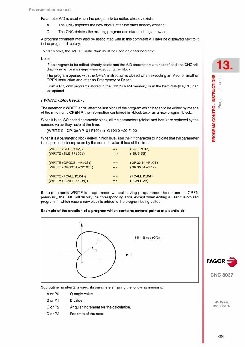
Programming manual
CNC 8037
PR
OG
RA
M C
ON
TR
OL
INS
TR
UC
TIO
NS
13.
·M· MODELSOFT: V01.4X
·261·
Pro
gram
inst
ruct
ions
Parameter A/D is used when the program to be edited already exists.
A The CNC appends the new blocks after the ones already existing.
D The CNC deletes the existing program and starts editing a new one.
A program comment may also be associated with it; this comment will later be displayed next to itin the program directory.
To edit blocks, the WRITE instruction must be used as described next.
Notes:
If the program to be edited already exists and the A/D parameters are not defined, the CNC willdisplay an error message when executing the block.
The program opened with the OPEN instruction is closed when executing an M30, or anotherOPEN instruction and after an Emergency or Reset.
From a PC, only programs stored in the CNC'S RAM memory, or in the hard disk (KeyCF) canbe opened
( WRITE <block text> )
The mnemonic WRITE adds, after the last block of the program which began to be edited by meansof the mnemonic OPEN P, the information contained in <block text> as a new program block.
When it is an ISO coded parametric block, all the parameters (global and local) are replaced by thenumeric value they have at the time.
(WRITE G1 XP100 YP101 F100) => G1 X10 Y20 F100
When it is a parametric block edited in high level, use the "?" character to indicate that the parameteris supposed to be replaced by the numeric value it has at the time.
If the mnemonic WRITE is programmed without having programmed the mnemonic OPENpreviously, the CNC will display the corresponding error, except when editing a user customizedprogram, in which case a new block is added to the program being edited.
Example of the creation of a program which contains several points of a cardioid:
Subroutine number 2 is used, its parameters having the following meaning:
A or P0 Q angle value.
B or P1 B value
C or P2 Angular increment for the calculation.
D or P3 Feedrate of the axes.
(WRITE (SUB P102))(WRITE (SUB ?P102))
(WRITE (ORGX54=P103))(WRITE (ORGX54=?P103))
(WRITE (PCALL P104))(WRITE (PCALL ?P104))
=>=>
=>=>
=>=>
(SUB P102)( SUB 55)
(ORGX54=P103)(ORGX54=222)
(PCALL P104)(PCALL 25)
| R = B cos (Q/2) |
·262·
Programming manual
CNC 8037
13.
PR
OG
RA
M C
ON
TR
OL
INS
TR
UC
TIO
NS
·M· MODELSOFT: V01.4X
Pro
gram
inst
ruct
ions
A way to use this example could be:
Program generating subroutine.
G00 X0 Y0G93(PCALL 2, A0, B30, C5, D500)M30
N100
( SUB 2)(OPEN P12345) (WRITE FP3)(P10=P1*(ABS(COS(P0/2)))) (WRITE G01 G05 RP10 QP0)(P0=P0+P2)(IF (P0 LT 365) GOTO N100)
(WRITE M30)(RET)
; Starts editing of program P12345; Selects machining feedrate; Calculates R; Movement block; New angle; If angle smaller than 365º, calculates new
point; End of program block; End of subroutine
Programming manual
CNC 8037
PR
OG
RA
M C
ON
TR
OL
INS
TR
UC
TIO
NS
13.
·M· MODELSOFT: V01.4X
·263·
Scr
een
cust
omiz
ing
inst
ruct
ions
13.8 Screen customizing instructions
Customizing instructions may be used only when customizing programs made by the user.
These customizing programs must be stored in the CNC's RAM memory and they may utilize the"Programming Instructions" and they will be executed in the special channel designed for this use;the program selected in each case will be indicated in the following general machine parameters.
In "USERDPLY" the program to be executed in the Execution Mode will be indicated.
In "USEREDIT" the program to be executed in the Editing Mode will be indicated.
In "USERMAN" the program to be executed in the Manual (JOG) Mode will be indicated.
In "USERDIAG" the program to be executed in the Diagnosis Mode will be indicated.
The customizing programs may have up to five nesting levels besides their current one. Also, thecustomizing instructions do not allow local parameters, nevertheless all global parameters may beused to define them.
( PAGE (expression) )
The mnemonic PAGE displays the page number indicated by means of a number or by means ofany expression resulting in a number.
User-defined pages will be from page 0 to page 255 and will be defined from the CNC keyboardin the Graphic Editor mode and as indicated in the Operating Manual.
System pages will be defined by a number greater than 1000. See the corresponding appendix.
( SYMBOL (expression 1), (expression 2), (expression 3) )
The mnemonic SYMBOL displays the symbol whose number is indicated by means of the value ofexpression 1 once this has been evaluated.
Its position on screen is also defined by expression 2 (column) and by expression 3 (row).
Expression 1, expression 2 and expression 3 may contain a number or any expression resulting ina number.
The CNC allows displaying any user-defined symbol (0-255) defined at the CNC keyboard in theGraphic Editor mode such as is indicated in the Operating Manual.
In order to position it within the display area its pixels must be defined, 0-639 for columns (expression2) and 0-335 for rows (expression 3).
(IB (expression) = INPUT "text", format)
The CNC has 26 data entry variables (IBO-1B25)
The IB mnemonic displays the text indicated in the data input window and stores the data input bythe user in the entry variable indicated by means of a number or by means of any expression resultingin a number.
The wait for data entry will only occur when programming the format of the requested data. Thisformat may have a sign, integer part and decimal part.
If it bears the "-" sign, it will allow positive and negative values, and if it does not have a sign,it will only allow positive values.
The integer part indicates the maximum number of digits (0-6) desired to the left of the decimalpoint.
The decimal part indicates the maximum number of digits (0-5) desired to the right of the decimalpoint.
If the numerical format is not programmed; for example: (IB1 =INPUT "text"), the mnemonic will onlydisplay the indicated text without waiting for the data to be entered.
·264·
Programming manual
CNC 8037
13.
PR
OG
RA
M C
ON
TR
OL
INS
TR
UC
TIO
NS
·M· MODELSOFT: V01.4X
Scr
een
cust
omiz
ing
inst
ruct
ions
( ODW (expression 1), (expression 2), (expression 3) )
The mnemonic ODW defines and draws a white window on the screen with fixed dimensions (1 rowand 14 columns).
Each mnemonic has an associated number which is indicated by the value of expression 1 oncethis has been evaluated.
Likewise, its position on screen is defined by expression 2 (row) and by expression 3 (column).
Expression 1, expression 2 and expression 3 may contain a number or any expression resulting ina number.
The CNC allows 26 windows (0-25) to be defined and their positioning within the display area,providing 21 rows (0-20) and 80 columns (0-79).
( DW(expression 1) = (expression 2), DW (expression 3) = (expression 4), ... )
The instruction DW displays in the window indicated by the value for expression 1, expression 3,.. once they have been evaluated, the numerical data indicated by expression 2, expression 4, ...
Expression 1, expression 2, expression 3, .... may contain a number or any expression which mayresult in a number.
The following example shows a dynamic variable display:
The CNC allows displaying the data in decimal, hexadecimal and binary format; the followinginstructions are available:
(DW1 = 100)
Decimal format. Value "100" displayed in window 1.
(DWH2 = 100)
Hexadecimal format. Value "64" displayed in window 2.
(DWB3 = 100)
Binary format. Value "01100100" displayed in window 3.
When using the binary format, the display is limited to 8 digits in such a way that a value of"11111111" will be displayed for values greater than 255 and the value of "10000000" for valuesmore negative than -127.
Besides, the CNC allows the number stored in one of the 26 data input variables (IB0-IB25) to bedisplayed in the requested window.
The following example shows a request and later displays the axis feedrate:
(SK (expression 1) = "text1" (expression 2) = "text 2", .... )
The instruction SK defines and displays the new softkey menu indicated.
Each of the expressions will indicate the softkey number which it is required to modify (1-7, startingfrom the left) and the texts which it is required to write in them.
Expression 1, expression 2, expression 3, .... may contain a number or any expression which mayresult in a number.
N10
(ODW 1, 6, 33); Defines data window 1
(ODW 2, 14, 33); Defines data window 2
(DW1=DATE, DW2=TIME); Displays the date in window 1 and the time in 2
(GOTO N10)
(ODW 3, 4, 60); Defines data window 3.
(IB1=INPUT "Axis feed: ", 5.4); Axis feedrate request.
(DW3=IB1); Displays feedrate in window 3.
Programming manual
CNC 8037
PR
OG
RA
M C
ON
TR
OL
INS
TR
UC
TIO
NS
13.
·M· MODELSOFT: V01.4X
·265·
Scr
een
cust
omiz
ing
inst
ruct
ions
Each text will allow a maximum of 20 characters that will be shown in two lines of 10 characters each.If the text selected has less than 10 characters, the CNC will center it on the top line, but if it hasmore than 10 characters the programmer will center it.
Examples:
(SK 1="HELP", SK 2="MAXIMUN POINT")
(SK 1="FEED", SK 2=" _ _MAXIMUN_ _ _POINT")
( WKEY )
The mnemonic WKEY stops execution of the program until the key is pressed.
The pressed key will be recorded in the KEY variable.
( WBUF "text", (expression) )
The WBUF instruction can only be used when editing a program in the user channel.
This instruction may be programmed in two ways:
• ( WBUF "text", (expression) )
It adds the text and value of the expression, once it has been evaluated, to the block that is beingedited and within the data entry window.
(Expression) may contain a number or any expression resulting in a number.
It will be optional to program the expression, but it will be required to define the text. If no textis required, "" must be programmed.
Examples for P100=10:
HELP MAXIMUN POINT
FEED MAXIMUN POINT
If while a standard CNC softkey menu is active, one or more softkeys are selected via high levellanguage instruction: "SK", the CNC will clear all existing softkeys and it will only show the selectedones.If while a user softkey menu is active, one or more softkeys are selected via high level languageinstruction "SK", the CNC will only replace the selected softkeys leaving the others intact.
...(WKEY)(IF KEY EQ $FC00 GOTO N1000)...
; Wait for key; If key F1 has been pressed, continue in N1000
(WBUF "X", P100)(WBUF "X P100")
=>=>
X10X P100
·266·
Programming manual
CNC 8037
13.
PR
OG
RA
M C
ON
TR
OL
INS
TR
UC
TIO
NS
·M· MODELSOFT: V01.4X
Scr
een
cust
omiz
ing
inst
ruct
ions
• ( WBUF )
Enters into memory, adding to the program being edited and after the cursor position, the blockbeing edited by means of (WBUF "text", (expression)). It also clears the editing buffer in orderto edit a new block.
This allows the user to edit a complete program without having to quit the user editing mode aftereach block and press ENTER to "enter" it into memory.
After executing this program the block being edited contains:
(PCALL 25, A=23.5, B=-2.25)
( SYSTEM )
The mnemonic SYSTEM stops execution of the user customized program and returns to thecorresponding standard menu of the CNC.
Customizing program example:
The following customizing program must be selected as user program associated to the EditingMode.
After selecting the Editing Mode and pressing the USER softkey, this program starts executing andit allows assisted editing of 2 user cycles. This editing process is carried out a cycle at a time andas often as desired.
Displays the initial editing page (screen)
Sets the softkeys to access the various modes and requests a choice
(WBUF "(PCALL 25, "); Adds "(PCALL 25, " to the block being edited.
(IB1=INPUT "Parameter A:",-5.4); Request of Parameter A.
(WBUF "A=", IB1); Adds "A=(value entered)" to the block being edited.
(IB2=INPUT "Parameter B: ", -5.4); Request of Parameter B.
(WBUF ", B=", IB2); Adds "B=(value entered)" to the block being edited.
(WBUF ")"); Adds ")" to the block being edited.
(WBUF ); Enters the edited block into memory.
...
N0 ( PAGE 10 )
N5 (SK 1="CYCLE 1",SK 2="CYCLE 2",SK 7="EXIT")(WKEY )(IF KEY EQ $FC00 GOTO N10)(IF KEY EQ $FC01 GOTO N20) (IF KEY EQ $FC06 SYSTEM ELSE GOTO N5)
; Request a key; Cycle 1; Cycle 2; Quit or request a key
Programming manual
CNC 8037
PR
OG
RA
M C
ON
TR
OL
INS
TR
UC
TIO
NS
13.
·M· MODELSOFT: V01.4X
·267·
Scr
een
cust
omiz
ing
inst
ruct
ions
CYCLE 1
CYCLE 2
; Displays page 11 and defines 2 data entry windowsN10 (PAGE 11)
(ODW 1,10,60)(ODW 2,15,60)
;Editing
(WBUF "( PCALL 1,") ; Adds "(PCALL 1," to the block being edited.
(IB 1=INPUT "X:",-6.5)(DW 1=IB1)(WBUF "X",IB1)
; Requests the value of X.; Data window 1 shows the entered value.; Adds X (entered value) to the block being edited.
(WBUF ",") ; Adds "," to the block being edited.
(IB 2=INPUT "Y:",-6.5)(DW 2=IB2)(WBUF "Y",IB2)
; Requests the value of Y.; Data window 2 shows the entered value.; Adds Y (entered value) to the block being edited.
(WBUF ")")(WBUF )
; Adds ")" to the block being edited.; Enters the edited block into memory.; For example : (PCALL 1, X2, Y3)
(GOTO N0)
; Displays page 12 and defines 3 data entry windowsN20 (PAGE 12)
(ODW 1,10,60)(ODW 2,13,60)(ODW 3,16,60)
; Editing(WBUF "( PCALL 2,") ; Adds "(PCALL 2," to the block being edited.
(IB 1=INPUT "A:",-6.5)(DW 1=IB1)(WBUF "A",IB1)
; Requests the value of A.; Data window 1 shows the entered value.; Adds A (entered value) to the block being edited.
(WBUF ",") ; Adds "," to the block being edited.
(IB 2=INPUT "B:",-6.5)(DW 2=IB2)(WBUF "B",IB2)
; Requests the value of B.; Data window 2 shows the entered value.; Adds B (entered value) to the block being edited.
(WBUF ",")(IB 3=INPUT "C:",-6.5)(DW 3=IB3)(WBUF "C",IB3)
; Adds "," to the block being edited.; Requests the value of C.; Data window 3 shows the entered value.; Adds C (entered value) to the block being edited.
(WBUF ")") ; Adds ")" to the block being edited.
(WBUF ) ; Enters the edited block into memory.For example: (PCALL 2, A3, B1, C3).
(GOTO N0)
·268·
Programming manual
CNC 8037
13.
PR
OG
RA
M C
ON
TR
OL
INS
TR
UC
TIO
NS
·M· MODELSOFT: V01.4X
Scr
een
cust
omiz
ing
inst
ruct
ions
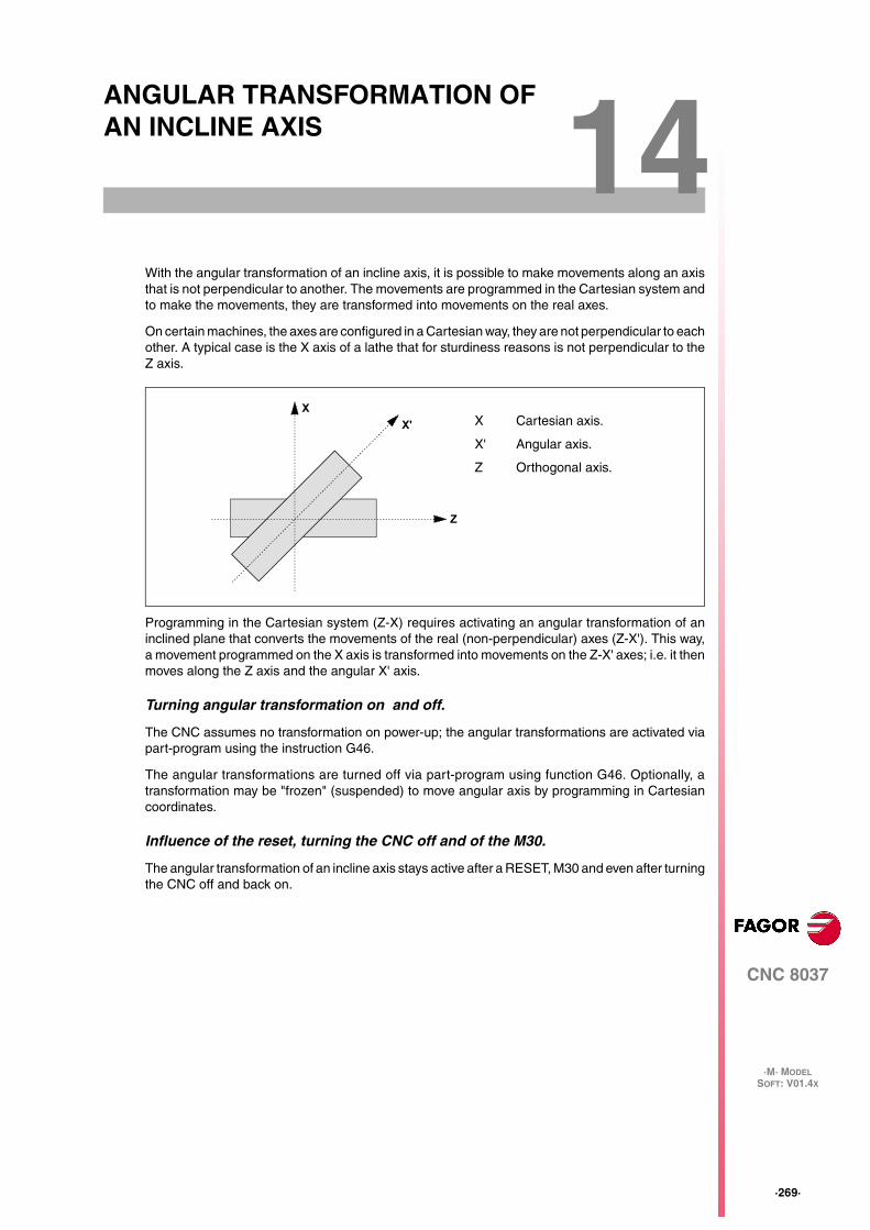
CNC 8037
·M· MODELSOFT: V01.4X
14
·269·
ANGULAR TRANSFORMATION OF AN INCLINE AXIS
With the angular transformation of an incline axis, it is possible to make movements along an axisthat is not perpendicular to another. The movements are programmed in the Cartesian system andto make the movements, they are transformed into movements on the real axes.
On certain machines, the axes are configured in a Cartesian way, they are not perpendicular to eachother. A typical case is the X axis of a lathe that for sturdiness reasons is not perpendicular to theZ axis.
Programming in the Cartesian system (Z-X) requires activating an angular transformation of aninclined plane that converts the movements of the real (non-perpendicular) axes (Z-X'). This way,a movement programmed on the X axis is transformed into movements on the Z-X' axes; i.e. it thenmoves along the Z axis and the angular X' axis.
Turning angular transformation on and off.
The CNC assumes no transformation on power-up; the angular transformations are activated viapart-program using the instruction G46.
The angular transformations are turned off via part-program using function G46. Optionally, atransformation may be "frozen" (suspended) to move angular axis by programming in Cartesiancoordinates.
Influence of the reset, turning the CNC off and of the M30.
The angular transformation of an incline axis stays active after a RESET, M30 and even after turningthe CNC off and back on.
Z
X'
XX Cartesian axis.
X' Angular axis.
Z Orthogonal axis.
·270·
Programming manual
CNC 8037
14.
AN
GU
LA
R T
RA
NS
FO
RM
AT
ION
OF
AN
INC
LIN
E A
XIS
·M· MODELSOFT: V01.4X
Considerations for the angular transformation of an incline axis.
The axes involved in an angular transformation must be linear. Both axes may have Gantry axesassociated with them.
If the angular transformation is active, the coordinates displayed will be those of the Cartesiansystem. Otherwise, it will display the coordinates of the real axes.
The following operations are possible while the transformation is active:
• Zero offsets.
• Coordinate preset.
• Movements in continuous / incremental jog and handwheels.
The following operations are not possible while the transformation is active:
• Movement until making contact (against a hard stop).
• Coordinate rotation.
• Surface feedrate in milling.
Home search.
Function G46 is canceled when homing an axis that is involved in the angular transformation(machine parameters ANGAXNA and ORTAXNA). When homing the axes that are not involved inthe angular axis transformation, function G46 stays active.
While searching home, only the real axes move.
Jogging and handwheel movements.
Either the real or the Cartesian axes may be jogged depending on how they've been set by themanufacturer. It is selected via PLC (MACHMOVE) and it may be available, for example, from a userkey.
Programming manual
CNC 8037
AN
GU
LA
R T
RA
NS
FO
RM
AT
ION
OF
AN
INC
LIN
E A
XIS
14.
·M· MODELSOFT: V01.4X
·271·
Tur
ning
ang
ular
tran
sfor
mat
ion
on a
nd o
ff
14.1 Turning angular transformation on and off
Turn angular transformation on
When the transformation is on, the movements are programmed in the Cartesian system and tomake the movements, the CNC transforms them into movements on the real axes. The coordinatesdisplayed on the screen will be those of the Cartesian system.
The angular transformation is turned on using function G46 whose programming format is:
G46 S1
This instruction turns a "frozen" (suspended) transformation on again. See "14.2 Freezing theangular transformation" on page 272.
Turning the angular transformation off
If the transformation is off, the movements are programmed and executed in the system of the realaxes. The coordinates displayed on the screen will be those of the real axes.
The angular transformation is turned off using function G46 whose programming format is:
G46 S0G46
The angular transformation of an incline axis stays active after a RESET, M30 and even after turningthe CNC off and back on.
·272·
Programming manual
CNC 8037
14.
AN
GU
LA
R T
RA
NS
FO
RM
AT
ION
OF
AN
INC
LIN
E A
XIS
·M· MODELSOFT: V01.4X
Fre
ezin
g th
e an
gula
r tr
ansf
orm
atio
n
14.2 Freezing the angular transformation
Freezing the angular transformation is a special way to make movements along the angular axis,but programming it in the Cartesian system. The angular transformation cannot be "frozen"(suspended) while jogging.
The angular transformation is "frozen" (suspended) using function G46 whose programming formatis:
G46 S2
Programming movements after "freezing" the angular transformation.
If an angular transformation is "frozen" (suspended), only the coordinate of the angular axis mustbe programmed in the motion block. If the coordinate of the orthogonal axis is programmed, themovement is carried out according to the normal angular transformation.
Canceling the freezing of a transformation.
The "freezing" of an angular transformation is canceled after a reset or an M30. Turning thetransformation on (G46 S1) also cancels the "freezing".
Programming manual
CNC 8037
SOFT: V01.4X
·273·
APPENDIX
A. ISO code programming............................................................................ 275
B. Program control instructions.................................................................... 277
C. Summary of internal CNC variables........................................................ 279
D. Key code .................................................................................................. 285
E. Maintenance............................................................................................. 287

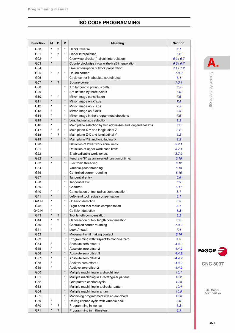
Programming manual
CNC 8037
A.
·M· MODELSOFT: V01.4X
·275·
ISO
cod
e pr
ogra
mm
ing
ISO CODE PROGRAMMING
Function M D V Meaning Section
G00 * ? * Rapid traverse 6.1
G01 * ? * Linear interpolation 6.2
G02 * * Clockwise circular (helical) interpolation 6.3 / 6.7
G03 * * Counterclockwise circular (helical) interpolation 6.3 / 6.7
G04 Dwell/interruption of block preparation 7.1 / 7.2
G05 * ? * Round corner 7.3.2
G06 * Circle center in absolute coordinates 6.4
G07 * ? Square corner 7.3.1
G08 * Arc tangent to previous path. 6.5
G09 * Arc defined by three points 6.6
G10 * * Mirror image cancellation 7.5
G11 * * Mirror image on X axis 7.5
G12 * * Mirror image on Y axis 7.5
G13 * * Mirror image on Z axis 7.5
G14 * * Mirror image in the programmed directions 7.5
G15 * * Longitudinal axis selection 8.2
G16 * * Main plane selection by two addresses and longitudinal axis 3.2
G17 * ? * Main plane X-Y and longitudinal Z 3.2
G18 * ? * Main plane Z-X and longitudinal Y 3.2
G19 * * Main plane Y-Z and longitudinal X 3.2
G20 Definition of lower work zone limits 3.7.1
G21 Definition of upper work zone limits. 3.7.1
G22 * Enable/disable work zones. 3.7.2
G32 * * Feedrate "F" as an inverted function of time. 6.15
G33 * * Electronic threading 6.12
G34 Variable-pitch threading 6.13
G36 * Controlled corner rounding 6.10
G37 * Tangential entry 6.8
G38 * Tangential exit 6.9
G39 * Chamfer 6.11
G40 * * Cancellation of tool radius compensation 8.1
G41 * * Left-hand tool radius compensation 8.1
G41 N * * Collision detection 8.3
G42 * * Right-hand tool radius compensation 8.1
G42 N * * Collision detection 8.3
G43 * ? * Tool length compensation 8.2
G44 * ? Cancellation of tool length compensation 8.2
G50 * * Controlled corner rounding 7.3.3
G51 * * Look-Ahead 7.4
G52 * Movement until making contact 6.14
G53 * Programming with respect to machine zero 4.3
G54 * * Absolute zero offset 1 4.4.2
G55 * * Absolute zero offset 2 4.4.2
G56 * * Absolute zero offset 3 4.4.2
G57 * * Absolute zero offset 4 4.4.2
G58 * * Additive zero offset 1 4.4.2
G59 * * Additive zero offset 2 4.4.2
G60 * Multiple machining in a straight line 10.1
G61 * Multiple machining in a rectangular pattern 10.2
G62 * Grid pattern canned cycle 10.3
G63 * Multiple machining in a circular pattern 10.4
G64 * Multiple machining in an arc 10.5
G65 * Machining programmed with an arc-chord 10.6
G69 * * Drilling canned cycle with variable peck 9.6
G70 * ? * Programming in inches 3.3
G71 * ? Programming in millimeters 3.3
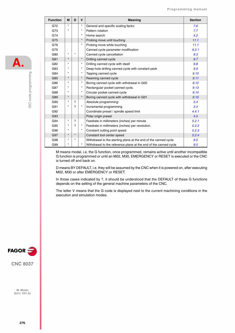
·276·
Programming manual
CNC 8037
A.
·M· MODELSOFT: V01.4X
ISO
cod
e pr
ogra
mm
ing
M means modal, i.e. the G function, once programmed, remains active until another incompatibleG function is programmed or until an M02, M30, EMERGENCY or RESET is executed or the CNCis turned off and back on.
D means BY DEFAULT, i.e. they will be assumed by the CNC when it is powered on, after executingM02, M30 or after EMERGENCY or RESET.
In those cases indicated by ?, it should be understood that the DEFAULT of these G functionsdepends on the setting of the general machine parameters of the CNC.
The letter V means that the G code is displayed next to the current machining conditions in theexecution and simulation modes.
G72 * * General and specific scaling factor 7.6
G73 * * Pattern rotation 7.7
G74 * Home search 4.2
G75 * Probing move until touching 11.1
G76 * Probing move while touching 11.1
G79 Canned cycle parameter modification 9.2.1
G80 * * Canned cycle cancellation 9.3
G81 * * Drilling canned cycle 9.7
G82 * * Drilling canned cycle with dwell 9.8
G83 * * Deep-hole drilling canned cycle with constant peck 9.9
G84 * * Tapping canned cycle 9.10
G85 * * Reaming canned cycle 9.11
G86 * * Boring canned cycle with withdrawal in G00 9.12
G87 * * Rectangular pocket canned cycle. 9.13
G88 * * Circular pocket canned cycle 9.14
G89 * * Boring canned cycle with withdrawal in G01 9.15
G90 * ? Absolute programming: 3.4
G91 * ? * Incremental programming 3.4
G92 Coordinate preset / spindle speed limit 4.4.1
G93 Polar origin preset 4.5
G94 * ? Feedrate in millimeters (inches) per minute 5.2.1
G95 * ? * Feedrate in millimeters (inches) per revolution. 5.2.2
G96 * * Constant cutting point speed 5.2.3
G97 * * Constant tool center speed 5.2.4
G98 * * Withdrawal to the starting plane at the end of the canned cycle 9.5
G99 * * Withdrawal to the reference plane at the end of the canned cycle 9.5
Function M D V Meaning Section
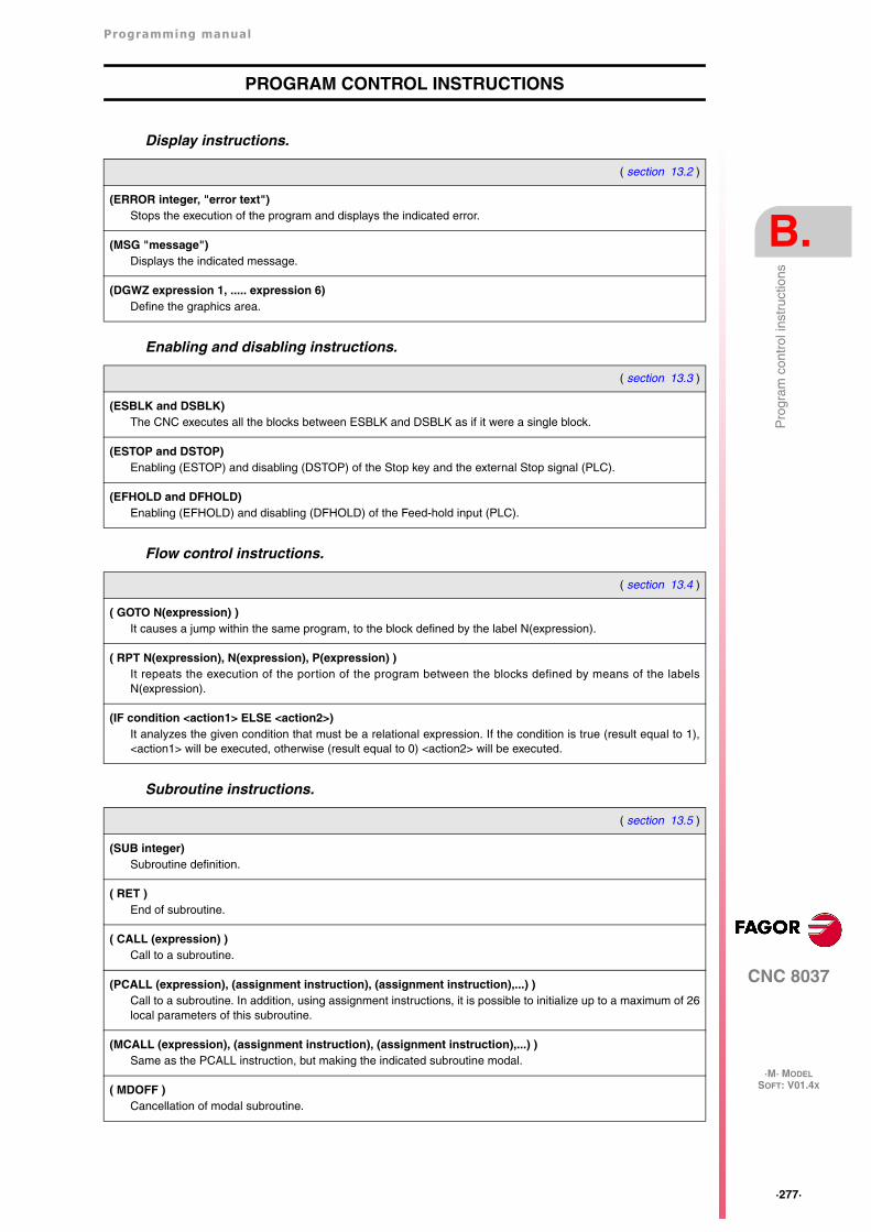
Programming manual
CNC 8037
B.
·M· MODELSOFT: V01.4X
·277·
Pro
gram
con
trol
inst
ruct
ions
PROGRAM CONTROL INSTRUCTIONS
Display instructions.
Enabling and disabling instructions.
Flow control instructions.
Subroutine instructions.
( section 13.2 )
(ERROR integer, "error text")Stops the execution of the program and displays the indicated error.
(MSG "message")Displays the indicated message.
(DGWZ expression 1, ..... expression 6)Define the graphics area.
( section 13.3 )
(ESBLK and DSBLK)The CNC executes all the blocks between ESBLK and DSBLK as if it were a single block.
(ESTOP and DSTOP)Enabling (ESTOP) and disabling (DSTOP) of the Stop key and the external Stop signal (PLC).
(EFHOLD and DFHOLD)Enabling (EFHOLD) and disabling (DFHOLD) of the Feed-hold input (PLC).
( section 13.4 )
( GOTO N(expression) )It causes a jump within the same program, to the block defined by the label N(expression).
( RPT N(expression), N(expression), P(expression) )It repeats the execution of the portion of the program between the blocks defined by means of the labelsN(expression).
(IF condition <action1> ELSE <action2>)It analyzes the given condition that must be a relational expression. If the condition is true (result equal to 1),<action1> will be executed, otherwise (result equal to 0) <action2> will be executed.
( section 13.5 )
(SUB integer)Subroutine definition.
( RET )End of subroutine.
( CALL (expression) )Call to a subroutine.
(PCALL (expression), (assignment instruction), (assignment instruction),...) )Call to a subroutine. In addition, using assignment instructions, it is possible to initialize up to a maximum of 26local parameters of this subroutine.
(MCALL (expression), (assignment instruction), (assignment instruction),...) )Same as the PCALL instruction, but making the indicated subroutine modal.
( MDOFF )Cancellation of modal subroutine.
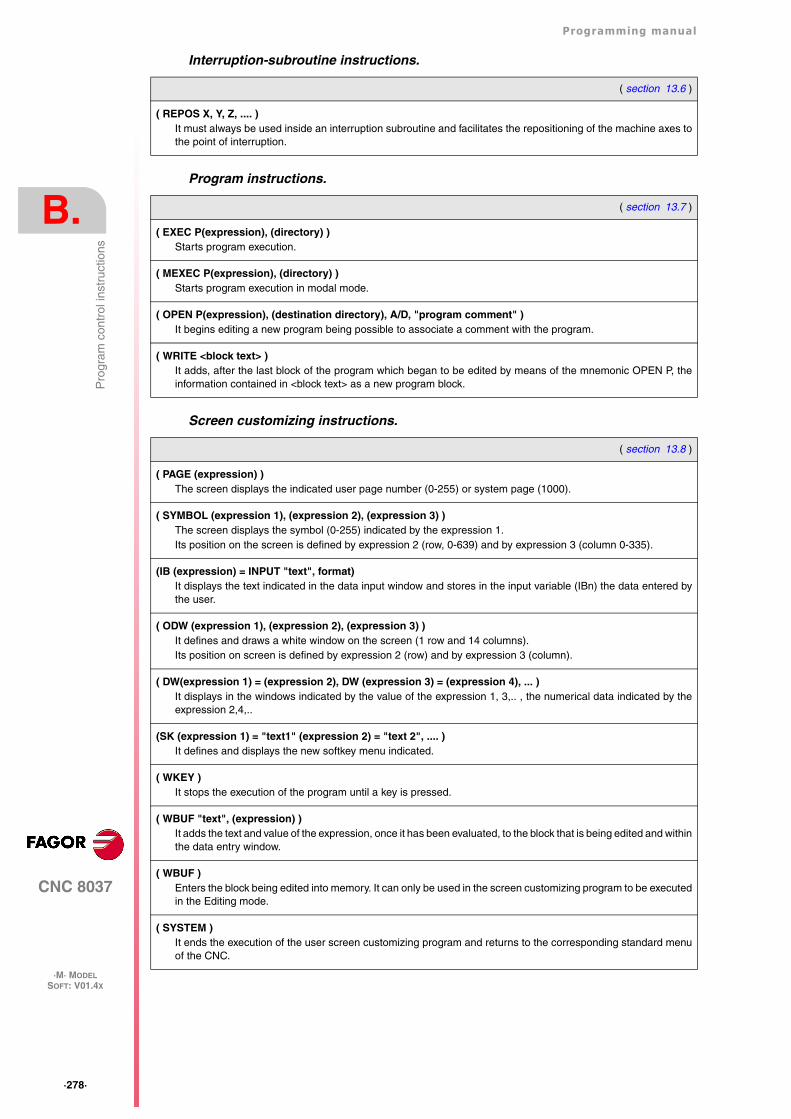
·278·
Programming manual
CNC 8037
B.
·M· MODELSOFT: V01.4X
Pro
gram
con
trol
inst
ruct
ions
Interruption-subroutine instructions.
Program instructions.
Screen customizing instructions.
( section 13.6 )
( REPOS X, Y, Z, .... )It must always be used inside an interruption subroutine and facilitates the repositioning of the machine axes tothe point of interruption.
( section 13.7 )
( EXEC P(expression), (directory) )Starts program execution.
( MEXEC P(expression), (directory) )Starts program execution in modal mode.
( OPEN P(expression), (destination directory), A/D, "program comment" )It begins editing a new program being possible to associate a comment with the program.
( WRITE <block text> )It adds, after the last block of the program which began to be edited by means of the mnemonic OPEN P, theinformation contained in <block text> as a new program block.
( section 13.8 )
( PAGE (expression) )The screen displays the indicated user page number (0-255) or system page (1000).
( SYMBOL (expression 1), (expression 2), (expression 3) )The screen displays the symbol (0-255) indicated by the expression 1.Its position on the screen is defined by expression 2 (row, 0-639) and by expression 3 (column 0-335).
(IB (expression) = INPUT "text", format)It displays the text indicated in the data input window and stores in the input variable (IBn) the data entered bythe user.
( ODW (expression 1), (expression 2), (expression 3) )It defines and draws a white window on the screen (1 row and 14 columns).Its position on screen is defined by expression 2 (row) and by expression 3 (column).
( DW(expression 1) = (expression 2), DW (expression 3) = (expression 4), ... )It displays in the windows indicated by the value of the expression 1, 3,.. , the numerical data indicated by theexpression 2,4,..
(SK (expression 1) = "text1" (expression 2) = "text 2", .... )It defines and displays the new softkey menu indicated.
( WKEY )It stops the execution of the program until a key is pressed.
( WBUF "text", (expression) )It adds the text and value of the expression, once it has been evaluated, to the block that is being edited and withinthe data entry window.
( WBUF )Enters the block being edited into memory. It can only be used in the screen customizing program to be executedin the Editing mode.
( SYSTEM )It ends the execution of the user screen customizing program and returns to the corresponding standard menuof the CNC.
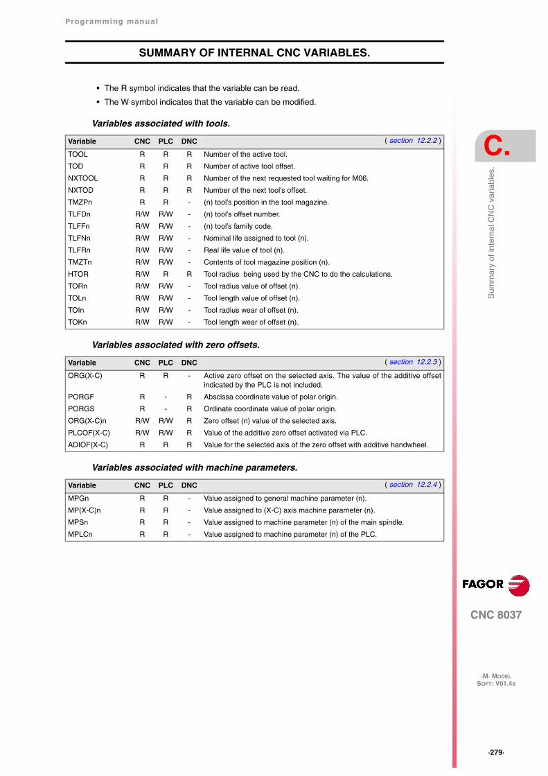
Programming manual
CNC 8037
C.
·M· MODELSOFT: V01.4X
·279·
Sum
mar
y of
inte
rnal
CN
C v
aria
bles
.
SUMMARY OF INTERNAL CNC VARIABLES.
• The R symbol indicates that the variable can be read.
• The W symbol indicates that the variable can be modified.
Variables associated with tools.
Variables associated with zero offsets.
Variables associated with machine parameters.
Variable CNC PLC DNC ( section 12.2.2 )
TOOL R R R Number of the active tool.
TOD R R R Number of active tool offset.
NXTOOL R R R Number of the next requested tool waiting for M06.
NXTOD R R R Number of the next tool’s offset.
TMZPn R R - (n) tool’s position in the tool magazine.
TLFDn R/W R/W - (n) tool’s offset number.
TLFFn R/W R/W - (n) tool’s family code.
TLFNn R/W R/W - Nominal life assigned to tool (n).
TLFRn R/W R/W - Real life value of tool (n).
TMZTn R/W R/W - Contents of tool magazine position (n).
HTOR R/W R R Tool radius being used by the CNC to do the calculations.
TORn R/W R/W - Tool radius value of offset (n).
TOLn R/W R/W - Tool length value of offset (n).
TOIn R/W R/W - Tool radius wear of offset (n).
TOKn R/W R/W - Tool length wear of offset (n).
Variable CNC PLC DNC ( section 12.2.3 )
ORG(X-C) R R - Active zero offset on the selected axis. The value of the additive offsetindicated by the PLC is not included.
PORGF R - R Abscissa coordinate value of polar origin.
PORGS R - R Ordinate coordinate value of polar origin.
ORG(X-C)n R/W R/W R Zero offset (n) value of the selected axis.
PLCOF(X-C) R/W R/W R Value of the additive zero offset activated via PLC.
ADIOF(X-C) R R R Value for the selected axis of the zero offset with additive handwheel.
Variable CNC PLC DNC ( section 12.2.4 )
MPGn R R - Value assigned to general machine parameter (n).
MP(X-C)n R R - Value assigned to (X-C) axis machine parameter (n).
MPSn R R - Value assigned to machine parameter (n) of the main spindle.
MPLCn R R - Value assigned to machine parameter (n) of the PLC.
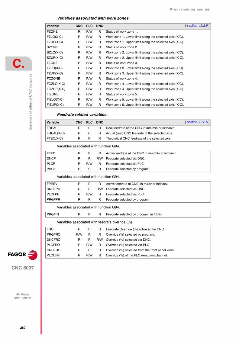
·280·
Programming manual
CNC 8037
C.
·M· MODELSOFT: V01.4X
Sum
mar
y of
inte
rnal
CN
C v
aria
bles
.
Variables associated with work zones.
Feedrate related variables.
Variables associated with function G94.
Variables associated with function G94.
Variables associated with function G94.
Variables associated with feedrate override (%)
Variable CNC PLC DNC ( section 12.2.5 )
FZONE R R/W R Status of work zone 1.
FZLO(X-C) R R/W R Work zone 1. Lower limit along the selected axis (X/C).
FZUP(X-C) R R/W R Work zone 1. Upper limit along the selected axis (X-C).
SZONE R R/W R Status of work zone 2.
SZLO(X-C) R R/W R Work zone 2. Lower limit along the selected axis (X/C).
SZUP(X-C) R R/W R Work zone 2. Upper limit along the selected axis (X-C).
TZONE R R/W R Status of work zone 3.
TZLO(X-C) R R/W R Work zone 3. Lower limit along the selected axis (X/C).
TZUP(X-C) R R/W R Work zone 3. Upper limit along the selected axis (X-C).
FOZONE R R/W R Status of work zone 4.
FOZLO(X-C) R R/W R Work zone 4. Lower limit along the selected axis (X/C).
FOZUP(X-C) R R/W R Work zone 4. Upper limit along the selected axis (X-C).
FIZONE R R/W R Status of work zone 5.
FIZLO(X-C) R R/W R Work zone 5. Lower limit along the selected axis (X/C).
FIZUP(X-C) R R/W R Work zone 5. Upper limit along the selected axis (X-C).
Variable CNC PLC DNC ( section 12.2.6 )
FREAL R R R Real feedrate of the CNC in mm/min or inch/min.
FREAL(X-C) R R R Actual (real) CNC feedrate of the selected axis.
FTEO/X-C) R R R Theoretical CNC feedrate of the selected axis.
FEED R R R Active feedrate at the CNC in mm/min or inch/min.
DNCF R R R/W Feedrate selected via DNC.
PLCF R R/W R Feedrate selected via PLC.
PRGF R R R Feedrate selected by program.
FPREV R R R Active feedrate at CNC, in m/rev or inch/rev.
DNCFPR R R R/W Feedrate selected via DNC.
PLCFPR R R/W R Feedrate selected via PLC.
PRGFPR R R R Feedrate selected by program.
PRGFIN R R R Feedrate selected by program, in 1/min.
FRO R R R Feedrate Override (%) active at the CNC.
PRGFRO R/W R R Override (%) selected by program.
DNCFRO R R R/W Override (%) selected via DNC.
PLCFRO R R/W R Override (%) selected via PLC.
CNCFRO R R R Override (%) selected from the front panel knob.
PLCCFR R R/W R Override (%) of the PLC execution channel.
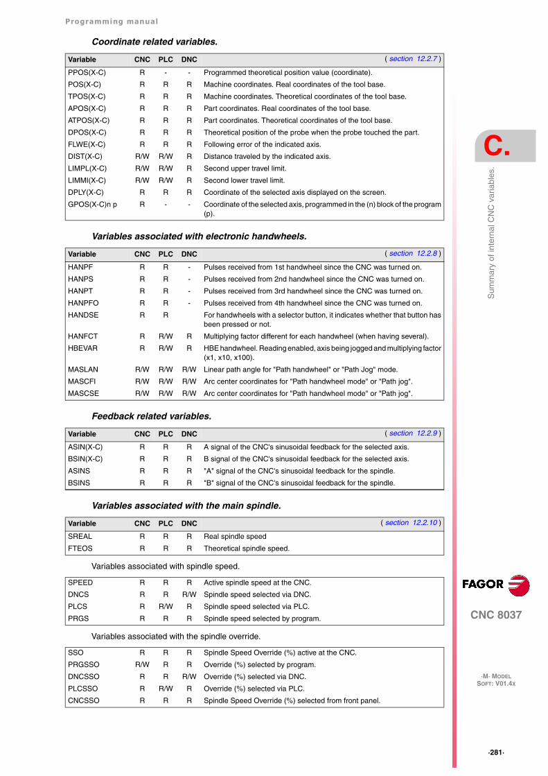
Programming manual
CNC 8037
C.
·M· MODELSOFT: V01.4X
·281·
Sum
mar
y of
inte
rnal
CN
C v
aria
bles
.
Coordinate related variables.
Variables associated with electronic handwheels.
Feedback related variables.
Variables associated with the main spindle.
Variables associated with spindle speed.
Variables associated with the spindle override.
Variable CNC PLC DNC ( section 12.2.7 )
PPOS(X-C) R - - Programmed theoretical position value (coordinate).
POS(X-C) R R R Machine coordinates. Real coordinates of the tool base.
TPOS(X-C) R R R Machine coordinates. Theoretical coordinates of the tool base.
APOS(X-C) R R R Part coordinates. Real coordinates of the tool base.
ATPOS(X-C) R R R Part coordinates. Theoretical coordinates of the tool base.
DPOS(X-C) R R R Theoretical position of the probe when the probe touched the part.
FLWE(X-C) R R R Following error of the indicated axis.
DIST(X-C) R/W R/W R Distance traveled by the indicated axis.
LIMPL(X-C) R/W R/W R Second upper travel limit.
LIMMI(X-C) R/W R/W R Second lower travel limit.
DPLY(X-C) R R R Coordinate of the selected axis displayed on the screen.
GPOS(X-C)n p R - - Coordinate of the selected axis, programmed in the (n) block of the program(p).
Variable CNC PLC DNC ( section 12.2.8 )
HANPF R R - Pulses received from 1st handwheel since the CNC was turned on.
HANPS R R - Pulses received from 2nd handwheel since the CNC was turned on.
HANPT R R - Pulses received from 3rd handwheel since the CNC was turned on.
HANPFO R R - Pulses received from 4th handwheel since the CNC was turned on.
HANDSE R R For handwheels with a selector button, it indicates whether that button hasbeen pressed or not.
HANFCT R R/W R Multiplying factor different for each handwheel (when having several).
HBEVAR R R/W R HBE handwheel. Reading enabled, axis being jogged and multiplying factor(x1, x10, x100).
MASLAN R/W R/W R/W Linear path angle for "Path handwheel" or "Path Jog" mode.
MASCFI R/W R/W R/W Arc center coordinates for "Path handwheel mode" or "Path jog".
MASCSE R/W R/W R/W Arc center coordinates for "Path handwheel mode" or "Path jog".
Variable CNC PLC DNC ( section 12.2.9 )
ASIN(X-C) R R R A signal of the CNC's sinusoidal feedback for the selected axis.
BSIN(X-C) R R R B signal of the CNC's sinusoidal feedback for the selected axis.
ASINS R R R "A" signal of the CNC's sinusoidal feedback for the spindle.
BSINS R R R "B" signal of the CNC's sinusoidal feedback for the spindle.
Variable CNC PLC DNC ( section 12.2.10 )
SREAL R R R Real spindle speed
FTEOS R R R Theoretical spindle speed.
SPEED R R R Active spindle speed at the CNC.
DNCS R R R/W Spindle speed selected via DNC.
PLCS R R/W R Spindle speed selected via PLC.
PRGS R R R Spindle speed selected by program.
SSO R R R Spindle Speed Override (%) active at the CNC.
PRGSSO R/W R R Override (%) selected by program.
DNCSSO R R R/W Override (%) selected via DNC.
PLCSSO R R/W R Override (%) selected via PLC.
CNCSSO R R R Spindle Speed Override (%) selected from front panel.
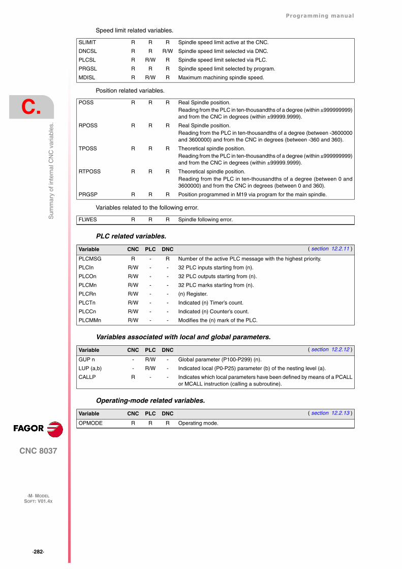
·282·
Programming manual
CNC 8037
C.
·M· MODELSOFT: V01.4X
Sum
mar
y of
inte
rnal
CN
C v
aria
bles
.
Speed limit related variables.
Position related variables.
Variables related to the following error.
PLC related variables.
Variables associated with local and global parameters.
Operating-mode related variables.
SLIMIT R R R Spindle speed limit active at the CNC.
DNCSL R R R/W Spindle speed limit selected via DNC.
PLCSL R R/W R Spindle speed limit selected via PLC.
PRGSL R R R Spindle speed limit selected by program.
MDISL R R/W R Maximum machining spindle speed.
POSS R R R Real Spindle position.Reading from the PLC in ten-thousandths of a degree (within ±999999999)and from the CNC in degrees (within ±99999.9999).
RPOSS R R R Real Spindle position.Reading from the PLC in ten-thousandths of a degree (between -3600000and 3600000) and from the CNC in degrees (between -360 and 360).
TPOSS R R R Theoretical spindle position.Reading from the PLC in ten-thousandths of a degree (within ±999999999)and from the CNC in degrees (within ±99999.9999).
RTPOSS R R R Theoretical spindle position.Reading from the PLC in ten-thousandths of a degree (between 0 and3600000) and from the CNC in degrees (between 0 and 360).
PRGSP R R R Position programmed in M19 via program for the main spindle.
FLWES R R R Spindle following error.
Variable CNC PLC DNC ( section 12.2.11 )
PLCMSG R - R Number of the active PLC message with the highest priority.
PLCIn R/W - - 32 PLC inputs starting from (n).
PLCOn R/W - - 32 PLC outputs starting from (n).
PLCMn R/W - - 32 PLC marks starting from (n).
PLCRn R/W - - (n) Register.
PLCTn R/W - - Indicated (n) Timer’s count.
PLCCn R/W - - Indicated (n) Counter’s count.
PLCMMn R/W - - Modifies the (n) mark of the PLC.
Variable CNC PLC DNC ( section 12.2.12 )
GUP n - R/W - Global parameter (P100-P299) (n).
LUP (a,b) - R/W - Indicated local (P0-P25) parameter (b) of the nesting level (a).
CALLP R - - Indicates which local parameters have been defined by means of a PCALLor MCALL instruction (calling a subroutine).
Variable CNC PLC DNC ( section 12.2.13 )
OPMODE R R R Operating mode.
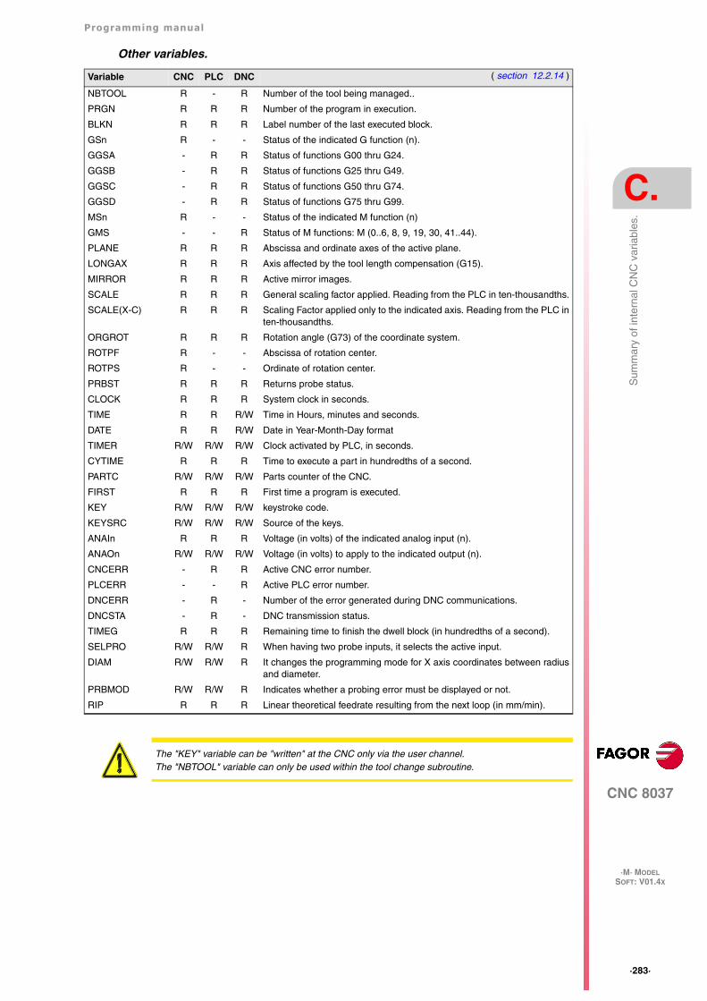
Programming manual
CNC 8037
C.
·M· MODELSOFT: V01.4X
·283·
Sum
mar
y of
inte
rnal
CN
C v
aria
bles
.
Other variables.
Variable CNC PLC DNC ( section 12.2.14 )
NBTOOL R - R Number of the tool being managed..
PRGN R R R Number of the program in execution.
BLKN R R R Label number of the last executed block.
GSn R - - Status of the indicated G function (n).
GGSA - R R Status of functions G00 thru G24.
GGSB - R R Status of functions G25 thru G49.
GGSC - R R Status of functions G50 thru G74.
GGSD - R R Status of functions G75 thru G99.
MSn R - - Status of the indicated M function (n)
GMS - - R Status of M functions: M (0..6, 8, 9, 19, 30, 41..44).
PLANE R R R Abscissa and ordinate axes of the active plane.
LONGAX R R R Axis affected by the tool length compensation (G15).
MIRROR R R R Active mirror images.
SCALE R R R General scaling factor applied. Reading from the PLC in ten-thousandths.
SCALE(X-C) R R R Scaling Factor applied only to the indicated axis. Reading from the PLC inten-thousandths.
ORGROT R R R Rotation angle (G73) of the coordinate system.
ROTPF R - - Abscissa of rotation center.
ROTPS R - - Ordinate of rotation center.
PRBST R R R Returns probe status.
CLOCK R R R System clock in seconds.
TIME R R R/W Time in Hours, minutes and seconds.
DATE R R R/W Date in Year-Month-Day format
TIMER R/W R/W R/W Clock activated by PLC, in seconds.
CYTIME R R R Time to execute a part in hundredths of a second.
PARTC R/W R/W R/W Parts counter of the CNC.
FIRST R R R First time a program is executed.
KEY R/W R/W R/W keystroke code.
KEYSRC R/W R/W R/W Source of the keys.
ANAIn R R R Voltage (in volts) of the indicated analog input (n).
ANAOn R/W R/W R/W Voltage (in volts) to apply to the indicated output (n).
CNCERR - R R Active CNC error number.
PLCERR - - R Active PLC error number.
DNCERR - R - Number of the error generated during DNC communications.
DNCSTA - R - DNC transmission status.
TIMEG R R R Remaining time to finish the dwell block (in hundredths of a second).
SELPRO R/W R/W R When having two probe inputs, it selects the active input.
DIAM R/W R/W R It changes the programming mode for X axis coordinates between radiusand diameter.
PRBMOD R/W R/W R Indicates whether a probing error must be displayed or not.
RIP R R R Linear theoretical feedrate resulting from the next loop (in mm/min).
The "KEY" variable can be "written" at the CNC only via the user channel.The "NBTOOL" variable can only be used within the tool change subroutine.
·284·
Programming manual
CNC 8037
C.
·M· MODELSOFT: V01.4X
Sum
mar
y of
inte
rnal
CN
C v
aria
bles
.
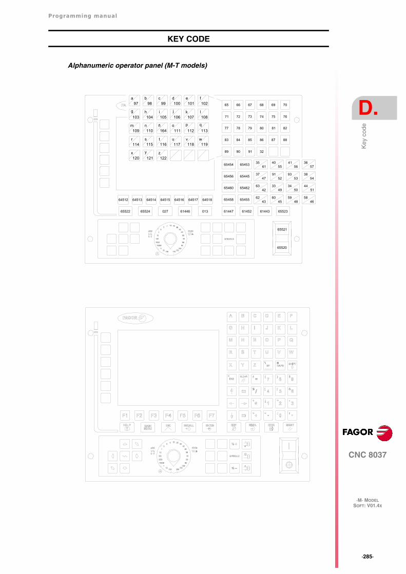
Programming manual
CNC 8037
D.
·M· MODELSOFT: V01.4X
·285·
Key
cod
e
KEY CODE
Alphanumeric operator panel (M-T models)
61452 61443 65523
65 66 67 68 69 70
71 72 73 74 75 76
77 78 79 80 81
86 87
82
8883 84 85
89 90 91 32
65453
65456 65445
65460 65462
65458 65455
6545435
6140
5541
5636
57
3747
9152
9353
3854
6342
3349
3450
4451
6243
6045
5948
5846
61447013614460276552465522
64512 64513 64514 64515 64516 64517 64518
65521
65520
a b c d e f97 10210110098 99
g h i j k l
m n ñ o p q
r s t u v w
x y z
103 108107106104 105
109
114
113112110 111
115
120
119118116 117
121
164
122
·286·
Programming manual
CNC 8037
D.
·M· MODELSOFT: V01.4X
Key
cod
e
Programming manual
CNC 8037
E.
·M· MODELSOFT: V01.4X
·287·
Mai
nten
ance
MAINTENANCE
Cleaning
The accumulated dirt inside the unit may act as a screen preventing the proper dissipation of theheat generated by the internal circuitry which could result in a harmful overheating of the CNC and,consequently, possible malfunctions.
On the other hand, accumulated dirt can sometimes act as an electrical conductor and short-circuitthe internal circuitry, especially under high humidity conditions.
To clean the operator panel and the monitor, a smooth cloth should be used which has been dippedinto de-ionized water and /or non abrasive dish-washer soap (liquid, never powder) or 75º alcohol.
Do not use highly compressed air to clean the unit because it could generate electrostaticdischarges.
The plastics used on the front panel are resistant to :
• Grease and mineral oils.
• Bases and bleach.
• Dissolved detergents.
• Alcohol.
Fagor Automation shall not be held responsible for any material or physical damage derived from theviolation of these basic safety requirements.To check the fuses, first unplug the unit from mains If the CNC does not turn on when flipping the powerswitch, check that the fuses are the right ones and they are in good condition.Avoid solvents. The action of solvents such as chlorine hydrocarbons, benzole, esters and ether maydamage the plastics used to make the front panel of the unit.Do not get into the inside of the unit. Only personnel authorized by Fagor Automation may manipulatethe inside of this unit.Do not handle the connectors with the unit connected to main AC power. Before handling theseconnectors (I/O, feedback, etc.), make sure that the unit is not connected to main AC power.
·288·
Programming manual
CNC 8037
E.
8037 ·M·SOFT: V01.4X
Mai
nten
ance
Programming manual
CNC 8037
E.
SOFT: V01.4X
·289·
·290·
Programming manual
CNC 8037
E.
SOFT: V01.4X