Embed Size (px)
Citation preview
(Ref: 1901)
8070CNCProgramming manual.
BLANK PAGE
·2·
MACHINE SAFETY
It is up to the machine manufacturer to make sure that the safety of the machineis enabled in order to prevent personal injury and damage to the CNC or to theproducts connected to it. On start-up and while validating CNC parameters, itchecks the status of the following safety elements. If any of them is disabled, theCNC shows the following warning message.
• Feedback alarm for analog axes.
• Software limits for analog and sercos linear axes.
• Following error monitoring for analog and sercos axes (except the spindle)both at the CNC and at the drives.
• Tendency test on analog axes.
FAGOR AUTOMATION shall not be held responsible for any personal injuries orphysical damage caused or suffered by the CNC resulting from any of the safetyelements being disabled.
DUAL-USE PRODUCTS
Products manufactured by FAGOR AUTOMATION since April 1st 2014 willinclude "-MDU" in their identification if they are included on the list of dual-useproducts according to regulation UE 428/2009 and require an export licensedepending on destination.
TRANSLATION OF THE ORIGINAL MANUAL
This manual is a translation of the original manual. This manual, as well as thedocuments derived from it, have been drafted in Spanish. In the event of anycontradictions between the document in Spanish and its translations, the wordingin the Spanish version shall prevail. The original manual will be labeled with thetext "ORIGINAL MANUAL".
HARDWARE EXPANSIONS
FAGOR AUTOMATION shall not be held responsible for any personal injuries orphysical damage caused or suffered by the CNC resulting from any hardwaremanipulation by personnel unauthorized by Fagor Automation.
If the CNC hardware is modified by personnel unauthorized by FagorAutomation, it will no longer be under warranty.
COMPUTER VIRUSES
FAGOR AUTOMATION guarantees that the software installed contains nocomputer viruses. It is up to the user to keep the unit virus free in order toguarantee its proper operation. Computer viruses at the CNC may cause it tomalfunction.
FAGOR AUTOMATION shall not be held responsible for any personal injuries orphysical damage caused or suffered by the CNC due a computer virus in thesystem.
If a computer virus is found in the system, the unit will no longer be under warranty.
All rights reserved. No part of this documentation may be transmitted,transcribed, stored in a backup device or translated into another languagewithout Fagor Automation’s consent. Unauthorized copying or distributing of thissoftware is prohibited.
The information described in this manual may be subject to changes due totechnical modifications. Fagor Automation reserves the right to change thecontents of this manual without prior notice.
All the trade marks appearing in the manual belong to the corresponding owners.The use of these marks by third parties for their own purpose could violate therights of the owners.
It is possible that CNC can execute more functions than those described in itsassociated documentation; however, Fagor Automation does not guarantee thevalidity of those applications. Therefore, except under the express permissionfrom Fagor Automation, any CNC application that is not described in thedocumentation must be considered as "impossible". In any case, FagorAutomation shall not be held responsible for any personal injuries or physicaldamage caused or suffered by the CNC if it is used in any way other than asexplained in the related documentation.
The content of this manual and its validity for the product described here has beenverified. Even so, involuntary errors are possible, hence no absolute match isguaranteed. However, the contents of this document are regularly checked andupdated implementing the necessary corrections in a later edition. We appreciateyour suggestions for improvement.
The examples described in this manual are for learning purposes. Before usingthem in industrial applications, they must be properly adapted making sure thatthe safety regulations are fully met.
Programming manual.
CNC 8070
·3·
(REF: 1901)
I N D E X
About the product - CNC 8070 ..................................................................................................... 9Declaration of CE conformity and warranty conditions ............................................................... 13Version history - CNC 8070 ........................................................................................................ 15Safety conditions ........................................................................................................................ 25Returning conditions ................................................................................................................... 29CNC maintenance ...................................................................................................................... 31
CHAPTER 1 CREATING A PROGRAM.
1.1 Programming languages................................................................................................ 331.2 Program structure. ......................................................................................................... 341.2.1 Program body............................................................................................................. 351.2.2 The subroutines. ........................................................................................................ 361.3 Program block structure................................................................................................. 371.3.1 Programming in ISO code.......................................................................................... 381.3.2 High-level language programming. ............................................................................ 401.4 Programming of the axes............................................................................................... 411.5 List of "G" functions........................................................................................................ 421.6 List of auxiliary (miscellaneous) M functions.................................................................. 451.7 List of statements and instructions................................................................................. 461.8 Programming the block labels........................................................................................ 491.9 Comment programming. ................................................................................................ 501.10 Variables and constants................................................................................................. 511.11 Arithmetic parameters.................................................................................................... 521.12 Arithmetic and logic operators and functions. ................................................................ 531.13 Arithmetic and logic expressions. .................................................................................. 55
CHAPTER 2 MACHINE OVERVIEW
2.1 Axis nomenclature ......................................................................................................... 572.2 Coordinate system ......................................................................................................... 592.3 Reference systems ........................................................................................................ 602.3.1 Origins of the reference systems ............................................................................... 612.4 Home search.................................................................................................................. 622.4.1 Definition of "Home search" ....................................................................................... 622.4.2 "Home search" programming ..................................................................................... 63
CHAPTER 3 COORDINATE SYSTEM
3.1 Programming in millimeters (G71) or in inches (G70).................................................... 653.2 Absolute (G90) or incremental (G91) coordinates. ........................................................ 663.2.1 Rotary axes. ............................................................................................................... 673.3 Absolute and incremental coordinates in the same block (I). ........................................ 693.4 Programming in radius (G152) or in diameters (G151).................................................. 703.5 Coordinate programming ............................................................................................... 713.5.1 Cartesian coordinates ................................................................................................ 713.5.2 Polar coordinates ....................................................................................................... 723.5.3 Angle and Cartesian coordinate................................................................................. 74
CHAPTER 4 WORK PLANES.
4.1 About work planes on lathe and mill models.................................................................. 784.2 Select the main new work planes. ................................................................................. 794.2.1 Mill model or lathe model with "trihedron" type axis configuration. ............................ 794.2.2 Lathe model with "plane" type axis configuration....................................................... 804.3 Select any work plane and longitudinal axis. ................................................................. 814.4 Select the longitudinal axis of the tool............................................................................ 83
CHAPTER 5 ORIGIN SELECTION
5.1 Programming with respect to machine zero................................................................... 865.2 Set the machine coordinate (G174). ............................................................................. 885.3 Fixture offset .................................................................................................................. 895.4 Coordinate preset (G92) ................................................................................................ 905.5 Zero offsets (G54-G59/G159) ........................................................................................ 91
Programming manual.
CNC 8070
·4·
(REF: 1901)
5.5.1 Variables for setting zero offsets................................................................................ 935.5.2 Incremental zero offset (G158) .................................................................................. 945.5.3 Excluding axes in the zero offset (G157) ................................................................... 965.6 Zero offset cancellation (G53) ....................................................................................... 975.7 Polar origin preset (G30) ............................................................................................... 98
CHAPTER 6 TECHNOLOGICAL FUNCTIONS
6.1 Machining feedrate (F)................................................................................................. 1016.2 Feedrate related functions ........................................................................................... 1036.2.1 Feedrate programming units (G93/G94/G95) .......................................................... 1036.2.2 Feedrate blend (G108/G109/G193) ......................................................................... 1046.2.3 Constant feedrate mode (G197/G196) .................................................................... 1066.2.4 Cancellation of the % of feedrate override (G266)................................................... 1086.2.5 Acceleration control (G130/G131) ........................................................................... 1096.2.6 Jerk control (G132/G133) ........................................................................................ 1116.2.7 Feed-Forward control (G134) .................................................................................. 1126.2.8 AC-Forward control (G135)...................................................................................... 1136.3 Spindle speed (S) ........................................................................................................ 1146.4 Tool number (T) ........................................................................................................... 1156.5 Tool offset number (D)................................................................................................. 1186.6 Auxiliary (miscellaneous) functions (M) ....................................................................... 1206.6.1 List of "M" functions ................................................................................................. 1216.7 Auxiliary functions (H).................................................................................................. 122
CHAPTER 7 THE SPINDLE. BASIC CONTROL.
7.1 The master spindle of the channel............................................................................... 1247.1.1 Manual selection of a master spindle....................................................................... 1267.2 Spindle speed .............................................................................................................. 1277.2.1 G192. Turning speed limitation ................................................................................ 1287.2.2 Constant surface speed ........................................................................................... 1297.3 Spindle start and stop .................................................................................................. 1307.4 Gear change. ............................................................................................................... 1327.5 Spindle orientation. ...................................................................................................... 1347.5.1 The turning direction for spindle orientation............................................................. 1367.5.2 M19 function with an associated subroutine. ........................................................... 1387.5.3 Positioning speed..................................................................................................... 1397.6 M functions with an associated subroutine. ................................................................. 140
CHAPTER 8 PATH CONTROL.
8.1 Rapid traverse (G00). .................................................................................................. 1418.2 Linear interpolation (G01). ........................................................................................... 1438.3 Circular interpolation (G02/G03). ................................................................................. 1498.3.1 Cartesian coordinates (Arc center programming). ................................................... 1518.3.2 Cartesian coordinates (arc radius programming). ................................................... 1538.3.3 Cartesian coordinates (arc radius pre-programming) (G263). ................................. 1558.3.4 Polar coordinates. .................................................................................................... 1568.3.5 Programming example (M model). Polar coordinates.............................................. 1588.3.6 Programming example (M model). Polar coordinates. ............................................ 1598.3.7 Programming example (T model). Programming examples. ................................... 1608.3.8 Polar coordinates. Temporary Polar origin shift to the center of arc (G31).............. 1618.3.9 Cartesian coordinates. Arc center in absolute coordinates (no-modal) (G06). ........ 1628.3.10 Cartesian coordinates. Arc center in absolute coordinates (modal) (G261/G262). . 1638.3.11 Arc correction (G264/G265). .................................................................................... 1658.4 Arc tangent to previous path (G08).............................................................................. 1678.5 Arc defined by three points (G09). ............................................................................... 1698.6 Helical interpolation (G02/G03). .................................................................................. 171
CHAPTER 9 TOOL PATH CONTROL. MANUAL INTERVENTION.
9.1 Additive manual intervention (G201/G202).................................................................. 1749.2 Exclusive manual intervention (G200). ........................................................................ 1759.3 Jogging feedrate. ......................................................................................................... 1769.3.1 Feedrate in continuous jog (#CONTJOG)................................................................ 1769.3.2 Feedrate in incremental jog (#INCJOG). ................................................................. 1779.3.3 Feedrate in incremental jog (#MPG). ....................................................................... 1789.3.4 Manual path movement limits (#SET OFFSET)....................................................... 1799.3.5 Synchronization of coordinates and additive manual offset (#SYNC POS). ............ 1809.4 Variables...................................................................................................................... 181
Programming manual.
CNC 8070
·5·
(REF: 1901)
CHAPTER 10 ELECTRONIC THREADING AND RIGID TAPPING.
10.1 Electronic threading with constant pitch (G33) ............................................................ 18310.1.1 Programming examples (·M· model)........................................................................ 18610.1.2 Programming examples (·T· model) ........................................................................ 18710.2 Electronic threading with variable pitch (G34) ............................................................. 18910.3 Rigid tapping (G63)...................................................................................................... 19310.4 Withdraw the axes after interrupting an electronic threading (G233)........................... 19510.4.1 Variables related to G233. ....................................................................................... 19810.4.2 Programming example. ............................................................................................ 198
CHAPTER 11 GEOMETRY ASSISTANCE
11.1 Square corner (G07/G60) ............................................................................................ 19911.2 Semi-rounded corner (G50) ......................................................................................... 20011.3 Controlled corner rounding, radius blend, (G05/G61).................................................. 20111.3.1 Types of corner rounding ......................................................................................... 20211.4 Corner rounding, radius blend, (G36) .......................................................................... 20611.5 Corner chamfering, (G39) ............................................................................................ 20811.6 Tangential entry (G37) ................................................................................................. 21011.7 Tangential exit (G38) ................................................................................................... 21111.8 Mirror image (G11, G12, G13, G10, G14) ................................................................... 21211.9 Pattern rotation (G73) .................................................................................................. 21611.10 General scaling factor .................................................................................................. 21811.11 Work zones. ................................................................................................................. 22111.11.1 CNC behavior when there are active work zones. ................................................... 22211.11.2 Set the limits of the work zones (G120/G121/G123)................................................ 22311.11.3 Enable/disable the work zones (G122). ................................................................... 22511.11.4 Summary of work zone related variables. ................................................................ 228
CHAPTER 12 ADDITIONAL PREPARATORY FUNCTIONS
12.1 Dwell (G04 / #TIME). ................................................................................................... 22912.2 Software limits.............................................................................................................. 23112.2.1 Define the first software limit (G198/G199). ............................................................. 23212.2.2 Define the first software limit via variables. .............................................................. 23412.2.3 Define the second software limit via variables. ........................................................ 23512.2.4 Variables associated with the software limits........................................................... 23612.3 Turn Hirth axis on and off (G170/G171)....................................................................... 23712.4 Set and gear change.................................................................................................... 23812.4.1 Change parameter set of an axis (G112)................................................................. 23812.4.2 Change the gear and set of a Sercos drive using variables..................................... 23912.4.3 Variables related to set and gear change. ............................................................... 24012.5 Smooth the path and the feedrate. .............................................................................. 24112.5.1 Smooth the path (#PATHND)................................................................................... 24112.5.2 Smooth the path and the feedrate (#FEEDND). ...................................................... 242
CHAPTER 13 TOOL COMPENSATION
13.1 Tool radius compensation............................................................................................ 24513.1.1 Location code (shape or type) of the turning tools ................................................... 24613.1.2 Functions associates with radius compensation ...................................................... 24913.1.3 Beginning of tool radius compensation .................................................................... 25213.1.4 Sections of tool radius compensation ...................................................................... 25513.1.5 Change of type of radius compensation while machining ........................................ 25913.1.6 Cancellation of tool radius compensation ................................................................ 26113.2 Tool length compensation............................................................................................ 26413.3 3D tool compensation. ................................................................................................. 26613.3.1 Programming the vector in the block........................................................................ 268
CHAPTER 14 CONTROLLING THE EXECUTION AND DISPLAYING THE PROGRAM.
14.1 Conditional block skip (/) ............................................................................................. 26914.2 Abort the execution of the program and resume it in another block or program. ........ 27014.2.1 Define the execution resuming block or program (#ABORT)................................... 27114.2.2 Default point to continue the execution (#ABORT OFF). ......................................... 27214.3 Block repetition (NR).................................................................................................... 27314.3.1 Movement block repetition n times (NR/NR0).......................................................... 27314.3.2 Prepare a subroutine without executing it (NR0). .................................................... 27414.4 Block group repetition (#RPT)...................................................................................... 27514.4.1 Programming example. ............................................................................................ 27714.5 Interrupt block preparation until an event is caused (#WAIT FOR). ............................ 27814.6 Interrupt block preparation (#FLUSH).......................................................................... 27914.7 Enable/disable the single-block treatment (#ESBLK/ #DSBLK). ................................. 280
Programming manual.
CNC 8070
·6·
(REF: 1901)
14.8 Enable/disable the stop signal (#DSTOP/#ESTOP). ................................................... 28114.9 Enable/disable the feed-hold signal (#DFHOLD/#EFHOLD). ...................................... 28214.10 Block skip ($GOTO)..................................................................................................... 28314.11 Conditional execution ($IF). ......................................................................................... 28414.11.1 Conditional execution ($IF). ..................................................................................... 28414.11.2 Conditional execution ($IF - $ELSE)........................................................................ 28514.11.3 Conditional execution ($IF - $ELSEIF). ................................................................... 28614.12 Conditional execution ($SWITCH)............................................................................... 28714.13 Block repetition ($FOR) ............................................................................................... 28814.14 Conditional block repetition ($WHILE). ........................................................................ 29014.15 Conditional block repetition ($DO)............................................................................... 291
CHAPTER 15 SUBROUTINES.
15.1 Executing subroutines from RAM memory. ................................................................. 29515.2 Definition of the subroutines ........................................................................................ 29615.3 Subroutine execution. .................................................................................................. 29715.3.1 LL. Call to a local subroutine.................................................................................... 29815.3.2 L. Call to a global subroutine. .................................................................................. 29815.3.3 #CALL. Call to a global or local subroutine.............................................................. 29915.3.4 #PCALL. Call to a global or local subroutine initializing parameters........................ 30015.3.5 #MCALL. Modal call to a local or global subroutine. ................................................ 30115.3.6 #MDOFF. Turning the subroutine into non-modal. .................................................. 30315.3.7 #RETDSBLK. Execute subroutine as a single block................................................ 30415.4 #PATH. Define the location of the global subroutines. ................................................ 30515.5 OEM subroutine execution. ......................................................................................... 30615.6 Generic user subroutines (G500-G599). ..................................................................... 30815.7 Assistance for subroutines........................................................................................... 31115.7.1 Subroutine help files. ............................................................................................... 31115.7.2 List of available subroutines..................................................................................... 31315.8 Interruption subroutines. .............................................................................................. 31415.8.1 Repositioning axes and spindles from the subroutine (#REPOS). .......................... 31515.9 Subroutine associated with the start. ........................................................................... 31615.10 Subroutine associated with the reset. .......................................................................... 31715.11 Subroutines associated with the kinematics calibration cycle. .................................... 318
CHAPTER 16 EXECUTING BLOCKS AND PROGRAMS
16.1 Executing a program in the indicated channel. ............................................................ 31916.2 Executing a block in the indicated channel. ................................................................. 321
CHAPTER 17 C AXIS
17.1 Activating the spindle as "C" axis................................................................................. 32417.2 Machining of the face of the part ................................................................................. 32617.3 Machining of the turning side of the part...................................................................... 328
CHAPTER 18 ANGULAR TRANSFORMATION OF AN INCLINE AXIS.
18.1 Turning angular transformation on and off................................................................... 33318.2 Freezing (suspending) the angular transformation. ..................................................... 33418.3 Obtaining information on angular transformation......................................................... 335
CHAPTER 19 TANGENTIAL CONTROL.
19.1 Turning tangential control on and off. .......................................................................... 33919.2 Freezing tangential control. ......................................................................................... 34219.3 Obtaining information on tangential control. ................................................................ 344
CHAPTER 20 KINEMATICS AND COORDINATE TRANSFORMATION
20.1 Coordinate systems. .................................................................................................... 34620.2 Movement in an inclined plane. ................................................................................... 34720.3 Select a kinematics (#KIN ID). ..................................................................................... 34820.4 Coordinate systems (#CS / #ACS). ............................................................................. 34920.4.1 Define a coordinate system (MODE1). .................................................................... 35320.4.2 Define a coordinate system (MODE2). .................................................................... 35420.4.3 Define a coordinate system (MODE3). .................................................................... 35520.4.4 Define a coordinate system (MODE4). .................................................................... 35620.4.5 Define a coordinate system (MODE5). .................................................................... 35720.4.6 Define a coordinate system (MODE6). .................................................................... 35820.4.7 Operation with 45º spindles (Huron type). ............................................................... 36020.4.8 How to combine several coordinate systems........................................................... 362
Programming manual.
CNC 8070
·7·
(REF: 1901)
20.5 Tool perpendicular to the inclined plane (#TOOL ORI)................................................ 36420.5.1 Programming examples. .......................................................................................... 36520.6 Using RTCP (Rotating Tool Center Point). .................................................................. 36720.6.1 Programming examples. .......................................................................................... 36920.7 Correct the implicit tool length compensation of the program (#TLC).......................... 37120.8 How to withdraw the tool when losing the plane. ......................................................... 37220.9 Tool orientation in the part coordinate system. ............................................................ 37320.9.1 Activate tool orientation in the part coordinate system............................................. 37320.9.2 Cancel tool orientation in the part coordinate system. ............................................. 37420.9.3 How to manage the discontinuities in the orientation of rotary axes. ....................... 37520.9.4 Screen for choosing the desired solution. ................................................................ 37720.9.5 Execution example. Selecting a solution.................................................................. 37820.10 Selecting the rotary axes that position the tool in type-52 kinematics. ........................ 37920.11 Transform the current part zero considering the position of the table kinematics........ 38020.11.1 Process of saving a part zero with the table axes in any position............................ 38120.11.2 Example to maintain the part zero without rotating the coordinate system.............. 38220.12 Summary of kinematics related variables. ................................................................... 383
CHAPTER 21 HSC. HIGH SPEED MACHINING.
21.1 Recommendations for machining. ............................................................................... 38821.2 User subroutines G500-G501 to turn HSC on/off. ....................................................... 38921.2.1 Alternative example for functions G500-G501 supplied by Fagor............................ 39121.3 HSC SURFACE mode. Optimization of surface finish. ................................................ 39321.4 HSC CONTERROR mode. Optimizing the contouring error. ....................................... 39621.5 HSC FAST mode. Optimizing the machining feedrate................................................. 39821.6 Canceling the HSC mode. ........................................................................................... 400
CHAPTER 22 VIRTUAL TOOL AXIS.
22.1 Activate the virtual tool axis. ........................................................................................ 40222.2 Cancel the virtual tool axis. .......................................................................................... 40322.3 Variables associated with the virtual tool axis.............................................................. 404
CHAPTER 23 DISPLAYING MESSAGES, WARNINGS AND ERRORS.
23.1 #ERROR. Display an error on the screen.................................................................... 40623.2 #WARNING / #WARNINGSTOP. Displaying a warning on the screen. ...................... 40823.3 #MSG. Display a message on the screen.................................................................... 41023.4 Format identifiers and special characters. ................................................................... 41223.5 cncError.txt file. List of OEM and user errors and warnings. ....................................... 41323.6 cncMsg.txt file. List of OEM and user messages. ........................................................ 41423.7 Summary of the variables. ........................................................................................... 415
CHAPTER 24 DMC (DYNAMIC MACHINING CONTROL).
24.1 Activating the DMC. ..................................................................................................... 41824.2 Deactivating the DMC. ................................................................................................. 42024.3 Summary of the variables. ........................................................................................... 42124.4 Operating with DMC..................................................................................................... 42324.4.1 DMC operation. ........................................................................................................ 42324.4.2 DMC status and progress. Automatic mode. ........................................................... 42524.4.3 Percentage of feedrate (feedrate override). ............................................................. 425
CHAPTER 25 OPENING AND WRITING FILES.
25.1 #OPEN. Open file for writing........................................................................................ 42725.2 #WRITE. Writing in a file.............................................................................................. 42925.3 #CLOSE. Close a file. .................................................................................................. 43125.4 cncWrite.txt file. List of OEM and user messages. ...................................................... 432
CHAPTER 26 PROGRAMMING STATEMENTS.
26.1 Display instructions. Define the size of the graphics area ........................................... 43326.2 ISO generation............................................................................................................. 43626.3 Electronic axis slaving.................................................................................................. 43926.4 Axis parking ................................................................................................................. 44026.5 Modifying the configuration of the axes of a channel................................................... 44226.6 Modifying the configuration of the spindles of a channel ............................................. 44726.7 Spindle synchronization ............................................................................................... 45026.8 Selecting the loop for an axis or a spindle. Open loop or closed loop ......................... 45426.9 Collision detection........................................................................................................ 45626.10 Spline interpolation (Akima) ......................................................................................... 458
Programming manual.
CNC 8070
·8·
(REF: 1901)
26.11 Polynomial interpolation............................................................................................... 46126.12 Acceleration control ..................................................................................................... 46226.13 Definition of macros ..................................................................................................... 46426.14 Communication and synchronization between channels............................................. 46626.15 Movements of independent axes................................................................................. 46926.16 Electronic cams. .......................................................................................................... 47326.17 On line modification of the machine configuration in HD graphics (xca files). ............. 476
CHAPTER 27 CNC VARIABLES.
Programming manual.
CNC 8070
·9·
(REF: 1901)
ABOUT THE PRODUCT - CNC 8070
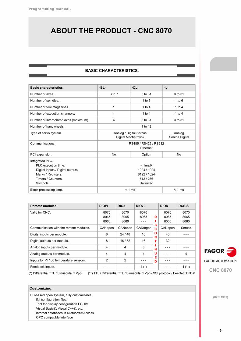
BASIC CHARACTERISTICS.
(*) Differential TTL / Sinusoidal 1 Vpp (**) TTL / Differential TTL / Sinusoidal 1 Vpp / SSI protocol / FeeDat / EnDat
Basic characteristics. ·BL· ·OL· ·L·
Number of axes. 3 to 7 3 to 31 3 to 31
Number of spindles. 1 1 to 6 1 to 6
Number of tool magazines. 1 1 to 4 1 to 4
Number of execution channels. 1 1 to 4 1 to 4
Number of interpolated axes (maximum). 4 3 to 31 3 to 31
Number of handwheels. 1 to 12
Type of servo system. Analog / Digital SercosDigital Mechatrolink
AnalogSercos Digital
Communications. RS485 / RS422 / RS232Ethernet
PCI expansion. No Option No
Integrated PLC. PLC execution time.Digital inputs / Digital outputs.Marks / Registers.Timers / Counters.Symbols.
< 1ms/K1024 / 10248192 / 1024
512 / 256Unlimited
Block processing time. < 1 ms < 1 ms
Remote modules. RIOW RIO5 RIO70 RIOR RCS-S
Valid for CNC. 807080658060
807080658060
80708065- - -
DISCONTINUED
807080658060
807080658060
Communication with the remote modules. CANopen CANopen CANfagor CANopen Sercos
Digital inputs per module. 8 24 / 48 16 48 - - -
Digital outputs per module. 8 16 / 32 16 32 - - -
Analog inputs per module. 4 4 8 - - - - - -
Analog outputs per module. 4 4 4 - - - 4
Inputs for PT100 temperature sensors. 2 2 - - - - - - - - -
Feedback inputs. - - - - - - 4 (*) - - - 4 (**)
Customizing.
PC-based open system, fully customizable.INI configuration files.Tool for display configuration FGUIM.Visual Basic®, Visual C++®, etc.Internal databases in Microsoft® Access.OPC compatible interface
Programming manual.
CNC 8070
·10·
(REF: 1901)
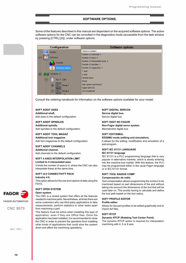
SOFTWARE OPTIONS.
Some of the features described in this manual are dependent on the acquired software options. The activesoftware options for the CNC can be consulted in the diagnostics mode (accessible from the task windowby pressing [CTRL] [A]), under software options.
Consult the ordering handbook for information on the software options available for your model.
SOFT ADDIT AXESAdditional shaft.Add axes to the default configuration.
SOFT ADDIT SPINDLESAdditional spindle.Add spindles to the default configuration.
SOFT ADDIT TOOL MAGAZAdditional tool magazine.Add tool magazines to the default configuration.
SOFT ADDIT CHANNELSAdditional channel.Add channels to the default configuration.
SOFT 4 AXES INTERPOLATION LIMITLimited to 4 interpolated axes.It limits the number of axes to 4, where the CNC can alsointerpolate these at the same time.
SOFT i4.0 CONNECTIVITY PACKIndustry 4.0.This option allows for the use and capture of data using theFSYS.
SOFT OPEN SYSTEMOpen system.The CNC is a closed system that offers all the featuresneeded to machine parts. Nevertheless, at times there aresome customers who use third-party applications to takemeasurements, perform statistics or other tasks apartfrom machining a part.This feature must be active when installing this type ofapplication, even if they are Office files. Once theapplication has been installed, it is recommended to closethe CNC in order to prevent the operators from installingother kinds of applications that could slow the systemdown and affect the machining operations.
SOFT DIGITAL SERCOSSercos digital bus.Sercos digital bus.
SOFT DIGIT NO FAGORNon-Fagor digital servo system.Mechatrolink digital bus.
SOFT EDIT/SIMULEDISIMU mode (editing and simulation).It allows for the editing, modification and simulation of apart-program.
SOFT IEC 61131 LANGUAGEIEC 61131 languageIEC 61131 is a PLC programming language that is verypopular in alternative markets, which is slowly enteringinto the machine-tool market. With this feature, the PLCmay be programmed either in the usual Fagor languageor in IEC 61131 format.
SOFT TOOL RADIUS COMPCompensación de radio.Tool compensation allows programming the contour to bemachined based on part dimensions of the and withouttaking into account the dimensions of the tool that will beused later on. This avoids having to calculate and definethe tool path based on the tool radius.
SOFT PROFILE EDITORProfile editor.Allows for the part profiles to be edited graphically and toimport dxf files.
SOFT RTCPDynamic RTCP (Rotating Tool Center Point).The dynamic RTCP option is required for interpolationmachining with 4, 5 or 6 axis.
Programming manual.
CNC 8070
·11·
(REF: 1901)
SOFT C AXISC axis.It activates the kinematics for working with the C axis andthe associated canned cycles. The CNC can controlseveral C axes. The parameters of each axis indicate if itwill function as a C axis or not, where it will not benecessary to activate another axis for the machineparameters.
SOFT TANDEM AXESTandem axes.A tandem axis consists in two motors mechanicallycoupled (slaved) and making up a single transmissionsystem (axis or spindle). A tandem axis helps provide thenecessary torque to move an axis when a single motor isnot capable of supplying enough torque to do it.When activating this feature, it should be kept in mind thatfor each tandem axis of the machine, another axis must beadded to the entire configuration. For example, on a large3-axis lathe (X Z and tailstock), if the tailstock is a tandemaxis, the final purchase order for the machine mustindicate 4 axes.
SOFT SYNCHRONISMSynchronization of axes and spindles.The axes and ballscrews may be synchronized in twoways: in terms of speed or posi t ion. The CNCconfiguration takes into consideration the synchronizationof 2 axes or 2 spindles. Once synchronized, only themaster displays and programs the element.
SOFT HSSA II MACHINING SYSTEMHSSA-II machining system.This is the new version of algorithms for high speedmachining (HSC). This new HSSA algorithm allows forhigh speed machining optimization, where higher cuttingspeeds, smoother contours, a better surface finishing andgreater precision are achieved.
SOFT TANGENTIAL CONTROLTangential control."Tangential Control" maintains a rotary axis always in thesame orientation with respect to the programmed toolpath. The machining path is defined on the axes of theactive plane and the CNC maintains the orientation of therotary axis along the entire tool path.
SOFT DRILL CYCL OLDrilling ISO cycles for the OL model.Drilling ISO cycles for the OL model (G80, G81, G82,G83).
SOFT PROBEProbing canned cycles.The CNC may have two probes; usually a tabletop probeto calibrate tools and a measuring probe to measure thepart. This option activates the functions G100, G103 and G104(for probe movements); probe canned cycles are notincluded.
SOFT THIRD PARTY CANOPENThird-party CANopen.Enables the use of non-Fagor CANopen modules.
SOFT FVC BASICSOFT FVC UP TO 10m3SOFT FVC MORE TO 10m3Volumetric compensation.5-axis machines are general ly used dur ing themanufacturing of large parts. The accuracy of the parts islimited by the machine manufacturing tolerances and iseffected by temperature variations during machining.In sectors such as the aerospace industry, machiningdemands mean that classic compensation tools are
becoming suboptimal. Volumetric compensation FVCcomes in to complement the machine adjusting tools.When mapping the total work volume of the machine, theCNC knows the exact position of the tool at all times. Afterapplying the required compensation, the resulting part ismade with the desired precision and tolerance.There are 3 options, which depend on the size of themachine.
• FVC BASIC: 25-point compensation on each axis.Quick calibration (time), but less precise than theother two, but sufficient for the desired tolerances.
• FVC UP TO 10m3: Volume compensation up to 10 m³.More accurate than FVC BASIC, but requires a moreaccurate calibration using a Tracer or Tracker laser).
• FVC MORE TO 10m3: Volume compensation greaterthan 10 m³. More accurate than FVC BASIC, butrequires a more accurate calibration using a Tracer orTracker laser.
SOFT 60 PWM CONTROLPulse-Width Modulation.This function is only available for Sercos bus controlledsystems. It is mostly oriented toward laser machines forthe cutting of very thick sheets, where the CNC generatesa series of PWM pulses to control the power of the laserwhen drilling the starting point.This feature is essential for cutting very thick sheets andit requires two quick digital outputs located on the centralunit. With this new feature, the OEM does not need toinstall or program any external device, which reducesmachine costs and installation times. The end user alsobenefits, since the “Cutting with PWM ” feature is mucheasier to use and program.
SOFT 60 GAP CONTROLGap control.This is mostly oriented toward laser machines. Gapcontrol makes it possible to maintain a set distancebetween the laser nozzle and the surface of the sheet. Thisdistance is calculated by a sensor connected to the CNC,so that the CNC offsets the sensor variations on thedistance programmed with additional movements in theaxis programmed for the gap.
SOFT DMCDynamic Machining Control.DMC adapts the feedrate during machining to maintain thecutting power as close as possible to ideal machiningconditions.
SOFT FMCFagor Machining Calculator.The FMC application consists of a database of materialsto be machined and machining operations (milling andturning) with an interface to choose suitable cuttingconditions for these operations.
SOFT FFCFagor Feed Control.During the execution of a canned cycle of the editor, theFFC function makes it possible to replace the feedrate andspeed programmed in the cycle with the active values ofthe execution, which are acted upon by the feed overrideand speed override.
SOFT 60/65/70 OPERATING TERMSTemporary user license.The "Operating Terms" option activates a temporary userlicense for the CNC, which is valid until the datedetermined by the OEM.
Programming manual.
CNC 8070
·12·
(REF: 1901)
SOFT MANUAL NESTINGManual nestingNesting consists of creating a pattern on the sheet materialusing previously defined figures (in dxf, dwg or parametricfiles), so as to use most of the sheet as possible. Once thepattern has been defined, the CNC creates a program.During manual nesting, the operator distributes the partson top of the sheet material.
SOFT AUTO NESTINGAutomatic nestingNesting consists of creating a pattern on the sheet materialusing previously defined figures (in dxf, dwg or parametricfiles), so as to use most of the sheet as possible. Once thepattern has been defined, the CNC creates a program.During automatic nesting, the application distributes thefigures on the sheet material and optimizes the spaces.
Programming manual.
CNC 8070
·13·
(REF: 1901)
DECLARATION OF CE CONFORMITY AND WARRANTY CONDITIONS
DECLARATION OF CONFORMITY
The declaration of conformity for the CNC is available in the downloads section of FAGOR’S corporatewebsite. http://www.fagorautomation.com. (Type of file: Declaration of conformity).
WARRANTY TERMS
The warranty conditions for the CNC are available in the downloads section of FAGOR’s corporate website.http://www.fagorautomation.com. (Type of file: General sales-warranty conditions.

BLANK PAGE
·14·
Programming manual.
CNC 8070
·15·
(REF: 1901)
VERSION HISTORY - CNC 8070
Here is a list of the features added to each manual reference.
Ref. 0201
Ref. 0212
Ref. 0501
Software V01.00
First version. Milling model.
Software V01.10
New repositioning feedrate after tool inspection. • Machine parameter: REPOSFEED.
New treatment of the JOG keys. Different keys to select the axis and thedirection.
• Machine parameter: JOGKEYDEF.
Know the dimensions of the kinematics on an axis. • Variable: (V.)A.HEADOF.xn
Keyboard simulation from the PLC. • Variable: (V.)G.KEY
General scaling factor. • Instruction: #SCALE.
Probe selection. • Instruction: #SELECT PROBE.
Probing canned cycles. • Instruction: #PROBE.
Programming of warnings. • Instruction: #WARNING.
Block repetition. • Instruction: #RPT.
Know the active general scaling factor. • Variable: (V.)G.SCALE
Knowing which is the active probe. • Variable: (V.)G.ACTIVPROBE
Improved programming of high speed machining. • Instruction: #HSC.
Improved programming of axis swapping. • Instructions: #SET#CALL#FREE#RENAME
The number of macros in a program is now limited to 50. • Macros.
Software V02.01
Windows XP operating system.
Emergency shutdown with battery (central unit PC104).
Multi-channel system, up to 4 channels. Swapping of axes and spindles,communication and synchronization between channels, common arithmeticparameters, access variables by channel, etc.
Multi-spindle system, up to 4 spindles.
Tool management with up to 4 magazines.
Tool radius compensation mode (G136/G137) by default • Machine parameter: IRCOMP.
New behavior for rotary axes.
The "(V.)TM.MZWAIT " variable is not necessary in the subroutine associatedwith M06.
• Subroutine associated with M6.
• Variable: (V.)TM.MZWAIT
Know the software version. • Variable: (V.)G.SOFTWARE
Variables related to loop adjustment. Gain setting via PLC. • Variables: (V.)A.PLCFFGAIN.xn(V.)A.PLCACFGAIN.xn(V.)A.PLCPROGAIN.xn
Variables related to loop adjustment. Position increment and sampling period. • Variables: (V.)A.POSINC.xn(V.)A.TPOSINC.xn(V.)A.PREVPOSINC.xn
Variables related to loop adjustment. Fine adjustment of feedrate, accelerationand jerk.
• Variables: (V.)A.FEED.xn(V.)A.TFEED.xn(V.)A.ACCEL.xn(V.)A.TACCEL.xn(V.)A.JERK.xn(V.)A.TJERK.xn
Variables related to the feedback inputs. • Variables: (V.)A.COUNTER.xn(V.)A.COUNTERST.xn(V.)A.ASINUS.xn(V.)A.BSINUS.xn
Programming manual.
CNC 8070
·16·
(REF: 1901)
Ref. 0504
Ref. 0509
Ref. 0601
Optimize the reading and writing of variables from the PLC. Only the accessto the following variables will be asynchronous.
• The tool variables will be read asynchronously when the tool is neitherthe active one nor in the magazine.
• The tool variables will be written asynchronously whether the tool is theactive one or not.
• The variables referred to local arithmetic parameters of the active levelswill be read and written asynchronously.
• Reading and writing of variables from the PLC.
Spindle parking and unparking. • Instructions: #PARK#UNPARK
Tool radius compensation.
• Behavior of the beginning and end of tool radius compensation when notprogramming a movement.
• Changing the type of radius compensation while machining.
Via program, loading a tool in a specific magazine position.
Programming of modal subroutines. • Instruction: #MCALL.
Executing a block in a channel. • Instruction: #EXBLK.
Programming the number of repetitions in the block. • NR command.
Software V02.03
Electronic cam programming (real coordinates). • Instruction: #CAM.
Synchronization of independent axis (real coordinates). • Instruction: #FOLLOW.
Movement of the independent axis. • Instruction: #MOVE.
G31. Temporary polar origin shift to the center of interpolation. • Function G31.
G112. Change the drive's parameter set. • Function G112.
Software V03.00
Lathe model. Machining canned cycles, lathe tool calibration, variables toconsult the geometry of lathe tools, etc.
Incline axis.
Permit using the G95 function in jog mode. • Machine parameter: FPRMAN.
"C" axis maintained. • Machine parameter: PERCAX.
Magazine-less system.
Ground tools for a turret magazine.
Variable to read the accumulated PLC offset. • Variable: (V.)A.ACTPLCOF.xn
Variable to obtain a linear estimation of the following error. • Variable: (V.)A.FLWEST.xn
Variables to read the instant value of feed-forward or AC-forward. • Variables: (V.)A.ACTFFW.xn(V.)A.ACTACF.xn
Variable to know the line number of the file being executed. • Variable: (V.)G.LINEN
Variable to know what kind of cycle is active. • Variable: (V.)G.CYCLETYPEON
Variable to know the tool orientation. • Variable: (V.)G.TOOLDIR
Variable to know whether the HSC mode is active or not. • Variable: (V.)G.HSC
Variable to know the theoretical feedrate on 3D path. • Variable: (V.)G.F3D
Variable to know the number of the warning being displayed. • Variable: (V.)G.CNCWARNING
The variable (V.)G.CNCERR is now per channel. • Variable: (V.)G.CNCERR
Select the type of loop, open or closed, for the spindle. • Instruction: #SERVO.
Spindle synchronization. • Instruction: #SYNC.
Spindle synchronization. • Instruction: #TSYNC.
Spindle synchronization. • Instruction: #UNSYNC.
Select milling cycles at a lathe model. • Instruction: #MILLCY.
Select turning cycles at a milling model. • Instruction: #LATHECY.
Define a kinematics when activating the C axis. • #CYL instruction.
Define a kinematics when activating the C axis. • #FACE instruction.
Improved coordinate transformation (#CS/#ACS).
• Keep the part zero when deactivating the transformation.
• Working with 45º spindles. Select between the two choices.
• Keep the rotation of the plane axes with MODE 6.
• Instructions #CS#ACS.
G33. New parameter (Q1) to define the entry angle. • Function G33.
G63. Tool inspection is possible during rigid tapping. • Function G63.
Function G112 is not valid for the spindle. • Function G112.
New criteria when assuming a new master spindle in the channel.
Software V03.01
Axis slaving. Configuring the default status of an axis slaving (coupling). • Machine parameters: LINKCANCEL.
Tool radius compensation. The way tool radius is canceled. • Machine parameters: COMPCANCEL.
Using the ":" character to program a comment in a part-program.
Variables. Geometry of the lathe tools.
Variables. Number of the tool in the claws of the changer arm. • Variables: (V.)TM.TOOLCH1[mz](V.)TM.TOOLCH2[mz]
Software V02.01
Programming manual.
CNC 8070
·17·
(REF: 1901)
Ref. 0606
Ref. 0608
Ref. 0704 / Ref. 0706
Ref. 0707
Ref. 0709
Ref. 0712
The instruction #EXEC does not issue an error if the channel is busy; theinstruction waits for the operation in progress to end.
• #EXEC instruction.
The instruction #EXBLK does not issue an error if the channel is busy; theinstruction waits for the operation in progress to end.
• #EXBLK instruction.
Software V03.10
Feedrate. Maximum machining feedrate. • Machine parameter: MAXFEED.
Feedrate. Default machining feedrate when none has been programmed. • Machine parameter: DEFAULTFEED.
The CNC allows changing the spindle override during electronic threading(G33) and in the threading canned cycles of the ·T· model (G86, G87 and theirequivalent of the cycle editor).
• Machine parameters:THREADOVR, OVRFILTER.
"Retrace" function.
Tangential control.
The CNC checks whether the programmed turning direction (M3/M4) matchesthe one preset in the tool table.
M02/M30. There is no need to program M02 or M30 to end a part program. • Functions M02/M30.
Canceling the preset turning direction of a tool. • Variables: (V.)G.SPDLTURDIR
Change the maximum feedrate allowed in the channel from the PLC. • Variables: (V.)PLC.PLCG00FEED
Show the status of the emergency relay. • Variables: (V.)G.ERELAYST
HSC. New FAST mode. • #HSC instruction.
C axis. The #CYL instruction requires programming the radius. • #CYL instruction.
Software V03.11
"Retrace" function. Several improvements to the retrace function.
HSC. New command CORNER. • #HSC instruction.
G33. The override limitation is maintained while returning to the beginning ofthe thread.
• Function G33.
RTCP. Home search is now possible on the axes that are not involved in RTCP.
Abort the execution of the program and resume it somewhere else. • Instruction: #ABORT.
Software V03.13
Define the tool wear with incremental or absolute values.
Variables (V.)TM.TOOLCH1[mz] / (V.)TM.TOOLCH2[mz] may be written fromthe PLC.
• Variables: (V.)TM.TOOLCH1[mz](V.)TM.TOOLCH2[mz].
Software V03.14
MCU and ICU central unit. battery powered RAM. Connecting handwheels tothe central unit. local I/O. Local feedback inputs. Loca probes.
The turning speed limitation (G192) is also applied when the spindle is workingat constant turning speed (G97)
• Function G192.
Software V03.15
Know the type of hardware. • Variable: (V.)G.HARDTYPE
Theoretical tool feedrate along the path • Variable: (V.)G.PATHFEED
Zero offsets for the C axis.
The CNC shows a warning when a channel is expecting a tool that is beingused in another channel.
Software V03.16
Tandem spindles.
The CNC does not assume any kinematics on power-up.
The CNC allows modifying the override while threading if it detects that thefeed forward (parameter FFWTYPE) is not active in a gear or if the active feedforward is lower than 90%
Software V03.17
C axis maintained after executing M02, M30 or after an emergency or reset. • Machine parameter: PERCAX.
Software V03.01
Programming manual.
CNC 8070
·18·
(REF: 1901)
Ref. 0801
Ref. 0809
Ref. 0811
Ref. 0907
Ref. 1007
Software V03.20
Set change. The CNC lets change the gear of the slave axis or spindle of atandem.
Coordinate latching with the help of a probe or a digital input. • Variables: (V.)A.LATCH1.xn(V.)A.LATCH2.xn
Status of the local probes. • Variables: (V.)G.PRBST1 (V.)G.PRBST2.
Axis synchronization. Managing a rotary axis as an infinite axis making itpossible to increase the feedback count of the axis indefinitely (wihout limits)regardless of the value of the module.
• Variables: (V.)A.ACCUDIST.xn
Show a warning and interrupt program execution. • Instruction: #WARNINGSTOP.
Electronic cam programming (theoretical coordinates). • Instruction: #TCAM.
Dynamic distribution of the machining operations between channels. • Instruction: #DINDIST.
The CNC can park the main axes.
The axes may be programmed using the "?" wild card that refers to the axisposition in the channel.
• Wild card "?".
Functions G130 (percentage of acceleration) and G132 (percentage of jerk)may be applied to the spindles.
• Functions G130 and G132.
Interface related variables.
Software V04.00 (it does not include the features of version V03.21)
Unicode.
Cancel spindle synchronization after executing M02, M30 or after an error ora reset.
• Instructions #SYNC and #TSYNC.
Positioning a turret magazine whether there is a tool in the indicated positionor not.
• #ROTATEMZ instructions.
A channel maintains its master spindle after executing M02, M30 or after anemergency or a reset or restarting the CNC.
• #MASTERinstruction.
Force the change of gears and/or of the parameter set of a Sercos drive • Variable: (V.)A.SETGE.xn
Set a machine coordinate. • Function G174.
There can now be up to 99 zero offsets. • Function G159.
There can now be up to 100 synchronization marks. • Instructions #MEET, #WAIT and #SIGNAL.
Select a turret position. • #ROTATEMZ instructions.
Axis synchronization. Managing a rotary axis as an infinite axis making itpossible to increase the feedback count of the axis indefinitely (wihout limits)regardless of the value of the module.
• Variables: (V.)A.PREVACCUDIST.xn
Variables. The variable (V.)E.PROGSELECT can be written via part-program,PLC and interface. This variable can only be written with the value of ·0·
• Variables: (V.)E.PROGSELECT
Variables. The following variables are valid for the spindle. • Variables: (V.)A.MEAS.sn(V.)A.ATIPMEAS.sn(V.)A.MEASOF.sn(V.)A.MEASOK.sn(V.)A.MEASIN.sn
Handwheels. Number of pulses sent by the handwheel since the system wasstarted up.
• Variables: (V.)G.HANDP[hw]
Feed handwheel.
Software V03.21 (features not included in version V04.00)
There can now be up to 1024 PLC messages. • PLC resources: MSG.
There can now be up to 1024 PLC errors. • PLC resources: ERR.
Software V04.01
Define the maximum acceleration and jerk allowed on the tool path. • Variables: (V.)G.MAXACCEL(V.)G.MAXJERK
Variable to know the following error (lag) when feedback combination is active. • Variables: (V.)A.FLWE.xn(V.)A.FLWACT.xn
Variable to know the position value of the first feedback when feedbackcombination is active.
• Variable: (V.)A.POSMOTOR.xn
Software V04.10 (it does not include the features of version V04.02)
New languages (Russian and Czech). • Machine parameter: LANGUAGE.
Cancel the inclined plane on start-up. • Machine parameter: CSCANCEL.
M functions with an associated subroutine.
The CNC admits function G174 for axes in DRO mode and spindles. • Function G174.
Detailed CNC status in jog mode. • Variable: (V.)G.CNCMANSTATUS
Detailed CNC status in automatic mode. • Variable: (V.)G.CNCAUTSTATUS
Know the axes selected for home search, repositioning, coordinate preset ormovement to a coordinate.
• Variable: (V.)G.SELECTEDAXIS
Programming manual.
CNC 8070
·19·
(REF: 1901)
Ref. 1010
Ref. 1107
Ref. 1304
Know the current position of the main rotary axes of the kinematics (third axis). • Variable: (V.)G.POSROTT
Know the target position of the main rotary axes of the kinematics (third axis). • Variable: (V.)G.TOOLORIT1(V.)G.TOOLORIT2
Cancel the name change for axes and spindles (#RENAME) after executingM02 or M30, after a reset or at the beginning of a new part-program in the samechannel.
• #RENAME instruction.
Software V04.02 (features not included in version V04.10)
New language (Russian). • Machine parameter: LANGUAGE.
The CNC admits function G174 for axes in DRO mode and spindles. • Function G174.
Detailed CNC status in jog mode. • Variable: (V.)G.CNCMANSTATUS
Detailed CNC status in automatic mode. • Variable: (V.)G.CNCAUTSTATUS
Know the axes selected for home search, repositioning, coordinate preset ormovement to a coordinate.
• Variable: (V.)G.SELECTEDAXIS
Know the current position of the main rotary axes of the kinematics (third axis). • Variable: (V.)G.POSROTT
Know the target position of the main rotary axes of the kinematics (third axis). • Variable: (V.)G.TOOLORIT1(V.)G.TOOLORIT2
Know the status of a cam. • Variable: (V.)G.CAMST[cam]
Modify the range of the slave axis when activating the cam. • Variable: (V.)G.CAM[cam][index]
Set 0% feedrate override via PLC. • Variable: (V.)PLC.FRO
Cancel the name change for axes and spindles (#RENAME) after executingM02 or M30, after a reset or at the beginning of a new part-program in the samechannel.
• #RENAME instruction.
Software V04.11
Synchronized switching. • Variables: (V.)G.TON(V.)G.TOF(V.)G.PON(V.)G.POF
• Statement: #SWTOUT
Software V04.20
Maximum safety limit for feedrate. • Machine parameter: FLIMIT.
Maximum safety speed limit. • Machine parameter: SLIMIT.
Interruption subroutines per channel. • Programming instructions: #REPOS.
There may be up to 30 OEM subroutines per channel now (G180-G189 / G380-G399).
The OEM subroutines may be executed either in a non-modal (G180, G181,etc) or in a modal way (MG180, MG181, etc).
The operation of M19 with subroutine has changed. • Function: M19.
Know the status of a cam. • Variable: (V.)G.CAMST[cam]
Modify the range of the slave axis when activating the cam. • Variable: (V.)G.CAM[cam][index]
Set 0% feedrate override via PLC. • Variable: (V.)PLC.FRO
Detailed CNC status in automatic mode. New values. • Variable: (V.)G.CNCAUTSTATUS
Active zero offset. • Variable: (V.)G.EXTORG
The CNC can execute programs of the 8055 MC and 8055 TC models madeup with conversational canned cycles including geometric assistance.
Software V04.21
New model LCD-10K. • Variables: (V.)MPMAN.JOGKEYDEF[jk](V.)MPMAN.USERKEYDEF[uk]
Software V04.22
Set the zero offsets with a coarse part and a fine part. • Variables: (V.)A.ADDORG.xn(V.)A.COARSEORG.xn(V.)A.FINEORG.xn(V.)A.COARSEORGT[nb].xn(V.)A.FINEORGT[nb].xn
Cancel mirror image (G11/G12/G13/G14) after M30 and reset.
Software V04.24
Additional negative command pulse for analog axes. • Variable: (V.)MPA.BAKANOUT[set].xn
The SPDLEREV mark (reverse turning direction) affects the spindle in M19. • Variable: (V.)MPA.M19SPDLEREV.xn
Functions M02, M30 and reset do not cancel the speed limit function G192. • Function G192.
Functions M02, M30 and reset do not cancel the constant surface speed(CSS) function.
• Function G96.
Software V04.10 (it does not include the features of version V04.02)
Programming manual.
CNC 8070
·20·
(REF: 1901)
Ref. 1305
Ref. 1309
Ref. 1405
Ref. 1408
Software V04.25
Synchronized switching. • Variables: (V.)G.TON(V.)G.TOF(V.)G.PON(V.)G.POF
• Statement: #SWTOUT
Error programmed in HSC mode. • Variable: (V.)G.CONTERROR
The HSC FAST mode may be used to adjust the chordal error (parameter E). • Statement: #HSC
The CNC will load into RAM memory the subroutines having the extension .fst.
If function G95 is active and the spindle does not have an encoder, the CNCwill use the programmed theoretical rpm to calculate the feedrate.
• Function G95.
Software V04.26
New model LCD-10K.
New LCD-15 model.
New keyboard VERTICAL-KEYB.
New keyboard HORIZONTAL-KEYB.
New operator panel OP-PANEL.
• Variables: (V.)MPMAN.JOGKEYDEF[jk](V.)MPMAN.USERKEYDEF[uk]
Keep the longitudinal axis when changing planes (G17/G18/G19). • Function G17/G18/G19.
The M3/M4/M5 functions cancel the C axis and set the spindle in open loop.
Programs with ".mod" extension may be modified when they are interruptedusing "cancel and resume".
Software V04.27
Virtual tool axis. • Statement: #VIRTAX
• Variable: (V.)G.VIRTAXIS(V.)G.VIRTAXST(V.)A.VIRTAXOF.xn
PWM (Pulse-Width Modulation) • Statement: #PWMOUT
• Variable: (V.)G.PWMON(V.)G.PWMFREQ(V.)G.PWMDUTY(V.)PLC.PWMFREQ(V.)PLC.PWMDUTY
Modify the simulation speed via PLC. • Variable: (V.)PLC.SIMUSPEED
Execute subroutine as a single block. • Statement: #RETDSBLK
Software V04.27.10
HSC. New SURFACE mode. • #HSC instruction.
Generic user subroutines. • Functions G500-G599.
Generic user subroutines pre-configured by Fagor. • G500-G501 functions.
"program-start" subroutine.
Override of the dynamics for HSC. • Variable: (V.)G.DYNOVR
New name for the (V.)G.CONTERROR variable • Variable: (V.)G.ACTROUND
Maximum frequency generated on the machining path. • Variable: (V.)MPG.MAXFREQ
Software V05.01
ModBUS server. • Variables: (V.)MPG.MODBUSSVRTCP(V.)MPG.MODBUSSVRRS (V.)MPG.MODSVRID(V.)MPG.MODBRATE
CANopen bus communication frequency. • Variable: (V.)MPG.CANOPENFREQ
Feedback type associated with the handwheel input, • Variable: (V.)MPMAN.HWFBTYPE[hw]
Detailed CNC status in jog mode. New values. • Variable: (V.)G.CNCMANSTATUS
Activate the Mechatrolink drive options. • Variable: (V.)MPA.OPTION.xn
Enable the hardware alarm (alarm pin) of the local feedback. • Variable: (V.)MPA.HWFBACKAL[set].xn
Maximum position difference allowed to consider that there is no need to homeagain.
• Variable: (V.)MPA.MAXDIFREF[set].xn
Software V05.10
Orient the tool in the part coordinate system. • Instructions #CSROT, #DEFROT.
Select onto which rotary axes of the kinematics the tool orientation iscalculated for a given direction on the work piece (part).
• Instruction #SELECT ORI.
• Variable: (V.)G.SELECTORI
Transform the current part zero considering the position of the tablekinematics.
• Instruction #KINORG.
Type of the active kinematics. • Variable: (V.)G.KINTYPE
Number of axes of the active kinematics. • Variable: (V.)G.NKINAX
Current position of the fourth rotary axis of the kinematics. • Variable: (V.)G.POSROTO
Programming manual.
CNC 8070
·21·
(REF: 1901)
Ref. 1501
Ref. 1505
Position to be occupied by the fourth rotary axis of the kinematics in order toposition the tool perpendicular to the inclined plane (solution 1 and 2).
• Variable: (V.)G.TOOLORIO1(V.)G.TOOLORIO2
Status of the #CSROT function. • Variable: (V.)G.CSROTST
Position (machine coordinates) calculated for the rotary axis of the kinematicsat the beginning of the block, for solution 1 of the #CSROT mode.
• Variables: (V.)G.CSROTF1[1](V.)G.CSROTS1[1](V.)G.CSROTT1[1](V.)G.CSROTO1[1]
Position (machine coordinates) calculated for the rotary axis of the kinematicsat the end of the block, for solution 1 of the #CSROT mode.
• Variables: (V.)G.CSROTF1[2](V.)G.CSROTS1[2](V.)G.CSROTT1[2](V.)G.CSROTO1[2]
Position (machine coordinates) calculated for the rotary axis of the kinematicsat the beginning of the block, for solution 1 of the #CSROT mode.
• Variables: (V.)G.CSROTF2[1](V.)G.CSROTS2[1](V.)G.CSROTT2[1](V.)G.CSROTO2[1]
Position (machine coordinates) calculated for the rotary axis of the kinematicsat the end of the block, for solution 1 of the #CSROT mode.
• Variables: (V.)G.CSROTF2[2](V.)G.CSROTS2[2](V.)G.CSROTT2[2](V.)G.CSROTO2[2]
Position (machine coordinates) to be occupied by the rotary axis of thekinematics at the beginning of the block, for the #CSROT mode.
• Variables: (V.)G.CSROTF[1](V.)G.CSROTS[1](V.)G.CSROTT[1](V.)G.CSROTO[1]
Position (machine coordinates) to be occupied by the rotary axis of thekinematics at the end of the block, for the #CSROT mode.
• Variables: (V.)G.CSROTF[2](V.)G.CSROTS[2](V.)G.CSROTT[2](V.)G.CSROTO[2]
Position of the part zero transformed by the instruction #KINORG, consideringthe table position, on the first three axes of the channel.
• Variable: (V.)G.KINORG1(V.)G.KINORG2(V.)G.KINORG3
Allow the user modify the kinematics parameters. • Variable: (V.)MPK.TDATAFkin[nb](V.)G.OFTDATAkin[nb](V.)G.OFTDATAFkin[nb](V.)G.OFTDATA_Ikin[nb](V.)MPK.MAXOFTDATAkin[nb](V.)MPK.MAXOFTDATAFkin[nb](V.)MPK.MAXOFTDATA_Ikin[nb]
Software V05.20
New options in graphics.
• Define whether the part is cylindrical or rectangular.
• Define up to four parts.
• Assign a part to one or more channels.
• Statement: #DGWZ.
On line modification of the machine configuration in HD graphics (xca files). • Statement: #DEFGRAPH.
3D tool compensation. • Statement: #COMP3D.
HSC. SURFACE mode. New commands RE, SF and AXF. • #HSC instruction.
HSC. FAST mode. New commands RE, SF and AXF. • #HSC instruction.
HSC. CONTERROR mode. New commands RE and AXF. • #HSC instruction.
Software V05.31
Coordinate programming. Angle and Cartesian coordinate.
Electronic threading with variable pitch. • Function G34.
Withdraw the axes after interrupting an electronic threading. • Function G233.
• Variable: (V.)G.RETREJ
Assume IPLANE as active plane after M30/RESET or keep the active one.
Detailed CNC status in automatic mode. New value $100000. • Variable: (V.)G.CNCAUTSTATUS
Volts of output [n] of the RCS-S module. • Variable: (V.)G.ANASO[n]
HSC. SURFACE mode. New command OS. • Statement: #HSC.
HSC. If the RE command is not programmed, the amount of error allowed onrotary axes will be the maximum between parameter MAXERROR and the Ecommand.
• Statement: #HSC.
If no resume point has been defined, the execution continues in the#ABORT OFF instruction; if the instruction has not been defined, the programwill jump to the end of the program (M30).
• Statement: #ABORT
ISO generation. • Statement: #ISO
System spindles involved in the subroutine associated with M3, M4, M5, M19and M41-M44.
• Variable: (V.)G.SUBMSPDL
Active canned cycle. • Variable: (V.)G.ACTIVECYLE
Status of probe ·1·. • Variable: (V.)G.PRBST
Probing movement. Value measured at the master spindle of the channel. • Variable: (V.)G.PLMEAS4
End of axis and spindle repositioning at the starting point. • Variable: (V.)G.ENDREPINI
End of axis and spindle repositioning at the interruption point. • Variable: (V.)G.ENDREPINT
Time remaining to activate the laser output. • Variable: (V.)G.LASEROTMON
Time remaining to deactivate the laser output. • Variable: (V.)G.LASEROTMOFF
Amount of time that PWM stays active in burst mode. • Variable: (V.)G.PWMBTIME
Final PWM status once burst mode is over. • Variable: (V.)G.PWMBEND
Software V05.10
Programming manual.
CNC 8070
·22·
(REF: 1901)
Ref. 1512
Ref. 1604
Ref. 1709
Percentage of loop time (cycle time) used by the PLC. • Variable: (V.)G.PLCTIMERATE
Percentage of loop time (cycle time) used by the dynamic preparation of thetool path.
• Variable: (V.)G.TRAYTIMERATE
Value of the local count-up 1 input. • Variable: (V.)G.LCOUNTER1
Value of the local count-up 2 input. • Variable: (V.)G.LCOUNTER2
Actual (real) CNC feedrate in G95. • Variable: (V.)G.FREALPR
Real feedrate on the tool path. • Variable: (V.)G.ACTFEED
Feedrate active in the block. • Variable: (V.)G.IPOFEED
Active tool. Code of the tool offset type. • Variable: (V.)TM.TOOLTYP[ofd]
Tool being prepared. Code of the tool offset type. • Variable: (V.)G.TOOLTYP
Tool being prepared. Tool-holder orientation. • Variable: (V.)G.FIXORI
Solution 2 is selected in instruction #CS or #ACS. • Variable: (V.)G.TORISOL2
CNC model. • Variable: (V.)G.CNCMODEL
CNC sub-version number (decimal value). • Variable: (V.)G.SUBVERSIO
Number of the line of the program where the cursor is. • Variable: (V.)G.CURSORLINE
Orientation smoothing of the rotary axes working with RTCP. • Variable: (V.)MPG.ORISMOOTH
Amount of error allowed on the axis for the HSC mode. • Variable: (V.)A.ACTROUND.xn
Software V05.40
Work zones. • Function: G120, G121, G122, G123.
• Variables: (V.)MPA.ZONELIMITTOL.xn(V.)G.ZONEST[k](V.)G.ZONETOOLWATCH[k](V.)G.ZONEWARN[k](V.)A.ZONELIMITTOL.xn(V.)A.ZONELOWLIM[k].xn(V.)A.ZONEUPLIM[k].xn(V.)G.ZONECIR1[k](V.)G.ZONECIR2[k](V.)G.ZONER[k](V.)G.ZONECIRAX1[k] (V.)G.ZONECIRAX2[k]
Smooth the path. • Statement: #PATHND
Smooth the path and the feedrate. • Statement: #FEEDND
Software V05.50
The CNC permits setting the machine coordinate for gantry axes. • Function: G174.
The CNC permits executing seven subroutines per block.
Software V05.60.00
Subroutine associated with the reset. • Subroutine: PROGRAM_RESET
Subroutine associated with the tool calibration cycle. • Subroutine: KinCal_Begin.ncKinCal_End.nc
New search criteria for help files associated with the subroutines. • File: pcall.txt
• File:subroutine_name.txtsubroutine_name.bmp
The subroutines associated with functions G500-599 may also have help fileswhich are displayed during editing.
• File: G500.txt, G501.txt, etc.G500.bmp, G501.bmp, etc.
The subroutines associated with functions G8000-8999 may also have helpfiles which are displayed during editing.
• File: G8000.txt, G8001.txt, etc.G8000.bmp, G8001.bmp, etc.
New radius compensation algorithm, optimized to solve stepped profiles.
User subroutines (G500-G599) and modal subroutines. • Functions: G500, G501, etc.
• Instructions: #MCALL
User subroutines (G8000-G8999) and modal subroutines. • Functions: G8000, G8001, etc.
• Instructions: #MCALL
Calls to subroutines with parameter initialization allow the programming of 32additional parameters (P26 to P57), which can also be defined as "D0= " to"D31=", so that "D0=" is equal to P26, "D1=" to P27 and so forth.
• Functions: G500, G501, etc.G180, G181, etc.G380, G381, etc.
• Instructions: #PCALL, #MCALL
Non-modal G02 and G03 functions. • Functions: G2, G3
Non-modal function G00. • Functions: G0
Being the CNC in SETUP mode, the OEM subroutines with an fst extensionwill be loaded into RAM memory during the preparation of the blocks.
Software V05.31
Programming manual.
CNC 8070
·23·
(REF: 1901)
Ref. 1807
Ref. 1901
Software V01.70
DMC function. • Instructions: #DMC ON, #DMC OFF
Opening and writing files.
• Open file for writing.
• Writing in a file.
• Close a file.
• The OEM or the user can define a text group for the cncWrite.txt file.
• Instructions: #OPEN, #WRITE, #CLOSE
CNC messages.
• Format identifiers (%D, %i, %u, etc).
• Define messages using a number.
• The OEM or the user can define a text group for the cncMsg.txt file.
• Statement: #MSG
Errors and warnings.
• Format identifiers (%D, %i, %u, etc).
• Change location of cncError.txt file.
• Programming a warning with value 0 clears all displayed warnings
• Instructions: #ERROR#WARNING#WARNINGSTOP
Work zones. The command "E" must always be placed after the function G122;otherwise the CNC will interpret it as the name of an axis.
• Function G122.
Software V06.00
New command to select the file type (TYPE command). • Statement: #OPEN

BLANK PAGE
·24·
Programming manual.
CNC 8070
·25·
(REF: 1901)
SAFETY CONDITIONS
Read the following safety measures in order to prevent harming people or damage to this product and thoseproducts connected to it. Fagor Automation shall not be held responsible of any physical or material damageoriginated from not complying with these basic safety rules.
PRECAUTIONS BEFORE CLEANING THE UNIT
PRECAUTIONS DURING REPAIRS
In case of a malfunction or failure, disconnect it and call the technical service.
PRECAUTIONS AGAINST PERSONAL HARM
Before start-up, verify that the machine that integrates this CNC meets the 2006/42/EC Directive.
Do not get into the inside of the unit. Only personnel authorized by Fagor Automation may access theinterior of this unit.
Do not handle the connectors with the unitconnected to AC power.
Before handling these connectors (I/O, feedback, etc.), make surethat the unit is not powered.
Do not get into the inside of the unit. Only personnel authorized by Fagor Automation may access theinterior of this unit.
Do not handle the connectors with the unitconnected to AC power.
Before handling these connectors (I/O, feedback, etc.), make surethat the unit is not powered.
Interconnection of modules. Use the connection cables provided with the unit.
Use proper cables. To prevent risks, only use cables and Sercos fiber recommended forthis unit. To prevent a risk of electrical shock at the central unit, use the properconnector (supplied by Fagor); use a three-prong power cable (oneof them being ground).
Avoid electric shocks. To prevent electrical shock and fire risk, do not apply electrical voltageout of the indicated range.
Ground connection. In order to avoid electrical discharges, connect the ground terminalsof all the modules to the main ground terminal. Also, beforeconnecting the inputs and outputs of this product, make sure that theground connection has been done.In order to avoid electrical shock, before turning the unit on verify thatthe ground connection is properly made.
Do not work in humid environments. In order to avoid electrical discharges, always work with a relativehumidity (non-condensing).
Do not work in explosive environments. In order to avoid risks, harm or damages, do not work in explosiveenvironments.
Programming manual.
CNC 8070
·26·
(REF: 1901)
PRECAUTIONS AGAINST DAMAGE TO THE PRODUCT
SAFETY SYMBOLS
Symbols that may appear in the manual.
Work environment. This unit is ready to be used in industrial environments complying withthe directives and regulations effective in the European Community.Fagor Automation shall not be held responsible for any damagesuffered or caused by the CNC when installed in other environments(residential, homes, etc.).
Install this unit in the proper place. It is recommended, whenever possible, to install the CNC away fromcoolants, chemical product, blows, etc. that could damage it.This unit meets the European directives on electromagneticcompatibility. Nevertheless, it is recommended to keep it away fromsources of electromagnetic disturbance such as:
Powerful loads connected to the same mains as the unit.Nearby portable transmitters (radio-telephones, Ham radiotransmitters).Nearby radio / TC transmitters.Nearby arc welding machines.Nearby high voltage lines.
Enclosures. It is up to the manufacturer to guarantee that the enclosure where theunit has been installed meets all the relevant directives of theEuropean Union.
Avoid disturbances coming from themachine.
The machine must have all the interference generating elements(relay coils, contactors, motors, etc.) uncoupled.
Use the proper power supply. Use an external regulated 24 Vdc power supply for the keyboard,operator panel and the remote modules.
Connecting the power supply to ground. The zero Volt point of the external power supply must be connectedto the main ground point of the machine.
Analog inputs and outputs connection. Use shielded cables connecting all their meshes to the correspondingpin.
Ambient conditions. Maintain the CNC within the recommended temperature range, bothwhen running and not running. See the corresponding chapter in thehardware manual.
Central unit enclosure. To maintain the right ambient conditions in the enclosure of the centralunit, it must meet the requirements indicated by Fagor. See thecorresponding chapter in the hardware manual.
Power switch. This switch must be easy to access and at a distance between 0.7 and1.7 m (2.3 and 5.6 ft) off the floor.
Danger or prohibition symbol.This symbol indicates actions or operations that may hurt people or damage products.
Warning or caution symbol.This symbol indicates situations that certain operations could cause and the suggested actions to preventthem.
Obligation symbol. This symbol indicates actions and operations that must be carried out.
Information symbol.This symbol indicates notes, warnings and advises.
Symbol for additional documentation.This symbol indicates that there is another document with more detailed and specific information.
i
Programming manual.
CNC 8070
·27·
(REF: 1901)
Symbols that the product may carry.
Ground symbol.This symbol indicates that that point must be under voltage.
ESD components.This symbol identifies the cards as ESD components (sensitive to electrostatic discharges).

BLANK PAGE
·28·
Programming manual.
CNC 8070
·29·
(REF: 1901)
RETURNING CONDITIONS
Pack it in its original package along with its original packaging material. If you do not have the originalpackaging material, pack it as follows:
1 Get a cardboard box whose 3 inside dimensions are at least 15 cm (6 inches) larger than those of theunit itself. The cardboard being used to make the box must have a resistance of 170 Kg (375 lb.).
2 Attach a label to the device indicating the owner of the device along with contact information (address,telephone number, email, name of the person to contact, type of device, serial number, etc.). In caseof malfunction also indicate symptom and a brief description of the problem.
3 Protect the unit wrapping it up with a roll of polyethylene or with similar material. When sending a centralunit with monitor, protect especially the screen.
4 Pad the unit inside the cardboard box with polyurethane foam on all sides.
5 Seal the cardboard box with packaging tape or with industrial staples.

BLANK PAGE
·30·
Programming manual.
CNC 8070
·31·
(REF: 1901)
CNC MAINTENANCE
CLEANING
The accumulated dirt inside the unit may act as a screen preventing the proper dissipation of the heatgenerated by the internal circuitry which could result in a harmful overheating of the unit and, consequently,possible malfunctions. Accumulated dirt can sometimes act as an electrical conductor and short-circuit theinternal circuitry, especially under high humidity conditions.
To clean the operator panel and the monitor, a smooth cloth should be used which has been dipped intode-ionized water and /or non abrasive dish-washer soap (liquid, never powder) or 75º alcohol. Never useair compressed at high pressure to clean the unit because it could cause the accumulation of electrostaticcharges that could result in electrostatic shocks.
The plastics used on the front panel are resistant to grease and mineral oils, bases and bleach, dissolveddetergents and alcohol. Avoid the action of solvents such as chlorine hydrocarbons, venzole, esters andether which can damage the plastics used to make the unit’s front panel.
PRECAUTIONS BEFORE CLEANING THE UNIT
Fagor Automation shall not be held responsible for any material or physical damage derived from theviolation of these basic safety requirements.
• Do not handle the connectors with the unit supplied with power. Before handling these connectors (I/O,feedback, etc.), make sure that the unit is not powered.
• Do not get into the inside of the unit. Only personnel authorized by Fagor Automation may access theinterior of this unit.

BLANK PAGE
·32·
CNC 8070
1
·33·
(REF: 1901)
1. CREATING A PROGRAM.
1.1 Programming languages.
The CNC has its own programming language described in this manual. The program is editedblock by block and each one may be written in ISO language or in High level language. See"1.3 Program block structure." on page 37.
When editing high level commands, the editor offers a list of available commands.
8055 language.
Programs can also be edited in the 8055 CNC language. Programming in 8055 CNClanguage is enabled from the part-program editor. Refer to the operating manual to enablethis option.
This manual does not describe the 8055 language; refer to the specific documentation forthis product. Obviously, since this CNC and the 8055 are two functionally different products,some concepts may be different.
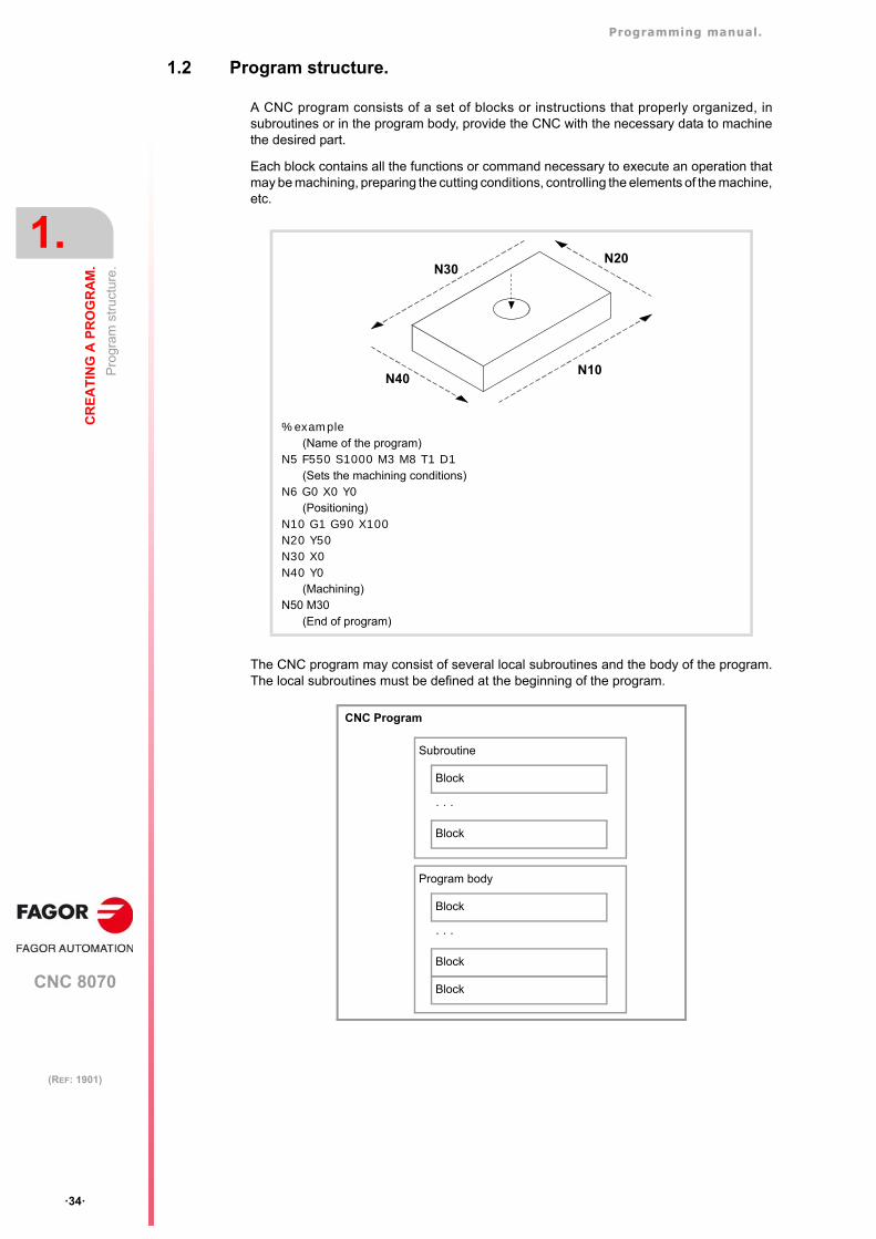
Programming manual.
CNC 8070
1.
CR
EA
TIN
G A
PR
OG
RA
M.
Pro
gram
str
uctu
re.
·34·
(REF: 1901)
1.2 Program structure.
A CNC program consists of a set of blocks or instructions that properly organized, insubroutines or in the program body, provide the CNC with the necessary data to machinethe desired part.
Each block contains all the functions or command necessary to execute an operation thatmay be machining, preparing the cutting conditions, controlling the elements of the machine,etc.
The CNC program may consist of several local subroutines and the body of the program.The local subroutines must be defined at the beginning of the program.
%example(Name of the program)
N5 F550 S1000 M3 M8 T1 D1(Sets the machining conditions)
N6 G0 X0 Y0(Positioning)
N10 G1 G90 X100N20 Y50N30 X0N40 Y0
(Machining)N50 M30
(End of program)
N10
N20N30
N40
CNC Program
Block
· · ·
Block
Subroutine
Block
· · ·
Block
Program body
Block
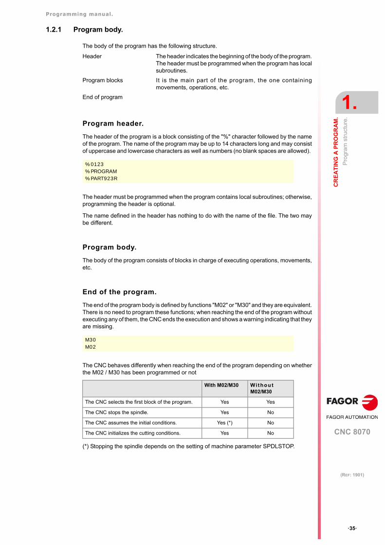
Programming manual.
CNC 8070
CR
EA
TIN
G A
PR
OG
RA
M.
1.
Pro
gram
str
uctu
re.
·35·
(REF: 1901)
1.2.1 Program body.
The body of the program has the following structure.
Program header.
The header of the program is a block consisting of the "%" character followed by the nameof the program. The name of the program may be up to 14 characters long and may consistof uppercase and lowercase characters as well as numbers (no blank spaces are allowed).
The header must be programmed when the program contains local subroutines; otherwise,programming the header is optional.
The name defined in the header has nothing to do with the name of the file. The two maybe different.
Program body.
The body of the program consists of blocks in charge of executing operations, movements,etc.
End of the program.
The end of the program body is defined by functions "M02" or "M30" and they are equivalent.There is no need to program these functions; when reaching the end of the program withoutexecuting any of them, the CNC ends the execution and shows a warning indicating that theyare missing.
The CNC behaves differently when reaching the end of the program depending on whetherthe M02 / M30 has been programmed or not
(*) Stopping the spindle depends on the setting of machine parameter SPDLSTOP.
Header The header indicates the beginning of the body of the program.The header must be programmed when the program has localsubroutines.
Program blocks It is the main part of the program, the one containingmovements, operations, etc.
End of program
%0123%PROGRAM%PART923R
M30M02
With M02/M30 Wi thoutM02/M30
The CNC selects the first block of the program. Yes Yes
The CNC stops the spindle. Yes No
The CNC assumes the initial conditions. Yes (*) No
The CNC initializes the cutting conditions. Yes No
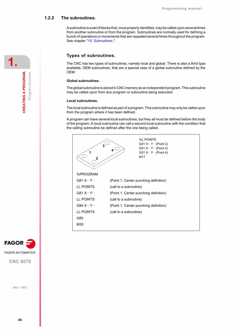
Programming manual.
CNC 8070
1.
CR
EA
TIN
G A
PR
OG
RA
M.
Pro
gram
str
uctu
re.
·36·
(REF: 1901)
1.2.2 The subroutines.
A subroutine is a set of blocks that, once properly identified, may be called upon several timesfrom another subroutine or from the program. Subroutines are normally used for defining abunch of operations or movements that are repeated several times throughout the program.See chapter "15 Subroutines.".
Types of subroutines.
The CNC has two types of subroutines, namely local and global. There is also a third typeavailable, OEM subroutines, that are a special case of a global subroutine defined by theOEM.
Global subroutines.
The global subroutine is stored in CNC memory as an independent program. This subroutinemay be called upon from any program or subroutine being executed.
Local subroutines.
The local subroutine is defined as part of a program. This subroutine may only be called uponfrom the program where it has been defined.
A program can have several local subroutines; but they all must be defined before the bodyof the program. A local subroutine can call a second local subroutine with the condition thatthe calling subroutine be defined after the one being called.
1
3
2
4
%L POINTSG01 X·· Y·· (Point 2)G01 X·· Y·· (Point 3)G01 X·· Y·· (Point 4)M17
%PROGRAM
G81 X·· Y·· (Point 1. Center punching definition)
LL POINTS (call to a subroutine)
G81 X·· Y·· (Point 1. Center punching definition)
LL POINTS (call to a subroutine)
G84 X·· Y·· (Point 1. Center punching definition)
LL POINTS (call to a subroutine)
G80
M30
Programming manual.
CNC 8070
CR
EA
TIN
G A
PR
OG
RA
M.
1.
Pro
gra
m b
lock
str
uctu
re.
·37·
(REF: 1901)
1.3 Program block structure.
The blocks comprising the subroutines or the program body may be defined by commandsin ISO code or in high-level language. Each block must be written in either language but notmixed; a program may combine blocks written in both languages. Empty blocks (empty lines)are also allowed.
In either language, it is also possible to use any type of arithmetic, relational or logicexpression.
Programming in ISO code.
It is especially designed to control the movement of the axes because it provides movementdata and conditions as well as feedrate and speed. Some of the available commands are:
• Preparatory functions for movement establishing the geometry and work conditions suchas linear and circular interpolations, threading, canned cycles, etc.
• Functions to control cutting conditions such as feedrate of the axes, spindle speed andaccelerations.
• Functions to control the tools.
• Complementary functions, with technological instructions.
• Definition of position values.
High-level language programming.
This language provides the user with a set of control commands with a terminology similarto the one used by other languages, such as $IF, $GOTO, #MSG, #HSC, etc. Some availablecommands are:
• Programming instructions.
• Flow controlling instructions to make loops and jumps within the program.
• To define and call upon subroutines with local parameters where a local variable is theone only known to the subroutine where it has been defined.
It is also possible to use any type of arithmetic, relational or logic expression.
Arithmetic parameters, variables, constants and arithmeticexpressions.
Constants, arithmetic parameters, variables and arithmetic expressions may be used fromISO blocks as well as from high level commands.
Programming manual.
CNC 8070
1.
CR
EA
TIN
G A
PR
OG
RA
M.
Pro
gra
m b
lock
str
uctu
re.
·38·
(REF: 1901)
1.3.1 Programming in ISO code.
ISO-coded functions consist of letters and numbers. The letters are "N", "G", "F", "S", "T","D", "M", "H", "NR" plus those identifying the axes.
The numbers include digits "0" through "9", the "+" and "-" signs and the decimal point ".".Likewise, the numerical format may be replaced by a parameter, variable or arithmeticexpression whose result is a number.
Programming allows blank spaces between letters, numbers and a sign as well as not usingthe sign with positive values.
Block structure.
A block may have the following functions, but needs not contain all of them. The data hasno set order, it may be programmed anywhere in the block. The only exception being theblock-skip condition and the block identification which must always be programmed at thebeginning.
·/· Block skip condition.
The block skip condition is governed by the BLKSKIP1 mark of the PLC. If the mark is active,the CNC will skip the blocks where it is programmed (not executing them) and will go on tothe next block.
The control reads various blocks ahead of the one being executed in order to calculate thetool path in advance. The block skip condition will be analyzed at the time when the blockis read, i.e. various blocks before execution. If the block skip needs to be analyzed at thetime of execution, it is necessary to interrupt the block preparation, by programming theinstruction #FLUSH in the previous block.
[LABEL] ·N· Block label.
The labels allow the blocks to be identified. The programming of labels assists in themonitoring of the program and allows block skips and repetitions to be programmed. In thislast case, it is recommended to program the labels alone in the block. See "1.8 Programmingthe block labels." on page 49.
·G· Preparatory functions.
G functions set the geometry and work conditions such as linear and circular interpolations,chamfers, canned cycles, etc. See "1.5 List of "G" functions." on page 42.
·X..C· Coordinates of the point.
These functions set the movement of the axes. See "1.4 Programming of the axes." on page41.
Depending on the units, the programming format will be:
• In millimeters, format ±5.4 (5 integers and 4 decimals).
• In inches, format ±4.5 (4 integers and 5 decimals).
·F· Axis feedrate.
The feedrate is represented by the letter "F" followed by the desired feedrate value.
·S· Spindle speed.
This function sets the spindle speed.
The spindle name is defined by 1 or 2 characters. The first character is the letter S and thesecond character is optional, it must be a numerical suffix between 1 and 9. This way, thename of the spindles may be within the range S, S1 ... S9.
/ N— G— G— X..C— F— S— T— D— M— H— NR—
Programming manual.
CNC 8070
CR
EA
TIN
G A
PR
OG
RA
M.
1.
Pro
gra
m b
lock
str
uctu
re.
·39·
(REF: 1901)
The feedrate is represented by the axis letter followed by the target position for the axis. Forspindles like S1, S2, etc. the "=" sign must be included between the axis name and the speed.
·T· Tool number.
This function selects the tool to be used to carry out the programmed machining operation.The tool is represented by the letter "T" followed by the tool number (0-4294967295).
·D· Tool offset number.
This function selects the tool offset. The tool offset is represented by the letter "D" followedby the tool offset number. The number of offsets available for each tool is defined in the tooltable.
·M H· Auxiliary functions.
With the auxiliary functions, it is possible to control machine elements such as spindle turningdirection, coolant, etc. These functions are represented by the letters "M" or "H" followed bythe function number (0-65535)
·NR· Number of block repetitions.
The NR command indicates the number of times a block is to be executed, and it can onlybe added to blocks when a movement, a canned cycle or a modal subroutine has beenprogrammed. See "14.3 Block repetition (NR)." on page 273.
Block comment .
Any comment may be associated with the blocks. When executing the program, the CNCignores this information.
The CNC offers various methods to include comments in the program. See "1.9 Commentprogramming." on page 50.
S1000S1=334
Programming manual.
CNC 8070
1.
CR
EA
TIN
G A
PR
OG
RA
M.
Pro
gra
m b
lock
str
uctu
re.
·40·
(REF: 1901)
1.3.2 High-level language programming.
The commands of high level language are made up of control instructions "#" and flow controlinstructions "$".
Block structure.
A block may have the following commands, but needs not contain all of them.
·/· Block skip condition.
The block skip condition is governed by the BLKSKIP1 mark of the PLC. If the mark is active,the CNC will skip the blocks where it is programmed (not executing them) and will go on tothe next block.
The control reads various blocks ahead of the one being executed in order to calculate thetool path in advance. The block skip condition will be analyzed at the time when the blockis read, i.e. various blocks before execution. If the block skip needs to be analyzed at thetime of execution, it is necessary to interrupt the block preparation, by programming theinstruction #FLUSH in the previous block.
[LABEL] ·N· Block label.
The labels allow the blocks to be identified. The programming of labels assists in themonitoring of the program and allows block skips and repetitions to be programmed. In thislast case, it is recommended to program the labels alone in the block. See "1.8 Programmingthe block labels." on page 49.
·# $· High-level language commands.
The high-level commands comprise the instructions and flow control instructions.
• Instructions are programmed preceded by the "#" sign and they can only be programmedone per block. They are used to carry out various functions.
• Flow control instructions are programmed preceded by the "$" sign and can only beprogrammed one per block. They are used to make loops and program jumps.
Assigning values to parameters and variables can also be considered as high-levelcommands.
Block comment .
Any comment may be associated with the blocks. When executing the program, the CNCignores this information.
The CNC offers various methods to include comments in the program. See "1.9 Commentprogramming." on page 50.
/ N— <rest of commands>
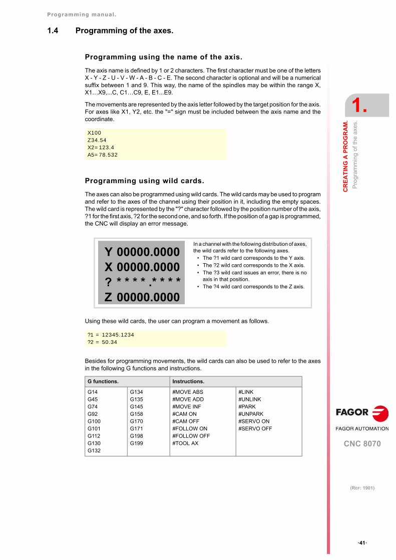
Programming manual.
CNC 8070
CR
EA
TIN
G A
PR
OG
RA
M.
1.
Pro
gram
min
g o
f the
axe
s.
·41·
(REF: 1901)
1.4 Programming of the axes.
Programming using the name of the axis.
The axis name is defined by 1 or 2 characters. The first character must be one of the lettersX - Y - Z - U - V - W - A - B - C - E. The second character is optional and will be a numericalsuffix between 1 and 9. This way, the name of the spindles may be within the range X,X1…X9,...C, C1…C9, E, E1...E9.
The movements are represented by the axis letter followed by the target position for the axis.For axes like X1, Y2, etc. the "=" sign must be included between the axis name and thecoordinate.
Programming using wild cards.
The axes can also be programmed using wild cards. The wild cards may be used to programand refer to the axes of the channel using their position in it, including the empty spaces.The wild card is represented by the "?" character followed by the position number of the axis,?1 for the first axis, ?2 for the second one, and so forth. If the position of a gap is programmed,the CNC will display an error message.
Using these wild cards, the user can program a movement as follows.
Besides for programming movements, the wild cards can also be used to refer to the axesin the following G functions and instructions.
X100Z34.54X2=123.4A5=78.532
In a channel with the following distribution of axes,the wild cards refer to the following axes.
• The ?1 wild card corresponds to the Y axis.• The ?2 wild card corresponds to the X axis.• The ?3 wild card issues an error, there is no
axis in that position. • The ?4 wild card corresponds to the Z axis.
?1 = 12345.1234?2 = 50.34
G functions. Instructions.
G14G45G74G92G100G101G112G130G132
G134G135G145G158G170G171G198G199
#MOVE ABS#MOVE ADD#MOVE INF#CAM ON#CAM OFF#FOLLOW ON#FOLLOW OFF#TOOL AX
#LINK#UNLINK#PARK#UNPARK#SERVO ON#SERVO OFF
YX?Z
00000.000000000.0000* * * * .* * * *00000.0000
Programming manual.
CNC 8070
1.
CR
EA
TIN
G A
PR
OG
RA
M.
List
of "
G"
func
tions
.
·42·
(REF: 1901)
1.5 List of "G" functions.
The following tables show a list of "G" functions available at the CNC. The meaning of the"M", "D" and "V" fields of the table is the following:
Next to each function, it indicates which chapter of this manual describes it; if no chapteris indicated, the function is described in another manual.
·M· Modal function.
A modal function, once programmed, remains active until an incompatible "G" code isprogrammed or an M02 or an M30 or until an EMERGENCY or a RESET is carried out orthe CNC is turned off and back on.
Those cases indicated with "!", mean the function remains active even after an M02, M30or a reset and after the CNC is powered off and back on.
·D· Default function.
It is the function that is activated by default; in other words, the function assumed by the CNCon power-up, after executing an M02 or M30 and after an EMERGENCY or a RESET.
Those cases indicated with "?" mean that the default quality of the function depends on thesettings of the CNC machine parameters.
·V· Displayed function.
The function is displayed in automatic and jog modes next to the current machiningconditions.
·M· Modal function. ·D· Default function.
·V· Displayed function.
Function M D V MeaningG00 * ? * Rapid positioning. 8.1G01 * ? * Linear interpolation. 8.2G02 * * Clockwise circular (helical) interpolation. 8.3 / 8.6G03 * * Counterclockwise circular (helical) interpolation. 8.3 / 8.6G04 * Dwell. 12.1G05 * ? * Controlled corner rounding (modal). 11.3G06 * Arc center in absolute coordinates (not modal). 8.3.9G07 * ? * Square corner (modal). 11.1G08 * Arc tangent to previous path. 8.4G09 * Arc defined by three points. 8.5G10 * * Mirror image cancellation. 11.8G11 * * Mirror image on X. 11.8G12 * * Mirror image on Y. 11.8G13 * * Mirror image on Z. 11.8G14 * * Mirror image in the programmed directions. 11.8G17 * ? * Main plane X-Y, and longitudinal axis Z. 4.2G18 * ? * Main plane Z-X, and longitudinal axis Y. 4.2G19 * * Main plane Y-Z, and longitudinal axis X. 4.2G20 * * Main plane by two directions and longitudinal axis. 4.3G30 * Polar origin preset. 5.7G31 * Temporary polar origin shift to the center of arc. 8.3.8G33 * * Electronic threading with constant pitch. 10.1G34 * * Electronic threading with variable pitch. 10.2G36 * Automatic radius blend. 11.4G37 * Tangential entry. 11.6G38 * Tangential exit. 11.7G39 * Automatic chamfer blend. 11.5G40 * * Cancellation of tool radius compensation. 13.1G41 * * Left-hand tool radius compensation. 13.1G42 * * Right-hand tool radius compensation. 13.1G45 Turn tangential control on and off. 19.1G50 * ? Semi-rounded corner. 11.2G53 * Zero offset cancellation. 5.6G54 ! * Absolute zero offset 1. 5.5G55 ! * Absolute zero offset 2. 5.5G56 ! * Absolute zero offset 3. 5.5
Programming manual.
CNC 8070
CR
EA
TIN
G A
PR
OG
RA
M.
1.
List
of "
G"
func
tions
.
·43·
(REF: 1901)
G57 ! * Absolute zero offset 4. 5.5G58 ! * Absolute zero offset 5. 5.5G59 ! * Absolute zero offset 6. 5.5G60 * Square corner (not modal). 11.1G61 * Controlled corner rounding (not modal). 11.3G63 * * Rigid tapping. 10.3G66 * (·T· model). Pattern repeat canned cycle. - - -G68 * (·T· model). Stock removal cycle along X axis. - - -G69 * (·T· model). Stock removal canned cycle along Z axis. - - -G70 * ? * Programming in inches. 3.1G71 * ? Programming in millimeters. 3.1G72 * Scaling factor. 11.10G73 * * Rotation of the coordinate system. 11.9G74 * Machine reference zero (home) search. 2.4G80 * * (·M· model). Canned cycle cancellation. - - -G81 * * (·M· model). Drilling canned cycle. - - -G81 * (·T· model). Turning canned cycle for straight sections. - - -G82 * * (·M· model). Drilling canned cycle with a variable peck. - - -G82 * (·T· model). Facing canned cycle for straight sections. - - -G83 * * (·M· model). Deep-hole drilling canned cycle with constant peck. - - -G83 * (·T· model). Drilling / tapping canned cycle. - - -G84 * * (·M· model). Tapping canned cycle. - - -G84 * (·T· model). Turning canned cycle for curved sections. - - -G85 * * (·M· model). Reaming canned cycle. - - -G85 * (·T· model). Facing canned cycle for curved sections. - - -G86 * * (·M· model). Boring canned cycle. - - -G86 * (·T· model). Longitudinal threading canned cycle. - - -G87 * * (·M· model). Rectangular pocket canned cycle. - - -G87 * (·T· model). Face threading canned cycle. - - -G88 * * (·M· model). Circular pocket canned cycle. - - -G88 * (·T· model). Grooving canned cycle along the X axis. - - -G89 * (·T· model). Z axis grooving canned cycle. - - -G90 * ? Programming in absolute coordinates. 3.2G91 * ? * Programming in incremental coordinates. 3.2G92 ! * Coordinate preset. 5.4G93 * * Setting machining time in seconds. 6.2.1G94 * ? Feedrate in millimeters/minute (inches/minute). 6.2.1G95 * ? * Feedrate in millimeters/revolution (inches/revolution). 6.2.1G96 * * Constant surface speed. 7.2.2G97 * * Constant turning speed. 7.2.2G98 * * (·M· model). Withdrawal to the starting plane. - - -G99 * * (·M· model). Withdrawal to the reference plane at the end of the
canned cycle.- - -
G100 * Probing until making contact. - - -G101 * Include probe offset. - - -G102 * Exclude probe offset. - - -G103 * Probing until not making contact. - - -G104 Probe movement up to the programmed position. - - -G108 * * Feedrate blending at the beginning of the block. 6.2.2G109 * Feedrate blending at the end of the block. 6.2.2G112 * Changing of parameter range of an axis. 12.4G120 ! Set lower linear limits of the work zone. 11.11.2G121 ! Set upper linear limits of the work zone. 11.11.2G122 * Enable/disable the work zones. 11.11.3G123 ! Set circular limits of the work zone. 11.11.2G130 * * Percentage of acceleration to be applied per axis or spindle. 6.2.5G131 * * Percentage of acceleration to be applied, global. 6.2.5G132 * * Percentage of jerk to be applied per axis or spindle. 6.2.6G133 * * Percentage of jerk to be applied, global. 6.2.6G134 * * Percentage of Feed-Forward to be applied. 6.2.7G135 * * Percentage of AC-Forward to be applied. 6.2.8G136 * * Circular transition between blocks. 13.1.2G137 * * Linear transition between blocks. 13.1.2G138 * * Direct activation/cancellation of tool compensation. 13.1.2G139 * * Indirect activation/cancellation of tool compensation. 13.1.2G145 Freeze tangential control. 19.2G151 * * * Programming in diameters. 3.1
Function M D V Meaning
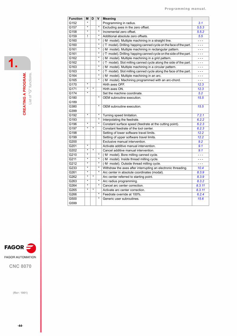
Programming manual.
CNC 8070
1.
CR
EA
TIN
G A
PR
OG
RA
M.
List
of "
G"
func
tions
.
·44·
(REF: 1901)
G152 * Programming in radius. 3.1G157 * * Excluding axes in the zero offset. 5.5.3G158 * * Incremental zero offset. 5.5.2G159 ! * Additional absolute zero offsets. 5.5G160 * (·M· model). Multiple machining in a straight line. - - -G160 * (·T· model). Drilling / tapping canned cycle on the face of the part. - - -G161 * (·M· model). Multiple machining in rectangular pattern. - - -G161 * (·T· model). Drilling / tapping canned cycle on the side of the part. - - -G162 * (·M· model). Multiple machining in a grid pattern. - - -G162 * (·T· model). Slot milling canned cycle along the side of the part. - - -G163 * (·M· model). Multiple machining in a circular pattern. - - -G163 * (·T· model). Slot milling canned cycle along the face of the part. - - -G164 * (·M· model). Multiple machining in an arc. - - -G165 * (·M· model). Machining programmed with an arc-chord. - - -G170 * Hirth axes OFF. 12.3G171 * * Hirth axes ON. 12.3G174 * Set the machine coordinate. 5.2G180G189
* OEM subroutine execution. 15.5
G380G399
* OEM subroutine execution. 15.5
G192 * * Turning speed limitation. 7.2.1G193 * Interpolating the feedrate. 6.2.2G196 * * Constant surface speed (feedrate at the cutting point). 6.2.3G197 * * Constant feedrate of the tool center. 6.2.3G198 Setting of lower software travel limits. 12.2G199 Setting of upper software travel limits. 12.2G200 Exclusive manual intervention. 9.2G201 * Activate additive manual intervention. 9.1G202 * * Cancel additive manual intervention. 9.1G210 * * (·M· model). Bore milling canned cycle. - - -G211 * * (·M· model). Inside thread milling cycle. - - -G212 * * (·M· model). Outside thread milling cycle. - - -G233 * * Withdraw the axes after interrupting an electronic threading. 10.4G261 * * Arc center in absolute coordinates (modal). 8.3.9G262 * * Arc center referred to starting point. 8.3.9G263 * * Arc radius programming. 8.3.2G264 * * Cancel arc center correction. 8.3.11G265 * * Activate arc center correction. 8.3.11G266 * Feedrate override at 100%. 6.2.4G500G599
* Generic user subroutines. 15.6
Function M D V Meaning
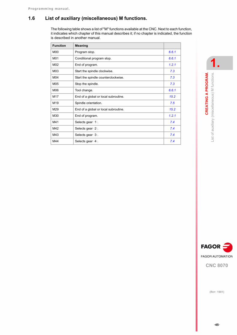
Programming manual.
CNC 8070
CR
EA
TIN
G A
PR
OG
RA
M.
1.
List
of a
uxili
ary
(mis
cella
neo
us)
M fu
nctio
ns.
·45·
(REF: 1901)
1.6 List of auxiliary (miscellaneous) M functions.
The following table shows a list of "M" functions available at the CNC. Next to each function,it indicates which chapter of this manual describes it; if no chapter is indicated, the functionis described in another manual.
Function Meaning
M00 Program stop. 6.6.1
M01 Conditional program stop. 6.6.1
M02 End of program. 1.2.1
M03 Start the spindle clockwise. 7.3
M04 Start the spindle counterclockwise. 7.3
M05 Stop the spindle. 7.3
M06 Tool change. 6.6.1
M17 End of a global or local subroutine. 15.2
M19 Spindle orientation. 7.5
M29 End of a global or local subroutine. 15.2
M30 End of program. 1.2.1
M41 Selects gear ·1·. 7.4
M42 Selects gear ·2·. 7.4
M43 Selects gear ·3·. 7.4
M44 Selects gear ·4·. 7.4
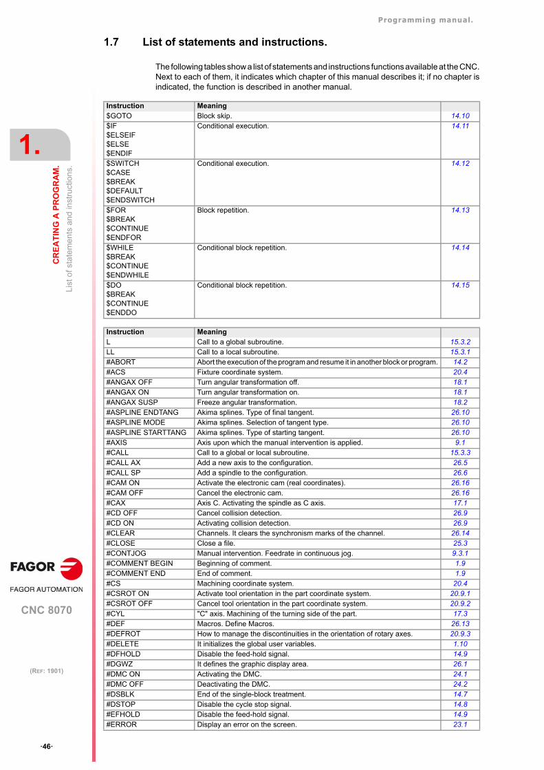
Programming manual.
CNC 8070
1.
CR
EA
TIN
G A
PR
OG
RA
M.
List
of s
tate
me
nts
and
inst
ruct
ions
.
·46·
(REF: 1901)
1.7 List of statements and instructions.
The following tables show a list of statements and instructions functions available at the CNC.Next to each of them, it indicates which chapter of this manual describes it; if no chapter isindicated, the function is described in another manual.
Instruction Meaning$GOTO Block skip. 14.10$IF$ELSEIF$ELSE$ENDIF
Conditional execution. 14.11
$SWITCH$CASE$BREAK$DEFAULT$ENDSWITCH
Conditional execution. 14.12
$FOR$BREAK$CONTINUE$ENDFOR
Block repetition. 14.13
$WHILE$BREAK$CONTINUE$ENDWHILE
Conditional block repetition. 14.14
$DO$BREAK$CONTINUE$ENDDO
Conditional block repetition. 14.15
Instruction MeaningL Call to a global subroutine. 15.3.2LL Call to a local subroutine. 15.3.1#ABORT Abort the execution of the program and resume it in another block or program. 14.2#ACS Fixture coordinate system. 20.4#ANGAX OFF Turn angular transformation off. 18.1#ANGAX ON Turn angular transformation on. 18.1#ANGAX SUSP Freeze angular transformation. 18.2#ASPLINE ENDTANG Akima splines. Type of final tangent. 26.10#ASPLINE MODE Akima splines. Selection of tangent type. 26.10#ASPLINE STARTTANG Akima splines. Type of starting tangent. 26.10#AXIS Axis upon which the manual intervention is applied. 9.1#CALL Call to a global or local subroutine. 15.3.3#CALL AX Add a new axis to the configuration. 26.5#CALL SP Add a spindle to the configuration. 26.6#CAM ON Activate the electronic cam (real coordinates). 26.16#CAM OFF Cancel the electronic cam. 26.16#CAX Axis C. Activating the spindle as C axis. 17.1#CD OFF Cancel collision detection. 26.9#CD ON Activating collision detection. 26.9#CLEAR Channels. It clears the synchronism marks of the channel. 26.14#CLOSE Close a file. 25.3#CONTJOG Manual intervention. Feedrate in continuous jog. 9.3.1#COMMENT BEGIN Beginning of comment. 1.9#COMMENT END End of comment. 1.9#CS Machining coordinate system. 20.4#CSROT ON Activate tool orientation in the part coordinate system. 20.9.1#CSROT OFF Cancel tool orientation in the part coordinate system. 20.9.2#CYL "C" axis. Machining of the turning side of the part. 17.3#DEF Macros. Define Macros. 26.13#DEFROT How to manage the discontinuities in the orientation of rotary axes. 20.9.3#DELETE It initializes the global user variables. 1.10#DFHOLD Disable the feed-hold signal. 14.9#DGWZ It defines the graphic display area. 26.1#DMC ON Activating the DMC. 24.1#DMC OFF Deactivating the DMC. 24.2#DSBLK End of the single-block treatment. 14.7#DSTOP Disable the cycle stop signal. 14.8#EFHOLD Disable the feed-hold signal. 14.9#ERROR Display an error on the screen. 23.1
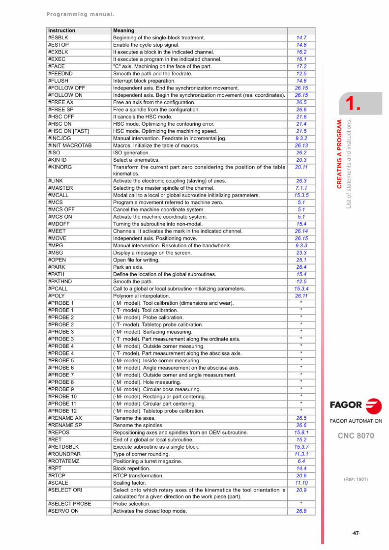
Programming manual.
CNC 8070
CR
EA
TIN
G A
PR
OG
RA
M.
1.
List
of s
tate
me
nts
and
inst
ruct
ions
.
·47·
(REF: 1901)
#ESBLK Beginning of the single-block treatment. 14.7#ESTOP Enable the cycle stop signal. 14.8#EXBLK It executes a block in the indicated channel. 16.2#EXEC It executes a program in the indicated channel. 16.1#FACE "C" axis. Machining on the face of the part. 17.2#FEEDND Smooth the path and the feedrate. 12.5#FLUSH Interrupt block preparation. 14.6#FOLLOW OFF Independent axis. End the synchronization movement. 26.15#FOLLOW ON Independent axis. Begin the synchronization movement (real coordinates). 26.15#FREE AX Free an axis from the configuration. 26.5#FREE SP Free a spindle from the configuration. 26.6#HSC OFF It cancels the HSC mode. 21.6#HSC ON HSC mode. Optimizing the contouring error. 21.4#HSC ON [FAST] HSC mode. Optimizing the machining speed. 21.5#INCJOG Manual intervention. Feedrate in incremental jog. 9.3.2#INIT MACROTAB Macros. Initialize the table of macros. 26.13#ISO ISO generation. 26.2#KIN ID Select a kinematics. 20.3#KINORG Transform the current part zero considering the position of the table
kinematics.20.11
#LINK Activate the electronic coupling (slaving) of axes. 26.3#MASTER Selecting the master spindle of the channel. 7.1.1#MCALL Modal call to a local or global subroutine initializing parameters. 15.3.5#MCS Program a movement referred to machine zero. 5.1#MCS OFF Cancel the machine coordinate system. 5.1#MCS ON Activate the machine coordinate system. 5.1#MDOFF Turning the subroutine into non-modal. 15.4#MEET Channels. It activates the mark in the indicated channel. 26.14#MOVE Independent axis. Positioning move. 26.15#MPG Manual intervention. Resolution of the handwheels. 9.3.3#MSG Display a message on the screen. 23.3#OPEN Open file for writing. 25.1#PARK Park an axis. 26.4#PATH Define the location of the global subroutines. 15.4#PATHND Smooth the path. 12.5#PCALL Call to a global or local subroutine initializing parameters. 15.3.4#POLY Polynomial interpolation. 26.11#PROBE 1 (·M· model). Tool calibration (dimensions and wear). *#PROBE 1 (·T· model). Tool calibration. *#PROBE 2 (·M· model). Probe calibration. *#PROBE 2 (·T· model). Tabletop probe calibration. *#PROBE 3 (·M· model). Surfacing measuring. *#PROBE 3 (·T· model). Part measurement along the ordinate axis. *#PROBE 4 (·M· model). Outside corner measuring. *#PROBE 4 (·T· model). Part measurement along the abscissa axis. *#PROBE 5 (·M· model). Inside corner measuring. *#PROBE 6 (·M· model). Angle measurement on the abscissa axis. *#PROBE 7 (·M· model). Outside corner and angle measurement. *#PROBE 8 (·M· model). Hole measuring. *#PROBE 9 (·M· model). Circular boss measuring. *#PROBE 10 (·M· model). Rectangular part centering. *#PROBE 11 (·M· model). Circular part centering. *#PROBE 12 (·M· model). Tabletop probe calibration. *#RENAME AX Rename the axes. 26.5#RENAME SP Rename the spindles. 26.6#REPOS Repositioning axes and spindles from an OEM subroutine. 15.8.1#RET End of a global or local subroutine. 15.2#RETDSBLK Execute subroutine as a single block. 15.3.7#ROUNDPAR Type of corner rounding. 11.3.1#ROTATEMZ Positioning a turret magazine. 6.4#RPT Block repetition. 14.4#RTCP RTCP transformation. 20.6#SCALE Scaling factor. 11.10#SELECT ORI Select onto which rotary axes of the kinematics the tool orientation is
calculated for a given direction on the work piece (part). 20.9
#SELECT PROBE Probe selection. *#SERVO ON Activates the closed loop mode. 26.8
Instruction Meaning
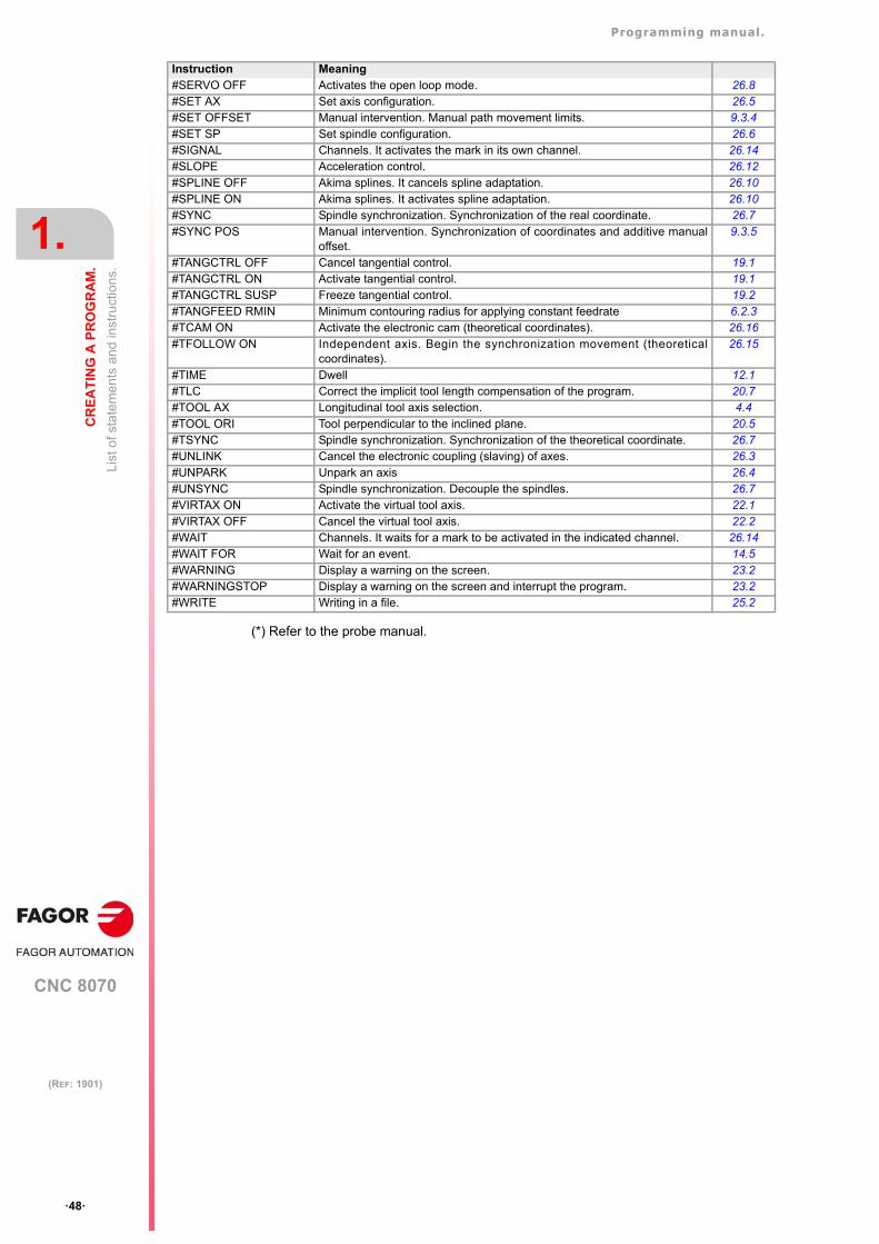
Programming manual.
CNC 8070
1.
CR
EA
TIN
G A
PR
OG
RA
M.
List
of s
tate
me
nts
and
inst
ruct
ions
.
·48·
(REF: 1901)
(*) Refer to the probe manual.
#SERVO OFF Activates the open loop mode. 26.8#SET AX Set axis configuration. 26.5#SET OFFSET Manual intervention. Manual path movement limits. 9.3.4#SET SP Set spindle configuration. 26.6#SIGNAL Channels. It activates the mark in its own channel. 26.14#SLOPE Acceleration control. 26.12#SPLINE OFF Akima splines. It cancels spline adaptation. 26.10#SPLINE ON Akima splines. It activates spline adaptation. 26.10#SYNC Spindle synchronization. Synchronization of the real coordinate. 26.7#SYNC POS Manual intervention. Synchronization of coordinates and additive manual
offset.9.3.5
#TANGCTRL OFF Cancel tangential control. 19.1#TANGCTRL ON Activate tangential control. 19.1#TANGCTRL SUSP Freeze tangential control. 19.2#TANGFEED RMIN Minimum contouring radius for applying constant feedrate 6.2.3#TCAM ON Activate the electronic cam (theoretical coordinates). 26.16#TFOLLOW ON Independent axis. Begin the synchronization movement (theoretical
coordinates).26.15
#TIME Dwell 12.1#TLC Correct the implicit tool length compensation of the program. 20.7#TOOL AX Longitudinal tool axis selection. 4.4#TOOL ORI Tool perpendicular to the inclined plane. 20.5#TSYNC Spindle synchronization. Synchronization of the theoretical coordinate. 26.7#UNLINK Cancel the electronic coupling (slaving) of axes. 26.3#UNPARK Unpark an axis 26.4#UNSYNC Spindle synchronization. Decouple the spindles. 26.7#VIRTAX ON Activate the virtual tool axis. 22.1#VIRTAX OFF Cancel the virtual tool axis. 22.2#WAIT Channels. It waits for a mark to be activated in the indicated channel. 26.14#WAIT FOR Wait for an event. 14.5#WARNING Display a warning on the screen. 23.2#WARNINGSTOP Display a warning on the screen and interrupt the program. 23.2#WRITE Writing in a file. 25.2
Instruction Meaning
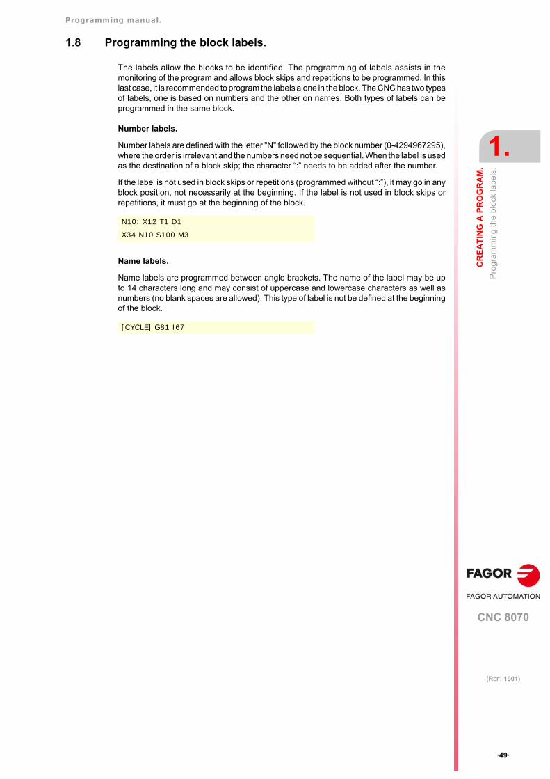
Programming manual.
CNC 8070
CR
EA
TIN
G A
PR
OG
RA
M.
1.
Pro
gra
mm
ing
the
bloc
k la
bel
s.
·49·
(REF: 1901)
1.8 Programming the block labels.
The labels allow the blocks to be identified. The programming of labels assists in themonitoring of the program and allows block skips and repetitions to be programmed. In thislast case, it is recommended to program the labels alone in the block. The CNC has two typesof labels, one is based on numbers and the other on names. Both types of labels can beprogrammed in the same block.
Number labels.
Number labels are defined with the letter "N" followed by the block number (0-4294967295),where the order is irrelevant and the numbers need not be sequential. When the label is usedas the destination of a block skip; the character “:” needs to be added after the number.
If the label is not used in block skips or repetitions (programmed without “:”), it may go in anyblock position, not necessarily at the beginning. If the label is not used in block skips orrepetitions, it must go at the beginning of the block.
Name labels.
Name labels are programmed between angle brackets. The name of the label may be upto 14 characters long and may consist of uppercase and lowercase characters as well asnumbers (no blank spaces are allowed). This type of label is not be defined at the beginningof the block.
N10: X12 T1 D1
X34 N10 S100 M3
[CYCLE] G81 I67
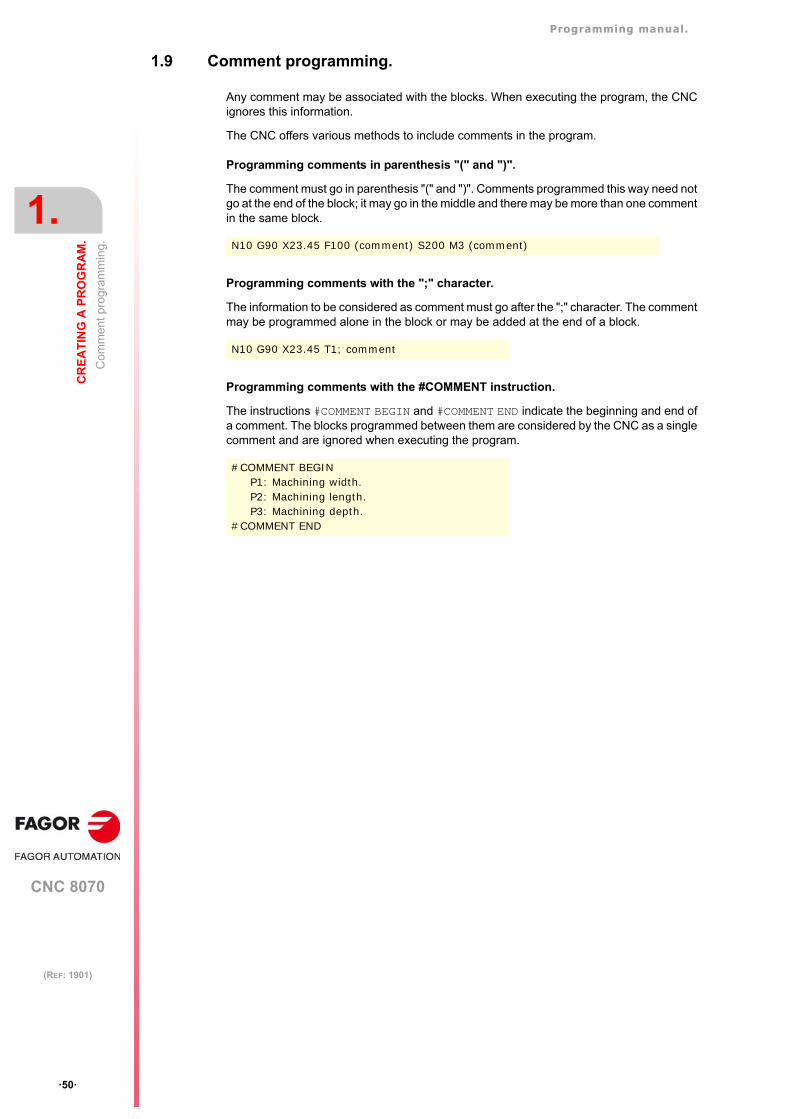
Programming manual.
CNC 8070
1.
CR
EA
TIN
G A
PR
OG
RA
M.
Com
men
t pro
gra
mm
ing.
·50·
(REF: 1901)
1.9 Comment programming.
Any comment may be associated with the blocks. When executing the program, the CNCignores this information.
The CNC offers various methods to include comments in the program.
Programming comments in parenthesis "(" and ")".
The comment must go in parenthesis "(" and ")". Comments programmed this way need notgo at the end of the block; it may go in the middle and there may be more than one commentin the same block.
Programming comments with the ";" character.
The information to be considered as comment must go after the ";" character. The commentmay be programmed alone in the block or may be added at the end of a block.
Programming comments with the #COMMENT instruction.
The instructions #COMMENT BEGIN and #COMMENT END indicate the beginning and end ofa comment. The blocks programmed between them are considered by the CNC as a singlecomment and are ignored when executing the program.
N10 G90 X23.45 F100 (comment) S200 M3 (comment)
N10 G90 X23.45 T1; comment
#COMMENT BEGINP1: Machining width.P2: Machining length.P3: Machining depth.
#COMMENT END
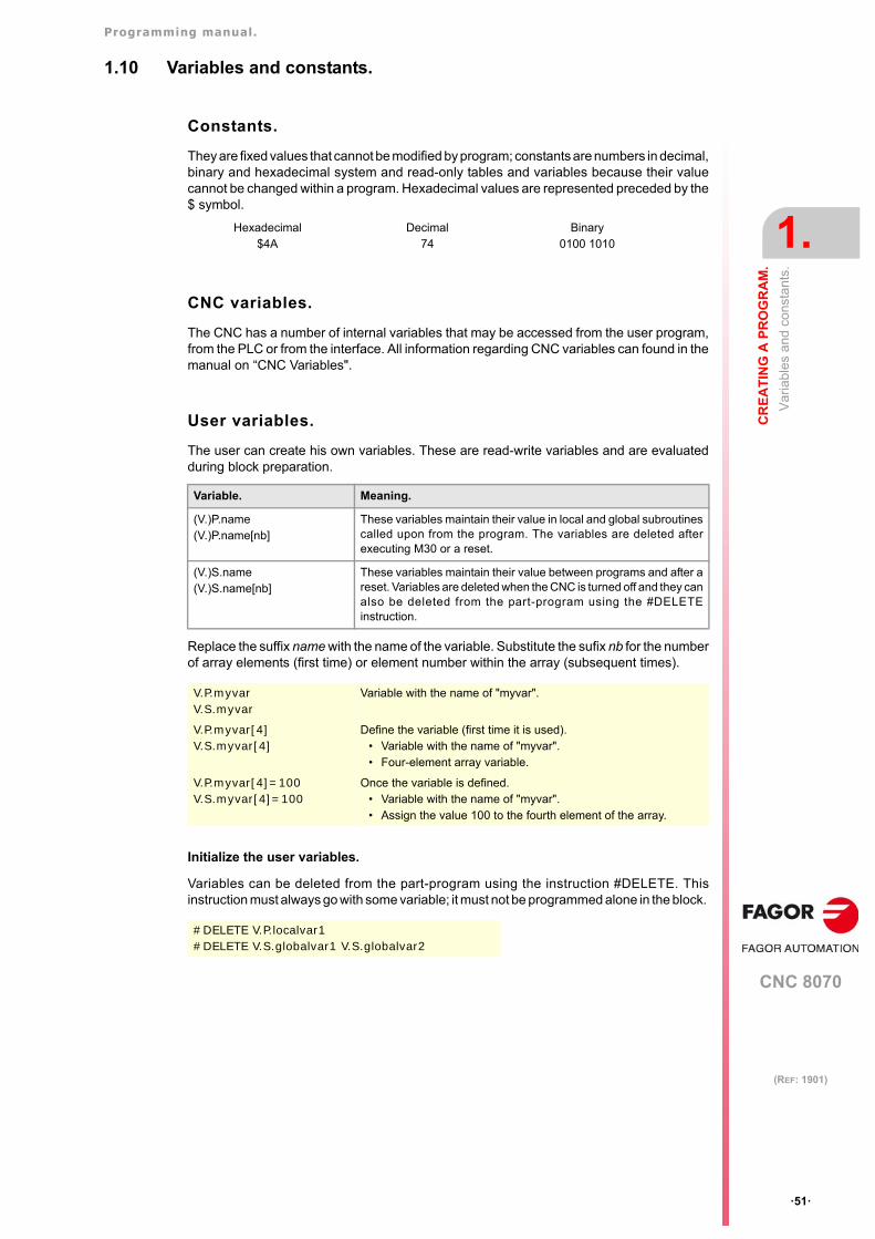
Programming manual.
CNC 8070
CR
EA
TIN
G A
PR
OG
RA
M.
1.
Va
riabl
es a
nd c
onst
ants
.
·51·
(REF: 1901)
1.10 Variables and constants.
Constants.
They are fixed values that cannot be modified by program; constants are numbers in decimal,binary and hexadecimal system and read-only tables and variables because their valuecannot be changed within a program. Hexadecimal values are represented preceded by the$ symbol.
CNC variables.
The CNC has a number of internal variables that may be accessed from the user program,from the PLC or from the interface. All information regarding CNC variables can found in themanual on “CNC Variables".
User variables.
The user can create his own variables. These are read-write variables and are evaluatedduring block preparation.
Replace the suffix name with the name of the variable. Substitute the sufix nb for the numberof array elements (first time) or element number within the array (subsequent times).
Initialize the user variables.
Variables can be deleted from the part-program using the instruction #DELETE. Thisinstruction must always go with some variable; it must not be programmed alone in the block.
Hexadecimal$4A
Decimal 74
Binary0100 1010
Variable. Meaning.
(V.)P.name(V.)P.name[nb]
These variables maintain their value in local and global subroutinescalled upon from the program. The variables are deleted afterexecuting M30 or a reset.
(V.)S.name(V.)S.name[nb]
These variables maintain their value between programs and after areset. Variables are deleted when the CNC is turned off and they canalso be deleted from the part-program using the #DELETEinstruction.
V.P.myvarV.S.myvar
Variable with the name of "myvar".
V.P.myvar[4]V.S.myvar[4]
Define the variable (first time it is used).• Variable with the name of "myvar".• Four-element array variable.
V.P.myvar[4]=100V.S.myvar[4]=100
Once the variable is defined.• Variable with the name of "myvar".• Assign the value 100 to the fourth element of the array.
#DELETE V.P.localvar1#DELETE V.S.globalvar1 V.S.globalvar2
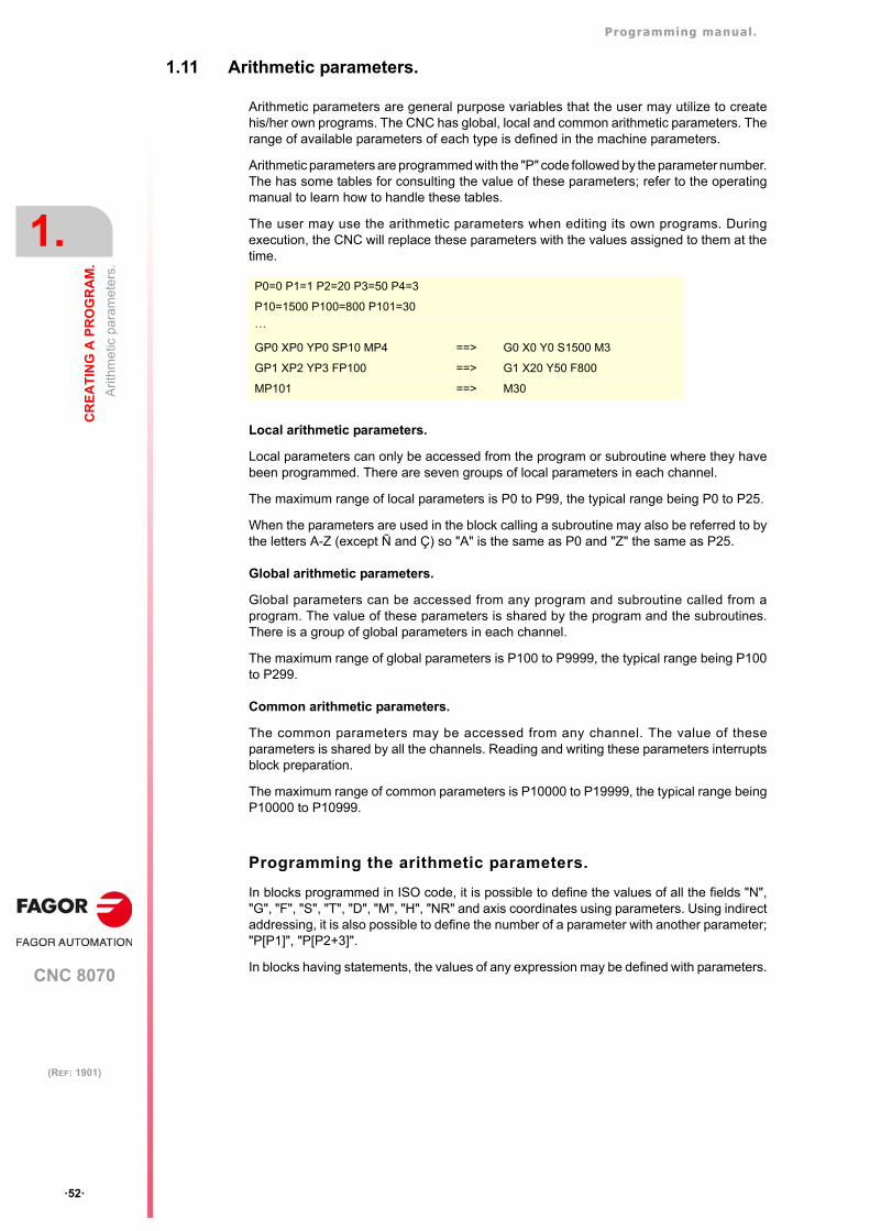
Programming manual.
CNC 8070
1.
CR
EA
TIN
G A
PR
OG
RA
M.
Arit
hmet
ic p
aram
eter
s.
·52·
(REF: 1901)
1.11 Arithmetic parameters.
Arithmetic parameters are general purpose variables that the user may utilize to createhis/her own programs. The CNC has global, local and common arithmetic parameters. Therange of available parameters of each type is defined in the machine parameters.
Arithmetic parameters are programmed with the "P" code followed by the parameter number.The has some tables for consulting the value of these parameters; refer to the operatingmanual to learn how to handle these tables.
The user may use the arithmetic parameters when editing its own programs. Duringexecution, the CNC will replace these parameters with the values assigned to them at thetime.
Local arithmetic parameters.
Local parameters can only be accessed from the program or subroutine where they havebeen programmed. There are seven groups of local parameters in each channel.
The maximum range of local parameters is P0 to P99, the typical range being P0 to P25.
When the parameters are used in the block calling a subroutine may also be referred to bythe letters A-Z (except Ñ and Ç) so "A" is the same as P0 and "Z" the same as P25.
Global arithmetic parameters.
Global parameters can be accessed from any program and subroutine called from aprogram. The value of these parameters is shared by the program and the subroutines.There is a group of global parameters in each channel.
The maximum range of global parameters is P100 to P9999, the typical range being P100to P299.
Common arithmetic parameters.
The common parameters may be accessed from any channel. The value of theseparameters is shared by all the channels. Reading and writing these parameters interruptsblock preparation.
The maximum range of common parameters is P10000 to P19999, the typical range beingP10000 to P10999.
Programming the arithmetic parameters.
In blocks programmed in ISO code, it is possible to define the values of all the fields "N","G", "F", "S", "T", "D", "M", "H", "NR" and axis coordinates using parameters. Using indirectaddressing, it is also possible to define the number of a parameter with another parameter;"P[P1]", "P[P2+3]".
In blocks having statements, the values of any expression may be defined with parameters.
P0=0 P1=1 P2=20 P3=50 P4=3
P10=1500 P100=800 P101=30
···
GP0 XP0 YP0 SP10 MP4 ==> G0 X0 Y0 S1500 M3
GP1 XP2 YP3 FP100 ==> G1 X20 Y50 F800
MP101 ==> M30
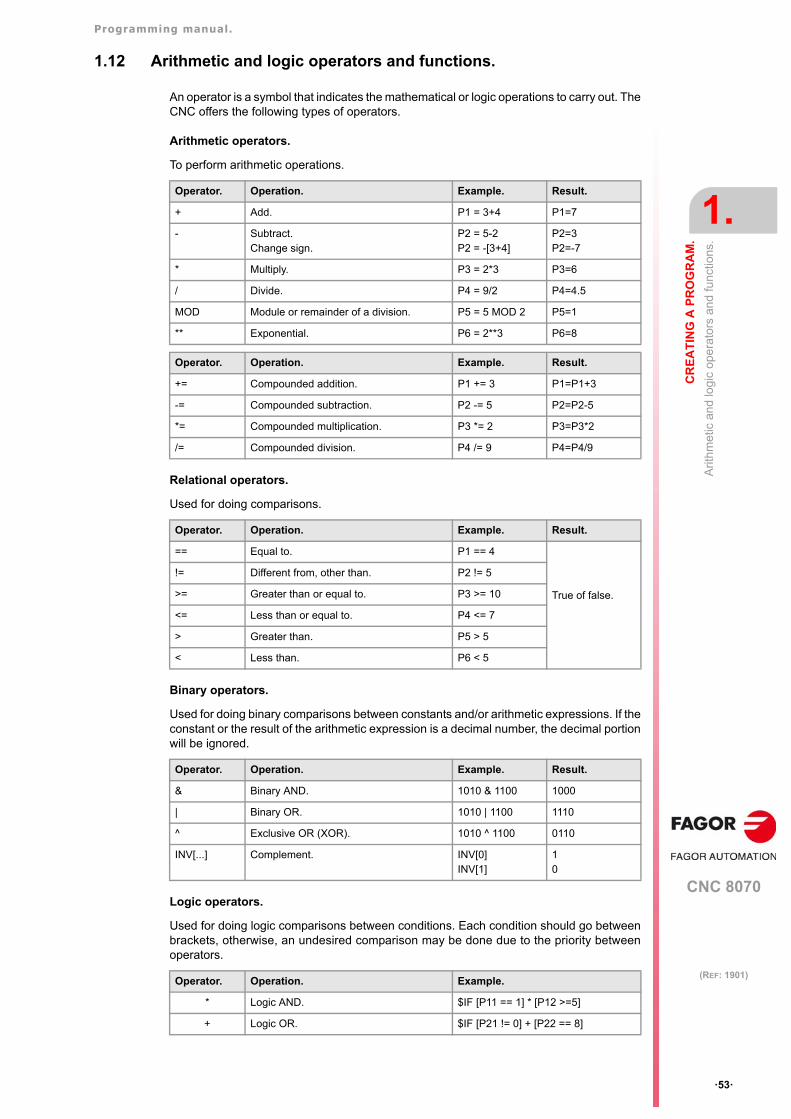
Programming manual.
CNC 8070
CR
EA
TIN
G A
PR
OG
RA
M.
1.
Arit
hmet
ic a
nd lo
gic
ope
rato
rs a
nd
func
tions
.
·53·
(REF: 1901)
1.12 Arithmetic and logic operators and functions.
An operator is a symbol that indicates the mathematical or logic operations to carry out. TheCNC offers the following types of operators.
Arithmetic operators.
To perform arithmetic operations.
Relational operators.
Used for doing comparisons.
Binary operators.
Used for doing binary comparisons between constants and/or arithmetic expressions. If theconstant or the result of the arithmetic expression is a decimal number, the decimal portionwill be ignored.
Logic operators.
Used for doing logic comparisons between conditions. Each condition should go betweenbrackets, otherwise, an undesired comparison may be done due to the priority betweenoperators.
Operator. Operation. Example. Result.
+ Add. P1 = 3+4 P1=7
- Subtract.Change sign.
P2 = 5-2P2 = -[3+4]
P2=3P2=-7
* Multiply. P3 = 2*3 P3=6
/ Divide. P4 = 9/2 P4=4.5
MOD Module or remainder of a division. P5 = 5 MOD 2 P5=1
** Exponential. P6 = 2**3 P6=8
Operator. Operation. Example. Result.
+= Compounded addition. P1 += 3 P1=P1+3
-= Compounded subtraction. P2 -= 5 P2=P2-5
*= Compounded multiplication. P3 *= 2 P3=P3*2
/= Compounded division. P4 /= 9 P4=P4/9
Operator. Operation. Example. Result.
== Equal to. P1 == 4
True of false.
!= Different from, other than. P2 != 5
>= Greater than or equal to. P3 >= 10
<= Less than or equal to. P4 <= 7
> Greater than. P5 > 5
< Less than. P6 < 5
Operator. Operation. Example. Result.
& Binary AND. 1010 & 1100 1000
| Binary OR. 1010 | 1100 1110
^ Exclusive OR (XOR). 1010 ^ 1100 0110
INV[...] Complement. INV[0]INV[1]
10
Operator. Operation. Example.
* Logic AND. $IF [P11 == 1] * [P12 >=5]
+ Logic OR. $IF [P21 != 0] + [P22 == 8]
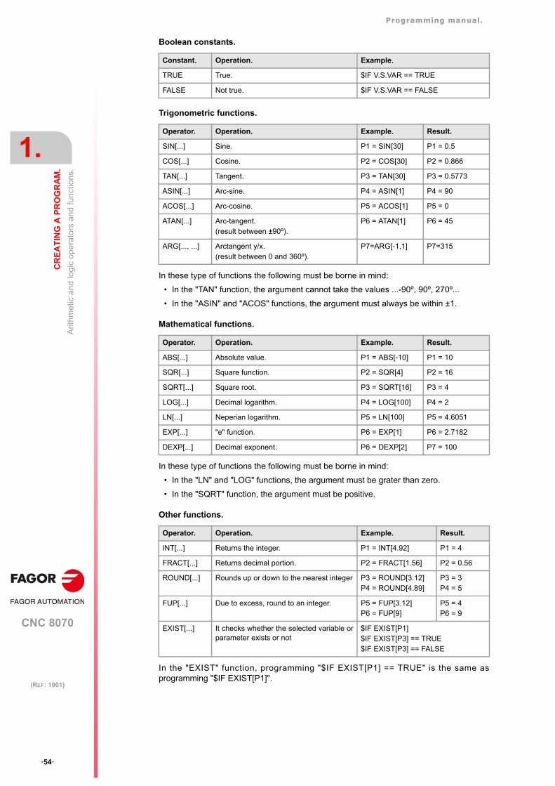
Programming manual.
CNC 8070
1.
CR
EA
TIN
G A
PR
OG
RA
M.
Arit
hmet
ic a
nd lo
gic
ope
rato
rs a
nd
func
tions
.
·54·
(REF: 1901)
Boolean constants.
Trigonometric functions.
In these type of functions the following must be borne in mind:
• In the "TAN" function, the argument cannot take the values ...-90º, 90º, 270º...
• In the "ASIN" and "ACOS" functions, the argument must always be within ±1.
Mathematical functions.
In these type of functions the following must be borne in mind:
• In the "LN" and "LOG" functions, the argument must be grater than zero.
• In the "SQRT" function, the argument must be positive.
Other functions.
In the "EXIST" function, programming "$IF EXIST[P1] == TRUE" is the same asprogramming "$IF EXIST[P1]".
Constant. Operation. Example.
TRUE True. $IF V.S.VAR == TRUE
FALSE Not true. $IF V.S.VAR == FALSE
Operator. Operation. Example. Result.
SIN[...] Sine. P1 = SIN[30] P1 = 0.5
COS[...] Cosine. P2 = COS[30] P2 = 0.866
TAN[...] Tangent. P3 = TAN[30] P3 = 0.5773
ASIN[...] Arc-sine. P4 = ASIN[1] P4 = 90
ACOS[...] Arc-cosine. P5 = ACOS[1] P5 = 0
ATAN[...] Arc-tangent.(result between ±90º).
P6 = ATAN[1] P6 = 45
ARG[..., ...] Arctangent y/x.(result between 0 and 360º).
P7=ARG[-1,1] P7=315
Operator. Operation. Example. Result.
ABS[...] Absolute value. P1 = ABS[-10] P1 = 10
SQR[...] Square function. P2 = SQR[4] P2 = 16
SQRT[...] Square root. P3 = SQRT[16] P3 = 4
LOG[...] Decimal logarithm. P4 = LOG[100] P4 = 2
LN[...] Neperian logarithm. P5 = LN[100] P5 = 4.6051
EXP[...] "e" function. P6 = EXP[1] P6 = 2.7182
DEXP[...] Decimal exponent. P6 = DEXP[2] P7 = 100
Operator. Operation. Example. Result.
INT[...] Returns the integer. P1 = INT[4.92] P1 = 4
FRACT[...] Returns decimal portion. P2 = FRACT[1.56] P2 = 0.56
ROUND[...] Rounds up or down to the nearest integer P3 = ROUND[3.12]P4 = ROUND[4.89]
P3 = 3P4 = 5
FUP[...] Due to excess, round to an integer. P5 = FUP[3.12]P6 = FUP[9]
P5 = 4P6 = 9
EXIST[...] It checks whether the selected variable orparameter exists or not
$IF EXIST[P1]$IF EXIST[P3] == TRUE$IF EXIST[P3] == FALSE
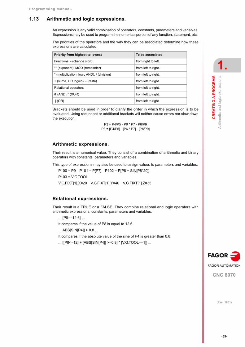
Programming manual.
CNC 8070
CR
EA
TIN
G A
PR
OG
RA
M.
1.
Arit
hmet
ic a
nd lo
gic
expr
ess
ions
.
·55·
(REF: 1901)
1.13 Arithmetic and logic expressions.
An expression is any valid combination of operators, constants, parameters and variables.Expressions may be used to program the numerical portion of any function, statement, etc.
The priorities of the operators and the way they can be associated determine how theseexpressions are calculated:
Brackets should be used in order to clarify the order in which the expression is to beevaluated. Using redundant or additional brackets will neither cause errors nor slow downthe execution.
P3 = P4/P5 - P6 * P7 - P8/P9P3 = [P4/P5] - [P6 * P7] - [P8/P9]
Arithmetic expressions.
Their result is a numerical value. They consist of a combination of arithmetic and binaryoperators with constants, parameters and variables.
This type of expressions may also be used to assign values to parameters and variables:
P100 = P9 P101 = P[P7] P102 = P[P8 + SIN[P8*20]]
P103 = V.G.TOOL
V.G.FIXT[1].X=20 V.G.FIXT[1].Y=40 V.G.FIXT[1].Z=35
Relational expressions.
Their result is a TRUE or a FALSE. They combine relational and logic operators witharithmetic expressions, constants, parameters and variables.
... [P8==12.6] ...
It compares if the value of P8 is equal to 12.6.
... ABS[SIN[P4]] > 0.8 ...
It compares if the absolute value of the sine of P4 is greater than 0.8.
... [[P8<=12] + [ABS[SIN[P4]] >=0.8] * [V.G.TOOL==1]] ...
Priority from highest to lowest To be associated
Functions, - (change sign) from right to left.
** (exponent), MOD (remainder) from left to right.
* (multiplication, logic AND), / (division) from left to right.
+ (suma, OR lógico), - (resta) from left to right.
Relational operators from left to right.
& (AND),^ (XOR) from left to right.
| (OR) from left to right.
Programming manual.
CNC 8070
1.
CR
EA
TIN
G A
PR
OG
RA
M.
Arit
hmet
ic a
nd lo
gic
expr
ess
ions
.
·56·
(REF: 1901)

CNC 8070
2
·57·
(REF: 1901)
2. MACHINE OVERVIEW
2.1 Axis nomenclature
With this CNC, the manufacturer may select up to 28 axes (that must be properly definedas linear, rotary, etc. by setting machine parameters), without no limitation as how to programthem and they may all be interpolated at the same time.
The DIN 66217 standard denomination for the axes is:
However, the machine manufacturer may call the axes differently.
As an option, the name of the axes may be followed by a number between 1 and 9 (X1, X3,Y5, A8...).
X-Y-Z Main axes of the machine. The X-Y axes form the main work plane whereas theZ axis is parallel to the main axis of the machine and perpendicular to the XYplane.
U-V-W Auxiliary axes, parallel to X-Y-Z respectively.
A-B-C Rotary axes, on X-Y-Z respectively.
E Extrusion axis for additive manufacturing machines or 3D printing.
Axis nomenclature on different machines.
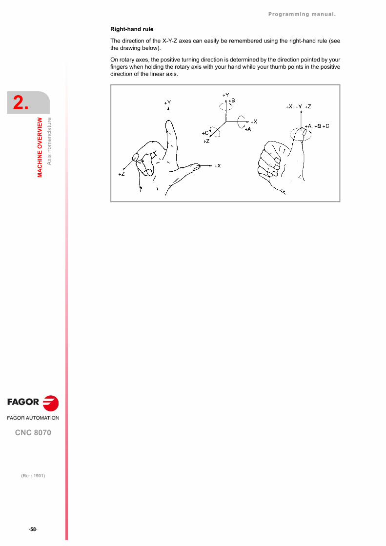
Programming manual.
CNC 8070
2.
MA
CH
INE
OV
ER
VIE
W
Axi
s n
omen
cla
ture
·58·
(REF: 1901)
Right-hand rule
The direction of the X-Y-Z axes can easily be remembered using the right-hand rule (seethe drawing below).
On rotary axes, the positive turning direction is determined by the direction pointed by yourfingers when holding the rotary axis with your hand while your thumb points in the positivedirection of the linear axis.
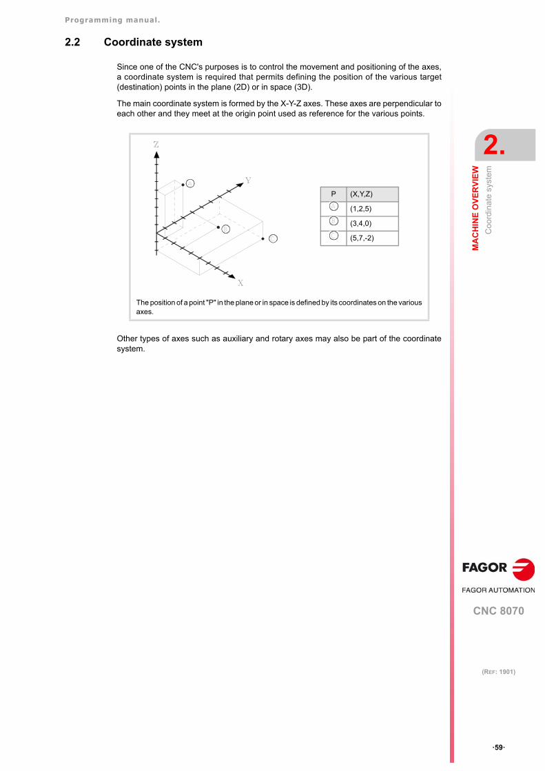
Programming manual.
CNC 8070
MA
CH
INE
OV
ER
VIE
W
2.
Coo
rdin
ate
syst
em
·59·
(REF: 1901)
2.2 Coordinate system
Since one of the CNC's purposes is to control the movement and positioning of the axes,a coordinate system is required that permits defining the position of the various target(destination) points in the plane (2D) or in space (3D).
The main coordinate system is formed by the X-Y-Z axes. These axes are perpendicular toeach other and they meet at the origin point used as reference for the various points.
Other types of axes such as auxiliary and rotary axes may also be part of the coordinatesystem.
The position of a point "P" in the plane or in space is defined by its coordinates on the variousaxes.
P (X,Y,Z)
(1,2,5)
(3,4,0)
(5,7,-2)
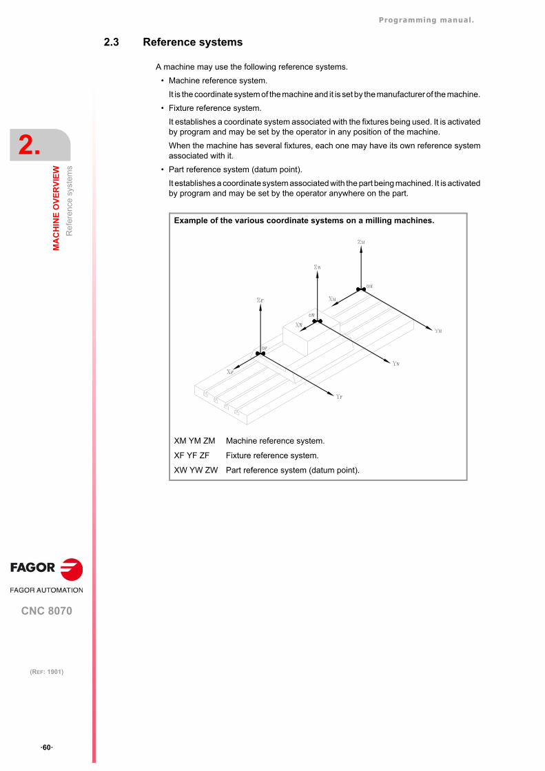
Programming manual.
CNC 8070
2.
MA
CH
INE
OV
ER
VIE
W
Ref
eren
ce s
yste
ms
·60·
(REF: 1901)
2.3 Reference systems
A machine may use the following reference systems.
• Machine reference system.
It is the coordinate system of the machine and it is set by the manufacturer of the machine.
• Fixture reference system.
It establishes a coordinate system associated with the fixtures being used. It is activatedby program and may be set by the operator in any position of the machine.
When the machine has several fixtures, each one may have its own reference systemassociated with it.
• Part reference system (datum point).
It establishes a coordinate system associated with the part being machined. It is activatedby program and may be set by the operator anywhere on the part.
Example of the various coordinate systems on a milling machines.
XM YM ZM Machine reference system.
XF YF ZF Fixture reference system.
XW YW ZW Part reference system (datum point).
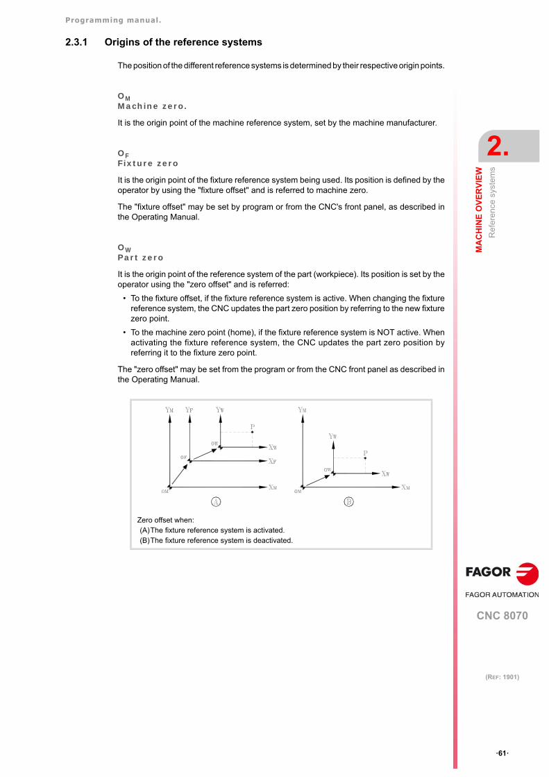
Programming manual.
CNC 8070
MA
CH
INE
OV
ER
VIE
W
2.
Ref
eren
ce s
yste
ms
·61·
(REF: 1901)
2.3.1 Origins of the reference systems
The position of the different reference systems is determined by their respective origin points.
OMMachine zero.
It is the origin point of the machine reference system, set by the machine manufacturer.
OFFixture zero
It is the origin point of the fixture reference system being used. Its position is defined by theoperator by using the "fixture offset" and is referred to machine zero.
The "fixture offset" may be set by program or from the CNC's front panel, as described inthe Operating Manual.
OWPart zero
It is the origin point of the reference system of the part (workpiece). Its position is set by theoperator using the "zero offset" and is referred:
• To the fixture offset, if the fixture reference system is active. When changing the fixturereference system, the CNC updates the part zero position by referring to the new fixturezero point.
• To the machine zero point (home), if the fixture reference system is NOT active. Whenactivating the fixture reference system, the CNC updates the part zero position byreferring it to the fixture zero point.
The "zero offset" may be set from the program or from the CNC front panel as described inthe Operating Manual.
Zero offset when:(A)The fixture reference system is activated.(B)The fixture reference system is deactivated.
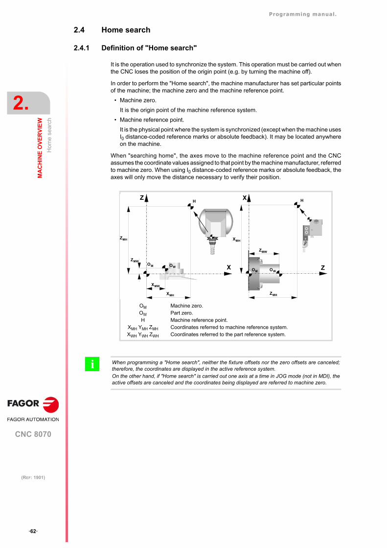
Programming manual.
CNC 8070
2.
MA
CH
INE
OV
ER
VIE
W
Hom
e s
earc
h
·62·
(REF: 1901)
2.4 Home search
2.4.1 Definition of "Home search"
It is the operation used to synchronize the system. This operation must be carried out whenthe CNC loses the position of the origin point (e.g. by turning the machine off).
In order to perform the "Home search", the machine manufacturer has set particular pointsof the machine; the machine zero and the machine reference point.
• Machine zero.
It is the origin point of the machine reference system.
• Machine reference point.
It is the physical point where the system is synchronized (except when the machine usesI0 distance-coded reference marks or absolute feedback). It may be located anywhereon the machine.
When "searching home", the axes move to the machine reference point and the CNCassumes the coordinate values assigned to that point by the machine manufacturer, referredto machine zero. When using I0 distance-coded reference marks or absolute feedback, theaxes will only move the distance necessary to verify their position.
OM
OW
HXMH YMH ZMH
XWH YWH ZWH
Machine zero.Part zero.Machine reference point.Coordinates referred to machine reference system.Coordinates referred to the part reference system.
Z
XOM OW
XMH
XMW
ZMW
ZMH
HX
Z
H
OM OW
ZMH
ZMW
XMH
When programming a "Home search", neither the fixture offsets nor the zero offsets are canceled;therefore, the coordinates are displayed in the active reference system.On the other hand, if "Home search" is carried out one axis at a time in JOG mode (not in MDI), theactive offsets are canceled and the coordinates being displayed are referred to machine zero.
i
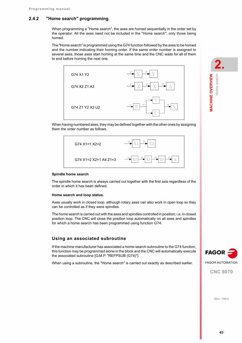
Programming manual.
CNC 8070
MA
CH
INE
OV
ER
VIE
W
2.
Hom
e s
earc
h
·63·
(REF: 1901)
2.4.2 "Home search" programming
When programming a "Home search", the axes are homed sequentially in the order set bythe operator. All the axes need not be included in the "Home search", only those beinghomed.
The "Home search" is programmed using the G74 function followed by the axes to be homedand the number indicating their homing order. If the same order number is assigned toseveral axes, those axes start homing at the same time and the CNC waits for all of themto end before homing the next one.
When having numbered axes, they may be defined together with the other ones by assigningthem the order number as follows.
Spindle home search
The spindle home search is always carried out together with the first axis regardless of theorder in which it has been defined.
Home search and loop status.
Axes usually work in closed loop, although rotary axes can also work in open loop so theycan be controlled as if they were spindles.
The home search is carried out with the axes and spindles controlled in position; i.e. in closedposition loop. The CNC will close the position loop automatically on all axes and spindlesfor which a home search has been programmed using function G74.
Using an associated subroutine
If the machine manufacturer has associated a home-search subroutine to the G74 function,this function may be programmed alone in the block and the CNC will automatically executethe associated subroutine [G.M.P. "REFPSUB (G74)"].
When using a subroutine, the "Home search" is carried out exactly as described earlier.
G74 X1 Y2
G74 X2 Z1 A3
G74 Z1 Y2 X3 U2
G74 X1=1 X2=2
G74 X1=2 X2=1 A4 Z1=3
Programming manual.
CNC 8070
2.
MA
CH
INE
OV
ER
VIE
W
Hom
e s
earc
h
·64·
(REF: 1901)
CNC 8070
3
·65·
(REF: 1901)
3. COORDINATE SYSTEM
3.1 Programming in millimeters (G71) or in inches (G70)
The displacements and feedrates of the axes may be defined in millimeters or in inches. Theunit system may be selected by program using the following functions:
G70 Programming in inches.
G71 Programming in millimeters.
Both functions may be programmed anywhere in the program; they do not have to go alonein the block.
Operation
After executing one of these functions, the CNC assumes that unit system for the followingblocks. If none of these functions is programmed, the CNC uses the unit system set bymachine manufacturer [G.M.P. "INCHES"].
When changing the unit system, the CNC converts the currently active feedrate into the newunit system.
Properties of the functions
The G70 and G71 functions are modal and are incompatible.
On power-up, after an M02 or M30 and after an EMERGENCY or a RESET, the CNCassumes function G70 or G71 as set by the machine manufacturer [G.M.P. "INCHES"].
...
G01 G71 X100 Y100 F508 (Programming in millimeters.)(Feedrate: 508 mm/minute)
...
G70 (It changes the units.)(Feedrate: 20 inches/minute)
...
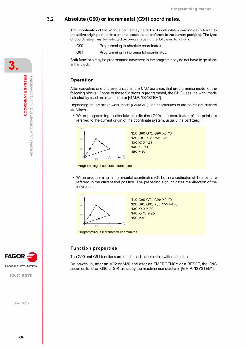
Programming manual.
CNC 8070
3.
CO
OR
DIN
AT
E S
YS
TE
M
Abs
olu
te (
G90
) or
incr
emen
tal (
G91
) co
ordi
nate
s.
·66·
(REF: 1901)
3.2 Absolute (G90) or incremental (G91) coordinates.
The coordinates of the various points may be defined in absolute coordinates (referred tothe active origin point) or incremental coordinates (referred to the current position). The typeof coordinates may be selected by program using the following functions:
G90 Programming in absolute coordinates.
G91 Programming in incremental coordinates.
Both functions may be programmed anywhere in the program; they do not have to go alonein the block.
Operation
After executing one of these functions, the CNC assumes that programming mode for thefollowing blocks. If none of these functions is programmed, the CNC uses the work modeselected by machine manufacturer [G.M.P. "ISYSTEM"].
Depending on the active work mode (G90/G91), the coordinates of the points are definedas follows:
• When programming in absolute coordinates (G90), the coordinates of the point arereferred to the current origin of the coordinate system, usually the part zero.
• When programming in incremental coordinates (G91), the coordinates of the point arereferred to the current tool position. The preceding sign indicates the direction of themovement.
Function properties
The G90 and G91 functions are modal and incompatible with each other.
On power-up, after an M02 or M30 and after an EMERGENCY or a RESET, the CNCassumes function G90 or G91 as set by the machine manufacturer [G.M.P. "ISYSTEM"].
N10 G00 G71 G90 X0 Y0N20 G01 X35 Y55 F450N30 X75 Y25N40 X0 Y0N50 M30
Programming in absolute coordinates.
N10 G00 G71 G90 X0 Y0N20 G01 G91 X35 Y55 F450N30 X40 Y-30N40 X-75 Y-25N50 M30
Programming in incremental coordinates.
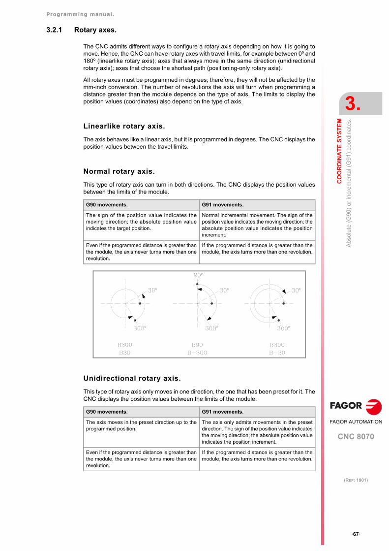
Programming manual.
CNC 8070
CO
OR
DIN
AT
E S
YS
TE
M
3.
Abs
olu
te (
G90
) or
incr
emen
tal (
G91
) co
ordi
nate
s.
·67·
(REF: 1901)
3.2.1 Rotary axes.
The CNC admits different ways to configure a rotary axis depending on how it is going tomove. Hence, the CNC can have rotary axes with travel limits, for example between 0º and180º (linearlike rotary axis); axes that always move in the same direction (unidirectionalrotary axis); axes that choose the shortest path (positioning-only rotary axis).
All rotary axes must be programmed in degrees; therefore, they will not be affected by themm-inch conversion. The number of revolutions the axis will turn when programming adistance greater than the module depends on the type of axis. The limits to display theposition values (coordinates) also depend on the type of axis.
Linearlike rotary axis.
The axis behaves like a linear axis, but it is programmed in degrees. The CNC displays theposition values between the travel limits.
Normal rotary axis.
This type of rotary axis can turn in both directions. The CNC displays the position valuesbetween the limits of the module.
Unidirectional rotary axis.
This type of rotary axis only moves in one direction, the one that has been preset for it. TheCNC displays the position values between the limits of the module.
G90 movements. G91 movements.
The sign of the position value indicates themoving direction; the absolute position valueindicates the target position.
Normal incremental movement. The sign of theposition value indicates the moving direction; theabsolute position value indicates the positionincrement.
Even if the programmed distance is greater thanthe module, the axis never turns more than onerevolution.
If the programmed distance is greater than themodule, the axis turns more than one revolution.
G90 movements. G91 movements.
The axis moves in the preset direction up to theprogrammed position.
The axis only admits movements in the presetdirection. The sign of the position value indicatesthe moving direction; the absolute position valueindicates the position increment.
Even if the programmed distance is greater thanthe module, the axis never turns more than onerevolution.
If the programmed distance is greater than themodule, the axis turns more than one revolution.
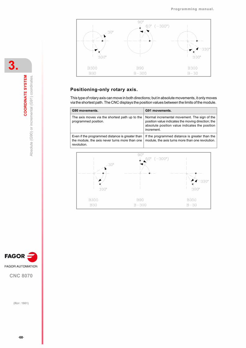
Programming manual.
CNC 8070
3.
CO
OR
DIN
AT
E S
YS
TE
M
Abs
olu
te (
G90
) or
incr
emen
tal (
G91
) co
ordi
nate
s.
·68·
(REF: 1901)
Positioning-only rotary axis.
This type of rotary axis can move in both directions; but in absolute movements, it only movesvia the shortest path. The CNC displays the position values between the limits of the module.
G90 movements. G91 movements.
The axis moves via the shortest path up to theprogrammed position.
Normal incremental movement. The sign of theposition value indicates the moving direction; theabsolute position value indicates the positionincrement.
Even if the programmed distance is greater thanthe module, the axis never turns more than onerevolution.
If the programmed distance is greater than themodule, the axis turns more than one revolution.
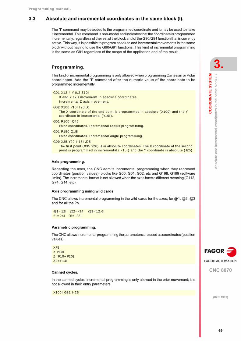
Programming manual.
CNC 8070
CO
OR
DIN
AT
E S
YS
TE
M
3.
Abs
olu
te a
nd in
crem
enta
l co
ordi
nat
es in
the
sam
e b
lock
(I)
.
·69·
(REF: 1901)
3.3 Absolute and incremental coordinates in the same block (I).
The "I" command may be added to the programmed coordinate and it may be used to makeit incremental. This command is non-modal and indicates that the coordinate is programmedincrementally, regardless of the rest of the block and of the G90/G91 function that is currentlyactive. This way, it is possible to program absolute and incremental movements in the sameblock without having to use the G90/G91 functions. This kind of incremental programmingis the same as G91 regardless of the scope of the application and of the result.
Programming.
This kind of incremental programming is only allowed when programming Cartesian or Polarcoordinates. Add the "I" command after the numeric value of the coordinate to beprogrammed incrementally.
Axis programming.
Regarding the axes, the CNC admits incremental programming when they representcoordinates (position values), blocks like G00, G01, G02, etc and G198, G199 (softwarelimits). The incremental format is not allowed when the axes have a different meaning (G112,G74, G14, etc).
Axis programming using wild cards.
The CNC allows incremental programming in the wild-cards for the axes; for @1, @2, @3and for all the ?n.
Parametric programming.
The CNC allows incremental programming the parameters are used as coordinates (positionvalues).
Canned cycles.
In the canned cycles, incremental programming is only allowed in the prior movement; it isnot allowed in their entry parameters.
G01 X12.4 Y-0.2 Z10IX and Y axis movement in absolute coordinates.Incremental Z axis movement.
G02 X100 Y10I I20 J0The X coordinate of the end point is programmed in absolute (X100) and the Y coordinate in incremental (Y10I).
G01 R100I Q45Polar coordinates. Incremental radius programming.
G01 R150 Q15IPolar coordinates. Incremental angle programming.
G09 X35 Y20 I-15I J25The first point (X35 Y20) is in absolute coordinates. The X coordinate of the second point is programmed in incremental (I-15I) and the Y coordinate is absolute (J25).
@1=12I @2=-34I @3=12.6I?1=24I ?5=-23I
XP1IX-P10IZ [P10+P20]IZ2=P14I
X100I G81 I-25
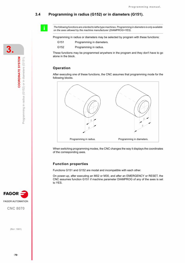
Programming manual.
CNC 8070
3.
CO
OR
DIN
AT
E S
YS
TE
M
Pro
gram
min
g in
ra
dius
(G
152
) or
in d
iam
ete
rs (
G1
51).
·70·
(REF: 1901)
3.4 Programming in radius (G152) or in diameters (G151).
Programming in radius or diameters may be selected by program with these functions:
G151 Programming in diameters.
G152 Programming in radius.
These functions may be programmed anywhere in the program and they don't have to goalone in the block.
Operation
After executing one of these functions, the CNC assumes that programming mode for thefollowing blocks.
When switching programming modes, the CNC changes the way it displays the coordinatesof the corresponding axes.
Function properties
Functions G151 and G152 are modal and incompatible with each other.
On power-up, after executing an M02 or M30, and after an EMERGENCY or RESET, theCNC assumes function G151 if machine parameter DIAMPROG of any of the axes is setto YES.
The following functions are oriented to lathe type machines. Programming in diameters is only availableon the axes allowed by the machine manufacturer (DIAMPROG=YES).i
Programming in radius. Programming in diameters.
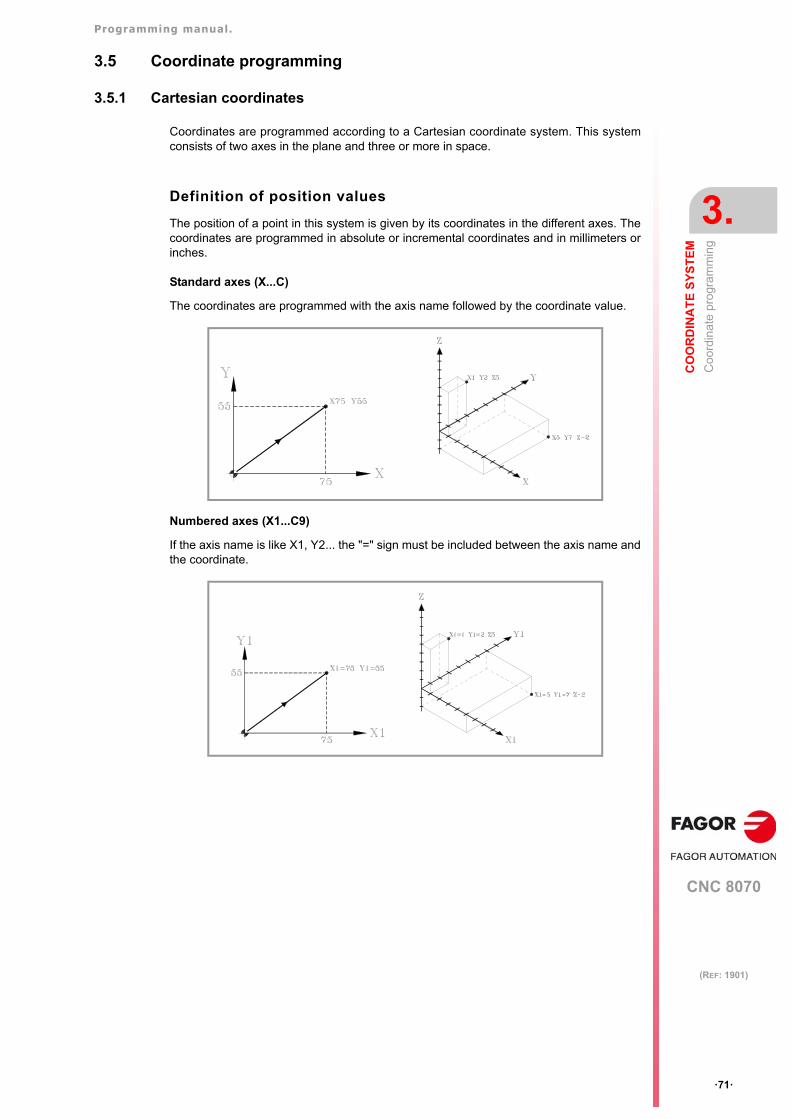
Programming manual.
CNC 8070
CO
OR
DIN
AT
E S
YS
TE
M
3.
Co
ordi
nat
e p
rogr
amm
ing
·71·
(REF: 1901)
3.5 Coordinate programming
3.5.1 Cartesian coordinates
Coordinates are programmed according to a Cartesian coordinate system. This systemconsists of two axes in the plane and three or more in space.
Definition of position values
The position of a point in this system is given by its coordinates in the different axes. Thecoordinates are programmed in absolute or incremental coordinates and in millimeters orinches.
Standard axes (X...C)
The coordinates are programmed with the axis name followed by the coordinate value.
Numbered axes (X1...C9)
If the axis name is like X1, Y2... the "=" sign must be included between the axis name andthe coordinate.
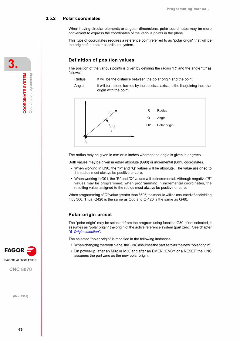
Programming manual.
CNC 8070
3.
CO
OR
DIN
AT
E S
YS
TE
M
Co
ordi
nat
e p
rogr
amm
ing
·72·
(REF: 1901)
3.5.2 Polar coordinates
When having circular elements or angular dimensions, polar coordinates may be moreconvenient to express the coordinates of the various points in the plane.
This type of coordinates requires a reference point referred to as "polar origin" that will bethe origin of the polar coordinate system.
Definition of position values
The position of the various points is given by defining the radius "R" and the angle "Q" asfollows:
Radius It will be the distance between the polar origin and the point.
Angle It will be the one formed by the abscissa axis and the line joining the polarorigin with the point.
The radius may be given in mm or in inches whereas the angle is given in degrees.
Both values may be given in either absolute (G90) or incremental (G91) coordinates.
• When working in G90, the "R" and "Q" values will be absolute. The value assigned tothe radius must always be positive or zero.
• When working in G91, the "R" and "Q" values will be incremental. Although negative "R"values may be programmed, when programming in incremental coordinates, theresulting value assigned to the radius must always be positive or zero.
When programming a "Q" value greater than 360º, the module will be assumed after dividingit by 360. Thus, Q420 is the same as Q60 and Q-420 is the same as Q-60.
Polar origin preset
The "polar origin" may be selected from the program using function G30. If not selected, itassumes as "polar origin" the origin of the active reference system (part zero). See chapter"5 Origin selection".
The selected "polar origin" is modified in the following instances:
• When changing the work plane, the CNC assumes the part zero as the new "polar origin".
• On power-up, after an M02 or M30 and after an EMERGENCY or a RESET, the CNCassumes the part zero as the new polar origin.
R Radius
Q Angle
OP Polar origin
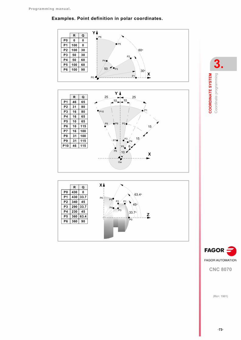
Programming manual.
CNC 8070
CO
OR
DIN
AT
E S
YS
TE
M
3.
Co
ordi
nat
e p
rogr
amm
ing
·73·
(REF: 1901)
Examples. Point definition in polar coordinates.
P1
P2
P3
P4
P5
P6
5030o
60o
P0
Y
X
R Q
P0 0
P1 100
0
0
P2
P3
P4
100
50
50
30
30
60
P5 100 60
P6 100 90
10
6
101025 25
15
15
P1
P2
P3P4
P5
P6
P7
P8P9
P10
Ow
R
P1 46
P2
P3
P4
31
16
16
P5 10
P6 10
P7 16
P8
P9
P10
31
31
46
Q
65
80
80
65
65
115
100
100
115
115
Y
X
P0
P1P2
P3P4
P5P6
63.4o
45o
33.7o
R Q
P0 430
P1 430
0
33.7
P2
P3
P4
340
290
230
45
33.7
45
P5 360 63.4
P6 360 90
X
Z
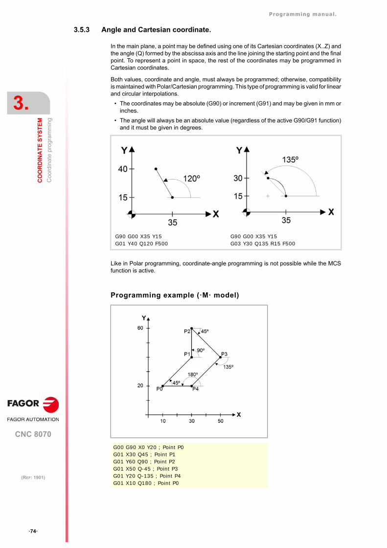
Programming manual.
CNC 8070
3.
CO
OR
DIN
AT
E S
YS
TE
M
Co
ordi
nat
e p
rogr
amm
ing
·74·
(REF: 1901)
3.5.3 Angle and Cartesian coordinate.
In the main plane, a point may be defined using one of its Cartesian coordinates (X..Z) andthe angle (Q) formed by the abscissa axis and the line joining the starting point and the finalpoint. To represent a point in space, the rest of the coordinates may be programmed inCartesian coordinates.
Both values, coordinate and angle, must always be programmed; otherwise, compatibilityis maintained with Polar/Cartesian programming. This type of programming is valid for linearand circular interpolations.
• The coordinates may be absolute (G90) or increment (G91) and may be given in mm orinches.
• The angle will always be an absolute value (regardless of the active G90/G91 function)and it must be given in degrees.
Like in Polar programming, coordinate-angle programming is not possible while the MCSfunction is active.
Programming example (·M· model)
G90 G00 X35 Y15 G01 Y40 Q120 F500
G90 G00 X35 Y15 G03 Y30 Q135 R15 F500
G00 G90 X0 Y20 ; Point P0G01 X30 Q45 ; Point P1G01 Y60 Q90 ; Point P2G01 X50 Q-45 ; Point P3G01 Y20 Q-135 ; Point P4G01 X10 Q180 ; Point P0
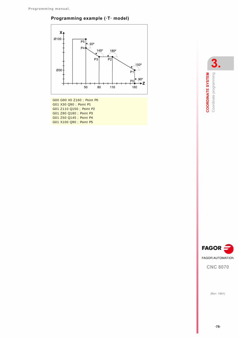
Programming manual.
CNC 8070
CO
OR
DIN
AT
E S
YS
TE
M
3.
Co
ordi
nat
e p
rogr
amm
ing
·75·
(REF: 1901)
Programming example (·T· model)
G00 G90 X0 Z160 ; Point P0G01 X30 Q90 ; Point P1G01 Z110 Q150 ; Point P2G01 Z80 Q180 ; Point P3G01 Z50 Q145 ; Point P4G01 X100 Q90 ; Point P5
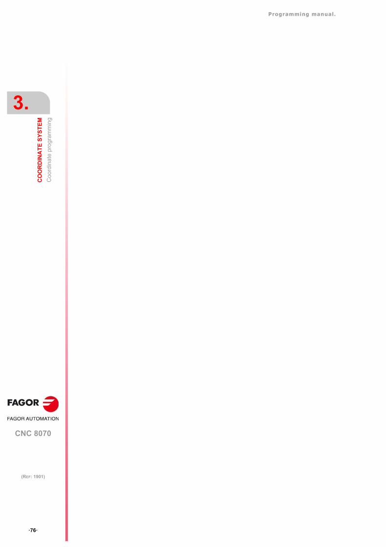
Programming manual.
CNC 8070
3.
CO
OR
DIN
AT
E S
YS
TE
M
Co
ordi
nat
e p
rogr
amm
ing
·76·
(REF: 1901)
CNC 8070
4
·77·
(REF: 1901)
4. WORK PLANES.
The work planes determine which axes define the work plane/trihedron and which axiscorresponds to the longitudinal axis of the tool. Plane selection is required to executeoperations like:
• Circular and helical interpolations.
• Corner chamfering and rounding.
• Tangential entries and exits.
• Machining canned cycles.
• Tool radius and length compensation.
These operations, except tool length compensation, can only be executed in the active workplane. Tool length compensation, on the other hand, can only be applied on the longitudinalaxis.
Commands for changing the work planes.
Mill model or lathe model with "trihedron" type axis configuration.
Lathe model with "plane" type axis configuration.
Function. Meaning.
G17 Main plane formed by the first axis (abscissa), second (ordinate) and third axis(perpendicular) of the channel.
G18 Main plane formed by the third axis (abscissa), first axis (ordinate) and second axis(perpendicular) of the channel.
G19 Main plane formed by the second axis (abscissa), third axis (ordinate) and first axis(perpendicular) of the channel.
G20 Select any work plane formed by the first three axes of the channel.
Instruction. Meaning.
#TOOL AX Select the longitudinal axis of the tool.
Function. Meaning.
G18 Main plane formed by the second axis (abscissa) and first axis (ordinate) of thechannel.
G20 Select the longitudinal axis of the tool.
Instruction. Meaning.
#TOOL AX Select the longitudinal axis of the tool.
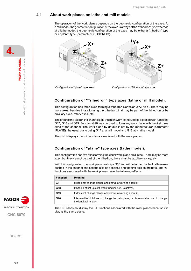
Programming manual.
CNC 8070
4.
WO
RK
PL
AN
ES
.
Abo
ut w
ork
pla
nes
on la
the
and
mill
mod
els.
·78·
(REF: 1901)
4.1 About work planes on lathe and mill models.
The operation of the work planes depends on the geometric configuration of the axes. Ata mill model, the geometric configuration of the axes is always of the "trihedron" type whereasat a lathe model, the geometric configuration of the axes may be either a "trihedron" typeor a "plane" type (parameter GEOCONFIG).
Configuration of "Trihedron" type axes (lathe or mill model).
This configuration has three axes forming a trihedron Cartesian XYZ type . There may bemore axes, besides those forming the trihedron; that may be part of the thihedron or beauxiliary axes, rotary axes, etc.
The order of the axes in the channel sets the main work planes, those selected with functionsG17, G18 and G19. Function G20 may be used to form any work plane with the first threeaxes of the channel. The work plane by default is set by the manufacturer (parameterIPLANE), the usual plane being G17 at a mill model and G18 at a lathe model.
The CNC displays the ·G· functions associated with the work planes.
Configuration of "plane" type axes (lathe model).
This configuration has two axes forming the usual work plane on a lathe. There may be moreaxes, but they cannot be part of the trihedron; there must be auxiliary, rotary, etc.
With this configuration, the work plane is always G18 and will be formed by the first two axesdefined in the channel, the second axis as abscissa and the first axis as ordinate. The ·G·functions associated with the work planes have the following effects.
The CNC does not display the ·G· functions associated with the work planes because it isalways the same plane.
Configuration of "plane" type axes. Configuration of "Trihedron" type axes.
Function. Meaning.
G17 It does not change planes and shows a warning about it.
G18 It has no effect (except when function G20 is active).
G19 It does not change planes and shows a warning about it.
G20 It is permitted if it does not change the main plane; i.e. it can only be used to changethe longitudinal axis.
X+
Z+
X+
Z+
Y+
Programming manual.
CNC 8070
WO
RK
PL
AN
ES
.
4.
Se
lect
the
mai
n ne
w w
ork
pla
nes.
·79·
(REF: 1901)
4.2 Select the main new work planes.
4.2.1 Mill model or lathe model with "trihedron" type axis configuration.
The main planes may be selected by program using functions G17, G18 and G19 and areformed by two of the first three axes of the channel. Ther third axis corresponds to the axisperpendicular to the plane, which coincides with the longitudinal axis of the tool, the one onwhich tool length compensation is applied.
The OEM, can use machine parameter LCOMPTYP to change the behavior of thelongitudinal axis when changing planes so the CNC keeps the longitudinal axis that wasactive before changing planes.
Function G20 may select any plane with the first three axes of the channel. Function G20and the instruction #TOOL AX can change the longitudinal axis of the tool.
Programming.
These functions may be programmed anywhere in the program and they don't have to goalone in the block.
Programming format.
The programming format is:
G17G18G19
Properties of the function and Influence of the reset, turning theCNC off and of the M30 function.
Functions G17, G18, G19 and G20 are modal and incompatible with each other. On power-up, after an M02 or M30 and after an emergency or a reset, the CNC assumes function G17or G18 as set by the machine manufacturer (parameter "IPLANE").
G17 Main plane formed by the first axis (abscissa), second (ordinate) and third axis(perpendicular) of the channel.
G18 Main plane formed by the third axis (abscissa), first axis (ordinate) and secondaxis (perpendicular) of the channel.
G19 Main plane formed by the second axis (abscissa), third axis (ordinate) and firstaxis (perpendicular) of the channel.
G17
G18
G19
Programming manual.
CNC 8070
4.
WO
RK
PL
AN
ES
.
Se
lect
the
mai
n ne
w w
ork
pla
nes.
·80·
(REF: 1901)
4.2.2 Lathe model with "plane" type axis configuration.
The work plane is always G18 and will be formed by the first two axes defined in the channel.Functions G17 and G19 have no meaning for the CNC.
In the case of lathe tools, tool length compensation is applied on all the axes where a tooloffset has been defined.
On milling tools, tool length compensation is applied on the second axis of the channel. Ifthe X (first axis of the channel) and Z (second axis of the channel) axes have been defined,the work plane will be the ZX and Z will be the longitudinal axis. Function G20 and theinstruction #TOOL AX can change the longitudinal axis of the tool.
Programming.
These functions may be programmed anywhere in the program and they don't have to goalone in the block.
Programming format.
The programming format is:
G18
Properties of the function and Influence of the reset, turning theCNC off and of the M30 function.
Functions G18 and G20 are modal and incompatible with each other. On power-up, afterexecuting an M02 or M30, and after an emergency or reset, the CNC assumes function G18.
G18 Main plane formed by the second axis (abscissa) and first axis (ordinate) of thechannel.
G18
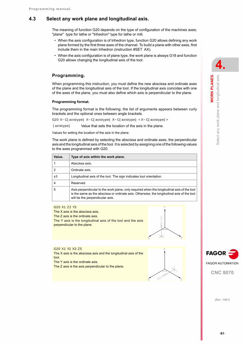
Programming manual.
CNC 8070
WO
RK
PL
AN
ES
.
4.
Sel
ect
an
y w
ork
pla
ne a
nd
long
itudi
nal
axi
s.
·81·
(REF: 1901)
4.3 Select any work plane and longitudinal axis.
The meaning of function G20 depends on the type of configuration of the machines axes;"plane" type for lathe or "trihedron" type for lathe or mill.
• When the axis configuration is of trihedron type, function G20 allows defining any workplane formed by the first three axes of the channel. To build a plane with other axes, firstinclude them in the main trihedron (instruction #SET AX).
• When the axis configuration is of plane type, the work plane is always G18 and functionG20 allows changing the longitudinal axis of the tool.
Programming.
When programming this instruction, you must define the new abscissa and ordinate axesof the plane and the longitudinal axis of the tool. If the longitudinal axis coincides with oneof the axes of the plane, you must also define which axis is perpendicular to the plane.
Programming format.
The programming format is the following; the list of arguments appears between curlybrackets and the optional ones between angle brackets.
G20 X~C{axistype} X~C{axistype} X~C{axistype} <X~C{axistype}>
Values for setting the location of the axis in the plane.
The work plane is defined by selecting the abscissa and ordinate axes, the perpendicularaxis and the longitudinal axis of the tool. It is selected by assigning one of the following valuesto the axes programmed with G20.
{axistype} Value that sets the location of the axis in the plane.
Value. Type of axis within the work plane.
1 Abscissa axis.
2 Ordinate axis.
±3 Longitudinal axis of the tool. The sign indicates tool orientation.
4 Reserved.
5 Axis perpendicular to the work plane, only required when the longitudinal axis of the toolis the same as the abscissa or ordinate axis. Otherwise, the longitudinal axis of the toolwill be the perpendicular axis.
G20 X1 Z2 Y3The X axis is the abscissa axis.The Z axis is the ordinate axis.The Y axis is the longitudinal axis of the tool and the axisperpendicular to the plane.
G20 X1 Y2 X3 Z5The X axis is the abscissa axis and the longitudinal axis of thetool.The Y axis is the ordinate axis.The Z axis is the axis perpendicular to the plane.
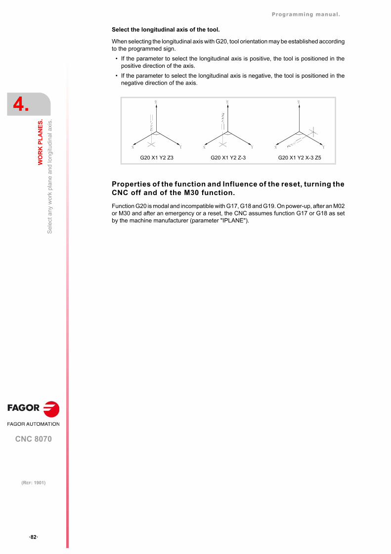
Programming manual.
CNC 8070
4.
WO
RK
PL
AN
ES
.
Sel
ect
an
y w
ork
pla
ne a
nd
long
itudi
nal
axi
s.
·82·
(REF: 1901)
Select the longitudinal axis of the tool.
When selecting the longitudinal axis with G20, tool orientation may be established accordingto the programmed sign.
• If the parameter to select the longitudinal axis is positive, the tool is positioned in thepositive direction of the axis.
• If the parameter to select the longitudinal axis is negative, the tool is positioned in thenegative direction of the axis.
Properties of the function and Influence of the reset, turning theCNC off and of the M30 function.
Function G20 is modal and incompatible with G17, G18 and G19. On power-up, after an M02or M30 and after an emergency or a reset, the CNC assumes function G17 or G18 as setby the machine manufacturer (parameter "IPLANE").
G20 X1 Y2 Z3 G20 X1 Y2 Z-3 G20 X1 Y2 X-3 Z5
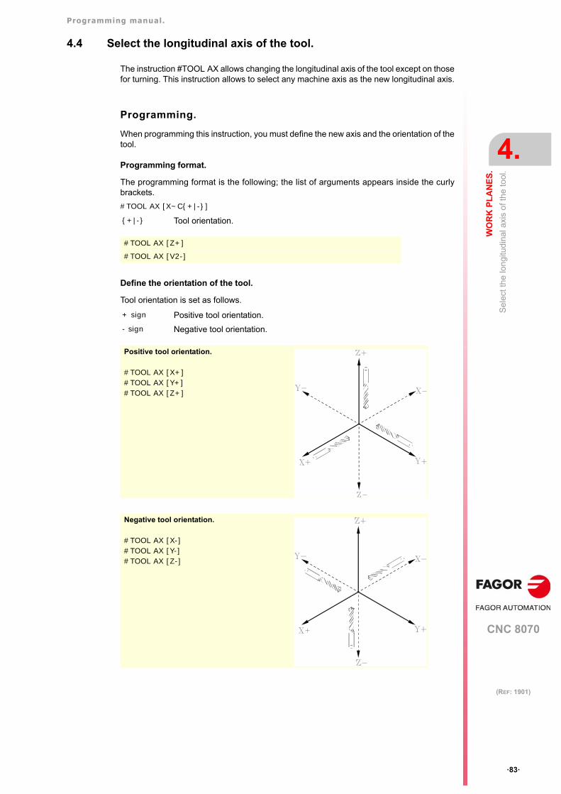
Programming manual.
CNC 8070
WO
RK
PL
AN
ES
.
4.
Sel
ect t
he lo
ngi
tud
inal
axi
s o
f th
e to
ol.
·83·
(REF: 1901)
4.4 Select the longitudinal axis of the tool.
The instruction #TOOL AX allows changing the longitudinal axis of the tool except on thosefor turning. This instruction allows to select any machine axis as the new longitudinal axis.
Programming.
When programming this instruction, you must define the new axis and the orientation of thetool.
Programming format.
The programming format is the following; the list of arguments appears inside the curlybrackets.
#TOOL AX [X~C{+|-}]
Define the orientation of the tool.
Tool orientation is set as follows.
{+|-} Tool orientation.
#TOOL AX [Z+]
#TOOL AX [V2-]
+ sign Positive tool orientation.
- sign Negative tool orientation.
Positive tool orientation.
#TOOL AX [X+]#TOOL AX [Y+]#TOOL AX [Z+]
Negative tool orientation.
#TOOL AX [X-]#TOOL AX [Y-]#TOOL AX [Z-]
Programming manual.
CNC 8070
4.
WO
RK
PL
AN
ES
.
Sel
ect t
he lo
ngi
tud
inal
axi
s o
f th
e to
ol.
·84·
(REF: 1901)
CNC 8070
5
·85·
(REF: 1901)
5. ORIGIN SELECTION
With this CNC, it is possible to program movements in the machine reference system or applyoffsets in order to use reference systems referred to the fixtures or the part without havingto change the coordinates of the different points of the part in the program.
There are three different offset types; fixture offset, zero offsets and PLC offsets. The CNCmay have several of these offsets active at the same time, in that case, the system coordinateorigin being used will be defined by the sum of the active offsets.
Type of offset. Description.
Fixture offset. Distance between the machine reference zero and the fixture'szero point.On machines using several fixtures, this offsets allows selectingthe particular fixture to be used.
Zero offset. Distance between the fixture's zero point and the part zero. If thefixture zero is not active (no fixture offset), the zero offset ismeasured from machine zero.The zero offset may be set by presetting a coordinate or a zerooffset.
PLC offset. Special offset handled by the PLC that is used to correct thedeviations due to dilatations, etc.The PLC always applies this offset, even when programmingwith respect to machine zero.
Programming manual.
CNC 8070
5.
OR
IGIN
SE
LE
CT
ION
Pro
gram
min
g w
ith r
esp
ect t
o m
ach
ine
zero
·86·
(REF: 1901)
5.1 Programming with respect to machine zero
Machine zero is the origin of the machine reference system. Movements referred to machinezero are programmed using the instructions #MCS and #MCS ON/OFF.
Program a movement referred to machine zero.
This instruction may be added to any block containing a movement so it is executed in themachine reference system.
Machine coordinate system.
The #MCS ON and #MCS OFF instructions activate and deactivate the machine referencesystem; therefore, the movements programmed between them are executed in the machinereference system. Both instructions must be programmed alone in the block.
Considerations for movements referred to machine zero.
Zero offsets and coordinate transformations
When executing a movement referred to machine zero, the CNC ignores the active offsets(except the PLC offset), the kinematics and cartesian transformations; therefore, themovement is carried out in the machine reference system. Once the movement has ended,the CNC restores the offsets, kinematics and cartesian transformations that were active.
The programmed movements do not admit polar coordinates, nor other kinds oftransformations such as mirror image, coordinate (pattern) rotation or scaling factor. Whilethe #MCS function is active, functions for setting a new origin such as G92, G54-G59, G158,G30, etc. are not admitted either.
Tool radius and length compensation
Tool radius and length compensation is also canceled during the movements referred tomachine zero. The CNC assumes that the coordinates have been programmed with respectto the tool base, not to the tool tip.
G00 X30 Y30
G92 X0 Y0 (Coordinate preset)
G01 X20 Y20
#MCS X30 Y30 (Movement referred to machine zero. Offsets canceled)
G01 X40 Y40 (Offsets restored)
G01 X60 Y60
M30
G92 X0 Y0 (Coordinate preset)
G01 X50 Y50
#MCS ON (Beginning of programming referred to machine zero)
G01 ...
G02 ...
G00 ...
#MCS OFF (End of programming referred to machine zero. Offsets restored)
Programming manual.
CNC 8070
OR
IGIN
SE
LE
CT
ION
5.
Pro
gram
min
g w
ith r
esp
ect t
o m
ach
ine
zero
·87·
(REF: 1901)
System units; millimeters or inches
When moving with respect to machine reference zero, the G70 or G71 units(inches/millimeters) selected by the user are ignored. It assumes the units predefined at theCNC (INCHES parameter); assumed by the CNC on power-up. These units are assumedfor defining the coordinates, for the feedrate and for the speed.
Programming manual.
CNC 8070
5.
OR
IGIN
SE
LE
CT
ION
Set
the
mac
hine
coo
rdin
ate
(G1
74).
·88·
(REF: 1901)
5.2 Set the machine coordinate (G174).
Function G174 may be used to set the machine coordinate of an axis or spindle; in otherwords, temporarily set a new machine zero. The new machine coordinate stays active untilthe axis or spindle is homed; then, the CNC restores the original machine reference zero(set in the machine parameters).
After executing function G174, the CNC assumes that the programmed coordinate definesthe current position referred to machine reference zero (home). The zero offsets, movementswith respect to machine zero, etc. will be referred to the coordinate programmed in G174.
Programming the function.
Program function G174, and then the machine coordinate of a single axis or spindle. Forgantry axes, program the machine coordinate of the master axis. With this function only themachine coordinate of an axis or spindle may be set; to set the machine coordinates ofseveral, program one G174 for each one of them.
When sett ing the machine coordinate, the CNC ignores the G70/G71 units(inches/millimeters) selected by the user and uses the unit system pre-defined at the CNC(parameter INCHES). The CNC also ignores all the other options, radius/diameter, mirrorimage, scaling factor, etc.
Programming format.
The programming format is:
G174 X..CG174 S
Considerations and limitations.
• Function G174, by itself, does not cause any axis or spindle movement. After executingfunction G174, the CNC considers that the axis or spindle is homed and verifies that itis within the software travel limits.
• The CNC does not allow setting the machine coordinate on slaved axes, tandem or onaxes that are part of the active kinematics or active transform. The CNC permits settingthe machine coordinate for tandem axes. Before setting the new machine coordinate,the CNC checks that the axis or spindle is in position and it is not synchronized, if that'snot the case, it issues an error message.
• On gantry axes, the CNC applies the coordinate defined in G174 to both axes, masterand slave.
• A G174 can be executed in a deactivated multi-axis group.
Properties of the function and Influence of the reset, turning theCNC off and of the M30 function.
Function G174 is modal. This function is neither affected by functions M02 and M30 nor bya reset, by an emergency or by turning the CNC off. On power-up, the CNC assumes themachine coordinates that were active when the CNC was turned off.
Use this function with caution. Changing the machine coordinate can cause the axes to exceed thetravel limits during the movement.
X..C Machine coordinate at the axes.
S Machine coordinate at the spindles.
G174 X100
G174 S180
On Sercos axes, function G174 also resets the coordinate of the drive. Setting the machine coordinateson position-Sercos axes requires drive version V6.20 or newer.i
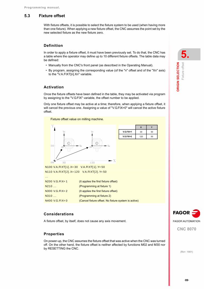
Programming manual.
CNC 8070
OR
IGIN
SE
LE
CT
ION
5.
Fix
ture
offs
et
·89·
(REF: 1901)
5.3 Fixture offset
With fixture offsets, it is possible to select the fixture system to be used (when having morethan one fixture). When applying a new fixture offset, the CNC assumes the point set by thenew selected fixture as the new fixture zero.
Definition
In order to apply a fixture offset, it must have been previously set. To do that, the CNC hasa table where the operator may define up to 10 different fixture offsets. The table data maybe defined:
• Manually from the CNC's front panel (as described in the Operating Manual).
• By program, assigning the corresponding value (of the "n" offset and of the "Xn" axis)to the "V.A.FIXT[n].Xn" variable.
Activation
Once the fixture offsets have been defined in the table, they may be activated via programby assigning to the "V.G.FIX" variable, the offset number to be applied.
Only one fixture offset may be active at a time; therefore, when applying a fixture offset, itwill cancel the previous one. Assigning a value of "V.G.FIX=0" will cancel the active fixtureoffset.
Considerations
A fixture offset, by itself, does not cause any axis movement.
Properties
On power-up, the CNC assumes the fixture offset that was active when the CNC was turnedoff. On the other hand, the fixture offset is neither affected by functions M02 and M30 norby RESETTING the CNC.
N100 V.A.FIXT[1].X=30 V.A.FIXT[1].Y=50
N110 V.A.FIXT[2].X=120 V.A.FIXT[2].Y=50
...
N200 V.G.FIX=1 (It applies the first fixture offset)
N210 ... (Programming at fixture 1)
N300 V.G.FIX=2 (It applies the first fixture offset)
N310 ... (Programming at fixture 2)
N400 V.G.FIX=0 (Cancel fixture offset. No fixture system is active)
X Y
V.G.FIX=1 30 50
V.G.FIX=2 120 50
Fixture offset value on milling machine.
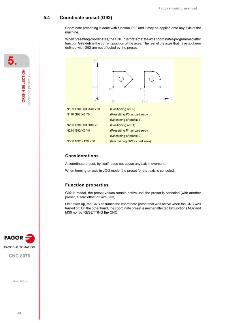
Programming manual.
CNC 8070
5.
OR
IGIN
SE
LE
CT
ION
Coo
rdin
ate
pres
et (
G9
2)
·90·
(REF: 1901)
5.4 Coordinate preset (G92)
Coordinate presetting is done with function G92 and it may be applied onto any axis of themachine.
When presetting coordinates, the CNC interprets that the axis coordinates programmed afterfunction G92 define the current position of the axes. The rest of the axes that have not beendefined with G92 are not affected by the preset.
Considerations
A coordinate preset, by itself, does not cause any axis movement.
When homing an axis in JOG mode, the preset for that axis is canceled.
Function properties
G92 is modal, the preset values remain active until the preset is canceled (with anotherpreset, a zero offset or with G53).
On power-up, the CNC assumes the coordinate preset that was active when the CNC wasturned off. On the other hand, the coordinate preset is neither affected by functions M02 andM30 nor by RESETTING the CNC.
N100 G90 G01 X40 Y30 (Positioning at P0)
N110 G92 X0 Y0 (Presetting P0 as part zero)
... (Machining of profile 1)
N200 G90 G01 X80 Y0 (Positioning at P1)
N210 G92 X0 Y0 (Presetting P1 as part zero)
... (Machining of profile 2)
N300 G92 X120 Y30 (Recovering OW as part zero)
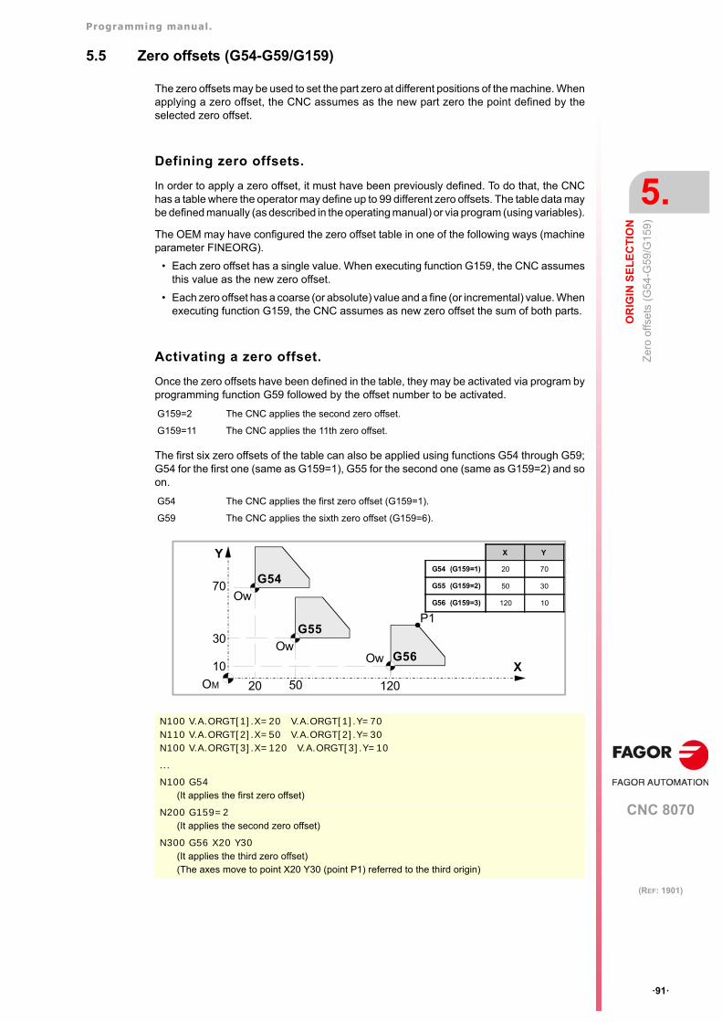
Programming manual.
CNC 8070
OR
IGIN
SE
LE
CT
ION
5.
Zer
o of
fset
s (G
54-G
59/G
159)
·91·
(REF: 1901)
5.5 Zero offsets (G54-G59/G159)
The zero offsets may be used to set the part zero at different positions of the machine. Whenapplying a zero offset, the CNC assumes as the new part zero the point defined by theselected zero offset.
Defining zero offsets.
In order to apply a zero offset, it must have been previously defined. To do that, the CNChas a table where the operator may define up to 99 different zero offsets. The table data maybe defined manually (as described in the operating manual) or via program (using variables).
The OEM may have configured the zero offset table in one of the following ways (machineparameter FINEORG).
• Each zero offset has a single value. When executing function G159, the CNC assumesthis value as the new zero offset.
• Each zero offset has a coarse (or absolute) value and a fine (or incremental) value. Whenexecuting function G159, the CNC assumes as new zero offset the sum of both parts.
Activating a zero offset.
Once the zero offsets have been defined in the table, they may be activated via program byprogramming function G59 followed by the offset number to be activated.
The first six zero offsets of the table can also be applied using functions G54 through G59;G54 for the first one (same as G159=1), G55 for the second one (same as G159=2) and soon.
G159=2 The CNC applies the second zero offset.
G159=11 The CNC applies the 11th zero offset.
G54 The CNC applies the first zero offset (G159=1).
G59 The CNC applies the sixth zero offset (G159=6).
N100 V.A.ORGT[1].X=20 V.A.ORGT[1].Y=70N110 V.A.ORGT[2].X=50 V.A.ORGT[2].Y=30N100 V.A.ORGT[3].X=120 V.A.ORGT[3].Y=10
...
N100 G54(It applies the first zero offset)
N200 G159=2(It applies the second zero offset)
N300 G56 X20 Y30(It applies the third zero offset)(The axes move to point X20 Y30 (point P1) referred to the third origin)
Y
X
70
10
30
20 50 120
OwOw
Ow
G54
G55
G56
P1
OM
X Y
G54 (G159=1) 20 70
G55 (G159=2) 50 30
G56 (G159=3) 120 10
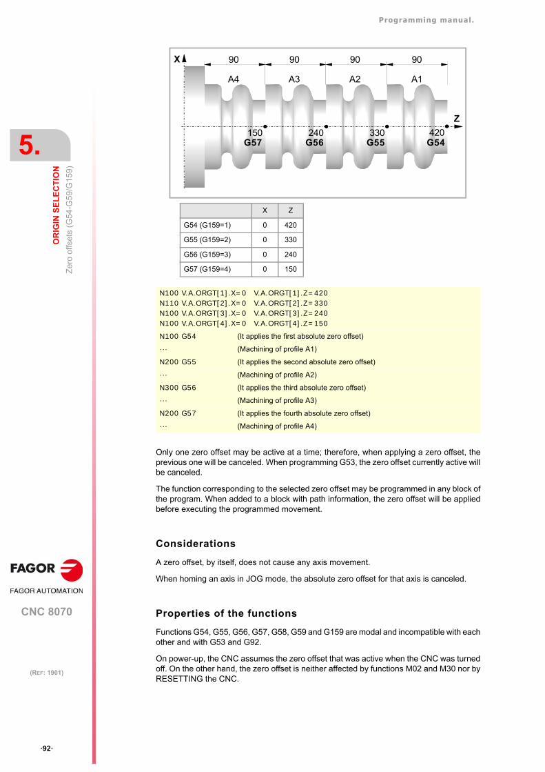
Programming manual.
CNC 8070
5.
OR
IGIN
SE
LE
CT
ION
Zer
o of
fset
s (G
54-G
59/G
159)
·92·
(REF: 1901)
Only one zero offset may be active at a time; therefore, when applying a zero offset, theprevious one will be canceled. When programming G53, the zero offset currently active willbe canceled.
The function corresponding to the selected zero offset may be programmed in any block ofthe program. When added to a block with path information, the zero offset will be appliedbefore executing the programmed movement.
Considerations
A zero offset, by itself, does not cause any axis movement.
When homing an axis in JOG mode, the absolute zero offset for that axis is canceled.
Properties of the functions
Functions G54, G55, G56, G57, G58, G59 and G159 are modal and incompatible with eachother and with G53 and G92.
On power-up, the CNC assumes the zero offset that was active when the CNC was turnedoff. On the other hand, the zero offset is neither affected by functions M02 and M30 nor byRESETTING the CNC.
N100 V.A.ORGT[1].X=0 V.A.ORGT[1].Z=420N110 V.A.ORGT[2].X=0 V.A.ORGT[2].Z=330N100 V.A.ORGT[3].X=0 V.A.ORGT[3].Z=240N100 V.A.ORGT[4].X=0 V.A.ORGT[4].Z=150
N100 G54 (It applies the first absolute zero offset)
··· (Machining of profile A1)
N200 G55 (It applies the second absolute zero offset)
··· (Machining of profile A2)
N300 G56 (It applies the third absolute zero offset)
··· (Machining of profile A3)
N200 G57 (It applies the fourth absolute zero offset)
··· (Machining of profile A4)
X Z
G54 (G159=1) 0 420
G55 (G159=2) 0 330
G56 (G159=3) 0 240
G57 (G159=4) 0 150
X
Z
90 9090
150 240 330
A2A3A4
90
A1
420G54G55G56G57
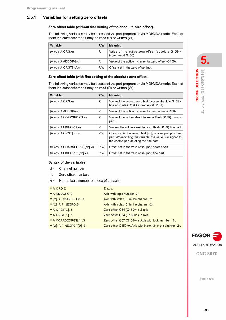
Programming manual.
CNC 8070
OR
IGIN
SE
LE
CT
ION
5.
Zer
o of
fset
s (G
54-G
59/G
159)
·93·
(REF: 1901)
5.5.1 Variables for setting zero offsets
Zero offset table (without fine setting of the absolute zero offset).
The following variables may be accessed via part-program or via MDI/MDA mode. Each ofthem indicates whether it may be read (R) or written (W).
Zero offset table (with fine setting of the absolute zero offset).
The following variables may be accessed via part-program or via MDI/MDA mode. Each ofthem indicates whether it may be read (R) or written (W).
Syntax of the variables.
·ch· Channel number.
·nb· Zero offset number.
·xn· Name, logic number or index of the axis.
Variable. R/W Meaning.
(V.)[ch].A.ORG.xn R Value of the active zero offset (absolute G159 +incremental G158).
(V.)[ch].A.ADDORG.xn R Value of the active incremental zero offset (G158).
(V.)[ch].A.ORGT[nb].xn R/W Offset set in the zero offset [nb].
Variable. R/W Meaning.
(V.)[ch].A.ORG.xn R Value of the active zero offset (coarse absolute G159 +fine absolute G159 + incremental G158).
(V.)[ch].A.ADDORG.xn R Value of the active incremental zero offset (G158).
(V.)[ch].A.COARSEORG.xn R Value of the active absolute zero offset (G159), coarsepart.
(V.)[ch].A.FINEORG.xn R Value of the active absolute zero offset (G159), fine part.
(V.)[ch].A.ORGT[nb].xn R/W Offset set in the zero offset [nb]; coarse part plus finepart. When writing this variable, the value is assigned tothe coarse part deleting the fine part.
(V.)[ch].A.COARSEORGT[nb].xn R/W Offset set in the zero offset [nb]; coarse part.
(V.)[ch].A.FINEORGT[nb].xn R/W Offset set in the zero offset [nb]; fine part.
V.A.ORG.Z Z axis.
V.A.ADDORG.3 Axis with logic number ·3·.
V.[2].A.COARSEORG.3 Axis with index ·3· in the channel ·2·.
V.[2].A.FINEORG.3 Axis with index ·3· in the channel ·2·.
V.A.ORGT[1].Z Zero offset G54 (G159=1). Z axis.
V.A.ORGT[1].Z Zero offset G54 (G159=1). Z axis.
V.A.COARSEORGT[4].3 Zero offset G57 (G159=4). Axis with logic number ·3·.
V.[2].A.FINEORGT[9].3 Zero offset G159=9. Axis with index ·3· in the channel ·2·.
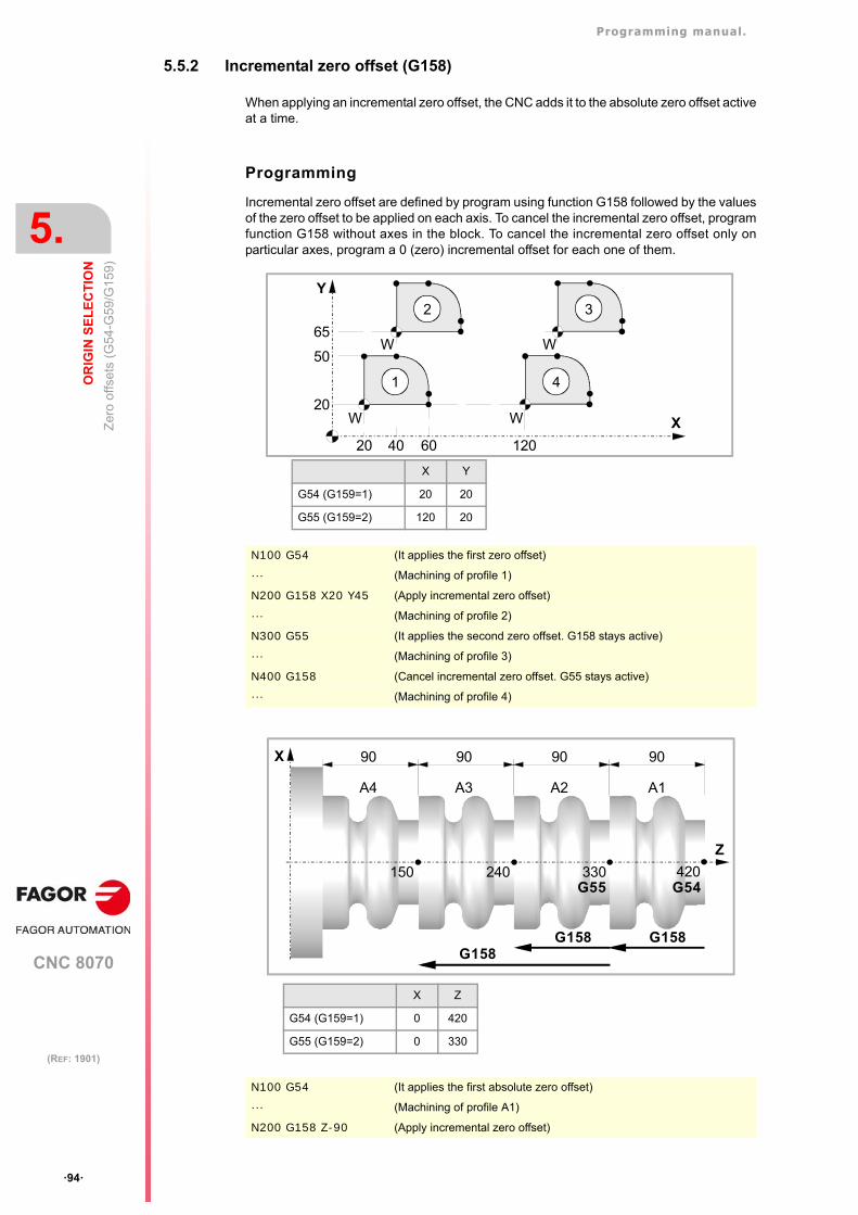
Programming manual.
CNC 8070
5.
OR
IGIN
SE
LE
CT
ION
Zer
o of
fset
s (G
54-G
59/G
159)
·94·
(REF: 1901)
5.5.2 Incremental zero offset (G158)
When applying an incremental zero offset, the CNC adds it to the absolute zero offset activeat a time.
Programming
Incremental zero offset are defined by program using function G158 followed by the valuesof the zero offset to be applied on each axis. To cancel the incremental zero offset, programfunction G158 without axes in the block. To cancel the incremental zero offset only onparticular axes, program a 0 (zero) incremental offset for each one of them.
N100 G54 (It applies the first zero offset)
··· (Machining of profile 1)
N200 G158 X20 Y45 (Apply incremental zero offset)
··· (Machining of profile 2)
N300 G55 (It applies the second zero offset. G158 stays active)
··· (Machining of profile 3)
N400 G158 (Cancel incremental zero offset. G55 stays active)
··· (Machining of profile 4)
N100 G54 (It applies the first absolute zero offset)
··· (Machining of profile A1)
N200 G158 Z-90 (Apply incremental zero offset)
X Y
G54 (G159=1) 20 20
G55 (G159=2) 120 20
Y
X
65
W
WW
W
50
20
20 40 60 120
1
2 3
4
X Z
G54 (G159=1) 0 420
G55 (G159=2) 0 330
X
Z
90 9090
150 240 330
A2A3A4
90
A1
420G54
G158G158
G55
G158
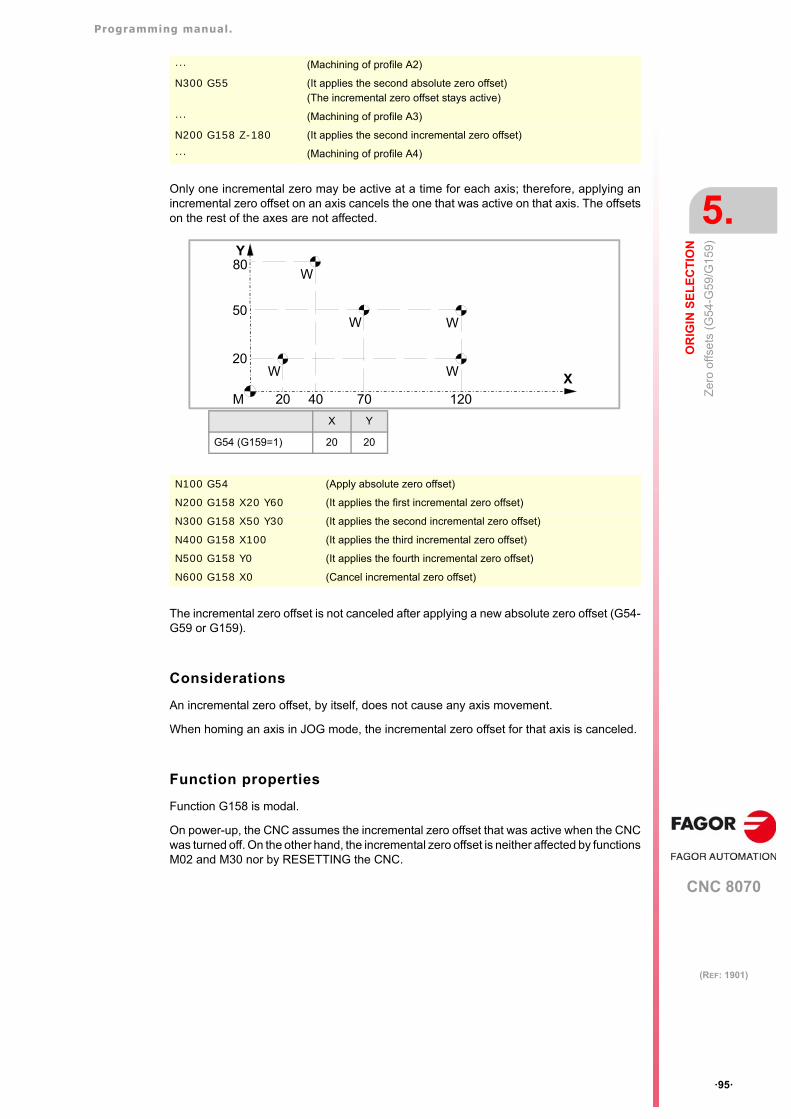
Programming manual.
CNC 8070
OR
IGIN
SE
LE
CT
ION
5.
Zer
o of
fset
s (G
54-G
59/G
159)
·95·
(REF: 1901)
Only one incremental zero may be active at a time for each axis; therefore, applying anincremental zero offset on an axis cancels the one that was active on that axis. The offsetson the rest of the axes are not affected.
The incremental zero offset is not canceled after applying a new absolute zero offset (G54-G59 or G159).
Considerations
An incremental zero offset, by itself, does not cause any axis movement.
When homing an axis in JOG mode, the incremental zero offset for that axis is canceled.
Function properties
Function G158 is modal.
On power-up, the CNC assumes the incremental zero offset that was active when the CNCwas turned off. On the other hand, the incremental zero offset is neither affected by functionsM02 and M30 nor by RESETTING the CNC.
··· (Machining of profile A2)
N300 G55 (It applies the second absolute zero offset)(The incremental zero offset stays active)
··· (Machining of profile A3)
N200 G158 Z-180 (It applies the second incremental zero offset)
··· (Machining of profile A4)
N100 G54 (Apply absolute zero offset)
N200 G158 X20 Y60 (It applies the first incremental zero offset)
N300 G158 X50 Y30 (It applies the second incremental zero offset)
N400 G158 X100 (It applies the third incremental zero offset)
N500 G158 Y0 (It applies the fourth incremental zero offset)
N600 G158 X0 (Cancel incremental zero offset)
Y
X
80
W
50
20
20 40 70 120
WW
W
W
M
X Y
G54 (G159=1) 20 20
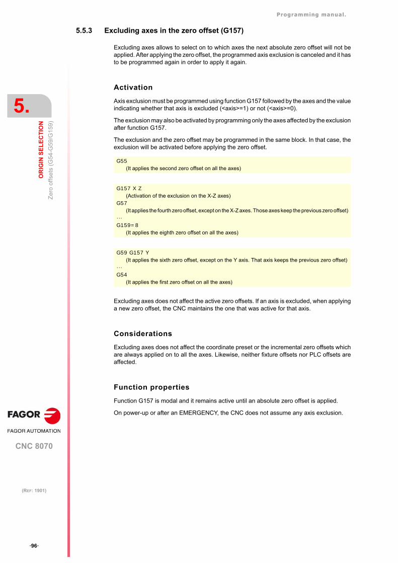
Programming manual.
CNC 8070
5.
OR
IGIN
SE
LE
CT
ION
Zer
o of
fset
s (G
54-G
59/G
159)
·96·
(REF: 1901)
5.5.3 Excluding axes in the zero offset (G157)
Excluding axes allows to select on to which axes the next absolute zero offset will not beapplied. After applying the zero offset, the programmed axis exclusion is canceled and it hasto be programmed again in order to apply it again.
Activation
Axis exclusion must be programmed using function G157 followed by the axes and the valueindicating whether that axis is excluded (<axis>=1) or not (<axis>=0).
The exclusion may also be activated by programming only the axes affected by the exclusionafter function G157.
The exclusion and the zero offset may be programmed in the same block. In that case, theexclusion will be activated before applying the zero offset.
Excluding axes does not affect the active zero offsets. If an axis is excluded, when applyinga new zero offset, the CNC maintains the one that was active for that axis.
Considerations
Excluding axes does not affect the coordinate preset or the incremental zero offsets whichare always applied on to all the axes. Likewise, neither fixture offsets nor PLC offsets areaffected.
Function properties
Function G157 is modal and it remains active until an absolute zero offset is applied.
On power-up or after an EMERGENCY, the CNC does not assume any axis exclusion.
G55(It applies the second zero offset on all the axes)
G157 X Z(Activation of the exclusion on the X-Z axes)
G57 (It applies the fourth zero offset, except on the X-Z axes. Those axes keep the previous zero offset)
···G159=8
(It applies the eighth zero offset on all the axes)
G59 G157 Y(It applies the sixth zero offset, except on the Y axis. That axis keeps the previous zero offset)
···G54
(It applies the first zero offset on all the axes)
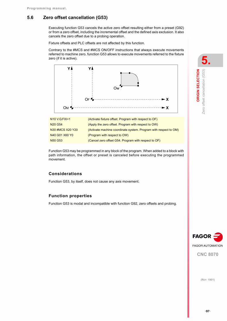
Programming manual.
CNC 8070
OR
IGIN
SE
LE
CT
ION
5.
Zer
o o
ffset
ca
ncel
latio
n (G
53)
·97·
(REF: 1901)
5.6 Zero offset cancellation (G53)
Executing function G53 cancels the active zero offset resulting either from a preset (G92)or from a zero offset, including the incremental offset and the defined axis exclusion. It alsocancels the zero offset due to a probing operation.
Fixture offsets and PLC offsets are not affected by this function.
Contrary to the #MCS and #MCS ON/OFF instructions that always execute movementsreferred to machine zero, function G53 allows to execute movements referred to the fixturezero (if it is active).
Function G53 may be programmed in any block of the program. When added to a block withpath information, the offset or preset is canceled before executing the programmedmovement.
Considerations
Function G53, by itself, does not cause any axis movement.
Function properties
Function G53 is modal and incompatible with function G92, zero offsets and probing.
N10 V.G.FIX=1 (Activate fixture offset. Program with respect to OF)
N20 G54 (Apply the zero offset. Program with respect to OW)
N30 #MCS X20 Y20 (Activate machine coordinate system. Program with respect to OM)
N40 G01 X60 Y0 (Program with respect to OW)
N50 G53 (Cancel zero offset G54. Program with respect to OF)
Y
X
Ow
OM
OF
Y
X
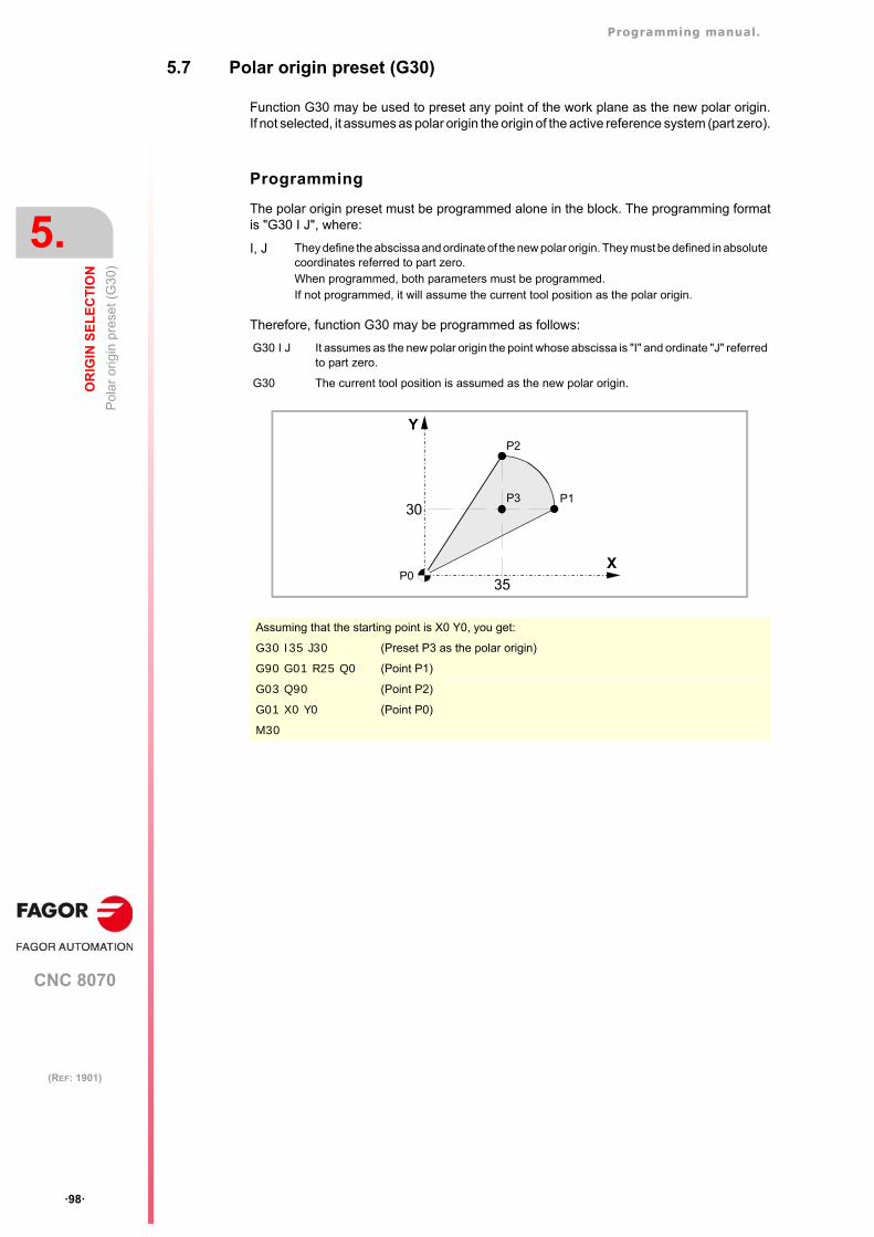
Programming manual.
CNC 8070
5.
OR
IGIN
SE
LE
CT
ION
Pol
ar
orig
in p
rese
t (G
30)
·98·
(REF: 1901)
5.7 Polar origin preset (G30)
Function G30 may be used to preset any point of the work plane as the new polar origin.If not selected, it assumes as polar origin the origin of the active reference system (part zero).
Programming
The polar origin preset must be programmed alone in the block. The programming formatis "G30 I J", where:
Therefore, function G30 may be programmed as follows:
I, J They define the abscissa and ordinate of the new polar origin. They must be defined in absolutecoordinates referred to part zero.When programmed, both parameters must be programmed. If not programmed, it will assume the current tool position as the polar origin.
G30 I J It assumes as the new polar origin the point whose abscissa is "I" and ordinate "J" referredto part zero.
G30 The current tool position is assumed as the new polar origin.
Assuming that the starting point is X0 Y0, you get:
G30 I35 J30 (Preset P3 as the polar origin)
G90 G01 R25 Q0 (Point P1)
G03 Q90 (Point P2)
G01 X0 Y0 (Point P0)
M30
Y
X
30
35
P3 P1
P2
P0
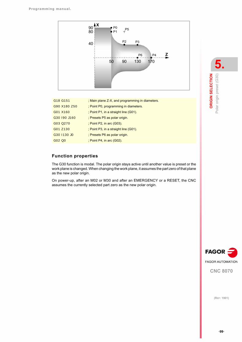
Programming manual.
CNC 8070
OR
IGIN
SE
LE
CT
ION
5.
Pol
ar
orig
in p
rese
t (G
30)
·99·
(REF: 1901)
Function properties
The G30 function is modal. The polar origin stays active until another value is preset or thework plane is changed. When changing the work plane, it assumes the part zero of that planeas the new polar origin.
On power-up, after an M02 or M30 and after an EMERGENCY or a RESET, the CNCassumes the currently selected part zero as the new polar origin.
G18 G151 ; Main plane Z-X, and programming in diameters.
G90 X180 Z50 ; Point P0, programming in diameters.
G01 X160 ; Point P1, in a straight line (G01).
G30 I90 J160 ; Presets P5 as polar origin.
G03 Q270 ; Point P2, in arc (G03).
G01 Z130 ; Point P3, in a straight line (G01).
G30 I130 J0 ; Presets P6 as polar origin.
G02 Q0 ; Point P4, in arc (G02).
X
Z
P0
50
80
90 130 170
P1
P2 P3
P5
P4P6
90
40
Programming manual.
CNC 8070
5.
OR
IGIN
SE
LE
CT
ION
Pol
ar
orig
in p
rese
t (G
30)
·100·
(REF: 1901)
CNC 8070
6
·101·
(REF: 1901)
6. TECHNOLOGICAL FUNCTIONS
6.1 Machining feedrate (F)
The machining feedrate may be selected by programmed using the "F" code which remainsactive until another value is programmed. The programming units depend on the active workmode (G93, G94 or G95) and the type of axis being moved (linear or rotary).
G94 - Feedrate in millimeters/minute (inches/minute).
G95 - Feedrate in millimeters/revolution (inches/revolution).
G93 - Machining time in seconds.
The programmed "F" is effective in linear (G01) or circular (G02, G03) interpolations.Movements in G00 (rapid traverse) are executed in rapid regardless of the programmed "F"value.
Movement without programmed feedrate.
In principle, the CNC will show the corresponding error when programming a movement inG01/G02/G03 without having set a feedrate.
Optionally, the manufacturer may have configured the CNC to make the movements at themaximum machining feedrate, set by machine parameter MAXFEED.
Feedrate limitation.
The manufacturer may have limited the maximum feedrate with machine parameterMAXFEED. When trying to exceed the maximum feedrate via part-program, via PLC or fromthe operator panel, the CNC limits the feedrate to the maximum value set without showingany error message or warning.
If this parameter is set to zero, the machining feedrate is not limited and the CNC assumesthe one set for G00 as the maximum feedrate.
Variable to limit the feedrate via PLC.
(V.)[n].PLC.G00FEED is a variable that may be written from the PLC to set, at a particularmoment and in real time, the maximum feedrate of the channel for any type of movement.
Feedrate regulation.
The programmed feedrate "F" may be varied between 0% and 200% using the selectorswitch on the CNC's operator panel or it may be selected by program or by PLC. However,the maximum override is limited by the machine manufacturer [G.M.P. "MAXOVR"].
When making movements in G00 (rapid traverse), the feedrate override percentage will befixed at 100% or it may be varied between 0% and 100% depending on how the machinemanufacturer has set [G.M.P. "RAPIDOVR"].
When carrying out threading operations, the feedrate percentage will be fixed at 100% ofthe programmed feedrate.
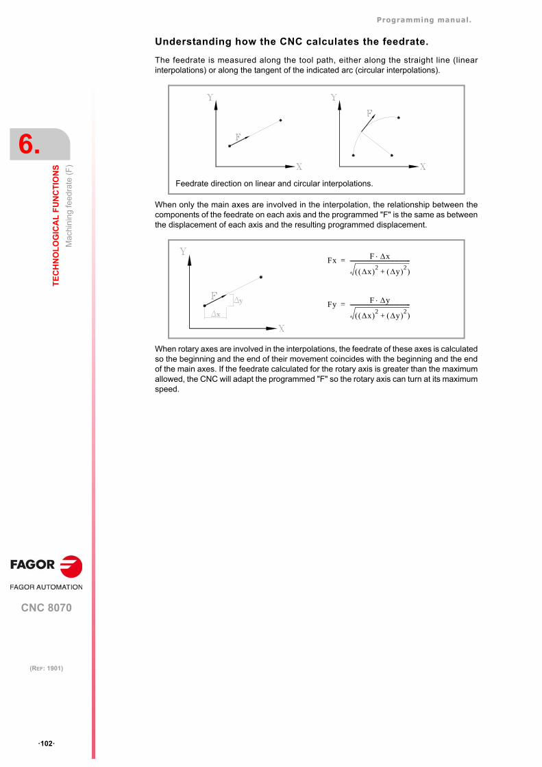
Programming manual.
CNC 8070
6.
TE
CH
NO
LO
GIC
AL
FU
NC
TIO
NS
Mac
hin
ing
feed
rate
(F
)
·102·
(REF: 1901)
Understanding how the CNC calculates the feedrate.
The feedrate is measured along the tool path, either along the straight line (linearinterpolations) or along the tangent of the indicated arc (circular interpolations).
When only the main axes are involved in the interpolation, the relationship between thecomponents of the feedrate on each axis and the programmed "F" is the same as betweenthe displacement of each axis and the resulting programmed displacement.
When rotary axes are involved in the interpolations, the feedrate of these axes is calculatedso the beginning and the end of their movement coincides with the beginning and the endof the main axes. If the feedrate calculated for the rotary axis is greater than the maximumallowed, the CNC will adapt the programmed "F" so the rotary axis can turn at its maximumspeed.
Feedrate direction on linear and circular interpolations.
Fx F x
x 2 y 2+ --------------------------------------------=
Fy F y
x 2 y 2+ --------------------------------------------=
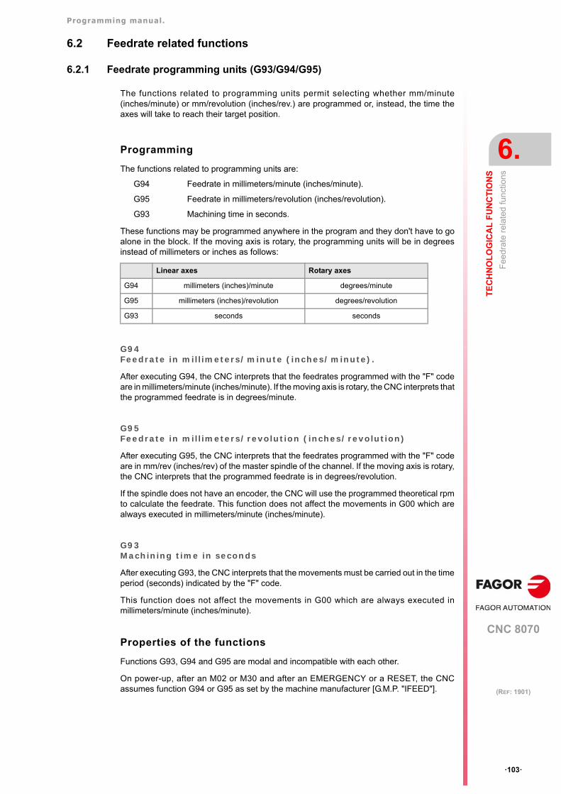
Programming manual.
CNC 8070
TE
CH
NO
LO
GIC
AL
FU
NC
TIO
NS
6.
Fee
drat
e re
late
d fu
nctio
ns
·103·
(REF: 1901)
6.2 Feedrate related functions
6.2.1 Feedrate programming units (G93/G94/G95)
The functions related to programming units permit selecting whether mm/minute(inches/minute) or mm/revolution (inches/rev.) are programmed or, instead, the time theaxes will take to reach their target position.
Programming
The functions related to programming units are:
G94 Feedrate in millimeters/minute (inches/minute).
G95 Feedrate in millimeters/revolution (inches/revolution).
G93 Machining time in seconds.
These functions may be programmed anywhere in the program and they don't have to goalone in the block. If the moving axis is rotary, the programming units will be in degreesinstead of millimeters or inches as follows:
G94Feedrate in millimeters/minute (inches/minute).
After executing G94, the CNC interprets that the feedrates programmed with the "F" codeare in millimeters/minute (inches/minute). If the moving axis is rotary, the CNC interprets thatthe programmed feedrate is in degrees/minute.
G95Feedrate in millimeters/revolution (inches/revolution)
After executing G95, the CNC interprets that the feedrates programmed with the "F" codeare in mm/rev (inches/rev) of the master spindle of the channel. If the moving axis is rotary,the CNC interprets that the programmed feedrate is in degrees/revolution.
If the spindle does not have an encoder, the CNC will use the programmed theoretical rpmto calculate the feedrate. This function does not affect the movements in G00 which arealways executed in millimeters/minute (inches/minute).
G93Machining time in seconds
After executing G93, the CNC interprets that the movements must be carried out in the timeperiod (seconds) indicated by the "F" code.
This function does not affect the movements in G00 which are always executed inmillimeters/minute (inches/minute).
Properties of the functions
Functions G93, G94 and G95 are modal and incompatible with each other.
On power-up, after an M02 or M30 and after an EMERGENCY or a RESET, the CNCassumes function G94 or G95 as set by the machine manufacturer [G.M.P. "IFEED"].
Linear axes Rotary axes
G94 millimeters (inches)/minute degrees/minute
G95 millimeters (inches)/revolution degrees/revolution
G93 seconds seconds
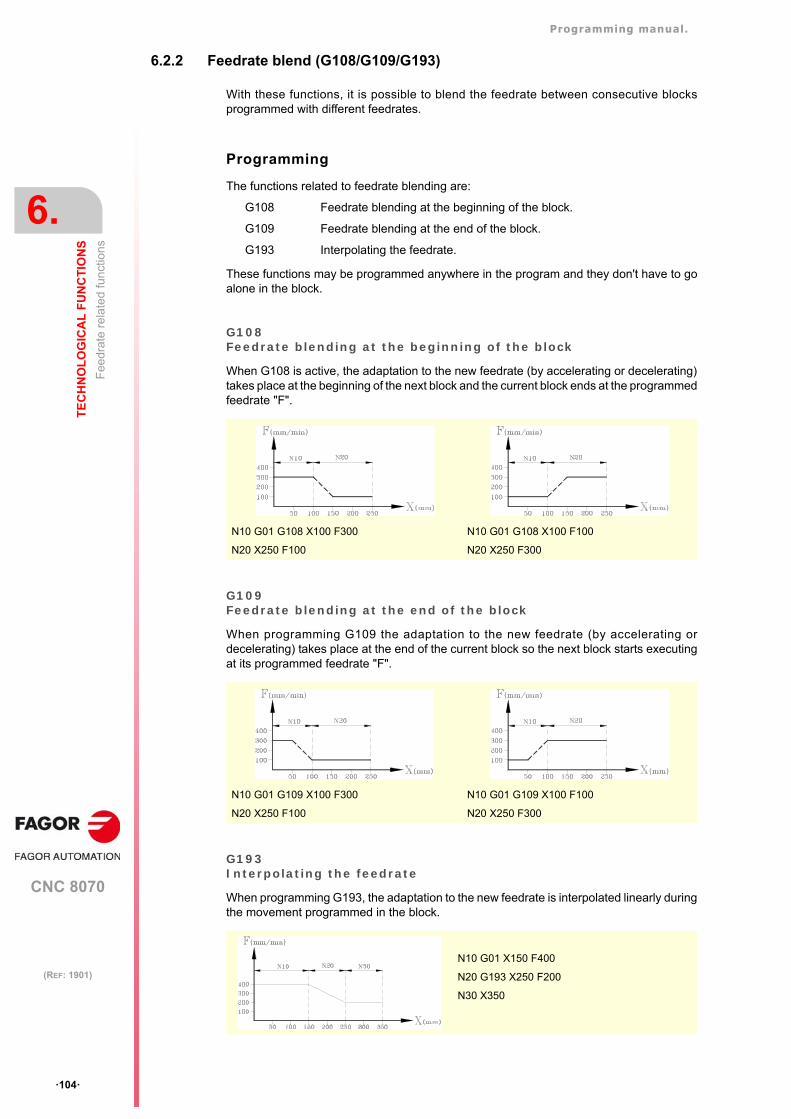
Programming manual.
CNC 8070
6.
TE
CH
NO
LO
GIC
AL
FU
NC
TIO
NS
Fee
drat
e re
late
d fu
nctio
ns
·104·
(REF: 1901)
6.2.2 Feedrate blend (G108/G109/G193)
With these functions, it is possible to blend the feedrate between consecutive blocksprogrammed with different feedrates.
Programming
The functions related to feedrate blending are:
G108 Feedrate blending at the beginning of the block.
G109 Feedrate blending at the end of the block.
G193 Interpolating the feedrate.
These functions may be programmed anywhere in the program and they don't have to goalone in the block.
G108Feedrate blending at the beginning of the block
When G108 is active, the adaptation to the new feedrate (by accelerating or decelerating)takes place at the beginning of the next block and the current block ends at the programmedfeedrate "F".
G109Feedrate blending at the end of the block
When programming G109 the adaptation to the new feedrate (by accelerating ordecelerating) takes place at the end of the current block so the next block starts executingat its programmed feedrate "F".
G193Interpolating the feedrate
When programming G193, the adaptation to the new feedrate is interpolated linearly duringthe movement programmed in the block.
N10 G01 G108 X100 F300 N10 G01 G108 X100 F100
N20 X250 F100 N20 X250 F300
N10 G01 G109 X100 F300 N10 G01 G109 X100 F100
N20 X250 F100 N20 X250 F300
N10 G01 X150 F400
N20 G193 X250 F200
N30 X350
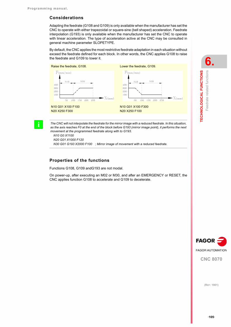
Programming manual.
CNC 8070
TE
CH
NO
LO
GIC
AL
FU
NC
TIO
NS
6.
Fee
drat
e re
late
d fu
nctio
ns
·105·
(REF: 1901)
Considerations
Adapting the feedrate (G108 and G109) is only available when the manufacturer has set theCNC to operate with either trapezoidal or square-sine (bell shaped) acceleration. Feedrateinterpolation (G193) is only available when the manufacturer has set the CNC to operatewith linear acceleration. The type of acceleration active at the CNC may be consulted ingeneral machine parameter SLOPETYPE.
By default, the CNC applies the most restrictive feedrate adaptation in each situation withoutexceed the feedrate defined for each block. In other words, the CNC applies G108 to raisethe feedrate and G109 to lower it.
Properties of the functions
Functions G108, G109 andG193 are not modal.
On power-up, after executing an M02 or M30, and after an EMERGENCY or RESET, theCNC applies function G108 to accelerate and G109 to decelerate.
Raise the feedrate, G108. Lower the feedrate, G109.
N10 G01 X100 F100N20 X250 F300
N10 G01 X100 F300N20 X250 F100
The CNC will not interpolate the feedrate for the mirror image with a reduced feedrate. In this situation,as the axis reaches F0 at the end of the block before G193 (mirror image point), it performs the nextmovement at the programmed feedrate along with to G193.
N10 G0 X1100N20 G01 X1000 F120N30 G01 G193 X2000 F100 ; Mirror image of movement with a reduced feedrate.
i
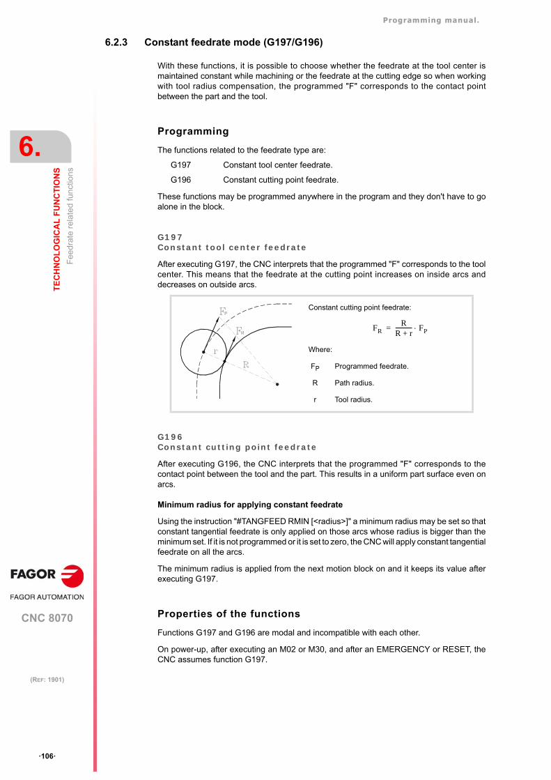
Programming manual.
CNC 8070
6.
TE
CH
NO
LO
GIC
AL
FU
NC
TIO
NS
Fee
drat
e re
late
d fu
nctio
ns
·106·
(REF: 1901)
6.2.3 Constant feedrate mode (G197/G196)
With these functions, it is possible to choose whether the feedrate at the tool center ismaintained constant while machining or the feedrate at the cutting edge so when workingwith tool radius compensation, the programmed "F" corresponds to the contact pointbetween the part and the tool.
Programming
The functions related to the feedrate type are:
G197 Constant tool center feedrate.
G196 Constant cutting point feedrate.
These functions may be programmed anywhere in the program and they don't have to goalone in the block.
G197Constant tool center feedrate
After executing G197, the CNC interprets that the programmed "F" corresponds to the toolcenter. This means that the feedrate at the cutting point increases on inside arcs anddecreases on outside arcs.
G196Constant cutting point feedrate
After executing G196, the CNC interprets that the programmed "F" corresponds to thecontact point between the tool and the part. This results in a uniform part surface even onarcs.
Minimum radius for applying constant feedrate
Using the instruction "#TANGFEED RMIN [<radius>]" a minimum radius may be set so thatconstant tangential feedrate is only applied on those arcs whose radius is bigger than theminimum set. If it is not programmed or it is set to zero, the CNC will apply constant tangentialfeedrate on all the arcs.
The minimum radius is applied from the next motion block on and it keeps its value afterexecuting G197.
Properties of the functions
Functions G197 and G196 are modal and incompatible with each other.
On power-up, after executing an M02 or M30, and after an EMERGENCY or RESET, theCNC assumes function G197.
Constant cutting point feedrate:
Where:
FP Programmed feedrate.
R Path radius.
r Tool radius.
FRR
R r+------------ FP=
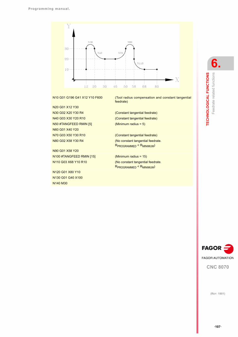
Programming manual.
CNC 8070
TE
CH
NO
LO
GIC
AL
FU
NC
TIO
NS
6.
Fee
drat
e re
late
d fu
nctio
ns
·107·
(REF: 1901)
N10 G01 G196 G41 X12 Y10 F600 (Tool radius compensation and constant tangentialfeedrate)
N20 G01 X12 Y30
N30 G02 X20 Y30 R4 (Constant tangential feedrate)
N40 G03 X30 Y20 R10 (Constant tangential feedrate)
N50 #TANGFEED RMIN [5] (Minimum radius = 5)
N60 G01 X40 Y20
N70 G03 X50 Y30 R10 (Constant tangential feedrate)
N80 G02 X58 Y30 R4 (No constant tangential feedrate.RPROGRAMMED < RMINIMUM)
N90 G01 X58 Y20
N100 #TANGFEED RMIN [15] (Minimum radius = 15)
N110 G03 X68 Y10 R10 (No constant tangential feedrate.RPROGRAMMED < RMINIMUM)
N120 G01 X80 Y10
N130 G01 G40 X100
N140 M30
Programming manual.
CNC 8070
6.
TE
CH
NO
LO
GIC
AL
FU
NC
TIO
NS
Fee
drat
e re
late
d fu
nctio
ns
·108·
(REF: 1901)
6.2.4 Cancellation of the % of feedrate override (G266)
G266Feedrate override at 100%
This function sets the feedrate override at 100%, which can neither be changed by selectorswitch on the operator panel nor via PLC.
Function G266 only affects the block where it has been programmed, therefore, it only makessense to add it to a block that defines a movement (motion block).
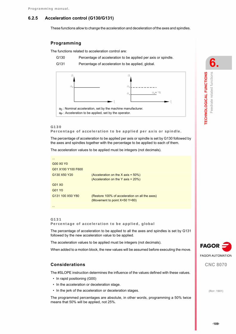
Programming manual.
CNC 8070
TE
CH
NO
LO
GIC
AL
FU
NC
TIO
NS
6.
Fee
drat
e re
late
d fu
nctio
ns
·109·
(REF: 1901)
6.2.5 Acceleration control (G130/G131)
These functions allow to change the acceleration and deceleration of the axes and spindles.
Programming
The functions related to acceleration control are:
G130 Percentage of acceleration to be applied per axis or spindle.
G131 Percentage of acceleration to be applied, global.
G130Percentage of acceleration to be applied per axis or spindle.
The percentage of acceleration to be applied per axis or spindle is set by G130 followed bythe axes and spindles together with the percentage to be applied to each of them.
The acceleration values to be applied must be integers (not decimals).
G131Percentage of acceleration to be applied, global
The percentage of acceleration to be applied to all the axes and spindles is set by G131followed by the new acceleration value to be applied.
The acceleration values to be applied must be integers (not decimals).
When added to a motion block, the new values will be assumed before executing the move.
Considerations
The #SLOPE instruction determines the influence of the values defined with these values.
• In rapid positioning (G00)
• In the acceleration or deceleration stage.
• In the jerk of the acceleration or deceleration stages.
The programmed percentages are absolute, in other words, programming a 50% twicemeans that 50% will be applied, not 25%.
a0 : Nominal acceleration, set by the machine manufacturer.aP : Acceleration to be applied, set by the operator.
...
G00 X0 Y0
G01 X100 Y100 F600
G130 X50 Y20 (Acceleration on the X axis = 50%)(Acceleration on the Y axis = 20%)
G01 X0
G01 Y0
G131 100 X50 Y80 (Restore 100% of acceleration on all the axes)(Movement to point X=50 Y=80)
...
Programming manual.
CNC 8070
6.
TE
CH
NO
LO
GIC
AL
FU
NC
TIO
NS
Fee
drat
e re
late
d fu
nctio
ns
·110·
(REF: 1901)
Properties of the functions
Functions G130 and G131 are modal and incompatible with each other.
On power-up, after an M02, M30, EMERGENCY or a RESET, the CNC restores 100% ofacceleration for all the axes and spindles.
Programming manual.
CNC 8070
TE
CH
NO
LO
GIC
AL
FU
NC
TIO
NS
6.
Fee
drat
e re
late
d fu
nctio
ns
·111·
(REF: 1901)
6.2.6 Jerk control (G132/G133)
The jerk of axes and spindles may be modified with these functions.
Programming
The functions associated with jerk control are:
G132 Percentage of jerk to be applied per axis or spindle.
G133 Percentage of jerk to be applied, global.
G132Percentage of jerk to be applied per axis or spindle.
The percentage of jerk to be applied per axis or spindle is set by G132 followed by the axesand spindles together with the new jerk to be applied to each of them.
The jerk values to be applied must be integers (not decimals).
G133Percentage of jerk to be applied, global
The percentage of jerk to be applied to all the axes and spindles is set by G133 followed bythe new jerk value to be applied.
The jerk values to be applied must be integers (not decimals).
When added to a motion block, the new jerk values will be assumed before executing themove.
Considerations
The #SLOPE instruction determines whether the new percentages are to be applied or noton to rapid traverse movements (G00).
The programmed percentages are absolute, in other words, programming a 50% twicemeans that 50% will be applied, not 25%.
Properties of the functions
Functions G132 and G133 are modal and incompatible with each other.
On power-up, after an M02, M30, EMERGENCY or a RESET, the CNC restores 100% ofjerk for all the axes and spindles.
G00 X0 Y0
G01 X100 Y100 F600
G132 X20 Y50 (Jerk on the X axis = 20%)(Jerk on the Y axis = 50%)
G01 X0
G01 Y0
G133 100 X50 Y80 (Restore 100% of jerk on all the axes. Movement to point X=50 Y=80)
Programming manual.
CNC 8070
6.
TE
CH
NO
LO
GIC
AL
FU
NC
TIO
NS
Fee
drat
e re
late
d fu
nctio
ns
·112·
(REF: 1901)
6.2.7 Feed-Forward control (G134)
Feed-Forward control may be used to reduce the amount of following error (axis lag).
Feed-forward may be applied via machine parameters and via PLC as well as by program.The value defined by PLC will be the one with the highest priority and the one defined bythe machine parameters will have the lowest priority.
Programming
G134Percentage of Feed-Forward to be applied
The Feed-Forward percentaje is set by G134 followed by the axes and the new percentageof Feed-Forward to be applied to each axis.
The Feed-forward values to be applied may be defined with up to two decimals.
Considerations
The maximum Feed-Forward value to be applied is 120%.
The programmed percentages are absolute, in other words, programming a 50% twicemeans that 50% will be applied, not 25%.
The value defined with G134 prevails over those defined in the machine parameters, but notover the one defined by PLC.
Properties of the functions
Function G134 is modal.
On power-up, after an M02 or M30, EMERGENCY or a RESET, the CNC restores the Feed-Forward set by the machine manufacturer for each axis.
Variable to define the feed-forward from the PLC
The write variable (V.)A.PLCFFGAIN.Xn may be used to set the feed-forward for eachaxis from the PLC. The value defined by this variable prevails over the ones defined bymachine parameters or by program.
Setting this variable with a negative value cancels its effect (a zero value is also valid). Thisvariable is initialized neither by a reset nor when validating the parameters.
G134 X50.75 Y80 Z10 (Percentage of Feed-Forward to be applied:)
(On the X axis = 50.75%)
(On the Y axis = 80%)
(On the Z axis = 10%)
Programming manual.
CNC 8070
TE
CH
NO
LO
GIC
AL
FU
NC
TIO
NS
6.
Fee
drat
e re
late
d fu
nctio
ns
·113·
(REF: 1901)
6.2.8 AC-Forward control (G135)
AC-Forward control may be used to improve system response in acceleration changes andreduce the amount of following error (axis lag) on the acceleration and deceleration stages.
AC-forward may be applied via machine parameters and via PLC as well as by program.The value defined by PLC will be the one with the highest priority and the one defined bythe machine parameters will have the lowest priority.
Programming
G135Percentage of AC-Forward to be applied
The AC-Forward percentaje is set by G135 followed by the axes and the new percentageof AC-Forward to be applied to each axis.
The AC-forward values to be applied may be defined with up to one decimal.
Considerations
The maximum AC-Forward value to be applied is 120%.
The programmed percentages are absolute, in other words, programming a 50% twicemeans that 50% will be applied, not 25%.
The value defined with G135 prevails over those defined in the machine parameters, but notover the one defined by PLC.
Properties of the functions
The G135 function is modal.
On power-up, after an M02 or M30, EMERGENCY or a RESET, the CNC restores the AC-Forward set by the machine manufacturer for each axis.
Variable to define the AC-forward from the PLC
The write variable (V.)A.PLCACGAIN.Xn may be used to set the AC-forward for each axisfrom the PLC. The value defined by this variable prevails over the ones defined by machineparameters or by program.
Setting this variable with a negative value cancels its effect (a zero value is also valid). Thisvariable is initialized neither by a reset nor when validating the parameters.
G135 X55.8 Y75 Z110 (Percentage of AC-Forward to be applied:)
(On the X axis = 55.8%)
(On the Y axis = 75%)
(On the Z axis = 110%)
Programming manual.
CNC 8070
6.
TE
CH
NO
LO
GIC
AL
FU
NC
TIO
NS
Spi
ndle
sp
eed
(S)
·114·
(REF: 1901)
6.3 Spindle speed (S)
The spindle speed is selected by program using the spindle name followed by the desiredspeed. The speeds of all the spindles of the channel may be programmed in the same block.See chapter "7 The spindle. Basic control.".
The programmed speed stays active until another value is programmed. On power-up, afterexecuting an M02 or M30, and after an emergency or reset, the spindles assume a ·0· speed.
The speed may be programmed in rpm or in m/min (feet/min), depending on whether G197or G196 is active. The default units are rpm.
Spindle start and stop
Defining a speed does not imply starting the spindle. The startup is defined using thefollowing auxiliary functions.
M03 - Starts the spindle clockwise.
M04 - Starts the spindle counterclockwise.
M05 - Stops the spindle.
Maximum speed
The maximum turning speed in each range (gear) is limited by the machine manufacturer.When programming a higher turning speed, the CNC limits its value to the maximum allowedby the active range (gear). The same thing occurs when trying to exceed the maximum limitsusing the "+" and "-" keys of the operator panel or doing it via PLC or by program.
Speed override
The programmed "S" speed may be varied between 50% and 120% using the "+" and "-"of the operator panel or via PLC. However the maximum and minimum variation may bedifferent depending on how the machine manufacturer has set [A.M.P. "MINOVR" y"MAXOVR"].
Likewise, the incremental step associated with the "+" and "-" keys of the Operator Panelto change the programmed spindle speed "S" will be 10; but this value may be differentdepending on the setting of axis machine parameter [P.P.E. "STEPOVR"].
During threading operations, the programmed speed cannot be overridden and it will be setat 100% of the programmed "S" speed.
S1000S1=500S1100 S1=2000 S4=2345
Programming manual.
CNC 8070
TE
CH
NO
LO
GIC
AL
FU
NC
TIO
NS
6.
Too
l nu
mb
er (
T)
·115·
(REF: 1901)
6.4 Tool number (T)
The "T" code identifies the tool to be selected. The tools may be in a magazine managedby the CNC or in a manual magazine (referred to as ground tools).
The programming format is T<0-4294967294> and it can be programmed using parametersand arithmetic expressions. In these cases, by default, the value calculated is rounded upto an integer. If the result is negative, the CNC will issue the pertinent error message.
Definition
To select a tool, it must be previously defined. To do that, the CNC offers a table where theuser may define the data for each tool. On the other hand, when having a magazine managedby the CNC, one must define the magazine position occupied by each tool. To do that, theCNC offers a table where the user may define the position of each tool. The table data maybe defined:
• Manually from the CNC's front panel (as described in the Operating Manual).
• Via program, using the associated variables (as described in the relevant chapter of thismanual).
Select a tool
The tool required for machining may be selected by program using the "T<n>" code where<n> is the tool number.
• On a lathe, the "T" code selects the tool in the tool holder.
• On a milling machine, The "T" code only selects the tool. After selecting a tool, functionM06 must be programmed to load it into the spindle. Loading/unloading is carried outdepending on the subroutine associated with the M06 (if so defined by the machinemanufacturer).
Example on a lathe model.
N10 ...
N20 T1 (The CNC selects tool T1 in the turret)
N30 ... (The CNC loads tool T1 into the spindle)
N40 ...
N50 T2 (The CNC selects tool T2 in the turret)
Example on a mill model.
N10 ...
N20 T1 (The CNC selects tool T1 in the tool magazine)
N30 M06 (The CNC loads tool T1 into the spindle)
N40 ...
N50 T2 (The CNC selects tool T2)
N60 ...
N70 ...
N80 ...
N90 M06 (The CNC loads tool T2 into the spindle)
N100 ...
N110 M30
Programming manual.
CNC 8070
6.
TE
CH
NO
LO
GIC
AL
FU
NC
TIO
NS
Too
l nu
mb
er (
T)
·116·
(REF: 1901)
Loading and unloading a tool in the magazine
To load the tools into the magazine, the magazine must be in load mode. To unload the toolsfrom the magazine, the magazine must be in unload mode. The tools are loaded from groundto the magazine going through the spindle and are unloaded to ground going through thespindle.
The magazine's work mode is set by variable V.[n].TM.MZMODE where n is the channelnumber. Depending on the value of the variable, the manager will assume one of thefollowing work modes.
Once the magazine is load or unload mode, the operation is carried out from the programusing the code Tnwhere n is the tool number. Once the tools have been loaded or unloaded,the magazine must be set to normal mode (value of ·0·).
Loading a tool in a specific magazine position
Some tools, due to their characteristics (size, weight, etc.) must be placed in a specificmagazine position.
The command POSn defines the magazine position for the tool. It must always beprogrammed in the same block as Tn.
The magazine position can only selected when the magazine is in load mode. Otherwise,it issues the relevant error message.
Loading a tool in a system with several magazines
When using more than one tool magazine, one must indicate in which one of them the toolis to be loaded using the codeMZn, where n indicates the magazine number. It must alwaysbe programmed in the same block as Tn.
Considerations. The tool and the M06 function.
The machine manufacturer may have associated a subroutine with the "T" code, that will beexecuted automatically when selecting the tool. If the M06 has been included in thissubroutine, the tool will be loaded into the spindle when executing the "T" code.
Value Meaning
0 Normal mode (by default and after Reset).
1 Magazine loading mode.
2 Magazine unloading mode.
V.[1].TM.MZMODE = 1T1 M6T2 M6···V.[1].TM.MZMODE = 0
V.[1].TM.MZMODE = 1T3 M6 POS24
(Places tool 3 in magazine position 24)···V.[1].TM.MZMODE = 0
T1 MZ1 M6(Place tool 1 in the first magazine)
T8 MZ2 POS17 M6(Place tool 8 in position 17 of the second magazine)
Programming manual.
CNC 8070
TE
CH
NO
LO
GIC
AL
FU
NC
TIO
NS
6.
Too
l nu
mb
er (
T)
·117·
(REF: 1901)
Positioning a turret magazine.
The CNC allows positioning the turret in a particular position whether there is a tool in theindicated position or not. If the selected position contains a tool, the CNC assumes it asprogrammed tool; otherwise, the CNC assumes T0.
Programming.
When programming this instruction, you must define the magazine number and the positionto be selected on the turret. The new position of the turret may be defined eitherincrementally, defining the number of positions to rotate and the rotating direction, orabsolutely, defining the position to reached.
The programming format is the following; the list of arguments appears between curlybrackets and the optional ones between angle brackets
#ROTATEMZ{mz} P{pos}#ROTATEMZ{mz} {±n}
{mz} Magazine number.
{pos} Absolute turret position.
{±n} Number of positions to rotate; the sign indicates the rotating direction, positive ornegative. If only the sign is programmed, the turret rotates one position.
#ROTATEMZ1 P5(Absolute position; select position 5).
#ROTATEMZ2 +3(Incremental positioning; rotate the turret 3 positions in positive direction).
#ROTATEMZ1 -7(Incremental positioning; rotate the turret 7 positions in negative direction).
#ROTATEMZ2 +(Incremental positioning; rotate the turret 1 position in positive direction).
#ROTATEMZ1 -(Incremental positioning; rotate the turret 1 position in negative direction).
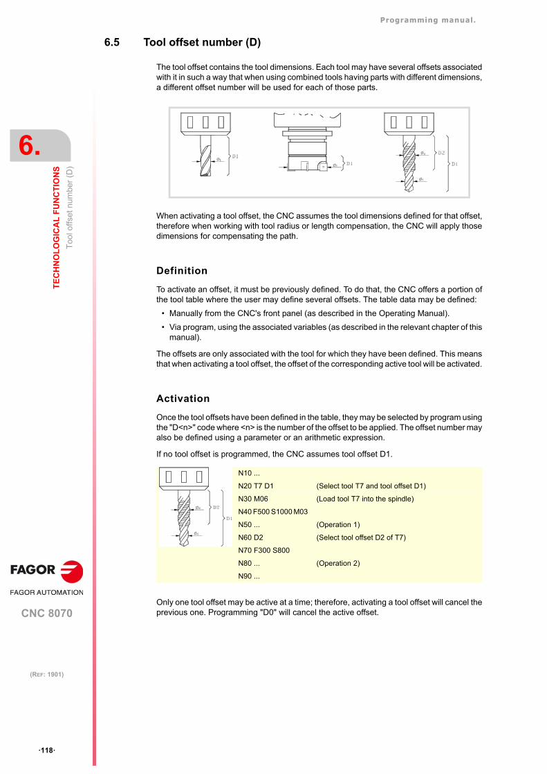
Programming manual.
CNC 8070
6.
TE
CH
NO
LO
GIC
AL
FU
NC
TIO
NS
Too
l offs
et n
umbe
r (D
)
·118·
(REF: 1901)
6.5 Tool offset number (D)
The tool offset contains the tool dimensions. Each tool may have several offsets associatedwith it in such a way that when using combined tools having parts with different dimensions,a different offset number will be used for each of those parts.
When activating a tool offset, the CNC assumes the tool dimensions defined for that offset,therefore when working with tool radius or length compensation, the CNC will apply thosedimensions for compensating the path.
Definition
To activate an offset, it must be previously defined. To do that, the CNC offers a portion ofthe tool table where the user may define several offsets. The table data may be defined:
• Manually from the CNC's front panel (as described in the Operating Manual).
• Via program, using the associated variables (as described in the relevant chapter of thismanual).
The offsets are only associated with the tool for which they have been defined. This meansthat when activating a tool offset, the offset of the corresponding active tool will be activated.
Activation
Once the tool offsets have been defined in the table, they may be selected by program usingthe "D<n>" code where <n> is the number of the offset to be applied. The offset number mayalso be defined using a parameter or an arithmetic expression.
If no tool offset is programmed, the CNC assumes tool offset D1.
Only one tool offset may be active at a time; therefore, activating a tool offset will cancel theprevious one. Programming "D0" will cancel the active offset.
N10 ...
N20 T7 D1 (Select tool T7 and tool offset D1)
N30 M06 (Load tool T7 into the spindle)
N40 F500 S1000 M03
N50 ... (Operation 1)
N60 D2 (Select tool offset D2 of T7)
N70 F300 S800
N80 ... (Operation 2)
N90 ...
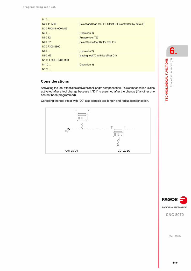
Programming manual.
CNC 8070
TE
CH
NO
LO
GIC
AL
FU
NC
TIO
NS
6.
Too
l offs
et n
umbe
r (D
)
·119·
(REF: 1901)
Considerations
Activating the tool offset also activates tool length compensation. This compensation is alsoactivated after a tool change because it "D1" is assumed after the change (if another onehas not been programmed).
Canceling the tool offset with "D0" also cancels tool length and radius compensation.
N10 ...
N20 T1 M06 (Select and load tool T1. Offset D1 is activated by default)
N30 F500 S1000 M03
N40 ... (Operation 1)
N50 T2 (Prepare tool T2)
N60 D2 (Select tool offset D2 for tool T1)
N70 F300 S800
N80 ... (Operation 2)
N90 M6 (loading tool T2 with its offset D1)
N100 F800 S1200 M03
N110 ... (Operation 3)
N120 ...
G01 Z0 D1 G01 Z0 D0
Programming manual.
CNC 8070
6.
TE
CH
NO
LO
GIC
AL
FU
NC
TIO
NS
Aux
iliar
y (m
isce
llane
ous)
func
tion
s (M
)
·120·
(REF: 1901)
6.6 Auxiliary (miscellaneous) functions (M)
Auxiliary "M" functions are related to the overall CNC program execution and the control ofthe various devices of the machine such as spindle gear change, coolant, tool changes andso on.
Programming
Up to 7 "M" functions may be programmed in a block. The programming format is M<0 -65535>, and it can be programmed using parameters and arithmetic expressions. In thesecases, by default, the value calculated is rounded up to an integer. If the result is negative,the CNC will issue the pertinent error message.
Execution
Depending on how they have been set by the machine manufacturer ("M" function table):
• The "M" functions will be executed before or after the movement of the block where theywere programmed.
When setting an "M" to be executed after the move of the block, depending on the activefunction G05 or G07:
• The CNC will wait or not for the confirmation that the "M" function has been executedbefore resuming program execution. If it has to wait for confirmation, it will have to bereceived before or after executing the movement of the block where it has beenprogrammed.
• The "M" functions that have not been set in the table will be executed before themovement of the block where they have been programmed and the CNC will wait for the"M-done" confirmation before executing the movement of the block.
Certain "M" functions have a particular internal meaning in the CNC. The section on"6.6.1 List of "M" functions" in this chapter shows a list of these functions with their internalmeaning for the CNC.
Associated subroutine
The "M" functions may have an associated subroutine that will be executed instead of thefunction.
If, within a subroutine associated with an "M" function, the same "M" function is programmed,this function will be executed, but not its associated subroutine.
G05 The "M" function is executed with the theoretical end of the movement (when the axeshave not reached position).
G07 The "M" function is executed with the real end of the movement (when the axes arealready in position).
Programming manual.
CNC 8070
TE
CH
NO
LO
GIC
AL
FU
NC
TIO
NS
6.
Aux
iliar
y (m
isce
llane
ous)
func
tion
s (M
)
·121·
(REF: 1901)
6.6.1 List of "M" functions
Program Interruption (M00/M01)
M00Program stop.
Function M00 interrupts the execution of the program. It does not stop the spindle or initializethe cutting conditions.
The [CYCLE START] key of the operator panel must be pressed again in order to resumeprogram execution.
This function should be set in the "M" function table so it is executed at the end of the blockwhere it is programmed.
M01Conditional program stop.
When the external conditional stop switch is active (PLC signal "M01 STOP"), it interruptsprogram execution. It does not stop the spindle or initialize the cutting conditions.
The [CYCLE START] key of the operator panel must be pressed again in order to resumeprogram execution.
This function should be set in the "M" function table so it is executed at the end of the blockwhere it is programmed.
Tool change (M06)
M06Tool change.
The M06 function executes the tool change. The CNC will manage the tool change andupdate the table for the tool magazine.
This function should be set in the "M" table so it executes the subroutine corresponding tothe tool changer installed on the machine.
Programming manual.
CNC 8070
6.
TE
CH
NO
LO
GIC
AL
FU
NC
TIO
NS
Aux
iliar
y fu
nctio
ns (
H)
·122·
(REF: 1901)
6.7 Auxiliary functions (H)
Auxiliary "H" functions are used to send information out to the PLC. They differ from the "M"functions in that the "H" functions do not wait for confirmation that the function has beenexecuted in order to go on executing the program.
Programming
Up to 7 "H" functions may be programmed in the same block. The programming format isH<0 - 65535>, and it can be programmed using parameters and arithmetic expressions. Inthese cases, by default, the value calculated is rounded up to an integer. If the result isnegative, the CNC will issue the pertinent error message.
Execution
The auxiliary "H" functions are executed at the beginning of the block where they have beenprogrammed.
CNC 8070
7
·123·
(REF: 1901)
7. THE SPINDLE. BASIC CONTROL.
The CNC can have up to four spindles distributed between the various channels of thesystem. A channel may have one, several or no spindles associated with it.
Each channel can only control its spindles; it is not possible to start up or stop the spindlesof another channel directly. Indirectly, the CNC can control the spindles of another channelusing the instruction #EXBLK.
Multi-spindle channel
A multi-spindle channel is one that has two or more spindles. Via part-program or MDI, it ispossible to indicate which spindle the commands are directed to; when not indicated, thecommands are directed to the master spindle of the channel.
All the spindles of the channel may be running at the same time. Also, each of them maybe in a different mode; turn in different directions, be in positioning mode, etc.
Master spindle of the channel
The master spindle is the main spindle of the channel. In general, whenever a channel hasa single spindle, it will be its master spindle. When a channel has several spindles, the CNCwill choose the master spindle according to the established criteria. See "7.1 The masterspindle of the channel" on page 124.
Programming manual.
CNC 8070
7.
TH
E S
PIN
DL
E. B
AS
IC C
ON
TR
OL
.
The
mas
ter
spin
dle
of t
he c
hann
el
·124·
(REF: 1901)
7.1 The master spindle of the channel
The master spindle is the main spindle of the channel. It is the spindle that receives thecommands when no specific spindle is mentioned. In general, whenever a channel has asingle spindle, it will be its master spindle.
CNC criterion for selecting the master spindle after executingM02, M30 or after an emergency or a reset or restarting the CNC.
The selection of the master spindle in the channel depends on machine parameterMASTERSPDL. This parameter indicates whether the channel keeps the current masterspindle or recovers its original master spindle after executing M02, M30 or after anemergency or reset or restarting the CNC.
When a channel does not keep its master spindle, on CNC power-up and after a reset, thechannel assumes as master spindle the first spindle defined by the machine parameters ofthe channel (original master). If this spindle is parked or "handed out" to another channel,the channel assumes as master spindle the next spindle defined by the machine parametersand so on. If the channel does not have spindles of the original configuration (the one definedby the machine parameters) because they are parked or "handed out", it assumes as masterspindle the first one of the current configuration that is not parked.
Exchanging spindles between channels.
When spindles are being exchanged between channels, the behavior of this parameter alsodepends on parameter AXISEXCH that sets whether the channel change of a spindle istemporary or permanent. If the current master spindle of the channel is a spindle "loaned"by another channel and its permission to change channels is temporary (AXISEXCH =Temporary), the spindle returns to its original channel.
Which one is the master spindle after executing M30?
When executing an M30, it follows the same criteria, but considering that after executing thisfunction, the temporary spindle swaps are not undone; they are undone at the beginning ofthe next program. This means that the original master might not be available after executingan M30, but it will be at the beginning of the next program. In this situation, after an M30,the channel will temporarily assume a master spindle that will change at the beginning ofthe next program.
W h i c h o n e i s t h e m a s t e r s p i n d l e a f t e r m o d i f y i n g t h econfiguration of the channel?.
If no master spindle is indicated, after parking or swapping spindles, it assumes oneaccording to the following criteria. In general, whenever a channel has a single spindle, itwill be its master spindle.
• If the whole system only has one spindle, it will be the master spindle of the currentchannel.
• If a spindle is added to a channel that does not have one, it will be the master spindle.
• If a channel releases its master spindle and it has only one spindle left, this one will beits new master spindle.
• If a channel having two spindles but no master spindle releases one of them, theremaining one will be its master spindle.
• At first, in a channel with several spindles, the master spindle will be the one configuredby machine parameters.
MASTERSPDL Meaning.
Temporary. The channel recovers its original master spindle if it is free; otherwise, it selectsas master the firs spindle available in the original configuration.
Maintained. The channel keeps the active master spindle.
Programming manual.
CNC 8070
TH
E S
PIN
DL
E. B
AS
IC C
ON
TR
OL
.
7.
The
mas
ter
spin
dle
of t
he c
hann
el
·125·
(REF: 1901)
• If two or more spindles remain in a channel and none of the previous rules can be applied,it applies the following criteria.
If any of the spindles is the original master, it is assumed as master spindle. If it is parked,it selects the next spindle from the original configuration (those defined by the machineparameters) and so on.
If no spindles from the original configuration are available in the channel, it assumes asmaster spindle the first one of its current configuration. If it is parked, it selects the nextspindle and so on.
Which one is the master spindle after parking or unparkingspindles?
The same treatment is applied as when modifying the configuration of the channel.
Programming manual.
CNC 8070
7.
TH
E S
PIN
DL
E. B
AS
IC C
ON
TR
OL
.
The
mas
ter
spin
dle
of t
he c
hann
el
·126·
(REF: 1901)
7.1.1 Manual selection of a master spindle
Selecting a new master spindle
Whenever a channel has a single spindle, it will be its master spindle. When a channel hasseveral spindles, the CNC will choose the master spindle according to the criteria describedearlier. However, a different master spindle may be selected via MDI or via part-programusing the #MASTER instruction.
Programming format.
#MASTER sp
Canceling the master spindle
The master spindle may be selected at any time. If the master spindle changes channels,the channel will select a new master spindle according to the criterion described earlier.
On power-up, after executing an M02 or M30, and after an emergency or reset, the CNCacts as defined by the OEM (parameter MASTERSPDL).
sp Spindle name.
#MASTER S#MASTER S2
Programming manual.
CNC 8070
TH
E S
PIN
DL
E. B
AS
IC C
ON
TR
OL
.
7.
Sp
ind
le s
pee
d
·127·
(REF: 1901)
7.2 Spindle speed
The spindle speed is selected by program using the spindle name followed by the desiredspeed. The speeds of all the spindles of the channel may be programmed in the same block.It is not possible to program the speed of a spindle that is not in the channel.
The programmed speed stays active until another value is programmed. On power-up, afterexecuting an M02 or M30, and after an emergency or reset, the spindles assume a ·0· speed.
Programming format
The spindle may have any name in the S, S1...S9 range. There is no need to program the"=" sign for the "S" spindle.
Sn={vel}S{vel}
The speed may be programmed in rpm or in m/min (feet/min), depending on whether G97or G96 is active. The default units are rpm.
Spindle start and stop
Defining a speed does not imply starting the spindle. The startup is defined using thefollowing auxiliary functions. See "7.3 Spindle start and stop" on page 130.
M03 - Starts the spindle clockwise.
M04 - Starts the spindle counterclockwise.
M05 - Stops the spindle.
Speed ranges (gears)
Each spindle may have up to 4 different ranges (gears). Each gear means a speed rangefor the CNC work in. The programmed speed must be within the active gear; otherwise, agear change will be required. The CNC does not admit speeds higher than the one definedfor the last gear.
The gear change may be automatic or manual. When the change is manual, the gear isselected with auxiliary functions M41 through M44. When the change is automatic, the CNCitself generates these functions according to the programmed speed. See "7.4 Gearchange." on page 132.
Sn Spindle name.
S Spindle "S".
{vel} Turning speed.
S1000S1=500S1100 S1=2000 S4=2345
Programming manual.
CNC 8070
7.
TH
E S
PIN
DL
E. B
AS
IC C
ON
TR
OL
.
Sp
ind
le s
pee
d
·128·
(REF: 1901)
7.2.1 G192. Turning speed limitation
Function G192 limits the spindle turning speed in both work modes; G96 and G97. Thisfunction is especially useful when working at constant cutting speed while machining largeparts or when doing spindle maintenance work.
If function G192 is not programmed, the turning speed is limited by machine parameterG00FEED of the gear.
G192. Programming the turning speed limit
The turning speed limit is set by programming function G192 and then the maximum speedfor each spindle. This function may be programmed while the spindle is running; in this case,the CNC will limit the speed to the new programmed value.
Programming format
The spindle may have any name in the S, S1...S9 range. There is no need to program the"=" sign for the "S" spindle.
G192 Sn={vel}G192 S{vel}
The maximum turning speed is always set in RPM. It is possible to program using arithmeticparameters, variables or expressions.
Properties of the function and Influence of the reset, turning theCNC off and of the M30 function.
Function G192 is modal.
The CNC cancels function G192 on power-up. After executing an M02 or M30, and after anemergency or a reset, the CNC maintains function G192.
{vel} Maximum spindle speed.
G192 S1000G192 S1=500
Programming manual.
CNC 8070
TH
E S
PIN
DL
E. B
AS
IC C
ON
TR
OL
.
7.
Sp
ind
le s
pee
d
·129·
(REF: 1901)
7.2.2 Constant surface speed
The functions related to spindle speed programming may be used to select either ConstantSurface Speed mode or Constant turning speed mode. Constant Surface Speed is onlyavailable at the master spindle of the channel.
G96 - Constant surface speed.
G97 - Constant turning speed.
At constant surface speed, the CNC changes the spindle speed as the perpendicular axismoves in order to maintain the cutting speed constant between the tool and the part, thusoptimizing the machining conditions. When working at constant surface speed, it isrecommended to limit by program the maximum turning speed that the spindle can reach.See "7.2.1 G192. Turning speed limitation" on page 128.
G96. Constant surface speed.
The G96 function only affects the master spindle of the channel.
After executing G96, the CNC interprets that the spindle speeds programmed for the masterspindle of the channel are in meters/minute (feet/minute). This work mode is activated whenprogramming a new speed while G96 is active.
This function may be programmed anywhere in the program and it doesn't have to go alonein the block. It is recommended to program the speed in the same block as the G96 function.The spindle gear (range) must be selected in the same block or in a previous one.
G97. Constant turning speed
The G97 function affects all the spindles of the channel.
After executing G97, the CNC interprets that the spindle speeds programmed are in rpm andstarts working at constant turning speed.
This function may be programmed anywhere in the program and it doesn't have to go alonein the block. It is recommended to program the speed in the same block as the G97 function;if not programmed, the CNC assumes as programmed speed the one the spindle is currentlyturning at. The gear may be selected at any time.
Properties of the function and Influence of the reset, turning theCNC off and of the M30 function.
Functions G96 and G97 are modal and incompatible with each other. The CNC assumesfunction G97 on power-up or after an emergency. After executing an M02 or M30, and aftera reset, the behavior of the function G96 depends on the parameter SPDLSTOP.
The following functions are oriented to lathe type machines. In order for Constant Surface Speed modeto be available, the machine manufacturer must have set one of the axis -face axis- (usually axisperpendicular to the shaft of the part).
i
SPDLSTOP Meaning.
Yes After an M2, M30 or reset, the CNC cancels the function G96 (active G97).
No After an M2, M30 or reset, the CNC keeps the function G96 active.
Programming manual.
CNC 8070
7.
TH
E S
PIN
DL
E. B
AS
IC C
ON
TR
OL
.
Spi
ndl
e s
tart
an
d st
op
·130·
(REF: 1901)
7.3 Spindle start and stop
A speed must be set in order to start up a spindle. The spindle start-up and stop are definedusing the following auxiliary functions.
M03 - Start the spindle clockwise.
M04 - Start the spindle counterclockwise.
M05 - Stop the spindle.
These functions are modal and incompatible with each other and with function M19.
M03/M04. Start the spindle clockwise/counterclockwise.
Function M03 starts the spindle clockwise and function M04 counterclockwise. Thesefunctions should be set in the "M functions" table so they are executed at the end of the blockwhere it is programmed.
These functions may be defined together with the programmed speed or in a separate block.If the block where they are programmed does not mention any spindle, they will be appliedto the master spindle of the channel.
If several spindles are programmed in a single block, functions M3 and M4 apply to all ofthem. To start the spindles in different directions, define next to each M function the spindleit is associated with, as follows.
M3.S / M4.S M3 or M4 associated with the spindle S.
M05. Stop the spindle.
Function M05 stops the spindle.
To stop a spindle, define next to the M5 the spindle it is associated with, as follows. If it doesnot mention any spindle, it applies to the master spindle.
M5.S Function M5 associated with the spindle S.
Turning direction preset in the tool table.
It is possible to set a preset turning direction for each tool. The value is defined in tool table.
When assigning a turning direction in the table, the CNC will verify, during execution, thatthe turning direction in the table is the same as the one programmed (M03/M04). If the twodirections are not the same, the CNC will display the corresponding error message. The CNCverifies this every time an M03, M04 or M06.is programmed.
S1000 M3(The spindle "S" starts clockwise at 1000 rpm)
S1=500 M4(The spindle "S1" starts counterclockwise at 500 rpm)
M4(The master spindle starts counterclockwise)
S1000 S2=456 M3(Spindle "S" turning at 1000 rpm and S2 at 456 rpm, both clockwise)
M3.S S1000 S2=456 M4.S2(The spindle "S" turns clockwise at 1000 rpm)(The spindle "S2" turns counterclockwise at 456 rpm)
S1000 S2=456 M5(Stops the master spindle)
M5.S M5.S2 S1=1000 M3.S1(Stops the spindles "S" and "S2")(Spindle "S1" turns clockwise)
Programming manual.
CNC 8070
TH
E S
PIN
DL
E. B
AS
IC C
ON
TR
OL
.
7.
Spi
ndl
e s
tart
an
d st
op
·131·
(REF: 1901)
Knowing which is the preset turning direction.
The turning direction preset for each tool may be consulted in the tool table; the one for theactive tool can also be consulted with a variable.
(V.)G.SPDLTURDIR
This variable returns the preset turning speed of the active tool. ·0· value if there is nopreset turning direction, ·1· if it is M03, and ·2· if it is M04.
Canceling the preset turning direction temporarily.
The preset turning speed of the active tool may be temporarily canceled from the part-program. This is done by setting the variable V.G.SPDLTURDIR = 0.
When changing a tool, this variable will take the corresponding value according to what hasbeen set in the tool table.
Programming manual.
CNC 8070
7.
TH
E S
PIN
DL
E. B
AS
IC C
ON
TR
OL
.
Gea
r ch
ange
.
·132·
(REF: 1901)
7.4 Gear change.
Each spindle may have up to 4 different ranges (gears). Each gear means a speed rangefor the CNC work in. The programmed speed must be within the active gear; otherwise, agear change will be required.
The gear change may be automatic or manual. When the change is manual, the gear isselected with auxiliary functions M41 (gear 1) through M44 (gear 4). When the change isautomatic, the CNC itself generates these functions according to the programmed speed.
The configuration of the speed ranges or gears (automatic or manual change, maximumspeed for each gear, etc.) is defined by the machine manufacturer. See "How to know thegear configuration of a spindle." on page 133.
Manual gear change
When the change is manual, the gear is selected with auxiliary functions M41 through M44.
M41 - Selects gear ·1·.
M42 - Selects gear ·2·.
M43 - Selects gear ·3·.
M44 - Selects gear ·4·.
These functions may be defined together with the programmed spindles or in a separateblock. If the block where they are programmed does not mention any spindle, they will beapplied to the master spindle of the channel.
If several spindles are programmed in a single block, the functions apply to all of them. Toapply different gears to the spindles, define next to each M function the spindle it is associatedwith, as follows.
M41.S Function M41 associated with the spindle S.
Influence of the reset, turning the CNC off and of the M30.
Gears (speed ranges) are modal. On power-up, the CNC assumes the gear defined by themachine manufacturer. After executing an M02 or M30 and after an emergency or a reset,the CNC maintains the active gear.
Knowing which is the active gear.
The window for the M functions in the jog and automatic modes shows which is the activegear; if none is shown, it means that gear ·1· is the active one.
The active gear may be consulted using the following variable.
The graphic shows a spindle with three speed ranges (gears). The first gear goes from 0 to S1 rpm;the second one from S1 to S2; the third one from S2 to S3.
S1000 M41S1=500 M42M44
S1000 S2=456 M41(Gear 1 for spindle "S" and S2)
M41.S M42.S3(Gear 1 for spindle "S")(Gear 2 for spindle "S3")
M41
rpm
M43M42
S1 S2 S3
Programming manual.
CNC 8070
TH
E S
PIN
DL
E. B
AS
IC C
ON
TR
OL
.
7.
Gea
r ch
ange
.
·133·
(REF: 1901)
(V.)[n].G.MS[i]
Variable that can only be read from the PRG and PLC.
The variable indicates the status of the auxiliary Mi function This variable returns a ·1·if it is active and a ·0· if not.
Gear change on Sercos spindles.
When using Sercos spindles, functions M41-M44 also involve changing the drive's velocityset.
How to know the gear configuration of a spindle.
Both the type of gear change (automatic or manual) and the maximum speed for each gearare defined by the machine manufacturer. The configuration may be checked directly in themachine parameter table or using the following variables.
How to know whether the spindle has an automatic tool changer or not.
(V.)SP.AUTOGEAR.Sn
Variable that can only be read from the PRG and PLC.
This variable indicates whether the spindle Sn has an automatic gear change or not. Thisvariable returns a ·1· if the gear changer is automatic and a ·0· if it is manual.
Number of gears available
(V.)SP.NPARSETS.Sn
Variable that can only be read from the PRG and PLC.
This variable indicates the number of gears defined for the spindle Sn.
Maximum speed for each gear
(V.)SP.G00FEED[g].Sn
Variable that can only be read from the PRG and PLC.
This variable indicates the maximum speed of the spindle Snin the gear g.
Gear active by default.
(V.)SP.DEFAULTSET.Sn
Variable that can only be read from the PRG and PLC.
This variable indicates which is the gear assumed by the CNC on power-up for the spindleSn.
Programming manual.
CNC 8070
7.
TH
E S
PIN
DL
E. B
AS
IC C
ON
TR
OL
.
Sp
ind
le o
rien
tatio
n.
·134·
(REF: 1901)
7.5 Spindle orientation.
The spindle orientation is defined with function M19. This function stops the spindle and itpositions it at an angle defined by parameter "S". See "How is positioning carried out" onpage 135.
After executing function M19, the spindle no longer works in speed mode and it switchesto positioning mode. This mode stays active until the spindle is started up again in speedmode with M3/M4.
Programming a spindle orientation
Every spindle positioning move requires an M19 and the positioning angle. If no angle isdefined, the CNC orients the master spindle at 0º.
Even if function M19 is active, if an "S" value is defined without an M19, the CNC assumesit as the new turning speed for the next time the spindle is turned on in speed mode usingfunctions M03/M04.
Programming format (1).
When executing function M19, the CNC interprets that the value entered with the "Sn" codeindicates the angular position of the spindle. If several spindles are programmed in a singleblock, function M19 applies to all of them.
M19 S{pos}
This angular position is programmed in degrees and it is always assumed in absolutecoordinates, thus not being affected by functions G90/G91. To do the positioning, the CNCcalculates the module (between 0 and 360º) of the programmed value.
Programming format (2). Positioning of the spindle at 0º
To orient the spindle to the ·0· position, it may also be programmed by defining, next to theM19, the spindle to be oriented. If no spindle is defined, the CNC assumes that the masterspindle is the one to be oriented.
M19.S
Properties of the function and Influence of the reset, turning theCNC off and of the M30 function.
M19 is modal and incompatible with M03, M04 and M05.
On power-up, after executing an M02 or M30, and after an emergency or reset, the CNCsets the spindle in speed mode with function M05.
This work mode is only available on machines having a rotary encoder installed on the spindle.i
S{pos} Spindle to be oriented and positioning angle. The angle is defined in degrees.
M19 S0(Positioning of spindle S at 0º)
M19 S2=120.78(Positioning of spindle S2 at 120.78º)
M19 S1=10 S2=34(Positioning of spindle S1 at 10º and S2 at 34º)
S Spindle to be oriented at 0º.
M19.S4(Positioning of spindle S4 at 0º)
M19(Positioning of the master spindle at 0º)
Programming manual.
CNC 8070
TH
E S
PIN
DL
E. B
AS
IC C
ON
TR
OL
.
7.
Sp
ind
le o
rien
tatio
n.
·135·
(REF: 1901)
How is positioning carried out
When executing function M19, the CNC behaves as follows.
1 The CNC stops the spindle (if it was turning).
2 The spindle no longer works in speed mode and it switches to positioning mode.
3 If it is the first time the M19 is executed, the CNC homes the spindle (home search).
4 It positions the spindle at 0º or at the angular position defined by the "S" code (if it hasbeen programmed). To do that, it will calculate the module (between 0 and 360º) of theprogrammed value and the spindle will reach that position.
It executes the M19 for the first time
When executing the M19 function for the first time, it homes the spindle. The M19 functionsprogrammed afterwards only orient the spindle. To home the spindle again, use function G74.
N10 G97 S2500 M03(The spindle turns at 2500 RPM)
N20 M19 S50(Spindle in positioning mode. The spindle orients at 50º)
N30 M19 S150 (Positioning at 150º)
N40 S1000(New spindle speed. The spindle stays in positioning mode)
N50 M19 S-100(Positioning at -100º)
N60 M03(Spindle controlled in speed. The spindle turns at 1000 RPM)
N70 M30
Programming manual.
CNC 8070
7.
TH
E S
PIN
DL
E. B
AS
IC C
ON
TR
OL
.
Sp
ind
le o
rien
tatio
n.
·136·
(REF: 1901)
7.5.1 The turning direction for spindle orientation
The turning direction for positioning may be set with function M19; if not defined, the CNCapplies a turning direction by default. Each spindle may have a different turning direction bydefault.
Turning direction by default
If no turning direction has been defined, the CNC behaves as follows. If when executingfunction M19, there was an M3 or M4 active, even if the speed is zero, this function will setthe spindle orienting direction. If no M3 or M4 is active, the turning direction is set dependingon machine parameter SHORTESTWAY.
• If it is a SHORTESTWAY spindle, it positions via the shortest way.
• If it is not a SHORTESTWAY type spindle, it positions in the same direction as the lastspindle movement.
Turning direction defined set by the user.
The positioning direction programmed next to the M19 is applied to all the spindlesprogrammed in the block. If the turning direction has not been programmed, each spindlewill turn in the direction set earlier; if none has been defined, it will assume the turningdirection by default.
The programmed turning direction is maintained until another one is programmed.
Programming format (1). Turning direction for all the spindles programmed.
M19.POS S{pos}M19.NEG S{pos}
If no spindle is defined, the CNC orients the master spindle at 0º in the indicated direction.
When programming the orienting direction for a SHORTESTWAYtype spindle, theprogrammed direction will be ignored.
Programming format (2). Turning direction for one spindle only.
Since several spindles may be programmed in a block, it is possible to apply the turningdirection just to one of them. The rest of the spindles will turn in their active direction.
M19.POS.S S{pos} S{pos}M19.NEG.S S{pos} S{pos}
POS Positioning in the positive direction
NEG Positioning in the negative direction
S{pos} Spindle to be oriented and positioning angle.
M19.NEG S120 S1=50(The negative direction is applied to spindle "S" and "S1")
M19.POS S120 S1=50(The positive direction is applied to spindle "S" and "S1")
POS.S Spindle that orients in the positive direction.
NEG.S Spindle that orients in the negative direction.
S{pos} Spindle to be oriented and positioning angle.
M19.NEG.S1 S1=100 S34.75(The negative direction is applied to spindle "S1")
Programming manual.
CNC 8070
TH
E S
PIN
DL
E. B
AS
IC C
ON
TR
OL
.
7.
Sp
ind
le o
rien
tatio
n.
·137·
(REF: 1901)
How to know the type of spindle.
The type of spindle may be checked directly in the machine parameter table or using thefollowing variables.
(V.)SP.SHORTESTWAY.Sn
Variable that can only be read from the PRG and PLC.
This variable indicates whether the spindle Sn orients via the shortest way. This variablereturns a ·1· if so.
Properties of the function and Influence of the reset, turning theCNC off and of the M30 function.
On power-up, after executing an M02 or M30, and after an emergency or reset, the CNCcancels the turning direction set by the user.
Programming manual.
CNC 8070
7.
TH
E S
PIN
DL
E. B
AS
IC C
ON
TR
OL
.
Sp
ind
le o
rien
tatio
n.
·138·
(REF: 1901)
7.5.2 M19 function with an associated subroutine.
Function M19 may have a subroutine associated with them that the CNC executes insteadof the function. If, within a subroutine associated with an "M" function, the same "M" functionis programmed, The CNC will executed it; but not its associated subroutine.
Although the function may affect more than one spindle in the same block, the CNC onlyexecutes the subroutine once. The following behavior is applicable to all positioningmovements programmed in the block.
When programming function M19 and a positioning (M19 S), the CNC executes thesubroutine associated with the function and ignores the positioning movement. The CNCexecutes the positioning when executing the M19 function from the subroutine.
• If inside the subroutine, the M19 function is not accompanied by a positioning move (S),the CNC executes the positioning programmed in the calling block.
• If inside the subroutine, the M19 function is accompanied by a positioning move (S), theCNC executes this positioning.
The same criterion applies to the moving direction. If the turning direction is programmedwith the M19 function that calls the subroutine, the turning direction is applied in the M19programmed inside the subroutine if it another one has not been specified.
Programming manual.
CNC 8070
TH
E S
PIN
DL
E. B
AS
IC C
ON
TR
OL
.
7.
Sp
ind
le o
rien
tatio
n.
·139·
(REF: 1901)
7.5.3 Positioning speed
It is possible to set the spindle positioning (orienting) speed; if it is not set, the CNC assumesthe one set by machine parameter REFEED1as the positioning speed. Each spindle mayhave a different positioning speed.
Programming format.
The positioning speed is set as follows.
S.POS={vel}
The positioning speed is given in rpm.
Knowing the active positioning speed.
The active positioning speed for the CNC may be consulted using the following variable.
(V.)SP.SPOS.Sn
Variable that can only be read from the PRG and PLC.
This variable indicates the active positioning speed for the spindle Sn.
S Spindle name.
{vel} Positioning speed.
M19 S.POS=120 S1.POS=50 (Positioning of spindle "S" at 120 rpm and S1 at 50 rpm)
Programming manual.
CNC 8070
7.
TH
E S
PIN
DL
E. B
AS
IC C
ON
TR
OL
.
M fu
nctio
ns w
ith a
n as
soci
ated
sub
rou
tine.
·140·
(REF: 1901)
7.6 M functions with an associated subroutine.
M3, M4, M5, M19 and M41 to M44 may have a subroutine associated with them that the CNCexecutes instead of the function. Although a function may affect more than one spindle inthe same block, the CNC only executes the subroutine once per block.
If, within a subroutine associated with an "M" function, the same "M" function is programmed,The CNC will executed it; but not its associated subroutine. When a spindle M function isprogrammed inside the subroutine, it will be applied to the spindles programmed in thesubroutine block itself. If the subroutine block does not indicate which spindles the functionis for, the CNC will assume that it is for the spindles programmed in the subroutine callingblock.
The CNC relates the functions with the spindles according to the following criterion, whetherit is in the calling block or inside the subroutine.
• If the M function is assigned to a spindle (for example, M3, S), the CNC only applies thefunction to the indicated spindle.
• If functions M3 and M4 are not assigned to any spindle, the CNC applies them to all thespindles whose speed has been programmed in the block and have not been assignedto another M function. If there are no spindles with programmed speed, the CNC appliesthem to the master spindle.
• If function M19 is not assigned to any spindle, the CNC applies them to all the spindleswhose speed has been programmed in the block and have not been assigned to anotherM function.
• If functions M5 and M41 to M44 are not assigned to any spindle, the CNC applies themto the master spindle.
Inside the subroutine, the CNC applies this criterion to all the programmed spindle Mfunctions, not only to the M functions that correspond to the calling block.
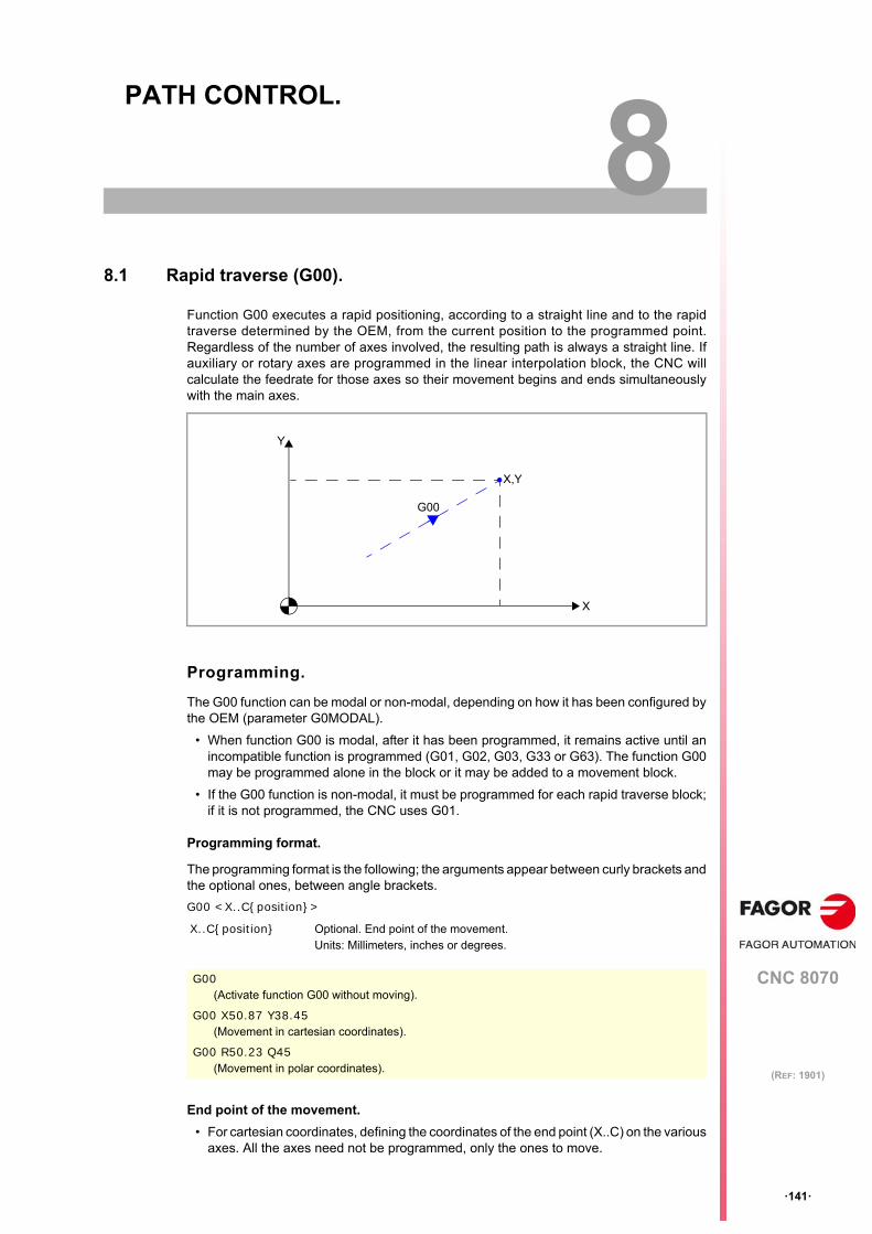
CNC 8070
8
·141·
(REF: 1901)
8. PATH CONTROL.
8.1 Rapid traverse (G00).
Function G00 executes a rapid positioning, according to a straight line and to the rapidtraverse determined by the OEM, from the current position to the programmed point.Regardless of the number of axes involved, the resulting path is always a straight line. Ifauxiliary or rotary axes are programmed in the linear interpolation block, the CNC willcalculate the feedrate for those axes so their movement begins and ends simultaneouslywith the main axes.
Programming.
The G00 function can be modal or non-modal, depending on how it has been configured bythe OEM (parameter G0MODAL).
• When function G00 is modal, after it has been programmed, it remains active until anincompatible function is programmed (G01, G02, G03, G33 or G63). The function G00may be programmed alone in the block or it may be added to a movement block.
• If the G00 function is non-modal, it must be programmed for each rapid traverse block;if it is not programmed, the CNC uses G01.
Programming format.
The programming format is the following; the arguments appear between curly brackets andthe optional ones, between angle brackets.
G00 <X..C{position}>
End point of the movement.
• For cartesian coordinates, defining the coordinates of the end point (X..C) on the variousaxes. All the axes need not be programmed, only the ones to move.
X..C{position} Optional. End point of the movement.Units: Millimeters, inches or degrees.
G00(Activate function G00 without moving).
G00 X50.87 Y38.45(Movement in cartesian coordinates).
G00 R50.23 Q45(Movement in polar coordinates).
X
G00
Y
X,Y
Programming manual.
CNC 8070
8.
PA
TH
CO
NT
RO
L.
Rap
id tr
ave
rse
(G
00).
·142·
(REF: 1901)
• For polar coordinates, define the radius (R) and the angle (Q) of the end point relativeto the polar origin. The "R" radius will be the distance between the polar origin and thepoint. The "Q" angle will be formed by the abscissa axis and the line joining the polar originwith the point. If the angle or the radius is not programmed, it keeps the valueprogrammed for the last move.
Considerations.
Feedrate behavior.
• A movement in G00 temporarily cancels the programmed "F" feedrate and the CNCexecutes the movement based according to the rapid traverse specified by the OEM(parameter G00FEED). The CNC recovers the "F" feedrate when programming amovement function G01, G02, G03, etc.
• When several axes are involved, the resulting feedrate is calculated so at least one ofthe axis moves at its maximum speed.
• When defining an "F" value and G00 in the same block, the CNC will store the valueassigned to "F" and it will apply it next time a G01, G02 or G03 type function isprogrammed.
Feedrate override.
The override percentage is set at 100% or it may be varied between 0% and 100% usingthe switch on the operator panel, depending on how it was set by the OEM (parameterRAPIDOVR).
Canned cycles.
Within the range of influence of a canned cycle or modal subroute (#MCALL), the lastprogrammed G will be maintain active, G0 or G1, meaning G0 remains as modal.
Properties of the function and Influence of the reset, turning theCNC off and of the M30 function.
Function G00 may be programmed as G0.
The G00 function can be modal or non-modal, depending on how it has been configured bythe OEM (parameter G0MODAL). Function G00 is modal and incompatible with G01, G02,G03, G33 and G63. For the following program block, if there is no programmed movementfunction in a non-modal G00 function (G0, G1, G2, G3, G33 or G63), the CNC uses G1.
On power-up, after an M02 or M30 and after an emergency or a reset, the CNC assumesfunction G00 or G01 as set by the OEM (parameter IMOVE). If the CNC assumes the functionG00, and this function is defined as non-modal (parameter G0MODAL), after programmingG1, G2 or G3, the CNC assumes G1 as a modal function.
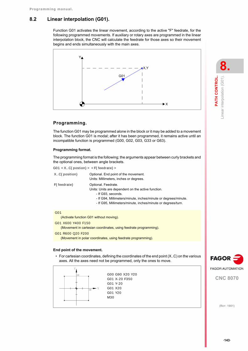
Programming manual.
CNC 8070
PA
TH
CO
NT
RO
L.
8.
Lin
ear
inte
rpo
latio
n (
G01
).
·143·
(REF: 1901)
8.2 Linear interpolation (G01).
Function G01 activates the linear movement, according to the active "F" feedrate, for thefollowing programmed movements. If auxiliary or rotary axes are programmed in the linearinterpolation block, the CNC will calculate the feedrate for those axes so their movementbegins and ends simultaneously with the main axes.
Programming.
The function G01 may be programmed alone in the block or it may be added to a movementblock. The function G01 is modal; after it has been programmed, it remains active until anincompatible function is programmed (G00, G02, G03, G33 or G63).
Programming format.
The programming format is the following; the arguments appear between curly brackets andthe optional ones, between angle brackets.
G01 <X..C{postion}> <F{feedrate}>
End point of the movement.
• For cartesian coordinates, defining the coordinates of the end point (X..C) on the variousaxes. All the axes need not be programmed, only the ones to move.
X..C{position} Optional. End point of the movement.Units: Millimeters, inches or degrees.
F{feedrate} Optional. Feedrate.Units: Units are dependent on the active function.
- If G93, seconds.- If G94, Millimeters/minute, inches/minute or degrees/minute.- If G95, Millimeters/minute, inches/minute or degrees/turn.
G01(Activate function G01 without moving).
G01 X600 Y400 F150(Movement in cartesian coordinates, using feedrate programming).
G01 R600 Q20 F200(Movement in polar coordinates, using feedrate programming).
X
G01
Y
X,Y
G00 G90 X20 Y20G01 X-20 F350G01 Y-20G01 X20G01 Y20M30
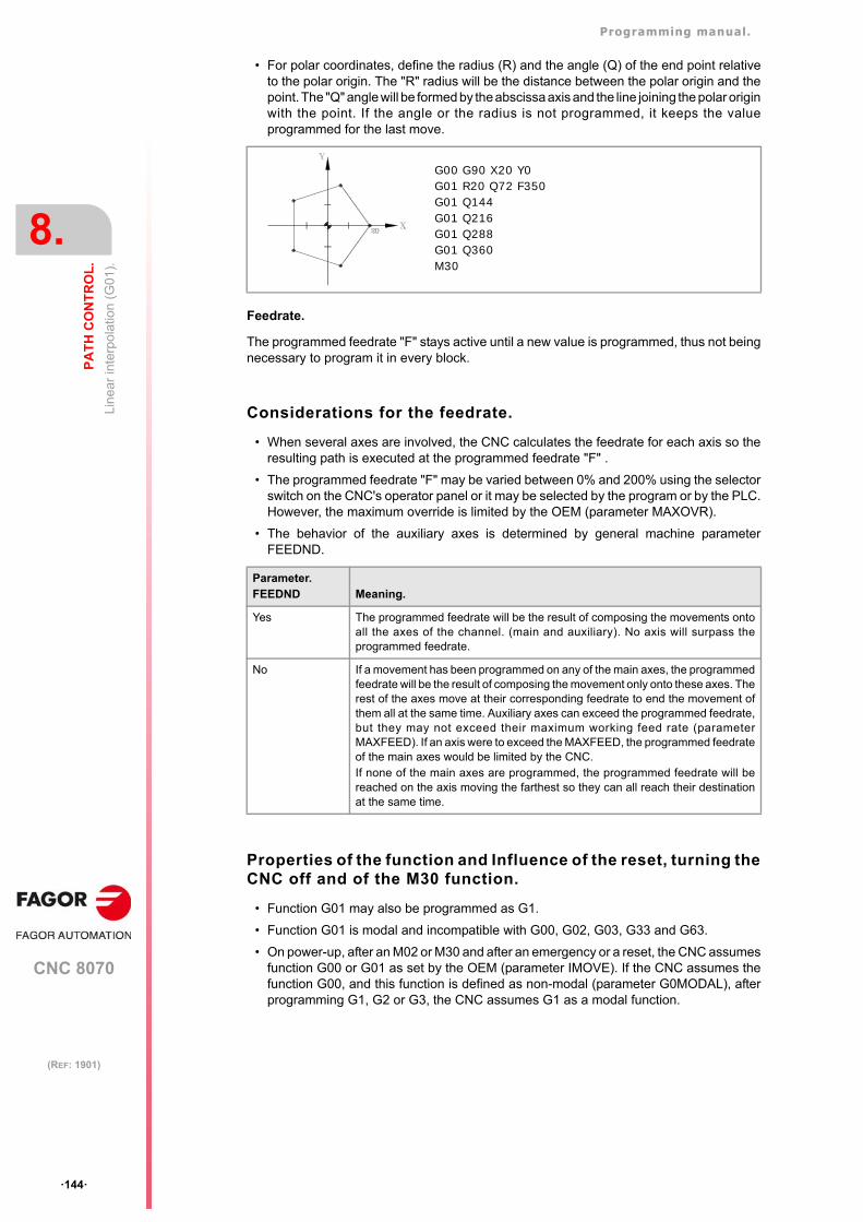
Programming manual.
CNC 8070
8.
PA
TH
CO
NT
RO
L.
Lin
ear
inte
rpo
latio
n (
G01
).
·144·
(REF: 1901)
• For polar coordinates, define the radius (R) and the angle (Q) of the end point relativeto the polar origin. The "R" radius will be the distance between the polar origin and thepoint. The "Q" angle will be formed by the abscissa axis and the line joining the polar originwith the point. If the angle or the radius is not programmed, it keeps the valueprogrammed for the last move.
Feedrate.
The programmed feedrate "F" stays active until a new value is programmed, thus not beingnecessary to program it in every block.
Considerations for the feedrate.
• When several axes are involved, the CNC calculates the feedrate for each axis so theresulting path is executed at the programmed feedrate "F" .
• The programmed feedrate "F" may be varied between 0% and 200% using the selectorswitch on the CNC's operator panel or it may be selected by the program or by the PLC.However, the maximum override is limited by the OEM (parameter MAXOVR).
• The behavior of the auxiliary axes is determined by general machine parameterFEEDND.
Properties of the function and Influence of the reset, turning theCNC off and of the M30 function.
• Function G01 may also be programmed as G1.
• Function G01 is modal and incompatible with G00, G02, G03, G33 and G63.
• On power-up, after an M02 or M30 and after an emergency or a reset, the CNC assumesfunction G00 or G01 as set by the OEM (parameter IMOVE). If the CNC assumes thefunction G00, and this function is defined as non-modal (parameter G0MODAL), afterprogramming G1, G2 or G3, the CNC assumes G1 as a modal function.
Parameter.FEEDND Meaning.
Yes The programmed feedrate will be the result of composing the movements ontoall the axes of the channel. (main and auxiliary). No axis will surpass theprogrammed feedrate.
No If a movement has been programmed on any of the main axes, the programmedfeedrate will be the result of composing the movement only onto these axes. Therest of the axes move at their corresponding feedrate to end the movement ofthem all at the same time. Auxiliary axes can exceed the programmed feedrate,but they may not exceed their maximum working feed rate (parameterMAXFEED). If an axis were to exceed the MAXFEED, the programmed feedrateof the main axes would be limited by the CNC.If none of the main axes are programmed, the programmed feedrate will bereached on the axis moving the farthest so they can all reach their destinationat the same time.
G00 G90 X20 Y0G01 R20 Q72 F350G01 Q144G01 Q216G01 Q288G01 Q360M30
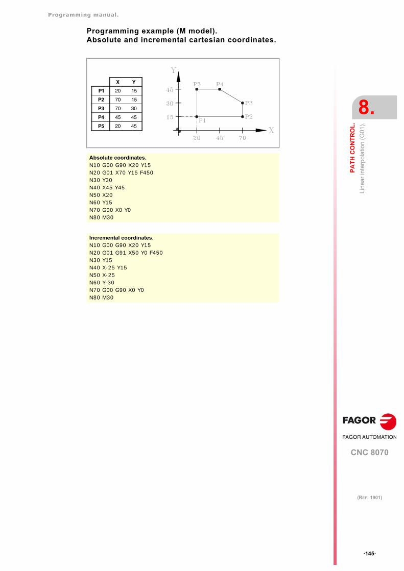
Programming manual.
CNC 8070
PA
TH
CO
NT
RO
L.
8.
Lin
ear
inte
rpo
latio
n (
G01
).
·145·
(REF: 1901)
Programming example (M model).Absolute and incremental cartesian coordinates.
Absolute coordinates.N10 G00 G90 X20 Y15N20 G01 X70 Y15 F450N30 Y30N40 X45 Y45N50 X20N60 Y15N70 G00 X0 Y0N80 M30
Incremental coordinates.N10 G00 G90 X20 Y15 N20 G01 G91 X50 Y0 F450N30 Y15N40 X-25 Y15N50 X-25N60 Y-30N70 G00 G90 X0 Y0N80 M30
X Y
P1 20 15
P2 70 15
P3 70 30
P4 45 45
P5 20 45
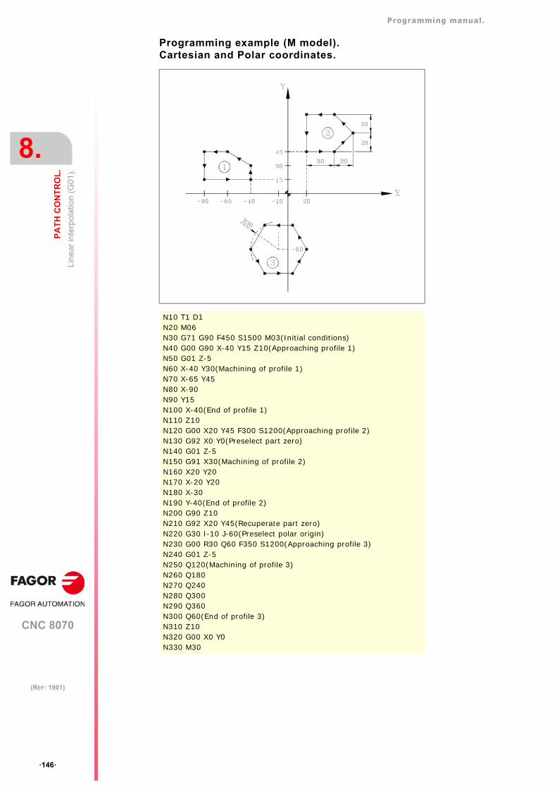
Programming manual.
CNC 8070
8.
PA
TH
CO
NT
RO
L.
Lin
ear
inte
rpo
latio
n (
G01
).
·146·
(REF: 1901)
Programming example (M model).Cartesian and Polar coordinates.
N10 T1 D1N20 M06N30 G71 G90 F450 S1500 M03(Initial conditions)N40 G00 G90 X-40 Y15 Z10(Approaching profile 1)N50 G01 Z-5N60 X-40 Y30(Machining of profile 1)N70 X-65 Y45N80 X-90N90 Y15 N100 X-40(End of profile 1)N110 Z10N120 G00 X20 Y45 F300 S1200(Approaching profile 2)N130 G92 X0 Y0(Preselect part zero)N140 G01 Z-5N150 G91 X30(Machining of profile 2)N160 X20 Y20N170 X-20 Y20N180 X-30N190 Y-40(End of profile 2)N200 G90 Z10N210 G92 X20 Y45(Recuperate part zero)N220 G30 I-10 J-60(Preselect polar origin)N230 G00 R30 Q60 F350 S1200(Approaching profile 3)N240 G01 Z-5N250 Q120(Machining of profile 3)N260 Q180N270 Q240N280 Q300N290 Q360N300 Q60(End of profile 3)N310 Z10N320 G00 X0 Y0N330 M30
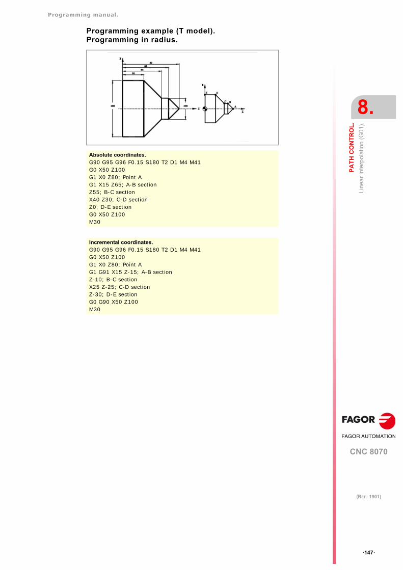
Programming manual.
CNC 8070
PA
TH
CO
NT
RO
L.
8.
Lin
ear
inte
rpo
latio
n (
G01
).
·147·
(REF: 1901)
Programming example (T model).Programming in radius.
Absolute coordinates.G90 G95 G96 F0.15 S180 T2 D1 M4 M41G0 X50 Z100G1 X0 Z80; Point AG1 X15 Z65; A-B sectionZ55; B-C sectionX40 Z30; C-D sectionZ0; D-E sectionG0 X50 Z100M30
Incremental coordinates.G90 G95 G96 F0.15 S180 T2 D1 M4 M41G0 X50 Z100G1 X0 Z80; Point AG1 G91 X15 Z-15; A-B sectionZ-10; B-C sectionX25 Z-25; C-D sectionZ-30; D-E sectionG0 G90 X50 Z100M30
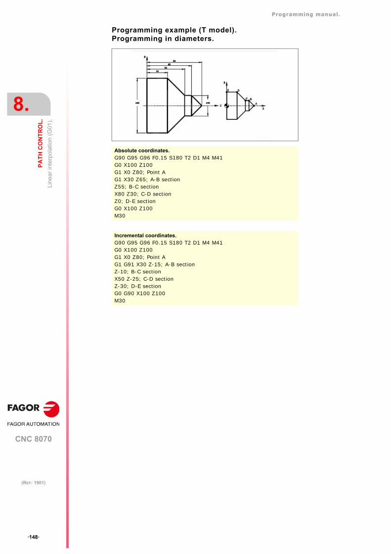
Programming manual.
CNC 8070
8.
PA
TH
CO
NT
RO
L.
Lin
ear
inte
rpo
latio
n (
G01
).
·148·
(REF: 1901)
Programming example (T model).Programming in diameters.
Absolute coordinates.G90 G95 G96 F0.15 S180 T2 D1 M4 M41G0 X100 Z100G1 X0 Z80; Point AG1 X30 Z65; A-B sectionZ55; B-C sectionX80 Z30; C-D sectionZ0; D-E sectionG0 X100 Z100M30
Incremental coordinates.G90 G95 G96 F0.15 S180 T2 D1 M4 M41G0 X100 Z100G1 X0 Z80; Point AG1 G91 X30 Z-15; A-B sectionZ-10; B-C sectionX50 Z-25; C-D sectionZ-30; D-E sectionG0 G90 X100 Z100M30

Programming manual.
CNC 8070
PA
TH
CO
NT
RO
L.
8.
Circ
ular
inte
rpol
atio
n (G
02/G
03).
·149·
(REF: 1901)
8.3 Circular interpolation (G02/G03).
Movements programmed for G02 and G03 are executed along a circular tool path at theprogrammed feedrate "F" from the current position to the indicated target point. A circularinterpolation can only be executed in the active plane.
Clockwise (G02) and counterclockwise (G03) moving directions have been establishedaccording to the following coordinate system.
Programming.
G02 Clockwise circular interpolation.
G03 Counterclockwise circular interpolation.
The coordinate system is referred to the movement of the tool on the part.
G02/G03 X Y I J
Cartesian coordinates (Arc center programming).
The arc is defined by programming function G02 or G03followed by the coordinates of the arc's end point andthose of its center (referred to the starting point of the arc)according to the axes of the active work plane.
G02/G03 X Y R
Cartesian coordinates (arc radius programming).
The arc is defined by programming function G02 or G03followed by the coordinates of the arc's end point and itsradius.
G02/G03 R Q I J
Polar coordinates.
The arc is defined by programming function G02 or G03followed by the coordinates of the arc's end point (radiusand angle) and those of its center (relative to the startingpoint of the arc) according to the axes of the active workplane.
Programming manual.
CNC 8070
8.
PA
TH
CO
NT
RO
L.
Circ
ular
inte
rpol
atio
n (G
02/G
03).
·150·
(REF: 1901)
Considerations for the feedrate.
• The programmed feedrate "F" stays active until a new value is programmed, thus notbeing necessary to program it in every block.
• The programmed feedrate "F" may be varied between 0% and 200% using the selectorswitch on the CNC's operator panel or it may be selected by the program or by the PLC.However, the maximum override is limited by the OEM (parameter MAXOVR).
Properties of the function and Influence of the reset, turning theCNC off and of the M30 function.
• Functions G02 and G03 may also be programmed as G2 and G3.
• Functions G02 and G03 are modal and incompatible with each other and with G00, G01,G33 and G63. Function G74 (Home search) also cancels functions G02 and G03.
• On power-up, after an M02 or M30 and after an emergency or a reset, the CNC assumesfunction G00 or G01 as set by the OEM (parameter IMOVE). If the CNC assumes thefunction G00, and this function is defined as non-modal (parameter G0MODAL), afterprogramming G1, G2 or G3, the CNC assumes G1 as a modal function.
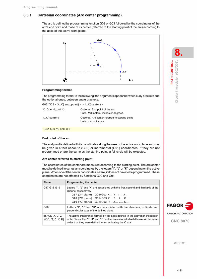
Programming manual.
CNC 8070
PA
TH
CO
NT
RO
L.
8.
Circ
ular
inte
rpol
atio
n (G
02/G
03).
·151·
(REF: 1901)
8.3.1 Cartesian coordinates (Arc center programming).
The arc is defined by programming function G02 or G03 followed by the coordinates of thearc's end point and those of its center (referred to the starting point of the arc) according tothe axes of the active work plane.
Programming format.
The programming format is the following; the arguments appear between curly brackets andthe optional ones, between angle brackets.
G02/G03 <X..C{end_point}> <I..K{center}>
End point of the arc.
The end point is defined with its coordinates along the axes of the active work plane and maybe given in either absolute (G90) or incremental (G91) coordinates. If they are notprogrammed or are the same as the starting point, a full circle will be executed.
Arc center referred to starting point.
The coordinates of the center are measured according to the starting point. The arc centermust be defined in cartesian coordinates by the letters "I", "J" or "K" depending on the activeplane. When one of the center coordinates is zero, it does not have to be programmed. Thesecoordinates are not affected by functions G90 and G91.
X..C{end_point} Optional. End point of the arc.Units: Millimeters, inches or degrees.
I..K{center} Optional. Arc center referred to starting point.Units: mm or inches.
G02 X50 Y0 I28 J13
Plane. Programming the center.
G17 G18 G19 Letters "I", "J" and "K" are associated with the first, second and third axis of thechannel respectively.
G17 (XY plane) G02/G03 X... Y... I... J...G18 (ZX plane) G02/G03 X... Z... I... K...G19 (YZ plane) G02/G03 R... Z... J... K...
G20 Letters "I", "J" and "K" are associated with the abscissa, ordinate andperpendicular axes of the defined plane.
#FACE [X, C, Z]#CYL [Z, C, X, R]
The active trihedron is formed by the axes defined in the activation instructionof the C axis. The "I", "J", and "K" centers are associated with the axes in the sameorder that they were defined when activating the C axis.
X
G02Y
X,Y
I,J
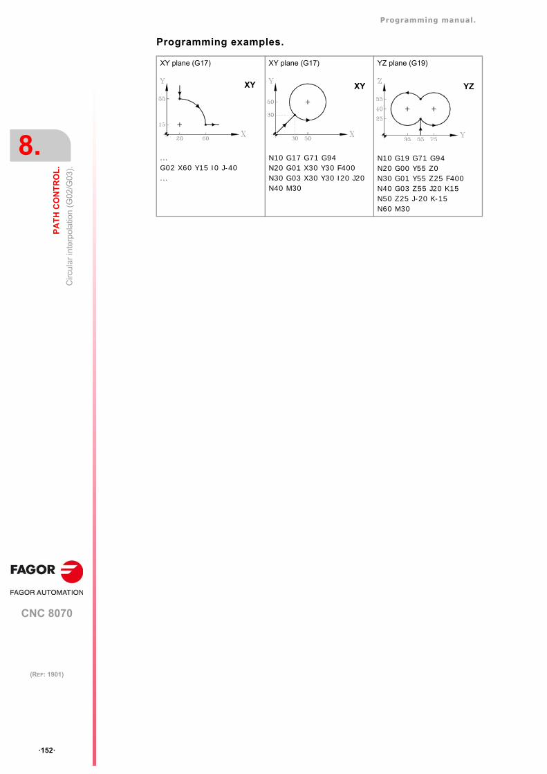
Programming manual.
CNC 8070
8.
PA
TH
CO
NT
RO
L.
Circ
ular
inte
rpol
atio
n (G
02/G
03).
·152·
(REF: 1901)
Programming examples.
XY plane (G17)
...G02 X60 Y15 I0 J-40...
XY plane (G17)
N10 G17 G71 G94N20 G01 X30 Y30 F400N30 G03 X30 Y30 I20 J20N40 M30
YZ plane (G19)
N10 G19 G71 G94N20 G00 Y55 Z0N30 G01 Y55 Z25 F400N40 G03 Z55 J20 K15N50 Z25 J-20 K-15N60 M30
XY XY YZ
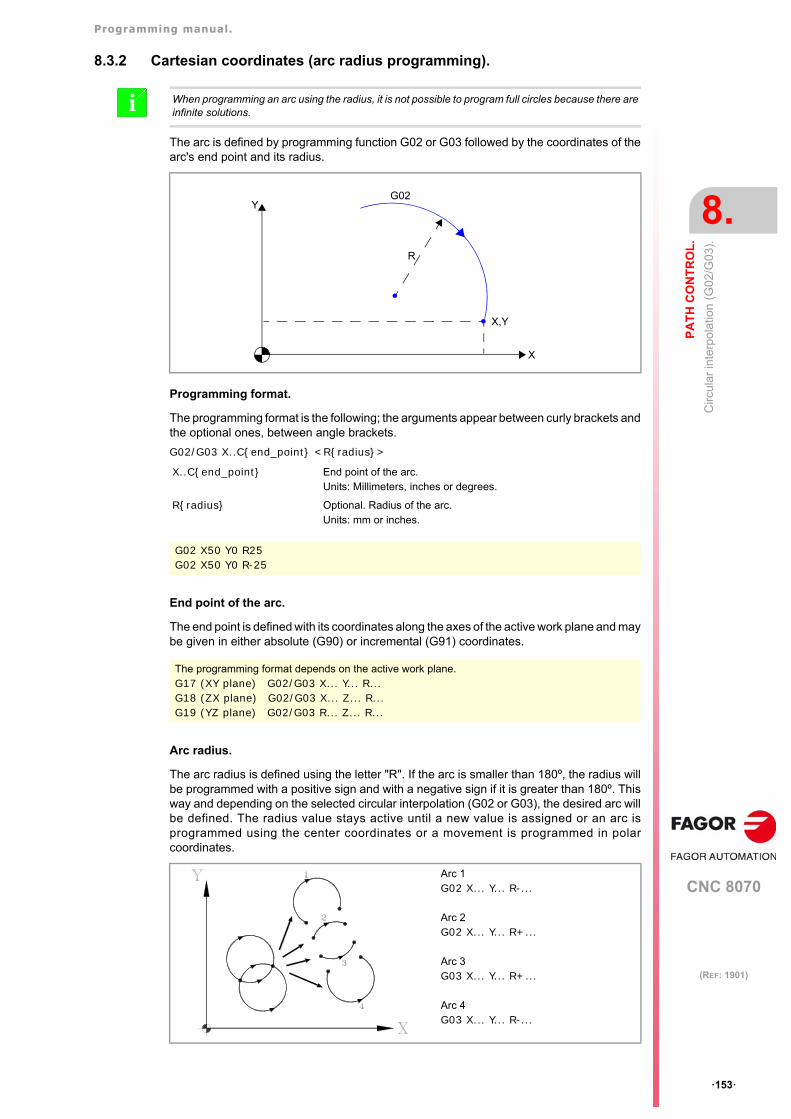
Programming manual.
CNC 8070
PA
TH
CO
NT
RO
L.
8.
Circ
ular
inte
rpol
atio
n (G
02/G
03).
·153·
(REF: 1901)
8.3.2 Cartesian coordinates (arc radius programming).
The arc is defined by programming function G02 or G03 followed by the coordinates of thearc's end point and its radius.
Programming format.
The programming format is the following; the arguments appear between curly brackets andthe optional ones, between angle brackets.
G02/G03 X..C{end_point} <R{radius}>
End point of the arc.
The end point is defined with its coordinates along the axes of the active work plane and maybe given in either absolute (G90) or incremental (G91) coordinates.
Arc radius.
The arc radius is defined using the letter "R". If the arc is smaller than 180º, the radius willbe programmed with a positive sign and with a negative sign if it is greater than 180º. Thisway and depending on the selected circular interpolation (G02 or G03), the desired arc willbe defined. The radius value stays active until a new value is assigned or an arc isprogrammed using the center coordinates or a movement is programmed in polarcoordinates.
When programming an arc using the radius, it is not possible to program full circles because there areinfinite solutions.i
X..C{end_point} End point of the arc.Units: Millimeters, inches or degrees.
R{radius} Optional. Radius of the arc.Units: mm or inches.
G02 X50 Y0 R25G02 X50 Y0 R-25
The programming format depends on the active work plane.G17 (XY plane) G02/G03 X... Y... R...G18 (ZX plane) G02/G03 X... Z... R...G19 (YZ plane) G02/G03 R... Z... R...
X
G02Y
X,Y
R
Arc 1G02 X... Y... R-...
Arc 2G02 X... Y... R+...
Arc 3G03 X... Y... R+...
Arc 4G03 X... Y... R-...
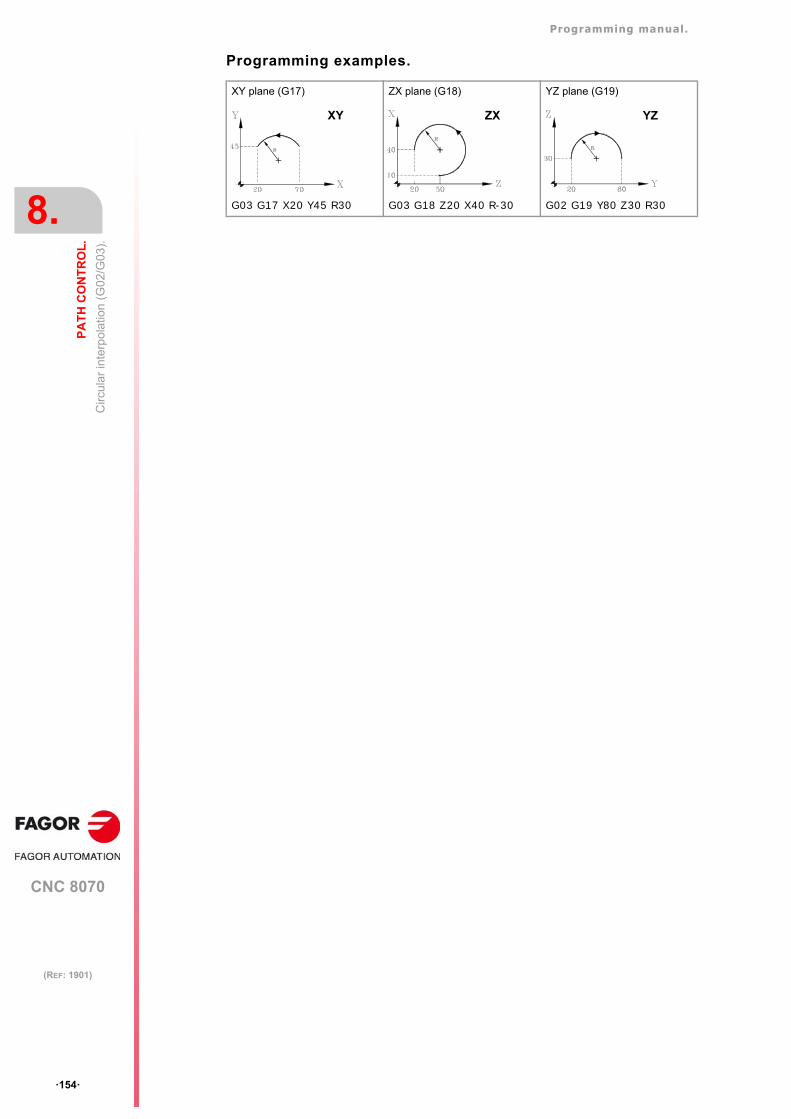
Programming manual.
CNC 8070
8.
PA
TH
CO
NT
RO
L.
Circ
ular
inte
rpol
atio
n (G
02/G
03).
·154·
(REF: 1901)
Programming examples.
XY plane (G17)
G03 G17 X20 Y45 R30
ZX plane (G18)
G03 G18 Z20 X40 R-30
YZ plane (G19)
G02 G19 Y80 Z30 R30
XY ZX YZ
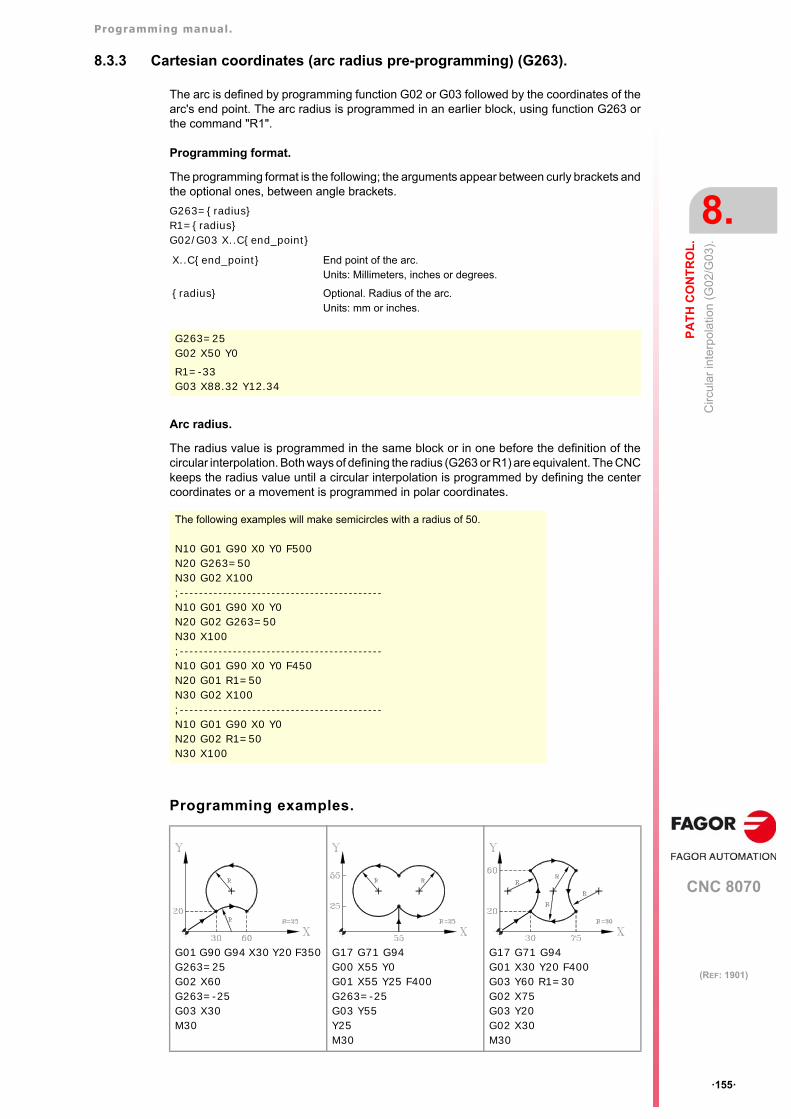
Programming manual.
CNC 8070
PA
TH
CO
NT
RO
L.
8.
Circ
ular
inte
rpol
atio
n (G
02/G
03).
·155·
(REF: 1901)
8.3.3 Cartesian coordinates (arc radius pre-programming) (G263).
The arc is defined by programming function G02 or G03 followed by the coordinates of thearc's end point. The arc radius is programmed in an earlier block, using function G263 orthe command "R1".
Programming format.
The programming format is the following; the arguments appear between curly brackets andthe optional ones, between angle brackets.
G263={radius}R1={radius}G02/G03 X..C{end_point}
Arc radius.
The radius value is programmed in the same block or in one before the definition of thecircular interpolation. Both ways of defining the radius (G263 or R1) are equivalent. The CNCkeeps the radius value until a circular interpolation is programmed by defining the centercoordinates or a movement is programmed in polar coordinates.
Programming examples.
X..C{end_point} End point of the arc.Units: Millimeters, inches or degrees.
{radius} Optional. Radius of the arc.Units: mm or inches.
G263=25G02 X50 Y0
R1=-33G03 X88.32 Y12.34
The following examples will make semicircles with a radius of 50.
N10 G01 G90 X0 Y0 F500N20 G263=50N30 G02 X100;------------------------------------------N10 G01 G90 X0 Y0N20 G02 G263=50N30 X100;------------------------------------------N10 G01 G90 X0 Y0 F450N20 G01 R1=50N30 G02 X100;------------------------------------------N10 G01 G90 X0 Y0N20 G02 R1=50N30 X100
G01 G90 G94 X30 Y20 F350G263=25G02 X60G263=-25G03 X30M30
G17 G71 G94G00 X55 Y0G01 X55 Y25 F400G263=-25G03 Y55Y25M30
G17 G71 G94G01 X30 Y20 F400G03 Y60 R1=30G02 X75G03 Y20G02 X30M30
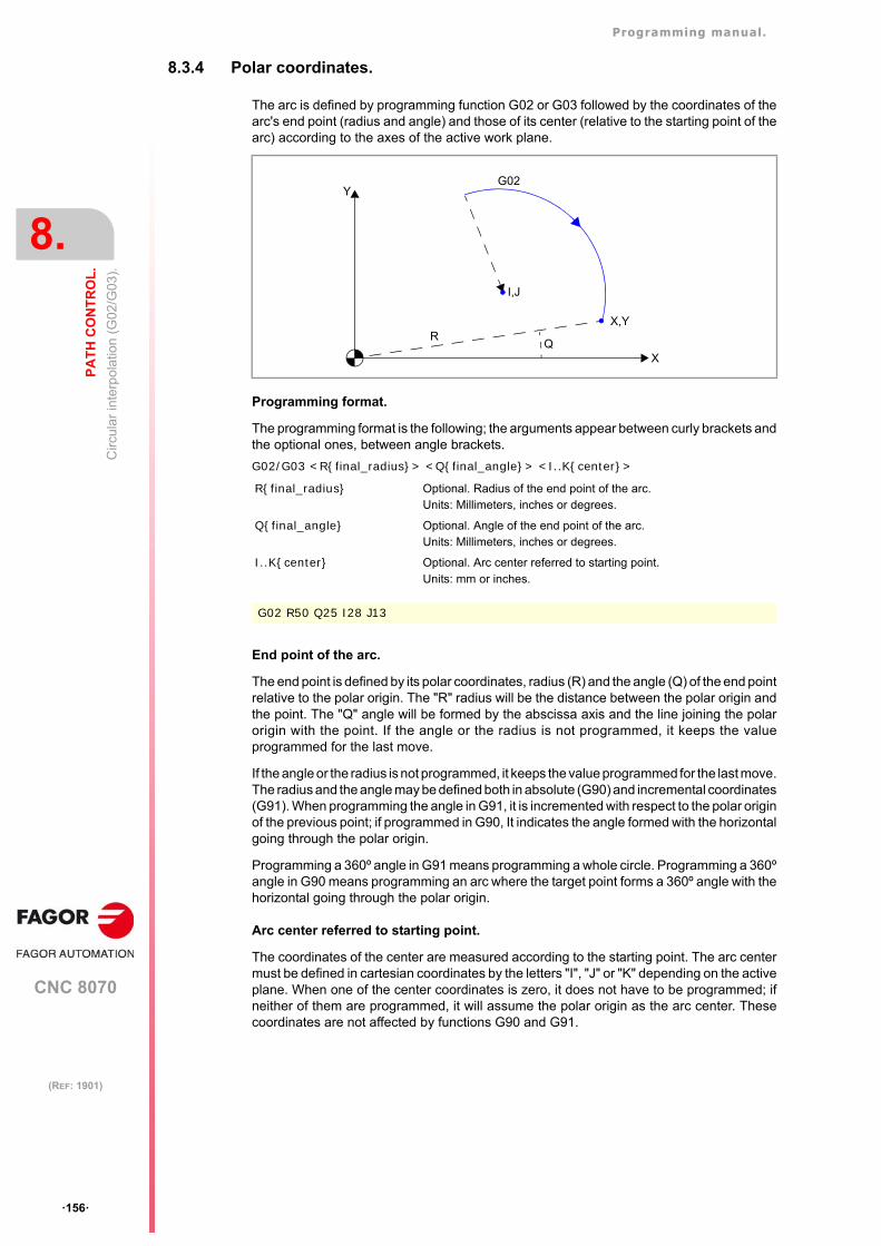
Programming manual.
CNC 8070
8.
PA
TH
CO
NT
RO
L.
Circ
ular
inte
rpol
atio
n (G
02/G
03).
·156·
(REF: 1901)
8.3.4 Polar coordinates.
The arc is defined by programming function G02 or G03 followed by the coordinates of thearc's end point (radius and angle) and those of its center (relative to the starting point of thearc) according to the axes of the active work plane.
Programming format.
The programming format is the following; the arguments appear between curly brackets andthe optional ones, between angle brackets.
G02/G03 <R{final_radius}> <Q{final_angle}> <I..K{center}>
End point of the arc.
The end point is defined by its polar coordinates, radius (R) and the angle (Q) of the end pointrelative to the polar origin. The "R" radius will be the distance between the polar origin andthe point. The "Q" angle will be formed by the abscissa axis and the line joining the polarorigin with the point. If the angle or the radius is not programmed, it keeps the valueprogrammed for the last move.
If the angle or the radius is not programmed, it keeps the value programmed for the last move.The radius and the angle may be defined both in absolute (G90) and incremental coordinates(G91). When programming the angle in G91, it is incremented with respect to the polar originof the previous point; if programmed in G90, It indicates the angle formed with the horizontalgoing through the polar origin.
Programming a 360º angle in G91 means programming a whole circle. Programming a 360ºangle in G90 means programming an arc where the target point forms a 360º angle with thehorizontal going through the polar origin.
Arc center referred to starting point.
The coordinates of the center are measured according to the starting point. The arc centermust be defined in cartesian coordinates by the letters "I", "J" or "K" depending on the activeplane. When one of the center coordinates is zero, it does not have to be programmed; ifneither of them are programmed, it will assume the polar origin as the arc center. Thesecoordinates are not affected by functions G90 and G91.
R{final_radius} Optional. Radius of the end point of the arc.Units: Millimeters, inches or degrees.
Q{final_angle} Optional. Angle of the end point of the arc.Units: Millimeters, inches or degrees.
I..K{center} Optional. Arc center referred to starting point.Units: mm or inches.
G02 R50 Q25 I28 J13
X
G02Y
X,Y
I,J
RQ
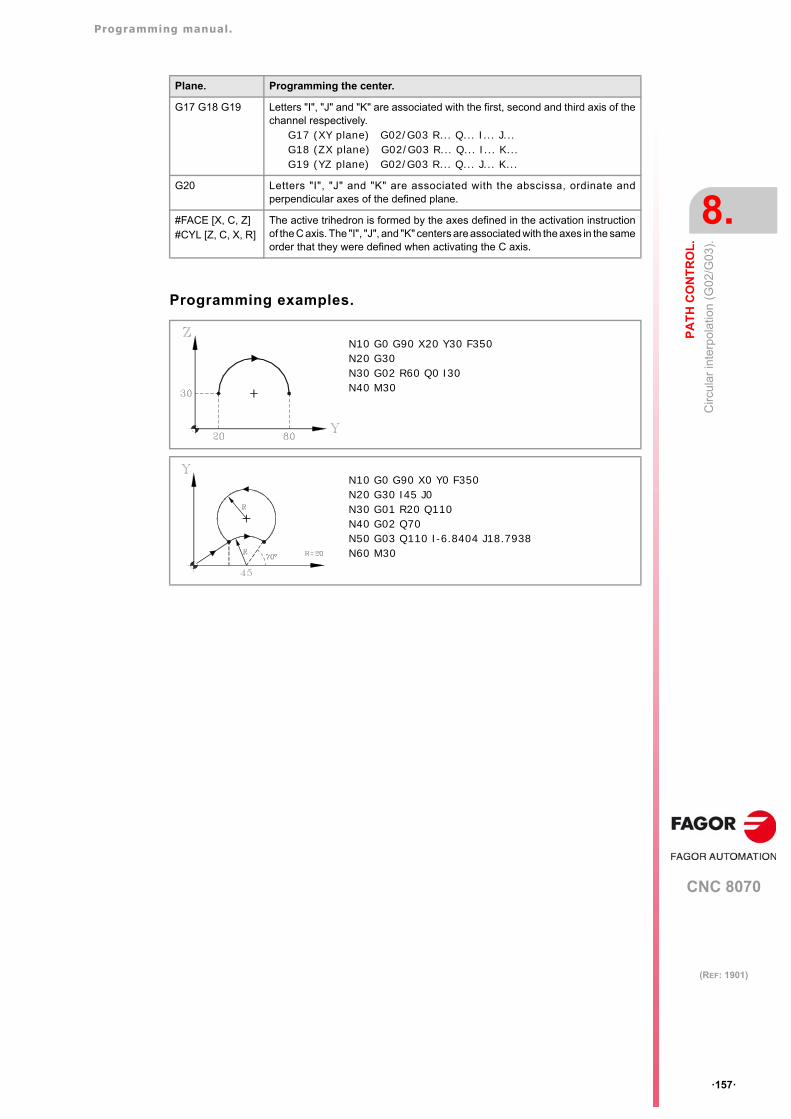
Programming manual.
CNC 8070
PA
TH
CO
NT
RO
L.
8.
Circ
ular
inte
rpol
atio
n (G
02/G
03).
·157·
(REF: 1901)
Programming examples.
Plane. Programming the center.
G17 G18 G19 Letters "I", "J" and "K" are associated with the first, second and third axis of thechannel respectively.
G17 (XY plane) G02/G03 R... Q... I... J...G18 (ZX plane) G02/G03 R... Q... I... K...G19 (YZ plane) G02/G03 R... Q... J... K...
G20 Letters "I", "J" and "K" are associated with the abscissa, ordinate andperpendicular axes of the defined plane.
#FACE [X, C, Z]#CYL [Z, C, X, R]
The active trihedron is formed by the axes defined in the activation instructionof the C axis. The "I", "J", and "K" centers are associated with the axes in the sameorder that they were defined when activating the C axis.
N10 G0 G90 X20 Y30 F350N20 G30N30 G02 R60 Q0 I30 N40 M30
N10 G0 G90 X0 Y0 F350N20 G30 I45 J0N30 G01 R20 Q110N40 G02 Q70 N50 G03 Q110 I-6.8404 J18.7938N60 M30
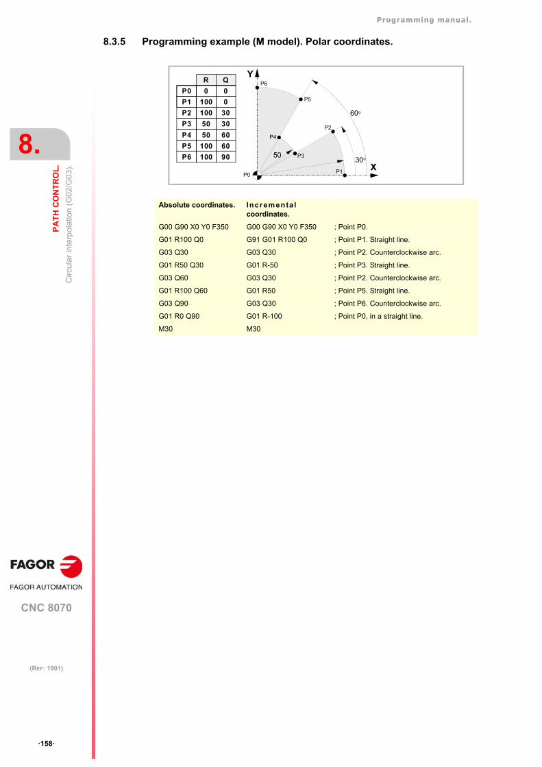
Programming manual.
CNC 8070
8.
PA
TH
CO
NT
RO
L.
Circ
ular
inte
rpol
atio
n (G
02/G
03).
·158·
(REF: 1901)
8.3.5 Programming example (M model). Polar coordinates.
Absolute coordinates. Incrementa lcoordinates.
G00 G90 X0 Y0 F350 G00 G90 X0 Y0 F350 ; Point P0.
G01 R100 Q0 G91 G01 R100 Q0 ; Point P1. Straight line.
G03 Q30 G03 Q30 ; Point P2. Counterclockwise arc.
G01 R50 Q30 G01 R-50 ; Point P3. Straight line.
G03 Q60 G03 Q30 ; Point P2. Counterclockwise arc.
G01 R100 Q60 G01 R50 ; Point P5. Straight line.
G03 Q90 G03 Q30 ; Point P6. Counterclockwise arc.
G01 R0 Q90 G01 R-100 ; Point P0, in a straight line.
M30 M30
P1
P2
P3
P4
P5
P6
5030o
60o
P0
Y
X
R Q
P0 0
P1 100
0
0
P2
P3
P4
100
50
50
30
30
60
P5 100 60
P6 100 90
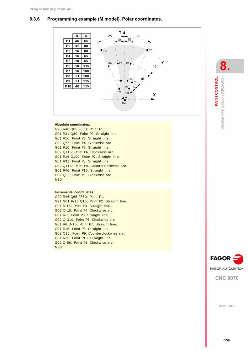
Programming manual.
CNC 8070
PA
TH
CO
NT
RO
L.
8.
Circ
ular
inte
rpol
atio
n (G
02/G
03).
·159·
(REF: 1901)
8.3.6 Programming example (M model). Polar coordinates.
10
6
101025 25
15
15
P1
P2
P3P4
P5
P6
P7
P8P9
P10
Ow
R
P1 46
P2
P3
P4
31
16
16
P5 10
P6 10
P7 16
P8
P9
P10
31
31
46
Q
65
80
80
65
65
115
100
100
115
115
Y
X
Absolute coordinates.G90 R46 Q65 F350; Point P1.G01 R31 Q80; Point P2. Straight line.G01 R16; Point P3. Straight line.G02 Q65; Point P4. Clockwise arc.G01 R10; Point P5. Straight line.G02 Q115; Point P6. Clockwise arc.G01 R16 Q100; Point P7. Straight line.G01 R31; Point P8. Straight line.G03 Q115; Point P9. Counterclockwise arc.G01 R46; Point P10. Straight line.G02 Q65; Point P1. Clockwise arc.M30
Incremental coordinates.G90 R46 Q65 F350; Point P1.G91 G01 R-15 Q15; Point P2. Straight line.G01 R-15; Point P3. Straight line.G02 Q-15; Point P4. Clockwise arc.G01 R-6; Point P5. Straight line.G02 Q-310; Point P6. Clockwise arc.G01 R6 Q-15; Point P7. Straight line.G01 R15; Point P8. Straight line.G03 Q15; Point P9. Counterclockwise arc.G01 R15; Point P10. Straight line.G02 Q-50; Point P1. Clockwise arc.M30
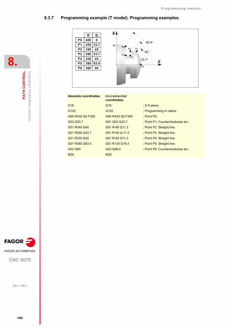
Programming manual.
CNC 8070
8.
PA
TH
CO
NT
RO
L.
Circ
ular
inte
rpol
atio
n (G
02/G
03).
·160·
(REF: 1901)
8.3.7 Programming example (T model). Programming examples.
Absolute coordinates. Incrementa lcoordinates.
G18 G18 ; Z-X plane,
G152 G152 ; Programming in radius.
G90 R430 Q0 F350 G90 R430 Q0 F350 ; Point P0.
G03 Q33.7 G91 G03 Q33.7 ; Point P1. Counterclockwise arc.
G01 R340 Q45 G01 R-90 Q11.3 ; Point P2. Straight line.
G01 R290 Q33.7 G01 R-50 Q-11.3 ; Point P3. Straight line.
G01 R230 Q45 G01 R-60 Q11.3 ; Point P4. Straight line.
G01 R360 Q63.4 G01 R130 Q18.4 ; Point P5. Straight line.
G03 Q90 G03 Q26.6 ; Point P6. Counterclockwise arc.
M30 M30
P0
P1P2
P3P4
P5P6
63.4o
45o
33.7o
R Q
P0 430
P1 430
0
33.7
P2
P3
P4
340
290
230
45
33.7
45
P5 360 63.4
P6 360 90
X
Z
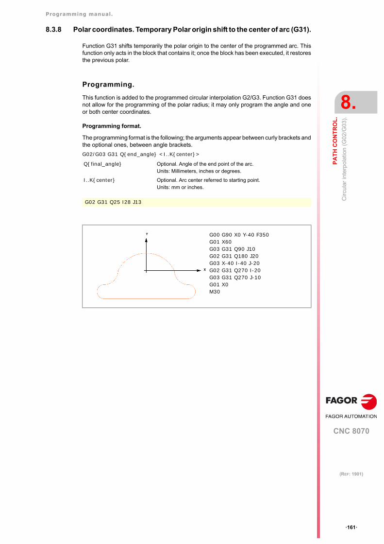
Programming manual.
CNC 8070
PA
TH
CO
NT
RO
L.
8.
Circ
ular
inte
rpol
atio
n (G
02/G
03).
·161·
(REF: 1901)
8.3.8 Polar coordinates. Temporary Polar origin shift to the center of arc (G31).
Function G31 shifts temporarily the polar origin to the center of the programmed arc. Thisfunction only acts in the block that contains it; once the block has been executed, it restoresthe previous polar.
Programming.
This function is added to the programmed circular interpolation G2/G3. Function G31 doesnot allow for the programming of the polar radius; it may only program the angle and oneor both center coordinates.
Programming format.
The programming format is the following; the arguments appear between curly brackets andthe optional ones, between angle brackets.
G02/G03 G31 Q{end_angle} <I..K{center}>
Q{final_angle} Optional. Angle of the end point of the arc.Units: Millimeters, inches or degrees.
I..K{center} Optional. Arc center referred to starting point.Units: mm or inches.
G02 G31 Q25 I28 J13
G00 G90 X0 Y-40 F350G01 X60 G03 G31 Q90 J10G02 G31 Q180 J20G03 X-40 I-40 J-20G02 G31 Q270 I-20G03 G31 Q270 J-10G01 X0M30
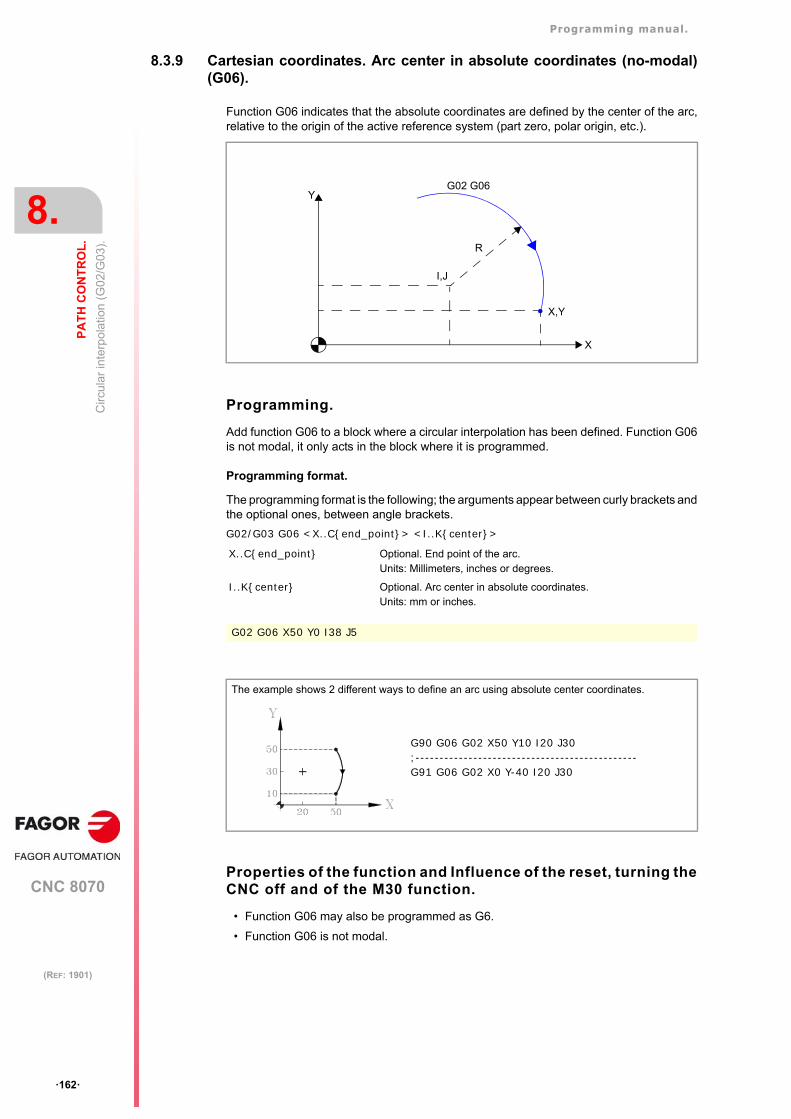
Programming manual.
CNC 8070
8.
PA
TH
CO
NT
RO
L.
Circ
ular
inte
rpol
atio
n (G
02/G
03).
·162·
(REF: 1901)
8.3.9 Cartesian coordinates. Arc center in absolute coordinates (no-modal)(G06).
Function G06 indicates that the absolute coordinates are defined by the center of the arc,relative to the origin of the active reference system (part zero, polar origin, etc.).
Programming.
Add function G06 to a block where a circular interpolation has been defined. Function G06is not modal, it only acts in the block where it is programmed.
Programming format.
The programming format is the following; the arguments appear between curly brackets andthe optional ones, between angle brackets.
G02/G03 G06 <X..C{end_point}> <I..K{center}>
Properties of the function and Influence of the reset, turning theCNC off and of the M30 function.
• Function G06 may also be programmed as G6.
• Function G06 is not modal.
X..C{end_point} Optional. End point of the arc.Units: Millimeters, inches or degrees.
I..K{center} Optional. Arc center in absolute coordinates.Units: mm or inches.
G02 G06 X50 Y0 I38 J5
The example shows 2 different ways to define an arc using absolute center coordinates.
X
G02 G06Y
R
X,Y
I,J
G90 G06 G02 X50 Y10 I20 J30;----------------------------------------------G91 G06 G02 X0 Y-40 I20 J30
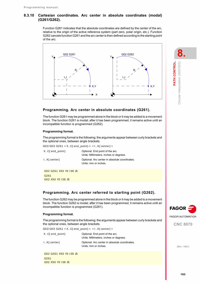
Programming manual.
CNC 8070
PA
TH
CO
NT
RO
L.
8.
Circ
ular
inte
rpol
atio
n (G
02/G
03).
·163·
(REF: 1901)
8.3.10 Cartesian coordinates. Arc center in absolute coordinates (modal)(G261/G262).
Function G261 indicates that the absolute coordinates are defined by the center of the arc,relative to the origin of the active reference system (part zero, polar origin, etc.). FunctionG262 cancels function G261 and the arc center is then defined according to the starting pointof the arc.
Programming. Arc center in absolute coordinates (G261).
The function G261 may be programmed alone in the block or it may be added to a movementblock. The function G261 is modal; after it has been programmed, it remains active until anincompatible function is programmed (G262).
Programming format.
The programming format is the following; the arguments appear between curly brackets andthe optional ones, between angle brackets.
G02/G03 G261 <X..C{end_point}> <I..K{center}>
Programming. Arc center referred to starting point (G262).
The function G262 may be programmed alone in the block or it may be added to a movementblock. The function G262 is modal; after it has been programmed, it remains active until anincompatible function is programmed (G261).
Programming format.
The programming format is the following; the arguments appear between curly brackets andthe optional ones, between angle brackets.
G02/G03 G261 <X..C{end_point}> <I..K{center}>
X..C{end_point} Optional. End point of the arc.Units: Millimeters, inches or degrees.
I..K{center} Optional. Arc center in absolute coordinates.Units: mm or inches.
G02 G261 X50 Y0 I38 J5
G261G02 X50 Y0 I38 J5
X..C{end_point} Optional. End point of the arc.Units: Millimeters, inches or degrees.
I..K{center} Optional. Arc center in absolute coordinates.Units: mm or inches.
G02 G261 X50 Y0 I38 J5
G261G02 X50 Y0 I38 J5
X
G02 G261Y
R
X,Y
I,J
G02 G262Y
R
X,Y
I,J
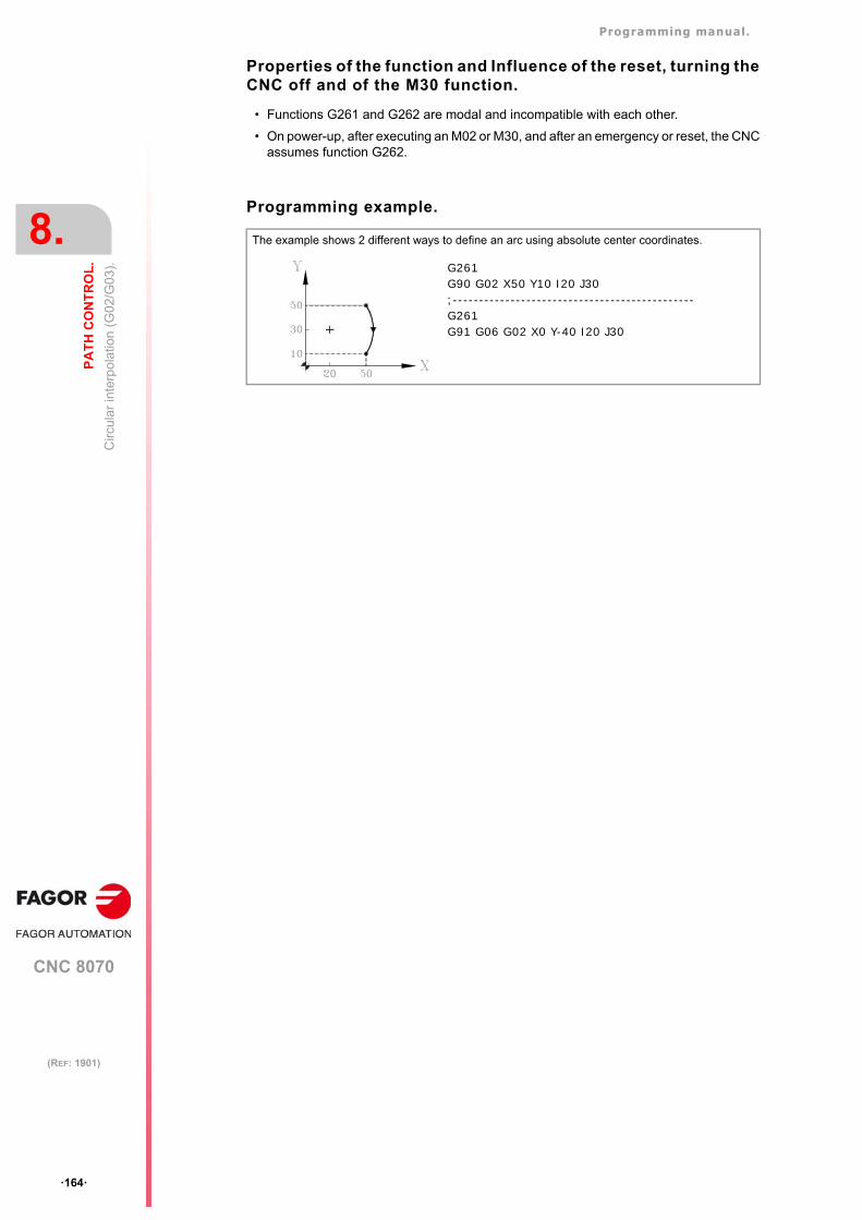
Programming manual.
CNC 8070
8.
PA
TH
CO
NT
RO
L.
Circ
ular
inte
rpol
atio
n (G
02/G
03).
·164·
(REF: 1901)
Properties of the function and Influence of the reset, turning theCNC off and of the M30 function.
• Functions G261 and G262 are modal and incompatible with each other.
• On power-up, after executing an M02 or M30, and after an emergency or reset, the CNCassumes function G262.
Programming example.
The example shows 2 different ways to define an arc using absolute center coordinates.
G261G90 G02 X50 Y10 I20 J30;----------------------------------------------G261G91 G06 G02 X0 Y-40 I20 J30
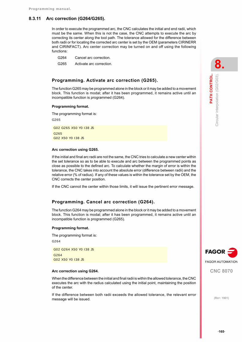
Programming manual.
CNC 8070
PA
TH
CO
NT
RO
L.
8.
Circ
ular
inte
rpol
atio
n (G
02/G
03).
·165·
(REF: 1901)
8.3.11 Arc correction (G264/G265).
In order to execute the programmed arc, the CNC calculates the initial and end radii, whichmust be the same. When this is not the case, the CNC attempts to execute the arc bycorrecting its center along the tool path. The tolerance allowed for the difference betweenboth radii or for locating the corrected arc center is set by the OEM (parameters CIRINERRand CIRINFACT). Arc center correction may be turned on and off using the followingfunctions:
Programming. Activate arc correction (G265).
The function G265 may be programmed alone in the block or it may be added to a movementblock. This function is modal; after it has been programmed, it remains active until anincompatible function is programmed (G264).
Programming format.
The programming format is:
G265
Arc correction using G265.
If the initial and final arc radii are not the same, the CNC tries to calculate a new center withinthe set tolerance so as to be able to execute and arc between the programmed points asclose as possible to the defined arc. To calculate whether the margin of error is within thetolerance, the CNC takes into account the absolute error (difference between radii) and therelative error (% of radius). If any of these values is within the tolerance set by the OEM, theCNC corrects the center position.
If the CNC cannot the center within those limits, it will issue the pertinent error message.
Programming. Cancel arc correction (G264).
The function G264 may be programmed alone in the block or it may be added to a movementblock. This function is modal; after it has been programmed, it remains active until anincompatible function is programmed (G265).
Programming format.
The programming format is:
G264
Arc correction using G264.
When the difference between the initial and final radii is within the allowed tolerance, the CNCexecutes the arc with the radius calculated using the initial point, maintaining the positionof the center.
If the difference between both radii exceeds the allowed tolerance, the relevant errormessage will be issued.
G264 Cancel arc correction.
G265 Activate arc correction.
G02 G265 X50 Y0 I38 J5
G265G02 X50 Y0 I38 J5
G02 G264 X50 Y0 I38 J5
G264G02 X50 Y0 I38 J5
Programming manual.
CNC 8070
8.
PA
TH
CO
NT
RO
L.
Circ
ular
inte
rpol
atio
n (G
02/G
03).
·166·
(REF: 1901)
Properties of the function and Influence of the reset, turning theCNC off and of the M30 function.
• Functions G264 and G265 are modal and incompatible with each other.
• On power-up, after executing an M02 or M30, and after an emergency or reset, the CNCassumes function G265.
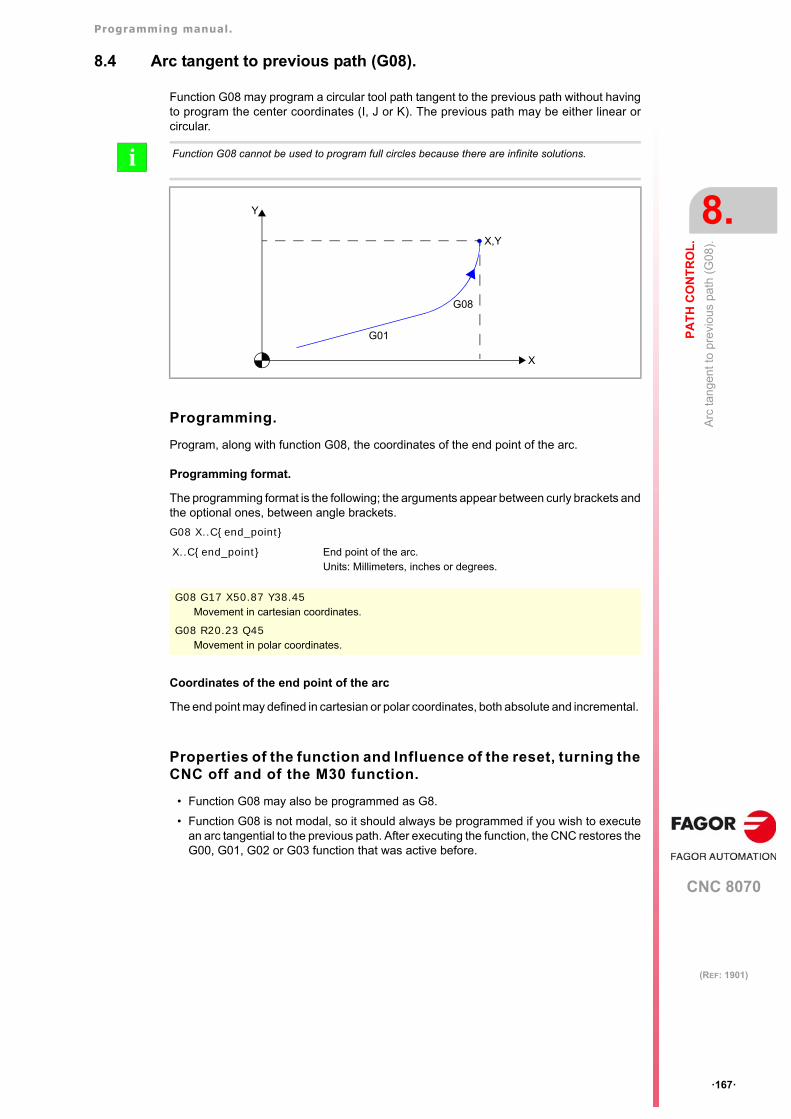
Programming manual.
CNC 8070
PA
TH
CO
NT
RO
L.
8.
Arc
tan
gen
t to
pre
viou
s pa
th (
G08
).
·167·
(REF: 1901)
8.4 Arc tangent to previous path (G08).
Function G08 may program a circular tool path tangent to the previous path without havingto program the center coordinates (I, J or K). The previous path may be either linear orcircular.
Programming.
Program, along with function G08, the coordinates of the end point of the arc.
Programming format.
The programming format is the following; the arguments appear between curly brackets andthe optional ones, between angle brackets.
G08 X..C{end_point}
Coordinates of the end point of the arc
The end point may defined in cartesian or polar coordinates, both absolute and incremental.
Properties of the function and Influence of the reset, turning theCNC off and of the M30 function.
• Function G08 may also be programmed as G8.
• Function G08 is not modal, so it should always be programmed if you wish to executean arc tangential to the previous path. After executing the function, the CNC restores theG00, G01, G02 or G03 function that was active before.
Function G08 cannot be used to program full circles because there are infinite solutions.i
X..C{end_point} End point of the arc.Units: Millimeters, inches or degrees.
G08 G17 X50.87 Y38.45Movement in cartesian coordinates.
G08 R20.23 Q45Movement in polar coordinates.
X
G08
Y
X,Y
G01
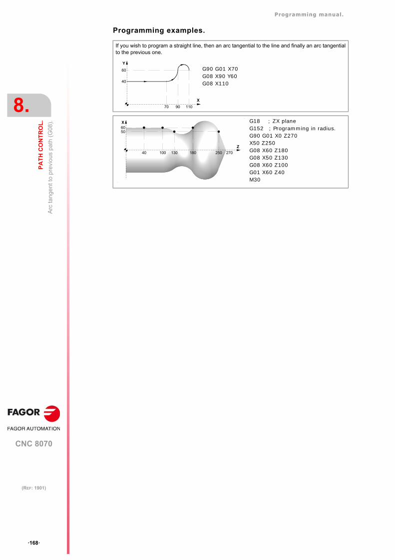
Programming manual.
CNC 8070
8.
PA
TH
CO
NT
RO
L.
Arc
tan
gen
t to
pre
viou
s pa
th (
G08
).
·168·
(REF: 1901)
Programming examples.
If you wish to program a straight line, then an arc tangential to the line and finally an arc tangentialto the previous one.
Y
X
40
70
60
90 110
G90 G01 X70G08 X90 Y60G08 X110
X
Z
40 100 130 180 270250
5060
G18 ; ZX planeG152 ; Programming in radius.G90 G01 X0 Z270X50 Z250G08 X60 Z180G08 X50 Z130G08 X60 Z100G01 X60 Z40M30
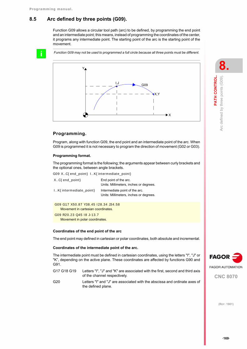
Programming manual.
CNC 8070
PA
TH
CO
NT
RO
L.
8.
Arc
de
fined
by
thre
e po
ints
(G
09).
·169·
(REF: 1901)
8.5 Arc defined by three points (G09).
Function G09 allows a circular tool path (arc) to be defined, by programming the end pointand an intermediate point; this means, instead of programming the coordinates of the center,it programs any intermediate point. The starting point of the arc is the starting point of themovement.
Programming.
Program, along with function G09, the end point and an intermediate point of the arc. WhenG09 is programmed it is not necessary to program the direction of movement (G02 or G03).
Programming format.
The programming format is the following; the arguments appear between curly brackets andthe optional ones, between angle brackets.
G09 X..C{end_point} I..K{intermediate_point}
Coordinates of the end point of the arc
The end point may defined in cartesian or polar coordinates, both absolute and incremental.
Coordinates of the intermediate point of the arc.
The intermediate point must be defined in cartesian coordinates, using the letters "I", "J" or"K”, depending on the active plane. These coordinates are affected by functions G90 andG91.
Function G09 may not be used to programmed a full circle because all three points must be different.i
X..C{end_point} End point of the arc.Units: Millimeters, inches or degrees.
I..K{intermediate_point} Intermediate point of the arc.Units: Millimeters, inches or degrees.
G09 G17 X50.87 Y38.45 I28.34 J34.58Movement in cartesian coordinates.
G09 R20.23 Q45 I8 J-13.7Movement in polar coordinates.
G17 G18 G19 Letters "I", "J" and "K" are associated with the first, second and third axisof the channel respectively.
G20 Letters "I" and "J" are associated with the abscissa and ordinate axes ofthe defined plane.
X
G09
Y
X,Y
I,J
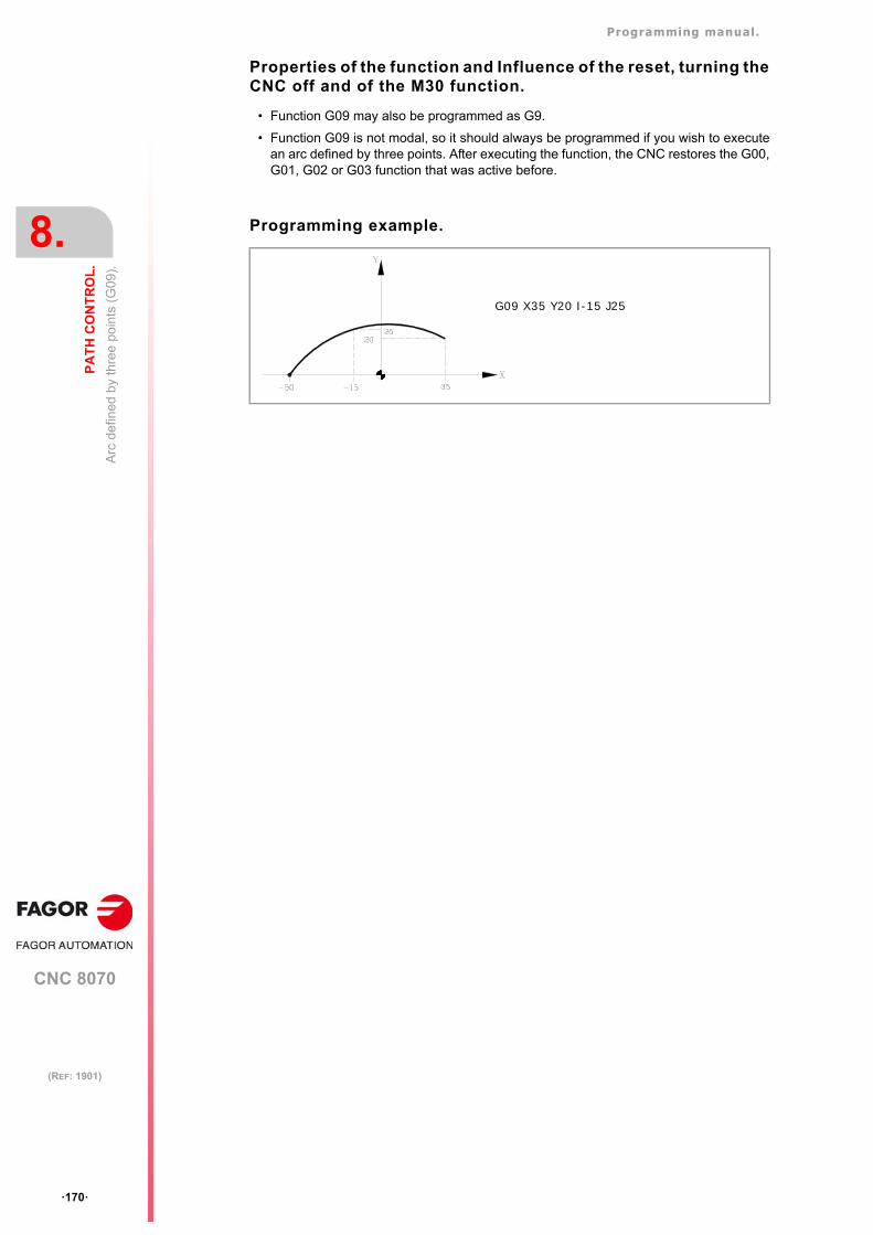
Programming manual.
CNC 8070
8.
PA
TH
CO
NT
RO
L.
Arc
de
fined
by
thre
e po
ints
(G
09).
·170·
(REF: 1901)
Properties of the function and Influence of the reset, turning theCNC off and of the M30 function.
• Function G09 may also be programmed as G9.
• Function G09 is not modal, so it should always be programmed if you wish to executean arc defined by three points. After executing the function, the CNC restores the G00,G01, G02 or G03 function that was active before.
Programming example.
G09 X35 Y20 I-15 J25
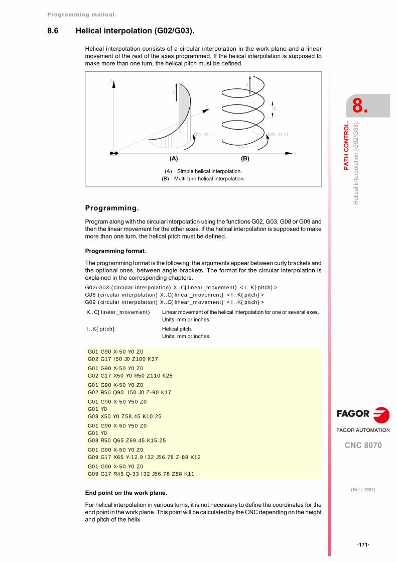
Programming manual.
CNC 8070
PA
TH
CO
NT
RO
L.
8.
Hel
ical
inte
rpol
atio
n (G
02/G
03).
·171·
(REF: 1901)
8.6 Helical interpolation (G02/G03).
Helical interpolation consists of a circular interpolation in the work plane and a linearmovement of the rest of the axes programmed. If the helical interpolation is supposed tomake more than one turn, the helical pitch must be defined.
Programming.
Program along with the circular interpolation using the functions G02, G03, G08 or G09 andthen the linear movement for the other axes. If the helical interpolation is supposed to makemore than one turn, the helical pitch must be defined.
Programming format.
The programming format is the following; the arguments appear between curly brackets andthe optional ones, between angle brackets. The format for the circular interpolation isexplained in the corresponding chapters.
G02/G03 (circular interpolation) X..C{linear_movement} <I..K{pitch}>G08 (circular interpolation) X..C{linear_movement} <I..K{pitch}>G09 (circular interpolation) X..C{linear_movement} <I..K{pitch}>
End point on the work plane.
For helical interpolation in various turns, it is not necessary to define the coordinates for theend point in the work plane. This point will be calculated by the CNC depending on the heightand pitch of the helix.
(A) Simple helical interpolation.(B) Multi-turn helical interpolation.
X..C{linear_movement} Linear movement of the helical interpolation for one or several axes. Units: mm or inches.
I..K{pitch} Helical pitch.Units: mm or inches.
G01 G90 X-50 Y0 Z0G02 G17 I50 J0 Z100 K37
G01 G90 X-50 Y0 Z0G02 G17 X50 Y0 R50 Z110 K25
G01 G90 X-50 Y0 Z0G02 R50 Q90 I50 J0 Z-90 K17
G01 G90 X-50 Y50 Z0G01 Y0G08 X50 Y0 Z58.45 K10.25
G01 G90 X-50 Y50 Z0G01 Y0G08 R50 Q65 Z69.45 K15.25
G01 G90 X-50 Y0 Z0G09 G17 X65 Y-12.9 I32 J56.78 Z-88 K12
G01 G90 X-50 Y0 Z0G09 G17 R45 Q-33 I32 J56.78 Z88 K11
(A) (B)
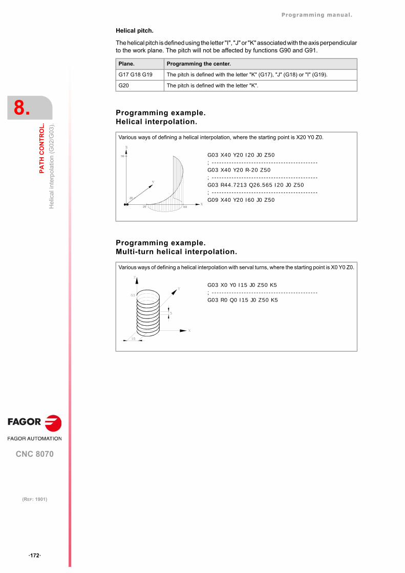
Programming manual.
CNC 8070
8.
PA
TH
CO
NT
RO
L.
Hel
ical
inte
rpol
atio
n (G
02/G
03).
·172·
(REF: 1901)
Helical pitch.
The helical pitch is defined using the letter "I", "J" or "K" associated with the axis perpendicularto the work plane. The pitch will not be affected by functions G90 and G91.
Programming example.Helical interpolation.
Programming example.Multi-turn helical interpolation.
Plane. Programming the center.
G17 G18 G19 The pitch is defined with the letter "K" (G17), "J" (G18) or "I" (G19).
G20 The pitch is defined with the letter "K".
Various ways of defining a helical interpolation, where the starting point is X20 Y0 Z0.
Various ways of defining a helical interpolation with serval turns, where the starting point is X0 Y0 Z0.
G03 X40 Y20 I20 J0 Z50; -------------------------------------------G03 X40 Y20 R-20 Z50; -------------------------------------------G03 R44.7213 Q26.565 I20 J0 Z50; -------------------------------------------G09 X40 Y20 I60 J0 Z50
G03 X0 Y0 I15 J0 Z50 K5; -------------------------------------------G03 R0 Q0 I15 J0 Z50 K5
CNC 8070
9
·173·
(REF: 1901)
9. TOOL PATH CONTROL. MANUAL INTERVENTION.
Manual intervention makes it possible to activate the JOG mode by program; in other words,the axes may be jogged even while executing a program. The movement may be made usinghandwheels or the jog keys (incremental or continuous jog). The functions related to manualintervention are:
G200 Exclusive manual intervention.
G201 Activation of additive manual intervention.
G202 Cancellation of additive manual intervention.
The difference between exclusive and additive interventions is that the exclusive one (G200)interrupts the execution of the program to activate the jog mode whereas the additive one(G201) lets you jog an axis while executing the programmed movements.
Feedrate behavior.
The feedrate of the jogging movements during manual intervention is independent from theactive "F" and may be defined by the operator using instructions in high-level language; adifferent feedrate may be set for each work mode (incremental or continuous jog). If notdefined, the movements are carried out at the feedrate set by the OEM.
The feedrate may be varied between 0% and 200% using the selector switch on the CNC'soperator panel which affects the same way the programmed "F" and the feedrate of manualintervention.
Programming manual.
CNC 8070
9.
TO
OL
PA
TH
CO
NT
RO
L. M
AN
UA
L IN
TE
RV
EN
TIO
N.
Add
itive
man
ual i
nte
rve
ntio
n (G
201
/G2
02).
·174·
(REF: 1901)
9.1 Additive manual intervention (G201/G202).
The additive manual intervention makes it possible to jog the axes using handwheels or thejog keys (continuous or incremental) while executing the program. This function can beapplied on any axis of the machine; however, it cannot be applied on the spindle, althoughthis can work in positioning mode.
Programming. Activate additive manual intervention.
To activate the additive manual intervention, the function G201 must be programmed in thesame block, followed by the #AXIS statement with the applicable axes. This statement mustdefine at least one axis.
Programming format.
The programming format is the following; the arguments appear between curly brackets andthe optional ones between angle brackets.
G201 #AXIS[{axis}, .. , {axis}]
Programming. Cancel additive manual intervention.
To cancel the additive manual intervention, the function G202 must be programmed in thesame block, followed by the #AXIS statement with the axes to be cancelled. ProgrammingG202 alone cancels manual intervention on all the axes.
Programming format.
The programming format is the following; the arguments appear between curly brackets andthe optional ones between angle brackets.
G202G202 #AXIS[{axis}, .. , {axis}]
Considerations
Axis parameters MANFEEDP, IPOFEEDP, MANACCP, IPOACCP limit the feedrate andmaximum acceleration permitted for each type of movement (jog or automatic). If the additionof the two exceeds 100%, it will be up to the user to ensure that the two movements are notsimultaneous on the same axis because it may cause the dynamics to overshoot.
Properties of the function and Influence of the reset, turning theCNC off and of the M30 function.
Functions G201 and G202 are modal and incompatible with each other and with functionG200. On power-up, after executing an M02 or M30, and after an emergency or reset, theCNC assumes function G202.
{axis} Axis name.Units: -.
G201 #AXIS [X, Z](Activate additive manual intervention on the X Z axes)
{axis} Axis name.Units: -.
G202 #AXIS [X, Z](Cancel additive manual intervention on the X Z axes)
G202(Cancel additive manual intervention on all axes)
Programming manual.
CNC 8070
TO
OL
PA
TH
CO
NT
RO
L. M
AN
UA
L IN
TE
RV
EN
TIO
N.
9.
Exc
lusi
ve m
anua
l in
terv
ent
ion
(G2
00).
·175·
(REF: 1901)
9.2 Exclusive manual intervention (G200).
With exclusive manual intervention, the axes may be jogged using handwheels or jog keys(continuous or incremental) by interrupting the execution of the program. This function canbe applied on any axis of the machine; however, it cannot be applied on the spindle, althoughthis can work in positioning mode.
To cancel manual intervention and resume program execution, press the [CYCLE START]key.
Programming.
To activate the additive manual intervention, the function G200 must be programmed in thesame block, followed by the #AXIS statement with the applicable axes. Programming G200alone applies the manual intervention on all the axes.
Programming format.
The programming format is the following; the arguments appear between curly brackets andthe optional ones between angle brackets.
G200G200 #AXIS[{axis}, .. , {axis}]
Considerations
If a manual intervention is executed before a circular interpolation and one of the axesinvolved in the circular interpolation is jogged, it could issue an error message indicating thata circle has been programmed wrong or it may execute a circle other than the oneprogrammed.
Properties of the function and Influence of the reset, turning theCNC off and of the M30 function.
Function G200 is non-modal and is incompatible with functions G201 and G202. On power-up, after executing an M02 or M30, and after an emergency or reset, the CNC assumesfunction G202.
{axis} Axis name.Units: -.
G200 #AXIS [X, Z](Interrupt the execution and activate additive manual intervention on XZaxes)
G200(Interrupt the execution and activate additive manual intervention on allaxes)
Programming manual.
CNC 8070
9.
TO
OL
PA
TH
CO
NT
RO
L. M
AN
UA
L IN
TE
RV
EN
TIO
N.
Jogg
ing
fee
drat
e.
·176·
(REF: 1901)
9.3 Jogging feedrate.
9.3.1 Feedrate in continuous jog (#CONTJOG).
This statement allows the feedrate to be configured in continuous jog mode for the specifiedaxis. These values may be defined before or after activating manual intervention and stayactive until the end of the program or a reset.
Programming.
Program the #CONTJOG statement, followed by the feedrate and the axis.
Programming format.
The programming format is the following; the arguments appear between curly brackets andthe optional ones between angle brackets.
#CONTJOG [{feed}] {axis}
{feed} Axis feedrate.Units: Millimeters/minute, inches/minute or degrees/minute.
{axis} Axis name.Units: -.
#CONTJOG [400] X(Manual intervention; feedrate in continuous jog for X)
#CONTJOG [600] Y(Manual intervention; feedrate in continuous jog for Y)
Programming manual.
CNC 8070
TO
OL
PA
TH
CO
NT
RO
L. M
AN
UA
L IN
TE
RV
EN
TIO
N.
9.
Jogg
ing
fee
drat
e.
·177·
(REF: 1901)
9.3.2 Feedrate in incremental jog (#INCJOG).
This instruction configures the indicated incremental movement and axis feedrate for eachincremental jog position of the selector switch. These values may be defined before or afteractivating manual intervention and stay active until the end of the program or a reset.
Programming.
Program the #INCJOG statement, followed by the increment and feedrate at each jogposition for the axis.
Programming format.
The programming format is the following; the arguments appear between curly brackets andthe optional ones between angle brackets.
#INCJOG [[{increment_1},{feed_1}] [{increment_10},{feed_10}] ... [...]] <axis>
{feed_1}··{feed_10000}
Feedrate position, 1 to 10000 for the incremental jog switch.Units: Millimeters/minute, inches/minute or degrees/minute.
{increment_1}··{increment_10000}
Increment position, 1 to 10000 for the incremental jog switch.Units: Millimeters, inches or degrees.
{axis} Axis name.Units: -.
#INCJOG [[0.1,100][0.5,200][1,300][5,400][10,500]] X(The movement and feedrate of the X axis for each incremental jog switchposition is as follows) (Position 1 on the switch; 0.1 mm to 100 mm/min)(Position 10 on the switch; 0.5 mm to 200 mm/min)(Position 100 on the switch; 1 mm to 300 mm/min)(Position 1000 on the switch; 5 mm to 400 mm/min)(Position 10000 on the switch; 10 mm to 500 mm/min)
Programming manual.
CNC 8070
9.
TO
OL
PA
TH
CO
NT
RO
L. M
AN
UA
L IN
TE
RV
EN
TIO
N.
Jogg
ing
fee
drat
e.
·178·
(REF: 1901)
9.3.3 Feedrate in incremental jog (#MPG).
This instruction allows for the configuration, for each position on the handwheel, of theresolution of the handwheel on the specified axis. These values may be defined before orafter activating manual intervention and stay active until the end of the program or a reset.
Programming.
Program the #INCJOG statement, followed by the resolution at each jog position for the axis.
Programming format.
The programming format is the following; the arguments appear between curly brackets andthe optional ones between angle brackets.
#MPG [{resolution_1},{resolution_10},{resolution_100}] {axis}
{resolution_1}··{resolution_100}
Resolution position, 1 to 100 for the handwheel switch.Units: Millimeters/pulse, inches/pulse or degrees/pulse.
{axis} Axis name.Units: -.
#MPG [0.1, 1, 10] X(The resolution at each handwheel switch position is as follows) (Position 1 on the switch; 0.1 mm/turn)(Position 10 on the switch; 1.0 mm/turn)(Position 100 on the switch; 10 mm/turn)
This instruction sets the distance per handwheel pulse in a time period equal to the CNC’s cycle time.If the feedrate required for this movement exceeds the maximum set by the machine manufacturer,the feedrate will be limited to this value and the axis moving distance will be less than what has beenprogrammed in the instruction.Example: If a 5 mm move is programmed and the cycle time is 4 msec, the resulting feedrate is 1250mm/sec. If the maximum feedrate is limited to 1000 mm/s, the actual distance moved will be 4 mm.
i
Programming manual.
CNC 8070
TO
OL
PA
TH
CO
NT
RO
L. M
AN
UA
L IN
TE
RV
EN
TIO
N.
9.
Jogg
ing
fee
drat
e.
·179·
(REF: 1901)
9.3.4 Manual path movement limits (#SET OFFSET).
This statement allows for the configuration of the movement limits made under additivemanual intervention. These limits are ignored when executing the movements by program.The limits may be defined after activating manual intervention and stay active until it isdeactivated.
Programming.
Program the #SET OFFSET statement, followed by the lower and upper movement limitsfor the axis.
Programming format.
The programming format is the following; the arguments appear between curly brackets andthe optional ones between angle brackets.
#SET OFFSET [{lower_limit},{upper_limit}] {axis}
Upper and lower movement limit.
The limits are referred to the axis position. The lower limit must be less than or equal to zeroand the upper limit must be zero or greater than zero.
{lower_limit}{upper_limit}
Upper and lower movement limit.Units: Millimeters, inches or degrees.
{axis} Axis name.Units: -.
#SET OFFSET [-20,35] Y(Movement limit less than 20 mm and greater than 35 mm on the Y axis)
Programming manual.
CNC 8070
9.
TO
OL
PA
TH
CO
NT
RO
L. M
AN
UA
L IN
TE
RV
EN
TIO
N.
Jogg
ing
fee
drat
e.
·180·
(REF: 1901)
9.3.5 Synchronization of coordinates and additive manual offset (#SYNCPOS).
This instruction synchronizes the preparation coordinate with the execution one andassumes the additive manual offset.
Programming.
Program the instruction #SYNC POS alone in the block.
Programming format.
The programming format is the following; the arguments appear between curly brackets andthe optional ones between angle brackets.
#SYNC POS
#SYNC POS
Programming manual.
CNC 8070
TO
OL
PA
TH
CO
NT
RO
L. M
AN
UA
L IN
TE
RV
EN
TIO
N.
9.
Var
iabl
es.
·181·
(REF: 1901)
9.4 Variables.
The following variables may be accessed via part-program or via MDI/MDA mode. Each ofthem indicates whether it may be read (R) or written (W). Reading these variables interruptsblock preparation.
Syntax of the variables.
·ch· Channel number.
·xn· Name, logic number or index of the axis.
Variable. PRG Meaning.
(V.)[ch].A.MANOF.xn R Distance moved in manual mode or tool inspection mode.Units: Millimeters, inches or degrees.
(V.)[ch].A.ADDMANOF.xn R Distance moved with G200 or G201. The value of thisvariable is maintained during the execution of the programeven when canceling manual intervention.Units: Millimeters, inches or degrees.
V.A.ADDMANOF.Z Z axis.
V.A.ADDMANOF.4 Axis with logic number ·4·.
V.[2].A.ADDMANOF.1 Axis with index ·1· in the channel ·2·.
Programming manual.
CNC 8070
9.
TO
OL
PA
TH
CO
NT
RO
L. M
AN
UA
L IN
TE
RV
EN
TIO
N.
Var
iabl
es.
·182·
(REF: 1901)
CNC 8070
10
·183·
(REF: 1901)
10.ELECTRONIC THREADING AND RIGID TAPPING.
10.1 Electronic threading with constant pitch (G33)
The electronic threading executes the programmed thread in a single pass. In the electronicthreading, the CNC does NOT interpolate the movement of the axes with the spindle.
Although, this type of threads are carried out along an axis, the CNC permits interpolatingseveral axes. Besides, with electronic threading, it is possible to make threads with severalentries (starts) and to blend threads.
Electronic threading may be carried out with any spindle, but when not using the masterspindle, the spindle being used must be synchronized with it. The spindles may besynchronized via program using the instruction #SYNC or #TSYNC.
Programming.
Program G33 followed by the coordinates of the end point of the thread and the thread pitch.Optionally, the entry angle may be defined which allows multi-entry (starts) thread.
Programming format.
The programming format is the following; the list of arguments appears between curlybrackets and the optional ones between angle brackets.
G33 X..Z{pos} I/J/K{pitch} <Q1={angle}>
Coordinates of the end point.
Although, this type of threads are carried out along an axis, the CNC permits interpolatingseveral axes. The coordinates of the end point may be defined either in Cartesian or Polarcoordinates as well as in absolute and incremental coordinates.
For electronic threading, the machine must have a rotary encoder installed on the spindle.i
X..Z{pos} Coordinates of the end point.Units: millimeters/inches.
I/J/K{pitch} Thread pitch.Units: millimeters/inches.
Q1={angle} Optional. Spindle angular position for the starting point of the thread. If notprogrammed, the function assumes a value of 0.Units: ±359.9999 degrees.
G33 Z-50 K3 Q1=0(3 mm pitch thread)
G33 Z-40 K1 Q1=30G33 Z-80 K1 Q1=210
(Two-start thread, at 30º and 210º)
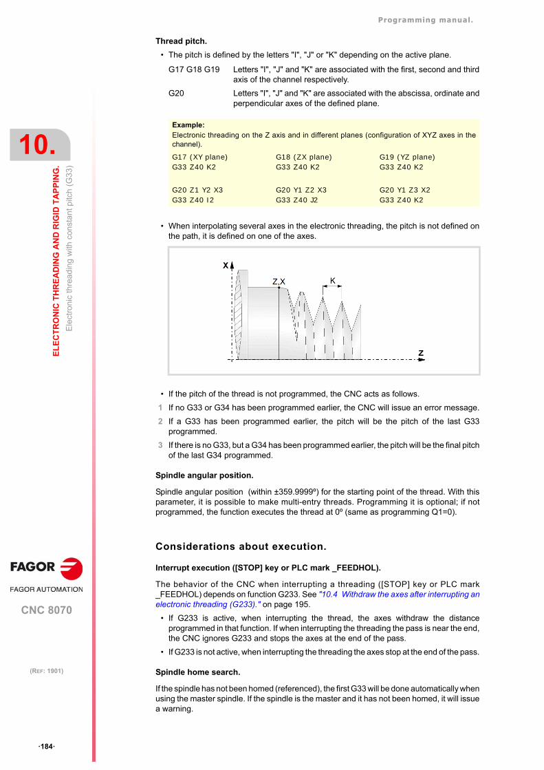
Programming manual.
CNC 8070
10.
EL
EC
TR
ON
IC T
HR
EA
DIN
G A
ND
RIG
ID T
AP
PIN
G.
Ele
ctro
nic
thre
adin
g w
ith c
onst
ant p
itch
(G3
3)
·184·
(REF: 1901)
Thread pitch.
• The pitch is defined by the letters "I", "J" or "K" depending on the active plane.
• When interpolating several axes in the electronic threading, the pitch is not defined onthe path, it is defined on one of the axes.
• If the pitch of the thread is not programmed, the CNC acts as follows.
1 If no G33 or G34 has been programmed earlier, the CNC will issue an error message.
2 If a G33 has been programmed earlier, the pitch will be the pitch of the last G33programmed.
3 If there is no G33, but a G34 has been programmed earlier, the pitch will be the final pitchof the last G34 programmed.
Spindle angular position.
Spindle angular position (within ±359.9999º) for the starting point of the thread. With thisparameter, it is possible to make multi-entry threads. Programming it is optional; if notprogrammed, the function executes the thread at 0º (same as programming Q1=0).
Considerations about execution.
Interrupt execution ([STOP] key or PLC mark _FEEDHOL).
The behavior of the CNC when interrupting a threading ([STOP] key or PLC mark_FEEDHOL) depends on function G233. See "10.4 Withdraw the axes after interrupting anelectronic threading (G233)." on page 195.
• If G233 is active, when interrupting the thread, the axes withdraw the distanceprogrammed in that function. If when interrupting the threading the pass is near the end,the CNC ignores G233 and stops the axes at the end of the pass.
• If G233 is not active, when interrupting the threading the axes stop at the end of the pass.
Spindle home search.
If the spindle has not been homed (referenced), the first G33 will be done automatically whenusing the master spindle. If the spindle is the master and it has not been homed, it will issuea warning.
G17 G18 G19 Letters "I", "J" and "K" are associated with the first, second and thirdaxis of the channel respectively.
G20 Letters "I", "J" and "K" are associated with the abscissa, ordinate andperpendicular axes of the defined plane.
Example:Electronic threading on the Z axis and in different planes (configuration of XYZ axes in thechannel).
G17 (XY plane)G33 Z40 K2
G18 (ZX plane)G33 Z40 K2
G19 (YZ plane)G33 Z40 K2
G20 Z1 Y2 X3G33 Z40 I2
G20 Y1 Z2 X3G33 Z40 J2
G20 Y1 Z3 X2G33 Z40 K2
Programming manual.
CNC 8070
EL
EC
TR
ON
IC T
HR
EA
DIN
G A
ND
RIG
ID T
AP
PIN
G.
10.
Ele
ctro
nic
thre
adin
g w
ith c
onst
ant p
itch
(G3
3)
·185·
(REF: 1901)
Feedrate behavior.
The threading feedrate depends on the programmed spindle speed and thread pitch(Feedrate = Spindle speed x Pitch). The electronic threading is carried out at 100% of thecalculated feedrate and these values cannot be modified from the CNC's operator panel orvia PLC.
Behavior of the spindle speed and of the spindle speed override
If the OEM allows it, (parameter THREADOVR), the user can modify the speed override fromthe operator panel and, in that case, the CNC will adapt the feedrate automatically respectingthe thread pitch. In order to be able to modify the override, the feed forward active on theaxes involved in threading must be higher than 90%.
If more than one G33 have been programmed for the same thread, all the threadingoperations must start at the same speed; otherwise, the entry point (start) to the thread willnot be the same in all the threads. The CNC permits changing the spindle override duringthe thread cutting pass.
If more than one G33 have been programmed for a multi-start (multi-entry) thread, all thethreading operations must start at the same speed; otherwise, the angle between the starts(entry points) to the thread will not be the same as the one programmed. The CNC permitschanging the spindle override during the thread cutting pass.
Considerations about thread blending.
When working in round corner (G05), the CNC lets blend different threads seamlessly in asingle part. When thread blending, the CNC only takes into consideration the angular positionof the spindle (Q1) in the first thread, after activating G33 or G34. The CNC ignores parameterQ1until this function is canceled and activated back and it is synchronized when goingthrough that angle.
Blending a thread of fixed pitch (G33) with a thread of variable pitch (G34).
The starting pitch of the variable thread (G34) must be the same as the pitch of the fixed-pitch thread (G33). The pitch increment of the variable thread will be half the increment("K1"/2) in the first turn and a full increment "K1" in the following turns.
Blending a thread of variable pitch (G34) with a thread of fixed pitch (G33).
This combination is used to end a variable-pitch thread (G34) with a portion of the threadthat maintains the final pitch of the previous thread. In this case, the pitch is not programmedin the fixed-pitch thread G33 and the CNC will use the last pitch of the previous thread.
Properties of the function and Influence of the reset, turning theCNC off and of the M30 function.
Function G33 is modal and incompatible with G00, G01, G02, G03, G34, G63 and G100.On power-up, after an M02 or M30 and after an emergency or a reset, the CNC assumesfunction G00 or G01 as set by the machine manufacturer (parameter IMOVE).
G33 Z-40 K2.5G34 Z-80 K2.5 K1=1
G34 Z-50 K2 K1=3G33 Z-100
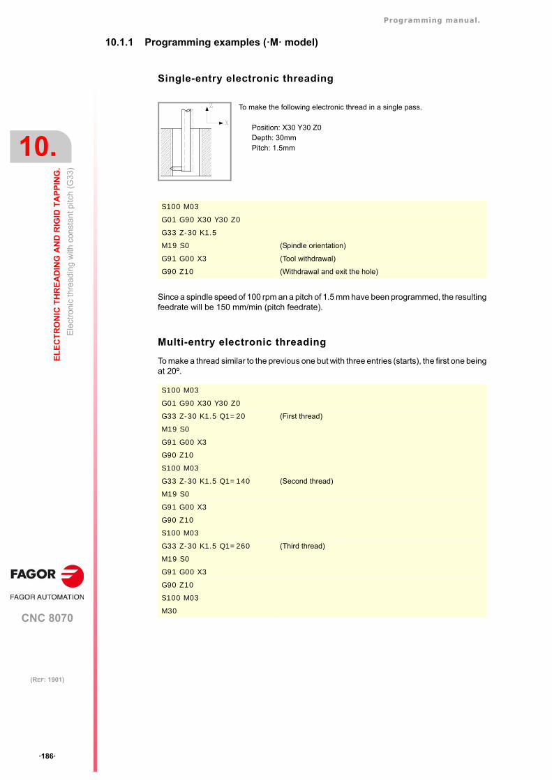
Programming manual.
CNC 8070
10.
EL
EC
TR
ON
IC T
HR
EA
DIN
G A
ND
RIG
ID T
AP
PIN
G.
Ele
ctro
nic
thre
adin
g w
ith c
onst
ant p
itch
(G3
3)
·186·
(REF: 1901)
10.1.1 Programming examples (·M· model)
Single-entry electronic threading
Since a spindle speed of 100 rpm an a pitch of 1.5 mm have been programmed, the resultingfeedrate will be 150 mm/min (pitch feedrate).
Multi-entry electronic threading
To make a thread similar to the previous one but with three entries (starts), the first one beingat 20º.
To make the following electronic thread in a single pass.
Position: X30 Y30 Z0Depth: 30mmPitch: 1.5mm
S100 M03
G01 G90 X30 Y30 Z0
G33 Z-30 K1.5
M19 S0 (Spindle orientation)
G91 G00 X3 (Tool withdrawal)
G90 Z10 (Withdrawal and exit the hole)
S100 M03
G01 G90 X30 Y30 Z0
G33 Z-30 K1.5 Q1=20 (First thread)
M19 S0
G91 G00 X3
G90 Z10
S100 M03
G33 Z-30 K1.5 Q1=140 (Second thread)
M19 S0
G91 G00 X3
G90 Z10
S100 M03
G33 Z-30 K1.5 Q1=260 (Third thread)
M19 S0
G91 G00 X3
G90 Z10
S100 M03
M30
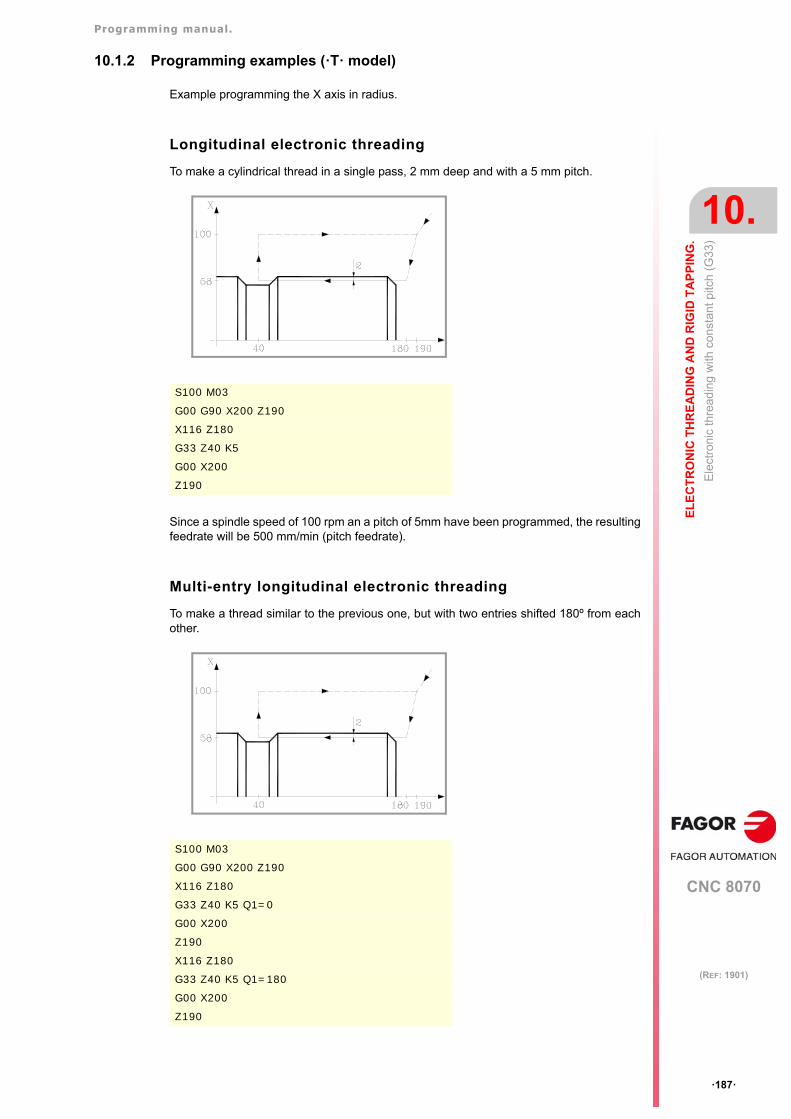
Programming manual.
CNC 8070
EL
EC
TR
ON
IC T
HR
EA
DIN
G A
ND
RIG
ID T
AP
PIN
G.
10.
Ele
ctro
nic
thre
adin
g w
ith c
onst
ant p
itch
(G3
3)
·187·
(REF: 1901)
10.1.2 Programming examples (·T· model)
Example programming the X axis in radius.
Longitudinal electronic threading
To make a cylindrical thread in a single pass, 2 mm deep and with a 5 mm pitch.
Since a spindle speed of 100 rpm an a pitch of 5mm have been programmed, the resultingfeedrate will be 500 mm/min (pitch feedrate).
Multi-entry longitudinal electronic threading
To make a thread similar to the previous one, but with two entries shifted 180º from eachother.
S100 M03
G00 G90 X200 Z190
X116 Z180
G33 Z40 K5
G00 X200
Z190
S100 M03
G00 G90 X200 Z190
X116 Z180
G33 Z40 K5 Q1=0
G00 X200
Z190
X116 Z180
G33 Z40 K5 Q1=180
G00 X200
Z190
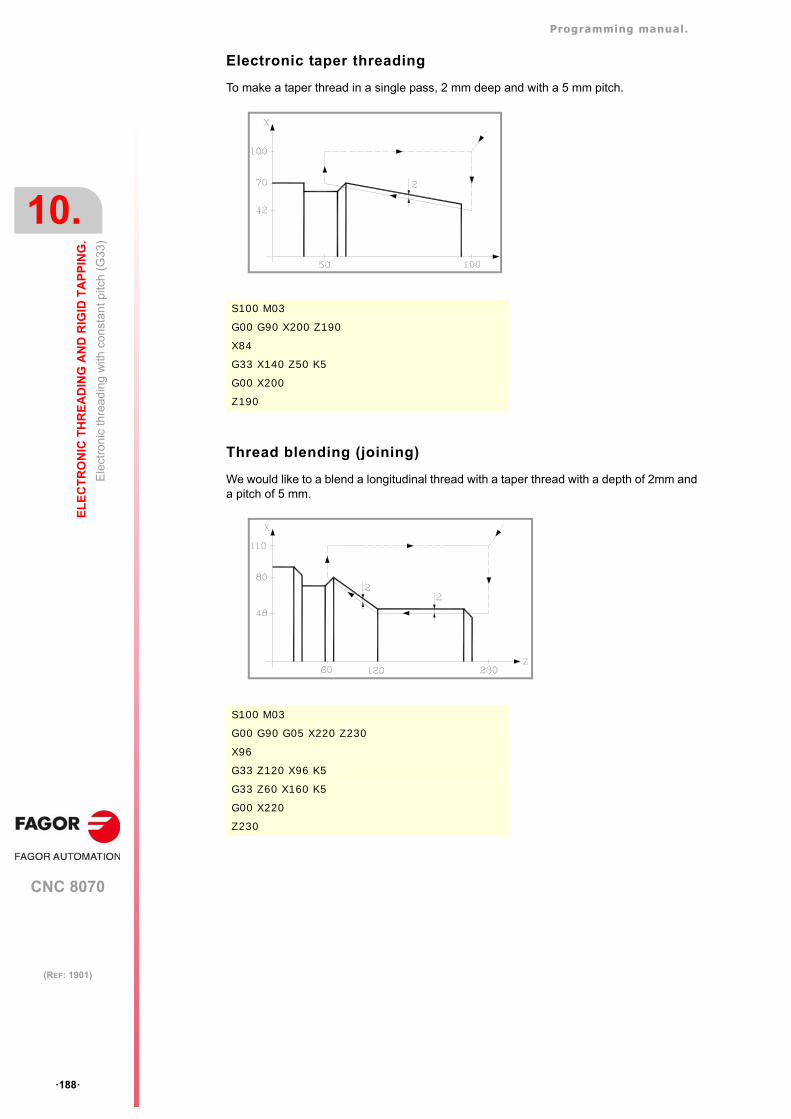
Programming manual.
CNC 8070
10.
EL
EC
TR
ON
IC T
HR
EA
DIN
G A
ND
RIG
ID T
AP
PIN
G.
Ele
ctro
nic
thre
adin
g w
ith c
onst
ant p
itch
(G3
3)
·188·
(REF: 1901)
Electronic taper threading
To make a taper thread in a single pass, 2 mm deep and with a 5 mm pitch.
Thread blending (joining)
We would like to a blend a longitudinal thread with a taper thread with a depth of 2mm anda pitch of 5 mm.
S100 M03
G00 G90 X200 Z190
X84
G33 X140 Z50 K5
G00 X200
Z190
S100 M03
G00 G90 G05 X220 Z230
X96
G33 Z120 X96 K5
G33 Z60 X160 K5
G00 X220
Z230
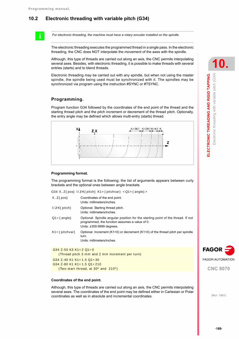
Programming manual.
CNC 8070
EL
EC
TR
ON
IC T
HR
EA
DIN
G A
ND
RIG
ID T
AP
PIN
G.
10.
Ele
ctro
nic
thre
adin
g w
ith v
aria
ble
pitc
h (G
34)
·189·
(REF: 1901)
10.2 Electronic threading with variable pitch (G34)
The electronic threading executes the programmed thread in a single pass. In the electronicthreading, the CNC does NOT interpolate the movement of the axes with the spindle.
Although, this type of threads are carried out along an axis, the CNC permits interpolatingseveral axes. Besides, with electronic threading, it is possible to make threads with severalentries (starts) and to blend threads.
Electronic threading may be carried out with any spindle, but when not using the masterspindle, the spindle being used must be synchronized with it. The spindles may besynchronized via program using the instruction #SYNC or #TSYNC.
Programming.
Program function G34 followed by the coordinates of the end point of the thread and thestarting thread pitch and the pitch increment or decrement of the thread pitch. Optionally,the entry angle may be defined which allows multi-entry (starts) thread.
Programming format.
The programming format is the following; the list of arguments appears between curlybrackets and the optional ones between angle brackets.
G34 X..Z{pos} I/J/K{pitch} K1={pitchvar} <Q1={angle}>
Coordinates of the end point.
Although, this type of threads are carried out along an axis, the CNC permits interpolatingseveral axes. The coordinates of the end point may be defined either in Cartesian or Polarcoordinates as well as in absolute and incremental coordinates.
For electronic threading, the machine must have a rotary encoder installed on the spindle.i
X..Z{pos} Coordinates of the end point.Units: millimeters/inches.
I/J/K{pitch} Optional. Starting thread pitch.Units: millimeters/inches.
Q1={angle} Optional. Spindle angular position for the starting point of the thread. If notprogrammed, the function assumes a value of 0.Units: ±359.9999 degrees.
K1={pitchvar} Optional. Increment (K1>0) or decrement (K1<0) of the thread pitch per spindleturn.Units: millimeters/inches.
G34 Z-50 K3 K1=2 Q1=0(Thread pitch 3 mm and 2 mm increment per turn)
G34 Z-40 K1 K1=1.5 Q1=30G34 Z-80 K1 K1=1.5 Q1=210
(Two-start thread, at 30º and 210º)
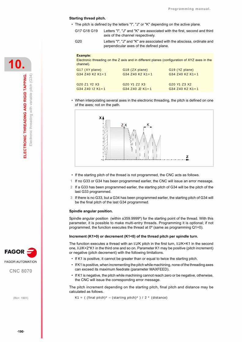
Programming manual.
CNC 8070
10.
EL
EC
TR
ON
IC T
HR
EA
DIN
G A
ND
RIG
ID T
AP
PIN
G.
Ele
ctro
nic
thre
adin
g w
ith v
aria
ble
pitc
h (G
34)
·190·
(REF: 1901)
Starting thread pitch.
• The pitch is defined by the letters "I", "J" or "K" depending on the active plane.
• When interpolating several axes in the electronic threading, the pitch is defined on oneof the axes; not on the path.
• If the starting pitch of the thread is not programmed, the CNC acts as follows.
1 If no G33 or G34 has been programmed earlier, the CNC will issue an error message.
2 If a G33 has been programmed earlier, the starting pitch of G34 will be the pitch of thelast G33 programmed.
3 If there is no G33, but a G34 has been programmed earlier, the starting pitch of G34 willbe the final pitch of the last G34 programmed.
Spindle angular position.
Spindle angular position (within ±359.9999º) for the starting point of the thread. With thisparameter, it is possible to make multi-entry threads. Programming it is optional; if notprogrammed, the function executes the thread at 0º (same as programming Q1=0).
Increment (K1>0) or decrement (K1<0) of the thread pitch per spindle turn.
The function executes a thread with an I/J/K pitch in the first turn, I/J/K+K1 in the secondone, I/J/K+2*K1 in the third one and so on. Parameter K1 may be positive (pitch increment)or negative (pitch decrement) with the following limitations.
• If K1 is positive, it cannot be greater than or equal to twice the starting pitch.
• If K1 is positive, when incrementing the pitch while machining, none of the threading axescan exceed its maximum feedrate (parameter MAXFEED).
• If K1 is negative, the pitch while machining cannot reach zero or be negative, otherwise,the CNC will issue the corresponding error message.
The pitch increment depending on the starting pitch, final pitch and distance may becalculated as follows.
K1 = ( (final pitch)² – (starting pitch)² ) / 2 * (distance)
G17 G18 G19 Letters "I", "J" and "K" are associated with the first, second and thirdaxis of the channel respectively.
G20 Letters "I", "J" and "K" are associated with the abscissa, ordinate andperpendicular axes of the defined plane.
Example:Electronic threading on the Z axis and in different planes (configuration of XYZ axes in thechannel).
G17 (XY plane)G34 Z40 K2 K1=1
G18 (ZX plane)G34 Z40 K2 K1=1
G19 (YZ plane)G34 Z40 K2 K1=1
G20 Z1 Y2 X3G34 Z40 I2 K1=1
G20 Y1 Z2 X3G34 Z40 J2 K1=1
G20 Y1 Z3 X2G34 Z40 K2 K1=1
Programming manual.
CNC 8070
EL
EC
TR
ON
IC T
HR
EA
DIN
G A
ND
RIG
ID T
AP
PIN
G.
10.
Ele
ctro
nic
thre
adin
g w
ith v
aria
ble
pitc
h (G
34)
·191·
(REF: 1901)
Considerations about execution.
Beginning of threading.
If threading begins in square (sharp) corner, the pitch increase in the first turn will be halfthe increment ("K1"/2) and it will be a full increment "K1" in the following turns.
Interrupt execution ([STOP] key or PLC mark _FEEDHOL).
The behavior of the CNC when interrupting a threading ([STOP] key or PLC mark_FEEDHOL) depends on function G233. See "10.4 Withdraw the axes after interrupting anelectronic threading (G233)." on page 195.
• If G233 is active, when interrupting the thread, the axes withdraw the distanceprogrammed in that function. If when interrupting the threading the pass is near the end,the CNC ignores G233 and stops the axes at the end of the pass.
• If G233 is not active, when interrupting the threading the axes stop at the end of the pass.
Spindle home search.
If the spindle has not been homed (referenced), the first G34 will be done automatically whenusing the master spindle. If the spindle is the master and it has not been homed, it will issuea warning.
Feedrate behavior.
The threading feedrate depends on the programmed spindle speed and thread pitch(Feedrate = Spindle speed x Pitch). The electronic threading is carried out at 100% of thecalculated feedrate and these values cannot be modified from the CNC's operator panel orvia PLC.
Behavior of the spindle speed and of the spindle speed override
If the OEM allows it, (parameter THREADOVR), the user can modify the speed override fromthe operator panel and, in that case, the CNC will adapt the feedrate automatically respectingthe thread pitch. In order to be able to modify the override, the feed forward active on theaxes involved in threading must be higher than 90%.
If more than one G34 have been programmed for the same thread, all the threadingoperations must start at the same speed; otherwise, the entry point (start) to the thread willnot be the same in all the threads. The CNC permits changing the spindle override duringthe thread cutting pass.
If more than one G34 have been programmed for a multi-start (multi-entry) thread, all thethreading operations must start at the same speed; otherwise, the angle between the starts(entry points) to the thread will not be the same as the one programmed. The CNC permitschanging the spindle override during the thread cutting pass.
Considerations about thread blending.
When working in round corner (G05), the CNC lets blend different threads seamlessly in asingle part. When thread blending, the CNC only takes into consideration the angular positionof the spindle (Q1) in the first thread, after activating G33 or G34. The CNC ignores parameterQ1until this function is canceled and activated back and it is synchronized when goingthrough that angle.
Blending a thread of fixed pitch (G33) with a thread of variable pitch (G34).
The starting pitch of the variable thread (G34) must be the same as the pitch of the fixed-pitch thread (G33). The pitch increment of the variable thread will be half the increment("K1"/2) in the first turn and a full increment "K1" in the following turns.
G33 Z-40 K2.5G34 Z-80 K2.5 K1=1
Programming manual.
CNC 8070
10.
EL
EC
TR
ON
IC T
HR
EA
DIN
G A
ND
RIG
ID T
AP
PIN
G.
Ele
ctro
nic
thre
adin
g w
ith v
aria
ble
pitc
h (G
34)
·192·
(REF: 1901)
Blending a thread of variable pitch (G34) with a thread of fixed pitch (G33).
This combination is used to end a variable-pitch thread (G34) with a portion of the threadthat maintains the final pitch of the previous thread. In this case, the pitch is not programmedin the fixed-pitch thread G33 and the CNC will use the last pitch of the previous thread.
Blending two variable-pitch threads (G34).
The starting pitch of the second thread must be the same as the final pitch of the first one.In this case, the pitch is not programmed in the second thread and the CNC will use the lastpitch of the previous thread. The pitch increment of the variable thread will be half theincrement ("K1"/2) in the first turn and a full increment "K1" in the following turns.
Properties of the function and Influence of the reset, turning theCNC off and of the M30 function.
Function G34 is modal and incompatible with G00, G01, G02, G03, G33, G63 and G100.On power-up, after an M02 or M30 and after an emergency or a reset, the CNC assumesfunction G00 or G01 as set by the machine manufacturer (parameter IMOVE).
G34 Z-50 K2 K1=3G33 Z-100
G34 Z-50 K2 K1=3G34 Z-100 K1=-2
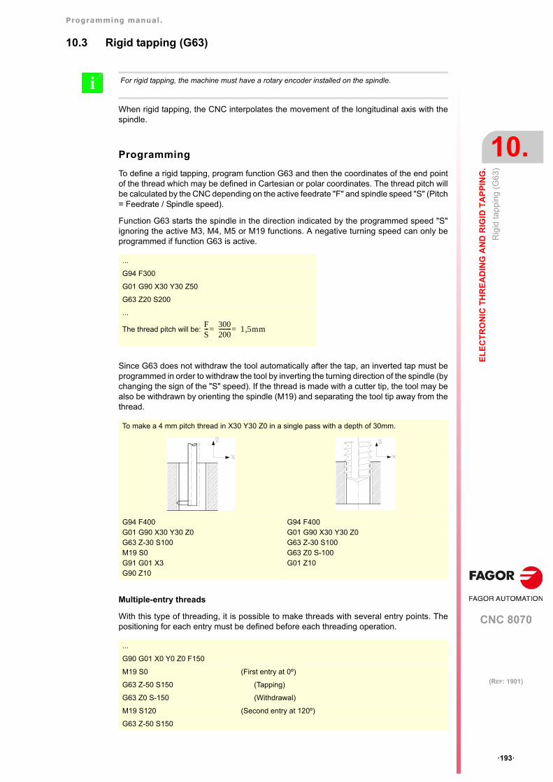
Programming manual.
CNC 8070
EL
EC
TR
ON
IC T
HR
EA
DIN
G A
ND
RIG
ID T
AP
PIN
G.
10.
Rig
id ta
ppin
g (G
63)
·193·
(REF: 1901)
10.3 Rigid tapping (G63)
When rigid tapping, the CNC interpolates the movement of the longitudinal axis with thespindle.
Programming
To define a rigid tapping, program function G63 and then the coordinates of the end pointof the thread which may be defined in Cartesian or polar coordinates. The thread pitch willbe calculated by the CNC depending on the active feedrate "F" and spindle speed "S" (Pitch= Feedrate / Spindle speed).
Function G63 starts the spindle in the direction indicated by the programmed speed "S"ignoring the active M3, M4, M5 or M19 functions. A negative turning speed can only beprogrammed if function G63 is active.
Since G63 does not withdraw the tool automatically after the tap, an inverted tap must beprogrammed in order to withdraw the tool by inverting the turning direction of the spindle (bychanging the sign of the "S" speed). If the thread is made with a cutter tip, the tool may bealso be withdrawn by orienting the spindle (M19) and separating the tool tip away from thethread.
Multiple-entry threads
With this type of threading, it is possible to make threads with several entry points. Thepositioning for each entry must be defined before each threading operation.
For rigid tapping, the machine must have a rotary encoder installed on the spindle.i
...
G94 F300
G01 G90 X30 Y30 Z50
G63 Z20 S200
...
The thread pitch will be:
To make a 4 mm pitch thread in X30 Y30 Z0 in a single pass with a depth of 30mm.
G94 F400G01 G90 X30 Y30 Z0G63 Z-30 S100M19 S0G91 G01 X3G90 Z10
G94 F400G01 G90 X30 Y30 Z0G63 Z-30 S100G63 Z0 S-100G01 Z10
...
G90 G01 X0 Y0 Z0 F150
M19 S0 (First entry at 0º)
G63 Z-50 S150 (Tapping)
G63 Z0 S-150 (Withdrawal)
M19 S120 (Second entry at 120º)
G63 Z-50 S150
FS--- 300
200--------- 1 5mm,==
Programming manual.
CNC 8070
10.
EL
EC
TR
ON
IC T
HR
EA
DIN
G A
ND
RIG
ID T
AP
PIN
G.
Rig
id ta
ppin
g (G
63)
·194·
(REF: 1901)
Considerations for the execution
Spindle speed behavior
Threading is carried out a the speed defined with function G63. If no particular threadingspeed is defined, threading will be executed at the speed active at the time. If a speed isprogrammed with function G63, it will be the active spindle speed at the end of the threadingoperation.
The spindle turning direction is determined by the sign of the programmed "S" speed ignoringthe active M3, M4, M5 or M19 functions. Programming any of these functions will cancel G63.
Feedrate behavior
While rigid tapping, the feedrate may be varied between 0% and 200% using the feedrateoverride switch on the CNC's operator panel of via PLC. The CNC will adapt the spindlespeed in order to keep the interpolation between the axis and the spindle.
Rigid tapping and tool inspection mode
When interrupting the rigid tapping and accessing the tool inspection mode, it is possible tojog the axes (only in jog mode) that are involved in threading. When moving the axis, theinterpolated spindle will also move; the spindle used to make the thread. If several axes areinvolved in the rigid tapping, when moving one of the axes all the axes involved in the threadwill also move with it.
This way, the axis may be moved into or out of the thread as often as desired until therepositioning softkey is pressed. The axes move at the programmed F except when an axisor spindle exceeds its maximum feedrate allowed (parameter MAXMANFEED), in which case,the feedrate will be limited to that value.
The spindle jogging keys are disabled during tool inspection. It is only possible to get outof the thread by jogging one of the axes involved in rigid tapping. Functions M3, M4, M5 andM19 cannot be programmed at the spindle either; these functions are ignored.
During repositioning, selecting one of the axes of the thread on the softkey menu will moveall the axes and the spindle involved in the thread.
Properties of the functions
Function G63 is modal and incompatible with G00, G01, G02, G03 and G33.
On power-up, after an M02 or M30 and after an EMERGENCY or a RESET, the CNCassumes function G00 or G01 as set by the machine manufacturer [G.M.P. "IMOVE"].
G63 Z0 S-150
M19 S240 (Third entry at 240º)
G63 Z-50 S150
G63 Z0 S-150
...
3-entry thread, 50mm deep and 1mm pitch.
Programming manual.
CNC 8070
EL
EC
TR
ON
IC T
HR
EA
DIN
G A
ND
RIG
ID T
AP
PIN
G.
10.
With
draw
the
axes
afte
r in
terr
upt
ing
an e
lect
roni
c th
read
ing
(G2
33).
·195·
(REF: 1901)
10.4 Withdraw the axes after interrupting an electronic threading(G233).
Function G233 may be used to program the safety distance that the axes will withdraw wheninterrupting a threading operation (G33/G34) either with the [STOP] key or from the PLC(mark _FEEDHOL). In the threading canned cycles (G86/G87 of the -T- model) this functionis ignored because it is implicit when programming the cycle.
This feature is particularly interesting in very long threads where it may be necessary tointerrupt the threading operation either because the tool broke or because the machiningis not right; for example due to vibrations on the work piece.
Programming. Defining and canceling the safety distance forthread exit.
• To define a safety distance, program function G233 and then the distance on each axis.
• To cancel the safety distance on an axis, define a safety distance of zero on the axis.
• To cancel the function, program it alone in the block or define a zero distance on all axeswhere it is active. In either case, function G233 disappears from the history.
Programming format. Defining a safety distance.
The programming format is the following; the list of arguments appears between curlybrackets.
G233 X..Z{distance}
Programming format. Canceling the safety distance on an axis.
The programming format is:
G233 X0..Z0
Programming format. Deactivate the function.
The programming format is:
G233G233 X0..Z0
Function G233 alone in the block also indicates the point where execution will resume afterpressing [START].
Thread exit distance on the axis perpendicular to the threading operation.
The safety distance is only defined on the axis perpendicular to the threading operation; itis ignored on the rest of the axes. On outside longitudinal threads will be a positive distanceand on inside ones it will be a negative distance.
On taper threading, the threading axis will be the one on which the pitch has been defined.
This feature must be enabled by the OEM in the machine parameters (parameter RETRACTTHREAD);otherwise, when interrupting the execution while threading (using the [STOP] key or the PLC mark_FEEDHOL) the axes always stop at the end of the pass.
i
X..Z{distance} Thread exit distance on the axis perpendicular to the threading operation.Units: millimeters/inches.
G233 X5 (The tool separates 5 mm from the thread on the X axis)
G233 X0(cancel the safety distance on an axis)
G233
G233 X0 Z0
Programming manual.
CNC 8070
10.
EL
EC
TR
ON
IC T
HR
EA
DIN
G A
ND
RIG
ID T
AP
PIN
G.
With
draw
the
axes
afte
r in
terr
upt
ing
an e
lect
roni
c th
read
ing
(G2
33).
·196·
(REF: 1901)
Programming. Define the block to resume the block to resumeexecution after pressing [START].
To resume execution, press the [START] key; execution resumes at the next block wherefunction G233 is programmed alone.
Operation.
The option to withdraw the axes when interrupting a threading operation depends on theconfiguration of the machine (parameter RETRACTTHREAD).
When the feature is enabled (parameter RETRACTTHREAD), the CNC behaves as followswhen interrupting a threading operation ([STOP] key or PLC mark _FEEDHOL).
• If G233 is active, the axis perpendicular to threading withdraws the programmed distancefrom the part. The threading axis withdraws the necessary distance as not to damagethe thread while maintaining the pitch.
• If G233 is active, and when interrupting the threading the pass is near the end, the CNCignores G233 and stops the axes at the end of the pass.
• If G233 is not active, the axes stop at the end of the pass.
Feedrate of the axes.
The axis perpendicular to threading withdraws from the part at the feedrate set in parameterMAXFEED of the active set. The threading axis maintains the pitch.
Considerations and limitations.
G233 with several G33/G34 functions in a row.
Function G233 sets the thread exit distance for all G33/G34 threads programmed after it.If there are several G33/G34 functions in a row and a different thread exit is desired for eachone of them, the corresponding G233 function must be programmed betore each one ofthem.
Thread blending.
If there are several threads in a row (thread blending), function G233 considers all of themcompleted.
Threading canned cycles, ISO and conversational (-T- model).
Function G233 is only applied in electronic threading G33/G34; it is ignored in threadingcanned cycles, both ISO and conversational, because it is implicit in the cycles, programmedas thread exit.
• In canned cycles where a thread exit has been programmed, the withdrawal distance forthe axis perpendicular to the threading is calculated automatically and corresponds tothe value of that thread exit of each pass.
• In cycles where the thread exit has not been programmed, the behavior depends onparameter RETRACTTHREAD.
Once the tool has withdrawn the programmed distance, it returns to the starting point of thecycle. The machine waits for the CYCLE START command to repeat the aborted pass.
RETRACTTHREAD Meaning.
ON The CNC behavior depends on function G233.
OFF The CNC ignores function G233 and stops the axes at the end of thethreading operation.
RETRACTTHREAD Meaning.
ON The tool withdraws to the safety coordinate, perpendicularly to thethreading axis (just the same as when having a thread exit).
OFF The axes stop at the end of the pass.
Programming manual.
CNC 8070
EL
EC
TR
ON
IC T
HR
EA
DIN
G A
ND
RIG
ID T
AP
PIN
G.
10.
With
draw
the
axes
afte
r in
terr
upt
ing
an e
lect
roni
c th
read
ing
(G2
33).
·197·
(REF: 1901)
Threading canned cycles, ISO and conversational (-T- model).
The option to withdraw the axes when interrupting a threading operation depends on theconfiguration of the machine (parameter RETRACTTHREAD).
The CNC ignores function G233 in threading canned cycles, both ISO and conversational,because it is implicit in the cycles, programmed as thread exit. When the feature is enabled(parameter RETRACTTHREAD), the CNC behaves as follows when interrupting a threadingoperation ([STOP] key or PLC mark _FEEDHOL).
• In canned cycles where a thread exit has been programmed, the withdrawal distance forthe axis perpendicular to the threading is calculated automatically and corresponds tothe value of that thread exit of each pass.
• In cycles where the thread exit has not been programmed, the axes withdraw to the safetycoordinate, perpendicularly to the threading axis (just the same as when having a threadexit).
Once the tool has withdrawn the programmed distance, it returns to the starting point of thecycle. The machine waits for the CYCLE START command to repeat the aborted pass.
Properties of the function and Influence of the reset, turning theCNC off and of the M30 function.
Function G233 is modal. On power-up, after executing an M02 or M30, and after anemergency or reset, the CNC cancels this function.
RETRACTTHREAD Meaning.
ON The CNC interrupts the threading and withdraws the axes.
OFF The CNC stops the axes at the end of the pass.
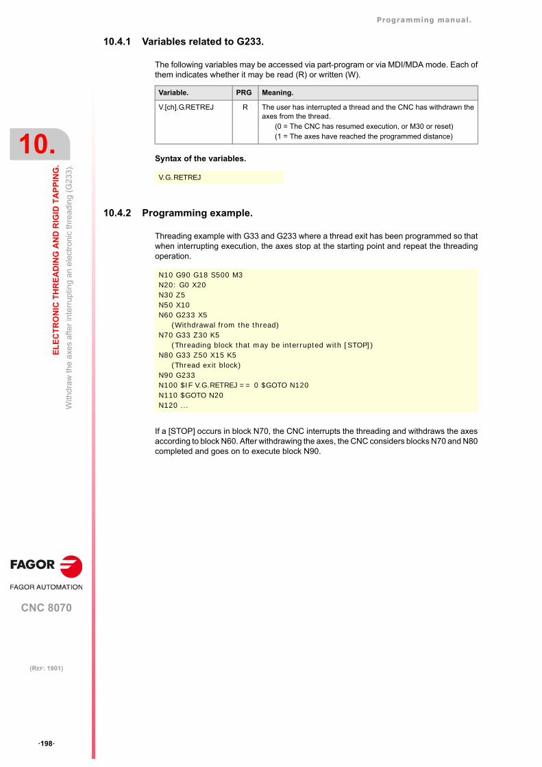
Programming manual.
CNC 8070
10.
EL
EC
TR
ON
IC T
HR
EA
DIN
G A
ND
RIG
ID T
AP
PIN
G.
With
draw
the
axes
afte
r in
terr
upt
ing
an e
lect
roni
c th
read
ing
(G2
33).
·198·
(REF: 1901)
10.4.1 Variables related to G233.
The following variables may be accessed via part-program or via MDI/MDA mode. Each ofthem indicates whether it may be read (R) or written (W).
Syntax of the variables.
10.4.2 Programming example.
Threading example with G33 and G233 where a thread exit has been programmed so thatwhen interrupting execution, the axes stop at the starting point and repeat the threadingoperation.
If a [STOP] occurs in block N70, the CNC interrupts the threading and withdraws the axesaccording to block N60. After withdrawing the axes, the CNC considers blocks N70 and N80completed and goes on to execute block N90.
Variable. PRG Meaning.
V.[ch].G.RETREJ R The user has interrupted a thread and the CNC has withdrawn theaxes from the thread.
(0 = The CNC has resumed execution, or M30 or reset)(1 = The axes have reached the programmed distance)
V.G.RETREJ
N10 G90 G18 S500 M3N20: G0 X20N30 Z5N50 X10N60 G233 X5
(Withdrawal from the thread)N70 G33 Z30 K5
(Threading block that may be interrupted with [STOP])N80 G33 Z50 X15 K5
(Thread exit block)N90 G233 N100 $IF V.G.RETREJ == 0 $GOTO N120N110 $GOTO N20N120 ...
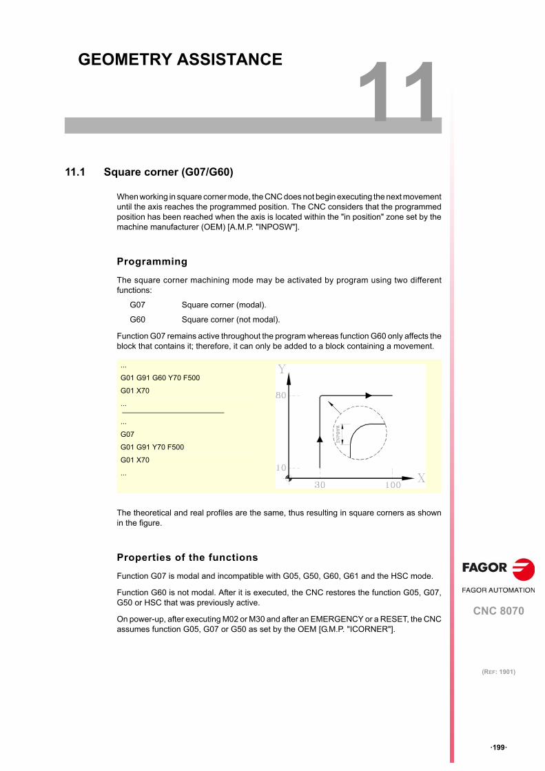
CNC 8070
11
·199·
(REF: 1901)
11.GEOMETRY ASSISTANCE
11.1 Square corner (G07/G60)
When working in square corner mode, the CNC does not begin executing the next movementuntil the axis reaches the programmed position. The CNC considers that the programmedposition has been reached when the axis is located within the "in position" zone set by themachine manufacturer (OEM) [A.M.P. "INPOSW"].
Programming
The square corner machining mode may be activated by program using two differentfunctions:
G07 Square corner (modal).
G60 Square corner (not modal).
Function G07 remains active throughout the program whereas function G60 only affects theblock that contains it; therefore, it can only be added to a block containing a movement.
The theoretical and real profiles are the same, thus resulting in square corners as shownin the figure.
Properties of the functions
Function G07 is modal and incompatible with G05, G50, G60, G61 and the HSC mode.
Function G60 is not modal. After it is executed, the CNC restores the function G05, G07,G50 or HSC that was previously active.
On power-up, after executing M02 or M30 and after an EMERGENCY or a RESET, the CNCassumes function G05, G07 or G50 as set by the OEM [G.M.P. "ICORNER"].
...
G01 G91 G60 Y70 F500
G01 X70
...
...
G07
G01 G91 Y70 F500
G01 X70
...
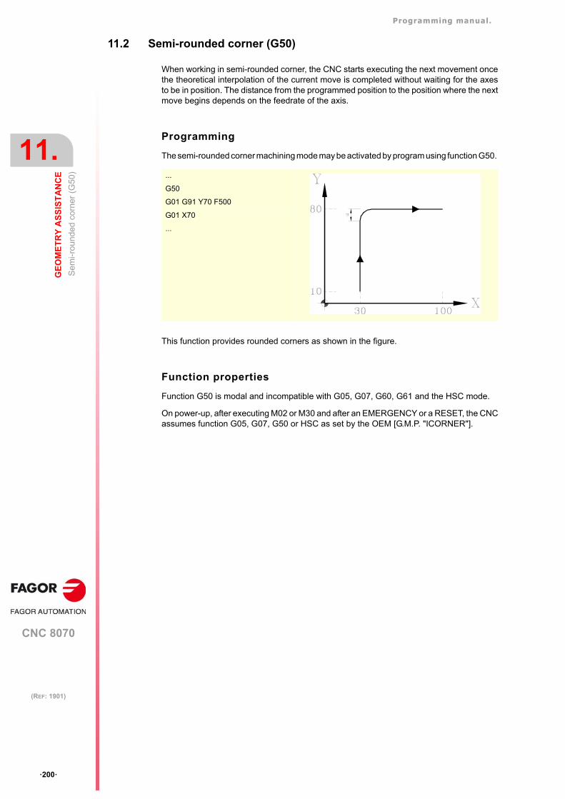
Programming manual.
CNC 8070
11.
GE
OM
ET
RY
AS
SIS
TA
NC
E
Se
mi-r
oun
ded
cor
ner
(G5
0)
·200·
(REF: 1901)
11.2 Semi-rounded corner (G50)
When working in semi-rounded corner, the CNC starts executing the next movement oncethe theoretical interpolation of the current move is completed without waiting for the axesto be in position. The distance from the programmed position to the position where the nextmove begins depends on the feedrate of the axis.
Programming
The semi-rounded corner machining mode may be activated by program using function G50.
This function provides rounded corners as shown in the figure.
Function properties
Function G50 is modal and incompatible with G05, G07, G60, G61 and the HSC mode.
On power-up, after executing M02 or M30 and after an EMERGENCY or a RESET, the CNCassumes function G05, G07, G50 or HSC as set by the OEM [G.M.P. "ICORNER"].
...
G50
G01 G91 Y70 F500
G01 X70
...
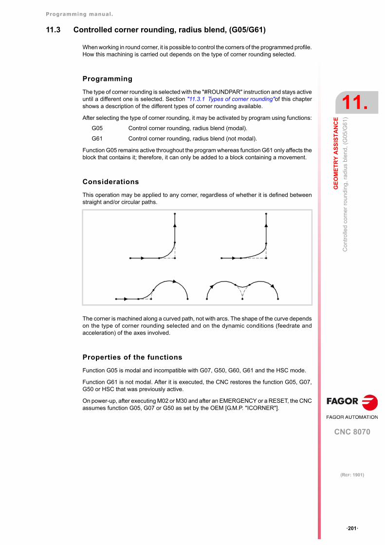
Programming manual.
CNC 8070
GE
OM
ET
RY
AS
SIS
TA
NC
E
11.
Con
trol
led
corn
er r
oun
ding
, rad
ius
ble
nd,
(G
05/G
61)
·201·
(REF: 1901)
11.3 Controlled corner rounding, radius blend, (G05/G61)
When working in round corner, it is possible to control the corners of the programmed profile.How this machining is carried out depends on the type of corner rounding selected.
Programming
The type of corner rounding is selected with the "#ROUNDPAR" instruction and stays activeuntil a different one is selected. Section "11.3.1 Types of corner rounding"of this chaptershows a description of the different types of corner rounding available.
After selecting the type of corner rounding, it may be activated by program using functions:
G05 Control corner rounding, radius blend (modal).
G61 Control corner rounding, radius blend (not modal).
Function G05 remains active throughout the program whereas function G61 only affects theblock that contains it; therefore, it can only be added to a block containing a movement.
Considerations
This operation may be applied to any corner, regardless of whether it is defined betweenstraight and/or circular paths.
The corner is machined along a curved path, not with arcs. The shape of the curve dependson the type of corner rounding selected and on the dynamic conditions (feedrate andacceleration) of the axes involved.
Properties of the functions
Function G05 is modal and incompatible with G07, G50, G60, G61 and the HSC mode.
Function G61 is not modal. After it is executed, the CNC restores the function G05, G07,G50 or HSC that was previously active.
On power-up, after executing M02 or M30 and after an EMERGENCY or a RESET, the CNCassumes function G05, G07 or G50 as set by the OEM [G.M.P. "ICORNER"].
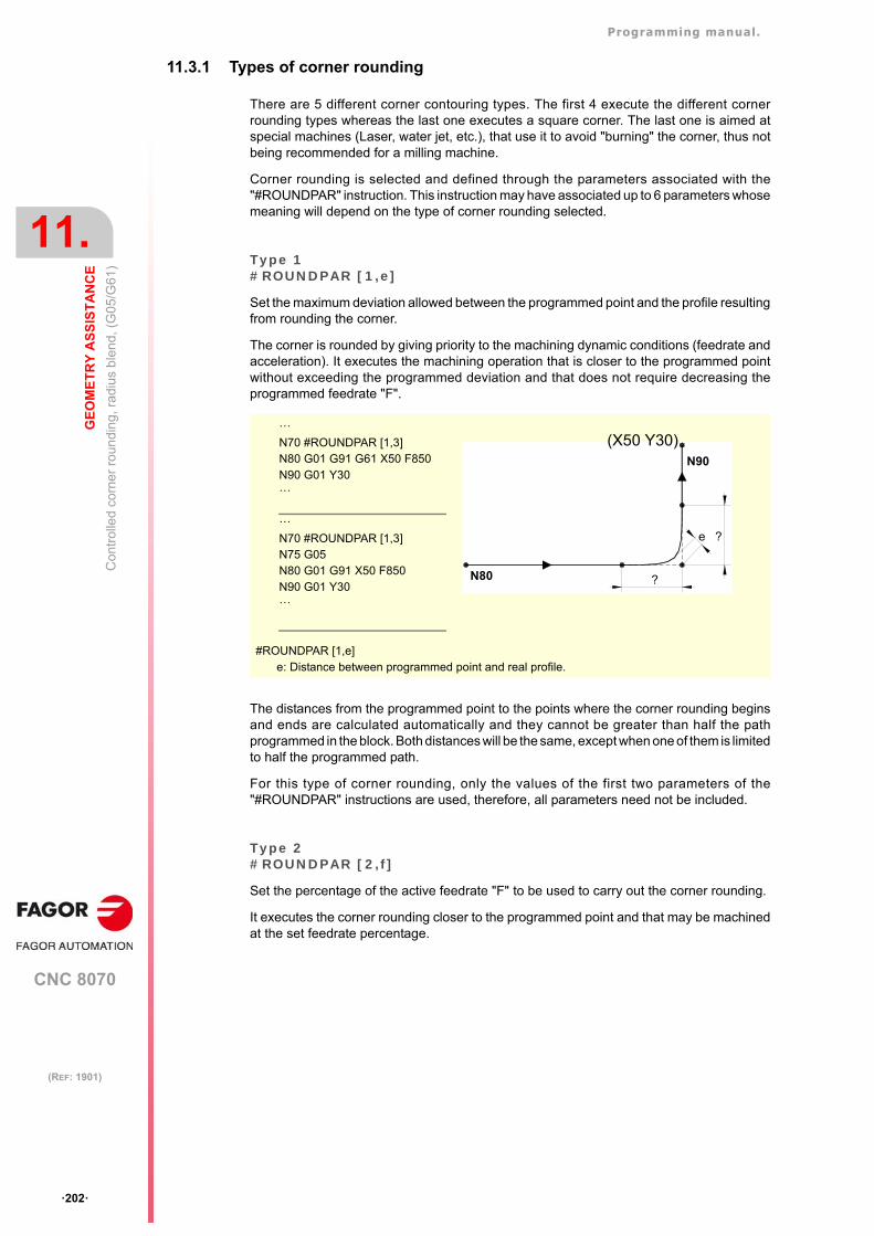
Programming manual.
CNC 8070
11.
GE
OM
ET
RY
AS
SIS
TA
NC
E
Con
trol
led
corn
er r
oun
ding
, rad
ius
ble
nd,
(G
05/G
61)
·202·
(REF: 1901)
11.3.1 Types of corner rounding
There are 5 different corner contouring types. The first 4 execute the different cornerrounding types whereas the last one executes a square corner. The last one is aimed atspecial machines (Laser, water jet, etc.), that use it to avoid "burning" the corner, thus notbeing recommended for a milling machine.
Corner rounding is selected and defined through the parameters associated with the"#ROUNDPAR" instruction. This instruction may have associated up to 6 parameters whosemeaning will depend on the type of corner rounding selected.
Type 1#ROUNDPAR [1,e]
Set the maximum deviation allowed between the programmed point and the profile resultingfrom rounding the corner.
The corner is rounded by giving priority to the machining dynamic conditions (feedrate andacceleration). It executes the machining operation that is closer to the programmed pointwithout exceeding the programmed deviation and that does not require decreasing theprogrammed feedrate "F".
The distances from the programmed point to the points where the corner rounding beginsand ends are calculated automatically and they cannot be greater than half the pathprogrammed in the block. Both distances will be the same, except when one of them is limitedto half the programmed path.
For this type of corner rounding, only the values of the first two parameters of the"#ROUNDPAR" instructions are used, therefore, all parameters need not be included.
Type 2#ROUNDPAR [2,f]
Set the percentage of the active feedrate "F" to be used to carry out the corner rounding.
It executes the corner rounding closer to the programmed point and that may be machinedat the set feedrate percentage.
#ROUNDPAR [1,e]e: Distance between programmed point and real profile.
···N70 #ROUNDPAR [1,3]N80 G01 G91 G61 X50 F850N90 G01 Y30···
···N70 #ROUNDPAR [1,3]N75 G05N80 G01 G91 X50 F850N90 G01 Y30···
N90
N80 ?
?e
(X50 Y30)
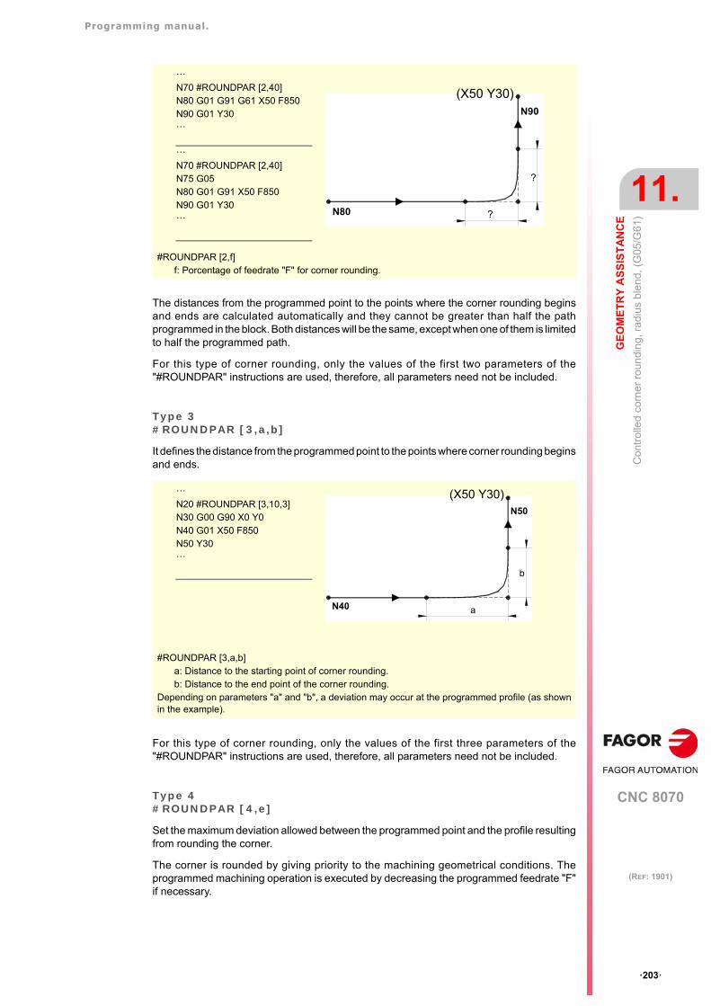
Programming manual.
CNC 8070
GE
OM
ET
RY
AS
SIS
TA
NC
E
11.
Con
trol
led
corn
er r
oun
ding
, rad
ius
ble
nd,
(G
05/G
61)
·203·
(REF: 1901)
The distances from the programmed point to the points where the corner rounding beginsand ends are calculated automatically and they cannot be greater than half the pathprogrammed in the block. Both distances will be the same, except when one of them is limitedto half the programmed path.
For this type of corner rounding, only the values of the first two parameters of the"#ROUNDPAR" instructions are used, therefore, all parameters need not be included.
Type 3#ROUNDPAR [3,a,b]
It defines the distance from the programmed point to the points where corner rounding beginsand ends.
For this type of corner rounding, only the values of the first three parameters of the"#ROUNDPAR" instructions are used, therefore, all parameters need not be included.
Type 4#ROUNDPAR [4,e]
Set the maximum deviation allowed between the programmed point and the profile resultingfrom rounding the corner.
The corner is rounded by giving priority to the machining geometrical conditions. Theprogrammed machining operation is executed by decreasing the programmed feedrate "F"if necessary.
#ROUNDPAR [2,f]f: Porcentage of feedrate "F" for corner rounding.
#ROUNDPAR [3,a,b]a: Distance to the starting point of corner rounding.b: Distance to the end point of the corner rounding.
Depending on parameters "a" and "b", a deviation may occur at the programmed profile (as shownin the example).
···N70 #ROUNDPAR [2,40]N80 G01 G91 G61 X50 F850N90 G01 Y30···
···N70 #ROUNDPAR [2,40]N75 G05N80 G01 G91 X50 F850N90 G01 Y30···
N90
N80 ?
?
(X50 Y30)
···N20 #ROUNDPAR [3,10,3]N30 G00 G90 X0 Y0N40 G01 X50 F850N50 Y30···
N50
N40 a
b
(X50 Y30)
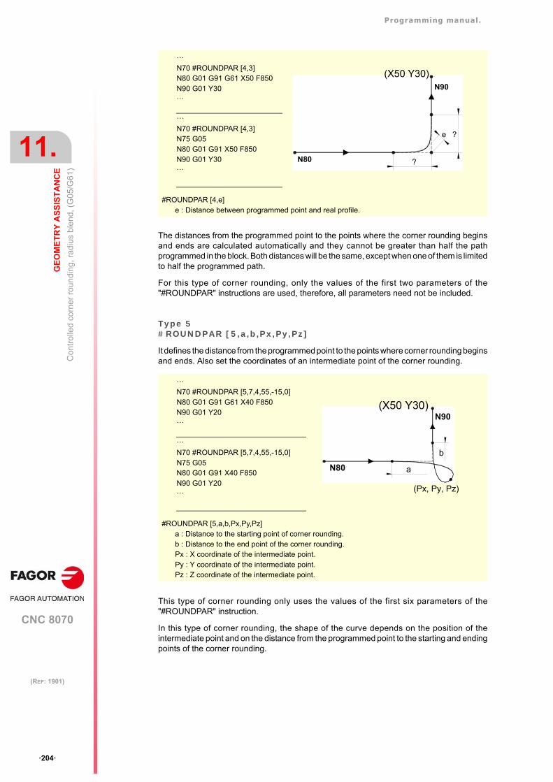
Programming manual.
CNC 8070
11.
GE
OM
ET
RY
AS
SIS
TA
NC
E
Con
trol
led
corn
er r
oun
ding
, rad
ius
ble
nd,
(G
05/G
61)
·204·
(REF: 1901)
The distances from the programmed point to the points where the corner rounding beginsand ends are calculated automatically and they cannot be greater than half the pathprogrammed in the block. Both distances will be the same, except when one of them is limitedto half the programmed path.
For this type of corner rounding, only the values of the first two parameters of the"#ROUNDPAR" instructions are used, therefore, all parameters need not be included.
Type 5#ROUNDPAR [5,a,b,Px,Py,Pz]
It defines the distance from the programmed point to the points where corner rounding beginsand ends. Also set the coordinates of an intermediate point of the corner rounding.
This type of corner rounding only uses the values of the first six parameters of the"#ROUNDPAR" instruction.
In this type of corner rounding, the shape of the curve depends on the position of theintermediate point and on the distance from the programmed point to the starting and endingpoints of the corner rounding.
#ROUNDPAR [4,e]e : Distance between programmed point and real profile.
#ROUNDPAR [5,a,b,Px,Py,Pz]a : Distance to the starting point of corner rounding.b : Distance to the end point of the corner rounding.Px : X coordinate of the intermediate point.Py : Y coordinate of the intermediate point.Pz : Z coordinate of the intermediate point.
N90
N80 ?
?e
(X50 Y30)
···N70 #ROUNDPAR [4,3]N80 G01 G91 G61 X50 F850N90 G01 Y30···
···N70 #ROUNDPAR [4,3]N75 G05N80 G01 G91 X50 F850N90 G01 Y30···
···N70 #ROUNDPAR [5,7,4,55,-15,0]N80 G01 G91 G61 X40 F850N90 G01 Y20···
···N70 #ROUNDPAR [5,7,4,55,-15,0]N75 G05N80 G01 G91 X40 F850N90 G01 Y20···
N90
N80 a
b
(X50 Y30)
(Px, Py, Pz)
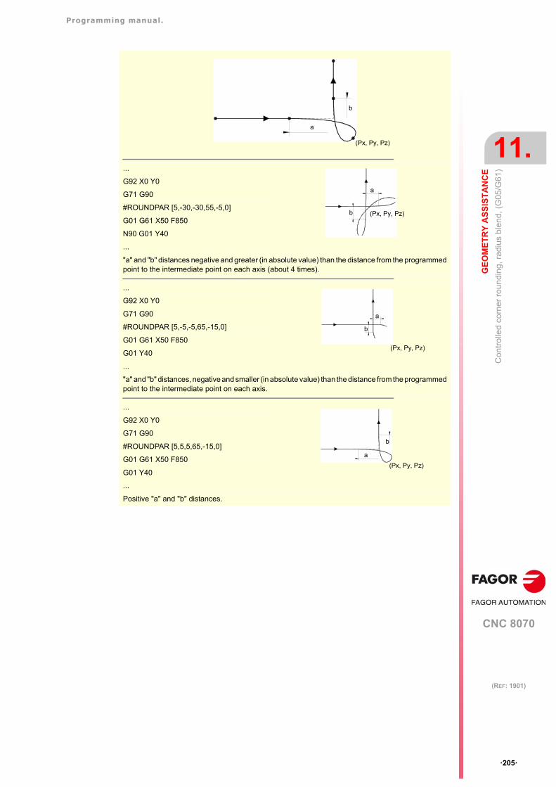
Programming manual.
CNC 8070
GE
OM
ET
RY
AS
SIS
TA
NC
E
11.
Con
trol
led
corn
er r
oun
ding
, rad
ius
ble
nd,
(G
05/G
61)
·205·
(REF: 1901)
...
G92 X0 Y0
G71 G90
#ROUNDPAR [5,-30,-30,55,-5,0]
G01 G61 X50 F850
N90 G01 Y40
...
"a" and "b" distances negative and greater (in absolute value) than the distance from the programmedpoint to the intermediate point on each axis (about 4 times).
...
G92 X0 Y0
G71 G90
#ROUNDPAR [5,-5,-5,65,-15,0]
G01 G61 X50 F850
G01 Y40
...
"a" and "b" distances, negative and smaller (in absolute value) than the distance from the programmedpoint to the intermediate point on each axis.
...
G92 X0 Y0
G71 G90
#ROUNDPAR [5,5,5,65,-15,0]
G01 G61 X50 F850
G01 Y40
...
Positive "a" and "b" distances.
(Px, Py, Pz)
a
b
a
b (Px, Py, Pz)
a
b
(Px, Py, Pz)
a
b
(Px, Py, Pz)
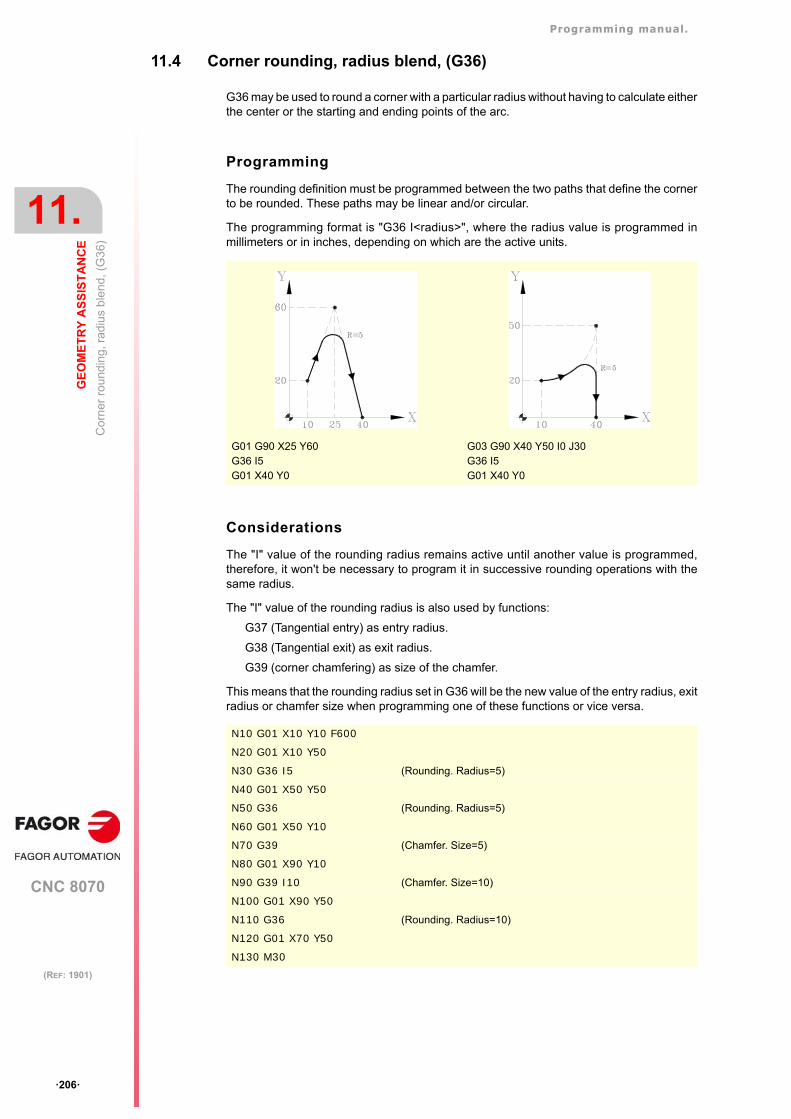
Programming manual.
CNC 8070
11.
GE
OM
ET
RY
AS
SIS
TA
NC
E
Co
rner
ro
und
ing,
rad
ius
ble
nd, (
G3
6)
·206·
(REF: 1901)
11.4 Corner rounding, radius blend, (G36)
G36 may be used to round a corner with a particular radius without having to calculate eitherthe center or the starting and ending points of the arc.
Programming
The rounding definition must be programmed between the two paths that define the cornerto be rounded. These paths may be linear and/or circular.
The programming format is "G36 I<radius>", where the radius value is programmed inmillimeters or in inches, depending on which are the active units.
Considerations
The "I" value of the rounding radius remains active until another value is programmed,therefore, it won't be necessary to program it in successive rounding operations with thesame radius.
The "I" value of the rounding radius is also used by functions:
G37 (Tangential entry) as entry radius.
G38 (Tangential exit) as exit radius.
G39 (corner chamfering) as size of the chamfer.
This means that the rounding radius set in G36 will be the new value of the entry radius, exitradius or chamfer size when programming one of these functions or vice versa.
G01 G90 X25 Y60G36 I5G01 X40 Y0
G03 G90 X40 Y50 I0 J30G36 I5G01 X40 Y0
N10 G01 X10 Y10 F600
N20 G01 X10 Y50
N30 G36 I5 (Rounding. Radius=5)
N40 G01 X50 Y50
N50 G36 (Rounding. Radius=5)
N60 G01 X50 Y10
N70 G39 (Chamfer. Size=5)
N80 G01 X90 Y10
N90 G39 I10 (Chamfer. Size=10)
N100 G01 X90 Y50
N110 G36 (Rounding. Radius=10)
N120 G01 X70 Y50
N130 M30
Programming manual.
CNC 8070
GE
OM
ET
RY
AS
SIS
TA
NC
E
11.
Co
rner
ro
und
ing,
rad
ius
ble
nd, (
G3
6)
·207·
(REF: 1901)
The programmed rounding feedrate depends on the type of movement programmedafterwards:
• If the next movement is in G00, the rounding will be carried out in G00.
• If the next movement is in G01, G02 or G03, the rounding will be carried out at the feedrateprogrammed in rounding definition block. If no feedrate has been programmed, therounding will be carried out at the active feedrate.
When defining a plane change between the two paths that define a rounding, it is carriedout in the plane where the second path is defined.
Function properties
Function G36 is not modal, therefore, it must be programmed every time a corner is to berounded.
N10 G01 G94 X10 Y10 F600
N20 G01 X10 Y50
N30 G36 I5 (Rounding. G00)
N40 G00 X50 Y50
N50 G36 (Rounding. F=600mm/min.)
N60 G01 X50 Y10
N70 G36 F300 (Rounding. F=300mm/min.)
N80 G01 X90 Y10 F600
N90 M30
N10 G01 G17 X10 Y10 Z-10 F600
N20 X10 Y50 Z0 (X-Y plane)
N30 G36 I10
N40 G18 (Z-X plane. The rounding is carried out in this plane)
N50 X10 Z30
N60 M30
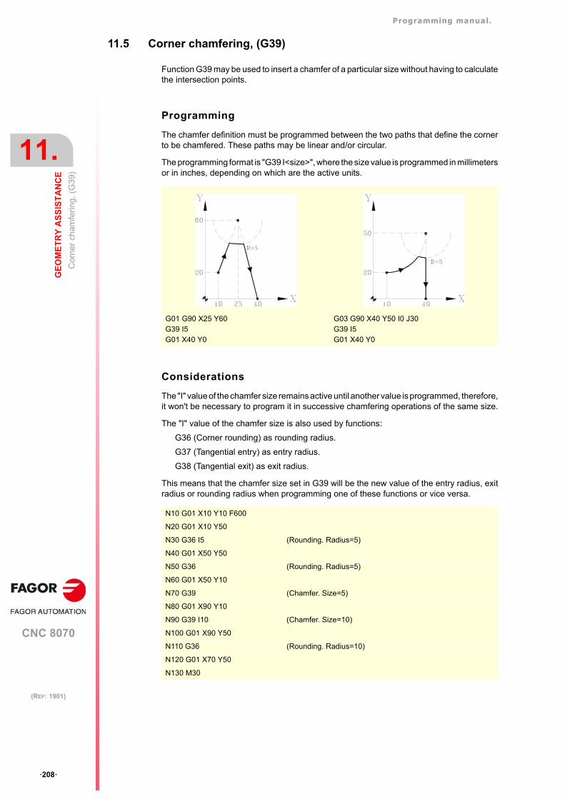
Programming manual.
CNC 8070
11.
GE
OM
ET
RY
AS
SIS
TA
NC
E
Co
rner
cha
mfe
ring
, (G
39)
·208·
(REF: 1901)
11.5 Corner chamfering, (G39)
Function G39 may be used to insert a chamfer of a particular size without having to calculatethe intersection points.
Programming
The chamfer definition must be programmed between the two paths that define the cornerto be chamfered. These paths may be linear and/or circular.
The programming format is "G39 I<size>", where the size value is programmed in millimetersor in inches, depending on which are the active units.
Considerations
The "I" value of the chamfer size remains active until another value is programmed, therefore,it won't be necessary to program it in successive chamfering operations of the same size.
The "I" value of the chamfer size is also used by functions:
G36 (Corner rounding) as rounding radius.
G37 (Tangential entry) as entry radius.
G38 (Tangential exit) as exit radius.
This means that the chamfer size set in G39 will be the new value of the entry radius, exitradius or rounding radius when programming one of these functions or vice versa.
G01 G90 X25 Y60G39 I5G01 X40 Y0
G03 G90 X40 Y50 I0 J30G39 I5G01 X40 Y0
N10 G01 X10 Y10 F600
N20 G01 X10 Y50
N30 G36 I5 (Rounding. Radius=5)
N40 G01 X50 Y50
N50 G36 (Rounding. Radius=5)
N60 G01 X50 Y10
N70 G39 (Chamfer. Size=5)
N80 G01 X90 Y10
N90 G39 I10 (Chamfer. Size=10)
N100 G01 X90 Y50
N110 G36 (Rounding. Radius=10)
N120 G01 X70 Y50
N130 M30
Programming manual.
CNC 8070
GE
OM
ET
RY
AS
SIS
TA
NC
E
11.
Co
rner
cha
mfe
ring
, (G
39)
·209·
(REF: 1901)
The programmed chamfering feedrate depends on the type of movement programmedafterwards:
• If the next movement is in G00, the chamfer will be carried out in G00.
• If the next movement is in G01, G02 or G03, the chamfer will be carried out at the feedrateprogrammed in chamfer definition block. If no feedrate has been programmed, thechamfer will be carried out at the active feedrate.
When defining a plane change between the two paths that define a chamfer, it is carried outin the plane where the second path is defined.
Function properties
Function G39 is not modal, therefore, it must be programmed every time a corner is to bechamfered.
N10 G01 G94 X10 Y10 F600
N20 G01 X10 Y50
N30 G39 I5 (Chamfering in G00)
N40 G00 X50 Y50
N50 G39 (Chamfer. F=600mm/min.)
N60 G01 X50 Y10
N70 G39 F300 (Chamfer. F=300mm/min.)
N80 G01 X90 Y10 F600
N90 M30
N10 G01 G17 X10 Y10 Z-10 F600
N20 X10 Y50 Z0 (X-Y plane)
N30 G39 I10
N40 G18 (Z-X plane. The chamfer is carried out in this plane)
N50 X10 Z30
N60 M30
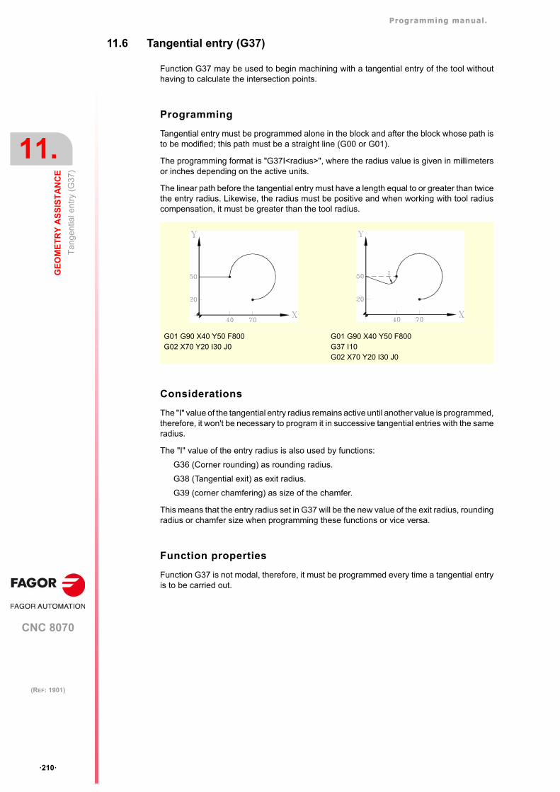
Programming manual.
CNC 8070
11.
GE
OM
ET
RY
AS
SIS
TA
NC
E
Tan
gen
tial e
ntry
(G
37)
·210·
(REF: 1901)
11.6 Tangential entry (G37)
Function G37 may be used to begin machining with a tangential entry of the tool withouthaving to calculate the intersection points.
Programming
Tangential entry must be programmed alone in the block and after the block whose path isto be modified; this path must be a straight line (G00 or G01).
The programming format is "G37I<radius>", where the radius value is given in millimetersor inches depending on the active units.
The linear path before the tangential entry must have a length equal to or greater than twicethe entry radius. Likewise, the radius must be positive and when working with tool radiuscompensation, it must be greater than the tool radius.
Considerations
The "I" value of the tangential entry radius remains active until another value is programmed,therefore, it won't be necessary to program it in successive tangential entries with the sameradius.
The "I" value of the entry radius is also used by functions:
G36 (Corner rounding) as rounding radius.
G38 (Tangential exit) as exit radius.
G39 (corner chamfering) as size of the chamfer.
This means that the entry radius set in G37 will be the new value of the exit radius, roundingradius or chamfer size when programming these functions or vice versa.
Function properties
Function G37 is not modal, therefore, it must be programmed every time a tangential entryis to be carried out.
G01 G90 X40 Y50 F800G02 X70 Y20 I30 J0
G01 G90 X40 Y50 F800G37 I10G02 X70 Y20 I30 J0
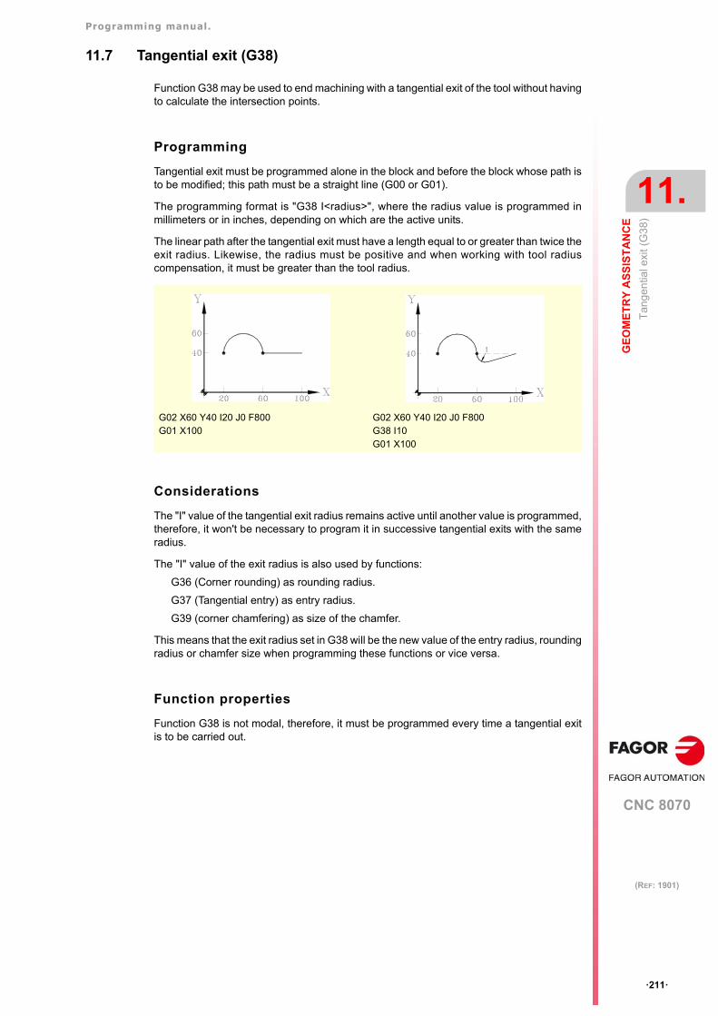
Programming manual.
CNC 8070
GE
OM
ET
RY
AS
SIS
TA
NC
E
11.
Tan
gen
tial e
xit (
G3
8)
·211·
(REF: 1901)
11.7 Tangential exit (G38)
Function G38 may be used to end machining with a tangential exit of the tool without havingto calculate the intersection points.
Programming
Tangential exit must be programmed alone in the block and before the block whose path isto be modified; this path must be a straight line (G00 or G01).
The programming format is "G38 I<radius>", where the radius value is programmed inmillimeters or in inches, depending on which are the active units.
The linear path after the tangential exit must have a length equal to or greater than twice theexit radius. Likewise, the radius must be positive and when working with tool radiuscompensation, it must be greater than the tool radius.
Considerations
The "I" value of the tangential exit radius remains active until another value is programmed,therefore, it won't be necessary to program it in successive tangential exits with the sameradius.
The "I" value of the exit radius is also used by functions:
G36 (Corner rounding) as rounding radius.
G37 (Tangential entry) as entry radius.
G39 (corner chamfering) as size of the chamfer.
This means that the exit radius set in G38 will be the new value of the entry radius, roundingradius or chamfer size when programming these functions or vice versa.
Function properties
Function G38 is not modal, therefore, it must be programmed every time a tangential exitis to be carried out.
G02 X60 Y40 I20 J0 F800G01 X100
G02 X60 Y40 I20 J0 F800G38 I10G01 X100
Programming manual.
CNC 8070
11.
GE
OM
ET
RY
AS
SIS
TA
NC
E
Mirr
or im
age
(G
11, G
12, G
13, G
10, G
14)
·212·
(REF: 1901)
11.8 Mirror image (G11, G12, G13, G10, G14)
Mirror image may be used to repeat the programmed machining operation in a symmetricalposition with respect one or more axes. When using with mirror image, the movements ofthe axes where mirror image is applied are executed with the opposite sign.
Programming
Mirror image may be applied by program using these functions:
G10 Mirror image cancellation.
G11 Mirror image in X.
G12 Mirror image in Y.
G13 Mirror image in Z.
G14 Mirror image in the programmed directions.
G10Mirror image cancellation
It cancels mirror image on all axes, including the mirror image activated with G14.
If it is added to a path defining block, the mirror image will be canceled before the movement.
G11 to G13Mirror image on X, on Y or on Z
Functions G11, G12 and G13 activate mirror image on the X, Y and Z axis respectively. Thesefunctions do not cancel each other, thus being possible to keep mirror image active onseveral axes at the same time.
If they are added to a path defining block, the mirror image will be activated before themovement.
G14Mirror image in the programmed directions
It may be used to activate or cancel mirror image on any axis. The activation or cancellationis defined by programming function G14 and then, the axes next to the value that determineswhether to activate (<axis>=-1) or to cancel (<axis>=1) mirror image on that axis.
G11(Mirror image on the X axis)
G12(Mirror image on the Y axis. It maintains the one of the X axis)
···G10
(Mirror image cancellation on all the axes)
G14 X-1 V-1(Mirror image on the X and V axes)
G14 X1(Mirror image cancellation on the X axis. The one on the V axis remains active)
···G14 V1
(Mirror image cancellation on the V axis)
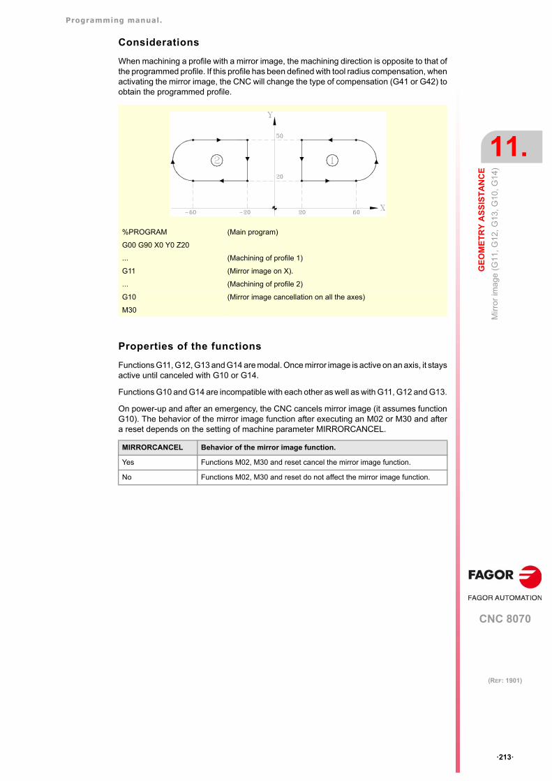
Programming manual.
CNC 8070
GE
OM
ET
RY
AS
SIS
TA
NC
E
11.
Mirr
or im
age
(G
11, G
12, G
13, G
10, G
14)
·213·
(REF: 1901)
Considerations
When machining a profile with a mirror image, the machining direction is opposite to that ofthe programmed profile. If this profile has been defined with tool radius compensation, whenactivating the mirror image, the CNC will change the type of compensation (G41 or G42) toobtain the programmed profile.
Properties of the functions
Functions G11, G12, G13 and G14 are modal. Once mirror image is active on an axis, it staysactive until canceled with G10 or G14.
Functions G10 and G14 are incompatible with each other as well as with G11, G12 and G13.
On power-up and after an emergency, the CNC cancels mirror image (it assumes functionG10). The behavior of the mirror image function after executing an M02 or M30 and aftera reset depends on the setting of machine parameter MIRRORCANCEL.
%PROGRAM (Main program)
G00 G90 X0 Y0 Z20
... (Machining of profile 1)
G11 (Mirror image on X).
... (Machining of profile 2)
G10 (Mirror image cancellation on all the axes)
M30
MIRRORCANCEL Behavior of the mirror image function.
Yes Functions M02, M30 and reset cancel the mirror image function.
No Functions M02, M30 and reset do not affect the mirror image function.
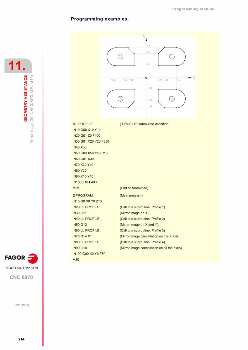
Programming manual.
CNC 8070
11.
GE
OM
ET
RY
AS
SIS
TA
NC
E
Mirr
or im
age
(G
11, G
12, G
13, G
10, G
14)
·214·
(REF: 1901)
Programming examples.
%L PROFILE ("PROFILE" subroutine definition)
N10 G00 X10 Y10
N20 G01 Z0 F400
N30 G01 X20 Y20 F850
N40 X50
N50 G03 X50 Y50 R15
N60 G01 X30
N70 X20 Y40
N80 Y20
N90 X10 Y10
N100 Z10 F400
M29 (End of subroutine)
%PROGRAM (Main program)
N10 G0 X0 Y0 Z10
N20 LL PROFILE (Call to a subroutine. Profile 1)
N30 G11 (Mirror image on X).
N40 LL PROFILE (Call to a subroutine. Profile 2)
N50 G12 (Mirror image on X and Y).
N60 LL PROFILE (Call to a subroutine. Profile 3)
N70 G14 X1 (Mirror image cancellation on the X axis)
N80 LL PROFILE (Call to a subroutine. Profile 4)
N90 G10 (Mirror image cancellation on all the axes)
N100 G00 X0 Y0 Z50
M30
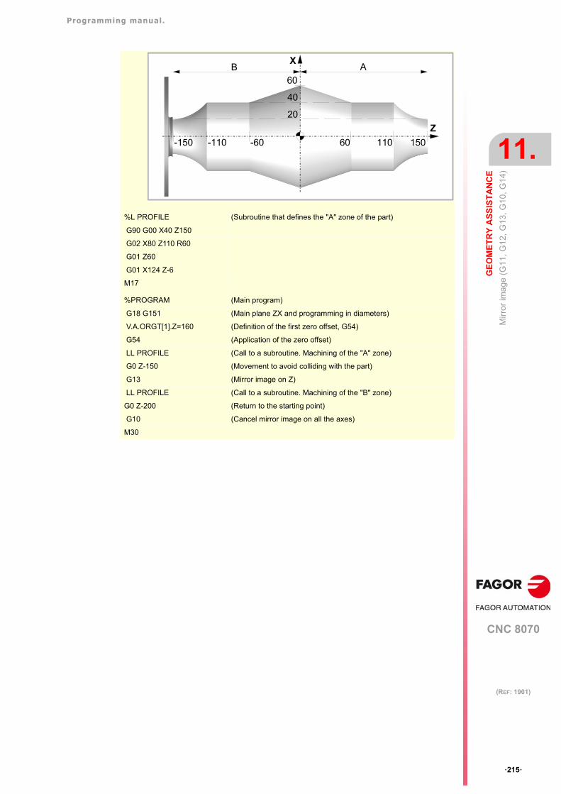
Programming manual.
CNC 8070
GE
OM
ET
RY
AS
SIS
TA
NC
E
11.
Mirr
or im
age
(G
11, G
12, G
13, G
10, G
14)
·215·
(REF: 1901)
%L PROFILE (Subroutine that defines the "A" zone of the part)
G90 G00 X40 Z150
G02 X80 Z110 R60
G01 Z60
G01 X124 Z-6
M17
%PROGRAM (Main program)
G18 G151 (Main plane ZX and programming in diameters)
V.A.ORGT[1].Z=160 (Definition of the first zero offset, G54)
G54 (Application of the zero offset)
LL PROFILE (Call to a subroutine. Machining of the "A" zone)
G0 Z-150 (Movement to avoid colliding with the part)
G13 (Mirror image on Z)
LL PROFILE (Call to a subroutine. Machining of the "B" zone)
G0 Z-200 (Return to the starting point)
G10 (Cancel mirror image on all the axes)
M30
X
Z
60 150110
40
60
-150 -60-110
B A
20
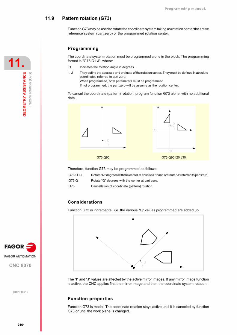
Programming manual.
CNC 8070
11.
GE
OM
ET
RY
AS
SIS
TA
NC
E
Pat
tern
rot
atio
n (G
73)
·216·
(REF: 1901)
11.9 Pattern rotation (G73)
Function G73 may be used to rotate the coordinate system taking as rotation center the activereference system (part zero) or the programmed rotation center.
Programming
The coordinate system rotation must be programmed alone in the block. The programmingformat is "G73 Q I J", where:
To cancel the coordinate (pattern) rotation, program function G73 alone, with no additionaldata.
Therefore, function G73 may be programmed as follows:
Considerations
Function G73 is incremental; i.e. the various "Q" values programmed are added up.
The "I" and "J" values are affected by the active mirror images. If any mirror image functionis active, the CNC applies first the mirror image and then the coordinate system rotation.
Function properties
Function G73 is modal. The coordinate rotation stays active until it is canceled by functionG73 or until the work plane is changed.
Q Indicates the rotation angle in degrees.
I, J They define the abscissa and ordinate of the rotation center. They must be defined in absolutecoordinates referred to part zero.When programmed, both parameters must be programmed.If not programmed, the part zero will be assume as the rotation center.
G73 Q90 G73 Q90 I20 J30
G73 Q I J Rotate "Q" degrees with the center at abscissa "I" and ordinate "J" referred to part zero.
G73 Q Rotate "Q" degrees with the center at part zero.
G73 Cancellation of coordinate (pattern) rotation.
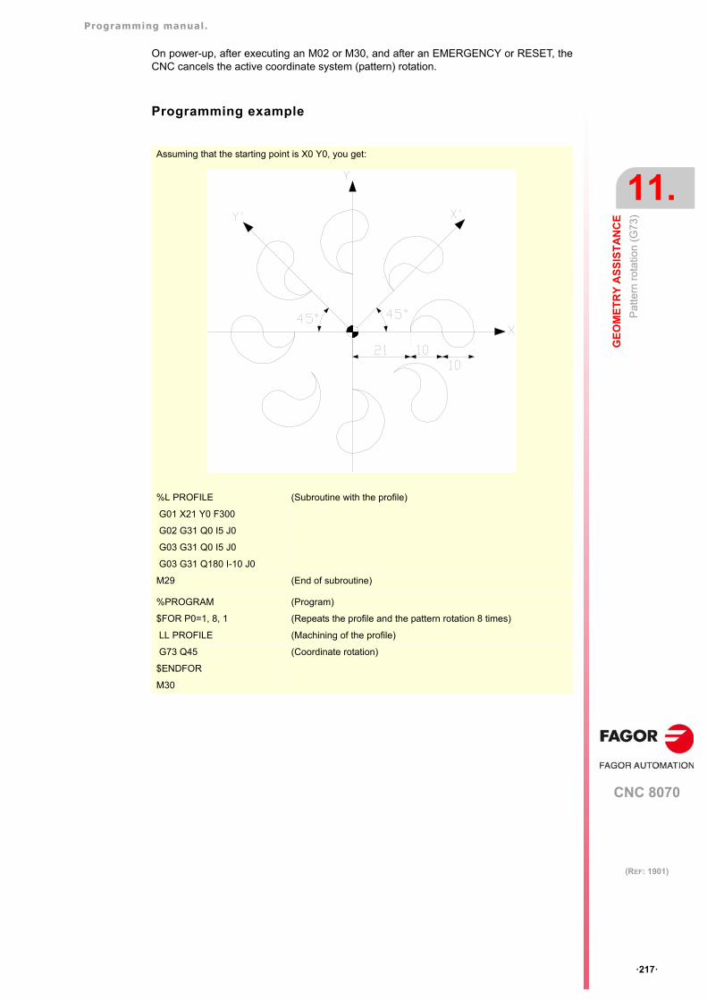
Programming manual.
CNC 8070
GE
OM
ET
RY
AS
SIS
TA
NC
E
11.
Pat
tern
rot
atio
n (G
73)
·217·
(REF: 1901)
On power-up, after executing an M02 or M30, and after an EMERGENCY or RESET, theCNC cancels the active coordinate system (pattern) rotation.
Programming example
Assuming that the starting point is X0 Y0, you get:
%L PROFILE (Subroutine with the profile)
G01 X21 Y0 F300
G02 G31 Q0 I5 J0
G03 G31 Q0 I5 J0
G03 G31 Q180 I-10 J0
M29 (End of subroutine)
%PROGRAM (Program)
$FOR P0=1, 8, 1 (Repeats the profile and the pattern rotation 8 times)
LL PROFILE (Machining of the profile)
G73 Q45 (Coordinate rotation)
$ENDFOR
M30
Programming manual.
CNC 8070
11.
GE
OM
ET
RY
AS
SIS
TA
NC
E
Ge
nera
l sca
ling
fact
or
·218·
(REF: 1901)
11.10 General scaling factor
It may be used to enlarge or reduce the scale of the programmed paths and contours. Thispermits using a single program to make sets of similar profiles of different dimensions.
The general scaling factor is applied to all the axes of the channel. After activating the scalingfactor, all the programmed coordinates will be multiplied by the defined scaling factor untilit is canceled or a new scaling factor is programmed.
Activate the scaling factor
The general scaling factor may be activated using the commands G72 or #SCALE. Eithercommand may be used.
Although there are two different commands, the scaling factor is the same; i.e. the scalingfactor programmed with G72modifies the one programmed with #SCALEand vice versa.
Programming with G72.
Program function G72 and then the scaling factor set by parameter Sas follows.
G72 S<scale>
Programming function G72 alone or a scaling factor of ·0· or ·1· cancels the active scalingfactor.
Parameter "S" that sets the scaling factor must be programmed after function G72. Ifprogrammed before, it will be interpreted as spindle speed.
Programming with #SCALE.
Program the instruction #SCALEand then the scaling factor as follows. The brackets mustbe programmed.
#SCALE [<scale>]
Programming a scaling factor of ·0· or ·1· cancels the active scaling factor.
Cancel the scaling factor
The general scaling factor is canceled using the same commands G72 or #SCALE, settinga scaling factor of ·0· or ·1·. When using function G72, the scaling factor is also canceledby programming it alone in the block.
Considerations
Activating the machine coordinate system (#MCS ON) cancels the scaling factor temporarilyuntil the machine coordinate system is canceled (#MCS OFF).
While the machine coordinate system is active, the scaling factor can neither be activatednor modified.
Properties
The scaling factor stays active until canceled with another scaling factor.
On power-up, after executing an M02 or M30, and after an EMERGENCY or RESET, theCNC cancels the active scaling factor.
G72 S2#SCALE [2]G72#SCALE [1]
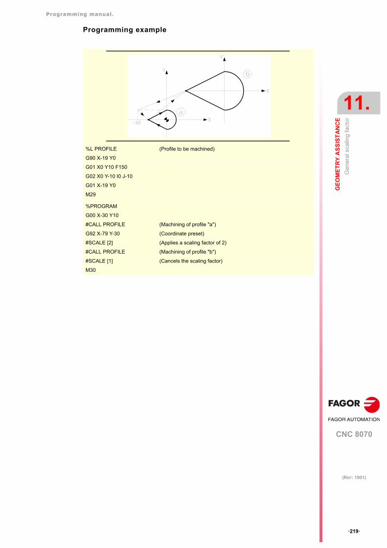
Programming manual.
CNC 8070
GE
OM
ET
RY
AS
SIS
TA
NC
E
11.
Ge
nera
l sca
ling
fact
or
·219·
(REF: 1901)
Programming example
%L PROFILE (Profile to be machined)
G90 X-19 Y0
G01 X0 Y10 F150
G02 X0 Y-10 I0 J-10
G01 X-19 Y0
M29
%PROGRAM
G00 X-30 Y10
#CALL PROFILE (Machining of profile "a")
G92 X-79 Y-30 (Coordinate preset)
#SCALE [2] (Applies a scaling factor of 2)
#CALL PROFILE (Machining of profile "b")
#SCALE [1] (Cancels the scaling factor)
M30
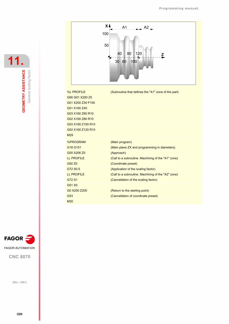
Programming manual.
CNC 8070
11.
GE
OM
ET
RY
AS
SIS
TA
NC
E
Ge
nera
l sca
ling
fact
or
·220·
(REF: 1901)
%L PROFILE (Subroutine that defines the "A1" zone of the part)
G90 G01 X200 Z0
G01 X200 Z30 F150
G01 X160 Z40
G03 X160 Z60 R10
G02 X160 Z80 R10
G03 X160 Z100 R10
G02 X160 Z120 R10
M29
%PROGRAM (Main program)
G18 G151 (Main plane ZX and programming in diameters)
G00 X206 Z0 (Approach)
LL PROFILE (Call to a subroutine. Machining of the "A1" zone)
G92 Z0 (Coordinate preset)
G72 S0.5 (Application of the scaling factor)
LL PROFILE (Call to a subroutine. Machining of the "A2" zone)
G72 S1 (Cancellation of the scaling factor)
G01 X0
G0 X250 Z200 (Return to the starting point)
G53 (Cancellation of coordinate preset)
M30
X
Z
30
A1 A2
50
100
40
60
80
100
120
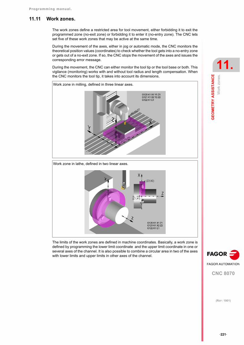
Programming manual.
CNC 8070
GE
OM
ET
RY
AS
SIS
TA
NC
E
11.
Wor
k zo
nes.
·221·
(REF: 1901)
11.11 Work zones.
The work zones define a restricted area for tool movement, either forbidding it to exit theprogrammed zone (no-exit zone) or forbidding it to enter it (no-entry zone). The CNC letsset five of these work zones that may be active at the same time.
During the movement of the axes, either in jog or automatic mode, the CNC monitors thetheoretical position values (coordinates) to check whether the tool gets into a no-entry zoneor gets out of a no-exit zone. If so, the CNC stops the movement of the axes and issues thecorresponding error message.
During the movement, the CNC can either monitor the tool tip or the tool base or both. Thisvigilance (monitoring) works with and without tool radius and length compensation. Whenthe CNC monitors the tool tip, it takes into account its dimensions.
The limits of the work zones are defined in machine coordinates. Basically, a work zone isdefined by programming the lower limit coordinate and the upper limit coordinate in one orseveral axes of the channel. It is also possible to combine a circular area in two of the axeswith lower limits and upper limits in other axes of the channel.
Work zone in milling, defined in three linear axes.
Work zone in lathe, defined in two linear axes.
Programming manual.
CNC 8070
11.
GE
OM
ET
RY
AS
SIS
TA
NC
E
Wor
k zo
nes.
·222·
(REF: 1901)
11.11.1 CNC behavior when there are active work zones.
Some general points to consider.
• On power-up, the CNC will not monitor the zones whose limits are defined by axes thathave non-absolute feedback and have not been homed.
• The CNC will not monitor the work zones during home search.
• The CNC takes into account the tool dimensions in the axes of the main trihedron. If thereis an active kinematics, the CNC will take into account the direction of the tool.
• The CNC also applies the work zones to the axes that work as DRO, monitoring in thiscase the limit in the direction of the real position increment for no-exit zones.
• The CNC monitors the machine coordinates of the axes of the channel; i.e. it takes intoaccount the programmed movements and those coming from the independentinterpolator of the manual intervention as well as of the PLCOFFSET.
Safety distance.
• The work zone limits have a safety distance set in machine parameters (parameterZONELIMITTOL) or from the variables. The CNC stops the axis when it reaches thesafety distance of the zone; i.e. if the safety distance is 0.1 mm, the programmedcoordinate can be, at the most, 0.1 mm before the limit.
Multi-channel system.
• When an axis changes channels, the CNC clears the limits of the axis in those zones.
• A channel axis cannot be changed while a zone that that axis belongs to is active.
Movements in automatic mode.
• Before starting the execution of a block, the CNC checks whether the end coordinatesare inside a forbidden zone or the path crosses a forbidden zone.. If so, the CNC stopsthe movement of the axes and issues the corresponding error message. This check atthe beginning of the block will also be done in the simulation modes.
• If manual intervention on an axis is enabled during the execution, from then on the CNConly checks the real position for the zones with limits on that axis. During blockpreparation, the CNC does not check the position for the zones with limits set on that axis.
Movements in jog mode (continuous, incremental jog or handwheels).
• When an axis reaches the limit of a zone, it stops and the CNC issues the correspondingwarning message.
• The axis stops at the most restrictive limit of all the work zones in the moving directionrespecting the safety distance (parameter ZONELIMITTOL). The CNC will look for themost restrictive limits from all the no-exit zones. From all the no-entry zones, the CNCwill only consider the ones relevant to the position of the moving axis. The no-entry zoneis considered relevant if the rest of the axes defined in the zone are in it, but not the movingaxis.
• For no-exit zones, the CNC only checks the limit in the moving direction, thus allowingthe axis to return to the valid zone.
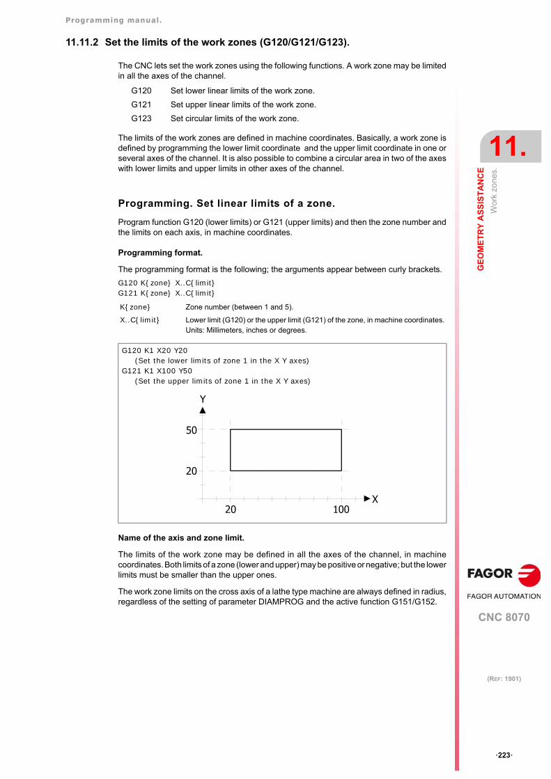
Programming manual.
CNC 8070
GE
OM
ET
RY
AS
SIS
TA
NC
E
11.
Wor
k zo
nes.
·223·
(REF: 1901)
11.11.2 Set the limits of the work zones (G120/G121/G123).
The CNC lets set the work zones using the following functions. A work zone may be limitedin all the axes of the channel.
The limits of the work zones are defined in machine coordinates. Basically, a work zone isdefined by programming the lower limit coordinate and the upper limit coordinate in one orseveral axes of the channel. It is also possible to combine a circular area in two of the axeswith lower limits and upper limits in other axes of the channel.
Programming. Set linear limits of a zone.
Program function G120 (lower limits) or G121 (upper limits) and then the zone number andthe limits on each axis, in machine coordinates.
Programming format.
The programming format is the following; the arguments appear between curly brackets.
G120 K{zone} X..C{limit}G121 K{zone} X..C{limit}
Name of the axis and zone limit.
The limits of the work zone may be defined in all the axes of the channel, in machinecoordinates. Both limits of a zone (lower and upper) may be positive or negative; but the lowerlimits must be smaller than the upper ones.
The work zone limits on the cross axis of a lathe type machine are always defined in radius,regardless of the setting of parameter DIAMPROG and the active function G151/G152.
G120 Set lower linear limits of the work zone.
G121 Set upper linear limits of the work zone.
G123 Set circular limits of the work zone.
K{zone} Zone number (between 1 and 5).
X..C{limit} Lower limit (G120) or the upper limit (G121) of the zone, in machine coordinates.Units: Millimeters, inches or degrees.
G120 K1 X20 Y20(Set the lower limits of zone 1 in the X Y axes)
G121 K1 X100 Y50(Set the upper limits of zone 1 in the X Y axes)
X
Y
20 100
20
50
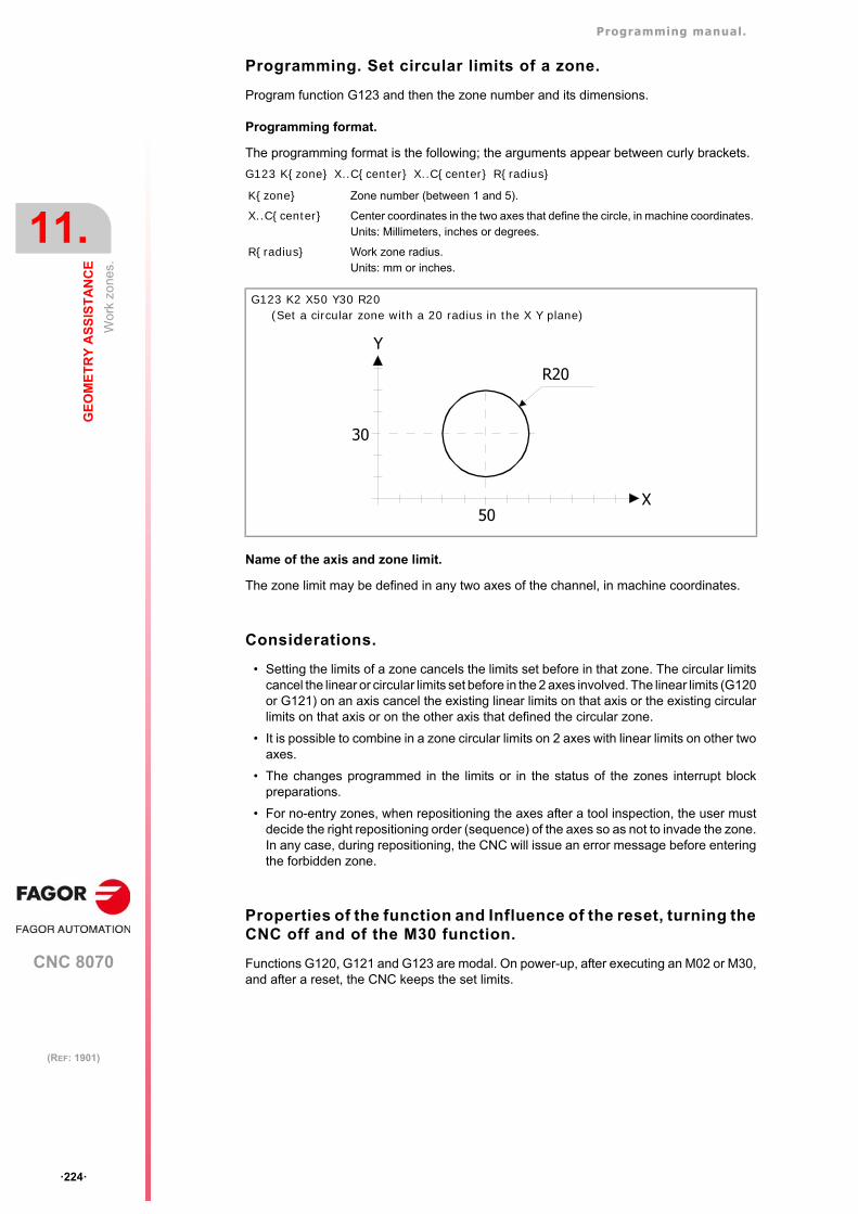
Programming manual.
CNC 8070
11.
GE
OM
ET
RY
AS
SIS
TA
NC
E
Wor
k zo
nes.
·224·
(REF: 1901)
Programming. Set circular limits of a zone.
Program function G123 and then the zone number and its dimensions.
Programming format.
The programming format is the following; the arguments appear between curly brackets.
G123 K{zone} X..C{center} X..C{center} R{radius}
Name of the axis and zone limit.
The zone limit may be defined in any two axes of the channel, in machine coordinates.
Considerations.
• Setting the limits of a zone cancels the limits set before in that zone. The circular limitscancel the linear or circular limits set before in the 2 axes involved. The linear limits (G120or G121) on an axis cancel the existing linear limits on that axis or the existing circularlimits on that axis or on the other axis that defined the circular zone.
• It is possible to combine in a zone circular limits on 2 axes with linear limits on other twoaxes.
• The changes programmed in the limits or in the status of the zones interrupt blockpreparations.
• For no-entry zones, when repositioning the axes after a tool inspection, the user mustdecide the right repositioning order (sequence) of the axes so as not to invade the zone.In any case, during repositioning, the CNC will issue an error message before enteringthe forbidden zone.
Properties of the function and Influence of the reset, turning theCNC off and of the M30 function.
Functions G120, G121 and G123 are modal. On power-up, after executing an M02 or M30,and after a reset, the CNC keeps the set limits.
K{zone} Zone number (between 1 and 5).
X..C{center} Center coordinates in the two axes that define the circle, in machine coordinates.Units: Millimeters, inches or degrees.
R{radius} Work zone radius.Units: mm or inches.
G123 K2 X50 Y30 R20(Set a circular zone with a 20 radius in the X Y plane)
X
Y
50
30
R20
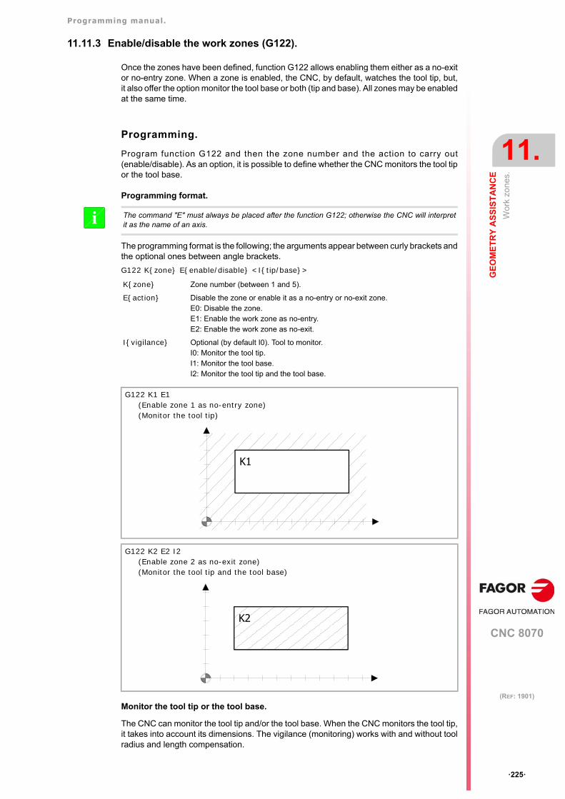
Programming manual.
CNC 8070
GE
OM
ET
RY
AS
SIS
TA
NC
E
11.
Wor
k zo
nes.
·225·
(REF: 1901)
11.11.3 Enable/disable the work zones (G122).
Once the zones have been defined, function G122 allows enabling them either as a no-exitor no-entry zone. When a zone is enabled, the CNC, by default, watches the tool tip, but,it also offer the option monitor the tool base or both (tip and base). All zones may be enabledat the same time.
Programming.
Program function G122 and then the zone number and the action to carry out(enable/disable). As an option, it is possible to define whether the CNC monitors the tool tipor the tool base.
Programming format.
The programming format is the following; the arguments appear between curly brackets andthe optional ones between angle brackets.
G122 K{zone} E{enable/disable} <I{tip/base}>
Monitor the tool tip or the tool base.
The CNC can monitor the tool tip and/or the tool base. When the CNC monitors the tool tip,it takes into account its dimensions. The vigilance (monitoring) works with and without toolradius and length compensation.
The command "E" must always be placed after the function G122; otherwise the CNC will interpretit as the name of an axis.i
K{zone} Zone number (between 1 and 5).
E{action} Disable the zone or enable it as a no-entry or no-exit zone.E0: Disable the zone.E1: Enable the work zone as no-entry.E2: Enable the work zone as no-exit.
I{vigilance} Optional (by default I0). Tool to monitor.I0: Monitor the tool tip.I1: Monitor the tool base.I2: Monitor the tool tip and the tool base.
G122 K1 E1(Enable zone 1 as no-entry zone)(Monitor the tool tip)
G122 K2 E2 I2(Enable zone 2 as no-exit zone)(Monitor the tool tip and the tool base)
K1
K2
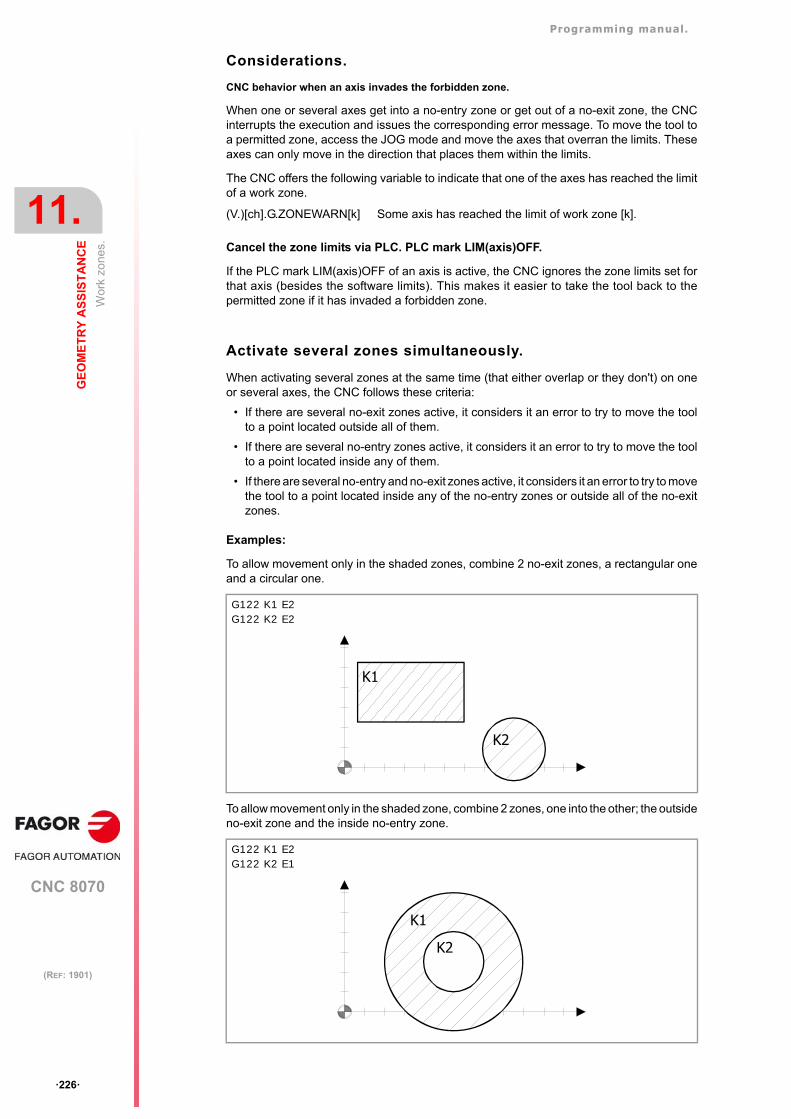
Programming manual.
CNC 8070
11.
GE
OM
ET
RY
AS
SIS
TA
NC
E
Wor
k zo
nes.
·226·
(REF: 1901)
Considerations.
CNC behavior when an axis invades the forbidden zone.
When one or several axes get into a no-entry zone or get out of a no-exit zone, the CNCinterrupts the execution and issues the corresponding error message. To move the tool toa permitted zone, access the JOG mode and move the axes that overran the limits. Theseaxes can only move in the direction that places them within the limits.
The CNC offers the following variable to indicate that one of the axes has reached the limitof a work zone.
Cancel the zone limits via PLC. PLC mark LIM(axis)OFF.
If the PLC mark LIM(axis)OFF of an axis is active, the CNC ignores the zone limits set forthat axis (besides the software limits). This makes it easier to take the tool back to thepermitted zone if it has invaded a forbidden zone.
Activate several zones simultaneously.
When activating several zones at the same time (that either overlap or they don't) on oneor several axes, the CNC follows these criteria:
• If there are several no-exit zones active, it considers it an error to try to move the toolto a point located outside all of them.
• If there are several no-entry zones active, it considers it an error to try to move the toolto a point located inside any of them.
• If there are several no-entry and no-exit zones active, it considers it an error to try to movethe tool to a point located inside any of the no-entry zones or outside all of the no-exitzones.
Examples:
To allow movement only in the shaded zones, combine 2 no-exit zones, a rectangular oneand a circular one.
To allow movement only in the shaded zone, combine 2 zones, one into the other; the outsideno-exit zone and the inside no-entry zone.
(V.)[ch].G.ZONEWARN[k] Some axis has reached the limit of work zone [k].
G122 K1 E2G122 K2 E2
G122 K1 E2G122 K2 E1
K1
K2
K1
K2
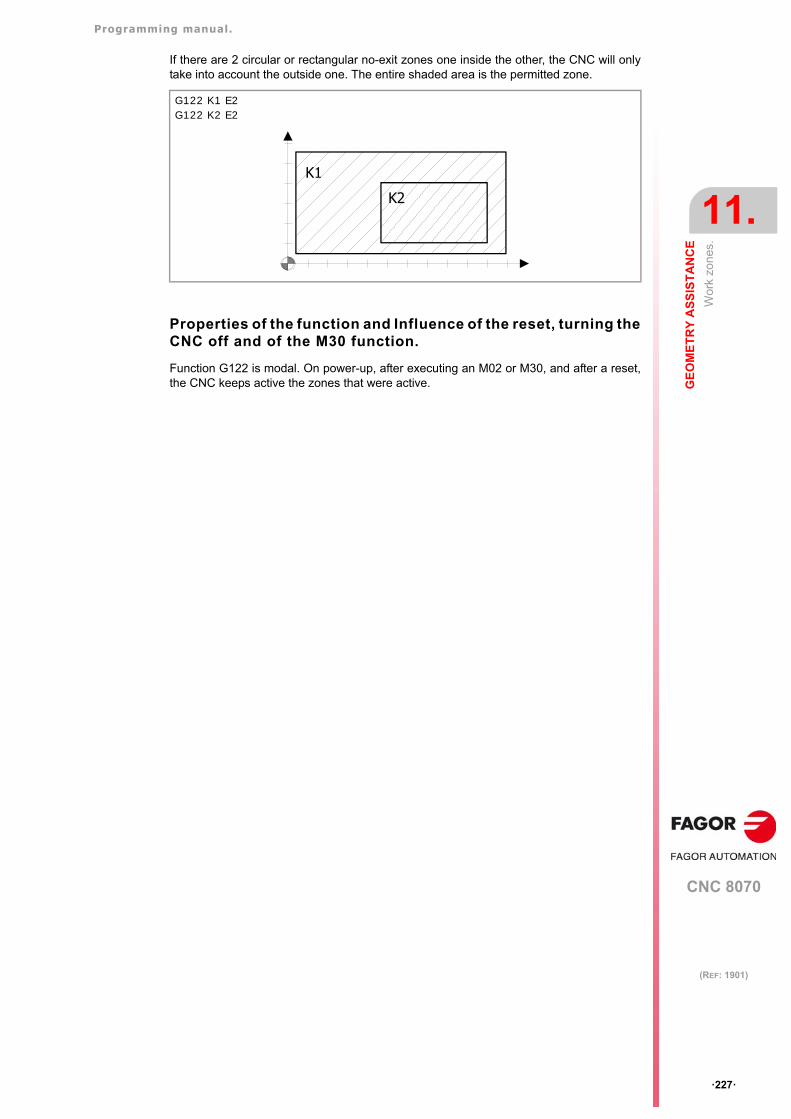
Programming manual.
CNC 8070
GE
OM
ET
RY
AS
SIS
TA
NC
E
11.
Wor
k zo
nes.
·227·
(REF: 1901)
If there are 2 circular or rectangular no-exit zones one inside the other, the CNC will onlytake into account the outside one. The entire shaded area is the permitted zone.
Properties of the function and Influence of the reset, turning theCNC off and of the M30 function.
Function G122 is modal. On power-up, after executing an M02 or M30, and after a reset,the CNC keeps active the zones that were active.
G122 K1 E2G122 K2 E2
K1
K2
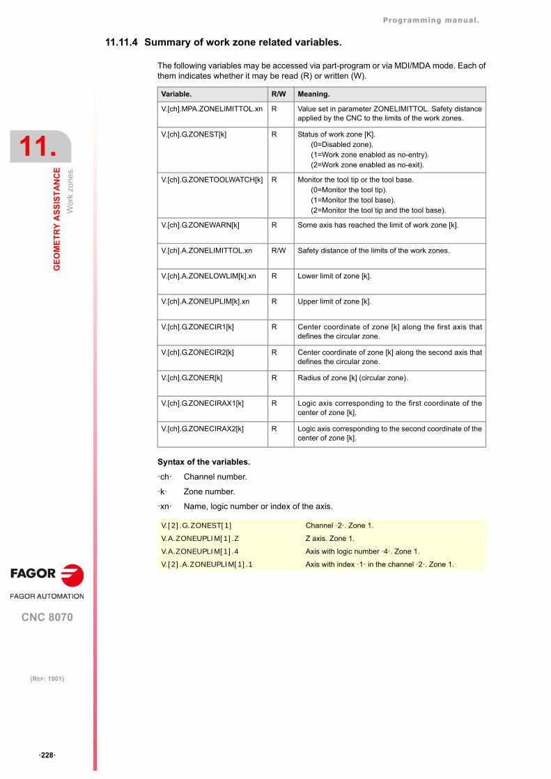
Programming manual.
CNC 8070
11.
GE
OM
ET
RY
AS
SIS
TA
NC
E
Wor
k zo
nes.
·228·
(REF: 1901)
11.11.4 Summary of work zone related variables.
The following variables may be accessed via part-program or via MDI/MDA mode. Each ofthem indicates whether it may be read (R) or written (W).
Syntax of the variables.
·ch· Channel number.
·k· Zone number.
·xn· Name, logic number or index of the axis.
Variable. R/W Meaning.
V.[ch].MPA.ZONELIMITTOL.xn R Value set in parameter ZONELIMITTOL. Safety distanceapplied by the CNC to the limits of the work zones.
V.[ch].G.ZONEST[k] R Status of work zone [K].(0=Disabled zone).(1=Work zone enabled as no-entry).(2=Work zone enabled as no-exit).
V.[ch].G.ZONETOOLWATCH[k] R Monitor the tool tip or the tool base.(0=Monitor the tool tip).(1=Monitor the tool base).(2=Monitor the tool tip and the tool base).
V.[ch].G.ZONEWARN[k] R Some axis has reached the limit of work zone [k].
V.[ch].A.ZONELIMITTOL.xn R/W Safety distance of the limits of the work zones.
V.[ch].A.ZONELOWLIM[k].xn R Lower limit of zone [k].
V.[ch].A.ZONEUPLIM[k].xn R Upper limit of zone [k].
V.[ch].G.ZONECIR1[k] R Center coordinate of zone [k] along the first axis thatdefines the circular zone.
V.[ch].G.ZONECIR2[k] R Center coordinate of zone [k] along the second axis thatdefines the circular zone.
V.[ch].G.ZONER[k] R Radius of zone [k] (circular zone).
V.[ch].G.ZONECIRAX1[k] R Logic axis corresponding to the first coordinate of thecenter of zone [k].
V.[ch].G.ZONECIRAX2[k] R Logic axis corresponding to the second coordinate of thecenter of zone [k].
V.[2].G.ZONEST[1] Channel ·2·. Zone 1.
V.A.ZONEUPLIM[1].Z Z axis. Zone 1.
V.A.ZONEUPLIM[1].4 Axis with logic number ·4·. Zone 1.
V.[2].A.ZONEUPLIM[1].1 Axis with index ·1· in the channel ·2·. Zone 1.
CNC 8070
12
·229·
(REF: 1901)
12.ADDITIONAL PREPARATORY FUNCTIONS
12.1 Dwell (G04 / #TIME).
The F04 function and the #TIME instruction may be used to interrupt the execution of theprogram for the specified period of time. Both commands are equivalent and either one maybe used.
Programming (1). G04.
Program function G04 and then the dwell time.
Programming format.
The programming format is the following; the arguments appear between curly brackets andthe optional ones between angle brackets. The K command may be left out when the dwellis programmed with a constant.
G04 K{time}G04 {time}
Programming (2). #TIME.
The dwell must be programmed with programming this instruction.
Programming format.
The programming format is the following; the arguments appear between curly brackets andthe optional ones between angle brackets. If the time is programmed with a constant or aparameter, the brackets [] may be left out .
#TIME [{time}]#TIME {time}
K{time} Dwell. Units: Seconds.
{time} Dwell (programmed with a constant). Units: Seconds.
G04 K0.5(0.5 second dwel)
G04 8.5(8.5 second dwel)
P1=3G04 KP1
(3 second dwel)
P1=3G04 K[P1+7]
(10 second dwel)
{time} Dwell. Units: Seconds.
Programming manual.
CNC 8070
12.
AD
DIT
ION
AL
PR
EP
AR
AT
OR
Y F
UN
CT
ION
S
Dw
ell (
G04
/ #T
IME
).
·230·
(REF: 1901)
Properties of the function and Influence of the reset, turning theCNC off and of the M30 function.
Function G04 is not modal, therefore, it must be programmed every time a dwell is desired.Function G04 may also be programmed as G4.
#TIME [5]#TIME 5
(5 second dwel)
P1=2#TIME [P1]#TIME P1
(2 second dwel)
P1=2#TIME [P1+3]
(5 second dwel)
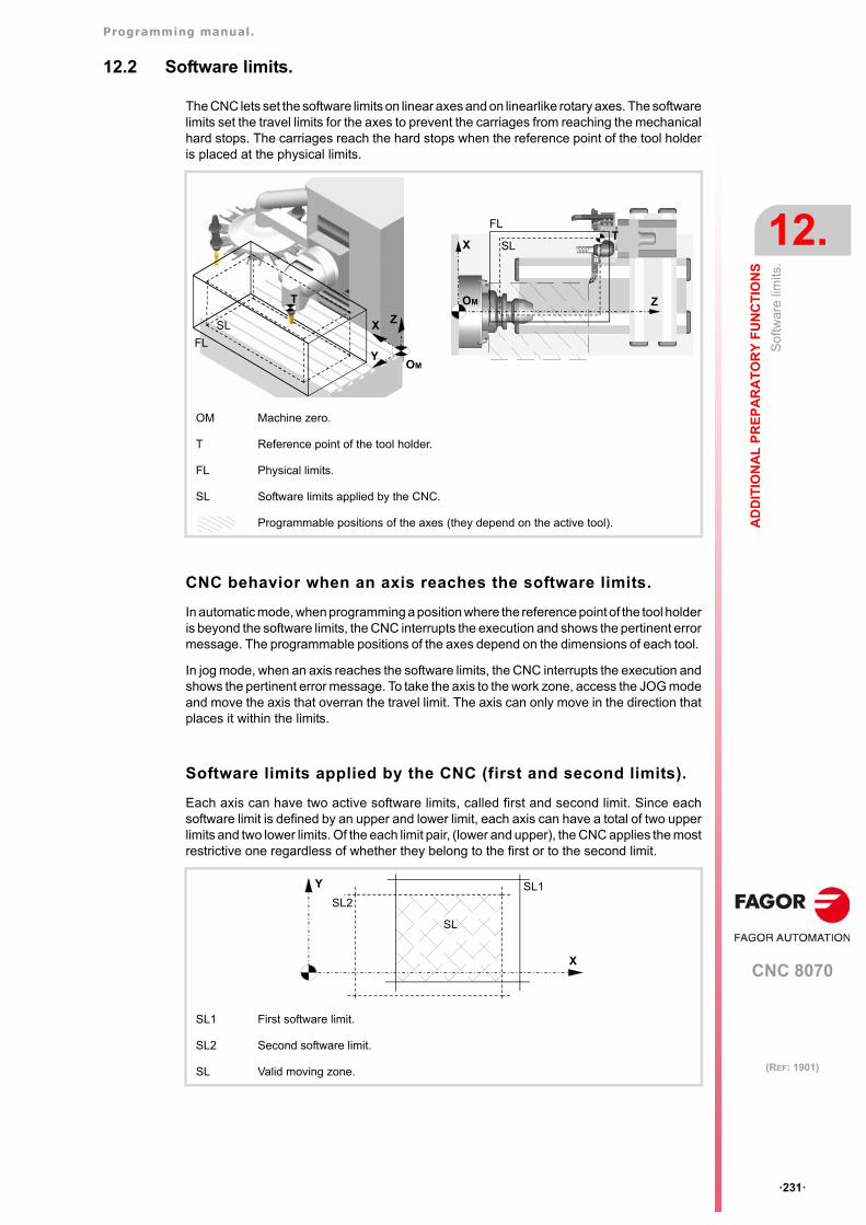
Programming manual.
CNC 8070
AD
DIT
ION
AL
PR
EP
AR
AT
OR
Y F
UN
CT
ION
S
12.
So
ftwar
e lim
its.
·231·
(REF: 1901)
12.2 Software limits.
The CNC lets set the software limits on linear axes and on linearlike rotary axes. The softwarelimits set the travel limits for the axes to prevent the carriages from reaching the mechanicalhard stops. The carriages reach the hard stops when the reference point of the tool holderis placed at the physical limits.
CNC behavior when an axis reaches the software limits.
In automatic mode, when programming a position where the reference point of the tool holderis beyond the software limits, the CNC interrupts the execution and shows the pertinent errormessage. The programmable positions of the axes depend on the dimensions of each tool.
In jog mode, when an axis reaches the software limits, the CNC interrupts the execution andshows the pertinent error message. To take the axis to the work zone, access the JOG modeand move the axis that overran the travel limit. The axis can only move in the direction thatplaces it within the limits.
Software limits applied by the CNC (first and second limits).
Each axis can have two active software limits, called first and second limit. Since eachsoftware limit is defined by an upper and lower limit, each axis can have a total of two upperlimits and two lower limits. Of the each limit pair, (lower and upper), the CNC applies the mostrestrictive one regardless of whether they belong to the first or to the second limit.
OM Machine zero.
T Reference point of the tool holder.
FL Physical limits.
SL Software limits applied by the CNC.
Programmable positions of the axes (they depend on the active tool).
SL1 First software limit.
SL2 Second software limit.
SL Valid moving zone.
T
SL ZX
YOM
FL
Z
XT
FL
SL
OM
SL1
SL2
X
Y
SL
Programming manual.
CNC 8070
12.
AD
DIT
ION
AL
PR
EP
AR
AT
OR
Y F
UN
CT
ION
S
So
ftwar
e lim
its.
·232·
(REF: 1901)
12.2.1 Define the first software limit (G198/G199).
The CNC lets set the software limits on linear axes and on linearlike rotary axes. The firstsoftware limits of the axes are pre-defined in the machine parameters (parameters LIMIT+/ LIMIT-). These limits may be changed by program using the following functions andvariables.
The CNC also offers the following variables equivalent to functions G198/G199. See"12.2.2 Define the first software limit via variables." on page 234.
Programming.
Program one of the functions G198/G199, and then, the axes and their new software limits.These functions may be used to program several axes.
Programming format.
The programming format is the following; the arguments appear between curly brackets andthe optional ones between angle brackets.
G198 X..C{soft_limit}G199 X..C{soft_limit}
Name of the axis and software limit.
Both limits of an axis (lower and upper) may be positive or negative; but the lower limits mustbe smaller than the upper ones. Otherwise, the might not move in any direction.
When setting both upper and lower limits of an axis to ·0·, the CNC cancels the first softwarelimit of that axis and applies the second one (if it has been defined). To restore the first limit,it must be programmed again.
Considerations.
Absolute (G90) or incremental (G91) programming.
Depending on the active work mode G90 or G91, the position of the new limits will be definedin absolute coordinates (G90) in the machine reference system or in incremental coordinates(G91) referred to the current active limits.
G198 Set lower software travel limits (first limit).
G199 Set upper software travel limits (first limit).
V.A.NEGLIMIT.xn Set lower software travel limits (first limit). Variable equivalent to G198.
V.A.POSLIMIT.xn Set upper software travel limits (first limit). Variable equivalent to G199.
X..C{soft_limit} Name of the axis and software limit.Units: millimeters/inches.
G198 X-1000 Y-1000(New lower limits X=-1000 Y=-1000)
G199 X1000 Y1000(New upper limits X=1000 Y=1000)
G90G198 X-800
(New lower limit X=-800)G199 X500
(New upper limit X=500)·
G91G198 X-700
(New incremental lower limit X=-1500)
Programming manual.
CNC 8070
AD
DIT
ION
AL
PR
EP
AR
AT
OR
Y F
UN
CT
ION
S
12.
So
ftwar
e lim
its.
·233·
(REF: 1901)
Axes out of position.
If after setting the new limits, an axis positions beyond them, it will be possible to move thataxis towards the work zone (between those limits).
Programming on a lathe (radius/diameter).
The software limits are always defined in radius, regardless of the setting of parameterDIAMPROG and the active function G151/G152.
Restore the software limits set in the machine parameters.
The software limits set in the machine parameters may be restored by program using theirvariables.
Properties of the function and Influence of the reset, turning theCNC off and of the M30 function.
On power-up or after validating the axis machine parameters the CNC assumes the softwarelimits set by the machine parameters. After an M02 or M30 and after an emergency or a reset,the CNC maintains the software limits set by G198 and G199 or their equivalent variables.
G198 X[V.MPA.NEGLIMIT.X] Y[V.MPA.NEGLIMIT.Y]G199 X[V.MPA.POSLIMIT.X] Y[V.MPA.POSLIMIT.Y]
(The CNC restores the limits set in the machine parameters)
Programming manual.
CNC 8070
12.
AD
DIT
ION
AL
PR
EP
AR
AT
OR
Y F
UN
CT
ION
S
So
ftwar
e lim
its.
·234·
(REF: 1901)
12.2.2 Define the first software limit via variables.
The first software limits can also be defined by the variables equivalent to G198/G199. Thefunctions and the variables modify the same software limits; therefore, either ones may beused.
On power-up, these variables assume the values of the machine parameters (LIMIT+ /LIMIT-).
Programming of software limits.
Programming is equivalent to G198/G199. Both limits of an axis (lower and upper) may bepositive or negative; but the lower limits must be smaller than the upper ones. When settingboth upper and lower limits of an axis to ·0·, the CNC cancels the first software limit of thataxis and applies the second one (if it has been defined).
Considerations.
Absolute (G90) or incremental (G91) programming.
Unlike functions G198/G199, the limits defined with variables do not depend on functionsG90/G91, they are always in absolute coordinates and in the machine reference system.
Axes out of position.
If after setting the new limits, an axis positions beyond them, it will be possible to move thataxis towards the work zone (between those limits).
Programming on a lathe (radius/diameter).
The software limits are always defined in radius, regardless of the setting of parameterDIAMPROG and the active function G151/G152.
Influence of the reset, turning the CNC off and of the M30.
After an M02 or M30 and after an emergency or a reset, the CNC maintains the softwarelimits set by these variables.
V.A.NEGLIMIT.xn Set lower software travel limits (first limit). Variable equivalent toG198.
V.A.POSLIMIT.xn Set upper software travel limits (first limit). Variable equivalent toG199.
Programming manual.
CNC 8070
AD
DIT
ION
AL
PR
EP
AR
AT
OR
Y F
UN
CT
ION
S
12.
So
ftwar
e lim
its.
·235·
(REF: 1901)
12.2.3 Define the second software limit via variables.
The second software limits can only be defined by variables.
On power-up, these variables assume the values of the first software limits. As long as thesevariables are not defined with their own value, they copy the values of the first software limits.
Programming of software limits.
Both limits of an axis (lower and upper) may be positive or negative; but the lower limits mustbe smaller than the upper ones. When setting both upper and lower limits of an axis to ·0·,the CNC cancels the second software limit of that axis.
Considerations.
Absolute (G90) or incremental (G91) programming.
The limits defined with variables do not depend on functions G90/G91, they are always inabsolute coordinates and in the machine reference system.
Axes out of position.
If after setting the new limits, an axis positions beyond them, it will be possible to move thataxis towards the work zone (between those limits).
Programming on a lathe (radius/diameter).
The software limits are always defined in radius, regardless of the setting of parameterDIAMPROG and the active function G151/G152.
Influence of the reset, turning the CNC off and of the M30.
After an M02 or M30 and after an emergency or a reset, the CNC maintains the softwarelimits set by these variables.
V.A.RTNEGLIMIT.xn Set lower software travel limits (second limit).
V.A.RTPOSLIMIT.xn Set upper software travel limits (second limit).
Programming manual.
CNC 8070
12.
AD
DIT
ION
AL
PR
EP
AR
AT
OR
Y F
UN
CT
ION
S
So
ftwar
e lim
its.
·236·
(REF: 1901)
12.2.4 Variables associated with the software limits.
The following variables may be accessed via part-program or via MDI/MDA mode. Each ofthem indicates whether it may be read (R) or written (W).
Syntax of the variables.
·ch· Channel number.
·xn· Name, logic number or index of the axis.
Variable. R/W Meaning.
V.[ch].MPA.NEGLIMIT.xn R Lower software limit (first limit) set in the machineparameters.
V.[ch].MPA.POSLIMIT.xn R Upper software limit (first limit) set in the machineparameters.
V.[ch].A.NEGLIMIT.xn R/W Lower software limit (first limit).Equivalent to G198.
V.[ch].A.POSLIMIT.xn R/W Upper software limit (first limit).Equivalent to G199.
V.[ch].A.RTNEGLIMIT.xn R/W Lower software limit (second limit).
V.[ch].A.RTPOSLIMIT.xn R/W Upper software limit (second limit).
V.[ch].G.SOFTLIMIT R Software limit reached on some axis.(0=No 1=Yes)
V.A.POSLIMIT.Z Z axis.
V.A.POSLIMIT.4 Axis with logic number ·4·.
V.[2].A.POSLIMIT.1 Axis with index ·1· in the channel ·2·.
V.[2].G.SOFTLIMIT Channel ·2·.
Programming manual.
CNC 8070
AD
DIT
ION
AL
PR
EP
AR
AT
OR
Y F
UN
CT
ION
S
12.
Tur
n H
irth
axis
on
and
off
(G1
70/G
171
).
·237·
(REF: 1901)
12.3 Turn Hirth axis on and off (G170/G171).
A Hirth axis is the one that can only be positioned at particular positions, multiple of its pitch(parameter HPITCH). When a Hirth axis is not active, it behaves like a normal rotary or linearaxis and can reach any position. Hirth axes may be canceled and activated by program usingthe following functions.
Programming. Activate a Hirth axis.
Program function G171, and then, the axes to be activated as Hirth and the order in whichthey will be activated. Several axes may be programmed with this function.
Programming format.
The programming format is the following; the arguments appear between curly brackets.
G171 X..C{n_order}
Programming. Cancel a Hirth axis.
Program function G170, and then the Hirth axes to be deactivated and the order in whichthey will be deactivated. Several axes may be programmed with this function.
Programming format.
The programming format is the following; the arguments appear between curly brackets.
G170 X..C{n_order}
Considerations.
• If when activating a Hirth axis, it is located in the wrong position, the CNC will issue awarning so the operator can turn it to a correct position.
• A Hirth axis must always be positioned at positions multiple of its pitch. For thesepositioning movements, the CNC takes into account the active zero offset (preset or zerooffset).
• Both linear and rotary axes may be Hirth. Only those axes defined as Hirth axes by theOEM (parameter HIRTH) may be activated as Hirth axes.
Properties of the function and Influence of the reset, turning theCNC off and of the M30 function.
Functions G170 and G171 are modal and incompatible with each other. On power-up, afteran M02 or M30 and after an emergency or a reset, the CNC activates all the Hirth axes.
G170 Hirth axes OFF.
G171 Hirth axes ON.
X..C{n_order} Name of the axis and order number.
G171 B1 C2(Activate B first and then C, as Hirth axis)
X..C{n_order} Name of the axis and order number.
G170 B2 C1(Deactivate the C axis first and then B)
Programming manual.
CNC 8070
12.
AD
DIT
ION
AL
PR
EP
AR
AT
OR
Y F
UN
CT
ION
S
Se
t an
d g
ear
chan
ge.
·238·
(REF: 1901)
12.4 Set and gear change.
12.4.1 Change parameter set of an axis (G112)
The CNC may have up to 4 sets of parameters for each axis defined by the OEM in themachine parameter table. The parameter set may be selected by program using functionG112. This function does not carry out any physical change on the machine (gear change),it only assumes the parameters of the selected set. When using Sercos axes, function G112also involves changing the drive's velocity gear.
Programming.
Program G112 and then the axes and the new parameter set to be activated for each oneof them. Several axes may be programmed with this function.
Programming format.
The programming format is the following; the arguments appear between curly brackets andthe optional ones between angle brackets.
G112 X..C{set}
Change of the drive's parameter set.
The CNC only allows the set of the spindle parameters to be modified when working as aC axis. In this case, a change to the set is programmed using the name of the axis, not thename of the spindle.
Properties of the function and Influence of the reset, turning theCNC off and of the M30 function.
Function G112 is modal. After validating the machine parameters, every time a program isexecuted from the automatic mode, on power-up, after executing an M02 or M30, after anemergency or a reset, the CNC acts as follows depending on how the OEM has set it(parameter DEFAULTSET).
X..C{set} Name of the axis and parameter set (between 1 and 4).
G112 X2 Y3(The CNC selects the second set of parameters for the X axis, and the third one for the Y axis)
#CAX[S,C]G112 C2
(It selects the second set of parameters for the C axis)
DEFAULTSET Meaning.
0 The CNC maintains the parameter set.
1..4 Set number assumed by the CNC.
Programming manual.
CNC 8070
AD
DIT
ION
AL
PR
EP
AR
AT
OR
Y F
UN
CT
ION
S
12.
Se
t an
d g
ear
chan
ge.
·239·
(REF: 1901)
12.4.2 Change the gear and set of a Sercos drive using variables.
The following variables may be used to change the gear and set of a Sercos drive for axesand for spindles. This variable does not affect the parameter set of the CNC.
Programming.
The drive can have 8 work ranges or gears identified from 0 through 7 (drive parameter GP6)and 8 sets of parameters (drive parameter GP4) identified from 0 through 7.
The 4 least significant bits indicate the work range and the 4 most significant bits indicatethe set of parameters. If the value of any 4-bit set is ·0·, the CNC does not change the activegear or set at the drive. Example of some values of the variable.
Considerations.
Only one change can be taking place at a time. If other gear or set changes are programmedduring this process, even if they are at different drives, the CNC only keeps the oneprogrammed last and ignores the rest of the intermediate changes.
(V.)[ch].A.SETGE.xn(V.)[ch].A.SETGE.sn(V.)[ch].SP.SETGE.sn
Select the set and the gear at the Sercos drive.
Value. Meaning.
$21 First range or gear (gear ·0·).Second set of parameters (set ·1·).
$40 The drive maintains the active gear.Fourth set of parameters (set ·3·).
$07 Seventh range or gear (gear ·6·).The drive maintains the active parameter set.
Programming manual.
CNC 8070
12.
AD
DIT
ION
AL
PR
EP
AR
AT
OR
Y F
UN
CT
ION
S
Se
t an
d g
ear
chan
ge.
·240·
(REF: 1901)
12.4.3 Variables related to set and gear change.
The following variables may be accessed via part-program or via MDI/MDA mode. Each ofthem indicates whether it may be read (R) or written (W).
Syntax of the variables.
·ch· Channel number.
·xn· Name, logic number or index of the axis.
·sn· Name, logic number or index of the spindle.
Variable. R/W Meaning.
(V.)[ch].A.ACTIVSET.xn(V.)[ch].A.ACTIVSET.sn(V.)[ch].SP.ACTIVSET.sn
R Parameter set active at the axis or spindle.The variable returns the value of execution or preparationas follows. If the spindle belongs to the channel requestingthe variable, it returns the preparation value; if the axis orspindle belongs to a different channel, the variable returnsthe execution value and interrupts block preparation.
(V.)[ch].A.SETGE.xn(V.)[ch].A.SETGE.sn(V.)[ch].SP.SETGE.sn
R/W Select the set and the gear at the Sercos drive.The 4 least significant bits indicate the work range and the4 most significant bits indicate the set of parameters. If thevalue of any 4-bit set is ·0·, the CNC does not change theactive gear or set at the drive.
V.A.ACTIVSET.Z Z axis.
V.A.ACTIVSET.S Spindle S.
V.SP.ACTIVSET.S Spindle S.
V.SP.ACTIVSET Master spindle.
V.A.ACTIVSET.4 Axis or spindle with logic number ·4·.
V.[2].A.ACTIVSET.1 Axis with index ·1· in the channel ·2·.
V.SP.ACTIVSET.2 Spindle with index ·2· in the system.
V.[2].SP.ACTIVSET.1 Spindle with index ·1· in the channel ·2·.
Programming manual.
CNC 8070
AD
DIT
ION
AL
PR
EP
AR
AT
OR
Y F
UN
CT
ION
S
12.
Sm
ooth
the
path
an
d th
e fe
edr
ate.
·241·
(REF: 1901)
12.5 Smooth the path and the feedrate.
By default, the CNC calculates the space and the feedrate on the main three axes and therest of the axes follow their corresponding feedrate. This way, on a machine that moves morethan tree axes and has the kinematics and RTCP active, the tool tip moves at theprogrammed feedrate. However, when these machining operations show discontinuedmovements on the main axes, this process can generate irregularities on the velocity profileand, therefore, the resulting movement might not always be continuous.
To solve both situations, the CNC offers several instructions that make the movement a lotmore continuous, thus improving part finish quality and reduce machining time considerably.These instructions are incompatible with each other.
12.5.1 Smooth the path (#PATHND).
This instruction being active (#PATHND ON), the CNC calculates the space between all theaxes and obtains a smoother movement. If this instruction is not active (#PATHND OFF),the CNC calculates the space on the three main axes.
In either case, the CNC applies the programmed feedrate to the three main axes; the restof the axes move at their corresponding feedrate to end the movement of them all at the sametime.
Programming. Activate path smoothing.
Program the instruction alone in the block.
Programming format.
The programming format is:
#PATHND ON
Programming. Cancel path smoothing.
Program the instruction alone in the block.
Programming format.
The programming format is:
#PATHND OFF
Properties of the function and Influence of the reset, turning theCNC off and of the M30 function.
Instructions #PATHND and #FEEDND are incompatible with each other. On power-up, afteran M02 or M30 and after an emergency or a reset, the CNC assumes the behavior set bythe machine manufacturer (parameter FEEDND].
#PATHND Smooth the path.
#FEEDND Smooth the path and the feedrate.
#PATHND ON
#PATHND OFF
Programming manual.
CNC 8070
12.
AD
DIT
ION
AL
PR
EP
AR
AT
OR
Y F
UN
CT
ION
S
Sm
ooth
the
path
an
d th
e fe
edr
ate.
·242·
(REF: 1901)
12.5.2 Smooth the path and the feedrate (#FEEDND).
This instruction being active (#FEEDND ON), the CNC considers all the axes whencalculating the space. The programmed feedrate will be the result of composing themovements onto all the axes of the channel. The CNC applies the programmed feedrate toall the axes.
If the instruction is not active (#FEEDND OFF) the programmed feedrate will be the resultof composing the movement only onto the main axes. The rest of the axes move at theircorresponding feedrate to end the movement of them all at the same time.
Programming. Activate path and feedrate smoothing.
Program the instruction alone in the block.
Programming format.
The programming format is:
#FEEDND ON
Programming. Cancel path and feedrate smoothing.
Program the instruction alone in the block.
Programming format.
The programming format is:
#FEEDND OFF
Considerations.
• The CNC only limits the programmed feedrate if an axis exceeds its maximum feedrate(parameter MAXFEED).
• If none of the main axes are programmed, the programmed feedrate will be reached onthe axis moving the farthest so they can all reach their destination at the same time.
Properties of the function and Influence of the reset, turning theCNC off and of the M30 function.
Instructions #PATHND and #FEEDND are incompatible with each other. On power-up, afteran M02 or M30 and after an emergency or a reset, the CNC assumes the behavior set bythe machine manufacturer (parameter FEEDND].
#FEEDND ON
#FEEDND OFF
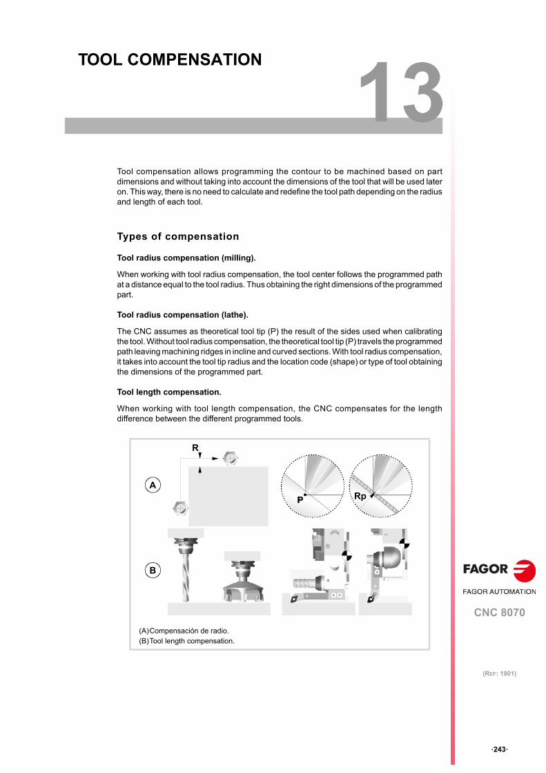
CNC 8070
13
·243·
(REF: 1901)
13.TOOL COMPENSATION
Tool compensation allows programming the contour to be machined based on partdimensions and without taking into account the dimensions of the tool that will be used lateron. This way, there is no need to calculate and redefine the tool path depending on the radiusand length of each tool.
Types of compensation
Tool radius compensation (milling).
When working with tool radius compensation, the tool center follows the programmed pathat a distance equal to the tool radius. Thus obtaining the right dimensions of the programmedpart.
Tool radius compensation (lathe).
The CNC assumes as theoretical tool tip (P) the result of the sides used when calibratingthe tool. Without tool radius compensation, the theoretical tool tip (P) travels the programmedpath leaving machining ridges in incline and curved sections. With tool radius compensation,it takes into account the tool tip radius and the location code (shape) or type of tool obtainingthe dimensions of the programmed part.
Tool length compensation.
When working with tool length compensation, the CNC compensates for the lengthdifference between the different programmed tools.
(A)Compensación de radio.(B)Tool length compensation.
A
R
Rp
B
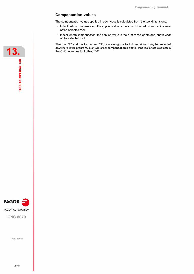
Programming manual.
CNC 8070
13.
TO
OL
CO
MP
EN
SA
TIO
N
·244·
(REF: 1901)
Compensation values
The compensation values applied in each case is calculated from the tool dimensions.
• In tool radius compensation, the applied value is the sum of the radius and radius wearof the selected tool.
• In tool length compensation, the applied value is the sum of the length and length wearof the selected tool.
The tool "T" and the tool offset "D", containing the tool dimensions, may be selectedanywhere in the program, even while tool compensation is active. If no tool offset is selected,the CNC assumes tool offset "D1".
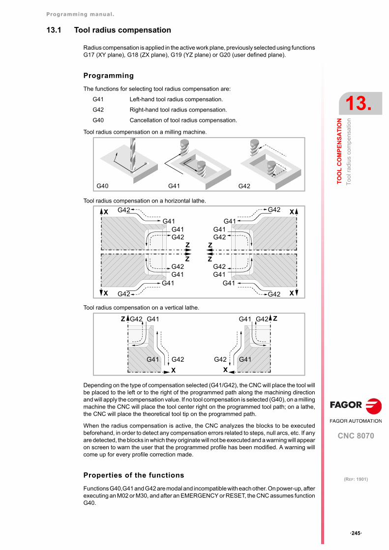
Programming manual.
CNC 8070
TO
OL
CO
MP
EN
SA
TIO
N
13.
To
ol r
adiu
s co
mp
ensa
tion
·245·
(REF: 1901)
13.1 Tool radius compensation
Radius compensation is applied in the active work plane, previously selected using functionsG17 (XY plane), G18 (ZX plane), G19 (YZ plane) or G20 (user defined plane).
Programming
The functions for selecting tool radius compensation are:
G41 Left-hand tool radius compensation.
G42 Right-hand tool radius compensation.
G40 Cancellation of tool radius compensation.
Tool radius compensation on a milling machine.
Tool radius compensation on a horizontal lathe.
Tool radius compensation on a vertical lathe.
Depending on the type of compensation selected (G41/G42), the CNC will place the tool willbe placed to the left or to the right of the programmed path along the machining directionand will apply the compensation value. If no tool compensation is selected (G40), on a millingmachine the CNC will place the tool center right on the programmed tool path; on a lathe,the CNC will place the theoretical tool tip on the programmed path.
When the radius compensation is active, the CNC analyzes the blocks to be executedbeforehand, in order to detect any compensation errors related to steps, null arcs, etc. If anyare detected, the blocks in which they originate will not be executed and a warning will appearon screen to warn the user that the programmed profile has been modified. A warning willcome up for every profile correction made.
Properties of the functions
Functions G40,G41 and G42 are modal and incompatible with each other. On power-up, afterexecuting an M02 or M30, and after an EMERGENCY or RESET, the CNC assumes functionG40.
G42G41G40
G41G42
G41
G42
G41G42
G41
G42
Z
X
Z
X
G42G41
G42G41
G41 G41
G42 G42
ZZ
XX
G42 G41
G42
Z
X
G41
G42G41
G42
Z
G41
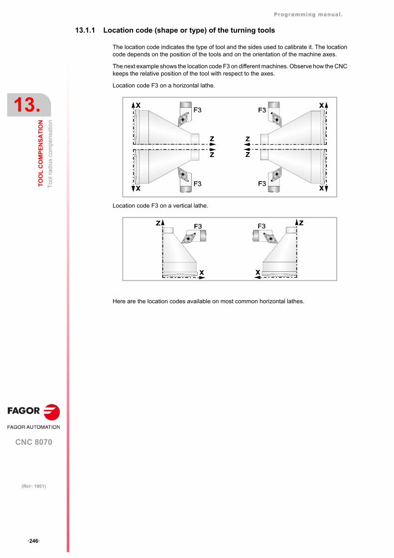
Programming manual.
CNC 8070
13.
TO
OL
CO
MP
EN
SA
TIO
N
To
ol r
adiu
s co
mp
ensa
tion
·246·
(REF: 1901)
13.1.1 Location code (shape or type) of the turning tools
The location code indicates the type of tool and the sides used to calibrate it. The locationcode depends on the position of the tools and on the orientation of the machine axes.
The next example shows the location code F3 on different machines. Observe how the CNCkeeps the relative position of the tool with respect to the axes.
Location code F3 on a horizontal lathe.
Location code F3 on a vertical lathe.
Here are the location codes available on most common horizontal lathes.
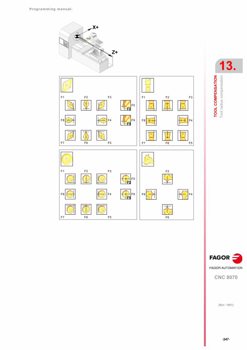
Programming manual.
CNC 8070
TO
OL
CO
MP
EN
SA
TIO
N
13.
To
ol r
adiu
s co
mp
ensa
tion
·247·
(REF: 1901)
F1 F2 F3
F4
F5F6F7
F8
F0
F9
F1 F2 F3
F4
F5F6F7
F8
F0
F9
F1 F2 F3
F4
F5F6F7
F8
F2
F4
F6
F8
X+
Z+
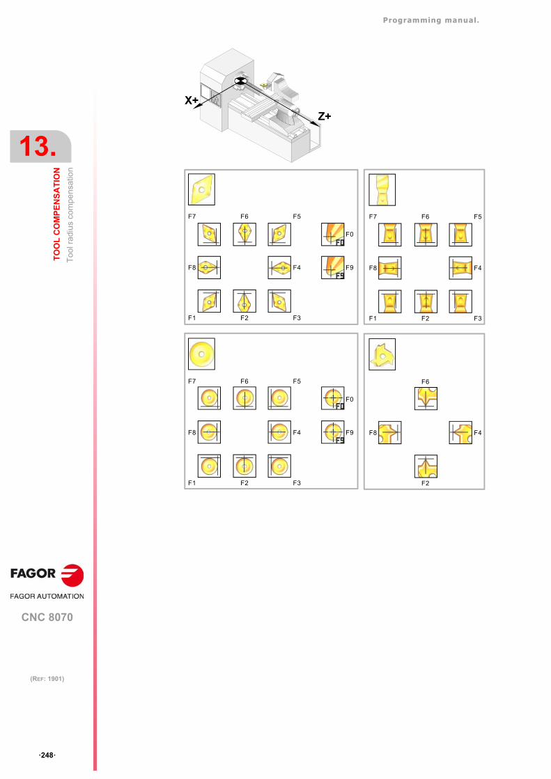
Programming manual.
CNC 8070
13.
TO
OL
CO
MP
EN
SA
TIO
N
To
ol r
adiu
s co
mp
ensa
tion
·248·
(REF: 1901)
F5F6F7
F1 F2 F3
F4F8
F0
F9
X+
Z+
F5F6F7
F1 F2 F3
F4F8
F0
F9
F6
F2
F4F8
F5F6F7
F1 F2 F3
F4F8

Programming manual.
CNC 8070
TO
OL
CO
MP
EN
SA
TIO
N
13.
To
ol r
adiu
s co
mp
ensa
tion
·249·
(REF: 1901)
13.1.2 Functions associates with radius compensation
The functions associated with tool compensation may be programmed anywhere in theprogram, even while tool radius compensation is active.
SELECTING THE TYPE OF TRANSITION BETWEEN BLOCKS
The transition between blocks determines how the compensated paths are joined together.
Programming
The type of transition may be selected from the program by means of the following functions:
G136 Circular transition between blocks.
G137 Linear transition between blocks.
G136Circular transition between blocks.
Being function G136 active, the CNC joins the compensated paths using circular paths.
G137Linear transition between blocks.
Being function G137 active, the CNC joins the compensated paths using linear paths.
Remarks
Later sections of this chapter offer graphic descriptions of how different paths are joined,depending on the type of transition selected (G136/G137).
Properties of the functions
Functions G136 and G137 are modal and incompatible with each other.
On power-up, after executing an M02 or M30, and after an EMERGENCY or RESET, theCNC assumes function G136 or G137 depending on the value of machine parameterIRCOMP.
(A)Circular transition between blocks (G136).(B)Linear transition between blocks (G137).
(B)(A)
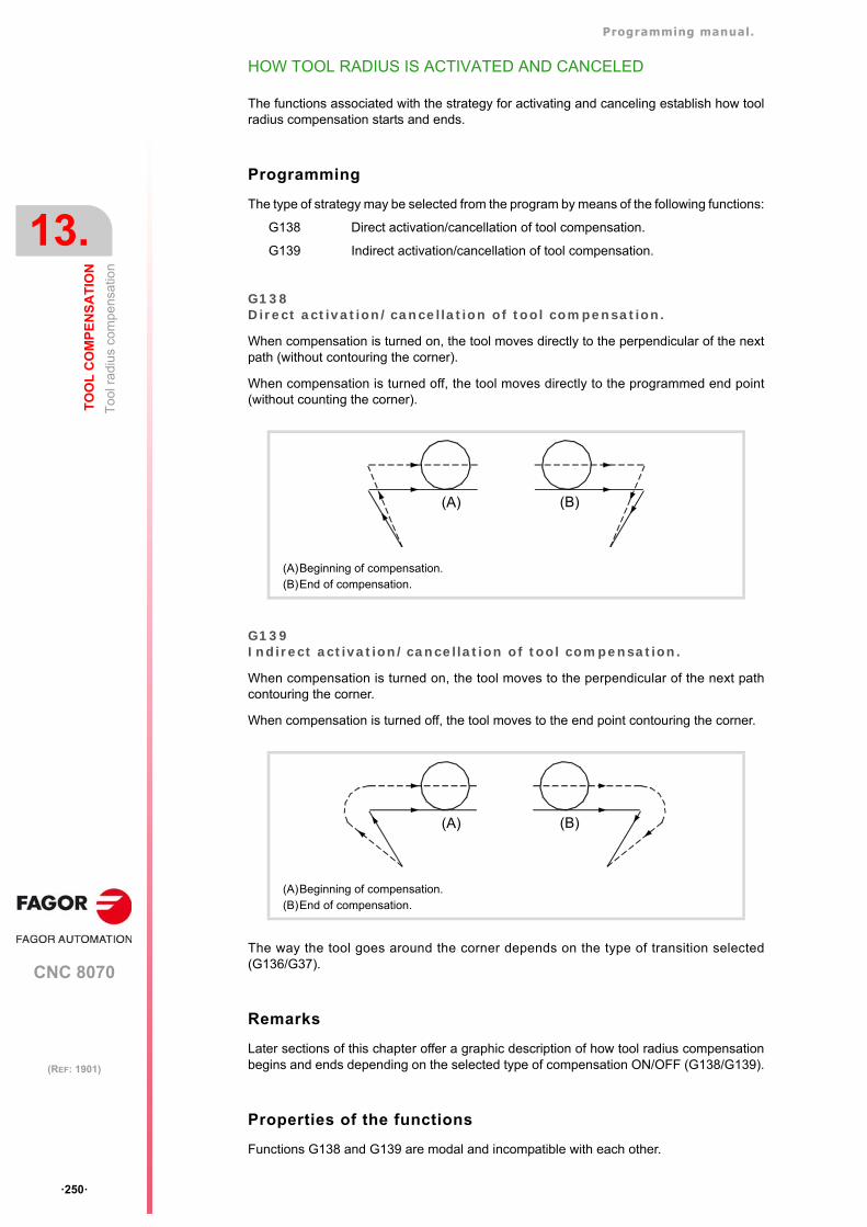
Programming manual.
CNC 8070
13.
TO
OL
CO
MP
EN
SA
TIO
N
To
ol r
adiu
s co
mp
ensa
tion
·250·
(REF: 1901)
HOW TOOL RADIUS IS ACTIVATED AND CANCELED
The functions associated with the strategy for activating and canceling establish how toolradius compensation starts and ends.
Programming
The type of strategy may be selected from the program by means of the following functions:
G138 Direct activation/cancellation of tool compensation.
G139 Indirect activation/cancellation of tool compensation.
G138Direct activation/cancellation of tool compensation.
When compensation is turned on, the tool moves directly to the perpendicular of the nextpath (without contouring the corner).
When compensation is turned off, the tool moves directly to the programmed end point(without counting the corner).
G139Indirect activation/cancellation of tool compensation.
When compensation is turned on, the tool moves to the perpendicular of the next pathcontouring the corner.
When compensation is turned off, the tool moves to the end point contouring the corner.
The way the tool goes around the corner depends on the type of transition selected(G136/G37).
Remarks
Later sections of this chapter offer a graphic description of how tool radius compensationbegins and ends depending on the selected type of compensation ON/OFF (G138/G139).
Properties of the functions
Functions G138 and G139 are modal and incompatible with each other.
(A)Beginning of compensation.(B)End of compensation.
(A)Beginning of compensation.(B)End of compensation.
(B)(A)
(B)(A)
Programming manual.
CNC 8070
TO
OL
CO
MP
EN
SA
TIO
N
13.
To
ol r
adiu
s co
mp
ensa
tion
·251·
(REF: 1901)
On power-up, after executing an M02 or M30, and after an EMERGENCY or RESET, theCNC assumes function G139.
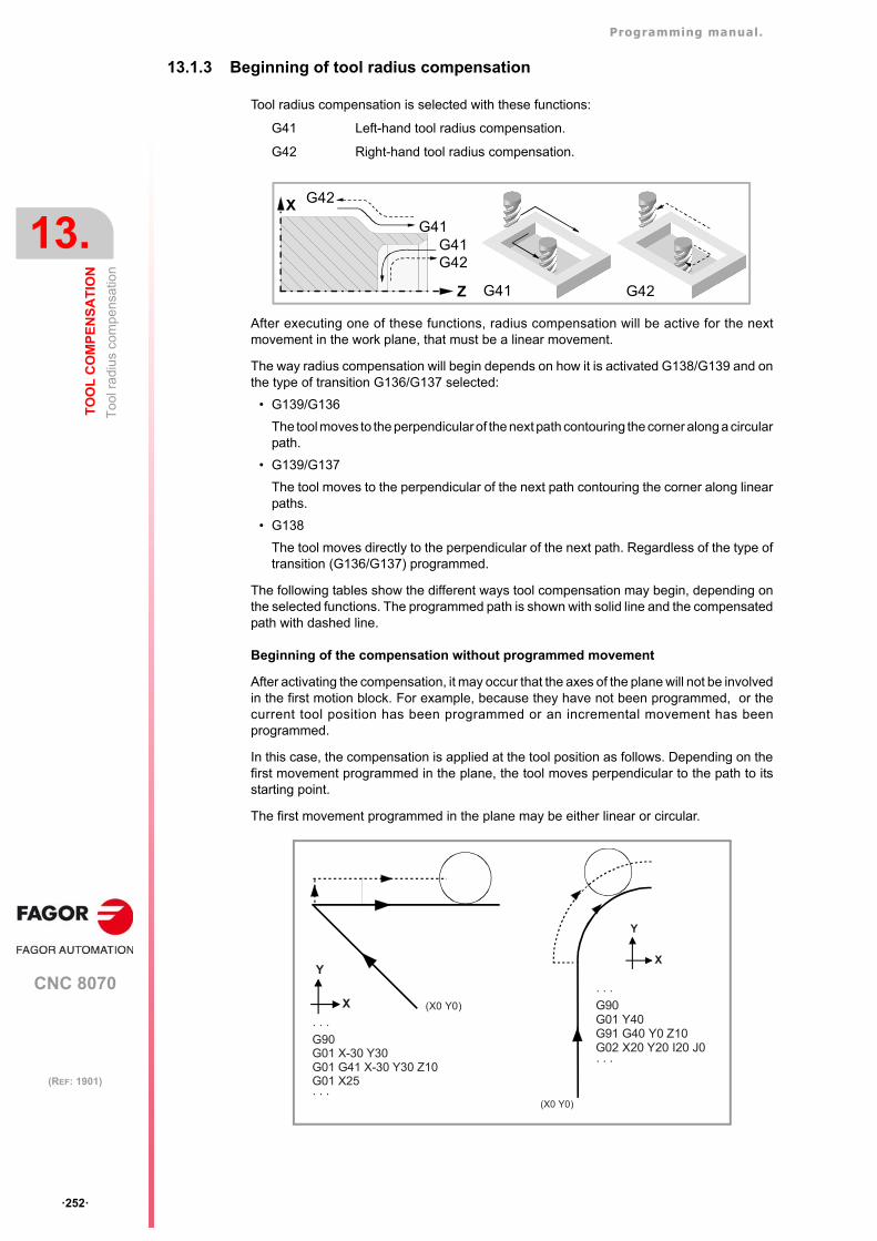
Programming manual.
CNC 8070
13.
TO
OL
CO
MP
EN
SA
TIO
N
To
ol r
adiu
s co
mp
ensa
tion
·252·
(REF: 1901)
13.1.3 Beginning of tool radius compensation
Tool radius compensation is selected with these functions:
G41 Left-hand tool radius compensation.
G42 Right-hand tool radius compensation.
After executing one of these functions, radius compensation will be active for the nextmovement in the work plane, that must be a linear movement.
The way radius compensation will begin depends on how it is activated G138/G139 and onthe type of transition G136/G137 selected:
• G139/G136
The tool moves to the perpendicular of the next path contouring the corner along a circularpath.
• G139/G137
The tool moves to the perpendicular of the next path contouring the corner along linearpaths.
• G138
The tool moves directly to the perpendicular of the next path. Regardless of the type oftransition (G136/G137) programmed.
The following tables show the different ways tool compensation may begin, depending onthe selected functions. The programmed path is shown with solid line and the compensatedpath with dashed line.
Beginning of the compensation without programmed movement
After activating the compensation, it may occur that the axes of the plane will not be involvedin the first motion block. For example, because they have not been programmed, or thecurrent tool position has been programmed or an incremental movement has beenprogrammed.
In this case, the compensation is applied at the tool position as follows. Depending on thefirst movement programmed in the plane, the tool moves perpendicular to the path to itsstarting point.
The first movement programmed in the plane may be either linear or circular.
G42G41
G41G42
G41
G42
Z
X
· · ·G90G01 Y40G91 G40 Y0 Z10G02 X20 Y20 I20 J0· · ·
(X0 Y0)
Y
X
· · ·G90G01 X-30 Y30G01 G41 X-30 Y30 Z10G01 X25· · ·
(X0 Y0)
Y
X
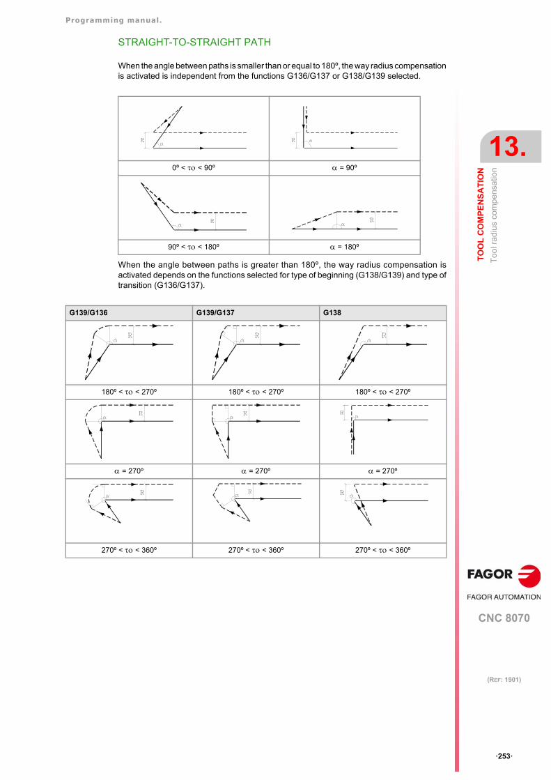
Programming manual.
CNC 8070
TO
OL
CO
MP
EN
SA
TIO
N
13.
To
ol r
adiu
s co
mp
ensa
tion
·253·
(REF: 1901)
STRAIGHT-TO-STRAIGHT PATH
When the angle between paths is smaller than or equal to 180º, the way radius compensationis activated is independent from the functions G136/G137 or G138/G139 selected.
When the angle between paths is greater than 180º, the way radius compensation isactivated depends on the functions selected for type of beginning (G138/G139) and type oftransition (G136/G137).
0º < < 90º = 90º
90º < < 180º = 180º
G139/G136 G139/G137 G138
180º < < 270º 180º < < 270º 180º < < 270º
= 270º = 270º = 270º
270º < < 360º 270º < < 360º 270º < < 360º
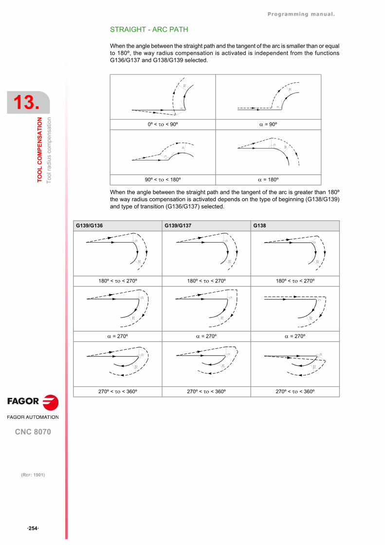
Programming manual.
CNC 8070
13.
TO
OL
CO
MP
EN
SA
TIO
N
To
ol r
adiu
s co
mp
ensa
tion
·254·
(REF: 1901)
STRAIGHT - ARC PATH
When the angle between the straight path and the tangent of the arc is smaller than or equalto 180º, the way radius compensation is activated is independent from the functionsG136/G137 and G138/G139 selected.
When the angle between the straight path and the tangent of the arc is greater than 180ºthe way radius compensation is activated depends on the type of beginning (G138/G139)and type of transition (G136/G137) selected.
0º < < 90º = 90º
90º < < 180º = 180º
G139/G136 G139/G137 G138
180º < < 270º 180º < < 270º 180º < < 270º
= 270º = 270º = 270º
270º < < 360º 270º < < 360º 270º < < 360º
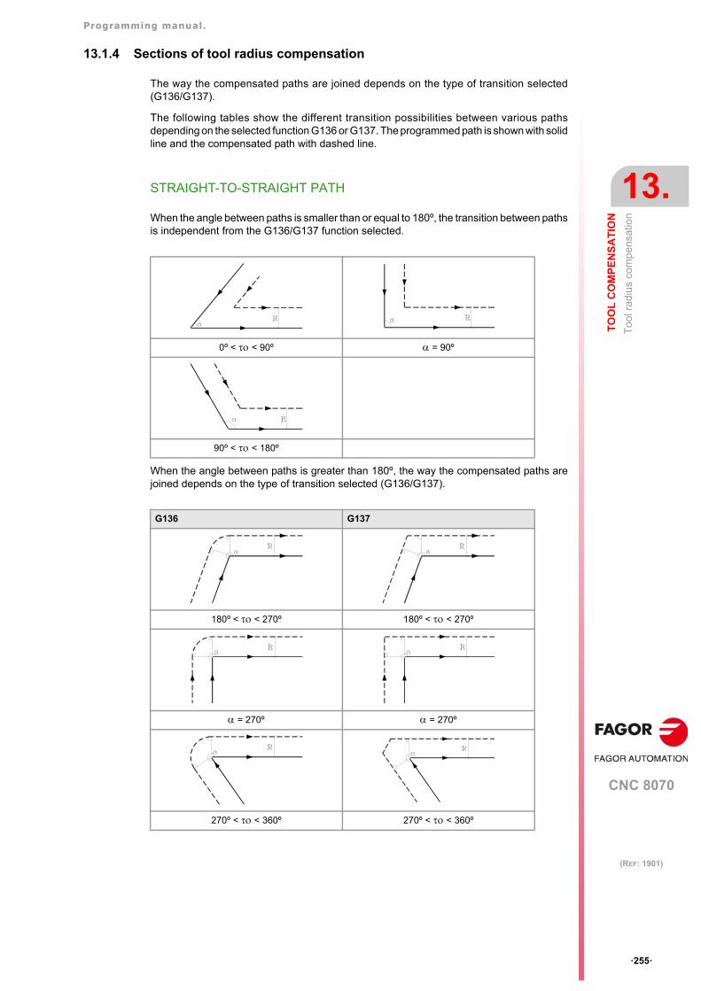
Programming manual.
CNC 8070
TO
OL
CO
MP
EN
SA
TIO
N
13.
To
ol r
adiu
s co
mp
ensa
tion
·255·
(REF: 1901)
13.1.4 Sections of tool radius compensation
The way the compensated paths are joined depends on the type of transition selected(G136/G137).
The following tables show the different transition possibilities between various pathsdepending on the selected function G136 or G137. The programmed path is shown with solidline and the compensated path with dashed line.
STRAIGHT-TO-STRAIGHT PATH
When the angle between paths is smaller than or equal to 180º, the transition between pathsis independent from the G136/G137 function selected.
When the angle between paths is greater than 180º, the way the compensated paths arejoined depends on the type of transition selected (G136/G137).
0º < < 90º = 90º
90º < < 180º
G136 G137
180º < < 270º 180º < < 270º
= 270º = 270º
270º < < 360º 270º < < 360º
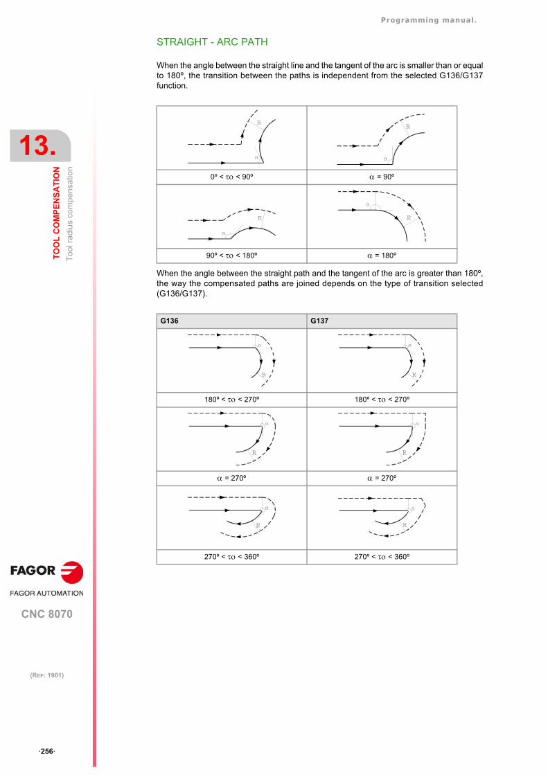
Programming manual.
CNC 8070
13.
TO
OL
CO
MP
EN
SA
TIO
N
To
ol r
adiu
s co
mp
ensa
tion
·256·
(REF: 1901)
STRAIGHT - ARC PATH
When the angle between the straight line and the tangent of the arc is smaller than or equalto 180º, the transition between the paths is independent from the selected G136/G137function.
When the angle between the straight path and the tangent of the arc is greater than 180º,the way the compensated paths are joined depends on the type of transition selected(G136/G137).
0º < < 90º = 90º
90º < < 180º = 180º
G136 G137
180º < < 270º 180º < < 270º
= 270º = 270º
270º < < 360º 270º < < 360º
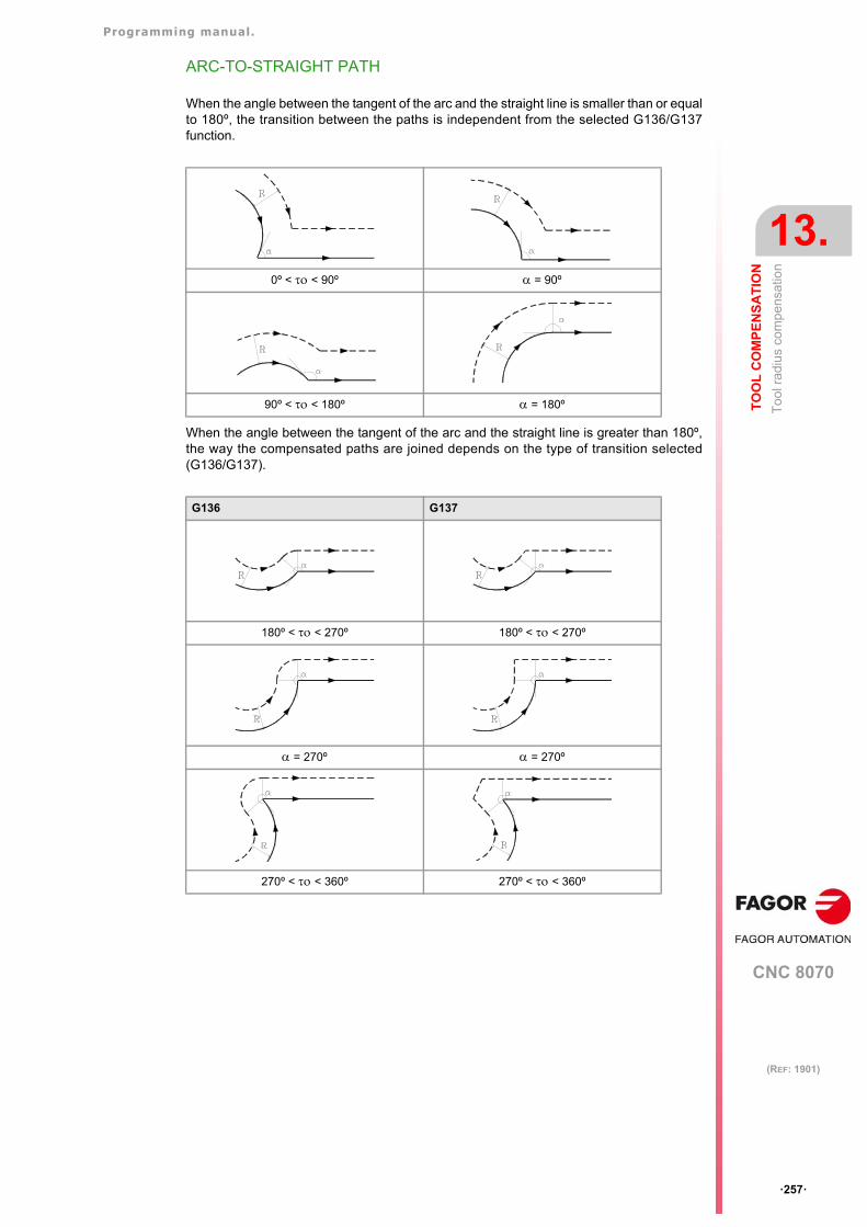
Programming manual.
CNC 8070
TO
OL
CO
MP
EN
SA
TIO
N
13.
To
ol r
adiu
s co
mp
ensa
tion
·257·
(REF: 1901)
ARC-TO-STRAIGHT PATH
When the angle between the tangent of the arc and the straight line is smaller than or equalto 180º, the transition between the paths is independent from the selected G136/G137function.
When the angle between the tangent of the arc and the straight line is greater than 180º,the way the compensated paths are joined depends on the type of transition selected(G136/G137).
0º < < 90º = 90º
90º < < 180º = 180º
G136 G137
180º < < 270º 180º < < 270º
= 270º = 270º
270º < < 360º 270º < < 360º
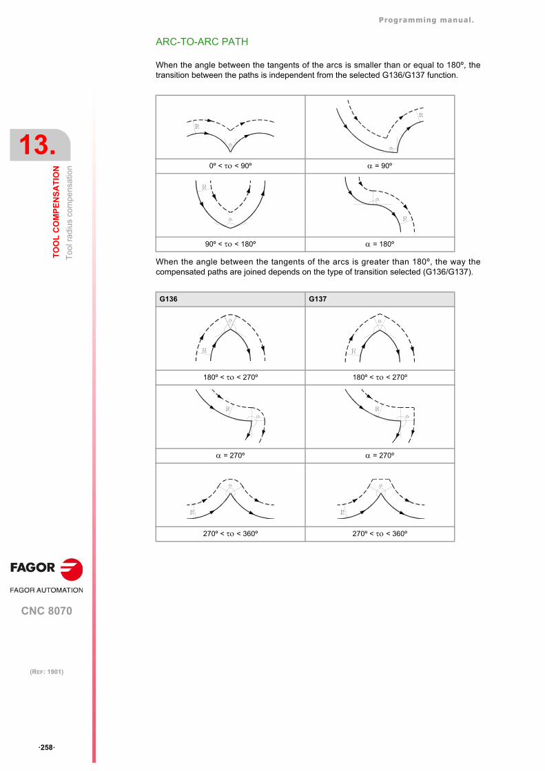
Programming manual.
CNC 8070
13.
TO
OL
CO
MP
EN
SA
TIO
N
To
ol r
adiu
s co
mp
ensa
tion
·258·
(REF: 1901)
ARC-TO-ARC PATH
When the angle between the tangents of the arcs is smaller than or equal to 180º, thetransition between the paths is independent from the selected G136/G137 function.
When the angle between the tangents of the arcs is greater than 180º, the way thecompensated paths are joined depends on the type of transition selected (G136/G137).
0º < < 90º = 90º
90º < < 180º = 180º
G136 G137
180º < < 270º 180º < < 270º
= 270º = 270º
270º < < 360º 270º < < 360º
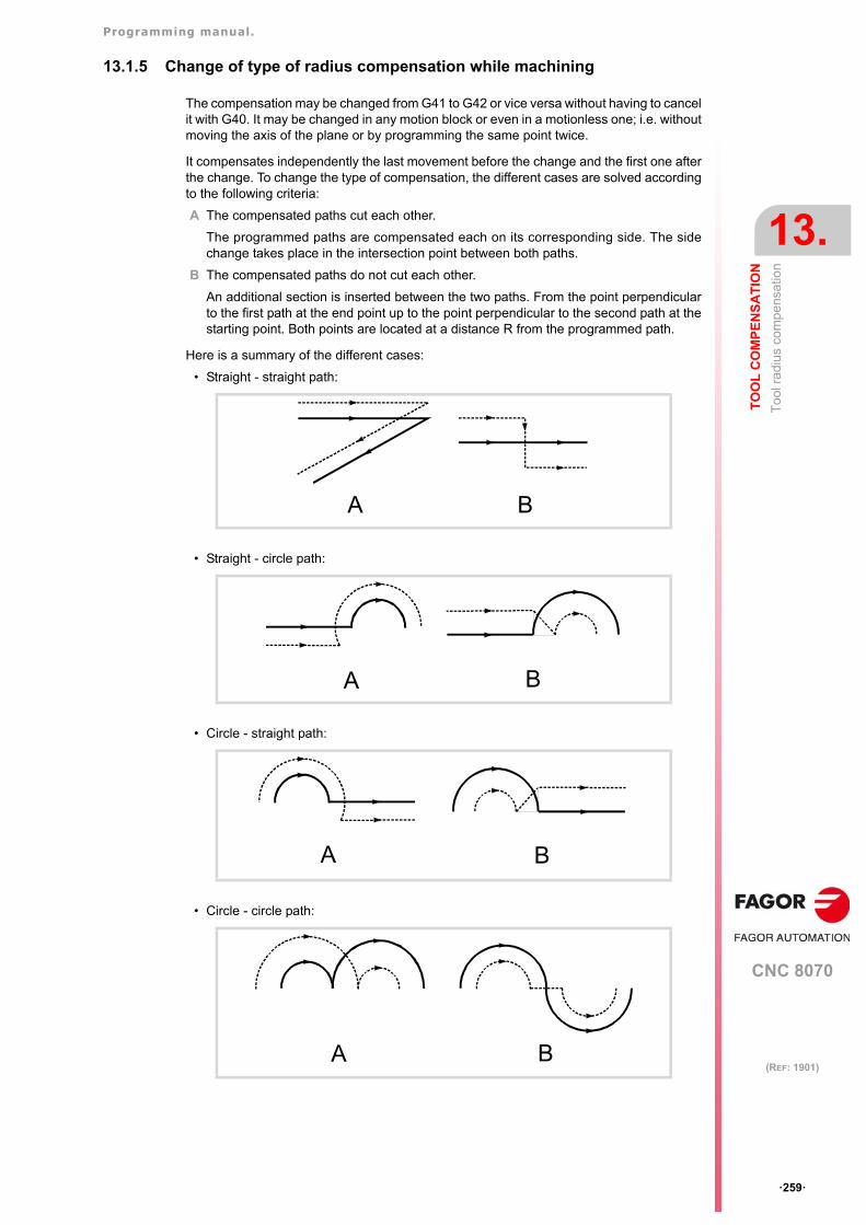
Programming manual.
CNC 8070
TO
OL
CO
MP
EN
SA
TIO
N
13.
To
ol r
adiu
s co
mp
ensa
tion
·259·
(REF: 1901)
13.1.5 Change of type of radius compensation while machining
The compensation may be changed from G41 to G42 or vice versa without having to cancelit with G40. It may be changed in any motion block or even in a motionless one; i.e. withoutmoving the axis of the plane or by programming the same point twice.
It compensates independently the last movement before the change and the first one afterthe change. To change the type of compensation, the different cases are solved accordingto the following criteria:
A The compensated paths cut each other.
The programmed paths are compensated each on its corresponding side. The sidechange takes place in the intersection point between both paths.
B The compensated paths do not cut each other.
An additional section is inserted between the two paths. From the point perpendicularto the first path at the end point up to the point perpendicular to the second path at thestarting point. Both points are located at a distance R from the programmed path.
Here is a summary of the different cases:
• Straight - straight path:
• Straight - circle path:
• Circle - straight path:
• Circle - circle path:
A B
A B
A B
A B
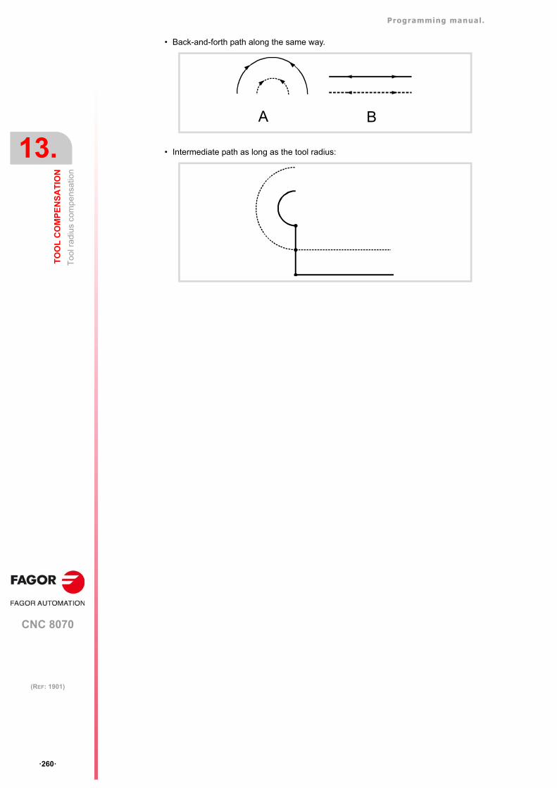
Programming manual.
CNC 8070
13.
TO
OL
CO
MP
EN
SA
TIO
N
To
ol r
adiu
s co
mp
ensa
tion
·260·
(REF: 1901)
• Back-and-forth path along the same way.
• Intermediate path as long as the tool radius:
BA
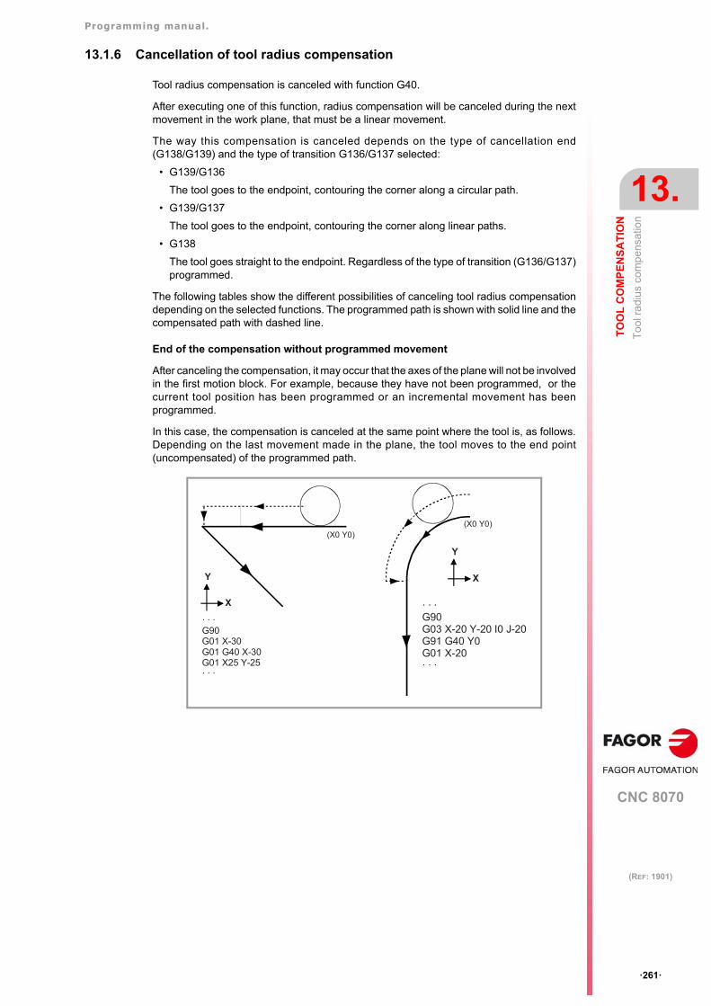
Programming manual.
CNC 8070
TO
OL
CO
MP
EN
SA
TIO
N
13.
To
ol r
adiu
s co
mp
ensa
tion
·261·
(REF: 1901)
13.1.6 Cancellation of tool radius compensation
Tool radius compensation is canceled with function G40.
After executing one of this function, radius compensation will be canceled during the nextmovement in the work plane, that must be a linear movement.
The way this compensation is canceled depends on the type of cancellation end(G138/G139) and the type of transition G136/G137 selected:
• G139/G136
The tool goes to the endpoint, contouring the corner along a circular path.
• G139/G137
The tool goes to the endpoint, contouring the corner along linear paths.
• G138
The tool goes straight to the endpoint. Regardless of the type of transition (G136/G137)programmed.
The following tables show the different possibilities of canceling tool radius compensationdepending on the selected functions. The programmed path is shown with solid line and thecompensated path with dashed line.
End of the compensation without programmed movement
After canceling the compensation, it may occur that the axes of the plane will not be involvedin the first motion block. For example, because they have not been programmed, or thecurrent tool position has been programmed or an incremental movement has beenprogrammed.
In this case, the compensation is canceled at the same point where the tool is, as follows.Depending on the last movement made in the plane, the tool moves to the end point(uncompensated) of the programmed path.
· · ·G90G03 X-20 Y-20 I0 J-20G91 G40 Y0G01 X-20· · ·
(X0 Y0)
Y
X
· · ·G90G01 X-30G01 G40 X-30G01 X25 Y-25· · ·
(X0 Y0)
Y
X
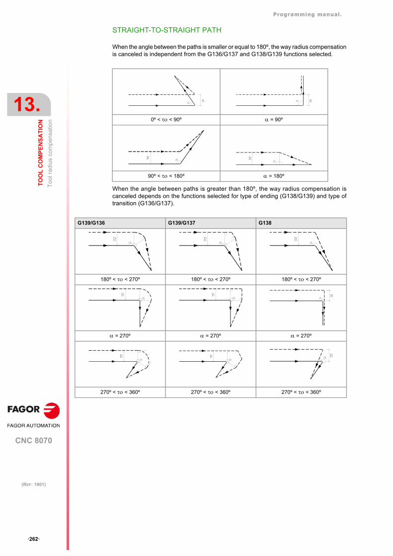
Programming manual.
CNC 8070
13.
TO
OL
CO
MP
EN
SA
TIO
N
To
ol r
adiu
s co
mp
ensa
tion
·262·
(REF: 1901)
STRAIGHT-TO-STRAIGHT PATH
When the angle between the paths is smaller or equal to 180º, the way radius compensationis canceled is independent from the G136/G137 and G138/G139 functions selected.
When the angle between paths is greater than 180º, the way radius compensation iscanceled depends on the functions selected for type of ending (G138/G139) and type oftransition (G136/G137).
0º < < 90º = 90º
90º < < 180º = 180º
G139/G136 G139/G137 G138
180º < < 270º 180º < < 270º 180º < < 270º
= 270º = 270º = 270º
270º < < 360º 270º < < 360º 270º < < 360º
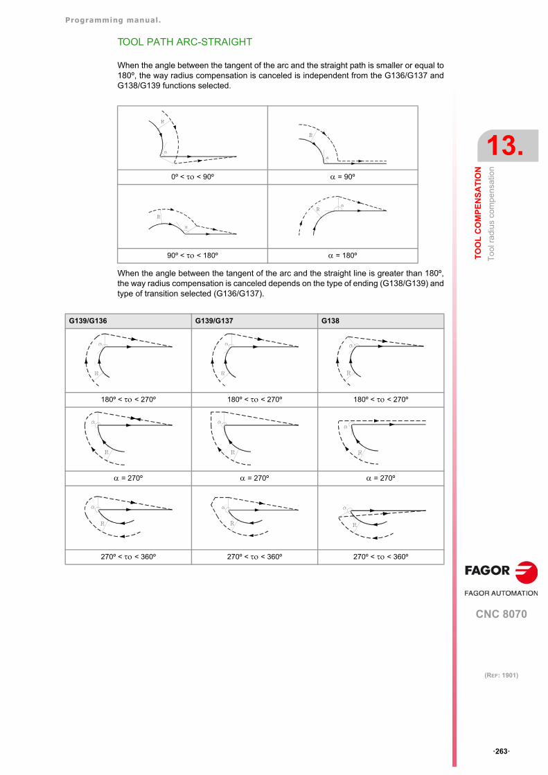
Programming manual.
CNC 8070
TO
OL
CO
MP
EN
SA
TIO
N
13.
To
ol r
adiu
s co
mp
ensa
tion
·263·
(REF: 1901)
TOOL PATH ARC-STRAIGHT
When the angle between the tangent of the arc and the straight path is smaller or equal to180º, the way radius compensation is canceled is independent from the G136/G137 andG138/G139 functions selected.
When the angle between the tangent of the arc and the straight line is greater than 180º,the way radius compensation is canceled depends on the type of ending (G138/G139) andtype of transition selected (G136/G137).
0º < < 90º = 90º
90º < < 180º = 180º
G139/G136 G139/G137 G138
180º < < 270º 180º < < 270º 180º < < 270º
= 270º = 270º = 270º
270º < < 360º 270º < < 360º 270º < < 360º

Programming manual.
CNC 8070
13.
TO
OL
CO
MP
EN
SA
TIO
N
Too
l len
gth
com
pen
satio
n
·264·
(REF: 1901)
13.2 Tool length compensation
Tool length compensation on a milling machine.
On a milling machine, tool length compensation is applied to the longitudinal axis; i.e. on theaxis indicated by the instruction "#TOOL AX", or when missing, to the longitudinal axisdesignated by selecting the plane.
If G17, tool lengh compensation is aplied to Z axis.
If G18, tool lengh compensation is aplied to Y axis.
If G19, tool lengh compensation is aplied to X axis.
Whenever any of functions G17, G18 or G19 is executed, the CNC assumes the axisperpendicular to the selected plane as the new longitudinal axis. If, then, "#TOOL AX" isexecuted, the new selected longitudinal axis replaces the previous one.
Tool length compensation on a lathe.
In a turning operation, the CNC takes into account the dimensions of the new tool, definedin the corresponding tool offset, and moves the tool holding turret so the tip of the new tooloccupies the same position as the previous one.
Programming
Tool length compensation is activated when selecting a tool offset.
Positioning of several tools at position "0", with tool length compensation off.
Positioning of several tools at position "0", with tool length compensation on.
Z=0OW
Z=0OW
Off. Z Off. Z´
Off. X Off. X´
Programming manual.
CNC 8070
TO
OL
CO
MP
EN
SA
TIO
N
13.
Too
l len
gth
com
pen
satio
n
·265·
(REF: 1901)
• To activate this compensation, program "D<n>", where <n> is the tool offset number thatcontains the tool dimensions that will be used as compensation values.
• To cancel this compensation, program "D0".
Once one of these codes has been executed, tool length compensation will be activated orcancel during the next movement of the longitudinal axis.
Programming manual.
CNC 8070
13.
TO
OL
CO
MP
EN
SA
TIO
N
3D
too
l com
pens
atio
n.
·266·
(REF: 1901)
13.3 3D tool compensation.
In tool radius compensation (G41/G42) tool orientation is constant. 3D tool compensationallows changing the tool orientation during the path considering the dimensions and theshape of the tool.
There are two kinds of 3D compensation; paraxial compensation (or compensation factors)or the compensation calculated from the normal vector. In the first case, the CAM generatesthe program with the necessary blocks to generate the tool paths. In the second case, theCAM generates the blocks with a vector normal (perpendicular) to the surface and the CNCruns the relevant calculations to generate the paths. Both kinds of 3D compensation areincompatible with tool radius compensation (G41/G42).
Programming. Activating 3D compensation.
This instruction must be programmed alone in the block. When programming this instruction,you must define the type of 3D compensation to activate.
Programming format.
The programming format is the following; the list of arguments appears between curlybrackets and the optional ones between angle brackets.
#COMP3D <ON>#COMP3D <ON> [<{mode}>]
The paraxial mode is the default mode; however, inside a program, it keeps the modeselected last.
Type of compensation. Paraxial 3D compensation.
The CAM calculates the paths and gives the CNC a program with the necessary informationto generate the paths at the corners. The CAM takes into account the tool shape andconsequently the program may be executed with any type of tool.
The CAM adds to the motion blocks a vector (unnormalized) like N[P,Q,R]. The vectorgenerated by the CAM is a compensation vector (paraxial vector) on the programmedcoordinate, an offset vector. This vector is the equivalent to the one that the CNC wouldgenerate taking into account the vector normal to the surface, the type of tool and theintersection with the next tool path. Based on this vector, the CNC calculates the offset tobe added to the programmed coordinate depending on the tool radius.
X offset = Tool radius * P
Y offset = Tool radius * Q
Z offset = Tool radius * R
Paraxial compensation is a full 3D compensation for 5-axis machines, and it is applied forsmall movements and 3D surfaces. When working with rotary axes, we recommendactivating the RTCP.
With this mode, the CNC can compensate profiles formed by segments, by segments andarcs tangents to each other and also by arcs as long they still are after being compensated for.
{mode} Optional. Type of compensation. Program one of the followingcommands.
• PARAX; paraxial 3D compensation (by default).
• NORMAL; 3D compensation with normal vector.
#COMP3D#COMP3D ON#COMP3D [PARAX]#COMP3D ON [PARAX]#COMP3D [NORMAL]#COMP3D ON [NORMAL]
Programming manual.
CNC 8070
TO
OL
CO
MP
EN
SA
TIO
N
13.
3D
too
l com
pens
atio
n.
·267·
(REF: 1901)
Type of compensation. 3D compensation with normal vector.
The CAM generates a program with the necessary information for the CNC to generate thepaths at the corners, depending on the type of tool, if necessary. This type of compensationcan only be executed with cylindrical, toric or spherical tools.
The CAM adds to the motion blocks a unit vector normal to the surface like N[P,Q,R]. Basedon this vector, the CNC calculates the offset to be added to the programmed coordinatedepending on the type of tool and the intersection with the next path.
Programming. Canceling 3D compensation.
This instruction must be programmed alone in the block.
Programming format.
The programming format is:
#COMP3D OFF
Considerations.
• 3D compensation are incompatible with tool radius compensation (G41/G42).
• 3D compensation affects linear movements (G00, G01), circular movements (G02, G03,G08, G09) and threading (G33, G63).
• 3D compensation does not affect probing movements (G100, G103), home search (G74)or polynomials (#POLY).
• During tool inspection, the CNC temporarily cancels 3D compensation; in other words,it does not apply the normal vector to jog or MDI movements. The CNC restores 3Dcompensation when resuming the program after tool inspection.
Properties of the function and Influence of the reset, turning theCNC off and of the M30 function
On power-up, after executing an M02 or M30, and after an emergency or reset, the CNCcancels 3D compensation and initializes it to the paraxial compensation mode. When 3Dcompensation is active, the window for active G codes shows "C3D".
#COMP3D OFF
Programming manual.
CNC 8070
13.
TO
OL
CO
MP
EN
SA
TIO
N
3D
too
l com
pens
atio
n.
·268·
(REF: 1901)
13.3.1 Programming the vector in the block.
The vector MUST BE programmed in all linear and circular motion blocks; if not programmedand 3D compensation is active, the CNC will issue an error message. If the vector isprogrammed but 3D compensation is not active, the CNC ignores that the vector has beenprogrammed. This way, the same blocks may be used to generate compensated surfacesor not depending on whether #COMP3D is active or not.
Programming.
The vector may be programmed anywhere in the block. For paraxial compensation, thevector may be unnormalized whereas for compensation with normal vector, the vector mustbe a unit vector.
Programming format.
The vector may be programmed anywhere in the block. The programming format is:
N[{p,q,r}]
Programming the vector.
The vector (paraxial or normal) is programmed like N[P,Q,R], where the three componentsof the vector MUST BE programmed. Vector components may be numerical values,parametric or the result of math expressions.
Considerations about the vector (paraxial or normal).
Vector programming is not affected by the following coordinate transformations; but it isaffected by mirror images.
• Programming in mm/inches (G70/G71).
• Programming in radius/diameters (G150/G151).
• Absolute/incremental coordinates (G90/G91).
• Scaling factor (G72).
• Zero offsets (G159).
• Coordinate rotation in the plane (G73).
The components of the vector N[p,q,r] are applied to the first three axes of the main trihedronof the channel regardless of the active plane (G17, G18, G19 or G20). If the first three axesof the channel are XYZ and the vector is N[A,B,C], the A component is always applied tothe X axis; B to the Y axis; C to the Z axis.
{p,q,r} Components of the vector.
N[1,0,1]N[-1,0,-1]N[-1.4,-0.4,1.333]N[P1,-P10,10]N[P1+3,-P10-P2,10*P100]
CNC 8070
14
·269·
(REF: 1901)
14.CONTROLLING THE EXECUTION AND DISPLAYING THE PROGRAM.
14.1 Conditional block skip (/)
The block skip condition (/) is governed by the mark BLKSKIP1 of the PLC; the user maydo so using the keypad if the OEM has been provided a button or key for this purpose. Ifthe mark is active, the CNC will skip the blocks where it is programmed (not executing them)and will go on to the next block.
Programming.
The block skip condition must always be programmed at the beginning of the block.
Programming format.
The programming format is:
/
Considerations.
The CNC analyzes the block skip condition during the block preparation. If the block skipneeds to be analyzed at the time of execution, it is necessary to interrupt the blockpreparation, by programming the instruction #FLUSH in the previous block. See"14.6 Interrupt block preparation (#FLUSH)." on page 279.
In order to use this feature, the machine manufacturer must have defined the corresponding PLCoperation. Refer to the machine’s documentation for further information.
/N10 X10 Y20 F1000
#FLUSH/N10 X10 Y20 F1000
Programming manual.
CNC 8070
14.
CO
NT
RO
LL
ING
TH
E E
XE
CU
TIO
N A
ND
DIS
PL
AY
ING
TH
E
Ab
ort t
he
exe
cutio
n o
f th
e pr
ogr
am a
nd
resu
me
it in
ano
the
r bl
ock
or
pro
gram
.
·270·
(REF: 1901)
14.2 Abort the execution of the program and resume it in another blockor program.
The CNC offers a special interruption mode, handled via PLC, that allows aborting theexecution of the program and resuming it either from a particular previously defined blockor in another program. If the execution resumes in a different program, it will be executedfrom the beginning; it will not be possible to select the starting block.
The point where the execution is resumed is defined and canceled with the #ABORTinstruction.
Within the same program, it is possible to define several resume points; when interruptingthe program, the CNC will use the one that is active at the time; in other words, the oneexecuted last.
Considerations.
Abort the program.
Usually, this feature is turned on and off using an external push button or key configured forthat purpose. This interruption mode is not applied when pressing the [CYCLE STOP] key.
When interrupting the program from the PLC, the CNC channel aborts the execution of theprogram but without affecting the spindle, initializes the program history and resumes theexecution in the point indicated by the active #ABORT instruction.
Abort a threading process and other machining operations that cannot be interrupted.
If the CNC aborts the program during a threading operation that cannot be interrupted, theCNC behaves like when doing a reset. After receiving the command to abort the execution,the CNC interrupts the execution once the operation has been properly completed. Whilethe program is interrupted, it will be necessary to repeat the command to abort the programin order for the CNC to do so.
Considerations when resuming the program.
When the program is interrupted, the history is initialized. Thus, it is recommended to definethe minimum machining conditions such as feedrate, ·M· functions, etc in the block wherethe execution will be resumed.
In order to use this feature, the machine manufacturer must have defined the corresponding PLCoperation. Refer to the machine’s documentation for further information.
#ABORT Define the execution resuming block or program.
#ABORT OFF Canceling the execution resuming point.
Programming manual.
CNC 8070
CO
NT
RO
LL
ING
TH
E E
XE
CU
TIO
N A
ND
DIS
PL
AY
ING
TH
E
14.
Ab
ort t
he
exe
cutio
n o
f th
e pr
ogr
am a
nd
resu
me
it in
ano
the
r bl
ock
or
pro
gram
.
·271·
(REF: 1901)
14.2.1 Define the execution resuming block or program (#ABORT).
The point where the execution is resumed is defined with the #ABORT instruction. Withinthe same program, it is possible to define several resume points; when interrupting theprogram, the CNC will use the one that is active at the time; in other words, the one executedlast. If no resume point has been defined, the execution continues in the #ABORT OFFinstruction; if the instruction has not been defined, the program will jump to the end of theprogram (M30).
Programming.
Program the instruction alone in the block. When defining this instruction, there is an optionto define a block or program where it will resume execution.
Programming format.
The programming format is the following; the arguments appear between curly brackets.
#ABORT#ABORT {label} #ABORT ["{path\name}"]
Label programming.
The labels that identify the blocks may be of a number type or a name type. In the program,the ":" character must be added to the number type labels after the block number.
Program name and location (path).
The program to be executed may be defined by either writing the full path or without it. Whenindicating the whole path, the CNC only looks for the program in the indicated folder. If thepath has not been indicated, the CNC looks for the program in the following folders and inthis order.
1 Directory selected with the #PATH instruction.
2 Directory of the program that executes the #ABORT instruction.
3 Directory defined by machine parameter SUBPATH.
{label} Block label.
{path\name} Program name and location (path).
#ABORT(Cancels the active point).(Execution continues at #ABORT OFF; if there isn't one, resumes at M30).
#ABORT N120(The execution continues in block N120).
#ABORT [LABEL](The execution continues in block [LABEL]).
#ABORT ["PRG.NC"](The execution continues in program PRG.NC).
#ABORT ["C:\FAGORCNC\USERS\PRG\EXAMPLE.NC"](The execution continues in program EXAMPLE.NC).
#ABORT N50··
N50: G01 G91 X15 F800
#ABORT [LABEL]··
[LABEL] G01 G91 F800
Programming manual.
CNC 8070
14.
CO
NT
RO
LL
ING
TH
E E
XE
CU
TIO
N A
ND
DIS
PL
AY
ING
TH
E
Ab
ort t
he
exe
cutio
n o
f th
e pr
ogr
am a
nd
resu
me
it in
ano
the
r bl
ock
or
pro
gram
.
·272·
(REF: 1901)
Considerations.
It is recommended to program the target labels at the beginning of the program, outside themain program. Otherwise, and depending on the length of the program, if the jump labelsare defined at the end of it, the #ABORT instruction may take longer to find them.
14.2.2 Default point to continue the execution (#ABORT OFF).
If no resume point has been defined or it has been canceled, the execution continues in the#ABORT OFF instruction; if the instruction has not been defined, the program will jump tothe end of the program (M30).
Programming.
Program the instruction alone in the block.
Programming format.
The programming format is:
#ABORT OFF
#ABORT OFF
Programming manual.
CNC 8070
CO
NT
RO
LL
ING
TH
E E
XE
CU
TIO
N A
ND
DIS
PL
AY
ING
TH
E
14.
Blo
ck r
epet
ition
(N
R).
·273·
(REF: 1901)
14.3 Block repetition (NR).
14.3.1 Movement block repetition n times (NR/NR0).
The command NR indicates the number of times that programmed block movement is to beexecuted. If NR0 is programmed, the CNC executes the block only once.
Programming.
This command must be added to a movement block. When programming this command, thenumber of repetitions must be defined.
Programming format.
The programming format is the following; the arguments appear between curly brackets.
NR{repetitions}NR0
Considerations.
Movement blocks under the influence of a canned cycle or modal subroutine.
If inside the influence zone of a canned cycle or modal subroutine, a movement block isprogram containing an NR command, the CNC executes the programmed movement andthe canned cycle or subroutine the programmed number of times.
Do not execute the canned cycle or modal subroutine after the movement.
If the number of repetitions is zero (NR0), the CNC will only execute the programmedmovement.
{repetitions} Number of repetitions.
G91 G01 X34.678 F150 NR4(The CNC repeats the block 4 times).
G91 G01 X34.678 F150 NR0(The CNC executes the block once, without any repetitions).
T11 M6(Tool change).
F100 S800 M3(Initial conditions).
G0 G90 X0 Y0 Z20 (Positioning).
G81 I-20 Z1(Execution of the canned cycle for X0 Y0).
G91 X15 NR3(Repeat the movement and canned cycle 3 times).
G90 X30 Y30 NR0(Movement without executing the canned cycle).
G80(End of canned cycle).
M30.
Programming manual.
CNC 8070
14.
CO
NT
RO
LL
ING
TH
E E
XE
CU
TIO
N A
ND
DIS
PL
AY
ING
TH
E
Blo
ck r
epet
ition
(N
R).
·274·
(REF: 1901)
14.3.2 Prepare a subroutine without executing it (NR0).
The command NR0 (always with a value set to 0) prevents the execution of the modalsubroutines or modal cycle programmed in the block, but leaves it ready to execute duringthe following motion blocks. Movements can be defined in the following blocks or asubroutine.
Programming.
Add the NR0 command (always with a value set to 0) to a block with a modal subroutine ormodal cycle.
Programming format.
The programming format is the following; the arguments appear between curly brackets.
NR0
T11 M6(Tool change).
F100 S800 M3(Initial conditions).
G0 G90 Z100G81 Z5 I-20 NR0
(Canned cycle definition; without execution).Y0 X20
(Movement and execution of the canned cycle).X40 NR0
(Movement and execution of the canned cycle).X60 NR0
(Movement without executing the canned cycle).X80X100 NR0Y50X80 NR0X60X40X20 NR0G80G0 G90 Z100M30
Programming manual.
CNC 8070
CO
NT
RO
LL
ING
TH
E E
XE
CU
TIO
N A
ND
DIS
PL
AY
ING
TH
E
14.
Blo
ck g
roup
rep
etiti
on
(#R
PT
).
·275·
(REF: 1901)
14.4 Block group repetition (#RPT).
This instruction #RPT may be used to execute a portion of the program defined between twoblocks must will be identified with labels. The number of times for the blocks to be repeatedcan be configured; if it is not programmed, the CNC repeats the block group only once. Oncethe repetition is done, the execution resumes at the block after the one containing theinstruction #RPT.
The block group to be repeated must be defined in the same program or subroutine executingthis instruction. They may also be after the program (after function M30)
For the block group to be repeated, where a second block repetition may have been definedand within this a third could have also been and so forth, the CNC limits this type of callsto a maximum of 20 nesting levels.
Programming.
Program the instruction alone in the block. When programming this instruction, the start andend block repetition must be defined. Optionally, the number of times the blocks are to berepeated can be defined.
Programming format.
The programming format is the following; the arguments appear between curly brackets andthe optional ones, between angle brackets.
#RPT [{label_begin}, {label_end}, <{repetitions}>]
Label programming.
The labels that identify the blocks may be of a number type or a name type. The label of thefirst block may be part of the block being repeated, but the label of the last block must bealone in the block. The labels of the first and last blocks must be different.
• Programming with number labels. In the program, for the begin and end block labels, thecharacter “:” must be added after the block number.
{label_begin} First block label.
{label_end} Last block label.
{repetitions} Number of repetitions.Optional (by default, 1).
#RPT [N100, N200](The CNC repeats the blocks N100 through N200 once).
#RPT [N18, N19, 7](The CNC repeats the blocks N18 through N19 seven times).
#RPT [[BEGIN], [END]](The CNC repeats the blocks [BEGIN] through [END] once).
#RPT [N50,N70]··
N50: G01 G91 X15 F800 (first block)X-10 Y-10X20X-10 Y10
N70: (last block)
Programming manual.
CNC 8070
14.
CO
NT
RO
LL
ING
TH
E E
XE
CU
TIO
N A
ND
DIS
PL
AY
ING
TH
E
Blo
ck g
roup
rep
etiti
on
(#R
PT
).
·276·
(REF: 1901)
• Programming with name labels.
Considerations.
Repeating the execution of a single block.
The execution of a single block repetition, program as follows: Movement blocks can alsobe repeated using the "NR" command. See "14.3.1 Movement block repetition n times(NR/NR0)." on page 273.
Block repetitions and execution loops ($IF, $WHILE, etc).
The block group to be repeated can include execution loops, such as $IF, $WHILE, etc. Inthis case, a loop closing instruction must always be accompanied with the correspondingopening instruction. If within the block group to be repeated there is only the loop closinginstruction, the CNC will display the corresponding error.
#RPT [[BEGIN],[END]]··
[BEGIN] G01 G91 F800 (first block)X-10 Y-10X20X-10 Y10G90
[END] (last block)
N10 #RPT [N10,N20,4]N10: G01 G91 F800 (first block)N20: (last block)
Correct.
#RPT [N10,N20]·
N10: $FOR P1=1,10,1··
$ENDFOR·
N20:
Incorrect.
#RPT [N10,N20]·
$FOR P1=1,10,1·
N10:·
$ENDFORN20:
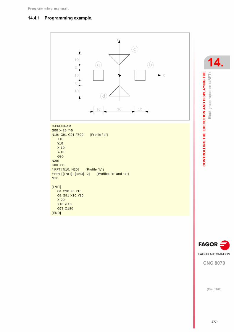
Programming manual.
CNC 8070
CO
NT
RO
LL
ING
TH
E E
XE
CU
TIO
N A
ND
DIS
PL
AY
ING
TH
E
14.
Blo
ck g
roup
rep
etiti
on
(#R
PT
).
·277·
(REF: 1901)
14.4.1 Programming example.
%PROGRAMG00 X-25 Y-5N10: G91 G01 F800 (Profile "a")
X10Y10X-10Y-10G90
N20:G00 X15#RPT [N10, N20] (Profile "b")#RPT [[INIT], [END], 2] (Profiles "c" and "d")M30
[INIT]G1 G90 X0 Y10G1 G91 X10 Y10X-20X10 Y-10G73 Q180
[END]
Programming manual.
CNC 8070
14.
CO
NT
RO
LL
ING
TH
E E
XE
CU
TIO
N A
ND
DIS
PL
AY
ING
TH
E
Inte
rru
pt b
lock
pre
para
tion
until
an
eve
nt is
cau
sed
(#W
AIT
FO
R).
·278·
(REF: 1901)
14.5 Interrupt block preparation until an event is caused (#WAIT FOR).
The instruction #WAIT FOR interrupts block preparation until the programmed condition ismet.
Programming.
Program the instruction alone in the block. When programming this instruction, the conditionto resume the block preparation must be defined.
Programming format.
The programming format is the following; the arguments appear between curly brackets.
#WAIT FOR [{condition}]
Considerations.
This instruction does not synchronize block preparation and execution; for synchronizing,use function #FLUSH. See "14.6 Interrupt block preparation (#FLUSH)." on page 279.
{condition} True or false comparison.
#WAIT FOR [V.PLC.O[1] == 1](The CNC waits until the variable is set to ·1· to resume the block preparation).
P100=1#FLUSH#WAIT FOR [P100==0]
Programming manual.
CNC 8070
CO
NT
RO
LL
ING
TH
E E
XE
CU
TIO
N A
ND
DIS
PL
AY
ING
TH
E
14.
Inte
rrup
t blo
ck p
repa
ratio
n (#
FLU
SH
).
·279·
(REF: 1901)
14.6 Interrupt block preparation (#FLUSH).
The CNC reads several blocks ahead of the one being executed in order to calculate inadvance the path to follow. This prior reading is known as "block preparation". The instruction#FLUSH interrupts block preparation, executes up to the last prepared block, synchronizesthe preparation and execution of blocks and then goes on with the execution of the programand block preparation.
The blocks have data that is analyzed by the CNC when it is read; to analyze it when it isexecuted, then use the #FLUSH instruction.
Programming.
Program the instruction alone in the block.
Programming format.
The programming format is:
#FLUSH
Influence of the block preparation during the execution of somefunctions.
Radius compensation.
Careful must be taken with the programming of the instruction #FLUSH, since when theyare inserted between machining blocks with compensation it may cause undesired profiles.It must be borne in mind that interrupting block preparation may result in compensated pathsdifferent from the one programmed, undesired joints when working with very short moves,jerky axis movements, etc.
Block skip condition.
The CNC analyzes the block skip condition during the block preparation. The instruction#FLUSH is used to evaluate a block skip condition at the time of the execution.
Variables.
The CNC checks certain variables during block preparation and others during execution.
• Variables that use the execution value. These variables the block preparation temporarilyand the CNC resumes it when it is done reading/writing the variable.
• Variables that use the preparation value. Program the instruction #FLUSH from theprevious block to force the evaluation of a variable when it is being executed.
#FLUSH
N110 #FLUSH/N120 G01 X100
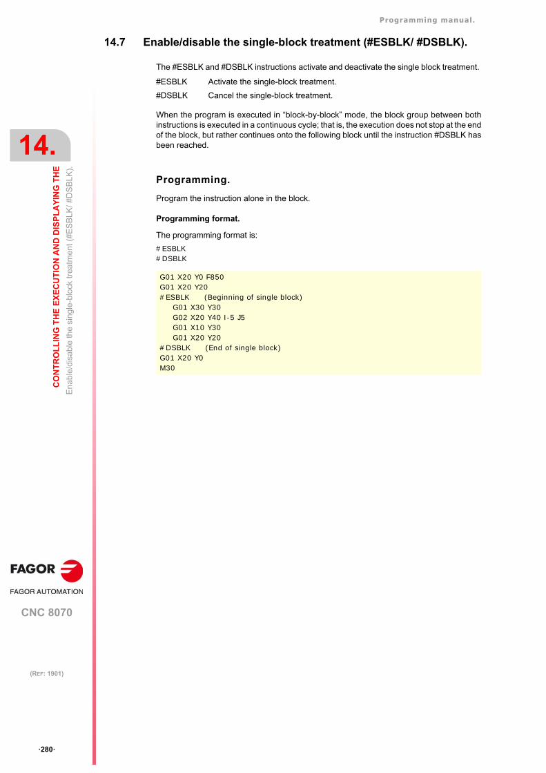
Programming manual.
CNC 8070
14.
CO
NT
RO
LL
ING
TH
E E
XE
CU
TIO
N A
ND
DIS
PL
AY
ING
TH
E
En
able
/dis
able
the
sing
le-b
lock
tre
atm
ent (
#ES
BLK
/ #D
SB
LK).
·280·
(REF: 1901)
14.7 Enable/disable the single-block treatment (#ESBLK/ #DSBLK).
The #ESBLK and #DSBLK instructions activate and deactivate the single block treatment.
When the program is executed in “block-by-block” mode, the block group between bothinstructions is executed in a continuous cycle; that is, the execution does not stop at the endof the block, but rather continues onto the following block until the instruction #DSBLK hasbeen reached.
Programming.
Program the instruction alone in the block.
Programming format.
The programming format is:
#ESBLK#DSBLK
#ESBLK Activate the single-block treatment.
#DSBLK Cancel the single-block treatment.
G01 X20 Y0 F850G01 X20 Y20#ESBLK (Beginning of single block)
G01 X30 Y30G02 X20 Y40 I-5 J5G01 X10 Y30G01 X20 Y20
#DSBLK (End of single block)G01 X20 Y0M30
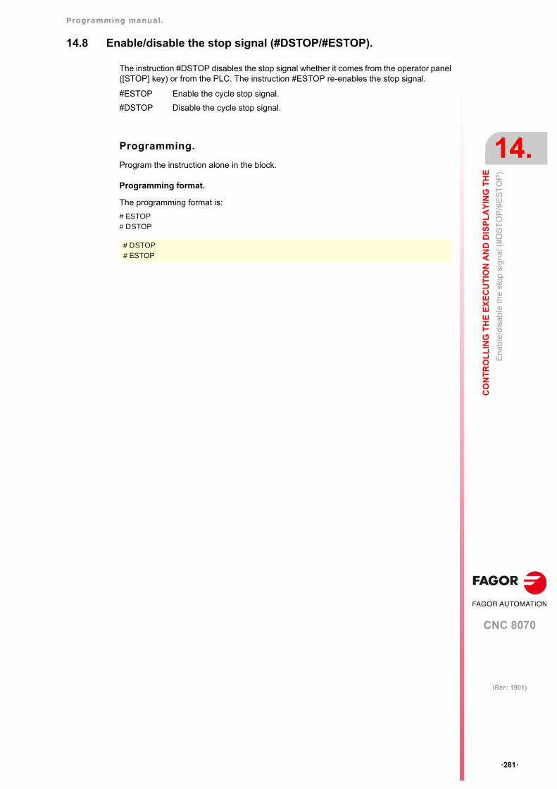
Programming manual.
CNC 8070
CO
NT
RO
LL
ING
TH
E E
XE
CU
TIO
N A
ND
DIS
PL
AY
ING
TH
E
14.
Ena
ble/
disa
ble
the
stop
sig
nal (
#DS
TO
P/#
ES
TO
P).
·281·
(REF: 1901)
14.8 Enable/disable the stop signal (#DSTOP/#ESTOP).
The instruction #DSTOP disables the stop signal whether it comes from the operator panel([STOP] key) or from the PLC. The instruction #ESTOP re-enables the stop signal.
Programming.
Program the instruction alone in the block.
Programming format.
The programming format is:
#ESTOP#DSTOP
#ESTOP Enable the cycle stop signal.
#DSTOP Disable the cycle stop signal.
#DSTOP#ESTOP
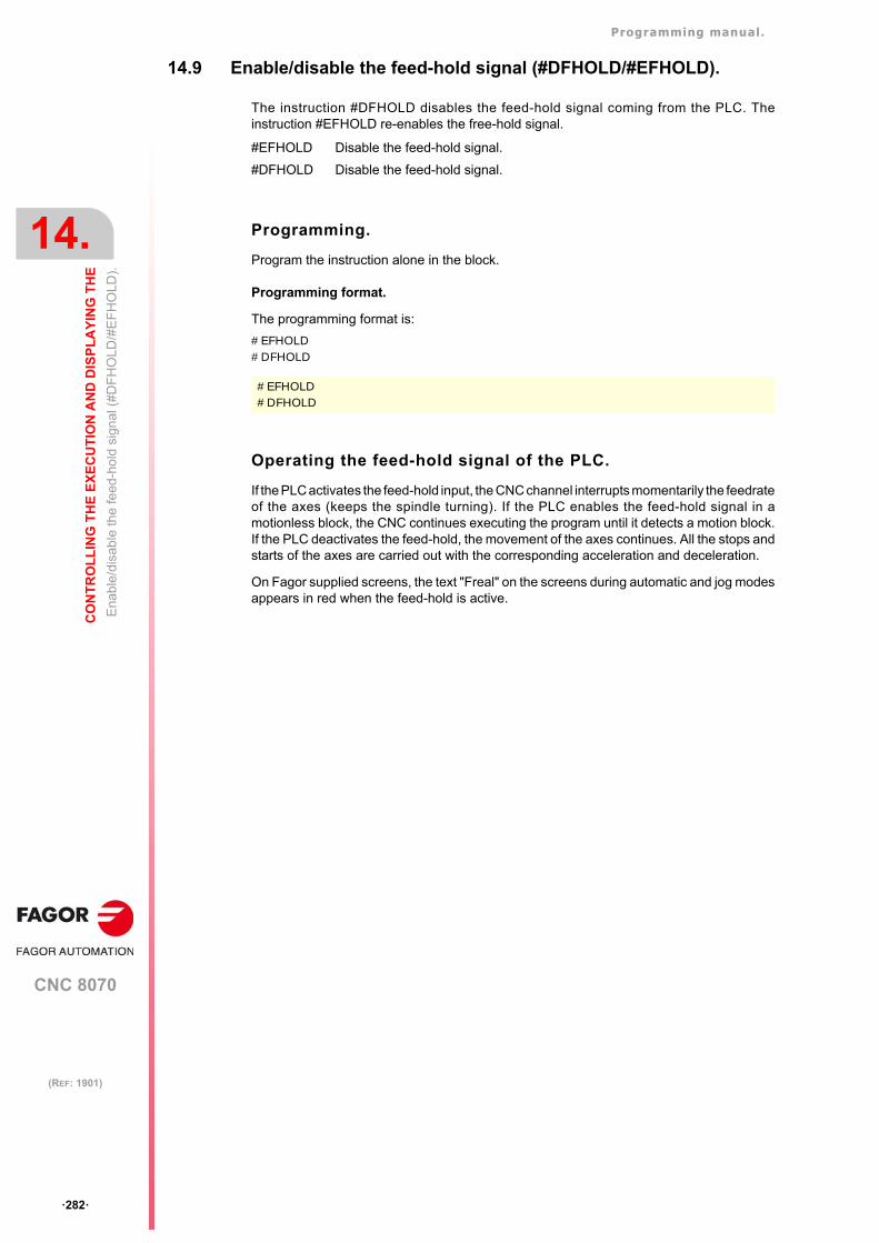
Programming manual.
CNC 8070
14.
CO
NT
RO
LL
ING
TH
E E
XE
CU
TIO
N A
ND
DIS
PL
AY
ING
TH
E
Ena
ble/
disa
ble
the
feed
-ho
ld s
ign
al (
#DF
HO
LD
/#E
FH
OLD
).
·282·
(REF: 1901)
14.9 Enable/disable the feed-hold signal (#DFHOLD/#EFHOLD).
The instruction #DFHOLD disables the feed-hold signal coming from the PLC. Theinstruction #EFHOLD re-enables the free-hold signal.
Programming.
Program the instruction alone in the block.
Programming format.
The programming format is:
#EFHOLD#DFHOLD
Operating the feed-hold signal of the PLC.
If the PLC activates the feed-hold input, the CNC channel interrupts momentarily the feedrateof the axes (keeps the spindle turning). If the PLC enables the feed-hold signal in amotionless block, the CNC continues executing the program until it detects a motion block.If the PLC deactivates the feed-hold, the movement of the axes continues. All the stops andstarts of the axes are carried out with the corresponding acceleration and deceleration.
On Fagor supplied screens, the text "Freal" on the screens during automatic and jog modesappears in red when the feed-hold is active.
#EFHOLD Disable the feed-hold signal.
#DFHOLD Disable the feed-hold signal.
#EFHOLD#DFHOLD
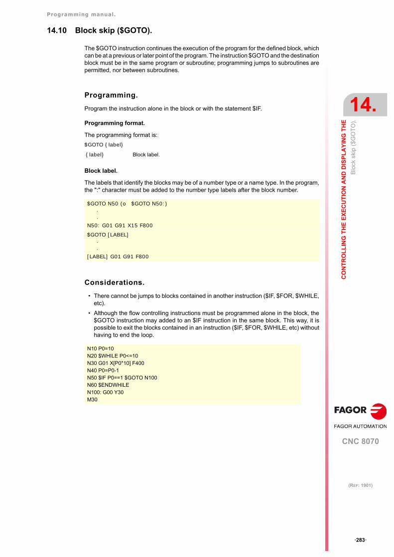
Programming manual.
CNC 8070
CO
NT
RO
LL
ING
TH
E E
XE
CU
TIO
N A
ND
DIS
PL
AY
ING
TH
E
14.
Blo
ck s
kip
($G
OT
O).
·283·
(REF: 1901)
14.10 Block skip ($GOTO).
The $GOTO instruction continues the execution of the program for the defined block, whichcan be at a previous or later point of the program. The instruction $GOTO and the destinationblock must be in the same program or subroutine; programming jumps to subroutines arepermitted, nor between subroutines.
Programming.
Program the instruction alone in the block or with the statement $IF.
Programming format.
The programming format is:
$GOTO {label}
Block label.
The labels that identify the blocks may be of a number type or a name type. In the program,the ":" character must be added to the number type labels after the block number.
Considerations.
• There cannot be jumps to blocks contained in another instruction ($IF, $FOR, $WHILE,etc).
• Although the flow controlling instructions must be programmed alone in the block, the$GOTO instruction may added to an $IF instruction in the same block. This way, it ispossible to exit the blocks contained in an instruction ($IF, $FOR, $WHILE, etc) withouthaving to end the loop.
{label} Block label.
$GOTO N50 (o $GOTO N50:)··
N50: G01 G91 X15 F800
$GOTO [LABEL]··
[LABEL] G01 G91 F800
N10 P0=10N20 $WHILE P0<=10N30 G01 X[P0*10] F400N40 P0=P0-1N50 $IF P0==1 $GOTO N100N60 $ENDWHILEN100: G00 Y30M30
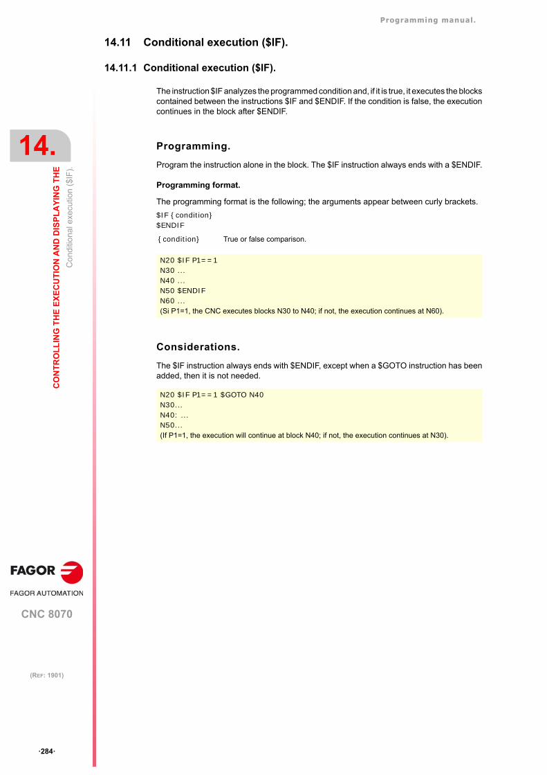
Programming manual.
CNC 8070
14.
CO
NT
RO
LL
ING
TH
E E
XE
CU
TIO
N A
ND
DIS
PL
AY
ING
TH
E
Co
nditi
ona
l exe
cutio
n ($
IF).
·284·
(REF: 1901)
14.11 Conditional execution ($IF).
14.11.1 Conditional execution ($IF).
The instruction $IF analyzes the programmed condition and, if it is true, it executes the blockscontained between the instructions $IF and $ENDIF. If the condition is false, the executioncontinues in the block after $ENDIF.
Programming.
Program the instruction alone in the block. The $IF instruction always ends with a $ENDIF.
Programming format.
The programming format is the following; the arguments appear between curly brackets.
$IF {condition} $ENDIF
Considerations.
The $IF instruction always ends with $ENDIF, except when a $GOTO instruction has beenadded, then it is not needed.
{condition} True or false comparison.
N20 $IF P1==1N30 ...N40 ...N50 $ENDIFN60 ...(Si P1=1, the CNC executes blocks N30 to N40; if not, the execution continues at N60).
N20 $IF P1==1 $GOTO N40N30...N40: ...N50...(If P1=1, the execution will continue at block N40; if not, the execution continues at N30).
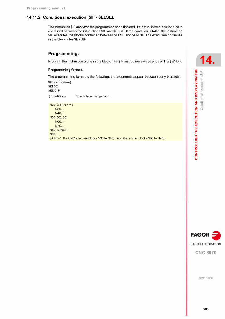
Programming manual.
CNC 8070
CO
NT
RO
LL
ING
TH
E E
XE
CU
TIO
N A
ND
DIS
PL
AY
ING
TH
E
14.
Co
nditi
ona
l exe
cutio
n ($
IF).
·285·
(REF: 1901)
14.11.2 Conditional execution ($IF - $ELSE).
The instruction $IF analyzes the programmed condition and, if it is true, it executes the blockscontained between the instructions $IF and $ELSE. If the condition is false, the instruction$IF executes the blocks contained between $ELSE and $ENDIF. The execution continuesin the block after $ENDIF.
Programming.
Program the instruction alone in the block. The $IF instruction always ends with a $ENDIF.
Programming format.
The programming format is the following; the arguments appear between curly brackets.
$IF {condition}$ELSE$ENDIF
{condition} True or false comparison.
N20 $IF P1==1N30...N40...
N50 $ELSEN60...N70...
N80 $ENDIFN90 ...(Si P1=1, the CNC executes blocks N30 to N40; if not, it executes blocks N60 to N70).
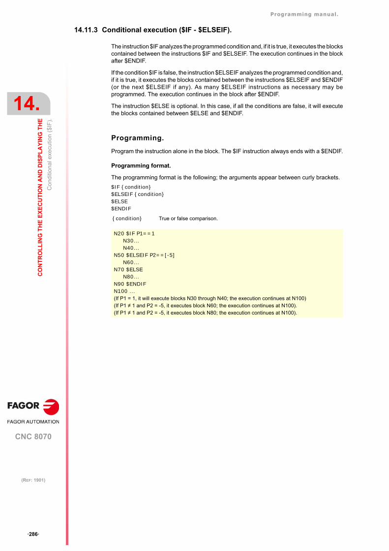
Programming manual.
CNC 8070
14.
CO
NT
RO
LL
ING
TH
E E
XE
CU
TIO
N A
ND
DIS
PL
AY
ING
TH
E
Co
nditi
ona
l exe
cutio
n ($
IF).
·286·
(REF: 1901)
14.11.3 Conditional execution ($IF - $ELSEIF).
The instruction $IF analyzes the programmed condition and, if it is true, it executes the blockscontained between the instructions $IF and $ELSEIF. The execution continues in the blockafter $ENDIF.
If the condition $IF is false, the instruction $ELSEIF analyzes the programmed condition and,if it is true, it executes the blocks contained between the instructions $ELSEIF and $ENDIF(or the next $ELSEIF if any). As many $ELSEIF instructions as necessary may beprogrammed. The execution continues in the block after $ENDIF.
The instruction $ELSE is optional. In this case, if all the conditions are false, it will executethe blocks contained between $ELSE and $ENDIF.
Programming.
Program the instruction alone in the block. The $IF instruction always ends with a $ENDIF.
Programming format.
The programming format is the following; the arguments appear between curly brackets.
$IF {condition}$ELSEIF {condition}$ELSE$ENDIF
{condition} True or false comparison.
N20 $IF P1==1N30...N40...
N50 $ELSEIF P2==[-5]N60...
N70 $ELSEN80...
N90 $ENDIFN100 ...(If P1 = 1, it will execute blocks N30 through N40; the execution continues at N100)(If P1 ≠ 1 and P2 = -5, it executes block N60; the execution continues at N100).(If P1 ≠ 1 and P2 = -5, it executes block N80; the execution continues at N100).
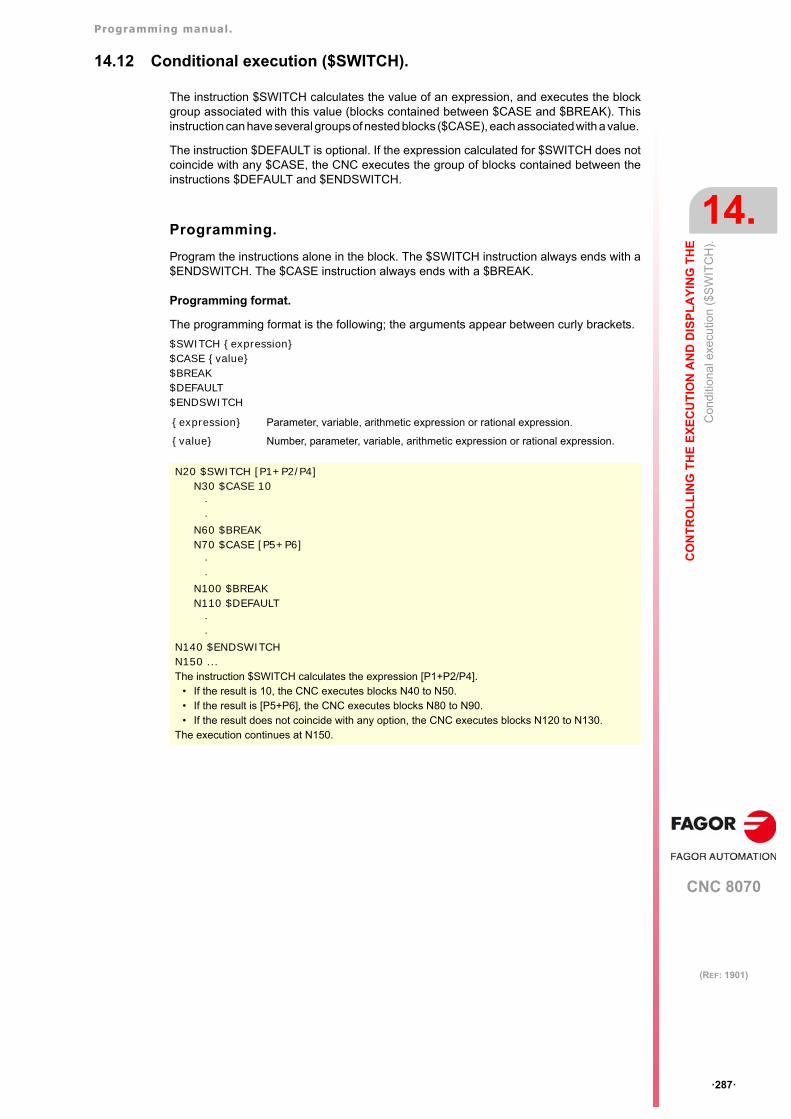
Programming manual.
CNC 8070
CO
NT
RO
LL
ING
TH
E E
XE
CU
TIO
N A
ND
DIS
PL
AY
ING
TH
E
14.
Con
diti
ona
l exe
cutio
n (
$SW
ITC
H).
·287·
(REF: 1901)
14.12 Conditional execution ($SWITCH).
The instruction $SWITCH calculates the value of an expression, and executes the blockgroup associated with this value (blocks contained between $CASE and $BREAK). Thisinstruction can have several groups of nested blocks ($CASE), each associated with a value.
The instruction $DEFAULT is optional. If the expression calculated for $SWITCH does notcoincide with any $CASE, the CNC executes the group of blocks contained between theinstructions $DEFAULT and $ENDSWITCH.
Programming.
Program the instructions alone in the block. The $SWITCH instruction always ends with a$ENDSWITCH. The $CASE instruction always ends with a $BREAK.
Programming format.
The programming format is the following; the arguments appear between curly brackets.
$SWITCH {expression}$CASE {value}$BREAK$DEFAULT$ENDSWITCH
{expression} Parameter, variable, arithmetic expression or rational expression.
{value} Number, parameter, variable, arithmetic expression or rational expression.
N20 $SWITCH [P1+P2/P4]N30 $CASE 10
··
N60 $BREAKN70 $CASE [P5+P6]
··
N100 $BREAKN110 $DEFAULT
··
N140 $ENDSWITCHN150 ...The instruction $SWITCH calculates the expression [P1+P2/P4].
• If the result is 10, the CNC executes blocks N40 to N50. • If the result is [P5+P6], the CNC executes blocks N80 to N90.• If the result does not coincide with any option, the CNC executes blocks N120 to N130.
The execution continues at N150.
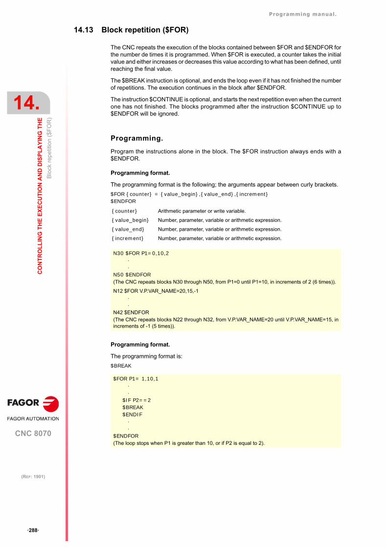
Programming manual.
CNC 8070
14.
CO
NT
RO
LL
ING
TH
E E
XE
CU
TIO
N A
ND
DIS
PL
AY
ING
TH
E
Blo
ck r
epe
titio
n ($
FO
R)
·288·
(REF: 1901)
14.13 Block repetition ($FOR)
The CNC repeats the execution of the blocks contained between $FOR and $ENDFOR forthe number de times it is programmed. When $FOR is executed, a counter takes the initialvalue and either increases or decreases this value according to what has been defined, untilreaching the final value.
The $BREAK instruction is optional, and ends the loop even if it has not finished the numberof repetitions. The execution continues in the block after $ENDFOR.
The instruction $CONTINUE is optional, and starts the next repetition even when the currentone has not finished. The blocks programmed after the instruction $CONTINUE up to$ENDFOR will be ignored.
Programming.
Program the instructions alone in the block. The $FOR instruction always ends with a$ENDFOR.
Programming format.
The programming format is the following; the arguments appear between curly brackets.
$FOR {counter} = {value_begin},{value_end},{increment}$ENDFOR
Programming format.
The programming format is:
$BREAK
{counter} Arithmetic parameter or write variable.
{value_begin} Number, parameter, variable or arithmetic expression.
{value_end} Number, parameter, variable or arithmetic expression.
{increment} Number, parameter, variable or arithmetic expression.
N30 $FOR P1=0,10,2··
N50 $ENDFOR(The CNC repeats blocks N30 through N50, from P1=0 until P1=10, in increments of 2 (6 times)).
N12 $FOR V.P.VAR_NAME=20,15,-1··
N42 $ENDFOR(The CNC repeats blocks N22 through N32, from V.P.VAR_NAME=20 until V.P.VAR_NAME=15, inincrements of -1 (5 times)).
$FOR P1= 1,10,1··
$IF P2==2$BREAK$ENDIF
··
$ENDFOR(The loop stops when P1 is greater than 10, or if P2 is equal to 2).
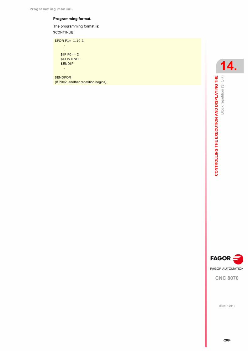
Programming manual.
CNC 8070
CO
NT
RO
LL
ING
TH
E E
XE
CU
TIO
N A
ND
DIS
PL
AY
ING
TH
E
14.
Blo
ck r
epe
titio
n ($
FO
R)
·289·
(REF: 1901)
Programming format.
The programming format is:
$CONTINUE
$FOR P1= 1,10,1··
$IF P0==2$CONTINUE$ENDIF
··
$ENDFOR(If P0=2, another repetition begins).
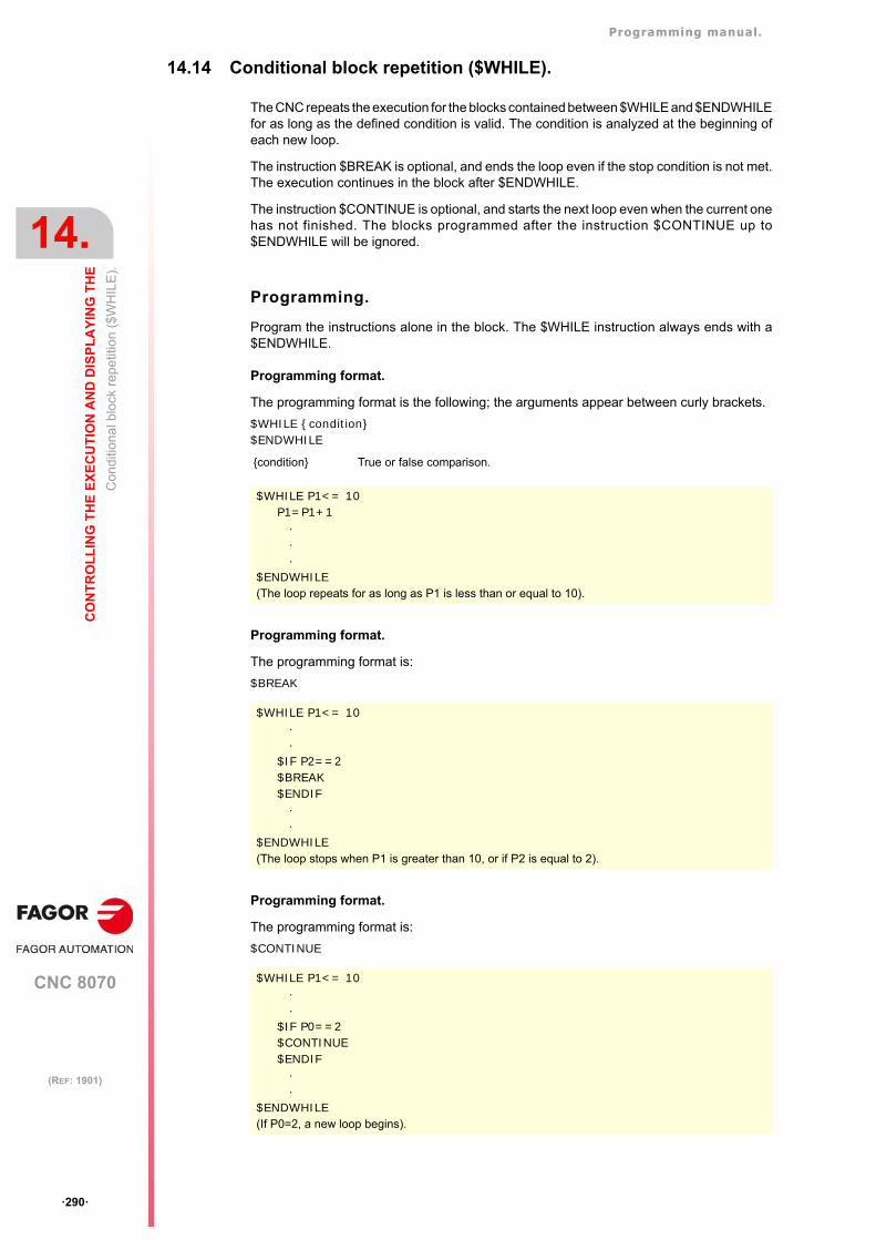
Programming manual.
CNC 8070
14.
CO
NT
RO
LL
ING
TH
E E
XE
CU
TIO
N A
ND
DIS
PL
AY
ING
TH
E
Con
diti
ona
l blo
ck r
epe
titio
n ($
WH
ILE
).
·290·
(REF: 1901)
14.14 Conditional block repetition ($WHILE).
The CNC repeats the execution for the blocks contained between $WHILE and $ENDWHILEfor as long as the defined condition is valid. The condition is analyzed at the beginning ofeach new loop.
The instruction $BREAK is optional, and ends the loop even if the stop condition is not met.The execution continues in the block after $ENDWHILE.
The instruction $CONTINUE is optional, and starts the next loop even when the current onehas not finished. The blocks programmed after the instruction $CONTINUE up to$ENDWHILE will be ignored.
Programming.
Program the instructions alone in the block. The $WHILE instruction always ends with a$ENDWHILE.
Programming format.
The programming format is the following; the arguments appear between curly brackets.
$WHILE {condition}$ENDWHILE
Programming format.
The programming format is:
$BREAK
Programming format.
The programming format is:
$CONTINUE
{condition} True or false comparison.
$WHILE P1<= 10P1=P1+1
···
$ENDWHILE(The loop repeats for as long as P1 is less than or equal to 10).
$WHILE P1<= 10··
$IF P2==2$BREAK$ENDIF
··
$ENDWHILE(The loop stops when P1 is greater than 10, or if P2 is equal to 2).
$WHILE P1<= 10··
$IF P0==2$CONTINUE$ENDIF
··
$ENDWHILE(If P0=2, a new loop begins).
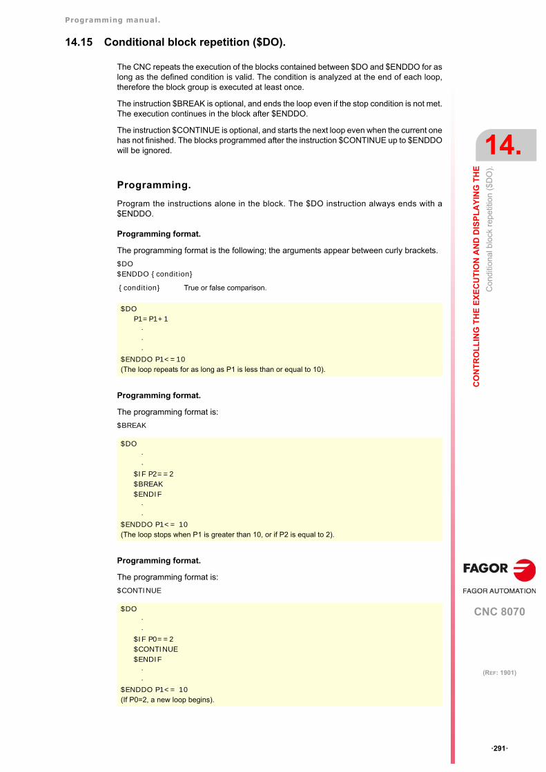
Programming manual.
CNC 8070
CO
NT
RO
LL
ING
TH
E E
XE
CU
TIO
N A
ND
DIS
PL
AY
ING
TH
E
14.
Con
ditio
nal b
lock
rep
etiti
on (
$D
O).
·291·
(REF: 1901)
14.15 Conditional block repetition ($DO).
The CNC repeats the execution of the blocks contained between $DO and $ENDDO for aslong as the defined condition is valid. The condition is analyzed at the end of each loop,therefore the block group is executed at least once.
The instruction $BREAK is optional, and ends the loop even if the stop condition is not met.The execution continues in the block after $ENDDO.
The instruction $CONTINUE is optional, and starts the next loop even when the current onehas not finished. The blocks programmed after the instruction $CONTINUE up to $ENDDOwill be ignored.
Programming.
Program the instructions alone in the block. The $DO instruction always ends with a$ENDDO.
Programming format.
The programming format is the following; the arguments appear between curly brackets.
$DO $ENDDO {condition}
Programming format.
The programming format is:
$BREAK
Programming format.
The programming format is:
$CONTINUE
{condition} True or false comparison.
$DOP1=P1+1
···
$ENDDO P1<=10(The loop repeats for as long as P1 is less than or equal to 10).
$DO··
$IF P2==2$BREAK$ENDIF
··
$ENDDO P1<= 10(The loop stops when P1 is greater than 10, or if P2 is equal to 2).
$DO ··
$IF P0==2$CONTINUE$ENDIF
··
$ENDDO P1<= 10(If P0=2, a new loop begins).
Programming manual.
CNC 8070
14.
CO
NT
RO
LL
ING
TH
E E
XE
CU
TIO
N A
ND
DIS
PL
AY
ING
TH
E
Con
ditio
nal b
lock
rep
etiti
on (
$D
O).
·292·
(REF: 1901)
CNC 8070
15
·293·
(REF: 1901)
15.SUBROUTINES.
A subroutine is a set of blocks that, once properly identified, may be called upon several timesfrom another subroutine or from the program. Subroutines are normally used for defining abunch of operations or movements that are repeated several times throughout the program.The CNC allows up to a total of seven subroutines to be executed per block (G180, G380,G500, functions M with subroutine, etc.).
Types of subroutines.
The CNC has two types of subroutines, namely local and global. There is also a third typeavailable, OEM subroutines, that are a special case of a global subroutine defined by theOEM. See "15.5 OEM subroutine execution." on page 306.
Global subroutines.
The global subroutine is stored in CNC memory as an independent program. This subroutinemay be called upon from any program or subroutine being executed.
Local subroutines.
The local subroutine is defined as part of a program. This subroutine may only be called uponfrom the program where it has been defined.
A program can have several local subroutines; but they all must be defined before the bodyof the program. A local subroutine can call a second local subroutine with the condition thatthe calling subroutine be defined after the one being called.
Subroutine nesting levels and parameters.
Since a subroutine may be called upon from the main program (or a subroutine) and anothersubroutine from this one and so on. The CNC limits the number of these calls to a maximumof 20 nesting levels.
Arithmetic parameters in the subroutines
Local parameters.
The CNC has global parameters (accessible from the program or any subroutine) and localparameters (accessible only from the program or subroutine where they have beenprogrammed).
Local parameters may be assigned to more than one subroutine up to 7 parameter nestinglevels within the 20 subroutine nesting levels. Not all the subroutine call types change thenesting level; only the #PCALL, #MCALL calls and functions G180 to G189 and G380 toG399.
Global parameters.
Global parameters will be shared by the program and the subroutines of the channel. Theymay be used in any block of the program and of the subroutine regardless of the nesting levelthey may be at.
Programming manual.
CNC 8070
15.
SU
BR
OU
TIN
ES
.
·294·
(REF: 1901)
Common parameters.
Common parameters will be shared by the program and the subroutines of any channel.They may be used in any block of the program and of the subroutine regardless of the nestinglevel they may be at.
Programming manual.
CNC 8070
SU
BR
OU
TIN
ES
.
15.
Exe
cutin
g su
brou
tines
from
RA
M m
emor
y.
·295·
(REF: 1901)
15.1 Executing subroutines from RAM memory.
If the same subroutines are executed repeatedly during execution, it is more efficient to loadthem into the RAM memory of the CNC because this way, they may be accessed faster andexecution time may be consequently optimized. This option is valid for OEM as well as foruser subroutines. To load a subroutine into RAM, it must have the extension fst. The reservedRAM space for subroutines is 5 Mb.
fst user subroutines.
Subroutines with the fst extension that are not saved in the folder..\MTB\Sub. User routineshaving a fst extension are loaded into RAM memory during block preparation. The CNCchecks whether or not it is loaded into RAM memory; if it is not and there is room for it, itloads it.
At the end of the program (M02/M30) or after a reset, if no other channel is executingsubroutines, the CNC deletes them from its RAM memory. This way, if a user subroutinehaving a fst extension is edited or modified, the CNC assumes the changes the next timeit executes it.
OEM (manufacturer's) subroutines.
Subroutines with the fst extension saved in the folder..\MTB\Sub.
• Being the CNC in USER mode, the OEM routines having a fst extension are loaded intoRAM memory when starting up the CNC application.
When the OEM is debugging his subroutines, they must have another extension so thechanges are assumed without having to restart the application. Once they are debugged,the OEM must change the extension of the subroutines to fst so they are loaded into RAMmemory.
• Being the CNC in SETUP mode, the OEM subroutines with an fst extension will be loadedinto RAM memory during the preparation of the blocks. The CNC checks whether or notit is loaded into RAM memory; if it is not and there is room for it, it loads it. At the endof the program (M02/M30) or after a reset, if no other channel is executing subroutines,the CNC deletes them from its RAM memory. This way, the changes made in thesubroutine will be taken into account the next time the program is executed.
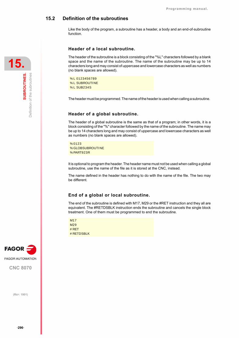
Programming manual.
CNC 8070
15.
SU
BR
OU
TIN
ES
.
De
finiti
on o
f th
e su
brou
tines
·296·
(REF: 1901)
15.2 Definition of the subroutines
Like the body of the program, a subroutine has a header, a body and an end-of-subroutinefunction.
Header of a local subroutine.
The header of the subroutine is a block consisting of the "%L" characters followed by a blankspace and the name of the subroutine. The name of the subroutine may be up to 14characters long and may consist of uppercase and lowercase characters as well as numbers(no blank spaces are allowed).
The header must be programmed. The name of the header is used when calling a subroutine.
Header of a global subroutine.
The header of a global subroutine is the same as that of a program; in other words, it is ablock consisting of the "%" character followed by the name of the subroutine. The name maybe up to 14 characters long and may consist of uppercase and lowercase characters as wellas numbers (no blank spaces are allowed).
It is optional to program the header. The header name must not be used when calling a globalsubroutine, use the name of the file as it is stored at the CNC, instead.
The name defined in the header has nothing to do with the name of the file. The two maybe different.
End of a global or local subroutine.
The end of the subroutine is defined with M17, M29 or the #RET instruction and they all areequivalent. The #RETDSBLK instruction ends the subroutine and cancels the single blocktreatment. One of them must be programmed to end the subroutine.
%L 0123456789%L SUBROUTINE%L SUB234S
%0123%GLOBSUBROUTINE%PART923R
M17M29#RET#RETDSBLK
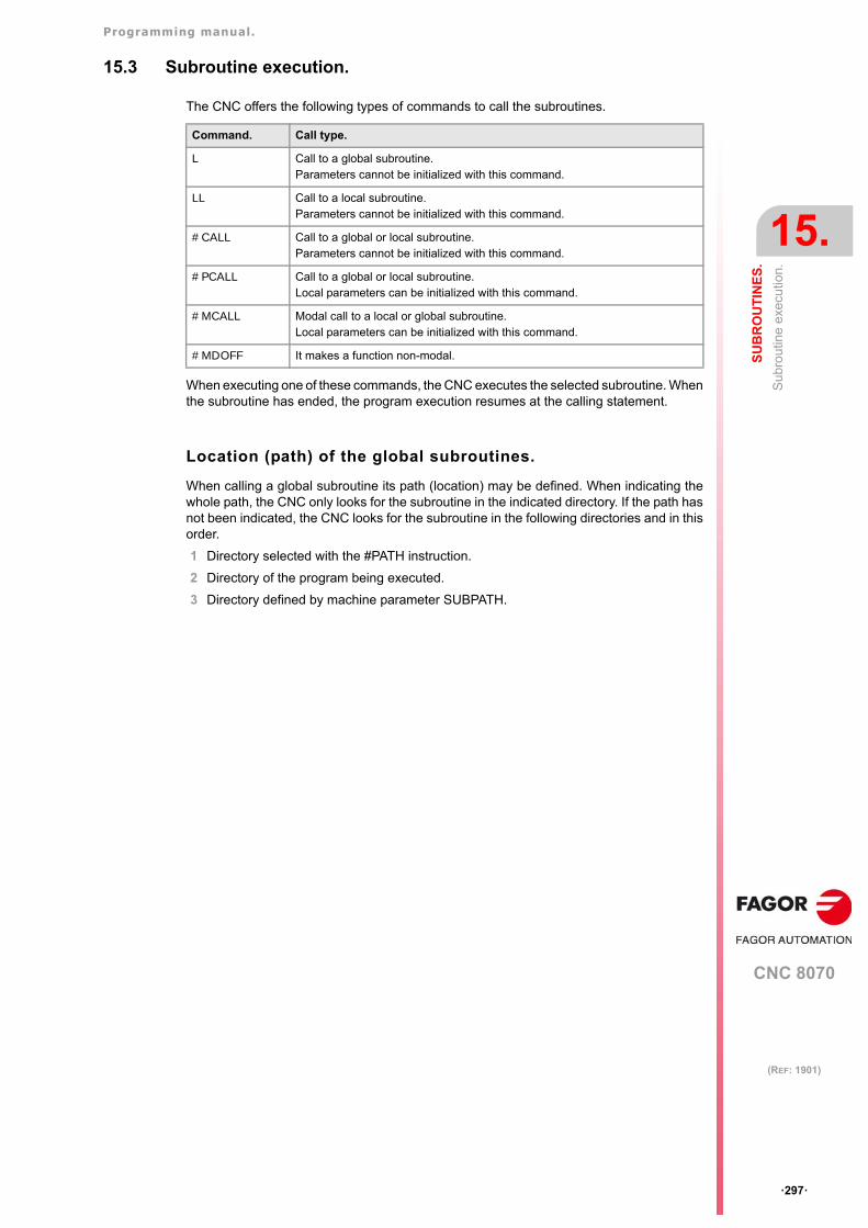
Programming manual.
CNC 8070
SU
BR
OU
TIN
ES
.
15.
Sub
rout
ine
exec
utio
n.
·297·
(REF: 1901)
15.3 Subroutine execution.
The CNC offers the following types of commands to call the subroutines.
When executing one of these commands, the CNC executes the selected subroutine. Whenthe subroutine has ended, the program execution resumes at the calling statement.
Location (path) of the global subroutines.
When calling a global subroutine its path (location) may be defined. When indicating thewhole path, the CNC only looks for the subroutine in the indicated directory. If the path hasnot been indicated, the CNC looks for the subroutine in the following directories and in thisorder.
1 Directory selected with the #PATH instruction.
2 Directory of the program being executed.
3 Directory defined by machine parameter SUBPATH.
Command. Call type.
L Call to a global subroutine.Parameters cannot be initialized with this command.
LL Call to a local subroutine.Parameters cannot be initialized with this command.
#CALL Call to a global or local subroutine.Parameters cannot be initialized with this command.
#PCALL Call to a global or local subroutine.Local parameters can be initialized with this command.
#MCALL Modal call to a local or global subroutine.Local parameters can be initialized with this command.
#MDOFF It makes a function non-modal.
Programming manual.
CNC 8070
15.
SU
BR
OU
TIN
ES
.
Sub
rout
ine
exec
utio
n.
·298·
(REF: 1901)
15.3.1 LL. Call to a local subroutine.
The command LL calls a local subroutine. This type of call allows initializing local parametersof the subroutine.
Programming format.
The programming format is:
LL sub
15.3.2 L. Call to a global subroutine.
The command L calls a global subroutine. This type of call allows initializing local parametersof the subroutine. When it is a global subroutine, its whole path may be defined.
Programming format.
The programming format is:
L <path> sub
sub Name of the subroutine
LL sub2.nc
path Optional. Subroutine location.
sub Name of the subroutine
L C:\Cnc8070\Users\Prg\sub1.ncL C:\Cnc8070\Users\sub2.ncL Sub3.nc
Programming manual.
CNC 8070
SU
BR
OU
TIN
ES
.
15.
Sub
rout
ine
exec
utio
n.
·299·
(REF: 1901)
15.3.3 #CALL. Call to a global or local subroutine.
The #CALL instruction calls a local or global subroutine. This type of call allows initializinglocal parameters of the subroutine. When it is a global subroutine, its whole path may bedefined.
When there are two subroutines, one local and the other one global, with the same name,the following criteria is applied. If the path has been defined in the call, the CNC will executethe global subroutine, otherwise, it will execute the local one.
Programming format.
The programming format is:
#CALL <path> sub
Path definition.
Defining the path is optional. If defined, the CNC only looks for the subroutine in that folder;if not defined, the CNC looks for the subroutine in the default folders. See "Location (path)of the global subroutines." on page 297.
path Optional. Subroutine location.
sub Name of the subroutine
#CALL C:\Cnc8070\Users\Prg\sub1.nc#CALL C:\Cnc8070\Users\sub2.nc#CALL Sub3.nc
Programming manual.
CNC 8070
15.
SU
BR
OU
TIN
ES
.
Sub
rout
ine
exec
utio
n.
·300·
(REF: 1901)
15.3.4 #PCALL. Call to a global or local subroutine initializing parameters.
The #PCALL instruction calls a local or global subroutine. This type of call allows initializinglocal parameters of the subroutine. When it is a global subroutine, its whole path may bedefined.
When there are two subroutines, one local and the other one global, with the same name,the following criteria is applied. If the path has been defined in the call, the CNC will executethe global subroutine, otherwise, it will execute the local one.
Programming format.
The programming format is:
#PCALL <path> sub <P0..Pn>
How to set local parameters.
Calling a subroutine allows for the 57 local parameters (P0 to P57) to be initializes. Thevalues of the parameters must be defined following the call statement and may be definedin two ways. Both ways of setting local parameters are equivalent and may be combined inthe same block.
• The parameters P0 to P25 can also be defined using the letters from A to Z, so that "A"is equal to P0, "B" to P1 and so forth and where "Z" is equal to P25.
• The parameters P26 to P52 can also be defined using the letters from "D0= " a "D31=",so that "D0=" is equal to P26, "D1=" to P27 and so forth and where "D31=" is equal to P57.
Path definition.
Defining the path is optional. If defined, the CNC only looks for the subroutine in that folder;if not defined, the CNC looks for the subroutine in the default folders. See "Location (path)of the global subroutines." on page 297.
Local parameter nesting levels.
If local parameters are initialized in the #PCALL instruction, this instruction generates a newnesting level for the local parameters. Remember that up to 7 parameter nesting levels arepossible within 20 subroutine nesting levels.
path Optional. Subroutine location.
sub Name of the subroutine
P0..Pn Optional. Initializing parameters.
#PCALL C:\Cnc8070\Users\Prg\sub1.nc#PCALL C:\Cnc8070\Users\sub2.nc A12.3 P10=6#PCALL Sub3.nc A12.3 F45.3 P10=6
Programming example.#PCALL subroutine.nc A12.3 F45.3 P10=6 D0=34.12 D1=5 P28=0
Programming manual.
CNC 8070
SU
BR
OU
TIN
ES
.
15.
Sub
rout
ine
exec
utio
n.
·301·
(REF: 1901)
15.3.5 #MCALL. Modal call to a local or global subroutine.
The #MCALL instruction calls a local or global subroutine. This type of call allows initializinglocal parameters of the subroutine. When it is a global subroutine, its whole path may bedefined.
When there are two subroutines, one local and the other one global, with the same name,the following criteria is applied. If the path has been defined in the call, the CNC will executethe global subroutine, otherwise, it will execute the local one.
With this type of call, the subroutine becomes modal; i.e. the subroutine remains active insuccessive movements and it is repeated at the end of each move. See "Considerationsabout the modal character of the subroutine." on page 302.
Programming format.
The programming format is:
#MCALL <path> sub <P0..Pn>
How to set local parameters.
Calling a subroutine allows for the 57 local parameters (P0 to P57) to be initializes. Thevalues of the parameters must be defined following the call statement and may be definedin two ways. Both ways of setting local parameters are equivalent and may be combined inthe same block.
• The parameters P0 to P25 can also be defined using the letters from A to Z, so that "A"is equal to P0, "B" to P1 and so forth and where "Z" is equal to P25.
• The parameters P26 to P52 can also be defined using the letters from "D0= " a "D31=",so that "D0=" is equal to P26, "D1=" to P27 and so forth and where "D31=" is equal to P57.
Path definition.
Defining the path is optional. If defined, the CNC only looks for the subroutine in that folder;if not defined, the CNC looks for the subroutine in the default folders. See "Location (path)of the global subroutines." on page 297.
Turning the subroutine into non-modal.
A subroutine stops being modal with the instruction #MDOFF and in the following cases: See"15.4 #PATH. Define the location of the global subroutines." on page 305.
• After executing an M02 or an M30 and after a RESET.
• When changing the work plane.
• When programming a probing move (G100).
• When changing the configuration of the axes (#FREE AX, #CALL AX and #SET AX).
• When calling another subroutine (#PCALL, #CALL, L, LL, G180-G189).
• When activating a canned cycle.
path Optional. Subroutine location.
sub Name of the subroutine
P0..Pn Optional. Initializing parameters.
#MCALL C:\Cnc8070\Users\Prg\sub1.nc#MCALL C:\Cnc8070\Users\sub2.nc A12.3 P10=6#MCALL Sub3.nc A12.3 F45.3 P10=6
Programming example.#MCALL subroutine.nc A12.3 F45.3 P10=6 D0=34.12 D1=5 P28=0
Programming manual.
CNC 8070
15.
SU
BR
OU
TIN
ES
.
Sub
rout
ine
exec
utio
n.
·302·
(REF: 1901)
Local parameter nesting levels.
If local parameters are initialized in the #MCALL instruction, this instruction generates a newnesting level for the local parameters. Remember that up to 7 parameter nesting levels arepossible within 20 subroutine nesting levels.
Considerations about the modal character of the subroutine.
The modal subroutine will not be executed in the motion blocks programmed inside thesubroutine itself or in the subroutines associated with T or M6. It will not be executed either,when programming a number of block repetitions using a NR value of ·0·.
If a motion block contains a number of repetitions NR other than 0 while a modal subroutineis active, both the movement and the subroutine will be repeated NR times.
If, when a subroutine is selected as modal, a block containing the #MCALL mnemonic isexecuted, the present subroutine will lose its modal quality and the new subroutine selectedwill be changed to modal.
Programming manual.
CNC 8070
SU
BR
OU
TIN
ES
.
15.
Sub
rout
ine
exec
utio
n.
·303·
(REF: 1901)
15.3.6 #MDOFF. Turning the subroutine into non-modal.
The subroutine stops being modal with the instruction #MDOFF. .
Programming format.
The programming format is:
#MDOFF
#MDOFF
Programming manual.
CNC 8070
15.
SU
BR
OU
TIN
ES
.
Sub
rout
ine
exec
utio
n.
·304·
(REF: 1901)
15.3.7 #RETDSBLK. Execute subroutine as a single block.
The #RETDSBLK instruction ends the subroutine and cancels the single block treatment.
Programming format.
Program the instruction alone in the block and at the end of the subroutine.
#RETDSBLK
How to create the subroutine.
For a subroutine to be executed as a single block, it usually has the following structure.
%Sub.nc#ESBLK; Beginning of the single-block treatment.
··
#DSBLK; End of the single-block treatment.#RET; End of subroutine.
When executing this subroutine in single-block mode, the [START] key must be pressedtwice because the execution stops in the #RET block. To prevent this so the subroutine isexecuted with a single [START], the subroutine must begin with #ESBLK and end with#RETDSBLK.
%Sub.nc#ESBLK; Beginning of the single-block treatment.
··
#RETDSBLK; End of subroutine and end of the single-block treatment.
#RETDSBLK
Programming manual.
CNC 8070
SU
BR
OU
TIN
ES
.
15.
#PA
TH
. Def
ine
the
loca
tion
of th
e gl
obal
sub
rou
tines
.
·305·
(REF: 1901)
15.4 #PATH. Define the location of the global subroutines.
The instruction #PATH defines the pre-determined location of the global subroutines If nopath is defined in the global subroutine call, the CNC will look for the subroutine in the pathdefined using the instruction #PATH.
If the path is defined when calling a global subroutine, the CNC looks for the subroutine inthat location, it ignores the location defined in the #PATH statement.
Programming format.
The programming format is:
#PATH ["path"]
path Pre-determined subroutine location.
#PATH ["C:\Cnc8070\Users\Prg\"]#PATH ["C:\Cnc8070\Users\"]
Programming manual.
CNC 8070
15.
SU
BR
OU
TIN
ES
.
OE
M s
ubro
utin
e ex
ecu
tion.
·306·
(REF: 1901)
15.5 OEM subroutine execution.
The machine manufacturer may define up to 30 subroutines per channel and associate themwith functions G180 through G189 and G380 through G399 in such a way that when achannel executes one of these functions, it will execute the subroutine associated with thatfunction for that channel. These OEM subroutines may be executed either in a non-modalor modal way and it also allows resetting the local parameters of the subroutine.
Programming format.
These functions may be programmed anywhere in the program and they don't have to goalone in the block and allow resetting the local parameters of the subroutine.
Programming format. Executing the subroutine in a non-modal way.
The programming format is the following; the list of arguments appears inside the curlybrackets. To execute the subroutine in a non-modal way, call it using the G code (G180,G181,etc).
G180 G380 G180 {P0..Pn}G380 {P0..Pn}
Programming format. Executing the subroutine in a modal way.
The programming format is the following; the list of arguments appears inside the curlybrackets. To execute the subroutine in a modal way, call it using the MG code (MG180,MG181, etc).
MG180 MG380 MG180 {P0..Pn}MG380 {P0..Pn}
How to set local parameters.
Calling a subroutine allows for the 57 local parameters (P0 to P57) to be initializes. Thevalues of the parameters must be defined following the call statement and may be definedin two ways. Both ways of setting local parameters are equivalent and may be combined inthe same block.
• The parameters P0 to P25 can also be defined using the letters from A to Z, so that "A"is equal to P0, "B" to P1 and so forth and where "Z" is equal to P25.
• The parameters P26 to P52 can also be defined using the letters from "D0= " a "D31=",so that "D0=" is equal to P26, "D1=" to P27 and so forth and where "D31=" is equal to P57.
P0..Pn Optional. Local parameters of the subroutine.
G180G183 P1=12.3 P2=6G388 A12.3 B45.3 P10=6
P0..Pn Optional. Local parameters of the subroutine.
G180G183 P1=12.3 P2=6G388 A12.3 B45.3 P10=6
Programming example.G180 A12.3 F45.3 P10=6 D0=34.12 D1=5 P28=0
Programming manual.
CNC 8070
SU
BR
OU
TIN
ES
.
15.
OE
M s
ubro
utin
e ex
ecu
tion.
·307·
(REF: 1901)
Additional data in the block.
Besides initializing the parameters, any other type of additional information may be addedto these functions, even movements. This information must be programmed before thesubroutine calling function; otherwise, the data will considered as for initializing theparameters. The associated subroutine is executed once the execution of the rest of theinformation programmed in the block has ended.
Cancelling a modal subroutine.
A subroutine stops being modal and in the following cases.
• When programming G80 or #MDOFF.
• When changing the work plane.
• When programming a probing move (G100).
• When executing another subroutine (#PCALL, #CALL, #MCALL, L, LL, G180-G189,G380-G399).
• When executing a canned cycle.
• After executing an M02 or an M30 and after a RESET.
• When changing the configuration of the axes (#FREE AX, #CALL AX and #SET AX).
Local parameter nesting levels.
If these functions initialize local parameters, this instruction generates a new nesting levelfor the local parameters. Remember that up to 7 parameter nesting levels are possible within20 subroutine nesting levels.
Considerations about the modal character of the subroutine.
The modal subroutine will not be executed in the motion blocks programmed inside thesubroutine itself or in the subroutines associated with T or M6. It will not be executed either,when programming a number of block repetitions using a NR value of ·0·.
If a motion block contains a number of repetitions NR other than 0 while a modal subroutineis active, both the movement and the subroutine will be repeated NR times.
If while a subroutine is selected as modal, another modal OEM subroutine is executed, thecurrent subroutine will stop being modal and the new selected subroutine will become modal.
Properties of the function and Influence of the reset, turning theCNC off and of the M30 function.
Functions G180-G189 and G380-G399 are not modal. Functions MG180-MG189 andMG380-MG399 are modal.
G01 X50 F450 G180 P0=15 P1=20
It first executes the programmed movement to point X50 and then thesubroutine associated with G180 initializing parameters P0 and P1.
G180 P0=15 P1=20 G01 X50 F450
All the data is interpreted as parameter setting, where P6(G)=1, P23(X)=50 andP5(F)=450.
Programming manual.
CNC 8070
15.
SU
BR
OU
TIN
ES
.
Ge
neric
use
r su
brou
tines
(G
500-
G5
99).
·308·
(REF: 1901)
15.6 Generic user subroutines (G500-G599).
The CNC lets the uses define up to 100 subroutines, common to all channels and that willbe associated with functions G500 through G599, so when the CNC executes one of thesefunctions, it will execute its associated subroutine. These OEM subroutines may be executedeither in a non-modal or modal way and it also allows resetting the local parameters of thesubroutine.
These subroutines are loaded into RAM memory when they are executed for the first time.If there is no room in RAM, the CNC will issue a warning and it will execute the subroutinefrom the disk. At the end of the program (M30), if no other channel is executing subroutines,the CNC deletes them from its RAM memory. This way, if a user subroutine is edited ormodified, the CNC assumes the changes the next time it executes it.
When updating the version, only the subroutines supplied by Fagor will be updated whenchoosing the third installation level "rename previous version and install completely".
Programming format.
These functions may be programmed anywhere in the program and they don't have to goalone in the block and allow resetting the local parameters of the subroutine.
Programming format. Executing the subroutine in a non-modal way.
The programming format is the following; the list of arguments appears inside the curlybrackets. To execute the subroutine in a non-modal way, call it using the G code (G500,G501,etc).
G500 G500 {P0..Pn}
Programming format. Executing the subroutine in a modal way.
The programming format is the following; the list of arguments appears inside the curlybrackets. To execute the subroutine in a modal way, call it using the MG code (MG500,MG501, etc).
MG500 MG500 {P0..Pn}
How to set local parameters.
Calling a subroutine allows for the 57 local parameters (P0 to P57) to be initializes. Thevalues of the parameters must be defined following the call statement and may be definedin two ways. Both ways of setting local parameters are equivalent and may be combined inthe same block.
• The parameters P0 to P25 can also be defined using the letters from A to Z, so that "A"is equal to P0, "B" to P1 and so forth and where "Z" is equal to P25.
• The parameters P26 to P52 can also be defined using the letters from "D0= " a "D31=",so that "D0=" is equal to P26, "D1=" to P27 and so forth and where "D31=" is equal to P57.
P0..Pn Optional. Local parameters of the subroutine.
G500G583 P1=12.3 P2=6G588 A12.3 B45.3 P10=6
P0..Pn Optional. Local parameters of the subroutine.
G500G583 P1=12.3 P2=6G588 A12.3 B45.3 P10=6
Programming example.G588 P0=12.3 P5=45.3 K6 P26=34.12 P27=5 D2=0
Programming manual.
CNC 8070
SU
BR
OU
TIN
ES
.
15.
Ge
neric
use
r su
brou
tines
(G
500-
G5
99).
·309·
(REF: 1901)
Additional data in the block.
Besides initializing the parameters, any other type of additional information may be addedto these functions, even movements. This information must be programmed before thesubroutine calling function; otherwise, the data will considered as for initializing theparameters. The associated subroutine is executed once the execution of the rest of theinformation programmed in the block has ended.
User subroutines (G500-G599) and modal subroutines.
User routines do not alter the modal/non-modal status of other possible active subroutines,this means should there be an active subroutine with #MCALL among the user subroutines,it will remain modal.
For this case, if the program activates a local subroutine as a modal subroutine and withinthe user subroutine there are motion blocks, the CNC will display a subroutine not found error.Modal subroutines must be global, so they may be used outside the range of influence ofthe program.
Cancelling a modal subroutine.
A subroutine stops being modal and in the following cases.
• When programming G80 or #MDOFF.
• After executing an M02 or an M30 and after a RESET.
Define the subroutines.
The subroutines associated with these functions will be global and will have the same nameas the function, without extension. The subroutines must be defined in the folder..\Users\Sub. If the CNC executes a function and there is no subroutine, the CNC will issuean error message.
G500 will have subroutine G500 associated with it.
G501 will have subroutine G501 associated with it.
· · ·
G599 will have subroutine G599 associated with it.
Subroutines supplied by Fagor.
Execute the subroutines.
The CNC executes the subroutine after executing the function with which they areassociated. To execute the subroutine as a single block, program the instructions #ESBLKand #RETDSBLK. After executing the instruction #ESBLK, the CNC executes the blocksprogrammed next as a single block until it reaches the end of the subroutine (#RETDSBLK).
If the file that contains the subroutine has the "hidden" attribute, the CNC does not displaythe contents of the subroutine while it is executed. The attributes of the files may be modifiedfrom the utilities mode (see the operating manual).
G01 X50 F450 G500 P0=15 P1=20
It first executes the programmed movement to point X50 and then the subroutineassociated with G500 initializing parameters P0 and P1.
G500 P0=15 P1=20 G01 X50 F450
All the data is interpreted as parameter setting, where P6(G)=1, P23(X)=50 andP5(F)=450.
Subroutine. Meaning.
G500 HSC cancellation.
G501 HSC activation for roughing operations.
Programming manual.
CNC 8070
15.
SU
BR
OU
TIN
ES
.
Ge
neric
use
r su
brou
tines
(G
500-
G5
99).
·310·
(REF: 1901)
Local parameter nesting levels.
If these functions initialize local parameters, this instruction generates a new nesting levelfor the local parameters. Remember that up to 7 parameter nesting levels are possible within20 subroutine nesting levels.
Properties of the function and Influence of the reset, turning theCNC off and of the M30 function.
Functions G500 - G599 are not modal. Functions MG500 - MG599 are modal.
Programming manual.
CNC 8070
SU
BR
OU
TIN
ES
.
15.
Ass
ista
nce
for
subr
outin
es.
·311·
(REF: 1901)
15.7 Assistance for subroutines.
15.7.1 Subroutine help files.
Help files may be associated with each OEM subroutine (G180, G380, etc), user subroutine(G500, G800, etc) and each global subroutine called upon using #MCALL or #PCALL andthey will be displayed while editing.
The help window is displayed while editing, after a blank space or tab following a G functionor following the name of the subroutine. The help window is only informative, it cannot beaccessed with the cursor nor browse through it. The help window closes with [ESC], deletingthe key word or going on to another line of the program.
The help window of the subroutines is only available when the editor uses the CNC language;when the editor is enabled for the 8055 CNC, these helps are not available. The help windowof the subroutines is available even when the contextual helps of the editor are disabled.
When the help file is displayed, its text may be inserted into the part-program using the [INS]key.
Edit the help files.
Each subroutine may have two help files; a text file (txt) and an image file (bmp). There'sno need to define both files; either one may be defined alone.
When the help window is only informative, it cannot be accessed with the cursor nor browsethrough it with the page-up-down keys. This is why it is recommended to use short help files;for example, that only contain the description of the parameters of the subroutine. Also, sincethe text of the help file can be inserted into the program ([INS] key), the following isrecommended.
• That the help file contains the line calling the subroutine. Since the user must have writtenpart of the call to display the help window, the editor deletes the call before inserting thehelp text.
• That all the lines of the help file follow the format of a CNC comment, except the linecontaining the call to the subroutine.
Name and location of files.
Name of the help files.
The name of the files must follow the following rule:
Help file example for a subroutine.
G180 P0= P1= P2= P3= P4= P5=#COMMENT BEGIN---------------- G180 ----------------P1 = Movement in XP2 = Movement in YP3 = Movement in ZP4 = Feedrate FP5 = Speed S--------------------------------------#COMMENT END
Subroutine. Name of the help files.
G180-G189G380-G399G500-G599G800-G899G8000-G8999
The name of the files must be the function it is associated with. For example G180.txt y G180.bmp.
#MCALL#PCALL
The name of the files must be the name of the subroutine. For example subroutine.txt and subroutine.bmp.
Programming manual.
CNC 8070
15.
SU
BR
OU
TIN
ES
.
Ass
ista
nce
for
subr
outin
es.
·312·
(REF: 1901)
Where to save the help files.
The machine manufacturer can save the help files in the folders ..\Mtb\Sub\Help and..\Mtb\Sub\Help\{language}. Since the modifications to the MTB directory in the "User" workmode disappear when turning the unit off, the user must save his help files in the folder..\Users\Sub\Help and ..\Users\Sub\Help\{language}.
The CNC looks for the files in the following order and displays the first that it finds, this isthe reason why it is recommended that the user does not define subroutines and/or help fileswith the same name as those of the OEM. If there are no help files, the CNC will not showany help and it will not display an error.
..\Users\Sub\Help\{idioma}
..\Users\Sub\Help
..\Mtb\Sub\Help\{idioma}
..\Mtb\Sub\Help\
For versions V1.60 (8060) y V5.60 (8065), the CNC no longer searches for help files in the followingfolders...\Users\Session\Help\{idioma}..\Mtb\Sub\Help\{idioma}...\Users\Help\{idioma}.
For versions prior to V1.60 (8060) and V5.60 (8065), the CNC first searched for the help files in themanufacturer folders and then in the user folders. For these and later versions, it does so in the oppositeorder.
i
i
Programming manual.
CNC 8070
SU
BR
OU
TIN
ES
.
15.
Ass
ista
nce
for
subr
outin
es.
·313·
(REF: 1901)
15.7.2 List of available subroutines.
The editor allows having in a text file (txt) a list that is displayed while editing the part-program,every time a #PCALL or an #MCALL instruction is edited.
The editor shows the list of subroutines while editing, after a blank space or tab followinga G180-G189 or following a #PCALL or #MCALL instruction. This list works the same wayas the lists of variables, it is possible to use the arrow keys to scroll through the variouselements. Pressing [ENTER], the editor inserts the selected line in the current position ofthe cursor. The list of subroutines disappears with [ESC], deleting the key word or going onto another line of the program.
This help is always active, regardless of the editing help softkey, "Prog. help".
List of subroutines.
The list of subroutines must be in a text (txt) file. The file must be edited so each line is thename of a possible subroutine to be called.
Name and location of files.
The name of the file should be pcall.txt.
Where to save the list of subroutines.
The machine manufacturer must save the pcall.txt file in the folder ..\Mtb\Sub\Help. Sincethe modifications to the MTB directory in the "User" work mode disappear when turning theunit off, the user must save his pcall.txt file in the folder ..\Users\Sub\Help.
The CNC looks for the help files in both files; if the files are not there, the CNC will not showany help. If there is a pcall.txtfile in both directories, the list will show the names of thesubroutines contained in both of them.
Example of a file with a list of subroutines.
C:\CNC8070\USERS\SUB\FAGOR.NCSUBROUTINE.NCEXAMPLE.NCPOSITIONING.NC
For versions V1.60 (8060) y V5.60 (8065), the CNC no longer searches for help files in the followingfolders...\Users\Session\Help\{idioma}..\Mtb\Sub\Help\{idioma}...\Users\Help\{idioma}.
i
Programming manual.
CNC 8070
15.
SU
BR
OU
TIN
ES
.
Inte
rrup
tion
subr
outin
es.
·314·
(REF: 1901)
15.8 Interruption subroutines.
The interruption subroutines are defined by the machine manufacturer and will be executedfrom the PLC. When the PLC commands the execution of one of these subroutines, thechannel interrupts the execution of the program and executes the corresponding interruptionsubroutine.
If the program is already interrupted (STOP) or no program is in execution (channel inREADY state), the execution of the subroutine depends on parameter SUBINTSTOP. Also,in order to execute the subroutine when no program is in execution, the channel must bein automatic mode; the subroutine cannot be executed from jog mode.
The CNC executes the subroutine with the current history of the interrupted program (Gfunctions, feedrate, etc.). Once the subroutine is executed, the CNC resumes the executionof the program from the interruption point and maintaining the changes made to the historyby the subroutine (G functions, etc.).
The execution of an interruption subroutine may be interrupted with a STOP, but not byanother interruption subroutine. When a subroutine is interrupted, it is not possible to getinto tool inspection mode.
Programming manual.
CNC 8070
SU
BR
OU
TIN
ES
.
15.
Inte
rrup
tion
subr
outin
es.
·315·
(REF: 1901)
15.8.1 Repositioning axes and spindles from the subroutine (#REPOS).
The #REPOS can only be used inside the interruption subroutines and allows repositioningaxes and spindles before ending that subroutine. The CNC does not reposition the axeswhen the instruction is executed, it does when returning from the subroutine to the programas the last action associated with the subroutine.
An interruption subroutine may contain several #REPOS instructions, but they all must beprogrammed at the end of the subroutine, in the blocks before the end of the subroutine(#RET, M17, M29). Blocks programmed between the last #REPOS instruction and the end-of-subroutine block will cause an error.
Programming.
This instruction must be programmed at the end of the subroutine, before the end-of-subroutine block. When programming this instruction, you must define the axes to berepositioned. Optionally, it is possible to indicate whether the reposition point for the axesis the point where the program was interrupted or the starting point of the interrupted block.
Programming format.
The programming format is the following; the list of arguments appears between curlybrackets and the optional ones between angle brackets.
#REPOS <{point}> X~C <X~C>
Sequence of axes and spindles to be repositioned.
The CNC repositions the axes in the program sequence, except the axes of the active planethat reposition simultaneously when the first of them repositions. Since there may be several#REPOS instructions in the same subroutine, axes or spindles repeated (duplicated) in thesame instruction or in a previous one are ignored.
Reposition point.
This parameter is defined with one of the following commands; if not programmed, theinstruction assumes the INT value.
The same subroutine may have several #REPOS instructions, but all of them must have thesame INT/INI reposition point.
{point} Optional. Reposition point. This parameter is set with one of the INT/INIvalues.
X~C Sequence of axes and spindles to be repositioned.
#REPOS A1 A2 S1The reposition point is the point where the program was interrupted.
#REPOS INT X A1 U Z SThe reposition point is the point where the program was interrupted.
#REPOS INI X Y ZThe reposition point is the starting point of the interrupted block.
Value. Meaning.
INT The reposition point for the axes is the point where theprogram was interrupted when activating the subroutine.
INI The reposition point for the axes is the starting point of theinterrupted block.
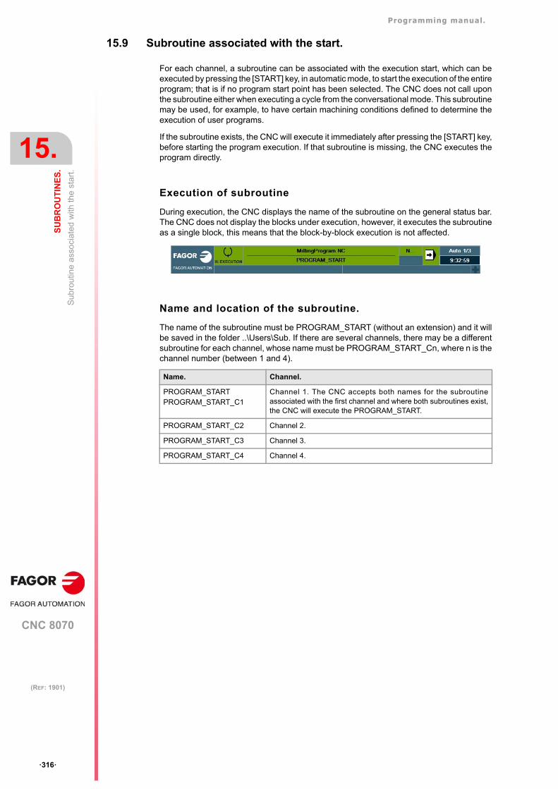
Programming manual.
CNC 8070
15.
SU
BR
OU
TIN
ES
.
Sub
rout
ine
ass
oci
ated
with
the
sta
rt.
·316·
(REF: 1901)
15.9 Subroutine associated with the start.
For each channel, a subroutine can be associated with the execution start, which can beexecuted by pressing the [START] key, in automatic mode, to start the execution of the entireprogram; that is if no program start point has been selected. The CNC does not call uponthe subroutine either when executing a cycle from the conversational mode. This subroutinemay be used, for example, to have certain machining conditions defined to determine theexecution of user programs.
If the subroutine exists, the CNC will execute it immediately after pressing the [START] key,before starting the program execution. If that subroutine is missing, the CNC executes theprogram directly.
Execution of subroutine
During execution, the CNC displays the name of the subroutine on the general status bar.The CNC does not display the blocks under execution, however, it executes the subroutineas a single block, this means that the block-by-block execution is not affected.
Name and location of the subroutine.
The name of the subroutine must be PROGRAM_START (without an extension) and it willbe saved in the folder ..\Users\Sub. If there are several channels, there may be a differentsubroutine for each channel, whose name must be PROGRAM_START_Cn, where n is thechannel number (between 1 and 4).
Name. Channel.
PROGRAM_STARTPROGRAM_START_C1
Channel 1. The CNC accepts both names for the subroutineassociated with the first channel and where both subroutines exist,the CNC will execute the PROGRAM_START.
PROGRAM_START_C2 Channel 2.
PROGRAM_START_C3 Channel 3.
PROGRAM_START_C4 Channel 4.
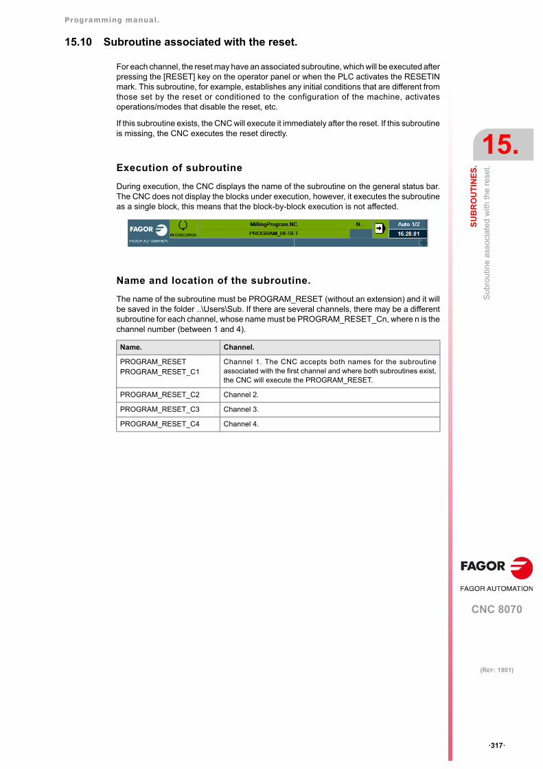
Programming manual.
CNC 8070
SU
BR
OU
TIN
ES
.
15.
Su
brou
tine
asso
ciat
ed w
ith th
e r
ese
t.
·317·
(REF: 1901)
15.10 Subroutine associated with the reset.
For each channel, the reset may have an associated subroutine, which will be executed afterpressing the [RESET] key on the operator panel or when the PLC activates the RESETINmark. This subroutine, for example, establishes any initial conditions that are different fromthose set by the reset or conditioned to the configuration of the machine, activatesoperations/modes that disable the reset, etc.
If this subroutine exists, the CNC will execute it immediately after the reset. If this subroutineis missing, the CNC executes the reset directly.
Execution of subroutine
During execution, the CNC displays the name of the subroutine on the general status bar.The CNC does not display the blocks under execution, however, it executes the subroutineas a single block, this means that the block-by-block execution is not affected.
Name and location of the subroutine.
The name of the subroutine must be PROGRAM_RESET (without an extension) and it willbe saved in the folder ..\Users\Sub. If there are several channels, there may be a differentsubroutine for each channel, whose name must be PROGRAM_RESET_Cn, where n is thechannel number (between 1 and 4).
Name. Channel.
PROGRAM_RESETPROGRAM_RESET_C1
Channel 1. The CNC accepts both names for the subroutineassociated with the first channel and where both subroutines exist,the CNC will execute the PROGRAM_RESET.
PROGRAM_RESET_C2 Channel 2.
PROGRAM_RESET_C3 Channel 3.
PROGRAM_RESET_C4 Channel 4.
Programming manual.
CNC 8070
15.
SU
BR
OU
TIN
ES
.
Sub
rout
ines
ass
ocia
ted
with
the
kine
mat
ics
calib
ratio
n cy
cle.
·318·
(REF: 1901)
15.11 Subroutines associated with the kinematics calibration cycle.
The kinematics calibration cycle has two associated subroutines (KinCal_Begin.nc andKinCal_End.nc), which the CNC executes before and after the cycle.
Fagor supplies both subroutines as incomplete and it is the manufacturer's responsibility todefine both subroutines. Software updates do not modify any existing subroutines.
Name and location of the subroutine.
The names of the subroutines are KinCal_Begin.nc and KinCal_End.nc. Both subroutinesmust be saved in the folder ..\Mtb\Sub. All channels use the same subroutines.
Name. Meaning.
KinCal_Begin.nc Subroutine associated with the beginning of the kinematicscalibration cycle.
KinCal_End.nc Subroutine associated with the end of the kinematics calibrationcycle.
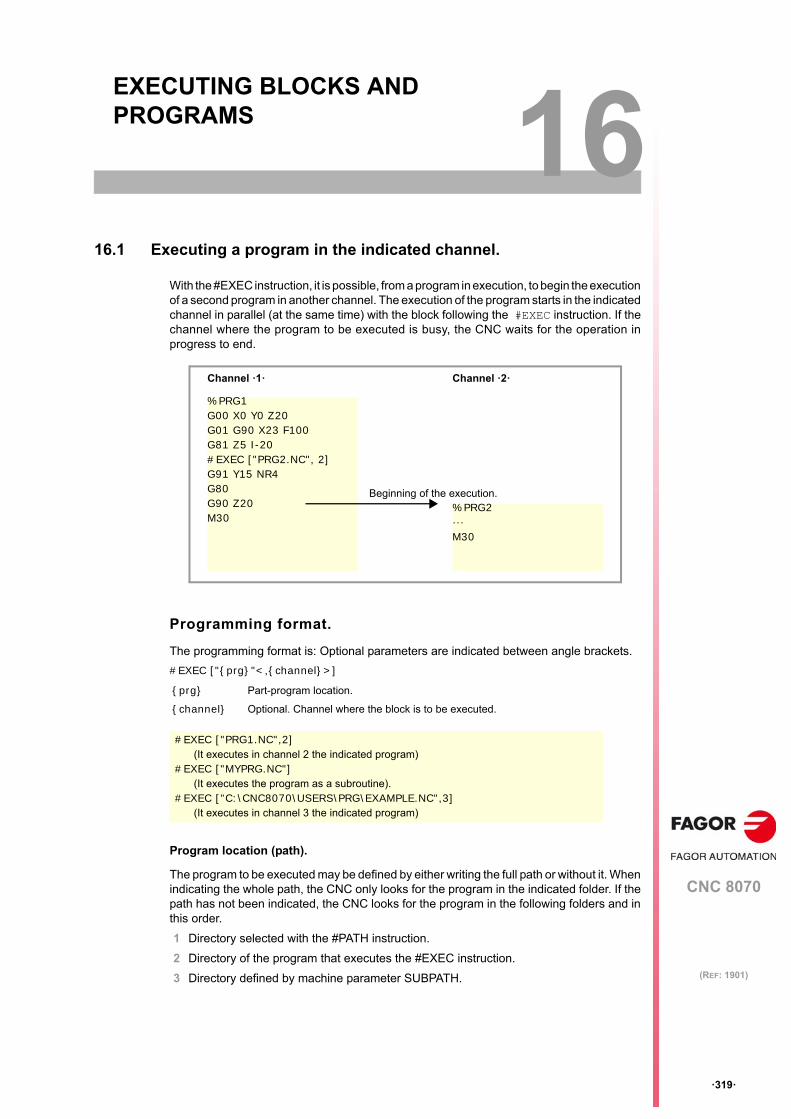
CNC 8070
16
·319·
(REF: 1901)
16.EXECUTING BLOCKS AND PROGRAMS
16.1 Executing a program in the indicated channel.
With the #EXEC instruction, it is possible, from a program in execution, to begin the executionof a second program in another channel. The execution of the program starts in the indicatedchannel in parallel (at the same time) with the block following the #EXEC instruction. If thechannel where the program to be executed is busy, the CNC waits for the operation inprogress to end.
Programming format.
The programming format is: Optional parameters are indicated between angle brackets.
#EXEC ["{prg}"<,{channel}>]
Program location (path).
The program to be executed may be defined by either writing the full path or without it. Whenindicating the whole path, the CNC only looks for the program in the indicated folder. If thepath has not been indicated, the CNC looks for the program in the following folders and inthis order.
1 Directory selected with the #PATH instruction.
2 Directory of the program that executes the #EXEC instruction.
3 Directory defined by machine parameter SUBPATH.
{prg} Part-program location.
{channel} Optional. Channel where the block is to be executed.
#EXEC ["PRG1.NC",2](It executes in channel 2 the indicated program)
#EXEC ["MYPRG.NC"](It executes the program as a subroutine).
#EXEC ["C:\CNC8070\USERS\PRG\EXAMPLE.NC",3](It executes in channel 3 the indicated program)
Channel ·1· Channel ·2·
%PRG1G00 X0 Y0 Z20G01 G90 X23 F100G81 Z5 I-20#EXEC ["PRG2.NC", 2]G91 Y15 NR4G80G90 Z20M30
%PRG2···M30
Beginning of the execution.
Programming manual.
CNC 8070
16.
EX
EC
UT
ING
BL
OC
KS
AN
D P
RO
GR
AM
S
Exe
cutin
g a
pro
gram
in th
e in
dica
ted
chan
nel
.
·320·
(REF: 1901)
Channel where the block is to be executed.
Programming the channel is optional. If the channel is not indicated or it coincides with thechannel where the #EXEC instruction is executed, the second program will be executed asa subroutine. In this case, functions M02 and M30 will carry out all the associated actions(initialization, sending to the PLC, etc.) except the one for finishing the program. Afterexecuting function M02 or M30, it goes on executing the blocks programmed after the #EXECinstruction.
Considerations.
A program containing the #EXEC instruction may be executed, simulated, syntax checkedor searched for a particular block. In all the cases, programs called upon using the #EXECinstruction are executed in the same conditions as the original program
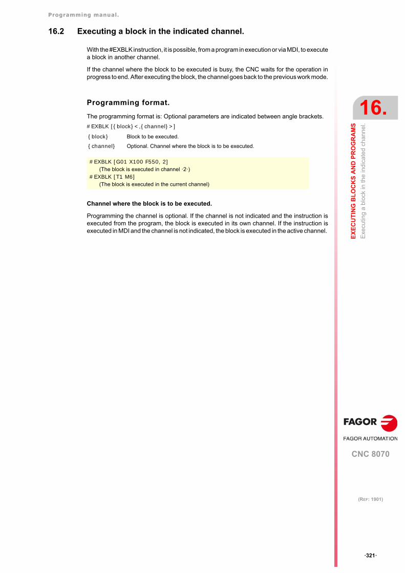
Programming manual.
CNC 8070
EX
EC
UT
ING
BL
OC
KS
AN
D P
RO
GR
AM
S
16.
Exe
cutin
g a
blo
ck in
the
indi
cate
d ch
ann
el.
·321·
(REF: 1901)
16.2 Executing a block in the indicated channel.
With the #EXBLK instruction, it is possible, from a program in execution or via MDI, to executea block in another channel.
If the channel where the block to be executed is busy, the CNC waits for the operation inprogress to end. After executing the block, the channel goes back to the previous work mode.
Programming format.
The programming format is: Optional parameters are indicated between angle brackets.
#EXBLK [{block}<,{channel}>]
Channel where the block is to be executed.
Programming the channel is optional. If the channel is not indicated and the instruction isexecuted from the program, the block is executed in its own channel. If the instruction isexecuted in MDI and the channel is not indicated, the block is executed in the active channel.
{block} Block to be executed.
{channel} Optional. Channel where the block is to be executed.
#EXBLK [G01 X100 F550, 2](The block is executed in channel ·2·)
#EXBLK [T1 M6](The block is executed in the current channel)
Programming manual.
CNC 8070
16.
EX
EC
UT
ING
BL
OC
KS
AN
D P
RO
GR
AM
S
Exe
cutin
g a
blo
ck in
the
indi
cate
d ch
ann
el.
·322·
(REF: 1901)
CNC 8070
17
·323·
(REF: 1901)
17.C AXIS
The CNC allows activating axes and spindles as C axis, that interpolated with a linear axismakes it possible to mill the cylindrical surface or the face of a turning part. Although themachine may have several axes or spindle defined as "C" axis, only one of them may beactive.
·C· axis on a lathe.
On a lathe, it is most common to activate the spindle as ·C· axis and use a live tool to machinethe part.
·C· axis on a milling machine.
On a milling machine, it is most common to activate a rotary axis as ·C· axis and use thespindle to machine the part.
Configuration of a ·C· axis.
To activate an axis or spindle as "C" axis, it must have been defined as such by the machinemanufacturer. To know whether an axis or spindle may be activated as a ·C· axis, refer toparameter CAXIS in the machine parameter table or to its variable.
(V.)MPA.CAXIS.Xn
Variable indicating whether the axis or spindle can be enabled as the C axis; a value of·1· is yes and a value ·0· is no.
In the machine parameter table, parameter CAXNAME indicates the default name of the ·C·axis of the channel. This is the name that a spindle enabled as ·C· axis will take if not indicatedotherwise via part-program.
The zero offsets on the C axis.
Once the zero offsets have been defined in the table, they may be activated by program usingfunctions G54 to G59 and G159. The zero offsets on the C axis have the followingpeculiarities.
• If there is an active zero offset and, then, a C axis is activated, the zero offset for the Caxis is not assumed.
• When the spindle works as C axis (#CAX instruction) the zero offset is applied in degrees.
• When face machining is active (#FACE instruction) or cylinder machining (#CYLinstruction) is active, the zero offset is applied in the active units, millimeters or inches.
Programming manual.
CNC 8070
17.
C A
XIS
Act
iva
ting
the
spin
dle
as
"C"
axis
.
·324·
(REF: 1901)
17.1 Activating the spindle as "C" axis.
To use a spindle as ·C· axis, it must be enabled as such first. Once this is done, it will bepossible to program machining operation on the face or on the side using the instructions#FACE or #CYL respectively.
Activating the spindle as ·C· axis.
The #CAX instruction activates a spindle as ·C· axis.
The programming format is: Optional parameters are indicated between angle brackets.
#CAX [<{spdl}><,{name}>]
The spindle needs only be indicated when a spindle other than the master is to be activatedas a C axis. Otherwise, there is no need to program it.
The {name} parameter sets the name that will identify the C axis. This name will be usedin the part program to define the movements. If the name is not defined, the CNC assignsa name by default. See "Configuration of a ·C· axis." on page 323.
Considerations about working with the C axis
Activating a running spindle as C axis stops the spindle. While being a spindle active as "C"axis, no speed may be programmed for it.
When activating the spindle as "C" axis, the CNC carries out a home search of the "C" axis.
Accessing the variables of a spindle activated as C axis.
After activating a spindle as C axis, the new name of the spindle must be used to accessits variables from the part-program or MDI. The access to the variables from the PLCA orfrom an interface does not change; the original name of the spindle remains unchanged.
Influence of the M3/M4/M5 functions.
If the spindle is working as C axis, executing an M3, M4 or M5 function will automaticallyset the spindle in open loop (same as programming #CAX OFF).
Deactivating the spindle as C axis.
The C axis is deactivated with the #CAX instruction and the spindle goes back to workingas a normal spindle.
#CAX OFF
Programming the spindle as ·C· axis.
When the spindle works as ·C· axis, it will be programmed as if it were a rotary axis (indegrees).
{spdl} Optional. Spindle to be activated as C axis.
{name} Optional. Name of the C axis.
#CAX#CAX [S1]#CAX [S,C]
Programming Spindle that is activated as ·C· axis. Axis name.
#CAX Master spindle. By default.
#CAX [S1] Spindle S1 (it may be the master). By default.
#CAX [S,C] Spindle S (it may be the master). C
#CAX [S3,B2] Spindle S3 (it may be the master). B2
#CAX OFF
Programming manual.
CNC 8070
C A
XIS
17.
Act
iva
ting
the
spin
dle
as
"C"
axis
.
·325·
(REF: 1901)
Programming the master spindle as ·C· axis.
Programming any spindle as ·C· axis.
#CAXG01 Z50 C100 F100 G01 X20 C20 A50#CAX OFF
#CAX [S1,C1](The spindle "S1" is activated as "C" axis under the name of "C1")
G01 Z50 C1=100 F100 G01 X20 C1=20 A50 S1000#CAX OFF
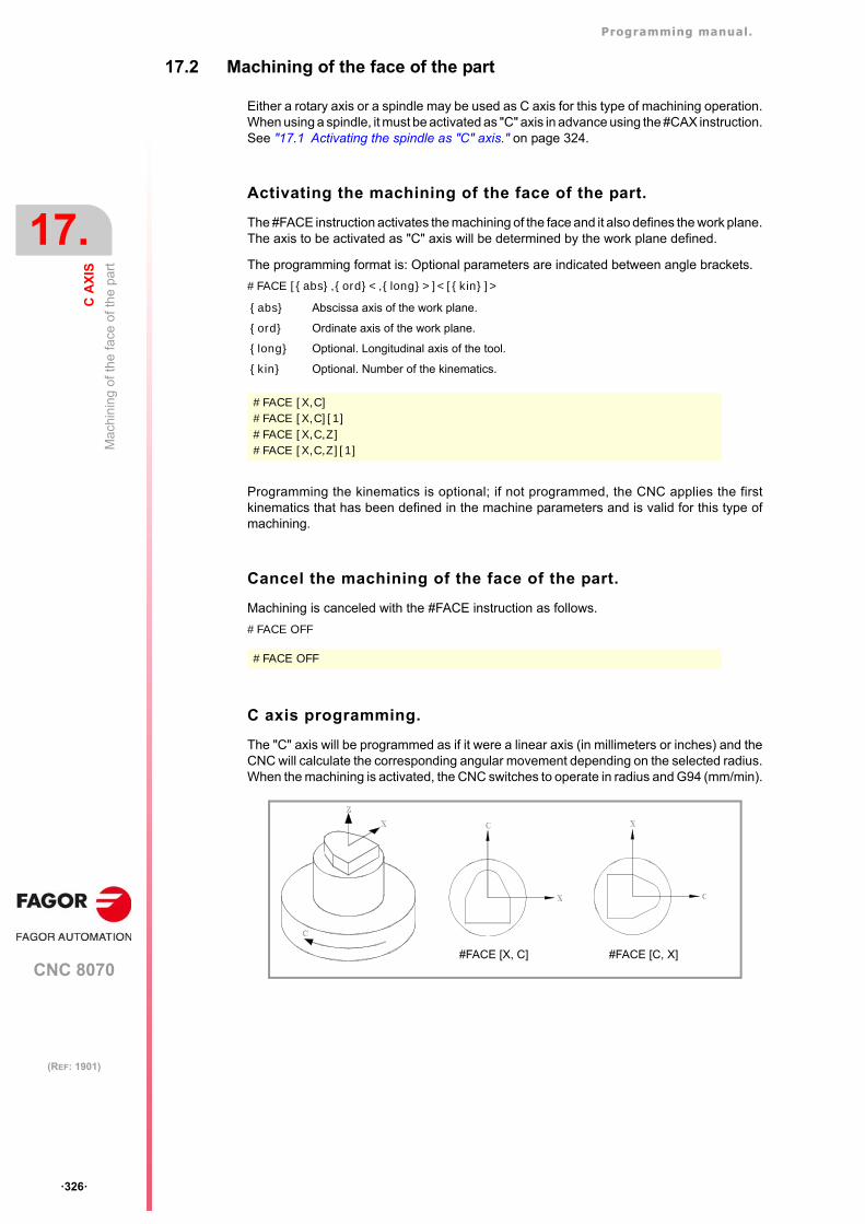
Programming manual.
CNC 8070
17.
C A
XIS
Mac
hin
ing
of th
e fa
ce o
f th
e pa
rt
·326·
(REF: 1901)
17.2 Machining of the face of the part
Either a rotary axis or a spindle may be used as C axis for this type of machining operation.When using a spindle, it must be activated as "C" axis in advance using the #CAX instruction.See "17.1 Activating the spindle as "C" axis." on page 324.
Activating the machining of the face of the part.
The #FACE instruction activates the machining of the face and it also defines the work plane.The axis to be activated as "C" axis will be determined by the work plane defined.
The programming format is: Optional parameters are indicated between angle brackets.
#FACE [{abs},{ord}<,{long}>]<[{kin}]>
Programming the kinematics is optional; if not programmed, the CNC applies the firstkinematics that has been defined in the machine parameters and is valid for this type ofmachining.
Cancel the machining of the face of the part.
Machining is canceled with the #FACE instruction as follows.
#FACE OFF
C axis programming.
The "C" axis will be programmed as if it were a linear axis (in millimeters or inches) and theCNC will calculate the corresponding angular movement depending on the selected radius.When the machining is activated, the CNC switches to operate in radius and G94 (mm/min).
{abs} Abscissa axis of the work plane.
{ord} Ordinate axis of the work plane.
{long} Optional. Longitudinal axis of the tool.
{kin} Optional. Number of the kinematics.
#FACE [X,C]#FACE [X,C][1]#FACE [X,C,Z]#FACE [X,C,Z][1]
#FACE OFF
#FACE [X, C] #FACE [C, X]
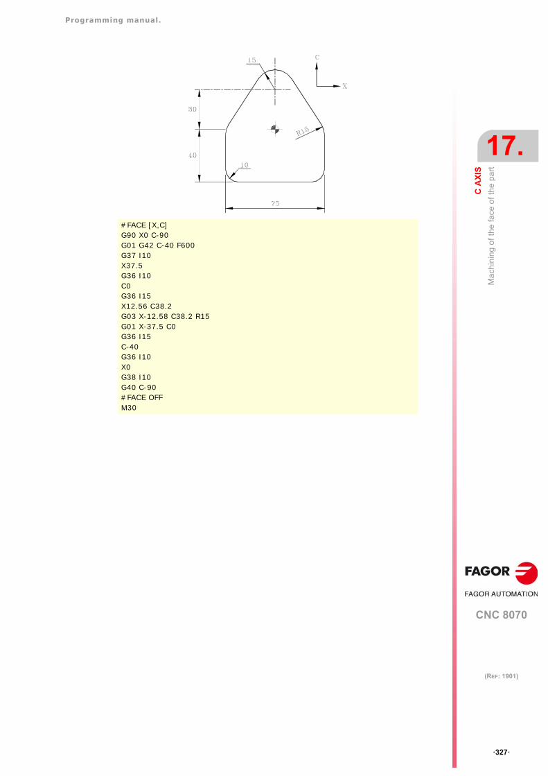
Programming manual.
CNC 8070
C A
XIS
17.
Mac
hin
ing
of th
e fa
ce o
f th
e pa
rt
·327·
(REF: 1901)
#FACE [X,C]G90 X0 C-90G01 G42 C-40 F600G37 I10X37.5G36 I10C0G36 I15X12.56 C38.2G03 X-12.58 C38.2 R15G01 X-37.5 C0G36 I15C-40G36 I10X0G38 I10G40 C-90#FACE OFFM30
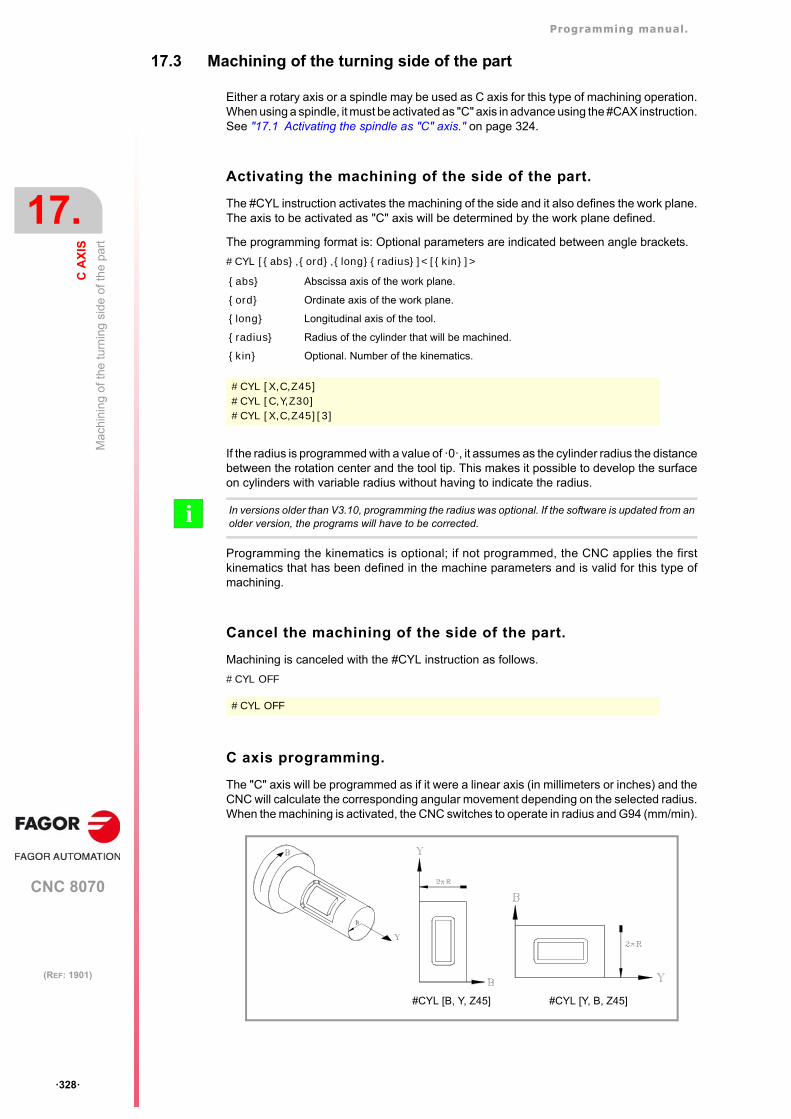
Programming manual.
CNC 8070
17.
C A
XIS
Ma
chin
ing
of th
e tu
rnin
g si
de o
f th
e pa
rt
·328·
(REF: 1901)
17.3 Machining of the turning side of the part
Either a rotary axis or a spindle may be used as C axis for this type of machining operation.When using a spindle, it must be activated as "C" axis in advance using the #CAX instruction.See "17.1 Activating the spindle as "C" axis." on page 324.
Activating the machining of the side of the part.
The #CYL instruction activates the machining of the side and it also defines the work plane.The axis to be activated as "C" axis will be determined by the work plane defined.
The programming format is: Optional parameters are indicated between angle brackets.
#CYL [{abs},{ord},{long}{radius}]<[{kin}]>
If the radius is programmed with a value of ·0·, it assumes as the cylinder radius the distancebetween the rotation center and the tool tip. This makes it possible to develop the surfaceon cylinders with variable radius without having to indicate the radius.
Programming the kinematics is optional; if not programmed, the CNC applies the firstkinematics that has been defined in the machine parameters and is valid for this type ofmachining.
Cancel the machining of the side of the part.
Machining is canceled with the #CYL instruction as follows.
#CYL OFF
C axis programming.
The "C" axis will be programmed as if it were a linear axis (in millimeters or inches) and theCNC will calculate the corresponding angular movement depending on the selected radius.When the machining is activated, the CNC switches to operate in radius and G94 (mm/min).
{abs} Abscissa axis of the work plane.
{ord} Ordinate axis of the work plane.
{long} Longitudinal axis of the tool.
{radius} Radius of the cylinder that will be machined.
{kin} Optional. Number of the kinematics.
#CYL [X,C,Z45]#CYL [C,Y,Z30]#CYL [X,C,Z45][3]
In versions older than V3.10, programming the radius was optional. If the software is updated from anolder version, the programs will have to be corrected. i
#CYL OFF
#CYL [B, Y, Z45] #CYL [Y, B, Z45]
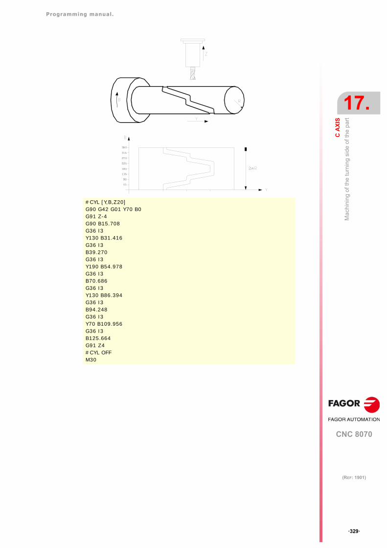
Programming manual.
CNC 8070
C A
XIS
17.
Ma
chin
ing
of th
e tu
rnin
g si
de o
f th
e pa
rt
·329·
(REF: 1901)
#CYL [Y,B,Z20]G90 G42 G01 Y70 B0G91 Z-4G90 B15.708G36 I3Y130 B31.416G36 I3B39.270G36 I3Y190 B54.978G36 I3B70.686G36 I3Y130 B86.394G36 I3B94.248G36 I3Y70 B109.956G36 I3B125.664G91 Z4#CYL OFFM30
Programming manual.
CNC 8070
17.
C A
XIS
Ma
chin
ing
of th
e tu
rnin
g si
de o
f th
e pa
rt
·330·
(REF: 1901)
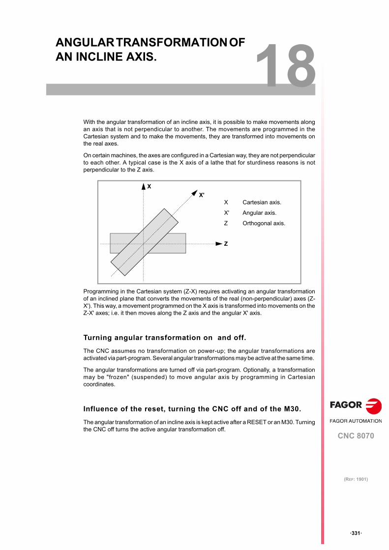
CNC 8070
18
·331·
(REF: 1901)
18.ANGULAR TRANSFORMATION OF AN INCLINE AXIS.
With the angular transformation of an incline axis, it is possible to make movements alongan axis that is not perpendicular to another. The movements are programmed in theCartesian system and to make the movements, they are transformed into movements onthe real axes.
On certain machines, the axes are configured in a Cartesian way, they are not perpendicularto each other. A typical case is the X axis of a lathe that for sturdiness reasons is notperpendicular to the Z axis.
Programming in the Cartesian system (Z-X) requires activating an angular transformationof an inclined plane that converts the movements of the real (non-perpendicular) axes (Z-X'). This way, a movement programmed on the X axis is transformed into movements on theZ-X' axes; i.e. it then moves along the Z axis and the angular X' axis.
Turning angular transformation on and off.
The CNC assumes no transformation on power-up; the angular transformations areactivated via part-program. Several angular transformations may be active at the same time.
The angular transformations are turned off via part-program. Optionally, a transformationmay be "frozen" (suspended) to move angular axis by programming in Cartesiancoordinates.
Influence of the reset, turning the CNC off and of the M30.
The angular transformation of an incline axis is kept active after a RESET or an M30. Turningthe CNC off turns the active angular transformation off.
Z
X'
X
X Cartesian axis.
X' Angular axis.
Z Orthogonal axis.
Programming manual.
CNC 8070
18.
AN
GU
LA
R T
RA
NS
FO
RM
AT
ION
OF
AN
INC
LIN
E A
XIS
.
·332·
(REF: 1901)
Considerations for the angular transformation of an inclineaxis.
The axes that make up the angular transformation must meet the following requirements:
• Both axes must belong to the same channel.
• Both axes must be linear.
• Both axes may be masters in a pair of slaved (coupled) axes or gantry axes.
Home search is not possible when the angular transformation is active.
If the angular transformation is active, the coordinates displayed will be those of theCartesian system. Otherwise, it will display the coordinates of the real axes.
Programming manual.
CNC 8070
AN
GU
LA
R T
RA
NS
FO
RM
AT
ION
OF
AN
INC
LIN
E A
XIS
.
18.
Tu
rnin
g a
ngul
ar tr
ansf
orm
atio
n o
n an
d o
ff
·333·
(REF: 1901)
18.1 Turning angular transformation on and off
Turn angular transformation on.
When the transformation is on, the movements are programmed in the Cartesian systemand to make the movements, the CNC transforms them into movements on the real axes.The coordinates displayed on the screen will be those of the Cartesian system.
The angular transformation is turned on with the instruction #ANGAX. This instruction maybe used to activate the transformation in one or several axes.
#ANGAX ON [1,...,n]
At least one transformation must be programmed in the activating instruction, otherwise therelevant error message will be issued. The number of the angular transformation isdetermined by the order in which they have been defined in the machine parameter table.
Angular transformations may be activated either all of them at the same time or one by one.Activating one transformation does not cancel the previous ones.
This instruction turns a "frozen" (suspended) transformation on again. See "18.2 Freezing(suspending) the angular transformation." on page 334.
Turn angular transformation off.
If the transformation is off, the movements are programmed and executed in the system ofthe real axes. The coordinates displayed on the screen will be those of the real axes.
The angular transformation is turned on with the instruction #ANGAX. The programmingformat is: Optional parameters are indicated between angle brackets.
#ANGAX OFF <[1,...,n]>
If no transformation has been defined, all the transformations of the channel are turned off.
The angular transformation of an incline axis is kept active after a RESET or an M30. Turningthe CNC off turns the active angular transformation off.
1,...,n Angular transformation to be activated.
#ANGAX ON [1]
#ANGAX ON [5.7]
1,...,n Optional. Angular transformation to be activated.
#ANGAX OFF
#ANGAX OFF [1]
#ANGAX OFF [5.7]
Programming manual.
CNC 8070
18.
AN
GU
LA
R T
RA
NS
FO
RM
AT
ION
OF
AN
INC
LIN
E A
XIS
.
Fre
ezin
g (
susp
endi
ng)
the
angu
lar
tra
nsfo
rma
tion.
·334·
(REF: 1901)
18.2 Freezing (suspending) the angular transformation.
Freezing the angular transformation is a special way to make movements along the angularaxis, but programming it in the Cartesian system. The angular transformation cannot be"frozen" (suspended) while jogging.
The angular transformation is "frozen" (suspended) using the instruction #ANGAX SUSPwhose programming format is.
#ANGAX SUSP [1,...,n]
If no angular transformation has been programmed, all the transformations of the channelare "frozen" (suspended). The number of the angular transformation is determined by theorder in which they have been defined in the machine parameter table.
Programming movements a fte r " f reez ing" the angu la rtransformation.
If an angular transformation is "frozen" (suspended), only the coordinate of the angular axismust be programmed in the motion block. If the coordinate of the orthogonal axis isprogrammed, the movement is carried out according to the normal angular transformation.
Canceling the freezing of a transformation.
The "freezing" of an angular transformation is canceled after a reset or an M30.
Programming #ANGAX ONon the frozen transformation turns it back on.
1,...,n Angular transformation to be activated.
#ANGAX SUSP Freezing all the transformations of the channel.
#ANGAX SUSP [1] Freezing transformation ·1·.
#ANGAX SUSP [5.7] Freezing transformations ·5· and ·7·.
Programming manual.
CNC 8070
AN
GU
LA
R T
RA
NS
FO
RM
AT
ION
OF
AN
INC
LIN
E A
XIS
.
18.
Obt
aini
ng in
form
atio
n o
n an
gula
r tr
ans
form
atio
n.
·335·
(REF: 1901)
18.3 Obtaining information on angular transformation.
Checking the configuration of the angular transformation.
The configuration data of the angular transformation may be checked directly in the machineparameter table or using the following variables.
Number of angular transformations defined.
(V.)MPK.NANG
Variable that can only be read from the PRG, PLC and INT.
It returns the number of angular transformations defined in the machine parameter table.
Axes that make up the angular transformation.
These variables refer to the angular transformation n. Programming using the curly bracketsis mandatory.
(V.)MPK.ANGAXNA[n](V.)MPK.ORTGAXNA[n]
Variable that can only be read from the PRG, PLC and INT.
The first one returns the name of the angular axis. The second one returns the name ofthe orthogonal axis.
Geometry of the angular transformation.
These variables refer to the angular transformation n. Programming using the curly bracketsis mandatory.
(V.)MPK.ANGANTR[n]
Variable that can only be read from the PRG, PLC and INT.
Angle between the Cartesian angle and the angular axis it is associated with. Positiveangle when the angular axis has been rotated clockwise and negative ifcounterclockwise.
(V.)MPK.OFFANGAX[n]
Variable that can only be read from the PRG, PLC and INT.
Offset of the origin of the angular transformation. Distance between machine zero andthe origin of the coordinate system of the incline axis.
Checking the status of the angular transformation.
Status of the angular transformation.
(V.)[n].G.ANGAXST
Variable that can only be read from the PRG, PLC and INT.
It returns the status of angular transformation defined in the channel.
(V.)[n].G.ANGIDST
Variable that can only be read from the PRG, PLC and INT.
It returns the status of angular transformation defined in the [i] position in the machineparameters.
Both variables return the following values:
Value Meaning
0 The transformation is deactivated.
1 The transformation is activated.
2 The transformation is frozen (suspended).
Programming manual.
CNC 8070
18.
AN
GU
LA
R T
RA
NS
FO
RM
AT
ION
OF
AN
INC
LIN
E A
XIS
.
Obt
aini
ng in
form
atio
n o
n an
gula
r tr
ans
form
atio
n.
·336·
(REF: 1901)
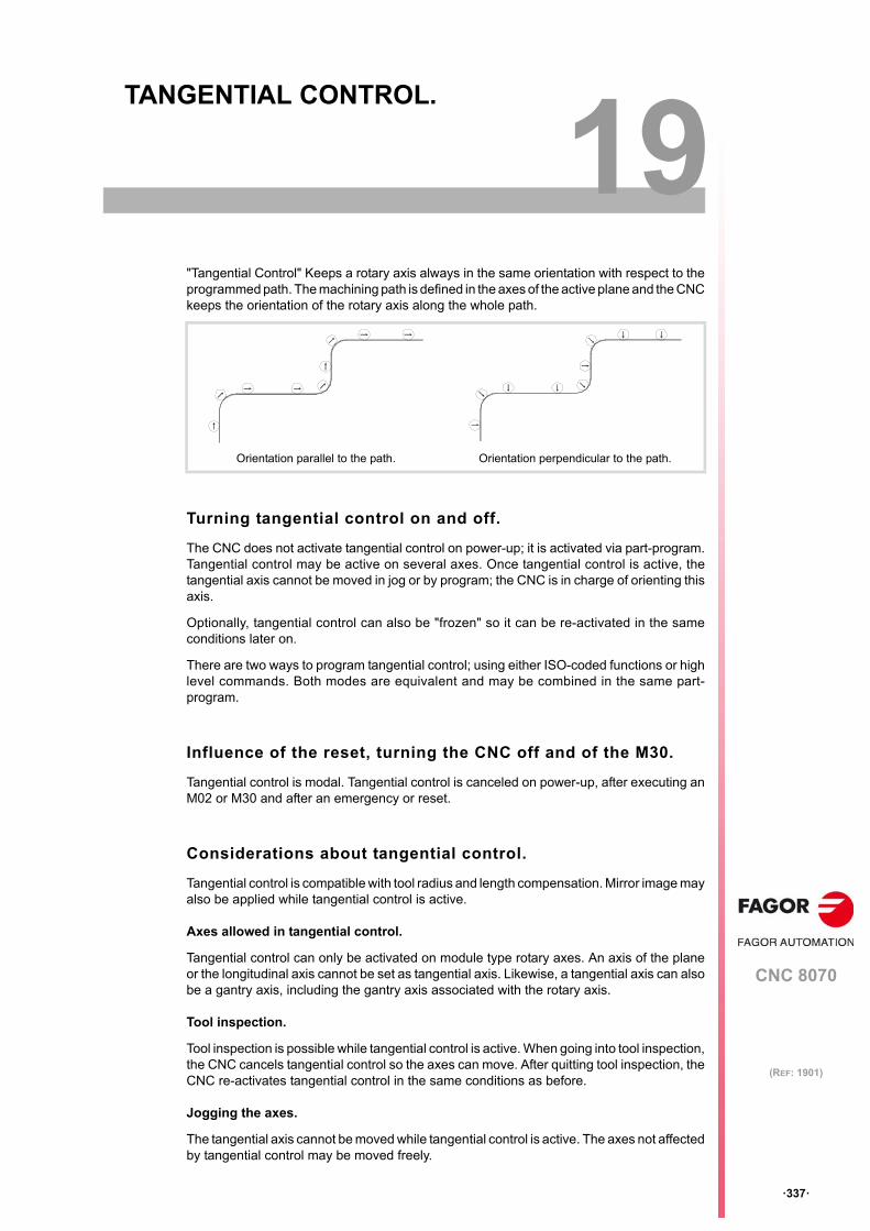
CNC 8070
19
·337·
(REF: 1901)
19.TANGENTIAL CONTROL.
"Tangential Control" Keeps a rotary axis always in the same orientation with respect to theprogrammed path. The machining path is defined in the axes of the active plane and the CNCkeeps the orientation of the rotary axis along the whole path.
Turning tangential control on and off.
The CNC does not activate tangential control on power-up; it is activated via part-program.Tangential control may be active on several axes. Once tangential control is active, thetangential axis cannot be moved in jog or by program; the CNC is in charge of orienting thisaxis.
Optionally, tangential control can also be "frozen" so it can be re-activated in the sameconditions later on.
There are two ways to program tangential control; using either ISO-coded functions or highlevel commands. Both modes are equivalent and may be combined in the same part-program.
Influence of the reset, turning the CNC off and of the M30.
Tangential control is modal. Tangential control is canceled on power-up, after executing anM02 or M30 and after an emergency or reset.
Considerations about tangential control.
Tangential control is compatible with tool radius and length compensation. Mirror image mayalso be applied while tangential control is active.
Axes allowed in tangential control.
Tangential control can only be activated on module type rotary axes. An axis of the planeor the longitudinal axis cannot be set as tangential axis. Likewise, a tangential axis can alsobe a gantry axis, including the gantry axis associated with the rotary axis.
Tool inspection.
Tool inspection is possible while tangential control is active. When going into tool inspection,the CNC cancels tangential control so the axes can move. After quitting tool inspection, theCNC re-activates tangential control in the same conditions as before.
Jogging the axes.
The tangential axis cannot be moved while tangential control is active. The axes not affectedby tangential control may be moved freely.
Orientation parallel to the path. Orientation perpendicular to the path.
Programming manual.
CNC 8070
19.
TA
NG
EN
TIA
L C
ON
TR
OL
.
·338·
(REF: 1901)
When jogging the axes, the CNC cancels tangential control Once the movement has ended,the CNC re-activates tangential control in the same conditions as before.
MDI mode.
The MDI mode may be accessed from jog mode to activate tangential control and move theaxes using blocks programmed in MDI. The tangential axis cannot be moved while tangentialcontrol is active.
Programming manual.
CNC 8070
TA
NG
EN
TIA
L C
ON
TR
OL
.
19.
Tur
nin
g ta
nge
ntia
l con
trol
on
and
off.
·339·
(REF: 1901)
19.1 Turning tangential control on and off.
There are two ways to manage tangential control; using either ISO-coded functions or highlevel commands. Both modes are equivalent and may be combined in the same part-program.
Activating tangential control.
While tangential control is active, the movements are programmed for the axes of the activework plane. It is not possible to program movements of the tangential axis; it is up to the CNCto orient this axis.
Tangential control is activated with function G45 or with the instruction #TANGCTRL. Thesecommands also restore a "frozen" tangential control, but the angle must be programmedagain. See "19.2 Freezing tangential control." on page 342.
Programming format (1).
This function may be used to activate tangential control on one or several axes; it does notallow to set the positioning feedrate of the tangential axis. At least one tangential axis mustbe defined in this function.
G45 X~C
Programming format (2).
This statement may be used to activate tangential control on one or several axes and to setthe positioning feedrate of the tangential axis. There is no need to activate any axis in orderto set the feedrate.
The programming format is: Optional parameters are indicated between angle brackets.
#TANGCTRL ON [<X~C>, <F>]
Although both parameters are optional, at least one of them must be programmed.
Combining both programming formats.
The two programming formats may be combined in the same part-program. For example,the instruction may be used to set the positioning feedrate and function G45 to activetangential control.
Programming the positioning angle.
The positioning angle is defined in degrees (±359.9999). The angle is defined with respectto the path to follow, positive angle for counterclockwise positioning and negative angle forclockwise positioning.
X~C Axis upon which tangential control is applied and angular position with respect to the path.The angle is defined in degrees (±359.9999).
G45 A90G45 B45 W15.123 B2=-34.5
X~C Optional. Axis upon which tangential control is applied and angular position with respectto the path. The angle is defined in degrees (±359.9999).
F Optional. Tangential axis orienting feedrate.
#TANGCTRL ON [A34.35]#TANGCTRL ON [A90, F300]#TANGCTRL ON [B-45, W15.123, F300]#TANGCTRL ON [F300]
#TANGCTRL ON [F1000]G45 W45
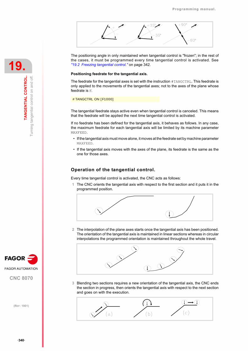
Programming manual.
CNC 8070
19.
TA
NG
EN
TIA
L C
ON
TR
OL
.
Tur
nin
g ta
nge
ntia
l con
trol
on
and
off.
·340·
(REF: 1901)
The positioning angle in only maintained when tangential control is "frozen"; in the rest ofthe cases, it must be programmed every time tangential control is activated. See"19.2 Freezing tangential control." on page 342.
Positioning feedrate for the tangential axis.
The feedrate for the tangential axes is set with the instruction #TANGCTRL. This feedrate isonly applied to the movements of the tangential axes; not to the axes of the plane whosefeedrate is F.
The tangential feedrate stays active even when tangential control is canceled. This meansthat the feedrate will be applied the next time tangential control is activated.
If no feedrate has been defined for the tangential axis, it behaves as follows. In any case,the maximum feedrate for each tangential axis will be limited by its machine parameterMAXFEED.
• If the tangential axis must move alone, it moves at the feedrate set by machine parameterMAXFEED.
• If the tangential axis moves with the axes of the plane, its feedrate is the same as theone for those axes.
Operation of the tangential control.
Every time tangential control is activated, the CNC acts as follows:
1 The CNC orients the tangential axis with respect to the first section and it puts it in theprogrammed position.
2 The interpolation of the plane axes starts once the tangential axis has been positioned.The orientation of the tangential axis is maintained in linear sections whereas in circularinterpolations the programmed orientation is maintained throughout the whole travel.
3 Blending two sections requires a new orientation of the tangential axis, the CNC endsthe section in progress, then orients the tangential axis with respect to the next sectionand goes on with the execution.
#TANGCTRL ON [F1000]
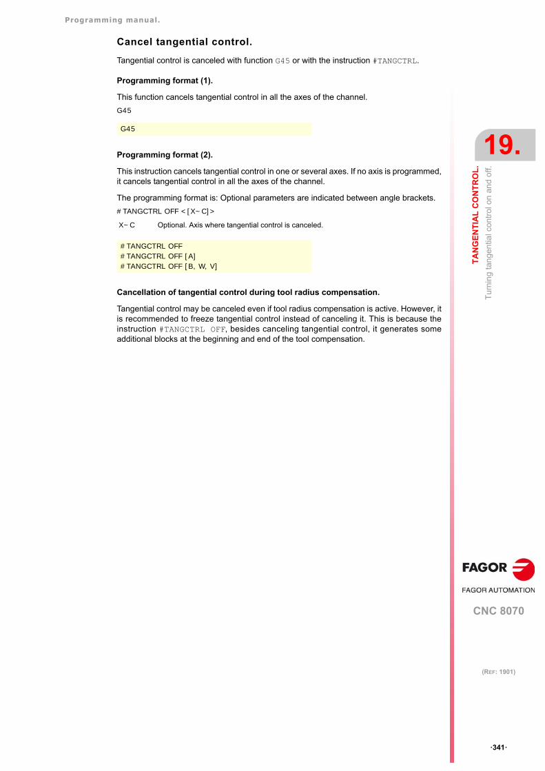
Programming manual.
CNC 8070
TA
NG
EN
TIA
L C
ON
TR
OL
.
19.
Tur
nin
g ta
nge
ntia
l con
trol
on
and
off.
·341·
(REF: 1901)
Cancel tangential control.
Tangential control is canceled with function G45 or with the instruction #TANGCTRL.
Programming format (1).
This function cancels tangential control in all the axes of the channel.
G45
Programming format (2).
This instruction cancels tangential control in one or several axes. If no axis is programmed,it cancels tangential control in all the axes of the channel.
The programming format is: Optional parameters are indicated between angle brackets.
#TANGCTRL OFF <[X~C]>
Cancellation of tangential control during tool radius compensation.
Tangential control may be canceled even if tool radius compensation is active. However, itis recommended to freeze tangential control instead of canceling it. This is because theinstruction #TANGCTRL OFF, besides canceling tangential control, it generates someadditional blocks at the beginning and end of the tool compensation.
G45
X~C Optional. Axis where tangential control is canceled.
#TANGCTRL OFF#TANGCTRL OFF [A]#TANGCTRL OFF [B, W, V]
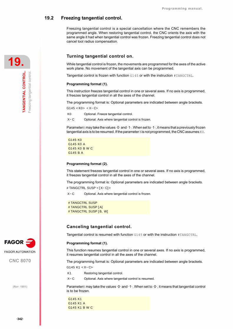
Programming manual.
CNC 8070
19.
TA
NG
EN
TIA
L C
ON
TR
OL
.
Fre
ezin
g ta
nge
ntia
l con
trol
.
·342·
(REF: 1901)
19.2 Freezing tangential control.
Freezing tangential control is a special cancellation where the CNC remembers theprogrammed angle. When restoring tangential control, the CNC orients the axis with thesame angle it had when tangential control was frozen. Freezing tangential control does notcancel tool radius compensation.
Turning tangential control on.
While tangential control is frozen, the movements are programmed for the axes of the activework plane. No movement of the tangential axis can be programmed.
Tangential control is frozen with function G145 or with the instruction #TANGCTRL.
Programming format (1).
This instruction freezes tangential control in one or several axes. If no axis is programmed,it freezes tangential control in all the axes of the channel.
The programming format is: Optional parameters are indicated between angle brackets.
G145 <K0> <X~C>
ParameterK may take the values ·0· and ·1·. When set to ·1·, it means that a previously frozentangential axis is to be resumed. If the parameter Kis not programmed, the CNC assumes K0.
Programming format (2).
This statement freezes tangential control in one or several axes. If no axis is programmed,it freezes tangential control in all the axes of the channel.
The programming format is: Optional parameters are indicated between angle brackets.
#TANGCTRL SUSP <[X~C]>
Canceling tangential control.
Tangential control is resumed with function G145 or with the instruction #TANGCTRL.
Programming format (1).
This function resumes tangential control in one or several axes. If no axis is programmed,it resumes tangential control in all the axes of the channel.
The programming format is: Optional parameters are indicated between angle brackets.
G145 K1 <X~C>
ParameterK may take the values ·0· and ·1·. When set to ·0·, it means that tangential controlis to be frozen.
K0 Optional. Freeze tangential control.
X~C Optional. Axis where tangential control is frozen.
G145 K0G145 K0 AG145 K0 B W CG145 B A
X~C Optional. Axis where tangential control is frozen.
#TANGCTRL SUSP#TANGCTRL SUSP [A]#TANGCTRL SUSP [B, W]
K1 Restoring tangential control.
X~C Optional. Axis where tangential control is resumed.
G145 K1G145 K1 AG145 K1 B W C
Programming manual.
CNC 8070
TA
NG
EN
TIA
L C
ON
TR
OL
.
19.
Fre
ezin
g ta
nge
ntia
l con
trol
.
·343·
(REF: 1901)
Programming format (2).
This instruction resumes tangential control in one or several axes. If no axis is programmed,it resumes tangential control in all the axes of the channel.
The programming format is: Optional parameters are indicated between angle brackets.
#TANGCTRL RESUME <[X~C]>
X~C Optional. Axis where tangential control is resumed.
#TANGCTRL RESUME#TANGCTRL RESUME [A]#TANGCTRL RESUME [B, W, C]
Programming manual.
CNC 8070
19.
TA
NG
EN
TIA
L C
ON
TR
OL
.
Ob
tain
ing
info
rmat
ion
on
tan
gen
tial c
ontr
ol.
·344·
(REF: 1901)
19.3 Obtaining information on tangential control.
Checking the configuration of the angular transformation.
The configuration data of the tangential control may be checked directly in the machineparameter table or using the following variables.
Is it a module type of rotary axis?
(V.)[n].MPA.AXISMODE.Xn
The variable indicates the type of rotary axis; if it is a module type, the variable must returnthe value of ·0·.
Consulting the tangential control data.
(V.)A.TANGAN.Xn
This variable returns the angle programmed in the Xn axis.
(V.)G.TANGFEED
This variable returns the positioning feedrate programmed for tangential control.
Consulting the tangential control status.
(V.)PLC.TANGACTIVCn
This variable indicates whether tangential control is active in channel n nor not. A ·1·if the tangential control is active and a ·0· if otherwise.
(V.)PLC.TANGACTx
This variable indicates whether tangential control is active in the x axis or not. A ·1· ifthe tangential control is active and a ·0· if otherwise.
(V.)[n].G.TGCTRLST
It returns the status of tangential control in the channel. A value of ·0· if tangential controlis off, a ·1· if it is on and a ·2· if frozen (suspended).
(V.)[n].A.TGCTRLST.Xn
It returns the status of tangential control in the axis. A value of ·0· if tangential controlis off, a ·1· if it is on and a ·2· if frozen (suspended).
Initialization of the variables.
Canceling tangential control initializes all the variables except (V.)A.TANGFEED, becausethe programmed feedrate is maintained for a possible future tangential control.
When freezing (suspending) tangential control, the variables act as follows.
(V.)A.TANGAN.Xn It maintains the value of the programmed angle.
(V.)G.TANGFEED It is not initialized.
(V.)PLC.TANGACTIVCn It is not initialized.
(V.)PLC.TANGACTx It is initialized.
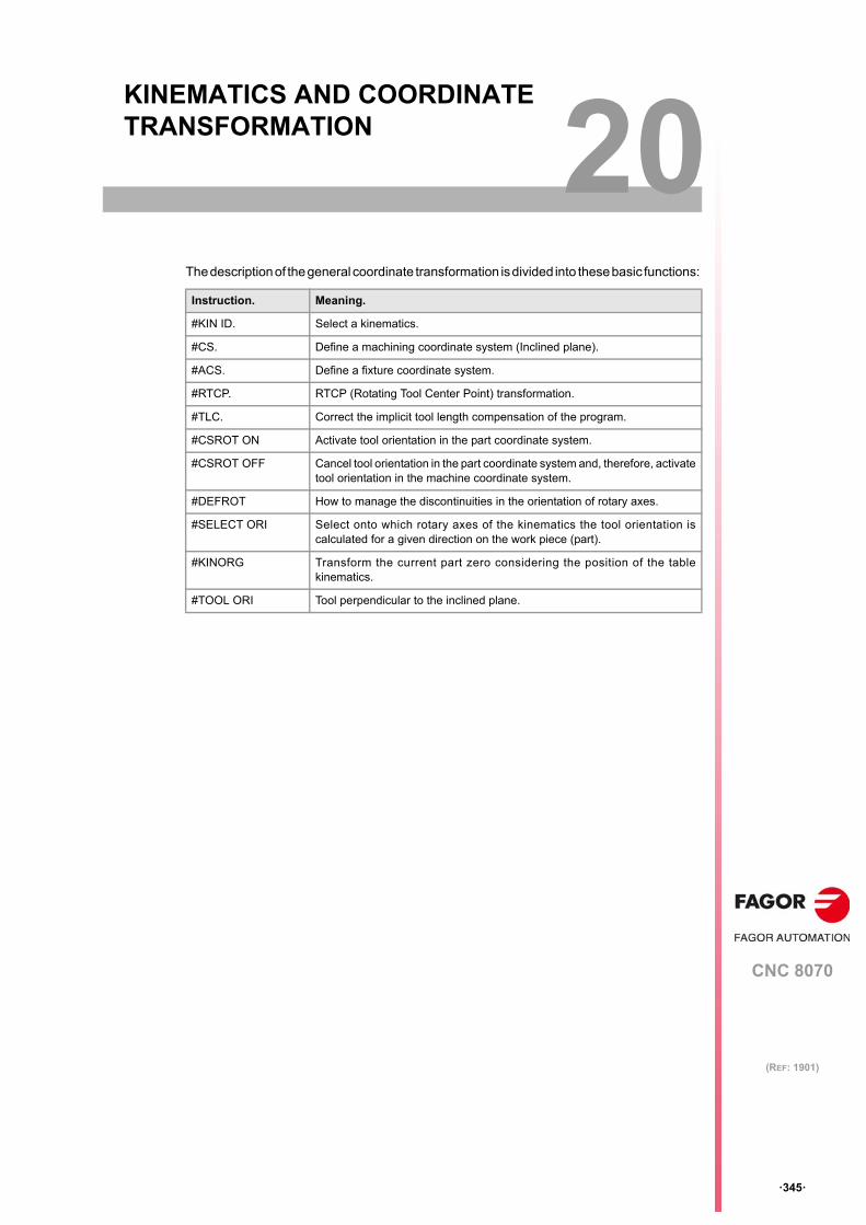
CNC 8070
20
·345·
(REF: 1901)
20.KINEMATICS AND COORDINATE TRANSFORMATION
The description of the general coordinate transformation is divided into these basic functions:
Instruction. Meaning.
#KIN ID. Select a kinematics.
#CS. Define a machining coordinate system (Inclined plane).
#ACS. Define a fixture coordinate system.
#RTCP. RTCP (Rotating Tool Center Point) transformation.
#TLC. Correct the implicit tool length compensation of the program.
#CSROT ON Activate tool orientation in the part coordinate system.
#CSROT OFF Cancel tool orientation in the part coordinate system and, therefore, activatetool orientation in the machine coordinate system.
#DEFROT How to manage the discontinuities in the orientation of rotary axes.
#SELECT ORI Select onto which rotary axes of the kinematics the tool orientation iscalculated for a given direction on the work piece (part).
#KINORG Transform the current part zero considering the position of the tablekinematics.
#TOOL ORI Tool perpendicular to the inclined plane.
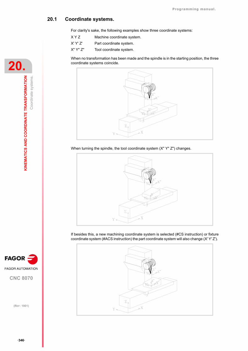
Programming manual.
CNC 8070
20.
KIN
EM
AT
ICS
AN
D C
OO
RD
INA
TE
TR
AN
SF
OR
MA
TIO
N
Coo
rdin
ate
syst
ems.
·346·
(REF: 1901)
20.1 Coordinate systems.
For clarity's sake, the following examples show three coordinate systems:
When no transformation has been made and the spindle is in the starting position, the threecoordinate systems coincide.
When turning the spindle, the tool coordinate system (X" Y" Z") changes.
If besides this, a new machining coordinate system is selected (#CS instruction) or fixturecoordinate system (#ACS instruction) the part coordinate system will also change (X' Y' Z').
X Y Z Machine coordinate system.
X' Y' Z' Part coordinate system.
X" Y" Z" Tool coordinate system.
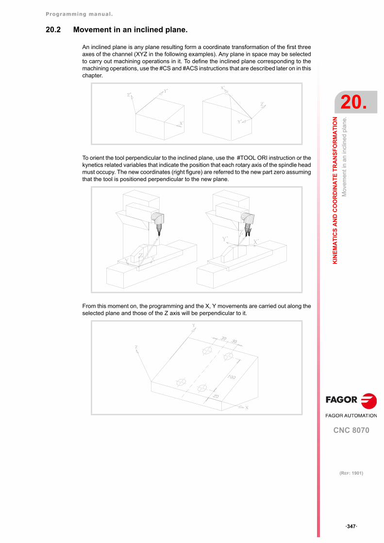
Programming manual.
CNC 8070
KIN
EM
AT
ICS
AN
D C
OO
RD
INA
TE
TR
AN
SF
OR
MA
TIO
N
20.
Mov
emen
t in
an in
clin
ed p
lane
.
·347·
(REF: 1901)
20.2 Movement in an inclined plane.
An inclined plane is any plane resulting form a coordinate transformation of the first threeaxes of the channel (XYZ in the following examples). Any plane in space may be selectedto carry out machining operations in it. To define the inclined plane corresponding to themachining operations, use the #CS and #ACS instructions that are described later on in thischapter.
To orient the tool perpendicular to the inclined plane, use the #TOOL ORI instruction or thekynetics related variables that indicate the position that each rotary axis of the spindle headmust occupy. The new coordinates (right figure) are referred to the new part zero assumingthat the tool is positioned perpendicular to the new plane.
From this moment on, the programming and the X, Y movements are carried out along theselected plane and those of the Z axis will be perpendicular to it.
Programming manual.
CNC 8070
20.
KIN
EM
AT
ICS
AN
D C
OO
RD
INA
TE
TR
AN
SF
OR
MA
TIO
N
Sel
ect a
kin
ema
tics
(#K
INID
).
·348·
(REF: 1901)
20.3 Select a kinematics (#KIN ID).
The manufacturer can set up to 6 kinematics for the machine each one indicating the typeof spindle or table, its characteristics and dimensions. Usually, the OEM defines thekinematics number being used by default by means of general machine parameter KINID.
To work with coordinate transformation, the kinematics being used must be indicated. Ifseveral kinematics have been defined, it is possible to activate the desired one via part-program using the instruction #KIN ID. If there is only one and it has been set as the defaultkinematics, there is no need to program this instruction.
Programming.
When defining this instruction, define the number of the kinematics to activate out of thepossible 6.
Programming format.
The programming format is the following; the list of arguments appears between curlybrackets.
#KIN ID [{kin}]
Deactivating the kinematics.
Programming the #KIN ID instruction with a 0 value deactivates the active kinematics.
Considerations.
• Functions #RTCP, #TLC and #TOOL ORI must always be activated after selecting akinematics.
• The kinematics cannot be changed while function #RTCP or #TLC is active.
{kin} Kinematics number (between 0 and 6). A value of 0 deactivates the kinematics.
#KIN ID [2](Activate kinematics number 2)
#KIN ID [0](Deactivate active kinematics)
N50 #KIN ID [2](Activate kinematics number 2)
N60 #RTCP ON(Activate RTCP transformation with kinematics 2)
.
.N70 #RTCP OFF
(Turn RTCP off)N80 M30
Programming manual.
CNC 8070
KIN
EM
AT
ICS
AN
D C
OO
RD
INA
TE
TR
AN
SF
OR
MA
TIO
N
20.
Coo
rdin
ate
syst
ems
(#C
S /
#AC
S).
·349·
(REF: 1901)
20.4 Coordinate systems (#CS / #ACS).
There are two different types of coordinate systems, namely the machining coordinatesystem and the fixture coordinate system. Each one is handled with its associatedinstruction.
Both instructions use the same programming format and may be used independently orcombined as indicated in the following sections.
Several #ACS and #CS coordinate systems may be combined. When activating a new one,it is added to the current coordinate system. See "20.4.8 How to combine several coordinatesystems." on page 362.
It is recommended to start the program with #CS NEW or #ACS NEW to avoid undesiredplanes. This happens, for example, after interrupting the program and resuming execution.
Programming.
Both instructions (#CS and #ACS) use the same programming format. There are variousprogramming formats depending on the operations to carry out with the coordinate systems;define, activate, save, cancel and delete.
Programming format.
The general programming format is the following; later on in this chapter, there is a moredetailed description of the different formats for each operation. See "Detailed programing."on page 350.
#CS <DEF/ON/NEW/OFF> <ALL> <ACT> [{nb}] [MODE {mode}, {V1}, {V2}, {V3}, {1}, {2}, {3}, <{align}>, <FIRST/SECOND>]#ACS <DEF/ON/NEW/OFF> <ALL> <ACT> [{nb}] [MODE {mode}, {V1}, {V2}, {V3}, {1}, {2}, {3}, <{align}>, <FIRST/SECOND> <SOL2>]
#CS With the #CS instruction, up to 5 machining coordinate systems may bedefined, stored, activated and deactivated.
#ACS With the #ACS instruction, up to 5 fixture coordinate systems may bedefined, stored, activated and deactivated. This system is used tocompensate for workpiece inclination due to the fixtures used to securethem.
In EDISIMU mode, the user can access an editor that makes programming inclined planes easier usingthe instructions #CS and #ACS. See the operating manual for further information on the editor ofinclined planes.
DEF/ON/NEW/OFF
Operation to be carried out.DEF: Define and save a coordinate system.ON: Define, save and activate a coordinate system.NEW: Cancel and delete all coordinate systems.OFF: Cancel a coordinate system.
ACT Together with the DEF command, it assumes and saves the current coordinatesystem.
ALL Together with the ALL command, cancels all coordinate systems.
{nb} Number of the coordinate system (from 1 to 5).
MODE {mode} Definition mode (from 1 to 6).
{V1}...{V3} Components of the translation vector.
{1}...{3} Rotation angles.
{align} Optional. Plane alignment (value 0/1). Only in modes 3, 4 and 5.
KEEP Optional. Command to maintain the part zero when canceling the coordinatesystem.
FIRST/SECOND Optional. Command to define the orientation of the axes. Only in mode 6.
<SOL2> Optional. On Huron type spindles, use the second solution to orient the spindle;if not programmed, use the first one.
Programming manual.
CNC 8070
20.
KIN
EM
AT
ICS
AN
D C
OO
RD
INA
TE
TR
AN
SF
OR
MA
TIO
N
Coo
rdin
ate
syst
ems
(#C
S /
#AC
S).
·350·
(REF: 1901)
Definition mode.
The MODE definition mode sets the order in which the axes rotate to reach the desired plane.In some cases, the resolution of the plane presents two solutions; the selection is carriedout defining which axis of the coordinate system stays aligned with the plane.
Maintain the part zero when canceling the coordinate system.
Turning a transformation off, if not defined otherwise, restores the part zero that was definedbefore activating the inclined plane. To maintain the current part zero, the one defined withthe coordinate system, program the command KEEP. This command is only admitted ininstructions that deactivate a coordinate system.
45º spindles (Huron type).
Huron type spindles have two solutions for orienting the tool perpendicular to the new workplane. For this type of spindles, it is possible to select which one of the two solutions is tobe applied (SOL2 command). See "20.4.7 Operation with 45º spindles (Huron type)." onpage 360.
Detailed programing.
Here are all the possible programming formats; the list of arguments appears between curlybrackets and the optional ones between angle brackets.
Format to define and save (without activating) a coordinate system.
If the coordinate system has already been defined earlier, these instructions will redefine it.
#CS DEF [{nb}] [MODE {mode}, {V1}, {V2}, {V3}, {1}, {2}, {3}, <{align}>, <FIRST/SECOND>]#ACS DEF [{nb}] [MODE {mode}, {V1}, {V2}, {V3}, {1}, {2}, {3}, <{align}>, <FIRST/SECOND>]
Format to define, save and activate a coordinate system.
#CS ON [{nb}] [MODE {mode}, {V1}, {V2}, {V3}, {1}, {2}, {3}, <{align}>, <FIRST/SECOND>]#ACS ON [{nb}] [MODE {mode}, {V1}, {V2}, {V3}, {1}, {2}, {3}, <{align}>, <FIRST/SECOND>]
{nb} Number of the coordinate system (from 1 to 5).
MODE {mode} Definition mode (from 1 to 6).
{V1}...{V3} Components of the translation vector.
{1}...{3} Rotation angles.
{align} Optional. Plane alignment (value 0/1). Only in modes 3, 4 and 5.
FIRST/SECOND Optional. Command to define the orientation of the axes. Only in mode 6.
#CS DEF [2] [MODE 1,0,15,5,30,15,4.5](Defines and saves a new coordinate system as CS2)
#CS DEF [3] [MODE 3,0,15,5,30,15,4.5,1](Defines and saves a new coordinate system as CS3)
#CS DEF [4] [MODE 6,20,105,50,30,FIRST](Defines and saves a new coordinate system as CS4)
{nb} Number of the coordinate system (from 1 to 5).
MODE {mode} Definition mode (from 1 to 6).
{V1}...{V3} Components of the translation vector.
{1}...{3} Rotation angles.
{align} Optional. Plane alignment (value 0/1). Only in modes 3, 4 and 5.
FIRST/SECOND Optional. Command to define the orientation of the axes. Only in mode 6.
#CS ON [2] [MODE 1,0,15,5,30,15,4.5](Defines, saves and activates a new coordinate system as CS2)
Programming manual.
CNC 8070
KIN
EM
AT
ICS
AN
D C
OO
RD
INA
TE
TR
AN
SF
OR
MA
TIO
N
20.
Coo
rdin
ate
syst
ems
(#C
S /
#AC
S).
·351·
(REF: 1901)
Format to define and activate (without saving) a coordinate system.
Only one of them may be defined; to define another one, the previous one must be canceled.The coordinate system may be used, until canceled, as any other coordinate system savedin memory.
#CS ON [MODE {mode}, {V1}, {V2}, {V3}, {1}, {2}, {3}, <{align}>, <FIRST/SECOND>]#ACS ON [MODE {mode}, {V1}, {V2}, {V3}, {1}, {2}, {3}, <{align}>, <FIRST/SECOND>]
Format to deactivate and delete all current coordinate systems and define, save andactivate a new one.
#CS NEW <KEEP> [{nb}] [MODE {mode}, {V1}, {V2}, {V3}, {1}, {2}, {3}, <{align}>, <FIRST/SECOND>]#ACS NEW <KEEP> [{nb}] [MODE {mode}, {V1}, {V2}, {V3}, {1}, {2}, {3}, <{align}>, <FIRST/SECOND>]
Format to cancel and delete all current coordinate systems and define and activatea new one (without saving).
#CS NEW <KEEP> [MODE {mode}, {V1}, {V2}, {V3}, {1}, {2}, {3}, <{align}>, <FIRST/SECOND>]#ACS NEW <KEEP> [MODE {mode}, {V1}, {V2}, {V3}, {1}, {2}, {3}, <{align}>, <FIRST/SECOND>]
MODE {mode} Definition mode (from 1 to 6).
{V1}...{V3} Components of the translation vector.
{1}...{3} Rotation angles.
{align} Optional. Plane alignment (value 0/1). Only in modes 3, 4 and 5.
FIRST/SECOND Optional. Command to define the orientation of the axes. Only in mode 6.
#CS ON [MODE 1,0,15,5,30,15,4.5](Defines and activates a new coordinate system)
{nb} Number of the coordinate system (from 1 to 5).
MODE {mode} Definition mode (from 1 to 6).
{V1}...{V3} Components of the translation vector.
{1}...{3} Rotation angles.
{align} Optional. Plane alignment (value 0/1). Only in modes 3, 4 and 5.
KEEP Optional. Command to define whether the part zero defined in the coordinatesystem will be maintained (kept) or not when canceling the coordinate system.
FIRST/SECOND Optional. Command to define the orientation of the axes. Only in mode 6.
#CS NEW KEEP [2] [MODE 1,0,15,5,30,15,4.5](Cancels and deletes all coordinate systems)(Defines, saves and activates a new coordinate system as CS2)(Keeps the part zero)
MODE {mode} Definition mode (from 1 to 6).
{V1}...{V3} Components of the translation vector.
{1}...{3} Rotation angles.
{align} Optional. Plane alignment (value 0/1). Only in modes 3, 4 and 5.
KEEP Optional. Command to define whether the part zero defined in the coordinatesystem will be maintained (kept) or not when canceling the coordinate system.
FIRST/SECOND Optional. Command to define the orientation of the axes. Only in mode 6.
#CS NEW [2] [MODE 1,0,15,5,30,15,4.5](Cancels and deletes all coordinate systems)(Defines and activates a new coordinate system)
Programming manual.
CNC 8070
20.
KIN
EM
AT
ICS
AN
D C
OO
RD
INA
TE
TR
AN
SF
OR
MA
TIO
N
Coo
rdin
ate
syst
ems
(#C
S /
#AC
S).
·352·
(REF: 1901)
Format to assume and save the current coordinate system.
#CS DEF ACT [{nb}]#ACS DEF ACT [{nb}]
Format to activate a saved coordinate system.
#CS ON [{nb}]#ACS ON [{nb}]
Format to activate the coordinate system saved last.
#CS ON#ACS ON
Format to cancel the coordinate system activated last.
#CS OFF <KEEP>#ACS OFF <KEEP>
Format to cancel all the active coordinate systems.
#CS OFF ALL#ACS OFF ALL
The coordinate systems and part zero.
The origin of the coordinate system is referred to the current part zero. While a CS or ACScoordinate system is active, new part zeros may be preset in the inclined plane.
Deactivating a inclined plane, if not defined otherwise, restores the part zero that was definedbefore activating the inclined plane. Optionally, it is possible to define whether to keep or notthe current part zero.
Sometimes, it could happen that when activating a CS or a ACS coordinate system savedearlier, the coordinate origin of the plane may not be desired one. This happens if the partzero is modified between the definition and the application of the coordinate system.
Considerations for the two functions.
Both coordinate systems, (#CS and #ACS) are kept active after a Reset or after executingan M02 or M30. On power-up, the CNC either keeps or cancels the coordinate systemaccording to the setting of machine parameter CSCANCEL.
{nb} Number of the coordinate system (from 1 to 5).
#CS DEF ACT [2](Assumes and saves a new coordinate system as CS2)
{nb} Number of the coordinate system (from 1 to 5).
#CS ON [2](Activates the CS2 coordinate system)
#CS ON(Activates the coordinate system saved last)
KEEP Optional. Command to define whether the part zero defined in the coordinatesystem will be maintained (kept) or not when canceling the coordinate system.
#CS OFF(Cancels the coordinate system activated last)
#CS OFF KEEP(Cancels the coordinate system activated last)(Keeps the part zero)
#CS OFF ALL(Cancels all active coordinate systems)
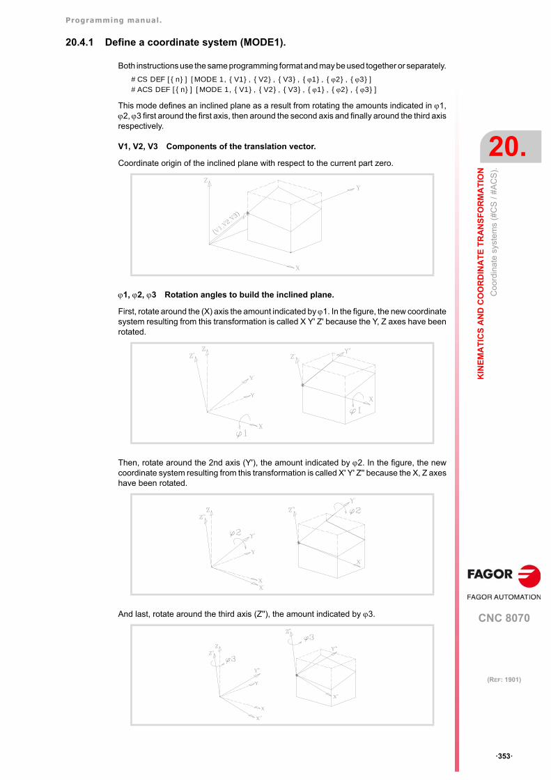
Programming manual.
CNC 8070
KIN
EM
AT
ICS
AN
D C
OO
RD
INA
TE
TR
AN
SF
OR
MA
TIO
N
20.
Coo
rdin
ate
syst
ems
(#C
S /
#AC
S).
·353·
(REF: 1901)
20.4.1 Define a coordinate system (MODE1).
Both instructions use the same programming format and may be used together or separately.
#CS DEF [{n}] [MODE 1, {V1}, {V2}, {V3}, {1}, {2}, {3}]#ACS DEF [{n}] [MODE 1, {V1}, {V2}, {V3}, {1}, {2}, {3}]
This mode defines an inclined plane as a result from rotating the amounts indicated in 1,2, 3 first around the first axis, then around the second axis and finally around the third axisrespectively.
V1, V2, V3 Components of the translation vector.
Coordinate origin of the inclined plane with respect to the current part zero.
1, 2, 3 Rotation angles to build the inclined plane.
First, rotate around the (X) axis the amount indicated by 1. In the figure, the new coordinatesystem resulting from this transformation is called X Y' Z' because the Y, Z axes have beenrotated.
Then, rotate around the 2nd axis (Y'), the amount indicated by 2. In the figure, the newcoordinate system resulting from this transformation is called X' Y' Z'' because the X, Z axeshave been rotated.
And last, rotate around the third axis (Z''), the amount indicated by 3.
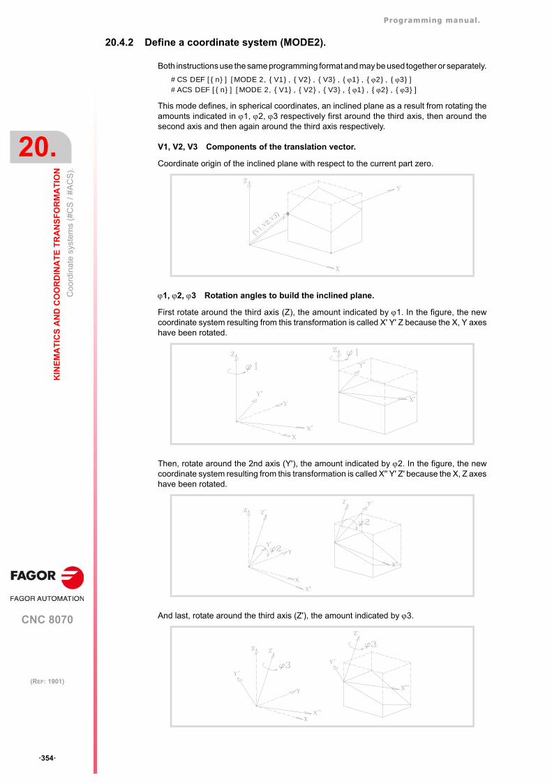
Programming manual.
CNC 8070
20.
KIN
EM
AT
ICS
AN
D C
OO
RD
INA
TE
TR
AN
SF
OR
MA
TIO
N
Coo
rdin
ate
syst
ems
(#C
S /
#AC
S).
·354·
(REF: 1901)
20.4.2 Define a coordinate system (MODE2).
Both instructions use the same programming format and may be used together or separately.
#CS DEF [{n}] [MODE 2, {V1}, {V2}, {V3}, {1}, {2}, {3}]#ACS DEF [{n}] [MODE 2, {V1}, {V2}, {V3}, {1}, {2}, {3}]
This mode defines, in spherical coordinates, an inclined plane as a result from rotating theamounts indicated in 1, 2, 3 respectively first around the third axis, then around thesecond axis and then again around the third axis respectively.
V1, V2, V3 Components of the translation vector.
Coordinate origin of the inclined plane with respect to the current part zero.
1, 2, 3 Rotation angles to build the inclined plane.
First rotate around the third axis (Z), the amount indicated by 1. In the figure, the newcoordinate system resulting from this transformation is called X' Y' Z because the X, Y axeshave been rotated.
Then, rotate around the 2nd axis (Y'), the amount indicated by 2. In the figure, the newcoordinate system resulting from this transformation is called X'' Y' Z' because the X, Z axeshave been rotated.
And last, rotate around the third axis (Z'), the amount indicated by 3.
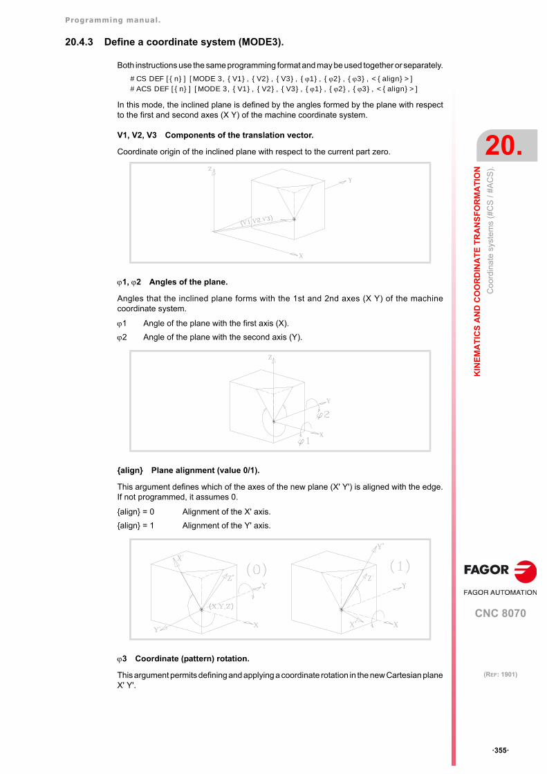
Programming manual.
CNC 8070
KIN
EM
AT
ICS
AN
D C
OO
RD
INA
TE
TR
AN
SF
OR
MA
TIO
N
20.
Coo
rdin
ate
syst
ems
(#C
S /
#AC
S).
·355·
(REF: 1901)
20.4.3 Define a coordinate system (MODE3).
Both instructions use the same programming format and may be used together or separately.
#CS DEF [{n}] [MODE 3, {V1}, {V2}, {V3}, {1}, {2}, {3}, <{align}>]#ACS DEF [{n}] [MODE 3, {V1}, {V2}, {V3}, {1}, {2}, {3}, <{align}>]
In this mode, the inclined plane is defined by the angles formed by the plane with respectto the first and second axes (X Y) of the machine coordinate system.
V1, V2, V3 Components of the translation vector.
Coordinate origin of the inclined plane with respect to the current part zero.
1, 2 Angles of the plane.
Angles that the inclined plane forms with the 1st and 2nd axes (X Y) of the machinecoordinate system.
{align} Plane alignment (value 0/1).
This argument defines which of the axes of the new plane (X' Y') is aligned with the edge.If not programmed, it assumes 0.
3 Coordinate (pattern) rotation.
This argument permits defining and applying a coordinate rotation in the new Cartesian planeX' Y'.
1 Angle of the plane with the first axis (X).
2 Angle of the plane with the second axis (Y).
{align} = 0 Alignment of the X' axis.
{align} = 1 Alignment of the Y' axis.
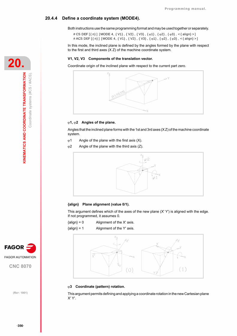
Programming manual.
CNC 8070
20.
KIN
EM
AT
ICS
AN
D C
OO
RD
INA
TE
TR
AN
SF
OR
MA
TIO
N
Coo
rdin
ate
syst
ems
(#C
S /
#AC
S).
·356·
(REF: 1901)
20.4.4 Define a coordinate system (MODE4).
Both instructions use the same programming format and may be used together or separately.
#CS DEF [{n}] [MODE 4, {V1}, {V2}, {V3}, {1}, {2}, {3}, <{align}>]#ACS DEF [{n}] [MODE 4, {V1}, {V2}, {V3}, {1}, {2}, {3}, <{align}>]
In this mode, the inclined plane is defined by the angles formed by the plane with respectto the first and third axes (X Z) of the machine coordinate system.
V1, V2, V3 Components of the translation vector.
Coordinate origin of the inclined plane with respect to the current part zero.
1, 2 Angles of the plane.
Angles that the inclined plane forms with the 1st and 3rd axes (X Z) of the machine coordinatesystem.
{align} Plane alignment (value 0/1).
This argument defines which of the axes of the new plane (X' Y') is aligned with the edge.If not programmed, it assumes 0.
3 Coordinate (pattern) rotation.
This argument permits defining and applying a coordinate rotation in the new Cartesian planeX' Y'.
1 Angle of the plane with the first axis (X).
2 Angle of the plane with the third axis (Z).
{align} = 0 Alignment of the X' axis.
{align} = 1 Alignment of the Y' axis.
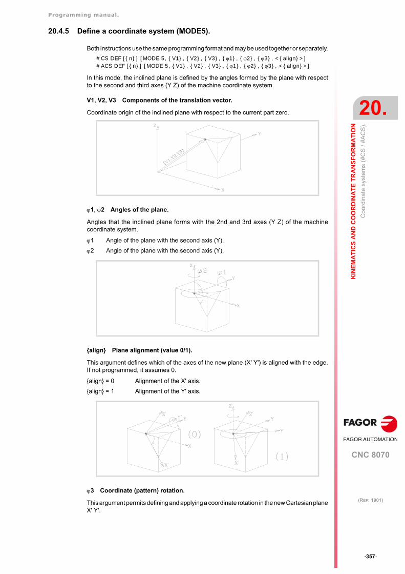
Programming manual.
CNC 8070
KIN
EM
AT
ICS
AN
D C
OO
RD
INA
TE
TR
AN
SF
OR
MA
TIO
N
20.
Coo
rdin
ate
syst
ems
(#C
S /
#AC
S).
·357·
(REF: 1901)
20.4.5 Define a coordinate system (MODE5).
Both instructions use the same programming format and may be used together or separately.
#CS DEF [{n}] [MODE 5, {V1}, {V2}, {V3}, {1}, {2}, {3}, <{align}>]#ACS DEF [{n}] [MODE 5, {V1}, {V2}, {V3}, {1}, {2}, {3}, <{align}>]
In this mode, the inclined plane is defined by the angles formed by the plane with respectto the second and third axes (Y Z) of the machine coordinate system.
V1, V2, V3 Components of the translation vector.
Coordinate origin of the inclined plane with respect to the current part zero.
1, 2 Angles of the plane.
Angles that the inclined plane forms with the 2nd and 3rd axes (Y Z) of the machinecoordinate system.
{align} Plane alignment (value 0/1).
This argument defines which of the axes of the new plane (X' Y') is aligned with the edge.If not programmed, it assumes 0.
3 Coordinate (pattern) rotation.
This argument permits defining and applying a coordinate rotation in the new Cartesian planeX' Y'.
1 Angle of the plane with the second axis (Y).
2 Angle of the plane with the second axis (Y).
{align} = 0 Alignment of the X' axis.
{align} = 1 Alignment of the Y' axis.
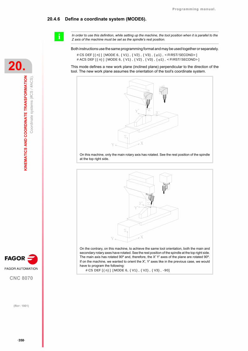
Programming manual.
CNC 8070
20.
KIN
EM
AT
ICS
AN
D C
OO
RD
INA
TE
TR
AN
SF
OR
MA
TIO
N
Coo
rdin
ate
syst
ems
(#C
S /
#AC
S).
·358·
(REF: 1901)
20.4.6 Define a coordinate system (MODE6).
Both instructions use the same programming format and may be used together or separately.
#CS DEF [{n}] [MODE 6, {V1}, {V2}, {V3}, {1}, <FIRST/SECOND>]#ACS DEF [{n}] [MODE 6, {V1}, {V2}, {V3}, {1}, <FIRST/SECOND>]
This mode defines a new work plane (inclined plane) perpendicular to the direction of thetool. The new work plane assumes the orientation of the tool's coordinate system.
In order to use this definition, while setting up the machine, the tool position when it is parallel to theZ axis of the machine must be set as the spindle's rest position.i
On this machine, only the main rotary axis has rotated. See the rest position of the spindleat the top right side.
On the contrary, on this machine, to achieve the same tool orientation, both the main andsecondary rotary axes have rotated. See the rest position of the spindle at the top right side.The main axis has rotated 90º and, therefore, the X' Y' axes of the plane are rotated 90º.If on the machine, we wanted to orient the X', Y' axes like in the previous case, we wouldhave to program the following:
#CS DEF [{n}] [MODE 6, {V1}, {V2}, {V3}, -90]
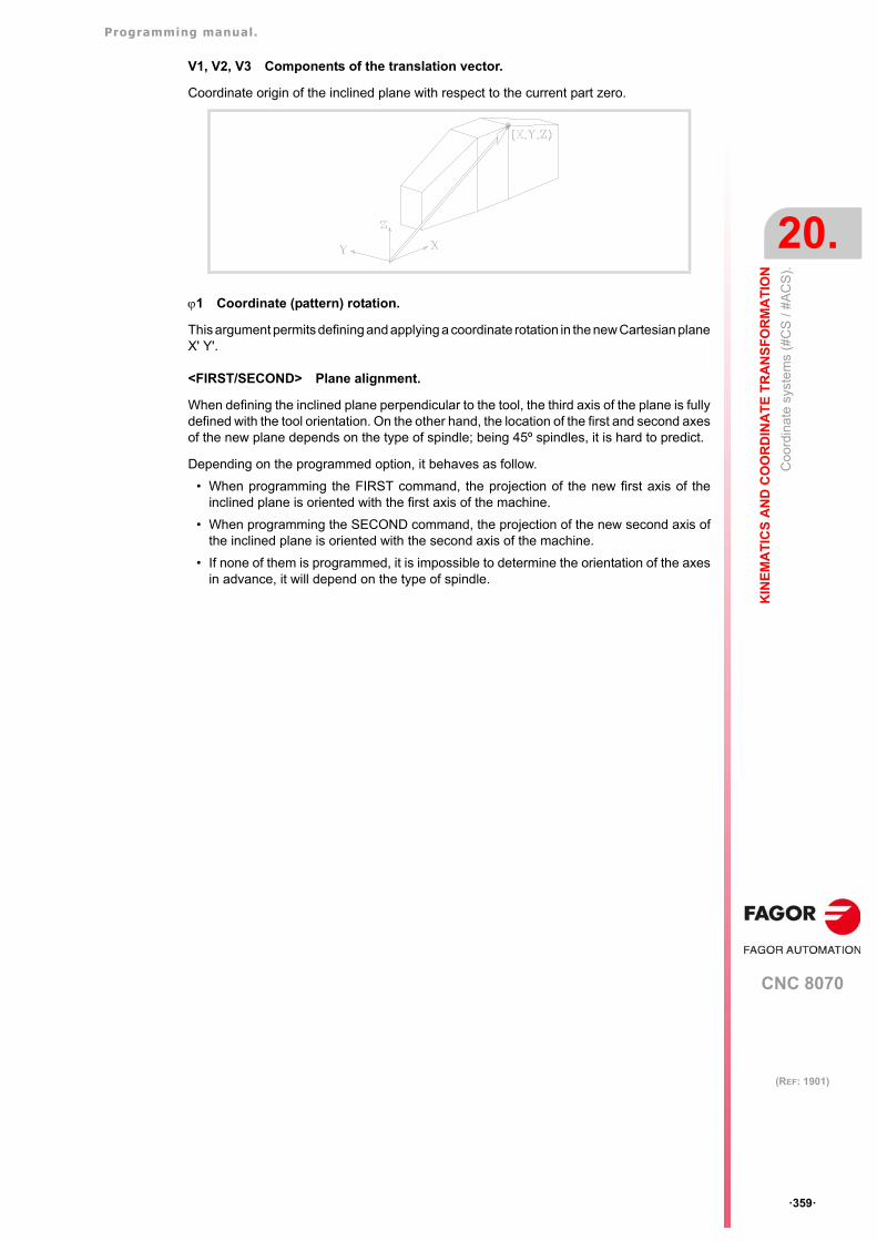
Programming manual.
CNC 8070
KIN
EM
AT
ICS
AN
D C
OO
RD
INA
TE
TR
AN
SF
OR
MA
TIO
N
20.
Coo
rdin
ate
syst
ems
(#C
S /
#AC
S).
·359·
(REF: 1901)
V1, V2, V3 Components of the translation vector.
Coordinate origin of the inclined plane with respect to the current part zero.
1 Coordinate (pattern) rotation.
This argument permits defining and applying a coordinate rotation in the new Cartesian planeX' Y'.
<FIRST/SECOND> Plane alignment.
When defining the inclined plane perpendicular to the tool, the third axis of the plane is fullydefined with the tool orientation. On the other hand, the location of the first and second axesof the new plane depends on the type of spindle; being 45º spindles, it is hard to predict.
Depending on the programmed option, it behaves as follow.
• When programming the FIRST command, the projection of the new first axis of theinclined plane is oriented with the first axis of the machine.
• When programming the SECOND command, the projection of the new second axis ofthe inclined plane is oriented with the second axis of the machine.
• If none of them is programmed, it is impossible to determine the orientation of the axesin advance, it will depend on the type of spindle.
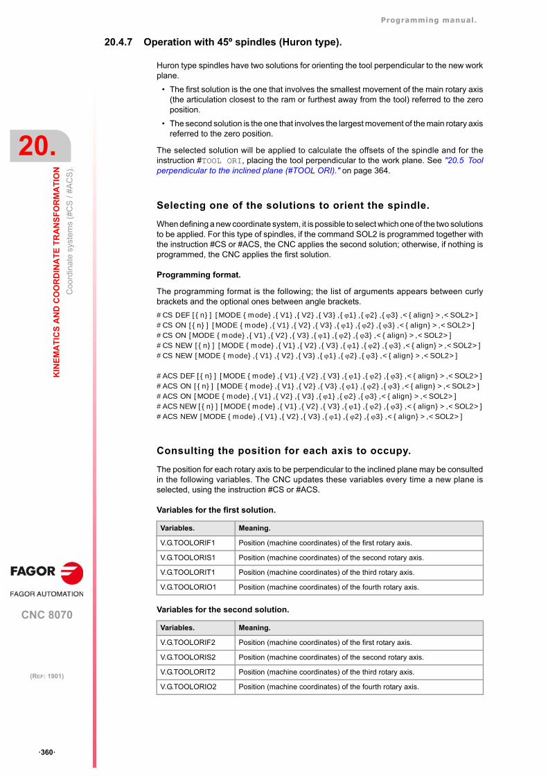
Programming manual.
CNC 8070
20.
KIN
EM
AT
ICS
AN
D C
OO
RD
INA
TE
TR
AN
SF
OR
MA
TIO
N
Coo
rdin
ate
syst
ems
(#C
S /
#AC
S).
·360·
(REF: 1901)
20.4.7 Operation with 45º spindles (Huron type).
Huron type spindles have two solutions for orienting the tool perpendicular to the new workplane.
• The first solution is the one that involves the smallest movement of the main rotary axis(the articulation closest to the ram or furthest away from the tool) referred to the zeroposition.
• The second solution is the one that involves the largest movement of the main rotary axisreferred to the zero position.
The selected solution will be applied to calculate the offsets of the spindle and for theinstruction #TOOL ORI, placing the tool perpendicular to the work plane. See "20.5 Toolperpendicular to the inclined plane (#TOOL ORI)." on page 364.
Selecting one of the solutions to orient the spindle.
When defining a new coordinate system, it is possible to select which one of the two solutionsto be applied. For this type of spindles, if the command SOL2 is programmed together withthe instruction #CS or #ACS, the CNC applies the second solution; otherwise, if nothing isprogrammed, the CNC applies the first solution.
Programming format.
The programming format is the following; the list of arguments appears between curlybrackets and the optional ones between angle brackets.
#CS DEF [{n}] [MODE {mode},{V1},{V2},{V3},{1},{2},{3},<{align}>,<SOL2>]#CS ON [{n}] [MODE {mode},{V1},{V2},{V3},{1},{2},{3},<{align}>,<SOL2>]#CS ON [MODE {mode},{V1},{V2},{V3},{1},{2},{3},<{align}>,<SOL2>]#CS NEW [{n}] [MODE {mode},{V1},{V2},{V3},{1},{2},{3},<{align}>,<SOL2>]#CS NEW [MODE {mode},{V1},{V2},{V3},{1},{2},{3},<{align}>,<SOL2>]
#ACS DEF [{n}] [MODE {mode},{V1},{V2},{V3},{1},{2},{3},<{align}>,<SOL2>]#ACS ON [{n}] [MODE {mode},{V1},{V2},{V3},{1},{2},{3},<{align}>,<SOL2>]#ACS ON [MODE {mode},{V1},{V2},{V3},{1},{2},{3},<{align}>,<SOL2>]#ACS NEW [{n}] [MODE {mode},{V1},{V2},{V3},{1},{2},{3},<{align}>,<SOL2>]#ACS NEW [MODE {mode},{V1},{V2},{V3},{1},{2},{3},<{align}>,<SOL2>]
Consulting the position for each axis to occupy.
The position for each rotary axis to be perpendicular to the inclined plane may be consultedin the following variables. The CNC updates these variables every time a new plane isselected, using the instruction #CS or #ACS.
Variables for the first solution.
Variables for the second solution.
Variables. Meaning.
V.G.TOOLORIF1 Position (machine coordinates) of the first rotary axis.
V.G.TOOLORIS1 Position (machine coordinates) of the second rotary axis.
V.G.TOOLORIT1 Position (machine coordinates) of the third rotary axis.
V.G.TOOLORIO1 Position (machine coordinates) of the fourth rotary axis.
Variables. Meaning.
V.G.TOOLORIF2 Position (machine coordinates) of the first rotary axis.
V.G.TOOLORIS2 Position (machine coordinates) of the second rotary axis.
V.G.TOOLORIT2 Position (machine coordinates) of the third rotary axis.
V.G.TOOLORIO2 Position (machine coordinates) of the fourth rotary axis.
Programming manual.
CNC 8070
KIN
EM
AT
ICS
AN
D C
OO
RD
INA
TE
TR
AN
SF
OR
MA
TIO
N
20.
Coo
rdin
ate
syst
ems
(#C
S /
#AC
S).
·361·
(REF: 1901)
In order that the tool is perpendicular to the defined plane, the positioning must be performedusing machine coordinates (#MCS), since the CNC provides the solution in machinecoordinates, or by using the instruction #TOOL ORI and the movement of an axis.
Option 1. Movement in machine dimensions with the given solution.
#MCS ONG01B[V.G.TOOLORIF1] C[V.G.TOOLORIS1] F1720#MCS OFF
Option 2. Orientate the work plane so that it is perpendicular to the tool for the nextmovement after #TOOL ORI.
#TOOL ORIG01 X0 Y0 Z40
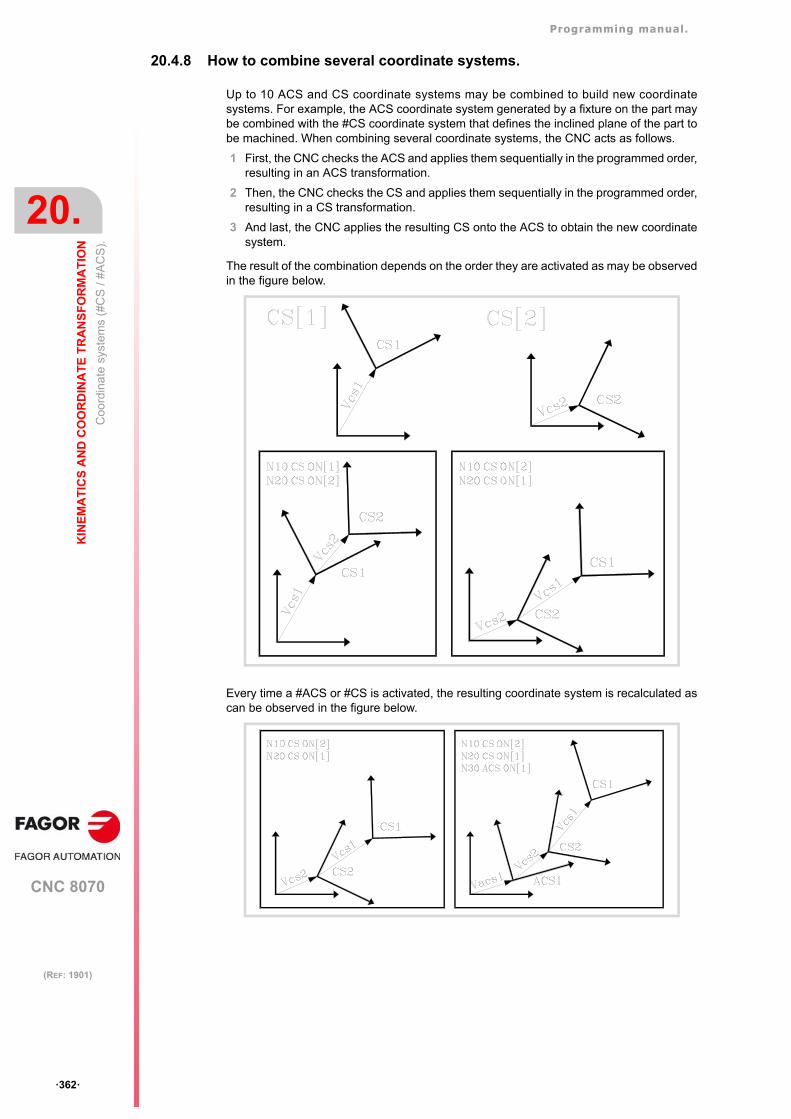
Programming manual.
CNC 8070
20.
KIN
EM
AT
ICS
AN
D C
OO
RD
INA
TE
TR
AN
SF
OR
MA
TIO
N
Coo
rdin
ate
syst
ems
(#C
S /
#AC
S).
·362·
(REF: 1901)
20.4.8 How to combine several coordinate systems.
Up to 10 ACS and CS coordinate systems may be combined to build new coordinatesystems. For example, the ACS coordinate system generated by a fixture on the part maybe combined with the #CS coordinate system that defines the inclined plane of the part tobe machined. When combining several coordinate systems, the CNC acts as follows.
1 First, the CNC checks the ACS and applies them sequentially in the programmed order,resulting in an ACS transformation.
2 Then, the CNC checks the CS and applies them sequentially in the programmed order,resulting in a CS transformation.
3 And last, the CNC applies the resulting CS onto the ACS to obtain the new coordinatesystem.
The result of the combination depends on the order they are activated as may be observedin the figure below.
Every time a #ACS or #CS is activated, the resulting coordinate system is recalculated ascan be observed in the figure below.
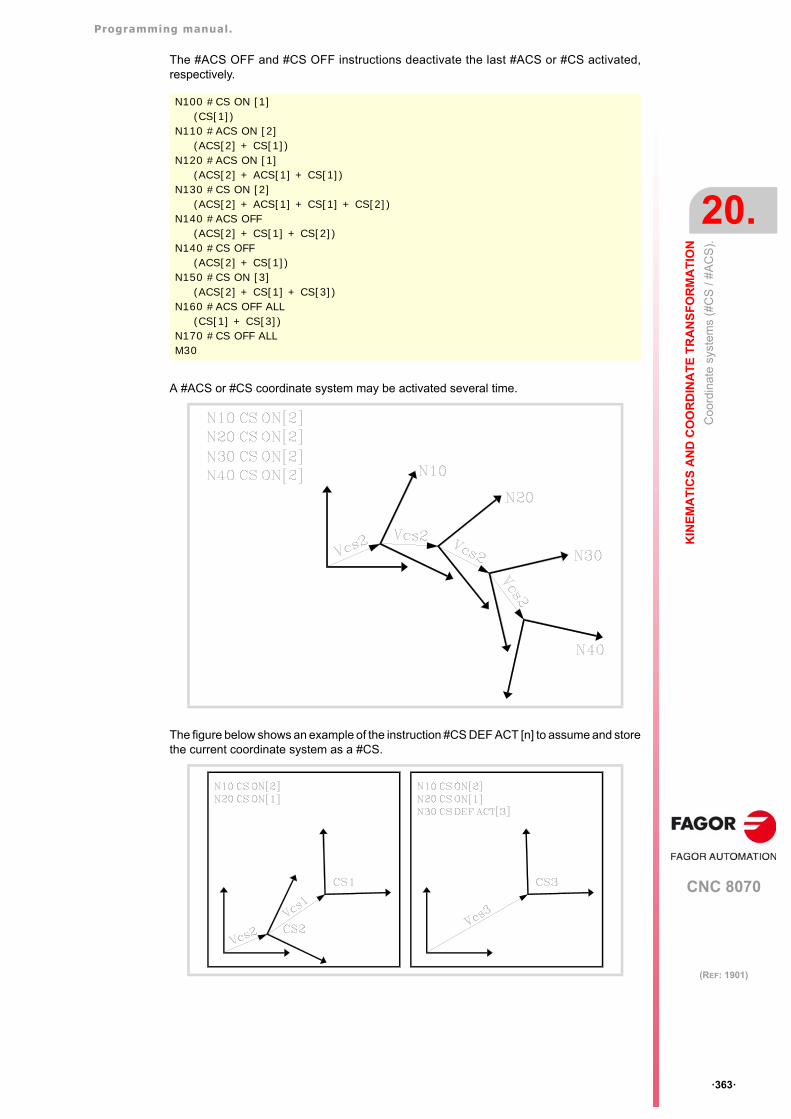
Programming manual.
CNC 8070
KIN
EM
AT
ICS
AN
D C
OO
RD
INA
TE
TR
AN
SF
OR
MA
TIO
N
20.
Coo
rdin
ate
syst
ems
(#C
S /
#AC
S).
·363·
(REF: 1901)
The #ACS OFF and #CS OFF instructions deactivate the last #ACS or #CS activated,respectively.
A #ACS or #CS coordinate system may be activated several time.
The figure below shows an example of the instruction #CS DEF ACT [n] to assume and storethe current coordinate system as a #CS.
N100 #CS ON [1](CS[1])
N110 #ACS ON [2](ACS[2] + CS[1])
N120 #ACS ON [1](ACS[2] + ACS[1] + CS[1])
N130 #CS ON [2](ACS[2] + ACS[1] + CS[1] + CS[2])
N140 #ACS OFF(ACS[2] + CS[1] + CS[2])
N140 #CS OFF(ACS[2] + CS[1])
N150 #CS ON [3](ACS[2] + CS[1] + CS[3])
N160 #ACS OFF ALL(CS[1] + CS[3])
N170 #CS OFF ALLM30
Programming manual.
CNC 8070
20.
KIN
EM
AT
ICS
AN
D C
OO
RD
INA
TE
TR
AN
SF
OR
MA
TIO
N
Too
l pe
rpen
dic
ula
r to
the
incl
ined
pla
ne (
#TO
OL
OR
I).
·364·
(REF: 1901)
20.5 Tool perpendicular to the inclined plane (#TOOL ORI).
The #TOOL ORI instruction is used to position the tool perpendicular to the active inclinedplane. After executing this instruction, the tool is positioned perpendicular to the inclinedplane, parallel to the third axis of the active coordinate system at the first motion programmednext.
Programming.
Program the instruction alone in the block.
Programming format.
The programming format is:
#TOOL ORI
#TOOL ORI(Tool perpendicular to the inclined plane; request)
G1 X_ Y_ Z_(Position at the defined point, with the tool perpendicular to the inclined plane)
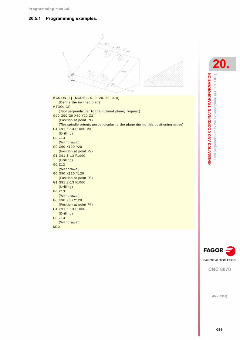
Programming manual.
CNC 8070
KIN
EM
AT
ICS
AN
D C
OO
RD
INA
TE
TR
AN
SF
OR
MA
TIO
N
20.
Too
l pe
rpen
dic
ula
r to
the
incl
ined
pla
ne (
#TO
OL
OR
I).
·365·
(REF: 1901)
20.5.1 Programming examples.
#CS ON [1] [MODE 1, 0, 0, 20, 30, 0, 0](Define the inclined plane)
#TOOL ORI(Tool perpendicular to the inclined plane; request)
G90 G90 G0 X60 Y20 Z3(Position at point P1)(The spindle orients perpendicular to the plane during this positioning move)
G1 G91 Z-13 F1000 M3(Drilling)
G0 Z13(Withdrawal)
G0 G90 X120 Y20(Position at point P2)
G1 G91 Z-13 F1000(Drilling)
G0 Z13(Withdrawal)
G0 G90 X120 Y120(Position at point P3)
G1 G91 Z-13 F1000(Drilling)
G0 Z13(Withdrawal)
G0 G90 X60 Y120(Position at point P4)
G1 G91 Z-13 F1000(Drilling)
G0 Z13(Withdrawal)
M30
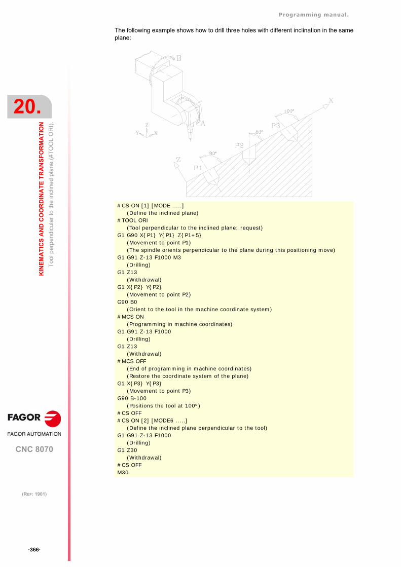
Programming manual.
CNC 8070
20.
KIN
EM
AT
ICS
AN
D C
OO
RD
INA
TE
TR
AN
SF
OR
MA
TIO
N
Too
l pe
rpen
dic
ula
r to
the
incl
ined
pla
ne (
#TO
OL
OR
I).
·366·
(REF: 1901)
The following example shows how to drill three holes with different inclination in the sameplane:
#CS ON [1] [MODE .....](Define the inclined plane)
#TOOL ORI(Tool perpendicular to the inclined plane; request)
G1 G90 X{P1} Y{P1} Z{P1+5}(Movement to point P1)(The spindle orients perpendicular to the plane during this positioning move)
G1 G91 Z-13 F1000 M3(Drilling)
G1 Z13(Withdrawal)
G1 X{P2} Y{P2}(Movement to point P2)
G90 B0(Orient to the tool in the machine coordinate system)
#MCS ON(Programming in machine coordinates)
G1 G91 Z-13 F1000(Drilling)
G1 Z13(Withdrawal)
#MCS OFF(End of programming in machine coordinates)(Restore the coordinate system of the plane)
G1 X{P3} Y{P3}(Movement to point P3)
G90 B-100(Positions the tool at 100º)
#CS OFF#CS ON [2] [MODE6 .....]
(Define the inclined plane perpendicular to the tool)G1 G91 Z-13 F1000
(Drilling)G1 Z30
(Withdrawal)#CS OFFM30
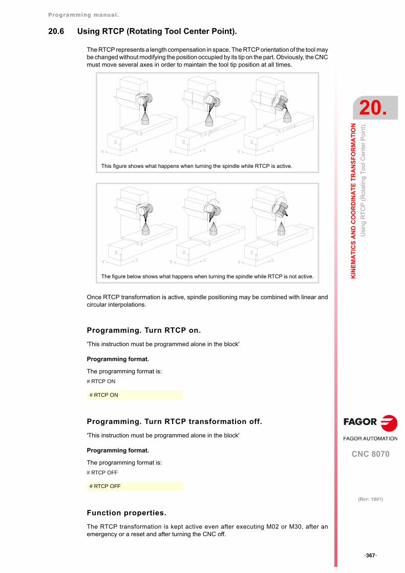
Programming manual.
CNC 8070
KIN
EM
AT
ICS
AN
D C
OO
RD
INA
TE
TR
AN
SF
OR
MA
TIO
N
20.
Usi
ng R
TC
P (
Ro
tatin
g T
ool
Cen
ter
Poi
nt)
.
·367·
(REF: 1901)
20.6 Using RTCP (Rotating Tool Center Point).
The RTCP represents a length compensation in space. The RTCP orientation of the tool maybe changed without modifying the position occupied by its tip on the part. Obviously, the CNCmust move several axes in order to maintain the tool tip position at all times.
Once RTCP transformation is active, spindle positioning may be combined with linear andcircular interpolations.
Programming. Turn RTCP on.
'This instruction must be programmed alone in the block'
Programming format.
The programming format is:
#RTCP ON
Programming. Turn RTCP transformation off.
'This instruction must be programmed alone in the block'
Programming format.
The programming format is:
#RTCP OFF
Function properties.
The RTCP transformation is kept active even after executing M02 or M30, after anemergency or a reset and after turning the CNC off.
This figure shows what happens when turning the spindle while RTCP is active.
The figure below shows what happens when turning the spindle while RTCP is not active.
#RTCP ON
#RTCP OFF

Programming manual.
CNC 8070
20.
KIN
EM
AT
ICS
AN
D C
OO
RD
INA
TE
TR
AN
SF
OR
MA
TIO
N
Usi
ng R
TC
P (
Ro
tatin
g T
ool
Cen
ter
Poi
nt)
.
·368·
(REF: 1901)
Considerations about the RTCP transformation.
• In order to work with RTCP transformation, the first three axes of the channel (for exampleX, Y, Z) must be defined, they must form a trihedron and be linear. These axes may beGANTRY axes.
• Being RTCP transformation active, it is possible to apply zero offsets (G54-G59, G159)and preset coordinates (G92).
• Being RTCP transformation active, it is possible to carry out movements in continuousjob, incremental jog and handwheel mode.
• RTCP transformation being active, the CNC only allows home search (G74) on the axesnot involved in RTCP .
• The RTCP transformation cannot be selected while the TLC compensation is active.
• RTCP transformation being active, the CNC does not allow modifying the activekinematics (#KIN ID).
• RTCP transformation being active, the CNC does not allow modifying the software limits(G198/G199).
Recommended programming order.
When working with inclined planes and RTCP transformation, it is recommended to followthis programming order (sequence). RTCP should be turned on first because it allowsorienting the tool without modifying the tool tip position.
#RTCP ON(Turn RTCP on)
#CS ON(Activate the inclined plane)
#TOOL ORI(Position the tool perpendicular to the plane)
G_ X_ Y_ Z_(Machine on the inclined plane)···
#CS OFF(Cancel the inclined plane)
#RTCP OFF(Turn RTCP off)
M30(End of part-program)
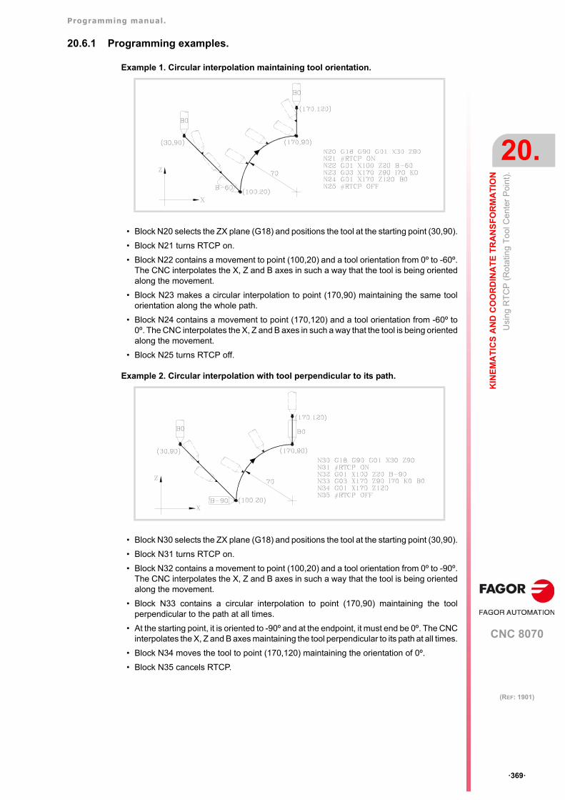
Programming manual.
CNC 8070
KIN
EM
AT
ICS
AN
D C
OO
RD
INA
TE
TR
AN
SF
OR
MA
TIO
N
20.
Usi
ng R
TC
P (
Ro
tatin
g T
ool
Cen
ter
Poi
nt)
.
·369·
(REF: 1901)
20.6.1 Programming examples.
Example 1. Circular interpolation maintaining tool orientation.
• Block N20 selects the ZX plane (G18) and positions the tool at the starting point (30,90).
• Block N21 turns RTCP on.
• Block N22 contains a movement to point (100,20) and a tool orientation from 0º to -60º.The CNC interpolates the X, Z and B axes in such a way that the tool is being orientedalong the movement.
• Block N23 makes a circular interpolation to point (170,90) maintaining the same toolorientation along the whole path.
• Block N24 contains a movement to point (170,120) and a tool orientation from -60º to0º. The CNC interpolates the X, Z and B axes in such a way that the tool is being orientedalong the movement.
• Block N25 turns RTCP off.
Example 2. Circular interpolation with tool perpendicular to its path.
• Block N30 selects the ZX plane (G18) and positions the tool at the starting point (30,90).
• Block N31 turns RTCP on.
• Block N32 contains a movement to point (100,20) and a tool orientation from 0º to -90º.The CNC interpolates the X, Z and B axes in such a way that the tool is being orientedalong the movement.
• Block N33 contains a circular interpolation to point (170,90) maintaining the toolperpendicular to the path at all times.
• At the starting point, it is oriented to -90º and at the endpoint, it must end be 0º. The CNCinterpolates the X, Z and B axes maintaining the tool perpendicular to its path at all times.
• Block N34 moves the tool to point (170,120) maintaining the orientation of 0º.
• Block N35 cancels RTCP.
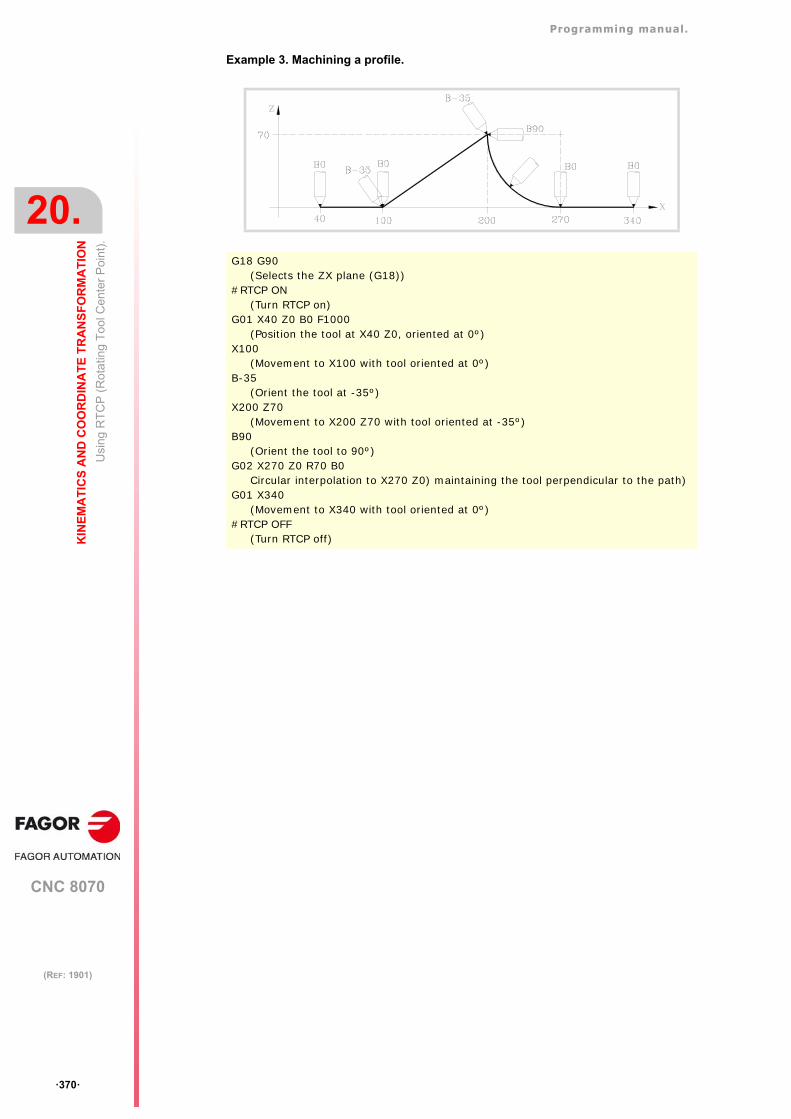
Programming manual.
CNC 8070
20.
KIN
EM
AT
ICS
AN
D C
OO
RD
INA
TE
TR
AN
SF
OR
MA
TIO
N
Usi
ng R
TC
P (
Ro
tatin
g T
ool
Cen
ter
Poi
nt)
.
·370·
(REF: 1901)
Example 3. Machining a profile.
G18 G90(Selects the ZX plane (G18))
#RTCP ON(Turn RTCP on)
G01 X40 Z0 B0 F1000(Position the tool at X40 Z0, oriented at 0º)
X100(Movement to X100 with tool oriented at 0º)
B-35(Orient the tool at -35º)
X200 Z70(Movement to X200 Z70 with tool oriented at -35º)
B90(Orient the tool to 90º)
G02 X270 Z0 R70 B0Circular interpolation to X270 Z0) maintaining the tool perpendicular to the path)
G01 X340(Movement to X340 with tool oriented at 0º)
#RTCP OFF(Turn RTCP off)
Programming manual.
CNC 8070
KIN
EM
AT
ICS
AN
D C
OO
RD
INA
TE
TR
AN
SF
OR
MA
TIO
N
20.
Cor
rect
the
impl
icit
too
l len
gth
com
pen
satio
n o
f the
pro
gram
(#T
LC).
·371·
(REF: 1901)
20.7 Correct the implicit tool length compensation of the program(#TLC).
CAD-CAM programs take the tool length into consideration and generate the coordinatesfor the tool base. The instruction #TLC must be used with CAD-CAM generated programsand the CNC does not have a tool with the same dimensions. When using the #TLC function(Tool Length Compensation) the CNC compensates the length difference between bothtools, the actual (real) one and the theoretical (calculated) one. The #TLC compensates forthe length difference; but it does not compensate for the radius difference.
Programming. Turn tool length compensation (TLC) on.
When defining this instruction, one must define the length difference between the real tooland the theoretical one used to write the program.
Programming format.
The programming format is the following; the list of arguments appears between curlybrackets.
#TLC ON [{long}]
Programming. Cancel tool length compensation (TLC off).
'This instruction must be programmed alone in the block'
Programming format.
The programming format is:
#TLC OFF
Considerations about the TLC.
• TLC compensation being active, the CNC only allows home search (G74) on the axesnot involved in TLC.
• TLC cannot be selected while the RTCP transformation is active.
• TLC compensation being active, the CNC does not allow modifying the active kinematics(#KIN ID).
• TLC compensation being active, the CNC does not allow modifying the software limits(G198/G199).
{long} Tool length difference (real - theoretical).
#TLC ON [1.5](Turn on with a tool that is 1.5 mm longer)
#TLC ON [-2](Turn on with a tool that is 2 mm shorter)
#TLC OFF
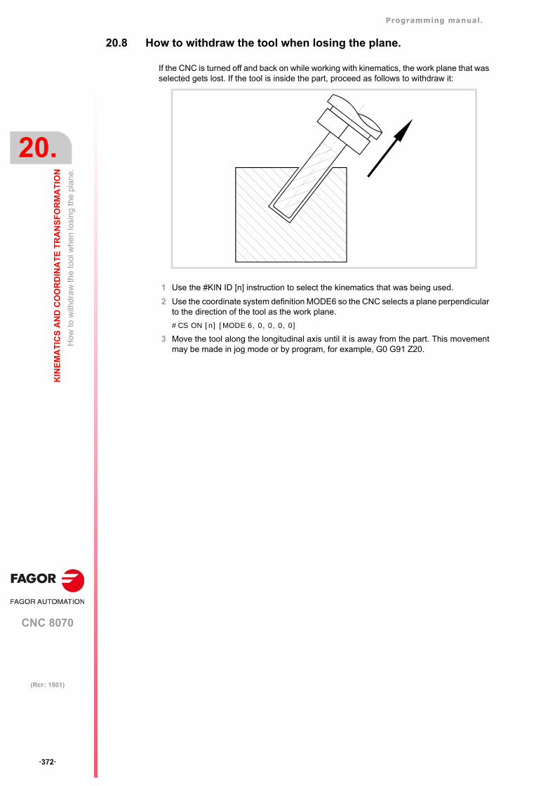
Programming manual.
CNC 8070
20.
KIN
EM
AT
ICS
AN
D C
OO
RD
INA
TE
TR
AN
SF
OR
MA
TIO
N
How
to w
ithdr
aw
the
tool
wh
en lo
sing
the
pla
ne.
·372·
(REF: 1901)
20.8 How to withdraw the tool when losing the plane.
If the CNC is turned off and back on while working with kinematics, the work plane that wasselected gets lost. If the tool is inside the part, proceed as follows to withdraw it:
1 Use the #KIN ID [n] instruction to select the kinematics that was being used.
2 Use the coordinate system definition MODE6 so the CNC selects a plane perpendicularto the direction of the tool as the work plane.
#CS ON [n] [MODE 6, 0, 0, 0, 0]
3 Move the tool along the longitudinal axis until it is away from the part. This movementmay be made in jog mode or by program, for example, G0 G91 Z20.
Programming manual.
CNC 8070
KIN
EM
AT
ICS
AN
D C
OO
RD
INA
TE
TR
AN
SF
OR
MA
TIO
N
20.
To
ol o
rient
atio
n in
the
part
coo
rdin
ate
syst
em.
·373·
(REF: 1901)
20.9 Tool orientation in the part coordinate system.
20.9.1 Activate tool orientation in the part coordinate system.
Currently at the CNC, in order to orient the tool considering an active kinematics, one hasto program the angles of the rotary axes (the position that those axes take). With thisinstruction, it is possible to add the defined orientation due to the inclined plane to the toolorientation defined in the program; in other words, to refer the tool orientation to either themachine coordinate system or to the part coordinate system (#CS/#ACS) defined with theinclined plane.
Usually, the axis orienting process provides two possible solution in the positioning of therotary axes for a particular tool orientation. The CNC applies the one resulting in the shortestdistance with respect to the current position. If a little change in the programmed angle resultsin a huge change of angle due to the inclined plane, it is possible to define different actionsdepending on the angle (instruction #DEFROT).
Programming.
When defining this instruction, there is an option to set when the CNC orients the tool.
Programming format.
The programming format is the following; the list of arguments appears between curlybrackets and the optional ones between angle brackets. Programming the ON command isoptional.
#CSROT <ON> #CSROT <ON> [ROTATE]
ROTATE command.
Using the ROTATE command, the CNC orients the tool in the new coordinate systemtogether with the first motion block, even if the rotary axes have not been programmed. Ifthe ROTATE option is not programmed, the CNC orients the tool together with the first motionblock where the rotary axes have been programmed.
Considerations.
Once activated, this instruction stays active until an M02 or M30 is executed, after a resetor it is canceled (#CSROT OFF).
#CSROT
#CSROT ON
#CSROT [ROTATE]
#CSROT ON [ROTATE]
Programming manual.
CNC 8070
20.
KIN
EM
AT
ICS
AN
D C
OO
RD
INA
TE
TR
AN
SF
OR
MA
TIO
N
To
ol o
rient
atio
n in
the
part
coo
rdin
ate
syst
em.
·374·
(REF: 1901)
20.9.2 Cancel tool orientation in the part coordinate system.
The instruction #CSROT OFF cancels the programming of the rotary axes in the activeACS/CS coordinate system and, therefore, activates the programming of those axes in themachine coordinate system.
After executing an M30 and after a reset, it also cancels the programming of the rotary axesof the kinematics in the part coordinate system.
Programming.
Program the instruction alone in the block.
Programming format.
The programming format is:
#CSROT OFF
#CSROT OFF
Programming manual.
CNC 8070
KIN
EM
AT
ICS
AN
D C
OO
RD
INA
TE
TR
AN
SF
OR
MA
TIO
N
20.
To
ol o
rient
atio
n in
the
part
coo
rdin
ate
syst
em.
·375·
(REF: 1901)
20.9.3 How to manage the discontinuities in the orientation of rotary axes.
Usually, the axis orienting process provides two possible solution in the positioning of therotary axes for a particular tool orientation. The CNC applies the one resulting in the shortestdistance with respect to the current position.
A discontinuity means that a little change in the programmed angle results in a huge changeof angle on the rotary axes due to the inclined plane. When the CNC detects a discontinuity,the instruction #DEFROT defines what the CNC must do depending on the angle differencebetween the one programmed and the one calculated.
Programming.
Programming format.
The programming format is the following; the list of arguments appears between curlybrackets and the optional ones between angle brackets.
#DEFROT [<{action},><{criterion},><Q{angle}>]
The CNC admits programing any combination of the three parameters (a minimum of oneand a maximum of three), maintaining the order.
CNC action when it detects a discontinuity.
These values define what the CNC must do when it detects a discontinuity.
If not programmed, the CNC assumes the last value programmed. After executing an M30and after a reset, the CNC assumes the WARNING value (show a warning and interrupt theexecution).
{action} Optional. CNC action when it detects a discontinuity.
{criterion} Optional. Criterion to solve the discontinuity.
Q{angle} Optional. Comparison angle.
#DEFROT
#DEFROT [ERROR, Q5]
#DEFROT [WARNING, DNEGF, Q10]
#DEFROT [NONE, LOWF]
Command. Meaning.
ERROR Show an error and interrupt the execution.
WARNING Show a warning and interrupt the execution. The CNC displays a screen for the user to choose the solution to be applied,either the solution programmed in the instruction (the {criterion} argument) or thesecond solution.
NONE Ignore the discontinuity and resume program execution.The CNC applies the solution programmed in the instruction (argument{criterion}), without showing to the user the screen to choose a solution. If nocriterion has been programmed, the CNC applies the last one active.
Programming manual.
CNC 8070
20.
KIN
EM
AT
ICS
AN
D C
OO
RD
INA
TE
TR
AN
SF
OR
MA
TIO
N
To
ol o
rient
atio
n in
the
part
coo
rdin
ate
syst
em.
·376·
(REF: 1901)
Criterion to solve the discontinuity.
The possible criteria are:
If not programmed, the CNC assumes the last value programmed. After executing an M30and after a reset, the CNC assumes the LOWF value (the shortest distance for the main rotaryaxis and then secondary axis).
Comparison angle.
This value indicates the maximum travel difference between the programmed angle and thecalculated angle, from which the actions and criteria are applied to choose the solution.
If not programmed, the CNC assumes the last value programmed. After executing an M30and after a reset, the assumes the value of 5º.
Command. Meaning.
LOWF The shortest way for the main rotary axis, then the secondary axis.
LOWS The shortest way for the secondary rotary axis, then the main axis.
DPOSF Positive direction of the main rotary axis.
DPOSS Positive direction of the secondary rotary axis.
DNEGF Negative direction of the main rotary axis.
DNEGS Negative direction of the secondary rotary axis.
VPOSF Positive value of the main rotary axis.
VPOSS Positive value of the secondary rotary axis.
VNEGF Negative value of the main rotary axis.
VNEGS Negative value of the secondary rotary axis.
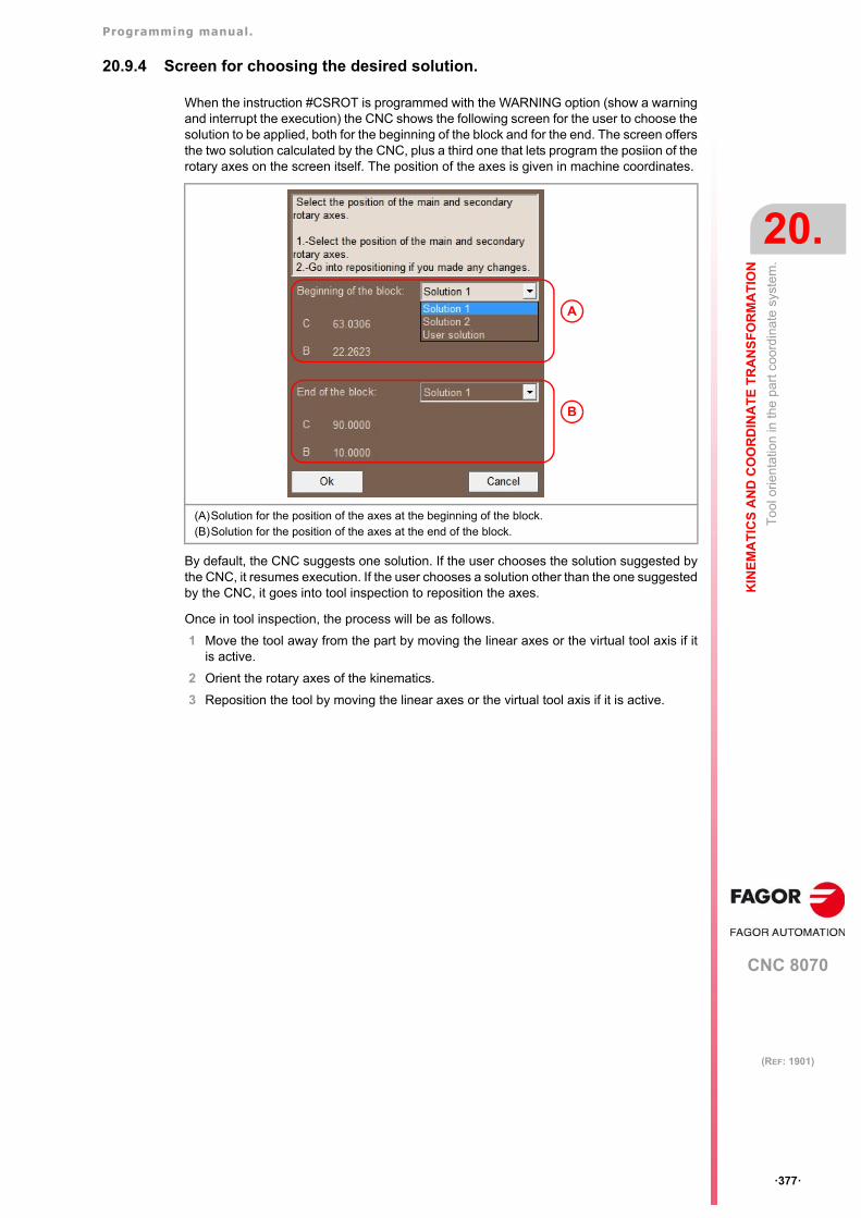
Programming manual.
CNC 8070
KIN
EM
AT
ICS
AN
D C
OO
RD
INA
TE
TR
AN
SF
OR
MA
TIO
N
20.
To
ol o
rient
atio
n in
the
part
coo
rdin
ate
syst
em.
·377·
(REF: 1901)
20.9.4 Screen for choosing the desired solution.
When the instruction #CSROT is programmed with the WARNING option (show a warningand interrupt the execution) the CNC shows the following screen for the user to choose thesolution to be applied, both for the beginning of the block and for the end. The screen offersthe two solution calculated by the CNC, plus a third one that lets program the posiion of therotary axes on the screen itself. The position of the axes is given in machine coordinates.
By default, the CNC suggests one solution. If the user chooses the solution suggested bythe CNC, it resumes execution. If the user chooses a solution other than the one suggestedby the CNC, it goes into tool inspection to reposition the axes.
Once in tool inspection, the process will be as follows.
1 Move the tool away from the part by moving the linear axes or the virtual tool axis if itis active.
2 Orient the rotary axes of the kinematics.
3 Reposition the tool by moving the linear axes or the virtual tool axis if it is active.
(A)Solution for the position of the axes at the beginning of the block. (B)Solution for the position of the axes at the end of the block.
A
B
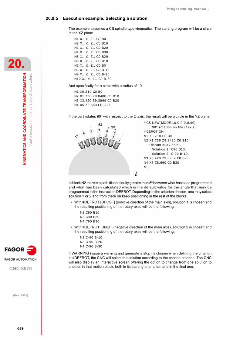
Programming manual.
CNC 8070
20.
KIN
EM
AT
ICS
AN
D C
OO
RD
INA
TE
TR
AN
SF
OR
MA
TIO
N
To
ol o
rient
atio
n in
the
part
coo
rdin
ate
syst
em.
·378·
(REF: 1901)
20.9.5 Execution example. Selecting a solution.
The example assumes a CB spindle type kinematics. The starting program will be a circlein the XZ plane.
N1 X.. Y.. Z.. C0 B0N2 X.. Y.. Z.. C0 B10N3 X.. Y.. Z.. C0 B20N4 X.. Y.. Z.. C0 B30N5 X.. Y.. Z.. C0 B20N6 X.. Y.. Z.. C0 B10N7 X.. Y.. Z.. C0 B0N8 X.. Y.. Z.. C0 B-10N9 X.. Y.. Z.. C0 B-20N10 X.. Y.. Z.. C0 B-30
And specifically for a circle with a radius of 10.
N1 X0 Z10 C0 B0N2 X1.736 Z9.8480 C0 B10N3 X3.420 Z9.3969 C0 B20N4 X5 Z8.660 C0 B30...
If the part rotates 90º with respect to the C axis, the result will be a circle in the YZ plane.
In block N2 there is a path discontinuity greater than 5º between what has been programmedand what has been calculated which is the default value for the angle that may beprogrammed in the instruction DEFROT. Depending on the criterion chosen, one may selectsolution 1 or 2 and from there on keep positioning in the rest of the blocks.
• With #DEFROT [DPOSF] (positive direction of the main axis), solution 1 is chosen andthe resulting positioning of the rotary axes will be the following.
N2 C90 B10N3 C90 B20N4 C90 B30
• With #DEFROT [DNEF] (negative direction of the main axis), solution 2 is chosen andthe resulting positioning of the rotary axes will be the following.
N2 C-90 B-10N3 C-90 B-20N4 C-90 B-30
If WARNING (issue a warning and generate a stop) is chosen when defining the criterionin #DEFROT, the CNC will select the solution according to the chosen criterion. The CNCwill also display an interactive screen offering the option to change from one solution toanother in that motion block, both in its starting orientation and in the final one.
#CS NEW[MODE1,0,0,0,0,0,90]; 90º rotation on the C axis.
#CSROT ONN1 X0 Z10 C0 B0 N2 X1.736 Z9.8480 C0 B10
Discontinuity point.; Solution 1: C90 B10.; Solution 2: C-90 B-10.
N3 X3.420 Z9.3969 C0 B20 N4 X5 Z8.660 C0 B30 M30
Y
Z
17
26
35
4
89
10
10º
Programming manual.
CNC 8070
KIN
EM
AT
ICS
AN
D C
OO
RD
INA
TE
TR
AN
SF
OR
MA
TIO
N
20.
Se
lect
ing
the
rota
ry a
xes
tha
t pos
itio
n th
e to
ol in
typ
e-52
kin
emat
ics.
·379·
(REF: 1901)
20.10 Selecting the rotary axes that position the tool in type-52kinematics.
The instruction #SELECT ORI may be used to choose onto which rotary axes of thekinematics the tool orientation is calculated for a given direction on the work piece (part).
Kinematics 52 has at the most 2 rotary axes on the spindle and two rotary axes on the table,which means that there may be up to 4 rotary axes to orient the tool on the work piece.Therefore, there are always several solutions when calculating the position of the rotary axesto orient the tool. The tool orientation on the work piece is calculated in the followinginstructions:
Programming.
When defining this instruction, you must define the rotary axes involved in the positioncalculation.
Programming format.
The programming format is the following; the list of arguments appears between curlybrackets.
#SELECT ORI [{ROT1}, {ROT2}]
Both arguments are defined using the following commands; HEAD1 (first axis of the spindle),HEAD2 (second axis of the spindle), TABLE1 (first axis of the table), TABLE2 (second axisof the table). Any programming sequence (order) is permitted.
Considerations.
This instruction is modal. On power-up, after an M02 or M30 and after an EMERGENCY ora RESET, the instruction assumes its default value; #SELECT ORI [HEAD1, HEAD2].
• #CS. Define and select the machining coordinate system (Inclined plane).
• #ACS. Define and select the fixture coordinate system.
• #TOOL ORI. Orient the tool perpendicular to the work plane.
• #CSROT. Tool orientation in the part coordinate system.
{ROT1} Rotary axis of the kinematics.
{ROT2} Rotary axis of the kinematics.
#SELECT ORI [HEAD1, HEAD2]Default value. The tool orientation instructions work on the first and second axes of the spindle, leaving the table axis in their current position.
#SELECT ORI [HEAD1, TABLE1]The tool orientation instructions work on the first axis of the spindle and the first axis of the table, leaving the other two rotary axes of the kinematics in their current position.
#SELECT ORI [HEAD2, TABLE1]The tool orientation instructions work on the second axis of the spindle and the first axis of the table, leaving the other two rotary axes of the kinematics in their current position.
Programming manual.
CNC 8070
20.
KIN
EM
AT
ICS
AN
D C
OO
RD
INA
TE
TR
AN
SF
OR
MA
TIO
N
Tra
nsfo
rm th
e cu
rren
t par
t ze
ro c
ons
ide
ring
the
posi
tion
of th
e ta
ble
kine
mat
ics.
·380·
(REF: 1901)
20.11 Transform the current part zero considering the position of thetable kinematics.
On 7-axis kinematics (spindle-table) or 5-axis table kinematics, without coordinate systemrotation, it may be necessary to get a part zero with the axes of the table in any position, touse it later on when activating the RTCP of the kinematics with the option to keep the partzero without coordinate system rotation.
The instruction #KINORG may be used to transform the active part zero into a new part zerothat considers the position of the table. After executing this instruction, the following variablesoffer the values of the transformed part zero considering the position of the table.
Save the value of these variables in the zero offset table for later in order to have that partzero available and be able to activate it at any time.
Programming.
Program the instruction alone in the block.
Programming format.
The programming format is:
#KINORG
Variable. Meaning.
(V.)[ch.]G.KINORG1 Position of the part zero transformed by the instruction #KINORG,considering the table position, on the first axis of the channel.
(V.)[ch.]G.KINORG2 Position of the part zero transformed by the instruction #KINORG,considering the table position, on the second axis of the channel.
(V.)[ch.]G.KINORG3 Position of the part zero transformed by the instruction #KINORG,considering the table position, on the third axis of the channel.
#KINORG
Programming manual.
CNC 8070
KIN
EM
AT
ICS
AN
D C
OO
RD
INA
TE
TR
AN
SF
OR
MA
TIO
N
20.
Tra
nsfo
rm th
e cu
rren
t par
t ze
ro c
ons
ide
ring
the
posi
tion
of th
e ta
ble
kine
mat
ics.
·381·
(REF: 1901)
20.11.1 Process of saving a part zero with the table axes in any position.
The following steps are valid for the type-51 table kinematics, type-52 spindle-tablekinematics and the standard tables with parameter TDATA17=1.
1 Activate the kinematics (#KIN ID [ ]).
2 If it is easier for measuring, in type-52 kinematics (table-spindle) it is possible to activateonly the RTCP of the spindle side.
3 Position the rotary axes of the spindle in the desired position for measuring the part zero.Make the measurement and activate the part zero at the desired point on X-Y-Z (G92).
4 From the current part zero and without moving the rotary axes of the table, calculate thevariables referred to the part zero that consider the current position of the spindle andof the table (#KINORG).
5 At any time after executing #KINORG, save the calculated new part zero in the zero offsettable.
V.A.ORGT[n].X = V.G.KINORG1
V.A.ORGT[n].Y = V.G.KINORG2
V.A.ORGT[n].Z = V.G.KINORG3
The necessary steps to activate and work with that part zero, with the spindle-table or tablekinematics, without coordinate system rotation keeping the part zero are the following.
1 Activate the part zero where the values have been saved (G159 =n).
2 Activate the kinematics.
3 Activate the RTCP.
• Type-52 kinematics: Activate the full RTCP (TDATA52=0) and without coordinatesystem rotation (TDATA51=1).
• Type-51 kinematics: Activate the RTCP without coordinate system rotation(TDATA31=1).
The variable of the kinematics that are applied for each TDATA are the result of adding the value andthe offset, defined in the machine parameter tables. The value is defined by the OEM and the offsetis a value that may be modified by the user.
i
Programming manual.
CNC 8070
20.
KIN
EM
AT
ICS
AN
D C
OO
RD
INA
TE
TR
AN
SF
OR
MA
TIO
N
Tra
nsfo
rm th
e cu
rren
t par
t ze
ro c
ons
ide
ring
the
posi
tion
of th
e ta
ble
kine
mat
ics.
·382·
(REF: 1901)
20.11.2 Example to maintain the part zero without rotating the coordinate system.
The following example shows a possible sequence of steps so the measured part zero maybe saved and restored after activating the RTCP with the option to maintain the part zerowithout rotating the coordinate system. The part zero may be activated with the rotary axesin any position, those of the spindle as well as those of the table.
The example uses a vectorial spindle-table type-52 kinematics on the third kinematics table.The rotary axes of the spindle are A-B and the rotary axes of the table U-V.
1 Activate the kinematics.
2 Activate the RTCP only on the spindle side (optional). This option may be used to workeasily considering the tool tip and moving the X-Y-Z axes aligned with respect to themachine axes.
3 Measure the reference point. Position the rotary axes of the spindle and table in thedesired position for measuring the part zero on X-Y-Z.
4 Activate the part zero at the desired point on X-Y-Z.
5 Transform the current part zero, without moving the rotary axes of the table into a newset of values that consider the table position.
6 Save the calculated values in to the zero offset table; for example, in G55 (G159=2).
7 Move the axes to any position and keep doing all the desired processes .
To activate the RTCP maintaining the measured part zero and without rotating the coordinatesystem, with the rotary and linear axes in any position, follow these steps.
1 Cancel the RTCP, if it is active.
2 Activate the kinematics if there is another one active.
3 Activate the part zero where the KINORG has been saved; in this case, G55.
4 Activate the full RTCP, considering the spindle and the table and without rotating thecoordinate system.
#KIN ID [3]
V.G.OFTDATA3[52]=1(Apply RTCP only to the spindle side)
#RTCP ON
A_ B_ U_ V_X_ Y_ Z_
G92 X_ Y_ Z_
#KINORG
V.A.ORGT[2].X = V.G.KINORG1V.A.ORGT[2].Y = V.G.KINORG2V.A.ORGT[2].Z = V.G.KINORG3
#RTCP OFF
#KIN ID [3]
G55
V.G.OFTDATA3[52]=0(Apply full RTCP; table and spindle)
V.G.OFTDATA3[51]=1(RTCP without rotation of the coordinate system)
#RTCP ON
Programming manual.
CNC 8070
KIN
EM
AT
ICS
AN
D C
OO
RD
INA
TE
TR
AN
SF
OR
MA
TIO
N
20.
Sum
mar
y of
kin
emat
ics
rela
ted
varia
bles
.
·383·
(REF: 1901)
20.12 Summary of kinematics related variables.
The following variables may be accessed via part-program or via MDI/MDA mode. Each ofthem indicates whether it may be read (R) or written (W).
Variables related to the active kinematics.
Variables related to the position of the rotary axes of kinematics (1).
These variables indicate the current position of the rotary axes of the kinematics.
Variables related to the position of the rotary axes of kinematics (2).
These variables that indicate the position the rotary axes of the kinematics must occupy inorder for the tool to be perpendicular to the define inclined plane. These variables are veryuseful when the spindle is not fully motorized (mono-rotary or manual spindles). The CNCupdates these variables every time a new plane is selected, using the instruction #CS or#ACS.
Since there isn't a single solution for angular spindle, it offers two possible solutions; the oneinvolving the smallest movement of the main rotary axis with respect to the zero position(solution 1) and the one involving the greater movement of the main rotary axis with respectto the zero position (solution 2).
Variables. R/W Meaning.
V.G.KINTYPE R Type of the active kinematics.
V.G.NKINAX R Number of axes of the active kinematics.
V.G.SELECTORI R Rotary axes selected for positioning the tool (instruction #SELECTORI)
V.G.CSROTST R Status of the #CSROT function.
Variables. R/W Meaning.
V.G.POSROTF R/W Current position of the first rotary axis of the kinematics.
V.G.POSROTS R/W Current position of the second rotary axis of the kinematics.
V.G.POSROTT R/W Current position of the third rotary axis of the kinematics.
V.G.POSROTO R/W Current position of the fourth rotary axis of the kinematics.
Variables. R/W Meaning.
V.G.TOOLORIF1 R Position (machine coordinates) to be occupied by the first rotary axisin order to position the tool perpendicular to the inclined plane,according to solution 1.
V.G.TOOLORIF2 R Position (machine coordinates) to be occupied by the first rotary axisin order to position the tool perpendicular to the inclined plane,according to solution 2.
V.G.TOOLORIS1 R Position (machine coordinates) to be occupied by the second rotaryaxis in order to position the tool perpendicular to the inclined plane,according to solution 1.
V.G.TOOLORIS2 R Position (machine coordinates) to be occupied by the second rotaryaxis in order to position the tool perpendicular to the inclined plane,according to solution 2.
V.G.TOOLORIT1 R Position (machine coordinates) to be occupied by the third rotaryaxis in order to position the tool perpendicular to the inclined plane,according to solution 1.
V.G.TOOLORIT2 R Position (machine coordinates) to be occupied by the third rotaryaxis in order to position the tool perpendicular to the inclined plane,according to solution 2.
V.G.TOOLORIO1 R Position (machine coordinates) to be occupied by the fourth rotaryaxis in order to position the tool perpendicular to the inclined plane,according to solution 1.
V.G.TOOLORIO2 R Position (machine coordinates) to be occupied by the fourth rotaryaxis in order to position the tool perpendicular to the inclined plane,according to solution 2.
Programming manual.
CNC 8070
20.
KIN
EM
AT
ICS
AN
D C
OO
RD
INA
TE
TR
AN
SF
OR
MA
TIO
N
Sum
mar
y of
kin
emat
ics
rela
ted
varia
bles
.
·384·
(REF: 1901)
In order that the tool is perpendicular to the defined plane, the positioning must be performedusing machine coordinates, since the CNC provides the solution in machine coordinates,or by using the instruction #TOOL ORI and the movement of an axis.
Variables related to the CSROT option (tool orientation in the part coordinate system).
Option 1. Movement in machine dimensions with the given solution.
#MCS ONG01B[V.G.TOOLORIF1] C[V.G.TOOLORIS1] F1720#MCS OFF
Option 2. Orientate the work plane so that it is perpendicular to the tool for the nextmovement after #TOOL ORI.
#TOOL ORIG01 X0 Y0 Z40
Variables. R/W Meaning.
V.G.CSROTST R Status of the #CSROT function.
V.G.CSROTF1[1] R Position (machine coordinates) calculated for the first rotary axis ofthe kinematics at the beginning of the block, for solution 1 of the#CSROT mode.
V.G.CSROTF1[2] R Position (machine coordinates) calculated for the first rotary axis ofthe kinematics at the end of the block, for solution 1 of the #CSROTmode.
V.G.CSROTS1[1] R Position (machine coordinates) calculated for the second rotary axisof the kinematics at the beginning of the block, for solution 1 of the#CSROT mode.
V.G.CSROTS1[2] R Position (machine coordinates) calculated for the second rotary axisof the kinematics at the end of the block, for solution 1 of the #CSROTmode.
V.G.CSROTT1[1] R Position (machine coordinates) calculated for the third rotary axis ofthe kinematics at the beginning of the block, for solution 1 of the#CSROT mode.
V.G.CSROTT1[2] R Position (machine coordinates) calculated for the third rotary axis ofthe kinematics at the end of the block, for solution 1 of the #CSROTmode.
V.G.CSROTO1[1] R Position (machine coordinates) calculated for the fourth rotary axisof the kinematics at the beginning of the block, for solution 1 of the#CSROT mode.
V.G.CSROTO1[2] R Position (machine coordinates) calculated for the fourth rotary axisof the kinematics at the end of the block, for solution 1 of the #CSROTmode.
V.G.CSROTF2[1] R Position (machine coordinates) calculated for the first rotary axis ofthe kinematics at the beginning of the block, for solution 2 of the#CSROT mode.
V.G.CSROTF2[2] R Position (machine coordinates) calculated for the first rotary axis ofthe kinematics at the end of the block, for solution 2 of the #CSROTmode.
V.G.CSROTS2[1] R Position (machine coordinates) calculated for the second rotary axisof the kinematics at the beginning of the block, for solution 2 of the#CSROT mode.
V.G.CSROTS2[2] R Position (machine coordinates) calculated for the second rotary axisof the kinematics at the end of the block, for solution 2 of the #CSROTmode.
V.G.CSROTT2[1] R Position (machine coordinates) calculated for the third rotary axis ofthe kinematics at the beginning of the block, for solution 2 of the#CSROT mode.
V.G.CSROTT2[2] R Position (machine coordinates) calculated for the third rotary axis ofthe kinematics at the end of the block, for solution 2 of the #CSROTmode.
V.G.CSROTO2[1] R Position (machine coordinates) calculated for the fourth rotary axisof the kinematics at the beginning of the block, for solution 2 of the#CSROT mode.
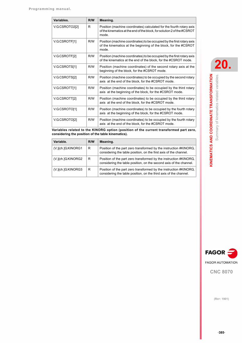
Programming manual.
CNC 8070
KIN
EM
AT
ICS
AN
D C
OO
RD
INA
TE
TR
AN
SF
OR
MA
TIO
N
20.
Sum
mar
y of
kin
emat
ics
rela
ted
varia
bles
.
·385·
(REF: 1901)
Variables related to the KINORG option (position of the current transformed part zero,considering the position of the table kinematics).
V.G.CSROTO2[2] R Position (machine coordinates) calculated for the fourth rotary axisof the kinematics at the end of the block, for solution 2 of the #CSROTmode.
V.G.CSROTF[1] R/W Position (machine coordinates) to be occupied by the first rotary axisof the kinematics at the beginning of the block, for the #CSROTmode.
V.G.CSROTF[2] R/W Position (machine coordinates) to be occupied by the first rotary axisof the kinematics at the end of the block, for the #CSROT mode.
V.G.CSROTS[1] R/W Position (machine coordinates) of the second rotary axis at thebeginning of the block, for the #CSROT mode.
V.G.CSROTS[2] R/W Position (machine coordinates) to be occupied by the second rotaryaxis at the end of the block, for the #CSROT mode.
V.G.CSROTT[1] R/W Position (machine coordinates) to be occupied by the third rotaryaxis at the beginning of the block, for the #CSROT mode.
V.G.CSROTT[2] R/W Position (machine coordinates) to be occupied by the third rotaryaxis at the end of the block, for the #CSROT mode.
V.G.CSROTO[1] R/W Position (machine coordinates) to be occupied by the fourth rotaryaxis at the beginning of the block, for the #CSROT mode.
V.G.CSROTO[2] R/W Position (machine coordinates) to be occupied by the fourth rotaryaxis at the end of the block, for the #CSROT mode.
Variable. R/W Meaning.
(V.)[ch.]G.KINORG1 R Position of the part zero transformed by the instruction #KINORG,considering the table position, on the first axis of the channel.
(V.)[ch.]G.KINORG2 R Position of the part zero transformed by the instruction #KINORG,considering the table position, on the second axis of the channel.
(V.)[ch.]G.KINORG3 R Position of the part zero transformed by the instruction #KINORG,considering the table position, on the third axis of the channel.
Variables. R/W Meaning.

Programming manual.
CNC 8070
20.
KIN
EM
AT
ICS
AN
D C
OO
RD
INA
TE
TR
AN
SF
OR
MA
TIO
N
Sum
mar
y of
kin
emat
ics
rela
ted
varia
bles
.
·386·
(REF: 1901)
CNC 8070
21
·387·
(REF: 1901)
21.HSC. HIGH SPEED MACHINING.
Nowadays, lots of parts are designed using CAD-CAM systems. This type of information islater post-processed to generate a CNC program, usually made up of a large number of veryshort blocks of several mm or just a few tenths of a micron.
In this type of parts, the CNC must be capable to analyze a large number of points in advanceso it can generate a continuous path that goes through (or near) the points of the programwhile keeping (the best way possible) the programmed feedrate and the restrictions ofmaximum acceleration, jerk, etc of each axis and of the path.
Default HSC mode.
The command to execute programs made up of lots of small blocks, typical of high speedmachining, is carried out with a single instruction #HSC. This function offers several waysto work; optimizing part surface finish (SURFACE mode) optimizing the contour error(CONTERROR mode) or the machining feedrate (FAST mode).
The default machining mode is defined by parameter HSCDEFAULTMODE, where Fagoroffers the SURFACE mode as default. The more sophisticated algorithms of the SURFACEmode obtain more accurate machining. In parallel, the CNC controls machine movementsmore smoothly reducing considerably the vibrations due to part geometry or machinedynamics. Reducing machine vibrations results in higher surface quality of the machinedparts.
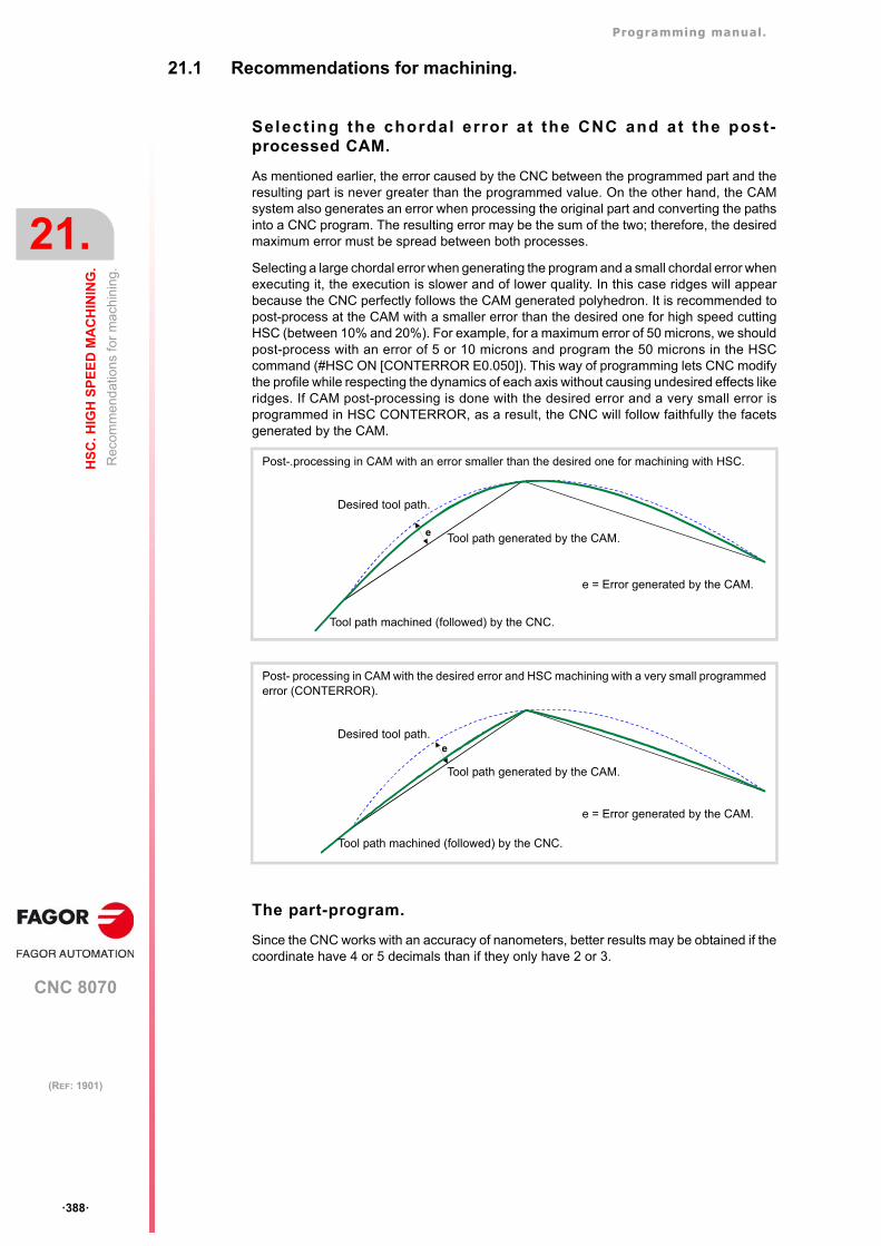
Programming manual.
CNC 8070
21.
HS
C. H
IGH
SP
EE
D M
AC
HIN
ING
.
Rec
omm
end
atio
ns
for
ma
chin
ing.
·388·
(REF: 1901)
21.1 Recommendations for machining.
Select ing the chordal error at the CNC and at the post-processed CAM.
As mentioned earlier, the error caused by the CNC between the programmed part and theresulting part is never greater than the programmed value. On the other hand, the CAMsystem also generates an error when processing the original part and converting the pathsinto a CNC program. The resulting error may be the sum of the two; therefore, the desiredmaximum error must be spread between both processes.
Selecting a large chordal error when generating the program and a small chordal error whenexecuting it, the execution is slower and of lower quality. In this case ridges will appearbecause the CNC perfectly follows the CAM generated polyhedron. It is recommended topost-process at the CAM with a smaller error than the desired one for high speed cuttingHSC (between 10% and 20%). For example, for a maximum error of 50 microns, we shouldpost-process with an error of 5 or 10 microns and program the 50 microns in the HSCcommand (#HSC ON [CONTERROR E0.050]). This way of programming lets CNC modifythe profile while respecting the dynamics of each axis without causing undesired effects likeridges. If CAM post-processing is done with the desired error and a very small error isprogrammed in HSC CONTERROR, as a result, the CNC will follow faithfully the facetsgenerated by the CAM.
The part-program.
Since the CNC works with an accuracy of nanometers, better results may be obtained if thecoordinate have 4 or 5 decimals than if they only have 2 or 3.
Post-.processing in CAM with an error smaller than the desired one for machining with HSC.
Post- processing in CAM with the desired error and HSC machining with a very small programmederror (CONTERROR).
e
Desired tool path.
Tool path generated by the CAM.
Tool path machined (followed) by the CNC.
e = Error generated by the CAM.
eDesired tool path.
Tool path generated by the CAM.
Tool path machined (followed) by the CNC.
e = Error generated by the CAM.
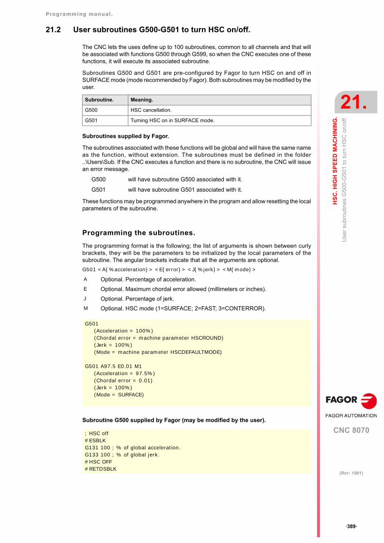
Programming manual.
CNC 8070
HS
C. H
IGH
SP
EE
D M
AC
HIN
ING
.
21.
Use
r su
bro
utin
es G
500
-G50
1 to
turn
HS
C o
n/of
f.
·389·
(REF: 1901)
21.2 User subroutines G500-G501 to turn HSC on/off.
The CNC lets the uses define up to 100 subroutines, common to all channels and that willbe associated with functions G500 through G599, so when the CNC executes one of thesefunctions, it will execute its associated subroutine.
Subroutines G500 and G501 are pre-configured by Fagor to turn HSC on and off inSURFACE mode (mode recommended by Fagor). Both subroutines may be modified by theuser.
Subroutines supplied by Fagor.
The subroutines associated with these functions will be global and will have the same nameas the function, without extension. The subroutines must be defined in the folder..\Users\Sub. If the CNC executes a function and there is no subroutine, the CNC will issuean error message.
G500 will have subroutine G500 associated with it.
G501 will have subroutine G501 associated with it.
These functions may be programmed anywhere in the program and allow resetting the localparameters of the subroutine.
Programming the subroutines.
The programming format is the following; the list of arguments is shown between curlybrackets, they will be the parameters to be initialized by the local parameters of thesubroutine. The angular brackets indicate that all the arguments are optional.
G501 <A{%acceleration}> <E{error}> <J{%jerk}> <M{mode}>
Subroutine G500 supplied by Fagor (may be modified by the user).
Subroutine. Meaning.
G500 HSC cancellation.
G501 Turning HSC on in SURFACE mode.
A Optional. Percentage of acceleration.
E Optional. Maximum chordal error allowed (millimeters or inches).
J Optional. Percentage of jerk.
M Optional. HSC mode (1=SURFACE; 2=FAST; 3=CONTERROR).
G501(Acceleration = 100%)(Chordal error = machine parameter HSCROUND)(Jerk = 100%)(Mode = machine parameter HSCDEFAULTMODE)
G501 A97.5 E0.01 M1(Acceleration = 97.5%)(Chordal error = 0.01)(Jerk = 100%)(Mode = SURFACE)
; HSC off#ESBLKG131 100 ; % of global acceleration.G133 100 ; % of global jerk.#HSC OFF#RETDSBLK
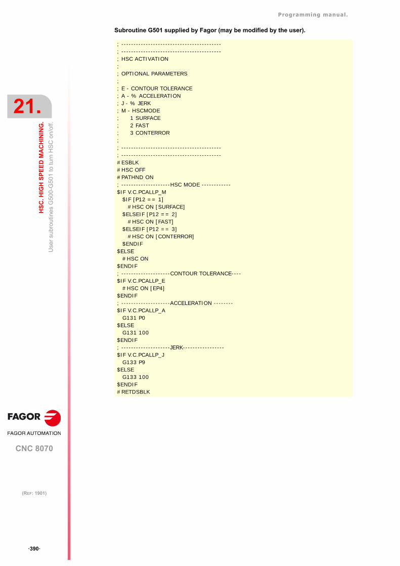
Programming manual.
CNC 8070
21.
HS
C. H
IGH
SP
EE
D M
AC
HIN
ING
.
Use
r su
bro
utin
es G
500
-G50
1 to
turn
HS
C o
n/of
f.
·390·
(REF: 1901)
Subroutine G501 supplied by Fagor (may be modified by the user).
; -----------------------------------------; -----------------------------------------; HSC ACTIVATION;; OPTIONAL PARAMETERS;; E - CONTOUR TOLERANCE; A - % ACCELERATION; J - % JERK; M - HSCMODE; 1 SURFACE; 2 FAST; 3 CONTERROR;; -----------------------------------------; -----------------------------------------#ESBLK#HSC OFF#PATHND ON; --------------------HSC MODE ------------$IF V.C.PCALLP_M
$IF [P12 == 1] #HSC ON [SURFACE]
$ELSEIF [P12 == 2]#HSC ON [FAST]
$ELSEIF [P12 == 3]#HSC ON [CONTERROR]
$ENDIF$ELSE
#HSC ON$ENDIF; --------------------CONTOUR TOLERANCE----$IF V.C.PCALLP_E
#HSC ON [EP4] $ENDIF; --------------------ACCELERATION --------$IF V.C.PCALLP_A
G131 P0$ELSE
G131 100 $ENDIF; --------------------JERK-----------------$IF V.C.PCALLP_J
G133 P9$ELSE
G133 100 $ENDIF#RETDSBLK

Programming manual.
CNC 8070
HS
C. H
IGH
SP
EE
D M
AC
HIN
ING
.
21.
Use
r su
bro
utin
es G
500
-G50
1 to
turn
HS
C o
n/of
f.
·391·
(REF: 1901)
21.2.1 Alternative example for functions G500-G501 supplied by Fagor.
G500 subroutines supplied by Fagor may be modified by the user. Here is another examplefor turning HSC ON/OFF using three subroutines.
Programming the subroutines.
The programming format is the following; the arguments appear between curly brackets andthe optional ones between angle brackets. In these subroutines, all the arguments areoptional.
G501 <A{%acceleration}> <E{error}>G502 <A{%acceleration}> <E{error}>
Example of a G500 subroutine. Turn HSC off.
Subroutine. Meaning.
G500 Turn HSC off.
G501 Turn HSC on in FAST mode.
G502 Turn HSC on in SURFACE mode.
A Optional. Percentage of acceleration.
E Optional. Maximum chordal error allowed (millimeters or inches).
G501(Acceleration = 100%)(Chordal error = twice the value set in machine parameter HSCROUND)
G501 A97.5 E0.01(Acceleration = 97.5%)(Chordal error = 0.01)
G502(Acceleration = 100%)(Chordal error = machine parameter HSCROUND)
;-------------------------------------------------------------------------;-------------------------------------------------------------------------; HSC DEACTIVATION;-------------------------------------------------------------------------;-------------------------------------------------------------------------#ESBLKG131 100 ;% accelerationG133 100 ;% decelerationV.G.DYNOVR = 100 ;%Dynamic override#PATHND OFF#HSC OFF
#RETDSBLK
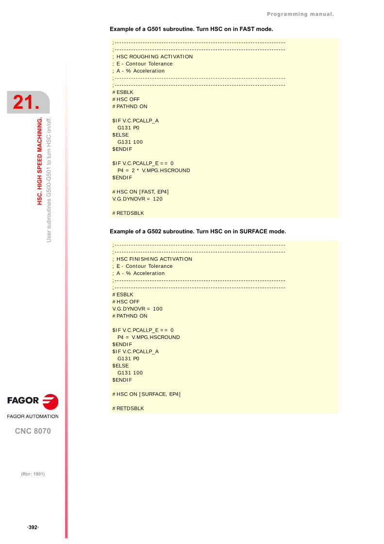
Programming manual.
CNC 8070
21.
HS
C. H
IGH
SP
EE
D M
AC
HIN
ING
.
Use
r su
bro
utin
es G
500
-G50
1 to
turn
HS
C o
n/of
f.
·392·
(REF: 1901)
Example of a G501 subroutine. Turn HSC on in FAST mode.
Example of a G502 subroutine. Turn HSC on in SURFACE mode.
;-------------------------------------------------------------------------;-------------------------------------------------------------------------; HSC ROUGHING ACTIVATION; E - Contour Tolerance; A - % Acceleration;-------------------------------------------------------------------------;-------------------------------------------------------------------------#ESBLK#HSC OFF#PATHND ON
$IF V.C.PCALLP_AG131 P0
$ELSEG131 100
$ENDIF
$IF V.C.PCALLP_E == 0P4 = 2 * V.MPG.HSCROUND
$ENDIF
#HSC ON [FAST, EP4]V.G.DYNOVR = 120
#RETDSBLK
;-------------------------------------------------------------------------;-------------------------------------------------------------------------; HSC FINISHING ACTIVATION; E - Contour Tolerance; A - % Acceleration;-------------------------------------------------------------------------;-------------------------------------------------------------------------#ESBLK#HSC OFFV.G.DYNOVR = 100#PATHND ON
$IF V.C.PCALLP_E == 0P4 = V.MPG.HSCROUND
$ENDIF$IF V.C.PCALLP_A
G131 P0$ELSE
G131 100 $ENDIF
#HSC ON [SURFACE, EP4]
#RETDSBLK
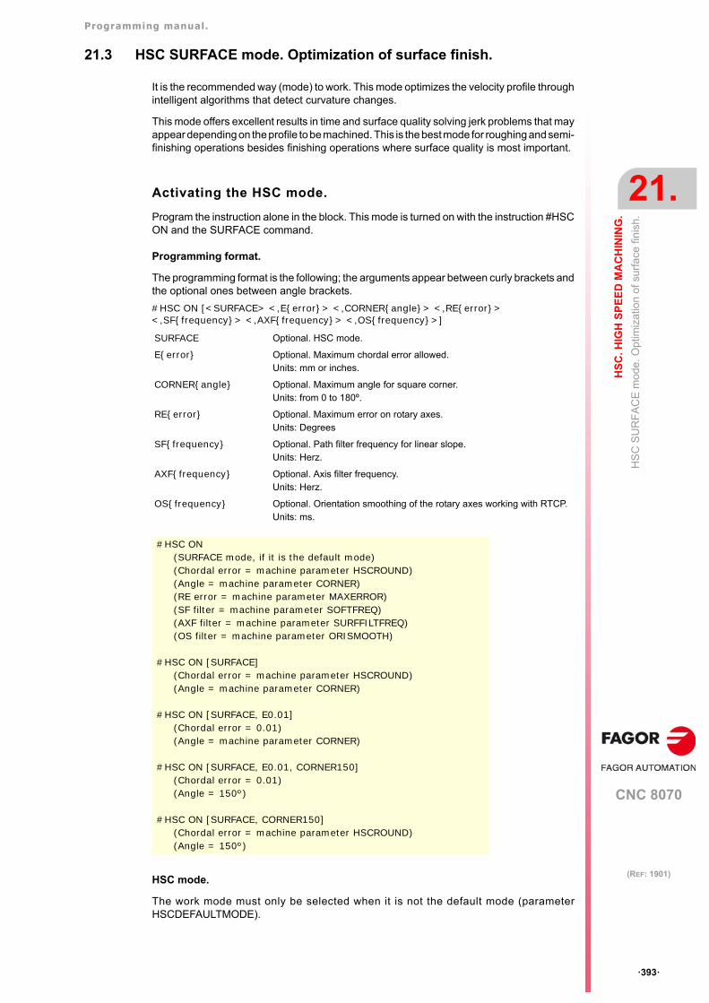
Programming manual.
CNC 8070
HS
C. H
IGH
SP
EE
D M
AC
HIN
ING
.
21.
HS
C S
UR
FA
CE
mod
e. O
ptim
izat
ion
of s
urfa
ce fi
nis
h.
·393·
(REF: 1901)
21.3 HSC SURFACE mode. Optimization of surface finish.
It is the recommended way (mode) to work. This mode optimizes the velocity profile throughintelligent algorithms that detect curvature changes.
This mode offers excellent results in time and surface quality solving jerk problems that mayappear depending on the profile to be machined. This is the best mode for roughing and semi-finishing operations besides finishing operations where surface quality is most important.
Activating the HSC mode.
Program the instruction alone in the block. This mode is turned on with the instruction #HSCON and the SURFACE command.
Programming format.
The programming format is the following; the arguments appear between curly brackets andthe optional ones between angle brackets.
#HSC ON [<SURFACE> <,E{error}> <,CORNER{angle}> <,RE{error}> <,SF{frequency}> <,AXF{frequency}> <,OS{frequency}>]
HSC mode.
The work mode must only be selected when it is not the default mode (parameterHSCDEFAULTMODE).
SURFACE Optional. HSC mode.
E{error} Optional. Maximum chordal error allowed.Units: mm or inches.
CORNER{angle} Optional. Maximum angle for square corner.Units: from 0 to 180º.
RE{error} Optional. Maximum error on rotary axes.Units: Degrees
SF{frequency} Optional. Path filter frequency for linear slope.Units: Herz.
AXF{frequency} Optional. Axis filter frequency.Units: Herz.
OS{frequency} Optional. Orientation smoothing of the rotary axes working with RTCP.Units: ms.
#HSC ON(SURFACE mode, if it is the default mode)(Chordal error = machine parameter HSCROUND)(Angle = machine parameter CORNER)(RE error = machine parameter MAXERROR)(SF filter = machine parameter SOFTFREQ)(AXF filter = machine parameter SURFFILTFREQ)(OS filter = machine parameter ORISMOOTH)
#HSC ON [SURFACE](Chordal error = machine parameter HSCROUND)(Angle = machine parameter CORNER)
#HSC ON [SURFACE, E0.01](Chordal error = 0.01)(Angle = machine parameter CORNER)
#HSC ON [SURFACE, E0.01, CORNER150](Chordal error = 0.01)(Angle = 150º)
#HSC ON [SURFACE, CORNER150](Chordal error = machine parameter HSCROUND)(Angle = 150º)
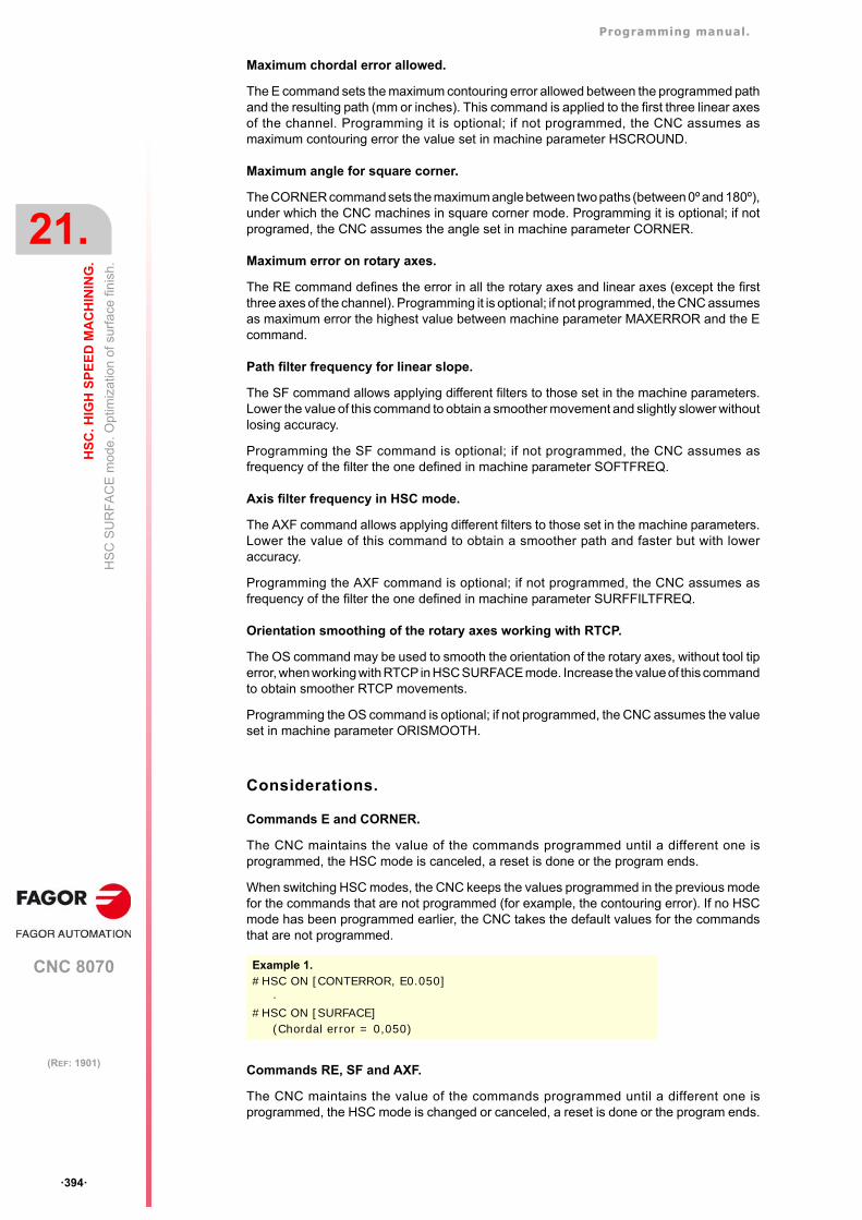
Programming manual.
CNC 8070
21.
HS
C. H
IGH
SP
EE
D M
AC
HIN
ING
.
HS
C S
UR
FA
CE
mod
e. O
ptim
izat
ion
of s
urfa
ce fi
nis
h.
·394·
(REF: 1901)
Maximum chordal error allowed.
The E command sets the maximum contouring error allowed between the programmed pathand the resulting path (mm or inches). This command is applied to the first three linear axesof the channel. Programming it is optional; if not programmed, the CNC assumes asmaximum contouring error the value set in machine parameter HSCROUND.
Maximum angle for square corner.
The CORNER command sets the maximum angle between two paths (between 0º and 180º),under which the CNC machines in square corner mode. Programming it is optional; if notprogramed, the CNC assumes the angle set in machine parameter CORNER.
Maximum error on rotary axes.
The RE command defines the error in all the rotary axes and linear axes (except the firstthree axes of the channel). Programming it is optional; if not programmed, the CNC assumesas maximum error the highest value between machine parameter MAXERROR and the Ecommand.
Path filter frequency for linear slope.
The SF command allows applying different filters to those set in the machine parameters.Lower the value of this command to obtain a smoother movement and slightly slower withoutlosing accuracy.
Programming the SF command is optional; if not programmed, the CNC assumes asfrequency of the filter the one defined in machine parameter SOFTFREQ.
Axis filter frequency in HSC mode.
The AXF command allows applying different filters to those set in the machine parameters.Lower the value of this command to obtain a smoother path and faster but with loweraccuracy.
Programming the AXF command is optional; if not programmed, the CNC assumes asfrequency of the filter the one defined in machine parameter SURFFILTFREQ.
Orientation smoothing of the rotary axes working with RTCP.
The OS command may be used to smooth the orientation of the rotary axes, without tool tiperror, when working with RTCP in HSC SURFACE mode. Increase the value of this commandto obtain smoother RTCP movements.
Programming the OS command is optional; if not programmed, the CNC assumes the valueset in machine parameter ORISMOOTH.
Considerations.
Commands E and CORNER.
The CNC maintains the value of the commands programmed until a different one isprogrammed, the HSC mode is canceled, a reset is done or the program ends.
When switching HSC modes, the CNC keeps the values programmed in the previous modefor the commands that are not programmed (for example, the contouring error). If no HSCmode has been programmed earlier, the CNC takes the default values for the commandsthat are not programmed.
Commands RE, SF and AXF.
The CNC maintains the value of the commands programmed until a different one isprogrammed, the HSC mode is changed or canceled, a reset is done or the program ends.
Example 1.#HSC ON [CONTERROR, E0.050]
·#HSC ON [SURFACE]
(Chordal error = 0,050)
Programming manual.
CNC 8070
HS
C. H
IGH
SP
EE
D M
AC
HIN
ING
.
21.
HS
C S
UR
FA
CE
mod
e. O
ptim
izat
ion
of s
urfa
ce fi
nis
h.
·395·
(REF: 1901)
When changing HSC modes, the CNC assumes the default values set in the machineparameters.
Execute an HSC mode starting with initial conditions.
To execute in HSC mode starting with initial conditions, first cancel the previous mode. See"21.6 Canceling the HSC mode." on page 400.
Example 2.#HSC ON [CONTERROR, E0.050]
·#HSC OFF
·#HSC ON [SURFACE]
(Chordal error = machine parameter HSCROUND)
Programming manual.
CNC 8070
21.
HS
C. H
IGH
SP
EE
D M
AC
HIN
ING
.
HS
C C
ON
TE
RR
OR
mod
e. O
ptim
izin
g th
e co
ntou
ring
erro
r.
·396·
(REF: 1901)
21.4 HSC CONTERROR mode. Optimizing the contouring error.
From this instruction on, the CNC modifies the geometry through intelligent algorithms foreliminating unnecessary points and automatically generating polynomials. . This way, thecontour is traveled at a variable feedrate according to the curvature and the programmedparameters (acceleration and feedrate) but respecting the set error limits.
Programming.
Program the instruction alone in the block. This mode is turned on with the instruction #HSCON and the CONTERROR command.
Programming format.
The programming format is the following; the arguments appear between curly brackets andthe optional ones between angle brackets.
#HSC ON [<CONTERROR> <,E{error}> <,CORNER{angle}> <,RE{error}> <,AXF{frequency}>]
HSC mode.
The work mode must only be selected when it is not the default mode (parameterHSCDEFAULTMODE).
Maximum chordal error allowed.
The E command sets the maximum contouring error allowed between the programmed pathand the resulting path (mm or inches). This command is applied to the first three linear axesof the channel. Programming it is optional; if not programmed, the CNC assumes asmaximum contouring error the value set in machine parameter HSCROUND.
Maximum angle for square corner.
The CORNER command sets the maximum angle between two paths (between 0º and 180º),under which the CNC machines in square corner mode. Programming it is optional; if notprogramed, the CNC assumes the angle set in machine parameter CORNER.
CONTERROR Optional. HSC mode.
E{error} Optional. Maximum chordal error allowed.Units: mm or inches.
CORNER{angle} Optional. Maximum angle for square corner.Units: from 0 to 180º.
RE{error} Optional. Maximum error on rotary axes.Units: Degrees
AXF{frequency} Optional. Axis filter frequency.Units: Herz.
#HSC ON [CONTERROR](Chordal error = machine parameter HSCROUND)(Angle = machine parameter CORNER)(RE error = machine parameter MAXERROR)(AXF filter = machine parameter HSCFILTFREQ)
#HSC ON [CONTERROR, E0.01](Chordal error = 0.01)(Angle = machine parameter CORNER)
#HSC ON [CONTERROR, E0.01, CORNER150](Chordal error = 0.01)(Angle = 150º)
#HSC ON [CONTERROR, CORNER150](Chordal error = machine parameter HSCROUND)(Angle = 150º)
Programming manual.
CNC 8070
HS
C. H
IGH
SP
EE
D M
AC
HIN
ING
.
21.
HS
C C
ON
TE
RR
OR
mod
e. O
ptim
izin
g th
e co
ntou
ring
erro
r.
·397·
(REF: 1901)
Maximum error on rotary axes.
The RE command defines the error in all the rotary axes and linear axes (except the firstthree axes of the channel). Programming it is optional; if not programmed, the CNC assumesas maximum error the highest value between machine parameter MAXERROR and the Ecommand.
Axis filter frequency in HSC mode.
The AXF command allows applying different filters to those set in the machine parameters.Programming it is optional; if not programmed, the CNC assumes as maximum contouringerror the value set in machine parameter HSCFILTFREQ.
Considerations.
Commands E and CORNER.
The CNC maintains the value of the commands programmed until a different one isprogrammed, the HSC mode is canceled, a reset is done or the program ends.
When switching HSC modes, the CNC keeps the values programmed in the previous modefor the commands that are not programmed (for example, the contouring error). If no HSCmode has been programmed earlier, the CNC takes the default values for the commandsthat are not programmed.
Commands RE, SF and AXF.
The CNC maintains the value of the commands programmed until a different one isprogrammed, the HSC mode is changed or canceled, a reset is done or the program ends.
When changing HSC modes, the CNC assumes the default values set in the machineparameters.
Execute an HSC mode starting with initial conditions.
To execute in HSC mode starting with initial conditions, first cancel the previous mode. See"21.6 Canceling the HSC mode." on page 400.
Example 1.#HSC ON [CONTERROR, E0.050]
·#HSC ON [SURFACE]
(Chordal error = 0,050)
Example 2.#HSC ON [CONTERROR, E0.050]
·#HSC OFF
·#HSC ON [SURFACE]
(Chordal error = machine parameter HSCROUND)
Programming manual.
CNC 8070
21.
HS
C. H
IGH
SP
EE
D M
AC
HIN
ING
.
HS
C F
AS
T m
ode.
Opt
imiz
ing
the
mac
hin
ing
fee
drat
e.
·398·
(REF: 1901)
21.5 HSC FAST mode. Optimizing the machining feedrate.
In spite of the recommendations for generating CAM programs, it is possible to haveprograms already generated that do not show a continuity between the error generated bythe CAM, the block size and the error required by the HSC. For this type of programs, theHSC mode has a fast mode where the CNC generates paths trying to restore this continuityand thus be able to work on a smoother surface and obtain a more continuous feedrate.
Programming.
Program the instruction alone in the block. This mode is turned on with the instruction #HSCON and the FAST command.
Programming format.
The programming format is the following; the arguments appear between curly brackets andthe optional ones between angle brackets.
#HSC ON [<FAST> <,E{error}> <,CORNER{angle}> <,RE{error}> <,SF{frequency}> <,AXF{frequency}>]
HSC mode.
The work mode must only be selected when it is not the default mode (parameterHSCDEFAULTMODE).
Maximum chordal error allowed.
The E command sets the maximum contouring error allowed between the programmed pathand the resulting path (mm or inches). This command is applied to the first three linear axesof the channel. Programming it is optional; if not programmed, the CNC assumes asmaximum contouring error the value set in machine parameter HSCROUND.
Programming the chordal error improves the accuracy in curved segments or circles;however, and considering the peculiarities of executing in FAST mode, the contour error atthe corners is not ensured.
FAST Optional. HSC mode.
E{error} Optional. Maximum chordal error allowed.Units: mm or inches.
CORNER{angle} Optional. Maximum angle for square corner.Units: from 0 to 180º.
RE{error} Optional. Maximum error on rotary axes.Units: Degrees
SF{frequency} Optional. Path filter frequency for linear slope.Units: Herz.
AXF{frequency} Optional. Axis filter frequency.Units: Herz.
#HSC ON [FAST](Chordal error = machine parameter HSCROUND)(Angle = machine parameter CORNER)(RE error = machine parameter MAXERROR)(SF filter = machine parameter SOFTFREQ)(AXF filter = machine parameter FASTFILTFREQ)
#HSC ON [FAST, E0.05](Chordal error = 0.05)(Angle = machine parameter CORNER)
#HSC ON [FAST, E0.01, CORNER130](Chordal error = 0.01)(Angle = 130º)
Programming manual.
CNC 8070
HS
C. H
IGH
SP
EE
D M
AC
HIN
ING
.
21.
HS
C F
AS
T m
ode.
Opt
imiz
ing
the
mac
hin
ing
fee
drat
e.
·399·
(REF: 1901)
Maximum angle for square corner.
The CORNER command sets the maximum angle between two paths (between 0º and 180º),under which the CNC machines in square corner mode. Programming it is optional; if notprogramed, the CNC assumes the angle set in machine parameter CORNER.
Maximum error on rotary axes.
The RE command defines the error in all the rotary axes and linear axes (except the firstthree axes of the channel). Programming it is optional; if not programmed, the CNC assumesas maximum error the highest value between machine parameter MAXERROR and the Ecommand.
Path filter frequency for linear slope.
The SF command allows applying different filters to those set in the machine parameters.Programming it is optional; if not programmed, the CNC assumes as frequency of the filterthe one defined in machine parameter SOFTFREQ.
Axis filter frequency in HSC mode.
The AXF command allows applying different filters to those set in the machine parameters.Programming it is optional; if not programmed, the CNC assumes as maximum contouringerror the value set in machine parameter FASTFILTFREQ.
Considerations.
Percentage of acceleration in the transition between blocks.
The percentage of acceleration in the transition between blocks may be modified usingfunctions G130/G131. The CNC assumes by default the value of machine parameterACCEL.
Commands E and CORNER.
The CNC maintains the value of the commands programmed until a different one isprogrammed, the HSC mode is canceled, a reset is done or the program ends.
When switching HSC modes, the CNC keeps the values programmed in the previous modefor the commands that are not programmed (for example, the contouring error). If no HSCmode has been programmed earlier, the CNC takes the default values for the commandsthat are not programmed.
Commands RE, SF and AXF.
The CNC maintains the value of the commands programmed until a different one isprogrammed, the HSC mode is changed or canceled, a reset is done or the program ends.
When changing HSC modes, the CNC assumes the default values set in the machineparameters.
Execute an HSC mode starting with initial conditions.
To execute in HSC mode starting with initial conditions, first cancel the previous mode. See"21.6 Canceling the HSC mode." on page 400.
From versions V1.30 (8060) and V5.30 (8065/8070), the #HSC instruction does not let program thepercentage of acceleration for transition between blocks. i
Example 1.#HSC ON [CONTERROR, E0.050]
·#HSC ON [SURFACE]
(Chordal error = 0,050)
Programming manual.
CNC 8070
21.
HS
C. H
IGH
SP
EE
D M
AC
HIN
ING
.
Ca
ncel
ing
the
HS
C m
ode
.
·400·
(REF: 1901)
21.6 Canceling the HSC mode.
The HSC mode is canceled with the instruction #HSC OFF. HSC is also canceled whenprogramming any of the functions G05, G07 or G50. Functions G60 and G61 do not cancelthe HSC mode. Activating a second HSC mode does not cancel the previous HSC mode.
Programming.
Program the instruction alone in the block.
Programming format.
The programming format is:
#HSC OFF
Influence of the reset, turning the CNC off and of the M30.
The HSC mode is canceled on power-up, after executing an M02 or M30 and after anemergency or reset.
#HSC OFF
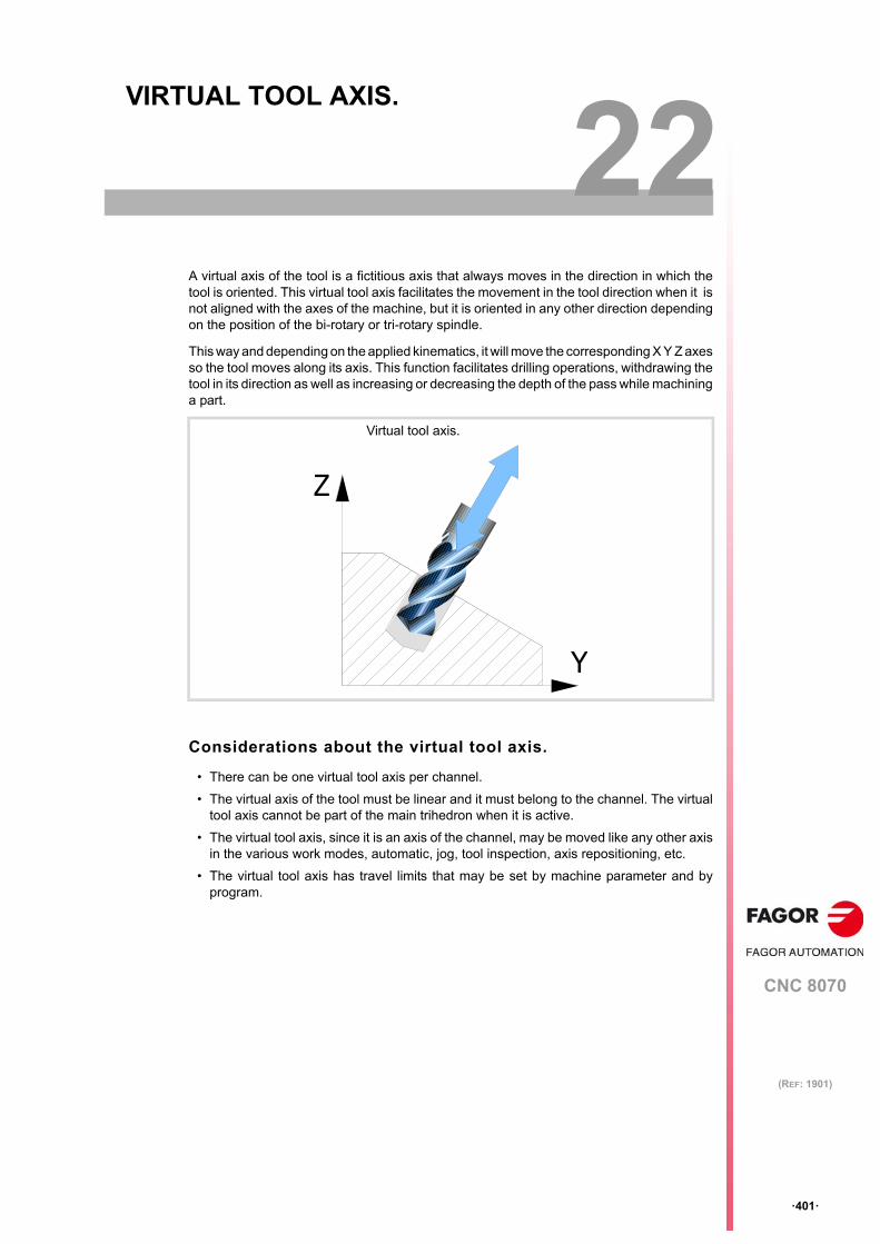
CNC 8070
22
·401·
(REF: 1901)
22.VIRTUAL TOOL AXIS.
A virtual axis of the tool is a fictitious axis that always moves in the direction in which thetool is oriented. This virtual tool axis facilitates the movement in the tool direction when it isnot aligned with the axes of the machine, but it is oriented in any other direction dependingon the position of the bi-rotary or tri-rotary spindle.
This way and depending on the applied kinematics, it will move the corresponding X Y Z axesso the tool moves along its axis. This function facilitates drilling operations, withdrawing thetool in its direction as well as increasing or decreasing the depth of the pass while machininga part.
Considerations about the virtual tool axis.
• There can be one virtual tool axis per channel.
• The virtual axis of the tool must be linear and it must belong to the channel. The virtualtool axis cannot be part of the main trihedron when it is active.
• The virtual tool axis, since it is an axis of the channel, may be moved like any other axisin the various work modes, automatic, jog, tool inspection, axis repositioning, etc.
• The virtual tool axis has travel limits that may be set by machine parameter and byprogram.
Y
Z
Virtual tool axis.
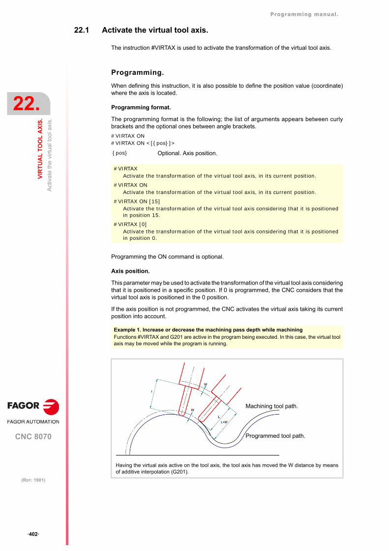
Programming manual.
CNC 8070
22.
VIR
TU
AL
TO
OL
AX
IS.
Act
ivat
e th
e vi
rtua
l to
ol a
xis.
·402·
(REF: 1901)
22.1 Activate the virtual tool axis.
The instruction #VIRTAX is used to activate the transformation of the virtual tool axis.
Programming.
When defining this instruction, it is also possible to define the position value (coordinate)where the axis is located.
Programming format.
The programming format is the following; the list of arguments appears between curlybrackets and the optional ones between angle brackets.
#VIRTAX ON#VIRTAX ON <[{pos}]>
Programming the ON command is optional.
Axis position.
This parameter may be used to activate the transformation of the virtual tool axis consideringthat it is positioned in a specific position. If 0 is programmed, the CNC considers that thevirtual tool axis is positioned in the 0 position.
If the axis position is not programmed, the CNC activates the virtual axis taking its currentposition into account.
{pos} Optional. Axis position.
#VIRTAXActivate the transformation of the virtual tool axis, in its current position.
#VIRTAX ONActivate the transformation of the virtual tool axis, in its current position.
#VIRTAX ON [15]Activate the transformation of the virtual tool axis considering that it is positioned in position 15.
#VIRTAX [0]Activate the transformation of the virtual tool axis considering that it is positioned in position 0.
Example 1. Increase or decrease the machining pass depth while machining Functions #VIRTAX and G201 are active in the program being executed. In this case, the virtual toolaxis may be moved while the program is running.
Having the virtual axis active on the tool axis, the tool axis has moved the W distance by meansof additive interpolation (G201).
Programmed tool path.
Machining tool path.
Programming manual.
CNC 8070
VIR
TU
AL
TO
OL
AX
IS.
22.
Can
cel t
he
virt
ual
tool
axi
s.
·403·
(REF: 1901)
22.2 Cancel the virtual tool axis.
The instruction #VIRTAX OFF cancels the transformation of the virtual tool axis. The waythe virtual tool axis will behave after executing an M30 or after a reset depends on the settingof parameter VIRTAXCANCEL.
Programming.
Program the instruction alone in the block.
Programming format.
The programming format is:
#VIRTAX OFF
Example 2. Increase or decrease the machining pass depth while machining Functions #VIRTAX and G201 are not active in the program being executed. The steps to changethe machining pass are the following.(1) Interrupt program execution with the [STOP] key.(2) Go into tool inspection mode.(3) From MDI mode, execute #VIRTAX[0].(4) Move the axis the desired distance via MDI, jog, etc.(5) Resume execution without repositioning the axes.
#VIRTAX OFF
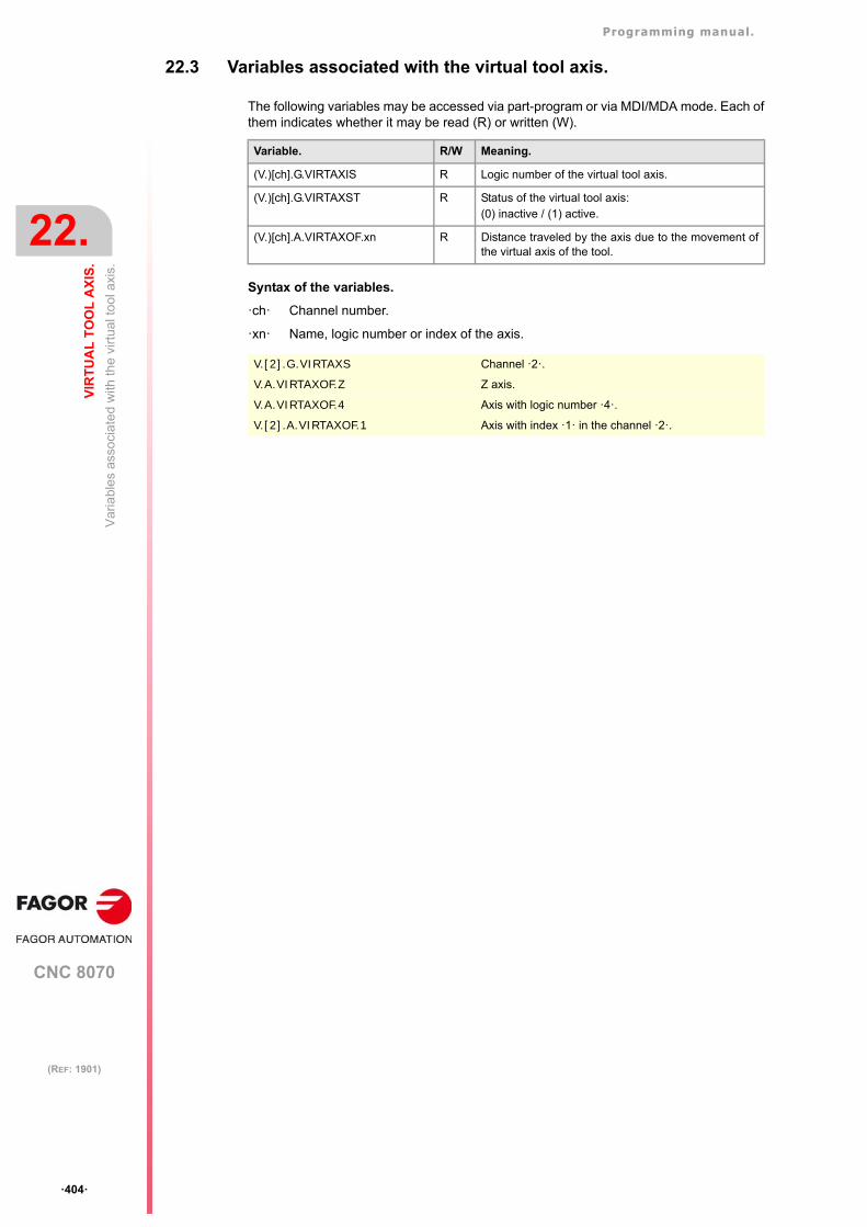
Programming manual.
CNC 8070
22.
VIR
TU
AL
TO
OL
AX
IS.
Var
iabl
es a
ssoc
iate
d w
ith th
e vi
rtu
al to
ol a
xis.
·404·
(REF: 1901)
22.3 Variables associated with the virtual tool axis.
The following variables may be accessed via part-program or via MDI/MDA mode. Each ofthem indicates whether it may be read (R) or written (W).
Syntax of the variables.
·ch· Channel number.
·xn· Name, logic number or index of the axis.
Variable. R/W Meaning.
(V.)[ch].G.VIRTAXIS R Logic number of the virtual tool axis.
(V.)[ch].G.VIRTAXST R Status of the virtual tool axis: (0) inactive / (1) active.
(V.)[ch].A.VIRTAXOF.xn R Distance traveled by the axis due to the movement ofthe virtual axis of the tool.
V.[2].G.VIRTAXS Channel ·2·.
V.A.VIRTAXOF.Z Z axis.
V.A.VIRTAXOF.4 Axis with logic number ·4·.
V.[2].A.VIRTAXOF.1 Axis with index ·1· in the channel ·2·.
CNC 8070
23
·405·
(REF: 1901)
23.DISPLAYING MESSAGES, WARNINGS AND ERRORS.
The display of messages provides a simple way to follow the execution of a program, byshowing messages at certain times during the program that the operator considersimportant, such as at the beginning of each operation, etc. The CNC only shows the lastexecuted message. Messages, in combination with the function M0 (program interruption),are also useful when requesting the intervention of the operator.
The warning and error windows are a CNC resource for informing of undesired situationsduring program execution. All warnings and errors remain active, visible or minimized on thestatus bar until they are removed by the operator. Warning windows offer the possibility tocontinue program execution, whereas an error window stops the execution of the program.
Programming messages, warnings and errors.
The CNC provides the following instructions to display messages, warning windows or errorwindows. The table below shows a summary of the properties of each of the instructions.
Instruction. Meaning and properties.
#MSG Show a message on the status bar.• The CNC only displays the last executed message.• The CNC does not interrupt program execution.• An empty message, a CNC reset or when starting the execution of a
program will remove the message.
#WARNING Shows a warning window.• The CNC displays all executed warning windows.• The CNC does not interrupt program execution. • The [ESC] key closes the window.
#WARNINGSTOP Shows a warning window and interrupts the execution.• The CNC displays all executed warning windows.• The CNC interrupts program execution. The user can continue
executing the program or stop it.• The [ESC] key closes the window.
#ERROR Shows a message in a warning window.• The CNC displays all executed error windows.• The CNC interrupts program execution and enters an error state.• The [ESC] key closes the window and CNC reset will remove the error
status.
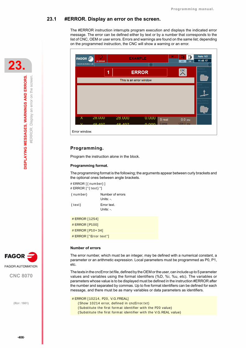
Programming manual.
CNC 8070
23.
DIS
PL
AY
ING
ME
SS
AG
ES
, WA
RN
ING
S A
ND
ER
RO
RS
.
#E
RR
OR
. Dis
play
an
erro
r on
the
scre
en.
·406·
(REF: 1901)
23.1 #ERROR. Display an error on the screen.
The #ERROR instruction interrupts program execution and displays the indicated errormessage. The error can be defined either by text or by a number that corresponds to thelist of CNC, OEM or user errors. Errors and warnings are found on the same list; dependingon the programmed instruction, the CNC will show a warning or an error.
Programming.
Program the instruction alone in the block.
Programming format.
The programming format is the following; the arguments appear between curly brackets andthe optional ones between angle brackets.
#ERROR [{number}]#ERROR ["{text}"]
Number of errors
The error number, which must be an integer, may be defined with a numerical constant, aparameter or an arithmetic expression. Local parameters must be programmed as P0, P1,etc.
The texts in the cncError.txt file, defined by the OEM or the user, can include up to 5 parametervalues and variables using the format identifiers (%D, %i, %u, etc). The variables orparameters whose value is to be displayed must be defined in the instruction #ERROR afterthe number and separated by commas. Up to five format identifiers can be defined for eachmessage, and there must be as many variables or data parameters as identifiers.
Error window.
{number} Number of errorsUnits: -.
{text} Error text.Units: -.
#ERROR [1254]
#ERROR [P100]
#ERROR [P10+34]
#ERROR ["Error text"]
#ERROR [10214, P20, V.G.FREAL] (Show 10214 error, defined in cncError.txt)(Substitute the first format identifier with the P20 value)(Substitute the first format identifier with the V.G.REAL value)
Programming manual.
CNC 8070
DIS
PL
AY
ING
ME
SS
AG
ES
, WA
RN
ING
S A
ND
ER
RO
RS
.
23.
#E
RR
OR
. Dis
play
an
erro
r on
the
scre
en.
·407·
(REF: 1901)
Error text.
The text must be defined between quote marks. If no text is defined, an empty window isdisplayed. The text can include 5 parameter values and variables in the message using theformat identifiers (%D, %i, %u, etc). The variables or parameters whose value is to bedisplayed must be defined after the text and separated by commas. Up to five formatidentifiers can be defined for each message, and there must be as many variables or dataparameters as identifiers.
Considerations.
Fagor text and OEM/USER text.
Errors and warnings between 0 and 9999 and between 23000 and 23999 are reserved byFagor. The range of errors and warnings from 10000 to 20000 is available to the OEM andthe user, so that other text can be created. See "23.5 cncError.txt file. List of OEM and usererrors and warnings." on page 413.
Format identifiers.
See "23.4 Format identifiers and special characters." on page 412.
#ERROR ["The current tool is %D", V.G.TOOL]
#ERROR [10214, V.G.TOOL, V.G.FREAL, P1] (The 10214 error must be defined in the cncError.txt file)
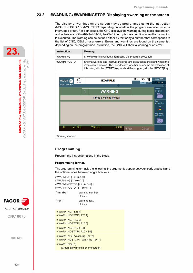
Programming manual.
CNC 8070
23.
DIS
PL
AY
ING
ME
SS
AG
ES
, WA
RN
ING
S A
ND
ER
RO
RS
.
#W
AR
NIN
G /
#W
AR
NIN
GS
TO
P. D
ispl
ayin
g a
wa
rnin
g o
n th
esc
reen
.
·408·
(REF: 1901)
23.2 #WARNING / #WARNINGSTOP. Displaying a warning on the screen.
The display of warnings on the screen may be programmed using the instruction#WARNINGSTOP or #WARNING depending on whether the program execution is to beinterrupted or not. For both cases, the CNC displays the warning during block preparation,and in the case of #WARNINGSTOP, the CNC interrupts the execution when the instructionis executed. The warning can be defined either by text or by a number that corresponds tothe list of CNC, OEM or user errors. Errors and warnings are found on the same list;depending on the programmed instruction, the CNC will show a warning or an error.
Programming.
Program the instruction alone in the block.
Programming format.
The programming format is the following; the arguments appear between curly brackets andthe optional ones between angle brackets.
#WARNING [{number}]#WARNING ["{text}"]#WARNINGSTOP [{number}]#WARNINGSTOP ["{text}"]
Instruction. Meaning.
#WARNING Show a warning without interrupting the program execution.
#WARNINGSTOP Show a warning and interrupt the program execution at the point where theinstruction is located. The user decides whether to resume the execution atthis point, with the [START] key, or abort the program, with the [RESET] key.
Warning window.
{number} Warning number.Units: -.
{text} Warning text.Units: -.
#WARNING [1254]#WARNINGSTOP [1254]
#WARNING [P100]#WARNINGSTOP [P100]
#WARNING [P10+34]#WARNINGSTOP [P10+34]
#WARNING ["Warning text"]#WARNINGSTOP ["Warning text"]
#WARNING [0](Clears all warnings on the screen)
Programming manual.
CNC 8070
DIS
PL
AY
ING
ME
SS
AG
ES
, WA
RN
ING
S A
ND
ER
RO
RS
.
23.
#W
AR
NIN
G /
#W
AR
NIN
GS
TO
P. D
ispl
ayin
g a
wa
rnin
g o
n th
esc
reen
.
·409·
(REF: 1901)
Warning number.
The warning number, which must be an integer, may be defined using a numerical constant,a parameter or an arithmetic expression. Local parameters must be programmed as P0, P1,etc.
The texts in the cncError.txt file, defined by the OEM or the user, can include up to 5 parametervalues and variables using the format identifiers (%D, %i, %u, etc). The variables orparameters whose value is to be displayed must be defined in the call instruction (forexample, #WARNING) after the number and separated by commas. Up to five formatidentifiers can be defined for each message, and there must be as many variables or dataparameters as identifiers.
Warning text.
The text must be defined between quote marks. If no text is defined, an empty window isdisplayed. The text can include 5 parameter values and variables in the message using theformat identifiers (%D, %i, %u, etc). The variables or parameters whose value is to bedisplayed must be defined after the text and separated by commas. Up to five formatidentifiers can be defined for each message, and there must be as many variables or dataparameters as identifiers.
Clears all displayed warnings.
Programming a warning with a value of 0 clears all the warnings that are being displayed.
Considerations.
Fagor text and OEM/USER text.
Errors and warnings between 0 and 9999 and between 23000 and 23999 are reserved byFagor. The range of errors and warnings from 10000 to 20000 is available to the OEM andthe user, so that other text can be created. See "23.5 cncError.txt file. List of OEM and usererrors and warnings." on page 413.
Format identifiers.
See "23.4 Format identifiers and special characters." on page 412.
#WARNING [10214, P20, V.G.FREAL] (Show the 10214 warning, defined in cncError.txt)(Substitute the first format identifier with the P20 value)(Substitute the first format identifier with the V.G.REAL value)
#WARNING ["The current tool is %D", V.G.TOOL]
#WARNING [0](Clears all warnings on the screen)
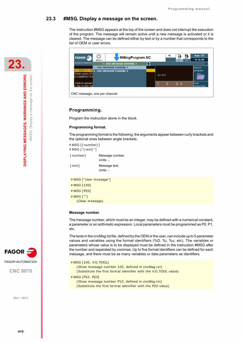
Programming manual.
CNC 8070
23.
DIS
PL
AY
ING
ME
SS
AG
ES
, WA
RN
ING
S A
ND
ER
RO
RS
.
#MS
G. D
ispl
ay
a m
essa
ge
on th
e sc
reen
.
·410·
(REF: 1901)
23.3 #MSG. Display a message on the screen.
The instruction #MSG appears at the top of the screen and does not interrupt the executionof the program. The message will remain active until a new message is activated or it iscleared. The message can be defined either by text or by a number that corresponds to thelist of OEM or user errors.
Programming.
Program the instruction alone in the block.
Programming format.
The programming format is the following; the arguments appear between curly brackets andthe optional ones between angle brackets.
#MSG [{number}]#MSG ["{text}"]
Message number.
The message number, which must be an integer, may be defined with a numerical constant,a parameter or an arithmetic expression. Local parameters must be programmed as P0, P1,etc.
The texts in the cncMsg.txt file, defined by the OEM or the user, can include up to 5 parametervalues and variables using the format identifiers (%D, %i, %u, etc). The variables orparameters whose value is to be displayed must be defined in the instruction #MSG afterthe number and separated by commas. Up to five format identifiers can be defined for eachmessage, and there must be as many variables or data parameters as identifiers.
CNC message, one per channel.
{number} Message number.Units: -.
{text} Message text.Units: -.
#MSG ["User message"]
#MSG [100]
#MSG [P20]
#MSG [""](Clear message)
#MSG [100, V.G.TOOL](Show message number 100, defined in cncMsg.txt)(Substitute the first format identifier with the V.G.TOOL value)
#MSG [P10, P20](Show message number P10, defined in cncMsg.txt)(Substitute the first format identifier with the P20 value)
Programming manual.
CNC 8070
DIS
PL
AY
ING
ME
SS
AG
ES
, WA
RN
ING
S A
ND
ER
RO
RS
.
23.
#MS
G. D
ispl
ay
a m
essa
ge
on th
e sc
reen
.
·411·
(REF: 1901)
Message text.
The text must be defined between quote marks. If no text is defined, the message is erasedfrom the screen. The text can include 5 parameter values and variables in the message usingthe format identifiers (%D, %i, %u, etc). The variables or parameters whose value is to bedisplayed must be defined after the text and separated by commas. Up to five formatidentifiers can be defined for each message, and there must be as many variables or dataparameters as identifiers.
Clears the displayed message.
Programming an empty message clears the message on the screen. A reset or “end ofprogram” will not clear the message on the screen)
#MSG ["Part number %D", P2]
#MSG ["Finishing F=%D mm/min and S=%D RPM", P21, 1200]
#MSG ["Tool %u has expired", V.G.TOOL]
#MSG [""](Clear message on the screen)
Programming manual.
CNC 8070
23.
DIS
PL
AY
ING
ME
SS
AG
ES
, WA
RN
ING
S A
ND
ER
RO
RS
.
Fo
rma
t id
entif
iers
and
spe
cial
cha
ract
ers.
·412·
(REF: 1901)
23.4 Format identifiers and special characters.
Format identifiers.
Writing text with %letter that is not found in this list or the following list, the CNC will includeit as %letter.
Special characters.
Writing text with %letter that is not found in this list or the previous list, the CNC will includeit as %letter.
Identifier. Meaning.
%d %D Integer or floating point number (with or without decimals).With this identifier, the number of integers and decimals tobe displayed (default 5.5) can be defined; this format isdefined between the symbol % and a letter; for example%5.5d.
%i Integer in base 10 with positive or negative sign (int).
%u Integer in base 10 without positive or negative sign (int).
%o Integer in base 8 without positive or negative sign (int).
%x Integer in base 16 using lowercase letters (int).
%X Integer in base 16 using uppercase letters (int).
%f %F Simple precision floating decimal (float). With this identifier,the number of integers and decimals to be displayed (default5.5) can be defined; this format is defined between thesymbol % and a letter; for example %5.5f.
%e Scientific notation (coefficient / exponent), lower case(single precision or double precision).
%E Scientific notation (coefficient / exponent), upper case(single precision or double precision).
%c Write a character using its ASCII code (decimal number).
%s Write a string (string of characters) from a string. Thisiden t i f i e r can on ly be used w i th the va r iab les(V.)A.AXISNAME.xn and (V.)A.SPDLNAME.sn.
Identifier. Meaning.
%% Character %.
\" Quotation marks.
#WARNING ["Difference between P12 and P14 > 40%%"]
#ERROR ["Parameter \"P100\" is wrong"]
#MSG ["The tool \"T1\" is a finishing tool"]
#MSG ["80%% of feedrate"]
#WARNING ["%s", V.A.AXISNAME.1](Display the name of the axis).
#WARNING ["%c", 65](Show character A, because 65 is its ASCII code).
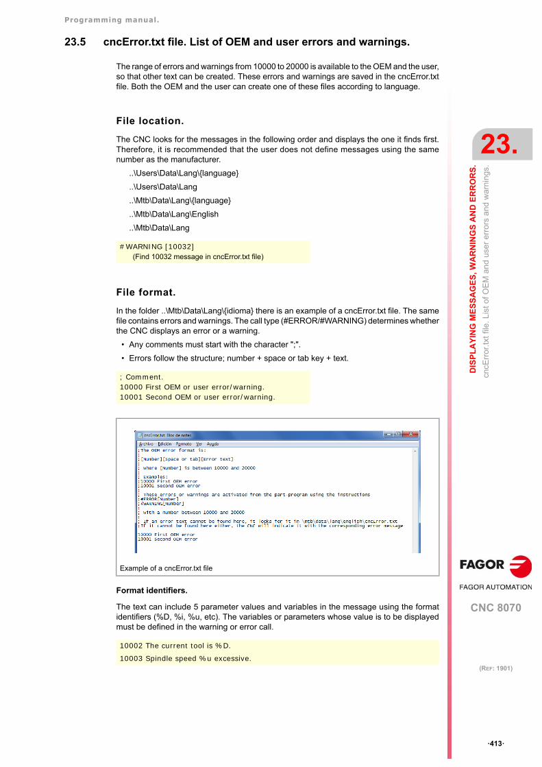
Programming manual.
CNC 8070
DIS
PL
AY
ING
ME
SS
AG
ES
, WA
RN
ING
S A
ND
ER
RO
RS
.
23.
cncE
rror
.txt f
ile. L
ist o
f OE
M a
nd
user
err
ors
and
war
ning
s.
·413·
(REF: 1901)
23.5 cncError.txt file. List of OEM and user errors and warnings.
The range of errors and warnings from 10000 to 20000 is available to the OEM and the user,so that other text can be created. These errors and warnings are saved in the cncError.txtfile. Both the OEM and the user can create one of these files according to language.
File location.
The CNC looks for the messages in the following order and displays the one it finds first.Therefore, it is recommended that the user does not define messages using the samenumber as the manufacturer.
..\Users\Data\Lang\{language}
..\Users\Data\Lang
..\Mtb\Data\Lang\{language}
..\Mtb\Data\Lang\English
..\Mtb\Data\Lang
File format.
In the folder ..\Mtb\Data\Lang\{idioma} there is an example of a cncError.txt file. The samefile contains errors and warnings. The call type (#ERROR/#WARNING) determines whetherthe CNC displays an error or a warning.
• Any comments must start with the character ";".
• Errors follow the structure; number + space or tab key + text.
Format identifiers.
The text can include 5 parameter values and variables in the message using the formatidentifiers (%D, %i, %u, etc). The variables or parameters whose value is to be displayedmust be defined in the warning or error call.
#WARNING [10032](Find 10032 message in cncError.txt file)
; Comment.10000 First OEM or user error/warning.10001 Second OEM or user error/warning.
Example of a cncError.txt file
10002 The current tool is %D.
10003 Spindle speed %u excessive.
Programming manual.
CNC 8070
23.
DIS
PL
AY
ING
ME
SS
AG
ES
, WA
RN
ING
S A
ND
ER
RO
RS
.
cncM
sg.tx
t file
. Lis
t of O
EM
an
d us
er m
ess
age
s.
·414·
(REF: 1901)
23.6 cncMsg.txt file. List of OEM and user messages.
The file cncMsg.txt contains the OEM and user defined messages for the instruction #MSG.Both the OEM and the user can create one of these files according to language.
File location.
The CNC looks for the messages in the following order and displays the one it finds first.Therefore, it is recommended that the user does not define messages using the samenumber as the manufacturer. If the message is not found in any file, the CNC will not showany message.
..\Users\Data\Lang\{language}
..\Users\Data\Lang
..\Mtb\Data\Lang\{language}
..\Mtb\Data\Lang
File format.
The file format will be:
• Any comments must start with the character ";".
• Errors follow the structure; number + space or tab key + text.
Format identifiers.
The text can include 5 parameter values and variables in the message using the formatidentifiers (%D, %i, %u, etc). The variables or parameters whose value is to be displayedmust be defined in the message call.
#MSG [1234](Find 1234 message in cncMsg.txt file)
; Comment.1 First message.2 Second message.3 Third message.
12 The current tool is %D.
13 Spindle speed %u excessive.
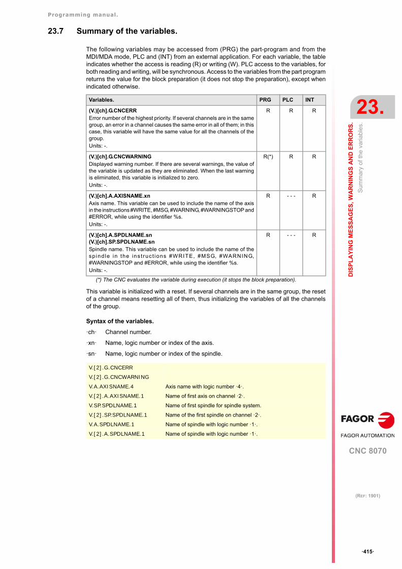
Programming manual.
CNC 8070
DIS
PL
AY
ING
ME
SS
AG
ES
, WA
RN
ING
S A
ND
ER
RO
RS
.
23.
Sum
mar
y of
the
varia
bles
.
·415·
(REF: 1901)
23.7 Summary of the variables.
The following variables may be accessed from (PRG) the part-program and from theMDI/MDA mode, PLC and (INT) from an external application. For each variable, the tableindicates whether the access is reading (R) or writing (W). PLC access to the variables, forboth reading and writing, will be synchronous. Access to the variables from the part programreturns the value for the block preparation (it does not stop the preparation), except whenindicated otherwise.
This variable is initialized with a reset. If several channels are in the same group, the resetof a channel means resetting all of them, thus initializing the variables of all the channelsof the group.
Syntax of the variables.
·ch· Channel number.
·xn· Name, logic number or index of the axis.
·sn· Name, logic number or index of the spindle.
Variables. PRG PLC INT
(V.)[ch].G.CNCERRError number of the highest priority. If several channels are in the samegroup, an error in a channel causes the same error in all of them; in thiscase, this variable will have the same value for all the channels of thegroup.Units: -.
R R R
(V.)[ch].G.CNCWARNINGDisplayed warning number. If there are several warnings, the value ofthe variable is updated as they are eliminated. When the last warningis eliminated, this variable is initialized to zero.Units: -.
R(*) R R
(V.)[ch].A.AXISNAME.xnAxis name. This variable can be used to include the name of the axisin the instructions #WRITE, #MSG, #WARNING, #WARNINGSTOP and#ERROR, while using the identifier %s.Units: -.
R - - - R
(V.)[ch].A.SPDLNAME.sn(V.)[ch].SP.SPDLNAME.snSpindle name. This variable can be used to include the name of thesp ind le in the ins t ruc t ions #WRITE, #MSG, #WARNING,#WARNINGSTOP and #ERROR, while using the identifier %s.Units: -.
R - - - R
(*) The CNC evaluates the variable during execution (it stops the block preparation).
V.[2].G.CNCERR
V.[2].G.CNCWARNING
V.A.AXISNAME.4 Axis name with logic number ·4·.
V.[2].A.AXISNAME.1 Name of first axis on channel ·2·.
V.SP.SPDLNAME.1 Name of first spindle for spindle system.
V.[2].SP.SPDLNAME.1 Name of the first spindle on channel ·2·.
V.A.SPDLNAME.1 Name of spindle with logic number ·1·.
V.[2].A.SPDLNAME.1 Name of spindle with logic number ·1·.
Programming manual.
CNC 8070
23.
DIS
PL
AY
ING
ME
SS
AG
ES
, WA
RN
ING
S A
ND
ER
RO
RS
.
Sum
mar
y of
the
varia
bles
.
·416·
(REF: 1901)
CNC 8070
24
·417·
(REF: 1901)
24.DMC (DYNAMIC MACHINING CONTROL).
The choice of machining feedrate depends on the material to be machined, the tool (material,number of teeth, etc.) and the depth of pass. The feedrate for machining is set at the startand remains constant until the end. If the machining conditions change (for example, dueto tool wear), the programmed feedrate may no longer be appropriate, which will have anegative effect on the tool life, machining time, etc.
DMC (dynamic machining control) adapts the feedrate during machining to maintain thecutting power as close as possible to ideal machining conditions. DMC adapts the feedrateby changing the override.
DMC optimizes the use of the machine and the tool, which makes it possible to increase thematerial removal rate (MRR) without impairing the life of the tool, since it is operatingaccording to its rated conditions. Optimization is based on the cutting power to be reached,which is also referred to as target power. This power not only depends on the tool, but alsoon the material and the cutting conditions (feedrate, spindle turning speed, depth of passand sideways step (pass)), and therefore its value must be linked to the entire combinationof the tool+material+cutting conditions.
DMC is only available for milling operations with "Milling" and "Surface milling” operations.This function can be applied to roughing and finishing operations, but this function providesthe most benefits in terms of machining time and tool life in roughing operations.
The DMC is only available for the master spindle using Fagor digital servo systems. The spindle mustbe enabled for the DMC in the machine parameter DMCSPDL. i
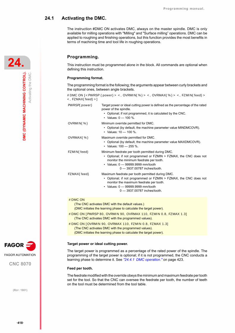
Programming manual.
CNC 8070
24.
DM
C (
DY
NA
MIC
MA
CH
ININ
G C
ON
TR
OL
).
Act
ivat
ing
the
DM
C.
·418·
(REF: 1901)
24.1 Activating the DMC.
The instruction #DMC ON activates DMC, always on the master spindle. DMC is onlyavailable for milling operations with "Milling" and "Surface milling” operations. DMC can beapplied to roughing and finishing operations, but this function provides the most benefits interms of machining time and tool life in roughing operations.
Programming.
This instruction must be programmed alone in the block. All commands are optional whendefining this instruction.
Programming format.
The programming format is the following; the arguments appear between curly brackets andthe optional ones, between angle brackets.
#DMC ON [<PWRSP {power}> <, OVRMIN{%}> <, OVRMAX{%}> <, FZMIN{feed}> <, FZMAX{feed}>]
Target power or ideal cutting power.
The target power is programmed as a percentage of the rated power of the spindle. Theprogramming of the target power is optional; if it is not programmed, the CNC conducts alearning phase to determine it. See "24.4.1 DMC operation." on page 423.
Feed per tooth.
The feedrate modified with the override obeys the minimum and maximum feedrate per toothset for the tool. So that the CNC can oversee the feedrate per tooth, the number of teethon the tool must be determined from the tool table.
PWRSP{power} Target power or ideal cutting power is defined as the percentage of the ratedpower of the spindle.
• Optional; if not programmed, it is calculated by the CNC. • Values: 0 — 100 %.
OVRMIN{%} Minimum override permitted for DMC.• Optional (by default, the machine parameter value MINDMCOVR). • Values: 10 — 100 %.
OVRMAX{%} Maximum override permitted for DMC.• Optional (by default, the machine parameter value MAXDMCOVR). • Values: 100 — 255 %.
FZMIN{feed} Minimum feedrate per tooth permitted during DMC.• Optional; if not programmed or FZMIN > FZMAX, the CNC does not
monitor the minimum feedrate per tooth. • Values: 0 — 99999.9999 mm/tooth
0 — 3937.00787 inches/tooth.
FZMAX{feed} Maximum feedrate per tooth permitted during DMC.• Optional; if not programmed or FZMIN > FZMAX, the CNC does not
monitor the maximum feedrate per tooth. • Values: 0 — 99999.9999 mm/tooth
0 — 3937.00787 inches/tooth.
#DMC ON(The CNC activates DMC with the default values.)(DMC initiates the learning phase to calculate the target power).
#DMC ON [PWRSP 80, OVRMIN 90, OVRMAX 110, FZMIN 0.8, FZMAX 1.3](The CNC activates DMC with the programmed values).
#DMC ON [OVRMIN 90, OVRMAX 110, FZMIN 0.8, FZMAX 1.3](The CNC activates DMC with the programmed values).(DMC initiates the learning phase to calculate the target power).
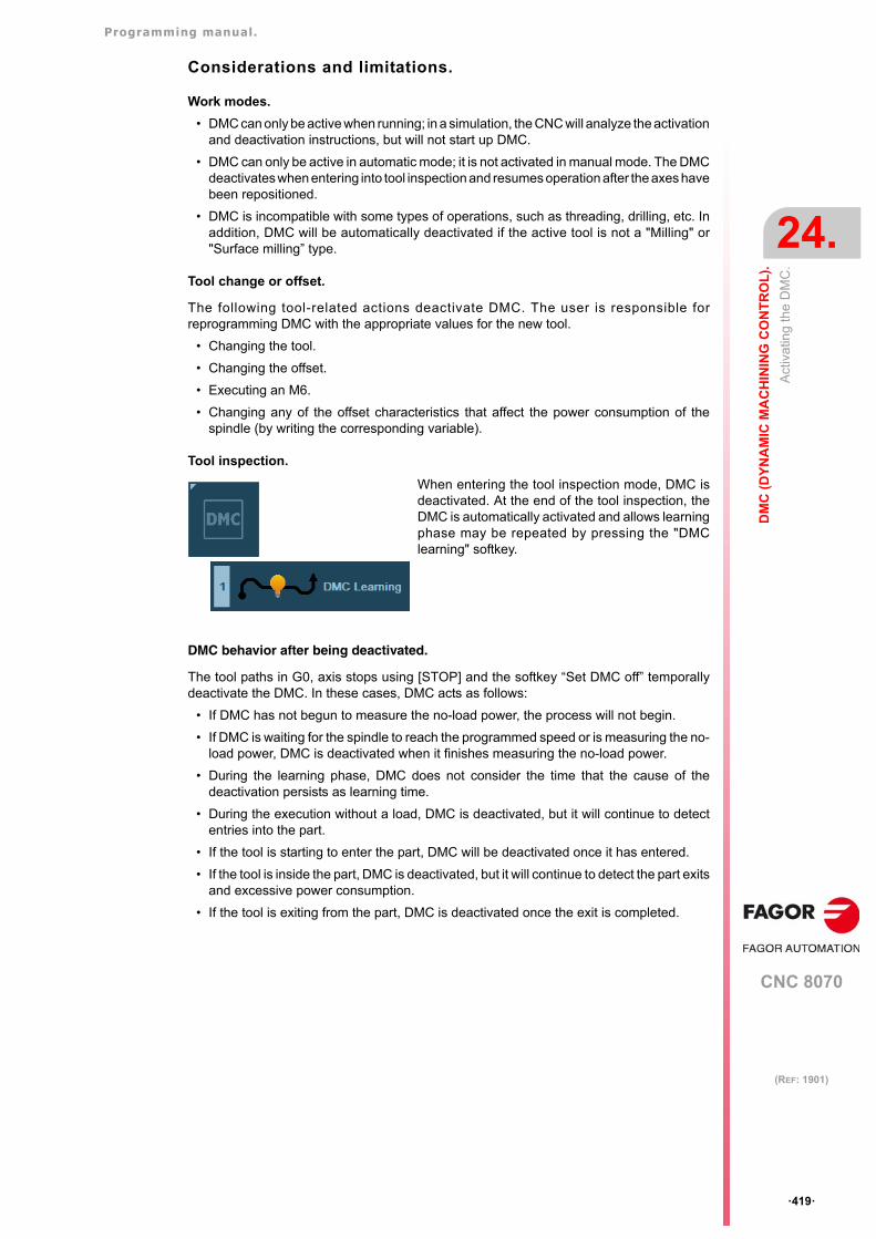
Programming manual.
CNC 8070
DM
C (
DY
NA
MIC
MA
CH
ININ
G C
ON
TR
OL
).
24.
Act
ivat
ing
the
DM
C.
·419·
(REF: 1901)
Considerations and limitations.
Work modes.
• DMC can only be active when running; in a simulation, the CNC will analyze the activationand deactivation instructions, but will not start up DMC.
• DMC can only be active in automatic mode; it is not activated in manual mode. The DMCdeactivates when entering into tool inspection and resumes operation after the axes havebeen repositioned.
• DMC is incompatible with some types of operations, such as threading, drilling, etc. Inaddition, DMC will be automatically deactivated if the active tool is not a "Milling" or"Surface milling” type.
Tool change or offset.
The following tool-related actions deactivate DMC. The user is responsible forreprogramming DMC with the appropriate values for the new tool.
• Changing the tool.
• Changing the offset.
• Executing an M6.
• Changing any of the offset characteristics that affect the power consumption of thespindle (by writing the corresponding variable).
Tool inspection.
DMC behavior after being deactivated.
The tool paths in G0, axis stops using [STOP] and the softkey “Set DMC off” temporallydeactivate the DMC. In these cases, DMC acts as follows:
• If DMC has not begun to measure the no-load power, the process will not begin.
• If DMC is waiting for the spindle to reach the programmed speed or is measuring the no-load power, DMC is deactivated when it finishes measuring the no-load power.
• During the learning phase, DMC does not consider the time that the cause of thedeactivation persists as learning time.
• During the execution without a load, DMC is deactivated, but it will continue to detectentries into the part.
• If the tool is starting to enter the part, DMC will be deactivated once it has entered.
• If the tool is inside the part, DMC is deactivated, but it will continue to detect the part exitsand excessive power consumption.
• If the tool is exiting from the part, DMC is deactivated once the exit is completed.
When entering the tool inspection mode, DMC isdeactivated. At the end of the tool inspection, theDMC is automatically activated and allows learningphase may be repeated by pressing the "DMClearning" softkey.
Programming manual.
CNC 8070
24.
DM
C (
DY
NA
MIC
MA
CH
ININ
G C
ON
TR
OL
).
Dea
ctiv
atin
g th
e D
MC
.
·420·
(REF: 1901)
24.2 Deactivating the DMC.
The #DMCºOFF instruction deactivates DMC. The M02 or M30 (end of program) functionsand the reset also deactivate DMC. A spindle stop, function M5, deactivates DMC.
Programming.
This instruction must be programmed alone in the block. This instruction has no commands.
Programming format.
The programming format is:
#DMC OFF
#DMC OFF(The CNC deactivates DMC).
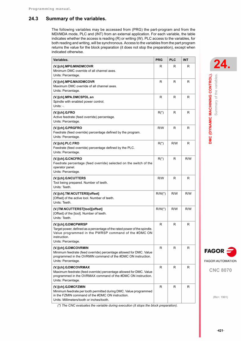
Programming manual.
CNC 8070
DM
C (
DY
NA
MIC
MA
CH
ININ
G C
ON
TR
OL
).
24.
Sum
mar
y of
the
varia
bles
.
·421·
(REF: 1901)
24.3 Summary of the variables.
The following variables may be accessed from (PRG) the part-program and from theMDI/MDA mode, PLC and (INT) from an external application. For each variable, the tableindicates whether the access is reading (R) or writing (W). PLC access to the variables, forboth reading and writing, will be synchronous. Access to the variables from the part programreturns the value for the block preparation (it does not stop the preparation), except whenindicated otherwise.
Variables. PRG PLC INT
(V.)[ch].MPG.MINDMCOVRMinimum DMC override of all channel axes.Units: Percentage.
R R R
(V.)[ch].MPG.MAXDMCOVRMaximum DMC override of all channel axes.Units: Percentage.
R R R
(V.)[ch].MPA.DMCSPDL.snSpindle with enabled power control.Units: -.
R R R
(V.)[ch].G.FROActive feedrate (feed override) percentage.Units: Percentage.
R(*) R R
(V.)[ch].G.PRGFROFeedrate (feed override) percentage defined by the program.Units: Percentage.
R/W R R
(V.)[ch].PLC.FROFeedrate (feed override) percentage defined by the PLC.Units: Percentage.
R(*) R/W R
(V.)[ch].G.CNCFROFeedrate percentage (feed override) selected on the switch of theoperator panel.Units: Percentage.
R(*) R R/W
(V.)[ch].G.NCUTTERSTool being prepared. Number of teeth.Units: Teeth.
R/W R R
(V.)[ch].TM.NCUTTERS[offset][Offset] of the active tool. Number of teeth.Units: Teeth.
R/W(*) R/W R/W
(V.)TM.NCUTTERST[tool][offset][Offset] of the [tool]. Number of teeth.Units: Teeth.
R/W(*) R/W R/W
(V.)[ch].G.DMCPWRSPTarget power, defined as a percentage of the rated power of the spindle.Value programmed in the PWRSP command of the #DMC ONinstruction.Units: Percentage.
R R R
(V.)[ch].G.DMCOVRMINMinimum feedrate (feed override) percentage allowed for DMC. Valueprogrammed in the OVRMIN command of the #DMC ON instruction.Units: Percentage.
R R R
(V.)[ch].G.DMCOVRMAX Maximum feedrate (feed override) percentage allowed for DMC. Valueprogrammed in the OVRMAX command of the #DMC ON instruction.Units: Percentage.
R R R
(V.)[ch].G.DMCFZMINMinimum feedrate per tooth permitted during DMC. Value programmedin the FZMIN command of the #DMC ON instruction.Units: Millimeters/tooth or inches/tooth.
R R R
(*) The CNC evaluates the variable during execution (it stops the block preparation).
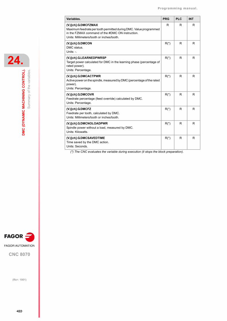
Programming manual.
CNC 8070
24.
DM
C (
DY
NA
MIC
MA
CH
ININ
G C
ON
TR
OL
).
Sum
mar
y of
the
varia
bles
.
·422·
(REF: 1901)
(V.)[ch].G.DMCFZMAXMaximum feedrate per tooth permitted during DMC. Value programmedin the FZMAX command of the #DMC ON instruction.Units: Millimeters/tooth or inches/tooth.
R R R
(V.)[ch].G.DMCONDMC status.Units: -.
R(*) R R
(V.)[ch].G.LEARNEDPWRSPTarget power calculated for DMC in the learning phase (percentage ofrated power).Units: Percentage.
R(*) R R
(V.)[ch].G.DMCACTPWRActive power on the spindle, measured by DMC (percentage of the ratedpower).Units: Percentage.
R(*) R R
(V.)[ch].G.DMCOVRFeedrate percentage (feed override) calculated by DMC.Units: Percentage.
R(*) R R
(V.)[ch].G.DMCFZFeedrate per tooth, calculated by DMC.Units: Millimeters/tooth or inches/tooth.
R(*) R R
(V.)[ch].G.DMCNOLOADPWRSpindle power without a load, measured by DMC.Units: Kilowatts.
R(*) R R
(V.)[ch].G.DMCSAVEDTIMETime saved by the DMC action.Units: Seconds.
R(*) R R
Variables. PRG PLC INT
(*) The CNC evaluates the variable during execution (it stops the block preparation).
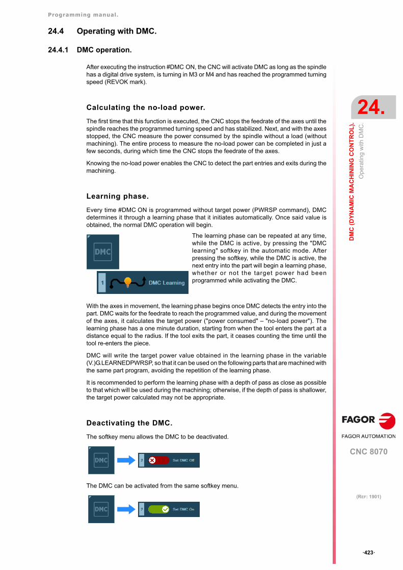
Programming manual.
CNC 8070
DM
C (
DY
NA
MIC
MA
CH
ININ
G C
ON
TR
OL
).
24.
Op
erat
ing
with
DM
C.
·423·
(REF: 1901)
24.4 Operating with DMC.
24.4.1 DMC operation.
After executing the instruction #DMC ON, the CNC will activate DMC as long as the spindlehas a digital drive system, is turning in M3 or M4 and has reached the programmed turningspeed (REVOK mark).
Calculating the no-load power.
The first time that this function is executed, the CNC stops the feedrate of the axes until thespindle reaches the programmed turning speed and has stabilized. Next, and with the axesstopped, the CNC measure the power consumed by the spindle without a load (withoutmachining). The entire process to measure the no-load power can be completed in just afew seconds, during which time the CNC stops the feedrate of the axes.
Knowing the no-load power enables the CNC to detect the part entries and exits during themachining.
Learning phase.
Every time #DMC ON is programmed without target power (PWRSP command), DMCdetermines it through a learning phase that it initiates automatically. Once said value isobtained, the normal DMC operation will begin.
With the axes in movement, the learning phase begins once DMC detects the entry into thepart. DMC waits for the feedrate to reach the programmed value, and during the movementof the axes, it calculates the target power ("power consumed" – "no-load power"). Thelearning phase has a one minute duration, starting from when the tool enters the part at adistance equal to the radius. If the tool exits the part, it ceases counting the time until thetool re-enters the piece.
DMC will write the target power value obtained in the learning phase in the variable(V.)G.LEARNEDPWRSP, so that it can be used on the following parts that are machined withthe same part program, avoiding the repetition of the learning phase.
It is recommended to perform the learning phase with a depth of pass as close as possibleto that which will be used during the machining; otherwise, if the depth of pass is shallower,the target power calculated may not be appropriate.
Deactivating the DMC.
The softkey menu allows the DMC to be deactivated.
The DMC can be activated from the same softkey menu.
The learning phase can be repeated at any time,while the DMC is active, by pressing the "DMClearning" softkey in the automatic mode. Afterpressing the softkey, while the DMC is active, thenext entry into the part will begin a learning phase,whether or not the target power had beenprogrammed while activating the DMC.
Programming manual.
CNC 8070
24.
DM
C (
DY
NA
MIC
MA
CH
ININ
G C
ON
TR
OL
).
Op
erat
ing
with
DM
C.
·424·
(REF: 1901)
DMC operation.
Once the target power is known, and after detecting the entry into the part, DMC will beginto function as normal. During the machining, DMC adapts the feedrate so that the cuttingpower ("power consumed" – "no-load power") is as close as possible to the target power.DMC adapts the feedrate by changing the override. See "24.4.3 Percentage of feedrate(feedrate override)." on page 425.
Processing of part entries and exits.
DMC detects the part entries and exits and carries out a special feedrate override processso that said transitions are smooth and do not damage the tool. For entries into the part, DMCuse a 75% feedrate until the tool enters the part along a length equal to the tool radius. TheCNC also attempts to optimize the time on the paths without a load.
The target power and the part entries and exits.
To ensure the proper operation of the DMC, the target power (programmed or obtained bylearning) must be at least 20% of the no-load power. If the DMC detects this type of situation,it will display a 3103 warning.
• If the actual values of the no-load power and the target power during machining aresimilar, it is likely that the DMC cannot accurately distinguish the part inputs and outputsor it may detect false inputs or outputs. In this case, it is recommended to check the valueof the target power.
• Programming a higher target power, which is not actually going to be achieved, can meanthat the DMC never detects part inputs and performs all the machining as if the tool wereworking in a vacuum.
For both these reasons, if the actual target power is less than 20% of the no-load power, itis recommended to deactivate the DMC function during this machining process.
Monitoring of consumed power.
During operation, DMC continuously monitors the power consumed by the spindle to detectany problems with the tool or in the machining.
Collision detection.
If the instantaneous power exceeds the target power in a predefined range, the CNCconsiders that a collision has occurred. In this case, the CNC displays warning 3101, stopsthe feedrate of the axes, while keeping the spindle turning (this behavior is the equivalentof having pressed the [STOP] button). After verifying the cause of the warning, the user cancontinue the machining (pressing [START]), enter in tool inspection or terminate theexecution to replace the damaged tool.
Worn tool. Excessive continuous power consumption.
If DMC detects excessive power consumption during a certain amount of time, it understandsthat the tool is worn or deteriorated and displays the warning 3100, without stopping theexecution. The user decides if it is necessary to stop the execution.
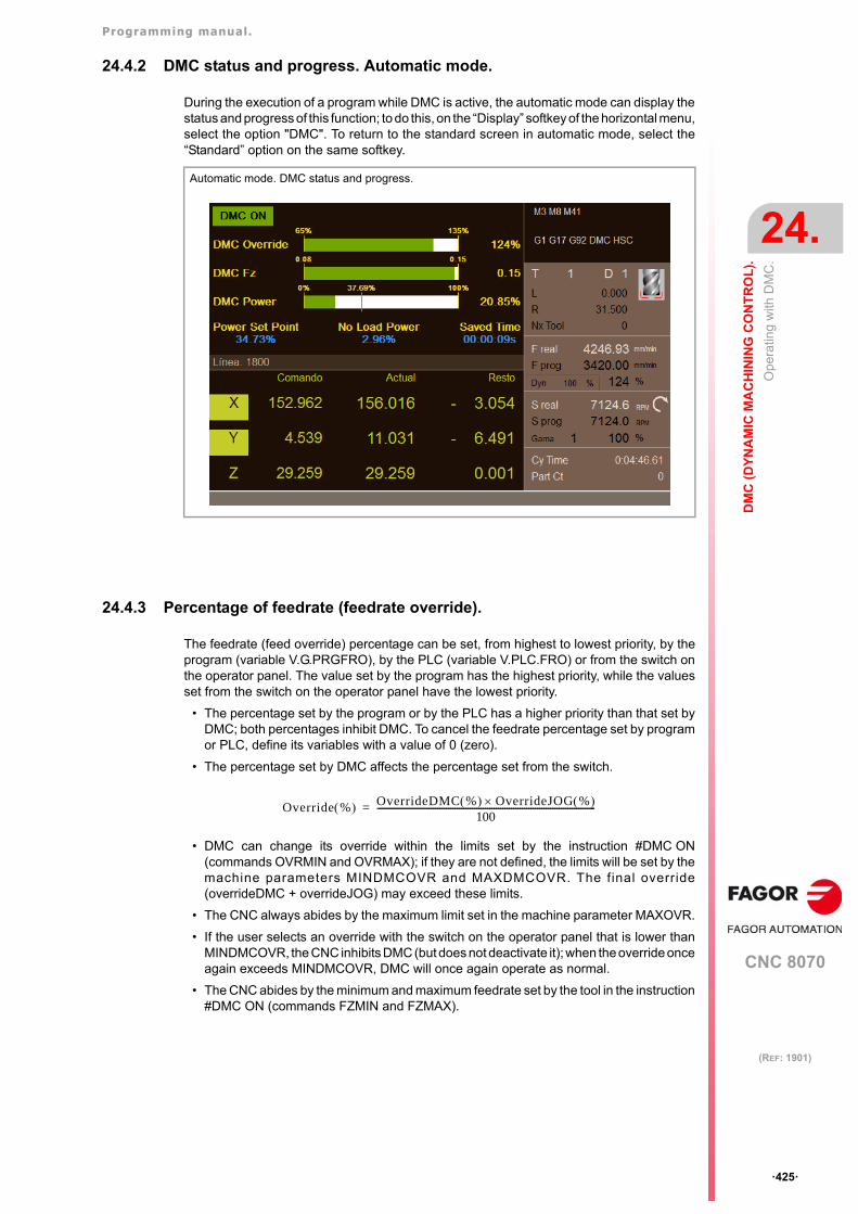
Programming manual.
CNC 8070
DM
C (
DY
NA
MIC
MA
CH
ININ
G C
ON
TR
OL
).
24.
Op
erat
ing
with
DM
C.
·425·
(REF: 1901)
24.4.2 DMC status and progress. Automatic mode.
During the execution of a program while DMC is active, the automatic mode can display thestatus and progress of this function; to do this, on the “Display” softkey of the horizontal menu,select the option "DMC". To return to the standard screen in automatic mode, select the“Standard” option on the same softkey.
24.4.3 Percentage of feedrate (feedrate override).
The feedrate (feed override) percentage can be set, from highest to lowest priority, by theprogram (variable V.G.PRGFRO), by the PLC (variable V.PLC.FRO) or from the switch onthe operator panel. The value set by the program has the highest priority, while the valuesset from the switch on the operator panel have the lowest priority.
• The percentage set by the program or by the PLC has a higher priority than that set byDMC; both percentages inhibit DMC. To cancel the feedrate percentage set by programor PLC, define its variables with a value of 0 (zero).
• The percentage set by DMC affects the percentage set from the switch.
• DMC can change its override within the limits set by the instruction #DMC ON(commands OVRMIN and OVRMAX); if they are not defined, the limits will be set by themachine parameters MINDMCOVR and MAXDMCOVR. The final override(overrideDMC + overrideJOG) may exceed these limits.
• The CNC always abides by the maximum limit set in the machine parameter MAXOVR.
• If the user selects an override with the switch on the operator panel that is lower thanMINDMCOVR, the CNC inhibits DMC (but does not deactivate it); when the override onceagain exceeds MINDMCOVR, DMC will once again operate as normal.
• The CNC abides by the minimum and maximum feedrate set by the tool in the instruction#DMC ON (commands FZMIN and FZMAX).
Automatic mode. DMC status and progress.
Override % OverrideDMC % OverrideJOG % 100
-----------------------------------------------------------------------------------------------------=

Programming manual.
CNC 8070
24.
DM
C (
DY
NA
MIC
MA
CH
ININ
G C
ON
TR
OL
).
Op
erat
ing
with
DM
C.
·426·
(REF: 1901)
CNC 8070
25
·427·
(REF: 1901)
25.OPENING AND WRITING FILES.
25.1 #OPEN. Open file for writing.
The instruction #OPEN opens a file so that the part-program (#WRITE) can be written. Thefile must have write permission, otherwise the CNC will show the corresponding error. Theexecution and the simulation write on the same file.
Programming.
Program the instruction alone in the block.
Programming format.
The programming format is the following; the arguments appear between curly brackets andthe optional ones between angle brackets.
#OPEN [{“file”}, <A/D>, <F{IdOfFile}>, <KEEPLINE>, <TYPE{format}]
File path and name.
Programming the path is optional. The path and the file name must be defined betweeninverted commas. The file name cannot contain any of the following characters: \ / : * ? " < > |.
File identifier for multi-channel access.
The F1 to F4 identifier allows for a channel to write to a file opened in an other channel whenthe identifier is determimed. If no identifier is programmed, only the channel opening it canwrite to the file. If a file with a previously used identifier is opened, the CNC will show thecorresponding error.
{“file”} Name of file and its path (optional). If the path is not programmed, the CNC savesthe file in the same folder as the program executing it.
A/D Optional. Default access mode is D.A (APPEND): Add file D (DELETE): Clears content and write from scratch.
F{IdOfFile} Optional. File identifier (F1 to F4) for multi-channel access. From one channel itis possible to write to a file from any other channel when its identifier is determined.If no identifier is programmed, only the channel opening it can write to the file.
KEEPLINE Optional. Does not add a line break after each sentence. If it is not programmed,each instruction will create a line break.
TYPE{format} Optional. File format; by default UCS-2LE BOM.1 = COD_ANSI 2 = UCS-2LE BOM
#OPEN ["FileForWrite.txt", A, F2, KEEPLINE]
#OPEN ["FileForWrite.txt", D]
#OPEN ["FileForWrite.txt"]
#OPEN ["FileForWrite.txt", A, F2, KEEPLINE, TYPE 2]
Programming manual.
CNC 8070
25.
OP
EN
ING
AN
D W
RIT
ING
FIL
ES
.
#OP
EN
. Op
en fi
le fo
r w
ritin
g.
·428·
(REF: 1901)
Access mode.
• The "D" (DELETE) option deletes the file and creates a new one in the format specifiedby the TYPE command (by default, UCS-2LE BOM).
• The "A" (APPEND) option adds content to an existing file. If the file does not exist, createa new one in the format specified by the command TYPE (by default, UCS-2LE BOM).If the file already exists, the command TYPE must match the file format.
Line feed.
When the command KEEPLINE is programmed, the line break manages the text of the#WRITE instruction using the \n identifier.
When the command KEEPLINE is not programmed, each #WRITE instruction will create aline break. If the identifier \n is appended to the text, two line breaks are inserted.
File format (command TYPE).
#OPEN ["FileForWrite.txt", A, KEEPLINE] #WRITE ["Message \n"]
(The instruction #WRITE inserts a line break)
#OPEN ["FileForWrite.txt", A] #WRITE ["Mensaje"]
(The instruction #WRITE inserts a line break)#WRITE ["Message \n"]
(The instruction #WRITE inserts two line breaks)
COD_ANSI Non-Unicode format, for files that are to be used in applications thatdo not support Unicode format.
UCS-2LE BOM Unicode format (recommended).
Programming manual.
CNC 8070
OP
EN
ING
AN
D W
RIT
ING
FIL
ES
.
25.
#WR
ITE
. Writ
ing
in a
file
.
·429·
(REF: 1901)
25.2 #WRITE. Writing in a file.
The instruction #WRITE inserts text into the file opened with the instruction #OPEN. Fromone channel it is possible to write to a file from any other channel when its identifier isdetermined (comando "F"). The instruction is performed during the execution, but the CNCdoes not wait for the instruction to finish before continuing with the execution. Theinstructions will be stored until an error occurs or M30 is executed.
Programming.
Program the instruction alone in the block.
Programming format.
The programming format is the following; the arguments appear between curly brackets andthe optional ones between angle brackets.
#WRITE [<F{IdOfFile},> “{Message}”/{IdOflMessage}, <{var1},>...<{var5}>]
Message number.
The error number, which must be an integer, may be defined with a numerical constant, aparameter or an arithmetic expression. Local parameters must be programmed as P0, P1,etc.
The texts in the cncWrite.txt file, defined by the OEM or the user, can include up to 5parameter values and variables using the format identifiers (%D, %i, %u, etc). The variablesor parameters whose value is to be displayed must be defined in the instruction #WRITEafter the number and separated by commas. Up to five format identifiers can be defined foreach message, and there must be as many variables or data parameters as identifiers.
F{IdOfFile} Optional. File identifier (F1 to F4) for multi-channel access. If an identifier isnot programmed, the program writes in the open file using an #OPENinstruction without the “F” file identifier in the channel executing the #WRITEinstruction.
"{Message}"{IdOfMessge}
Message or message number predefined by the cncWrite.txt file. Bothmessages allow format identifiers.
{var1}...{var5} Optional. Variables or parameters whose value is to be inserted in themessage text (replaces the format identifiers).
#WRITE ["%d value incorrect", P21](Write in the file that was opened in the channel using #OPEN without an "F" file identifier)(The line break depends on the programming of #OPEN instruction, with or without KEEPLINEinstruction)(The identifier %d is resolved with the P21 value)
#WRITE [F2, “Tool %u worn down\n", V.G.TOOL](Write #OPEN in the open file [F2])(The format identifier \n inserts a line break) (Depending on the #OPEN programming, with or withoutthe KEEPLINE instruction, there may be another line break)(The identifier %u is addressed with the V.G.TOOL value)
#WRITE [F2, 10214, V.G.TOOL] (Write #OPEN in the open file [F2])(The line break depends on the programming of #OPEN instruction, with or without KEEPLINEinstruction)(Write the instruction10214, defined in the cncWrite.txt file)(The identifier %d of the 10214 text is addressed with the V.G.TOOL value)
#WRITE [F2, "%s = %d", V.A.AXISNAME.1, P100](Write #OPEN in the open file [F2])(The line break depends on the programming of #OPEN instruction, with or without KEEPLINEinstruction)(The identifiers %s and %d are resolved with the values V.A.AXISNAME.1 and P100)
#WRITE [123, P20, V.G.FREAL] (Write the instruction123, defined in the cncWrite.txt file)(Substitute the first format identifier with the P20 value)(Substitute the first format identifier with the V.G.REAL value)
Programming manual.
CNC 8070
25.
OP
EN
ING
AN
D W
RIT
ING
FIL
ES
.
#WR
ITE
. Writ
ing
in a
file
.
·430·
(REF: 1901)
Error text.
The text must be defined between quote marks. The text can include 5 parameter values and variables in the message using the format identifiers (%D, %i, %u, etc). The variablesor parameters whose value is to be displayed must be defined after the text and separatedby commas. Up to five format identifiers can be defined for each message, and there mustbe as many variables or data parameters as identifiers.
Format identifiers and special characters.
Format identifiers.
Writing text with %letter that is not found in this list or the following list, the CNC will includeit as %letter.
The identifier %s can only be used with the variables (V.)A.AXISNAME.xn and(V.)A.SPDLNAME.sn.
Special characters.
If you write a text with %letter that is not included in this list or the previous one, the CNCwill include it as %letter.
#WRITE ["The current tool is %D", V.G.TOOL]
Identifier. Meaning.
%d %D Integer or floating point number (with or without decimals). With this identifier, thenumber of integers and decimals to be displayed (default 5.5) can be defined;this format is defined between the symbol % and a letter; for example %5.5d.
%i Integer in base 10 with positive or negative sign (int).
%u Integer in base 10 without positive or negative sign (int).
%o Integer in base 8 without positive or negative sign (int).
%x Integer in base 16 using lowercase letters (int).
%X Integer in base 16 using uppercase letters (int).
%f %F Simple precision floating decimal (float). With this identifier, the number ofintegers and decimals to be displayed (default 5.5) can be defined; this formatis defined between the symbol % and a letter; for example %5.5f.
%e Scientific notation (coefficient / exponent), lower case (single precision or doubleprecision).
%E Scientific notation (coefficient / exponent), upper case (single precision or doubleprecision).
%c Write a character using its ASCII code (decimal number).
%s Write a string (string of characters) from a string. This identifier can only be usedwith the variables (V.)A.AXISNAME.xn and (V.)A.SPDLNAME.sn.
Identifier. Meaning.
%% Character %.
\" Quotation marks.
\n Line feed.
#WRITE ["Difference between P12 and P14 > 40%%"]
#WRITE ["Parameter \"P100\" is wrong"]
#WRITE [“Message with line break \n"]
#WRITE ["%s", V.A.AXISNAME.1](Write the name of the axis).
#WRITE ["%c", 65](Show the character A, because 65 is its ASCII code).
Programming manual.
CNC 8070
OP
EN
ING
AN
D W
RIT
ING
FIL
ES
.
25.
#CL
OS
E. C
lose
a fi
le.
·431·
(REF: 1901)
25.3 #CLOSE. Close a file.
The instruction #CLOSE closes the file opened with the instruction #OPEN.
Programming.
Program the instruction alone in the block.
Programming format.
The programming format is the following; the arguments appear between curly brackets andthe optional ones between angle brackets.
#CLOSE [<F{IdOfFile}>]
Considerations.
• If the file has been opened without an identifier (F1 to F4), function M30 closes one fromthe file.
• If the file has been opened with an identifier (F1 to F4), the function M30 does not closethe file to allow multi-channel management.
• If an error occurs in the channel opening the file, it will be closed with a reset.
• Closing the CNC will close all the open files.
F{IdOfFile} Optional. File identifier (F1 to F4) for multi-channel access. If an identifier is notprogrammed, the instruction closes the file that opened in the channel using#OPEN without an "F" file identifier.
#CLOSE
#CLOSE [F2]
Programming manual.
CNC 8070
25.
OP
EN
ING
AN
D W
RIT
ING
FIL
ES
.
cncW
rite.
txt f
ile. L
ist o
f OE
M a
nd
user
me
ssa
ges.
·432·
(REF: 1901)
25.4 cncWrite.txt file. List of OEM and user messages.
The file cncWrite.txt contains the OEM and user defined messages for the instruction#WRITE. Both the OEM and the user can create one of these files according to language.
File location.
The CNC can have two cncWrite.txt files: that created by the OEM and another created bythe user. The CNC looks for the messages in both files, in the following order, and displaysthe message it finds first. Therefore, it is recommended that the user does not definemessages using the same number as the manufacturer. If the message is not found in anyfile, the CNC will not show any error.
..\Users\Data\Lang\{language}
..\Users\Data\Lang
..\Mtb\Data\Lang\{language}
..\Mtb\Data\Lang
File format.
The file format will be:
• Any comments must start with the character ";".
• Errors follow the structure; number + space or tab key + text.
Format identifiers.
The text can include 5 parameter values and variables in the message using the formatidentifiers (%D, %i, %u, etc). The variables or parameters whose value is to be displayedmust be defined in the message call.
; Comment.1 First message.2 Second message.3 Third message.
12 The current tool is %D.
13 Spindle speed %u excessive.
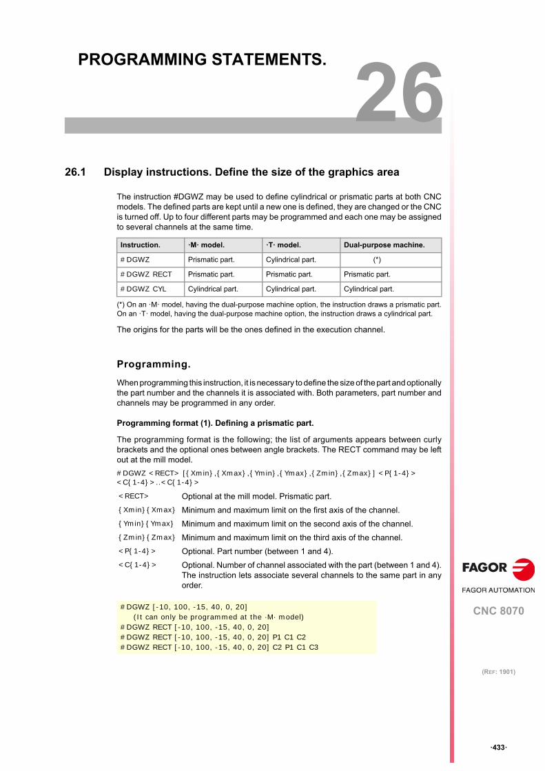
CNC 8070
26
·433·
(REF: 1901)
26.PROGRAMMING STATEMENTS.
26.1 Display instructions. Define the size of the graphics area
The instruction #DGWZ may be used to define cylindrical or prismatic parts at both CNCmodels. The defined parts are kept until a new one is defined, they are changed or the CNCis turned off. Up to four different parts may be programmed and each one may be assignedto several channels at the same time.
(*) On an ·M· model, having the dual-purpose machine option, the instruction draws a prismatic part.On an ·T· model, having the dual-purpose machine option, the instruction draws a cylindrical part.
The origins for the parts will be the ones defined in the execution channel.
Programming.
When programming this instruction, it is necessary to define the size of the part and optionallythe part number and the channels it is associated with. Both parameters, part number andchannels may be programmed in any order.
Programming format (1). Defining a prismatic part.
The programming format is the following; the list of arguments appears between curlybrackets and the optional ones between angle brackets. The RECT command may be leftout at the mill model.
#DGWZ <RECT> [{Xmin},{Xmax},{Ymin},{Ymax},{Zmin},{Zmax}] <P{1-4}> <C{1-4}>..<C{1-4}>
Instruction. ·M· model. ·T· model. Dual-purpose machine.
#DGWZ Prismatic part. Cylindrical part. (*)
#DGWZ RECT Prismatic part. Prismatic part. Prismatic part.
#DGWZ CYL Cylindrical part. Cylindrical part. Cylindrical part.
<RECT> Optional at the mill model. Prismatic part.
{Xmin}{Xmax} Minimum and maximum limit on the first axis of the channel.
{Ymin}{Ymax} Minimum and maximum limit on the second axis of the channel.
{Zmin}{Zmax} Minimum and maximum limit on the third axis of the channel.
<P{1-4}> Optional. Part number (between 1 and 4).
<C{1-4}> Optional. Number of channel associated with the part (between 1 and 4).The instruction lets associate several channels to the same part in anyorder.
#DGWZ [-10, 100, -15, 40, 0, 20](It can only be programmed at the ·M· model)
#DGWZ RECT [-10, 100, -15, 40, 0, 20]#DGWZ RECT [-10, 100, -15, 40, 0, 20] P1 C1 C2#DGWZ RECT [-10, 100, -15, 40, 0, 20] C2 P1 C1 C3
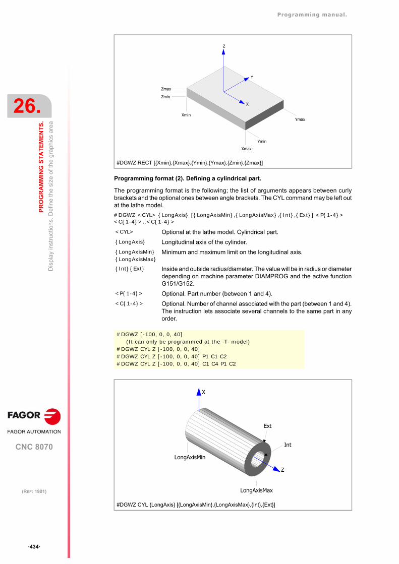
Programming manual.
CNC 8070
26.
PR
OG
RA
MM
ING
ST
AT
EM
EN
TS
.
Dis
pla
y in
stru
ctio
ns. D
efin
e th
e si
ze o
f the
gra
phic
s ar
ea
·434·
(REF: 1901)
Programming format (2). Defining a cylindrical part.
The programming format is the following; the list of arguments appears between curlybrackets and the optional ones between angle brackets. The CYL command may be left outat the lathe model.
#DGWZ <CYL> {LongAxis} [{LongAxisMin},{LongAxisMax},{Int},{Ext}] <P{1-4}> <C{1-4}>..<C{1-4}>
#DGWZ RECT [{Xmin},{Xmax},{Ymin},{Ymax},{Zmin},{Zmax}]
<CYL> Optional at the lathe model. Cylindrical part.
{LongAxis} Longitudinal axis of the cylinder.
{LongAxisMin}{LongAxisMax}
Minimum and maximum limit on the longitudinal axis.
{Int}{Ext} Inside and outside radius/diameter. The value will be in radius or diameterdepending on machine parameter DIAMPROG and the active functionG151/G152.
<P{1-4}> Optional. Part number (between 1 and 4).
<C{1-4}> Optional. Number of channel associated with the part (between 1 and 4).The instruction lets associate several channels to the same part in anyorder.
#DGWZ [-100, 0, 0, 40](It can only be programmed at the ·T· model)
#DGWZ CYL Z [-100, 0, 0, 40]#DGWZ CYL Z [-100, 0, 0, 40] P1 C1 C2#DGWZ CYL Z [-100, 0, 0, 40] C1 C4 P1 C2
#DGWZ CYL {LongAxis} [{LongAxisMin},{LongAxisMax},{Int},{Ext}]
Xmax
Xmin
Z
X
Y
Ymin
Ymax
Zmin
Zmax
LongAxisMin
LongAxisMax
X
Z
Int
Ext
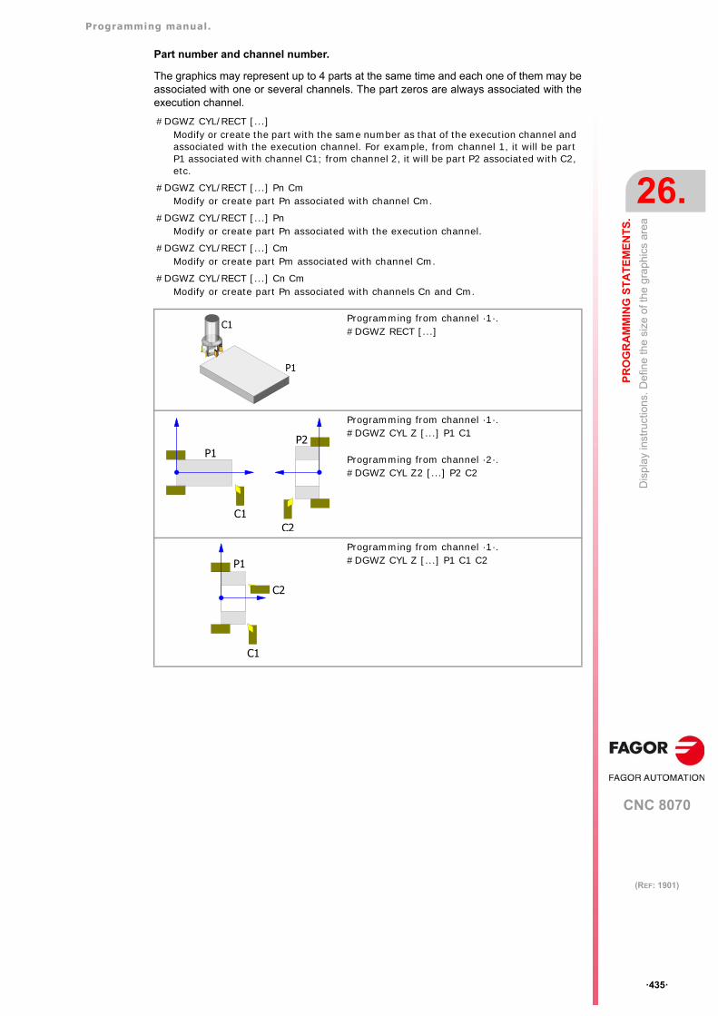
Programming manual.
CNC 8070
PR
OG
RA
MM
ING
ST
AT
EM
EN
TS
.
26.
Dis
pla
y in
stru
ctio
ns. D
efin
e th
e si
ze o
f the
gra
phic
s ar
ea
·435·
(REF: 1901)
Part number and channel number.
The graphics may represent up to 4 parts at the same time and each one of them may beassociated with one or several channels. The part zeros are always associated with theexecution channel.
#DGWZ CYL/RECT [...] Modify or create the part with the same number as that of the execution channel and associated with the execution channel. For example, from channel 1, it will be part P1 associated with channel C1; from channel 2, it will be part P2 associated with C2, etc.
#DGWZ CYL/RECT [...] Pn CmModify or create part Pn associated with channel Cm.
#DGWZ CYL/RECT [...] PnModify or create part Pn associated with the execution channel.
#DGWZ CYL/RECT [...] CmModify or create part Pm associated with channel Cm.
#DGWZ CYL/RECT [...] Cn CmModify or create part Pn associated with channels Cn and Cm.
Programming from channel ·1·.#DGWZ RECT [...]
Programming from channel ·1·.#DGWZ CYL Z [...] P1 C1
Programming from channel ·2·.#DGWZ CYL Z2 [...] P2 C2
Programming from channel ·1·.#DGWZ CYL Z [...] P1 C1 C2
P1
C1
P1P2
C1C2
C2
P1
C1
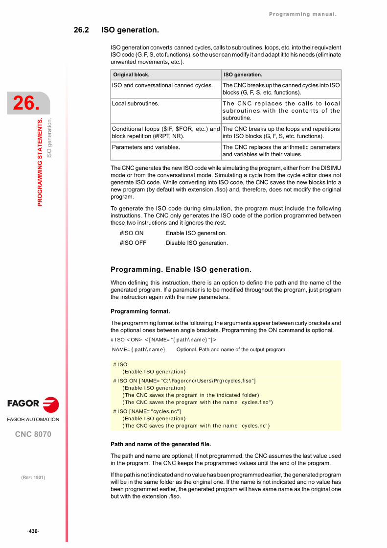
Programming manual.
CNC 8070
26.
PR
OG
RA
MM
ING
ST
AT
EM
EN
TS
.
ISO
gen
era
tion.
·436·
(REF: 1901)
26.2 ISO generation.
ISO generation converts canned cycles, calls to subroutines, loops, etc. into their equivalentISO code (G, F, S, etc functions), so the user can modify it and adapt it to his needs (eliminateunwanted movements, etc.).
The CNC generates the new ISO code while simulating the program, either from the DISIMUmode or from the conversational mode. Simulating a cycle from the cycle editor does notgenerate ISO code. While converting into ISO code, the CNC saves the new blocks into anew program (by default with extension .fiso) and, therefore, does not modify the originalprogram.
To generate the ISO code during simulation, the program must include the followinginstructions. The CNC only generates the ISO code of the portion programmed betweenthese two instructions and it ignores the rest.
Programming. Enable ISO generation.
When defining this instruction, there is an option to define the path and the name of thegenerated program. If a parameter is to be modified throughout the program, just programthe instruction again with the new parameters.
Programming format.
The programming format is the following; the arguments appear between curly brackets andthe optional ones between angle brackets. Programming the ON command is optional.
#ISO <ON> <[NAME="{path\name}"]>
Path and name of the generated file.
The path and name are optional; If not programmed, the CNC assumes the last value usedin the program. The CNC keeps the programmed values until the end of the program.
If the path is not indicated and no value has been programmed earlier, the generated programwill be in the same folder as the original one. If the name is not indicated and no value hasbeen programmed earlier, the generated program will have same name as the original onebut with the extension .fiso.
Original block. ISO generation.
ISO and conversational canned cycles. The CNC breaks up the canned cycles into ISOblocks (G, F, S, etc. functions).
Local subroutines. The CNC rep laces the ca l l s to loca lsubrout ines w i th the con tents o f thesubroutine.
Conditional loops ($IF, $FOR, etc.) andblock repetition (#RPT, NR).
The CNC breaks up the loops and repetitionsinto ISO blocks (G, F, S, etc. functions).
Parameters and variables. The CNC replaces the arithmetic parametersand variables with their values.
#ISO ON Enable ISO generation.
#ISO OFF Disable ISO generation.
NAME={path\name} Optional. Path and name of the output program.
#ISO(Enable ISO generation)
#ISO ON [NAME="C:\Fagorcnc\Users\Prg\cycles.fiso"](Enable ISO generation)(The CNC saves the program in the indicated folder)(The CNC saves the program with the name "cycles.fiso")
#ISO [NAME="cycles.nc"](Enable ISO generation)(The CNC saves the program with the name "cycles.nc")
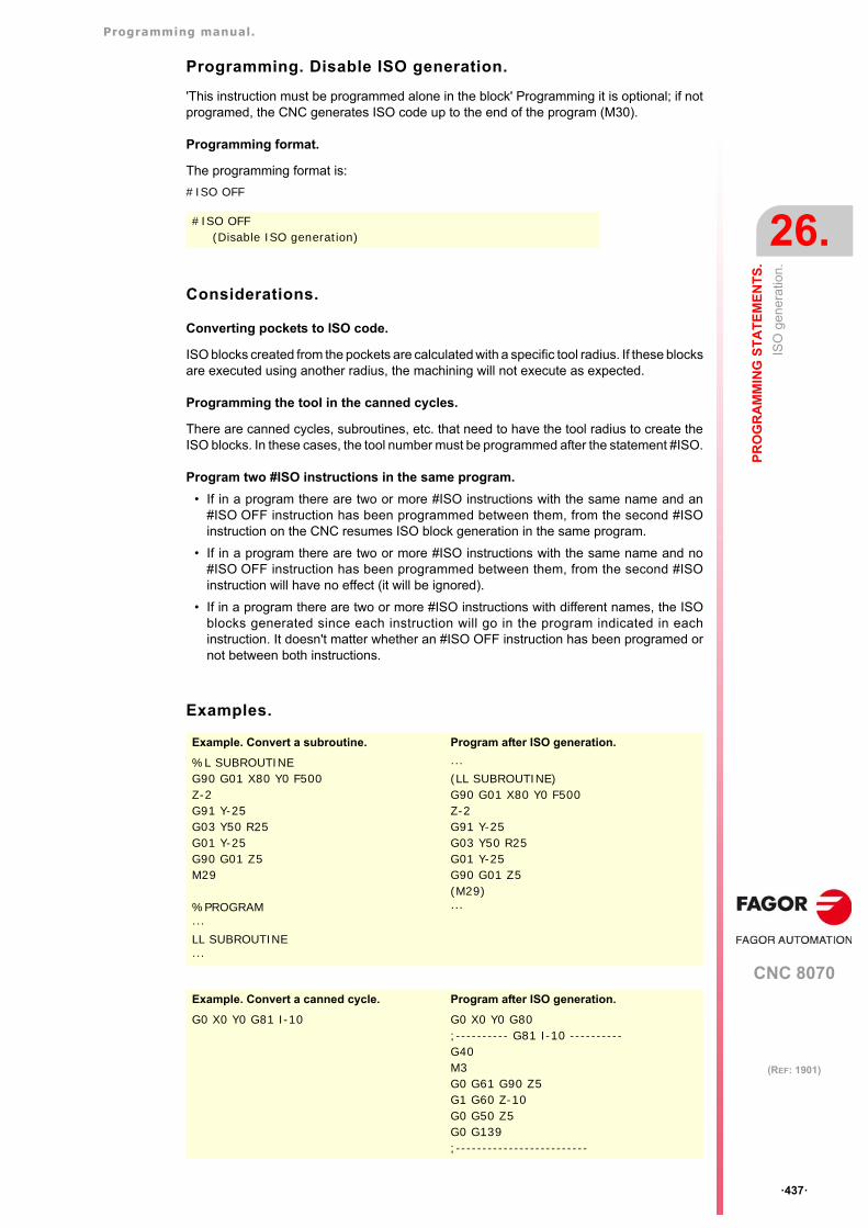
Programming manual.
CNC 8070
PR
OG
RA
MM
ING
ST
AT
EM
EN
TS
.
26.
ISO
gen
era
tion.
·437·
(REF: 1901)
Programming. Disable ISO generation.
'This instruction must be programmed alone in the block' Programming it is optional; if notprogramed, the CNC generates ISO code up to the end of the program (M30).
Programming format.
The programming format is:
#ISO OFF
Considerations.
Converting pockets to ISO code.
ISO blocks created from the pockets are calculated with a specific tool radius. If these blocksare executed using another radius, the machining will not execute as expected.
Programming the tool in the canned cycles.
There are canned cycles, subroutines, etc. that need to have the tool radius to create theISO blocks. In these cases, the tool number must be programmed after the statement #ISO.
Program two #ISO instructions in the same program.
• If in a program there are two or more #ISO instructions with the same name and an#ISO OFF instruction has been programmed between them, from the second #ISOinstruction on the CNC resumes ISO block generation in the same program.
• If in a program there are two or more #ISO instructions with the same name and no#ISO OFF instruction has been programmed between them, from the second #ISOinstruction will have no effect (it will be ignored).
• If in a program there are two or more #ISO instructions with different names, the ISOblocks generated since each instruction will go in the program indicated in eachinstruction. It doesn't matter whether an #ISO OFF instruction has been programed ornot between both instructions.
Examples.
#ISO OFF (Disable ISO generation)
Example. Convert a subroutine. Program after ISO generation.
%L SUBROUTINEG90 G01 X80 Y0 F500Z-2 G91 Y-25G03 Y50 R25G01 Y-25 G90 G01 Z5 M29
%PROGRAM···LL SUBROUTINE···
···(LL SUBROUTINE)G90 G01 X80 Y0 F500Z-2 G91 Y-25G03 Y50 R25G01 Y-25 G90 G01 Z5 (M29)···
Example. Convert a canned cycle. Program after ISO generation.
G0 X0 Y0 G81 I-10 G0 X0 Y0 G80;---------- G81 I-10 ---------- G40M3G0 G61 G90 Z5G1 G60 Z-10G0 G50 Z5G0 G139;-------------------------
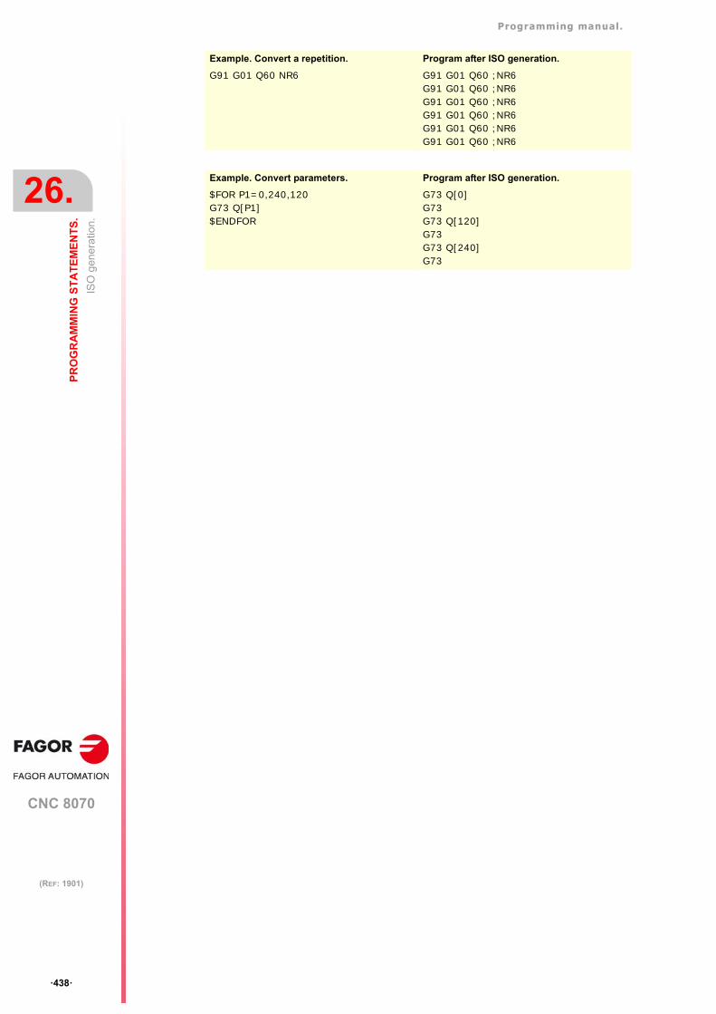
Programming manual.
CNC 8070
26.
PR
OG
RA
MM
ING
ST
AT
EM
EN
TS
.
ISO
gen
era
tion.
·438·
(REF: 1901)
Example. Convert a repetition. Program after ISO generation.
G91 G01 Q60 NR6 G91 G01 Q60 ;NR6G91 G01 Q60 ;NR6G91 G01 Q60 ;NR6G91 G01 Q60 ;NR6G91 G01 Q60 ;NR6G91 G01 Q60 ;NR6
Example. Convert parameters. Program after ISO generation.
$FOR P1=0,240,120G73 Q[P1]$ENDFOR
G73 Q[0]G73G73 Q[120]G73G73 Q[240]G73
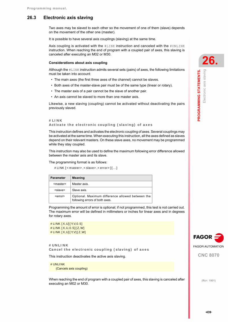
Programming manual.
CNC 8070
PR
OG
RA
MM
ING
ST
AT
EM
EN
TS
.
26.
Ele
ctro
nic
axis
sla
vin
g
·439·
(REF: 1901)
26.3 Electronic axis slaving
Two axes may be slaved to each other so the movement of one of them (slave) dependson the movement of the other one (master).
It is possible to have several axis couplings (slaving) at the same time.
Axis coupling is activated with the #LINK instruction and canceled with the #UNLINKinstruction. When reaching the end of program with a coupled pair of axes, this slaving iscanceled after executing an M02 or M30.
Considerations about axis coupling
Although the #LINK instruction admits several sets (pairs) of axes, the following limitationsmust be taken into account:
• The main axes (the first three axes of the channel) cannot be slaves.
• Both axes of the master-slave pair must be of the same type (linear or rotary).
• The master axis of a pair cannot be the slave of another pair.
• An axis cannot be slaved to more than one master axis.
Likewise, a new slaving (coupling) cannot be activated without deactivating the pairspreviously slaved.
#LINKActivate the electronic coupling (slaving) of axes
This instruction defines and activates the electronic coupling of axes. Several couplings maybe activated at the same time. When executing this instruction, all the axes defined as slavesdepend on their relevant masters. On these slave axes, no movement may be programmedwhile they stay coupled.
This instruction may also be used to define the maximum following error difference allowedbetween the master axis and its slave.
The programming format is as follows:
#LINK [<master>,<slave>,<error>][...]
Programming the amount of error is optional; if not programmed, this test is not carried out.The maximum error will be defined in millimeters or inches for linear axes and in degreesfor rotary axes.
#UNLINKCancel the electronic coupling (slaving) of axes
This instruction deactivates the active axis slaving.
When reaching the end of program with a coupled pair of axes, this slaving is canceled afterexecuting an M02 or M30.
Parameter Meaning
<master> Master axis.
<slave> Slave axis.
<error> Optional. Maximum difference allowed between thefollowing errors of both axes.
#LINK [X,U][Y,V,0.5]#LINK [X,U,0.5][Z,W]#LINK [X,U][Y,V][Z,W]
#UNLINK(Cancels axis coupling)
Programming manual.
CNC 8070
26.
PR
OG
RA
MM
ING
ST
AT
EM
EN
TS
.
Axi
s pa
rkin
g
·440·
(REF: 1901)
26.4 Axis parking
Some machines, depending on the type of machining, may have two different configurations(axes and spindles). In order to prevent the elements not present in one of the configurationsfrom causing an error message (drives, feedback systems, etc.) the CNC allows parkingthem.
Several axes and spindles may stay parked at the same time, but they must always be parked(and unparked) one by one.
Use the #PARK instruction to park the axes and spindles and #UNPARKto cancel (unpark)them. The axes and spindles stay parked after executing an M02 or M30, after a RESETand even after turning the CNC off and back on.
Considerations about axis parking
The CNC will not allow parking an axis in the following cases.
• If the axis belongs to the active kinematics.
• If the axis belongs to an active transformation #AC or #ACS.
• If the axis belongs to an active angular transformation #ANGAX .
• If the axis belongs to a gantry, tandem pair or is a slaved axis.
• If the axis belongs to an active tangential control #TANGCTRL.
Considerations about spindle parking
The CNC will not allow parking a spindle in the following cases.
• If the spindle is not stopped.
• If the spindle is working as a C axis.
• If G96 or G63 is active and it is the master spindle of the channel.
• If G33 or G95 is active and it is the master spindle of the channel or the spindle is usedto synchronize the feedrate.
• If the spindle belongs to a tandem pair or is a synchronized spindle, be it the master orthe slave.
If after parking the spindles, there is only one spindle left in the channel, it will become thenew master. If a spindle is unparked and it is the only spindle of the channel, it is also assumedas the new master spindle.
#PARKParks an axis
This instruction is used to park the selected axis or spindle. When any of them is parked,the CNC interprets that it no longer belongs to the machine configuration and no longercontrols it (ignoring the signals from the drive and from the feedback systems, etc.).
Once an axis or spindle has been parked, the part-program cannot mention it (movements,speed, M functions, etc.).
The programming format is as follows:
#PARK <axis/spindle>
Each element (axis or spindle) must be parked separately. However, a second element canbe parked without having to unpark the first one.
For example, a machine that swaps a normal spindle with a rectangular one may have thefollowing axes configurations:
• With a normal spindle, X Y Z axes configuration.• With an orthogonal spindle, X Y Z A B axes configuration.
In this case, when working with the normal spindle, the A and B axes may be parked to ignoretheir signals.
Programming manual.
CNC 8070
PR
OG
RA
MM
ING
ST
AT
EM
EN
TS
.
26.
Axi
s pa
rkin
g
·441·
(REF: 1901)
When trying to park an axis or spindle that is already parked, the programming is ignored.
#UNPARKUnparks an axis
This instruction is used to unpark the selected axis or spindle. When unparking one of them,the CNC interprets that it belongs to the machine configuration and starts controlling it.
The programming format is as follows:
#UNPARK <axis/spindle>
The axes must be unparked one by one.
When trying to unpark an axis or spindle that is already unparked, the programming isignored.
#PARK A(It parks the "A" axis)
#PARK S2(It parks spindle "S2")
#UNPARK A(It unparks the "A" axis)
#UNPARK S(It unparks the "S" spindle)
Programming manual.
CNC 8070
26.
PR
OG
RA
MM
ING
ST
AT
EM
EN
TS
.
Mo
dify
ing
the
conf
igur
atio
n o
f th
e ax
es o
f a c
hann
el
·442·
(REF: 1901)
26.5 Modifying the configuration of the axes of a channel
Initially, each channel has some axes assigned to it as set by the machine parameters. Whileexecuting a program, a channel may release its axes or request new axes. This possibilityis determined by machine parameter AXISEXCH, which establishes whether an axis canchange channels or whether this change is permanent or not.
A permanent change is maintained after the end of the program, after a reset and on power-up. The original configuration may be restored either by validating the general parametersand restarting or by a part-program that undoes the changes.
Knowing if an axis can change channels
Machine parameter AXISEXCH may be consulted using the following variable.
V.MPA.AXISEXCH.Xn
Replace "Xn" with the name or logic number of the axis.
Knowing in which channel the axis is
It is possible to know in which channel the axis is by using the following variable.
V.[n].A.ACTCH.Xn
Replace "Xn" with the name or logic number of the axis.
Replace the "n" letter with the channel number.
Commands for modifying the axis configuration via program
The following instructions are used to modify the configuration of the axes. It is possible toadd or remove axes, change their names and even redefine the main axes of the channelby swapping their names.
Changing the configuration of the axes cancels the active polar origin, the pattern rotation,the mirror image and the scaling factor.
In the configuration of the axes (if G17 is active), the axis that occupies the first position mustbe the abscissa axis, the second will be the ordinate axis, the third will be the axisperpendicular to the work plane, the fourth will be the first auxiliary axis and so on.
#SET AXSets the axis configuration
Defines a new axis configuration in the channel. The channel axes not programmed in theinstruction and the nonexistent programmed ones will be added. The axes are placed in thechannel in the positions as they are programmed in the instruction #SET AX. Optionally, oneor several offsets may be applied to the defined axes.
It is the same as programming a #FREE AX of all the axes and then a #CALL AX of all thenew axes.
The instruction #SET AX may also be used only to order the existing axes in the channeldifferently.
The programming format is as follows:
#SET AX [<Xn>,...] <offset> <...>
It also restores the machine parameter settings if a checksum error occurs when powering up the CNC. .
Value Meaning
0 It cannot change channels.
1 The change is temporary.
2 The change is permanent.
Value Meaning
0 It is not in any channel.
1-4 Channel number.
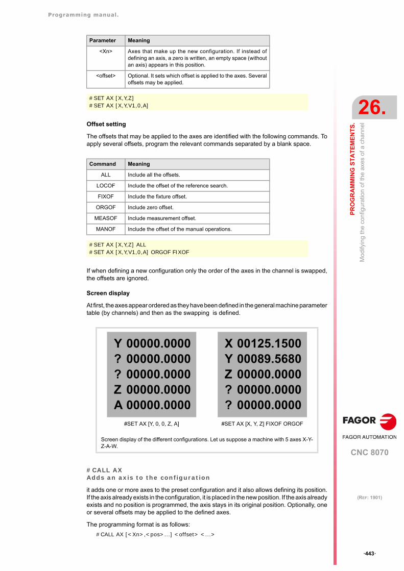
Programming manual.
CNC 8070
PR
OG
RA
MM
ING
ST
AT
EM
EN
TS
.
26.
Mo
dify
ing
the
conf
igur
atio
n o
f th
e ax
es o
f a c
hann
el
·443·
(REF: 1901)
Offset setting
The offsets that may be applied to the axes are identified with the following commands. Toapply several offsets, program the relevant commands separated by a blank space.
If when defining a new configuration only the order of the axes in the channel is swapped,the offsets are ignored.
Screen display
At first, the axes appear ordered as they have been defined in the general machine parametertable (by channels) and then as the swapping is defined.
#CALL AXAdds an axis to the configuration
it adds one or more axes to the preset configuration and it also allows defining its position.If the axis already exists in the configuration, it is placed in the new position. If the axis alreadyexists and no position is programmed, the axis stays in its original position. Optionally, oneor several offsets may be applied to the defined axes.
The programming format is as follows:
#CALL AX [<Xn>,<pos>...] <offset> <...>
Parameter Meaning
<Xn> Axes that make up the new configuration. If instead ofdefining an axis, a zero is written, an empty space (withoutan axis) appears in this position.
<offset> Optional. It sets which offset is applied to the axes. Severaloffsets may be applied.
#SET AX [X,Y,Z]#SET AX [X,Y,V1,0,A]
Command Meaning
ALL Include all the offsets.
LOCOF Include the offset of the reference search.
FIXOF Include the fixture offset.
ORGOF Include zero offset.
MEASOF Include measurement offset.
MANOF Include the offset of the manual operations.
#SET AX [X,Y,Z] ALL#SET AX [X,Y,V1,0,A] ORGOF FIXOF
Screen display of the different configurations. Let us suppose a machine with 5 axes X-Y-Z-A-W.
Y??ZA
00000.000000000.000000000.000000000.000000000.0000
#SET AX [Y, 0, 0, Z, A]
XYZ??
00125.150000089.568000000.000000000.000000000.0000
#SET AX [X, Y, Z] FIXOF ORGOF
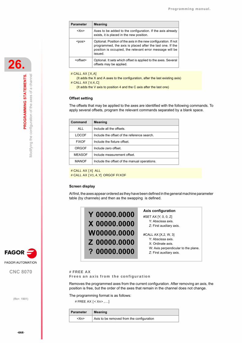
Programming manual.
CNC 8070
26.
PR
OG
RA
MM
ING
ST
AT
EM
EN
TS
.
Mo
dify
ing
the
conf
igur
atio
n o
f th
e ax
es o
f a c
hann
el
·444·
(REF: 1901)
Offset setting
The offsets that may be applied to the axes are identified with the following commands. Toapply several offsets, program the relevant commands separated by a blank space.
Screen display
At first, the axes appear ordered as they have been defined in the general machine parametertable (by channels) and then as the swapping is defined.
#FREE AXFrees an axis from the configuration
Removes the programmed axes from the current configuration. After removing an axis, theposition is free, but the order of the axes that remain in the channel does not change.
The programming format is as follows:
#FREE AX [<Xn>,...]
Parameter Meaning
<Xn> Axes to be added to the configuration. If the axis alreadyexists, it is placed in the new position.
<pos> Optional. Position of the axis in the new configuration. If notprogrammed, the axis is placed after the last one. If theposition is occupied, the relevant error message will beissued.
<offset> Optional. It sets which offset is applied to the axes. Severaloffsets may be applied.
#CALL AX [X,A](It adds the X and A axes to the configuration, after the last existing axis)
#CALL AX [V,4,C](It adds the V axis to position 4 and the C axis after the last one)
Command Meaning
ALL Include all the offsets.
LOCOF Include the offset of the reference search.
FIXOF Include the fixture offset.
ORGOF Include zero offset.
MEASOF Include measurement offset.
MANOF Include the offset of the manual operations.
#CALL AX [X] ALL#CALL AX [V1,4,Y] ORGOF FIXOF
Axis configuration
#SET AX [Y, 0, 0, Z]Y: Abscissa axis.Z: First auxiliary axis.
#CALL AX [X,2, W, 3]Y: Abscissa axis.X: Ordinate axis.W: Axis perpendicular to the plane.Z: First auxiliary axis.
Parameter Meaning
<Xn> Axis to be removed from the configuration
YXWZ?
00000.000000000.000000000.000000000.000000000.0000
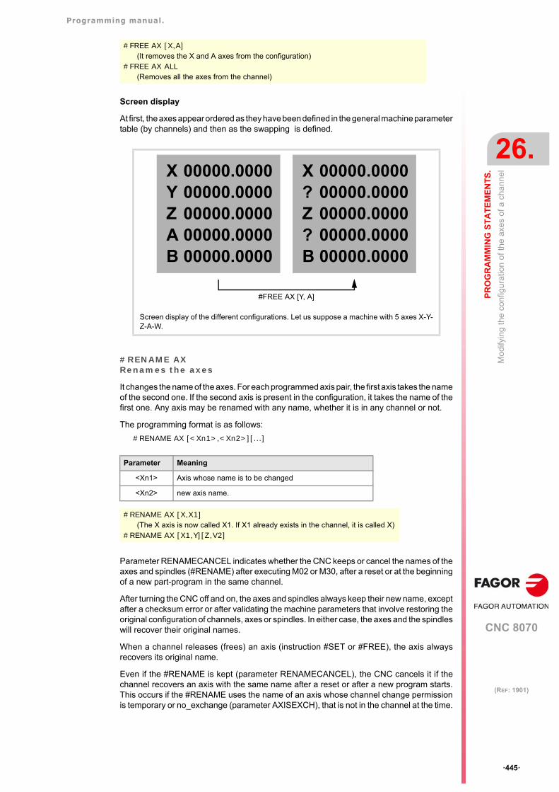
Programming manual.
CNC 8070
PR
OG
RA
MM
ING
ST
AT
EM
EN
TS
.
26.
Mo
dify
ing
the
conf
igur
atio
n o
f th
e ax
es o
f a c
hann
el
·445·
(REF: 1901)
Screen display
At first, the axes appear ordered as they have been defined in the general machine parametertable (by channels) and then as the swapping is defined.
#RENAME AXRenames the axes
It changes the name of the axes. For each programmed axis pair, the first axis takes the nameof the second one. If the second axis is present in the configuration, it takes the name of thefirst one. Any axis may be renamed with any name, whether it is in any channel or not.
The programming format is as follows:
#RENAME AX [<Xn1>,<Xn2>][...]
Parameter RENAMECANCEL indicates whether the CNC keeps or cancel the names of theaxes and spindles (#RENAME) after executing M02 or M30, after a reset or at the beginningof a new part-program in the same channel.
After turning the CNC off and on, the axes and spindles always keep their new name, exceptafter a checksum error or after validating the machine parameters that involve restoring theoriginal configuration of channels, axes or spindles. In either case, the axes and the spindleswill recover their original names.
When a channel releases (frees) an axis (instruction #SET or #FREE), the axis alwaysrecovers its original name.
Even if the #RENAME is kept (parameter RENAMECANCEL), the CNC cancels it if thechannel recovers an axis with the same name after a reset or after a new program starts.This occurs if the #RENAME uses the name of an axis whose channel change permissionis temporary or no_exchange (parameter AXISEXCH), that is not in the channel at the time.
#FREE AX [X,A](It removes the X and A axes from the configuration)
#FREE AX ALL(Removes all the axes from the channel)
Screen display of the different configurations. Let us suppose a machine with 5 axes X-Y-Z-A-W.
Parameter Meaning
<Xn1> Axis whose name is to be changed
<Xn2> new axis name.
#RENAME AX [X,X1](The X axis is now called X1. If X1 already exists in the channel, it is called X)
#RENAME AX [X1,Y][Z,V2]
#FREE AX [Y, A]
XYZAB
00000.000000000.000000000.000000000.000000000.0000
X?Z?B
00000.000000000.000000000.000000000.000000000.0000
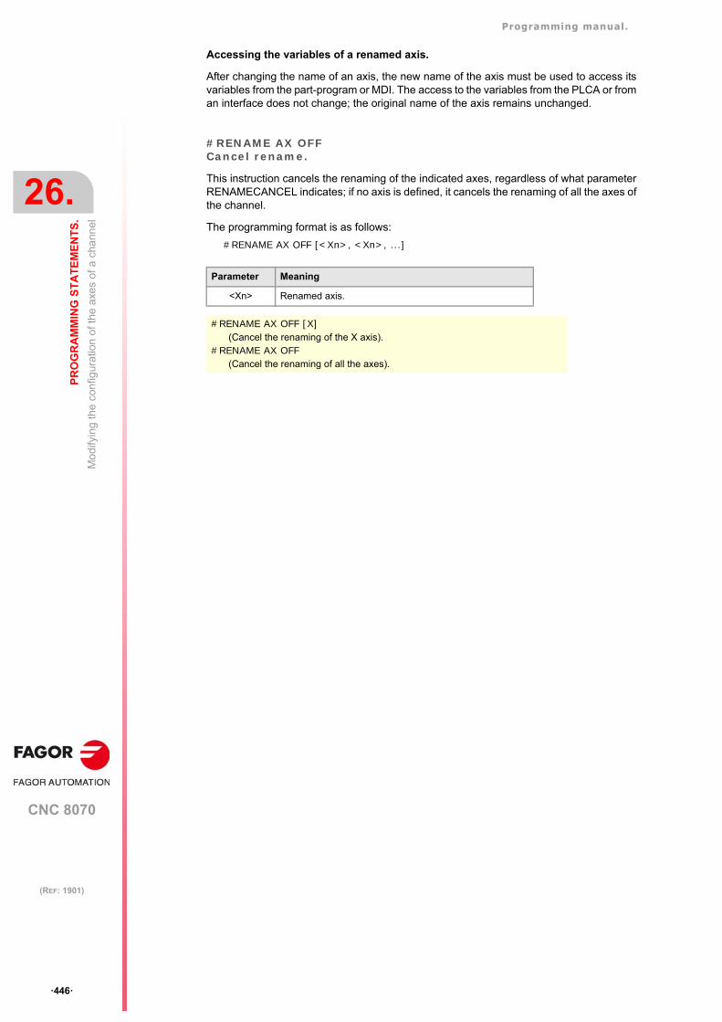
Programming manual.
CNC 8070
26.
PR
OG
RA
MM
ING
ST
AT
EM
EN
TS
.
Mo
dify
ing
the
conf
igur
atio
n o
f th
e ax
es o
f a c
hann
el
·446·
(REF: 1901)
Accessing the variables of a renamed axis.
After changing the name of an axis, the new name of the axis must be used to access itsvariables from the part-program or MDI. The access to the variables from the PLCA or froman interface does not change; the original name of the axis remains unchanged.
#RENAME AX OFFCancel rename.
This instruction cancels the renaming of the indicated axes, regardless of what parameterRENAMECANCEL indicates; if no axis is defined, it cancels the renaming of all the axes ofthe channel.
The programming format is as follows:
#RENAME AX OFF [<Xn>, <Xn>, ...]
Parameter Meaning
<Xn> Renamed axis.
#RENAME AX OFF [X](Cancel the renaming of the X axis).
#RENAME AX OFF(Cancel the renaming of all the axes).
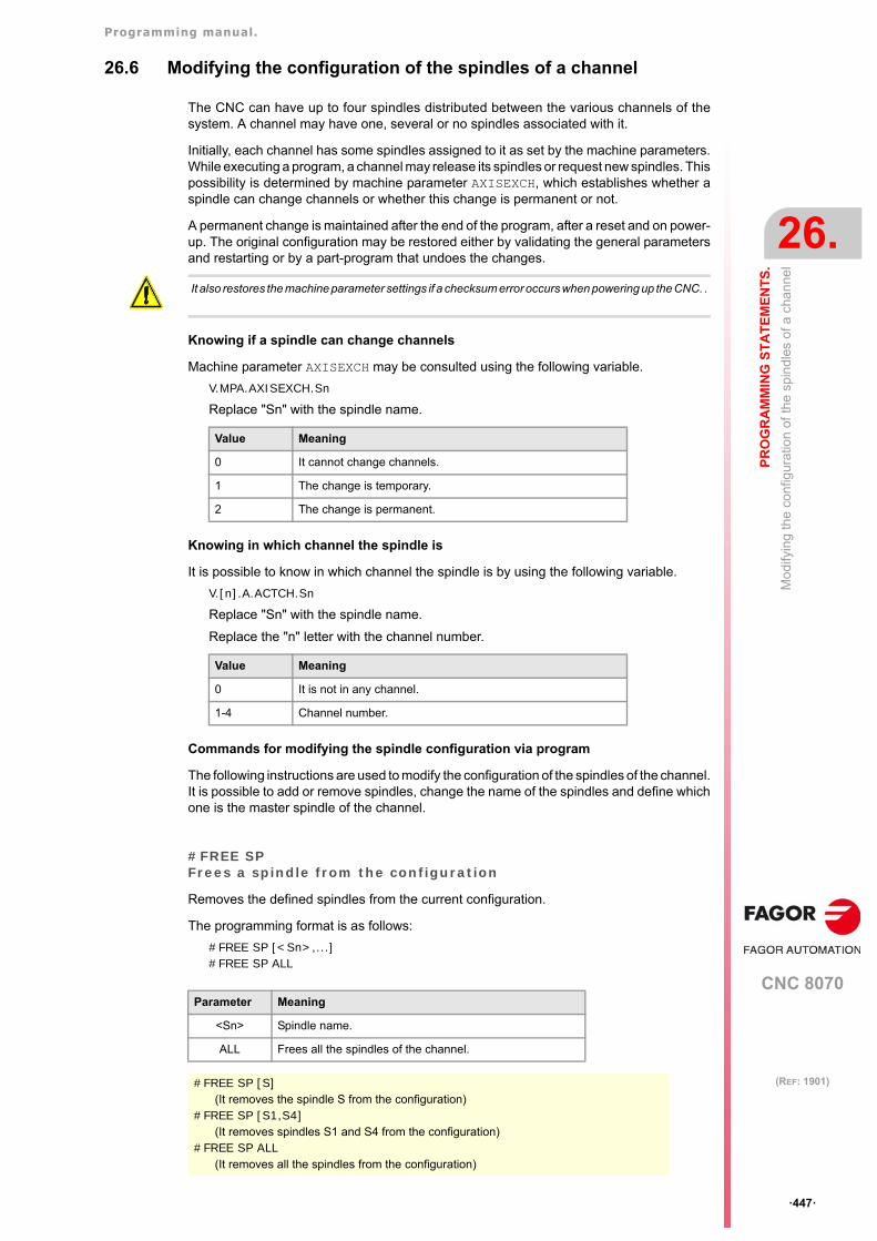
Programming manual.
CNC 8070
PR
OG
RA
MM
ING
ST
AT
EM
EN
TS
.
26.
Mo
dify
ing
the
conf
igur
atio
n o
f th
e sp
ind
les
of a
cha
nne
l
·447·
(REF: 1901)
26.6 Modifying the configuration of the spindles of a channel
The CNC can have up to four spindles distributed between the various channels of thesystem. A channel may have one, several or no spindles associated with it.
Initially, each channel has some spindles assigned to it as set by the machine parameters.While executing a program, a channel may release its spindles or request new spindles. Thispossibility is determined by machine parameter AXISEXCH, which establishes whether aspindle can change channels or whether this change is permanent or not.
A permanent change is maintained after the end of the program, after a reset and on power-up. The original configuration may be restored either by validating the general parametersand restarting or by a part-program that undoes the changes.
Knowing if a spindle can change channels
Machine parameter AXISEXCH may be consulted using the following variable.
V.MPA.AXISEXCH.Sn
Replace "Sn" with the spindle name.
Knowing in which channel the spindle is
It is possible to know in which channel the spindle is by using the following variable.
V.[n].A.ACTCH.Sn
Replace "Sn" with the spindle name.
Replace the "n" letter with the channel number.
Commands for modifying the spindle configuration via program
The following instructions are used to modify the configuration of the spindles of the channel.It is possible to add or remove spindles, change the name of the spindles and define whichone is the master spindle of the channel.
#FREE SPFrees a spindle from the configuration
Removes the defined spindles from the current configuration.
The programming format is as follows:
#FREE SP [<Sn>,...]#FREE SP ALL
It also restores the machine parameter settings if a checksum error occurs when powering up the CNC. .
Value Meaning
0 It cannot change channels.
1 The change is temporary.
2 The change is permanent.
Value Meaning
0 It is not in any channel.
1-4 Channel number.
Parameter Meaning
<Sn> Spindle name.
ALL Frees all the spindles of the channel.
#FREE SP [S](It removes the spindle S from the configuration)
#FREE SP [S1,S4](It removes spindles S1 and S4 from the configuration)
#FREE SP ALL(It removes all the spindles from the configuration)
Programming manual.
CNC 8070
26.
PR
OG
RA
MM
ING
ST
AT
EM
EN
TS
.
Mo
dify
ing
the
conf
igur
atio
n o
f th
e sp
ind
les
of a
cha
nne
l
·448·
(REF: 1901)
#CALL SPAdd a spindle to the configuration
It adds one or several spindles to the current configuration. The position of the spindles inthe channel is not relevant. To add a spindle to the channel, the spindle must be free; it mustnot be in another channel.
The programming format is as follows:
#CALL SP [<Sn>,...]
#SET SPSets the spindle configuration
Defines a new spindle configuration. The spindles existing in the channel and notprogrammed in #SET SP are removed and those programmed that are not already in thechannel will be added. When a new configuration is defined, the order in which the spindlesare defined is not relevant; the CNC always arranges them in an ascending order, accordingto the list of machine parameters.
It is the same as programming a #FREE SP of all the spindles and then a #CALL SP of allthe new spindles. The programming format is as follows:
#SET SP [<Sn>,...]
#RENAME SPRename the spindles
It changes the name of the spindles. For each programmed spindle pair, the first spindle takesthe name of the second one. If the second spindle is present in the configuration, it takesthe name of the first one. Any axis may be renamed with any name, whether it is in anychannel or not.
The programming format is as follows:
#RENAME SP [<Sn>,<Sn>][...]
Parameter RENAMECANCEL indicates whether the CNC keeps or cancel the names of theaxes and spindles (#RENAME) after executing M02 or M30, after a reset or at the beginningof a new part-program in the same channel.
After turning the CNC off and on, the axes and spindles always keep their new name, exceptafter a checksum error or after validating the machine parameters that involve restoring theoriginal configuration of channels, axes or spindles. In either case, the axes and the spindleswill recover their original names.
Parameter Meaning
<Sn> Spindle name.
#CALL SP [S1](It adds spindle S1 to the configuration)
#CALL SP [S,S2](It adds spindles S and S2 to the configuration)
Parameter Meaning
<Sn> Spindle name.
#SET SP [S](Configuring one spindle)
#SET SP [S1,S2](Configuring two spindles)
Parameter Meaning
<Sn> Spindle name.
#RENAME SP [S,S1]#RENAME SP [S1,S2][S3,S]
Programming manual.
CNC 8070
PR
OG
RA
MM
ING
ST
AT
EM
EN
TS
.
26.
Mo
dify
ing
the
conf
igur
atio
n o
f th
e sp
ind
les
of a
cha
nne
l
·449·
(REF: 1901)
When a channel releases (frees) a spindle (instruction #SET or #FREE), the axis alwaysrecovers its original name.
Even if the #RENAME is kept (parameter RENAMECANCEL), the CNC cancels it if thechannel recovers a spindle with the same name after a reset or after a new program starts.This occurs if the #RENAME uses the name of a spindle whose channel change permissionis temporary or no_exchange (parameter AXISEXCH), that is not in the channel at the time.
Accessing the variables of a renamed axis.
After changing the name of an axis, the new name of the axis must be used to access itsvariables from the part-program or MDI. The access to the variables from the PLCA or froman interface does not change; the original name of the axis remains unchanged.
#RENAME SP OFFCancel rename.
This instruction cancels the renaming of the indicated spindles, regardless of what parameterRENAMECANCEL indicates; if no spindle is defined, it cancels the renaming of all thespindles of the channel.
The programming format is as follows:
#RENAME SP OFF [<Sn>, <Sn>, ...]
Parameter Meaning
<Sn> Renamed spindle.
#RENAME SP OFF [S3](Cancel the renaming of spindle S3).
#RENAME SP OFF(Cancel the renaming of all the spindles).
Programming manual.
CNC 8070
26.
PR
OG
RA
MM
ING
ST
AT
EM
EN
TS
.
Spi
ndle
syn
chro
niza
tion
·450·
(REF: 1901)
26.7 Spindle synchronization
This mode may be used to set the movement of a spindle (slave) synchronized with that ofanother spindle (master) through a given ratio. The spindle synchronization is alwaysprogrammed in the channel the slave spindle belongs to, both to activate it or deactivate itand to reset it.
There are two types of synchronization; in speed and in position. The activation andcancellation of the different types of synchronization are programmed with the followinginstructions.
#SYNC - Spindle synchronization based on the real (actual) coordinate.
#TSYNC - Spindle synchronization based on the theoretical coordinate.
#UNSYNC - Cancellation of spindle synchronization.
#SYNCSpindle synchronization based on the real (actual) coordinate
#TSYNCSpindle synchronization based on the theoretical coordinate
The programming format for each of them is the following. Optional parameters are indicatedbetween the <> characters.
#SYNC [{master}, {slave} <,N{nratio}, D{dratio}> <,O{posync}> <,{looptype}> <,{keepsync}>][··]#TSYNC [{master}, {slave} <,N{nratio}, D{dratio}> <,O{posync}> <,{looptype}> <,{keepsync}>][··]
Each pair of brackets defines a synchronism between two spindles.
Parameter Meaning
{master} Master spindle of the synchronization.
{slave} Master spindle of the synchronization.
{nratio}{dratio}
Optional. This pair of numbers define the gear ratio (nratio/dratio) between thesynchronized spindles.Both values can be positive or negative.
{posync} Optional. This parameter determines that they are synchronized in position andit also sets the offset (shift) between the two spindles. The values may be positive or negative and greater than 360º.
{looptype} Optional. This parameter indicates the type of loop for the master spindle."CLOOP" for the spindle in closed loop. "OLOOP" for the spindle in open loop. If not programmed, the statement assumes the value "CLOOP".
{keepsync} Optional. This parameter indicates whether the CNC cancels spindlesynchronization or not after executing M02, M30 or after an error or reset. With"CANCEL" value, the CNC cancels the synchronism; with "NOCANCEL" value,it doesn't cancel it.If not programmed, the statement assumes the value set by the OEM (parameterSYNCCANCEL).
#SYNC [S,S1]The spindles are synchronized in speed. The slave spindle S1 turns at the same speed as themaster spindle S.
#SYNC [S,S1,N1,D2]The slave spindle S1 turns at half the speed (1/2) of the master spindle S.
#SYNC [S,S1,N1,D2,O15]After synchronizing in speed and in position, the slave spindle S1 follows the master S with theindicated offset, which could be for example 15º.
#SYNC [S,S1,O30,OLOOP]Synchronism in speed and position with 30º offset. The master spindle works in open loop.
#SYNC [S,S1,O30,CLOOP, CANCEL]Synchronism in speed and position with 30º offset. The master spindle works in closed loop. TheCNC cancels the synchronism after M30, an error or a reset.
Programming manual.
CNC 8070
PR
OG
RA
MM
ING
ST
AT
EM
EN
TS
.
26.
Spi
ndle
syn
chro
niza
tion
·451·
(REF: 1901)
Considerations for the synchronization
The #SYNC function may be executed either in open loop (M3 or M4) or in closed loop (M19)In the synchronization, the master spindle can work in either open or closed loop; the slavespindle is always in closed loop.
Several pairs of synchronized spindles may be programmed in the same instruction #SYNCor #TSYNC. Several consecutive #SYNC instructions can also be programmed with anadditive effect as long as they do not conflict with the previous ones.
The slave spindle must be in the channel where the synchronization is activated whereasthe master spindle may be in any channel. Several slave spindles may have the same masterspindle, but a slave spindle cannot be the master of a third one; thus preventing synchronismloops.
It is possible to program either first the synchronism in speed and then in position or bothat the same time. Once a pair has been synchronized, it is possible to change its speed ratioand/or its offset (shift); if necessary, the spindles will get out of synchronism and back insynchronism to make the change.
Both spindles must operate in closed loop in order to assure proper follow-up. Once they'reboth in closed loop, the slave spindle switches from its current speed to the synchronismspeed. The master spindle may be turning when programming the synchronization and itwill switch to closed loop maintaining its rotation.
Programming the master and slave spindles
For the slave spindle, it is not possible to program the speed, the spindle functions M3, M4,M5 and M19, gear changes M41 through M44 or change the speed override.
The following functions may be programmed for the master spindle:
• Change the spindle speed via PLC or CNC.
• Execute the speed functions G94, G95, G96 and G97.
• Execute the auxiliary functions M3, M4, M5 and M19.
• Change the spindle speed override via PLC, CNC or keyboard.
• Change the spindle speed limit via PLC or CNC.
• If the C axis is activated, define the XC or ZC plane.
When defining the synchronization or when it is active, the master spindle can work as Caxis or in G63. Functions G33, G95 or G96 may also be active at the master spindle.Functions G33 and G95 may also be active at the slave spindle, but function G96 will staytemporarily "frozen" and without effect during the synchronization.
On the other hand, the synchronized spindles cannot change channels and it is not possibleto change gears M41 through M44. If the gear change is automatic and the new speedrequires a gear change, the relevant error message will be issued.
Work gear
The spindles may have different gears (ranges). If at the time of the synchronization, thespindles are not in the same state, the slave "freezes" its state, changes the gear indicatedby machine parameter SYNCSET and is forced to follow the master.
If the master belongs to the same channel, it also changes to the gear indicated by itsparameter SYNCSET If the master is in another channel, the gear must be activated beforeactivating the synchronization. Therefore, it is up to the user to prepare the master spindleso the slave can synchronize it with it.
Machine reference (home) search
The slave spindle must be homed (referenced) before activating the position synchronismif it has been homed before. If the master spindle is in the same channel and has not beenhomed, it is also forced to be homed. An error message will be issued if the master spindleis in another channel and it has not been homed.
Programming manual.
CNC 8070
26.
PR
OG
RA
MM
ING
ST
AT
EM
EN
TS
.
Spi
ndle
syn
chro
niza
tion
·452·
(REF: 1901)
#UNSYNCUncouple one or several spindles
The programming format is: Optional parameters are indicated between the <> characters.
#UNSYNC#UNSYNC [slave1 <,slave2> ...]
All the spindles are uncoupled if no parameter is defined.
Considerations for uncoupling
The synchronism is also canceled with M30 and RESET.
When canceling the synchronism, the master spindle stays in its current state and the slavestops. The slave does not recover the M function prior to the synchronization, but it keepsthe synchronism gear until a new S function is programmed.
Variables associated with the synchronization movement
These variables are read/write (R/W) synchronous and are evaluated during execution.They have generic names.
• Replace the "n" character with the channel number, maintaining the brackets. The firstchannel is identified with the number 1, "0" is not a valid number.
• Replace the "Xn" character by the name, logic number or index in the channel of the axis.
Adjust the speed synchronism ratio
(V.)[n].A.GEARADJ.Xn
Read-only from the PRG, PLC and INT. The PLC reading comes in hundredths (x100)
Fine adjustment of the gear ratio during the synchronization itself. It is programmed as apercentage of the original adjustment value.
Speed synchronization
(V.)[n].A.SYNCVELW.Xn
Read-only from the PRG, PLC e INT.
When the spindles are synchronized in speed, the slave spindle turns at the same speedas the master spindle (taking the ratio into account). If the value defined in this variable isexceeded, the SYNSPEED signal goes low; the movement is not stopped and no errormessage is issued.
Its default value is that of machine parameter DSYNCVELW.
(V.)[n].A.SYNCVELOFF.Xn
Read-only from the PRG, PLC e INT.
Velocity offset of the slave spindle synchronization.
Parameter Meaning
slave Slave spindle to be synchronized.
#UNSYNCAll the spindles of the channel are uncoupled.
#UNSYNC [S1,S2]Slave spindles S1 and S2 are uncoupled from the master spindle with which they weresynchronized.
Programming manual.
CNC 8070
PR
OG
RA
MM
ING
ST
AT
EM
EN
TS
.
26.
Spi
ndle
syn
chro
niza
tion
·453·
(REF: 1901)
Position synchronization
(V.)[n].A.SYNCPOSW.Xn
Read-only from the PRG, PLC e INT.
When the spindles are synchronized in position, the slave spindle follows the master keepingthe programmed offset (taking the ratio into account). If the value defined in this variable isexceeded, the SYNCPOSI signal goes low; the movement is not stopped and no errormessage is issued.
Its default value is that of machine parameter DSYNCPOSW.
(V.)[n].A.SYNCPOSOFF.Xn
Read-only from the PRG, PLC e INT.
Position offset.
Programming manual.
CNC 8070
26.
PR
OG
RA
MM
ING
ST
AT
EM
EN
TS
.
Sel
ect
ing
the
loop
for
an a
xis
or a
spi
ndle
. Ope
n lo
op o
r cl
ose
d lo
op
·454·
(REF: 1901)
26.8 Selecting the loop for an axis or a spindle. Open loop or closed loop
When working in open loop, the command does not depend on the feedback. When workingin closed loop, the command is generated according to the feedback.
The spindle usually works in open loop when it is in M3 or M4 and in closed loop when itis in M19. In spindle synchronization, the slave always works in closed loop and the mastercan work either in open loop or closed loop depending on the programming parameters ofthe #SYNC instruction. However, it is possible to work in closed loop with functions M3 andM4 to make the following adjustments on a spindle:
• Adjust the loop for M19.
• Adjust a loop for when the spindle is the master of a synchronization.
The axes usually work in closed loop. A rotary axis may be controlled in open loop as if itwere a spindle.
The following instructions may be used to open and close the loops and they are valid foraxes as well as for spindles.
#SERVO ON - Activates the closed loop mode.
#SERVO OFF - Activates the open loop mode.
#SERVO ONActivates the closed loop mode
Programming this instruction switches the axis or spindle to closed loop mode.
The spindle must be homed before switching to closed loop mode; otherwise the loop willbe closed and a warning message will be issued.
The programming format is as follows:
#SERVO ON [axis/spindle]
The loop of each axis or spindle must be closed separately.
#SERVO OFFActivates the open loop mode
Programming this instruction switches the axis or spindle to open loop mode. For a spindle,it cancels the closed-loop mode programmed #SERVO ON and restores the status that thespindle had before closing the loop.
• If the spindle was in M19, it stays in closed loop after programming this instruction.
• In spindle synchronization, the #SERVO OFF instruction cannot be programmed for theslave spindle; if programmed, the CNC will issue an error message.
If the synchronization has been defined withe master spindle working in closed loop, itstays in closed loop after programming #SERVO OFF. If the synchronization has beendefined with the master spindle working in open loop and, later on, it is closed with#SERVO ON, the loop of the master spindle will be opened after programmming#SERVO OFF.
• If the spindle was in M3, M4 or M5 without synchronism, the CNC opens the loop.
This function is not available for Sercos position-drives (axis or spindle). In this case, the CNC cannotopen or close the loop, the drive controls the loop, instead.i
Parameter Meaning
axis/spindle Name of the axis or spindle.
#SERVO ON [S]Closes the loop of spindle S.
#SERVO ON [S2]Closes the loop of spindle S2.
#SERVO ON [X]Closes the loop of the X axis.
Programming manual.
CNC 8070
PR
OG
RA
MM
ING
ST
AT
EM
EN
TS
.
26.
Sel
ect
ing
the
loop
for
an a
xis
or a
spi
ndle
. Ope
n lo
op o
r cl
ose
d lo
op
·455·
(REF: 1901)
The programming format is as follows:
#SERVO ON [axis/spindle]
The loop of each axis or spindle must be opened separately.
Considerations for programming the loops
Function M19 involves always working in closed loop. Functions M3, M4 and M5 work in openloop by default , but they can also work in closed loop when programming a spindlesynchronization or the instruction #SERVO ON .
When a spindle becomes a C axis or is interpolated with the rest of the axes (for rigid tapping,for example) does not lose its open-loop or closed-loop condition that it had. When done withthese instructions, the previous situation is restored.
On power-up, the spindle is set in open loop. After executing an M30 or reset, the CNC opensthe loop and cancels the instruction #SERVO ON, except when the reset is for the masterspindle of a synchronization (which could be in a different channel from that of the slave);in that case, the synchronization is not canceled and it does not switch to open loop. Thiscase issues a warning message.
Parameter Meaning
axis/spindle Name of the axis or spindle.
#SERVO OFF [S]It cancels the closed loop of spindle S.
#SERVO OFF [Z2]The Z2 axis switches to open loop mode.
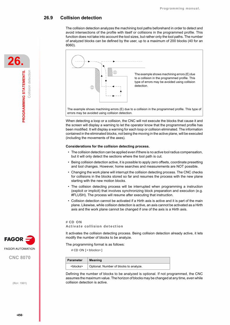
Programming manual.
CNC 8070
26.
PR
OG
RA
MM
ING
ST
AT
EM
EN
TS
.
Co
llisi
on d
etec
tion
·456·
(REF: 1901)
26.9 Collision detection
The collision detection analyzes the machining tool paths beforehand in order to detect andavoid intersections of the profile with itself or collisions in the programmed profile. Thisfunction does not take into account the tool sizes, but rather only the tool paths. The numberof analyzed blocks can be defined by the user, up to a maximum of 200 blocks (40 for an8060).
When detecting a loop or a collision, the CNC will not execute the blocks that cause it andthe screen will display a warning to let the operator know that the programmed profile hasbeen modified. It will display a warning for each loop or collision eliminated. The informationcontained in the eliminated blocks, not being the moving in the active plane, will be executed(including the movements of the axes).
Considerations for the collision detecting process.
• The collision detection can be applied even if there is no active tool radius compensation,but it will only detect the sections where the tool path is cut.
• Being collision detection active, it is possible to apply zero offsets, coordinate presettingand tool changes. However, home searches and measurements are NOT possible.
• Changing the work plane will interrupt the collision detecting process. The CNC checksfor collisions in the blocks stored so far and resumes the process with the new planestarting with the new motion blocks.
• The collision detecting process will be interrupted when programming a instruction(explicit or implicit) that involves synchronizing block preparation and execution (e.g.#FLUSH). The process will resume after executing that instruction.
• Collision detection cannot be activated if a Hirth axis is active and it is part of the mainplane. Likewise, while collision detection is active, an axis cannot be activated as a Hirthaxis and the work plane cannot be changed if one of the axis is a Hirth axis.
#CD ONActivate collision detection
It activates the collision detecting process. Being collision detection already active, it letsmodify the number of blocks to be analyze.
The programming format is as follows:
#CD ON [<blocks>]
Defining the number of blocks to be analyzed is optional. If not programmed, the CNCassumes the maximum value. The horizon of blocks may be changed at any time, even whilecollision detection is active.
The example shows machining errors (E) due to a collision in the programmed profile. This type oferrors may be avoided using collision detection.
Parameter Meaning
<blocks> Optional. Number of blocks to analyze.
The example shows machining errors (E) dueto a collision in the programmed profile. Thistype of errors may be avoided using collisiondetection.
Programming manual.
CNC 8070
PR
OG
RA
MM
ING
ST
AT
EM
EN
TS
.
26.
Co
llisi
on d
etec
tion
·457·
(REF: 1901)
#CD OFFCancels collision detection
It cancels the collision detecting process.
The process will also be canceled automatically after executing an M02 or M30 and afteran error or a reset.
Example of a profile with a loop.
#CD ON [50]G01 X0 Y0 Z0 F750X100 Y0Y-50X90Y20X40Y-50X0Y0#CD OFF
Example of profile collision.
#CD ONG01 G41 X0 Y0 Z0 F750X50Y-50X100Y-10X60Y0X150Y-100X0G40 X0 Y0#CD OFFM30
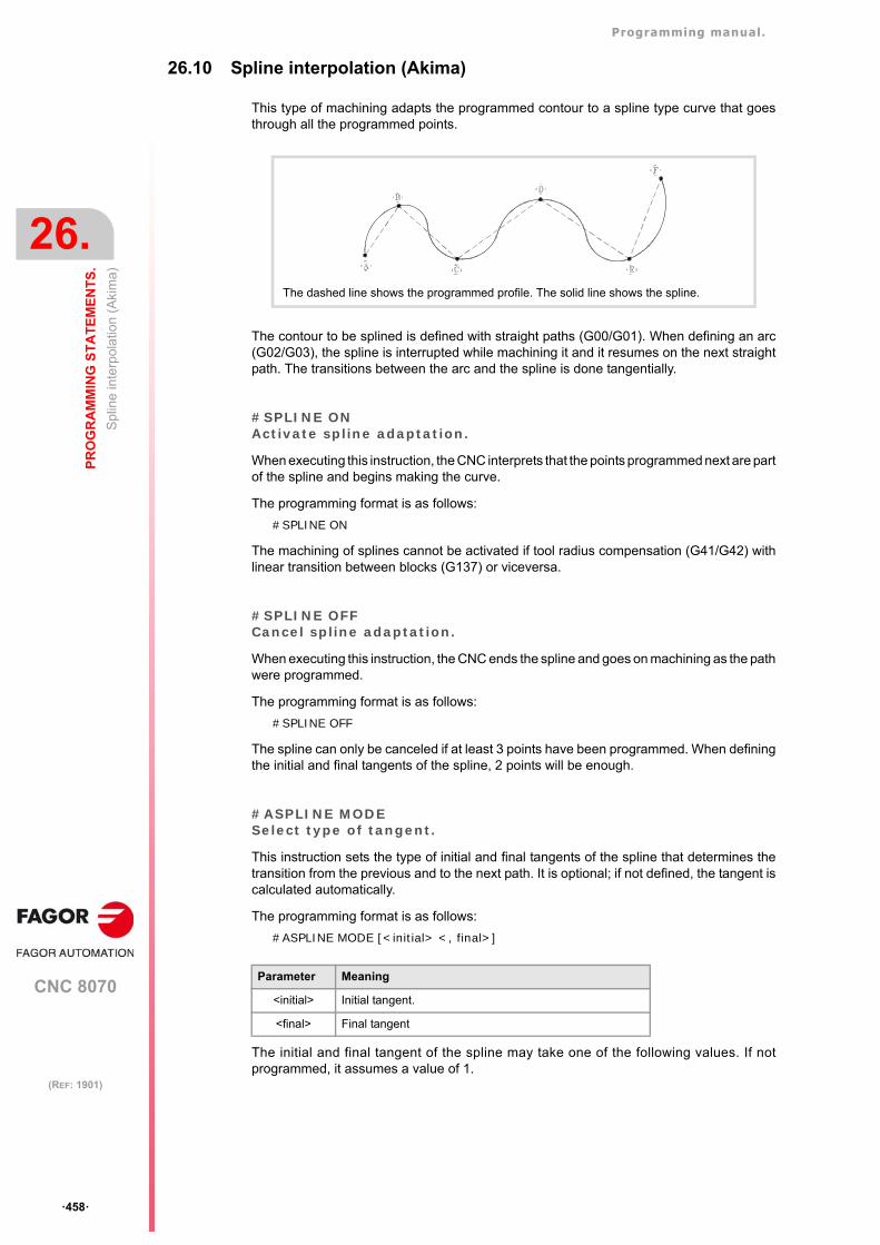
Programming manual.
CNC 8070
26.
PR
OG
RA
MM
ING
ST
AT
EM
EN
TS
.
Sp
line
inte
rpol
atio
n (A
kim
a)
·458·
(REF: 1901)
26.10 Spline interpolation (Akima)
This type of machining adapts the programmed contour to a spline type curve that goesthrough all the programmed points.
The contour to be splined is defined with straight paths (G00/G01). When defining an arc(G02/G03), the spline is interrupted while machining it and it resumes on the next straightpath. The transitions between the arc and the spline is done tangentially.
#SPLINE ONActivate spline adaptation.
When executing this instruction, the CNC interprets that the points programmed next are partof the spline and begins making the curve.
The programming format is as follows:
#SPLINE ON
The machining of splines cannot be activated if tool radius compensation (G41/G42) withlinear transition between blocks (G137) or viceversa.
#SPLINE OFFCancel spline adaptation.
When executing this instruction, the CNC ends the spline and goes on machining as the pathwere programmed.
The programming format is as follows:
#SPLINE OFF
The spline can only be canceled if at least 3 points have been programmed. When definingthe initial and final tangents of the spline, 2 points will be enough.
#ASPLINE MODESelect type of tangent.
This instruction sets the type of initial and final tangents of the spline that determines thetransition from the previous and to the next path. It is optional; if not defined, the tangent iscalculated automatically.
The programming format is as follows:
#ASPLINE MODE [<initial> <, final>]
The initial and final tangent of the spline may take one of the following values. If notprogrammed, it assumes a value of 1.
The dashed line shows the programmed profile. The solid line shows the spline.
Parameter Meaning
<initial> Initial tangent.
<final> Final tangent
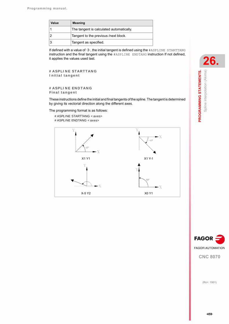
Programming manual.
CNC 8070
PR
OG
RA
MM
ING
ST
AT
EM
EN
TS
.
26.
Sp
line
inte
rpol
atio
n (A
kim
a)
·459·
(REF: 1901)
If defined with a value of ·3·, the initial tangent is defined using the #ASPLINE STARTTANGinstruction and the final tangent using the #ASPLINE ENDTANG instruction If not defined,it applies the values used last.
#ASPLINE STARTTANGInitial tangent
#ASPLINE ENDTANGFinal tangent
These instructions define the initial and final tangents of the spline. The tangent is determinedby giving its vectorial direction along the different axes.
The programming format is as follows:
#ASPLINE STARTTANG <axes>#ASPLINE ENDTANG <axes>
Value Meaning
1 The tangent is calculated automatically.
2 Tangent to the previous /next block.
3 Tangent as specified.
X1 Y1 X1 Y-1
X-5 Y2 X0 Y1
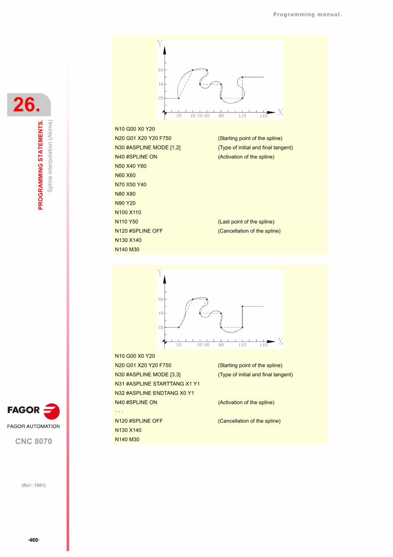
Programming manual.
CNC 8070
26.
PR
OG
RA
MM
ING
ST
AT
EM
EN
TS
.
Sp
line
inte
rpol
atio
n (A
kim
a)
·460·
(REF: 1901)
N10 G00 X0 Y20
N20 G01 X20 Y20 F750 (Starting point of the spline)
N30 #ASPLINE MODE [1,2] (Type of initial and final tangent)
N40 #SPLINE ON (Activation of the spline)
N50 X40 Y60
N60 X60
N70 X50 Y40
N80 X80
N90 Y20
N100 X110
N110 Y50 (Last point of the spline)
N120 #SPLINE OFF (Cancellation of the spline)
N130 X140
N140 M30
N10 G00 X0 Y20
N20 G01 X20 Y20 F750 (Starting point of the spline)
N30 #ASPLINE MODE [3,3] (Type of initial and final tangent)
N31 #ASPLINE STARTTANG X1 Y1
N32 #ASPLINE ENDTANG X0 Y1
N40 #SPLINE ON (Activation of the spline)
· · ·
N120 #SPLINE OFF (Cancellation of the spline)
N130 X140
N140 M30
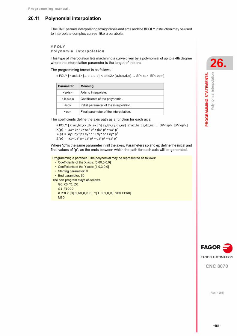
Programming manual.
CNC 8070
PR
OG
RA
MM
ING
ST
AT
EM
EN
TS
.
26.
Pol
yno
mia
l int
erpo
latio
n
·461·
(REF: 1901)
26.11 Polynomial interpolation
The CNC permits interpolating straight lines and arcs and the #POLY instruction may be usedto interpolate complex curves, like a parabola.
#POLYPolynomial interpolation
This type of interpolation lets machining a curve given by a polynomial of up to a 4th degreewhere the interpolation parameter is the length of the arc.
The programming format is as follows:
#POLY [<axis1>[a,b,c,d,e] <axis2>[a,b,c,d,e] .. SP<sp> EP<ep>]
The coefficients define the axis path as a function for each axis.
#POLY [X[ax,bx,cx,dx,ex] Y[ay,by,cy,dy,ey] Z[az,bz,cz,dz,ez] .. SP<sp> EP<ep>]X(p) = ax+bx*p+cx*p²+dx*p³+ex*p4
Y(p) = ay+by*p+cy*p²+dy*p³+ey*p4
Z(p) = az+bz*p+cz*p²+dz*p³+ez*p4
Where "p" is the same parameter in all the axes. Parameters sp and ep define the initial andfinal values of "p", as the ends between which the path for each axis will be generated.
Parameter Meaning
<axis> Axis to interpolate.
a,b,c,d,e Coefficients of the polynomial.
<sp> Initial parameter of the interpolation.
<ep> Final parameter of the interpolation.
Programming a parabola. The polynomial may be represented as follows:• Coefficients of the X axis: [0,60,0,0,0]• Coefficients of the Y axis: [1,0,3,0,0]• Starting parameter: 0• End parameter: 60
The part program stays as follows.G0 X0 Y1 Z0 G1 F1000#POLY [X[0,60,0,0,0] Y[1,0,3,0,0] SP0 EP60]M30
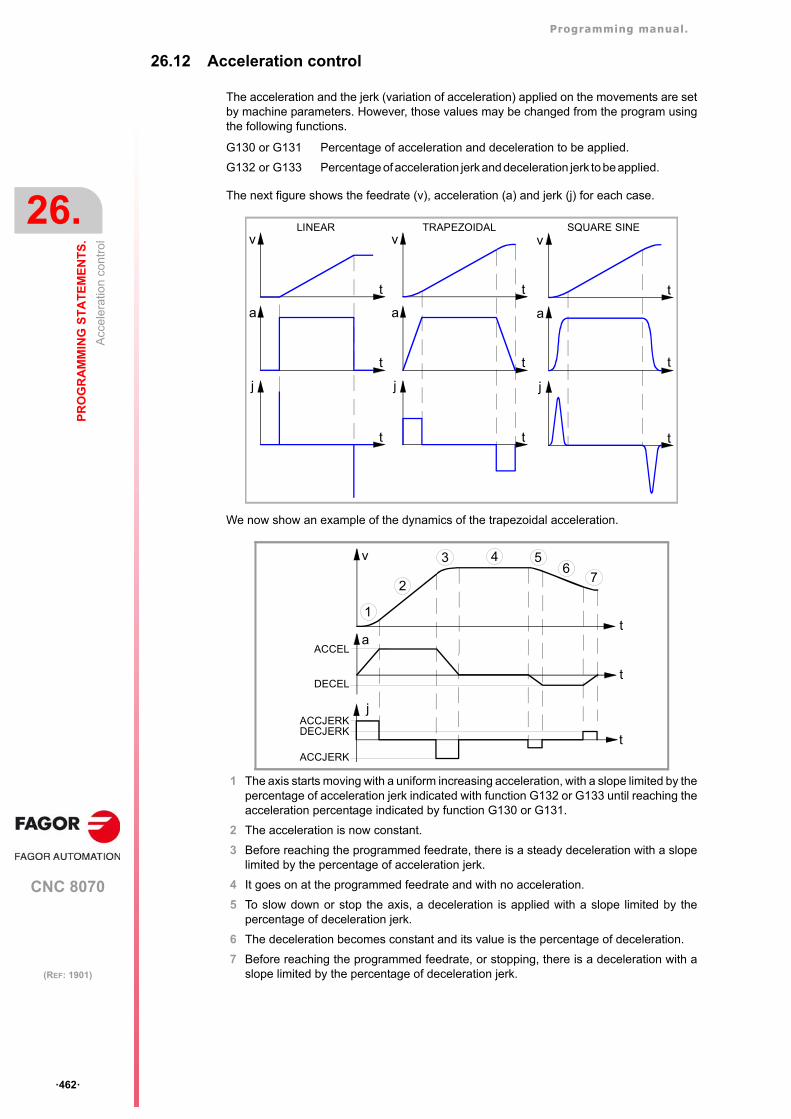
Programming manual.
CNC 8070
26.
PR
OG
RA
MM
ING
ST
AT
EM
EN
TS
.
Acc
eler
atio
n co
ntro
l
·462·
(REF: 1901)
26.12 Acceleration control
The acceleration and the jerk (variation of acceleration) applied on the movements are setby machine parameters. However, those values may be changed from the program usingthe following functions.
The next figure shows the feedrate (v), acceleration (a) and jerk (j) for each case.
We now show an example of the dynamics of the trapezoidal acceleration.
1 The axis starts moving with a uniform increasing acceleration, with a slope limited by thepercentage of acceleration jerk indicated with function G132 or G133 until reaching theacceleration percentage indicated by function G130 or G131.
2 The acceleration is now constant.
3 Before reaching the programmed feedrate, there is a steady deceleration with a slopelimited by the percentage of acceleration jerk.
4 It goes on at the programmed feedrate and with no acceleration.
5 To slow down or stop the axis, a deceleration is applied with a slope limited by thepercentage of deceleration jerk.
6 The deceleration becomes constant and its value is the percentage of deceleration.
7 Before reaching the programmed feedrate, or stopping, there is a deceleration with aslope limited by the percentage of deceleration jerk.
G130 or G131 Percentage of acceleration and deceleration to be applied.
G132 or G133 Percentage of acceleration jerk and deceleration jerk to be applied.
t
v
t
a
t
j
t
v
t
a
t
j
t
v
t
a
t
j
LINEAR TRAPEZOIDAL SQUARE SINE
t
v
t
a
3
2
1
4 56
7
ACCEL
DECEL
t
jACCJERKDECJERK
ACCJERK
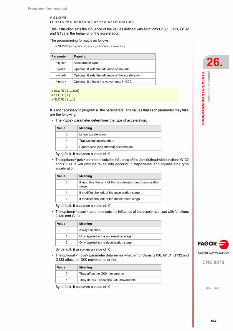
Programming manual.
CNC 8070
PR
OG
RA
MM
ING
ST
AT
EM
EN
TS
.
26.
Acc
eler
atio
n co
ntro
l
·463·
(REF: 1901)
#SLOPEIt sets the behavior of the acceleration
This instruction sets the influence of the values defined with functions G130, G131, G132and G133 in the behavior of the acceleration.
The programming format is as follows:
#SLOPE [<type>,<jerk>,<accel>,<move>]
It is not necessary to program all the parameters. The values that each parameter may takeare the following.
• The <type> parameter determines the type of acceleration.
By default, it assumes a value of ·0·.
• The optional <jerk> parameter sets the influence of the Jerk defined with functions G132and G133. It will only be taken into account in trapezoidal and square-sine typeacceleration.
By default, it assumes a value of ·0·.
• The optional <accel> parameter sets the influence of the acceleration set with functionsG130 and G131.
By default, it assumes a value of ·0·.
• The optional <move> parameter determines whether functions G130, G131, G132 andG133 affect the G00 movements or not.
By default, it assumes a value of ·0·.
Parameter Meaning
<type> Acceleration type.
<jerk> Optional. It sets the influence of the jerk.
<accel> Optional. It sets the influence of the acceleration.
<mov> Optional. It affects the movements in G00.
#SLOPE [1,1,0,0]#SLOPE [1]#SLOPE [2,,,1]
Value Meaning
0 Linear acceleration.
1 Trapezoidal acceleration.
2 Square sine (bell shaped) acceleration.
Value Meaning
0 It modifies the jerk of the acceleration and decelerationstage.
1 It modifies the jerk of the acceleration stage.
2 It modifies the jerk of the deceleration stage.
Value Meaning
0 Always applied.
1 Only applied in the acceleration stage.
2 Only applied in the deceleration stage.
Value Meaning
0 They affect the G00 movements.
1 They do NOT affect the G00 movements.
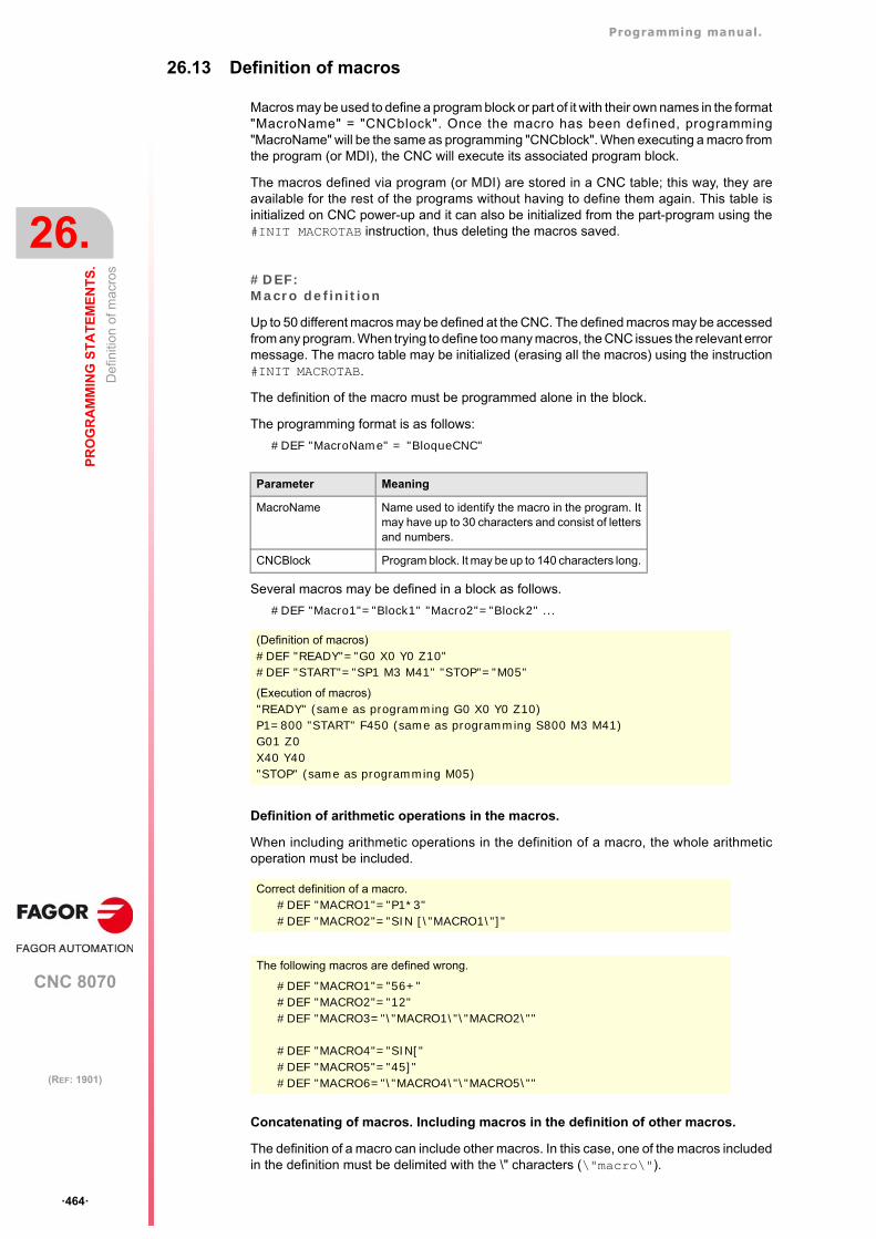
Programming manual.
CNC 8070
26.
PR
OG
RA
MM
ING
ST
AT
EM
EN
TS
.
De
finiti
on o
f mac
ros
·464·
(REF: 1901)
26.13 Definition of macros
Macros may be used to define a program block or part of it with their own names in the format"MacroName" = "CNCblock". Once the macro has been defined, programming"MacroName" will be the same as programming "CNCblock". When executing a macro fromthe program (or MDI), the CNC will execute its associated program block.
The macros defined via program (or MDI) are stored in a CNC table; this way, they areavailable for the rest of the programs without having to define them again. This table isinitialized on CNC power-up and it can also be initialized from the part-program using the#INIT MACROTAB instruction, thus deleting the macros saved.
#DEF:Macro definition
Up to 50 different macros may be defined at the CNC. The defined macros may be accessedfrom any program. When trying to define too many macros, the CNC issues the relevant errormessage. The macro table may be initialized (erasing all the macros) using the instruction#INIT MACROTAB.
The definition of the macro must be programmed alone in the block.
The programming format is as follows:
#DEF "MacroName" = "BloqueCNC"
Several macros may be defined in a block as follows.
#DEF "Macro1"="Block1" "Macro2"="Block2" ...
Definition of arithmetic operations in the macros.
When including arithmetic operations in the definition of a macro, the whole arithmeticoperation must be included.
Concatenating of macros. Including macros in the definition of other macros.
The definition of a macro can include other macros. In this case, one of the macros includedin the definition must be delimited with the \" characters (\"macro\").
Parameter Meaning
MacroName Name used to identify the macro in the program. Itmay have up to 30 characters and consist of lettersand numbers.
CNCBlock Program block. It may be up to 140 characters long.
(Definition of macros)#DEF "READY"="G0 X0 Y0 Z10"#DEF "START"="SP1 M3 M41" "STOP"="M05"
(Execution of macros)"READY" (same as programming G0 X0 Y0 Z10)P1=800 "START" F450 (same as programming S800 M3 M41)G01 Z0X40 Y40"STOP" (same as programming M05)
Correct definition of a macro.#DEF "MACRO1"="P1*3"#DEF "MACRO2"="SIN [\"MACRO1\"]"
The following macros are defined wrong.
#DEF "MACRO1"="56+"#DEF "MACRO2"="12"#DEF "MACRO3="\"MACRO1\"\"MACRO2\""
#DEF "MACRO4"="SIN["#DEF "MACRO5"="45]"#DEF "MACRO6="\"MACRO4\"\"MACRO5\""
Programming manual.
CNC 8070
PR
OG
RA
MM
ING
ST
AT
EM
EN
TS
.
26.
De
finiti
on o
f mac
ros
·465·
(REF: 1901)
#INIT MACROTABResetting the table of macros
When defining a macro from a program (or MDI), it is stored in a CNC table so it is availablefor all the rest of the programs. This instruction resets the table of macros erasing the onesstored in it.
Example1#DEF "MACRO1"="X20 Y35"#DEF "MACRO2"="S1000 M03"#DEF "MACRO3"="G01 \"MA1\" F100 \"MA2\""
Example 2#DEF "POS"="G1 X0 Y0 Z0"#DEF "START"="S750 F450 M03"#DEF "MACRO"="\"POS\" \"START\""
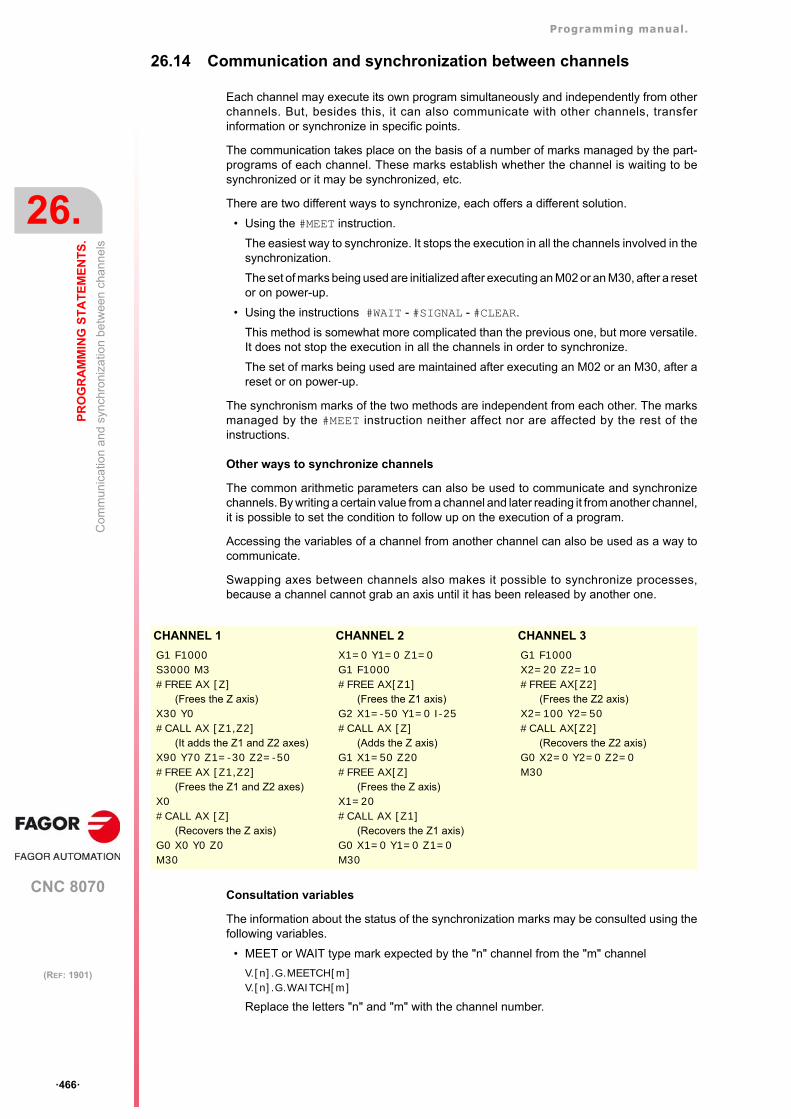
Programming manual.
CNC 8070
26.
PR
OG
RA
MM
ING
ST
AT
EM
EN
TS
.
Com
mun
ica
tion
and
syn
chro
niza
tion
bet
wee
n c
hann
els
·466·
(REF: 1901)
26.14 Communication and synchronization between channels
Each channel may execute its own program simultaneously and independently from otherchannels. But, besides this, it can also communicate with other channels, transferinformation or synchronize in specific points.
The communication takes place on the basis of a number of marks managed by the part-programs of each channel. These marks establish whether the channel is waiting to besynchronized or it may be synchronized, etc.
There are two different ways to synchronize, each offers a different solution.
• Using the #MEET instruction.
The easiest way to synchronize. It stops the execution in all the channels involved in thesynchronization.
The set of marks being used are initialized after executing an M02 or an M30, after a resetor on power-up.
• Using the instructions #WAIT - #SIGNAL - #CLEAR.
This method is somewhat more complicated than the previous one, but more versatile.It does not stop the execution in all the channels in order to synchronize.
The set of marks being used are maintained after executing an M02 or an M30, after areset or on power-up.
The synchronism marks of the two methods are independent from each other. The marksmanaged by the #MEET instruction neither affect nor are affected by the rest of theinstructions.
Other ways to synchronize channels
The common arithmetic parameters can also be used to communicate and synchronizechannels. By writing a certain value from a channel and later reading it from another channel,it is possible to set the condition to follow up on the execution of a program.
Accessing the variables of a channel from another channel can also be used as a way tocommunicate.
Swapping axes between channels also makes it possible to synchronize processes,because a channel cannot grab an axis until it has been released by another one.
Consultation variables
The information about the status of the synchronization marks may be consulted using thefollowing variables.
• MEET or WAIT type mark expected by the "n" channel from the "m" channel
V.[n].G.MEETCH[m]V.[n].G.WAITCH[m]
Replace the letters "n" and "m" with the channel number.
CHANNEL 1 CHANNEL 2 CHANNEL 3
G1 F1000 S3000 M3#FREE AX [Z]
(Frees the Z axis)X30 Y0#CALL AX [Z1,Z2]
(It adds the Z1 and Z2 axes)X90 Y70 Z1=-30 Z2=-50#FREE AX [Z1,Z2]
(Frees the Z1 and Z2 axes)X0#CALL AX [Z]
(Recovers the Z axis)G0 X0 Y0 Z0M30
X1=0 Y1=0 Z1=0G1 F1000#FREE AX[Z1]
(Frees the Z1 axis)G2 X1=-50 Y1=0 I-25 #CALL AX [Z]
(Adds the Z axis)G1 X1=50 Z20#FREE AX[Z]
(Frees the Z axis)X1=20#CALL AX [Z1]
(Recovers the Z1 axis)G0 X1=0 Y1=0 Z1=0M30
G1 F1000X2=20 Z2=10#FREE AX[Z2]
(Frees the Z2 axis)X2=100 Y2=50#CALL AX[Z2]
(Recovers the Z2 axis)G0 X2=0 Y2=0 Z2=0M30
Programming manual.
CNC 8070
PR
OG
RA
MM
ING
ST
AT
EM
EN
TS
.
26.
Com
mun
ica
tion
and
syn
chro
niza
tion
bet
wee
n c
hann
els
·467·
(REF: 1901)
• Status of the MEET or WAIT type "m" mark in the "n" channel
V.[n].G.MEETST[m]V.[n].G.WAITST[m]
#MEETIt activates the mark indicated in the channel and waits for it to be activated in the rest of the programmed channels.
This instruction, after activating the mark in its own channel, waits for it to also be active inthe programmed channels before resuming the execution. Each channel has 100 marks thatare numbered from 1 to 100.
Programming the same instruction in several channels, all of them stop and wait for the restto reach the indicated point before they all resume the execution at the same time from thatpoint on.
The programming format is:
#MEET [<mark>, <channel>,...]
There is no need to include the number of its own channel in each instruction because themark is activated when executing the #MEET instruction. However, it is recommended toprogram it in order to make the program more understandable.
Operation
Programming the same instruction in each channel, all of them are synchronized at that pointand the execution resumes from there on. It works as follows.
1 It activates the mark selected in its own channel.
2 It waits for the mark to be activated in all the indicated channels.
3 After synchronizing the channels, it deletes the mark from its own channel and goes onexecuting the program.
Each channel stops on its #MEET. When the last one of them reaches the command andchecks that all the marks are active, the process unlocks for all of them at the same time.
In the following example, it waits for mark ·5· to be active in channels ·1·, ·2· and ·3· tosynchronize the channels and resume the execution.
#WAITIt waits for the mark to be activated in the indicated channel
The #WAIT instruction waits for the indicated mark to be active in the specified channels.If the mark is already active when executing the command, the execution is not interruptedand the program keeps running.
Each channel has 100 marks that are numbered from 1 to 100.
The programming format is:
#WAIT [<mark>, <channel>,...]
Parameter Meaning
<mark> Synchronization mark that is activated in the channel itselfand must be activated in the rest of the channels beforegoing on.
<channel> Channel or channels where the same mark must beactivated.
CHANNEL 1 CHANNEL 2 CHANNEL 3
%PRG_1······#MEET [5,1,2,3]······M30
%PRG_2···#MEET [5,1,2,3]·········M30
%PRG_3············#MEET [5,1,2,3]M30
Programming manual.
CNC 8070
26.
PR
OG
RA
MM
ING
ST
AT
EM
EN
TS
.
Com
mun
ica
tion
and
syn
chro
niza
tion
bet
wee
n c
hann
els
·468·
(REF: 1901)
As opposed to the #MEET instruction, it does not activate the indicated mark of its ownchannel. The marks of the channel are activated using the instruction #SIGNAL.
#SIGNALIt activates the mark in its own channel
The #SIGNAL instruction activates the indicated marks in its own channel. Each channel has100 marks that are numbered from 1 to 100. These marks correspond to the #WAITinstructions.
This instruction does not perform any wait; it goes on executing. Once synchronized, themarks are deactivated, if so wished, using the #CLEAR instruction.
The programming format is:
#SIGNAL [<mark>,...]
#CLEARIt clears the synchronism marks of the channel
This instruction activates the indicated marks in its own channel. If no marks areprogrammed, it deletes all of them.
The programming format is:
#CLEAR#CLEAR [<mark>,...]
In the following example, channels ·1· and ·2· wait for mark ·5· to be active in channel ·3·to synchronize. When mark ·5· is activated in channel ·3·, it resumes the execution in all threechannels.
Parameter Meaning
<mark> Synchronization mark waited for to be activated.
<channel> Channel or channels that must activate the mark.
Parameter Meaning
<mark> Synchronization marks that is activated in the channel.
Parameter Meaning
<mark> Synchronization marks that is deleted in the channel.
CHANNEL 1 CHANNEL 2 CHANNEL 3
%PRG_1······#WAIT [5,3]·········M30
%PRG_2···#WAIT [5,3]············M30
%PRG_3·········#SIGNAL [5]···#CLEAR [5]M30
Programming manual.
CNC 8070
PR
OG
RA
MM
ING
ST
AT
EM
EN
TS
.
26.
Mov
emen
ts o
f ind
epen
den
t axe
s
·469·
(REF: 1901)
26.15 Movements of independent axes
The CNC has the possibility of executing independent positioning and synchronization. Forthis type of movements, each CNC axis has an independent interpolator that keeps trackof the current position on its own without depending on the tracking of the general interpolatorof the CNC.
It is possible to execute an independent movement and general movement simultaneously.The result will be the sum of the two interpolators.
The CNC stores up to a maximum of two independent-motion instructions per axis. The restof instructions sent when there are two pending execution imply a wait from the part-program.
Treatment of a rotary axis as an infinite axis.
Axis synchronization permits treating a rotary axis as an infinite axis making it possible toincrease the feedback count of the axis indefinitely (without limits) regardless of the valueof the module. This type of axis is activated when programming by adding the prefix ACCUto the name of the master axis. From the moment this is programmed, the CNC uses thevariable V.A.ACCUDIST.xn that may be initialized at any time to follow up on the axis.
This feature is useful, for example, for a rotary axis or encoder that moves an endlessconveyor belt on where the part is. The infinite axis treatment allows synchronizing thecoordinate of the conveyor belt with an external event and, this way, count the movingdistance of the part beyond the value of the module of the rotary axis that moves the belt.
Restrictions for the independent axes
Any axis of the channel may be moved independently using the associated instructions.However, this function presents the following restrictions.
• A spindle can only move independently when set in axis mode with the instruction #CAX. However, it can always be the master of a synchronization.
• A rotary axis may be of any module, but the lower limit must always be zero.
• A Hirth axis cannot move independently.
Synchronizing the interpolators
In order for the incremental movements to take the real coordinate of the machine intoaccount, each interpolator must be synchronized with that real coordinate. Thesynchronization is done from the part-program using the instruction #SYNC POS.
Resetting the CNC synchronizes the theoretical coordinates of both interpolators with thereal coordinate. These synchronizations will only be necessary when inserting instructionsof both types of interpolators.
Every time the program is initiated or an MDI block is executed, the coordinate of the generalinterpolator of the CNC is synchronized and every new independent instruction (without anyone pending) also synchronizes the coordinate of the independent interpolator.
Influence of the movements in block preparation
None of these blocks interrupt block preparation, but they do interrupt the interpolation.Therefore, it will not blend two blocks, there will be an intermediate one.
This function has a specific manual. This manual that you are reading now only offers some informationabout this function. Refer to the specific documentation to obtain further information regarding therequirements and operation of the independent axes.
Programming manual.
CNC 8070
26.
PR
OG
RA
MM
ING
ST
AT
EM
EN
TS
.
Mov
emen
ts o
f ind
epen
den
t axe
s
·470·
(REF: 1901)
Positioning move (#MOVE)
The various types of positioning are programmed with the following instructions.
#MOVE - Absolute positioning move.
#MOVE ADD - Incremental positioning move.
#MOVE INF - Infinite (endless) positioning move.
The programming format for each of them is the following. Optional parameters are indicatedbetween the <> characters.
#MOVE <ABS> [Xpos <,Fn> <,blend>]#MOVE ADD [Xpos <,Fn> <,blend>]#MOVE INF [X+/- <,Fn> <,blend>]
[ Xpos ] Axis and position to reach
Axis and position to reach. With #MOVE ABS it will be defined in absolute coordinateswhereas with #MOVE ADD it will be defined in incremental coordinates.
The moving direction is determined by the coordinate or the increment programmed. Forrotary axes, the moving direction is determined by the type of axis. If normal, via the shortestpath; if unidirectional, in the preset direction.
[ X+/- ] Axis and moving direction
Axis (without coordinate) to position. The sign indicates the moving direction.
It is used with #MOVE INF to execute an endless (infinite) movement until the axis limit isreached or until the movement is interrupted.
[ Fn ] Positioning feedrate
Positioning feedrate.
Feedrate given in mm/min, inches/min or degrees/min.
Optional parameter. If not defined, it assumes the feedrate set by machine parameterPOSFEED.
[ blend ] Dynamic blend with the next block
Optional parameter. The feedrate used to reach the position (dynamic blend with the nextblock) is defined by an optional parameter.
The feedrate used to reach the position is given by one of these elements:
Programming this parameter is optional. If not programmed, the dynamic blend is carriedout according to machine parameter ICORNERas follows.
[blend] Type of dynamic blend
PRESENT It reaches the indicated position at the positioning feedrate specified for the blockitself.
NEXT It reaches the indicated position at the positioning feedrate specified in the nextblock.
NULL The indicated position is reached at zero feedrate.
WAITINPOS The indicated position is reached at zero feedrate and it waits to be in positionbefore executing the next block.
ICORNER Type of dynamic blend
G5 According to the setting for the PRESENT value.
G50 According to the setting for the NULL value.
G7 According to the setting for the WAITINPOS value.
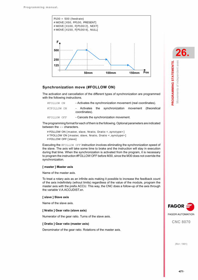
Programming manual.
CNC 8070
PR
OG
RA
MM
ING
ST
AT
EM
EN
TS
.
26.
Mov
emen
ts o
f ind
epen
den
t axe
s
·471·
(REF: 1901)
Synchronization move (#FOLLOW ON)
The activation and cancellation of the different types of synchronization are programmedwith the following instructions.
#FOLLOW ON - Activates the synchronization movement (real coordinates).
#TFOLLOW ON - Activates the synchronization movement (theoreticalcoordinates).
#FOLLOW OFF - Cancels the synchronization movement.
The programming format for each of them is the following. Optional parameters are indicatedbetween the <> characters.
#FOLLOW ON [master, slave, Nratio, Dratio <,synctype>]#TFOLLOW ON [master, slave, Nratio, Dratio <,synctype>]#FOLLOW OFF [slave]
Executing the #FOLLOW OFF instruction involves eliminating the synchronization speed ofthe slave. The axis will take some time to brake and the instruction will stay in executionduring that time. When the synchronization is activated from the program, it is necessaryto program the instruction #FOLLOW OFF before M30, since the M30 does not override thesynchronization.
[ master ] Master axis
Name of the master axis.
To treat a rotary axis as an infinite axis making it possible to increase the feedback countof the axis indefinitely (wihout limits) regardless of the value of the module, program themaster axis with the prefix ACCU. This way, the CNC does a follow-up of the axis throughthe variable V.A.ACCUDIST.xn.
[ slave ] Slave axis
Name of the slave axis.
[ Nratio ] Gear ratio (slave axis)
Numerator of the gear ratio. Turns of the slave axis.
[ Dratio ] Gear ratio (master axis)
Denominator of the gear ratio. Rotations of the master axis.
P100 = 500 (feedrate)#MOVE [X50, FP100, PRESENT]#MOVE [X100, F[P100/2], NEXT]#MOVE [X150, F[P100/4], NULL]
F
Pos
500
250
125
50mm 100mm 150mm
Programming manual.
CNC 8070
26.
PR
OG
RA
MM
ING
ST
AT
EM
EN
TS
.
Mov
emen
ts o
f ind
epen
den
t axe
s
·472·
(REF: 1901)
[ synctype ] Type of synchronization
Optional parameter. Indicator that determines whether it is a velocity or positionsynchronization type.
Programming it is an option. If not programmed, it executes a velocity synchronization.
[ synctype ] Type of synchronism
POS It is a position synchronization.
VEL It is a velocity synchronization.
#FOLLOW ON [X, Y, N1, D1]#FOLLOW ON [A1, U, N2, D1, POS]#FOLLOW OFF [Y]#FOLLOW ON [ACCUX, Y, N1, D1]
Programming manual.
CNC 8070
PR
OG
RA
MM
ING
ST
AT
EM
EN
TS
.
26.
Ele
ctro
nic
cam
s.
·473·
(REF: 1901)
26.16 Electronic cams.
The electronic cam mode may be used to move a slave axis based on a positions-table oron a cam profile. If while executing a cam profile, a second cam profile is executed, thesecond one gets ready and waiting for the current execution to be over. Once the currentcam profile has ended, it starts executing the second cam blending both profiles like whenblending (joining) two positioning blocks. Executing the cam synchronization endinginstruction (#CAM OFF) will end the current cam, but not immediately, it will do so the nexttime it goes through the end of the cam profile.
After executing the synchronization of the cam, no positioning moves of the independent axis(MOVE) are possible. It makes no sense to add another movement to the camsynchronization movement that would brake the synchronization already achieved.
Position - position cam
On this type of cam, it is possible to obtain non-linear electronic synchronization ratiosbetween two axes. Thus, the position of the slave axis is synchronized with the position ofthe master axis using a cam profile.
Position - time cam
On this type of cam, it is possible to obtain other movement profiles different from trapezoidalor S-shaped ones.
Electronic-cam editor.
Before activating an electronic cam, it must have been defined at the cam editor which isaccessed from the machine parameters. This editor offers a friendly assistance to analyzethe behavior of the cam projected through graphically assisted data entry for speed,acceleration and jerk.
It is up to the user to select the parameters and the functions to design an electronic camand must make sure that his design is coherent with the required specifications.
Activating and canceling the file cam from the part-program.
The data of a cam may be defined in a file that may be loaded from the CNC or from thePLC. When executing a cam from a file, the CNC reads its data dynamically and,consequently, the number of points to define the cam is unlimited. After selecting a file cam,it stays available until the cam table of the machine parameters is validated or the CNC isturned off.
To select or cancel a file cam, use the following instructions. The following instructions onlydefines the location of the cam; to activate it, use the instruction #CAM ON.
#CAM SELECT - Select a file cam.
#CAM DESELECT - Cancel the cam of a file.
The programming format for each of them is the following.
#CAM SELECT [cam, file]#CAM DESELECT [cam]
This function has a specific manual. This manual that you are reading now only offers some informationabout this function. Refer to the specific documentation to obtain further information regarding therequirements and operation of the electronic cams.
Parameter. Meaning.
cam Cam number.
path/file Name and path of the file containing the cam data.
#CAM SELECT [6, "C:\USERCAM\cam.txt"](The CNC uses for cam ·6· the data defined in the cam.txt file)
#CAM DESELECT [6](The CNC stops using for cam ·6· the data defined in the cam.txt file)
Programming manual.
CNC 8070
26.
PR
OG
RA
MM
ING
ST
AT
EM
EN
TS
.
Ele
ctro
nic
cam
s.
·474·
(REF: 1901)
Activating and canceling the electronic cam (#CAM).
The activation and cancellation of the electronic cam is programmed with the followinginstructions.
#CAM ON - Activates the cam (real coordinates).
#TCAM ON - Activates the cam (theoretical coordinates).
#CAM OFF - Cancel the electronic cam.
The programming format for each of them is the following. Optional parameters are indicatedbetween the <> characters.
#CAM ON [cam, master/"TIME", slave, master_off, slave_off, range_master, range_slave <,type>]#TCAM ON [cam, master/"TIME", slave, master_off, slave_off, range_master, range_slave <,type>]#CAM OFF [slave]
Executing the #CAM OFF instruction involves eliminating the synchronization of the cam.Once this instruction has been programmed, the cam ends when reaching the end of itsprofile.
[cam] Cam number.
To activate a cam, it must have been previously defined at the cam editor, within the machineparameters.
[master/"TIME"] Master axis.
Name of the master axis, when it is a position cam. When programming the "TIME" commandinstead of an axis name, the cam is interpreted as being a time cam.
In a position cam, treating a rotary axis as an infinite axis making it possible to increase thefeedback count of the axis indefinitely (wihout limits) regardless of the value of the module,program the master axis with the prefix ACCU. This way, the CNC does a follow-up of theaxis through the variable V.A.ACCUDIST.xn.
[slave] Slave axis.
Name of the slave axis.
[master_off] Offset of the master axis or time offset.
In a position cam, this offset sets the position where the cam is activated. The offset issubtracted from the master axis position to calculate the entry position of the cam table.
In a time cam this offset may be used to set a time for the cam trigger.
[slave_off] Offset of the master axis.
The slave_off and range_slave values allow moving the slave axis positions outside therange of values set by the cam function.
[Range_master] Master axis activation scale or range.
The position cam is activated when the master axis is between the positions "master_off"and "master_off + range_master". The cam only regulates the slave axis position within thisrange.
In a time cam, this parameter sets the time range or total duration of the cam.
[Range_slave] Slave axis activation scale or range.
The cam applies it to the slave axis when the slave axis is between "slave_off" and "slave_off+ range_slave".
#CAM ON [1, X, Y, 30, 0, 100, 100]#CAM ON [1, ACCUX, Y, 30, 0, 100, 100]#CAM ON [1, TIME, A2, 0, 0, 6, 3, ONCE]#CAM OFF [Y]
Programming manual.
CNC 8070
PR
OG
RA
MM
ING
ST
AT
EM
EN
TS
.
26.
Ele
ctro
nic
cam
s.
·475·
(REF: 1901)
[type] Cam type.
Depending on the execution mode, the time cams and the position cams may be of twodifferent types; i.e. periodic or non-periodic. This selection is made using the followingcommands:
If the master axis is a rotary module and the cam definition range is that module, the twoexecution modes are equivalent. Either mode maintains synchronization until the #CAM OFFinstruction is executed. When reaching that instruction, the execution of the cam will end thenext time the end of the cam profile is reached.
[type] Meaning.
ONCE Non-periodic cam.This mode maintains the synchronization for the range defined for the master axis. If themaster axis moves backwards or if it is a module, the slave axis will keep on executingthe cam profile until the cancellation is programmed.
CONT Periodic cam.In this mode, when reaching the end of the range of the master axis, it calculates the offsetto execute the cam again shifted in the amount of that range. In other words, identicalcams are executed along the path of the master axis.
Programming manual.
CNC 8070
26.
PR
OG
RA
MM
ING
ST
AT
EM
EN
TS
.
On
line
mod
ifica
tion
of th
e m
ach
ine
con
figur
atio
n in
HD
gra
phi
cs (x
cafil
es).
·476·
(REF: 1901)
26.17 On line modification of the machine configuration in HD graphics(xca files).
The CNC offers several xca files, one per model, containing the definition and configurationof the machine for HD graphics. On power-up, the CNC assumes the last file used. Thesefiles cover most configurations; therefore, new xca will have to be generated when themachine has some special requirement that affects graphics.
If the physical configuration of the machine changes during execution (for example, spindlechange with different number of axes), the corresponding xca file must be loaded so thegraphics show the changes. The xca files may be loaded either from the softkey menu orfrom the program using the instruction #DEFGRAPH.
When changing the machine configuration, the CNC saves the part displayed on the screenautomatically as LastPiece.stl into the folder ../Users/Grafdata, and it recovers it after thenew configuration.
Programming.
This instruction must be programmed alone in the block. When programming this instruction,the name of the file must be defined and, optionally, its location.
Programming format.
The programming format is the following; the list of arguments appears between curlybrackets and the optional ones between angle brackets.
#DEFGRAPH ["<{path\}>{file.xca}"]
Path definition.
Defining the path is optional. If defined, the CNC only looks for the file in that folder; if notdefined, the CNC looks for the file in the default folder ..\MTB\Grafdata. If the file is missing,the CNC issues the relevant error message.
Remarks
The machine configuration files supplied by Fagor consist of a single file, the xca. When anOEM creates his own configuration files, for each xca file, he must create a ".def" file withthe same name that completes the configuration of the axes involved in the kinematics. Bothfiles must be copied when saving the configuration file in another folder.
{path\} Optional. File location.
{file.xca} Name of the file.
#DEFGRAPH ["Machine.xca"]#DEFGRAPH ["c:\FagorCnc\MTB\Grafdata\Machine.xca"]
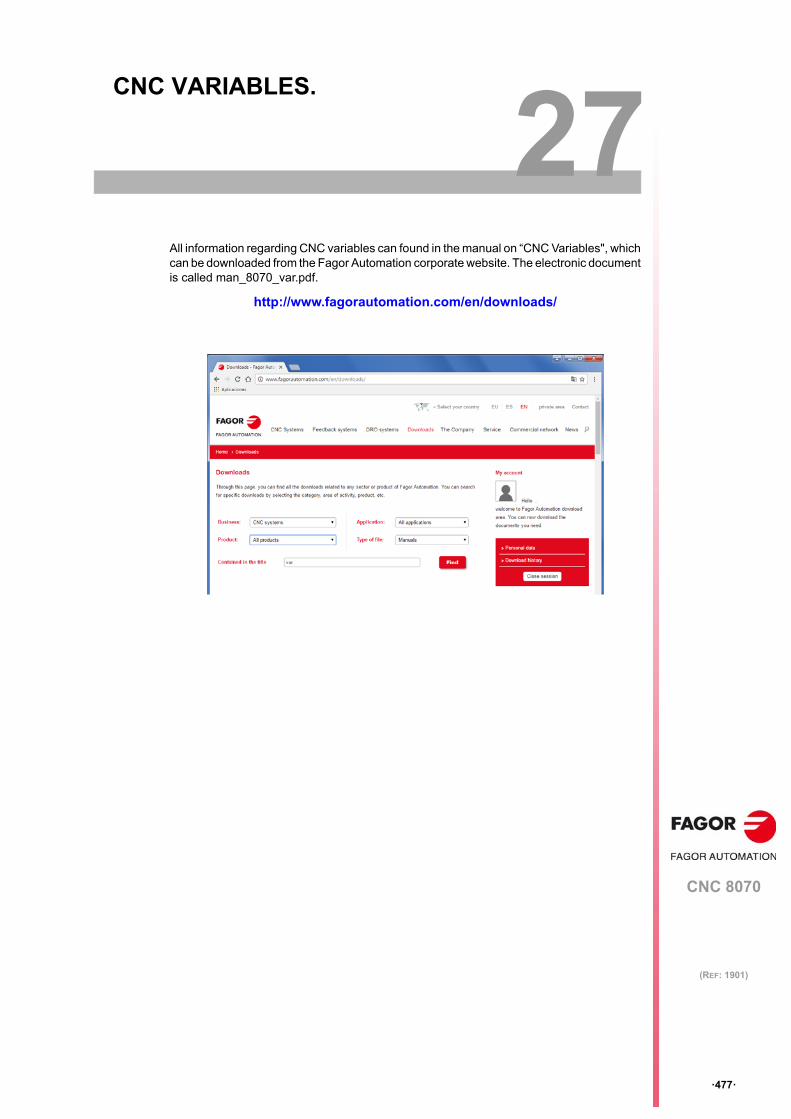
CNC 8070
27
·477·
(REF: 1901)
27.CNC VARIABLES.
All information regarding CNC variables can found in the manual on “CNC Variables", whichcan be downloaded from the Fagor Automation corporate website. The electronic documentis called man_8070_var.pdf.
http://www.fagorautomation.com/en/downloads/
Programming manual.
CNC 8070
27.
CN
C V
AR
IAB
LE
S.
·478·
(REF: 1901)

Programming manual.
CNC 8070
·479·
User notes:
(REF: 1901)
Programming manual.
CNC 8070
·480·
User notes:
(REF: 1901)
Programming manual.
CNC 8070
·481·
User notes:
(REF: 1901)

Fagor Automation S. Coop.Bº San Andrés, 19 - Apdo. 144E-20500 Arrasate-Mondragón, SpainTel: +34 943 719 200
+34 943 039 800Fax: +34 943 791 712E-mail: [email protected]