Embed Size (px)
Citation preview
CNC-Calc Mill Tutorial ~ 1 ~
CNC-Calc Tutorial
2D Construction of a Part for Milling & Creating Toolpaths
CNC-Calc Mill Tutorial ~ 2 ~
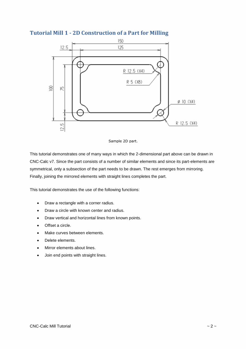
Tutorial Mill 1 - 2D Construction of a Part for Milling
Sample 2D part.
This tutorial demonstrates one of many ways in which the 2-dimensional part above can be drawn in
CNC-Calc v7. Since the part consists of a number of similar elements and since its part-elements are
symmetrical, only a subsection of the part needs to be drawn. The rest emerges from mirroring.
Finally, joining the mirrored elements with straight lines completes the part.
This tutorial demonstrates the use of the following functions:
Draw a rectangle with a corner radius.
Draw a circle with known center and radius.
Draw vertical and horizontal lines from known points.
Offset a circle.
Make curves between elements.
Delete elements.
Mirror elements about lines.
Join end points with straight lines.
CNC-Calc Mill Tutorial ~ 3 ~
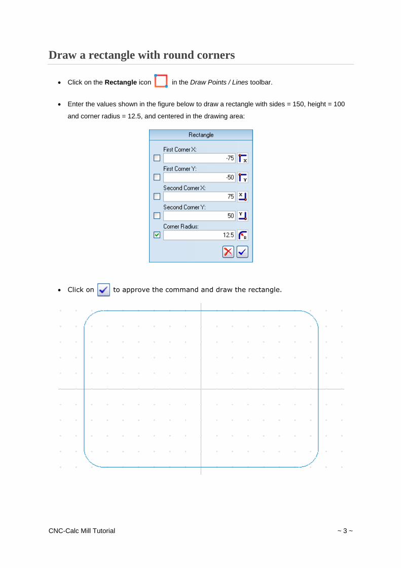
Draw a rectangle with round corners
Click on the Rectangle icon in the Draw Points / Lines toolbar.
Enter the values shown in the figure below to draw a rectangle with sides = 150, height = 100
and corner radius = 12.5, and centered in the drawing area:
Click on to approve the command and draw the rectangle.
CNC-Calc Mill Tutorial ~ 4 ~
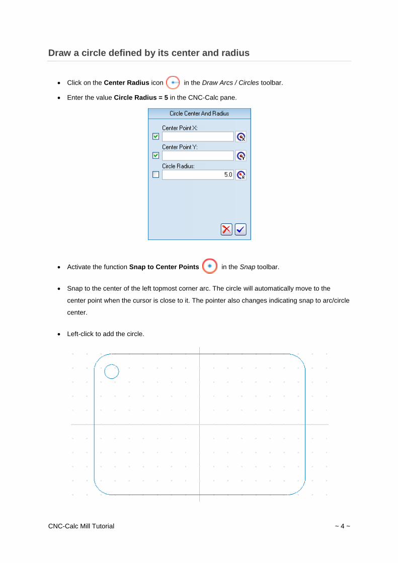
Draw a circle defined by its center and radius
Click on the Center Radius icon in the Draw Arcs / Circles toolbar.
Enter the value Circle Radius = 5 in the CNC-Calc pane.
Activate the function Snap to Center Points in the Snap toolbar.
Snap to the center of the left topmost corner arc. The circle will automatically move to the
center point when the cursor is close to it. The pointer also changes indicating snap to arc/circle
center.
Left-click to add the circle.
CNC-Calc Mill Tutorial ~ 5 ~
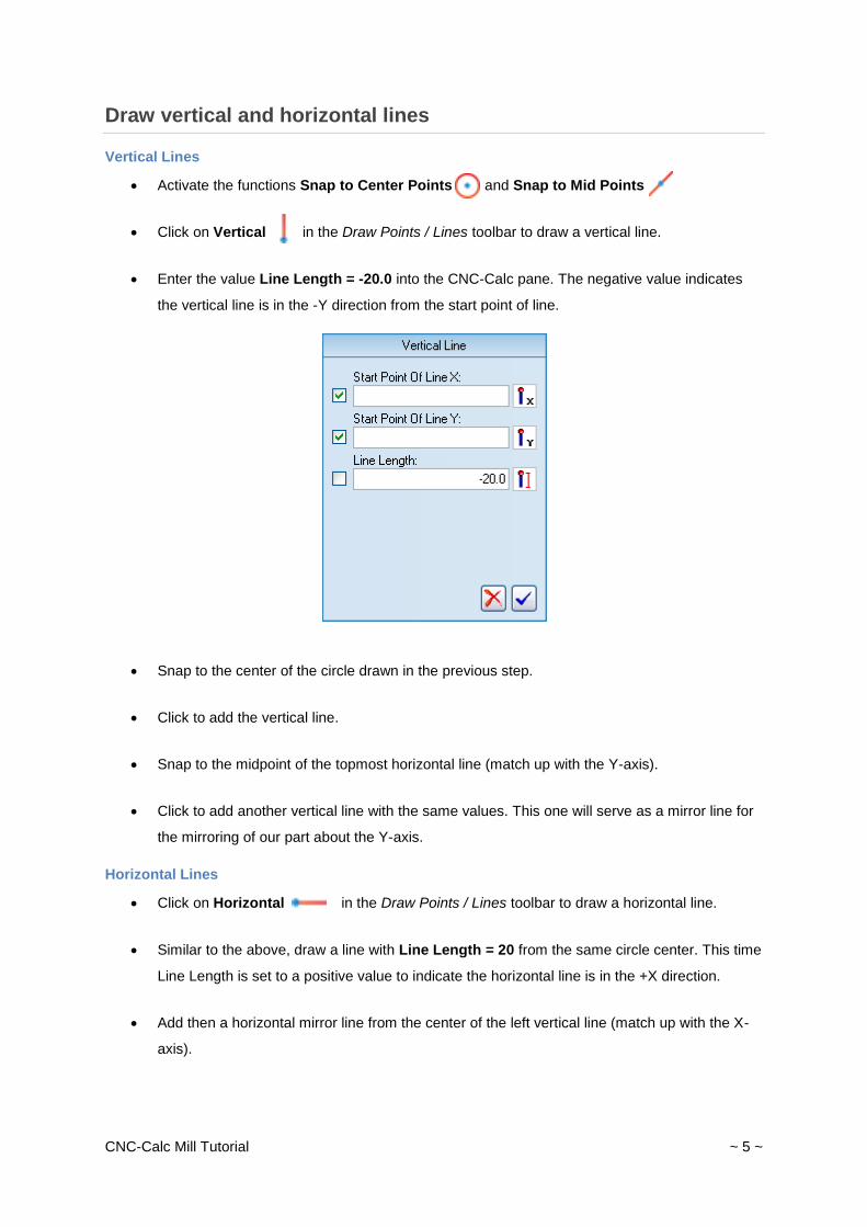
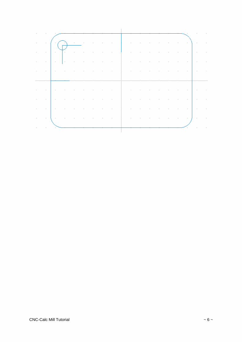
Draw vertical and horizontal lines
Vertical Lines
Activate the functions Snap to Center Points and Snap to Mid Points .
Click on Vertical in the Draw Points / Lines toolbar to draw a vertical line.
Enter the value Line Length = -20.0 into the CNC-Calc pane. The negative value indicates
the vertical line is in the -Y direction from the start point of line.
Snap to the center of the circle drawn in the previous step.
Click to add the vertical line.
Snap to the midpoint of the topmost horizontal line (match up with the Y-axis).
Click to add another vertical line with the same values. This one will serve as a mirror line for
the mirroring of our part about the Y-axis.
Horizontal Lines
Click on Horizontal in the Draw Points / Lines toolbar to draw a horizontal line.
Similar to the above, draw a line with Line Length = 20 from the same circle center. This time
Line Length is set to a positive value to indicate the horizontal line is in the +X direction.
Add then a horizontal mirror line from the center of the left vertical line (match up with the X-
axis).
CNC-Calc Mill Tutorial ~ 6 ~
CNC-Calc Mill Tutorial ~ 7 ~
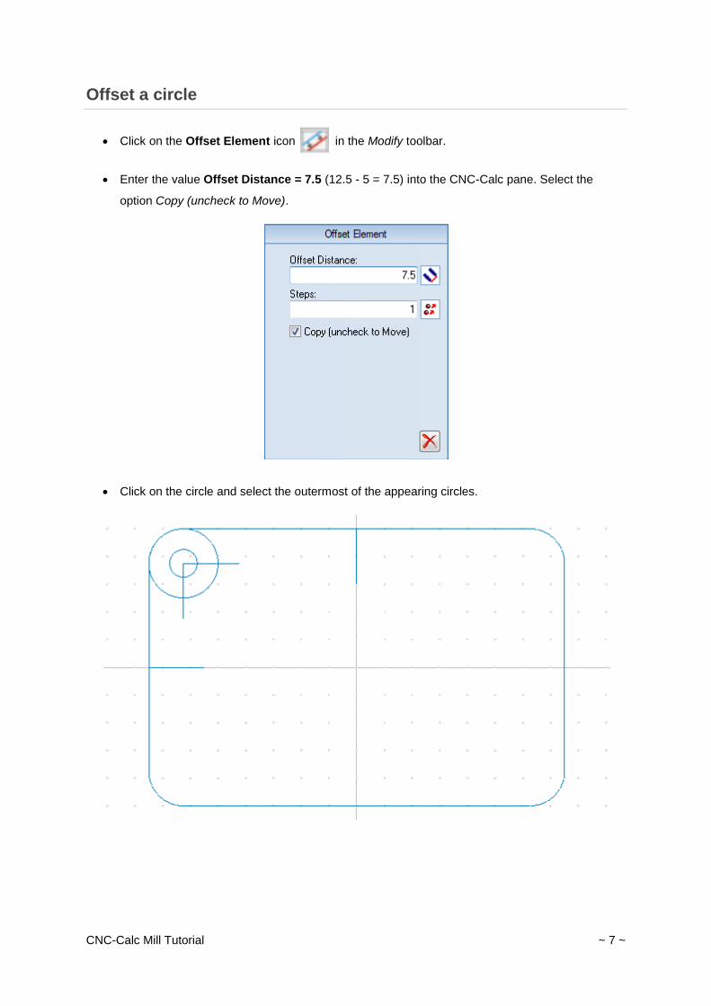
Offset a circle
Click on the Offset Element icon in the Modify toolbar.
Enter the value Offset Distance = 7.5 (12.5 - 5 = 7.5) into the CNC-Calc pane. Select the
option Copy (uncheck to Move).
Click on the circle and select the outermost of the appearing circles.
CNC-Calc Mill Tutorial ~ 8 ~
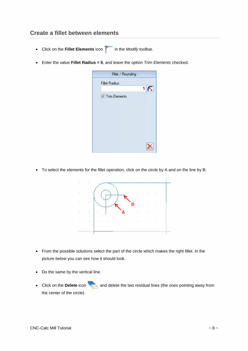
Create a fillet between elements
Click on the Fillet Elements icon in the Modify toolbar.
Enter the value Fillet Radius = 5, and leave the option Trim Elements checked.
To select the elements for the fillet operation, click on the circle by A and on the line by B.
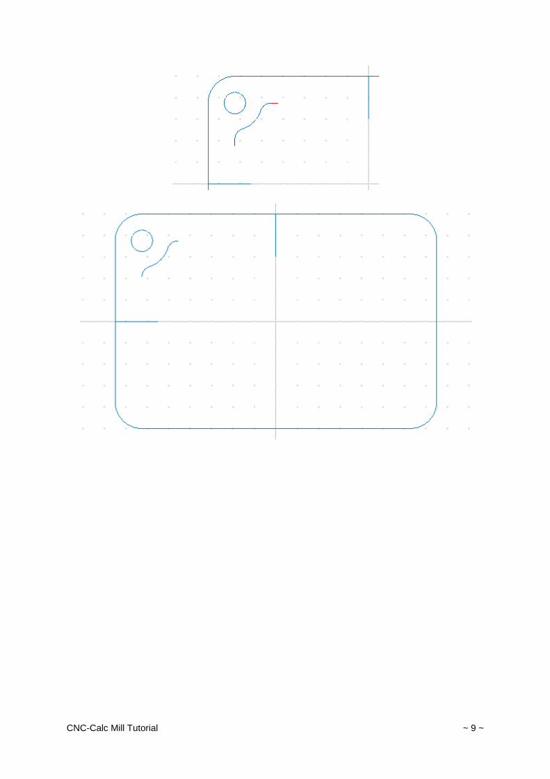
From the possible solutions select the part of the circle which makes the right fillet. In the
picture below you can see how it should look.
Do the same by the vertical line.
Click on the Delete icon and delete the two residual lines (the ones pointing away from
the center of the circle).
CNC-Calc Mill Tutorial ~ 9 ~
CNC-Calc Mill Tutorial ~ 10 ~
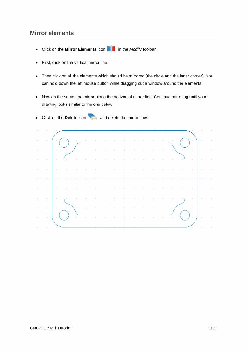
Mirror elements
Click on the Mirror Elements icon in the Modify toolbar.
First, click on the vertical mirror line.
Then click on all the elements which should be mirrored (the circle and the inner corner). You
can hold down the left mouse button while dragging out a window around the elements.
Now do the same and mirror along the horizontal mirror line. Continue mirroring until your
drawing looks similar to the one below.
Click on the Delete icon and delete the mirror lines.
CNC-Calc Mill Tutorial ~ 11 ~
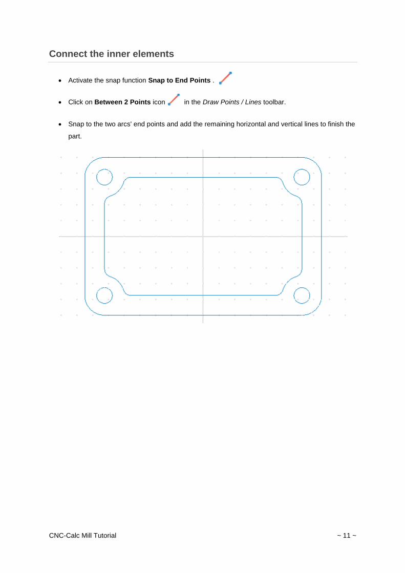
Connect the inner elements
Activate the snap function Snap to End Points .
Click on Between 2 Points icon in the Draw Points / Lines toolbar.
Snap to the two arcs' end points and add the remaining horizontal and vertical lines to finish the
part.
CNC-Calc Mill Tutorial ~ 12 ~
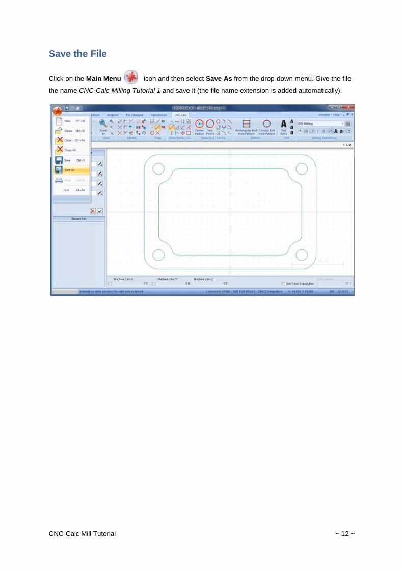
Save the File
Click on the Main Menu icon and then select Save As from the drop-down menu. Give the file
the name CNC-Calc Milling Tutorial 1 and save it (the file name extension is added automatically).
CNC-Calc Mill Tutorial ~ 13 ~
Machining the Part
With CNC-Calc v7 it is possible to create toolpaths directly from the program's geometrical drawings.
Thereby, calculations become more secure and programming becomes much faster compared to
doing it manually. At the same time you get a big advantage since it is possible to move, copy, rotate,
scale, and mirror elements with the result of instant NC-code generation. There are several machine
types in CNC-Calc, but the most commonly used are ISO G-code programming and Heidenhain plain
text.
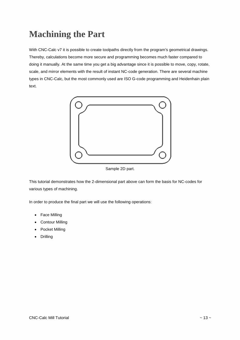
Sample 2D part.
This tutorial demonstrates how the 2-dimensional part above can form the basis for NC-codes for
various types of machining.
In order to produce the final part we will use the following operations:
Face Milling
Contour Milling
Pocket Milling
Drilling
CNC-Calc Mill Tutorial ~ 14 ~
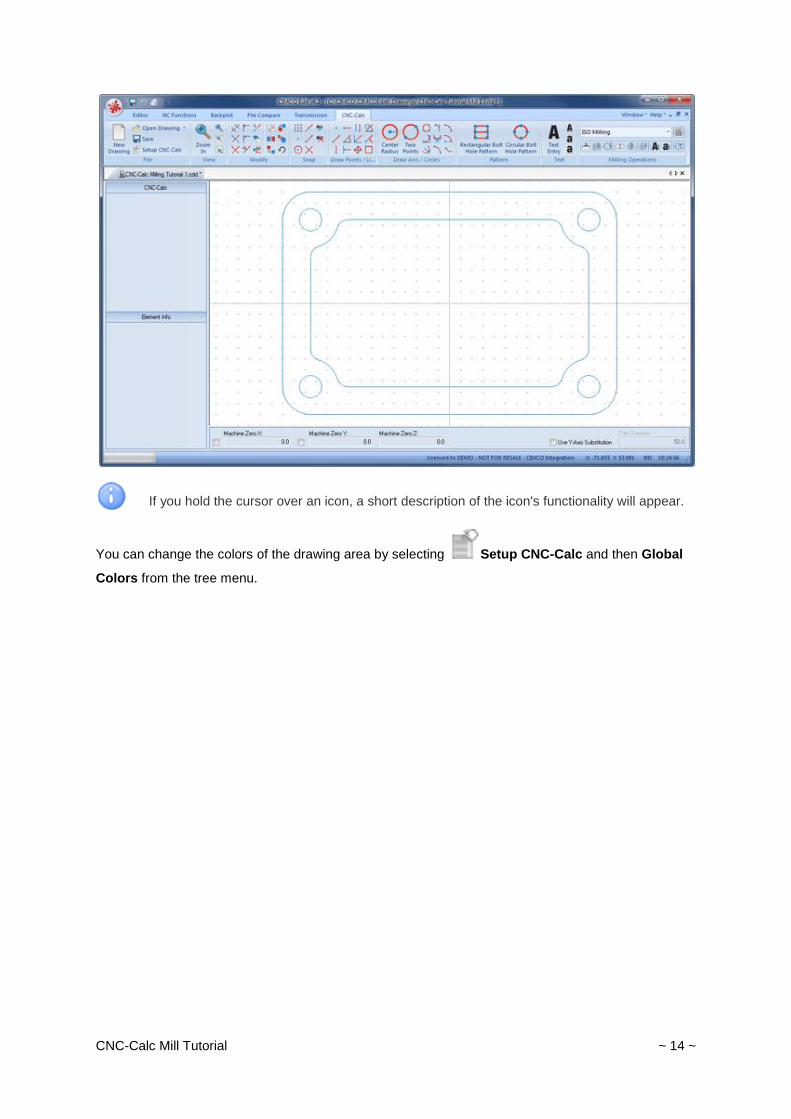
If you hold the cursor over an icon, a short description of the icon's functionality will appear.
You can change the colors of the drawing area by selecting Setup CNC-Calc and then Global
Colors from the tree menu.
CNC-Calc Mill Tutorial ~ 15 ~
Face Milling
CNC-Calc v7 can generate CNC toolpaths for face milling, with or without finishing passes and using
different cutting strategies.
Creation of Facing Toolpaths
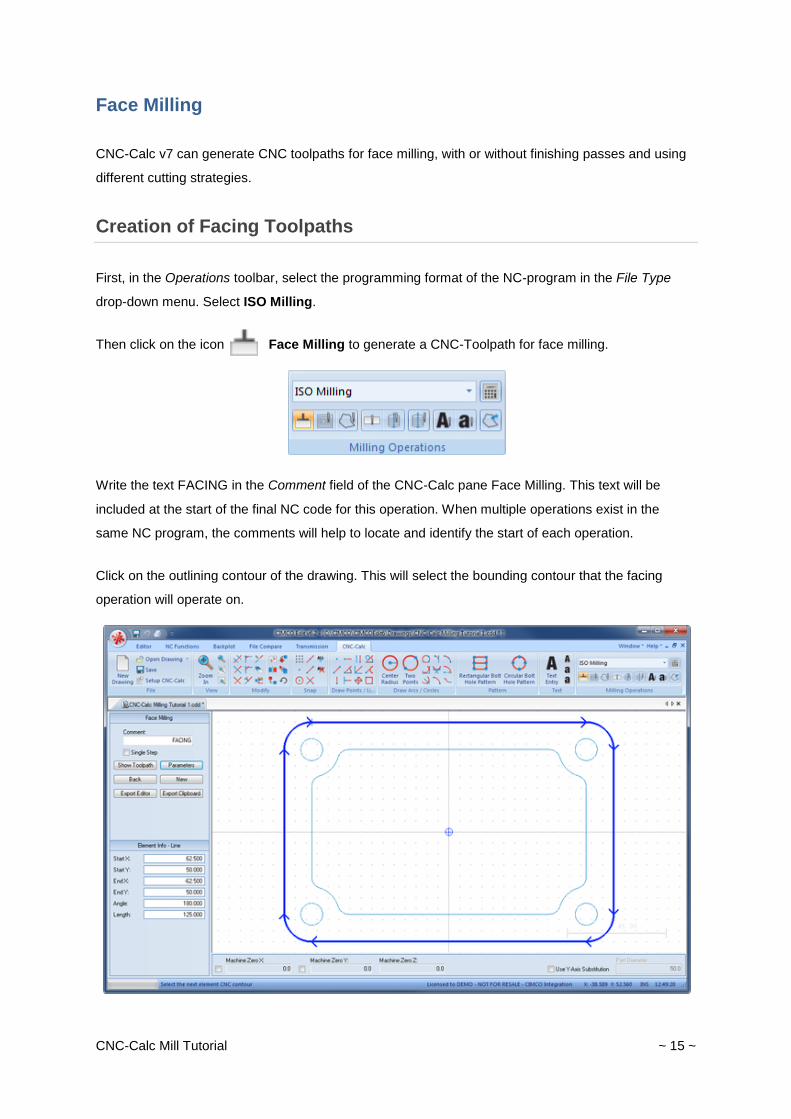
First, in the Operations toolbar, select the programming format of the NC-program in the File Type
drop-down menu. Select ISO Milling.
Then click on the icon Face Milling to generate a CNC-Toolpath for face milling.
Write the text FACING in the Comment field of the CNC-Calc pane Face Milling. This text will be
included at the start of the final NC code for this operation. When multiple operations exist in the
same NC program, the comments will help to locate and identify the start of each operation.
Click on the outlining contour of the drawing. This will select the bounding contour that the facing
operation will operate on.
CNC-Calc Mill Tutorial ~ 16 ~
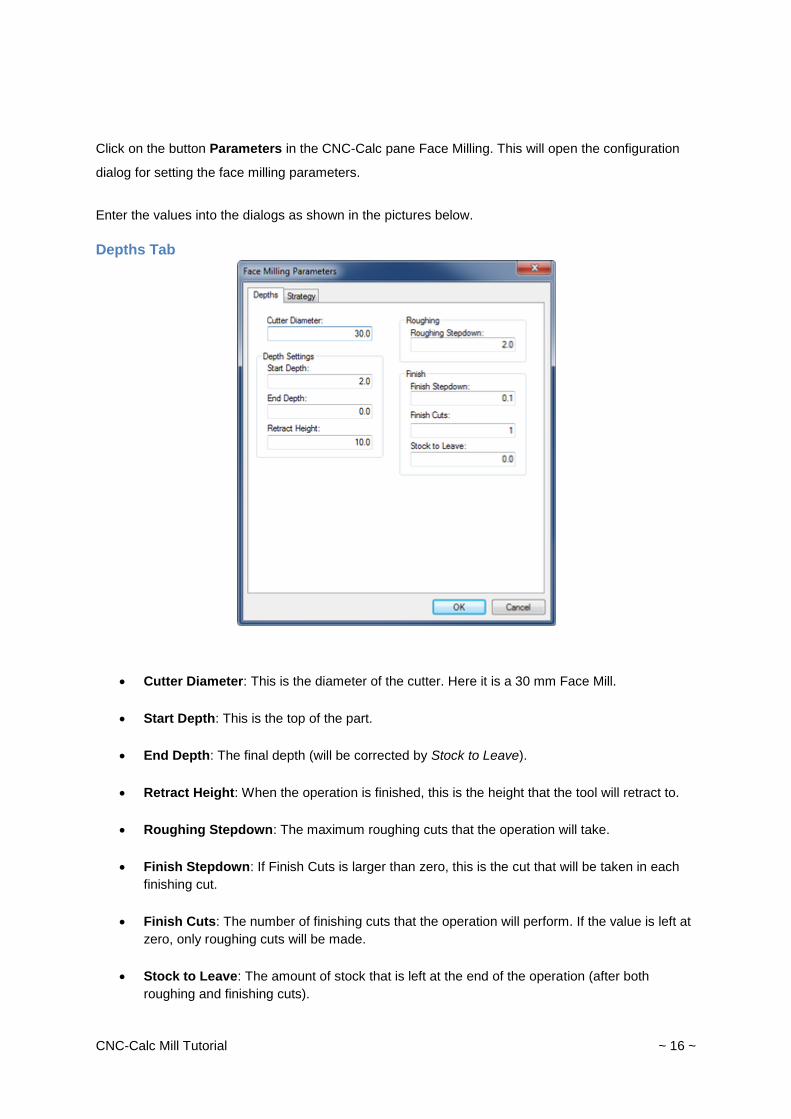
Click on the button Parameters in the CNC-Calc pane Face Milling. This will open the configuration
dialog for setting the face milling parameters.
Enter the values into the dialogs as shown in the pictures below.
Depths Tab
Cutter Diameter: This is the diameter of the cutter. Here it is a 30 mm Face Mill.
Start Depth: This is the top of the part.
End Depth: The final depth (will be corrected by Stock to Leave).
Retract Height: When the operation is finished, this is the height that the tool will retract to.
Roughing Stepdown: The maximum roughing cuts that the operation will take.
Finish Stepdown: If Finish Cuts is larger than zero, this is the cut that will be taken in each
finishing cut.
Finish Cuts: The number of finishing cuts that the operation will perform. If the value is left at
zero, only roughing cuts will be made.
Stock to Leave: The amount of stock that is left at the end of the operation (after both
roughing and finishing cuts).
CNC-Calc Mill Tutorial ~ 17 ~
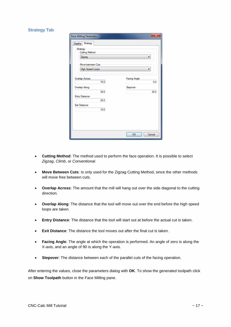
Strategy Tab
Cutting Method: The method used to perform the face operation. It is possible to select
Zigzag, Climb, or Conventional.
Move Between Cuts: Is only used for the Zigzag Cutting Method, since the other methods
will move free between cuts.
Overlap Across: The amount that the mill will hang out over the side diagonal to the cutting
direction.
Overlap Along: The distance that the tool will move out over the end before the high speed
loops are taken.
Entry Distance: The distance that the tool will start out at before the actual cut is taken.
Exit Distance: The distance the tool moves out after the final cut is taken.
Facing Angle: The angle at which the operation is performed. An angle of zero is along the
X-axis, and an angle of 90 is along the Y-axis.
Stepover: The distance between each of the parallel cuts of the facing operation.
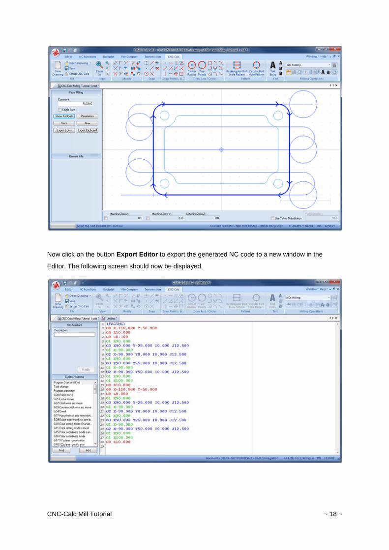
After entering the values, close the parameters dialog with OK. To show the generated toolpath click
on Show Toolpath button in the Face Milling pane.
CNC-Calc Mill Tutorial ~ 18 ~
Now click on the button Export Editor to export the generated NC code to a new window in the
Editor. The following screen should now be displayed.
CNC-Calc Mill Tutorial ~ 19 ~
Inserting a Tool with Feed and Speed Calculator
The Feed and Speed calculator built into CNC-Calc is used to insert feed and speed data into the NC
program. All the data used in the calculations can normally be found in the reference material
supplied by the manufacturer.
In the facing example, we use a face mill that we give the following characteristics: diameter is 30
mm, it has 5 flutes, a cutting feed of 0.08 mm per tooth, and a cutting speed of 190 mm/min.
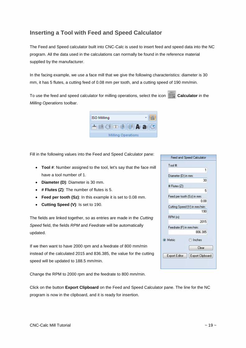
To use the feed and speed calculator for milling operations, select the icon Calculator in the
Milling Operations toolbar.
Fill in the following values into the Feed and Speed Calculator pane:
Tool #: Number assigned to the tool, let's say that the face mill
have a tool number of 1.
Diameter (D): Diameter is 30 mm.
# Flutes (Z): The number of flutes is 5.
Feed per tooth (Sz): In this example it is set to 0.08 mm.
Cutting Speed (V): Is set to 190.
The fields are linked together, so as entries are made in the Cutting
Speed field, the fields RPM and Feedrate will be automatically
updated.
If we then want to have 2000 rpm and a feedrate of 800 mm/min
instead of the calculated 2015 and 836.385, the value for the cutting
speed will be updated to 188.5 mm/min.
Change the RPM to 2000 rpm and the feedrate to 800 mm/min.
Click on the button Export Clipboard on the Feed and Speed Calculator pane. The line for the NC
program is now in the clipboard, and it is ready for insertion.
CNC-Calc Mill Tutorial ~ 20 ~
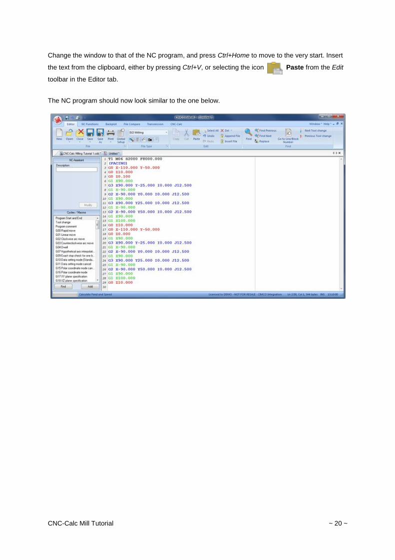
Change the window to that of the NC program, and press Ctrl+Home to move to the very start. Insert
the text from the clipboard, either by pressing Ctrl+V, or selecting the icon Paste from the Edit
toolbar in the Editor tab.
The NC program should now look similar to the one below.
CNC-Calc Mill Tutorial ~ 21 ~
Contour Milling
CNC-Calc v7 can generate contour milling toolpaths - with or without radius compensation.
Creation of Contour Toolpaths
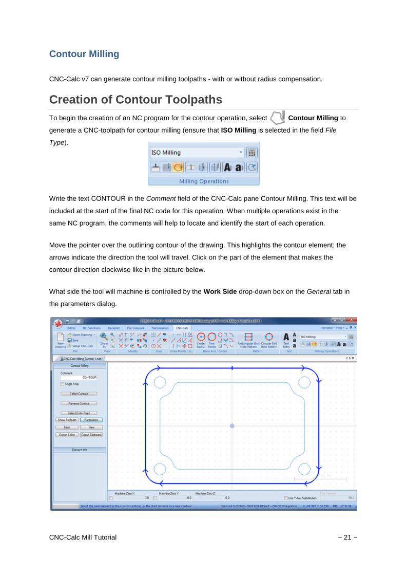
To begin the creation of an NC program for the contour operation, select Contour Milling to
generate a CNC-toolpath for contour milling (ensure that ISO Milling is selected in the field File
Type).
Write the text CONTOUR in the Comment field of the CNC-Calc pane Contour Milling. This text will be
included at the start of the final NC code for this operation. When multiple operations exist in the
same NC program, the comments will help to locate and identify the start of each operation.
Move the pointer over the outlining contour of the drawing. This highlights the contour element; the
arrows indicate the direction the tool will travel. Click on the part of the element that makes the
contour direction clockwise like in the picture below.
What side the tool will machine is controlled by the Work Side drop-down box on the General tab in
the parameters dialog.
CNC-Calc Mill Tutorial ~ 22 ~
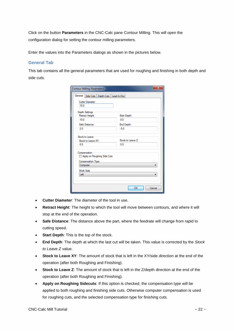
Click on the button Parameters in the CNC-Calc pane Contour Milling. This will open the
configuration dialog for setting the contour milling parameters.
Enter the values into the Parameters dialogs as shown in the pictures below.
General Tab
This tab contains all the general parameters that are used for roughing and finishing in both depth and
side cuts.
Cutter Diameter: The diameter of the tool in use.
Retract Height: The height to which the tool will move between contours, and where it will
stop at the end of the operation.
Safe Distance: The distance above the part, where the feedrate will change from rapid to
cutting speed.
Start Depth: This is the top of the stock.
End Depth: The depth at which the last cut will be taken. This value is corrected by the Stock
to Leave Z value.
Stock to Leave XY: The amount of stock that is left in the XY/side direction at the end of the
operation (after both Roughing and Finishing).
Stock to Leave Z: The amount of stock that is left in the Z/depth direction at the end of the
operation (after both Roughing and Finishing).
Apply on Roughing Sidecuts: If this option is checked, the compensation type will be
applied to both roughing and finishing side cuts. Otherwise computer compensation is used
for roughing cuts, and the selected compensation type for finishing cuts.
CNC-Calc Mill Tutorial ~ 23 ~
Compensation Type: This is the compensation type used for the operation.
Work Side: This field determines on which side of the contour the tool will pass. Together
with the selected direction of the contour it determines if the milling type will be climb or
conventional.
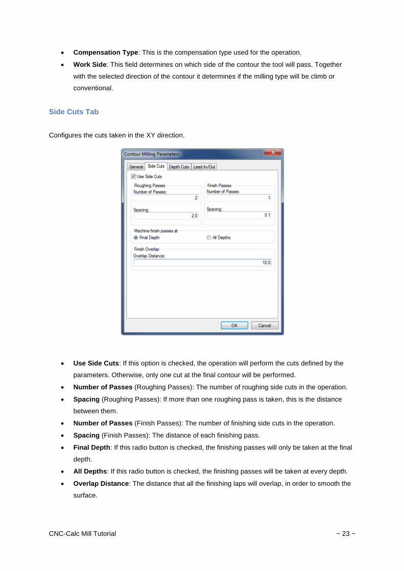
Side Cuts Tab
Configures the cuts taken in the XY direction.
Use Side Cuts: If this option is checked, the operation will perform the cuts defined by the
parameters. Otherwise, only one cut at the final contour will be performed.
Number of Passes (Roughing Passes): The number of roughing side cuts in the operation.
Spacing (Roughing Passes): If more than one roughing pass is taken, this is the distance
between them.
Number of Passes (Finish Passes): The number of finishing side cuts in the operation.
Spacing (Finish Passes): The distance of each finishing pass.
Final Depth: If this radio button is checked, the finishing passes will only be taken at the final
depth.
All Depths: If this radio button is checked, the finishing passes will be taken at every depth.
Overlap Distance: The distance that all the finishing laps will overlap, in order to smooth the
surface.
CNC-Calc Mill Tutorial ~ 24 ~
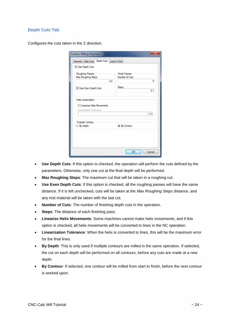
Depth Cuts Tab
Configures the cuts taken in the Z direction.
Use Depth Cuts: If this option is checked, the operation will perform the cuts defined by the
parameters. Otherwise, only one cut at the final depth will be performed.
Max Roughing Steps: The maximum cut that will be taken in a roughing cut.
Use Even Depth Cuts: If this option is checked, all the roughing passes will have the same
distance. If it is left unchecked, cuts will be taken at the Max Roughing Steps distance, and
any rest material will be taken with the last cut.
Number of Cuts: The number of finishing depth cuts in the operation.
Steps: The distance of each finishing pass.
Linearize Helix Movements: Some machines cannot make helix movements, and if this
option is checked, all helix movements will be converted to lines in the NC operation.
Linearization Tolerance: When the helix is converted to lines, this will be the maximum error
for the final lines.
By Depth: This is only used if multiple contours are milled in the same operation. If selected,
the cut on each depth will be performed on all contours, before any cuts are made at a new
depth.
By Contour: If selected, one contour will be milled from start to finish, before the next contour
is worked upon.
CNC-Calc Mill Tutorial ~ 25 ~
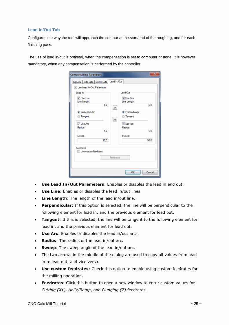
Lead In/Out Tab
Configures the way the tool will approach the contour at the start/end of the roughing, and for each
finishing pass.
The use of lead in/out is optional, when the compensation is set to computer or none. It is however
mandatory, when any compensation is performed by the controller.
Use Lead In/Out Parameters: Enables or disables the lead in and out.
Use Line: Enables or disables the lead in/out lines.
Line Length: The length of the lead in/out line.
Perpendicular: If this option is selected, the line will be perpendicular to the
following element for lead in, and the previous element for lead out.
Tangent: If this is selected, the line will be tangent to the following element for
lead in, and the previous element for lead out.
Use Arc: Enables or disables the lead in/out arcs.
Radius: The radius of the lead in/out arc.
Sweep: The sweep angle of the lead in/out arc.
The two arrows in the middle of the dialog are used to copy all values from lead
in to lead out, and vice versa.
Use custom feedrates: Check this option to enable using custom feedrates for
the milling operation.
Feedrates: Click this button to open a new window to enter custom values for
Cutting (XY), Helix/Ramp, and Plunging (Z) feedrates.
CNC-Calc Mill Tutorial ~ 26 ~
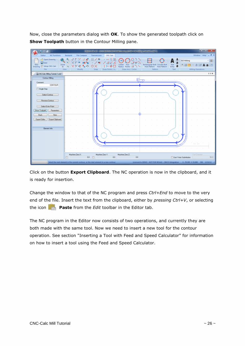
Now, close the parameters dialog with OK. To show the generated toolpath click on
Show Toolpath button in the Contour Milling pane.
Click on the button Export Clipboard. The NC operation is now in the clipboard, and it
is ready for insertion.
Change the window to that of the NC program and press Ctrl+End to move to the very
end of the file. Insert the text from the clipboard, either by pressing Ctrl+V, or selecting
the icon Paste from the Edit toolbar in the Editor tab.
The NC program in the Editor now consists of two operations, and currently they are
both made with the same tool. Now we need to insert a new tool for the contour
operation. See section "Inserting a Tool with Feed and Speed Calculator" for information
on how to insert a tool using the Feed and Speed Calculator.
CNC-Calc Mill Tutorial ~ 27 ~
Pocket Milling
CNC-Calc v7 can generate pocket milling toolpaths.
Creation of Pocket Toolpaths
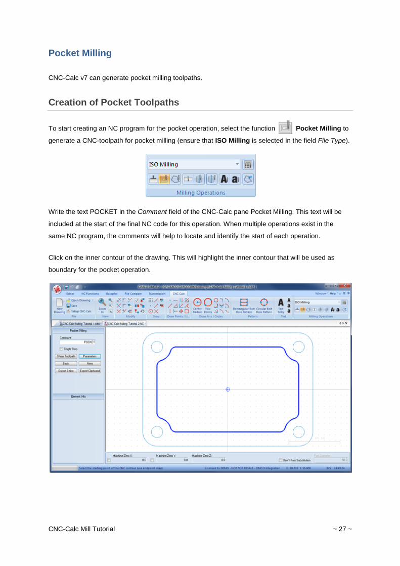
To start creating an NC program for the pocket operation, select the function Pocket Milling to
generate a CNC-toolpath for pocket milling (ensure that ISO Milling is selected in the field File Type).
Write the text POCKET in the Comment field of the CNC-Calc pane Pocket Milling. This text will be
included at the start of the final NC code for this operation. When multiple operations exist in the
same NC program, the comments will help to locate and identify the start of each operation.
Click on the inner contour of the drawing. This will highlight the inner contour that will be used as
boundary for the pocket operation.
CNC-Calc Mill Tutorial ~ 28 ~
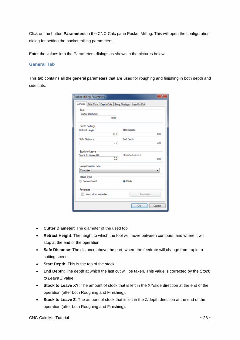
Click on the button Parameters in the CNC-Calc pane Pocket Milling. This will open the configuration
dialog for setting the pocket milling parameters.
Enter the values into the Parameters dialogs as shown in the pictures below.
General Tab
This tab contains all the general parameters that are used for roughing and finishing in both depth and
side cuts.
Cutter Diameter: The diameter of the used tool.
Retract Height: The height to which the tool will move between contours, and where it will
stop at the end of the operation.
Safe Distance: The distance above the part, where the feedrate will change from rapid to
cutting speed.
Start Depth: This is the top of the stock.
End Depth: The depth at which the last cut will be taken. This value is corrected by the Stock
to Leave Z value.
Stock to Leave XY: The amount of stock that is left in the XY/side direction at the end of the
operation (after both Roughing and Finishing).
Stock to Leave Z: The amount of stock that is left in the Z/depth direction at the end of the
operation (after both Roughing and Finishing).
CNC-Calc Mill Tutorial ~ 29 ~
Compensation Type: This is the compensation type used for the operation.
Conventional: When checked, the operation will be generated using conventional milling.
Climb: When checked, the operation will be generated using climb milling.
Use custom feedrates: Check this option to enable using custom feedrates for the milling
operation.
Feedrates: Click this button to open a new window to enter custom values for Cutting (XY),
Helix/Ramp, and Plunging (Z) feedrates.
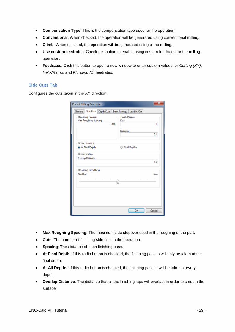
Side Cuts Tab
Configures the cuts taken in the XY direction.
Max Roughing Spacing: The maximum side stepover used in the roughing of the part.
Cuts: The number of finishing side cuts in the operation.
Spacing: The distance of each finishing pass.
At Final Depth: If this radio button is checked, the finishing passes will only be taken at the
final depth.
At All Depths: If this radio button is checked, the finishing passes will be taken at every
depth.
Overlap Distance: The distance that all the finishing laps will overlap, in order to smooth the
surface.
CNC-Calc Mill Tutorial ~ 30 ~
Roughing Smoothing: This slider controls the amount of smoothing used. The higher the
value (rightmost), the smoother the resulting toolpath will be.
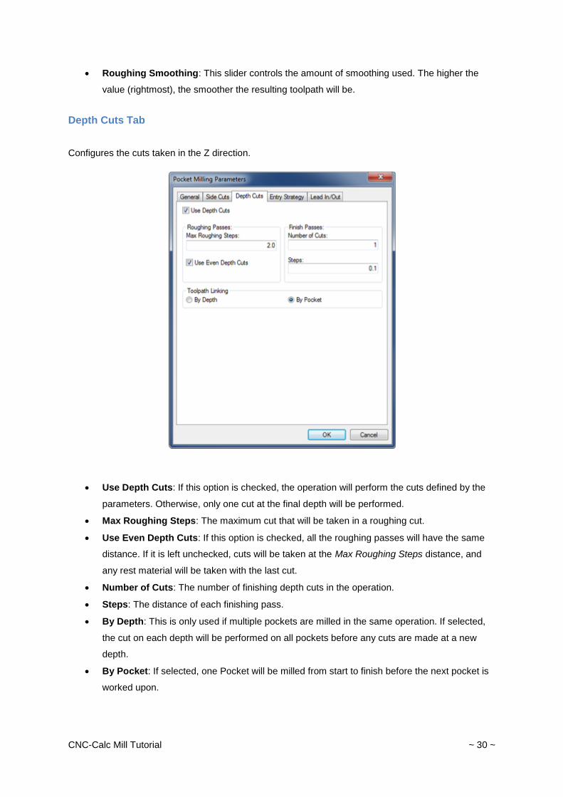
Depth Cuts Tab
Configures the cuts taken in the Z direction.
Use Depth Cuts: If this option is checked, the operation will perform the cuts defined by the
parameters. Otherwise, only one cut at the final depth will be performed.
Max Roughing Steps: The maximum cut that will be taken in a roughing cut.
Use Even Depth Cuts: If this option is checked, all the roughing passes will have the same
distance. If it is left unchecked, cuts will be taken at the Max Roughing Steps distance, and
any rest material will be taken with the last cut.
Number of Cuts: The number of finishing depth cuts in the operation.
Steps: The distance of each finishing pass.
By Depth: This is only used if multiple pockets are milled in the same operation. If selected,
the cut on each depth will be performed on all pockets before any cuts are made at a new
depth.
By Pocket: If selected, one Pocket will be milled from start to finish before the next pocket is
worked upon.
CNC-Calc Mill Tutorial ~ 31 ~
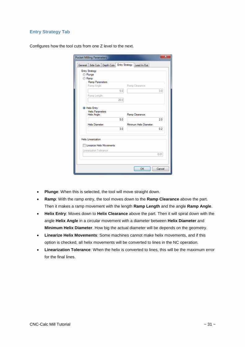
Entry Strategy Tab
Configures how the tool cuts from one Z level to the next.
Plunge: When this is selected, the tool will move straight down.
Ramp: With the ramp entry, the tool moves down to the Ramp Clearance above the part.
Then it makes a ramp movement with the length Ramp Length and the angle Ramp Angle.
Helix Entry: Moves down to Helix Clearance above the part. Then it will spiral down with the
angle Helix Angle in a circular movement with a diameter between Helix Diameter and
Minimum Helix Diameter. How big the actual diameter will be depends on the geometry.
Linearize Helix Movements: Some machines cannot make helix movements, and if this
option is checked, all helix movements will be converted to lines in the NC operation.
Linearization Tolerance: When the helix is converted to lines, this will be the maximum error
for the final lines.
CNC-Calc Mill Tutorial ~ 32 ~
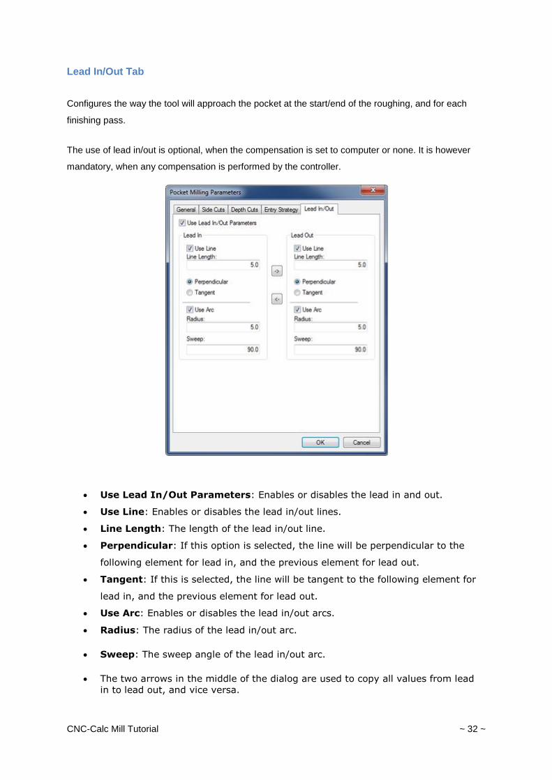
Lead In/Out Tab
Configures the way the tool will approach the pocket at the start/end of the roughing, and for each
finishing pass.
The use of lead in/out is optional, when the compensation is set to computer or none. It is however
mandatory, when any compensation is performed by the controller.
Use Lead In/Out Parameters: Enables or disables the lead in and out.
Use Line: Enables or disables the lead in/out lines.
Line Length: The length of the lead in/out line.
Perpendicular: If this option is selected, the line will be perpendicular to the
following element for lead in, and the previous element for lead out.
Tangent: If this is selected, the line will be tangent to the following element for
lead in, and the previous element for lead out.
Use Arc: Enables or disables the lead in/out arcs.
Radius: The radius of the lead in/out arc.
Sweep: The sweep angle of the lead in/out arc.
The two arrows in the middle of the dialog are used to copy all values from lead
in to lead out, and vice versa.
CNC-Calc Mill Tutorial ~ 33 ~
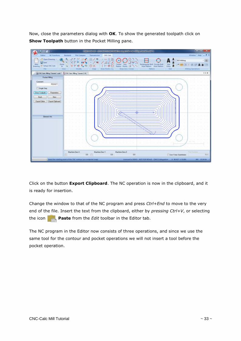
Now, close the parameters dialog with OK. To show the generated toolpath click on
Show Toolpath button in the Pocket Milling pane.
Click on the button Export Clipboard. The NC operation is now in the clipboard, and it
is ready for insertion.
Change the window to that of the NC program and press Ctrl+End to move to the very
end of the file. Insert the text from the clipboard, either by pressing Ctrl+V, or selecting
the icon Paste from the Edit toolbar in the Editor tab.
The NC program in the Editor now consists of three operations, and since we use the
same tool for the contour and pocket operations we will not insert a tool before the
pocket operation.
CNC-Calc Mill Tutorial ~ 34 ~
Drilling
CNC-Calc v7 can generate codes for drilling in either canned cycles or as longhand.
Generate a Drill Cycle
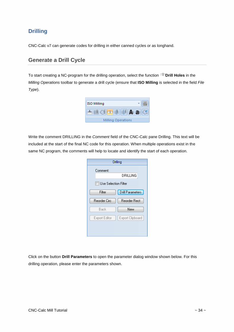
To start creating a NC-program for the drilling operation, select the function Drill Holes in the
Milling Operations toolbar to generate a drill cycle (ensure that ISO Milling is selected in the field File
Type).
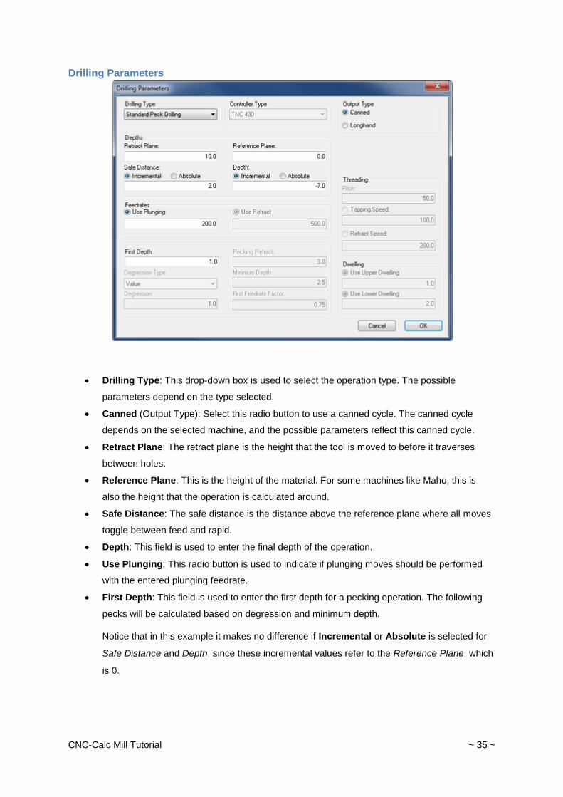
Write the comment DRILLING in the Comment field of the CNC-Calc pane Drilling. This text will be
included at the start of the final NC code for this operation. When multiple operations exist in the
same NC program, the comments will help to locate and identify the start of each operation.
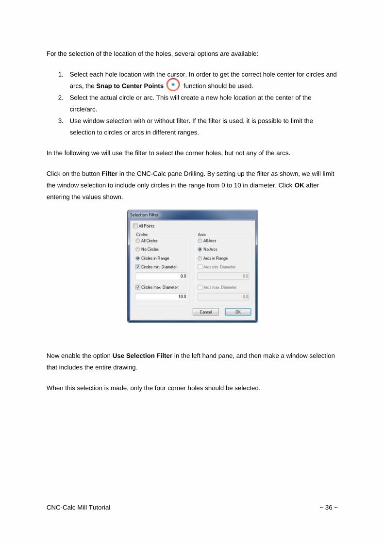
Click on the button Drill Parameters to open the parameter dialog window shown below. For this
drilling operation, please enter the parameters shown.
CNC-Calc Mill Tutorial ~ 35 ~
Drilling Parameters
Drilling Type: This drop-down box is used to select the operation type. The possible
parameters depend on the type selected.
Canned (Output Type): Select this radio button to use a canned cycle. The canned cycle
depends on the selected machine, and the possible parameters reflect this canned cycle.
Retract Plane: The retract plane is the height that the tool is moved to before it traverses
between holes.
Reference Plane: This is the height of the material. For some machines like Maho, this is
also the height that the operation is calculated around.
Safe Distance: The safe distance is the distance above the reference plane where all moves
toggle between feed and rapid.
Depth: This field is used to enter the final depth of the operation.
Use Plunging: This radio button is used to indicate if plunging moves should be performed
with the entered plunging feedrate.
First Depth: This field is used to enter the first depth for a pecking operation. The following
pecks will be calculated based on degression and minimum depth.
Notice that in this example it makes no difference if Incremental or Absolute is selected for
Safe Distance and Depth, since these incremental values refer to the Reference Plane, which
is 0.
CNC-Calc Mill Tutorial ~ 36 ~
For the selection of the location of the holes, several options are available:
1. Select each hole location with the cursor. In order to get the correct hole center for circles and
arcs, the Snap to Center Points function should be used.
2. Select the actual circle or arc. This will create a new hole location at the center of the
circle/arc.
3. Use window selection with or without filter. If the filter is used, it is possible to limit the
selection to circles or arcs in different ranges.
In the following we will use the filter to select the corner holes, but not any of the arcs.
Click on the button Filter in the CNC-Calc pane Drilling. By setting up the filter as shown, we will limit
the window selection to include only circles in the range from 0 to 10 in diameter. Click OK after
entering the values shown.
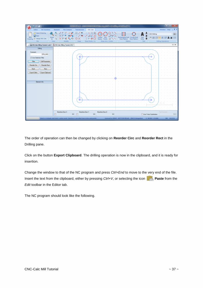
Now enable the option Use Selection Filter in the left hand pane, and then make a window selection
that includes the entire drawing.
When this selection is made, only the four corner holes should be selected.
CNC-Calc Mill Tutorial ~ 37 ~
The order of operation can then be changed by clicking on Reorder Circ and Reorder Rect in the
Drilling pane.
Click on the button Export Clipboard. The drilling operation is now in the clipboard, and it is ready for
insertion.
Change the window to that of the NC program and press Ctrl+End to move to the very end of the file.
Insert the text from the clipboard, either by pressing Ctrl+V, or selecting the icon Paste from the
Edit toolbar in the Editor tab.
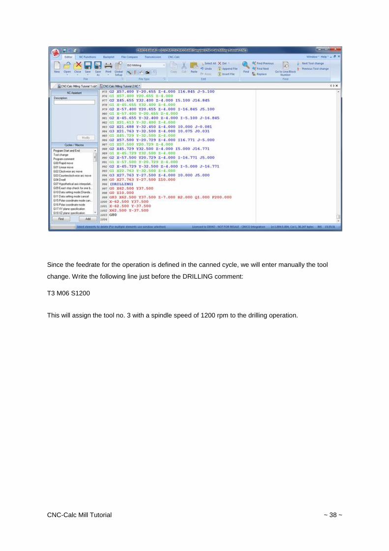
The NC program should look like the following.
CNC-Calc Mill Tutorial ~ 38 ~
Since the feedrate for the operation is defined in the canned cycle, we will enter manually the tool
change. Write the following line just before the DRILLING comment:
T3 M06 S1200
This will assign the tool no. 3 with a spindle speed of 1200 rpm to the drilling operation.