Embed Size (px)
Citation preview
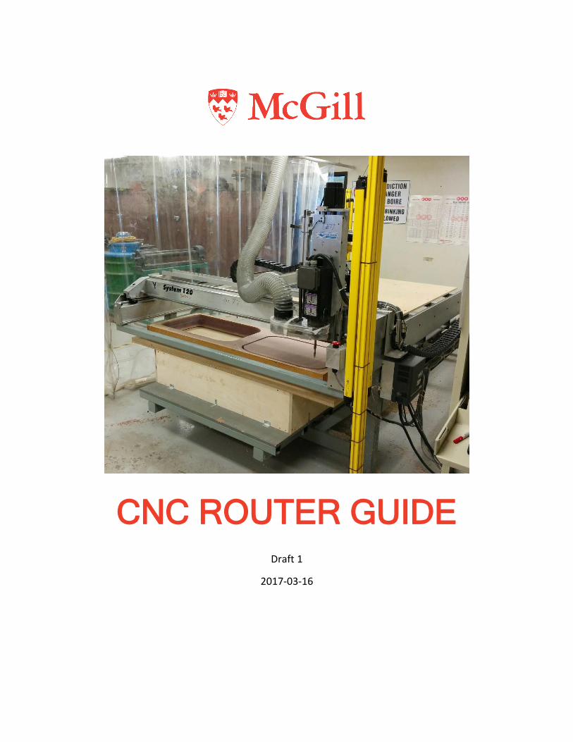
CNC ROUTER GUIDE
Draft 1
2017-03-16
Contents 1. General Overview and Machine Specifications .................................................................................... 1
1.1. Machine Overview ........................................................................................................................ 1
1.2. Bed Dimensions ............................................................................................................................ 2
1.3. Materials ....................................................................................................................................... 2
1.4. Tooling........................................................................................................................................... 2
1.5. Speeds and Feeds .......................................................................................................................... 2
2. User Interface Overview ....................................................................................................................... 3
2.1. Main Screen Overview .................................................................................................................. 3
2.2. Toolpath Viewport Box ................................................................................................................. 4
2.3. Control Selection Box .................................................................................................................... 5
2.3.1. G-Code Control Panel ............................................................................................................ 5
2.3.2. Jog Control Panel .................................................................................................................. 6
2.3.3. Point Control Panel ............................................................................................................... 7
2.3.4. Home Control Panel .............................................................................................................. 8
2.3.5. Auxiliary Control Panel .......................................................................................................... 8
2.3.6. MDI Control Panel (Manual Data Input) ............................................................................... 9
3. Operating Procedure ........................................................................................................................... 10
3.1. Mounting the workpiece and loading the cutting tool ............................................................... 10
3.2. Guards and Safety Check ............................................................................................................ 11
3.3. Starting up controllers and software .......................................................................................... 13
3.4. Homing ........................................................................................................................................ 14
3.5. Loading G-Code ........................................................................................................................... 15
3.6. Setting program zero .................................................................................................................. 16
3.7. Running G-Code .......................................................................................................................... 18
4. Frequently Asked Questions ............................................................................................................... 21
CNC Router Guide 1
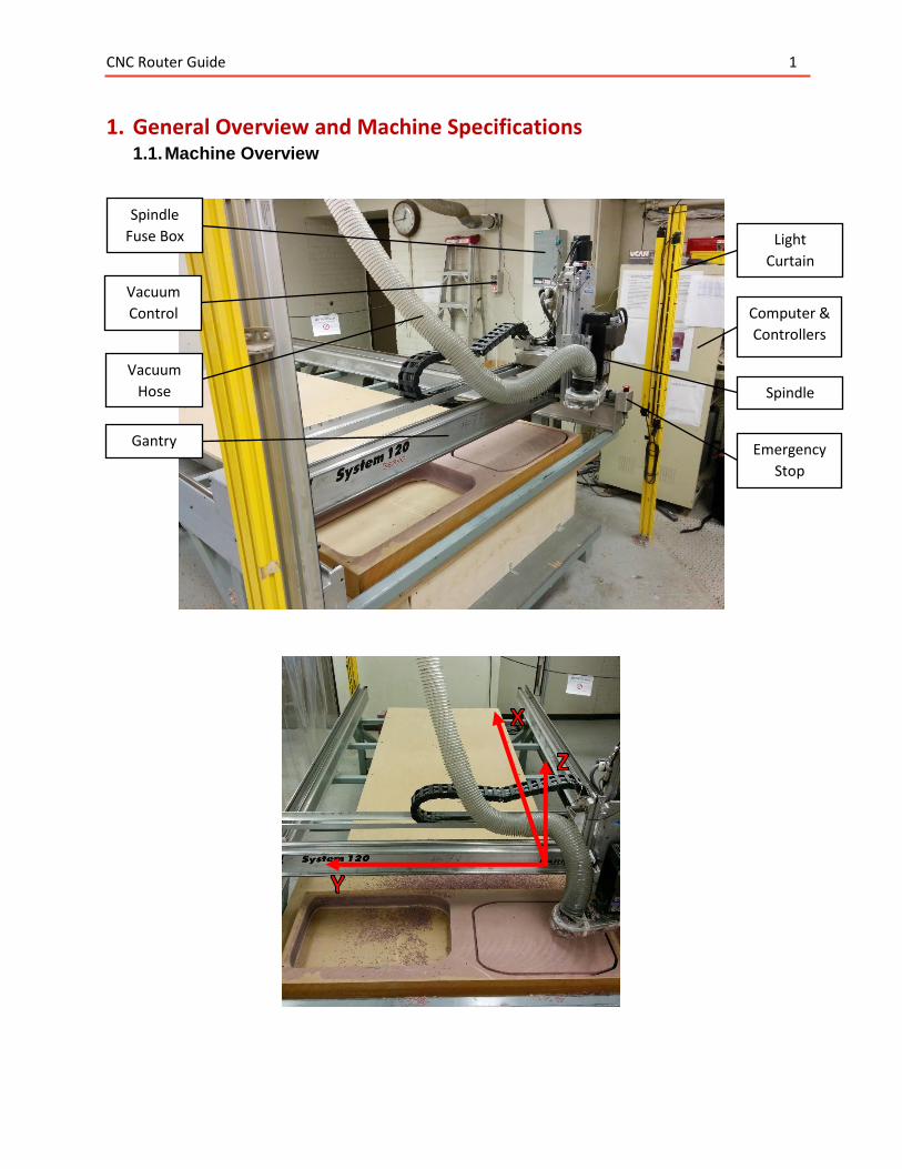
1. General Overview and Machine Specifications 1.1. Machine Overview
Vacuum
Control Computer &
Controllers
Spindle
Light
Curtain
Emergency
Stop
Gantry
Spindle
Fuse Box
Vacuum
Hose
CNC Router Guide 2
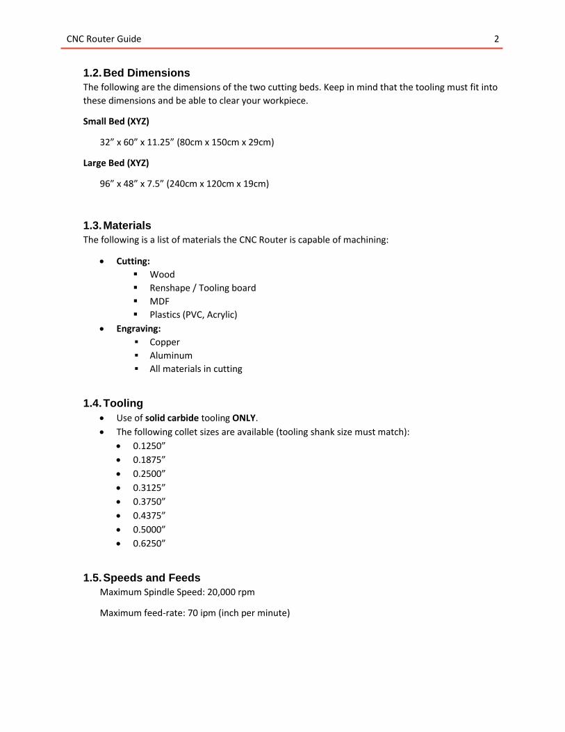
1.2. Bed Dimensions
The following are the dimensions of the two cutting beds. Keep in mind that the tooling must fit into
these dimensions and be able to clear your workpiece.
Small Bed (XYZ)
32” x 60” x 11.25” (80cm x 150cm x 29cm)
Large Bed (XYZ)
96” x 48” x 7.5” (240cm x 120cm x 19cm)
1.3. Materials
The following is a list of materials the CNC Router is capable of machining:
Cutting:
Wood
Renshape / Tooling board
MDF
Plastics (PVC, Acrylic)
Engraving:
▪ Copper
▪ Aluminum
▪ All materials in cutting
1.4. Tooling
Use of solid carbide tooling ONLY.
The following collet sizes are available (tooling shank size must match):
0.1250”
0.1875”
0.2500”
0.3125”
0.3750”
0.4375”
0.5000”
0.6250”
1.5. Speeds and Feeds
Maximum Spindle Speed: 20,000 rpm
Maximum feed-rate: 70 ipm (inch per minute)
CNC Router Guide 3
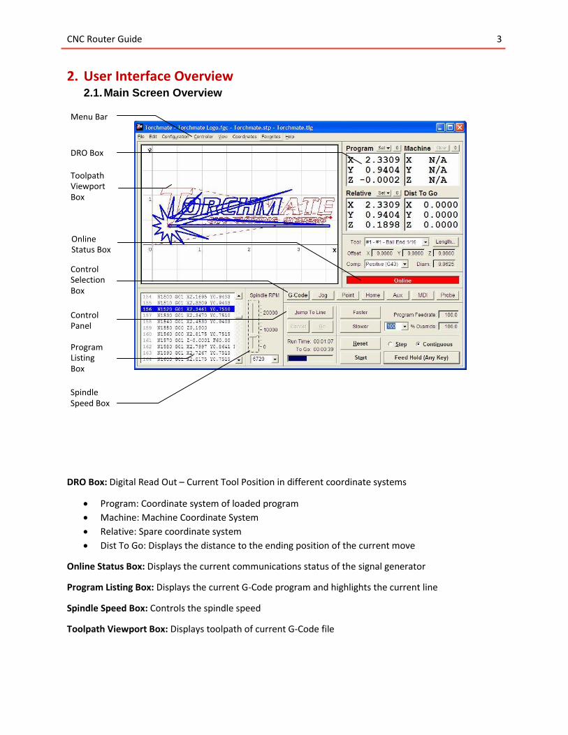
2. User Interface Overview 2.1. Main Screen Overview
DRO Box: Digital Read Out – Current Tool Position in different coordinate systems
Program: Coordinate system of loaded program
Machine: Machine Coordinate System
Relative: Spare coordinate system
Dist To Go: Displays the distance to the ending position of the current move
Online Status Box: Displays the current communications status of the signal generator
Program Listing Box: Displays the current G-Code program and highlights the current line
Spindle Speed Box: Controls the spindle speed
Toolpath Viewport Box: Displays toolpath of current G-Code file
Menu Bar
DRO Box
Toolpath Viewport Box
Online
Control Selection Box
Control Panel
Status Box
Program Listing Box
Spindle Speed Box
CNC Router Guide 4
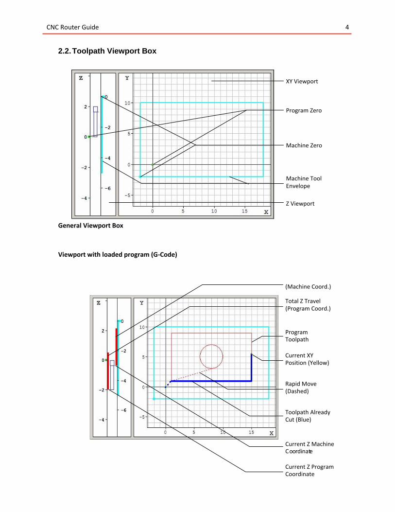
2.2. Toolpath Viewport Box
General Viewport Box
Viewport with loaded program (G-Code)
XY Viewport
Program Zero
Machine Zero
Machine Tool Envelope
Z Viewport
( Machine Coord.)
Total Z Travel Program Coord.) (
Program Toolpath
Current XY Position (Yellow)
Rapid Move ( Dashed)
Toolpath Already Cut (Blue)
Current Z Machine C o o r di nat e
Current Z Program Coordinate
CNC Router Guide 5
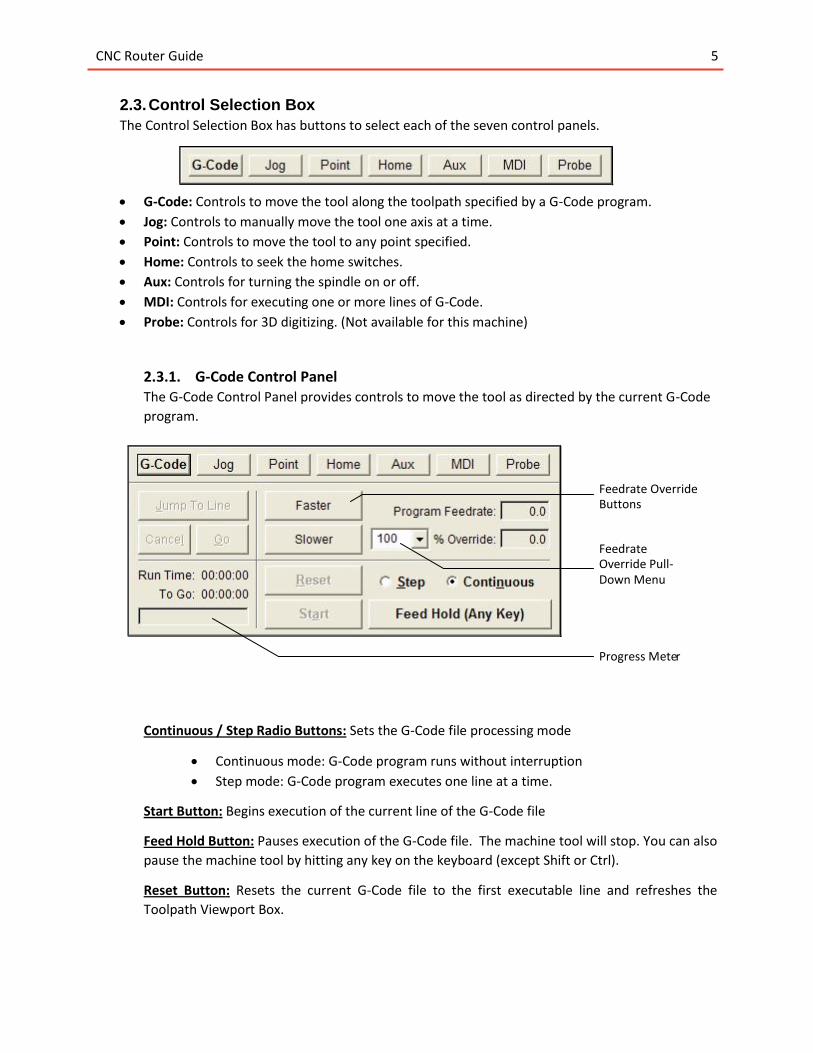
2.3. Control Selection Box
The Control Selection Box has buttons to select each of the seven control panels.
G-Code: Controls to move the tool along the toolpath specified by a G-Code program.
Jog: Controls to manually move the tool one axis at a time.
Point: Controls to move the tool to any point specified.
Home: Controls to seek the home switches.
Aux: Controls for turning the spindle on or off.
MDI: Controls for executing one or more lines of G-Code.
Probe: Controls for 3D digitizing. (Not available for this machine)
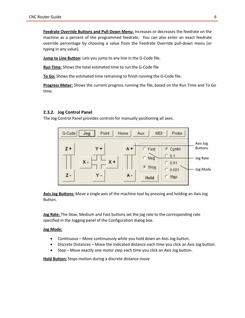
2.3.1. G-Code Control Panel The G-Code Control Panel provides controls to move the tool as directed by the current G-Code
program.
Continuous / Step Radio Buttons: Sets the G-Code file processing mode
Continuous mode: G-Code program runs without interruption
Step mode: G-Code program executes one line at a time.
Start Button: Begins execution of the current line of the G-Code file
Feed Hold Button: Pauses execution of the G-Code file. The machine tool will stop. You can also
pause the machine tool by hitting any key on the keyboard (except Shift or Ctrl).
Reset Button: Resets the current G-Code file to the first executable line and refreshes the
Toolpath Viewport Box.
Feedrate Override Buttons
Feedrate Override Pull- Down Menu
Progress Mete r
CNC Router Guide 6
Feedrate Override Buttons and Pull-Down Menu: Increases or decreases the feedrate on the
machine as a percent of the programmed feedrate. You can also enter an exact feedrate
override percentage by choosing a value from the Feedrate Override pull-down menu (or
typing in any value).
Jump to Line Button: Lets you jump to any line in the G-Code file.
Run Time: Shows the total estimated time to run the G-Code file
To Go: Shows the estimated time remaining to finish running the G-Code file.
Progress Meter: Shows the current progress running the file, based on the Run Time and To Go
time.
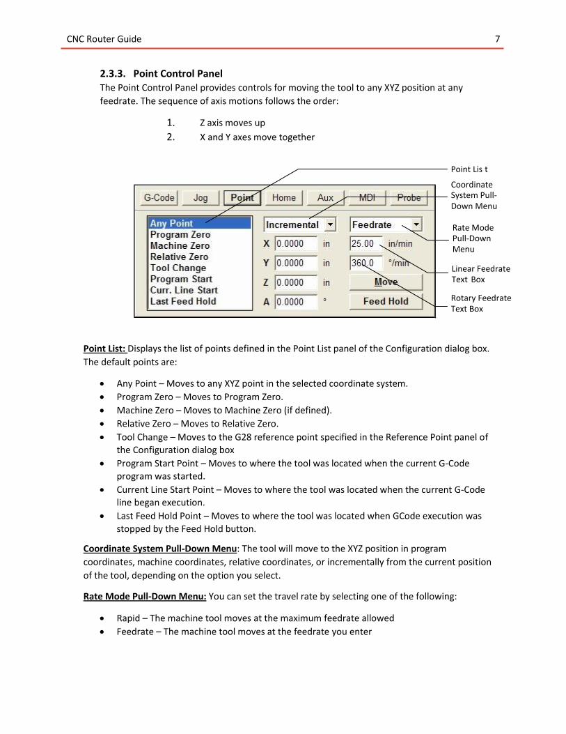
2.3.2. Jog Control Panel The Jog Control Panel provides controls for manually positioning all axes.
Axis Jog Buttons: Move a single axis of the machine tool by pressing and holding an Axis Jog
Button.
Jog Rate: The Slow, Medium and Fast buttons set the jog rate to the corresponding rate
specified in the Jogging panel of the Configuration dialog box.
Jog Mode:
Continuous – Move continuously while you hold down an Axis Jog button.
Discrete Distances – Move the indicated distance each time you click an Axis Jog button.
Step – Move exactly one motor step each time you click an Axis Jog button.
Hold Button: Stops motion during a discrete distance move
Axis Jog Buttons
Jog Rate
Jog Mode
CNC Router Guide 7
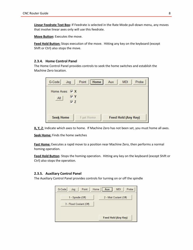
2.3.3. Point Control Panel The Point Control Panel provides controls for moving the tool to any XYZ position at any
feedrate. The sequence of axis motions follows the order:
1. Z axis moves up
2. X and Y axes move together
Point List: Displays the list of points defined in the Point List panel of the Configuration dialog box.
The default points are:
Any Point – Moves to any XYZ point in the selected coordinate system.
Program Zero – Moves to Program Zero.
Machine Zero – Moves to Machine Zero (if defined).
Relative Zero – Moves to Relative Zero.
Tool Change – Moves to the G28 reference point specified in the Reference Point panel of
the Configuration dialog box
Program Start Point – Moves to where the tool was located when the current G-Code
program was started.
Current Line Start Point – Moves to where the tool was located when the current G-Code line began execution.
Last Feed Hold Point – Moves to where the tool was located when GCode execution was
stopped by the Feed Hold button.
Coordinate System Pull-Down Menu: The tool will move to the XYZ position in program
coordinates, machine coordinates, relative coordinates, or incrementally from the current position
of the tool, depending on the option you select.
Rate Mode Pull-Down Menu: You can set the travel rate by selecting one of the following:
Rapid – The machine tool moves at the maximum feedrate allowed
Feedrate – The machine tool moves at the feedrate you enter
Point Lis t
Coordinate System Pull- Down Menu
Rate Mode Pull-Down Menu
Linear Feedrate Text Box
Rotary Feedrate Text Box
CNC Router Guide 8
Linear Feedrate Text Box: If Feedrate is selected in the Rate Mode pull-down menu, any moves
that involve linear axes only will use this feedrate.
Move Button: Executes the move.
Feed Hold Button: Stops execution of the move. Hitting any key on the keyboard (except
Shift or Ctrl) also stops the move.
2.3.4. Home Control Panel The Home Control Panel provides controls to seek the home switches and establish the
Machine Zero location.
X, Y, Z: Indicate which axes to home. If Machine Zero has not been set, you must home all axes.
Seek Home: Finds the home switches
Fast Home: Executes a rapid move to a position near Machine Zero, then performs a normal
homing operation.
Feed Hold Button: Stops the homing operation. Hitting any key on the keyboard (except Shift or
Ctrl) also stops the operation.
2.3.5. Auxiliary Control Panel The Auxiliary Control Panel provides controls for turning on or off the spindle
CNC Router Guide 9
Spindle On / Off: Turns the spindle control line on or off.
Feed Hold Button: Stops automatic tool changing or tool length sensing.
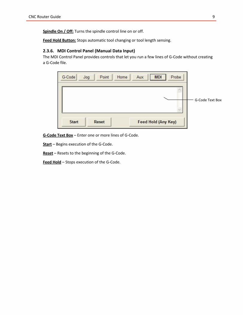
2.3.6. MDI Control Panel (Manual Data Input) The MDI Control Panel provides controls that let you run a few lines of G-Code without creating
a G-Code file.
G-Code Text Box – Enter one or more lines of G-Code.
Start – Begins execution of the G-Code.
Reset – Resets to the beginning of the G-Code.
Feed Hold – Stops execution of the G-Code.
G-Code Text Box
CNC Router Guide 10
3. Operating Procedure 3.1. Mounting the workpiece and loading the cutting tool
1) Securely mount the workpiece on the router bed using screws for rigid materials or double sided
tape for foam. Verify that the toolpath in your G-Code will clear these mounting points.
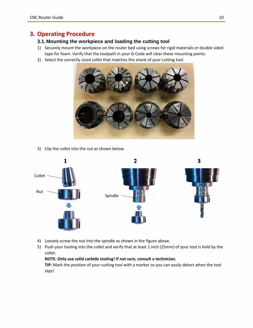
2) Select the correctly sized collet that matches the shank of your cutting tool.
3) Clip the collet into the nut as shown below.
4) Loosely screw the nut into the spindle as shown in the figure above.
5) Push your tooling into the collet and verify that at least 1 inch (25mm) of your tool is hold by the
collet.
NOTE: Only use solid carbide tooling! If not sure, consult a technician.
TIP: Mark the position of your cutting tool with a marker so you can easily detect when the tool
slips!
Collet
Nut Spindle
CNC Router Guide 11
6) With the cutting tool in place, tighten the nut by using the provided spanner and an adjustable
wrench shown below. Verify that the nut is tight and that the cutting tool sits securely in the
collet.
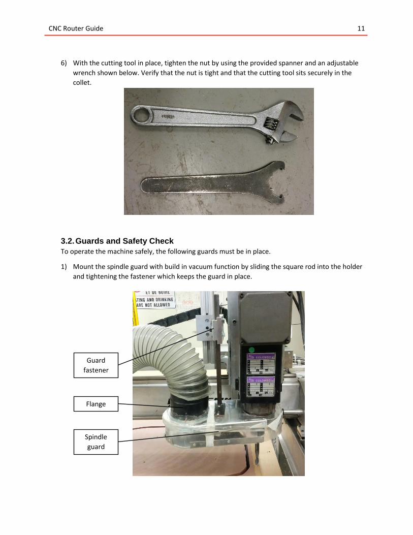
3.2. Guards and Safety Check
To operate the machine safely, the following guards must be in place.
1) Mount the spindle guard with build in vacuum function by sliding the square rod into the holder
and tightening the fastener which keeps the guard in place.
Spindle
guard
Guard
fastener
Flange
CNC Router Guide 12
2) Secure the vacuum hose to the guard inlet by pulling the hose over the flange on the guard.
3) Pull the see-through plastic curtain around the router table to prevent dust and debris from
entering the rest of the workshop.
4) Ensure that the router head and the gantry can move freely without obstruction. No tools or
loose items should be on the router bed.
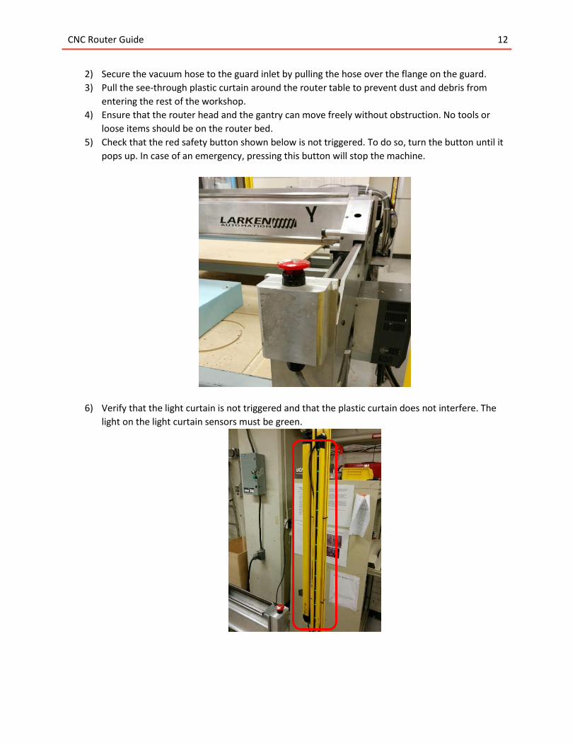
5) Check that the red safety button shown below is not triggered. To do so, turn the button until it
pops up. In case of an emergency, pressing this button will stop the machine.
6) Verify that the light curtain is not triggered and that the plastic curtain does not interfere. The
light on the light curtain sensors must be green.
CNC Router Guide 13
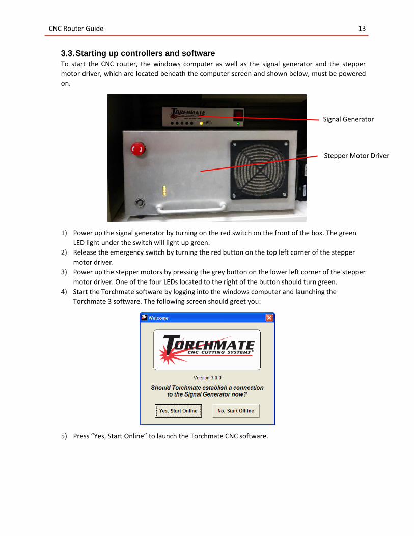
3.3. Starting up controllers and software
To start the CNC router, the windows computer as well as the signal generator and the stepper
motor driver, which are located beneath the computer screen and shown below, must be powered
on.
1) Power up the signal generator by turning on the red switch on the front of the box. The green
LED light under the switch will light up green.
2) Release the emergency switch by turning the red button on the top left corner of the stepper
motor driver.
3) Power up the stepper motors by pressing the grey button on the lower left corner of the stepper
motor driver. One of the four LEDs located to the right of the button should turn green.
4) Start the Torchmate software by logging into the windows computer and launching the
Torchmate 3 software. The following screen should greet you:
5) Press “Yes, Start Online” to launch the Torchmate CNC software.
Signal Generator
Stepper Motor Driver
CNC Router Guide 14
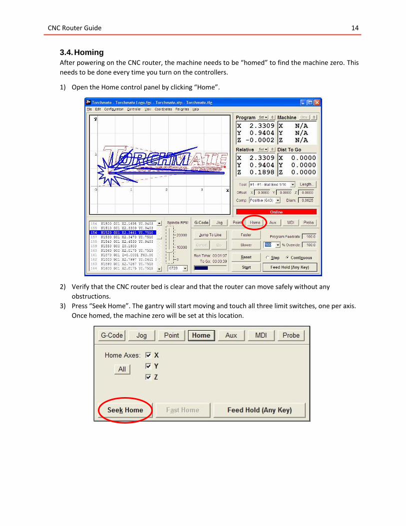
3.4. Homing
After powering on the CNC router, the machine needs to be “homed” to find the machine zero. This
needs to be done every time you turn on the controllers.
1) Open the Home control panel by clicking “Home”.
2) Verify that the CNC router bed is clear and that the router can move safely without any
obstructions.
3) Press “Seek Home”. The gantry will start moving and touch all three limit switches, one per axis.
Once homed, the machine zero will be set at this location.
CNC Router Guide 15
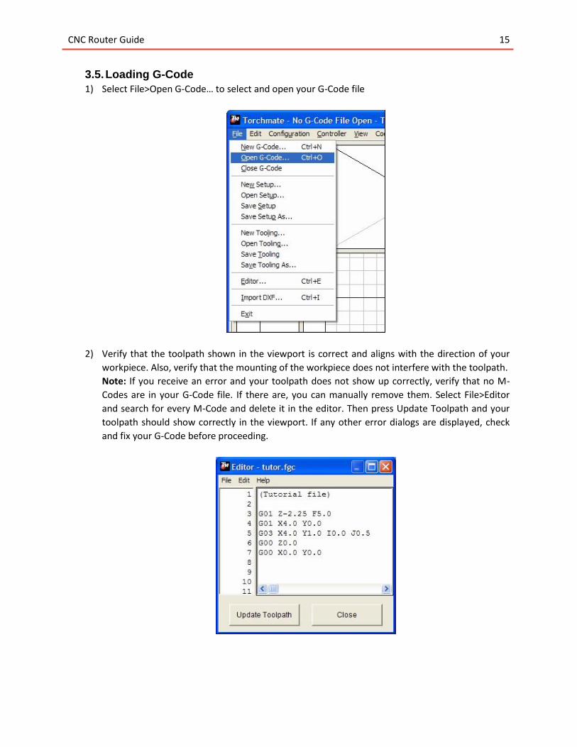
3.5. Loading G-Code
1) Select File>Open G-Code… to select and open your G-Code file
2) Verify that the toolpath shown in the viewport is correct and aligns with the direction of your
workpiece. Also, verify that the mounting of the workpiece does not interfere with the toolpath.
Note: If you receive an error and your toolpath does not show up correctly, verify that no M-
Codes are in your G-Code file. If there are, you can manually remove them. Select File>Editor
and search for every M-Code and delete it in the editor. Then press Update Toolpath and your
toolpath should show correctly in the viewport. If any other error dialogs are displayed, check
and fix your G-Code before proceeding.
CNC Router Guide 16
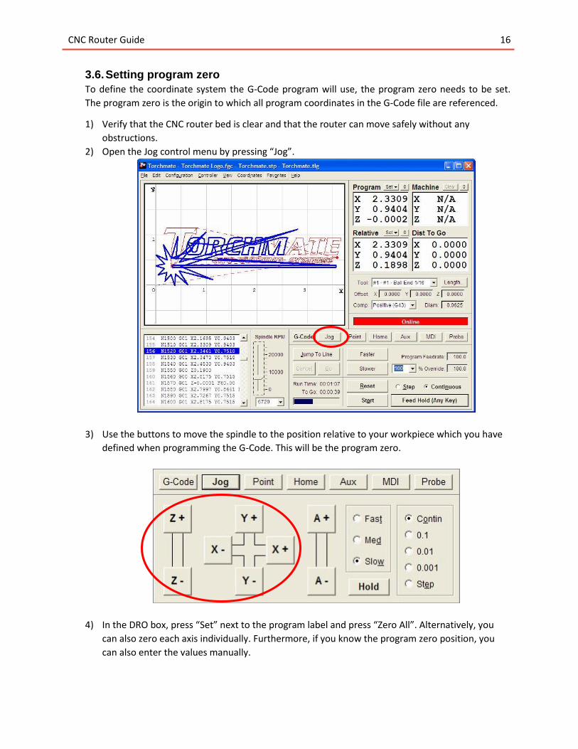
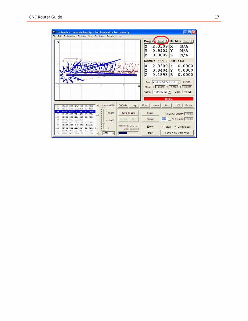
3.6. Setting program zero
To define the coordinate system the G-Code program will use, the program zero needs to be set.
The program zero is the origin to which all program coordinates in the G-Code file are referenced.
1) Verify that the CNC router bed is clear and that the router can move safely without any
obstructions.
2) Open the Jog control menu by pressing “Jog”.
3) Use the buttons to move the spindle to the position relative to your workpiece which you have
defined when programming the G-Code. This will be the program zero.
4) In the DRO box, press “Set” next to the program label and press “Zero All”. Alternatively, you
can also zero each axis individually. Furthermore, if you know the program zero position, you
can also enter the values manually.
CNC Router Guide 17
CNC Router Guide 18
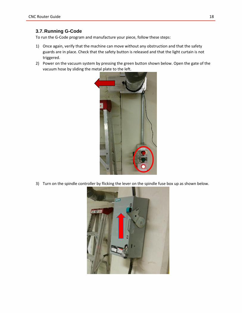
3.7. Running G-Code
To run the G-Code program and manufacture your piece, follow these steps:
1) Once again, verify that the machine can move without any obstruction and that the safety
guards are in place. Check that the safety button is released and that the light curtain is not
triggered.
2) Power on the vacuum system by pressing the green button shown below. Open the gate of the
vacuum hose by sliding the metal plate to the left.
3) Turn on the spindle controller by flicking the lever on the spindle fuse box up as shown below.
CNC Router Guide 19
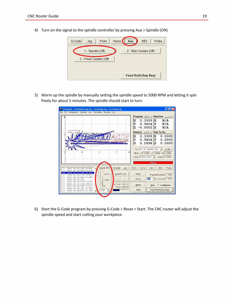
4) Turn on the signal to the spindle controller by pressing Aux > Spindle (ON)
5) Warm up the spindle by manually setting the spindle speed to 5000 RPM and letting it spin
freely for about 5 minutes. The spindle should start to turn.
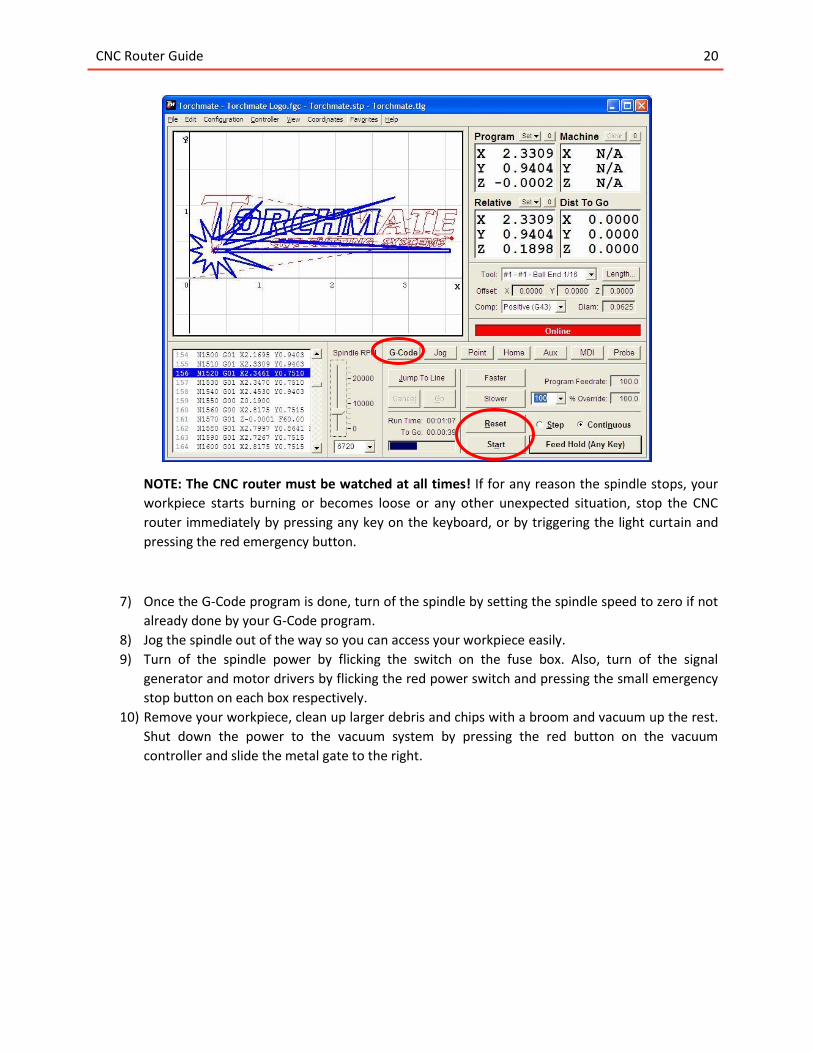
6) Start the G-Code program by pressing G-Code > Reset > Start. The CNC router will adjust the
spindle speed and start cutting your workpiece.
CNC Router Guide 20
NOTE: The CNC router must be watched at all times! If for any reason the spindle stops, your
workpiece starts burning or becomes loose or any other unexpected situation, stop the CNC
router immediately by pressing any key on the keyboard, or by triggering the light curtain and
pressing the red emergency button.
7) Once the G-Code program is done, turn of the spindle by setting the spindle speed to zero if not
already done by your G-Code program.
8) Jog the spindle out of the way so you can access your workpiece easily.
9) Turn of the spindle power by flicking the switch on the fuse box. Also, turn of the signal
generator and motor drivers by flicking the red power switch and pressing the small emergency
stop button on each box respectively.
10) Remove your workpiece, clean up larger debris and chips with a broom and vacuum up the rest.
Shut down the power to the vacuum system by pressing the red button on the vacuum
controller and slide the metal gate to the right.
CNC Router Guide 21
4. Frequently Asked Questions I need to use multiple cutting tools for my workpiece, but there is no tool-changer.
Split your G-Code into separated programs, one program for every tool. Switch the tool
manually to the next tool after each program is finished. You will need to zero the Z-Axis every
time you change the tool. To do so, follow the instructions in Section 3.6 but zero the Z-Axis
only.
I loaded my G-Code program, but I get an error dialog and my toolpath is not shown in the
viewport.
Check if your G-Code contains “M Codes”. Go to the G-Code editor by clicking File>Editor… and
search for the letter “M” followed by a number. Remove both the letter and the number. M-
Codes are machine specific codes such as tool change or cooling control and while included by
many post-processors, they are not supported by the CNC router and often result in an error
dialog.
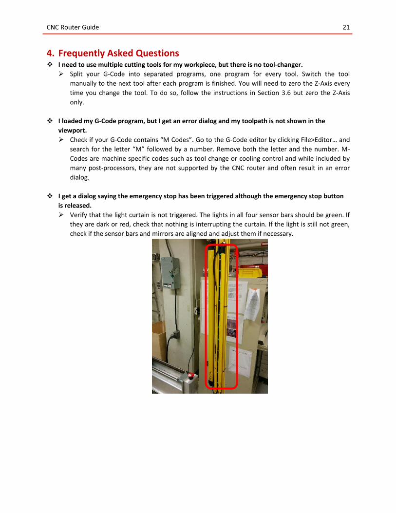
I get a dialog saying the emergency stop has been triggered although the emergency stop button
is released.
Verify that the light curtain is not triggered. The lights in all four sensor bars should be green. If
they are dark or red, check that nothing is interrupting the curtain. If the light is still not green,
check if the sensor bars and mirrors are aligned and adjust them if necessary.
CNC Router Guide 22
I turn on the spindle by setting the spindle RPM, but the spindle won’t start turning.
First check that the fuse box switch is turned up and that the spindle controller has power.
Next, go to the AUX menu and press Spindle ON. When the emergency stop is triggered, the
Spindle will be automatically set to OFF.
If the spindle is still not turning, check if there is an error code on the spindle controller. If so,
turn off the power on the fuse box, wait 5 seconds and turn the power back on. The error
message should disappear.
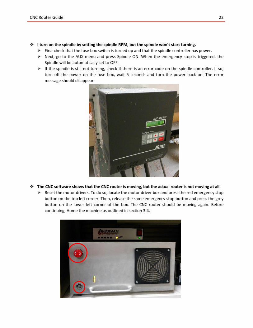
The CNC software shows that the CNC router is moving, but the actual router is not moving at all.
Reset the motor drivers. To do so, locate the motor driver box and press the red emergency stop
button on the top left corner. Then, release the same emergency stop button and press the grey
button on the lower left corner of the box. The CNC router should be moving again. Before
continuing, Home the machine as outlined in section 3.4.
CNC Router Guide 23
The CNC software shows that the CNC router is moving, but one or more axis aren’t moving.
When the CNC router collides with something or too much force is put onto the stepper drives,
the motors will shut down. To reset the motor driver, follow the instructions above and don’t
forget to home the machine before continuing as outlined in section 3.4.
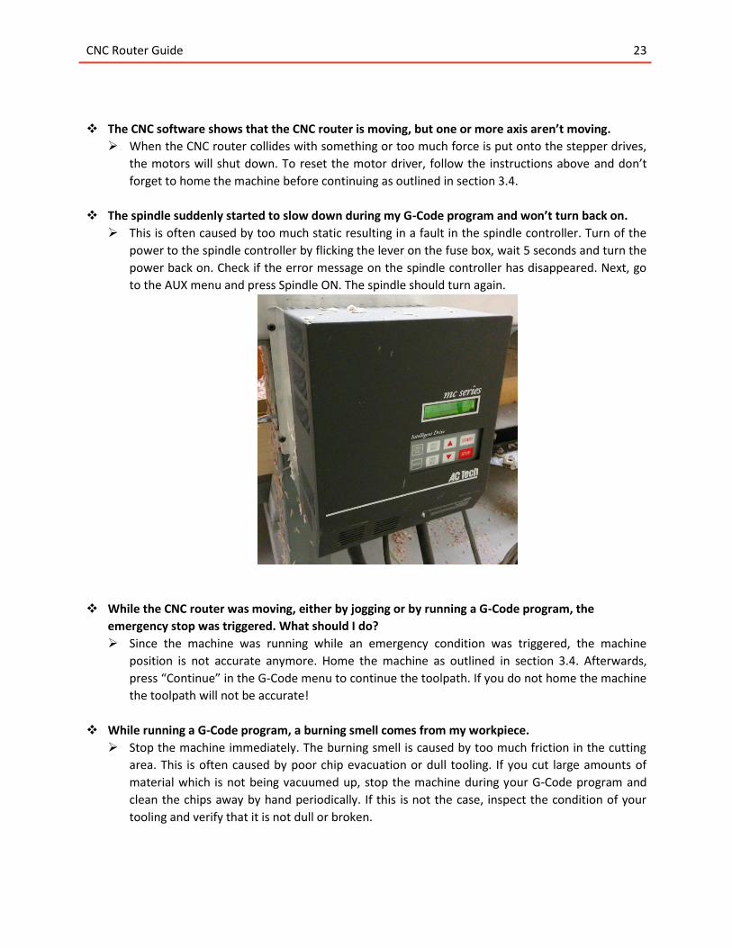
The spindle suddenly started to slow down during my G-Code program and won’t turn back on.
This is often caused by too much static resulting in a fault in the spindle controller. Turn of the
power to the spindle controller by flicking the lever on the fuse box, wait 5 seconds and turn the
power back on. Check if the error message on the spindle controller has disappeared. Next, go
to the AUX menu and press Spindle ON. The spindle should turn again.
While the CNC router was moving, either by jogging or by running a G-Code program, the
emergency stop was triggered. What should I do?
Since the machine was running while an emergency condition was triggered, the machine
position is not accurate anymore. Home the machine as outlined in section 3.4. Afterwards,
press “Continue” in the G-Code menu to continue the toolpath. If you do not home the machine
the toolpath will not be accurate!
While running a G-Code program, a burning smell comes from my workpiece.
Stop the machine immediately. The burning smell is caused by too much friction in the cutting
area. This is often caused by poor chip evacuation or dull tooling. If you cut large amounts of
material which is not being vacuumed up, stop the machine during your G-Code program and
clean the chips away by hand periodically. If this is not the case, inspect the condition of your
tooling and verify that it is not dull or broken.
CNC Router Guide 24
While running a G-Code program, my cutting tool slipped in the collet and is now cutting deeper
than intented.
This is often caused by too high feedrates or dull tooling. Stop the machine and verify the
condition of your tool. If the tool is broken or dull, replace your tooling. If the tool is in good
condition, try to reduce the feedrate. Before continuing, remount the cutting tool as outlined in
section 3.1 and set the program zero for the Z-Axis as outlined in section 3.6.
When moving the CNC router, a crunching sound is coming from the machine.
Check the linear bearings on the gantry. If you can see small steel balls around the bearings, the
bearings have seized and need to be replaced. Do not continue running the CNC router and
contact a technician for assistance.