Embed Size (px)
Citation preview
CNC USB Controller Mk3/4
User manual
2014-12-17
1
Disclaimer
CONTROLLER AND CONTROLLER SOFTWARE ARE PROVIDED TO YOU "AS IS," WITHOUT
WARRANTY. THERE IS NO WARRANTY FOR THE CONTROLLER AND CONTROLLER
SOFTWARE, EITHER EXPRESSED OR IMPLIED, INCLUDING, BUT NOT LIMITED TO, THE
IMPLIED WARRANTIES OF MERCHANTABILITY AND FITNESS FOR A PARTICULAR PURPOSE
AND NONINFRINGEMENT OF THIRD PARTY RIGHTS. THE ENTIRE RISK AS TO THE QUALITY
AND PERFORMANCE OF THE CONTROLLER OR CONTROLLER SOFTWARE IS WITH YOU.
SHOULD THE CONTROLLER OR CONTROLLER SOFTWARE PROVE DEFECTIVE, YOU ASSUME
THE COST OF ALL NECESSARY SERVICING, REPAIR OR CORRECTION.
IN NO EVENT SHALL THE AUTHOR BE LIABLE TO YOU FOR DAMAGES, INCLUDING ANY
GENERAL, SPECIAL, INCIDENTAL OR CONSEQUENTIAL DAMAGES ARISING OUT OF THE USE
OR INABILITY TO USE THE CONTROLLER OR CONTROLLER SOFTWARE.
2
1 Introduction
1.1 Overview
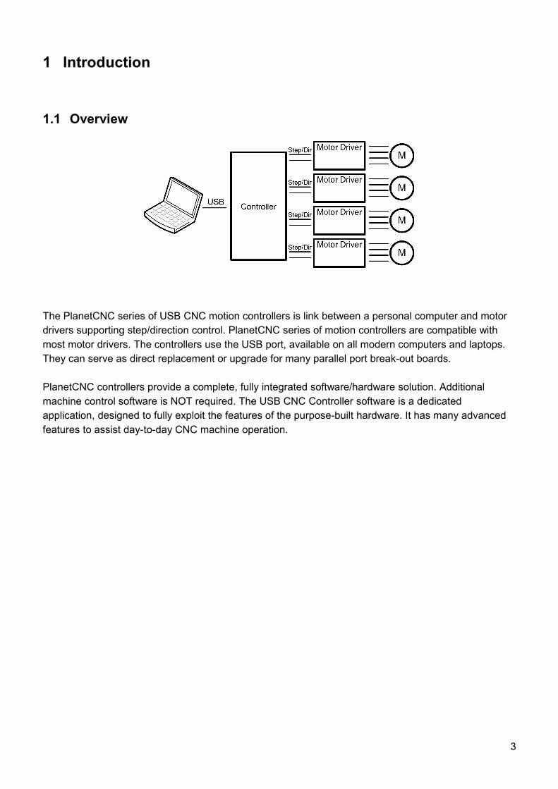
The PlanetCNC series of USB CNC motion controllers is link between a personal computer and motor drivers supporting step/direction control. PlanetCNC series of motion controllers are compatible with most motor drivers. The controllers use the USB port, available on all modern computers and laptops. They can serve as direct replacement or upgrade for many parallel port break-out boards.
PlanetCNC controllers provide a complete, fully integrated software/hardware solution. Additional machine control software is NOT required. The USB CNC Controller software is a dedicated application, designed to fully exploit the features of the purpose-built hardware. It has many advanced features to assist day-to-day CNC machine operation.
3
1.2 Features and specifications:
• USB (V2.x) from PC/Laptop running Windows XP, Vista, Windows 7, 8 or 8.1 (32 bit or 64bit)
• motor driver connector pin-out is compatible with 10 pin open source interface (Linistepper, PICStep)
• controller works with most step/dir stepper and servo motor drivers available on the market
• buffered IO for maximum performance
• advanced interpolation algorithms
• start, stop, pause and resume execution of program on your machine
• standard RS274/NGC G-code (EMC2 and LinuxCNC compatible)
• advanced G-codes - G40, G41, G42 (Cutter Radius Compensation) supported
• advanced G-codes - G43, G49 (Tool Length Offsets) supported
• advanced G-codes - G54, G59.3 (Coordinate System Origins) supported
• tested with SolidCAM, MasterCAM, ArtCAM, Vectric, CamBam, MeshCAM ... generated G-code
• Profili 4-axes and 3-axes G-code supported
• import toolpath from DXF files
• import toolpath from PLT/HPGL files
• import toolpath from image files
• import toolpath from NC-Drill (Excellon) files
• import toolpath from Gerber (RS-274X) files
• toolpath simulation
• automatic homing procedure
• advanced toolchange procedures
• automatic tool length measuring
• export toolpath to G-code
• export toolpath to DXF
• SDK (software developers kit) is available
• works on MacOS with virtual machine emulating Windows
Mk3/4 - 4 axes USB CNC controller
• 4 axes controller for stepper and servo motors
• USB connection
• 110 kHz maximum step frequency
• 25 us minimum pulse width, 50% duty cycle at higher frequencies
• 3 digital outputs on board
• 3 PWM capable outputs with selectable frequency (10Hz to 500kHz)
• 3 outputs with support for RC servo motors
• jogging keyboard support with speed potentiometer, shift, step and spindle sync feature
• 4 limit switches with shift feature
• 4 digital inputs on board, filtered and protected
• MPG pendant support
• spindle encoder and index signal support for spindle synchronization
• SD card support for running g-code without computer
4
• control external devices with I2C and UART protocol
• homing procedure
• tool change procedure
• tool length sensor support
• sensor for capturing and measuring
• digitizing probe support
• H-bot kinematics support
• transformation matrix
• soft limits
• slave axes
• backlash compensation
• API
• screw terminal connectors for connecting motor drivers, inputs and outputs
1.3 System RequirementsMinimum system requirements:
• 1 GHz or faster processor
• 512MB RAM
• 500 MB available hard disk space
• Graphics with OpenGL support
• USB 2.0 port
• .NET Framework 3.5 SP1
Recommended system requirements:
• 2 GHz or faster processor
• 2GB RAM
• 500 MB available hard disk space
• Graphics with OpenGL support
• USB 2.0 port
• .NET Framework 3.5 SP1
5
2 Hardware
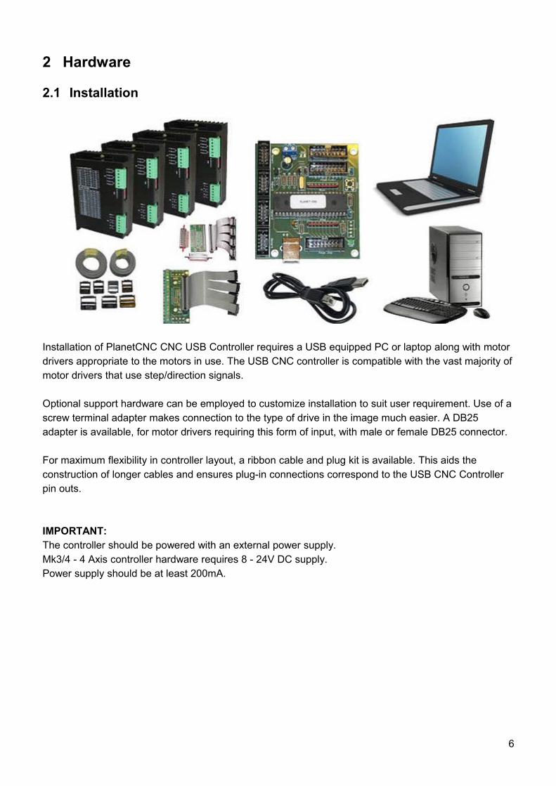
2.1 Installation
Installation of PlanetCNC CNC USB Controller requires a USB equipped PC or laptop along with motor drivers appropriate to the motors in use. The USB CNC controller is compatible with the vast majority ofmotor drivers that use step/direction signals.
Optional support hardware can be employed to customize installation to suit user requirement. Use of ascrew terminal adapter makes connection to the type of drive in the image much easier. A DB25 adapter is available, for motor drivers requiring this form of input, with male or female DB25 connector.
For maximum flexibility in controller layout, a ribbon cable and plug kit is available. This aids the construction of longer cables and ensures plug-in connections correspond to the USB CNC Controller pin outs.
IMPORTANT:The controller should be powered with an external power supply. Mk3/4 - 4 Axis controller hardware requires 8 - 24V DC supply.Power supply should be at least 200mA.
6
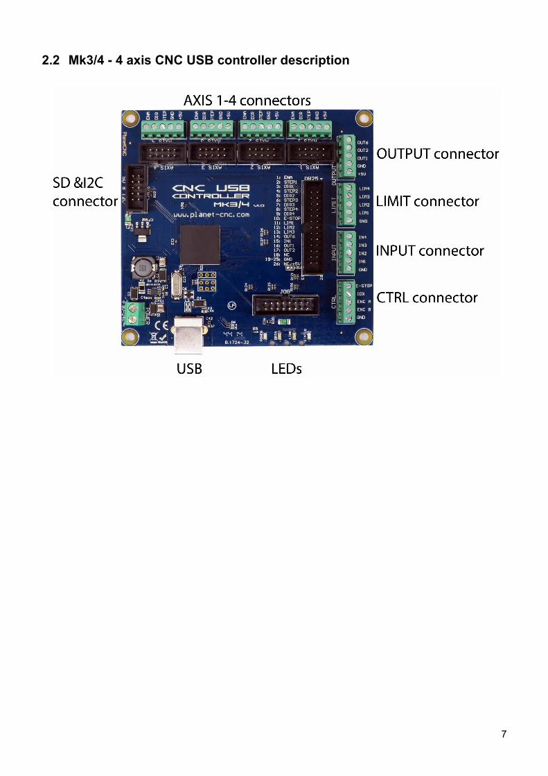
2.2 Mk3/4 - 4 axis CNC USB controller description
7
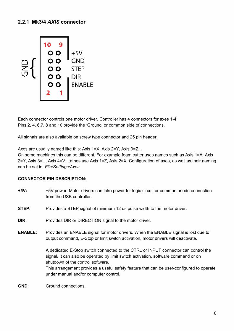
2.2.1 Mk3/4 AXIS connector
Each connector controls one motor driver. Controller has 4 connectors for axes 1-4. Pins 2, 4, 6,7, 8 and 10 provide the ‘Ground’ or common side of connections.
All signals are also available on screw type connector and 25 pin header.
Axes are usually named like this: Axis 1=X, Axis 2=Y, Axis 3=Z...On some machines this can be different. For example foam cutter uses names such as Axis 1=A, Axis 2=Y, Axis 3=U, Axis 4=V. Lathes use Axis 1=Z, Axis 2=X. Configuration of axes, as well as their namingcan be set in File/Settings/Axes.
CONNECTOR PIN DESCRIPTION:
+5V: +5V power. Motor drivers can take power for logic circuit or common anode connection from the USB controller.
STEP: Provides a STEP signal of minimum 12 us pulse width to the motor driver.
DIR: Provides DIR or DIRECTION signal to the motor driver.
ENABLE: Provides an ENABLE signal for motor drivers. When the ENABLE signal is lost due to output command, E-Stop or limit switch activation, motor drivers will deactivate.
A dedicated E-Stop switch connected to the CTRL or INPUT connector can control the signal. It can also be operated by limit switch activation, software command or on shutdown of the control software.This arrangement provides a useful safety feature that can be user-configured to operateunder manual and/or computer control.
GND: Ground connections.
8
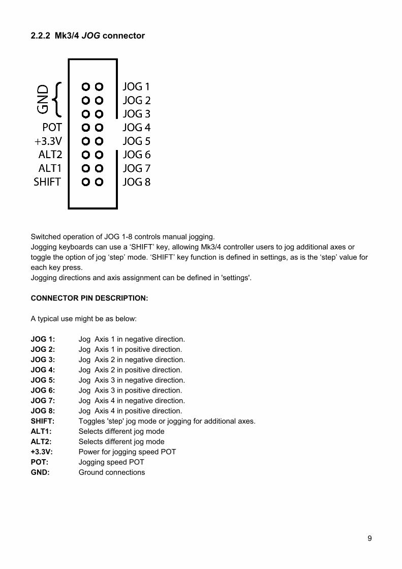
2.2.2 Mk3/4 JOG connector
Switched operation of JOG 1-8 controls manual jogging. Jogging keyboards can use a ‘SHIFT’ key, allowing Mk3/4 controller users to jog additional axes or toggle the option of jog ‘step’ mode. ‘SHIFT’ key function is defined in settings, as is the ‘step’ value for each key press. Jogging directions and axis assignment can be defined in 'settings'.
CONNECTOR PIN DESCRIPTION:
A typical use might be as below:
JOG 1: Jog Axis 1 in negative direction.JOG 2: Jog Axis 1 in positive direction.JOG 3: Jog Axis 2 in negative direction.JOG 4: Jog Axis 2 in positive direction.JOG 5: Jog Axis 3 in negative direction.JOG 6: Jog Axis 3 in positive direction.JOG 7: Jog Axis 4 in negative direction.JOG 8: Jog Axis 4 in positive direction.SHIFT: Toggles 'step' jog mode or jogging for additional axes.ALT1: Selects different jog modeALT2: Selects different jog mode+3.3V: Power for jogging speed POTPOT: Jogging speed POTGND: Ground connections
9
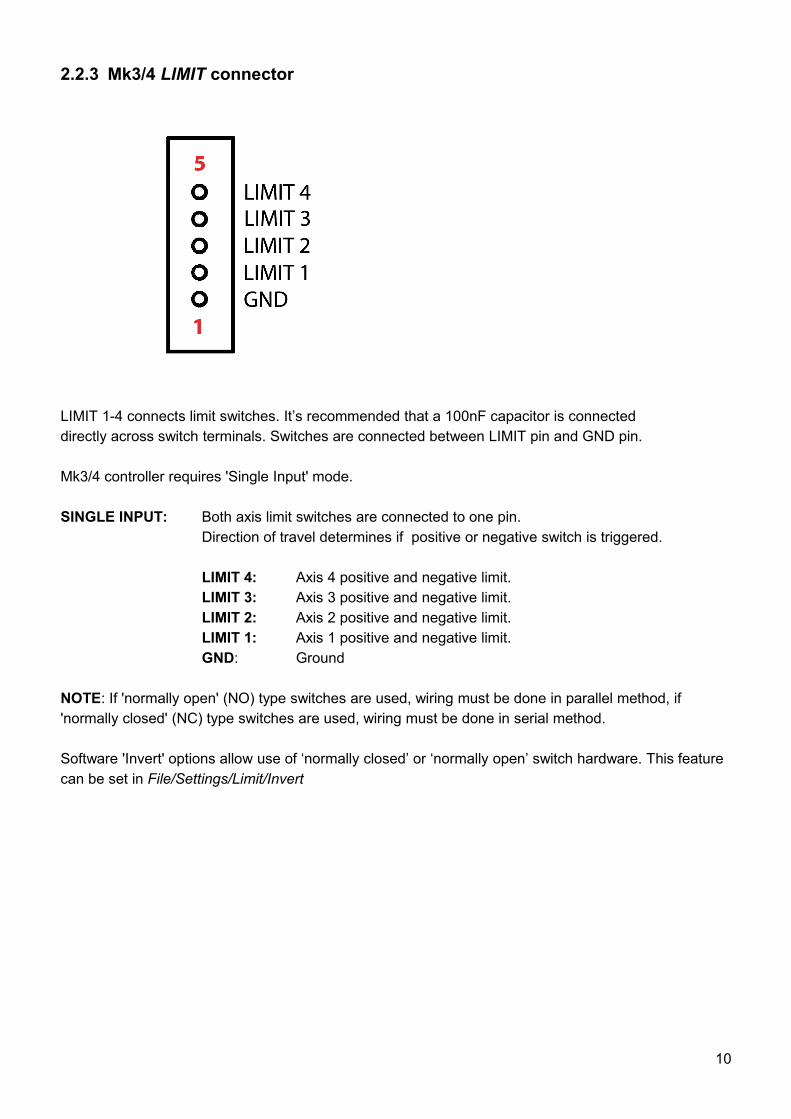
2.2.3 Mk3/4 LIMIT connector
LIMIT 1-4 connects limit switches. It’s recommended that a 100nF capacitor is connecteddirectly across switch terminals. Switches are connected between LIMIT pin and GND pin.
Mk3/4 controller requires 'Single Input' mode.
SINGLE INPUT: Both axis limit switches are connected to one pin. Direction of travel determines if positive or negative switch is triggered.
LIMIT 4: Axis 4 positive and negative limit.LIMIT 3: Axis 3 positive and negative limit.LIMIT 2: Axis 2 positive and negative limit.LIMIT 1: Axis 1 positive and negative limit.GND: Ground
NOTE: If 'normally open' (NO) type switches are used, wiring must be done in parallel method, if 'normally closed' (NC) type switches are used, wiring must be done in serial method.
Software 'Invert' options allow use of ‘normally closed’ or ‘normally open’ switch hardware. This feature can be set in File/Settings/Limit/Invert
10
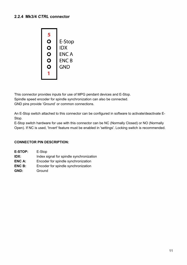
2.2.4 Mk3/4 CTRL connector
This connector provides inputs for use of MPG pendant devices and E-Stop.Spindle speed encoder for spindle synchronization can also be connected. GND pins provide ‘Ground’ or common connections.
An E-Stop switch attached to this connector can be configured in software to activate/deactivate E-Stop.E-Stop switch hardware for use with this connector can be NC (Normally Closed) or NO (Normally Open). If NC is used, 'Invert' feature must be enabled in 'settings'. Locking switch is recommended.
CONNECTOR PIN DESCRIPTION:
E-STOP: E-StopIDX: Index signal for spindle synchronizationENC A: Encoder for spindle synchronizationENC B: Encoder for spindle synchronizationGND: Ground
11
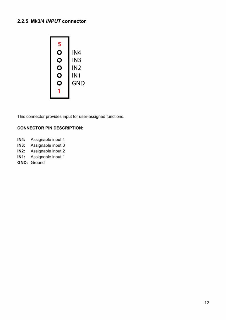
2.2.5 Mk3/4 INPUT connector
This connector provides input for user-assigned functions.
CONNECTOR PIN DESCRIPTION:
IN4: Assignable input 4IN3: Assignable input 3IN2: Assignable input 2IN1: Assignable input 1GND: Ground
12
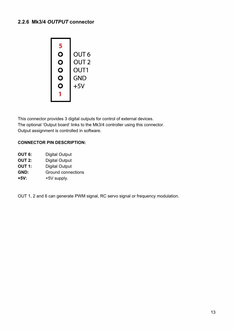
2.2.6 Mk3/4 OUTPUT connector
This connector provides 3 digital outputs for control of external devices. The optional ‘Output board’ links to the Mk3/4 controller using this connector. Output assignment is controlled in software.
CONNECTOR PIN DESCRIPTION:
OUT 6: Digital OutputOUT 2: Digital OutputOUT 1: Digital OutputGND: Ground connections+5V: +5V supply.
OUT 1, 2 and 6 can generate PWM signal, RC servo signal or frequency modulation.
13
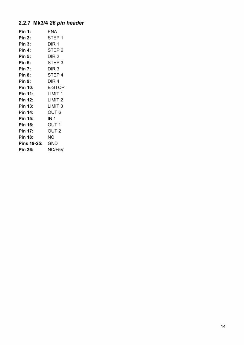
2.2.7 Mk3/4 26 pin header
Pin 1: ENAPin 2: STEP 1Pin 3: DIR 1Pin 4: STEP 2Pin 5: DIR 2Pin 6: STEP 3Pin 7: DIR 3Pin 8: STEP 4Pin 9: DIR 4Pin 10: E-STOPPin 11: LIMIT 1Pin 12: LIMIT 2Pin 13: LIMIT 3Pin 14: OUT 6Pin 15: IN 1Pin 16: OUT 1Pin 17: OUT 2Pin 18: NCPins 19-25: GNDPin 26: NC/+5V
14
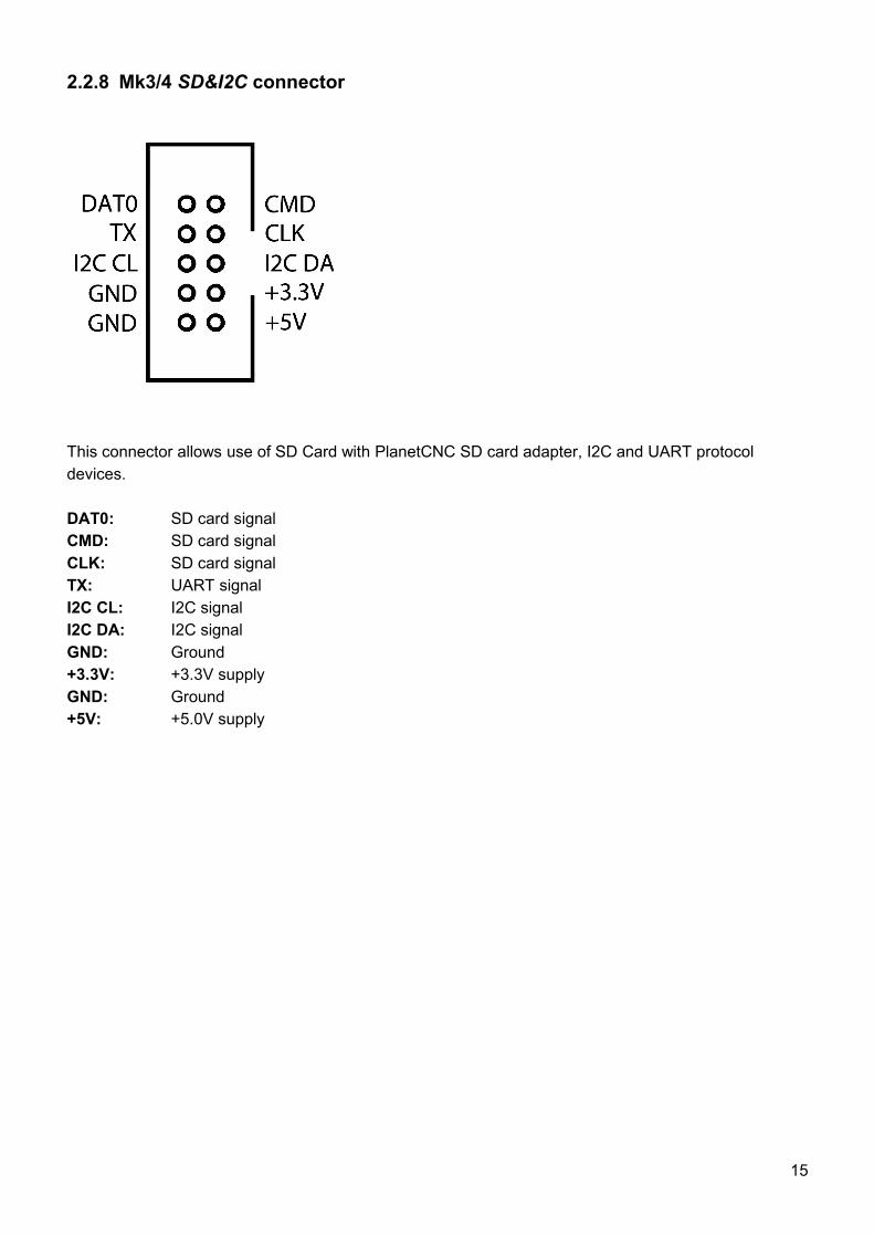
2.2.8 Mk3/4 SD&I2C connector
This connector allows use of SD Card with PlanetCNC SD card adapter, I2C and UART protocol devices.
DAT0: SD card signalCMD: SD card signalCLK: SD card signalTX: UART signalI2C CL: I2C signalI2C DA: I2C signalGND: Ground+3.3V: +3.3V supplyGND: Ground+5V: +5.0V supply
15
2.2.9 Mk3/4 USB connector
The Mk3/4 USB CNC controller connects to computer via the USB port. The port uses the USB 2.x standard.
2.2.10 Mk3/4 Power terminal
The controller should be powered with an external power supply.Mk3/4 - 4 Axis controller hardware requires 8 - 24V DC supplyPower supply should be at least 200mA
2.2.11 Mk3/4 LED indicators
The user is provided with helpful feedback and live ‘status’ information via on-board LED indicators. There are four indicators.
POWER: Lights when the controller is powered.DATA: Indicates controller functions.LINK: Indicates controller communication.STATUS: Blinks to indicate controller function is ‘good’.
16
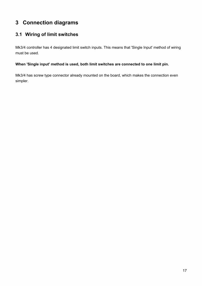
3 Connection diagrams
3.1 Wiring of limit switches
Mk3/4 controller has 4 designated limit switch inputs. This means that 'Single Input' method of wiring
must be used.
When 'Single input' method is used, both limit switches are connected to one limit pin.
Mk3/4 has screw type connector already mounted on the board, which makes the connection even
simpler.
17
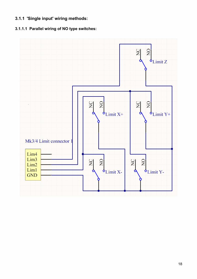
3.1.1 'Single input' wiring methods:
3.1.1.1 Parallel wiring of NO type switches:
18
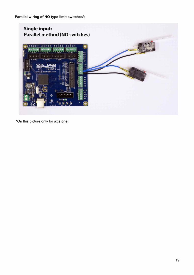
Parallel wiring of NO type limit switches*:
*On this picture only for axis one.
19
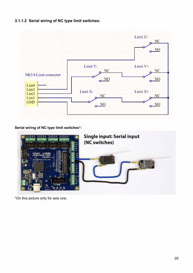
3.1.1.2 Serial wiring of NC type limit switches:
Serial wiring of NC type limit switches*:
*On this picture only for axis one.
20
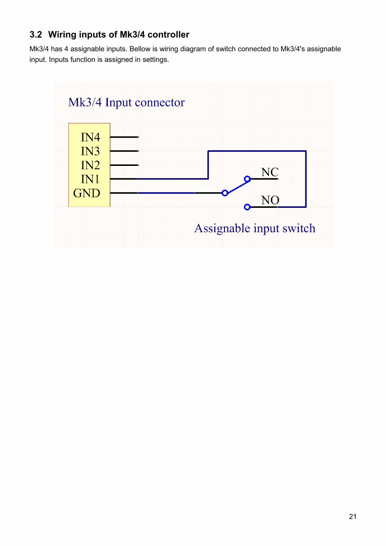
3.2 Wiring inputs of Mk3/4 controller
Mk3/4 has 4 assignable inputs. Bellow is wiring diagram of switch connected to Mk3/4's assignable
input. Inputs function is assigned in settings.
21
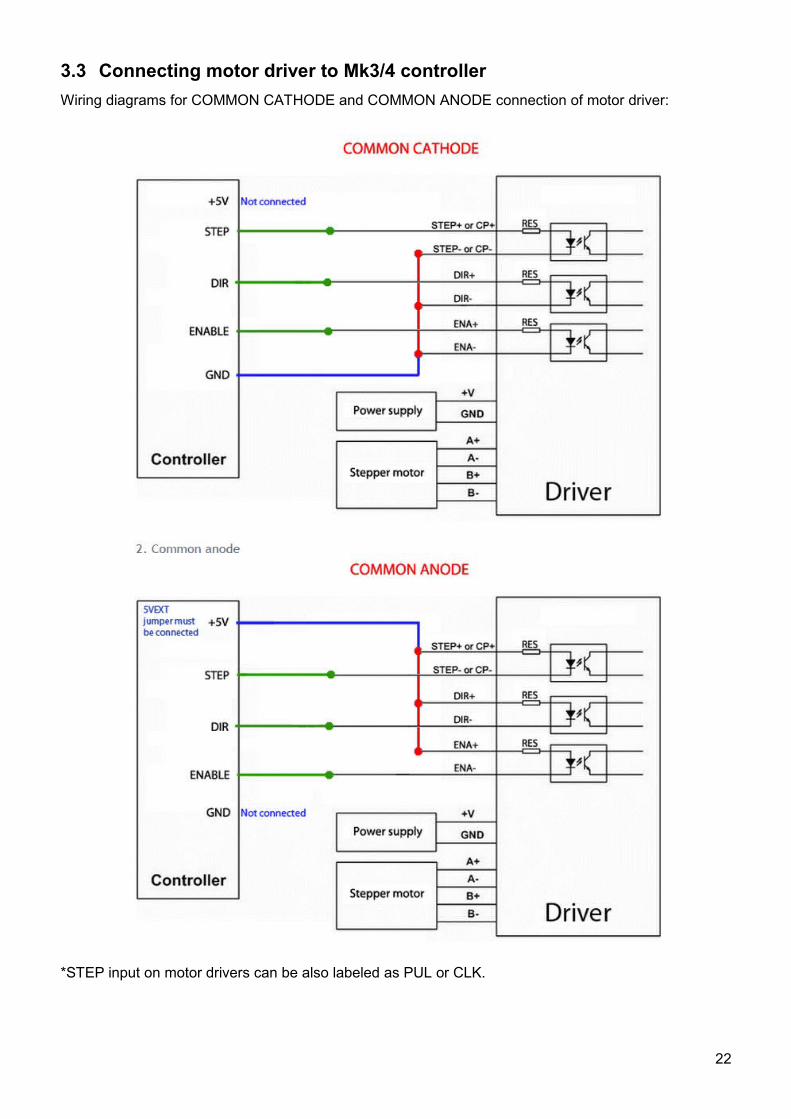
3.3 Connecting motor driver to Mk3/4 controller
Wiring diagrams for COMMON CATHODE and COMMON ANODE connection of motor driver:
*STEP input on motor drivers can be also labeled as PUL or CLK.
22
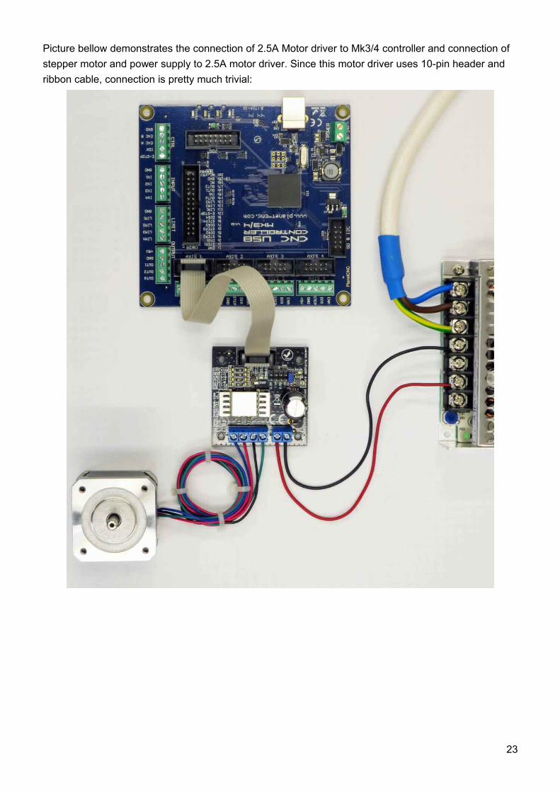
Picture bellow demonstrates the connection of 2.5A Motor driver to Mk3/4 controller and connection of
stepper motor and power supply to 2.5A motor driver. Since this motor driver uses 10-pin header and
ribbon cable, connection is pretty much trivial:
23
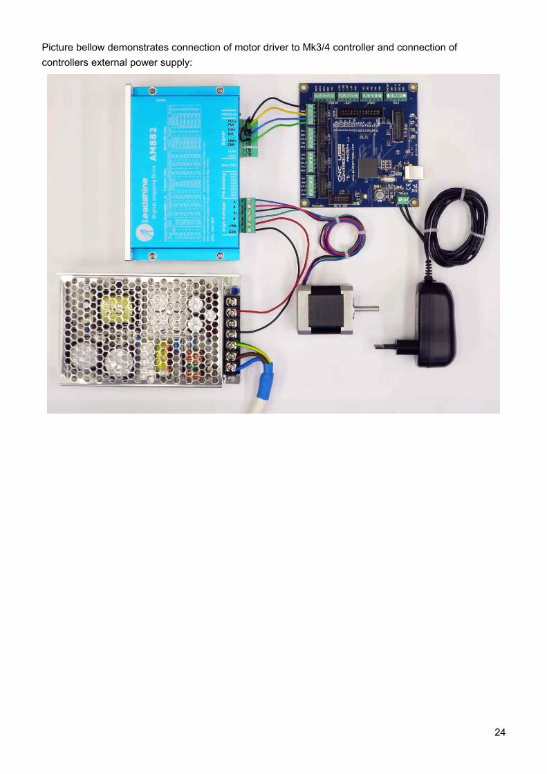
Picture bellow demonstrates connection of motor driver to Mk3/4 controller and connection of
controllers external power supply:
24
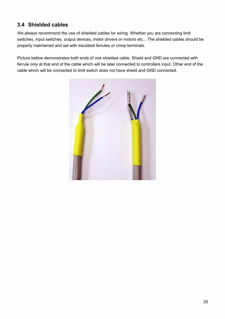
3.4 Shielded cables
We always recommend the use of shielded cables for wiring. Whether you are connecting limit
switches, input switches, output devices, motor drivers or motors etc... The shielded cables should be
properly maintained and set with insulated ferrules or crimp terminals.
Picture bellow demonstrates both ends of one shielded cable. Shield and GND are connected with
ferrule only at that end of the cable which will be later connected to controllers input. Other end of the
cable which will be connected to limit switch does not have shield and GND connected.
25
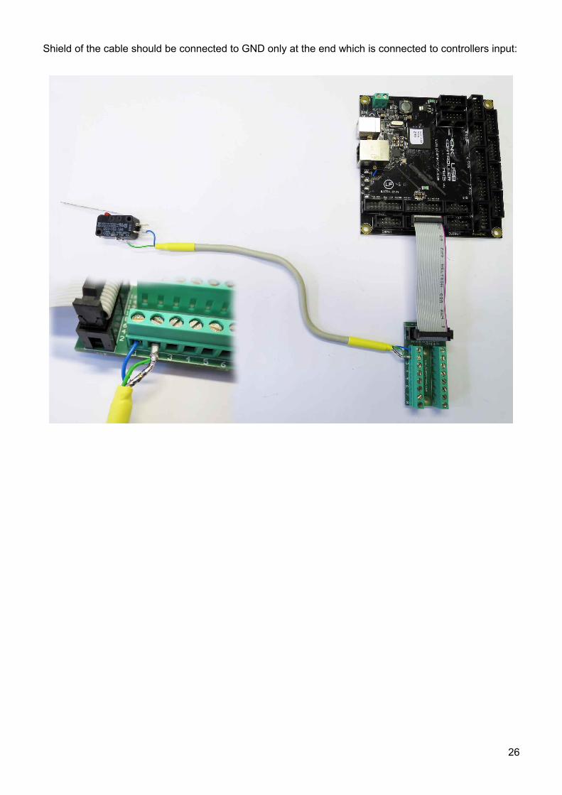
Shield of the cable should be connected to GND only at the end which is connected to controllers input:
26
Table of Contents
1 Introduction........................................................................................................................................ 3
1.1 Overview.....................................................................................................................................3
1.2 Features and specifications:........................................................................................................4
1.3 System Requirements.................................................................................................................5
2 Hardware........................................................................................................................................... 6
2.1 Installation...................................................................................................................................6
2.2 Mk3/4 - 4 axis CNC USB controller description...........................................................................72.2.1 Mk3/4 AXIS connector.........................................................................................................82.2.2 Mk3/4 JOG connector..........................................................................................................92.2.3 Mk3/4 LIMIT connector......................................................................................................102.2.4 Mk3/4 CTRL connector......................................................................................................112.2.5 Mk3/4 INPUT connector.....................................................................................................122.2.6 Mk3/4 OUTPUT connector.................................................................................................132.2.7 Mk3/4 26 pin header..........................................................................................................142.2.8 Mk3/4 SD&I2C connector...................................................................................................152.2.9 Mk3/4 USB connector........................................................................................................162.2.10 Mk3/4 Power terminal......................................................................................................162.2.11 Mk3/4 LED indicators.......................................................................................................16
3 Connection diagrams.......................................................................................................................17
3.1 Wiring of limit switches..............................................................................................................173.1.1 'Single input' wiring methods:.............................................................................................18
3.1.1.1 Parallel wiring of NO type switches:..........................................................................18
3.1.1.2 Serial wiring of NC type limit switches:......................................................................20
3.2 Wiring inputs of Mk3/4 controller...............................................................................................21
3.3 Connecting motor driver to Mk3/4 controller .............................................................................22
3.4 Shielded cables.........................................................................................................................25
27