Embed Size (px)
Citation preview

Co-Design of Digital Telecommunication System
Ref: Hardware/Software Co-Design of Digital Telecommunication System, IVO Bolsens et. al. ,
Proceedings of IEEE, March 1997
Hardware-Software Codesign of Embedded System CPSC489-501

Mahapatra-Texas A&M- Fall'00 2
Why codesign of Telecom System?
• The rapid breakthrough of consumer electronics (CD, DCC, DAB, ….), wireless or wired voice and data networking (ISDN, GSM, Videophone, …), broadband networks (ATM, ADSL, …) and multimedia is phenomenal these days.
• The digital communication technique is the basis of all these fast growing industrial activities.
• Development of digital communication is possible due to combined growth of VLSI and DSP.
• DSP System: Performs real-time mathematical transformation on digitized samples of analog signal with finite bandwidth and signal to noise ratio (SNR). – These transformation can be implemented either on a programmable
processor using software, or application-specific hardware and determined by trade-offs between cost, power, performance and flexibility.
Mahapatra-Texas A&M- Fall'00 3
Codesign of Telecom system• DSP based products have a growth rate of more than 35% per year.
• The average time to market window is reduced to few months only.
• Complexity and functional density is on demand.
• Design productivity:– communication system designer conceive the design at board and
executable concurrent programmable paradigm that is not understood by chip architect who works in the RTL domain. Gap between system design and implementation.
– The system need to be design at processor-memory level by reusing component designs. This needs methodology and codesign approach.
– Size of design team does not seem to grow as chip complexity grows.
– Hence, there is a need to increase design productivity and seamless transition of design strategy from software centric to implementation-reuse hardware-software codesign approach.
Mahapatra-Texas A&M- Fall'00 4
Specification view of DSP system
• Digital Signal results from: binary encoding of time and range discretized measurable continuous time, continuous range quantities.
• Sampling occurs at or above Nyquist frequency and coding is done with just enough word-length to maintain SNR.
• Digital signals are usually fixed-point type to save power and hardware to meet desired performance.
• Digital signals are stream of digital words due to periodic sampling. These words are naturally structured into multidimensional arrays, which are to be processed frame period Tf, that is the duration of the algorithm when it takes a set of input to produce the set of results.
• Thus the elementary DSP algorithm is a dataflow function.

Mahapatra-Texas A&M- Fall'00 5
DSP System Specification• Synchronous dataflow (SDF) algorithm are modeled as DAG.
– The dataflow DSP algorithms are described efficiently by many applicative programming languages (LUSTER, DFL, SILAGE,…).
– The operations can be scheduled at compile time and execution of compiled code can be two orders of magnitude faster than the execution of event driven code (VHDL simulation).
• Dynamic dataflow (DDF) algorithms contain data-dependent token production and consumption.
– Allows while and if-then-else constructs– Hard periodic constraints are satisfied by inserting exit paths in while loops
that guarantee a bounded execution time whereby unassigned signals are assigned default values.
– One can transform DDF’s into worst case SDF and schedule statistically.– Else, DDF’s can be partitioned into a set of compiled time scheduled SDF
functions fired by internal or external Boolean events.

Mahapatra-Texas A&M- Fall'00 6
DSP Specifications
• CAD systems for DSP (DSP-Station of Mentor graphic, Ptolemy, GRAPE-II, COSSAP from Synopsis, SPW from The Alta) group allow the specification in SDF and DDF and use static scheduling as much as possible to achieve the speed over event driven simulator.
• Communication system typically consist of one or more signal paths, slow control loops and a reactive control system. The control loop and reactive control system are slow environments due to some user interfaces and status update in signal paths.
• The signal path is usually a concatenation of dataflow functional blocks (DFFB) and could operate at different speed and data set. The difference in data rate is due to digital communication system it self.

Mahapatra-Texas A&M- Fall'00 7
Heterogeneous functional specs
L2 L1 m1 h2 h1 Signal path
Keypad
DisplayUI control
Example:h1, h2: matched filter, correlatorm1: low rate demodulatorL1: error correction in base bandL2: speech decompression

Mahapatra-Texas A&M- Fall'00 8
Specification of DSP
• The DFFB’s in the signal path are strongly connected DFG’s and rarely partitioned if timing constraints allow it. Usually fast.
• Control loop and mode control by parameter setting are common to most communication systems (tracking and acquisition loop). These loops are orders of magnitude slower that the data rate. Hence, reactive semantics are used here. They run concurrent to data flow.
• Program State Machine (PSM) can be used for such environment. It is a hierarchical program state where each state may be a distinct mode of computation. StateCharts or SpecCharts are suitable that allow exception handling and interprocess communication. But VHDL is too low level to describe it.
• Co-simulate dataflow and event driven models.

Mahapatra-Texas A&M- Fall'00 9
DSP specs
• In case of video and image processing there is virtually no other way for validation than emulation. Which requires retargetable synthesis technique.
• The retargetable synthesis technique allows to map on to FPGA architecture, programmable DSP and video signal processor. Also can map on to the final on-chip architecture (to be discussed).
Mahapatra-Texas A&M- Fall'00 10
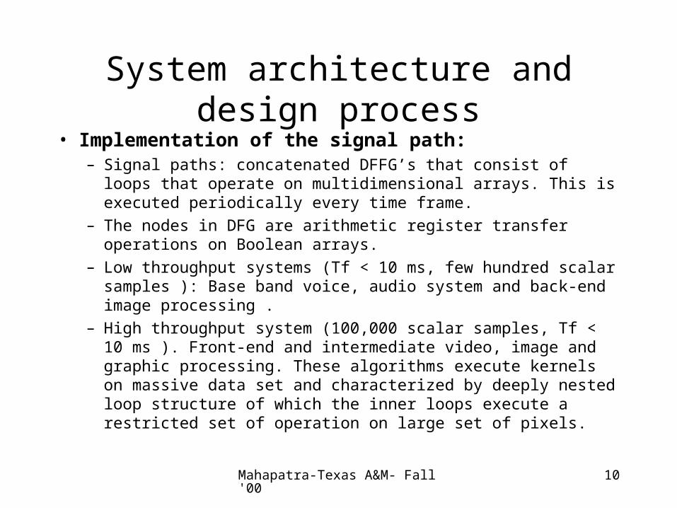
System architecture and design process
• Implementation of the signal path:– Signal paths: concatenated DFFG’s that consist of loops that operate
on multidimensional arrays. This is executed periodically every time frame.
– The nodes in DFG are arithmetic register transfer operations on Boolean arrays.
– Low throughput systems (Tf < 10 ms, few hundred scalar samples ): Base band voice, audio system and back-end image processing .
– High throughput system (100,000 scalar samples, Tf < 10 ms ). Front-end and intermediate video, image and graphic processing. These algorithms execute kernels on massive data set and characterized by deeply nested loop structure of which the inner loops execute a restricted set of operation on large set of pixels.

Mahapatra-Texas A&M- Fall'00 11
Processor Architectures
• Highly Multiplex Data Path (HMDP) processor:
– Executes low throughput algorithms (20 to 500,000 clock cycles) of irregular flow graphs, less than 10 operations per cycle.
– Few concurrently operators with rich instruction set, controlled by a single thread sequencer with instruction and status pipelines.
– Three types of processors:
(1) Commercial DSP processor: fixed point core with separate program memory and data memory and fixed I/O peripherals. Core has encoded instruction set tuned to arithmetic sum-of-product operation and regular memory access for convolution type algorithms. Has very heterogeneous register architecture. (C compiler for regular register architecture has poor performance and hence DSP engineers use assembly language).

Mahapatra-Texas A&M- Fall'00 12
Processor Architectures
• HMDP Processor types:
(2) VLIW processor: Has global single thread hardwired controller and data memory.
-only one DSP algorithm is executed due to customization. Higher degree parallelism is possible using multiple functional units and memory blocks.
-Examples: Cathedral-2, MISTRAL-2
(3) ASIPs: Uses application specific instructions for programmability.
– Better area efficient than commercial DSP processor and more flexible compared to VLIW.
– Combine reuse of hardware with performance, low power.

Mahapatra-Texas A&M- Fall'00 13
Processor Architectures• Low Multiplexed Data Path (LMDP) Processor:
– High throughput algorithms are characterized by a set of repetitive computation intensive kernels for which only few cycles are available to execute each iteration. Hence low multiplexing is used to save cycles.
– Decision making must be done within single clock cycle by inserting local control in the data-paths.
– You need application-specific pipelined datapath that is tuned to a time folding of the kernels to execute.
– Example applications: video processing, CDMA transceiver etc.. Known as hardware accelerators.
– Distributed Memory architecture is used to meet the data throughput.
– Synthesis tools: Cathedral-3, PHIDEO and Hyper
– Low power design favors this: central memory fetching consumes one order of magnitude more than the local memory.

Mahapatra-Texas A&M- Fall'00 14
Control Loops and UI
• Control loops consist of interactive state machines and hard to keep it time constrained (unlike arithmetic operations).
• Micro controller based implementation is mostly used today. This helps for redefinition later and maintain product legacy.
• Synthesis of hardware FSMs may be cheaper in area and power. RT-level synthesis is useful.

Mahapatra-Texas A&M- Fall'00 15
Typical Hardware components of a Telecommunication System and their role in the implementation.
(Table from Bolsens et.al paper)
Component Class Implementations Compiler SpecHMDPDSP Processor
Low datarate DSPSlow control LoopsAppl. Spec Algorithm
RetargetableCode generatorsHigh level Synthesis
AssemblyCDFL
LMDPDSP Processors
High datarate DSP High level synthesisRT Level Synthesis
C, DFLVHDL
MicroControllerHardware FSM
User interfaceSlow control loops
C compiler
RT Synthesis
Multithread CFSM
Peripherals Usually FSDMs.clock generators. DMA blocks
RT level SynthesisAsynchronoussynthesis
VHDLPSM
CommunicationsBlocks &memory
Internal & ExternalCommunicationStorage & bufferingof Shared variables
Memory mgmt synthAsynchronousInterface synthesis
Data-sheetsSTG(sig Tra. Graph)
CSP
Mahapatra-Texas A&M- Fall'00 16
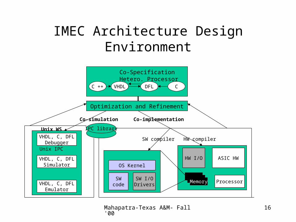
IMEC Architecture Design Environment
Optimization and Refinement
IPC library
HW I/O ASIC HW
ProcessorMemory
OS Kernel
SWcode
SW I/ODrivers
VHDL, C, DFLDebugger
VHDL, C, DFLSimulator
VHDL, C, DFLEmulator
C ++ VHDL DFL C
Co-SpecificationHetero. Processor
Unix IPC
Unix WS
Co-simulation Co-implementation
SW compiler HW compiler

Mahapatra-Texas A&M- Fall'00 17
System Design Process: co-ware environment
• System design process must bridge the gap between heterogeneous functional specifications.
• Functional specification is based on the concept of communicating co-ware processes. Processes are concurrent programs in a host language.
• In co-ware, there is no difference between co-simulation and co-implementation. Both are based on refining the specs to implement.
• First step in implementation is to allocate the processors optimally. The next step is to merge functional specs and assign that to allocated processor. This assignment step is Partitioning and hard to automate.
• Most essential step is to implement abstract communication between HW and SW. Interface synthesis is required.
• Then the process follows as usual …. synthesis step.
Mahapatra-Texas A&M- Fall'00 18
CoWare Data Model
• Process: container for a number of host language encapsulations of a component. ( different implementations for the same component)– presently, the languages are C, DFL, VHDL, Verilog, and CoWare
• In CoWare language incapsulation, one can instantiate processes and connect their ports with channels. (The other host language encapsulation consists of a context and threads. The context contain code that is common to all threads, useful for interthread comm.)
• Ports: Objects through which processes communicate. The port is characterized by a protocol and data type parameter. Construct port is the implicit port to which remote procedure call is performed.
• Protocols: Define communication semantics of a port. (master, inmaster, outmaster, inoutmaster, slave, inslave, outslave, inoutslave)
Mahapatra-Texas A&M- Fall'00 19
CoWare Model
• Thread: A single flow of control within a process. It contains code in host language of encapsulation.– Slave threads: associated with slave port activated due to RPC.
– Autonomous thread: not associated with any port.
• Channel: A point to point connection of master port and slave port. Can be uni- or bidirectional. Data exchanges between connected channels. In HW implement it using wire. In SW use function call.
• Assignment: Identify various type of ports, channels, threads in the Fig. 4.

Mahapatra-Texas A&M- Fall'00 20
Communication in CoWare
• Communication always happens between two threads. – If threads are part of the same process: intraprocess comm. Uses shared
variable for communication that has been declared in that process. Two threads access same variable or protection of critical section is provided by the host language.
– Else, interprocess communication.
• Interprocess communication with a primitive protocol is RPC based. On a master port, RPC function can be used to initiate a thread in a remote process. A master port can be used from anywhere host language. The RPC function returns when the slave thread is completed. Read and Write functions can be used in the slave thread to access data from the slave port. The Index function access indices of the protocol of the port. The RW* function finds the direction of inoutslave port.

Mahapatra-Texas A&M- Fall'00 21
Communication Refinement
• Once the designer is convinced on the correctness of functionality, the communication behavior is refined.
• Communication behavior in CoWare is refined by making the communication objects (channel, port, protocol) hierarchical.
• Hierarchical Channels: are processes that assign a given communication behavior to a primitive channel. The behavioral interface of a hierarchical channel is fixed by the ports connected by the primitive channels. One can parallelize or pipeline the processes by adding buffers. The only prpoerty that is preserved by making a channel hierarchical is the direction of data transfer. (see Fig.5).– The channel between P1 and P23 is refined to be FIFO behavior. Now the
rate of RPC issued by P1 is no more controlled by RPC serviced by P23.
Mahapatra-Texas A&M- Fall'00 22
Comm. refinement
• Hierarchical Ports: are processes that assign a given communication behavior to a primitive port. The hierarchical port process has one primitive port, return, that is connected to the primitive port that is made hierarchical. – In Fig.5, say we want to impose a data formatting over the data
transported between P1 and FIFO process. This is achieved by making the port p1 and left hierarchical.
– The format process that refine port p, might add a CRC to the data through them. The unformat process that refine port left of the FIFO process then uses this CRC to check the data for validity.
– The actual data and CRC are sent sequentially over the same primitive channel.
Mahapatra-Texas A&M- Fall'00 23
Comm. refinement
• Hierarchical protocols: refine primitive protocols with a timing diagram and the associated I/O terminals. These are high level models for alternative implementation of a primitive protocols. – To access the terminals of the hierarchical protocols, a hierarchical port is
introduced at the same time. The terminal can be accessed from within the thread code by using functions Put, Sample and Wait.
– In Fig.5, the primitive protocol of op port and ip port of the format and unformat process are refined into an RS232 protocol.
– In the RS232 hierarchical port, an RPC issued in the format process on the op port is converted into manipulations of the terminals according to a timing diagram.
Mahapatra-Texas A&M- Fall'00 24
Communication in CoWare
• Hierarchical channels and ports being processes, can be removed from a system description by expansion or flattening. The result is a coware description that contain only process instances of which the primitive ports (possibly with hierarchical protocols) are connected by primitive channels. Thus we have three basic communication mechanism as follows.

Mahapatra-Texas A&M- Fall'00 25
Communication mechanism in CoWare(Table 2 of the reference)
Intra-processcommunication
Inter-processcommunicationPrimitive protocol
Inter-processcommunicationHierarchicalcommunication
context Remote procedure call Terminals, Timing diagrams
shared Master port:RPC() Input:Sample(), Wait()
Variables Slave port: Read(), Write()
Index(), RW*()
Output: Put()

Mahapatra-Texas A&M- Fall'00 26